lu cu ll oo l3 - World Radio History
240
e solucullool3 rvoilvDriend - 1 - 11H-AnvdoovN SHVTIOCIdnod LI71. /...1GMOd SOAJOSUO0 119E)0JddU sov\J-0 :soepoo uo 9.10V\J oe./ssÁdsp LicleJ5-Jeq aEuetiosp-seb sewidwis dmo eoepelui k/DNIOVMOlid AlISN3CI - HDIH I:10d HSIld 3H.1. :11:110d31:11V133dS SL61- H9V\131dS
-
Upload
khangminh22 -
Category
Documents
-
view
1 -
download
0
Transcript of lu cu ll oo l3 - World Radio History
esolucullool3 rvoilvDriend -1-11H-AnvdoovN SHVTIOCIdnod
LI71. /...1GMOd SOAJOSUO0 119E)0JddU sov\J-0 :soepoo uo 9.10V\J
oe./ssÁdsp LicleJ5-Jeq aEuetiosp-seb sewidwis dmo eoepelui k/DNIOVMOlid AlISN3CI-HDIH I:10d HSIld 3H.1. :11:110d31:11V133dS
SL61- H9V\131dS

sh your total on-board costs! Only Boums delivers both DIP and SIP trimmers for high volume, auto-insertion applications. Machine insertion reduces your production costs and increases productivity. Production costs are slashed from as high as 10 cents to as low as 0.3 cents per insertion! Trimmers can be auto-inserted at least 30 times faster than by hand!
Use Your Standard IC Insertion Equipment — If you already have equipment for auto-insertion of DIP — IC's, you can use the same equipment to insert DIP trimmers. Bourns Model 3099 DIP trimmers have identical height and lead spacing as standard IC's. Or, if you need to purchase insertion equipment, the payback can begin at 3,000,000 insertions!
Meet the New SIP Space Saver — Boums recently introduced the world's first SIP trimmer — the Model 20. Auto- or hand insertable, the Model 20 cermet trimmer saves precious board space with no sacrifice in performance. Featuring .100-inch spacing and a low board profile of .I85-inches, it occupies only 50% of the space used by conventional /4-inch rectangular trimmers.
Both DIP's and SIP*s feature stable, infinite resolution cermet elements with a low temperature coefficient of 100 ppm/°C. They are sealed to withstand industrial cleaning processes and are available in 18 standard resistance values ranging from 10 ohms to 5 megohms.
Backed by the Boums reputation for leadership, performance and quality at cost-effective prices, Boums DIP and SIP trimmers can slash total on-board costs and increase productivity. Call or write today for information on the Bourns family of auto-insertable trimmers.
TRIMPOT PRODUCTS DIVISION, BOURNS, INC., 1200 Columbia Avenue, Riverside, CA 92507. Phone: 714 781-5050. TWX: 910 332-1252.
1-- Mild I wita ¡um For Immediate Application—Circle 120 For Future Application—Circle 220

Ooopefree PROM programming with the
CMOS buffered programmer.
Avoid lost or altered data, misprogrammed PROMs, ruined master PROMs with the M900B, the only programmer with built-in CMOS buffer. Our new M900B has a buffer of 2048 8-bit words with capacity to 4096 words. It's CMOS with power-backup so you can shut off or lose AC power for up to 60 seconds and not lose data. That's plenty of time to replace one PROM personality module with another. Thus you can transfer data from one PROM type to an entirely different PROM type (UV eraseable to bipolar, for instance) or transfer from several small PROMs to a single large one. A Data-Shift feature lets you change data locations when transferring data between PROM and memory.
Helps prevent misprogramming. The M900B lets you check, correct and verify your data in the buffer before you com-mit it to a PROM.
CMOS technology with power-backup guards against transients that can alter data stored in a cheap-er but volatile bipolar RAM.
PRO-LOG (: OH PO H AT I ON
Microprocessors at your fingertips.
Use it with or without the buffer. Two-socket personality modules guard your master PROMs. With the buffer switched out, the M900B gives you direct PROM to PROM copying. We use two sockets, one for the master PROM, one for the copy PROM. Operator error can't alter a PROM in our master socket because that socket contains no program-ming voltages.
Tie M900B, like all our con-trol units and PROM per-sonality modules, comes U.L. listed, designed and built to U.L. electrical safety s:andards.
The M900B with standard 2K buffer costs only $2,100. With full 4K buffer, it costs only $2,400.
Write for our PROM User's Information Package. Pro-Log Corporation, 2411 Garden Road, Monterey, CA 93940, phone (408) 372-4593.
Electronics/September 28, 1978 Circle 1 on reader service card 1

...for POSITIVE switching in low energy circuits Now your 4 to 100 milliampere, 4 to 30 volt circuits can have the same high reliability you've learned to love in Cherry snap action switches. Because, our 'heart of gold" snap action switches have the same long life coil spring mechanism, the same large overtravel as all of our snap action switches. They also have gold crosspoint contacts. A con-
figuration with knife-edge contact area so small (9 millionths of a square inch)... with contact force so great (about 5,000 psi)... and gold alloy so pure and film-free ... you are absolutely assured of posi-tive contact every time. For 50 million operations and beyond. Cherry Gold Crosspoint Contact Switches are
available in virtually every snap action design in
Cherry switches now available locally from distributors.
CHERRY ELECTRICAL PRODUCTS CORP., 3608 Sunset Avenue, Waukegan, IL 60085
Circle 2 on reader service card
Cherry's big catalog. And you know what a wide variety of switch types, sizes and mounts that is. Choose any switch design from a basic open or general purpose to a panel mount pushbutton, low torque, miniature, subminiature or subminiature module. Chances are 99 to 1 that the switch you have chosen is available with gold crosspoint con-tacts. Which will make designing low energy cir-cuits a whole lot easier... and a whole lot better. (No love letters, please.) For free test sample and complete catalog, just TWX 910-235-1572... or PHONE 312-689-7700.

Electronics The International Magazine of Electronics Technology
41 Electronics Review DATA COMMUNICATIONS: Computer makers disclose designs, 41 COMMUNICATIONS: Codec filter goes monolithic on Intel chip, 42 COMPUTERS: STC finds goods news, bad news with CCDs, 43 INSTRUMENTS: Infrared probe monitors powerful laser, 44 CAREERS: How EEs can help own patent interests, 46 TESTING: Microwave probe finds metal flaws, 48 SOLID STATE: AMI features V-MOS in processing role, 50 NEWS BRIEFS: 53 MEETINGS: Wescon heads for Anaheim in 1980, 53 FUSION: Microwaves to beat Tokamak plasma, 54
71 Electronics International JAPAN: Glass rods focus fiber-optic beams in device family, 71 WEST GERMANY: Optical cable is compact and rugged, 72 GREAT BRITAIN: Microprocessor makes Teletext smarter, 74 Optical fiber in perimeter fence warns of trespassers, 74 FRANCE: Lots of air gives a good Schottky microwave diode, 76
85 Probing the News COMPUTERS: Soviet machines are better than expected, 85 SOLID STATE: Pentagon's VHSI program draws interest, 89 ABROAD: Common Market eyes VLSI cooperation, 92 COMMENTARY: Britain's NEB flourishes amid controversy, 95 PHOTOVOLTAICS: Silicon growers try to cut cost/watt, 97
109 Technical Articles MEMORIES: 64-K RAM with one 5-V supply outstrips 16-K parts, 109 PACKAGING: Answering the call for higher densities, 117 DESIGNER'S CASEBOOK: Generator sets music-box timbre, 126 VCOs produce selectable pseudo-random noise, 127 Multiplier, op amp generate sine for producing vectors, 129 COMPONENTS: IC driver simplifies gas-discharge display, 130 INSTRUMENTS: Logic analyzer minimizes setup problems, 136 COMMUNICATIONS: Codec splits transmitting, receiving sections, 141 ENGINEER'S NOTEBOOK: Circuit simplifies processor interrupt, 148 Badge reader checks for production defects, 150
165 New Products IN THE SPOTLIGHT: Single chip reads floppy disks, 165 INSTRUMENTS: Counter/timer spans 100 MHz for $800, 174 DATA ACQUISITION: I/O boards stress flexibility, 185 COMPUTERS & PERIPHERALS: Muscle added to Eclipse line, 198 COMMUNICATIONS: Fiber-optic link spans 100 meters, 204 INDUSTRIAL: Dedicated timer programs system, 212 MATERIALS: 228
Departments Publisher's letter, 4 Readers' comments, 6 Editorial, 10 People, 12 News update, 28 Meetings, 33 Electronics newsletter, 35 Washington newsletter, 61 Washington commentary, 62 International newsletter, 67 Engineer's newsletter, 156 Products newsletter, 227 New literature, 236
Services Employment opportunities, 240 Reprints available, 250 Reader service card, 251
Vol. 51, No. 20 • September 28, 1978
Highlights
The cover: Dynamic 64-K RAM bows, 109
A single 5-volt supply suffices for a 64-K dynamic random-access memory that fits into a 16-K RAM's 16-pin package while offering dramatically better performance. Process improvements and geometry reduc-tion are the keys to the new chip. Cover is by Associate Art Director Charles
D. Ciatto.
Cheaper solar cells are hot topic, 97
At least 10 U. S. companies are working on processes to cut the cost of making the silicon that goes into photovoltaic cells. Promising results are coming from their efforts, which are part of the Department of Energy's program for making photovoltaic energy economically viable.
New methods pack chips in, 117
The increasing density of integrated circuits calls for new packaging methods in order to cram more ICs onto a substrate. This special report covers the variety of tech-niques that are answering the call.
Codec boasts two d-a converters, 141
A single-chip coder-decoder uses one digi-tal-to-analog converter in the coding section and another in the decoder. Such an approach makes for high system isolation, ease of use, and low power dissipation.
And in the next issue . . .
A high-performance, 16-bit single-board computer . . . a pullout chart of the world's communications satellites . . . an end to the mystery of pc-board hook.
Electronics/September 28, 1978 3

Electronics
EDITOR-IN-CHIEF: Kemp Anderson
EXECUTIVE EDITOR: Samuel Weber
MANAGING EDITORS: Arthur Erikson, Gerald M. Walker
SENIOR EDITORS: William F. Arnold, Ray Connolly, Lawrence Curran
ART DIRECTOR: Fred Sklenar
ASSOCIATE EDITORS: Howard Wolff, Alfred Rosenblatt
DEPARTMENT EDITORS Aerospace/Military: Ray Connolly Circuit Design: Vincent Biancomano Communications & Microwave: Harvey J. Hindin
Components: Nicolas Mokhotf Computers: Anthony Durniak Consumer and Industrial: John Javetski Microsystems and Software:John G. Posa Instrumentation: Albert F. Shackil New Products: Michael J. Riezenman, Richard W. Comerford
Packaging & Production: Jerry Lyman Solid State: Raymond P. Capece
CHIEF COPY EDITOR: Margaret Eastman
COPY EDITORS: Ben Mason, Mike Robinson, Steven Weitzner
ART: Charles D. Ciatto, Associate Director Paula Piazza, Assistant Director
EDITORIAL SECRETARIES: Janet Noto, Penny Kaplan, Maryann Tusa
EDITORIAL ASSISTANT: Marilyn B. Rosoff
REGIONAL EDITORS Boston: Lawrence Curran Pamela Hamilton (617) 262-1160
Dallas: Wesley R. Iversen (214) 742-1747 Los Angeles: Larry Waller (213) 487-1160 New York: Bruce LeBoss (212) 997-3444 San Francisco: William F. Arnold
Robert Brownstein (415) 968-2712 Washington: Ray Connolly (202) 624-7592 Frankfurt: John Gosch London: Kevin Smith Paris: Arthur Erikson Tokyo: Charles Cohen
McGRAW-HILL WORLD NEWS Editor: Michael Johnson Brussels: James Smith Milan: Andrew Heath Moscow: Peter Hann Paris: Andrew Lloyd Stockholm: Robert Skole Tokyo: Robert E. Lee
PUBLISHER: Dan McMillan
ADVERTISING SALES MANAGER: Paul W. Reiss
MARKETING ADMINISTRATION MANAGER: Wallis Clarke
CIRCULATION MANAGER: Karl Peterson
MARKETING SERVICES MANAGER: Tomlinson Howland
RESEARCH MANAGER: Margery D. Sholes
Publisher's letter Very large-scale integration and Ls!
too are making greater demands than ever on the art of packaging. The result is a variety of high-densi-ty techniques, the most promising of which are the subject of the special report that starts on page 117. As packaging and production edi-
tor Jerry Lyman points out, "We are seeing an era of new packages, finer lines, multilayer boards, and exotic Ic package materials to accommo-date the new chips." Efforts in this field have created a blending of printed-circuit and hybrid methods into one technology that encom-passes screened-on interconnects and wire-bonding and film and ceramic chip-carriers planted on extremely large substrates of new materials, such as ceramic fired on steel. This technology is changing rapidly with the introduction of more and more carriers and improved automated-packaging techniques. In fact, Jerry reports that two new ceramic car-riers have come out since he wrap-ped up the story. Oddly enough, although the tech-
nique was developed here, U. S. manufacturers are just beginning to try the film chip-carrier method for hybrid packaging. Even although the Japanese and Europeans have been using the technology for some time, U. S. manufacturers are still reluctant to try it. This situation could change, however, if the bumped tapes now being developed prove effective. More stimulus may come from the military, which is funding programs to develop low-cost film chip-carriers. With chips getting denser and
demand for space greater, it's clear
that manufacturers will have to come up with some solution. A good indication of their interest appeared at a talk that Jerry recently presented on this subject for a local meeting of the International Society for Hybrid Microelectronics. The presentation, which was supposed to run 30 minutes, took over an hour because of the questions and discus-sion following his talk.
E lectronics in Europe is the subject of two Probing the News stories in
this issue. Kevin Smith, our bureau chief in London4 takes a hard look at the track record of the British Government's National Enterprise Board (p. 95) while Jim Smith, the McGraw-Hill World News man in Brussels, reports on the possibility of a Common Market VLSI develop-ment project (p. 92). Together, these two stories underline the vital impor-tance of electronics development in Europe and at the same time high-light the difficulties these nations encounter in keeping up in the tech-nology race.
Kevin Smith's Commentary con-cludes that the investment made by the UK government through NEB to put some zest into its electronics industries may pay off, no matter what the fate of the controversial Inmos formation. "If the activities of the NEB stimulate more UK compa-nies out of their over-cautious lethar-gy, the price could be cheap indeed," he concludes.
September 28 1978 Volume 51, Number 20 100,108 copies of this issue printed
Published every other Thursday by McGraw-Hill, Inc. Founder: James H. McGraw 1860-1948. Publication office 1221 Avenue of the Americas. N.Y.. N.Y. 10020; second class postage paid at New York, N.Y. and additional mailing offices. ID* 172400.
Executive, editorial, circulation and advertising addresses: Electronics. McGraw-Hill Building, 1221 Avenue of the Americas. New York, N.Y. 10020. Telephone (212)997-1221. Teletype 12-7960 TWO 710-581-4879. Cable address: MCGRAWHILL NE WYOR K.
Subscriptions limited to professional persons with active responsibility in electronics technology. No subscriptions accepted without complete identification of subscriber name, title or job function, company or ore-nization. and product manufactured or services performed. Based on inlormation supplied, the publisher reserves the right to reject non. qualified requests. Subscription rates: in the United Slates and posses-sions $15 one year. $26 two years. $38 three years; company addressed and company libraries $20 one year. $36 two years. $50 three years; APO/FPO addressed $35 one year only; Canada and Mexico $17 one year. $29 two years. $43 three years; Europe $42 one year. $71 two years. $100 three years; Japan, Israel and Brazil $70 one year, $115 two years, $165 three years; Australia and New Zealand $95 one year, $170 two years, $240 three years. including air freight; all other countries $45 one year. $80 two years, $112 three years. Limited quota of subscriptions available al higher-than-basic rate for persons allied to field served. Check with publisher for these rates. Single copies: $4.00. Please allow four to eight weeks for shipment.
Officers of McGraw.Hill Publications Company: Gordon L. Jones. President; Paul F. McPherson, Executive Vice-President Group Vice-President: Gene W. Simpson; Senior Vice-Presidents. Russell F. Ander-son; James E. Boddorf, Planning 11 Development; Ralph R. Schulz,
Editorial; Vice-Presidents: Denis C. Beran, European Operations; David P. Forsyth. Research; James E. Hackett, Controller; Eric B. Herr, Economics; Thomas H. King. Manufacturing; Robert L. Leyburn, Circu-lation; John W. Patten. Sales; Edward E. Schirmer, International.
Officers of the Corporation: Harold W. McGraw, Jr., President, Chief Executive Officer, and Chairman of the Board; Robert N. Landes, Senior Vice President and Secretary; Ralph J. Webb. Treasurer.
Title registered in U.S. Patent Office; Copyright e 1978 by McGraw-Hill, Inc. All rights reserved. The contents of this publication may not be reproduced in whole or in part without the consent ol copyright owner. Where necessary, permission is granted by the copyright owner for
libraries and others registered with the Copyright Clearance Center (CCC) to photocopy any article herein for the base lee of 50.50 Per copy of the article plus $0.25 per page. Payment should be sent directly to the CCC. Copying done or other than personal or internal reference use without the express permission of McGraw-Hill is prohibited. Requests lor special permission or bulk orders should be addressed to the publisher. ISSN 0013-5070178$0.50+.25.
Subscribers: The publisher, upon written request to our New York office from any subscriber, agrees to refund that part of the subscrip-tion price applying to copies not yet mailed. Please send change-of -address notices or complaints to Fulfillment Manager; subscription orders to Circulation Manager, Electronics, at address below. Change-of -address notices should provide old as well as new address, including postal zip code number. If possible, attach address label from recent issue. Allow one month for change to become effective.
Postmaster: Please send form 3579 to Fulfillment Manager. Electron-ics, P.O. Box 430. Hightstown, N.J. 08520.
4 Electronics/September 28, 1978
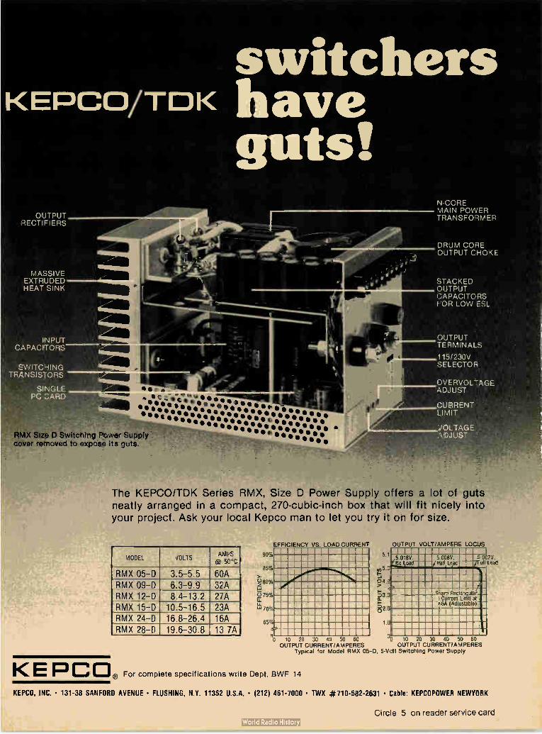
switchers KEPCO/TOK have
guts! OUTPUT
RECTIFIERS
MASSIVE EXTRUDED HEAT SINK
l'N PUT CAPACITORS
SWITCHING TRANSISTORS
SINGLE PC CARD
leer' .,,t.411111•••e••• lie • • • le •
•C'silIt••••rok • S • • • • • • • 11-11-0-04•Iele • • • • II • • • • It e • • •
116•••••••••_••• • • • • • 111 • • fbelbeeeeiele.41111.•••••• RMX Size D Switching Power Supply - • e • • • • • • • • • • e • • • • • • e •
cover removed to expose its guts.
N-CCRE MAIN POWER TRANSFORMER
DRUM CORE OUTPUT CHOKE
STACKED OUTPUT CAPACITORS FOR LOW ESL
OUTPUT TERMINALS
1151230V SELECTOR
OVERVOLTAGE ADJUST
CURRENT LIMIT
i/OLTAGE ADJUST
The KEPCO/TDK Series RMX, Size D Power Supply offers a lot of guts neatly arranged in a compact, 270-cubic-inch box that will fit nicely into your project. Ask your local Kepco man to let you try it on for size.
MODEL VOLTS AMPS e 50°C
RMX 05-D 3.5-5.5 60A RMX 09-D 6.3-9.9 32A RMX 12-D 8.4-13.2 27A RMX 15-D 10.5-16.5 23A RMX 24-D 16.8-26.4 16A RMX 28-D 19.6-30.8 13.7A
90S,
EFFICIENCY VS. LOAD CURRENT OUTPUT VOLT/AMPERE LOCUS
5.1 .., 007V, Full Lead
85%
0 80% Ui
75% u.
70%
65 '
, 10 20 30 40 50 60 10 20 30 40 50 60 OUTPUT CURREN F/AMPERES OUTPUT CURRENT/AMPERES
Typical for Model RMX 05-D, 5-Voqt Switching Power Supply
S ram Sec angulaF Current Lon at
ti5A (Adrustable)
[‹E PCO, For complete specifications write Dept. BWF 14 KEPCO. INC. • 131-38 SANFORD AVENUE • FLUSHING, N.Y. 11352 U.S.A. • (212) 461-7000 • TWX #710-582-2631 • Cable: KEPCOPOWER NEWYORK
Circle 5 on reader service card

Capacitors
Reproduced by permission of AEG-Telefunken, Hannover, Germany
Digital Programme Memory for Colour TV Sets. Highly integrated non-erasable memory with AFC, together with automatic and manual station tuning. Storage capacity: 8-16 programmes. Capacitors: WIMA MKS, and WIMA FKS 2
WIMA Capacitors: High Quality Components for Electronic Equipment
WILH. WESTERMANN Spezialvertrieb elektron. Bauelemente P. O. Box 2345 • D-6800 Mannheim 1 Fed. Rep. of Germany
U.S. Sales Offices: BOSL & ROUNDY • 3333, Delray Drive Ft. Wayne • Indiana 46805 (219) 483-3378
THE INTER-TECHNICAL GROUP INC. North Dearman Street • P.O. Box 23 Irvington • New York 10533 (914) 591-8822
TAW ELECTRONICS CO. 4215 W. Burbank Blvd., Burbank California 91505 • (213) 846-3911
Readers' comments
Mention omitted
To the Editor: Your article on X-ray lithography ["X-ray lithography gains ground," July 20, P. 84] re-ferred to Etec and Varian as the only electron-beam machines commer-cially available at present. However, Cambridge Instruments have been the leading company in electron-beam lithography since the inception of the technique. Our first system was supplied to
European and U. S. semiconductor houses as far back as 1969, and two are still in active use. Since that time, we have developed our technol-ogy to the point where our current systems, EBM F-1 and EBM F-2, are the market leaders in the submi-crometer field. These systems have been installed in the U. S., Japan, and Europe. We have been taking an active
interest in the development of X-ray technology. It is clear that the paral-lel technique of mask exposure is potentially much faster than the serial techniques of most electron-beam systems. However, the prob-lems of wafer-mask alignment men-tioned in your article and the very serious problem of wafer distortion (depending on the process, up to 4 micrometers distortion on a 4-inch wafer is common) may dictate the use of the more flexible electron-beam systems. Still, an exciting time is ahead for those of us who are pushing X-ray and electron-beam technologies, and it is likely that both will find a substantial market.
I. A. Cruttwell Cambridge Scientific
Instruments Ltd. EBMF Division
Melbourn, Royston, Herts., England
Simpler modification
To the Editor: Mr. Halt's suggestion that a caller's phone number should be displayed is an excellent one [Readers' Comments, Aug. 3, p. 6]. Contrary to what he supposes,
however, such a system could be implemented without a central-office modification. A simple infrasonic subcarrier could carry the informa-tion. Such a signal could originate
within the instrument itself and be decoded at the other instrument.
His suggestion that this would cut down on crank calls certainly makes sense. In fact, if we are ever to have video phones, such a system would be a must.
Homer B. Tilton Killeen, Texas
Decoupling TTL
To the Editor: I read with great astonishment the comments of Mr. D. S. Walton [Aug. 17, p. 124] on my recent note about using lossy chokes to cut TTL power-supply noise [June 22, p. 152] in Engineer's Newsletter. He states that inductors inserted between lc packages and decoupling the capacitors would cut speed. That is surely the case, but who says that the inductor should be placed between the lc and the decou-pling capacitor? As I stated, the lc should be decoupled as close to the supply pins as possible.
Mr. Walton also suggests using a large capacitor (about 1 microfarad or so) for decoupling. He forgets that this capacitor must bypass frequencies in the 100-to-300-mega-hertz range. Any 1-µF capacitor other than chip types will exhibit several tens to hundreds of ohms of inductive reactance at these frequen-cies, thus rendering them totally useless. The cure is using smaller values
(20 to 50 nanofarads) of disk-ceram-ic or polycarbonate types with leads cut as short as possible. Capacitors in the microfarad range have their series resonance point at about 0.5 to 15 MHz. They are almost purely inductive at vhf frequencies.
Iklil Kayihan Istanbul, Turkey
Corrections
Builders of GrYgera and Králová's circuit ["Twin Regulators deliver con-stant voltage and current," July 20, p. 123] will get the supply to work if pin 7 of AI and the top of the load resistor, RL, is grounded. Also, the unregulated input voltage should be applied between the collector of Q1 and the bottom of R3/ RL.
6 Circle 6 on reader service card Electronics/September 28, 1978

New 16K 5-volt EPROM joins the Texas Instruments leadership line.
Now you know who to call. Performance. Price. Delivery. In EPROMs, Texas Instruments moves ahead. Offering a growing, available family that now includes the new 16K 5-volt TMS 2516.
It's the only 16K in production completely compatible with the Intel 2716. The new TMS 2516 is organized as 2K 8-bit words. Fully static with fully TTL compatible inputs and outputs. Active power dissipation: typically 285 mW; standby: typically 50 mW. During the read mode, only a single +5-volt supply is needed.
An available product array...
Call Texas Instruments and you fill all your EPROM needs no mat-ter what. Quickly. Dependably. From probably the broadest avail-able choice in EPROMs. A proven family ranging from the only 32K
EPROM—the TMS 2532 —to the TMS 2708-35, an 8K device offering 350 ns maximum access time. In-cluded are the standard 8K TMS-2708 ...the /ow power TMS 27L08 ...and the economical 16KTMS 2716 (see table). Coming later this year: two new 5-volt members—the TMS 2508 and TMS 2564.
...with a lot in common
All TI EPROMs are pin-com-patible. Which means you can up-grade easily and simply with only minor changes in pins 18 to 21. All are standardized. Second
sources are also available for all except the new TMS 2532 and sources are lining up rapidly for it.
All offer guaranteed de noise im-munity in both the high and low states—no external pullup resis-tors needed.
All come in a rugged 24-pin dual-in-line ceramic package that with-stands the repeated handling and insertions associated with repro-gramming.
Finally, these TI EPROMs are extremely cost effective. So much so that they are now feasible as assembly line parts rather than prototyping tools.
To order the new TMS 2516, or any of the available, affordable EPROMs from TI, call your near-est TI distributor. Or for more in-formation, write Texas Instru-ments Incorporated, P. 0. Box 1443, M/S 669, Houston, Texas 77001.
TI's available EPROM Family
Device
TMS 2532
TMS 2516 TMS 2716 TMS 2708
TMS 27L08 TMS 2708-35 *TA = 70°C
©1978 Texas Ins:funterds Incorporated
Description
32K 16K 16K 8K
8K 8K
TEXAS INSTRUMENTS MOVING AHEAD IN MEMORIES
Power Power (Max.) Supply Operating Standby
5V 840 mW 131 mW 5V 525 mW 131 mW
+12, -±.5V 720 mW +12, -±-5V 800 mW*
+12, -±-5V 580 mW +12, ±-5V 800 mW"
TEXAS INSTRUMENTS I NCOR POR AT ED
Access 100-piece
Price
450 ns 450 ns 450 ns
450 ns 450 ns
350 ns
$53.80 36.92 24.60
12.30 16.90
15.40
85109
Electronics/September 28, 1978 Circle 7 on reader service card 7

Who do you think of for a complete line of 8-bit microprocessors?
Nextil
Our 8-bit Families 'Al) 8080AF µ PD 8085A µPD 8048 ' µPD 780
PD 8080AF
,PD 8080AF-2 „pp 8080AF-1
µPD 8041
µPD 8085A
µPD8085A-2
µPD 8048 µPD 8049 !
µ PD 8039
µPD 8035
PD 780
,,TD 780-1
µPB 8212
µPD 8155 ll
1
µPD 8156 b.
8214 • µPB
µPB 8216/26
µPB 8224
µPB 8228/38
µPD 8251/A
µ PD 8243
1 8253 11... µPD
µPD 8255/A-5
µPD 8257 1
lo µPD 8259 > ,PD 8279-5 1
µPD 765
,PD 8355
1 1,
TM Zilog
REPS: Action Unlimited, Arlington, TX; Spring, TX. Burton-Medley Associates, Grandview, MO. Cerco, San Diego, CA. Contact Sales, Inc. Burlington, MA. D/Z As-sociates, Inc., Denver, CO. Electronic Innovators, Inc., Minneapolis, MN. Eltron, Phoenix, AZ. HLM Assoc., Northport, NY; Parsippany, NJ. Imtech, Inc., Cleveland, OH: Dayton, OH. Kaytronics Limited, Ville St. Pierre, Quebec; Downsview, Ontario; Surrey, British Columbia.L & M Associates, Pikesville, MD; Montpelier, VA. Harry Nash Associates, Willow Grove, PA. R.C. Nordstrom & Company, Lathrup Village, MI. Peirott Associates, Inc., Fort Lauderdale, FL; Clearwater, FL; Orlando, FL. Santana Sales, Costa Mesa, CA. Stone Component Sales, Waltham, MA. Technology Sales, Inc.. Palatine, IL. Trident Associates, Inc., Sunnyvale, CA. Tri-Tronix, Albuquerque, NM. Tri-Tronix, NW., Mercer Island, WA. 20th Century Marketing, Inc., Huntsville, AL; Greenville, TN. Wolff's Sales Service Company, Raleigh, NC. DISTRIBUTORS: Almo Electronics Corp., Philadelphia, PA, Baltimore, MD. Bell Industries, Bellevue, WA. Century Electronics, Albuquerque, NM; Wheatridge, CO; Salt Lake City, UT. Norman Davis Electronics, South Euclid, OH. Diplomat/Westland, Inc. Sunnyvale, CA. Diplomat/Southland, Inc., Clearwater. FL. Diplomat/Lakeland, Inc., Elk Grove Village, IL Diplomat/IPC of Mass., Chicopee Falls, MA. Diplomat, Holliston, MA. Diplomat/Northland, Inc., Farmington, MI. Diplomat/Electro-Com
If you haven't checked into our 8-bit line recently, take a look at what you've been missing.
We've got everything you need in 8-bit processors—plus a full assortment of industry standard peripherals and memories. And we've got them all in volume, ready to ship.
Not only do we support the entire 8080A family; we also offer the lower-cost single-chip 8048 family and the higher-performance 8085A series.
And for those with applications that require the capability of a Z80,Tm we have
the fully compatible µPD780 —supported by the full family of 8080 peripherals.
8 Electronics/September 28, 1978

We can also fill your needs for a wide range of high-performance peripherals, including our IBM-compatible, double-density, double-sided floppy disc controller, the µPD765.
NEC not only means advanced technol-ogy and volume delivery; we also offer remark-able product reliability—thanks to experienced designers and meticulous manufacturing techniques, backed up by 100% burn-in and testing with MIL-STD-883 methods.
What's more, we give you thorough support—including documentation, design assistance, and product development serv-ices. And our engineers are always available to help with specific application problems.
Our new catalog will give you a better idea of just how much we can do for you, not just in 8-bit products, but also in 4-bit single-chip processors and 1K, 4K and 16K memories.
For your free copy, clip your business card or letterhead stationery to this page and send to: NEC Microcomputers, Inc., 173 Worcester Street, Wellesley, MA 02181.
If you haven't thought of NEC before, you will.
Next time. NEC NEC Microcomputers, Inc.
Corp., Minneapolis, MN. Diplomat/St. Louis, Inc., St. Louis, MO. Diplomat/IPC Corp., Totowa, NJ; Mt. Laurel, NJ. Diplomat Electronics Corp., Woodbury, NY. Diplomat/Alta-Land, Inc., Salt Lake City, UT. Future Electronics Corp., Montreal, Quebec; Rexdale, Ontario; Ottawa, Ontario. Hughes-Peters, Inc., Cincinnati, OH; Co-lumbus, OH. Intermark Electronics, Sunnyvale. CA; Santa Ana, CA; San Diego, CA. Kent Electronics, Houston, TX. G.S. Marshall, Sunnyvale, CA; Irvine, CA; El Monte, CA; San Diego. CA; Phoenix, AZ. Milgray Electronics, Inc., Freeport, NY; Orange, CT. Reptron Electronics, Inc., Livonia, MI. Resco/Raleigh, Raleigh, NC. Semiconduc-tor Specialists, Inc., Chicago, IL; Burlington, MA; Farmington, MI; Minneapolis, MN; Hazelwood, MO; Pittsburgh, PA; Dallas, TX; Milwaukee, WI. Sterling Electronics, Phoenix, AZ; Sun Valley, CA; San Diego, CA: Baton Rouge, LA; Waltham, MA; Albuquerque, NM; Dallas, TX; Houston TX; Seattle, WA. Summit Distributors, Inc., Buf-falo, NY. Summit Elec. of Roch., Inc., Rochester, NY. Technico, Inc., Columbia, MD; Roanoke, VA. Western Microtechnology Sales, Sunnyvale, CA. REGIONAL SALES OFFICES: Western Region, NEC Microcomputers, Orange, CA (714) 633-2980. Eastern Region, NEC Microcomputers, Melville, NY (516) 293-5660.
E-1-1
Electronics/September 28, 1978 9

Editorial
U. S. innovation may be ebbing, but not in semiconductors
The loss of U. S. engineering jobs to foreign competitors, caused by ebbing American innovation, is a depressing subject. So it comes as little surprise that few Wescon goers attended a session on this topic earlier this month in Los Angeles. More's the pity, because in contrast to the usual wailing about trade deficits and the decline in U. S. technological investment despite serious Government concern, a well-known scientist-businessman representing the semiconductor industry offered a brighter view of that industry's world.
"Innovation is not a problem for semiconductors," says Thomas A. Longo, vice president and chief technical officer at Fairchild Camera & Instrument Corp. In contrast to the troubled state of much of U. S. business, he says, semiconductors are spearheading what amounts to a "second industrial revolution, where computer advances are tied to semiconductor advances." What's more, "this industry as spawned in the U. S. is the most innovative of all time."
While those who keep close track of the semiconductor industry know the figures cited by Longo about its contribution to foreign trade, they are eye-openers to people accustomed to hearing only about red ink. Overall, U. S. semiconductor firms had a positive trade balance in 1977 of about $500 million and held 96% of the home market against outside competitors, principally the Japanese giants. Only the closely related computer industry can parade similar numbers.
Furthermore, the industry consistently whips inflation in its own products, with prices always dropping. Today, for example, 16-kilobit random-access memory sells for half the price and is a thousand times more complex than the 16-bit RAM (which Longo helped introduce) of 10 years ago. All in all, the lively and successful industry gets this done because it was itself born 25 years ago
as an innovation, has the fiercest kind of internal competition, and so far has avoided the kind of heavy-handed regulation that stifles so many industries.
But even Longo, who strongly believes tlie semiconductor industry can keep innovation going at a good clip no matter what, has misgivings about Japanese competition, based on his company's experience. "We take a new 1c in there, sell it well for a few years, then see the market dry up when the first Japanese competition appears." In fact, the only U. S. Government help Longo wants is stronger moves to break down the maze of restrictions facing U. S. companies selling into Japan. As a founder of the militant Semiconductor Industry Association, he and his peers are pressing for such changes, so far to little avail. Longo's stand is for freer trade, not more barriers, even for Japanese selling Americans. A tongue-in-cheek request, which he admits
has "no chance of ever happening," concerns a fundamental change in U. S. antitrust law. "Get out of our hair and let us collaborate, to meet foreign competition outside the country," he suggests. "Right now, if I talk to one of my counterparts about this, we'll both end up in jail. Any critic who claims monopolistic practices would result "hasn't looked at our record of lower prices and dog-eat-dog competition."
Although the ways semiconductor firms innovate, and the results they get, might not be possible for everyone, Longo's view has another lesson. After all the repeated doomsaying on the plight of American industry compared with foreign competitors, it is refreshing to hear a success story. Longo's message about the dynamism of the U. S. semiconductor industry deserves a wider hearing, not only in that industry, but among the community of American businessmen
and scientists as a whole.
10 Electronics/September 28, 1978

THE SMART MULTIBUS® COMPATIBLE MOS MEMORY THAT CORRECTS ITSELF!
COMES IN SEVEN MEMORY SIZES-4K, 8K, 12K,16K, 32K, 48K AND 64K BYTES
Get immediate delivery on the industry's most advanced Multibus 8 compatible memory. All sizes are available in three different configurations: • Straight memory • Memory with parity • The Life Saver-Full Error Checking and Correction (ECC)
Take a close look at our MBC-064C, a 64K full ECC board. You'll see excellent engineering and benefits that can save you time and money.
For example if your system design calls for battery backup, you'll like the fact that our 64K
MANUFACTURERS OF INNOVATIVE MICROCOMPUTER SYSTEMS, BOARDS, AND
SUPPORT EQUIPMENT
IMUPRO INC. 424 Oakmead Parkway Sunnyvale, California 94086 (408) 737-0500 TWX 910-339-9251
full ECC board draws 56% less power than the competitions' straight 64K memory board, and on-board error status can tell you if you made it through the brown-out. In operation our board is rated for ± 10% on all supplies—much more achievable at the system level than, say, ± 5%. Running your system at 2MHz and just missing
the speed requirement? Why not upgrade to our MBC series which runs at 3MHz? Anticipating using the new SBC 86/12 16 bit
micro? Our M BC boards are capable of handling the extended addressing, as well as the 16 bit data word, with full ECC, of course.
Is your application a critical one, where errors can cost money? Medical equipment, process control, numeric control, etc? Our ECC boards are 85 times more reliable during the first 10,000 hours than straight memory boards. Not to mention service calls, cost of spares, and repair time. Can you afford not to have full ECC?
For further information, fill out the coupon below or circle the bingo card; we'll save you time and money.
Multihued; trademark of Intel Corporation
Name
Title
Organization__
Address
City.
Telephone: (
Application
State Zip
Size K bytes .
Development Pre-production Production
Delivery needed (date) Quantities
Circle 11 on reader service card 11

Adjustable Flat-Pack
Socket/Carrier Systems
Versatile TEXTOOL test systems accept wide range of "non-standard" flat-pack packages with 24 to 44 leads. TEXTOOL's expanded series of ad-justable flat-pack socket/carrier sys-tems are designed to test most "non-standard" packages for which no suit-able system is readily available.
Like all TEXTOOL sockets/car-riers, these systems offer maximum device protection. The contacts give firm wiping action, but do not damage device leads. The carrier completely protects the device (with either flat or formed leads) and offers a fast, effi-cient method of testing or aging.
The sockets have a lid design that eliminates shorting against con-tacts and which will not separate from the socket body under normal usage. Other significant features include in-tegral chassis mounting holes and minimum lid overhang at the back of the socket to permit maximum PC board mounting density.
TWOOLs socket/carrier system series "eçcopts a wide range of pack-age sizes from 24 to 44 leads, thus offering test versatility previously un-available.
Detailed technical information on TEXTOOL's expanded line of adjustable flat-pack socket/carrier lest systems is available on request.
PRODUCTS, INC.
1410 W. Pioneer Drive • Irving,Texas 75061 214/259-2676
People
Trompeter looks at QPL
with a jaundiced eye
Quality isn't just an advertising campaign word to Ed Trompeter. As the outspoken president of Trompet-er Electronics Inc., of Chatsworth, Calif., he has been fighting connect-or quality battles for years; his pet peeve is the qualified product list (QPL), from which Government pur-chasers must choose their vendors.
"They should call it the unquali-fied product list," says Trompeter, whose 20-year-old company refuses to make the outer spring members in its BNC and TNC connectors from brass—a practice permitted by MIL-C-39012. "MIL-C-39012 is a minimum, not a maximum, spec, allowing the procurement of inade-quate and poorly made connectors," he maintains.
However, his company, a small connector concern with sales of about $6 million, does not even attempt to compete with the larger coaxial connector manufacturers. Its interest in BNC connectors was sparked by the discovery that con-tact holding ability was a major cause of failure in these components. Investigation showed that the outer contact material was soft brass, which offered no spring action. "The better beryllium-copper type
connectors cost more," says Trom-peter. "Since the military arsenal is bought on the basis of low dollar, brass connectors are generally used. We're not a QPL supplier because we don't intend to reduce the quality of our design or materials to minimum military standards."
Standards committees have paid little heed to Trompeter's insistence that bad connectors have an impact far out of proportion to their size and cost. The company president docu-ments this fact by pointing to the 1975 Viking 2 launch hold when a faulty type-N connector cut an antenna gain by 3 decibels. The Viking had to be pulled off the launch pad, and all the ships. and aircraft that had set out to track it were recalled. The brass battle is not the only
Hands off. Ed Trompeter's connector com-
pany will not make devices to QPL specs.
one that Trompeter is waging for the sake of quality. There also has been controversy over his company's in-troduction of a fiber-optic connector line (see p. 206).
"Although extensively used, the SMA type has many drawbacks, especially when used with fiber," says Trompeter. "This delicate screw type requires precision torquing and can be damaged beyond repair or strip its threads with hasty handling. It can also decouple under vibration. Our TPS can, on the other hand, be used as a quick-disconnect bayonet. It doesn't require torquing, has no threads, is vibration-proof, and locks positively. It's an alternative to the SMA connectors that are used in fiber systems only because they were there when a small connector was needed."
Can the Pentagon's Sumney
make ICs faster and better?
Industry followers of military elec-tronics have long agreed that getting information on new Pentagon plans and programs is easy once you find the people who have it. Locating them is the hard part. For the semi-conductor industry, Larry W. Sum-ney is one of those people. After 16
12 Circle 12 on reader service card Electronics/September 28, 1978

Latched Outputs
4 MHz Crystal Clock
On Card --Voltage
Regulation
1X RAM
I / Crornemeo Air<
11,1 11111111 '. 1111111111111111
8K ROM Capacity
Standard Bus fer System
Expandability
Programmable Baud Rate UART with
Interval Timers
4 MHz Z-80A
Completely Buffered Bus Interface
The single card computer with the features
that help you in real life COMPLETE COMPUTER
In this advanced card you get a pro-fessional quality computer that meets today's engineering needs. And it's one that's complete. It lets you be up and running fast. All you need is a power supply and your ROM software. The computer itself is super. Fast
4 MHz operation. Capacity for 8K bytes of ROM (uses 2716 PROMs which can be programmed by our new 32K BYTE-SAVERS PROM card). There's also 1K of on-board static RAM. Further, you get straightforward interfacing through an RS-232 serial interface with ultra-fast speed of up to 76,800 baud — software programmable.
Other features include 24 bits of bi-directional parallel I/O and five on-board programmable timers. Add to that vectored interrupts.
ENORMOUS EXPANDABILITY Besides all these features the Cro-
memco single card computer gives you enormous expandability if you ever need it. And it's easy to expand. First, you can expand with the new Cromemco 32K BYTESAVER PROM card mentioned above. Then there's Cromemco's broad line of S100-bus-compatible memory and I/0 interface cards. Cards with fea-tures such as relay interface, analog interface, graphics interface, opto-isolator input, and AID and D'A con-version. RAM and ROM cards, too.
32K BYTESAVER PROM card
Cromemco in c or p o r a ed
Specialists in computers and peripherals 280 BERNARDO AVE., MOUNTAIN VIEW, CA 94040 • (415) 9644400
EASY TO USE Another convenience that makes the
Model SCC computer easy to use is our Z-80 monitor and 3K Control BASIC (in two ROMs). With this optional software you're ready to go. The monitor gives you 12 commands. The BASIC, with 36 commands/functions, will directly ac-cess I/O ports and memory locations — ard cal machine language subroutines.
Finally, to simplify things to the ulti-mate, we even have convenient card cages. Rugged card cages. They hold cards firmly. No jiggling out of sockets.
AVAILABLE NOW/LOW PRICE The Cromemco Model SCC is avail-
able now at a low price of only $450 factory assembled ($395 kit).
So act today. Get this high-capability computer working for you right away.
Circle 13 on reader service card

CTS Offers You the DIP Switches You Need!
Choose from the finest line of DIP switches and options available. The CTS family of quality Series 206 DIP switches provides every imaginable electrical and mechanical configuration. New configurations include 2 DPDT's... 2 SPST's including a 2
and a 3 circuit package... and 1 each 2 circuit SPDT and DPST switch, all in addition to the 15 standard DIP switches previousfy available... high (extended) or low (flush) switch actuators ..and sealed versions for contaminant-free operation after flow soldering and cleaning.
All are designed for standard DIP socket insertion; feature crisp, positive slide detent actuation; reliable gold plated contacts and are economically priced. CTS DIP switches are used in all areas of the electronics industry
including communication, data processing, instrumentation and consumer applications. For prompt, efficient assistance for your DIP switch requirements, contact CTS KEENE, INC., 3230 River-side Avenue, Paso Robles, California 93446. Phone: (805) 238-0350.
CTS CORPORATION ELKHART, INDIANA
People
years of working his way up through the ranks of Navy researchers, the 38-year-old physicist is now manag-ing the Defense Department's hot-test new program a $200 million, six-year development effort to come up with very-high-speed integrated circuits on very large sili-con chips in production quantities [Electronics, Sept. 14, p. 81]. Sumney is the first to acknowl-
edge the ambitious and difficult nature of the assignment that he took on in August. "Increasing throughput of present integrated circuits by 100 times is certainly not going to be easy," he says. "But no challenge worthy of the name ever is, is it?" When the VHSI program gets under way in October, he expects it will attract strong interest on the part of the semiconductor industry and the university R&D community (see p. 89).
Experience. Anyone trying to lo-cate Sumney in the Pentagon's half-inch-thick phone book will still find him listed under the Naval Electron-ics Systems Command, which he joined in 1972 following 10 years with the Naval Research Laborato-ry. After basic research on silicon oxides, thin-film devices, and micro-electronics processing at the NRL, he took charge of the lab's digital microelectronics applications pro-grams in advanced navigation, com-munications, and identifica-tion—friend-or-foe systems. At Nav-elex he managed its effort in charge-coupled devices for three years before becoming head of the Solid State and Special Device Technolo-gy branch in 1975. Last year he was assigned the additional duties and responsibilities of research director for Navelex. With VHSI proposing "to replace
50 or more present ics with one" and bring the design cost for custom digi-tal VHS' chip types down to $100,000 from present industry levels of $300,000 to $400,000, Sumney faces a big challenge. He expects to draw on his knowledge of industry as well as technology, a knowledge he culti-vated during service on the Penta-gon's Advisory Group on Electron Devices.
14 Circle 14 on reader service card Electronics/September 28, 1978

hp MEASUREMENT COMPUTATION A ews
product advances from Hewlett-Packard
OCTOBER 1978
The addition of two technologies to that of spectrum analysis—frequency synthesis and microprocessor control—enhances the performance and
simplifies the operation of the HP 3585A Spectrum Analyzer.
This new spectrum analyzer makes difficult measurements easy in the 20 Hz to 40 MHz range
By portraying a signal's properties in the frequency domain, the standard spectrum analyzer can help measure linear and nonlinear circuit performance, distortion, modulation, frequency response, and many other properties. And while its spectral plots offer good qualitative information, the amplitude measurements derived from these plots are generally inaccurate. The HP 3585A combines synthesizer and microprocessor
technologies to overcome this limitation, and to achieve some other significant benefits.
Measurement performance. With a synthesizer based on a new type
of phase-locked loop, the HP 3585A can enter center frequency and span settings with a 0.1 Hz resolution and -± 1 X 10'7 per month stability over the analyzer's entire range of 20 Hz to 40.1 MHz. This
HP-IB
frequency precision and stability make it possible to use the narrowest resolution bandwidth, 3 Hz, for close-in analysis even at 40 MHz. Microprocessor control (an example of HPs on-going NMOS II microcircuit technology) provides -±0.5 decibel accuracy over most of the —135 to +30 dBm amplitude range.
(continued on seventh page)
IN THIS ISSUE
Low cost graphics plotter • New logic pattern generator • Transaction processing with new Series III

HP's two new business calculators are without equal and surprisingly affordable
ielely 1115,-
4!5› •
C, 3 5.6 18.3 d
PPE•11
ENTER f Cle X.0 CL
ADA,
101 Ell
UATE
g 1E1 UP
U
U 110193 38
HP's newest business management and advanced financial calculators, the HP-37E and the HP-38E, put unequalled performance within your reach. Conveni-ence features, such as larger and brighter LED display, diagnostic self-check capa-bility, and display messages that tell if a procedural error is made, have been coupled in the 37E and 38E with HP's time-proven RPN logic system and tradi-tional attention to detail. The resulting performance and affordable price add up to a truly outstanding value.
The HP-37E Business Management Calculator provides an excellent combina-tion of the financial, investment, and statistical capabilities so needed in mod-ern business. With the 37E, financial problems can be stated in a simple, intui-tive manner. It calculates amortization schedules, retail-style percent functions, cash flows, statistics with trendline schedules, and compound interest to name a few. Besides the five financial registers, the HP-37E is equipped with
seven user memories which make it possi-ble to store or recall constants, answers, or any numbers during calculations.
The HP-38E Advanced Financial Cal-culator with Programmability features powerful cash flow analysis, easy time and money calculations, advanced statistics capabilities, up to 99 lines of program memory, a 2,000-year calendar, plus the added advantage of personal program-ming. And programming the 38E is easy. Just switch to the program mode and key in the series of operations normally used to solve a problem. Then switch to the Run mode, key in the data, and press the Run/Stop key. The program can be re-peated with different data as many times as desired. There is no complicated lan-guage to learn and no elaborate start-up procedure to memorize.
For a complete list of functions and fea-tures, check A on the HP Reply Card.
Rugged, compact quartz oscillators rival lab performance
This family of three high performance quartz oscillators helps you to meet your needs optimally for precise frequency in instrumentation, communication, and navigation systems—electrically and physically. The 10544 A/B/C offers: AGING RATE is a low 5 x 10 -1°/day in
all models. These are aged under com-puter surveillance and are never shipped until that rate is met. You don't need to age them for months and recalibrate frequently. SPECTRAL PURITY is excellent, so
you can multiply the frequency into the microwave region. Signal to phase noise ratio exceeds 150 dB (for 1 kHz offset) and short term stability is 1 X 10 -11 (1 sec-ond average time). RUGGEDNESS: All models are built to
withstand field use, and environmental performance is fully specified. One model also has shock mount provisions. CONNECTORS: Models are available
with pc board or feed-through connectors. RELIABILITY: Since we produce these
oscillators in large quantity both for sys-tems users and for HP's most accurate elec-tronic counters and frequency synthe-sizers, we have the large data base neces-sary for accurate reliability figures. And they're built to HP's high quality standards, of course.
For more details, check B on the HP Reply Card.
Ruggedness, compactness-72 x52 x 62mm (2.8" x 2" x 2.4") — and high performance are
key features in this quartz oscillator family.
!MEASUREMENT COMPU TA TION NEWS

HP offers "menu" of choices to assemble complete graphics systems
4— A typical HP graphics system ineudes art HF 9845A Desktop Computer, HP 9872A 4-color Plotter, HP 9874A Digitizer aid
an HP 9885A Flexible Disc Drive.
Tailoring a complete computer graphics system to fit your needs is as easy as selecting from a "menu" offering a wide range of desktop computers, plotters, printers, on-line storage devices, and the new 9874A Digitizer from HP.
By mixing or matching HP desktop computers and HP graphics or memory peripherals, you can customize a system to meet your requirements—and all the components and interfaces are built and backed by HP quality and service.
An HP graphics system with its high-level programming languages, standard interface cards, and total system architec-tures provides all the graphics tools you need. For example, use the graphics power of the HP System 45 to drive an HP 9872A 4-color Plotter, the HP 9874A Di-gitizer, and an HP 9885A Flexible Disc to plot data from contour maps, design pe boards, create technical drawings, orpre-pare circuit diagrams and schematics.
Hewlett-Packard has engineered the complete desktop computer graphics sys-tem to save you system design and setup time. Interface cards, cables, and I/O slots are designed for "plug in and run" operation. The friendliness of HP's desktop computers has been extended lo the peripherals line, allowing you to in-teract with the system and operate it with a
minimum of specialized training. The Sys-tem 45 command structure, for example, allows you to upgrade any of the graphics component devices—printer, plotter, di-gitizer, or mass memory—by simply changing the address of a specified device without other software modification.
Your HP desktop computer graphics system is ready to begin solving your graphics problems as soon as you turn it on. There is no complicated start-up pro-cedure, no operating system to load, no compiling to do. The automatic data buf-
Graphic Input
Memory
Graphic Output
Softwar
HP 9825
fering feature on the System 45 allows overlapped input/output for slower de-vices so one component of the system doesn't slow down the whole operation.
If you need it, additional CPU power for your graphics system is available with the HP 1000 computer, or a graphics system could be built around the HP 2647A intel-ligent Graphics Terminal. Most of the HP graphics components are compatible with these systems. Obtain full details by checking Con the HP Reply Card.
HP 9845 HP 1000
HP 9874 Digitizer (new) HP 9874 Digitizer (new) HP 9874 Digitizer (new)
HP 9885 Flexible Disc
HP 9875 External Tape Cartridge (new)
HP 9885 Flexible Disc
HP 9875 External Tape Cartridge (new)
HP 7906 Hard Disc
HP 7920 Hard Disc
HP 12732A/12733A Flexible Disc
HP 12960A Hard Disc P 7906 Hard Disc H
HP 7920 Hard Disc HP 7970 B/E Magnetic
Tape Unit
HP 9872 4-color Plotter
HP 7225 Graphics Plotter (new)
HP 7245 Printer/Plotter
HP 1350 Graphics Translator
HP 9872 4-cohor Plotter
HP 7225 Graphics Plotter. (new)
HP 7245 Printer/Plotter
CRT Graphics (opt. 700)
HP 98040 Incremental Plotter Interface
HP 9872 4-color Plotter
HP 7921 4-color Plotter
HP 7245 Printer/Plotter
HP 2648 Graphics Terminal
HP 91200B TV Interface
Forecasting & Graphics Statistical Graphics
92890A Graphics Plotting Software
Si MEASUREMENT [COMPUTATION NEWS

HP's logic probes do more than repair Toshiba calculators they sell them
While Toshiba calculator dealers find the 545A Logic Probe a valuable service tool, a number of major customers do too. Here a technician for an oil company business machine maintenance department checks a Toshiba calculators main circuit board for pulse activity.
The Business Equipment Division of Toshiba America has increased sales of desktop calculators using HP's Model 545A Logic Probe for servicing. Faced with a highly competitive market, Toshiba
captures more of their dealers' share of mind by training mechanically oriented repairmen to fix electronic calculators profitably on site.
Toshiba conducts a two-day repair course and provides each trainee with manual, spare parts, and our 545A Logit Probe. In the repair procedure the calculator's keyboard stimulates circuit activity, and a lamp in the logic probe's ti indicates whether the calculator is responding correctly.
Economical repairs to the componen level are now commonplace, increasing dealer sales efforts for Toshiba. Some advantages of such on-site repairs are: • Reduced repair costs and calculator
downtime. Reduced dealer calculator loaner inventory; increases service profits.
• Improved dealer-customer relations. • Reduced dependency on expensive,
in-shop, analog test equipment. • Manufacturer repairs fewer units. Many users report similar advantage:
for HP's logic probes and other items our IC troubleshooters line.
To find out more about this product, chec, D on the HP Reply Card.
Individually calibrated data report now available for microwave attenuators
Fixed and step attenuators have long been used as reference standards in mi-crowave measurements. Step attenuators are also frequently used as signal-level-setting elements in signal generators.
Both of these applications require accu-rate calibration data of attenuation vs. fre-quency, beyond that offered by the usual data sheet specification. However, if such calibration reports were done in a micro-wave standards laboratory, costs could be quite high. Now an optional test report can be gen-
erated from testing performed on an HP 8542B computer-controlled Automatic Network Analyzer, thanks to several pro-gramming changes and higher accuracy procedures that have been made on the
8542B system. The test report includes SWR data for both ports and attenuation data at 42 frequencies from 100 MHz to 18 GHz. Some users are already programming
their test system data bank with such step attenuation data to improve accuracy of output test signals. The data is accessed from a look-up table and programmed in as a correction factor at the various fre-quencies and output levels.
The test report can be ordered by specifying Option 890 on HP 8491-2-3 fixed attenuators or 8484-5-6 and 33320-1-2 step attenuators.
For more information, check E on the HP Reply Card.
Optional high-accuracy calibration test report
CCCCCCC 1.880010 CCCCCC 000 CA TTTTTTT OM REPO.
mo.4. ttttt err Ste :tem. NOs ISfl ttttt 01-28-70 TECHNIC.. 82311,
PORT 1 tttttt IC tttttt 111.1 tttt 411411.1RE_ r,
Whore: ITUN' 7.1;"'
8000.00 2E00.00
4800.00 .001:
4100.00 .80.08 7800.80 0880
•
are now available for HP coaxial attenuatort
MEASUREMENTICOMPUTATION NEI1

Get fast and efficient on-line transaction processing for multuser environments
020
..
A poranozzumpi eximaium mium=muma
there are immediate answers for all these users accessing the new HP 3000 Series Ill transaction processing system. In this typical example of an
Dn-line transaction processing environment, the performance was high-2,638 transactions occurred per hour and response averaged three seconds.
Nhen multiple users share common programs and data bases, essential business decisions can be made on the spot.
The HP 3000 Series III Computer was designed specifically for high perfor-mance in situations where many people share the same programs and data base. The operating system, MPE III, dynami-cally allocates system resources to ensure the low response time and high throughput essential in on-line, transaction process-ing. With advances such as multiuser interactive processing, concurrent batch and terminal processing and BASIC, COBOL, FORTRAN, RPG, and SPL lan-guages, MPE III facilitates transaction processing without a special monitor.
Memory: $32,000 a megabyte By increasing our internal memory
capacity to two megabytes, we minimized time-consuming cfisc swaps and greatly improved performance. Increased board density was achieved by packing new 16K RAM semiconductor memory onto 256K boards—each containing error correction. At $32,000 a megabyte, the Series III leads the industry in memory pricing. We analyzed the workings of our mem-
ory allocation manager and learned how to
gMEASUREMENTICOMPUTATION NEWS
increase its efficiency. IMAGE, the data base management system, was also en-hanced to be more transaction oriented. By sharing user data base control informa-tion, we gained a 30 percent increase in the number of users with response time remaining the same.
View/3000 Software With View/3000 as a stand-alone
source data entry package, data entry ap-plications can be designed without pro-gramming. As a front-end to transaction processing applications programs, View/ 3000 augments programmer productivity. View/3000 also provides forms designs without programming. More sophisticated data entry needs, such as data formatting, can be satisfied with a VIEW design lan-guage. In addition, VIEW/3000 provides an extensive set of high-level terminal and data handling routines.
Easy user interface To spare the user from having to type in
a sequence of commands to accomplish a given task, a system designer can assign a simple name to such a sequence of MPE
III commands. Whenever that name is referenced, the sequence is automatically executed. This greatly simplifies user in-terface.
Never re-enter data To accommodate typical, large transac-
tion processing data bases, the Series III now supports up to eight HP 9725 Disc Drives for a total capacity of 960 mega-bytes. All data transactions that change the character of that data base are au-tomatically logged by IMAGE. A recovery program then restores transactions to the data base. When it is essential for one user to have
exclusive control of only a part of the data base, IMAGE'S associative, three-tiered locking scheme accomplishes this.
To guide our customers in selecting the exact configuration to handle their trans-action load, we conducted a series of realis-tic application tests. The performance data for Series Ill in these tests, and complete information on the Series III, is available by checking F on the HP Reply Card.

New serial data analyzer reduces computer network debugging time
L IST •{1i.
IFS SIT-MOO ',SC CQUNI -00551 TR I,
REPf,:0 T .00036
HP's new Serial Data Analyzer operates as a passive monitor for observing serial data at an RS-232C (V24) interface, or as an interactive system component capable of simulating a CPU, terminal, or modem.
Costly and frustrating downtime of communication computer networks can be significantly minimized with the aid of HP's new, completely programmable, and low-cost 1640A Serial Data Analyzer. The analyzer quickly locates faulty system components in computer networks or wherever RS-232C (V24) serial interfaces are used—be it a minicomputer or microprocessor with a few terminals, or a complex, centralized CPU-based network. Flexible triggering lets you trap on data errors, time-interval violations, or invalid protocol sequences.
Most problems can usually be located by using a nonintrusive monitor mode, but for subtle problems or loop- back tests the 1640A also simulates a CPU, terminal, or modem. Combinations of transmission modes can be used—Simplex, Half or Full Duplex, synchronous or asynchronous operation, and up to 9600 bps (19200 HDX) data rates. A menu setup concept with keyboard
parameter entry and preprogrammed measurement execution makes the 1640A easy to use. A simple matrix makes it easy to set up the 1640A to monitor an
RS-232C (V24) interface, measure time intervals, or simulate a network component. Mylar matrix overlays, prepacked for common applications, reduce both setup time and errors.
Real-time display of FDX data in ASCII, EBCDIC, or Hexadecimal, continuous display of trigger specifications, and a clear display of measurement results offers a convenient inside look at computer network operation.
For more diagnostic power, the 1640A can be linked to a computing controller via the optional HP-IB interface. This HP-IB capability offers user programming, remote control, direct ASCII entry of test messages, mass data storage, and data manipulation. Remote control via HP-IB allows the 1640A's menus to be set up, front panel keys "pressed," recorded data and test results read, and TX messages entered. The external controller provides intelligent data sorting such as 1) the ability to search data for specific character sequences, 2) comparing transmitted data with received data, character by character, and 3) in loop-back testing.
Available options include the HP-IB interface, SDLC/HDLC and LRC, CRC-16, and CRC-CCITT Checking/Generation.
Check item G on the HP Reply Card for additional information.
Take a closer look at HP's new multiple output OEM power supply
The success of your product may very well depend on a reliable power supply. We've prepared a four-page, descriptive brochure with technical data to help you see how you can benefit from HP's experience in advanced switching design, materials, and manufacturing technology incorporated in HP's new 63312F
Multiple Output Power Supply. Designed with features needed by
microprocessor based equipment and systems used throughout the world, the 63312F 550 W Multiple Output Switching Regulated DC Power Supply provides three basic output voltages of +4.75 V to 5.25 V, —12 V to —15 V, and +12 V to
+15 V. You can also specify an optional output be added for your individual application to drive a CRT display, a small motor, additional control circuitry, or point-of-load regulators.
For additional information, check Hon the HP Reply Card.
EMEASUREMENTICOMPUTATION NEWS

\Jew high-quality, low-cost graphics )lotter for OEM's and end users
Low cost combines with quality, versatility, and high performance in HP's new entry into the OEM and end user graphics plotter markets: the 7225A ISO A4 (or 81/2 " x11" paper size) flatbed, graphics plotter. Selling at about half the price of comparable plotters, this new convenient-sized plotter introduces high-quality, low-cost graphics to OEM's and end users who have not previously found graphics to be economically
feasible. A rugged, state-of-the-art plotter, the
7225A can be configured to meet any of a wide variety of hard-copy graphics needs, with plug-in personality modules that provide the interface, the graphics language, and other special capabilities.
Line quality is excellent. The 7225A
draws stepless straight lines of any length and angle, given only the end point coordinates. Addressable microsteps of 0.032 mm (9.00125 in.) provide visually clean, continuous ink lines to produce publication quality plots. Plotting speed between points is 250 millimetres per second, and text is drawn at 3 characters per second. In addition to a low initial purchase price, the 7225A owner may expect low cost of ownership thanks to HP's rugged„ new linear stepper mecha-nism that eliminates many moving parts.
There are presently three personality modules for the 7225A. The 17601A module adapts the 7225A to use the HP-IB (IEEE 488-1975) and through the Hewlett-Packard Graphics Language (HP-GL) makes available 38 instructions
• Interchangeable interface capability
• Low purchase price • Fewer moving parts • Excellent line quality • Fast plotting • Interfaces with the older and the new HP desktop computers
for vector plotting, character set and line type selection, point digitizing, user unit scaling, and labeling with programmable size, slant, and direction of characters.
The 17600A personality module is HP's GPIO module. The language is binary coded data. This interface is compatible with the graphic software drivers written for the HP 9815A, 9820A, 9821A, 9825A, and 9830A desktop computers.
The 17602A module, useful for OEM and computer systems applications, is a bit parallel interface that makes the 7225A interchangeable with the 7210A Digital Plotter.
Check M on the HP Reply Card for all the
details.
HP 3585A combines two technologies for easy use and high performance
t.cortinued from first page)
IMEASUREMENTICOMPUTATION NEWS
Ease of operation. Microprocessor control also gives the
HP 3585A user keyboard control of those functions with variable parameters such as center frequency, span, and reference level. All the information that defines the displayed spectrum is displayed alphanumerically at top and bottom of the CRT for quick interpretation or permanent record. Advanced microprocessor software gives users the choice of variable analog or precise digital control where
appropriate.
Programmability. By connecting the HP 3585A to a
computing controller such as the HP 9825A via the HP Interface Bus (HP-IB), measurement problems can be solved that would be impenetrable to analyzers alone. Those involved with communications and radar development will find the HP 3585A Spectrum Analyzer well worth
its price.
Check N on the HP Reply Card for full details.

A programmable stimulus for multichannel logic with new logic pattern generator
Mt
0 '0 LB CE
M LB LB GJ
LIJ
Capable of many bus-oriented tasks such as traffic simulation, peripheral stimulus, and RAM/PROM imitation, the HP 8170A Logic Pattern Generator is also a natural partner for the logic analyzer when a programmable stimulus is re-quired. Functional testing of multi-channel logic devices and subassemblies can be carried out rapidly and reliably. Whatever the stage of investigation, de-velopment, or production, they can be tested under realistic conditions without the need to integrate them. Remote pro-grammability (HP-IB and RS 232C) pro-vides a ready means of automatic test and response comparison.
Parallel 8 bit or 16 bit patterns at a memory depth of 1024 or 512 words are generated, optionally extendable to four times that capacity. Variable clock rate, up to 2 MHz, permits thorough functional test at full system operating speed. Rapid hook-up to the device-under-test is facili-
Om>
•ur...smcm are
n nnnnnn
tated by specially designed pods, select-able positive/negative logic, and selecta-ble TTL/CMOS compatability.
Data and addresses are multi-code programmable. These and the operating modes can be entered remotely or via the front panel keyboard. Special addresses define data start and stop, and generate a qualifier. The memory is nonvolatile, thus protecting all stored information.
Since synchronous (internal or external clock) or asynchronous (2- or 3-wire hand-shake) bus traffic can be simulated, the operation of any bus device can be inves-tigated. Alternatively, PROM operation can be emulated. Here, data is accessed by an externally applied address, and can be easily loaded or modified via the keyboard. Hence, software can be proved before being written into the PROM.
For more information, check I on the HP Reply Card.
1111-a.Z:immal iiimmalIVLETT-P1
HP designs large red LED display for low power consumption applications
Readable in bright light at distances of up to 10 metres (33 feet), the HDSP-3400 Series red LED numeric display is the largest in Hewlett-Packard's seven-segment product line, which ranges in size from 2.59 millimetre (.10 inch) to the new 20.32 millimetre (0.8 inch) display.
It was designed for use in electronic instruments, point-of-sale terminals, television sets, weighing scales, digital clocks, and a number of other applications requiring low power consumption in a large, easy-to-read display.
The gallium arsenide phosphide dis-plays are in a standard 15.24 millimetre (0.6 inch) dual-inline-package that per-mits mounting on PC boards or in standard IC sockets for easy use.
Models in the new series are: HDSP-3400, common anode left hand decimal; 3401, common anode right hand decimal; 3403, common cathode right hand deci-mal; 3405, common cathode left hand de-cimal; 3406, universal overflow (± 1) right hand decimal.
The HDSP-3400 Series displays are available from stock of Hewlett-Packard's franchised distributors.
For more details about this new product, check J on the HP Reply Card.
11 MEASUREMENT !COMPUTATION NEWS

The HFET-2201 has the lowest noise, highest gain, and widest useful range of any hermetic
packaged GaAs FET.
:ARD 1111SM ail
noise New .5 micrometer GaAs FET with low and high gain to 18 GHz
A new breakthrough in GaAs FET technology, the HFET-2201 offers state-of-the-art noise figure and gain perfor-mance in the 2 to 18 GHz frequency range. A high dynamic range is available with typical 10 GHz linear output power of 12 dBm.
Frequency
4 GHz 10 GHz 14 GHz
Typical Data
Noise Associated Figure Gain
1.2 dB 14.1 dB 2.4 dB 9.2 dB 3.1 dB 8 dB
Maximum Available Gain
14.5 dB
The device is packaged in a unique, hermetic microstrip package especially designed for wide bandwidth capability. A
high degree of pretuning is afforded by the HPAC-170 package, resulting in high transducer gain from 12 to 18 GHz.
With 100 percent visual and DC screening, plus 100 percent precap visu-als before sealing, the designer of ECM, wideband surveillance, and warning sys-tems will find this new FET to be very reliable. The characteristics of the FET simplify circuit design in applications such as radar and communications equipment.
For more, exciting details on this GaAs FET breakthrough, check K on the HP Reply Card.
Four bipolar transistors to make your designs more powerful and less complex
Here's a family of HP bipolar transis-tors that offers superior solutions to your linear power, gain, and low noise perfor-mance requirements from 1 to 4 GHz.
Well suited to both broad- and narrow-band applications, each transistor in the amplifier chain has been designed to op-timize a particular characteristic:
HXTR-6101 - Noise Figure 2.8 dB typical at 4 GHz
HXTR-2101 - Gain 10.5 dB typical at 4 GHz
HXTR-5101/2 - Linear Power and Gain
Design options made possible by this family of packaged bipolar transistors create opportunities for improving com-mercial and military system performance.
To help you in your designs, send for data sheets on these bipolar transistors, check L on the HP Reply Card.
HXTR-6101
Input
—10dBm
HXTR-2101 HXTR-5101
f = 4GHz
111-ree—eue9F
24dBm 30dBm
A hypothetical amplifier chain utilizing four bipolar transistors delivers 30 dBm.
gMEASUREMENTICOMPLITATION NEWS

Economy network analysis to 1.3 GHz
DULL ULLC .—,-
(410 • ,(4,,• 40 1,
Magnitude and phase measurements can be accomplished with one simple and compact system
using the HP 8754A Network Analyzer.
A complete and cost effective stimulus-response test system is now available with the introduction of the HP 8754A RF Network Analyzer. Operating over the wide 4 MHz to 1.3 GHz frequency range, the 8754A combines a swept source, three channel receiver, and CRT display for accurate measurements of both the magnitude and phase of a device's transmission and reflection characteris-tics. The system is contained in a single 132.6-mm (5 1/4-inch) high package weighing only 16.7 kg (371bs), which makes it excellent for field test applica-tions, as well as production test and laboratory design.
Despite its compact size and economi-cal price, the 8754A offers many features
associated only with much larger and more expensive instruments. These include:
• A tuned receiver with 80 dB of dynamic range (-80 dBm sensitivity) free from spurious and harmonic responses common to diode detection schemes.
• Three inputs and two independent dis-play channels for simultaneous trans-mission and/or reflection measure-ments of the user's choice.
• Internal rectilinear and polar CRT graticules with Smith Chart overlays for direct readout of complex impedance (R ± JX).
e Integral sweep oscillator with 1, 10, and 50 MHz crystal markers and LED frequency readout.
A broad selection of precision 50f1 and 7511 test sets are available, providing the versatility to tailor your test setup to your specific applications. These include the 11850A/B Power Splitters for precision transmission measurements, the 8502A/B high directivity Transmission/Reflection Test Sets, and the 8748A S-Parameter Test Set for complete S-parameter mea-surements without reversing the test de-vice. For in-circuit probing application up to 500 MHz, simply add the high impe-dance 1121A Active Probe. A wide range of cables, adapters, transistor fixtures, and other accessories are also available.
Direct compatibility between all 8754A's and the HP 8750A Storage-Normalizer provides further flexibility. Adding the 8750A provides flicker-free digital storage and automatic normaliza-tion of frequency response errors. If you want to measure very narrow-band devices such as crystal filters, where the 8754A's internal swept source is not applicable, you can do so quickly and easily by adding a stabilized source like the HP 8640A.
For more information, check 0 on the HP Reply Card.
Eut-4 Choke Cherry Road, Rockville, MD 20850.
Ph. (301) 948-6370.
South-P.O. Box 10505, 450 Interstate North Pkwy.,
Atlanta, GA 30348, Ph. 140414.34-4000.
Midwest-3201 Tollview Dr., Rolling Meadows, IL 60008,
Ph. 13121 255-9800.
West-3939 Lankershim Blvd, North Hollywood. CA
91604, Ph. (213) 877-1282.
Europe-Central Mailing Depot.. P.O. Box 529.
Amstelseen-1134, Netherlands,
Ph. 10201 47 20 21
Japan-Yokogawa-Hewlen-Packard Ltd.. Ohuhi
29-21 1 akaido-Higashi 3-chome
Suginami-ku, Tokyo 168, Ph. 03-331-6111.
HEWLETT ifled PACKARD
hp MEASUREMENT COMPUTATION news
product advances from HeveleWPackarc
•. mg. .R
HEWLETT-PACKARD
Editor:
Bojana Fazarinc-Bitencourt
Editorial Offices:
1507 Page Mill Road
Palo Alto, California, 94304 U.S.A.

AC Solid State Relays: We have more answers than
you have questions.
Whatever your AC solid state relay switching problem, the odds are we have the answer sitting on our shelf. With more than 90 different models ready to meet your needs, you have to look long and hard to find a problem we can't answer.
The features tell the story. Voltage ratings up to 800V peak. Steady state load current ratings up to 40 Amps. High transient immunity. Optical isolation. Zero cross-over switching. A variety of packages for pc board, chassis or heat sink mounting. Even a family of military SSRs designed to meet MIL-R-28750. It's industry's most complete line of AC SSRs.
If you still can't find your answer, we'll help you. The industry's most experienced engineering staff is available to give you applications support. After all, the more effectively you use our solid state relays, the better off we both are. So call or write us today, and tell us your problem.
TELEDYNE RELAYS 3155 W. El Segundo Blvd., Hawthorne, CA 90250 • (213) 973-4545
Circle 27 on reader service card

wairi:Z>
c.>›
It's not only the 361 days of sunshine It's also seagulls
and beaches ... and community leaders who recognize the
emelle"Iiier\ importance of an industrial base for economic and
cultural progress. Pinellas County on
Florida's West Coast offers all of these plus the things you
always hope will be at an expansion site, or a relocation for your business —
excellent transportation systems, low living costs, a skilled and
productive work force, who take pride in a job well done, and the tenth
'etch...› lowest state in local taxes in the U.S. The Pinellas County Industry
Council is ready to assist you with "---eeefeeeeeeer-1/4-1— your relocation or new location plans
Make your Great Escape to Florida's West Coast!
Pinellas County Industry Council P.O. BOX 13000R St. Petersburg. Fl. 33733
Mai BIM MI BM Mil
Name
Company
III Street
111 City State Zip
Telephone
la am mum ow am am im ma ma mum mum In cooperation with the Division of Economic Development, Florida Department of commerce.
Circle 28 on reader service card
Just published: 1978 EBG!
Completely new listings of catalogs, new phone numbers, new addresses, new manu-facturers, sales reps, and distributors! The total market in a book—four directories in one!
To insure prompt delivery
enclose your check with the
coupon now.
rElectronics Buyers' Guide 1221 Ave. of the Americas New York, N.Y. 10020 Yes, please send me copy(ies) of 1978 EBG. D I've enclosed $25 per copy delivered in the USA or Canada.
I've enclosed $35 per copy for delivery elsewhere ($47 if shipped by Air). Full money-back guarantee if returned in 10 days. Name
Company
Street
City State Zip
News update
• General Instrument Corp.'s Mi-croelectronics group quietly passed a significant milestone earlier this month. The Hicksville, N. Y., group shipped its two-millionth electrically erasable read-only memory—just two years after the first large volumes of 8,192-bit and smaller devices went to customers [Electron-ics, Sept. 16, 1976, p.40]. Robert McDonald, general manager of oes industrial business unit, estimates the market at about $15 million this year and growing at a rate of about 40% annually.
ol's first 100,000-unit month for electrically erasable Roms came in March 1977. "Right now, we're shipping in excess of 300,000 each month, most of them our 1,400-bit device for digital tuning applica-tions," McDonald says. "But even if that rate levels off some," he adds, "we expect to ship between three million and four million in 1979." To handle those volumes, GI
recently began converting a second wafer fabrication line in Hicksville to electrically erasable ROM produc-tion. "Presently, we have more of a problem of capacity than one of orders," says McDonald. As a result, prices remain in the $2 to $3 range in 100,000-piece lots. Bruce LeBoss
• One of the barriers to mating leadless ceramic chip-carriers and printed-circuit boards is about to come tumbling down [Electronics, Aug. 31, p. 41]. AMP Inc. of Harris-burg, Pa., is starting to deliver small quantities of a square plastic 68-pin socket that accepts a 68-pin leadless ceramic chip-carrier, with produc-tion quantities due early next year. The socket, which boasts a built-in heat sink, can be reflow-soldered to the standard printed-circuit pattern cited in the Joint Electron Device Engineering Council's LSI standard for devices with outputs on 50-mil centers [Electronics, March 17, 1977, p. 88]. The socket is the first in a family of AMP connectors for the popular chip carrier. They are being evaluated by several large computer firms. Jerry Lyman
28 Electronics/September 28, 1978

Move over 21 modems 81c static lam
is moving in! Double your system
density by replacing two 2114s with Mostek's new MK 4118 8K static RAM. In addition, you gain sig-nificant improvements in speed, power, and de-sign flexibility over older generation 2102 and 2114 static RAMs.
Organized as 1K X 8 bits, the MK 4118 is designed to interface directly with all present and future genera-tion microprocessors. A Chip Select con-trol is provided for easy memory expansion and decoding, and internal latches are available to latch the Address and Chip Select inputs, further simplifying system design. If the Latch function is not needed, it can be bypassed by connecting the Latch control input to +5V (the only power supply needed for the MK 4118). A fast Output
Access
Time Time
MK 4118-1 120 ns 120 ns MK 4118-2 150 ns 150 ns
MK 4118-3 200 ns 200 ns
MK 4118-4 250 ns 250 ns
MK4118 Family Cycle
Enable function (50% of address access) allows easy control of the data bus in all bus configurations.
All inputs and out-puts are TTL compati-ble, and the MK 4118 is pin compatible with standard 24-pin ROMs, PROMs, and EPROMs,
such as the MK 2716. Advanced circuit design and Mostek's
Poly RTm process technology are combined to pack 8K bits of static RAM on a chip com-parable in size to 4K static RAMs. Perfor-mance, reliability, flexibility, compatibility. The 4118 is the obvious choice. For informa-tion contact Mostek, 1215 West Crosby Road, Carrollton, TX. 75006. Telephone 214/242-0444. In Europe, contact Mostek, Brussels: Telephone (32) 02/660.25.68.66013.
MOSTEK
IMIIIIMIUM11111111111111111111M11111111111111111111111111111110."
1978 Mostek CorporatiO'
Circle 29 on reader service card 29 Electronics/ September 28, 1978
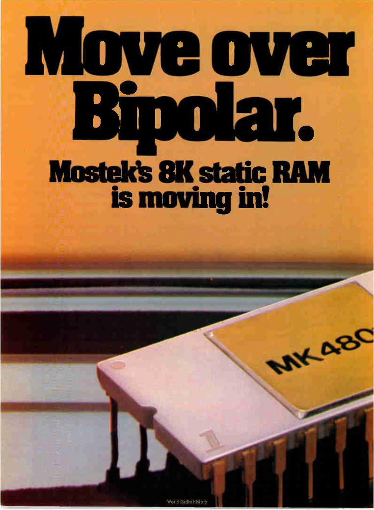
Move over • e
Mosteles 8K static is moving in!
RAM

The new MK4801 81‹ static RAM advances Mostek s memory technology leadership again. You can now replace bipolar tech-nology with MOS. The advantages are significant — increased system density. reduced system cost and lower power improving system reliability.
Fast access-55ns! With sub-10C ns access/cycle times the MK4801 family is ideal for wide-word cache, buffer and tele-communication applications. The 1Kx8 organiza-tion permits 1K increments in density optimizing memory size vs.cost tradeoffs. Requiring a single -5 volt power supply. the MK4801 is totally TTL compatible
and as easy to use as bipolar memory.
Other features include a fast CS function (50% of address access) allowing memory ex-
pansion without impacting sys-
tem access time. A fast 0E. also 50% of access time, permits data interleaving and a flexible latch allows optional !àtchina of CS and address. The 4801 uses Address
Activated rm inter-face to permit synchronous or asynchronous operation by com-bining the bene-fits of Mostek's Edge- ActivatedTM concept and fuily static operation. Mostek's MK4801 static RAM series includes the
MK4801-55 (55ns access/cycle time), MK4801-70(70ns access/ cycle time), and the MK4801-90 (90ns access/cycle time.
The technology of the future is here today. Mostek's next gen-eration process, Scaled Poly 5. is accomplished through a dou-ble polysilicon process in which all physical dimensions cf the transistor geometry are reduced, as are substrate doping concen-trations and operating voltages. The results are next generation
proçlycts IaIe t9daY,,
The MK4801 is lust the first of many Scaled Poly 5 products from Mostek. A die size of just 18.900 mils2, sub-100ns access and 5-volt only operation are typical of the features you can
expect from future Scaled Poly 5 products.Production volumes of the MK4801 are scheduled for the fourth quarter. Start designing your system now. For more infor-mation, contact Mostek at 1215 W. Crosby Road, Carrollton, Texas 75006; Telephone (214) 242-0444. In Europe, contact Mostek Brussels; Telephone (32) 02/660.25.68.66013.
MOSTEK Circle 31 on reader service card

mute's Combo Chip. The simple approach
to Z80 power. Get more ver- For design flexi-
satility with fewer bility, the serial I/O parts and lower sys- port has synchron-tern cost with ous or asynchron-Mostek's new ous operation with Combo Chip. programmable end-
For over two of-word interrupt. years, Mostek has 64 bytes of the RAM offered Z80 compo- pare both write-nents and develop- protected and Edge-ment systems. Now the Combo Chip ActivatedTM for low-power standby oper-makes Z80 power available for minimum ation. Plus the four external interrupts chip configuration designs. Only a have programmable vectors for special Combo Chip, Z80 CPU, ROM or PROM user requirements. memory, and TTL I/O are required. For more information, call or write
Mostek's 3886 Combo Chip features Mostek, 1215 W. Crosby Road, Carrollton, 256 bytes of RAM; two programmable TX 75006; phone 214/242-0444. In timers; serial I/O port; four external inter- Europe contact Mostek Brussels; phone rupts; and single +5 volt power supply. (32) 02/660.25.68.
CPU BUS 1/0
C) 19,78 Mostek Corporation
,NTEINIAL
S'F'' T • 'SEPIAL OC
• TIMER TIMER," VO
lir ,Ttr MK3886
..--INTERRUPT INPUTS
MOSTEK.
**4
32 Circle 32 on reader service card Electronics/September 28, 1978

e Meetings
isA/78 International Conference and Exhibit, Instrument Society of America, Philadelphia Civic Center, Philadelphia, Oct. 15-19; with the Joint Automatic Control Confer-ence, Oct. 18-20.
NcF-NEc/78 — National Communica-tions Forum and National Electron-ics Conference, National Engineer-ing Consortium, Inc. (Oak Brook, Ill.), Hyatt Regency O'Hare Hotel, Chicago, Oct. 16-18.
National Communications Forum, National Engineering Consortium Inc. (Oak Brook, Ill.), Hyatt Regen-cy O'Hare Hotel, Chicago, Oct. 16-18.
Image Transfer Symposium, Califor-nia Circuits Assoc. (Palo Alto, Calif.), LeBaron Inn, San Jose, Calif., Oct. 17-18.
Euromicro 78—Fourth Symposium on Microprocessing and Micropro-gramming, European Association for Microprocessing and Microprogram-ming, Paris (for information contact ¡contas Service, Munich), Technical University, Munich, West Germany, Oct. 17-19.
Canadian Communications and Pow-er Conference, IEEE, Montreal Sec-tion, Queen Elizabeth Hotel, Mon-treal, Oct. 18-20.
Electronic Industries Association An-nual Meeting, Century Plaza Hotel, Los Angeles, Oct. 25-26, preceded by EIA Distributor Products Division Annual Meeting, Del Webb's New-porter Inn, Newport Beach, Calif., Oct. 19-21.
1978 Design Automation Workshop, IEEE, Michigan State University, East Lansing, Mich., Oct. 18-21.
Engineering in Medicine and Biolo-gy, IEEE, Marriott Hotel, Atlanta, Oct. 21-25.
Fourth International Conference on Digital Satellite Communications, IEEE Canadian Region, Queen Eliza-beth Hotel, Montreal, Oct. 23-24.
Osborne & Associates announces
two new books. . .
AN INTRODUCTION TO MICROCOMPUTERS:
VOLUME 2 - SOME REAL MICROPROCESSORS
VOLUME 3 - SOME REAL SUPPORT DEVICES
There are hundreds of microprocessor books on the market today, but there's nothing
like Volumes 2 and 3 These books provide the only detailed descriptions of real products from an independent source.
NEW MICROPROCESSORS
Volume 2 describes individual microprocessors and support devices commonly used only with the parent microprocessor. The new edition represents a massive expansion of our
previous Volume 2: among other new material it includes the first detailed description of the Intel 8086 16-bit microprocessor.
NEW SUPPORT DEVICES
Volume 3 describes support devices that can be used with any microprocessor. The ma-
jority of this book is new material: in particular it has one of the most comprehensive dis-cussions of memory devices ever printed.
Between Volumes 2 and 3, every microprocessor and most support devices available to-
day are described — in detail, and from an independent, unbiased source.
NEW UPDATES
Because of the tremendous amount of material that Volumes 2 and 3 must cover, these books have been written to be updated on a regular bimonthly schedule. Six update sec-tions for each of the two volumes may be purchased on a yearly subscription basis. Each
update will describe new products, or products not covered in the original volumes: up-
dates also pçovide additional information for products already included, and errata pages for previous text.
NEW FORMAT
For your convenience, Volumes 2 and 3 are printed in loose leaf form and may be purchased with or without a binder.
The 1978 edition of Volume 2 and the new Volume 3 of AN INTRODUCTION TO
MICROCOMPUTERS will be available at the end of September. To order these or other Osborne Er Associates publications, check the appropriate boxes below.
t OSBORNE & ASSOCIATES, INC.
P.O. Box 2036 DEPT. E5
Berkeley, California 94702 U.S.A.
14151 548-2805
TWX 910-366-7277
NAME
ADDRESS
CITY STATE
PRICE OTT AMT
vo,me I Some Real IVIvroorocessms l4 4 1979 Edmon W. 134ele, 520 00
1, 2 W.. Bmdm $15 00
'fi n limr. Alone $ 500
v.. ,,,e 3 Some Real Somme Devves
W. Bolder 520 00
0E1 , Wolmal Bonder $15 00
to h and, alone $ 5 00
Volume 2 and 3 Umlage515.scootem
lo ho.5%,as o, ee. sere, 5.0 CO
Vol.. 2 Updates 0,11, Iv, .ss., 525 00
Volorne 3 Updates only Ism Issees1 52500
6 I. Si Sav Area res.dents onlv TOTAL
6% Casforma modems oulede Si Bav Area
Payment rn advance mum be emlosed for Sale4 Ta• 'Carl modems onlvl
purchases of . lo 570 03 Invmong for mechases of $7000 or more on the USA Slsmang Chao0,.,
avalable olsOn Moro., 0, your account All TOTAL AMOUNT ENCLOSED 'ores. orders mom be moped In U S dollars
drawn on a ll S bank
ZIP PHONE
SHIPPING CHARGES: Shipping for large orders to
be arranged.
UPDATE SUBSCRIPTIONS:
CI All foreign orders $4.00 per 6-issue subscription for airmaiI
• No extra charge in the U.S. - 4th Class Mail ONLY.
BOOKS:
ID AU foreign orders, $3.00 per book, for air shipment O 4th class $0.35 per book (allow 3-4 weeks within
USA.
• $0.75 per book, UPS (allow 10 days, in the U.S.
• $1.50 per book, special rush shipment by air in the U.S.
Please send information on:
CI Other OEtA publications Cl Becoming an 06A dealer
O School discounts
CI List of foreign distributors
• More information on Volumes 2 and 3
TTI}
Electronics/September 28, 1978 Circle 33 on reader service card 33

Two multi-turn trimmers that will set well with you.
Both our Type RT and MT cermet trimmers combine 20-turns and multi-fingered wipers to give you unexcelled adjustability. Both types: 10 ohms to 2.5 megs ±10%. Typical TCR is less than -±35 PPM/°C. True quality triMmers at very competitive prices. We have what you need. Our distributors have them when your need is now. Ask for Publication 5237 (RI) or 5241 (MT).
Te.-/PC/W7-
0.5W at 70°C; .375" square, 3 terminal options; or .410" by .375' 4 terminal options. Top or side adjustment. $1.08 each 1000 piece price.
.6teaâid ...tested in 85°C water.
Quality in the best tradition.
cSleirged.e2g7li»2e..,e-
tor extra strength and reliable bonding.
ALLE N-B RADLEY Milwaukee, Wisconsin 53204
-Low at 40°C; 750" long, 4 terminal options; choice of .250" or .340" case heights. Opaque or translucent case. $0.65 or 0.93 each 1000 piece price.
EC166
34 Circle 34 on reader service card Electronics/September 28, 1978

Electronics newsletter Bell turns out
Integrated version
of optical resonator
Admiral closes;
Japanese expected
to buy plant
Fairchild Camera
sells two more
instrument lines
PMI adds
4-inch wafers
for linears
Long-loop CCDs
gain as short-loop
versions fizzle
Another step has been taken toward an integrated optical receiver — and inexpensive optical communications. That's the significance of Bell Labo-ratories' report that the bulk-optics, nonlinear Fabry-Perot resonator developed there [Electronics, Oct. 30, 1975, p. 25] has now been made in an integrated-optics version that promises to be reproducible much as integrated electronic circuits are. The device is almost a universal optical element; it can take on the tasks
of a logic element in optical memories, a pulse shaper or limiter, an optical switch, a differential amplifier, and, most important of all, an optical "triode" in which a numerical gain of 7 has already been measured.
Rockwell International Inc., after years of absorbing losses from its Admiral domestic television business, has decided to close the business and take a $25 million write-off. Industry observers expect the move to present a golden opportunity to Sharp Corp. or Hitachi Corp. to get around the problems caused by the rising value of the yen and the resulting rise in prices of foreign-made products in the U. S. by buying Admiral's plant. At the same time, the write-off for Rockwell eventually should mean an increase in earnings of 15% to 20%.
President Robert Anderson of Rockwell blamed "intense price competi-tion" from the Japanese for Admiral's demise even though the company had cut costs and had benefited from currency fluctuations.
In the final step of total withdrawal from the instruments and controls markets, Fairchild Camera & Instrument Corp.'s Test Systems group is selling off two product lines: its Qualifier benchtop digital integrated-circuit tester, and its PATT (programmable automatic transistor tester). Previously, the group sold the bulk of its digital panel meter business to Dynamic Sciences International, while transferring chip-and-wire DPMS and the F8 8-bit microprocessor to its Semiconductor group. What's more, the San Jose, Calif., group has sold its IEEE-488 interface bus analyzer product line to Ics Electronics Corp. and agreed with customers to discontinue F8-based appliance controls programs.
Precision Monolithics Inc. in Santa Clara, Calif., has joined a select group of companies that can make 4-inch wafers for precision linear Ics. The large wafers will theoretically yield three times as many integrated circuits as present 3-in. wafers. The first batch has been oxidized and has had photoresist spun, exposed, and developed; full production runs are scheduled for the end of the year. Batch processing will decrease the cost of producing 4-in. linears significantly.
Charge-coupled devices built with long-loop architecture appear be the CCD devices of choice now that Intel and National Semiconductor have withdrawn their 64-K 4164 parts from the market. Their decision came after the arrival of the 64-K random-access memory [Electronics, Sept. 14, p. 39] locked the short-loop devices out of the market; the CCDS were intended as RAM replacements at the quarter-million-bit mark.
Meanwhile, the makers of long-loop parts, aimed as buffer, cache, and disk memory replacements, have gained second sources: Motorola Semi-
Electronics/September 28, 1978 35

Electronics newsletter conductor will build the Fairchild Camera Instrument device, while Nippon Electric will line up behind Texas Instruments.
Should Pentagon Because many semiconductor manufacturers feel that military programs don't generate enough volume and profits to be worth the trouble, the
make its own Defense Department may wind up having to make its own circuits under VHSI circuits? the proposed very-high-speed integration program (see p. 89), believes the
president of Integrated Circuit Engineering Corp. "It appears to be the only viable alternative," declares Glenn Madland, whose Scottsdale, Ariz., company is consultant to the U. S. Navy on submicrometer lithography for very large-scale integration.
Two-chip set Intel Corp. is shipping samples of its IEEE-488 two-chip interface set, half of which is a unique controller. The first chip, the 8291 GPIB talk/listen,
for IEEE 488 contains all the logic needed to interface any 8-bit microprocessor or an coming from Intel 8086 16-bit microprocessor with the IEEE-488 general-purpose interface
bus. To give the processor control of the bus, the second chip, the 8292 GPIB controller, can be added.
Disk controller Add Motorola Inc. to the list of companies expected soon to offer a single-chip controller geared to the new double-sided, double-density flop-
due next year py-disk drives introduced earlier this year. With a projected single-unit from Motorola price of $50, the MC6849 is to be available in sample quantities early in
the second quarter of 1979. Production is planned for early third quarter, says Mitch Gooze, strategic marketing manager.
Software package Although the Zilog Z8 microprocessor does not have an emulator, it will have a software development package that includes a diskette with
to be offered assembler and simulator, software manual, instructions and user's guide, for the Z8 and some sample programs. The software will run on existing MCZ-1
single-board computers and the ZDS-1 family of development systems if they are fitted with at least 60 kilobytes of random-access memory. The price will be $950 and it will be available Oct. 1.
Addenda The recent enhancement of IBM's System/34 with what it calls SSP-
ICF —Program-Interactive Communication Feature— is seen as a prelude to the announcement of a new small business system. SSP-IC F provides support for program-to-program communication within the same system or between systems, says IBM'S General Systems division in Atlanta. To handle the extra workload, the new machine, which is expected to be unveiled next month as the System/36 or 38, will reportedly offer power comparable to some of the System 3 models but at improved prices. . . . A series of ciphering devices, suitable for business and commercial environments, will soon be marketed in the U. S. by Siemens. The microprocessor-based units are manufactured in Switzerland by Crypto AG and range in price from $3,790 for a portable, hand-held ciphering unit with 1.4 X 10'4 code possibilities to $29,650 for an off-line cipher terminal with 10" possible codes. Crypto AG has long been a supplier to diplomatic and military users.
36 Electronics/September 28, 1978

Now, everything you loved about the 2114 plus 1125mW power down.
Memory retention at 2.5 volts Vcc —the 2114LV. 125rnW stand-by vs. 350mVV operating. Think of the power you save. And think of the complete 2114 family from Synertek. All fully static. No clocks or triggers using valuable system time. 200, 300 and 45Onsec versions. The low power 2114L series — plus power down.
And Mil versions soon-to-come. The broadest family of 4K static RAMs available. From Synertek, now. For specs, samples and complete informa-
tion, contact Larry Hester, Synertek, 3001 Stender Way,
Santa Clara, California 95051. (408) 988-5600. TWX: 910-338-0135.
Synertek Circle 37 on reader service card
L.2,..1110111•Ion ,..)Gt../1.1 I I \_,C, C 1/4 /, I .1

Superb circuit-negative film at significant savings!
Introducing new, economical Kodak Precision Line film LEN4— send for a free sample negative.
Superior line edge acutance, high-maximum density, minimum pinholing, excellent dimensional stability...our new film has everything you'd expect of a premium-quality, line-negative film for circuit work.
But new Kodak Precision Line film LEN4 isn't premium priced. It costs significantly less than comparable films! LEN4 is ideal for projection applications
(it's extremely fast), with processing in lith chemicals. It's also very good for contact work, and can be used with a variety of processing techniques.
Write, on your letterhead, and we'll send you proof: a free sample negative made on LEN4. Check its quality on your own scope. We'll also send our free "Take a New Look" information packet. Eastman Kodak Company, Dept. GA004,Rochester, NY14650.
KODAK 'mill 11111 Ill 11111111 II Film Kodak
Circle 40 on reader service card

Electronics review S,golficant developments in technology and Ousmess
Computer producers unveil designs for data communications Underscoring merger of EDP
and communications,
CompCon focuses on infrared,
digitized voice, networking
The technologies of data processing and data communications are be-coming harder than ever to separate, and no group is more aware of the overlap than the computer designers and engineers who met earlier this month in Washington, D. C., at the IEEE Computer Society's CompCon 78. Responsible for designing more communications and sophisticated network capabilities into the next generation of computers, the group discussed a variety of hardware tech-nologies and communications soft-ware and protocols, as well as tech-niques for controlling and measuring the performance of computer net-works. One of the research projects, for
example, is a novel scheme for connecting computer hardware lo-cated in the same room. F. R. Gfell-er of Ism Corp.'s Zurich Research Laboratory proposes to use infrared light for a wireless communications system that would offer the user greater freedom in positioning his equipment. The infrared radiation would be bounced off the walls and ceiling of the room, rather than along a line of sight.
Other advantages of the infrared system include its immunity to elec-tromagnetic interference and the fact that the infrared radiation is confined to the room. "This arrange-ment contributes to the security of the communications link and elimi-
nates interference with communica-tions links operating in adjacent rooms," Gfeller says.
Ele reports that a research team has built a prototype using four arrays of 10 gallium-arsenide light-emitting diodes, each with an output of 16 milliwatts, and a receiving array of nine photodiodes with a total area of 0.68 square centimeter. The unit achieved data rates of 64 kilobits per second using phase-shift keying with a carrier frequency of 256 kilohertz.
Hearing voices. As computers do more communicating, a more flexi-ble interface with humans will be useful. Thus another popular topic is
research into digitized voice and techniques for its storage, automatic recognition, and generation. James L. Flanagan, with the Acoustic Research department of Bell Labo-ratories, Murray Hill, N. J., says Bell Labs is already using some of the techniques in its internal directo-ry-assistance service. With the com-puter-controlled service, a user types in the name of the party, using the key-pad of the tone-dialing system. Once the computer locates the num-ber, it reconstructs it from digitally stored recordings of an announcer. A more sophisticated experiment
at Bell Labs has stored the pronun-ciation guide of a dictionary, with
Telecommunications policies clash
Despite its technical orientation, the CompCon meeting provided a forum for major policy statements on telecommunications regulation.
Regarding the regulation of communications common carriers, Henry Geller, assistant secretary of the Department of Commerce and head of the recently formed National Telecommunications and Information Administra-tion, says that the "national commitment to free enterprise will guide common carrier policy." He admits, however, that with the lines between data processing and data communications blurring, it is becoming difficult to decide what to regulate. The current state of confusion, he concedes, is due not to "a failure of the
market or technology, but to a failure of Government policy. It is incumbent on the Government to get its act in order."
Lewis M. Branscomb, vice president and chief scientist at IBM Corp., used the opportunity to fire a salvo at American Telephone and Telegraph Corp.'s proposed Advanced Communications Service [Electronics, Sept. 14, p. 33]. Branscomb maintains that the phone company should be allowed to offer the value-added features of ACS on an unregulated basis only.
At a separate session on the impact of the Federal Communications Commission's Second Computer Inquiry, AT&T's director for data-telecom-munications policies and planning, Franklin T. Julian, replied that deregulat-ing an area and promoting free competition is fine, so long as the phone company can also compete. "An overly broad definition of unregulated data processing would serve no purpose other than to limit the Bell System's participation, should the 1956 consent decree preclude the Bell System from providing an unregulated service," he says.
Electronics/September 28, 1978 41

CCD loops replace disk
Storage Technology Corp.'s 4305 Solid State Disk uses 64-kilobit charge-coupled devices with 4-kilobit loops that operate between 1 and 3 mega-hertz. The 4305 architecture selects a loop in each of 72 CCD chips and reads out 1 bit from each loop. This provides 72 parallel bits, 64 for data and 8 parity bits for single-bit error correction. When all the bits in that set of loops are used, the unit shifts to another set of loops; and when all the loops in the first 72 CCDs have been used, it shifts to another column or set of 72 CCDs. This architecture produces data transfer rates of 8 to 24 megabytes per second. For STC's current IBM-plug—compatible applications, however, this had to be cut to speeds of 1.0, 1.5 and 3.0 megabytes/s. In typical memory-paging operations, the 4305 will operate some 30% to 50% faster than the fixed-head disk it is designed to replace, STC estimates.
- - ile4OP Ve
_ _ se.,4> is *oil' Ale aeâ>
tfi4r r 44e: it 41i 1:4Trie 4 eg
eseeireeireeorg p p « * iregredir4,41rAiref! tfir a' 4r 4,
eeiorefeeeir4dr4r 4r ffigi eidre#4111reeireeSdir f
lee," trig 4r tee, ee
Instruments moving-head disk. And because it does so at such an attractive price, we feel the CCD technology we've chosen will be the best for this type of application."
Using the CCDS, the 4305 achieves an average access time of 0.7 milli-seconds, compared to the 5-ms aver-age access time of the IBM 2305 Mod 2. As for the IBM 3350 moving-head disk, it has an average access time of 35 ms.
Also, the SIC unit can store 45 megabytes in a cabinet half the size of the IBM 2305, which stores a maximum of 11 megabytes. Prices start at $150,000, about half of what the IBM disk costs, says Holwick, and run to $400,000 for a fully config-ured system.
Infrared probe
monitors 15-kW laser
When a high-power laser is used as a metalworking tool, control over its 15-kilowatt continuous-wave output is critical—but how to do it? One way is to combine a fiber-optic probe with two photodetectors to form an infrared temperature monitor that is blind to the carbon-dioxide laser's 10.6-micrometer wavelength. That's the solution Vanzetti In-
frared & Computer Systems Inc. provided when an Italian research institute sought precise control of a
laser's output for metalworking ap-plications. Officials of Istituto per le Ricerche di Tecnologia Meccanica (IRTm) completed acceptance tests of the metalworking laser earlier this month in Somerville, Mass., where its builder, Avco Everett Metalwork-ing Lasers, is located. Essentially, the laser unit's control system is a noncontact thermometer, says Ric-cardo Vanzetti, president of the Canton, Mass., company that bears his name. Under fire. Vanzetti explains that
different metals have different op-timum temperatures for working and that precise control of the laser's output power can mean the differ-ence between good and bad welds, for example. Heretofore, sampling of the beam's output has been used to get less precise temperature read-ings. But sampling the laser beam produces just that—a sample and not a precise measurement of the temperature at the workpiece as it is being treated or welded, Vanzetti points out. The Vanzetti instrument, on the
other hand, looks at the infrared radiation from the workpiece with a fiber-optic probe while, the metal is in the process of being worked. The radiation changes exponentially with temperature, Vanzetti says, and the probe picks up the radiation even as the crystal structure at the surface of the metal changes because of oxida-tion and fusion. Under control. The probe trans-
mits the optical signal to a detector head, where two separate detec-tors—one germanium and one sili-con —convert the optical signal into a voltage. The two detectors in the Vanzetti monitor are sensitive to two different spectral regions, but the company is not divulging what those regions are. "The ratio of the two indicates
precisely the slope of the blackbody radiation curve [a theoretical ideal curve] characteristic of the tempera-ture being observed," Vanzetti ex-plains. The technique is called band ratio detection, and it indicates the correct temperature to within ± 1%, no matter what the changes in surface emissivity may be during the
44 Electronics/September 28, 1978

RENT NOW!! I/O Terminals
1111111•1111141421111111111• 41 111111•111•11114•1111110, • • mortiemeaaani•, • • •81 ••1331111 - •
•
Month-To-Month CONTINENTAL RESOURCES
has the world's largest inventory of computer peripherals ready to fill your rental needs. CRT's, teleprinters, portable data ter-minals, and the latest model of data monitors from such top manufacturers as DEC, Lear Siegler, Texas Instruments, TeletypeTm, Hewlett-Packard, and Spectron. All are available for weekly, monthly or yearly rental. CONTINENTAL is geared to res-
pond and support your peak loads, crash programs, or emergency re-quirements. With nationwide inven-tory and service centers, staffed with more than 100 professionals, we can provide you with the equip-ment and service you need, when you need it, and for as long as you want it.
Rent with confidence from CONTINENTAL! You're backed by: • top manufacturers
• immediate availability
• one monthly charge
• in-house service
• no down time
CALL CONTINENTAL's nearest inventory center now. Find out how you can rent these CRT's, teleprinters, portable data terminals, and data monitors for a week, a month, or a year.
/ CONTINENTAL RESOURCES, INC.
175 MIDDLESEX TPK., BEDFORD, MA. 01730
Inventory Centers: Boston, MA (617) 275-0850, New York, NY (212) 695-3206, Long Island, NY (516) 752-1622, Philadelphia, PA (609) 234-5100, Scotch Plains, NJ (201) 654-6900, Baltimore, MD (301) 948-4310, Washington, DC (301) 948-4310, Atlanta, GA 800-638-4050, Fort Lauderdale, FL 800-638-4050,
Chicago, IL (312) 439-4700, Dayton, OH 800-323-9656, Houston, TX 800-323-9656, Seattle, WA (408) 249-9870, Santa Clara, CA (408) 249-9870, Los Angeles, CA (213) 638-0454, Santa Barbara, CA (805) 653-1696,
Costa Mesa, CA (714) 540-6566, San Diego, CA (714) 292-0750.
Circle 45 on reader service card

Electronics review
Big zap. Vanzetti monitor on an Avco laser (above strip-chart recorder) is connected to an
optical-fiber light pipe and infrared detector head to the right of the laser nozzle.
metalworking operations. Next, by means of a feedback
loop, the electrical signal corre-sponding to the ratio is sent to the laser's 70-kilovolt electron beam, where the beam's maximum current of 80 milliamperes is controlled. It is then possible to vary the rate of ioni-zation of the laser's gases and the beam's power output. "We keep the temperature profile within the de-sired limits," Vanzetti explains. "and there's no danger that the workpiece may be over- or underheated."
The Avco laser will be sent to IRTM in the town of Vico Canavese, located about 40 miles north of the city of Turin, Italy, where the company will use it for research into the welding, cutting, and heat treat-ing of various metals. David West, Avco Everett's service manager, says the metalworking laser is among the most powerful continuous-wave units in the world. The Avco group has built four other such units to date, but only one included the Vanzetti Thermal Monitor Controller. D
Careers
EEs can help own patent interests
by keeping documentation from day one Creating a salable new product may often be easier for an inventive elec-trical engineer than figuring out how to protect future patent rights to it. In fact, it is while conceiving and building the product that most inventors take a wrong turn on docu-mentation and thus jeopardize both its patentability and their financial rewards, say patent attorneys. "But there is a simple way for
either an individual or a company to ensure these rights are protected right up to patent-application time," says Billy A. Robbins, a Los
Angeles—based lawyer. Drawing on more than 20 years' experience, Robbins and other partners in his law firm described patent practice at a Wescon session earlier this month.
Document. Essence of their advice is compiling extensive documenta-tion during the two key phases of invention, the legal terms for which are "conception" and "reduction to practice," or building the product. "I like to see these in a bound notebook, and bound is important because it gives an air of legitimacy and authority," counsels partner Robert
Berliner. Particularly critical is es-tablishing exact dates of invention "during the mental part of the act, because it determines the all-impor-tant priority." This date often is contested by the Federal patent office and by later litigation, he says. The attorneys recommend keeping
step-by-step records in this bound notebook, numbering, initialing, and dating each page. Further, Berliner stresses that an inventor must always use ink, must never erase, and must cross out all white space. While this emphasis on form might seem trivial to an inventor preoccupied with technical problems, courts focus on such details later, when dates and competing claims conflict. "Above all, make sure there is no
opportunity for a charge that entries have been altered," he continues. Also, the account should be as complete as possible, describing the field of the invention, the problem to be solved, and its significance as well as identifying all prior known "art," or materials relating to it.
Witnesses. Contrary to common belief, mailing a letter to oneself as documentation of a date is worthless, says Berliner. Another misconcep-tion is that having a notary witness some phase of the invention helps out later. "All that does is prove a signature," he explains.
But "obtaining a competent wit-ness at frequent intervals is a pivotal point of evidence during possible liti-gation." Ideal for this purpose is a co-worker who is not an inventor but who understands the process.
Finally, the attorneys recommend that inventors not waste time be-tween conceiving the idea and build-ing the product. "If there's a tie for time of conception, it goes to the one who first reduced it to practice," Berliner says.
"If you do all these things, you will have a document that can be corroborated and that's it for a patent," concludes Robbins. Howev-er, confusion exists about when an inventor should first consult a patent attorney.
Robbins' rule of thumb is "when you have your invention complete in your mind, that is, completely
46 Electronics/September 28, 1978

,
The 2114 It's old hat to us
Most 2114s are new products with new
product problems. Not ours. The SEMI
2114 is a member of the Royal Family
of Static RAMs. It is, in fact,
a new pin-out of an 18-pin,
5V, 1Kx4 static RAM that we've
been delivering in production quan-
tities for a year and a half.
The SEMI 2114 features low power
(only 300 mw), TTL compatible I/O,
and all the speed you need for
microprocessor applications.
If you'd like complete informa-
tion on the SEMI 2114, or any other
members of the Royal Family of static
RAMS, see your ocal EMM/SEMI
distributor, or contact us directly.
Memory at Work
SEMCINC. A subsidiary of Electronic Memories & Magnetics Corp., 3883 N. 28th Ave., Phoenix, Arizona 85017 (602) 263-0202
ALABAMA (205) 534-9771 • ALASKA (415) 692-4250 • ARIZONA (602) 258-4531 • ARKANSAS (214) 341-2900 • CALIFORNIA (No.) (415) 692-4250 • (So.) (213) 322-1120 • COLORADO (303) 424-1985 • DELAWARE (800) 257-8210 • FLORIDA (305) E94-4401 • GEORGIA (404) 455-1206 • HAWAII (415) 692-4250 • IDAHO (206) 455-9180 • ILLINOIS (No.) (312) 345-4245 • LOUISIANA (504) 887-7610 • MARYLAND (800) 257-8210 • MICHIGAN (313) 971-8220 • MINNESOTA (612) 887-6400 • MONTANA (206) 455-9180 • NEVADA (Clark Co.) (213) 322-1120 • NEW JERSEY (No.) (516) 466-2300 • (So.) (609) 795-4200 • NEW MEXICO (915) 584-5842 • NEW YORK CITY & LONG ISLAND (516) 466-2300 • NEW YORK (Up State) (518) 489-4777 • NORTH CAROLINA (919) 227-3639 • OHIO (No.) (216) 464-2000 • OHIO (So.) (513) 253-9176 • OKLAHOMA (214) 341-2900 • OREGON (503) 620-5800 • PENNSYLVANIA (800) 257-8210 • SOUTH CAROLINA (919) 227-3639 • TENNESSEE (205) 534-9771 • TEXAS (Eastern) (214) 341-2900 • TEXAS (Western) (915) 584-5842 • UTAH (801) 972-6969 • VIRGINIA (800) 257-8210 • WASHINGTON (206) 455-9180 • WEST VIRGINIA (800) 257-8210 • WISCONSIN (So.) (312) 345-4245
Electronics/September 28, 1978 Circle 47 on reader service card ›,4 -

Electronics review
thought out, go to a lawyer for advice. A working model is good, but not necessary at that point." Legal costs depend on individual cases but usually run from $275 up for a document search and upwards of $1,000 for the patent application.
Patenting software has become a puzzle that will probably not be solved until the issue is taken to the U. S. Supreme Court, Berliner adds. Right now, it cannot be patented as such, but a clever use of loopholes can get around this sometimes. Instead of calling it software, "get as much hardware as possible into it to make it look like a special-purpose computer," he advises.
Testing
Microwave probe
finds metal flaws When a ferromagnetic microwave resonator is put near a metal surface, it undergoes a measurable shift in frequency that could detect flaws in the metal. But researchers have been stymied because there has been little theory properly correlating this fre-quency shift to a flaw. Now a team at Stanford Universi-
ty's Ginzton Laboratory has come up with equations that remedy the lack. These have been used to design a prototype handheld probe in which the resonator source is an yttrium-iron-garnet sphere. The unit prom-ises to make metal flaws easier and simpler to detect than they are with conventional methods, which use a test coil to induce eddy currents in the metal (see "Finding the flaws").
Potential. Aerospace firms, auto-mobile companies, and virtually any metal user who conducts nondestruc-tive testing could use the probe. When passed over metal, it can detect cracks—at Stanford, ma-chined test slots—just 115 micro-meters wide. "Our probe basically contains a
microwave resonator that experi-ences a frequency shift when brought into proximity with a metal surface," explains Donald K. Wins-
Finding the flaws
In conventional testing to find surface flaws or cracks in metals, currents are induced at the metal surface by a nearby test coil that oscillates at a frequency anywhere from about 0.002 to 2 megahertz. The natural flow of these eddy currents is disturbed by the presence of a surface flaw, and this effect changes the coil's input impedance. The new probe designed by the Stanford researchers uses a different
principle—microwave ferromagnetic resonance—which has been widely used to set the frequencies of microwave filters and oscillators. A small yttrium-iron-garnet sphere, typically 375 micrometers in diameter, is made to behave as a microwave resonator by having a dc magnetic field applied to it. The bias field required to make the sphere resonate and its resonant frequency are related by the ratio 2.8 MHz per oersted. This means that a 3.6-gigahertz resonator requires an external field of about 1,300 oersteds, which is readily achievable.
In the resonance condition, the YIG ball induces eddy currents in the surface being tested. Perturbation of these currents by a surface flaw shifts the resonant frequency, and this shift is measured.
y-AXIS
RADIO FREQUENCY MAGNETIC FIELD
MAGNETIC MOMENT
low who worked with Bert A. Auld and Gary Elston, patenters of the device. "A small crack causes an additional perturbation, which we can measure on an oscilloscope or frequency meter."
Big shifts. Winslow, Auld, and Elston experimented with machined slots in aluminum. They saw fre-quency shifts as large as 0.5% at a resonator operating frequency of 3.6 gigahertz. Such an 18-megahertz shift is readily detectable by conven-tional instrumentation. They were also able to detect cracks in nonmag-netic stainless steel.
Another advantage is that it is possible to use either passive or active probes. With a passive device,
rf
DRIVER CURRENT
x-AXIS
STATIC MAGNETIC FIELD
z-AXIS
the resonator is driven by a swept-frequency generator and the fre-quency shift is displayed on an oscil-loscope. With the more sensitive active device, a given slot size causes even more of a frequency shift, because the resonator detunes a coupled-transistor oscillator whose frequency is measured.
Moreover, two orientations of either resonator type are possible. The biasing magnetic field required to make the resonator operate can be tangential or perpendicular to the test surface. The perpendicular field is necessary for checking magnetic materials and also gives greater frequency shifts whether the probe is active or passive, according to the
48 Electronics/September 28, 1978

Analog I/O systems for your micro.
If you're doing data acquisition with micros, our analog I/O sys-tems can make the job go faster and easier.
For Jaboratory, industrial or sci-entific applications, we make sev-eral standard analog interfaces for most major microcomputers- DEC, Intel, Zilog, Computer Automation and National Semi. This saves de-velopment time and eliminates the
debugging and software problems so common with custom setups. Plug in a module to change your application.
But, best of all, if your require-ments change just plug in a new module. Data Translation has over 20 standard data acquisition mod-ules, from isolated inputs to very high speed inputs. Plus more than 50 standard analog I/O boards. And each module is totally pin-for-pin compatible and system trans-
parent. No software or hardware changes are ever required.
In a hurry? 5-day delivery.
Call Data Translation today at (617) 655-5300 to order your analog I/O system. Or write 4 Strathmore Road, Natick, Massa-chusetts 01760, for your free prod-uct catalog.
( DATA TRANSLATION INC 4 Strathmore Rd., Natick MA 01760
\__(617) 655-5300 Telex 948474
Dozens of analog modules. One microcomputer interface.
Absolute compatibility.
SALES OFFICES; AZ 602-994-5400; AR 405-364-8320; CA 408-248-9616, 213-681-5631. CO 303-837-1247; CT 516-488-2100; DC 301-636-1151, DE 301-636-1151: ID 801-L66-6522: LA 713-
780-25/1: MD 30/ -636-1151; MA 617-655-5300; MN 612-488-1129: NJ 516-488-2100; NM 505-292-1212, 505-523-0601: NV 602-944-5400, 408-248-9616: NV 516-488-2100; OK 405-364-8320;
TX 512-451-5174 214-661-0300, 505-523-0601, 713-780-2511, 512-828-2251: UT 801-466-6522: VA 301-636-1151: WI 715-294-3128; WY 303-837-1247: CANADA 416-625-1907
Circle 49 on reader service card

Electronics review
Stanford research team. The new method is more sensitive
than the older test-coil impedance-shift approach because it is able to detect the frequency shift of a reso-nator with a high quality factor (Q .-1,000). This feature makes it possible to spot smaller cracks and to recognize greater frequency shifts for the same size crack. "The probes are relatively simple
to produce," Winslow notes. "They are also small enough to hold in one
hand and don't require big driving magnets to power them." The team, which presented its
results this month at the European Microwave Conference in Paris, plans further study of a miniature normal-field probe suitable for mag-netic steels, testing of other materi-als and slot sizes, and possible devel-opment of commercial ruggedized models. Several aerospace compa-nies are interested in developing the probe, according to Winslow. D
Solid state
AMI features V-MOS in processing role
that takes advantage of high density
Can vertical-groove metal-oxide-semiconductor technology make it as a broad-based large-scale-integra-tion process capable of handling complicated logic functions? Though its three-dimensional gate structure enables it to produce high-density memories, the industry has been skeptical whether the complex pro-cess can provide the same yields when applied to the irregular geome-tries of random-logic LSI.
But v-mos pioneer American Mi-
crosystems Inc. of Santa Clara, Calif., is prepared to take the gamble. At this month's Wescon Show and Convention in Los An-geles, it described a v-mos—based signal-processing peripheral.
Still in the design stage, the chip will be like other v-mos devices—big and dense. It will measure slightly less than 200 mils on a side and be packed with something like 34,000 devices, many of which will be v-mos. It follows the firm's an-
Slave processor. American Microsystems Inc.'s signal-processing peripheral puts a vertical-
groove metal-oxide-semiconductor chip into a logic function application.
nouncement of a v-mos program-mable communications controller [Electronics, March 16, p. 46]. Thus AMI'S pet technology is aiding the firm's thrust into telecommunica-tions chips, which at present include non-v-mos coder-decoders, filters, and subscriber-line interface circuits (sucs). The signal-processing peripheral
will be a monster, admits Richard W. Blasco, AMI'S manager of ad-vanced development and systems. Some 400 small- and medium-scale transistor-transistor-logic packages are required to emulate it. "We defi-nitely have our necks out a bit," he observes. Although AMI might be taking a chance in pushing v-mos, Blasco points out that "the chip and logic design are very conservative."
For example, all cells are static to lessen processing worries. Helping the density problem is the fact that v-mos provides four levels of inter-connection, Blasco points out.
Competition. The sir should be in working silicon by early 1979, with samples following a few months later. When it appears, it will pit v-mos against tough competition in this market segment—the 2900 fam-ily of bipolar bit-slice devices.
But Blasco thinks that because of its density the v-mos product will better the bit-slice devices in cost and therefore get an edge in low-end uses calling for 12- to 16-bit word lengths and short programs. These low-end uses include 4,800- and 9,600-bit-per-second modems in polled networks.
In the 4,800-b/s modem applica-tions, for example, a six-package signal-processing peripheral would dissipate 1.2 watts and cost less than $90, compared with a $155 bit-slice design that needs 35 parts dissipat-ing 20 w, according to AMI. Because the SPP should be able to perform 128-point fast Fourier transforms in 10.7 milliseconds, a $75 part should be more attractive than a 20-ms minicomputer-based approach. The chip will add, multiply, and
store 12-bit numbers in a single 300-nanosecond cycle and will have a special instruction set optimized for digital filtering, PF-rs, and manipu-
50 Circle 50 on reader service card —I.-

Grab onto top reliability with the top TO-2201 of them all Get a grip on the kind of plastic power transistor reliability only the top engineered TO-220 can give you. Get a hold of plastic with orders of magnitude more reliability than also-rans.
Hang onto Motorola TO-220...designed, engineered and fabricated to take the kind of punishment found in the most rugged environments.
Motorola TO-220 power technology offers:
• 21/2 times stronger, lead-free die-attach solder • cross-hatched die bond areas that control solder thickness and minimize bond degradation • Moisture barrier moats around bond area • Ultrasonic wire bonding • Glass passivation • Heavier, rugged, flat copper leads • Matched CTE mold compound • Continuous QC production line audits Motorola TO-220. Made better to last longer. Stats bear it out.
6,355 Off-the-shelf Motorola TO-220s survived 37,800,000 device-operating cycles of full-on/full-off testing, one minute each, at Tj of 100°C with only 1.1% failure.
Under high-temperature, 150°C, reverse bias test-ing for over a quarter million device-cycles, failure rate was just 0.4%. And temperature cycling from — 65° to 150°C under MIL-STD-202 for over 20,000 hours showed just 0.2% failure.
Detailed results are documented and available for the asking.
Motorola TO-220s are tops in economy, too. Device by device, series by series, quantity by quantity. Prices are low because of cost-effective two-piece assembly and molded construction on automated lines. And even though we 100% test all basic electricals including SOA, our published prices are still as low, or lower, than our nearest competitor's.
And you can get the broadest range of TO-220 high voltage Switchmode* chips, from 2 to 12 A, 120 to 400 V, including the new MJE15028-31 complements offering 40 minimum hFE and 30 MHz capability. Switchmode price tags start at just $1.22.
Choose from 98 TO-220 types, including all TIP-series listed on the other side, from factory or authorized distributor. Or contact Motorola Semiconductors, P.O. Box 20912, Phoenix, AZ 85036.
The right choice 100% of the time. Trademark of Motorola Inc.
MOTOROLA
Semiconductor Group

Motorola TO-220
PLASTIC POWER TRANSISTORS
For lead mounted applications or use
with heat sinks; power dissipation
of 40 to 100 watts at 25 °C case.
STYLE 1: PIN 1. BASE
2. COLLECTOR 3. EMITTER 4. COLLECTOR
Resistive Switching
IC (cont) V CE0(sus) ts tf fT PD (Case)
Amps Volts Device Type hFE IC us us IC MHz Watts
Min NPN PNP Min/Max Amp Max Max Amp Min @ 25°C
0.5 350 MJE2360T 15 min 0.1 10 typ 30 MJE2361T 40 min 0.1 10 typ 30
1 40 TIP29 TI P30 15/75 1 0.6 typ 0.3 typ 1 3 30 60 TIP29A TIP30A 15/75 1 0.6 typ 0.3 typ 1 3 30 80 TIP29B TIP3OB 15/75 1 0.6 typ 0.3 typ 1 3 30 100 TIP29C TIP30C 15/75 1 0.6 typ 0.3 typ 1 3 30 250 TIP47 30/150 0.3 2 typ 0.18 typ 0.3 10 40 300 TIP48 30/150 0.3 2 typ 0.18 typ 0.3 10 40 350 TIP49 30/150 0.3 2 typ 0.18 typ 0.3 10 40 400 TIP50 30/150 0.3 2 typ 0.18 typ 0.3 10 40
2 60 TIP110$ T1P115$ 500 min 2 1.7 typ 1.3 typ 2 25" 50 80 TIP111 1 T1P116$ 500 min 2 1.7 typ 1.3 typ 2 25" 50 100 TIP112t T1P117$ 500 min 2 1.7 typ 1.3 typ 2 25" 50
3 40 TIP31 TI P32 25 min 1 0.6 typ 0.3 typ 1 3 40 60 TIP31A TIP32A 25 min 1 0.6 typ 0.3 typ 1 3 40 75 MJE1909 20/150 0.5 100 10 80 TIP31B TIP32B 25 min 1 0.6 typ 0.3 typ 1 3 40 100 TIP31C TIP32C 25 min 1 0.6 typ 0.3 typ 1 3 40
4 45 2N6121 2N6124 25/100 1.5 0.4 typ 0.3 typ 1.5 2.5 40 60 2N6122 2N6125 25/100 1.5 0.4 typ 0.3 typ 1.5 2.5 40 80 2N6123 2N6126 20/80 1.5 0.4 typ 0.3 typ 1.5 2.5 40 300 MJE13004# 6/30 3 3 0.7 3 4 60 400 MJE13005# 6/30 3 3 0.7 3 4 60
5 60 TIP120t TIP125t 1k min 3 1.5 typ 1.5 typ 3 4"* 65 80 TIP121 1 TIP126t 1k min 3 1.5 typ 1.5 typ 3 4" 65 100 T1P122$ T1P127$ 1k min 3 1.5 typ 1.5 typ 4 4*" 75 250 MJE51T 5 min 5 2 typt 2.5 2.5 80
2N6497# 10/75 2.5 1.8 0.8 2.5 5 80 300 MJE52T 5 min 5 2 typt 2.5 2.5 80
2N6498# 10/75 2.5 1.8 0.8 2.5 5 80 350 MJE53T 5 min 5 2 typt 2.5 2.5 80
2N6499# 10/75 2.5 1.8 0.8 2.5 5 80
6 40 TIP41 TIP42 15/75 3 0.4 typ 0.15 typ 3 3 65 60 TIP41A TIP42A 15/75 3 0.4 typ 0.15 typ 3 3 65 80 TIP41B TIP42B 15/75 3 0.4 typ 0.15 typ 3 3 65 100 TIP41C TIP42C 15/75 3 0.4 typ 0.15 typ 3 3 65
7 30 2N6288 2N6111 30/150 3 0.4 typ 0.15 typ 3 4 40 50 2N6290 2N6109 30/150 2.5 0.4 typ 0.15 typ 3 4 40 70 2N6292 2N6107 30/150 3 0.4 typ 0.15 typ 3 4 40
8 40 2N6386$ 1k/20k
d" ct
u") Lfl
20" 65 60 2N60431 2N60401 1k/10k 1.5 typ 1.5 typ 3 4" 75
T1P100$ T1P105$ 1k/20k 1.5 typ 1.5 typ 3 4" 80 80 2N60441 2N6041$ 1k/10k 1.5 typ 1.5 typ 3 4** 75
T1P101$ TIP106t 1k/20k 1.5 typ 1.5 typ 3 4** 80 100 2N6045t 2N60421 1k/1 0k 1.5 typ 1.5 typ 3 4** 75
TIP102t T1P107$ 1 k/20k 1.5 typ 1.5 typ 3 4** 80 120 - IIMJE15028 OMJE15029 40 min 30 50 150 IIMJ E 15030 OMJ E15031 40 min 30 50 300 MJE13006# 6/30 3 0.7 5 4 80 400 MJE13007# 6/30 3 0.7 5 4 80
10 60 MJE2801T MJE2901T 25/100 3 75 MJE3055T MJE2955T 20/70 4 75 2N6387$ 1k/20k 5 20" 65
80 2N6388t 1k/20k 5 20" 65 •D44H10 OD45H10 20 min 4 50 typ 50 6044H11 OD45H11 40 min 4 50 typ 50
12 300 MJE13008# 6/30 8 3 0.7 8 4 100 400 MJE13009# 6/30 8 3 0.7 8 4 100
15 40 2N6486 2N6489 20/150 5 0.6 typ 0.3 typ 5 5 75 60 2N6487 2N6490 20/150 5 0.6 typ 0.3 typ 5 5 75 80 2N6488 2N6491 20/150 5 0.6 typ 0.3 typ 5 5 75
• New Device j Darlington # Switchmode DevIce t to ff • • h fe at 1 MHz RED TYPE DENOTES DESIGNERS DATA SHEET CHARACTERIZATION

Electronics review
lating matrixes. As shown in the illustration, it is intended for use as a slave processor to standard 8-bit microprocessors like the 6800. The SPP will have such on-board
features as a high-speed parallel multiplier, serial input and output ports, four addressing modes, extra registers for other functions, a bus structure that permits parallel oper-ations, and a program memory of 256-by-17-bit read-only memory. It has a working memory of 128-by-16-bit random-access memory and a 128-by-16-bit read-only memory for the user's program. It comes in a 28-pin package and dissipates 500 milliwatts. Later versions will have 512- or 1,024-bit memories. El
Meetings
Wescon heads for
Anaheim in 1980
After the most heavily attended Wescon in a decade, show officials are looking southward in planning the next Southern California edition, in 1980. They have taken the initial step in deciding to hold it at Anaheim's convention center for the first time. The reason, officials say, is the move of industry during the 1970s away from Los Angeles and into Orange County. While William C. Weber, general
News briefs
Campbell to head TRW's electronics As expected, Richard A. Campbell will be taking over TRW Inc.'s electronics group as executive vice president, succeeding J. S. Webb who recently became vice chairman of the corporation. Campbell joined TRW in 1954 as an engineer and is at present serving as vice president and general manager of the communications unit. Named to fill his post is Robert L. Ashley, currently associate general manager. Both Campbell and Ashley will start their new jobs on Jan. 1, 1979.
Computerized mail system to speed bills Western Union and the U. S. Postal Service are planning to collaborate on a new version of the Mailgram. Tentatively dubbed ECOM (Electronic Comput-er Originated Mail), the system is planned for the end of the year and is designed for businesses using computers to communicate billing and other information. The customer will electronically prepare at least 5,000 messages a month and send them to Western Union, which will process and switch them to one of 25 major post offices around the country for further processing and delivery within two days. There will be a two-page maximum, and rates, depending on volume, will vary from 30 to 55 cents for a one-page letter. Annual market for this service is estimated at 15 billion pieces of mail from the 750 companies that have computerized mail systems.
Control Data unveils disk drive Control Data Corp. is introducing a 635-million byte fixed-media device called the 33502 that goes the 317.5 million-byte drive IBM 3350 one better. The new device, manufactured by Magnetic Peripherals Inc., a subsidiary of CDC and Honeywell, has 660 tracks per inch, 40 moving heads, and 20 data surfaces as compared to the 3350's 485 tracks/in., 30 moving heads, and 15 surfaces. A fixed-head option gives 1.72 megabytes more than the 1.14 of the IBM option. Base price will be $59,000.
GTE Sylvania wins Cruise missile contract A $10 million contract for the design and development of the command and control electronics for the Air Force's ground-launched Cruise missile has been awarded to GTE Sylvania Inc. The Waltham, Mass., company competed against RCA, Collins Radio, E-Systems, and Ford Aerospace for the contract. GTE Sylvania will be a subcontractor to General Dynamics Corp. and will be eligible to compete for the $66 million follow-on production contract once the initial development work is done.
MORE POWER MORE BANDWIDTH
LESS COST
<4 •
Our Model 601L is an ultra-wideband RF Power Amplifier whose wide range of frequency coverage and power output provides the user with the ultimate in flexibility and versatility in a laboratory instrument. Easily mated with any signal generator, this completely solid state unit amplifies AM, FM, SSB, TV pulse and other complex modulations with minimum distortion.
With a flat frequency response from 0.8 to 1000MHz the Model 601L will provide a linear class A output of 1.2 watts and a maximum saturated power output of 2 watts.
Constant forward power is continuously available regardless of the output load impedance match, making the 6011_ ideal for driving reactive as well as resistive loads.
Unconditional stability and instantaneous failsafe provisions in the unit provide absolute protection from damage due to transients and overloads.
Priced at $1195 U.S.A.
APPLICATIONS INCLUDE: • Laboratory Instrumentation • RFI/EMI Testing • NMR Spectroscopy • TV Signal Distribution • Communication Systems
For further information or a demonstration, contact:
ENI 3000 Winton Road South Rochester, New York 14623 Call 716-473-6900, or Telex 97-8283 ENI ROC
ENI The worlds leader in power amplifiers
Electronics/September 28, 1978 Circle 53 on reader service card 53

MITEL
CMOS/1S1 DIGITAL TONE CIRCUIT MT8820
Featuring: • CMOS Low Power Consumption • Wide Operating Ranges
—Supply Voltage 5 to 15 volts —Temp Ranges: —55 to 125°C &
40 to 85°C • Decodes all 16 DTMF Digits • Has 3 Selectable Output Codes • Latched 3-State Buffered Outputs • Uses Std 3.58 MHz TV Crystal • Detect Times 10 to 30 MS • Adjustable Detect & Release Times • Std 24-Pin Plastic & Ceramic DIP • Immediate Delivery • LOW PRICE
$15.00 ea in Qty's of 100-up.
Contact the leader in tone receivers and CMOS technology for more information
1745 JEFFERSON DAVIS HVVY SUITE 611 ARLINGTON, VA. 22202 TEL 703-243-1600
MITEL Semiconductor
54 Circle 54 on reader service card
Electronics review
manager of Wescon, sees no overrid-ing problems in shifting the event 35 miles south, he admits that planners are certainly aware of what hap-pened at June's National Computer Conference held at Anaheim. NCC management expected some 40,000 there, but the show was inundated when more than 55,000 jammed the doors. The result was inadequate parking, interminable lines for regis-tration and admission, and exhibit aisles so crowded as to be nearly impassable.
Shuttle. Weber thinks much of the parking congestion can be cut by the
Wescon shuttle bus system, even from as far away as Los Angeles International Airport. Moreover, the Anaheim center offers more than 1,100 exhibit booths, compared with 921 in Los Angeles and 736 in San Francisco's Brooks Hall, where the show is held in alternate years. The final but unaudited atten-
dance tally for 1978's three-day event is 42,784, up from 1977's 34,403. It is the largest since 45,000 went to the four-day 1969 show, but still trails record years of the mid-1960s, when crowds of 46,000 to 48,000 were routine. D
Nuclear fusion
Microwaves to heat Tokamak plasma
in MIT attempt to reach 100,000,000°C
Nuclear fusion occurs at six times the sun's temperature, and, say MIT researchers, there surely is more than one way to get that degree of heat. To prove their point, they are preparing a microwave-based tem-perature booster.
Physicists working in the thermo-nuclear fusion program at Princeton University captured headlines last month when they heated a plasma of hydrogen ions to the record-setting temperature of 60,000,000°C. They did it by introducing a neutral beam of deuterium into the plasma, con-fined by a very high magnetic field
in what is called a Tokamak reactor. The effect was to drive the tempera-ture upward, still short of the 100,000,000°C needed for a sus-tained fusion reaction, but an extremely encouraging step forward in the quest to develop a generator of electric power.
Introducing a neutral beam into the plasma is one of several heating methods researchers are investigat-ing. Another method is being hotly pursued at the Massachusetts Insti-tute of Technology. It hopes to boost the temperature of the plasma contained in the toroidally shaped
Plasma potential. Ronald R. Parker of MIT's Plasma Fusion Center leans against the almost completed Alcator C. Microwaves will be beamed into the glass-faced diagnostic ports.

"I design the best!' — John Jacobs, ADDS Chief Engineer
Circle 55 on reader service card
ADDS Regent is about the best TTY terminal money can buy. I know. I designed it.
State-of-the-art: Regent uses the highest per-formance microprocessor components availa-ble. I know. I specified them.
In fact, our sophisticated technology means Regent is a remarkably simple termina.. It has fewer components than most of our competitors.
That means fewer problems. And more Regents in your ftrure.
From the beginning, I've designed ADDS equipment to be the very best. And 65,000 in-stalled Terminals have proved me right.
ADDS Regent. Quality you can rely on. ADDS, Applied Digital Data Systems Inc., 100
Marcus Blvd., Hauppauge, NY 11787, (516) 231-5400. •
ADDS REGENT

AO STEREOSTAW Microscope. It has everything from Ato Zoom. ALL ESSENTIAL FEATURES FOR AN
OUTSTANDING INDUSTRIAL MICROSCOPE
Auxiliary Lenses: .5x, 2x
Body Rotation: 360°
Eyepieces: 10x, 15x, 25x
Field Size Range (inches): .13-2.25
Magnification: Standard 7-30x; Range 3.5-150x
UL listed Illuminator
Working Distance: Standard, 4.0 inches; Range, 1.4-5.7 inches
Zoom Range: .7-3x; Zoom Control: Dual Side Mounted; Zoom Ratio: 4.3-1
These are all features you want and need for efficient assembly or inspec-tion of microcomponents. The AO STEREOSTAR ZOOM Microscope was specifically designed for production-line applications. It's easy to use, with plenty of working distance plus coupled zoom control conveniently loca-ted on both sides. And traditional AO quality optics give very high resolu-tion for crisp, sharp images. Send for a detailed brochure. American Opti-cal, Scientific Instrument Division, Buffalo, NY 14215.
AD American Optical
Electronics review
Tokamak chamber by beaming in microwave energy.
This month, MIT'S Plasma Fusion Center will sign a contract with Varian Associates' Radar and Scien-tific Tube division in Palo Alto, Calif., for 16 klystrons capable of generating peak powers of 250 kilo-watts. The plan is to beam 4 mega-watts at around 4 gigahertz into the Tokamak chamber through its diag-nostic ports (see photo).
Resistive heating. Basically, the plasma within the Tokamak cham-ber is heated resistively using a giant transformer that has a primary coil at the center of its chamber and a secondary that is the plasma itself. As the plasma, composed of hydro-gen ions originally at about Vi00,000 of sea-level pressure, becomes hotter, it also becomes more conductive. "At the radio frequency, the plas-
ma is opaque to the microwaves and they are absorbed, rather than propagated," explains Ronald R. Parker, group leader of the Alcator project at MIT. "The principle is much the same as microwave ovens in relation to [heating] water." Microwave heating experiments with plasmas conducted at 100-kilowatt levels in France and Japan confirm that microwaves do increase the plasma temperature, he points out.
Varian, the only company bidding for the award, will supply the klys-trons and their power supplies for under $2 million. They are of conventional design. The Plasma Fusion Center at MIT has a Depart-ment of Energy grant for $6 million to equip its newest Tokamak, called Alcator C, with them. The klystrons should be installed
by next June, and full operation should begin by August 1980, though repeatable ignition condi-tions probably will be unattainable before 1985, according to Parker. The goal is to confine the plasma for at least 1 second at 100,000,000°C while the fusion of the hydrogen atoms into more complex atoms, and the release of energy, occurs. It is generally agreed that fusion reactors will not be ready to generate power commercially until sometime after the year 2000 at the earliest.
56 Circle 56 on reader service card Electronics/September 28, 1978

MCUs/MPUs • Memories • CMOS • Power • Linear • TTL • Small-Signal • LSI/VLSI • Thyristors • RF • Mil Units • MEd L • Chips • LS • Opto • FETs • RTL/DTL/HTL • Multiples
Less Dollars for More Sensor—MTS102/103/105
LESS BUCKS MORE SENSE
A highly linear, stable and reproducible alternative to thermocouples, thermistors and platinum resistance devices is available in a new series of silicon temperature sensors.
The devices produce a highly linear, pre-dictable and repeatable change in voltage,
about 400 mV, over the -40 to 150°C operat-ing range, making them easy to interface with the world of electronics.
Because of their high output voltage and "precalibration", MTS- units are suitable where multiple remote sensors are selected by switching to a single amplifier without the expense of special lead wires and very low contact resistance switches needed by other sensor types. Fast thermal response time permits steady-state readings within 3 seconds of temperature change in liquid or 8 seconds in air. Accuracy is available in three grades.
Prices are 504 for ±5°C, 854 for ±3°C and $1.25 for ±2°C. A
Low-power static 4K RAMs added to Motorola line.
A pair of low-power 4K static RAMs with industry-standard pinouts are now staples in the comprehensive Motorola MOS memory line.
The MCM2 1 1 4/2 1L 1 4 and the MCM6641/66L41 operate from single +5 V power supplies. They both are fully TTL-compatible, have three-state outputs, and they require no clocks or refreshing. They also have access times ranging from 450 ns down to 200 ns in both regular and lower-power types.
The MCM2114 is a 1K x 4 RAM with power dissipation of 525 mW. The '21L14 version operates with a low, 65 mA supply current affording max power dissipation of 370 mW.
Organization of the MCM6641 is 4K x 1. The '66L41 low-power type operates with a supply current of 70 mA, and the MCM6641 uses 100 mA current. Besides offering all the advantages of a fully static RAM like the '2114, the '6641/66L41 are direct replace-ments for the TMS4044, provide industry-standard pinouts and are available in 18-pin plastic packages.
These two static RAMs are versatile, easy to use, fast, and power conscious. B
Industry-standard 16K EPROMs
Come to the second source.
Motorola is the only second source for the three-supply TMS2716 device. Our part has a wider 10% supply voltage tolerance. We're the only supplier for the faster 300 ns TMS27A16 making it an ideal complement to high-speed MPU systems.
The TMS2716s are pin-compatible with '2708 8K types, like the MCM2708 and MCM68708, so upgrading is simple . . . one jumper wire should do the trick. C
Listen up to what everybody wants to hear about-16K RAMs.
Motorola's MCM4116 is the high-speed 16K x 1 industry-standard 16-pin 16K RAM that's equally good for new designs and for upgrading from 16-pin 4Ks in an existing system.
But that's not really what you want to hear right now about RAMs.
You want to know about delivery. So we're telling you Motorola is geared for short lead times. D
Motorola pipes up with the very latest thing in BIFET technology.
I
LF255/6/7 H
LF255/6/7 J
LF2S5/6/7 N
LF35513/613/78 H
LF3558/68178 J
LF35513/6B/713 N
1-F3.55/13/7 H
1F355/6/1 J
LF355/6/7 N
The pipe is full and overflowing! Supported by substantial inventory and
a full production pipeline, Motorola now has major-source capability for supplying 12 variations of LF155/156/157 BIFET series immediately.
Because we intend to be your No. 1 BIFET supplier before others can say "where-did-they-come-from," we have ensured total warehouse availability of plastic and metal devices before turning on the valve. We're ready for those BIG orders that may choke our competitors' plumbing.
It looks like we'll be the only real supplier of 8-lead ceramics, too, while only one other source makes B-suffix types, two sources won't touch the '157 series and four manu-facturers aren't supplying plastic. Motorola's got all three temperature versions, plus plastic DIP. And we'll have A-suffix versions soon.
We're out to flood the market with the best BIFETs the least money can buy!
And you thought the Alaskan pipeline was full! E
Electronics/September 28, 1978 57

Clamp transiten problems
with low-cost, plastic suppressors.
Where transients are a problem (and where aren't they), you can protect your sensitive equipment, and get excellent clamping capability besides, with the 1N5629P/AP series of zeners.
Designed to protect components like MPUs from high-voltage, high-energy faults, they have high surge capability of 1,500 watts, low impedance and fast response time. That makes for a sharp, well-defined knee and clamping ratio that many devices like MOVs can't measure up to.
The series is electrically equivalent to the 1N5629 units except for its packaging in Motorola's exclusive, cost-effective, highly-reliable Surmetic* axial lead package. It's ideally suited for use in communication sys-tems, numerical controls, process controls, medical equipment, business machines, Switchmode* power supplies and many other industrial/consumer applications.
Standard zener voltage range is 6.8 to 200 V, peak power is 1,500 W @ 10 ms, maxi-mum clamping voltage is measured at peak pulse current, leakage is less than 5 m A above 10 V and maximum tempco is spec'd.
Price is just $1.27, 100-up. F
Keep your sensitives out of trouble from two places with the MC3423/3523 OVP.
Now there's another industry source for Motorola's famous MC3423/3523 OVP.
So now you can keep your sensitive electronic parts, like MPUs, out of trouble two ways.
Specifically designed to protect against transient or regulator failure that can destroy devices tied to power supply outputs, it also protects you from using a whole raft of discretes to do the same job.
Coupled with an external SCR like the 25 A 2N6504, it senses overvoltage, triggers the SCR and shorts the supply output forcing the supply into current limiting or opening fuse or breaker.
100-Up price for the linear device is just 794. Great device. Two sources. You can't go wrong. G
Industrial Short System, Low-Frequency Fiber Optics A family of fiber optics components—
three photodetectors, MFOD100/200/300, and two emitters, MFOE100/200—are now available from Motorola.
Packaged in selected glass-lensed metal cases compatible with AMP fiber optic con-nectors, the units are suited to low frequency transmission of digital pulse signals through the insulating fiber medium for applications in medical electronics, industrial controls, M6800 MPU systems and security systems where lower cost can be a determining factor.
The emitters offer power outs of 550 and 1,600 µW at 50 mA drive and radiant inten-sities of 4 and 11.6 mW steradian with response times of 50 and 250 ns respectively.
The photodetectors provide a tradeoff between speed and sensitivity. MFOD100 has sensitivity of 18 p AlmW/cm2, and rise and fall times of 1 ns, considerably faster than response time of the photoemitters. The MFOD200, a one-transistor sensor, trades much greater sensitivity, 5.6 mA/mW/cm2, for a rise time of 2.5 g s and fall time of 4 g s. A Darlington photodetector, the MFOD300 provides greatest sensitivity, 75 mA/mW/cm2, with 40 to 60 gs rise/fall times. 100-Ups range from $2.10—$4.10. H
New 8 A Audio Driver
Best in industry linearity Clean, clean sound. That's what's available with the new 50W
MJE15028-31 NPN/PNP series audio drivers from Motorola's large stock of TO-220 packages
There's typically less than a 2:1 variation in gain of any combination of current/voltage from 2 to 20 V, 100 mA to 3 A ... best you can get for low distortion audio drivers anywhere.
The new family's rated at 8 A, continuous, and 30 MI-Iz T min, about 10 MI-Iz above its nearest competitor, for minimized crossover distortion. A 150 V sustaining voltage beats out the also-ran, too.
All the other goodies are there— complementary capability for direct-coupling, the most reliable TO-220 package around, availability of TO-66 leadforms, and ... availability from factory or authorized distributor.
Prices are lower, too ... about 54 less, list. Clean up your act with the MJE15028-31. J
The EMR is dead. long live Motorola
Where multiple-pole, higher current con-tactor applications are required, it'll still be around—but . . . for the bulk of logic level designs where you need solid-state reliability, convenience, versatility, standard packaging, multiple sourcing and low cost . . . SSRs are the only way to go.
Motorola's got a new, broad line of SSRs and I/O modules offering significant advan-tages even over similar contemporaries— better input characteristics for optimized coupler life . . . the finest, in-house manu-factured semis . . . design performance veri-fied by MIL-type testing . . . void-free, vibration-resistant potting . . . MPU-compatibility . . . etc. For power designs
We guarantee the control points of the output switch over the full spec'd temp range of these units. You can count on them from 3 to 32 V over a -40° to 80°C range. And higher voltages don't shorten coupler life.
You get zero voltage switching, too, with closures occurring only near the zero-crossing point of line voltage minimizing noise generation, transient immunity with 100% overrated, internally-protected com-ponents, 1,000% single cycle surge ratings, reverse polarity protection and shock and vibration resistance to MIL-spec testing.
Ask for the M120-/240- series of 5 and 10 A, 120 and 240 V units. For PC boards
Fit-anywhere, go-anywhere horizontal-
solid-state relays! or vertical-mounted convenience are yours with the P/MP- series of 2 and 3 A, 120 and 240 V relays.
Measuring just 3/8" thick, P-series offers the lowest profile solid-state unit for card rack mounting on 1/2" centers. No wire ter-minations or mechanical skills needed. You treat system loads like any other electrical signal and avoid connector-wire, board-mounting problems and associated labor costs.
The MP-series offers vertical mounting for tight, dense areas.
1,500 V isolation, zero-voltage turn-on, built-in snubber network, and a -40° to 100°C operating range are standard.
For I/O systems
Cut your I/O system cost drastically with Motorola I/O modules . . . each contains signal conditioning, isolation, logic interface, power handling and status indication drive in one compact, compatible package that inter-faces with all 5 V logic families and standard MPU I/O requirements.
We've got a color-codable board to go with them, too, with or without the modules, and you can interface the entire system with minis such as PDP-11t and Supernovas and Motorola and Intel micros, install them in standard NEMA enclosures and remove or replace modules without disturbing field wiring or exposure to shock hazards.
The package is becoming the industry standard, too. K
58 Electronics/September 28, 1978

Looking for better RF specs? Your number's up at Motorola.
High gain, low price, excellent linearity mark MRF426/426A units.
Priced at only about half of comparable transistors, the new MRF426/426A linear amplifiers are designed for high gain driver and output application in 1.5 to 30 MHz SSB equipment.
Offering minimum GpE of 22 dB at 25 W PEP, these 28 V parts are ideal for Class A (8 W PEP) and Class AB (25 W PEP) imple-mentation. 3rd Order intermodulation distortion for Class A is -40 dB ensuring excellent linearity.
The MRF426 is packaged in the 211-07 flange case and the MRF426A in the 145A-09 stud. Both are 100% tested for load mismatch at all phase angles with 30:1 VSWR and are BLX13 equivalents.
Price for either is just $7.65, 100-up. L Industry-first plastic SSB
Here's a new TO-220 made to order for lower-cost single sideband and large-signal amplifier applications utilizing low-level modulation.
Price for the MRF485 is just $2.30, 500-999, proving RF devices with 15W PEP/ 15W CW don't have to be priced out of sight.
It operates at 28 V and provides 40% SSB efficiency with 10 dB minimum GpE (PEP and CW).
Motorola's TO-220, of course, is the industry's top reliability package constructed with 2-1/2-times stronger lead-free solder, ultrasonic wire bonds, glass passivation, moisture barrier moats around the die, proprietary case with low tempco, Al/Mg wire and gold-plated copper leads.
That builds up to documented orders of magnitude more reliability for you. M
100 W at 400 MHz ... that's our new MRF328 Controlled-Q* unit designed for military UHF radios in wide-band large-signal output and driver stages in the 100-500 MHz range.
Specified, 28 V, 400 MHz characteristics include 7 dB minimum GpE, 50% minimum efficiency and 100% testing for load mismatch at all phase angles with 3:1 VSWR. It's gold-metallized, too, for high reliability and the low-parasitic package utilizes built-in match-ing networks for broadband operation using the Double Match Technique.
100-499 is $55. N
CATV modules make short work of long reach
Why use two where one will do? Silly question when you've got the MHW1391/ 1392 modules working in your broadband CATV line extender applications. They offer equivalent power gain to the 17 and 22 dB devices so you now have to use only one in place of two for those long reach systems.
Characterized for low distortion perfor-mance, they feature 39 dB typical Gp at 40-300 MHz. Broadband NF is 5 dB typical at 300 MHz and all-gold-metallization en-sures reliability. Other attributes include superior gain, return loss and DC current stability with temperature.
$40/$50, 100-up. P
50 W for hams Guaranteed performance in a 450 MHz
amplifier at 28 V with 50 W output and 7 dB minimum gain at 450 MHz is what you're getting with the MRF309 device.
This Controlled-Q unit has a built-in matching network for broadband operation using Double Match Technique, is 100% tested for load mismatch at all phase angles with 20:1 VSWR and is priced at just $20.15, 1-99.
Engineering Bulletin EB-67 describes the construction of a 100 W (peak) 420-450 MHz linear amplifier using a pair of MRF309s. We'll send it to you with the data sheet if you just give us your call letters. R
New Duowatts good for 2 W
Even though they're spec-for-spec alter-nates to GE's power tab units, the new D40/41 series Duowatts (T0-202) from Motorola offer a full, honest-to-goodness, two watts of power dissipation capability in free air.
That beats anybody's PD. The family ranges from 0.1 to 2 A, 30 to
225 V, with fTs from 50 to 230 MHz. Ojc is just 62.5°C/W, lowest in the industry, for low junction stress and a real edge in reliability.
We've got the lowest cost part in the industry, too, the D40C I costing out at just 404, 100-up.
Motorola's entire Duowatt family now numbers 73 individual registered, house-and-replacement-numbered parts from 0.1 to 3 A, 30 to 300V with PD to 10W. Use them in all kinds of places for chassis- or lead-mounting wherever you need the optimized combo of ruggedness, reliability and price. S
Complementary TO-66s TX, TXV-Qualified
MIL-STD-19500 has given six new com-plementary Motorola power transistors a military salute with qualification to /501, /502 and /518 specs of the 2N6051/52, 58/59 complementary Darlingtons and 2N3766/67 NPN TO-66 units.
The latter complement PNP 2N3740/ 41 JAN units.
The general-purpose 12 A JAN 2N6051-59 family offers 3,500 typical hFE at 5 A and 80 to 100 V(sus) capability plus built-in BE shunt resistors and excellent safe operating areas. They are 150 W devices.
The TO-66 JAN 2N3766/67 units can be used in driver, switching and medium-power amplifiers. They offer 1 V VCE(sat) at 500 mA, 40 to 60 hFE and 20 W PD.
Both are Motorola-developed EpiBase* products, ensuring better reproducibility and uniformity, higher yields and lower cost to you. A bargain, military or civilian. T
MOTOROLA OMNIBUS Looking ahead in all technologies.
(Coupon Missing?) Send inquiries to: Department LDC, Motorola Semiconductor
Products Inc., PO. Box 20912 Phoenix, AZ 85036
*Trademark of Motorola Inc. tTrademark of Digital Equipment Corporation :Trademark of Data General
(Please Check Only The Items You're Interested In:)
A D Temperature Sensors G B D 4K RAMs H C D EPROMs D 12 16K RAMs E III BIFETs F D Transient Suppressor M
For complete product itineraries, fill in and send to: Motorola Semiconductor Products Inc., P.O. Box 20912, Phoenix, Arizona 85036
D Please have salesman call (
Name Title
Company Address
DOVP N D Fiber Optics El Audio Driver R SSRs S
D Class A Amplifier T D Plastic RF SSB
El Military UHF CATV Modules
CHAIN Amplifier Duowatts
DMIL Power
City State 7ip
Electronics/September 28, 1978 59

RCA first in CMOS. Now you can get a faster
5101 from RCA. Fast. It's the fastest 5101 you can get. 250 ns access at 10 µA leakage, plus a range of other speed/ leakage values. And they're available fast, from stock. At any participating RCA Solid State Distributor.
Unique 10 V, 256 X 4 RAM.
The CDP1822 is a 10 V, 250 ns version of the 5101 with 256 X 4 organization. Which makes the 1822, like the 5101, ideal for use with the RCA 1800 microprocessor.
In-use simplicity.
Both RAMs have separate data inputs and outputs—the outputs are TTL compatible. And there are two Chip-Select inputs for easy system expansion.
For immediate delivery contact your RCA distributor. For more information contact RCA Solid State headquarters in Somerville, NJ; 1130 Brussels, Belgium; Sunbury-on-Thames, Middlesex, England; Quickborn 2085, W. Germany; Ste.-Anne-de-Bellevue, Quebec, Canada; Sao Paulo, Brazil; Tokyo, Japan.
Now featuring immediate 5101 delivery:
Arrow Electronics, Inc. Liberty Electronics A.W. Mayer Co., Inc. Milgray Electronics, Inc. Cesco Electronics Ltd. Newark Electronics Cramer Electronics, Inc. Pyttronic Industries, Inc. Deeco. Inc. Radio, Inc. Electro Sonic, Inc. Resco Electronics Division Electronic Supply Corp. of Astres Elmar Electronics, Inc. Robert E. Priebe Company Graham Electronics Rochester Radio Supply Co. Supply. Inc. RPS Electronics, Inc.
G.S. Marshall Company RS Electronics, Inc.
Hamilton-Avnet Electronics Schweber Electronics Corp. 11 Hamilton Electro Sales Semiconductor Specialists, Inc.
Hammond Electronics Sterling Distributors, Inc. of Carolina, Inc. Summit Distributors, Inc.
Herbach & Rademan. Inc. Taylor Electric Company Hughes-Peters, Inc. The Stotts Friedman Co. Kierulff Electronics. Inc. Trevino Electronics, Inc. L.A. Varah Ltd. Wilshire Electronics
1
4 r.
, fiwii ,r 111111.- I
- •--,m,- - , <... AR I I
Leakage Access Voltage Temperature Type MA Time, ns V Range, °C
MWS5101DL-1 10 250 5 0 to +70
MWS5101DL-2 50 250 5 0 to +70 MWS5101DL-3 200 350 5 0 to +70 MWS5101DL-8 500 450 5 0 to +70 CDP1822D 1000 250 10 -40 to +85
CDP1822CD 500 450 5 -40 to +85
RCA COS/MOS experience is working for you. Circle 60 on reader service card
RCA

Washington newsletter
Pentagon chills A proposal by European members of the North Atlantic Treaty Organiza-
NATO adoption tion to establish international electronic-component standards based on the West European plan called Cenelec has been effectively shortstopped by
of standard the Department of Defense. While the Pentagon wants standards certifica-tion, it has warned NATO not to move hastily until it can consider the proposed International Electrotechnical Commission system known as IECO — for IEC quality assessment system—favored by the U. S. and the Electronic Industries Association [Electronics, Nov. 10, 1977, p. 50]. The warning is likely to be heeded because, even though American policy calls for greater sharing in new weapons development and production, the U. S. still picks up the lion's share of NATO costs for hardware, which is most often designed around U. S. technology.
Will Japan's NTT Plans of the Nippon Telegraph and Telephone Public Corp. to spend more bu American than $5 billion over the next 10 years on installing computerized billing y systems may become a major issue in the trade negotiations between Japan
for computer billing? and the U. S. The systems would supply telephone subscribers with itemized bills, much like those AT&T gives American subscribers. Industry observers in Tokyo suggest that U. S. computer companies, which have experience with this type of billing system, could provide the equipment at lower cost than Japanese suppliers. As part of the current trade talks, the U. S. is trying to persuade Japan to open up the telecommunications market to American suppliers, but the Japanese negotiators claim no influence over NTT, saying that it is a private company. That contention is not being bought by the U. S. Government, which considers the Japanese phone company to be part of the public utilities sector. Furthermore, the Government holds that every country's communications-equipment market should be thrown open to all suppliers of all nations. On the other hand, it agrees that defense-electronics purchases and the like are properly reserved for domestic manufacturers.
NAB to set up The National Association of Broadcasters is moving to set up an engineer-ing laboratory next year that probably will be located at its Washington
engineering lab headquarters. The lab's proposed functions and budget must get NAB board in Washington approval at its January meeting, but one official says improved audio
processing techniques are a prime example of the activity the lab might undertake. The association's vice president, George Bartlett, is considering the effort.
Addenda The American Federation of Information Processing Societies will move its headquarters to Washington next August, joining its counterparts in computer-manufacturing associations, the Computer and Business Equip-ment Manufacturers Association and the Computer and Communications Industry Association. Now in Montvale, N. J., AF1PS represents more than 100,000 members in 14 associations concerned with data processing technology. . . . A forecast of an upturn in the Government electronics market over the next decade will come in detail from the Electronic Industries Association's Government division during an Oct. 24-26 symposium at the Los Angeles International Airport's Hyatt House.
Electronics/September 28, 1978 61

Washington commentary America's Cold War mentality on trade
"Because most Americans don't like the Soviet system of doing things, it is natural to write about what is wrong with it. This helps reinforce our view that it's a lousy system. Furthermore, to write about the positive features of their system can carry the risk of being considered an apologist. However, because the USSR is our principal ideological adversary, it strikes me as more important to know what is good about their system—where and when it does function well, its successes and achieve-ments. Only by being conscious of our understanda-ble ideological preference for seeing the system's defects can we counteract the danger of misjudging how bad things are." John W. Kiser III That judgment by Kiser, an independent
Washington-based researcher on technology and trade, was written last fall. It appears in a fact-filled 89-page study he prepared under contract for the State Department and the National Science Foundation on the potential for technology transfer from the Soviet Union to the U. S. Had Kiser advanced that thesis during the Cold War era 25 years earlier, he might have been challenged to explain his views before a Senate investigation committee.
Embarrassing the CIA
Despite the limited relaxation of tensions in U. S.-Soviet relations since the reign of Secre-tary of State John Foster Dulles, a Cold War mentality still skews the judgment of some U. S. agencies. The Central Intelligence Agency, for one, refuses to accept the professional estimates of some American computer industry experts that electronic data-processing technology with-in the Soviet Union and a number of its East Bloc allies is better than existing CIA estimates and improving steadily. Industry officials con-tend that, were their analysis accepted, the CIA'S low estimate of Communist capabilities would have to be revised, to the embarrassment of the agency's analysts.
Industry's motives, it must be pointed out, do not spring purely from patriotism. They want the U. S., as the dominant nation in the trade coordinating committee called CoCom, to recognize East Bloc capabilities and raise the performance limits on industrial and scientific computer products that can be sold to Russia and its allies. CoCom, composed of the U. S., its NATO partners, and Japan, begins its quadren-nial review of technology export regulations next month in Paris. New rules are expected to emerge not later than next June, and American exporters are worried. Reports out of the Commerce Department indicate the U. S. has rejected nearly all industry recommendations to
upgrade performance levels for exportable hard-ware, as well as other proposals to simplify and speed up the export licensing process (see p. 85).
Defense Department sources scoff at the idea that a "Cold War mentality" on export license applications prevails within the bureaucracy there, although one official concedes that the result is the same. "Frankly, a lot of people here find it easier to stay out of trouble by saying 'no' every time a company's application is dumped on us by Commerce for review," the official says. It is a kind of candor that comes only when anonymity is guaranteed. "Commerce is incom-petent when it comes to evaluating technology. So we have to almost bludgeon people here who have the necessary expertise to set aside what-ever they may be doing for the people who pay their salaries and take a look. It takes valuable time and can be a rough road. They know that if they recommend approval, it must be justified with lots of specifics and bucked up the command chain. The easier route is to simply reject it on national security grounds."
Exporters know well that, despite military protestations to the contrary, that attitude prevails in much of the Pentagon. It is an atti-tude that is as stupid as the CIA's is dangerous. Combined with the Commerce Department's evident incompetence, they are making an unworkable shambles of President Carter's stated policy of promoting U. S. exports to reduce the national trade deficit and gain new markets for American industry. East-West trade in technology is being smothered in a national security blanket.
The real threat
More importantly, the CIA's simplistic rank-ing of the Soviet Union as a collection of klutzes when it comes to computers fails to recognize that what Russia lacks are good manufacturing methods and management to support its superior capability in basic research and proto-type development. Yet American industry will not have the opportunity, much less the motiva-tion, to look at and perhaps license much of what is available to them from the Soviet indus-trial R&D community if the CIA's views continue to prevail. Certainly there are valid reasons for export controls that contain reasonable and real-istic limits. But when the Federal bureaucracy continues to play it safe by insisting on limiting electronic product exports to parts and compo-nents and antiquated, noncompetitive systems, then U. S. economic troubles can only increase. And that is a real threat to national security.
Ray Connolly
62 Electronics/September 28, 1978

16 1 4 3 12 1 10 9
1 23 45ó78
(1 of 3 standard circultS)
TYPE 906C DUAL IN-UNE Low profile, for applications with height limitation. Molded plastic package stands up against severe environmental conditions. Excellent for use with automatic insertion equipment. Compatible with other standard DIP compo-nents. Standard resistance values from 50 to 100n, capacitor is .01 ;IF g 50 WVDC. Other ratings available on special order.
1
® CD CD IC) SPRRGuE
I
TYPE 201C SINGLE IN-UNE For use where utilization of board space is important. Con-formal resin coating for mechanical and environmental protection. Bosses on plastic base give positive seating on board surface and eliminate entrapment of moisture. Stan-dard resistance values from 50 to 100 n, capacitor is .01 F @ 50 WVDC. Other ratings can also be supplied.
Cut component count...simplify board layout...reduce equipment size...with Sprague ECL terminating resistor-capacitor networks. (Metanet® Metal-Film Resistors, Monolythic® Ceramic Capacitors)
This series of Multi-Comp® precision r-c networks is specifically designed for ECL terminator applica-tions (VT,- Series Terminator, —2V) where repetitive component values and circuits are required, as in signal and data processing equipment. With up to 14 resistors and capacitors per network, their use will usually result in considerable cost reductions as
compared with discrete components. Unlike some manufacturers, Sprague makes its own resistor and capacitor chips, ensuring that performance charac-teristics are carefully matched for mechanical and electrical compatibility. Other Sprague Multi-Comp resistor-capacitor networks include bypassed pull-up, speed-up, and active terminator networks.
Sprague puts more passive component families into DIP and SIP packages than any other manufacturer: • RESISTOR-CAPACITOR NETWORKS • MULTIPLE TANTALUM CAPACITORS • 4-TERMINAL TANTALUM CAPACITORS • MULTIPLE CERAMIC CAPACITORS • 4-TERMINAL CERAMIC CAPACITORS
(ask for Bulletins 6611, 6611.1, 6612) (ask for Bulletin 3542) (ask for Bulletin 3542.3) (ask for Bulletins 6242B, 6243) (ask for Bulletin 6242.3)
'TANTALUM-CERAMIC CAPACITORS *MULTIPLE METAL-FILM RESISTORS *PRECISION RESISTOR NETWORKS *MULTIPLE PULSE TRANSFORMERS 'TAPPED DELAY LINES
For complete technical data on the component type(s) in which you are interested, write for appropriate engineering bulletin(s), as listed above, to: Technical Literature Service, Sprague Electric Company, 35 Marshall Street, North Adams, Mass. 01247.
THE BROAD-LINE PRODUCER OF ELECTRONIC PARTS
(ask for Bulletin 6642) (ask for Bulletin 7042A) (ask for Bulletins 7041A, 7041.1, 7042A) (ask for Bulletin 40400) (ask for Bulletin 45004)
4SR 7,1
SPRAGUE THE MARK OF RELIABILITY
a General
able ,/
Electronics/September 28, 1978
subsidiary Circle 63 on reader service card 63

For every subscriber who pays to read Electronics, three others read the magazine 'over his shoulder:
Do they count? As much as the circulation of any free magazine in the field.
90,000 people all over the world pay from $15 to $95 per year to read Electronics. For every one of these paid subscrib-ers, three more readers — called "passalongs" — borrow the maga-zine and read it free.
Advertisers value our paid subscribers most, because they have proved their interest in the magazine with money. Our pass-along readership is a bonus.
But what a bonus! In a one-for-one comparison, this huge audience of passalong readers is the equivalent of the primary circulation of any free magazine in the field.
As for our paid subscribers, there is no way to compare them with the unpaid distribution of a free magazine unless you know how many free recipients equal one paid reader — and that's one answer research has not come up with yet!
Electronics Magazine 1221 Avenue of the Americas NewYork, N.Y. 10020
Passalong readers. Another reason your ad sells best in Electronics.
Electronics/September 28, 1978

offers more than
logic.
ACTUAL SIZE
0
PULSE
MEM
PULSE
TTL CMOS
Reveals pulse presence to 50MHz
and costs only $50 Most logic probes do a satisfactory job of indicating logic status; some also display low frequency pu ses, but now B&K-PRECISION offers more. The new DP-50 Digital Probe actually displays pulse presence to 50MHz. In addition, the inten-sity of its PULSE LED is directly proportional to the duty cycle of of the signal observed, up to a 10:1 ratio. For high-speed or intermittent pulses, the DP-50 offers a MEM-
ORY mode to "freeze" and store the pulse display. In the PULSE mode, pulses as short as 10 nanoseconds (typical) are "stretched" for a clear visual indication. A 2-megohm input impedance ensures that the DP-50 will have no effect on the circuit under test. This im-pedance is significantly higher than ordinary logic probes. The DP-50 is a multi-family device, compatible with TTL, DTL, RTL,
HTL, CMOS, MOS and high-noise immunity logic (HiNIL). As a result, the DP-50 simplifies the analysis and troubleshooting of any digital circuit by clearly displaying in-circuit logic activity. The DP-50 is a com-pact and lightweight instrument, yet it outperforms conventional logic probes. Like other B&K-PRECISION instruments, the DP-50 is fully over-load protected. At only $50, the DP-50 is the most cost-effective high-performance
digital probe available. All together, the DP-50 offers much more than just logic. But isn't that logical? It's from B&K-PRECISION
Available from your local electronics distributor.
:41(PRECISION DYNASCAN CORPORATION
6460 W. Cortland Street • Chicago, IL 60635 • 312/889-9087 Circle 65 on reader service card In Canada: Atlas Electror ics Ontario
international Sales: Empire Exporters, Inc. 270 Newtown Road, Plainview, L.I., N.Y. 11803
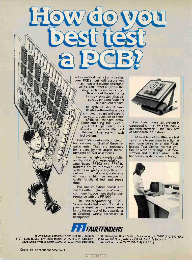
With a method that not only can test your PCB's, but will assure you maxi mum cost savings and higher yields. You'll want a system that
is highly reliable and well known throughout the electronics industry. A system that will quickly pinpoint faults for
subsequent repairs.
The systems should have flexible software that a 'lows
you to edit, adapt and expand as your production or state-of-the-art changes occur.
Complementing the system, you'll want dependable, easily
stored and easily handled test fixtures to interface with each
test system.
Faultfinders automatic in-circuit test systems fulfill all of these re-quirements. They are presently being used by the largest manu-facturers of PCB assemblies.
For testing highly complex digital and hybrid PCB's the powerful, com-puter-based FF303 and FF303D systems are your answer. These systems will give you high through-put and, in most cases, reduce or eliminate a high percentage of costly functional test and repair time.
For smaller hybrid boards and boards with a higher ratio of analog components, you'll get similar per-formance with the FF101C.
The self-programming FF200 Series shorts and continuity testers provide significant improvements in the throughput of bareboards or in checking wiring harnesses or backplanes.
M FAULTFINDERS
Each Faultfinders test system is equipped with a low cost, easily operated interface ... the ThinlineTm or Standardlinem fixtures.
The best test of Faultfinders test systems is to see them in action at our home office or at the Fault-finders Test Center nearest you. Call or write to arrange a demon-stration and to learn what Fault-finders test systems can do for you.
15 Avis Drive, Latham, NY 12110 (518) 783-3600 1305 Remington Road, Suite J, Schaumburg, IL 60195 (312) 882-3902 17971 Suite E, Sky Park Circle, Irvine, CA 92714 (714) 549-4901 235 Bear Hill Road, Waltham, MA 02154 (617) 890-4717
2306 Walsh Avenue, Santa Clara, CA 95050 (408) 243-9876 7747 LaRisa, Dallas, TX 75268 (214) 423-7731
Circle 66 on reader service card

International newsletter
Siemens testing
fiber-optic cables
in computers
Minicomputer uses
multimicroprocessor
technology
Portable color TV
has efficient tube
for low power
SGS seeks
government funds
for R&D effort
The space savings and the lack of interference inherent in optical commu-nications make glass-fiber cables as attractive for intracomputer communi-cations as for telecommunications. So Siemens AG engineers are testing in computers two cables, 8 mm in diameter and incorporating 10 gradient-profile fibers. One optical system transmits at 2 megabits a second, the other as high as 40 Mb/S. The simpler system uses a commercially available infrared diode for the transmitter and a photodiode as the receiver. The high-performance version has a special Burrus transmitter diode and a receiver photodiode that feeds into a transimpedanc,e ampli-fier. They are being used both within the central processor and between the processor and peripherals. Optical cables enhance data security because they are difficult to tap, and, since they do not provide a conducting path, they eliminate ground noise between processor and peripherals.
British minicomputer manufacturer Computer Technology Ltd. has turned to a multiprocessor system combining bit-slice and byte-oriented microprocessors on a common 32-bit-wide, 56-mb/s emitter-coupled-logic data bus. Its latest 8020 and 8040 16-bit minicomputer systems use Advanced Micro Device's bit-slice architecture in the central processing unit to emulate its existing instruction set and in the high-speed direct-memory-access controller. Motorola 6800 microprocessors are used in the floppy disk and slave controllers. By adopting a multiprocessor configura-tion [Electronics, Sept. 14, p. 92], the Hemel, Hempstead, company says design times and costs are down and performance and systems reliability are up.
Europe's spring next year will be brightened by Matsushita's new low-power portable color Tv receiver that eliminates two of the three color guns and the usual shadow mask that ensures that the beam from the appropriate gun strikes the appropriate color phosphor dots or stripes. The single beam excites the stripes on the 5-in.-diagonal tube. Periodic black control stripes between the color stripes emit ultraviolet light that synch-ronizes color decoder gating, so that the proper color signal is fed to the electron gun as the beam passes over that color or stripe. Utilization of beam current is on the order of 60%, compared with about 20% in a shadow-mask tube, so power drain drops from 12 w to 7 w, even though the deflection angle was increased from 50° to 70°. Thus viewers can operate the set for three hours on nine D-size flashlight batteries.
Making its way through Italian government channels is an SGS-ATES SA request for aid in five-year research-and-development program aimed primarily at keeping the company abreast of developing semiconductor technology. It proposes to spend $158 million, including $60 million in capital investment. The firm, Italy's leading semiconductor maker, wants to put about $82 million into improving rvtos wafer-processing techniques. Low-temperature processing, electron-beam microlithography, and high-speed testing will be key R&D areas, the firm says. Another $41 million would go for analog integrated-circuit R&D, $25 million on silicon power components, and $10 million for silicon radio-frequency components (including the groundwork for expansion into hybrid devices). SGS recently completed development of its own 4-K and 16-K dynamic random-access
Electronics/September 28, 1978 67

International newsletter
memories and is manufacturing the Z-80 and F-8 microprocessors with masks supplied by Zilog and Fairchild. Development of a 64-K RAM is under way. The Italian government is slating about $135 million for grants and low-cost loans to the components sector, and SGS, a member of the state-controlled group STET, is a leading candidate for the aid.
France puts France is gearing up for bigger space efforts, with a special commission to investigate opportunities for the satellite-communications industry. This
stress on space move follows a government report recommending strong backing for the communications space industry, and a move to make the space agency part of the industry
ministry rather than of the research administration. Meanwhile, industry sources are expecting a go-ahead by the end of the year for France's communications satellite, Telecom 1, the first to be launched with the country's Ariane rocket. However, the payload is still up in the air. Originally Telcom I was to be a $230 million satellite offering business communications facilities and telephone links. Another possibility is a number of smaller satellites offering various facilities and covering differ-ent areas, such as France and Africa.
SGS/Ericsson chip Watch for the Italian semiconductor maker, SGS-ATES spA, to unveil a int egrates functions linear integrated circuit performing a host of jobs in telephone sets. Bowing
at the Electronica show in Munich, Nov. 9 to 15, the chip will be turning for phone sets up by the end of the year in phones from its codeveloper, the Swedish
communications-equipment maker, Lm Ericsson. The lc eliminates the differential transformer and performs local noise suppression. It incorpo-rates a receiving amplifier and a transmitting amplifier that allows use of a dynamic microphone or other type of transducer. It also compensates gain for the distance between the phone and the central exchange.
Hitachi readies mos technology is making its way into television cameras. Hitachi Ltd. is MOS col planning to introduce a black-and-white camera with a single-chip image or sensor IC
array Bext year and a color camera with an image sensor that includes a for TV imaging chip with a color filter in several years. The company says it chose mos
technology over its solid-state competitor, charge-coupled-device technolo-gy, because it has higher blue sensitivity and lower susceptibility to blooming from excessive illumination. It says that its imager can provide the same picture quality as a CCD array but with half the number of sensing elements. Both cameras will be aimed at the developing market in video tape recorders. The monochromatic version will cost about the same as similar vidicon cameras; it will have a resolution better than 240 TV lines and a signal-to-noise ratio of more than 40 dB. Minimum illumina-tion with an f-1.8 lens is 30 lux; maximum is 100,000 lux.
Report urges UK To help British manufacturers catch up with the U. S. and Japanese competition, the UK should spend $185 million to promote industrial
promotion of applications of microprocessors and microcircuit technology, an influen-IC applications tial government-commissioned report from the Advisory Council for
Applied Research and Development urges. The money would be in addition to the $130 million in government support for the nation's semiconductor makers and the National Enterprise Board (see p. 95).
68 Electronics/September 28, 1978

CTS mini cermet trimmers... low in price, high in performance.
Fantastic! Small %" dia. (10mm), great performance and CTS reliability are only three reasons you should use our NEW series 375 single turn cermet trimmers. The low 25(e price tag is still another. CTS 375's, in six popular terminal
styles, feature a low -± 100 ppm/°C standard temperature coefficient— throughout the resistance range. Power rating, 1 watt at 40°C; 1/2 watt at
70°C. CRV of 2%. Settability of .03%. And the serrated adjustment knob
doubles as a dust cover to protect the element from dirt, oil and other con-taminants. It's a lot for so little. But you expect that from a company that's put millions into electronics for industry. For complete information, write CTS OF WEST LIBERTY, INC., 6800 County Road 189, West Liberty, Ohio 43357 or phone (513) 465-3030.
CTS CORPORATION ELKHART, INDIANA
Electronics/September 28, 1978
A world leader in cermet and variab e resistor technology.
Circle 69 on reader service card 69

FUJITSU: KEYBOARDS 8c KEYSWITCHES
Every day brings about a new computer or new use for keyboards. Naturally, the larger the de-mand, the larger the number of companies trying to meet that de-mand. Choosing the right supplier for your keyboard needs can be a hit or miss proposition. Unless you choose Fujitsu. Our reliability is known and
trusted throughout the world, be-cause Fujitsu doesn't depend on what someone else thinks is good enough. We manufacture every part of our keyswitches and keyboards. From key tops to con-tacts to the keyboard system. That makes for tight quality control every step of the way. And that makes for a more reliable keyboard.
Fujitsu reliability also comes from experience. Fujitsu comput-ers are in use worldwide. We know
our keyboards will work for you because they work for us. Auto-mated production insures a stan-dardized product. Fujitsu insures that ifs dependable. As far as service, Fujitsu consid-
ers it a point of pride, as well as good business, to cater to your company's needs before, during
le111111.1 II Ill 11 0
uj/Tsu FUJITSU AMERICA, INC.
1111 11 1111111111111 11 11 111 ,'D14s1:1cE):1WOeOr IOLREINS/ED-73ISI APIE BLUFF, ILLINOIS 60044
and after the sale. We custom build to fit your
design needs for layout, keying, cod-ing and slant. Our warehouse is stocked to supply your com-pany with samples. Large orders come di-rectly from the factory. And Fujitsu can match any source's lead time for processing and shipping. Fujitsu keyswitches
and keyboards are available in mechanical, reed, hall effect and capacitant modes. Our flat, low-profile keyboards give valuable tactile and audio response to touch that most membrane type keyboards don't. Considering everything we
have to offer, Fujitsu could just be the key to your keyboard needs. Quality, reliability and service are part of our product.
For more information on our superior components, call or write us.
TEL (312) 295-2610 TWX 910-651-2259
ICIMRi''M [D1B 70 Circle 70 on reader service card Electronics/September 28, 1978

Electronics international
Glass rods focus fiber-optic beams in device family New line of optical devices
uses index of refraction
to focus light beams;
component count slashed
Another step down the road to a fully optical communications system has been taken by the Nippon Electric Co. The company has devised a new generation of optical couplers per-mitting duplex transmission, filters allowing wavelength-division multi-plexing, and similar devices, all of which use glass rods rather than the classical spherical lens as the basic component.
Focusing of the light depends upon the rod's varying index of refraction, rather than on the lens shape. This alternative requires many fewer components than a first-generation bulk device based on spherical lenses, mirrors, gratings, and other filters. As well as being a more compact
structure, it is more solid, because NEC is gluing the parts together in a way that obviates post-production adjustment or cleaning. Fabrication should cost at least an order of magnitude less than for bulk devices, the company says.
Production. Unlike the experimen-tal approach taken by Bell Laborato-ries [Electronics, Aug. 31, p. 39], NEC has not moved into fully integrated optical devices. But NEC's new line is in the working-prototype stage, and the company is on the verge of deliv-ering production devices.
Teiji Uchida, general manager of the laser-equipment-development di-vision in Kawasaki, expects them to
be used in the field. While optical-fiber cable has been used in a number of field tests around the world, invariably the signal is con-verted to an electrical output for any processing; the optical part of the system is solely transmission. NEC and Nippon Sheet Glass Co.
devéloped the Selfoc focusing glass rod, which comes from the glass company in diameters between 2 and 3 millimeters. The focusing comes from the parabolic variation, along the rod's radius, of the index of refraction; maximum refraction is at the center. The light beam is injected at an
off-axis point on the radius, with the undulations of the resulting wave varying periodically from one point to another. Typically, the pitch of the undulations is 20 mm, and the rods are either 1/4- or V2-pitch long. As the examples in the figure show,
the specific device is formed from the rods and reflection or interfer-ence layers. Interaction between the undulating light wave and these layers provides the desired func-tion—directional coupling, multi-plexer filtering, and so on.
Fiber match. The signal input and output is provided by multimode or single-mode optical fibers with di-ameters of 60 to 100 micrometers. They may be either the step-index or graded type, and they are coupled axially or eccentrically to the rods, giving undulations either along the axes or eccentrically to them. The two couplers in the figure use eccen-tric injection.
Uchida says the rods are made several meters long, so the price of a 5-to-10-mm-long piece is relatively low. Moreover, fabrication of the devices is also a relatively low-cost process, he says, because it is a
Focusing light. As arrows indicate, new optical devices can serve as directional coupler
(top), allowing single-fiber duplex transmission, and as a multiplexer-demultiplexer, allowing
combination of two wavelengths for single-fiber transmission and separation at the other end.
Electronics/September 28, 1978 71

Electronics international
simple matter of cutting the rods to the partial-pitch lengths and lapping ends as necessary. Adding the reflec-tion or interference layers is also a relatively simple deposition process, he says. 171
West Germany
Optical cable is
compact and rugged For the 34-megabit-per-second op-tical transmission system it turned over to the German post office for field tests last month, Standard Elektrik Lorenz AG developed a tough but featherweight glass-fiber cable. The compact structure gives low attenuation, and it is highly resistant to field stresses.
In addition to eight fibers, the cable has four copper wires to power signal repeaters that system opera-tors may need to install. Even with so many signal and power conduc-tors and the required insulation and protective coating, the cable has a
Check it out. Careful measurements after splicing help SEL to achieve low attenuation in its
new compact fiber-optic cable developed for an experimental post-office installation.
diameter of only 9.6 millimeters, about a third of the 30 mm specified by the post office. As well as reducing cable weight
to only 70 grams per meter, the small diameter makes handling the cable and pulling it through shafts a relatively easy task. It was achieved by arranging the fibers, the copper wires, and the separating spacers in a tight cylinder around the cable's core, instead of in a number of layers one above the other.
Tight fit. The 120-micrometer-thick gradient-profile fibers, made from doped quartz glass, have a core diameter of 40 micrometers ± 2 gm. Such a tight tolerance aids low-loss coupling of light from the fiber into connectors and splices. Serving as the fiber's first protective sheath is a 30-µm silicone layer. The second is a tight-fitting polypropylene coating that brings the overall outside diam-eter to 1 mm.
"Normally, a tight coating tends to add to the fiber's attenuation," says Herbert Haupt, project man-ager in the materials and compo-nents section of the Irr subsidiary's
research center. The Stuttgart re-searchers believe the added attenua-tion results from the mechanical stress that a tight coating exerts on the fiber. Although other firms pref-er a loose coating, Haupt says a loose fit impairs the fiber's ability to withstand mechanical impact and other forces.
Steps. By optimizing certain cable production steps such as the precoat-ing and subsequent plastic extrusion processes, "we succeeded in keeping the increase in attenuation resulting from a tight coating to below 1 deci-bel per kilometer," he says. More-over, microbending of the fiber, which worsens attenuation and dis-persion values and can occur in loose-fit designs, is all but prevented in a tight-fit concept. Haupt cites a few figures support-
ing these claims. The fiber's initial attenuation of 3.55 dB/km goes to only 4.0 dB/km after the cable-production and cable-laying pro-cesses. The initial dispersion of 1.65 nanoseconds per kilometer increases to only 1.96 ns/km for the cables. The attenuation gives a very-high-
performance cable, equal to the best on the market. However, the disper-sion is only run-of-the-mill, says one American industry observer. "Most telephone-grade systems in the U. S., or West Germany for that matter, use twice or three times that band-width," or dispersion, he says. The small size of the cable is good but not special, he adds; Northern Tele-com of Canada has a 12-strand cable not too much bigger in diameter.
In the West Berlin experimental system, which links telephone ex-change offices 4 kilometers apart, the cable's low attenuation obviates the need for repeaters along the line. Repeaters would not even be neces-sary in a loop; that is, in an 8-km signal-return transmission.
Mechanically, SEL'S cable can take quite a beating. Drop a 4-kilogram hammer from a 10-centi-meter height onto the cable 1,000 times, and its fibers will not break, even though the cable is squeezed to less than half its original diameter. The fibers can take a lot of bending, too. Wind the cable around two 8-
72 Electronics/September 28, 1978

L.Eso1.1 #1: How -ra 15ua LP P pr2 Ferer2 sud4LE at. Douel-E - WIDE
CHARACTER* imTERMIxEP ON «THE SAME LIME
C OOLIK16 VEMT.S,
6W 4á- OPEN c:theE vaR. E A4.y- Acc.E.55. le pApEe SOPFLY
gie4•RELiKeiturf PRINT MEcHAtespi(
nitceEt--PLATED C-4-k A 64 ts
EASY ACCESS powER-
oN/OF F w rrck
Top PAPER EMT Foie._ IMMEPlerE. REA7AeLi-rY
MOL'E', IMPAcr-RESISTANT
Pt-AS-tic CASE
sim4LE BOARD Pc DESi4M
Foe. MINIMuMI
IIITERcoemEcTiot44
epriomAL RFI/EMI FILTER.
OPTioNAL 50/40 It INTERLocKEP AC PoWER cog:LP TRAK5FoRMER.
••••••../
WE DID OUR HOMEWORK!
*100 quantity price for parallel ASO Il interface model
Why pay for more printer than you need? Our series 40 printers offer more features for less bucks than any other commercial quality printer on the market today. A complete stand-alone 40 column impact dot matrix printer with a 64 character ASC I I set. Includes power supply, casework and interface electronics. Single quantity price for the parallel ASCII interface model is $425. Serial RS232/current loop interface models start at $575. OEM discounts available. For more information write to: MPI 2099 West 2200 South, Salt Lake City,
Utah 84119 or call (801) 973-6053.
Ann Circle 73 on reader service card

Electronics international
cm-diameter pulleys, pull it back and forth, and the first fiber break takes more than 2,000 cycles. The cable also exhibits remarka-
ble tensile strength. Tear tests on 10-meter-long sections show that the fibers did not break until subjected to a 1,600-newton force.
Great Britain
Microprocessor
smartens Teletext Programmed data carried piggy-back along with the Teletext infor-mation service on conventional tele-vision signals may transform the domestic TV set into a small home computer. Britain's Independent Television Companies Association (icrA) has an experimental home terminal that uses a standard Tele-text decoder linked to a Signetics 2650 microprocessor. So far the terminal has been
programmed to play Mastermind, a Tv game, and to perform mortgage calculations. Though these first demonstrations are relatively trivial, Telesoftware's inventor, W. J. G. Overington, foresees many major social and business applications. In education, for example, it could provide an interactive programmed learning capability at low cost for any number of users simultaneously. The technique adds a basic pro-
cessing capability to the Teletext-equipped TV receiver. The viewer selects an application's program and is guided through it by instructions flashed on the screen. Teletext could now steal some of the thunder from the fully interactive Viewdata sys-tem, backed by the post office and now trade-named Prestel. Two approaches. Viewdata links
television sets to a computerized data bank via telephone lines and gives viewers access to an ency-clopedic volume of data. Prestel engineers are working with the soft-ware company CAP-CPP Ltd. on transmitting programs for business and other applications over the phone lines also.
Until now Teletext has been limited to displaying textual infor-mation on news and topics of general interest. This data is transmitted digitally, four lines at a time, during the field-blanking interval of the TV signal until all 24 lines of the 40-character-per-line page display have been filled.
Viewers can call up this informa-tion service with an armchair con-troller, selecting any page from a library of several hundred, each broadcast in sequence. A selected page is routed into the Teletext page store, which for a 7-bit ASCII code uses seven 1-kilobit random-access memories or two 4-K static RAMs.
Overington capitalized on the Teletext decoder's inclusion of sev-eral basic elements of a simple computer: memory, display, and interactive terminal. By careful mar-riage with an appropriate micropro-cessor, a small but powerful comput-er system results.
Programs. The novelty of his concept came with the idea that bytes of data and complete programs could be broadcast, as well as char-acters and text pages. Each charac-ter pair is replaced by 1 byte of program plus additional Hamming-code error-checking bits. Programs are loaded into the page store 480 bytes at a time, checked, then trans-ferred into the microprocessor's sec-ondary store, which can hold 8 kilo-bytes. In this way, quite sizable programs may be loaded into the processor. The extra cost of incorporating a
basic system into the present genera-tion of decoders would be around $100 in mass production, says John Hedger of the ITCA Oracle project (Oracle is a trade name for Tele-text). Moreover, Telesoftware could be incorporated in a microprocessor-based Teletext/Viewdata module at little or no extra cost. A design based on a single-chip Intel 8086 has been completed, and Overington is work-ing on the instruction set for a custom microprocessor, intended for adoption by all suppliers of Teletext equipment.
Broadcast programs could vary from study modules for Britain's
University of the Air to instructions for filling out standard forms, such as income-tax blanks. Telesoftware might also serve in business applica-tions, such as insurance quotations. A major stumbling block must be
overcome: there is not now enough space in the TV signal for Telesoft-ware. Since Teletext pages must be transmitted sequentially, response times with a greatly expanded data bank could become too long. There are solutions, including use of more than 4 of the 23 frame-blanking lines, or setting aside more lines of the TV signal for such services. Both the ICTA and equipment suppliers are searching for an answer.
Optical fiber warns
of trespassing Intruders beware: a British company has come up with a barbed-wire perimeter fence with an optical fiber in each wire run that warns not only of a break but also of its location. Nor is the system fooled by attempts to bridge the wire electrically before cutting, for that would interrupt the "all-quiet" code continuously trans-mitted down the fiber from the system's nerve center. The fiber has a low breaking
strain and snaps if a trespasser tries to scale the fence. Should he get over by some other means, there is a hair-fine fiber-optic trap that triggers the alarm back in the watch house. The company, Branglea Ltd. in
Hartley-Wintney, Hampshire, ex-pects to find both governmental and industrial customers who need to protect long perimeters at borders, say, or large installations like oil refineries. It is tooling up for produc-tion of the barbed-wire cable in which is inserted an optical fiber developed for the purpose by Stan-dard Telecommunication Laborato-ries Ltd. in Harlow.
Also, manufacture has started of the repeater units used to link sections together. Perimeter fences are built in sections as short as 100 meters. The coupling repeater units comprise a light-emitting-diode
74 Electronics/September 28, 1978

We put our entire 260,000 sq. ft. plant
into every hybrid microcircuit.
There's more to a Hughes hybrid than meets the eye.
Each hybrid is totally customized to your needs. Not just the optomized thick or thin film layout', but the LSIs as well. That's because we're the only people in the business with extensive hybrid and LSI design capability under one roof.
As microelectronic specialists, we engineer and produce everything from chips to the final package at our Newport Beach plant. We can incorporate either MOS or bipolar products into your hybrid. We build both.
So for those special hybrid requirements— customized to your exact needs in the smallest possible package, and employing the most advanced LSI technology—try Hughes. We think you'll benefit from our fifteen years' experience-in high reliability hybrids and microelectronic products.
For more information, including our 8-page color brochure, write to Hughes Aircraft Company, Microelectronic Products Division,
500 Superior Avenue, Newport Beach, CA 92663. Or call (714) 759-2411.
The sooner you do, the sooner we can start putting our plant into
your hybrid.
r HUGHES 1 HUGHES AIRCRAFT COMPANY
MICROELECTRONIC
PRODUCTS DIVISION
Circle 75 on reader service card

Electronics international
source, photodiode detector, and some complementary-metal-oxide-semiconductor logic. Power to each repeater is provided by an insulated wire also in the barbed wire. The status of each sector is indi-
cated on an intelligent display devel-oped for Branglea by Leenshire Ltd., a neighboring design and manufac-turing consulting firm in Winches-ter. The perimeter fence forms a fiber-optic communication link in which continuity is indicated by correct receipt of a data word trans-mitted from one end. "We transmit a 13-bit data word
with a high off-to-on ratio," says Noel Parkinson, founder of Leen-shire, and designer of the Branglea system. In this way, the power consumption per module is kept down to 1 milliampere. "The data rate itself is typically 100 kilohertz but can be as low as 10 kHz in some applications," he says.
Warning. If the fiber is cut or broken by an intruder's weight, the next repeater downstream will not receive the data word. Instead it will transmit its own coded identity. This is decoded by the display unit —a transistor-transistor-logic processor with a PDP-8—like architecture de-veloped by Leenshire. The 13-bit word length is suffi-
cient to identify 8,000 sections, so it is more than adequate for any likely application. Each repeater is coded during manufacture with its own identity by soldering wire links, a low-cost technique.
Since the system was first develop-ed, it has aroused a tremendous interest, says R. I. Davidson, manag-ing director of Branglea, a textile-machinery company with ambitions to diversify. "We have had to hold people off till we are in control of volume manufacture. But now we will be up to full production within six months."
Davidson says a 4-kilometer fence with four fiber-optic strands laced into the barbed wire and with inter-face electronics and a mimic dia-gram of the perimeter for the display might cost about $25,000. A small, simple system for a garden might cost around $2,000. CI
France
Lots of air around the contact gives
a good Schottky diode for microwaves Microwave receivers designed around Schottky-barrier diodes need high-performance gallium-arsenide diodes in order to compete with low-noise field-effect-transistor front ends, especially in the X band of frequencies. The Schottky diodes also need very high cutoff frequen-cies to cope with increasingly popu-lar millimeter- and submillimeter-wave transmissions. With these criteria in mind, the
Laboratoires d'Electronique et de Physique Appliquée of Limeil-Brévannes, just outside Paris, have developed a novel way of producing high-performance, low-cost diodes giving at least 2-terahertz cutoff frequencies and a series resistance around 1.3 ohms. The diode, fabricated by a fully
planar technique, uses a metal "bridge" suspended over a tiny gap between the active diode area and a connecting pad. "Traditional ap-proaches employ a contact on the semiconductor surface," says LEP
engineer, Dcminique Boccon-Gibod. "The advantage of the suspended contact is increased isolation and the resulting reduction in parasitic ca-pacitance."
Process. The lab produced alumi-num Schottky-barrier diodes on a double epitaxial layer to minimize series resistance. Vapor-phase epi-taxy was used to grow a thick n+ layer and a thin active layer on a chromium-doped semi-insulating substrate. The two gallium-arsenide epitaxial layers are both sulfur-doped. After cleaning the n layer, a 5,000-angstrom aluminum layer is evapórated onto it. Then the lab defines the diode in a
three-step photolithographic process. First, a window is opened in the photoresist for what will become a gold-germanium ohmic contact. Etching through this window• re-moves the aluminum from the active n layer and continues until the Al is
etched away slightly around the window's perimeter, underneath the photoresist that defines it. An AuGe layer is evaporated on.
Because of the under-etching, it is self-aligning with the surrounding Al. The distance between the two is about 1 micrometer.
Bridge. In the second step, the aluminum for a connecting pad is defined, along with an Al band, 6 en wide, that connects the pad to the AuGe layer. Finally, the GaAs around the diode is etched away, leaving two mesas—the active area and the connecting pad—separated by air but linked by the 6-µm-wide Al bridge. The LEP lab has experimented
with various geometries. Boccon-Gibod says several approaches are possible, including the plating of several diodes in parallel or diodes with four aluminum bridges. The diodes have been used in two types of microwave mixers: a narrow wave-guide mixer at 12 gigahertz with a 30-megahertz intermediate frequen-cy and a microstrip mixer at 12 GHZ with a 1-GHz intermediate frequen-cy. Conversion loss for the wave-guide mixer was 2.7 decibels, and for the microstrip mixer, 3.5 dn.
According to Boccon-Gibod, the process promises both performance and cost payoffs. The lab has already achieved 2-THz cutoff fre-quencies with the diodes. "If we increase the doping of the n-layer GaAs and reduce the thickness to lower the series resistance, we should be able to reach 4 THZ or better," he says. Only three photoengraving masks are needed for the LEP approach, and the reproducibility may be better than 80%. Production costs should be reasonable.
Decisions on production are up to la Radiotechnique Compelec (m), the Philips subsidiary controlling LEP. If the go-ahead is given, produc-tion could start next year.
76 Electronics/September 28, 1978

Technical Innovation Begins With Quality Components.
GTE Automatic Electric uses General Instrument
Quality is no accident. It's the result of good
engineering in design and in component selection
and specification. So naturally when GTE
Automatic Electric needed quality rectifiers for their communication products, one of the choices was the General Instrument
Superectifier.
sermellcally sealed glees paselvated lunation.
lame retardant epoxy encapeulation.
Brecad conctructlon et greeter hen SOOT.
Not only does Superectifier help assure long dependable life for GTE
Automatic Electric products, it also eliminates costly production-related failures
caused by the stresses of automated assembly techniques — like wave soldering
and automatic insertion. And that helps keep production costs down! Just look at its
patented construction: • Metallurgically Bonded at greater than 600°C at both the leads and the junction.
• Hermetically Sealed glass passivated junction. • Flame Retardant, UL Listed epoxy encapsulation.
The result -- a rectifier that eliminates soft solders, pressure
contacts, environmentally created intermittents and exceeds military environmental and reliability requirements — a Superectifier.
Not everyone needs the kind of quality GTE Automatic Electric requires, but everyone can afford it because with Superectifier the premium is on quality, not price.
GENERAL INSTRUMENT CORPORATION DISCRETE SEMICONDUCTOR DIVISION
600 West John Street, Hicksville, New York 11802 (516) 733-3333
Electronics/September 28, 1978 Circle 77 on reader service card 77


TRW takes another step in digital signal processing
INTRODUCING
A NEW FAMILY
OF MULTIPLIER CHIPS
We've just taken a giant leap forward
and developed a new family of
increased performance multiplier
chips, called the "NJ" series.
You can select from among 16,12
and 8-bit devices to provide sophisti-
cated number-crunching options for
your minicomputer.
Use our MPY-16HJ, -12HJ or -8HJ
to boost your mini's arithmetic per-
formance and you'll open up a wealth
of new applications in areas that
require general scientific algorithms,
like FFTs.
In medical electronics for instance,
FFT-supported imaging systems are
becoming important supplements to
X-ray diagnosis. New techniques—
including ultrasound—are being used
for viewing internal organs, soft
tissue, tendons and blood vessels.
No matter how you decide to apply
them, our new multipliers offer higher
speed and lower power than any
devices you've seen before—the
MPY-16HJ , for instance, produces a
32-bit product in just 10Onsec and
its power consumption is a mere 3W.
Both the MPY-16HJ and -12HJ
multipliers offer important new opera-
ting features, like zero-nanosecond
input register hold time, transparent
output registers, and operation on
numbers in either unsigned magnitude
form,two's complement or mixed.
They are easily expandable—you can
array them to multiply 32,48, or 64-bit
numbers and greater.
Our MPY-8HJ has a super-fast ver-
sion available that produces a 16-bit
product in just 45nsec. It is designated
MPY-8HJ-1 and is specially suited
to television applications.
These faster "HJ" series multipliers
are plug-compatible with our popular
"AJ" series multipliers. Just plug
them into a socket wired for the corre-
sponding "AJ" device, and the new
features are automatically masked out.
You can ignore the additional fea-
tures and benefit from additional speed
and reduced power.
Our new multipliers are very stingy
with power—the MPY-16HJ uses just
3W; the MPY-12HJ, 2W; the MPY-8HJ,
one lonely Watt.
Prices have been lowered for the
new multiplier family, too —in 100's,
the MPY-8HJ is priced at $59; MPY-
8HJ-1, $71; MPY-12HJ, $103, and the
MPY-16HJ, $157.
Like all TRW LSI Products, each
of these new MPY/ HJ multipliers
is available from stock through
Hamilton /Avnet. For more informa-
tion, send in the coupon or talk to
one of our digital signal processing
experts at 213/535-1831.
TRW LSI Products An Electronic Components Division of TRW Inc. P.O. Box 1125 Redondo Beach, CA 90278
Please send data sheets on the new MPY/HJ family of multipliers.
Name
Company
Div/Dept Mad Code
Address
City
State Zp
E•9
TRW LSI PRODUCTS ... for Digital Signal Processing
Electronics/September 28, 1978 Circle 79 on reader service card 79
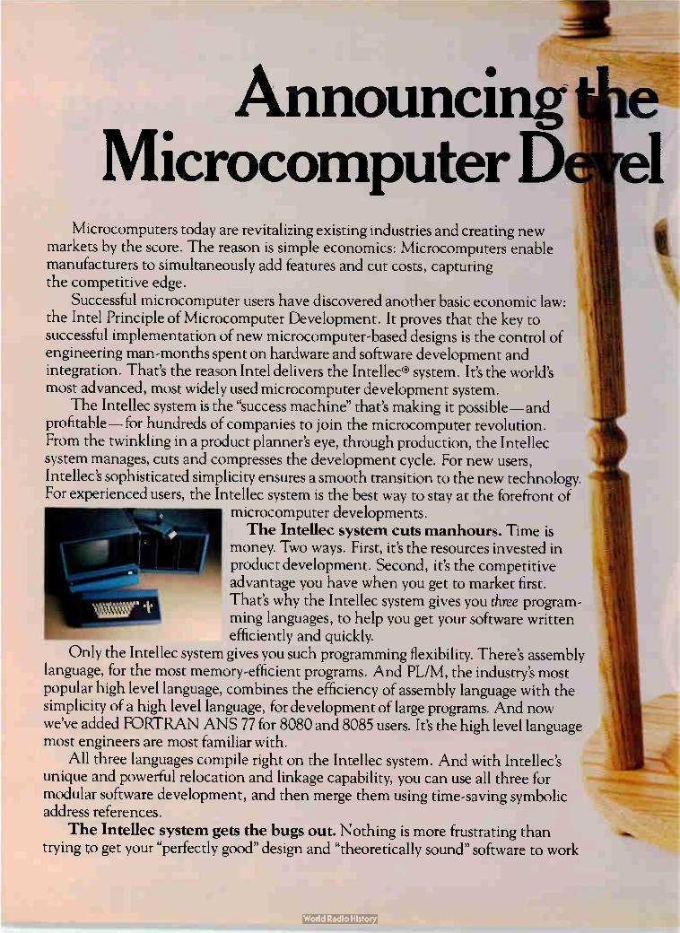
Announcing Microcomputer D í el
Microcomputers today are revitalizing existing industries and creating new markets by the score. The reason is simple economics: Microcomputers enable manufacturers to simultaneously add features and cut costs, capturing the competitive edge.
Successful microcomputer users have discovered another basic economic law: the Intel Principle of Microcomputer Development. It proves that the key to successful implementation of new microcomputer-based designs is the control of engineering man-months spent on hardware and software development and integration. That's the reason Intel delivers the Intellec® system. It's the world's most advanced, most widely used microcomputer development system.
The Intellec system is the "success machine" that's making it possible— and profitable— for hundreds of companies to join the microcomputer revolution. From the twinkling in a product planner's eye, through production, the Intellec system manages, cuts and compresses the development cycle. For new users, Intellec's sophisticated simplicity ensures a smooth transition to the new technology. For experienced users, the Intellec system is the best way to stay at the forefront of
microcomputer developments. The Intellec system cuts manhours. Time is
money. Two ways. First, it's the resources invested in product development. Second, it's the competitive advantage you have when you get to market first. That's why the Intellec system gives you three program-ming languages, to help you get your software written efficiently and quickly.
Only the Intellec system gives you such programming flexibility. There's assembly language, for the most memory-efficient programs. And PL/M, the industry's most popular high level language, combines the efficiency of assembly language with the simplicity of a high level language, for development of large programs. And now we've added FORTRAN ANS 77 for 8080 and 8085 users. It's the high level language most engineers are most familiar with.
All three languages compile right on the Intellec system. And with Intellec's unique and powerful relocation and linkage capability, you can use all three for modular software development, and then merge them using time-saving symbolic address references.
The Intellec system gets the bugs out. Nothing is more frustrating than trying to get your "perfectly good" design and "theoretically sound" software to work

••••••■111111111111..
ciple of ime is Money.
together. With ICETM In-Circuit Emulation, the Intellec system ends that frustration.
ICE enables you to start debugging software in your system before your prototype is much more than a crystal and CPU. ICE lets you execute your programs in real time or single steps, with full control from the Intellec system console. And you can make necessary modifications as you go, using fast, simple symbolic debugging. The Intellec system takes the mystery out of microcomputers by giving you a diagnostic window into your system.
The Intellec system is for winners. Intellec systems make it easy to succeed with microcomputers. That's why it's important that the Intellec system supports the entire family of Intel microcomputers, from the single-chip 8021, 8022, 8041, 8048 and 8049 through the industry standard 8080 and 8085, and the all new 8086 16-bit microcomputer. And, as new Intel microcomputers are introduced, the Intellec system will support them, too. It's the only develop-ment system you'll ever need for every microcomputer you'll ever need.
Find out more about how the Intellec system can save you time and money. For a free copy of our book, "Guide to Intellec® Microcomputer Development Systems," by Daniel D. McCracken, contact Intel Corporation, Literature Department, 3065 Bowers
Ave., Santa Clara, CA 95051. Telephone (408) 987-6475. To arrange a demonstration,contact your nearest Intel distributor or sales office.
intp:l delivers. European Headquarters: Intel International, Brussels, Belgium, Telex 24814. Japan: Intel Japan K.K., Telex 781-28426.
Circle No. 81 for information
I
'Any bunch of hotshots can design a new microcomputer.
It takes brains to improve an old one'?
John Jones Product Marketing Manager Series/80 Microcomputer
Systems
4 J. AIL .
Series/80 Microcomputer Systems
"We're super aware that forcing a change in system architecture causes customers a lot of pain and agony. It costs a small fortune. And no amount of cross assemblers, trans-lators or mode switckes will make things easier.
If you want to hear real horror stories, ask the minicomputer guys. They've seen it.
It just doesn't make sense to me to force customers into a change when there are tons of things you can do to improve any system — especially once it's been in use. And with Series/80 that's exactly what we do.
80/204, 8oho — the advantages of hindsight.
We've just begun offering the 80/204 board. And you can bet we've added some improvements.
Like shadow ROM.' It lets ROM share the same memory address as RAM. And the ROM can be com-pletely shut down and shut out when you don't need it.
In standby, our BLC 80/204 draws less than a watt versus 4 watts for Intel's SBC 80/204. And our bus master handles 6 masters on system bus compared to 3.
R9 Flendstretnid+a IC.ntornh.r 9f-1 1 Q7R

In addition to board level products, we offer a complete line of 80/204 and 80/10 rack mounted computer (RMC) systems with significant advantages over what has gone before.
Dorit get me wrong. The SBC 80/204 — in fact, all the original SBC products are very good. But coming later lets us take customer reaction into account.
In 80/10 boards, for instance, we felt people might like the on-board memory beefed up. So we got out and talked to customers. They told us, 'you bet we want more memory'
COMB1 MEMO
"gliM
CPU
BLC/SBC BLC/SBC 80/10 80/10A
PLC BLC/SBC 80/14 80/204
FiLUSBC • 016
S/34:615 44 KC/ tiliC 660 1 C/
lecm5W
PLC/ SBC 614 SBC 604
BLC/SBC 416
PLC 84 32
FIRMWARE
PLC/ SBC 910
BLC/ SBC 92,
LC/ LC S *508
LC LC/ SBC 517 "BC '
PLC/ SBC 711
PLC/ Sac 724
SYSTEMS
PLC/ MX: y RMC/ SBC MOP/1 , SYS 801' 14 A80/10
RMC/le RMC BLC/ SYS 80/ 80/ SBC 8o1', 204 14 204
And that's what we gave them with the BLC 80/11, 80/12 and 80/14.
Customer feedback also led to the development of National's exclusive 32K BLC8432 ROM/PROM
BLC/ SAC 732
memory card, which is twice the capability of everybody else's.
It's a plain fact that National will continue to be customer driven instead of product driven. Wal come across with features customers want and need instead of what might be clever.
A New Industry Standard.
I feel the best hardware investment is one that protects a software invest-ment. And with Series/80, we're helping create an industry standard microcomputer. So more customers
can use an existing software base And software and hardware
designers will be easier to find. Also, two vendors competing for business means freedom of choice. And that's
what free enterprise is all about.
Serious about Series/80.
We're dead serious about Series/80. Just last year we started
with seven products. Now we're at 41 and still counting — every one designed from a top-down systems point of view.
For more on Series/80 — or, if our market-driven philosophy
makes sense and you'd like to talk job opportunities, write me: John Jones, Series/80 Product Marketing, National Semiconductor Corporation, Drawer 6,2900 Semiconductor
Drive, Santa Clara, California 95051. Or call 800-538-1866 — 800-672-1811 in California:'
ACCESSO
SB BCLC61/0 PLC 8610 BLC/ BLC/ BLCi
SBC 901 SBC 902 SBC 903
BLC/ PLC/ BLC/ SRC 905 SRC 955 SBC 956 PLC 957 BLC 8905
Computer Products Group National Semiconductor Corporation
Electronics/September 28, 1978 83

IF TERADYNE'S N151 CAN TEST THIS BOARD IN TWO SECONDS, HOW
MANY CAN IT TEST IN A DAY?
Frankly, the daily output of this bare pc board test system is ultimately up to you. But whether you use the N151 one,
two or three shifts a day, you'll find it more productive than whatever method you're using now. And not only because the N151 can
test a bare board in two seconds or less. (Even with handling time, the total test cycle can take less than 15 seconds.) The fact is, Teradyne has refined
every aspect of bare board testing, increasing throughput, reducing the cost of testing again and again. Menu programming is one such
refinement. The N151 is so simple to use that a nontechnical person can prepare job plans.
Better data management is a second refinement. The system's
data-base translation capability gives you advantages other bare board testers don't.
Fast CMOS testing, error mes-sages in your own product language,
Teradyne, I want to know what you know about bare pc board testing.
Please send me a copy of your booklet and information on the N151 test system.
Name
Title
Company
City
State Zip
Phone _— Mail to: Teradyne, 183 Essex St.,
Boston, MA 02111
reliable fixturing„ and go no-go testing also contribute to the N151's eco-nomical performance.
Teradyne's experience helps you in other ways, too- In fixture sizing, applications support, and field service. What's more, the N151 is protected by a 10-year circuit module warranty. Teradyne has been steadily reduc-
ing the time, effort, and expense involved in bare board testing. And we'd like to share what we've learned with you. So, we've prepared a book-let entitled Some Whys and Hows of Testing Bare PC Boards. For a free copy— and more informa-
tion on the N151 Interconnection Test System— simply return the coupon. ,ete
Circle 84 on reader service card

Probing the news Analysis of technology and business developments
Soviet computers: better than expected Americans back from USSR maintain that U. S. machines on banned list
would not provide secrets and point to poor Russian manufacturing
by Anthony Durnok, Computers Editor
Recent Government efforts to prevent the sale of • American computers to the Soviet Union have reawakened the controversy over controls on items sold to Eastern Bloc countries. While the debate swirls around ques-tions of politics and balance of trade questions, the crux of the argument appears to be the state of Soviet electronics. A recent survey in Eastern Europe
by American computer experts who are free-trade advocates provides a peek at the progress behind what is still, technologically, the Iron Cur-tain. These experts ask to remain anonymous because of their dealings with both the U. S. and Soviet governments. They say a preliminary analysis of
the new Ryad-2 family of computers [Electronics, Aug. 17, p. 82] shows that although it lags behind current U. S. commercial products, it is more powerful than is generally believed. Thus they conclude that the Soviets would gain little knowl-edge from buying many of the American commercial computers now on the prohibited list. Poor manufacturing. One thing
the Soviets lack, the American visi-tors say, is manufacturing prowess. Although the design of their com-puters is reaching U. S. levels, the Eastern Bloc countries have not been able to produce them in quantity at acceptable levels of quality. This deficiency makes them a good mar-ket for U. S. goods while still preserving America's technological lead, the observers say, because manufacturing skills cannot be learned by dismantling and examin-ing a product.
Responding to the often-voiced
fears that the Soviets could "reverse-engineer" an American computer and thus catch up technologically, the observers point out that it would take them two to three years to produce their version. By that time, American manufacturers would have advanced to a new generation of products. With their survey of Soviet techni-
cal capability behind them, the American observers make another point. They say that the lack of free-market pressures for continually improving price/performance have contributed to the Eastern Bloc's slow pace of innovation. The inabili-ty to buy computers from Western manufacturers is one factor that will force them to increase their efforts. The seven-model Ryad-2 line (also
called ES-2 or ECS-2 family) ranges from the low-end ES-1015 to the ES-1065 and includes the ES-1060 that has no parallel in the Ryad-1 family. In many ways, the Ryad-2 machines run roughly parallel to IBM's System/370 family—and no wonder, because they were designed to run the System/370 instruction set, just as the Ryad-1 used the System/360 instructions.
Inside the ES-2s. The internal hardware is entirely different, how-ever, and in terms of performance, the Ryads trail the 370s (see chart). The analysts note that the 370 has already been surpassed by ism's 303X family, which offers up to 1.8 times the performance of the 370/168-3.
For example, the ECS-1025 is
PERFORMANCE I
N MIPS (MILLIONS OF INSTRUCTIONS PER SECOND
40
3.0
2.0
1.0
0.8
06
0.5
0.4
0.3
0.2
0.1
370/168-3
ECS-1060
370/158-3
ECS-1055
E CS-1045
370/145
370/135
EiCS-1035 1 1 1 1 1 1 1 1 1 1 1
0.1 0.2 03 04 0.5 0.6 0.8 1.0 2.0 3.0 4.0 5.0 6.0 8.0
MEMORY CAPACITY (MEGABYTES)
Electronics/September 28, 1978 85

Probing the news
estimated to perform between 0.03 million and 0.04 million instructions per second (MIPS) and can handle between 128 and 256 kilobytes of memory, while the ECS-1035 oper-ates at between 0.1 and 0.14 MIPS, with as much as 512 kilobytes of memory and an iio data rate of 1,300 kilobytes per second. By com-parison, the IBM 370/135 is rated at about 0.12 to 0.16 MIPS, can handle up to 524 kilobytes of memory, and has an I/O rate of 2,400 kilobytes/s. The newer IBM 370/138, which
offers some 28% more performance than the 135 it replaced, has up to 1 megabyte of main memory. The IBM 370/145 runs at 0.23 to 0.3 MIPS with up to 2 megabytes of memory and an vo rate of 5,300 kilobytes/s, while the IBM 148 offers a 43% performance improve-ment over that. Tn. and chip memories. Coming in
above the IBM 370/135 and 145 but below the IBM 370/158-3 are the ECS-1045 and 1055, which slightly overlap in performance. Both ma-chines are said to be based on tran-sistor-transistor logic and use semi-conductor memory with single-bit error correction and double-bit error detection. Cache memory is also used in both machines.
Performance of the ECS-1045 is 0.4 to 0.5 MIPS, with as much as 3 megabytes of main memory and I/O rates up to 5,000 kilobytes/s. Main memory on the ECS-1055 goes up to 4 megabytes, and performance ranges from 0.45 MIPS without cache memory to 0.9 MIPS with it. The I/O rate on the 1055 is 6,000 kilobytes/s. The 1055, which the East Ger-
mans displayed last March and are expected to begin shipping this fall, is more powerful than the Sperry Univac 1100/10 computer. In July, President Carter blocked Univac from selling an 1100/10 to the Soviet news agency Tass, saying it would have provided a "quantum leap in computer capability." The Univac 1100/10, which is roughly in the IBM 135-148 performance range, offers up to 524,000 36-bit words of main memory—about 2.3 megabytes. The older IBM 370/158-3, with a
U. S. unwilling to loosen export controls
Despite increasing evidence that commercial and industrial computer tech-nology is improving within the Soviet Union and among its Eastern European allies, the United States has rejected most of the U. S. computer industry recommendations that the Commerce Department loosen its export regula-tions to permit Americans to capture a share of that expanding market. At next month's Paris meeting of CoCom —the international coordinating committee composed of the U. S., its NATO partners, and Japan—the American position on technology trade with Eastern Bloc countries is expected to remain essentially unchanged. The reason: the Commerce Department, theoretically responsible for ruling on U. S. exports, is being overridden by the more powerful Department of Defense, which has the ear of the White House. "Jimmy Carter is not a free trader when it comes to Communist countries," complains one Commerce official, "and the Defense Department effectively still has a veto on technology exports." Thus the U. S. rejected in July all but one of the three general recommen-
dations requested by the Commerce Department and submitted along with specific hardware guidelines by an industry technical advisory committee. The proposals reflected a consensus among eight companies: Burroughs, Control Data, Digital Equipment, Data General, Hewlett-Packard, Honeywell, IBM, and Sperry Univac.
While the U. S. did buy the committee's concept of establishing an annual automatic increase in export guidelines that would compensate for the real growth in Soviet and Eastern Bloc computer performance, Government officials indicate they are not certain about "optimistic" industry estimates that growth rate approximates the U. S. industry's level of 25%. Moreover, the Government rejected completely two crucial industry recommendations: that case-by-case review of export applications be eliminated for products that are qualified and approved in advance under performance guidelines; and that export control guidelines be set up for categories of peripherals and
subsystems, rather than for total systems. "Nothing has changed," says one exporter. Not only will export rules
"continue to be cumbersome and burdensome for both the exporter and the Government," but U. S. companies will be unable to effectively compete for what they believe is a significant share of an estimated $200 million to $300 million commercial electronics market. Ray Connolly
performance of about 0.7 to 0.9 MIPS, overlaps the Ryad-2 machines, but can handle more memory—up to 6 megabytes. Also in this perform-ance range is Control Data Corp.'s Cyber 171, which can control up to 262,000 60-bit words of main memo-ry (about 2 megabytes worth). Topping out IBM'S line is the
370/168-3, which is estimated to operate between 2.5 and 2.7 MIPS,
offers up to 8 megabytes of memory, and has an I/O rate of 16,000 kilo-bytes/s. And the newest IBM ma-chine, the 3033, is said to perform at 1.8 times the 168, and has an I/O
rate of 26,000 kilobytes/s. High end. Little is known, howev-
er, about the high-end Ryad comput-ers. The ECS-1060, which has yet to be built, was to be included in the Ryad-1 family, but was reportedly upgraded for inclusion in the Ryad-2 group. It is specified to operate at 1.3 to 1.6 MIPS, handle between 2
and 8 megabytes of memory, and have an I/O rate of 9,000 kilobytes/s. Specifications for the 1065, and that appears to be all that exists of it at this point, indicate it will operate at 4 to 5 MIPS, have up to 16 megabytes of memory and an I/O rate of 15,000 kilobytes/s.
Despite the advances in computer-mainframe technology, the Ameri-can observers say the Eastern Bloc is still behind in peripherals. The current top-of-the line disk available for use with the 1055 is the Model 5066 and 5067 disk, which appear comparable to the IBM 3330 Mod I and 11 disk drives. The 5066 provides 100 megabytes of storage with an average access time of 38 milliseconds, while the 5067 has 200 megabytes and an access time of 30 ms. ism's top-of-the line 3350 disk, on the other hand, stores up to 317.5 megabytes and transfers data at a rate of 1,198 kilobytes/second. CI
86 Electronics/September 28, 1978

Who said choosing the best electronic assembly machines is a game of chance?
Improved Model 6295 dual head VCD with new high speed cycle rate of 25,000 an hour.
There is only one basis for selecting component sequencing and insertion equipment—and that's system productivity. Universal has maintained its strong leadership in automation for electronic assembly by designing and building reliable systems that are responsive to the growing production needs of our customers.
And now, Universal announces a 30% increase in sequencing and component insertion rates.
Again, as always in the past, Universal leads the way for obtaining the lowest unit cost to produce your product.
Don't gamble with your profits—call Universal for a demonstration of these new systems. Seeing is believing.
Improved Model 2596 Sequencer with up to 160 input stations and new cycle rate of 25,000 an hour.
Patent Pending
li
COLniversaL Universal Instruments Corporation Kirkwood Industrial Park Box 825, Binghamton. New York 13902 Tel: 607/772/7522 TWX: 510/252/1990
Circle 87 on reader service card

ON THE BENCH, THE MOST ADVANCED DVM.
IN SYSTEMS TOO.
- 10.0000 - 0
The new 8502A digital voltmeter—the precision DVM just right for both systems and bench applications.
It's right because it brings all the power of the 8500A, the world's most advanced system DVM, to the front panel.
Press SCALING and enter any multiplier to scale volts, ohms or amps to temperature, percent, engineering units, or any scale of convenience. Press OFFSET and add or sub-tract any numerical value to set your prescaled units to the right reference point.
If you're looking only for a good/bad indication, use LIMITS and key in both high and low tolerance values on any function. After that you'll get a friendly "Hi, Pass or Lo" reading at full accuracy.
The 8502A remembers its highest and lowest read-ings. Leave it unattended on a stability test, for example, then touch PEAK, HI and LO later to observe the amount of drift that occurred.
Want 61/2-digit resolution? Press HI RES and get it on all functions. This lets you utilize the full instrument accuracy —6 ppm on DC volts.
The 8502A is fast—up to 250 read-ings/second on the bench, 500/second in a system. This speed is put to work to provide noise rejection through digit-al averaging. Adding analog filtering gives you up to 100 dB NMR.
Calibration memory is a Fluke ex-clusive that saves time and money.
"Y=AX+B"
Without removing the voltmeter or taking off covers, sim-ple recalibration is done from the front panel in a few minutes. Lab calibration is recommended only once a year if calibration memory is used.
The five FUNCTION pushbuttons are evidence of another exclusive. Besides volts and ohms, the 8502A can have AC and DC current capability installed, a fea-ture not available in any other precision DVM.
We even provide diag-nostic error codes to keep you out of trouble by iden-tifying programming mis-takes and hardware errors.
For systems use, we of-fer more interface options
than anyone: IEEE 488, RS-232 or full parallel. And, a switchable front/rear input option is available.
U.S. base price: $2595.
I- • r I 1_I r
For more information, contact any one of the more than 100 Fluke offices or representatives, worldwide. In the U.S., CALL (800) 426-0361*, TOLL FREE. Residents of the U.S.A. and all countries outside Europe, contact: John Fluke Mfg. Co., Inc., P.O. Box 43210, Mountlake Terrace, WA 98043, U.S.A. Telex: 32-0013.
In Europe, contact Fluke (Nederland) B.V., P.O. Box 5053, Tilburg, The Netherlands. Telephone: (013) 673973. Telex: 52237.
*Alaska, Hawaii, Washington residents — please call (206) 774-2481.
6104-8002 IFLUKE1
Circle 89 for literature Circle 88 for demonstration

Probing the news
Solid state
VHSI proposal finds willing audience Most semiconductor makers say they plan to take part
in Pentagon's six-year, $200 million development program
The Department of Defense is shop-ping at the right time in the right place. America's semiconductor manufacturers are reacting with eager interest to the Pentagon's proposal to spend $200 million and six years developing high-speed inte-grated circuits capable of operating 100 times faster than today's circuits [Electronics, Sept. 14, p. 81]. Indica-tive of that interest is that 10 compa-nies attended the meeting on the program convened by the Pentagon earlier this month. Among them are believed to have been the semicon-ductor industry leaders, with the notable exception of Intel Corp. The consensus is that since the
Government is anxious to push development of circuits in the same direction that the companies them-selves are going, why not let the research and development financing come from the Federal coffers?
That's how Pierre Lamond views it. As vice president and technical director at National Semiconductor Corp. in Santa Clara, Calif., he says, "Our initial reaction is positive." The goals of the program are realis-tic partly because the Defense Department is "piggybacking on existing projects in the industry," he points out, adding that the money will be especially helpful in view of the cost of developing new technolo-gy today.
At National's Santa Clara neigh-bor, American Microsystems Inc., J. Leland Seely, corporate vice presi-dent and manager of research and development, says, "We're sure go-ing to strongly consider [participa-ting in the program]. What I like about it is that it takes us in a direc-tion we really want to go, but I don't
know if the goals are right." He is referring to the stated target of a minimum-feature size of 0.5 micro-meter: "That's a little farther than we really want to go. There's a possi-
bility that you run out of steam because the scaling laws restrict lowering the voltages and solving attendant noise problems." And get-ting right to the commercial possibil-
VHS' competitive opportunities abound
Where will the money go? That is the question makers of integrated circuits and their production equipment are asking about the Defense Department's VHS' program. The six-year effort is to begin in October under the direction of the under secretary for research and engineering, William Perry. VHS' program manager Larry W. Sumney (see p. 12) says funding plans presently run to "more than $150 million," but knowledgeable industry sources peg it at $200 million —a total the Pentagon does not dispute. What troubles some semiconductor makers are delivery goals of 1,000
militarized 2-megabit random-access memories and 1,000 militarized logic integrated circuits with throughputs of roughly 1 million instructions per second on a single silicon chip measuring 400 mils on a side [Electronics, Sept. 14, p. 81]. Those pilot-line production quantities, coupled to highly ambitious performance goals, suggest to some industry officials that only the semiconductor industry giants will be able to participate. Not so, says Sumney. "Certainly the people who produce VHS' circuits will have to have the capability, but I can think of 10 or 15, perhaps 16, companies who would qualify," he says. Sumney sees opportunities for smaller companies and university research
laboratories in other VHSI goals to develop commercially available submi-crometer lithography equipment that will be able to reduce features on a chip to 0.5-gm resolution, 0.1-gm alignment, and 15 minutes' exposure time per 3 inches of wafer or mask. Funds for these exploratory developments could run to $50 million by industry estimates. "There are a lot of smaller companies qualified to compete in this area, and a number of university laboratories, too," Sumney says. He adds that possible contributors could include organi-zations like Perkin-Elmer Corp. and others, as well as university laboratories like Stanford Research Institute or the Carnegie-Mellon Institute. Similarly, the industrial and academic communities have a wide range of facilities qualified to participate in the program's committee called DAST — for design, archi-tecture, software and testing —which also will have an estimated $50 million budget.
Nevertheless, the VHSI delivery effort of pilot-time production chips will get about half the program's budget, and Sumney does stress that "this is not going to be an effort spread among 50 companies getting $50,000 each." The first three years of the delivery effort "will be competitive in every sense," he says, with the number of companies to be limited later to those producers who are able to achieve their milestones. Industry sources estimate that the first three-year phase for the production program would involve six to eight IC companies and then drop to two or three.
Ray Connolly
Electronics/September 28, 1978 89
1024 BYTES
...and it still
works
The KILOBYTE CARD' 11 Over 1024 8-bit bytes of reliable program/data storage, on the toughest S0.15 media
ever devised.
And the compatible KB-31 MICROLOADER1". Field proven read/encode accuracy, and half-million cycle dependability, even
in adverse environments. As low
as $99, in 1000 quantity.
The wide range of standard KB-31
electronics, control and interface options can satisfy the most demanding applications from intelligent terminals and instrumentation to machine tool controls and test equipment.
If you have a potential application, and are D&B rated, we'll be happy to let you evaluate a KB-31 and KILOBYTE CARDs free for 30 days.
14111 IF"' 11;;111 1111111 111'1111
11111 111 1111111 'hill I 125 Ellsworth Street, Dept. E9
Clifton, New Jersey 07012 Tel: (201) 472-1331
Probing the news
ities of what the Federal government is sponsoring, an executive at Ad-vanced Micro Devices Inc. in Sunny-vale,' Calif., says, "Clearly, we're all moving in the direction of smaller geometries. This spells out what's coming. I don't see any conflict between what the Defense Depart-ment wants and what companies want to do commercially." A spokes-man for Fairchild Camera and Instrument Corp. says there is no doubt that the program will signifi-cantly influence the semiconductor industry in the next decade, but adds the company will not discuss its plans until it learns more. More focus. The feeling at Rock-
well International, an old hand at responding to military needs, is one of enthusiasm. Malcolm B. North-rup, vice president at the Microelec-tronic Device division in Anaheim, Calif., says, "We have known about it for two months and definitely intend to participate. It's going to be essential to electronics systems for the military because otherwise de-vice development will not proceed nearly as- fast. What we think the military is looking for are very-high-speed signal-processing devices, which are not now commercially available. While at Rockwell we have been doing this for our systems divisions for all three services, what has been lacking is the unified approach. The proposed program will provide a lot more focused effort."
In Texas, all eyes are on the VHS! program. While Texas Instruments Inc. says that it has signed a nondis-closure agreement and will not talk about what it will do, the company is believed to have been among the 10 to attend the Pentagon-sponsored meeting earlier this month. And while Mostek Corp. will not say flat out that it will participate, the word from marketing vice president Berry Cash is that his Carrollton outfit is likely to be there when the shooting starts. Cash is more willing to get into
specifics about the program than most of his counterparts at other companies. Pointing out that Mos-tek's interest naturally leans more to
the memory portion of the undertak-ing than toward the one dealing with high-speed logic, Cash says that the goals sound about right, given the time and money specified by the Government. A six-year project aimed at production of circuits that are 400 mils on a side is "probably about right in the ballpark to be looking for," he says. "Even with these much tighter geometries-2-micrometer line widths and so on— we will still have to make much larg-er chips than we are at present to produce the densities they want." As for the $200 million, Cash
believes "it ain't too much, that's for sure." Caution must be exercised not to waste money, he says, particularly in the photolithography portion of the project. "You could pour away a lot of money quick in that sort of effort and not have a lot to show for it if you aren't careful," Cash warns.
Considering the project as an indi-cator of future Federal policy and its response to foreign Ic development, Cash is optimistic. "I would like to think that somebody up there cares and is thinking about us," he says. But he feels that a strong factor is probably that since mos became a reality, the military has lost its place as the industry's foremost market and has taken a back seat to the consumer, industrial, and data-processing markets.
In general, Cash thinks "the industry will respond positively to the VHS! project." Particularly from the vantage point of Mostek, which is suing the new, British—govern-ment—backed Inmos over alleged expropriation of technology, the VHS! announcement is a welcome, positive move by the U. S. Govern-ment. "The Government should be doing something to encourage this technology," he concludes, "so it looks like a reasonable thing." That threat from abroad and any
official American moves to counter it are important factors to more than one semiconductor executive. As National Semiconductor's Lamond puts it, "The Defense Department has a twofold concern" in promoting the development of VHS! circuits. Besides rekindling the industry's interest in the military, "the poten-tial enemy has made considerable advances in technology." D
90 Circle 90 on reader service card Electronics/September 28, 1978

Reduce Custom Power Supply Time
and.. st
With a handful of Powercube's Cirkitblock Fr' modules and a few clip leads, you can quickly syn-thesize an infinite variety of custom power supplies.
Cirkitblock modules have demonstrated capability to meet most design needs and are packaged within a 1" x 1" x 2" basic building block format so you can assemble supplies of any complexity to any form factor appropriate in building block fashion.
Design time to operating prototype can be reduced by more than 50% because conventional breadboarding is eliminated. Your quickly assembled "breadboard" of modules becomes your operating prototype.
Cirkitblock modules utilize space technology but are specified and priced for industrial as well as military applications. They can substan-tially reduce the "as installed" power supply costs in airborne and ground based instruments such as receivers, navigational systems, displays, stores management systems, and communication gear.
Cirkitblock functional modules not only save design time and money; they are also a lot of fun to work with.
Circle the reader service number to learn more about Powercube's Cirkitblock functional modules. Send for free catalogues describing the entire Cirkitblock module family and packaging styles for complete power supplies.
Aar POWERCUBE A SUBSIDIARY OF umTRODE CORPORATION
POVVERCUBE CORPORATION
EIGHT SUBURBAN PARK DRIVE
BILLERICA, MASSACHUSETTS 01821
(617 667-9500
Circle 91 on reader service card 91 Electronics/September 28, 1978

Probing the news
Electronics abroad
Common Market eyes VLSI effort Commission seeks to avoid resistance to know-how exchange
by concentrating efforts on production equipment, testing
by James Smith, McGraw-Hill World News
It is almost impossible to get faction-al national electronics producers together on advanced projects in computers or microelectronics, but Common Market experts are trying anyway. Their goal: to remedy Western Europe's dangerously grow-ing gap in very-large-scale inte-
grated-circuit technology. The scheme, which has been circu-
lated for industry reaction, would sidestep the hotly competitive area of manufacturers' know-how, where previous cooperation efforts broke down. Instead, the European Eco-nomic Commission would concen-
Getting it together. Electron-beam mask-making
Research Laboratories. Equipment would play an important role in VLSI
equipment is tested at the Philips
effort.
trate on the VLSI production infra-structure and on applications for industrial users. Both areas are woefully• lacking because of the dependence of the microelectronics industry on standard imported cir-cuitry, except for those firms making circuits for their own consumer appliance needs.
If they get industry support as they expect, commission officials would set up a three-pronged fund-ing program: • Research into materials, produc-tion equipment, and production engi-neering (not necessarily VLSI only). • Research into computer-assisted design, testing, and manufacturing for vLsi. • Educational and training pro-grams to acquaint users with vLsi's product-development potential. Too late. The idea behind the
scheme is that equipment and mate-rials for microcircuit production, supplied largely from specialized U. S. or Japanese firms, are avail-able late to European semiconductor companies. By the time these firms have completed their journey along the learning curve, international competition has already lowered the prices of new la so drastically that European competitors can no longer get into the market. Hence, until a home-based production expertise ex-ists, there is virtually no hope of building a competitive European VLSI industry. The lag in the supply of sophisti-
cated ics in turn weakens the ability of European electronic equipment and system manufacturers to under-take circuit design and prevents industrial users from developing products employing new microcir-
92 Electronics/September 28, 1978

cuits. "Without something to awak-en industry to the challenge, a disas-ter like that of the Swiss watchmak-ers in the face of digital watches will be repeated in a horde of other sectors," says an EEC expert. The effort is not the commission's
first to get European VLSI coopera-tion going. Last year an attempt to formulate a five- to six-year program died over proposals for short-term collaboration in sensitive product-design areas. Now the commission hopes to win
industry endorsement in principle by staying on the production-equipment side, where it believes technologies are not yet competitive. If the companies support the approach, the commission will then ask the council for a go-ahead to work out a detailed funding program with the companies and the national governments. Go it alone. The failure of last
year's proposal has already given Common Market governments time to field national programs intended to bolster their own industries. In July, the United Kingdom's Depart-ment of Industry announced $140 million in five-year grants for both producers of microelectronic devices and suppliers of specialist equip-ment, materials, or services. The program aims at competitive capa-bility in standard products, like memories and microprocessors, as well as in custom circuits. Next year, the West German government starts a $100 million, three-year VLSI program on top of its current support for electronics components. The French government is report-
edly spending $10 million annually, largely through the Commissariat a l'Energie Atomique and Thomson-CSF. It seeks VLSI circuitry with 2-micrometer lines in production by 1981 and with 1-am lines by 1983. The CEA is concentrating on optical engraving for the first phase and on electron-beam or X-ray methods for the second stage. It will also look at low-temperature technology, and Thomson will focus on higher-temperature n-channel metal-oxide-semiconductor approaches. Such national efforts are still far
behind what is being done in the U. S. and probably Japan. More-over, "they are heavily product-oriented and cannot generate the
broad infrastructure necessary to match U. S. industry capabilities stemming from massive programs and the huge market," says Leon Smulian, the EEC adviser on the elec-tronics sector.
"It's a pity the Europeans are pushing their national industries," adds Robert Heikes, vice mesident of Motorola Semiconductors (France). He tried unsuccessfully to get Motorola and European firms including Plessey and Telefunken
together in a semiconductor venture years ago. "They can spend billions and still not get into the semiconduc-tor business on a profitable basis," says Heikes.
Despite Commission efforts to supplement rather than replace them, the national programs may complicate efforts to provide a Euro-pean development approach. Coop-eration on both direct and indirect electron-beam fabrication tech-niques is already under way in the
IPOWER-ONE offers the largest off-
shelf line of triple output D.C. power supplies in the industry. 13 Models, from 16W to 150W. Precision regulated D.C. voltages for logic, memory, interface, linear devices, and Floppy-Disk memory systems.
II 115/230 VAC Input III OVP on +5V Outputs
3 +.05% Regulation
3 Two-Year Warranty
3 UL and CSA Recognized
Still Only $49.95 Microcomputer Model HTAA-16W Output # 1 5V @ 2 DA.with ()VP. Output #2 9-15V, @ 0.4A. Output # 3 ( 19-15V @ 0 4 Á or 5V @ 15-4A
Get all the details on our 84 standard open frames.
Send for our new 1979 Catalog.
IN-STOCK NATIONWIDE... FOR IMMEDIATE DELIVERY ARIZ.: Scotsdale, PLS Assoc. (602) 279-1531 CAL.: Pasadena, A-F Sis Engr. (213) 681-5631; San Diego, A-F Sis Engr. (714) 226-8424; San Jose, Richards Assoc. (408) 246-5860 COL.: Denver, PLS Assoc. (303) 773-1218 CT.: Litchfield, Digital Sis. Assoc. (203) 567-9776 FLA.: Orlando, Gra-Mar (305) 894-3351 ILL: Chicago, Coombs Assoc. (312) 298-4830 IND.: Indianapolis, Coombs Assoc. (317) 897-5424 MD.: Lanham, Brimberg Sis. Assoc. (301) 946-2670; Baltimore, Brimberg Sls. Assoc. (301) 792-8661 MASS.: Waltham, Digital Sls. Assoc. (617) 899-4300 MINN.: Minneapolis, Engr. Prod. Assoc. (612) 925-1883 N.J.: Whippany, Livers-Polk Assoc. (201) 377-3220 N.M.: Albuquerque, PLS Assoc. (505) 255-2330 N.Y.: Roslyn Hts., Livera-Polk Assoc. (516) 484-1276; Syracuse. C.W. Beach (315)446-9587 ORE.: Portland, Jas. J. Backer (503) 297-3776; Salem, Jas. J. Backer (503) 362-0717 TEX.: Dallas, Advance Technical Sls. (214) 361-8584; Solid State Electr. (214) 352-2601; Houston, Advance Technical Sls. (713) 469-6668; Solid State Electr. (713) 785-5436 UTAH: Salt Lake City, PLS Assoc. (801) 278-2141 WASH.: Seattle, Jas. J. Backer (206) 285-1300; Radar Elec. Co. (206) 282-2511 WIS.: Milwaukee. Coombs Assoc. (414) 671-1945 EUROPE: Haney, LA., CA (213) 556-3807 CANADA: Duncan Instr. Weston, Ontario (416) 742-4448
"Think
about0Power-oneNc. OC POWER SUPPLIES
Power One Drive • Camarillo, CA 93010 • Phone: 805/484-2806 •TWX: 910-336-1297
SEE OUR COMPLETE PRODUCT LISTING IN EEM & GOLDBOOK
Electronics/September 28, 1978 Circle 93 on reader service card 93

SOLID STATE IMAGER ACTUAL SIZE:
3" x 3" PRINTED CIRCUIT CARD
DIODE ARRAY IN 16 PIN DIP PACKAGE
CONNECTOR PINS: POWER SUPPLY IN VIDEO OUT
ACTUAL PRICE:
Now all engineers can afford to evaluate optical scanning techniques for their system application. For just $98. RETICON offers the RL128G self-scanning photo-diode array with 128 diodes on 25µm 1 mil ) centers and a complete interface circuit model RC301 ) which allows the diode array to be operated over a wide range of scan rates and integration times to fit any system requirement. Just connect your standard power supply and get a wide dyna-mic range video signal out. Applications include OCR, pattern recognition, non-
contact size and position measurement, inspection for defects, spectrometer readouts and many more. For higher resolution requirements, other RETICON
self-scanning photodiode arrays are available with up to 2048 diodes in a linear configuration and 100x100 diodes in a matrix configuration.
This special offer valid only in the U.S. and Canada for a period of 60 days from publication. Don't delay —evaluate this exciting new technology today.
en*EsEe RETICON 345 Potrero Avenue Sunnyvale, California 94086 (408) 738-4266 TWX: 910-339-9343
94 Circle 94 on reader service card Electronics/September 28, 1978
SCAN RATE ADJ. POT.
Probing the news
UK, for example, under a $1.8 million support program launched last November. Commission officials say some
techniques to inscribe and delineate submicrometer patterns on the wafer are already in use for current lc circuitry. But they note that most of the work is in mask making, and the industry is still far from direct elec-tron-beam etching. Moreover, the EEC believes equipment and parallel process development for VLSI (metal-ization, passivation, and materials) can come into existence only on a European scale, and that the same holds for next-generation computer-aided circuit design and testing. A standard language. Such work
could include interfacing software standards and setting design goals. It could also embrace a standard input descriptor language for users and manufacturers, so that users would functionally specify the system in which the microelectronic subsys-tems will be incorporated. So far, European companies do
not completely rule out cooperation. Siemens officials think it desirable in component standardization and semiconductor manufacturing equip-ment. Derek Roberts, head of Ples-sey Microsystems, favors coopera-tion, though he thinks it will come first strictly on a national level. But he notes that Common Market efforts at cooperation so far have been desultory and intermittent and "it may be a long time before it has even an infrastructural program in operation. "The approach is similar to ideas
floated by Plessey two years ago," says Roberts, "so we are in favor of it. But the great question is who pays? If the funds come out of exist-ing national programs, it will never occur. If the Commission is really serious on making it happen, it will have to find its own way of funding." The EEc's consultant Smulian, a
former managing director of Plessey Microsystems, says he is confident that industry's positive response for creation of a European infrastruc-ture "will be matched by the Council of Ministers," the community's leg-islative and funding authority. EJ

Probing the news
Commentary
Britain's NEB thrives amid controversy Successful venture-capital arm of Labour government, parent
of start-up semiconductor firm Inmos, is Tory whipping boy
by Kevin Smith, London bureau manager
As Inmos, the United Kingdom's brand new government-financed semiconductor company, readies its defense against U. S. court action brought by Mostek Corp. over alleg-ed improper use of trade secrets, its parent company back home, the three-year-old National Enterprise Board, faces a trial of a different kind.
Set up by the present Labour government to provide sorely needed funds for growth industries, to restructure uncompetitive sectors of British industry, and to restore ailing companies to industrial health, the NEB faces imminent extinction or, at best, emasculation by an incoming Conservative government —should Labour lose the next election.
Already, the Tories' Sir Keith Joseph has made threatening growls in the direction of the board. His particular target has been Inmos, where he accuses NEB executives of recklessly gambling with taxpayers' money. So Prime Minister Calla ghan's decision not to hold an autumn election, but to soldier on with a minority government, grants NEB chairman Sir Leslie Murphy a reprieve in which to win over the Conservatives. He is trying to avoid the face of the board's predecessor, the Industrial Reorganization Corp., which was unceremoniously axed by the last Conservative government in its first days of power.
Accord. Both political parties agree on this at least: one cause of British industrial ills is a lack of investment. The Tories argue that investment funds will flow once again if the business climate is improved by easing crippling corpo-rate and personal taxes and . by
Critic. Sir Keith Joseph, who would be a
cabinet minister if the Tories win the next
election, says Inmos is a reckless gamble by
the NEB using taxpayers' money.
freeing industry from the rigors of price controls. Certainly, NEB execu-tives would be the first to welcome increased investment of this kind by the private sector.
But the Conservatives go further. Government intervention is unneces-sary, they say, ignoring entirely the monolithic battering ram being un-leashed on the American high-tech-nology citadel by a grand alliance of Japanese government and industry. Every Conservative has a dream of the British economy as a mini-Amer-ica that will flower again as once it did during the world's first industrial revolution—if only industry's tax shackles are removed.
Structural weaknesses, like the
fragmentation and backwardness of some sectors of British industry, are ignored as are the small size of the domestic market, the stifling con-servatism of many companies, and the sheer bad management of others. On Labour's return to power, the
National Enterprise Board was given a $2 billion borrowing limit to buy into private industry. Industrialists feared that the NEB would buy a controlling interest in profitable industries and interfere in their day-to-day operations. Instead, the "monster" turned out to be surpris-ingly similar to the venture-capital arm of a big oil corporation. The board's executives have stepped into a yawning gap in the long-term equi-ty funding market, caused by a decline in company profitability and years of rampant inflation. Track record. After three years of
operation, the NEB has attracted a lot of brickbats, but it also has begun to win the respect and cash of the City — London's financial district— for its hard-nosed commercial ap-proach. One of the four big clearing banks, the Midland Bank, has set up a joint company with the board to provide small firms with financing. Barclays Bank recently stepped in with the NEB to rescue Monotype Corp.—soon to launch a laser-based typesetting system—from insolven-cy. Even the Confederation of Brit-ish Industry, in its soon-to-be-released policy document, adds a limited endorsement of the board, though it wants its free-ranging activities to be severely curtailed.
It is in the rough-and-tumble, fast-moving world of high technolo-gy that the NEB executive team and its inner court of high-technology
Electronics/September 28, 1978 95

Probing the news
ance to date showed peak production rates of 13 square centimeters of web per minute, with 8 ce/min more typical. To meet the 1986 cost goals, that rate has to go up to 25 cm2/min and Muss expects do so in the laboratory early in 1979. The top conversion efficiency shown by web cells is 15.8%, already ahead of the 14%-by-1986 goal.
David Richman is not downplay-ing the obstacles, however. He heads semiconductor materials research in RCA'S Energy Systems Research Laboratory, Princeton, N. J. RCA is using chemical vapor deposition to grow epitaxial layers of silicon on two types of low-cost silicon sub-strates, either single-crystal silicon or the less pure polycrystalline metallurgical-grade silicon. The lab-oratory has grown layers as thin as 1 mil on these substrates, with conversion efficiencies topping 13% for the single-crystal substrate and 12% for the polysilicon one. The work at Honeywell Inc.'s
Foreign labs hard at work
Work is also under way outside the U. S. to bring low-cost silicon solar cells to the market. In West Germany, a subsidiary of Wacker-Chemitronic GmbH, a leading silicon supplier, is "industrializing" a process for casting polycrys-talline wafers [Electronics, May 11, p. 44]. In France, a research facility of the Philips group —Laboratoires d'Electronique et de Physique Appliquée— has a research team working on silicon ribbons. Further, jointly owned Japan Solar Energy, which has a license for the Mobil Tyco process, has been turning some of the ribbons into completed solar panels and shipping them to customers since March.
Corporate Technology Center in Bloomington, Minn., is based on a silicon-on-ceramic process that was begun and dropped in the 1960s. It has been refined to the point where it can produce a 1-cm2 cell with a conversion efficiency of 10%. More needed. The throughput has
to be increased, though, to approach the 1986 goals. Today's best rate is about 0.06 cm/second, and program manager Paul Chapman says that must go up to 1.5 cm/s in a contin-uous grower.
Well south of Minnesota's snow country, workers in Motorola Semi-conductor Group's solar operations
in Phoenix are concentrating on a so-called ribbon-to-ribbon technique. Polysilicon is vapor-deposited on a substrate, then peeled off in ribbons up to 3 in. wide and 4 to 8 mils thick by means of thermal expansion shear separation. Then a laser beam scans the ribbon to melt the small-grain silicon into larger grains that, though still polysilicon, permit high-er conversion efficiency. Arnold Lesk, manager of solar energy research and development, says the best throughput rates to date convert into 0.35 m2/hour.
For all of these non-Czochralski processes, with the exception of
PotteratBrunifield

Westinghouse's web method, JPL
Task 2 manager Krishna Koliwad is looking for higher efficiencies. He, too, cautions that a good bit of work remains to be done with all of them, especially to automate them.
Ingots. Further along, though, is Czochralski crystal growth. It has been used for years to make ingots for semiconductor chip makers. In the process, a silicon seed crystal is dipped into, and a slowly forming ingot is drawn out of, a crucible of molten silicon inside the vacuum chamber' of a furnace. However, today's furnaces are limited to mak-ing ingots weighing 16 to 20 kilo-grams from one melt, and when allowed to cool after an ingot is with-drawn, they almost always crack the crucible and destroy it. That is why the advanced work in this area is aimed at developing rechargeable furnaces that would let as much as 100 kg—four or five ingots—be pulled before cooling.
All the funded ingot producers, except Crystal Systems, are using Czochralski crystal-pulling furnaces modified to accept some kind of
hopper or premelting chamber that automatically replenishes the melt— either after the ingot has been pulled or while it is actually growing. The Varian Lexington Vacuum division uses a vibratory feeder to drop sili-con pellets into the melt after one ingot has been pulled [Electronics, June 22, p. 44].
Texas Instruments, however, plans to feed liquid silicon into the melt to replenish it while the crystal is being grown. Gene Wakefield, manager of the Materials Technology Center in Ti's semiconductor research and en-gineering laboratories in Dallas, ad-mits this involves a major "technical unknown" for Ti: development of a premelting unit for the liquid-replen-ishing stock, "so that it will function in a reliable, controlled manner and add silicon at the proper rate" with-out disturbing the growing ingot.
Liquid transfer. At Siltec Corp. in Menlo Park, Calif., the approach is similar to TVs, in that Siltec trans-fers liquid silicon under pressure from a premelt chamber to the grow-ing chamber as the crystal grows. Among other things, Siltec is a
supplier of polished single-crystal wafers to semiconductor makers. The other funded advanced-
Czochralski ingot producer is the Hamco division of Kayex Corp. in Rochester, N. Y., where the goal also is to pull 100 kg of ingots before the furnace is cooled, instead of 20 to 25 kg. "We're about halfway there," says Richard Lane, director of engineering. Hamco has grown three ingots weighing a total of 47.5 kg from one crucible.
All square. Finally, Crystal Sys-tems of Salem, Mass., is casting ingots with a square cross-section using its heat-exchanger or direc-tional solidification process [Elec-tronics, July 20, p. 44; June 26, 1976, p. 34]. In this non-Czochralski pro-cess, the ingot grows up and out from a seed at the bottom of a square crucible, promising less waste than with round wafers.
JPL will have to choose from among all the competing Task 2 technologies by 1981. Koliwad says one process will be chosen for full implementation, along with a back-up process.
The source with the best resources. Auld'
Potter &Brumfield
Engineering. Potter & Brumfield has the application design engineering know-how to solve tough control problems. Working with high technology com-
panies, we've developed an outstanding ability to marry circuits and components, including microprocessors and memories, into control systems matched to the appli-cation. And, this includes knowing how to package them effectively and economically.
Manufacturing. We've already made the huge investment in capital equipment necessary for efficient production: microprocessor programmers, complete printed circuit board manufac-turing facilities, flow soldering equipment, and more. The components we don't make we buy at a high-volume, low unit cost and pass the savings on to you. We also save you inventory carrying
and capital costs, manpower, pre-produc-tion processing equipment costs, and scrap losses. Quality. We're known for quality and want to keep it that way. Our control procedures for custom assemblies are based on MIL-Q. 9858A. Every custom product is subjected
to a final, 100% functional test on our specially designed, highly accurate test equipment.
For example, a new microprocessor-based test and diagnostic system performs seventeen sequential tests on six assem-blies at one time. In less than one minute. Two time delay functions are tested at mini-mum and maximum voltages. The diagnos-tic system can pinpoint any circuit faults and calculate the optimum value of components required to meet the test specifications. A printout of test data is provided.
Call us first. When you add it all together, Potter & Brumfield will be your number one choice for custom control assemblies. We have the most to offer. Deon Hendrickson, Custom Control
Assemblies Product Manager, at 812-386-2273, can provide complete details. Or con-tact your local P&B representative or Potter & Brumfield Division of AMF Incorporated, Princeton, Indiana 47671. Get the source with the best resources.
Circle 99 on reader service card

M&T pmtects some of the
great American Institutions.
A Visit to Grandma's. Protected by M&T specialty adhesives. Today, a visit to Grandma's is likely to mean a jet flight.
And when the kids look out the window to see Grandma waving from the arrival gate, FURANE* and URALANE* urethane adhesives made by M&T are helping to hold that window in place. Our EPIBOND* epoxy adhesives helped to secure the overhead storage compartment. Even the galley and the food and beverage carts the flight attendants use to serve you are bonded using M&T products.
Not to mention the protection you don't see—M&T technology has helped the aircraft and aerospace industries to keep inner and outer construction reliable and safe by supplying an extensive line of urethane and epoxy formulations.
*ALSTAN. aduaMeT. COPPER-LUME, EPIBOND, FURANE, THERMOGUARD and URALANE are trademarks of M&T Chemicals Inc. © M&T Cnemicals Inc. 1978
100 Electronics/September 28, 1978

Late night TV. Protected by our acid copper plating.
Thanks to the late, late show, America's millions of insomniacs can rely on something a lot more entertaining than counting sheep.
And thanks to M&T, manufacturers of printed circuit boards can rely on our COPPER-LUME* PC process to protect the reliability and integrity of their circuits.
With COPPER-LUME PC, they're assured of uniform plating to prevent cracking and breaking. Extra protection in the holes, where cracking is most common. And extra protection during soldering to resist thermal shock.
Our other plating innovations protect some great institutions, too. Like our ALSTAN* 80 process for preplating aluminum car bumpers, so car buyers can enjoy shiny bumpers and lower gas consumption. If you're involved in plating on other metals or plastics, we can deliver some innovative solu-tions for you, too.
The Camping Trip. Protected by our waterborne coatings. Anybody who goes camping ktiows that your station wagon can fill up With a lot more gear than you thought you'd ever need to rough it.
And anybody who knows station wagons realizes that, unless you have the right protection, an uncarpeted deck can get pretty roughed up from sliding gear across it.
That's why M&T came up with aquaMeT* waterborne organic coating, to offer car manufacturers a nonpolluting thick paint system for total scratch-resistant protection with just one coat.
And when the beer and soft drinks come out around the fire, remember that M&T supplies a complete line of inks, coatings, compounds, and sealants to some of the world's largest can producers.
The Blow Dry. Protected by our flame-retardant
additives for plastics.
Where would people be without their blow driers, to face the world with every hair in place (or carefully windblown)?
And where do hot comb manufacturers get the flame retardants to keep the plastic safe?
From M&T. Supplier of the THERMOGUARD* line of anti-mony-based flame retardants including the flame retardant that gives you such a constant price advantage, you'd think we named it after your accountant—THERMOGUARD CPA.
So if you make plastics that have to be made flame retar-dant—for any application at all—remember the company that protects the appliances that come closest to people.
For more information on how M&T can help you protect the institutions that are nearest and dearest to you, write to our Director of Corporate Communications, M&T Chemicals Inc., Rahway, N.J. 07065, or call (201) 499-0200. And use our great TM competitive edge to your profit. CHEMICALS INC.
Protecting American Institutions since 1908. PLATING CHEMICALS • ORGANOTIN AND SPECIALTY CHEMICALS • COATINGS AND INKS • FUNCTIONAL LASTICS
Electronics/September 28, 1978 Circle 116 on reader service card 101

M9torola announces microcomputer yet: Three easily user-implemented modes on one powerful microcomputer chip.
IMC6801
MC6801 Expanded Non-Multiplexed Mode
Minimal system configuration.
PORT 3
ENABLE
PORT 4
iT PORT 1 PORT 2
8 I/0 5 I/0
LINES LINES
Sc'
16- BIT TIMER
I
RAM I GPIA
> DATA BUS
8 LINES
> ADDRESS
BUS
8 LINES
VDD STANDBY
RESET
PORT 1 8 I/O LINES
PORT 4 8 I/O
LINES
MC6801 Single-Chip Mode
Two MC6801s tied together, both in single-chip mode, for dual processor configuration.
vop
ENABLE
NMI
"i11-0-1 VDD STANDBY
PORT 3 AESET
HANDSHAKE PORT 3
PORT 2 PORT 2 5 110 LINES 5 110 LINES SCI SCI
VSS 16-BIT TIMER 16-BIT TIMER
Parallel I/O Interface
VDD
ENABLE
NMI
IRO1
PORT 1 8 I/O LINES
PORT 4 8 I/O LINES
MC6801E Single-Chip Mode
Peripheral controller configuration as an alternative to custom chip or MSI design.
MC6800
MC6801
MC6802
MC6809
ENABLE
ROM RAM
V st/
PI GPIA
Eit
> ADDRESS BUS
_x_1038T >°E,A,":
S LU
CD
u
CONFIGURED AS A
PERIPHERAL
PORT 1 8 I/0 PORT 4 8 1,0
PORT 2 5 1/0
MC6801 Expanded Multiplexed Mode
Full 65-byte configuration for higher-end communication/EDP applications.
PORT 1 40
L 8 I/INEOS
PORT 2 I* 5 I/0
LINES SCI
16- BIT TIMER
MC6801
PORT 3
ADDRESS STROBE
PORT 4
ENABLE
8
a
LATCH
8 16
> CATA BUS
> ADDRESS BUS
ROM G A
a>. eels cbta
o _L
PIA
102 Electronics/September 28, 1978

the most flexible the unique MC6801. Now you can field-select a variety of system-on-silicon operating modes from one single-chip, powerful microcomputer: Motorola's MC6801.
Each of its various modes are user-selectable, easily, right in your own facility, offering an un-paralleled, state-of-the-art optimum in design convenience.
The versatile MC6801 is an eight-bit microcomputer—with 16-bit instructions, an internal data bus, and on-board ROM, RAM, timer, clock, I/O and serial communications interface—and it's 100% bus-compatible, op- and source-code compatible, software-compatible and upward expandable with all M6800 micros, memories, peripherals, special purpose devices and development and support hardware and software.
And it's a powerful one-chipper. The CPU has 10 enhanced 16-bit instructions, one of which is an 8 x 8 hardware multiply with 16-bit result in 10 secs (1 MHz clock) and 64K external addressability.
The MC6801 replaces many multi-chip and board-level systems with a single 5 V chip that's faster, more powerful and reliable, easier to test and lower in system cost. All of which gets you to market faster, more aggressively.
For serial communications in distributed processing, the I/O port can be used with the SCI in a slow-speed system or with parallel data I/O in higher-speed systems. It has full or half duplex capability, both with mark/space (NRZ) and bi-phase (FM) options; an on-board bit rate generator with four user-selectable .baud rates; and three-wire transmission (clock, receiver and transmitter lines).
The single-chip, multimode microcomputer: MC 6801. • Available now (samples) • Three field-select modes • Serial communications interface • Ten 16-bit instructions
• 8 x 8 Hardware multiply • Up to 64K addressability • Full EXORciser* family support • 100% 6800 Upward compatibility
• EPROM (MC68701) for prototyping (04 '78)
MC6875
CLOCK
MC6800
µPROCESSOR
MC6801
MC6850
SERIAL
I/O
MC6810 128 X 8-BIT
RAM
MC6830 1024 X 8-BIT
ROM
ML6821 PARALLEL -
I/O
MC6840 TIMER
X2
X1 -1/2
X1/3
Trademark of Motorola Inc.
The MC6801 microcomputer is available now, in limited sample quantities. Production quantities will be
available in December. Same for a no-ROM version of the '6801, the MC6803. An EPROM version—the MC68701—will also be out in the fourth quarter, while the MC6801E— which is the '6801 wired for external clock operation—will bow first quarter '79.
The versatile MC6801 is backed by not only one of the highest VLSI production capabilities in the world but also Motorola's vast commitment to continued expansion of the M6800 Family and full retention of software compatibility with all existing and planned parts. And thus users' systems of tomorrow.
Whether to gain the economy
of a one-part buy for a variety of applications, or to win 100% compatible, expandable flexibility for your mid- to high-end applica-tions of tomorrow, the MC6801 rates your very serious examination. For a data sheet and a complete overview brochure on this third-generation, first-of-its-kind-on-the-market microcomputer, write Motorola Semiconductor Products Inc., P.O. Box 20912, Phoenix, AZ 85036, or circle the reader service number.
MOTOROLA Semiconductor Group
Electronics/September 28, 1978 Circle 103 on reader service card 103

e too , gmir ole new look at floppy disc technology, #p With a whole new kind of flexible disc drive.
The MFE 700/750 is the smallest full-sized floppy und, which gives you extra design flexibility.
And because we designed from scratch — not from an existing model—we were able to provide state-of-the-art features throughout. For example:
Our floppy uses a fast, precise HELI-BAND' posi-tioning system instead of the less-accurate lead screw.
In addition to our AC motor, we offer a unique brushless DC motor which cuts power consumption in half and won't add to your heat problem.
Our twin ceramic heads act as nearly frictionless load pads. They actually help extend media life.
Our IBM compatibility is true compatibility, including track 43 write-current switching, tunnel erase for sharper trim and less fringing, and a data separator that can handle either a missing-clock or a non-missing-clock scheme.
Standard features include data transfer rates of 250/500K bits/sec. and a packing density of 3400/ 6800bpi. And our standard option list is the longest in the industry. We can tailor a unit to your exact needs.
Naturally, we offer single-sided models, too. Once you've talked to the company everybody's heard
of, talk to us. We'll show you why the best design is more important than the biggest name.
For details, contact MFE, Keewaydin Drive, Salem, New Hampshire 03079, Tel. 603-893-1921/ TWX 710-366-1887/TELEX 94-7477.
Europe: MFE Products SA, Vevey, Switzerland, Tel. 021 52.80.40/TELEX 26238.
MFE
Circle 105 on reader service card


IMAGINE WHAT OUR 10-BIT OUR AD753310-BIT, $6 CMOS MULTIPLYING CONVERTER BREAKS THE PRICE BARRIER. In five short years, the price of our mon-olithic CMOS 10-bit multiplying DAC has been reduced dramatically. From $18 in 1973 to $13 in 1976 to an unbelievably low $6 today. With no sacrifice in performance. It's all due to the optimization of the CMOS processing technology which allows maxi-mum circuit density on the chip. $6 in 1000s today. In 1982?
PRICE ALONE COULD CONVINCE YOU BUT THINK ABOUT THE APPLICATIONS. The price. $6 in 1000s for a 10-bit CMOS multiplying DAC is a tremendous break-through. And the applications are almost limitless. Digitally controlled gain or atten-uator circuits, synchro-to-digital con-verters, and ratiometric low-power A/D converters, as well as digitally controlled power supplies, to name a few.
In addition, single-chip construction inherently offers vastly improved reliability over multi-chip hybrid designs. This allows us to offer high reliability versions fully screened to MIL-STD-883A, Class B.
DIGITAL INPUTS
0000 0001
0010
CODE
0011 O
0100 SENSE
0101
0110
Complementary 0111 Binary 1000 -10V Code
1001
1010
POSITIVE 1011
CODE 1100 SENSE
1101
1110
1111
NEGATIVE REFERENCE
10V
5V
-10
eOUT
EQUIVALENT DECIMAL
FRACTIONS
e +7/8
+6/8
.5/8
.4/8
+3/8
+2/8
+1/8
+1Civ
-1/8 (Analog)
-2/8
-3/8
4/8
-5/8
-6/8
-7/8
(-8/8) POSITIVE
REFERENCE
ACCURATE AND VERSATILE 4-QUADRANT MULTIPLICATION MAKES IT AN M-DAC. The AD7533 10-bit CMOS multiplying DAC is not your ordinary DAC. It contains CMOS switches and the logic to drive them and a thin-film-on-the-chip R-2R ladder network. The result is a digitally controlled attenua-tor with 10-bit conversion linearity and even better inherent analog linearity, with very low feedthrough to frequencies beyond 50kHz.
Beyond its ordinary converter applica-tions, it's a 4-quadrant multiplying DAC or a digital pot. This means it accepts variable references. So it can be used to modulate an analog signal by a computer output. Or an M-DAC with front-panel thumbwheels can replace conventional pots.
The price is down. The potential is up. For complete specs and information, call Doug Grant at (617) 935-5565. Analog Devices, Inc., P.O. Box 280, Norwood, MA 02062.

JD 90!AJGS Japea) uo 90 910.40
•••::
MUM MR 11
:7-
••••
Me%
••••••• ..... ••••••.••
VIRMII•MM•
1".";ff=1.12E
•••• •
iiiiiiii!!!!!!!111111
I 11
••••
(0
Ul
(0
( 0
`.1
(.0
1
iiMI
....
¡Mai!!!
111•1111111•18U111 88
1111 11
1111
1111
1.1•
1111
.0
Ill zumesesecesumniestease
IIIIIMMI111111111101
1111
1111
1111
11
—u
ssue
siss
noeu
sase
sees
un 1:
2111
1110
1ill
..
1111
11:1
1111
11•1
1:11
115
M01111111'
_ . >
#
....HI
u 4..
.....
ii
numi
numu
lmmi
mum
—.m
inim
OHM ul
HMG:
.. e.
.Untras 1%
iiii
ihil
III!
!!!!
!!!!
!!!! C64 tiddO!!!!!iiiii111.111111811111:1111111061181
. 11111111111111MMIIIIIIIIIIIIIIIN
8:.
MEMInnillinien110n
LIN1
t
Ilii
nses
essa
essi
ssim
et?"
,S11
1111
1111
1188
MiliiiiiiIMIIIMISSISIII1001111110111111
...œ
..M1111:111118111101110'
.S111111100:0111:18181
. 7B en
oiesessienuir
mom
"IllgiinliiiiiiiiMir
.41MMIMIMMUMEalinallEran
•
1111
1 Mg
MIMIMMIIIIMMiseessesmumsesesi
1111
1111
1111
1111
1111
110
••••
ISM
....
....
..
.idlIMMIIP
nip:
UM HUI lini
q'rm
"le.
Aeul
soss
ssis
usis
esse
ssus
sess
ulsg
sms
.....
M3111:011181111:1111111111110110111110180IIIIIIMISUS
raan:911., •
REIM
!milli
:::1111
le
lle.
...6
0111
1111
8 :1111111::119111116111
••••
M••
;MC1811111,
AZ OM MU
eses
esem
muss--
-%WIWI:1111W
4•1111111111111111:001111110:::1111:
••
ZS: 1111111110:1111111101011
••••• •••
•••••
••••
SUSS..1....
1:11
1:11
1"lign

The only other professional quality sweepers in our price range that we know about make a loud noise and are constantly needing their bags emptied. So if you're more interested in
clean sweeps than clean floors, we recommend our Model 1061. It sweeps from 1MHz to 400MHz at
line frequency, with excellent signal quality. Output flatness is ± 0.25dB, sweep linearity 2%. The calibrated output is +10 to -60 dBm and you have a choice of either 50-ohm or 75-ohm output impedance.
All for $695. But if anyone else tries to sell
you a sweeper with a three-digit price tag, watch out. You may be getting sucked in. Wavetek Indiana, Inc. 66 N.
First Ave., P.O. Box 190, Beech Grove, Indiana 46107. Telephone (317) 783-3221, TWX 810-341-3226.
AVE T FC
o
Without Waveteles Model 1061,
the under s700 sweeper market
would be a vacuum.
Circle 108 on reader service card

MIS
mamma ==ze
inauglaggfaminiumm• 1:11:11DIM=M2111= memianamm
111111031 SEAN'.
imumellITIMMIIIIIIIIIII% 18111.111:1174 je L ir eile.11/ 6_ 11...... q(
Illeal ‘'Itile err
lathael) 6116111d'•1 2' "AlFri ".
flieLM11:111erelealt0
I I111111111111rgni.1.142111kim••••N p 1111,111111MS . moms- MIIIIIIIIII• M. MM. mare" • 111111181111111 01111klimerim!litiVii!!).¡-*• 2. %.11 _., 1 I -- I let il
91111 ilitineillealliel'iv' die. "del' froijilliaill • ta«.....t1; mai-lignmemuliiim 1.191:1DIMZIEZ:11111= --_---_---I IÉ ......ren
11111111MSKI '•,. »mar imielemlieenege.legreem
Mg Ingillit iO;10, i//it0i.,4ei me j 1
Inalb MUM 17 • •e - = :.. t---=:._ '.:-.. .-- , ,.._ollerimile..k.Y.ol.dhk%iisi itr. •
rli amagailiii6ezete-Pu9 ij;5*'‘ ,...Eert-.71eArri iellniEreal. 'tided cede I. idler, el; iL%rinipl nir eieel e-i"Vi r r q ;zi,;,...., "1 --- Air\-- , el) •-p Ill)il : ,J.1 .:J) igebgebg•b °‘• II Hamm. lee!lisiLfbk!eraiPbNi-&!ei - iej.....6.:i.....:.:-.._rlii mom§ ,:-•=i n ii
ramnimmes= man minfileMmi, ti/ltïveembeed- ! inammi ipeamo eeEinge ..m
t4içql«Nie
anaLte..... -•.:-; 1, •) o gaieelre.ailkirjeiii.tialà_ii 7, 1 (.12,12-.e -,I eir-i !I !
me') %-i ' 11.11'// ‘eriLe . I ritiletal Arkibeilie_,E;_401Ft-! 6(
dori 1 ANirLile..r1_(,,4.4.0.1..._. r rum letzi--._, -!....re-e.r-iier...e2ee.2-i_iiieeiiii: , mr.....r. mipia5Vgi!utiVII!!trel.19%flitr0,1111 MIIMMIIMI gcs I el, b*g• root% ,ii ....Mffli m
;;;;;;;; zre.--,;..•,•.z-........eniceitreeeeef. gi a ',Ieli; itfilli '19*.! a trî Ags rip rve rills i
1.:mmil-iii--n...a.,lime=r-_.611...iiiiii_,1/424.1 et-uteeil.jt..7-eri 'iteteedererlogl . II
Zunis» meirli?:ihilih-mthietLiezelkee==llee4 - el 39--iTi 19ei;1115e¡dijel
..Willitle-dilidi- 4 =Mum elr2Mr.É=.ei.é.:E=:41>Ereai_fPiEliiiiilof..%.+:4, magnigtm..zre. ow a "aid 1 mijiiiii ! aljugi;119-ail ! p commr.sre-m= • gvrodynivreiter bi ll
.. .,,...... --
-
: till ;Wellijeilebgrel i i
...flILS. a-.e-r..-ed.
!'m -1-teeme01;1Alie:weiro;wii i 1 so--ze.. Ile_r Libel' ;;;=;;; r i IIM..emi MI! 7---e...:. i .141,%41,%efeg i C4ileillkflai,..4%.agie...!iie
'eV II Tçiji; otre! ;VW: I 9 ç¡jo, . I le eltsfilei-g-ke..-Refiebiegiffk../4!
' 1 : a tiegejr ' 1 Iffli lo.fii (dàAregiAllie.iAremAi
i,-; iv* Mlej! fsgur-* mgedel keel -
Technical articles
644 dynamic RAM
needs only one
5-volt supply to
outstrip 16-K parts by G. R. Mohan Rao and John Hewkin Texas Instruments Inc., Components Group, Houston, Texas
D Four times the capacity of a 16-K dynamic RAM in the same 16-pin package—that's 65,536 bits of random-access memory, more than most board-level computers contain. As if that weren't enough, Texas Instruments Inc.'s TMS 4164 also takes a giant step forward by eliminating two of the three power supplies commonly used in dynamic RAMS. But there is still more: perform-ance has been improved dramatically—power consump-tion, for example, is way down, and speed is up.
It was clear from the start that significant departures from 4-K and 16-K techniques would be required to develop a 64-K part. The goal was to attain a chip only slightly larger than that of the 16-K RAM. Therefore, substantial reductions in chip geometries had to be made, which in turn dictated reduced electric fields and supply voltages.
Process improvements permitted the necessary reduc-tion in chip geometries (Table 1), as well as operation from a single power supply. However, the reduced volt-ages inherent in the smaller geometries tended to degrade performance significantly. (The speed-power product is directly proportional to [Vcs — VT] 2, where VGs is the gate-source voltage and VT the threshold voltage.) This was partially offset by the reduced para-sitic capacitances resulting from the smaller geometries and subsequently reversed by the use of highly resistive substrates combined with new circuit techniques.
Providing for a single supply
The 4164 was developed from the beginning with the ideal + 5-volt supply as another goal. The usual — 5-v bias voltage for reducing body effect and parasitic capacitance at the substrate level was eliminated. This bias produces the positive 0.8-v threshold voltage needed for transistor-transistor-logic compatibility. It character-izes the 64-K RAM from Fujitsu Ltd. in Japan, which has + 7-v and — 2-v supply requirements. Another factor in developing the single supply was the
package's pin configuration (Fig. 1), which has been adopted as a standard by the Joint Electron Device Engineering Council's JC-42 committee on pinout stan-
109

TABLE 1 CHIP GEOMETRIES OF THE TMS 4116 AND 4164 RANDOM-ACCESS MEMORIES
Channel length (pm)
Gate oxide thickness ($1/4)
Junction depth (pm)
Bit area (Mm2)
TMS 4116
6 — 7
900 — 1,000
1 — 1.2
450
TMS 4164
2.5 — 3
400 — 500
0.4 — 0.5
170
1. Single supply. In Ti's TMS 4164, the + 12-volt pin was adopted
for the + 5-V supply, and the V88 substrate voltage eliminated. The
Vcc voltage pin, used solely for the output buffers on the 16-K part, is
replaced by the extra address pin required for a 64-K RAM.
4060 1-TRANSISTOR-CELL, n-CHANNEL SINGLE-LEVEL POLYSILICON
4116 1-TRANSISTOR-CELL, n-CHANNEL DOUBLE-LEVEL POLYSILICON
2. Dwindling. Cell size has decreased dramatically to the point
where the cell of the 1978 64-K RAM is less than half the size of the
4116s one-transistor cell and about one tenth the size of the 1971
three-transistor cell in the p-channel 1103 1-K RAM.
TABLE 2: STORED CHARGE AND BIT- LINE CAPACITANCES FOR THE TMS 4116 AND 4164
TMS 4116
TMS 4164
Density
16 kilobits
64 kilobits
Cstor
40 fF
50 fF
0.8 pF
0.6 pF
Cstor
0.05
0.08
dards for integrated circuits. Since the Vcc supply feeds only the output buffer on the 16-K memory, it was an obvious candidate to be dropped in order to get the extra address pin needed on the 64-K device. To achieve high performance, dynamic RAMS must
combine three basic elements: a small storage cell with adequate storage capacitance and associated charge capacity,' a highly sensitive low-power sense amplifier, and peripheral circuitry that consumes minimum power and is insensitive to random data patterns. These three elements were carefully evaluated and balanced through detailed circuit simulations and studies.
Storage cell
Since the debut of the 1103 dynamic RAM in 1971, cell sizes have decreased dramatically (Fig. 2), first with Ti's one-transistor n-channel 4060 RAM and later by the use of double-level polysilicon and scaled n-channel metal-oxide-semiconductor techniques. The result is cells almost one tenth the size of the 1103.
Although the storage cell area for the 4164 is less than half that of the 16-K RAM (Fig. 3), the actual detectable stored charge is 25% higher, partly as a result of a thinner gate oxide and a more compact layout made possible by the single supply. Additionally, through innovations in processing, the bit-line capacitance is reduced by more than 25%,2 thus almost doubling the ratio of the storage capacitance to the bit-line capaci-tance (Table 2). This parameter is fundamental to the signal/noise performance of the device.'
Another factor affecting the ability of the cell to store data is the voltage across the cell capacitance, since the stored charge is proportional to CV. In commercially available 16-K RAMS, circuit limitations hold this voltage to 75% of the VDD supply voltage for writing into the storage cell, in both the read/write and refresh modes of operation. The voltage across the cell capacitance there-fore reaches only 9 y for VDD = 12 v. This loss would translate into 0.75 X 5 v, or 3.75 v, for a 5-v 64-K device. However, a novel circuit implemented in the 4164 over-drives this voltage, allowing a full VDD-level signal to be written into the cell. The full signal, combined with increased storage capacitance, ensures reliable operation under all conditions.
Refreshing the cell
Like all dynamic RAM cells, the 4164's cell needs periodic refreshing. The 4164 provides a 4-millisecond refresh period rather than the 2 ms specified for 4-K and
110 Electronics/September 28, 1978

4116
(dl
TO SAME SCALE
(cl
4164
3. Condensed. Detecting is and Os in the TMS 4164 64-K RAM is easier than in the 4116, partly as a result of the smaller bit-cell area (a) and
thinner gate oxides. Bit lines are shown in gray tint, contacts in color. Differences in configuration between the 16-K and 64-K cells can be
seen in the top-view photographs (b and c, respectively); cross sections (d and e) reveal differences in cell topology.
16-K RAMS. Since refreshing is critically dependent on chip temperature, which in turn depends on power dissi-pation, every available opportunity was taken in the design to reduce power consumption.
Specifically, power consumption was reduced by an optimum configuration of the storage bit itself. 4, 5, 6 In dynamic RAMS, the voltage is stored across two capaci-tors in parallel —C.„, the oxide capacitance, and Cb, the bulk capacitance across the depletion layer. Decay of the
logic 1 level is caused primarily by four major leakages: the leakage due to generation centers in the bulk deple-tion region, the leakage due to generation centers in the periphery, the surface-induced currents due to minority-carrier generation in the neutral regions, and the diffu-sion component from the bulk. The first two leakages not only are directly proportional to the storage area and its periphery, respectively, but also are strongly dependent on the voltage level stored. In fact, studies have shown
Electronics/September 28, 1978 111

4. The difference. The active pu-II-up networks made the difference between using two power supplies or going with a single + 5-v supply. The
pull-up networks are turned on by dynamic circuitry after the sensing operation to rewrite a full logic 1 into the bit.
-2 -4 -6
SUBSTRATE BIAS VOLTAGE, VBF3 (V)
5. Testing. For testing 64-K RAM circuits, the optimum combination
of device characteristics and purely dynamic design increases the
refresh time with decreasing V8B.
that leakages due to generation centers in the periphery are the dominant cause of refresh time degradation. Through layout precautions and proper process flow
(adjustments of implant profiles and annealing tempera-tures), all four leakages have minimal effect on the storage area of the TMS 4164. This contributes to the 37% increase in the ratio of the stored-charge capaci-
tance to bit-line capacitance of the 64-K part over that of the 16-K RAM. The sense amplifiers in the TMS 4164 (Fig. 4) were
developed initially with computer-aided simulation and later by fabricating test chips.' To meet overall perform-ance goals, they had to satisfy these requirements: • Sensitivity—signals of 30 millivolts had to be detected in less than 20 nanoseconds. • Low power —purely dynamic circuitry (see Fig. 4 again) was employed throughout, using active pull-ups turned on after the sensing operation to rewrite a full 1 into the bit, in order to achieve minimum power dissipa-tion for maximum refresh time. • Component balance—threshold voltage, capacitance, and gain imbalances were minimized by a unique process flow that places the devices as close as possible in the differential amplifier. • Optimum layout—parasitic capacitances associated with diffusion overlapping and interlevel conductors were minimized by a careful layout of components. In addition, the layout was chosen to compensate for the inevitable variations in photolithographic geometry incurred in the production process.
For best performance, minimum number of sense amplifiers, and minimum chip area, the optimum organi-zation for a RAM is an N-by-N matrix. The larger the number of sense amplifiers, the higher the probability of a weak or marginal one. A weak amplifier would show up in a system operation as a soft, or data-pattern—re-lated, error. The current sensitivity of 16-K sense ampli-fiers inherently limits the number of bits per amplifier to
112 electronics/ beptemoer L"b,

128-8Y-256-B1T ARRAY
SENSE AMPLIFIERS AND COLUMN DECODERS
• • — • e
128-13Y-256-BIT ARRAY
6. Four times as dense. The 33,000-mil2 chip is divided into two 128-by-256 arrays with common sense amplifiers tnat are two to four times
as sensitive as those in current 16-K devices. This architecture quadruples chip density within the same physical package.
64 per side, and thus 512 sense amplifiers per 64-x chip would have to be used. This would increase chip area and power dissipation by 20% to 30% and double the instan-taneous currents produced when operating the device. The results on several hundred 64-x test chips show
that 128 bits per side, and therefore a 256-by-256 matrix, are not only technically, but also commercially, feasible. The TMS 4164's sense amplifiers thus are two to four times as sensitive as current 16-x parts, allowing the desired 4-ms refresh cycle, and are well suited to be laid out in the required 19-micrometer column-to-column spacing. The other main elements of a dynamic RAM are the
address input buffers, the associated decoding circuitry, and the clock circuits to provide dynamic operation. The input buffers must be Tn-compatible and immune to system noise and possible timing skews. These features are usually enhanced by having a — 5-v substrate bias supply (VBB). One of the major impediments to the elimination of
that supply is that the memory system can cause inputs to undershoot down to as much as — 1 y for 20 to 30 ns. At present the Vee supply in 16-x memories allows the inputs to undershoot as far as —1 v. This is practical because VBB holds the substrate of the device at a suffi-ciently negative potential with respect to the inputs to avoid forward biasing of the inputs, which would cause - the device to malfunction. A simplistic approach for a single-supply RAM would
be to generate the negative supply on the chip, using on-chip oscillators, voltage doublers, and external stor-
TABILE 3: PERFORMANCE CHARACTERISTICS OF THE TIV1S 4116 AND d1134
Power supply, VD() (V)
Organization (bits)
Access, max Ins)
Cycle, min Ins)
Rower,. max (mW)
Poweri.bi-t, max (µW)
Refresh period, max (ms)
Number of refresh cyclEs
Refresh overhead time, at min cycle (%)
TMS 4116
+12
16- K 1
150
375
462
28
2
128
2.4
TMS 3164
- 5
64-K > 1
100 — 150
200 — 250
200
3
4
256
1 3 1.6
age dements. This approach is inconvenient at best and incompatible with a high-reliability, high-performance RAM. Instead, the 4164 uses a circuit technique that allows input undershooting to —1 V with no Veg supply, either internal or external. Another impediment is the relationship between
refresh time and Vgg. With 16-x design techniques,
Electronics/September 28, ' 978 113

What about alpha particles?
Alpha particles have recently been shown to cause soft errors in dynamic random-access and charge-coupled-device memories. They are emitted by the radioactive decay of uranium, thorium, and other radioactive traces present in chip package materials.
Both memory types rely on stored charge to contain data, and since an alpha particle penetrating the surface of the chip generates a relatively large quantity of elec-tron-hole pairs, a random single-bit error may occur. This error has become more critical with some 16-K dynamic RAMs because as chips become denser, the amount of
stored charge decreases, thus increasing susceptibility to the ionizing radiation. The TMS 4164, with its larger cell capacitance (but
lower supply voltage) maintains practically the same stored charge as the TMS 4116, despite the smaller geom-etries, while improving both the ratio of the storage capac-itance to the bit-line capacitance and the sensitivity of the sense amplifier. These factors minimize the effects of alpha particles. In addition, extensive studies are now in progress to substantially reduce alpha emissions from parts within the package.
7. Great expectations. With advancing product maturity, cycle times of 100 ns should be realizable by 1981. This parameter should track ever-decreasing access times, which are expected to reach
down into 50-ns range in the same period.
refresh time degrades significantly as Vgg is reduced. However, the optimum combination of transistor charac-teristics and purely dynamic design, proven out in early 64-K chips, actually reverses the relationship for the 4164 (Fig. 5).
Technology
Cost is invariably the most significant element of a successful dynamic RAM, particularly in large systems, where memory components account for a significant proportion of the system cost. The goal of course is to get the maximum number of
good chips from the slice. Clearly, the smaller the chip area, the more chips per slice. However, the probe yield reaches a maximum and declines if the chip is too small and thus too difficult to manufacture. For cost-effective production yields by 1979, the optimum chip size for the 4164 was calculated to be 21.3 square millimeters, or 33,000 square mils (Fig. 6).
Also, to achieve line-width geometry tolerances of ± 0.25 gm, the masks are manufactured with electron-beam equipment. Because of the density of the 64-K
RAM, it is imperative that wafers be made from masks by projection printing, thereby avoiding direct contact between mask and wafer. In addition, the geometries on several critical levels of the 4164 are 2.5 to 3 gm, necessitating the use of positive photo-resist (for resolu-tion and delineation control) as well as dry-plasma processing at these critical levels.
Performance
Performance exceeds that of current 16-K RAMS in all respects (Table 3). Worst-case (70°C) access times of under 120 ns were achieved with the first prototypes, and subsequent characterization has shown that 100 ns is easily achievable in the near future with greater product maturity. Cycle time has been improving at an increas-ing rate since 1975, the worst case reaching 250 ns and projected to be 200 ns for the 100-ns-access versions (Fig. 7). Total maximum power dissipation has been reduced by almost 60%, while the bit density has quadrupled, thus giving a nearly tenfold improvement in power per bit. This dramatic reduction in power dissipa-tion makes the 4164 ideal for mainframe systems. The reduced power dissipation also results in improved
reliability, as does the reduced electric field across the oxide as compared with the one in 4-K and 16-K RAMS. (In the smaller parts, at nominal voltages a potential of 17 v exists across the oxide, 0.09 to 0.1 gm thick, and although 5 of those volts, due to Vgg, have no direct relationship to the performance of the chip, those 5 volts do play a direct part in inducing failures.) The 4164 was designed to be compatible with the 4116
16-K dynamic RAM not only in the pinouts (see Fig. 1 again) but also in the pin function and timing parame-ters [Electronics, May 13, 1976, p. 81]. The extra address line takes the place of the Vcc bus (pin 9), while the Vgg line is not connected on the TMS 4164, but may be required on other 64-K RAMS in the future. It will also be the obvious place for the extra address line that will be required when 256-K devices arrive.
Compatibility with the 4116
Timing characteristics (Fig. 8) are essentially identi-cal to those of the 4116, with two clocks, RAS (row-address strobe) and CAS (column-address strobe), controlling the gating of the multiplexed 8-bit addresses (Fig. 9). Row-address setup time is instantaneous (0 ns), and hold time is 15 ns. Column-address setup time is
114 Electronics/September 28, 1978

ROW-ADDRESS
STROBE (RAS)
CO LUMN-ADDRESS
STROBE (CAS)
ADDRESSES
WRITE (in
Vi„
VIL
VIH
VIL
VIE{
VIL
READ-CYCLE TIME
144- tRLCL - 1,1
141- 15 50 ns
14-1— ts.(AR/ I I
— /--10.1 14— I
I I I -41 14— tsulACI
third tsuIrd)
VIH VVVV1VV
L eAl\AIÁA OONT CAREXXXY
VOH
DATA OUT (DO)
VOL
1
HI GH-IMPEDANCE STATE
ROW ACCESS TIME
VALI D
toici = ACCESS TIME FROM CO LUMN-ADDRESS STROBE
th = HOLD TIME tpxz = OUTPUT DISABLE TIME
tm_cL = DELAY TIME, RAS LOW TO CAS LOW
YVVYVYY DON'T CARE
t,„ = SETUP TIME AC = CO LUMN ADDRESS
AR = ROW ADDRESS
rd = READ COMMAND
8. Compatible. The 4164 is internally configured to match the timing characteristics of the 4116 RAM. To the system designer, all row and
column addresses, as well as the refresh and read/write timing requirements, are essentially identical to those of the 16-K part.
9. Squeezing it all in. An extra address bit (A7) is multiplexed into the row and column decoders to address 1 of 65,536 data words at the
row-address and column-address strobe rates, which allow a 35-ns window between the times the two strobe signals become active.
ROW DECO DER
Y: MEMORY ARRAY
DUMMY CELLS
SENSE-AMP CO N-
TROLLER
Y, (1-0 E-64 COLUMN DE CO DER)
256 SENSE-REFRESH AMPLIFIERS
'A 11-0 E-64 COLUMN DE COD ER)
ROW DECODER
DUMMY CELLS
Y: MEMORY ARRAY
Electronics/September 28, 1978 115

Riding the learning curve
Dynamic RAMs have been following a predictable decline in cost per bit ever since the introduction of the 1-K part in the early 1970s. The curves shown below are intended to depict trends and thus simplify analysis of the normally complex variation of price with different products (pack-age type, speed selection, special processing, etc.) and market trends (quantity discounts, purchase agreements, and other marketing influences). The next-generation dynamic RAM typically enters the
market at a higher cost per bit because of the initially low yields associated with the start of production. Once this phase is over and additional competitors appear, the price falls steadily. At the same time, the previous-generation product sometimes has a new lease on life (perhaps because of redesign or chip shrinkage) and may fall further in price than expected, thus expanding the cross-
over point with the new-generation product. A classic example of this extension occurred in 1978
when the prices of 4-K RAMs dropped further than expected, possibly in an attempt to slow the conversion to 16-K parts. Inevitably, however, the 4-K memory has reached a saturation point, where yields cannot be improved further, and the 16-K RAM (with four times the bits) will drive the cost per bit down further. Similarly, the 64-K memory will follow the same trend, passing the cost per bit of 16-K devices by 1982. Component cost per bit, it should be mentioned, is not
the ultimate criterion as far as system cost is concerned. Reduction in board area, lower assembly cost, and performance and reliability improvements advance the system-cost crossover point perhaps a year or more ahead of the component-parity point.
— 5 ns, and spacing between RAS and CAS is 15 to 50 ns, allowing the system designer a full 35-ns window in which to change addresses and bring CAS low, without extending the access time beyond 150 ns.
Refresh compatibility with the 4116 is also main-tained, since, although the 4164 requires twice as many refresh cycles (256), it also has double the refresh period (4 ms). Thus the basic refresh-controller timing can be addressed through an 8-bit refresh counter-multiplexer. Since most counter-multiplexers already provide an eighth bit, upgrading from a 16-K system to a 64-K one
becomes an easy matter. As dynamic RAMS increase in density, the refresh
overhead time naturally degrades with each new genera-tion of chips. (Refresh overhead time is the number of refresh cycles multiplied by the cycle time and divided by the total refresh period, expressed as a percentage.) In this case, however, that time actually improves by virtue of the 4-ms refresh period coupled with improved cycle time. For the 4164, the refresh overhead time becomes [256 x (200 to 250 ns)] 4 ms, or 1.3% to 1.6%, compared with 2.4% for the 4116, thereby making possi-
ble higher system operating efficiency. The performance potential of the 4164, with clearly
achievable access times below 100 ns, is leaving less and less time for the address-multiplexing tolerances needed in practical systems. Since system speed is essential in applying 64-K RAMS, a nonmultiplexed-address 64-K-by-1-bit version with access times in the 50-ns range is the next step. Such a device would require a 24-pin dual in-line package, which in its current form takes up three times the board area of the 16-pin multiplexed-address 4164. In order to gain acceptable board density, some form of alternative packaging such as a chip carrier would be essential.
Other organizations
Other organizations of the 64-K part are likely, since the 64-K-by- 1 -bit organization is heavily inclined toward mainframe computers. Also, static RAMS used in smaller microprocessor-based systems become much less cost-competitive on larger, mainframe systems, indicating a need for an N-by-8 dynamic RAM. This type of device would feature simple (nonmultiplexed) addressing with perhaps self-refreshing capability to further emulate static RAMS and thus simplify the small-system design-er's task.
Another possibility is a 16-K-by-4-bit organization aimed at improving board density for existing 16-K systems. It would use multiplexed addressing and fit into an 18-pin package. Since both the 16-K-by-4 and the nonmultiplexed 64-K-by-1 pinouts are currently being standardized by Jedec's JC-42 committee, development of such versions will be highly desirable. LI
References 1. A. F. Tasch, P. K. Chatterjee, H. S. Fu, and T. C. Holloway, The HI-C RAM Cell Concept," IEEE Transactions on Electron Devices, January 1978, p. 33. 2. G. D. Baker, private communication, 1978. 3. P. R. Schroeder and R. Proebsting, "A 16Kx 1 Dynamic RAM," ISSCC Digest, 1977, p. 12. 4. G. R. Mohan Rao, "Method of Making N-channel MOS Integrated Circuits," U. S. Patent 4,055,444, October 1977. 5. R. C. Sun and J. T. Clemens, "Characterization of Reverse Bias Leakage Currents and Their Effect on the Holding Time Characteristics of MOS Dynamic RAM Circuits," IEDM Digest, 1977, p. 254. 6. A. F. Tasch, private communications, 1978. 7. J. C. McAlexander, L. S. White, and G. R. Mohan Rao, "A High Performance Dynamic Sense Amplifier with Active Loads," U. S. patent pending.
116 Electronics/September 28, 1978

Packaging technology responds to the demand for higher densities
In the search for ways to cram more VLSI and LSI onto a substrate,
several forms of chip-carrier are emerging as leaders
by Jerry Lyman, Packaging & Production Editor
O The art of squeezing in the most chips per square inch—commonly called high-density packaging—is spreading rapidly from the military and aerospace domain into many other areas of electronics. Designers of all kinds of electronic equipment, particularly large-computer mainframes, are feeling that the real-estate crunch has only just begun, now that large-scale and very-large-scale integrated-circuit technology is spinning off 24-, 48-, 64-pin, and even larger packages. Familiar high-density schemes, such as cramming dual in-line packages onto a single two-sided printed-circuit board, are already inadequate for many applications: the DIPS required by the larger and more complex ics take up too much space and their internal line resistance and capaci-tance limit circuit performance. To meet demands for higher density while maintain-
ing performance and reliability, manufacturers of elec-
tronic equipment are now looking hard at these alterna-tives to the ubiquitous DIP-on-board method: ceramic chip-carriers on multilayer pc boards or multilayer ceramic substrates; film chip-carriers on multilayer ceramic substrates; and bare chips wire-bonded to multi-layer thick-film hybrids. Table 1 lists the planar high-density packaging techniques now available to the designer with their relative chip densities and maximum substrate dimensions.
In selecting one of these methods, an engineer must consider: what component density is needed; how many components are to be packaged; what type of digital logic is to be used; environmental and thermal considera-tions; and cost. At first glance, the conventional bare-chip hybrid or the tape-mounted hybrid automatically bonded to multilayer ceramic substrates might seem the best choices with their highest component-per-square-
1. Polyimide substrate. One way to overcome the size limitation of ceramic substrates is
illustrated below. The unit is a Pactel six-layer substrate laminated to an aluminum heat sink.
The conductive pad pattern is for either ceramic or film carriers. Substrates as large as 16 by
14 inches may be fabricated using this method.
Ir 1111111111111111111 ..... III I --= ...... ... „....., ...... ,.... - ,.. ... IN N N
N *N
N .• Mg N Mil •-• .... ... .. ....
N N
N IN N
m. NoN N *N IN N IM. •-• .. MI3 •-• ••• .., •-• •-• ...• ....... •-• O. .......
MI 1111111 Mil •-• •-• ,. .1. •-• d0.0 •••
N N N ... ... al. N ..... ......
alai N m. N IN
NO N Mi N
MI N ea IN M. 111-• all. N
0.113
MI
11111.
Mal
II:
!U
MI
MI
ww Bel I t.*
to.4111 ••••
Mno
•-• •-• ••••• •-•• tb. Fe an• 11.•
0.0
0-11 era. •-•
01.• Fee «11.0
••• 11.111
Mr•
.4 N 111-0
M.411 11111. M-6
Un
as me •.1.
11.•
NO,
M-0
1O-011 IN/
ged :411
./..• 'NO .. •-• M. .-• N ... 11••• ee.• .-... •-• N ilin-e Ir. *N
1111 E-11
111111111-=- 111111111
•-•
•-•
•-•
I
Electronics/September 28, 1978
2. Chip and wire. The Raytheon unit shown
here has four conductive layers and carries
29 low-power Schottky chips in a 2.2-by-
1.4-inch pluggable package.

inch density. But the tradeoffs explored in this article suggest that chip-carriers on multilayer pc boards can be a better choice and that DIPS on multilayer boards are still a viable alternative in some applications. First, then, a look at the advantages the older techniques still offer: DIPS and flatpacks on pc boards and conventional wire-bonded hybrids.
The DIP goes on
The familiar dual in-line package is both the most readily available and lowest-cost package on the scene today. This is one reason why the most frequently used high-density packaging method is DIPS mounted on multilayer pc boards. The DIPS may either be wave-soldered to the boards or plugged into sockets.
Computer-aided design programs are available to lay out the interconnections for multilayer boards, and the manufacturing of these boards is now a mature technolo-gy. Multilayer boards made of either epoxy glass or polyimide have one outstanding advantage over ceramic substrates: a pc board as large as 22 by 16 inches can be made, while at present most independent and in-house
3. SEM. Many of the Navy's standard electronic modules (SEMs)
consist of small thick-film substrates mounted to either ceramic or
epoxy-glass motherboards. ILC Data Device Corporation uses the
latter construction method in the SEM shown above.
4. Motherboard. Texas Instruments combines chip-carriers with a multilayer ceramic motherboard in this unit. The circuitry consists of a
complete militarized microcomputer with a PROM, RAM and TI's integrated-injection-logic SPB 9900 microprocessor.
hybrid manufacturers will not take on a ceramic substrate larger than 2 inches on a side. These dimen-sions limit the total number of chips per substrate to around 100, but computer manufacturers routinely pack 200 to 300 DIPS on a single multilayer board.
In the future, however, the ceramic-coated steel substrates produced by Alpha Metals Inc., Newark, N. J., and Erie Ceramic Arts Co., Erie, Pa. [Electronics, April 27, p. 116], may overcome the area limitations of the all-aluminum substrate. Alpha, for instance, is tool-ing up to supply ceramic-coated steel substrates or boards as large as 12 by 8 inches. At the bare-chip packaging density specified in Table 1, this could mean a large porcelainized substrate with screened and fired-on conductors capable of carrying hundreds of chips.
Another future possibility for large-scale hybrids is Pactel's use of thin layers of polyimide with additive metal patterns plated on. The layers are laminated to an aluminum heat sink [electronics, July 22, 1976, p. 101]. This method, developed by the Newbury Park, Calif. firm, allows substrates as large as 16 by 14 inches. The unit shown in Fig. 1, a 2-by-3-inch substrate, is a six-layer type designed to accept either ceramic or film carriers.
Still, says Jeff Waxweiler of Algorex Corp., a Syos-set, N. Y., computer-based design service, "DIPS on pc boards give the highest performance at the lowest cost." With this type of construction—layers consisting of interconnects, power and ground planes—it is possible to control the characteristic impedance of the circuit board to an extremely close tolerance, according to Waxweiler. This type of control is still not possible with the multi-layered ceramic substrate, so the designer can only try to keep his interconnections as short as possible.
Perhaps a better solution for high-speed logic is the fine-line printed-circuit board. In this construction, pc traces and spaces are 5 to 7 mils wide rather than the 10 to 20 mils of a standard pc board. This line reduction yields an interconnect density equivalent to that of an eight-to-ten-layer board on just one two-sided pc board [Electronics, April 27, p. 117]. Since it is simpler to control the dimensions and tolerances of the laminate materials used in fine-line boards, the method is well suited to emitter-coupled-logic technology, which re-
118 Electronics/September 28, 1978

quires a tightly controlled characteristic impedance. Many large mainframe firms like Sperry Univac, Blue
Bell, Pa., and IBM Corp., Endicott, N. Y., combine fine-line and multilayer techniques to create extremely large, dense, and fast circuit structures. For instance, Sperry Univac is producing a 10-layer ECL processor with a 50-ohm characteristic impedance by using fine lines on all the interconnection layers. ECL ICS in 48-pin packages are mounted on the large board, which has four working layers, two pad (outer) layers, and four ground and power planes.
Flatpacks on multilayer boards
Another established technique and the next step up in the high-density hierarchy is the use of hermetically sealed, metal flatpacks on multilayer boards. A flatpack is a small, square package with two rows of ribbon leads emerging from opposite sides (newer versions have leads extending from all four sides). These leads are reflow-soldered to a pc board, rather than wave-soldered, leav-ing the board's plated-through holes free to connect the various layers. The combination of flatpacks and multi-layer boards has always been extremely popular in mili-tary and aerospace electronics applications, primarily because it doubles chip density over DIP designs. The metal-packaged flatpack also transfers heat better than a ceramic DIP. The main disadvantage of the flatpack is simply that
not all 1c types are available in this package. Another disadvantage is more subtle: as the component density of any circuit increases beyond eight chips per square inch, it becomes almost impossible to put conductors on the outer layer or layers. At the low digital-logic speeds of transistor-transistor logic or metal-oxide-semiconductor devices, this is not a problem, but for ECL applications the substrate now needs a strip-line—like configuration. A structure of this type is difficult to manufacture to tolerances tight enough to control impedance.
Chip and wire
This illustrates a packaging fact of life—the higher the IC speed, the lower the packaging density possible. In many space-limited applications, however, component density takes precedence over performance, cost, and
total number of components packaged. Here, the wire-bonded, bare-chip multilayer hybrid is the undisputed leader, as Table 1 shows. The ultimate system for component density, the chip-
and-wire multilayer-ceramic hybrid, saves space by using the smallest package available—the IC chip itself. Multilayering eliminates interconnects from the board surface, allowing the designer to pack wire-bonded chips into the space saved. A typical large digital hybrid is shown in Fig. 2. Substrates can be as large as 2 by 2 in. and can have as many as eight conductive layers, although most companies prefer only four or five. As Table 1 shows, component density for chip-and-wire hybrids can vary from 15 to 25 chips per square inch. The nearest competing technique, the chip-carrier, has only half the density.
But despite its superior packaging density, the multi-layer chip-and-wire hybrid has some disadvantages. It is well known that as the number of chips per hybrid goes up, the individual chip yield must approach 100% to get a decent packaging yield. This means that if a company does not probe or pretest 100% of its chips, final hybrid yield will be low, resulting in excessive repair. But the cost of 100% testing at the chip or wafer level is extreme-ly high, so many hybrid manufacturers are looking at two alternatives: subsectioning large hybrids and mount-ing chips on a testable film carrier or ceramic chip-carrier for pretesting.
Cutting up
Subsectioning can be approached in two ways. Circuit Technology Corp. of Farmingdale, N. Y., makes two 1-by-2-in. substrates for a hybrid design, rather than one large 2-by-2-in. substrate. It then tests each smaller substrate, wire-bonds interconnections between the two units, and hermetically seals the combined hybrid with the two substrates butted against each other. This subsectioned 2-by-2-in. device has proven to have a better yield than the single 2-by-2-in. substrate. Another approach to hybrid subsectioning is the
Navy's standard electronic module, or SEM, which is part of a Navy program to create a library of digital and analog function modules. In this method, ceramic substrates with standard case sizes and printed-circuit
TABLE 1 RATING PLANAR HIGH -DENSITY PACKAGING TECHNIQUES
Method IC package Circuit substrate Density (IC chips/in.2) Maximum size of substrate (in.)
1 dual in-line package multilayer pc board or
fine-line two sided pc board
2 — 2.5
(14 — 16 pin) 22 x 16
2 flatpack multilayer pc board 3 — 4.5
(14 — 16 pin) 22 x 16
3a
3b
chip-carrier
chip-carrier
multilayer pc board
alumina substrate
8
8
22 x 16
--- 2 x 2
4a
4b
bare chip
chip on tape
multilayer alumina substrate
multilayer alumina substrate
15 — 25
.-- 15 — 25
--,- 2 x 2
.-->.• 2 x 2
SOURCE: ALGOREX CORP. ........---
Electronics/September 28, 1978 119

5. Chip on tape. The Jade 1810 system is specifically designed for
hybrid work. It excises chips from a tape carrier, forms the outer
leads of the chip's spider, die-bonds the chip to a substrate, and
mass-bonds the chip's outer leads to a thick-film substrate.
7. TAB. A closeup view shows an .0 chip bonded to a ceramic
thick-film substrate by the tape-automated-bonding method (TAB).
The chip and its spider were excised from a three-layer tape and
thermocompression-bonded to the substrate's gold pattern.
6. Large-scale hybrid. This 2-by-2-inch multilayer substrate houses
an array of current-mode logic chips on film carriers. CII Honeywell
Bull mounts up to nine of these substrates on an 11-layer mother-
board. Note the cooling fin assembly on the bottom of the substrate.
connectors or standardized rectangular multilayer pc boards are used as interconnects for smaller thick-film hybrids in sealed packages. A typical SEM, manufactured by ILC Data Device Corporation of Bohemia, N. Y., is shown in Fig. 3.
Each SEM submodule may be pretested and removed if necessary. The SEM sacrifices packaging density for testability and yield. The yield is higher than that of a large-scale single-substrate hybrid, while density ap-proaches that of the leadless ceramic chip-carrier.
Carrying chips
The ceramic chip-carrier is a small, leadless, square package with a gold-plated cavity. Lead metalization is connected internally to gold solder pads on the bottom face of the unit. The alumina package is designed specif-ically for reflow-soldering to an alumina substrate. The combination of a multilayered-ceramic (componentless) motherboard and leadless ceramic chip-carriers is listed as method 3b on Table 1. Not only does this method allow pretesting and/or burning in of the chips in the carriers, but it also protects the chips from damage while handling. These advantages contribute to a higher yield than the straight bare-chip hybrid method. Many companies have gone to the ceramic mother-
board/chip-carrier technique. These include Circuit Technology; RCA Corp., Moorestown, N.J.; Martin Marietta Corp., Orlando, Fla.; Honeywell Avionics, St. Petersburg, Fla.; and Texas Instruments Inc., Dalias.
Table 2, furnished by Jon S. Prokop and Dale Williams of TI'S microelectronic center, compares several packaging techniques applied to a hypothetical case of a digital circuit with 20 digital chips. The methods include conventional DIPS soldered to a pc board, chip-carriers soldered to a ceramic motherboard, and a multichip hybrid. The data shows that the chip-carrier and The data establishes that the chip-carrier and
motherboard combination is more cost-effective than the DIP and pc board approach. But note that the limitation
120 Electronics/September 28, 1978
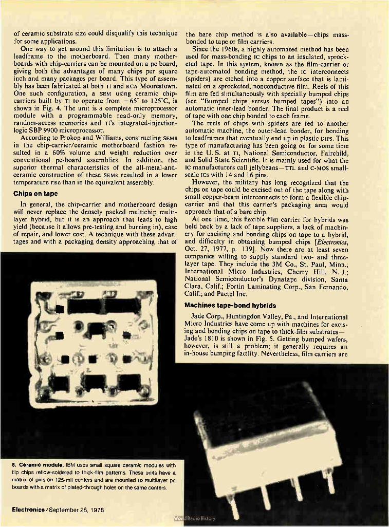
of ceramic substrate size could disqualify this technique for some applications. One way to get around this limitation is to attach a
leadframe to the motherboard. Then many mother-boards with chip-carriers can be mounted on a pc board, giving both the advantages of many chips per square inch and many packages per board. This type of assem-bly has been fabricated at both TI and RCA Moorestown. One such configuration, a SEM using ceramic chip-carriers built by TI to operate from —65° to 125°C, is shown in Fig. 4. The unit is a complete microprocessor module with a programmable read-only memory, random-access memories and Ti's integrated-injection-logic SBP 9900 microprocessor.
According to Prokop and Williams, constructing SEMS in the chip-carrier/ceramic motherboard fashion re-sulted in a 60% volume and weight reduction over conventional pc-board assemblies. In addition, the superior thermal characteristics of the all-metal-and-ceramic construction of these SEMS resulted in a lower temperature rise than in the equivalent assembly.
Chips on tape
In general, the chip-carrier and motherboard design will never replace the densely packed multichip multi-layer hybrid, but it is an approach that leads to high yield (because it allows pre-testing and burning in), ease of repair, and lower cost. A technique with these advan-tages and with a packaging density approaching that of
8. Ceramic module. IBM uses small square ceramic modules with
flip chips reflow-soldered to thick-film patterns. These units have a
matrix of pins on 125-mil centers and are mounted to multilayer pc
boards with a matrix of plated-through holes on the same centers.
Electronics/September 28, 1978
the bare chip method is also available—chips mass-bonded to tape or film carriers.
Since the 1960s, a highly automated method has been used for mass-bonding fc chips to an insulated, sprock-eted tape. In this system, known as the film-carrier or tape-automated bonding method, the IC interconnects (spiders) are etched into a copper surface that is lami-nated on a sprocketed, nonconductive film. Reels of this film are fed simultaneously with specially bumped chips (see "Bumped chips versus bumped tapes") into an automatic inner-lead bonder. The final product is a reel of tape with one chip bonded to each frame. The reels of chips with spiders are fed to another
automatic machine, the outer-lead bonder, for bonding to leadframes that eventually end up in plastic Du's. This type of manufacturing has been going on for some time in the U. S. at Ti, National Semiconductor, Fairchild, and Solid State Scientific. It is mainly used for what the ic manufacturers call jellybeans — TTL and c-mos small-scale ICs with 14 and 16 pins.
However, the military has long recognized that the chips on tape could be excised out of the tape along with small copper-beam interconnects to form a flexible chip-carrier and that this carrier's packaging area would approach that of a bare chip. At one time, this flexible film carrier for hybrids was
held back by a lack of tape suppliers, a lack of machin-ery for excising and bonding chips on tape to a hybrid, and difficulty in obtaining bumped chips [Electronics, Oct. 27, 1977, p. 139]. Now there are at least seven companies willing to supply standard two- and three-layer tape. They include the 3M Co., St. Paul, Minn.; International Micro Industries, Cherry Hill, N. J.; National Semiconductor's Dynatape division, Santa Clara, Calif.; Fortin Laminating Corp., San Fernando, Calif.; and Pactel Inc.
Machines tape-bond hybrids
Jade Corp., Huntingdon Valley, Pa., and International Micro Industries have come up with machines for excis-ing and bonding chips on tape to thick-film substrates — Jade's 1810 is shown in Fig. 5. Getting bumped wafers, however, is still a problem; it generally requires an in-house bumping facility. Nevertheless, film carriers are

available now and suitable to a fully automated approach consisting of automatic bonding of chip to tape; testing and burn-in on tape; and excising and bonding to the conductors of a thick-film substrate. On the other hand, there is no denying that this method requires an expensive initial capital investment.
cu-Honeywell-Bull, the major French computer mak-er, is now installing machines to produce film-carrier packages at its factory in Angers next year. The French firm calls its process TAB—for tape-automated bond-ing—and will use it mainly for current-mode-logic modules in computer mainframes. There will be some TAB packaging for fast bipolar memory too, but all n-mos chips will use standard DIPS.
In the Honeywell-Bull process, up to 36 chips-on-film can be mounted on a 2-in.2 piece of alumina. This substrate has four conductive layers for connections— one for logic, one for the supply voltage, one for ground, and one for the pads of the chips. A cooling-fin assembly is mounted on the bottom side of the substrate, as shown in Fig. 6.
TABLE 2: PACKAGING COMPARISON FOR A 20-CHIP DESIGN
Method Weight (gm)
Area (cm2)
Yield Cost
Printed-circuit board
Chip-carrier/ mother carrier
Hybrid
52
12
10
81
12
6
high
high
low
low
medium
high
SOURCE TEXAS INSTRUMENTS INC.
ege MUST BE SOLDERED r—,\ MAY USE INTERCONNECTING — If ELEMENT OR BE SOLDERED
REQUIRES INTERCONNECTING ELEMENT
Up to nine substrates are mounted on an 11-layer motherboard that measures 10.2 by 11.2 in. The mother-board has three logic connection layers, three ground planes, one layer for clock distribution, one for reference voltage, two for supply voltages, and one for the pads of the substrates. Center-to-center spacing between the motherboards is one inch. To cool the boards, a turbine forces air over the fins of the substrates. The Honeywell-Bull system, with its excised chips-
on-carriers reflow-soldered to the substrate, bears some resemblance to a hybrid module that the Phoenix-based Honeywell Information Systems used in the production of its now defunct System 66/85 and to another module in a joint Toshiba/NEC computer [Electronics, March 17, 1977, p. 90]. At Honeywell Avionics' hybrid facility in St. Peters-
burg, Fla., TAB is being used for military hybrids produced in smaller quantities. Honeywell Avionics uses its own 35-mm three-layer tapes and adds bumps to purchased wafers. A Jade inner-lead bonder is used to place the chips on strips rather than reels of tape. The tested and burned-in chips are excised, then the die is epoxy-bonded and the lead spider is thermocompression-bonded to a four-layer substrate by a Jade 4810 machine. A typical film chip-carrier bonded at Honey-well Avionics is shown in Fig. 7.
Honeywell Avionics has so much confidence in the process that it lays out all new hybrids in both chip-and-wire and TAB formats. These digital and analog hybrids, which are mainly on 1-by-2-in. substrates, use both Schottky-TTL and mos ics.
Rudolph Oswald, head of the hybrid microelectronics
100-MIL-CENTER VIA HOLES
9. Chip-carrier family. In order to further the use of chip-carriers on pc boards, the Jedec JC-11 committee created a standard for this family
of five different carriers. Each can be attached to a standard pattern of pads on 50-mil centers.
122 Electronics/September 28, 1978

avionics division of Honeywell, says: "We have found the yield with TAB much higher than with a comparable chip-and-wire hybrid. In my opinion, most people in the hybrid field are afraid of TAB because it means acquiring a good technical base covering bumping chips, tape design, and bonding, as well as a familiarity with multi-layer hybrid technology." Oswald sees TAB as the next big hybrid technology. He
is concerned that the U. S. will be bypassed by both the Japanese and Europeans in hybrids because, he says, more work is being done on TAB overseas and a great quantity of TAB equipment is going offshore.
Alan Kiezer, director of engineering at Jade, has indirectly confirmed Oswald's remarks. He notes that unlike the U. S., where only military and computer hybrids have been fabricated with the chips-on-tape method, European and Japanese firms are actively engaged in using the same method for high-volume production items like television sets, calculators, cameras and telecommunication equipment.
Bumped tape may simplify production
One reason for the slow acceptance of this method in the U. S. may be the need for bumped wafers, an added expense in wafer processing. A start has now been made in eliminating the need for bumped wafers—a bugaboo to the small and medium-sized hybrid producer inter-ested in acquiring a TAB capability. Dynatape, Fortin, 3M, and Koltron Corp. of Sunnyvale, Calif., are all working on testable bumped tapes, which would elimi-nate the need for bumping wafers.
General Dynamics, Pomona, Calif., has a Navy-funded program to look at the feasibility of bumped testable tape as a means of increasing hybrid yields. The firm has made its own bumped testable tapes and is evaluating samples from outside vendors on 1-by- 1 -in. multilayer hybrid substrates. Like Honeywell Avionics, the Pomona firm is working with Jade automatic equip-ment to excise the chip and spider, epoxy-bond the chip and thermocompression-bond the lead spider to a ceram-ic substrate.
Packaging engineers for the large computer main-frame companies have been observing the film chip-carrier activity in hybrids for some time. The ceramic chip-carrier, covering roughly half the area of a DIP, seems a better choice to these engineers as a smaller replacement lc package for the large multilayer pc boards that most computers use.
Since 1965, IBM has been using its own ceramic chip-carrier, a half-inch-square substrate with either a single chip or multiple chips bonded to a thick-film intercon-• nect. As shown in Fig. 8, this carrier has a matrix of pins on 0.125-in. centers. The pins are soldered into a fine-line multilayer board that has a matrix of pads and holes also on 0.125-in. centers. The basis of the chip-carrier was and still is a flip-chip technology, pioneered by IBM, in which chips are bumped for reflow soldering to the small ceramic substrate. This construction was the basis for the IBM System 370 models. Newer IBM ceramic modules can have as many as 72 input/output pins on 0.1 inch centers compared to 20 on the 1970 version. In both the old and new Ism computers, dual substrates are
Bumped chips vs bumped tapes
In the film carrier process special metalization layers are evaporated over an IC chip's aluminum intercon-nect pads. These built-up pads have come to be known as bumps. Their purpose is to protect the IC's I/O pads from the heat and pressure of mass bonding.
In order to eliminate the need for bumped chips and to allow the use of standard chips on tape, bumped tapes are now being developed. These tapes will have the special metalized bumps needed for mass bonding on the inner leads of each frame's copper microinter-connects or spiders.
Yet another version of the bumped chip is the IBM's flip chip. This semiconductor device is designed for face-down reflow soldering to a thick-film substrate.
In the flip chip process, an initial layer of glass is put down over the IC's surface. Via holes are then etched through to the IC's aluminum I/O pads. Additional metalization layers are plated on to the exposed pads, and then solder bumps, typically 6 mils in diameter and 4 mils high, are built up.
often stacked one atop another to increase memory chip density. The latest IBM computers mix a 1-in.2 version of IBM'S
ceramic carrier with standard ICS in DIPS. Both types are soldered to mounting holes in the same type of multi-layer board used in the System 370.
In 1976, interest in the use of chip-carriers on pc boards moved the Joint Electron Device Engineering Council task group JC11.3.1, consisting of mainframe, lc and LSI package firms, to create a standard for a family of small square devices that could be reflow-soldered to a standard pad pattern on a pc board [Elec-tronics, March 17, 1977, p. 88]. The standard called out two leadless ceramic types that required sockets, a plas-tic type with compliant leads, a ceramic substrate with solderable clip-on edge connectors, and a leadless chip-carrier on an epoxy-glass substrate.
All of these units were to fit on a standard square pc footprint on 50-mil centers. Figure 9 illustrates the vari-ous types of chip-carriers designed for reflow soldering to a pc board. At present, leadless types A and B shown in the diagram are commercially available. A socket for these types is being produced in sample lots at AMP Inc., Harrisburg, Pa., and in the developmental stage at Berg Electronic division of Du Pont, New Cumberland, Pa., The plastic package with compliant leads has been devel-oped at AMP but is still being evaluated. Leaded type B, a square substrate with soldered-on edge clips on four sides, is to be available soon. The edge clips are in pilot production at Berg. Mini-Pak, the last package, is used by General Instrument Corp. Hicksville, N. Y., for consumer-type mos chips, but is not available separately. Dan Amey, chairman of the Jedec JC 11 committee, is
engineering manager of packaging techniques at Sperry Univac, Blue Bell, Pa. He is now in the midst of a development program to make the transition from large multilayer boards with ECL ICs in DIPS to the same type of boards and circuitry with chip-carriers.
In one of Amey's projects, Sperry Univac supplied
Electronics/September 28, 1978 123

10. Chip-carriers socketed. This is an example of a 68-pin leadless ceramic chip-carrier mounted in a new AMP plastic socket. The socket is reflow-soldered to the printed-circuit board, and a finned heat sink maintains the proper junction temperature for the IC.
AMP with an existing dual in-line package memory ariay and its peripheral circuit on an 11-by-14.6 inch six-layer pc board. AMP was directed to re-layout the board so that the 84 22-pin DIPS in the memory array could be replaced with the leaded plastic AMP package. Peripheral circuits were to remain in DIPS. With the leaded chip-carrier the area taken up by the memory array was reduced by two thirds, demonstrating the packaging efficiency of the chip-carrier over the DIP. A similar size reduction could be accomplished for the entire unit if all ics were packaged in the premolded leaded chip-carrier. Despite its promising potential, the AMP unit must still prove that it can handle the environmental conditions encountered in computer applications. Amey is also evaluating a ceramic leadless carrier in
an AMP socket, a 68-pin heat-sink version as shown in Fig. 10, and a leadless carrier with Berg edge clips soldered on 50-mil centers.
In one application, Sperry Univac has put both small multichip hybrids and ceramic chip-carriers on one multilayer pc card. The hybrid, an assembly of ECL chips on a 1.35-in.2 three-conductive-layer ceramic substrate, has edge clips that are reflow-soldered to the substrate and then later to the pc board. The ceramic chip-carrier houses an ECL LSI chip and also uses an edge-clip mount. Amey points out that this mix of hybrids and chip.
carriers, both using edge clips as leads, is based on existing technology. Berg, for instance, has been making edge clips on 100-mil centers since 1971. The 50-mil-center edge clips for the ceramic chip-carrier present no
new problems, according to Jim Diliplane of Berg. Using the new space-saving carrier with leads on
50-mil centers will not mean the abandonment of the present-day 100-mil hole spacing on pc boards. Amey -points out that with 50-mil hole spacing, pc traces cannot be run between adjacent holes. The optimum layout for chip-carriers, says Amey, is to have all holes on 100-mil centers and all chip-carrier patterns on 50-mil centers. With this layout and 5-to-7-mil pc line-widths, at least two lines can be run between adjacent holes. It should be kept in mind that all the Jedec versions of the chip-carrier are reflow-soldered to a board and that the plated-through holes serve as vias between conductive layers, rather than as mounting holes for component leads.
Going against the tide
The Jedec spec on chip-carriers was based on the assumption that the leadless ceramic chip-carriers avail-able in 1976 (made by 3M and Kyocera International, Inc.) could not be soldered to standard pc substrates. It was thought that the differential coefficient between the carrier's ceramic and the pc substrate was too large and that the board and carrier would separate after thermal cycling. However, there are mavericks like John E. Fennimore, a member of the professional staff in charge of mechanical microelectronic design at Martin Mariet-ta's Aerospace division in Orlando. Fennimore has been reflow-soldering standard leadless ceramic chip-carriers to standard pc substrates for about two years. For exam-
124 Electronics/September 28, 1978
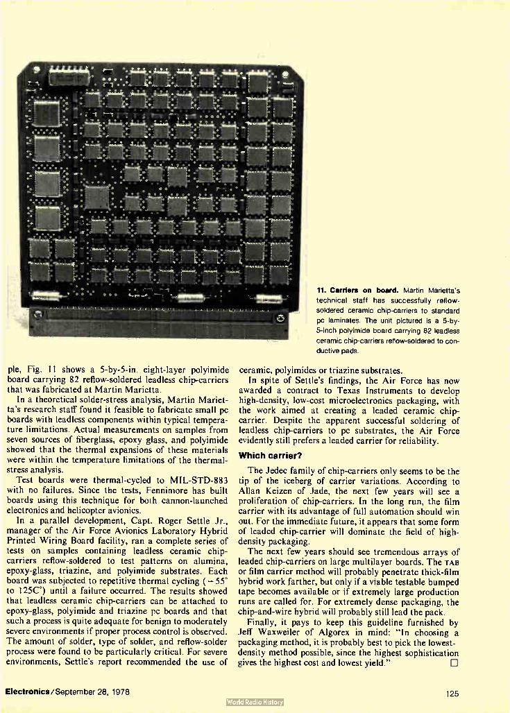
pie, Fig. 11 shows a 5-by-5-in. eight-layer polyimide board carrying 82 reflow-soldered leadless chip-carriers that was fabricated at Martin Marietta.
In a theoretical solder-stress analysis, Martin Mariet-ta's research staff found it feasible to fabricate small pc boards with leadless components within typical tempera-ture limitations. Actual measurements on samples from seven sources of fiberglass, epoxy glass, and polyimide showed that the thermal expansions of these materials were within the temperature limitations of the thermal-stress analysis.
Test boards were thermal-cycled to MIL-STD-883 with no failures. Since the tests, Fennimore has built boards using this technique for both cannon-launched electronics and helicopter avionics.
In a parallel development, Capt. Roger Settle Jr., manager of the Air Force Avionics Laboratory Hybrid Printed Wiring Board facility, ran a complete series of tests on samples containing leadless ceramic chip-carriers reflow-soldered to test patterns on alumina, epoxy-glass, triazine, and polyimide substrates. Each board was subjected to repetitive thermal cycling ( — 55° to 125C°) until a failure occurred. The results showed that leadless ceramic chip-carriers can be attached to epoxy-glass, polyimide and triazine pc boards and that such a process is quite adequate for benign to moderately severe environments if proper process control is observed. The amount of solder, type of solder, and reflow-solder process were found to be particularly critical. For severe environments, Settle's report recommended the use of
11. Carriers on board. Martin Marietta's
technical staff has successfully reflow-
soldered ceramic chip-carriers to standard
pc laminates. The unit pictured is a 5-by-
5-inch polyimide board carrying 82 leadless
ceramic chip-carriers reflow-soldered to con-
ductive pads.
ceramic, polyimides or triazine substrates. In spite of Settle's findings, the Air Force has now
awarded a contract to Texas Instruments to develop high-density, low-cost microelectronics packaging, with the work aimed at creating a leaded ceramic chip-carrier. Despite the apparent successful soldering of leadless chip-carriers to pc substrates, the Air Force evidently still prefers a leaded carrier for reliability.
Which carrier?
The Jedec family of chip-carriers only seems to be the tip of the iceberg of carrier variations. According to Allan Keizen of Jade, the next few years will see a proliferation of chip-carriers. In the long run, the film carrier with its advantage of full automation should win out. For the immediate future, it appears that some form of leaded chip-carrier will dominate the field of high-density packaging. The next few years should see tremendous arrays of
leaded chip-carriers on large multilayer boards. The TAB or film carrier method will probably penetrate thick-film hybrid work farther, but only if a viable testable bumped tape becomes available or if extremely large production runs are called for. For extremely dense packaging, the chip-and-wire hybrid will probably still lead the pack.
Finally, it pays to keep this guideline furnished by Jeff Waxweiler of Algorex in mind: "In choosing a packaging method, it is probably best to pick the lowest-density method possible, since the highest sophistication gives the highest cost and lowest yield."
Electronics/September 28, 1978 125
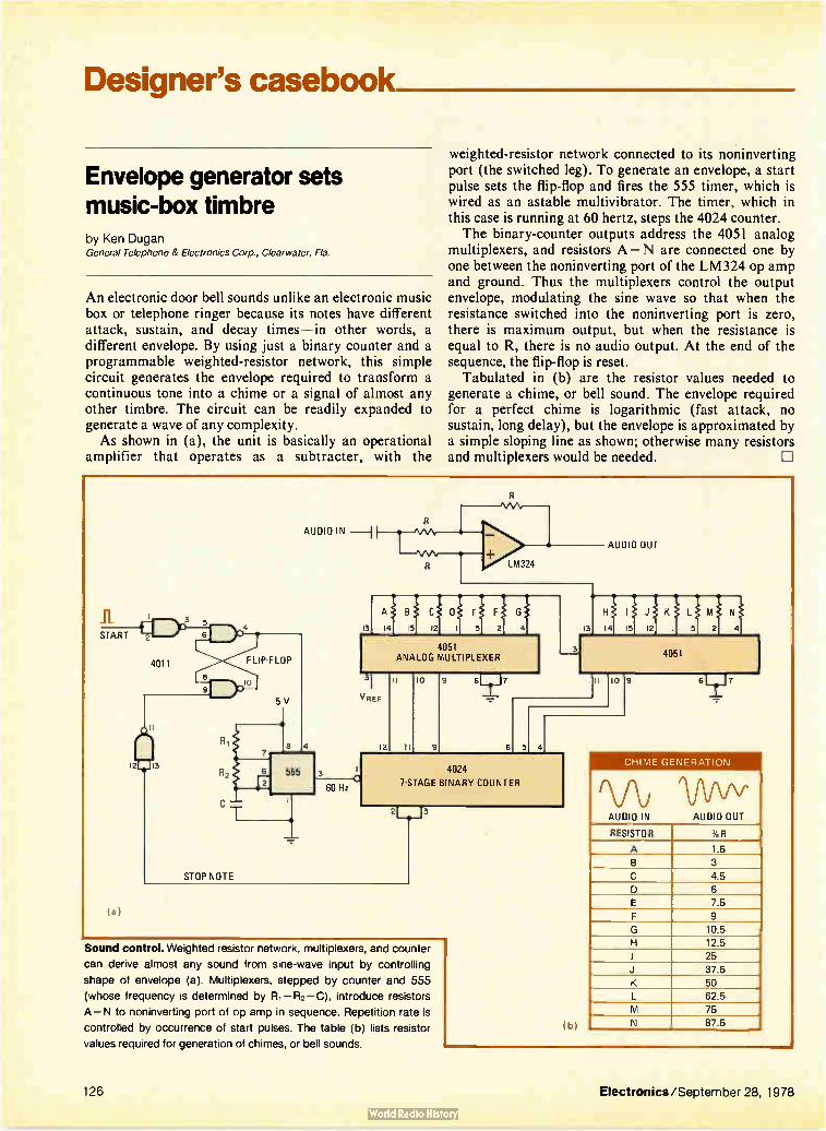
Designer's casebook
Envelope generator sets music-box timbre by Ken Dugan General Telephone & Electronics Corp., Clearwater, Fla.
An electronic door bell sounds unlike an electronic music box or telephone ringer because its notes have different attack, sustain, and decay times—in other words, a different envelope. By using just a binary counter and a programmable weighted-resistor network, this simple circuit generates the envelope required to transform a continuous tone into a chime or a signal of almost any other timbre. The circuit can be readily expanded to generate a wave of any complexity. As shown in (a), the unit is basically an operational
amplifier that operates as a subtracter, with the
weighted-resistor network connected to its noninverting port (the switched leg). To generate an envelope, a start pulse sets the flip-flop and fires the 555 timer, which is wired as an astable multivibrator. The timer, which in this case is running at 60 hertz, steps the 4024 counter. The binary-counter outputs address the 4051 analog
multiplexers, and resistors A — N are connected one by one between the noninverting port of the LM324 op amp and ground. Thus the multiplexers control the output envelope, modulating the sine wave so that when the resistance switched into the noninverting port is zero, there is maximum output, but when the resistance is equal to R, there is no audio output. At the end of the sequence, the flip-flop is reset.
Tabulated in (b) are the resistor values needed to generate a chime, or bell sound. The envelope required for a perfect chime is logarithmic (fast attack, no sustain, long delay), but the envelope is approximated by a simple sloping line as shown; otherwise many resistors and multiplexers would be needed. CI
START 2
4011
3 5 6
12E_113
STOP NOTE
FLIP.F LOP
o
5V
AUDIO IN --I
13
LM324
A B C$ E F G
14 15 12 I 5l 2 4
4051 ANALOG MULTIPLEXER
VREF
8 4 12 .11,1••••••••
6 555 3
60 Hz
10 1 17
6
AUDIO OUT
. 13 I4 i5 Jj
M N
2 41
4051
5 4
10
4024
7-STAGE BINARY COUNTER
Sound control. Weighted resistor network, multiplexers, and counter
can derive almost any sound from sine-wave input by controlling
shape of envelope (a). Multiplexers, stepped by counter and 555
(whose frequency is determined by R, — R2— C), introduce resistors
A — N to noninverting port of op amp in sequence. Repetition rate is
controlled by occurrence of start pulses. The table (b) lists resistor
values required for generation of chimes, or bell sounds.
9 6 7
CHIME GENERATION
AUDIO IN AUDIO OUT
RESISTOR %R
A 1.5
B 3
C 4.5
D 6
E 7.5
F 9
G 10.5
H 12.5
I 25
J 37.5
K 50
L 62.5
M 75
N 87.5
126 Electronics/September 28, 1978

VCOs generate selectable pseudo-random noise by James D Long Aerojet ElectraSystems Co., Azusa, Calif.
In this circuit, several voltage-controlled oscillators, whose outputs are summed in order to generate a suit-able feedback voltage to their inputs, are used to gener-ate pseudo-random noise over band limits that can be selected by the user. Using vcos makes possible a trans-fer function that is closer to the ideal and ensures that the circuit has better amplitude-versus-temperature stability than conventional generators, which rely on special and often expensive diodes to produce noise over a wide band. This generator will be suitable for many applications, producing random noise over a bandwidth of three octaves, with a crest factor (ratio of peak to true root-mean-square voltage) of three. The key to circuit operation is to generate a random
feedback voltage to the bank of vcos so that their output frequencies vary randomly, thus in effect producing noise. This task can be accomplished with the circuit shown in the block diagram. Note that the frequency of the feedback (modulating) voltage is unimportant so long as the maximum modulating frequency is less than any oscillator's output frequency. A single vco usually retains its linear input-voltage-
to-output frequency characteristic over less than one
octave. The three-octave bandwidth can be realized by operating several vcos over adjacent frequency bands (staggered tuning). Low-pass filters remove the higher-order harmonics contained in the square-wave outputs of the oscillators and the signal appearing at the output of the summing amplifier is similar to random noise. The feedback signal required to generate the random
noise is derived by first combining the output of all vcos in a resistive summing network. The output from the summer is a signal that contains zero crossings occurring at random intervals. A divide-by-64 circuit detects threshold crossings and
brings the summer signal down to a frequency range consistent with the requirement that the highest modula-tion frequency be much less than the total output frequency of the vcos. A narrowband (Q= 5) LC filter then smooths these random amplitudes into a continuous signal for the vcos' inputs. With proper scaling factors provided by the amplifier, the desired range of random frequencies can be generated.
Each vco is biased to its appropriate geometric-mean frequency and operates there if the modulation ampli-tude is zero. Attenuators al through a„ allow indepen-dent control of the deviation range of each vco, and the adjustable limiter permits control of the peak deviation frequency. The function of the adjustable limiter is to ensure that the oscillators do not deviate beyond their prescribed frequency bands. If the vcos' band edges are aligned so that no overlaps nor gaps occur between adjacent bands, the distribution of frequencies at the output of the summing amplifier will be uniform. Align-ment of the band edges is not difficult.
Si
ADJUSTABLE LIMITER
OTHER MODULATING GENERATORS
ATTENUATOR
I , > ATTENUATOR az
VOLTAGE-CONTROLLED OSCILLATORS: MOTOROLA MC1648
DUAL VCO 1
p.
ATTENUATOR a3
DUAL VCO 2
LOW-PASS FILTER 1
LOW-PASS FILTER 2
I, ATTENUATOR
AMPLIFIER
DUAL VCO 3
LOW-PASS FILTER 3
p. LOW-PASS FILTER 4
NARROW BAND FILTER
DUAL VCO
LOW-PASS FILTER 5
LOW-PASS FILTER 6
LOW-PASS FILTER n-1
p.
-11.•
64 DIGITAL DIVIDER
RESISTIVE SUMMER
LOW-PASS FILTER n
OUTPUT SIGNAL
SUMMING AMPLIFIER
In the noise. Method for generating noise uses summed outputs of voltage-controlled oscillators to generate feedback voltage that varies randomly with time, thereby causing frequencies of oscillators to vary in the same manner. System provides uniform noise output over three
octaves, with a noise-voltage crest factor of three. Generator can produce other waveforms if appropriate modulating signals are applied.
Electronics/September 28, 1978 127

Én CV
•
+•., (2)
(1) (1.)
(I)
nrc cz
o
c.) ,a)
0
,
c 0 (I) "C5
g
cu° o
4-+
Li)
'44 0 u4
cm. -0
co to
ct,t5 g, e
,
5
e
5 E
C) 0
,§)
=•-C.75
I)
e ”cl
(1) CU
CL) C
(nC"C$
(1)
2 t 3 a, e 8
0 •
o or. 0 ,
••;,.
6, gcvj
LID I in "CS
uj 4-eg
te)r.-• .5
-cs
e .5
a) e
.5 .8

This generator can produce signals other than noise. Switch SI may be used to apply any modulating signal to the vcos' inputs. For example, a sawtooth input signal
will generate a swept-tone output. If the vco has an inhibit input, it can be selectively activated so that pulsed tones can be generated. EJ
Multiplier, op amp generate sine for producing vectors by Jerald Graeme Burr-Brown, Tucson, Ariz.
To compute trigonometric functions of the kind that produce a vector from its X and Y components, a system needs to be supplied with signals that are proportional to the sines of the applied X and Y dc-voltage inputs. A multiplier, operating as a signal squarer, and an opera-tional amplifier, serving as a subtracter, will process the X or Y component more simply than other circuits now generally used. With these components, the desired waveform response for either input —the positive half of a sine function—can be approximated to within 5% of a perfect waveform, a value well within the limits that yield good computational accuracy.
Using the multiplier and the op amp to generate the sinusoidal transfer function is much easier than using diodes in complex circuits to synthesize the nonlinear response by producing a piecewise-linear approximation. Also, this circuit produces the sine response over the required — 90° to + 90° quadrant using one less multi-plier than existing analog circuits,' which generate the approximation by means of a long mathematical series or an equivalent method. The circuit shown in (a) processes the dc input voltage
that corresponds to either the X or Y component of the vector. The BB4213AM has a transfer function of G = X ' Y' /10, where X' and Y' are the inputs; it is made to square the input voltage, ei, when the X' and Y' ports are connected. The output of the squarer is then intro-duced into the inverting port of the BB3500 op amp, with e, fed to its input, so that:
e. = 3.86 (e,_ e 2 ) 10
But Eq. 1 can be expressed by:
e. -.1" 10 sin (br) , 0≤ e, ≤ 10 (2)
which results from a simple series approximation. This can be confirmed in the actual output-versus-input volt-age plot (b). Equation 2 may be scaled for other input-voltage ranges by changing the gain of the op amp.
Note that term 2 in Eq. 1 (representing the actual output response) has a second-order exponent, whereas a Taylor-series, which would yield a closer approximation to a sine wave, would have a third-order exponent of considerable magnitude in term 2. In spite of this differ-ence, however, Eq. 1 is reasonably accurate as evidenced by the error-curve plot (c), which peaks at 4% of full scale. Dominant distortion is related to the second and
(1)
e,
X COM-PONENT OR Y COM-PONENT
(a )
(b)
ERROR I% OF FULL-SCALE READING)
cl
o a,
10.2 ki2 39.2
e.
TO VECTOR-BB3500 PROCESSING
CIRCUIT
10.2 1c12 39.2 1d2
e. = 3.861e, — e12/101 10 sin lei/1017, O< ei < 10
10
5 10 e, (V dc)
Coordinates. Squaring and subtraction (a) of input wave from itself
produces a series approximation to a half sine wave (b). Two such
circuits, given X and Y coordinates in the form of dc-voltage inputs,
can generate output for systems suitable for computing vectors.
Approximation error (c) for half sine is within 5%.
third harmonics that are present at the output. An additional error term of up to 1% is introduced by
the inherent nonlinearities in the multiplier circuit's transfer function. The error introduced by the op amp, however, is negligible.
Referent:« 1. Burr-Brown, Model 4213 Product Data Sheet, PDS366, 1976.
Designer's casebook is a regular feature in Electronics. We invite readers to submit original and unpublished circuit ideas and solutions to design problems. Explain briefly but thoroughly the circuit's operating principle and purpose. We'll pay $50 for each item published.
Electronics/September 28, 1978 129

IC driver simplifies gas-discharge
bar-graph display Driver integrated circuit requires
only a handful of external components
and fits into many applications
by Robert Marshall, Signetics Corp., Sunnyvale, Calif.
LI For all their myriad possible uses, bar-graph gas-discharge displays have been standing on the design sidelines for a number of years now. A key reason for their second-string status has been their cumbersome and relatively expensive discrete drive circuitry, a handi-cap now eliminated by a bipolar large-scale integrated circuit. The NE 580 contains most of the electronics needed to
interface an analog voltage of a bar-graph display. These flat-panel indicators give digital accuracy to an analog measurement (see "What is a bar-graph gas-discharge display?"p. 133). Moreover, their soft neon orange glow is uniformly bright and pleasing to the eye, yet it possesses enough contrast to be comfortably visible in high ambient light.
Integrating the drive circuitry greatly simplifies the
use of such displays. All that is needed in the way of additional components are three capacitors, a high-voltage driver, and a couple of output-driver transistors for the display's anodes. These anodes do need a 250-volt supply, but small, low-cost 12-to-250-v dc-to-dc convert-ers are readily available these days.
Because the NE 580 is a dual driver with two indepen-dent analog inputs and two digital outputs, it can serve in applications where two interrelated displays are needed. It also can drive a light-emitting-diode bar graph and even can serve as a two-channel serial analog-to-digital converter. The block diagram of the display driver in Fig. la
shows the complement of components fitted onto the lc. The internal clock drives both a counter and ramp generator, and a single external capacitor (pin 4) sets the clock frequency. The counter addresses a read-only memory to obtain
the proper sequence for the phase decoder that generates the pulses illuminating the cathode segments. A single external pin sets the decoder for five-phase or six-phase operation (pin 3 low and high, respectively). Three-phase operation is simply a variant of the six-phase setup. Sample-and-hold and ramp capacitors are the two other external capacitors required.
In operation
Each segment of the display requires an anode control signal, and each cathode requires an interlaced logic signal with a 1/N duty cycle, where N is the number of trigger phases. The pulse width of these cathode signals is 50 to 100 microseconds, and they are generated continuously throughout the frame period, which is the total number of pulses required to illuminate the neces-sary number of cathode segments. The anode signal is on only for a portion of the time,
1. Inside information. The display driver consists of a clock generator, a counter, and a ramp generator, as well as a read-only memory. The
output voltage goes low when each 200-pulse frame starts and then high when the ramp voltage exceeds the input voltage.
VCC VREF
7
SAMPLE-AND-HOLD CAPACITOR
— H
RAMP-CONTROL — 1 ill_ CAPACITOR
10 INPUT A
PHASE GENERATOR
SAMPLE-AND-HOLD CIRCUIT
COUNTER
ANALOG 112 GROUND
(a)
RAMP
OMPARATOR
OUTPUT BUFFER
16
14
READ-ONLY MEMORY
PHASE DECODE OMPARATOR
OUTPUT BUFFER
15
13
22 21 20 19 17
PHASE 01 02 03 04 05 06 CATHODE CONTROL
INPUT B
j1 DIGITAL
" GROUND
OUTPUT A
OVERRANGE A
OUTPUT B
OVERRANGE B
130 Electronics/September 28, 1978

VCC
78HVO5
1).• JUMPER OPTION
0.22 µFT
78L02
*- 1 c, T 0.1 pF
Rl 10 kS2
0.22µF
3
18
12
7
C4 I , 0.022 µF 4 I
T II 0.4 C5 7µF 9 6
_L C6 -r- 8
0A71.1F
AIN
a,
0 7 NE 580
03
0 4
05
CATHODE RESET
INPUT CHANNELS BIN
83, 83
10 kS2
15 16
2
B+ (250 V)
R7
33 kS2
k70 V
2
22 3
21
20
17
a, 2N2618
AOUT
100 kS2
15
NE 5504
13
12
BURROUGH'S SELF-SCAN FIVE-PHASE 200-ELEMENT
BG 12205-2
112 3 4 5 6 7 8 9 10
BOUT
84
Wv 13 kS2
02 2N2618
R5 AAA, 13 kS2
R15
1 M12
R14 AA
22 kS2
R6 VV'-
22 kS2
2. Few extra parts. The drive circuit for a five-phase 200-segment bar graph requires the addition of a minimum number of discrete
components. Small, low-cost 12-to-250-V converters are available and therefore are not an impediment for this type of circuit.
corresponding to the time the input voltage is applied to the driver. Thus the input voltage equals a fraction of the reference voltage. That fraction consists of the number
INPUT B of cathode clock cycles for which the cathode is on divided by the number of segments in the display. The timing diagram (Fig. lb) shows the staircase
waveform making up the full-scale reference ramp that incrementally illuminates the cathodes. The clock gates a constant-current source to charge the ramp capacitor with the equal incremental steps, shown in the detail on the right of the figure. Each of these steps corresponds to a cathode phase pulse, but there are two steps per segment to allow sufficient sampling time. Thus the comparison of the analog input voltages with respect to
02 the ramp is made at the midpoint of each segment. In a 200-segment display, the counter inhibits the
03 current source after 200 cathode counts and discharges the ramp. The ramp voltage is strobed into the sample-and-hold amplifier, where it is compared with the refer-ence voltage and then fed back to the constant-current source of the ramp, thus restarting the cycle. The anode voltage goes low at the beginning of each
VNEF
INPUT A -
GROUND
OUTPUT A 1
OUTPUT B 1
b
0 1
0 4
Electronics/September 28, 1978 131

200-pulse frame and goes high again when the ramp voltage exceeds the input voltage. If the ramp voltage reaches full scale before the anode is high, the over-range output goes low until the input is within range.
Figure 2 shows the complete drive circuit for a typical
IN
RAMP
INPUT3
CATHODE PULSES
NE 580 DRIVER
PHASE DATA
ANODE SIGNALS
LM339
COMPAR-ATOR
ANODE SIGNALS
LOGIC GATING
MULTI-PLEXER
NE 5504
HIGH-VOLTAGE DRIVER
TO BAR GRAPH
EG 12203-2
3. Independent. Dual resettable bar graphs such as Burroughs'
BG 12203-2 share common cathode segments and have separate
anode connections allowing completely independent operation.
five-phase, 200-segment bar graph, the Burroughs BG 12205-2. Here the external high-voltage driver, the NE 5504, must be used. The 78HVO5 voltage-regulator chip provides the necessary regulated 5 y for the NE 580. A jumper option is included in the event that a regulated Vcc supply is available. The three-terminal 78L02 2.5-v regulator lc provides a stable reference signal for the 580, with its signal level adjustable with RI.
In setting the internal clock frequency for the driver chip, the timing-set capacitor, C4, determines the cath-ode pulse width, which equals two clock periods. The frequency can be approximated by f(kHz) = 0.555/C, where C is the timing capacitance in microfarads. To generate the 70-µs cathode pulses required by the
bar graph, a 0.019-µF capacitor should be used. Howev-er, a standard 0.022-µF capacitor will do: the clock frequency is set to 25 kilohertz, so with 200 phase outputs (400 clock pulses per frame), the frame frequen-cy is 25,000/400 or 62.5 frames a second. This frequen-cy is high enough to avoid flicker. The constant-current source in the ramp-generating
circuit is dependent on operating frequency. At 25 kHz, the current typically is 80 microamperes. The ramp-control capacitor, C5, should be a large Mylar or other low-leakage part. However, a C5 capacitance greater than 1 µF will diminish the output current's capability. For the BG 12205-2, the optimum value is 0.47 F. The sample-and-hold capacitor, C6, should have a
value above 0.33 µF and should exhibit low leakage in
+5 V
78L02
0.1 i./F
J_ 0.022pF CT
_L
0.047p - R F
6
Cs. I
0.047 p FT 8
ANALOG INPUT
3 5
5/6 Vcc
0 4
NE 580
RAMP
SAMPLE ANDROID
AIN
6
RESET
Aou
10
2 11
2 10
19 1, 34075
13
16
14
4
5
CLOCK
C04017
RESET
CARRY
12
CLOCK MR
A 7493
A CLOCK
2 e
8 9 12
3 4 5
+5 V
64 SZ
CA3082
34075
LIGHT-EMITTING-DIODE BAR
GRAPH
G
12 13 14
74145 BA
15
j— +5 V
4. Light-emitting-diode bare, too. Another display that can be driven by the 580 is the LED bar graph. By ORing three of the six phases, a
100-pulse clock is generated to drive the 100-element display. Display cycles at a flicker-free 70-Hz rate.
132 Electronics/September 28, 1978

What's a bar-graph gas-discharge display?
Gas-discharge displays, including bar graphs, consist of electrolytic elements in a neon-gas environment, sand-wiched between a plate of glass and a substrate (see figure). The cathodes forming the visible part of the display are printed in conductive ink on the substrate, which usually is blackened to enhance contrast. The anodes are continuous transparent bars printed behind the front glass.
In a bar-graph gas-discharge display, the cathodes are arranged as short segments in a column to give a ther-mometer-like effect when lit. The operating principle is what is known as glow transfer. When a big enough electrical pulse reaches the anode and a given cathode segment, the resulting gas ionization causes a visible glow in the cathode region. The charged particles around the glowing cathode then diffuse outwards toward the adja-cent unlit cathode.
This infusion of particles "primes" the neighboring cath-ode so that it will require a lower firing voltage for ioniza-tion to occur than in its unexcited state. Successive firing of the segments provides a continuous lighted bar. To start this process, an anode and cathode at the
bottom end of the display are kept permanently ignited. They act as the source of charged particles that lower the firing voltage of the first segment. To obtain an accurate representation of the quantity
being measured, a bar-graph display must be divided into a number of cathode segments, each representing a numerical increment. A typical display has 200 such segments, and it would be extremely complex and expen-sive to provide 200 outputs from the drive circuitry. Thus it is standard practice to connect the segments in a bus arrangement so that a few bus lines can drive many cathode segments. A simple setup would be a nine-segment display, driven
DRIVE ANODE
+ 250 V 0
DRIVE ANODE
FRONT GLASS
KEEP-ALIVE ANODE
SCREENED CATHODE SEGMENTS
KEEP-ALIVE CATHODE
RESET 4, o o
0 2
in three phases, with segments one, four, and seven on one bus line; segments two, five, and eight on the second line; and segments three, six, and nine on the final line. The three firing phases repeat cyclically. When the display is activated, the first segment will light
as soon as a pulse is applied to phase one. Even though segments four and seven are on the same bus line, they will not ignite because they require a higher firing voltage than is applied. However, once phases two and three have triggered segments two and three, the glow-transfer phenomenon will prime segment four for the next pulse on its bus line. Successive illumination of the segments will occur so long as the cycle of firing phases continue.
Applying the exciting pulses to the proper bus lines is a simple matter: it takes no more than incrementation of a counter synchronized to a clock. If the clock speed is too slow, the viewer will see the segments flickering. However, a flicker-free display may be obtained by maintaining the clock above a certain minimum frequency, which is typi-cally 70 hertz.
Most bar-graph gas-discharge displays have five or six phases, rather than three, but the bus arrangement is the same. No matter how many phases there are, the display appears as a continuous bar of light, a state of affairs that makes slowly varying signal inputs easier to interpret than with a digital display. These displays excel as analog indicators in such appli-
cations as process control, automobile dashboards and airplane cockpit displays, depth indicators, level indica-tors, and so on. An important advantage in these applica-tions is the lack of the mechanical hysteresis of a standard meter movement: thus the bar graph exhibits a much faster response. However, the response can be slowed by filtering the input signals, making hysteresis a designer option rather than a mechanical restriction.
RESET SEGMENT TO TRIGGER NEW SCAN
03
SCREENED INTERNAL THREE-PHASE BUSING
Electronics/September 28, 1978 133

5. Alter ego. Versatility is par for the course for the 580. Here it is wired up as a slow dual-channel analog-to-digital converter. Conversion times of 1 millisecond with 7-bit accuracy are readily achievable; with the variables shown, it is 16 ms.
order to minimize errors due to voltage droops when strobing the internal comparators. Pin 3 is grounded for the five-phase operation of the Burroughs display. The analog input voltages at Ain and 13,, may have an input range between 0 y and the 2.5-v reference, with limits set at —0.3 and + 7 v.
The anode and cathode outputs
The anode outputs A. and B. drive the bases of 2N2618 transistors, or their equivalents. These power transistors must carry 10 milliamperes of current and must withstand a breakdown of 250 v, which is the on voltage of the anodes. With the anodes off, these transis-tors drop the voltage to about 95 y because the anode off bias for the BG 12205-2 is specified at less than 100 v. The cathode output phases, 01 through 05, of the
NE 580 and the reset pulse, pin 17, drive a high-voltage Darlington array, such as the NE 5504. The Burroughs display requires a cathode off bias of 72 v, and the 5504's 10-v breakdown voltage can accommodate this bias. A 70-v zener sets the cathode off bias for the display. Resistor R15 limits the current for the keep-alive anode (pin 5) of the display, with the keep-alive cathode (pin 6) at ground.
Other phase schemes
As well as five-phase operation, the 580 can drive six-or three-phase displays. Moreover, it can easily be expanded to handle more input channels than the stan-dard two. All that is required is additional logic circuitry to multiplex the added input signals.
For six-phase operation, the only change necessary from the five-phase mode described is to keep pin 3 high. The sixth phase output then is available on pin 19. For three-phase operation, the outputs of the NE 5504 Darlington array are wire-oRed to provide display driver
circuitry that has three instead of six phases. Driving multiple displays showing the same data is
another possibility. All it takes is additional external comparators to control the anodes of the additional displays and a few logic gates. Proper timing is main-tained by strobing these comparators when the ramp is in a hold mode. An anode blanking signal generated for each added display is active when all output phases are low. The cathode phasing is common to all displays.
Another kind of display that can be driven by the 580 is a dual resettable bar graph, in which the cathode segments may be scanned from either direction or from both directions simultaneously. Thus each bar may display two separate columns of data.
Dual resettable bar graph
One such display is the Burroughs 203-element dual resettable self-scan bar graph. The BG 12203-2 is configured as a flat panel indicator displaying two bars. The two bar graphs have common cathode segments and separate anode connections for independent operation. The external logic required by the display can be
generated easily with the 580 and multiplexing circuits (Fig. 3). The driver ic has the anode controls for two inputs plus the logic for generating the phase data to drive the display. External comparators compare the extra analog input signals with the driver-generated ramp. The anode output signals are multiplexed synchro-nously with the appropriate cathode pulses.
For the three-phase mode of the BG 12203-2, the logic circuit must generate two reset pulses (RI. and RB for the top and bottom displays, respectively) and 201 clock pulses (the extra pulse insuring complete turnoff of the anode voltage). When a reset pulse is applied to one end of a bar, cathode scanning runs from that end until the full data input is displayed. The logic then discontinues
134 Electronics/September 28, 1978

FLOAT LEVEL
GAS TANK
AIN
8 1N
ENGINE SPEED
DISTRIBUTOR POINTS
TACH
SPEEDOMETER
CRANALL
NE 580
CATHODE PHASING
ANODES OUT
CLOCK
OIL PRESSURE
COOLANT
Ay TEMPERATURE
FUEL FLOW
SERIAL OUTPUT TO MICROPROCESSOR OR MONITOR SYSTEM
LOGIC AND
GATING CIRCUIT
HIGH-VOLTAGE DRIVER
ANODE GATES
CATHODE PHASING
ANODE GATES ..01
"ULLII
ANODE GATE
ANODE GATE
LINEAR BAR GRAPHS
CIRCULAR BAR GRAPHS
6. A process-control application. In an automobile instrument panel, the 580 drive circuit plays an important role in monitoring and
controlling key engine parameters by feeding data back to a microprocessor, as well as displaying the parameters for the driver of the car.
the scan and activates the reset at the other end of the panel. The cathode clock count is then picked up at the proper phase, and reverse scanning takes place.
Although the NE 580 was designed primarily to drive a gas-discharge bar graph, it can be used as the control element of a light-emitting-diode bar graph (Fig. 4). Operated in the six-phase mode, the cathode pulse count from the driver will total 200. However, most LED bar graphs require only 100 pulses, so °Ring three of the six phases as shown generates a 100-pulse clock that updates a CD 4017 decade counter/divider.
The LED setup
The reset pulse from the 580 initializes the counter circuits to zero and inhibits the display by driving high the C and D pins of the 74145 binary-coded-decimal/de-cade decoder. When the reset pulse goes low, the decoder actuates cathode A of the bar graph. The clock pulses step the counter through, illuminating each anode of the bar graph sequentially until the 7493 counter reaches 10. The counter then outputs a carry, incrementing the ripple counter while the decoder activates cathode B of the display, and so on.
During this sequence, the A. signal of the 580's ramp voltage rises to exceed the analog input voltage. When this occurs, A. goes high and inhibits all outputs of the decoder. This completes the frame, and the cycle can begin again.
One timing capacitor
The complete cycle time is again controlled by the single timing capacitor of the 580. With the values shown in Fig. 4, the display is cycled at a 70-hertz rate and thus is flicker-free. The anode resistors of the bar graph control the display's brightness. To generate the bar-graph control signals, the NE 580
must perform an analog-to-digital conversion. It takes only three additional chips to configure the lc as a dual-channel a-d converter (Fig. 5).
Here, the A. and B.„1 signals are oRed together to provide a multiplexed scheme for numerous conversion systems. The outputs go low at the leading edge of the reset pulse, and they remain low for a period dependent on the analog input levels at Ain and Bin. The output signals can be used as gates for the inter-
nal or external clock. In effect, their pulse widths are direct functions of the amplitude of the input voltage signals. The input is restricted from zero volts to the Vre, 2.5-v maximum. A full-scale transistor-transistor-logic signal of 400 counts results at the output. The conversion time depends on the input volta -_,es.
With the values shown, conversion time is 16 mili'sec-onds. However, conversion times of 1 ms with ", bit accuracy are achievable.
Many control uses
The single-supply and dual-channel operation makes the NE 580 an ideal candidate for many process-control conversion circuits that do not have high-speed require-ments. One such system (Fig. 6) is an automobile instru-ment panel, but the same basic application can be used in any process-control system.
Here the output digital information can be gated into a microprocessor control system. Thus, in addition to providing status indications to the driver, the 580 can take part in the engine monitoring and control functions through a microprocessor feedback loop.
Both circular and linear bar graphs may be used for the display. The serial output format to the processor minimizes the necessary wiring, permitting serial-to-parallel conversions, which the processor can easily be programmed to perform. El
Electronics/September 28, 1978 135
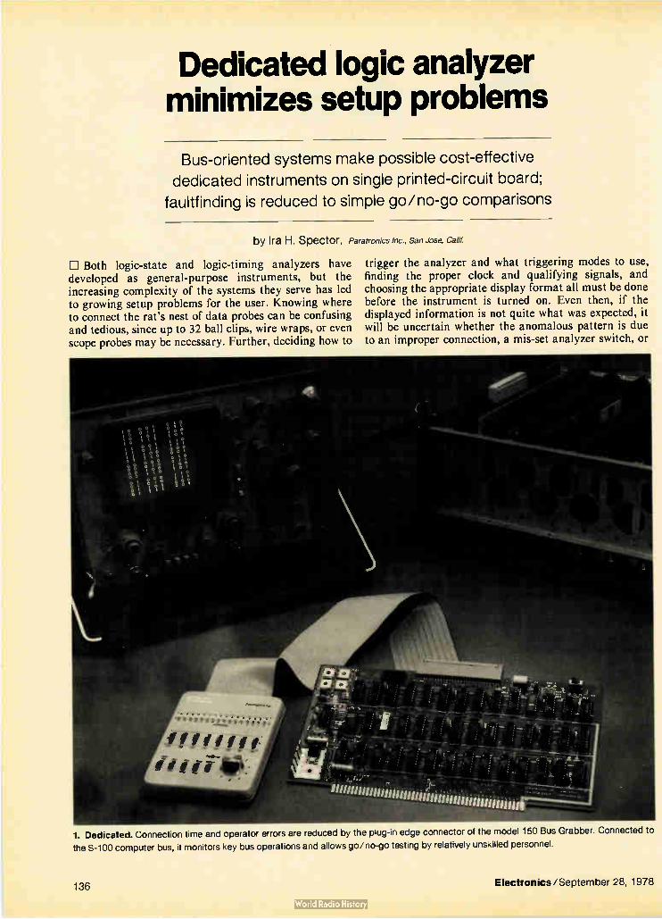
Dedicated logic analyzer minimizes setup problems
Bus-oriented systems make possible cost-effective
dedicated instruments on single printed-circuit board;
faultfinding is reduced to simple go/no-go comparisons
by Ira H. Spector, Paratronics Inc., San Jose, Calif.
1:1 Both logic-state and logic-timing analyzers have developed as general-purpose instruments, but the increasing complexity of the systems they serve has led to growing setup problems for the user. Knowing where to connect the rat's nest of data probes can be confusing and tedious, since up to 32 ball clips, wire wraps, or even scope probes may be necessary. Further, deciding how to
trigger the analyzer and what triggering modes to use, finding the proper clock and qualifying signals, and choosing the appropriate display format all must be done before the instrument is turned on. Even then, if the displayed information is not quite what was expected, it will be uncertain whether the anomalous pattern is due to an improper connection, a mis-set analyzer switch, or
***
smiromnitintuntimunimiumunnif
1. Dedicated. Connection time and operator errors are reduced by the plug-in edge connector of the model 150 Bus Grabber. Connected to
the S-100 computer bus, it monitors key bus operations and allows go/no-go testing by relatively unskilled personnel.
136 Electronics/September 28, 1978

2. Monitoring capability. Fifty-six critical S-100 bus signals and eight optional data signals can be monitored and displayed. The control pod
selects the desired format display, as well as which 16-bit address, 8-bit data signal, or combination of the two to trigger upon.
a new and unsuspected circuit problem. The problems inherent with both types of analyzer can
be reduced by the use of a dedicated instrument. Such an analyzer is made possible by the bus-oriented design of many modern systems. Designed as a single printed-circuit board, it can be plugged into any slot in a bus-oriented system. Thus, there are no probes to connect: address, data, and qualifier information are fed to the analyzer through the edge connector by the bus itself. In addition, the number of signals monitored is limited only by the number of pinouts on the card edge. In the case of the popular S-100 computer bus, up to 100 pinouts can be monitored by a dedicated logic analyzer (Fig. 1).
Dedicated to the S-100
Since the analyzer is a single pc board without the embellishments of a front panel, numerous probes, sepa-rate power supply, and external packaging, its price can be such that it may be economically dedicated to an individual system. To test this concept, Paratronics Inc. dedicated one of its general-purpose logic-state analyzer designs to the S-100 computer bus. This bus was chosen because it has become a de facto standard among many users of low-cost microcomputer systems. For these applications, the dedicated analyzer's low cost, simple operation, instant bus access, and ability to display many levels of programming and status are particularly desir-able features. The result is the model 150 Bus Grabber, a one-board
logic-state analyzer that plugs into any S-100 system.
00 111 010 10 000 000 00 000 000 01 010 101 01 000 111 00 111 010 10 000 001 00 000 000
18 ó8à 8à8 00 110 010 10 000 010
?? 888 ?88 88 888 88?
Connected by flat cable to an external, hand-held control pod, it can monitor 56 key S-100 bus signals, including 16 address lines, 8 data-in lines, 8 data-out lines, 8 lines each for microprocessor status and control, and 8 vectored interrupts (Fig. 2). In addition, four shielded cables bring out the X, Y, Z, and trigger signals to external BNC connectors for scope readout. A second flat-ribbon cable allows additional monitoring of eight signals outside the system.
Currently, the only dedicated logic analyzers are the model 150 and the Datalyzer by Databyte Inc. of Mid-dleton, Wis. But it is easy to visualize similar products being developed for the IEEE-488, the RS-232, and Intel's SBC-80 bus. Although it is important to monitor many points in a
computer system, it is unnecessary to monitor them all simultaneously. In fact, if the model 150 provided room in its 16-word, 8-megahertz memory for 56-bit-wide words, it would no longer be economically feasible to dedicate the instrument. Instead, the emphasis is on monitoring 8-bit sections of the bus and on switching between them on successive tests.
Monitoring technique
The model 150 stores the post-trigger or pretrigger information from the selected 8-bit bus section in its 8-by-16-bit data memory; the corresponding lower 8 bits of address are stored in its 8-by-16-bit address memory. The control-pod switch determines which 8-bit bus section will be fed into the data memory or, instead, whether the lower 8-bit address memory will be
Electronics/September 28, 1978 137

What logic analyzers do differently
Logic analyzers have three big advantages over traditional methods of digital troubleshooting. Perhaps the most significant is the ability to record multiple channels simul-taneously. Logic analyzers also can easily trigger upon a unique selected condition (address or data word or a combination of the two) among the many channels moni-tored, and the same trigger can be used to stop the data-collection process as well. These features allow the examination of multichannel
events occurring both before and after a system crash, and if desired, triggering on the crash itself. Logic analyzer sales have increased dramatically in response to these capabilities, as have a demand for more channels, greater sophistication, and less expensive units. As a consequence, several features have been added
as these instruments have matured. The data-sampling rates of logic-timing analyzers made by companies like Biomation Inc., E-H International Inc., and Tektronix Inc. have been greatly increased (20 to 200 megahertz) to be faster than the system under test, retaining in their large memory perhaps five bytes of data for every system clock interval. Also, the glitch-capturing capability now usually included in the triggering circuitry is extremely helpful.
Logic-timing analyzers are better than logic-state analyzers in solving system problems that are analog in nature (for instance, showing the position in time of switching waveforms). Therefore, if the problem involves a race condition, a logic-timing analyzer can display it best.
However, most system problems result in changes in the system's state. It is therefore possible to detect such problems by using the system clock to drive the logic analyzer. Thus, companies such as Hewlett-Packard Co. and Paratronics Inc. concentrated on developing the logic-state analyzer. Since such instruments need operate only as fast as the data rate of the system under test, usually under 10 MHz, they are often less expensive than logic-timing analyzers.
Logic-state analyzers can simultaneously record up to 32 channels of data and display the sequence of states in various formats (octal, hexadecimal, binary-coded-deci-mal, and so on). This capability, along with the ability to selectively trigger on a unique sequence of states, elimi-nates the need for a large memory capacity, since only the data of interest is recorded. In addition, these units can handle analog problems by transmitting a trigger pulse to a scope to allow viewing the state-dependent waveform.
displayed on the scope. The lower address byte is recorded along with the data byte because it is the single most important reference for tracing program flow.
Triggering
Triggering is also extremely important. Often the need arises to trigger on a 16-bit-wide address word, and sometimes on an 8-bit data word at the same time. The model 150 provides a 24-bit-wide trigger, plus the ability to trigger on data only or address only. The data switches have three positions, for high, low, or "don't care" triggering modes. A separate switch on the control pod determines whether pretrigger or post-trigger data is collected. The analyzer has two modes: single and repetitive.
The single mode allows display of a particular logic sequence at any given instant, for detailed analysis, whereas the repetitive mode permits dynamic analysis of a sequence. In the latter mode, the analyzer captures a data table, displays it, then immediately resets itself to capture another data table, thus making it possible to tell whether a counter is counting up or down. Of course, an oscilloscope is required to display the analyzer's output of binary is and Os, which are formatted in octal or hexadecimal grouping by a switch on the control pod.
Having these features available in a logic analyzer that is in effect already on board in a S-100 system adds tremendously to the system's self-diagnostic power. As a practical example, consider the debugging of an S-100 turnkey system. Such a system would not normally have the traditional control-panel functions of single-step, trap, break-point, or data monitoring, but these func-tions have the traditional shortcomings of being only one word deep and of interrupting the program flow. The system may have a diagnostic routine, say, a
monitor program, written into its software. For this
program to work, however, the central processing unit, memory, and input/output systems must be working correctly, and of course, the monitor program itself must be debugged. Take the not unlikely case that something is wrong in
the S-100 system's hardware or in its bootstrapping program. The computer is turned on, but the terminal does not print out a ready indication. Immediately, the monitor program itself becomes suspect.
Debugging the bootstrap
To check it, the logic analyzer can be set to trigger on the monitor program's starting address. If the analyzer triggers, then the system has entered the program and the monitor's first 16 steps are observable. If not, the address trigger can be set to "don't care" and the analyz-er will display what addresses the computer is accessing. A struck address bit may become evident here. If the addresses look good, then a similar snapshot, or single mode, with all triggering criteria at "don't care" can be taken of the data-in bus. Again, any struck bit would show up.
If the monitor program is being executed correctly, the problem is probably in the uo subsystems. Setting the analyzer to trigger on the starting address of an uo routine allows the data being read from the keyboard to be checked. Also, the data going to video display can be checked by setting the selector switch on the control pod to allow monitoring of the data-out bus.
If the computer itself appears to be operating correct-ly, the problem is probably in one of the uo devices. Connecting the analyzer's external data-input probes to the peripheral device, and selecting external data for monitoring, causes the uo data transfers and handshak-ing operations to be displayed. The difference that such an analyzer can make in a
138 Electronics/September 28, 1978

START
1
DEFINE SIGNALS TO BE
MONITORED
SPECIFY MEMORY SIZE (WIDTH AND DEPTH)
DESIGN INPUT BUFFERS AND
LATCHES
DETERMINE TRIGGERING
MODES
L.... SPECIFY DISPLAY FORMAT (BINARY,
HEXADECIMAL, ETC.)
DESIGN MEMORY LOGIC
DESIGN POO TRIGGERING CONTROLS
DESIGN CHARACTER-GENERATOR
AND POD-FORMATTING CONTROLS
NO
DOES DESIGN SATISFY BOARD SIZE, POWER, AND PINOUT
CONSTRAINTS?
YES ) FINISH
3. Design steps. Flow chart illustrates development procedure for a dedicated logic analyzer. Early planning and incorporation of the
analyzer into the design can result in cost-effective product development, not to mention simplified production testing and field servicing.
system is the difference between trying to guess or infer whether a malfunction exists and actually seeing it. The preceding example may sound like a problem in research or development, but it could just as easily happen in production testing or in the field. A dedicated logic analyzer provides additional advan-
tages for both production testing and field service: in both, testing becomes faster and surer because the user is not encumbered with numerous probe disconnections and reconnections. Also, in either context, the task of finding a system fault no longer requires an intimate knowledge of the system's engineering. Faultfinding at the board level is reduced to a simple go/no-go compari-son of expected data tables with the actual scope display. This task can be performed by relatively unskilled test personnel: the operator simply selects the appropriate bus to monitor, sets the address and/or data trigger word, then views the scope.
Considering the cost
Finally, there is a choice of how far to carry the concept of analyzer dedication. If an S-100 system is sufficiently complex, putting a model 150 in each system that is shipped may be economically justified (the model 150 costs $449). If not, the system can be shipped with a blank pc-card slot. Dedicated logic analyzers can then be
stocked by production test and field service personnel and slipped into the blank slot when analysis is required.
Ideally, the dedicated logic analyzer would be planned for and designed in at the earliest stages of product development so that its utility could be maximized.
Designing in
First, the project engineer should define which signals can be monitored given the pinouts and board size avail-able. In choosing these signals, thought should be given to systems integration and the requirements of produc-tion testing and field maintenance, as well as those of the immediate development system application. Fortunately, many of the signals requiring monitoring, such as those on the address and data lines, are common for all these applications. The rest of the design tasks, such as defining the width and depth of the data memory and the display format, are summarized in Fig. 3. When the circuitry is defined and the mechanical
outline is known, the analyzer board can be treated just like any other pc board in the product. And since the control pod is a plug-in unit, primarily containing switches, its development can proceed in parallel. In addition, because of its simplicity, the same pod design can be used for a variety of different dedicated analyzer boards. EJ
Electronics/September 28, 1978 139

Biomation invented the glitch fixer. Our new 9100-D logic analyzer combines the useful features and advanced capabilities you need for fast, effiçient troubleshooting of digital systems. The 9100-D enables you to record up to nine digital signals
simultaneously, each in a 1024-word memory. And it records at a full 100 MHz, with Latch Mode for capturing glitches as narrow as 5ns.
We've added a new and useful feature to our newest logic analyzer - an LED numeric readout of trigger delay, cursor position and selected time interval. So analysis of captured data is easier and more precise. Check all the features of the 9100-D. Then check with our
Ed Jacklitch to arrange a demonstration in your lab. Call (408) 988-6800. Or, for more information, write Gould/ Biomation Division, 4600 Old Ironsides Drive, Santa Clara, CA 95050.
Now we've made it even better.
INTERNAL CLOCK
01
CZ> ir
Lei c.
100 MHz speed Dial in clock rate, from 100 Hz to 100 MHz.
CH9
Nine channels Ideal for debugging 8-bit-plus-parity systems.
DELAY/CURSOR
1-1 Ci Ci
INC ma DELAY 411,
CURSOR e DEC
CURSOR •
CLEAR I
MI6 SET
LED readout For precise measurement of trigger delay, cursor position andtime intervals.
QUALIFIERS
TRIGGER CLOCK
1 1 Qualifier selection Control data recording with clock and trigger qualifiers.
•-11 g '
Trigger position Marks trigger on CRT, LED readout shows trigger position.
Expansion from movable cursor Cursor position determines where expansion of display begins.
Precise time interval measurement Readout indicates clock periods between selected cursor positions.
Trigger on 30-bit words Optional 10-IC Probe Pods extend trigger word from 10-bit trigger.
INPUT MODE CH 1-4 CH 5-9
SMPLII
'LATCH
Latch/sample selection Catch glitches of 5ns or narrower, using Latch Mode.
A portable performer The 9100-D is compact and light, and connects to any oscilloscope with simple two-cable hook-up.
Gould Inc., Biomation Division 4600 Old Ironsides Drive Santa Clara CA 95050
Circle 140 for Information

C-MOS codec splits transmitting, receiving sections
Design makes for high isolation,
ease of use, and low power dissipation
K. B. Ohri and M.J. Callahan, Mostek Corp., Carrollton, Texas
Why the boom In codecs
The current trend in telecommunications is toward the conversion of voice signals to digital information, with pulse-code modulation emerging as the most popular method. Once converted into a serial data stream, the voice signals are far more easily manipulated: the data can be compressed for extremely high-speed transmission between the phone company's central offices, for exam-ple, without the loss of integrity that analog transmissions would suffer. What's more, if data streams corresponding to individual voice signals are ordered into specific time slots—or time-domain-multiplexed—the interconnection of two circuit paths can be carried out essentially in software: computers at each end simply agree on a common time slot. In short, all-digital switching will, in time, supplant the electromechanical cross-reed switches that switch the bulk of today's phone conversations. The semiconductor industry as a result sees a huge
market opening up for chip versions of the coder-decod-ers that are vital elements in these new phone systems. The accompanying article from Mostek Corp. is the third of a series of articles on chip codecs [Electronics, Sept. 28, p. 108 and p. 1111
CI In the MK5150 coder-decoder, the use of one digital-to-analog converter in the coding section and another in the decoding section has several advantages. For one, it improves performance, because the isolation between the transmitting and receiving circuitry greatly exceeds that of the more common shared-converter approach. For another, it makes the device easier to use, because the transmitting and receiving sections are separate and can even be clocked at different rates. As a bonus, the MK5150 has a signaling capability that conforms to standard D3 channel-bank specifications.
All this fits on a 170-by-184-mil chip built with metal-gate complementary-metal-oxide-semiconductor tech-nology, which offers the low power consumption required in telecommunications. Though the chip may be larger than other integrated codecs, novel design has minimized the number of on-chip analog circuits, which are more likely to impair yields than digital elements.
Metal-gate c-mos is used for several reasons. The process makes for high-quality matched capacitors of minimum size. It builds analog circuits well—particu-larly high-gain amplifiers and comparators. And it can
Electronics/September 28, 1978 141

1. Split system. The Mostek MK5150 codec has separate transmitting and receiving sections, with a 13-bit digital-to-analog converter in
each. The converters are linear, keeping the number of on-chip analog components to a minimum for improved yields. Signaling is built in.
125 ms
TRANSMIT PREVIOUS SAMPLE TRANSMIT SYNCHRONIZING LINE
80 ps
AUTO-ZERO AND SAMPLE-AND-HOLD
ENABLE SAR
ENABLE SUCCESSIVE- r APPROXIMATION
REGISTER
UPDATE-OUTPUT REGISTER
RECEIVE SYNC LINE
141— 20 ¡is — ill
n. RECEIVE NEXT SAMPLE
UPDATE ANALOG OUTPUT
—0.1 5 bis
2. Timing. Each of the 125-microsecond frames carries both data being received and data being transmitted. A period of 2 to 5 microseconds
separates the encoding from the decoding operation; the variable interval allows for completion of the encoding.
142 Electronics/September 28, 1978

+VREF
VREF
1.016 pF
pFI 1 pd.
-I — _
2 pFI 4 pd.. 8 pFI 16 pF.I_
—
32 ptl_
—
I IIIIIIII.
1 pF 2 pF — 4 pF 8 pF 16 pF — 32 pF 64 p
I I I , . 1 . I I 1 1 I 1
9
•
a- 9 0 9 ar 0 or 0 Jr- 0 •-
o
•
d-a CONVERTER OUTPUT
3. The converter. The MK5150 uses a pair of switched-capacitor-type digital-to-analog converters. Since companding is done digitally with
an 8-bit-to-13-bit converter, a linear d-a converter with full 13-bit resolution is used.
be applied with confidence to high-volume production. The 5150 does require a ± 5-volt supply, however. But
it minimizes power dissipation by running its logic section from the +5-v line to ground. The entire 10-v swing drives only the analog section, which is by far the smaller portion of the chip. The codec typically dissi-pates 30 milliwatts at room temperature.
Architecture
The block diagram of the codec (Fig. 1) reveals impor-tant features of the encoding-decoding scheme em-ployed. As noted, the 5150 uses not one but two digital-to-analog converters for encoding and decoding data, making it easy to use and giving it a system isolation unattainable with a shared approach. What's more, the d-a converters are the capacitive type and so require no external sample-and-hold capacitors. Nor is an external filter needed for auto-zeroing, as it would be with a shared converter.
The block diagram also shows how few elements are required to handle analog signals. In fact, there are only two on the entire chip: a comparator and a single op amp. The reason is that the data-compression/expansion scheme carried out according to telephone company specification is implemented with a digital 8-to-13-bit converter, which allows the use of a linear 13-bit d-a converter. The analog components use the full 10-v swing of the power supply, so having as few of them as possible on chip means lower power consumption.
Because the receiving and transmitting sections oper-ate independently, the chip can use synchronous or asyn-chronous modes at various input and output clock rates.
Operating modes
The chip timing diagram is shown in Fig. 2. In the receiving mode, the input data is shifted serially into the input buffer at the receive-clock rate and thence in parallel into the decoding section for as long as the receive-synchronizing line is high. After the falling edge of the receive-sync pulse, the encoding process is halted for about 2 to 5 microseconds while the data is processed through the 8-to-13-bit converter. The result then is
wi, cr, vr 64
WHERE
1.016 pF
F
64 pF
7
E n=1
d-a CONVERTER OUTPUT
Wr, C„ V,
127
Wn = O OR 1 FOR THE nT" BIT
Cn = riTH BIT CAPACITOR
V, = REFERENCE VOLTAGE (+VREF OR -VREF)
4. Equivalent. The two sections of the d-a converter (a binary-
weighted capacitor ladder) can be represented with an equivalent
circuit. The capacitances are the sums of various elements; the
converter output can also be written as a sum of voltages.
latched into the 13-bit receive latch, which updates the output of the receiving d-a converter with a 100% duty cycle. The receiving converter acts as a sample-and-hold circuit and its output is buffered by the unity-gain operational amplifier.
During each signaling frame (which is every sixth I 25-microsecond period in the 12-frame standard data format), only a 7-bit decoding operation is performed and the eighth data bit is latched into either the A or the B signal output latch—whichever is selected by the A/B-select input in the receiving section. This eighth bit is a signaling bit and is assigned the analog value of 1/2 step; the result is a lower signal-to-distortion ratio than if it were set arbitrarily to either 1 or 0.
In the transmitting mode of operation, the analog signal is sampled by the input sample-and-hold circuit, which simultaneously performs the auto-zero function, and is encoded by a successive-approximation technique. The d-a converter in the transmitting section operates much like the one in the receiving section. Once the encoding process is complete, the output of
the successive-approximation register is loaded into the
Electronics/September 28, 1978 143

50
VIN 128 pF
1 St
S2
5. Multifunction. The capacitor ladder also does auto-zeroing and
sample-and-hold. It stores the offset voltage with switch S, connect-
ed to V„-, and S2 closed. With S, at ground and S2 open, the op amp
acts as a comparator while the ladder performs the d-a conversion.
output buffer. The data is transmitted serially at the output clock rate for as long as the transmit-sync line is high. A or B signaling information is inserted during the signaling frame into the output bit stream in place of the eighth data bit as determined by the A/B-select input line in the transmitting section of the codec.
About the circuit
The sequence controller, which is driven by a master clock rate ranging from 1.544 to 2.048 megahertz, keeps the system in step with itself. All timing signals for sample-and-hold, successive approximation, and so on, are generated in that section. To ensure proper encoding, a decoding intérrupt is allowed only when the successive-approximation register clock line is low. The decoding interrupt interval therefore varies from 2 to 5 his. The 8-to-13-bit converter provides a one-to-one trans-
lation between 8-bit companded code at its input and 13-bit linear code at its output. The d-a converters therefore are 13-bit linear types. Shown in Fig. 3, each converter operates on the charge-distribution principle of a binary-weighted capacitor ladder. The capacitor ladder has two sections-7 most signifi-
cant bits and 6 least significant bits—connected by a 64:1 capacitive divider. An equivalent circuit of the two sections can be drawn as in Fig. 4. The d-a converter's output, VDAC, may then be written as:
128 el V, [ 7 rw"c" +Ewn(c„/64)]
13
n-8
which is equivalent to the output of a 13-bit d-a convert-er with an output capacitance of 128 picofarads.
In the encoding section, this equivalent capacitor of 128 pF is also employed to perform auto-zero and sample-and-hold, thereby eliminating external capaci-tors. Figure 5 indicates how this is done. Switch SI is initially connected to the input voltage, Vin, and switch S2 is closed. The op amp operates as a unity-gain follow-er, and the capacitor stores its offset voltage (Var).
Switch S2 is then opened and SI switched to analog ground. The voltage at the inverting input of the op amp •becomes Voff — Vin. Thus when the amplifier operates with S2 open, it acts as a comparator with zero effective offset voltage and — Vh, on its inverting input. The other end of the capacitor can now be operated as a d-a
SIGNAL-TO-DISTORTIDN RATIO P
IR
‘11
40
30
20
10
O 10 0 -10 -20 -30 -40 -50 Gn hi
INPUT LEVEL (ama)
MK 5150
CCITT SPECS
GAIN TRACKING (dB)
4
3
2
O
+O5-CCITT SPECS
10 3 0 -10 -20 -30 -40 -50 -60
- 5-) INPUT LEVEL (dBmo) MK 5150
6. Bettor. The MK5150 exceeds CCITT specifications for full signal-
to-distortion ratio and gain tracking. Its signal-to-distortion ratio of
better than 40 dB (a) surpasses the 34 dB required. Gain tracking (b)
is within 0.15 dB—well under the 0.5-dB specification.
converter. The capacitor ladder therefore performs all the functions of auto-zero and sample-hold as well as the d-a conversion in the encoding section of the chip. The 5150 can be evaluated simply by taking a pair of
the devices and connecting the transmitting section of one to the receiving section of the other. As the results in Fig. 6 indicate, the codec exceeds the specifications proposed by the American Telephone & Telegraph Co. for D3 channel-bank performance. The first graph shows the ratio of signal to quantizing distortion as a function of input level. Idle-channel noise, at 13 to 14 dienco, surpasses the D3 specification by more than 9 decibels. The second graph shows the 5150's excellent gain-tracking ability. It is within 0.15 du, while the specifica-tion only calls for 0.5-dB tracking at best.
This article is the third in a series on the new integrated-circuit codeos. The first two articles appeared in the last issue. pp. 108-111 and pp. 111-114.
144 Electronics/September 28, 1978

Your search is over... Professional quality, fully tested low-power and receiving tubes
are still available from THOMSON-CSF.
We know they aren't "the latest word in state-of-the-art technology", but we also know that there are still a lot in use in equipment all over the world. And they're even being designed into some new units.
Following its well established policy of maximum service to the customer, THOMSON-CSF still offers many top professional quality, fully tested tube types in the following families:
• 7- and 9-pin, miniature types • subminiature types • low-power and relay-receivers tubes • rectifie tubes • discharge voltage-regulator tubes • thyratrons
• thermal relays • ionization gauges
Circle 145 on reader service card
THOMSON-CSF THOMSON-CSF ELECTRON TUBES / 750 BLOOMFIELD AVENUE / CLIFTON NJ 07015 / TEL. : (201) 779.10.04 / TWX : 710.989.71.49
France - THOMSON-CSF Division Tubes Electroniques / 38, rue Vauthier / 92100 BOULOGNE-BILLANCOURT / Tel. : (1) 604.81.75 Germany - THOMSON-CSF Elektronenreehren GmbH / Leerbachstr. 58 / 6000 FRANKFURT am MAIN.1 / Tel. : (0611) 71.72.81
Italy - THOMSON-CSF Tubi Elettronici SRL / Viale degli Ammiragli 71 I - 00136 ROMA / Tel. : (6) 638.14.58 Japan - THOMSON-CSF Japan K.K. / TBR Building / Kojimactii 5-7 / Chiyoda-Ku / TOKYO / -7-102 / Tel. : (03) 264.63.41
Spain - THOMSON-CSF Tubos Electronicos S.A. / Calle del Segre, 17 MADRID 2 / Tel. : (1) 250.84.07 Sweden - THOMSON-CSF Elektronnir AB / Box 27080 / S 10251 STOCKHOLM 27 / Tel. : (08) 225.815
United Kingdom - THOMSON-CSF COMPONENTS AND MATERIALS Ltd / Ringway House / Bell Road / BASINGSTOKE RG24 00G / Tel. : (0256) 29155 / Telex : 858865

If you buy our competitors' programmers you'll be able
to program or Olt o
PROM
EPROM
Never before has one programmer been able to do so much and make it so easy.
• With the new Data I/O System 19 Pro-grammer you have the capacity to go to 16K x 8 words of RAM memory.
• Changing card sets is easy. You can change the new programming modules with the power on and still retain the data in your RAM. With the encased protected module you won't have to worry about card sets being damaged. And you can use the existing Data I/O card sets you now own.
• You can load in sequence from smaller to larger or from larger to smaller PROMs. For example, you can transfer the data from four 2708s into one 2532 and vice versa.
• Keyboard data entry, editing and mani-pulation are simple. You use the keyboard to execute data complementing, nibble swapping, I/O operations and to select an optional family of translators.
• You can change baud rates simply by turning a switch.
• Interfacing to peripherals, computers or microprocessor development systems is easy with Data I/O's exclusive dual function serial port or optional remote control software packages.
• Gang programming capability. Our new gang module will let you program up to eight MOS EPROMS at a time.
146 Electronics/September 28, 1978

Buy our new System 19 and you'll be able to program
and e and and )Ri PA and 01!!' and and and 41>
And don't forget our new System 17... The Data I/O System 17 is the perfect
machine for the production environment. It offers the program electronics of the System 19
with a simplified panel for device duplication. It features the new "IVIode Lock" that gives you error-free, one button programming.
If you'd like more information about these brand new programmers from Data I/O, simply contact: DATA I/O, PO. Box 308,
Issaquah, WA 98027, or phone toll free 1-800-426-9016.
110 ramming systems for tomorrow...today
Circle 147 on reader service card

Engineer's notebook
Small interface simplifies processor interrupt routine by Robert Shanafelt Los Altos Call!.
The closing and opening of an assigned key triggers an exit from the memory-resident display- and keyboard-strobing routine supplied in National Semiconductor's popular SC/MP keyboard kit. But often the SC/MP micro-processor needs to respond to a signal not initiated through the keyboard, such as a transmit/receive inter-rupt when the kit is used to control a transceiver. A way out of this difficulty is to transform the interrupt command into a simulated key closure by means of a small hardware interface. Built out of a dual one-shot and four NAND gates, this interface not only simplifies hardware design but also keeps the amount of software that will be needed for servicing the interrupt to a minimum. As indicated by the figure, depressing the microphone
key initiates the transmit interrupt request to the NS 10586 keyboard-to-microprocessor board that comes with the kit. The event causes Al to generate a positive-
going, 16-millisecond pulse. This pulse first combines at NAND gate G3 with the digit-1 strobe from G2 that interrogates keys A, 8, and 0 (line P55) of the keyboard matrix. The result is then transferred through the wired-OR logic configuration of G 1—G, to column 1 on the matrix (line P39). At column 1 a negative-going pulse is produced that is synchronous with the digit-1 strobe and is identical to the pulse that would be generated if the A key on the keyboard matrix were depressed. When the microphone key is released, A2 generates a
positive-going pulse for long enough (16 ms) to overcome the effects of switch bounce. The transfer of this pulse to line P39 is similar to the process previously described, except that gate G4 is activated instead of G3, corre-sponding to activation of the B key. The program required to produce the interrupt request
is shown in the table. It is written so that a light will turn on when the circuit is in the transmitting mode and will turn off when the circuit is in the receiving mode. In advanced applications, the program steps that turn on the light could be replaced with coding that would fetch the transmitting frequency corresponding to the channel input, display it, and present it to the frequency synthe-sizer for the transmitter, while the code that turns off the light could be replaced with coding that would do the same jobs for the receiver. An advantage of this scheme is that during program
2.2 kS-2
( PUSH-TO-TALK MICROPHONE KEY
t A1
Y274123
a 4 é
14
13
47 kS2
TO MICROPROCESSOR
"d
t A2 'h74123
4
6 T 14F 5 12
4.7 kS2
12
10 G2
G4
G,
7401
5 V
4 x 5.1 kS2
Pas COL 8 P43 COL 4 P41 COL 2 P39 COL 1
P27 SEO G
r KEYBOARD MATRIX —1 .10 II .12 13 14 15 16 17
4
14 9 10
o
2
3
.4" 4
o 6
I P66 DIG 1
3 34 IF
11111111
IA da fi d IF —F -,F I
02 P53 DIG 2
3 P51 DIG 3 4 48 DIG 4
05 06 P61 DIG 6
07 P59 706 P57 DIG 8
8
63 DIG 5
o
76 aMérd.
DIG 7 6 7
NS 10586
Simulated keyboard interrupt. Two one-shots and four NAND gates transform transmit/receive command into an apparent keyboard
closure for SC/MP microprocessor. Only three interconnections to the microprocessor board are required. The small interface simplifies
hardware design and keeps the amount of software needed for servicing the interrupt to a minimum (see table).
148 Electronics/September 28, 1978

ANY MORE SCOPE COULD BE A WitgrE OF MONEY. Why spend extra money on a 100 MHz scope when our 50 MHz, 0S3300 or 30 MHz, OS-1100 could easily have all the capability you need? Plus their portability makes them equally at home on the bench or in the field. The hard-working 0S3300B gives you all
the bandwidth required of most commonly used logic such as MOS, ECL and T.T.L. and the latest low power Schottky. The 50 MHz bandwidth combined with a 7nS rise-time is more than enough for accurate analysis of pulse trains and other digital signals. With the 0S3300B, you get
plenty of high-performance features without a budget-bending price tag. Dual time base. Delayed sweep. Jitter-free gated delay. Mixed Sweep. Composite trigger. Switchable probes (U.S. only). The 0S1100 provides 1 mV
sensitivity across its 30 MHz bandwidth with an 11 n sec.
AA AA1RA
rim r,
risetime. Its bright 10 kV CRT, delayed sweep and versatile triggering modes make it ideal for the measurement of a wide variety of complex wave forms. Non switching probes are standard.. Whatever model you choose, you'll get
prompt delivery, efficient service and a full two year limited warranty on all parts and labor excluding fuses, calibration and minor maintenance. You can count on excellence in every
scope we make. For more information on these oscilloscopes and our complete line contact Gould Inc., Instruments Division, 3631 Perkins Ave., Cleveland, OH 44114. Phone: (216) 361-3315. In Europe contact Gould Instruments, Roebuck Road, Hainault, Essex, CB10 IEJ, England. For brochure or demon-
stration call toll free: (800) 325-6400, ext 77. In Missouri: (800) 324-6600.
ma> Gown Circle 149 on reader service card

RAM location . . ..„ Pode Mnemonic
SC/MP INTERRUPT ROUTINE Comment
+0F20 C4 LDI •
OF21 01 01 OF22
OF23
37
C4
XPAH
LDI ›
Load 0184 into P3 register, which is starting point of keyboard strobe and display routine.
OF24 84 84
OF25
OF26
33
3F XPAL
XPPC
,
} Start keyboard strobe and display routine
OF27 90 JMP r -0F28 00 00 /
Jump if either GO, TERM, or MEM key pushed
L-OF29 C4 LDI OF2A
OF2B OA
60
OA
XRE /
Test if A key pushed
OF2C 9C JNZ
-0F2D 05 05 /
If not A, jump to OF33
OF2E C4 LDI
OF2F 00 00 Set flag 1 low (turn light off)
OF30 07 CAS /
OF31 90 JMP 4 OF32 OF32 ED -19 }
Jump to OF20
0F33 OF34
C4
OB
LDI
OB
/
Test if 8 key pushed
OF35 60 XRE
OF36 9C JNZ -« OF37 E8 -24
1 If not 8, jump to OF20
OF38
OF39 OF3A
C4
02 07
LDI
02
CAS /
Set flag 1 high (turn light on)
OF3B 90 JMP
OF3C E3 -29 / Jump to OF20
development, interrupts may be simulated simply by pressing the A or B buttons on the keyboard matrix. In some cases, though, it would be better to use the command keys GO, MEM, and TERM for the interrupts, because they return the program counter to the next program step instead of skipping over two program steps.
In the latter case, a JUMP command might be needed for repositioning the program counter to the desired loca-tion, depending upon the program requirements. Note that in no instance could the ABORT command be used, because program execution would terminate on this instruction. CI
Badge reader checks for production defects by K. C. Herrick ESI Electronics Corp., San Francisco, Calif.
Though production testing of electronic products usually involves only a set of simple individual tests, the repeti-tive measurements that must be made require much manual switching to connect the test circuit to identical points in each device. The small perforated-card (badge) reader described here, however, will eliminate much of the labor of constructing test-set fixtures by enabling a single set of cards, each of which is individually coded
150 Electronics/September 28, 1978

THE BEST 300 LPM PRINTER ON THE MARKET
IS NOW EVEN B ER.
In order to build up a customer base of more than 40,000 units in three years, you have to have a superior printer. And no matter how you look at it, the Teletype* model 40 printer has a lot going for it.
Look at cost. Nowhere does anyone offer as much in a 300 LPM printer for as little as the model 40 costs. At the OEM price of under $2000, it even compares favorably against low-speed printer costs.
Look at reliability. The model 40's unique design utilizes a minimum of moving parts for a maximum of on-line time. Plus proven LSI (Large Scale Integration) circuitry handles many functions formerly performed mechanically. This reduces hardware requirements and increases pnnter life.
Look at features. The unit is completely operational to give you everything necessary to go on-line. You also get 32 switch-selectable no-cost options to choose from, easily changeable character sets, and self-diagnostics.
Finally, look at product support. Not only do we offer nation-wide service, we'll maintain your printer for as little as $23 per month—and that includes labor and material.
With all that going for the model 40, how could we make it even better? Two ways.
First, we gave it a new, simplified OEM interface. Simply com-mand the motor on, watch for the next character command, and send data.
Next, ribbon life has been significantly extended with our new re-inker mechanism that's available as a low-cost option.
No wonder we're getting a reputation as the OEM printer people.
THE OEM PitlièR PEOPLE *Teletype is a trademark and service mark of the Teletype Corporation.
Circle 151 on reader service card

for a specific test, to set all switches automatically. The most useful type of badge reader for testing
purposes is the bed-of-nails variety. In this reader, an array of metal pins is clamped against an inserted card to sense hole or no-hole status at all possible hole positions simultaneously. Typical readers contain 100 to 240 hole positions and include a switch at each position that is activated if a hole exists there. Actuation of the reader either is automatic, using a solenoid, or requires a spring-release, which is cocked by prior actuation of a card-ejection lever. The readers are readily available from AMP, Sealectro and others, and some are available on the surplus market. A hand punch can be used to punch holes in a card in
any desired configuration. A set of cards is then prepared for each test performed. Only a single reader need be used if the reader's sensing and control circuits are connected to standardized connectors. The specific test setup for each item to be checked is then configured with mating connectors so that the reader can be easily plugged into the desired test jig.
The reader's sensing switches may be wired in almost any configuration, because both sides of each switch are isolated. In general, however, it is advantageous to create a switching matrix that is bused along one axis, yielding, for example, 10 individual switches making contact to each of 12 buses. Far fewer wires need be brought to a connector when the busing technique is used. The usefulness of a small card reader- may be illus-
trated with a simple example in which 15 identical circuits have to be tested on each item. Each circuit is to have one balanced input port and one output port. Bipo-
lar circuit potentials must be applied and measured. Because the input to each circuit is balanced, input signals must be applied separately. Only the input lines and power line may be bused. Also, 15 diodes must be tested for their forward voltage drop and the peak-inverse voltage they can withstand.
Wiring up a conventional manual-switch test jig would require much labor and several multiposition switches. Consider how the card reader would be used instead. Each of the 15 circuits may be looked upon as a black
box with seven leads, of which the first two represent the input port, the third and fourth go to measuring instru-ments, and the fifth represents the output. Each of the 15 diodes can be accessed via the sixth (cathode) and seventh (anode) terminals. A 12-by-10-switch matrix (Fig. la) may be used in
this example. The matrix lines or points are designated by letters or letter pairs A—Z or AA—EV, each of which denotes a bus or switch point. Note that columns are bused, but switch contacts in the rows are individu-ally connected to the wire denoted by the letter or letter pair. The leads of each circuit to be connected to a switch or bus are given by a designation in the area below and to the right of a given cross-point. Conductor 1 of each circuit is assigned numbers 1-1 to
1-15. Conductors 2 through 7 are similarly assigned n—I to n-15. Because each bus has only 10 contacts, two buses must be assigned to accommodate all leads 1 and 2. Thus lines A and B of the matrix are tied together, and so are lines C and D. The signal source driving the circuits' input designated
8 and 9 is not connected directly to the buses, but rather
EEEEEEEEEEEE H\J\K\L\MNP
OODDDEEEEFEE
1-9 1-10 2-9 2-10 R S TU V
V\W\X\Y\Z
1)00 1 1) 1-9 1-11 2-8 2-11
DD
A BCD
D DO
EF
DOD
G
G\H\J\K\LM
CCC 1-7 1-12 2-7
CCCCDO 2-12
NPR S
ODD
T U
T\U\V\11\X
rrr 1-6 1-13 2-6
CrcrCCCCC 2-13
Y Z A BCEF
E\F\G\H\JKLMNPRS
Rj R13"B 1-5 1-14 2-5 2-14
88 BBB CCC R\S\T\U\VW
R RRRPBBBEIBBB 1-4 1-15 2-4 2-15
X Y ZABD
C\DE\FGHJKLMNP Je% 1-3
A 2-3 A A A A A A ABE)
P\RS\TU
A 1-2 A A
2-2 A_A
V
A
W
A
X
A
Y
A
Z
A
A
A
B
A B\CD\ 1EFGHJKLMN
Al P 1,7 q -1- U V W X Y Z A
0
A
\ 8
0
R,
\ 9
0
c ,
\ 8
0
D.
\ 9
0
E
0
F 0
n 0
1-1 0
.1 0
k 0
i
A
0
LI
(a) CARD ENTRY (TOP VIEW)
A
N
A
'911î HI
(b)
LO
DIODE UNDER TEST
TEST' VOLTAGE INPUTS
DIGITAL VOLTMETER
1. Automatic. A 12-by-10-switch matrix formed by card-reader contacts can be used to make production line test-jig checks (a).
Programmed cards switch in balanced line inputs (and outputs) of seven-port circuits under test (see text), to be driven by external sources 8
and 9 at lines A through D on matrix. Setup for checking diodes' forward voltage drop and inverse withstanding value is shown in (b).
152 Electronics/September 28, 1978

They all know about the comparative
advantages of digital positioning devices. And the specific advantages
of SLO-SYN® stepping motors over conventional positioning systems.
And they all know the world leader in stepping motor technology and produc-
tion...Superior Electric.
If your application - requires digital interface, multiple 3 positioning, holding torque at
, or t Data General and start/standstill repetiyive stop type motion, ou should know about
SLO-SYN step-ping motors, too.
They eliminate gears, clutches,
brakes and belts while opening, closing, rotating, reversing, cycling. Providing highly accurate positioning in variable locations.
SLO-SYN steppers. Available in a wide range of sizes and configurations. With holding torque ratings from 53 to 3,000 ounce-inches. And stepping
rates up to 10,000 steps per second.
Now that you're in the company of those who know—let's talk over your particular positioning application. The Superior Electric Company,
Bristol, Connecticut 06010. (203) 582-9561. We want you to know.
hat do erox
Hewlett-Packard know that you should learn?
'Xerox is a trademark of Xeiox Corporation.
Superior Electric
Circle 153 on reader service card

2 A
BADGE READER'S 115-V ac SOLENOID
I1N4004
1 kS2
2N5755
RESET
1 kS2
100 St
POWER INTERLOCK PROTECTION FOR CARD-READER CONTACTS
10 kS2dc — —MécleAMéM-
50µF
2. Reader actuator. Control circuit for card reader that uses solenoid, such as Sealectro's model 0811-012-007, has relay delay that protects
reader contacts from excessive current should a short circuit exist in test jig. The relay also prevents pitting of reader's sensing switches if
contacts make or break with current flowing. M represents reader microswitch that is activated by insertion of card.
to the field of the matrix, as shown. Then leads 1 and 2 of the individual circuit boards are connected to the assigned matrix points. Now, by punching a card at points AB, AD, N and S,
an input signal of a given polarity can be applied to leads 1 and 2 of circuit board number 1. By punching a second card at AB, AD, P and R, a voltage of the opposite polarity is applied. In this way, all input connecting is done by punching four holes in one card—two to select the signal polarity and two to select the individual circuit board to be tested. A circuit's measurement leads (3 and 4) and output
lead (5) may be accessed in a similar way, but because polarity need not be considered, test circuits may be connected via the matrix buses. For instance, the output device at lead 5 (perhaps a load or a meter) can be connected to buses E and F, with leads 5 of the individu-al circuit boards connected to T, AF, AU, etc. Similarly, buses G and H should be tied together and then connect-ed to a meter (lead 3), and buses J and K should be tied together and connected to the measuring instrument at lead 4. Columns L and M of the matrix are used for diode
measurements. One side of each diode is grounded, and its free end is connected to the matrix field. Extra contacts are available for applying two polarities of test signal, and a digital voltmeter can be connected to buses L and M. The circuit is as shown in Fig. 1 b.
If holes AA and BB are punched on a card, the
forward drop for a diode will be measured by the digital voltmeter. If a second card is punched at Z and BB, the diode's reverse voltage will be measured.
For card readers that are operated by a solenoid, a permanent control circuit should be built. The one in Fig. 2 serves well for a popular Sealectro reader. With the example setup, all tests are done using 30
cards and separate meters for 3, 4, and diode testing. A single meter could be used for all measurements if 92 cards were used: a set of 30 cards would be required to access output lead 5, each of which, in addition to having its normal complement of holes, would require a hole at V and a 3 hole in matrix column G or H. A second set of 30 cards would access output lead 4. These cards would resemble the first set, except that hole X and holes in columns J and K would have to be punched in addition. A final set of 32 cards would require holes only in columns L and M for testing the diodes.
Blank cards can be obtained from at least one supplier (AMP), premarked with matrix-hole locations. AMP also sells a hand punch. These accessories have on occasion been offered with surplus readers also. The cost of a new badge reader could run from $150
to $350. Surplus units can be obtained for as low as $50, and some of these units with cards and punches are available from the author. El
Engineer's notebook is a regular feature in Electronics. We !mite readers to submit original design shortcuts, calculation aids, measurement and test techniques, and other ideas for saying engineering time or cost. We'll pay $50 for each item published.
104 Electronics/September 28, 1978

Philips AlternateTume Base Display 25MHz Scope.
It's built to so ve more pro ems for less money! We'll prove it in your office with a hands-on
demonstration. The PM 3214 25MHz/2mV dual trace oscilloscope has
all the triggering facilities found on the latest, most expensive oscilloscopes, but the price is only $1,445.* Complete triggering facilities include AC, DC, TV and an Auto position that derives its trigger from the peak to peak value of the incoming signal. Trigger selection is available from either channel, line or external sources as well as composite triggering for asynchronous signals. And alternate time base display shows main and delayed sweep simultaneously, eliminating back and forth switching. You can even use DC triggering on both time bases. Double insulated power supply eliminates ground loop problems and measurement inaccuracies caused by hum or other spurious signals.
For Problem Solving Without Delayed Time Base, choose our single time base PM 3212 25MHz/2mV dual trace scope. It has all the triggering and overall performance of the PM 3214, but the price is only $1,195.* Triggering includes AC, DC, Auto and Composite mode. Double-insulated power supply eliminates ground loop problems and measurement inaccuracies caused by hum or other spurious signals. This is easily the most versatile instrument in its price range today.
For Immediate Information, Or to Schedule a Demonstration,
use our toll-free hot line number, (800) 631-7172, except Hawaii, Alaska and New Jersey. Calls placed in New Jersey, please call collect, (201) 529-3800, or contact Philips Test & Measuring Instruments. Inc.
*U.S. Domestic Price only.
PHILIPS Test & Measuring Instruments
In the U.S.:
85 McKee Drive Mahwah, New Jersey 07430 Tel (201) 529-3800
In Canada:
6 Leswyn Road Toronto, Canada M6A 1K2 Tel. (416) 789-7188
Mail To: Philips Test & Measuring Instruments,Inc.
PHans Toorens Product Manager Philips Test & Meat.uring Instruments 85 McKee Drive Mahwah, New Jersey 07430
Please contact me so you can demonstrate tne 3214, 3212. I understand that after the demonstration I will receive free the $16.50 value new Philips book on oscilloscopes.
Name
Title
Company Name
Street
City State
Zip Phone (Area Code)
E 9/78
Free! $16.50 Value. Philips new book on oscilloscopes will be given to you free after a demonstration of any Philips scope.
PHILIPS
Electronics/September 28, 1978 Circle 155 on reader service card 155

Engineer's newsletter A new way to make In building multilayer printed circuits, it may be preferable to make the
holes first and then join the layers in a single solder-fusion process, rather multIlayers: begin than (as is standard) laminate the layers together first and then intercon-
with the holes nect them with plated-through holes. Workers at Sandia Laboratories made test panels from copper-covered Kapton laminate, drilled each with an identical pattern of holes, and then etched a conductive pattern on them. Next they copper-plated and solder-coated all the holes. Finally they aligned four of the panels for bonding, sandwiching sheets of prepunched film adhesive between them. The adhesive was cured under pressure and temperature, and the solder at the plated-through holes was fused at 200°C for 2 minutes. George Voida of Sandia describes the technique in "Solder-Fused Interconnections in Multilayer Circuits," SAND77-0197, available from National Technical Information Service, Springfield, Va.
Feedback stiffens
C-MOS threshold
at low temperature
Converting feet
to meters digitally
Using standard complementary-mos logic elements as simple linear ampli-fiers can often reduce design time and cost. At low temperatures, though, these elements suffer a loss of gain and an attendant softening of their gate threshold voltage.
Floyd Griffin of Ordnance Research Inc., Fort Walton Beach, Fla., points out that applying positive feedback from the logic output to the analog input of a standard c-mos gate used as a linear threshold element extends the acceptable low-temperature limit of threshold voltage by a minimum of 20°C. The feedback has no adverse effect at high tempera-tures. Griffin uses a high-impedance voltage divider in his circuitry to set the amount of feedback.
For making linear measurements with a transducer, Jerry Ball of Solutions Unlimited, Natick, Mass., has designed a novel digital divider for convert-ing feet to meters.
In Ball's circuit, which uses one and a half Ics, the 1-pulse-per-foot waveshape is first fed to a flip-flop (1/2 74107) and divided by 2. The divided-down pulse train is then fed into the clock input of a 7497 binary rate multiplier. If pins 4, 1, 14, 3, and 12 of this lc are tied to + 5 y and pins 15, 2, 10, 11 and 13 are grounded, the 7497 will act as a 39/64 divider. The divisor of the overall circuit is (1/2 )(39/64) = 0.30469. Since 1 foot = 0.30478 meters, the pulse-rate output of the overall circuit is 1 pulse per meter with a conversion error of less than 0.03%.
Learn how to steer Since computer circuitry is particularly susceptible to electromagnetic interference, Don White Consultants Inc. is presenting a seminar entitled
data processors "EMI Control in Design and Installation of Data Processing Equipment" clear of emi in Boston, Mass., from Oct. 16 through 19. Normally four days long, this
session will offer an optional fifth day on minicomputer and microproces-sor techniques and an evaluation of the noise characteristics of various logic families. In general, computers, peripherals, and associated interface equipment will be discussed, along with design measures for controlling the susceptibility of the data-processing gear to everyday rf environments and emissions.
Seminar price is $585 for the four-day session, $695 for the five-day one. For more information, write to Don White Consultants Inc., 656 Quince Orchard Rd., Suite 410, Gaithersburg, Md. 20760. Jerry Lyman
156 Electronics/September 28, 1978

For the cost of a dumb instnunent you can now have a very sophisticated microprocessor controlled universal timer/counter. The new Racal-Dana Series 9500.
The Series 9500 gives you our patented Auto 'nigger function that automatically sets trigger levels to the ideal trigger point of each incoming waveform at the touch of a button. No more hunting, no more guessing.
The Series 9500 also gives you GPIB interface that saves design time, simplifies system operation and elimi-nates the need for additional equipment
The Series 9500 has versatile arming capabilities that enable you to take advantage of Synchronous Window and Selective Gate Control. This simplifies your measure-ment procedure and gives you the capability of selecting specific ranges or events to measure with absolute confidence in your results.
The Series 9500 is the fastest, easiest, most versatile instrument in its price range. It's a very smart buy... even on a dumb budget. Give us a call and we'll tell you just how smart the Series 9500 really is.
Racal-Dana Instruments, Inc., 18912 Von Karman Ave., Irvine, CA 92715. Phone: 714/833-1234.
RACAL-DANA OEJSCI!!
Circle 156 for Product Demonstration Circle 157 for Literature Only
157 Electronics/September 28, 1978
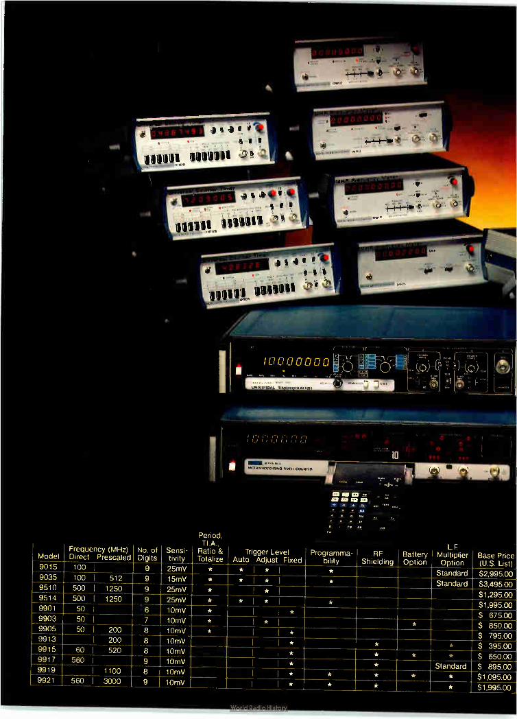
1.111111111111Mt_
1 Period,
JNIVI •Al 1.11 ',COLIN IliII
I4I II 1.."1 I-, I-1 1-1 I Li I
0 0 0 O. û û O
'' ....
,
Att
10I ZS CD in CM Cla no
Model Frequency (MHz) Direct Prescaled
No. of Digits
Sensi- tivity
....,-.., Ratio & Totalize
Trigger Level Auto Adjust Fixed
Programma- bility
RF Shielding
Battery Option
LE Multiplier Option
Base Price (U.S. List) 9015 100 I 9 25mV * * I * I * Standard $2,995.00 9035 100 I 512 9 15mV * * I * I * Standard $3,495.00 9510 500 j 1250 9 25mV * I * I $1,295.00 9514 500 I 1250 9 25mV * * * I * $1,995.00 9901 50 I 6 10mV * I * $ 675.00 9903 50 I 7 10mV * I * I * $ 850.00 9905 50 j 200 8 10mV * I I * $ 795.00 9913 I 200 8 10mV I I * * * $ 395.00 9915 60 I 520 8 10mV I I * * * * $ 650.00 9917 560 I 9 10mV I I * * Standard $ 895.00 9919 I 1100 8 10mV I I * * * * * $1,095.00 9921 560 I 3000 9 10mV I I * * * * $1,995.00

A new force in the Expanding universe
of counters.
Our combined technologies now give you a broader selection of per-formance characteristics than any other counter source in the world
If you purchase counters, there is a name you must consider to get the best meas-urement value for your company's dollar
The name is Racal-Dana. We are the new force in frequency measure-ment, with a complete range of practically priced, working solutions to your meas-urement needs.
Racal-Dana not only developed the world's first microprocessor controlled timer-counter, but today also offers the least expensive µP unit at under $2000.
We offer 12 totally unique fre-quency measurement instruments, for as little as $400 or as much as $4000. Each gives you more performance for every measurement dollar.
Call or write today. Put the force to work or you.
Racal-Dana Instruments Inc., 18912 Von Karman Avenue, Irvine, CA 92715. Telephone: 714/ 833-1234.
RACAL-DANA G100133
For demonstration, circle no. 158 For literature, circle no. 159

How to tell a dad connector It's easy to think of connectors
as all being pretty much the same. But actually, there are
significant differences between ordinary
connectors and clad con-
nectors.
For example, the shortcomings of connectors with monometal contacts have long been known.
Alloys, though more versatile than monometals, haven't been able to provide the range of characteristics demanded by today's applications. And most gold platings, such
as flash gold, are too thin for any kind of durability. They tend to be porous and vulnerable to abrasion and intermittendes. And they're wasteful and costly, because you really need gold only at the point of contact. The optimum solution, then,
would be a combination of metals that provide the exact characteris-tics required for the specific application. As of today, there is only one way to produce such a combination.
Cut-a-Way End View Solder Tail
Accepts ace P.C. Board
(1,571,0,02)
Ii — 10-0ç..010 4262 ±025) hearth. Depth
.030 (0,76)
.010 (025)
It's a bonding process pioneered and developed by Texas Instru-ments. And it's called cladding.
The dad difference. Basically, a clad metal is two
or more metals bonded at the molecular level into a composite. There's no need for intermedi-ate adhesives or brazing alloys. It's simple, it's clean and it's permanent.
In TI connectors, a strip of metal— the "contact" metal, usually gold—is bonded as a 50 to 75 micro-inch inlay to a base "spring" metal. When the connector is
fabricated, the gold inlay ap-pears at the point of contact, the only place it's needed. So even though it's non-porous, much thicker and far more reliable than gold plating, we
—7—75 L_.015 (.145i
Our toughest customen
Cross section of a 3-layer pressure-bonded composite metal.
can almost always offer our clad connectors for less than you'd pay
for an ordinary connector. And because we manu-
facture our connectors from start to finish at a single site, you not only get a low priced connector, but a high quality connec-tor; too.
The technique of bonding one metal to another is simple in concept but difficult to execute. This probably explains why there are so few manufacturers of clad metal. Of these manu-facturers, TI is far and away the
Clad metal strip material

from an ordinary connector.
Clad metal strips are stamped into contacts by high speed presses.
largest in the world. We are also the largest semi-
conductor manufacturer, which gives us an intimate knowledge of connectors and their electrical re-quirements. So as we developed our clad metal capability, we were able to apply it intelligently and immediately to our
connectors. And since we use our
own connectors in many of the products we make, we get direct and rapid feedback from one of the most exacting manufacturers in the electronics industry
In short, we're our own tough-est customer. Which is why our connectors have to be the best.
Cross Section of H4 Series Edge board Connector
Custom features, standard prices.
TI's gold inlay is easy to spot. But there are other features, usually associated with custom-ized connectors, that aren't so easily seen. These features come with all standard TI con-nectors and sockets, along with off-the-shelf availability. They include the following: A special edge grip
contact design that maximizes contact pressure and per-mits fast, posi-tive insertion.
Face grip contacts that provide
excellent inser-tion/withdrawal force ratios.
Pre-loaded contacts for faster, easier production in-sertion of IC's. And individ-
ually replaceable contacts which can be changed without remov-ing an entire socket from its mounting.
In most cases you'll be able to find the connec-tor you need among our standard offer-ings. But if you have a complex or unusual appli-cation that calls for a custom-designed connector, tell us about it. We've helped hundreds of
Clad metal is:
More conductive
More durable
Non-porous
Wrought
Homogeneous
customers with such problems. And chances are, we can help you, too.
Ask for our catalog. It's beautiful and its free. Now that you know there's a
big difference between clad connectors and ordinary con-nectors, you'll probably want to
see what we have to offer. We have a fasci-nating cata-log — "The Texas Con-nection"— that tells
More reliable
More dense
Less costly
Fire assay helps Texas Instruments metallurgists determine precious metal purity, fundamental to achieving high reliability.
H4 Series Edgeboard Connector
the whole story about TI clad connectors — and sockets— and presents the products in detail with accompanying descriptions, illustrations and specifi-cations.
For a copy, just call or write Texas Instruments Incorporated, Connector Systems
Department, Mail Station 2-16, Attle-boro, Massa-
chusetts 02703. Tele-phone (617) 222-2800, extension 268, 269 or 7327.
TEXAS INSTRUMENTS INCORPORATED
Electronics/September 28, 1978 Circle 161 on reader service card 161

Another First
When you need bipolar memory, come to the leader. Come to Signetics. You'll find a long line of industry firsts that have routinely become industry standards. Like our high-density 16K PROM. And our FPLAs and byte-organized RAMs. Our most recent first—the Low-Power Schottky 8K
PROM—needs only 418mW (max.) to operate. Thaes about 55% less power than you'd need with comparable devices. Less power means higher reliability. And reduced power supply costs. Benefits like these are vital to telecommunications, EDP and military fields. As you optimize word expansion in bused organizations, you can
choose from two outputs: open-collector (82LS180) or three-state (82LS181). Moreover, you can select models for either commercial or military temperature ranges—with access times of 175ns or 225ns, respectively. To meet special military needs, the new 8K is also available as an MOS-compatible part (S82LS2708). Our new low-power 8K will be followed by more industry firsts.
Soon, you can expect an 8K PROM with latched outputs. To learn more about our bipolar memory firsts, use the coupon below. Or better yet, contact your local Signetics sales office or franchised distributor.

r To: Signetics Information Services, 811 East Argues Ave.,
P.O.Box 9052, Sunnyvale, CA 94086
-ammo-SIGNETICS PROM SELECTION GUIDE (4K & ABOVE)
Mr Size Organization Type Output* Pins
Max. TAll(ns)
Max. ICerrnA1 Key Benefits
à-' o o rl- w•
e
1024x4 82S136 82S137
OC TS
18 18
60 60
140 140
High speed.
512x8 820115 IS 24 60 175 Latched output.
825140 • 82S141
OC IS
24 24
60 60
175 175
Four enable inputs for memory expansion.
82S146 82S147
OC IS
20 20
45 45
155 155
Fastest 4K available; 0.3" pkg. saves space.
- m o cc a. . to
2048x4 82S184 825185
OC TS
18 18
100 100
120 120
Maximize PC board packing density.
1024x8 82S180 820181
OC TS
24 24 -
70 70
175 175
High speed.
8214180 82L6181
OC TS
24 24
175 175
BO BO
Low power.
825182 B2S183
OC TS
24 24
60 60
175 175
Fastest 8K available; latched output.
16K PROMu
2048x8 82S t90 825191
OC TO
24 80 24 80
175 115
Highest density PROM available.
OC = open collector; TS = three-state.
Please send technical details for the following 8K PROMs*:
D 82LS180/181 0 82LS2708: Military part only.
D I have an urgent requirement. Please have a bipolar memory specialist phone me at once- (
Name Title
I Company Division
I Address
I City State Zip
I *The 82LS180/181 is available now in limited sample quantity. Full preductior. is sch?cl-aled for 4th art?r, 1978.
..... a mom ma .....
MS

the next 41% 4S. generation
of bench DMMs! Twc New Keithley Models offer uncompromising performance and outstanding value.
• Accuracy 31/2's can't match: 0.04% 1 digit on dc volts and ohms.
• Large, bright, 20,000-count LED display that's quick and easy to read.
• Convenient bench size that won't get "lost" yet doesn't crowd.
• Exceptional reliability.
Model 178 offers functions and ranges for most measurements: 100µV to 1200V dc, 100µV to 1000V ac, 0.1n to 20Mil. At $199*it is a remarkable value!
Model 179 is a full-function, multi-feature model offering the same
• U S. domestic price only.
II Orr 12CV A" i 2'
111 111111
20k 200k 2000k 10k,
0 I
at:b advantages as the
178. Plus TRMS AC; 10µV Sensitivity; Hi and Lo
Ohms; AC and DC Current. Yet it's still half the price you'd expect. Only $289*!
Model 179
Both models feature designed-in reliability.
Rugged circuits use a minimum of parts— high quality, off-the-shelf parts— carefully assembled and tested by Keithley (we've been making sensitive laboratory instrumentation for more than 30 years.)
Outstanding overload protection and rugged mechanical design keep both
Model 178
units going even after severe abuse. One-year accuracy specifications minimize recalibration costs. Local assistance keeps downtime to a mini-mum should service ever be needed. A battery option, user installable,
gets you off "line.' for critical measure-ments or for field use. Nine other accessories add versatility.
Keithley's 178 and 179 are designed, built and supported to provide continuous usability at the lowest total cost of ownership. Need autoranging, more accuracy or
sensitivity? See Keithley's complete line of DMMs.
For complete specifications and immediate delivery on the 178 and 179, call your local Keithley representative (see adjoining list). Or, call or write: Keithley Instruments, Inc., 28775 Aurora Road, Cleveland, Ohio 44139. (216) 248-0400. In Europe: D-800 München 70, Heiglhofstrasse 5, West Germany. (089) 7144065.
KEITHLEY The measurement engineers.
164 Circle 164 on reader service card Electronics/September 28, 1978

New products
Single chip reads floppy disks Monolithic circuit supplies all the analog and digital functions
needed to convert the ac signal on a disk into a clean TTL output
Detecting, amplifying, and convert-ing the analog signals present on a floppy disk into a usable sequence of digital pulses can be an arduous task. The discrete analog and digital components that traditionally per-form these functions have to be adjusted for variations in everything from the type of disk-drive in use to the layout of individual printed-circuit boards. Now disk-drive manufacturers
can replace all the discrete active elements with a single integrated circuit —the MC3470 floppy-disk read amplifier system. Combining both analog and digital functions, the MC3470 provides all necessary signal processing from the read head through to a digital output that is compatible with transistor-transistor logic. Unlike, say, a floppy-disk controller chip, the MC3470 goes inside the floppy-disk drive itself and is designed to accept the differential ac signal from the read head and produce a digital stream of data in accordance with the input peaks. As the block diagram shows, the
read head is connected directly to a differential-gain stage, which ampli-fies the input waveform. The ampli-fied signal is then ac-coupled to an external passive-filter network and on to an active differentiator and time-domain filter to produce the desired output. The filter network removes high-
frequency noise from the signal. Since its characteristics depend upon the coupling configuration of the MC3470 as well as upon the electri-cal and mechanical parameters of the particular floppy-disk system being used, the filter is external and adjustable by the user.
by John G. Posa, Industrial Editor
The differential output of the filter is fed to an active differentiator circuit, which is realized on chip by coupling the emitters of a differen-tial amplifier through a capacitor. The result is a collector current that is the derivative of the input voltage. The voltage across the two collectors provides zero-crossing detection of the current waveform. Since the capacitor shifts the current 90° from
the input voltage, the comparator, in turn, provides peak detection of the input voltage.
If, as often happens, the input waveform suffers from distortion at the zero-crossing points, the digital output may be triggered falsely. The time-domain filter in the MC3470 will eliminate this distortion if the user sets the period of the one-shots properly by means of external resis-
12 V
1
FILTER NETWORK
16 15
ACTIVE-DIFFERENTIATOR COMPONENTS
14 13 12
DIGITAL 5" OUTPUT
10
AMPLI-FIER
GAIN I STAGE I
ACTIVE DIFFERENTIATOR
COMPAR-ATOR I
PEAK DETECTOR - _
MC3470
I-TIME-DOMAIN FILTER
PULSE GEN-
ERATOR
ONE SHUT D
D-TYPE C
1 PULSE GEN-
ERATOR
MAGNETIC HEAD
ANALOG INPUTS GAIN SELECT
5 V — I( • •••••• t
MONOSTABLE MULTI VIBRATOR COMPONENTS
Electronics/September 28, 1978 165

Forethought. The only sure cure for buyer's remorse.
By the time you get all your electronics into the cabinet, get it sold and get it shipped, any weaknesses in the design will show up in spades.
If the levelling legs aren't properly reinforced, they can pop through the bottom under a full load.
If the seams aren't completely welded and sealed, they may begin to open after you install your equipment.
If the internal engineering isn't perfect, the unit may exhibit the Leaning Tower Effect by the time it gets to your customer.
If the external design isn't first class, your product won't have that crisp, professional look.
If the cabinet isn't a Zero Matrix IV, the design engineerinp` probably won't protect you from all the problems you didn't think about.
We think about all those problems. Our design engineering makes a science of forethought_ Don't be sorry tomorrow. Send for your free catalog today.
ZERO We make you look good.
Zero Corporation • Burbank, CA 213/846-4191 • Monson, MA 413/267-5561
Call Me, I'm Interested 166 Mail Catalog 165
The magazine you're reading now, could be your own. Drop off the routing list. Get your own fresh, unclipped copy mailed to your home or office. Turn to the subscription card in the back of the magazine. If somebody has beat you to it, write: Electronics, P.O. Box 430, Hightstown, N.J. 08520.
New products
tor-capacitor timing networks. Peak shift, resulting from current
imbalance in the differentiator, off-set voltage in the comparator, and so on, is guaranteed to be no greater than 5% of a data period. Moreover, peak shift can be eliminated alto-gether by connecting an external potentiometer across the differentia-tor components (with the wiper connected to ground). George Soliman, director of prod-
uct management at Shugart Asso-ciates Inc., Sunnyvale, Calif., the largest U. S. manufacturer of flop-py-disk drives, feels the part repre-sents a significant alternative to conventional read-function design. "In working with such low-level analog signals, the chances of screw-ing up are good," he says, adding that the device "will improve the noise rejection." Ron Campo, marketing manager
for linear interface products at Motorola, says that a few firms saw the unit coming and are already figuring it into their designs. In fact, Campo predicts that "a major portion of the floppy-disk drives will eventually use this chip." The MC3470 is contained in an
18-pin plastic package and uses two supplies, +5- and +12-v. The price is $5.95 in lots of 100. Availability is from stock. Motorola Semiconductor Products Inc., P. 0.
Box 20912, Phoenix, Ariz. 85036 [411]
Electronics/September 28, 1978

PCB Flexibility with Bendix Brush
Connectors.
A low mating force connector with up to 400 contacts. 4 body styles. 3 contact variations with options. Superior electrical characteristics and long mechanical life. That's flexibility! And Bendix has one for your high-contact needs. The Brush Con-nector. Here's what you get.
Bendix Brush Connectors increase circuit count per board. • Reduce number of boards by allowing more cir-
cuits per board. • Greater board effectiveness by providing exact
circuit counts up to 400 contacts in only one connector!
Bendix Brush Connectors reduce mating force 70% to 90%. • Less complex board supports. • Secondary actuators eliminated. • Extended mechanical life. Up to 20,000 mates/ unmates.
• Fewer damaged boards. • Eliminates fixture mounting need of multiple
smaller connectors.
Bendix Brush Connectors—a broad product line. • Mother Board, Daughter Board, Input/Output, PC
receptacle body styles. • 2, 3 and 4 row configurations. • 90° and straight PC, solderless wrap, crimp re-movable terminations with multiple lengths and plating options.
Bendix Brush contacts improve electrical charac-teristics. • Highly redundant contact sites with multiple elec-
trical paths and wiping action. • Gold plated wire bristles mesh together intimately
with gas-tight junctions • Stable contact resistance even after extreme me-
chanical durability abuse to 20,000 matings.
For full information, cal! (607) 563-5302, or write The Bendix Corporation, Electrical Components Divi-sion, Sidney, New York 13838.
We speak connectors. Electronics/September 28, 1978 Circle 167 on reader service card 167

Model 2500 Code Generator. Powered by the 101D or 101C via a rear connector panel, this accessory can generate any arbitrary code up to 4096 bits long (longer on special order). The Model 2501 Burst Generator (not shown) is a similar type of accessory for generating bursts up to 999 pulses in length.
Latest in a long line of distinguished pulse generators— the new Model 101D. The Model 101D features a 50 MHz repetition rate with a variable rise and fall time from 5 nanoseconds. Its applications are considerably expanded by the use of the code generator shown here. Other key features of Model 101D: 20 volts amplitude • VMOS output protects against inverse voltages and short circuits • Automatic duty factor limit indicators • TTL outputs • Affordably priced at $895.
Prices are U.S. only.
SD: The pulse generator people. And a lot more.
168 Electronics/September 28, 1978

The "best buys" in pulse generators. Models 101D, and 101C.
Model 101C. Offering the finest price/performance ratio avail-able today, the Model 1010 serves a wide variety of appli-cations from bench to complex data systems. Features: main output variable to 18 V • 20 MHz repetition rate • Automatic duty factor limit indicator • Simul-taneous TTL and CMOS outputs • Optional pulse burst and code generator accessories • Price $595.
To find out more about the S-D pulse generator family, contact Scientific Devices, our nation-wide, factory-trained manufac-turer's representatives. (See phone numbers below.) Or contact us at 10 Systron Drive, Concord, CA 94518. Phone (415) 676-5000.
Model 154-4 Programmable Pulse Generator. (Left) This automatic pulse generator's programming capabili on the IEEE-488 bus. Any instrumentation controller can rem program it. Rep rates are variable from 10 Hz to 50 MHz. Delay and width is from 10 ns to 10 ms. Model 154-3 (not shown) is a serial-by-character programmed unit.
Model 114A Pulse Generator. (Center) Here's real pulse testing flexibility for both laboratory and production line. All parameters are variable, including amplitude from 80 mV to 100 V into 50 ohms in 9 overlapping ranges. Model 114A can deliver 200 watts of peak power at 10% duty cycle into 50 ohms. Rep rates are variable up to 1 MHz.
Model 110D Dual Channel Pulse Generator. (Right) Actually two pulse generators in one, the Model 110D is a two-channel unit which allows all pulse parameters except rep rate to be controlled separately for each channel. As such, the 110D is suitable for many applications other than logic circuit testing. These include triple and double pulse pair for chirp radar testing and controllable pulse trains for data simulation. Output variable from 0.5 V to 18 V in a ±- 18 volt window, 50 ohm load.
• SeatUe (206) 454ingjât. Louis (314)Addak • Washington, DC Area (703) 451-6500_
SYSTRON DONNER PUT OUR PERFORMANCE TO THE TEST
Circle #168 for literature Circle #169 for demonstration

actua size
Weston 860
Weston proudly introduces the first low cost 1/4" square multiturn cermet trimmer . . . the 860. Using the same advanced technology which produced our well-known 830, 840 and 850 series trimming potentiometers, the 860 offers you a miniature trimmer excellent for P.C. board packaging.
Its actual size of .250" x .250" x .170" needs only one-half the board space as conventional 3/8 " square trimmers . .. and at comparable prices!
The 860 features 16 turns of adjustability in either top or side adjust models. Its power rating is 1/4 watt at 85° C, with an operating temperature range of -55°C to + 150° C. The 860 is completely sealed against contaminants. Military (RJ26) and Established Reliability (RJR26) models are also available. Write or phone today for evaluation samples, specifications and pricing.
SANGAMO WESTON
Schlumberger
WESTON COMPONENTS 8 CONTROLS A Donsion of Sangamo Weston, Inc. Archbald, Pa 18403 Tel (717) 876-1500 TWX 510 656-2902 Telex 83-1873
172 Circle 172 on readerservice card Electronics/September 28, 1978

CHECK US. We've been coming up with better instrumentation recorders for more than 40 years. And we're willing to put our reputation on the line. So check the boxes below for the type of recording equipment you need and send us this page. We'll send you some no-nonsense specs that will stand up to the toughest comparisons you care to make.
VISICORDER OSCILLOGRAPHS
El Graphic data acquisition system (One to 32 channels, dc to 5000 Hz, choice of eight plug-in signal conditioning modules.)
E Linescan facsimile-type recorder (DC to 8 MHz; X, Y, Y', Z axis; high resolution, broad gray scale.)
Cl Recording oscilloscope (DC to 10 MHz; X, Y, Y', Z axis; up to one million in/sec writing speed.)
11 Light-beam galvanometer recorders (DC to 25 kHz, up to 36 channels.)
SIGNAL CONDITIONING
III Gage control units (Multi-excitation, calibration, balance, filtering, suppression, various gain ranges.)
III Thermocouple compensation unit (Calibration, suppression and span controls.)
1:3 Amplifier/attenuator units (Differential, single ended, multi-bandwidth, various gain ranges.)
MAGNETIC TAPE SYSTEMS
E Large-reel portable (DC to 2 MHz, 15-inch reels.) Cl Small-reel portable (DC to 1 MHz, 10Y2-inch reels.) III Laboratory systems (DC to 4 MHz, 16-inch reels.)
SIGNAL ANALYZERS
CI Correlation/probability analyzers III Fourier transform analyzers
INDUSTRIAL TEST SYSTEMS
• Die casting test systems El Welding test systems EJ Data communications recording systems • Air/oil circuit breaker analyzer system
SPECIAL MILITARY PRODUCTS CI Digital cartridge tape recorder III Shipboard analog tape recorder Ill Airborne analog tape recorder O Special applications recording oscillographs
To get a free catalog that describes all of our instrumentation recording systems, just circle the Reader Service Number.
WE'LL SHOW YOU A BETTER WM. Honeywell
Honeywell Test Instruments Division • MS-218 • Box 5227 • Denver, Colorado 80217
Circle 173 on reader service card

New products
Instruments
Counter/timer
spans 100 MHz
Microcomputer-controlled
unit uses custom IC to
get price down to $800
Given that a high-frequency univer-sal computing counter/timer needs high-speed digital circuitry, several types of analog circuitry, and some sort of processing unit, it is quite a challenge for a manufacturer to design one with an upper frequency limit of 100 mHz while keeping the price below $1,000. Hewlett-Pack-ard has done it by first designing a large-scale integrated circuit, which is essentially a counter on a chip, and then building its $800 model 5315A around the chip.
Called a multiple-register counter, the lc combines high-density inte-grated injection logic with high-speed emitter-function logic—an offshoot of emitter-coupled logic that is better suited to large-scale
integration than ECL —to provide all the analog and digital signal-processing functions needed to pro-vide seven-digit resolution from 0.1 Hz to 100 MHz. Two years in the making, the chip had to include fast multidecade serial counters in its front end but slower and denser counter chains elsewhere. Com-pounding the difficulty, an assort-ment of analog circuits had to be included to handle the diverse count-ing functions. Altogether, the single silicon slab contains an address decoder, four registers, a data input/output multiplexer, a signal input multiplexer and synchronizer, a status buffer, and a 10-MHz system clock designed to work with an external crystal.
Despite its complexity, the multi-ple-register counter must have an external controller if it is to provide the 5315A's frequency, period, dual-channel ratio, time-interval, and totalizing measurement modes. Fill-ing the role of system controller, as well as that of data processor, is a Mostek 3870 microcomputer chip. It is the synergistic interplay of the MRC and the 3870 that forms the core of the 5315A, says Bosco Wong, project leader of lc develop-
ment at the Santa Clara division. Because it contains a computer,
the counter can resolve any frequen-cy in its range to seven digits with a 1-second gate time. Ordinary direct-reading frequency counters are lim-ited to 1-Hz resolution unless the gate time is increased or phase-locked frequency multipliers are used, according to Rex Chappell, product marketing manager. "The trick is the 5315A actually
measures the period of the input signals up to a frequency limit of 10 MHz, then the 3870 calculates a multiple-period average, inverts it, and comes up with a frequency value. Above 10 MHz, the 5315A measures the frequency directly," Chappell explains. The instrument's continuously
variable ± 2-v trigger-level potenti-ometers can be converted into 20:1 variable-sensitivity controls by push-ing a front-panel button. "For time-interval measurements, precise trig-ger-level control is useful, but for measuring the frequency or period of sine waves, a sensitivity control is more important," Chappell explains. The user chooses whichever he happens to need. The accuracy of a counter is inti-
mately tied to its time-base stability. The 5315A's 10-MHz crystal-con-trolled time base ages only 3 parts in 107 per month, according to Louis Masters, that product's project man-ager. Temperature coefficient, an-other important measure of stability, is a low ± 5 parts per million over the 0° to 50°C operating range. The 5315A is useful as both a
portable tester and as a laboratory bench-top instrument. It weighs 6 lb, 5 oz and measures 9.375 by 3.875 by 10.875 in. This compactness plus a $225 rechargeable-battery option plus a combination stand and carry-ing handle makes the instrument suitable for field-service work. The option provides up to four hours of continuous operation before the bat-tery charge drops below a predeter-mined limit and the counter shuts itself off. A built-in self-test and error light calls the operator's atten-tion to instrument faults. The counter's signal inputs have
174 Electronics/September 28, 1978

Software programmable flexibility makes Motorola's CRT Controller a low-cost MPU-to-CRT interface
II Alphanumeric, sal-graphic. arid full graphic display mode
II Fully-programmable va processor data bus Generates timing for /litany any readable alphanumer,c screen density
II Single 4 5 V power supr,40
II Line bufferless operaton No edema: OW required Refresh memory rnultipleml between folP1.1 and CRT Controller
II Programmable interface or non-interlace scan
II Hardware scrolling
The MC6845 CRT Controller provides MPU-to-CRT interlace in processor-based systems for your smart, programmable, and intelligent terminals and other raster scan CRT displays, either standing alone or clustered. A "happy medium" hardware/
software balance is achieved for maximum flexibility. You pay only for what your system requires. Consequently, you pay much less than for bipolar approaches that load nearly everything but the CRT onto a single chip.
The MC6845 generates alpha-
numeric, semi-graphic, and full graphic black-and-white displays utilizing an external character generator. It's fully programmable via the processor data bus, and generates timing for a wide variety of alphanumeric screen densities.
As a full-fledged member of the M6800 Family, the MC6845 is '6800 compatible. It's also compatible with any 8-bit MPU or CPU which can synchronize external devices. A single +5 V power supply is all it requires.
To find out more about the MC6845, contact your Motorola
sales office or your authorized Motorola distributor, or write to Motorola Semiconductor Products Inc., P.O. Box 20912, Phoenix, AZ 85036, or circle the reader service number.
Motorola peripherals—doing more so your processor can do more!
MOTOROLA Semiconductor Group
Electronics/September 28, 1978 Circle 175 on reader service card 175
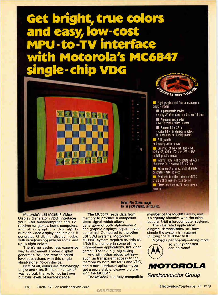
Get bright, true colors and easy, low-cost iiPU -to -Tv interface with Motorola's MIC6847 single-chip VDG
Motorola's LSI MC6847 Video Display Generator (VDG) interfaces your 8-bit microcomputer and TV receiver for games, home computers, and other graphic and/or alpha-numeric video display applications. It generates 12 distinct display modes, with variations possible on some, and up to eight colors.
There's no easier, less expensive way to implement a video display generator. You can replace board-level subsystems with this single stand-alone, 40-pin device.
Best of all. colors are refreshingly bright and true. Brilliant, instead of washed out, thanks to not just one but four levels of luminescence.
• Eight graphic and fou' alphanumeric display modes
II Alphanumeric modes display 32 characters per line on 16 lines
• Alphanumeric modes have selectable video inverse
• 8-color 64 x 32 or 4-colar Ed x 48 density graphics in alphanumeric display modes
• Full graphic and seregraph c modes
• Dens.ties of 64 x 64, 128 x 64 128 x 96, 128 x 192. and 256 x 192 in full grapnic modes
la Internat RCN will generate 64 ASCII characters in a standard 5 x 7 box
MI Either on-chip or external character generators may be used
• Available: in either imerlace (NTSC Standard) or non-interlace option
III Direct interface to RF modulator or monitor
Honest Abe. Screen images are as photographed, unretouched.
The MC6847 reads data from memory to produce a composite video signal which allows generation of both alphanumerc and graphic displays, separately or combined. Compared to the other LSI VDG systems, Motorola's MC6847 system requires as little as 1/6th the memory in some of the high-volume applications, like video games. That's a big, big saving.
And with other added extras— such as transparent access to the memory by both the MPU and VDG, and a non-interlaced option—you get a more stable, cleaner picture with the MC6847.
The MC6847 is a fully-compatible
member of the M6800 Family, and it's equally effective with the other popular 8-bit microcomputer systems.
The illustrated application diagram demonstrates just how simple the system is in games utilizing the MC6847 VDG.
Motorola peripherals—doing more so your processor can do more!
MOTOROLA Semiconductor Group
176 Circle 176 on reader service card Electronics/September 28, 1978

lifleVSTRIat VERAGE VS XIII
Mixed Alphanumerics and Semi-Graphics
Alphanumerics Seim-Graphics and Inverted Alphanumertcs
High-Resolution Graptics Reclines only 1K x 6 Memory!
Test .. Eight Selected Colors
Sample application of the VDG in a TV game
Contact your Motorola sales office, authorized Motorola distributor, write to Motorola Semiconductor Products Inc., P.O. Box 20912, Phoenix, AZ 85036, or circle the reader service number for information.
New products
impedances of 10 vq-2 shunted by less than 40 pF. When dc-coupled, the bandwidth extends from 0.1 Hz to 100 MHz. However, in the ac-coupled mode, the lower limit is 30 Hz. The display uses yellow light-emitting diodes and an amber filter; the format is scientific notation with units in hertz or seconds, as appro-priate. First shipments of the coun-ters are scheduled to begin in Octo-ber, according to Chappell. Hewlett-Packard Co., 1507 Page Mill Rd.,
Palo Alto, Calif. 94304 [351]
25-MHz oscilloscope
provides delayed sweep
The model D67A oscilloscope is a 25-MHz instrument that offers de-layed, intensified, and mixed-sweep operation at a suggested list price of
$1,325. Made by Telequipment, a British subsidiary of Tektronix Inc., the dual-trace scope has integral signal delay lines and comprehensive triggering facilities for capturing fast pulse inputs. Vertical sensitivity of the D67A is 10 mv per division. The instrument is available from stock. Tektronix Inc., P. O. Box 500, Beaverton,
Ore. 97077. Phone (503) 644-0161 [353]
Unit links instruments
with interface bus
Designed primarily as an option for the synchro instruments made by it..c Data Device Corp., the DBA-488 data-bus adapter will link instru-ments and other data-handling de-
43, 0 gee l e-
0 ef e
se
vices to the IEEE-488 general-purpose interface bus. Microproces-sor-based, the adapter controls the transmission of data, timing, and control signals between the device and the bus. The unit is unusually versatile because its read-only mem-ory can be custom-programmed to link almost any device to the bus with no need for hardwiring changes. Externally accessible rocker switches allow easy changing of the bus address. The DBA-488 has dimensions of
8.1 by 6.1 by 1.7 inches and can be chassis- or panel-mounted. It sells for less than $1,000 each in small quantities and has a delivery time of 8 to 10 weeks. ILC Data Device Corp., Airport International
Plaza, Bohemia, N. Y. 11716. Phone (516) 567-5600 [354]
51/2-digit synthesizer
spans 0.1 Hz to 16 MHz
Users who need a signal source for testing filters, calibrating test instru-ments, providing radar range mark-ers, serving as the local oscillator in a precision receiver, or similar appli-cations should take a look at the model SI-102 frequency synthesizer. The unit covers the frequency range from 0.1 Hz to 16 MHZ with 51/2 -digit resolution, which means that it provides 0.00001-Hz resolution from
Electronics/September 28, 1978 177

ELECTRONICS REPRINTS
No ot
copies
wanted New reprints _ R-801 World market report 1978 24 pp
$4.00 R-734 Microcomputer families expand
20 pp. $4.00
R-730 Special Report-Automotive
electronics gets the green light
10 pp $3.00
R-728 Flexible circuits bend to design-
ers' will 10 pp $3.00
R-724 Special Report -Technologies squeeze more performance from
LSI 22 pp. $3.00 R-722 Demands of LSI are turning chip
makers towards automation 12
pp $3.00 _ R-720 How EEs Feel About Engineer-
ing -3-part series 26 pp $5.00
_ R-718 Display makers strive to refine their technologies 8 pp $3.00
Books R-803 New product trends in electron-
ics- Electronics Book Series
333 pp $14.95
R-732 Memory Design-Microcomput-
ers to Mainframes- Electronics
Book Series 180 pp $12.95
R-726 Design Techniques for Electron-
ics Engineers-Electronics Book
Series 370 pp $15.95 R-711 Circuits for electronics engi-
neers: 306 circuits in 51 func-
tional groups-Electronics Book
Series 396 pp $15.95
R-704 Thermal design in electronics
$5.00 R-701 Applying microprocessors-
Electronics Book Series 191 pp
$9.95 R-608 Basics of Data Communica-
tions-Electronics Book Series
$12.50
R-602 Large Scale Integration-Elec-
tronics Book Series 208 pp
$9.95 R-520 Microprocessors-Electronics
Book Series 154 pp $8.95
Payment must accompany your order
Make check or money order payable to Elec-
tronics Reprints. All orders are shipped
prepaid by parcel post. Allow two to three weeks for delivery. For additional information
call (609) 448-1700 ext. 5494.
Mail your order to:
Janice Austin ELECTRONICS REPRINTS
P.O. Box 669 Hightstown, N.J. 08520
178
New products
0.1 to 1.0 Hz and 100-Hz resolution from 1 to 16 MHz. An internal oscillator that drifts
less than 10 parts per million over the frequency range from 0° to 50°C is included in the standard $515 instrument. A special high-stability oscillator that drifts no more than 1 ppm is available as an extra-cost option. The unit is available from stock to 30 days. Syntest Corp., 169 Millham St., Marlboro,
Mass. 01752. Phone (617) 481-7827 [355]
15-MHz scope can be
powered three ways
For users who are unsure where they will want to use a 15-MHz scope, the Japanese-made model 303 seems to cover all the power possibilities. It can be run from ac line voltages from 90 to 260 y at frequencies from 48 to 440 Hz, from external dc sources from 11 to 30 v, or from its internal nickel-cadmium batteries. The dual-channel portable instru-
ment weighs only 5.5 kg (12.1 lb) including the batteries, which pro-vide two hours of operation before requiring recharging. It has a 3-inch cathode-ray tube, fully automatic triggering, direct coupling, and a sensitivity of 5 mv per division. Available from stock, the model 303 sells for $895 in small quantities. Ancrona Corp., P. 0. Box 2208, Culver City,
Calif. 90230. Phone Tom Nixon at (213)
641-4064 [356]
Noise generator covers
audio-frequency range
The model NOD 72-1 noise genera-tor puts out a white-noise signal that
is flat to within ±0.5 dB from 20 Hz to 20 kHz. The output can be varied from 0 to approximately 1.0 y rms across 600 Q. As the load resistance is increased from 600 Q to an open circuit, the output voltage will increase no more than 2.5 dB. The standard noise generator,
which sells for $79.95 in small quan-tities, requires a 28-v de power supply from which it draws a maxi-mum of 30 mA. Option 00172, which adds $17.50 to the price of the instrument, permits operation from 115 y ac. The unit has a delivery time of four weeks. Micronetics Inc., 36 Oak St., Norwood, N. J.
07648. Phone (201) 767-1320 [357]
Portable counter-timer
works up to 1.3 GHz
The compact PM 6616 universal counter-timer is a 1.3-GHz instru-ment with a sensitivity of 10 my rms. In addition to frequency, it measures period, period average, multiple ra-tio, and events. The $1,395 unit weighs only 9.2 lb complete with its optional battery pack. Philips Test & Measuring Instruments Inc., 85
McKee Dr., Mahwah, N. J. 07430. Phone
(201) 529-3800 [358]
Instrumentation
amplification
In the photograph accompanying our write-up of Krohn-l-lite's model 2200 sweep/function generator on p. 188 of our Aug. 31 issue, we inad-vertently cropped off half of the instrument. For those readers who have been wondering how to change the generator frequency, here is the complete picture.
Electronics/September 28, 1978

If you can't decide between an LSI & VLSI tester, get them both.
You probably don't Jet. think you need
a true 120-pin test system
right now. Few companies do. But you will.
Maybe sooner than you think. And, in the meantime, why spend all that money for a mere dedicated tester that won't meet your long term testing needs.
The Sentry VIII with its 120 fully programmable I/O pins will meet today's LSI requirements, and be ready to take on your VLSI testing later. But, let's take a look at some of the things the Sentry VIII can do for you right now. Testing complex devices? The Sentry VIII
will routinefy perform precise characterization of microprocessors, peripheral chips, bit slices, RAMs, ROMs, shift registers, UARTs and digital hybrids in technologies such as NMOS, PMOS, CMOS, SOS, ECL, TTL, and PL. Multiple pass testing? Chances are, you're occasionally forced to do some multiple pass testing of complex multi-pin devices. Well, the Sentry VIII can eliminate that extra pass. It has the ability to change any pin or timing assign-ment (input, output or format) on the fly. That can represent a tremendous improvement in throughput and can save as much as 50% of your testing time.
Still testing devices one at a time? By multiplexing the 120 fully programmable I/O pins on the Sentry VIII you can test two, even three, LSI devices simultaneously. Another 50% to 60% savings in test time.
And you can save even more. To provide lower operating costs, the Sentry VW features multi-task (foreground/background) software for simultaneous compiling, editing and testing; a CPU that provides 50 to 200% faster throughput; a sequence processor to handle high complexity devices; and a pattern processor to tackle the largest memories.
Still don't think you're ready for a true 120-pin tester? Maybe you'd better think again.
Fairchild Test Systems Group, Fairchild Camera and Instrument Corp., 1725 Technology Dr., San Jose, CA 95110 (408) 998-0123
MAI RCHI L-ID
Electronics/September 28, 1978 Circle 179 on reader service card 179

Upward mobility.
When are you going to get your very own, personal subscription to Electronics?
It could be very important to you And we're not just referring to your status in the
office hierarchy You (and we) are in a quick-moving
business. News breaks frequently Change is the name of the game. Awareness is the way to win.
You've got to follow what's going on beyond your specialty Your career may have to last longer than your specialty
If change is the game, obsolescence is the penalty for losing. Obsolescence of products, of technology and, unfortunately of people. We can't change this fact. But we can help you cope with it.
Give us one hour of reading time every two weeks and we will keep you aware of what's going on around you and around the changing world of electronics technology
Move up. Fill out one of the subscrip-tion postcards in this issue.
Electronics Magazine. The one worth paying for.
180 Electronics/September 28, 1978

Pure CODSiSiefICY...
Chemicals for a bold new world. Optical waveguides. Thin film memory. Liquid crystal displays. Wherever today's breakthroughs are shaping tomorrow's world, you'll find EM Laboratories as a source for fine chemicals.
We manufacture chemicals for vacuum deposition, liquid crystal displays, fiber optics, crystal growth... dopants for electronics ... that's just the start. And the R&D for tomorrow is bubbling in our labs.
Pure consistency in fine chem-icals from EM Laboratories. Whatever you need to frame your future, we produce it. For a better world.
EM Laboratories, Inc. associate of
E. Merck, Darmstadt, Germany 500 Executive Boulevard Elmsford., N.Y. 10523 (914) 592-4660
• Chemicals for electro optics • Suprapur" • Patinal® • Anerone • Licristal® • Selectipure
Circle 181 on reader service card

Remember DEC's RI(05?
DEC doesn't: The old RK05 was recently replaced by the new RL01, and as disc drives go, the price is nice.
Until you figure in the cost of converting all your media (to media that you can get from only a single source), and the cost of the new controller, new software and the entirely new support situation that you'll be facing. Regieerrd tradernark Dignal EquIpmem Corporation
,;/11/0/11111/
Plessey never forgets: We'll continue to support your RK11e-based systems.
If you need a controller, just slip the Plessey Hex board PM-DC11/A into your PDP-11® mainframe or our Quad PM-DCV11 into your LSI-11® or our Micro-1. Plessey con-trollers and drives are fully compatible with DEC's RK11, but much less expensive. We've been selling them for years, and have no plans to stop now.
If you need more storage, just add one or more of our PM-DD11 disc drives. They're enhanced versions of the RK05, faster and smaller, but fully hardware, software and media compatible with your systems, so you can con-tinue to use your existing cartridges. And they're available now for a great deal less than the DEC equivalents.
Supporting our customers with the right products, prices and deliveries has made us the largest independent supplier of DEC-compatible peripherals. Our product line presently includes add-in/add-on core and semiconductor mem-ories, cartridge disc systems, floppy disc systems, mag tape systems, complete computer-based systems, and a wide variety of backplanes, expansion chassis and other accessories.
We're the only real alternative to DEC for all your miniperipherals, a complete single source. For all the details, please contact the nearest Plessey sales office today.
Plessey Peripheral Systems 17466 Daimler, Irvine, California 92714. (714) 540-9945
182 Circe 182 on reader service card Electronics/September 28, 1978

RELAX...it's amazing how an easy mind ties relationships.
We're the easy mind people. TRW Capacitors.You can rely on us to choose the best raw materials.
Our X363 metallized polypropylene line is a perfect ex-ample. We spent several years making sure we had chosen precisely the right dielectric. And simultaneously making sure our technology was precisely right, too. The results were worth it.
The line features excellent electrical properties— high IR, low DF, and dielectric absorption that's even better than polystyrene — to minimize offsets and errors in slope integrators and sample and hold circuitry.
The line features low dissipation factor (High Q) in a small package, for pulse, low level RF or filter applications. And it features high stability— for the long term shelf life and resistance to severe environments that's important for time base generators, integrators and filters. The specs are unique. And impressive. So are our engineering services. So relax and give us a call. Or write: TRW Capacitors, An Electronic Components Divi-sion of TRW, Inc., 301 West "0" St., Ogallala, Nebraska 69153 • Tel: (308) 284-3611.
TRW CAPACITORS Electronics/September 28, 1978
ANOTHER PRODUCT OF A COMPANY CALLED TRW
Circle 183 on reader service card 183

How to defend against attack by air, Series 1 panel sealed lighted pushbuttons are qual-ified under MIL—S-22885.
TL toggles offer environment-pr• " ng an many circuit options. TW pr• ides switchin versatility in a smaller size.
SE and XE miniature basic ment-proof. HM version _prom ing and larger-sized HT w temperatures.
FW solid state self-contained proximity cont provide high reliability and long life.
EN is environment-proof limit switc with variet of actuators, circuitries, and electric is hermetically-sealed version.

sea or dust. For use in extraordinary con-ditions, MICRO SWITCH builds some pretty extraor-dinary devices. Sealed to keep the environment out and keep on working in a wide variety of aerospace, transportation, ordnance and marine uses.
Uses where they simply can't afford to fail.
I LE and HM switches offer true hermetic sealing, with metal-to-metal, glass-to-metal construction.
There's the FW solid state proximity control for high reliabilry in severe en-vironments. For high tem-perature uses up to +1,000°F, there's the HT line. The SE and XE basic switches are the smallest environment--proof basic switches offered _Py MICRO SWITCH.
MICRO SWITCH also makes toggles with a variety of locking configurations and different-shaped levers, including colorec. tab levers. Integrated Wire Termination System is also available.
And there's also a com-plete line of Series 1 lighted pushbuttons. They're built to last hundreds of thousands of operations, and offer round or square buttons, momen-tary or alternate action and solid state options.
Every bit as rugged as the buttons, switches and toggles, MICRO SWITCH keyboards offer panel sealing plus solid state Hall-effect technolo%gv for reliability.
MICRO SWITCH will provide you with factory-trained field engineers for application assistance and a network of Authorized Dis-tributors for local availability. For complete information, write us for details or call 815/235-6600.
MICRO SWITCH FREEPORT. ILLINOIS 61032
A DIVISION OF HONEYWELL
New products
Data acquisition
Stress flexibility
in I/O boards
Units for Micromodule and
Exorcizer include input-only
and output-only models
Analog input/output interface sub-systems for microcomputers—like the microcomputers themselves— require some time for evaluation before users design them into sys-tems. Barry Glasgow, marketing manager for microcomputer board products at Analog Devices Inc., believes this evaluation period is coming to a close and that the analog vo board business is on the verge of a big boom as users begin to commit to production volumes. That's why the Instruments and Systems group in Norwood, Mass., is now offering a new family of seven boards to mate with the Motorola Micromodule and Exorcizer. The family is not the first on the
market to interface with the Motoro-la single-board computer series, since products from three other vendors are available. But Glasgow thinks that Analog Devices has been able to take advantage of its own experience with monolithic lc data converters to offer a line that is
lower in price and more flexible than the others. As evidence of the flexi-bility, there are three versions each of the the input-only model RTI-1230 and input/output model RTI-1231 units, providing varying capa-bilities at various prices. The seventh board is an output-only device—the model RTI-1232. Each of the first six versions has
analog-to-digital converters provid-ing either 12 or 8 bits of resolution and accuracy. Resistor-program-mable gain is standard on those units, with gains ranging from 1 to 1,000. In addition, the 12-bit models provide software-programmable gains of 1, 2, 4, and 8. The RT1-1230 and RTI-1231
have 16 single-ended input channels (8 differential), expandable to 32 single-ended. The boards will accept 4-to-20-mA current-loop inputs or full-scale voltage inputs from 10 mv to ± 10 V. A fast sample-and-hold amplifier is included on both models. The RTI-1231 combination in-
put/output subsystems also offer two channels of 12-bit digital-to-analog outputs with ranges of ± 5 v, ± 10 v, +5 v, and + 10 v. The RT1-1232 output-only board has four channels of 12-bit multiplying d-to-a output, four open-collector peripheral driv-ers able to sink 300 mA, and up to four optional 4-to-20-mA current-loop outputs available at $50 each.
Dc-to-dc converters are optional with the family, but all the boards have memory-mapped vo interfaces
• 1,11212
MICRO SWITCH products are available worldwide through Honeywell International.
185

When you need L or more than LEDs...
Dialight is the first place to look. We can help you do more with LEDs...because we've done more with them.
Discrete LEDs come in a variety of sizes, shapes, colors (red, yellow, green in clear or diffused), with or without built-in resistors.
Low cost logic state fault indicators for trouble shooting complex circuits. Designed for close density PC board mounting.
High-brightness bi-color LEDs (red/green) suit-able for go/no-go situations. Designed with unique
lenses for the extra visibility you'll want for your most critical applications.
Snap-in mounting LED indicators reduce labor cost. Available in red, yellow or green with or without built-in resistors.
Whatever you need in LEDs, Dialight's probably got it already. For your free 60-page selector guide and
listing of our nationwide 13. ¡ALIGHT stocking distributors, con-tact us today. A North American Philips Company
Dialight meets your needs. fleet, 203 Harrison Place, Brooklyn. N.Y. 11237 (212) 497-7600
Circle 186 on reader service card

New products
selectable by wrapped-wire termi-nals. Prices start at $399 for the 1230 input board, $515 for the 1231 combination input/output version, and $395 for the 1232 output board. Delivery time is four weeks. Analog Devices Inc., P. 0. Box 280, Route 1
Industrial Park, Norwood, Mass. 02062.
Phone Russ Ver Nooy at (617) 329-4700
[381]
Input/output system gathers
data from remote reaches
Imagine having to monitor and control a system in the middle of Death Valley 24 hours a day for a number of years. Harsh and remote as such a locale might seem, the IOS2000, an intelligent input/out-put system that can be tailored and expanded to meet individual needs, would be right at home in it.
Designed to operate in tempera-tures between —40° and +85°C, the modular system consists of rack-mountable cards for input/output control, analog-to-digital conversion, a microprocessor system, communi-cations, and power supply. Up to 48 1/0 cards can operate with a single set of processor, a-d, and communi-cations cards to form a system capa-ble of handling 768 digital points or 384 analog channels—or an equiva-lent combination.
Channel scan rates of greater than 1,000 digital points per second can be attained; depending on the nature of the application, from 10 to 100 analog channels can be scanned in a second. Providing analog or digital inputs or outputs, each I/O card with its on-board programmable read-only memory offers linearization for RTD and thermocouple devices and unit conversions. The a-d card performs automatic zeroing and ranging, system calibration, and, at operator request, baseline offset. The microprocessor card is fac-
tory-preprogrammed to control the IOS2000's internal functions, yet is transparent to an external central processing unit. Among other things, it allows operators to request sequen-tial scans or access channels ran-
.045" .096"—.1 Fe—
ACTUAL SIZE
555 SERIES LED logic state indicators available in 14 models with voltage ratings from 1.7 to 14. Suitable for dense pack-aging on printed circuit boards—up to 10 units to the inch—IC compatible. With built-in resistor. Polarity identified. Low power consumption. With pricing as low as .57C (1000 lot quantity).
These low cost LED logic state indicators are extremely versatile devices and lend themselves to a wide range of applica-tions. Digital status indicators and circuit fault indicators are typical applications.
550-0204 550-0405 550-0306
ACTUAL SIZE
-4.6—.020"
550 SERIES Mix 'em or match 'em. LED logic state indicators are avail-able in red, yellow and green, in a variety of shapes, some with a built-in resistor. Can be driven from DTL and TTL logic. Designed for easy alignment on PC boards. Akso available with high brightness LEDs. With pricing as low as .32C (1000 lot quantity).
s. So talk to the specirsts at Dialight, first. Send for your free copy of Dialight's cur-rent catalog today.
/3/A LIGHT Electronics/September 28, 1978 Dialight, A North American Philips Company
203 Harrison Place, Brooklyn, N. Y. 11237 (212) 497-7600
Circle 187 on reader service card

The last time you saw a really new bench/portable DMM was 1972.
That's the year our 8000A was introduced. Its custom LSI and solid owner benefits quickly established it as the world's leading DMM.
Now, look at the new 8010A and 8012A: single-chip CMOS de-signs for problem-solving in the eighties!
RAZOR- SHARP LCD for large, no-strain answers at first glance— in any light.
TOUCH AND HOLD probe option, so you can thread your way through a component jungle and capture the reading you need.
FUNCTION POWER: 22 ranges of AC and DC volts and current, six ranges of resistance, and three ranges of conductance — the mis-sing function on other bench multi-meters.
CONDUCTANCE RANGES for noise-free leakage measurements to 10,000 Ma A valuable function for bench-testing boards and com-ponents, conductance also meas-ures transistor beta (using a bias resistor) and light intensity (by using a photocell).
OVERLOAD-PROTECTED — like no other DMM, including re-jection of 6000V transients and up to 600V applied to the current ter-minals.
HONEST AC ANSWERS de-rived from a Fluke hybrid true rms converter. You'll even see the dif-ference on your AC line between the correct value and what your average-responding meter reads. And 50 kHz bandwidth won't let any significant distortion products go unmeasured. Plus, 10 times the basic response you may be limited to now!
SPECS YOU EXPECT from Fluke — like -.±0.1% on DC for one year. Both models available with rechargeable batteries, and backed by the same solid warranty and worldwide service that helped make the 8000A the industry standard.
LEADERSHIP HAS TO BE EARNED. And we're committed to keeping the price of your confi-dence as realistic as possible. Like $239 for the 8010A with a 10A cur-rent range, and $299 for the 8012A with two extra-low ohms ranges that allow measurements from 0.0010 to 10,000 MIl — making it the widest range ohmmeter avail-able!
Contact one of the more than 100 Fluke offices and representatives, worldwide, or CALL (800) 426-0361* TOLL FREE. In the U.S., and all countries outside Europe, write: John Fluke Mfg. Co., Inc., P.O. Box 43210, Mountlake Terrace, WA 98043, U.S.A.
In Europe, contact Fluke (Nederland) B.V., P.O. Box 5053, Tilburg, The Nether-lands. Telephone: (013) 673973. Telex: 52237.
Prices U.S. only. •Alaska, Hawaii, Washington residents — please call (206) 774-2481.
FLUKE
2509-8020
Circle #188 for literature 188 Circle #189 for demonstration Electronics/September 28, 1978
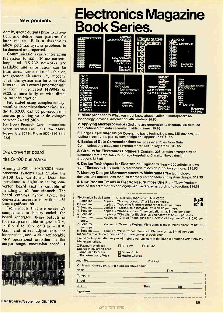
New products
domly, queue outputs prior to activa-tion, and define scan patterns for later request. Built-in diagnostics allow potential system problems to be detected and reported. Communications cards interfacing
the system to ASCII, 20-mA current-loop, and RS-232 networks are available and information can be transferred over a mile of cable or, for greater distances, by modem. Thus, the system can be controlled from the user's central processor unit or from a dedicated HP9845 or 9825, automatically or with direct operator interaction.
Fabricated using complementary-metal-oxide-semiconductor circuitry, the 10S2000 can be powered from sources providing ac or dc voltages between 24 and 240 v. Burr-Brown Research Corp., International
Airport Industrial Park, P. O. Box 11400,
Tucson, Ariz. 85734. Phone (602) 746-1111
[383]
D-a converter board
hits S-100 bus market
Aiming at Z80 or 8080/8085 micro-processor systems that employ the S- 100 bus, California Data has introduced a digital-to-analog con-verter board that is capable of handling a full four channels. The board employs hybrid 12-bit d-a converters accurate to within ± 1/2 least significant bit. From inputs that are either 2's
complement or binary coded, the board generates 10-mA outputs in four strap-selectable ranges: ± 5 v, ± 10 v, 0 to 10 v, or 0 to -10 v. Gain and offset adjustments are independent, and, with a replaceable 74-v operational amplifier in the output stage, conversion speed is
2. Send me 3. Send me 4. Send me 5. Send me 6. Send me
copy. 7. Send me copies of "Memory Design : Microprocessors to Mainframes" at $12.95
per copy. 8. Send me copies of "New Product Trends in Electronics" at $14.95 per copy. Discounts of 40% on orders of 10 or more copies of each book.
I must be fully satisfied or you will refund full payment if the book is returned after ten -day trial examination.
D Payment enclosed Ill Bill Firm 11 Bill me Charge to my credit card: D American Express CI Diners Club D BankAmericard/Visa D Master Charge
Electronics Magazine Book Series. ogeDRocessoRs
mmliw immny
nimm, 1111111111 RITI111
Itstnitt
ItstRst Ek3ctrorics Intstter Book Series
APPLYING MICROPROCESSORS
MR; New hardware, software and applications
Electronics eok Sales
CIRCUBS ascuts CIRCUITS CIRCuitS altars toselectscnics enigneeks
ffls Electronics Booksees
ençaieess enguneeks
memory design memory dese
memory cleset MbCROODMPU1ERS TO MAINFRAMES
y
memtxy desir.B1 Bectnxics Wx:ik sedes
new new new new pRoduct Mends 111 eteCTROWycs new new new
e new new numbee one
Elecionics Book series
1. Microprocessors What you must know about available microprocessor technology, devices, information, 4th printing. $8.95
2. Applying Microprocessors 2nd and 3rd generation tech nology. 26 deta il ed
applications from data networks to video games. $9.95
3. Large Scale Integration Covers the basic technology, new LSI devices, LSI testing procedures, plus system design and applications. $9.95
4. Basics of Data Communications Includes 47 articles from Data Communications magazine covering more than 11 key areas. $12.95
5. Circuits for Electronics Engineers Contai ns 306 circu its arranged by 51
functions from Amplifiers to Voltage Regulating Circuits. Saves design
drudgery. $15.95
6. Design Techniques for Electronics Engineers Nearly 300 articles drawn from "Engineer's Notebook." A storehouse of design problem soluti ons. $15 .95
7. Memory Design: Microcomputers to Mainframes The technology, devices, and applications that link memory components and system design. $12.95
8. New Product Trends in Electronics, Number One From "New Products," state-of-the-art materials and equipment, arranged according to function. $14.95
Electronics Book Series P.O. Box 669, Hightstown, N.J . 08520 1. Send me copies of "Microprocessors" at $8.95 per copy. lj
copies of "Applying Microprocessors" at $9.95 per copy. copies of "Large Scale Integration" at $9.95 per copy. copies of "Basics of Data Communications" at $12.95 per copy. copies of "Circuits for Electronics Engineers" at $15.95 per copy. copies of "Design Techniques for Electronics Engineers" at $15.95 per
Acc't No. Date exp
On Master Charge only, first numbers above name
Name Title
Company
Street
City State Zip
Electronics/September 28, 1978
Signature
189
Bowmar New Loo in Tactile Feedback Keyboards Bowmar's new flat-surface custom keyboards are
ideal for any configuration from a basic keyboard to
complex total systems.
• Tactile-response so vital to quick and positive contact • Flat, spill-resistant surfaces for ease of maintenance • Unlimited overlay graphics include colors, sizes, shapes and nomenclatures to meet functional and aesthetic demands with a limitless variety of customized designs • Special advice and assistance in keyboard problems
• • Bowniar
Bowmar Instrument Corp. 8000 Bluffton Road • Fort Wayne, Indiana 46809 (219) 747-3121
Circle 190 on reader service card
OUR QUICK START PROGRAM CAN HAVE YOUR COMPANY OFF-AND-RUNNING THE DAY IT p — mum am MOVES TO a ATLANTA. A CITY WITHOUT ATLANTA. a LIMITS. Yes. I'd like to hear Dr. Charles When your company decides •McDaniel, Georgia Superintendent of Schools, ex-
to relocate or expand to •plain in detail how the Quick Start Program works. Atlanta, tell us the kind of send the cassette.
employees you need, and we'll recruit and train them before Name
you get here. And it doesn't cost you a Th thing.at's Georgia's Quick
II
Start Training Program. We can give your employees, hired here, advance job train-
ing in the skills you specify City State Zip before they start working.
And it's free. So is the audio cassette you get by clipping
and mailing this coupon. Il
190 Circle 258 on reader service card
Company Title
Street
Mail to: Roy Cooper, Economic Development Division, The Atlanta Chamber of Commerce, P.O. Box 1740, Dept. EM, Atlanta, Georgia 30301.
New products
typically about 3 microseconds. The board requires + 8-v and ± 18-v supply voltages, both obtain-able from the S-100 bus. In single quantities it is priced at $495 with delivery from stock to 30 days. California Data Corp., 3475 Old Conejo Rd.,
Newbury Park, Calif. 91320. Phone Jack
Robinson at (805) 498-3651 [384]
Hybrid a-d converter series
features high speed, accuracy
With conversion times as fast as 1.2 s, hybrid successive-approxima-tion analog-to-digital converters of the HAS series are useful for radar, pulse-code modulation, digital audio,
and digital signal processing appli-cations. Units with 8-, 10-, or 12-bit resolution are available. The converters can attain accura-
cies within 0.012% of full scale with-out external adjustment. Therefore, they can operate with only an analog input signal, an encode command, and a 1.8-w dc supply.
In single quantities, the converters are priced at $149, $169, and $199 for resolutions of 8, 10, and 12 bits, respectively. Delivery is from stock to four weeks. Computer Labs Inc., 505 Edwardia Dr.,
Greensboro, N. C. 27409. Phone (919) 292-
6427 [385]
Converters help mate analog
signals and microprocessor
The ADC 3511 and ADC 3711 convert analog signals to binary-coded-decimal outputs, each digit of which can be selected by a two-digit address. The 351 provides 31/2 bina-ry-coded-decimal digits, so that the
Electronics/September 28, 1978

Designing in optical switches? Call us for your broadest choice of high-technology
optoelectronic components — off the shelf!
Spectronics optoelectronic switches and other components are designed to meet growing needs in such areas as industrial controls, copiers, card readers, computers, solid state relays, motion sensors, switching supplies and object sensors. Even if your application is different, It's likely we've got a component to do your job.
El Infrared Emitters and Detectors Spectronics IR emitters and detectors are available
either as stand-alone components or in pre-aligned optical switch (interrupter module) configurations. They interface directly with digital logic circuits.
El Here's How They Work Spectronics high-efficiency infrared light emitting diodes
and light sensitive phototransistors are specially matched for peak efficiency. Design our components into your circuits just like diodes and transistors.
What's your application? Do you need to sense falling quarters or moving parts? Or perhaps the leading edge of paper or the speed of a shaft? Spectronics infrared LEDs and phototransistors will do these jobs for you ... and a lot more. In pulsed applications, the emitter and detector can be placed a dozen feet apart. Or we've got standard modules with gaps from .1 to .375 inches.
Need to detect a moving train of objects or count passing water drops? Or sense a credit card or other document? Then consider our reflective object sensors. We can supply the discrete components or make custom arrays for just about any application.
E Designing a Microprocessor Interface? You can isolate your µP from power line and switching
transients with our optocouplers. Our patented epoxy inner mold assures reliable isolation from surges to 5000 VDC. Drive currents can be as low as 1 mA.
[I) Gating an SCR or TRIAC? Level shifting from control circuits to power line levels is
readily accomplished. Our SCR coupler can gate a 40 amp TRIAC. The complete Spectronics line also includes standard transistor and darlington outputs.
D Replace Mechanical Switches By specifying Spectronics opto switches you eliminate
such common problems as corrosion, contact bounce and mechanical fatigue. Lifetime measured in decades — not number of switching cycles! Products are directly microprocessor compatible from —55°C to +100°C.
r] High-Technology Leader Last year, Spectronics devoted over $1 million to
optoelectronic research and development. That's one of the reasons you'll be hearing more about us. And we want to hear from you. Call us now for assistance with your non-standard design problem, or write for our free opto catalog. Spectronics Commercial Components Division, 830 East Arapaho Road, Richardson, Texas 75081, telephone (214) 234-4271.
stigammin
Electronics/September 28, 1978 Circle 191 on reader service card 191
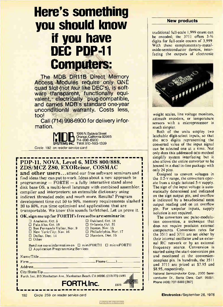
Here's something you should know
if you have DEC PDP-11 Computers:
The MDB DR11B Direct Memory Access Modules require only ONE quad slot (not four like DEC's), is soft-ware transparent, functionally equi-valent, electrically plug-compatible, and carries MDB's standard one-year unconditional warranty. Costs less, too!
Call (714) 998-6900 for delivery infor-mation.
1995 N. Batavia Street Orange, California 92665
11 DB 714-998-6900 SYSTEMS INC. TWX: 910-593-1339
Circle 192 on reader service card
PDP-11, NOVA, Level 6, MDS 800/888, ZDS/MCZ Z80, EXOReisor, COSMAC and other users... attend our free software seminars and find ideas they can put to work. Ideas about a new approach to programming — FORTH — a fully interactive stand alone disk base OS, a multi-level language with combined assembler. compiler and interpreters; an extensible dictionary using
indirect threaded code; and much more. Results? Program development time cut 50 to 90%, memory requirements slashed 30 to 80%, run time optimized and applications that are transportable. We know this sounds farfetched. Let us prove it.
OK, sign me up for FORTH's free software seminar in: O Anaheim, Oct. 5 E Oakland, Oct. 18 O Palo Alto, Oct. 19 III Orlando. Oct. 31 O San Fernando Valley, Nov. 9 0 Boston, Nov. 15 El New York City. Nov. 16 0 Philadelphia. Nov. 17 O Dallas, Dec. 14 0 Houston, Dec. 15 D Other
Send me more information on D miniFORTH D microFORTH O Application Programming Services
Name/Title
Firm Phone (
Address
City/State/Zip
Forth, Inc., 815 Manhattan Ave.. Manhattan Beach, CA 90266.(213)372-8493
FORTH, Inc.
192 Circle 259 on reader service card Electronics/September 28, 1978
New products
traditional full-scale 1,999 count can be encoded; the 3711 offers 3-1/4 digits for full-scale counts of 3,999. With these complementary-metal-oxide-semiconductor devices, inter-facing the outputs of electronic
E928
weight scales, line voltage monitors, azimuth encoders, or temperature sensors with a microprocessor is much simpler.
Both of the units employ two latchable digit-select inputs, so that the BCD digits representing the converted value of the input signal can be selected one at a time. Not only does this addressed-act) method simplify system interfacing but it also allows the entire converter to be housed in a dual in-line package with only 24 pins.
Designed to convert voltages in the ± 2-v range, the converters oper-ate from a single isolated 5-v supply. The sign of the input voltage is auto-matically determined and indicated on the sign output pin, and overflow is indicated by a hexadecimal EEEE output reading and on an overflow pin. For unipolar inputs, supply isolation is not required. The converters use pulse-modula-
tion conversion, a technique that does not require precision external components. Conversion rates for the 3511 and 3711 are set either by their internal oscillator and an exter-nal RC network or by an external frequency source. Conversion is started using the start-conversion pin and monitored at the conversion-complete pin. In hundreds, the 3511 and 3711 are priced at $7.95 and $8.95, respectively. National Semiconductor Corp., 2900 Semi-
conductor Dr., Santa Clara, Calif. 95051.
Phone (408) 737-5000 [387]

The real test for a display's readability is direct sunlight. Most of them are washouts.
By comparison, Beckman displays stand out. With wider viewing angles and more brightness by the foot. Important factors when you're looking at critical readouts in the air or on the ground.
The reason for most of our product advantages can be summed up in two words: Superior Technoloe For example, Beckman's unique raised-cathode construction method in-sures a smooth, even glow over all the segments. The result: Optimum visibility through a feat in human engineering.
Besides outstanding visibility, Beckman displays give you letter-perfect numbers. No breaks or gaps. Natural, flowing lines that are pleasing to the eye. In any number. And, in vibrant orange, filterable to bright red. Perfect for the designer who wants his numbers to look like numbers. Not like jigsaw puzzles.
ckman displays are designer's designs. Modular.
In character heights from 1/3" to Arranged on one-to-four-digit, plug-in building blocks that save space and assembly time. Or, if you need a custom display, we stand out in that picture, too.
Reliability is another place where Beckman displays really shine. Assured by extensive in-process testing and 100% burn-in. As a result, we can give you a warranty that's good for one year. (Or, you may qualify for our Warranty Plus Option.)
To top it all, Beckman displays can give you a visible edge in your market -a simple case of product differentiation.
This is how Beckman displays beat the daylights out of all others. Point for point, digit by digit. Clearly and decisively. If you're not convinced, just plug in one of ours. Compare it to theirs. The difference will show up day or night.
For complete details, write: Beckman Information Displays Operations, P.O. Box 3579, Scottsdale, AZ 85257; or, call (602) 947-8371.
Beckman beats the daylights out of all other displays.
Beckman displays. The visible edge.
CKIVIAN' DISPLAYS OPEPAIC,NS
This photo of our model SP-101 was taken in actual daylight. Circle 193 on reader service card

Are you going too far? 'efe
Granted, you can buy "standard" integrated circuits in Japan or the U.S.
Even a bit cheaper, maybe, than in Europe. But if you need more than just standard circuits,
the shortest route is directly to us. We specialize in the development and production of CMOS integrated circuits, using metal or silicon gate technology — integrated circuits adapted to special products with specific requirements.
We are one of the few companies in the elec-tronics industry capable of producing integrated circuits with low voltage and extremely low current consumption. We have not only a highly qualified staff, but some of the most advanced development and production facilities in the industry. So we can handle every phase of your project, including in-
house mask making. Which means we're not only more flexible than most other companies in our field, but also that we can develop new circuits and get them into production faster.
Naturally, this demands close, continuous contact between customer and supplier. And that's yet another reason why being right in the heart of Europe is such a big advantage for our clients. Staying in contact is so much easier and faster.
We cordially invite you to contact us. You won't have to look any farther.
Mi j MMIZ MIIMM
i7IC7O7LECTRONIC - MARIN
CH-2074 Marin/Switzerland Tel. (038) 35 21 21 Telex: Derby CH 35 316
Member of the Ebauches Group 194 Circle 194 on reader service card Electronics/September 28, 1978

AUGAT MADE ZERO-PROFILE SOCKETS POSSIBLE. NOW WE'VE
MADE THEM PRACTICAL.
Not long ago Augat intro-duced the HoltiteTM concept of solderless sockets, to give you zero-profile component plug-ability without conventional sockets or solder, and the unmatched dependability of machined beryllium contacts. Now we've made the Holtite
idea practical for almost every application — including ones where PC boards already con-tain soldered components. The Holtite System now offers a new,
Augat contacts, magnIfl
low cost (just $695) pneumatic insertion machine which presses Holtite contacts into plated-through holes converting the holes into plug-in sockets. Contacts for this new system are preloaded in DIP patterns on a Mylar carrier strip supplied on reels. Typical insertion rate for the machine is 5,000 contacts/hour. And if you need mass loading
capability, we can lease you a
machine that loads more than 50,000 contacts/hour. The thing to remember is no
matter what the size or nature of your aoplication, the Holtite System can now offer you all the advantages of sockets: reduced test cycle times, less dam-age to ICs and PCs from soldering, easier com-ponent changes, and economical field maintain-ability. Holtite delivers all these benefits and still gives you card spacing as low as .400".
You don't have to change a thing to use Holtite; simply drill the holes to the recom-mended diameter. Prove it for yourself. Order one of our Holtite Prototype kits. With all the tools, contacts, instruc-tions, and test reports you need to judge the system on your job.
The kit costs only $94.50. The reels, the insertion machine, and the trial kit are all avail-able from Augat's worldwide distributors.
r write Augat, nc., 33 Perry
Avenue, PO, Box 779, Attleboro, Mass. 02703. Tel. (617) 222-2202.
AUGAT® Augat inierconnection products, Isotronics microcircuit packaging, and Alco subminiature switches.
Electronics/September 28, 1978 Circle 195 on reader service card 195

Teradyne finds the practical solution. No. 7 in a series.
The electronic knife
On the cutting ec e of boarc
Ever since its introduction by Teradyne in 1972, guided probing has been the accepted technique for tracking down functional faults on a circuit board. All the leading functional board test systems now include guided probes, and Teradyne offers an automated version for high-volume applications. Conventional guided probing does, however, have one shortcoming: Its fault diagnosis is almost always ambigu-ous to some degree, because it cannot discriminate between electrically common points. In the past, that has not proved a serious limitation, since work-manship errors (the most common type of fault) are easy to spot once the guided probe narrows the search to a specific section of the board. Today, however, with in-circuit testers increasingly used to screen out workmanship errors, the functional board test sys-tem is left with mostly device fail-ures, which are of course impossible to detect visually. The increasing use of bus-oriented LSI boards further complicates the prob-lem, since a great many ICs may be connected to the failing node. One can replace each of the suspect ICs in turn, of course, but that's usually too time-consuming to be prac-tical. Besides, trial-and-error replacement of 40-pin LSI devices can easily do the board more harm than good. Teradyne's answer to this problem is the "Electronic Knife," a revolutionary new probe designed to sense the impedance of an IC relative to the impedance on the rest of the node. Since the IC with the lowest relative impedance is generally the one controlling voltage on the node (and thus responsible for any node fail-ure), the Knife is far and away the best
-testinc technolocy
method devised for finding a bad IC without pulling it off the board. To sense the relative impedance, the probe contacts the IC lead at three points, 'thus: The Electronic Knife in-jects ac at point A, and the fraction of the in- V1 jected current flow-
ing away from the device causes a
voltage drop, V1, from B to C. The Knife measures and stores this value. Then the same ac is injected at point C, and the Knife measures and stores V2, the volt-age drop caused by the fraction of the inject-ed current flowing into the IC. From the
measurements of V, and V2 the Knife derives the relative impedance of the probed IC. The voltage drops that must be measured are in the nanovolt re-gion, which means that an ac ap-proach is essential to avoid the effects of dc probe-to-lead contact potentials. Moreover, with the resistivity of various lead mate-rials differing by as much as
an order of magnitude, meaningful measurements would be out of the
question without the three-point probe approach, which cancels lead re-
sistances out of the calculations. Even then, the measurement technique called
for skillful and innovative circuit design. Before its introduction on the L135 LSI Board Test System, the Electronic Knife took
its first cuts on a variety of boards at Teradyne, including many with microprocessors. In al-most every instance, the Knife zeroed in on de-fective ICs with deadly precision. Clearly, the fast-moving technology of circuit-board testing has just made another fast move.
196 Circle 196 on reader service card

Jacket Flexible. scuff-resistant
polyurethane
Buffer Tube Protective, double-layer
construction
Fiberglass Load bearing layer
Optical Waveguide 10 dB/km., 100 MHz • km. transmission
The Siecor Breakthrough. Less than 25e a foot.
Siecor 133 Optical Cable. Siecor can now supPy the lowest priced, general purpose, fiber optic cable. At 75tI per meter this cable is approximately half the price of competitive alternatives. Straightforward construction and fiberglass reinforcement make this price breakthrough possible. We haven't sacrificed fiber quality either. We use a commercial grade of all-glass telephony fiber.
Siecor 133 is designed for installation in conduit. ducts and trays. It accepts a crimped connector. Siecor offers a broad range of optical cables and ancillary hardware. Let Siecor tell you more.
SIECOR Siecor Optical Cables. Inc. 631 Miracle Mile Horseheads, New York 14845 Tel: 607-739-3562
Circle 197 on reader service card

New products
Computers & peripherals
Muscle added to Eclipse line
Latest scientific machine
has a megabyte of memory
and a 200-ns microcycle time
The computer industry will continue to grow at annual rates of 30% or more "as long as we can keep prices coming down at about 20% per year," maintains Edson de Castro, president of Data General Corp. His belief is reflected in two new entries in the company's Eclipse line—the S/250 and C/350 [Electronics, Aug. 31, p. 34]. Both systems offer some of the advanced features of the firm's top-of-the-line Eclipse M/600 [Electronics, Feb. 2, p. 40], and outperform their predecessors at lower or similar prices.
Richard Schreiber, senior market-ing specialist for scientific proces-sors, says the S/250 is the most powerful scientific processor in the Eclipse line and is intended for real-time computational and communica-tions applications. The C/350, on the other hand, is aimed at the commercial data-processing market
and incorporates as standard some of the features that are extra-price options with the S/250. The S/250 offers up to 1 mega-
byte of metal-oxide-semiconductor main memory in increments of 64, 128, and 256 kilobytes. Its predeces-sor, the S/230, has a maximum of 512 kilobytes of mos main memory. The new machine can have 512 kilo-bytes of core main memory if the user does not want the semiconduc-tor variety, which is implemented with 16-K chips.
Included as standard with the S/250 are the Eclipse and floating-point-arithmetic instruction sets. The microprogrammed central pro-cessor has a microcycle time of 200 ns. That speed permits the S/250 to take full advantage of its standard data-channel input/output transfer rate of 2.5 megabytes per second.
In addition, an optional burst multiplexer channel permits disk input transfer rates as high as 10 megabytes/s, and output rates up to 6.7 megabytes/s. It is essentially a direct communications path between the main memory and high-perform-ance peripherals.
Other CPU options include a high-speed floating-point processor and an integral array processor. The latter offers 64-bit, double-precision operations, including, for example, a
2-as execution time for a multiply instruction. Among other things, the array processor can do a fast Fourier transform on a 1,024-point array of 64-bit complex numbers in 8.75 ms. Schreiber says these and other instruction execution times are 20 to 200 times faster than those for competitive scientific minicomput-ers. The price for a small S/250
system—including 128 kilobytes of main memory, 10 megabytes of disk storage, a cathode-ray-tube terminal and controller, a 180-character-per-second printer, and the Data Gener-al Real-time Disk Operating Sys-tem—is $52,040. A typical C/350 for the commer-
cial data-processing market will sell for $133,000 and includes a 256-kilobyte processor and a 50-mega-byte DG/Disc storage subsystem, a 1,600/800-bit-per-inch magnetic-tape subsystem, eight Dasher display terminals, a 300-line-per-minute printer, a system console, and a synchronous communications con-troller. The C-350 features the full Eclipse commercial instruction set and comes with the company's Advanced Operating System or the Real-time Disk Operating System. The burst multiplexer channel is
an option, but the floating-point processor optional with the S/250 is standard in the C/350. Delivery time of both systems is 90 days. Data General Corp., Route 9, Westboro,
Mass., 01581. Phone Richard Schreiber at
(617) 366-8911, ext. 4116 [361]
Mainframe-style software
now on Interdata minis
Users engaged in scientific research, industrial automation, simulation and other areas where rapid process-ing is mandatory can now get a Fortran compiler for the Interdata 8/32 minicomputer (equipped with OS/32MT and OS/32MTM operat-ing systems) that optimizes pro-grams globally. Called Fortran VII, the compiler examines an entire program and eliminates redundant operations from it in the process of
198 Electronics/September 28, 1978

THE WIDEBAND RMS VOLTMETER ONLY FLUKE COULD CREATE.
You're probably accustomed to using analog meters for audio-to-rf measurements. Maybe you've given up hope of going digital at a reasonable price.
Good news! Fluke's new 8920A wideband true
rms DMM is loaded with features—some you can't buy anywhere at any price, and it sells at an analog price: $995!
For starters, 8920A bandwidth is 10 Hz to 20 MHz for sub-audio to video AC measurements. Mid-band accuracy is 0.5%, compliments of an exclusive Fluke designed (and built) micro-electronic rms chip. Accurately measuring noise and non-sinusoidal waveforms is easy since the chip responds only to the heating effect of the waveform. You can select the AC + DC function for non-symmet-rical waveforms like pulses that have a DC component.
We gave the 8920A dynamic range from 180 p.V to 700 volts, to measure from low noise levels to the output of powerful amplifiers. And, fast auto-ranging relieves you of the knob twist-ing chores!
Put the 8920A into dbV mode and measure from —75db to +57db (132db range), with 0.01db resolution. If you want your dbV reference somewhere else beside 1V, Fluke's
8921A's Isolated Banana Jack Input.
"Dial-An-Ohm"
exclusive relative reference lets you store any voltage as the 0-db point. Imagine how simple your gain measure-ments can be!
To make the 8920A all things to all people, we've in-cluded a "dial-an-ohm" feature for dbm measurements. Instead of laboriously correcting each of your readings from a 600 ohm reference, simply dial 50, 75, 300, or one of nine other impedances up to 1200 ohms, and be right on every reading. There are several selections for broad-cast, telephone, TV and RF applications.
An analog meter is standard, for convenient peaking/ dipping/nulling, as is a linear analog output for continuous recording. Optional are logrithmic analog output and an isolated output to drive a counter. Soon, IEEE 488 inter-face will be available for systems use.
If your prefer an isolated banana jack input with full floating capability, specify the 8921A (also only $995). *U.S. Price
For more information, contact one of the more than 100 Fluke offices or representatives, worldwide. In the U.S., CALL (800) 426-0361*, TOLL FREE. Residents of the U.S. and all countries outside of Europe, contact: John Fluke Mfg. Co., Inc., P.O. Box 43210, Mountlake Terrace, WA 98043, U.S.A. Telex: 32-0013.
In Europe, contact: Fluke (Nedeiland) B.V., P.O. Box 5053, Tilburg, The Netherlands. Telephone (013) 673973. Telex: 52237.
Price U.S. only. *Alaska, Hawaii, Washington residents — please call (206) 774-
2481.
2504-8018 FLUKE
Circle 198 for Literature Circle 199 for Demonstration

LH's NEW Super-MITE Switcher packs up to 67% more power in the same space!
Competitive switchers produce only 600 to 750 watts in a 5" x 8" x 11" case.
Ideal choice for large add-on memory systems.
Designed specifically for large add-on eystems, LH's new Super-MITE (SM) Series witcher produces 1000 watts in a case no bigger than competitors use for switchers producing only 600 to 750 watts. And what's more, you get: • Choice of four single-output voltages*: 2 V @225 amps, 5 V @ 200 amps, 12 V @ 84 amps, or 15 V @ 67 amps.
• Wide input range — 85 - 130 V AC or
166 - 250 V AC— for brown-out protec-tion.
• 50-msec hold-up time if AC power fails.
• Power-fail signal triggered 40 msec after AC power loss.
"Three new multiple output models (2,3, and 4) also available.
• Direct paralleling of units without a mas-ter or special hookups. • IC regulator control chip reduces com-ponent count, assures highest rel iabi I ity.
• Extremely low output impedance. • 75% efficiency (5 V unit).
• 0.4% line reg. over entire input range. • 0.4% load reg. from zero to full load.
• 1% p-p ripple and noise.
• 2% max. deviation for a load change of 25% at 5A/sec.
• 0°C to 50°C operating temperature. • Remote automatic voltage margining
(optional).
• Designed to meet UL 478.
111 RESEARCH
The New Super-MITE produces 1000 watts of power in a 5" x 8" x 11" case.
World's largest manufacturer of switchers!
The Super-MITE is one more milestone in LH's continuing effort to offer the most technically advanced line of single- and multiple-output switchers including open-frame models. Nobody packs more power in smaller packages or offers more desira-ble features including 1 through 7 outputs, up to 2.26w/in., up to 80% efficiency, and a 2-year guarantee— at less than 60¢/w in
quantity. For price and delivery information, call or write
today!
LH RESEARCH, INC. 1821 Langley Avenu Irvine, CA 92714 (714) 546-5279
TWX 910-595-2540 Circle 202 on reader service card

Ilk
2,685 answers to power supply questions. Answers to better power and thermal efficiency. Answers to size and weight reductions. Answers to available off-the-shelf covered/open frame power supplies and transformers. And price and delivery answers.
These and many more answers can be found in our three product catalogs. And they're yours. Free. Just circle reader card number. Better
yet, write or call Abbott. The Power Supply Specialist.
Power Supply Catalog — Comprehensive 60-pager describes our full line of 1,573 hi-efficiency, hermetically sealed, single and dual output power supplies and switcher modules. Inputs of 60 and 400Hz and DC are
available with outputs from 3VDC to 740VDC, 1 to 250 Watts. Prices start
as low as $174 for 2-4 units. Circle Card Number 100
Industrial Power Supply Catalog — Some 279 of our low cost, high quality
OEM power modules are detailed n this 16-pager. Includes covered/ open frame, AC to DC single, dual and triple output versions, with outputs from 5 to 36VDC, 0.5 to 320 Watts. Plus DC to AC converters with 50
and 60Hz outputs. Priced as low as $35 for up to 24 units.
Circle Card Number 101
Transformer Catalog — A 20-pager for the do-it-yourself power supply designer with instructions on how lo specify for your custom units. Also covers 833 of our standard military, industrial and miniature pcb power transformers. Included are 60 and 400Hz, single phase input units, with prices starting as low as $5.10 for up to 9 pieces.
Circle Card Number 102
See Power Supply Section 4000, and Transformer Section 5600, Vol. 2, of your EEM catalog; or Power Supply Section 4500, and Transformer Section 0400, Vol. 2, of your GOLD BOOK for complete information on Abbott products.
abbott transistor
LABORATORIES,
General Offices 5200 W. Jefferson Blvd., Los Arigeles 90016 (213) 936-8185 Telex: 69-1398
:3 1 1/91U- 105U
EiEst
INCORPORATED
Eastern Office 1224 Anderson Ave., Fort Lee, N.J. 07024 (201) 224-6900 Telex: 13-5332
1 Dual open slots available
-r \JO
4 Quad
• Other memory modules available 16K, 32K, and 64K bytes.
computer corporation corporate square/825 north cass avenue/westmont, ill inois 60559/(312) 9201050
®Registered trademark of Digital Equipment Corp., Maynard, Mass.
T.Registered trademark of First Computer Corporation Circle 205 on reader service card

New products
Communications
Fiber-optic link
spans 100 meters
System has error rate of
New products
available: a double-ended version that provides separate input and output ports with about 20 dB of isolation between outputs, and a single-ended, duplex type, in which any port can serve as either an input or output port.
Either version of the 0-0CS-9-10110 is priced at $2,500 in single quantities and is deliverable within 30 days. A three-port model, 0-0CS-3-10120, is also available and costs $475. Olektron Corp., 61 Sutton Rd., Webster,
Mass. 01570. Phone (617) 943-7440 [403]
Uplink amplifier delivers
250-W output in Ku band
Upcoming commercial satellite com-munications systems such as Satel-lite Business Systems, Intelsat V, and Canada's Anik B and C will be designed to operate in the Ku band. Responding to the interest in such systems, Hughes' Electron Dynam-ics division has produced an ampli-fier that delivers 250 w of contin-uous-wave power in the 14.0-to-14.5-GHz uplink portion of the band.
Designated the model 9225H-04, the earth-terminal transmission am-plifier is composed of two major subsystems. A beryllia-ceramic trav-elling-wave tube, which uses periodic permanent-magnet focusing and a modulating anode, is housed with associated components in the radio-frequency portion. The electronic
plications, which can justify the use of elaborate terminal circuitry to minimize the overall cost per chan-nel-mile, industrial applications re-quire terminal circuits that are inex-pensive and widely applicable." The new link is aimed at meeting
these requirements in point-to-point
power-conditioning portion contains all logic and control circuitry and the power supply. A solid-state driv-er may be added to boost the gain from 41 to 46 dB at rated power. The unit's operational features
include an rf power monitor and alarm for both transmitted and reflected power. All status indicators and control switches can be remotely monitored and controlled. The rack-mountable system with
typical options costs $27,000 and is deliverable in 90 to 120 days. Electron Dynamics Division, Hughes Aircraft
Co., 3100 W. Lomita Blvd., Torrance, Calif.
90509. Phone (213) 534-2121 [404]
Module clarifies
fast-talk pitch
By adding the model M-8 pitch-correction module to, say, a small tape recorder, tapes can be played at speeds up to three times normal recording speed—and the voice out-put will not sound like a bunch of Christmas-caroling chipmunks. The module restructures high-speed speech signals in bucket-brigade fashion, using a patented technique. The printed-circuit-board system
is available with a circuit for control-ling the motor speed of small record-ers, so both tape transport speed and pitch correction can be adjusted with a single potentiometer. The circuit can be modified to provide a dc control voltage for larger systems; its power driver is rated for 400 mA at 10 v dc. A preamplifier that accepts inputs
directly from a playback head is located on the 3.3-by-5-in, board, as is automatic gain control circuitry that limits the output to a 30-dB range. Based on 0-dBm output, the signal-to-noise ratio is 46 dB from 350 Hz to 5 kHz—a range that gives optimum intelligibility in speech-compression applications.
Designed to mate with an 18-pin edge connector, the board operates from a 12-v supply from which the speech-correcting circuitry draws only 50 mA. In quantities of 100 and up, the M-8 with motor speed
Actually, any combination of data rate, format, link length, and tem-perature (between 0° and 70°C) can be accommodated at some bit error rate.
For example, the illustration shows a power budget for a 100-m link. The horizontal lines toward the
control sells for $80. Delivery takes from four to six weeks. Variable Speech Control Co., 185 Berry St.,
San Francisco, Calif. 94107. Phone (415)
495-6100 [405]
Fiber-optic connector
lets go quickly
To provide an alternative to delicate SMA connector screws, a vibration-proof bayonet connector has been introduced by Trompeter Electron-ics. Dubbed TPS, it requires no torquing; its three-lug bayonet seat-ing ensures positive locking, while springs in two planes provide preci-sion positioning. The connector is designed so that
an optical cable encased in a strength member may be easily attached and removed without spe-cial tools, allowing the connector to be reused. It can accomodate single fibers as small as 125 gm and fiber bundles as large as 1.143 mm in diameter.
Since SMA connectors are used in many optical systems, SMA versions are available that accept fibers of the same dimensions as the TPS units but need a special tool for crimping.
Fiber cables with Tefzel or Kevlar strength members can be crimped or epoxied to either type connector. Four quick-disconnect TPS types are offered: cable plug OPL50-N, bulk-head feedthrough OBJ58, two-screw flange mount OBJ59F2, and four-screw flange mount OBJ59F4. Price and delivery of the TPS connectors and of the five SMA versions depend upon customer specifications such as fiber size. Trompeter Electronics Corp., 8936 Com-
anche Ave., Chatsworth, Calif. 91311. Phone
(213) 882-1020 [406]
206 Electronics/September 28, 1978

Grayhill puts the seal on Rocker DIP Switch customer satisfaction
Total sealing capability now available including a sealed base without price premium
‘tritti oe-s
.4e. IIQJ , 95'
-
jiff
I 2 3
:Ill
: 1114
-... , •11,7.c -, 4 iii -I t
''''''' t ''',.\\ \ )\-)\\ 111 ft/111 . -'1k -- / ,, ' ,- / e* %-- .....\ -...... ,1
% /l/// 1 I 1 N. 1i> 1 i fr ..%1 N /0/ iijiiiiiii: i\t\ \ ‘ \ .
\
---
1 %, / ----- ‘-- _ — oPEN-- --- 0 , II • N.,,
..."
< 2 \ \
, \ t de s „;,c5, \
,4 ‘ elife;
4 5 6 7 in8 • e lVlI"--, P'e,t, Ale \,5---'-/----
— ,..... - .14 ,..
, . .,,
The different DIP switch has added another difference that's very important to our cus-tomers' satisfaction. Each switch is now potted as part of the assembly process. You get a more professional and economical seal, with greater seal integrity than is pos-sible with bead-seal add-ons. Flux entry during the wave soldering pro-cess is prevented by completely pot-ting the bottom side of the switch. Contamination is eliminated; reliability is enhanced; and prices are unchanged... there is no cost premium for this improved performance on our regular SPST rocker DIP switch line. (Recessed rocker units carry a modest premium.)
Grayhill also offers three top-side sealing options, applicable to raised as well as re-cessed rockers—a tape seal, applied at
ale
Grayhill, that will endure strenuous cleaning processes; cards of tape seals, for your ap-plication following incoming inspection; or re-usable protective covers.
You'll also give your seal of approval to the Grayhill spring-loaded sliding-ball contact system that provides the basis for our 50,000 operation life-rating,
with positive wiping action and immunity to normal shock and vibration.
Grayhill Sealed Base Rocker DIP Switches are available SPST, from 2 to 10 rockers. Take your choice — they're available off-the-shelf from Grayhill or its nationwide distributor network. For detailed information, contact Grayhill for your free up-to-date copy of Bulletin #288.
Pea (1Àdi the Difference between Excellent and Adequate. àrizzo
561 Hillgrove Ave. • La C range, Illinois 60525 (312) 354-1040
CLOSED
DIP SWITCH SI EALTC I.
Circle 207 on reader service card

LEARN Microprocessor Operation, Interfacing and Programming with
The New HEATHKIT Microprocessor
Course!
Update your knowledge of today's changing technology!
Today, more than ever, you must stay on top of the very newest technology, or risk falling behind as new people with up-to-the-minute knowledge come into your field. Heath's new self-instruc-tion microprocessor course is designed to do just that — it's the easiest, fastest and most cost-efficient way available to master microprocessor operation and applications! It even equips you to continue learning and developing on your own!
Working with the popular 6800 microprocessor, you'll explore this exciting field in 3 easy steps! In step 1, using proven self-in-struction text materials, you'll learn about micro-computer basics, number systems and codes, computer arithmetic, programming, 6800 capabilities and interfacing and more. In step 2, with the aid of audio visuals included, you'll go deeper into programming, de-signing with microprocessors and semiconductor memories. Then, in step 3, you'll actually perform 19 "hands on" experiments with the optional trainer designed to reinforce the theory you've mastered to that point! The ET-3400 Trainer kit, designed to accompany your course,
features the popular 6800 microprocessor. It is actually a miniature digital computer in itself, complete with a: 1K ROM monitor pro-gram; 6 digit LED display for address and data readout; 17-key hexadecimal keyboard for entering programs, data and control; 256 bytes of RAM (expandable to 512 bytes with the chips sup-plied in the course); breadboarding socket; 8 buffered LED's for display of logic states; 8 SPST switches for binary input plus an on-board power supply with +5, +12 and —12 volt outputs.
The Course comes complete with 62 electronic components, in-cluding a 6280 PIA, two 2112 RAM's, a 1406 digital-to-analog converter, 741 and 301 op amps and more. Includes audio visual aids such as an audio cassette, colorful flip charts and pro-grammed learning text material in two deluxe permanent binders.
Complete the optional exam and receive a Certificate of Achievement and 8.0 Continuing Education Units (CEU's) — a na-tionally accepted means of recognizing participation in non-credit adult education. (Note: Microprocessor Course requires comple-tion of Digital Techniques Course or equivalent knowledge.)
ORDER ETS-3400 (Course and Trainer kit)
HEATH
Schlumberger
$26995 (Add $3.06 shipping and handling)
MONEY-BACK GUARANTEE!
SOLDERING IRON! Included with your Course at no extra cost — this pencil-style sold-ering iron that's perfect for printed circuit work — a $7.95 comparable value — yours FREE!
If you are not 100% satisfied with your Heathkit Course, we will refund the full purchase price of the course text material, less trainer.
NEED DIGITAL TECHNIQUES TRAINING? Comprehensive Digital Techniques Course — the background you need
to understand computer and modern electronics technology! Digital tun-damentals, semi-conductor devices for digital applications, Boolean algebra, flip-flops and registers, sequential and combinational logic cir-cuits, digital design and an introduction to computers and more! The course includes programmed instruction text, audio-visual aids, parts for experiments arid more.
Digital Design Experimenter/Trainer lets you perform all the experi-ments in your course, then develop and test your own projects.
Features solderless breadboard sockets, 4 binary data switches, 2 "no bounce" switches to pulse logic circuits, 3-frequency pulse clock generators, 4 LED's for visual indication of logic states plus 3 regulated power supplies. Upon completion of the optional final exam, you receive a Certificate of Achievement and 4.0 Continuing Education Units.
12995 ORDER EES-3201 (Course and Trainer Kit) (Add $3.64 shipping and handling)
SAVE TIME—ORDER BY PHONE Call (616)982-3411 mu, ma. ma am. ma Heath Company, Dept. 510-451 Benton Harbor, Michigan 49022
Gentlemen: Please send me the item(s) checked below and include my FREE Soldering Iron. D Microprocessor Course and Trainer (ETS-3400) $269.95
(+$3.06 shipping & handling)
D Microprocessor Course only (EE-3401) $89.95 (+$2.23 shipping & handling)
D Microprocessor Trainer kit only (ET-3400) $189.95 (+$1.69 shipping & handling)
D Digital Techniques Course and Trainer kit (EES-3201) $129.95
I (+$3.64 shipping & handling) Prices subject to change without notice CITY STATE ZIP
a am aim am ma am mu am nim um imi um mil mil am am ma
208 Circle 208 on reader service card
OR, MAIL COUPON TODAY! I 1 enclose D check D money order for $ ; OR,
(Michigan residents, add 4% sales tax)
CHARGE to my D VISA/BankAmericard D Master Charge Account e-`• Exp. Date Master Charge Code #
Signature Necessary to send merchandise
Please print ADDRESS
NAME
Electronics/September 28, 1978

WE HAVE INFRARED POWER. And matching
photodetectors, too. You may know of our broad
ow-cost line of high-power infrared levices and high-sensitivity )hoto-detectors. But what you may not mow is just how good they are. Infrared devices from Litronix are
he most reliable you can find. ‘nywhere. Competing products would
be hard pressed to match our long term stability. Or the sensitivity of our detectors. Or the low cost of our high-
power diodes. Speaking of high power, we have
an IR emitter that puts out a hefty 16 milliwatts. It's the most powerful available anywhere. Put three of these together, and you can control or interface with products as far as 150 feet away. Imagine a cordless communication system with that kind of range.
litronix AN AFFILIATE OF SIEMENS
You can select a matching sensor for each infrared emitter. And all Litronix IR and detector
products come in a variety of different packages — low-cost standard plastic; subminiature; arrays; and high reliability "militarized" hermetic metal cans. When people look at the quality
of our "invisible" products, they usually see the light.
Litronix, 19000 Homestead Road, Cupertino, CA 95014. Phone (408) 257-7910.
THE LIGHTS FANTASTIC
Circle 209 on reader service card

Principle of the Zeiss Light-Section Microscope.
The only way to measure wet films is with light. And it's the safest way...wet or dry.
And the most economical.
The Zeiss Light-Section microscope uses a razor-edge beam of light to clearly profile the surface of thick-film hybrids, integrated circuits, or other semiconductor components. Then, by fine-tuning a reference line coupled to a micrometer, with 1/2 micron divisions, you can easily obtain direct readings of heights and widths ranging from 1 micron to approximately 400 microns. Even an inexperienced technician can learn how in minutes.
Completely non-destructive.
Because there's no physical contact with the surface, there's no chance of damage or false readings. And the built-in camera gives you Polaroid® photo records, as shown below. These examples demonstrate the microscope's versatility. To find out about its economy, ease of use, and accuracy, write or call today.
Nationwide Service
Carl Zeiss, Inc., 444 5th Avenue, N.Y., N.Y.10018 (212) 730-4400. Branches in: Atlanta, Boston, Chicago, Columbus, Houston, Los Angeles, San Francisco, Washington, D.C. In Canada: 45 Valleybrook Drive, Don Mills, Ont., M3B 2S6. Or call (416) 449-4660.
Learning to use the amazingly accurate Light-Section Microscope is a matter of minutes.
Beam leads on integrated circuits. Height and cross-section are measured.
Measuring a thick-film conductor print in the wet state means no waste of sub-strates.
Checking the thickness of a fired print.
Flip-chip bumps. Measurement of height and cross-section.
Measuring a dried print to determine if the deviation is within acceptable limits.
Measuring the emulsion thickness of a thick-film screen.
Transparent foil, 71 microns thick.
ZEISN THE GREAT NAME IN OPTICS
rCRL ZEISS WEST GERMANY
Photomicrographs courtesy Mr. R. Atkinson, Affiliated Manufacturers, Inc.
210 Circle 210 on reader service card Electronics/September 28, 1978

INTRODUCING THE JELLYBEAN 8-BIT DAC.
AT $2 IN 1000s, THE AD7523 IS THE LOWEST COST 8-BIT CMOS MULTIPLYING DAC AVAILABLE. It's a sweet deal. A brand new thin-film-on-CMOS multiplying digital-to-analog converter fea-turing 8-bit resolution, full 8-bit accuracy (10-bit accurate version available), low 20 mW power consumption and low cost. And sweet enough for you to use in countless applications that price alone prevented you from even considering before.
But, it's the application potential that really makes the AD7523 the universal 8-bit DAC. Four-quadrant multiplying capa-bility for AC or DC signals and the low cost make it ideal for appli-cations such as low noise audio circuit control, CRT character generation, motor speed con-trol, and digitally controlled attenuation.
p u*
OUR AD7523 WILL DO FOR DACS WHAT THE 741 DID FOR OP AMPS.
INDITALLV CONTAOLLED AUDIO PANNER
Today the basic commodity op amp is the 741, the one you use for everything. Our AD7523 is already becoming the com-modity DAC. High performance.
Lowest price. What better rea-sons are there?
The AD7523 is compatible physically and functionally with our popular AD7520 but is designed for lowest cost in applications calling for 8-bit res-o ution, CMOS logic levels and low power consumption.
At $2, think of what you can do with the AD7523. It's like tak-ing candy from a baby. Call your local Analog Devices sales office for complete specs and evalua-tion samples. Or, write Analog Devices, Inc., P.O. Box 280, Norwood, MA 02062.
ANALOG DEVICES
WierOUT IN FRONT
IAnalog Devices, Inc , Box 280, Norwood, MA 02062; East Coast: (617) 329-4700; Midwest (312) 894-3300; West Coast: (213)595-1783; Texas. (214) 231-5)94. Belgium: 031,37 48 03. Denmark (02)84580Q England- 01/94 10 46 6, France: 686-7760, Germany: 089/53 03 19: Japan. 03/26 36 82 6; Netherlands 076/879 251, Switzerland, 022:319704, and representatives around the world
Circle 211 on reader service card

New products
Industrial
Dedicated timer
programs system
Unit uses four-relay modules
for flexible configuration,
programmable keys for timing
Having introduced a pencil-program-mable timer that, among other things, allows users to optimize timing when developing control systems [Electronics, Jan. 5, p. 263], Xanadu Controls is now unveiling the model DPT, a dedicated programmable timer for production units. The DPT can be configured to control any number of discrete events by opening and closing solid-state relays in cycles lasting anywhere from 10 milliseconds to 100 hours.
Four units compose a minimal timing system: a base unit, a four-relay program module, and two keys. The base unit provides functional control of the timing sequence through four termi-nals: go, stop, reset, and common. Momentary connection of any of the first three terminals to common by means of a manual or remotely controlled switch produces the system
effect indicated; sustained contact of the go terminal results in system cycling. One of the DPT's two keys plugs into
the base unit and sets the total cycle time; the time base is controlled by a crystal to ensure accurate repetition of the system's desired cycle time. The other key plugs into the program module, thus determining when during the cycle each relay will open and close. Both keys contain programmable read-only memories burnt to the user's speci-fications at the factory. The program module, in turn, plugs into the top of the base unit.
For systems requiring more than four-relay control, program modules can be stacked. Each relay can handle 1.5 A at 120 v ac, operates at intervals as short as 0.1% of full cycle time, and because it is solid-state, will not jam or exhibit contact bounce or appreciable voltage drop. The DPT requires a regulated 5-v de
power supply from which each program module draws 0.5 A; in the event of power loss, the system will retain its program indefinitely. The price of a minimal system is $255; additional program modules, cycle-time keys, and relay program keys are priced at $120, $35, and $60 each, respectively. Xanadu Controls, Division of Valcor Engineering
Corp., 45 Fadem Rd., Springfield, N. J. 07081.
Phone (201) 467-8100 [371]
3-digit temperature meter
boasts 2-digit price tag
Selling for only $55 in 100-up quan-tities, the AD2040 stakes claim to the title "lowest-cost digital panel temperature meter." The three-digit instrument measures temperature from — 55° to + 150°C or, at the user's pleasure, can be scaled to read the same range in degrees Fahren-heit, Kelvin, or Rankine by jumper-ing. Accurate to within ± 1°C or ± 2°C, depending on the grade of sensor with which it is used, the meter can resolve 1°. The AD2040 is intended for use
with the AD590, a two-terminal integrated-circuit sensor whose out-put current is a linear function of temperature. The least expensive grade of this sensor sells for $1.95 each in hundreds.
In addition to its low price, the meter features single 5-v supply operation and measures only 1.9 by 4.2 by 6.4 in. It is available from stock, as is its big brother, the
AD2038, a 31/2-digit meter that can be used to scan six channels manual-ly, automatically, or under computer control. Analog Devices Inc., Rte. 1 Industrial Park, P. 0. Box 280, Norwood, Mass. 02062 [372]
Digital angle converter fits
in a variety of small places
The HDSC-14, a hybrid module that can be pin-programmed to convert 14-bit digital angle data to either synchro or resolver output format, is the smallest d-s or d-r converter
212 Electronics/September 28, 1978
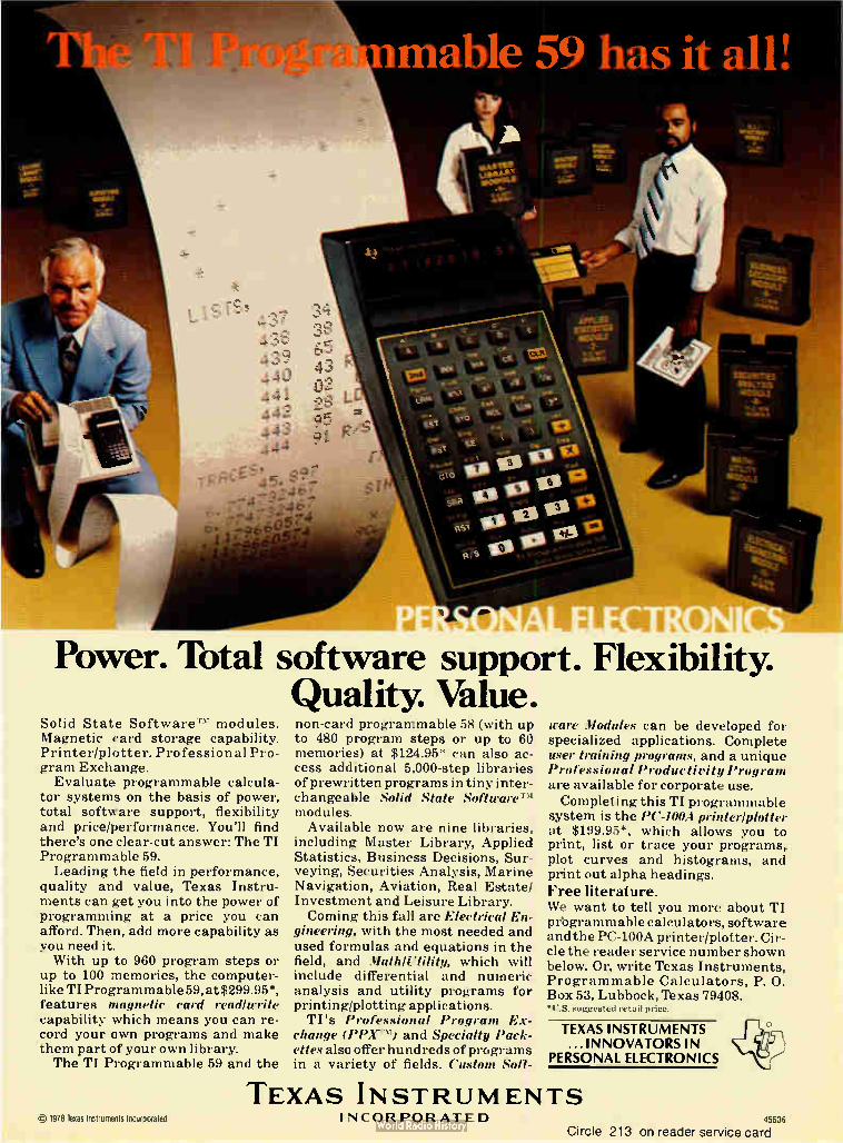
mable 59 has it all!
efoge Power. Total software support. Flexibility.
Quality. Value. Solid State Software." modules. Magnetic card storage capability. Printer/plotter. Professional Pro-gram Exchange. Evaluate programmable calcula-
tor systems on the basis of power, total software support, flexibility and price/performance. You'll find there's one clear-cut answer: The TI Programmable 59. Leading the field in performance,
quality and value, Texas Instru-ments can get you into the power of programming at a price you can afford. Then, add more capability as you need it. With up to 960 program steps or
up to 100 memories, the computer-like TI Programmable 59, at $299.95*, features magnetic card read/write capability which means you can re-cord your own programs and make them part of your own library. The TI Programmable 59 and the
non-card programmable 58 (with up to 480 program steps or up to 60 memories) at $124.95* can also ac-cess additional 5,000-step libraries of prewritten programs in tiny inter-changeable Solid State SoftwareT`i modules. Available now are nine libraries,
including Master Library, Applied Statistics, Business Decisions, Sur-veying, Securities Analysis, Marine Navigation, Aviation, Real Estate/ Investment and Leisure Library. Coming this fall are Electrical En-
gineering, with the most needed and used formulas and equations in the field, and Math/Utility, which will include differential and numeric analysis and utility programs for printing/plotting applications. TI's Professional Program Ex-
change (PPX") and Specialty Pack-ettes also offer hundreds of programs in a variety of fields. Custom Soft-
ware Modules can be developed for specialized applications. Complete user training programs, and a unique Professional Productivity Program are available for corporate use. Completing this TI programmable
system is the PC-100A printer/plotter at $199.95*, which allows you to print, list or trace your programs, plot curves and histograms, and print out alpha headings.
Free literature. We want to tell you more about TI prbgrammable calculators, software and the PC-100A printer/plotter. Cir-cle the reader service number shown below. Or, write Texas Instruments, Programmable Calculators, P. 0. Box 53, Lubbock, Texas 79408. *U.S. sugirested retail price.
TEXAS INSTRUMENTS ... INNOVATORS IN
PERSONAL ELECTRONICS
cj 1978 Texas Instruments Incorporated
TEXAS INSTRUMENTS INCORPORATED 1560c,
Circle 213 on reader service card

New products
around: it measures only 1.90 by 0.78 by 0.21 in. But size is not the unit's only drawing card, for the HDSC-14 has been designed for use in systems where many other units of its type cannot perform. Key to the unit's versatility is its
low, ± 0.2% variation in scale factor. This allows the unit to be used, for example, in the resolver mode to generate independent sine and cosine signals for a plotter —signals that retain consistent amplitude accura-cy. In addition, the unit accepts reference inputs ranging from dc to 1 kHz, so its output could be used directly to generate the sweep of a plan position indicator display for radar systems. The unit's output settles to its
final valde in under 20 is for a 180° step, and has a maximum value of 2 mA. Its input is compatible with
both complementary-metal-oxide-semiconductor and transistor-tran-sistor logic, and it is protected against transients. The HDSC-14 requires ± 15-v supplies and a supply that ranges from 4.5 to 13 for its c-mos logic. The standard version is accurate
to within ± 4 minutes and is priced at $495 for the 0°-to-70°C unit and at $595 for the — 55°-to- +125°C model. Versions with higher, ± 2-min. accuracy are also available at a 25% increase in price. Delivery is from stock to eight weeks. ILC Data Device Corp., Airport International
Plaza, Bohemia, N. Y. 11716. Phone (516)
567-5600 [373]
Transducers face up to
tough environments
Designed for low-pressure measure-ments in media such as mild caustics or acids, the series 1700 linear inter-
grated-circuit transducers do not use protective diaphragms to isolate sensing elements from the media. Instead, their strain-sensing silicon diaphragms are themselves coated with a protective glass layer.
Transducers that sense gage or absolute pressures are available, with maximum ranges as high as 100 psig or 100 psia. Full-scale output is typically 100 my and the effects of nonlinearity and hysteresis result in a maximum combined error of ± 0.25% of full span. Individual
transducers are priced at $60. Foxboro/I.C.T. Inc., 1750 Junction Ave.,
San Jose, Calif. 95112. Phone (408) 998-
8720 [376]
Velocity transducers speed
design with high output
The ability of VT-Z series velocity transducers to produce relatively high output voltages allows them to be used without output amplifiers, thus reducing design time, circuit complexity, and required hardware. Voltages as high as 600 mv/in./s are produced by the series' 1-in.-range model; the 10-model series covers the linear range from 0.5 to 20.0 in.
Employing a rotating permanent magnet to induce a voltage in differ-entially wound coils, the transducers require no excitation voltage or field calibration. The dc output voltage produced is linear to within 1.0% of full scale.
In single quantities, prices start at $84.90 for the 0.5-in.-range model. Schaevitz Engineering, P. O. Box 505,
Camden, N. J. 08101. Phone (609) 662-
8000 [377]
Thermocouple amplifier
handles two at a time
Designed for use with E, J, K, and T type thermocouples, the SA-TC thermocouple amplifier module can simultaneously process outputs of two thermocouples. Internal cold reference junctions provide automat-ic compensation for each channel, and transformer coupling isolates the transducer for off-ground mea-surements.
Front-panel adjustments by the' operator set the zero point and span of the module, whose output range is 0 to 5 y dc. The SA-TC is accurate to within 0.1% of full scale ±1°. Outputs of 4 to 20 mA and eight-
point linearization are available as options. The unit is priced at $400 in single
quantities. Delivery is 30 days. Sensotec Inc., 1200 Chesapeake Ave.,
Columbus, Ohio 43212. Phone 1-800-848-
6564 toll free [379]
Meter monitors and controls
system backup power
Having a backup battery should mean not having to worry about power loss, so having to worry about the status of the backup battery is sort of self-defeating. However, the model 966 ampere-hour meter and controller can restore purpose by monitoring and controlling standby power. In its normal operating mode, when installed across a customer-supplied shunt, the unit's meter displays the percent of full battery
214 Electronics/September 28, 1978

Bose er low-power switchers
Ms' stamp of approval. Here's wily.
Low cost. Only Boschert is delivering switching power supplies that are cost-competitive with linears in the 25 to 400 watt range. That's because Boschert is focusing exclusively on the design and production of low-power switchers. Our modular design techniques are lowering prices while maintaining quality and reliability.
Small, light and efficient. Boschert power supplies are perfect for microprocessor-based systems and other digital equipment because they're five times smaller than comparable linear supplies, and nine times lighter. Because little power is wasted as heat, they require no fans — only convection cooling. And Boschert switchers are well-suited for high pulse-load environments such as printers: when additional power is required, it is available instantaneously — at any output.
Multiple ouf puis. Boschert power supplies are convenient for system designers because they offer as many as six outputs in flexible voltage configurations. Our
computer-evaluated modular design approach with 90 percent common components allows us to meet your unique technical requirements at low cost, with a minimum of design time.
Boschert experience and reliability. Boschert has assembled the finest switching power supply design and production team anywhere. Our facilities are prepared to meet expanded production schedules rapidly and reliably — with rigorous automatic burn-in, wave soldering and testing techniques. With over 50,000 of our power systems in operation today, we're the leading company for low-power, low-cost OEM switchers.
For information, contact a Boschert tat ive. Or write Boschert Incorporated, 384 Santa Trinita Ave., Sunnyvale,
\ CA 94086. Phone (408) 732-2440.
dt‘
\ Ç TWX 910-339-9241. The finest ) microprocessor-based systems are
powered by Boschert. What about yours?
Circle No. 215 for more information

4-bit, one-chip micro-
computers
Brainy enough for anything
from TV games to industrial controls.
Block diagram of MN1400 with on-chip, 1024x8-bit ROM.
Now Panasonic offers you a whole family of TTL compatible, one-chip microcomputers. So you can choose the combination of features and capabilities that are most cost-effective for your application. From appliances to gas pumps and electronic scales, to copiers, POS and intelligent terminals, tractor controls and countless others.
Why pay for costly I/O interfacing when Panasonic puts it all on the chip? Our MN1400 family is ideally suited for control
functions with its extensive array of on-chip lo
facilities. There's an 8-bit presettable counter'timer, a clock generator, an arithmetic logic unit, and several input and output ports. Units are available with a self-contained 1024x8-bit ROM and a 64x4-bit RAM memory.
Still more flexibility and efficiency from Panasonic. For flexibility, our instruction set contains up to 75
instructions. To give you TTL compatibility, all our family members operate on + 5V. And for extra computing speed, we've utilized N-channel E. MOS construction.
Panasonic can help you cut development time and costs. Our Evaluator, the MN1499, can help you design, evaluate and debug programs quickly. In addition, software is available for a number of applications.
The Panasonic family of one-chip microcomputers.
Package
M141400 40 Pin
Plastic DIP
MN1402 28 Pin
Plastic DIP
MN t498 40 Pin
Plastic DIP
MN1499 64 Pin
Ceramic DIP
Power Supply i 5V • 59 • 5V
10, )
• 5V
10, , ) ------' Instructier Cycle Time
I0,s 10,, b
Instruction set 75 5/ 68 /5
Instruction Memory
Instruction ROM
Internal 1024 1 8 bits (8192 bits)
Internal /68 n 9 bits (6144 bits)
External 1024 1 8 bits (8192 bits)
External 2048 n 8 bits (16364 bast
Total on Chip RAM
64 n 4 bits (256 bits)
32 x 4 bits (128 bits)
64 a 4 Ws (256 bits)
64 n 4 bits (256 bits)
16-bit microprocessors, too. They're ideally suited for a wide variety of com-
puter peripheral and business machine applications. Designed with minicomputer architecture LOCOS MOS N-channel construction for optimum speed and thruput efficiency.
For complete information and prices, write to Panasonic Electronic Components, One Panasonic Way, Secaucus, N.J. 07094; or call (201) 348-7269.
Panasonic e just slightly ahead of our time
Circle 216 on reader service card

New products
capacity available. The full-scale value is field-adjustable using con-trols protected by a removable front panel. The controls permit users to tailor the meter to an individual system's charging and discharging characteristics, and a suppression switch can be used to eliminate the effects of long-term drift and trickle charging on the display. The unit's control capability con-
sists of three normally open relays, two of which close below levels preset by the user and one of which closes. above. Programmable by a switch that lets the meter be set to any desired reading, the relays can be used to trip alarms, shed battery load, or prevent overcharg-ing of the battery. The 966 also provides a dc output that varies from 5 v at full capacity down to 0.33 for remote sensing.
Priced at $595, the 966 is avail-able from stock to three weeks. Curtis Instruments Inc., 200 Kisco Ave., Mt.
Kisco, N. Y. 10549. Phone (914) 666-2971 [375]
Reflective scanner detects
very small objects
The Tele-Skan S24131 is a high-resolution reflective scanner that can detect an object with a diameter or width of 0.040 in. from 2.5 to 3.5 in. away.
Depending on application, the unit's output current ranges from 50 to 150 LIA. It has an optimum response time of about 1 ms. Priced at $250 each, the unit is deliverable in quantity in from one to two weeks. Skan-a-matic Corp., P.O. Box S, Elbridge, N.Y. 13060 [3781
Now, the first data logger with get-up-and-go.
Take EMR's suitcase-sized COMPACT 3430 Data Logger away to those "difficult" sites where bulky equipment or hardwiring would be too inconvenient or costly. Just take it and leave it — anywhere, any time, for as long as a month. COMPACT's built-in battery and power source make it easy.
You can even take your pick of three models: one with a built-in line printer; one with a built-in cassette tape recorder; and one with a universal peripheral inter-face usable with a line printer, paper punch tape, tele-printer or modem. All three are microprocessor-con-trolled, providing keyboard programmabilityfor up to 30 analog inputs and 20 (optional) digital status inputs, with any mix of voltage or thermocouple inputs.
As simple to use as a pocket calculator, COMPACT's push-button control eliminates plug-in modules, and lets you set individual high and low limits, specify channel input type, skip channels and select scan intervals. A choice of three modes lets you record all input data, out-of-limit conditions only, or inputs as they pass through the set limits. You can even print out alarm conditions.
For more details ora demonstration, call or write today.
FSANGAMO WESTON Schlumberger
Sangamo Weston. Inc EMR Telemetry
P.O. Box 3041,Sarasota. F L 33578 813-371-0811
Electronics/S3ptember 28, 1978 Circle 217 on reader service card 217

Instant access to all American and International
Data Communications Standards
Data communications standards are undeniably necessary and helpful. B ut ... the proliferation of standards by the many committees and groups has left the data communications equipment user and designer searching through numerous publications to find the applicable standards for each job.
Now: that time- and effort-wasting trial is over.
With the publication of this landmark resource, you can quickly and accurately determine exactly which standards apply to the project at hand, and speedily integrate those standards into your own network requirements.
Presents all relevant data communications standards promulgated by:
• Consultative Committee for International Telephone and Telegraph (CCITT')
• International Organization for Standardization (ISO)
• American National Standards Institute (ANSI)
• Electronic Industries Association (EIA)
• Federal Telecommunications Standards Committee (FTSC)
Need to know the latest standards for...
• data transmission over public data networks?
• computers and information processing systems?
• peripheral equipment?
• signal quality and analog and digital interfaces?
It's all here, and more, complete with introductory descriptions of the groups that promulgate the standards.., and relational charts of similar interfacing standards produced by different groups.
Order today using this coupon!
Edited by
HAROLD C. FOLTS, data communi-cations standards consultant; and HARRY R. KARP, Editor-in-Chief, Data Communications, McGraw-Hill Publications Company 1133 pages
Design Engineers Find the technical specs you need instantly. Planning Engineers Determine which standards apply to a vast range of networks and components.
Operations Managers Learn whether the equipment you're buying will operate at all applicable standards.
Return coupon to: Data Communications Standards P.O. Box 669 Hightstown, New Jersey 08520
Send me copy (copies) of DATA COMMUNICATIONS STANDARDS (099782-9) on a 10-day money-back guarantee. I un-derstand that if I am not absolutely satisfied, I may return the book(s) within ten days at no further obligation. Otherwise, McGraw-Hill will bill me $165. for each copy, plus applicable sales tax, shipping and handling charges.
Name
Title
Company
Address
City State Zip
SAVE MONEY! Enclose payment In full, plus local sales tax, and McGraw-Hill pays all regular shipping and handling charges. Ten-day money-back guarantee still applies.
Check enclosed BIll me Bill my company Company purchase order This offer subject to acceptance by McGraw-Hill.
EL 1

DRALORIC Metal Film ReSistors
now produced in the U.S.A.
DRALORIC, located in W-Germany, Europe's leading manufacturer of passive components, with more than half a century of experience has opened a plant in Norwich/ Connecticut. Why not improve the reliability of your products by incorporating DRALORIC SMA Metal Film Resis-tors? The advanced technology offered by DRALORIC provides out-
standing characteristics, such as
superior long term stability. The metal film resistors are in accord-ance with MiL-R-10509 (RN) and MIL-R-55182 (RNR).
Sales representative:
United Mineral & Chemical Corp. 129, Hudson Street New York, N.Y. 10013
For further information and samples Phone: 212-966-4330 please contact: Mfg. facility: DRALORIC ELECTRONICS CORP. One Winnenden Road
Norwich, Connecticut Phone: 203-886-0151
DRALORIC DRALORIC ELECTRONICS CORP.
WAK 7
42 E
Circle 219 on reader service card

Does its broad line malq Centronics matrix printer family
Eivl enseryi es currently hi us oraruegnhtl y conti nuallythe9 mCe ntronicsocie elsx pa t a. nandda7i0nraOgnge
of print e printer fe speeds
much more to it than just breadth of line. For example, there's a choice of 6 different types of forms handling capability; choice of uni- and bi-directional operation; and choice of 80 and 132-column formats. Why so much choice? It comes from the simple, highly flexible modular 700 series design that delivers superior reliability, exceptional parts commonality — and competitive prices. And like all Centronics printers, the 700 series is fully supported by the
largest worldwide service organization of any printer company. For com-plete 700 series information write or call today. Centronics Data Computer Corp., Hudson, NH 03051, Tel. (603) 883-0111.
cEnTrzonirs PRInTER5 Simply Better
Circle 220 on reader service card Circle 221 on reader service card —>

L258
ONLY FROM LAMBDA
New 2Amp Monolithic Voltage Regulator
a
• Both fixed and variable 2 amp regulators. LAS 1605-1615/16U • Guaranteed output-input differential 2.1V 0-125°C
• Pin for Pin replacement of 1.5 amp device for increased current capability
• Low thermal resistance 2.5°C/W • 20 watt power dissipation • 100% of all devices burned in under load
• A complete line - 1.5 amp, 2 amp, 3 amp and 5 amp
A LAMBDA SEMICONDUCTORS

¿LAMBDA LAS 1600, 16U SERIE FIXED AND VARIABLE
2 AMP, 20 WATT MONOLITHIC VOLTAGE REGULATORS
Description 2 amp positive regulator
The LAS 1600 series three-terminal positive voltage regulators are designed for applications requiring a well regulated output voltage for load currents up to 2 Amperes. The monolithic construction of the integrated circuit permits the incorporation of current-limiting, thermal shutdown, and a safe-area protection on the chip providing protection for the series pass Darlington under most operating conditions. A low-noise temperature-stable diode reference circuit is the key to the excellent temperature regulation of the circuit. A very low output impedance ensures excellent load regulation. A hermetically sealed steel TO 3 package is used for high reliability and low thermal resistance. The pin connections of the devices are the same as the LAS 1500 series thus allowing existing designs to be up-graded to 2 Amperes without layout or wiring changes.
The LAS 16U, a four terminal positive voltage regulator, is designed for applications requiring a well regulated output voltage for load currents up to 2 Amperes. Output voltage can be adjusted over a 4.0 to 30 volt range by the use of a single potentiometer. The monolithic construction of the integrated circuit permits the incorporation of current limiting, thermal shutdown, and safe area protection on the chip providing protection for the series pass Darlington under most operating conditions. A low-noise temperature-stable diode reference circuit is the key to the excellent temperature regulation of the circuit. A very low output impedance insures excellent load regulation. A hermetically sealed 4-pin TO 3 package is used for high reliability and low thermal resistance.
Regulator Performance Specifications
TEST CONDITIONS
PARAMETER SYMBOL VIN TJ
LAS 1605 — 1615 LAS 16U TEST LIMITS TEST LIMITS
MIN MAX MIN MAX UNITS
Input Voltage V IN 10mA 0-125°C . .V +2.6V . .301351 0 ) . . .V +2.6V. .30130" ) . .Volts o vs) Output Voltage " • Vo V1 to V2. .10mA to 2.0A. 25°C .0.D5V0(2) .1.05V0 4%(") 30 Volts Input Output Differential 2 OA 0-125°C 2 6 -0) 2 6 -(1) V 1N'Vo Volts Input Output Differential VIN-V0 04A 0-125°C - 25 - 25 Volts Output Current lo 25°C 20 20 Amps Standby Current ID V1 25°C 50 15 50 15 mA Standby Current Change with Input .10 V1 to V2. .10mA 25°C 50 50 mA Standby Current Change with Load ID V1 .10mA to 2.0A. 25°C 50 50 mA Maximum Current Limit ILIM .V0+5V 25°C 3 5 Amps
Junction-to-case Thermal Resistance Power Dissipation(4, .PD
R 0..IC +32210:5550 20 2 5
1 0
°C per Watt
Watts s
Short-Circuit Current , .1s 25V 25°C
Storage Temperature Ts -65 -65 +150 °C per Watt Maximum Operating Junction Temperature Tj -55 +150 -55 +150 °C per Watt Regulation-LoadM . . .1RED/L . .Vo+5V 10mA to 2.0A. 25°C 06 06 %V0 Regulation-LineW . . . .(REG/IN. .V1 to V3 3 OA 25°C 20 1 0 %V0 Temperature Coefficient Tc V1 0 1A 0-125°C 002 002 %V01°C Output Noise Voltage(°) VN V1 0 1A 0-125°C 10 10 µVrms/V Ripple Attenuation. .RA V1 1 OA 0-125°C .60(° ) 60(°) dB Control Voltage Vo V1 to V2. .5mA 25°C 3 625 3 925 Volts
(1)
(2)
(3)
(4)
(6) (6)
(7)
VI = V. + 3V, V2 = V + 10V, V3 = Vo + 12V or the maximum total input voltage or differential, whichever is less.
Nominal output voltages are specified under ordering information. Instantaneous regulation, average chip temperature changes must be accounted for separately.
Derate above Tc = 100°C 8)400 mw/ C. Specified in µVrms/volts output BW = 10 Hz - 100K Hz. Ripple attenuation is specified for a 1 Vrms, 120 Hz input ripple. Ripple attenuation is a minimum of 60 dB at 5V output (for LAS 1600 Serles), 62 dB at 3.75V output (for LAS 16U).
Value of 30V applies to Vo of +5 to +12V. Value of 35V applies to V, of 15V.
(8) Maximum input-output differential Is constrained by 25V, current limit-SOA, and maximum power specifications, whichever is less. Care should be taken to avoid differential voltages greater than the maximum specified. However, the devices employ a power limiting circuit to protect the series pass Darlington from overvoitage stress conditions such as an inadvertent short on the output. If the over-stress exceeds 25 Volts, power must be interrupted to restore operation.
(9) Minimum input voltage is 6.525V.
(10) V. = Vc (1 + R1) R1 = resiStance from output to control.
R, = resistance from control to common.
(11) Instantaneous regulatron, average chip temperature changes must be accounted for separately.

Operational Data
25
(/)
< 20
W
0 15
F3 10
cc
3' 5 o
o 55
3.0
z 2.5 Ui cc
2.0
E o > 1.5
1.0
o .5
-22 20 40 60 80 100 120 140 150 160
CASE TEMPERATURE 1°C) MEASURED
BETWEEN THE TERMINALS
POWER DERATING
2A
IA
.5A
0 -75 50 -25 0 25 50 75 100 125
JUNCTION TEMPERATURE °C
TYPICAL INPUT-OUTPUT DIFFERENTIAL VOLTAGE VS JUNCTION TEMPERATURE
Functional Block Diagram
CURRENT
LIMITING
AMPLIFIER
VOLTAGE
REGULATION
AMPLIFIER
SENSE
LAS 1600, LAS 160
SAFE AREA
PROTECTION
0.251(S2 4
(DEPENDS ON Vol
4
INPUT
OUTPUT
CONTROL FOR
LAS 160 ONLY
THESE INTERNAL CONNECTIONS
FOR FIXED LAS 1600 ONLY
COMMON
100
80
o
< 60 D
I- 40
Et 20
3.5
3.0
2.5
T - 25C
T = 125C
o o 5 10 15 20 25 30 35 40 45
NPUT OUTPUT DIFFERENTIAL
VOLTAGE, VOLTS
TYPICAL CURRENT LIMIT VS INPUT OUTPUT VOLTAGE
DIFFERENTIAL
11111111•111111111111111111
aillIZZEM1 1.11111
11111 VIN = 10+ 1V I = .5A o RMS 11111111111
11111 = VA° = 5V T 25°C 11111111
111111.11111111111111 010 100 1K
FREQUENCY, HERTZ
10K
RIPPLE ATTENUATION VS FREQUENCY
100
10V
5V
.5A
25 C
VIN =
V. =
lo =
TA =
100K
110 100 1K
FREQUENCY, HERTZ
10K
TYPICAL OUTPUT IMPEDANCE
VS FREQUENCY
100K
Price List V,
VOLTS MODEL
QTY
1-24
QTY
25-49
QTY
50-99
QTY
100-249
QTY
250-499
QTY
500-999
QTY
1000-2499
QTY
2500-4999
5 LAS 1605 $3.00 $2.80 $2.60 $2.40 $2.24 $2.15 $2.05 $1.90 6 LAS 1606 3.00 2.80 2.60 2.40 2.24 2.15 2.05 1.90 8 LAS 1608 3.00 2.80 2.60 2.40 2.24 2.15 2.05 1.90 10 LAS 1610 3.00 2.80 2.60 2.40 2.24 2.15 2.05 1.90 12 LAS 1612 3.00 2.80 2.60 2.40 2.24 2.15 2.05 1.90 14 LAS 16CB 3.00 2.80 2.60 2.40 2.24 2.15 2.05 1.90 15 LAS 1615 3.00 2.80 2.60 2.40 2.24 2.15 2.05 1.90
4-30 LAS 16U 4.50 4.20 3.90 3.60 3.40 3.25 3.08 2.85

Outline Drawing
LAS-1605-1615
0.188R MAX BOTH ENDS
LISS& 0.059
9,C13 DIA _ 0.038 2 LEADS
0.151 0.161 DIA 2 HOLES
1.050 MAX
0.525R MAX
..--L575 MAX - 0.875 MAX DIA
FUNCTION
PIN 1600SERIES
1 Input 2 Output 3 Common
.4- 50 250
.480 74-41T
0.420 574-4-6
(CASE)
LAS-16U
0.175R MAX BOTH ENDS
0.064 b703-6
T------
0.043 I5.7-)31 () IA -
4 LEADS
1.190 1.184
72°
1.050 MAX
0.525R MAX
.449
.445
0.450
0.480 Tin
470./ I1 Y5 .01 _LI L .192 .280
5 (CASE) .074 ...IL._ :irg • 7176 I...668 «..1
.161 DI, Trr 2 HOLES
FUNCTION
PIN 16U
1 Common (elec) 2 Control 3 Output 4 Input 5 Common
VOLTAGE PF
LINE 1 ••••••• 5000
TANTALUM 2/./ F SOLID Cl
RIPPLE <2mVrms LINE AND LOAD REGULATION <0.2%
Connection Diagrams
RECTIFIED INPUT
5000 Cl ;IF
I 2pF SOLID — TANTALUM
RECTIFIED INPUT
o
LAS 1605
3
V + 'a
•ylie Io
o
'L i
LOAD
_t
CURRENT REGULATOR CIRCUIT
5.0 AMP ADJUSTABLE POWER SUPPLY CIRCUIT
OUTPUT
5.0 AMP POWER SUPPLY CIRCUIT
— C.
200rd
Lambda staffed sales and service offices
ATLANTIC REGION Melville, New York 11746 515 Broad Hollow Road
Tel. 516-694-4209 TWX: 510-224-6484
NORTH-EASTERN REGION Lexington, Massachusetts 02173
2 Militia Drive Tel 617-861-6028 TWX: 710-326-7558
SOUTH-WESTERN REGION Corpus Christi, Texas 78410
121 International Drive Tel. 512-883-6251
MID-WESTERN REGION Arlington Heights, III. 60005 2420 East Oakton St.. Unit
Tel 312-593-2650 TWX: 910-222-2856
FAR-WESTERN REGION Carson, Calif. 90746 20601 S. Annalee Ave
Tel. 231-537-2890 TWX: 910-345-7649
NORTH-WESTERN REGION Sunnyvale, California 94086
599 N. Mathilda Ave.. Tel 408-245-0380 TWX: 910-339-9243
FOR TECHNICAL INFORMATION CALL JIM ARNOLD AT (512) 883.6251 121 INTERNATIONAL DRIVE CORPUS CHRISTI, TEXAS 78410
zsgammilia ELECTFPNICS

Ride high with Mostek!
Don't wait for your career to "peak in the Valley" when you can ride high with Mostek today. A Mostek career combines the flexibility and upward mobility of a small company with the security and prestige of an industry leader. Look at what Mostek has to offer you:
A growth company. A technology leader in memories, microcomputers, memory systems, telecommunications, and more. Plus an unbeatable location in Car-rollton, a northern suburb of Dallas.
Dedicated professionals brought us to the forefront, and we want the same to keep us there. We're looking for design, product, test and process engineers, as well as planners, mar-keters, and technicians.
Interested candidates are invited to return the coupon below. We'll get back to you for a prompt consultation.
Name Job Title
Address
Telephone
Present Employer Degree
My career interests are
Direct response to the Professional Placement Department, Mostek,
1215 West Crosby Road, Carrollton, Texas 75006.
We are an equal opportun-ity employer, m/f.
MOSTEIK.„,

THE INSIDE STORY OF A =WY SW1TCHER RO ASSOCIATES a pioneer in
20 KHz switching power supplies with over 15 years of advanced design and manufacturing expertise is proud to introduce the latest series 700 switcher, producing 5V at 120 amps in a package less than 3.5 inches high. Incorporating the latest advances in power semicon-ductors, the model 712 delivers 600 watts without paralleling power transistors. RO has demonstrated its reliability
with over 60,000 switchers now in
Epoxy vacuum impregnated magnetics
Soft start oscillator
Die-cast chassis
Transient suppressors
The leader in quality switching power supplies
the field. This reliability has been achieved by employing such tech-niques as a four day burn-in, rigor-ous testing and inspection, and epoxy vacuum impregnated mag-netics. All RO switchers have a full five-year warranty. The model 712 comes in a 3.5" x
8" x 13" package, which produces 1.6 watts per cubic inch due to its high efficiency of 75%. The unit has 115 or 230 VAC input, 47-60 Hz. Brown out protection to below 95 VAC is included. Units can be
Plug out PC cards
paralleled simply by connecting the outputs. 5V-50A and 5V-100A as well as
12-15V at 40A and 24-30V at 20A models are available in the same package.
All units have current limiting short circuit protection. Overvoltage protection is also standard.
For the complete Inside Story of the full line of reliable off the shelf switching power supplies, call or write for our new 24 page free catalog.
Computer grade components
Soft start limits inrush
RO ASSOCIATES RO ASSOCIATES, INC.
Circle 226 on reader service card
/ 246 CASPIAN DRIVE / SUNNYVALE, CA 94086 / (408) 744-1450 / TWX 910-378-5929

Products newsletter LED tester aimed
at auto makers
E-H International Inc., Oakland, Calif., is checking the reactions of Detroit auto makers to its new VIM model 4000 tester for arrays of light-emitting diodes. The company expects to find a ready market for its $28,500 test system because the use of LEDS in cars is expected to rise dramatically as microcomputers penetrate more deeply into Detroit's product lines. Based on National Semiconductor Corp.'s 16-bit IMP 16/500 microprocessor, the 4000 can test arrays of up to 10 characters with up to 40 segments per character. It tests electrical parameters as well as such optical parameters as brightness uniformity.
I Corp. to announce The third in the series of computer-aided design packages developed by I Corp., Berkeley, Calif., will soon be announced. Like the PC-50 and
third CAD package SC-50, the new MD-50 is designed to provide users with interactive computer graphics hardware and software that mate with the Tektronix 4051 graphics terminal. Just as the first two packages provided low-cost CAD help with printed-circuit and schematic-diagram layout, the new one will provide the same kind of help for mechanical design. Pricing for the MD-50 and the associated Tektronix gear starts at $16,000.
Rf transistors Siemens AG of West Germany is coming out with two microwave silicon d eveloped transistors—thefor 1.2-GHz BFQ 17 and the 5.5-GHz BFQ 19. Both npn
planar transistors can be soldered onto film-circuit substrates using the film substrates reflow process. For protection against adverse environments, particularly
moisture, the chips are nitride-passivated. A titanium-gold metalization scheme ensures high reliability and long-term stability of the internal connections. Both devices come in an SOT-89 package.
Kolimorgen licenses In the first step of a program for independent manufacturing and market-ing of Multiwire boards using Kollmorgen processes and quality standards,
Multiwire technology Kollmorgen Technologies Corp., Glen Cove, N. Y., has concluded an
agreement with Space Circuits Ltd. of Canada. The Space Circuits efforts will be concentrated in upstate New York, Minnesota, and Canada. Multiwire boards are computer-designed interconnection systems that use insulated wiring connections. This permits conductor crossovers, which, in turn, allows very-high-density circuitry.
A new source of A new manufacturer of aluminum electrolytic capacitors — Deleon Elec-tronics, Canoga Park, Calif. —is offering off-the-shelf delivery of a line of
electrolytic miniature units in more than 100 sizes. The capacitors are available with capacitors axial or radial leads. They are all packaged in cylindrical aluminum cans
with insulating sleeves.
Price changes The following price changes have been announced: • A 38% price reduction on 4,096-word random-access memories for its refresh vector graphics system has been put into effect by Megatek Corp., San Diego, Calif. • Control Data Corp., Minneapolis, Minn., has increased the purchase and lease prices of selected disk pack and disk cartridge products by an average of approximately 5%.
Electronics/September 28, 1978 227

New products/materials
A laser recording material permits a green argon laser with only 5-mw, 100-ns pulses to record spots 0.8 etm in diameter with good contrast. Called Drexon, it is sufficiently sensitive for commercially available semiconductor lasers to record effec-tively on it. According to the compa-ny, this combination of sensitive direct-read-after-write material and semiconductor laser is what is needed for laser data recording to develop into a commercial market. Drexon requires less than half the laser power of previous materials. In volume, it is expected to cost 10¢ per megabyte compared with $3 per megabyte for magnetic disks and 40¢ per megabyte for magnetic-tape cartridges. Drexler Technology Corp., 3960 Fabian Way,
Palo Alto, Calif. 94303 [475]
A liquid-crystal fluid allows displays made with it to have 30-ms on and 45-ms off times. These times are compatible with the low-level drive
voltage of the Intersil 7106 voltmeter chip and the Siliconix DF 411 decoder-driver circuit. Displays can be updated at a rate of 10 times per second at 25°C (73°F) and 3 times per second at 0°C (32°F). Operating temperature range is — 5°C (23°F) to + 70°C (158°F). Hamlin Inc., Lake and Grove Streets, Lake
Mills, Wis. 53551 [476]
A machinable ceramic can be used for a variety of high-temperature processes at temperatures up to 1,100°C. Cured in a 2,000°F oven, the alumina-silicate material devel-
ops the hardness of tool steel. Toler-ances, as fired, of ± 0.002 in. can be attained, and the material may also be ground to tolerances as close as ±0.0001 in. The 502-1100 ceramic exhibits a low thermal expansion rate after curing of 1.5 X 10 -6 in./in./°F. It is available in standard plates and rods from 2 by 2 in. up to 6 by 6 in. with diameters from 0.25 up to 3 in. Special sizes and shapes are available on request and can be delivered within one week. Aremco Products Inc., P. 0. Box 429, Ossin-
ing, N. Y. 10562 [477]
Self-adhesive lead foil disks are useful for masking in electroplating, chemical milling, and other applica-tions. The disks range in diameter
from 0.25 to 2 in. (6.35 to 50.8 mm) in increments of 0.125 in. They oper-ate in the range of —65° to + 225°F ( — 54° to + 106°C). Higher temper-atures can be accommodated for brief periods. They are available in rolls of 1,000 and 5,000 disks. Webtek Corp., 4326 W. Pico Blvd., Los
Angeles, Calif. 90019 [478]
High-voltage ferrite cores are avail-able in a wide variety of sizes and configurations of which most are
9: o custom-engineered for a specific application. These materials are characterized by low loss and a narrow hysteresis loop. Ceramic Magnetics Inc., Fairfield, N. J.
07006 [479]
A continuously extruded elastomer provides high electrical conductivity to shield against electromagnetic interference and static discharge and can be used as a seal against mois-ture. This silicone material, Consil-E, has a volume resistivity of less than 0.09 ohm-cm and a minimum tensile strength of 50 psi. It can be stretched to a minimum of twice its normal length. It comes in solid-cord, D, tubular, rectangular, and P shapes. In quantities of 250 ft or less, the price for standard cord shapes ranges from $1.80/ft (0.062-in, di-ameter) to $10.92/ft (0.375-in. di-ameter). Technical Wire Products, 129 Dermody St,
Cranford, N. J 07016 [480]
228 Electronics/September 28, 1978

Latest 1 kW UHF Transmitter
1111111.111.
1
Circle 229 on reader service card
laboratoire igénéral des ,télécommunications 51, bd de la République 78400 CHATOU (France) Tél. : 976.00.13 + Télex: 691-833
Distributed in U.S.A. by: THOMSON-CSF INC. 75 Rockfeller Plaza NEW YORK 10019 NY Tel. (212) 977 22 00 Telex 12.5118 TCI NY
- single 19 inch cabinet
- only one tube
- common amplification
1. Driver stage Non frequency conscious amplifiers = Ease of maintenance and small replacement part stock
Amplifiers and filters in separate modules = Simple adjustment
Up to the tube stage all amplifiers have built-in redundancy = Programme safeguard
2. If modulator Automatic video level control from vertical interval test signals = Stability of modulation Wide use of microelectronics = Reliable compact unit
•
THOM°S:N-CSF

MiCROPROCeSSORS TTTTTTTTYT
TTTTTTTTTT
LaKe scale integRaten L I
APPLYING MICROPROCESSORS
TTTTTTTTTT
1T1IMM TTTTYTTTYT
TTTTTTTTTT
TTTTTTTTTT
'TIMM TTTTTTTTTT E-2'.•7=.77-7-•
New hardware, software and applications
Electronics io-ok series
CIRCU CIRCUltS CIRCUI1S CIRCUI1S CIRCUI1S CIRCURS fOR electRonics engnceRs engineeRs engineeRs engineeRs engineeRs engineeRs Bectrorlics engineeRs Book • Senes engineeRs en IneeRs
B_axs OF Quinn COMMUNKXMONS daTa --dam daTa
desIgn tec ni ues
foR electRonics en ineeRs
memory design memory design
memory design: MICROCOMPUTERS TO MAINFRAMES
memory design memory design Bectronics ikkek Series
new new new new pRoduct tends in etectRonics new new - - new new new new new numbeR one
Bectronics Book-- Series
Electronics Magazine Book Series
1. Microprocessors What you must know about available microprocessor technology, devices, informa-tion, 4th printing. $8.95
2. Applying Microprocessors 2nd and 3rd generation tech-nology. 26 detailed applica-tions from data networks to video games. $9.95
3. Large Scale Integration Covers the basic technology, new LSI devices, LSI testing procedures, plus system design and applications. $9.95
4. Basics of Data Communications Includes 47 articles from Data Communications magazine covering more than 11 key areas. $12.95
5. Circuits for Electronics Engineers Contains 306 circuits arranged by 51 functions from Ampli-fiers to Voltage Regulating Circuits. Saves design drudgery. $15.95
6. Design Techniques for Electronics Engineers Nearly 300 articles drawn from "Engineer's Notebook." A storehouse of design problem solutions. $15.95
7. Memory Design: Micro-computers to Mainframes The technology, devices, and applications that link memory components and system design. $12.95
8. New Product Trends in Electronics, Number One From "New Products," state-of-the-art materials and equip-ment, arranged according to function. $14.95
Electronics Book Series P.O. Box 669, Hightstown, NJ 08520
1. Microprocessors Send me copies at $8.95 per copy.
2. Applying Microprocessors Send me copies at $9.95 per copy.
3. Large Scale Integration Send me copies at $9.95 per copy.
4. Basics of Data Communications Send me copies at $12.95 per copy.
5. Circuits for Electronics Engineers Send me copies at $15.95 per copy.
6. Design Techniques for Electronics Engineers Send me copies at $15.95 per copy.
7. Memory Design: Microcomputers to Mainframes Send me copies at $12.95 per copy.
8. New Product Trends in Electronics Send me copies at $14.95 per copy.
Discounts of 40% on orders of 10 or more copies of each book.
If after my 10-day free-trial examination I am not fully satisfied I understand that my payment will be refunded.
D Payment enclosed ED Bill firm D Bill me Charge to my credit card: D American Express
BankAmericard/Visa
Acct No.
D Diners Club D Master Charge'
Date Exp.
'On Master Charge only,first numbers above name
Name Title
Company
Street
City
Signature
State Zip
230 Electronics/September 28, 1978

Top-Convenient through-the-wal I mount to conserve
clean-room space.
Above-High-speed planetaries and two S-Gun Sources for
excellent step coverage.
Microprocessor control plus diagnostic package for
automatic deposition and troubleshooting.
varian
Proven? Yes! Major wafer fab facilities around the world now rely on this system for superior coatings.
It's a turnkey package with: S-Gun Sources that sputter up, so that debris does not fall on wafers; dynamic rate and thickness control; stable power supply. planetary fixturing; microprocessor control for repeatability; and opening front and back for easy maintenance.
Add the rf matching network (seen on the left side of the bell jar) for pre-deposition sputter-etch cleaning.
The Varian 3120-H delivers stoichiometric alloys at high rates. Interested? Call or write for data. Varian Palo Alto Vacuum Division, Palo Alto, CA 94303. 415-493-4000.
Circle 231 or reader service card

A new Introductory Electronics
SEMICONDUCTOR ELECTRONICS DESIGN. By E K. Manasse. 562 pp., illus. Today the microelectronics industry is going places faster than ever before. Are you going with it? To get and keep yourself completely up to date, you will do well to keep this volume nearby. Its chapters on design techniques are among the most complete and detailed ever published. 772/622 Pub. Pr., $21.95 Club Pr., $18.25
MICROPROCESSOR APPLICATIONS MANUAL. By Motorola Semiconductor Prod-ucts. Inc. 720 pp.. illus. Here's every piece of info you need to use MPU's to simplify your board layouts, lower your hardware costs, save precious time, design better and faster, and ver-ify your designs from the start! Overflowing with illustrations! 435/278 Pub. Pr., 832.50 Club Pr., $24.00
BE SURE TO CONSIDER THESE IMPORTANT TITLES AS WELL:
DIFFERENTIAL EQUATIONS FOR ENGINEERS. By T M. Creese & R. M. Haralick, 135/10X Pub. Pr., $17.50 Club Pr., $13.50
APPROXIMATION METHODS FOR ELEC-TRONIC FILTER DESIGN. By R. W. Daniels 153/086 Pub. Pr.. $31.50 Club Pr., $19.50
MANAGEMENT OF ENGINEERING PROJECTS, 2 / e. By V. G. Hajek. 255/342 Pub. Pr.. $16.95 Club Pr.. 12.50
HANDBOOK OF COMPONENTS FOR ELEC-TRONICS. By C. A Harper. 266/824 Pub. Pr., $39.50 Club Pr., $28.50
ENGINEERING CIRCUIT ANALYSIS, 3/e. By W Hayt & J. Kemmerly. 273/936 Pub. Pr.. $22.00 Club Pr., $16.50
OPTOELECTRONIC APPLICATIONS MANUAL. By Hewlet:-Packard 286/051 Pub. Pr., $22.50 Club Pr., $16.50
DIGITAL COMPUTER ELECTRONICS. By A. P
398315 Pub. Pr.. $14.95 Club Pr., $10.95
A USER'S HANDBOOK OF D/A AND AID CONVERTERS. By E. R Hnatek 767.149 Pub. Pr., $24.95 Club Pr., $18.50
HANDBOOK OF ENGINEERING FUNDAMEN-TALS, 3/e. By 9 Eshbach & M Souders 769,842 Pub. Pr, $31.50 Club Pr., $24.95
COMPLETE GUIDE TO DIGITAL TEST EQUIP-MENT. By W. Buchsbaum 772.088 Pub. Pr., $14.95 Club Pr., $10.50
DESIGNING WITH TTL INTEGRATED CIRCUITS. By IC Applications Staff of Texas Instruments, Inc. 322 pp., 399 illus. For gen-eral, technical, and non-engineer managers, all the information you need to get the most out of TTL devices-their design, economics, fea-tures, performance, applications. 637/458 Pub. Pr., $31.50 Club Pr., $22.50
HANDBOOK OF OPERATIONAL AMPLIFIER CIRCUIT DESIGN. By D. Stout. Edited by M. Kaufman. 434 pp., 223 illus. Compact, concise, highly concentrated, and containing a storehouse of information, this one-stop volume will help you solve any op amp circuit problem! 617/97X Pub. Pr., $29.65 Club Pr., $17.50
DESIGNING WITH OPERATIONAL AMPLIFIERS, Applications Alternatives. By J.G. Graeme. 269 pp., 203 illus. You can now guarantee that every elec-tronics decision you make will be easier, more productive, freer of error-and more consis-tently cost-effective! Topics include signal amplifiers, signal conditioners, absolute-value circuits, signal generators. computing circuits, data transmission circuits, and test and mea-surement circuits. 238/91X Pub. Pr., $21.50 Club Pr., $15.50
STANDARD HANDBOOK OF ENGINEERING CALCULATIONS. By TG. Hicks, Editor-in Chief. 1.200 pp, 428 illus. Tells you what to do. when to do it. and how to do it-giving step-by-step solutions to the design and application problems that engineers en-counter daily. Containing some 1,000 calculation procedures accompanied by worked-out numer-ical examples, it also features 4.000 related cal-culation procedures. 287/341 Pub. Pr., $27.50 Club Pr., $19.95
ELECTRONICS DESIGNERS' HAND-BOOK. Edited by L. J. Giacoletto. 2nd Ed. 2,344 pp., 1,686 illus. Now doubled in size and with 90% of its material new, this famous classic (first edition by Landee, Davis, Albrecht) has been thoroughly revised and updated to give you not only the how and the why of all your design work but also the how much of every design step you take! 231/494 Pub. Pr.. $52.50 Club Pr., $39.50
DIGITAL INTEGRATED CIRCUITS AND OPERATIONAL AMPLIFIER AND OP-TOELECTRONIC CIRCUIT DESIGN. Edited by B. Norris. 206 pp., 400 illus. Having this vast amount of case-tested data, proven shortcuts, worked-out circuit designs, and cir-cuit diagrams handy saves you valuable time for your other, more vital, areas of creative de-sign-and cuts down costs in all areas! 637/539 Pub. Pr., $19.50 Club Pr., 814.50
CIRCUITS FOR ELECTRONICS ENGINEERS. Edited by S. Weber. 396 pp., 346 circuits. This book is filled with the circuits you need in 51 areas-from amplifiers to vol-tage regulators-arranged in alphabetical order and grouped for easy finding. Use them "as is" or adapt them. Each has been tested and proved in action. 191/573 Pub. Pr., $19.50 Club Pr., $16.00
MICROCOMPUTER-BASED DESIGN. By J. B. Peatman. 540 pp., over 400 illus. You'll now do both your day-to-day as well as your best, most creative design work around a mi-crocomputer. This 100% specific how-to book makes it simpler than you've imagined and will open up a whole new world of "smart" instru-ments design for you! 491/380 Pub. Pr., $24.50 Club Pr., $17.50
232 Electronics/September 28, 1978

ELECTRONICS and CONTROL ENGINEERS' BOOK CLUB MEMBERSHIP ENROLLMENT CARD
Please enroll me as a member and send me the two books indi-cated. I am to receive the bonus book at the introductory price of $1.89 plus my first selection, plus tax, postage and handling. If not completely satisfied, I may return the books within 10 days and request that my membership be cancelled. If I keep the books, I agree to take a minimum of three additional books dur-ing the next two years at special Club prices (guaranteed 15% discount, often more). I will receive the Club Bulletin 13 times a year. If I want to examine the featured selection, I need take no action. It will be shipped automatically. It, however, I want an alternate selection—or no book at all-1 simply notify the Club by returning the convenient card always enclosed. I will always have a minimum of ten days in which to return the card and you will credit my account fully, including postage, If this is not the case. Membership in the Club is continuous but cancellable by me at any time after the four-book purchase requirement has been filled. This order subject to acceptance by McGraw-Hill. Orders from outside the continental U.S. must be prepaid. All prices subject to change without notice. Offer good for new members only.
INDICATE BY NUMBER THE TWO BOOKS YOU WANT Write Code # of $1.89 bonus Write Code # of
book selection here first selection here
SEND NO MONEY. SIMPLY MAIL THIS CARO TODAY AND WE WILL BILL YOU
NAME
ADDRESS
CITY
STATE ZIP
EXTRA SAVINGS: Remit in full with your order, plus any local and state tax and McGraw-Hill will pay all regular postage and handling charges.
ELECTRONICS and CONTROL ENGINEERS' BOOK CLUB MEMBERSHIP ENROLLMENT CARD
Please enroll me as a member and send me the two books indi-cated. 1 am to receive the bonus book at the introductory price of $1.89 plus my first selection, plus tax, postage and handling. If not completely satisfied, I may return the books within 10 days and request that my membership be cancelled. If I keep the books, I agree to take a minimum of three additional books dur-ing the next two years at special Club prices (guaranteed 15% discount, often more). 1 will receive the Club Bulletin 13 times a year. If I want to examine the featured selection, I need take no action. It will be shipped automatically. If, however, I want an alternate selection—or no book at all—I simply notify the Club by returning the convenient card always enclosed. I will always have a minimum of ten days in which to return the card and you will credit my account fully, including postage, if this is not the case. Membership in the Club is continuous but cancellable by me at any time after the four-book purchase requirement has been filled. This order subject to acceptance by McGraw-Hill. Orders from outside the continental U.S. must be prepaid. All prices subject to change without notice. Offer good for new members only.
INDICATE BY NUMBER THE TWO BOOKS YOU WANT Write Code # of $1.89 bonus Write Code # of
book selection here first selection here
SEND NO MONEY. SIMPLY MAIL THIS CARD TODAY AND WE WILL BILL YOU
NAME
ADDRESS
CITY
STATE ZIP
EXTRA SAVINGS: Remit in full with your order, plus any local and state tax and McGraw-Hill will pay all regular postage and handling charges.
ELECTRONICS 1978 E33359 ELECTRONICS 1978 E33358

BUSINESS REPLY CARD No Postage Stamp Necessary if Mailed in the United States
FIRST CLASS
PERMIT NO. 26
NEW YORK, N.Y.
POSTAGE WILL BE PAID BY
Electronics and Control Engineers' Book Club 1221 Avenue of the Americas
New York, N.Y. 10020
Attn: R. Wilson-26th Floor
BUSINESS REPLY CARD No Postage Stamp Necessary if Mailed in the United States
FIRST CLASS
PERMIT NO. 26
NEW YORK, N.Y.
POSTAGE WILL BE PAID BY
Electronics and Control Engineers' Book Club
1221 Avenue of the Americas
New York, N.Y. 10020
Attn: R. Wilson-26th Floor

offer to new members of the and Control Engineers' Book Club
ELECTRONICS ENGINEER'S HAND-BOOK. Editor-in-Chief, D. G. Fink. 2,104 pp., 2,026 illus. Huge in every sense, this instant-reference volume gives you every latest essen-tial in the field, 2,100 formulas and equations, a 2,500-item bibliography, and every illustration you need to clarify all of modern electronics! 209/804 Pub. Pr., $49.50 Club Pr., S35.00
GUIDEBOOK OF ELECTRONIC CIR-CUITS. By J. Markus. 1,018 pp., illus. Are you constantly on the lookout for circuits that will meet your needs? Here's a giant collection of them to use "as is" or to adapt to your own ideas. Complete with values. 404/453 Pub. Pr., $33.50 Club Pr., $25.00
PROFESSIONAL ENGINEERS' EXAM-INATION QUESTIONS AND ANSWERS. By W. S. LaLonde, Jr., and W. J. Stack-Staikidis. 3rd Ed. 601 pp., 276 illus. Over 500 questions and complete answers—suitable for all states—prepare you for passing your exams for the E.I.T. certificate and your PE. license. 360/936 Pub. Pr., 119.50 Club Pr., 114.50
DESIGN TECHNIQUES FOR ELECTRONICS ENGINEERS, Electronics Book Series. By ELEC-TRONICS Magazine. 370 pp., illus. The whole gamut of complex techniques required when you're designing a circuit or system is explained and shown in the superb collection of the "best of the best" from Electronics magazine. 191/581 Pub. Pr., $19.50 Club Pr., $16.50
HANDBOOK FOR ELECTRONICS EN-GINEERING TECHNICIANS. By M. Kauf-man and A. H. Seidman. 520 pp., 695 illus. Rely on this technician's godsend for all your work with analog and digital integrated and dis-crete circuits. Here are the stiff brush-up you want and the solutions to every possible prob-lem. 334/013 Pub. Pr., $23.50 Club Pr., $16.50
MICROPROCESSORS 8, SMALL DIGITAL COMPUTER SYSTEMS FOR ENGINEERS &SCIENTISTS. By G.A. Korn 390 pp. This exceptional book is your quick reference for expert advice on product selection, interfacing, and programming. Con-taining a huge variety of computer possibilities, system features, and costs, it's also a terrific tool for career updating. 353/670 Pub. Pr., $27.50 Club Pr., $18.95
ELECTRONICS DICTIONARY. Edited by John Markus. 4th Ed.. 768 pp., 1,173 illus., 17,090 terms. With the new edition of this world-renowned dictionary you'll be able to quickly find the meaning and correct usage of any electronics term, no matter how obscure! 404/313 Pub. Pr., $24.50 Club Pr., $19.50
APPLIED ELECTROMAGNETICS. By M.A. Plonus. 6/5 pp.. illus. A fascinating ap-proach to theory through the use of totally up-to-date applications encountered in everyday situations. Covers solid-state electronics, phys-ical electronics, linear and rotating machines, microwaves, and super-conductivity. 503/451 Pub. Pr., $21.00 Club Pr., $16.50
ELECTRONIC TROUBLESHOOTING, A Manual for Engineers and Techni-cians. By C.N. Herrick. 2nd Ed.. 348 pp., illus. One of the best manuals ever published for en-gineers and technicians, this new edition moves you right along in practical steps from basics to more and more complex jobs. 784/639 Pub. Pr., $16.95 Club Pr., $14.25
MASTER OP-AMP APPLICATIONS HANDBOOK. By H.W. Fox. 467 pp., 320i//us. There's enough practical build-it information in this book to keep you breadboarding and exper-imenting and creating for years! It shows you how to put op amps to work in literally hundreds of different circuits, in hundreds of hardworking applications. 784/477 Pub. Pr., $16.95 Club Pr., $13.50
ELECTRONICS AND CONTROL ENGINEERS' BOOK CLUB saves you both time and money!
Here is a professional book club designed to meet your on-the-job engineering needs by providing practical books in your field on a regular basis at below publisher prices. If you're missing out on important technical literature—if today's high cost of reading curbs the growth of your library—here's the solution to your problem. The Electronics and Control Engineers' Book Club was organized for you, to
provide an economical reading program that cannot fail to be of value. Adminis-tered by the McGraw-Hill Book Company, all books are chosen by qualified editors and consultants. Their understanding of the standards and values of the literature in your field guarantees the appropriateness of the selections. How the club operates: Every month you receive free of charge The Electronics
and Control Engineers' Book Club Bulletin. This announces and describes the Club's featured book of the month as well as alternate selections available at special members' prices. If you want to examine the Club's feature of the month, you do nothing. If you prefer one of the alternate selections—or if you want no book at all—you notify the Club by returning the card enclosed with each Bulletin. As a Club member, you agree only to the purchase of four books (including
your first selection) over a two-year period. Considering the many books pub-lished annually, there will surely be at least four you would want to own anyway. By joining the Club, you save both money and the trouble of searching for the best books.
any one of these great
professional books
for only
89
values up to $52.50
Special $1.89 bonus book comes to you
with your first club selection
MAIL COUPON TODAY
ELECTRONICS AND CONTROL ENGINEERS' BOOK CLUB P.O. Box 582. Princeton Road, Hightstown, New Jersey 08520
Please enroll me as a member and send me the two books indicated. I am to receive the bonus book at the introductory price of $1.89 plus my first selection, plus tax, postage and handling. If not completely satisfied. t may return the books within 10 days and request that my membership be cancelled. If I keep the books, I agree :o take a minimum of three additional books during the next two years at special Club prices (guaranteed 15% dis-count, often more). I will receive the Club Bulletin 13 times a year. If I want to examine the featured selection. I need take no action. It will be shipped automatically. If, however, I want an alternate selection—or no book at all—I simply notify the Club by returning the convenient card always enclosed. I will always have a minimum of ter days in which to return the card and you will credit my account fully, including postage, if this is not the case. Mem-bership in the Club is continuous but cancellable by me at any time after the four-book purchase requirement has been filled. This order subject to acceptance by McGraw-Hill. Orders from outside the continental U.S. must be prepaid. All prices subject to change without notice. Offer good for new members only
WRITE BELOW:
Code No. of 51.89 book Code # of 1st selection
NAME
ADDRESS
CITY
STATE ZIP
EXTRA SAVINGS: Remit in full with your order, plus any local and state tax, and McGraw-Hill will pay all regular postage and han-dling charges.
E33370 L.
Electronics/September 28, 1978 Circle 235 on reader service card 235

World's most popular -
MONOBLOC® Ceramic
Capacitors
Temperature Compensating
Stable and
General Purpose
ERIE Red Cap Monoblocs Ceramic Capacitors are in a quality class by themselves and today represent a standard of excellence unequalled in the industry.
Monobloc capacitor elements, solid structures of fused ceramic, are produced in a wide range of capacitance values, charac-teristics and sizes. They offer inherent stability with conservative voltage ratings for long, trouble-free life. The combination of Monobloc
and "Weecons" capacitors, under the famous Red Cap name, provide circuit engineers with unlimited design flexibility.
Best delivery in the industry for these popular Z5U values ... .1 .47 .68 1.0 2.2 4.7 µF.
II Capacitance range 100 pF. thru 7.5 F.
• 25, 50, 100, 200, 500 Volts
• Broadest range of TC materials and tolerances
Write for catalog 8100
ERIE TECHNOLOGICAL PRODUCTS, INC. State College, Pa. 16802
814-237-1431
New literature
Wires and cables. More than 1,300 electronic wire and cable construc-tions are listed in "Electronic Wire and Cable." This 180-page publica-tion is divided into seven indexed categories: multiconductor cables, computer cables, bonded and lami-nated flexible flat cables, hookup wire, coaxial cables, dealer and convenience-packaged products, and
BELDEN ELECTRONIC: WIRE AND CABLE
shielded/unshielded cords and porta-ble cordage. Construction details are provided, as well as physical specifi-cations and electrical characteristics in both conventional and metric units. Request publication 878 from the Manager, Marketing Communi-cations, Belden Corp., 2000 Batavia Ave., Geneva, Ill. 60134, or circle reader service number 421.
Marking system products. Every-thing you always wanted to know about recorder marking systems products is at your fingertips in "Your Single Source of Supply for Marking System Products." The 64-page catalog features a line of disposable fiber-tip pens, replace-
ment pen arms, capillary pens and kits, ink cartridges, and accessories and replacement parts for recording instruments' marking systems. Be-sides product information, it also tells how to use the catalog and how to order the products. A technical assistance request form is included. Graphic Controls Corp., Marking Systems Division, 2 Springdale Rd., Cherry Hill, N. J. 08003 [422]
Microwave connectors. "Microwave Coaxial Connectors," a 212-page catalog, lists several thousand con-nector types, as well as more than 100 associated test fixtures, adapt-ers, tool sets, and phase trimmers.
Accompanying these connectors and accessories are photographs, draw-ings, selection charts, and tables. Omni Spectra, Microwave Connect-or Division, 140 Fourth Ave., Wal-tham, Mass. 02154 [423]
Passive components. Electronic Components Catalog C-564A de-scribes 253 component types in 18 product categories with more than 29,000 product choices. Electrical and mechanical data and applica-tions information are included for each item. Listings have been updated and expanded for capaci-tors, resistors, voltage converters, pulse transformers, interference fil-ters, switches, mounting hardware, components, and test instruments. Sprague Products Co., Distributors' Division of Sprague Electric Co.,
236 Circle 236 on reader service card Electronics/September 28, 1978

Marshall Street, North Adams, Mass. 01247 [427]
Solid-state oscillators. Technical and general information on voltage-controlled oscillators that cover the frequency range of 10 mHz to 15 GHZ' is provided in a 29-page catalog.
Discussed are power output and tuning bandwidth, frequency stabili-ty, tuning linearity, a-m and fm oscillator noise, VSWR and load impedance, and tuning speed and post-tuning drift. Broadband varac-tor tuning of transistor oscillators is examined. EMF Systems Inc., P. O. Box 1009, State College, Pa. 16801 [425]
Power supplies. A 32-page catalog gives detailed descriptions and speci-
fications for its line of switching-regulated and ferroresonant power supplies, as well as its series-regu-lated modular supplies, laboratory units, and power-system accessories. NIE Division, P. 0. Box 50, Dayton, N. J. 08810 [426]
Update. The second supplement to the 1978 ECG Semiconductor Master Replacement Guide supplements the one published earlier this year with information on 31 new ECG devices. Approximately 3,500 industry part numbers have been added to the cross-reference section, and separate listings give recommended changes in ECG replacements and deletions from the line. GTE Sylvania, 1025 Westminster Dr., Williamsport, Pa. 17701 [428]
Aluminum standards. In preparation for U. S. conversion to the metric system, "Aluminum Standards and Data —1978 Metric SI," presents information in rounded metric val-ues. Divided into three sections, this 200-page manual covers physical and mechanical data, has a glossary, and provides minimum mechanical property limits and manufacturing tolerances for aluminum mill prod-ucts. Aluminum Allocation Publica-tions Department, 818 Connecticut Ave., N. W., Washington, D. C. 20006 [429]
Microwave products. A complete line of microwave integrated circuits and other rf and i-f products are covered in a 104-page catalog. It contains three sections of detailed technical data on i-f amplifiers, microwave lc mixers, mixer preamplifiers, and microwave relay links. RHG Elec-tronics Laboratory Inc., Marketing Department, 161 E. Industry Ct., Deer Park, N. Y. 11729 [430]
Capital of the world for
EMI FILTERS From ceramic powder to MIL-approved test labs. .. ERIE has it all — 100% in-house
Only one company can deliver your total EMI Ceramic Filter needs .. ERIE. We've been applying sophisticated
ceramic and related technologies to developing superior filters for 40 years. Today, ERIE has, by far, the broadest line of subminiature EMI Filters in the world. The scope of this product line
includes tiny high frequency through broad band styles — filtered connectors and custom filter assemblies ... all offering the ultimate in quality. With this expERIEnce, you receive a unique responsibility, for only ERIE builds the complete filter in a plant devoted exclusively to the design and manufacture of EMI Filters. Whatever your application, we can
help you achieve EMC (electromagnetic compatibility).
Write for our complete catalog... EMI Filters, or call 613-392-2581.
OFFSET MANAGERS— Please contact Dean Pond for assistance in meeting your customer's requirements.
ERIE TECHNOLOGICAL PRODUCTS, INC. Trenton, Ontario Canada
613-392-2581
Electronics/September 28, 1978 Circle 237 on reader service card 237

Suddenly your last year's Electronics Buyers'Guide is as outdated as last year's phone book
Just published; 1978 Electronics Buyers' Guide. Completely new listings of catalogs, new phone numbers, new addresses, new manufacturers, sales reps, and distributors! The total market in a book—four directories in one!
1. Directory of products. Over 4,000 products, over 5,000 manufacturers.
Directory of catalogs. Includes six post-paid catalog inquiry cards for 10-second ordering.
If you haven't got it, you're not in the market.
To insure prompt delivery enclose your check with the
coupon now.
The only book of its kind in the field.
Directory of manufacturers. Local sales offices, reps, and distributors, with phone numbers. Number of em-ployees and engineers, dollar volume, name of company contact.
Directory of trade names of products and their manufac-turers. You can trace a prod-uct by its trade name only.
Electronics Buyers' Guide 1221 Ave. of the Americas New York, N.Y. 10020
Yes, please send me copy(ies) of 1978 EBG. 0 I've enclosed $25 per copy delivered in the USA or canada. 0 I've enclosed $35 per copy for delivery elsewhere ($47 if shipped by Air). Full money-back guarantee if returned in 10 days.
Name
Company
Street
City State Zip
238 Electronics/September 28, 1978

• Attenuator manufacturers used
to hide when they saw us coming..
Before we became attenuator manufacturers ourselves, we used to buy them from other vendors.
We were tough customers because the sweep generators and test equipment we made demanded it.
Attenuator specs had to be right on. The quality had to be right up there. The delivery had to be right on time.
And then there were all those special custom requirements we needed.
Everybody probably sighed with relief when we gave up and started making our own attenuators.
But not for long. Because we became an even tougher
competitor than we were a customer. We pioneered Distributed Field Resistor
Technology, which has set new industry standards for attenuator accuracy and repeatability.
And we offer a very wide range of off-the-shelf attenuator types in fixed and variables, plus custom designs to meet your special needs.
Nobody knows a customer's problems like a customer.
And nobody solves them like Telonic/Berkeley.
Contact us today for full information.
TELONIC/BERKELEy 2700 DuPont Drive, Irvine, CA 92715. (714) 833-3300. TWX: 910-596-1320.
Toll free (800) 854-3813.
Electronics/September 28, 1978 Circle 239 on reader service card 239

Classified section FOR ENGINEERING/TECHNICAL EMPLOYMENT OPPORTUNITIES CLASSIFIED SALES REPRESENTATIVES Cleveland Atlanta 404/892-2868 Dallas Boston Jim McClure 617/262-1160 Denver Chicago Bill Higgens 312/751-3733 Detroit
Mac Huestis 216/781-7000 Houston Mike Taylor 214/742-1747 Los Angeles Shirley Klotz 303/837-1010 New York Mac Huestis 313/873-7410 New York
Mike Taylor 713/659-8381 Philadelphia ...Dan Ferro.. 215/568-6) e Ana Galaz . 213/487-1160 Pittsburgh ....Dan Ferro . • 412/391-1314 Larry Kelly . 212/997-3594 San Francisco .M.E. Kenny 415/362-4600
M. Melton 212/997-2422 Stamford William Eydt 203/359-2860
MOS/LSI Designer
You will work with our instrument designers to design MOS/LSI circuits using CMOS and NMOS processes. Activities extend from initial device conception, prototype evaluation, to technical support for production groups. Responsibilities also include project leadership for IC design and supervision and checking circuit layouts.
Your background should include several years experience in MOS/LSI design using CMOS, NMOS, or PMOS processes and logic/system design. Experience in MPU design is a plus.
We design and manufacture custom, in-house, state-of-the-art MOS, bipolar and hybrid linear and digital IC's for our electronic test and measurement instrumentation and computer peripherals. The Tektronix Microelectronics Components Group offers the challenges and growth potential of the semiconductor industry, stability of an established diversified corporation, and the Pacific Northwest.
Salary is open. Benefits include educational support, insurance and profit sharing programs.
Send detailed resume and salary history to Roy Epperson, TEKTRONIX, INC., P.O. Box 500 L94, Beaverton, Oregon 97077.
An Equal Opportunity Employer m/f/h
'fflctronix COMMITTED TO EXCEL1_ENCE
ELECTRONICS ENGINEERS ROBINS AIR FORCE BASE,
GEORGIA
Challenging civilian career opportunities in the following areas:
ELECTRONIC WARFARE SYSTEMS
RADAR SYSTEMS
COMPUTER CONTROLLED
WEAPONS SYSTEMS
DIGITAL AVIONICS SYSTEMS
AUTOMATIC TEST EQUIPMENT
OPERATIONAL FLIGHT PROGRAMS
COMMUNICATION-NAVIGATION
SYSTEMS
ELECTRO-OPTICAL
WEAPONS SYSTEMS
AVIONICS SYSTEMS
Robins AFB is Georgia's largest employer and borders Warner Robins, Georgia's larg-est certified city. Middle Georgia offers high quality living at a moderate cost. It is an ideal location for a variety of outdoor activities with an average temperature of 65 degrees and an average yearly rainfall of 46.3 inches. Nearby facilities provide for fishing, hunting, golf, tennis, boating, and other leisure activities. With Atlanta just 100 miles to the north, professional sports and "big city" civic and cultural events are within easy reach. Salary range: $12,947 to $21,883 DOE. Excellent fringe benefits including reloca-tion assistance. Applicants should have a degree or be a registered PE and be a U.S. citizen. All qualified applicants will receive consideration without regard to race, color, sex, national origin, age, marital status, nondisqualifying physical handicap, or poli-tical affiliation. Reply in confidence to: Warner Robins Air Logistics Center/DPCER, Robins AFB, GA. 31098. Phone (912) 926-5711 or 5821.
ELECTRONICS ENGINEERS Specializing in the placement of Electrical Engineers Nationally. All fees company paid. This is only a partial list-ing. Send resume. Project Mgr. 30K Power Eng. 23K Design E.E. 21K Controls Eng. 23K Instrumentation22K Systems Eng. 22K Sr. Systems 25K Facilities 25K Project Eng 22K Mechanical Des. 24K
COREY ASSOCIATES Suite 230, 105 Wolf Rd., Albany, NY
12205
"ELECTRONICS ENGINEER"
National Trucking Industry Trade Associa-tion in Washington, D.C. seeks Automotive Electronics Engineer. Responsibilities would be with programs relating to the application of electronic technology to trucks. Work would include research: dealing with Federal agencies: and involvement in motor carrier, and automotive industry commit-tees. Some travel required. Applicants should be Engineering graduates. Back-ground in vehicle control, instrument or diagnostic systems highly desirable. Writ-ten and oral communication skills essential. Salary commensurate with background and experience.
P-7851 Electronics Class. Adv. Dept. P.O. Box 900
N.Y. N.Y. 10020
POSITION VACANT
Department Chairperson: Fenn College of Engineering of Cleveland State University is accepting applica-tions and nominations for the posi-tion of chairperson for the depart-ment of technology. The department of technology has five full-time faculty, several adjunct faculty, and 215 undergraduate students. The de-partment offers the final two years of a two-plus-two program in cooperation with local community colleges. Baccalaureate programs are offered in civil, electrical, electronic, industrial and mechanical technology. A minimum of masters degree in a related area is required. The qualifications sought in the new chairperson include teaching and administrative experience. Industrial experience is desirable. Salary and academic rank are dependent on qualifications. Starting date: July 15 or September 15, 1979. Inquiries, applications, and nominations should be directed to: Dr. Chester J. Kishel, Chairperson, Search Committee, Fenn College of Engineering, Cleve-land State University, Cleveland, Ohio 44115. Or call (216) 687-2045. Equal Opportunity Employer, M/F/ Handicap.
Wanted: Electronics Engineers: 140 Fortune 500 companies within 250 miles. Our clients offer growth and advancement. If you are experienced in design, analog and circuitry, fa-miliar with DOD Stds. or UL and NEMA, ME, EE 1E, or Non-degreed, send your resume today: Check-Mate Intl, 5700 Southwyck, Toledo, Oh, 43614
240 Electronics/September 28, 1978

WIRE LINE WANTED
Manufacturers' Agent established in 1946 desires line cords, cord sets and bulk wire line to sell on a straight commission basis. Presently selling component parts to the original equipment manufacturers. There will be no conflict with salesmen selling to other type outlets. One man sales organization selling in mid-south with headquarters in Jackson, MS. Owner is MBA graduate from Harvard. Will consider stock imports.
W. T. McDonnell P.O. Box 2024
Jackson, MS. 39205
EMPLOYMENT SERVICE
Electronic engineering growth posi-tions with clients located nationally. We would be glad to consider your resume. Joe Torcassi (EE), Director, R.J. Bushee & Associates, 1001 Carew Tower, Cincinnati, OH 45202. 513/621-2015. M.E.s, Ch.E.s—Let our search firm represent you to our clients nationally and overseas, If you are seeking a more prestigious position with increased responsi-bilities and a better Future, send a resume or request a position profile and at no charge we will provide you with interview opportunities. Register in our exclusive Executive Search Program. All 1.eplies strictly confidential. All Fees employer paid at Management Recruiters, 1900 Point West Way, Suite 281, Sacra-mento, CA 95815. (916) 920-0441.
WHERE DO YOU FIT? In today's job market, that
is. One way to see if you're
in demand is to check the
employment opportuni-
ties contained in ELEC-
TRONICS' Classified Sec-
tion.
Another way to get a
reading on your value is
to place a blind (box num-
ber) Position Wanted ad
there. The cost is low (only
$1.25 per line) and the
results are often reward-
ing.
For more information
call or write:
ELECTRONICS Post Office Box 900 New York, N.Y. 10020 Phone: 212/997-2556
SECURE YOUR FUTURE! EXPLORE OUR CAREER
OPPORTUNITIES. The Woodward Governor Company, manufacturer of prime mover controls ex-clusively since 1870, produces controls for vir-tually every type of prime mover in use today. Controls for diesel and gas engines, steam and industrial gas turbines are manufactured at the Engine and Turbine Controls Division plant at Fort Collins, Colorado. Our business is growing and we are in need of qualified Electronic and Mechanical people.
ELECTRONIC Electronic Technicians Printed Circuit Board Designer Electronic Drafting Checker Electronic Drafters Technical Writers (electronic products)
MECHANICAL Mechanical Designer Mechanical Drafters
If you know where you are going, you've got a good start.. but that's all you've got. Become a member of our well established, stable organiza-tion which offers an outstanding profit sharing plan, benefit program and excellent working conditions. Please send your resume to: The Woodward Governor Company, Dept. KD, 1000 East Drake, Fort Col-lins, Colorado 80525. We are an equal opportunity employer m/f.
OODWAR
Electronics/September 28, 1978 241

eENEERS The Boeing Company in Seattle, Washington offers a
variety of challenging engineering career opportunities in support of a wide range of programs. You won't find a bet-ter opportunity to enjoy the relaxed life-styles and abun-dant recreational activities of the unspoiled Pacific North-west in the "Nation's Most Liveable City."
We'd like to hear from you if you have U.S. citizenship, a B.S. degree in engineering or computer science and an interest in the following:
TECHNOLOGY ENGINEERING E ELECTRICAL/ELECTRONIC PARTS EVALUATION • WIRING AND CONNECTOR DESIGN D GUIDANCE AND CONTROL ANALYSIS D ANTENNAS AND PROPAGATION D ELECTROMAGNETIC COMPATIBILITY E ELECTROMAGNETIC PULSE ANALYSIS
TEST ENGINEERING D AUTOMATED TEST INSTRUMENTATION DEVELOPMENT
• ELECTRICAL/ELECTRONIC TEST E TEST SYSTEMS SOFTWARE DEVELOPMENT D TEST PROGRAM PLANNING E FLIGHT/MISSION/SYSTEMS TEST
E/E DESIGN ENGINEERING CI COMPUTERS AND DISPLAYS DESIGN LI DIGITAL CIRCUIT DESIGN LI ELECTRONIC PACKAGING DESIGN
E/E MANUFACTURING ENGINEERING D MICROELECTRONICS CI ELECTRONIC EQUIPMENT El PRINTED WIRING BOARDS
SYSTEMS ENGINEERING E] SYSTEMS DESIGN AND ANALYSIS III SYSTEMS REQUIREMENTS DEFINITION
SOFTWARE ENGINEERING CI OPERATIONAL SOFTWARE DEVELOPMENT CI SOFTWARE/COMPUTING SYSTEM DESIGN AND ANALYSIS
CI SOFTWARE/COMPUTING SYSTEM TEST AND EVALUATION
Send your résumé to The Boeing Company, P.O. Box 3707-LPX, Seattle, WA 98124. An equal opportunity employer.
19.47 —IrAedU Getting people together
PROJECT ENGINEERS
$18-28,000
Blue chip growth client company needs numerous EE's for their Corporate Engineering function:
SR. SYSTEMS ENGINEERS to provide leadership in systems control and instrumentation technology for complex manu-facturing processes.
SR. ENGINEER—EQUIPMENT to install, debug and run equipment for the production of thin film SIP and DIP resistor networks.
PROCESS ENGINEER—NET-WORKS to develop process and control systems for production of resistor networks, select subordinate engineers.
Clearly demonstrated profes-sional and or academic achieve-ment required. Location: small Northeast city.
WETERRINOS & AONEW PROFESSIONAL PLACEMENT CONSULTANTS
425 MIDTOWN TOWER ROCHESTER. NEW YORK 14604 • 716 454 3888
We are looking for qualified REPRESENTATIVE
for extensive line of high quality bimetallic and solid state
THERMOSTATS We have manufacturing facilities in Canada and West Germany. Territory: all U.S. (except CT, DE, IL, MA, ME, NH, Ni, NY, RI, VT, WI) and Canada (except Quebec). Please contact: C. P. BECKMANN, VP CANADIAN THERMOSTATS & CONTROL DEVICES 2255 DANDURAND MONTREAL H2G 1Z6 Telephone: (514) 270-7135 Telex: 02-25277
ELECTRONIC ENGINEER
LIGHT-MEASURING INSTRUMENTATION
Unique opportunity for experienced, all-around engineer. Responsible for Electronic Design, Breadboarding, Testing and Packaging of new Commercial/Industrial light-measuring instruments.
Requires B.S. in Electronic Engineering and work experience in low-signal-level Analog Circuit Design. Experience with Photode-tectors, IC's and P.C. Layout is highly de-sirable. Experience with Digital Circuitry, TV Systems and/or Microprocessors is an asset.
Rush complete resume, including salary history, to Engineering Manager,
Photo Research 3000 N. Hollywood Way
Burbank, CA 91505
POSITION VACANT
Systems Engineer—MS/BS and hardware design experience. De-termine performance and reliability characteristics of large computer controlled Naval systems. Excep-tional growth opportunity and liberal benefits. Ryan Computer Systems Inc., 901 N. Washington Street, Alexandria, VA 22314.
242 Electronics/September 28, 1978
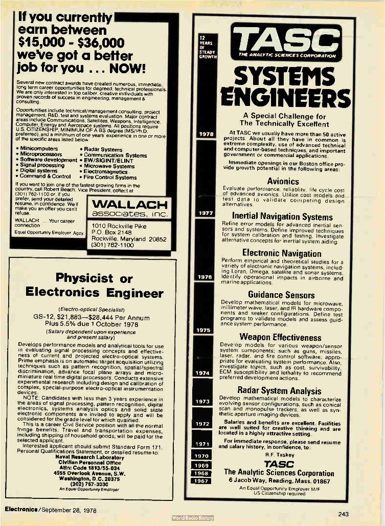
If you currently earn between $15,000 - $36,000 we've got a better job for you ... NOW! Several new contract awards have created numerous, immediate, long term career opportunities for degreed, technical professionals. We are only interested in top caliber, creative individuals with proven records of success in engineering, management & consulting.
Opportunities include technical/management consulting, project management, R&D. test and systems evaluation. Major contract areas include Communications. Satellites, Weapons, Intelligence, Computer. Energy and Aerospace systems. All positions require U.S. CITIZENSHIP, MINIMUM OF A BS degree (MS/Ph.D. preferred), and a minimum of one years experience in one or more of the specific areas listed below.
• Minicomputers • Radar Systems • Microprocessors • Communication Systems • Software development • EW/SIGINT/ELINT • Signal processing • Microwave Systems • Digital systems • Electromagnetics • Command & Control • Fire Control Systems
If you want to join one of the fastest growing firms in the country, call Robert Beach, Vice President. collect at 13011762-1100 or. if you prefer, send your detailed resume, in confidence. We'll make you an offer you can't refuse.
WALLACH. Your career connection
Equal Opportunity Employer Agcy
WALLACH associates, inc.
1010 Rockville Pike P.O. Box 2148 Rockville, Maryland 20852 (301) 762-1100
Physicist or Electronics Engineer
(Electro-optical Specialist)
GS-12, $21,883—$28,444 Per Annum Plus 5.5% due 1 October 1978 (Salary dependent upon experience
and present salary)
Develops performance models and analytical tools for use in evaluating signal processing concepts and effective-ness of current and projected electro-optical systems. Prime emphasis is on automatic target acquisition utilizing techniques such as pattern recognition, spatial/spectral discrimination, advance focal plane arrays and micro-miniature real time digital processors. Conducts extensive experimental research including design and calibration of complex, special-purpose electro-optical instrumentation devices. NOTE: Candidates with less than 3 years experience in
the areas of signal processing, pattern recognition, digital electronics, systems analysis optics and solid state electronic components are invited to apply and will be considered for the grade level for which qualified.
This is a career Civil Service position with all the normal fringe benefits. Travel and transportation expenses, including shipping of household goods, will be paid for the selected applicant.
Interested applicant should submit Standard Form 171, Personal Qualifications Statement, or detailed resume to:
Naval Research Laboratory Civilian Personnel Office Attn: Code 1813/55-034
4555 Overlook Avenue, S.W. Washington, D.C. 20375
(202) 767-3030 An Equal Opportunity Employer
12 YEARS OF STEADY GROWTH
1978
1977
1976
1975
1974
1973
1972
1971
1970
1969
1968
1967
grAsc THE ANALYTIC SCIENCES CORPORATION
SYSTEMS ENGINEERS
A Special Challenge for The Technically Excellent
At TASC we usually have more than 50 active projects. About all they have in common is extreme complexity, use of advanced technical and computer-based techniques, and important government or commercial applications.
Immediate openings in our Boston office pro-vide growth potential in the following areas:
Avionics Evaluate performance reliablity, life cycle cost of advanced avionics. Utilize cost models and test data to validate competing design alternatives.
Inertial Navigation Systems Refine error models for advanced inertial sen-sors and systems. Define improved techniques for system calibration and testing. Investigate alternative concepts for inertial system aiding.
Electronic Navigation Perform empirical and theoretical studies for a variety of electronic navigation systems, includ-ing Loran, Omega, satellite and sonar systems. Identify operational impacts in airborne and marine applications.
Guidance Sensors Develop mathematica models for microwave, millimeter wave, laser, and IR hardware compo-nents and seeker configurations. Define test programs to validate models and assess guid-ance system performance.
Weapon Effectiveness Develop models for various weapon/sensor system components; such as guns, missiles, laser, radar, and fire control software; appro-priate for evaluating system performance. Also, investigate topics, such as cost, survivability, ECM susceptibility and lethality to recommend preferred development actions.
Radar System Analysis Develop mathematical models to characterize evolving sensor configurations, such as conical scan and monopulse trackers, as well as syn-thetic aperture imaging devices.
Salaries and benefits are excellent. Facilities are well suited for creative thinking and are located in a highly attractive setting.
For immediate response, please send resume and salary history, in confidence, to:
R.F. Taskey
TASC The Analytic Sciences Corporation 6 Jacob Way, Reading, Mass. 01867
An Equal Opportunity Employer M/F US Citizenship required
Electronics/September 28, 1978 243

'Peers
o Stability +Growth
le Opportunity!
The SYSTEMS division of Litton has DOUBLED its size in the past four years, and TRIPLED volume in SALES creating one of the more STABLE environments in industry.
Positions of uncommon potential are now available in Defense and non-Defense contracts. Ask us about them!
ANALOG OR DIGITAL PROCESSING • LSI application • High speed data conversion • Power supplies
TELECOMMUNICATIONS SYSTEMS DESIGN • Advanced digital subsystems including TOM • RF and analog subsystems including frequency synthesis and FDM techniques • Microprocessors and related real-time operating systems software • Voice switching systems
ELECTRONIC WARFARE SYSTEMS • State-of-the-Art, ESM/ECM • Signal processing
ELECTRONIC WARFARE PROCESSING — HARDWARE • Microwave subsystem design • Circuit design — RF, video, analog, high speed A/D converters • EW digital subsystem design — signal sorting, microprocessors/microcontroller design, computer interfacing
RF • Microwave communications and receiving systems • High Sensitivity DF Receivers • Solid state microwave component design
We are located in a pleasant college town in Maryland with rolling hills, and the Chesapeake Bay and nation's capital less than an hour away. If this sounds like the opportunity you seek, please send your resume including salary history in confidence to:
W.L. McAmis
11 Litton
Arnecom Division LITTON SYSTEMS, INC.
5115 Calvert Rd., College Park, MD 20740 An equal opportunity employer. M/F/H
Electronics Engineers
San Francisco Peninsula Hewlett-Packard Corporate Labs, located in Palo Alto, has immediate Research and Development openings for Engineers.
Analog Opportunity to design and build state-of-the-art analog electronics to extend the bandwidth capabilities of magnetic recording. The electronics will be used to write and read data at above 20 megabits/sec. PhD or equivalent experience with state-of-the-art analog design experience at high data rates.
Digital Opportunity to design and build ECL Electronics to analyze errors in high speed data streams. The electronics will interface to a minicomputer for which software will be developed. PhD or equivalent experience with state-of-the-art digital design and software experience. Bit slice microprocessor experience is desirable. Hewlett-Packard provides a stimulating work environment and outstanding compensa-tion and benefits. Please send resumes to Allan J. Richardson, 1501 Page Mill Road, Palo Alto, CA 94304. We are an equal opportunity employer dedicated to affirmative action.
HEWLETT ig PACKARD
Plau it again sam. At SIMMS we ALWAYS need good people. Send your resume to the good people company. Signetics, MS 300, 811 East Argues Avenue, Sunnyvale, CA 94086. We are an equal opportunity employer m/f.
The Good People Company.
%FIRMS a subsidiary of U.S. Philips Corporation
244 Electronics/September 28, 1978

If you're not enjoying your career,
Hughes Missile Systems Group
has a proposition for you. Join us in the beautiful, suburban community of Canoga Park. Here we can offer you the casual lifestyle many people seek, plus the challenge of exciting research and development projects.
Advancement opportunities are plentiful for ambitious and bright engineers, and our stimu-lating state-of-the-art programs will keep you interested year after year.
Why not look into our opportunities today?
MISSILE SYSTEMS ANALYSTS Company-funded programs plus exciting long-range contracts have created several truly tine career opportunities, at both entry and senior levels, in our Advanced Programs Laboratory for systems analysts to engage in the conceptual design and development of advanced Radar and Electro-optical Missile guidance systems. Tasks involve definition of requirements. functional design, analysis and operational software development/integra-tion. Our experience suggests that incumbents most comfortable on the job are those with BS. MS, PhD degrees in EE. ME. Aerospace. Computer Science or Physics. combined with a background in one or more of the following disciplines:
• Detection/estimation theory • Advanced signal processing techniques • Classical or modern control theory • Target signature analysis • Optical design/analysis • Pattern recognition • Real time software design • Waveform analysis • Kalman filter and estimation theory
RF ENGINEERS Experienced in microwave circuit design. Duties will involve Circuit Analysis/Design for automatic test station and writing programs for automatic test units and circuit subassemblies. A background on equipment operating at frequencies up to 16 CHz is de-sirable.
COMPUTERIZED TEST EQUIPMENT ENGINEERS • Experience in digital/logic and analog circuit design. To perform digital and analog cir-cuit analysis/design for an automatic test circuit cards. Power supply design/analysis experience desired for some positions. • To design software/hardware for minicomputer-based automatic test equipment. Re-quires experience on digital systems. H.F. 21 MK/RTE experience highly desirable.
SYSTEMS TEST & EVALUATION ENGINEERS To perform developmental test of missiles at systems/subsystems level: plan tests and
evaluate results. Experience desired in guided missiles, avionics, or airborne radar technology. Digital hardware and software helpful. BSEE desired.
CIRCUITS DESIGN ENGINEERS With recent relevant experience in the design and development of RF/IF, digital, or analog circuits for missle guidance systems. MSEE, software/hardware integration experience also desirable. Must be familiar with applicable state-of-the-art components— phase and frequency lock loops, wide and narrow receivers, use of microprocessors.
SYSTEMS ENGINEERS These positions require system engineering for missile systems using radar and electro-optical technologies. This includes defining design characteristics, interfaces, test require-ments, and performing trade studies. Weapons experience not required, but previous systems engineering, servo analysis, or circuit or logic design experience in the above technologies is desirable.
SYSTEMS ANALYSTS To perform design and anlaysis for state-of-the art electro-optical missile seekers. Job assignments require ability to develop mathematical models for missile guidance systems performance evaluation. Proficiency in advanced one and two-dimensional signal processing techniques desired.
DIGITAL SYSTEMS DESIGN ENGINEER To participate in digital systems analysis and designer trade offs on RF components, subsystems and systems. Write design requirements, specifications and test requirements. Do RF modeling, hybrid missile flight simulation. Knowledge of Machine Languages,
Basic and Fortran. Familiarity with microprocessor use in analytical and control systems. Interface equipment to systems.
AUTOMATIC TEST EQUIPMENT (ATE) SYSTEMS ENGINEERS
Several openings in our ROLAND Division for system test engineers with a background or interest in computer based automatic test equipment, for testing L band and Ku band radar units. Must be familiar with Basic or Atlas programming. Will be responsible for unit application software development, maintenance, and tasks related to production test stations.
PRODUCT ENGINEERS Experienced in CAD, including interactive graphics: ability to do product design for high-rated production and knowledge of hybrid microelectronis and circuit partitioning re-quired. Design experience in hybrids and electronic subassemblies desirable.
MICROWAVE ENGINEERS Growth in microwave product development requirements for radar missiles has created immediate openings in:
• Microwave Antennas • Solid State Transmitter • Microwave Sources and Receivers • Missile Radomes • RF/Microwave Mechanical Systems Engineering
LSI/DESIGN AUTOMATION FOR THE 80's • LSI Design Engineers needed for analog and digital circuit design for MOS/CCD and bipolar custom LSI. Positions require complete design responsibility including partition-ing, establishing design requirements and directing layout and evaluation testing. • IC Manufacturing Support Engineers to interface between LSI design group and IC production facilities. Positions require knowledge of IC production and assembly techniques and the ability to schedule and monitor IC prototype and production
manufacturing.
Our offers include an excellent salary and benefits package. For immediate and confi-dential consideradoe, please send your resume and salary history to: Employment Manager, Hughes Missik Systems Group, Fallbrook at Roscoe, Canoga Park, CA 91300.
U.S. citizenship required • Equal opportunity M/F/HC employer
HUGHES HUGHES AIRCRAFT COMPANY
Electronics/September 28, 1978 245

ELECTRICAL ENGINEERS TEST SYSTEMS ZENITH's reputation for integrity, quality and reliability earned over the past 60 years is ZENITH's greatest asset. The dedication of the people at ZENITH to quality without compromise has made and continues to make ZENITH the nation's leader in Color Television.
This commitment to manufacture state-of-the-art products and continued quality, demands: the establishment of new functional areas...the expansion of old ones...the dedication of creative Engineers willing to "go the distance," and to push towards excellence in every endeavor. Immediate openings are available for these Engineers in the following areas:
Integrated Circuits — Modules — Chassis/Tuners If you are degreed with at least 5 years directly related experience and have expertise in electrical testing techniques our Test Systems Group has a lot to offer you:
• On-going projects in such areas as integrated circuits, LSI, tooling systems, digital circuitry and automatic test equipment; • A unique project management approach enabling you to interface with design engineering, test equipment and manufacturing in the development and evaluation of testing specifications and current procedures;
• An opportunity to utilize the widest range of your skills and abilities in a broadly defined functional area.
The successful candidates can expect an excellent salary and benefit package, along with outstanding concrete opportun-tes for professional growth.
Our location on the boundary between Chicago and its suburbs offers a variety of lifestyles — urban, suburban and rural — along with all the cultural and educational advantages of a major metropolitan area.
Respond in confidence now! Arrange a telephone interview with our Engineering Management.
Call Collect (312) 745-6066 Michael Maciekowich 8 a.m. to 5 p.m.
Or send a letter with resume to:
Michael Maciekowich
RADIO CORPORATION YEARS 1900 North Austin Avenue OF Chicago, Illinois 60639
An Equal Opportunity Employer m/f LEADERSHIP THROUGH QUALITY
r SECTION MANAGER In -Process Inspection
Modern, well-equipped 450,000 sq. ft. computer pe-ripheral fabrication and assembly plant needs a seasoned floor manager to direct and coordinate all In-Process O.C. and inspection efforts.
.... Products include line printers, display terminals, magnetic tape units, and disc products;
.... Will direct a staff of four supervisors and 70 inspec-tors;
.... A strong background in Q.C. and/or inspection tech-niques as applied to electro-mechanical assembly and several years management experience required;
.... A degree in E.E., M.E. or related engineering dis-cipline preferred.
Attractive living conditions, excellent wages and benefits, and an impressive corporate growth record makes this a very fine opportunity for an individual who wishes to make a long term commitment to southern coastal Maine, and the computer industry.
For further information, please forward your resume to or call Mike Pendergrass, Sr. Personnel Representative, 207-854-9701, Data General, 80 Eisenhower Drive, Westbrook, Me. 04092. An Equal Opportunity Employer M/F
LI I DataGeneral
Job-seekers... be the first to know with McGraw-Hill's Advance Job Listings By having our weekly ADVANCE JOB LISTINGS sent to your home every Monday you can be the first to know about open-ings both in and out of your field AJL will enable you to contact anxious recruitment managers BEFORE their ads ap-pear in upcoming issues of 21 McGraw-Hill publications. To receive a free sample copy, plus information about our low subscription rates, fill out and return the coupon below
ADVANCE JOB LISTINGS / P.O. BOX 900 / NY 10020
PLEASE SEND A SAMPLE COPY OF ADVANCE JOB LISTINGS TO
NAME
CITY
ADDRESS
STATE/ZIP
246 Electronics/September 28, 1978

Electronics advertisers September 28, 1978
• Abbott Transistor Labs 203 • English Electric Valve 151 $ NEC Microcomputers 8-9
• Allen-Bradley 34 a Erie Technological Products 236-237 • NEOHM SPA 6E-7E
• American Optical Scientific Instrument Division 56 Fairchild Systems Technology (Camera & 179 $ Ohio Scientific 200 Instr)
AMF Potter & Brumfield 98-99 Osborne & Associates, Inc. 33 Faultfinders, Inc. 66
Amplifier Research 96 • Oscilloquartz 40 • FEME 213
Analog Devices 211, 106-107 Panasonic Industrial Division 216 First Computer Corporation 205. 249
Applied Digital Data Systems 55 •• Philips Elcoma 75
• John Fluke Manufacturing Co., 88, 199, 188-189 Inc.
Atlanta Chamber of Commerce Industrial 190 •• Philips Industries 8-9 Development
Forth, Inc. 192
•8 • Augat, Inc. 195 Philips TMI 155
$ Fujitsu America, Inc. 70
•• Philips TMI 1E .8 Beckman Instruments, Inc., IDO Division 193
• General Instrument Corporation, 77
Semiconductor Pinellas County 28 The Bendix Corporation, Electrical 167 Components Division
• Gould, Inc., Instrument Systems 149 Plessey Perpheral Systems 182 Biomation 140 Division/7 & M
• Power One, Inc. 93 at B & K Precision, Division Dynascan Corporation 65 • Grayhill, Inc. 207
Powercube Corporation, Division of Unitrode 91 Boschert 215 8 Heath Co. Schlumberger 208
• B ourns Pro-Audio Specialties 248 Inc. 2nd c. , • Hewlett-Packard Company 15-26
• Bowmar Commercial Products 190 Pro-Log • Honeywll TID 173
• Brown Boverie & Cie 5E Racal-Dana Instruments, Inc. 157-159 at Hughes Aircraft 75
•• Burr Brown Research Corporation 209, 14E • Racal Dana Instruments Ltd. 193 I Corporation 249
8 Centronics 220 ' Racal Thermionic Ltd. 2E-3E Intel-Microcomputer Components 80-81
• Cherry Electrical Products 2 RCA Solid State 60 • Keithley Instruments 164
• Clairex Electronics 4th c. Reticon Corporation 94 • Kepco, Inc. 5
Computique 248 • Riken Denski Co., Ltd. 12E • Lambda Electronics Corporation 221-224
• Continental Connector Corporation 180 RO Associates, Inc. 226
L.G.T. 229
•$ Continental Resources, Inc. 45 • Rohde & Schwarz 69, 9E, 15E LH Research, Inc. 202
Cromemco 13 • Rotron B.V. 216 j Litronix 209
$ Cts Corporation 14, 69 Sangamo Weston, Division of Schlumberger 172 MOB Systems 192
Data I/O Corporation 146-147 • Sescosem Thomson CSF 16E • M.E.S.L. Microwave Division 10E
• Data Translation 49 • Sfernice 155 MFE Corporation 104-105
• Dialight 186-187 $ Siecor Optical Cables, Inc. 197 Micro Peripherals, Inc. 73
• Ducati Elettrotecnica Microfarad 197 • Siemens AG Munich 64 • Microswitch, Division of Honeywell 184-185
$ Eastman Kodak Co., Graphic Markets Division 40 Signetics Corporation 162-163 Mitel Semiconductor, Inc. 54
Ebauches SA 194 Shger Kearfott 170 Mostek Corporation 225, 29-32
Electromatic Component Ltd. 3rd c. • Societe Seder 16E a Motorola 51-52, 57-59, 102-103, 175-177
Semiconductor • Electronic Navigation Industries 53 • Solartron 19E-20E
M & T Chemicals, Inc. 100-101 EM Laboratories, Inc. 181 Spectronics, Inc. 191
Mu-Pro EMM-Electronic Memories & Magnetics 47 Sprague Electric 63
McGraw-Hill Electronics & Control 232-235 EMR Telemetry 217 Engineers Book Club • STE Fort 205
• Enertec Schlumberger 11E • National Semiconductor Corporation 38-39, 82-83 • Superior Electric 153
Electronics/September 28, 1978 247

V111\‘‘M'pkrefrI
AUDIO CONNECTORS
JACKS/PLUGS/PATCH CORDS
Shipped from STOCK!
Ask for Our Catalog
PRO-AUDIO SPECIALTIES CO.
1291 RAND ROAD
DES PLAINES, ILLINOIS 60016
PHONE (312) 827-8388
Circle 248 on reader service card
PROFESSIONAL DISCOUNTS Texas Instruments electronic calculator
I 1;' ,.41 [ un $19.35 SR 30 D23.75 I 25 aEw 27.95 Ii 55 NEW
49. MI" 1,1 12.55 TI 57 NEW ,5 mama, NEW 1995 II 58 NEW 95.79 1 510(1 an i i 59 NEW 219.95 I 501 NEW 5595 Pf 1500 147.00 1 5050 M 77.55 MBA 59.95 I 5010 00 87.95 Pus A ••,.. • 26.95 130 SP 15.95 II Prowa. . NEW 49.95 Dataclip . 28.09 11 In(' NEW 39.95 Ask for 11 Digital Watches
HEWLETT ilk PACKARD HP 10 NEW $139.00 HP 31E NEW. S 49.95 HP I9C NEW 219.95 HP 32E NEW. 69.95 HP 29C NEW 139.95 HP 33E NEW. 65.00 HP 80 235.00 HP-37E NEW. . 64.95 HP 67 35435 HP 38E NEW.. 99.95
.Up9 P 927 NEW... 399.95
594.95
Were HP's authorized franchise dealer - all accessories are professionally discounted.
Also SCM. Olivetti. Casio. Canon. APF. Sharp. Craig. Sanyo. Record-A-Call. Horelco-Phillips and more. All at great prices!
Phillips $164.00 Sanyo 9908 3299.95 Phillips 245.00 Sanyo 8000A . - 249.95
WE WILL BEAT OR MEET ANY COMPETITOR'S PRICE IF HE HAS MERCHANDISE ON HAND. All units shipped in original factory cartons with accessories according to manu-facturers' specification. In Calif. call (714) 549-7373 or CALL lean 854-0523 (other than CA). BankAmericard/ Visa & Master Charge. Send money order. Pers ck (2 wks to clear). In CA add 6% sales tax. Add 83.50 min. shipping charges. WE SHIP AIR on request. Subject to availability. Send mail orders to DEPT. EL-128
WRITE OR CALL FOR FREE CATALOG. o
tk Kuntgpres camp' utique 3211 SOUTH HARBOR BLVD . SANTA ANA, CA 92704
IS NOW
Synertek
Systron-Donner, Concord
• Teledyne Relays
9 Teletype
Telonic Berkeley
• Tektronix Datatek NV
Teradyne, Inc.
Texas Instruments Components
Texas Instruments, Calculator
Texas Instruments
Textool Products, Inc.
Thomson CSF
• Thomson CSF Division D.T.E.
TRW Capacitors
TRW Division, Cinch Connectors
TRW LSI Products
United Mineral & Chemical Corporation
Universal Instruments
• Vacuumschmelze
Varian Vacuum
Vertel, Inc.
• V /0 Techmashexport
• Wendel un Goltermann
• Wavetek Indiana
Wilhelm Westermann
54 Carl Zeiss Inc. Micro
• Zeltron
Zero Corporation
37
168-169
27
151
239
8E
84, 128, 196
7
213
160-161
12
145
45
183
171
78-79
219
87
13E
231
90
205
70, 12E
108
6
210
200
166
Classified and employment advertising F. J Eberle. Manager 212-997-2557
Boeing Co. 242 Canadian Thermostats 242 Corey Assoc. 240 Data General 244 Hewlett Packard 246 Hughes Aircraft Co. 245 Litton Systems, Inc. 246 W.T. McDonnell 241 Photo Research 242 Robins Air Force Base, GA 240 Sig netics 246 TASC 243 Tektronix 240 U.S. Navy 243 Wallach Assoc., Inc. 243 Weterrings a Agnew 242 Woodward Governor 241 Zenith Radio Corp. 244
W For more information of complete product line see advertisement in the latest Electronics Buyers Guide
• Advertisers in Electronics International Advertisers in Electronics domestic edition
Advertising Sales Staff
Advertising sales manager: Paul W. Reiss 1221 Avenue ot the Americas, New York, N.Y. 10020 [212] 997-4371 Atlanta, Ga. 30809: Michael Charlton 100 Colony Square, 1175 Peachtree St., N.E. [404] 892-2868 Boston, Mess. 02118: Frank Mitchell 607 Boylston St. [617] 262-1160 Chicago, M. 80511 645 North Michigan Avenue Jack Anderson [312] 751-3739 Robert M. Denmead [312] 751-3738 Cleveland, Ohio 44113: William J. Boyle [716] 586-5040 Dallas, Texas 75201: John J. Uphues 2001 Bryant Tower, Suite 1070 [2141 742-1747 Denver, Colo. 80203: Harry B. Doyle, Jr. 123 Speer Blvd. #400 [303] 837-1010 Detroit, Michigan 48202 Jack Anderson 1400 Fisher Bldg. [313) 873-7410 Fort Lauderdale, Fla. 33305: Michael Charlton 3000 N.E. 30th Place [305] 563-9111 Houston, Texas 77002 John J. Uphues 601 Jefferson Street, Dresser Tower [713] 659-8381 Los Angeles, Calif. 90010: Robert J. Rielly Robert E. Boedicker, 3200 Wilshire Blvd., South Tower [213]487-1160 Minneapolis, Minn. 55435: Robert M. Denmead 4015 W. 65th St. [312] 751-3738 New York, N.Y. 10020 1221 Avenue of the Americas Michael J. Stoller [212] 997-3616 Matthew T. Reseska [212] 997-3617 Philadelphia, Pa. 19102 Matthew T. Reseska Three Parkway [212] 997-3617 Pittsburgh, Pa. 15222 Matthew T. Reseska 4 Gateway Center [212] 997-3617 Rochester, N.Y. 14534: William J. Boyle 1175 Pittsford-Victor Rd., Pittsford, N.Y. [716] 248-5620 San Francisco, Calif. 94111: Don Farris Dean Genge, 425 Battery Street, [415] 362-4600 Paris: Patrick Mouillard 17 Rue-Georges Bizet, 75116 Paris, France Tel: 720-73-01 United Kingdom 8 Scandinavia: Robert Ghey 34 Dover Street, London W1 Tel: 01-493-1451 Scandinavia: Andrew Karnig and A.,.nn. Kungsholmsgatan 10 112 27 Stockholm, Sweden Tel: 08 51 68 70 Telex: 179 51 Milan: Luigi Rancatl 1 via Baracchini, Italy Phone 86-90-656 Brussels: 23 chausses de Wavre Brussels 1040, Belgium Tel: 13-73-95 Frankfurt/Main: Fritz Krusebecker Liebigstrasse 27c, Germany Phone 72 01 81 Tokyo: Tatsuml Katagiri, McGraw-Hill Publications Overseas Corporation, Kasumigasekl Building 2-5, 3-chome, Kasumigaseki, Chiyoda-Ku, Tokyo, Japan [581] 9811
Business Department Thomas M. Egan Production Manager [212] 997-3140
Carol Gallagher Production Manager International [212] 997-2045
Betty Preis Production Manager Domestic [212] 997-2908
Roberta Cummings Production Manager Related Products [212] 997-2044
Thomas Kazich, Production Assistant (212) 997-2843
Frances Vallons Reader Service Manager [212] 997-6057
Electronics Buyers' Guide H.T. Howland, General Manager [212] 997-6642 Regina Hera, Directory Manager [212] 997-2544 Roberta Cummings, Production Manager [212] 997-2044 Thomas Kezich, Production Assistant [212] 997-2843 Frances Vallons, Reader Service Manager [212] 997-6057
Classified and Employment Advertising Frank Eberle, Manager [212] 997-2557
\‘ (714) 549-7373 • (800) 854-0523
Circle 255 on reader service card Electronics/September 28, 1978

Layout PC Boards in Hours... Prototypes in Minutes
COMPUTER-AIDED DRAFTING FOR UNDER $16,000 Generate camera-ready art for schematics, flow charts, block diagrams, bills of ma-terials, large dense multi-layer pc boards, ground planes, silkscreen art, sol-der mask art, assembly drawings, part drawings, NC drill tapes, drive photo-plotters, and make actual prototype pc boards. Com-plete system for $16,000 to $30,000 saves weeks on ev-ery project, and man years every year.
735 ADDISON STREET • BERKELEY, CALIFORNIA 94710 • (415) 848-6600 Circle 249 on reader service card
New MOSTEK Dual Size LSI-1 1/2 Add-In Memory
Available Now Off-The-Shelf From FIRST COMPUTER CORPORATION
To Order Call Or Write
312/920-1050
ELst
Description Price
1 2-9 10-24
MK8005A-00 32K X 16 RAM $1350. S1275. $1245.
MK8005A-01 24K X 16 RAM $1090. $1030. $1000.
MK8005A-02 $ 855. $ 810. $ 790.
16K X 16 RAM $ 855. $ 810. $ 790.
MK80056-00
32K X 18 RAM $1435. $1355. $1325.
MK80056-01 24K X 18 RAM $1160. $1090. $1070.
MK80056-02 24K X 18 RAM $ 900. $ 850. $ 830.
Authorized MOSTEK
Other Quantity Discounts Available On Request
Memory Systems Dealer.
computer corporation corporate square/825 north cass avenue/westmont, ill i nois 60559
Electronics/September 28, 1978 Circle 256 on reader service card 249

REPRINTS AVAILABLE FROM ELECTRONICS No. of copies wanted Books
R-803 New product trends in electron-ics-Electronics Book Series 333 pp $14.95
R-732 Memory design-Microcomput-ers to mainframes-Electronics
Book Series 180 pp $12.95
R-726 Design Techniques for Electron-ics Engineers: 293 time-saving
ideas in 48 chapters-Electron-ics Book Series 370 pp $15.95
R-711 Circuits for electronics engi-
neers: 306 circuits in 51 func-
tional groups-Electronics Book Series 396 pp $15.95
R-704 Thermal design in electronics 52 pp $5.00
R-701 Applying microprocessors-
Electronics Book Series 191 pp $9.95
R-608 Basics of Data Communica-
tions-Electronics Book Series 303 pp $12.95
R-602 Large Scale Integration-Elec-
tronics Book Series 208 pp $9.95
R-520 Microprocessors-Electronics
Book Series 154 pp $8.95
R-011 Computer-aided Design 135 pp $4.00
Articles R-815 Higher power ratings extend V-
MOS FETs' dominion 8 pp $2.00 R-813 Data-link control chips: bringing
order to data protocols 10 pp $3.00
R-811 Multiplexing liquid-crystal dis-plays 10 pp $3.00
R-809 New methods and materials stir
up printed wiring 10 pp $3.00
R-801 World market report 1978 24 pp $4.00
R-734 Microcomputer families expand
20 pp $4.00
R-730 Special report-Automotive
electronics gets the green light 10 pp $3.00
R-728 Flexible circuits bend to design-
ers' will 10 pp $3.00
R-724 Special report-Technologies
squeeze more performance from LSI 22 pp $3.00
R-722 Demands of LSI are turning chip makers towards automation 12
pp $3.00
R-720 How EEs feel about engineer-
ing-3-part series 26 pp $5.00 R-718 Display makers strive to refine
their technologies 8 pp $3.00 R-716 Special report-Japanese wave
in semiconductor technology 24 pp $3.00
R-714 Special report -active filter technology 6 pp $3.00
R-713 Electron-beam lithography
draws fine line 10 pp $3.00 R-712 Special report-large-scale inte-
gration 16 pp $3.00
R-710 Personal computers mean busi-
ness 8 pp $2.00
R-708 So you want to be a consultant 6 pp $2.00
R-706 Low-cost dual delayed sweep
method 6 pp $2.00 R-705 Powering up with linear ICs 12
pp $3.00
R-703 Special report -memories
16 pp $3.00 R-702 World market report 1977 24 pp
$4.00
R-616 Special issue-technology up-date $4.00
R-614 Power supply choices for so-phisticated designs 8 pp $3.00
R-612 Fiber-optic communications
special report 24 pp $3.00
R-610 Special report on hybrid-circuit
technology 19 pp $3.00
R-606 Special issue-Making it with microprocessors $4.00
R-526 How reliable are today's compo-
nents 16 pp $3.00 R-524 Special report on bipolar large-
scale integration 12 pp $3.00 R-522 Special report on power semi-
conductors 12 pp $3.00
R-518 Special issue- productivity $4.00
R-514 Eight ways to better radio
receiver design 6 pp $3.00
R-512 Design of circuits for dangerous
environments 4 pp $2.00 R-510 Bipolar advances with I2L micro-
processor 8 pp $2.00 R-508 Designing microprocessors with
standard logic 12 pp $3.00 R-506 The case for component burn-in
7 pp $2.00
R-434 Designing systems with the stan-
dard interface 12 pp $3.00
R-432 An update on communications satellites 8 pp $2.00
_ R-430 Choosing the right bipolar tran-
sistor model for computer-aided
design 20 pp $3.00
R-428 Designing with low-cost lasers 6
pp $2.00
R-424 Microprocessor applications 28
pp $3.00
R-422 A microprogramable minicom-puter 8 pp $2.00
R-420 Computerized text-editing and typesetting 8 pp $2.00
R-418 Computer analyses of rf circuits
8 pp $2.00
R-414 The ion-implanted n-channel
process 6 pp $2.00 R-412 Liquid cooling of power semi-
conductors 6 pp $2.00 R-410 Special report on passive com-
ponents 16 pp $3.00
R-406 Designing with the new logic,
C-MOS and bipolar 16 pp $3.00 R-324 Semiconductor memories are
taking over data-storage appli-
cations 16 pp $3.00
Charts R-516 Electronic symbols $2.00
R-213 Electromagnetic spectrum (up-
dated 1976) $3.00 R-326 Optical spectrum (6-page report
and chart) $3.00
Payment must accompany your order
Make check or money order payable to Elec-
tronics Reprints. All orders are shipped
prepaid by parcel post. Allow two to three
weeks for delivery. For additional information
call (609) 448-1700 ext. 5494.
Back issues now available:
1960 to 1969, $5.00 each 1970 to 1973, $3.00 each
1974 to 1977, $4.00 each
USE THIS PAGE AS YOUR ORDER FORM
Cost of orders Plus 10% handling charge
TOTAL AMOUNT ENCLOSED
SEND REPRINTS TO
Mail your order to: Janice Austin
ELECTRONICS REPRINTS P.O. Box 669
Hightstown, N.J. 08520
Name
Company Dept
Street
City State Zip
250 Electronics/September 28, 1978

The world's leading timing machines are now in America, too! S-SYSTEM BY ELECTROMATIC OF DENMARK. Also includes Timing Relays. Compact, modular, interchangeable plug-in units. Applications limited only by your imagination. Let us show you!
•
S "SYSTE SL 160 220 SUPPLY 220 VAC.
LOGIC RELAY
BIS7-ABLE vi MEMO
SINGLE INPUT
41, RELAY
DieribLto, Inquiries Invitee
libRELAY ON
S - SYsTEm srvi 155 220
SUPPLY 220 V AC
TACHOMETER
REL AY
200 - 2030 PPM
nue.
rEni !20
• V AC
JIDS
RELAY
et RELAY ON ,s( ON
ânetturrn.aie
ELECTROMATIC COMPONENTS LTD. 742 West Algonquin Road Arlington Heights, Illinois 60005 (312) 364-0100 TWX 910-222-3452
Outskde the United States, contact your Local ELECTROMATIC Sales Office located in 43 Daunt ri es World Wide
Circle Number 901 on Reader Service Card
Ynlik
STEM torrtsfic
220 YSTEM
220
DHOT • • •
•

PHOTOVOLTAIC DIODES
from Clair« with tight specifications and 100% tested...twice
Clairex photodiodes of the CLP series are designed to optimize the photovoltaic characteristk§bf silicon and maintain tight -:_specifications on all significant parameters.
The four silicon FN planar diodes presently. available all offer high linearity, kw dark current and fast response for use in .éririaimeasement applications. Three
Th'erlri-étielYiiealed type; are available for
use in hostile environments and one epoxy encapsulated type for lower cost applications.
And, as is the case with all Clairex opto-electronic devices, these photodiodes are .100(4 tested twice.
Try Clairex photodiodes. Call (914) 664-6602 or write Ckiirexe 500 South Third Avenue, Mount Vernon, New lilork 10550.
CLAIREX ELECTRONICS Division of Clairex Corporation
circle 902 on Reader Service Card


![Panasonic SIVI-IS! ~~~ [}(]oo[po](https://static.fdokumen.com/doc/165x107/631d3a1b76d2a4450503e6ab/panasonic-sivi-is-oopo.jpg)