Low-density three-dimensional foam using self-reinforced hybrid two-dimensional atomic layers
9
ARTICLE Received 26 Jan 2014 | Accepted 26 Jun 2014 | Published 29 Jul 2014 Low-density three-dimensional foam using self-reinforced hybrid two-dimensional atomic layers Soumya Vinod 1, *, Chandra Sekhar Tiwary 1,2, *, Pedro Alves da Silva Autreto 1,3 , Jaime Taha-Tijerina 1 , Sehmus Ozden 1 , Alin Cristian Chipara 1 , Robert Vajtai 1 , Douglas S. Galvao 3 , Tharangattu N. Narayanan 4 & Pulickel M. Ajayan 1 Low-density nanostructured foams are often limited in applications due to their low mechanical and thermal stabilities. Here we report an approach of building the structural units of three-dimensional (3D) foams using hybrid two-dimensional (2D) atomic layers made of stacked graphene oxide layers reinforced with conformal hexagonal boron nitride (h-BN) platelets. The ultra-low density (1/400 times density of graphite) 3D porous structures are scalably synthesized using solution processing method. A layered 3D foam structure forms due to presence of h-BN and significant improvements in the mechanical properties are observed for the hybrid foam structures, over a range of temperatures, compared with pristine graphene oxide or reduced graphene oxide foams. It is found that domains of h-BN layers on the graphene oxide framework help to reinforce the 2D structural units, providing the observed improvement in mechanical integrity of the 3D foam structure. DOI: 10.1038/ncomms5541 1 Department of Materials Science and Nanoengineering, Rice University, Texas 77005, USA. 2 Materials Engineering, Indian Institute of Science, Bangalore 560012, India. 3 Instituto de Fı ´sica ’Gleb Wataghin’, Universidade Estadual de Campinas, Unicamp, CP 6165, 13083-970 Campinas, Sa ˜o Paulo, Brazil. 4 CSIR- Central Electrochemical Research Institute (CSIR-CECRI), Karaikudi 630 006, India. *These authors contributed equally to this work. Correspondence and requests for materials should be addressed to P.M.A. (email: [email protected]) or to T.N.N. (email: [email protected]). NATURE COMMUNICATIONS | 5:4541 | DOI: 10.1038/ncomms5541 | www.nature.com/naturecommunications 1 & 2014 Macmillan Publishers Limited. All rights reserved.
Transcript of Low-density three-dimensional foam using self-reinforced hybrid two-dimensional atomic layers

ARTICLE
Received 26 Jan 2014 | Accepted 26 Jun 2014 | Published 29 Jul 2014
Low-density three-dimensional foam usingself-reinforced hybrid two-dimensional atomiclayersSoumya Vinod1,*, Chandra Sekhar Tiwary1,2,*, Pedro Alves da Silva Autreto1,3, Jaime Taha-Tijerina1,
Sehmus Ozden1, Alin Cristian Chipara1, Robert Vajtai1, Douglas S. Galvao3, Tharangattu N. Narayanan4
& Pulickel M. Ajayan1
Low-density nanostructured foams are often limited in applications due to their low
mechanical and thermal stabilities. Here we report an approach of building the structural
units of three-dimensional (3D) foams using hybrid two-dimensional (2D) atomic layers
made of stacked graphene oxide layers reinforced with conformal hexagonal boron nitride
(h-BN) platelets. The ultra-low density (1/400 times density of graphite) 3D porous
structures are scalably synthesized using solution processing method. A layered 3D foam
structure forms due to presence of h-BN and significant improvements in the mechanical
properties are observed for the hybrid foam structures, over a range of temperatures,
compared with pristine graphene oxide or reduced graphene oxide foams. It is found that
domains of h-BN layers on the graphene oxide framework help to reinforce the 2D structural
units, providing the observed improvement in mechanical integrity of the 3D foam structure.
DOI: 10.1038/ncomms5541
1 Department of Materials Science and Nanoengineering, Rice University, Texas 77005, USA. 2 Materials Engineering, Indian Institute of Science, Bangalore560012, India. 3 Instituto de Fısica ’Gleb Wataghin’, Universidade Estadual de Campinas, Unicamp, CP 6165, 13083-970 Campinas, Sao Paulo, Brazil. 4 CSIR-Central Electrochemical Research Institute (CSIR-CECRI), Karaikudi 630 006, India. * These authors contributed equally to this work. Correspondence andrequests for materials should be addressed to P.M.A. (email: [email protected]) or to T.N.N. (email: [email protected]).
NATURE COMMUNICATIONS | 5:4541 | DOI: 10.1038/ncomms5541 | www.nature.com/naturecommunications 1
& 2014 Macmillan Publishers Limited. All rights reserved.

The intriguing architecture and properties of cellular solidsin nature have inspired researchers to create theirbiomimetic replicas1,2. These man-made, low-density,
highly porous materials called foams, exhibit novel physicalproperties compared with their bulk counterparts. Large specificarea, high energy absorption at impact and outstanding strengthto weight ratios make them ideal for catalysis, energy storage,damping and building structural components3–5. Creating three-dimensional (3D) structures using nanoscale elements allowtailoring of properties by integrating specific elements infavourable proportions6–8. Although a wide range of nano-sizedelements in different dimensionalities can be used, the fascinatingphysical phenomena in materials at atomic layer thicknessesmake two-dimensional (2D) materials such as graphene, boronnitride and transition metal dichalcogenides extremely attractivebuilding blocks for macroscopic multilayer assemblies9–11. 3Dframeworks can be built from these 2D materials by templateassisted growth or self-assembly in solution by van der Waalsforces or chemical cross-linking12–14.
Building 3D interconnected structure from 2D materials is stillin infancy stage and most of the previous reports are on graphene-based foams15–19. This is due to the excellent electrical, thermaland mechanical properties of graphene combined with the reactiveedges that allows functionalization20–23. Nevertheless, comparedwith the explosion of work done on 2D graphene and graphene-based materials such as graphene oxide (GO), there have beenonly few reports about the 3D nanoengineered structures builtfrom them. Both chemical vapour deposition and solutionprocessing methods have been used in the past for developing3D architecture of the above-mentioned materials15–17. Thecomplex setup and poor scalability of chemical vapourdeposition process make self-assembly in solution the idealsynthesis route for the bottom-up approach. The 3D structuresformed by GO and graphene were predominantly openporous networks with no ordered stacking. The eventual freezedrying process for removing water from the macroporousnetworks were found to leave the nanoflakes forming thestructural units crumbled and bent24. An adverse effect of this isconspicuous in the thermal and mechanical stabilities of the foamscreated for these units.
For many practical applications, graphene nanocomposites arepreferred for synergistic effects that allow controlled function-ality. The heterostructures formed by atomic layer stacking ofhexagonal boron nitride (BN) with graphene have led to veryinteresting optical, electronic and mechanical properties25–29. Thechemical inertness, high mechanical strength and the ability towithstand extremely high temperature make BN an ideal materialfor building monolithic and composite 3D scaffolds30–33. BNexists in different crystalline forms of which hexagonal boronnitride (h-BN) is the most structurally compatible form and is anisomorph of graphene34,35. A good lattice matching is observed intheir hybrids. The present study focuses on the effect of uniqueinteraction between h-BN and graphene and the role of h-BN ingenerating and strengthening graphene-based 3D structures.
In the current work, we report the formation of h-BNreinforced layered 3D stacks of GO with adjacent layersconnected to each other through a porous network. The strongphysical interactions between h-BN and GO resulted in fairlyuniform distribution of h-BN platelets throughout the foam. Theh-BN domain prevents the GO flakes from crumbling and bindsthem to form large plates. The layered restacking of these platesforms a unique ordered 3D structure. The mechanical andthermal stabilities were significantly enhanced compared to therandom open porous networks of GO foams without h-BN. Thecomplex and novel structural formation which leads to animproved mechanical performance are further corroborated using
molecular dynamics (MD) simulation. The foam prepared usingsimple wet chemistry followed by lyophilization can easily acquirethe shape of the container. This allows low cost and large-scalesynthesis of these structures.
ResultsSynthesis and characterization of GO-BN 3D hybrids. It hasbeen identified that the synthesis of elementary 2D buildingblocks and their combinational stacking will lead to the devel-opment of new solids with multifunctional properties36. In anearlier attempt, we have developed such an extended solid fromh-BN and graphene, where a solution-based self-assembly lead tothe formation of a new solid24. The solution mixing of GO andh-BN also forms similar solids and their difference in lateral sizeforms h-BN decorated GO sheets. The solution processingmethod for producing covalently interconnected GO sheets wasused in making the GO-BN composite foams17. The mechanismof cross-linking of GO sheets is explained in our previousreport17, where glutaraldehyde forms hemiacetal group withhydroxyl groups (-OH) in the adjacent GO sheets. The highernumber of –OH groups in GO facilitates the cross-linkingbetween adjacent sheets via aging (24 h), and the resultantsolution is subjected to freeze drying process. An ultralow density(B5 mg cm� 3, that is, 1/400 times density of graphite) foam castin the shape of the vial as shown in Fig. 1a was obtained afterlyophilization. The foam is named GO-0.5BN where 0.5 standsfor the weight fraction of h-BN in the composite. GO-0.5BN wasviewed at different magnifications and different tilted projectionsusing scanning electron microscope (SEM) as shown in Fig. 1b–f.The high-magnification image of the top layer shows (Fig. 1b)platelets of h-BN embedded in the layer. The low-magnificationimage Fig. 1d shows the several microns long 2D sheets of h-BNembedded GO with nanometre thickness stacked on top of eachother. These layers are stacked on each other by a porousinterconnected (Fig. 1c) film constituted by GO flakes joiningperpendicular to the larger layer as shown in Fig. 1e–f. The planview of interconnected film is shown in Fig. 2c. The high-magnification image of the region shown in Fig. 1e reveals thethickness of these films and their in-plane and out-of-plane cross-linking connection. The elevation view of these layers shows(Fig. 1f) clear junction to larger layer. The fine platelets aresurrounded by a local strain distribution in the layer. A schematicof the 3D structure is shown in Fig. 1g.
Field emission gun transmission electron microscopy (TEM)has been extensively used for observing the basic 2D buildingblocks followed by the 3D structure. The size and structuralanalysis of initial raw 2D nanosheet of GO and h-BN performedusing TEM is shown in Supplementary Fig. 1. It shows a largerGO nanosheet and smaller-sized h-BN flakes. Several imagesfrom different samples has been used to determine the meansheet dimension which was found to be micron size GO andB400 nm size h-BN nanosheet with an average of two-layerthickness. To understand the role of h-BN in structure formation,a detailed TEM of GO without h-BN and with two fractions ofh-BN has been performed. A representative low-magnificationtransmission electron microscope (TEM) images show h-BNembedded in the large GO flakes as shown in Fig. 2a. Thepresence of h-BN in multilayers possibly resulted from inherenthydrophobicity and high concentration of solution used forlyophilization. Figure 2a shows h-BN providing support to twoadjoining few-layered GO flakes and the red marked area inFig. 2b has GO perpendicularly attached to a horizontal flake,which shows the origin of the 3D architecture. The selected areaelectron diffraction pattern shown in Fig. 2c confirms thehexagonal lattices of h-BN and graphene. High angle annular
ARTICLE NATURE COMMUNICATIONS | DOI: 10.1038/ncomms5541
2 NATURE COMMUNICATIONS | 5:4541 | DOI: 10.1038/ncomms5541 | www.nature.com/naturecommunications
& 2014 Macmillan Publishers Limited. All rights reserved.
dark field micrograph shown in Fig. 2d reveals that multilayeredh-BN is distributed in GO. The sharp edges of GO layer are seenwhere there is high concentration of h-BN but the absence ofh-BN results in the bending of other edge areas. It clearly reveals ahigh impact of h-BN on the morphology of GO sheet.
The bulk phase and structural characterization of these foamswere performed using X-ray diffraction (XRD), Raman spectro-scopy and Fourier transform infrared spectroscopy (FTIR). XRDshown in Fig. 2e reveals a peak at 2y¼ 10 degrees for GO (001)corresponding to an interlayer spacing of 8.8 Å and for h-BN(002) at 2y¼ 27 degrees corresponding to a lattice constant of3.29 Å. FTIR was used to detect the different bonds andfunctionalities present in the sample (Fig. 2f). The spectrumshows different functional groups of GO at B3,420 cm� 1 (O–Hstretching vibrations), B2,950 (C–H stretching vibrations),B1,720 cm� 1 (C¼O stretching vibrations), B1,210 cm� 1
(C–OH stretching vibrations) and B1,060 cm� 1 (C–O stretchingvibrations). In addition to these, the skeletal vibrations from
unoxidized C¼C bonds was seen at B1,620 cm� 1. The B-N-Bin-plane vibrations (E1u mode) for h-BN was assigned toB1,370 cm� 1 and the out-of-the-plane B-N-B vibrations(A2u mode) to B800 cm� 1. All the above characterization alsoclearly confirms absence of any other impurity.
Raman spectrum shows the G band at B1,580 cm� 1 and Dband at B1,340 cm� 1 (Fig. 2g). The G band is common to bothGO and h-BN, which arises from the first-order scattering of E2g
mode and the D band is from the basal plane defects created bythe presence of functional groups in GO. To understand the roleof BN in forming these 3D stacked structures, GO (GO-0.0BN)and GO with 25% h-BN (GO-0.25BN) were also synthesized bykeeping the overall concentration and procedure same as in GO-0.5BN. Although GO-0.0BN has interconnected network as thatof GO-0.5BN, the stacked structure with micron-sized 2D layer isabsent. The high-magnification SEM image in Fig. 3a shows GO-0.0BN that consists of interconnected GO layers and resemblesthe structure in Fig. 1c, which is the porous mesh between the
GO GO-0.25BN GO-0.5BN
BN
GO
GO
h-BN
Figure 1 | Morphology of the 3D GO-BN Foam. (a) Photograph of GO foams with varying concentrations of h-BN. (b–f) SEM images showing the
layered interconnected structure of GO-0.5BN. Different views show (b) h-BN embedded in GO and the low-magnification image in the inlay shows
the presence of h-BN large in-plane connected layers of GO, scale bar, 2 mm; (c) interconnecting porous network between the layers, scale bar, 10mm;
(d) low-magnification image showing layers stacked to form 3D structure, scale bar, 100 mm; (e,f) the 3D connection between layers in different
magnifications. Scale bars, (e) 2mm, (f) 100 nm. (g) Proposed schematic for GO-0.5BN foam based on SEM observations.
NATURE COMMUNICATIONS | DOI: 10.1038/ncomms5541 ARTICLE
NATURE COMMUNICATIONS | 5:4541 | DOI: 10.1038/ncomms5541 | www.nature.com/naturecommunications 3
& 2014 Macmillan Publishers Limited. All rights reserved.

layers in GO-0.5BN. The GO without BN are bent from edges asclear from both low-magnification and high-magnification-images. The high-magnification top view of the GO-0.25BN(Fig. 3b) shows very similar structure as that of GO-0.5BN withfewer fractions of h-BN platelets on top. This reaffirms ourassumption that h-BN is the key element in obtaining the stacked3D architecture. The morphology of these structures is furtherconfirmed using low-magnification TEM images shown inFig. 3c,d. The TEM image of GO shows wrinkled and foldedsheets (Fig. 3c) in contrast to the flat sheets seen in samples withh-BN (Fig. 3d). The curling was only found at the edges of thesheets in GO-0.25BN where there is minimum concentration ofh-BN platelets (marked by arrow).
Mechanical testing. The ultralow density GO-0.5BN foam showsunique sponge behaviour. The mechanical testing of the foamswas performed using controlled strain and load experimentsusing dynamical mechanical analyser. In the controlled strainexperiments, the foams were subjected to three different strains S1
(0.5%), S2 (1%) and S3 (2%) applied in sequence and the stiffnesswas recorded as a function of time. In the first step, strain isapplied for 30 min, released and then re-applied again. The same
process is followed subsequently for other strains and performedon all the three samples. GO-0.0BN shows a constant stiffness atS1 strain and at higher strain, the stiffness drops drastically asshown in Fig. 4a. This may be due to permanent deformation inthe sample. On the other hand GO-0.5BN (Fig. 4b) and GO-0.25BN (Supplementary Fig. 2) reveals a different behaviour. GO-0.5BN shows an increase in stiffness as time increases. Thebehaviour remains same in next cycles of strains as well. GO-0.25BN also exhibits a similar behaviour and is shown inSupplementary Fig. 2. The samples were further subjected to loadcontrol experiments. Figure 4c–e shows loading and unloadingcycles applied in GO-0.0BN and GO-0.5BN. Three differentmaximum loads P1, P2 and P3 were applied and the stiffness wasmeasured during this process. For GO-0.0BN, in lowest load, theload and unload curve shows a compression; that is, a drop instiffness as seen in strain control test. On further loading, it loadsbut rapidly unloads with a drastic drop in stiffness. On higherloading cycle, the maximum stiffness remains same but the breakin stiffness shows a clean fracture in the foam. On the other handGO-0.5BN shows similar behaviour of stiffness in loading/unloading cycle and can be interpreted as complete recoverywithout any permanent deformation. GO-0.5BN shows remark-able recovery and is tested using Instron at a strain rate of
GO
a b
c d
h-BN
h-BN
h-BN
h-BN
GO
GOGO
GOGO
GO
BN
h-BN
e f gBN
GO
BNBN
C-O
C=O
C=C
B-N-BC-OH B-N-B
5000
20
20
40
40
2θ (degrees)
% T
rans
mis
sion
Inte
nsity
(a.
u.)
Inte
nsity
(a.
u.)
60
60
GO/BN
GO
500 1,000 1,500
80
80
100
1,000 1,500
Wavenumber (cm–1) Raman shift (cm–1)
2,000
C-H
O-H
2,500 3,000 3,500 2,000 2,500 3,000
Figure 2 | Material characterization of GO-0.5BN. (a–d) TEM analysis of h-BN embedded GO sheets constituting the fundamental units of the foam
revealing (a) two adjoining GO sheets with h-BN providing support at the point of contact, scale bar, 0.5mm; (b) h-BN embedded in flat GO sheet and
3D structure originating from perpendicularly attached GO flake (marked in red dotted line), scale bar, 0.5 mm; (c) diffraction pattern corresponding to
the hexagonal lattices of h-BN (multilayered) and GO; (d) HADDF showing smaller-sized multilayered h-BN distributed along GO, scale bar, 200 nm;
(e) XRD showing GO peak at B10 degrees and h-BN peak at B27 degrees. (f) FTIR showing different bond vibrations in GO and h-BN, (g) Raman spectra
showing the D band for GO and G band for GO and h-BN. a.u., arbitrary unit., HADDF, high angle annular dark field.
ARTICLE NATURE COMMUNICATIONS | DOI: 10.1038/ncomms5541
4 NATURE COMMUNICATIONS | 5:4541 | DOI: 10.1038/ncomms5541 | www.nature.com/naturecommunications
& 2014 Macmillan Publishers Limited. All rights reserved.

10� 3 s� 1. It shows a linear increase in stress till 30–35% afterwhich it starts compacting on further load as seen in Fig. 4f. Thesame behaviour is observed for GO-0.25BN. The foams wereloaded with weight of 2.5 g (United States penny coin was used asthe weight) and it was found to compress 20% and after removingthe load, it returned back to its original shape. On higher load of5 g (two pennies placed on top of each other), it deformed per-manently, but still did not fracture. The deformed GO-0.0BN andGO-0.5BN samples were observed under SEM. Figure 5a showslow-magnification image of GO-0.0BN with high-magnificationimage in inlay. There are multiple cracks passing across the GOsheet as well as at the junctions formed by cross-linking. Severalsmall cracks are observed near the main crack as marked byarrow. This implies that the bonds between GO are not strongenough to overcome the strain and tends to break apart resultingin poor mechanical behaviour. Figure 5b shows low-magnifica-tion SEM image of GO-0.5BN after deformation. The layeredstructure is still present but the compression creates bending ofthese layers. The distribution of load by bending of layersprevents the whole structure from breaking. The load distributionin single entity of the 3D structure is shown as inlay. Infrequentsmall cracks are created along the layers (as seen in high-mag-nification SEM in Fig. 5c) due to some tensile stress created inregions where there is no significant bending. But it is observedthat the cracks are hindered when it encounters h-BN platelets.The bending of layers and the prevention of crack propagationalong layers coactively contribute to the mechanical strength ofGO-0.5BN. The effect on mechanical behaviour due to tem-perature variation is tested in GO-0.5BN and GO-0.25BN whereboth are subjected to high temperature mechanical testing andthe stiffness was stable even at 200 �C as shown in Fig. 5d. Onlysmall weight fraction loss in that temperature range was seen in
thermogravimetric analysis as shown in Supplementary Fig. 3.The weight loss in the case of higher h-BN concentration showslower weight loss which is expected as h-BN has a very hightemperature stability. The SEM of GO-0.5BN (SupplementaryFig. 4) tested at high temperature shows that the 3D morphologyremains still intact and confirms its structural stability.
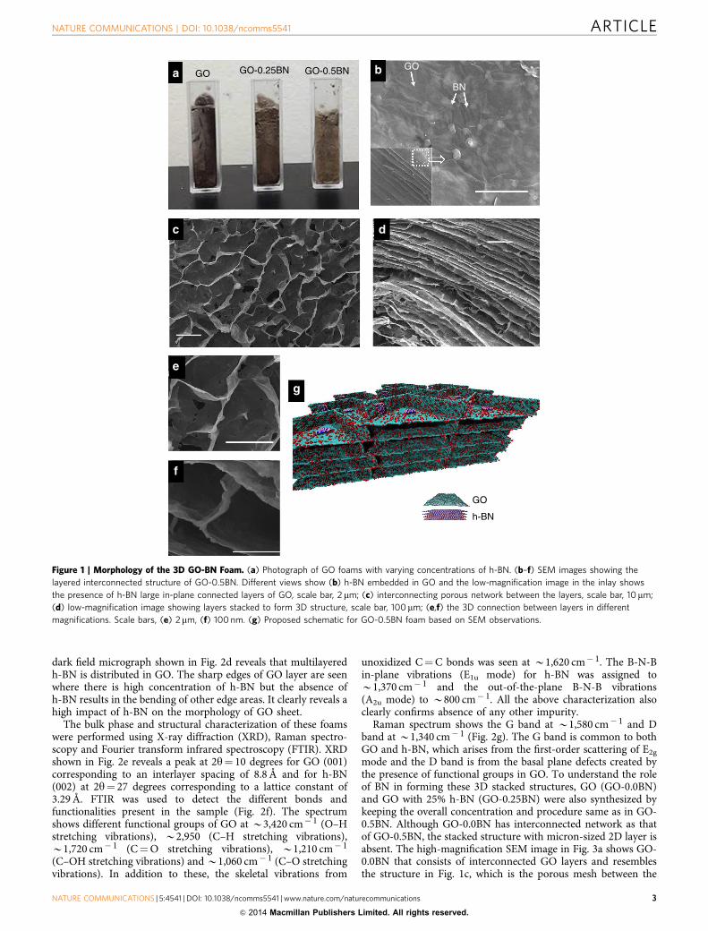
Molecular dynamics simulation of 2D building blocks. Theinnovative and complex 3D structure formation due to h-BN andthe influence of h-BN in mechanical behaviour of GO sheets werestudied using fully atomistic simulations. A comparative simu-lation between GO sheet with and without h-BN has been per-formed. For close resemblance with experimental work, we havemaintained the same ratio of dimension of the two nanosheets. Itis important to note that the 3D structure consists of 2D sheetswhich undergo tension in one direction and results compressionin the other direction. Keeping above in mind we have appliedtension in one direction and compared naked GO and GO withh-BN flakes. Stretching process was simulated at temperature of300 K until the cracking point and due to that a reactive forcefield, ReaxFF37, was chosen for these simulations. ReaxFF issimilar to standard nonreactive force fields such as MM3 with thedifference that it can describe bond formation and dissociation(making or breaking bonds) as a function of bond order values.For GO-BN, a finite h-BN was placed in the middle/top of thesemi-infinite GO membranes (see Fig. 6). The strain wasgenerated by gradual increase of the unit cell value alongperiodic direction. The stress was calculated by computing theforces on each atom and then obtaining the stress tensor. Fromthis tensor, we calculated a quantity known as von Mises stress,the second invariant of the deviatoric stress tensor, which isrelated to the distortion state of the system. Von Mises stressprovides very helpful information on the fracturing processes as itis possible to visualize the time evolution of the local stress. Thismethodology has been successfully used to investigate themechanical failure of carbon-based nano structures such asgraphene and carbon nanotubes and also h-BN structures38–40.
As there is a significant strain induced in the foam duringprocessing and testing, the simulations give us an insight into thestructural formation and mechanical stability of the h-BNreinforced GO foam. The snapshots of stretching process withstress distributions for naked GO flake and GO partially coveredwith h-BN flake at different strains are shown in Fig. 6. First rowof Fig. 6 shows GO and GO with h-BN at initial stage (0% strain).Note that the interaction between h-BN and GO produces a morestressed structure than naked GO. When the strain (see 7.5%strained), is continuously applied, the resulting stress isdistributed uniformly through GO, which presents an out-of-plane distortion (shown by arrow). On the other hand, thoughsmall, for same strain, GO-BN structure concentrates stress inlocalized regions across area of BN and border along periodicdirection and no distortion is allowed by h-BN coverage, whichexplains our TEM observation. Because of uniform stressdistribution, at 10% strain, naked GO starts to break from edgesclose to the membrane centre. This cracking provokes a high out-of-plane distortion in GO sheet. As the stress in GO-BN is moreconcentrated on borders along periodic direction, the samecracking area in GO remains intact with only presence of a smallhole that does not propagate. An extensive cracking is observed inGO sheets without h-BN at B12.5% strain, where the flake startsto break apart. Only at that strain of B12.5%, a cracking occursfor GO-BN. For this case, the stress distributed on borders alongperiodic directions induces a parallel cracking at the edges awayfrom h-BN without any bending or buckling, thereby providingmore structural stability. These results are in agreement with the
GO GO-hBN
Figure 3 | SEM and TEM characterization of GO-0.0BN and GO-0.25BN.
(a) SEM image of GO-0.0BN showing the interconnected porous
structure but absence of large layers. Scale bars, 20mm, (inlay) 50mm.
(b) SEM image of GO-0.25 which shows large layers similar to GO-0.5BN.
Scale bars, 20mm, (inlay) 50mm. (c) TEM image of GO-0.0BN showing
wrinkled sheets of GO as there is no h-BN present on it. Scale bars 0.5mm
(d) TEM image of GO-0.25BN with flat GO sheets and curling only on
the edges where there is less concentration of h-BN. Scale bars 20mm,
(inlay) 50mm.
NATURE COMMUNICATIONS | DOI: 10.1038/ncomms5541 ARTICLE
NATURE COMMUNICATIONS | 5:4541 | DOI: 10.1038/ncomms5541 | www.nature.com/naturecommunications 5
& 2014 Macmillan Publishers Limited. All rights reserved.

inferences from SEM and TEM images. From the simulation, it ispossible to highlight two main effects of h-BN coverage. The firstone is related to the changes in stress distribution. The interactionbetween h-BN and GO complicates the stress distribution alongstructure, which concentrates in the region immediately close towhere strain is generated (border along periodic direction). Inaddition, h-BN also alters the out-of-plane deformation ofstructure. These effects induce a completely different process ofstretching and consequently different cracking patterns forpristine GO and GO-BN as we observe from Fig. 6. To furtherinvestigate the mechanical stability, the effect of h-BN on singleout-of-the-plane GO sheet (which is the GO sheet in the porousnetwork as indicated in Supplementary Fig. 5a) during compres-sion was also studied and is shown in Supplementary Fig. 5b,c.Significant bending is induced in GO sheet in naked GO, but inGO-BN the bending is restricted to regions where h-BN isnot present. An increased threshold fracture limit and moreefficient stress accumulation and dissipation is observed on GOwith h-BN compared with naked GO flake. During compression,
deformation occurs on h-BN and this in turn minimizes bendingof the large GO flake. Hence in naked GO, buckling can occur atlower stress leading to early fracture. The bending/buckling givesrise to high stress concentration at the bent edge leading the localstress to cross the critical stress (fracture value). These resultsindicate the superior mechanical behaviour in h-BN reinforcedGO flakes at 2D level and it is very critical in the overall structuralformation and mechanical performance of the entire 3Dstructure.
DiscussionUnlike the hydrogel/aerogel structures formed from graphene-based materials reported earlier, the novel architecture reportedhere has macro-sized layers of conjoined GO sheets orderlystacked with the out-of-plane mesh completing the 3D frame-work. The innovation and improvement in mechanical propertiesand stabilities lie in the structure of the 3D foam. Thecomparative study between GO only and h-BN reinforced GO
350
300
250
200
UNLOADING
LOADINGLOADING
LOADINGLOADING
LOADING
LOADING
LOADING
1
2
Time (min)
LOADING LOADING
LOADING LOADING
UNLOADING
UNLOADING
UNLOADING
UNLOADING
UNLOADING
UNLOADING
UNLOADING
UNLOADING
UNLOADING
S1S2 S3
P3
P2
P2
P2
P3
P3
P1
P1
P1
LOADING
LOADING
Stif
fnes
s (k
N m
m–1
)
Stif
fnes
s (k
N m
m–1
)
S1
S2
S3
150
100
50
00 20 40
Time (min)60 80 100 0
020406080
100120140160180200
Stif
fnes
s (k
N m
–1)
Stif
fnes
s (k
N m
–1)
020406080
100
00 50 100 150 200 250 300
Time (min) % Compressive strain
00.0
0.5
1.0
2.0
1.5
0.00
0.02
0.04Load
(N
)
0.06
0.08
0.10
Com
pres
sive
str
ess
(MP
a)
5 10 15 20 25 30 35 40 450 50 100 150 200 250 300
Time (s)
0 50 100 150 200 250 300
20
40
60
80
100
120140160180200
220
20 40Time (min)
60 80 100 120 140
Figure 4 | Controlled strain/load experiments and compression testing. (a,b) Controlled strain experiments with three different strains S1 (0.5%),
S2 (1%) and S3 (2%) applied in sequence and stiffness monitored for (a) GO-0.0BN where a drastic drop in the stiffness is observed after S2 is applied due
to permanent deformation, (b) GO-0.5BN where the stiffness is maintained during different cycles. (c–e) Controlled load experiment where three different
maximum loads P1, P2 and P3 were applied as shown in c, the loading/unloading cycles on d, GO-0.0BN where a compression is observed in the lowest
load and permanent deformation in subsequent loads, (e) GO-0.5BN where stiffness does not decrease during different loads, exhibiting complete
recovery. (f) Compression test results on Instron showing a linear increase in stress until 35% strain; the photographs show GO-0.5BN taking the load of
2.5 g and 5 g and resuming the original shape after unloading.
ARTICLE NATURE COMMUNICATIONS | DOI: 10.1038/ncomms5541
6 NATURE COMMUNICATIONS | 5:4541 | DOI: 10.1038/ncomms5541 | www.nature.com/naturecommunications
& 2014 Macmillan Publishers Limited. All rights reserved.

foams clearly reveals that h-BN in GO sheet has very importantrole in the formation of 3D layered network structure. First of all,the atomic level interactions between h-BN and GO were foundto aid the formation of nearly flat flexible layers, which is furtherobserved in our MD simulation. The higher stiffness of h-BNdoes not allow the GO sheet to bend due to in-plane lateral stress.The presence of h-BN maintains the GO sheet flat and there arewrinkles only in few areas. This results in increased van der Waalsforces between similar sheets face to face and as the sheets aredispersed in water and not aligned, they stack together partiallyoverlapping with each other resulting in formation of large layers.The cross-linking between GO sheets also aids the formation oflayers and is considered accountable for the 3D connectionbetween the layers. The spacing between the layers is attributed tothe mutual interaction of van der Waals forces and electrostaticrepulsions due to the ionized carboxylic and phenol hydroxylgroups in GO. However in the absence of h-BN, the sheets arewrinkled and the formation of large layer is not possible and theyform an interconnected porous network due to the crosslinkingby GAD and Resorcinol. The TEM and SEM data showmultilayered h-BN preventing the GO sheets from breaking bysignificantly reducing the crack propagation from the straininduced during lyophilization. The HRTEM image showingdislocation reveals role of h-BN in GO sheet in distribution ofstress (Supplementary Fig. 6). The stress generated during theprocess of freeze drying is transferred from GO sheet to a multifold higher stiff h-BN nanosheet. The dislocation at the interfaceof GO and h-BN confirms the above phenomena. The same isalso observed in our MD simulation results. MD simulation isconsistent with the electron microscopy results and the drasticchange in the structure formation in the presence and absence ofh-BN is attributed to the difference in stress distribution in the
two cases. While the uniform stress distribution in GO results inthe in-plane cracking and out-of-plane distortion, the complexstress distribution in h-BN-covered GO restrains the crack frompropagating. These results elucidate the layered assembly and theenhanced mechanical stability of the GO-BN foams.
As discussed in the previous section, the foam consists of twotypes of 2D sheets which align in two directions to loading. Theschematic of the alignment of loading to the sheets is shown asinlay in Fig. 5c. In this type of foam structure consisting of highstiffness and high modulus GO-h-BN sheet with high fracturetoughness, the top sheet transfers the load to perpendicularaligned sheet and undergoes tension at other places. Thesheet aligned parallel to load direction undergoes compressionbending due to small thickness. The large layers do not fractureeven at much higher load due to the presence of h-BN mitigatingthe cracks (Fig. 5c). Also the stress is localized near h-BN platelets(also shown in Fig. 3g) and gets relaxed and transmitted throughthe sheet during unloading. Changing loading direction shows achange in properties which proves anisotropy of the 3D foambehaviour (Supplementary Fig. 7). On the other hand, therandomly oriented GO sheet foam without h-BN however showssimilar stiffness but fails after first loading.
In summary, a unique reinforcement effect of h-BN wasdemonstrated and investigated in GO-based ultralow density 3Dhybrids. Excellent elastic behaviour was demonstrated by the GO-BN foam up to a strain of B40%. The mechanical stiffness wasunchanged and the structural integrity was retained even athigher temperatures. The high mechanical and thermal stabilitiesof the foam overcome the major limitations associated withconventional nanoengineered foams. The simple processing andscalability of the foams enable developing them in desired shapesand sizes.
LOAD
BNBN
BNBN
BNBNBN
BNGO
GO
GO
GO
BN
0
50
50
100
100Temperature (°C)
150
150
Stif
fnes
s (k
N m
–1)
200
200
250
300
350
a b
c d
Figure 5 | Analysis of mechanical deformation in GO-0.0BN and GO-0.5BN and high temperature compression testing. (a) Low-magnification SEM
revealing cracking along GO sheets and also at the junctions; high magnification is shown in inlay confirms the inferences. Scale bars, 10 mm, (inlay)
1mm. (b) Low-magnification SEM of GO-0.5BN showing the layers bending rather than cracking and the alignment of load along the structure is shown
in the schematic (inlay). Scale bar, 50mm. (c) High-magnification SEM showing small crack along the large layer where h-BN prevents it from
propagating. Scale bar, 50 nm. (d) Compression testing at high temperature on GO-0.25BN and GO-0.5BN showing stiffness is stable to temperature as
high as 200 �C.
NATURE COMMUNICATIONS | DOI: 10.1038/ncomms5541 ARTICLE
NATURE COMMUNICATIONS | 5:4541 | DOI: 10.1038/ncomms5541 | www.nature.com/naturecommunications 7
& 2014 Macmillan Publishers Limited. All rights reserved.

MethodsSynthesis of GO-BN foams. GO was prepared from graphite powder (45 mm,99.99%, SP-1 Bay Carbon) using improved Hummer’s method reported else-where41. Liquid exfoliation method was followed for synthesizing few-layeredh-BN flakes42. The starting material used was h-BN powder (1 mm, 98%) fromSigma Aldrich. Dimethyl formamide (DMF, room temperature surface tensionB37 mN m� 1) was obtained from Sigma Aldrich and used as the exfoliation fluidmedium. The micron-sized h-BN powder was added to the container batches withDMF. Subsequently, the prepared solution was extensively sonicated (B5 h) in aBranson 5510 water bath sonicator, keeping the temperature of the water bathconstant (room temperature B300 K). After sonication, the solution wascentrifuged with a Thermo Fisher Scientific sorvall biofuge stratos centrifuge for30 min at 1,500 r.p.m. The whitish supernatant (top part) is decanted and wasvacuum filtered, using a Sartorious PTFE—filter membrane with a pore size of
0.2 mm. After this process, 2D h-BN nanosheets (B500 nm by 500 nm,approximatelyfive layers in thickness) were obtained33. The h-BN nanosheets werewashed twice with water, ethanol and chloroform to remove any residual DMF andthe dried material was then scraped off from the filter paper. Equal weight amountsof GO and h-BN were separately sonicated in deionized water for 30 min andmixed together to make a concentration of 10 mg ml� 1. Resorcinol(0.25 mg ml� 1), glutaraldedhyde (2ml ml� 1) and a very small amount (B0.1 mg)of sodium tetraborate decahydrate was added to the GO-BN dispersion andsonicated for 2 h. The solution was then lyophilized in a bench-top freeze dryer(MillRock Technology) for 48 h.
Material characterization and mechanical testing. Raman spectroscopy wasdone using Renishaw in Via Raman Microscope at laser excitation of 514.5 nm.Nicolet FTIR Infrared Microscope was used for performing FTIR on the sample forstudying the chemical bonds present. The morphology of the samples was observedusing FEI Quanta 400 scanning electron microscope under high vacuum at 10 kV.A 10-nm thick gold film was sputtered on the sample before imaging for reducingthe charging effects from h-BN. TEM images and diffraction patterns were takenusing JEOL 2100 field emission gun transmission electron microscope. For pre-paring the TEM samples, small pieces were broken from the foams and bathsonicated in isopropyl alcohol for 30 min. A few drops were then cast onto theholy-carbon grids and allowed to dry in vacuum. The TEM samples were then leftunder vacuum overnight. Q800 dynamic mechanical analysis was employed forperforming mechanical test on the samples from room temperature up to 200 �C.Compressive stress versus strain curve was obtained from Instron universal testingmachine.
Simulation. All calculations were carried out using the reactive force fieldReaxFF37. This forcefield was parameterized using density functional theorycalculations and, through bond length/bond order relationship, it can handlechemical reactions. The average deviation between ReaxFF heat of formation valueand the experimental one is 2.8 and 2.9 kcal mol� 1 for nonconjugated andconjugated systems, respectively. Similarly to standard nonreactive force fields,ReaxFF divides the system energy into partial energy contributions associated withterms such as: valence angle bending, bond stretching as well as nonbondedCoulomb and van der Waals interactions37. The main difference, however, is thatReaxFF can make and break bonds as a function of bond order values. In this way,the system energy for ReaxFF is composed by:
ESystem¼Ebond þ Eover þ Eunder þ Eval þ Epen þ Etors þEtors þ Econj
þ EvdWaals þ Ecoulombð1Þ
where Ebond is the bond energy, Eover is over-coordination, under-coordination isEunder, valency energy is Eval, energy penalty for handling atoms with two doublebonds is Epen, Etors is torsion energy, conjugated bond energies is Econj, van derWaals energy is EvdWaals and Coulomb energy is Ecoulomb. For better description ofreactivity in the simulations, all bond orders were calculated and charge effectswere taken into account in electronegativity equalization method approach43.
For the stretching process and stress analysis, our system was composed bysemi-infinite GO strips, generated by random distributions of oxygen atoms intographene membranes. System temperatures were set to 300 K and controlled by aNose–Hoover thermostat imposing a canonical ensemble with constant number ofatoms, temperature and volume (NVT ensemble) as implemented on large-scaleatomic/molecular massively parallel simulator44. Time-steps of 0.05 fs were usedand a constant strain rate of 10� 6 fs� 1 was continuously implemented during thewhole simulation until the mechanical rupture. Stress values are obtainedcalculating the force per atom at each step of simulation and then subtracted fromthe hydrostatic components to obtain the deviatoric stress and one of its invariants,the so-called von Mises stress. von Mises stress describes the distortion stress stateand provide relevant information for the analysis of fracture mechanisms.
References1. Reinfried, M. et al. Hybrid foams—a new approach for multifunctional
applications. Adv. Eng. Mater. 13, 1031–1036 (2011).2. Studart, A. R., Gonzenbach, U. T., Tervoort, E. & Gauckler, L. J. Processing
routes to macroporous ceramics: a review. J. Am. Ceram. Soc. 89, 1771–1789(2006).
3. Reddy, E. S. & Schmitz, G. J. Superconducting foams. Supercond. Sci. Technol.15, L21–L24 (2002).
4. Banhart, J. Metal foams: production and stability. Adv. Eng. Mater. 8, 781–794(2006).
5. Banhart, J. Manufacture, characterisation and application of cellular metals andmetal foams. Prog. Mater. Sci. 46, 559–632 (2001).
6. Svagan, A. J., Samir, M. A. S. A. & Berglund, L. A. Biomimetic foams of highmechanical performance based on nanostructured cell walls reinforced bynative cellulose nanofibrils. Adv. Mater. 20, 1263–1269 (2008).
7. Cao, X. et al. Preparation of novel 3D graphene networks for supercapacitorapplications. Small 7, 3163–3168 (2011).
BN
0%
7.5%
10%
12.5%
GO GO:BN – +Stress
Figure 6 | MD simulation results of mechanical behaviour of naked GO
sheet and GO sheet partially covered with h-BN (GO:BN) on application
of different strains. (a) 0% showing the original shapes of GO and GO:BN,
(b) 7.5% where stress is distributed uniformly along GO and there is an
out-of-plane distortion; there is localized stress around h-BN bordering
along periodic direction but no distortion allowed by h-BN, (c) 10% where
stress distribution causes GO to break thereby provoking out-of-plane
distortion; in GO:BN, the small crack in GO sheet is not allowed to
propagate, (d) 12.5% where high-order cracking and crumbling is observed
in GO; in GO:BN the stress distributed along periodic direction leads to a
crack along the edges of GO sheet away from h-BN and no crumbling is
observed.
ARTICLE NATURE COMMUNICATIONS | DOI: 10.1038/ncomms5541
8 NATURE COMMUNICATIONS | 5:4541 | DOI: 10.1038/ncomms5541 | www.nature.com/naturecommunications
& 2014 Macmillan Publishers Limited. All rights reserved.

8. Cao, A., Dickrell, P. L., Sawyer, W. G., Ghasemi-Nejhad, M. N. & Ajayan, P. M.Super-compressible foamlike carbon nanotube films. Science 310, 1307–1310(2005).
9. Butler, S. Z. et al. Progress, challenges, and opportunities in two-dimensionalmaterials beyond graphene. ACS Nano 7, 2898–2926 (2013).
10. Zhou, W. & Wang, Z. L. Three-Dimensional Nanoarchitectures: Designing Next-Generation Devices (Springer, 2011).
11. Novoselov, K. S. et al. Two-dimensional atomic crystals. Proc. Natl Acad. Sci.USA 102, 10451–10453 (2005).
12. Keller, S. W., Kim, H.-N. & Mallouk, T. E. Layer-by-layer assembly ofintercalation compounds and heterostructures on surfaces: toward molecular‘beaker’ epitaxy. J. Am. Chem. Soc. 116, 8817–8818 (1994).
13. Fendler, J. H. Self-assembled nanostructured materials. Chem. Mater. 8,1616–1624 (1996).
14. Jones, M. R. & Mirkin, C. A. Materials science: self-assembly gets new direction.Nature 491, 42–43 (2012).
15. Zhang, X. et al. Mechanically strong and highly conductive graphene aerogeland its use as electrodes for electrochemical power sources. J. Mater. Chem. 21,6494–6497 (2011).
16. Xu, Y., Sheng, K., Li, C. & Shi, G. Self-assembled graphene hydrogel via a one-step hydrothermal process. ACS Nano 4, 4324–4330 (2010).
17. Sudeep, P. M. et al. Covalently interconnected three-dimensional grapheneoxide solids. ACS Nano 7, 7034–7040 (2013).
18. Yan, Z. et al. Three-dimensional metal–graphene–nanotube multifunctionalhybrid materials. ACS Nano 7, 58–64 (2013).
19. Lu, X. et al. Macroporous foam of reduced graphene oxides prepared bylyophilization. Mater. Res. Bull. 47, 4335–4339 (2012).
20. Novoselov, K. S. et al. Electric field effect in atomically thin carbon films.Science 306, 666–669 (2004).
21. Geim, A. K. & Novoselov, K. S. The rise of graphene. Nat. Mater. 6, 183–191(2007).
22. Allen, M. J., Tung, V. C. & Kaner, R. B. Honeycomb carbon: a review ofgraphene. Chem. Rev. 110, 132–145 (2010).
23. Stankovich, S. et al. Graphene-based composite materials. Nature 442, 282–286(2006).
24. Han, Z. et al. Ammonia solution strengthened three-dimensional macro-porousgraphene aerogel. Nanoscale 5, 5462–5467 (2013).
25. Gao, G. et al. Artificially stacked atomic layers: toward new van der waals solids.Nano Lett. 12, 3518–3525 (2012).
26. Britnell, L. et al. Field-effect tunneling transistor based on vertical grapheneheterostructures. Science 335, 947–950 (2012).
27. Rafiee, M. A. et al. Hexagonal boron nitride and graphite oxide reinforcedmultifunctional porous cement composites. Adv. Funct. Mater. 23, 5624–5630(2013).
28. Liu, Z. et al. In-plane heterostructures of graphene and hexagonal boron nitridewith controlled domain sizes. Nat. Nanotechnol. 8, 119–124 (2013).
29. Peng, Q., Zamiri, A. R., Ji, W. & De, S. Elastic properties of hybrid graphene/boron nitride monolayer. Acta Mech. 223, 2591–2596 (2012).
30. Pacile, D., Meyer, J. C., Girit, C. O. & Zettl, A. The two-dimensional phase ofboron nitride: Few-atomic-layer sheets and suspended membranes. Appl. Phys.Lett. 92, 133107–133107–3 (2008).
31. Pakdel, A., Zhi, C., Bando, Y., Nakayama, T. & Golberg, D. Boron nitridenanosheet coatings with controllable water repellency. ACS Nano 5, 6507–6515(2011).
32. Kimura, Y., Wakabayashi, T., Okada, K., Wada, T. & Nishikawa, H. Boronnitride as a lubricant additive. Wear 232, 199–206 (1999).
33. Taha-Tijerina, J. et al. Electrically insulating thermal nano-oils using 2D fillers.ACS Nano 6, 1214–1220 (2012).
34. Song, L. et al. Large scale growth and characterization of atomic hexagonalboron nitride layers. Nano Lett. 10, 3209–3215 (2010).
35. Nag, A. et al. Graphene analogues of BN: novel synthesis and properties. ACSNano 4, 1539–1544 (2010).
36. Neto, A. H. C. & Novoselov, K. Two-dimensional crystals: beyond graphene.Mater. Exp. 1, 10–17 (2011).
37. Van Duin, A. C. T., Dasgupta, S., Lorant, F. & Goddard, W. A. ReaxFF: areactive force field for hydrocarbons. J. Phys. Chem. A 105, 9396–9409 (2001).
38. Paci, J. T., Belytschko, T. & Schatz, G. C. Computational studies of thestructure, behavior upon heating, and mechanical properties of graphite oxide.J. Phys. Chem. C 111, 18099–18111 (2007).
39. Grantab, R., Shenoy, V. B. & Ruoff, R. S. Anomalous strength characteristics oftilt grain boundaries in graphene. Science 330, 946–948 (2010).
40. Perim, E., Autreto, P. A. S., Paupitz, R. & Galvao, D. S. Dynamical aspects of theunzipping of multiwalled boron nitride nanotubes. Phys. Chem. Chem. Phys.15, 19147 (2013).
41. Marcano, D. C. et al. Improved synthesis of graphene oxide. ACS Nano 4,4806–4814 (2010).
42. Coleman, J. N. et al. Two-dimensional nanosheets produced by liquidexfoliation of layered materials. Science 331, 568–571 (2011).
43. Mortier, W. J., Ghosh, S. K. & Shankar, S. Electronegativity-equalizationmethod for the calculation of atomic charges in molecules. J. Am. Chem. Soc.108, 4315–4320 (1986).
44. Plimpton, S. Fast parallel algorithms for short-range molecular dynamics.J. Comput. Phys. 117, 1–19 (1995).
AcknowledgementsWe acknowledge the funding support from U.S. Department of Defense: U.S. Air ForceOffice of Scientific Research for the Project MURI: ‘Synthesis and Characterization of3-D Carbon Nanotube Solid Networks’ Award No. FA9550-12-1-0035. We alsoacknowledge the support by EAGER—NSF ECCS-1327093, CONACYT (213780)and INDO-US: IUSSTF/JC/22-2012/2013-14.
Author contributionsP.M.A. and T.N.N. proposed the project. S.V. and C.S.T. designed and conductedexperiments. S.V. performed material synthesis and characterization. C.S.T. performedmechanical testing and electron microscopy imaging. P.A.d.S.A. performed and D.S.Gsupervised the MD simulation J.T.-T. helped in raw material synthesis and XRDcharacterization. S.O. helped in FTIR and TGA characterization. A.C.C. helped in DMAcompression testing. S.V., C.S.T. and P.M.A. analysed the data and wrote the paper.P.M.A., T.N.N. and R.V. supervised the project. All authors discussed and revised thefinal manuscript.
Additional informationSupplementary Information accompanies this paper at http://www.nature.com/naturecommunications
Competing financial interests: The authors declare no competing financial interests.
Reprints and permission information is available online at http://www.nature.com/reprintsandpermissions.
How to cite this article: Vinod, S. et al. Low-density three-dimensional foam usingself-reinforced hybrid two-dimensional atomic layers. Nat. Commun. 5:4541doi: 10.1038/ncomms5541 (2014).
NATURE COMMUNICATIONS | DOI: 10.1038/ncomms5541 ARTICLE
NATURE COMMUNICATIONS | 5:4541 | DOI: 10.1038/ncomms5541 | www.nature.com/naturecommunications 9
& 2014 Macmillan Publishers Limited. All rights reserved.