Low Cost Multi Touch Human Computer Interface
71
Low Cost Multi-Touch Human Computer Interface SCHOOL OF ELECTRICAL AND ELECTRONIC ENGINEERING ROHIT JHA YEAR 2010/2011 Low Cost Multi-Touch Human Computer Interface (A3061-101) ROHIT JHA YEAR 2010/2011
-
Upload
independent -
Category
Documents
-
view
0 -
download
0
Transcript of Low Cost Multi Touch Human Computer Interface
Low Cost Multi-Touch Human Computer Interface
SCHOOL OF ELECTRICAL AND ELECTRONIC
ENGINEERING
ROHIT JHA
YEAR 2010/2011
Low
Cost M
ulti-T
ou
ch H
um
an
Co
mp
uter
Inter
face (A
30
61
-10
1)
RO
HIT
JH
A
YEAR
2010/2011

LOW COST MULTI-TOUCH HUMAN COMPUTER
INTERFACE
Submitted By: ROHIT JHA
Matriculation Number: 078252F03
Supervisors
Assoc Prof Chua Hock Chuan
Asst Prof Martin Constable
School of Electrical and Electronic Engineering
Year 2010/2011
A Final Year Project report presented to Nanyang Technological University in partial fulfillment of
the requirements for the Degree of Bachelor of Engineering.

Page | i
TABLE OF CONTENTS
Abstract ____________________________________________________________________ iii
Acknowledgement ____________________________________________________________ iv
List of Figures ________________________________________________________________ v
List of Abbreviations __________________________________________________________ viii
Chapter 1: Introduction ________________________________________________________ 1
1.1 Background ___________________________________________________________________ 1
1.2 Motivation ____________________________________________________________________ 2
1.3 Objective _____________________________________________________________________ 2
1.4 Scope & Limitations _____________________________________________________________ 3
1.5 Organization of Report __________________________________________________________ 4
Chapter 2: Literature Review ____________________________________________________ 6
2.1 Low cost Multi-Touch Implementations _____________________________________________ 6
2.1.1 Frustrated Total Internal reflection (FTIR) __________________________________________________ 6
2.1.2 Diffused Illumination (DI) _______________________________________________________________ 8
2.1.3 Diffused Surface Illumination (DSI) _______________________________________________________ 9
2.1.4 LED Light Plane (LED-LP) ______________________________________________________________ 10
2.1.5 Laser Light Plane (LLP) ________________________________________________________________ 11
2.2 Tangible User Interface Objects (TUIO) Protocols ____________________________________ 12
2.3 Tracker Applications ___________________________________________________________ 13
2.3.1 Community Core Vision (CCV) __________________________________________________________ 13
2.3.2 Reactivision _________________________________________________________________________ 14
2.4 Client Applications _____________________________________________________________ 15
2.4.1 Flash ______________________________________________________________________________ 16
2.4.2 C# (.NET/Silverlight/WPF) _____________________________________________________________ 17
Chapter 3: Hardware _________________________________________________________ 19
3.1 Technology ___________________________________________________________________ 19

Page | ii
3.2 Components __________________________________________________________________ 20
3.2.1 Wooden Frame ______________________________________________________________________ 20
3.2.2 Surface & Projection film ______________________________________________________________ 20
3.2.3 Laser Module _______________________________________________________________________ 21
3.2.4 Camera ____________________________________________________________________________ 21
3.2.5 Other miscellaneous components _______________________________________________________ 23
3.3 Design & Construction Process ___________________________________________________ 24
3.3.1 Phase 1 ____________________________________________________________________________ 24
3.3.2 Phase 2 ____________________________________________________________________________ 25
3.3.3 Phase 3 ____________________________________________________________________________ 36
3.4 Problems ____________________________________________________________________ 40
Chapter 4: Software __________________________________________________________ 42
4.1 CCV Calibration & configuration __________________________________________________ 42
4.2 Flash Applications _____________________________________________________________ 43
4.3 Windows 7 Native Multi-Touch ___________________________________________________ 45
4.3.1 How it works? _______________________________________________________________________ 46
4.3.2 Features ___________________________________________________________________________ 46
4.4 Android Integration ____________________________________________________________ 48
4.4.1 Android x86 + Virtual Machine (VM) _____________________________________________________ 48
4.4.2 Android Virtual Devices _______________________________________________________________ 49
Chapter 5: Conclusion _________________________________________________________ 51
Chapter 6: Recommendations for Future Work ____________________________________ 53
Chapter 7: References ________________________________________________________ 54
Chapter 8: Appendix __________________________________________________________ 56
8.1 Appendix A ___________________________________________________________________ 56
8.2 Appendix B ___________________________________________________________________ 58
Page | iii
ABSTRACT
Multi-touch refers to a touch system's ability to simultaneously detect and resolve a minimum of
3+ touch points. Multi-touch is one of the key techniques of implementing the concept of Human
Computer Interaction. The speed, efficiency and intuitiveness of the technology have resulted in
its widespread popularity, with many companies doing rapid research in this area. This
technology has its applications varying from elementary education like in schools to specialized
implementation like in space research centers. But the basic problem with such systems is the
exponential increase in cost with the increase in complexity and size of the system.
This project is developed to overcome the difficulties mentioned before. The objective is to
develop a low-cost multi-touch human computer interface which can support the existing
applications (including graphic intensive). Two prototype multi-touch boards have been
constructed to demonstrate this feat. The boards have a 50 inch screen which provides a huge
surface area for the user to interact with applications. The main innovation here is the extremely
low cost at which the board was built. The response is extremely fast to touches on the screen.
The boards are capable of running flash applications that support multi-touch. Also the boards
bring native multi-touch capabilities to Windows 7 thereby allowing the user to freely and
intuitively interact with all the existing Windows programs. Presence of two boards also allows
collaborative features like simultaneous editing and communication. This project also is
currently exploring the possibility of natively running Google Android 3.0 on its hardware.
Page | iv
ACKNOWLEDGEMENT
The author would like to acknowledge the contribution made by the people mentioned below
towards the successful completion of this project.
First of all, the author would like to thank the two project supervisors – Associate Professor
Chua Hock Chuan and Assistant Professor Martin Constable. Prof Chua helped the author by
providing guidance at each and every step. Prof Chua held weekly meetings thereby giving the
student a direction to carry forward the project in. His visionary and clear ideas about the project
provided inspiration for the student. Prof Martin provided the author with his vast expertise on
product design and in innovative thinking. Prof Martin helped the author in thinking and
improving on various ideas before implementing them.
Second of all, the author would like to thank his teammates Mr. Han Feimin and Miss Mi Qi.
Both of them have been a fantastic team to work with. Both of them have helped the author in
bouncing off ideas and discussing them. Both of them, with their knowledge and experience,
have made it possible for the author to successfully bring the project to a successful level.
Third of all, the author would like to thank Mr. Jason Ho. Mr. Jason was a wooden product
designer and constructor. His invaluable practical experience, which was used in setting up the
prototype, is greatly appreciated.
Last but not the least, the author would also like to thank all the inventors and developers on
whose past work the current project could be realized.

Page | v
LIST OF FIGURES
Figure 1: FTIR Setup ...................................................................................................................... 6
Figure 2: Total Internal Reflection ................................................................................................. 7
Figure 3: FTIR touch image ............................................................................................................ 7
Figure 4: DI Setup ........................................................................................................................... 8
Figure 5: Front DI touch image ...................................................................................................... 8
Figure 6: Rear DI touch image........................................................................................................ 9
Figure 7: DSI Setup ........................................................................................................................ 9
Figure 8: DSI touch image ............................................................................................................ 10
Figure 9: LED-LP Setup ............................................................................................................... 10
Figure 10: LED-LP touch image ................................................................................................... 11
Figure 11: LLP Setup .................................................................................................................... 11
Figure 12: LLP touch image ......................................................................................................... 12
Figure 13: TUIO Setup ................................................................................................................. 12
Figure 14: Community Core Vision (Windows) .......................................................................... 14
Figure 15: reaTIVison ................................................................................................................... 15
Figure 16: Flash framework for multi-touch ................................................................................ 16
Figure 17: MulitTouchVista Framework ...................................................................................... 18
Figure 18: LLP Setup .................................................................................................................... 19
Figure 19: Projection Film ............................................................................................................ 21
Page | vi
Figure 20: Tracing Paper .............................................................................................................. 21
Figure 21: Laser module with line generator ................................................................................ 21
Figure 22: CCD capability to read IR light ................................................................................... 22
Figure 23: Sony PS3 Eye .............................................................................................................. 23
Figure 24: Behavior of IR Bandpass Filter ................................................................................... 23
Figure 25: Phase 1 Hardware Setup .............................................................................................. 24
Figure 26: Product Design Steps................................................................................................... 26
Figure 27: 3D Hardware models ................................................................................................... 27
Figure 28: SimProj with single mirror .......................................................................................... 28
Figure 29: Dimensions of Board 1 parts ....................................................................................... 29
Figure 30: Assembling of Board 1 ................................................................................................ 30
Figure 31: Back Panel with mirror................................................................................................ 30
Figure 32: DC Power Supply ........................................................................................................ 33
Figure 33: Testing the Laser Light Plane ...................................................................................... 33
Figure 34: Completed Board 1 at the end of Phase 1 ................................................................... 35
Figure 35: Revised Board Configurations .................................................................................... 37
Figure 36: Dimensions of Board 2 parts ....................................................................................... 38
Figure 37: Board 1 changed to new mirror configuration ............................................................ 39
Figure 38: Board 2 after pasting the tracing paper ....................................................................... 40
Figure 39: Optimum CCV and camera settings ............................................................................ 42
Figure 40: CCV calibration ........................................................................................................... 43

Page | vii
Figure 41: Adobe Flash Global Security Settings......................................................................... 44
Figure 42: Inter-Board collaboration ............................................................................................ 48

Page | viii
LIST OF ABBREVIATIONS
TUIO Tangible User Interface Objects
CCV Community Core Vision
UDP User Datagram Protocol
TCP Transmission Control Protocol
XML Extensible Markup Language
OSC Open Sound Control
LLP Laser Light Plane
DI Diffused Illumination
DSI Diffused Surface Illumination
LED-LP LED Light Plane
FTIR Frustrated Total Internal Reflection
AVD Android Virtual Devices
AOSP Android Open Source Project
JVM Java Virtual Machine
LED Light Emitting Diode
Page | 1
CHAPTER 1: INTRODUCTION
1.1 BACKGROUND
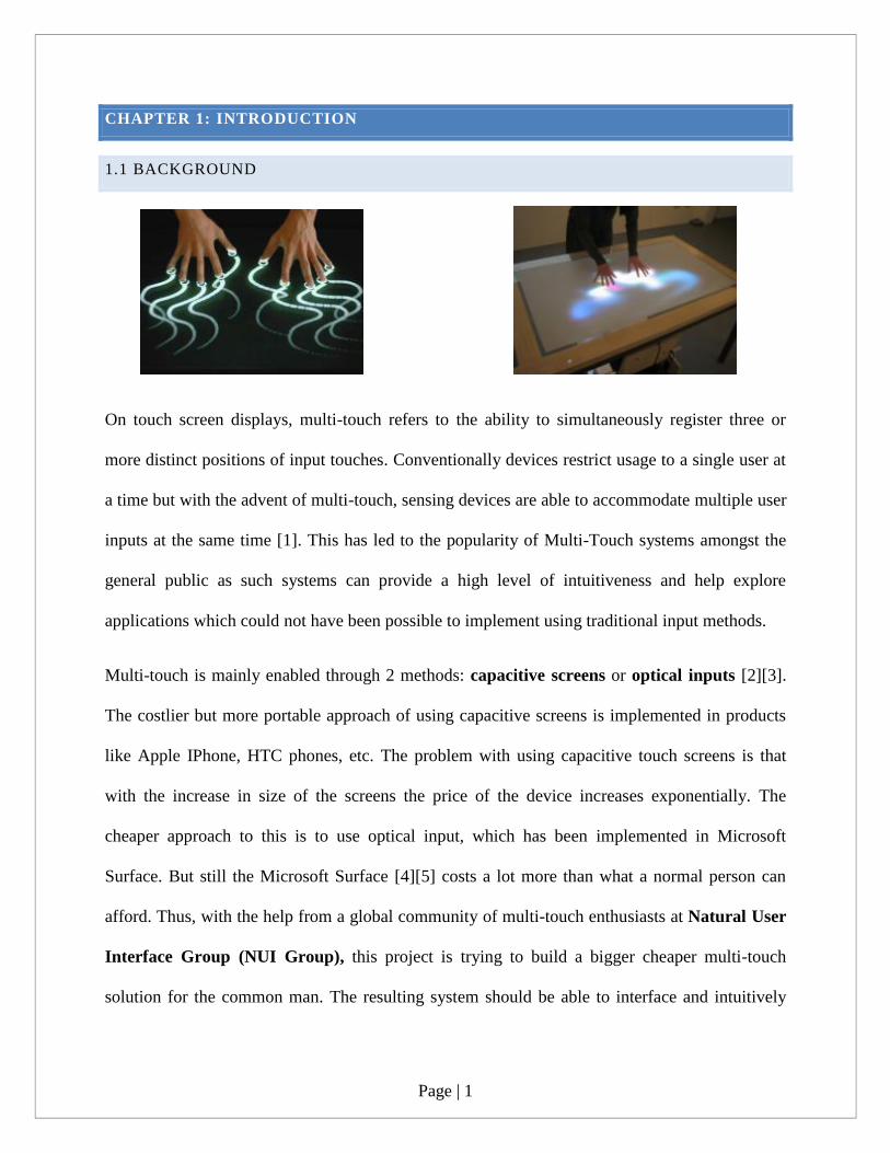
On touch screen displays, multi-touch refers to the ability to simultaneously register three or
more distinct positions of input touches. Conventionally devices restrict usage to a single user at
a time but with the advent of multi-touch, sensing devices are able to accommodate multiple user
inputs at the same time [1]. This has led to the popularity of Multi-Touch systems amongst the
general public as such systems can provide a high level of intuitiveness and help explore
applications which could not have been possible to implement using traditional input methods.
Multi-touch is mainly enabled through 2 methods: capacitive screens or optical inputs [2][3].
The costlier but more portable approach of using capacitive screens is implemented in products
like Apple IPhone, HTC phones, etc. The problem with using capacitive touch screens is that
with the increase in size of the screens the price of the device increases exponentially. The
cheaper approach to this is to use optical input, which has been implemented in Microsoft
Surface. But still the Microsoft Surface [4][5] costs a lot more than what a normal person can
afford. Thus, with the help from a global community of multi-touch enthusiasts at Natural User
Interface Group (NUI Group), this project is trying to build a bigger cheaper multi-touch
solution for the common man. The resulting system should be able to interface and intuitively
Page | 2
interact with existing programs and applications as well as new applications built in the future.
Plus, there should also be ample scope to deploy the device in a wide range of scenarios.
1.2 MOTIVATION
The main motivation of doing this project was to create a multi-touch device which would be of
a very low cost and at the same time will not compromise with quality. This would lead to the
extensive usage of such cheap interactive devices in a variety of environments such as school,
colleges, hospitals, clubs, airports, hotels, etc. Such extensive use of multi-touch technologies is
important to bring about a level of intuitiveness and collaboration that was seen with the advent
of the current GUI based systems by Apple [6].
The project was also motivated by the fact that most of the cheap multi-touch implementations
do not make it past the prototype phase. Also most of such prototypes are ugly looking
unfinished products which have very little chance of being used by regular users. This is where
Microsoft Surface is able to penetrate the market even with its extremely high cost. Thus, this
project will be a completely finished product, which if required can have the capability to be
deployed in real life.
Also for most of the multi-touch systems like touch phones, tablets and Microsoft Surface
developers need to separately come up with a suite of applications to support the device and its
firmware e.g. IPhone App Store, Android App Store, Surface Suite, etc. Another motivation to
develop such a product is to reduce the work of developers. The product would support all the
existing mouse based applications also by bringing native multi-touch to the existing operating
systems like Windows, Ubuntu, etc. It also leaves opportunity for developers to develop multi-
touch applications for inter-board collaboration and sharing.
1.3 OBJECTIVE
The objective of this project is to develop a low cost multi-touch human computer interface. The
project is divided into two development stages – hardware stage and software stage.
The main objectives of the hardware development stage are:
Page | 3
To build a structurally stable and flawless design of the prototype.
To create a 3D model and software simulation of the internal structure and dimensions of
the prototype.
To create the prototype using light, cheap and easy to modify materials.
To experiment with other alternatives of multi-touch technology, if time permits.
To build at least 2 of these prototypes so as to experiment on collaborative features
between boards.
The main objectives of the software development stage are:
To stabilize the touch input to the software system and make it reliable and accurate.
To design stable and versatile framework for the TUIO tracking.
To make the prototype compatible with existing multi-touch applications and open
possibilities of supporting future applications.
To create multi-touch implementation for Flash applications, Windows programs and to
interface the multi-touch compatibility of Google Android 3.0 with our developed
product.
1.4 SCOPE & LIMITATIONS
This project is involved with implementing low cost human computer interaction systems which
have support capability for a large number of application frameworks. However, due to the short
period of time available, the project could not have been successfully completed without the use
of certain open source applications. The project thus looks into integrating these various tools
and how to make them work in sync.

Page | 4
For hardware, the project will mainly focus on setting up a Laser Light Plane (LLP) type of
hardware setup. This is because LLP is one of the cheapest and the fastest to setup in a short
period of time. If time permits, other implementations like LED-Light Plane or Diffused
Illumination will be explored.
For software, the project will mainly focus on using Community Core Vision to track finger
gestures and then utilize the TUIO data generated from it to interact with various other
technologies. Some of the frameworks being explored will be Flash, native Windows multi-touch
and Google Android.
One of the limitations that can be foreseen is the lack of funding to get better short throw
projectors, professional quality projection films and an industry quality IR camera.
1.5 ORGANIZATION OF REPORT
The following report has been organized into the following chapters:
Chapter 1: Introduction – This chapter discusses the background, objective,
motivations, scope and limitations of this project.
Chapter 2: Literature Review – This chapter discusses the review of the history of
multi-touch and the development of the various technologies associated with multi-touch
implementation. Discussed in the chapter are 2 popular tracker applications and 2 popular
client application frameworks.
Chapter 3: Hardware – This chapter discusses the technology used to develop the
prototype, the design process, the various components used and the finally the
construction process of the prototypes.
Chapter 4: Software – This chapter discusses the calibration of the prototype, making
existing Flash and Windows applications compatible with multi-touch and to interface
Android Honeycomb 3.0 with the prototype.
Page | 5
Chapter 5: Conclusion – This chapter concludes the various chapters discussed above
and all the effort that has been put into the project.
Chapter 6: Recommendations – This chapter provides recommendations for the
researchers and developers who will be continuing work on this project in future.
Chapter 7: References – This chapter lists the references which have been used to
prepare this report.
Chapter 8: Appendix – This chapter lists the appendix.
Page | 6
CHAPTER 2: LITERATURE REVIEW
2.1 LOW COST MULTI-TOUCH IMPLEMENTATIONS
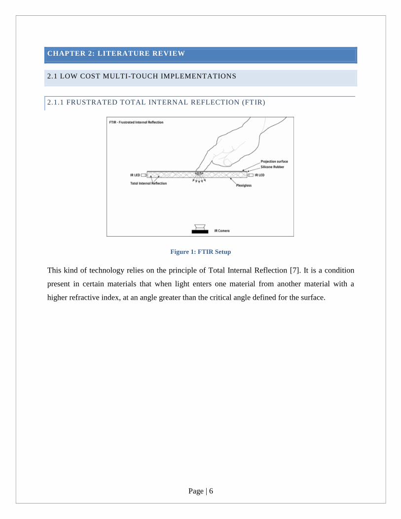
2.1.1 FRUSTRATED TOTAL INTERNAL REFLECTION (FTIR)
Figure 1: FTIR Setup
This kind of technology relies on the principle of Total Internal Reflection [7]. It is a condition
present in certain materials that when light enters one material from another material with a
higher refractive index, at an angle greater than the critical angle defined for the surface.

Page | 7
Figure 2: Total Internal Reflection
When the user comes into contact with the surface, the light rays are said to be frustrated, since
they can now pass through into the contact material (usually skin), and the reflection is no longer
total at that point [8]. This frustrated light is scattered downwards towards the infrared webcam,
capable of picking these „blobs‟ up, and relaying them to the tracking software.
Figure 3: FTIR touch image
Construction of the display requires 4 layers of materials:
Acrylic – polished surface to improve illumination and act as FTIR base material.
Baffle – required to hide the light leaking from the sides of the LEDs
Page | 8
Diffuser – used to block out light from objects behind the surface thus only allowing
touches to be picked up from the camera
Compliant layer – made of higher refractive index than the acrylic, helping in frustrating
the TIR. It “couples” with the acrylic when pressure is applied.
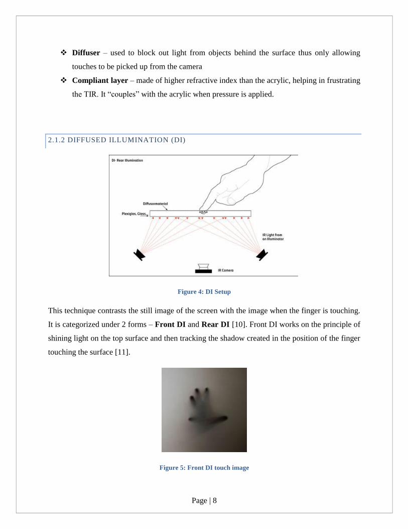
2.1.2 DIFFUSED ILLUMINATION (DI)
Figure 4: DI Setup
This technique contrasts the still image of the screen with the image when the finger is touching.
It is categorized under 2 forms – Front DI and Rear DI [10]. Front DI works on the principle of
shining light on the top surface and then tracking the shadow created in the position of the finger
touching the surface [11].
Figure 5: Front DI touch image
Page | 9
Rear DI works on the principle of shining infrared light from behind the screen. The screen is
supported with a diffuser and touching the diffuser causes more light to be reflected than its
surrounding thus, being picked up by a web camera.
Figure 6: Rear DI touch image
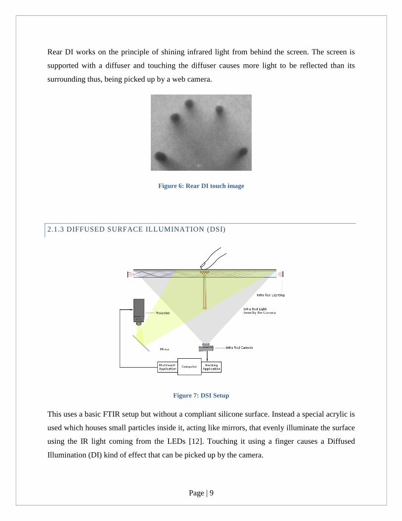
2.1.3 DIFFUSED SURFACE ILLUMINATION (DSI)
Figure 7: DSI Setup
This uses a basic FTIR setup but without a compliant silicone surface. Instead a special acrylic is
used which houses small particles inside it, acting like mirrors, that evenly illuminate the surface
using the IR light coming from the LEDs [12]. Touching it using a finger causes a Diffused
Illumination (DI) kind of effect that can be picked up by the camera.

Page | 10
Figure 8: DSI touch image
2.1.4 LED LIGHT PLANE (LED-LP)
Figure 9: LED-LP Setup
It works on the same principle except that the infrared light travels over a touch surface instead
of through the sides of an acrylic. An IR plane of light is created which registers a touch when
obstructed by a finger. It is better to use such a method of lighting in case of use of LCD screens
as touch screens. This is because with projectors, a more sturdy and thick screen is needed and
thus, Read DI or LLP are preferred. An optically clear screen should be used along with a
projection film when projection is the method of display. In case of use of LCD screens, a
diffuser needs to be placed below the screen so as to evenly distribute the light from the LCD
backlight [13].
Page | 11
Figure 10: LED-LP touch image
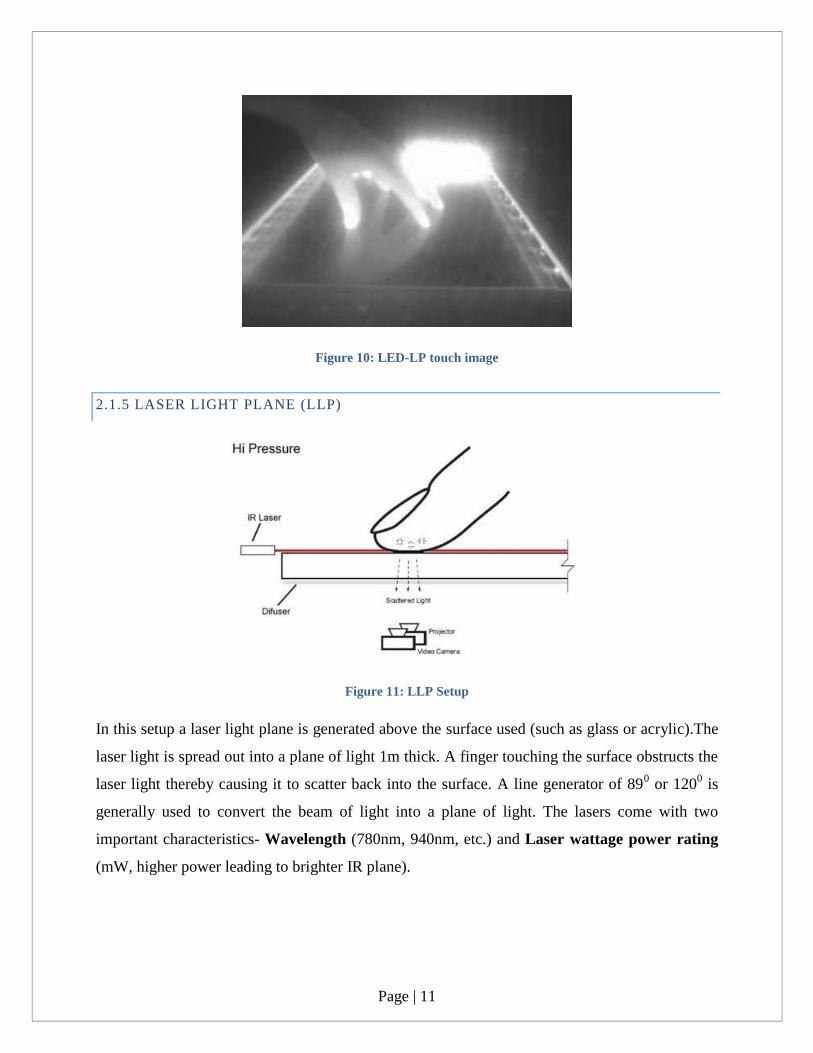
2.1.5 LASER LIGHT PLANE (LLP)
Figure 11: LLP Setup
In this setup a laser light plane is generated above the surface used (such as glass or acrylic).The
laser light is spread out into a plane of light 1m thick. A finger touching the surface obstructs the
laser light thereby causing it to scatter back into the surface. A line generator of 890 or 120
0 is
generally used to convert the beam of light into a plane of light. The lasers come with two
important characteristics- Wavelength (780nm, 940nm, etc.) and Laser wattage power rating
(mW, higher power leading to brighter IR plane).

Page | 12
Figure 12: LLP touch image
2.2 TANGIBLE USER INTERFACE OBJECTS (TUIO) PROTOCOLS
TUIO protocol is a flexible and open framework specifically designed to handle the requirements
of touch surfaces [15]. TUIO is based on Open Sound Control (OSC) standard which is used for
interactive environments. It contains a common protocol and API for application to multi-touch
surfaces in recognizing touch events and tangible state objects. The camera sends the control
data, based on computer vision, to a TUIO tracker application and then accordingly the TUIO
protocol sends the data to client application which is capable of interpreting the protocol
messages.
Figure 13: TUIO Setup
Page | 13
Various TUIO client libraries are applicable for application frameworks like Flash, C++, C#, etc.
These client libraries are used to construct multi-touch interfaces which respond to control data
from TUIO protocol coming from TUIO tracker applications.
2.3 TRACKER APPLICATIONS
2.3.1 COMMUNITY CORE VISION (CCV)
Community Core Vision (CCV) is an open source and cross-platform application used in
computer vision and machine sensing [16]. Video stream from a camera is taken as its input. It
outputs tracking data (e.g. coordinates and blob size) and events (e.g. finger down, moved and
released) which is then interpreted by a client application and processed accordingly. Input
sources can be a variety of conventional web cameras and video devices. CCV, currently output
tracking data in 3 different formats:
TUIO UDP: Sending of the TUIO messages in the OSC (UDP: User Datagram Protocol)
format.
FLASH XML: Sending of the XML (TCP) messages to FLASH applications.
BINARY TCP: Sending of the RAW messages in [x, y] coordinates.
The calibration and configuration process has been mentioned in the Software Section.

Page | 14
Figure 14: Community Core Vision (Windows)
2.3.2 REACTIVISION
ReacTIVision is an open source, cross-platform computer vision framework for the fast and
robust tracking of fiducial markers attached onto physical objects, as well as for multi-touch
finger tracking [17]. It was developed by Martin Kaltenbrunner and Ross Bencina at the
Music Technology Group at the Universitat Pompeu Fabra in Barcelona, Spain [17]. Like
CCV, reacTIVision also supports a variety of input sources like web cameras and video devices.
But unlike CCV, a lot of features are missing in reacTIVision. It lacks a proper GUI like that of
CCV. Also the output format for reacTIVision is TUIO via UDP port 3333 to any TUIO enabled
client application.
Page | 15
Figure 15: reaTIVison
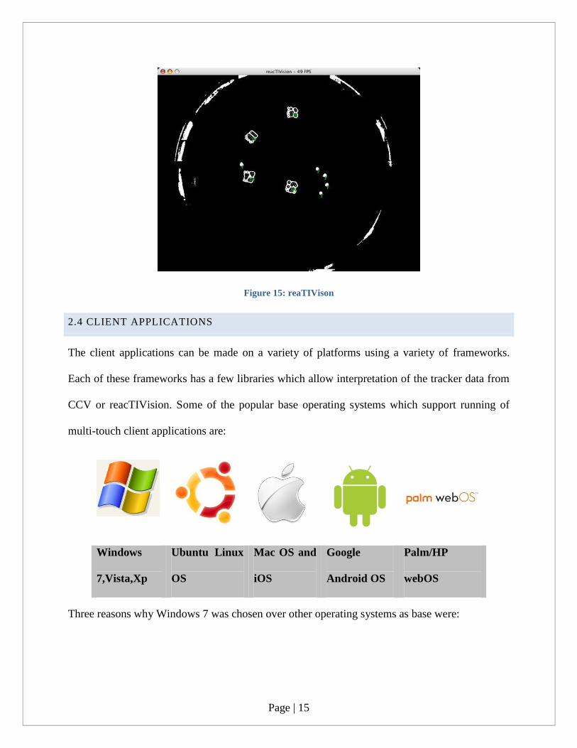
2.4 CLIENT APPLICATIONS
The client applications can be made on a variety of platforms using a variety of frameworks.
Each of these frameworks has a few libraries which allow interpretation of the tracker data from
CCV or reacTIVision. Some of the popular base operating systems which support running of
multi-touch client applications are:
Windows
7,Vista,Xp
Ubuntu Linux
OS
Mac OS and
iOS
Android OS
Palm/HP
webOS
Three reasons why Windows 7 was chosen over other operating systems as base were:

Page | 16
Windows 7 natively supports multi touch and also is the only OS which supports all the
application frameworks (to be mentioned later).
Windows 7 is present in most of our lab computers and thus easier to find a machine to
setup the CCV & code on.
Windows 7 has a better software support and is better in hardware acceleration of blob
tracking and faster handling of TUIO data.
Some of the most popular frameworks on which the applications are made are:
2.4.1 FLASH
Figure 16: Flash framework for multi-touch
The TUIO (OSC) data is SENT from the Simulator or Touchlib(a tracker application for TUIO
data) [18][19].The FLOSC gateway CONVERTS the OSC (UDP) data into XML (TCP).The
Flash client uses an XMLSocket to RECEIVE and parse the XML data then renders the cursors
within your application [19]. The flash applications are developed using either ActionScript3 or
Flash Develop 3.3.4. CCV can natively convert incoming computer vision directly to Flash XML
Page | 17
for Flash applications. Flash is a cross-development platform and thus applications made can run
on any of the above mentioned operating systems.
The above mentioned line makes the .as file recognize the TUIO data and makes the Flash
interact with the various objects and functions declared in the program.
Importing the above two Events causes the application to gather touch information and make it
available for the application. They also keep a track of blob lines in an array, thus providing a
touch database of events to the program. For further details on how to develop multi-touch flash
applications, please refer to Appendix A for a sample application development.
2.4.2 C# (.NET/SILVERLIGHT/WPF)
Visual Studio can be used to develop multi-touch applications for the Windows platform
Silverlight is like flash, using XML and UDP gateways to generate applications for multi-touch
interfaces. One of the most important frameworks for C# is the MultiTouchVista HID Drivers
[20]. The HID drivers allow multiple mice input as well bring native multi touch to windows.
Running these drivers allow direct interfacing of CCV with native Windows elements. Multi-
Touch Vista is a user input management layer that handles input from various devices (touchlib,
multiple mice, TUIO etc.) and normalizes it against the scale and rotation of the target window.

Page | 18
„
Figure 17: MulitTouchVista Framework
Other important frameworks are:
Python – the PyMT application framework which has libraries supporting multi-touch
application development on the python platform.
Java – the MT4j application framework containing libraries which allow MT
applications development. Java is also a primary language for developing applications for
the Android mobile system.
C/C++ - mainly interfacing with output from CCV. Library frameworks like MT Mouse
Driver can be used to develop relevant applications.
Page | 19
CHAPTER 3: HARDWARE
3.1 TECHNOLOGY
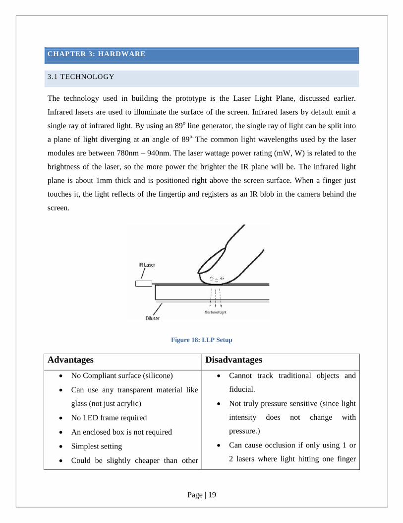
The technology used in building the prototype is the Laser Light Plane, discussed earlier.
Infrared lasers are used to illuminate the surface of the screen. Infrared lasers by default emit a
single ray of infrared light. By using an 89o line generator, the single ray of light can be split into
a plane of light diverging at an angle of 89o.
The common light wavelengths used by the laser
modules are between 780nm – 940nm. The laser wattage power rating (mW, W) is related to the
brightness of the laser, so the more power the brighter the IR plane will be. The infrared light
plane is about 1mm thick and is positioned right above the screen surface. When a finger just
touches it, the light reflects of the fingertip and registers as an IR blob in the camera behind the
screen.
Figure 18: LLP Setup
Advantages Disadvantages
No Compliant surface (silicone)
Can use any transparent material like
glass (not just acrylic)
No LED frame required
An enclosed box is not required
Simplest setting
Could be slightly cheaper than other
Cannot track traditional objects and
fiducial.
Not truly pressure sensitive (since light
intensity does not change with
pressure.)
Can cause occlusion if only using 1 or
2 lasers where light hitting one finger
Page | 20
technologies. blocks another finger from receiving
light.
3.2 COMPONENTS
3.2.1 WOODEN FRAME
Wood is one the easiest to drill and modify according to design. Thus, it was decided to be used
as the base material for designing the prototype. Initially during Phase 1, the wooden planks
were obtained from IKEA. These wooden planks turned out to be easy to setup because of their
soft nature but in the end turned out to be soft enough to bend under the weight of the mirror.
3.2.2 SURFACE & PROJECTION FILM
Surface or screen refers to the front part of the model which has a laser light plane just above it
and on which the camera is able to project the image. Generally this surface requires some kind
of projection film attached to it (which is a very thin translucent film) to facilitate projection.
Two most commonly used surfaces are – acrylic and glass. For the purpose of this project,
weight is an important factor and thus since the glass is much heavier than acrylic, acrylic was
chosen to be the screen. The acrylic screen chosen was 32 inches by 42 inches so as to suit the
dimensions of the front panel designed during phase 2 of the project (Further details are
mentioned in the Phase 2 under Hardware Design & Construction Process). Since every screen
needs to be coupled with a projection film, two types of projection films are being tested in this
project:

Page | 21
Figure 19: Projection Film
Figure 20: Tracing Paper
3.2.3 LASER MODULE
Figure 21: Laser module with line generator
The laser module used is 780nm with a power output of 25mW. It has an 890 line generator
attached to its front. This laser module requires 3.2V DC current and needs to be attached in
parallel with other laser modules.
3.2.4 CAMERA
A camera is needed behind the screen to detect the IR blobs that are generated by the finger
touch on the screen surface. Normally to detect an infrared light an infrared camera should be
used. But with certain modifications, a normal web camera can also be used to detect light in the
infrared frequency.
Page | 22
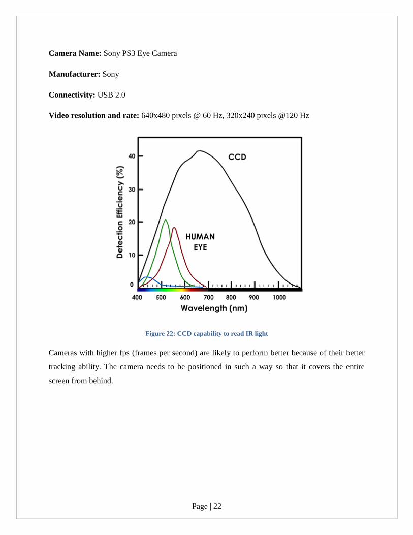
Camera Name: Sony PS3 Eye Camera
Manufacturer: Sony
Connectivity: USB 2.0
Video resolution and rate: 640x480 pixels @ 60 Hz, 320x240 pixels @120 Hz
Figure 22: CCD capability to read IR light
Cameras with higher fps (frames per second) are likely to perform better because of their better
tracking ability. The camera needs to be positioned in such a way so that it covers the entire
screen from behind.
Page | 23
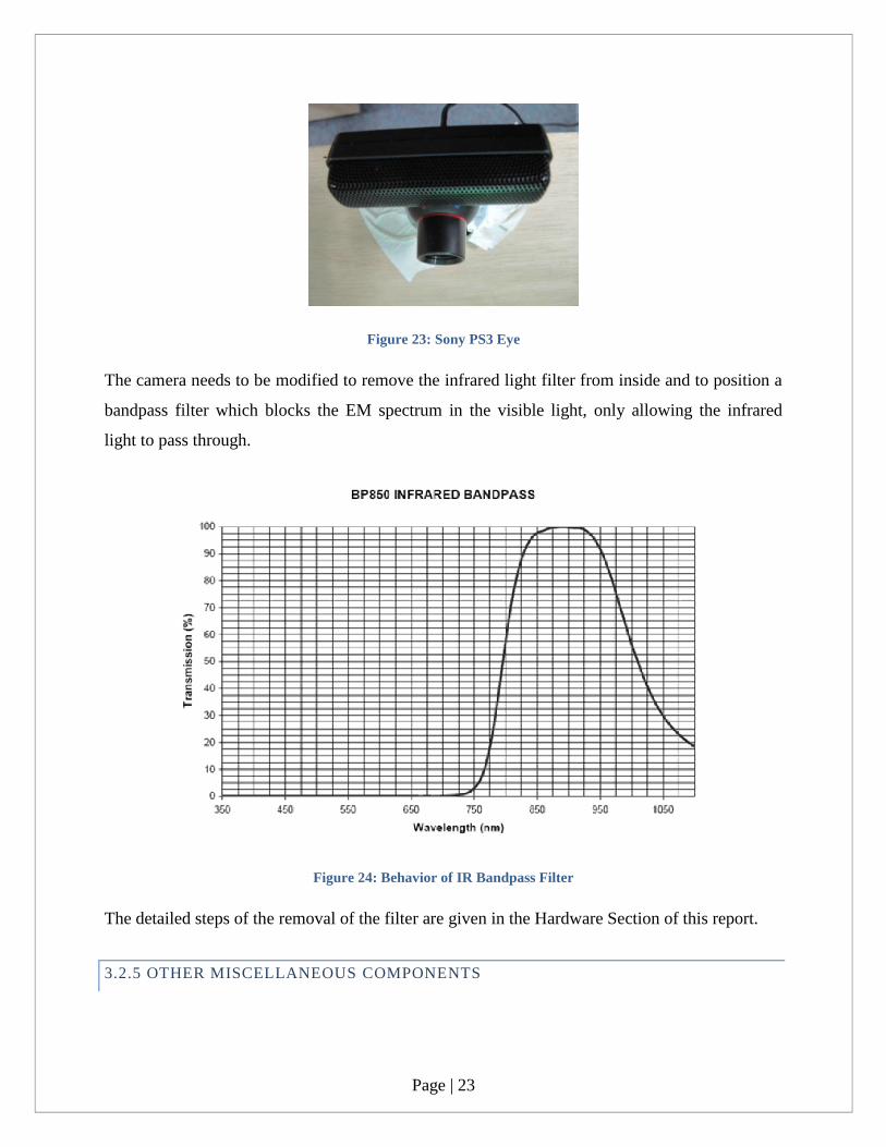
Figure 23: Sony PS3 Eye
The camera needs to be modified to remove the infrared light filter from inside and to position a
bandpass filter which blocks the EM spectrum in the visible light, only allowing the infrared
light to pass through.
Figure 24: Behavior of IR Bandpass Filter
The detailed steps of the removal of the filter are given in the Hardware Section of this report.
3.2.5 OTHER MISCELLANEOUS COMPONENTS

Page | 24
Two computers running Microsoft Windows 7 to facilitate running of the CCV and
graphic intensive applications. The computer should preferably be a dual core processor
system with an advanced model of a NVIDIA or ATI graphics card and a minimum Ram
of 2 GB.
2 projectors – preferably a short-throw one to allow projection of the computer output
onto the projection screen.
2 big mirrors with a diagonal length equal to the diagonal length of the acrylic screen
being used in the setup and 2 small mirrors. The combination of these mirrors will allow
the reduction in the projection distance so as to obtain the required 60 inch projection.
Double sided tape, PVC tape (for insulation purposes on the laser wiring), super-fast
glue, white tack to hold various components in place, a set of various sized screwdrivers
and a power drill.
3.3 DESIGN & CONSTRUCTION PROCESS
3.3.1 PHASE 1
Figure 25: Phase 1 Hardware Setup
A wooden frame was initially required for testing purposes. Wooden planks were bought from
IKEA, Singapore and a rough structure was made by screwing some of the planks together in the
way shown above in the figures. Wooden wedges were placed to mount the acrylic screen at the
Page | 25
front and the mirror (60 inch diagonal with an aspect ratio of 4:3 which was bought from a local
company in Jurong East) at the back.
Soon we discovered some of the problems associated with this method:
The wooden planks were relatively very soft and so although it was easier to drill holes in
them but it was difficult for such soft planks to support the weight of both the acrylic
screen and the mirror.
Such a structure had no base mounts where the web camera and the projector can be
accurately positioned at a certain angle.
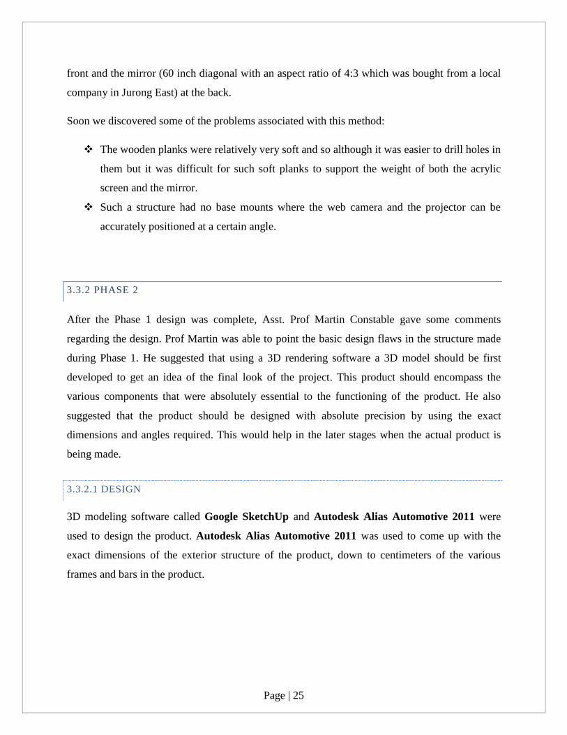
3.3.2 PHASE 2
After the Phase 1 design was complete, Asst. Prof Martin Constable gave some comments
regarding the design. Prof Martin was able to point the basic design flaws in the structure made
during Phase 1. He suggested that using a 3D rendering software a 3D model should be first
developed to get an idea of the final look of the project. This product should encompass the
various components that were absolutely essential to the functioning of the product. He also
suggested that the product should be designed with absolute precision by using the exact
dimensions and angles required. This would help in the later stages when the actual product is
being made.
3.3.2.1 DESIGN
3D modeling software called Google SketchUp and Autodesk Alias Automotive 2011 were
used to design the product. Autodesk Alias Automotive 2011 was used to come up with the
exact dimensions of the exterior structure of the product, down to centimeters of the various
frames and bars in the product.
Page | 26
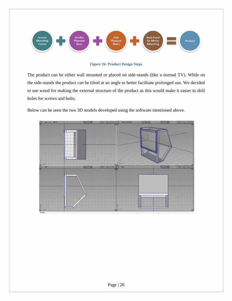
Figure 26: Product Design Steps
The product can be either wall mounted or placed on side-stands (like a normal TV). While on
the side-stands the product can be tilted at an angle to better facilitate prolonged use. We decided
to use wood for making the external structure of the product as this would make it easier to drill
holes for screws and bolts.
Below can be seen the two 3D models developed using the software mentioned above.
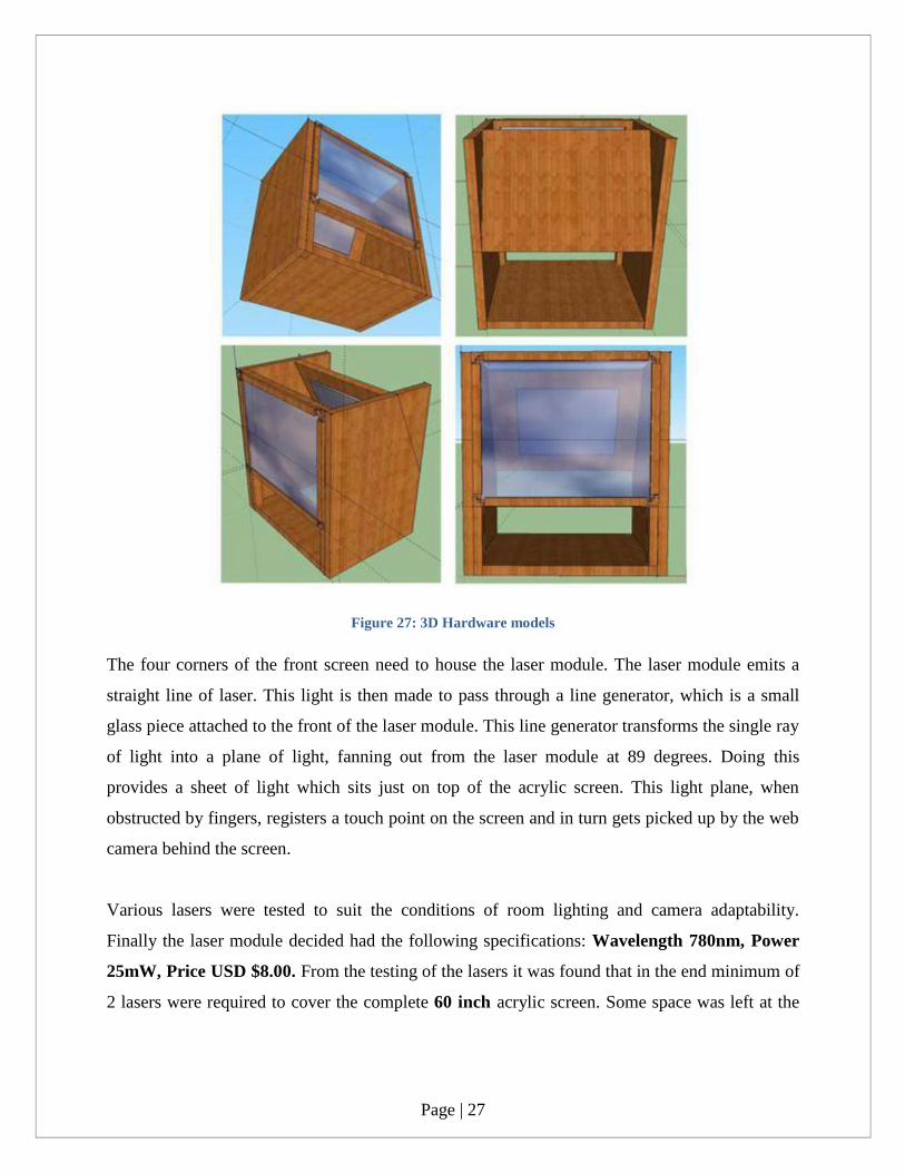
Page | 27
Figure 27: 3D Hardware models
The four corners of the front screen need to house the laser module. The laser module emits a
straight line of laser. This light is then made to pass through a line generator, which is a small
glass piece attached to the front of the laser module. This line generator transforms the single ray
of light into a plane of light, fanning out from the laser module at 89 degrees. Doing this
provides a sheet of light which sits just on top of the acrylic screen. This light plane, when
obstructed by fingers, registers a touch point on the screen and in turn gets picked up by the web
camera behind the screen.
Various lasers were tested to suit the conditions of room lighting and camera adaptability.
Finally the laser module decided had the following specifications: Wavelength 780nm, Power
25mW, Price USD $8.00. From the testing of the lasers it was found that in the end minimum of
2 lasers were required to cover the complete 60 inch acrylic screen. Some space was left at the

Page | 28
bottom and sides of the front screen frame so that if the approach of using lasers did not work,
then a LED strip could be used to implement an FTIR approach.
To exactly figure out the dimensions and angles of our product, software called SimProj was
used [21]. This software allows us to simulate the mirror, the projector and the screen. This
software takes a lot of inputs and provides us the resulting image size on the screen, the angle at
which the mirror and the projector should be kept. After going through various possible
orientations the one shown below was finally decided:
Figure 28: SimProj with single mirror
This is the minimum height and width dimensions we could obtain using a single mirror.
3.3.2.2 CONSTRUCTION
Prof Martin was able to recommend a carpenter in Singapore, Jason Ho, who is generally
involved with meeting unconventional project design needs of Art, Design and Media students.
A meeting was setup with Jason to discuss the building of the various individual components.
Plywood is one of the best prototyping materials – light, sturdy and easy to drill into when
screwing different panels.
Page | 29
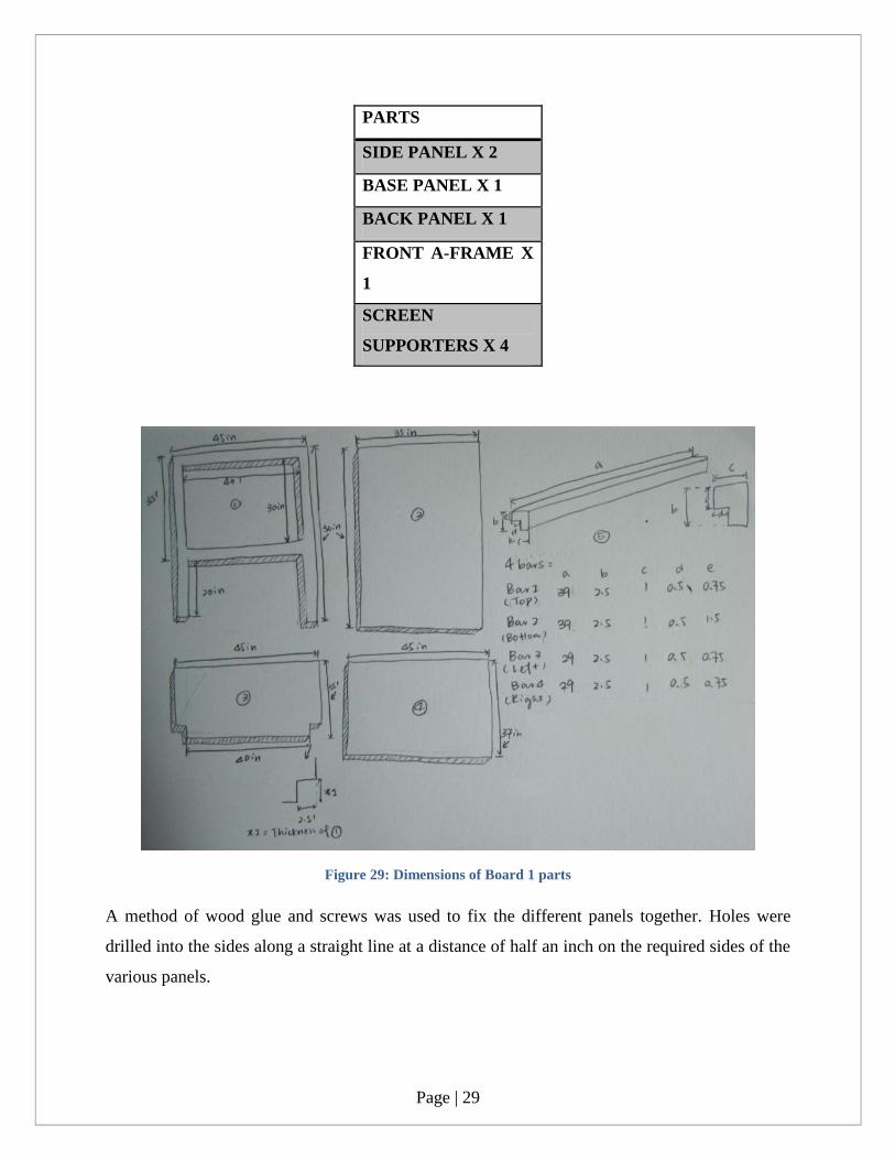
PARTS
SIDE PANEL X 2
BASE PANEL X 1
BACK PANEL X 1
FRONT A-FRAME X
1
SCREEN
SUPPORTERS X 4
Figure 29: Dimensions of Board 1 parts
A method of wood glue and screws was used to fix the different panels together. Holes were
drilled into the sides along a straight line at a distance of half an inch on the required sides of the
various panels.

Page | 30
Figure 30: Assembling of Board 1
Then the different panels were applied with wood glue and screwed together tightly so as to fix
them. After the side panels, base panel and the front A-frame was put together, it was time for
the back panel. The back panel had a mirror already firmly fixed to it by the carpenter.
Figure 31: Back Panel with mirror

Page | 31
After measuring the correct angle on the side panel, the back panel was mounted onto the side
panels using screws and wood glue again.
The front screen supporters were screwed in and the acrylic was mounted. The projection film
used was a professional grey projection film. It was stretched across the back of the screen (on
the side not facing the user) and was evenly spread across the acrylic to facilitate smooth
projection.
Fixing the lasers was a tough problem. The lasers had to be positioned just above the surface,
firmly fixed, so that they would reflect into the screen only when the fingertip would touch the
surface. At the same time the laser modules had to flexible enough so that they could be adjusted
by rotating every time. Rotating the lasers was required during the initial calibration and setup
procedure because the laser plane coming out from the module had to be parallel to the surface
and not intersecting the plane at some angle (otherwise that would result in false blobs being
detected by the CCV). The fixing of the laser module occurs in 4 steps:
STEP 1 #
Glass tags which are used on doors (where
PUSH/PULL is written) were bought from
the Yunan Book Store. These tags were then
cut using advanced glass cutting machines
from a robotics lab into perfect squares.
Page | 32
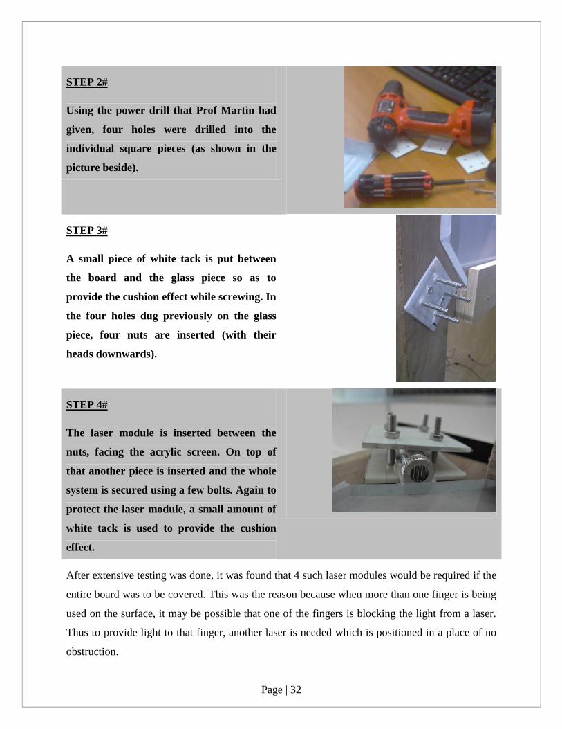
STEP 2#
Using the power drill that Prof Martin had
given, four holes were drilled into the
individual square pieces (as shown in the
picture beside).
STEP 3#
A small piece of white tack is put between
the board and the glass piece so as to
provide the cushion effect while screwing. In
the four holes dug previously on the glass
piece, four nuts are inserted (with their
heads downwards).
STEP 4#
The laser module is inserted between the
nuts, facing the acrylic screen. On top of
that another piece is inserted and the whole
system is secured using a few bolts. Again to
protect the laser module, a small amount of
white tack is used to provide the cushion
effect.
After extensive testing was done, it was found that 4 such laser modules would be required if the
entire board was to be covered. This was the reason because when more than one finger is being
used on the surface, it may be possible that one of the fingers is blocking the light from a laser.
Thus to provide light to that finger, another laser is needed which is positioned in a place of no
obstruction.

Page | 33
After wiring all the four laser modules together in parallel, the wire ends were connected to a DC
power supply. This power supply was able to provide a constant 3.2V DC current to the laser
modules in parallel.
Figure 32: DC Power Supply
After switching on the laser, the laser modules needed to be rotated and moved a bit so as to
bring the laser plane very close to the surface and almost parallel to it. To do this a wooden plank
was taken and using a phone‟s camera (a phone‟s camera is like an USB camera is able to detect
IR rays) the alignment of the lasers was done.
Figure 33: Testing the Laser Light Plane
Page | 34
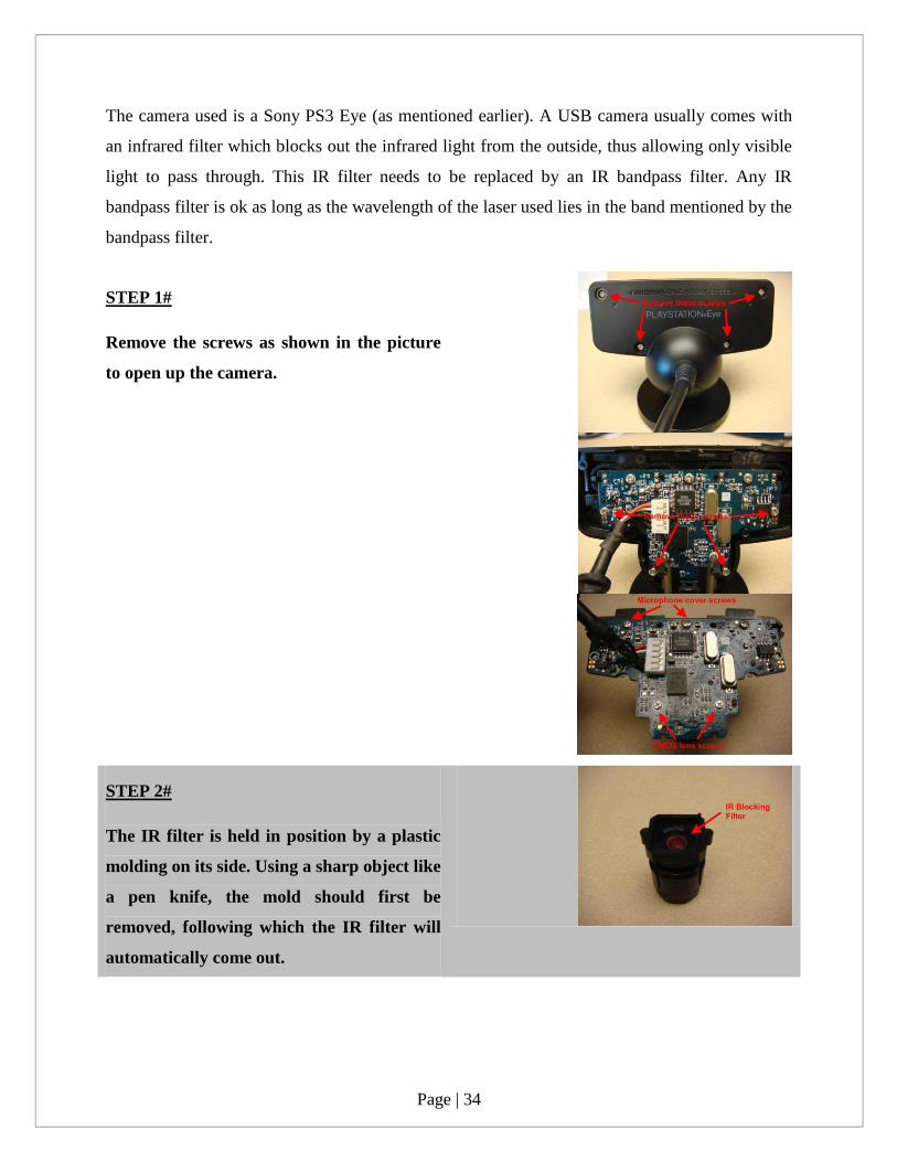
The camera used is a Sony PS3 Eye (as mentioned earlier). A USB camera usually comes with
an infrared filter which blocks out the infrared light from the outside, thus allowing only visible
light to pass through. This IR filter needs to be replaced by an IR bandpass filter. Any IR
bandpass filter is ok as long as the wavelength of the laser used lies in the band mentioned by the
bandpass filter.
STEP 1#
Remove the screws as shown in the picture
to open up the camera.
STEP 2#
The IR filter is held in position by a plastic
molding on its side. Using a sharp object like
a pen knife, the mold should first be
removed, following which the IR filter will
automatically come out.
Page | 35
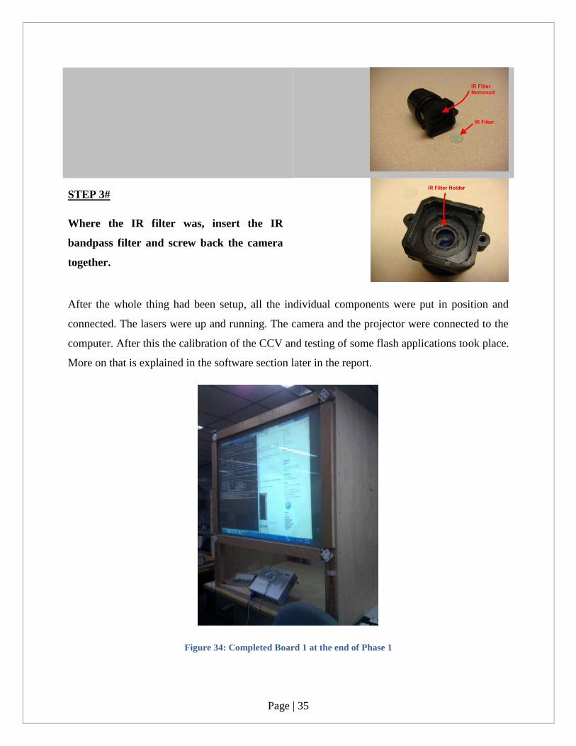
STEP 3#
Where the IR filter was, insert the IR
bandpass filter and screw back the camera
together.
After the whole thing had been setup, all the individual components were put in position and
connected. The lasers were up and running. The camera and the projector were connected to the
computer. After this the calibration of the CCV and testing of some flash applications took place.
More on that is explained in the software section later in the report.
Figure 34: Completed Board 1 at the end of Phase 1

Page | 36
3.3.3 PHASE 3
After setting up the first board and testing the board for laser configuration, camera image
processing stability and application functionality, the need to build another board came up. A
second board was needed to demonstrate the inter-board application interactions and
connectivity. Such an implementation would result in multi-user multi-application
implementation of the designed board.
3.3.3.1 PROBLEMS WITH PHASE 2
One of the problems of using the earlier configuration of the projector and the mirror was the
placement of the projector. The projector had to be at a specific angle to produce the required
size of the projected image. During design it seemed fairly easy to build the model that way but
when the individual panels were delivered by the carpenter and the board was built, it became
difficult to position the projector at precisely the angle required by the SimProj simulation. Also
the first board was quite heavy to be relocated to another place. Thus, a system of wheels was to
be attached below the boards to allow comfortable movement of the boards in the lab.
3.3.3.2 DESIGN
The two most comfortable configurations for keeping the projector were either vertical or
horizontal. One of the projectors had cables and ports at the back and one at the side. Limited by
one of the projectors, the only possible configuration now was horizontal positioning of the
projector. It was decided to change the mirror angle to 450 on the second board to reduce the size
of the mirror as well as to increase the height of the board to facilitate human interaction. Thus,
based on that two different simulations were created:
Page | 37
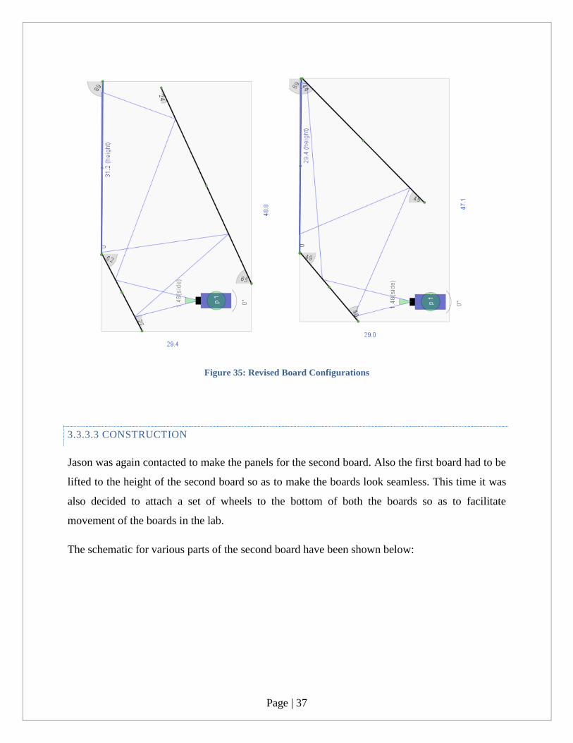
Figure 35: Revised Board Configurations
3.3.3.3 CONSTRUCTION
Jason was again contacted to make the panels for the second board. Also the first board had to be
lifted to the height of the second board so as to make the boards look seamless. This time it was
also decided to attach a set of wheels to the bottom of both the boards so as to facilitate
movement of the boards in the lab.
The schematic for various parts of the second board have been shown below:

Page | 38
Figure 36: Dimensions of Board 2 parts
The second board is 75 inches in height while the first one is 50 inches in height. To compensate
for height, the first board was fitted with a 15 inch high base. Both the bases of the two boards
were fitted with Omni-directional wheels. The base attached to the board 1 can be seen below:

Page | 39
Figure 37: Board 1 changed to new mirror configuration
Similar to the board 1, again a combination of wood glue and nails were used to connect the
various panels together for board 2. The acrylic on this board was not coupled with a projection
film like the previous board. Instead to cut cost, an A0 sized tracing paper was used. The
problem with using tracing paper is that the paper if pasted on the screen, after sometime
becomes crumpled up and thus the projection becomes very irregular. To overcome this problem
a new idea was proposed. Super strong glue, which dries up instantly, was applied to the sides of
the acrylic and the tracing paper was stretched over the screen and pasted on its sides. The super
strong glue was fully capable of keeping the paper in place for a brilliant projection quality.
Page | 40
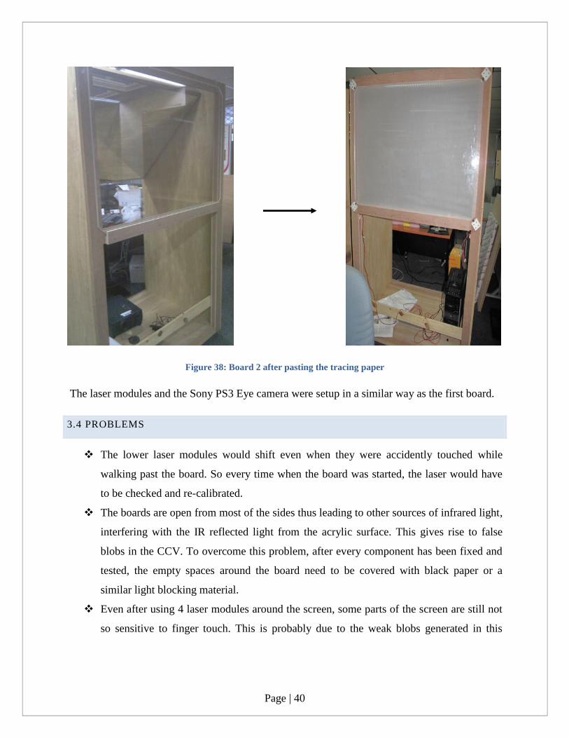
Figure 38: Board 2 after pasting the tracing paper
The laser modules and the Sony PS3 Eye camera were setup in a similar way as the first board.
3.4 PROBLEMS
The lower laser modules would shift even when they were accidently touched while
walking past the board. So every time when the board was started, the laser would have
to be checked and re-calibrated.
The boards are open from most of the sides thus leading to other sources of infrared light,
interfering with the IR reflected light from the acrylic surface. This gives rise to false
blobs in the CCV. To overcome this problem, after every component has been fixed and
tested, the empty spaces around the board need to be covered with black paper or a
similar light blocking material.
Even after using 4 laser modules around the screen, some parts of the screen are still not
so sensitive to finger touch. This is probably due to the weak blobs generated in this
Page | 41
region and since an ordinary web camera is being used, it does not have enough precision
to pick up that blob.

Page | 42
CHAPTER 4: SOFTWARE
4.1 CCV CALIBRATION & CONFIGURATION
CCV was preferred over reacTIVision because of the ease of use and the variety of output
protocols supported by the application. The CCV required QuickTime and VS2008
Redistributable x86 installed on the Windows 7 system for it to run. Calibration is required for
the screen because the computer vision software needs to be aware of the relative position of the
touch on the screen and the items on the desktop.
Two important things while setting up the configuration are: Camera settings and CCV
settings. Two major problems faced by incorrect settings are: Background noise and weak
blobs. Both of these can be tackled by playing around with both the settings mentioned above.
After a lot of adjustments, the correct settings were obtained to be used for both the boards.
Figure 39: Optimum CCV and camera settings
The calibration process involves touching a few dots on the calibration screen in sequence until
all the dots on the screen have been exhausted. With more number of dots used for calibration, a
better accuracy is achieved in interacting with items in a multi-touch application.
Page | 43
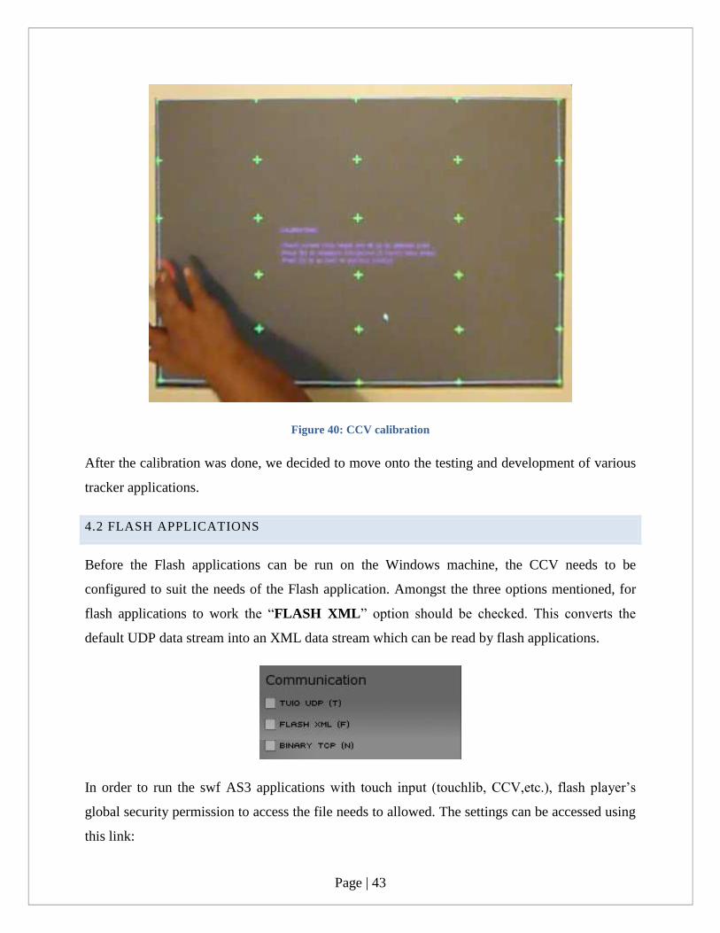
Figure 40: CCV calibration
After the calibration was done, we decided to move onto the testing and development of various
tracker applications.
4.2 FLASH APPLICATIONS
Before the Flash applications can be run on the Windows machine, the CCV needs to be
configured to suit the needs of the Flash application. Amongst the three options mentioned, for
flash applications to work the “FLASH XML” option should be checked. This converts the
default UDP data stream into an XML data stream which can be read by flash applications.
In order to run the swf AS3 applications with touch input (touchlib, CCV,etc.), flash player‟s
global security permission to access the file needs to allowed. The settings can be accessed using
this link:

Page | 44
http://www.macromedia.com/support/documentation/en/flashplayer/help/settings_manager04.ht
ml
Figure 41: Adobe Flash Global Security Settings
In the Trust this location box, put in the absolute path or browse to the folder where the demo
swf files are located. Click Confirm when done. Any future swf files added to the demo folder
will automatically have permissions set.
Some of the demo pre-compiled applications that we tested were:
FIRE
A trail of fire follows the finger tips
touching the screen.
ART GENERATION
A beautiful pattern diverges out from the
point of touch on the screen.
PIANO
A piano emulation is done where each
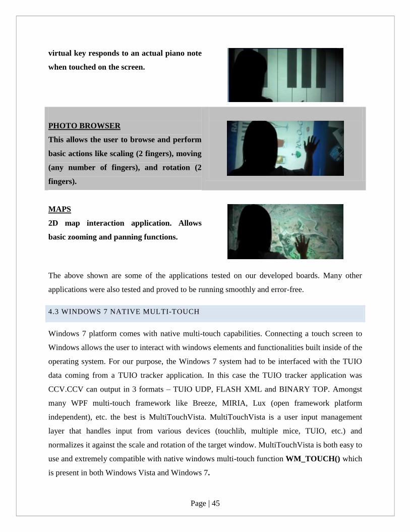
Page | 45
virtual key responds to an actual piano note
when touched on the screen.
PHOTO BROWSER
This allows the user to browse and perform
basic actions like scaling (2 fingers), moving
(any number of fingers), and rotation (2
fingers).
MAPS
2D map interaction application. Allows
basic zooming and panning functions.
The above shown are some of the applications tested on our developed boards. Many other
applications were also tested and proved to be running smoothly and error-free.
4.3 WINDOWS 7 NATIVE MULTI-TOUCH
Windows 7 platform comes with native multi-touch capabilities. Connecting a touch screen to
Windows allows the user to interact with windows elements and functionalities built inside of the
operating system. For our purpose, the Windows 7 system had to be interfaced with the TUIO
data coming from a TUIO tracker application. In this case the TUIO tracker application was
CCV.CCV can output in 3 formats – TUIO UDP, FLASH XML and BINARY TOP. Amongst
many WPF multi-touch framework like Breeze, MIRIA, Lux (open framework platform
independent), etc. the best is MultiTouchVista. MultiTouchVista is a user input management
layer that handles input from various devices (touchlib, multiple mice, TUIO, etc.) and
normalizes it against the scale and rotation of the target window. MultiTouchVista is both easy to
use and extremely compatible with native windows multi-touch function WM_TOUCH() which
is present in both Windows Vista and Windows 7.
Page | 46
4.3.1 HOW IT WORKS?
MultiTouchVista emulates multi-touch by enabling a list of components under the “Universal
Software HID”. Then it runs a driver service which allows the windows to receive touch co-
ordinates via the UDP under the TUIO protocol. Thus, TUIO events loop back to windows
events and the elements interacting with the event respond in a defined manner.
4.3.2 FEATURES
Some of the native Windows 7 features that can be used with MultiTouchVista are:
Two finger tap in Internet Explorer instantly zooms into the webpage. Two finger
moving apart or coming closer results in dynamic zooming of the page i.e. controlled
zooming.
Bigger Close Tab Button in Internet Explorer for the ease of finger touching.
Flicking left or right causes momentary preview of the coming page before the new
page loads. Flicking right causes the IE to move ahead while flicking left causes the IE
to go back one page in history.
Flick up and down a webpage with single finger to quickly scroll up or down. With
two fingertips on a webpage, hold the page there, and then drag the page right or left if
it's too wide to fit in your browser window.
Using Windows Snap to quickly resizing the windows. Using fingers to do this leads to
a much faster window management. Holding a window down and shaking it with one
fingertip causes all the other open windows to minimize, leaving the one used by the
person open.
Keeping single finger pressed down on an area for a long amount of time gives the right
click menu at that position.
Some of the applications tested were:

Page | 47
INTERNET EXPLORER 8
A set of multi-touch gestures supported
by IE. Text Input is done through a
virtual keyboard that pops up whenever
the user wants to write something.
BING MAPS 3D
Bing Maps comes with the Microsoft
Surface Suite of applications. This
supports the native interaction with
objects like 2 fingers for zooming in.
Navigating through it is quite intuitive.
REBOUND
A multi-player game where two players
can use electric discharge between two
electrodes to propel a ball in the
direction of the opponent’s goal.
The reason that another board was built was to show inter-connectivity between the boards. This
inter-connectivity was demonstrated using the collaborative features of Google Docs.

Page | 48
Figure 42: Inter-Board collaboration
4.4 ANDROID INTEGRATION
Android is the flagship mobile operating system from Google Inc. It is basically a software stack
for mobile devices that includes an operating system, middleware and key applications.
Currently Android comes in two main versions – mobile phone version and tablet version. The
latest version on mobile phones is Android 2.3.3 Gingerbread and the latest version on tablets in
Android 3.0 Honeycomb. Android comes with an in-built capability to support multi-touch in its
applications and has a database of over 150,000 applications. The main purpose of using Android
for our prototype is to allow the board to have an access to the vast library of Android
applications.
For using Android with the prototypes developed, the camera was required to be interfaced
somehow with a tracker application which would then be sending the TUIO data to the Android
system. So running the tracker application on Android would be impossible as connecting a
camera to it would be troublesome. Instead it would be possible to redirect the TUIO data to the
appropriate functions in the Android system which can then interpret the data as touch points on
the system. To achieve this 2 different approaches were considered:
4.4.1 ANDROID X86 + VIRTUAL MACHINE (VM)
This approach allows a special build of the Android called the Android x86 to be run on a regular
x86 architecture rather than on a mobile architecture. The project x86 is a project which aims to
port Android Open Source Project (AOSP) to the x86 platform. Currently the Android x86
projects has made a patch for Android 2.2 Froyo. After the Virtual Machine has been setup on
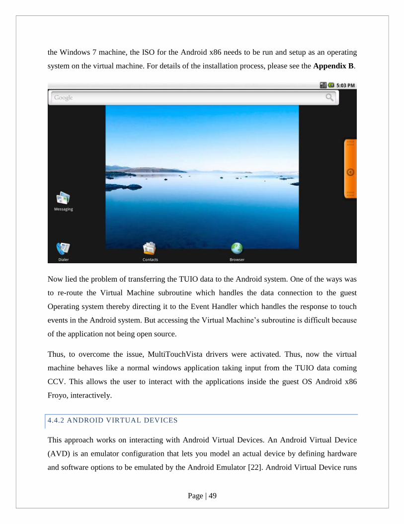
Page | 49
the Windows 7 machine, the ISO for the Android x86 needs to be run and setup as an operating
system on the virtual machine. For details of the installation process, please see the Appendix B.
Now lied the problem of transferring the TUIO data to the Android system. One of the ways was
to re-route the Virtual Machine subroutine which handles the data connection to the guest
Operating system thereby directing it to the Event Handler which handles the response to touch
events in the Android system. But accessing the Virtual Machine‟s subroutine is difficult because
of the application not being open source.
Thus, to overcome the issue, MultiTouchVista drivers were activated. Thus, now the virtual
machine behaves like a normal windows application taking input from the TUIO data coming
CCV. This allows the user to interact with the applications inside the guest OS Android x86
Froyo, interactively.
4.4.2 ANDROID VIRTUAL DEVICES
This approach works on interacting with Android Virtual Devices. An Android Virtual Device
(AVD) is an emulator configuration that lets you model an actual device by defining hardware
and software options to be emulated by the Android Emulator [22]. Android Virtual Device runs

Page | 50
on JAVA Virtual Machine (JVM). The method of using AVD has one advantage and one
disadvantage. The advantage is that the screen size being used is 50 inches which requires the
operating system to have a high resolution. Using AVD allows the usage of Android Honeycomb
3.0 which supports the higher resolution which is required by our prototype. The disadvantage of
using AVD is that since it runs on a JVM, the response to interaction is very slow and takes time.
Although feasible, it is impractical to use this setup because of the delay time associated with the
response from the AVD.
Page | 51
CHAPTER 5: CONCLUSION
In the end, the project was successfully completed with almost all of the objectives mentioned
before achieved. In the end, two low cost multi-touch human computer interface prototypes were
built which run on open source finger tracking TUIO application.
The prototype was initially designed in 2 popular 3D modeling applications called Google
SketchUp 3D and Automotive Alias 3D. The design was made perfectly accurate in terms of
dimensions and angles. The prototype is based on a projection system. Thus, to reduce the
projection distance a system of mirrors is used in the prototype. This setup requires a perfect
alignment and angular setup of the mirrors. To do this software called SimProj was used. After
the simulation of the model and the mirror placement was done, the wooden consultant was
called and explained the various parts that were needed to be built for this device. When the parts
were built, they were assembled and nailed together to provide a complete feeling of a finished
product. For the display, a combination of an Acrylic sheet and a projection film was used. The
projector light, after passing through the setup of mirror, would project on the acrylic screen at a
display size of 50 inches diagonally. The front side of the screen is covered with a plane of laser
light. This plane of laser light is generated by a group of 4 lasers. These lasers are capable of
emitting IR light at a frequency of 780nm. Using an 890 line generator, the IR light generated
from the lasers is converted into a plane of laser light which covers the acrylic board (1mm
above the board).
A Sony PS3 Eye camera was modified by removing the IR blocking filter from inside and by
placing an IR bandpass filter just in front of the camera lens. This modification allows the
camera to pick up the IR rays which get reflect if a person is touching and blocking the laser
light plane on the acrylic board. This camera is positioned behind the screen to pick up these
reflected rays. These points of touch are detected as white blobs on a black background in the
CCV. The CCV then interprets these images (i.e. after the CCV has been calibrated to adjust to
the screen being used) and convert finger positions into TUIO data. This data is communicated to
tracker applications in the form of TUIO UDP, FLASH XML and BINARY TOP.

Page | 52
The TUIO data stream obtained from CCV is then picked up tracker applications which allow
users to interact with the application using multi-touch gestures. Three kinds of tracker
application frameworks were tested – Flash applications, Windows applications and Android
applications. For flash applications, CCV broadcasts Flash XML output which then gets picked
up by flash applications supporting multi-touch. For Windows applications, TUIO UDP data is
sent to a set of drivers called MultiTouchVista which then converts finger touches on the screen
to native Windows touch events. Thus, by using this, default Windows 7 applications can be
interacted with via multi-touch gestures. For Android applications, an Android x86 deployment
on Virtual Machine needs to be done or an Android Virtual Device needs to be setup up. Again
to interact with the Android applications, MultiTouchVista drivers need to be interfaced with
CCV.
Finally, it can be seen that in essence a low cost multi-touch device can be created and that this
device can also be linked to existing application technologies so as to enable interactivity using
multi-touch gestures. With the restrictions on large screen capacitive devices due to price and
incompatibility with existing application technology, the author believes that the age of low cost
optical multi-touch devices is coming. This project, in the end, aims to be a stepping stone for
future research in this field.

Page | 53
CHAPTER 6: RECOMMENDATIONS FOR FUTURE WORK
The above completed project, given time and resources, could have been able to achieve much
more than what it was able to. Given time, other technologies for implementing multi-touch like
Diffused Surface Illumination (DSI), LED-Light Plane, etc. could be explored so as to find out
whether there can be an improvement in sensitivity of touch points or an improvement in the
accuracy of the touch point. Another important drawback of the project is the use of conventional
projectors to project image. Thus, even though a system of mirrors has been used to reduce the
projection distance, a considerable width needs to be present in the board. With more funding,
instead of conventional projectors, short-throw high definition projectors could be used. These
short throw projectors need very little distance to project a very big image.
Another very important factor for accuracy and sensitivity of the blobs is the processing
capabilities of the computer which is running the whole system. More RAM, more number of
cores and high end graphics card lead to much better and much faster blob detection and video
processing by CCV.
Currently, Android can only be run via Virtual Machines or via Android Virtual Devices. Given
time, the Android running off a mobile device like a tablet should be interfaced with the web
camera to provide the video input and an application running inside Android in the background
must constantly process the video signals to produce TUIO data which can respond to touch
events on the Android system.
Page | 54
CHAPTER 7: REFERENCES
1. "What is Multitouch". 3M Systems . Retrieved on 30 Dec 2010
2. Scientific American. 2008. "How It Works: Multitouch Surfaces Explained". Retrieved
on January 9, 2011.
3. Brandon, John. 2009. "How the iPhone Works
4. Wall, J. "Microsoft Surface and the Single View Platform" in The 2009 INternational
Symposium on Collaborative Technologies and Systems . 2009.
5. Schurman, K. (2007) Microsoft Surface White Ppaer. Computer Power User 7, 56-59
6. Steve Jobs. (2006). "And Boy Have We Patented It". Retrieved 2010-10-14. "And we
have invented a new technology called Multi-touch"
7. Han, J.Y., “Low Cost Multi-touch Sensing through Frustated Total Internal Reflection”
in Procedings of the 18th Annual ACM symposium on User interface software and
technology. 2005. Seattle,WA,USA. 115-118
8. Jangwoon Kim, J.P. HyungKwan Kim, Chilwoo Lee, HCI (Human Computer
Interaction) Using Multi-Touch Tabletop Display. 2007, Chonnam National University:
Department of Computer Engineering
9. NUIGroup. Diffused Illumination (DI). Retrieved on 15 Apr 2011. Available at
http://wiki.nuigroup.com/Diffused_Illumination
10. T. Roth. DSI – DI used surface illumination. http://iad.projects.zhdk.ch/multitouch/.
[Retrieved on 20-Apr-2011].
11. Nolan. Front Diffused Illumination (Front DI). Retrieved on 20-Apr-2011 . Available at
http://peauproductions.com/frontdi.html
12. TouchScreenMagazine. Diffused Surface Illumination. Retrieved on 20-Apr-2011.
Available at http://www.touchscreenmagazine.nl/multitouch-techniques/direct-surface-
illumination
13. L. Bürgi et al.,. “Optical proximity and touch sensors based on monolithically integrated
polymer photodiodes and polymer LEDs” Organic Electronics 7. 2006
14. NUIGroup. Laser Light Plane Illumination (LLP). Retrieved on 20-Apr-2011. Available
at http://wiki.nuigroup.com/Laser_Light_Plane_Illumination_(LLP)

Page | 55
15. M.Kaltenbrunner,t.B., R.Bencina , and E.Costanza, TUIO:A Protocol for table-top
tangible user interfaces. in Proc. Of the 6th International Workshop on Gesture in
Human-Computer Interaction and Simulation.2005.
16. Community, NuiGroup Community Core Vision . Retrieved 10-Dec-2010 . Available at
http://cc.nuigroup.com/
17. M. Kaltenbrunner and R. Bencina. reacTIVision: a computer-vision framework for table-
based tangible interaction. Proceedings of the 1st international conference on Tangible
and embedded interaction, pages 69-74, 2007.
18. D. Wallin. Touchlib: an opensource multi-touch framework. 2006.
19. Wright, M., Freed, A., Momeni A. OpenSound Control:State of the Art 2003 Proceedings
of the 3rd Conference on New Instruments for Musical Expression (NIME 03). 2003.
Montreal, Canada
20. Multi-Touch Vista . Retrieved on 20-Apr-2011. Available at
http://multitouchvista.codeplex.com/
21. SimProj . Retrieved on 20-Apr-2011. Available at http://benjamin.kuperberg.fr/lab/?p=4
22. Android Virtual Devices, Google Inc.,
http://developer.android.com/guide/developing/devices/index.html

Page | 56
CHAPTER 8: APPENDIX
8.1 APPENDIX A
So to get the touchlib‟s AS3 library for multi-touch go to http://wiki.nuigroup.com/SVN and
download the /AS3 folder to your computer as per the steps mentioned there. Let us call the
folder MTProject. So now my MTProject folder will have the folders named “ext“,”int” and
“src” and a file called flashapp.flp . Then start a new AS3 project in FlashDevelop and give the
location as the MTProject folder. Now check that your project contains all the folders(i.e
ext,int,src and some extra made by FlashDevelop).So now right-click on the src folder.Add a
new class and give it a name “MyTouchApp”.Now go to project->properties->Add Classpaths
and then add the “int” and “ext” folders. Now you can paste the code snippets in the post and
change the package statement i.e. make the statement package app.demo.MyTouchApp as only
package. Now right click on the file and select “Always Compile”. Now if out of curiosity if you
run the project, you will find it working fine but not reacting to the touch events (i.e. circles will
not appear in the very first code). So to solve the problem you have to create a new Sprite which
is same as the rectangle drawn in flash. The code snippet for adding a rectangle is:
Full code for MyTouchApp.as:
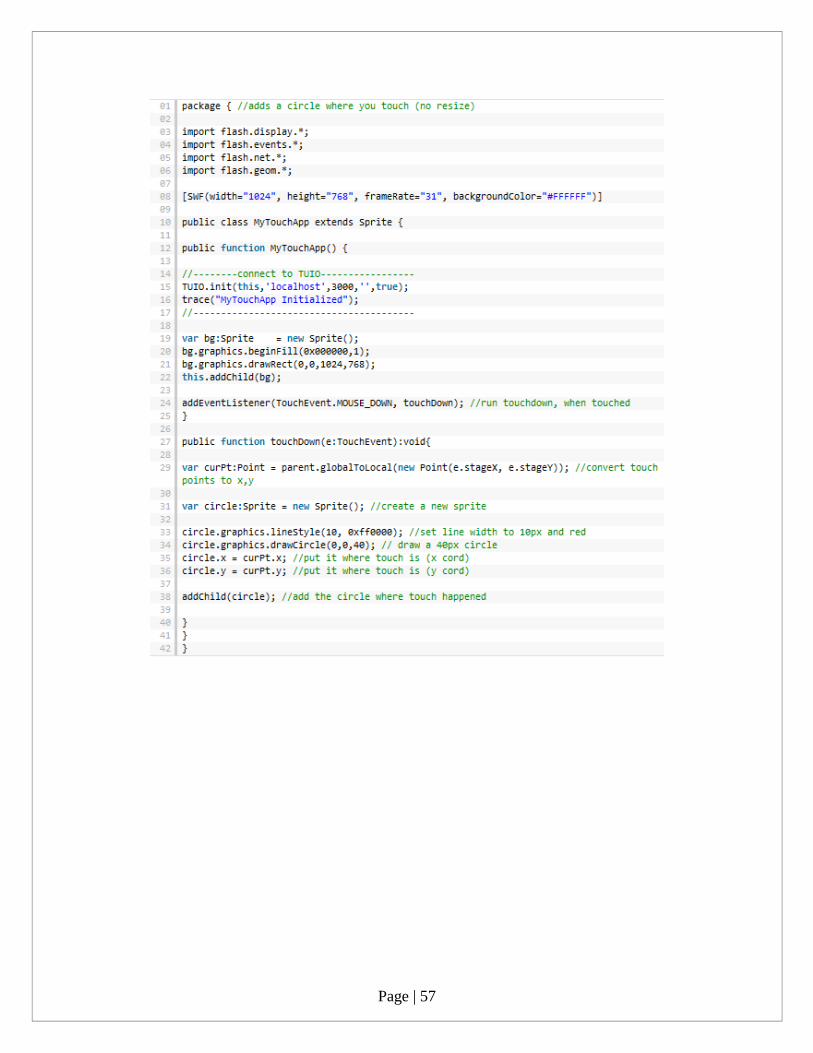
Page | 57

Page | 58
8.2 APPENDIX B
Burn the iso image to cdrom, or create a bootable USB disk (recommended). See
the Advanced section for details.
Boot from the Android-x86 installation CD/USB, choose the 'Install Android to harddisk'
item, as show below
After seconds of booting, you will see a partition selection dialog. You can choose an
existing partition to install Android-x86, or you can create or modify partitions by
choosing 'Create/Modify partitions'. Note you can install Android-x86 to an external disk
like USB drive. If the target drive is not shown, try 'Detect devices'.

Page | 59
Android-x86 can co-exist with other operating system or data in the chosen partition. If
the partition is formatted, you may choose 'Do not format' to keep existing data.
Otherwise, choose a filesystem type to format. Note the type you chosen must match the
partition id, or the boot loader will fail to boot.
Also note if you choose to format to fat32, you will see a warning that android cannot
save data to fat32. You can still proceed to install, but the installed android system will

Page | 60
work like a live cd system. That is, all data will lose after power off. Therefore we do not
recommend to install Android-x86 to a fat32 partition.
Next question is whether to install boot loader Grub. Usually you should answer yes,
unless you want to install boot loader by hand yourself. Note the installer only creates
boot items for Android-x86. If you hope to boot other operating systems, you need to add
the item to /grub/menu.lst manually. See the Advanced section for how to do this.
If you are lucky, the installation will begin, and you will see the progress bar.

Page | 61
If you see this screen, the installation is complete. Congratulations! Now you can run
Andrond-x86 directly, or you can reboot and run it.