An interactive touch phone for office automation
6
T HIS PAPER describes the exploratory development of a microprocessor-controlled PABX telephone called the Touch Phone. Advanced hardware and software techniques have been utilized in the system design to implement new interface concepts for a user-friendly PABX telephone set. With its interactive capability, the user can easily gain access to themanyfeatures of a modern PABX system with minimal memorization. The user enters commands by touching “buttons” on a touch-sensitive screen that are drawn by the self-contained microprocessor. With the guidance of tree-like structured menus presented on an electroluminescent (EL) display panel, the user can interactivelyselect the various features and options provided by the PABX system. The goals of the Touch Phone are to make the man-machine interaction simple and precise. Introduction Modern electronic PABX’s, such as GTE’s GTD 4600, offer thetelephoneusermanycapabilitiesbeyondtheusual tele- phone service, including features such as call forward, camp- on, and call park. These PABX’s were designed to work with traditional 12-button keypads. Thus, features can only be activated by special dialing sequences, sometimes involving precisely controlled hookflashes. These dialing procedures must either be memorized or referred to in an instruction booklet, making their use inconvenient for infrequent users. A result is that many users of modern PABX’s fail to take advantage of their features. Due to the rapid progress of IC technology, the concept of merging a telephone and a microprocessor has created workstation [I] and videotex [2] marketplaces. This paper describes the final exploratory work that developed from an investigation of an experimental advanced integrated work- station [3]. Theoperativegoals of theTouchPhoneareto make the man-machine interaction simple and precise. A microprocessor-controlled interactive Touch Phone, which combines advanced IC’s and software techniques, resulting in a user-friendly PABX telephone set, has been developed to validate these concepts. A critical element in the widespread acceptance of future officeworkstations is thedesign of a friendly man-machine interface [4,5]. Failure to achieve a satisfactory human interface will result in user.frustration and disuse. A typical example is the lack of widespread use of the advanced services of electronic PABX’s, mainly because of the complex procedures required of the user to activate the services in a PABX system. These procedures are often difficult to remember. One has to memorize a variety of dialing sequences and special codes, the meaning of which is obscure. Thus, unless one uses the services frequently, it is adifficulttasktorecalltheseproceduresfor casual usage. The interactive Touch Phone described in this paper permits users to access a PABX easily and to invoke its many available service features with minimal memorization. Tree-structured menus [6,7] make it unnecessary for the user to memorize special codes and dialing procedures. Instead. a progressive disclosure technique leads the user, step by step, to the desired end result. The user invokes a service feature by simply touching the appropriate boxes drawn on a flat-panel display (relabelable buttons). The system then automatically carries out the command issued by the user. The command may be to change the display presenting a subsequent menu to assist the user in reaching the right service, or transmission of a special An abbreviated version of this paper entitled “An Interactive Touch Phone for Future Offices” was presented at ICC ’84. May 22. 1984, Amsterdam. February 1985-Vol. 23, No. 2 IEEE Communications Magazine
-
Upload
independent -
Category
Documents
-
view
0 -
download
0
Transcript of An interactive touch phone for office automation

T HIS PAPER describes the exploratory development of a microprocessor-controlled PABX telephone called the
Touch Phone. Advanced hardware and software techniques have been utilized in the system design to implement new interface concepts for a user-friendly PABX telephone set. With its interactive capability, the user can easily gain access to the many features of a modern PABX system with minimal memorization. The user enters commands by touching “buttons” on a touch-sensitive screen that are drawn by the self-contained microprocessor. With the guidance of tree-like structured menus presented on an electroluminescent (EL) display panel, the user can interactively select the various features and options provided by the PABX system. The goals of the Touch Phone are to make the man-machine interaction simple and precise.
Introduction
Modern electronic PABX’s, such as GTE’s G T D 4600, offer the telephone user many capabilities beyond the usual tele- phone service, including features such as call forward, camp- on, and call park. These PABX’s were designed to work with traditional 12-button keypads. Thus, features can only be activated by special dialing sequences, sometimes involving precisely controlled hookflashes. These dialing procedures must either be memorized or referred to in an instruction booklet, making their use inconvenient for infrequent users. A result is that many users of modern PABX’s fail to take advantage of their features.
Due to the rapid progress of IC technology, the concept of merging a telephone and a microprocessor has created workstation [ I ] and videotex [2] marketplaces. This paper describes the final exploratory work that developed from an investigation of an experimental advanced integrated work- station [3]. The operative goals of the Touch Phone are to make the man-machine interaction simple and precise. A microprocessor-controlled interactive Touch Phone, which combines advanced IC’s and software techniques, resulting in a user-friendly PABX telephone set, has been developed to validate these concepts.
A critical element in the widespread acceptance of future office workstations is the design of a friendly man-machine interface [4,5]. Failure to achieve a satisfactory human interface will result in user.frustration and disuse. A typical example is the lack of widespread use of the advanced services of electronic PABX’s, mainly because of the complex procedures required of the user to activate the services in a PABX system. These procedures are often difficult to remember. One has to memorize a variety of dialing sequences and special codes, the meaning of which is obscure. Thus, unless one uses the services frequently, it is a difficult task to recall these procedures for casual usage.
The interactive Touch Phone described in this paper permits users to access a PABX easily and to invoke its many available service features with minimal memorization. Tree-structured menus [6,7] make it unnecessary for the user to memorize special codes and dialing procedures. Instead. a progressive disclosure technique leads the user, step by step, to the desired end result. The user invokes a service feature by simply touching the appropriate boxes drawn on a flat-panel display (relabelable buttons). The system then automatically carries out the command issued by the user. The command may be to change the display presenting a subsequent menu to assist the user in reaching the right service, or transmission of a special
An abbreviated version of this paper entitled “An Interactive Touch Phone for Future Offices” was presented at ICC ’84. May 22. 1984, Amsterdam.
February 1985-Vol. 23, No. 2 IEEE Communications Magazine

dialing sequence. The burden of memorizing dialing procedures and special codes is relieved. The use of audio-tactile feedback has also been added to the Touch Phone to enhance the man- machine interface in our experimental model.
System-Overview
The Touch Phone permits a user to access services available in the digital PABX system easily and without error. As shown in Fig. I , it consists of a n electroluminescent (EL) display panel with an overlay touch-sensitive screen, a handset, and PABX interface circuitry for connection to the telephone network. The user does not have to memorize special codes and dialing procedures in order to invoke the service features, as users of the traditional 12-button keypad do. Instead, the E L display presents sequences of menus leading the user to activate the desired features. The user issues commands by touching the appropriate "buttons" drawn on the display.
As soon as the user operates the mechanical line switch on the handset, the system responds with a short beep and then waits for commands. At this time, as well as during the time the switch is off (on hook), the main menu is displayed as shown in Fig. 2. There are ten broad service features in our concept system from which the user can select the first step in the use of the phones. They are D I A L , DIRECTORY, FEATURES. CALL PICK-UP, TRANSFER, REDIAL, CALL FORWARD, CALL PARK,
CONFERENCE, and HELP. All the service features are presented in the main menu. Requesting one of these services will cause the computer to display its various options. Unlike a standard phone, the user will not be able to hear the dial tone until the first command is given by touching the screen. The reason for this approach is that the user may need time to read the menu before making a decision as to which "button" to touch, and reading the menu may take longer than the PABX allows before removing the dial tone and replacing it with the service tone. This disables phone service until the user goes back on hook and off again.
Besides the services generally available in the digital PABX system, the Touch Phone provides two additional ones: R E D I A L and DIRECTORY. The REDIAL feature enables a user to redial the last number dialed just by touching the appropriate button. The DIRECTORY feature has two options, LIS-I- and EDI-I-. Touching I -IST causes the system to display the user's personal directory. In the present experimental model, the personal directory can hold up to five names and phone numbers in a single displayed page. To call a number listed in the directory, the user touches the "button" next to the name. The E D I T option allows the user to edit the directory. Once the E D I T option is selected, a keyboard is displayed as shown in Fig. 3. The user can then type in the directory, one line at a time, using the following format:
k Person's name Telephone number
where k is the location on the list where the item is to be entered. The user can easily correct typing errors by touching the "-" button on the displayed keyboard. As the user enters information, the line is displayed on the top line of the screen. To terminate an entry, the user presses the "button" labeled Ex
In addition to the two features described above, the Touch Phone has an enhanced CONFERENCE service feature that allows the user to correct mistakes made during the course of dialing conferee's numbers without having to hang up and start over.
Also included in the main menu is the H E L P option, which gives information to assist the user in operating the system. Pressing the H E L P button will reveal a table of contents of the service feature selected. Each service, except for trivial ones such as DIAL and REDIAL, has a page of information to assist the user when necessary; for example, when the "CAMP-ON" button is touched, the following information will be displayed:
(EXIl ) .
~~ ~~" p:$" ::*::::.: _, % ~ ? z : _, , , ~ , , :: ,"**-~, ; ". ,,".m4a'f:,... , 1. ;:::: :,:. . I
~ j ( ~ i " "~ j"j" I, , II ~ " . ~ , ,~" , , n ,~~',?'
February 1985-VO1.23, No. 2 IEEE Communications Magazine 22

If you dial a station that is busy, and you do not want to keep redialing, camp-on to that station. Your phone will ring when the dialed station stops being busy.
If the “CALL P A R K ” button is touched, the information displayed will be:
This feature enables you to put the party you are conversing with on hold. Retrieval can be done on the same station or on another one. The parked call should be retrieved within three minutes. Multiple parking is allowed. The order of retrieval is on a first-in/first-out basis. The parking station can originate and receive other calls.
The menus of the system are organized in a tree-like structure as shown in Fig. 4. The menus are organized in multiple levels and are shown sequentially as the user selects various options provided in different levels of the menus. In addition to identifying “buttons.” a message is sometimes added to suggest what the user needs to do at a particular time. For example, when the S E T - U P option for the CALL FORWARD service is requested, the following message is displayed:
PRESS T H E N U M B E R PRESS E N T E R
Furthermore, in order to improve the error resistance of the system, a “button” is not displayed unless it can be effective. For example, in some procedures there are intermediate stages during which the message “PLEASE W A I I ” is presented before the next-level menu is displayed. From our subjective evalua- tion, all these features have been proven to contribute to the friendly man-machine interface of this telephone set.
Hardware Structure
A block diagram of the system hardware is shown in Fig. 5 . The system is built around an Intel 80/24 Single Board Computer, which uses an 8085 microprocessor and has two 8255 IC’s for I / O ports. The 80/24 iSBC was chosen as the controller for the system because of its adequate memory space for EPROM and RAM, as well as its I / O facilities, allowing flexibility for future expansion.
Input-Output Devices
The microprocessor receives inputs from a touch-sensitive screen and the mechanical line switch on the handset. The output devices consist of an EL display panel with its refresh memory, a beeper, and the PABX interface circuitry. The following describes the role and operation of each of these I / 0 devices.
Mechanical Line Switch-The mechanical line switch, the equivalent of a hookswitch in the GTE Solitone telephone, has been disconnected from the telephone circuit board and provides an input to the computer to indicate the wishes of the user. When the switch is off, any touch-screen inputs are ignored until the switch is turned on.
Touch-Sensitive Screen-The EL display is overlaid by a touch-sensitive panel, the main device by which the user communicates with the system. The user initiates commands by touching the panel. The system monitors inputs from the panel and interprets the commands based on the part of the screen touched. Action taken as a result can be a change of the display, that is, filling in the display memory with a new set of data or transmission of a DTMF code to the PABX interface to activate one of the services of the digital PABX system.
The touch panel used in the system being discussed is a Sierracin #503-900PR. This panel consists of two conductive layers of transparent plastic material separate from the other. Each layer has eight or ten separately insulated, uniformly spaced ribs on the surface, adjacent to the other layer. The panel has been assembled so that the ribs on each layer are orthogonal to the other layer (ten vertical and eight horizontal). When touched, a rib from one layer contacts a rib from the other layer. The pair of ribs in contact indicate the coordinates of the pointed touched.
The computer must sense the rib from each layer that has contacted the other to determine which of the 80 areas defined by the ribs was touched. All the conductive ribs from both layers are connected to both of the computer I / 0 ports. These I / O ports can be programmed to be either input or output. The computer. determines the vertical coordinate being touched by placing a high-level voltage on all the horizontal ribs and sensing the voltage level from each vertical rib. The process is repeated by reversing the order of the horizontal and vertical ribs to determine the horizontal coordinate being touched. The region defined by the two coordinates is translated by software to the desired command.
Beeper-This acoustic device generates a short beep for user feedback whenever the mechanical line switch is turned on or the screen is touched. It acknowledges the user’s entry of a command. Volume control for the beeper is not available in our system. However, we believe that the availability of volume control will make the beeper friendlier. For a “friendly” man- machine interface, the minimum duration of a “beep” appears to be 100 ms.
The Display Panel-The current display device of the Touch Phone is an Electroluminescent (EL) flat panel. The panel being used is a n S-1021A Sharp Electronics EL graphic unit
23 February 1985-VOl . 23, No. 2
IEEE Communications Magazine
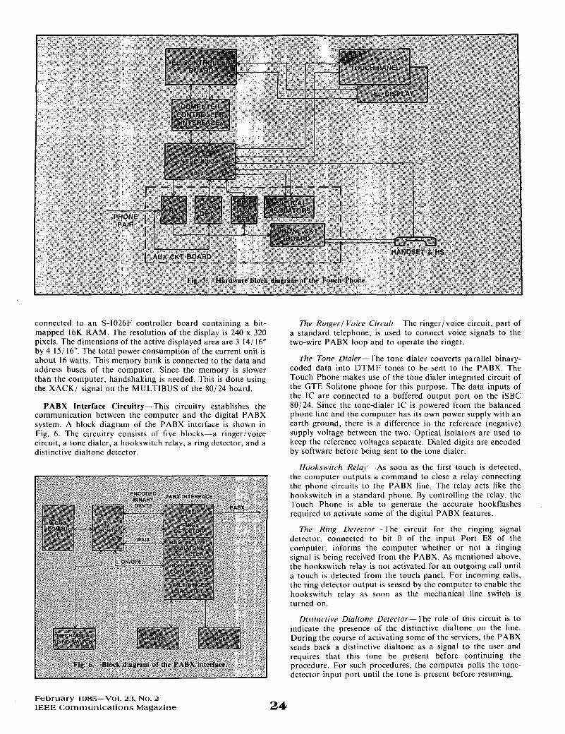
connected to an S-1026F controller board containing a bit- mapped 16K RAM. The resolution of the display is 240 x 320 pixels. The dimensions of the active displayed area are 3 14/ 16” by 4 IS/ 16”. The total power consumption of the current unit is about 16 watts. This memory bank is connected to the data and address buses of the computer. Since the memory is slower than the computer, handshaking is needed. This is done using the XACK/ signal on the MULTIBUS of the 80/24 board.
PABX Interface Circuitry-This circuitry establishes the communication between the computer and the digital PABX system. A block diagram of the PABX interface is shown in Fig. 6. The circuitry consists of five blocks-a ringer/voice circuit, a tone dialer, a hookswitch relay, a ring detector, and a distinctive dialtone detector.
February 1985-Vol. 23, No. 2 IEEE Communications Magazine
The Ringer/ Voice Circuit-The ringer/voice circuit, part of a standard telephone, is used to connect voice signals to the two-wire PABX loop and to operate the ringer.
The Tone Dialer-The tone dialer converts parallel binary- coded data into DTMF tones to be sent to the PABX. The Touch Phone makes use of the tone dialer integrated circuit of the GTE Solitone phone for this purpose. The data inputs of the IC are connected to a buffered output port on the iSBC 80/24. Since the tone-dialer IC is powered from the balanced phone line and the computer has its own power supply with an earth ground, there is a difference in the reference (negative) supply voltage between the two. Optical isolators are used to keep the reference voltages separate. Dialed digits are encoded by software before being sent to the tone dialer.
Hookswitch Rela.,t-As soon as the first touch is detected. the computer outputs a command to close a relay connecting the phone circuits to the PABX line. The relay acts like the hookswitch in a standard phone. By controlling the relay, the Touch Phone is able to generate the accurate hookflashes required to activate some of the digital PABX features.
The Ring Detector-The circuit for the ringing signal detector. connected to bit 0 of the input Port E8 of the computer, informs the computer whether or not a ringing signal is being received from the PABX. As mentioned above. the hookswitch relay is not activated for an outgoing call until a touch is detected from the touch panel. For incoming calls, the ring detector output is sensed by the computer to enable the hookswitch relay as soon as the mechanical line switch is turned on.
Distinctive Dialtone Detector-The role of this circuit is to indicate the presence of the distinctive dialtone on the line. During the course of activating some of the services, the PABX sends back a distinctive dialtone as a signal to the user and requires that this tone be present before continuing the procedure. For such procedures, the computer polls the tone- detector input port until the tone is present before resuming.
24

The distinctive dialtone consists of two frequencies-440 Hz and 480 Hz. The 480-Hz component is present also in the ringback tone. However, when the distinctive dialtone is expected, the ringback tone will not be present. Therefore, by detecting the 480-Hz component only, it is possible to detect a distinctive dialtone.
Memory Requirements
There are four kilobytes of RAM on the computer board that are used for storing the personal directory, results of the computations during operations, and the microprocessor stack. The system software is stored in Type-2764 EPROM’s. In addition to the on-board RAM, the system includes 16K of RAM for the EL display.
System Software
The system software for the Touch Phone is written in PL/M and is compiled, linked, located, and stored in EPROM’s. Figure 7 shows the functional modularization of the software system, which includes an executive module and a variety of service modules. It is necessary that initializing data located in EPROM be transferred to RAM prior to execution. This task is carried out by a subroutine written in assembly language, which is linked to the rest of the system. The following shows how the software operates in order to control the Touch Phone.
As mentioned earlier, the position of the mechanical line switch determines the Touch Phone operating modes, off hook or on hook. Different positions of software are executed for each mode.
I ) On-Hook Mode-When the Touch Phone operates in the on-hook mode, the main menu is constantly displayed, and the microprocessor does not respond to any touch on the screen. During this time, the hookswitch detection software module is constantly executed, waiting for an off-hook indication.
2) Off-Hook Mode-Upon detecting an on-hook to off-hook transition, the system generates a short beep by executing the beep-generator module. The beep informs the user that the Touch Phone is ready for service. The computer then executes the ring-detection module to determine whether or not the phone is being rung. If it is, the computer executes the hookswitch controller to close the relay, thereby connecting the phone to the PABX line. If the ringer is not active, the system then waits for a touch command by alternatively executing the touch-detection and the hookswitch-detection modules. Each time a touch is detected, a 0.1-second beep is produced to inform the user that the touch has been accepted. The touch is then interpreted as a screen position with the touch-interpreter module. Once the screen position is known, this is translated into a command. The command requests the system to perform some task. perhaps to change the display or transmit one of a series of special dialing sequences. To change the display, the display box drawing and character drawing subroutines are called. To activate a PABX service, the PABX module is executed. For service features requiring the computer to wait for the distinctive dialtone before continuing, the distinctive- dialtone detection module is called, causing continual polling for presence of this tone. For reliability, a time-out function has been added to this module. This prevents the computer from becoming stuck in the polling loop if a hardware malfunction should occur in the distinctive-dialtone detector.
After each task, the microprocessor polls the line switch. Manually generated hookflashes (for most PABX systems, the time period is about one second) are ignored by requiring the switch to remain on hook for more than 1.2 seconds before the microprocessor will consider the change.
Conclusion
The Touch Phone brings together friendly software and advanced hardware technologies that will allow users to access the digital PABX features easily, precisely, and with minimal memorization. The experimental unit has verified the utility of
25 F e b r u a r y 1985-Vol. 23, No. 2
IEEE C o m m u n i c a t i o n s Magazine
this concept in our subjective evaluation and is ready for product development.
The present implementation relies o n discrete logic. For mass production, this would be replaced by custom VLSl logic t o give the advantages of low price and compact size.
As an addition to the PABX interface functions currently implemented on the Touch Phone, one might consider the possibility of extending the system so that it could be used a s a computer or videotex terminal. This can be accomplished using the graphic capability of the display panel. Modem capability should be included in the electronics for these applications. These functions have not been implemented, however.
Acknowledgment
The authors wish to thank Donald Gray of GTE Labora- tories for his constant support during the course of this work, and also for his critical comments on the original manuscript. The authors a lso wish to thank the reviewer for many constructive suggestions. And finally, the authors wish to thank Voula Georgopoulos for building the PABX interface circuitry and Margie Layton for typing the manuscript.
References
[ I ] T. P. Sosnowski and R. C. Brainard, “An experimental visual communication terminal,” Proc. SID, vol. 20/3. third quarter, 1979.
[2] Special Issue on Videotex, Bvre. vol. 8, no. 7. July 1983. [3] To R. Hsing, H. A. Quach, C. LeBlanc, R. Mednick, and L.
Abraham, “An interactive touch phone for future offices,” Proc. ICC ’84. Amsterdam, May 14-17. 1984.
[4] Special Issue on Communication in the Automated Office, I € € € Trans. Commun.. COM-30. no. I , Jan. 1982.
F e b r u a r y 1985-Vol. 23, No. 2 IEEE C o m m u n i c a t i o n s M a g a z i n e 26
[5] Special Issue on Office Automation, Proc. IEEE, April 1983. [6] R. A. Thompson, “Accessing Experimental Teletro Service,”
[7] R. D. Gordon. “An interactive video information terminal.” IEEE N.T.C., 1981.
Trans. Commun., COM-31, no. 2, Feb. 1983.
Charles LeBlanc received his A.S. degree in Engineering from the New Hampshire Technical Institute in 1980, and will be graduating from Nor- theastern University with a B. S. degree in Engineering in June, 1985. He has also started course work towards his M.B.A.
Currently, he is working in the office products group at Wang Laboratories, Inc. Previously, he had worked for GTE Laborator.ies.
To Russel Hsing received his B.S. degree in electrophysics from National Chiao-Tung University, Taiwan, Republic of China, in 1970; and his M.S. and Ph.D. degrees from the University of Rhode Island, Kingston, Rhode Island in 1974 and 1977, respectively.
From 1977 to February 1982, he was a senior engineer with Burroughs Corporation, Wayne. Michigan and a Technical Specialist/ Project Manager with Xerox Corporation, Webster, New York. Before joining Telco Systems Fiber Optics Corporation in November 1984. he was a principal member of technical staff with GTE Laboratories, Waltham, Massachusetts. He is presently the director of Applied Research at Telco Systems Fiber Optics Corporation, where he is responsible for research and development in telecommunications.
He has two patents and three others pending. has published over two dozen papers, and has contributed a chapter to a book on fiber optics (CRC Press, 1984). He is now a Senior Member of IEEE and is also a member of SPIE and OSA.
James C. Stoddard was born in Boston, MA in 1931. He received the B.S. and M.S. degrees from the Massachusetts Institute of Technology, Cambridge. Massachusetts, in 1953 and 1955, respectively.
He has been a member of the Technical Staff of GTE Laboratories, Inc., Waltham, MA, since 1970. He is currently working on a high- speed fiber-optic local area network.
Mr. Stoddard is a Member of the IEEE. Hoa A. Quach received the M.S. degree in Mathematics from the
University of Saigon in 1966, and the M.S. degree in Electrical Engineering from the University of New Hampshire in 1980.
From 1969 to 1975 he was on the faculty of the University of Cantho (S. Vietnam) where he taught Applied Mathematics to engineering students. From 1980 to 1983 he was a member of the Digital Signal Processing Department at GTE Laboratories, Waltham! Massachusetts. Since 1984 he has been a Sr. Project Engineer with Spedy Radio Systems, Aerospace and Marine Group, in Phoenix, AZ. / , , ,
His professional interests are in the areas of dlgltal signal processing and applied mathematics. / w