Low-cost human motion capture system for postural analysis onboard ships
15
* [email protected]; phone +39 81 5476632; fax +39 81 547 6501; http://ltf.uniparthenope.it Low-cost human motion capture system for postural analysis onboard ships Erica Nocerino* a,b , Sebastiano Ackermann a , Silvio Del Pizzo a , Fabio Menna a,c , Salvatore Troisi a a LTF - Dept. of Applied Sciences, “Parthenope” University of Naples (Italy), http://ltf.uniparthenope.it b Dept. of Naval Engineering, “Federico II” University of Naples (Italy) c 3DOM Research Group, FBK - Fondazione Bruno Kessler, Trento (Italy), http://3dom.fbk.eu ABSTRACT The study of human equilibrium, also known as postural stability, concerns different research sectors (medicine, kinesiology, biomechanics, robotics, sport) and is usually performed employing motion analysis techniques for recording human movements and posture. A wide range of techniques and methodologies has been developed, but the choice of instrumentations and sensors depends on the requirement of the specific application. Postural stability is a topic of great interest for the maritime community, since ship motions can make demanding and difficult the maintenance of the upright stance with hazardous consequences for the safety of people onboard. The need of capturing the motion of an individual standing on a ship during its daily service does not permit to employ optical systems commonly used for human motion analysis. These sensors are not designed for operating in disadvantageous environmental conditions (water, wetness, saltiness) and with not optimal lighting. The solution proposed in this study consists in a motion acquisition system that could be easily usable onboard ships. It makes use of two different methodologies: (I) motion capture with videogrammetry and (II) motion measurement with Inertial Measurement Unit (IMU). The developed image-based motion capture system, made up of three low-cost, light and compact video cameras, was validated against a commercial optical system and then used for testing the reliability of the inertial sensors. In this paper, the whole process of planning, designing, calibrating, and assessing the accuracy of the motion capture system is reported and discussed. Results from the laboratory tests and preliminary campaigns in the field are presented. Keywords: Videogrammetry, motion capture, IMU, low-cost instruments, human postural stability onboard ships 1. INTRODUCTION Human postural stability is a multidisciplinary topic of great interest for several sciences and disciplines, since it has a profound impact on several aspects of everyday life. How individuals maintain balance, employ correct and efficient postural strategies, are able to prevent falls and occurrence of severe injuries are aspects that relate to medicine and neurophysiology, biomechanics and robotics, as well as rehabilitation surgery, occupational safety, ergonomics and sport applications. The study of postural stability and human movements in general is performed by employing different measurement methodologies that differ according to the sensors used. These techniques can be roughly classified in direct measurement methods, based on mechanical, electromagnetic, acoustic, inertial trackers, and indirect optical (imaged- based) methods 1,2 . In the past, direct measurement techniques made use of goniometers, electrical potentiometers attached to body’s limbs to measure joint angles 3 . In the last decade, inertial sensors, often integrated with magnetic sensors or GPS receivers, have become quite common for motion capturing and measuring 2,4 . Image-based sensors are nowadays very popular in both human body modelling and movement analysis 1,2,5,6 . Among the wide range of existing methodologies and technologies, the choice of instrumentations and sensors depends on the requirements of the specific experimentation. For example, high accuracy is needed for medical applications, as in gait analysis of cerebral palsy patients 3 . In sport applications, high data acquisition rate is necessary for better understanding athlete movements and improving performances 4 . Character animation in film and game industries, virtual reality, video surveillance are further sectors where motion capture is required, but in these cases photorealism of the final 3D model is the principal aspect 1,2 . Postural stability is a critical matter as far as the naval and commercial ship sector is concerned, since ship motions
-
Upload
independent -
Category
Documents
-
view
0 -
download
0
Transcript of Low-cost human motion capture system for postural analysis onboard ships
* [email protected]; phone +39 81 5476632; fax +39 81 547 6501; http://ltf.uniparthenope.it
Low-cost human motion capture system for
postural analysis onboard ships
Erica Nocerino*a,b
, Sebastiano Ackermanna, Silvio Del Pizzo
a, Fabio Menna
a,c, Salvatore Troisi
a
aLTF - Dept. of Applied Sciences, “Parthenope” University of Naples (Italy),
http://ltf.uniparthenope.it bDept. of Naval Engineering, “Federico II” University of Naples (Italy)
c3DOM Research Group, FBK - Fondazione Bruno Kessler, Trento (Italy),
http://3dom.fbk.eu
ABSTRACT
The study of human equilibrium, also known as postural stability, concerns different research sectors (medicine,
kinesiology, biomechanics, robotics, sport) and is usually performed employing motion analysis techniques for recording
human movements and posture. A wide range of techniques and methodologies has been developed, but the choice of
instrumentations and sensors depends on the requirement of the specific application. Postural stability is a topic of great
interest for the maritime community, since ship motions can make demanding and difficult the maintenance of the
upright stance with hazardous consequences for the safety of people onboard. The need of capturing the motion of an
individual standing on a ship during its daily service does not permit to employ optical systems commonly used for
human motion analysis. These sensors are not designed for operating in disadvantageous environmental conditions
(water, wetness, saltiness) and with not optimal lighting. The solution proposed in this study consists in a motion
acquisition system that could be easily usable onboard ships. It makes use of two different methodologies: (I) motion
capture with videogrammetry and (II) motion measurement with Inertial Measurement Unit (IMU). The developed
image-based motion capture system, made up of three low-cost, light and compact video cameras, was validated against
a commercial optical system and then used for testing the reliability of the inertial sensors. In this paper, the whole
process of planning, designing, calibrating, and assessing the accuracy of the motion capture system is reported and
discussed. Results from the laboratory tests and preliminary campaigns in the field are presented.
Keywords: Videogrammetry, motion capture, IMU, low-cost instruments, human postural stability onboard ships
1. INTRODUCTION
Human postural stability is a multidisciplinary topic of great interest for several sciences and disciplines, since it has a
profound impact on several aspects of everyday life. How individuals maintain balance, employ correct and efficient
postural strategies, are able to prevent falls and occurrence of severe injuries are aspects that relate to medicine and
neurophysiology, biomechanics and robotics, as well as rehabilitation surgery, occupational safety, ergonomics and sport
applications.
The study of postural stability and human movements in general is performed by employing different measurement
methodologies that differ according to the sensors used. These techniques can be roughly classified in direct
measurement methods, based on mechanical, electromagnetic, acoustic, inertial trackers, and indirect optical (imaged-
based) methods1,2
. In the past, direct measurement techniques made use of goniometers, electrical potentiometers
attached to body’s limbs to measure joint angles3. In the last decade, inertial sensors, often integrated with magnetic
sensors or GPS receivers, have become quite common for motion capturing and measuring2,4
. Image-based sensors are
nowadays very popular in both human body modelling and movement analysis1,2,5,6
. Among the wide range of existing
methodologies and technologies, the choice of instrumentations and sensors depends on the requirements of the specific
experimentation. For example, high accuracy is needed for medical applications, as in gait analysis of cerebral palsy
patients3. In sport applications, high data acquisition rate is necessary for better understanding athlete movements and
improving performances4. Character animation in film and game industries, virtual reality, video surveillance are further
sectors where motion capture is required, but in these cases photorealism of the final 3D model is the principal aspect1,2
.
Postural stability is a critical matter as far as the naval and commercial ship sector is concerned, since ship motions

heavily influence human performance and can negatively affect safety of personnel working on deck. In any motion
environment, losing balance is a likely event and potentially its occurrence increases with worsening sea conditions.
Several models were proposed for predicting loosing of balance events, named Motion Induced Interruptions (MIIs) in
naval jargon, or simulating the postural behaviour of a crewmember onboard sailing vessels7. The commonly used model
assumes the individual to react as a rigid body (a dummy) and underestimates the human capacity to counteract external
disturbances (i.e. ship motions). More complex postural models were proposed but necessitate to be verified7. Validating
theoretical models requires many experiments to be conducted, in order to obtain relevant (statistically) data and infer
significant results. A general procedure should require having one or more ships completely available for executing a set
of trials in different environmental conditions, testing many individuals involved in several tasks. This would be an
“optimum” for obtaining data in a real environment, without the limitation on motion magnitude imposed by motion
simulators, but would result in unbearable costs. In this sector, studying human stability and postural movements in the
field means to conduct experiments in locations that differs substantially from any conventional ashore laboratory. A
ship is not only a movable platform, but it is a place where people perform daily working activities and also spend leisure
and resting time. The choice and setting of a motion capture and measurement system cannot disregard these
peculiarities. The need of capturing the motion of an individual standing on a ship during its daily service does not
permit the use of optical systems commonly employed for human motion analysis in indoor, motionless laboratories.
This paper presents an own-developed procedure for measuring human motion onboard vessels. The proposed motion
capture system represents the core of a wider test equipment where different techniques (videogrammetry, inertial
measurement, global positioning system) and instruments (consumer-grade digital cameras, low-cost inertial and
positioning system) were integrated with the ultimate goal of acquiring human motions in a moving environment (ship).
The whole process of planning, designing, calibrating, and assessing the accuracy of the motion capture system is
reported and discussed in the following sections. Results from laboratory tests and preliminary campaigns in the field are
presented.
2. REQUIREMENTS FOR AN OPTICAL-BASED SYSTEM ONBOARD SHIPS
Motion capture systems (or MoCap) involving optical sensors are based on photogrammetric algorithms that allow to
obtain 3D trajectory of one or more signalized points on a moving human body with high precision6. Such systems imply
the use of 2 or more digital recording devices that acquire the scene: the images can be processed in real time (in this
case video devices usually store only image coordinates and no single frames) or in post processing with
photogrammetric algorithms and dedicated software. This measurement technique is today most popular for human
movement analysis in biomechanics, medicine, virtual reality, game industry, thanks to the achievable high accuracy but
also to its flexibility and reduced time for data processing. Commercial optical-based motion capture systems (e.g.,
Motion AnalysisTM
, ViconTM
, QualisysTM
) do not require the human body being equipped with sensors but make use of
both retro-reflective adhesive passive and active markers located in crucial position for capturing the movements of
interest5. Thanks to the absence of wires and circuitry on body, by using passive markers the measured subject can easily
move without any mechanical or physical constraints. Conversely, active marker systems allow better accuracies and
sampling rate5. Moreover, commercial systems need to be employed in appropriate locations or dedicated laboratories,
due to their technical requirements such as power-line, dedicated PC and DAQ board, light controlled environment, etc.
Nowadays, low-cost optical sensors, mainly developed for gaming and entertainment experience, allow retrieving 3D
models of human body and tracking people movements. The growing interest for such “recreational” devices is
witnessed by the development of numerous software (often shared on public websites), applications, and publication of
scientific studies aiming to verify their metric capabilities8.
In order to encompass the strong practical limitations related to the execution of postural stability onboard ships, an ad-
hoc motion capture system was realised. The unavoidable requirement to be fulfilled by the system can be formulated as
followings: “the motion acquisition system must be usable onboard ships while accomplishing their daily mission”.
Furthermore, it should be handled even by only one person in order to minimise the encumbrance onboard. Bearing these
leading principles in mind, the characteristics of the proposed motion measurement system are: (I) affordable cost for
operating in potentially “dangerous” environment (water, wetness, saltiness), (II) ease of use and calibration even in
disadvantageous conditions, as on a ship’s deck; (III) speed in setting up in different configurations and removing in
order to not hinder the normal execution of onboard tasks; (IV) flexibility for being employed on a movable platform, in
cramped spaces, in unfavourable lighting conditions (also in the dark); (V) taking up a minimal amount of space; (VI) to
be portable on different platforms (different kind of ships), without interfering with onboard work. The realised
videogrammetric system was also designed for operating together with and serving as “reference” for inertial sensors for

both human and ship motion measurement. Capturing and analysing human stability on moving vessels have to be
necessarily related to the motion of the platform itself. With the advent of new technologies, flexible and low-cost
instrumentations for measuring the motion of objects are now available. Advances of Micro-Electro-Mechanical System
(MEMS) technology have permitted the development of low-cost inertial sensors (composed of a cluster of
accelerometers and gyroscopes), that can be used for evaluating both ship’s angular motions and linear accelerations7.
Lightweight and portable inertial units can be successfully used for biomechanics, rehabilitation, and also sport
application9,10
. As widely discussed in literature2,10
there are important limitations in the current motion measurement
systems based on MEMS Inertial Measurement Units (IMU). These arise mainly because the inherent drift of the
orientation and position estimates limits long-term stability. The presented optical-based system was also employed for
testing the reliability of the inertial sensors for the application of interest.
3. THE PROPOSED VIDEOGRAMMETRIC SYSTEM
The proposed low-cost videogrammetric system does not require a computer controller (no cables are necessary); each
video camera operates autonomously storing data on an internal memory. The system is designed not to operate in real-
time.
3.1 Hardware overview
The system is composed of three commercial video cameras SonyTM
HDR CX106E with a HD (High Definition) sensor
resolution. The camcorders have a 1920×1080 pixels resolution CMOS (Complementary Metal-Oxide Semiconductor)
sensor and an acquisition frequency of 50fps interlaced mode (50i) for an effective 25fps output video.
Interlaced video is a technique of doubling the perceived frame rate of a video signal: the recording system acquires odd
and even lines (also called upper and lower fields) in two consecutive moments (for PAL standard one field is acquired
in 1/50th
of a second). In order to obtain one full frame in 1/25th
of a second, the two fields are combined into a single
frame. That results in a slight shift effect when the object or the camera is moving while recording (figure 1-left). Several
deinterlacing procedures for solving this misalignment effect are available. The “line doubling” deinterlacing method
was applied to the videos acquired by the employed cameras. This method takes the lines of each interlaced field and
interpolates the missing lines preserving the 50fps acquisition frequency. The result of the deinterlacing procedure is
shown in figure1-right.
Figure 1. Image frame before (left) and after (right) the deinterlacing process.
3.2 System calibration
Commercial motion capture systems and computer-machine vision community refer to system calibration as the
procedure for the simultaneous determination of interior and exterior orientation parameters of the cameras1,11
. For the
proposed system, camera calibration and orientation are performed separately: (I) camera calibration is performed in
laboratory through self-calibration, (II) camera orientation is computed every time the system is set up.
The precision in determining calibration and orientation parameters for the whole set of cameras influences the precision
in measuring 3D coordinates. However, when dynamic events are observed, the synchronization of the cameras also
plays a fundamental role.
- Camera Calibration
For each of the three camcorders, the Interior Orientation parameters (camera constant and principal point position) and
additional parameters12
(radial and decentering distortions) were computed with an off-line13
self-calibration approach14
.
A 3D test-field with circular coded targets (figure 2) was used in order to achieve a sub-pixel accuracy with the LSM
(Least Squares Matching) technique6. The entire procedure was performed with Photomodeler 6 software by EOS
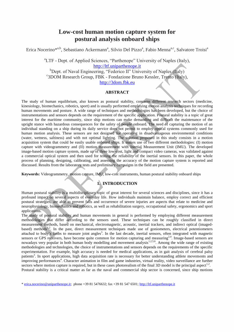
systems Inc.TM
which implements the Brown camera model12
. Camera calibrations were checked in different epochs
verifying their temporal stability for the demanded accuracy15
.
Figure 2. Left and centre: test field used for self-calibration. Right: resulting bundled camera station network.
- System synchronization
A fundamental requirement of a videogrammetric system is the synchronization among the cameras. Professional motion
capture systems adopt dedicated hardware (frame grabber) to which cameras are connected and related management
software which ensure the camera synchronization. For synchronizing the proposed low-cost optical-based system, a
LED (Light Emitting Diode) was used. The LED lighting time (≈106
seconds) can be considered instantaneous,
compared to the camera frame rate. The LED is switched on (off) within the Field of View (FOV) of all the recording
cameras: the first frame in which it changes its state (from off to on or vice-versa) is taken as the synchronization event.
The misalignment error between the three video tracks can be one frame at most.
This systematic synchronization error affects the accuracy of point coordinates as much as the recorded object or the
recording system moves with high speed.
- Camera orientation
The low-cost motion capture system was designed for being flexible: the camera configuration (relative positions) can
differ significantly according to the setting where the system is required to operate. Therefore, the camera orientation has
to be performed every time the system is set up. Since for multi-camera configuration the standard procedure for exterior
orientation by means of pre-signalized targets is not always convenient or feasible, a specific procedure is employed. A
white high power LED is used as an active 3D target: it is moved in all directions within the cameras’ FOV in order to
cover the whole measurement volume.
- Own-developed tracking algorithm
The image observations are collected with an own developed automated tracking algorithm. The tracking software
isolates the pixels covered by the LED, which are characterized by a high brightness in the scene, and tracks their
centroid. The process needs to start with approximate image coordinates of the LED on the first frame. The following
steps are then used to process the subsequent images: (I) a ROI (Region Of Interest) is centred on the centroid
coordinates marked on the previous frame; (II) the image area within the ROI is binarized; (III) a segmentation of the
ROI is performed, the best segment (for shape and dimension) is selected and the image coordinates of its centroid are
computed. Image coordinates of the LED for each frame are used as observation for a bundle adjustment automatically
performed with PhotomodelerTM
via Windows standard DDE (Dynamic Data Exchange) interface. The photogrammetric
model is scaled by using a reference calibrated frame or bar located within the measuring volume. The tracking software
is also able to automatically track, one by one, multiple LEDs or well-distinguishable targets (e.g., circular retro-
reflective markers) moving in the scene.
4. VIDEOGRAMMETRIC LOW-COST SYSTEM VALIDATION
In order to evaluate the performances (accuracy and reliability) of the proposed videogrammetric system, a comparison
with a commercial motion capture system, based on high-speed cameras, was performed. With the two optical system a
reference bar was tracked simultaneously in order to verify that the relative distance between the bar’s ends throughout
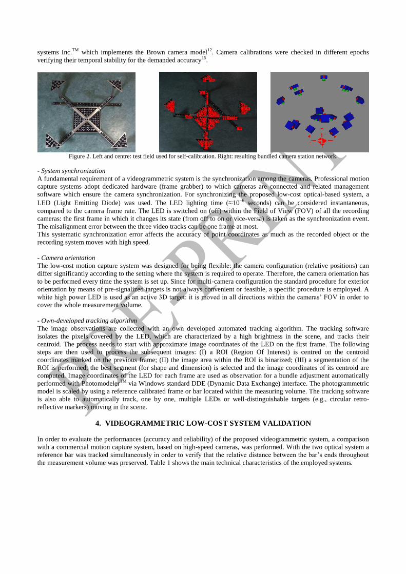
the measurement volume was preserved. Table 1 shows the main technical characteristics of the employed systems.
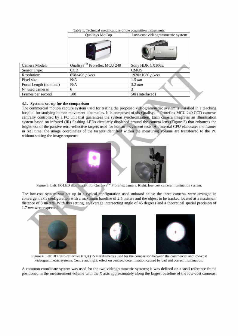
Table 1. Technical specifications of the acquisition instruments.
Qualisys MoCap Low-cost videogrammetric system
Camera Model: QualisysTM
Proreflex MCU 240 Sony HDR CX106E
Sensor Type: CCD CMOS
Resolution: 658×496 pixels 1920×1080 pixels
Pixel size N/A 1.5 μm
Focal Length (nominal) N/A 3.2 mm
N° used cameras 6 3
Frames per second 100 50i (Interlaced)
4.1. Systems set-up for the comparison
The commercial motion capture system used for testing the proposed videogrammetric system is installed in a teaching
hospital for studying human movement kinematics. It is composed of six QualisysTM
Proreflex MCU 240 CCD cameras
centrally controlled by a PC unit that guarantees the system synchronization. Each camera integrates an illumination
system based on infrared (IR) flashing LEDs circularly displaced around the camera lens (Figure 3) that enhances the
brightness of the passive retro-reflective targets used for human movement tests. An internal CPU elaborates the frames
in real time; the image coordinates of the targets identified within the measuring volume are transferred to the PC
without storing the image sequence.
Figure 3. Left: IR-LED illumination for QualisysTM Proreflex camera. Right: low-cost camera illumination system.
The low-cost system was set up in a typical configuration used onboard ships: the three cameras were arranged in
convergent axis configuration with a maximum baseline of 2.5 meters and the object to be tracked located at a maximum
distance of 3 meters. With this setting, an average intersecting angle of 45 degrees and a theoretical spatial precision of
1.7 mm were expected.
Figure 4. Left: 3D retro-reflective target (15 mm diameter) used for the comparison between the commercial and low-cost
videogrammetric systems. Centre and right: effect on centroid determination caused by bad and correct illumination.
A common coordinate system was used for the two videogrammetric systems; it was defined on a steal reference frame
positioned in the measurement volume with the X axis approximately along the largest baseline of the low-cost cameras,

the Z axis upward along the vertical, and the Y axis to complete a left-handed coordinate system.
To validate the low-cost videogrammetric system, targets have to be tracked simultaneously by the two optical systems.
Since the illumination system of the QualisysTM
emits infrared light, a set of three lamps (one per camera) was used for
enhancing the brightness of the retro-reflective targets also within the visible spectrum. The lamps were positioned as
closer as possible to the cameras (Figure 3) in order to avoid that an eccentricity between the light source and the camera
produced a partial illumination of the sphere. This condition could produce an error in computing the target centroid
(Figure 4). The temporal synchronization between the two systems was performed by switching on two LEDs
simultaneously, one in the visible spectrum (visible by the low-cost cameras) and the second one in the IR spectrum
(visible by the ProReflex cameras).
4.2. Performed tests
In order to estimate the accuracy of a videogrammetric system, different kinds of trials, usually classified into two
groups, are suggested in literature5. The first group of tests aim at revealing the deviation of the inter-target distance
observed in each epoch from a reference measured distance, which is invariant. With the second type of tests, the
validation is usually performed by comparing the measured trajectory of a single target (or of a set of targets having an
invariant relative position) with its expected path. The reference trajectory could be carried out by using targets fixed on
a rotating platform manoeuvred with a servo motor16,17
, or by conducting gravity tests18
.
Table 2. Summary of the performed validation tests.
Test Description Calibrated bar (wand) movement
Full Volume5,18
A solid bar mounting two spherical targets at each end
is vertically aligned approximately with the Z (vertical)
axis of the reference coordinate system and then moved
parallel to each axis, throughout the entire
measurement survey volume. The speed of the rod
movement is kept constant and the two targets move at
similar speed.
Pendulum5,18
A rigid pendulum mounting two markers in known
relative positions is suspended to swing in two
orthogonal planes (XZ and YZ planes). The 3D
coordinates of the markers are recorded for at least two
complete oscillations. In this test, the top target is hold
almost steady, while the bottom target swings.
Rotation
The bar is rotated around Y axis with respect to its
centre. The bar angular speed is kept almost constant
and the two targets move at similar angular speed.
In this paper, the results from the first type of tests are presented, since they are of major interest for the conducted study.
As discussed in the following sections, the meaningful measures to be retrieved are angles, that are evaluated on the
basis of inter-marker distances.
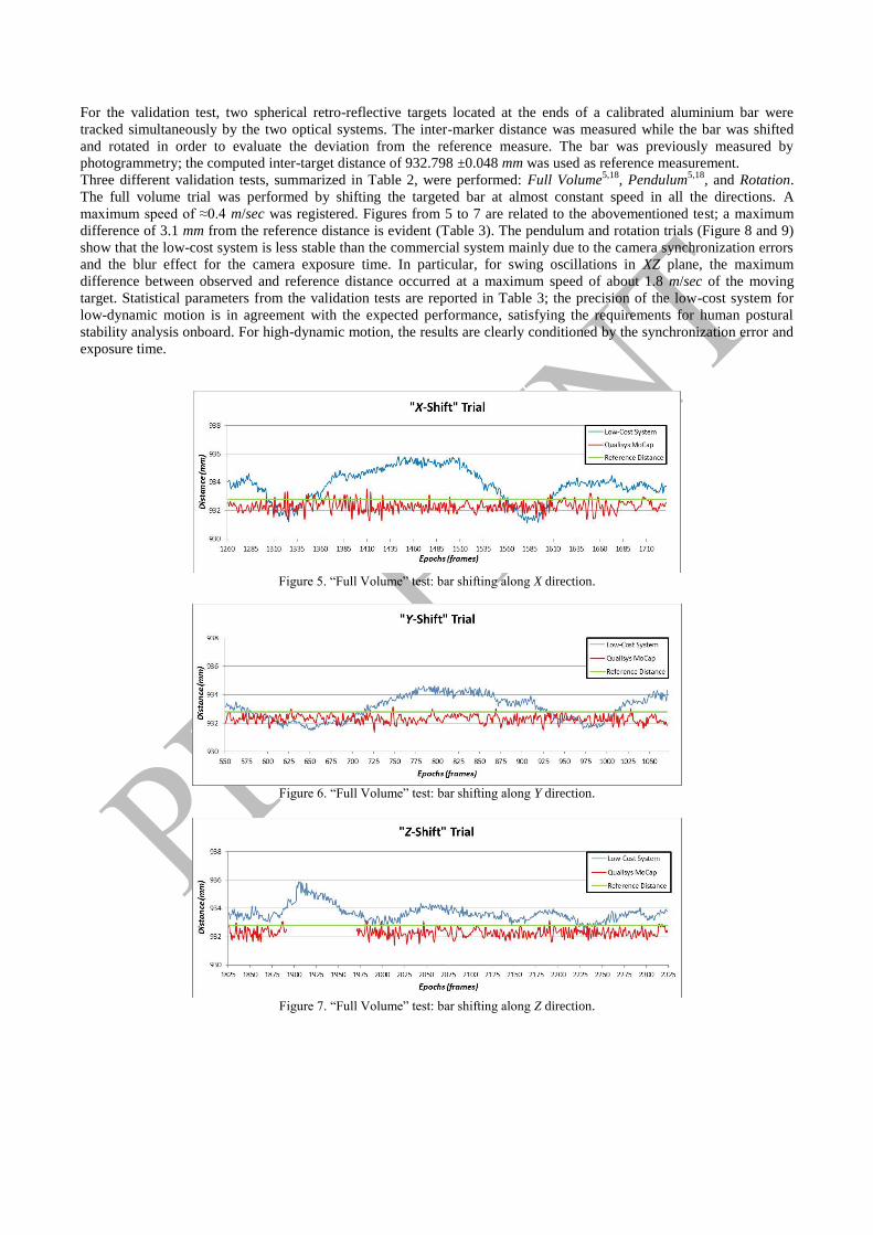
For the validation test, two spherical retro-reflective targets located at the ends of a calibrated aluminium bar were
tracked simultaneously by the two optical systems. The inter-marker distance was measured while the bar was shifted
and rotated in order to evaluate the deviation from the reference measure. The bar was previously measured by
photogrammetry; the computed inter-target distance of 932.798 ±0.048 mm was used as reference measurement.
Three different validation tests, summarized in Table 2, were performed: Full Volume5,18
, Pendulum5,18
, and Rotation.
The full volume trial was performed by shifting the targeted bar at almost constant speed in all the directions. A
maximum speed of ≈0.4 m/sec was registered. Figures from 5 to 7 are related to the abovementioned test; a maximum
difference of 3.1 mm from the reference distance is evident (Table 3). The pendulum and rotation trials (Figure 8 and 9)
show that the low-cost system is less stable than the commercial system mainly due to the camera synchronization errors
and the blur effect for the camera exposure time. In particular, for swing oscillations in XZ plane, the maximum
difference between observed and reference distance occurred at a maximum speed of about 1.8 m/sec of the moving
target. Statistical parameters from the validation tests are reported in Table 3; the precision of the low-cost system for
low-dynamic motion is in agreement with the expected performance, satisfying the requirements for human postural
stability analysis onboard. For high-dynamic motion, the results are clearly conditioned by the synchronization error and
exposure time.
Figure 5. “Full Volume” test: bar shifting along X direction.
Figure 6. “Full Volume” test: bar shifting along Y direction.
Figure 7. “Full Volume” test: bar shifting along Z direction.

Figure 8. Left: “Pendulum” test oscillations in YZ plane: Right: “Pendulum” test oscillations in XZ plane.
Figure 9. “Rotation” test comparison: the bar was rotate around Y reference axis.
Table 3. Test Statistics in mm.
X-Shift Y-Shift Z-Shift
Pendulum
YZ-plane
Pendulum
XZ-plane Rotation
QualisysTM MoCap
MEAN measured distance 932.309 932.290 932.289 932.226 932.370 932.619
MEAN – Ref. distance* -0.489 -0.508 -0.509 -0.572 -0.428 -0.179
RMS Error** 0.375 0.272 0.306 0.347 0.471 0.503
MAX Error 1.567 1.424 1.386 1.544 2.588 1.832
Low-Cost System
MEAN measured distance 933.826 933.071 933.659 934.047 934.557 932.019
MEAN – Ref. distance* 1.028 0.273 0.861 1.249 1.759 -0.779
RMS Error** 1.158 0.845 0.567 1.019 4.797 2.403
MAX Error 3.002 1.816 3.068 4.592 9.855 7.580
*Reference distance = 932.798 mm ** RMS Error = Root Mean Square of the difference between the measured and reference distance

5. VIDEOGRAMMETRIC SYSTEM FOR IMU STABILITY CHECKING
Once validated the proposed motion capture system against the commercial QualisysTM
System, several experiments
were performed with the aim of testing the reliability of low-cost inertial units. MEMS sensors were used for measuring
both ship and human movements and form, together with the videogrammetric system, the motion acquisition system for
executing postural stability tests onboard a moving platform.
The inertial sensors employed are two miniature units consisting of three accelerometers, three gyros, three
magnetometers and static pressure (barometer) produced by XSens Technologies (www.xsens.com). For measuring ship
motions, the Motion Tracker MTi-G, integrating a GPS antenna with the inertial unit, was chosen. A lightweight portable
system, made up of a master (Xbus Master) and a Motion Tracker (MTx), was used for measuring the human motion.
Both the sensors provide three linear accelerations, rates of turn and orientation data (Euler angles) referred to an inertial
reference frame. When the GPS signal is available, the MTi-G also supplies position and velocity data.
Two different set of tests were conducted. The videogrammetric system was arranged into an indoor laboratory for
executing the experiments with the MTx (Figure 10), the IMU (Inertial Measurement Unit) for measuring human motion.
In the case of the MTi-G employed for recording the ship motion, the experiments were carried on outside, in order to
test the integration with the GPS.
Figure 10. Left: Indoor laboratory setting for dynamic tests with inertial sensor. Right : The non-magnetic base with photogrammetric
targets for the inertial unit.
A suitable base of support was built of non-magnetic rigid material. The IMUs were fastened on the top of the plate,
where a recognisable path with four coded targets was drawn. The targets were: (I) used for defining on the plate a
reference frame parallel to the IMU-fixed coordinate system; (II) tracked for retrieving both the linear and angular
movements of the plate and, consequently, the sensor motion.
In order to synchronise videos and IMU data, a suitable system was assembled. A mechanic switch simultaneously hits
the inertial sensor and turns on a LED fixed to the IMU housing. The inertial sensor measures the hit as a peak in the
value of the acceleration along the Z axis and, at same time, the videogrammetric system captures the LED switching on:
this point is selected as the synchronization moment for the two different measurement systems.
During the tests, the plate was manually moved by an operator, gradually increasing the dynamics of movement. The
motion of the plate was recorded by the three camcorders and, simultaneously, calibrated data from the inertial sensors
were acquired and sampled at 100 Hz using the factory software. Each trial lasted about 90 seconds and was composed
of three phases: (I) an initial phase in which the plate remained still (with the Z axis in the vertical direction); (II) a
central phase where the dynamics was gradually increasing; (III) a final phase in which the plate was placed again in the
original position.
Figure 11 shows a representative comparison between the Euler angles measured by the MTx (in red) and calculated
with videogrammetry (in blue). The roll and pitch angles from the inertial sensor do not show a significant drift
compared to the videogrammetric output: in the last part of the test, when the plate is placed again in the original
stationary position, they go back to the initial values. The maximum difference between the two measurement techniques
(less than 6 degrees) is registered in the measurement of the pitch angle when the plate moved around the Y axis at a turn
rate of about 4 degrees/sec. The yaw angle provided by the MTx is not sufficiently reliable, since a non-negligible drift is
visible at the end of the test. The reason is that the magnetometers, that provide the measurement of the yaw angle, are
no longer able to compensate the local magnetic field. On the contrary, the yaw angle provided by the MTi-G was
proved to be more stable thanks to the integration with the GPS.
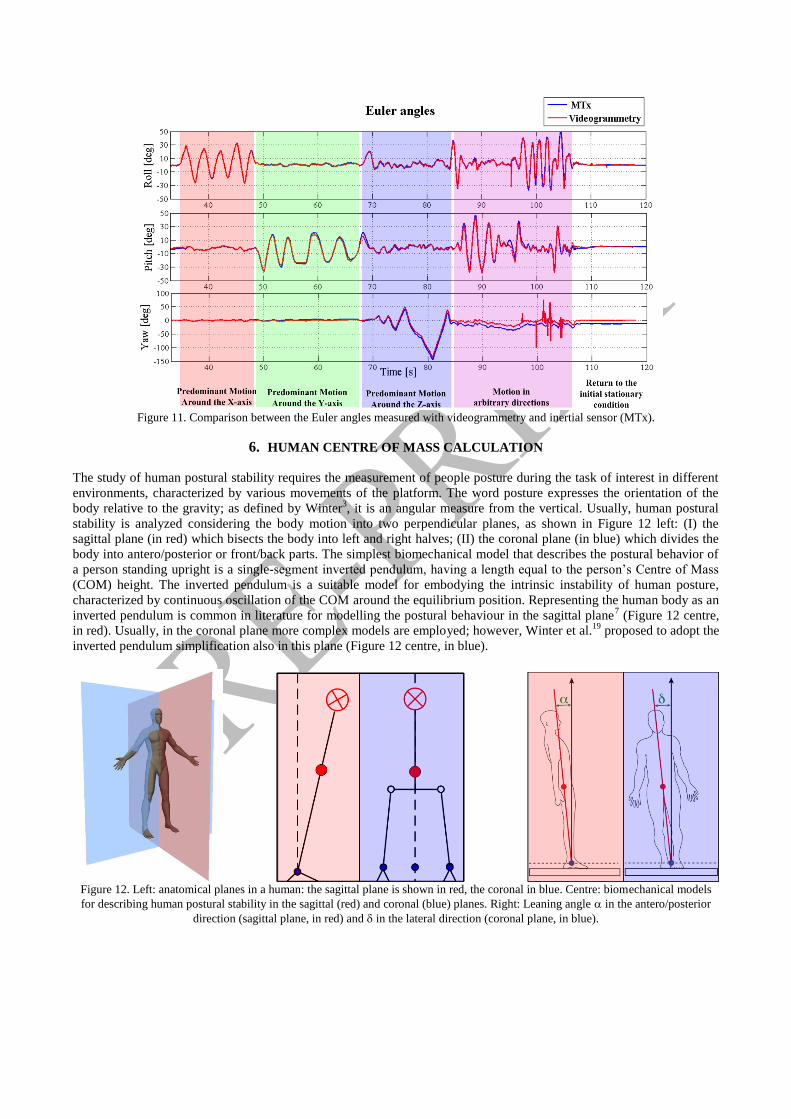
Figure 11. Comparison between the Euler angles measured with videogrammetry and inertial sensor (MTx).
6. HUMAN CENTRE OF MASS CALCULATION
The study of human postural stability requires the measurement of people posture during the task of interest in different
environments, characterized by various movements of the platform. The word posture expresses the orientation of the
body relative to the gravity; as defined by Winter3, it is an angular measure from the vertical. Usually, human postural
stability is analyzed considering the body motion into two perpendicular planes, as shown in Figure 12 left: (I) the
sagittal plane (in red) which bisects the body into left and right halves; (II) the coronal plane (in blue) which divides the
body into antero/posterior or front/back parts. The simplest biomechanical model that describes the postural behavior of
a person standing upright is a single-segment inverted pendulum, having a length equal to the person’s Centre of Mass
(COM) height. The inverted pendulum is a suitable model for embodying the intrinsic instability of human posture,
characterized by continuous oscillation of the COM around the equilibrium position. Representing the human body as an
inverted pendulum is common in literature for modelling the postural behaviour in the sagittal plane7 (Figure 12 centre,
in red). Usually, in the coronal plane more complex models are employed; however, Winter et al.19
proposed to adopt the
inverted pendulum simplification also in this plane (Figure 12 centre, in blue).
Figure 12. Left: anatomical planes in a human: the sagittal plane is shown in red, the coronal in blue. Centre: biomechanical models
for describing human postural stability in the sagittal (red) and coronal (blue) planes. Right: Leaning angle in the antero/posterior
direction (sagittal plane, in red) and in the lateral direction (coronal plane, in blue).

Figure 13. Location of 21 markers in the 14 segment 3D model to estimate total body COM3.
Accurate determination of the COM position requires a fully body kinematics analysis20
, which is usually performed, for
example, in clinical studies. For the present study, evaluating the COM’s height was necessary in order to obtain an
approximated location for placing the inertial sensor and videogrammetric targets. This estimation is important for the
trials onboard ships, setting that is characterised by cramped spaces and where to perform a fully body kinematics
analysis is not easily feasible (sometimes not possible). For this purpose, the model proposed by Winter3 has been used:
the human body is divided into 14 segments, identified by 21 markers (Figure 13). Measuring the 3D coordinates of the
21 markers with a videogrammetric system, the COM position in 3D is determined according to the general formula for
barycentre calculation3,7
.
In a suitable space (indoor laboratory), the proposed capture system was set up and calibrated. A set of 21 adhesive
bandage markers were prepared for each individual to be measured. The markers were drawn as black circles on a white
background, in order to ensure high contrast; this made easier the point measurement phase with the photogrammetric
software PhotomodelerTM
.
Once calculated the COM’s height, each subject was also instrumented with the IMU placed on the reference plate; a
high-power LED was attached to the sensor housing in order to synchronise the inertial sensor with the videogrammetric
system (see Section 5).
Figure 14. Left: 2D displacement of the COM for an 80-second record in quiet standing. Right: out-of-plane COM component from
videogrammetry.
Assuming that the person body is rigid, the COM motion can be tracked recording the displacement of the

photogrammetric reference plate positioned at the measured COM height. Figure 14 left reports the two-dimensional
displacement of the COM for an 80-second record in quiet standing. The trend shows that the main motion component is
in the anterior/posterior direction, in agreement with the hypothesis of modelling a person as an inverted pendulum. In
Figure 14 right, the motion component outside of the coronal plane is illustrated; the trend gives information about the
validity of the “inverted pendulum” hypothesis. If the magnitude of the out-of-plane component increased significantly,
the “inverted pendulum” model would be no longer suitable for describing the individual postural stability. The final part
of the displayed trace shows that the out-of plane COM component is increasing: this corresponds to the moment where
the recorded subject is moving at the end of the postural stability test.
Figure 15. Trend of the leaning angle in the antero/posterior direction: comparison between inertial sensor and videogrammetry.
A measure for quantifying the postural stability of a person standing on a stationary (quiet standing) or moving
(perturbed or dynamic standing) is provided by the sway or leaning angles of the person’s COM from the ankle joint. In
Figure 12 right, the angles in the sagittal and coronal plane are shown in the case of quiet standing. The angles are
labelled and respectively.
These quantities were measured simultaneously by the two motion capture techniques: the inertial sensor and optical-
based system. Figure 15 shows the comparison between the leaning angles obtained by the two measurement
techniques. The trend corresponds to voluntary movements of the tested subject in the antero/posterior direction. The two
outputs slightly differ: the angle from the MTx is systematically larger, in the order of dynamic accuracy (2°) declared by
the manufacturer.
7. POSTURAL STABILITY TEST ONBOARD SHIPS
Onboard trials were conducted to test the proposed motion capture system in the real environment, characterized by
challenging conditions (cramped spaces, adverse lighting conditions, vibrations, etc.). The ship employed for the tests is
a 16.30 meter long wooden fishing vessel named “San Gaetano”, whose activity is concentred within the Bay of Naples
(Italy).
In order to not interfere with the normal activities of the crew members, the trials were performed inside a cabin located
behind the pilot bridge. The camcorders were secured to the ship structures using suitable clamps. Two video cameras
were placed for viewing simultaneously an individual facing forward. The third camera was arranged in order to form a
base with one of the other two devices and record an individual facing laterally. The two baselines between the cameras
were about 1.3 meters; with the object to be tracked at an average distance of 1.25 meters, an average intersecting angle
of 50 degrees and a spatial precision in 3D coordinates of 0.6 mm were expected.
The tested subjects (Figure 16 right) were instrumented with the inertial sensor MTx positioned at the COM height
estimated during preliminary laboratory tests (Section 6). The photogrammetric plate to which the MTx was secured
(Section 5) was modified for improving and making the tracking performed with the own-developed algorithm (Section
3) more robust. Four coloured high-power LEDs were fixed at the corners of the plate and were used as active “color-
coded” 3D markers (Figure 16 left and centre). The MTi-G for ship motions measurement was positioned on the cabin
deck close to the vertical projection of the individual’s COM (Figure 16 right) and the GPS antenna was located on the
top of the pilot bridge.
The two separate inertial sensors were connected to the same PC and the data from both the MTi-G and MTx were

collected via the factory software at a 120 Hz acquisition rate. This allowed to reduce the hardware required onboard and,
at the same time, to synchronise the data from the two inertial units. The method explained in Section 5 was applied to
synchronize the inertial sensors with the videogrammetric system. Several trials were executed: the postural motion of
the tested subjects was measured while maintaining the upright stance facing forward and laterally.
Figure 16. Left and centre: improved videogrammetric plate for the MTx sensor equipped with coloured LEDs for onboard tests.
Right: videogrammetric plate with inertial unit (MTx) at the subject’s COM (red rectangle) and inertial sensor (MTi-G) for ship
motion measurement (cyan rectangle).
The inertial sensors provide the orientation of human body and ship relative to an inertial frame, while the optical-based
system measures the movement of the observed individual in the ship-fixed frame. Figure 17 shows the angles measured
by the three devices for a person facing laterally: (I) and are the ship roll and pitch angles from the MTi-G; (II) and
are the human sway angles in the antero/posterior and lateral directions relative to the vertical (inertial frame) from the
MTx; (III) and are the human sway angles in the antero/posterior and lateral directions relative to the normal to ship
deck (ship-fixed frame) from videogrammetry.
The orientation output for the MTx were opportunely transformed (rotated) and compared with the leaning angles from
videogrammetry. Figures 18 and 19 show the postural sway measured both by the inertial device and with
videogrammetry for an individual facing laterally. The deck roll and pitch angles are also illustrated. The RMS errors
between inertial sensors and videogrammetry resulted to be 2.2 degrees and 0.7 degrees for the and respectively.
Figure 17. Human postural sway on a moving ship deck: the person is facing laterally. Left: in the sagittal plane the human stability is
influenced by the deck roll angle ; the postural sway angle in the antero/posterior direction is relative to the vertical and to the
normal to ship deck. Right: in the coronal plane the human stability is influenced by the deck pitch angle ; the postural sway angle in
the lateral direction is relative to the vertical and to the normal to the deck.

Figure 18. Postural sway angle in the antero/posterior direction relative to the normal to ship deck) from videogrammetry (red) and
inertial sensor (blue); ship roll angle in green. The person is facing laterally.
Figure 19. Postural sway angle in the lateral direction relative to the normal to ship deck) from videogrammetry (red) and inertial
sensor (blue); ship pitch angle in green. The person is facing laterally.
8. CONCLUSIONS
This contribution presented a low-cost multi-camera system for human motion capture onboard ships. The proposed
videogrammetric system was designed in order to be flexible, light and manageable: it is made up of three consumer-
grade video cameras that do not require any central controller or additional cables and can be installed in different
configurations and settings (by means of suitable tripods and clamps). Because of the technical characteristics of the
optical-based system, the acquired data, stored in the internal memory of each camera, are post processed. The paper
covered the main aspects of system calibration, describing the own-developed procedure for synchronizing the three
cameras and algorithms that allow the automatic tracking of multiple well-distinguishable targets (high-intensity LEDs,
circular retro-reflective markers).
The proposed system was tested and compared with a commercial MoCap system in order to verify its accuracy and
robustness in surveying objects moving at different speeds. The performed tests showed an accuracy of about 1:1000 in
measuring distances when the captured object moves slowly, but this sensibly decreased for faster movements, mainly
due to the combination of synchronization error and shutter time. For low movements, the comparison showed that
employing low-cost optical systems is an acceptable compromise between cost, flexibly and achievable accuracy.
The videogrammetric system was also designed for operating together with inertial sensors for both human and ship
motion measurements. Laboratory tests were conducted for testing the reliability of low-cost inertial units by using the
videogrammetric system as reference. For 120 second last tests at most, the inertial data provided satisfactory results, in
terms of stability and accuracy. Several trials were conducted onboard a fishing vessel to test the proposed motion
capture system in the real environment. Despite the practical difficulties related to the specific setting (cramped spaces,
adverse lighting conditions, vibrations, etc.) the motion acquisition system provided satisfactory results. The inertial
sensors are able to provide all the parameters for studying human postural stability onboard. Nevertheless, the integration

of videogrammetry guarantees redundancy and control (reliability) in their estimation and allows a deeper understanding
and reconstruction of the phenomena.
ACKNOWLEDGEMENTS
The authors would like to express their grateful to: M.Sc. Alberto Greco, Dept. of Applied Sciences, for the valued
technical support; M.Sc. Dario Avella, M.Sc. Rosaria Rucco and Ph.D. Valeria Agosti, staff members of the
Neuromechanics Laboratory of “Parthenope” University of Naples (Italy), headed by Prof. Giuseppe Sorrentino, for the
cooperation in the execution of tests with QualisysTM
motion capture system; the crew members of M/T “S. Gaetano” for
the assistance during the onboard surveys.
REFERENCES
[1] D'Apuzzo, N., "Surface Measurement and Tracking of Human Body Part from Multi Station Video Sequences",
Ph.D. Thesis, ETH - Swiss Federal Institute of Technology, Zurich, Switzerland, (2003).
[2] Roetenberg, D., "Inertial and Magnetic Sensing of Human Motion", Ph.D. Thesis, University of Twente, Enschede,
The Netherland, (2006).
[3] Winter, D. A., [Biomechanics and Motor Control of Human Movement], John Wiley and Sons Inc., (2005).
[4] Brodie, M. A. D., "Development of Fusion Motion Capture for Optimisation of Performance in Alpine Ski Racing",
Ph.D. Thesis, Massey University, Wellington, New Zealand, (2009).
[5] Chiari, L., Croce, U. D., Leardini, A., Cappozzo, A., "Human movement analysis using stereophotogrammetry: Part
2: Instrumental errors", Gait & posture 21(2), 197-211, (2005).
[6] Remondino, F., "Videogrammetry for human movement analysis", Ninth international symposium on 3D analysis
of human movement (2006).
[7] Nocerino, E., "Human postural stability onboard ship as seakeeping criterion. Stance control model and procedure
for validating it: a proposal", Ph.D. Thesis, "Federico II" University of Naples, Naples, Italy, (2011).
[8] Menna, F., Remondino, F., Battisti, R., Nocerino, E., "Geometric investigation of a gaming active device", Proc.
SPIE 8085, (2011), (in press).
[9] Ferrari, A., Cutti, A., Garofalo, P., Raggi, M., Heijboer, M., Cappello, A., Davalli, A., "First in vivo assessment of
“Outwalk”: a novel protocol for clinical gait analysis based on inertial and magnetic sensors", Medical and
Biological Engineering and Computing 48(1), 1-15, (2010).
[10] Chang, H., Xue, L., Qin, W., Yuan, G., Yuan, W., "An Integrated MEMS Gyroscope Array with Higher Accuracy
Output", Sensors 8(4), 2886-2899, (2008).
[11] Gruen, A., "Fundamentals of videogrammetry -- A review", Human Movement Science 16(2-3), 155-187, (1997).
[12] Brown, D. C., "Close-Range Camera Calibration", Photogrammetric Engineering & Remote Sensing 37(8), 855-
866, (1971).
[13] Luhmann, T., "Close range photogrammetry for industrial applications", ISPRS Journal of Photogrammetry and
Remote Sensing 65(6), 558-569, (2010).
[14] Fraser, C. S., "Digital camera self-calibration", ISPRS Journal of Photogrammetry and Remote Sensing 52(4), 149-
159, (1997).
[15] Wackrow, R., Chandler, J. H., Bryan, P., "Geometric consistency and stability of consumer-grade digital cameras
for accurate spatial measurement", The Photogrammetric Record 22(118), 121-134, (2007).
[16] Cappello, A., Leardini, A., Benedetti, M. G., Liguori, R., Bertani, A., "Application of stereophotogrammetry to
total body three-dimensional analysis of human tremor", IEEE Transactions on Rehabilitation Engineering 5(4),
388-393, (1997).
[17] Richards, J. G., "The measurement of human motion: A comparison of commercially available systems", Human
Movement Science 18(5), 589-602, (1999).
[18] Cappozzo, A., Della Croce, U., Catani, F., Leardini, A., Fioretti, S., Maurizi, M., et al., "Stereometric system
accuracy tests", In: Measurement and data processing methodology in clinical movement analysis-preliminary,
CAMRAC II Internal Report, (1993).
[19] Winter, D. A., Patla, A. E., Prince, F., Ishac, M., Gielo-Perczak, K., "Stiffness control of balance in quiet standing",
Journal of Neurophysiology 80(3), 1211-1221, (1998).
[20] Eames, M. H. A., Cosgrove, A., Baker, R., "Comparing methods of estimating the total body centre of mass in
three-dimensions in normal and pathological gaits", Human Movement Science 18(5), 637-646, (1999).