Low-Cost Differential GPS for Field Robotics - ANU Open ...
6
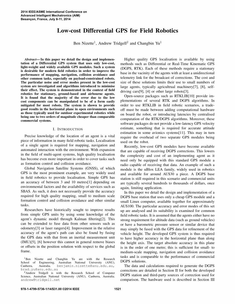
Low-cost Differential GPS for Field Robotics Ben Nizette 1 , Andrew Tridgell 2 and Changbin Yu 1 Abstract— In this paper we detail the design and implemen- tation of a Differential GPS system that uses only low-cost, light-weight and widely available GPS modules. Such a system is desirable for modern field robotics in order to improve the performance of mapping, navigation, collision avoidance and other common tasks, especially on payload-constrained robots. The particular noise and error modes present in the low-cost system are investigated and algorithms introduced to minimise their effect. The system is demonstrated in the context of field robotics for stationary, ground-based and airbourne agents. It is found that the majority of the error due to the low cost components can be manipulated to be of a form easily mitigated for most robots. The system is shown to provide good results in the horizontal plane in open environments such as those typically used for outdoor experimental robotics while being one to two orders of magnitude cheaper than comparable commercial systems. I. I NTRODUCTION Precise knowledge of the location of an agent is a vital piece of information in many field robotic tasks. Localisation of a single agent is required for mapping, navigation and automated interaction with the environment. With expansion in the field of multi-agent systems, high quality localisation has become even more important in order to cover tasks such as formation control and collision avoidance. Global Navigation Satellite Systems (GNSS), of which GPS is the most prominent example, are very widely used in field robotics to provide localisation. Simple GPS has an accuracy of between 3 and 10 metres[1] depending on environmental factors and the availability of services such as SBAS. As such, it does not necessarily provide the accuracy required for high quality mapping, small to medium scale formation control and collision avoidance and other similar tasks. Researchers have historically sought to improve results from simple GPS units by using some knowledge of the agent’s dynamic model through Kalman filtering[2]. This can be extended to fuse data from other sensors such as odometry[3] or laser rangers[4]. Improvement in the relative accuracy of the agent’s path can also be found by fusing the GPS data with that from an inertial measurement unit (IMU)[5], [6] however this cannot in general remove biases or offsets in the position solution with respect to the global frame. 1 Ben Nizette and Changbin Yu are with the Research School of Engineering, Australian National University (ANU), Canberra, Australia. [email protected], [email protected] 2 Andrew Tridgell is with the Research School of Computer Science, Australian National University (ANU), Canberra, Australia. [email protected] Higher quality GPS localisation is available by using methods such as Differential or Real-Time Kinematic GPS (DGPS, RTK). Each of these methods require a stationary base in the vacinity of the agents with at least a unidirectional telemetry link for the broadcast of corrections. The cost and size of these solutions limits their use to small numbers of large agents, typically agricultrual machinery[7], [8], self- driving cars[9], [4] or other large robots[3]. Open-source packages such as RTKLIB[10] provide im- plementations of several RTK and DGPS algorithms. In order to use RTKLIB in field robotic scenarios, a trade- off must be made between adding computational hardware on board the robot, or introducing latencies by centralised computation of the RTK/DGPS algorithms. Moreover, these software packages do not provide a low-latency GPS velocity estimate, something that is required for accurate attitude estimation in some avionics systems[11]. This may in turn require the overhead of two separate GPS modules being used on the robot. Recently, low-cost GPS modules have become available that are capable of receiving DGPS corrections. This lowers the complexity and cost of an implementing agent as it need only be equipped with this standard GPS module a radio capable of receiving that data. An example of such a module is the uBlox LEA family, widely used in robotics and available for around AU$30 a piece. A DGPS base station is still required in this scenario and commercial units are typically several hundreds to thousands of dollars, once again, limiting application. In this paper we detail the design and implementation of a DGPS base station that uses only a cheap GPS module and a small Linux computer, available together for approximately AU$100. The particular accuracy and error modes of this set up are analysed and its suitability is examined for common field robotic tasks. It is assumed that the agents either have no strong requirement for altitude data (such as ground vehicles) or have a barometric pressure sensor or similar device that may simply be fused with the GPS data for refinement of the vehicle height. The developed GPS system is thus required to have higher accuracy in the horizontal plane than along the height axis. The target absolute accuracy in this plane is in the order of one metre; this is sufficient for small- to medium-scale mapping, navigation and collision avoidance tasks and is comparable to the performance of commercial DGPS solutions. The data and calculations required to generate the DGPS corrections are detailed in Section II for both the developed DGPS station and third-party sources of correction used for comparison. The hardware used is described in Section III 2014 IEEE/ASME International Conference on Advanced Intelligent Mechatronics (AIM) Besançon, France, July 8-11, 2014 978-1-4799-5736-1/14/$31.00 ©2014 IEEE 1521
-
Upload
khangminh22 -
Category
Documents
-
view
1 -
download
0
Transcript of Low-Cost Differential GPS for Field Robotics - ANU Open ...
Low-cost Differential GPS for Field Robotics
Ben Nizette1, Andrew Tridgell2 and Changbin Yu1
Abstract— In this paper we detail the design and implemen-tation of a Differential GPS system that uses only low-cost,light-weight and widely available GPS modules. Such a systemis desirable for modern field robotics in order to improve theperformance of mapping, navigation, collision avoidance andother common tasks, especially on payload-constrained robots.The particular noise and error modes present in the low-costsystem are investigated and algorithms introduced to minimisetheir effect. The system is demonstrated in the context of fieldrobotics for stationary, ground-based and airbourne agents.It is found that the majority of the error due to the lowcost components can be manipulated to be of a form easilymitigated for most robots. The system is shown to providegood results in the horizontal plane in open environments suchas those typically used for outdoor experimental robotics whilebeing one to two orders of magnitude cheaper than comparablecommercial systems.
I. INTRODUCTION
Precise knowledge of the location of an agent is a vitalpiece of information in many field robotic tasks. Localisationof a single agent is required for mapping, navigation andautomated interaction with the environment. With expansionin the field of multi-agent systems, high quality localisationhas become even more important in order to cover tasks suchas formation control and collision avoidance.
Global Navigation Satellite Systems (GNSS), of whichGPS is the most prominent example, are very widely usedin field robotics to provide localisation. Simple GPS hasan accuracy of between 3 and 10 metres[1] depending onenvironmental factors and the availability of services such asSBAS. As such, it does not necessarily provide the accuracyrequired for high quality mapping, small to medium scaleformation control and collision avoidance and other similartasks.
Researchers have historically sought to improve resultsfrom simple GPS units by using some knowledge of theagent’s dynamic model through Kalman filtering[2]. Thiscan be extended to fuse data from other sensors such asodometry[3] or laser rangers[4]. Improvement in the relativeaccuracy of the agent’s path can also be found by fusingthe GPS data with that from an inertial measurement unit(IMU)[5], [6] however this cannot in general remove biasesor offsets in the position solution with respect to the globalframe.
1Ben Nizette and Changbin Yu are with the ResearchSchool of Engineering, Australian National University (ANU),Canberra, Australia. [email protected],[email protected]
2Andrew Tridgell is with the Research School of ComputerScience, Australian National University (ANU), Canberra, [email protected]
Higher quality GPS localisation is available by usingmethods such as Differential or Real-Time Kinematic GPS(DGPS, RTK). Each of these methods require a stationarybase in the vacinity of the agents with at least a unidirectionaltelemetry link for the broadcast of corrections. The cost andsize of these solutions limits their use to small numbers oflarge agents, typically agricultrual machinery[7], [8], self-driving cars[9], [4] or other large robots[3].
Open-source packages such as RTKLIB[10] provide im-plementations of several RTK and DGPS algorithms. Inorder to use RTKLIB in field robotic scenarios, a trade-off must be made between adding computational hardwareon board the robot, or introducing latencies by centralisedcomputation of the RTK/DGPS algorithms. Moreover, thesesoftware packages do not provide a low-latency GPS velocityestimate, something that is required for accurate attitudeestimation in some avionics systems[11]. This may in turnrequire the overhead of two separate GPS modules beingused on the robot.
Recently, low-cost GPS modules have become availablethat are capable of receiving DGPS corrections. This lowersthe complexity and cost of an implementing agent as itneed only be equipped with this standard GPS module aradio capable of receiving that data. An example of such amodule is the uBlox LEA family, widely used in roboticsand available for around AU$30 a piece. A DGPS basestation is still required in this scenario and commercial unitsare typically several hundreds to thousands of dollars, onceagain, limiting application.
In this paper we detail the design and implementation of aDGPS base station that uses only a cheap GPS module and asmall Linux computer, available together for approximatelyAU$100. The particular accuracy and error modes of this setup are analysed and its suitability is examined for commonfield robotic tasks. It is assumed that the agents either have nostrong requirement for altitude data (such as ground vehicles)or have a barometric pressure sensor or similar device thatmay simply be fused with the GPS data for refinement of thevehicle height. The developed GPS system is thus requiredto have higher accuracy in the horizontal plane than alongthe height axis. The target absolute accuracy in this planeis in the order of one metre; this is sufficient for small- tomedium-scale mapping, navigation and collision avoidancetasks and is comparable to the performance of commercialDGPS solutions.
The data and calculations required to generate the DGPScorrections are detailed in Section II for both the developedDGPS station and third-party sources of correction used forcomparison. The hardware used is described in Section III
2014 IEEE/ASME International Conference onAdvanced Intelligent Mechatronics (AIM)Besançon, France, July 8-11, 2014
978-1-4799-5736-1/14/$31.00 ©2014 IEEE 1521
followed by the results of experiments in urban and ruralenvironments in Section IV. Potential for future work is givenin Section V.
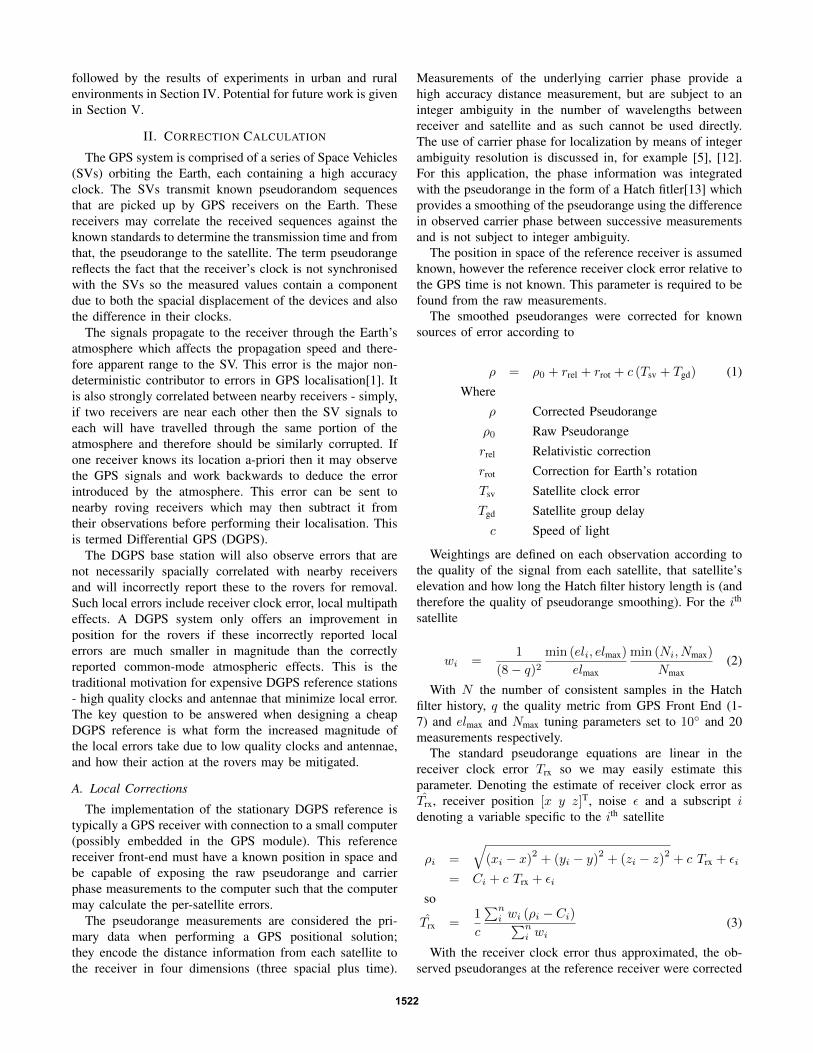
II. CORRECTION CALCULATION
The GPS system is comprised of a series of Space Vehicles(SVs) orbiting the Earth, each containing a high accuracyclock. The SVs transmit known pseudorandom sequencesthat are picked up by GPS receivers on the Earth. Thesereceivers may correlate the received sequences against theknown standards to determine the transmission time and fromthat, the pseudorange to the satellite. The term pseudorangereflects the fact that the receiver’s clock is not synchronisedwith the SVs so the measured values contain a componentdue to both the spacial displacement of the devices and alsothe difference in their clocks.
The signals propagate to the receiver through the Earth’satmosphere which affects the propagation speed and there-fore apparent range to the SV. This error is the major non-deterministic contributor to errors in GPS localisation[1]. Itis also strongly correlated between nearby receivers - simply,if two receivers are near each other then the SV signals toeach will have travelled through the same portion of theatmosphere and therefore should be similarly corrupted. Ifone receiver knows its location a-priori then it may observethe GPS signals and work backwards to deduce the errorintroduced by the atmosphere. This error can be sent tonearby roving receivers which may then subtract it fromtheir observations before performing their localisation. Thisis termed Differential GPS (DGPS).
The DGPS base station will also observe errors that arenot necessarily spacially correlated with nearby receiversand will incorrectly report these to the rovers for removal.Such local errors include receiver clock error, local multipatheffects. A DGPS system only offers an improvement inposition for the rovers if these incorrectly reported localerrors are much smaller in magnitude than the correctlyreported common-mode atmospheric effects. This is thetraditional motivation for expensive DGPS reference stations- high quality clocks and antennae that minimize local error.The key question to be answered when designing a cheapDGPS reference is what form the increased magnitude ofthe local errors take due to low quality clocks and antennae,and how their action at the rovers may be mitigated.
A. Local Corrections
The implementation of the stationary DGPS reference istypically a GPS receiver with connection to a small computer(possibly embedded in the GPS module). This referencereceiver front-end must have a known position in space andbe capable of exposing the raw pseudorange and carrierphase measurements to the computer such that the computermay calculate the per-satellite errors.
The pseudorange measurements are considered the pri-mary data when performing a GPS positional solution;they encode the distance information from each satellite tothe receiver in four dimensions (three spacial plus time).
Measurements of the underlying carrier phase provide ahigh accuracy distance measurement, but are subject to aninteger ambiguity in the number of wavelengths betweenreceiver and satellite and as such cannot be used directly.The use of carrier phase for localization by means of integerambiguity resolution is discussed in, for example [5], [12].For this application, the phase information was integratedwith the pseudorange in the form of a Hatch fitler[13] whichprovides a smoothing of the pseudorange using the differencein observed carrier phase between successive measurementsand is not subject to integer ambiguity.
The position in space of the reference receiver is assumedknown, however the reference receiver clock error relative tothe GPS time is not known. This parameter is required to befound from the raw measurements.
The smoothed pseudoranges were corrected for knownsources of error according to
ρ = ρ0 + rrel + rrot + c (Tsv + Tgd) (1)Where
ρ Corrected Pseudorangeρ0 Raw Pseudorangerrel Relativistic correctionrrot Correction for Earth’s rotationTsv Satellite clock errorTgd Satellite group delayc Speed of light
Weightings are defined on each observation according tothe quality of the signal from each satellite, that satellite’selevation and how long the Hatch filter history length is (andtherefore the quality of pseudorange smoothing). For the ith
satellite
wi =1
(8 − q)2min (eli, elmax)
elmax
min (Ni, Nmax)
Nmax(2)
With N the number of consistent samples in the Hatchfilter history, q the quality metric from GPS Front End (1-7) and elmax and Nmax tuning parameters set to 10◦ and 20measurements respectively.
The standard pseudorange equations are linear in thereceiver clock error Trx so we may easily estimate thisparameter. Denoting the estimate of receiver clock error asT̂rx, receiver position [x y z]T, noise ε and a subscript idenoting a variable specific to the ith satellite
ρi =
√(xi − x)
2+ (yi − y)
2+ (zi − z)
2+ c Trx + εi
= Ci + c Trx + εi
so
T̂rx =1
c
∑ni wi (ρi − Ci)∑n
i wi(3)
With the receiver clock error thus approximated, the ob-served pseudoranges at the reference receiver were corrected
1522
to obtain approximate observed geometric ranges to eachof the satellites then differenced with the true geometricdistance. The correction measurement y is then:
y = ρ+ c T̂rx − rgeo (4)
The true geometric distance rgeo is found by extractingeach satellite’s position from the broadcast Ephemeris anddifferencing with the reference’s known location.
These corrections were generated at the receiver outputfrequency of 5Hz and stored in a time-sorted buffer ofconfigurable length. At each output time step the historybuffer was sorted by correction magnitude and the outputgiven as the mean of the centre half of this magnitude-sortedbuffer. That is, for time sorted First-in First-out history buffery1...n and correction signal ∆ρ:
m1...n = sorted(yi...n)
∆ρ =
3n/4∑i=n/4
mi (5)
This was effective in rejecting several-sample outlierswithout adversely affecting the bandwidth of the correctionsignal.
Remark Equation 5 is a design choice that was found to beeffective in practice. Statistical analysis of large data sets mayyeild an optimal form of this equation and will be discussedin future work.
The output format for the correction data was chosen tobe RTCMv2 in order to be compatible with the chosen low-cost receivers. This standard requires that the corrections astransmitted also include the satellite clock errors, group delayand relativistic correction; each calculated according to theGPS Interface Control Document[14].
The RTCMv2 format also requires an estimate of the rateof change of each correction in order to extend the useful lifeof the corrections in the receiver[15]. This rate was calculatedsimply as the first order difference of preceeding samples.
The User Differential Range Error estimate (UDRE) fieldof the RTCMv2 message provides an opportunity for thereference station to communicate information to the receiversregarding the certainty of the error for each particular satel-lite. This allows the receiver to adjust the satellite weightingsin their internal least-squares position solution. For thissystem, the UDRE used for each satellite was exactly theweighting factor given in Equation 2
B. Infrastructure Corrections
The system was extended to receive correction informationfrom external Continuously Operating Reference Stations(CORS) operated by a third party. These stations providesignal observations in RTCMv3 format [16] encapsulated inNTRIP for internet transport.
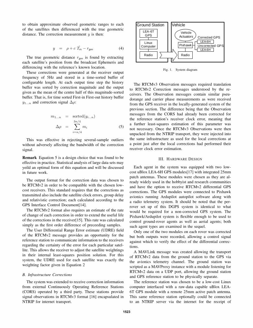
Fig. 1. System diagram
The RTCMv3 Observation messages required translationto RTCMv2 Correction messages understood by the re-ceivers. The Observation messages contain similar pseu-dorange and carrier phase measurements as were receivedfrom the GPS receiver in the locally-generated system of theprevious section. The difference being that the Observationmessages from the CORS had already been corrected forthe reference station’s receiver clock error, meaning thata further least-squares estimation of this parameter wasnot necessary. Once the RTCMv3 Observations were thenunpacked from the NTRIP transport, they were injected intothe same infrastructure as used for the local corrections ata point just after the local corrections had performed theirreceiver clock error estimation.
III. HARDWARE DESIGN
Each agent in the system was equipped with two low-cost uBlox LEA-6H GPS modules[17] with integrated 25mmpatch antennas. These modules were chosen as they are al-ready widely used in the hobbyist and research communitiesand have the option to receive RTCMv2 differential GPScorrections. The GPS modules were connected to Pixhawkavionics running Ardupilot autopilot software along witha radio telemetry system. It should be noted that the per-rover set up of this DGPS system is identical to whatwould be required for a non-corrected GPS system. ThePixhawk/Ardupilot system is flexible enough to be used tocontrol ground-rover agents as well as aerial agents; bothsuch agent types are examined in the sequel.
Only one of the two modules on each rover was correctedbut both outputs were recorded, allowing a control signalagainst which to verify the effect of the differential correc-tions.
A MAVLink message was created allowing the transportof RTCMv2 data from the ground station to the GPS viathe avionics telemetry channel. The ground station wasscripted as a MAVProxy instance with a module listening forRTCMv2 data on a UDP port, allowing the ground stationand GPS reference station to be physically separate.
The reference station was chosen to be a low-cost Linuxcomputer interfaced with a raw-data capable uBlox LEA-6T GPS module with a remote 25mm active patch antenna.This same reference station optionally could be connectedto an NTRIP server via the internet for the receipt of
1523
RTCMv3 observations from a third-party Continually Oper-ating Reference Station. The proposed algorithm was foundto use a negligable portion of the resources available oneven these low-cost computers, no performance advantageis expected if the system were to be implemented on moreexpensive computational hardware. The uBlox family of raw-capable receivers were chosen for their availability, low costand communications compatibility with the roving receivers.The use of other low-cost raw-capable GPS receivers suchas the NVS Techologies NV08C-CSM is possible but notinvestigated in this work.
All code is released under the terms of Version 3 of theGNU Public Licence at http://github.com/benizl/pyUblox.
IV. RESULTS
All experiments had an RTCMv2 update rate of 1Hz,downsampled from the reference station solution rate of 5Hz.This was found to offer the best compromise between DGPSperformance and telemetry bandwidth.
Several days of recorded raw data was examined foroutliers; periods where the correction signal for any satellitedeviated from the expected value by more than 5 metres. Thisis an indication that the GPS has lost lock on the satellite,has incorrectly chosen a multipath signal or otherwise is notproviding healthy data from that satellite. It was found thatthese periods typically lasted less than three seconds andshould form no more than one quarter of the history bufferlength of Equation 5 in order to be effectively rejected. Assuch, the history buffer length was set to 15 seconds for allexperiments.
A. Reference Position Discovery
For each new experimental environment, the ground truthposition of the reference receiver had to be discoveredand recorded. In each case, the reference receiver was leftto record raw observations for a 72-hour period. At thecompletion of this time, the observations were convertedto RINEX format and uploaded to the Canadian SpacialReference System’s Precise Point Positioning service[18].This is a free service that provides a high quality post-processed GPS localization solution of user observationsincorporating atmospheric observations recorded at the timeof the user’s observations along with high rate ephemerisdata from the measured orbits of the satellites and as such, itcan provide much more accurate localization than a realtimeservice.
All experiments had the GPS module’s internal dynamicmodel set to the most permissive setting “Airbourne 4G”.This was done in order to minimise the filtering performedinternally on position and as such to get the clearest pictureof the effect of the differential corrections by themselves.
B. Urban Environments
The first experiment was set up in an urban environment,on the roof of a dwelling. The three modules (reference,corrected and uncorrected receivers) were colocated in order
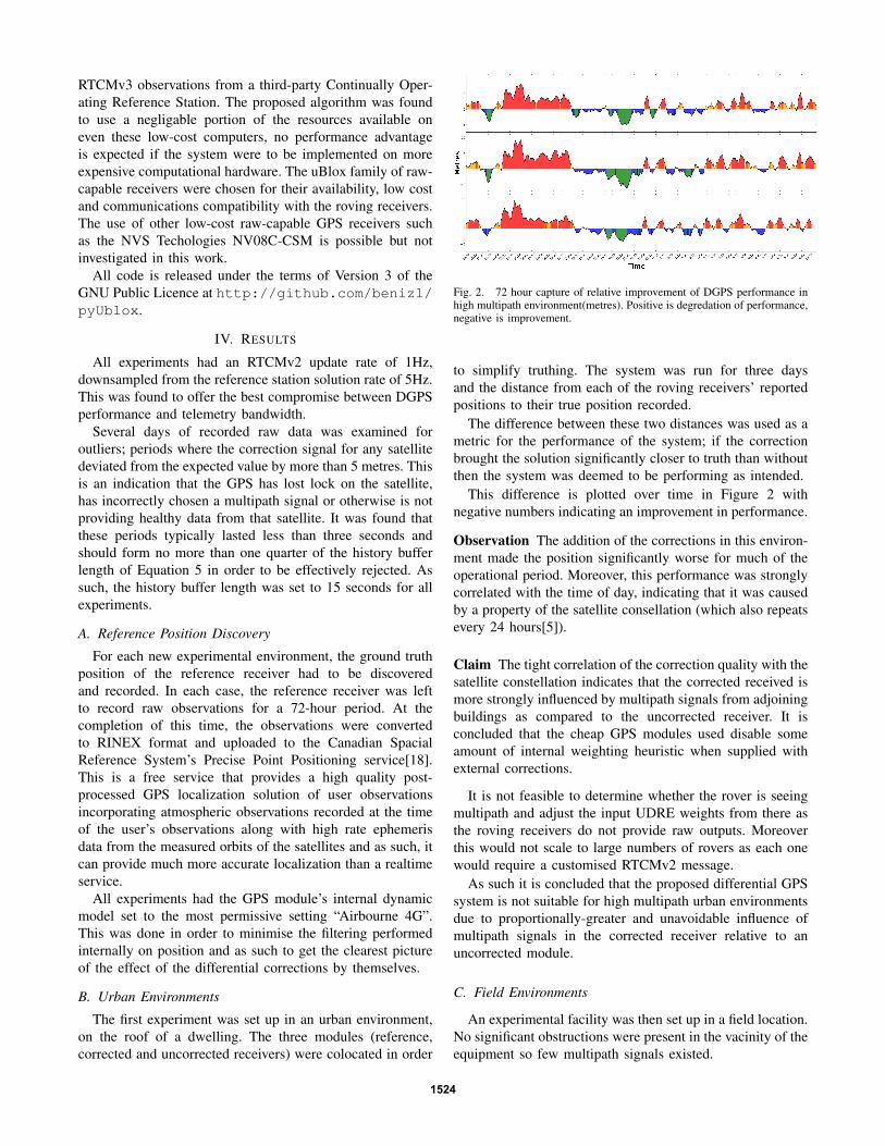
Fig. 2. 72 hour capture of relative improvement of DGPS performance inhigh multipath environment(metres). Positive is degredation of performance,negative is improvement.
to simplify truthing. The system was run for three daysand the distance from each of the roving receivers’ reportedpositions to their true position recorded.
The difference between these two distances was used as ametric for the performance of the system; if the correctionbrought the solution significantly closer to truth than withoutthen the system was deemed to be performing as intended.
This difference is plotted over time in Figure 2 withnegative numbers indicating an improvement in performance.
Observation The addition of the corrections in this environ-ment made the position significantly worse for much of theoperational period. Moreover, this performance was stronglycorrelated with the time of day, indicating that it was causedby a property of the satellite consellation (which also repeatsevery 24 hours[5]).
Claim The tight correlation of the correction quality with thesatellite constellation indicates that the corrected received ismore strongly influenced by multipath signals from adjoiningbuildings as compared to the uncorrected receiver. It isconcluded that the cheap GPS modules used disable someamount of internal weighting heuristic when supplied withexternal corrections.
It is not feasible to determine whether the rover is seeingmultipath and adjust the input UDRE weights from there asthe roving receivers do not provide raw outputs. Moreoverthis would not scale to large numbers of rovers as each onewould require a customised RTCMv2 message.
As such it is concluded that the proposed differential GPSsystem is not suitable for high multipath urban environmentsdue to proportionally-greater and unavoidable influence ofmultipath signals in the corrected receiver relative to anuncorrected module.
C. Field Environments
An experimental facility was then set up in a field location.No significant obstructions were present in the vacinity of theequipment so few multipath signals existed.
1524
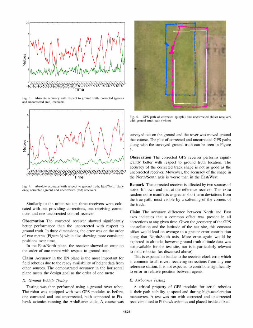
Fig. 3. Absolute accuracy with respect to ground truth, corrected (green)and uncorrected (red) receivers
Fig. 4. Absolute accuracy with respect to ground truth, East/North planeonly, corrected (green) and uncorrected (red) receivers.
Similarly to the urban set up, three receivers were colo-cated with one providing corrections, one receiving correc-tions and one uncorrected control receiver.
Observation The corrected receiver showed significantlybetter performance than the uncorrected with respect toground truth. In three dimensions, the error was on the orderof two metres (Figure 3) while also showing more consistantpositions over time.
In the East/North plane, the receiver showed an error onthe order of one metre with respect to ground truth.
Claim Accuracy in the EN plane is the most important forfield robotics due to the ready availability of height data fromother sources. The demonstrated accuracy in the horizontalplane meets the design goal as the order of one metre
D. Ground Vehicle Testing
Testing was then performed using a ground rover robot.The robot was equipped with two GPS modules as before,one corrected and one uncorrected, both connected to Pix-hawk avionics running the ArduRover code. A course was
Fig. 5. GPS path of corrected (purple) and uncorrected (blue) receiverswith ground truth path (white)
surveyed out on the ground and the rover was moved aroundthat course. The plot of corrected and uncorrected GPS pathsalong with the surveyed ground truth can be seen in Figure5.
Observation The corrected GPS receiver performs signif-icantly better with respect to ground truth location. Theaccuracy of the corrected track shape is not as good as theuncorrected receiver. Moveover, the accuracy of the shape inthe North/South axis is worse than in the East/West
Remark The corrected receiver is affected by two sources ofnoise: It’s own and that at the reference receiver. This extrarandom noise manifests as greater short-term deviations fromthe true path, most visible by a softening of the corners ofthe track.
Claim The accuracy difference between North and Eastaxes indicates that a common offset was present in allcorrections at any given time. Given the geometry of the GPSconstellation and the lattitude of the test site, this constantoffset would lead on average to a greater error contributionalong that North/South axis. More error again would beexpected in altitude, however ground truth altitude data wasnot available for the test site, nor is it particularly relevantto field robotics (as discussed above).
This is expected to be due to the receiver clock error whichis common to all rovers receiving corrections from any onereference station. It is not expected to contribute significantlyto error in relative position between agents.
E. Airbourne Testing
A critical property of GPS modules for aerial roboticsis their path stability at speed and during high-accelerationmanouvres. A test was run with corrected and uncorrectedreceivers fitted to Pixhawk avionics and placed inside a fixed-
1525
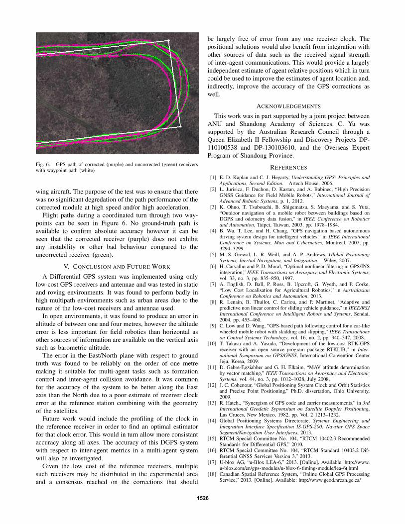
Fig. 6. GPS path of corrected (purple) and uncorrected (green) receiverswith waypoint path (white)
wing aircraft. The purpose of the test was to ensure that therewas no significant degredation of the path performance of thecorrected module at high speed and/or high acceleration.
Flight paths during a coordinated turn through two way-points can be seen in Figure 6. No ground-truth path isavailable to confirm absolute accuracy however it can beseen that the corrected receiver (purple) does not exhibitany instability or other bad behaviour compared to theuncorrected receiver (green).
V. CONCLUSION AND FUTURE WORK
A Differential GPS system was implemented using onlylow-cost GPS receivers and antennae and was tested in staticand roving environments. It was found to perform badly inhigh multipath environments such as urban areas due to thenature of the low-cost receivers and antennae used.
In open environments, it was found to produce an error inaltitude of between one and four metres, however the altitudeerror is less important for field robotics than horizontal asother sources of information are available on the vertical axissuch as barometric altitude.
The error in the East/North plane with respect to groundtruth was found to be reliably on the order of one metremaking it suitable for multi-agent tasks such as formationcontrol and inter-agent collision avoidance. It was commonfor the accuracy of the system to be better along the Eastaxis than the North due to a poor estimate of receiver clockerror at the reference station combining with the geometryof the satellites.
Future work would include the profiling of the clock inthe reference receiver in order to find an optimal estimatorfor that clock error. This would in turn allow more consistantaccuracy along all axes. The accuracy of this DGPS systemwith respect to inter-agent metrics in a multi-agent systemwill also be investigated.
Given the low cost of the reference receivers, multiplesuch receivers may be distributed in the experimental areaand a consensus reached on the corrections that should
be largely free of error from any one receiver clock. Thepositional solutions would also benefit from integration withother sources of data such as the received signal strengthof inter-agent communications. This would provide a largelyindependent estimate of agent relative positions which in turncould be used to improve the estimates of agent location and,indirectly, improve the accuracy of the GPS corrections aswell.
ACKNOWLEDGEMENTS
This work was in part supported by a joint project betweenANU and Shandong Academy of Sciences. C. Yu wassupported by the Australian Research Council through aQueen Elizabeth II Fellowship and Discovery Projects DP-110100538 and DP-130103610, and the Overseas ExpertProgram of Shandong Province.
REFERENCES
[1] E. D. Kaplan and C. J. Hegarty, Understanding GPS: Principles andApplications, Second Edition. Artech House, 2006.
[2] L. Jurisica, F. Duchon, D. Kastan, and A. Babinec, “High PrecisionGNSS Guidance for Field Mobile Robots,” International Journal ofAdvanced Robotic Systems, p. 1, 2012.
[3] K. Ohno, T. Tsubouchi, B. Shigematsu, S. Maeyama, and S. Yuta,“Outdoor navigation of a mobile robot between buildings based onDGPS and odometry data fusion,” in IEEE Conference on Roboticsand Automation, Taipei, Taiwan, 2003, pp. 1978–1984.
[4] B. Wu, T. Lee, and H. Chang, “GPS navigation based autonomousdriving system design for intelligent vehicles,” in IEEE InternationalConference on Systems, Man and Cybernetics, Montreal, 2007, pp.3294–3299.
[5] M. S. Grewal, L. R. Weill, and A. P. Andrews, Global PositioningSystems, Inertial Navigation, and Integration. Wiley, 2007.
[6] H. Carvalho and P. D. Moral, “Optimal nonlinear filtering in GPS/INSintegration,” IEEE Transactions on Aerospace and Electronic Systems,vol. 33, no. 3, pp. 835–850, 1997.
[7] A. English, D. Ball, P. Ross, B. Upcroft, G. Wyeth, and P. Corke,“Low Cost Localisation for Agricultural Robotics,” in AustralasianConference on Robotics and Automation, 2013.
[8] R. Lenain, B. Thuilot, C. Cariou, and P. Martinet, “Adaptive andpredictive non linear control for sliding vehicle guidance,” in IEEE/RSJInternational Conference on Intelligent Robots and Systems, Sendai,2004, pp. 455–460.
[9] C. Low and D. Wang, “GPS-based path following control for a car-likewheeled mobile robot with skidding and slipping,” IEEE Transactionson Control Systems Technology, vol. 16, no. 2, pp. 340–347, 2008.
[10] T. Takasu and A. Yasuda, “Development of the low-cost RTK-GPSreceiver with an open source program package RTKLIB,” in Inter-national Symposium on GPS/GNSS, International Convention CenterJeju, Korea, 2009.
[11] D. Gebre-Egziabher and G. H. Elkaim, “MAV attitude determinationby vector matching,” IEEE Transactions on Aerospace and ElectronicSystems, vol. 44, no. 3, pp. 1012–1028, July 2008.
[12] J. C. Cohenour, “Global Positioning System Clock and Orbit Statisticsand Precise Point Positioning,” Ph.D. dissertation, Ohio University,2009.
[13] R. Hatch., “Synergism of GPS code and carrier measurements,” in 3rdInternational Geodetic Sypomsium on Satellite Doppler Positioning,Las Cruces, New Mexico, 1982, pp. Vol. 2 1213–1232.
[14] Global Positioning Systems Directorate, Systems Engineering andIntegration Interface Specification IS-GPS-200: Navstar GPS SpaceSegment/Navigation User Interfaces, 2013.
[15] RTCM Special Committee No. 104, “RTCM 10402.3 RecommendedStandards for Differential GPS,” 2010.
[16] RTCM Special Committee No. 104, “RTCM Standard 10403.2 Dif-ferential GNSS Services Version 3,” 2013.
[17] U-blox AG, “u-Blox LEA-6,” 2013. [Online]. Available: http://www.u-blox.com/en/gps-modules/u-blox-6-timing-module/lea-6t.html
[18] Canadian Spatial Reference System, “Online Global GPS ProcessingService,” 2013. [Online]. Available: http://www.geod.nrcan.gc.ca/
1526