Live Line Working Tool and Framing Design Innovation
15
[email protected] Live Line Working Tool and Framing Design Innovation A.J. CARREIRA, P.Eng., SMIEEE K-LINE INSULATORS LIMITED CANADA SUMMARY Over the years, many distribution and transmission line pole structures have been constructed using crossarms. Over this same period of time, these crossarms made of wood, steel and fiberglass have deteriorated and various utilities are now finding it necessary to replace them. Some arms are very heavy and difficult to transport and erect, especially in difficult access rights-of way (ROW). Many of the utilities conducting these replacements on transmission lines prefer using live line work (LLW) techniques. In order to use this work method, it is necessary to “park” the live conductors. Unfortunately, some line spans are long and the conductor weights become too heavy to be supported temporarily by conventional live line tools (LLT). These challenges inspired the development of new tools and crossarms that would eliminate most of the issues raised above. This opportunity led to the development and design of the K-ARM ® tool and the Totally Insulated Framing (TIF ® ) arrangements discussed in this paper. These new designs not only address the issues discussed above but offer new features not possible with conventional tools and crossarm framings. These new designs facilitate safer and more efficient work methods. All of the K-ARM ® and the TIF ® designs incorporate existing and well proven silicone insulator products and proprietary materials technology. These materials are lightweight and facilitate reduced framing installation time and cost. The silicone insulator materials used will eliminate current crossarm material deterioration issues and other related problems. The materials will also result in increased life expectancy of the framing arrangement. The higher mechanical load capacity of the K-ARM ® tool design overcomes the issues experienced as a result of the conventional weaker LLT capabilities. Some of the TIF ® designs offer an opportunity to increase line clearances and/or line operating current capacity using the existing pole structures and conductor. On new line construction, these designs promote the use of shorter poles and can result in a reduced right-of-way (ROW) width requirement. Using the transmission TIF ® designs will also eliminate the need to use suspension insulators. Totally Insulated Framings discourage bird nesting and other animal issues. The framing designs have been modeled using PLS CADD and have demonstrated their ability to support the line loads expected under every day loading conditions. The framings have also been physically mechanically tested under varying loading conditions to confirm the modelling results. CIGRE-305 2020 CIGRE Canada Conference Toronto, Ontario, October 19-22, 2020
-
Upload
khangminh22 -
Category
Documents
-
view
4 -
download
0
Transcript of Live Line Working Tool and Framing Design Innovation

Live Line Working Tool and Framing Design Innovation A.J. CARREIRA, P.Eng., SMIEEE
K-LINE INSULATORS LIMITED
CANADA
SUMMARY
Over the years, many distribution and transmission line pole structures have been constructed using
crossarms. Over this same period of time, these crossarms made of wood, steel and fiberglass have
deteriorated and various utilities are now finding it necessary to replace them. Some arms are very
heavy and difficult to transport and erect, especially in difficult access rights-of way (ROW).
Many of the utilities conducting these replacements on transmission lines prefer using live line work
(LLW) techniques. In order to use this work method, it is necessary to “park” the live conductors.
Unfortunately, some line spans are long and the conductor weights become too heavy to be supported
temporarily by conventional live line tools (LLT).
These challenges inspired the development of new tools and crossarms that would eliminate most of
the issues raised above. This opportunity led to the development and design of the K-ARM® tool and
the Totally Insulated Framing (TIF®) arrangements discussed in this paper.
These new designs not only address the issues discussed above but offer new features not possible
with conventional tools and crossarm framings. These new designs facilitate safer and more efficient
work methods. All of the K-ARM® and the TIF® designs incorporate existing and well proven silicone
insulator products and proprietary materials technology. These materials are lightweight and facilitate
reduced framing installation time and cost. The silicone insulator materials used will eliminate current
crossarm material deterioration issues and other related problems. The materials will also result in
increased life expectancy of the framing arrangement.
The higher mechanical load capacity of the K-ARM® tool design overcomes the issues experienced as
a result of the conventional weaker LLT capabilities.
Some of the TIF® designs offer an opportunity to increase line clearances and/or line operating current
capacity using the existing pole structures and conductor. On new line construction, these designs
promote the use of shorter poles and can result in a reduced right-of-way (ROW) width requirement.
Using the transmission TIF® designs will also eliminate the need to use suspension insulators. Totally
Insulated Framings discourage bird nesting and other animal issues.
The framing designs have been modeled using PLS CADD and have demonstrated their ability to
support the line loads expected under every day loading conditions. The framings have also been
physically mechanically tested under varying loading conditions to confirm the modelling results.
CIGRE-305 2020 CIGRE Canada Conference
Toronto, Ontario, October 19-22, 2020

1
The new framing equipment and materials discussed offer new opportunities for electric utility and
contractor operations personnel to effectively and safely meet these challenging maintenance and
system performance requirements. Since the TIF® framings require significantly less labour to erect
compared to traditional cross-arms, line crew work activity exposure (energized or de-energized) is
greatly reduced.
These innovative framing designs can be used to retrofit existing conventional line framings, they can
be used in new line construction and they can be used as emergency restoration components. These
design arrangements can be customized to suit most structure or conductor spacing and framing
requirements.
The K-ARM® as well as the distribution and transmission line TIF® systems are proven to provide
many advantages and benefits. These include installed cost reduction as well as life cycle cost savings
over conventional LLT and conventional crossarm arrangements.
KEYWORDS
crossarms; totally insulated framing; TIF®; live line tools; K-ARM®
2
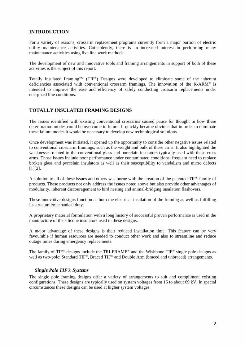
INTRODUCTION
For a variety of reasons, crossarm replacement programs currently form a major portion of electric
utility maintenance activities. Coincidently, there is an increased interest in performing many
maintenance activities using live line work methods.
The development of new and innovative tools and framing arrangements in support of both of these
activities is the subject of this report.
Totally Insulated Framing™ (TIF®) Designs were developed to eliminate some of the inherent
deficiencies associated with conventional crossarm framings. The innovation of the K-ARM® is
intended to improve the ease and efficiency of safely conducting crossarm replacements under
energized line conditions.
TOTALLY INSULATED FRAMING DESIGNS
The issues identified with existing conventional crossarms caused pause for thought in how these
deterioration modes could be overcome in future. It quickly became obvious that in order to eliminate
these failure modes it would be necessary to develop new technological solutions.
Once development was initiated, it opened up the opportunity to consider other negative issues related
to conventional cross arm framings, such as the weight and bulk of these arms. It also highlighted the
weaknesses related to the conventional glass and porcelain insulators typically used with these cross
arms. Those issues include poor performance under contaminated conditions, frequent need to replace
broken glass and porcelain insulators as well as their susceptibility to vandalism and micro defects
[1][2].
A solution to all of these issues and others was borne with the creation of the patented TIF® family of
products. These products not only address the issues noted above but also provide other advantages of
modularity, inherent discouragement to bird nesting and animal-bridging insulation flashovers.
These innovative designs function as both the electrical insulation of the framing as well as fulfilling
its structural/mechanical duty.
A proprietary material formulation with a long history of successful proven performance is used in the
manufacture of the silicone insulators used in these designs.
A major advantage of these designs is their reduced installation time. This feature can be very
favourable if human resources are needed to conduct other work and also to streamline and reduce
outage times during emergency replacements.
The family of TIF® designs include the TRI-FRAME® and the Wishbone TIF® single pole designs as
well as two-pole; Standard TIF®, Braced TIF® and Double Arm (braced and unbraced) arrangements.
Single Pole TIF® Systems
The single pole framing designs offer a variety of arrangements to suit and compliment existing
configurations. These designs are typically used on system voltages from 15 to about 69 kV. In special
circumstances these designs can be used at higher system voltages.

3
The TRI-FRAME® design (Figure 1) was developed as an enhanced replacement for the conventional
single circuit, single pole crossarm or even delta shape configured side bracket framings.
Figure 1 - TRI-FRAME TIF®
A Wishbone TIF® framing configuration (Figure 2) was also developed to meet the needs of a specific
Utility. However, the design has also found favour with other utilities who have also used the
conventional wishbone design in the past.
Figure 2 - Wishbone TIF®
These single pole designs are all supplied as factory-assembled one-piece framings and are relatively
light weight (Figure 3).
Figure 3: Lightweight Characteristics of the TIF® Designs
Availability of human resource time is of critical importance to most utilities. A major feature of the
TRI-FRAME® design is that it can be installed within about 6 minutes. This is quite a short erection
time when compared to the approximate forty minute framing time for a conventional crossarm
arrangement. This immense savings in time can be then reallocated to conduct other important
maintenance and construction activities.

4
The quick installation of this type of framing was very clearly demonstrated during an early-on trial
installation at a Canadian utility training school in the province of Alberta. Line staff from other
utilities also attend the demonstration and were quite impressed with the ease of installation (Figure 4).
Figure 4: Trial Installation Demonstration
The stringing methods used with the new TIF® are exactly the same as used with conventional framing
construction. As illustrated in Figure 5, conventional line stringing equipment is also the norm for use
with these new framing designs.
Figure 5: Distribution TRI-FRAME® with Stringing Equipment
The TRI-FRAME® design is normally shipped individually crated as illustrated in Figure 6. Special
packaging arrangements can also be accommodated, if required.
Figure 6: Standard TRI-FRAME® Shipping Crate

5
Transmission Line TIF® Systems
These new two pole transmission framing designs can be used to replace any existing standard
arrangements including H-Frame and Gulfport construction. These designs are typically used on
system voltages up to about 230 kV. In special circumstances these designs can be used at higher
system voltages. A typical replacement using a TIF® framing is demonstrated over the ghosted
conventional H-Frame arm in Figure 7.
Figure 7: Transmission Totally Insulated Framing
The lightweight and modularity features of these transmission designs make them especially popular
for installation in difficult to access ROW. These components can be easily transported to the work
location without the need for expensive heavy transportation and erection equipment such as
helicopters and cranes. The use of these TIF® designs can offer other unique benefits when compared
to the installation of conventional two pole crossarms.
A significant attribute of Totally Insulated Framings is the inherent ability to increase vertical line to
ground and underbuild clearances on existing lines. This is attributed to the elimination of the need for
suspension insulators or insulator strings (refer to Figure 8). This TIF® feature offers an opportunity to
improve or correct clearance violation issues.
Figure 8: Transmission TIF® Facilitates Clearance or Sag Increases
Alternatively, if clearance is not a problem, TIF® creates an opportunity to increase line sags, which in
turn allows for higher operating currents and increased capacity of existing lines. This uprating of
capacity can actually increase the value of the asset without the need to replace conductors or
structures.

6
An example of a potential line capacity increase is illustrated in Figure 9 for a 115 kV line.
Figure 9: Example: Operating Current & Line Capacity Increase
The opportunity to increase line sag by about one meter on a 115 kV line, as demonstrated above, is
attributed to the elimination of the suspension insulator strings.
When using TIF® arrangements to build new lines, the line design engineer is able to specify the use of
shorter poles. The pole height length reduction is equivalent to the suspension insulator string length
that would normally be required for a conventional crossarm framing for each specific voltage system.
Another attribute of these new designs is the opportunity to build compact lines by virtue of the
elimination of the suspension insulator strings. As explained above, not only is it possible to have lines
with lower heights; they can also have smaller foot prints. A smaller foot print also means a narrower
ROW. The latter is possible because elimination of the suspension insulator strings also eliminates the
conductor swing component attributed to those insulators (Figure 10).
Figure 10: Conventional Framing Insulator Swing/Displacement
System Voltage: 115 kV
Span: 200 meters
Ampacity @ 50°C : 160 A
Sag @ 50°C : 5.01 m (16.42’)
Ampacity @ 127°C : 861 A
Sag @ 127°C : 6.02 m (19.74’)
Ampacity increase : 538%
Sag Difference : 1.01 m

7
If an existing line has some excess ground and underbuild clearance it may be possible to convert the
conventional single crossarm structure to a double circuit crossarm framing (Figure 11).
Figure 11: Transmission TIF® Double Circuit Structure
There is no doubt that the ability to reconfigure an existing single circuit line in this fashion will also
greatly increase the asset value of that line.
Unbraced TIF® designs are typically the first option to consider. However, for longer line spans with
larger conductors it is possible to use a braced design option (Figure 12).
Figure 12: Transmission Braced TIF® System
The braced TIF® option can add an increased line vertical load capability of up to 80% of the unbraced
arm strength. The angle between the brace and the line post will determine the maximum permitted
specific load capability [3]. In some cases, the braced system will also allow designing lines with
longer spans. This approach to line design can result in the erection of much fewer structures and
therefore a much lower line construction cost. Other cost savings are a result of the reduced
installation time of these designs compared to the installation of a conventional H-Frame crossarm. In
one installation the erection time of the TIF® was about 22 minutes. Two installations are
demonstrated in Figure 13.
Electric Utility Training Facility Installation in Ontario, Canada Demonstration at ESMO 2016, USA
Figure 13: Transmission Totally Insulated Framing Installations
All of the designs described above can be installed using live line work methods.
8
PLS POLE MODELING
The framing designs have been modeled using PLS Pole and have demonstrated their ability to
support the line loads expected under every day loading conditions. The framings have also been
physically mechanically tested under varying loading conditions to confirm the simulated results.
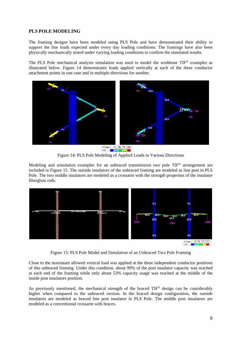
The PLS Pole mechanical analysis simulation was used to model the wishbone TIF® examples as
illustrated below. Figure 14 demonstrates loads applied vertically at each of the three conductor
attachment points in one case and in multiple directions for another.
Figure 14: PLS Pole Modeling of Applied Loads in Various Directions
Modeling and simulation examples for an unbraced transmission two pole TIF® arrangement are
included in Figure 15. The outside insulators of the unbraced framing are modeled as line post in PLS
Pole. The two middle insulators are modeled as a crossarm with the strength properties of the insulator
fiberglass rods.
Figure 15: PLS Pole Model and Simulation of an Unbraced Two Pole Framing
Close to the maximum allowed vertical load was applied at the three independent conductor positions
of this unbraced framing. Under this condition, about 99% of the post insulator capacity was reached
at each end of the framing while only about 53% capacity usage was reached at the middle of the
inside post insulators position.
As previously mentioned, the mechanical strength of the braced TIF® design can be considerably
higher when compared to the unbraced version. In the braced design configuration, the outside
insulators are modeled as braced line post insulator in PLS Pole. The middle post insulators are
modeled as a conventional crossarm with braces.

9
A PLS Pole model of the braced transmission two pole TIF® design is included in Figure 16.
Figure 16: PLS Pole Simulation of a Braced Two Pole Framing
When a 100% allowed vertical load was applied at the two outside braced post insulator conductor
positions of this framing, only about 55% of the capacity of the middle of the inside post insulators
position was used. The maximum vertical load capacity of this braced framing is much higher than
that of its unbrace equivalent.
In addition to determining the vertical loads, it was also possible to simulate the results of applying
longitudinal and transverse loads.
MECHANICAL TESTING
The use of PLS Pole was quite valuable in predicting the mechanical load capabilities of each of the
various TIF® designs. However, it is also necessary to mechanically test the framings to confirm those
expected results. Tests were performed to establish the maximum longitudinal, vertical and transverse
load capabilities of each framing design.
A schematic of some of the set ups to test the distribution TRI-FRAME TIF® is included in Figure 17.
Figure 17: Distribution TIF® Mechanical Loading Layout

10
The following photographs (Figure 18) derived from test reports demonstrate how the loads are
applied for the vertical and transverse loading directions, at each loading position.
Transverse Loading Direction
Vertical Loading Direction
Figure 18: Distribution TIF® Mechanical Test Set Ups
A series of photographs demonstrating the mechanical testing of a Wishbone TIF® design are included
in Figure 19.
Figure 19 : Mechanical Testing of a Wishbone TIF® Design
The vertical test illustrated above was performed on the KL69P1WBTIFT framing design. In this case,
the vertical applied loads reached a maximum strength equivalent to 191% of maximum design
vertical load (MDVL) requirements for this configuration. While there was some bending of the
insulator rod as well as displacement at the framing bolt connection points, there was no actual
mechanical destruction of the framing.
When a transverse load was applied to this same framing design, it reached a maximum capacity
equivalent to about 214% of maximum design transverse load (MDTL) requirements. During this test
there was evidence of minor bending of the insulator rod at the load application points as well as
minor displacement at the framing connections.
There was no actual fracture of the framings themselves during any of the testing conducted.

11
Finally, one of the test set up arrangements for the Transmission Line TIF® Systems is included in
Figure 20.
Figure 20: Transmission TIF® Mechanical Loading Layout – Mid Connector Plate Assembly
Figure 21 shows the test results for the two pole framing mid connector plate assembly.
Mid Connector Plate Assembly Test Mid Connector Assembly Close Up After Test
Figure 21: Transmission TIF® Mechanical Load Test
It is evident from the photographs, that the mid connector plate assembly withstood the testing without
any damage, such as cracks or even deformation.
All testing indicates that the framings can exceed the typical mechanical load requirements without
failure.
K-ARM® LIVE LINE TOOL
As previously discussed, many early electric utility structure designs were composed of two wood
poles and some form of crossarm framing arrangement. As replacements of these crossarms become
more prevalent, there is a frequent need to take these lines out of service to perform the replacements.
Coincidently, there appears to be a resurgence in interest to conduct more and more power line work
activities using live line work methods [4]. These two situations created an interest in developing a
special tool configuration and components that would make performing transmission line crossarm
replacements easier, more efficient and safer.

12
It was quite evident that any new tooling would need to be designed in a manner necessary to
overcome some of the deficiencies experienced with existing live line tooling. This would include the
capability to support heavy vertical conductor loads. Other key considerations in the development of
this device included the requirements that the tool be able to maintain its electrical characteristics,
even when exposed to inclement weather conditions, as well as being as lightweight as possible. These
two features are critical when having to move the tooling into hard to access work locations or having
to leave the tool in-service for longer periods of time or when the weather turns to rain or snow.
The tool design developed to overcome current design weaknesses is the K-ARM®. A close up of the
115 kV system voltage rating version of this tooling is illustrated in Figure 22.
Figure 22: 115 kV K-ARM® Tool
The tool is designed to be modular for easy storage and transportation. The configurations of this
design include features that permit securing it directly to the work structure using through bolts or
strap binders that can be attached to eye nuts mounted on the base of the tool. The tools can be used
universally with wood poles, concrete poles, steel poles or with fiberglass poles.
A key feature of this tool design is that it is constructed with the “original” K-CLAMP® universal
clamp. This component complete with an eye nut, is extremely versatile and easy to operate using live
line sticks and can accommodate a broad range of conductor diameters.
As illustrated in Figure 23, the tool is also supplied with a brace insulator which when used with the
tool, can increase its vertical load carrying capacity by up to 80%, in some cases.
Figure 23: Braced and Unbraced K-ARM® Options
The tool is composed of insulators manufactured using a proprietary, state of the art and well proven
silicone rubber formulation. Because these insulators exhibit excellent hydrophobic surfaces, they
have the ability to perform as well or better than any insulator currently installed on the line, even
under wet conditions.

13
An illustration of the use of the tool during a temporary conductor relocation is included in Figure 24.
Figure 24: Relocating Conductor to K-ARM®
Because the tool is used under live conditions, it must be electrically tested when first purchased and
periodically, as required. The test set up and actual testing are represented in Figure 25.
Figure 25: Preconditioning and electrical testing of the insulators used in the K-ARM®
Just as any other tool used under energized working conditions, the K-ARM® must be kept dry and
clean at all times. To ensure these tools are kept protected during storage and transportation, they are
supplied in hard shell cases similar to that in Figure 26.
115 kV Kit 230 kV Kit
Figure 26: K-ARM® Protective Cases

14
CONCLUSIONS
The current crossarm replacement programs at many utilities have generated an opportunity to develop
improved designs that will address many of the deficiencies currently experienced with existing
conventional framings. The creation of a variety of TIF® designs for both single and twin pole structures
for voltage systems up to 230 kV, are discussed in this paper.
The designs have been simulated and analyzed through the use of PLS Pole and tested to ensure they meet
the rigours of successful operation in the field.
During the development of these designs, it was discovered that many utilities are interested in doing more
and more maintenance and line upgrade work using live line work techniques and equipment. In fact,
some utilities have expressed a desire to conduct crossarm replacements using these live line work
methods whenever possible.
This created another opportunity for innovation and stimulated the development of the K-ARM®. This tool
design approach not only created an easy to use and efficient time saving device, but it also addressed pre-
existing issues with conventional tooling used in this manner.
The design and development of the TIF® and the K-ARM® offer utilities a combined opportunity to
benefit from installed cost savings as well as a better performing distribution and transmission system.
BIBLIOGRAPHY
[1] A.J. Carreira, “Insulator Inspection”, 2015 INMR World Congress, Munich, Germany, October 18-21,
2015.
[2] A.C. Baker, R.A. Bernstorf, E.A. Cherney, R Christman, R.S. Gorur, R.J. Hill, Z. Lodi, S. Marra, D.G
Powell, A.E. Schwalm, D.H. Shaffner, G.A. Stewart and J. Varner, “High Voltage Insulators Mechanical
Load Limits-Part I Overhead Line Load annd Strength Requirements”, IEEE TPWRD-00043-2011,
January 2011.
[3] A.C. Baker, “Design and Application of Braced High Voltage Insulator Assemblies”, DEIS IEEE
Electrical Insulating Magazine, March/April 2010.
[4] A.J. Carreira, P. Komaromi, “State of the Art Transmission Live Line Maintenance and Techniques”.
CEATI TLAM Report #T183700-3276, February 2020.