list of makesof sub-vendor items
40
AIR CONDITIONING SYSTEM LIST OF MAKES OF SUB-VENDOR ITEMS-AS APPLICABLE 1.1 P 56 ROTAMETER CHEMTROLS SAMIL / EUREKA IND / IL / TRANSDUCERS AND CONTROL 57 BATTERY CHARGER AMARARAJA/ CHHABI ELECTRICAL / DUBAS ENGG. / HBL POWER SYSTEM / STATCON / CALDYNE 58 BATTERY (NI -Cd) HBL POWER / AMCO SAFT / SAFT NOTE Above sub-vendor are also subjected to Customer approval during detailed engineering. 708 of 766
-
Upload
khangminh22 -
Category
Documents
-
view
1 -
download
0
Transcript of list of makesof sub-vendor items

AIR CONDITIONING SYSTEM
LIST OF MAKES OF SUB-VENDOR ITEMS-AS APPLICABLE
1.1
P
56 ROTAMETER CHEMTROLS SAMIL / EUREKA IND / IL / TRANSDUCERS AND CONTROL
57 BATTERY CHARGER AMARARAJA/ CHHABI ELECTRICAL / DUBAS ENGG. / HBL POWER SYSTEM / STATCON / CALDYNE
58 BATTERY (NI -Cd) HBL POWER / AMCO SAFT / SAFT NOTE
Above sub-vendor are also subjected to Customer approval during detailed engineering.
708 of 766

VENTILATION SYSTEM
LIST OF MAKES OF SUB-VENDOR ITEMS-AS APPLIACBLE
1.1
P
LIST OF MAKES OF SUB-VENDOR ITEMS
709 of 766

VENTILATION SYSTEM
LIST OF MAKES OF SUB-VENDOR ITEMS-AS APPLIACBLE
1.1
P
S.No. Description Makes
1.
AIR WASHER & UAF* HYDERABAD POLUTION CONTROL / SK SYSTEM / ADVANCE VENTILATION / DRAFT AIR / BLUE STAR / VOLTAS / STERLING WILSON & ROOTS COOLING SYSTEM / C.DOCTOR
2. AIR HANDLING UNITS 3.
CENTRIFUGAL FAN FLAKT / KRUGGER / DRAFT AIR / HYDERABAD POLUTION CONTROL / ADVANCE VENTILATION / PATEL AIR / NICOTRA/ SK SYSTEM / MARATHON / CB DOCTOR / SARLA
4. AXIAL FLOW FANS/RE UNITS
HYDERABAD POLLUTION/ SK SYSTEM / ADVANCE VENTILATION / KRUGER / NICOTRA / MARATHON / FLAKT / CB DOCTOR/ PATEL AIR /SITAL
5. FAN FLAKT WOODS/ KRUGER/ ANDREW YULE/ AEROTHERM/
DUVENT/ SIWENT ( SARLA)/ S.R PRAYAVARAN/ GEC( Alstom) 6.
CENTRIFUGAL WATER PUMP
BEST & CROMPTON / JYOTI / SAM TURBO / KBL / KSB / M&P / VOLTAS / BEACON-WEIR / WORTHINGTON / FLOWMORE / SULZER / BHARAT PUMPS & COMPRESSORS LTD / FLOWSERVE INDIA CONTROL PVT LTD / V-FLOW PUMPS & SYSTEMS CO
7. INDUCTION MOTORS (LT) SIEMENS / ABB / CGL / MARATHON / KEC / BHARAT BIJLEE /
NGEF /JYOTI / LHP/ KIRLOSKAR/ G.E.C. 8.
AIR FILTER PUROLATOR / FMI / ANFILCO / TENACITY / JOHN FOWLER /SPECTRUM / AIR TECH / PUROMATIC/ CHEMFARM/ KIRLOAKAR/ CLEAR AIR PUROFIL/ DYNA
9. INSULTATION MATERIAL BEARDSHELL / K-FLEX / PARAMONT/ ARMAFLEX / SUPREME /
LLOYDS / UP TWIGA 10. RESIN BOUNDED FIBRE
GLASS UP TWIGA/ CLYOL/ COOLINE
11. FIRE DAMPER TSC / CARRYAIRE / RAVISTAR (SYSTEM AIR ) 12.
BUTTERFLY VALVE AUDCO / FOURESS / INTER VALVE / BDK / WEIR BDK / TYCO / CRANE PROCESS / KEYSTONE
13. NON RETURN VALVE LEADER / H.SARKAR / FLUID LINE / HI -TECH / CRESENT / A V
VALVES / BANKIM & COMPANY / SHIVADURGA 14.
GATE/GLOBE VALVES CRESENT / BDK / AUDCO / FOURESS / KIRLOSKAR / SANT / BOMBAY METAL & ALLOYS / BANKIM / LEADER / H SARKAR / AV VALVES / VENUS PUMPS AND ENGG
15. PIPING - ERW SURYA ROSHNI / TISCO / DADU PIPES / INDUS TUBE / WELSPUN /
TATA / BST / JINDAL / SAIL 16.
GI SHEETS FOR DUCTING TISCO / INDIAN IRON & STEEL CO LTD. / RASHITRYA ISPAT NIGAM LTD. / ESSAR/ ISPAT INDUSTRIES / JSW STEEL / LLOYDS STEEL / BHUSHAN / TATA / SAIL / JINDAL/ NIPPON
17. HUMID STAT JHONSON CONTROL / HONEYWELL / PENN 18. GRILLES/ DIFFUSERS MOOSA HAJI/ NUTECH/ COSMOS/ OPELLA/ CARYAIRE 19.
PRESSURE GAUGE
GENERAL INST CONSORTIUM / BELL / H.GURU INST / WAAREE INSTRUMENTS / H. GURU IND / FORBES MARSHALL / MANOMETER / A.N. INST / GAUGES BOURDON / GLUCK / WIKA / ASHCROFT / BAUMER TECHNOLOGIES/PRECISION MASS PRODUCTS/ BOSE PANDA/ FIEBIG/ JAPSIN/ MICA
710 of 766

VENTILATION SYSTEM
LIST OF MAKES OF SUB-VENDOR ITEMS-AS APPLIACBLE
1.1
P
20. THERMOSTATS H.GURU/ FIEBIG/ JAPSIN/ MICA/ PENN/ HONEYWELL 21.
TEMPERATURE GAUGE
H. GURU IND/ H.GURU INST/ FORBES MARSHALL/DETRIVE INST & ELECTRONICS / PYRO ELECTRIC /TOSHNIWAL BROSS / WAREE INSTRUMENTS / A.N.INST / GOA INSTRUMENTS / WIKA/ ASHCROFT / H GURU (SI)/ BAUMER TECHNOLOGIES/ GAUGE BOURDON/ GOA THERMOSTAT/ BUDENBERG GAUGE/ PRECISION MASS PRODUCTS
22.
LEVEL GAUGE
GENERAL INSTRUMENTS / CHEMTROLS / SBEM, PUNE/ AUTOMAT MUMBAI /SIGMA / TOSHNIWAL / TECHNOMATIC / TELACO /LEVCON / D K INSTRUMENTS / PUNE TECHTROL / FLOW STAR/ BLISS ANAND
23. PRESSURE SWITCH / DP SWITCHES
BELLS / DANFOSS / DK INSTRUMENTS/ DRESSER / SOR INC / VASU / SWITZER / INDFOSS / TRAFAG / GIC / ASHCROFT/ KASTURBA UDYOG/ BARKSDALE/ PRECISION MASS/ MITTAL REFRIGERATION
24.
LEVEL SWITCH
SBEM / BLISS ANAND / HI TECH / RAMAN INST / SIGMA / SOR INC / WAREE INST / LEVCON / DK INSTURMENT / V AUTOMAT /CHEMTROLS / SIMENS / FLOW STAR / TRAC/ NIVO CONTROLS/ PUNE TECHTROLS/ SAPCON INSTRUMENTS/ BAUMER TECHNOLOGIES/ GIC
25.
Y / POT STRAINER
MULTITEX / GREAVES COTTON / JAYPEE / SANT / OTOKLIN / GRAND PRIX / GUJARAT OTOLIFT / DS ENGG / SAROJINI ENTERPRISE / BHATIA ENGINEERING / FILTERATION ENGINEERS INDIA PVT LTD / SUNGOV ENGINEERING
26.
CONTROL PANEL INDUSTRIAL CONTROL & APPLIANCE/ PYROTECH /POSITRONICS / CONTROL & SWITCHGEAR /SIEMENS / L&T /GE POWER /RITTAL / HOFFMAN
27. SWITCHGEAR (MCCB, CROMPTON/ SIEMENS/ ABB/ L&T CONTRACTORS ETC.) 28.
CABLES FINOLEX/ NICCO/ UNIVERSAL CABLES/ GRANDLEY/ CCI/ POLYCAB/ FORT GLOSTER
NOTE * Designed by C. Doctor / Blue Star / Voltas / Hyderabad Pollution Controls / SK System
/Advance Ventilation / Draft Air / Sterling & Wilson / Roots cooling and fabricated by their approved fabricators.
Above sub-vendor are also subjected to Customer approval during detailed engineering.
711 of 766

4x111MW VISHNUGAD PIPALKOTI HEP
HVAC MANDATORY SPARE LIST
SPECIFICATION No: PE-TS-413-571-11000A-A001
SECTION : I
SUB-SECTION : E
REV 00 DATE: JAN 2020
SHEET
1.1
P
SECTION-I SUB SECTION -E
ANNEXURE-II
MANDATORY SPARE LIST
712 of 766

A VENTILATION SYSTEM
1 Bearings for each type of fan Set 2
2 Bearings set for each type of electric motor Set 2
3 V-Belts / Flexible coupling for each type of fan Set 2
4 Filter element Sets 2
5 Water Cooler Set 1
B AIR CONDITIONING SYSTEM
B1 Ductable Splt AC
1 Fan-motor bearing for outdoor unit & indoor unit Set 2
2 Filter Set 2
3 Expansion valve Set 2
B2 Non- Ductable Split AC
1 Fan-motor bearing for outdoor unit Set 2
2 Filter Set 2
3 Expansion valve Set 2
C ELECTRICAL SPARES
1 Spare cable lengths of each type and size of power cables used
2 Cable racks, trays, supports, embedment plats, conduits etc.
3 Other Accessories:
Termination kits for each type and size of cable Sealing ends / glandsfor each cable size Cable lugs for each type ands size of cable Pre-fabricated straight through joints for each type and size of cablesCable marker ferrules Self adhesive marker Aluminium stripsCouplings, elbow plates, G.I. flats, brackets, rock bolts etc. (for eachtype)
4 415V completely assembled ACBs
5 415 V MCCBs
6 240 V AC, MCBs
7 220V DC MCBs
8 Spares for ACBs -1No. Each of following
i) i) Main Contacts
ii) ii) Arcing contacts
iii) iii) Trip coils
iv) iv) Closing coils
v) v)Spring charging
vi) vi) Closing & tripping springs
vii) vii) Auxiliary contact assembly
viii) viii) Local/Remote selector
6 Relays
7 7. CTs
8 8. PTs
9 9. Voltmeters
10 10. Ammeters
11 11. KWH meters
ANNEXURE - IILIST OF MANDATORY SPARES
4 sets of each ratings
5% of the total cable length but at least one length equal to the longest cable length used in the scope.
5% of the total scope of quantities of each type & size
5% of the total scope of each accessory but not less than 2pcs. of each item
10% of each type but not less than one
10% of each type but not less than one
10% of each type but not less than one
10% of each type but not less than one
5 sets of each rating
5 sets of each rating
10 nos. of each rating
10 nos. of each rating
6 nos. for each rating mechanism complete with motors
S. No. DescriptionUNIT Qty
6 nos. of each rating
4 Nos. of each rating switch
2 nos. of each type
2 set of each rating
2 set of each rating
2 nos.
6 nos.
6 nos.
713 of 766

12 12. Glass covers for relays with rubber gaskets
13 13. Glass covers for measuring instruments with rubber gaskets
14 14. Indicating lamps
15 15. Indicating lamp assembly
16 16. Glass dome covers of different colours
17 Fuse units
18 Push buttons
19 Contactors
20 Timers
21 Terminal blocks
22 Brass screws
23 Spring washers
24 Ferrules
25 Auto-manual switches
26 Bus bar supporting insulators with fittings
27 Strip heaters
28 Thermostats for heaters
D C&I SPARES
1 Measuring transmitter of type / model used
2 Sensors/transducers of type and model used
3 Indicating instruments of type/model used
4 Relays of type/model used
5 Indicating Instruments
6 Control Switch, Selector Switches, Push Buttons, Indicating
7 Bulbs for indicating lamps
8 Heating resistor for thermostat for cubicle heater
9 Operator Key board
10 Terminals of each type
11 Fuses of each type
Notes:a) Spares listed in Price Schedule is bare minimum requirement. In case any additional mandatory spares required for 5 years of successful operation of the system or those covered elsewhere in the tender specification apart from specified above, same shall be deemed to have been covered in bidder’s scope of supply.
b) One set corresponds to actual quantity of components and devices as installed for one equipment/item/assembly.
c) All Spares shall be supplied as per the requirement of the specifications. In case any spare indicated in the specification is “not applicable” for particular equipment, then suitable applicable alternate spare has been offered / shall be supplied by the bidder without any financial implication." d) Any item which is quoted as “not applicable” by the bidder in the above list and is found to be “applicable” at a later date shall be supplied by the bidder without any commercial and delivery implication.e) Any cell left blank in the unpriced schedule shall be treated as “Quoted” and is included in total price.
200 each type
6 nos.
02 sets of each type
02 sets of each type
02 sets of each type
02 sets of each type
01 set of each type
20 % of each type
20 % of each type
02 sets of each type
One
200
200 nos.
12 nos.
500 nos. of each colour
100 sets of each rating
100 nos. of each shade
12 nos. of each rating
12 nos.
50 nos.
50 packets of each size
50 packets of each size
1000 nos. of each size
12 nos.
30 nos.
200 nos. (W/O lamp)
6 nos. of each size
6 nos. of each size
714 of 766

4x111MW VISHNUGAD PIPALKOTI HEP
HVAC SYSTEM LIST OF TOOLS & TACKLES
SPECIFICATION No: PE-TS-413-571-11000A-A001
SECTION: I
SUB-SECTION : E
REV 00 DATE: JAN 2020
SHEET 1 OF 2
1.1
P
SECTION-I
SUB-SECTION-E
ANNEXURE-III
LIST OF TOOLS & TACKLES
715 of 766

4x111MW VISHNUGAD PIPALKOTI HEP
HVAC SYSTEM LIST OF TOOLS & TACKLES
SPECIFICATION No: PE-TS-413-571-11000A-A001
SECTION: I
SUB-SECTION : E
REV 00 DATE: JAN 2020
SHEET 2 OF 2
1.1
P
SL NO ITEM DESCRIPTION UNIT QTY 1 FLAT D WRENCH - 6 MM TO 32 MM (12 Pcs) SET 1 2 BOX WRENCHES - 6 MM TO 22 MM (14 Pcs) SET 1 3 RING SPANNER - 6 MM TO 32 MM (12 Pcs) SET 1 4 ALLEN KEYS - 2 MM TO 10 MM SET 1 5 CRESCENT SCREW SPANNER NO. 1 6 SCREW DRIVER NO. 1 7 OFFSET SCREW DRIVER NO. 1 8 INSULATED PLIER NO. 1 9 TORCH LIGHT FOR 2 CELL NO. 1
10 HAMMER 1 LB NO. 1 11 OIL CAN NO. 1 12 POCKET THERMOMETER - 0 TO 50 DEG. C) NO. 1 13 INSULATION TAPE ROLL NO. 1 14 STEEL FOOT RULE - 12" NO. 1 15 FEELER GAUGE 9 BLADES NO. 1 16 PIPE WRENCH NO. 1 17 FLARE NUT (1/4") NOS. 6 18 FLARING TOOL NO. 1 19 TUBE CUTTER NO. 1 20 GAS CHARGING PIPE NO. 1 21 NITOGEN CHARGING ADAPTER NO. 1 22 FREON PRESSURE GAUGE (2 1/2" DIA DIAL) ) 0 - 300 MM PSI NO. 1
23 FREON PRESSURE GAUGE (2 1/2" DIA DIAL) ) 30 - 150 MM PSI NO. 1 24 PSYCHRO METER NO. 1 25 LOCK WITH KEY FOR TOOL BOX NO. 1 26 RATCHET 1/4" NO. 1 27 MS TOOL BOX NO. 1
716 of 766

4x111MW VISHNUGAD PIPALKOTI HEP
HVAC SYSTEM DRAWINGS / DOCUMENTS SUBMISSION PROCEDURE
SPECIFICATION No: PE-TS-413-571-11000A-A001
SECTION : I
SUB-SECTION : E
REV 00 DATE: JAN 2020
SHEET 1 OF 1
1.1
P
SECTION-I
SUB-SECTION-E
ANNEXURE-IV
DRAWINGS / DOCUMENTS SUBMISSION PROCEDURE (COVERED UNDER SECTION C2-B)
717 of 766

4x111MW VISHNUGAD PIPALKOTI HEP
HVAC SYSTEM MASTER DRAWING LIST WITH
SCHEDULE OF SUBMISSION
SPECIFICATION No: PE-TS-413-571-11000A-A001
SECTION : I
SUB-SECTION : E
REV 00 DATE: JAN 2020
SHEET 1 OF 3
1.1
P
SECTION-I
SUB-SECTION-E
ANNEXURE-V
MASTER DRAWING LIST WITH SCHEDULE OF SUBMISSION
718 of 766

4x111MW VISHNUGAD PIPALKOTI HEP
HVAC SYSTEM MASTER DRAWING LIST WITH
SCHEDULE OF SUBMISSION
SPECIFICATION No: PE-TS-413-571-11000A-A001
SECTION : I
SUB-SECTION : E
REV 00 DATE: JAN 2020
SHEET 2 OF 3
1.1
P
S.
NO. DRAWING NO DRG./ DOC. TITLE SCH. WEEK
(FROM DATE OF LOI)
1 PE-V0-413-571-11000-A -A001 INSPECTION CATEGORISATION PLAN HVAC 04 2 PE-V0-413-571-11000-A –A002 QUALITY PLAN OF CENTRIFUGAL PUMPS 17 3 PE-V0-413-571-11000-A –A004 QUALITY PLAN OF AHU 16 4 PE-V0-413-571-11000-A –A005 QUALITY PLAN OF CENTRIFUGAL FANS 14 5 PE-V0-413-571-11000-A –A006 QUALITY PLAN OF AXIAL FANS 16 6 PE-V0-413-571-11000-A –A007 QUALITY PLAN OF MOTOR 18
7 PE-V0-413-571-11000-A –A008 QUALITY PLAN OF MCC/ SWITCHGEAR 18
8 PE-V0-413-571-11000-A –A009 QUALITY PLAN OF CABLES 18
9 PE-V0-413-571-11000-A -A101 HEAT LOAD CALCULATION FOR HVAC AREAS 04
10 PE-V0-413-571-11000-A -A102 OPERATION AND CONTROL PHILOSOPHY FOR HVAC SYSTEM 04
11 PE-V0-413-571-11000-A -A103 PRESSURE DROP CALCULATION FOR CIRCULATING WATER PIPING 14
12 PE-V0-413-571-11000-A -A104 VENTILATION FAN SCHEDULE. 24
13 PE-V0-413-571-11000-A -A105 SPLIT AC SCHEDULE 19
14 PE-V0-413-571-11000-A –A201 DATA SHEET & GA FOR PUMPS WITH FOUNDATION DETAILS. 19
15 PE-V0-413-571-11000-A –A202 DATA SHEET & GA FOR AHU WITH FOUNDATION DETAILS. 19
16 PE-V0-413-571-11000-A –A203 DATA SHEET & GA FOR SPLIT AC 16
17 PE-V0-413-571-11000-A –A204 DATA SHEET & GA FOR CENTRIFUGAL FANS 16
18 PE-V0-413-571-11000-A –A205 DATA SHEET & GA FOR AXIAL AND PROPELLAR FANS 16
19 PE-V0-413-571-11000-A –A206 DATA SHEET & GA FOR VALVES AND STRAINER. 13
20 PE-V0-413-571-11000-A –A207 DATA SHEET FOR INSULATION. 16 22 PE-V0-413-571-11000-A –A208 DATA SHEET & GA FIRE DAMPER. 14
23 PE-V0-413-571-11000-A –A209 DATA SHEET FOR INSTRUMENTS (PRESSURE GAUGE, TEMP GAUGE, LEVEL GAUGE, PRESSURE SWITCH, LEVEL SWITCH).
16
24 PE-V0-413-571-11000-A –A210 DATA SHEET OF PIPE. 9
25 PE-V0-413-571-11000-A –A211 DATA SHEET OF GI AND MS SHEET. 9 26 PE-V0-413-571-11000-A –A212 DATA SHEET & GA FOR PRE AND FINE FILTERS. 14
27 PE-V0-413-571-11000-A –A213 DATA SHEET & GA FOR MOTORS (Fan, pumps, RE units, Supply and Exhaust axial fans) 19
28 PE-V0-413-571-11000-A –A214 DATA SHEET & GA FOR HEATERS 10
719 of 766

4x111MW VISHNUGAD PIPALKOTI HEP
HVAC SYSTEM MASTER DRAWING LIST WITH
SCHEDULE OF SUBMISSION
SPECIFICATION No: PE-TS-413-571-11000A-A001
SECTION : I
SUB-SECTION : E
REV 00 DATE: JAN 2020
SHEET 3 OF 3
1.1
P
S. NO. DRAWING NO DRG./ DOC. TITLE
SCH. WEEK (FROM DATE
OF LOI)
29 PE-V0-413-571-11000-A –A215 DATA SHEET & GA FOR CYCLONE SEPERATOR & DUPLEX FILTERS 10
30 PE-V0-413-571-11000-A -A501 PID FOR HVAC SYSTEM 04
31 PE-V0-413-571-11000-A -A502
TYPICAL Details DUCT FABRICATION DRAWING / SUPPORT / ERECTION. INSULATION OF DUCTING / PIPING & EQUIPMENTS PIPE ERECTION
10
32 PE-V0-413-571-11000-A -A503 AC DUCT LAYOUT FOR CONTROL ROOM 21
33 PE-V0-413-571-11000-A -A504 VENTILATION ROOM & VENTILATION DUCT LAYOUT FOR ALL THE FLOOR FOR POWER HOUSE
21
34 PE-V0-413-571-11000-A -A505 VENTILATION ROOM & VENTILATION DUCT LAYOUT FOR ALL THE FLOOR FOR TRANSFORMER CAVERN
17
35 PE-V0-413-571-11000-A -A506 VENT. ARRANGEMENT FOR BATTERY ROOM. 16
36 PE-V0-413-571-11000-A -A507 FRESH & EXHAUST AIR DUCT LAYOUT 25
37 PE-V0-413-571-11000-A –A508 VENT. ARRANGEMENT FOR VARIOUS AUXILIARY BUILDING. 25
38 PE-V0-413-571-11000-A -A701 ELECTRICAL PANEL DRAWING INCULDING SLD 25
39 PE-V0-413-571-11000-A -A702
TDS OF PLC WITH CONFIGURATION DIAGRAM, BILL OF MATERIAL, GA &INTERNAL WIRING DIAGRAM, LOGIC FLOW DIAGRAM, IO WIRING DIAGRAM , PLC ROOM LAYOUT
22
40 PE-V0-413-571-11000-A -A703 ELECTRICAL FEEDER LIST. 22
41 PE-V0-413-571-11000-A -A704 CABLE SCHEDULE 22
42 PE-V0-413-571-11000-A -A705 TDS FOR POWER AND CONTROL CABLES-TYPE TEST CERTIFICATE FOR CALES, TYPE TEST PROCEDUE, CROSS SECTION
22
43 PE-V0-413-571-11000-A -A706 TDS AND GA FOR ELECTRICAL PANEL- SCHEME, SLD, BILL OF MATERIAL 22
44 PE-V0-413-571-11000-A -A707
TDS FOR CABLING-CABLE TRAY, CABLE SUPPORT, TYPE TEST CERTIFICATE, JOINTING KITS, TRIFOIL CLAMPS, ABOVE GROUND EARTHING
25
45 PE-V0-413-571-11000-A -A901 PERFORMANCE/ DEMONSTRATION TEST 20
720 of 766

4x111MW VISHNUGAD PIPALKOTI HEP
HVAC SYSTEM MASTER DRAWING LIST WITH
SCHEDULE OF SUBMISSION
SPECIFICATION No: PE-TS-413-571-11000A-A001
SECTION : I
SUB-SECTION : E
REV 00 DATE: JAN 2020
SHEET 4 OF 3
1.1
P
S. NO. DRAWING NO DRG./ DOC. TITLE
SCH. WEEK (FROM DATE
OF LOI) PROCEDURE.
Note: The above is not the complete list and may change during detail engineering
721 of 766

4x111MW VISHNUGAD PIPALKOTI HEP
HVAC SYSTEM FORMAT FOR OPERATION AND
MAINTENANCE MANUAL
SPECIFICATION No: PE-TS-413-571-11000A-A001
SECTION : I
SUB-SECTION : E
REV 00 DATE: JAN 2020
SHEET 1 OF 4
PE
M-6
66
6-0
SECTION-I
SUB-SECTION-E
ANNEXURE-VI
FORMAT FOR OPERATION AND MAINTENANCE MANUAL
722 of 766

4x111MW VISHNUGAD PIPALKOTI HEP
HVAC SYSTEM FORMAT FOR OPERATION AND
MAINTENANCE MANUAL
SPECIFICATION No: PE-TS-413-571-11000A-A001
SECTION : I
SUB-SECTION : E
REV 00 DATE: JAN 2020
SHEET 2 OF 4
PE
M-6
66
6-0
Project name : Project number : Package Name : PO reference : Document number : Revision number :
Sl.no. & Sections
Description Tick ( √ )if included in Manual
Remarks
Yes No Not Applicable
1. COVER PAGE
1.1 Project Name 1.2 Customer/consultant Name 1.3 Name of Package 1.4 Supplier details with phone, FAX ,email address
, Emergency Contact number
1.5 Name and sign of prepared by , checked by & approved by
1.6 Revision history with approval Details 2.0
INDEX
2.1 showing the sections & related page nos All the pages should be numbered section wise
3.0 DESCRIPTION OF PLANT/SYSTEM
3.1 Description /write up of operating principle of system equipment/ associated sub-systems & accessories/controls system , operating conditions, performance parameters under normal , start up and special cases
3.2 Equipment list and basic parameter with Tag numbers
3.3 Data sheets approved by Customer/for information and catalogues provided by original manufacturer
3.4 Associated other packages and Interface /terminal points
3.5 P&ID & Process Diagrams 3.6 GA Layout drawings, As-built drawings , Actual
photograph of items/system (Drawings of A2 & bigger sizes are to be attached in the last)
3.7 Single line/wiring diagrams
723 of 766

4x111MW VISHNUGAD PIPALKOTI HEP
HVAC SYSTEM FORMAT FOR OPERATION AND
MAINTENANCE MANUAL
SPECIFICATION No: PE-TS-413-571-11000A-A001
SECTION : I
SUB-SECTION : E
REV 00 DATE: JAN 2020
SHEET 3 OF 4
PE
M-6
66
6-0
Sl.no. & Sections
Description Tick ( √ )if included in Manual
Remarks
Yes No Not Applicable
3.8 Control philosophy /control write-ups 4.0
COMMISSIONING ACTIVITIES (IF NOT COVERED IN SEPARATE DOCUMENT I.E. ERECTION MANUAL, COMMISSIONING MANUAL)
4.1 Pre-Commissioning Checks 4.2 handling of items at site 4.3 Storage at site 4.4 Unpacking & Installation procedure
5.0 OPERATION GUIDELINES FOR PLANT PERSONAL/USER/OPERATOR
5. 1 Interlock & Protection logic along with the limiting values of protection settings for the equipment along with brief philosophy behind the logic, drawings etc. to be provided.
5. 2 Start up, normal operation and shut down procedure for equipments along with the associated systems in step by step mode. Valve sequence chart, step list, interlocks etc. with Equipment isolating procedures to be mentioned.
5. 3 Do’s & Don’t of the equipments. 5. 4 Safety precautions to be taken during normal
operation. Safety symbols, Emergency instructions on total power failure condition/lubrication failure/any other condition
5. 5 Parameters to be monitored with normal values and limiting values
5. 6 Trouble shooting with causes and remedial measures
5. 7 Routine operational checks, recommended logs & records
5. 8 Changeover schedule if more than one auxiliary for the same purpose is given
5. 9 Painting requirement and schedule 5. 10 Inspection, repair , Testing and calibration
procedures
6.0 MAINTENANCE GUIDELINES FOR PLANT
724 of 766

4x111MW VISHNUGAD PIPALKOTI HEP
HVAC SYSTEM FORMAT FOR OPERATION AND
MAINTENANCE MANUAL
SPECIFICATION No: PE-TS-413-571-11000A-A001
SECTION : I
SUB-SECTION : E
REV 00 DATE: JAN 2020
SHEET 4 OF 4
PE
M-6
66
6-0
Sl.no. & Sections
Description Tick ( √ )if included in Manual
Remarks
Yes No Not Applicable
PERSONAL
6.1 List of Special Tools and Tackles required for Overhaul/Trouble shooting including special testing equipment required for calibration etc.
6.2
Stepwise dismantling and re-assembly procedure clearly specifying the tools to be used, checks to be made, records to be maintained, clearances etc. to be mentioned. Tolerances for fitment of various components to be given.
6.3 Preventive Maintenance & Overhauling schedules linked with running hours/calendar period along with checks to be given
6.4 Long term maintenance schedules especially for structural, foundations etc.
6.5 Consumable list along with the estimated quantity required during commissioning, normal running and during maintenance like Preventive Maintenances and Overhaul. Storage/handling requirement of consumables/self-life.
6.6 List of lubricants with their Indian equivalent, Lubrication Schedule, Quantity required for each equipment for complete replacement is to be given
6.7 List of vendors & Sub-vendors with their latest addresses, service centres ,Telephone Nos., Fax Nos., Mobile Nos., e-mail IDs etc.
6.8 List of mandatory and recommended spare parts list
6.9 Tentative Lead time required for ordering of spares from the equipment supplier
6.10 Guarantee and warranty clauses 7.0 Statutory and other specific requirements
considerations.
8.0 List of reference documents 9.0 Binding as per requirement
725 of 766

4x111MW VISHNUGAD PIPALKOTI HEP
HVAC SYSTEM SITE STORAGE AND PRESERVATION
SPECIFICATION No: PE-TS-413-571-11000A-A001
SECTION : I
SUB-SECTION : E
REV 00 DATE: JAN 2020
SHEET 1 OF 16
1.1
P
SECTION-I
SUB-SECTION-E
ANNEXURE-VII
SITE STORAGE AND PRESERVATION
726 of 766

PROJECT ENGINEERING MANAGEMENT, POWER SECTOR
BHARAT HEAVY ELECTRICALS LIMITED-NOIDA
727 of 766

CONTENT
1 SCOPE OF THE DOCUMENT
2 PURPOSE OF STORAGE & PRESERVATION
3 MEASURES TO BE TAKEN FOR STORAGE AND PRESERVATION
a) GENERAL STORAGE REQUIREMENTS
b) GENERAL PRESERVATION REQUIREMENTS
c) GENERAL INSPECTION REQUIREMENTS
4 TYPE OF STORAGE FOR VARIOUS EQUIPMENT
5. CONCLUSION
6. STACKING ARRANGEMENT FOR PLATES AND STRUCTURAL STEEL
728 of 766

1. SCOPE OF THE DOCUMENT
This guideline is prepared in intent to provide proper site storage and preservation of the
Mechanical, Electrical and C & I items / equipment supplied under various bought out
packages/items. This storage procedure shall be followed at different power plant sites by
concerned agency for storage and preservation from the date of equipment received at
site until the same are erected and handed over to the customer.
2. PURPOSE OF STORAGE & PRESERVATION
Many of the items may be required to be kept in stores for long period. It shall therefore
be essential that proper methods of storage and preservation be applied so that items do
not deteriorate, loose some of their properties and become unusable due to atmospheric
conditions and biological elements.
3. MEASURES TO BE TAKEN FOR STORAGE, HANDLING & PRESERVATION
a) GENERAL STORAGE REQUIREMENTS
1. To the extent feasible, materials should be stored near the point of erection. The
storage areas should have adequate unloading and handling facilities with adequate
passage space for movement of material handling equipment such as cranes, fork lift
trucks, etc. The storage of materials shall be properly planned to minimise time loss
during retrieval of items required for erection.
2. The outdoor storage areas as well as semi-closed stores shall be provided with
adequate drainage facilities to prevent water logging. Adequacy of these facilities shall
be checked prior to monsoon.
3. The storage sheds shall be built in conformity with fire safety requirements. The stores
shall be provided with adequate lights and fire extinguishers. ‘No smoking’ signs shall
be placed at strategic locations. Safety precautions shall be strictly enforced.
4. Adequate lighting facility shall be provided in storage areas and storage sheds and
security personnel positioned to ensure enforcement of security measures to prevent
theft and loss of materials.
5. Adequate number of competent stores personnel and security staff shall be deployed
to efficiently store and maintain the equipment / material.
7. The equipment shall be stored in an orderly manner, preserving their identification
slips, tags and instruction booklets, etc., required during erection. The storage of
materials shall be equipment-wise. Loose parts shall be stored in sheds on racks,
729 of 766

preserving the identification marks and tags in good condition. The group codes shall
be displayed on the racks
6. At no time shall any materials be stored directly on ground. All materials shall be
stored minimum 200 mm above the ground preferably on wooden sleepers
b) GENERAL PRESERVATION REQUIREMENTS
1. All special measures to prevent corrosion shall be taken like keeping material in dry
condition, avoiding the equipment coming in contact with corrosive fluid like water,
acid etc.
2. Materials which carry protective coating shall not be wrapped in paper, cloth, etc., as
these are liable to absorb and retain moisture. The material shall be inspected and in
case of signs of wear or damages to protective coating, that portion shall be cleaned
with approved solution and coated with an approved protective paint. Complete record
of all such observations and protective measures taken shall be maintained.
3. Generally equipment supplied at site are properly greased or rust protective oil is
applied on machined/ fabricated components. However periodic inspection shall be
carried out to ensure that protection offered is intact.
4. While handling the equipment, no dragging on the ground is permitted. Avoid using
wire rope for lifting coated components. Use polyester slings (if possible) otherwise
protective material (e.g. clothes, wood block etc.) should be used while handling the
components with rope / slings
5. For Equipment supplied with finished paint, touch paint shall be done in case any
surface paint gets peeled off during handling. Otherwise such surfaces shall
necessarily be wrapped with polythene to avoid any corrosion. Further for equipment
wherein finish coat is to be applied at site, site to ensure that equipment is received
with primer coat applied.
6. It shall be ensured by periodic inspection that plastic inserts are intact in tapped holes,
wherever applicable.
7. Pipes shall be blown with air periodically and it shall be ensured that there is no
obstruction.
8. Silica gel or approved equivalent moisture absorbing material in small cotton bags
shall be placed and tied at various points on the equipment, wherever necessary.
9. Heavy rotating parts in assembled conditions shall be periodically rotated to prevent
corrosion/jamming due to prolonged storage.
730 of 766

10. All the electrical equipment such as motors, generators, etc. shall be tested for
insulation resistance at least once in three months and a record of such measured
insulation values shall be maintained.
11. Following preservatives/preservation methods can be used depending upon type of
equipment
a. Rust preventive fluid (RPF)
b. Rust protective paints
c. Tarpaulin covers, in case of outdoor storage
d. De-oxy aluminate for weld-ments
c) GENERAL INSPECTION REQUIREMENTS
1. Period inspection of materials with specific reference to –
Ingress of moisture and corrosion damages.
Damage to protective coating.
Open ends in pipes, vessels and equipment -
- In case any open ends are noticed, same shall be capped.
2. Any damages to equipment / materials.
- In case of any damages, these shall be promptly notified and in all cases, the
repairs / rectification shall be carried out.
- Any items found damaged or not suitable as per project requirements shall be
removed from site. If required to store temporarily, they shall be clearly
marked and stored separately to prevent any inadvertent use.
731 of 766
4. TYPE OF STORAGE FOR VARIOUS EQUIPMENT
The types of storage are broadly classified under the following heads:
i Closed storage with dry and dust free atmosphere. (C )
The closed shed can be constructed by using cold-rolled / tubular components for
structure and corrugated asbestos sheets / galvanised iron sheets for roofing. Brick
walls / asbestos sheets can be used to cover all the sides. The floor of the shed can
be finished with plain cement concrete suitably glazed. The shed shall be provided
with proper ventilation and illumination.
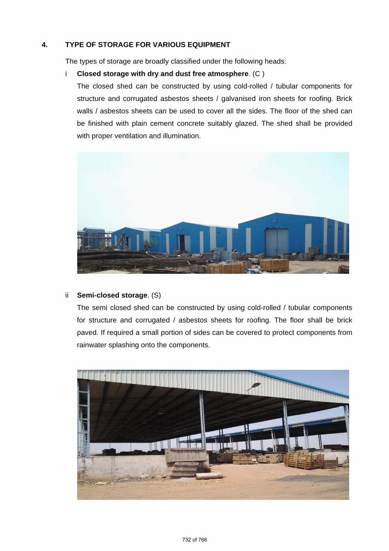
ii Semi-closed storage. (S)
The semi closed shed can be constructed by using cold-rolled / tubular components
for structure and corrugated / asbestos sheets for roofing. The floor shall be brick
paved. If required a small portion of sides can be covered to protect components from
rainwater splashing onto the components.
732 of 766

iii Open storage (O )
The open yard shall be levelled, well consolidated to achieve raised ground with the
provision of feeder roads for crane approach along with access roads running all
sides. One part of the open yard shall be stone pitched, levelled and consolidated with
raised ground suitable for storing / stacking heavier and critical components with due
space to handle them by cranes etc . Adequate number of sleepers, concrete block
etc. to be provided to make raised platforms to stack critical materials.
A separate yard to be identified as “scrap yard” slightly away from main open yard to
store wooden/steel scraps, which are to be disposed off. This is required to avoid mix
up with regular components as well as to avoid fire hazard.
Some of the components, which are having both machined & un-machined surfaces
and are bulky, shall be stored in open storage area on a raised ground and suitably
covered with water proof / fire retardant tarpaulin.
733 of 766

The equipment listed below shall be stored and inspected as per requirement mentioned in the
table below.
Sl. No. Description of the equipment Type of Storage
Check for Remarks
Raw material /mechanical items like pipes, plates, structure sections etc.)
1. Steel pipes ( lined/unlined) S Damage , paint, corrosion, rubber lining peeling
Provide end cap
2. MS Plates S Damage, paint, corrosion
3. SS Plates S Damage
4. Non-metallic pipes S Damage, cracks Provide end cap
5. Stainless steel pipes S Damage , Provide end cap
6. MS sections, beams S Damage, paint, corrosion
7. Cable trays S Damage, condition of preservations
8. Insulation sheets S Damage
9. Insulation C Damage, packing
10. Hangers Rods S Damage, paint, packing
11. Tubes S Damage, paint , packing
Provide end cap
12. Hume pipes O Damage
13. Castings O Damage, paint, corrosion
Fabricated mechanical items (pressure vessels, tanks etc.)
14. Pressure vessels (unlined) O Damage, paint, corrosion,
Covered nozzles
15. Atmospheric storage tanks (unlined)
O Damage, paint, corrosion
Covered nozzles
734 of 766

Sl. No. Description of the equipment Type of Storage
Check for Remarks
16. Pressure vessels (lined) S Damage, paint, corrosion, rubber lining
17. Atmospheric storage tanks(lined) S Damage, paint, corrosion, rubber lining
18. Support structures O Damage , paint, corrosion
19. Flanges C Damage , paint, corrosion
20. Fabricated pipes S Damage , paint, corrosion
Provide end cap
21. Vessels internals C Damage , paint, corrosion ,packing
22. Grills S Damage , paint, corrosion
23. Angles S Damage , paint, corrosion
24. Bridge mechanism/clarifier mechanism
O Damage , paint, corrosion
25. Cranes, rails S Damage , paint, corrosion
26. Stair cases O Damage , paint, corrosion
27. Ladders/handrails O Damage , paint, corrosion
28. Fabricated ducts S Damage , paint, corrosion
29. Isolation Gates O Damage , paint, corrosion
30. Fabricated boxes/panels S Damage , paint, corrosion
Mechanical components like valves, fittings, cables glands, spares etc.)
31. Valves S Damage , packing
735 of 766

Sl. No. Description of the equipment Type of Storage
Check for Remarks
32. Fittings S Damage , packing Provide end cap
33. Cable glands C Damage , packing
34. Tools & tackles C Damage , packing
35. Nut , bolts, washers, C Damage , packing
36. Gasket & Packings C Damage , packing
37. Copper tubes C Damage , packing, corrosion
Provide end cap
38. SS tubing C Damage , packing Provide end cap
Rotating assemblies (pumps, blowers, stirrers, fans, compressors etc.)
39. Pumps S Damage , packing, corrosion
Shaft rotation
40. Blowers/Compressors S Damage , packing, corrosion
Shaft rotation
41. Agitators/stirrers/radial launders C Damage , packing, corrosion
Shaft rotation
42. Rollers for chlorine tonner mounting
C Damage , packing, corrosion
43. Centrifuge S Damage , packing,
44. Gear box C Damage , packing, corrosion
45. Bearings C Damage , packing, corrosion
46. Fans S Damage , packing, corrosion
47. Dosing skids S Damage , packing, corrosion
48. Pump assemblies S Damage , packing, corrosion
49. Air washers( INTERNALS) S Damage , packing
50. Air conditioners ( split) C Damage , packing
736 of 766

Sl. No. Description of the equipment Type of Storage
Check for Remarks
51. Elevators( CONTAINERIZED) O Damage , packing, corrosion
52. Chillers/VA machines S Damage , packing
53. Air handling Unit/Package unit S Damage , packing
54. Chlorinators & Evaporators C Damage , packing
55. Ejectors C Damage , packing
56. Electrolyser C Damage , packing
Miscellaneous items like chain pulley blocks, hoists etc.
57. Chain pulley blocks S Damage, Packing
58. Electric hoists S Damage, Packing
59. Fire extinguishers C Damage, expiry date
60. Fork Lift Truck S Damage, Packing
61. Hydraulic Mobile Crane O Damage, Packing
62. Mobile Pick Up & Carry Crane O Damage, Packing
63. Motor boats O Damage, Packing
64. Safety showers S Damage, Packing
65. Diffusers/dampers S Damage, Packing
Chemicals and consumables ( acid, alkali, paints, oils, reagents and special chemicals)
66. Hydro Chloric Acid (HCl)
Store in canes/ storage tank in dyke area
Date of production/ leakage/fumes
hazardous chemical
67. Sulphuric acid (H2SO4 )
Store in canes/ storage tank in dyke area
Date of production/ leakage/fumes
hazardous chemical
737 of 766

Sl. No. Description of the equipment
Type of Storage
Check for Remarks
68. Sodium hydroxide (NaOH)
Store in canes/ storage tank in dyke area
Date of production/ leakage/ fumes/ breather
hazardous chemical ,breather to be checked for air ingress
69. Sodium hypo chlorite To be stored under shed
Date of production/ leakage/ fumes
hazardous chemical ,self-life normally 15-30 days after which strength of chemical decays
70. Ammonia S Date of production/ leakage/ fumes
Store in closed storage tanks, hazardous chemical
71. CW treatment chemicals S Date of production , Self-life
Store in closed canes
72. RO/UF cleaning chemicals S Date of production , Self-life
Store in closed canes
73. Lime C Damage to packing , seepage
Prevent moisture, rain
74. Alum bricks C Damage to packing Prevent moisture, rain
75. Poly electrolyte S Store in closed storage tanks
76. Laboratory chemicals( powder)
C Damage, Packing self-life
77. Laboratory chemicals( liquid)
C Damage, Packing self-life
78. Lubrication oils C Leakage
79. Paints S Leakage ,air tightness
80. Sand O Damage of packing No hooks
81. Salt (NaCl) C Damage of packing, water ingress
Prevent moisture, rain
82. Anthracite S Damage of packing
83. Activated carbon S Damage of packing
738 of 766

Sl. No. Description of the equipment
Type of Storage
Check for Remarks
84. Thermal insulation S Damage of packing
85. Cement C Damage of packing Prevent moisture, rain
86. Gravels O Damage of packing
87. ION exchange resins C Damage , packing Refer manufacturer guidelines
88. RO membranes C Damage , packing Refer manufacturer guidelines
89. UF membranes C Damage , packing Refer manufacturer guidelines
90. Cleaning chemicals C Damage , packing Refer manufacturer guidelines
91. Chemicals for analysers/calibration
C Damage , packing Refer manufacturer guidelines
Electrical and C & I items (motors, cables etc.)
92. Motors C Damage , packing
93. Cable drums O Damage
94. Control Panel /control desk, UPS ,JB
S Damage, Packing
95. Instruments( gauges/analysers) C Damage
Special items As per Manufacturer’s item, like Hydrogen cylinders, Ozonator, Analyser, Chlorine dioxide generators etc.
739 of 766

5. CONCLUSION
Concerned storage agency at site should make sure that loss in equipment performance
and wear & tear are minimised through proper storage and preservation. The above are
broad guidelines and cover major equipment / materials. However specific storage
practices shall be followed as per manufacturer recommendation. All the necessary
measures even in addition to the ones mentioned above, if found necessary, should be
taken to achieve the objective.
740 of 766

Figure – 1 – PLATE STACKING ARRANGEMENT
Figure – 2 – STRUCTURAL STEEL STACKING ARRANGEMENT
741 of 766

4x111MW VISHNUGAD PIPALKOTI HEP
HVAC SYSTEM PAINTING SPECIFICATION & COLOUR
SCHEME
SPECIFICATION No: PE-TS-413-571-11000A-A001
SECTION : I
SUB-SECTION : E
REV 00 DATE: JAN 2020
SHEET 1 OF 1
1.1
P
SECTION-I
SUB SECTION E
ANNEXURE-VIII
PAINTING SPECIFICATION & COLOUR SCHEME (COVERED UNDER SECTION C2-B)
742 of 766

4x111MW VISHNUGAD PIPALKOTI HEP
HVAC SYSTEM PACKING PROCEDURE
SPECIFICATION No: PE-TS-413-571-11000A-A001
SECTION : I
SUB-SECTION : E
REV 00 DATE: JAN 2020
SHEET 1 OF 1
1.1
P
SECTION-I
SUB SECTION E
ANNEXURE-VIII
PACKING PROCEDURE (COVERED UNDER SECTION C2-B)
743 of 766

4x111MW VISHNUGAD PIPALKOTI HEP
HVAC SYSTEM
SPECIFICATION No: PE-TS-413-571-11000A-A001
SECTION: II
REV. 00 DATE: JAN 2020
SECTION II
744 of 766

4x111MW VISHNUGAD PIPALKOTI HEP
HVAC SYSTEM INSPECTION AND TESTING
SPECIFICATION No: PE-TS-413-571-11000A-A001
SECTION : II
SUB-SECTION : 1
REV 00 DATE: JAN 2020
SHEET 1 OF 4
1.1
P
SECTION-II
SUB-SECTION-1
INSPECTION AND TESTING
745 of 766

4x111MW VISHNUGAD PIPALKOTI HEP
HVAC SYSTEM INSPECTION AND TESTING
SPECIFICATION No: PE-TS-413-571-11000A-A001
SECTION : II
SUB-SECTION : 1
REV 00 DATE: JAN 2020
SHEET 2 OF 4
1.1
P
1.01.00 Inspection and Tests during Manufacture. 1.01.01 The method and techniques to be used by the Bidder for the control of quality during
manufacture of all plant and equipment shall be agreed with the Owner. 1.01.02 The Owner’s general requirements with respect to quality control and the required
shop tests are set out elsewhere in this specification. 1.01.03 Before any item of plant or equipment leaves its place of manufacture the Owner shall
be given the option of witnessing inspections and tests for compliance with the specification and related standards.
1.01.04 Advance notice shall be given to the Owner as agreed in the Contract, prior to the
stage of manufacture being reached, and the piece of plant must be held at this stage until the Owner has inspected the piece, or has advised in writing that inspection is waived. If having consulted the Owner and given reasonable notice in writing of the date on which the piece of plant will be available for inspection, the Owner does not attend the Bidder may proceed with manufacture having forwarded to the Owner duly certified copies of his own inspection and test results. The owner’s representative shall have at all reasonable times access to bidder’s or his sub-vendor’s premises and shall have power to inspect/ examine materials and workmanship or equipment under manufacture.
The Bidder shall forthwith forward to the engineer duly certified copies of the Test
Certificates in six copies (one to the Purchaser and five to the Consulting Engineer) for approval. Further nine (9) copies of Shop Test Certificates shall be bound with Instruction Manuals referred to elsewhere. For electrical equipment, routine tests as per relevant IS spec are to be carried out on all equipment. Type tests are also to be carried out on selected equipment as detailed in the specs of concerned electrical equipment.
1.01.05 Under no circumstances any repair or welding of castings be carried out without the consent of the Engineer. Proof of the effectiveness of each repair by radiographic and/or other non-destructive testing technique, shall be provided to the Engineer.
1.01.06 All the individual and assembled rotating parts shall be statically and dynamically
balanced in the works. Where accurate alignment is necessary for component parts of machinery normally
assembled on site, the Bidder shall allow for trial assembly prior to despatch from place of manufacture.
1.01.07 All materials used for the manufacture of equipment covered under this specification
shall be of tested quality. Relevant test certificates shall be made available to the
746 of 766

4x111MW VISHNUGAD PIPALKOTI HEP
HVAC SYSTEM INSPECTION AND TESTING
SPECIFICATION No: PE-TS-413-571-11000A-A001
SECTION : II
SUB-SECTION : 1
REV 00 DATE: JAN 2020
SHEET 3 OF 4
1.1
P
Purchaser. The certificates shall include tests for mechanical properties and chemical analysis of representative material. Equipment or parts coming under any statutory Regulations shall be certified by a Competent Authority under the regulations in the specified format.
1.01.08 All pressure parts connected to pumping main shall be subjected to hydraulic testing
at a pressure of 150% of shut-off head for a period not less than one hour. Other parts shall be tested for one and half times the maximum operating pressure, for a period not less than one hour.
1.01.09 All necessary non-destructive examinations shall be performed to meet the applicable
code requirements. 1.01.10 All welding procedures adopted for performing welding work shall be qualified in
accordance with the requirements of Section-IX of ASME code or IBR as applicable. All welded joints for pressure parts shall be tested by liquid penetrant examination according to the method outlined in ASME Boiler and Pressure Vessel code. Radiography, magnetic particle examination magnuflux and ultrasonic testing shall be employed wherever necessary/ recommended by the applicable code. At least 10% of all major but welding joints shall be radiographed unless otherwise stipulated.
Statutory payments in respect of IBR approvals including inspection shall be made by
the bidder. Bidder’s scope shall include to preparation of all necessary documents, co-ordination and follow-up for above approval. Owner shall only forward assistance/endorsement of documents /design /drawings /reports/records to be submitted for approval as stipulated/ required by Statutory Authorities till registration of the unit and clearance for commercial operation.
1.02.00 Performance Tests at Site 1.02.01 The full requirements for testing the system shall be agreed between the Owner and
the Bidder prior to Award of Contract. The completely erected System shall be tested by the Bidder on site under normal operating conditions. The Bidder shall also ensure the correct performance of the System under abnormal conditions, i.e. the correct working of the various emergency and safety devices, interlocks, etc.
1.02.02 The Bidder shall provide complete details of his normal procedures for testing, for the
quality of erection and for the performance of the erected plant. These tests shall include site pressure test on all erected pipe work to demonstrate the quality of the piping and the adequacy of joints made at site.
1.02.03 The Bidder shall furnish the quality procedures to be adopted for assuring quality from
the receipt of material at site, during storage, erection, pre-commissioning to tests on completion and commissioning of the complete system/equipment.
1.03.00 For details of specific tests required on individual equipment refer to respective
section of this specification.
747 of 766