LIQUIP AVIATION COMPONENTS PRODUCT OVERVIEW
139
LIQUIP AVIATION COMPONENTS PRODUCT OVERVIEW
-
Upload
khangminh22 -
Category
Documents
-
view
0 -
download
0
Transcript of LIQUIP AVIATION COMPONENTS PRODUCT OVERVIEW

LIQUIP AVIATION COMPONENTS PRODUCT OVERVIEW
www.liquip.com Issue 10
Aviation Components Catalogue
2
Content
www.liquip.com
Hydrant Pit - HPA150 Hydrant Pit - HPA200 Hydrant Pit - HPA250 EN Approved Hydrant PitsTether
Hosereels & FittingsElaflex Aviation HoseElaflex Hose FittingsHose SwivelsHose Quick Disconnect Hose BeadsHose Reflective Cover Aviation Hosereel Drum Style - HP Series Aviation Hosereel Drum Style - AHR Series Aviation Hosereel Cartwheel Style - AHR Series Hosereel Assemblies - Electric Rewind
Nozzles & AccessoriesOPW295SA & SAJ Aircraft NozzlesAV042 Overwing NozzleElaflex Nozzle Bowser Nozzle Overwing Nozzle Stowage
Bottom Load AccessoriesOPW EuroLine Series Foot ValveNormec Internal Footvalve
HydrantsHydrant Pit Hydrant Pit - HPA100
Non-Return Valves - NRV80Stainless Steel Flanged Ball ValvesSmall Isolation Ball ValvesApollo ValveTank Compartment Internal Drain ValveATS Tank Sump
Valves
Epoxy Lined ContainerCollector TankMillipore AdaptorAljac Sampler
Fuel Sampling
Schultz Differential Pressure GaugesPressure Gauges
Gauges
Electronic Meter Register - DFV Series Pulser - ERP200Junction Box - EJB101Sampi Meters Sampi Meters - SM 5 Sampi Meters - SM 30 Isoil Digital Display - LFD-6Gorman Rupp Pump 2”Gorman Rupp Pump 3”Portable Aviation Drum PumpAvery Hardoll BM Series Meter
Meters & Pumps
Liquip Detection Probes - LDP SeriesProbe HoldersOn Board Monitor
Overfill Protection
Filter Standard Sensing AssembliesFacet Small Filter Housings - VF-21 and VF-22 SeriesILS400 In-line Suction StrainerBasket StrainersElaflex Rubber Expansion JointsSwivelsCamlocksStatic Reel - LSR SeriesAljac Continuity TesterPower ConditionerDeadman AssembliesDecals & SignageSpill Management ProductsPlatform LaddersWing MatsStainless Steel BucketsFire Extinguisher HolderStainless Steel Safety Lock WireWater Finding PasteFuel Finding (Ullage) PasteDensity Calculator
Accessories
NOTE: All information contained within this document is subject to engineering and other changes. Issue 10 - Aviation Components Catalogue 3

Hosereels & Fittings
Issue 10 - Aviation Components Catalogue 4
Hosereels & Fittings
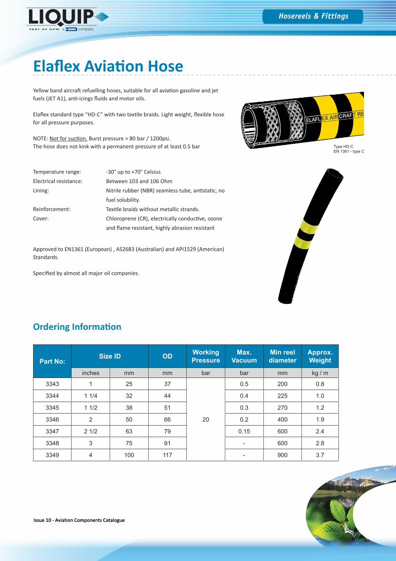
Yellow band aircraft refuelling hoses, suitable for all aviation gasoline and jet fuels (JET A1), anti-icings fluids and motor oils.
Elaflex standard type “HD-C” with two textile braids. Light weight, flexible hose for all pressure purposes.
NOTE: Not for suction. Burst pressure > 80 bar / 1200psi.The hose does not kink with a permanent pressure of at least 0.5 bar
Temperature range: Electrical resistance: Lining:
Reinforcement: Cover:
Approved to EN1361 (European) , AS2683 (Australian) and API1529 (American) Standards.
Specified by almost all major oil companies.
Ordering Information
Part No:Size ID OD Working
PressureMax.
VacuumMin reel diameter
Approx. Weight
inches mm mm bar bar mm kg / m
3343 1 25 37
20
0.5 200 0.8
3344 1 1/4 32 44 0.4 225 1.0
3345 1 1/2 38 51 0.3 270 1.2
3346 2 50 66 0.2 400 1.9
3347 2 1/2 63 79 0.15 600 2.4
3348 3 75 91 - 600 2.8
3349 4 100 117 - 900 3.7
-30° up to +70° CelsiusBetween 103 and 106 OhmNitrile rubber (NBR) seamless tube, antistatic, nofuel solubility.Textile braids without metallic strands.Chloroprene (CR), electrically conductive, ozoneand flame resistant, highly abrasion resistant
Type HD-CEN 1361 - type C
Elaflex Aviation Hose
Issue 10 - Aviation Components Catalogue 4Issue 10 - Aviation Components Catalogue 5
Hosereels & Fittings
www.liquip.com
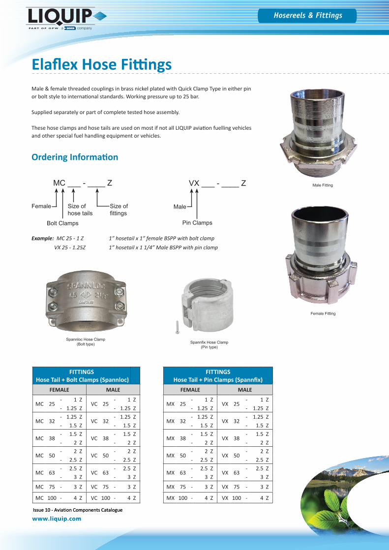
Male & female threaded couplings in brass nickel plated with Quick Clamp Type in either pin or bolt style to international standards. Working pressure up to 25 bar.
Supplied separately or part of complete tested hose assembly.
These hose clamps and hose tails are used on most if not all LIQUIP aviation fuelling vehicles and other special fuel handling equipment or vehicles.
Male Fitting
Female Fitting
Spannloc Hose Clamp (Bolt type) Spannfix Hose Clamp
(Pin type)
MC ___ - ____ Z
Female
Bolt Clamps
Size of hose tails
Size of fittings
VX ___ - ____ Z
Male
Pin Clamps
Example: MC 25 - 1 Z VX 25 - 1.25Z
1” hosetail x 1” female BSPP with bolt clamp1” hosetail x 1 1/4” Male BSPP with pin clamp
FITTINGS Hose Tail + Bolt Clamps (Spannloc)
FEMALE MALE
MC 25- 1 Z
VC 25- 1 Z
- 1.25 Z - 1.25 Z
MC 32- 1.25 Z
VC 32- 1.25 Z
- 1.5 Z - 1.5 Z
MC 38- 1.5 Z
VC 38- 1.5 Z
- 2 Z - 2 Z
MC 50- 2 Z
VC 50- 2 Z
- 2.5 Z - 2.5 Z
MC 63- 2.5 Z
VC 63- 2.5 Z
- 3 Z - 3 Z
MC 75 - 3 Z VC 75 - 3 Z
MC 100 - 4 Z VC 100 - 4 Z
FITTINGS Hose Tail + Pin Clamps (Spannfix)
FEMALE MALE
MX 25- 1 Z
VX 25- 1 Z
- 1.25 Z - 1.25 Z
MX 32- 1.25 Z
VX 32- 1.25 Z
- 1.5 Z - 1.5 Z
MX 38- 1.5 Z
VX 38- 1.5 Z
- 2 Z - 2 Z
MX 50- 2 Z
VX 50- 2 Z
- 2.5 Z - 2.5 Z
MX 63- 2.5 Z
VX 63- 2.5 Z
- 3 Z - 3 Z
MX 75 - 3 Z VX 75 - 3 Z
MX 100 - 4 Z VX 100 - 4 Z
Elaflex Hose Fittings
Ordering Information
Issue 10 - Aviation Components Catalogue 5Issue 10 - Aviation Components Catalogue 6
Hosereels & Fittings
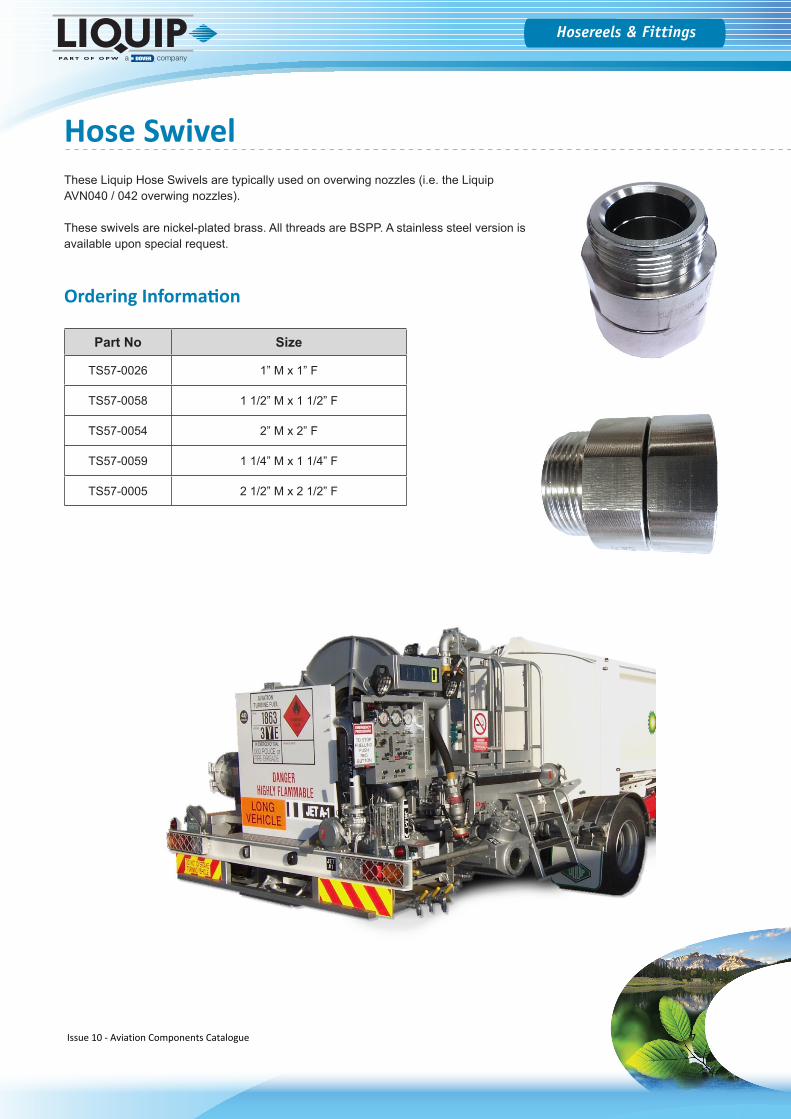
These Liquip Hose Swivels are typically used on overwing nozzles (i.e. the Liquip AVN040 / 042 overwing nozzles).
These swivels are nickel-plated brass. All threads are BSPP. A stainless steel version is available upon special request.
Hose Swivel
Part No Size
TS57-0026 1” M x 1” F
TS57-0058 1 1/2” M x 1 1/2” F
TS57-0054 2” M x 2” F
TS57-0059 1 1/4” M x 1 1/4” F
TS57-0005 2 1/2” M x 2 1/2” F
Ordering Information
Issue 10 - Aviation Components Catalogue 7
Hosereels & Fittings
www.liquip.com
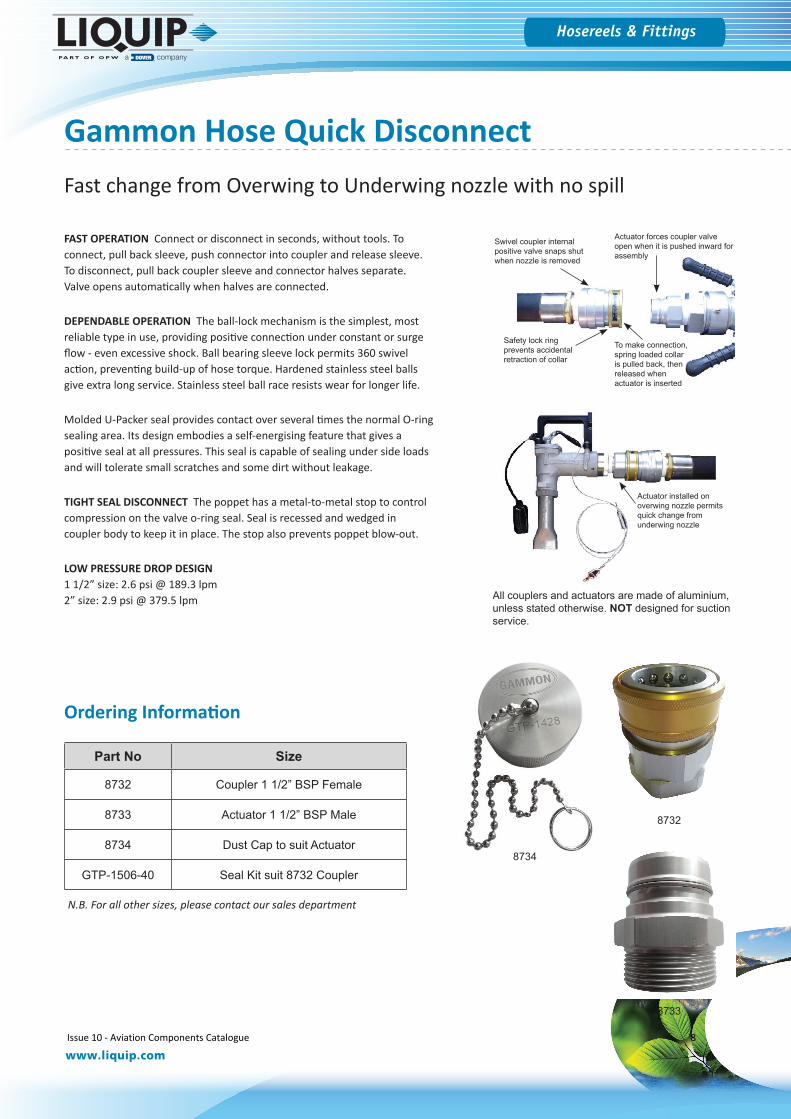
FAST OPERATION Connect or disconnect in seconds, without tools. To connect, pull back sleeve, push connector into coupler and release sleeve. To disconnect, pull back coupler sleeve and connector halves separate. Valve opens automatically when halves are connected.
DEPENDABLE OPERATION The ball-lock mechanism is the simplest, most reliable type in use, providing positive connection under constant or surge flow - even excessive shock. Ball bearing sleeve lock permits 360 swivel action, preventing build-up of hose torque. Hardened stainless steel balls give extra long service. Stainless steel ball race resists wear for longer life.
Molded U-Packer seal provides contact over several times the normal O-ring sealing area. Its design embodies a self-energising feature that gives a positive seal at all pressures. This seal is capable of sealing under side loads and will tolerate small scratches and some dirt without leakage.
TIGHT SEAL DISCONNECT The poppet has a metal-to-metal stop to control compression on the valve o-ring seal. Seal is recessed and wedged in coupler body to keep it in place. The stop also prevents poppet blow-out.
LOW PRESSURE DROP DESIGN 1 1/2” size: 2.6 psi @ 189.3 lpm2” size: 2.9 psi @ 379.5 lpm
Gammon Hose Quick Disconnect
Part No Size
8732 Coupler 1 1/2” BSP Female
8733 Actuator 1 1/2” BSP Male
8734 Dust Cap to suit Actuator
GTP-1506-40 Seal Kit suit 8732 Coupler
Swivel coupler internal positive valve snaps shut when nozzle is removed
Actuator forces coupler valve open when it is pushed inward for assembly
To make connection, spring loaded collar is pulled back, then released when actuator is inserted
Safety lock ring prevents accidental retraction of collar
Actuator installed on overwing nozzle permits quick change from underwing nozzle
All couplers and actuators are made of aluminium, unless stated otherwise. NOT designed for suction service.
Fast change from Overwing to Underwing nozzle with no spill
N.B. For all other sizes, please contact our sales department
8732
8733
8734
Ordering Information
Issue 10 - Aviation Components Catalogue 8
Hosereels & Fittings
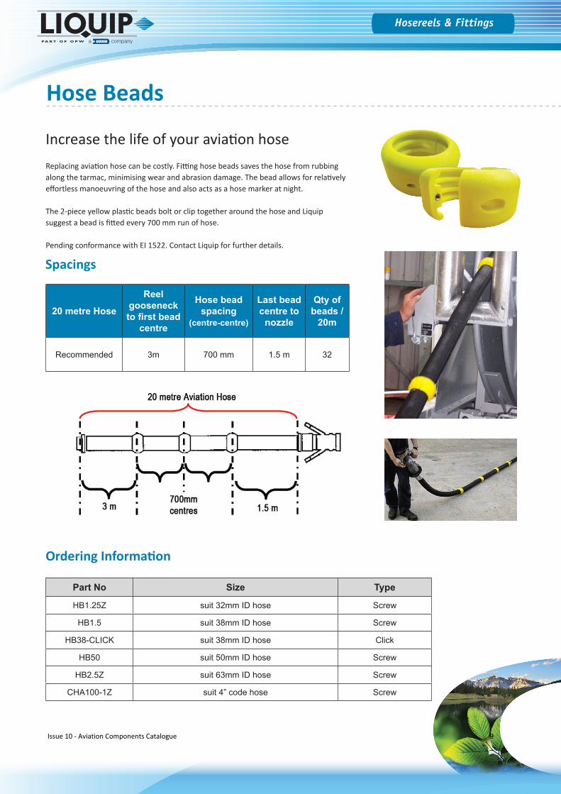
Increase the life of your aviation hoseReplacing aviation hose can be costly. Fitting hose beads saves the hose from rubbing along the tarmac, minimising wear and abrasion damage. The bead allows for relatively effortless manoeuvring of the hose and also acts as a hose marker at night.
The 2-piece yellow plastic beads bolt or clip together around the hose and Liquip suggest a bead is fitted every 700 mm run of hose.
Pending conformance with EI 1522. Contact Liquip for further details.
20 metre Hose
Reel gooseneck to first bead
centre
Hose bead spacing
(centre-centre)
Last bead centre to
nozzle
Qty of beads /
20m
Recommended 3m 700 mm 1.5 m 32
Spacings
Part No Size Type
HB1.25Z suit 32mm ID hose Screw
HB1.5 suit 38mm ID hose Screw
HB38-CLICK suit 38mm ID hose Click
HB50 suit 50mm ID hose Screw
HB2.5Z suit 63mm ID hose Screw
CHA100-1Z suit 4” code hose Screw
Hose Beads
Ordering Information
Issue 10 - Aviation Components Catalogue 9
Hosereels & Fittings
www.liquip.com
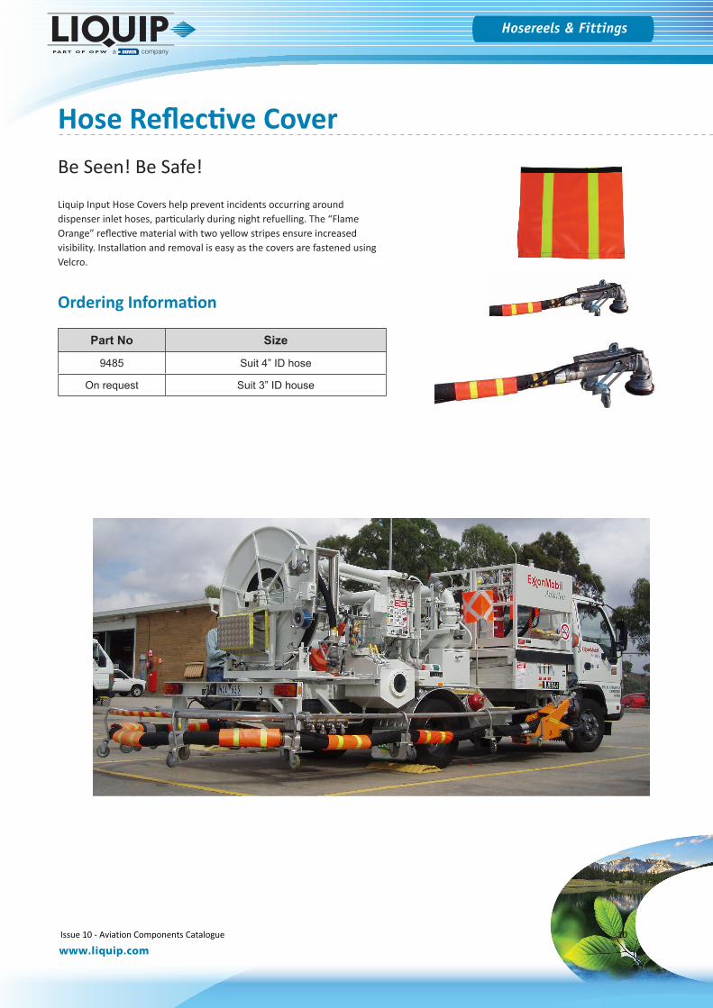
Hose Reflective Cover
Liquip Input Hose Covers help prevent incidents occurring around dispenser inlet hoses, particularly during night refuelling. The “Flame Orange” reflective material with two yellow stripes ensure increased visibility. Installation and removal is easy as the covers are fastened using Velcro.
Be Seen! Be Safe!
Part No Size
9485 Suit 4” ID hose
On request Suit 3” ID house
Ordering Information
Issue 10 - Aviation Components Catalogue 10
Hosereels & Fittings
Aviation Hosereel Drum Style - HP Series
The HP series of hose reels are a generation of reels for high pressure use and available with hand or hydraulic rewind and in different sizes. Sealing is by lip seal and all models incorporate a lock assembly. Ball bearings look after rotation, with end thrust being taken care of by heavy-duty circlips and thrust washers. All components are easily replaced and all wetted surfaces are nickel plated for longer life.
Stainless steel inlet flange, nickel plated gooseneck with 1 1/4” MBSPP.
Technical SpecificationsSizes Hose size - 25mm, 32mm and 38mm diameter
Rewind type - Manual or hydraulicDrum width - 300mm, 450mm or 600mmAnti-rotation lock to prevent hose unravelling
Pressure Rated to 2100 kPa
Servicing Quarterly grease plumber block bearingAnnually remove and repack bearing on the inlet side of the reel
Mounting 4 x M10 bolts
Materials Stiffened steel cheek plates, extremely sturdy thick wall manifold with added strength from steel inner drum, steel base frame and self aligning bearing. Polyurethane seals.
Options Hot dip galvanised version1 1/2” N/P FBSP gooseneckRollers and guides
High pressure hose reel suitable for petroleum products
Issue 10 - Aviation Components Catalogue 10Issue 10 - Aviation Components Catalogue 11
Hosereels & Fittings
www.liquip.com
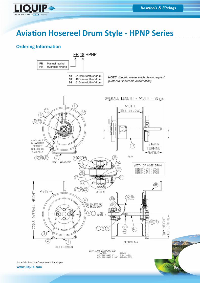
FR 18 HPNP
12 315mm width of drum18 465mm width of drum24 615mm width of drum
FR Manual rewindHR Hydraulic rewind
NOTE: Electric made available on request (Refer to Hosereels Assemblies)
Aviation Hosereel Drum Style - HPNP SeriesOrdering Information
Issue 10 - Aviation Components Catalogue 12
Hosereels & Fittings
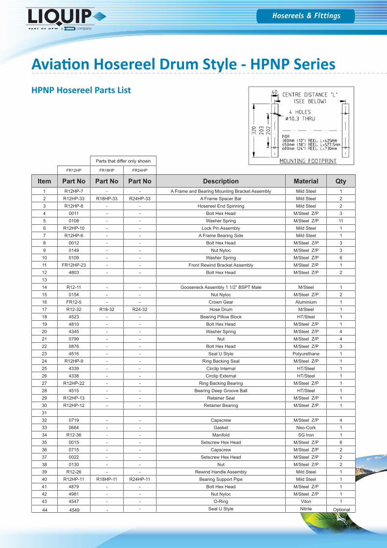
HPNP Hosereel Parts List
Parts that differ only shown
FR12HP FR18HP FR24HP
Item Part No Part No Part No Description Material Qty1 R12HP-7 - - A Frame and Bearing Mounting Bracket Assembly Mild Steel 12 R12HP-33 R18HP-33 R24HP-33 A Frame Spacer Bar Mild Steel 23 R12HP-8 - - Hosereel End Spinning Mild Steel 24 0011 - - Bolt Hex Head M/Steel Z/P 35 0108 - - Washer Spring M/Steel Z/P 116 R12HP-10 - - Lock Pin Assembly Mild Steel 17 R12HP-6 - - A Frame Bearing Side Mild Steel 18 0012 - - Bolt Hex Head M/Steel Z/P 39 0149 - - Nut Nyloc M/Steel Z/P 310 0109 - - Washer Spring M/Steel Z/P 611 FR12HP-23 - - Front Rewind Bracket Assembly M/Steel Z/P 112 4803 - - Bolt Hex Head M/Steel Z/P 21314 R12-11 - - Gooseneck Assembly 1 1/2” BSPT Male M/Steel 115 0154 - - Nut Nyloc M/Steel Z/P 216 FR12-5 - - Crown Gear Aluminium 117 R12-32 R18-32 R24-32 Hose Drum M/Steel 118 4523 - - Bearing Pillow Block HT/Steel 119 4810 - - Bolt Hex Head M/Steel Z/P 120 4345 - - Washer Spring M/Steel Z/P 421 0799 - - Nut M/Steel Z/P 422 0876 - - Bolt Hex Head M/Steel Z/P 323 4516 - - Seal U Style Polyurethane 124 R12HP-9 - - Ring Backing Seal M/Steel Z/P 125 4339 - - Circlip Internal HT/Steel 126 4338 - - Circlip External HT/Steel 127 R12HP-22 - - Ring Backing Bearing M/Steel Z/P 128 4515 - - Bearing Deep Groove Ball HT/Steel 129 R12HP-13 - - Retainer Seal M/Steel Z/P 130 R12HP-12 - - Retainer Bearing M/Steel Z/P 13132 0719 - - Capscrew M/Steel Z/P 433 0664 - - Gasket Neo-Cork 134 R12-36 - - Manifold SG Iron 135 0015 - - Setscrew Hex Head M/Steel Z/P 636 0715 - - Capscrew M/Steel Z/P 237 0022 - - Setscrew Hex Head M/Steel Z/P 238 0130 - - Nut M/Steel Z/P 239 R12-26 - - Rewind Handle Assembly Mild Steel 140 R12HP-11 R18HP-11 R24HP-11 Bearing Support Pipe Mild Steel 141 4879 - - Bolt Hex Head M/Steel Z/P 142 4981 - - Nut Nyloc M/Steel Z/P 143 4547 - - O-Ring Viton 1
44 4549 - - Seal U Style Nitrile Optional
Aviation Hosereel Drum Style - HPNP Series
Hosereels & Fittings
www.liquip.com
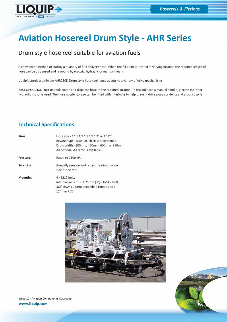
A convenient method of storing a quantity of fuel delivery hose. When the fill point is located at varying location the required length of hose can be dispensed and rewound by electric, hydraulic or manual means.
Liquip’s sturdy aluminium AHR250D Drum style hose reel range adapts to a variety of drive mechanisms.
EASY OPERATION Just unhook nozzle and dispense hose to the required location. To rewind hose a manual handle, electric motor or hydraulic motor is used. The hose nozzle storage can be fitted with interlocks to help prevent drive away accidents and product spills.
Technical Specifications
Sizes Hose size - 1”, 1 1/4”, 1 1/2”, 2” & 2 1/2” Rewind type - Manual, electric or hydraulicDrum width - 300mm, 450mm, 600m or 950mmAn optional A-Frame is available.
Pressure Rated to 2100 kPa
Servicing Annually remove and repack bearings on each side of the reel
Mounting 4 x M12 boltsInlet flange is to suit 75mm (3”) TTMA - 8 off 3/8” BSW x 25mm deep blind threads on a 124mm PCD
Aviation Hosereel Drum Style - AHR SeriesDrum style hose reel suitable for aviation fuels
Issue 10 - Aviation Components Catalogue 14
Hosereels & Fittings
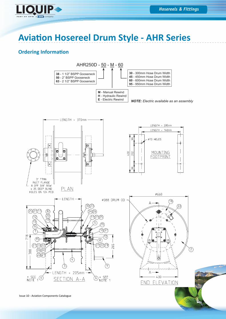
AHR250D - 50 - M - 60
30 - 300mm Hose Drum Width45 - 450mm Hose Drum Width60 - 600mm Hose Drum Width95 - 950mm Hose Drum Width
M - Manual RewindH - Hydraulic RewindE - Electric Rewind
38 - 1 1/2” BSPP Gooseneck50 - 2” BSPP Gooseneck63 - 2 1/2” BSPP Gooseneck
NOTE: Electric available as an assembly
Aviation Hosereel Drum Style - AHR SeriesOrdering Information
Issue 10 - Aviation Components Catalogue 15
Hosereels & Fittings
www.liquip.com
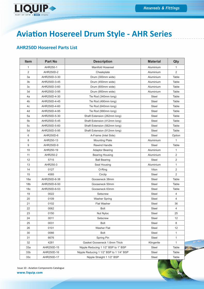
AHR250D Hosereel Parts List
Item Part No Description Material Qty1 AHR250-1 Manifold Hosereel Aluminium 1
2 AHR250D-2 Cheekplate Aluminium 2
3a AHR250D-3-30 Drum (300mm wide) Aluminium Table
3b AHR250D-3-45 Drum (450mm wide) Aluminium Table
3c AHR250D-3-60 Drum (600mm wide) Aluminium Table
3d AHR250D-3-95 Drum (950mm wide) Aluminium Table
4a AHR250D-4-30 Tie Rod (340mm long) Steel Table
4b AHR250D-4-45 Tie Rod (490mm long) Steel Table
4c AHR250D-4-60 Tie Rod (640mm long) Steel Table
4d AHR250D-4-95 Tie Rod (990mm long) Steel Table
5a AHR250D-5-30 Shaft Extension (262mm long) Steel Table
5b AHR250D-5-45 Shaft Extension (412mm long) Steel Table
5c AHR250D-5-60 Shaft Extension (562mm long) Steel Table
5d AHR250D-5-95 Shaft Extension (912mm long) Steel Table
6 AHR250D-6 A-Frame (Inlet Side) Steel Option
8 AHR250-13 Mounting Plate Aluminium 1
9 AHR250D-9 Rewind Handle Steel Table
10 AHR250-19 Adaptor Bearing Aluminium 1
11 AHR250-2 Bearing Housing Aluminium 2
12 5715 Ball Bearing Steel 2
13 AHR250-3 Seal Housing Aluminium 1
14 0127 O-Ring Viton 2
15 4585 Circlip Steel 2
18a AHR250D-6-38 Gooseneck 38mm Steel Table
18b AHR250D-6-50 Gooseneck 50mm Steel Table
18c AHR250D-6-53 Gooseneck 63mm Steel Table
19 0022 Setscrew Steel 4
20 0109 Washer Spring Steel 4
21 0102 Flat Washer Steel 36
22 0062 Bolt Steel 4
23 0150 Nut Nyloc Steel 25
24 0011 Setscrew Steel 12
25 0031 Bolt Steel 8
26 0101 Washer Flat Steel 12
30 0066 Bolt Steel 1
31 6676 Spring Pin Steel 1
32 4281 Gasket Gooseneck 1.6mm Thick Klingerite 1
33a AHR250D-15 Nipple Reducing 1 1/2” BSP to 1” BSP Steel Table
33b AHR250D-16 Nipple Reducing 1 1/2” BSP to 1 1/4” BSP Steel Table
33c AHR250D-17 Nipple Straight 1 1/2” BSP Steel Table
Aviation Hosereel Drum Style - AHR Series
Issue 10 - Aviation Components Catalogue 16
Hosereels & Fittings
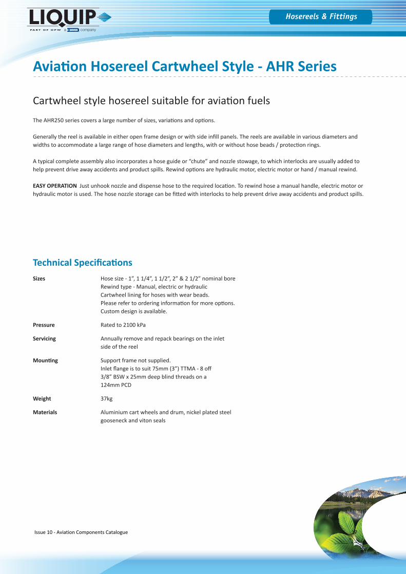
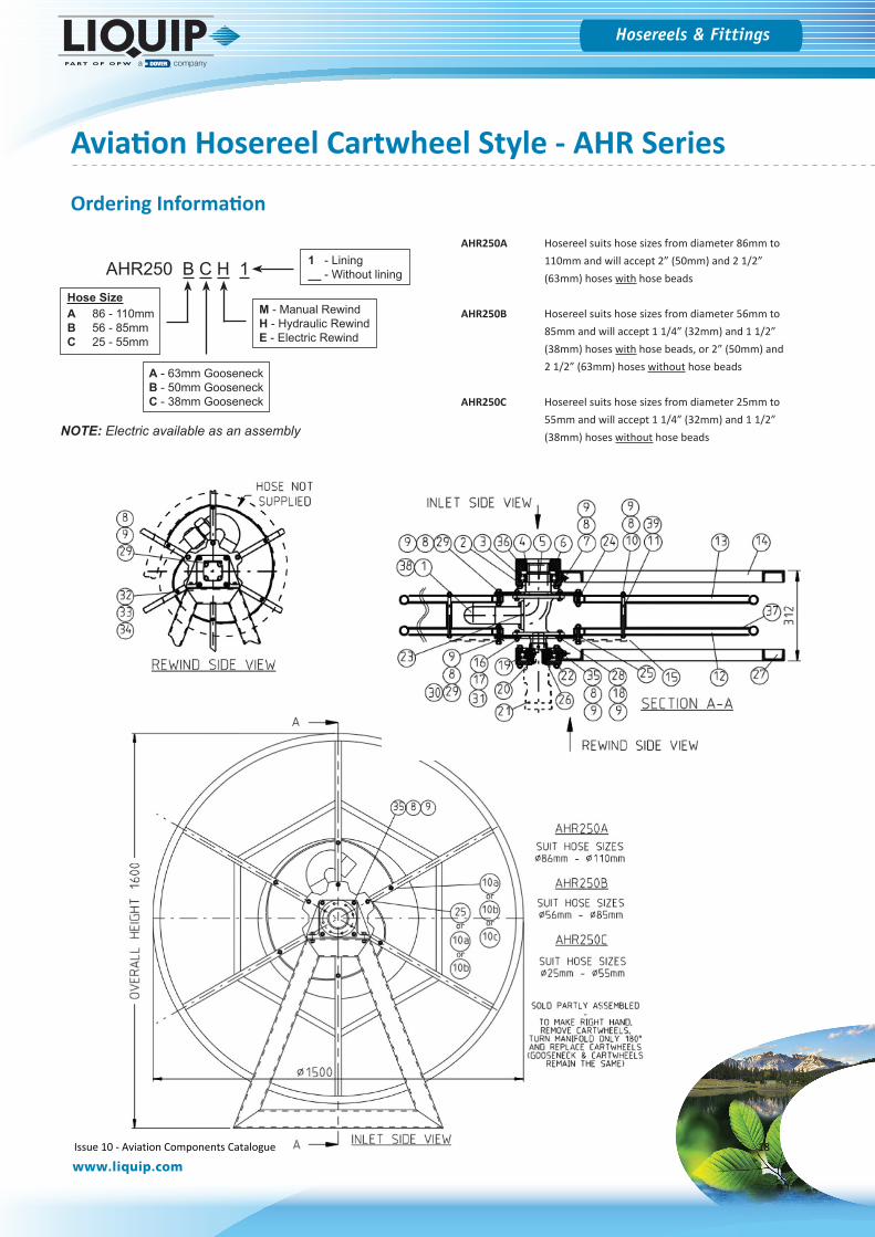
Aviation Hosereel Cartwheel Style - AHR Series
Cartwheel style hosereel suitable for aviation fuelsThe AHR250 series covers a large number of sizes, variations and options.
Generally the reel is available in either open frame design or with side infill panels. The reels are available in various diameters and widths to accommodate a large range of hose diameters and lengths, with or without hose beads / protection rings.
A typical complete assembly also incorporates a hose guide or “chute” and nozzle stowage, to which interlocks are usually added to help prevent drive away accidents and product spills. Rewind options are hydraulic motor, electric motor or hand / manual rewind.
EASY OPERATION Just unhook nozzle and dispense hose to the required location. To rewind hose a manual handle, electric motor or hydraulic motor is used. The hose nozzle storage can be fitted with interlocks to help prevent drive away accidents and product spills.
Technical SpecificationsSizes Hose size - 1”, 1 1/4”, 1 1/2”, 2” & 2 1/2” nominal bore
Rewind type - Manual, electric or hydraulicCartwheel lining for hoses with wear beads.Please refer to ordering information for more options.Custom design is available.
Pressure Rated to 2100 kPa
Servicing Annually remove and repack bearings on the inlet side of the reel
Mounting Support frame not supplied.Inlet flange is to suit 75mm (3”) TTMA - 8 off 3/8” BSW x 25mm deep blind threads on a 124mm PCD
Weight 37kg
Materials Aluminium cart wheels and drum, nickel plated steel gooseneck and viton seals
Issue 10 - Aviation Components Catalogue 17
Hosereels & Fittings
www.liquip.com
AHR250A Hosereel suits hose sizes from diameter 86mm to 110mm and will accept 2” (50mm) and 2 1/2” (63mm) hoses with hose beads
AHR250B Hosereel suits hose sizes from diameter 56mm to 85mm and will accept 1 1/4” (32mm) and 1 1/2” (38mm) hoses with hose beads, or 2” (50mm) and 2 1/2” (63mm) hoses without hose beads
AHR250C Hosereel suits hose sizes from diameter 25mm to 55mm and will accept 1 1/4” (32mm) and 1 1/2” (38mm) hoses without hose beads
AHR250 B C H 1
A - 63mm GooseneckB - 50mm GooseneckC - 38mm Gooseneck
M - Manual RewindH - Hydraulic RewindE - Electric Rewind
Hose SizeA 86 - 110mmB 56 - 85mmC 25 - 55mm
NOTE: Electric available as an assembly
1 - Lining__ - Without lining
Ordering Information
Aviation Hosereel Cartwheel Style - AHR Series
Issue 10 - Aviation Components Catalogue 18
Hosereels & Fittings
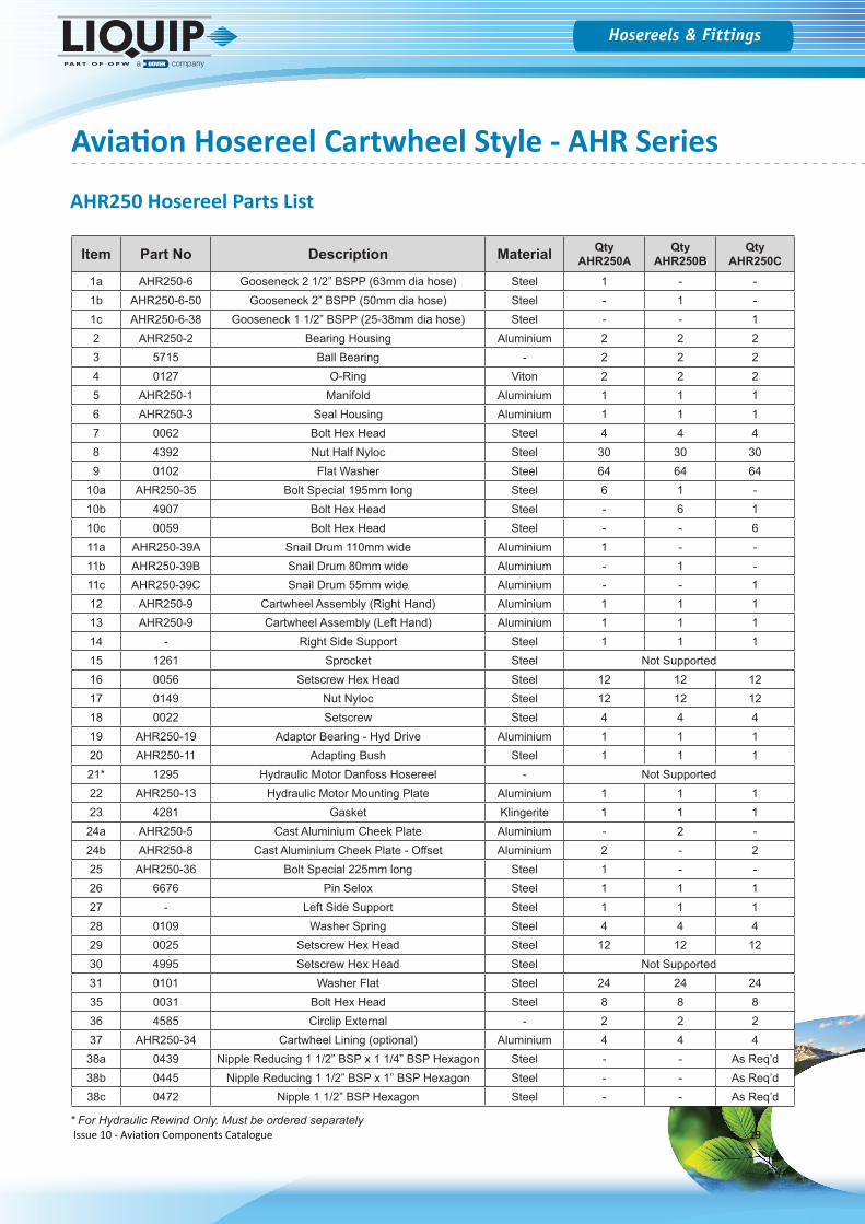
AHR250 Hosereel Parts List
Item Part No Description Material QtyAHR250A
QtyAHR250B
QtyAHR250C
1a AHR250-6 Gooseneck 2 1/2” BSPP (63mm dia hose) Steel 1 - -1b AHR250-6-50 Gooseneck 2” BSPP (50mm dia hose) Steel - 1 -1c AHR250-6-38 Gooseneck 1 1/2” BSPP (25-38mm dia hose) Steel - - 12 AHR250-2 Bearing Housing Aluminium 2 2 23 5715 Ball Bearing - 2 2 24 0127 O-Ring Viton 2 2 25 AHR250-1 Manifold Aluminium 1 1 16 AHR250-3 Seal Housing Aluminium 1 1 17 0062 Bolt Hex Head Steel 4 4 48 4392 Nut Half Nyloc Steel 30 30 309 0102 Flat Washer Steel 64 64 64
10a AHR250-35 Bolt Special 195mm long Steel 6 1 -10b 4907 Bolt Hex Head Steel - 6 110c 0059 Bolt Hex Head Steel - - 611a AHR250-39A Snail Drum 110mm wide Aluminium 1 - -11b AHR250-39B Snail Drum 80mm wide Aluminium - 1 -11c AHR250-39C Snail Drum 55mm wide Aluminium - - 112 AHR250-9 Cartwheel Assembly (Right Hand) Aluminium 1 1 113 AHR250-9 Cartwheel Assembly (Left Hand) Aluminium 1 1 114 - Right Side Support Steel 1 1 115 1261 Sprocket Steel Not Supported16 0056 Setscrew Hex Head Steel 12 12 1217 0149 Nut Nyloc Steel 12 12 1218 0022 Setscrew Steel 4 4 419 AHR250-19 Adaptor Bearing - Hyd Drive Aluminium 1 1 120 AHR250-11 Adapting Bush Steel 1 1 121* 1295 Hydraulic Motor Danfoss Hosereel - Not Supported22 AHR250-13 Hydraulic Motor Mounting Plate Aluminium 1 1 123 4281 Gasket Klingerite 1 1 1
24a AHR250-5 Cast Aluminium Cheek Plate Aluminium - 2 -24b AHR250-8 Cast Aluminium Cheek Plate - Offset Aluminium 2 - 225 AHR250-36 Bolt Special 225mm long Steel 1 - -26 6676 Pin Selox Steel 1 1 127 - Left Side Support Steel 1 1 128 0109 Washer Spring Steel 4 4 429 0025 Setscrew Hex Head Steel 12 12 1230 4995 Setscrew Hex Head Steel Not Supported31 0101 Washer Flat Steel 24 24 2435 0031 Bolt Hex Head Steel 8 8 836 4585 Circlip External - 2 2 237 AHR250-34 Cartwheel Lining (optional) Aluminium 4 4 4
38a 0439 Nipple Reducing 1 1/2” BSP x 1 1/4” BSP Hexagon Steel - - As Req’d38b 0445 Nipple Reducing 1 1/2” BSP x 1” BSP Hexagon Steel - - As Req’d38c 0472 Nipple 1 1/2” BSP Hexagon Steel - - As Req’d
* For Hydraulic Rewind Only. Must be ordered separately
Aviation Hosereel Cartwheel Style - AHR Series
Issue 10 - Aviation Components Catalogue 19
Hosereels & Fittings
www.liquip.com
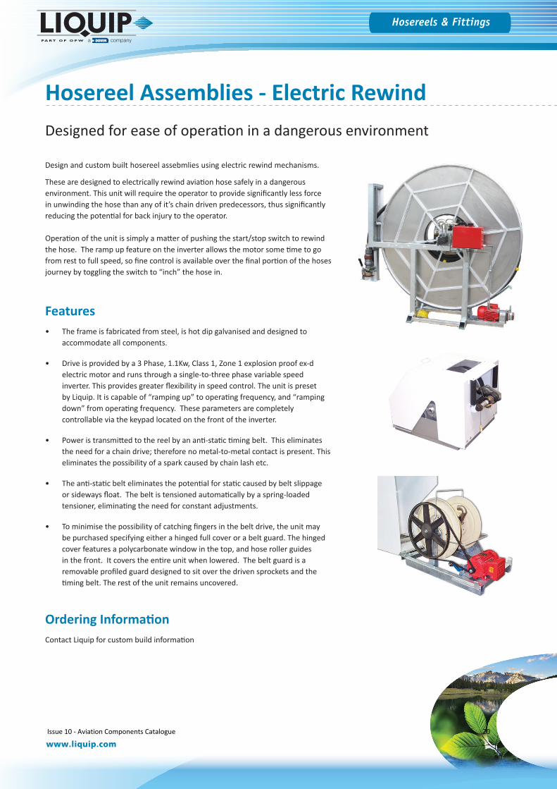
Hosereel Assemblies - Electric Rewind
Features• The frame is fabricated from steel, is hot dip galvanised and designed to
accommodate all components.
• Drive is provided by a 3 Phase, 1.1Kw, Class 1, Zone 1 explosion proof ex-delectric motor and runs through a single-to-three phase variable speedinverter. This provides greater flexibility in speed control. The unit is presetby Liquip. It is capable of “ramping up” to operating frequency, and “rampingdown” from operating frequency. These parameters are completelycontrollable via the keypad located on the front of the inverter.
• Power is transmitted to the reel by an anti-static timing belt. This eliminatesthe need for a chain drive; therefore no metal-to-metal contact is present. Thiseliminates the possibility of a spark caused by chain lash etc.
• The anti-static belt eliminates the potential for static caused by belt slippageor sideways float. The belt is tensioned automatically by a spring-loadedtensioner, eliminating the need for constant adjustments.
• To minimise the possibility of catching fingers in the belt drive, the unit maybe purchased specifying either a hinged full cover or a belt guard. The hingedcover features a polycarbonate window in the top, and hose roller guidesin the front. It covers the entire unit when lowered. The belt guard is aremovable profiled guard designed to sit over the driven sprockets and thetiming belt. The rest of the unit remains uncovered.
Ordering InformationContact Liquip for custom build information
Design and custom built hosereel assebmlies using electric rewind mechanisms.
These are designed to electrically rewind aviation hose safely in a dangerous environment. This unit will require the operator to provide significantly less force in unwinding the hose than any of it’s chain driven predecessors, thus significantly reducing the potential for back injury to the operator.
Operation of the unit is simply a matter of pushing the start/stop switch to rewind the hose. The ramp up feature on the inverter allows the motor some time to go from rest to full speed, so fine control is available over the final portion of the hoses journey by toggling the switch to “inch” the hose in.
Designed for ease of operation in a dangerous environment
Issue 10 - Aviation Components Catalogue 20
Hosereels & Fittings
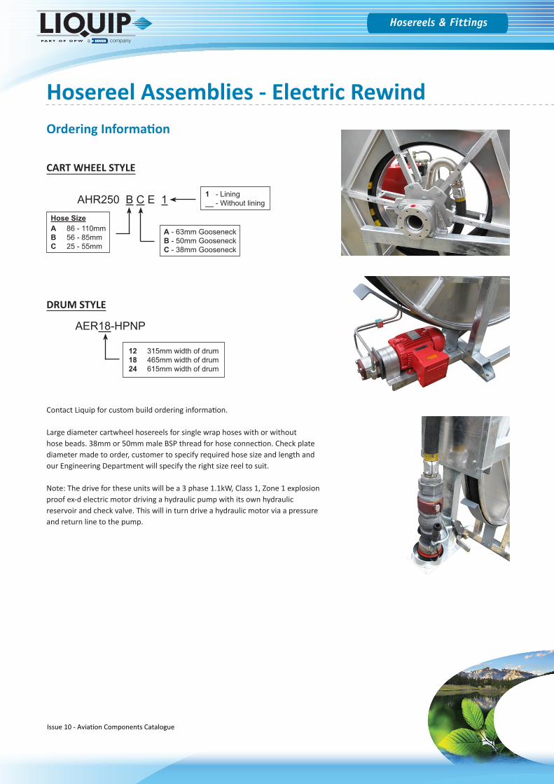
Contact Liquip for custom build ordering information.
Large diameter cartwheel hosereels for single wrap hoses with or without hose beads. 38mm or 50mm male BSP thread for hose connection. Check plate diameter made to order, customer to specify required hose size and length and our Engineering Department will specify the right size reel to suit.
Note: The drive for these units will be a 3 phase 1.1kW, Class 1, Zone 1 explosion proof ex-d electric motor driving a hydraulic pump with its own hydraulic reservoir and check valve. This will in turn drive a hydraulic motor via a pressure and return line to the pump.
AHR250 B C E 1
A - 63mm GooseneckB - 50mm GooseneckC - 38mm Gooseneck
Hose SizeA 86 - 110mmB 56 - 85mmC 25 - 55mm
1 - Lining__ - Without lining
AER18-HPNP
DRUM STYLE
CART WHEEL STYLE
12 315mm width of drum18 465mm width of drum24 615mm width of drum
Hosereel Assemblies - Electric RewindOrdering Information
Issue 10 - Aviation Components Catalogue 21

Nozzles & Accessories
Issue 10 - Aviation Components Catalogue 22
Hosereels & Fittings
www.liquip.com
Nozzles & Accessories
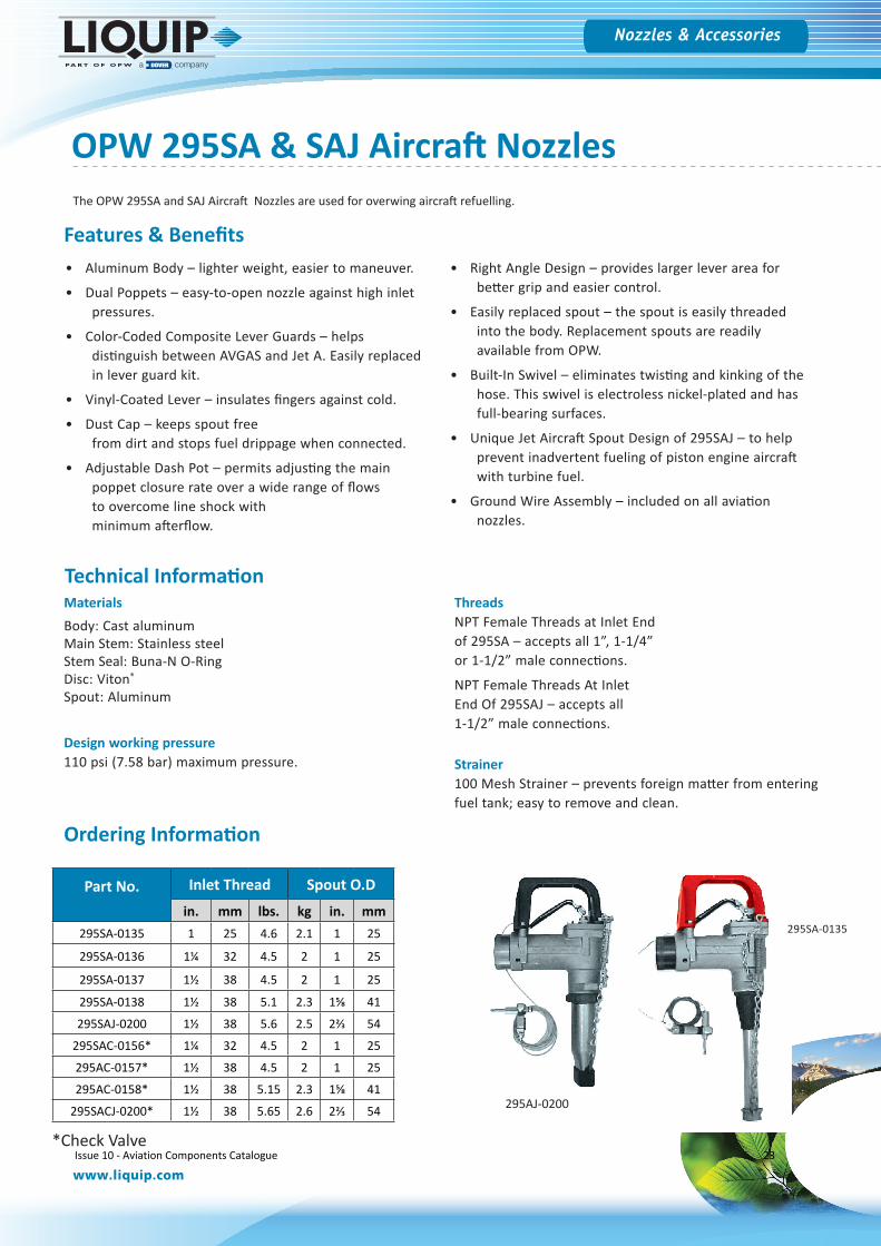
The OPW 295SA and SAJ Aircraft Nozzles are used for overwing aircraft refuelling.
OPW 295SA & SAJ Aircraft Nozzles
Ordering Information
• Aluminum Body – lighter weight, easier to maneuver.
• Dual Poppets – easy-to-open nozzle against high inletpressures.
• Color-Coded Composite Lever Guards – helpsdistinguish between AVGAS and Jet A. Easily replacedin lever guard kit.
• Vinyl-Coated Lever – insulates fingers against cold.
• Dust Cap – keeps spout freefrom dirt and stops fuel drippage when connected.
• Adjustable Dash Pot – permits adjusting the mainpoppet closure rate over a wide range of flowsto overcome line shock withminimum afterflow.
• Right Angle Design – provides larger lever area forbetter grip and easier control.
• Easily replaced spout – the spout is easily threadedinto the body. Replacement spouts are readilyavailable from OPW.
• Built-In Swivel – eliminates twisting and kinking of thehose. This swivel is electroless nickel-plated and hasfull-bearing surfaces.
• Unique Jet Aircraft Spout Design of 295SAJ – to helpprevent inadvertent fueling of piston engine aircraftwith turbine fuel.
• Ground Wire Assembly – included on all aviationnozzles.
Features & Benefits
Technical Information
Part No. Inlet Thread Spout O.D
in. mm lbs. kg in. mm295SA-0135 1 25 4.6 2.1 1 25
295SA-0136 1¼ 32 4.5 2 1 25
295SA-0137 1½ 38 4.5 2 1 25
295SA-0138 1½ 38 5.1 2.3 1⅝ 41
295SAJ-0200 1½ 38 5.6 2.5 2⅔ 54
295SAC-0156* 1¼ 32 4.5 2 1 25
295AC-0157* 1½ 38 4.5 2 1 25
295AC-0158* 1½ 38 5.15 2.3 1⅝ 41
295SACJ-0200* 1½ 38 5.65 2.6 2⅔ 54
*Check Valve
295AJ-0200
295SA-0135
MaterialsBody: Cast aluminumMain Stem: Stainless steelStem Seal: Buna-N O-RingDisc: Viton®
Spout: Aluminum
Design working pressure 110 psi (7.58 bar) maximum pressure.
Threads NPT Female Threads at Inlet End of 295SA – accepts all 1”, 1-1/4” or 1-1/2” male connections.
NPT Female Threads At Inlet End Of 295SAJ – accepts all 1-1/2” male connections.
Strainer 100 Mesh Strainer – prevents foreign matter from entering fuel tank; easy to remove and clean.
Issue 10 - Aviation Components Catalogue 23
Hosereels & Fittings
www.liquip.com
Nozzles & Accessories
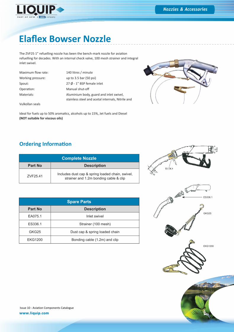
The ZVF25 1” refuelling nozzle has been the bench-mark nozzle for aviation refuelling for decades. With an internal check valve, 100 mesh strainer and integral inlet swivel.
Maximum flow rate: 140 litres / minuteWorking pressure: up to 3.5 bar (50 psi)Spout: 27 Ø - 1” BSP female inletOperation: Manual shut-offMaterials: Aluminium body, guard and inlet swivel,
stainless steel and acetal internals, Nitrile and Vulkollan seals
Ideal for fuels up to 50% aromatics, alcohols up to 15%, Jet fuels and Diesel (NOT suitable for viscous oils)
Elaflex Bowser Nozzle
Spare PartsPart No Description
EA075.1 Inlet swivel
ES336.1 Strainer (100 mesh)
GKG25 Dust cap & spring loaded chain
EKG1200 Bonding cable (1.2m) and clip
Complete NozzlePart No Description
ZVF25.41 Includes dust cap & spring loaded chain, swivel, strainer and 1.2m bonding cable & clip
GKG25
EKG1200
ES336.1
Ordering Information
Issue 10 - Aviation Components Catalogue 24
Hosereels & Fittings
www.liquip.com
Nozzles & Accessories
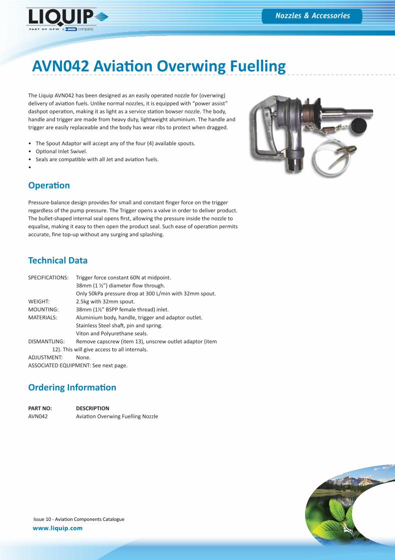
AVN042 Aviation Overwing Fuelling The Liquip AVN042 has been designed as an easily operated nozzle for (overwing) delivery of aviation fuels. Unlike normal nozzles, it is equipped with “power assist” dashpot operation, making it as light as a service station bowser nozzle. The body, handle and trigger are made from heavy duty, lightweight aluminium. The handle and trigger are easily replaceable and the body has wear ribs to protect when dragged.
• The Spout Adaptor will accept any of the four (4) available spouts.• Optional Inlet Swivel.• Seals are compatible with all Jet and aviation fuels.•
Operation
Pressure-balance design provides for small and constant finger force on the trigger regardless of the pump pressure. The Trigger opens a valve in order to deliver product. The bullet-shaped internal seal opens first, allowing the pressure inside the nozzle to equalise, making it easy to then open the product seal. Such ease of operation permits accurate, fine top-up without any surging and splashing.
Technical Data
SPECIFICATIONS: Trigger force constant 60N at midpoint.38mm (1 ½”) diameter flow through.Only 50kPa pressure drop at 300 L/min with 32mm spout.
WEIGHT: 2.5kg with 32mm spout.MOUNTING: 38mm (1½” BSPP female thread) inlet.MATERIALS: Aluminium body, handle, trigger and adaptor outlet.
Stainless Steel shaft, pin and spring.Viton and Polyurethane seals.
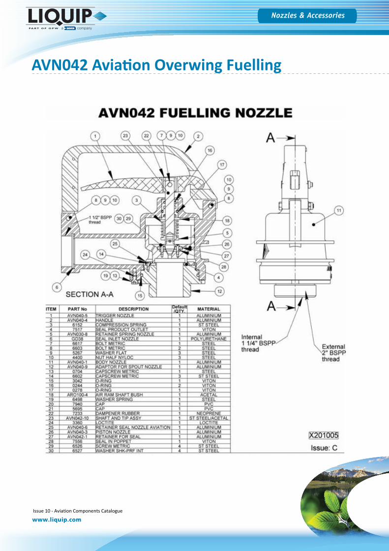
DISMANTLING: Remove capscrew (item 13), unscrew outlet adaptor (item 12). This will give access to all internals.
ADJUSTMENT: None.ASSOCIATED EQUIPMENT: See next page.
Ordering Information
PART NO: DESCRIPTIONAVN042 Aviation Overwing Fuelling Nozzle
Issue 10 - Aviation Components Catalogue 25
Hosereels & Fittings
www.liquip.com
Nozzles & Accessories
AVN042 Aviation Overwing Fuelling
Issue 10 - Aviation Components Catalogue 26
Hosereels & Fittings
www.liquip.com
Nozzles & Accessories
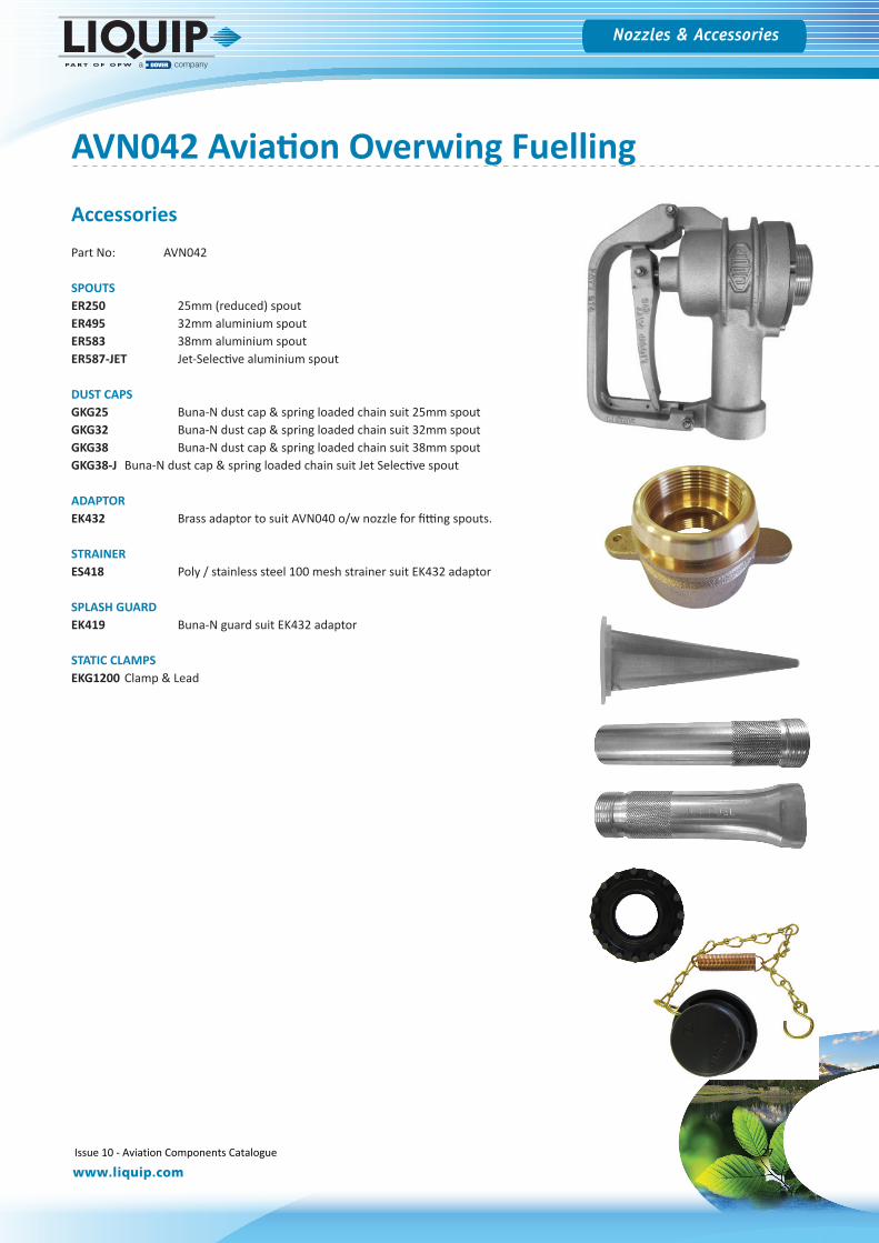
AVN042 Aviation Overwing Fuelling
Accessories
Part No: AVN042
SPOUTSER250 25mm (reduced) spoutER495 32mm aluminium spoutER583 38mm aluminium spoutER587-JET Jet-Selective aluminium spout
DUST CAPSGKG25 Buna-N dust cap & spring loaded chain suit 25mm spoutGKG32 Buna-N dust cap & spring loaded chain suit 32mm spoutGKG38 Buna-N dust cap & spring loaded chain suit 38mm spoutGKG38-J Buna-N dust cap & spring loaded chain suit Jet Selective spout
ADAPTOREK432 Brass adaptor to suit AVN040 o/w nozzle for fitting spouts.
STRAINERES418 Poly / stainless steel 100 mesh strainer suit EK432 adaptor
SPLASH GUARDEK419 Buna-N guard suit EK432 adaptor
STATIC CLAMPSEKG1200 Clamp & Lead
Issue 10 - Aviation Components Catalogue 27
Hosereels & Fittings
www.liquip.com
Nozzles & Accessories
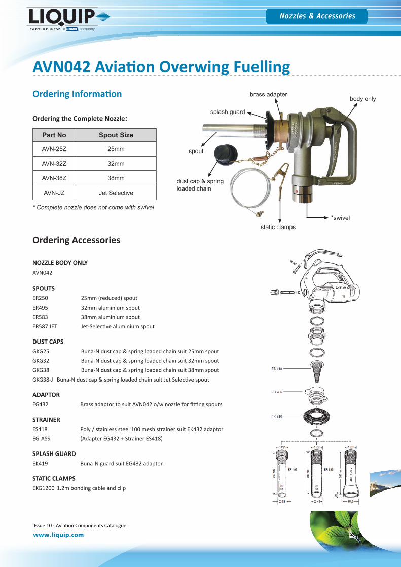
Part No Spout Size
AVN-25Z 25mm
AVN-32Z 32mm
AVN-38Z 38mm
AVN-JZ Jet Selective
brass adapter
splash guard
spout
body only
static clamps
dust cap & spring loaded chain
*swivel
NOZZLE BODY ONLYAVN042
SPOUTSER250 25mm (reduced) spoutER495 32mm aluminium spoutER583 38mm aluminium spoutER587 JET Jet-Selective aluminium spout
DUST CAPSGKG25 Buna-N dust cap & spring loaded chain suit 25mm spoutGKG32 Buna-N dust cap & spring loaded chain suit 32mm spoutGKG38 Buna-N dust cap & spring loaded chain suit 38mm spoutGKG38-J Buna-N dust cap & spring loaded chain suit Jet Selective spout
ADAPTOREG432 Brass adaptor to suit AVN042 o/w nozzle for fitting spouts
STRAINERES418 Poly / stainless steel 100 mesh strainer suit EK432 adaptorEG-ASS (Adapter EG432 + Strainer ES418)
SPLASH GUARDEK419 Buna-N guard suit EG432 adaptor
STATIC CLAMPSEKG1200 1.2m bonding cable and clip
Ordering Accessories
Ordering the Complete Nozzle:
* Complete nozzle does not come with swivel
AVN042 Aviation Overwing Fuelling Ordering Information
Issue 10 - Aviation Components Catalogue 28
Hosereels & Fittings
www.liquip.com
Nozzles & Accessories
Nozzle Stowage
Ball & Socket - Underwing
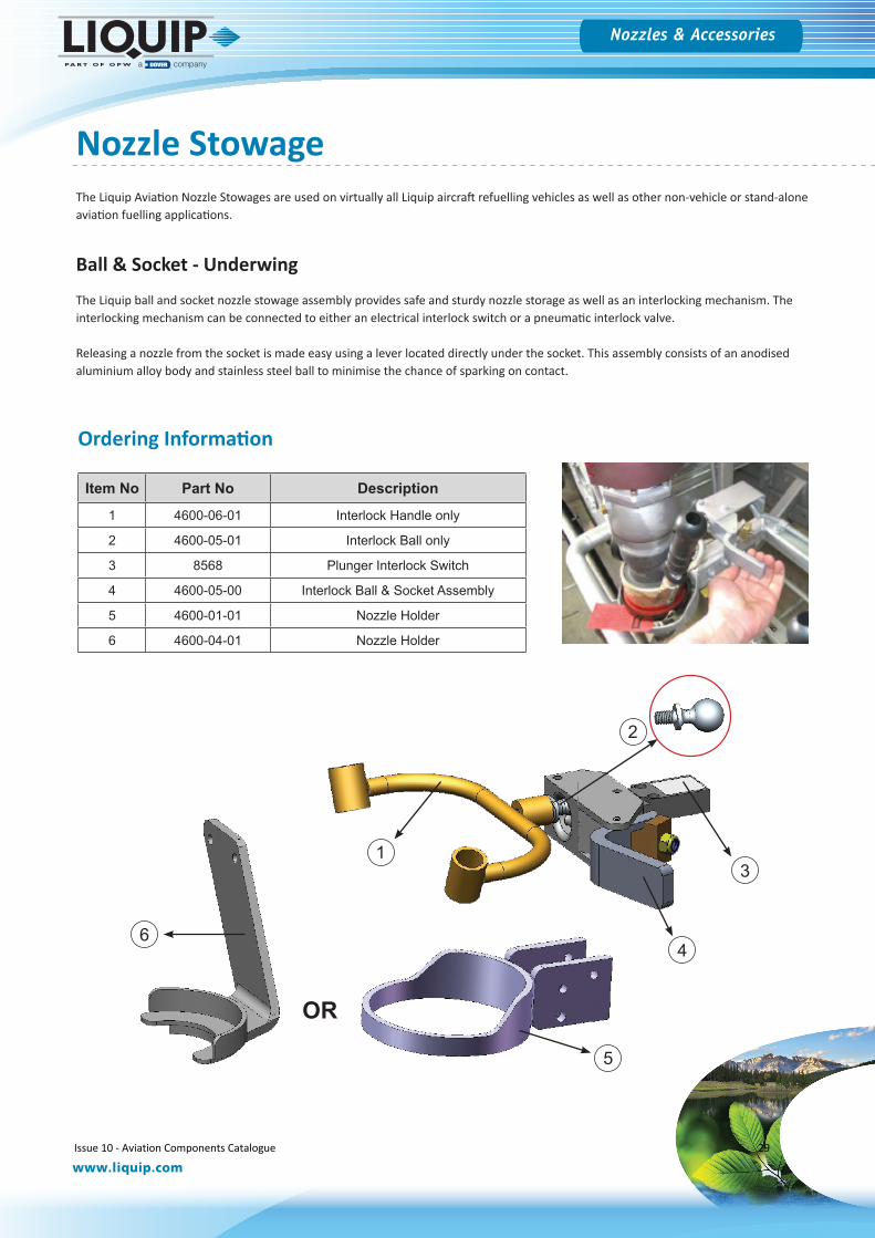
The Liquip ball and socket nozzle stowage assembly provides safe and sturdy nozzle storage as well as an interlocking mechanism. The interlocking mechanism can be connected to either an electrical interlock switch or a pneumatic interlock valve.
Releasing a nozzle from the socket is made easy using a lever located directly under the socket. This assembly consists of an anodised aluminium alloy body and stainless steel ball to minimise the chance of sparking on contact.
Item No Part No Description
1 4600-06-01 Interlock Handle only
2 4600-05-01 Interlock Ball only
3 8568 Plunger Interlock Switch
4 4600-05-00 Interlock Ball & Socket Assembly
5 4600-01-01 Nozzle Holder
6 4600-04-01 Nozzle Holder
The Liquip Aviation Nozzle Stowages are used on virtually all Liquip aircraft refuelling vehicles as well as other non-vehicle or stand-alone aviation fuelling applications.
5
64
2
31
OR
Ordering Information
Issue 10 - Aviation Components Catalogue 29
Hosereels & Fittings
www.liquip.com
Nozzles & Accessories
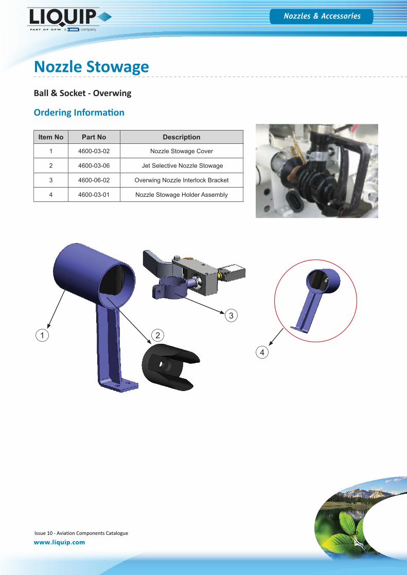
Item No Part No Description
1 4600-03-02 Nozzle Stowage Cover
2 4600-03-06 Jet Selective Nozzle Stowage
3 4600-06-02 Overwing Nozzle Interlock Bracket
4 4600-03-01 Nozzle Stowage Holder Assembly
4
3
21
Ball & Socket - Overwing
Nozzle Stowage
Ordering Information
Issue 10 - Aviation Components Catalogue 30
Hosereels & Fittings
www.liquip.com
Nozzles & Accessories
Item No Part No Description
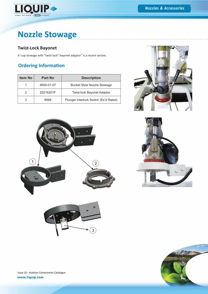
1 4600-01-07 Bucket Style Nozzle Stowage
2 20216201F Twist-lock Bayonet Adaptor
3 8568 Plunger Interlock Switch (Ex’d Rated)
2
3
Twist-Lock BayonetA ‘cup stowage with “twist-lock” bayonet adaptor” is a recent variant.
1
Ordering Information
Nozzle Stowage
Issue 10 - Aviation Components Catalogue 31
Hosereels & Fittings
www.liquip.com
Nozzles & Accessories
Item No Part No Description
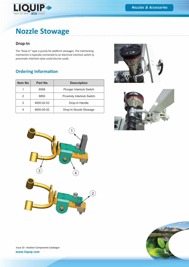
1 8568 Plunger Interlock Switch
2 8850 Proximity Interlock Switch
3 4600-02-03 Drop-In Handle
4 4600-00-02 Drop-In Nozzle Stowage
Drop-InThe “drop-in” type is purely for platform stowages. The interlocking mechanism is typically connected to an electrical interlock switch (a pneumatic interlock valve could also be used).
2
1
3 4
Ordering Information
Nozzle Stowage
Issue 10 - Aviation Components Catalogue 32

Bottom Load Accessories
Issue 10 - Aviation Components Catalogue 33
Bottom Load Accessories
www.liquip.com
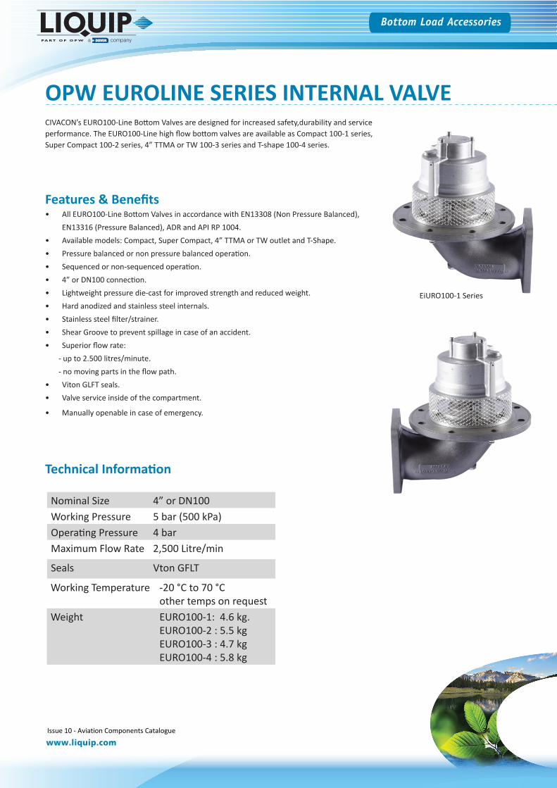
OPW EUROLINE SERIES INTERNAL VALVECIVACON’s EURO100-Line Bottom Valves are designed for increased safety,durability and service performance. The EURO100-Line high flow bottom valves are available as Compact 100-1 series, Super Compact 100-2 series, 4” TTMA or TW 100-3 series and T-shape 100-4 series.
Features & Benefits• All EURO100-Line Bottom Valves in accordance with EN13308 (Non Pressure Balanced),
EN13316 (Pressure Balanced), ADR and API RP 1004.• Available models: Compact, Super Compact, 4” TTMA or TW outlet and T-Shape.• Pressure balanced or non pressure balanced operation.• Sequenced or non-sequenced operation.• 4” or DN100 connection.• Lightweight pressure die-cast for improved strength and reduced weight.• Hard anodized and stainless steel internals.• Stainless steel filter/strainer.• Shear Groove to prevent spillage in case of an accident.• Superior flow rate:
- up to 2.500 litres/minute.- no moving parts in the flow path.
• Viton GLFT seals.• Valve service inside of the compartment.
• Manually openable in case of emergency.
Nominal Size 4” or DN100Working Pressure 5 bar (500 kPa)Operating Pressure 4 barMaximum Flow Rate 2,500 Litre/min
Seals Vton GFLT
Working Temperature -20 °C to 70 °Cother temps on request
Weight EURO100-1: 4.6 kg.EURO100-2 : 5.5 kgEURO100-3 : 4.7 kgEURO100-4 : 5.8 kg
Technical Information
EiURO100-1 Series
Issue 10 - Aviation Components Catalogue 34
Bottom Load Accessories
www.liquip.com
OPW EUROLINE SERIES INTERNAL VALVEOrdering Information
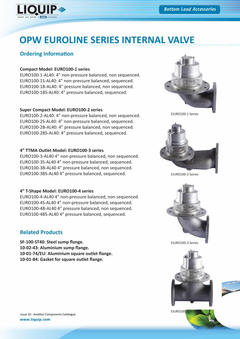
Compact Model: EURO100-1 seriesEURO100-1-AL40: 4” non-pressure balanced, non sequenced.EURO100-1S-AL40: 4” non-pressure balanced, sequenced.EURO100-1B-AL40: 4” pressure balanced, non sequenced.EURO100-1BS-AL40: 4” pressure balanced, sequenced.
Super Compact Model: EURO100-2 seriesEURO100-2-AL40: 4” non-pressure balanced, non sequenced.EURO100-2S-AL40: 4” non-pressure balanced, sequenced.EURO100-2B-AL40: 4” pressure balanced, non sequenced.EURO100-2BS-AL40: 4” pressure balanced, sequenced.
4” TTMA Outlet Model: EURO100-3 seriesEURO100-3-AL40 4” non-pressure balanced, non sequenced.EURO100-3S-AL40 4” non-pressure balanced, sequenced.EURO100-3B-AL40 4” pressure balanced, non sequenced.EURO100-3BS-AL40 4” pressure balanced, sequenced.
4” T-Shape Model: EURO100-4 seriesEURO100-4-AL40 4” non-pressure balanced, non sequenced.EURO100-4S-AL40 4” non-pressure balanced, sequenced.EURO100-4B-AL40 4” pressure balanced, non sequenced.EURO100-4BS-AL40 4” pressure balanced, sequenced.
EiURO100-1 Series
EiURO100-2 Series
EiURO100-3 Series
EiURO100-4 Series
Related ProductsSF-100-ST40: Steel sump flange.10-02-43: Aluminium sump flange.10-01-74/EU: Aluminium square outlet flange.10-01-84: Gasket for square outlet flange.
Issue 10 - Aviation Components Catalogue 35
Bottom Load Accessories
www.liquip.com
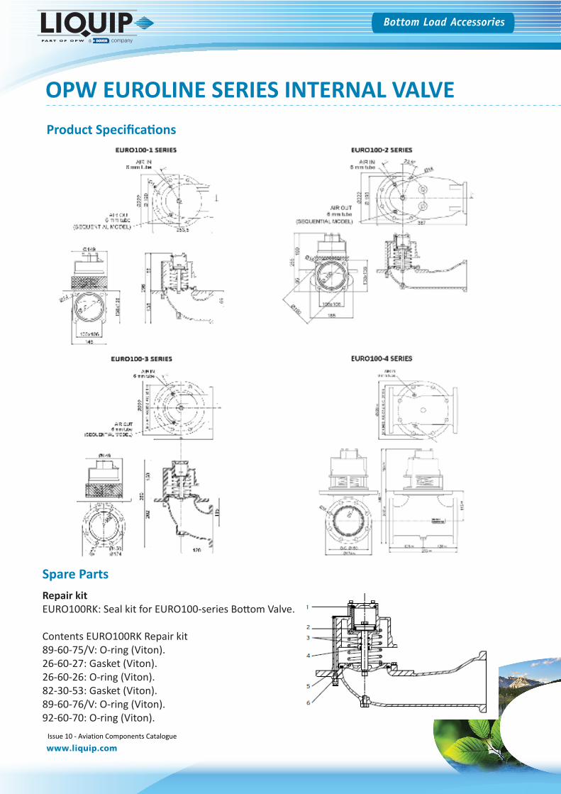
OPW EUROLINE SERIES INTERNAL VALVEProduct Specifications
Spare PartsRepair kitEURO100RK: Seal kit for EURO100-series Bottom Valve.
Contents EURO100RK Repair kit89-60-75/V: O-ring (Viton).26-60-27: Gasket (Viton).26-60-26: O-ring (Viton).82-30-53: Gasket (Viton).89-60-76/V: O-ring (Viton).92-60-70: O-ring (Viton).
Issue 10 - Aviation Components Catalogue 36
Bottom Load Accessories
www.liquip.com
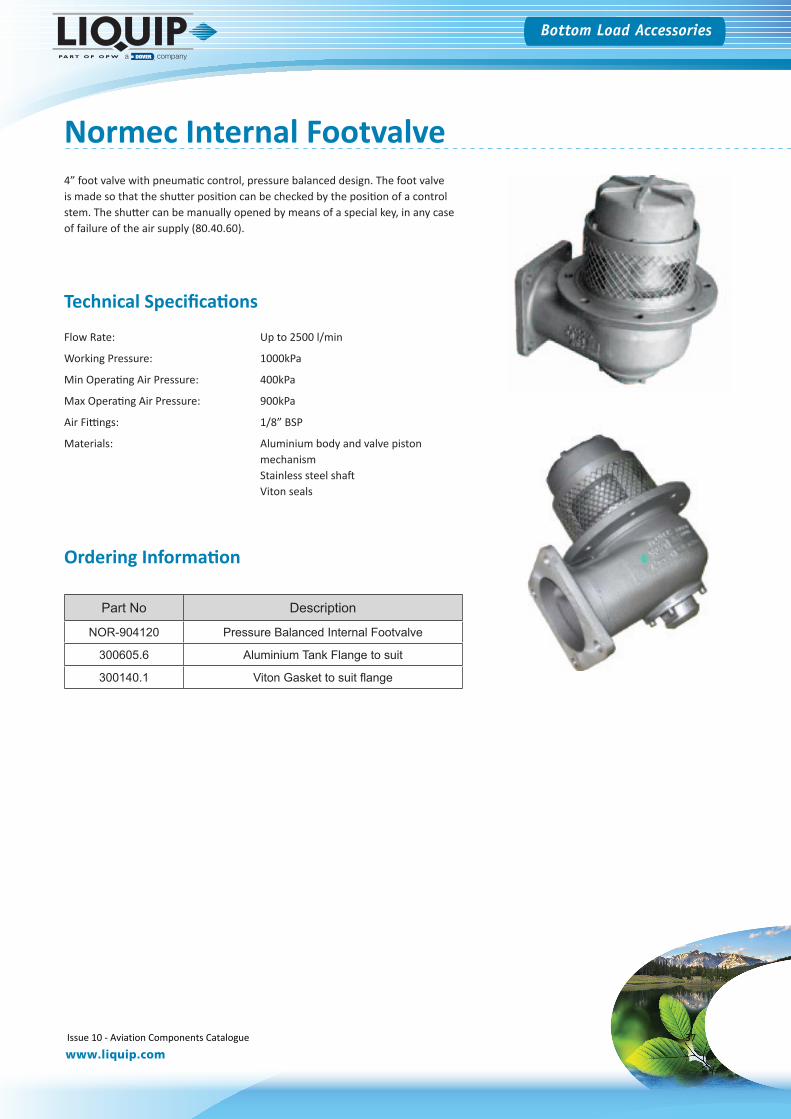
Normec Internal Footvalve4” foot valve with pneumatic control, pressure balanced design. The foot valve is made so that the shutter position can be checked by the position of a control stem. The shutter can be manually opened by means of a special key, in any case of failure of the air supply (80.40.60).
Technical Specifications
Flow Rate: Up to 2500 l/min
Working Pressure: 1000kPa
Min Operating Air Pressure: 400kPa
Max Operating Air Pressure: 900kPa
Air Fittings: 1/8” BSP
Materials: Aluminium body and valve piston mechanism Stainless steel shaftViton seals
Part No Description
NOR-904120 Pressure Balanced Internal Footvalve
300605.6 Aluminium Tank Flange to suit
300140.1 Viton Gasket to suit flange
Ordering Information
Issue 10 - Aviation Components Catalogue 37
Bottom Load Accessories
www.liquip.com
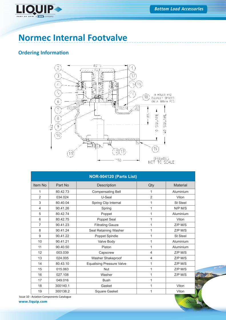
NOR-904120 (Parts List)
Item No Part No Description Qty Material1 80.42.73 Compensating Bell 1 Aluminium2 034.024 U-Seal 2 Viton3 80.40.04 Spring Clip Internal 1 St Steel4 90.41.26 Spring 1 N/P M/S5 80.42.74 Poppet 1 Aluminium6 80.42.75 Poppet Seal 1 Viton7 90.41.23 Filtrating Gauze 1 Z/P M/S8 90.41.24 Seal Retaining Washer 1 Z/P M/S9 90.41.22 Poppet Spindle 1 St Steel
10 90.41.21 Valve Body 1 Aluminium11 90.40.50 Piston 1 Aluminium12 003.039 Capscrew 4 Z/P M/S13 024.005 Washer Shakeproof 4 Z/P M/S14 80.43.10 Equalising Pressure Valve 1 Z/P M/S15 015.063 Nut 1 Z/P M/S16 027.108 Washer 1 Z/P M/S17 049.016 Bush 118 300140.1 Gasket 1 Viton19 300138.2 Square Gasket 1 Viton
Ordering Information
Normec Internal Footvalve
Issue 10 - Aviation Components Catalogue 38

Hydrants
Issue 10 - Aviation Components Catalogue 39

Bottom Load Accessories
www.liquip.com
Hydrant
When you buy Liquip products, you’re buying a trusted heritage of solutions from the company that’s been quietly setting industry standards for over four decades, in Australia and beyond. Our comprehensive line of hydrant pits provide superior operation and easy access for maintenance while meeting the latest EN standard. Liquip can also make double walled steel pits on request.
Our Hydrant pit designs have been proven at airport installations in countries all over the world including: Australia, New Zealand, Singapore and Brazil.
We have taken these trusted designs to the next level and developed an access cover which meets the stringent F900 requirements as part of the EN standard. Even with stricter requirements, Liquip’s ingenuity has resolved related manual handling challenges, by allowing covers to be maneuvered easily by one person and with one hand. This is thanks to an easy to use, purpose built tool.
A New Generation in Hydrant Pit Technologies
Features Include:
Water Tight SealingSpecially designed one-piece constructionSteel or Polyflex Body Polyflex: Lightweight option to suit installation restrictions Steel: Heavy-duty and durable EN Rated or Lightweight Access Cover Options
EN F900: 21.5 kg Lightweight: 15.5 kg
Slip Resistant and Ergonomic Covers Keeping ground staff safe Standard JET-A1 product ID. Other options: AVGAS, FH, SVEasy One-Hand Operation of Covers Less than 25 kg force required thanks to a purpose built tool.Two Sizes Available 450mm (18”) with inner lid (aperture = 16”)
600mm (24”) with inner and outer lid (aperture = 23.5”) Latching and Lifting Options EN Rated Cover - lifting tool, no lock
Lightweight Cover - locking mechanism with lifting handle
Tethering Options
Tethering options to meet latest EN and JIG standards
Inlet Flange Kit Options
Pits can be supplied with steel or stainless steel flanges
100 Litre Capacity (24” PolyFlex Pit)
Up to 45 Litres before any potential leak point (bellow/riser).
Purpose Built Lifting Tool
Steel Hydrant Pit & EN approved Cover
Inlet flange kit
Issue 10 - Aviation Components Catalogue 40
Bottom Load Accessories
www.liquip.com
Hydrant
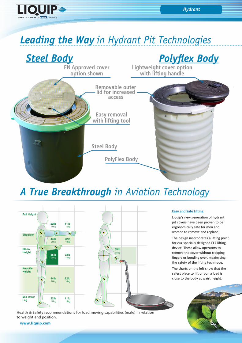
Leading the Way in Hydrant Pit Technologies
Steel Body
EN Approved cover option shown
Easy removal with lifting tool
PolyFlex Body
55lb25kg
22lb10kg
11lb5kg
44lb20kg
22lb10kg
55lb25kg
33lb15kg
44lb20kg
22lb10kg
22lb10kg
11lb5kg
Full Height
Shoulder
ElbowHeight
KnuckleHeight
Mid-lowerLeg
Easy and Safe Lifting
Liquip’s new generation of hydrant pit covers have been proven to be ergonomically safe for men and women to remove and replace.
The design incorporates a lifting point for our specially designed FL7 lifting device. These allow operators to remove the cover without trapping fingers or bending over, maximising the safety of the lifting technique.
The charts on the left show that the safest place to lift or pull a load is close to the body at waist height.
A True Breakthrough in Aviation Technology
Lightweight cover option with lifting handle
Steel Body Polyflex Body
Removable outer lid for increased
access
Health & Safety recommendations for load moving capabilities (male) in relation to weight and position. 41
Bottom Load Accessories
www.liquip.com
Hydrant
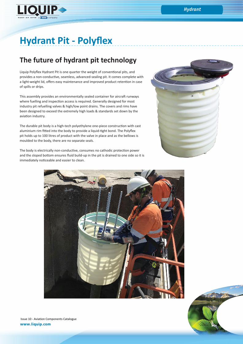
Hydrant Pit - Polyflex
The future of hydrant pit technologyLiquip Polyflex Hydrant Pit is one quarter the weight of conventional pits, and provides a non-conductive, seamless, advanced-sealing pit. It comes complete with a light-weight lid, offers easy maintenance and improved product retention in case of spills or drips.
This assembly provides an environmentally sealed container for aircraft runways where fuelling and inspection access is required. Generally designed for most industry pit refuelling valves & high/low point drains. The covers and rims have been designed to exceed the extremely high loads & standards set down by the aviation industry.
The durable pit body is a high-tech polyethylene one-piece construction with cast aluminium rim fitted into the body to provide a liquid-tight bond. The Polyflex pit holds up to 100 litres of product with the valve in place and as the bellows is moulded to the body, there are no separate seals.
The body is electrically non-conductive, consumes no cathodic protection power and the sloped bottom ensures fluid build-up in the pit is drained to one side so it is immediately noticeable and easier to clean.
Issue 10 - Aviation Components Catalogue 42
Bottom Load Accessories
www.liquip.com
Hydrant
Hydrant Pit - Polyflex
Technical Specifications
Variants: HPA100, HPA150, HPA200 and HPA250
Pit Body: High density polyethylene, non-conductingUV stabilised for outdoor storageWorking temperature range: - 40 degrees C to 200 degrees CYield 18Mpa S.G. 0.94Elongation 450%Flex modules 690Mpa
Pit Rim & Outer Lid: Aluminium AA601 heat treated and aged T6
Weld Neck: 100mm or 150mm ANSI 150 with fully sealed blind drilled and tapped stud holes, machine finish outside diameter and fastening point for bonding strap. The bonding strap runs from the pipe to the pit rim and is stainless steel.
Integral Bellows: The integral moulded bellows provides seamless flexibility to accommodate the riser pipe. The 24” pit retains 45 litres before the liquid level reaches the top of the bellows. The bellows has an extended top, allowing variable installation height and surplus can be trimmed back. Entry point is designed for 100mm ANSI 150 bolt pattern weld neck flange with thick flange for improved sealing.
Lightweight Lid: The HLA100 is the lightest pit lid on the market today which can still withstand the high forces and weights exerted by aircraft as set out in some specifications. It has an automatic self latching feature with single latch mechanism and an anti-slip top. It fits both the 18” and 24” pit (the 24” pit has an “outer lid”). The outer lid on 24” pits can also easily be removed when a larger access area is required for maintenance purposes.
Weight Comparison: Conventional Steel Pit with Lid, 18” ± 115 kgsConventional Steel Pit with Lid, 24” ± 158 kgsConventional Aluminium Lid ± 25 kgsLiquip Lightweight Aluminium Lid, HLA100 ± 13 kgsTotal Weight of Liquip HPA200 (24” Pit, 4” Bellows) ± 75.5 kgsTotal Weight of Liquip HPA250 (24” Pit, 6” Bellows) ± 85.0 kgsTotal Weight of Liquip HPA100 (18” Pit, 4” Bellows) ± 32 kgsTotal Weight of Liquip HPA150 (18” Pit, 6” Bellows) ± 32 kgs
Issue 10 - Aviation Components Catalogue 43
Bottom Load Accessories
www.liquip.com
Hydrant
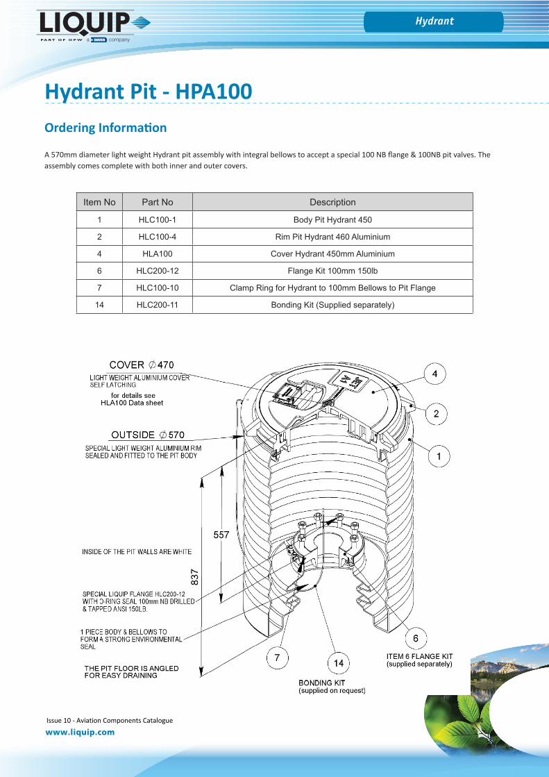
Hydrant Pit - HPA100
Item No Part No Description
1 HLC100-1 Body Pit Hydrant 450
2 HLC100-4 Rim Pit Hydrant 460 Aluminium
4 HLA100 Cover Hydrant 450mm Aluminium
6 HLC200-12 Flange Kit 100mm 150lb
7 HLC100-10 Clamp Ring for Hydrant to 100mm Bellows to Pit Flange
14 HLC200-11 Bonding Kit (Supplied separately)
A 570mm diameter light weight Hydrant pit assembly with integral bellows to accept a special 100 NB flange & 100NB pit valves. The assembly comes complete with both inner and outer covers.
Ordering Information
Issue 10 - Aviation Components Catalogue 44
Bottom Load Accessories
www.liquip.com
Hydrant
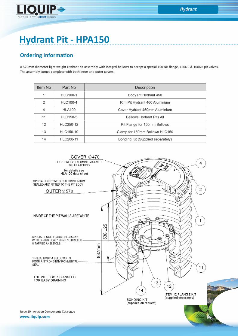
Hydrant Pit - HPA150
Item No Part No Description
1 HLC100-1 Body Pit Hydrant 450
2 HLC100-4 Rim Pit Hydrant 460 Aluminium
4 HLA100 Cover Hydrant 450mm Aluminium
11 HLC150-5 Bellows Hydrant Pits All
12 HLC250-12 Kit Flange for 150mm Bellows
13 HLC150-10 Clamp for 150mm Bellows HLC150
14 HLC200-11 Bonding Kit (Supplied separately)
A 570mm diameter light weight Hydrant pit assembly with integral bellows to accept a special 150 NB flange, 150NB & 100NB pit valves. The assembly comes complete with both inner and outer covers.
Ordering Information
Issue 10 - Aviation Components Catalogue 45
Bottom Load Accessories
www.liquip.com
Hydrant
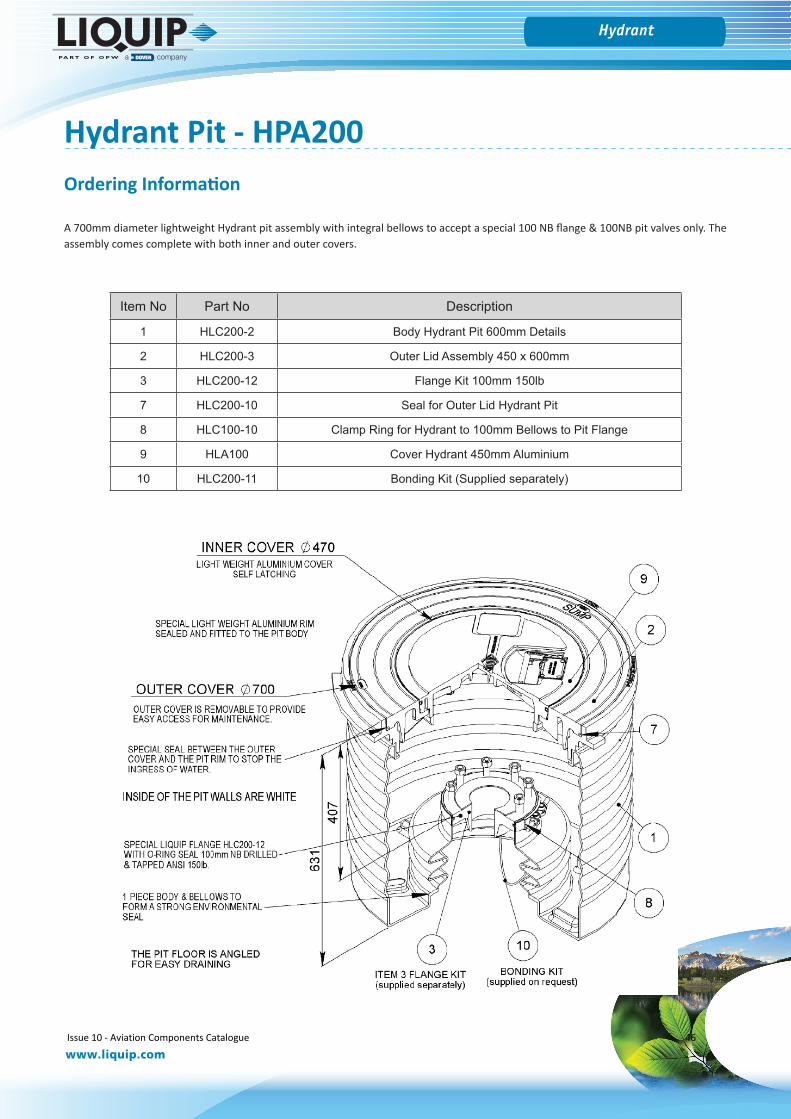
Hydrant Pit - HPA200
Item No Part No Description
1 HLC200-2 Body Hydrant Pit 600mm Details
2 HLC200-3 Outer Lid Assembly 450 x 600mm
3 HLC200-12 Flange Kit 100mm 150lb
7 HLC200-10 Seal for Outer Lid Hydrant Pit
8 HLC100-10 Clamp Ring for Hydrant to 100mm Bellows to Pit Flange
9 HLA100 Cover Hydrant 450mm Aluminium
10 HLC200-11 Bonding Kit (Supplied separately)
A 700mm diameter lightweight Hydrant pit assembly with integral bellows to accept a special 100 NB flange & 100NB pit valves only. The assembly comes complete with both inner and outer covers.
Ordering Information
Issue 10 - Aviation Components Catalogue 46
Bottom Load Accessories
www.liquip.com
Hydrant
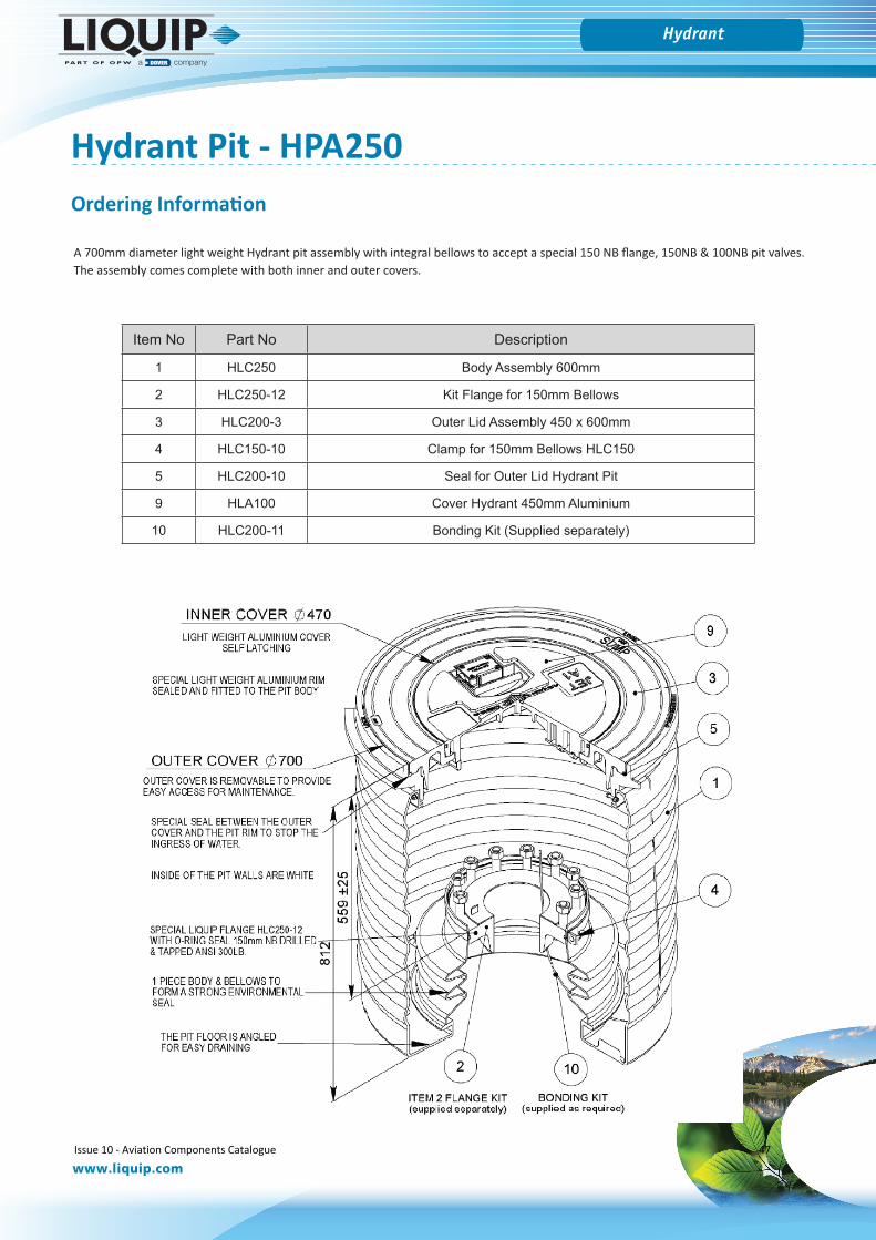
Hydrant Pit - HPA250
A 700mm diameter light weight Hydrant pit assembly with integral bellows to accept a special 150 NB flange, 150NB & 100NB pit valves. The assembly comes complete with both inner and outer covers.
Item No Part No Description
1 HLC250 Body Assembly 600mm
2 HLC250-12 Kit Flange for 150mm Bellows
3 HLC200-3 Outer Lid Assembly 450 x 600mm
4 HLC150-10 Clamp for 150mm Bellows HLC150
5 HLC200-10 Seal for Outer Lid Hydrant Pit
9 HLA100 Cover Hydrant 450mm Aluminium
10 HLC200-11 Bonding Kit (Supplied separately)
Ordering Information
Issue 10 - Aviation Components Catalogue 47
Bottom Load Accessories
www.liquip.com
Hydrant
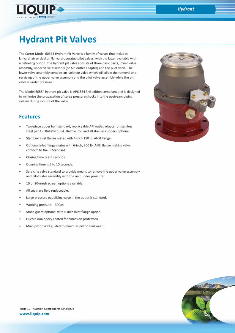
Hydrant Pit Valves The Carter Model 60554 Hydrant Pit Valve is a family of valves that includes lanyard, air or dual air/lanyard operated pilot valves, with the latter available with a defueling option. The hydrant pit valve consists of three basic parts, lower valve assembly, upper valve assembly (or API outlet adapter) and the pilot valve. The lower valve assembly contains an isolation valve which will allow the removal and servicing of the upper valve assembly and the pilot valve assembly while the pit valve is under pressure.
The Model 60554 hydrant pit valve is API1584 3rd edition compliant and is designed to minimize the propagation of surge pressure shocks into the upstream piping system during closure of the valve.
Features• Two-piece upper half standard, replaceable API outlet adapter of stainless
steel per API Bulletin 1584. Ductile iron and all stainless uppers optional.
• Standard inlet flange mates with 4-inch 150 lb. ANSI flange.
• Optional inlet flange mates with 6-inch, 300 lb. ANSI flange making valveconform to the IP Standard.
• Closing time is 2-5 seconds.
• Opening time is 5 to 10 seconds.
• Servicing valve standard to provide means to remove the upper valve assemblyand pilot valve assembly with the unit under pressure.
• 10 or 20-mesh screen options available.
• All seals are field replaceable.
• Large pressure equalizing valve in the outlet is standard.
• Working pressure – 300psi
• Stone guard optional with 6-inch inlet flange option.
• Ductile iron epoxy coated for corrosion protection
• Main piston well guided to minimise piston seal wear.
Issue 10 - Aviation Components Catalogue 48
Bottom Load Accessories
www.liquip.com
Hydrant
Pilot Options• Model 60554D — Lanyard operated pilot valve for manual on/off control. Valve allows flow in the fuelling direction only.
• Model 60554E — Air operated pilot valve for deadman control. Valve allows flow in the fuelling direction only.
• Model 60554F — Dual air and lanyard operated pilot valve for deadman control and manual on/off control for use in small pits only(12 or 13 inch diameter). Unidirectional only, unless combined with option J.
• Model 60554J — Air operated pilot valve for deadman control with defuel control to allow flow of fuel in either fuelling or defuelingdirection
• Model 60554-3D — Same as Model 60554D except material of outer housing is ductile iron per ASTM A395 (special order only).The upper and lower valve assemblies are fastened together with 15 metric threaded screws instead of the normal 8-UNF threadedscrews (replaced Model 60554-2D). Two piece upper half not available on this unit.
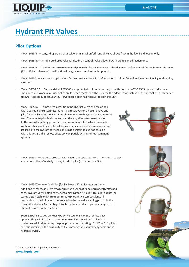
• Model 60554X — Remove the pilots from the Hydrant Valve and replacing itwith a sealed male disconnect fitting. As a result you only need to have onepilot for each hydrant servicer rather than one for each hydrant valve, reducingcost. The remote pilot is also sealed and thereby eliminates issues relatedto the inward breathing pistons in the conventional pilots which can inhalecontaminates resulting in internal corrosion and increased maintenance. Fuelleakage into the hydrant servicer’s pneumatic system is also not possiblewith this design. The remote pilots are compatible with air or fuel commandsystems.
• Model 60554Z — New Dual Pilot (for Pit Boxes 18” in diameter and larger):Additionally, for those users who require the dual pilot to be permanently attachedto the hydrant valve, Eaton now offers a new Option “Z” pilot. This pilot adopts thesealed piston technology from our remote pilots into a compact lanyardmechanism that eliminates issues related to the inward breathing pistons in theconventional pilots. Fuel leakage into the hydrant servicer’s pneumatic system isalso not possible with this design.
Existing hydrant valves can easily be converted to any of the remote pilotoptions. They eliminate all of the common maintenance issues related tocontaminated fluids entering the pilot piston area of existing “E”, “F”, or “U” pilotsand also eliminated the possibility of fuel entering the pneumatic systems on thehydrant servicer.
• Model 60554Y — As per X pilot but with Pneumatic operated “fork” mechanism to ejectthe remote pilot, effectively making it a dual pilot (part number 47834)
Hydrant Pit Valves
Issue 10 - Aviation Components Catalogue 49
Bottom Load Accessories
www.liquip.com
Hydrant
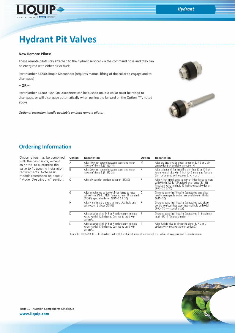
New Remote Pilots:
These remote pilots stay attached to the hydrant servicer via the command hose and they can be energized with either air or fuel:
Part number 64230 Simple Disconnect (requires manual lifting of the collar to engage and to disengage)
– OR –
Part number 64280 Push-On Disconnect can be pushed on, but collar must be raised to disengage, or will disengage automatically when pulling the lanyard on the Option “Y”, noted above.
Optional extension handle available on both remote pilots.
Ordering Information
Hydrant Pit Valves
Issue 10 - Aviation Components Catalogue 50
Bottom Load Accessories
www.liquip.com
Hydrant
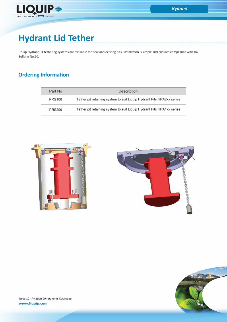
Hydrant Lid TetherLiquip Hydrant Pit tethering systems are available for new and existing pits. Installation is simple and ensures compliance with JIG Bulletin No.10.
Part No Description
PRS100 Tether pit retaining system to suit Liquip Hydrant Pits HPA2xx series
PRS200
Ordering Information
Issue 10 - Aviation Components Catalogue 51
Tether pit retaining system to suit Liquip Hydrant Pits HPA1xx series
Meters & Pumps
Issue 10 - Aviation Components Catalogue 52
Meters & Pumps
www.liquip.com
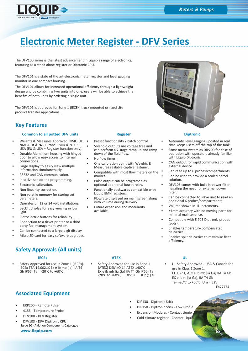
Electronic Meter Register - DFV SeriesThe DFV100 series is the latest advancement in Liquip’s range of electronics, featuring as a stand alone register or Diptronic CPU.
The DFV101 is a state of the art electronic meter register and level gauging monitor in one compact housing. The DFV101 allows for increased operational efficiency through a lightweight design and by combining two units into one, users will be able to achieve the benefits of both units by ordering a single unit.
The DFV101 is approved for Zone 1 (IECEx) truck mounted or fixed site product transfer applications..
• Weights & Measures Approved: NMO UK,NMI-Aust & NZ, Europe - MID & NTEP -USA (EU & USA = Register function only).
• Durable Aluminium housing with hingeddoor to allow easy access to internalconnections.
• Large display to easily view multipleinformation simultaneously.
• RS232 and CAN communication.• Intuitive set up and programming.• Electronic calibration.• Non-linearity correction.• Non volatile memory for storing set
parameters.• Operates on 12 or 24 volt installations.• Backlit display for easy viewing in low
light.• Piezoelectric buttons for reliability.• Connection to a ticket printer or a third
party fuel management system.• Can be connected to a large digit display• Micro SD card for easy software upgrades.
• Preset functionality / batch control.• Solenoid outputs are voltage free and
can perform a 2 stage ramp up and rampdown of the fluid flow.
• No flow timer.• One calibration point with Weights &
Measures sealable captive fastener.• Compatible with most flow meters on the
market.• Pulse output can be programed as
optional additional fourth relay.• Functionally backwards compatible with
Liquip EMH registers.• Flowrate displayed on main screen along
with volume during delivery.• Future expansion and modularity
available.
• Automatic level gauging updated in realtime keeps users off the top of the tank.
• Same menu system as DIP200 for ease ofoperation with operators already familiarwith Liquip Diptronic.
• CAN output for rapid communication withexternal device.
• Can read up to 6 probes/compartments.• Can be used to provide a sealed parcel
solution.• DFV103 comes with built in power filter
negating the need for external powerfilter.
• Can be connected to slave unit to read anadditional 6 probes/compartments.
• Volume shown in 1L increments.• ±1mm accuracy with no moving parts for
minimal maintenance.• Compatible with E 705 Diptronic probes
(pots).• Enables temperature compensated
deliveries.• Enables split deliveries to maximise fleet
efficiency.
Key FeaturesCommon to all potted DFV units Register Diptronic
• Safety Approved for use in Zone 1 (IECEx).IECEx TSA 14.0021X Ex e ib mb [ia] IIA T4Gb IP66 (Ta = -20°C to +60°C)
• UL Safety Approved - USA & Canada foruse in Class 1 Zone 1.CI. I, Zn1, AEx e ib mb [ia Ga] IIA T4 GbEX e ib m [ia Ga], IIA T4 GbTa= -20oC to +60oC Um = 32V
E477774
• Safety Approved for use in Zone 1(ATEX) DEMKO 14 ATEX 1407XEx e ib mb [ia Ga] IIA T4 Gb IP66 (Ta=-20°C to +60°C) 0518 II 2 (1) G
Safety Approvals (All units)IECEx ATEX UL
Associated Equipment
• ERP200 - Remote Pulser• 4155 - Temperature Probe• DFV100 - DFV Register• DFV103 - DFV Diptronic CPU
• DIP130 - Diptronic Stick• DIP150 - Diptronic Stick - Low Profile• Expansion Modules - Contact Liquip• Cold climate register - Contact Liquip
Issue 10 - Aviation Components Catalogue 53

Meters & Pumps
www.liquip.com
Electronic Meter Register - DFV Series
Size Approx, 250 x 200 x 140mmDisplays 1 line x 14 characters 14 mm high and 4 lines x 24 characters 8 mm high
Power Input 9 to 32Vdc (safety approved) or 9 to 45V (operational) @ 250mA polarity protected. In-line fuse (rated 3A, antisurge) is strongly recommended
Operating Temperature -20°C to +60°C (safety approved)
Temperature Correction -40 to +60°C for all petroleum productsExtended ranges available according to local regulations
Temperature Probe Pt100 class A, 3 wires, Liquip P/N 4155Ingress Protection IP66Product Density 0.653 - 1.075kg/L (petroleum products) - For others contact LiquipWeight Approx. 6kg
CommunicationTwo RS232C ports to be used to communicate with a PC or other serial device such as a modem or printer. One CAN port.Compatible with Epson CTM-290 or TM-295, Blaster Printer.
Touch PC Commands that can be interrogated include resetting the meter and requesting the current delivery quantity. See software section for detail.
Pulse Input Will accept 3-channel pulses of 60° phase shifted, from ERP200 pulser, dual (quadrature) or single pulse (reed or open-collector) from third-party pulsers. Third party pulsers may not be NMI approved
Pulse Output Open drain, active-low output, signal calibrated to 10 pulses/litre, where the pulse frequency can be set up to either 400Hz or 2kHz max. (with fixed pulse duration 1.25 ms or 0.25 ms respectively).
External Reset This is an input/output signal.
Relay Outputs Up to 4 Relay Outputs. Current sink, 3A max. Solenoid to be connected between this output and the positive of the power supply. Additional in-line fuse (3A, antisurge) is strongly recommended.
Program Memory microSD card
Technical Information
Mounting InstructionsThe DFV101 can be either remote mounted or mounted to a meter using an adaptor bracket.
Adaptor Bracket: Front mount to various metersWhen direct mounting to a meter is unavoidable DFV100-23 (Suits the following meters)
• LC - M5, M7, M10, M15, M25, M30, M40, M60
• SAMPI - M5, M7, M15, M30
Adaptor Bracket: Top mount to various metersDFV100-18 - Top mount bracket to suit meters that use the OE standard 4 bolt register mount.
For mounting to other meters please contact Liquip
Issue 10 - Aviation Components Catalogue 54
Meters & Pumps
www.liquip.com
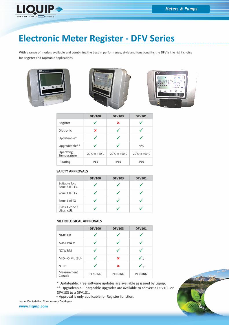
Electronic Meter Register - DFV SeriesWith a range of models available and combining the best in performance, style and functionality, the DFV is the right choice for Register and Diptronic applications.
DFV100 DFV103 DFV101
Register Diptronic Updateable* Upgradeable** N/A
Operating Temperature -20°C to +60°C -20°C to +60°C -20°C to +60°C
IP rating IP66 IP66 IP66
DFV100 DFV103 DFV101Suitable for: Zone 2 IEC Ex Zone 1 IEC Ex Zone 1 ATEX Class 1 Zone 1 ULus, cUL
DFV100 DFV103 DFV101
NMO UK AUST W&M NZ W&M MID - OIML (EU) +
NTEP +
Measurement Canada PENDING PENDING PENDING
SAFETY APPROVALS
METROLOGICAL APPROVALS
* Updateable: Free software updates are available as issued by Liquip.** Upgradeable: Chargeable upgrades are available to convert a DFV100 orDFV103 to a DFV101.+ Approval is only applicable for Register function.
Issue 10 - Aviation Components Catalogue 55
Meters & Pumps
www.liquip.com
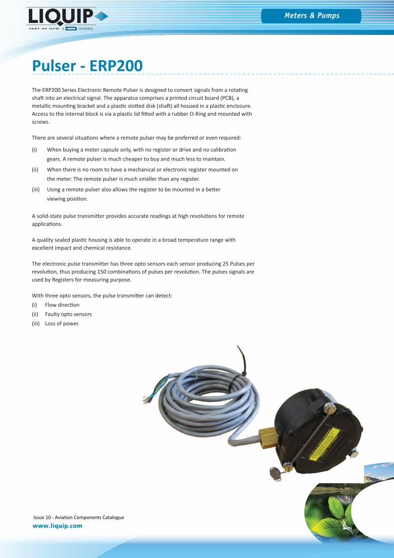
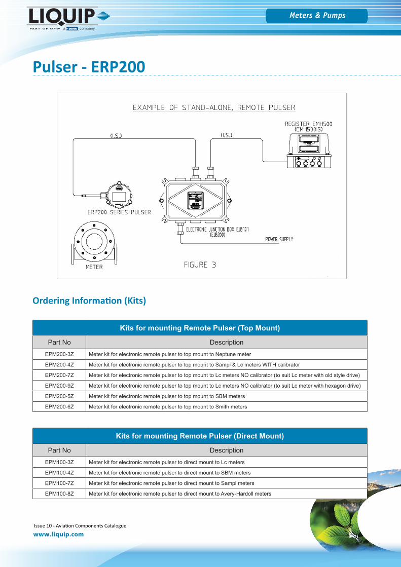
Pulser - ERP200The ERP200 Series Electronic Remote Pulser is designed to convert signals from a rotating shaft into an electrical signal. The apparatus comprises a printed circuit board (PCB), a metallic mounting bracket and a plastic slotted disk (shaft) all housed in a plastic enclosure. Access to the internal block is via a plastic lid fitted with a rubber O-Ring and mounted with screws.
There are several situations where a remote pulser may be preferred or even required:
(i) When buying a meter capsule only, with no register or drive and no calibrationgears. A remote pulser is much cheaper to buy and much less to maintain.
(ii) When there is no room to have a mechanical or electronic register mounted onthe meter. The remote pulser is much smaller than any register.
(iii) Using a remote pulser also allows the register to be mounted in a betterviewing position.
A solid-state pulse transmitter provides accurate readings at high revolutions for remote applications.
A quality sealed plastic housing is able to operate in a broad temperature range with excellent impact and chemical resistance.
The electronic pulse transmitter has three opto sensors each sensor producing 25 Pulses per revolution, thus producing 150 combinations of pulses per revolution. The pulses signals are used by Registers for measuring purpose.
With three opto sensors, the pulse transmitter can detect:(i) Flow direction(ii) Faulty opto sensors(iii) Loss of power.
Issue 10 - Aviation Components Catalogue 56
Meters & Pumps
www.liquip.com
Operation
Pulser - ERP200
2.1 Specifications
Fully solid state electronic circuit.Intrinsically safe, approved for Zone 0Fully weather sealed to IP 66Weights & Measures approved
Electrical Certification Parameters Safe Zone Parameters
Input Ui = 26.6V, li = 660mAPi = 1.2W, Ci = 1.14μF, Li = 0mH
Vin : +9VDC to +30VDCIin : 100mA max
Operating Temperature -20°C to +60°C -40°C to +80°C
Rotation Bi-directional
Input Shaft Speed 1000 rpm maximum
Output Pulse(P1, P2, P3)
Push-Pull Outputs.0V to +5VDC with in-line resistor 100R per channel. Square wave.
For clockwise rotation, channel 2(P2) lags channel 1(P1) by 60 electrical degrees and channel 3(P3) lags channel 1(P1) by 120 electrical degrees. The disk has 25 evenly spaced slots, each slot corresponding to one electrical cycle (360 electrical deg.) or 14.4 mechanical angular Deg. The duty cycle of the pulse is 50% therefore there are 6 stages for each electrical cycle (S0 - S5). Ref. Figure 2.
K factor K = N pulses pulses/rev/single channel = 25 litre pulses/rev/combined 3 channel =150
Mechanical:Drive: Bearing is a sealed ball bearing for low friction, long life and no maintenance. Vibration is controlled by spring
loaded friction washer.
Mounting: Body mounting is the same pattern as Veeder Root pulsers for interchangeability. It can therefore be driven off a Veeder-Root mechanical register: off the existing post-calibration gear drive train by mounting on an adaptor plate; or by driving directly off the meter chamber main shaft.
Materials: Construction of body, cover and toothed wheel and shaft is in acetal, supported by a sealed-for-life ball bearing. Friction damping is by spring-loaded Teflon washer. Cover is bolt-on for ease of access with calibration-seal lug provided and O-Ring water sealing. Maximum speed of 1,000 rpm is sufficient for all current applications when driving directly off the meter main shaft. There is no minimum speed, each tooth is counted.
Weight: The unit is lightweight and only weighs 500g per assembly (without cable).
Port: One entry M16 conduit thread complete with adaptor & strain relief to suit M16 conduit. Use suitable conduit or cable gland, min IP66. Refer to section 3.3.
Note: Removing adaptor may affect IP rating.
Issue 10 - Aviation Components Catalogue 57
Meters & Pumps
www.liquip.com
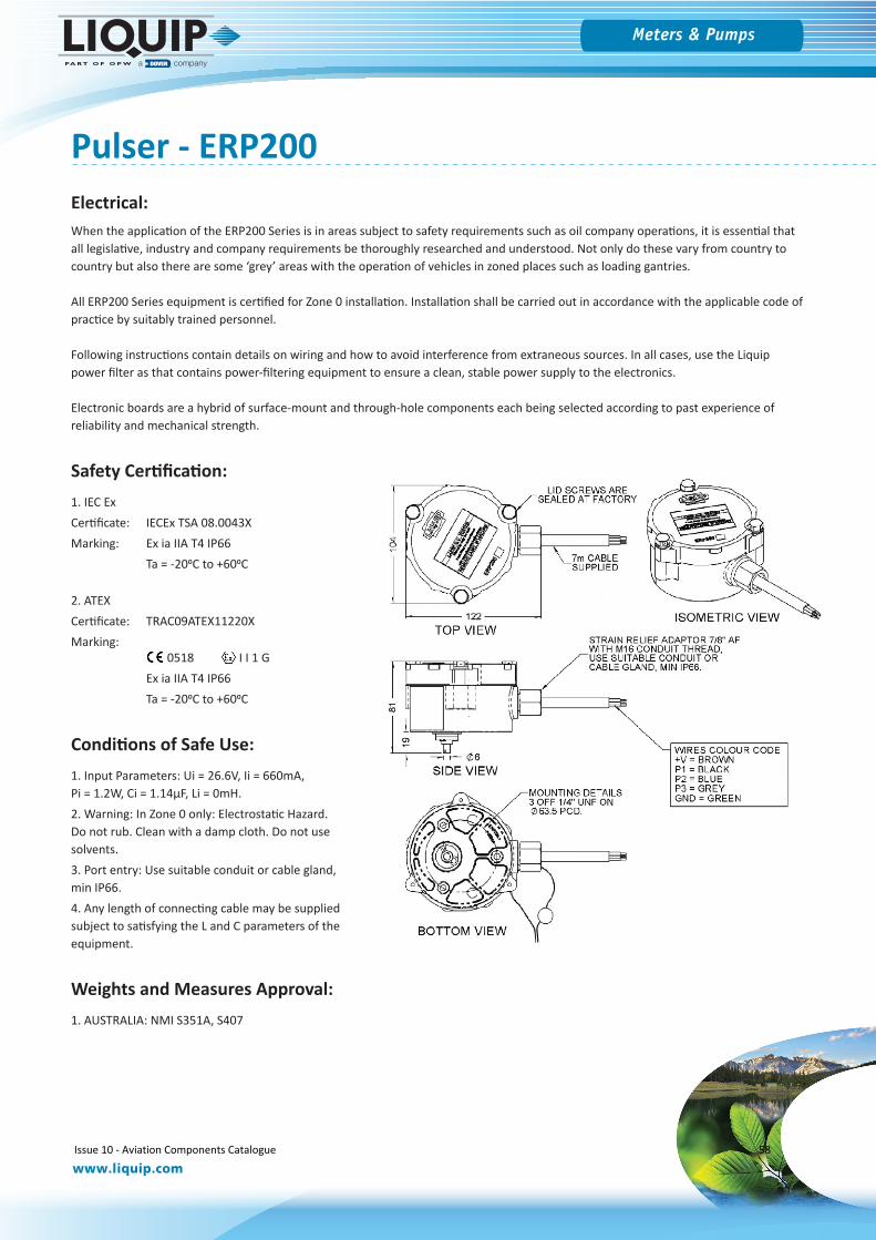
Pulser - ERP200Electrical:When the application of the ERP200 Series is in areas subject to safety requirements such as oil company operations, it is essential that all legislative, industry and company requirements be thoroughly researched and understood. Not only do these vary from country to country but also there are some ‘grey’ areas with the operation of vehicles in zoned places such as loading gantries.
All ERP200 Series equipment is certified for Zone 0 installation. Installation shall be carried out in accordance with the applicable code of practice by suitably trained personnel.
Following instructions contain details on wiring and how to avoid interference from extraneous sources. In all cases, use the Liquip power filter as that contains power-filtering equipment to ensure a clean, stable power supply to the electronics.
Electronic boards are a hybrid of surface-mount and through-hole components each being selected according to past experience of reliability and mechanical strength.
Safety Certification:1. IEC ExCertificate: IECEx TSA 08.0043XMarking: Ex ia IIA T4 IP66
Ta = -200C to +600C
2. ATEXCertificate: TRAC09ATEX11220XMarking:
0518 I I 1 GEx ia IIA T4 IP66Ta = -200C to +600C
Conditions of Safe Use:1. Input Parameters: Ui = 26.6V, Ii = 660mA,Pi = 1.2W, Ci = 1.14μF, Li = 0mH.2. Warning: In Zone 0 only: Electrostatic Hazard.Do not rub. Clean with a damp cloth. Do not usesolvents.3. Port entry: Use suitable conduit or cable gland,min IP66.4. Any length of connecting cable may be suppliedsubject to satisfying the L and C parameters of theequipment.
Weights and Measures Approval:1. AUSTRALIA: NMI S351A, S407
Issue 10 - Aviation Components Catalogue 58
Meters & Pumps
www.liquip.com
Pulser - ERP200
Kits for mounting Remote Pulser (Top Mount)
Part No DescriptionEPM200-3Z Meter kit for electronic remote pulser to top mount to Neptune meter
EPM200-4Z Meter kit for electronic remote pulser to top mount to Sampi & Lc meters WITH calibrator
EPM200-7Z Meter kit for electronic remote pulser to top mount to Lc meters NO calibrator (to suit Lc meter with old style drive)
EPM200-9Z Meter kit for electronic remote pulser to top mount to Lc meters NO calibrator (to suit Lc meter with hexagon drive)
EPM200-5Z Meter kit for electronic remote pulser to top mount to SBM meters
EPM200-6Z Meter kit for electronic remote pulser to top mount to Smith meters
Kits for mounting Remote Pulser (Direct Mount)
Part No DescriptionEPM100-3Z Meter kit for electronic remote pulser to direct mount to Lc meters
EPM100-4Z Meter kit for electronic remote pulser to direct mount to SBM meters
EPM100-7Z Meter kit for electronic remote pulser to direct mount to Sampi meters
EPM100-8Z Meter kit for electronic remote pulser to direct mount to Avery-Hardoll meters
Ordering Information (Kits)
Issue 10 - Aviation Components Catalogue 59
Meters & Pumps
www.liquip.com
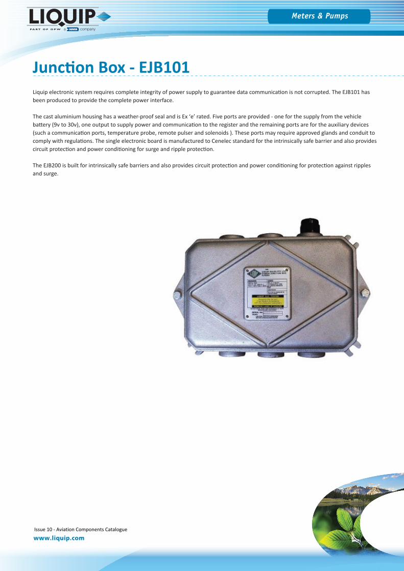
Liquip electronic system requires complete integrity of power supply to guarantee data communication is not corrupted. The EJB101 has been produced to provide the complete power interface.
The cast aluminium housing has a weather-proof seal and is Ex ʻeʼ rated. Five ports are provided - one for the supply from the vehicle battery (9v to 30v), one output to supply power and communication to the register and the remaining ports are for the auxiliary devices (such a communication ports, temperature probe, remote pulser and solenoids ). These ports may require approved glands and conduit to comply with regulations. The single electronic board is manufactured to Cenelec standard for the intrinsically safe barrier and also provides circuit protection and power conditioning for surge and ripple protection.
The EJB200 is built for intrinsically safe barriers and also provides circuit protection and power conditioning for protection against ripples and surge.
Junction Box - EJB101
Issue 10 - Aviation Components Catalogue 60
Meters & Pumps
www.liquip.com
Sampi Meters
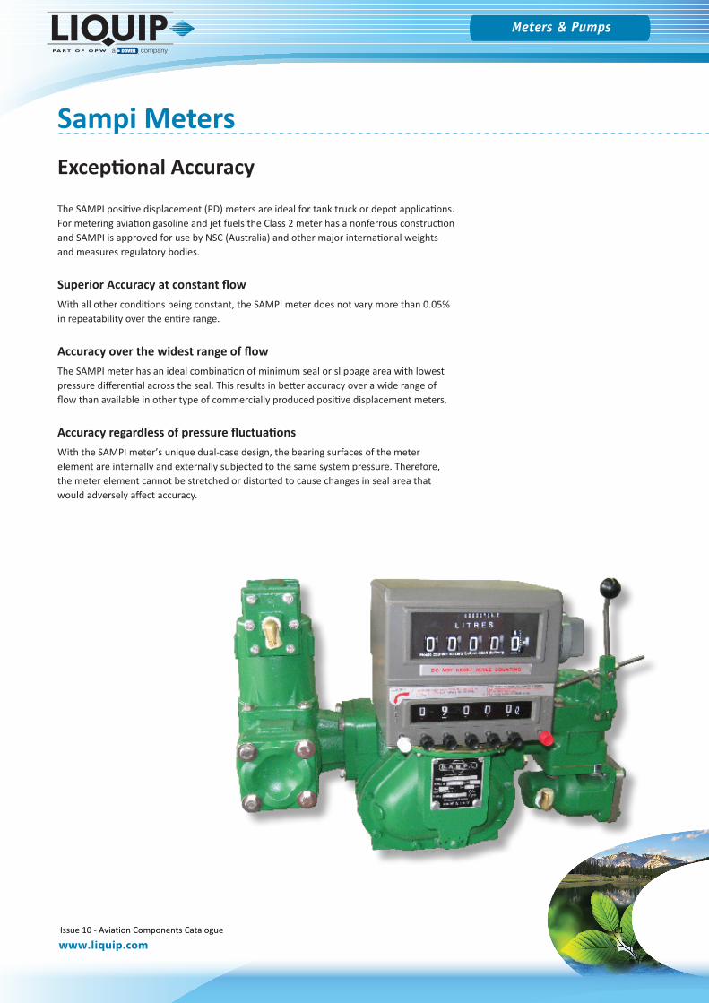
The SAMPI positive displacement (PD) meters are ideal for tank truck or depot applications. For metering aviation gasoline and jet fuels the Class 2 meter has a nonferrous construction and SAMPI is approved for use by NSC (Australia) and other major international weights and measures regulatory bodies.
Superior Accuracy at constant flowWith all other conditions being constant, the SAMPI meter does not vary more than 0.05% in repeatability over the entire range.
Accuracy over the widest range of flowThe SAMPI meter has an ideal combination of minimum seal or slippage area with lowest pressure differential across the seal. This results in better accuracy over a wide range of flow than available in other type of commercially produced positive displacement meters.
Accuracy regardless of pressure fluctuationsWith the SAMPI meterʼs unique dual-case design, the bearing surfaces of the meter element are internally and externally subjected to the same system pressure. Therefore, the meter element cannot be stretched or distorted to cause changes in seal area that would adversely affect accuracy.
Exceptional Accuracy
Issue 10 - Aviation Components Catalogue 61
Meters & Pumps
www.liquip.com
NO STRAINERNO AIR ELIMINATOR
NO VALVE
STRAINERNO AIR ELIMINATOR
NO VALVE
STRAINERAIR ELIMINATOR
NO VALVE
NO STRAINERNO AIR ELIMINATOR
VALVE
STRAINERNO AIR ELIMINATOR
VALVE
STRAINERAIR ELIMINATOR
VALVE
COUNTERNO PRINTERNO PRE-SET
COUNTERPRINTERNO PRE-SET
COUNTERNO PRINTERPRE-SET
COUNTERPRINTERPRE-SET
NO COUNTERNO PRINTERNO PRE-SET
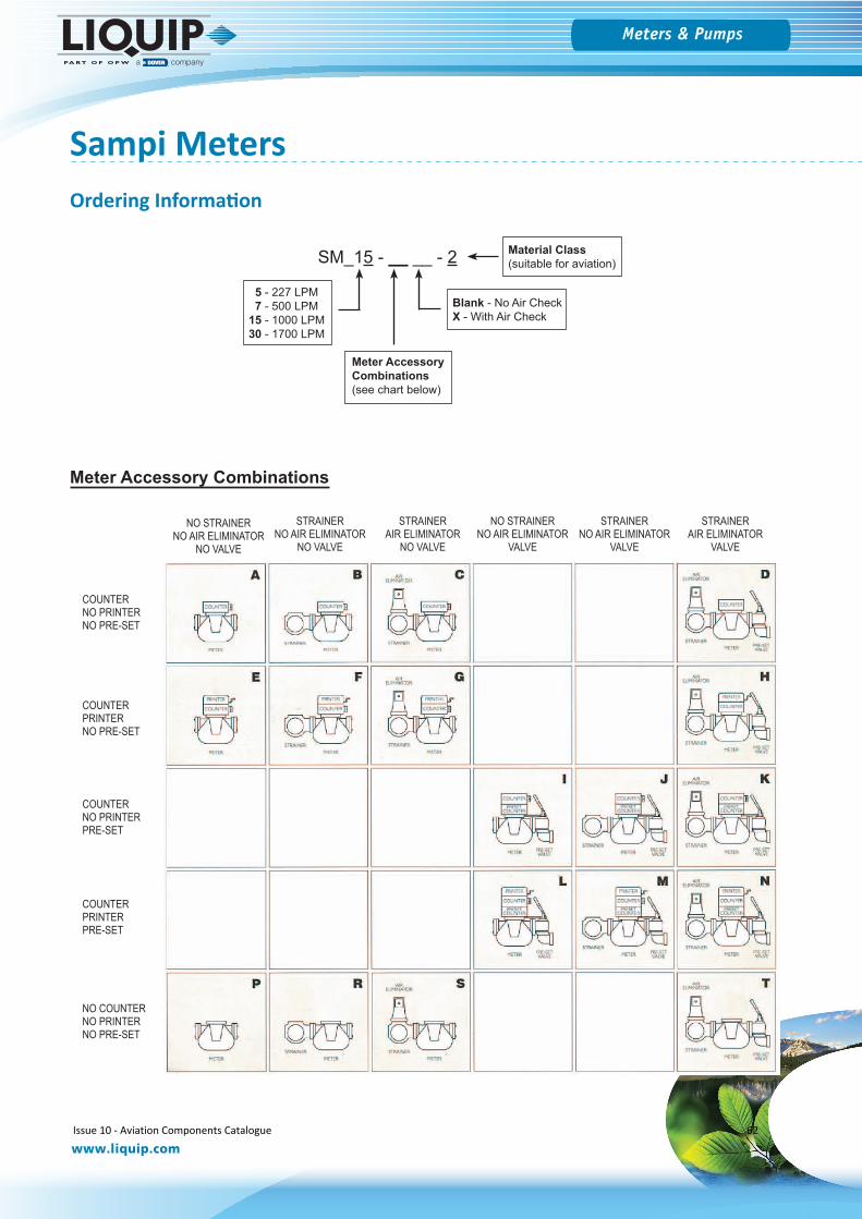
Sampi Meters
Meter Accessory Combinations
SM_15 - __ __ - 2
Blank - No Air CheckX - With Air Check
Meter Accessory Combinations(see chart below)
5 - 227 LPM 7 - 500 LPM15 - 1000 LPM30 - 1700 LPM
Material Class(suitable for aviation)
Ordering Information
Issue 10 - Aviation Components Catalogue 62
Meters & Pumps
www.liquip.com
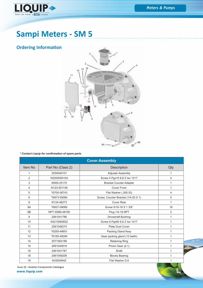
Sampi Meters - SM 5
Cover AssemblyItem No Part No (Class 2) Description Qty
1 2030040101 Adjuster Assembly 1
2 N320005010A Screw 5 Pgx10 8,8 Z Iso 1217 4
3 I0000-25170 Bracket Counter Adapter 1
4 I0123-501148 Cover Front 1
5 *I0705-06743 Flat Washer (.265 ID) 4
6 *I0673-09084 Screw, Counter Bracket (1/4-20 X 1) 4
8 I0124-48273 Cover Rear 1
8A *I0627-09080 Screw 5/16-18 X 1 3/8” 18
8B NPT I0566-06790 Plug 1/4-18 NPT 2
9 2061041786 Driveshaft Bushing 1
10 N321006060Z Screw 6 Pgx60 8,8 Z Iso 1217 1
11 2061048274 Plate Dust Cover 1
12 *I0250-48601 Packing Gland Assy 1
13 *I0165-48284 Gear packing gland (12 teeth) 1
14 2071002188 Retaining Ring 1
15 2061040818 Pinion Gear (2:1) 1
16 2061041787 Shaft 1
18 2061048208 Blocks Bearing 1
19 N3300064Z Flat Washer D.6 1
12
23
4
11
13
12 65
10 192 9
8
18
8A8B
14 15 16
Ordering Information
* Contact Liquip for confirmation of spare parts
Issue 10 - Aviation Components Catalogue 63
Meters & Pumps
www.liquip.com
Sampi Meters - SM 5
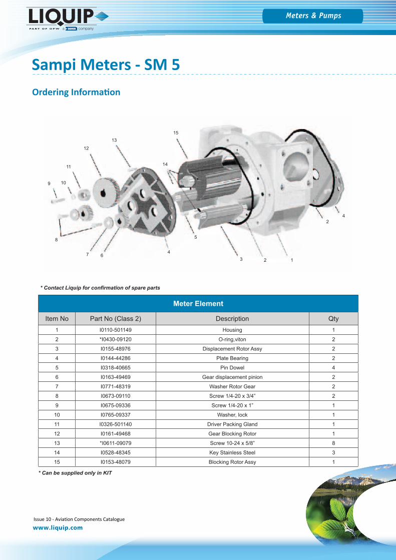
Meter Element
Item No Part No (Class 2) Description Qty1 I0110-501149 Housing 1
2 *I0430-09120 O-ring,viton 2
3 I0155-48976 Displacement Rotor Assy 2
4 I0144-44286 Plate Bearing 2
5 I0318-40665 Pin Dowel 4
6 I0163-49469 Gear displacement pinion 2
7 I0771-48319 Washer Rotor Gear 2
8 I0673-09110 Screw 1/4-20 x 3/4” 2
9 I0675-09336 Screw 1/4-20 x 1” 1
10 I0765-09337 Washer, lock 1
11 I0326-501140 Driver Packing Gland 1
12 I0161-49468 Gear Blocking Rotor 1
13 *I0611-09079 Screw 10-24 x 5/8” 8
14 I0528-48345 Key Stainless Steel 3
15 I0153-48079 Blocking Rotor Assy 1
1
2
3
4
11
13
12
6
5
10
2
9
8
14
15
47
Ordering Information
* Can be supplied only in KIT
* Contact Liquip for confirmation of spare parts
Issue 10 - Aviation Components Catalogue 64
Meters & Pumps
www.liquip.com
Sampi Meters - SM 30
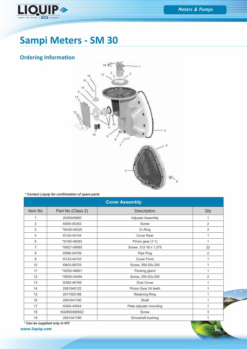
Cover Assembly
Item No Part No (Class 2) Description Qty1 2030045660 Adjuster Assembly 1
2 I0000-00362 Screw 2
3 *I0430-09325 O–Ring 2
4 I0125-44104 Cover Rear 1
5 *I0165-48283 Pinion gear (1:1) 1
7 *I0627-09085 Screw .312-18 x 1,375 22
8 I0566-04759 Pipe Plug 2
9 I0123-44103 Cover Front 1
10 I0603-06703 Screw. 250-20x.250 1
11 *I0250-48601 Packing gland 1
12 *I0630-04494 Screw. 250-20x.250 2
13 I0362-46169 Dust Cover 1
14 2061040122 Pinion Gear 24 teeth 1
15 2071002188 Retaining Ring 1
16 2061041790 Shaft 1
17 I0364-43044 Plate adjuster mounting 1
18 N3280048065Z Screw 3
19 2061041786 Driveshaft bushing 1
1
2
3
3
11
13
12
8
5
10
2
98
14
15
47
18
1716
19
Ordering Information
* Contact Liquip for confirmation of spare parts
65* Can be supplied only in KIT
Meters & Pumps
www.liquip.com
Sampi Meters - SM 30
16 3
11
5
10
2
9
8
14
15
7
11
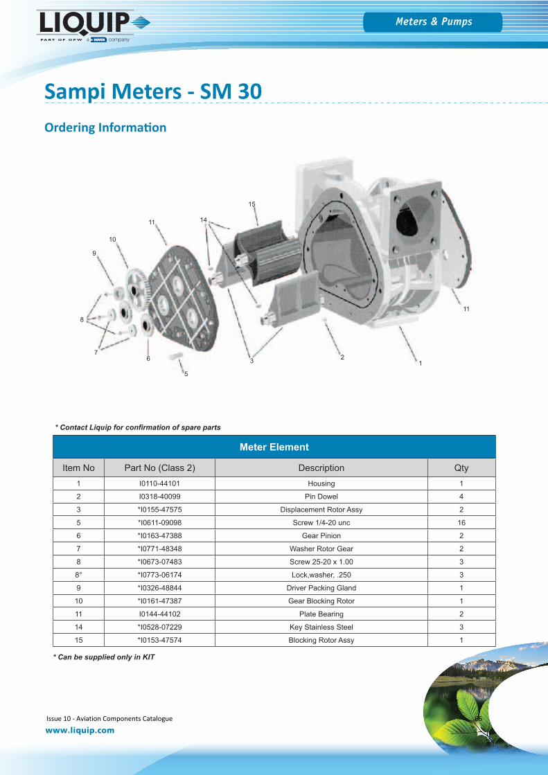
Meter Element
Item No Part No (Class 2) Description Qty1 I0110-44101 Housing 1
2 I0318-40099 Pin Dowel 4
3 *I0155-47575 Displacement Rotor Assy 2
5 *I0611-09098 Screw 1/4-20 unc 16
6 *I0163-47388 Gear Pinion 2
7 *I0771-48348 Washer Rotor Gear 2
8 *I0673-07483 Screw 25-20 x 1.00 3
8° *I0773-06174 Lock,washer, .250 3
9 *I0326-48844 Driver Packing Gland 1
10 *I0161-47387 Gear Blocking Rotor 1
11 I0144-44102 Plate Bearing 2
14 *I0528-07229 Key Stainless Steel 3
15 *I0153-47574 Blocking Rotor Assy 1
Ordering Information
* Can be supplied only in KIT
* Contact Liquip for confirmation of spare parts
Issue 10 - Aviation Components Catalogue 66
Meters & Pumps
www.liquip.com
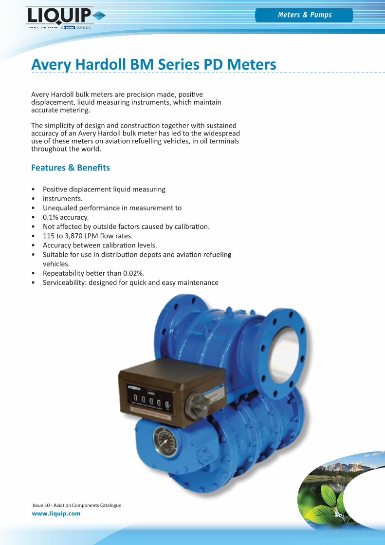
Avery Hardoll BM Series PD Meters
Avery Hardoll bulk meters are precision made, positive displacement, liquid measuring instruments, which maintain accurate metering.
The simplicity of design and construction together with sustained accuracy of an Avery Hardoll bulk meter has led to the widespread use of these meters on aviation refuelling vehicles, in oil terminals throughout the world.
Features & Benefits
• Positive displacement liquid measuring• instruments.• Unequaled performance in measurement to• 0.1% accuracy.• Not affected by outside factors caused by calibration.• 115 to 3,870 LPM flow rates.• Accuracy between calibration levels.• Suitable for use in distribution depots and aviation refueling
vehicles.• Repeatability better than 0.02%.• Serviceability: designed for quick and easy maintenance
Issue 10 - Aviation Components Catalogue 67
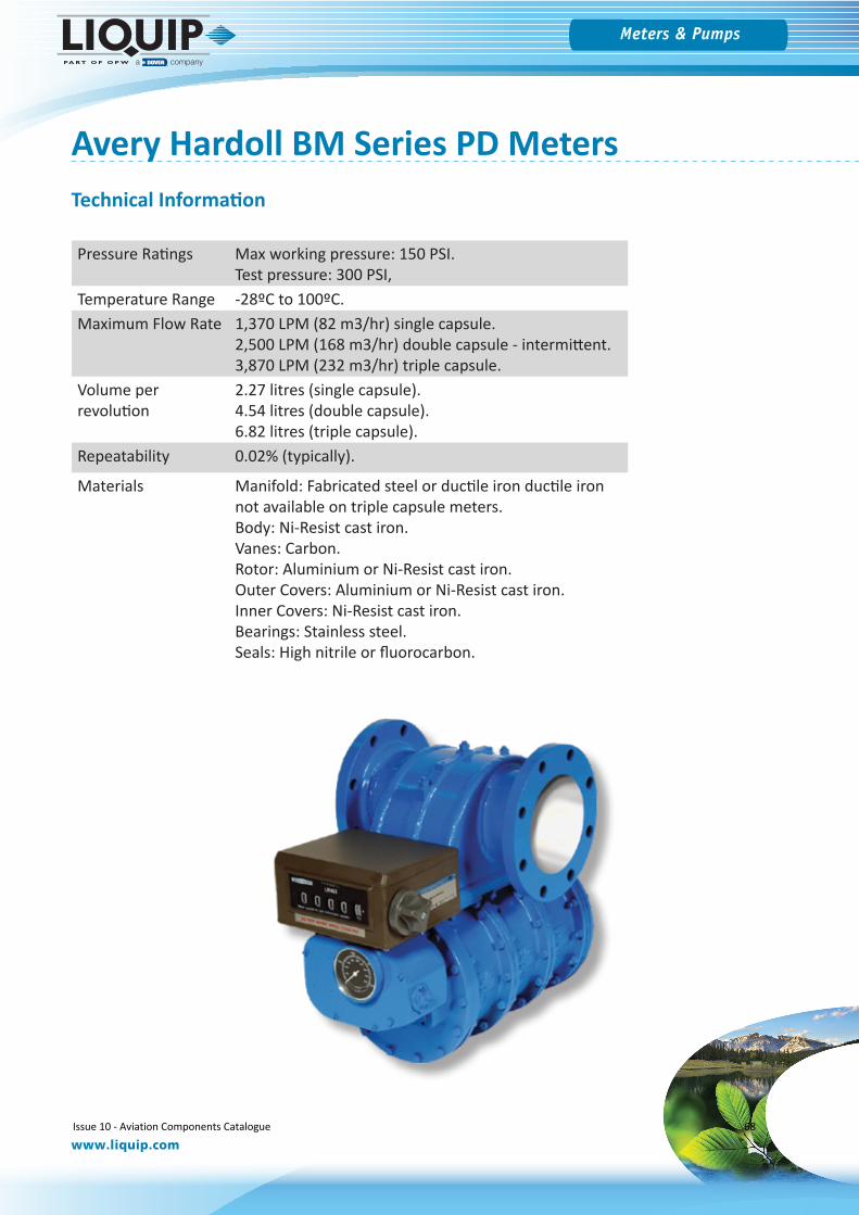
Meters & Pumps
www.liquip.com
Avery Hardoll BM Series PD MetersTechnical Information
Pressure Ratings Max working pressure: 150 PSI.Test pressure: 300 PSI,
Temperature Range -28ºC to 100ºC.Maximum Flow Rate 1,370 LPM (82 m3/hr) single capsule.
2,500 LPM (168 m3/hr) double capsule - intermittent.3,870 LPM (232 m3/hr) triple capsule.
Volume per revolution
2.27 litres (single capsule).4.54 litres (double capsule).6.82 litres (triple capsule).
Repeatability 0.02% (typically).
Materials Manifold: Fabricated steel or ductile iron ductile iron not available on triple capsule meters.Body: Ni-Resist cast iron.Vanes: Carbon.Rotor: Aluminium or Ni-Resist cast iron.Outer Covers: Aluminium or Ni-Resist cast iron.Inner Covers: Ni-Resist cast iron.Bearings: Stainless steel.Seals: High nitrile or fluorocarbon.
Issue 10 - Aviation Components Catalogue 68
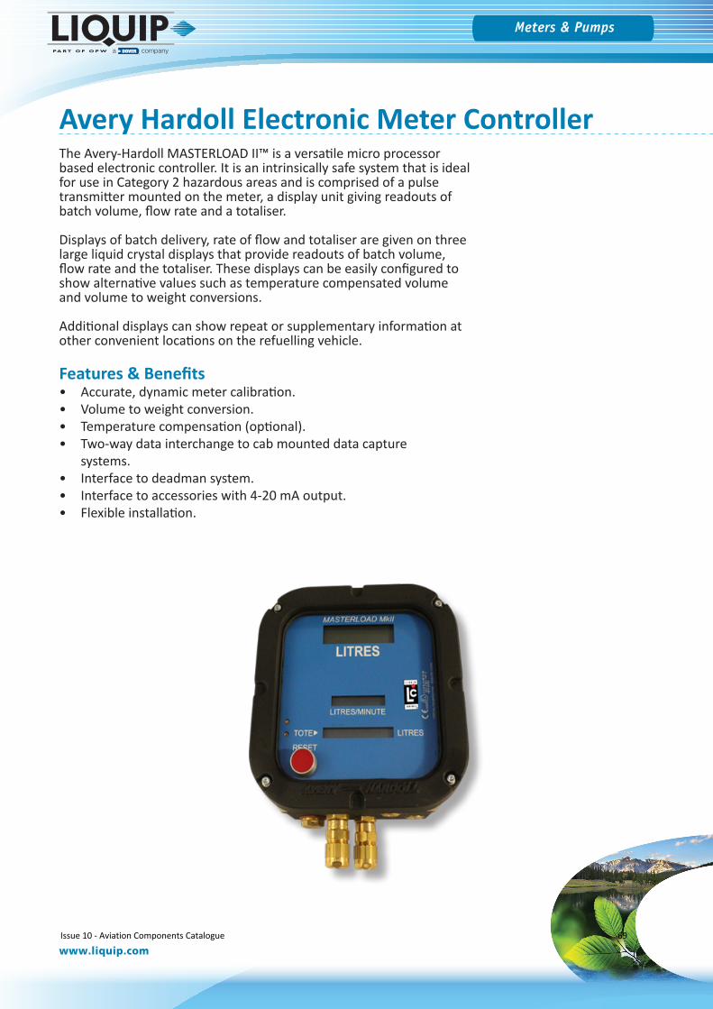
Meters & Pumps
www.liquip.com
Avery Hardoll Electronic Meter ControllerThe Avery-Hardoll MASTERLOAD II™ is a versatile micro processor based electronic controller. It is an intrinsically safe system that is ideal for use in Category 2 hazardous areas and is comprised of a pulse transmitter mounted on the meter, a display unit giving readouts of batch volume, flow rate and a totaliser.
Displays of batch delivery, rate of flow and totaliser are given on three large liquid crystal displays that provide readouts of batch volume, flow rate and the totaliser. These displays can be easily configured to show alternative values such as temperature compensated volume and volume to weight conversions.
Additional displays can show repeat or supplementary information at other convenient locations on the refuelling vehicle.
Features & Benefits• Accurate, dynamic meter calibration.• Volume to weight conversion.• Temperature compensation (optional).• Two-way data interchange to cab mounted data capture
systems.• Interface to deadman system.• Interface to accessories with 4-20 mA output.• Flexible installation.
Issue 10 - Aviation Components Catalogue 69

Meters & Pumps
www.liquip.com
Avery Hardoll Electronic Meter ControllerTechnical Information
IP Ratings All units are designed for outdoor use & are sealed to specification IP 65.
Security Full wire sealing.Automatic error checking.Alarm reporting.Data Storage for 40 transactions.
Operating Temperature
-20 to 40° C.
Transitter Temperature: -30 to 120° C.Fitting: Direct drive available.Approval: EN ISO 6551-1995 Level A.Channels: 3 Independent.Security: Sense line.
Humidity Resistant up to 100% R.H.
Temperature Probe PRT
Accuracy: +/-0.1° C Discrimination: 0.1° C.Range: -30 to 120° C.Set Up: Factory set.Alarm Limits: Programmable.Display: °F or °C.Compensation: 15, 20 or 31.5° C.
Safety Classification
Category 2.
ATEX Approvals
Power Supply Unit: (flameproof).-II 2 G EEx d IIB T6.-Cert. No. ITS04ATEX11903.
Display Unit:-II 2 G EEx ib IIB T4-Cert. No. BAS02ATEX2199
Delivery Override
Key Operated IP 65 Box (option).
Non-volatile Memory
Infinite data retention.
Power Supply
12/24 VDC.
Power consumption
350mA max. (excluding relays).
Relays Max of 11 plug-in.Typical - 1 Deadman.Pulse output.
Inputs 4-20mA (4).
Linearisation 1, 2, 4 or 8 selectable.Full dynamic interpolation.Accuracy: +/- .02 @ measuring condition.and 15° C if temperature compensation fitted.
Manual Input
Density for weight indication.
Product correction tables
IP/ASTM Table Selection to IP65.Generalised crude (A tables).Generalised products.Table 54.Table 53
Locations Flexible mounting:(max 50 meters between units).
Issue 10 - Aviation Components Catalogue 70

Meters & Pumps
www.liquip.com
Isoil’s new LFD-6 remote display unit has been designed mainly for use on hydrant dispensers and aviation refuellers working at airports. This application requires the volume measured by the PD meter be repeated and easily read from a reasonable distance within the working area.
The LFD-6 nevertheless can be used in any application where the operator is working at a distance from the meter counter and an easily readable display is required. Such typical applications include top loading of tank trucks and rail cars, also loading of barges, ships, etc.
From a metrology standpoint, it is the main meter (and counter) that is the only official metering reference. Therefore, the LFD-6 has to be considered as a simple repeater of the main instrument. The value displayed is received by factorised pulses representing the minimum value to be read (e.g. if the display is required in litres, then 1 pulse=litre). If the LFD-6 is used in conjunction with ISOIL’s VegaII or VegaT electronic counter it can be linked via serial line. The LFD-6 has a maximum of 6 digits plus a decimal point that can be programmed in a fixed position. At the end of the delivery the unit can be reset to zero remotely by means of a dedicated input.
The display brightness is achieved by automatic, self adjusting LED which provides very high readability in all lighting conditions. The LFD-6 is suitable for use in explosive areas and harsh environments. ATEX conformity and IP66 protection rating.
Isoil Digital Display - LFD-6
Part No Description
LFD-6 Remote Digital Display
Ordering Information
Issue 10 - Aviation Components Catalogue 71
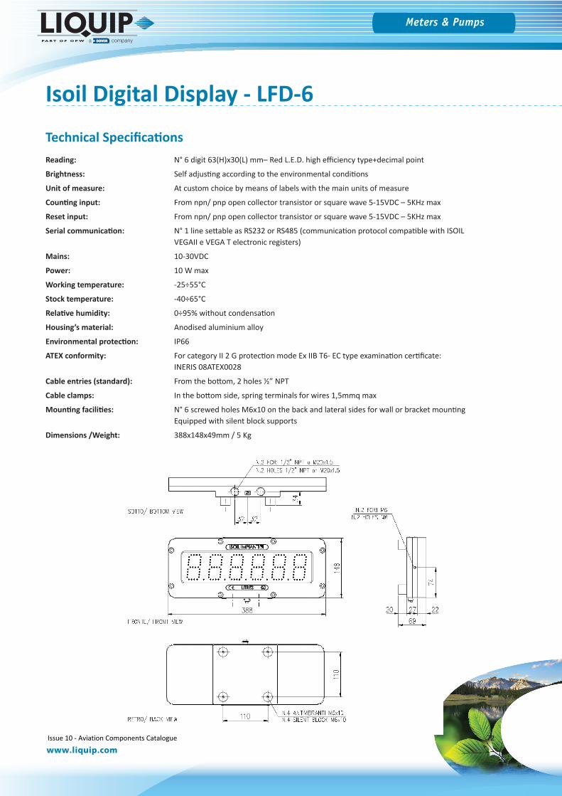
Meters & Pumps
www.liquip.com
Isoil Digital Display - LFD-6
Technical SpecificationsReading: N° 6 digit 63(H)x30(L) mm– Red L.E.D. high efficiency type+decimal point
Brightness: Self adjusting according to the environmental conditions
Unit of measure: At custom choice by means of labels with the main units of measure
Counting input: From npn/ pnp open collector transistor or square wave 5-15VDC – 5KHz max
Reset input: From npn/ pnp open collector transistor or square wave 5-15VDC – 5KHz max
Serial communication: N° 1 line settable as RS232 or RS485 (communication protocol compatible with ISOILVEGAII e VEGA T electronic registers)
Mains: 10-30VDC
Power: 10 W max
Working temperature: -25÷55°C
Stock temperature: -40÷65°C
Relative humidity: 0÷95% without condensation
Housing’s material: Anodised aluminium alloy
Environmental protection: IP66
ATEX conformity: For category II 2 G protection mode Ex IIB T6- EC type examination certificate:INERIS 08ATEX0028
Cable entries (standard): From the bottom, 2 holes ½” NPT
Cable clamps: In the bottom side, spring terminals for wires 1,5mmq max
Mounting facilities: N° 6 screwed holes M6x10 on the back and lateral sides for wall or bracket mountingEquipped with silent block supports
Dimensions /Weight: 388x148x49mm / 5 Kg
Issue 10 - Aviation Components Catalogue 72
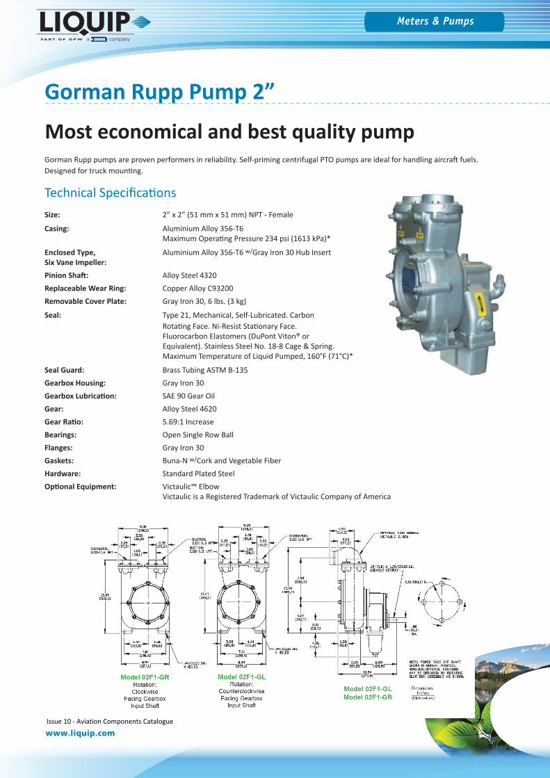
Meters & Pumps
www.liquip.com
Gorman Rupp Pump 2”
Gorman Rupp pumps are proven performers in reliability. Self-priming centrifugal PTO pumps are ideal for handling aircraft fuels. Designed for truck mounting.
Technical SpecificationsSize: 2” x 2” (51 mm x 51 mm) NPT - Female
Casing: Aluminium Alloy 356-T6Maximum Operating Pressure 234 psi (1613 kPa)*
Enclosed Type, Aluminium Alloy 356-T6 w/Gray Iron 30 Hub InsertSix Vane Impeller: Pinion Shaft: Alloy Steel 4320Replaceable Wear Ring: Copper Alloy C93200Removable Cover Plate: Gray Iron 30, 6 lbs. (3 kg)
Seal: Type 21, Mechanical, Self-Lubricated. Carbon Rotating Face. Ni-Resist Stationary Face. Fluorocarbon Elastomers (DuPont Viton® or Equivalent). Stainless Steel No. 18-8 Cage & Spring.Maximum Temperature of Liquid Pumped, 160°F (71°C)*
Seal Guard: Brass Tubing ASTM B-135Gearbox Housing: Gray Iron 30Gearbox Lubrication: SAE 90 Gear OilGear: Alloy Steel 4620Gear Ratio: 5.69:1 IncreaseBearings: Open Single Row BallFlanges: Gray Iron 30Gaskets: Buna-N w/Cork and Vegetable FiberHardware: Standard Plated SteelOptional Equipment: Victaulic™ Elbow
Victaulic is a Registered Trademark of Victaulic Company of America
Most economical and best quality pump
Issue 10 - Aviation Components Catalogue 73
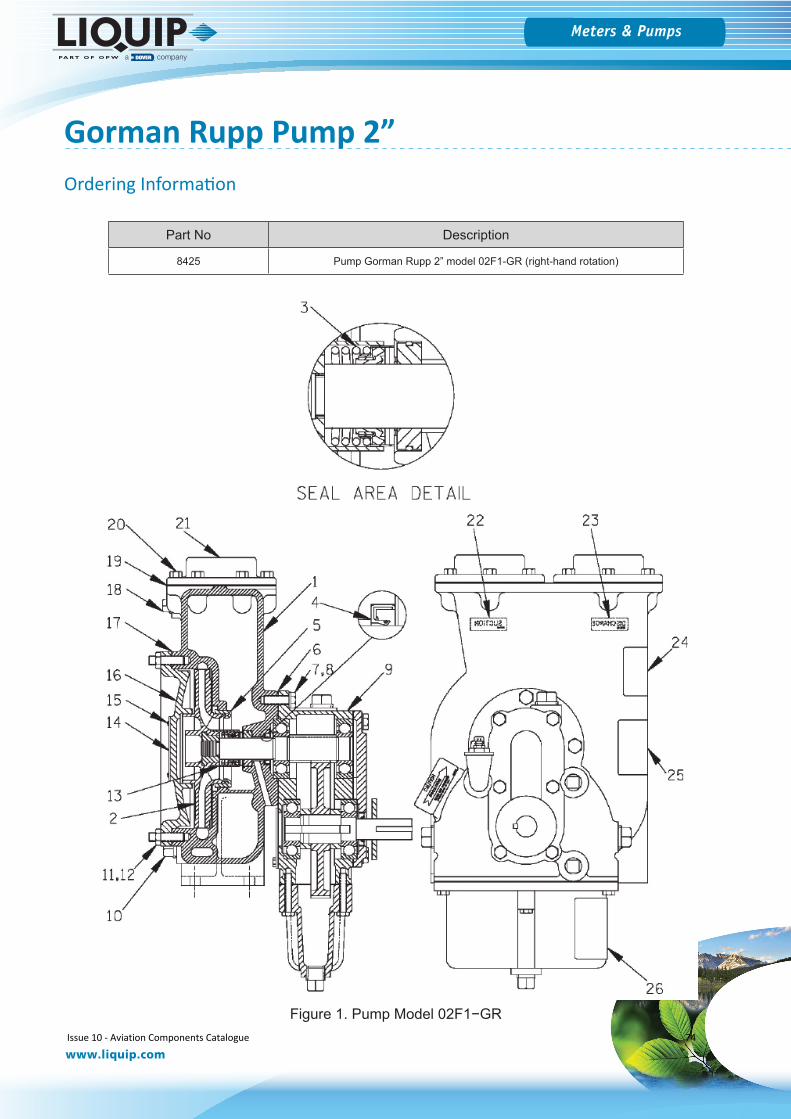
Meters & Pumps
www.liquip.com
Gorman Rupp Pump 2”
Figure 1. Pump Model 02F1−GR
Part No Description
8425 Pump Gorman Rupp 2” model 02F1-GR (right-hand rotation)
Ordering Information
Issue 10 - Aviation Components Catalogue 74
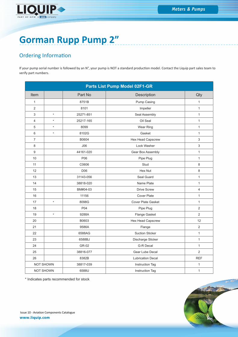
Meters & Pumps
www.liquip.com
Gorman Rupp Pump 2”
Parts List Pump Model 02F1-GR
Item Part No Description Qty
1 8751B Pump Casing 1
2 8101 Impeller 1
3 * 25271-851 Seal Assembly 1
4 * 25217-165 Oil Seal 1
5 * 8099 Wear Ring 1
6 * 8102G Gasket 1
7 B0604 Hex Head Capscrew 3
8 J06 Lock Washer 3
9 44161-020 Gear Box Assembly 1
10 P06 Pipe Plug 1
11 C0606 Stud 8
12 D06 Hex Nut 8
13 31143-056 Seal Guard 1
14 38818-020 Name Plate 1
15 BM#04-03 Drive Screw 4
16 11156 Cover Plate 1
17 * 8098G Cover Plate Gasket 1
18 P04 Pipe Plug 2
19 * 9288A Flange Gasket 2
20 B0603 Hex Head Capscrew 12
21 9586A Flange 2
22 6588AG Suction Sticker 1
23 6588BJ Discharge Sticker 1
24 GR-02 G-R Decal 1
25 38816-077 Gear Lube Decal 2
26 8382B Lubrication Decal REF
NOT SHOWN 38817-039 Instruction Tag 1
NOT SHOWN 6588U Instruction Tag 1
If your pump serial number is followed by an N”, your pump is NOT a standard production model. Contact the Liquip part sales team to verify part numbers.
* Indicates parts recommended for stock
Ordering Information
Issue 10 - Aviation Components Catalogue 75
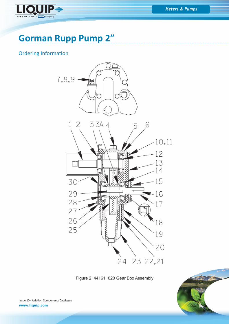
Meters & Pumps
www.liquip.com
Gorman Rupp Pump 2”
Figure 2. 44161−020 Gear Box Assembly
Ordering Information
Issue 10 - Aviation Components Catalogue 76
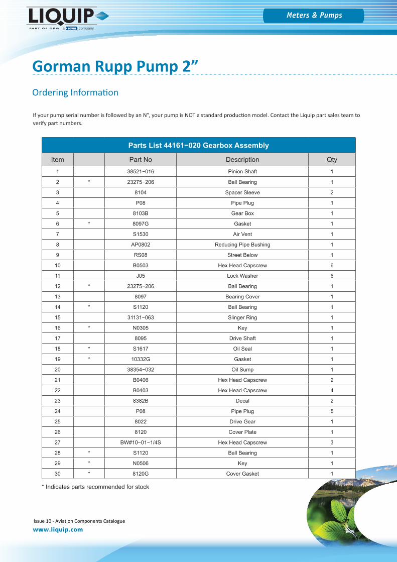
Meters & Pumps
www.liquip.com
Gorman Rupp Pump 2”
If your pump serial number is followed by an N”, your pump is NOT a standard production model. Contact the Liquip part sales team to verify part numbers.
Parts List 44161−020 Gearbox Assembly
Item Part No Description Qty
1 38521−016 Pinion Shaft 1
2 * 23275−206 Ball Bearing 1
3 8104 Spacer Sleeve 2
4 P08 Pipe Plug 1
5 8103B Gear Box 1
6 * 8097G Gasket 1
7 S1530 Air Vent 1
8 AP0802 Reducing Pipe Bushing 1
9 RS08 Street Below 1
10 B0503 Hex Head Capscrew 6
11 J05 Lock Washer 6
12 * 23275−206 Ball Bearing 1
13 8097 Bearing Cover 1
14 * S1120 Ball Bearing 1
15 31131−063 Slinger Ring 1
16 * N0305 Key 1
17 8095 Drive Shaft 1
18 * S1617 Oil Seal 1
19 * 10332G Gasket 1
20 38354−032 Oil Sump 1
21 B0406 Hex Head Capscrew 2
22 B0403 Hex Head Capscrew 4
23 8382B Decal 2
24 P08 Pipe Plug 5
25 8022 Drive Gear 1
26 8120 Cover Plate 1
27 BW#10−01−1/4S Hex Head Capscrew 3
28 * S1120 Ball Bearing 1
29 * N0506 Key 1
30 * 8120G Cover Gasket 1
* Indicates parts recommended for stock
Ordering Information
Issue 10 - Aviation Components Catalogue 77
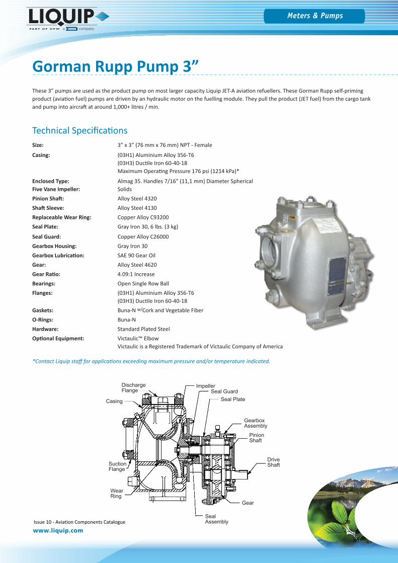
Meters & Pumps
www.liquip.com
Gorman Rupp Pump 3”
Technical SpecificationsSize: 3” x 3” (76 mm x 76 mm) NPT - Female
Casing: (03H1) Aluminium Alloy 356-T6(03H3) Ductile Iron 60-40-18Maximum Operating Pressure 176 psi (1214 kPa)*
Enclosed Type: Almag 35. Handles 7/16” (11,1 mm) Diameter Spherical Five Vane Impeller: SolidsPinion Shaft: Alloy Steel 4320Shaft Sleeve: Alloy Steel 4130Replaceable Wear Ring: Copper Alloy C93200Seal Plate: Gray Iron 30, 6 lbs. (3 kg)
Seal Guard: Copper Alloy C26000Gearbox Housing: Gray Iron 30Gearbox Lubrication: SAE 90 Gear OilGear: Alloy Steel 4620Gear Ratio: 4.09:1 IncreaseBearings: Open Single Row BallFlanges: (03H1) Aluminium Alloy 356-T6
(03H3) Ductile Iron 60-40-18Gaskets: Buna-N w/Cork and Vegetable FiberO-Rings: Buna-NHardware: Standard Plated SteelOptional Equipment: Victaulic™ Elbow
Victaulic is a Registered Trademark of Victaulic Company of America
*Contact Liquip staff for applications exceeding maximum pressure and/or temperature indicated.
These 3” pumps are used as the product pump on most larger capacity Liquip JET-A aviation refuellers. These Gorman Rupp self-priming product (aviation fuel) pumps are driven by an hydraulic motor on the fuelling module. They pull the product (JET fuel) from the cargo tank and pump into aircraft at around 1,000+ litres / min.
ImpellerSeal Guard
Casing Seal Plate
GearboxAssembly
Gear
SealAssembly
DriveShaft
PinionShaft
WearRing
SuctionFlange
DischargeFlange
Issue 10 - Aviation Components Catalogue 78
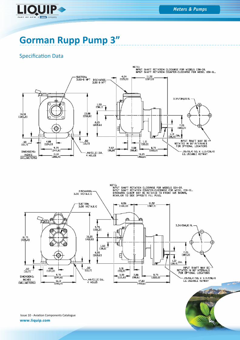
Meters & Pumps
www.liquip.com
Gorman Rupp Pump 3”Specification Data
Issue 10 - Aviation Components Catalogue 79
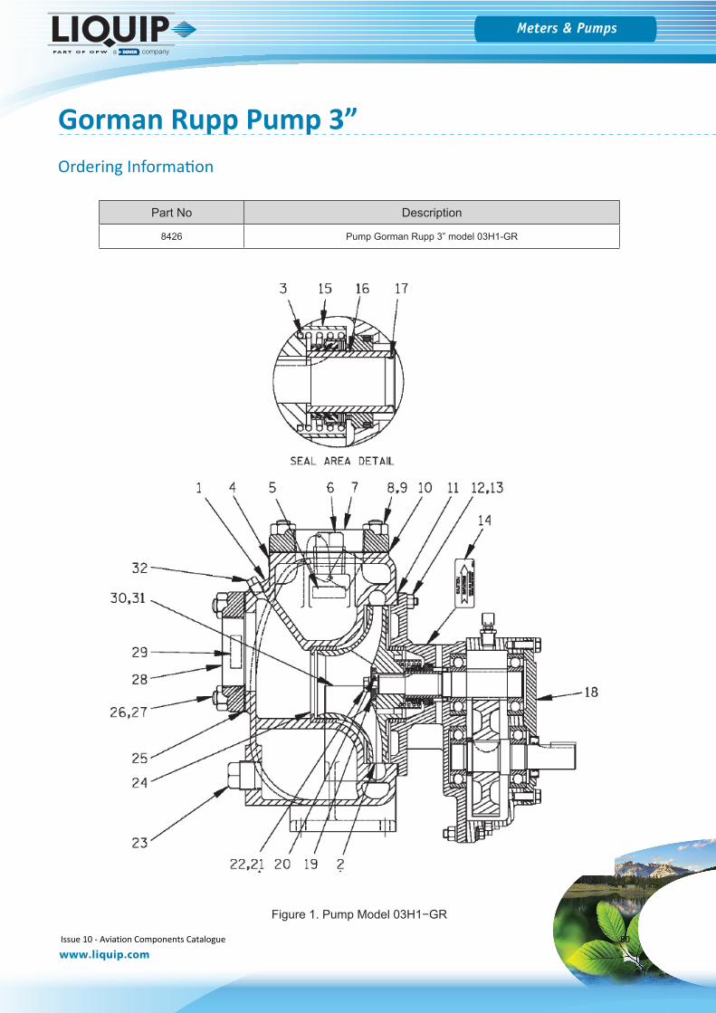
Meters & Pumps
www.liquip.com
Gorman Rupp Pump 3”
Part No Description
8426 Pump Gorman Rupp 3” model 03H1-GR
Figure 1. Pump Model 03H1−GR
Ordering Information
Issue 10 - Aviation Components Catalogue 80
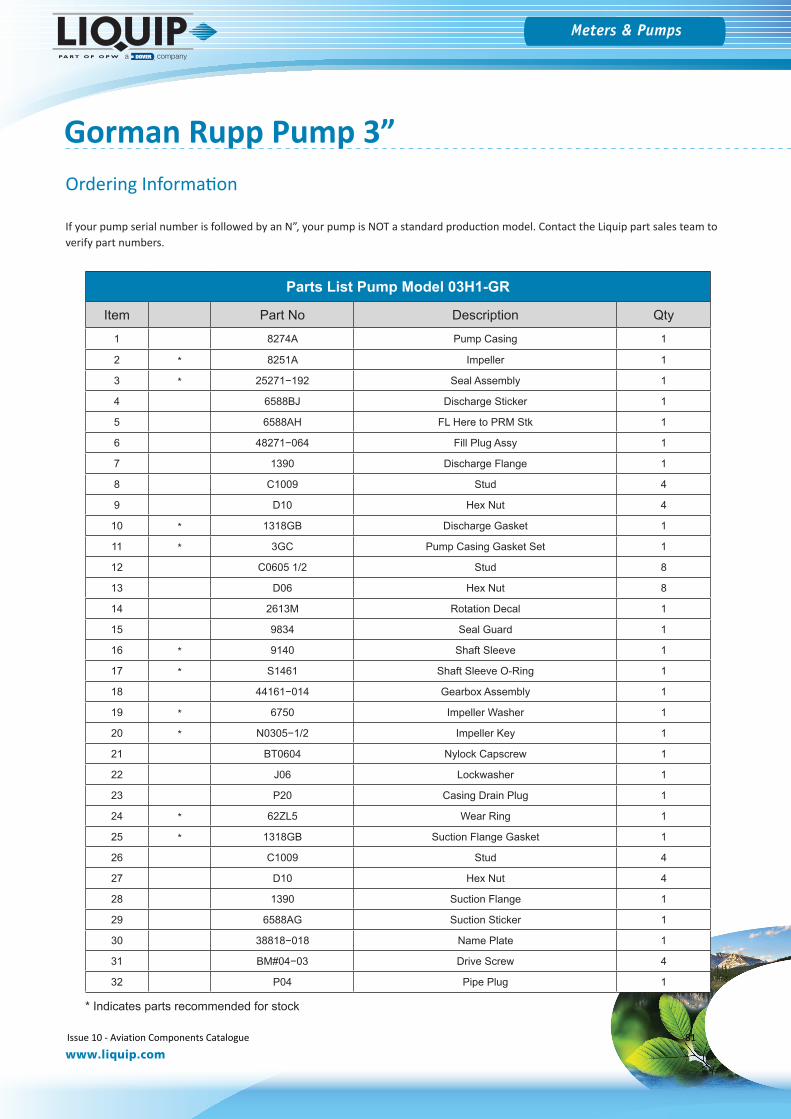
Meters & Pumps
www.liquip.com
Gorman Rupp Pump 3”
If your pump serial number is followed by an N”, your pump is NOT a standard production model. Contact the Liquip part sales team to verify part numbers.
Parts List Pump Model 03H1-GR
Item Part No Description Qty
1 8274A Pump Casing 1
2 * 8251A Impeller 1
3 * 25271−192 Seal Assembly 1
4 6588BJ Discharge Sticker 1
5 6588AH FL Here to PRM Stk 1
6 48271−064 Fill Plug Assy 1
7 1390 Discharge Flange 1
8 C1009 Stud 4
9 D10 Hex Nut 4
10 * 1318GB Discharge Gasket 1
11 * 3GC Pump Casing Gasket Set 1
12 C0605 1/2 Stud 8
13 D06 Hex Nut 8
14 2613M Rotation Decal 1
15 9834 Seal Guard 1
16 * 9140 Shaft Sleeve 1
17 * S1461 Shaft Sleeve O-Ring 1
18 44161−014 Gearbox Assembly 1
19 * 6750 Impeller Washer 1
20 * N0305−1/2 Impeller Key 1
21 BT0604 Nylock Capscrew 1
22 J06 Lockwasher 1
23 P20 Casing Drain Plug 1
24 * 62ZL5 Wear Ring 1
25 * 1318GB Suction Flange Gasket 1
26 C1009 Stud 4
27 D10 Hex Nut 4
28 1390 Suction Flange 1
29 6588AG Suction Sticker 1
30 38818−018 Name Plate 1
31 BM#04−03 Drive Screw 4
32 P04 Pipe Plug 1
* Indicates parts recommended for stock
Ordering Information
Issue 10 - Aviation Components Catalogue 81
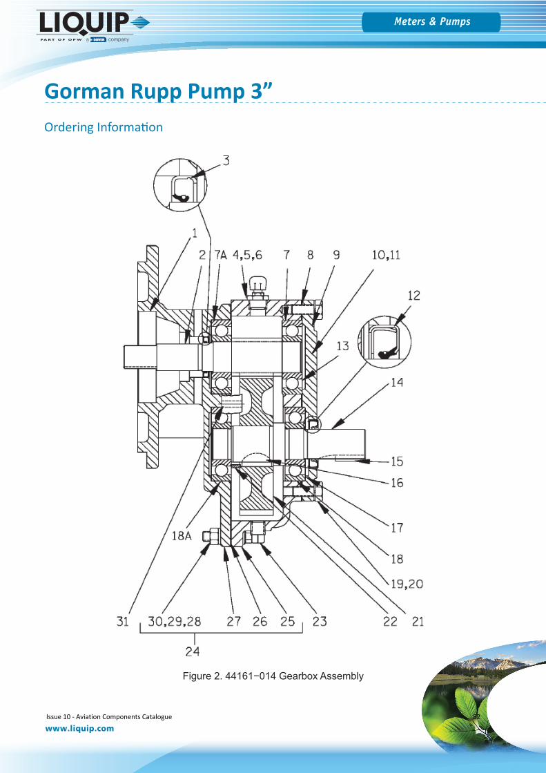
Meters & Pumps
www.liquip.com
Gorman Rupp Pump 3”
Figure 2. 44161−014 Gearbox Assembly
Ordering Information
Issue 10 - Aviation Components Catalogue 82
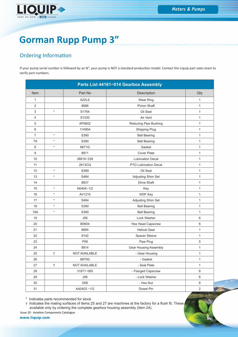
Meters & Pumps
www.liquip.com
Gorman Rupp Pump 3”
If your pump serial number is followed by an N”, your pump is NOT a standard production model. Contact the Liquip part sales team to verify part numbers.
Parts List 44161−014 Gearbox Assembly
Item Part No Description Qty
1 62ZL6 Wear Ring 1
2 8896 Pinion Shaft 1
3 * S1764 Oil Seal 1
4 S1530 Air Vent 1
5 AP0602 Reducing Pipe Bushing 1
6 11495A Shipping Plug 1
7 * S390 Ball Bearing 1
7A * S390 Ball Bearing 1
8 * 8871G Gasket 1
9 8871 Cover Plate 1
10 38816−239 Lubrication Decal 1
11 2613CQ PTO Lubrication Decal 1
12 * S389 Oil Seal 1
13 * S464 Adjusting Shim Set 1
14 8837 Drive Shaft 1
15 * N0404−1/2 Key 1
16 * AV1210 WDF Key 1
17 * S464 Adjusting Shim Set 1
18 * S390 Ball Bearing 1
18A * S390 Ball Bearing 1
19 J06 Lock Washer 6
20 B0604 Hex Head Capscrew 6
21 8895 Helical Gear 1
22 9142 Spacer Sleeve 1
23 P06 Pipe Plug 5
24 8914 Gear Housing Assembly 1
25 † NOT AVAILABLE - Gear Housing 1
26 8870G - Gasket 1
27 † NOT AVAILABLE - Seal Plate 1
28 31871−065 - Flanged Capscrew 8
29 J06 - Lock Washer 8
30 D06 - Hex Nut 8
31 AA0403 −1/2 Dowel Pin 2
* Indicates parts recommended for stock† Indicates the mating surfaces of items 25 and 27 are machines at the factory for a flush fit. These items are available only by ordering the complete gearbox housing assembly (Item 24).
Ordering Information
Issue 10 - Aviation Components Catalogue 83
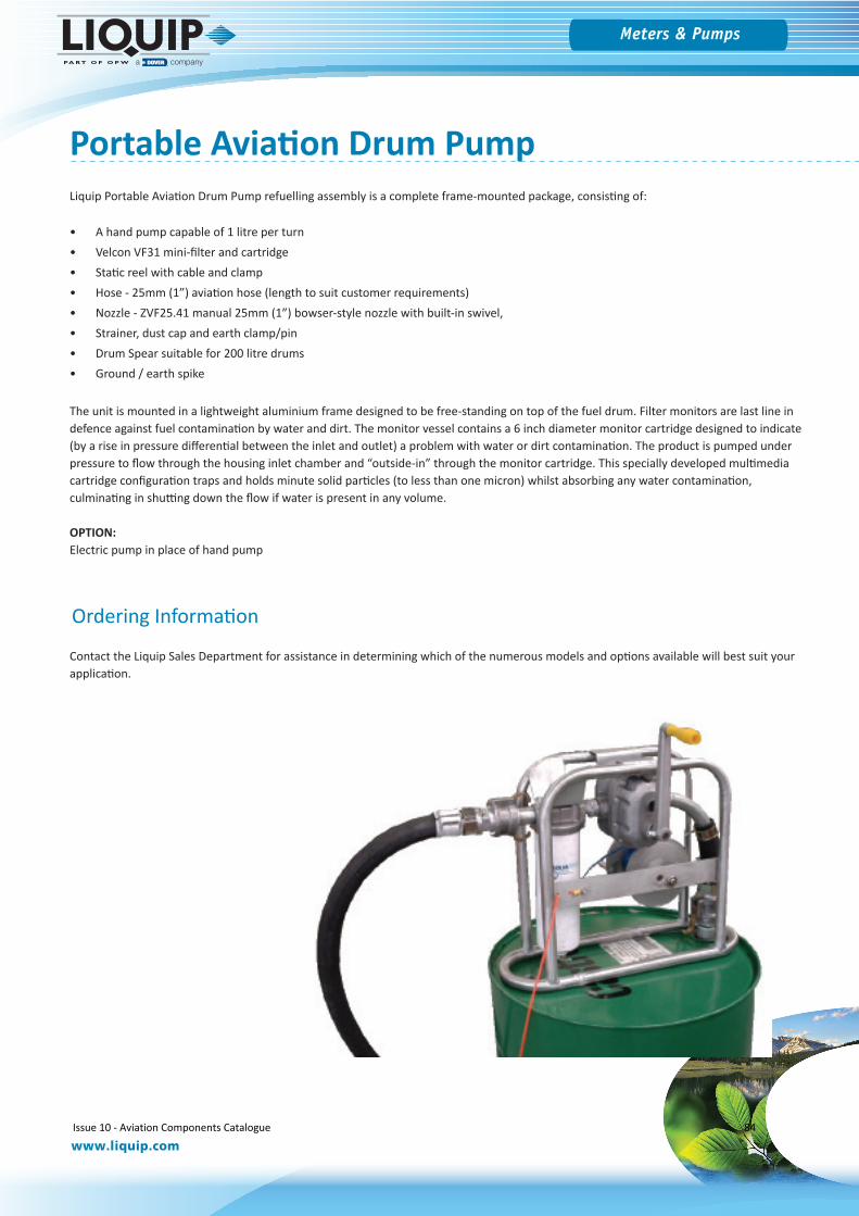
Meters & Pumps
www.liquip.com
Liquip Portable Aviation Drum Pump refuelling assembly is a complete frame-mounted package, consisting of:
• A hand pump capable of 1 litre per turn• Velcon VF31 mini-filter and cartridge• Static reel with cable and clamp• Hose - 25mm (1”) aviation hose (length to suit customer requirements)• Nozzle - ZVF25.41 manual 25mm (1”) bowser-style nozzle with built-in swivel,• Strainer, dust cap and earth clamp/pin• Drum Spear suitable for 200 litre drums• Ground / earth spike
The unit is mounted in a lightweight aluminium frame designed to be free-standing on top of the fuel drum. Filter monitors are last line in defence against fuel contamination by water and dirt. The monitor vessel contains a 6 inch diameter monitor cartridge designed to indicate (by a rise in pressure differential between the inlet and outlet) a problem with water or dirt contamination. The product is pumped under pressure to flow through the housing inlet chamber and “outside-in” through the monitor cartridge. This specially developed multimedia cartridge configuration traps and holds minute solid particles (to less than one micron) whilst absorbing any water contamination, culminating in shutting down the flow if water is present in any volume.
OPTION:Electric pump in place of hand pump
Contact the Liquip Sales Department for assistance in determining which of the numerous models and options available will best suit your application.
Portable Aviation Drum Pump
Ordering Information
Issue 10 - Aviation Components Catalogue 84

Fuel Sampling
Issue 10 - Aviation Components Catalogue 85
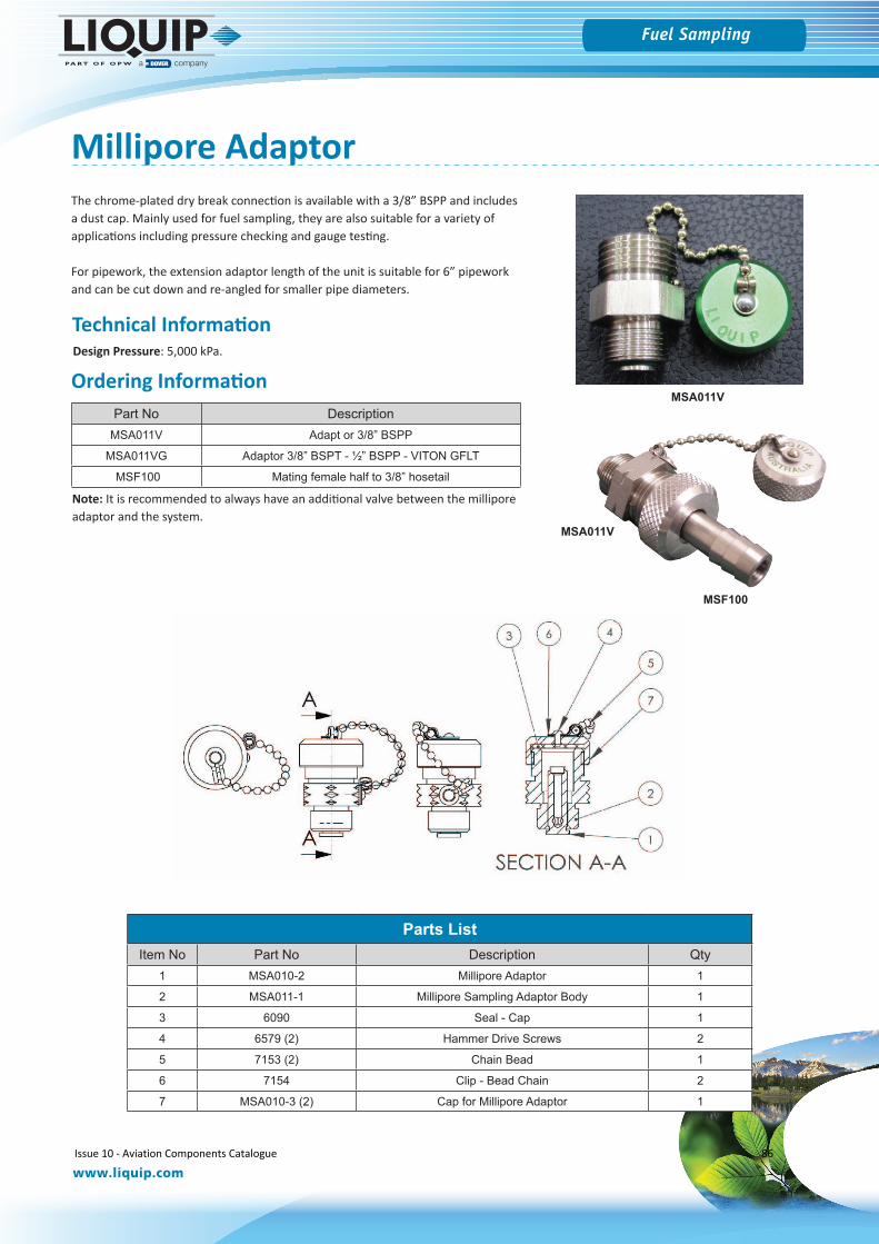
Fuel Sampling
www.liquip.com
Millipore AdaptorThe chrome-plated dry break connection is available with a 3/8” BSPP and includes a dust cap. Mainly used for fuel sampling, they are also suitable for a variety of applications including pressure checking and gauge testing.
For pipework, the extension adaptor length of the unit is suitable for 6” pipework and can be cut down and re-angled for smaller pipe diameters.
Parts ListItem No Part No Description Qty
1 MSA010-2 Millipore Adaptor 1
2 MSA011-1 Millipore Sampling Adaptor Body 1
3 6090 Seal - Cap 1
4 6579 (2) Hammer Drive Screws 2
5 7153 (2) Chain Bead 1
6 7154 Clip - Bead Chain 2
7 MSA010-3 (2) Cap for Millipore Adaptor 1
Part No DescriptionMSA011V Adapt or 3/8” BSPP
MSA011VG Adaptor 3/8” BSPT - ½” BSPP - VITON GFLT
MSF100 Mating female half to 3/8” hosetail
MSF100
MSA011V
MSA011VOrdering Information
Technical InformationDesign Pressure: 5,000 kPa.
Note: It is recommended to always have an additional valve between the millipore adaptor and the system.
Issue 10 - Aviation Components Catalogue 86
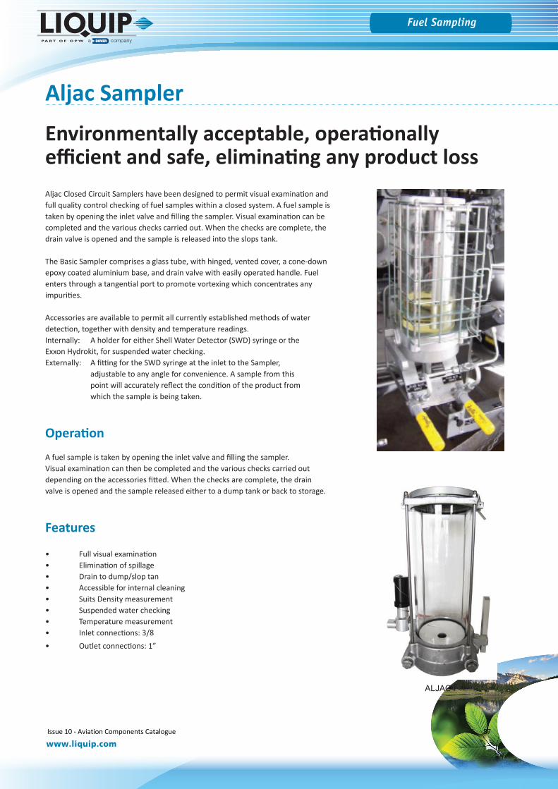
Fuel Sampling
www.liquip.com
Aljac Sampler
Aljac Closed Circuit Samplers have been designed to permit visual examination and full quality control checking of fuel samples within a closed system. A fuel sample is taken by opening the inlet valve and filling the sampler. Visual examination can be completed and the various checks carried out. When the checks are complete, the drain valve is opened and the sample is released into the slops tank.
The Basic Sampler comprises a glass tube, with hinged, vented cover, a cone-down epoxy coated aluminium base, and drain valve with easily operated handle. Fuel enters through a tangential port to promote vortexing which concentrates any impurities.
Accessories are available to permit all currently established methods of water detection, together with density and temperature readings. Internally: A holder for either Shell Water Detector (SWD) syringe or the Exxon Hydrokit, for suspended water checking.Externally: A fitting for the SWD syringe at the inlet to the Sampler,
adjustable to any angle for convenience. A sample from this point will accurately reflect the condition of the product from which the sample is being taken.
Operation
A fuel sample is taken by opening the inlet valve and filling the sampler. Visual examination can then be completed and the various checks carried out depending on the accessories fitted. When the checks are complete, the drain valve is opened and the sample released either to a dump tank or back to storage.
Features
• Full visual examination• Elimination of spillage• Drain to dump/slop tan• Accessible for internal cleaning• Suits Density measurement• Suspended water checking• Temperature measurement• Inlet connections: 3/8• Outlet connections: 1”
ALJAC4
Environmentally acceptable, operationally efficient and safe, eliminating any product loss
Issue 10 - Aviation Components Catalogue 87
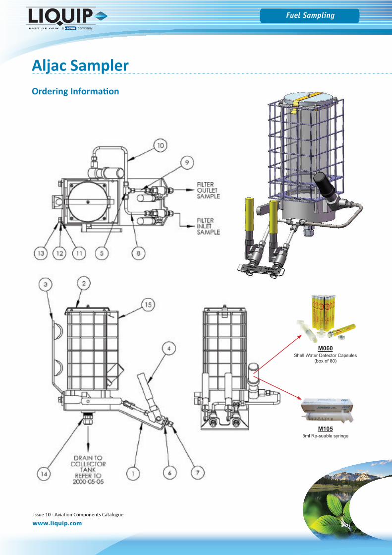
Fuel Sampling
www.liquip.com
M1055ml Re-suable syringe
Aljac Sampler
M060Shell Water Detector Capsules
(box of 80)
Ordering Information
Issue 10 - Aviation Components Catalogue 88
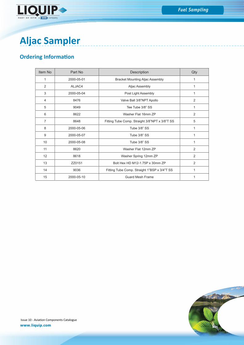
Fuel Sampling
www.liquip.com
Aljac Sampler
Item No Part No Description Qty
1 2000-05-01 Bracket Mounting Aljac Assembly 1
2 ALJAC4 Aljac Assembly 1
3 2000-05-04 Post Light Assembly 1
4 8476 Valve Ball 3/8”NPT Apollo 2
5 9049 Tee Tube 3/8” SS 1
6 8622 Washer Flat 16mm ZP 2
7 8648 Fitting Tube Comp. Straight 3/8”NPT x 3/8”T SS 5
8 2000-05-06 Tube 3/8” SS 1
9 2000-05-07 Tube 3/8” SS 1
10 2000-05-08 Tube 3/8” SS 1
11 8620 Washer Flat 12mm ZP 2
12 8618 Washer Spring 12mm ZP 2
13 ZZ0151 Bolt Hex HD M12-1.75P x 30mm ZP 2
14 9036 Fitting Tube Comp. Straight 1”BSP x 3/4”T SS 1
15 2000-05-10 Guard Mesh Frame 1
Ordering Information
Issue 10 - Aviation Components Catalogue 89

Overfill Protection
Issue 10 - Aviation Components Catalogue 90

Fuel Sampling
www.liquip.com
Overfill Protection
Liquid Detection Probes - LDP Series
Liquip’s LDP200 Series liquid detection probes are used as overfill protection on road tankers and in storage tanks. The probes are compatible with existing gantry monitors and interchangeable with current probes. They improve safety with a self-checking design. Probe can be checked for operation independently.
Sensing mechanism used is the different behaviour of a light beam in a glass prism when the prism is wet instead of dry. There is a very large difference in refractive index of air compared with petroleum liquids and this difference provides a very well defined and reliable switching point. With the probe dry, the light beam reflects back internally in the prism and in liquid the beam is refracted out into the liquid and “lost”. Electronics in the probe are designed to create the light beam, detect its return or disappearance and pass that message to the Rack Monitor for appropriate response.
Technical Specifications
Liquip LDP series optic overfill sensors raise the bar in safety with true fail safe technology & individual ‘optic-on’ light.
Electrical Parameters:IECEx: Ui = 30V, Ii = 690mA, Pi = 9W, Ci = 105pF, Li = 0mH
Operating Temperature: -400C to +650C
IP Rating: IP66
Level Repeatability: ±0.5mm
Design Pressure: 600kPa
Power Limit (Pi = 9W) applies:
Ii max = 690mA when Ui max = 13.04V ORIi max = 300mA when Ui max = 30V
Safety Certification
LDP202 and LDP205
• IECEx Certificate: IECEx ITA 14.0014X• Marking: Ex ia IIA T4 Ga IP66
Tamb = -400C to +650C• ATEX Certificate TUV 15ATEX 7627X• Marking 0518 II 1 G Ex ia IIA T4 Ga
Tamb = -400C to +650C
LDP202SS, LDP205SS, LDP202SC, LDP205SC
• IECEx Certificate: IECEx ITA 14.0014X• Marking: Ex ia IIA T3 Ga IP66
Tamb = -400C to +650C• ATEX Certificate TUV 15ATEX 7627X• Marking 0518 II 1 G Ex ia IIA T3 Ga
Tamb = -400C to +650C
Issue 10 - Aviation Components Catalogue 91

Fuel Sampling
www.liquip.com
Overfill Protection
Liquid Detection Probes - LDP Series
MATERIALS• Aluminium probe body, retainer & extension OR Stainless steel body, retainer & extension,
Pyrex glass prism, and epoxy.• Viton o-rings OR FFKM o-rings
MAINTENANCE Irreparable item, no routine maintenance required, replace with new if found faulty.
INSTALLATION
• It is the requirement of the ATEX Approval that the probe is installed in such a way that theprobe is Electrostatically Grounded. Install the grubscrew in PJB500, PJB301 & VOH200-5 kitfor this requirement.
• It is recommended to use Liquip PJB500, PJB301 or VOH200-5 Probe Holder which iscompatible with Liquip manhole covers. Probe can be removed from tank top withouthaving to access interior to remove a hood.
• Installation should be in accordance with APPLICABLE standards SUCH AS EN60079-14 andEN60079-25 or IEC60079-14 and IEC60079-25 or ANSI/ISA RP12.06.01 and ANSI/NFPA 70 orCSA C22.1 Part 1, Appendix F or EQUIVALENT.
• Users shall avoid ignition hazards due to impact or friction on the apparatus when used inZone 0 areas.
• Any free ends of cable not terminated shall be appropriately terminated to ensure nocontact with additional sources of power is possible.
WIRING METHOD
1. 2 - Wire System for LDP202, LDP202SS and LDP202SCAttached drawing shows a typical 6 channel compartment system based on AustralianStandard. For 8 channel compartment system ask Liquip for more details.|
2. 5 - Wire System for LDP205, LDP205SS and LDP205SCAttached drawing shows a typical 7 compartments tanker, the number of probes varieswith the number of compartments in the tanker as the probes are connected in series.
OPERATIONAL PARAMETERS
Liquid properties must conform to the following:• Have refractive index between 1.10 and 1.47. If in doubt, carry out test with sample of liquid
at working temperatures.• Not be reflective (e.g. milk will not trip probe as white reflects)• Be non-gelling and remain liquid at all operational temperatures. Viscosities up to 3500 cSt,
work without suffering from clingage.• No particles in suspension which can form clinging opaque surface coating on prism.• Use with standard petroleum products and water-based compounds only. Any other
chemical content must be checked with Liquip.• Not allow sunlight to access prism during operation.• Not install probe, or carry out routine tests adjacent to any reflective surface.
(Incident light and reflections may cause false readings)
HANDLING PRECAUTIONSTreat with care in particular protect tip until probe is installed. Protect open end of probe from moisture and chemicals.The probe prism is protected and light-shielded by the retainer.
ACCESSORIES
Extension bars of aluminium or stainless steel to suit various length applications. The following extension bars can only be used:
• LDP102-4 (80mm long)• LDP102-4SS (80mm long Stainless Steel)• LDP102-8 (Gauged, 80mm long)• LDP105-2 (222mm long)• LDP105-2SS (222mm long Stainless Steel)• Note: LC99 extension bar is not compatible.
ASSOCIATED EQUIPMENT
• RM100 Series Rack Monitor• TP Series “Ground Boss” truck plug• DP305 Dummy Probe• DP307 Dummy Probe• PJB301 Probe holder• PJB500 Probe holder• VOH200-5 Probe holder
Issue 10 - Aviation Components Catalogue 92
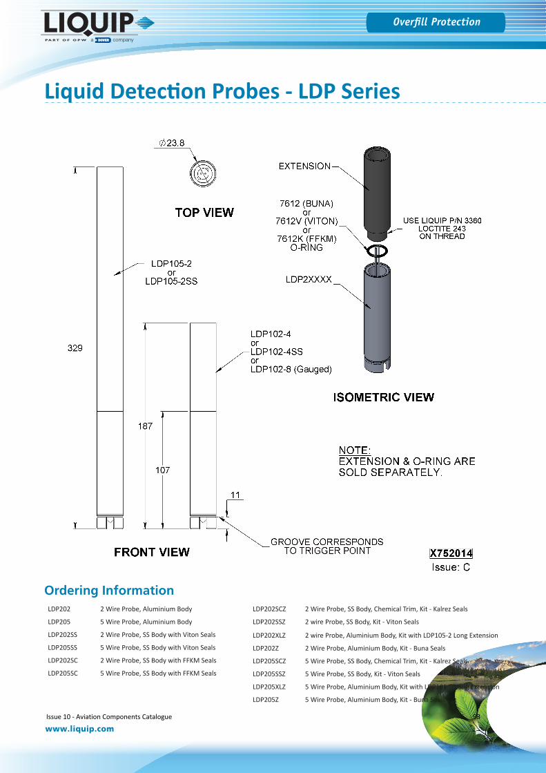
Fuel Sampling
www.liquip.com
Overfill Protection
Liquid Detection Probes - LDP Series
Ordering Information LDP202 2 Wire Probe, Aluminium Body
LDP205 5 Wire Probe, Aluminium Body
LDP202SS 2 Wire Probe, SS Body with Viton Seals
LDP205SS 5 Wire Probe, SS Body with Viton Seals
LDP202SC 2 Wire Probe, SS Body with FFKM Seals
LDP205SC 5 Wire Probe, SS Body with FFKM Seals
LDP202SCZ 2 Wire Probe, SS Body, Chemical Trim, Kit - Kalrez Seals
LDP202SSZ 2 wire Probe, SS Body, Kit - Viton Seals
LDP202XLZ 2 wire Probe, Aluminium Body, Kit with LDP105-2 Long Extension
LDP202Z 2 Wire Probe, Aluminium Body, Kit - Buna Seals
LDP205SCZ 5 Wire Probe, SS Body, Chemical Trim, Kit - Kalrez Seals
LDP205SSZ 5 Wire Probe, SS Body, Kit - Viton Seals
LDP205XLZ 5 Wire Probe, Aluminium Body, Kit with LDP105-2 Long Extension
LDP205Z 5 Wire Probe, Aluminium Body, Kit - Buna Seals
Issue 10 - Aviation Components Catalogue 93
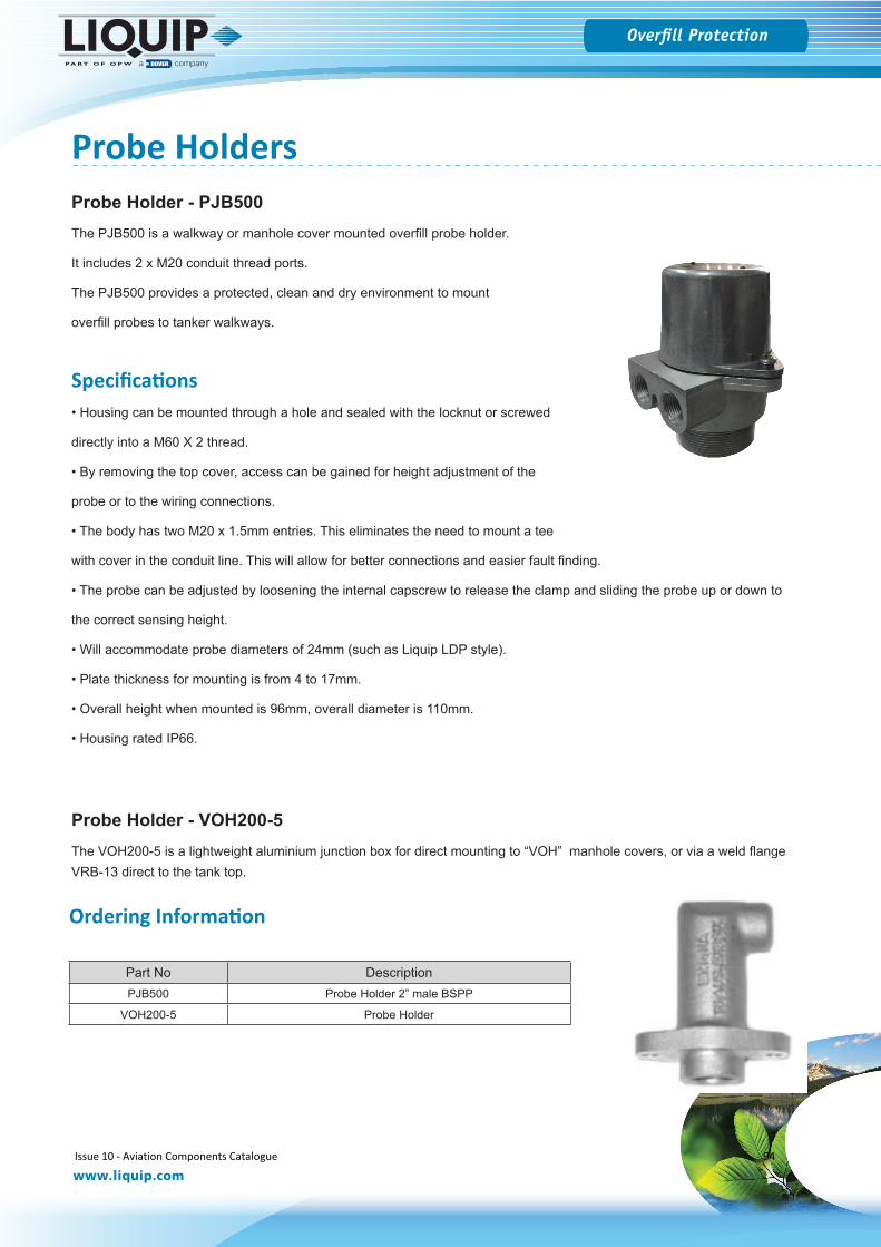
Fuel Sampling
www.liquip.com
Overfill Protection
Probe HoldersProbe Holder - PJB500The PJB500 is a walkway or manhole cover mounted overfill probe holder.
It includes 2 x M20 conduit thread ports.
The PJB500 provides a protected, clean and dry environment to mount
overfill probes to tanker walkways.
Specifications• Housing can be mounted through a hole and sealed with the locknut or screwed
directly into a M60 X 2 thread.
• By removing the top cover, access can be gained for height adjustment of the
probe or to the wiring connections.
• The body has two M20 x 1.5mm entries. This eliminates the need to mount a tee
with cover in the conduit line. This will allow for better connections and easier fault finding.
• The probe can be adjusted by loosening the internal capscrew to release the clamp and sliding the probe up or down to
the correct sensing height.
• Will accommodate probe diameters of 24mm (such as Liquip LDP style).
• Plate thickness for mounting is from 4 to 17mm.
• Overall height when mounted is 96mm, overall diameter is 110mm.
• Housing rated IP66.
Probe Holder - VOH200-5The VOH200-5 is a lightweight aluminium junction box for direct mounting to “VOH” manhole covers, or via a weld flange VRB-13 direct to the tank top.
Part No DescriptionPJB500 Probe Holder 2” male BSPP
VOH200-5 Probe Holder
Ordering Information
Issue 10 - Aviation Components Catalogue 94
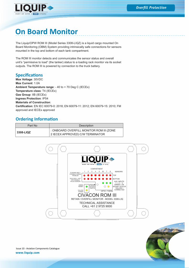
Fuel Sampling
www.liquip.com
Overfill Protection
On Board MonitorThe Liquip/OPW ROM III (Model Series 3308-LIQZ) is a liquid cargo mounted On Board Monitoring (OBM) System providing intrinsically safe connections for sensors mounted in the top and bottom of each tank compartment.
The ROM III monitor detects and communicates the sensor status and overall unit’s “permissive to load” (the tanker) status to a loading rack monitor via its socket outputs. The ROM III is powered by connection to the truck battery.
SpecificationsMax Voltage: 30VDC Max Current: 1.0AAmbient Temperature range: - 40 to + 70 Deg C (IECEx)Temperature class: T4 (IECEx)Gas Group: IIB (IECEx)Ingress Protection: IP54Materials of Construction:Certification: EN IEC 60079-0: 2018; EN 60079-11: 2012; EN 60079-15: 2010; FM approved and IECEx approved
Ordering Information
CIVACON ROM IIIRETAIN / OVERFILL MONITOR - MODEL 3308-LIQ
TECHNICAL ASSISTANCECALL +61 2 9725 9000
TOP
BOTTOM
1 • 2 • 3GREEN = OK
SOCKET STATUSYELLOW =
CONNECTED
POSSIBLE WIRINGPROBLEM
SOLID RED = WETOR POSSIBLE
GREENPERMIT
YELLOWPOWER
COMPARTMENT
FLASHING=RETAINEDTIMER ON
FLASHING RED =
FAILED SENSOR
GREEN
SENSORS
AUX. INPUTS
OPTIC • THERM
31 2 3 4 5 6 7 8
Part No Description
3308-LIQZ : ONBOARD OVERFILL MONITOR ROM III (ZONE 2 IECEX APPROVED) C/W TERMINATOR
Issue 10 - Aviation Components Catalogue 95

Valves
Issue 10 - Aviation Components Catalogue 96
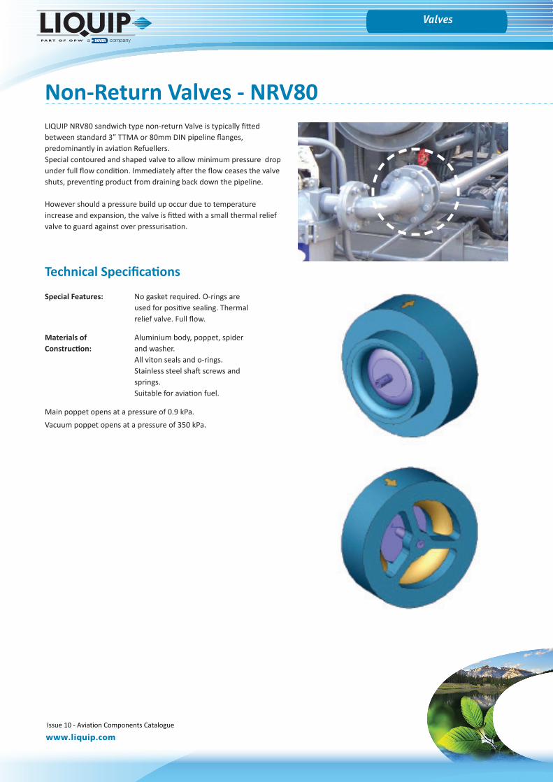
Fuel Sampling
www.liquip.com
Overfill ProtectionValves
Non-Return Valves - NRV80LIQUIP NRV80 sandwich type non-return Valve is typically fitted between standard 3” TTMA or 80mm DIN pipeline flanges, predominantly in aviation Refuellers. Special contoured and shaped valve to allow minimum pressure drop under full flow condition. Immediately after the flow ceases the valve shuts, preventing product from draining back down the pipeline.
However should a pressure build up occur due to temperature increase and expansion, the valve is fitted with a small thermal relief valve to guard against over pressurisation.
Technical Specifications
Special Features: No gasket required. O-rings are used for positive sealing. Thermal relief valve. Full flow.
Materials of Aluminium body, poppet, spider Construction: and washer.
All viton seals and o-rings.Stainless steel shaft screws and springs.Suitable for aviation fuel.
Main poppet opens at a pressure of 0.9 kPa.Vacuum poppet opens at a pressure of 350 kPa.
Issue 10 - Aviation Components Catalogue 97
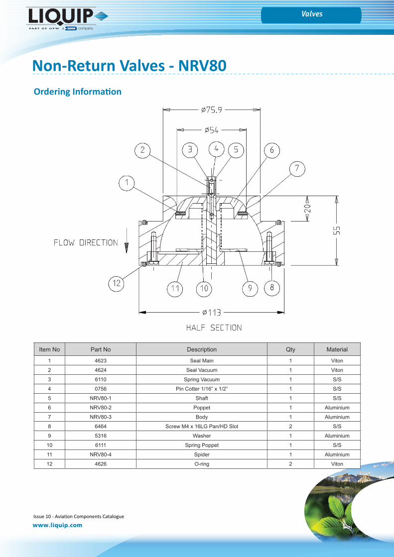
Fuel Sampling
www.liquip.com
Overfill ProtectionValves
Non-Return Valves - NRV80
Item No Part No Description Qty Material
1 4623 Seal Main 1 Viton
2 4624 Seal Vacuum 1 Viton
3 6110 Spring Vacuum 1 S/S
4 0756 Pin Cotter 1/16” x 1/2” 1 S/S
5 NRV80-1 Shaft 1 S/S
6 NRV80-2 Poppet 1 Aluminium
7 NRV80-3 Body 1 Aluminium
8 6464 Screw M4 x 16LG Pan/HD Slot 2 S/S
9 5316 Washer 1 Aluminium
10 6111 Spring Poppet 1 S/S
11 NRV80-4 Spider 1 Aluminium
12 4626 O-ring 2 Viton
Ordering Information
Issue 10 - Aviation Components Catalogue 98
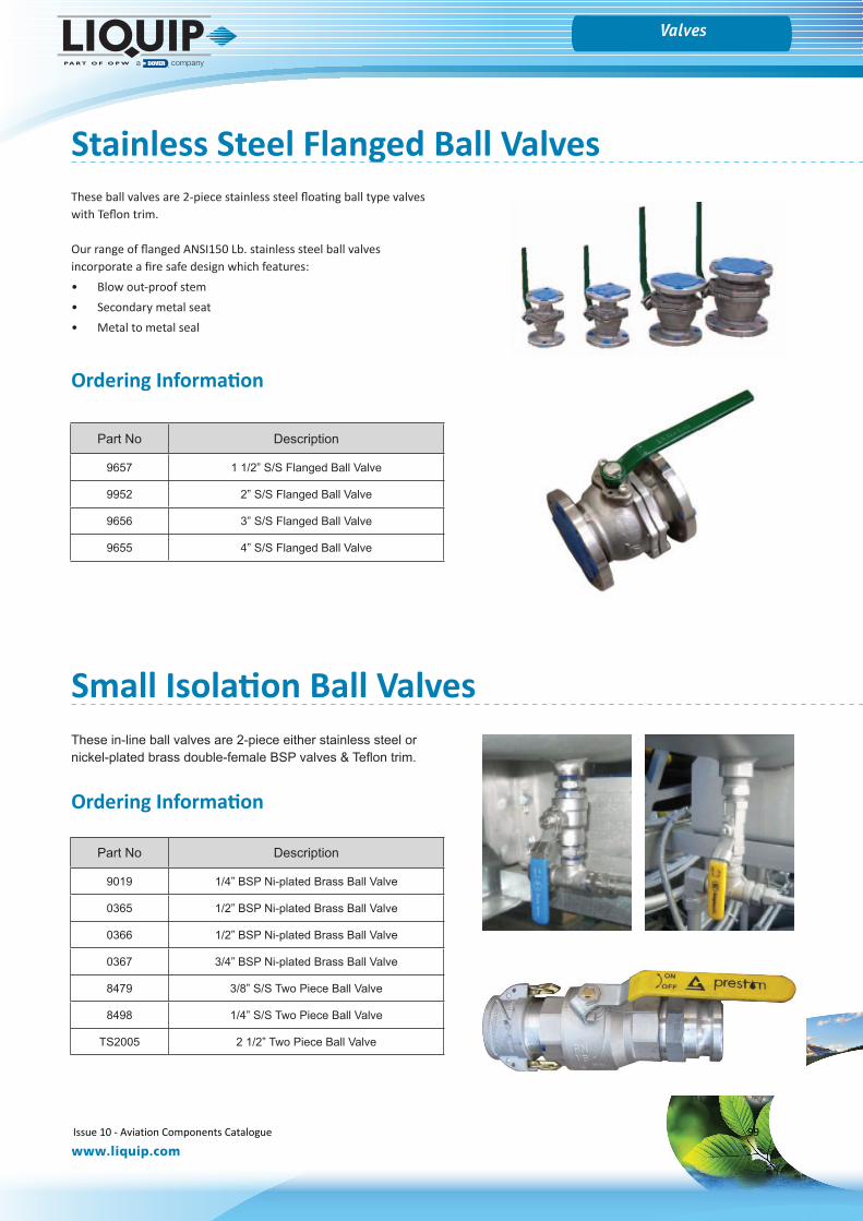
Fuel Sampling
www.liquip.com
Overfill ProtectionValves
Stainless Steel Flanged Ball ValvesThese ball valves are 2-piece stainless steel floating ball type valves with Teflon trim.
Our range of flanged ANSI150 Lb. stainless steel ball valves incorporate a fire safe design which features:• Blow out-proof stem• Secondary metal seat• Metal to metal seal
Part No Description
9657 1 1/2” S/S Flanged Ball Valve
9952 2” S/S Flanged Ball Valve
9656 3” S/S Flanged Ball Valve
9655 4” S/S Flanged Ball Valve
These in-line ball valves are 2-piece either stainless steel or nickel-plated brass double-female BSP valves & Teflon trim.
Part No Description
9019 1/4” BSP Ni-plated Brass Ball Valve
0365 1/2” BSP Ni-plated Brass Ball Valve
0366 1/2” BSP Ni-plated Brass Ball Valve
0367 3/4” BSP Ni-plated Brass Ball Valve
8479 3/8” S/S Two Piece Ball Valve
8498 1/4” S/S Two Piece Ball Valve
TS2005 2 1/2” Two Piece Ball Valve
Ordering Information
Ordering Information
Small Isolation Ball Valves
Issue 10 - Aviation Components Catalogue 99
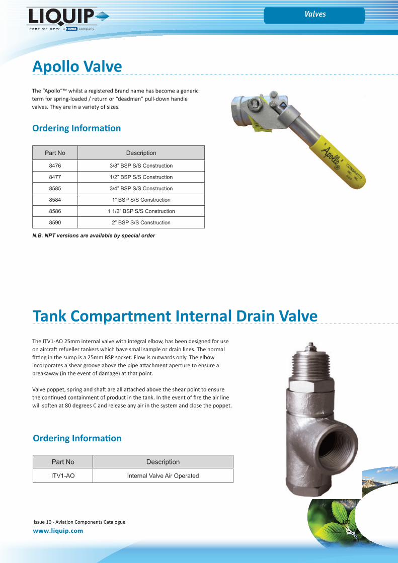
Fuel Sampling
www.liquip.com
Overfill ProtectionValves
Apollo ValveThe “Apollo”™ whilst a registered Brand name has become a generic term for spring-loaded / return or “deadman” pull-down handle valves. They are in a variety of sizes.
Part No Description
8476 3/8” BSP S/S Construction
8477 1/2” BSP S/S Construction
8585 3/4” BSP S/S Construction
8584 1” BSP S/S Construction
8586 1 1/2” BSP S/S Construction
8590 2” BSP S/S Construction
Ordering Information
N.B. NPT versions are available by special order
Tank Compartment Internal Drain ValveThe ITV1-AO 25mm internal valve with integral elbow, has been designed for use on aircraft refueller tankers which have small sample or drain lines. The normal fitting in the sump is a 25mm BSP socket. Flow is outwards only. The elbow incorporates a shear groove above the pipe attachment aperture to ensure a breakaway (in the event of damage) at that point.
Valve poppet, spring and shaft are all attached above the shear point to ensure the continued containment of product in the tank. In the event of fire the air line will soften at 80 degrees C and release any air in the system and close the poppet.
Part No Description
ITV1-AO Internal Valve Air Operated
Ordering Information
Issue 10 - Aviation Components Catalogue 100
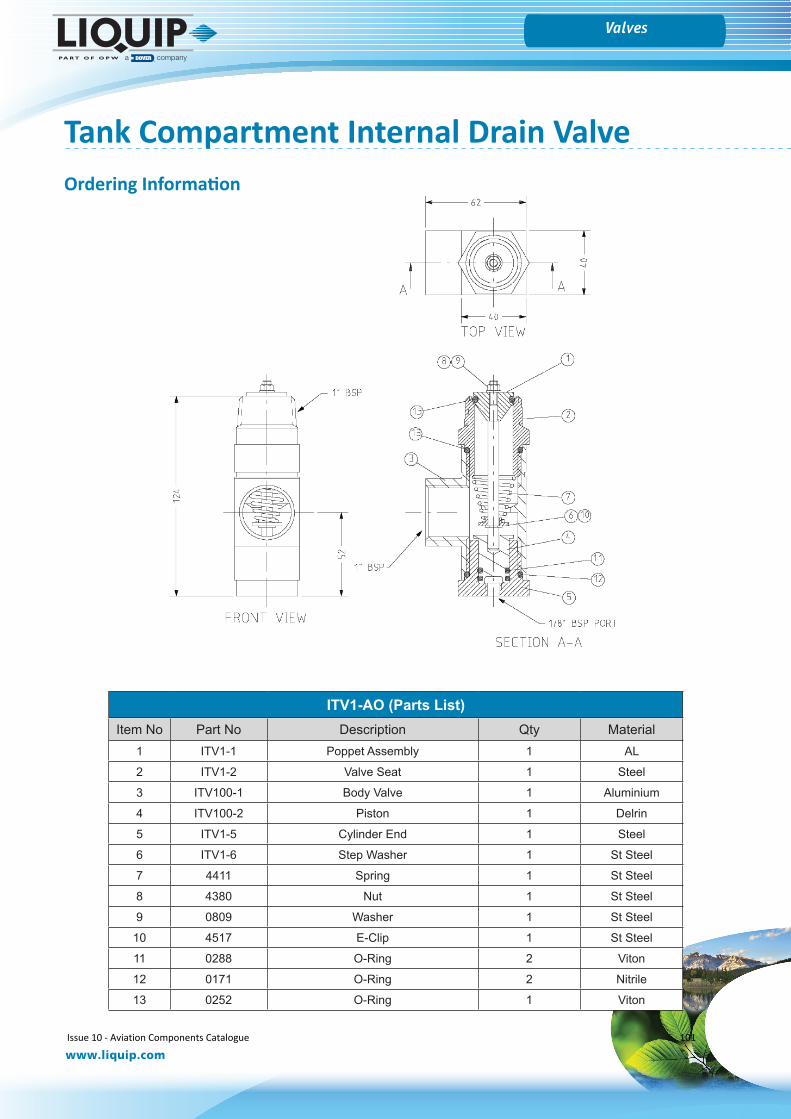
Fuel Sampling
www.liquip.com
Overfill ProtectionValves
Tank Compartment Internal Drain Valve
ITV1-AO (Parts List)Item No Part No Description Qty Material
1 ITV1-1 Poppet Assembly 1 AL
2 ITV1-2 Valve Seat 1 Steel
3 ITV100-1 Body Valve 1 Aluminium
4 ITV100-2 Piston 1 Delrin
5 ITV1-5 Cylinder End 1 Steel
6 ITV1-6 Step Washer 1 St Steel
7 4411 Spring 1 St Steel
8 4380 Nut 1 St Steel
9 0809 Washer 1 St Steel
10 4517 E-Clip 1 St Steel
11 0288 O-Ring 2 Viton
12 0171 O-Ring 2 Nitrile
13 0252 O-Ring 1 Viton
Ordering Information
Issue 10 - Aviation Components Catalogue 101
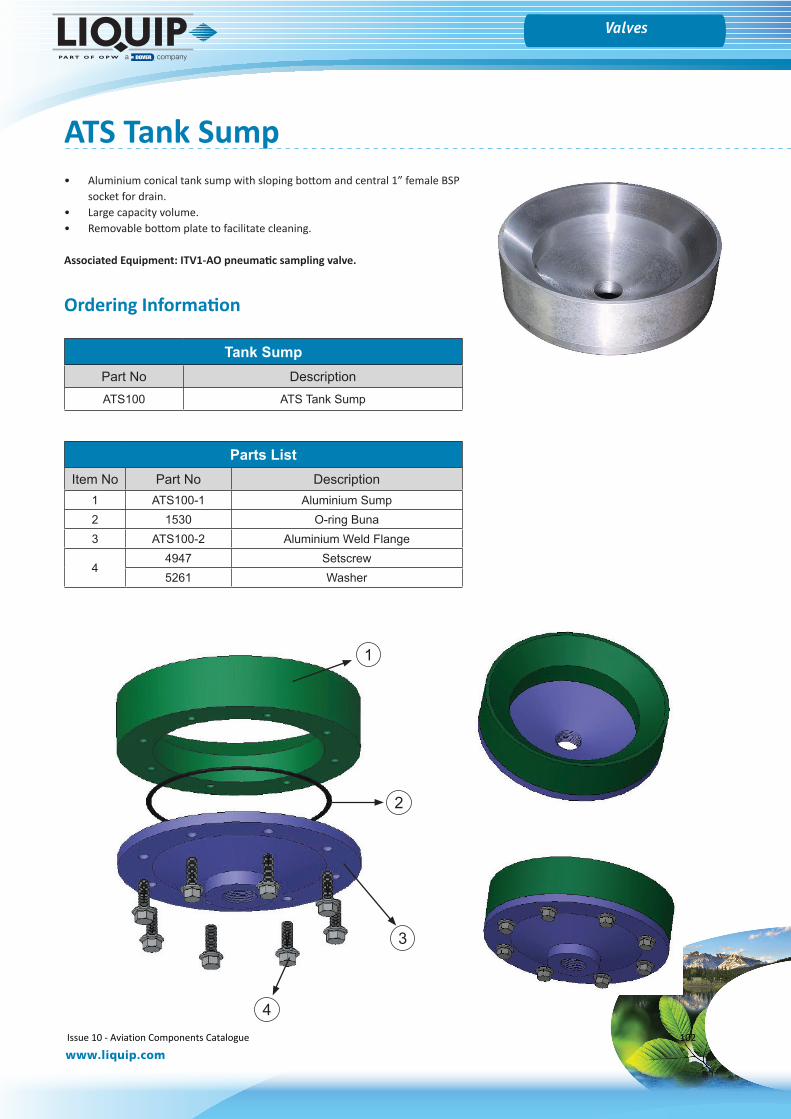
Fuel Sampling
www.liquip.com
Overfill ProtectionValves
ATS Tank Sump• Aluminium conical tank sump with sloping bottom and central 1” female BSP
socket for drain.• Large capacity volume.• Removable bottom plate to facilitate cleaning.
Associated Equipment: ITV1-AO pneumatic sampling valve.
Tank SumpPart No DescriptionATS100 ATS Tank Sump
3
4
2
1
Parts ListItem No Part No Description
1 ATS100-1 Aluminium Sump2 1530 O-ring Buna3 ATS100-2 Aluminium Weld Flange
44947 Setscrew5261 Washer
Ordering Information
Issue 10 - Aviation Components Catalogue 102
Gauges
Issue 10 - Aviation Components Catalogue 103
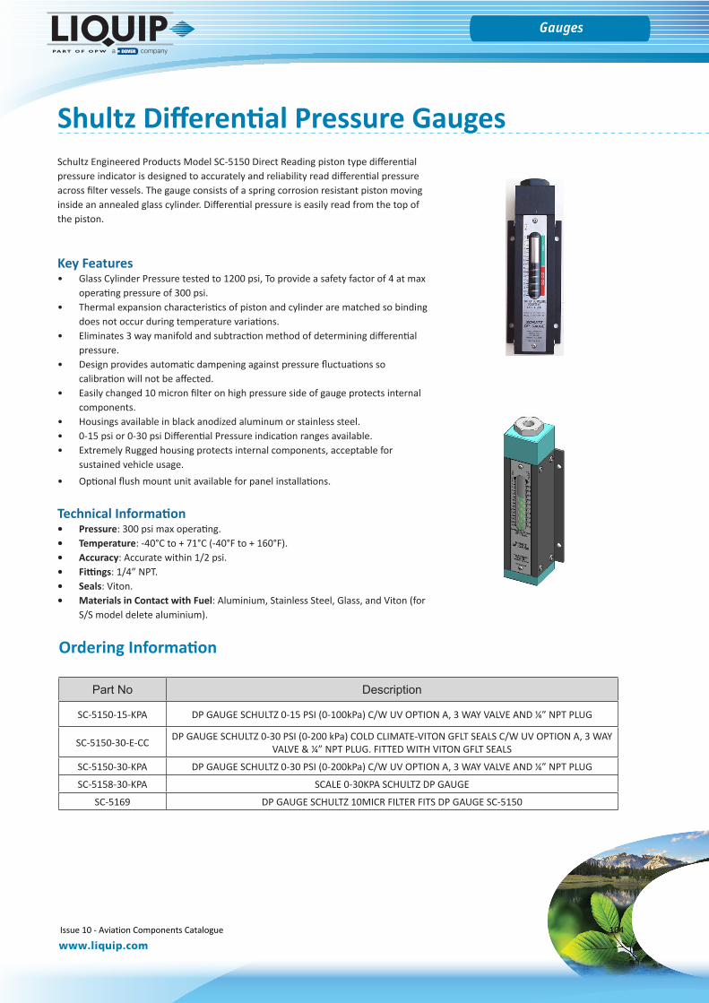
Gauges
www.liquip.com
Shultz Differential Pressure GaugesSchultz Engineered Products Model SC-5150 Direct Reading piston type differential pressure indicator is designed to accurately and reliability read differential pressure across filter vessels. The gauge consists of a spring corrosion resistant piston moving inside an annealed glass cylinder. Differential pressure is easily read from the top of the piston.
Key Features• Glass Cylinder Pressure tested to 1200 psi, To provide a safety factor of 4 at max
operating pressure of 300 psi.• Thermal expansion characteristics of piston and cylinder are matched so binding
does not occur during temperature variations.• Eliminates 3 way manifold and subtraction method of determining differential
pressure.• Design provides automatic dampening against pressure fluctuations so
calibration will not be affected.• Easily changed 10 micron filter on high pressure side of gauge protects internal
components.• Housings available in black anodized aluminum or stainless steel.• 0-15 psi or 0-30 psi Differential Pressure indication ranges available.• Extremely Rugged housing protects internal components, acceptable for
sustained vehicle usage.• Optional flush mount unit available for panel installations.
Technical Information• Pressure: 300 psi max operating.• Temperature: -40°C to + 71°C (-40°F to + 160°F).• Accuracy: Accurate within 1/2 psi.• Fittings: 1/4” NPT.• Seals: Viton.• Materials in Contact with Fuel: Aluminium, Stainless Steel, Glass, and Viton (for
S/S model delete aluminium).
Part No Description
SC-5150-15-KPA DP GAUGE SCHULTZ 0-15 PSI (0-100kPa) C/W UV OPTION A, 3 WAY VALVE AND ¼” NPT PLUG
SC-5150-30-E-CC DP GAUGE SCHULTZ 0-30 PSI (0-200 kPa) COLD CLIMATE-VITON GFLT SEALS C/W UV OPTION A, 3 WAY VALVE & ¼” NPT PLUG. FITTED WITH VITON GFLT SEALS
SC-5150-30-KPA DP GAUGE SCHULTZ 0-30 PSI (0-200kPa) C/W UV OPTION A, 3 WAY VALVE AND ¼” NPT PLUG
SC-5158-30-KPA SCALE 0-30KPA SCHULTZ DP GAUGE
SC-5169 DP GAUGE SCHULTZ 10MICR FILTER FITS DP GAUGE SC-5150
Ordering Information
Issue 10 - Aviation Components Catalogue 104
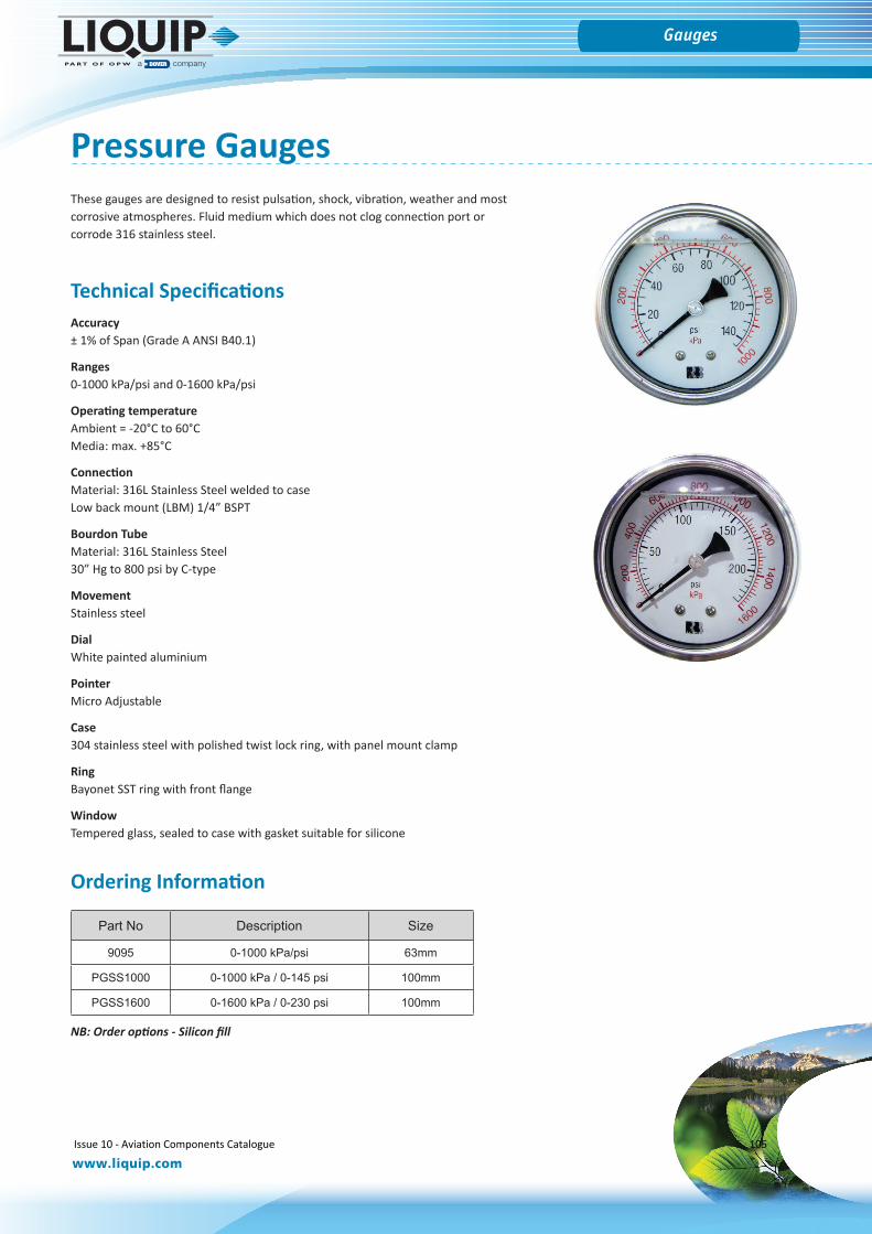
Gauges
www.liquip.com
Pressure GaugesThese gauges are designed to resist pulsation, shock, vibration, weather and most corrosive atmospheres. Fluid medium which does not clog connection port or corrode 316 stainless steel.
Part No Description Size
9095 0-1000 kPa/psi 63mm
PGSS1000 0-1000 kPa / 0-145 psi 100mm
PGSS1600 0-1600 kPa / 0-230 psi 100mm
Technical SpecificationsAccuracy ± 1% of Span (Grade A ANSI B40.1)
Ranges0-1000 kPa/psi and 0-1600 kPa/psi
Operating temperature Ambient = -20°C to 60°CMedia: max. +85°C
ConnectionMaterial: 316L Stainless Steel welded to caseLow back mount (LBM) 1/4” BSPT
Bourdon Tube Material: 316L Stainless Steel 30” Hg to 800 psi by C-type
Movement Stainless steel
DialWhite painted aluminium
PointerMicro Adjustable
Case304 stainless steel with polished twist lock ring, with panel mount clamp
RingBayonet SST ring with front flange
WindowTempered glass, sealed to case with gasket suitable for silicone
NB: Order options - Silicon fill
Ordering Information
Issue 10 - Aviation Components Catalogue 105

Accessories
Issue 10 - Aviation Components Catalogue 106
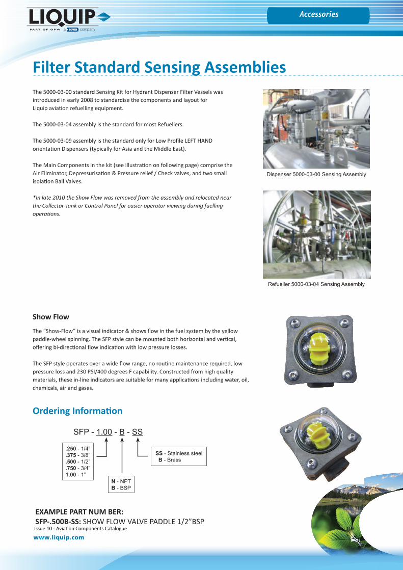
Gauges
www.liquip.com
Accessories
Filter Standard Sensing Assemblies
Dispenser 5000-03-00 Sensing Assembly
Refueller 5000-03-04 Sensing Assembly
The 5000-03-00 standard Sensing Kit for Hydrant Dispenser Filter Vessels was introduced in early 2008 to standardise the components and layout forLiquip aviation refuelling equipment.
The 5000-03-04 assembly is the standard for most Refuellers.
The 5000-03-09 assembly is the standard only for Low Profile LEFT HAND orientation Dispensers (typically for Asia and the Middle East).
The Main Components in the kit (see illustration on following page) comprise the Air Eliminator, Depressurisation & Pressure relief / Check valves, and two small isolation Ball Valves.
*In late 2010 the Show Flow was removed from the assembly and relocated nearthe Collector Tank or Control Panel for easier operator viewing during fuellingoperations.
Show Flow
The “Show-Flow” is a visual indicator & shows flow in the fuel system by the yellow paddle-wheel spinning. The SFP style can be mounted both horizontal and vertical, offering bi-directional flow indication with low pressure losses.
The SFP style operates over a wide flow range, no routine maintenance required, low pressure loss and 230 PSI/400 degrees F capability. Constructed from high quality materials, these in-line indicators are suitable for many applications including water, oil, chemicals, air and gases.
SFP - 1.00 - B - SS
SS - Stainless steel B - Brass
N - NPTB - BSP
.250 - 1/4”
.375 - 3/8”
.500 - 1/2”
.750 - 3/4”1.00 - 1”
Ordering Information
EXAMPLE PART NUM BER:SFP-.500B-SS: SHOW FLOW VALVE PADDLE 1/2”BSPIssue 10 - Aviation Components Catalogue 107

Gauges
www.liquip.com
Accessories
9020
0622
8995
8656
8445
8656
8995
0475
8578 86
5690
18
0475
9065
0365
FB
MSA
011
PR-0
95
9888
8484
047590
01
T/PP
9022
0
0475
0475
0365
FB
902004
75
1/2”
Tub
e PR
to A
E1/
2” T
ube
PR to
AE
1100
kPa
Rel
ief V
alve
SS-8
CPA
2-3
set a
t 20
PSI
Sensing Assembly Kit
Filter Standard Sensing Assemblies
Issue 10 - Aviation Components Catalogue 108
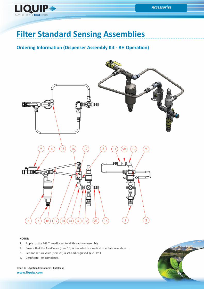
Gauges
www.liquip.com
Accessories
Ordering Information (Dispenser Assembly Kit - RH Operation)
Filter Standard Sensing Assemblies
NOTES:1. Apply Loctite 243 Threadlocker to all threads on assembly.2. Ensure that the Axial Valve (Item 10) is mounted in a vertical orientation as shown.3. Set non return valve (Item 20) is set and engraved @ 20 P.S.I4. Certificate Test completed.
Issue 10 - Aviation Components Catalogue 109
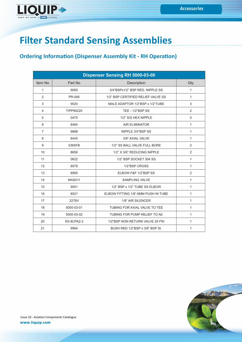
Gauges
www.liquip.com
Accessories
Dispenser Sensing RH 5000-03-00Item No Part No Description Qty
1 9065 3/4”BSPx1/2” BSP RED. NIPPLE SS 1
2 PR-095 1/2” BSP CERTIFIED RELIEF VALVE SS 1
3 9020 MALE ADAPTOR 1/2”BSP x 1/2”TUBE 3
4 T/PP90220 TEE - 1/2”BSP SS 2
5 0475 1/2” S/S HEX NIPPLE 5
6 8484 AIR ELIMINATOR 1
7 9888 NIPPLE 3/4”BSP SS 1
8 8445 3/8” AXIAL VALVE 1
9 0365FB 1/2” SS BALL VALVE FULL BORE 2
10 8656 1/2” X 3/8” REDUCING NIPPLE 2
11 0622 1/2” BSP SOCKET 304 SS 1
12 8578 1/2”BSP CROSS 1
13 8995 ELBOW F&F 1/2”BSP SS 2
14 MAS011 SAMPLING VALVE 1
15 9001 1/2” BSP x 1/2” TUBE SS ELBOW 1
16 8521 ELBOW FITTING 1/8”-6MM PUSH IN TUBE 1
17 2278V 1/8” AIR SILENCER 1
18 5000-03-01 TUBING FOR AXIAL VALVE TO TEE 1
19 5000-03-02 TUBING FOR PUMP RELIEF TO AE 1
20 SS-8CPA2-3 1/2"BSP NON RETURN VALVE 25 PSI 1
21 9994 BUSH RED 1/2”BSP x 3/8” BSP St. 1
Filter Standard Sensing AssembliesOrdering Information (Dispenser Assembly Kit - RH Operation)
Issue 10 - Aviation Components Catalogue 110
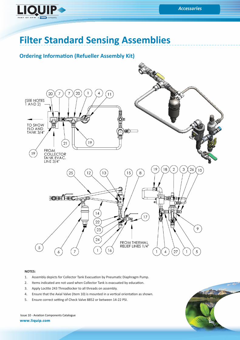
Gauges
www.liquip.com
Accessories
Filter Standard Sensing Assemblies
NOTES:1. Assembly depicts for Collector Tank Evacuation by Pneumatic Diaphragm Pump.2. Items indicated are not used when Collector Tank is evacuated by education.3. Apply Loctite 243 Threadlocker to all threads on assembly.4. Ensure that the Axial Valve (Item 10) is mounted in a vertical orientation as shown.5. Ensure correct setting of Check Valve 8852 or between 14-22 PSI.
Ordering Information (Refueller Assembly Kit)
Issue 10 - Aviation Components Catalogue 111
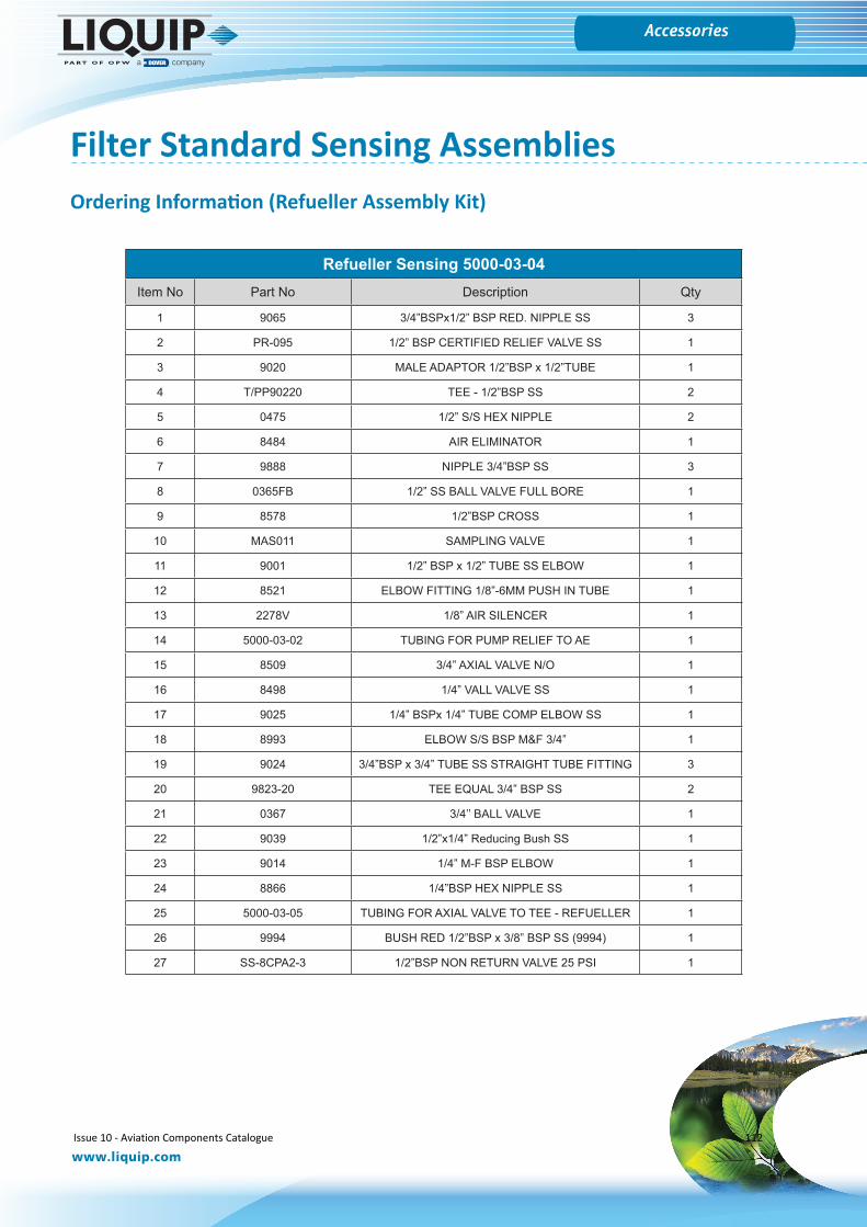
Gauges
www.liquip.com
Accessories
Refueller Sensing 5000-03-04Item No Part No Description Qty
1 9065 3/4”BSPx1/2” BSP RED. NIPPLE SS 3
2 PR-095 1/2” BSP CERTIFIED RELIEF VALVE SS 1
3 9020 MALE ADAPTOR 1/2”BSP x 1/2”TUBE 1
4 T/PP90220 TEE - 1/2”BSP SS 2
5 0475 1/2” S/S HEX NIPPLE 2
6 8484 AIR ELIMINATOR 1
7 9888 NIPPLE 3/4”BSP SS 3
8 0365FB 1/2” SS BALL VALVE FULL BORE 1
9 8578 1/2”BSP CROSS 1
10 MAS011 SAMPLING VALVE 1
11 9001 1/2” BSP x 1/2” TUBE SS ELBOW 1
12 8521 ELBOW FITTING 1/8”-6MM PUSH IN TUBE 1
13 2278V 1/8” AIR SILENCER 1
14 5000-03-02 TUBING FOR PUMP RELIEF TO AE 1
15 8509 3/4” AXIAL VALVE N/O 1
16 8498 1/4” VALL VALVE SS 1
17 9025 1/4” BSPx 1/4” TUBE COMP ELBOW SS 1
18 8993 ELBOW S/S BSP M&F 3/4” 1
19 9024 3/4”BSP x 3/4” TUBE SS STRAIGHT TUBE FITTING 3
20 9823-20 TEE EQUAL 3/4” BSP SS 2
21 0367 3/4’’ BALL VALVE 1
22 9039 1/2”x1/4” Reducing Bush SS 1
23 9014 1/4” M-F BSP ELBOW 1
24 8866 1/4”BSP HEX NIPPLE SS 1
25 5000-03-05 TUBING FOR AXIAL VALVE TO TEE - REFUELLER 1
26 9994 BUSH RED 1/2”BSP x 3/8” BSP SS (9994) 1
27 SS-8CPA2-3 1/2”BSP NON RETURN VALVE 25 PSI 1
Filter Standard Sensing AssembliesOrdering Information (Refueller Assembly Kit)
Issue 10 - Aviation Components Catalogue 112
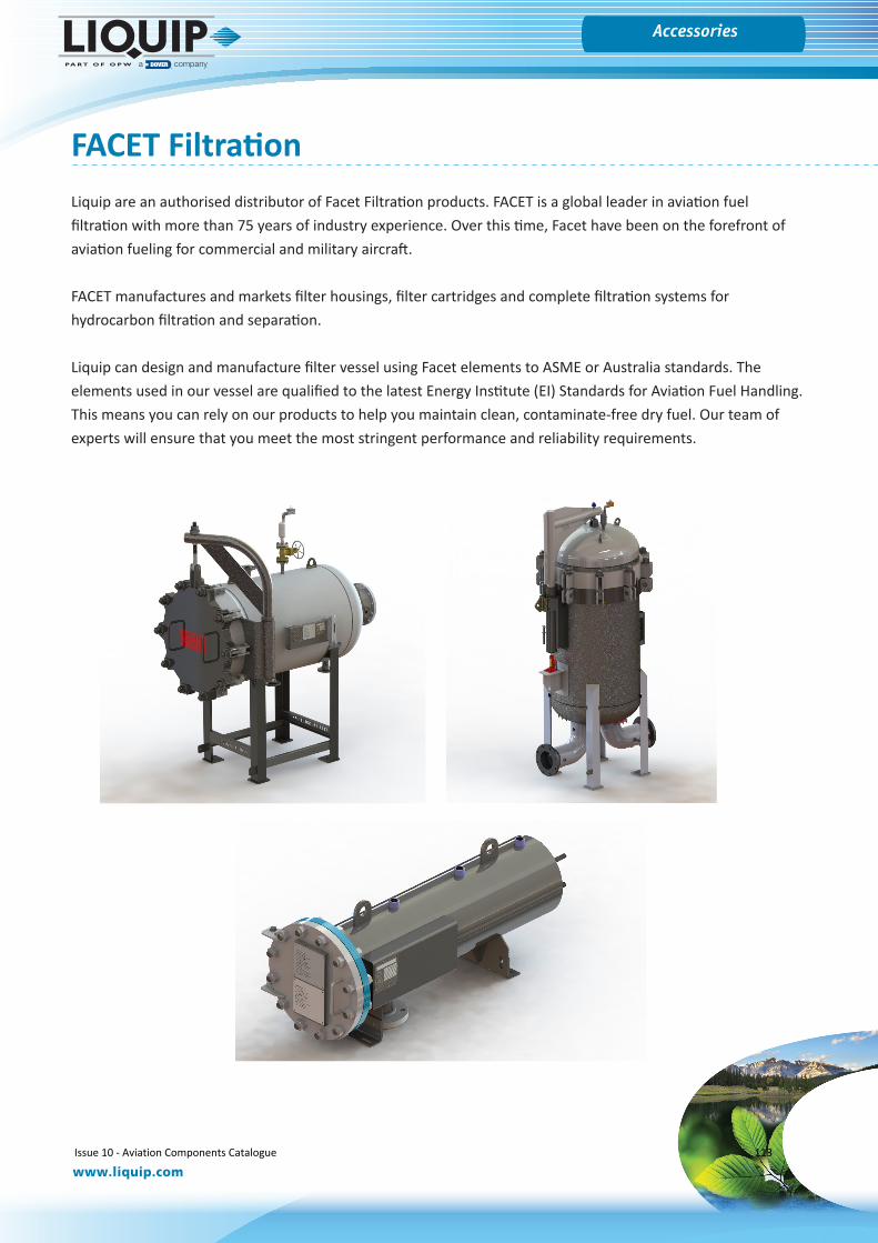
Gauges
www.liquip.com
Accessories
FACET FiltrationLiquip are an authorised distributor of Facet Filtration products. FACET is a global leader in aviation fuel filtration with more than 75 years of industry experience. Over this time, Facet have been on the forefront of aviation fueling for commercial and military aircraft.
FACET manufactures and markets filter housings, filter cartridges and complete filtration systems for hydrocarbon filtration and separation.
Liquip can design and manufacture filter vessel using Facet elements to ASME or Australia standards. The elements used in our vessel are qualified to the latest Energy Institute (EI) Standards for Aviation Fuel Handling. This means you can rely on our products to help you maintain clean, contaminate-free dry fuel. Our team of experts will ensure that you meet the most stringent performance and reliability requirements.
Issue 10 - Aviation Components Catalogue 113
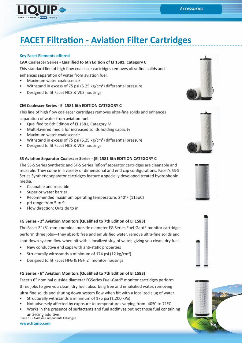
Gauges
www.liquip.com
Accessories
Key Facet Elements offered CAA Coalescer Series - Qualified to 6th Edition of EI 1581, Category CThis standard line of high flow coalescer cartridges removes ultra-fine solids and enhances separation of water from aviation fuel.• Maximum water coalescence• Withstand in excess of 75 psi (5.25 kg/cm²) differential pressure• Designed to fit Facet HCS & VCS housings
CM Coalescer Series - EI 1581 6th EDITION CATEGORY CThis line of high flow coalescer cartridges removes ultra-fine solids and enhances separation of water from aviation fuel.• Qualified to 6th Edition of EI 1581, Category M• Multi-layered media for increased solids holding capacity• Maximum water coalescence• Withstand in excess of 75 psi (5.25 kg/cm²) differential pressure• Designed to fit Facet HCS & VCS housings
SS Aviation Separator Coalescer Series - (EI 1581 6th EDITION CATEGORY C The SS-5 Series Synthetic and ST-5 Series Teflon®separator cartridges are cleanable and reusable. They come in a variety of dimensional and end cap configurations. Facet’s SS-5 Series Synthetic separator cartridges feature a specially developed treated hydrophobic media.• Cleanable and reusable• Superior water barrier• Recommended maximum operating temperature: 240°F (115oC)• pH range from 5 to 9• Flow direction: Outside to in
FG Series - 2” Aviation Monitors (Qualified to 7th Edition of EI 1583)The Facet 2” (51 mm.) nominal outside diameter FG Series Fuel-Gard® monitor cartridges perform three jobs—they absorb free and emulsified water, remove ultra-fine solids and shut down system flow when hit with a localized slug of water, giving you clean, dry fuel. • New conductive end caps with anti-static properties• Structurally withstands a minimum of 174 psi (12 kg/cm²)• Designed to fit Facet HFG & FGH 2” monitor housings
FG Series - 6” Aviation Monitors (Qualified to 7th Edition of EI 1583)Facet’s 6” nominal outside diameter FGSeries Fuel-Gard® monitor cartridges perform three jobs to give you clean, dry fuel: absorbing free and emulsified water, removing ultra-fine solids and shuting down system flow when hit with a localized slug of water.• Structurally withstands a minimum of 175 psi (1,200 kPa)• Not adversely affected by exposure to temperatures varying from -40ºC to 71ºC.• Works in the presence of surfactants and fuel additives but not those fuel containing
anti-icing additive
FACET Filtration - Aviation Filter Cartridges
Issue 10 - Aviation Components Catalogue 114

Gauges
www.liquip.com
Accessories
FACET Small Filter Housings - VF-21 and VF-22 SERIES
Facet Filter Housing VF-22SB-PG
Eliminate the need for other water defense devices and receive maximum water removal, solids holding capacity and shutdown protection to assure clean, dry fuel delivery while meeting the effluent fuel requirements of the latest Energy Institute (EI) specifications.
Economical, compact housings for superior inline filtration protection when used with Facet’s standard 21 or 22 Series filter cartridges to remove solids from aviation fuels. Both the exteriors and interiors of the Facet 21 and 22 Series filter housings carbon steel bodies are epoxy coated to protect against corrosion. These sturdy, single cartridge housings are easy to maintain and require only 2” (51 mm) base clearance for cartridge change out.
Key Features
• Sturdy single cartridge housing• Carbon steel body• Aluminium head• Epoxy coated internally and externally• Swing bolt quick open closure• Vent and drain connections with brass petcocks provided• 1.5″ (38mm) NPT inlet and outlet connections• Design pressure: 150 psi (10.5 kg/cm²)• Recommended maximum operating temperature: 240°F• Maximum differential pressure: 75 psi• pH range from 5 to 9• Flow direction: Outside to in
Associated Cartridges
• Model FG-0-609 series• Model FG-0-612 series
Issue 10 - Aviation Components Catalogue 115
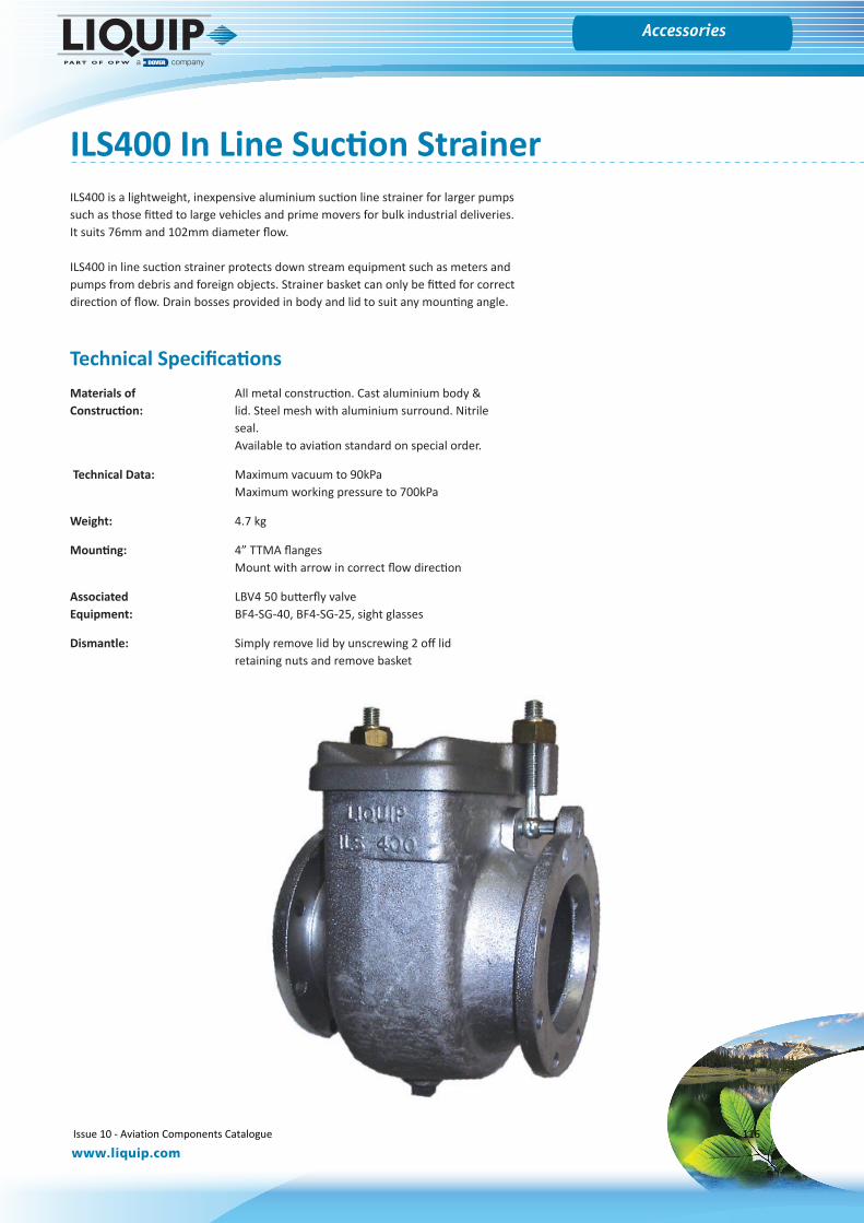
Gauges
www.liquip.com
Accessories
ILS400 In Line Suction StrainerILS400 is a lightweight, inexpensive aluminium suction line strainer for larger pumps such as those fitted to large vehicles and prime movers for bulk industrial deliveries. It suits 76mm and 102mm diameter flow.
ILS400 in line suction strainer protects down stream equipment such as meters and pumps from debris and foreign objects. Strainer basket can only be fitted for correct direction of flow. Drain bosses provided in body and lid to suit any mounting angle.
Technical SpecificationsMaterials of All metal construction. Cast aluminium body & Construction: lid. Steel mesh with aluminium surround. Nitrile
seal. Available to aviation standard on special order.
Technical Data: Maximum vacuum to 90kPaMaximum working pressure to 700kPa
Weight: 4.7 kg
Mounting: 4” TTMA flangesMount with arrow in correct flow direction
Associated LBV4 50 butterfly valveEquipment: BF4-SG-40, BF4-SG-25, sight glasses
Dismantle: Simply remove lid by unscrewing 2 off lid retaining nuts and remove basket
Issue 10 - Aviation Components Catalogue 116
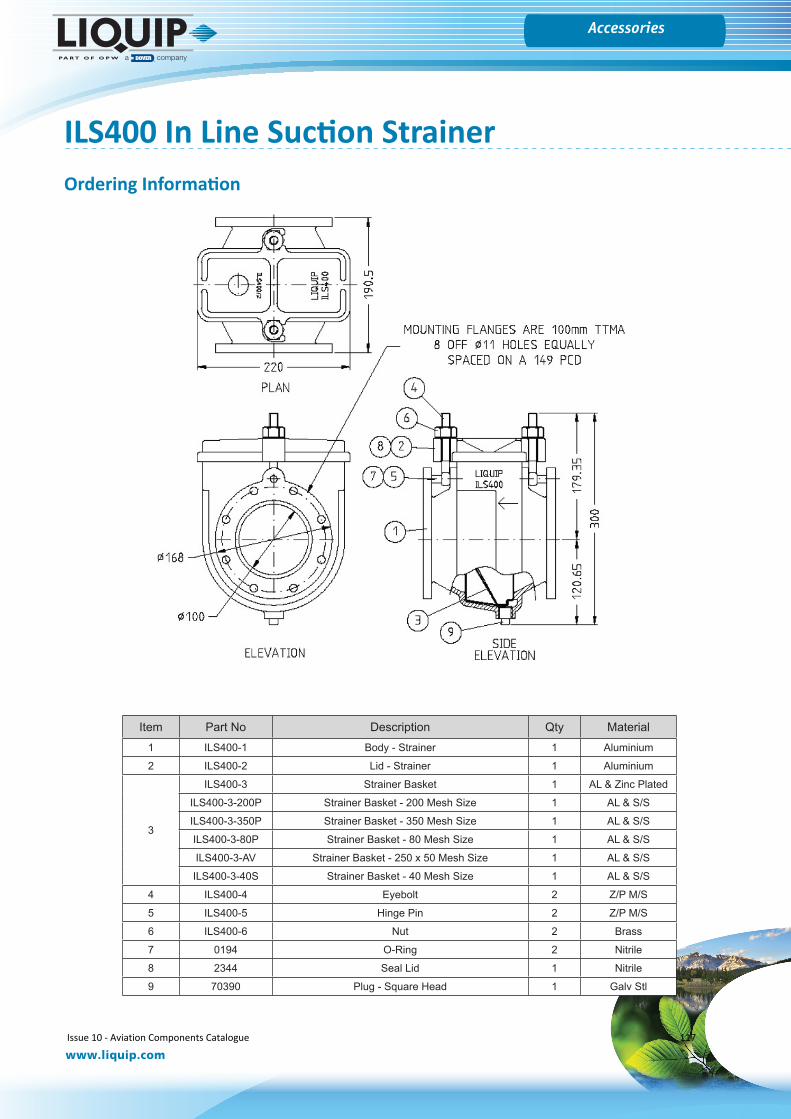
Gauges
www.liquip.com
Accessories
ILS400 In Line Suction Strainer
Item Part No Description Qty Material1 ILS400-1 Body - Strainer 1 Aluminium
2 ILS400-2 Lid - Strainer 1 Aluminium
3
ILS400-3 Strainer Basket 1 AL & Zinc Plated
ILS400-3-200P Strainer Basket - 200 Mesh Size 1 AL & S/S
ILS400-3-350P Strainer Basket - 350 Mesh Size 1 AL & S/S
ILS400-3-80P Strainer Basket - 80 Mesh Size 1 AL & S/S
ILS400-3-AV Strainer Basket - 250 x 50 Mesh Size 1 AL & S/S
ILS400-3-40S Strainer Basket - 40 Mesh Size 1 AL & S/S
4 ILS400-4 Eyebolt 2 Z/P M/S
5 ILS400-5 Hinge Pin 2 Z/P M/S
6 ILS400-6 Nut 2 Brass
7 0194 O-Ring 2 Nitrile
8 2344 Seal Lid 1 Nitrile
9 70390 Plug - Square Head 1 Galv Stl
Ordering Information
Issue 10 - Aviation Components Catalogue 117
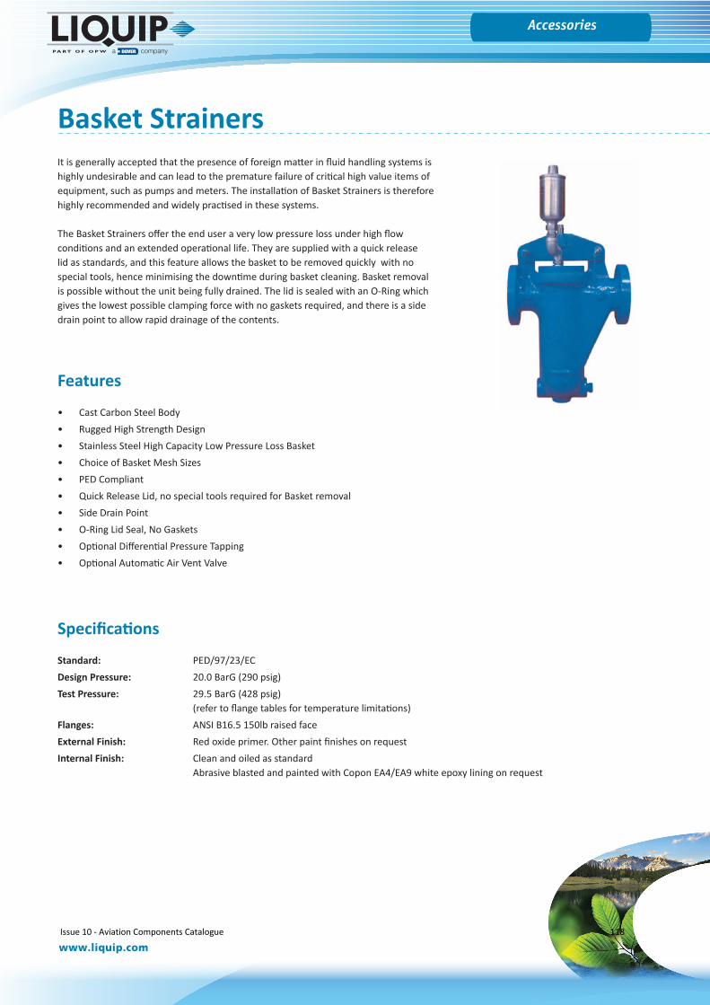
Gauges
www.liquip.com
Accessories
Basket StrainersIt is generally accepted that the presence of foreign matter in fluid handling systems is highly undesirable and can lead to the premature failure of critical high value items of equipment, such as pumps and meters. The installation of Basket Strainers is therefore highly recommended and widely practised in these systems.
The Basket Strainers offer the end user a very low pressure loss under high flow conditions and an extended operational life. They are supplied with a quick release lid as standards, and this feature allows the basket to be removed quickly with no special tools, hence minimising the downtime during basket cleaning. Basket removal is possible without the unit being fully drained. The lid is sealed with an O-Ring which gives the lowest possible clamping force with no gaskets required, and there is a side drain point to allow rapid drainage of the contents.
Features
• Cast Carbon Steel Body• Rugged High Strength Design• Stainless Steel High Capacity Low Pressure Loss Basket• Choice of Basket Mesh Sizes• PED Compliant• Quick Release Lid, no special tools required for Basket removal• Side Drain Point• O-Ring Lid Seal, No Gaskets• Optional Differential Pressure Tapping• Optional Automatic Air Vent Valve
Specifications
Standard: PED/97/23/ECDesign Pressure: 20.0 BarG (290 psig)Test Pressure: 29.5 BarG (428 psig)
(refer to flange tables for temperature limitations)Flanges: ANSI B16.5 150lb raised faceExternal Finish: Red oxide primer. Other paint finishes on requestInternal Finish: Clean and oiled as standard
Abrasive blasted and painted with Copon EA4/EA9 white epoxy lining on request
Issue 10 - Aviation Components Catalogue 118
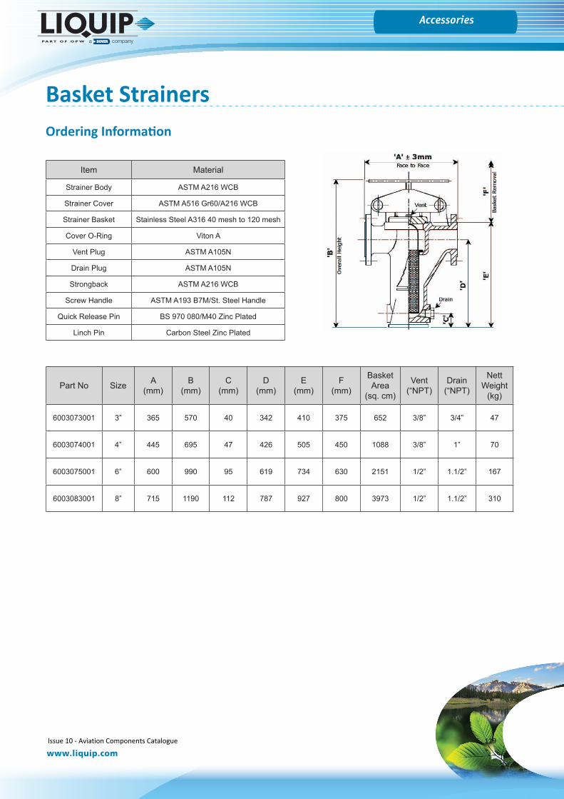
Gauges
www.liquip.com
Accessories
Item Material
Strainer Body ASTM A216 WCB
Strainer Cover ASTM A516 Gr60/A216 WCB
Strainer Basket Stainless Steel A316 40 mesh to 120 mesh
Cover O-Ring Viton A
Vent Plug ASTM A105N
Drain Plug ASTM A105N
Strongback ASTM A216 WCB
Screw Handle ASTM A193 B7M/St. Steel Handle
Quick Release Pin BS 970 080/M40 Zinc Plated
Linch Pin Carbon Steel Zinc Plated
Ordering Information
Basket Strainers
Part No Size A(mm)
B(mm)
C(mm)
D(mm)
E(mm)
F(mm)
Basket Area
(sq. cm)
Vent(“NPT)
Drain(“NPT)
Nett Weight
(kg)
6003073001 3” 365 570 40 342 410 375 652 3/8” 3/4” 47
6003074001 4” 445 695 47 426 505 450 1088 3/8” 1” 70
6003075001 6” 600 990 95 619 734 630 2151 1/2” 1.1/2” 167
6003083001 8” 715 1190 112 787 927 800 3973 1/2” 1.1/2” 310
Issue 10 - Aviation Components Catalogue 119
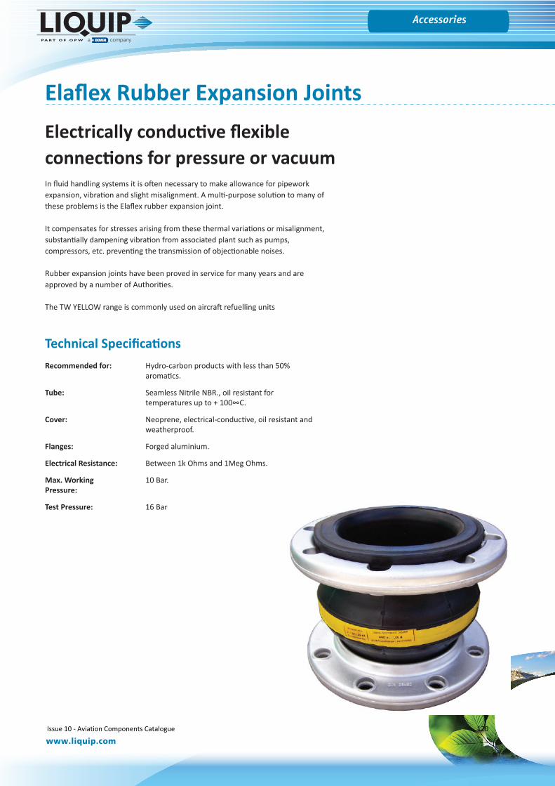
Gauges
www.liquip.com
Accessories
Elaflex Rubber Expansion JointsElectrically conductive flexible connections for pressure or vacuumIn fluid handling systems it is often necessary to make allowance for pipework expansion, vibration and slight misalignment. A multi-purpose solution to many of these problems is the Elaflex rubber expansion joint.
It compensates for stresses arising from these thermal variations or misalignment, substantially dampening vibration from associated plant such as pumps, compressors, etc. preventing the transmission of objectionable noises.
Rubber expansion joints have been proved in service for many years and are approved by a number of Authorities.
The TW YELLOW range is commonly used on aircraft refuelling units
Technical SpecificationsRecommended for: Hydro-carbon products with less than 50%
aromatics.
Tube: Seamless Nitrile NBR., oil resistant for temperatures up to + 100∞C.
Cover: Neoprene, electrical-conductive, oil resistant and weatherproof.
Flanges: Forged aluminium.
Electrical Resistance: Between 1k Ohms and 1Meg Ohms.
Max. Working 10 Bar.Pressure:
Test Pressure: 16 Bar
Issue 10 - Aviation Components Catalogue 120
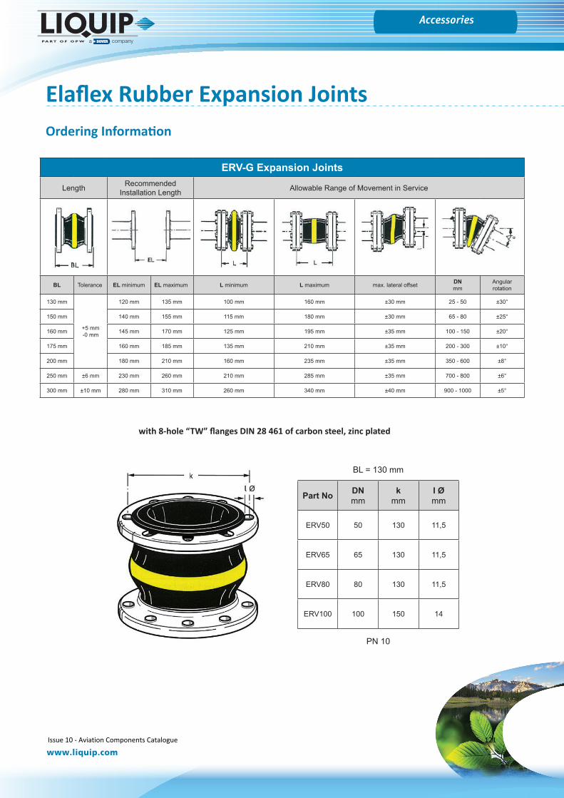
Gauges
www.liquip.com
Accessories
ERV-G Expansion Joints
Length Recommended Installation Length Allowable Range of Movement in Service
BL Tolerance EL minimum EL maximum L minimum L maximum max. lateral offset DN mm
Angular rotation
130 mm
+5 mm-0 mm
120 mm 135 mm 100 mm 160 mm ±30 mm 25 - 50 ±30°
150 mm 140 mm 155 mm 115 mm 180 mm ±30 mm 65 - 80 ±25°
160 mm 145 mm 170 mm 125 mm 195 mm ±35 mm 100 - 150 ±20°
175 mm 160 mm 185 mm 135 mm 210 mm ±35 mm 200 - 300 ±10°
200 mm 180 mm 210 mm 160 mm 235 mm ±35 mm 350 - 600 ±8°
250 mm ±6 mm 230 mm 260 mm 210 mm 285 mm ±35 mm 700 - 800 ±6°
300 mm ±10 mm 280 mm 310 mm 260 mm 340 mm ±40 mm 900 - 1000 ±5°
with 8-hole “TW” flanges DIN 28 461 of carbon steel, zinc plated
Part No DNmm
kmm
I Ømm
ERV50 50 130 11,5
ERV65 65 130 11,5
ERV80 80 130 11,5
ERV100 100 150 14
BL = 130 mm
PN 10
Ordering Information
Elaflex Rubber Expansion Joints
Issue 10 - Aviation Components Catalogue 121
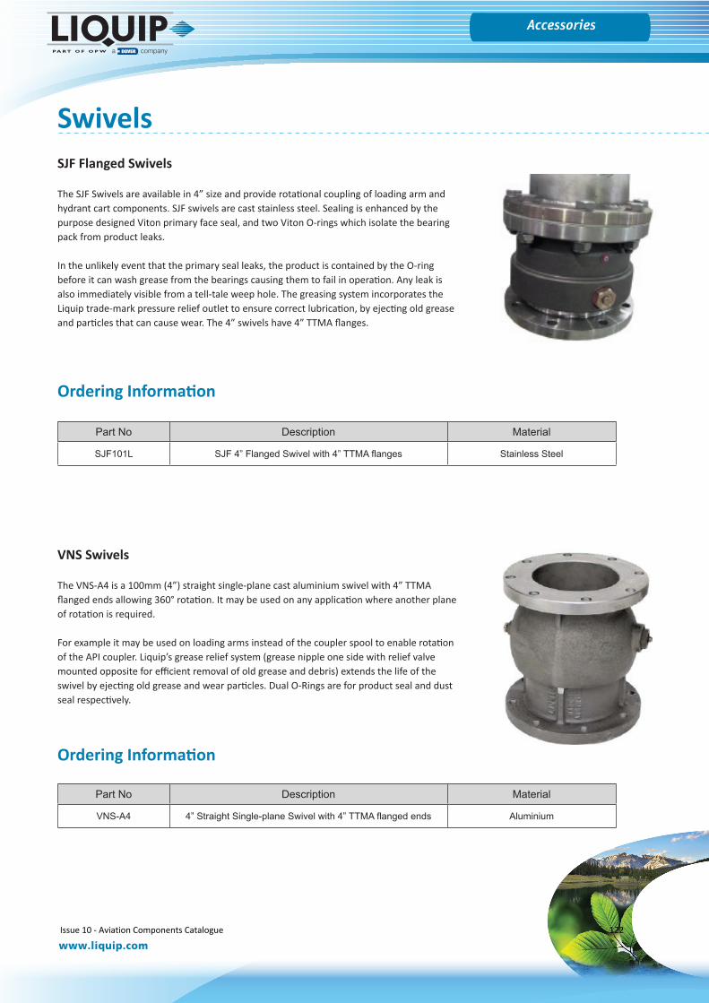
Gauges
www.liquip.com
Accessories
SwivelsSJF Flanged Swivels
The SJF Swivels are available in 4” size and provide rotational coupling of loading arm and hydrant cart components. SJF swivels are cast stainless steel. Sealing is enhanced by the purpose designed Viton primary face seal, and two Viton O-rings which isolate the bearing pack from product leaks.
In the unlikely event that the primary seal leaks, the product is contained by the O-ring before it can wash grease from the bearings causing them to fail in operation. Any leak is also immediately visible from a tell-tale weep hole. The greasing system incorporates the Liquip trade-mark pressure relief outlet to ensure correct lubrication, by ejecting old grease and particles that can cause wear. The 4” swivels have 4” TTMA flanges.
Part No Description Material
SJF101L SJF 4” Flanged Swivel with 4” TTMA flanges Stainless Steel
VNS Swivels
The VNS-A4 is a 100mm (4”) straight single-plane cast aluminium swivel with 4” TTMA flanged ends allowing 360° rotation. It may be used on any application where another plane of rotation is required.
For example it may be used on loading arms instead of the coupler spool to enable rotation of the API coupler. Liquip’s grease relief system (grease nipple one side with relief valve mounted opposite for efficient removal of old grease and debris) extends the life of the swivel by ejecting old grease and wear particles. Dual O-Rings are for product seal and dust seal respectively.
Part No Description Material
VNS-A4 4” Straight Single-plane Swivel with 4” TTMA flanged ends Aluminium
Ordering Information
Ordering Information
Issue 10 - Aviation Components Catalogue 122
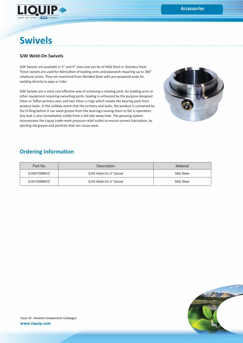
Gauges
www.liquip.com
Accessories
SwivelsSJW Weld-On Swivels
SJW Swivels are available in 3” and 4” sizes and can be of Mild Steel or Stainless Steel. These swivels are used for fabrication of loading arms and pipework requiring up to 360° rotational joints. They are machined from Nitrided Steel with pre-prepared ends for welding directly to pipe or tube.
SJW Swivels are a most cost-effective way of achieving a rotating joint, for loading arms or other equipment requiring swivelling joints. Sealing is enhanced by the purpose designed Viton or Teflon primary seal, and two Viton o-rings which isolate the bearing pack from product leaks. In the unlikely event that the primary seal leaks, the product is contained by the O-Ring before it can wash grease from the bearings causing them to fail in operation. Any leak is also immediately visible from a tell-tale weep hole. The greasing system incorporates the Liquip trade-mark pressure relief outlet to ensure correct lubrication, by ejecting old grease and particles that can cause wear.
Part No Description Material
SJW075MMVZ SJW Weld-On 3” Swivel Mild Steel
SJW100MMVZ SJW Weld-On 4” Swivel Mild Steel
Ordering Information
Issue 10 - Aviation Components Catalogue 123
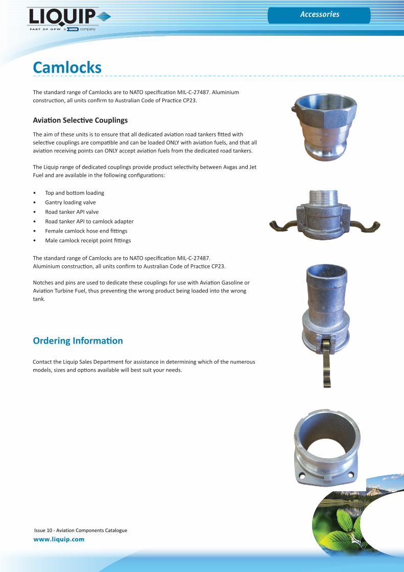
Gauges
www.liquip.com
Accessories
CamlocksThe standard range of Camlocks are to NATO specification MIL-C-27487. Aluminium construction, all units confirm to Australian Code of Practice CP23.
Aviation Selective Couplings
The aim of these units is to ensure that all dedicated aviation road tankers fitted with selective couplings are compatible and can be loaded ONLY with aviation fuels, and that all aviation receiving points can ONLY accept aviation fuels from the dedicated road tankers.
The Liquip range of dedicated couplings provide product selectivity between Avgas and Jet Fuel and are available in the following configurations:
• Top and bottom loading• Gantry loading valve• Road tanker API valve• Road tanker API to camlock adapter• Female camlock hose end fittings• Male camlock receipt point fittings
The standard range of Camlocks are to NATO specification MIL-C-27487.Aluminium construction, all units confirm to Australian Code of Practice CP23.
Notches and pins are used to dedicate these couplings for use with Aviation Gasoline or Aviation Turbine Fuel, thus preventing the wrong product being loaded into the wrong tank.
Contact the Liquip Sales Department for assistance in determining which of the numerous models, sizes and options available will best suit your needs.
Ordering Information
Issue 10 - Aviation Components Catalogue 124
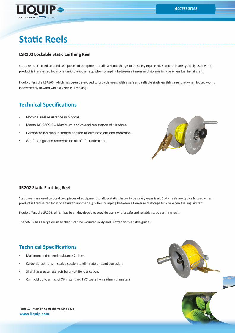
Gauges
www.liquip.com
Accessories
LSR100 Lockable Static Earthing Reel
Static reels are used to bond two pieces of equipment to allow static charge to be safely equalised. Static reels are typically used when product is transferred from one tank to another e.g. when pumping between a tanker and storage tank or when fuelling aircraft.
Liquip offers the LSR100, which has been developed to provide users with a safe and reliable static earthing reel that when locked won’t inadvertently unwind while a vehicle is moving.
Technical Specifications
• Nominal reel resistance is 5 ohms
• Meets AS 2809:2 – Maximum end-to-end resistance of 10 ohms.
• Carbon brush runs in sealed section to eliminate dirt and corrosion.
• Shaft has grease reservoir for all-of-life lubrication.
Static Reels
SR202 Static Earthing Reel
Static reels are used to bond two pieces of equipment to allow static charge to be safely equalised. Static reels are typically used when product is transferred from one tank to another e.g. when pumping between a tanker and storage tank or when fuelling aircraft.
Liquip offers the SR202, which has been developed to provide users with a safe and reliable static earthing reel.
The SR202 has a large drum so that it can be wound quickly and is fitted with a cable guide.
Technical Specifications• Maximum end-to-end resistance 2 ohms.
• Carbon brush runs in sealed section to eliminate dirt and corrosion.
• Shaft has grease reservoir for all-of-life lubrication.
• Can hold up to a max of 76m standard PVC coated wire (4mm diameter)
Issue 10 - Aviation Components Catalogue 125
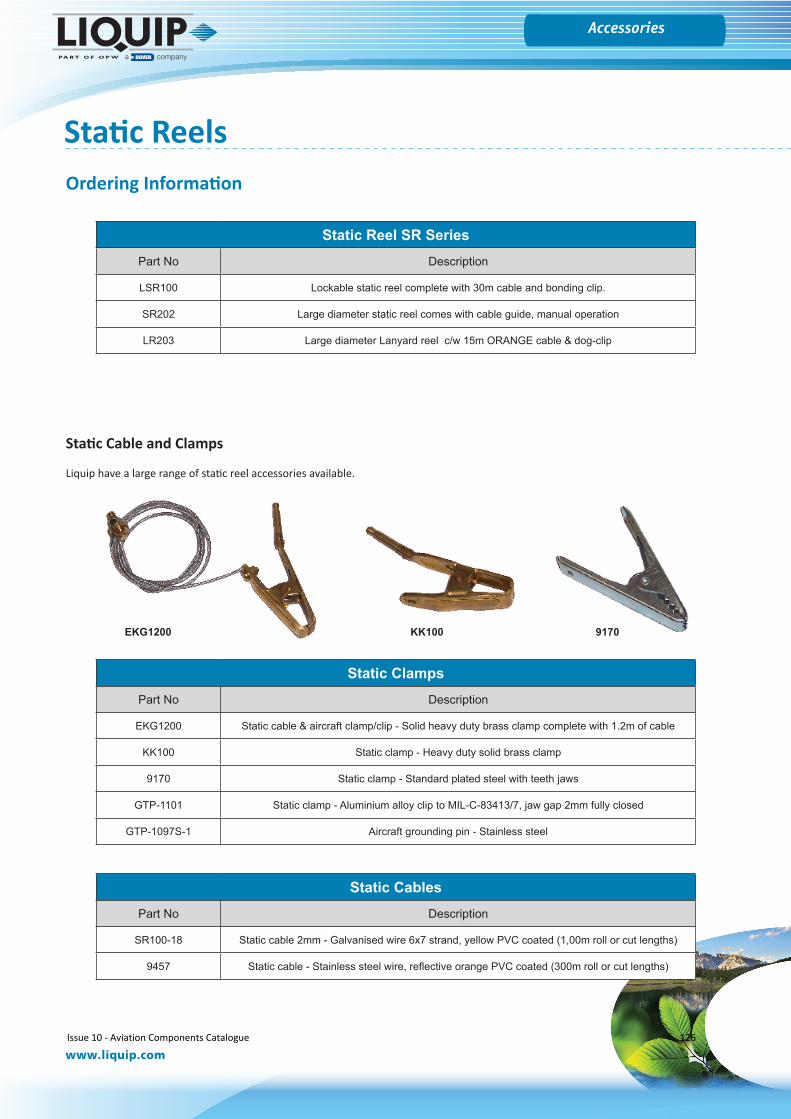
Gauges
www.liquip.com
Accessories
Static Reels
Static Reel SR SeriesPart No Description
LSR100 Lockable static reel complete with 30m cable and bonding clip.
SR202 Large diameter static reel comes with cable guide, manual operation
LR203 Large diameter Lanyard reel c/w 15m ORANGE cable & dog-clip
Static Cable and Clamps
Liquip have a large range of static reel accessories available.
Static ClampsPart No Description
EKG1200 Static cable & aircraft clamp/clip - Solid heavy duty brass clamp complete with 1.2m of cable
KK100 Static clamp - Heavy duty solid brass clamp
9170 Static clamp - Standard plated steel with teeth jaws
GTP-1101 Static clamp - Aluminium alloy clip to MIL-C-83413/7, jaw gap 2mm fully closed
GTP-1097S-1 Aircraft grounding pin - Stainless steel
Static CablesPart No Description
SR100-18 Static cable 2mm - Galvanised wire 6x7 strand, yellow PVC coated (1,00m roll or cut lengths)
9457 Static cable - Stainless steel wire, reflective orange PVC coated (300m roll or cut lengths)
EKG1200 9170KK100
Ordering Information
Issue 10 - Aviation Components Catalogue 126
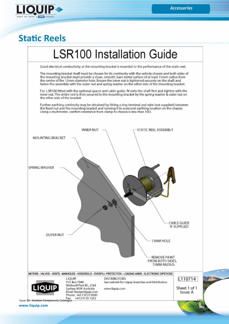
Gauges
www.liquip.com
Accessories
Static Reels
Issue 10 - Aviation Components Catalogue 127

Gauges
www.liquip.com
Accessories
Aljac Continuity Tester
Safe, reliable and cost effective loading of fuelThe Aljac Continuity Tester (ACT) is a foolproof Go/No Go device which can be used by non-skilled personnel, and it is controlled by a microprocessor which offers significant operational advantages. It self checks calibration and available battery power and only then allows the test to proceed. The ACT uses a single dual colour light emitting diode (LED) to indicate the condition of the bonding system under test, which makes the results very simple to interpret. The default set point is 25 Ohms which is in accordance with the JIG Guidelines for aviation fuel systems, but alternative set points can be specified at the time of order placement. In addition, throughout the test, a two figure digital display tells the operator the actual system resistance (in Ohms).
The ACT housing is ergonomically designed to be comfortably held in the hand and is moulded from impact resistant Polyamide, so it is lightweight, robust, and is highly portable. The ACT incorporates a sealed, non rechargeable, high capacity battery which gives it an extended operational life, but the battery life is further enhanced by a number of power saving features. The ACT does not have a constant power usage, it checks the resistance 200 times per second. Also, the microprocessor automatically switches off the ACT after a time out period at any stage of the operation, even if the clips are left connected or touching at the end of the test.
The ACT can be supplied with a calibration certificate if required, but in any event it self checks calibration before every test. The ACT incorporates a current limitation feature and is safe for use in hazardous areas, unlike many other devices which are currently in use. We can provide a Stowage Bracket which can be used to neatly stow the ACT when not in use, or can hold the ACT securely during testing.
Technical Specifications• Type: Go-No Go Continuity Tester• Set Point: 25 Ohms (default). Option 1 to 40 Ohms• Test Frequency: 200 tests per second• Display Update: Every 100 tests (0.5 seconds)• LED: Dual colour high intensity (Red/Green)• Display: Two digit 7 segment LCD, 12mm character height. Selectable on or off• Housing: High visibility orange impact resistant PA6 Polyamide• Battery: Lithium Thionyl Chloride 3.6V• Microprocessor: Atmel AVR EXMEGA 16A 4U• Flying Leads: 2 x 0.5 metres long, with plugs/clips
172mm
40mm
Net Weight: 180 grams
Part No Description0100400180 Continuity Tester
0100400181 Stowage Bracket
Ordering Information
Issue 10 - Aviation Components Catalogue 128

Gauges
www.liquip.com
Accessories
Smartwire PLCWith Liquip SMARTWIRE system the options are virtually unlimited.The SMARTWIRE system is a 2-wire programmable control system designed to simplify implementation and installation. The system consists of input and output modules, a power filter and an interface board.
With the SMARTWIRE system a majority of the operational functions of fuelling aircraft are transformed to electronic form. The system is extremely flexible, offering easy adaptation in the field, if required, without costly modifications.
The SMARTWIRE PLC ensures that all fuelling operations cannot be over ridden by an operator and it features a time-out which ensures the “deadman” is present in the operators hand at all times. The same PLC also controls all interlock functions for nozzle stowage, deck lowering, P.T.O. and all bottom load gates.
Liquip individually program each PLC to suit customer requirements.
Part No Description
Smartwire PLC
Ordering Information
Issue 10 - Aviation Components Catalogue 129
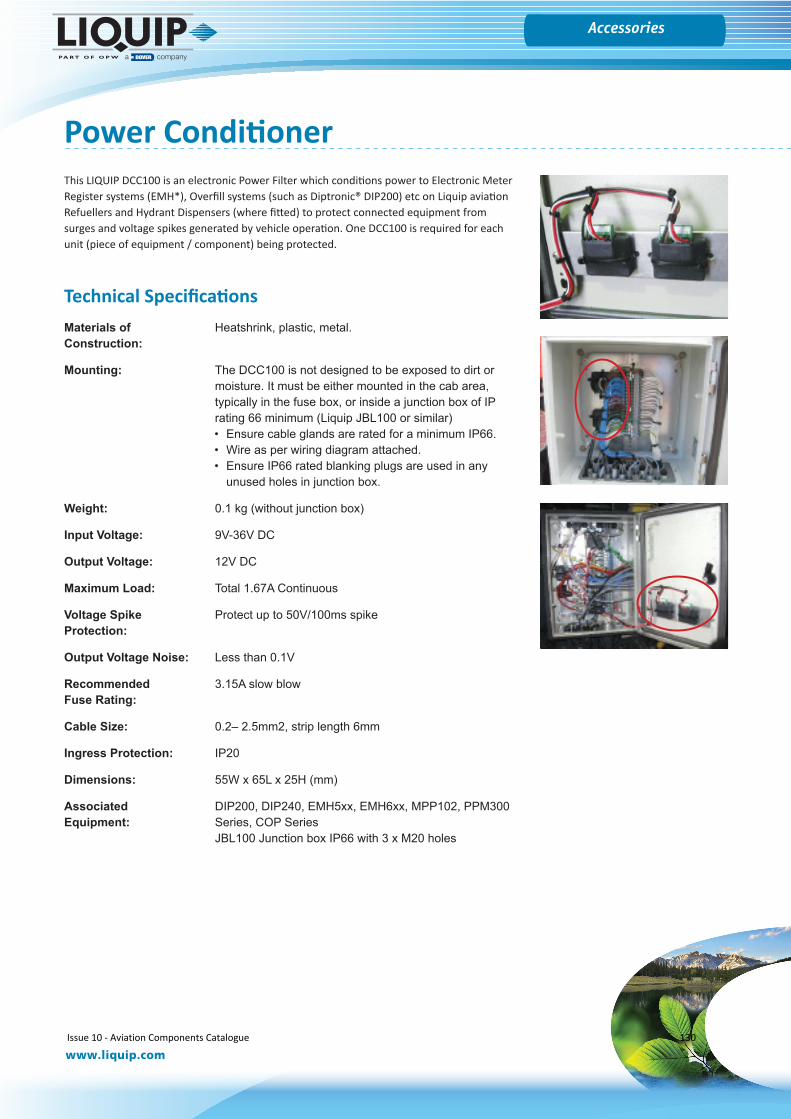
Gauges
www.liquip.com
Accessories
Power ConditionerThis LIQUIP DCC100 is an electronic Power Filter which conditions power to Electronic Meter Register systems (EMH*), Overfill systems (such as Diptronic® DIP200) etc on Liquip aviation Refuellers and Hydrant Dispensers (where fitted) to protect connected equipment from surges and voltage spikes generated by vehicle operation. One DCC100 is required for each unit (piece of equipment / component) being protected.
Technical SpecificationsMaterials of Heatshrink, plastic, metal.Construction:
Mounting: The DCC100 is not designed to be exposed to dirt or moisture. It must be either mounted in the cab area, typically in the fuse box, or inside a junction box of IP rating 66 minimum (Liquip JBL100 or similar)• Ensure cable glands are rated for a minimum IP66.• Wire as per wiring diagram attached.• Ensure IP66 rated blanking plugs are used in any
unused holes in junction box.
Weight: 0.1 kg (without junction box)
Input Voltage: 9V-36V DC
Output Voltage: 12V DC
Maximum Load: Total 1.67A Continuous
Voltage Spike Protect up to 50V/100ms spikeProtection:
Output Voltage Noise: Less than 0.1V
Recommended 3.15A slow blowFuse Rating:
Cable Size: 0.2– 2.5mm2, strip length 6mm
Ingress Protection: IP20
Dimensions: 55W x 65L x 25H (mm)
Associated DIP200, DIP240, EMH5xx, EMH6xx, MPP102, PPM300 Equipment: Series, COP Series
JBL100 Junction box IP66 with 3 x M20 holes
Issue 10 - Aviation Components Catalogue 130
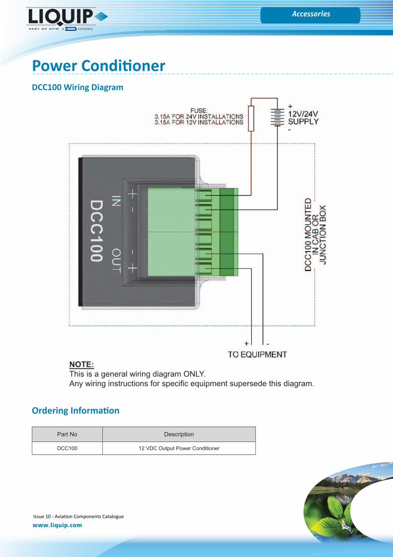
Gauges
www.liquip.com
Accessories
Power ConditionerDCC100 Wiring Diagram
NOTE:This is a general wiring diagram ONLY. Any wiring instructions for specific equipment supersede this diagram.
Part No Description
DCC100 12 VDC Output Power Conditioner
Ordering Information
Issue 10 - Aviation Components Catalogue 131
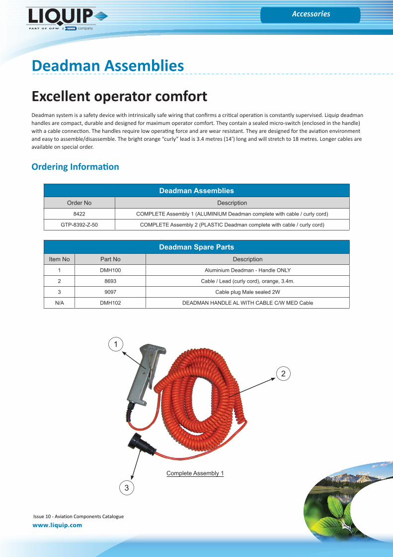
Gauges
www.liquip.com
Accessories
Deadman Assemblies
Excellent operator comfortDeadman system is a safety device with intrinsically safe wiring that confirms a critical operation is constantly supervised. Liquip deadman handles are compact, durable and designed for maximum operator comfort. They contain a sealed micro-switch (enclosed in the handle) with a cable connection. The handles require low operating force and are wear resistant. They are designed for the aviation environment and easy to assemble/disassemble. The bright orange “curly” lead is 3.4 metres (14’) long and will stretch to 18 metres. Longer cables are available on special order.
Deadman AssembliesOrder No Description
8422 COMPLETE Assembly 1 (ALUMINIUM Deadman complete with cable / curly cord)
GTP-8392-Z-50 COMPLETE Assembly 2 (PLASTIC Deadman complete with cable / curly cord)
Deadman Spare PartsItem No Part No Description
1 DMH100 Aluminium Deadman - Handle ONLY
2 8693 Cable / Lead (curly cord), orange, 3.4m.
3 9097 Cable plug Male sealed 2W
N/A DMH102 DEADMAN HANDLE AL WITH CABLE C/W MED Cable
1
2
3
Complete Assembly 1
Ordering Information
Issue 10 - Aviation Components Catalogue 132
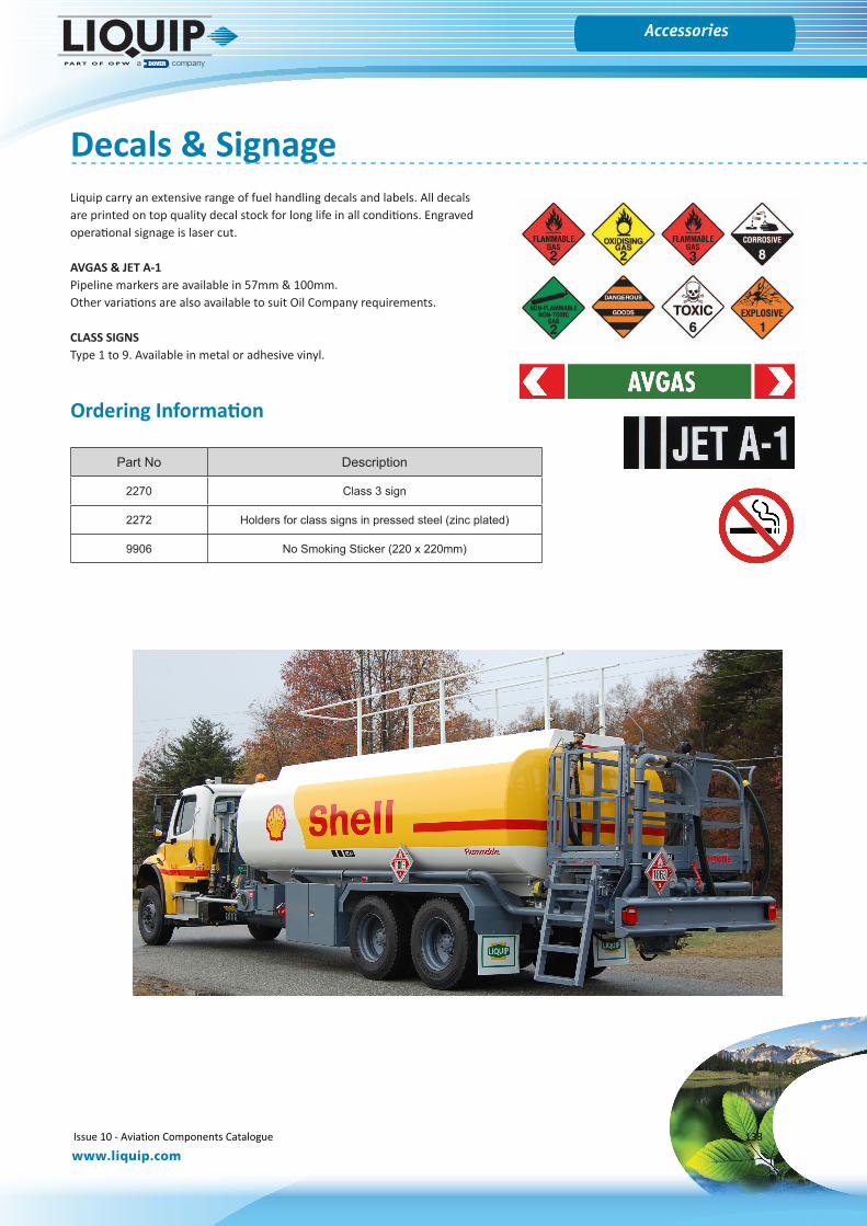
Gauges
www.liquip.com
Accessories
Decals & SignageLiquip carry an extensive range of fuel handling decals and labels. All decals are printed on top quality decal stock for long life in all conditions. Engraved operational signage is laser cut.
AVGAS & JET A-1Pipeline markers are available in 57mm & 100mm.Other variations are also available to suit Oil Company requirements.
CLASS SIGNSType 1 to 9. Available in metal or adhesive vinyl.
Part No Description
2270 Class 3 sign
2272 Holders for class signs in pressed steel (zinc plated)
9906 No Smoking Sticker (220 x 220mm)
Ordering Information
Issue 10 - Aviation Components Catalogue 133
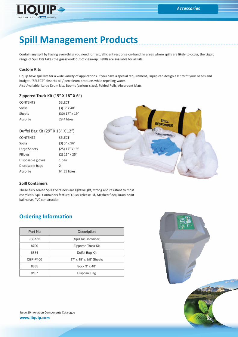
Gauges
www.liquip.com
Accessories
Contain any spill by having everything you need for fast, efficient response on-hand. In areas where spills are likely to occur, the Liquip range of Spill Kits takes the guesswork out of clean-up. Refills are available for all kits.
Custom KitsLiquip have spill kits for a wide variety of applications. If you have a special requirement, Liquip can design a kit to fit your needs and budget. “SELECT” absorbs oil / petroleum products while repelling water.Also Available: Large Drum kits, Booms (various sizes), Folded Rolls, Absorbent Mats
Zippered Truck Kit (15” X 18” X 6”)CONTENTS SELECTSocks (3) 3” x 48”Sheets (30) 17” x 19”Absorbs 28.4 litres
Duffel Bag Kit (29” X 13” X 12”)CONTENTS SELECTSocks (3) 3” x 96”Large Sheets (25) 17” x 19”Pillows (2) 15” x 25”Disposable gloves 1 pairDisposable bags 2Absorbs 64.35 litres
Spill Management Products
Part No Description
JBFA65 Spill Kit Container
8790 Zippered Truck Kit
8834 Duffel Bag Kit
CEP-P100 17” x 19” x 3/8” Sheets
8835 Sock 3” x 48”
9107 Disposal Bag
Spill ContainersThese fully sealed Spill Containers are lightweight, strong and resistant to most chemicals. Spill Containers feature: Quick release lid, Meshed floor, Drain point ball valve, PVC construction
Ordering Information
Issue 10 - Aviation Components Catalogue 134
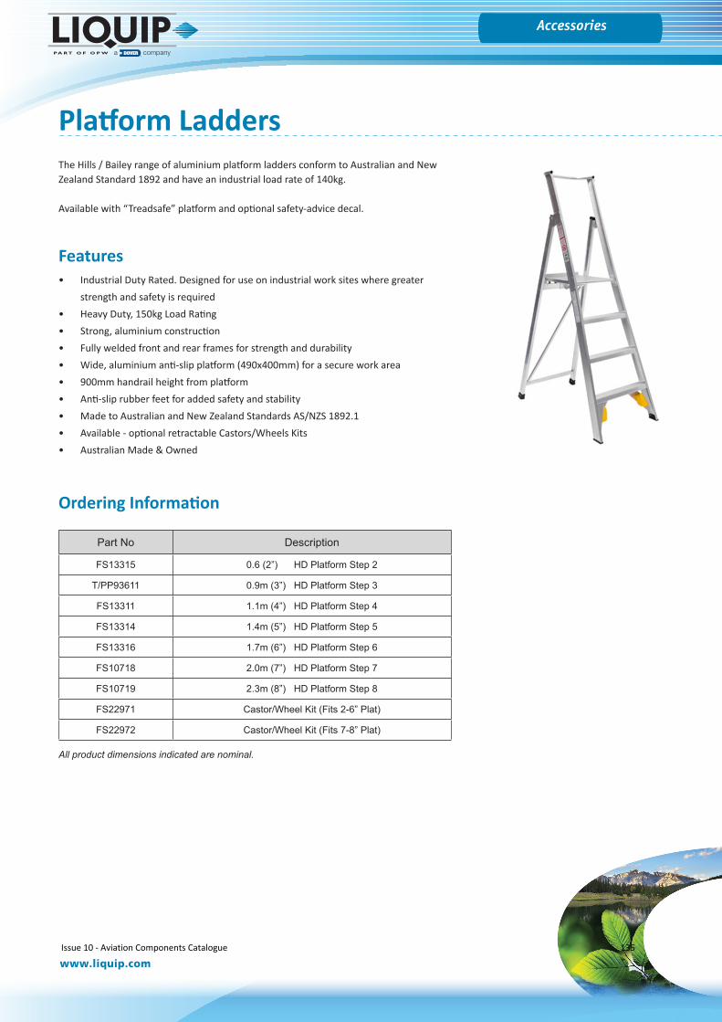
Gauges
www.liquip.com
Accessories
Platform LaddersThe Hills / Bailey range of aluminium platform ladders conform to Australian and New Zealand Standard 1892 and have an industrial load rate of 140kg.
Available with “Treadsafe” platform and optional safety-advice decal.
Features• Industrial Duty Rated. Designed for use on industrial work sites where greater
strength and safety is required• Heavy Duty, 150kg Load Rating• Strong, aluminium construction• Fully welded front and rear frames for strength and durability• Wide, aluminium anti-slip platform (490x400mm) for a secure work area• 900mm handrail height from platform• Anti-slip rubber feet for added safety and stability• Made to Australian and New Zealand Standards AS/NZS 1892.1• Available - optional retractable Castors/Wheels Kits• Australian Made & Owned
Part No Description
FS13315 0.6 (2”) HD Platform Step 2
T/PP93611 0.9m (3”) HD Platform Step 3
FS13311 1.1m (4”) HD Platform Step 4
FS13314 1.4m (5”) HD Platform Step 5
FS13316 1.7m (6”) HD Platform Step 6
FS10718 2.0m (7”) HD Platform Step 7
FS10719 2.3m (8”) HD Platform Step 8
FS22971 Castor/Wheel Kit (Fits 2-6” Plat)
FS22972 Castor/Wheel Kit (Fits 7-8” Plat)
All product dimensions indicated are nominal.
Ordering Information
Issue 10 - Aviation Components Catalogue 135
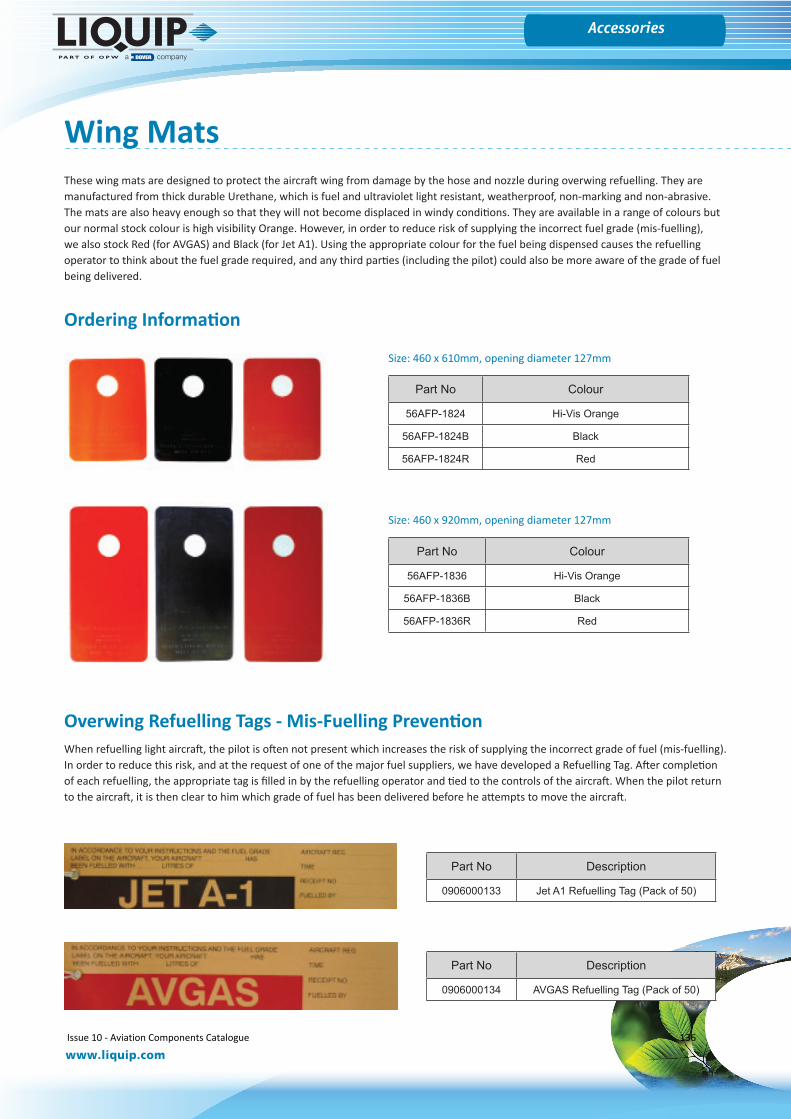
Gauges
www.liquip.com
Accessories
Wing MatsThese wing mats are designed to protect the aircraft wing from damage by the hose and nozzle during overwing refuelling. They are manufactured from thick durable Urethane, which is fuel and ultraviolet light resistant, weatherproof, non-marking and non-abrasive. The mats are also heavy enough so that they will not become displaced in windy conditions. They are available in a range of colours but our normal stock colour is high visibility Orange. However, in order to reduce risk of supplying the incorrect fuel grade (mis-fuelling), we also stock Red (for AVGAS) and Black (for Jet A1). Using the appropriate colour for the fuel being dispensed causes the refuelling operator to think about the fuel grade required, and any third parties (including the pilot) could also be more aware of the grade of fuel being delivered.
Part No Colour
56AFP-1824 Hi-Vis Orange
56AFP-1824B Black
56AFP-1824R Red
Ordering Information
Size: 460 x 610mm, opening diameter 127mm
Size: 460 x 920mm, opening diameter 127mm
Part No Colour
56AFP-1836 Hi-Vis Orange
56AFP-1836B Black
56AFP-1836R Red
When refuelling light aircraft, the pilot is often not present which increases the risk of supplying the incorrect grade of fuel (mis-fuelling). In order to reduce this risk, and at the request of one of the major fuel suppliers, we have developed a Refuelling Tag. After completion of each refuelling, the appropriate tag is filled in by the refuelling operator and tied to the controls of the aircraft. When the pilot return to the aircraft, it is then clear to him which grade of fuel has been delivered before he attempts to move the aircraft.
Overwing Refuelling Tags - Mis-Fuelling Prevention
Part No Description
0906000133 Jet A1 Refuelling Tag (Pack of 50)
Part No Description
0906000134 AVGAS Refuelling Tag (Pack of 50)
Issue 10 - Aviation Components Catalogue 136
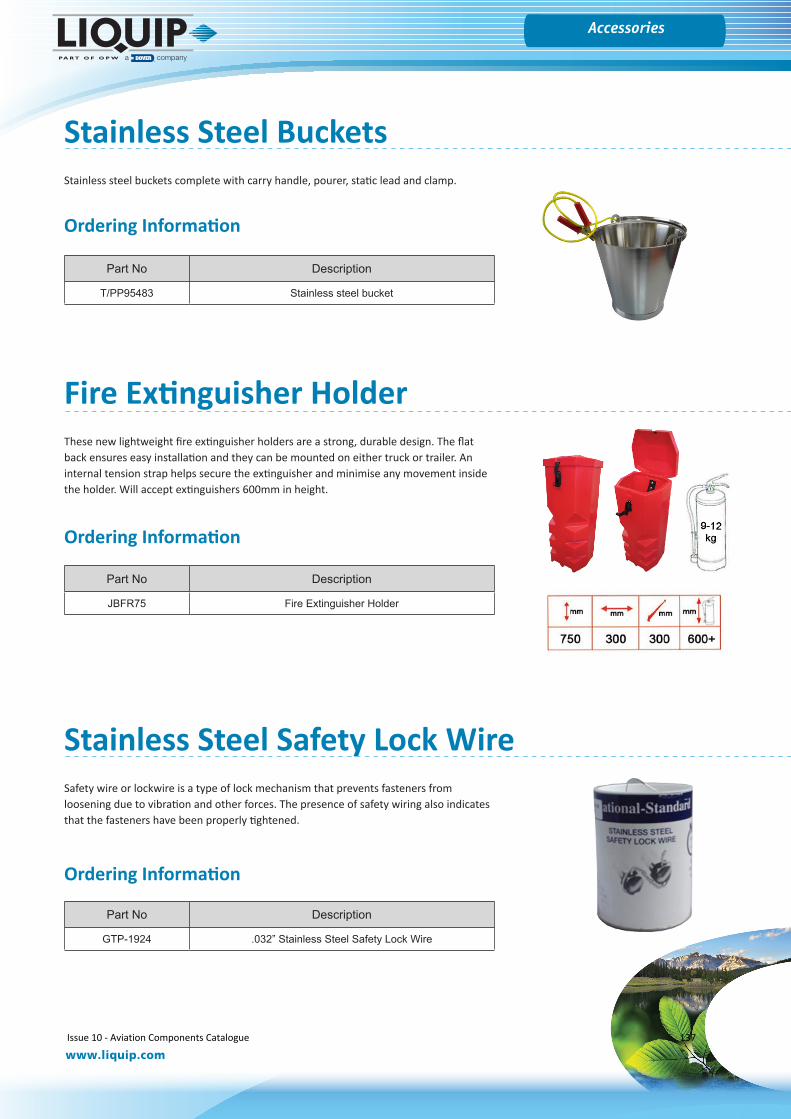
Gauges
www.liquip.com
Accessories
Stainless Steel BucketsStainless steel buckets complete with carry handle, pourer, static lead and clamp.
Part No Description
T/PP95483 Stainless steel bucket
These new lightweight fire extinguisher holders are a strong, durable design. The flat back ensures easy installation and they can be mounted on either truck or trailer. An internal tension strap helps secure the extinguisher and minimise any movement inside the holder. Will accept extinguishers 600mm in height.
Fire Extinguisher Holder
Part No Description
JBFR75 Fire Extinguisher Holder
Safety wire or lockwire is a type of lock mechanism that prevents fasteners from loosening due to vibration and other forces. The presence of safety wiring also indicates that the fasteners have been properly tightened.
Stainless Steel Safety Lock Wire
Part No Description
GTP-1924 .032” Stainless Steel Safety Lock Wire
Ordering Information
Ordering Information
Ordering Information
Issue 10 - Aviation Components Catalogue 137
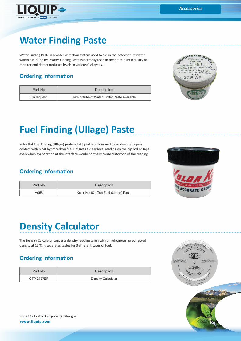
Gauges
www.liquip.com
Accessories
Water Finding PasteWater Finding Paste is a water detection system used to aid in the detection of water within fuel supplies. Water Finding Paste is normally used in the petroleum industry to monitor and detect moisture levels in various fuel types.
Part No Description
On request Jars or tube of Water Finder Paste available
Fuel Finding (Ullage) Paste
Part No Description
M056 Kolor Kut 62g Tub Fuel (Ullage) Paste
Density Calculator
Part No Description
GTP-2727EF Density Calculator
Kolor Kut Fuel Finding (Ullage) paste is light pink in colour and turns deep red upon contact with most hydrocarbon fuels. It gives a clear level reading on the dip rod or tape, even when evaporation at the interface would normally cause distortion of the reading.
The Density Calculator converts density reading taken with a hydrometer to corrected density at 15°C. It separates scales for 3 different types of fuel.
Ordering Information
Ordering Information
Ordering Information
Issue 10 - Aviation Components Catalogue 138

Leading The Way in Fluid Handling Solutions Worldwide
www.liquip.com NOTE: All information subject to engineering and/or other changes. All trade names are copyrighted. Patents Pending. ©2016 OPW Fueling Components. ©2016 Delaware Capital Formation, Inc. All Rights Reserved. DOVER and the DOVER logo are registered trademarks of Delaware Capital Formation, Inc., a wholly-owned subsidiary of Dover Corporation.
Retail FuelingComponents and products to protect the environment and the consumer at retail fueling sites for conventional and alternative fuels.
Dispensing & Automation SolutionsManufacturing a complete range of fuel dispensers, pumps and automation systems for the global retail fueling market.
Electronic SystemsInnovative electronic tank gauges and fuel control systems to ensure customers know how much fuel they have and where it is going. Also, Automated Vehicle Wash Systems.
Chemical & IndustrialSafe and efficient loading and unloading of critical hazardous chemicals: loading arms, swivel joints, sight flow indicators, quick and dry disconnect couplers, and safety breakaways.
TransportationComponents and systems for use on Tank Trucks and Rail Tank Cars to ensure the safe handling, loading, transport and unloading of hazardous bulk products, including: petroleum, chemical and dry bulk cargo.
LIQUIP GLOBALPRESENCE
To view the full range of Liquip’s Aviation ProductsPlease visit www.liquip.com
or contact us at
Liquip Head Office13 Hume Road, Smithfield
Sydney NSW Australia 2164Tel: +61 (2) 9725 9000