Lean Manufacturing of Pressure Valve Plate
11
IOSR Journal of Engineering (IOSRJEN) www.iosrjen.org ISSN (e): 2250-3021, ISSN (p): 2278-8719 Vol. 04, Issue 02 (February. 2014), ||V2|| PP 01-11 International organization of Scientific Research 1 | P a g e Lean Manufacturing of Pressure Valve Plate Shradha M. Patil Asst. Professor, Department of Mechanical Engineering, Fr. C. Rodrigues Institute of Technology, Vashi, Navi Mumbai, Maharashtra Abstract: - Manufacturing of Pressure Valve Plate is considered as complex process that demands the knowledge of different areas, such as geometry, tolerances, dimensions, manufacturing procedures and manufacturing processes. Lean manufacturing avoids both setup time and setup cost of in manufacturing. Milling fixtures must be sturdy, with relatively large locating and supporting areas and strong clamp. Work piece deformation is unavoidable due to its elastic/plastic nature, and the external forces impacted by the clamping actuation and machining operations. Deformation has to be limited to an acceptable magnitude in order to achieve the tolerance specifications. Accuracy of components like pressure valve plate is extremely essential. The analysis is carried out on fixture and pressure valve plate assembly. Pressure Valve plate fits on to hydraulic pump which is used to drive the engine load of defence vehicle. To study the fixture analysis and contact stress effect, fixture and valve plate are modelled and assembled for the analysis to be carried out. Keywords: - Fixtures, Lean Manufacturing, Locators, Pressure Valve Plate, Setup time I. PROBLEM DEFINITION & OBJECTIVE - Manufacturing of Pressure Valve plate with zero defects and minimum number of setups - Fixture design to achieve higher accuracy of valve plate and minimise errors due to previous process - Valve plate kidney port designed to provide minimum power loss and pressure pulsation throughout delivery Fig1: Pressure Valve Plate II. FIXTURE FOR REFERENCE MILLING AND DRILLING Number of different fixtures was used to carry out the sequence of operations to achieve valve plate as per the requirement of EATON Pvt Ltd. The different operations (OP) carried out on valve plate are the following: OP20-Reference milling and drilling (1st setup) OP30-Main milling (2nd setup)
-
Upload
independent -
Category
Documents
-
view
4 -
download
0
Transcript of Lean Manufacturing of Pressure Valve Plate

IOSR Journal of Engineering (IOSRJEN) www.iosrjen.org
ISSN (e): 2250-3021, ISSN (p): 2278-8719
Vol. 04, Issue 02 (February. 2014), ||V2|| PP 01-11
International organization of Scientific Research 1 | P a g e
Lean Manufacturing of Pressure Valve Plate
Shradha M. Patil Asst. Professor, Department of Mechanical Engineering, Fr. C. Rodrigues Institute of Technology, Vashi, Navi
Mumbai, Maharashtra
Abstract: - Manufacturing of Pressure Valve Plate is considered as complex process that demands the
knowledge of different areas, such as geometry, tolerances, dimensions, manufacturing procedures and
manufacturing processes. Lean manufacturing avoids both setup time and setup cost of in manufacturing.
Milling fixtures must be sturdy, with relatively large locating and supporting areas and strong clamp. Work
piece deformation is unavoidable due to its elastic/plastic nature, and the external forces impacted by the
clamping actuation and machining operations. Deformation has to be limited to an acceptable magnitude in
order to achieve the tolerance specifications.
Accuracy of components like pressure valve plate is extremely essential. The analysis is carried out on fixture
and pressure valve plate assembly. Pressure Valve plate fits on to hydraulic pump which is used to drive the
engine load of defence vehicle. To study the fixture analysis and contact stress effect, fixture and valve plate are
modelled and assembled for the analysis to be carried out.
Keywords: - Fixtures, Lean Manufacturing, Locators, Pressure Valve Plate, Setup time
I. PROBLEM DEFINITION & OBJECTIVE - Manufacturing of Pressure Valve plate with zero defects and minimum number of setups
- Fixture design to achieve higher accuracy of valve plate and minimise errors due to previous process
- Valve plate kidney port designed to provide minimum power loss and pressure pulsation throughout delivery
Fig1: Pressure Valve Plate
II. FIXTURE FOR REFERENCE MILLING AND DRILLING Number of different fixtures was used to carry out the sequence of operations to achieve valve plate as per the
requirement of EATON Pvt Ltd. The different operations (OP) carried out on valve plate are the following:
OP20-Reference milling and drilling (1st setup)
OP30-Main milling (2nd setup)

Lean Manufacturing of Pressure Valve Plate
International organization of Scientific Research 2 | P a g e
OP40-Milling of ports (3rd setup)
OP50-Finish machining setup
OP60-Break sharp edges to 0.25mm
OP70-Deburring
OP80-Marking for traceability
OP90-Inspection
OP100-Anodizing
OP110-Assembly
OP120-Pressure testing
The above following operations were carried out using different fixtures for different operations; the
time required for each operation depends upon the setup time, loading of material, machining time, skill of
labour, finishing operations and unloading of the part. Large number of operations on different faces of the
component demands specific types of fixtures which can provide ease while machining.
Pressure valve plate was machined using fixture as shown in fig.1, this fixture contained two points for holding
which is provided with help of screw and boss of valve plate is supported by fixture plate and clamped with help
of bolt and nut, the operation OP20 carried out using this fixture was reference milling and drilling.
2.1. Elimination of fixture for OP20
Due to non-uniform and complex geometry of valve plate it is difficult to find the point of locating and
holding the valve plate, and also the means by which the valve plate is supported or being hold, in the above
case screw was provided for positioning the part and the operator was allowed to adjust the part. Due to manual
adjustment and improper positioning, the valve plate while machining used to slide and move from its actual
position which affected machining operation.
As this operation was initially done taking in account the drawing provided by the customer (EATON) but the
final drawing of the valve plate does not include such a requirement. The unnecessary operation of reference
milling and drilling was then eliminated as shown in fig 2.
Fig 1: Fixture for reference milling and drilling
1. In the existing fixture the locating points are not taken as per drawing while designing the fixture
2. The target points given in the drawing are not considered for location
3. And the supporting / resting face is not considered as per drawing
Lean Manufacturing of Pressure Valve Plate
International organization of Scientific Research 3 | P a g e
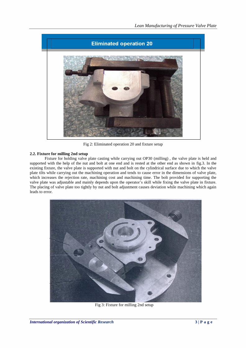
Fig 2: Eliminated operation 20 and fixture setup
2.2. Fixture for milling 2nd setup
Fixture for holding valve plate casting while carrying out OP30 (milling) , the valve plate is held and
supported with the help of the nut and bolt at one end and is rested at the other end as shown in fig.3. In the
existing fixture, the valve plate is supported with nut and bolt on the cylindrical surface due to which the valve
plate tilts while carrying out the machining operation and tends to cause error in the dimensions of valve plate,
which increases the rejection rate, machining cost and machining time. The bolt provided for supporting the
valve plate was adjustable and mainly depends upon the operator’s skill while fixing the valve plate in fixture.
The placing of valve plate too tightly by nut and bolt adjustment causes deviation while machining which again
leads to error.
Fig 3: Fixture for milling 2nd setup
Lean Manufacturing of Pressure Valve Plate
International organization of Scientific Research 4 | P a g e
III. DETAILED DRAWING AND SPECIFICATIONS OF NEW FIXTURE AND ITS
PARTS
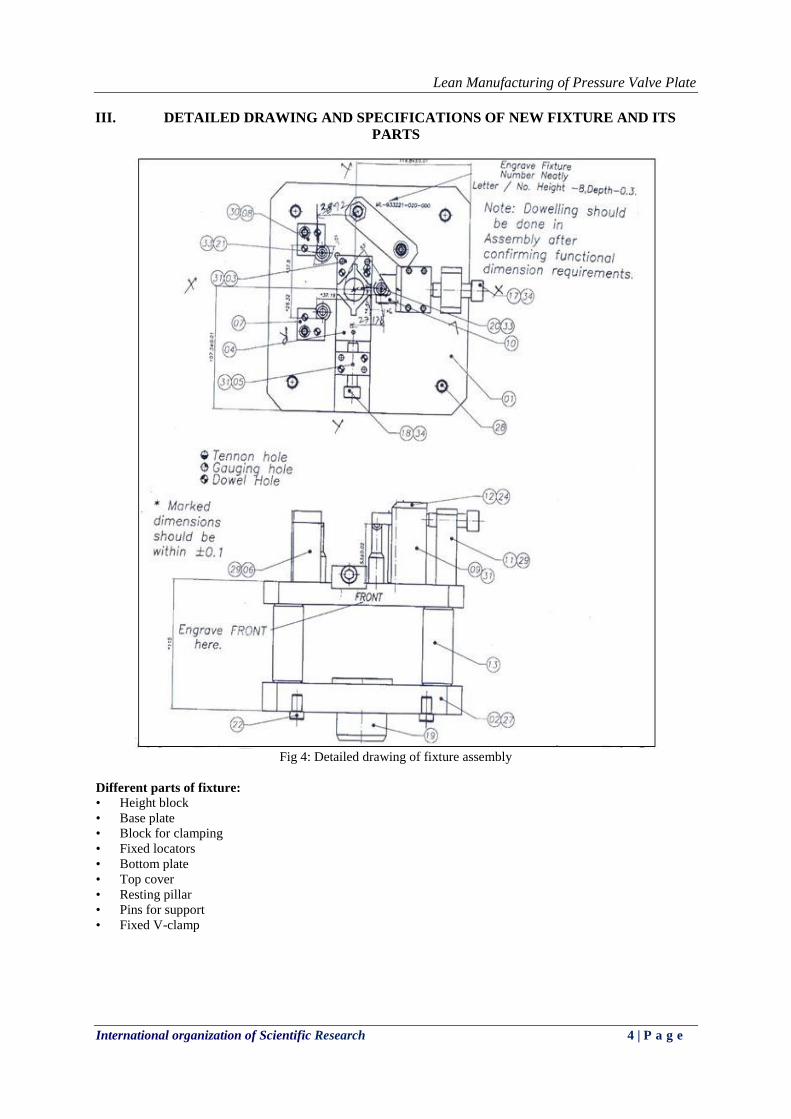
Fig 4: Detailed drawing of fixture assembly
Different parts of fixture: • Height block
• Base plate
• Block for clamping
• Fixed locators
• Bottom plate
• Top cover
• Resting pillar
• Pins for support
• Fixed V-clamp

Lean Manufacturing of Pressure Valve Plate
International organization of Scientific Research 5 | P a g e
Fig 4a: Drawing and specifications of base plate
Lean Manufacturing of Pressure Valve Plate
International organization of Scientific Research 6 | P a g e
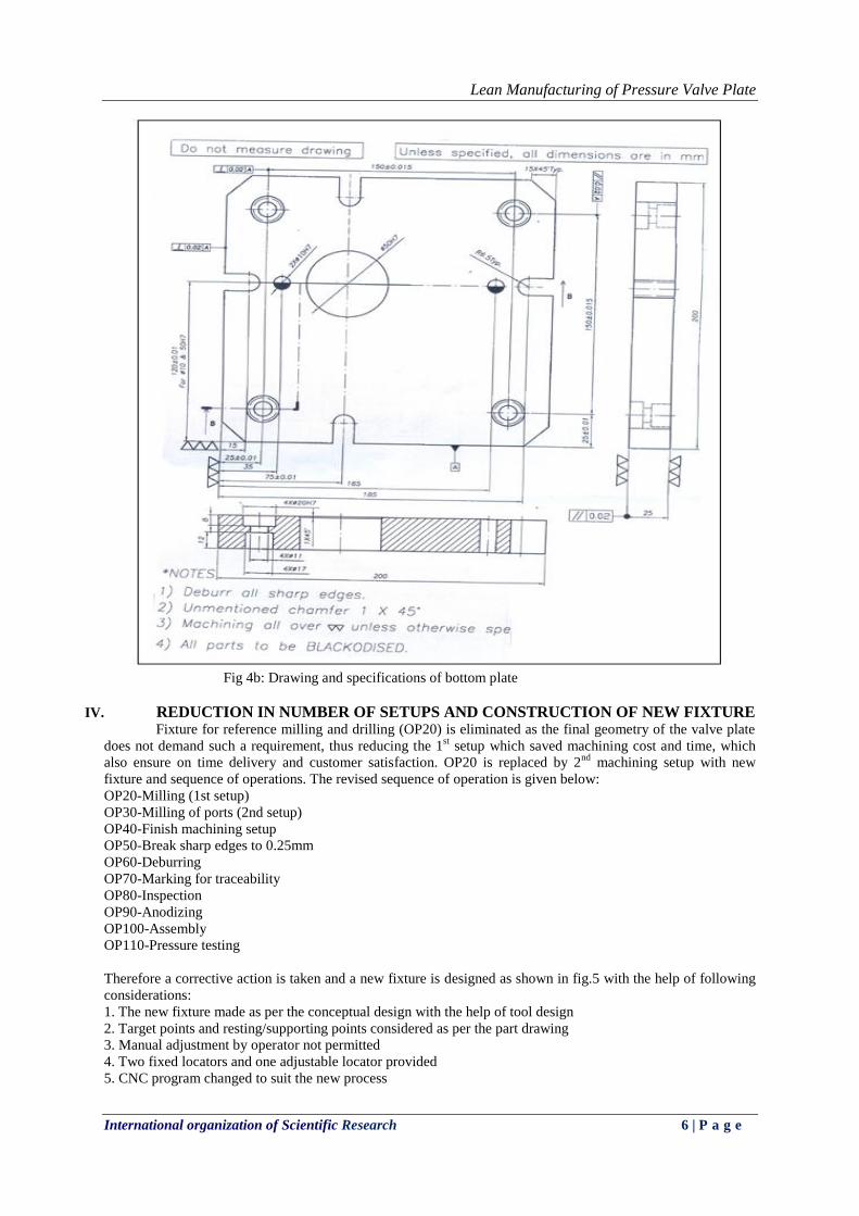
Fig 4b: Drawing and specifications of bottom plate
IV. REDUCTION IN NUMBER OF SETUPS AND CONSTRUCTION OF NEW FIXTURE
Fixture for reference milling and drilling (OP20) is eliminated as the final geometry of the valve plate
does not demand such a requirement, thus reducing the 1st setup which saved machining cost and time, which
also ensure on time delivery and customer satisfaction. OP20 is replaced by 2nd
machining setup with new
fixture and sequence of operations. The revised sequence of operation is given below:
OP20-Milling (1st setup)
OP30-Milling of ports (2nd setup)
OP40-Finish machining setup
OP50-Break sharp edges to 0.25mm
OP60-Deburring
OP70-Marking for traceability
OP80-Inspection
OP90-Anodizing
OP100-Assembly
OP110-Pressure testing
Therefore a corrective action is taken and a new fixture is designed as shown in fig.5 with the help of following
considerations:
1. The new fixture made as per the conceptual design with the help of tool design
2. Target points and resting/supporting points considered as per the part drawing
3. Manual adjustment by operator not permitted
4. Two fixed locators and one adjustable locator provided
5. CNC program changed to suit the new process
Lean Manufacturing of Pressure Valve Plate
International organization of Scientific Research 7 | P a g e
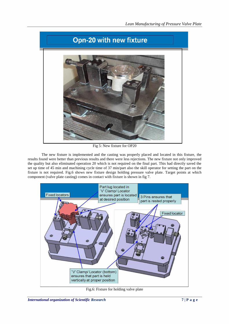
Fig 5: New fixture for OP20
The new fixture is implemented and the casting was properly placed and located in this fixture, the
results found were better than previous results and there were less rejections. The new fixture not only improved
the quality but also eliminated operation 20 which is not required on the final part. This had directly saved the
set up time of 45 min and machining cycle time of 37 min/part also the skill operator for setting the part on the
fixture is not required. Fig.6 shows new fixture design holding pressure valve plate. Target points at which
component (valve plate casting) comes in contact with fixture is shown in fig 7.
Fig.6: Fixture for holding valve plate
Lean Manufacturing of Pressure Valve Plate
International organization of Scientific Research 8 | P a g e
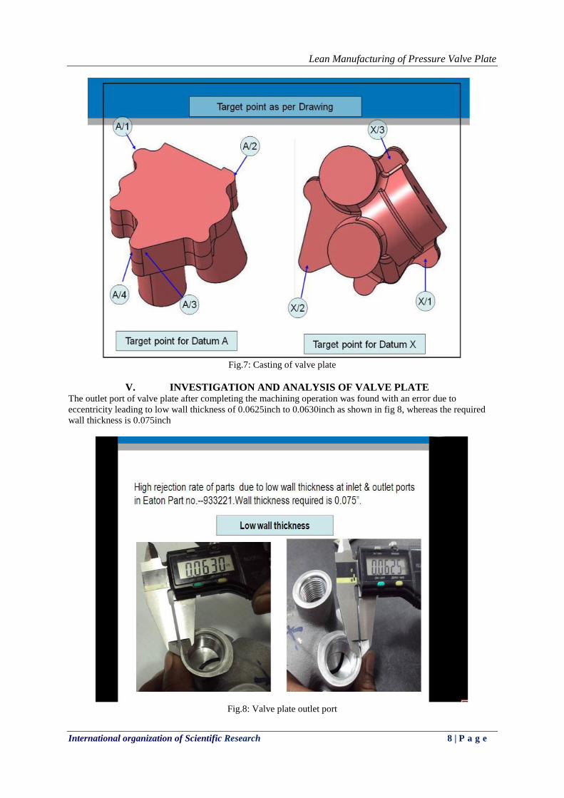
Fig.7: Casting of valve plate
V. INVESTIGATION AND ANALYSIS OF VALVE PLATE The outlet port of valve plate after completing the machining operation was found with an error due to
eccentricity leading to low wall thickness of 0.0625inch to 0.0630inch as shown in fig 8, whereas the required
wall thickness is 0.075inch
Fig.8: Valve plate outlet port
Lean Manufacturing of Pressure Valve Plate
International organization of Scientific Research 9 | P a g e
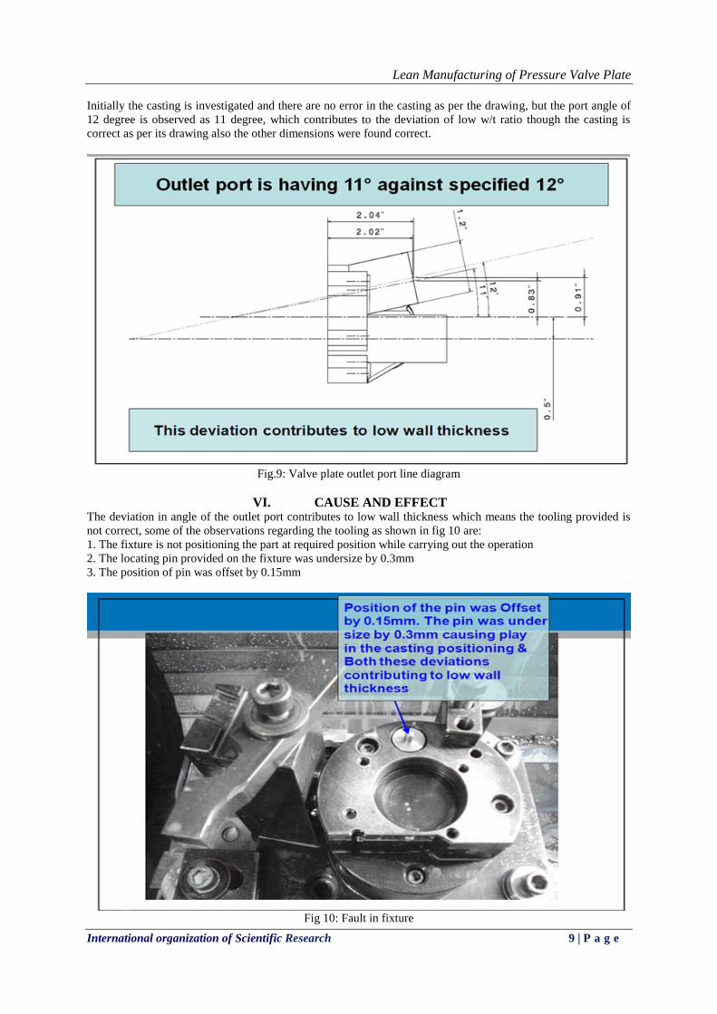
Initially the casting is investigated and there are no error in the casting as per the drawing, but the port angle of
12 degree is observed as 11 degree, which contributes to the deviation of low w/t ratio though the casting is
correct as per its drawing also the other dimensions were found correct.
Fig.9: Valve plate outlet port line diagram
VI. CAUSE AND EFFECT The deviation in angle of the outlet port contributes to low wall thickness which means the tooling provided is
not correct, some of the observations regarding the tooling as shown in fig 10 are:
1. The fixture is not positioning the part at required position while carrying out the operation
2. The locating pin provided on the fixture was undersize by 0.3mm
3. The position of pin was offset by 0.15mm
Fig 10: Fault in fixture
Lean Manufacturing of Pressure Valve Plate
International organization of Scientific Research 10 | P a g e
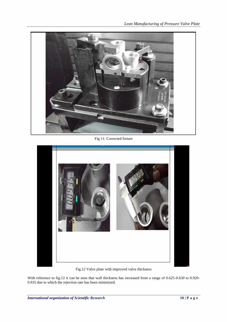
Fig 11: Corrected fixture
Fig.12 Valve plate with improved valve thickness
With reference to fig.12 it can be seen that wall thickness has increased from a range of 0.625-0.630 to 0.920-
0.935 due to which the rejection rate has been minimized.
Lean Manufacturing of Pressure Valve Plate
International organization of Scientific Research 11 | P a g e
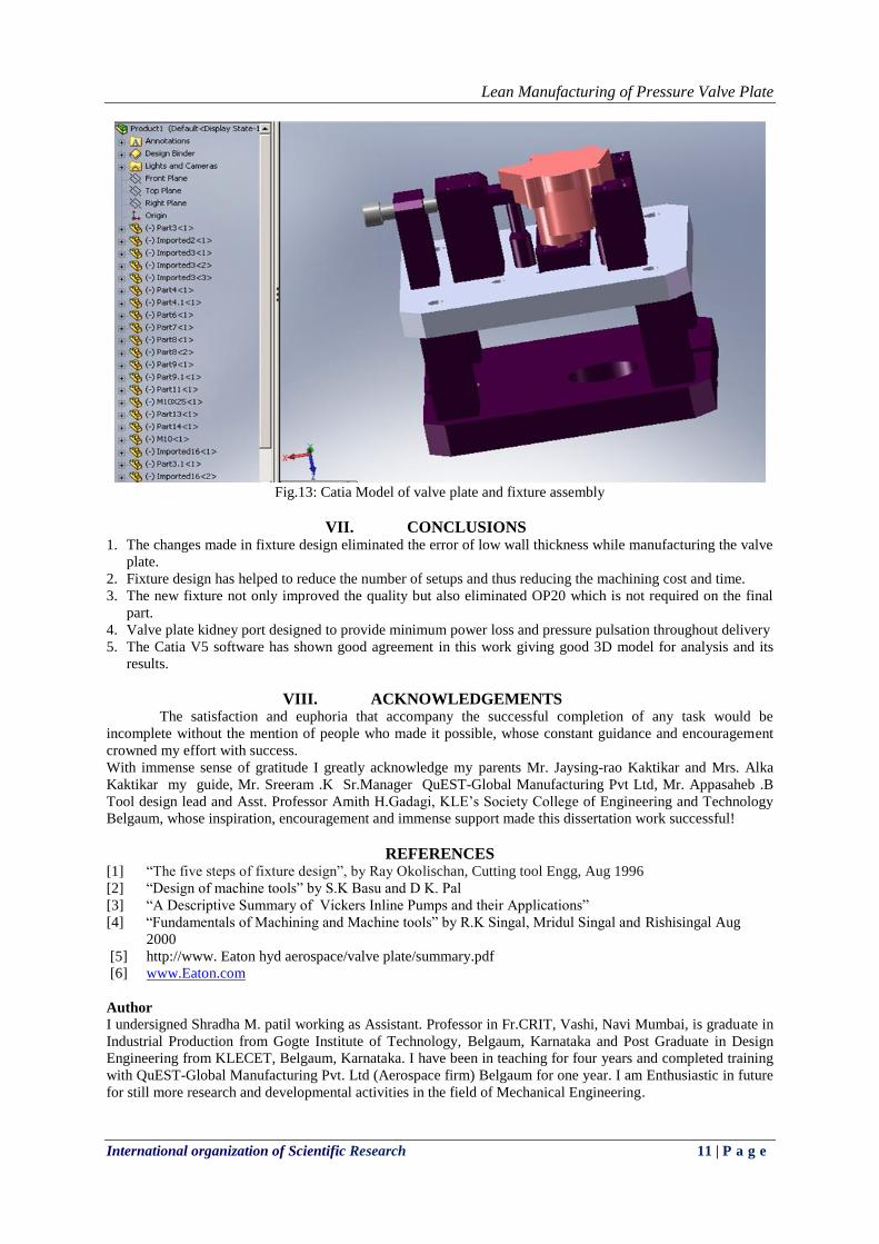
Fig.13: Catia Model of valve plate and fixture assembly
VII. CONCLUSIONS 1. The changes made in fixture design eliminated the error of low wall thickness while manufacturing the valve
plate.
2. Fixture design has helped to reduce the number of setups and thus reducing the machining cost and time.
3. The new fixture not only improved the quality but also eliminated OP20 which is not required on the final
part.
4. Valve plate kidney port designed to provide minimum power loss and pressure pulsation throughout delivery
5. The Catia V5 software has shown good agreement in this work giving good 3D model for analysis and its
results.
VIII. ACKNOWLEDGEMENTS The satisfaction and euphoria that accompany the successful completion of any task would be
incomplete without the mention of people who made it possible, whose constant guidance and encouragement
crowned my effort with success.
With immense sense of gratitude I greatly acknowledge my parents Mr. Jaysing-rao Kaktikar and Mrs. Alka
Kaktikar my guide, Mr. Sreeram .K Sr.Manager QuEST-Global Manufacturing Pvt Ltd, Mr. Appasaheb .B
Tool design lead and Asst. Professor Amith H.Gadagi, KLE’s Society College of Engineering and Technology
Belgaum, whose inspiration, encouragement and immense support made this dissertation work successful!
REFERENCES [1] “The five steps of fixture design”, by Ray Okolischan, Cutting tool Engg, Aug 1996
[2] “Design of machine tools” by S.K Basu and D K. Pal
[3] “A Descriptive Summary of Vickers Inline Pumps and their Applications”
[4] “Fundamentals of Machining and Machine tools” by R.K Singal, Mridul Singal and Rishisingal Aug
2000
[5] http://www. Eaton hyd aerospace/valve plate/summary.pdf
[6] www.Eaton.com
Author
I undersigned Shradha M. patil working as Assistant. Professor in Fr.CRIT, Vashi, Navi Mumbai, is graduate in
Industrial Production from Gogte Institute of Technology, Belgaum, Karnataka and Post Graduate in Design
Engineering from KLECET, Belgaum, Karnataka. I have been in teaching for four years and completed training
with QuEST-Global Manufacturing Pvt. Ltd (Aerospace firm) Belgaum for one year. I am Enthusiastic in future
for still more research and developmental activities in the field of Mechanical Engineering.