Yolk lip1d modifications by fat supplemented diets of laying hens
Upload
khangminh22Category
view
0download
0
CHENNAI METRO RAIL LIMITED
NATIONAL COMPETITIVE
BIDDING BID DOCUMENT
FOR
TENDER NO: CMRL/CON/UAA-09-US-01/2021
BID DOCUMENT
VOLUME - I
INVITATION FOR BIDS
INSTRUCTIONS TO
BIDDERS
CONTRACT DATA
CONDITIONS OF
CONTRACT
“Laying of sewer line, diversion of water supply line, house
connection works, testing, commissioning and other associated
works along TH Road near Tondiarpet Metro station from
Rettaikuzhi street junction to Tondiarpet ‘E’ pumping station’’
CMRL/CON/UAA-09-US-01/2021 Bid Document - Volume-1
Page 1 of 130 Sign and Stamp of Bidder
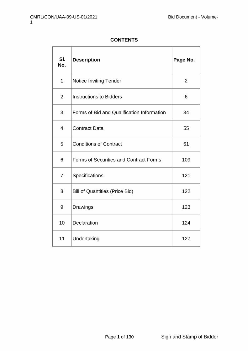
CONTENTS
Sl.
No. Description Page No.
1 Notice Inviting Tender 2
2 Instructions to Bidders 6
3 Forms of Bid and Qualification Information 34
4 Contract Data 55
5 Conditions of Contract 61
6 Forms of Securities and Contract Forms 109
7 Specifications 121
8 Bill of Quantities (Price Bid) 122
9 Drawings 123
10 Declaration 124
11 Undertaking 127
CMRL/CON/UAA-09-US-01/2021 Bid Document - Volume-1
Page 2 of 130 Sign and Stamp of Bidder
NOTICE INVITING TENDER (NIT)

CMRL/CON/UAA-09-US-01/2021 Bid Document - Volume-1
Page 3 of 130 Sign and Stamp of Bidder
File No: CMRL/CON/UAA-09-US-01/2021 Dated: 07-02-2021
CHENNAI METRO RAIL LIMITED
CHENNAI 600107, INDIA
NIT No: File No: CMRL/CON/UAA-09-US-01/2021
SHORT TENDER
National Competitive Bidding
CMRL invites Sealed Tender from reputed, experienced, financially sound, eligible applicants, who
fulfill the qualification criteria as mentioned in the tender through National Competitive Bidding (NCB)
under Single Stage Two Envelope (Technical & Financial) system for the works as detailed below.
1.
Name of work
Tender No: CMRL/CON/UAA-09-US-01/2021: - Laying of sewer line, diversion of water supply line,
house connection works, testing, commissioning and other associated works along TH Road near
Tondiarpet Metro Station from Rettaikuzhi street junction to Tondiarpet ‘E’ pumping station.
2. Tender validity 120 days from the date of submission of tender.
3. 4 Tender Security Amount
(EMD)
a) Amount: The total bid security / EMD amount shall be equivalent to INR 6,30,000/- (Rupees Six lakhs thirty thousand only) and submitted in the form of Bank Guarantee (BG) or via RTGS transactions to the below mentioned CMRL Bank account. Validity: In case of EMD by BG, it shall be valid for 148 days from date of stipulated Bid submission date i.e. up to 20-07-2021 or later.
b) Submission of Originals: Tender Security in case of BG / Demand Draft (in originals) shall be submitted along with the technical bid.
c) In case of RTGS / NEFT transactions, bidders shall submit the copies of transaction of payment along with the technical bid.
4.
Duration of Contract
(Completion period of
the work)
120 days
5. Details of NIT/ Tender
Document
NIT/Tender Notice Publication date in Newspapers/CMRL website:
07-02-2021.
The Tender documents can be collected from the Room no: 507
Office of Addl. General Manager (Contract Procurement), Chennai
Metro Rail Limited, Administrative Building, CMRL Depot,
Poonamallee High Road, Koyambedu, Chennai 600 107 OR
downloaded from CMRL website from 15:00 hrs on 08-02-2021 or
after.
6. Bid Submission fee
(Non-refundable)
There will be a non-refundable tender Fees of INR 8000/- (Rupees
Eight thousand only) including
GST to be paid by NEFT/RTGS/Demand Draft.
A copy of GST Registration Details of Bidder are to be provided
along with tender fees.
CMRL/CON/UAA-09-US-01/2021 Bid Document - Volume-1
Page 4 of 130 Sign and Stamp of Bidder
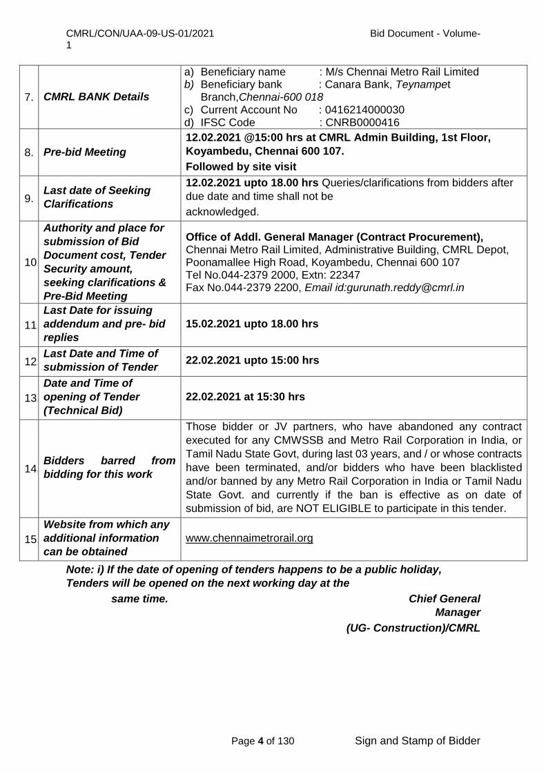
Note: i) If the date of opening of tenders happens to be a public holiday,
Tenders will be opened on the next working day at the
same time. Chief General
Manager
(UG- Construction)/CMRL
7. CMRL BANK Details
a) Beneficiary name : M/s Chennai Metro Rail Limited b) Beneficiary bank : Canara Bank, Teynampet
Branch,Chennai-600 018 c) Current Account No : 0416214000030 d) IFSC Code : CNRB0000416
8. Pre-bid Meeting
12.02.2021 @15:00 hrs at CMRL Admin Building, 1st Floor,
Koyambedu, Chennai 600 107.
Followed by site visit
9. Last date of Seeking
Clarifications
12.02.2021 upto 18.00 hrs Queries/clarifications from bidders after
due date and time shall not be
acknowledged.
10.
Authority and place for
submission of Bid
Document cost, Tender
Security amount,
seeking clarifications &
Pre-Bid Meeting
Office of Addl. General Manager (Contract Procurement), Chennai Metro Rail Limited, Administrative Building, CMRL Depot, Poonamallee High Road, Koyambedu, Chennai 600 107 Tel No.044-2379 2000, Extn: 22347 Fax No.044-2379 2200, Email id:[email protected]
11.
Last Date for issuing
addendum and pre- bid
replies
15.02.2021 upto 18.00 hrs
12. Last Date and Time of
submission of Tender 22.02.2021 upto 15:00 hrs
13.
Date and Time of
opening of Tender
(Technical Bid)
22.02.2021 at 15:30 hrs
14. Bidders barred from
bidding for this work
Those bidder or JV partners, who have abandoned any contract
executed for any CMWSSB and Metro Rail Corporation in India, or
Tamil Nadu State Govt, during last 03 years, and / or whose contracts
have been terminated, and/or bidders who have been blacklisted
and/or banned by any Metro Rail Corporation in India or Tamil Nadu
State Govt. and currently if the ban is effective as on date of
submission of bid, are NOT ELIGIBLE to participate in this tender.
15.
Website from which any
additional information
can be obtained
www.chennaimetrorail.org

CMRL/CON/UAA-09-US-01/2021 Bid Document - Volume-1
Page 5 of 130 Sign and Stamp of Bidder
Special Instructions for submission of Technical Bids
1. All pages in the Technical Bid (Both Original and Copy) should be page
numbered sequentially.
2. All pages of the Technical bid (Both Original and Copy) should be signed by
Authorized Signatory (ies).
3. All credentials including the copies of performance certificates and Bankers
certificates enclosed for the bids should be identified as the documents
submitted by the bidder over their signature with office seal.
4. Any document / credential submitted without signature of authorized persons
will not be considered for evaluation.
5. Bidders should produce the originals for the performance / client certificate for
verification whenever required with the copies of those certificates enclosed
along with the bid.
6. Bidder should furnish all the details pertaining to the Qualification Criteria in
Abstract Qualification Information and sign the declaration with full signature.
If the space available in the Table is insufficient, additional sheets may be
furnished in the specified format separately with declaration.
7. The copy of technical bid shall be properly bounded in separate volumes as
specified and submitted along with necessary documents.
8. The bidder shall not do any correction/ alteration on the bid document as found
in the website or supplied documents and he shall abide by all the terms,
conditions and specifications contained in the bid document. When there is
alteration / correction found in the bid document (downloaded / supplied
documents) submitted by the bidder then the printed version of the bid
document and replies to queries & addendum of the department will be binding
on the bidder. In case of alteration / correction found in the submitted document
of the bidder then the bid is liable for rejection with forfeiture of bid security.
9. All the rules and regulations of the Tamil Nadu Transparency in Tenders Act,
1988, Tamil Nadu Transparency in Tenders Rules, 2000 are applicable even
though not specifically mentioned in the bid document. Any conditions not
mentioned in the bid document and available in the said Acts and Rules thereof
will be invoked as and when required by the Management.

CMRL/CON/UAA-09-US-01/2021 Bid Document - Volume-1
Page 6 of 130 Sign and Stamp of Bidder
INSTRUCTIONS TO BIDDERS (ITB)
CMRL/CON/UAA-09-US-01/2021 Bid Document - Volume-1
Page 7 of 130 Sign and Stamp of Bidder
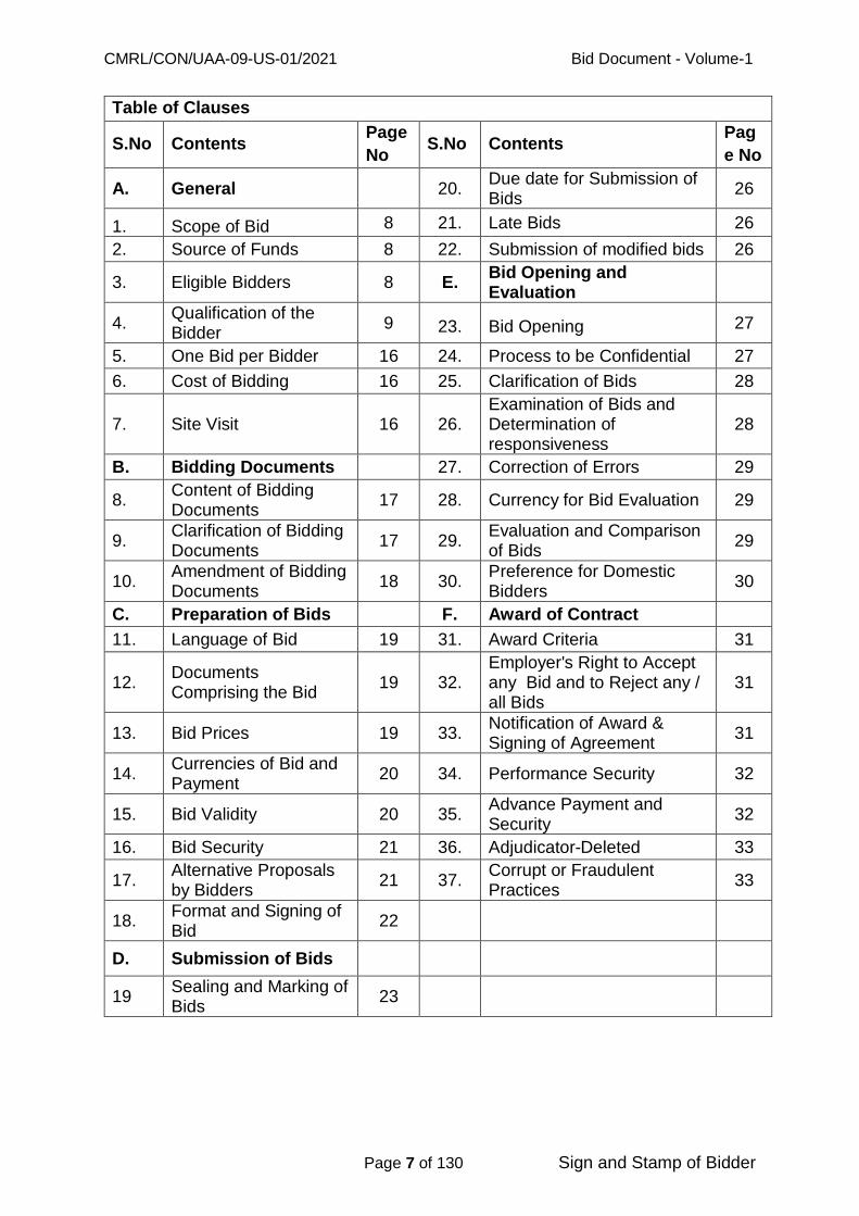
Table of Clauses
S.No Contents Page
No S.No Contents
Pag
e No
A. General 20. Due date for Submission of Bids
26 1.
Scope of Bid 8 21. Late Bids 26
2. Source of Funds 8 22. Submission of modified bids 26
3. Eligible Bidders 8 E. Bid Opening and Evaluation
4. Qualification of the Bidder
9
23. Bid Opening 27
5. One Bid per Bidder 16 24. Process to be Confidential 27
6. Cost of Bidding 16 25. Clarification of Bids 28
7. Site Visit 16 26. Examination of Bids and Determination of responsiveness
28
B. Bidding Documents 27. Correction of Errors 29
8. Content of Bidding Documents
17 28. Currency for Bid Evaluation 29
9. Clarification of Bidding Documents
17 29. Evaluation and Comparison of Bids
29
10. Amendment of Bidding Documents
18 30. Preference for Domestic Bidders
30
C. Preparation of Bids F. Award of Contract
11. Language of Bid 19 31. Award Criteria 31
12. Documents Comprising the Bid
19 32. Employer's Right to Accept any Bid and to Reject any / all Bids
31
13. Bid Prices 19 33. Notification of Award & Signing of Agreement
31
14. Currencies of Bid and Payment
20 34. Performance Security 32
15. Bid Validity 20 35. Advance Payment and Security
32
16. Bid Security 21 36. Adjudicator-Deleted 33
17. Alternative Proposals by Bidders
21 37. Corrupt or Fraudulent Practices
33
18. Format and Signing of Bid
22
D. Submission of Bids
19 Sealing and Marking of Bids
23

CMRL/CON/UAA-09-US-01/2021 Bid Document - Volume-1
Page 8 of 130 Sign and Stamp of Bidder
A. General
1. Scope of Bid
1.1. The CHENNAI METRO RAIL LIMITED invites sealed tender from reputed,
experienced, financially sound, eligible applicants, who fulfill the qualification
criteria as mentioned in the tender through National Competitive Bidding
(NCB) under Single Stage two Envelope (Technical & Financial) system for
the works, “Laying of sewer line, diversion of water supply line, house
connection works, testing, commissioning and other associated works
along TH Road near Tondiarpet Metro station from Rettaikuzhi street
junction to Tondiarpet ‘E’ pumping station” (as defined in these documents
and referred to as "the works").
1.2. The successful bidder will be expected to complete the works by the intended
completion date specified in the Contract data.
1.3. Throughout these Bidding documents, the terms bid and Tender and their
derivatives (bidder/Tenderer, bid/tender, bidding/Tendering, Bidding documents
/ tender documents etc) are synonymous and day means calendar day. Except
where the context requires otherwise, words indicating Singular also means
plural and words indicating plural also means singular.
1.4. The detailed Scope of Work for this tender is further described in the Vol-II and
other documents.
2. Source of Funds
2.1. Employer will fund this Work.
3. Eligible Bidders
3.1. All the bidders except those who have abandoned any contract executed for any
Metro Rail Corporation in India, or Tamil Nadu State Govt, or CMWSSB during
last 03 years, and / or whose contracts have been terminated, and/or bidders
who have been blacklisted and/or banned by any Metro Rail Corporation in India
or Tamil Nadu State Govt. and currently if the ban is effective as on date of
submission of bid, are eligible to bid for this tender. Payments will be made only
in Indian Rupees.

CMRL/CON/UAA-09-US-01/2021 Bid Document - Volume-1
Page 9 of 130 Sign and Stamp of Bidder
3.2. All bidders shall provide in Section 3, Forms of Bid and all Qualification
Information required under this contract.
3.3. Bidders shall not be under a declaration of ineligibility for corrupt and fraudulent
practices in accordance with sub-clause 37.1.
4. Qualification of the Bidder
4.1. All bidders shall provide in Section 3, Forms of Bid and Qualification Information,
a preliminary description of the proposed work method and schedule, including
drawings and charts, as necessary.
4.2. Pre-qualification was not undertaken for this contract.
4.3. All bidders shall include the following information and documents with their bids
in
Section 3:
a) Copies of original documents defining the constitution or legal status, place
of registration, and principal place of business; written power of attorney of
the signatory of the Bid to commit the Bidder.
b) Total monetary value of construction work performed for each of the qualifying
period.
c) Experience in works of a similar nature and details of the work completed
successfully during the qualifying period, and details of works under way or
contractually committed and clients who may be contacted for further
information on those contracts.
d) Major items of construction equipment proposed to carry out the Contract.
e) Qualifications and experience of key site management and Technical
personnel proposed for the Contract.
f) Reports on the financial standing of the Bidder, such as profit and loss
statements and auditor's reports for the past five years.
g) Evidence of adequacy of working capital for this contract (access to line (s)
of credit and availability of other financial resources).
h) Information regarding any litigation or arbitration resulting from contracts
executed by the Bidder in the last eight years or currently under execution.
The information shall include the names of the parties concerned, the
disputed amount, cause of litigation, and matter in dispute.
CMRL/CON/UAA-09-US-01/2021 Bid Document - Volume-1
Page 10 of 130 Sign and Stamp of Bidder
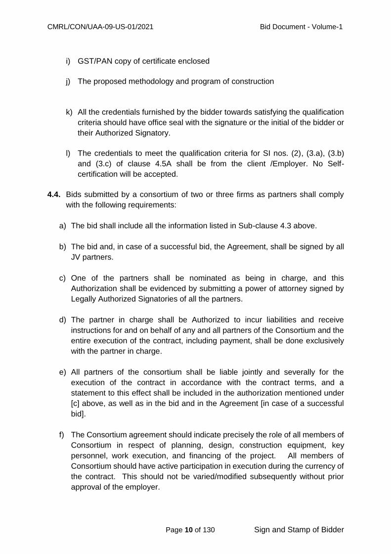
i) GST/PAN copy of certificate enclosed
j) The proposed methodology and program of construction
k) All the credentials furnished by the bidder towards satisfying the qualification
criteria should have office seal with the signature or the initial of the bidder or
their Authorized Signatory.
l) The credentials to meet the qualification criteria for SI nos. (2), (3.a), (3.b)
and (3.c) of clause 4.5A shall be from the client /Employer. No Self-
certification will be accepted.
4.4. Bids submitted by a consortium of two or three firms as partners shall comply
with the following requirements:
a) The bid shall include all the information listed in Sub-clause 4.3 above.
b) The bid and, in case of a successful bid, the Agreement, shall be signed by all
JV partners.
c) One of the partners shall be nominated as being in charge, and this
Authorization shall be evidenced by submitting a power of attorney signed by
Legally Authorized Signatories of all the partners.
d) The partner in charge shall be Authorized to incur liabilities and receive
instructions for and on behalf of any and all partners of the Consortium and the
entire execution of the contract, including payment, shall be done exclusively
with the partner in charge.
e) All partners of the consortium shall be liable jointly and severally for the
execution of the contract in accordance with the contract terms, and a
statement to this effect shall be included in the authorization mentioned under
[c] above, as well as in the bid and in the Agreement [in case of a successful
bid].
f) The Consortium agreement should indicate precisely the role of all members of
Consortium in respect of planning, design, construction equipment, key
personnel, work execution, and financing of the project. All members of
Consortium should have active participation in execution during the currency of
the contract. This should not be varied/modified subsequently without prior
approval of the employer.

CMRL/CON/UAA-09-US-01/2021 Bid Document - Volume-1
Page 11 of 130 Sign and Stamp of Bidder
g) A copy of the Consortium Agreement entered into by the partners shall be
submitted with the bid. Alternatively, a Letter of Intent to execute a consortium
Agreement in the event of a successful bid shall be signed by all partners and
submitted with the bid, together with a copy of the proposed Agreement.
4.5. A. To qualify for award of the contract, each bidder in its name should have
performed / executed the following during the period 01.04.2015 up to date
of submission of bid.
Sl.
No.
Qualification criteria
Minimum
required/
Eligible
Qualification
1
Must have achieved the annual financial turnover
from in any one financial year during 2015-16 to
2019-20 not less than the amount given (Rs. in
lakh)
780.00
2
Must have satisfactorily completed any single
construction works including laying of
sewer/water lines of value not less than the
amount given (Rs. in lakh)
312.00
3.a
Should have satisfactorily completed and tested the
RCC circular well by well sinking method in the last
five (5) years in a single contract
Minimum well
diameter of size
3m and minimum
well depth of 5m
3.b
Should have supplied, laid, jointed & tested and
successfully completed DWC PE/SW pipes in
anyone (1) year of last five (5) years
Minimum pipe
diameter of size
150mm and
minimum length of
250m
3.c
Should have supplied, laid, jointed & tested and
successfully completed the sewer line of CI/ DI/
RCC/ PSC pipes in anyone (1) year of last five (5)
years
Minimum pipe
diameter of size
350mm and
minimum length of
600m
- For Sl. Nos. (2), (3.a), (3.b) and (3.c) above, the experience of the bidders as
on date of bid submission will be considered for evaluation.
- Consortium bids are acceptable.

CMRL/CON/UAA-09-US-01/2021 Bid Document - Volume-1
Page 12 of 130 Sign and Stamp of Bidder
- The Bid Security of a JV/Consortium shall be in the name of the JV/Consortium
that submits the Bid. If the JV/ Consortium has not been legally constituted into
a legally enforceable JV/ Consortium at the time of bidding, the Bid Security
shall be in the names of all future members as named in the letter of intent.
- However, the Bid security of a JV/Consortium can also be submitted by the
Lead Member of the JV/Consortium in his name.
- Disqualification/Debarring done due to works executed in any State/ Central
Government Departments, or State / Central Undertakings/ Boards/
Corporations, Municipalities and Municipal Corporations, Urban Developments
Authorities and those bidder or JV partners, who have abandoned bidders
abandoned any contract executed for any Metro Rail Corporation in India, or
Tamil Nadu State Govt, or CMWSSB during last 03 years, and / or whose
contracts have been terminated, and/or bidders who have been blacklisted
and/or banned by any Metro Rail Corporation in India or Tamil Nadu State Govt.
and currently if the ban is effective as on date of submission of bid, are eligible
to bid for this tender will disqualify any entity from participation in the tender.
The bids of the Contractors whose previous performance is found to be poor / not
satisfactory, will not be taken up for evaluation. Decision of the employer in this
regard shall be final.
Financial turnover and cost of completed works of previous years shall be given
weightage of 6% per year to bring them to 2020-2021 price level and that will
be considered for the qualifying criteria.
B. Each bidder should further demonstrate:
(a) Availability (either owned or leased or by procurement) of the following key
and critical equipment for this work:
NAME OF THE EQUIPMENT NOS. CAPACITY
CIVIL:
Concrete mixture with hopper 2 nos. 10 cu.ft. capacity each
Needle vibrators 2 nos. 20-50 mm needle each
Earth mover 2 nos. 0.5 cum each
Trucks/tippers/dumpers 2 nos. 6 - 10 T capacity each
Dewatering pumps 40 HP Various capacity
Mobile DG set 2 nos. 10 KVA
MECHANICAL:
Hydraulic mobile crane 2 nos. Boom height 6 m (20 T)

CMRL/CON/UAA-09-US-01/2021 Bid Document - Volume-1
Page 13 of 130 Sign and Stamp of Bidder
Chain Pulley Block 2 nos. 5 T capacity
Tools and plants for jointing pipes 2 nos.
Pipe cutting machinery 2 nos.
Welding Transformers for Structural
Steel work welding. 1 no.
Drilling machine 1 no. Up to 16 mm drill size
Pipe bending machine 1 no.
Mechanical wrenches 4 nos.
Set of torque wrenches for
tightening flange joints up to 1600 NB 4 nos.
ELECTRICAL:
Earth Tester 4 nos. 500 V
Megger 4 nos. 500 V
Soil resistivity measurement kit 2 nos. Four peg method
Multi meter 4 nos.
0 -500 V AC
0 - 100 A AC
0 - 20 A DC
0 - 2000A DC
Set of Crimping Tool for all sizes of
cables (Copper & Aluminum) 4 Sets
Tong Tester 4 nos. 0 - 500 A
Tester 4 nos. 2 KV HV
Clip on type Ammeter 4 nos. 0 - 500 A
The bidders should, however, undertake their own studies and furnish with their
bid, a detailed construction planning, and methodology supported with layout and
necessary drawings and calculations (detailed) as stated in clause 4.3 (j) above to
allow the Employer to review their proposals. The numbers, types and capacities
of each plant/equipment shall be shown in the proposals along with the cycle time
for each operation for the given production capacity to match the requirements.
(b) Availability for this work of Project Manager and other Key personnel with
adequate experience as indicated in the below table and in the Contract Data;
and
S.
No
Key
Personnel
Eligibility
(Min Qualification and Experience required)
Nos.
1 Project
Manager
B.E. (Civil) with min. of 8 years’ experience or
Diploma in civil Engineering with minimum 15
years’ experience and with experience of at
least one Project/Work of similar nature of this
1 Nos.

CMRL/CON/UAA-09-US-01/2021 Bid Document - Volume-1
Page 14 of 130 Sign and Stamp of Bidder
work.
2 Engineer /
Civil
B.E. (Civil) with minimum of 5 years’ experience
or Diploma in civil Engineering with minimum 10
years’ experience and with experience of at least
one Project/Work of similar nature of this work.
1 Nos.
3 Engineer /
Mechanical
B.E. (Mechanical) with minimum of 5 years’
experience or Diploma in Mechanical
Engineering with minimum 10 years’ experience
and with experience of at least one Project/Work
of similar nature of this work.
1 Nos.
(c) Liquid assets and/or availability of credit facilities of not less than Rs. 145 lakhs
(Credit lines/letter of credit/certificates from Banks for meeting the
funds requirement etc.)
4.6. Consortium is permitted in this tender. Only a maximum of 3 partners are allowed
in a consortium.
1) In respect of Turnover as per the clause 4.5 A of ITB, Volume I of the bid
document, the lead partner should meet not less than 50 % of the qualifying
criteria and other partners should meet individually not less than 25% of the
qualifying criteria and all the partners should collectively meet 100% of the
qualification criteria.
2) In respect of qualification criteria towards
(i) Single Work (value),
(ii) Sewer pumping station works
as specified in item 2 & 3.a of clause 4.5 A, the bidder on his own or any one
of the partners of the consortium should have completed successfully the
works specified, as stipulated in the bid document for which necessary
documentary evidence should be produced along with the Bid.
3) In respect of qualification criteria related to pipe laying works as per item 3.b
& 3.c of clause 4.5A, the Bidder on his own or the consortium partners
together should satisfy the criteria as stipulated in the bid document for
which necessary documentary evidence should be produced along with the
Bid.
4.7. Bid Capacity Criteria: Bidders who meet the minimum qualification criteria will
be qualified only if their available bid capacity is more than 8Crs. The available
bid capacity will be assessed at the time of Technical evaluation of Bids itself

CMRL/CON/UAA-09-US-01/2021 Bid Document - Volume-1
Page 15 of 130 Sign and Stamp of Bidder
with reference to value put to Tender. In case of the Bidders who do not satisfy
the requirement of the Bid Capacity, their bids will be treated as non- responsive
and their price bids will not be opened.
Assessed Available Bid capacity = (A*N*2.0 - B)
Where,
A = Maximum turnover in any one year during the last five years (2020-21 price
level considering 5% inflation per year) taking into account the completed as well
as works in progress.
N = Number of years prescribed for completion of the works for which bids are
invited=0.33 year (4 months).
B = Value at 2020-21 price level of existing commitments and on-going works
to be completed during the next 12 months.
In case of the Bidders / Consortium Partners who formed part of consortium in
the past including for ongoing works, the references A & B would be determined
based on the details for such partners who undertook / proposed to undertake
physical execution of the works and in proportion to their participation in such
consortiums.
The assessed bid capacity of each of the consortium partners should be more
than the required bid capacity. The required bid capacity for consortium partners
would be determined on the basis of their participation in the consortium for the
purpose of this tender.
However, to qualify for the Bid capacity requirement, the lead partner should
meet not less than 50% of the required Bid capacity and other partners should
meet individually not less than 25% of the Bid capacity requirement. However,
all the partners should collectively meet 100% of the Bid capacity requirement.
4.8. Even though the bidders meet the above qualifying criteria, they are subject to
be disqualified if they have:
- made misleading or false representations in the forms, statements and
attachments submitted in proof of the qualification requirements; and/or
- record of poor performance such as abandoning the works, not properly
completing the contract, inordinate delays in completion, litigation history, or
financial failures etc.; and/or participated in the previous bidding for the same
work and had quoted unreasonably high bid prices and could not furnish
rational justification to the employer.

CMRL/CON/UAA-09-US-01/2021 Bid Document - Volume-1
Page 16 of 130 Sign and Stamp of Bidder
- Those bidder or JV partners, who have abandoned any contract executed for
any Metro Rail Corporation in India, or Tamil Nadu State Govt during last 03
years, and / or whose contracts have been terminated, and/or bidders who have
been blacklisted and/or banned by any Metro Rail Corporation in India or Tamil
Nadu State Govt. and currently if the ban is effective as on date of submission
of bid, are NOT ELIGIBLE to participate in this tender.
5. One Bid per Bidder
5.1. Each bidder shall submit only one bid for one package either individually or as a
partner in a consortium subject to clause 22. A bidder who submits or
participates in more than one Bid (other than as a subcontractor or in cases of
alternatives that have been permitted or requested) will cause all the bids with
the Bidder‘s participation to be disqualified and bid security shall be forfeited.
6. Cost of Bidding
6.1. The bidder shall bear all costs associated with the preparation and submission
of his Bid, and the Employer will in no case be responsible and liable for those
costs.
7. Site visit
7.1. The Bidder, at the Bidder‘s own responsibility and risk is encouraged to visit and
examine the Site of Works and its surroundings and obtain all information that
may be necessary for preparing the Bid and entering into a contract for
construction of the Works. The costs of visiting the Site shall be at the Bidder's
own expense.
******

CMRL/CON/UAA-09-US-01/2021 Bid Document - Volume-1
Page 17 of 130 Sign and Stamp of Bidder
B. Bidding Documents
8. Content of Bidding Documents
8.1. The set of bidding documents comprises the documents listed in the table below
and addenda issued in accordance with Clause 10:
Section 1. Invitation for Bids (NIT)
2. Instructions to Bidders
3. Forms of Bid and Qualification Information
4. Contract Data
5. Conditions of Contract
6. Forms of Securities and Contract Forms
7. Specifications
8. Bill of quantities (Price Bid)
9. Drawings
8.2. The downloaded/Supplied documents should be completed and submitted in two
sets “one Original and one Copy”.
9. Clarification of Bidding Documents
9.1. A prospective bidder requiring any clarification of the bidding documents may
notify the Employer in writing or by mail/ e-mail/telex/facsimile at the Employer's
address indicated in the invitation to bid. The Employer will respond to any
request for clarification which he received within the data specified in NIT. Copies
of the Employer's response will be forwarded to all purchasers of the bidding
documents, including a description of the enquiry but without identifying its
source.
9.2. Pre-bid meeting:
a) The bidder or his official representative is invited to attend a pre-bid
meeting which will take place as mentioned in the NIT.
b) The purpose of the meeting will be to clarify issues and to answer
questions on any matter that may be raised at that stage.
c) The bidder is requested to submit any questions in writing or by cable to
reach the Employer not later than day as mentioned in the NIT.
CMRL/CON/UAA-09-US-01/2021 Bid Document - Volume-1
Page 18 of 130 Sign and Stamp of Bidder
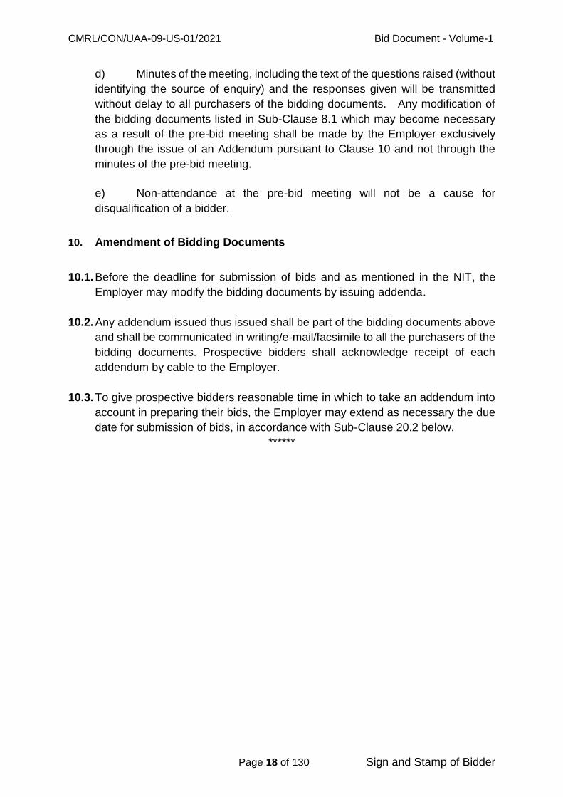
d) Minutes of the meeting, including the text of the questions raised (without
identifying the source of enquiry) and the responses given will be transmitted
without delay to all purchasers of the bidding documents. Any modification of
the bidding documents listed in Sub-Clause 8.1 which may become necessary
as a result of the pre-bid meeting shall be made by the Employer exclusively
through the issue of an Addendum pursuant to Clause 10 and not through the
minutes of the pre-bid meeting.
e) Non-attendance at the pre-bid meeting will not be a cause for
disqualification of a bidder.
10. Amendment of Bidding Documents
10.1. Before the deadline for submission of bids and as mentioned in the NIT, the
Employer may modify the bidding documents by issuing addenda.
10.2. Any addendum issued thus issued shall be part of the bidding documents above
and shall be communicated in writing/e-mail/facsimile to all the purchasers of the
bidding documents. Prospective bidders shall acknowledge receipt of each
addendum by cable to the Employer.
10.3. To give prospective bidders reasonable time in which to take an addendum into
account in preparing their bids, the Employer may extend as necessary the due
date for submission of bids, in accordance with Sub-Clause 20.2 below.
******
CMRL/CON/UAA-09-US-01/2021 Bid Document - Volume-1
Page 19 of 130 Sign and Stamp of Bidder
C. Preparation of Bids
11. Language of the Bid
11.1. All documents relating to the bid shall be in the English language.
12. Documents comprising the Bid
12.1. The bid submitted by the bidder shall comprise the following:
Part-A – Technical Bid:
a) Bid Security (in a separate envelope inside the envelope containing technical
bid) and proof of tender fee
b) Technical Bid
c) Bidding Forms and Qualification Information documents
Part-B – Price Bid
a) Priced Bill of quantities (Price Bid)
and any other materials required to be completed and submitted by bidders in
accordance with these instructions. The documents listed under Sections 3 and
8 of Sub-Clause 8.1 of ITB shall be filled in without exception.
The bids must be accompanied with the prescribed Bid security amount in a
separate envelope kept in the Technical bid envelope. The first cover with Bid
Security envelope and Technical Bid envelope shall be written on the cover as
"Technical Bid" and "Bid Security". The second cover with the Financial Bid
shall be written on the cover as "Price Bid".
13. Bid Prices
13.1. The contract shall be for the whole works as described in Sub-Clause 1.1, based
on the priced Bill of Quantities (Price Bid) submitted by the Bidder. The prices
and discounts (including any price reduction) quoted by the Tenderer in the Letter
of Price Bid and in the Bill of Quantities shall conform to the requirements
specified below.
13.2. The bidder shall fill in rates and prices, and line item total (both in figures and
words) for all items of the Works described in the Bill of Quantities along with
total bid price (both in figures and words). Items for which no rate or price is
entered by the bidder will not be paid for by the Employer when executed and

CMRL/CON/UAA-09-US-01/2021 Bid Document - Volume-1
Page 20 of 130 Sign and Stamp of Bidder
shall be deemed covered by the other rates and prices in the Bill of Quantities.
Corrections, if any, shall be made by crossing out, initialing, dating and rewriting.
13.3. All duties and other levies (other than GST) payable by the contractor under the
contract, or for any other cause shall be included in the rates, prices and total
Bid Price submitted by the Bidder. The Tenderer shall quote the price schedule
exclusive of GST. Any statutory variations in duties / levies, which take effect
from a date subsequent to the due date for receipt of tender, shall be to CMRL‘s
account.
13.4. The rates and prices quoted by the bidder shall be subject to adjustment during
the performance of the Contract in accordance with the provisions of Clause 47
of the Conditions of Contract.
14. Currencies of Bid and Payment
14.1. The unit rates and the prices shall be quoted by the bidder entirely in Indian
Rupees.
15. Bid Validity
15.1. Bids shall remain valid for a period not less than (120 days) one hundred and
twenty days after the deadline date for bid submission specified in Clause 20.
A bid valid for a shorter period shall be rejected by the Employer as non-
responsive.
15.2. In exceptional circumstances, prior to expiry of the original time limit, the
Employer may request that the bidders may extend the period of validity for a
specified additional period for the completion of evaluation provided that sum
total of all extensions shall ordinarily not exceed 200 (two hundred) days. The
request and the bidders' responses shall be made in writing. A bidder may refuse
the request without forfeiting his bid security. A bidder agreeing to the request
will not be required or permitted to modify his bid but will be required to extend
the validity of his bid security for a period of the extension, and in compliance
with Clause 16 in all respects.
15.3. The contract is NOT subjected to price adjustment.
15.4. In case the evaluation of tenders and award of contract is not completed within
extended validity period, all the tenders shall be deemed to have become invalid
and CMRL shall refund the Bid Security of all bidders and also may call for fresh
tender.

CMRL/CON/UAA-09-US-01/2021 Bid Document - Volume-1
Page 21 of 130 Sign and Stamp of Bidder
16. Bid Security
16.1. The Bidder shall furnish, as part of his Bid, a Bid security in the amount as shown
in NIT for this work. This bid security is to be furnished in the form of Bank
Guarantee (BG) or Demand Draft (DD) or via RTGS transactions to the below
mentioned CMRL Bank account.
a) Beneficiary name: M/s Chennai Metro Rail Limited
b) Beneficiary bank: Canara Bank, Teynampet Branch, Chennai-600
018
c) Current Account No: 0416214000030
d) IFSC Code: CNRB0000416
“Original BG or Demand Draft (DD) should be submitted along with the technical
bid. In case of online payment, UTR no and transaction slip is to be provided
along with the technical bid”.
16.2. Any bid not accompanied by an acceptable Bid Security as indicated in Sub-
Clauses 16.1 above shall be summarily rejected by the Employer.
16.3. The Bid Security of unsuccessful bidders will be returned as promptly as possible
upon the award of contract. The bid security of the bidder who has refused to
extend the bid validity as provided in 15.2 shall be refunded after the initial bid
validity. Employer shall pay no interest on the bid security.
16.4. The Bid Security of the successful bidder will be discharged when the bidder has
signed the Agreement and furnished the required Performance Security.
16.5. The Bid Security may be forfeited
(a) If the Bidder withdraws the Bid after opening of technical Bid during the
period of Bid validity and also the bidder will be debarred from participation in the
tenders invited by CMRL for a period of 1 year.
(b) In the case of a successful Bidder, if the Bidder fails within the specified
time limit to
(i) Sign the Agreement; or
(ii) Furnish the required Performance Security.
17. Alternative Proposals by Bidders
17.1. Alternative proposal shall not be considered.

CMRL/CON/UAA-09-US-01/2021 Bid Document - Volume-1
Page 22 of 130 Sign and Stamp of Bidder
18. Format and Signing of Bid
18.1. The Bidder shall prepare one original and one copy of the documents comprising
the bid as described in Clause 12 of these Instructions to Bidders, bound with
the volume containing the Form of Bid, and clearly marked "ORIGINAL" and
"COPY" as appropriate. In the event of discrepancy between them, the original
shall prevail.
18.2. The original and copy of the Bid shall be typed or written in indelible ink and shall
be signed by a person or persons duly authorized to sign on behalf of the Bidder,
pursuant to Sub-Clauses 4.3. All pages of the bid where entries or amendments
have been made shall be initialed by the person or persons signing the bid.
18.3. The Bid shall contain no alterations or additions, except those to comply with
instructions issued by the Employer, or as necessary to correct errors made by
the bidder, in which case such corrections shall be initialed by the person or
persons signing the bid.
18.4. In case the Bidder is a JV, the Bid shall be signed by an authorized representative
of the JV on behalf of the JV, pursuant to Sub-Clauses 4.4 and so as to be legally
binding on all the members as evidenced by a power of attorney signed by their
legally authorized representatives.
******

CMRL/CON/UAA-09-US-01/2021 Bid Document - Volume-1
Page 23 of 130 Sign and Stamp of Bidder
D. Submission of Bids
19. Sealing and Marking of Bids
19.1. The bid shall be submitted in two (2) parts viz. PART – A and PART - B. Each
part shall be placed in an independent sealed envelope. Each part shall be
labeled as follows.
PART - A: TECHNICAL BID ENVELOPE
Tender No.: CMRL/CON/UAA-09-US-01/2021
PART - B: PRICE BID ENVELOPE
Tender No.: CMRL/CON/UAA-09-US-01/2021
19.2. The contents of each of the two (2) envelopes shall be as described in the
subsequent clauses. For all further references, these envelopes will be referred
to briefly as:
- Technical bid Envelope
- Price bid Envelope
- The envelope containing Part A and the envelope containing Part B shall be
placed
inside an outer envelope and shall be labeled as follows:
Bid for: “Laying of sewer line, diversion of water supply line, house
connection works, testing, commissioning and other associated works
along TH Road near Tondiarpet Metro station from Rettaikuzhi street
junction to Tondiarpet ‘E’ pumping station’’.
This envelope contains two (2) independent sealed envelopes as follows:
PART – A: Technical Bid Envelope along with EMD in separate Envelope
PART - B: Price Bid Envelope
Tender No: CMRL/CON/UAA-09-US-01/2021
19.3. The envelope shall be addressed to
Office of Addl. General Manager (Contract Procurement),
Chennai Metro Rail Limited,
Administrative Building, CMRL Depot,
Poonamallee High Road,
Koyambedu, Chennai 600 107

CMRL/CON/UAA-09-US-01/2021 Bid Document - Volume-1
Page 24 of 130 Sign and Stamp of Bidder
Tel No.044-2379 2000, Extn: 22347
Fax No.044-2379 2200, Email id: [email protected]
Each envelope shall carry the name and address of the Bidder prominently.
19.4. The “Technical Bid” shall contain the following in the sequence indicated below.
This shall be submitted as two copies – 1 original and 1 copy.
i. Bid Security (EMD) and copy of proof for paid tender fee.
ii. Letter of Technical Bid.
iii. Performance Certificate obtained from the clients as per
Qualification Information.
iv. Documentary evidence of unambiguous fulfillment of Eligibility
criteria for Biding as per bidding forms.
v. Declaration by the Bidder that his Bid is without any technical and
commercial deviations on Bidder’s letter head and enclosed with
the Bid.
vi. Certified Power of Attorney authorizing a representative or
representatives of the Firm to sign the Bid and all subsequent
communication.
vii. Bid document signed by the authorized signatory.
viii. Full technical description of the items and services proposed by the
Bidder including makes.
ix. Details of Construction Equipment proposed for the execution of
the works and makes.
x. Details of manpower proposed for the Project Management
and Site Management including qualification and experience of
the personnel.
xi. Work methodology and plan.
xii. List of concurrent commitments including a schedule of contracts
under execution including values, percentage of works completed
and the schedule date of completion of the work.
xiii. Declaration for fulfilling the provisions of Contract Labor
(Regulations & Abolition) Act, 1970.
xiv. Declaration for fulfilling the Safety and Preventive measures and
Provisions of Labour laws brochure.
xv. Undertaking document for the Cleaning and Maintenance of
Sewerage System.
xvi. Any other technical details.
19.5. The "Technical Bid " shall NOT contain the following:

CMRL/CON/UAA-09-US-01/2021 Bid Document - Volume-1
Page 25 of 130 Sign and Stamp of Bidder
i. Schedule of Prices of the Bid Document constituting the Lump Sum
Bid Price.
ii. Any indication either direct or indirect or implicit or explicit or
implied regarding the Bid Price or its breakup details or any other
related price indication etc. shall be a cause for outright
disqualification of the entire Bid.
19.6. "Price Bid" envelope labeled, as "Price Bid Envelope" shall contain the
following in the sequence indicated below. This shall be submitted as two copies
– 1 original and 1 copy.
i. Letter of Price Bid
ii. The Bill of Quantities (BOQ) (Price Bid) for the work with each page
signed, dated and stamped with the seal of the Firm.
iii. Apart from the Schedule of Prices and Annexure duly filled in,
Bidders shall not enclose any other documents or statements that
influence the price except discount/rebate letter. In such an event
the CMRL shall summarily disqualify the Bidder and reject the Bid.
19.7. The Bidder shall seal the original and copy of the Bid in separate envelopes, duly
marking the envelopes as "ORIGINAL" and "COPY". These envelopes (called
as inner envelopes) shall then be put inside one outer envelope.
19.8. The inner and outer envelopes shall
a) Be addressed to the Employer at the following address:
Office of Addl. General Manager (Contract Procurement),
Chennai Metro Rail Limited,
Administrative Building, CMRL Depot,
Poonamallee High Road,
Koyambedu, Chennai 600 107
Tel No.044-2379 2000, Extn: 22347
Fax No.044-2379 2200, Email id: [email protected]
b) Bear the following identification:
- Bid for ...............................................[name of contract]
- Bid Reference No...............................[insert number]
- Do not open before. [time and date for bid opening, as per
Clause 20]

CMRL/CON/UAA-09-US-01/2021 Bid Document - Volume-1
Page 26 of 130 Sign and Stamp of Bidder
19.9. In addition to the identification required in Sub-Clause 19.2, the inner envelopes
shall indicate the name and address of the bidder to enable the bid to be returned
unopened in case it is declared late, pursuant to Clause 21.
19.10. If the outer envelope is not sealed and marked as above, the Employer will
assume no responsibility for the misplacement or premature opening of the bid.
20. Due date for Submission of the Bids
20.1. Bids must be received by the Employer at the address specified above not later
than 3.00 PM on 22.02.2021. In the event of the specified date for the submission
of bids declared a holiday for the Employer, the Bids will be received upto the
appointed time on the next working day.
20.2. The Employer may extend the due date for submission of bids by issuing an
amendment in accordance with Clause 10, in which case all rights and
obligations of the Employer and the bidders previously subject to the original due
date will then be subject to the new due date.
21. Late Bids
21.1. Any Bid received by the Employer after the due date prescribed in Clause 20 will
be returned unopened to the bidder.
Any Bid submitted in person after 3.00 PM. on the due date will not be accepted.
Similarly, any bid received by post after 3.00 PM. on the due date will not be
accepted and will be returned unopened to the bidder. Hence, the bidders are
requested to submit their bid well in advance i.e., before 3.00 PM. as per the
Office Clock on the due date / extended due date and time of bid submission.
The bidders can submit the bids on any working day during the bid submission
period.
22. Submission of Modified Bids
22.1. Bidders are not allowed to withdraw their bids after submitting the bid.
******

CMRL/CON/UAA-09-US-01/2021 Bid Document - Volume-1
Page 27 of 130 Sign and Stamp of Bidder
E. Bid Opening and Evaluation
23. Bid Opening
23.1. The Employer will open all the Technical Bids received (except those received
late), in the presence of the Bidders or their representatives who choose to attend
at 3.30 PM on 22.02.2021 and the place specified in NIT. In the event of the
specified date of Bid opening being declared a holiday for the Employer, the Bids
will be opened at the appointed time and location on the next working day.
23.2. The Bidders' names, Bid modifications and withdrawals, the presence or
absence of Bid security, and such other details as the Employer may consider
appropriate, will be announced by the Employer at the opening. No bid shall be
rejected at bid opening except for the late bids pursuant to Clause 21. Bids [and
modifications] sent pursuant to Clause 22 that are not opened and read out at
bid opening will not be considered for further evaluation regardless of the
circumstances. Late and withdrawn bids will be returned unopened to bidders.
The Price bid envelope will not be opened on the same day but on another day
in the presence of the qualified Bidders or their authorized representatives. The
date and time of opening the Price bid envelope will be advised to the qualified
Bidder in writing through email.
23.3. The Employer shall prepare minutes of the Bid opening, including the information
disclosed to those present in accordance with Sub-Clause 23.2.
23.4. Two cover bidding procedure will be adopted and will be processed as detailed
below: Bids (in two covers) must be delivered to the address as specified in
clause 19.8 at or before 3.00 PM office time on 22.02.2021. The first cover with
Bid Security cover and Technical Bid cover shall be written on the cover as
"Technical Bid" and "Bid Security" without any reference to the price. The second
cover with the Price Bid shall be written on the cover as "Price Bid" will consist
of Price Bid only.
23.5. Late bids and Bids without Bid security will be summarily rejected.
23.6. First cover will be opened in the presence of bidders' representatives who choose
to attend at the address given in the NIT at 3.30 PM. office time on 22.02.2021.
Only the price bids of those bidders whose bids are found technically responsive
and acceptable will be opened on the date and time to be intimated later and the
price bids will be evaluated.
24. Process to be Confidential

CMRL/CON/UAA-09-US-01/2021 Bid Document - Volume-1
Page 28 of 130 Sign and Stamp of Bidder
24.1. Information relating to the examination, clarification, evaluation, and comparison
of Bids and recommendations for the award of a contract shall not be disclosed
to Bidders or any other persons not officially concerned with such process until
the award to the successful Bidder has been announced. Any effort by a Bidder
to influence the Employer's processing of Bids or award decisions may result in
the rejection of his Bid.
25. Clarification of Bids
25.1. To assist in the examination, evaluation, and comparison of Bids, the Employer
may, at his discretion, ask any Bidder for clarification of his Bid, including
breakdowns of the unit rates. The request for clarification and the response shall
be in writing or by cable, but no change in the price or substance of the Bid shall
be sought, offered, or permitted except as required to confirm the correction of
arithmetic errors discovered by the Employer in the evaluation of the Bids in
accordance with Clause 27.
25.2. Subject to sub-clause 25.1, no Bidder shall contact the Employer on any matter
relating to its bid from the time of the bid opening to the time the contract is
awarded. If the Bidder wishes to bring additional information to the notice of the
Employer, it should do so in writing.
25.3. Any effort by the Bidder to influence the Employer in the Employer's bid
evaluation, bid comparison or contract award decisions may result in the
rejection of the Bidders’ bid.
26. Examination of Bids and Determination of Responsiveness
26.1. Prior to the detailed evaluation of Bids, the Employer will determine whether each
Bid (a) meets the eligibility criteria defined in Clause 3; (b) has been properly
signed; (c) is accompanied by the required securities and; (d) is substantially
responsive to the requirements of the Bidding documents.
26.2. A substantially responsive Bid is one which conforms to all the terms, conditions,
and specifications of the Bidding documents, without material deviation or
reservation. A material deviation or reservation is one (a) which affects in any
substantial way the scope, quality, or performance of the Works; (b) which limits
in any substantial way, inconsistent with the Bidding documents, the Employer's
rights or the Bidder's obligations under the Contract; or (c) whose rectification
would affect unfairly the competitive position of other Bidders presenting
substantially responsive Bids.

CMRL/CON/UAA-09-US-01/2021 Bid Document - Volume-1
Page 29 of 130 Sign and Stamp of Bidder
26.3. If a Bid is not substantially responsive, it will be rejected by the Employer, and
may not subsequently be made responsive by correction or withdrawal of the
non- conforming deviation or reservation.
27. Correction of Errors
27.1. Bids determined to be substantially responsive will be checked by the Employer
for any arithmetic errors. Errors will be corrected by the Employer as follows:
a) where there is a discrepancy between the rates in figures and in words,
the lower of the two will govern; and
b) where there is a discrepancy between the unit and the line item total
resulting from multiplying the unit rate by the quantity, the unit rate as
quoted will govern.
27.2. The amount stated in the Bid will be adjusted by the Employer in accordance with
the above procedure for the correction of errors and, with the concurrence of the
Bidder, shall be considered as binding upon the Bidder. If the Bidder does not
accept the corrected amount, the Bid will be rejected, and the Bid security may
be forfeited in accordance with Sub-Clause 16.5.
28. Currency for Bid Evaluation
28.1. Not applicable.
29. Evaluation and Comparison of Price Bids
29.1. The Employer will evaluate and compare only the Price Bids determined to be
substantially responsive in accordance with Clause 26 and as per Tamil Nadu
Transparency in Tenders Act 1998 and Rules 2000. Evaluation shall be done
without GST and inclusive of discounts if any.
29.2. In evaluating the Bids, the Employer will determine for each Bid the evaluated
Bid
Price by adjusting the Bid Price as follows:
(a) making any correction for errors pursuant to Clause 27; or
(b) making an appropriate adjustment for any other acceptable variations,
deviations; and
(c) Making appropriate adjustments to reflect discounts or other
price modifications offered.
29.3. The Employer reserves the right to accept or reject any variation, deviation, or
alternative offer. Variations, deviations, and alternative offers and other factors
which are in excess of the requirements of the Bidding documents or otherwise
CMRL/CON/UAA-09-US-01/2021 Bid Document - Volume-1
Page 30 of 130 Sign and Stamp of Bidder
result in unsolicited benefits for the Employer shall not be taken into account in
Bid evaluation.
29.4. The estimated effect of the price adjustment conditions under Clause 47 of the
Conditions of Contract, during the period of implementation of the Contract, will
not be taken into account in Bid evaluation.
29.5. If the Bid of the successful Bidder is seriously unbalanced in relation to the
Engineer's estimate of the cost of work to be performed under the contract, the
Employer may require the Bidder to produce detailed price analyses for any or
all items of the Bill of Quantities, to demonstrate the internal consistency of those
prices with the construction methods and schedule proposed. After evaluation
of the price analyses, the Employer may require that the amount of the
performance security set forth in Clause 34 be increased at the expense of the
successful Bidder to a level sufficient to protect the Employer against financial
loss in the event of default of the successful Bidder under the Contract.
30. Preference for Domestic Bidders
30.1. Not applicable.
******
CMRL/CON/UAA-09-US-01/2021 Bid Document - Volume-1
Page 31 of 130 Sign and Stamp of Bidder
F. Award of Contract
31. Award Criteria
31.1. Subject to Clause 32, the Employer will award the Contract to the Bidder whose
Bid has been determined to be substantially responsive to the Bidding
documents and who has offered the lowest evaluated Bid Price, provided that
such Bidder has been determined to be (a) eligible in accordance with the
provisions of Clause 3, and (b) qualified in accordance with the provisions of
Clause 4.
32. Employer's Right to accept any Bid and to Reject any or all Bids
32.1. Notwithstanding Clause 31, the Employer reserves the right to accept or reject
any Bid, and to cancel the Bidding process and reject all Bids, at any time prior
to the award of Contract, without thereby incurring any liability to the affected
Bidder or Bidders or any obligation to inform the affected Bidder or Bidders of the
grounds for the Employer's action.
33. Notification of Award and Signing of Agreement
33.1. The Bidder whose Bid has been accepted will be notified of the award by the
Employer prior to expiration of the Bid validity period by cable, telex or facsimile
confirmed by registered letter. This letter (hereinafter and in the Conditions of
Contract called the "Letter of Acceptance") will state the sum that the Employer
will pay the Contractor in consideration of the execution, completion, and
maintenance of the Works by the Contractor as prescribed by the Contract
(hereinafter and in the Contract called the "Contract Price"). However, the
contract price is likely to change depending upon the actual items executed at
Site. Letter of Acceptance shall be communicated by email with signed copy of
LOA attached, collected by hand by the successful bidder and dispatch by post
to the postal address of L1 successful bidder.
33.2. The notification of award will constitute the formation of the Contract, subject only
to the furnishing of a performance security in accordance with the provisions of
Clause 34.
33.3. The Agreement will incorporate all agreements between the Employer and the
successful Bidder. On submission of the performance security (BG as per Clause
34.1 within 14 days of receipt of the Letter of Acceptance), the successful bidder
shall produce two sets of stamp papers of 100/- rupees each for making the
contract agreement. The Employer will then prepare complete set of documents
in which the Employer and successful bidder will sign. This exercise of signing
the agreement should be completed within 7 days from the date of receipt of the
performance security from the successful bidder.
CMRL/CON/UAA-09-US-01/2021 Bid Document - Volume-1
Page 32 of 130 Sign and Stamp of Bidder
The tenderer while attending CMRL office for signing the contract, shall arrange
the following:
Two non-judicial stamp papers of Rs 100/- each, one in the name of
CMRL and the other in the name of the tenderer
20 Nos. of Green color A4 legal blank papers
Performance bank Guarantee with the validity and amount as per LOA
and as per Sub-Clause 34.4 of ITB.
Power of attorney (if any)
Seal of the tenderer
33.4. Upon the signing of Contract Agreement with the successful Bidder, the
Employer will promptly refund the Bid security of the other unsuccessful bidders.
33.5. It is expected that successful tenderer starts the work immediately after
completion of all formalities mentioned in the LOA within the time frame
mentioned therein.
34. Performance Security payable at Chennai
34.1. Within 14 days of receipt of the Letter of Acceptance, the successful Bidder shall
deliver to the Employer a Performance Security in any of the forms given below
for an amount to be calculated as per Clause 34.4 plus additional security for
unbalanced Bids in accordance with Clause 29.5 of ITB and Clause 52 of CC.
i) An Un conditional irrevocable Bank Guarantee from a Public Sector Bank in
Chennai in the form given in Forms of Securities
34.2. The performance security of a consortium shall be in the name of consortium. If
the performance security is provided by the successful Bidder in the form of a
Bank Guarantee, it shall be issued by a Public Sector Bank.
34.3. Failure of the successful Bidder to comply with the requirements of Sub-Clause
34.1 shall constitute sufficient grounds for cancellation of the award and forfeiture
of the Bid Security.
34.4. The value of performance security to be remitted for construction activity will be
7.5% of contract value.
35. Advance Payment and Security

CMRL/CON/UAA-09-US-01/2021 Bid Document - Volume-1
Page 33 of 130 Sign and Stamp of Bidder
35.1. The Employer will provide an interest-bearing Advance Payment on the Contract
Price as stipulated in the Conditions of Contract, subject to maximum amount,
as stated in the Contract Data.
36. Deleted.
37. Corrupt or Fraudulent Practices
37.1. The Employer requires that Bidders observe the highest standard of ethics during
the evaluation and execution of such contracts. In pursuance of this policy, the
Employer:
(a) Defines, for the purposes of this provision, the terms set forth below as
follows:
(i) corrupt practice means the offering, giving, receiving or soliciting of anything
of value to influence the action of a public official in the evaluation process or
in contract execution; and
(ii) fraudulent practice means a misrepresentation of facts in order to influence
the evaluation process or the execution of a contract to the detriment of the
Employer and includes collusive practice among Bidders (prior to or after bid
submission) designed to establish bid prices at artificial non-competitive levels
and to deprive the Employer of the benefits of free and open competition.
(b) will reject a proposal for award if it determines that the Bidder recommended
for award has engaged in corrupt or fraudulent practices in competing for the
contract in question.
(c) will declare a firm ineligible, either indefinitely or for a stated period of time, to
be awarded a contract if it at any time determines that the firm has engaged in
corrupt or fraudulent practices in competing for, or in executing a contract.
37.2. Furthermore, Bidders shall be aware of the provision stated in sub-clause 59.2
of the Conditions of Contract.
******
CMRL/CON/UAA-09-US-01/2021 Bid Document - Volume-1
Page 34 of 130 Sign and Stamp of Bidder
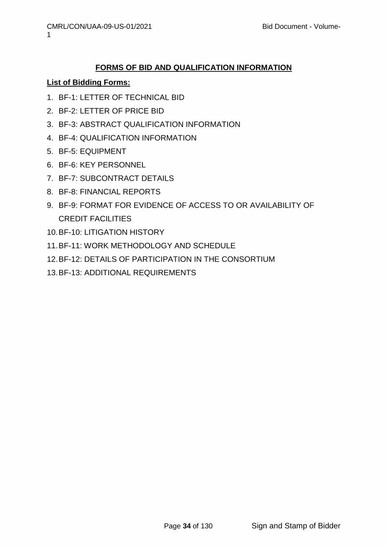
FORMS OF BID AND QUALIFICATION INFORMATION
List of Bidding Forms:
1. BF-1: LETTER OF TECHNICAL BID
2. BF-2: LETTER OF PRICE BID
3. BF-3: ABSTRACT QUALIFICATION INFORMATION
4. BF-4: QUALIFICATION INFORMATION
5. BF-5: EQUIPMENT
6. BF-6: KEY PERSONNEL
7. BF-7: SUBCONTRACT DETAILS
8. BF-8: FINANCIAL REPORTS
9. BF-9: FORMAT FOR EVIDENCE OF ACCESS TO OR AVAILABILITY OF
CREDIT FACILITIES
10. BF-10: LITIGATION HISTORY
11. BF-11: WORK METHODOLOGY AND SCHEDULE
12. BF-12: DETAILS OF PARTICIPATION IN THE CONSORTIUM
13. BF-13: ADDITIONAL REQUIREMENTS

CMRL/CON/UAA-09-US-01/2021 Bid Document - Volume-1
Page 35 of 130 Sign and Stamp of Bidder
Bidding Form-1 (BF-1)
LETTER OF TECHNICAL BID Description of the Works: Tender No: CMRL/CON/UAA-09-US-01/2021 – “Laying of sewer line, diversion of water supply line, house connection works, testing, commissioning and other associated works along TH Road near Tondiarpet Metro station from Rettaikuzhi street junction to Tondiarpet ‘E’ pumping station” To Address:
Chief General Manager (UG-C) Chennai Metro Rail Limited, Administrative Building, CMRL Depot,
Poonamallee High Road, Koyambedu, Chennai 600 107
GENTLEMEN,
We offer to execute the Work described above in accordance of Contract
accompanying this Technical Bid for the Contract Price stated in Financial Bid. We accept the proposal of interest-bearing advance payment upto a maximum of
10% of contract value for construction activities as per Condition prescribed by the
Employer.
We accept the all legal disputes are subject to the jurisdiction of Court at Chennai only.
This Bid and your written acceptance of its hall constitute a binding contract
between us. We understand that you are not bound to accept the lowest or any Bid
you receive. We undertake that in competing for (and, if the award is made to us, in
executing) the above contract, we will strictly observe the laws against fraud and
corruption in force in India namely, “Prevention of Corruption Act, 1988). We hereby confirm that this Bid complies with the Eligibility, Bid Validity and Bid security required by the Bidding documents.
Yours faithfully, Authorized Signature:
Name & Title of Signatory : -----------------------------------------------
Name of Bidder : -----------------------------------------------
Address : --------------------------------------------
---
CMRL/CON/UAA-09-US-01/2021 Bid Document - Volume-1
Page 36 of 130 Sign and Stamp of Bidder
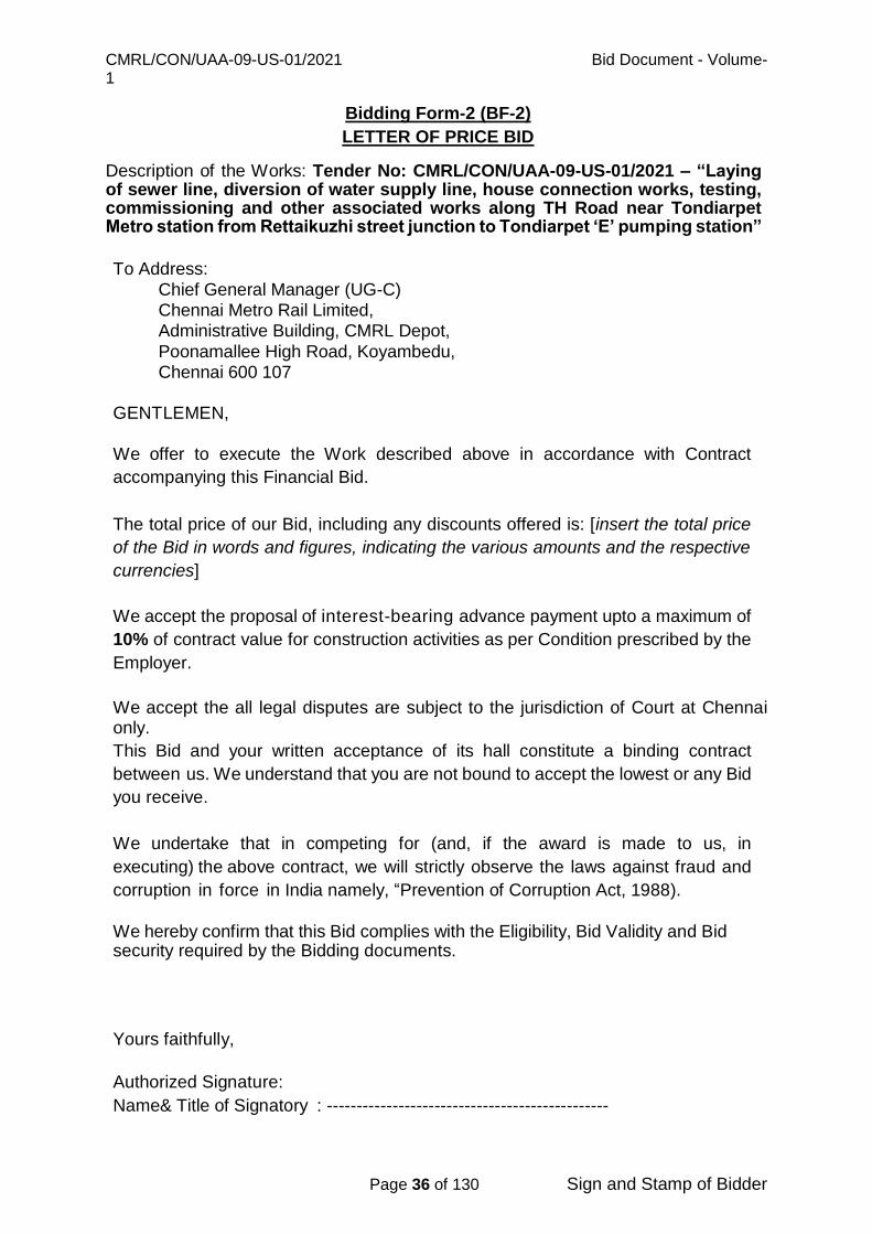
Bidding Form-2 (BF-2)
LETTER OF PRICE BID Description of the Works: Tender No: CMRL/CON/UAA-09-US-01/2021 – “Laying of sewer line, diversion of water supply line, house connection works, testing, commissioning and other associated works along TH Road near Tondiarpet Metro station from Rettaikuzhi street junction to Tondiarpet ‘E’ pumping station” To Address:
Chief General Manager (UG-C) Chennai Metro Rail Limited, Administrative Building, CMRL Depot,
Poonamallee High Road, Koyambedu, Chennai 600 107
GENTLEMEN,
We offer to execute the Work described above in accordance with Contract
accompanying this Financial Bid.
The total price of our Bid, including any discounts offered is: [insert the total price
of the Bid in words and figures, indicating the various amounts and the respective
currencies] We accept the proposal of interest-bearing advance payment upto a maximum of
10% of contract value for construction activities as per Condition prescribed by the
Employer.
We accept the all legal disputes are subject to the jurisdiction of Court at Chennai only.
This Bid and your written acceptance of its hall constitute a binding contract
between us. We understand that you are not bound to accept the lowest or any Bid
you receive. We undertake that in competing for (and, if the award is made to us, in
executing) the above contract, we will strictly observe the laws against fraud and
corruption in force in India namely, “Prevention of Corruption Act, 1988).
We hereby confirm that this Bid complies with the Eligibility, Bid Validity and Bid security required by the Bidding documents.
Yours faithfully,
Authorized Signature:
Name& Title of Signatory : -----------------------------------------------

CMRL/CON/UAA-09-US-01/2021 Bid Document - Volume-1
Page 37 of 130 Sign and Stamp of Bidder
Name of Bidder : -----------------------------------------------
Address : -----------------------------------------------
CMRL/CON/UAA-09-US-01/2021 Bid Document - Volume-1
Page 38 of 130 Sign and Stamp of Bidder
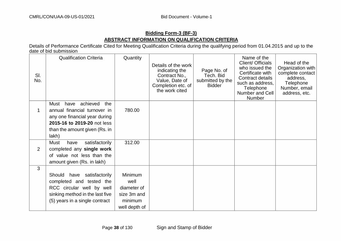
Bidding Form-3 (BF-3)
ABSTRACT INFORMATION ON QUALIFICATION CRITERIA
Details of Performance Certificate Cited for Meeting Qualification Criteria during the qualifying period from 01.04.2015 and up to the date of bid submission
Sl. No.
Qualification Criteria Quantity
Details of the work indicating the Contract No., Value, Date of
Completion etc. of the work cited
Page No. of Tech. Bid
submitted by the Bidder
Name of the Client/ Officials who issued the Certificate with Contract details
such as address, Telephone
Number and Cell Number
Head of the Organization with complete contact
address, Telephone
Number, email address, etc.
1
Must have achieved the
annual financial turnover in
any one financial year during
2015-16 to 2019-20 not less
than the amount given (Rs. in
lakh)
780.00
2
Must have satisfactorily
completed any single work
of value not less than the
amount given (Rs. in lakh)
312.00
3
Should have satisfactorily
completed and tested the
RCC circular well by well
sinking method in the last five
(5) years in a single contract
Minimum
well
diameter of
size 3m and
minimum
well depth of

CMRL/CON/UAA-09-US-01/2021 Bid Document - Volume-1
Page 39 of 130 Sign and Stamp of Bidder
5m
4
Should have supplied, laid,
jointed & tested and
successfully completed DWC
PE/SW pipes in anyone (1)
year of last five (5) years
Minimum
pipe
diameter of
size 150mm
and
minimum
length of
250m
5
Should have supplied, laid,
jointed & tested and
successfully completed the
sewer line of CI/ DI/ RCC/
PSC pipes in anyone (1) year
of last five (5) years
Minimum
pipe
diameter of
size 350mm
and
minimum
length of
600m
I / We declare that the information furnished above are true to our knowledge and we have taken care to furnish the correct details with contact address, available communication facilities such as FAX, email, Telephone numbers, Mobile numbers etc.
Signature of the bidder with Seal
Name and Title of the Signatory

CMRL/CON/UAA-09-US-01/2021 Bid Document - Volume-1
Page 40 of 130 Sign and Stamp of Bidder
Bidding Form-4 (BF-4)
QUALIFICATION INFORMATION
The information to be filled in by the Bidder in the following pages will be used for purposes of pre-qualification as provided for in Clause 4 of the Instructions to Bidders.
1. For Individual Bidders
1.1
Constitution or legal status of Bidder[Attach copy]
Place of registration:
Principal place of business:
Power of attorney of signatory of Bid [Attach]
1.2 Annual financial turnover achieved in the last five years (in Rs.
Crores). (Please refer Sl.No.1 at clause 4.5A of Instructions to Bidders)
Sl.No.
Year
Financial turnover (Rs. in Crores) *
Page No.
of Technical
Bid 1 2015-2016
2 2016-2017
3 2017-2018
4 2018-2019
5 2019-2020
Attach Certificate from Chartered Accountant along with Audited Balance Sheet.
Signature of the bidder with Seal Name & Title of Signatory:
IMPORTANT NOTE

CMRL/CON/UAA-09-US-01/2021 Bid Document - Volume-1
Page 41 of 130 Sign and Stamp of Bidder
Bidders are requested to furnish the above details separately giving reference to the page numbers of the credential enclosed to the Technical Bid.

CMRL/CON/UAA-09-US-01/2021 Bid Document - Volume-1
Page 42 of 130 Sign and Stamp of Bidder
1.3 Works performed by the Bidder in a single Contract during the period from 01.04.2015 and up to the date of bid submission as detailed below:-
(Please refer S. No. 2 at clause 4.5A of Instructions to Bidders (General))
Project Name
Name of the Employer*
Description of work
Agreement / Contract No. and Date
Value of contract (Rs. Lakhs)
Date of issue of work order
Stipulated period of completion
Actual date of completion*
Remarks explaining reasons for delay, if any and work completed
Credentials at Page No. of Tech. Bid
* Enclose certificate(s) from Engineer(s)- in- charge. * The experience of the bidder to the extent of work done as a Sub
contractor in the past and duly certified by the owner of the Project will be considered
Signature of the bidder with Seal Name & Title of Signatory:
IMPORTANT NOTE
Bidders are requested to furnish the Credentials in support of details of Qualification Information furnished above giving reference to the page numbers of the credentials enclosed to the Technical Bid.
The certificates / credentials not mentioned in the above statement will not be considered for evaluation towards satisfying the qualification criteria.

CMRL/CON/UAA-09-US-01/2021 Bid Document - Volume-1
Page 43 of 130 Sign and Stamp of Bidder
1.4 (a) Quantities of similar work executed by the Bidder during the period from 01.04.2015 and up to the date of bid submission (Please refer Sl. No. 3.a, 3.b and 3.c of Clause 4.5A of Instructions to Bidders (General))
For S. No: 3.a:
Year Name of work
Name of Employer*
Quantity of work performed @ Sewer pumping station
works Remarks (Indicate contract Ref.) *
Page No. of Technical Bid
Dia. of wells (m)
Depth of wells (in m)
Nos.
For S. No: 3.b and 3.c:
Year Name of work
Name of Employer*
Quantity of work performed @ pipe laying
Remarks (Indicate contract Ref.) *
Page No. of Technical Bid
Dia. of pipe (mm)
Length of pipe(m)
Type of pipe
@ The item of Work for which data is requested should fully satisfy with that specified in ITB clause 4.5 * Enclose certificate(s) from Engineer(s) - in –charge not below the rank of an Executive Engineer or equivalent. * The experience of the bidder to the extent of work done as a Sub contractor in the past and duly certified by the owner of the Project will be considered.
Signature of the bidder with Seal
Name & Title of Signatory IMPORTANT NOTE Bidders are requested to furnish the Credentials in support of details of Qualification Information furnished above giving reference to the page numbers of the credentials enclosed to the Technical Bid. The certificates / credentials not mentioned in the above statement will not be considered for evaluation towards satisfying the qualification criteria
CMRL/CON/UAA-09-US-01/2021 Bid Document - Volume-1
Page 44 of 130 Sign and Stamp of Bidder
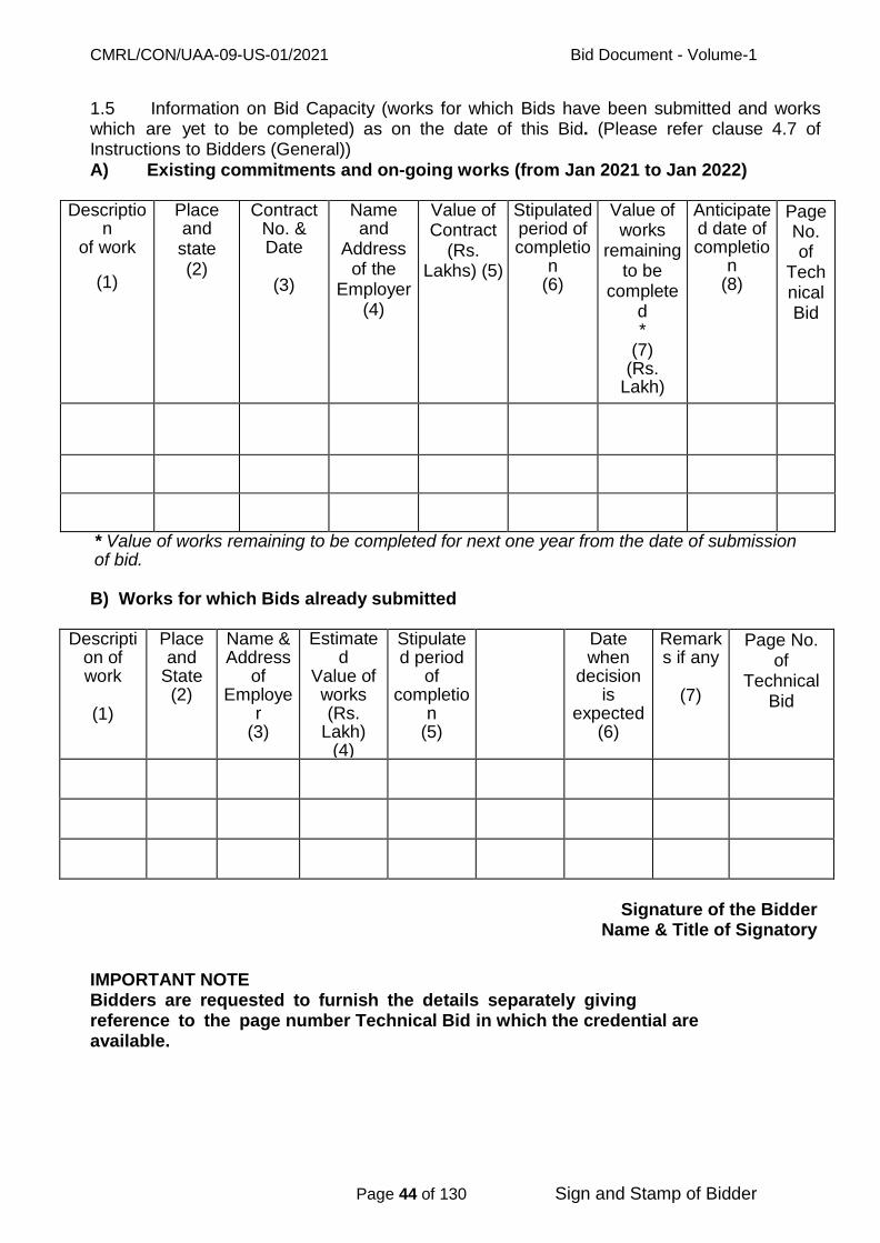
1.5 Information on Bid Capacity (works for which Bids have been submitted and works which are yet to be completed) as on the date of this Bid. (Please refer clause 4.7 of Instructions to Bidders (General)) A) Existing commitments and on-going works (from Jan 2021 to Jan 2022)
Description
of work
(1)
Place and state (2)
Contract No. & Date
(3)
Name and
Address of the
Employer (4)
Value of Contract
(Rs. Lakhs) (5)
Stipulated period of completio
n (6)
Value of works
remaining to be
completed *
(7) (Rs.
Lakh)
Anticipated date of completio
n (8)
Page No. of
Technical Bid
* Value of works remaining to be completed for next one year from the date of submission of bid. B) Works for which Bids already submitted
Description of work
(1)
Place and
State (2)
Name & Address
of Employe
r (3)
Estimated
Value of works (Rs.
Lakh) (4)
Stipulated period
of completio
n (5)
Date when
decision is
expected (6)
Remarks if any
(7)
Page No. of
Technical Bid
Signature of the Bidder Name & Title of Signatory
IMPORTANT NOTE Bidders are requested to furnish the details separately giving reference to the page number Technical Bid in which the credential are available.
CMRL/CON/UAA-09-US-01/2021 Bid Document - Volume-1
Page 45 of 130 Sign and Stamp of Bidder
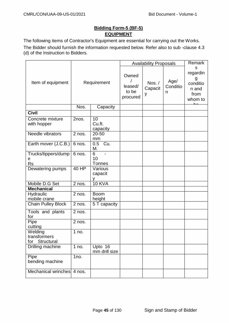
Bidding Form-5 (BF-5)
EQUIPMENT
The following items of Contractor's Equipment are essential for carrying out the Works.
The Bidder should furnish the information requested below. Refer also to sub -clause 4.3 (d) of the Instruction to Bidders.
Item of equipment
Requirement
Availability Proposals Remarks
regarding
condition and from
whom to be
purchase d/ or leased
Owned /
leased/ to be
procured
Nos. / Capacity
Age/
Condition
Nos. Capacity
Civil
Concrete mixture with hopper
2nos. 10 Cu.ft. capacity each
Needle vibrators 2 nos. 20-50 mm needle each
Earth mover (J.C.B.) 6 nos. 0.5 Cu. M. each
Trucks/tippers/dumpe Rs
6 nos. 6 - 10 Tonnes, each
Dewatering pumps 40 HP Various capacity
Mobile D.G Set 2 nos. 10 KVA Mechanical Hydraulic mobile crane
2 nos. Boom height 6 m (20 T)
Chain Pulley Block 2 nos. 5 T capacity
Tools and plants for jointing pipes
2 nos.
Pipe cutting machinery
2 nos.
Welding transformers for Structural Steel work welding.
1 no.
Drilling machine 1 no. Upto 16 mm drill size
Pipe bending machine
1no.
Mechanical wrinches 4 nos.
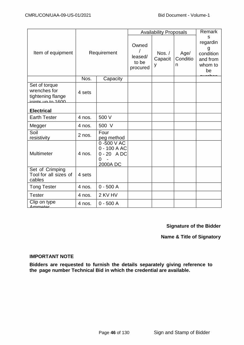
CMRL/CON/UAA-09-US-01/2021 Bid Document - Volume-1
Page 46 of 130 Sign and Stamp of Bidder
Item of equipment
Requirement
Availability Proposals Remarks
regarding
condition and from whom to
be purchase d/ or leased
Owned /
leased/ to be
procured
Nos. / Capacity
Age/ Condition
Nos. Capacity
Set of torque wrenches for tightening flange joints up to 1600 NB
4 sets
Electrical
Earth Tester 4 nos. 500 V
Megger 4 nos. 500 V
Soil resistivity measurement kit
2 nos. Four peg method
Multimeter 4 nos.
0 -500 V AC 0 - 100 A AC 0 - 20 A DC 0 - 2000A DC
Set of Crimping Tool for all sizes of cables (Copper & Aluminum)
4 sets
Tong Tester 4 nos. 0 - 500 A
Tester 4 nos. 2 KV HV
Clip on type Ammeter
4 nos. 0 - 500 A
Signature of the Bidder
Name & Title of Signatory
IMPORTANT NOTE
Bidders are requested to furnish the details separately giving reference to the page number Technical Bid in which the credential are available.

CMRL/CON/UAA-09-US-01/2021 Bid Document - Volume-1
Page 47 of 130 Sign and Stamp of Bidder
Bidding Form-6 (BF-6)
KEY PERSONNEL
The Bidder should furnish the below qualification and experience of key personnel
proposed for administration and execution of the contract. Refer also to sub-clause 4.3
(e) and 4.5 (B) (b) of Instructions to Bidders and sub clause 9.1 of Conditions of
Contract.
S. No Position Nos. Name of Proposed person
Educational Qualifications
Years of experience (general)
Years of experience (similar nature of work)
Key
personne
l
1 Project
Manager
1
2 Engineer /
Civil
1
3 Engineer /
Mechanic
al
1
Total 4
IMPORTANT NOTE Bidders are requested to furnish the details separately giving reference to the page number Technical Bid in which the credential are available.

CMRL/CON/UAA-09-US-01/2021 Bid Document - Volume-1
Page 48 of 130 Sign and Stamp of Bidder
Bidding Form-7 (BF-7)
SUBCONTRACT DETAILS
Proposed subcontracts and firms involved. (Refer ITB Clause 4.3(i))
Sections of the works
Value of subcontract
Subcontractor
(name and address)
Experience in similar work
Signature of the Bidder Name & Title of Signatory
IMPORTANT NOTE Bidders are requested to furnish the details separately giving reference to the page number Technical Bid in which the credential are available.

CMRL/CON/UAA-09-US-01/2021 Bid Document - Volume-1
Page 49 of 130 Sign and Stamp of Bidder
Bidding Form-8 (BF-8)
FINANCIAL REPORTS
Financial reports for the last five years; balance sheets, profit and loss
statements, auditors' reports, (in case of companies/corporations) etc.
List them below and attach copies of documents.
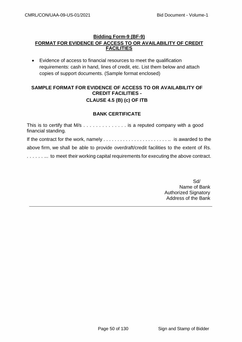
CMRL/CON/UAA-09-US-01/2021 Bid Document - Volume-1
Page 50 of 130 Sign and Stamp of Bidder
Bidding Form-9 (BF-9)
FORMAT FOR EVIDENCE OF ACCESS TO OR AVAILABILITY OF CREDIT FACILITIES
Evidence of access to financial resources to meet the qualification
requirements: cash in hand, lines of credit, etc. List them below and attach
copies of support documents. (Sample format enclosed)
SAMPLE FORMAT FOR EVIDENCE OF ACCESS TO OR AVAILABILITY OF CREDIT FACILITIES -
CLAUSE 4.5 (B) (c) OF ITB
BANK CERTIFICATE This is to certify that M/s . . . . . . . . . . . . . . is a reputed company with a good financial standing.
If the contract for the work, namely . . . . . . . . . . . . . . . . . . . . . . . .. is awarded to the
above firm, we shall be able to provide overdraft/credit facilities to the extent of Rs.
. . . . . . ... to meet their working capital requirements for executing the above contract.
Sd/ Name of Bank
Authorized Signatory Address of the Bank

CMRL/CON/UAA-09-US-01/2021 Bid Document - Volume-1
Page 51 of 130 Sign and Stamp of Bidder
Bidding Form-10 (BF-10) LITIGATION HISTORY
Information on litigation history in which the Bidder is involved. Otherwise
mention as ‘Not applicable’
Other Party (ies)
Employer Cause of Dispute
Amount Involved
Remarks showing
present status
IMPORTANT NOTE
Bidders are requested to furnish the INFORMATION ON LITIGATION HISTORY IN WHICH THE BIDDER INVOLVED in the format prescribed separately along with full signature and Seal.

CMRL/CON/UAA-09-US-01/2021 Bid Document - Volume-1
Page 52 of 130 Sign and Stamp of Bidder
Bidding Form-11 (BF-11) WORK METHODOLOGY AND SCHEDULE
Proposed work method and schedule. (Refer ITB Clause 4.1 and 4.3(j)).

CMRL/CON/UAA-09-US-01/2021 Bid Document - Volume-1
Page 53 of 130 Sign and Stamp of Bidder
Bidding Form-12 (BF-12)
DETAILS OF PARTICIPATION IN THE CONSORTIUM CONSORTIUMS:
The information listed in bidding forms 4 to 10 (BF-4 to BF-10) above shall be provided for each partner of the consortiums.
The information for bidding forms 1, 2, 3 and 11(BF-1, BF-2, BF-3 and BF-11) above shall be provided for Consortium.
Attach the power of attorney of the signatory(ies) of the bid authorizing signature of the bid on behalf of the consortium.
Attach the consortium agreement or letter of intent among all partners of the consortium (and which is legally binding on all partners) which shows the requirements as indicated in sub-clause 4.4 of the instruction to bidders.
Furnish details of participation in the consortium as below. DETAILS OF PARTICIPATION IN THE CONSORTIUM:
PARTICIPATION
DETAILS FIRM ‘A’
(Lead Partner)
FIRM ‘B’ FIRM ‘C’
Address of JV/Consortium Partner:
% of participation in JV/Consortium
Key Responsibility as per agreement /LOI
IMPORTANT NOTE
Bidders are requested to furnish the DETAILS OF PARTICIPATION IN THE CONSORTIUM in the format prescribed separately along with full signature and Seal.
CMRL/CON/UAA-09-US-01/2021 Bid Document - Volume-1
Page 54 of 130 Sign and Stamp of Bidder
Bidding Form-13 (BF-13)
ADDITIONAL REQUIREMENTS
ADDITIONAL REQUIREMENTS:
Bidders should provide any additional information required to fulfill the requirements of clause 4 of the Instruction to Bidders, if applicable.
CMRL/CON/UAA-09-US-01/2021 Bid Document - Volume-1
Page 55 of 130 Sign and Stamp of Bidder
CONTRACT DATA
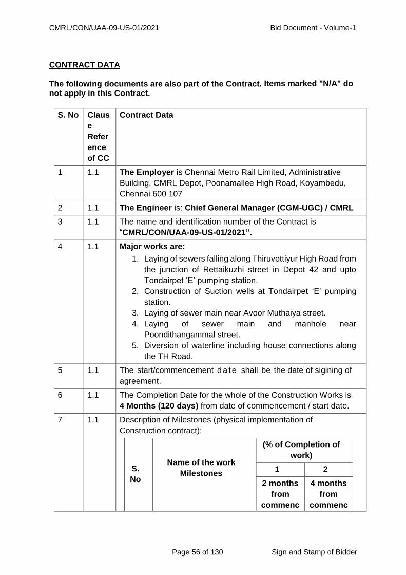
CMRL/CON/UAA-09-US-01/2021 Bid Document - Volume-1
Page 56 of 130 Sign and Stamp of Bidder
CONTRACT DATA
The following documents are also part of the Contract. Items marked "N/A" do
not apply in this Contract.
S. No Claus
e
Refer
ence
of CC
Contract Data
1 1.1 The Employer is Chennai Metro Rail Limited, Administrative
Building, CMRL Depot, Poonamallee High Road, Koyambedu,
Chennai 600 107
2 1.1 The Engineer is: Chief General Manager (CGM-UGC) / CMRL
3 1.1 The name and identification number of the Contract is
“CMRL/CON/UAA-09-US-01/2021”.
4 1.1 Major works are:
1. Laying of sewers falling along Thiruvottiyur High Road from
the junction of Rettaikuzhi street in Depot 42 and upto
Tondairpet ‘E’ pumping station.
2. Construction of Suction wells at Tondairpet ‘E’ pumping
station.
3. Laying of sewer main near Avoor Muthaiya street.
4. Laying of sewer main and manhole near
Poondithangammal street.
5. Diversion of waterline including house connections along
the TH Road.
5 1.1 The start/commencement d a te shall be the date of sigining of
agreement.
6 1.1 The Completion Date for the whole of the Construction Works is
4 Months (120 days) from date of commencement / start date.
7 1.1 Description of Milestones (physical implementation of
Construction contract):
S.
No
Name of the work
Milestones
(% of Completion of
work)
1 2
2 months
from
commenc
4 months
from
commenc
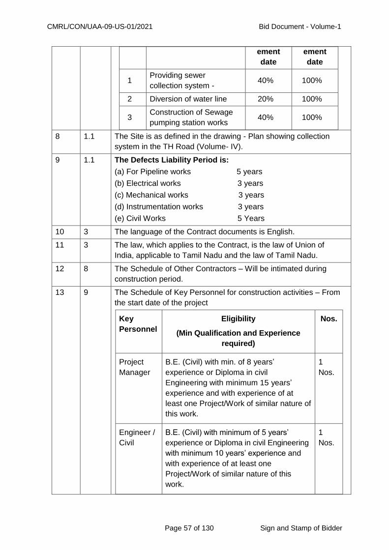
CMRL/CON/UAA-09-US-01/2021 Bid Document - Volume-1
Page 57 of 130 Sign and Stamp of Bidder
ement
date
ement
date
1 Providing sewer
collection system - 40% 100%
2 Diversion of water line 20% 100%
3 Construction of Sewage
pumping station works 40% 100%
8 1.1 The Site is as defined in the drawing - Plan showing collection
system in the TH Road (Volume- IV).
9 1.1 The Defects Liability Period is:
(a) For Pipeline works 5 years
(b) Electrical works 3 years
(c) Mechanical works 3 years
(d) Instrumentation works 3 years
(e) Civil Works 5 Years
10 3 The language of the Contract documents is English.
11 3 The law, which applies to the Contract, is the law of Union of
India, applicable to Tamil Nadu and the law of Tamil Nadu.
12 8 The Schedule of Other Contractors – Will be intimated during
construction period.
13 9 The Schedule of Key Personnel for construction activities – From
the start date of the project
Key
Personnel
Eligibility
(Min Qualification and Experience
required)
Nos.
Project
Manager
B.E. (Civil) with min. of 8 years’
experience or Diploma in civil
Engineering with minimum 15 years’
experience and with experience of at
least one Project/Work of similar nature of
this work.
1
Nos.
Engineer /
Civil
B.E. (Civil) with minimum of 5 years’
experience or Diploma in civil Engineering
with minimum 10 years’ experience and
with experience of at least one
Project/Work of similar nature of this
work.
1
Nos.

CMRL/CON/UAA-09-US-01/2021 Bid Document - Volume-1
Page 58 of 130 Sign and Stamp of Bidder
Engineer /
Mechanica
l
B.E. (Mechanical) with minimum of 5
years’ experience or Diploma in
Mechanical Engineering with minimum 10
years’ experience and with experience of
at least one Project/Work of similar nature
of this work.
1
Nos.
14 9.3 Penalty for not employing Project Manager and other Key
Personnel till the date of employment of the personnel
Project Manager Rs.50, 000/month
Other Key Personnel Rs.25, 000/month /
each
15 13 The minimum insurance cover for loss of or damage to the works,
plants, materials, equipment’s, physical property in connection
with contract, personal injury or death is 2% of contract value for
occurrence without any limit for occurrence. After each
occurrence, contractor will pay additional premium necessary to
make insurance valid for four occurrences always. CAR policy
shall be taken for the amount equal to contract value and to
be submitted within 10 days of issue of LOA
16 14 Not applicable
17 21 The Site possession date shall be within 21 days from the LOA
with the works.
18 27 The Contractor shall submit a program for the works within 15
days of date of Letter of Acceptance.
19 27 The period between Program updates shall be 30 days.
20 43.4 PAYMENT:
All payments will be subjected to deduction of retention money and
the deduction at service as per applicable Laws of India as stated
in Clause 48 of Conditions of Contract.

CMRL/CON/UAA-09-US-01/2021 Bid Document - Volume-1
Page 59 of 130 Sign and Stamp of Bidder
The payment terms shall be as follows:
1. PAYMENT TOWARDS PIPE LAYING WORKS (BOQ
Schedules 1,8 &11):
95% of the value on completion of individual line items and balance
5% will be released after satisfactory commissioning.
2. PAYMENT FOR OTHER ITEM:
Payment for all other items will be made as defined in the bill of
quantities as per the actual at the quoted rates.
21 44 The following events shall also be Compensation Events:
Nil
22 46 The currency of the Contract is Indian Rupees.
23 47 Price adjustment is NOT applicable for this contract.
24 48 The proportion of payments retained (retention money) shall be
2.5% from each bill subject to a maximum of 2.5% of contract
value and 1.25% of retention amount will be returned along with
the final Bill. The balance amount of 1.25 % of the retention money
will be retained for a period of 2 years reckoned from the date of
completion without interest and this amount will be paid to the
Contractor after obtaining an irrevocable Bank Guarantee from
Public Sector bank.
25 49 The liquidated damage for the whole of the work is Rs. 32290/-
per day and that, for the milestone are as under:
For milestone 1 Rs. 16145.00 per day
For milestone 2 Rs. 16145.00 per day
The maximum amount of liquidated damages for the whole of the
Works is 10% (ten percent) of final contract price.
26 51 The amounts of the advance payment are:
Nature of
Advance
Amount
(Rs.)
Conditions to be fulfilled
Mobilization up to a
maximum
10% of the
Contract
value.
On submission of irrevocable
Bank Guarantee from Public
Sector Bank and amount equal to
110% of advance amount.
27 51 Repayment of advance payment for mobilisation and
equipment:
The mobilisation advance shall be repaid with an interest of
SBI PLR +2% per annum with percentage deductions from the

CMRL/CON/UAA-09-US-01/2021 Bid Document - Volume-1
Page 60 of 130 Sign and Stamp of Bidder
interim payments certified by the Engineer under the Contract.
Deductions shall commence in the next Interim Payment Certificate
following that in which the total of all such payments to the
Contractor has reached not less than 15 percent of the Contract
Price or 1 month from the date of payment of first installment of
advance, whichever period concludes earlier, and shall be made at
the rate of 25 percent of the amounts of all Interim Payment
Certificates until such time as the mobilization advance has been
repaid, always provided that the mobilization advance shall be
completely repaid prior to the expiry of the original time for
completion pursuant to Clauses 17 and 28.
28 52 The Performance Security (including additional security for
unbalanced bids) shall be provided to the Employer not later
than 14 days of receipt of the Letter of Acceptance.
Performance Security to be calculated as per Clause 34.4 of
ITB plus an additional security in terms of ITB Clause 29.5.
The standard form of Performance Security acceptable to
the Employer shall be as presented in clause 34.1
Instructions to Bidders.
29 58 “As Built drawings and/ or O&M Manuals” shall be submitted within
28 days of issue of certificate of completion.
The date by which ―As-Built drawings (in appropriate scale) in 5
sets and also in digitized form are required is within 28 days of issue
of certificate of completion of whole or section of the work, as the
case may be.
The amount to be withheld for failing to supply ―As Built
drawings and O&M Manuals by the date required is
Rs.500000/-.
30 59.2 Following events shall also be fundamental breach of contract
1. The Contractor has contravened Sub-clause 7.1 and Clause 9.0
of Conditions of Contract.
31 60 The percentage to apply to the value of the work not completed
representing the Employer's additional cost for completing the
Works shall be 20 percent or as per actual whichever is higher.

CMRL/CON/UAA-09-US-01/2021 Bid Document - Volume-1
Page 61 of 130 Sign and Stamp of Bidder
CONDITIONS OF CONTRACT

CMRL/CON/UAA-09-US-01/2021 Bid Document - Volume-1
Page 62 of 130 Sign and Stamp of Bidder
Conditions of Contract
Table of Contents
S. No
Clause Page No
S. No Clause Page No
A. General C. Quality Control
1 Definitions 64 33 Identifying Defects 73
2 Interpretation 66 34 Tests 73
3 Language and Law 66 35 Correction of Defects 74
4 Engineer‘s Decisions 66 36 Uncorrected Defects 74
5 Delegation 67 D. Cost Control
6 Communications 67 37 Bill of Quantities 74
7 Subcontracting 67 38 Changes in the Quantities
75
8 Other Contractors 67 39 Variations 75
9 Personnel 67 40 Payments for Variations 75
10 Employer‘ & Contractors‘ Risks
68 41 Cash Flow forecasts 75
11 Employers‘ Risks 68 42 Payment Certificates 75
12 Contractors‘ Risks 68 43 Payments 77
13 Insurance 68 44 Deleted 77
14 Site Investigation Reports
69 45 Tax 77
15 Queries about the Contract Data
69 46 Currencies 77
16 Contractor to Construct the Works
69 47 Price Adjustments 77
17
The works to be completed by the Intended Completion Date
70 48 Retention 78
18 Approval by the Engineer
70 49 Liquidated Damages 78
19 Safety 70 50 Bonus 78
20 Discoveries 70 51 Advance Payment 78
21 Possession of the Site 71 52 Securities 79
22 Access to site 71 53 Deleted 79
23 Instructions 71 54 Cost of Repairs 79
24 Disputes 71 E. Finishing the Contract
B. Time Control 55 Completion 80
25 Deleted 56 Taking Over 80
26 Deleted 57 Final Account 80
27 Program 71 58 As Built Drawings /O&M Manuals
80
28 Extension of the Intended Completion Date
72 59 Termination 81
29 Deleted 60 Payment upon 82

CMRL/CON/UAA-09-US-01/2021 Bid Document - Volume-1
Page 63 of 130 Sign and Stamp of Bidder
Termination
30 Delays Ordered by the Engineer
72 61 Property 82
31 Management Meetings 72 62 Release from Performance
82
32 Notice 73 F. Special Conditions of Contract
83

CMRL/CON/UAA-09-US-01/2021 Bid Document - Volume-1
Page 64 of 130 Sign and Stamp of Bidder
Conditions of Contract
A. General
1. Definitions
1.1. Terms, which are defined in the Contract Data, and not also defined in the
Conditions of Contract but keep their defined meanings. Capital initials are used
to identify defined terms.
Bill of Quantities means the priced and completed Bill of Quantities to be
submitted by the Bidder.
The Completion Date is the date of completion of the Works as certified by the
Engineer in accordance with Sub Clause 55.1.
The Contract is the contract between the Employer and the Contractor to
execute, complete and maintain the Works. It consists of the documents listed in
Clause 2.3 below.
The Contract Data defines the documents and other information, which
comprise the Contract.
The Contractor is a person or corporate body whose Bid to carry out the Works
has been accepted by the Employer.
The Contractor's Bid is the completed Bidding document submitted by the
Contractor to the Employer.
The Contract Price is the price stated in the Letter of Acceptance (excluding
GST) and thereafter as adjusted in accordance with the provisions of the
Contract.
Days are calendar days; months are calendar months.
A Defect is any part of the Works not completed in accordance with the Contract.
The Defects Liability Period is the period named in the Contract Data and calculated from the Completion Date.
The Employer is the party who will employ the Contractor to carry out the Works.
The Engineer is the person named in the Contract Data (or any other competent person appointed and notified to the contractor to act in replacement of the

CMRL/CON/UAA-09-US-01/2021 Bid Document - Volume-1
Page 65 of 130 Sign and Stamp of Bidder
Engineer) who is responsible for supervising the Contractor, administering the Contract, certifying payments due to the Contractor, issuing and valuing Variations to the Contract, awarding extensions of time and valuing the Compensation Events.
Equipment is the Contractor's machinery and vehicles brought temporarily to the Site to construct the Works.
The Initial Contract Price is the Contract Price listed in the Employer's Letter of
Acceptance.
The Intended Completion Date is the date on which it is intended that the Contractor shall complete the Works. The Intended Completion Date is specified in the Contract Data. The Intended Completion Date may be revised only by the Engineer by issuing an extension of time.
Materials are all supplies, including consumables, used by the contractor for incorporation in the Works.
Plant is any integral part of the Works, which is to have a mechanical, electrical, electronic, or chemical or biological function.
The Site is the area defined as such in the Contract Data.
Site Investigation Reports are those, which were included in the Bidding documents and are factual interpretative reports about the surface and sub-surface conditions at the site.
Specification means the Specification of the Works to be submitted by the Bidder and any modification or addition made or approved by the Engineer.
The Start Date is given in the Contract Data. It is the date when the Contractor shall commence execution of the works. It does not necessarily coincide with any of the Site Possession Dates.
A Subcontractor is a person or corporate body who has a Contract with the Contractor to carry out a part of the work in the Contract, which includes work on the Site.
Temporary Works are works designed, constructed, installed, and removed by the
Contractor, which are needed for construction or installation of the Works.
A Variation is an instruction given by the Engineer, which varies the Works.
The Works are what the Contract requires the Contractor to construct, install, and turn over to the Employer, as defined in the Contract Data.

CMRL/CON/UAA-09-US-01/2021 Bid Document - Volume-1
Page 66 of 130 Sign and Stamp of Bidder
2. Interpretation
2.1. In interpreting these Conditions of Contract, singular also means plural, male
also means female or neuter, and the other way around. Headings have no
significance. Words have their normal meaning under the language of the
Contract unless specifically defined. The Engineer will provide instructions
clarifying queries about the Conditions of Contract.
2.2. If sectional completion is specified in the Contract Data, references in the
Conditions of Contract to the Works, the Completion Date, and the Intended
Completion Date apply to any Section of the Works (other than references to the
Completion Date and Intended Completion date for the whole of the Works).
2.3. The documents forming the Contract shall be interpreted in the following order of
priority:
(1) Agreement
(2) Letter of Acceptance
(3) Technical Bid and Financial Bid
(4) Contract Data
(5) Conditions of Contract (General and Special)
(6) Specifications (General and Special)
(7) Bill of Quantities
(8) Drawings and
(9) Any other document listed in the Contract Data and replies to
queries, clarifications issued by the employer, such confirmations given by the
bidder which are acceptable to the employer and all the Addendum issued as
forming part of the contract.
(10) Instructions to bidders
(11) Safety and Preventive measures and digest of Labour Laws as per CMRL
and CMWSSB norms
3. Language and Law
3.1. The language of the Contract and the law governing the Contract are stated in
the Contract Data.
4. Engineer's Decisions
CMRL/CON/UAA-09-US-01/2021 Bid Document - Volume-1
Page 67 of 130 Sign and Stamp of Bidder
4.1. Except where otherwise specifically stated the Engineer will decide contractual
matters between the Employer and the Contractor in the role representing the
Employer.
5. Delegation
5.1. The Engineer may delegate any of his duties and responsibilities to other people
after notifying the Contractor and may cancel any delegation after notifying the
Contractor.
6. Communications
6.1. Communications between parties which are referred to in the conditions are
effective only when in writing. A notice shall be effective only when it is delivered
(in terms of Indian Contract Act).
7. Subcontracting
7.1. The Contractor may subcontract with the approval of the Engineer but shall not
assign the Contract without the approval of the Employer in writing.
Subcontracting does not alter the Contractor's obligations.
8. Other Contractors
8.1. The Contractor shall cooperate and share the Site with other contractors,
public authorities, utilities, and the Employer between the dates given in the
Schedule of Other Contractors. The Contractor shall as referred to in the Contract
Data, also provide facilities and services for them as described in the Schedule.
The Employer may modify the schedule of other Contractors and shall notify the
Contractor of any such modification.
9. Personnel
9.1. The Contractor shall employ the key personnel named in the Schedule of Key
Personnel as referred to in the Contract Data to carry out the functions stated in
the Schedule or other personnel approved by the Engineer. The Engineer will
approve any proposed replacement of key personnel only if their qualifications,
abilities, and relevant experience are substantially equal to or better than those
of the personnel listed in the Schedule.

CMRL/CON/UAA-09-US-01/2021 Bid Document - Volume-1
Page 68 of 130 Sign and Stamp of Bidder
9.2. If the Engineer asks the Contractor to remove a person who is a member
of the Contractor‘s staff or his work force stating the reasons the Contractor shall
ensure that the person leaves the Site within seven days and has no further
connection with the work in the Contract.
9.3. Non-employment of Project Manager and other Key Personnel shall be liable for
a fine as specified in Contract Data.
10. Employer’s and Contractor's Risks
10.1. The Employer carries the risks which this Contract states are Employer‘s risks,
and the Contractor carries the risks which this Contract states are Contractor‘s
risks.
11. Employer's Risks
11.1. The Employer is responsible for the excepted risks which are (a) in so far as they
directly affect the execution of the Works in the Employer‘s country, the risks of
war, hostilities, invasion, act of foreign enemies, rebellion, revolution,
insurrection or military or usurped power, civil war, riot commotion or disorder
(unless restricted to the Contractor‘s employees), and contamination from any
nuclear fuel or nuclear waste or radioactive toxic explosive, or (b) a cause due
solely to the design of the Works, other than the Contractor‘s design.
12. Contractor’s Risks
12.1. All risks of loss of or damage to physical property and of personal injury and
death, which arise during and in consequence of the performance of the Contract
other than the excepted risks, are the responsibilities of the Contractor.
13. Insurance
13.1. The Contractor shall provide, in the joint names of the Employer and the
Contractor, insurance cover from the Start Date to the end of the Defects Liability
Period, in the amounts and deductibles stated in the Contract Data for the
following events which are due to the Contractor‘s risks:
(a) Loss of or damage to the Works, Plant and Materials;
(b) Loss of or damage to Equipment;
(c) Loss of or damage of property (except the Works, Plant, Materials and Equipment) in connection with the Contract; and
(d) Personal injury or death.
CMRL/CON/UAA-09-US-01/2021 Bid Document - Volume-1
Page 69 of 130 Sign and Stamp of Bidder
Insurance policies are to be submitted to CMRL within 10 days of issue of LOA.
13.2. Policies and certificates for insurance shall be delivered by the Contractor
to the Engineer for the Engineer‘s approval before the Start Date. All such
insurance shall provide for compensation to be payable in the types and
proportions of currencies required to rectify the loss or damage incurred.
13.3. If the Contractor does not provide any of the policies and certificates required,
the Employer may effect the insurance which the Contractor should have
provided and recover the premiums the Employer has paid from payments
otherwise due to the Contractor or, if no payment is due, the payment of the
premiums shall be a debt due.
13.4. Alterations to the terms of insurance shall not be made without the approval of
the Engineer.
13.5. Both parties shall comply with any conditions of the insurance policies.
14. Site Investigation Reports
14.1. The Contractor, in preparing the Bid, shall rely on any site Investigation
Reports referred to in the Contract Data, supplemented by any information
available to the Bidder.
15. Queries about the Contract Data
15.1. The Engineer will clarify queries on the Contract Data.
16. Contractor to Construct the Works
16.1. The Contractor shall design (if applicable), construct and install the Works
in accordance with the Specification and Drawings.
16.2. The basic centerlines, reference points and benchmarks will be fixed by
Employer.
16.3. The Contractor shall establish at his cost, at suitable points, additional reference
lines, benchmarks as may be necessary. The Contractor shall remain
responsible for the sufficiency and accuracy of all his benchmarks and reference
lines. He shall take precautions to see that the lines, points and benchmarks fixed
by Employer are not disturbed by his work and shall make good any such
damage.

CMRL/CON/UAA-09-US-01/2021 Bid Document - Volume-1
Page 70 of 130 Sign and Stamp of Bidder
17. The Works to Be Completed by the Intended Completion Date
17.1. The Contractor may commence execution of the Works on the Start Date and
shall carry out the Works in accordance with the program submitted by the
Contractor, as updated with the approval of the Engineer, and complete them by
the Intended Completion Date.
18. Approval by the Engineer
18.1. The Contractor shall submit Specifications and Drawings showing the proposed
Temporary Works to the Engineer, who is to approve them if they comply with
the Specifications and Drawings.
18.2. The Contractor shall be responsible for design of Temporary Works.
18.3. The Engineer's approval shall not alter the Contractor's responsibility for design
of the Temporary Works.
18.4. The Contractor shall obtain approval of third parties to the design of the
Temporary Works where required.
18.5. All Drawings prepared by the Contractor for the execution of the temporary
or permanent Works, are subject to prior approval by the Engineer before their
use.
18.6. The contractor shall “Request For Inspection (RFI)” by the Engineer as per the
format agreed by the Engineer. Such request along with the quantity of works
should also include all necessary information required for inspection. Any
comments given by the Engineer has to be promptly complied by the contractor
for the final approval of works.
19. Safety
19.1. The Contractor shall be responsible for the safety of all activities on the Site. In
addition to above, Safety provisions against Covid-19 Virus in view of Public
Safety shall be strictly followed.
20. Discoveries
20.1. Anything of historical or other interest or of significant value unexpectedly
discovered on the Site is the property of the Employer. The Contractor is to notify
CMRL/CON/UAA-09-US-01/2021 Bid Document - Volume-1
Page 71 of 130 Sign and Stamp of Bidder
the Engineer of such discoveries and carry out the Engineer's instructions for
dealing with them.
21. Possession of the Site
21.1. The Employer will give possession of all parts of the Site to the Contractor.
However, if possession of a part is not given by the date stated in the Contract
Data it cannot be taken as a reason for delay in start of the relevant activities and
it will not be considered a Compensation Event.
22. Access to the Site
22.1. The Contractor shall allow the Engineer and any person authorized by the
Engineer access to the Site, to any place where work in connection with the
Contract is being carried out or is intended to be carried out and to any place
where materials or plant are being manufactured / fabricated / assembled for the
works.
23. Instructions
23.1. The Contractor shall carry out all instructions of the Engineer, which comply with
the applicable laws where the Site is located.
23.2. The contractor shall permit the employer to inspect the Contractors accounts
and records relating to the performance of the Contractor and to have them
audited by auditors appointed by the employer if so required by the employer
24. Disputes
24.1. All legal disputes are subject to the jurisdiction of Courts at Chennai Only.
B. Time Control
25. Deleted 26. Deleted
27. Program
27.1. Within the time stated in the Contract Data the Contractor shall submit to the
Engineer for approval a Program showing the general methods, arrangements,
order, and timing for all the activities in the Works along with monthly cash flow
forecast.
CMRL/CON/UAA-09-US-01/2021 Bid Document - Volume-1
Page 72 of 130 Sign and Stamp of Bidder
27.2. An update of the Program shall be a program showing the actual progress
achieved on each activity and the effect of the progress achieved on the timing
of the remaining work including any changes to the sequence of the activities.
27.3. The Contractor shall submit to the Engineer, for approval, an updated Program
at intervals no longer than the period stated in the Contract Data.
27.4. The Engineer's approval of the Program shall not alter the Contractor's
obligations. The Contractor may revise the Program and submit it to the Engineer
again at any time. A revised Program is to show the effect of Variations.
28. Extension of the Intended Completion Date
28.1. The Engineer shall extend the Intended Completion Date if a Variation is issued
which makes it impossible for Completion to be achieved by the Intended
Completion Date without the Contractor taking steps to accelerate the remaining
work.
28.2. The Engineer shall decide whether and by how much to extend the Intended
Completion Date within 21 days of the Contractor asking the Engineer for a
decision upon the effect of a Variation and submitting full supporting information.
If the Contractor has failed to give early warning of a delay or has failed to
cooperate in dealing with a delay, the delay by this failure shall not be considered
in assessing the new Intended Completion Date.
28.3. For any events if the contractor intends to claim extension for the intended
completion date, the contractor has to submit his request within 10 days of
encountering such events along with necessary documentary evidence. The
Engineer shall decide upon the contractor’s request if the events claimed are
beyond the reasons attributable to the contractor.
29. Deleted
30. Delays Ordered by the Engineer
30.1. The Engineer may instruct the Contractor to delay the start or progress of any
activity within the Works.
31. Management Meetings
31.1. Either the Engineer or the Contractor may require the other to attend a
management meeting. The business of a management meeting shall be to

CMRL/CON/UAA-09-US-01/2021 Bid Document - Volume-1
Page 73 of 130 Sign and Stamp of Bidder
review the plans for remaining work and to deal with matters raised in
accordance with the early warning procedure.
31.2. The Engineer shall record the business of management meetings and is to
provide copies of his record to those attending the meeting and to the Employer.
The responsibility of the parties for actions to be taken is to be decided by the
Engineer either at the management meeting or after the management meeting
and stated in writing to all who attended the meeting.
32. Notice
32.1. The Contractor is advised to give in writing that the Engineer at the earliest
opportunity of specific likely future events or circumstances that may adversely
affect the quality of the work increase the Contract Price or delay in the execution
of works. The Engineer may require the Contractor to provide an estimate of the
expected effect of the future event or circumstance on the Contract Price and
Completion Date. The estimate is to be provided by the Contractor as soon as
reasonably possible.
32.2. The Contractor shall cooperate with the Engineer in making and considering
proposals for how the effect of such an event or circumstance can be avoided or
reduced by anyone involved in the work and in carrying out any resulting
instruction of the Engineer.
C. Quality Control
33. Identifying Defects
33.1. The Engineer shall check the Contractor's work and notify the Contractor
of any Defects that are found. Such checking shall not affect the Contractor's
responsibilities. The Engineer may instruct the Contractor to search for a Defect
and to uncover and test any work that the Engineer considers may have a Defect
34. Tests
34.1. If the Engineer instructs the Contractor to carry out a test not specified in
the Specification to check whether any work has a Defect and the test shows that
it does, the Contractor shall pay for the test and any samples.
34.2. All pipes, specials, electrical and mechanical items shall be subjected to Third
Party inspection at the cost of contactor and Engineer or Engineer’s
representative shall witness the same. The Contractor shall provide all necessary
CMRL/CON/UAA-09-US-01/2021 Bid Document - Volume-1
Page 74 of 130 Sign and Stamp of Bidder
details such as manufacturer‘s/supplier‘s address and location of the
manufacturing site well in advance to the Employer for such purpose.
34.3. The contractor is responsible for ready availability of materials at the
manufacturer‘s /supplier‘s address and location of the manufacturing site.
34.4. All pipes, specials, electrical and mechanical items shall be subjected to Third
Party inspection. If the materials are found inferior or defective and rejected by
the TPIA then the TPIA shall inspect again based on the inspection call of the
contractor. If the materials are again rejected due to inferior quality / defects the
inspection fee for third and subsequent inspection shall be recovered from the
contractor‘s bill at the rate at which TPIA was given work order on the value of
material (Ex-factory) that are rejected subject to a minimum of Rs 5000/- for
inspection within Tamilnadu and Rs.15,000/- outside Tamilnadu.
35. Correction of Defects
35.1. The Engineer shall give notice to the Contractor of any Defects before the end of
the Defects Liability Period, which begins at Completion and is defined in the
Contract Data. The Defects Liability Period shall be extended for as long as
Defects remain to be corrected.
35.2. Every time, notice of a Defect is given, the Contractor shall correct the notified
Defect
within the length of time specified by the Engineer‘s notice.
36. Uncorrected Defects
36.1. If the Contractor has not corrected a Defect within the time specified in the
Engineer‘s notice, the Engineer will correct the defect, assess the cost of
having the Defect corrected and the Contractor will pay this amount.
D. Cost Control
37. Bill of Quantities
37.1. The Bill of Quantities shall contain items for “Tender No: CMRL/CON/UAA-09-
US-01/2021 – “Laying of sewer line, diversion of water supply line, house
connection works, testing, commissioning and other associated works along TH
Road near Tondiarpet Metro station from Rettaikuzhi street junction to
Tondiarpet ‘E’ pumping station” to be done by the contractor.

CMRL/CON/UAA-09-US-01/2021 Bid Document - Volume-1
Page 75 of 130 Sign and Stamp of Bidder
38. Changes in the Quantities
38.1. If the final quantity of the work done, differs from the quantity in the Bill of
Quantities for the particular item the payment will be made as per actual quantity
executed.
38.2. The Engineer shall not adjust rates from changes in quantities if thereby the Initial
Contract Price is exceeded by more than 10 percent, except with the Prior
approval of the Employer.
38.3. If requested by the Engineer, the Contractor shall provide the Engineer with a
detailed cost breakdown of any rate in the Bill of Quantities.
39. Variations
39.1. All Variations shall be included in updated Programs produced by the Contractor.
40. Payments for Variations
40.1. The Contractor shall provide the Engineer with a quotation and detailed
cost breakup with supplier documents for carrying out the Variation when
requested to do so by the Engineer. The Engineer shall assess the quotation,
which shall be given within seven days of the request or within any longer period
stated by the Engineer and before the Variation is ordered.
40.2. DELETED
40.3. DELETED
40.4. DELETED.
40.5. The Contractor shall not be entitled to additional payment for costs, which could
have been avoided by giving early warning.
41. Cash flow forecasts
41.1. When the Program is updated, the contractor is to provide the Engineer with an
updated cash flow forecast.
42. Payment Certificates
42.1. The Contractor shall submit to the Engineer monthly statements of the estimated
value of the work completed less the cumulative amount certified previously.
CMRL/CON/UAA-09-US-01/2021 Bid Document - Volume-1
Page 76 of 130 Sign and Stamp of Bidder
42.2. Payments will be made to the Contractor under the certificates to be issued
at reasonably frequent intervals by the Engineer. Based on the certificate of the
Engineer, an intermediate payment will be made by the Engineer of a sum equal
to 97.5 percent of the value of work subject to the conditions deducting all dues
towards recovery of advances, interests, fines etc., as per terms of contract and
for the cost of materials, if issued, at the term stipulated in the agreement. The
balance of 2.5 percent will be withheld as Retention Money and retained as a
security for the due fulfillment of the contract. Under the certificate to be issued
by the Engineer on the completion of the entire works, the Contractor will receive
the final payment of all the moneys due or payable to him under or by virtue of
the Contract except performance security and a sum equal to 1.25% of the total
value of the work done provided there is no recovery or forfeiture. No certificate
of the Engineer shall be considered conclusive evidence as to the sufficiency of
any work or materials or correctness of measurements to which it relates, nor
shall it relieve the Contractor from his liability to make good defects as provided
by the contract. The Contractor when applying for a certificate shall prepare a
sufficiently detailed bill based on the original figures or quantities and rates in the
Bill of Quantities to the satisfaction of the Engineer to check the claim and
issue the certificate. The certificates as such of the claims mentioned in the
application as are allowed by the Engineer shall be issued within fourteen days
of the applications. No application for a certificate shall be made within 21
days of a previous application.
42.3. The Engineer shall determine the value of work executed.
42.4. The value of work executed shall comprise the value of the quantities of the items
in the Bill of Quantities completed.
42.5. The value of work executed shall include the valuation of Variation.
42.6. The Engineer may exclude any item certified in a previous certificate or reduce
the proportion of any item previously certified in any certificate in the light of later
information.
42.7. If for any reason, the Contractor or his authorised agent is not available and/or
the work is suspended by Employer, recording of measurements will be done
by Employer without the presence of the Contractor or his authorised
representatives and the Employer shall not entertain any claim from the
Contractor for any loss on this account. If the Contractor or his authorised agent
or representative does not remain present at the time of such measurements,
after the Contractor has been given a three day notice in writing, such
measurements may be taken in his absence and shall be deemed to be accepted

CMRL/CON/UAA-09-US-01/2021 Bid Document - Volume-1
Page 77 of 130 Sign and Stamp of Bidder
by the Contractor.
42.8. Payment for the work done by the Contractor will be based on measurements recorded at various stages of the Work. The Contractor or his authorised agent, or representative shall be present at the time of recording of each set of measurements to be annexed with “RFI”
43. Payments
43.1. 80% of the amount certified by the Engineer shall be paid within 7 days of date
of certification and the balance shall be paid after due scrutiny.
43.2. Payments shall be adjusted for deductions for advance payments, retention and
other recoveries in terms of the contract and deduction at source of taxes as
applicable under the law. The Employer shall pay the Contractor the amounts
certified by the Engineer.
43.3. DELETED.
43.4. Items of the Works for which no rate or price has been entered in the contract,
will not be paid for by the Employer and shall be deemed to have covered by
other rates and prices in the Contract.
43.5. Payment will be made by the Employer as indicated in the Contract Data.
44. DELETED
45. Tax
45.1. The Employer will deduct such taxes and other statutory levies at source as per
applicable law. Any statutory variations in duties / taxes, which takes effect from
a date subsequent to the due date for receipt of tender, shall be to CMRL‘s
account.
45.2. GST shall be reimbursed separately on production of proof of discharge of
liability.
46. Currencies
46.1. All payments shall be made in Indian Rupees.
47. Price Adjustment
47.1. Not applicable.

CMRL/CON/UAA-09-US-01/2021 Bid Document - Volume-1
Page 78 of 130 Sign and Stamp of Bidder
48. Retention
48.1. The Employer shall retain from each payment due to the Contractor the
proportion stated in the Contract Data until Completion of the whole of the Works.
48.2. On Completion of the whole of the Works, half the total amount retained is repaid
to the Contractor and half when the Defects Liability Period has passed and the
Engineer has certified that all Defects notified by the Engineer to the Contractor
before the end of this period have been corrected.
48.3. One half of the Recovered Retention money (1.25%) will be paid to the
Contractor along with the final bill. The other half of the Recovered Retention
money (1.25%) will be retained for a period of 2 years reckoned from the date of
completion without interest. If required, The contractor can substitute an
irrevocable Bank Guarantee for other half of retention money.
48.4. Any recovery advised by the Employer shall be recovered from any bill or money
retained from this Contract.
49. Liquidated Damages
49.1. The Contractor shall pay liquidated damages to the Employer at the rate per day
stated in the Contract Data for each day that the Completion Date is later than
the Intended Completion Date (for the whole of the works or the milestone as
stated in the contract data). The total amount of liquidated damages shall not
exceed the amount defined in the Contract Data. The Employer may deduct
liquidated damages from payments due to the Contractor. Payment of liquidated
damages does not affect the Contractor's liabilities.
49.2. If the Intended Completion Date is extended after liquidated damages have been
paid, the Engineer shall correct any overpayment of liquidated damages by the
Contractor by adjusting the next payment certificate.
50. Deleted..
51. Advance Payment
51.1. The Employer shall make advance payment to the Contractor of the amounts
stated in the Contract Data by the date stated in the Contract Data, against
provision by the Contractor of an irrevocable Bank Guarantee in a form and by
Public Sector bank and equal to 110% of amounts and currencies equal to the
advance payment. The guarantee shall remain effective until the advance
CMRL/CON/UAA-09-US-01/2021 Bid Document - Volume-1
Page 79 of 130 Sign and Stamp of Bidder
payment has been repaid, but the amount of the guarantee shall be progressively
reduced by the amounts repaid by the Contractor. Interest will be charged on the
advance payment at the rate of SBI PLR + 2% Per annum. In case of consortium,
the bank guarantee shall be in the name of consortium.
51.2. The Contractor is to use the advance payment only to pay for Equipment, Plant
and Mobilization expenses required specifically for execution of the Works. The
Contractor shall demonstrate that advance payment has been used in this way
by supplying copies of invoices or other documents to the Engineer.
51.3. The advance payment shall be repaid by deducting proportionate amounts
from payments otherwise due to the Contractor, following the schedule of
completed percentages of the Works on a payment basis. No account shall be
taken of the advance payment or its repayment in assessing valuations of work
done, Variations, Compensation Events, or Liquidated Damages.
52. Securities
52.1. The Performance Security (including additional security for unbalanced bids)
shall be provided to the Employer not later than the date specified and shall be
issued in the amount and form and by a bank or surety acceptable to the
Employer and denominated in Indian Rupees. The Performance Security for
construction activities shall be valid until three months from the date of issue of
Certificate of Completion and the additional security for unbalanced bids shall be
valid until a date 28 days from the date of issue of the certificate of completion.
The bank guarantee of a consortium bidder shall be in the name of Consortium.
53. DELETED
54. Cost of Repairs
54.1. Loss or damage to the Works or Materials to be incorporated in the Works
between the Start Date and the end of the Defects Correction periods shall be
remedied by the Contractor at the Contractor's cost if the loss or damage arises
from the Contractor's act or omissions. Contractor shall attend to the defect in
the work noticed during defects correction period within 3 days from the date of
issue of notice to attend to the defects, failing which the defect will be remedied
by engaging other Contractors at any cost and that cost will be recovered from
the Contractor's money available with the Employer and balance alone will be
paid when it is due.
E. Finishing the Contract

CMRL/CON/UAA-09-US-01/2021 Bid Document - Volume-1
Page 80 of 130 Sign and Stamp of Bidder
55. Completion
55.1. The Contractor shall request the Engineer to issue a Certificate of Completion of
the
Works and the Engineer will do so upon deciding that the Work is completed.
56. Taking Over
56.1. The Employer shall take over the Site and the Works within seven days of the
Engineer issuing a certificate of Completion.
57. Final Account
57.1. The Contractor shall supply to the Engineer a detailed account of the total
amount that the Contractor considers payable under the Contract before the end
of the Defects Liability Period. The Engineer shall issue a Defect Liability
Certificate and certify any final payment that is due to the Contractor within 56
days of receiving the Contractor's account if it is correct and complete. If it is not,
the Engineer shall issue within 56 days a schedule that states the scope of the
corrections or additions that are necessary. If the Final Account is still
unsatisfactory after it has been resubmitted, the Engineer shall decide on the
amount payable to the Contractor and issue a payment certificate, within 56 days
of receiving the Contractor‘s revised account.
58. ‘As Built’ Drawings / O&M Manuals
58.1. If ―As Built drawings and/ or O&M Manuals are required, the Contractor shall
supply them by the dates stated in the Contract Data.
58.2. If the Contractor does not supply the Drawings and manuals by the dates stated
in the Contract Data, or they do not receive the Engineers’ approval, the Engineer
shall withhold the amount stated in the Contract Data from payments due to the
Contractor.
58.3. The Contractor has to submit the ―As laid maps (As constructed) in the following
format for UGSS/WSS schemes/O&M works.
i. All the assets (both surface & underground) Geo referenced using (Real
Time Kinematics) RTK GPS Survey and drawing shall be in GIS shape
file format along with the direction of flow.
ii. X, Y and Z Coordinates of all the assets shall be surveyed.
iii. The Geo Coordinates (Spatial locations) of ―As constructed Assets using
CMRL/CON/UAA-09-US-01/2021 Bid Document - Volume-1
Page 81 of 130 Sign and Stamp of Bidder
RTK shall be with reference to the Base Point.
iv. The Base point shall be obtained from CMWSSB.
v. The coordinate reference system shall be in the Universal Transverse
Mercator (WGS 84 UTM Zone 44N) Coordinate system.
vi. The symbols/legends used by the consultancy firm would be based on the
NUIS Standards.
vii. The data model & attributes of the network component shall be submitted
to the needs of CMWSB (Templates shall be provided by CMWSSB).
59. Termination
59.1. The Employer or the Contractor may terminate the Contract if the other party
causes a fundamental breach of the Contract by giving seven days notice.
59.2. Fundamental breaches of Contract include, but shall not be limited to the
following:
(a) The Employer or the Contractor is made bankrupt or goes into liquidation
other than for a reconstruction or amalgamation;
(b) The Engineer gives Notice that failure to correct a particular Defect is
a fundamental breach of Contract and the Contractor fails to correct it within a
reasonable period of time determined by the Engineer;
(c) The Contractor does not maintain a security which is required;
(d) The Contractor has delayed the completion of works by the number of days
for which the maximum amount of liquidated damages can be paid as defined in
the Contract data; and
(e) If the Contractor, in the judgment of the Employer has engaged in corrupt or
fraudulent practices in competing for or in the executing the Contract.
(f) The Contractor (in case of Consortium) has modified the composition of the
Consortium and /other responsibility of each member of the Consortium from
what is stated in Consortium agreement without prior approval of the Employer.
(g) Failure of the contractor to achieve two successive milestones.
For the purpose of this paragraph: ―corrupt practice means the offering,
giving, receiving or soliciting of any thing of value to influence the action of a
public official in the evaluation process or in contract execution.
―Fraudulent practice means a misrepresentation of facts in order to influence
a evaluation process or the execution of a contract to the detriment of the
Employer, and includes collusive practice among Bidders (prior to or after bid
submission) designed to establish bid prices at artificial non-competitive levels
and to deprive the Employer of the benefits of free and open competition.
59.3. When either party to the Contract gives notice of a breach of contract to the
CMRL/CON/UAA-09-US-01/2021 Bid Document - Volume-1
Page 82 of 130 Sign and Stamp of Bidder
Engineer for a cause other than those listed under Sub Clause 59.2 above, the
Engineer shall decide whether the breach is fundamental or not.
59.4. Notwithstanding the above, the Employer may terminate the Contract for
convenience.
59.5. If the Contract is terminated the Contractor shall stop work immediately, make
the Site safe and secure and leave the Site as soon as reasonably possible.
60. Payment upon Termination
60.1. If the Contract is terminated because of a fundamental breach of Contract by
the Contractor, the work will be completed by the employer at the risk and cost
of the contractor.
60.2. If the Contract is terminated because of a fundamental breach of Contract by the
Contractor, the Engineer shall issue a certificate for the value of the work done
less advance payments received up to the date of the issue of the certificate, less
other recoveries due in terms of the contract, less taxes due to be deducted at
source as per applicable law and less the percentage to apply to the work not
completed as indicated in the Contract Data. Additional Liquidated Damages
shall not apply. If the total amount due to the Employer exceeds any payment
due to the Contractor the difference shall be a debt payable to the Employer.
60.3. If the Contract is terminated at the Employer's convenience or because of a
fundamental breach of Contract by the Employer, the Engineer shall issue a
certificate for the value of the work done, the reasonable cost of removal of
Equipment, repatriation of the Contractor's personnel employed solely on the
Works, and the Contractor's costs of protecting and securing the Works and less
advance payments received up to the date of the certificate, less other recoveries
due in terms of the contract and less taxes due to be deducted at source as per
applicable law.
61. Property
61.1. All materials on the Site, Plant, Equipment, Temporary Works and Works are
deemed to be the property of the Employer, if the Contract is terminated because
of a Contractor‘s default.
62. Release from Performance
62.1. If the Contract is frustrated by the outbreak of war or by any other event entirely
outside the control of either the Employer or the Contractor the Engineer shall

CMRL/CON/UAA-09-US-01/2021 Bid Document - Volume-1
Page 83 of 130 Sign and Stamp of Bidder
certify that the Contract has been frustrated. The Contractor shall make the Site
safe and stop work as quickly as possible after receiving this certificate and shall
be paid for all work carried out before receiving it and for any work carried out
afterwards to which commitment was made.
******
F. Special Conditions of Contract
Part 1
1. LABOUR:
The Contractor shall, unless otherwise provided in the Contract, make his own
arrangements for the engagement of all staff and labour, local or other, and for their
payment, housing, feeding and transport.
The Contractor shall, if required by the Engineer, deliver to the Engineer a return in
detail, in such form and at such intervals as the Engineer may prescribe, showing the
staff and the numbers of the several classes of labour from time to time employed by
the Contractor on the Site and such other information as the Engineer may require.
2. COMPLIANCE WITH LABOUR REGULATIONS:
During continuance of the contract, the Contractor and his sub contractors shall abide
at all times by all existing labour enactment‘s and rules made thereunder, regulations,
notifications and bye laws of the State or Central Government or local authority and
any other labour law (including rules), regulations, bye laws that may be passed or
notification that may be issued under any labour law in future either by the State or the
Central Government or the local authority. Salient features of some of the major labour
laws that are applicable to construction industry are given below. The Contractor shall
keep the Employer indemnified in case any action is taken against the Employer by
the competent authority on account of contravention of any of the provisions of any
Act or rules made thereunder, regulations or notifications including amendments.
If the Employer is caused to pay or reimburse, such amounts as may be necessary to
cause or observe, or for non-observance of the provisions stipulated in the
notifications/bye laws/Acts/Rules/regulations including amendments, if any, on the
part of the Contractor, the Engineer/Employer shall have the right to deduct any
money due to the Contractor including his amount of performance security. The
Employer/Engineer shall also have right to recover from the Contractor any sum
required or estimated to be required for making good the loss or damage suffered by
the Employer.
The employees of the Contractor and the Sub-Contractor in no case shall be treated
as the employees of the Employer at any point of time.

CMRL/CON/UAA-09-US-01/2021 Bid Document - Volume-1
Page 84 of 130 Sign and Stamp of Bidder
Further, the contractor has to give a declaration for the following provisions:
i. That in the capacity of Contractor, the contractor has to comply with the provisions of Contract Labour (Regulations & Abolition) Act, 1970 by obtaining a valid license under the Act and the Rules thereto and similarly under Factories Act wherever applicable.
ii. The contractor has to pay the wages in accordance with the Minimum Wages Act to all his / their employees.
iii. That the contractor has to abide to recover the Employees Provident Fund and the Employees‘ Insurance contributions (both Employees and employers contribution) from the payment of bills every month.
iv. The staffs who have been employed by the contractor will also have ESI & EPF number in their names. The contractor has to pay ESI & EPF contributions towards his/their staff every month. The copies of the remittance challans of the ESI & EPF contributions have to be submitted along with the bill for claiming the subsequent monthly payment. Similarly, contribution / premium/tax etc. payable to any other statutory authorities will be remitted by the contractor directly, after registering with the respective departments.
v. That the contractor has to authorize to recover the contributions towards Tamil Nadu Manual Workers (Regulations of Employment and Conditions of work) Act, 1982 fund at the percentage prescribed by the Government from time to time.
vi. That the contractor has to further declare and undertake that in case of any liability pertaining to his / their employees is to be discharged by the Principal Employer for his / their lapse, the contractor undertake to reimburse the same or the Principal Employer is authorised to deduct the same from the contractor‘s dues as payable.
vii. That the contractor will maintain the Registers and records about the Contract Labour employed under Section 29 of Labour (Regulation & Abolition) Act wherever applicable.
viii. That the contractor will take insurance policy under Workmen Compensation Act to meet out any untoward incident until the contract labourers are issued with ESI card.
ix. (1) That no Child Labour shall be employed in a house / work site / Establishment / Other places.
(2) As per the Section 2(ii) of the Child Labour (Prohibition and Regulation) Act 1986. ―Child means, a person who has not completed his fourteenth years of age.

CMRL/CON/UAA-09-US-01/2021 Bid Document - Volume-1
Page 85 of 130 Sign and Stamp of Bidder
SALIENT FEATURES OF SOME MAJOR LABOUR LAWS APPLICABLE TO ESTABLISHMENTS ENGAGED IN BUILDING AND OTHER CONSTRUCTION WORK.
a) Workmen Compensation Act 1923:- The Act provides for compensation in
case of injury/death by accident arising out of and during the course of employment.
The contractor shall also take out the Insurance under Workmen‘s Compensation Act-
1923 covering the total number of workmen employed by him on any work pertaining
to this contract or contractors. He shall also ensure that similar Insurance under
Workmen‘s Compensation Act 1923 covering the total number of workmen employed
by his sub-contractor if any, also included in this policy.
b) Payment of Gratuity Act 1972:- Gratuity is payable to an employee under the Act
on satisfaction of certain conditions on separation if an employee has completed 5
years service or more or on death the rate of 15 days wages for every completed year
of service. The Act is applicable to all establishments employing 10 or more
employees.
c) Employees P.F. and Miscellaneous Provision Act 1952:- The Act Provides for monthly contributions by the employer plus workers @ 10% or 8.33%. The benefits payable under the Act are:
(i) Pension or family pension on retirement or death, as the case may be.
(ii) Deposit linked insurance on the death in harness of the worker.
(iii) Payment of P.F. accumulation on retirement/death etc.
d) Maternity Benefit Act 1951:- The Act provides for leave and some other benefits
to women employees in case of confinement or miscarriage etc.
e) Contract Labour (Regulation & Abolition) Act 1970:- The Act provides for certain
welfare measures to be provided by the Contractor to contract labour and in case the
Contractor fails to provide, the same are required to be provided, by the Principal
Employer by Law. The Principal Employer is required to take Certificate of Registration
and the Contractor is required to take license from the designated Officer. The Act is
applicable to the establishments or Contractor of Principal Employer if they employ 20
or more contract labour.
f) Minimum Wages Act 1948:- The Employer is supposed to pay not less than the
Minimum Wages fixed by appropriate Government as per provisions of the Act if the
employment is a scheduled employment. Construction of Buildings, Roads, and
Runways are scheduled employment.
g) Payment of Wages Act 1936:- It lays down as to by what date the wages are to
be paid, when it will be paid and what deductions can be made from the wages of the
workers.
h) Equal Remuneration Act 1979:- The Act provides for payment of equal wages
for work of equal nature to Male and Female workers and for not making discrimination
against Female employees in the matters of transfers, training and promotions etc.
CMRL/CON/UAA-09-US-01/2021 Bid Document - Volume-1
Page 86 of 130 Sign and Stamp of Bidder
i) Payment of Bonus Act 1965:- The Act is applicable to all establishments
employing 20 or more employees. The Act provides for payments of annual bonus
subject to a minimum of 8.33% of wages and maximum of 20% of wages to employees
drawing Rs.3500/-per month or less. The bonus to be paid to employees getting
Rs.2500/- per month or above upto Rs.3500/- per month shall be worked out by taking
wages as Rs.2500/-per month only. The Act does not apply to certain establishments.
The newly set-up establishments are exempted for five years in certain circumstances.
Some of the State Governments have reduced the employment size from 20 to 10 for
the purpose of applicability of this Act.
j) Industrial Disputes Act 1947:- The Act lays down the machinery and procedure
for resolution of Industrial disputes, in what situations a strike or lock-out becomes
illegal and what are the requirements for laying off or retrenching the employees or
closing down the establishment.
k) Industrial Employment (Standing Orders) Act 1946:- It is applicable to all
establishments employing 100 or more workmen (employment size reduced by some
of the States and Central Government to 50). The Act provides for laying down
rules governing the conditions of employment by the Employer on matters provided
in the Act and get the same certified by the designated Authority.
l) Trade Unions Act 1926:- The Act lays down the procedure for registration of trade
unions of workmen and employers. The Trade Unions registered under the Act have
been given certain immunities from civil and criminal liabilities.
m) Child Labour (Prohibition & Regulation) Act 1986:- The Act prohibits
employment of children below 14 years of age in certain occupations and processes
and provides for regulation of employment of children in all other occupations and
processes. Employment of Child Labour is prohibited in Building and Construction
Industry.
n) Inter-State Migrant workmen‘s (Regulation of Employment & Conditions of
Service) Act 1979:- The Act is applicable to an establishment which employs 5 or
more inter-state migrant workmen through an intermediary (who has recruited
workmen in one state for employment in the establishment situated in another
state). The Inter-State migrant workmen, in an establishment to which this Act
becomes applicable, are required to be provided certain facilities such as housing,
medical aid, travelling expenses from home upto the establishment and back, etc.
o) The Building and Other Construction workers (Regulation of Employment and
Conditions of Service) Act 1996 and the Cess Act of 1996:- All the establishments
who carry on any building or other construction work and employs 10 or more workers
are covered under this Act. All such establishments are required to pay cess at the
rate not exceeding 2% of the cost of construction as may be modified by the
Government. The Employer of the establishment is required to provide safety
measures at the Building or construction work and other welfare measures, such as

CMRL/CON/UAA-09-US-01/2021 Bid Document - Volume-1
Page 87 of 130 Sign and Stamp of Bidder
Canteens, First-Aid facilities, Ambulance, Housing accommodations for workers near
the work place etc. The Employer to whom the Act applies has to obtain a registration
certificate from the Registering Officer appointed by the Government.
p) Factories Act 1948:- The Act lays down the procedure for approval at plans before
setting up a factory, health and safety provisions, welfare provisions, working
hours, annual earned leave and rendering information regarding accidents or
dangerous occurrences to designated authorities. It is applicable to premises
employing 10 persons or more with aid of power or 20 or more persons without the aid
of power engaged in manufacturing process.
q) Employee State Insurance Act, 1948
r) The Tamil Nadu Manual Workers (Regulation of Employment and Conditions
of Work) Act, 1982:- Every Employer other than an Employer operating a motor
transport for carrying passengers or goods by roads, employing manual worker in
any scheduled employment, shall be liable to pay, within such time as may be
prescribed, to the Board established under section 6, for the scheduled employments,
other than the scheduled employment in construction or maintenance of dams,
bridges, roads or in any building operations, every month a sum at such rate not
exceeding three percent of the wages payable by him to such manual worker, as may
be fixed by the Government by notification;
s) The Bonded Labour System (Abolition) Act, 1976
t) The Employer's Liability Act, 1938
******

CMRL/CON/UAA-09-US-01/2021 Bid Document - Volume-1
Page 88 of 130 Sign and Stamp of Bidder
Special Conditions of Contract
Part - 2
1. Contractor’s Responsibility
The information given hereunder and provided elsewhere is given in good faith but the
Contractor shall satisfy himself regarding all aspects of site conditions and no claim
whatsoever will be entertained on the plea that information supplied by the Engineers
is erroneous or insufficient.
2. Construction Water
The Contractor shall make his own arrangement for the fresh water required for the
manufacturing of the pipes, construction of civil works and testing of pipeline as well
as for the potable water required for his site & labour camps.
3. Construction Power
The Contractor shall make his own arrangement for supply electrical energy required
at his sites and the works from the Tamilnadu Electricity Board.
The Contractor is forewarned that there can be interruptions in power supply for
reasons beyond the control of the Tamil Nadu Electricity Board and therefore the
Contractor is advised to make his standby arrangement to provide and maintain all
essential power supply for his work area at his expense. The Contractor shall not be
entitled to any compensation for any loss or damage to his machinery or any
equipment or any consequential loss in progress of work and idle labour.
4. Survey
The Contractor shall, at his own expense provide and maintain survey stations which
he may require to carry out the works and shall remove the same on completion of the
works. The Contractor shall, at his own expense, carry out all the necessary surveys,
measurements and setting out of the works and shall for this purpose engage qualified
and competent engineering surveyors whose names and qualifications shall be
submitted to the Engineer for his approval.
The Contractor shall for the purpose of checking the survey and setting out, provide
to the Engineer all the assistance, which he may require. The surveyor shall be
selected having appropriate experience and as far as possible, the same surveyor
shall be provided throughout the contract period. Before commencing any work
at any locations, the Contractor shall give the Engineer not less than two days notice
of his intention to set out or give levels for any part of the work in order that
arrangements may be made for inspection. The Contractor shall provide for the sole
use of the Engineer and his staff, all necessary survey instruments and other
equipment and all technicians, labour and attendants which the Engineer may require
for checking the setting out and marking of the works. The Contractor shall maintain
in good working order at all time during the period of contract the instruments

CMRL/CON/UAA-09-US-01/2021 Bid Document - Volume-1
Page 89 of 130 Sign and Stamp of Bidder
provided by him, for the proper setting out of the works. The Contractor shall make
available at his own expense, any poles, staging templates.
5. Temporary Fencing
The Contractor shall, at his own expense, erect and maintain in good condition
temporary fences and gates along the boundaries of the areas assigned, if any, to him
by the Employer for the purpose of the execution of the works.
The Contractor shall, except when authorised by the Engineer, confine his men,
materials and plant within the site of which he is given possession. The Contractor
shall not use any part of the site for purposes not connected with the works unless
prior written consent of the Engineer has been obtained. Access shall be made to such
areas only by way of approved gateways.
6. Return of Labour and Plant
The Contractor shall supply to the Engineer by 9 a.m. every working day a return of
the men employed by him and his sub-contractors on the previous working day and
all of the work on which they were engaged specifying also the number employed in
each trade. He shall also supply monthly any other returns which may be required as
to the number of men and constructional plant employed and the nature and type of
the work done.
7. Sanitary Facilities
The Contractor shall provide and maintain in a clean and sanitary condition adequate
W.C.‘s and wash places which may be required on the various parts of the site for use
of his employees, to the satisfaction of the Engineer. The Contractor shall make all
arrangements for the disposal of sewage or drainage in accordance with the directions
of the Engineer.
8. Restricted Entry To Site
The Contractor shall get the prior permission of the Engineer before any person not
directly connected with the works visits the site.
9. Existing Services
Drains, pipes, cables, overhead electric wires and similar services encountered in the
course of the works shall be guarded from injury by the Contractor at his own cost, so
that they may continue in full and uninterrupted use to the satisfaction of the Employer
and the Contractor shall not store materials or otherwise occupy any part of the ‗site‘
in a manner likely to hinder the operation of such services. Should any damage
be done by the Contractor on any mains, pipes, cables or lines (whether above or
below ground), whether or not shown on the drawings, the Contractor must make good
or bear the cost of making good the same without delay to the satisfaction of the

CMRL/CON/UAA-09-US-01/2021 Bid Document - Volume-1
Page 90 of 130 Sign and Stamp of Bidder
Engineer and of the Employer.
10. Local Roads and Haul Roads
The approach roads and other public roads in the state may be used by the Contractor
to haul construction materials and equipment subject to restriction of load carrying
capacity on the roads in particular over bridges and culverts. However, the Contractor
will have to pay customary vehicles license and permit fees for use of public roads.
The Contractor shall plan transportation of construction materials to site in such a way that road accidents are avoided.
11. Permission for Road Cuts
Wherever the Contractor considers that it is necessary to cut through an existing road
or track he shall submit a detail to the Engineer for approval, a minimum of seven days
before such work commences.
In the event of cutting a road by the Contractor without permission from the Engineer
the Contractor shall pay compensation as claimed by the owner of the road until it is
restored at the cost of the erring Contractor.
Trench Digging:
Digging of trench by the Contractor beyond the length than that is specified by the
Engineer shall invite a fine of Rs.500/- per day till such time the damage is restored.
12. Temporary Diversion of Roads
During the execution of the works the Contractor shall make at his cost all necessary
provision for the temporary diversion of roads, cart-tracks, footpaths, drains, water
courses, channels etc., Should he fail to do so, the same shall be done by the Engineer
and the cost thereof will be recovered from the Contractor.
13. Notice to Telephone, Railways & Electricity Supply Under Takings / Depts., etc.
Before commencing operations the Contractor has to obtain permission from
local bodies/Highways Department when he wants to cut any section of the road. The
Employer will give necessary assistance such as sending letters and attending
meetings if required.
The Contractor before taking up operations which involve cutting of roads, shifting
utilities etc. during the process of work, shall give notice to the concerned authorities
viz. the Corporation/Panchayats/ Municipalities, State Highways Department,
National Highways Department, the Railway department, the Electricity Board,
Telegraphs department, the Traffic department attached to the police and other
departments or companies as may be affected by the work. The notice should identify
the specific details so that the necessary diversion of traffic may be arranged and
CMRL/CON/UAA-09-US-01/2021 Bid Document - Volume-1
Page 91 of 130 Sign and Stamp of Bidder
permissions obtained. The Contractor shall co-operate with the department
concerned and provide for necessary barricading of roads, protection to existing
underground cables etc. met with during the excavation of trenches. The Contractor
shall provide at his own expenses watching and lighting arrangements during day and
night and erect required notice board such as ―Caution Road closed for Traffic‖ etc.
He should also provide and maintain at his own cost the necessary supports for
underground cables etc. to afford best protection to them in consultation with the
authorities in-charge of the properties and to their best satisfaction. The Contractor
has to make necessary arrangements to get supply of electricity from TNEB for
operating the machinery and equipments. The Employer will pay the necessary
service connection and S.D. charges. The Contractor should obtain all approvals for
the installation and commissioning of machinery and accessories offered by them
from the respective inspecting authorities such as CEIG or CIFG etc., Fees if any, to
be paid to the inspecting authorities will be reimbursed by the Employer.
14. Barricading
The pit / trench shall be barricaded on all four sides. The Contractor who has dug up
the trench shall be responsible for any mishap, which may occur. Non-barricading of
trenches by the Contractor shall be liable for a fine of Rs.500/- per day.
Further Contractor to provide,
i. Full height fence, barriers, barricades etc. shall be erected around the site in
order to prevent the working area from the risk of accidents due to public
vehicular movements. The barriers are also designed to protect road users from
the dangers associated with general construction operation material handling
and temporary structures.
ii. The structure dimension of the barricade, material and composition, its colour
scheme, CMRL logo and other details shall be in accordance with specifications
as decided by CMRL.
iii. All barricades shall be erected as per the design requirements of the
Employer/Engineer, numbered, painted and maintained in good condition and
also Barricade in- charge maintains a barricade register in site. All barricades
shall be washed at least once a week and repainted at least annually. The
contractor shall submit barricade design to the Employer / Engineer for Notice
of No objection.
iv. All barricades shall be conspicuously seen in the dark/night time by the road
users so that no vehicle hits the barricade. Conspicuity shall be ensured by
affixing retro reflective stripes of required size and shape at appropriate angle
at the bottom and middle portion of the barricade at a minimum gap of 1000mm.
Red light blinker and Reflective sticker plate should be placed at the top of each
barricade.
v. The contractor shall ensure that all his construction vehicles plying on public
CMRL/CON/UAA-09-US-01/2021 Bid Document - Volume-1
Page 92 of 130 Sign and Stamp of Bidder
roads (like dump trucks, trailers, etc.) have appropriate licenses to ply on public
roads from the Govt. All drivers shall be medically fit and in possession of a
valid and current driving licence as per the requirements of motor vehicles act
as amended in 1994, the central motor vehicles rules, 1989 shall drive these
vehicles on the public highway.
vi. The contractor shall not undertake loading and unloading at carriageways
obstructing the free flow of vehicular traffic and encroachment of existing roads
by the contractor applying the excuse of work execution unless traffic
management alternatives have been installed e.g. diversion.
vii. The Contractor shall undertake Barricade Board maintenance work and
painting etc. at the Engineer’s request where concerns have been raised
regarding the suitability of barricading board. Such Barricade Board
maintenance shall be carried out with immediate effect.
15. Length of Trench Open at One Time
The Pipe line shall be excavated in such length as may be ordered by the
Engineer depending on the nature of the ground, the depth from the surface and the
risk of damage to the adjoining property. The pipes shall not be covered until they may
have been tested to the satisfaction of the Engineer. But in bad ground in close
proximity to buildings or in other places where the Engineer shall consider necessary
he may limit the length of trench so that there shall not be more than three pipes
lengths from the refilled trench to the unbroken ground ahead.
16. Watching and Lighting
The Contractor shall at his expense provide at the site of work sufficient lighting and
watching and fencing by night and by day and shall in every respect conform to the
police regulations in these matters and he shall free and relieve the Employer, Should
he neglect to do so, the same shall be provided by the Engineer and the cost thereof
will be recovered from the Contractor.
17. Filling in Holes and Trenches etc.
The Contractor immediately upon completion of the Works shall fill up holes and
trenches which may have been made or dug, level the mounds, or heaps or earth that
may have been raised or made, and clear away all rubbish which may have become
superfluous or have been occasioned or made in the execution of the works, and the
Contractor shall bear and pay all costs, charges etc. Failure to carry out the work within
two days will attract a fine of Rs 500/- per day.
18. Power to Vary Work
The description of work required to be executed by the Contractor are set forth in the
specification, schedules and in the drawings, but the Engineer reserves the power to
vary, extend or diminish the quantities of Work, to alter the line, level, or position of

CMRL/CON/UAA-09-US-01/2021 Bid Document - Volume-1
Page 93 of 130 Sign and Stamp of Bidder
any work to increase, change or decrease the size, quantity, description, character or
kind of any Work, to order the Contractor to execute the Works or any part thereof, by
day or night Work, or to add or to take from the Work included in the contract as he
may think proper without violating the contract and the Contractor shall not have any
claim upon the Employer for any such variation, extension, diminition, alteration,
increase, change or decrease other than for the Work actually done, calculated
according to the prices tendered and accepted in this contract.
19. Extra or Varied Work
If the Engineer uses the power reserved to him under Clause 18 above an order in
writing signed by the Engineer, shall be given to the Contractor to that effect and any
Work executed under such order shall be paid for at the rates set forth in the Schedule
of rates of CMWSSB prevailing at the time of execution where such rates in the opinion
of the Engineer apply. This shall apply to unforeseen items of work which are not found
in the Bill of Quantities. If the rates are not available in the Schedule of rates following
procedure shall be adopted to arrive at the cost and shall be agreed between the
Engineer and the Contractor in writing and failing their agreement the Contractor shall
forthwith execute such order and the Engineer shall determine the rates or prices at
which the work shall be paid of.
The cost of the varied Works, shall be derived in the following priority
1. Latest TNPWD schedule of Rates.
2. Latest Delhi Schedule of Rates without cost index for conversion of rates from
Delhi to Chennai.
3. If the items are not available in above schedule of rates market rates with 15%
towards Overheads and Profits shall be considered.
Until such time as such rate(s) are agreed or fixed, the Engineer, after consultation
with the Employer, shall determine the provisional rate(s) to enable the issuance of
payment certificate
20. Free Flow of traffic
While executing the work, as soon as possible, the Contractor should allow as much
traffic as possible on the roads/streets, by refilling the trenches cut across.
21. Tools and Plants
All tools and plants required for the work including sheet piles and timber for shoring
and strutting pump sets etc. shall be supplied by the Contractor at his own cost. The
rate for the relevant items of work are inclusive of all such tools and plants and
apparatus required for the execution of the work.
22. Excess Materials
The Contractor shall be responsible for the procurement of required quantity of
materials like pipes, specials, machinery, electrical items etc. Any materials procured

CMRL/CON/UAA-09-US-01/2021 Bid Document - Volume-1
Page 94 of 130 Sign and Stamp of Bidder
for the work even though as per Bill of Quantities, if found excess due to any reasons
after completion of the works, shall be taken back by the Contractor and the Employer
/ Engineer shall not be responsible for such excess materials. Amount paid if any for
such excess materials shall be deducted from any bills payable to the Contractor.
23. DELETED.
24. Commissioning of Works
The Contractor shall be responsible for successful commissioning of the works as
detailed in Contract Data before handing over.
25. Arbitration
Any dispute arising out the contract shall be referred to the arbitration after due notice by the party rasThe rules governing arbitration shall be as under:- A. In case of the Contractor or the Lead Partner of the Contractor (in the case of a
Joint Venture or Consortium) being of foreign origin. (i) The Arbitral Proceedings will be administered by the International Chamber
of Commerce (ICC) and conducted under the ICC Rules of Arbitration, by three Arbitrators appointed in accordance with the said Arbitration Rules.
(ii) The venue of Arbitration will be at Chennai, India. (iii) The Governing Law, governing the merits of the dispute shall be Indian Law
and the arbitration shall be conducted in English language. (iv) The Indian Arbitration and Conciliation Act, 1996, as amended from time to
time shall be applicable except to the extent they are inconsistent with the ICC Rules of Arbitration.
B. In case of the Contractor or the Lead Partner of the Contractor (in the case of a Joint Venture or Consortium) being of Indian origin.
(i) The dispute shall be referred to an Arbitral Tribunal comprising of three members. Either Party may propose to the other Party for referring the dispute to Arbitration. If the proposal is initiated by the Contractor, such proposal shall be addressed to the Employer and the Employer shall, within fifteen days from the date of receipt of such proposal, send the Panel of Arbitrators maintained by the Employer to the Contractor. The Contractor shall nominate an arbitrator from the said Panel within fifteen days from the date of receipt of the Panel from the Employer. The Employer shall nominate its Arbitrator from the said Panel within 15 days thereafter.
(ii) If the proposal for referring the dispute to Arbitration is made by the Employer to the Contractor, it shall forward such proposal to the Contractor along with the nomination of its Arbitrator from the said Panel. The Contractor shall, within fifteen days of receipt of the Panel from the Employer, nominate its arbitrator from the Panel.
(iii) If either party fails to nominate its Arbitrator within the prescribed time limit as mentioned above, after the nomination by the other party, then such other party, after the expiry of the prescribed time limit, has the right to nominate the arbitrator from the Panel, on behalf of the party failing to nominate.
(iv) The two arbitrators nominated by the Contractor and the Employer as above, shall appoint the Presiding Arbitrator from the Panel referred above, by mutual

CMRL/CON/UAA-09-US-01/2021 Bid Document - Volume-1
Page 95 of 130 Sign and Stamp of Bidder
consultation among themselves, within 15 days of the appointment of the second Arbitrator.
(v) If no consensus is reached within 15 days regarding the appointment of the Presiding Arbitrator, either party may apply to the Designated Court referred to in the Arbitration and Conciliation Act, 1996 as amended by the Arbitration and Conciliation (Amendment) Act 2015 for the appointment of the Presiding Arbitrator.
(vi) The Parties agree that the selection and nomination of Arbitrators from the Panel should be based on the nature and subject matter of dispute to be adjudicated upon, that is, the nominated Arbitrators shall have sufficient knowledge and experience to decide upon the disputed matter. It shall also be ensured by the nominating parties/ Arbitrators, as the case may be, that at least one member of the Tribunal shall be a legal professional with a minimum of 20 years of experience.
(vii) In the event of an arbitrator dying, neglecting or refusing to act or resigning or being unable to act for any reason, it shall be lawful to appoint another arbitrator in place of the outgoing arbitrator in the manner aforesaid.
(viii) Subject to aforesaid, the Arbitration and ConciliationAct,1996as amended from time to time, and the rules thereunder and any statutory modifications thereof for the time being in force shall be deemed to apply to the arbitration proceedings under this clause.
(ix) The venue of the arbitration shall be Chennai. The cost of Arbitration including the fees of the Arbitrator shall be borne equally by both the parties.
1. The arbitrators shall have full power to open up, review and revise any certificate, determination, instruction, opinion or valuation of the Engineer, and any decision of the DB relevant to the dispute. Nothing shall disqualify representatives of the Parties and the Engineer from being called as a witness and giving evidence before the arbitrators in any matter whatsoever relevant to the dispute.
2. Neither Party shall be limited in the proceedings before the arbitrators to the evidence or arguments previously put before the DAB to obtain its decision, or to the reasons for dissatisfaction given in its Notice of Dissatisfaction. Any decision of the DAB shall be admissible in the arbitration.
3. Arbitration may be commenced prior to or after completion of the Works. The obligations of the Parties, the Engineer and the DAB shall not be altered by reason of any arbitration being conducted during the progress of the Works.
4. In the event that a Party fails to comply with a final and binding DAB decision, then the other Party may, without prejudice to any other rights it may have, refer the failure itself to arbitration under Sub-Clause 20.6 [Arbitration], Sub-Clause 20.4 [Obtaining Dispute Board’s Decision] and Sub-Clause 20.5 [Amicable Settlement] shall not apply to this reference.
5. If a dispute arises between the Parties in connection with, or arising out of, the Contract or the execution of the Works and there is no DAB in place, whether by reason of the expiry of the DB’s appointment or otherwise:
(a) Sub-Clause 20.4 [Obtaining Dispute Board’s Decision] and Sub-Clause 20.5 [Amicable Settlement] shall not apply, and
The dispute may be referred directly to arbitration under Sub-Clause 25 [Arbitration].
******

CMRL/CON/UAA-09-US-01/2021 Bid Document - Volume-1
Page 96 of 130 Sign and Stamp of Bidder

CMRL/CON/UAA-09-US-01/2021 Bid Document - Volume-1
Page 97 of 130 Sign and Stamp of Bidder
Special Conditions of Contract
Part - 3
RULES FOR THE PROVISION OF HEALTH AND SANITARY ARRANGEMENTS FOR WORKERS EMPLOYED BY THE GOVERNMENT DEPARTMENTS AND OTHER CONTRACTORS
1. The contractor‘s special attention is invited to relevant clauses of the ‗General Conditions of Contract ‗ in the Tamil Nadu Building Practice and he is requested to provide at his own expense the amenities mentioned herein to the satisfaction of the Engineer.
2. Application These rules shall apply to all building, pipe laying and construction works.
3. Definition
a) Work Place means a place at which on an average fifty or more workers are
employed in connection with construction work.
b) Large Work Place‖ means a place at which on an average 500 or more
workers are employed in connection with construction work.
******
CMRL/CON/UAA-09-US-01/2021 Bid Document - Volume-1
Page 98 of 130 Sign and Stamp of Bidder
Special Conditions of Contract
Part - 4
1. General
Before submitting the bids, the bidder should carefully go through all the bid
documents, drawings and also inspect the place of work so as to get full and first hand
knowledge of the site conditions based on which he has to quote his rate.
2. Accidents
It shall be the duty of the Contractor to arrange for the execution of the works in such
a manner as to avoid the possibility of the accidents to persons or damage to the
properties at any stage of the progress of work. Nevertheless he shall be held wholly
responsible for any injury or damage to persons and properties which may occur
irrespective of any precautions he may take during the execution of the works. The
Contractor shall make good all claims and loss arising out of such accidents and
indemnify the Employer from all such claims and expenses on account thereof.
3. Flood Damages etc.
The Contractor may take risk insurance at his cost against losses due to
unprecedented floods and other acts of God. No claim shall be entertained on this
account and paid for.
4. Water and Lighting
The Contractor shall pay all fees and provide water and light as required from
Municipal mains or other sources and shall pay all charges, therefore (including
storage tanks, meters etc.) for the use of the works and workmen, unless otherwise
arranged and decided on by writing with Engineer. The water used for the works shall
be free from earthy vegetable or organic matter and from salts or other substances
likely to interfere with the setting of mortar or otherwise prove harmful to the work and
conform to relevant standards.
5. Rates
The Contractor shall particularly note that the accepted rates of the various items shall
be inclusive of all incidental charges such as bailing by manual labour, dewatering,
shoring etc. if found necessary during the execution and no extra shall be due
therefore on any account during the currency of the contract, unless stated other wise.
6. Royalty Charges
The Royalty will be charged for the materials obtained from P.W.Department, or other
Government quarries. Assistance as necessary will be given to the Contractor by the

CMRL/CON/UAA-09-US-01/2021 Bid Document - Volume-1
Page 99 of 130 Sign and Stamp of Bidder
Engineer. No plot rent shall be charged for materials stacked on Employer‘s lands
during the course of construction provided all such materials are removed within one
month after the work is completed. Royalty or charges due in the case of private
quarries and private bodies shall be paid by the Contractor.
7. Payment to Labourer
The Contractor should note, that in the event of emergency, he shall pay all Labourer
every day. The Contractor shall not employ any labourer below the age of 15 years.
8. Night Works
If night work is required to fulfill the agreed rate of progress and to complete the work
within the period stipulated, prior written approval is necessary and all arrangement
shall be made by the Contractor including lighting without any claim for extra rate.
9. Errors, Omissions and Discrepancies
In the case of errors, omissions, and/or disagreement between the written and the
scaled dimensions on the drawings or between the drawings and the specifications,
the following order of precedence shall apply;
i. In case of discrepancies in dimensions of any item of work as described
between the descriptive specifications and detailed working drawings, the
dimensions given in the detailed working drawings shall apply.
ii. In case of discrepancies in description of scope of work between what is
indicated in the item of work given in Bill of Quantities and the corresponding
detailed technical specifications, the latter shall apply.
iii. Figured dimensions shall supersede scaled dimensions. The drawings on a
large scale shall take precedence over those on a smaller scale.
iv. Drawing issued as construction drawings from time to time shall supersede the
corresponding drawings previously issued.
10. Equivalence of Standards and Codes
Whenever reference is made in the contract to the respective standards and codes in
accordance with which plant, equipment or materials are to be furnished and work is
to be performed or tested the provisions of the latest current edition or revision of the
relevant standards and codes in effect shall apply, unless otherwise expressly
set forth in the contract. Where such standards and codes are national in character,
or relate to a particular country or region, other authoritative standards which ensure
equal or higher quality than the standards and codes specified will be accepted subject
to the prior review and written approval by the Engineer. Difference between the
standards specified and the proposed authoritative standards must be fully described
in writing by the Contractor and submitted to the Engineer well in advance for approval.
If on the prior review, the Engineer determines that such proposed deviations do not
ensure equal or higher quality, the Contractor shall comply with the standards set forth
CMRL/CON/UAA-09-US-01/2021 Bid Document - Volume-1
Page 100 of 130 Sign and Stamp of Bidder
in the contract document.
11. Bidder to satisfy himself
It will be the Contractor's responsibility to satisfy himself from the inspection of the site
that sufficient quantities of construction materials required for the works exist in the
designated borrow areas and quarry sites.
Failure by the Contractor to have done all the things, which in accordance with
this condition he is deemed to have done shall not relieve him of the responsibility for
satisfactorily completing the work as required.
12. Employment of Scarcity Labour
If Government of Tamil Nadu declares a state of scarcity or famine to exist within 16
kms. of the project site, the Contractor shall be required to employ in his works for
which he will need unskilled labour and to the extent his works can accommodate
any person or persons certified to him by the Engineer to be in need of relief and
the Contractor shall pay to such persons wages not below the minimum wage which
the Government may fix in this behalf from time to time.
13. All labourers and other employees of the Contractor should be covered by a
suitable accident insurance policy to cover liabilities under the Workman's Compensation Act.
14. Electricity Tariff
The unit rates and prices quoted by the Bidder in the Bill of Quantities shall include
the cost of electric energy required for construction at the rates fixed by the Tamil Nadu
Electricity Board.
******
CMRL/CON/UAA-09-US-01/2021 Bid Document - Volume-1
Page 101 of 130 Sign and Stamp of Bidder
Special conditions of Contract
Part - 5
SAFETY PROVISION
1. Suitable scaffolds shall be provided for workers for all that cannot safely be done
from the ground or from solid construction, except such short period work, as can
be done safely from ladders. When a ladder is used, an extra mazdoor shall be
engaged for holding the ladder and if the ladder is used for carrying materials as
well , suitable footholds and handholds shall be provided on the ladder and the
ladder shall be given an inclination no steeper than 1\4 to 1 (1\4 horizontal to 1
vertical ) . Site code for scaffolding and ladders I.S 3696 -1996 Part -I and Part II
and latest revisions to be followed.
2. Scaffolding or staging more than 3.25 meters above the ground or floor swung or
suspended from an overhead support or erection with stationary support, shall have
guard rail properly attached bolted, braced and otherwise secured atleast 1
metre high above the floor or platform of such scaffolding of staging and extending
along the entire length of the outside and ends thereof with only such openings as
may be necessary for the delivery of materials. Such scaffolding or staging shall be
so fastened as to prevent it from swaying from the building or the structure.
3. Working platform, gangways and stairways shall be so constructed that they do not
sag unduly or unequally, and if height of a platform or gangways or stairway is more
than 3.25 metres above ground level, it shall be closely boarded, have adequate
width and be suitably fenced, as described in 2 above. Every opening in floor of a
building or in a working platform shall be provided with suitable means to prevent
fall of persons or materials by providing suitable fencing or railing with a minimum
height of 1 meter. Safe means of access shall be provided to all working platforms
and other working places. Every ladder shall be securely fixed. No portable single
ladder shall be over 7 metres in length. Width between side rails in a rung ladder
shall in no case be less than 30 cm, for ladders, this width shall be increased by
atleast 6mm for each additional 30cm length. Uniform steps spacing shall not
exceed 30cm.
4. Adequate precautions shall be taken to prevent danger from electrical
equipment. No material on any of the sites shall be so stocked or placed as
to cause danger or inconvenience to any person or to the public. The Contractor
shall provide all necessary fencing and lights to protect public from accidents and
shall be bound to bear expenses of defence of every suit, action or proceedings at
law that may be brought by any person for injury sustaining, owing to neglect of the
above precautions and to any such suit, action or proceedings to any such person
or which may with the consent of the Contractor be paid to compromise any claim
by any such person.

CMRL/CON/UAA-09-US-01/2021 Bid Document - Volume-1
Page 102 of 130 Sign and Stamp of Bidder
5. All necessary personal safety equipment as considered adequate by the Engineer
shall be available for use of persons employed on the site and maintained in a
condition suitable for immediate use and the Contractor shall take adequate
steps to ensure proper use of equipment by those concerned
a) Workers employed on mixing asphalt materials, cement and lime mortars
/concrete shall be provided with protective footwear, hand gloves and goggles.
b) Those engaged in handling any materials, which is injurious to eyes,
shall be provided with protective goggles.
c) Stonebreakers shall be provided with protective goggles and protective clothing.
d) When workers are employed in sewers and manholes, which are in use,
the Contractor shall ensure that manhole covers are opened and manholes are
ventilated atleast for an hour before workers are allowed to get into them. Manholes
so opened shall be cordoned-off with suitable railing and warning signals or boards
provided to prevent accident to public.
e) The Contractor shall not employ men below the age of 15 and women on the
work of painting with products containing lead in any form. Whenever men above
the age of 18 are employed on the work of lead painting the following precautions
shall be taken:
i) No paint containing lead or lead products shall be used except in the form of paste of ready-made paint.
ii) Suitable face masks shall be supplied for use by workers when paint is applied in the form of spray or a surface having lead paint dry rubbed and scraped.
iii) Overalls shall be supplied by the Contractor to workmen and adequate facilities shall be provided to enable working painters to wash during and on cessation of works.
6. When the work is done near any place where there is risk of drowning, all necessary
equipment shall be provided and kept ready for use and all necessary steps taken
for prompt rescue of any person in danger and adequate provisions made for
prompt first aid treatment of all injuries likely to be sustained during the course of
the work.
7. Use of hoisting machines and tacks including their attachments, anchorage and
supports shall conform to the following:
CMRL/CON/UAA-09-US-01/2021 Bid Document - Volume-1
Page 103 of 130 Sign and Stamp of Bidder
a)
i) These shall be of good mechanical construction, sound material and adequate strength and free from patent defects and shall be kept in good repair and in good working order.
ii) Every rope used in hoisting or lowering materials or as a means of suspension shall be of durable quality and adequate strength, and free from patent defects.
b) Every crane driver or hoisting appliance operator shall be properly qualified and
no person under the age of 21 years shall be in-charge of an hoisting machine,
including any scaffold winch or give signals to operator.
c) In case of every hoisting machine and of every chain ring hook, shackle, swivel
and pulley block used in hoisting machine or lowering or as means of suspension,
safe working load shall be ascertained by adequate means. Every hoisting
machine and all gear referred to above shall be plainly marked with safe working
load. In case of hoisting machine having a variable safe working load and the
conditions under which it is applicable shall be clearly indicated. No part of any
machine or of any gear referred to above in this paragraph shall be loaded beyond
safe working load except for the purpose of testing.
d) In case of departmental machine, safe working load shall be notified by the
Engineer.
As regards Contractor‘s machine, the Contractor shall notify safe working load of
each machine to the Engineer whenever he brings to the site of work and gets it
verified by the Engineer.
8. Motors, gearing, transmission, electrical wiring and other dangerous parts or
hoisting appliance shall be provided with such means as will reduce to the minimum
risk and accidental descending of load; adequate precautions shall be taken
to reduce to the minimum risk of any part of a suspended load becoming
accidentally displaced. When workers are employed on electrical installations,
which are already energised, insulating mats, wearing apparel such as gloves,
sleeves and boots, as may be necessary shall be provided. Workers shall not wear
any rings, watches and carry keys or other materials, which are good conductors
of electricity.
9. All scaffolds, ladders and other safety devices mentioned or described herein
shall be maintained in a safe condition and no scaffold ladder or equipment shall
be altered or removed, while it is in use. Adequate washing facilities shall be
provided at or near place of work.

CMRL/CON/UAA-09-US-01/2021 Bid Document - Volume-1
Page 104 of 130 Sign and Stamp of Bidder
10. The safety provision shall be brought to the notice of all concerned by displaying
on a notice board at a prominent place at the work spot, persons responsible for
ensuring compliance with the safety provision shall be named therein by the
Contractor.
11. To ensure effective enforcement of the rules and regulations relating to safety
precautions, arrangements made by the Contractor shall be open to inspection by
the Engineer or his representative and the inspecting Officer.
12. The Contractor shall obtain previous permission of the competent authority such as
Chief of Fire services for the site, manner and method of storing explosives near
the site of work. All handling of explosives including storage, transport shall be
carried out under the rules approved by the ―Explosive Department of the
Government‖.
13. The Contractor shall at his own cost provide and maintain at the sites of works,
standard first aid box as directed and approved by the Engineer, for the use of his
own as well as the Employer‘s staff on site.
14. Notwithstanding the above provision 1 to 15 Contractor is not exempted from the
operation of any other Act or rules in force relating to safety provisions.
15. Environmental Protection Work
15.1. The Contractor shall have to take following measures during
construction and commissioning of works for protection of environment as under
to avoid environmental impacts on air, water and land.
15.2. Site Clearance
The site clearance shall be done with minimum damage to existing structures flora
and fauna, electricity and telephone lines and other infrastructure service.
15.3. Earth Work and Excavation
The Contractor shall inform the local authorities / government if any fossils, coins
artifacts of value or antiquity, structures and other remains of geological or
archaeological interests and excavation shall be stopped until identification of cultural
relics by the authorised institution is completed.
The Contractor shall dispose off surplus / waste material at identified sites approved
by the Engineer. The Contractor shall ensure that there is minimum hindrance to
normal activities and business. The Contractor shall avoid damage to permanent
structures and shall avoid loss of standing crops along the road.

CMRL/CON/UAA-09-US-01/2021 Bid Document - Volume-1
Page 105 of 130 Sign and Stamp of Bidder
15.4. Replantation
The Contractor shall carry out Replantation on areas / on the periphery of construction
sites to minimise visual impact and soil erosion. The Contractor shall pay special
attention to the type of trees to be replanted to prevent fouling of water through falling
leaves and bird droppings. A list showing the type of trees to be replanted will be got
approved before replanting any trees.
15.5. Soil Erosion and Water Quality
The Contractor shall ensure that earth and stone do not silt up existing irrigation
/drainage systems.
The Contractor shall take suitable measures to prevent direct discharge of polluted
waters form construction activity into lakes/rivers/irrigation channels.
The Contractor shall minimise exposure of soil types susceptible to wind and water
erosion. The Contractor shall control run-off and erosion through proper drainage
channels and structures.
15.6. Soil Compaction
The Contractor shall restrict traffic movements and use low ground pressure
machines.
The Contractor shall preserve topsoil to be replaced after completion of
construction activity.
The Contractor shall avoid wet soils.
15.7. Social Disruption
The Contractor shall minimize interruptions to utility services through proper planning
and scheduling of activities.
The Contractor shall provide temporary roads and diversions as may be necessary
for smooth flow of traffic.
The Contractor shall preferably use local labour / Skilled persons during construction.
15.8. Dust / Air Pollution
The Contractor shall provide effective dust control through sprinkling / washing
of construction sites and access roads.
The Contractor shall cover / water stockpiles and storage areas to prevent dust
pollution. The Contractor shall cover trucks transporting construction materials to
minimize spills.
The Contractor shall have a preventive maintenance program for construction
equipment and vehicles to meet emission standards.
15.9. Noise Pollution

CMRL/CON/UAA-09-US-01/2021 Bid Document - Volume-1
Page 106 of 130 Sign and Stamp of Bidder
The Contractor shall normally undertake construction work during daytime only
(between
7.30 to 18.00 hrs) and when authorised to work beyond these hours adopt suitable
noise control methods during such works.
The Contractor shall maintain machines and trucks to keep them with low noise.
The Contractor shall install sound barriers and plant tree as appropriate during
construction.
15.10. Construction Camps
The Contractor shall take adequate measures such as provision of septic tank/pit
latrines at construction site / camps.
The Contractor shall provide crèches to working women labour.
The Contractor shall provide drinking water conforming to IS: 10500
The Contractor shall provide garbage cans at suitable fixed place and have the
garbage disposed off regularly.
15.11. Aesthetic Improvement
The Contractor shall through proper house keeping enhance aesthetic appearance of
construction sites.
The Contractor shall dispose-off construction wastes at approved disposal sites.
The Contractor shall repair pavements immediately following construction pipeline and
appurtenant structures.
The Contractor shall remove after completion of construction, all temporary structures
and restore the project and surrounding areas nearest possible to the pre construction
condition.
15.12. Conservation of Ecological Resources
The Contractor shall not use farmland and forest belts as materials borrow sites.
The Contractor shall not select arable land as material borrows site. In case excavation
in arable land is unavoidable, topsoil layer (30 cms. depth) shall be saved and returned
after construction work is completed so as to minimise impacts on ecosystem,
agriculture and animal husbandry.
The Contractor shall educate construction workers to protect natural resources, wild
plants and animals.
15.13. Risk of Accidents
The Contractor shall provide efficient lighting equipment and safety signs on temporary
roads during construction and shall adopt and implement adequate traffic regulation.
The Contractor shall take effective safety and warning measures to reduce accidents.
The Contractor shall provide suitable temporary crossings to facilitate normal life
CMRL/CON/UAA-09-US-01/2021 Bid Document - Volume-1
Page 107 of 130 Sign and Stamp of Bidder
and business.
15.14. Responsibility For Accidents, Damages Etc.
The care of the whole of the permanent work until their completion as defined in Clause
49 and for the period prescribed in Clause 58 and of the whole of the temporary work
until their removal shall remain with the Contractor who shall be responsible for all
accidents or damages from whatever cause arising and chargeable for anything that
may be stolen, removed, destroyed or damaged to whomsoever belonging and also
for making good all defects and damages to the said works or to any property adjoining
or any cause whatever, whether such damage or defects where occasioned by the
negligence of the Contractor or not or may be or might have been discovered during
the progress of the works or in consequence thereof, or shall appear to be known
after the completion whereof or whether payment may wholly or partially have been
made or the Works approved as supposed to have been properly done, and no
certificate or approval of any works by any officers or members of the Employer shall
effect
15.15. Noise Monitoring
I. Monitoring Frequency:
a) During construction period: 12 times a year each time including day and night.
b) During Commissioning period: 4 times ad hoc monitoring will be taken.
II. Monitoring points:
During construction period: Near construction sites, factory sites and sensitive areas.
16. Personal protective equipment
i. General: Reliance solely on personal protective equipment should be
regarded as a last resort. However, in construction works, the wearing of
some personal protective equipment is inevitable. The contractor shall carry
out risk assessments for PPE.
ii. Head protection: All persons on site shall wear protective headgear
conforming to BS EN 397:1995 or equivalent Indian Standard at all times.
iii. Foot protection: Strong boots, with steel sole plates and toe protection,
conforming to BS EN ISO 20345-2004 or equivalent Indian Standard, shall
be worn at all times. In wet tunnels, heavy rubber knee boots with sole plates
and toe protection may be required. Boots without toe and sole protection
shall not be considered acceptable by the Employer / Engineer.
iv. Hand protection: Gloves of appropriate material shall be worn where a
person is at risk from cuts, abrasions, burns or contact with corrosive or
irritant substances. Elbow-length gloves should be worn when grouting or
handling corrosive or irritant substances. Barrier creams shall be made
available and used by site personnel.
v. Eye protection: Safety goggles, face shields and fixed shields shall be

CMRL/CON/UAA-09-US-01/2021 Bid Document - Volume-1
Page 108 of 130 Sign and Stamp of Bidder
provided and used as appropriate for protection against flying particles,
hazardous substances or injurious light rays. Eye protection must always be
worn by site personnel engaged on sandblasting, shot-blasting, pressurized
air and water cleaning, spraying concrete, grinding or chipping metal,
cutting, burning and welding, grout mixing and placing. It shall also be worn
where there is a foreseeable risk of injury while breaking, cutting or drilling
concrete or stone or similar material, and by persons injecting liquids under
pressure.
vi. Whole body protection: Protective clothing shall be provided and used where
appropriate to the risk, e.g. in wet conditions, when burning or welding or
when handling hazardous substances.
vii. Respiratory protection: Where there is a risk of respiratory damage,
ventilation shall be employed to extract or dilute any hazardous materials.
The use of respiratory protective equipment shall only be employed as a last
resort and shall be demonstrated through the contractors risk assessment
of the task and environment.
viii. High-visibility clothing: Suitable high-visibility clothing conforming to BS EN
471-2003 & A1-2007 or equivalent Indian Standard shall be worn by all
persons on site.
ix. Hearing protection: Guidance on the selection and care of hearing protection
is to satisfy with employers guidelines.
x. Self-rescuers: All persons underground shall have immediate access to a
self-rescuer as described in and be trained in in their use. Records of such
training must be kept for inspection by the Employer /Engineer.
******
CMRL/CON/UAA-09-US-01/2021 Bid Document - Volume-1
Page 109 of 130 Sign and Stamp of Bidder
FORMS OF SECURITIES AND CONTRACT FORMS

CMRL/CON/UAA-09-US-01/2021 Bid Document - Volume-1
Page 110 of 130 Sign and Stamp of Bidder
Forms of Securities and Contract Forms
Acceptable forms of securities are annexed. Bidders should not complete the Performance
and Advance Payment Security forms at this time. Only the successful Bidder will be required
to provide Performance and Advance Payment Securities in accordance with one of the forms
or in a similar form acceptable to the Employer. Forms after award of contract are annexed.
Annex A: Performance Bank Guarantee
Annex B: Bank Guarantee for Advance Payment
Annex C: Letter of Acceptance (LOA)
Annex D: Form of agreement
Annex E: BG format for Bid Security
CMRL/CON/UAA-09-US-01/2021 Bid Document - Volume-1
Page 111 of 130 Sign and Stamp of Bidder
Annex A
PERFORMANCE BANK GUARANTEE To: [name of Employer]
[address of Employer]
WHEREAS [name and address of Contractor] (hereinafter
called "the Contractor") has undertaken, in pursuance of Contract No.
dated
to execute description of Works] (hereinafter called "the Contract");
[name of Contract and brief
AND WHEREAS it has been stipulated by you in the said Contract that the Contractor shall furnish you with a Bank Guarantee by a recognized bank for the sum specified therein as security for compliance with his obligations in accordance with the Contract;
AND WHEREAS we have agreed to give the Contractor such a Bank Guarantee;
NOW THEREFORE we hereby affirm that we are the Guarantor and responsible to you, on
behalf of the Contractor, up to a total of [amount of guarantee]
1 [in words], such sum being payable in the types and proportions of currencies in which the Contract Price is payable, and we undertake to pay you, upon your first written demand and without cavil or argument, any sum or sums within the limits of [amount of guarantee] 1 as aforesaid without your needing to prove or to show grounds or reasons for your demand for the sum specified therein.
We hereby waive the necessity of your demanding the said debt from the Contractor
before presenting us with the demand.
We further agree that no change or addition to or other modification of the terms of the Contract or of the Works to be performed thereunder or of any of the Contract documents which may be made between you and the Contractor shall in any way release us from any liability under this guarantee, and we hereby waive notice of any such change, addition or modification.
This guarantee shall be valid until 7 Calendar months from the date of issue of
certificate of completion.
Signature and seal of the guarantor Name of Bank

CMRL/CON/UAA-09-US-01/2021 Bid Document - Volume-1
Page 112 of 130 Sign and Stamp of Bidder
Address
Date
1An amount shall be inserted by the Guarantor, representing the percentage of the Contract Price specified in the Contract including additional security for unbalanced Bids, if any and denominated in Indian Rupees.

CMRL/CON/UAA-09-US-01/2021 Bid Document - Volume-1
Page 113 of 130 Sign and Stamp of Bidder
Annex B BANK GUARANTEE FOR ADVANCE PAYMENT
To: [name of Employer]
[address of Employer] [name of Contract]
Gentlemen:
In accordance with the provisions of the Conditions of Contract, sub clause 51.1 ("Advance
Payment") of the above-mentioned Contract,
[name and
address of Contractor] (hereinafter called "the Contractor") shall deposit with [name of Employer] a bank guarantee to guarantee his proper and faithful performance under the said Clause of the Contract in an amount of
[amount of guarantee] 1 [in words].
We, the
[bank or financial institution], as instructed by the
Contractor, agree irrevocably to guarantee as primary obligator and not as Surety merely, the payment to [name of Employer] on his first demand without whatsoever right of objection on our part and without his first claim to the Contractor, in the amount not exceeding [in words].
[amount of guarantee]1
We further agree that no change or addition to or other modification of the terms of the
Contract or of Works to be performed thereunder or of any of the Contract documents which may
be made between
[name of Employer] and the Contractor, shall in any
way release us from any liability under this guarantee, and we hereby waive notice of any such change, addition or modification.
This guarantee shall remain valid and in full effect from the date of the advance payment
under the Contract until repayment of the same amount from the Contractor.
Yours truly,
Signature and seal:_______________________
__

CMRL/CON/UAA-09-US-01/2021 Bid Document - Volume-1
Page 114 of 130 Sign and Stamp of Bidder
Name of Bank/Financial Institution:____________
Address:__________________________________ Date:____________________________________
1An amount shall be inserted by the bank or financial institution representing the amount of the Advance Payment and denominated in Indian Rupees.
[name of Employer] receives full

CMRL/CON/UAA-09-US-01/2021 Bid Document - Volume-1
Page 115 of 130 Sign and Stamp of Bidder
Annex C Letter of Acceptance
[Insert letterhead paper of the Employer]
CMRL/XX /XX/LOA/XXXX Dated: DD/MM/YYY To M/s
“LETTER OF ACCEPTANCE” Dear Sir, Sub : “Tender No:CMRL/CON/UAA-09-US-01/2021:- Laying of sewer line,
diversion of water supply line, house connection works, testing,
commissioning and other associated works along TH Road near Tondiarpet
Metro station from Rettaikuzhi street junction to Tondiarpet ‘E’ pumping
station”- Letter of Acceptance- Reg.
Ref: (i) Technical Bid opened on DD/MM/YYYY (ii) Financial bid opened on DD/MM/YYYY.
******
1. With reference to the above, we inform you that the Bid submitted by you
for the works of Tender No: with the details as under is accepted for a fully
complaint tender as per conditions given in the tender and those listed
below:
Quoted Amount : INR XXXXXXX
(INR in words).
GST as per existing Slab i.e @ 12% : INR XXXX/-
(INR in words).
Total Contract Amount including GST : INR XXXXX/-
(INR in words).
2. The contract amount shall be paid as per the Bill of quantities and amount quoted against items. The amount towards GST indicated above shall be reimbursed separately by CMRL on actual basis on production of documentary evidence.
3. The Date of Commencement / Start date of the works shall be 15 days from the date of issue of this letter of Acceptance (LOA).
4. The Time for Completion of the Works is 4 months from the date of commencement.
5. You shall submit the following documents,

CMRL/CON/UAA-09-US-01/2021 Bid Document - Volume-1
Page 116 of 130 Sign and Stamp of Bidder
a. You shall submit the Performance Security within 14 days after
receiving the LOA as per Clause 34.4 of ITB for an amount of INR
XXXX/- (INR in words) in the form of Bank Guarantee from reputable a
public sector bank as per Clause 52 of Conditions of Contract.
b. Retention Money: Limit of Retention Money 2.5% of the Total Contract
Amount and percentage of Retention Money to be recovered in each Bill
is 2.5% of payment certificate amount as per Clause 48 of Conditions of
Contract.
c. Insurance to be submitted as per Clause 13 of Conditions of Contract.
6. Mile stones will be monitored closely from very first day as per scheduling
to expedite timely action & completion.
7. You shall sign the Contract Agreement within 21 (Twenty-One) days from
the date of issue of this Letter of Acceptance, Prior to sign the Contract
Agreement you shall submit Bank Guarantee for Performance Security.
Until such time, the terms and conditions stipulated in the Tender
Document will be in force.
8. This Letter of Acceptance will be deemed to be an agreement till the formal
Contract Agreement is executed.
9. This “Letter of Acceptance” is sent in duplicate. You are requested to
return one copy of it duly acknowledged and signed by the Authorized
signatory on all pages indicating “Unconditional Acceptance” thereof, so as
to reach the undersigned, within one week of receipt of this letter.
For Chennai Metro Rail
Limited
Accepted by
(Signature of Authorized Representative along with Date & Stamp of M/s Company/JV/Consortium name)

CMRL/CON/UAA-09-US-01/2021 Bid Document - Volume-1
Page 117 of 130 Sign and Stamp of Bidder
Annex D
Form of Agreement
This agreement, made the day of ,2021
between [name and address of Employer] (hereinafter called “the
Employer)”and_
[name and address of contractor] (hereinafter called “the Contractor” of the other part). Whereas the Employer is desirous that the Contractor execute the work “________________” Contract No: ____________________ [name and identification number of Contract] (hereinafter called “the Works”) and the Employer has accepted the Bid by the Contractor for the execution and completion of such Works and the remedying of any defects therein, at a cost of Rs...................................................................................................................................................... ………………………………………………………………………………………………….. NOW THIS AGREEMENT WITNESSETH as follows: 1. In this Agreement, words and expression shall have the same meanings as are respectively assigned to them in the Conditions of Contract hereinafter referred to, and they shall be deemed to form and be read and construed as part of this Agreement. 2. In consideration of the payments to be made by the Employer to the Contractor as hereinafter mentioned, the Contractor hereby covenants with the Employer to execute and complete the Works and remedy any defects therein in conformity in all aspects with the provisions of the Contract. The Employer hereby covenants to pay the Contractor in consideration of the execution and completion of the Works and the remedying the defects wherein the Contract Price or such other sum as may become payable under the provisions of the Contract at the times and in the manner prescribed by the Contract. 4. The following documents shall be deemed to form and be read and construed as part of this Agreement, viz.:
(1) Agreement
(2) Letter of Acceptance

CMRL/CON/UAA-09-US-01/2021 Bid Document - Volume-1
Page 118 of 130 Sign and Stamp of Bidder
(3) Technical Bid and Price Bid
(4) Contract Data
(5) Conditions of Contract (General and Special)
(6) Specifications (General and Special)
(7) Bill of Quantities (Price Bid)
(8) Drawings and
(9) Any other document listed in the Contract Data and replies to
queries, clarifications issued by the employer, such confirmations given by
the bidder which are acceptable to the employer and all the Addendum
issued as forming part of the contract.
(10) Instructions to bidders
(11) Safety and Preventive measures and digest of Labour Laws as per
CMRL and CMWSSB norms
In witness whereof the parties thereto have caused this Agreement to be
executed the day and year first before written. The Common Seal of was hereunto affixed in the presence of: Signed, Sealed and Delivered by the said
in the presence of: Binding Signature of Employer
Binding Signature of Contractor

CMRL/CON/UAA-09-US-01/2021 Bid Document - Volume-1
Page 119 of 130 Sign and Stamp of Bidder
Annex E
Form of Bid Security
[Guarantor letterhead or SWIFT identifier code]
Beneficiary: [Employer to insert its name and address]
NIT No.: [Employer to insert NIT number]
Date: [Insert date of Issue]
BID GUARANTEE No.: [Insert guarantee reference number]
Guarantor: [Insert name and address of place of issue, unless indicated in the
letterhead]
We have been informed that [insert name of the Bidder, which in the case of a
joint venture/consortium shall be the name of the joint venture/ consortium
(whether legally constituted or prospective) or the names of all members thereof]
(hereinafter called ‘’the Applicant’’) has submitted or will submit to the Beneficiary
its Bid (hereinafter called ‘’the Bid’’) for execution of [insert description of contract]
under Invitation for Bids No._________(“the NIT).
Furthermore, we understand that, according to the Beneficiary’s conditions, Bids
must be supported by a Bid guarantee.
At the request of the Applicant, we, as Guarantor, hereby irrevocable undertake
to pay the Beneficiary any sum or sums not exceeding in total an amount of [insert
amount in words], ([Insert amount in figures]) upon receipt by us of the
Beneficiary’s complying demand, supported by the Beneficiary’s statement,
whether in the demand itself or a separate signed document accompanying or
identifying the demand, stating that either the Applicant:
a) has withdrawn its Bid during the period of bid validity set forth in the
Applicant’s Letter of Bid (“the Bid Validity Period”), or any extension thereto
provided by the Applicant; or
b) having been notified of the acceptance of its Bid by the Beneficiary during
the Bid Validity Period or any extension thereto provided by the Applicant,
(i) has failed to execute the contract agreement, or (ii) has failed to furnish
the Performance Security, in accordance with the Instructions to Bidders of
the Beneficiary’s bidding documents.
This guarantee will expire and shall be returned: (a) if the applicant is the
successful Bidder, upon our receipt of copies of the contract agreement signed by
the Applicant and the Performance Security issued to the Beneficiary in relation
to such contract agreement; or (b) If the Applicant is not the successful Bidder,

CMRL/CON/UAA-09-US-01/2021 Bid Document - Volume-1
Page 120 of 130 Sign and Stamp of Bidder
upon the earlier of (i) our receipt of a copy of the Beneficiary’s notification to the
Applicant of the results of the Bidding Process; or (ii) twenty-eight days after the
end of the Bid Validity Period.
Consequently, any demand for payment under this guarantee must be received
by us at the office indicated above on or before that date.
_____________________________ [Signature(s)] [Note: All italicized text is for use in preparing this form and shall be deleted from the final product.]
CMRL/CON/UAA-09-US-01/2021 Bid Document - Volume-1
Page 121 of 130 Sign and Stamp of Bidder
SPECIFICATIONS
(Refer Bid Document - Volume-II)

CMRL/CON/UAA-09-US-01/2021 Bid Document - Volume-1
Page 122 of 130 Sign and Stamp of Bidder
BILL OF QUANTITIES (Price Bid)
(Refer Bid Document Volume-III)

CMRL/CON/UAA-09-US-01/2021 Bid Document - Volume-1
Page 123 of 130 Sign and Stamp of Bidder
DRAWINGS
(Refer Bid Document Volume- IV)

CMRL/CON/UAA-09-US-01/2021 Bid Document - Volume-1
Page 124 of 130 Sign and Stamp of Bidder
DECLARATION -01
i) I . . . . . . . . . . . . . . . . . . . . . . . . . . . . . . . . . . . . . . . .. . . . . . s/o . . . . . . . . . . . . . . . . . . . . . .
. . . . . . . . . . . . . . . . . Proprietor / Partner / Director of . . . . . . . . . . . . . . . . . . . . . . . . . . . . .
. . . . . . . . . . . . Do hereby declare and undertake as under :
ii) That in the capacity of Contractor by M/s. . . . . . . . . . . . . . . . . . …… . . . . . . . . . . ……….
I will comply with the provisions of Contract Labour (Regulations & Abolition) Act, 1970 by obtaining a valid license under the Act and the Rules thereto and similarly under Factories Act wherever applicable.
iii) I will pay the wages in accordance with the Minimum Wages Act to all my employees.
iv) The staffs who have been employed by me will also have ESI & EPF
number in their names. I have to pay ESI & EPF contributions towards my staff every month. The copies of the remittance challans of the ESI & EPF contributions will be submitted along with the bill for claiming the subsequent monthly payment. Similarly, contribution / premium/tax etc. payable to any other statutory authorities will be remitted by me directly, after registering with the respective departments.
v) I authorize to recover the contributions towards Tamil Nadu Manual Workers
(Regulations of Employment and Conditions of work) Act, 1982 fund at the percentage prescribed by the Government from time to time.
vi) I further declare and undertake that in case of any liability pertaining to my
employees is to be discharged by the Principal Employer for my lapse, I undertake to reimburse the same or the Principal Employer is authorised to deduct the same from my dues as payable.
vii) I will maintain the Registers and records about the Contract Labour employed under
Section 29 of Labour (Regulation & Abolition) Act wherever applicable.
viii) I will take insurance policy under Workmen Compensation Act to meet out any
untoward incident until the contract labourers are issued with ESI card.
ix) I will not employ any child labour in a house / worksite / Establishment / other places as per the Section 2 (ii) of the Child Labour (Prohibition and Regulation) Act 1976 (Child means, a person who has not completed his fourteenth years of age).

CMRL/CON/UAA-09-US-01/2021 Bid Document - Volume-1
Page 125 of 130 Sign and Stamp of Bidder
SIGNATURE OF CONTRACTOR

CMRL/CON/UAA-09-US-01/2021 Bid Document - Volume-1
Page 126 of 130 Sign and Stamp of Bidder
DECLARATION -02
I.................................................................................................................................
.hereby acknowledge that I have read and understood the Safety and Preventive
measures and Provisions of Labour laws brochure available in award of contract and I
shall abide by the various clauses therein.
SIGNATURE OF THE
CONTRACTOR

CMRL/CON/UAA-09-US-01/2021 Bid Document - Volume-1
Page 127 of 130 Sign and Stamp of Bidder
UNDERTAKING
ADDITIONAL CONDITIONS FOR THE CLEANING AND MAINTENANCE OF SEWERAGE SYSTEM (INCLUDING SEPTIC TANKS)
I / We . . . . . . . . . . . . . . . . . . . . . . . . . . . . . . . . . . . . . . . . . . . . . . . . . . . . . . . . . . . . .aged about
. . . . . . years, S/o . . . . . . . . . . . . . . . . . . . . . . . . . . . . . . . . . . . . . . . . . . . residing at . . . . . . . . .
. . . . . . . . . . . . . . . . . . . . . . . . . . . . . . . . . . . . . . . . . . . . . . . . . am / are aware of the
direction of the Hon’ble High Court of Madras in its order dated 20.11.2008 in W.P. NO.
24403/2008 and the orders of the Government of Tamil Nadu in G.O.(Ms) No.293,
M.A & W.S (MW) Department, dated 26.11.2010, regarding the ban on manual
scavenging and on the entry of sanitary workers into the sewerage system of septic
tank. I undertake to abide by the said directions of the High Court and Government
Order in this regard. All cleaning and maintenance operations shall be done only
through mechanical devices.
I / We shall not allow sanitary workers to enter into the sewerage system / septic tank
for cleaning or maintenance operations except in the 4 circumstances permitted in the
orders of the High Court in W.P. No. 24403, dated 20.11.2008. I am aware that
even in these 4 circumstances, I should allow the workers to enter only with adequate
safety gadgets and under the supervision of a qualified staff, and only after duly
observing all safety precautions including testing for the presence of toxic gases.
I / We am/are aware that violation of the said directions of the Hon’ble High Court and
the G.O. will attract punishment under section 14 of the Employment of Manual
Scavengers and Construction of Dry Latrines (Prohibition) Act, 1993.
I / We shall not allow sanitary workers to enter into the sewerage system / septic tank
for cleaning or maintenance operations except in the 4 circumstances permitted in the
orders of the High Court in W.P. NO. 24403/2008, dated 20.11.2008 as follows:
1) For the removal of concrete / FRP manhole door which gets damaged due to the
heavy vehicular traffic and often falls inside the manhole causing obstructions /
CMRL/CON/UAA-09-US-01/2021 Bid Document - Volume-1
Page 128 of 130 Sign and Stamp of Bidder
blocks in the sewer and which results in the blockage of sewerage system, and
where mechanical equipment’s cannot be put into operation.
2) For the purpose of inter-linking the newly laid sewer main with the existing sewer main,

CMRL/CON/UAA-09-US-01/2021 Bid Document - Volume-1
Page 129 of 130 Sign and Stamp of Bidder
where it will be wholly necessary to block the main sewer main in
the servicing manhole. Entry of sanitary workers on such occasions has
to be necessarily permitted, in as much as it is stated that large size sewer
i.e. where the diameter is more than 300 mm, blocking the sewer main
from the top of the manhole is not possible and only the sanitary worker
has to enter the manhole and that too with necessary safety gadgets for
blocking the sewer temporarily.
3) For the removal of submersible pump sets fixed at the bottom of the
suction wells, which goes out of order, for which the sanitary worker has
to enter the well again with necessary safety gadgets after emptying the
sewage from the well in order to remove the pumpset. It is made clear that
before allowing any sanitary worker to enter on such occasions, steps
should be taken to see that the sewage is totally emptied and thereby
further ensure that no poisonous gas remains in the sewage line.
4) For the reconstruction of the manhole of rectification of the sewer main due
to any damage caused by sinking of man hole covers / sewer line when the
sewage pipe line gets blocked or gets obstructed, which results in the
system getting surcharged. Here again, before allowing any sanitary
worker to enter the sewer line, it is essential that sewage line is emptied by
blocking the manholes in the system on either side of the sinking manholes
/ damaged manholes.
Even in the above four instances, I / We will allow the workers to enter only with
adequate safety gadgets and under the supervision of a qualified staff, and only
after duly observing all safety precautions including testing for the presence of
toxic gases with a gas detector. Naked flame method of testing the presence of
poisonous gases is hazardous and should be strictly avoided
a. Even in the non-exceptional circumstances, consideration of safety of the
workers shall be paramount and the contractor shall ensure the same.
b. I / We will indemnify the employer for any loss or damage caused by his
negligence or by his non-observance / violations of any labour laws.
c. I / We will take out insurance policies under the Workmen’s Compensation
Act, 1923 for all the workers engaged by him and a photocopy of the
insurance policy should be furnished to the employer. The policy should be
kept alive till completion of the contract.

CMRL/CON/UAA-09-US-01/2021 Bid Document - Volume-1
Page 130 of 130 Sign and Stamp of Bidder
d. I / We will impart safety education to all his workers and train them in the use
of safety gadgets.
Signature of the Contractor
CHENNAI METRO RAIL LIMITED
NATIONAL COMPETITIVE
BIDDING BID DOCUMENT
FOR
TENDER NO: CMRL/CON/UAA-09-US-01/2021
VOLUME - II
SPECIFICATION
“Laying of sewer line, diversion of water supply line, house
connection works, testing, commissioning and other associated
works along TH Road near Tondiarpet Metro station from
Rettaikuzhi street junction to Tondiarpet ‘E’ pumping station’’

CMRL/CON/UAA-09-US-01/2021 Bid Document – Volume– 2
Page 1 of 197 Sign and Stamp of Bidder
CONTENTS
CHAPTER DESCRIPTION PAGE NO.
Interpretation 2
Scheme details 3
1 General 4
2 Submittals 25
3 Site preparation 27
4 Dismantling 29
5 Earth work 30
6 Brick work 43
7 Concrete work 48
8 Form work 68
9 Reinforcement 72
10 Plastering 78
11 Laying and jointing of pipes-General 86
12 Double Wall Corrugated pipes 96
13 Cast Iron pipes / fittings 104
14 House Service Connections 113
15 Polyethylene Manholes 119
16 Precast Manholes 120
17 Pumps, machinery and Electrical works 121
18 Appurtenances 189
19 Fixing of valves 193
Abbreviations and Acronyms 197

CMRL/CON/UAA-09-US-01/2021 Bid Document – Volume– 2
Page 2 of 197 Sign and Stamp of Bidder
INTERPRETATION
In this contract the following words shall be understood as having the meanings herein
assigned to them.
a. ‘CMRL’ means the Chennai Metro Rail Limited, a SPV named as “Chennai Metro Rail
Limited” was incorporated on 03.12.2007 under the Companies Act. It has now been
converted into a Joint Venture of Government of India and Government of Tamil Nadu with
equal equity holding. It is functioning at the address Admin Building, CMRL Depot, PH
Road, Koyambedu, Chennai – 107, Telephone: 044 2379 2300, Extn- 22347.
b. ‘The Board’ means the Chennai Metropolitan Water supply and Sewerage Board, a
Statutory Body constituted under Madras Metropolitan Water Supply and Sewerage Act
1978 having its Office at No. 1, pumping Station Road, Chintadripet Chennai – 2.
c. `Contractor' means the person or persons or firm or company contracting for the work
specified, including his or their executors or administrators of legal representatives or
successors:
d. `Engineer' means Chief General Manager- UGC (CGM/UGC) /CMRL (or) his
representative or any other Engineer appointed from time to time by the CMRL to act as
such in connection with these Works. Whenever any Work is specified to be done or
material supplied to the satisfaction of the Engineer, it shall be taken as including his
properly authorized assistants and duly authorized representatives.
e. `Works' means works to be constructed, completed and maintained in accordance with
contract.
f. TNBP - Tamil Nadu Building Practice.
g. IS - Indian Standards
h. ISS - Indian Standard Specifications
i. ISO - International Organization for Standardization
j. “CPHEEO Manual” means “Manual on Sewerage and Sewage Treatment” published by
Central Public Health & Environmental Engineering Organization.

CMRL/CON/UAA-09-US-01/2021 Bid Document – Volume– 2
Page 3 of 197 Sign and Stamp of Bidder
DETAILS OF WORK – “Laying of sewer line, diversion of water supply line, house
connection works, testing, commissioning and other associated works along TH
Road near Tondiarpet Metro station from Rettaikuzhi street junction to Tondiarpet
‘E’ pumping station’’
Major works are:
1. Laying of sewers falling along the Thiruvottiyur High Road from the junction of
Rettaikuzhi street in Depot 42 and upto Tondairpet ‘E’ pumping station.
2. Construction of Suction wells at Tondairpet ‘E’ pumping station.
3. Laying of sewer main near Avoor Muthaiya street.
4. Laying of sewer main and manhole near Poondithangammal street.
5. Diversion of waterline including house connections along the TH Road.

CMRL/CON/UAA-09-US-01/2021 Bid Document – Volume– 2
Page 4 of 197 Sign and Stamp of Bidder
CHAPTER 1 - GENERAL
1.1 MATERIALS:
a. The term “Materials” shall mean all materials, goods and articles of every kind
whether raw, processed or manufactured and equipment and plant of every kind
to be supplied by the Contractor for incorporation in the works.
b. All materials shall be new and of the kinds and qualities described in the contract
and shall be at least equal to approved samples.
c. Materials shall be transported, handled and stored in such a manner as to
prevent deterioration, damage or contamination failing which such damaged
materials will be rejected and shall not be used on any part of the works
under this contract.
1.2 SAMPLES AND TESTS OF MATERIALS:
a. The Contractor shall submit samples of such materials as may be required by the
Engineer and shall carry out the specified tests directed by the Engineer at the
Site, at the supplier‟s premises or at a laboratory approved by the Engineer.
b. Samples shall be submitted, and tests shall be carried out sufficiently early to
enable further samples to be submitted and tested if required by the Engineer.
c. The Contractor shall give the Engineer minimum fifteen days’ notice in writing of
the date on which any of the materials will be ready for testing or inspection at
the supplier‟s premises or at a laboratory approved by the Engineer.The
Engineer or his nominee shall attend the test at the appointed place within fifteen
days of the said date on which the materials are expected to be ready for testing
or inspection according to the Contractor, failing which the test may proceed in
his absence unless instructed by the Engineer to carry out such a test on a
mutually agreed upon date in his presence. The Contractor shall in any case
submit to the Engineer within seven days of every test such number of certified
copies (not exceeding six) of the test readings as the Engineer may require.

CMRL/CON/UAA-09-US-01/2021 Bid Document – Volume– 2
Page 5 of 197 Sign and Stamp of Bidder
d. Approval by the Engineer for placing orders for materials or for samples or tests
shall not prejudice any of the Engineer‟s powers under the Contract particularly
under the provisions of Conditions of Contract.
e. The provisions of this clause shall also apply to materials supplied under any
nominated sub-contract.
1.3 STANDARDS:
a. The special attention of the Contractor is drawn to the relevant sections
and clauses of the National Building Code of India (latest revision) and latest
I.S. Specifications (latest editions as amended) and should follow all the
specifications and conditions strictly.
b. Materials and workmanship shall comply with the relevant Indian Standards or
any other National standards equivalent or higher than Indian standard (with
amendments) current on the date of submission of tender only.
c. Where the relevant standard provides for the furnishing of a certificate to the
Employer, at his request, stating that the materials supplied comply in all
respects with the standards, the Contractor shall obtain the certificate and
forward it to the Engineer.
d. The specifications, standard and codes listed below are made a part of this
specification. All standards, tentative specifications, specifications, code of
practice referred to herein shall be the latest editions including all applicable
official amendments and revisions.
e. If no standard is indicated, the relevant Indian Standard, if any, shall apply,
Indian standards are published by:
Bureau of Indian Standards
Manak Bhavan,
9, Bahadur Shah Zafar Marg,
NEW DELHI – 110 002.
f. In case of discrepancy between the specification and the Standards referred
to herein, the Specification shall govern.
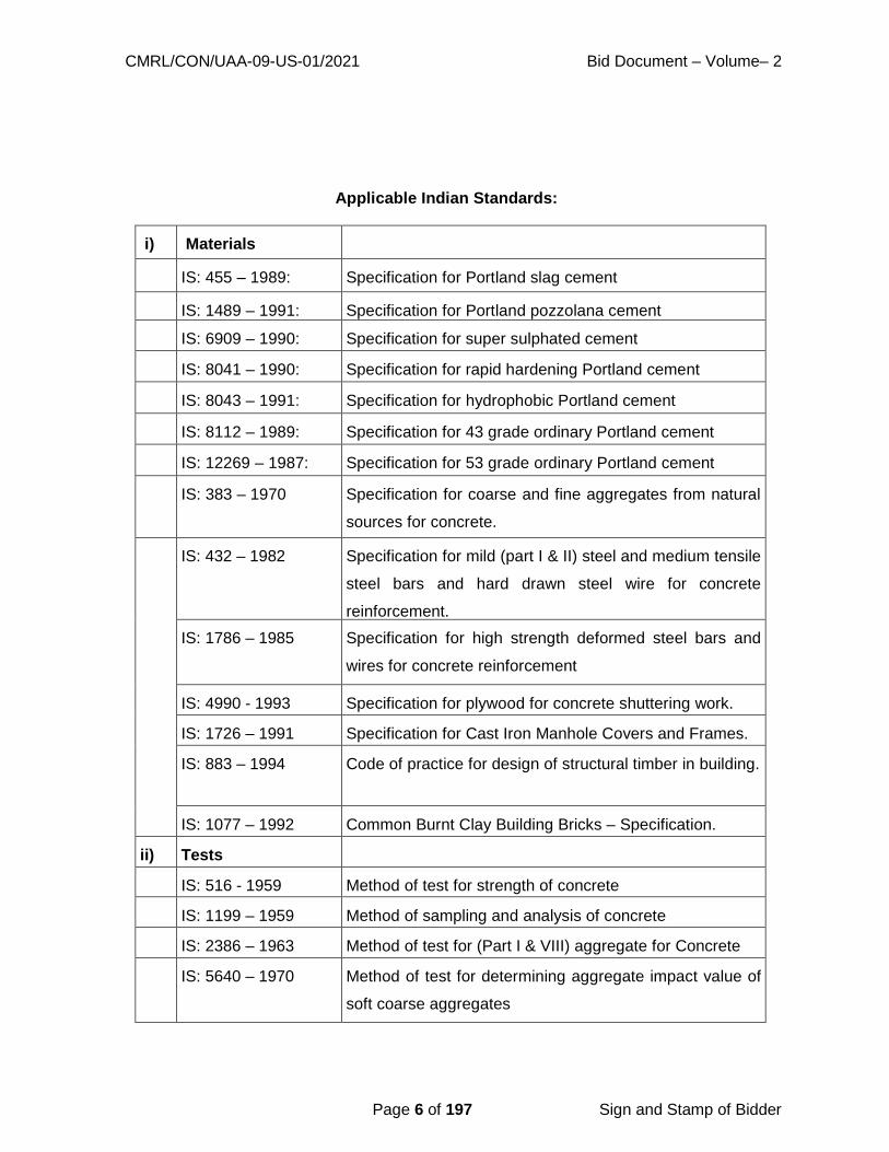
CMRL/CON/UAA-09-US-01/2021 Bid Document – Volume– 2
Page 6 of 197 Sign and Stamp of Bidder
Applicable Indian Standards:
i) Materials
IS: 455 – 1989: Specification for Portland slag cement
IS: 1489 – 1991: Specification for Portland pozzolana cement
IS: 6909 – 1990: Specification for super sulphated cement
IS: 8041 – 1990: Specification for rapid hardening Portland cement
IS: 8043 – 1991: Specification for hydrophobic Portland cement
IS: 8112 – 1989: Specification for 43 grade ordinary Portland cement
IS: 12269 – 1987: Specification for 53 grade ordinary Portland cement
IS: 383 – 1970 Specification for coarse and fine aggregates from natural
sources for concrete.
IS: 432 – 1982 Specification for mild (part I & II) steel and medium tensile
steel bars and hard drawn steel wire for concrete
reinforcement.
IS: 1786 – 1985 Specification for high strength deformed steel bars and
wires for concrete reinforcement
IS: 4990 - 1993 Specification for plywood for concrete shuttering work.
IS: 1726 – 1991 Specification for Cast Iron Manhole Covers and Frames.
IS: 883 – 1994 Code of practice for design of structural timber in building.
IS: 1077 – 1992 Common Burnt Clay Building Bricks – Specification.
ii) Tests
IS: 516 - 1959 Method of test for strength of concrete
IS: 1199 – 1959 Method of sampling and analysis of concrete
IS: 2386 – 1963 Method of test for (Part I & VIII) aggregate for Concrete
IS: 5640 – 1970 Method of test for determining aggregate impact value of
soft coarse aggregates
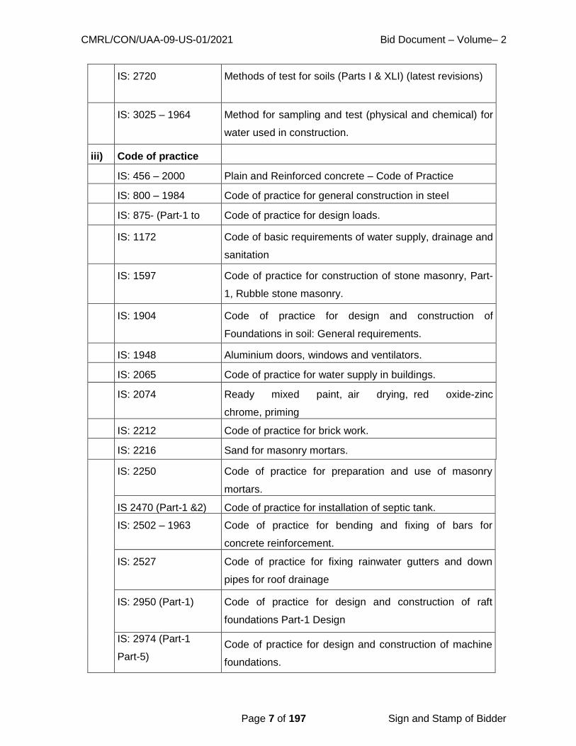
CMRL/CON/UAA-09-US-01/2021 Bid Document – Volume– 2
Page 7 of 197 Sign and Stamp of Bidder
IS: 2720 Methods of test for soils (Parts I & XLI) (latest revisions)
IS: 3025 – 1964 Method for sampling and test (physical and chemical) for
water used in construction.
iii) Code of practice
IS: 456 – 2000 Plain and Reinforced concrete – Code of Practice
IS: 800 – 1984 Code of practice for general construction in steel
IS: 875- (Part-1 to
(Part-5)
Code of practice for design loads.
IS: 1172 Code of basic requirements of water supply, drainage and
sanitation
IS: 1597 Code of practice for construction of stone masonry, Part-
1, Rubble stone masonry.
IS: 1904 Code of practice for design and construction of
Foundations in soil: General requirements.
IS: 1948 Aluminium doors, windows and ventilators.
IS: 2065 Code of practice for water supply in buildings.
IS: 2074 Ready mixed paint, air drying, red oxide-zinc
chrome, priming
IS: 2212 Code of practice for brick work.
IS: 2216 Sand for masonry mortars.
IS: 2250 Code of practice for preparation and use of masonry
mortars.
IS 2470 (Part-1 &2) Code of practice for installation of septic tank.
IS: 2502 – 1963 Code of practice for bending and fixing of bars for
concrete reinforcement.
IS: 2527 Code of practice for fixing rainwater gutters and down
pipes for roof drainage
IS: 2950 (Part-1) Code of practice for design and construction of raft
foundations Part-1 Design
IS: 2974 (Part-1
Part-5)
Code of practice for design and construction of machine
foundations.

CMRL/CON/UAA-09-US-01/2021 Bid Document – Volume– 2
Page 8 of 197 Sign and Stamp of Bidder
IS: 3370-2009 Code of practice for concrete structures for storage of
liquids
IS: 7634 (Part-2) Code of practice for plastic pipe works for potable water
supplies, Part-2 laying and jointing polyethylene (PE)
pipes.
IS: 3558 – 1983 Code of practice for use of immersion vibrators for
consolidating concrete
IS: 10005 – 1994 SI Units and Recommendations for the use of their
Multiples and of certain other units.
IS: 10262 – 1982 Recommended guidelines for concrete mix design
IS: 4111 Part 1 –
1986
Manholes (first revision)
IS: 4111 Part 4 –
1986
Pumping stations and Pumping mains (rising main)
iv)
Construction Safety
IS: 3696 Safety code of scaffolds (Parts I & II) and ladders (latest
revisions) IS: 2750 – 1964 Specification for steel scaffolding
IS: 3764 – 1992 Code of safety for excavation work
IS: 7969 Safety code for handling and storage of building
materials.
v) Steel
IS: 2751 – 1979 Code of practice for welding of M.S. Plain & Deformed
Bars for reinforced concrete construction
IS: 9417 – 1989 Recommendations for welding cold worked steel bars for
reinforced concrete construction
IS: 10790 - 1984 Methods of sampling of steel for prestressed and
reinforced concrete part 2 Reinforcing steel.
IS: 1566 – 1982 Specification for Hard-drawn steel wire fabric concrete
reinforcement.
Vi) Brickwork
plastering
IS: 2116 – 1980 Specification for Sand for masonry mortars.
IS: 3495 – 1992 Methods of test of Burnt clay Building Bricks. (Part-1 to
Part-4)
vii) Sluice Valves

CMRL/CON/UAA-09-US-01/2021 Bid Document – Volume– 2
Page 9 of 197 Sign and Stamp of Bidder
IS: 1364 Grade Hexagon Head Bolts, Screws and Nuts of product
A and B (Part 1 – 6 latest revision) IS: 638– 1979 Specification for sheet rubber jointing and rubber
insertion jointing.
IS: 2685 – 1971 Code of practice for selection, installation and
maintenance of sluice valves.
IS: 14846 – 2000 Sluice valve for water works purposes (50 to 1200mm
size) – Specification.
viii) Cast Iron Pipes
IS: 1536 – 2001 Centrifugally Cast (spun) Iron pressure pipes for water,
gas and sewage - Specification
IS: 5382 - 1985 Specification for Rubber sealing rings for gas mains,
water mains and sewers.
IS: 3400 Methods of test for vulcanized rubbers (Part 1 – 23 -
latest revisions)
IS: 13655 – 1993 Guidelines for Heat Treatment of Cast Iron.
IS: 1500 – 2005 Methods for brinell hardness test for metallic materials.
IS: 1536:2001 Centrifugally Cast (Spun) Iron Pressure Pipes for Water,
gas and Swage specification
IS: 1538:1993 Cast Iron Fittings for Pressur Pipes for Water, gas and
Swage specification
IS: 2062 – 1999 Steel for General Structural purposes – Specification.
xii) MDPE Pipes and fittings
IS: 781 - 1984 Specification for cast copper alloy screw down bib taps
and stop valves for water services
IS: 778 - 1984 Specification for copper alloy gate, globe and check
valves for water work purposes.
IS: 2692 – 1989 Specification for Ferrules for Water Services
DWC- PE/PP pipes
IS: 16098 Structured –Wall plastics piping systems for non- (Part 1
& 2): 2013 pressure drainage & sewerage – Specification

CMRL/CON/UAA-09-US-01/2021 Bid Document – Volume– 2
Page 10 of 197 Sign and Stamp of Bidder
vii) Sanitary Appliances
IS: 651-1980 Salt glazed stone ware pipes and fittings.
IS: 4127 - 1983 Code of practice for laying glazed Stoneware Pipes (First
revision).
IS: 1726 – 1974 Specification for cast iron manhole covers and frames -
Part 1 to 8.
IS: 5455 – 1969 Specification for cast iron steps for Manholes
IS: 5312 – 1984 Specification for swing check type reflux (non-return
valves – Part 1 & 2
i) Manuals:
a) Manual on Water Supply and Treatment - CPHEEO (Central Public Health
Environmental Engineering Organization)
b) Manual on Sewerage and Sewage Treatment published by CPHEEO
c) Tamil Nadu Building Practice
ii) Handbooks:
SP 20 - Handbook on masonry design and construction. SP 23 - Handbook on concrete
mixes.
SP 34 - Handbook on concrete reinforcement and detailing.

CMRL/CON/UAA-09-US-01/2021 Bid Document – Volume– 2
Page 11 of 197 Sign and Stamp of Bidder
SPECIAL CONDITIONS
1.4 CONSTRUCTION WATER:
The Contractor shall make his own arrangement for the fresh water required for
construction of civil works and testing of pipeline and hydraulic structures as well as for
the potable water required for his labor camps.
1.5 CONSTRUCTION POWER:
The Contractor shall make his own arrangement for supply of electrical energy required
at his sites and the works.
1.6 TEMPORARY FENCING:
The Contractor shall, at his own expense, erect and maintain in good condition
temporary fences and gates along the boundaries of the areas assigned, if any, to him by
the employer for the purpose of the execution of the works.
The Contractor shall, except when authorized by the Engineer, confine his men,
materials and plant within the site of which he is given possession. The Contractor shall
not use any part of the site for purposes not connected with the works unless prior
written consent of the Engineer has been obtained. Access shall be made to such areas
only by way of approved gateways.
1.7 SANITARY FACILITIES:
The Contractor shall provide and maintain in clean and sanitary condition adequate
W.C.‟s and wash places, which may be required on the various parts of the site or use of
his employees, to the satisfaction of the Engineer. The Contractor shall make all
arrangements for the disposal of sewage of drainage in accordance with the directions of
the Engineer.
1.8 RESTRICTED ENTRY TO SITE:
The Contractor shall get the prior permission of the Engineer before any person not
directly connected with the works to visit the site.
1.9 EXISTING SERVICES:

CMRL/CON/UAA-09-US-01/2021 Bid Document – Volume– 2
Page 12 of 197 Sign and Stamp of Bidder
Drains, pipes, cables, overhead electric wires and similar services encountered in the
course of the works shall be guarded from injury by the Contractor at his own cost, so
that they may continue in full and uninterrupted use to the satisfaction of the Employer
and the Contractor shall not store materials or otherwise occupy any part of the „site‟ in a
manner likely to hinder the operation of such services. The Contractor must make good
or bear the cost of making good, the damage done by him on any mains, pipes, cables or
lines (whether above or below ground), whether shown or not shown in the drawings,
without delay to the satisfaction of the Engineer and the Employer.
1.10 ELECTRIC POWER SUPPLY:
1. The Electrical Power required has to be obtained by the Contractor from the Tamil
Nadu Electricity Board.
2. The Contractor is forewarned that there can be interruptions in power supply for
reasons beyond the control of the Tamil Nadu Electricity Board and therefore the
contractor is advised to make his standby arrangement to provide and maintain all
essential power supply for his work area at his expense. The contractor shall not be
entitled to any compensation for any loss or damage to his machinery or any equipment
or any consequential loss in progress of work and idle labour as a result of any
interruptions in Power supply.
1.11 NOTICE TO TELEPHONE, RAILWAYS & ELECTRICITY SUPPLY
UNDERTAKING:
Before commencing operations, the contractor has to obtain permission from local bodies
/ Highways Department when he wants to cut any section of the road. the employer will
give necessary assistance such as sending letters and attending meetings if required. The
employer will also pay necessary charges towards restoration of roads to the
Corporation of Chennai / State Highways and National Highways. Any delay in getting
the permission from the Corporation / Panchayats / Municipalities, State Highways
Department, National Highways Department, Railway Department, Electricity Board,
Telegraphs Department, Traffic Department attached to the police and other departments
or companies for carrying out the work will be to the account of contractor.
The contractor before taking up operations, which involve cutting of roads, shifting
utilities etc., during the progress of the work, shall give notice to the concerned
CMRL/CON/UAA-09-US-01/2021 Bid Document – Volume– 2
Page 13 of 197 Sign and Stamp of Bidder
authorities viz. the Corporation / Panchayats / Municipalities, State Highways,
Department, National Highways Department, Railway Department, Electricity Board,
Telegraphs Department, Traffic Department attached to the police and other departments
or companies as may be affected by the work. The notice should identify the specific
details so that the necessary diversion of traffic may be arranged, and permissions
obtained. The contractor shall co-operate with the department concerned and provide for
necessary barricading of roads, protection to existing underground cables etc., met with
during the excavation of trenches. The contractor shall provide at his own expenses
watching and lighting arrangements during day and night and erect required notice board
such as “Caution Road closed for Traffic” etc. He should also provide and maintain at his
own cost the necessary supports for underground cables etc., to afford best protection to
them in consultation with the authorities in charge of the properties and to their best
satisfaction. The contractor has to make necessary arrangements to get supply of
electricity from TNEB for operating the machinery and equipment. The employer will pay
the necessary service connection and S.D charges. The contractor should obtain all
approvals for installation and commissioning of machinery and accessories offered by
them from the respective inspecting authorities such as CEIG or CEFG etc., Fees if any,
to be paid to the inspecting authorities will be reimbursed by the Employer.
1.12 PERMISSION FOR ROAD CUTS:
Wherever the Contractor considers that it is necessary to cut through an existing road or
track he shall submit details to the Engineer for approval, a minimum of seven days
before such work commence.
In the event of cutting a road by the Contractor without the written permission from the
Engineer, the Contractor shall be responsible for the cost of reinstating the road as
undertaken by the Municipal Road Department or the Highways Department, as the
case may be, notwithstanding the general procedures included in Chapter 5, Earthwork.
Where all permissions are correctly obtained the cost of such reinstatement will be paid
directly by the employer.
1.13 TEMPORARY DIVERSION OF ROADS:
During the execution of the work the Contractor shall make at his cost all necessary
provision for the temporary diversion of roads, cart-tracks, footpaths, drains, water
CMRL/CON/UAA-09-US-01/2021 Bid Document – Volume– 2
Page 14 of 197 Sign and Stamp of Bidder
courses, channels etc., if he fails to do so, the same shall be done by the Engineer and the
cost thereof will be recovered from the Contractor.
1.14 BARRICADING:
The manhole / trench shall be barricaded (Iron Barricading arrangements) on all four sides.
The Contractor who has dug up the trench shall be responsible for any mishap, which may
occur. Non-barricading of trenches by the Contractor shall be liable for a fine of Rs.500/-
per day, per location from the interim payment certificates prepared in accordance with
Sub Clause 60.2 of the conditions of particular application. Such deduction will not relieve
the Contractor of any liability or duty under the Contract.
Work areas shall be barricaded to the satisfaction of the Employer in accordance with
Special Conditions of the Contract (part 2).
1.15 FILLING IN HOLES AND TRENCHES ETC.:
The Contractor immediately upon completion of the Works shall fill up holes and trenches
which may have been made or dug, level the mounds, or heaps or earth that may have
been raised or made, and clear away all rubbish which may have become superfluous or
have been occasioned or made in the execution of the works, and the Contractor shall
bear and pay all costs, charges etc.
1.16 ACCIDENTS:
It shall be the duty of the Contractor to arrange for the execution of the works in such a
manner as to avoid the possibility of the accidents to persons or damage to the properties
at any state of the progress of work. Nevertheless, he shall be held wholly responsible for
any injury or damage to persons and properties, which may occur irrespective of any
precautions he may take during the execution of the works. The Contractor shall make
good all claims and loss arising out of such accidents and indemnify the Employer from all
such claims and expenses on account thereof.
1.17 WATER AND LIGHTING:
The Contractor shall pay all fees and provide water and light as required from Municipal
mains or other sources and shall pay all charges, thereof (including storage tanks, meters
etc.) for the use of the works and workmen, unless otherwise arranged and decided on by

CMRL/CON/UAA-09-US-01/2021 Bid Document – Volume– 2
Page 15 of 197 Sign and Stamp of Bidder
writing with Engineer. The water used for the works shall be free from earthy vegetable or
organic matter and from salts or other substances likely to interfere with the setting of
mortar or otherwise prove harmful to the work and conform to relevant standards.
1.18 PAYMENT TO LABOURERS:
The Contractor should note, that in the event of emergency, he shall pay all laborer’s every
day and if this is not done, the CMRL shall make requisite payment and recover the cost
from the Contractor. The Contractor shall not employ any laborer below age of 15 years.
1.19 EQUIVALENCE OF STANDARDS AND CODES:
Whenever reference is made in the contract to the respective standards and codes in
accordance with which plant, equipment or materials are to be furnished and work is to be
performed or tested the provisions of the latest current edition or revision of the relevant
standards and codes in effect shall apply, unless otherwise expressly set forth in the
contract. Where such standards and codes are national in character, or relate to a
particular country or region, other authoritative standards which ensure equal or higher
quality than the standards and codes specified will be accepted subject to the prior review
and written approval by the Engineer. Difference between the standards specified and the
proposed authoritative standards must be fully described in writing by the Contractor and
submitted to the Engineer well in advance for approval. If on the prior review, the
Engineer determines that such proposed deviations do not ensure equal or higher quality;
the Contractor shall comply with the standards set forth in the contract documents.
The Contractor should use only accepted makes of materials and plant and should
construct the entire Works according to Specifications, Standards, data sheets, drawings
etc. If no makes are specified, then only manufacturers of Plant and materials
corresponding to the state-of-the-Art technology and / or confirming to the latest Indian /
International standards shall be used. Providing materials of approved quality and
confirming to the standards does not relieve the Contractor from being responsible for the
successful performance of all system components.
1.20 SAFETY PROVISION:
1.20.1 General Requirements for Health and Safety:
The safety provision shall be brought to the notice of all concerned by displaying on a

CMRL/CON/UAA-09-US-01/2021 Bid Document – Volume– 2
Page 16 of 197 Sign and Stamp of Bidder
notice board at a prominent place at the work spot, persons responsible for ensuring
compliance with the safety provision shall be named therein by the Contractor.
To ensure effective enforcement of the rules and regulations relating to safety
precautions, arrangements made by the Contractor shall be open to inspection by the
Engineer or his representative and the inspecting officer.
Notwithstanding the above provision Contractor is not exempted from the operation of
any other Act or rules in force relating to safety provisions.
1.20.2 Protection of the Public:
No material on any of the sites shall be so stocked or placed as to cause danger or
inconvenience to any person or to the public. The Contractor shall provide all necessary
fencing and lights to protect public from accidents and shall be bound to bear expenses
of defense of every suit, action or proceedings of law that may be brought by any person
for injury sustaining, owing to neglect the above precautions and to any such suit, action
or proceedings to any such person or which may with the consent of the Contractor be
paid to compromise any claim by any such person.
1.20.3 Scaffolding and Ladders:
The Contractor shall ensure that suitable scaffolds are being provided for workers for all
the works, which cannot safely be done from the ground or from solid construction,
except such short period work, as can be done safely from ladders.
When a ladder is used an extra Mazdoor shall be engaged for holding the ladder and if the
ladder is used for carrying materials as well, suitable footholds and handholds shall be
provided on the ladder and the ladder shall be given an inclination not steeper than ¼
to 1 (¼ horizontal to 1 vertical). IS code for scaffolding and ladders, IS: 3696 Part – I
and Part II and its latest revision is to be followed. Every ladder shall be securely fixed.
No portable single ladder shall be over 7m in length. Width between side rails in rung
ladders shall in no case be less than 30cm. for ladders; this width shall be increased by at
least 6mm for each additional 30cm length. Uniform steps spacing shall not exceed
30cm.
Scaffolding or staging more than 3.25 meters above the ground or floor swung or
suspended from an overhead support or erection with stationary support shall have guard

CMRL/CON/UAA-09-US-01/2021 Bid Document – Volume– 2
Page 17 of 197 Sign and Stamp of Bidder
rail properly attached bolted, braced or otherwise secured at least at 1 metre high above
the floor or platform and the scaffolding of staging and extending along the entire length of
the outside and ends thereof with only such openings as may be necessary for the delivery
of materials. Such scaffolding or staging shall be so fastened as to prevent it from swaying
from the building or the structure.
All scaffolds, ladders and other safety devices mentioned or described herein shall be
maintained in a safe condition and no scaffold, ladder of equipment shall be altered or
removed while it is in use.
1.20.4 Working Platforms:
Working platform, gangways and stairways shall be so constructed that they do not sag
unduly or unequally and if height of a platform or gangways or stairway is more than 3.25
meters above ground level, it shall be closely boarded having adequate width and be
suitably fenced as described in 1.24.3 above. Every opening in the floor of a building or
in a working platform shall be provided with suitable means to prevent fall of persons or
materials by providing suitable fencing or railing with a minimum height of 1 meter. Safe
means of access shall be provided to all working platforms and other working places.
1.20.5 Precautions when using Electrical Equipment’s:
Adequate precautions shall be taken to prevent danger from electrical equipment. When
workers are employed on electrical installations, which are already energized, insulating
mats, wearing apparel such as gloves, sleeves and boots, as may be necessary shall be
provided. Workers shall not wear any rings, watches and carry keys or other materials,
which are good conductors of electricity.
1.21 DEMOLITION:
Before commencing any demolition work and also during the process of the work,
safety code for demolition of building IS: 4130 of the latest revision shall be followed:
a. All roads and open areas adjacent to the work site shall either be
closed or suitably protected.
b. No electric cable or apparatus, which is liable to be a source of danger for a
cable or apparatus used by operator, shall remain electrically charged.

CMRL/CON/UAA-09-US-01/2021 Bid Document – Volume– 2
Page 18 of 197 Sign and Stamp of Bidder
c. All practical steps shall be taken to prevent danger to persons employed from
risk or fire or explosion or flooding. No floor, roof or other part of a building
shall be so overloaded with debris or materials as to render it unsafe.
1.22 SAFETY EQUIPMENT:
1.22.1 General Requirements:
All necessary personal safety equipment as considered adequate by the Engineer shall be
available for use of persons employed on the site and maintained in a condition suitable for
immediate use and the Contractor shall take adequate steps to ensure proper use of
equipment by those concerned.
a. Workers employed on mixing asphaltic materials, cement and lime mortars /
concrete shall be provided with protective footwear, hand gloves and goggles.
b. Those engaged in handling any materials which is injurious to eyes shall
be provided with protective goggles.
c. Stone breakers shall be provided with protective goggles and protective clothing
When workers are employed in confined spaces (sewers, manholes etc.), which
are in use, the Contractor shall ensure that manhole covers are opened, and
manholes are ventilated at least for an hour before workers are allowed to get into
them. Manholes so opened shall be cordoned-off with suitable railing and warning
signals of boards provided to prevent accident to public. Before entry by any
worker the Contractor shall ensure that a gas detector is lowered into the confined
space and the atmosphere is shown to be safe.
d. The Contractor shall not employ men below the age of 15 and women on the
work of painting with products containing lead in any form. Whenever men
above the age of 18 are employed on the work of lead painting the following
precautions shall be taken:
I) No paint containing lead or lead products shall be used except in the form
of paste of ready-made paint.
ii) Suitable face makes shall be supplied for use by workers when paint
is applied in the form of spray or a surface having lead paints dry rubbed
CMRL/CON/UAA-09-US-01/2021 Bid Document – Volume– 2
Page 19 of 197 Sign and Stamp of Bidder
and scarped.
iii) Contractor shall supply overalls to workmen and adequate facilities shall
be provided to enable working painters to wash during and on cessation of
working periods.
1.22.2 Working near water:
When the work is done near any place where there is risk of drowning, all necessary
equipment shall be provided and kept ready for use and all necessary steps taken for
prompt rescue of any person in danger and adequate provisions made for prompt
first aid treatment of all injuries likely to be sustained during the course of the work.
1.22.3 Hoisting Machines:
Use of hoisting machines and tacks including their attachments, anchorage and supports
shall conform to the following:
a) I) These shall be of good mechanical construction, sound material and
adequate strength and free from patent defects and shall be kept in good
repair and in good working order.
ii) Every rope used in hoisting or lowering materials or as a means of
suspension shall be of durable quality and adequate strength, and free
from patent defects.
b) Every crane driver or hoisting appliance operator shall be properly qualified and
no person under the age of 21 years shall be in-charge of a hoisting machine,
including any scaffold winch or giving signals to operator.
c) In case of every hoisting machine and of every chain ring hook, shackle,
swivel and pulley block used in hoisting machine or lowering or as means of
suspension, safe working load shall be ascertained by adequate means.
Every hoisting machine and all gear referred to above shall be plainly marked
with safe working load in case of hoisting with safe working load. In case
of hoisting machine having a variable safe working load and the conditions
under which it is applicable shall be clearly indicated. No part of any
machine or of any gear referred to above in this paragraph shall be loaded
CMRL/CON/UAA-09-US-01/2021 Bid Document – Volume– 2
Page 20 of 197 Sign and Stamp of Bidder
beyond safe working load except for the purpose to testing.
d) Engineer shall notify the safe working load of the m a c h i n e i n c a s e o f
departmental machine. As regards Contractor’s machine, the Contractor shall
notify safe working load of each machine to the Engineer. Whenever he
brings to the site of work and get it verified by the Engineer.
Motors, gearing, transmission, electrical wiring another dangerous parts or hoisting
appliance shall be provided with such means so as to reduce to the minimum risk and
accident descend of load; adequate precautions shall be taken to reduce to the minimum
risk of any part of a suspended load becoming accidentally displaced.
1.23 WORKING WITH EXPLOSIVES:
The Contractor shall obtain prior permission of the competent authority such as Chief of
Fire services for the site, manner and method of storing explosives near the site of work.
All handling of explosives including storage, transport shall be carried out under the
rules approved by the “Explosive Department of the Government”.
1.24 ENVIRONMENTAL PROTECTION WORK:
The Contractor have to take following measures during construction and commissioning of
works for protection of environment as to avoid environmental impacts on air, water and
land.
1.25.1 Site Clearance:
The site clearance shall be done with minimum damage to existing structures flora and
fauna, electricity and telephone lines and other infrastructure service.
1.25.2 Earthwork and Excavation:
The Contractor shall inform the local authorities / government if any fossils, coins
artifacts of value or antiquity, structures and other remains of geological or archaeological
interests and excavation shall be stopped until identification of cultural relics by the
authorized institution is complete.
The Contractor shall dispose of surplus / waste material at identified sites approved by the
Engineer. The Contractor shall ensure that there is minimum hindrance to normal

CMRL/CON/UAA-09-US-01/2021 Bid Document – Volume– 2
Page 21 of 197 Sign and Stamp of Bidder
activities and business. The Contractor shall avoid damage to permanent structures and
shall avoid loss of standing crops along the road.
1.25.3 Replanting of Trees and Bushes:
The Contractor shall carry out replantation on areas / on the periphery of construction sites
to minimize visual impact and soil erosion. The Contractor shall pay special attention to
the type of trees to be replanted to prevent fouling of water through falling leaves and bird
droppings. A list showing the type of trees to be replanted shall be submitted to the
Engineer for approval prior for undertaking any replantation.
1.25.4 Soil Erosion and Water Quality:
The Contractor shall ensure that earth and stone do not silt up existing irrigation / drainage
systems. The Contractor shall take suitable measures to prevent direct discharge of
polluted waters from construction activity into lakes / rivers / irrigation channels.
The Contractor shall minimize exposure of soil types susceptible to wind and water
erosion. The Contractor shall control run-off and erosion through proper drainage channels
and structures.
1.25.5 Soil Compaction:
The Contractor shall restrict traffic movements and use low ground pressure machines.
The Contractor shall preserve topsoil to be replaced after completion of construction
activity. The Contractor shall avoid wet soils as far as possible.
1.25.6 Social Disruption:
The Contractor shall minimize interruptions to utility services through proper planning and
scheduling of activities. The Contractor shall provide temporary roads and diversions as
may be necessary for smooth flow of traffic and people.
1.25.7 Dust / Air Pollution:
The Contractor shall provide effective dust control through sprinkling / washing of
construction sites and access roads. The Contractor shall cover / water stockpiles and
storage areas to prevent dust pollution. The Contractor shall cover trucks transporting
construction materials to minimize spills. The Contractor shall have a preventive

CMRL/CON/UAA-09-US-01/2021 Bid Document – Volume– 2
Page 22 of 197 Sign and Stamp of Bidder
maintenance program for construction equipment and vehicles to meet emission
standards. Oil shall not be used to control dust.
1.25.8 Noise Pollution:
The Contractor shall normally undertake construction work during daytime only (between
7.30 to 18.00 hrs.) and when authorized to work beyond these hours adopt suitable noise
control methods during such works. The Contractor shall maintain machines and trucks to
keep them with low noise. The Contractor shall install sound barriers and plant tree as
appropriate during construction. The Contractor shall monitor the level of noise near the
construction site, factory sites and sensitive areas with the
following frequency.
a) During construction period: 12 times a year each time including day and night.
b) During commissioning period: 4 times ad hoc monitoring
1.25.9 Construction Camps:
The Contractor shall take adequate measures such as provision of septic tank / pit latrines
at construction site / camps. The Contractor shall provide crèches to working women labor.
The Contractor shall provide drinking water conforming to IS: 10500 –1991.
The Contractor shall provide garbage can at suitable fixed place and the garbage shall be
disposed of regularly.
1.25.10 Aesthetic Improvement:
The Contractor shall through proper housekeeping enhance aesthetic appearance of
construction sites. The Contractor shall dispose-off construction wastes at approved
disposal sites. The Contractor shall repair pavements immediately following construction of
pipeline and appurtenant structures.
The Contractor shall remove after completion of construction, all temporary structures and
restore the project and surrounding areas nearest possible to the reconstruction condition.
1.25.11 Conservation of Ecological Resources:
The Contractor shall not use farmland and forest belts as materials borrow sites. The
Contractor shall not select arable land as material borrow site. In case excavation in
CMRL/CON/UAA-09-US-01/2021 Bid Document – Volume– 2
Page 23 of 197 Sign and Stamp of Bidder
arable land is unavoidable, topsoil layer (30cms depth) shall be saved and returned after
construction work is completed so as to minimize impacts on ecosystem, agriculture and
animal husbandry. The Contractor shall educate construction workers to protect natural
resources, wild plants and animals.
1.26 USE OF TRADE NAMES:
Wherever reference is made in the contract to specific manufacturers or trade names the
Contractor shall be entitled to substitute Plant and materials supplied by other
manufacturers or producers. Such substitution shall be to the approvals of the Engineer,
which will not be unreasonably withheld. At the request of the Engineer the Contractor
shall provide information to establish that the substituted Plant and materials are
equivalent or better than those referred to.
1.27 DIRECTION BY THE ENGINEER:
The Contractor is responsible for all activities relating to the construction of the works.
Any reference in this Specification to the Engineer directing or ordering, prescribing etc.
the Contractor shall be deemed to mean “Contractor to propose a methodology of
construction and to submit to the Engineer for approval”. Any such approval by the
Engineer shall not limit the Contractor’s responsibilities relating to construction of the
Works. Notwithstanding this clause the Engineer shall be entitled to instruct the
Contractor whenever the Engineer considers it necessary to do so. Where such an
instruction is considered by the Contractor to represent additional work, he shall inform the
Engineer of his opinion before undertaking the work. No claim for additional work on the
basis of an instruction by the Engineer can be considered where the Contractor has failed
to provide such prior notification.
1.28 SPECIAL REQUIREMENTS:
Detailed soil investigation study has not been conducted at proposed site of
construction and all structural designs were made based on the assumed soil bearing
capacity. Before commencing the execution, the contractor shall conduct detailed survey
of the project area, soil investigation tests/ geotechnical investigations, study the
earthquake/ seismological data specific to the region/project area and based on the study
results, entire structural design has to be rechecked and vetted with a reputed Institution /
Structural Engineer as directed by the Engineer. The contractor shall be responsible for

CMRL/CON/UAA-09-US-01/2021 Bid Document – Volume– 2
Page 24 of 197 Sign and Stamp of Bidder
the safety of the structures, correctness of the design and drawing, even after the approval
of the Engineer.
1.29 DEFINITION OF THE ENGINEER:
Any reference in the Contract Documents to the Engineer in charge, or Board Engineer, or
Executive Engineer, or departmental officers, or CMRL, or CMRL’s representative shall be
taken to mean the Engineer.
******

CMRL/CON/UAA-09-US-01/2021 Bid Document – Volume– 2
Page 25 of 197 Sign and Stamp of Bidder
CHAPTER 2 - SUBMITTALS
2.1 DESCRIPTION:
This section covers additional requirements for submission of schedules, samples,
certificates, etc., and forms a part of all other sections in which submittals are required. It
is subjected to General Conditions of Contract.
Requirements of submissions to be included:
1. PERT / CPM Progress Schedule
2. Samples of all materials pertaining to this work.
3. Material lists and equipment.
4. Factory test reports
5. Certificates
6. Laboratory test reports
2.2 REQUIREMENTS:
CPM Progress Schedule:
Within 30 days of award of the tender, the Contractor shall submit a critical path method
analysis for construction progress control and make such revisions as are required for
approval. He shall clearly indicate all construction activities, sub activities and mileposts
on a time-oriented basis, with the critical path fully identified for all activities. He shall
update and resubmit the charts monthly, flag all slippages and mileposts and attach a
narrative description of the proposed corrective actions to the resubmitted charts. The
Contractor shall include the following minimum information for each activity and critical
path item:
i. Date and initial submittal, as applicable.
ii. Ordering dates for long lead time items.
iii. Dates for materials on site.
iv. Testing and clean up.
v. Final completion and handing over.
2.3 SAMPLES:
The Contractor has to submit samples of all materials used for the work prior to start of the
works and get the approval of the Engineer in charge. He shall label or tag each
CMRL/CON/UAA-09-US-01/2021 Bid Document – Volume– 2
Page 26 of 197 Sign and Stamp of Bidder
sample or set of samples, identifying the manufacturer’s name and address, brand
name, catalogue number, project title he intends use.
2.4 MATERIAL LISTS AND EQUIPMENT DATA:
The Contractor has to submit all material lists, equipment lists etc. well in advance before
starting the work and get the approval of the Engineer in charge.
******
CMRL/CON/UAA-09-US-01/2021 Bid Document – Volume– 2
Page 27 of 197 Sign and Stamp of Bidder
CHAPTER 3 - SITE PREPARATION
3.1 CLEARING SITE:
Preliminary work is required to be done before laying of pipes including pegging out,
clearing and disposal of shrubs, grasses, bushes, hedges, boulders, debris from the route.
This shall also include the removal of stumps, etc. or parts thereof lying along the
alignment of pipe. The Contractor should inform the Engineer in charge before removing
shrubs, grasses, etc. well in advance. The alignment of the mains shall be so fixed as to
avoid cutting of any trees.
3.2 REMOVAL OF TOPSOIL, SHRUBS AND OTHER VEGETATION:
All shrubs, vegetation and other plants shall be removed and cleared from the selected
stretch of the site. All debris and unsuitable material up to a depth of 30cm between
ground level or road level shall be removed. All debris and unsuitable material shall be
carted away from the site as per the direction of CMRL or Board Engineer up to a distance
of 10 kms.
3.3 UTILITIES PROTECTION:
All utility lines and structures, whether indicated on the drawings or not, which are to
remain in service shall be protected by the contractor from any damage likely to result from
his operations. Relocation wherever necessary will be done by the respective Service
Departments on payment by CMRL separately. No extra payment will be made for
minor relocation, which does not require dislocation from existing condition and shifting
to other location. In such a condition, the service lines shall be pushed slightly to
facilitate laying of main and brought back to original position after the work is completed
wherever necessary. The service lines should be supported at bottom with planks,
posts, etc. and tied with ropes properly. Any damage to any utility resulting from the
Contractor's operations shall be repaired at the Contractor's expense.
3.4 PAVEMENT REMOVAL:
The Contractor must inform the other concerned departments well in advance before

CMRL/CON/UAA-09-US-01/2021 Bid Document – Volume– 2
Page 28 of 197 Sign and Stamp of Bidder
starting the work. The Contractor must provide and maintain proper and efficient traffic
control system such as safety lamps, sign boards etc. operating day and night for the full
duration of work. The CMRL shall not be responsible under any circumstances for
any mishappenings, therefore. For the purpose of payment for removal of pavement, steel
tapes are to be used and the Engineer‟s representative and Contractor or his
representative shall take the measurement jointly. The width of trenches shall be as per
the specification drawing and only such widths shall be taken into account for computing
quantities for payment. The Contractor has to pay restoration charges for width
excavated in excess of prescribed width. For other elements of work such as making
cross connections, fixing other appurtenances etc. the Engineer shall prescribe the
dimensions for removal of pavement from time to time.
3.5 MAINTENANE OF TRAFFIC AND CLOSING OF STREETS:
The work shall be carried out in such a manner, which will cause the least interruption to
traffic, and road / street may be closed in such a manner that it causes the least
interruption to traffic. Where it is necessary for traffic to cross open trenches, suitable
bridges shall be provided. Suitable signs indicating that a street is closed shall be placed
and necessary detour signs for the proper maintenance of traffic shall be provided.
3.6 INTERRUPTION TO SERVICE:
No valve or other control of the existing services shall be operated without the permission
of the authority.
3.7 WORK DURING NIGHTS:
No extra payment will be made for doing the work in the nights. The Contractor shall get
prior approval from the Engineer in charge before starting the work during nights.
******
CMRL/CON/UAA-09-US-01/2021 Bid Document – Volume– 2
Page 29 of 197 Sign and Stamp of Bidder
CHAPTER 4 - DISMANTLING
4.1 DISMANTLING OF EXISTING STRUCTURES:
The structure shall be dismantled carefully, and materials removed without causing
damage to the serviceable material to be salvaged, the part of the structure to be retained
and any properties of structures nearby. Any avoidable damage to the articles to be
salvaged and part of the structure shall be made good by the Contractor without extra
claims. The Contractor shall be responsible for any injury to the lookers or the public.
Structure should be removed 45cm below Ground and portion which in any way comes
within new construction shall be removed entirely. Contractor shall maintain register or
the salvaged material, which shall have signature of the Engineer on entries made.
All the material obtained from the removed structure shall be the property of client.
Serviceable materials shall be stacked neatly in such a manner as to avoid deterioration at
site or at other places. Non-serviceable materials shall be disposed of by the Contractor
without causing any inconvenience.
All rubbish shall be cleared off the site and the Ground let clean and clear and Rubbish
and non-serviceable materials shall be carted away upto a distance of 10kms as per the
direction of CMRL Engineer.
4.2 MEASUREMENT AND PAYMENT:
The measurements of work shall be exact length and width and height of the dismantled
structure. It shall be priced per unit of the Cubic metre. Any excavation that may be
necessary for dismantling the structure below 45cm from ground level shall be paid under
the item of Excavation and shall include labour for refilling, watering and ramming,
spreading on site if required and for disposal of surplus earth.
******

CMRL/CON/UAA-09-US-01/2021 Bid Document – Volume– 2
Page 30 of 197 Sign and Stamp of Bidder
CHAPTER 5 - EARTH WORK
5.1 DESCRIPTION:
The work specified in this section includes the provision of all labour, machinery,
construction equipment and other appliances required to perform all earthwork specified
or required, in a sound, workmanlike manner.
5.2 GENERAL:
Excavation shall be required to be done for the following works:
a) Excavation for underground pipelines.
b) Excavations for valve chambers, Thrust blocks and Special structure c) Excavation
for pump rooms.
d) No separate payment shall be made for removal of shrubs, which are less than
e) 100mm in diameter at breast height, grass, small bushes and stumps.
f) The alignment of the main shall be so fixed as to avoid cutting of any trees.
g) No extra payment shall be made to the Contractor for working in a confined space.
5.3 CLASSIFICATION:
The excavation work shall be classified into the following categories by inspection of faces
of cutting:
i) Loamy, clayey soils like black cotton soils, red earth, hard gravel, mixture of
gravel and soft disintegrated rock like shale, ordinary gravel, stony earth and
earth mixed with fair sized boulders, except rock requiring blasting, chiseling,
wedging etc.
ii) Hard rock and boulders to be removed by benching, chipping, chiseling, wedging,
barring and by controlled blasting wherever permissible.
5.4 TRENCH EXCAVATION:
General:
Trench excavation means excavation of trenches into which the pipe is to be laid. Before
commencing trench excavation, the route of the trenches shall be pegged out accurately
and the natural ground levels and the alignment shall be agreed with the Engineer in
charge. The Contractor shall dig probing pits or appropriate size and depth including

CMRL/CON/UAA-09-US-01/2021 Bid Document – Volume– 2
Page 31 of 197 Sign and Stamp of Bidder
cutting the road at every 100m interval or as directed by Engineer in charge. The
quantity of excavation beyond the normal dimensions will be paid under relevant items of
excavations in various strata.
Stripping Surface materials:
Before the surface of any part of the site is disturbed or the works there on are started, the
Contractor shall take and record levels in the presence of the Engineer or his
representative. Before commencing the excavation, the surface materials shall be
carefully stripped and set aside for reuse as directed by the Engineer.
5.5 WIDTH OF TRENCH:
The minimum width of the trench at bottom between the faces of sheeting shall be
Nominal diameter of the pipe plus 200mm clearance on either side of the pipe.
Trenches shall be of such extra width for higher depths, when required as will permit the
convenient placing of timber supports, strutting and planking and handling of specials.
The width of trenches measured at the crown of the pipe shall permit adequate working
space. The trenches shall be widened at sockets and other structures as may be found
necessary. Payment for excavation shall be made on quantity basis as per width given in
the Table.
Care should be taken to avoid excessive trench width and thereby increasing the load on
the pipes.
5.6 DEPTH OF EXCAVATION OF TRENCHES:
The depths for the trenches will be calculated from the surface to the bed of the pipes and
in case when a layer of bedding is to be placed below the pipeline, the depth to the bottom
of the bedding will be paid.
The trench shall be so dug that the pipeline may be laid to the required gradient and to the
required depth, mentioned in the Table below. A minimum cover of 1.0 m is to be
provided above the crown level of pipe upto the Ground level / Road level.
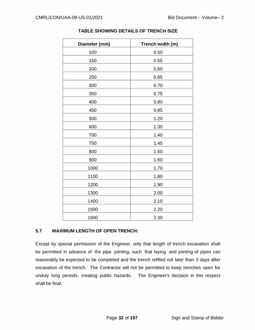
CMRL/CON/UAA-09-US-01/2021 Bid Document – Volume– 2
Page 32 of 197 Sign and Stamp of Bidder
TABLE SHOWING DETAILS OF TRENCH SIZE
Diameter (mm) Trench width (m)
100 0.50
150 0.55
200 0.60
250 0.65
300 0.70
350 0.75
400 0.80
450 0.85
500 1.20
600 1.30
700 1.40
750 1.45
800 1.50
900 1.60
1000 1.70
1100 1.80
1200 1.90
1300 2.00
1400 2.10
1500 2.20
1600 2.30
5.7 MAXIMUM LENGTH OF OPEN TRENCH:
Except by special permission of the Engineer, only that length of trench excavation shall
be permitted in advance of the pipe jointing, such that laying and jointing of pipes can
reasonably be expected to be completed and the trench refilled not later than 3 days after
excavation of the trench. The Contractor will not be permitted to keep trenches open for
unduly long periods, creating public hazards. The Engineer's decision in this respect
shall be final.

CMRL/CON/UAA-09-US-01/2021 Bid Document – Volume– 2
Page 33 of 197 Sign and Stamp of Bidder
5.8 WIDENING TRENCH AT JOINTS, ETC.
Any widening or deepening of the trench, whether in ordinary soil or rock, necessary to
accommodate curves, joints or bends as shown on the drawings or ordered by the
Engineer shall be carried out by the Contractor, after taking all the necessary safety
measures.
5.9 OVER-EXCAVATION OF TRENCH BOTTOMS:
All excavation carried below the grades or bottom of the bedding shall be refilled with sand
/ concrete at the Contractor's expense.
5.10 EXCAVATED MATERIAL:
The material from the excavation shall be deposited on either side of the trench leaving
clear berm on one side at least 40cm wide or at such further distance from the edges of
the trench as may be necessary to prevent the weight of materials from causing the side
of the trench to slip or fall, or at such a distance and such a manner as to avoid any wall
or structure or causing inconvenience to the public or other persons or otherwise as the
Engineer may direct, till it is carted away.
The excavated soil should be so placed and handled as not to inconvenience the usual
traffic, till it is carted away. The Contractor should also provide necessary bridging over
the excavated trenches for the householders and pedestrians to cross over and vehicular
crossings if and where required at no extra cost; if the Engineer decides that there is no
hindrance to traffic due to not carting away the excavated earth, he will give instructions to
that effect. The Contractor shall be responsible for making all arrangements for the
disposal of surplus excavated material upto a distance of 10kms.
5.11 PIPE BEDDING:
i) Sand Bedding:
Where specified, the river sand bedding the required thickness and level shall be provided
below pipe prior to laying the pipe in trenches. It shall be compacted with a light hand
hammer. Any reduction in compaction shall be made up by adding sand during
ramming. For the purpose of bedding under this item, only screened fine sand of grain
size not larger than 2mm shall be used. The sand shall be clean, uncoated and free from
CMRL/CON/UAA-09-US-01/2021 Bid Document – Volume– 2
Page 34 of 197 Sign and Stamp of Bidder
clay lumps, injurious amount of dust, soft particles, organic matter, loam or other
deleterious substances.
If the sand supplied is unclean, it shall be washed. In no case shall sand containing
more than 3.5% by dry volume or 5% by wet volume of clay, loam or silt be accepted.
Tests specified for determining silt in sand and organic impurities described in IS: 383
shall apply. Sieved and washed sand shall be stored on the works in such a manner as
to prevent intrusion of any foreign matter, including coarser particle of sand or any clay or
metal or chips. Tests as indicated above shall be performed if called for by the Engineer
at the expense of the Contractor.
ii) Concrete Bedding:
Where specified, this type of bedding is to be provided at locations specified by the
Engineer. A concrete bedding using M15 grade is to be adopted. The concrete work
related to this specification is detailed in the specifications of concrete and allied works.
5.12 EXCAVATION FOR APPURTENANCES:
Excavation in trenches for foundation of valve chambers, pedestals etc. shall be as
directed by the Engineer. The dimensions of the excavation shall be measured as the
projection in plan of the outermost edges of the structure.
5.13 KEEP EXCAVATION CLEAR OF WATER:
Where ground water is encountered or anticipated, the Contractor shall provide sufficient
pumps to handle the ingress of water and must provide and maintain in working order.
Standby pumping units are to be made available and employed in the event of
mechanical failure. The Contractor must also arrange for night and day operation of the
pumps wherever necessary to ensure that the work proceeds at all times.
5.14 DEWATERING IN AREAS OF HIGH-WATER TABLE:
The Contractor shall perform dewatering as required so that all works of the contract are
installed on dry areas and excavations, including without limitation the construction of all
structures and underground piping. The Contractor shall ensure that dewatering is carried
out only to a depth sufficient for the required excavation. The Contractor shall also
ensure that, at all times, during construction, no groundwater shall come into contact with
CMRL/CON/UAA-09-US-01/2021 Bid Document – Volume– 2
Page 35 of 197 Sign and Stamp of Bidder
any concrete surface or reinforcement and that any structure shall be capable of
withstanding any hydrostatic pressure to which it may be subjected during construction and
until completed.
The Contractor shall be deemed to have included in the tender price for maintaining all
works in a dry condition during construction. Any water removed from excavations shall
wherever practicable, be pumped directly to the natural drainage channel or to storm
sewers if approved via an efficient system of discharge lines. No water may be
discharged into the sewerage system or onto open spaces.
The Contractor shall include for the diversion of all water courses encountered in the work
until the scheme is completed and put into operation.
Notwithstanding any previous approval, the Contractor shall be fully responsible for
maintaining dry excavations.
Where deemed necessary by the Engineer, working drawings and data shall be submitted
for review or approval showing the intended plan for dewatering operations. Details of
locations and capacities of dewatering wells, well points, pumps, sumps, collection and
discharge lines, standby units, water disposal methods, monitoring and settlement shall be
included. These shall be submitted not less than 30 days prior to start of dewatering
operations.
The static water level shall be drawn down to a minimum of 300mm below the bottom of
the excavation so as to maintain the undisturbed state of the foundation soils and allow
the placement of any fill or backfill to the required density. The dewatering system shall
be installed and operated so that the groundwater level outside the excavation is not
reduced to the extent that would damage or endanger adjacent structures or property.
5.15 UNSOUND FOUNDATIONS, SOFT SPOTS:
When the specified levels of trench or structure are reached, the Engineer will inspect the
ground exposed and if he considers that any part of the ground is by its nature unsuitable,
he may direct the Contractor to excavate further and the further excavation shall be filled
with concrete M-10 or river sand. Should the bottom of any trench or structure
excavation, while acceptable to the Engineer at the time of his inspection subsequently
become unacceptable due to exposure to weather conditions or due to flooding or
have become puddled, soft or loose during the progress of the works, the Contractor shall

CMRL/CON/UAA-09-US-01/2021 Bid Document – Volume– 2
Page 36 of 197 Sign and Stamp of Bidder
remove such damaged, softened or loosened material and excavate further by hand. In
this case, the cost of the extra excavation and of the additional foundation materials
required will be the Contractor's responsibility if necessitated by his negligence.
The omission by the Engineer to give an instruction under this Clause shall not relieve the
Contractor from any responsibility for defect in the works due to the construction
being placed upon an unsuitable formation if prior to the construction of the work the
Contractor shall have failed to call the attention of the Engineer thereto in writing.
If in the opinion of the Engineer, a formation is unsound as a result of the Contractor failing
to keep the excavation free from water, the Engineer will order the removal and disposal of
the unsound material and filling of the resulting void. The Contractor shall execute the
work as directed and shall have no claim against the Board for any costs thus incurred.
5.16 CAUTION CUM INFORMATION BOARDS:
Before commencing an excavation, "Caution-Cum-Information" board shall be installed at
site by the Contractor. Such board shall remain at site as long as the trench remains
open. The board shall be installed at both the ends of the trench atleast 100m before the
approach to the area, if the trench is less than 600m in length. Additional boards at
every 300m shall be installed, if the length of the trench exceeds 600m. If the streetlight is
inadequate, lettering with fluorescent paint shall be used for these boards. The boards
shall also contain information regarding dates of commencement and completion of the
work, name and phone number of the Engineer in charge of the work. See also Clause
5.19. The size of lettering shall be adequate to be read by passing vehicles.
5.17 BARRICADING:
To prevent persons from injury and to avoid damage to the property, adequate barricades,
construction sign, torches, red lanterns and guards as required shall be provided and
maintained during the progress of the construction work and until it is safe for traffic to
use the roadways. The pipe laying trenches, manhole trench shall be barricaded on
all four sides. Providing Iron Barricading of size 2.50 m width and 1.75 m height using
40x40x4 mm angle for outer frame supports, 25 x 25 x 3 mm angle for inner frame
supports and 20 gauge thickness MS sheet for name board (as per drawing) including
cutting, welding, fabrication charges and one coat of primer and 2 coats of enamel paint of
approved quality, writing "METRO WATER / CMRL" & work detail/ caution sign,

CMRL/CON/UAA-09-US-01/2021 Bid Document – Volume– 2
Page 37 of 197 Sign and Stamp of Bidder
providing necessary interlocking arrangements with adjoining units, fixing danger flags,
danger lights, reflectors, fixing stickers etc, including watching during night and placing the
barricading units as directed at the sites. Barricading work also includes watching
during night, fixing danger flags, danger lights / reflector and painting in different
colours. The Contractor who has dug up the trench shall be responsible for any mishap,
which may occur.
5.18 FENCING, WATCHING, LIGHTING:
The parts of the fencing shall be of timber, securely fixed in the ground not more than
2.50m apart, they shall not be less than 10cm in dia. or not less than 1.25m above the
surface of the ground. There shall be no two rails, one near the top of the posts and the
other about 0.50m above the ground and each shall be of 5cm to 10cm in diameter and
sufficiently long to run from post to post to which they shall be tied with strong ropes.
The method of projecting rails beyond the posts and tying together where they meet will
not be allowed on any account. All along the edges of the excavated trenches, a bund of
earth about 1m high shall be formed when so required by the Engineer for further
protection. Proper provision shall be made for lighting at night and watchmen shall be kept
seeing that this is properly done and maintained. In addition to the normal lighting
arrangements, the Contractor shall provide, whenever such work is in progress, battery
operated blinking lights (6 volts) in the beginning and end of a trench with a view to provide
suitable indication to the vehicular traffic. The Contractor shall also provide and display
special boards printed with fluorescent prints indicating the progress of work along the
road. In the event of the Contractor not complying with the provisions of the clause, it may
be carried out by the Engineer and the cost recovered from the Contractor besides
claiming liquidity damages from the Contractor. In all such cases the work may be
carried out by Board. The Contractor shall be held responsible for all claims for
compensation as a result of accident or injury to persons / non-provision of red flags.
The Contractor shall at his own cost provide all notice boards before opening of roads as
directed by the Engineer.
Arrangements shall be made by the Contractor to obtain permission from CMC and traffic
authorities for working and to direct traffic when work is in progress. No separate
payment shall be paid for this item of work.
5.19 REFILLING TRENCHES:
CMRL/CON/UAA-09-US-01/2021 Bid Document – Volume– 2
Page 38 of 197 Sign and Stamp of Bidder
a) With a view to restrict the length of open trenches, on completion of the
pipe laying operations, refilling of trenches shall be started immediately by the
Contractor. Pipe laying and testing shall follow closely upon the progress
of trench excavation and the Contractor shall not be permitted more than 500
metres of trench excavation to remain open while awaiting testing of the
pipeline.
b) Care shall be taken while back filling, not to injure or disturb the pipe. Back fill
material shall be free from lumps, organic and other foreign material. Filling
shall be carried out simultaneously on both the sides of the pipes so that
unequal pressure does not occur.
c) Walking or working on the completed pipelines shall not be permitted unless
the trench has been filled to a height of at least 30cm over the top of the pipe
except as may be necessary for tamping etc., during back filling work.
d) Filling-in shall be done in layers not exceeding 150mm in thickness
accompanied by adequate watering, ramming etc. so as to get good
compaction upto 300mm above the top of the pipe. Above this level, sea sand
shall be placed in layers of 200mm watered and compacted by tamping.
e) The trench shall be refilled so as to build up to the original ground level,
keeping due allowance for subsequent settlement likely to take place.
f) Before and during the backfilling of the trench, precautions shall be taken
against the floatation of the pipeline due to the entry of large quantities of water
into the trench causing an uplift of the empty or the partly filled pipeline.
5.20 MEASUREMENT AND PAYMENT:
The payment of excavation shall be made on quantity basis as per the actual
dimensions of the trench excavated limited to the width as per specification drawings.
a) Trench Excavation:
The length of the trench excavation shall be measured along the center line of pipe at
various depths stated in the Bill of Quantities, the total length being segregated into
stretches according to the various depths of excavation contained in the Bill of Quantities
CMRL/CON/UAA-09-US-01/2021 Bid Document – Volume– 2
Page 39 of 197 Sign and Stamp of Bidder
to fall into the specified categories. Within each stretch, the depth applicable shall be
within the range specified in Bill of Quantities.
The depth of excavation shall be measured from the top of the trench at the center before
excavation upto the bottom of the bedding under the pipe. If no bedding is provided, the
measurement shall be to the top level of the bottom of the pipeline. The width of the
trench shall be measured on the basis of the specification drawing. No additional
payment shall be made for the deepening and widening at sockets specials, hunching or
surrounds beyond the dimensions mentioned. For excess width excavated the road
cutting charges to be paid by the Contractor.
The measurement of depth and width of trench shall be taken at every 20 metres along the
alignment and at every change in direction and diameter of the pipe.
b) Structure:
Measurement for structure excavation shall be made as per the projection in plan of the
outermost edges of the structure as per the plan at the bottom.
c) Rock excavation:
The depth of rock excavation measured for payment shall not exceed the corresponding
depth in ordinary excavation plus 150mm both for structure and trench excavations.
The maximum trench widths measured for payment in rock excavations will be as per
specification drawing.
In all above cases, no payment will be made for additional selected fill, lean concrete,
bedding cradling or hunching concrete that may be specified or ordered by the Engineer
as a consequence of excavating beyond the limits specified in the contract documents or
ordered by the Engineer.
d) Disposal of excavated material:
All the excavated material shall be carted away, and the contractor shall be paid in the
following manner for disposal of the same. An item is provided in the bill of quantities and it
includes loading, unloading, transporting to a site upto a distance of 10kms as directed by
the Engineer.
CMRL/CON/UAA-09-US-01/2021 Bid Document – Volume– 2
Page 40 of 197 Sign and Stamp of Bidder
e) For excess width of excavation than specified, no payment will be made and the
Contractor has to bear the cost of restoration.
5.21 PERMANENT REINSTATEMENT:
a. Highways:
Restoration and re-instatement of Highways head and sidewalk surface shall be done by
Highway Department and CMRL will pay the cost.
b. Municipal Roads:
The reinstatement of the Municipal roads, i.e., Asphalt and WBM roads and sidewalk
surface will be carried out by the Municipal Roads Department of the C h e n n a i
M u n i c i p a l C o r p o r a t i o n o r b y t h e H i g h w a y s D e p a r t m e n t a n d CMRL will pay
the cost.
c. Private properties:
However, any damages to the private properties such as compound wall, fencing, etc.
during the execution or immediately afterwards due to contractor carelessness, the same
has to be restored by the Contractor to the original shape at Contractor's own cost.
5.22 SHORING AND STRUTTING:
Open cuttings and trenches shall be suitably shored, sheeted and braced, if required by
the Engineer or by site conditions or to meet local laws, for protecting life, property of the
work.
Adequate shoring and strutting shall be provided by the Contractors at their own cost.
Warped or deformed timber shall not be used. The shoring shall project at least.
150mm above ground level and shall extend to a suitable depth below the bottom of the
trench. Wherever necessary, the planks or struts shall be driven by compressed air pile
drivers. The planks shall be fixed close enough to avoid any running in of sand earth
through the joints. The shoring material shall not be of sizes less than those specified
below, unless steel sheet piling is used or unless approved by the Engineer in writing.
a) Planks: 38mm thick

CMRL/CON/UAA-09-US-01/2021 Bid Document – Volume– 2
Page 41 of 197 Sign and Stamp of Bidder
b) Walling pieces: 100 cm x 100 cm
c) Struts: 15 cm x 20 cm
For walling pieces round timber shall not be allowed. In a vertical plane, there shall be at
least three struts or more as directed by the Engineer. They shall rest on walling
pieces. The spacing of the struts shall be as per the requirement of the design. At the
bottom, extra struts shall have to be provided if ordered by the Engineer. The rates for
excavation do not include the cost of shoring, which shall be paid for separately as per
relevant item of the Bill of Quantities. The Contractors shall be held responsible for
providing secure shoring, and for adopting every other precaution, which may be
necessary for protecting nearby structures, which are likely to be damaged as a result of
excavation. The Contractors shall design the shoring required for actual site conditions
and shall provide shoring accordingly. The design shall be submitted to the Engineer on
demand. The shoring shall be so designed that lowering of pipe of normal length or any
other pipe laying operation does not necessitate the removal of any strut or any other
member of shoring. If the Engineer requires the adoption of any special measures or
precautions, the Contractor will comply with the same immediately. If any part of a
nearby structure is cut out or removed for facility of work, the same shall be made good
on completion of the work by the Contractors at their cost.
In the event of the Contractors not complying with the provisions of this contract in respect
of shoring the Engineering may, with or without notice to the Contractors, put up shoring or
improve shoring already put up or adopt such other measures as he may deem necessary,
the cost of which shall be recovered from the Contractors. Such action on the part of the
Engineer, shall not, however absolve the Contractors of their responsibilities under this
contract.
No part of the shoring shall, at any time, be removed by the Contractors without obtaining
permission from the Engineer. While taking out shoring planks, the hollows formed shall
be simultaneously filled in with soft earth and shall be well compacted as directed.
No payment will be made if the Contractors leave shoring material in the trench on his
own or merely to suit their own convenience. The work of providing shoring shall be
measured and paid for one the basis of areas of planks provided upto ground level and no
separate payment will be made for providing and fixing of walling pieces, struts, dog spikes
etc. the cost of which shall be deemed to have been covered by the rate for

CMRL/CON/UAA-09-US-01/2021 Bid Document – Volume– 2
Page 42 of 197 Sign and Stamp of Bidder
shoring.
The planks shall project at least 150mm above the ground level. For the purpose of
payment, however, measurements shall be taken up to ground level only and no payment
will be made for planking above ground level.
5.23 QUALITY CONTROL TEST:
Trenches other than in roads and paved areas shall be backfilled as specified in Clause
5.20.
******

CMRL/CON/UAA-09-US-01/2021 Bid Document – Volume– 2
Page 43 of 197 Sign and Stamp of Bidder
CHAPTER 6 - BRICK WORK
6.1 BRICK WORK:
6.1.1 Masonry Mortars: Proportioning:
Mix proportion of cement sand mortar shall be as indicated. The mixes specified are by
volume. 50 kg. of cement shall be taken as equal to 0.035 cum. to determine bulk. The
quantity of water to be added to cement sand mortar shall be such that working
consistency is obtained. Excess water shall be avoided.
Preparation of Cement Mortar:
Mixing shall be done preferably in a mechanical mixer. If done by hand, mixing operation
shall be carried out on a clean watertight platform. Cement and sand shall be mixed dry in
the required proportion to obtain a uniform colour. The required quantity of water shall
then be added, and the mortar hoed back and forth for 5 to 10 minutes with additions of
water to a workable consistency. In the case of mechanical mixing, the mortar shall be
mixed for atleast three minutes after addition of water. Cement mortar shall be freshly
mixed for immediately use. Any mortar, which has commenced to set, shall be discarded
and removed from the site.
Time of use of Mortar:
Mortars with cement as an ingredient shall be used as early as possible after mixing,
preferably within half an hour from the time water is added to the mix or at the latest within
one hour of its mixing.
Workability of Masonry Mortar:
The working consistency of the mortar is usually judged by the work during application.
The water used shall be enough to maintain the fluidity of the mortar during application,
but at the same time it shall not be excessive leading to segregation of aggregates from
the cement.
6.1.2 Brick Masonry:
a. Manufacture:
Common burnt clay building bricks shall conform to the requirements of I S : 1077 and

CMRL/CON/UAA-09-US-01/2021 Bid Document – Volume– 2
Page 44 of 197 Sign and Stamp of Bidder
shall be of quality not less than class 20 with moisture absorption rate not exceeding 15
percent as defined in IS:1077. The bricks shall be chamber burnt and shall have sharp
corners and smooth faces and shall not be damaged in any manner and sizes shall
conform to the works sizes specified with tolerances as given in 6.2 IS: 1077.
b. Samples:
The Contractor shall deliver samples of each type of brick to the Engineer, and no orders
shall be placed without the written approval of the Engineer. All the bricks used in the
works shall be of the same standard as the approved samples. The samples shall be
preserved on site, and subsequent deliveries shall be checked for uniformity of shape,
colour and texture against the samples. If in the opinion of the Engineer any deliveries
vary from the standard of the samples, such bricks shall be rejected and removed from the
site. Samples of bricks shall be tested in accordance with IS: 3495 by the Contractor.
c. Uniformity:
The bricks selected for exposed pointed brickwork walls shall be of uniform colour, deep
cherry red or copper colour, and uniform texture. Only such bricks as are permitted by the
Engineer shall be used.
6.2 SETTING OUT:
All brickworks shall be set out and built to the respective dimensions, thickness and
heights as indicated.
6.3 SCAFFOLDING:
Scaffolding shall be strong to withstand all dead, live and impact loads, which are likely
to come on them. Scaffolding shall be provided to allow easy approach to every part
of the work overhand work shall not be allowed.
For exposed brick facing double scaffolding having two sets of vertical supports shall be
provided. For brickwork, which is to be plastered over, single scaffolding may be
provided. In single scaffolding one end of the putlogs shall rest in the hole provided in the
header course of brick masonry. Not more than one header for each putlog shall be left
out. Such holes shall not be allowed in the case of pillars of narrow masonry portions
between openings, which are less than one metre in width or are immediately under or
near the structural member supported by the walls. The holes left shall be made good on

CMRL/CON/UAA-09-US-01/2021 Bid Document – Volume– 2
Page 45 of 197 Sign and Stamp of Bidder
removal of scaffolding to match with the face work / surrounding area.
Timber or bamboo scaffolds shall be erected in accordance with the provisions contained
in IS: 3696 (Part I) - 1987. Safety code for scaffolds and ladders, Part I - Scaffolds, to
ensure safety of workmen and others. Steel scaffolding shall be erected in accordance
with the provisions contained in IS: 2750-1964. Specifications for steel scaffolding and
relevant provisions of IS: 3696 (Part I) - 1987 for safety code for scaffolds (Parts I & II)
and ladders shall be followed.
6.4 SOAKING OF BRICKS:
Bricks shall be soaked in water before use for a period of the water to just penetrate the
whole depth of the bricks. Alternatively, bricks may be adequately soaked in stacks by
profusely spraying with clean water at regular intervals for a period not less than six hours.
The bricks required for masonry work using mud mortar shall not be soaked. When
bricks are soaked, they shall be removed from the tank sufficiently early so that at the
time of laying they are skin-dry. Such soaked bricks shall be stacked-on clean place,
where they are not again spoiled by dirt, earth, etc.
6.5 LAYING:
All loose materials, dirt and set lumps of mortar which may be laying over the surface on
which brickwork is to be freshly started, shall be removed with a wire brush and surface
wetted slightly. Bricks shall be laid on a full bed of mortar. When laying, the bricks shall
be properly bedded and slightly pressed with handle of trowel so that the mortar can get
into all the pores of the brick surface to ensure proper adhesion. All the joints shall be
properly flushed and packed with mortar so that no hollow spaces are left. Care shall be
taken to see that the required quantity of water is added to the mortar at the mixing
platform to obtain required consistency. Addition of water during laying of the course shall
not be permitted. In the case of walls two bricks thick and over, the joints shall be grouted
at every course in addition to bedding and flushing with mortar.
Bricks shall be laid with frog up. However, if the top course is exposed, bricks shall be
laid with frog down. Care shall be taken to fill the frogs with mortar before embedding
the bricks in position.
All quoins shall be accurately constructed, and the height of courses checked with storey
rods as the work proceeds. Acute and obtuse quoins shall be bonded, where
CMRL/CON/UAA-09-US-01/2021 Bid Document – Volume– 2
Page 46 of 197 Sign and Stamp of Bidder
practicable, in the same way square quoins; obtuse quoins shall be formed with squint.
showing a three-quarter brick on one face and quarter brick on the other.
6.6 BOND:
All brickwork shall be built in English Bond, unless otherwise indicated. Half brick walls
shall be built in stretcher bond. Header bond shall be used for walls curved on plan for
better alignment. Header bond shall also be used in foundation footings, stretchers may
be used when the thickness of wall renders use of headers impracticable. Where the
thickness of footings is uniform for a number of course of the footings shall be headers.
Half or cut bricks shall not be used except where necessary to complete the bond. Overlap
in stretcher bond is usually half brick and is obtained by commencing each alternate
course with a half brick. The overlap in header bond which is usually half the width of the
brick is obtained by introducing a three-quarter brick in each alternate course at quoins.
In general, the cross joints in any course of brickwork shall not be nearer than a quarter
of brick length from those in the course below or above it.
6.7 UNIFORMITY:
The brickwork shall be built in uniform layers; corners and other advanced work shall be
raked back. No part of a wall during its construction shall be raised more than one
meter above the general construction level, to avoid unequal settlement. Parts of walls
left at different levels shall be properly raked back. Toothing may be done where future
extension is contemplated but shall not be used as an alternative to taking back.
For half brick partition to be keyed into main walls, indents shall be left in the main walls.
6.8 THICKNESS OF JOINTS:
The thickness of joints shall be 10mm + 3 or – 3mm, unless otherwise specified. Thickness
of joints shall be kept uniform. Slight difference to thickness of bricks shall be adjusted
within joint thickness. Where brickwork is to match the existing work, the joints shall be of
the same thickness as in the existing work.
6.9 STRIKING JOINTS:
Where no pointing, plastering or other finish is indicted, the green mortar shall be neatly

CMRL/CON/UAA-09-US-01/2021 Bid Document – Volume– 2
Page 47 of 197 Sign and Stamp of Bidder
struck flush. Where pointing, plastering or other finish is indicated, the joints shall be
squarely raked out to a depth not less than 10mm for plastering and 15mm for
pointing.
6.10 CURING:
The brickwork shall be constantly kept wet for atleast 7 days.
6.11 FACING:
In case of walls one brick thick and under, atleast one face shall be kept even and in
proper plane, while the other face may be slightly rough. In case of walls more than one
brick thick, both the face shall be kept even and in proper plane.
For exposed brickwork selected bricks of the specified class and sub-class shall be used
for the face work, where however, use of facing bricks is indicated, brick walls shall be
faced with facing bricks. No rubbing down of brickwork shall be allowed.
Brick walls shall be plastered pointed or otherwise finished, as indicated. Joints of external
faces of brick walls in foundation upto 15cm below ground level and of internal faces of
brick walls in foundation and plinth below sub-floor level shall be struck flush when the
mortar is green, as the work proceeds.
6.12 CLEANING:
Face of brickwork shall be cleaned on the same day it is laid and all mortar droppings
removed.
6.13 CONSTRUCTION DETAILS: Holes for Pipes etc.
All necessary holes for pipes, air flues, ventilators, etc. shall be cut or formed as work
proceeds and grouted in cement and sand mortar 1:3 of cement concrete 1:2:4 as required
and made good.
******

CMRL/CON/UAA-09-US-01/2021 Bid Document – Volume– 2
Page 48 of 197 Sign and Stamp of Bidder
CHAPTER 7 - CONCRETE WORKS
7.1 CONCRETE: General:
a. The quality of materials and method and control of manufacture
and transportation of all concrete work irrespective of mix whether reinforced or
otherwise, shall conform to the applicable portions of this Specification.
b. The Engineer shall have the right to inspect the source/s of materials, the
layout and operation of procurement and storage of materials, the concrete
batching and mixing equipment, and the quality control system. Such an
inspection shall be arranged and Engineer‟s approval obtained, prior to starting
of concrete work.
7.2 MATERIALS FOR STANDARD CONCRETE:
The ingredients to be used in the manufacture of concrete shall consist solely of Portland
cement, clean sand, natural coarse aggregate, clean water, and admixtures, if specifically
called for and conditions at site warrant its use.
a. Cement: Cement shall conform to IS: 12269 – 1987, IS: 6909 – 1990 Specification
for super sulphated cement)
b. Aggregates: Aggregates shall comply with the requirements of IS: 383 – 1970.
i. General
a) “Aggregate” in general designates both fine and coarse inert materials used in the
manufacture of concrete.
b) “Coarse Aggregate” is aggregate most of which is not passed through on
4.75mm IS sieve.
c) “Fine aggregate” is aggregate most of which is passed through on 4.75mm IS
sieve.
d) All fine and coarse aggregate proposed for use in the works shall be subject to the
Engineer‟s approval and after specific materials have been accepted, the source of

CMRL/CON/UAA-09-US-01/2021 Bid Document – Volume– 2
Page 49 of 197 Sign and Stamp of Bidder
supply of such materials shall not be changed without prior approval of the Engineer.
e) Aggregates shall, except as noted above, consist of natural sands, crushed
stone from a source known to produce satisfactory aggregate for concrete and
shall be chemically inert, strong, hand, durable against weathering of limited
porosity and free from deleterious materials that may cause corrosion of the
reinforcement or may impair the strength and or durability of concrete. The
grading of aggregates shall be such as to produce a dense concrete of specified
strength and consistency that will work readily into position without segregation
and shall be based on the “mix design” and preliminary tests on concrete specified
later.
f) Aggregates having a specific gravity below 2.6 (saturated surface dry basis) shall
not be used without the special permission of the Engineer.
ii. Fine Aggregate:
a) General:
Fine aggregate shall consist of natural or crushed sand conforming to IS:
383. The sand shall be clean, sharp, hard, strong and durable and shall be free from dust,
vegetable substances, adherent coating, clay, alkali, organic matter, mica, salt or other
deleterious substances, which can be injurious to the setting qualities / strength / durability
of concrete.
(i) Machine-made Sand: Machine-made sand will be acceptable, provided the constituent
rock-gravel composition shall be sound, hard, dense, non- organic, uncoated and durable
against weathering.
(ii) Screening and Washing: Sand shall be prepared for use by such screening or
washing, or both, as necessary, to remove all objectionable foreign matter while separating
the sand grains to the required size fraction.
(iii) Foreign material limitations: The percentage of deleterious substances in sand
delivered to the mixer shall not exceed the following:
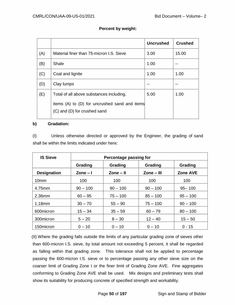
CMRL/CON/UAA-09-US-01/2021 Bid Document – Volume– 2
Page 50 of 197 Sign and Stamp of Bidder
Percent by weight:
b) Gradation:
(I) Unless otherwise directed or approved by the Engineer, the grading of sand
shall be within the limits indicated under here:
(II) Where the grading falls outside the limits of any particular grading zone of sieves other
than 600-micron I.S. sieve, by total amount not exceeding 5 percent, it shall be regarded
as falling within that grading zone. This tolerance shall not be applied to percentage
passing the 600-micron I.S. sieve or to percentage passing any other sieve size on the
coarser limit of Grading Zone I or the finer limit of Grading Zone AVE. Fine aggregates
conforming to Grading Zone AVE shall be used. Mix designs and preliminary tests shall
show its suitability for producing concrete of specified strength and workability.
Uncrushed Crushed
(A) Material finer than 75-micron I.S. Sieve 3.00 15.00
(B) Shale 1.00 --
(C) Coal and lignite 1.00 1.00
(D) Clay lumps -- --
(E) Total of all above substances including.
items (A) to (D) for uncrushed sand and items
(C) and (D) for crushed sand
5.00 1.00
IS Sieve Percentage passing for
Grading Grading Grading Grading
Designation Zone – I Zone – II Zone – III Zone AVE
10mm 100 100 100 100
4.75mm 90 – 100 90 – 100 90 – 100 95– 100
2.36mm 60 – 95 75 – 100 85 – 100 95 – 100
1.18mm 30 – 70 55 – 90 75 – 100 90 – 100
600micron 15 – 34 35 – 59 60 – 79 80 – 100
300micron 5 – 20 8 – 30 12 – 40 15 – 50
150micron 0 – 10 0 – 10 0 – 10 0 - 15
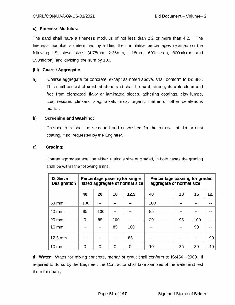
CMRL/CON/UAA-09-US-01/2021 Bid Document – Volume– 2
Page 51 of 197 Sign and Stamp of Bidder
c) Fineness Modulus:
The sand shall have a fineness modulus of not less than 2.2 or more than 4.2. The
fineness modulus is determined by adding the cumulative percentages retained on the
following I.S. sieve sizes (4.75mm, 2.36mm, 1.18mm, 600micron, 300micron and
150micron) and dividing the sum by 100.
(III) Coarse Aggregate:
a) Coarse aggregate for concrete, except as noted above, shall conform to IS: 383.
This shall consist of crushed stone and shall be hard, strong, durable clean and
free from elongated, flaky or laminated pieces, adhering coatings, clay lumps,
coal residue, clinkers, slag, alkali, mica, organic matter or other deleterious
matter.
b) Screening and Washing:
Crushed rock shall be screened and or washed for the removal of dirt or dust
coating, if so, requested by the Engineer.
c) Grading:
Coarse aggregate shall be either in single size or graded, in both cases the grading
shall be within the following limits.
IS Sieve Designation
Percentage passing for single sized aggregate of normal size
Percentage passing for graded aggregate of normal size
40
mm
20
mm
16
mm
12.5
mm
1
0
m
m
40
mm
20
mm
16
mm
12.
5
mm
63 mm 100 -- -- -- -
-
100 -- -- --
40 mm 85
100
100 -- -- -
-
95
100
-- -- --
20 mm 0
20
85
100
100 -- -
-
30
70
95
100
100 --
16 mm -- -- 85
100
100 -
-
-- -- 90
100
--
12.5 mm -- -- -- 85
100
1
0
0
-- -- -- 90
100 10 mm 0
5
0
20
0
30
0
45
8
5
1
0
0
10
35
25
35
30
70
40
85 d. Water: Water for mixing concrete, mortar or grout shall conform to IS:456 –2000. If
required to do so by the Engineer, the Contractor shall take samples of the water and test
them for quality.

CMRL/CON/UAA-09-US-01/2021 Bid Document – Volume– 2
Page 52 of 197 Sign and Stamp of Bidder
7.3 TRANSPORTING AND DEPOSITING CONCRETE:
Mixing plant shall be located as close as possible to the point of placement. Concrete shall
be placed within 30 minutes after mixing and shall be transported from the mixer to its final
placement as rapidly as practicable, taking care to see that no segregation or loss of
ingredients take place. It shall also be ensured that the concrete is of the required
workability at the point and time of placing.
Dropping of concrete from an excessive height or running or working it along forms will not
be permitted. Any concrete which, before placement has begun to set and has become
stiff shall be rejected.
Concrete shall not be disturbed after it has been placed in the form and has begun to set.
Concrete shall be carefully placed in horizontal layers which shall be kept at an even
height throughout the work. Concrete shall not be allowed to slide or flow down sloping
surfaces directly into its final position but shall be placed in its final position form the
skips, trucks, barrows, down pipes or other placing machines or device or, if this is
impossible it shall be shoveled into position, care being taken to avoid separation of the
constituent materials. Concrete placed in horizontal slabs from barrows or other tipping
vehicles shall be tipped into the face of the previously placed concrete.
Concrete dropped into place in the work shall be dropped vertically. It shall not strike the
formwork between the point of its discharge and its final place in the work and except by
approval of the Engineer, it shall not be dropped freely through a height greater than 1.5
metres. Chutes & Conveyor belts shall be so designed that there is no segregation or loss
of mortar and shall be provided with a vertical tapered down pipe or other device to ensure
that concrete is discharged vertically into place.
Where a lift of concrete is built up in layers each layer shall be properly merged into the
proceeding layer before initial set takes place.
7.4 QUALITY ASSURANCE
General Procedure:
A. General:
CMRL/CON/UAA-09-US-01/2021 Bid Document – Volume– 2
Page 53 of 197 Sign and Stamp of Bidder
In order to achieve the required strength and associated properties of concrete, proper
control of the Water / Cement ratio by weight need be enforced. The strength shall be
prime consideration and W.C. ratio as prescribed by Engineer in charge shall have to
be observed. Minimum Cement Content, Maximum Water-Cement Ratio and Minimum
Grade of Concrete for mild/moderate exposure condition (as applicable) with Normal
Weight Aggregates of 20 mm Nominal Maximum Size shall be complied with as given in
the Table 5 of IS 456-2000.
B. Operators:
At no time whatsoever will the mixer operator or those supervising or inspecting the works
be permitted to alter the quantity of water specified by the Engineer for mixing the
concrete. Batching shall be accurate and as specified by the Engineer.
C. Water / Cement Ratio:
The Water / Cement ratio will be determined after mix trials by the Contractor in the
presence of the Engineer or his representative. If batching is by volume, the Contractor
shall be required to fabricate such volumetric batches and water containers as the
Engineer may determine and require so as simulating the ideals of the trial mix
without recourse to assessments by site staff and workmen.
D. Weighing:
The Contractor shall make available always a weighing machine if so required, guaranteed
by the Contractor for its accuracy, for weighing cement and batches of aggregate as and
when the Engineer or his representative or his assistant may require. The machine
shall be capable of weighing upto 75 Kilograms and shall be accurate to half (0.5)
Kilogram.
E. Compaction:
All concrete shall be thoroughly compacted and fully worked round the reinforcement by
vibration just sufficiently so that the appearance of laitance is kept to a minimum and in
such manner as directed by the Engineer‟s Representative. Under no circumstances shall
concrete be compacted by trowels or the like.
F. Transport and Placing:
Fresh concrete from the mixer shall be transported where required by the quickest and

CMRL/CON/UAA-09-US-01/2021 Bid Document – Volume– 2
Page 54 of 197 Sign and Stamp of Bidder
most efficient means so as to prevent pre-set or segregation or any loss of ingredients and
shall maintain required workability. Any laitance from previous mixes shall be removed.
7.5 SAMPLING, TESTING AND STORAGE OF MATERIALS:
Samples of aggregates for mix design and determination of suitability shall be taken under
the supervision of Engineer and delivered to the laboratory well in advance of the
scheduled placing of concrete. Records of tests made on proposed aggregates and on
concrete made from this source of aggregates shall be furnished to the Engineer in
advance of the work for use in determining aggregate suitability. The cost of all such
tests, sampling etc. shall be borne by the Contractor.
Materials shall be tested as hereinafter specified and unless specified otherwise, all
sampling and testing shall be performed by Testing Laboratory approved by CMRL or
CMWSSB at the Contractor‟s expense.
A. Cement:
Cement shall, whether supplied by the Board or not, comply with the requirements of IS:
8041, IS: 455, IS: 8043, IS: 6909, IS: 1489, IS: 12269. Sulphate Resistant Cement (SRC)
shall comply with the requirements as per IS: 6909 – 1990 wherever used. The testing
laboratory at the discretion by the Engineer, shall perform such tests as are deemed
necessary. Cement bags or bulk silos shall be tagged for identification at location of
sampling. Tests will include tensile tests and weighing the cement supply to check for net
weight received at site and used in the works.
1. On arrival at site, cement shall be stored in weatherproof silos designed for the
purpose or in dry weather-tight and properly ventilated structures will floors
raised 15 to 20cm above ground level, 30cm away from walls and with adequate
provision to prevent absorption of moisture or flooding. All storage facilities shall
be subject to approval by the Engineer and shall be such as to permit easy access
for inspection and identification. Each consignment of cement shall be kept
separately, and the Contractor shall use the consignments in the order in which
they are received. Any cement in drums or bags, which have been opened, shall
be used immediately. Different types of cement shall be kept in clearly marked
separate storage facilities. Not more than 15 bags shall be stacked vertically in
one pile. Cement shall be stored in double locking arrangement, so that cement
transactions can be with the knowledge of supervisory staff. Daily account of

CMRL/CON/UAA-09-US-01/2021 Bid Document – Volume– 2
Page 55 of 197 Sign and Stamp of Bidder
cement shall be maintained by the Contractor in the prescribed register and shall
be made available to inspecting authorities for store verification.
2. The Contractor shall provide from each consignment of cement delivered to the
site such samples as the Engineer may require for testing. Any cement which is,
in the opinion of the Engineer, lumpy or partially set shall be rejected and the
Contractor shall promptly remove such cement from the site.
3. Cement which has been stored on the site for more than ninety (90) days and
cement which in the opinion of the Engineer is of doubtful quality shall not be used
in the work until it has been retested and test sheets showing that it complies in
all respects with the relevant standard have been delivered to the Engineer.
B. Water for Concrete Mixing & Curing:
Water shall be clean, clear and free from injurious quantities of salt, traces of oil, acids,
alkalis, organic matter and other deleterious materials. The sources of water shall be
approved by the Engineer and the containers for conveyance; storage and handling
shall be clean. If necessary, standard cement tests shall be conducted using the water
intended to be used, in comparison with those adding distilled water to check quality of
water.
Water shall meet the requirement of 4.3 of IS: 456 – 2000. Generally potable water is fit
for mixing and curing.
C. Aggregates:
Aggregate will be tested before and after concrete mix is established and whenever
character or source of material is changed. Tests will include a sieve analysis to
determine conformity with limits of gradation.
1. Samples of aggregates 50 kg. in weight will be taken by the Contractor at
source of supply and submitted to the Engineer before placing orders. These
samples if approved shall remain preserved in the Engineer’s care for reference
and the type of aggregate used in the works may not be altered without Engineer’s
prior approval.
2. Aggregate sha l l be ob ta ined f rom an approved source and sha l l

CMRL/CON/UAA-09-US-01/2021 Bid Document – Volume– 2
Page 56 of 197 Sign and Stamp of Bidder
conform to t he requirements of IS: 383.
For the aggregate grading, in table of IS: 383 – 1970 shall be applicable.
Aggregate shall not be flaky or elongated particles, defined as particles having a
maximum dimension greater than five times the minimum dimension. Aggregate
shall have water absorption not exceeding two percent when tested in accordance
with IS 383.
3. The Contractor shall sample and carry out analysis in the presence of the
Engineer’s representative, or the fine aggregate and each nominal size of coarse
aggregate in use employing the methods described in IS: 383 and 2386 at least
once in each week when concreting is in progress and such more frequent
intervals as the Engineer may require. The grading of all aggregates shall be
within the respective limits specified in the codes. For aggregates, which vary
more than the approved fineness modulus, the Engineer may instruct the
Contractor to alter the relative proportions of the aggregate in the mix to allow
for such difference or may require further trial mixes.
4. Storage of aggregates shall be provided at each point where concrete is made
such that each nominal size of coarse aggregate and the fine aggregate shall be
kept separated at all times. Contamination of the aggregates by the ground or
other foreign matter shall be effectively prevented at all times, and each heap of
aggregate shall be capable of draining freely. The Contractor shall ensure that
graded coarse aggregates are dumped, stored and removed from store in manner
that does not cause segregation.
Coarse aggregate shall be piled in layers not exceeding 1.2m in height to prevent
coning or segregation. The aggregates must be of specified quality not only at the
time of receiving at site but more so as the time of loading into mixer.
Wet fine aggregate shall not be used until, in the opinion of the Engineer, it has
drained to constant and uniform moisture content, unless the Contractor with the
knowledge of the Engineer measures the moisture content of fine aggregate
and adds water in each batch of concrete mixed to allow for the water contained
in the fine aggregate.
7.6 MIX DESIGN:

CMRL/CON/UAA-09-US-01/2021 Bid Document – Volume– 2
Page 57 of 197 Sign and Stamp of Bidder
Mix design is normally a prerequisite to any concreting job and will be required on all major
works. If so required, an approved testing laboratory shall, at the Contractor’s expense,
design a mix for each class of concrete and shall submit full details of the mix designs to
the Engineer for his approval. The Engineer’s representative and the Contractor shall
clearly code each approved mix with a number and date and file all details for identifying
and reproducing exactly the same mix.
A. General:
Each mix design shall be such that the aggregate shall comprise fine aggregate and
coarse aggregate of the size specified, and the combined aggregate grading shall be
continuous. Aggregate shall be calculated by weight, and batching procedures shall be
established. The cement content by weight shall not be outside the minimum and
maximum limits calculated from the minimum and maximum dry aggregate to cement
ratios specified. The mixes shall be designed to produce average concrete cube strength
at twenty eighth day after manufacture not less than the trail mix test strength specified.
The water / Cement ratio shall be in the region of 0.45 to 0.55 and shall never exceed
0.60.
B. Preliminary Mix:
The proportions of cement, aggregate and water determined by the Contractor in his mix
design shall be used in preliminary mix of concrete made and tested for strength and
workability under laboratory conditions observing the appropriate requirements. These
preliminary mixes shall be repeated with adjusted proportions as necessary until concrete
mixes meeting the requirements of the preliminary and trial mix tests specified and with
the workability defined herein have been produced. If at any time during construction of
the works, the source of cement or aggregates is changed, or the grading of the
aggregate alters, then further preliminary mixes shall be undertaken.
Trials:
After the Engineer’s approval of the preliminary concrete mix design for class of concrete
and during or following the carrying out of the preliminary tests, the Contractor shall
prepare a trial mix of each class in the presence of the Engineer. The trial mixes shall be
mixed for the same time and handled by means of the same plant that the Contractor
propose to use in the works. The proportion of cement, aggregates and water shall be
carefully determined by weight in accordance with the approved mix design (or modified

CMRL/CON/UAA-09-US-01/2021 Bid Document – Volume– 2
Page 58 of 197 Sign and Stamp of Bidder
mix design after preliminary tests) and sieve analyses shall be made, by approved
methods of the find aggregate and each nominal size of coarse aggregate used.
D. Admixtures:
Admixtures shall mean material added to the concrete materials during mixing for the
purpose of altering the properties of normal concrete mixes. If the Contractor wishes to
use admixtures, otherwise than as expressly ordered by the Engineer, he shall first obtain
the Engineer’s written permission. The methods of use and the quantities of admixture
used shall be subject to the Engineer’s approval, which approval or otherwise shall in no
way limit the Contractor’s obligations under the contract to produce concrete with the
specified strength and workability. Concrete of any class containing an admixture shall be
separately designed and have separate preliminary tests and trial mixes made and tested
for approval by the Engineer as if it were a separate class of concrete.
Waiver of Mix Design and Weigh Batching:
On certain works, the Engineer may waive the requirement of designing mixes and may
allow the use of established nominal mix proportion, provided always that preliminary trials
are made to establish the volumetric batching procedure and mix strengths. The
Contractor will ensure that any established procedure approved by the Engineer is
strictly adhered to, so as to achieve consistent strength, durability and economy of the
concrete while ensuring approved workability of the mix. Any waiver of mix design or
weigh batching will not relieve the Contractor of his obligations to consistently produce
concrete of the specified and approved strength and durability as determined by works
tests. However, in any particular work / part of work, the Engineer may decide to adopt mix
design (mix) concrete.
Workability:
The workability of each class of concrete shall be such that satisfactory compaction can be
obtained when the concrete is placed and vibrated in the works. There shall be no
tendency to segregate when it is handled, transported and compacted by the methods,
which the Contractor proposes to use when handling, transporting and compacting that
class of concrete in the works.
Grades of concrete:

CMRL/CON/UAA-09-US-01/2021 Bid Document – Volume– 2
Page 59 of 197 Sign and Stamp of Bidder
The concrete shall be in grades designed in Table 2 IS: 456 – 2000. All the water retaining
structures shall be of grade as specified in IS 3370 (Part-1): 2009, Code of practice for
Concrete structures for storage of liquids.
Concrete Mix Design:
Procedure for designing concrete mixes shall be as per IS: 10262 – 82. “Recommended
guidelines for concrete mix design”.
7.7 BATCHING
Cement:
All cement used in making concrete shall be measured by weight either with an approved
weighing machine or by making the size of each batch of concrete such as to require an
integral number of complete bags of cement of weight consistent with the requirements of
CI 9 of IS: 12269 - 1987. In case of ordinary mixes, the cement bag shall be taken to be 50
kg. (35 liters).
Aggregate:
The find and coarse aggregate shall be measured separately either by volume in gauge
boxes or by weight using machines with weigh batching attachments. For high grave
concrete, the fine aggregate shall be measured singly or cumulatively by weight. The
Engineer will rule on this requirement.
Gauge Boxes:
Gauge boxes shall be soundly constructed by the Contractor, with the approval of the
Engineer and shall be of timber or of steel to contain exactly the volume of the
various aggregates required for one batch of each mix. Each gauge shall be clearly
marked with the mix code and the aggregate for which it is intended. When calculating
the size of the gauge box for fine aggregate, allowance shall be made for the bulking of
the fine aggregate due to the average amount of moisture contained in the stockpiles on
the site. Before the Contractor shall put any gauge box into use on the site, he shall
obtain the approval of the Engineer of the size and construction of such gauge box.
Water Container:
Containers for measuring water shall be soundly constructed of metal to contain the exact
CMRL/CON/UAA-09-US-01/2021 Bid Document – Volume– 2
Page 60 of 197 Sign and Stamp of Bidder
quantity of water required for a batch of mix, due allowance having been made for the
moisture content of the aggregates, or such fractions of the quantity as are approved by
the Engineer. Containers shall have spouts, the pill levels of which determine the quantity.
Fixed containers shall be elevated and have overflow pipes, which determine the quantity
held in the container, and shall have an outlet valve and hose fixed to the bottom of the
container. Before any container is put into use, the approval of the Engineer shall be
obtained.
Weigh-Batching:
Weigh batching machines shall provide facilities for the accurate control and measurement
of the materials either singly or cumulatively and shall be capable of immediate adjustment
by operators in order to permit variations if ordered by the Engineer. All weight dials shall
be easily visible from the place at which filling and emptying of the hoppers are controlled.
Addition of Water and Mixing:
A. Water:
The addition of water to a mixer shall be controlled such that between five and ten
percent of the water enters the mixer before the cement and aggregate and a further five
to ten percent of water enters the mixer after the said materials have been batched. The
remainder of the water shall be added at a uniform rate with the said materials. The water-
measuring device shall also be readily adjustable so that the quantity of water added
to the mixer can, if necessary, in the opinion of the witnessing Engineer’s representative
be varied. The natural moisture contents of the aggregates shall be determined before
the commencement of concreting or at such intervals as may be necessary or as
required by the Engineer. The Contractor shall make do allowance for the water
contained in the aggregate when determining in consultation with the Engineer’s
representative, the quantity of water to be added to each mix and shall adjust the amount
of water added to each mix to maintain consistently the approved water / cement ratio of
the mixed concrete. All- important concrete shall be machine mixed to give complete
coating of cement mortar on each coarse aggregate particle and to produce uniform
colored concrete with uniform distribution of materials. The mixer shall be run minimum 1
½ minutes. In case, for a minor job, hand mixing is permitted by the Engineer, it shall be
done on smooth watertight platform not allowing the added water to flow out. The fine
aggregate shall be spread in uniform thickness layer over which cement as required shall
be placed and they shall be mixed thoroughly to give dry mortar. Water is then added

CMRL/CON/UAA-09-US-01/2021 Bid Document – Volume– 2
Page 61 of 197 Sign and Stamp of Bidder
gradually in required proportion, turning the mass, to give desired consistency mortar. The
required quantity of coarse aggregate is then placed on mixing platform, wetted and mortar
added. The entire mass is turned and returned to give uniform concrete of required
consistency. 5% additional cement shall be used for hand mixed concrete.
B. Admixtures:
Any admixtures approved by the Engineer, which may be used, shall be measured
separately in calibrated dispensers and shall be added to the mixture together with the
water.
C. Uniformity of Mix:
Concrete shall be mixed in batches in plant capable of mixing the aggregates, cement and
water (including admixtures, if any) into a mixture uniform in color and consistency and of
discharging the mixture without segregation.
D. Contractor’s Returns:
The Contractor shall render to the Engineer, daily return for each class of concrete of
the number of batches mixed, and total volume of concrete placed, the number of
batches wasted or rejected, and the weight of cement used. In case of ordinary mixes,
where permitted, the cement bags consumed for quantities of various classes of concrete
shall be furnished. In addition, daily details of time of starting concrete, closure, No. of
batches through mixer, W.C. ratio, slump, date of striking form works etc. shall be
maintained. This day-to-day record shall be authenticated by responsible supervisory
staff.
E. Plant and Equipment Generally:
All mixing and matching plants boxes, containers and other equipment shall be maintained
free of defects or of set concrete or cement and shall be cleaned before commencing
mixing. At such intervals as may be directed by the Engineer, the Contractor shall
provide weights, containers and equipment necessary for testing the accuracy of the
weighting plant, water measuring plant and admixture dispenser.
7.8 CONCRETING: Preparation:
The Contractor shall clear from the surface of the foundations or previously placed
concrete all oil, loose fragments of rock, earth, mud, timber and any other foreign matter
CMRL/CON/UAA-09-US-01/2021 Bid Document – Volume– 2
Page 62 of 197 Sign and Stamp of Bidder
and shall clear standing water and wash the surface of a previous lift of concrete to the
satisfaction of the Engineer.
a. Laitance:
Where laitance on a lift of concrete is evident or if a substantial bond between this lift or
bay or concrete and the next is required, in the opinion of the Engineer’s representative,
the Contractor shall have the surface wire brushed after initial set of the concrete or have it
bush-hammered at no extra cost to the Board. Any reinforcing bars covered in laitance
shall be wire brushed to clean the surface of the metal.
b. Blinding:
As ordered by the Engineer, or as shown on the drawings the formation surfaces on which
concrete is to be placed shall be covered with either blinding concrete not less than 75mm
thick, or waterproof, building paper, or polythene sheeting immediately after completion of
the final trimming of the excavation.
7.9 INSPECTION:
Concrete shall not be placed until the Engineer has inspected the formwork and the
reinforcing steel, and taken necessary measurements of the latter, and has approved the
surface upon which the concrete is to be placed.
a. Transporting:
Fresh concrete shall be transported from the mixer to its place in the works as quickly and
as efficiently as possible by methods, which will prevent pre-set or segregation. If
segregation has nevertheless occurred in any instance, the materials shall be remixed or
discarded at the opinion of the Engineer.
b. Placing:
Fresh concrete shall be placed and compacted before initial set has occurred and, in any
event, not later than thirty minutes from the time of mixing. Concrete shall be carefully
placed in horizontal layers which shall not be allowed to slide or flow down sloping
surfaces but shall be placed in its final position from skips, or similar devices. If this is
impracticable, it shall be shoveled into position care being taken to avoid segregation.
No concrete shall be dropped more than 1.5m. If greater drops are necessary approved
CMRL/CON/UAA-09-US-01/2021 Bid Document – Volume– 2
Page 63 of 197 Sign and Stamp of Bidder
chutes may be used. If the concrete abuts against earth or any other material liable to
become loose or to slip, care shall be taken to avoid falls of materials on the surface of the
wet concrete.
As far as possible concrete for any particular portion shall be done in one continuous
operation leaving construction joints, if specified by drawing.
Before commencing subsequent concrete on the one left incomplete, all the loose
particles, laitance etc. shall be removed and surface shall be covered with thick cement
slurry. The concrete compacted manually shall be laid in layers not more than 15 to
20cm. The successive layer shall follow within 30 minutes or earlier.
7.10 COMPACTION:
All concrete placed in-situ shall be compacted with power driven or pneumatic internal type
vibrators unless otherwise approved by the Engineer in writing and shall be supplemented
by hand spading and tamping where required. Vibrating by screed type vibrators may be
used for thin slabs. There shall be sufficient and spare vibrators of adequate capacity to
compact the work in hand.
a. Vibration:
Vibrators shall be inserted into the uncompacted concrete vertically and at regular
intervals. Where the uncompacted concrete is in a layer above freshly compacted
concrete, the vibrator shall be allowed to penetrate vertically for about 75mm into the
previous freshly compacted layer. The vibrators shall not be allowed to come into
contact with the reinforcement of formwork nor shall they be withdrawn quickly from the
mass of concrete but shall be drawn back slowly while in motion so as to leave no voids.
Internal type vibrators shall not be placed in the concrete in any arbitrary manner nor
shall concrete be moved from one part of the work to another by means of the vibrators.
The vibrators shall have minimum 3600 (preferably 5000) impulses per minute.
b. Duration:
The duration of vibration shall be limited to that required to produce satisfactory
compaction of the concrete without causing segregation. Vibration shall an no account
CMRL/CON/UAA-09-US-01/2021 Bid Document – Volume– 2
Page 64 of 197 Sign and Stamp of Bidder
be continued after the appearance of water or grout on the surface.
c. Hand compaction:
This shall be permitted exceptionally for small jobs by the Engineer. In such cases,
compaction shall be attained by means of rodding, tamping, ramming and slicing with
suitable tools. The thickness of concrete layers will also be suitably reduced when hand
compaction is resorted to.
7.11 UNDER WATER CONCRETING:
No concrete shall be placed in water without the Engineer’s written permission, which may
only be granted if in his opinion it is not practicable to place the concrete in the dry.
Concrete shall not be placed is running water nor shall concrete be allowed to fall
through water. Any water entering the area where concrete is being placed shall, at the
Contractor’s expense, be kept clear of the concreting works. If under water concreting
is permitted, the specified mix of concrete shall be strengthened by increasing the cement
content by at least 10.0% and reducing the water / cement ratio to no more than 0.45,
and the placing shall be only through a tremie approved by the Engineer. The volume
or mass of the coarse aggregate shall not be less than 1 ½ times not more than twice
that of the fine aggregate. The material shall be so proportioned as to produce a concrete
having a slump of not less than 100mm and not more than 180mm.
7.12 CURING:
All concrete shall be protected from the effects of sunshine, rain, running water or
mechanical damage and cured by covering with jute, hessian or similar absorbent material
kept constantly wet or a layer of sand kept covered with water is also permissible for a
continuous period of fourteen days at least from the date of placement. Should the
Contractor fail to water concrete continuously, the Engineer may provide labor and
materials required for curing and recover the cost from the Contractor.
7.13 FINISHING:
Immediately after removal of forms, any undulations, depressions, cavities, honey
combing, broken edges or corners, high spots and defects shall be made good and

CMRL/CON/UAA-09-US-01/2021 Bid Document – Volume– 2
Page 65 of 197 Sign and Stamp of Bidder
finished with C.M. 1:2, but the necessity of such finishing must be exceptional and total
surface requiring finishing shall not exceed 1%. Where concrete surface is to receive
plaster, the surface shall be roughened immediately after removal of forms and within a
day thereof to secure a hold for the plaster. The rate of concrete is inclusive of this
roughening and finishing. Concrete after finishing shall be cured for the full period.
7.14 JOINTS: Construction Joints:
Construction joints are defined as joints in the concrete introduced for convenience in
construction at which special measures are taken at achieve subsequent continuity without
provision for further relative movement.
a. Submittal:
No concreting shall be started until the Engineer has approved the methods of placing, the
positions and form of the construction joints and the size of lifts.
b. Jointing:
The face of a construction joint shall have all laitance removed and the aggregate exposed
prior to the placing of fresh concrete. The laitance shall wherever practicable be removed
by spraying the concrete surface with water under pressure and brushing whilst the
concrete is still green. Where the laitance cannot be removed whilst the concrete is green,
the whole of the concrete surface forming part of the joint shall be hacked to expose
the aggregate. Where aggregate is damaged during hacking, it shall be removed from
the concrete face by further hacking. All loose matter shall be removed, and the
exposed surface thoroughly cleaned by wire brushing, and washing down, and the surface
to which fresh concrete is applied shall be clean and damp.
Expansion Joints:
Expansion joints are defined as joints intended to accommodate relative movement
between adjoining parts of a structure special provision being made where necessary for
maintaining the water tightness of the joint.
a. The joint location and type will be as indicated in the drawings.
1. The Contractor shall comply with the instructions of manufacturers of proprietary
jointing materials and shall, if required by the Engineer, demonstrate that the
CMRL/CON/UAA-09-US-01/2021 Bid Document – Volume– 2
Page 66 of 197 Sign and Stamp of Bidder
jointing materials can be applied satisfactorily and will last the life of the structure.
2. Flexible water stops shall be fully supported in the formwork, free of nails and
clear of reinforcement and other fixtures. Damaged water stops shall be replaced
and during concreting care shall be taken to place the concrete so that water stops
do not bend or distort.
b. Jointing:
The surface of set concrete shall not be disturbed, and concrete shall be placed against
the dry finished surface.
3. If ingress of water or corrosive agents in the joint is possible, the steel, where
such steel is continued, shall be cleaned and coated with two coats of an
approved bituminous paint to a distance not exceeding 10mm.
4. Where specified, the surface of the set concrete shall be painted with two coats
of an approved bituminous paint, which shall be allowed to dry before placing
new concrete against it. Care shall be taken to prevent paint getting on the
water stop, if any.
5. Expansion joints shall be formed by a separating strip of pre-formed
compressible imperishable joint filler, to be approved by the Engineer.
7.15 TESTING OF CONCRETE:
Sampling and strength test of concrete shall be as per 14 of IS: 456 – 2000.
7.16 TESTING CONCRETE STRUCTURES FOR LEAKAGE
The Contractor shall take special care for concrete for liquid retaining structures,
underground structures and those others specifically called for to guarantee the finish and
water tightness.
The Contractor shall make all arrangements for hydro-testing of structure as per BIS:
3370 part I, all arrangements for testing such as temporary bulk heads, pressure gauges,
pumps, pipelines etc.
Any leakage that may occur during the hydro-test or subsequently during the defect’s
CMRL/CON/UAA-09-US-01/2021 Bid Document – Volume– 2
Page 67 of 197 Sign and Stamp of Bidder
liability period shall be effectively stopped either by cement/epoxy pressure grouting,
geniting or such other methods as may be approved by the engineer-in-charge. All
such rectification shall be done by the contractor to the entire satisfaction of the
engineer-in-charge at no extra cost to the department.
Hydrostatic test for water tightness shall be done at full storage level i/c free board as
may be directed by the Engineer-in-Charge, as described below:
In the case of structures whose external faces are exposed, the requirements of the test
shall be deemed to be satisfied if the external faces show no sign of leakage or sweating
and remain completely dry during the period of observation of seven days after allowing a
seven-day period for absorption after filling with water.
In the case of structures whose external faces are buried and are not accessible for
inspection, such as underground tanks, the structures shall be filled with water and after
the expiry of seven days after the filling; the level of the surface of the water shall be
recorded. The level of water shall be recorded again at subsequent intervals of 24 hours
over a period of seven days. The total drop in surface level over a period for seven days
shall be taken as an indication of water tightness of the structure. The Engineer-in-
Charge shall decide on the actual permissible nature of this drop in the surface level,
taking into account whether the structures are open or closed and the corresponding
effect it has on evaporation losses. Unless specified otherwise, a structure whose top is
covered shall be deemed to be watertight if the total drop in the surface level over a period
of seven days does not exceed 40 mm.
Each compartment/segment of the structure shall be tested individually and then all
together.
For structures such as pipes, tunnels etc. the hydrostatic test shall be carried out by filling
with water, after curing as specified, and subjecting to the specified test pressure for
specified period. If during this period the loss of water does not exceed the equivalent
of the specified rate, the structure shall be considered to have successfully passed the
test.
******
CMRL/CON/UAA-09-US-01/2021 Bid Document – Volume– 2
Page 68 of 197 Sign and Stamp of Bidder
CHAPTER 8 - FORM WORK
8.1 MATERIAL:
All formwork for concrete work shall be mostly of M.S. Plates. The plates shall be free
from wrinkles, lumps or other imperfections. Steel plates shall have sufficient thickness
to withstand the construction loads and the pressure exerted by the wet concrete as well
as vibration during placing of concrete. Normally the thickness shall not be less than 18
gauge for M.S. Plates.
The formwork may also be constructed of timber, or other approved material. It shall be
firmly supported, adequately strutted, braced and tied to withstand the placing and
vibrating of concrete and the effects of weather. One copy of the Contractors shoring, and
formwork drawings shall be submitted to the Board for record purpose only and not for
review or approval. Forms, shoring and false work shall be adequate for imposed live and
dead loads including equipment and men, height of concrete drop, concrete and
foundation pressures and stresses, wind pressures, lateral stability, and other safety
factors during construction. The Contractor shall be responsible for the calculations and
designs for the formwork. The Contractor shall be held solely responsible for any failure
and for the safety of work and workmen. He shall pay necessary compensation, if need
be, for damages to work, property and injuries to persons. The scaffolding, hoisting
arrangements and ladders shall have easy approach to work spot and afford easy
inspection.
All formworks shall be fabricated in compliance with the best modern practice, so that the
finished surface is even, unblemished free of fins and true to line, level and shape as
shown in the drawings. The forms shall comply with the requirements of IS: 456.
8.2 ARRANGEMENTS:
All formworks shall conform to the shape, lines, and dimensions as shown on the plans of
the concrete members. the formwork shall include all wedging, bracing, the rod, clamps,
stop off boards and other devices necessary to mold the concrete to the desired shape.
The formwork shall be constructed as to remain sufficiently rigid during the placing and
compacting of the concrete and shall withstand the necessary pressure, ramming and
vibrations without any deflection from the prescribed lines and curves. It shall be
properly strutted and braced in at least two directions. It shall be sufficiently tight to
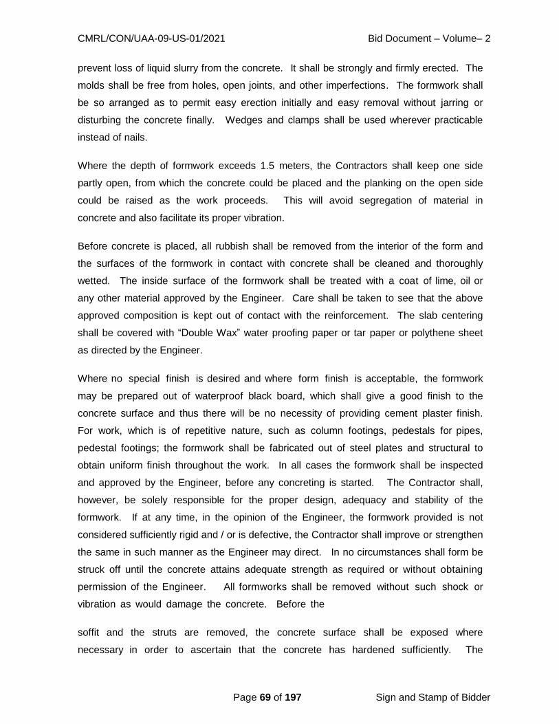
CMRL/CON/UAA-09-US-01/2021 Bid Document – Volume– 2
Page 69 of 197 Sign and Stamp of Bidder
prevent loss of liquid slurry from the concrete. It shall be strongly and firmly erected. The
molds shall be free from holes, open joints, and other imperfections. The formwork shall
be so arranged as to permit easy erection initially and easy removal without jarring or
disturbing the concrete finally. Wedges and clamps shall be used wherever practicable
instead of nails.
Where the depth of formwork exceeds 1.5 meters, the Contractors shall keep one side
partly open, from which the concrete could be placed and the planking on the open side
could be raised as the work proceeds. This will avoid segregation of material in
concrete and also facilitate its proper vibration.
Before concrete is placed, all rubbish shall be removed from the interior of the form and
the surfaces of the formwork in contact with concrete shall be cleaned and thoroughly
wetted. The inside surface of the formwork shall be treated with a coat of lime, oil or
any other material approved by the Engineer. Care shall be taken to see that the above
approved composition is kept out of contact with the reinforcement. The slab centering
shall be covered with “Double Wax” water proofing paper or tar paper or polythene sheet
as directed by the Engineer.
Where no special finish is desired and where form finish is acceptable, the formwork
may be prepared out of waterproof black board, which shall give a good finish to the
concrete surface and thus there will be no necessity of providing cement plaster finish.
For work, which is of repetitive nature, such as column footings, pedestals for pipes,
pedestal footings; the formwork shall be fabricated out of steel plates and structural to
obtain uniform finish throughout the work. In all cases the formwork shall be inspected
and approved by the Engineer, before any concreting is started. The Contractor shall,
however, be solely responsible for the proper design, adequacy and stability of the
formwork. If at any time, in the opinion of the Engineer, the formwork provided is not
considered sufficiently rigid and / or is defective, the Contractor shall improve or strengthen
the same in such manner as the Engineer may direct. In no circumstances shall form be
struck off until the concrete attains adequate strength as required or without obtaining
permission of the Engineer. All formworks shall be removed without such shock or
vibration as would damage the concrete. Before the
soffit and the struts are removed, the concrete surface shall be exposed where
necessary in order to ascertain that the concrete has hardened sufficiently. The
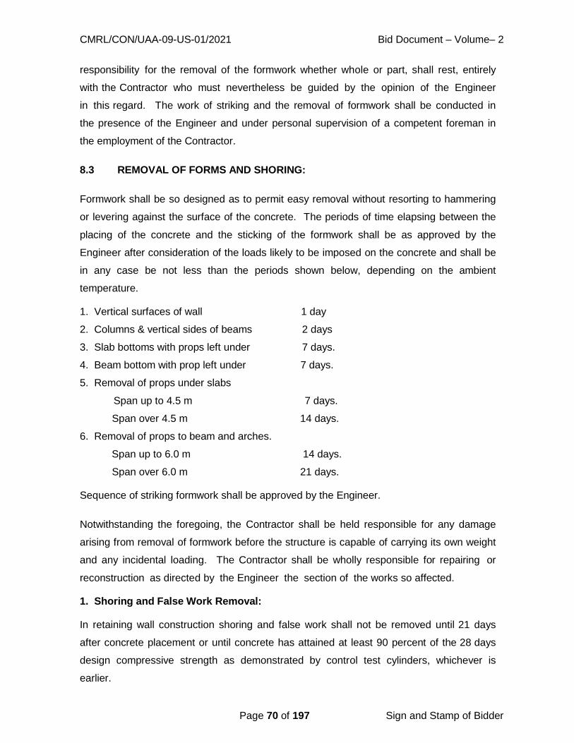
CMRL/CON/UAA-09-US-01/2021 Bid Document – Volume– 2
Page 70 of 197 Sign and Stamp of Bidder
responsibility for the removal of the formwork whether whole or part, shall rest, entirely
with the Contractor who must nevertheless be guided by the opinion of the Engineer
in this regard. The work of striking and the removal of formwork shall be conducted in
the presence of the Engineer and under personal supervision of a competent foreman in
the employment of the Contractor.
8.3 REMOVAL OF FORMS AND SHORING:
Formwork shall be so designed as to permit easy removal without resorting to hammering
or levering against the surface of the concrete. The periods of time elapsing between the
placing of the concrete and the sticking of the formwork shall be as approved by the
Engineer after consideration of the loads likely to be imposed on the concrete and shall be
in any case be not less than the periods shown below, depending on the ambient
temperature.
1. Vertical surfaces of wall 1 day
2. Columns & vertical sides of beams 2 days
3. Slab bottoms with props left under 7 days.
4. Beam bottom with prop left under 7 days.
5. Removal of props under slabs
Span up to 4.5 m 7 days.
Span over 4.5 m 14 days.
6. Removal of props to beam and arches.
Span up to 6.0 m 14 days.
Span over 6.0 m 21 days.
Sequence of striking formwork shall be approved by the Engineer.
Notwithstanding the foregoing, the Contractor shall be held responsible for any damage
arising from removal of formwork before the structure is capable of carrying its own weight
and any incidental loading. The Contractor shall be wholly responsible for repairing or
reconstruction as directed by the Engineer the section of the works so affected.
1. Shoring and False Work Removal:
In retaining wall construction shoring and false work shall not be removed until 21 days
after concrete placement or until concrete has attained at least 90 percent of the 28 days
design compressive strength as demonstrated by control test cylinders, whichever is
earlier.

CMRL/CON/UAA-09-US-01/2021 Bid Document – Volume– 2
Page 71 of 197 Sign and Stamp of Bidder
2. Restriction:
Construction equipment, or permanent loads shall not be imposed on columns, supported
slabs, or supported beams until concrete has attained the 28 days design compressive
strength as demonstrated by control test cylinders.
3. Concrete Curing during removals:
Concrete shall be thoroughly wetted as soon as forms are first loosened and shall be kept
wet during the removal operations and until curing media or sacking is applied. Portable
water supply with hoses or buckets shall be ready at each removal location before
removal operations are commenced.
8.4 SURFACE TREATMENT & FINISH:
When the formwork is struck, all the faces of concrete shall be smooth and sound,
free from voids and air holes. Any roughness or irregularity on the exposed surfaces
shall be immediately filled up while the concrete is still green with cement grout, cement
wash and / or 1:1 mortar properly troweled and finished. Such patching of the concrete
face shall be carried only with the permission of the Engineer. If the concrete is found
honey-combed, the honeycombed portion and whatever surrounding concrete that may be
considered unsatisfactory by the Engineer shall be dismantled and fresh concrete of
proper quality shall be provided at Contractor’s cost.
******

CMRL/CON/UAA-09-US-01/2021 Bid Document – Volume– 2
Page 72 of 197 Sign and Stamp of Bidder
CHAPTER 9 - REINFORCEMENT
9.1 GENERAL:
Reinforcement shall be either plain round mild steel bars Grade I as per IS:432 (Part
- I) or medium tensile steel bars as per IS: 432 (Part – I) or high strength deformed bars as
per IS: 1786. Wire mesh or fabric shall be in accordance with IS: 1566. Substitution of
reinforcement will not be permitted except upon written approval from the Engineer.
9.2 STORAGE:
The reinforcement shall not be kept in direct contact with the ground but stacked on top of
an arrangement of timber sleepers or the like. If the reinforcing rods have to be stored for
a long duration, they shall be coated with cement wash before stacking and / or be kept
under cover or stored as directed by the Engineer. Fabricated reinforcement shall be
carefully stored to prevent damage, distortion, corrosion and deterioration.
9.3 QUALITY:
a. All steel shall be of Grade I quality unless specifically permitted by the Engineer. No
re-rolled material will be accepted. If requested by the Engineer, the Contractor
shall submit the manufacturer’s test certificate for the steel. Random tests on
steel supplied by the Contractor may be performed by the Engineer as per relevant
Indian Standards. All costs incidental to such tests shall be at the Contractor’s
expense. Steel not conforming to specifications shall be rejected.
b. All reinforcements shall be clean, free from grease, oil, paint, dirt, loose mill scale,
loose rust, dust, bituminous material or any other substances that will destroy or
reduce the bond. All rods shall be thoroughly cleaned before being fabricated.
Pitted and defective rods shall not be used. No welding of rods to obtain
continuity shall be allowed unless approved by the Engineer. If welding is
approved, the work shall be carried out as per IS: 2751 according to the best
modern practices and as directed by the Engineer. In all cases of important
connections, tests shall be made to prove that the joints are of full strength of
bars welded. Special precautions, as specified by the Engineer, shall be taken
in the welding of cold worked reinforcing bars and bars other than mid steel.

CMRL/CON/UAA-09-US-01/2021 Bid Document – Volume– 2
Page 73 of 197 Sign and Stamp of Bidder
9.4 SUBMITAL OF DRAWINGS AND SAMPLES: Drawings:
The Engineer will supply detai led drawings of re inforced concrete wo rk s .
Working drawings and bar bending schedules shall be prepared by the Contractor from
the drawings supplied to him by the Engineer.
Samples:
At least one month in advance of placing an order by him, the Contractor shall submit four
samples of reinforcing bars which he intends ordering in case, the steel is to be supplied
by the Contractor.
The samples shall conform to IS: 10790 Part 2 – 1984. The Engineer may carry out any
test he may require satisfying that the steel to be brought by the Contractor complies with
the test Specifications.
9.5 LAPS AND SPLICES:
Laps and splices for reinforcement shall be as per IS: 456 – 2000. Splices in adjacent
bars shall be staggered and the locations of all splices, except those specified on the
approved Drawings, shall be only as approved by the Engineer. The bars shall not be
lapped unless the length required exceeds the maximum available lengths of bars at site.
9.6 DOWELS:
Where and as designated on the drawings, steel bar dowels shall be provided for
anchorage to previously cast concrete.
For anchorage were shown or required to existing construction, an approved non-
shrink epoxy type grout or approved bolting devices shall be used.
9.7 BENDING:
a. Reinforcement bars supplied bent or in coils, shall be straightened before they are
cut to size. Straightening of bars shall be done cold and without damaging the bars.
b. All bars shall be accurately bent according to the sizes and shapes shown on
the approved detailed working drawings / bar bending schedules. They shall be
bent gradually by machine or other approved means. Reinforcing bars shall not be

CMRL/CON/UAA-09-US-01/2021 Bid Document – Volume– 2
Page 74 of 197 Sign and Stamp of Bidder
straightened and in a manner that will injure the material; bars containing cracks or
splits shall be rejected. They shall be bend cold, except bars or over 25mm in
diameter which may be bent hot if specifically approved by the Engineer. Bars,
which depend for their strength on cold working, shall not be bent hot. Bars bent
hot shall not be treated beyond cherry red color (not exceeding 845 degree C) and
after bending shall be allowed to cool slowly without quenching. Bars incorrectly
bent shall be used only if the means used for straightening and rebinding is such
as shall not, in the opinion of the Engineer, injure the material. No reinforcement
shall be bent when in position in the work without approval, whether or not it is
partially embedded in hardened concrete. Bars having kinks or bends other than
those required by design shall not be used.
9.8 FIXING:
Reinforcement shall be accurately fixed by any approved means and maintained in the
correct position by the use of blocks, spacers and chairs, as per IS: 2502, to prevent
displacement during placing and compaction of concrete. Bars intended to be in contact
at crossing points shall be securely bound together at all such points with number 16
gauge annealed soft iron wire. The vertical distances required between successive layers
of bars in beams or similar members shall be maintained by the provision of mild steel
spacer bars at such intervals that the main bars do not perceptibly sag between adjacent
spacer bars.
The Contractor shall ensure that all reinforcing bars are thoroughly wire brushed and
cleaned free of loose mill scale, loose rust, coats and paints, oils, mud or other
coating.
Mesh reinforcement, where specified shall conform to IS: 1566 – 1982. Binding wire shall
be annealed wire conforming to IS: 280.
9.9 COVER:
Unless indicated otherwise, clear concrete cover for reinforcement (exclusive of plaster or
other decorative finish) shall be as follows:
(I) At each end of a reinforcement bar, not less than 25mm nor less than twice
the diameter of the bar.

CMRL/CON/UAA-09-US-01/2021 Bid Document – Volume– 2
Page 75 of 197 Sign and Stamp of Bidder
(ii) For a longitudinal reinforcing bar in a column not less than 40mm, nor less
than the diameter of the bar. In case of columns of minimum dimension of
20cm or under with reinforcing bars of 12mm and less in dia. a cover of
25mm may be used.
(iii) For longitudinal reinforcing bars in a beam, not less than 25mm nor less than the
diameter of the bar.
(iv) For tensile, compressive, shear or other reinforcement in a slab, or wall, not
less than 15mm, nor less than the diameter of such reinforcement.
(v) For any other reinforcement, not less than 15mm, nor less than the diameter
of such reinforcement.
(vi) For footing and other principal structural members in which the concrete is
poured on a layer of lean concrete, the bottom cover shall be minimum of 50mm.
(vii) For concrete surfaces exposed to the weather or the ground after removal of
forms, such as retaining walls, grade beams, footing sides and tops, etc. not
less than 50mm for bars larger than 16mm diameter and not less than 40mm
for bars 16mm diameter or smaller.
(viii) Increased Cover thickness shall be provided for surfaces exposed to the action
of harmful chemicals or exposed to earth contaminated by such chemicals
acids, alkalis, saline atmosphere, sulfurous smoke etc. and such increase of
cover may be between 15mm and 50mm beyond the figures mentioned here as
may be specified by the Engineer.
(ix) For liquid retaining structures, the minimum cover to all steel shall be 40mm or
the diameter of the main bar, whichever is greater. In the presence of soils and
waters of a corrosive character, the cover shall be increased by 10mm.
(x) The correct cover shall be maintained by cement mortar cubes or other approved
means. Reinforcement for footing, grade beams and slabs on sub grade shall
be supported on precast concrete blocks as approved by the Engineer. The
use of pebbles or stones shall not be permitted.
(xi) The 28- d a y crushing strength of cement mortar cubes / precast concrete

CMRL/CON/UAA-09-US-01/2021 Bid Document – Volume– 2
Page 76 of 197 Sign and Stamp of Bidder
cover blocks shall be at least equal to the specified strength of concrete in which
these cubes / blocks are embedded.
(xii) The minimum clear distance between reinforcing bars shall be in accordance
with IS: 456.
9.10 INSPECTION:
All continuous inspections shall be performed by the Engineers Representative. Erected
and secured reinforcement shall be inspected and approved by the Engineer prior to
placement of concrete.
9.11 REINFORCEMENT BARS PROCUREMENT:
All reinforcement steel (TMT) should be procured as per IS 1786:2008 Grade
Fe415/Fe500. Steel to be procured only from Primary steel producers/ Integrated Steel
Plants such as TATA / SAIL / RINL / JSW / SHYAM STEEL using iron ore as the basic raw
material and having in-house iron making facilities followed by production of liquid steel
and crude steel with in-house rolling, adopting BF-BOF route or DRI-EAF technology as
per Ministry of Steel guidelines. No Re-rolled material/secondary steel will be accepted or
allowed for any structural works.
As per IS.1786:2008, under clause 4.2.3, Low-alloyed/Micro alloyed/CRS steel can also be
used by adding alloying elements like Cr, Cu, Ni, Mo and P, either individually or in
combination to improve allied product properties. However, the total content of these
elements shall not be less than 0.40%. In such alloy steels when phosphorous is used, it
shall not exceed 0.12% and carbon shall be restricted to a maximum of 0.15%.
The steel manufacturing company should have latest ISO accreditation for Quality
Management System.
Every lot of supply shall require to be accompanied by manufacturers test certificate for
establishing correlation with TMT/CRS bars supplied.
Every lot shall be tested in the independent laboratory to assess whether the properties
are confirming to IS.1786:2008.
The Contractor shall arrange for transport, loading, unloading and storage at the work
sites. The Contractor should plan the procurement of steel in such a way that at least
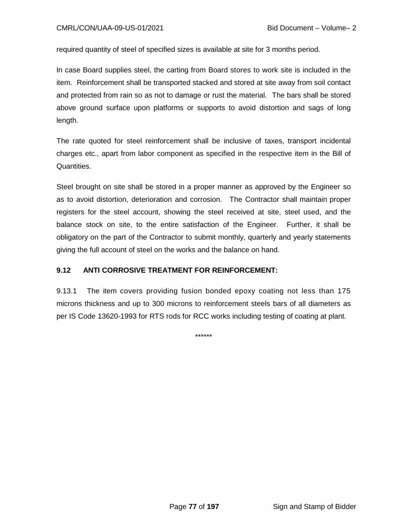
CMRL/CON/UAA-09-US-01/2021 Bid Document – Volume– 2
Page 77 of 197 Sign and Stamp of Bidder
required quantity of steel of specified sizes is available at site for 3 months period.
In case Board supplies steel, the carting from Board stores to work site is included in the
item. Reinforcement shall be transported stacked and stored at site away from soil contact
and protected from rain so as not to damage or rust the material. The bars shall be stored
above ground surface upon platforms or supports to avoid distortion and sags of long
length.
The rate quoted for steel reinforcement shall be inclusive of taxes, transport incidental
charges etc., apart from labor component as specified in the respective item in the Bill of
Quantities.
Steel brought on site shall be stored in a proper manner as approved by the Engineer so
as to avoid distortion, deterioration and corrosion. The Contractor shall maintain proper
registers for the steel account, showing the steel received at site, steel used, and the
balance stock on site, to the entire satisfaction of the Engineer. Further, it shall be
obligatory on the part of the Contractor to submit monthly, quarterly and yearly statements
giving the full account of steel on the works and the balance on hand.
9.12 ANTI CORROSIVE TREATMENT FOR REINFORCEMENT:
9.13.1 The item covers providing fusion bonded epoxy coating not less than 175
microns thickness and up to 300 microns to reinforcement steels bars of all diameters as
per IS Code 13620-1993 for RTS rods for RCC works including testing of coating at plant.
******

CMRL/CON/UAA-09-US-01/2021 Bid Document – Volume– 2
Page 78 of 197 Sign and Stamp of Bidder
CHAPTER 10 - PLASTERING
10.1 DEFINITIONS:
a) The term “plastering” shall cover all types of rough or fair finished plastering, rendering,
floating and setting coat or finishing coat, screed, etc., in mud, lime, cement lime
or cement mortar.
b) “Dubbing out” shall mean filling in hollows in the surface of wall and roughly
levelling up irregular or out of plumb surfaces, prior to rendering.
c) “Rendering” or “rendering coat” shall mean the plaster coat, which is applied following
the “Dubbing out” or the final coat in case of one coat work.
d) “Floating coat” shall mean the second coat in a three-coat plasterwork, to bring the
rendering coat to a true and even surface before the setting or finishing coat is
applied.
e) “Setting of finishing coat” shall mean final coat in a two or three coat plaster work.
f) “Thickness of plaster” shall mean the minimum thickness at any point on a surface.
This does not include thickness of dubbing out.
g) The term “even and fair” as referred to finishing of the plastered surface shall mean a
surface finished with a wooden float.
h) The term “even and smooth” as referred to finishing of the plastered surface shall
mean a surface levelled with wooden float and subsequently smoothened with a steel
trowel.
10.2 SCAFFOLDING:
Where possible, independent scaffolding shall be used to obviate the subsequent
restoration of masonry in putlog and other breaks in the work. Stage scaffolding shall be
provided for ceiling plaster.
10.3 PREPARATION OF MORTAR FOR PLASTERING:
10.3.1 Materials: Cement Mortar:
Cement mortar shall have the proportion of cement to sand as mentioned in the item or in
the special provisions and shall comply with following:

CMRL/CON/UAA-09-US-01/2021 Bid Document – Volume– 2
Page 79 of 197 Sign and Stamp of Bidder
Cement:
Cement shall conform to IS: 12269 - 1987 Ordinary Portland Cement or sulphate
resistance cement as the case. The weight of ordinary Portland cement shall be taken as
50 kg. per bag. The Contractor shall ensure that the cement is of sound and required
quality before using it. Any cement, which has deteriorated, caked or which has been
damaged shall not be used. The Specifications covered under the section brickwork and
concrete work shall be applicable in addition.
Water:
Water shall be clean, clear and free from injurious quantities of salt, traces of oil acids,
alkalis, organic matter and other deleterious materials. The sources of water shall be
approved by the Engineer and the containers for conveyance; storage and handling
shall be clean. If necessary, standard cement tests shall be conducted using the water
intended to be used, in comparison with those adding distilled water to check quality of
water.
Water shall meet the requirement of 4.3 of IS: 456 – 2000. Generally potable water is fit
for mixing and curing.
Fine Aggregate:
All fine aggregate shall conform to IS: 383 – 1970 and relevant portion of IS: 515
–1959.
Sand shall be clean, well graded, hard, strong, durable and of gritty particles free from
injurious amounts of dust, clay, kankar nodules, soft or flaky particles, shale, alkali, salts,
organic matter loam mica or other deleterious substances and shall be approved by the
Engineer. The maximum size of particles shall be limited to 5mm. If the fine aggregate
contains more than 4 percent of clay, dust or silt, it shall be washed.
The fine aggregate for cement mortar for masonry and first cost of plaster should generally
satisfy the following grading:
I.S. Sieve Percent by wt. Passing sieve
4.75mm 100
2.36mm 80-95
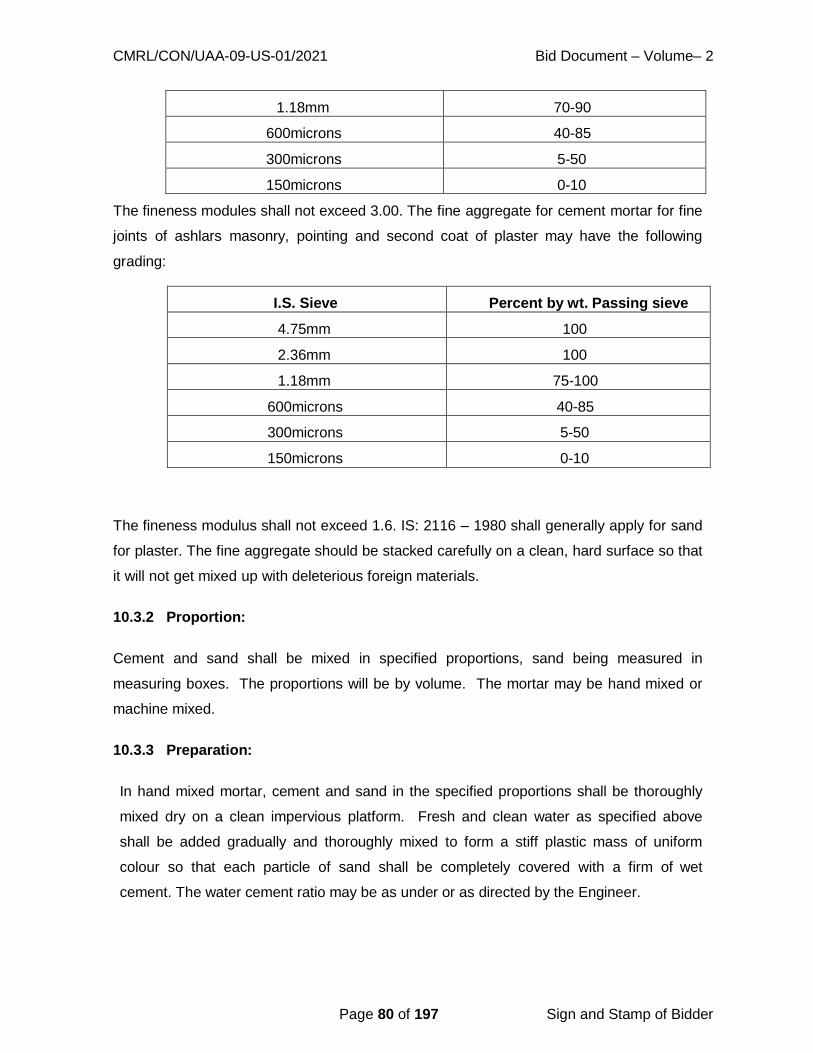
CMRL/CON/UAA-09-US-01/2021 Bid Document – Volume– 2
Page 80 of 197 Sign and Stamp of Bidder
1.18mm 70-90
600microns 40-85
300microns 5-50
150microns 0-10
The fineness modules shall not exceed 3.00. The fine aggregate for cement mortar for fine
joints of ashlars masonry, pointing and second coat of plaster may have the following
grading:
I.S. Sieve Percent by wt. Passing sieve
4.75mm 100
2.36mm 100
1.18mm 75-100
600microns 40-85
300microns 5-50
150microns 0-10
The fineness modulus shall not exceed 1.6. IS: 2116 – 1980 shall generally apply for sand
for plaster. The fine aggregate should be stacked carefully on a clean, hard surface so that
it will not get mixed up with deleterious foreign materials.
10.3.2 Proportion:
Cement and sand shall be mixed in specified proportions, sand being measured in
measuring boxes. The proportions will be by volume. The mortar may be hand mixed or
machine mixed.
10.3.3 Preparation:
In hand mixed mortar, cement and sand in the specified proportions shall be thoroughly
mixed dry on a clean impervious platform. Fresh and clean water as specified above
shall be added gradually and thoroughly mixed to form a stiff plastic mass of uniform
colour so that each particle of sand shall be completely covered with a firm of wet
cement. The water cement ratio may be as under or as directed by the Engineer.

CMRL/CON/UAA-09-US-01/2021 Bid Document – Volume– 2
Page 81 of 197 Sign and Stamp of Bidder
Machine mixed mortar shall be prepared in an approved mixer. Water cement ratio shall
be as per hand mixed mortar. The mortar so prepared shall be used within 30 minutes of
adding water. The mortar remaining unused after that period, mortar, which has partially
hardened or is otherwise damaged shall not be re tempered or remixed. It shall be
destroyed or thrown away.
10.4 PREPARATION OF BACKGROUND FOR APPLICATION OF PLASTER:
Cleanliness:
All dirt, dust and other foreign matter on masonry and laitance on the concrete surfaces
shall be removed by watering and brushing as required. If the background contains
soluble salts particularly sulphates, the application of plaster shall be done only after the
efflorescence of the salts is complete and the efflorescence is completely removed from
the surface.
Joints in brickwork, stone masonry and hollow block, masonry shall be raked out to a
depth of not less than 10mm as the work proceeds. Local projection in brickwork and
masonry beyond the general wall face shall be trimmed off where necessary.
Roughness:
Smooth surfaces of in-situ concrete walls and ceilings etc. shall be roughened by wire
brushing, if it is not hard; and by hacking or bush hammering if it is hard, to provide for
proper adhesion. Projecting burrs of mortar because of gaps at joints in shuttering shall
Cement Sand Water – Cement
ratio
Quantity of water per
50 kg. of cement
(Litres) 1 1 0.25 12.5
1 1 ½ 0.28 14.0
1 2 0.30 15.0
1 2 ½ 0.35 17.5
1 3 0.40 20.0
1 4 0.53 26.5
1 5 0.60 30.0
1 6 0.70 35.0
1 8 0.90 45.0

CMRL/CON/UAA-09-US-01/2021 Bid Document – Volume– 2
Page 82 of 197 Sign and Stamp of Bidder
be removed. The surface shall be scrubbed clean with wire brushes. In addition, concrete
surface shall be pock marked with a pointed tool at spacing of about 50mm, the pocks
made to be not less than 3mm deep.
Suction Adjustments:
Adequate drying intervals shall be allowed between the erection of masonry and plastering
to bring the surface suitable for suction adjustment. High rate of suction makes the
plaster week, porous and friable. The wall shall not be soaked but only damped
evenly before applying the plaster. If the surface becomes dry in spots, such areas
shall be moistened again to restore uniform suction. Excessive water leads to failure
of bond between the plaster and the background.
Evenness:
Any local unevenness must be leveled, and projections removed to avoid variance in the
thickness of plaster.
Immobility:
Differential movements between the background and the plaster due to moisture change,
temperature change, structural settlement, defection, etc. cause cracks. A major part
of such movements shall be allowed to set in before the plaster is applied.
10.5 PLASTERING: Plastering Generally:
The type and mix of mortar for plastering, the number of coats to be applied, the surface
finish of the plaster and the background to which the plaster is to be applied shall be as
indicated.
The mortar for dubbing out and rendering coat shall be of the same type and mix. Dubbing
out may be executed as a separate coat or along with the rendering coat.
Protection:
All existing work and fittings that are likely to be damaged in the application of plastering
shall be protected. Care shall be taken to avoid, as far as possible, the splashing of
mortar on to the finished surfaces such as joinery, paint work and glazing; all such
splashes shall be cleaned off immediately.

CMRL/CON/UAA-09-US-01/2021 Bid Document – Volume– 2
Page 83 of 197 Sign and Stamp of Bidder
Screeds 15 x 15cm shall be laid vertically and horizontally not more than 2m apart to
serve as guides in bringing the work to an even surface.
Plastering shall be done from top to bottom and care shall be taken to avoid joints in
continuous surface.
Maintenance of proper time intervals:
To avoid break down of adhesion between successive coats, drying shrinkage of first coat
shall be allowed to be materially completed before a subsequent coat is applied.
All corners, arises, angles, junctions shall be truly vertical or horizontal as the case may
be and shall be carefully finished. Rounding or chamfering of corners, arises and
junctions shall be carried out with proper templates to the required size. Plastering of
cornices, decorative features, etc. shall normally be completed before the finishing coat is
applied.
In suspending the work at the end of the day, the plaster shall be cut clean to the line both
horizontally and vertically. When recommencing the plastering, the edge of the old work
shall be scraped clean and wetted with lime putty or cement slurry before plaster is
applied to the adjacent area. Partially set and dried mortar shall not be re tempered for
use.
Cleaning of completion:
On completion, all work affected by plastering and pointing shall be left clean, special care
shall be taken when removing any set mortar form glass and joinery, etc. to avoid
damaging their surface.
10.6 ONE COAT PLASTER WORK:
Mortar shall be firmly applied to the masonry walls and well pressed into the joints and
forcing it into surface depressions to obtain a permanent bond. The plaster shall be
laid in a little more than the required thickness and levelled with a wooden float. On
concrete walls, rendering shall be dashed on to roughened surface to ensure adequate
bond. The dashing of rendering coat shall be done using a strong whipping motion at
right angles to the face of walls. The surface shall be finished even and fair. Unless
indicated to be finished even and smooth.

CMRL/CON/UAA-09-US-01/2021 Bid Document – Volume– 2
Page 84 of 197 Sign and Stamp of Bidder
10.7 TWO COAT PLASTER WORK: First Coat:
The first coat of the specified thickness shall be applied in a manner similar to one coat
plasterwork. Before the first coat hardens, the surface of the cement and cement lime
plasters shall be scored to provide key for second coat. In case of lime plasters the
surface shall be beaten with edges of wooden thapies and close dents shall be made
on the surface, to serve as a key to the subsequent coat. The rendering coat shall be kept
damp for atleast two days, it shall be allowed to become thoroughly dry.
Second Coat:
Before starting to apply second coat, the surface of the rendering coat shall be damped
evenly. The second coat shall be completed to the specified thickness in exactly the same
manner as the one coat plaster work.
10.8 NEERU FINISH:
After applying and finishing the undercoats and before they set, the finishing coat of
specially prepared lime putty about 1.5mm thick shall be applied. It shall be well
polished with a trowel.
10.9 SAND FACED PLASTER:
After the undercoat of cement and sand mortar 1:4 not less than 10mm thick, has been
applied and finished, the final coat of cement and sand mortar 1:4 shall be applied to a
thickness not less than 5mm and brought to an even surface with a wooden float. The
surface shall then be tapped gently with a wooden float lined with cork to retain a coarse
surface texture, care being taken that the tapping is even and uniform.
10.10 CURING:
Each coat shall be kept damp continuously for at least two days. Moistening shall
commence as soon as the plaster has hardened sufficiently and is not susceptible to
injury. The water shall be applied preferably by using a fine fog spray. Soaking of wall
shall be avoided and only as much water as can be readily absorbed shall be used.
Excessive evaporation on the sunny or wind ward sides of buildings in hot dry weather
shall be prevented by hanging matting or gunny bags on the outside of the plaster and
keeping them wet.
CMRL/CON/UAA-09-US-01/2021 Bid Document – Volume– 2
Page 85 of 197 Sign and Stamp of Bidder
After the completion of finishing coat, the plaster shall be kept wet for at least seven days
and shall be protected during that period from extremes of temperature and weather.
10.11 WATER PROOFING PLASTER:
Integral water proofing compound shall be mixed with cement in the proportion indicted by
weight. Care shall be taken to ensure waterproofing material gets well and integrally
mixed with cement and does not run out separately when water is added.
******

CMRL/CON/UAA-09-US-01/2021 Bid Document – Volume– 2
Page 86 of 197 Sign and Stamp of Bidder
CHAPTER 11 - LAYING AND JOINTING OF PIPES
11.1 GENERAL
The Work will be set out by the Engineer who will give proper lines, positions, level, depths
and particulars on the ground. The Contractor shall provide poles, rails, boning rods straight
edges, struts, pegs, etc. and all labour for fixing the same. The Contractor must check and
satisfy himself of the accuracy for the finished accuracy of the work in accordance with the
contract. The Contractor shall take every care that the pegs or pillars for levels or lines are
carefully preserved, from disturbances. Should he neglect this precaution the cost of re-
setting shall be borne by the contractor?
11.2. SIGHT RAILS AND BONING RODS
The Contractor shall be required to fix over the centre of each manhole or where a change
in direction or gradient occurs a strong timber sight rail, 150mm x 25mm with top edge
placed straight and true. These shall be supported and fixed to stout wooden posts at each
side of the excavation. The centre line of the sewer shall be marked on each sight rail both
back and front by the single vertical line drawn thereon and on other side white. All lengths
of sewer shall have three sight rails fixed one at each end and one in the centre and worked
one with the other. The boning rods shall have a movable cross head at right angles to the
rod so arranged that it can slide up and down the rod and capable of being fixed at any
required position on the rod by screws. The foot of the boning rod shall be provided with a
shoe made truly at right angles to the rod so that when placed on the pipe being laid it shall
rest properly on the pipe when the rod is truly vertical.
11.3 TRANSPORTATION:
The transportation of materials to work site and stacking shall be done in such a manner
as to cause minimum inconvenience to the traffic and other construction works. Pipes
shall be protected during handling against impact, shocks and free fall to avoid cracks and
damage. Pipes shall be loaded for transportation is in such a way that they are
secured, and no movement can take place on the vehicle during transit. The same care
shall be taken if pipes are transferred from one vehicle to another, however short the
journey may be. The cement mortar lining of pipes that are damaged during
transportation is to be repaired by hand application if possible; otherwise, it has to be
rejected. The decision for rejection shall be taken by the Engineer in charge.
CMRL/CON/UAA-09-US-01/2021 Bid Document – Volume– 2
Page 87 of 197 Sign and Stamp of Bidder
11.4 UNLOADING OF PIPES:
Each pipe consignment shall be inventoried and inspected with care upon arrival even
though the pipes have been inspected and loaded with care at the factory. Overall
examination shall be made during unloading to ensure that the pipes have reached
destination in good condition. If there is any sign of rough treatment on the coating, each
pipe shall be inspected for damage.
While unloading, pipes shall not be thrown down from the truck to the hard roads.
Cranes or Mechanical equipment shall be used for unloading the pipes from the truck. If
mechanical equipment is not available, care should be taken to unload the pipes on timber
skids. Unloading them on timber skids without a steadying rope and thus allowing the
pipe to bump hard against one another should not be allowed. In order to avoid damage
to the pipes specially to the spigot end, pipe should not be dragged along concrete and
similar pavements with hard surfaces.
The pipes shall be laid on timber battens and secured with wooden wedges. The pipes
shall be stacked with each tier at right angles to the preceding tier.
11.5 LOWERING OF PIPES AND FITTINGS:
The pipes shall be lowered cautiously to prevent disturbances of the bed and sides of
the trench.
Proper implements, tools and facilities satisfactory to the Authority shall be provided
and used for the safe and convenient execution of the work. All pipes, fittings, valves and
hydrants shall be carefully lowered into the trench, piece by piece, by means of a derrick,
ropes or other suitable tools or equipment, in such a manner as to prevent damage to
pipes materials and protective coatings and linings. Under no circumstances shall pipes
materials be dropped or dumped into the trench. Pipes over 300mm diameter shall be
handled and lowered into trenches with the help of chain pulley blocks or preferably by
cranes. Tripod supports used for this purpose shall be regularly checked to prevent all
risks of accidents.

CMRL/CON/UAA-09-US-01/2021 Bid Document – Volume– 2
Page 88 of 197 Sign and Stamp of Bidder
11.6 CLEANING OF PIPES AND FITTINGS:
All lumps, blisters and excess coating material shall be removed from the socket and
spigot end of each pipe. The outside of the spigot and the inside of the socket shall be
wire-brushed and wiped clean and dry and free from oil and grease before the pipe is laid.
11.7 LAYING:
Before lowering the pipe, the trench section shall be got approved from the Engineer in
charge. Trenches are to be dug to the specified level / grade. Sufficient cushion shall
be provided for protection from surface traffic, future changes in the ground elevation. The
width of the trench shall be to the required specifications providing room for pipe laying
operation, backfilling, compaction etc., Trenches should be shored and braced when
conditions so warrant.
The bottom of the trench shall form a continuous bed for the pipe. Where rock is
encountered, trenches shall be dug deeper and then filled and compacted to grade with
suitable bedding material. The Contractor shall have to provide and maintain sight rails
and boning rods wherever required till the completion of work. The pipe shall be laid in
reasonably dry condition and under no circumstances they shall rest on slushy bedding.
The pipes shall be lowered slowly into the trench by means of chain pulley block and tripod
stand or with the help of ropes and suitable size of wooden bullies or with the help of
cranes. They shall be brought to the required level by giving packing with wooden
sleeper pieces and ultimately with well-consolidated hard murum if required. The chain
pulley block and tripod stand must be approved from the Engineer in charge. Under no
circumstances pipe shall be allowed to be thrown in the trenches.
At the end of each day, the end of the pipe should be plugged to prevent entry of rodents,
foreign substances, water etc.
11.8 SUPPORT OF PIPE FOR NALLAH / RIVER CROSSING:
Venteak piles are proposed for portion of pipeline which crosses the nalla / river or slushy
soils. Each pipe shall be supported on a pair of Venteak piles driven up to 3.50m or
firm ground whichever is met earlier.
One pair of timber piles shall be driven about 150mm behind the shoulder of toe socket

CMRL/CON/UAA-09-US-01/2021 Bid Document – Volume– 2
Page 89 of 197 Sign and Stamp of Bidder
and another pair about 750mm in front of the spigot end of the pipe. The size of timber
section to be used for Venteak piles shall be:
100mm x 100mm for pipe sizes up to 300mm
150mm x 150mm for pipe sizes above 300mm
A cross piece of section same as that of pile shall be bolted to a pair of piles which
have been driven to the required depth.
The level of the cross piece should be such that when the pipe rests on its top, its Invert
level coincides with the proposed invert of the pipe.
The pipe shall be aligned for straightness and secured in position by wooden wedges
nailed down to the wooden cross piece.
The spigot end of each pipe shall be thoroughly homed in to socket of preceding pipe and
jointing made.
The pipe shall be further secured from moving upwards by timber crosspieces bolted to
the supporting piles. The section of the crosspiece shall be same as that of pile.
The socket ends of all pipes shall face up hill irrespective of the direction of water
flow. Any deviation either in plan or elevation of less than 11 ¼ deg. angle shall usually be
affected by laying straight pipes round a flat curve; of such radius that rubber gasket shall
not be disturbed in its place.
Wherever new pipes laid are to be jointed with existing pipeline, first pipe laying work of
new pipes are to be completed. Jointing of new pipeline with existing pipeline has to be
completed within a stipulated time as per the instructions of Engineer in charge to keep the
distribution system ready to supply water to the city. No extra payment will be made for
this time bound urgent work.
11.9 TESTING:
After laying and jointing, the pipeline must be pressure tested to ensure that the pipes and
joints are sound enough to withstand the maximum pressure likely to be developed under
working conditions. The Contractor shall submit for the Engineers approval, details of his
proposed methods and programme for testing including details of test equipments and
shall arrange for all tests to be witnessed by the Engineer or his representative. The

CMRL/CON/UAA-09-US-01/2021 Bid Document – Volume– 2
Page 90 of 197 Sign and Stamp of Bidder
Contractor shall provide all things necessary for carrying out testing and cleaning including
water pumps, gauges, piped connections, stop ends, and all other temporary works.
Pipelines shall be properly completed and supported before being put under test. No
testing will be permitted until ten days after thrust blocks and other holding down works
have been completed. In addition to any tests of individual joints or other interim tests
which may be specified elsewhere, the Contractor shall submit, all parts of the pipelines to
a final test. Notwithstanding the foregoing, the Contractor may at any stage of
construction, carry out such other tests as he considers desirable to check materials and
workmanship on the pipeline, but this shall not relieve the Contractor of his obligations to
achieve successful tests under the contract.
All water required for testing and cleaning the pipelines shall be potable water and shall
be provided by the Contractor at his cost. The test can be carried out by means of a hand
pump or a pressure pump. Pipelines shall be tested in lengths between valve pits or
such lengths as the Engineer may direct or permit.
Fittings required for temporarily closing the openings in pipelines to be tested shall be
properly designed for this purpose and shall be adequately strutted to withstand the
pressure specified.
The completed pipeline may be tested in sections; the length of section should be decided
by considering:
(a) the availability of suitable water.
(b) the number of joints to be inspected; and
(c) the difference in elevation between one part of the pipeline and another.
The maximum length that can be tested in one operation shall be restricted to 500m
and minimum length shall be 50m. Where joints are left uncovered until after testing,
sufficient materials should be backfilled over the centre of each pipe to prevent movement
under the test pressure.
The Contractor shall make his own arrangements to procure necessary
equipments, apparatus etc., required for testing and shall provide necessary labour for
filling with water the length of pipes to be tested, fixing all apparatus and for carrying on

CMRL/CON/UAA-09-US-01/2021 Bid Document – Volume– 2
Page 91 of 197 Sign and Stamp of Bidder
the testing operations until the length of pipe, specials and connections are firmly passed
by the Engineer. If the testing apparatus and equipments are available with the Board,
they can be hired by the Contractor at usual conditions and charges.
The length to be tested shall be provided with two blank flanges fastened on the usual
manner by collar bands and bolts to the end pipes or if the length to be tested shall have a
sluice valve at each end, such blank flanges may be dispensed with.
The length of pipes to be tested shall first be filled in with water from a higher section of
pipes already laid or with clean water obtained from a service connection, as the
Contractor may arrange with the approval of the Engineer.
Before the actual testing pressure is applied, any air which has logged in the length of
pipe to be tested shall be got rid of, by screwing on at the highest part of the length of
pipes or temporary air valve, or by opening a temporary stopcock or by other means as the
Engineer may direct.
The test pressure shall not be less than 10 kg/cm2.
Each pipeline or section thereof shall be filled with water and all air removed. The
pressure in the pipelines shall be raised steadily until the site test pressure is reached in
the lowest part of the section. This pressure should be maintained, by pumping if
necessary, for a period of not less than 1 hour. The pump should then be disconnected,
and no further water permitted to enter the pipeline for a period of 1 hour. At the end of
this period, the reduced pressure in the pipeline should be measured, the original test
pressure restored by pumping and the loss measured by drawing off water from the
pipeline until the pressure has fallen to match the reduced pressure previously noted. The
loss shall not exceed 0.02 litre per mm diameter per Kilometer per 24 hours for each bar
of head applied. If the pipeline fails to pass the test, the faults shall be located and
repaired, and the pipeline retested until it passes the pressure test. All exposed pipe,
fittings, valves and joints shall be visually inspected during the tests.
If the length of pipeline under test is found to be satisfactory and no leaks or sweating are
found at the pipe joints or at the joints of specials and connections, then this length of
pipeline will be passed by the Engineer.
But should any pipe, joint, special or connection be found to sweat or leak, Contractor shall

CMRL/CON/UAA-09-US-01/2021 Bid Document – Volume– 2
Page 92 of 197 Sign and Stamp of Bidder
make good at his cost such defective joints and the length of pipeline shall be retested
until all pipes, joints specials and connections are found to be satisfactory.
After satisfactory test, the Contractor shall remove water from the pipeline and clean it
after testing at his own cost, without flooding adjoining areas.
Duration of Hydraulic Test:
The test is for 1 hour only. The rate of allowable leakage is given on per day basis. The
leakage observed within one hour shall be converted to per day basis and compared
with criteria given.
Maximum field test pressure for pipes with flexible joints:
Table – 1 on page 11 of IS:12288 is not applicable in this case as our test
pressures are well below the maximum field hydraulic test pressures given in the table.
Allowance of test pressure for lower elevations:
As regards allowance for lower points, there is marginal level difference in levels,
between 2 points in the section to be chosen for testing and hence the difference in
pressure developed will be insignificant.
Saturation of pipe material:
As regards saturation of material, it is significant in case of RCC, PSC pipes for DI pipes it
is insignificant. We are not clear whether the remark is aimed at saturation of inner CM
lining. The adequate curing of the lining will take care of this. Also, the duration of the
test is long enough to discount such possibility.
11.10 INTERCONNECTION WORK:
The interconnection work between the existing main and the proposed main to be laid
under this contract shall proceed from the new main to the existing main. Before actually
proceeding with the interconnection work, the Contractor shall make ready necessary tools
and plants required for the work at site, such as pump sets, shoring materials etc. He shall
also keep ready at site necessary pipes, jointing materials, specials and valves required
for the work. The Contractor shall keep necessary skilled workmen of sufficient strength
at site and once the work commenced, the entire interconnection work shall proceed

CMRL/CON/UAA-09-US-01/2021 Bid Document – Volume– 2
Page 93 of 197 Sign and Stamp of Bidder
without interruption by engaging labour for carrying out the work on a continuous basis
both day and night till the work is completed. The work shall be executed as per
programme drawn up by the Engineer and shall be completed within the time ordered by
the Engineer, for each individual interconnection. The work shall be carried out under
the direction of the Engineer from the beginning to end.
Laying of specials, valves (except straight pipes from the branch of the new main to the
connecting point in the existing main) including conveying specials etc. from the stores or
site of stacking, excavating, timbering, pumping out water from the trenches, lowering,
aligning, jointing specials and valves, cutting the existing mains, dealing with water,
inserting the necessary branches, jointing, testing, refilling etc. is included in the item of
providing, laying and jointing Cast Iron / MS pipes. Any ancillary work either of Temporary
or Permanent nature required for interconnection and not covered by schedules shall be
executed by the Contractor at no extra cost.
11.11 MAKING JOINTS
a) Rubber Ring Joints
In case of rubber right joints or push on joints, the groove and the socket shall be
thoroughly cleaned before inserting the rubber gasket. While inserting the gasket it shall
be made sure that it faces the proper directions and that it is correctly seated in the
groove. After cleaning dirt or foreign materials from the plain end, lubricant shall be
applied in accordance with the pipe manufacture‟s recommendations.
The Contractor shall make sure that the plain end is beveled as square or shape edges
may damage or dislodge the gasket and cause a leak. When the pipe is cut at site, the
plain end shall be beveled with a heavy file or grinder to remove all sharp edges.
The plains end of the pipe shall be pushed into the socket of the pipe and while pushing,
the pipe shall be kept straight. If any deflections are to be made in the alignment, it may
be made after the joint is assembled. A timber header shall be used between the pipe
and crowbar or jack to avoid damage to the pipe while the plain end of the pipe is pushed
into the socket wither with a crowbar or jack, or lever puller.
b) Flanged Joints for CI pipes and specials
Flanged joint should be made by painting the facing of the flange with white lead freely and
CMRL/CON/UAA-09-US-01/2021 Bid Document – Volume– 2
Page 94 of 197 Sign and Stamp of Bidder
bolting up evenly on all sides. A thin fibre of lead wool may be very useful in making the
joints watertight were facing of the pipes is not true.
When packing must be used, it should be of rubber insertion three ply and of approved
thickness. The packing should be of the full diameter of the flange with proper pipe hold
and bolt holes cut out evenly on both the inner and outer edges. Where the flange is not
full faced, the packing may be of diameter of the packing strip only, proper placing of the
packing should be checked before another pipe is jointed on.
c) Lead joints for CI specials
Generally, lead joints shall be used for all size, in the case of 100mm pipes, cement
joints may be used if specified in which case for every ten cement joints, one lead joint
shall be used. Provisions of lead shall also be used at street crossings at closing joints
and for all specials and as determined by the Engineer depending upon the site conditions.
The spigot end of the pipe must be placed well home into its sockets and must be centered
so that the joints may be of even thickness all round, as may laps of white hemp spun yarn
as may be needed to leave the space required for the lead shall be driven to the bottom of
the socket without being forced through the joint into the pipe but carefully driven home
with a caulking tool. The proper depth of each joint shall be tested before running the
lead by passing completely round it a wooden gauge, noticed out to the correct depth
of lead the notch being held close against the face of the socket. The joints shall them be
run with molten lead in sufficient quantity so that being caulked solid, the lead may project
3 mm beyond the face of the socket against the outside of the spigot but must be flush
with the outside edge of the socket.
For pouring lead in the joints, a ring of hemp rope covered with clay shall be wrapped
around the pipe at the end of the socket leaving on opening at the socket into which led
can be poured. The hemp rope shall be supported by clay packing so as to withstand the
operation of lead pouring.
The lead used shall be carefully skimmed of all scale, when melted in a cast iron port or
patent melting machine. Sufficient lead shall then be taken by a ladle and run hot into the
joint, and the joint filled at one running. The joint shall than be caulked when cool by a
suitable caulking tool and a 2 kg hammer and joint left neat and smooth.
The weight of lead and hemp which shall be used in each joint shall be in conformity with
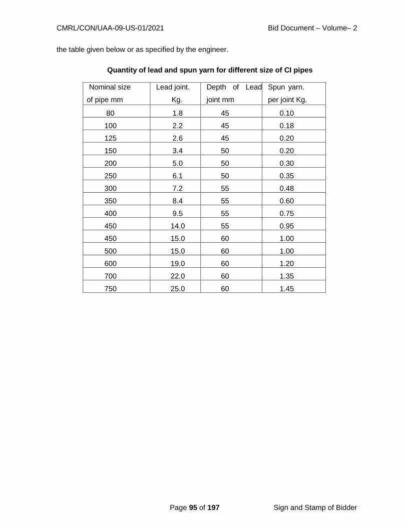
CMRL/CON/UAA-09-US-01/2021 Bid Document – Volume– 2
Page 95 of 197 Sign and Stamp of Bidder
the table given below or as specified by the engineer.
Quantity of lead and spun yarn for different size of CI pipes
Nominal size
of pipe mm
Lead joint.
Kg.
Depth of Lead
joint mm
Spun yarn.
per joint Kg.
80 1.8 45 0.10
100 2.2 45 0.18
125 2.6 45 0.20
150 3.4 50 0.20
200 5.0 50 0.30
250 6.1 50 0.35
300 7.2 55 0.48
350 8.4 55 0.60
400 9.5 55 0.75
450 14.0 55 0.95
450 15.0 60 1.00
500 15.0 60 1.00
600 19.0 60 1.20
700 22.0 60 1.35
750 25.0 60 1.45

CMRL/CON/UAA-09-US-01/2021 Bid Document – Volume– 2
Page 96 of 197 Sign and Stamp of Bidder
CHAPTER -12 DOUBLE WALL CORRUGATED (DWC) PIPES
12.General
Structured wall Plastic Piping Systems in the form of class SN-8 Double wall corrugated
(DWC) Polyethylene (PE) or Polypropylene (PP) Pipe with non-smooth external Annular
Corrugated and Smooth Internal Surfaces (double wall) featuring On-line coupler and
spigot end configurations type herein after called the DWC Piping System including
supply of elastomeric sealing ring shall be manufactured as per IS: 16098 (Part-2)
2013/EN:13476-1 & 3 (latest revision). The jointing of pipes shall be done using
elastomeric sealing ring gasket conforming to IS: 5382 (latest revision).
12.1 Applicable codes
12.2.1 The manufacturing, testing at factory, supplying, transportation, handling, stacking,
installation, jointing, and testing at sites shall comply with all currently applicable National
statutes, manuals, regulations, standards & codes. If requirements of these
specifications are at variance with any other standards, this particular document shall be
governed by the proceedings of and supplemented by the following National Code(s)
and International Specifications:
IS 16098 (Part 2): 2013 Structured-wall Plastics Piping Systems f o r N o n - pressure
Drainage and Sewerage – Specification
Part 2 Pipes and Fittings with Non-smooth External
Surface, Type B
EN 13476-1 Plastics piping Systems for non-pressure underground
drainage and sewerage- Structured-wall piping
systems.
Part 1: General requirements and performance
characteristics
EN 13476-3 Plastics piping Systems for non-pressure underground
drainage and sewerage- Structured-wall piping systems.
Part 3: Specifications for pipes and fittings with smooth internal
and profiled external surface and the system, Type B
12.2.2 For pipes manufactured in India, the pipe manufacturer should have valid BIS
license for manufacturing of DWC pipes of all sizes as per IS 16098 (Part-2) 2013 for
last two years third party certificate for compliance with relevant IS or EN mentioned
above, from a National/ international testing institute shall be provided.
12.2.3 The Pipe Manufacturer should be an ISO 9001 certified company.
12.2.4. The Manufacturer should give an undertaking that their firm is not blacklisted by

CMRL/CON/UAA-09-US-01/2021 Bid Document – Volume– 2
Page 97 of 197 Sign and Stamp of Bidder
any Government Departments / Government under takings / Statuary Body /
Municipal Corporation / Municipality for the past three years.
12.3. Raw material
Raw material used to manufacture DWC PE/PP pipes shall be virgin material in such
form as granules that has not been subjected to use or processing other than that required
for its manufacture and to which no re-processable or recyclable materials have been
added. The Material, Physical, Mechanical and Performance requirements shall be
governed by IS: 16098 (Part-2) 2013 / EN: 13476-1 &3 (latest revision) and other relevant
codes as applicable pertaining to above two Specification documents.
12.4 Composition of material
The material from which the pipe is produced shall consist substantially of polyethylene
(PE) or Polypropylene (PP) to which may be added those additives that are needed to
facilitate the manufacture of these pipes and fittings conforming to requirements of the
standard as per IS:
16098 (Part-2) 2013 / EN: 13476-1 & 3 (latest revision).
12.5 Colour of pipe
The Colour pipe of DWC pipe, class SN 8 pipe shall be Black outside and orange or off-
white.
12.6 Rework material
Clean re-processable material according to IS: 16098 (Part 2) 2013 / EN: 13476-1 & 3
(latest revision) may be used if it is derived from same raw material as used for relevant
production and generated in- house. Reworked material obtained from external source
and recyclable materials shall not be used.
12.7 Dimensions
The pipe dimensions shall be as per latest revisions and amendment of specified
standards and as given in tender documents. The pipes shall be supplied in straight
lengths of minimum 6m each with On-line (integral) or offline (below 250mm) coupler at
one end and one no of elastomeric sealing ring per pipe.

CMRL/CON/UAA-09-US-01/2021 Bid Document – Volume– 2
Page 98 of 197 Sign and Stamp of Bidder
The internal diameter, wall thickness, length and other dimensions of pipes shall be as per
relevant clauses given in IS 16098 (Part-2) 2013/ EN: 13476-3 (latest revision). The
dimensional tolerances shall be as per specified standards.
12.8 Performance Requirements
The pipes & fittings supplied should have passed the acceptance tests as per various
clauses given in the specified standards in terms of the relevant
Material/Physical/Mechanical Characteristics of pipes & fittings. The manufacturer should
provide the Performance test certificates for the tests conducted, as required in specified
standards along with the supply of pipes & fittings. These acceptance tests can be
performed in the in-house laboratory of the pipe manufacturer. The certificates provided by
the Raw Material manufacturers shall also be an integral part of the performance
requirements in terms of the material characteristics of the supplied pipes & fittings.
12.9 Marking
As per the provision of clause 11.2.1 of IS: 16098(Part 2) 2013 each straight length of
the pipe shall be clearly marked in indelible ink/ paint at an interval of maximum 3m, at
least once per pipe, with the following information:
a. Manufacturer’s name/Trademark
b. Diameter series, nominal size
c. c. Stiffness class
d. Material
e. Lot number / batch number containing information regarding period of manufacturing
12.10 jointing
Jointing shall be done using push-fit methodology and online/offline coupling for full length
pipe along with the elastomeric sealing ring provided. For pipes to be cut at site, the
manufacturer shall provide extra coupler that shall match the dimensions of the pipe (at
pro-rata extra cost).
CMRL/CON/UAA-09-US-01/2021 Bid Document – Volume– 2
Page 99 of 197 Sign and Stamp of Bidder
12.11 Field Sample Inspection
Employer / Department / Board reserves the right to test the samples of Pipes and Fittings
randomly picked up from project site storage / project site in terms of the specified clause
of Standards for testing at nationally reputed laboratories.
12.12. Handling & Installation
Handling
Following Recommendations shall be followed while handling the pipes:
1. Pipes to be smoothly lowered to the ground.
2. Pipes should not be dragged against the ground to avoid the damages to the
Coupler/pipes.
3. 800mm and larger diameter pipes are carried with Slings at two points spaced
approximately at 3 Meters apart.
4. For smaller diameters (400mm – 800mm) one lift point shall be sufficient & can be
handled either manually or mechanically.
5. Do not use a loading Boom or Forklift directly on or inside pipe.
Pipe Storage at Site
1. Stockpiling shall be done temporarily on a Flat Clear Area.
2. For avoiding collapse of Stacks, use Wooden Posts or Blocks
3. Stacking shall not be higher than 2.5 Meters.
4. While stacking, alternate the socket/coupler ends at each row of stacked pipes.
12.13 Lowering, Laying & jointing of Pipes.
The width of a Sewer Trench depends on the soil condition, type of side protection needed,
and the working space required at the bottom of Trench for smooth installations. Increase
in width over required minimum would unduly increase the load on pipe and cost of road
restoration. Considering all above factors, the Minimum Trench Width is specified as per

CMRL/CON/UAA-09-US-01/2021 Bid Document – Volume– 2
Page 100 of 197 Sign and Stamp of Bidder
Table below: -
Indicative Trench Widths**
Pipe Diameter (mm) Trench Width (M)
75-200 0.6
250 0.7
300 0.8
400 0.9
600 1.2
800 1.3
1000 1.8
In actual practice the trench width shall be kept as narrow as possible but shall be adequate
to allow the workmen to execute the Lowering, Laying & Jointing job satisfactorily.
The pipe segment between two manholes shall be laid approximately in straight line
without any vertical undulations (at prescribed Gradient). However, on the strength of its
flexibility, the DWC PE Piping system can be aligned and laid in wide smooth curve if
found necessary. The piping system shall rest on the carefully prepared bedding portion
of the „Backfill Envelope‟ and at appropriate jointing locations the trenches shall be
excavated deeper to accommodate the bulges of coupler-spigot joints. However, special
care shall be ensured as mentioned below: -
Excavation of trenches shall be carried out in accordance with the specifications and as
directed by the field engineer as well.
The piping system shall be laid and jointed in true to gradient with the help of sight rails
and boning rods as detailed in CPHEEO, MoUD, GoI Manual on Sewerage and sewerage
treatment. The levels need to be checked with calibrated modern Levelling Instrument.
Specific care shall be taken to prevent entry of sand / mud /slush/ any other foreign
material etc into the system during the installation operation.
The structural property of the system suggests that a minimum cover of 500 mm is
adequate even for maximum quantum of superimposed (live) load.

CMRL/CON/UAA-09-US-01/2021 Bid Document – Volume– 2
Page 101 of 197 Sign and Stamp of Bidder
The bedding area is an essential portion of Back fill Envelope and shall be constructed
with proper bedding material as computed in accordance with appropriate national code of
practice for structural bedding design mentioned in the list of normative references under
IS 16098-2. The bedding shall be laid to specified thickness and gradient with proper
manual/mechanical compaction of the aggregate.
On first valley of the corrugation of said spigot end (destined to receive the pushed
coupler), the sealing rubber ring of standard quality (as specified in Cl 8.3 of the
mentioned IS Code) shall be placed so that the Coupler End of the pipe smoothly but
tightly slides over the sealing ring for making an absolute watertight joint. For quality
connections following steps are to be ensured, failing which the performance aspects are
to be severely compromised: -
The non-coupler (socket) end needs to be thoroughly cleared and shall be free from any
foreign material Clean and lubricate the coupler end of the pipe, if required. Lubricate the
exposed Gasket in the same manner, if required.
Keep the non-coupler end free from dirt, backfill material, and foreign matter so that the
joint integrity is not compromised.
Push the coupler in onto the non-coupler end and align properly. Always push coupler end
onto non-coupler end.
For smaller diameter pipes simple manual insertion shall be sufficient. It should be
ensured that the coupler end is adequately „homed‟ on non-coupler end to ensure
installation and tight joining seal.
12.14 Construction of backfill envelope and final backfilling of the trenches.
DWC Piping System with well compacted Backfill Envelope along with the bottom and
sides of trench (native soil) work together to support soil overburden and superimposed
(traffic) loads. The carefully constructed Backfill Envelop has three distinct but non-isolated
stages. The construction needs to be done stage by stage as per the sequence stated
below:
o Bedding portion
o Up to Haunch level
o Remaining portion

CMRL/CON/UAA-09-US-01/2021 Bid Document – Volume– 2
Page 102 of 197 Sign and Stamp of Bidder
The material for backfill envelop shall be in accordance with the structural design of flexible
buried conduit as per relevant National codes in meticulous consultation with ISO 21138-
1 &3 :2007 and all other referred International Codes such as BS EN 1295-1 that
forms an integral part of the said ISO Specifications. It can be the same material that were
removed in the course of excavation or it can be fine sand/course sand/gravel / moram
/other form of course / fine aggregates depending on the effected Design Load
[Overburden + Superimposed (Live) load]. However, in no circumstances, the flexible
pipe should not be embedded in cement concrete (un- reinforced or reinforced) which
invariably induces undesired rigidity in the system. The Manufacturer may also be
consulted to provide for the necessary module for the Structural Design of the „Backfill
Envelope‟.
The remaining portion of backfilling which do not contribute to the structural
integrity of the system may be the materials that were removed in the course of excavation
or any other foreign material as may be required to suit the particular site condition. These
materials shall consist of at least clean earth and shall be free from large clod or stone
above 75 mm, ashes, refuse and other injurious materials.
After completion of bedding portion of the Backfill envelop and subsequent lying of
pipes, etc, first the haunch portion & then upper portion of Backfill Envelope shall be
constructed as per design around the pipe. Voids must be eliminated by knifing under
and around pipe or by some other indigenous tools.
The compaction, by hand rammers or compactors with necessary watering to a
possible maximum level of proctor density shall be ensured.
Remaining portion of the Construction of „Backfill Envelope‟ (above the Bedding
Portion) & subsequent final Backfilling of the Trench shall start only after ensuring
the water tightness test of joints for the concerned sewer segments. However, partial
filling may be done keeping the joints open.
Precautions s h a l l be taken against floatation (if at all necessary) as per the specified
methodology and the minimum required cover.
12.15 Field Hydraulic Test of DWC Pipeline
a. The Sectional Hydraulic Test shall be carried out after the pipeline section to be

CMRL/CON/UAA-09-US-01/2021 Bid Document – Volume– 2
Page 103 of 197 Sign and Stamp of Bidder
tested has been laid jointed and backfilled to a depth sufficient to prevent floatation.
b. Each length of the pipeline to be tested shall be capped or blanked off at each end and
securely strutted or restrained to withstand the forces which will be exerted when the
test pressure is applied.
c. The proper method of filling the pipeline with water shall be used. The length under
test shall be filled making certain that all air is displaced through an air valve or
any other appropriate mechanism. The test length shall then remain under constant.
moderate pressure as per testing method given in IS: 16098 (Part-2) 2013 / EN:
13476-3 (latest revision) / 7634 (Part 1) and as directed by engineer.
d. As per IS code, water required to build-up allowable drop in pressure during test will be
treated as make up water.
e. Notwithstanding the satisfactory completion of the hydraulic test, if there is any
discernable leakage of water from any pipe or joint, the Contractor shall, at his own
cost, replace the pipe, repair the pipe or re- make the joint and repeat the hydraulic
test with cost including the cost of water.
f. Hydraulic testing of manholes and DWC pipes shall be carried out along with testing of
pipeline which is mandatory. The contractor at his own cost shall arrange the required
water for testing and other requirements.
******

CMRL/CON/UAA-09-US-01/2021 Bid Document – Volume– 2
Page 104 of 197 Sign and Stamp of Bidder
CHAPTER 13 - CAST IRON PIPES / FITTINGS
13.1 MATERIALS:
Cast Iron Pipes and Fittings:
The pipes manufactured by Cast iron shall conform to IS: 1536 – 2001 and its latest
amendments. and having socket/spigot (p u s h on joint) and Flange joint. The Fittings
manufactured by Cast iron shall conform to IS: 1538 – 1993 and its latest
amendments having socket, spigot or Flange joint.
Rubber Gaskets:
The Rubber Gaskets used for push-on joints shall conform to IS: 5382:1985. Rubber ring
bundles from every lot shall carry with them manufactures test certificate for the following
mechanical properties.
a) Hardness
b) Tensile strength
c) Compression strength
d) Oil immersion test
e) Water absorption test
f) Stretch test and visual examination
The test procedures, the scale of sampling and the criteria for acceptance shall be as per
IS: 5382 and IS: 3400.
The Engineer or his representative shall at all reasonable times have free access to the
place of manufacture for inspection and examining the test conducted by manufacturer.
Rubber rings shall be clearly labeled in bundles to indicate the type of ring, the type of joint,
the size of the pipe with which they are to be used, the manufacture‟s name and trademark,
the month and year of manufacture.
Rubber gaskets should be stored in a cool, dark place protected from excessive exposure
to heat, direct sunlight, ozone, oil and grease. The rubber gasket should, whenever
possible, be stored in a relaxed form free from tension, compression or any other

CMRL/CON/UAA-09-US-01/2021 Bid Document – Volume– 2
Page 105 of 197 Sign and Stamp of Bidder
deformation.
Rubber gaskets for use with flanged joints shall conform to IS 638.
13.2 CLASSIFICATION:
Pipes have been classified as LA, A and B according to their thickness. depending on
service conditions. In the Bid document, the classes of socket spigot pipe considered are
according to its functional use and service conditions.
13.3 INSPECTION:
All works and materials under specification will be inspected during all phases of
manufacture and testing and such inspection shall not relieve the Contractor of his
responsibility to furnish materials and performed work in accordance with this specification.
The Contractor shall notify the Engineer, in advance of the production of materials and
fabrication thereof, in order that the employer may arrange for mill and shop inspection.
The Engineer may reject any or all materials or works that do not meet with any of the
requirements of these specifications. The Contractor shall rectify or replace such rejected
material / performed work at his own cost to the satisfaction of the Engineer.
The Engineer shall have free access to those parts of all plants or any other premises and
sites that are concerned with the furnishing of materials or the performance of work under
this specification.
The Contractor shall furnish to the Engineer or his representative responsible facilities and
space without charge for inspection, testing and obtaining of any information he desires in
respect of the character of material used and the progress and manner of the work.
The Contractor shall furnish all the test results from an approved laboratory at any time
during the progress of work to the satisfaction of the Engineer. The laboratory shall be
approved by the Board.
13.4 MANUFACTURE OF C.I. PIPES:
The general requirements relating to the supply of the material are laid in IS 1387.
The metal used for the manufacture for the pipes shall be of good quality commensurate
with the mechanical requirement laid down in Clause 11 of IS 1536:2001. It shall be
manufactured by any method at the discretion of the manufacturer provided that the
requirements defined in the IS 1536:2001are complied with. It is also essential that either

CMRL/CON/UAA-09-US-01/2021 Bid Document – Volume– 2
Page 106 of 197 Sign and Stamp of Bidder
the Contractor/supplier or the manufacturer should ensure that the manufacture of C.I. pipes
and Fittings should be fully covered by ISO 9000 certification.
The pipes shall be such that they could be cut, drilled or machined. In case of dispute the
pipes may be accepted provided hardness measured on the external unmachined surface
does not exceed 230HBS. Pipes centrifugally cast shall be heat treated in order to
achieve the necessary mechanical properties and to relieve casting stresses. If necessary,
the pipes may be subjected to reheat treatment to ensure that Brinell Hardness does
not exceed the specified value and the specified mechanical properties are satisfied.
The pipes shall be stripped with all precautions to avoid warping or shrinkage defects,
detrimental to their good quality. The pipes shall be sound and free from defects and
surface imperfections which could impair compliance with the requirements of this standard.
Pipes showing small imperfections which result from the method of manufacture, and
which do not affect their serviceability shall not be rejected on that account alone. Minor
defects arising out of manufacturing process may be rectified with consent of the purchaser.
Repairing of defects by soldering or application of epoxy putty may be carried out to such
minor defects provided that the repair pipes comply with all the requirements as given
below:
When necessary, pipes may be repaired to remove surface imperfections and localized
defects which do not affect the entire wall thickness, provided that the repaired pipes
comply with all the requirement as per clause 11 and 12 of IS 1536:2001.
Joints.
Joint designs for socket and spigot suitable for push-on joint / flange joints which are
generally followed as per the relevant IS.
In case of push-on joints, the spigot ends shall be suitably chamfered for smooth entry of
pipe in the socket fitted with the rubber gasket.
In case of flanged pipes, the flanges shall be at right angle to the axis of the pipe and
machined on the face. The bolt holes shall be drilled.
The bolt hole circle shall be concentric with the bore and the two flanges of the pipe shall be
correctly aligned.

CMRL/CON/UAA-09-US-01/2021 Bid Document – Volume– 2
Page 107 of 197 Sign and Stamp of Bidder
Rubber Gasket for use with push-on – joints shall conform to IS 5382. The dimension of
rubber gaskets, for use with push-on-joints shall conform to IS 12820. Rubber gaskets for
use with flanged joints shall conform to IS 638.
13.5 SAMPLING:
Sampling criteria for various tests, unless specified in the standard, shall be as laid down
in IS: 11606 - 1986. The material acceptance tests shall be carried out on cast iron pipes
grouped in batches as follows. Each batch shall be made up of pipes cast successively as
under:
DN 80 to 300 200 pipes
DN 350 to 600 100 pipes
DN 700 to 1000 50 pipes
DN Above 1050 25 pipes
13.6 MECHANICAL TESTS:
Mechanical tests shall be carried out during manufacture. Test shall be conducted for every
four hours of production. The results obtained shall be taken to represent all the pipes of all
sizes made during that period.
The ring test and tensile test for pipes shall be conducted as per clause 11.2 of IS
1536:2001.
13.7 BRINELL HARDNESS TEST:
For checking the Brinell hardness, the test shall be carried out on test ring or bars cut from
the fitting used for test conforming to IS: 1500 – 2005. The Brinell hardness shall not
exceed 230 HB on the external unmachined surface.
13.8 HYDROSTATIC TESTS:
Pipes shall be tested hydrostatically aat the pressure specified in Tables1 and 2as
appropriate as per clause 12 of IS 1536:2001. To perform the test, the pressure shall be
applied internally and shalllbe steadily maintained for aperiod of minimum 10s. The
pipes shall withstand the pressure test and shall not show any sign of leakage, sweating or
other defects. As far as possible, hydrostatic test shall be conducted before coating the
pipes. Socket and spigot pipes shall withstand test pressure at works as specified in the
following Table:

CMRL/CON/UAA-09-US-01/2021 Bid Document – Volume– 2
Page 108 of 197 Sign and Stamp of Bidder
Table: Hydrostatic Test Pressure for Centrifugally Cast Socket and Spigot pipes
Class Hydrostatic Test Pressure at works Mpa
Upto DN 600 (including) DN 700 and above
LA 3.5 1.5
A 3.5 2.0
B 3.5 2.5
pipes shall withstand test pressure at works as specified in the following
Table: Hydrostatic Test Pressure for Centrifugally Cast pipes with screwed on
flanges.
Class Hydrostatic Test Pressure at works
Mpa
Upto DN 300 (including) DN 350 to600
B 2.5 1.6

CMRL/CON/UAA-09-US-01/2021 Bid Document – Volume– 2
Page 109 of 197 Sign and Stamp of Bidder
13.9 COATING
Each pipe shall be coated in accordance with Clause 1 of IS 1536:2001. Coating shall not
be applied to any pipe unless its surfaces are clean, dry and free from rust. Unless
otherwise agreed between the employer and the contractor/ manufacturer all pipes
shall be coated externally and internally with the same material by dipping in tar or suitable
base bath. The pipes may be either preheated before dipping or the bath may be uniformly
heated. Alternatively, if mutually agreed between the employer and the contractor/
manufacturer, the pipes may be coated by spraying or brush painting.
The coating material shall set rapidly with good adherence and shall not scale off. Coating
test shall be conducted on a sample piece cut from the pipe having a sample area not less
than 10 sqm. Where the coating material has a bitumen or similar base, it shall be smooth
and tenacious and hard enough not to flow when exposed to a temperature of 65 degC for
five minutes but not so brittle at a temperature of 0 deg C as to chip off when scribed
lightly with a pen knife.
Pipes with or without sockets and flanges which are imperfectly coated or where the
coating does not set or conform to the required quality, the coating shall be removed, and
the pipes/flanges recoated.
13.10 QUALITY ASSURANCE
The Contractor /Manufacturer shall demonstrate the conformity of the CI Pipe/fittings with
the IS 1536:2001 and IS 1538;1993 respectively by controlling the manufacturing process
and carrying out the various tests.
13.11 MARKING
Each pipe shall have cast, stamped or indelibly painted on it the following appropriate
marks:
a) Manufacturer‟s name, initials or identification mark
b) The nominal diameter.
c) Class reference
d) Mass of pipe
e) The last two digits of the year of manufacture
CMRL/CON/UAA-09-US-01/2021 Bid Document – Volume– 2
Page 110 of 197 Sign and Stamp of Bidder
Marking may be done:
a) on the socket faces of pipe centrifugally cast in metal mould,
b) on the outside of the socket or on the barrel of pipe centrifugally cast in sand mould.
c) Any other marks required by the purchaser/ employer may be painted on.
13.12 CAST IRON FITTINGS
Cast Iron fittings having spigots, sockets or flanges shall conform to IS 1538:1993. The
general requirements relating to the supply of the material shall conform to IS 1387:1993.
The fittings shall be stripped with all precautions necessary to avoid warping or shriking
defects. The fittings shall be free from defects, other than any unavoidable surface
imperfections which result from the method of manufacture and which do not affect the
use of fittings. By agreement between the manufacturer and the purchaser, minor defects
may be rectified.
The fittings shall be such that they could be cut, drilled or machined and may be accepted
provided the hardness of the external unmachined surface does not exceed 210 HBS.
In the case of spigot and socket ends suitable for lead joints, socket shall be with or without
the centering ring. In the case of flanged joints, the flanges shall be at right angles to the
axis of the joint and machined in face. The bolt holes shall be drilled. The bolt hole circle
shall be concentric with the bore and bolt holes shall be located off the centre lines, unless
otherwise specified by the purchaser. The two flanges of the fittings shall be correctly
aligned.
13.13 MECHANICAL TESTS
Mechanical tests shall be carried out during manufacture. Two tests per day of casting
may be adequate. The results obtained are taken to represent all fittings of all sizes made
during the day.
Two tensile tests shall be made on bars cast from the same metal in accordance with the
method specified in IS 2078:1979. The results of the tests shall show a minimum tensile
strength of 150 MPa.
Brinell tests shall be carried out on the test bars used for the test as mentioned above. The
test shall be carried out by applying either a load of 3000 kg to a ball of 10 mm diameter
CMRL/CON/UAA-09-US-01/2021 Bid Document – Volume– 2
Page 111 of 197 Sign and Stamp of Bidder
for 15 seconds, or aload of 750 Kg to a ball of 5mm diameter for 10 seconds.
13.14 HYDROSTATIC TEST
For hydrostatic tests, the fittings shall be kept under pressure for 15 seconds; they may be
struck moderately 700g hammer. They shall withstand the pressure test without showing
any leakage, sweating or other defect of any kind. The hydrostatic test shall be conducted
before coating the fittings.
When fittings are required for higher test pressure, the test pressures are subject to special
agreement between the employer and the contractor/manufacturer.
The fittings shall withstand the pressure as given below:
Table: Hydrostatic Test Pressure for Fittings
Nominal diameter Test Pressure (Mpa)
Upto DN 300 (including) Fittings without branches
or with branches not greater
than half the principal diameter
Fittings with branches greater
than half the principal diameter
Upto and including 300.
mm
2.5 2.5
Over 300 mm and upto
and including 600 mm
2.0 2.0
Over 600 mm and upto
and including 1500 mm
1.5 1.5
13.15 MASS
The masses have been calculated by taking the density of iron as 7.15 kg/cu dm the
standard masses shall conform to those given in the relevant Tables of IS 1538:1993.
The permissible tolerances on standard mass of fittings shall be (+ or -) 8 percent except
for bends, fittings with more than one branch and non-standard fittings, in which case the
tolerance shall be (+ or -) 12 percent. Fittings of a heavier mass than the maximum may
be accepted provided they comply in every other respect with the requirement of this
standard.
13.16 COATING
After inspection and hydrostatic test, each fitting shall be coated as follows.
CMRL/CON/UAA-09-US-01/2021 Bid Document – Volume– 2
Page 112 of 197 Sign and Stamp of Bidder
Coating shall not be applied to any fitting unless its surface is clean, dry and free from rust.
Unless otherwise agreed between the purchaser and the manufacturer all fittings shall be
coated externally and internally with the same material by dipping in a tar or suitable
base bath. The fittings may be either preheated before dipping or the bath may be
uniformly heated. Alternatively, if mutually agreed between the employer and the
Contractor/ manufacturer, the fittings may be coated by spraying or brush painting.
The coating material shall set rapidly with good adherence and shall not scale off.
Where the coating material has tar or similar base, it shall be smooth and tenacious and
hard enough not to flow when exposed to a temperature of WC but not so brittle at a
temperature of 0°C as to chip off when scribed lightly with a penknife.
In the case of fittings (wholly or partially coated) which are imperfectly coated or where the
coating does not set or conform to the required quality specified the coating shall be
removed and the fittings re-coated.
13.17 MARKING
Each fitting shall have cast, stamped or indelibly painted on it the following appropriate
marks:
a) Manufacturer‟s name, initials or identification mark.
b) The nominal diameter.
c) Mass of fitting; and
d)The last two digits for the year of manufacture.
Marking may be done on the outside of the socket or on the barrel of the fitting. Any
other mark required by the purchaser may be painted on.
******
CMRL/CON/UAA-09-US-01/2021 Bid Document – Volume– 2
Page 113 of 197 Sign and Stamp of Bidder
CHAPTER 14 HOUSE SERVICE CONNECTIONS
14.1 GENERAL
The house service connection shall be affected using Stone ware pipes of sizes.
100mm diameter and 150mm diameter at manhole doors only and upto boundary of
premises (on road portion only) and do not require any specials except one stopper (100mm
& 150mm dia).
14.2 MATERIALS:
The Glazed Stoneware Pipes shall conform to IS: 651 – 1992.
14.3 QUALITY:
All pipes shall be sound and free from visible defects which impair the strength, durability
and serviceability. The glaze of pipes and fittings shall be free from crazing. The pipes shall
give a sharp clear note when struck with a light hammer. Colour of pipes/fittings may vary
from yellow to dark brown/black.
14.4 GLAZING:
The interior and exterior surfaces of the pipes which remain exposed after jointing, shall be
glazed. The portion which remains covered after jointing may or may not be glazed. The
glaze shall be obtained by the action of fumes of volatized common salt on the material of
the pipes during the process of burning.
14.5 INTERNAL DIAMETER
The internal diameter of the barrels of straight pipes, junctions and bends shall be as
specified in co1umn 1 of Table 1 in IS-651-1992.
14.6 LENGTH AND STRAIGHTNESS OF BARRELS OR STRAIGHT PIPES
The length of the barrel of the straight pipes exclusive of internal depth of the socket shall be
600mm.
CMRL/CON/UAA-09-US-01/2021 Bid Document – Volume– 2
Page 114 of 197 Sign and Stamp of Bidder
14.7 GROOVING
The interior of the sockets and exterior of the spigots shall be grooved circumferentially, and
such grooving on the spigot shall be for a length equal to one and half times the depth of the
socket, and depth of such groove shall be between 1mm to 25mm.
14.8 MARKING:
Every pipe and fitting shall have legibly impressed upon it More firing the following:
a) Name or trademark of the rnanufacturer, and
b) Size (Internal Dia).
Each pipe may also be marked with the Standard Mark.
14.9 TESTS
14.9.1 Testing Facilities
The manufacturer shall, at his premises and at his own cost, provide the necessary gauges,
supply and prepare all test pieces and supply all labour and apparatus for testing which
may be necessary for carrying out the tests as required by IS standard: 651-1992.
14.9.2 Hydraulic Test
When subjected to the hydraulic test, straight pipes shall withstand an internal hydraulic test
pressure of 0.15 MPa on the barrels without showing signs of injury or leakage. The
pressure shall be applied on pipes at a rate not exceeding 0.075 MPa in 5 seconds, and full
pressure shall be maintained for at least 5 seconds. Care shall be taken to ensure that all air
is expelled before the test is commenced.
14.9.3 Absorption Test
Pipes shall be tested for absorption in accordance with the procedure given in Clause 7.3 of
IS:651 - 1992.
14.9.4 Test for Acid Resistance
Pipes shall be tested for acid resistance with hydrocholoric or nitric or sulphuric or acetic
CMRL/CON/UAA-09-US-01/2021 Bid Document – Volume– 2
Page 115 of 197 Sign and Stamp of Bidder
acid in accordance with the procedure given in Annex A of IS:651 - 1992. The loss in mass
shall not exceed 0.25 percent.
14.9.5 Test for Alkali Resistance
Pipes and fittings shall be tested to the action of magnesium sulphate in accordance with
the procedure given in Annex B of IS:651-1992. There shall be no evidence of pitting,
softening, spalling or cracking in the pipe or fitting after the test.
14.9.6 Crushing Strength Test
When tested along the full length of the pipe barrel from shoulder to spigot in accordance
with Annex C, the pipe tested shall have a minimum crushing strength of 16 k N/m
length.
14.10. LAYING STONEWARE PIPES
Before laying the pipes, the Contractor shall carefully brush them to remove any soil, stores
or other materials which may be therein, even and regular bed having been prepared, and
joint pit excavated to form a recess under the socket of each pipe of no greater width and
depth than to enable to the pipe joining to be properly done, each pipe shall then be
carefully lowered and placed singly in the trench and shall rest on the solid ground for a
distance of not less than two thirds of its entire length.
Each pipe shall be brought into a true line from manhole to the premises, for this purpose, a
strong twine line (rat thread) sufficiently long to reach the full length between manholes shall
be used. Each pipe shall be set correctly to level.
The spigot of each pipe shall be carefully wrapped with a ring of spun yarn dipped in cement
grout or tarred gasket sufficiently thick to properly fit the socket of the adjoining pipe and to
allow true alignment. The pipe shall then be driven fully home into the socket of the adjacent
previously laid pipe and yarn or tarred gasket carefully driven home with a caulking tool.
The remaining space in the socket shall then be tightly and completely filled with cement
mortar composed of one part of Portland cement and one and a half parts sand and shall be
nearly bevelled off around the circumference and finished at an angle of 45 degrees outside
the socket of the pipes. A wooden caulking tool shall be used for forcing the mortar into the
sockets.

CMRL/CON/UAA-09-US-01/2021 Bid Document – Volume– 2
Page 116 of 197 Sign and Stamp of Bidder
A tightly fitting bag of shavings or straw having a rope attached shall be drawn through the
pipes as the work proceeds to ensure that there is no cement or yarn or other obstruction
projecting into the interior.
All joints shall be kept moist either by means of wet bags, wet clay or wet earth whichever
may be ordered by the Engineer to protect them from the sun. Such covering shall be
removed when the length is tested for water tightness.
In trenches where ordinary socket and spigot stone ware pipes are to be laid on concrete,
the method to be adopted is as follows.
When the earth is taken out to the proper depth and gradient, a concrete bed of suitable
thickness and width is to be laid as directed by the Engineer. The top of this concrete bed
shall be to the required gradient.
When the concrete has set sufficiently, a series of special concrete invert blocks are to be
laid about 60 cm apart and levelled so that their top surface may be exactly the level of the
sewer invert, less the thickness of the pipes. The correctness of level of the pipes is to be
ascertained by working a straight edge from the invert of each pipe to block ahead. The pipe
must also be checked at intervals for the proper line and level and the first pipe of any length
must be very carefully bedded and levelled into position.
The object to be obtained by the method above described is to ensure that the outside of the
sockets shall be raised approximately 25mm above the concrete bed in order to allow the
joints to be made properly in the underside.
In his prices for laying concrete, the Contractor must allow for doing the work in the manner
as above described including cost of blocks.
14.10.1 Concreting Pipelines
The bedding for different sizes of concrete pipes shall be with sand as per specifications
No.7 of Tamil Nadu Building Practice (TNBP).
The bedding for different sizes of SW pipes shall be with M-15 Concrete as per IS code.
The minimum earth cover for all the pipes to be laid shall be not less than 0.8m.
CMRL/CON/UAA-09-US-01/2021 Bid Document – Volume– 2
Page 117 of 197 Sign and Stamp of Bidder
14.10.2 Cleaning out Sewers and Manholes.
During the whole of the work the Contractor shall keep interior surface of sewer and
manholes free from cement mortar, bricks, soil or other superfluous matters and shall hand
over the sewers perfectly clean and free from deposit on completion.
14.10.3 Water Test of Sewers
All sewers shall be tested before the filling in of the trench or other excavations. Testing
shall also be done after refilling of the trench or other excavations, if considered necessary
by the Engineer. The testing or re-testing shall be carried out by and at the expense of the
Contractor who shall also provide the necessary appliances and water for the same. The
tests will only be made from manhole to manhole after the manholes connected with the
length under test have been completed finished.
The test shall be carried out in the following manner.
The pipes shall be carefully cleared of all earth or materials that may be lying thereon or
therein and all joints shall be exposed right round so that thorough examination may be
made whilst the pipes are under test.
The ends of the pipe shall be closed by means of expanding stoppers and all junctions with
stoneware stoppers or cement disc fixed in cement mortar.
The last but one pipe at the higher end of the length shall be a junction pipe with the junction
arm at the top which will permit of the filling of the length with water and also allow the
escape of all air in the pipes.
The expanding stoppers at each end of the length under test shall have a hold in the centre
with a small piece of a pipe screwed therein and threaded on the projecting pipe to permit of
a flexible tube not less than 2m long fixed thereto by a coupling. At the end of the flexible
tubing, the following shall be fixed.
a. at lower end of length, a cock,
b. at top end of length, a funnel of 15cm diameter.
The top of the funnel shall be fixed rigidly at a height of 30cm above the ground level, or
such other height as may be decided by the Engineer.
CMRL/CON/UAA-09-US-01/2021 Bid Document – Volume– 2
Page 118 of 197 Sign and Stamp of Bidder
After the above-mentioned expanding stoppers have been fixed together with flexible
tubing and funnel, the length shall then be filled with water through the junction arm of the
pipe provided, therefore. As soon as the water has risen to the level of the filling junction
arm an expanding stopper shall be fixed thereon. After a short time has been allowed for
absorption, water shall be poured into the funnel until the same is filled to the top.
If any of joints are leaking or if during a period of ten minutes the water level in the funnel
drops 25 mm or more (no more water being added, or sewer interfered with in anyway
during the period) the test shall be considered unsatisfactory. If the water does not drop
more than 25 mm and there is not sign of leakage at any of the joints, the test shall be
continued for one hour and at the end of the hour the pipelines including the joints shall be
examined and, if no indication of sweating or leakage is found then the test will be
considered satisfactory. Should the test be unsatisfactory, all such joints or pipes found to be
defective shall be removed, replaced or repaid to the satisfaction of the Engineer by the
Contractor at his cost.
The test shall be done as many times as may be necessary until the length is found to be
watertight to the satisfaction of the Engineer. The water required for testing shall be clean.
14.10.4 Cleaning of Mains
During the whole of the Work the Contractor shall keep the interior surface of the mains free
from cement, brick, soil or other superfluous matter and shall hand over the mains perfectly
clean and free from deposit on completion.
******

CMRL/CON/UAA-09-US-01/2021 Bid Document – Volume– 2
Page 119 of 197 Sign and Stamp of Bidder
CHAPTER 15- POLYETHYLENE MANHOLES
All PE manhole chambers shall be on the basis of EN 13598-2:2009 or equivalent Indian
Standard, if any with regard to design calculations and performance testing. All chambers
shall be of a solid single wall construction made of 100% virgin PE material without
recycling or foam content.
All chambers shall come with a prefabricated integrated base with a proper gradient. The
manhole shall be designed to receive inlet pipes of various diameters either at the base
level or anywhere at the shaft level with elastomer seal for a flexible connection of pipes
according to EN681-1. The inlet pipe connection methodology shall allow for fast, easy
and flexible on-site connection of inlet pipes either at the time of laying or at a later time
for further inlet connections such as house connections by simple drilling of hole of
appropriate diameter, placing EN 681-1 elastomer seal and pushing inlet pipe for a
watertight connection. In case the system is made of modular parts then triple safety
(three-sided lip/element) seal according to EN 681-1 or equivalent India Standard, if any, to
be used to connect the parts. Manholes shall have corrosion-resistant steps with vertical
step distance being 30 cm. In order to safeguard against uplift pressure manhole should
have solids horizontal circular reinforcement ribs of appropriate thickness and width.
These ribs should be strategically placed at regular intervals all along the outside of the
shaft of the manhole.
SFRC manhole cover and frame conforming to IS No.12592/2002 with clear dimension of
600mm diameter and appropriate loading as approved by the Engineer shall be placed
on a RCC load distribution ring. The RCC load distribution ring made of concrete grade M
35 shall be prefabricated and designed to handle heavy traffic load as approved by the
Engineer. For 1250mm dia PE manholes, the load distribution ring shall be of 160mm
thickness, 1300mm OD and appropriate ID. The prefabricated RCC load distribution ring
shall rest on a bed of RCC M20 grade concrete slab of 1750mm OD and appropriate ID.
The manhole shall be placed over stone dust bed of 15mm thick and PCC 1:3:6 of 200mm
thick and 1750mm diameter. There shall be an overlap of 75mm between the top surface
of the prefabricated RCC load distribution ring and top end of the PE manhole. Care
should be taken to ensure that RCC load bearing ring is not in direct contact with PE
manhole.

CMRL/CON/UAA-09-US-01/2021 Bid Document – Volume– 2
Page 120 of 197 Sign and Stamp of Bidder
CHAPTER 16 – PRECAST MANHOLES
Precast manholes shall be manufactured conforming to IS 3370:2009, IS 456:2000, IRC
BRIDGE CODE-1966, Design aids and CPHEEO Manual. Precast manholes shall be
constructed as base units of minimum 1m height and maximum height of 1.5m height, riser
unit of height (maximum 1.5m height) suiting to the depth of manhole and roof slab
separately. Base slab shall be constructed monolithically with base unit. Provision shall be
made for shear key (male and female joint) in the mid-section of wall for jointing Base
unit and riser unit in addition grout holes shall be provided in two faces of wall for insertion
of Protruded bars. These Protruded bars shall be provided adjoining to the vertical bars
in the grout hole locations for joining base unit and riser unit/riser and riser unit.
Dimension of shear key is 50mm x 50mm.Grout hole size shall be 10mm more than the
Protruded bar size. The jointing shall be with cement mortar 1:1 ratio with 1% (by weight
of cement) of Polyurethane based water sealant. Levelling concrete 1:1.5:3 using 20mm
jelly shall be provided below the base slab over the sand filling. Roof slab shall be
provided over the riser unit has the provision for FRC manhole cover. Hole size for
incoming, outgoing sewer and house service shall be pipe diameter plus 10mm. Holes
for incoming, outgoing sewer and house service shall be made in the base unit or riser
unit during the casting of the units itself and location of holes shall be made according to
the site conditions.CI steps fixed in the precast units during the casting of the units itself.
Sulphate resistant cement shall be used for concrete. M30 design mix concrete and Fe415
shall be used for RCC works. Cover shall be 45mm. Hoop steel and vertical bars
shall be provided on both sides. Wire mesh reinforcement shall be provided for shear key
male joint portion. Extra reinforcement shall be provided around openings for pipes
(main, branch sewers and house service connections) as per IS code SP 34. Adequate
curing should be ensured to attain required strength of precast units. Reinforcement for
handling and erection shall be designed as per site conditions during execution. The
precast units shall be transported to the site with trailer. Care should be taken to avoid
damage of units during transportation. The manhole shall be tested with water for
48hours for water tightness and the defects shall be rectified if any. The RCC design
for manholes is based on soil bearing capacity of 20t/sqm and hence the design shall be
checked according to the site conditions during execution. It is good to ensure adequacy of
connections of units during erection. Crack prevention and effective load transferring
in the precast units and at the joints should be ensured.

CMRL/CON/UAA-09-US-01/2021 Bid Document – Volume– 2
Page 121 of 197 Sign and Stamp of Bidder
CHAPTER 17- PUMPS, MACHINERY AND ELECTRICAL WORKS.
General Specifications
Following clauses s p e c i f y G e ne r a l E l e c t r i c a l r e q u i r e m e n t s a n d s t a n d a r d
o f workmanship for the equipment and installations. General Specification clauses shall
apply where appropriate except were particularly redefined elsewhere.
I. Electrical Wiring and installation of fittings
1.The materials used shall conform to the relevant I.S.S where applicable. The make
and other details of materials to be used should be furnished along with the tender.
2.Continuous earth connection is to be made with 14 SWG T.C. wire.
3.The wiring work done shall be neat, true to line, level etc. and in such a way that it
gives an impressive and aesthetic appearance to the building.
4.The actual location and number of points for lights, fan powers plug etc., may be
altered at the time of execution by the Engineer.
5.Entire wiring and cabling work should be done as per IE rules.
6.Any damages or breakages, chipping etc., caused by the electrification works to
the structures have to be rectified by the contractor at his cost of the satisfaction of
the Engineer.
7.The contractor has to test each and every point after completion of wiring to the
entire satisfaction of the Engineer by taking temporary supply from the existing
service.
8.Wiring to light point (both internal and external) and fan point will be treated as
complete only when supply as well as connection up to the ceiling rose is
completed.
9.Whenever conduit pipe wiring is done, cover for switch boards containing switches
plugs, etc., should be ahylam sheet or another specified sheet only.

CMRL/CON/UAA-09-US-01/2021 Bid Document – Volume– 2
Page 122 of 197 Sign and Stamp of Bidder
II. Machinery and other Equipment’s
1. All the materials used shall conform to relevant I.S.S. wherever applicable and should
be delivered at site of work. The contractor is responsible for safe custody of materials
and equipments under this contract till handling over to the Board.
2. The rates should include all the minor items of civil works if any required for
installation complete.
3. All necessary civil works for erection of all equipments for accessories offered by the
Contractor under this contract should be done by the Contractor. The rates for civil
works are to be quoted wherever called for.
4. Test certified for machinery and equipments should be produced along with the
supply.
5. The contractor should supply one set of tools for the pumpset maintenance of the
machinery and equipments supplied by them under this contract.
6. The contractor has to operate and maintain the pumpsets and other machinery and
equipments for a period of 30 days to the entire satisfaction of the Engineer, free of cost,
unless otherwise specified. Fuel, lubricants and power supply if required will be
supplied free of cost, for operation and maintenance during that period.
7. The tender should enclose along with their tender performance curves including
efficiency curves of the pumpsets, makes and other details and certificates from their
claimed manufacturers, stating that the equipments offered by them would be supplied
by the manufacturers.
8. The contractor should supply immediately after commissioning three sets of operation
and maintenance manuals for all equipments and machinery supplied under this
contract.

CMRL/CON/UAA-09-US-01/2021 Bid Document – Volume– 2
Page 123 of 197 Sign and Stamp of Bidder
General
1. Cable lengths given are only approximate and payment will be made for the actual length
of cable laid.
2. The contractor has to make necessary arrangements to get supply of electricity from
TNEB for operating the machinery and equipments. The necessary Service Connection
and S.D. charges will be paid by the Board.
3. The contractor should obtain all approvals for the installation and commissioning of
machineries and accessories offered by them from the respective inspecting authorities
such as CEIG or CIFG etc., Fees if any, to be paid to the inspecting authorities will be
reimbursed by the Board.
4. Before supply of the machinery equipments and other materials, prior approval of the
Engineer should be obtained giving the name of maker and other details required.
CMRL/CON/UAA-09-US-01/2021 Bid Document – Volume– 2
Page 124 of 197 Sign and Stamp of Bidder
GENERAL SPECIFICATIONS
1. Equivalency of Standards and Codes
Wherever reference is made in the contract to specific standards and codes to be met by
the materials, plant, and other supplies to be furnished, and work performed or tested, the
provisions of the latest current edition or revision of the relevant standards and codes in
effect shall apply, unless otherwise expressly stated in the contract. Where such
standards and codes are national or relate to a particular country or region, other
authoritative standards which ensure a substantially equal or higher performance than the
standards and codes specified will be accepted subject to the Engineer's prior review and
written approval. Differences between the standards specified and the proposed
alternative standards must be fully described in writing by the Contractor and submitted
to the Engineer at least 28 days prior to the date when the Contractor desires the
Engineer's approval. In the event the Engineer determines that such proposed deviations
do not ensure substantially equal performance, the Contractor shall comply with the
standards specified in the documents.
2. Use of Trade Names
Wherever reference is made in the Contract to specific manufacture‟s or trade names
the Contractor shall be entitled to substitute plant and materials supplied by other
manufacture‟s or produce‟s. Such substitutions shall be to the approval of Engineer,
which will not be unreasonable withheld. At the request of the Engineer the Contractor
shall provide full evidence to establish that the substituted plant and material is equal to
or better than that from the manufactures or supplied mentioned in the Contract.
3. Requirement of Statutory Authorities
The electrical equipment / installations shall comply with the requirements of Rules /
Regulations as amended up to date, required by Statutory Acts or Authorities.
- The Indian Electricity Rules, 1956
- The Indian Electricity Act.
- The Indian Electricity (Supply) Act, 1948
- The requirements of Chief Electrical Inspector to the Government of Tamil Nadu.
CMRL/CON/UAA-09-US-01/2021 Bid Document – Volume– 2
Page 125 of 197 Sign and Stamp of Bidder
- The requirement of Tamil Nadu State Electricity Board.
- Fire advisory Committee Insurance Act.
- The contractor shall get the drawings, layouts of HT subs tation etc. approved from
TNEB and chief Electrical inspector to the Govt. of Tamil Nadu, wherever
necessary. The contractor also shall arrange to get the installation inspected by CEIG
and carryout modifications/rectification as required by CEIG, prior tocommissioning of
substation/electrical equipments.
4. Voltage Regulation
During starting of heavy equipment, the voltage may drop by a maximum of 15% for
period of 45-60 seconds depending upon the duty of the driving equipment. All the
electrical equipment shall, therefore, be suitable for trouble free and uninterrupted
operation even during such voltage variation at the time of starting of heavy equipments.
5. Ambient Temperature
Where the equipment is installed outside and exposed to direct sunrays, these shall
be suitable for operation at higher ambient temperature and rigorous weather
conditions under which they are required to operate.
6. Power Factor
Suitable rating capacitors shall be provided to each individual motor above 1.5 KW
rating along with discharge device of appropriate rating to improve the power factor above
0.95.
7. Approval by Fire Insurance Authority
The equipment supplied along with the accessories shall be those approved for use in
Electrical installations by the Fire Sectional Committee, Central Regional Council of the
Insurance Association of India.
8. Conditions of Operation
The equipment offered shall be suitable for continuous operation under high ambient
temperature 45 C. Motors for outdoor installation shall be weatherproof.

CMRL/CON/UAA-09-US-01/2021 Bid Document – Volume– 2
Page 126 of 197 Sign and Stamp of Bidder
The switch board shall not be exposed to moisture or corrosive gases.
The Contractor shall submit layout drawings showing the location of switch board and
other equipment proposed to be installed for the approval of Engineer.
9. LT Supply
The contractor shall ascertain the availability of LT supply from TNEB and to procure
equipments accordingly.
9.1 MV / LT Panel
The medium voltage control panel or motor control panel shall normally have ACBs,
MCCB and MCB as the case may be. The number of equipments and capacity of each
equipment shall depend on the requirement of a particular pumping station. The Panel
shall be made of 12 SWG (2.6mm) sheet steel for the front side and 14 SWG (2.0mm)
sheet steel for bottom and other sides with powder coating for long life. Necessary neutral
link block to be provided at required locations. These panels shall be front wired, front
connected and provided with closing handles with ON and STOP mechanical indication
having in built locking system so that back access would not be required for inspection
and maintenance. The enclosure shall be dust and vermin proof type. Since the entry of
cables of the panel is generally from the bottom, the cable gland supporting plate shall be
mounted not less than 300 mm above the floor level.
9.2 Air Circuit Breakers
The medium voltage cubicle type switch board shall consist of four pole Air Circuit
Breakers confirming to latest revision of IS:13947 Part 2 / IEC:60947 Part 2. The breaker
shall be manually draw out type in open execution with over current trip device adjustable
64% to 110%. Time setting for overload, adjustable current setting for short circuit
protection and also earth fault protection adjustment facility shall be provided in the
ACB.
ACB shall be fitted with following:
- Heavy duty switch having not less than 4 No. + 4NC contacts
- Built in resin cast current transformer
- Auxiliary contacts
- Shunt and under voltage tripping device

CMRL/CON/UAA-09-US-01/2021 Bid Document – Volume– 2
Page 127 of 197 Sign and Stamp of Bidder
- Neutral CT for earth fault protection
- The ACB shall be suitable for locking the breaker in various position.
Provision for door locking ACB shall be provided with the requisite end
termination lugs/sockets. Terminal bars for connecting more than one
terminal.
The ACB shall have breaking capacity not less than 35kA at 415V AC.
9.3 Moulded case circuit breakers
Moulded Case Circuit Breakers confirming to latest revision of IS:13947 Part 2 / IEC:60947
Part 2 shall be fixed type fitted with trip free, manually closing mechanism, accommodated
in a sheet steel housing of robust and vermin proof construction matching with switch
boards. All MCCBs shall be tested as per IS-2516 Part-1, Sec-1 and shall be provided
short circuit and overload protection. (position of the knob shall clearly indicate ON, OFF
and TRIP conditions).
9.4 Terminal Blocks
Terminal blocks shall be 650 V grade, 10 Amps., rated one piece moulded, complete
with insulated barriers, screw type brass terminals suitable for stacking on C type rail
and identification strips. Marking on the terminal strips shall correspond to wire numbers
on the wiring diagrams. The terminal blocks for CT and VT secondary leads shall be
provided with test links and isolating facilities. Also, CT secondary leads shall be provided
with short circuiting and earthing facilities.
All spare contacts and terminal of panel mounted equipment and devices shall be wired to
terminal blocks.
At least 20% spare terminal shall be provided on each panel, uniformly distributed on all
terminal blocks.
9.5 Indicating Instruments.
All electrical indicating instruments shall be digital square type of 144 sq.mm or 96
sq.mm according to the suitability of panel. These shall be suitable for flush mounting
with only flanges projecting on vertical panel. Instrument dial shall be white with black
numericals and lettering.

CMRL/CON/UAA-09-US-01/2021 Bid Document – Volume– 2
Page 128 of 197 Sign and Stamp of Bidder
Instrument shall conform to IS - 1248 and shall have accuracy class of 1.00 or better. The
current coil of ammeters and potential coils of voltmeters shall continuously withstand
120% of rated current and voltage, respectively, without the loss of accuracy.
The meters shall have external zero adjustments. The ammeters fitted in the motor
circuits shall have suppressed scale to indicate the maximum starting current. The
instrument shall be provided with glass cover to avoid the possibility of measurements
due to static charge.
The three phase three wire trivector meter shall comprise of kWh meter and kVARh meter
mounted together with kVAh meter in one case with special summator mounted between
them to register correct kVAh at all power factors.
All the meters shall have respective maximum demand indicators to record the average
power over a period of half an hour. The trivector meter shall conform to relevant IS.
9.6 Equipment wiring
All the switch boards, panels, annunciator panel and mimic panel shall be neatly wired
using 1100/660-volt grade PVC insulated stranded copper conductor cable of minimum
2.5 mm to suit the requirement. The wiring shall be bunched in groups by non- metallic
clips or bands. Each group shall be adequately supported along its run to prevent sagging
and strain on the terminals.
Sharp and tight bends shall be avoided. Each wire shall be identified at both ends by
ferrules indicating the designation of the wire in accordance with the Schematic / wiring
diagrams. The wire shall be terminated on the terminals of the relays, switches,
instrument, conductors, lamps etc, or on the terminal blocks as the case may be. No joints
shall be provided in between. Terminal blocks shall have screw type terminals which can
take at least two wires per terminal on each side. At least 20% spare terminals shall be
provided on each terminal block.
9.7 Interlocking Arrangement
The panels containing the MCCB / MCB etc. shall be enclosed in free standing steel sheet
enclosure with front cover so interlocked with the isolator that the door cannot be opened
with isolator at „ON‟ position.
CMRL/CON/UAA-09-US-01/2021 Bid Document – Volume– 2
Page 129 of 197 Sign and Stamp of Bidder
9.8 Inspection of Circuits
Facility for inspection of the circuits, to ascertain if all the Conductors, relays, fuses, etc.
are in proper working order/condition or otherwise shall be provided by means of a push
button or selected switch.
9.9 Labeling
Labels of switch gears shall indicate reference number of the switch, the specified current
rating and the part of the distribution controlled. Labels on circuit breaker boards shall
indicate the reference number of controlling switches. The lettering of all labels shall not
be less than 5 mm, high. The schedule and details of the labels shall be submitted to the
Engineer for approval.
9.10 Cable Entry
The cable entry shall preferably be from the bottom which shall be dust and vermin
proof. The cable entry on each equipment shall be through a compression type cable
gland. The cable gland plate shall be sufficiently strong to take the load of the cables
and shall be mounted not less than 300 mm. above the floor level. The cables shall
be suitably clamped before the cable gland to avoid any strain on it.
9.11 Painting
The panels shall undergo chemical derusting, sand blasting, degreasing, pickling in acid
bath and phosphatised as per IS:6005 and primed. The panels shall be thoroughly rinsed
with clean water after phosphating, followed by final rinsing with dilute bichromate
solution and oven drying. The phosphate coating shall be sealed by the application of
two coats of ready mixed, stoving type zinc chromate primer.
Two coats of finishing synthetic enamel paint shall be applied, each coat followed by
stoving. The final finished thickness of the paint film on steel shall not be less than 100
microns and shall not be more than 150 microns. The colour for the finishing paint shall
be bright battleship grey as per IS:5 (Shade No. 631). The finished painted appearance
of panels shall present an aesthetically pleasing appearance free from dust and
uneven surface.
The paint shall withstand humid tropical climate, rain, etc. The paint shall not scale of
CMRL/CON/UAA-09-US-01/2021 Bid Document – Volume– 2
Page 130 of 197 Sign and Stamp of Bidder
or crinkle or removed by abrasion during normal handling.
Sufficient quantity for touch-up paint shall be furnished for application at site.
10. Motor Control Panel
The motor control panel shall have the following equipments.
- Main switch fuse or MCB, MCCB with required capacity in case of 415V motor
pumps sets.
- ACB or suitable circuit breaker to suit the motor capacity and voltage in case
of HT motor pump sets.
- Motor starter - Auto transformer / Star Delta.
- Contactors
- Single phase preventor
- Ammeter with selector switch
- Voltmeter
- Pilot lamps for indication
- Trip Alaram
- Stop push button
- Start Push Button
- Addition equipments if any
10.1 Push Button Operated DOL Starter
DOL starter shall be of double break type and shall incorporate air brake contactor with
bimetallic thermal electrom agnetic overload relays on all three phases with start/stop
push button in front of switch board. The starter shall be capable of 10 operations per
hour. The DOL starter shall conform to IS-13947 – Part 4 – Sec 1 (IEC 947-4-1 -1990).
10.2 Star / Delta Starter
The push button operated Star Delta Starter shall be of the fully automatic type with an
adjustable timer incorporated for automatic change-over from Star to Delta. The starter
shall incorporate the electromagnetic or thermal type bimetallic overload releases,
pneumatic electro time delay relay, the solenoid coil operated under voltage release and
current operating single phasing preventor. The starter shall be capable of 10 operations
per hour. The starter shall conform to IS-13947 – Part 4 – Sec 1 (IEC 947-4-1 -1990).
CMRL/CON/UAA-09-US-01/2021 Bid Document – Volume– 2
Page 131 of 197 Sign and Stamp of Bidder
10.3 Auto Transformer Starters
The auto transformer starter shall be of the fully automatic type. For auto transformer
starting, magnetically operated starting, accelerating and running contactors shall be
provided either, operating under solid state or electronic timing devices. The auto
transformer shall limit the starting current to 1.5 times full load current for motors upto 100
HP and 1.25 times ful l load current for motor above 100HP with appropriate tapping.
The auto transformer shall be provided with one under voltage coil, three magnetically
operated overload coils, and a single phasing preventor relay. One ammeter of
ample capacity to take care of the starting current shall also be provided in the starter.
The starter in general confirm to IS-13947 – Part 4 – Sec 1 (IEC 947-4-1 -1990).
10.4 Soft Starters
The Low Voltage Soft Starter shall generally confirm to IS 13947. The starter shall
employ semiconductor components (IS 12974 latest publication) or reactors (IS 555 Part
3) for limiting the starting current. The starter shall be suitable to operate at 415volts +/-
10%, 3 phase / 50 hz +/-3% power supply. The Soft Starter shall be rated equivalent to the
motor rated power and shall be capable of operating satisfactorily with the motor
under the various loading and starting conditions of the motor over the entire operating
range. The Soft Starter shall reduce the starting current of the motor within the levels
prescribed by the electricity supply authority. The Soft Starter shall be so rated as to
allow six starts per hour.
The soft starter shall work on the principle of full sine wave control and shall not lead to
generation of harmonics.
The three phase windings of the Soft Starter in case of series reactor type, shall be with
insulation class H and maximum temperature of winding shall be limited to that of class B.
The reactor shall be such that the losses due to the reactor shall be least.
The Soft Starter shall be housed in a sheet steel enclosure of thickness not less than
14 gauge and painted with corrosion resistive paint such as epoxy or Polyurethane. The
degree of protection shall be I.P.41. Soft Starter shall have a built-in facility for bypassing
the current limiting component after the motor reached the full speed so that the
incoming voltage to the motor in equal to the supply voltage.
Routine test: -
CMRL/CON/UAA-09-US-01/2021 Bid Document – Volume– 2
Page 132 of 197 Sign and Stamp of Bidder
Manufacturer should have following mandatory test facilities for routine tests at his shop.
1. High voltage test.
2. Full current injection test – A.C. Current equal to designed motor starting
current should be injected in to FCMA coils for time equal to starting time.
3. Insulation resistance test.
Performance Tests:
Manufacturer should prove the motor starting current on the site as guaranteed by
measuring the same with analog tong-tester.
10.5 Timer
Knob type electro-pneumatic time delay relay range 0-60 sec. It shall conform to
IEC.337-1-1970 or IS-5834 Part I, convertible from ON delay to OFF delay or vice versa,
suitable for 110 VAC 50 Hz rating, 1.5 Amps, terminal capacity for 2.5 mm2
copper
control wire, with 1 No + 1 NC.
10.6 Isolating Switches
Isolating switches shall be on load double break type and shall have suitable current and
voltage ratings. The “ON” and “OFF” position shall be clearly marked.
Isolators used for motor control circuits shall be of motor cut type, capable of carrying the
starting current of the motor.
10.7 Fuses and Fuse Carrier
All fuses shall be HRC cartridge type conforming to IS:13703, mounted on plug- in type
fuse bases. All accessible line connections to fuse base shall be adequately shrouded.
The fuses shall have operation indicators for indicating blown fuse condition. The fuse and
fuse carrier shall be suitably selected for rated and fault currents. The fuse for motor
control circuits shall be so selected that the same shall not operate during motor starting.
10.8 Contactors
The three pole contactors with minimum of 2 No. + 2 NC working contacts and one
CMRL/CON/UAA-09-US-01/2021 Bid Document – Volume– 2
Page 133 of 197 Sign and Stamp of Bidder
number of 1 No + 1 NC spare contact shall be used. The contact made of anti-weld silver
cadmium shall be designed to give minimum bounce to ensure long contact life. The
rating of the contactor shall suit the motor and capacitor circuit duty. The contactor shall
be suitable for 415V, 50Hz, AC 3Phase duty in respect of making and breaking
operations at specified power factors. The contactors shall conform to IS:13947 Part-1
and Part-4.
10.9 Single Phase Preventer
The single phasing preventor shall be provided for all 415 V, motors above 5 kW rating.
The single phasing preventor shall be current operated type using minimum current
detection / negative phase principle. Necessary current transformers shall be provided to
suit the requirement of the single phasing preventor. The single phasing preventor shall
be stable during the starting of the motor. The maximum operating time to the single
phasing preventor shall not exceed 2/3 second even in the starting condition of motor.
11. Cables and Cable Laying
Following type of cables shall be used.
1. For LT Power Supply: 3½ core, 3 core or 2 core 1100 / 600 V PVC
insulated PVC sheathed armoured cables.
2. For control cables: Multicore copper cable minimum 2.5 mm2
with
PVC insulation, armoured and PVC sheathed.
3. Submersible Motor cable : According to Manufacturer
The minimum size of control cable shall not be less than 2.5 mm2.
All cables shall be suitably de-rated for grouping and higher ambient temperature. For
selecting cable sizes, 450C ambient temperature shall be taken as base.
The cables shall conform for LT to IS:1554 - Part I and for HT to IS 1554 - Part - II.,
IS: 7098.
11.1 Cable Accessories
All accessories like cable glands, lugs and terminal markings etc. shall be used conforming

CMRL/CON/UAA-09-US-01/2021 Bid Document – Volume– 2
Page 134 of 197 Sign and Stamp of Bidder
to relevant standards / as specified. For 1100V grade cables Siemens type gland and
crimping type lugs shall be used.
11.2 Cable Laying
The power cables and its accessories shall confirm to latest relevant Indian Standards.
While laying the cables care shall be taken to avoid formation of kinks and damages to the
cables.
LT cable shall be laid on wall with suitable clapping or trays or burried underground with
appropriate protection. Black shall indicate the neutral, while red, yellow and blue for
three different phases. All LT cables when laid on the cable racks shall be properly
dressed and clamped as required without crisscrossing and unnecessary overlapping.
Cables shall be properly dressed and clamped.
11.3 Laying of LT underground cables.
The laying of UG cables on ground is by excavating a trench of 0.75-meter depth for LT
cable. Before the cable is laid in the trench, the bottom of the trench shall be cleared from
stones and other sharp materials and filled with sand layer of 150 mm.
The width of the trench at bottom shall be 0.4 meters for one cable. In case the total
number of cables laid in trenches is more than one, then the width shall be such that the
spacing between cables is not less than 150 mm. Each run of cable shall be protected by
placing bricks / RCC slabs on both the sides and top.
After placing bricks or RCC slabs, the trench shall be filled with the excavated soil, in
layers ensuring that each layer is well rammed by spraying water and consolidated. The
extra earth shall be removed from the trench and disposed as directed.
When cables pass through roads, they must be well protected by either hume pipes or GI
pipes of suitable dimensions properly sealed at either end and also at the joints with
suitable compound to avoid entry of soil and water.
While removing the cable from the drum, it shall be ensured that the cable drum is
supported on suitable jacks and the drum is rotated to unwind the cable from the drum.
The cable should never be pulled while unwinding from drum. It shall be ensured that the
cables are run over suitable wooden rollers placed in the trench at intervals not exceeding

CMRL/CON/UAA-09-US-01/2021 Bid Document – Volume– 2
Page 135 of 197 Sign and Stamp of Bidder
2 meters.
In routing, necessary barriers and spacing shall be maintained for cables of different
voltages in case they lie side by side. Telephone cables shall cross the power cables
only at about right angles and these two shall not run-in close proximity. LT cables shall be
bent in radius not less than 12 times their individual overall diameters.
Routes of these cables shall be arrived at on the basis of the relevant drawings and after
consulting the Engineer.
Contractor shall provide all necessary labour, tools, plants and other requisites at his own
cost; for carrying out pumping of water and removing of water from trenches if required
anywhere at the time of execution.
11.4 H.T. Cables
H.T. 11 KV grade suitable rating 3 core XLPE aluminum conductor cable minimum size
150 mm2
from TNEB supply point to Employer's 11 KV primary control switch gear and to
transformers as per requirement.
11.5 Specifications for H.T. Cables
This specification covers the requirements of high voltage cables and associated
accessories like straight joints and termination's etc. The cable sizes shall be calculated
based on the fault level of the local system. Minimum size of HT cables shall be 150 mm2
in case of XLPE cables.
11.6 Codes and Standards
1. The design manufacture and performance of the cables shall comply with all currently
applicable statutes regulations, and safety codes in the locality where they will be
installed. Nothing in this specification shall be construed to relieve the Contractor of
his responsibility in this regard.
2. The cables shall conform to the latest editions of following IS and other relevant IS.
mentioned therein.
IS 7098 (Part-II): Specifications for cross linked polyethylene Insulated PVC
CMRL/CON/UAA-09-US-01/2021 Bid Document – Volume– 2
Page 136 of 197 Sign and Stamp of Bidder
sheathed cables for working voltages from 3.3 KV up to
and including 33 KV.
11.7 Drawings and Schedules
Sizes of cables shall be given in single line power diagrams. A cable schedule shall be
prepared on the basis of relevant drawings. All cable and wires shall be adequately sized
to carry continuously the normal currents expected on the relative circuits. All trenches
for electrical cables shall be separate from water or sewage pipeline trenches.
11.8 Splicing and Termination.
Straight through joints shall be avoided. In case, these are absolutely necessary they
shall be made at convenient locations suitably protected as approved and sanctioned by
the Engineer-in-charge but in no case within the conduit pipes or ducts. Branch circuit
wiring shall be spliced only in switch boxes, panel switch socket outlet boxes light
fixtures outlets and circular junction boxes. They shall be made only with approved
porcelain connectors.
Cable glands for strip armored cables shall include a suitable armour clamps for receiving
and securely attaching the armoring of the cable in a manner such that no movement of
the armour occurs when the assembly is subjected to tension forces. The cable gland
shall not impose on armoring, a bending radius not less than 15 times the diameter of
the cable. The clamping ring shall be solid and adequate strength.
Provision shall be made for attachment of an external earthing bond between the clamp of
the cable and the metallic structure of the apparatus to which the cable box is attached.
Compression type cable end glands shall be used for cable connections. Double
compression cable end glands shall be used for flame proof switch gears. Cable glands
shall be of brass with cadmium or nickel plating.
Tinned copper lugs shall be used for cable termination. Cables shall be tested in
accordance with IS:1554 / 7098.
11.9 Testing of Cables
Once the cable is laid, following tests shall be conducted in presence of the departmental
representatives authorized by Engineer, before energizing the cable.

CMRL/CON/UAA-09-US-01/2021 Bid Document – Volume– 2
Page 137 of 197 Sign and Stamp of Bidder
1. Insulation resistance test (Sectional and Overall).
2. Sheathing continuity test.
3. Continuity and conductor resistance test.
4. Earth test.
5. High voltage test.
Teat conducted shall be as per Indian standard and National Electrical code.
12. Control Switches
Control and instrument switches shall be of rotary type flush mounting having enclosed
contacts which are accessible by the removal of cover and shall be provided with
properly designated escutcheon plates clearly marked to show the operating positions.
Control switches shall have momentary contacts, spring return to centre with pistol grip
handle. Instrument and selector switches shall have oval knob.
13. Push Buttons
Push Buttons shall be of momentary contact type with rear terminal connections. The
colour of the push buttons shall be “Green” for start and “Red” for stop. Whether required,
the push button shall be suitably shrouded to prevent inadvertent operations. They shall
be provided with integral inscription plates engraved with their functions. The contact
element shall have at least 1 No. and 1 NC contacts. The contacts shall be able to make
and carry at least 6 Amp. at 415 AC.
14. Indicating Lamps
Indicating lamps shall be panel mounting type with rear connection. The lamps shall be
provided with the built-in series resistors on the lamp holder. The lamp shall have
translucent lamp cover, of suitable colour. The cover shall be oil and dust proof
polycarbonate lense. The bulb and lenses shall be interchangeable and replaceable from
front of the panel.
15. Safety Equipments to be Provided.
The contractor shall provide the following safety equipments as per IE rules,
- Rubber mat conforming to relevant IS, in front of all the MV panel for their entire

CMRL/CON/UAA-09-US-01/2021 Bid Document – Volume– 2
Page 138 of 197 Sign and Stamp of Bidder
length - 1000m wide
- Sufficient pairs of electrically tested rubber gloves. These are to be kept in a
suitable wooden box.
- A shock treatment instruction chart in Tamil and English duly framed as detailed
in. The nearest medical facility available with phone number shall also be kept.
- First aid box containing full compliments of medicines for treatment of electrical
burns in the main switch room
- Adequate number of portable fire extinguishers of dry powder (store type) as per IS
2171 to suit the individual substation, pumping station requirement.
- Adequate number of caution notices in Tamil and English shall be fixed
permanently on the equipment to comply the requirement of IE rules
- Safety posters for vigilance against electrical accidents.
- Adequate number of fire buckets with MS angles stand
- Round bottom fire buckets marked fire shall be provided in the HT sub
stations.
16. Lighting & Small Power (IS: 1913, IS: 1777, IS: 1032 Part 5, IS: 13383 Part 2)
16.1 Definitions and Conventional Symbols
The definition of terms shall be in accordance with the Indian Standard Code of Practice
for Electrical working installation except for the definition of a “Point”. The wiring and
the equipments shall comply in all respects with the requirement of rule 50 and 51 of IE
rules / 56 as amended from time to time. The wiring and other electrical equipments shall
be suitable for trouble free operation at variation of voltage and frequency prescribed in IE
rules.
16.2 Pressure Frequency

CMRL/CON/UAA-09-US-01/2021 Bid Document – Volume– 2
Page 139 of 197 Sign and Stamp of Bidder
Pressure and frequency of supply all current consuming devices shall be suitable for the
pressure and frequency of the supply to which these are to be connected and shall
function at variation voltage and frequency as per IE rules.
16.3 Point Wiring
Point wiring shall include all work necessary to complete wiring from switch circuit of
any length from the tapping point on the distribution circuit switch board to the
following.
- Ceiling rose for fans, Lighting etc.
- Socket outlet (in the case of socket outlet points).
- Lamp holder (in the case of wall brackets, batten points, bulkhead and similar
fittings).
- Call bell b u z z e r (in the case of the works “via the ceiling rose / socket outlet
or bell push where no ceiling rose / socket outlet is provided”).
16.4 Circuit Wiring
Circuit wiring shall mean the length of wiring from the distribution board upto the tapping
point of the nearest first points of that circuit, viz., upto the nearest first switch board
measured along the run of wiring. Such wiring shall be measured on linear basis.
16.5 System of Wiring
The wiring shall be carried out on such a system as may be specified in the tender
schedule or otherwise specified in the special specification (“Power” and “Heating” wiring
shall be kept separate and distinct from “Lighting” and “Fan” wiring). Recessed conduit
wiring shall be done on distribution system main and branch distribution boards at
convenient physical and electrical centers and without fuses at isolated places. All
conductors shall run, as far as possible, along the walls and ceiling so as to be easily
accessible and capable of being thoroughly inspected. In no case, the open wiring shall
be run above the false ceiling without the approval of Engineer-in-Charge. In all type of
wiring due consideration shall be given for neatness, good appearance and safety.
16.6 Balancing of Circuits

CMRL/CON/UAA-09-US-01/2021 Bid Document – Volume– 2
Page 140 of 197 Sign and Stamp of Bidder
The balancing of circuits in three phase installations shall be arranged beforehand.
to the satisfaction of Engineer.
16.7 Drawings
All wiring diagrams shall indicate clearly in plan, the main switch board, the distribution
fuse board, the run of various mains and sub-mains and the position of all points with their
classification.
16.8 Cables
All cables shall confirm to the relevant Indian Standard. Conductors of all cables except
the flexible cable shall be of aluminum.
The smallest aluminum conductors for the final circuit shall have a nominal cross-
sectional area of not less than 2.5 sq.mm. The minimum size of aluminium conductors
for power wiring shall be 4 sq.mm. (1/2.24 mm).
16.9 Rating of Lamp, Fans, Socket Outlet Points and Exhaust Fans
Incandescent lamps installed in pump house & other means shall be rated at 60 watts and
100 watts respectively.
Table fans and ceiling fans shall be rated at 60 watts. Exhaust fans shall be rated
according to their capacity.
5 Amps. socket outlet points and 15 amp. socket outlet points shall be rated at 100 watts
and 1000 watts respectively, unless the actual values of load are known or specified.
16.10 Joint and Looping Back
Unless otherwise specified the wiring shall be done in the “Looping System”. Phase of live
conductors shall be looped at the switch box and neutral conductor can be looped from the
light, fan or socket outlet. In non-residential buildings, neutral conductor and earth
conductor and earth continuity wire shall be brought to each switch board situated in room
and halls. These shall be terminated inside the switch boards with suitable connectors
and the switch board shall be of adequate size to accommodate one number 5 amp.
socket outlet and control switch in future.
16.11 Control at point of Entry Supply

CMRL/CON/UAA-09-US-01/2021 Bid Document – Volume– 2
Page 141 of 197 Sign and Stamp of Bidder
There shall be a linked main switch gear with fuse on each live conductor of the supply
mains at the point of entry. The wiring throughout the installation shall be such that there
is no break in the neutral wire except in the form of a linked switch gear. The neutral shall
also be distinctively marked. In this connection rule 33(2) of the Indian electricity Rules,
1956 shall also be referred.
16.12 Installation of Main Switch Gear
The main switch gear shall be installed as near as practicable to the termination of service
line and shall be easily accessible without the use of any external aid.
16.13 Indication Identifying Earthed Neutral Conductors
On the main switch gear, where the conductors include an earthed conductor of a two-
wire system or a conductor which is to be connected thereto, an indication of a
permanent nature conductor. In this connection Rules 32(1) of the Indian Electricity
Rules, 1956, shall be referred.
16.14 Marking of Apparatus.
When a board is connected to voltage higher than 250 volts all the terminals or loads on
the apparatus mounted on it shall be marked in the following colours to indicate the
different poles of phases to which the apparatus or its different terminals may have been
connected.
AC Three Phase: Red, Blue and Yellow
Neutral: Black
When four wire three phase wiring is done, the neutral shall preferably be in one colour
and the other wires in another colour.
Where a board has more than one switch gear each such switch gear shall be marked to
indicate which section of the installation it controls. The main switch gear shall be
marked as such. Where there is more than one main switch board in the building, each
switch board shall be marked to indicate which section of the installation and building it
controls.
All markings required under this rule shall be clear and permanent.
All distribution boards shall be marked „Lighting‟ or „Power‟ as the case may be and also
CMRL/CON/UAA-09-US-01/2021 Bid Document – Volume– 2
Page 142 of 197 Sign and Stamp of Bidder
marked with the pressure and number of phases of the supply. Each shall be provided
with a circuit, diagram and the current rating of the circuit and size of the fuse element.
16.15 Main and Branch Distribution Boards and their Locations
Unless otherwise specified in the special specification main and distribution fuse boards
shall be the metal clad type.
Main distribution Boards shall be controlled by a linked fuse unit and a circuit breaker.
Each outgoing circuit shall be provided, of MCB with SP / TP as per requirement
Branch Distribution boards shall be controlled by an MCB. Each outgoing circuit shall be
provided with a fuse or MCB. The earthened neutral conductor shall have provision for
disconnecting individually for testing purpose. At least one spare circuit breaker of the
same capacity shall be provided on each branch distribution board.
16.16 Capacity of Circuits
Lights and fans may be wired on a common circuit, such circuit shall not have more than a
total of ten points of light, fan and socket outlet or a load or 800 watts whichever is less.
Power circuits on buildings shall be designed with a maximum of two outlets per circuit,
based on the loading.
Where, not specified the load shall be taken as 1 kW per outlet. Wherever the load to
be fed is more than 1 kW it shall be controlled by an isolator switch or miniature circuit
breaker.
16.17 Passing Through Walls
When conductors pass through walls, any one of the following methods shall be
employed. Care shall be taken to see that wires pass very freely through protective pipe
or box and that wire pass through in a straight line without any twist or cross in wires, on
either ends of such holes.
A conductor shall be carried in an approved heavy gauge solid drawn or lap welded
conduit or in a porcelain tube of such a size that it permits easy drawings in. The ends of
conduit shall be neatly bushed with porcelain, wood or other approved material.
CMRL/CON/UAA-09-US-01/2021 Bid Document – Volume– 2
Page 143 of 197 Sign and Stamp of Bidder
Where a wall tube passes outside a building so as to be exposed to weather, the outer
end shall be well mounted and turned downwards and properly bushed on the open end.
16.18 Fixing to Walls and Ceiling
Plug for ordinary walls or ceiling shall be of well-seasoned teak or other approved hard
wood not less than 5 cm. long by 25 cm. sq. on the inner and 2 cm. sq. on the outer end.
They shall be cemented into walls within 6.5 mm of the surface the remainder being
finished according to the nature of the surface with plaster. Where owing to irregular
coarsing or other reasons the plugging of the walls or ceiling with wood plugs present
difficulties, the wood casing, wood batten or metal conduit shall be attached to the wall
or ceiling in an approved manner. In the case of white washing. Plugging of walls or
ceiling can be done in a better way where neatness is the first consideration. In all such
case approver type of asbestos or fiber fixing plug (Rawl or Phil plug) with correct size of
tees shall be used and done in a workman like manner.
Were this cannot be done, wooden plugs as described can be used with special
permission of the Engineer.
16.19 Fittings
Lights, fans and sockets outlets shall be so located as to provide maximum comfort to the
occupant and to enable him to utilise the electricity in the most economical manner.
Where conductors are required to be drawn through tube or channel leading to the fitting,
the tube or channel must be free from sharp angles or projecting edges.
Non-flammable shades form a part of a light fitting against all risks or fire, celluloid shade
or light fitting shall not be used under any circumstances. Vitreous enameled iron shade
shall be of size 250 mm x 90 mm (nominal) size with a tolerance to
5 mm). Plastic shade shall not be generally used in the fittings suitable for incandescent
lamp.
Enclosed type fittings shall be provided with a removable glass receptacle, arranged to
enclose the lamp completely and of such size of construction as to prevent undue heating
of the lamp, or if the position of fittings be such that the glass shall be protected by a
suitable wire guard. The loads of pre-wired fixture shall be terminated on ceiling rose of
connector.
CMRL/CON/UAA-09-US-01/2021 Bid Document – Volume– 2
Page 144 of 197 Sign and Stamp of Bidder
External light fittings and lamps shall have weatherproof fittings of approved design so as
to effectively prevent the admission of moisture. An insulating distance piece of
moisture proof material shall be inserted between the lamp holder nipple and the fittings.
In verandahs and similar exposed situations, where pendants are used, they shall be of
fixed rod type. Bulkhead type fittings shall be of cast iron/cast aluminum body suitably
painted white inside and gray outside complete with heat resistance glass cover, P.C.
holder and wire guard suitable for 100 watts incandescent lamp. Where specified gasket
for cover and shock proof B.C. holder shall be provided. Fluorescent tube light fittings of
40W / 80W fixed type shall be provided in general for conservation of energy and less
maintenance.
16.20 Accessories
All switches shall be placed in the live conductor of the circuit and no single pole switch or
fuse shall be inserted in the earth or earthed neutral conductors of the circuit.
16.21 Socket Outlets
A socket outlet shall not embody terminal as integral part of it. But the fuse may be
embodying in plug in which case plug shall be non-reversible and shall be so arranged
and connected that the fuse is connected to phase, live conductor or the non-earthened
conductor of the circuit. Every socket outlet shall be controlled by a switch. The switch
controlling the socket outlet shall be on the „Live‟ side of the line.
5 Amps. and 15 Amps socket outlet shall normally be fixed at any convenient space 23
cms above the floor level or near such levels in special cases as desired by the Engineer-
in-charge. 15 Amps switch and socket should be an integral provision of an indicator
diode. The switch for 5 Amps socket outlet shall be kept along with socket outlet.
However, in special case, if desired by the Engineer the 5 Amps. socket outlet shall be
kept at normal switch level and that for 15 Amp along with the socket outlet. However, in
special case, if desired by the Engineer the 5 Amp socket outlet shall be placed at the
normal switch level.
Where socket outlet is placed at lower levels, they shall be enclosed in a suitable metallic
box, as the case may be to harmonise with the system or wiring adopted.
In an earthed system of supply a socket outlet and plug shall be of the three-pin type. The
CMRL/CON/UAA-09-US-01/2021 Bid Document – Volume– 2
Page 145 of 197 Sign and Stamp of Bidder
third terminal shall be connected to earth.
Conductors connecting electrical appliance with a socket outlet shall be of flexible twin
cord with an earthing cored which shall be secured by connecting between the earth
terminal of plug and the metallic body of the electrical appliance.
16.22 Attachment of Fittings and Accessories
In case of conduit wiring, all accessories like switches sockets, outlets, call bell pushes
and regulators shall be fixed in flush pattern inside metal boxes. Accessories like ceiling
roses, brackets, battens, stiff pendants, etc. shall be fixed on metal outlet boxes.
Aluminium alloy or cadmium platted iron screws shall be used to fix the accessories to
their bases. The blocks/board shall normally be mounted with their bottom 1.25 m from
floor level. The Boards shall have a sunmica finish.
16.23 Surface Conduit Wiring System
Conduit pipes of approved gauge thickness shall be used. The maximum number of
VIR/PVC insulated 250 volts grade aluminum conductor cable that can be drawn in one
conduit of various sizes and the number of cables per conduit shall not be exceeded. The
minimum conduit disconnector shall not be less than 25 mm.
In long distance straight run of conduit, inspection type junction box at reasonable intervals
shall be provided.
16.24 Fixing of Conduit.
Conduit pipes shall be fixed by heavy gauge clamps, secured to suitable wood plugs or
other approved plugs with screws in an approved manner at an interval of not more than
one metre but on either side of the couplers, bends, or similar fittings, saddles shall be
fixed at a distance of 30 cm from the centre of such fittings. The saddle should not be
less than 24 gauge for conduits up to 25 mm dia and not less than 20 gauge for larger
diameter.
Where conduit pipes are to be laid along the trusses, steel joints etc. the same shall
be secured by means of ordinary clips or girder lips as required by the Engineer-in-
charge. Where it is not possible to drill holes in the truss members, suitable clamps with
bolts and nuts shall be used. The width and the thickness of the ordinary clips or girders
clips and clamps shall not be less than as stated below:

CMRL/CON/UAA-09-US-01/2021 Bid Document – Volume– 2
Page 146 of 197 Sign and Stamp of Bidder
16.25 Switch Box
Switch box shall be made of metal on all sides, except on the front. In the case of cast
boxes, wall thickness shall be at least 3 mm and in case of welded mild steel sheet
boxes the wall thickness shall not be less than 18 gauge for boxes, upto a size of 20
cm x 30 cm and above this M.S. boxes shall be used. Except where otherwise stated 3
mm thick phenolic laminated sheets like sunmica shall be fixed on the front with brass
screws. Clear depth of the box shall not be less than 60 mm, and this shall be increased
suitably to accommodate mounting of fan regulators inflush pattern. All fittings shall be
flush pattern. Only a portion of the above box shall be sunk in the wall, the other portion
being projected out for suitable entry of conduit pipes into the box.
16.26 Conduit Wiring System
Conduit wiring system shall comply with all the requirements of surface conduit wiring
system specified in clauses above and in addition to the requirements specified in the
following clauses. The chase in the wall shall be neatly made and ample dimensions to
permit the conduit to be fixed in the manner desired. In the case of buildings under
construction, fixed work, special care shall be taken to fix the conduit and accessories in
position along within the building work, to avoid damage to the finished wall etc.
All outlets such as switches, wall sockets etc. shall be flush type.
The outlet box shall be same as above and shall be mounted flush with the wall. The
metal box shall be efficiently earthed with conduit by an approved means of earth
attachment.
To facilitate drawings of wire in the conduit. G.I mesh wire of 10 SWG shall be provided
while laying of recessed conduit.
16.27 Fans, Regulators and Clamps (IS: 374)
Ceiling fans including their suspension shall conform to relevant Indian Standards. All
ceiling fans shall be wired to ceiling roses or to a special connector boxes and suspended
from hooks or shackles with insulators between hooks and suspension rods. There shall
be no joint in the suspension rod. For concrete roofs, ceiling fan hooks shall be buried in
the concrete during construction. M.S. flat of size 40 mm x 60 x mm bent in the form of an
inverted „U‟ supported on two crossroads or cross flats. 60 mm long which are bound

CMRL/CON/UAA-09-US-01/2021 Bid Document – Volume– 2
Page 147 of 197 Sign and Stamp of Bidder
together to the top reinforcement of the roof shall be used. The distance between the
vertical legs shall not be less than 15 cm. and the legs shall project at least 13 cm below
the ceiling and oval holes shall be made in them for carrying a 15 cm dia rod hook.
Alternatively, a 15 mm dia, M.S. rod in the shape of „U‟ with their vertical legs bent
horizontally at the top at least 19 cm. on both side and bound to the top reinforcement
of the roof shall be used.
In building with concrete roofs having a low ceiling height where the fan clamp mentioned
under clause (c) cann ot be used or whatever specified, recessed type fan clamp
inside a cast iron box shall be used. Canopies on top of suspension rod shall effectively
hide the suspension. Unless otherwise specified all ceiling, fan shall be hung 2.75 M above
the floor.
In the case of measurement of extra down rod for ceiling fan including writing the same
shall be measured in units of 10 cms. Any lengths less than 5 cm. shall be ignored.
16.28 Exhaust Fans
Exhaust fans shall conform to the relevant Indian Standards. Exhaust fans shall be fixed at
the places indicated by the Engineer-in-charge. For fixing an exhaust fan, a circular hole
shall be provided in the wall to suit the size of the frame, which shall be fixed by means of
rag bolts embedded to the wall. The hole shall be neatly plastered to the original finish
of the wall. The exhaust fan shall be connected to exhaust fan point which shall be wired
as near to the hole as possible by means of a flexible cord, care being taken that the
blades rotate in the proper direction.
Exhaust fans for installation in corrosive atmosphere fan shall be painted with a special
PVC paint or chlorinated rubber paint (Chloro rubber paint). Installations of exhaust fans
at locations need careful consideration. The regulators of ceiling fans/exhaust fans shall
be connected to earth by loop earthling.
16.29 Indoor Decorative Luminaires
Luminaire shall be suitable for use with twin/single T.L. 40-wat t 1200 mm (4‟). 240V
fluorescent lamps, comprising of CRCA sheet steel channel stove enameled grey which
incorporates all electrical accessories like quick fit lamp holder, starter holder, polyester
filled ballast, power factor correction capacitor and duly prewired upto the terminal block,

CMRL/CON/UAA-09-US-01/2021 Bid Document – Volume– 2
Page 148 of 197 Sign and Stamp of Bidder
with earthling arrangement facility, cover made for channel from CRCA sheet steel stove
white enameled covering the channel fixed by twin screw, suitable for ceiling or pendent
mounting suitable for 19 mm dia conduit, reflector plate for acrylic diffuser and end covers,
complete in all respects ready for use. The luminaire shall conform to IS:1913.
16.30 Outdoor Lighting
16.30.1 Poles
Street light poles shall be steel tubular swaged type, conforming to IS:2713 - 1969.,
suitably long with M.S. base plate with pipe cap and over hung 2 metres long having dia
to suit the socket of 70/250 watts, 240V, High pressure sodium vapour lamp or metal
halide fitting.
16.30.2 Outdoor Luminaire
The luminaire shall be 250-watt H.P.S.V. with all accessories and shall be deep drawn
aluminium reflector stove enameled grey outside and brightened and annodised inside
lined with felt gasket to prevent insect entry.
Die cast aluminium housing covered with a lid shall be provided to accommodate all
electrical accessories, such as independent ballast, power factor improvement capacitor,
wired upto terminal block. A clear acrylic cover shall be fixed to the reflector by means of 4
toggles.
The luminaire shall be mounted on the mast arm of 50 mm O.D. Mirror compartment
and tray compartment shall have degree of protection IP 43 and IP 33 respectively. The
reflector shall be manufactured of drawn aluminium sheet and be painted to stove enamel
grey outside and brightened and annodised inside.
The housing shall be diecast aluminium - A6 Grade MBV treated covered with acrylic
sheet clear.
17. Emergency Light
Emergency light unit working on 230 volts. A.C. supply shall be self-containing unit with
20 watts 600 mm long florescent lamp type „SWITCH ON MAIN FAILURE‟. It shall be
electronic automatic fluorescent type which incorporates a unit trickle charge circuit, which
shall prevent overcharging of battery. The battery shall be maintenance free. The unit
shall provide 4 hours illumination following power failure. The units shall generally

CMRL/CON/UAA-09-US-01/2021 Bid Document – Volume– 2
Page 149 of 197 Sign and Stamp of Bidder
conform to IS:9583.
18. Earthing
Earthing in general shall comply with C.P. (Code of Practice) 3043 of Indian
Standards.
Earth electrode either in the form of pipe electrode or plate electrode should be provided at
all premises for providing earthing system.
As far as possible, all earth connection shall be visible for inspection and shall be carefully
made.
Except for equipment provided with double installation, all the non-circuit carrying metal
parts of electrical installation are to be earthed properly. All metal conduit trunking cases,
sheets, switch gears, distribution fuse boards, lighting fittings and all other parts made
of metal shall be connected to an effective earth electrode.
The main earth electrode should be G.I perforated pipes driven into the soil as per
standard practice. Continuous looped earthing should be provided with adequate size
G.I. wire / feat. Earthing work should conform to I.E Rules.
The earth pit shall conform to IS: 3043 and GI earth electrodes of not less than
100 mm external dia shall be driven to a depth of atleast 3m in the ground below the
ground level. The surrounding of the electrodes, soil shall be treated up with salt, coke
and charcoal.
Earth electrode shall be installed near the main supply point and shall comprise a copper
/ GI earth of appropriate diameter and driven to depth of 3 metres below ground level,
or to a greater depth, if so required to obtain a sufficiently low earth resistance value.
Alternatively, copper plate may be used as the main earth electrode conforming to
IS:3043. The electrodes shall be driven at least 1.5m away from the building or any other
earth station.
Minimum requirement of earth pits as per I.E., rules are as under:
The main earth electrodes after being driven into the ground shall be protected at the top

CMRL/CON/UAA-09-US-01/2021 Bid Document – Volume– 2
Page 150 of 197 Sign and Stamp of Bidder
by constructing a concrete or masonry chamber of size 300 mm x 300 mm x height
300 mm. and shall be provided with CI cover. The resistance of any point in the earth
continuity system of the installation to the main earth electrode shall not exceed 1.0 ohm.
The remaining space in the bore hole shall be filled with bentonite. The bentonite will hold
the earth rod in position. The neutral conductor shall be insulated throughout and shall not
be connected at any point to the consumers earthing system.
An earth continuity conductor shall run continuously from the farthest part of installation to
the main earth electrode and shall be connected by branch conductor to all metal casing
and sheating housing electrical apparatus and/or wires and cables. all branches shall be
connected to earthing. The earth continuity conductors shall have a cross-sectional
area at least half to the size of the phase conductor and in no case less than 1.5
sq.mm of copper / GS.
All earth wires and earth continuity conductor shall be galvanised M.S flats of appropriate
size. Interconnections of earth continuity main conductors and branch wires shall be
brazed properly, ensuring reliable, permanent and good electrical connections. The earth
lead run on structures must be securely bolted. Neutral earth leads shall be run on a
separate support without touching the body of the transformers. Earth wires shall be
protected against mechanical damage and possibility of corrosion particularly at the
junction points of earth electrodes and earth wire interconnections. Earth electrodes shall
be connected to the earth conductors using proper clamps and bolt links.
It shall not be allowed to use the armour of the incoming feeders cable to the sub-
distribution board as the only earthing system.
Sheathed lugs of ample capacities and size shall be used for all underground conductors
for sizes above 3 mm2
whenever they are to be fitted on equipment or flat copper
conductor.
The lugs shall be fitted on equipment body to be grounded or flat copper only after the
portion on which it is to be fixed is scrubbed, cleaned of paint or any oily substance on a
subsequently tinned.
No strands shall be allowed to be cut in case of stranded ground round conductors. G.I
embedded conduits shall be made electrically continuos means of good continuity fixing
and also be rounding copper wires and approved copper clamps.
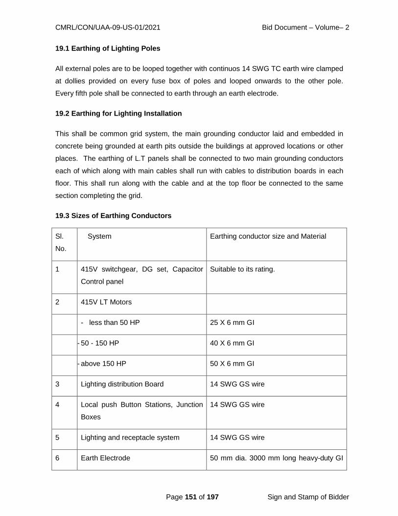
CMRL/CON/UAA-09-US-01/2021 Bid Document – Volume– 2
Page 151 of 197 Sign and Stamp of Bidder
19.1 Earthing of Lighting Poles
All external poles are to be looped together with continuos 14 SWG TC earth wire clamped
at dollies provided on every fuse box of poles and looped onwards to the other pole.
Every fifth pole shall be connected to earth through an earth electrode.
19.2 Earthing for Lighting Installation
This shall be common grid system, the main grounding conductor laid and embedded in
concrete being grounded at earth pits outside the buildings at approved locations or other
places. The earthing of L.T panels shall be connected to two main grounding conductors
each of which along with main cables shall run with cables to distribution boards in each
floor. This shall run along with the cable and at the top floor be connected to the same
section completing the grid.
19.3 Sizes of Earthing Conductors
Sl.
No.
System
Earthing conductor size and Material
1 415V switchgear, DG set, Capacitor
Control panel
Suitable to its rating.
2 415V LT Motors
- less than 50 HP 25 X 6 mm GI
- 50 - 150 HP 40 X 6 mm GI
- above 150 HP 50 X 6 mm GI
3 Lighting distribution Board 14 SWG GS wire
4 Local push Button Stations, Junction
Boxes
14 SWG GS wire
5 Lighting and receptacle system 14 SWG GS wire
6 Earth Electrode 50 mm dia. 3000 mm long heavy-duty GI

CMRL/CON/UAA-09-US-01/2021 Bid Document – Volume– 2
Page 152 of 197 Sign and Stamp of Bidder
pipe electrode
7 Street lighting poles 14 SWG TC wire
Note: 1. Conductors above ground shall be of galvanised steel to prevent atmospheric
corrosion. Note: 2. Conductors buried in ground or embedded in concrete shall be of mild
steel.
20. Power capacitor
Power shunt capacitors in general shall confirm to latest version of IS:13585, Part-1.
Power capacitor control panel shall be housed in metal enclosed cubicle. Power capacitor
shall be mounted on MS angle frame works and capacitor control panel along with MV
panel.
The capacitor banks shall be complete with all parts that are necessary or essential for
efficient operation. Such parts shall be deemed to be within the scope of supply
whether specifically mentioned or not.
The capacitor bank shall be complete with the required capacitors along with the
supporting post insulators, steel rack assembly, copper bus bars, copper connecting
strips, foundation channels, fuses, fuse clips, etc. The steel rack assembly shall be hot
dip galvanised.
The capacitor bank may comprise of suitable number of single- p h a s e units in
series parallel combination. However, the number of parallel units in each of the series
racks shall be such that failure of one unit shall not create an over voltage on the units in
parallel with it, which will result in the failure of the parallel units.
The assembly of the banks shall be such that it provides sufficient ventilation for each
unit. Each capacitor case and the cubicle shall be earthed to a separate earth bus.
Each capacitor unit/bank shall be fitted with directly connected continuously rated, low
loss discharge device to discharge the capacitors to reduce the voltage to 50 volts within
one minute in accordance with the provisions of the latest edition of IS: 13585 Part 1.
Film dielectric, Aluminium foil conductor, impregnated with Non- P C B , Non-Toxic
biodegradable capacitor grade oil, under vacuum, two layers of biaxially oriented
CMRL/CON/UAA-09-US-01/2021 Bid Document – Volume– 2
Page 153 of 197 Sign and Stamp of Bidder
propylene film shall be used.
Each unit shall satisfactorily operate at 135% of rated kVAR including factors of over
voltage, harmonic currents and manufacturing tolerance. The units shall be capable of
continuously withstanding satisfactorily any over voltage upto a maximum of 10% above
the rated voltage, excluding transients.
20.1 Unit Protection
Each capacitor unit shall be individually protected by an MCCB / MCB fuse suitably rated
for load current and interrupting capacity, so that a faulty capacitor unit shall be
disconnected by the fuse without causing the bank to be disconnected. Thus, the fuse
shall disconnect only the faulty unit and shall leave the rest of the units undisturbed. An
operated fuse shall give visual indication so that it may be detected during periodic
inspection. The MCB breaking time shall co-ordinate with the pressure built up within
the unit to avoid explosion. Mounting of the individual fuse may be internal or external to
the capacitor case.
20.2 Capacitor Control Panel
The control equipment shall be mounted in the MV panel made of 2.6mm / 2.0mm
cold rolled sheet steel for the front and other sides respectively. The panel shall be of
indoor type and shall consist of:
- Isolating switch / MCB / MCCB
- Red and Green lamps for capacitors ON/OFF indication.
20.3 Technical Particulars - The Equipment shall conform IS 13585 Part 1
- General
- Quantity : as per requirement
- Rated capacity as per requirement
- Rated Voltage : 433 V
- Rated frequency, and phases : 50 Hz, 3 Phase
- Design Requirements Insulation level : 2.5 KV (rms)
- Capacitor bank connection : Delta
- Short circuit withstand for busbars:
Short time (1 sec) : 40 KA (rms)
Dynamic : 102 KA (peak) Switches
CMRL/CON/UAA-09-US-01/2021 Bid Document – Volume– 2
Page 154 of 197 Sign and Stamp of Bidder
Type of switching: MANUAL switching
Income current rating : To suit-rated capacity of kVAR.
20.4 Tests and Test Reports
- All tests shall be conducted in accordance with the latest edition of IS –
13585 Part 1 and as applicable for the controls.
- Type test certificates for similar capacitor units shall be furnished.
20.5 Drawings
The following drawings shall be submitted for the approval of the Engineers
Representative.
- Fully dimensioned general arrangement drawings of capacitor and
capacitor control panel with elevation side view, sectional view and
foundation details.
- Complete schematic and wiring diagrams for capacitor control panel.
21. PUMPING MACHINERIES
21.1 Applicability
The following clauses shall specify general mechanical requirements and standards of
workmanship for equipment and installations and must be read in conjunction with the
particular requirements of the Contract. These general specification clauses shall apply
where appropriate except where redefined in the particular requirement sections of the
Specification which shall be applicable.
21.2 Materials
All materials incorporated in the Works shall be the most suitable for the duty concerned
and shall be new and of first-class commercial quality, free from imperfection, and selected
for long life and minimum maintenance.
21.3 Design and Construction
The plant design, workmanship and general finish shall be of sound quality in accordance
with good engineering practice. Design shall be robust and rated for continuous service,

CMRL/CON/UAA-09-US-01/2021 Bid Document – Volume– 2
Page 155 of 197 Sign and Stamp of Bidder
at the specified duties, under the prevailing operational site conditions.
The general design of mechanical and electrical Plant particularly that of wearing parts,
shall be governed by the need for long periods of service without frequent attention but
shall afford ready access for any necessary maintenance.
Similarly, items of Plant and their component parts shall be completely interchangeable.
Spare parts shall be manufactured from the same material specification as the originals.
No welding, filling or plugging of defective work will be permitted without the written
permission of the Engineer. All welding spatters shall be removed.
It shall be the responsibility of the contractor to ensure that all the equipment selected is
fully compatible, mechanically, electrically and also with respect to instrumentation, control
and automation.
It shall be the responsibility of the contractor to ensure his equipment interfaces with any
existing equipment correctly. Any interfaces must not affect the integrity of the equipment
or invalidate any warranties or guarantees.
Each component or assembly shall have been proven in service in a similar application
and under conditions no less than those specified therein.
The plant shall be compatible with the civil structure, when installed, with sufficient space
for operator access and maintenance procedures.
All materials shall be of the best commercial quality and free from any flaws, defects or
imperfections.
Materials shall be selected to eradicate or reduce corrosion to a minimum.
21.4 Tropicalisation
All plant and materials used shall in all respects be suitable for the climatic conditions of the
Chennai as detailed in Table - _ hereof. The following maximum conditions shall be
used for all design.
i) Maximum peak ambient shade temperature : 43oC
ii) Maximum daily average ambient shade temperature : 38oC
CMRL/CON/UAA-09-US-01/2021 Bid Document – Volume– 2
Page 156 of 197 Sign and Stamp of Bidder
iii)Maximum yearly average ambient shade temperature: 30oC
iv)Maximum Relative humidity : 100%
In damp situations and wherever exposed to the weather, precautions shall be taken
against corrosion of metal work, cable armour, conduit and the like.
All electrical equipment including cables shall be de-rated for continuous operation in an ambient
temperature of 45oC in accordance with the appropriate regulations.
All materials and equipment which are subject to certification by testing authorities etc., shall be
certified as being tested at 45oC ambient.
Tropical grade materials should be used wherever possible. Some relaxation of these
provisions may be permitted where equipment is hermetically sealed.
Iron and steel are in general to be painted or galvanized as appropriate in accordance with
the Specification. Small iron and steel parts (other than stainless steel) of all instruments
and electrical equipment, the cores of electro-magnets and the metal parts of relays and
mechanisms are to be treated in an approved manner to prevent rusting. Cores etc. which
are built up of laminations or cannot for any other reasons be anti-rust treated, are to have all
exposed parts thoroughly cleaned and heavily enamelled, lacquered or compounded.
The use of iron and steel is to be avoided in instruments and electrical relays whenever
possible. Steel screws, when used, are to be zinc, cadmium or chromium plated or, when
plating is not possible owing to tolerance limitations, shall be corrosion resisting steel.
Instrument screws (except those forming part of a magnetic circuit) are to be of brass or
bronze. Springs are to be of brass, bronze or other non-rusting material. Pivots and other
parts for which non-ferrous material is unsuitable are to be of an approved stainless steel.
Fabrics, cork, paper and similar materials, which are not subsequently to be treated by
impregnation, are to be adequately treated with an approved fungicide. Sleeving and
fabrics treated with linseed oil or linseed oil varnishes are not to be used.
21.5 Packing and Delivery
All plant and equipment as necessary shall be packed in first quality containers or packing;
no second-hand timber shall be used. All packings must be suitable for several stages
of handling via sea or air freight, inland transport and movement on site.

CMRL/CON/UAA-09-US-01/2021 Bid Document – Volume– 2
Page 157 of 197 Sign and Stamp of Bidder
Flanged pipes are to have their open ends protected by adhesive tape or jointing and are
then to be covered with a wooden blank flange secured by service bolts.
The sleeves and flanges of flexible couplings shall be bundled by wire ties. Cases
containing rubber rings, bolts and other small items shall not normally weigh more than 500
kg gross.
Precautions are to be taken to protect shafts and journals where they rest on wooden or
other supports likely to contain moisture. At such points wrappings impregnated with anti-
rust composition or vapour phase inhibitors are to be used of sufficient strength to resist
changing and indentation due to movement which is likely to occur in transit. The form of
the protective wrappings and impregnation are to be suitable for a minimum period of twelve
months.
Lids and internal cross battens of all packing cases are to be fixed by screws and not nails.
Hoop metal bindings of cases are to be sealed where ends meet and if not of rustless
material are to be painted. Contents of cases are to be bolted securely or fastened in
position with struts or cross battens and not with wood chocks, unless they are fastened
firmly in place. All struts or cross battens are preferably to be supported by cleats fixed to
the case above and below to form ledges on which the batten may rest. Cases are to be
up ended after packing to prove that there is no movement of contents.
Where parts are required to be bolted to the sides of the case, large washers are to be used
to distribute the pressure and the timber is to be strengthened by means of a pad. All
stencil marks on the outside of the casings are to be either of a waterproof material or
protected by Shellac or varnish to prevent obliteration in transit. Wood wool is to be avoided
as far as possible. Waterproof paper and felt linings are to overlap at seams at least 12mm
and the seams secured together in an approved manner, but the enclosure is to be provided
with screened openings to obtain ventilation.
Where applicable, indoor items such as electric motors, switch and control gear, instruments
and panels, machine components, etc. are to be ‘cocooned’ or covered in polythene
sheeting, sealed at the joints and the enclosures provided internally with an approved
desicator.
Bright metal parts are to be covered before shipment with an approved protective compound
or coating and protected adequately during transport to site. After erection these parts are

CMRL/CON/UAA-09-US-01/2021 Bid Document – Volume– 2
Page 158 of 197 Sign and Stamp of Bidder
to be cleaned by the Contractor.
Each crate or package is to contain a packing list in a waterproof envelope and copies in
duplicate are to be forwarded to the Engineer; prior to despatch. All items of material
are to be clearly marked for ready identification against the packing list. All cases,
packages, etc. are to be clearly marked on the outside to indicate the total weight, to show
where the weight is bearing and to indicate the correct positions for slings and are to bear an
indelible identification mark relating them to the appropriate shipping documents.
The Engineer may require inspecting and approve the packing before the items are
despatched, but the Contractor is to be entirely responsible for ensuring that the packing is
suitable for transit, and such inspection will not relieve the Contractor for any loss or
damage due to faulty packing.
21.6 Workmanship
Workmanship and general finish shall be of first-class commercial quality and in
accordance with best practice. All covers, flanges and joints shall be properly faced,
bored, fitted, fixed, hollowed, mounted or chamfered as the case may be, according to the
best approved practice and all working parts of the plant and other apparatus, shall
similarly be well and accurately fitted, finished, fixed and adjusted.
21.7 Castings and Metals
All castings shall have a homogenous structure and be free from blowholes, flaws and
cracks. Any casting having a thickness in parts in excess of 3 mm to that which it is
purported to shall be rejected. No repairs or patchwork to castings shall be allowed other
than that approved by the Engineer.
Castings subject to hydraulic pressure shall be tested to 1.5 times the maximum working
pressure. Certified copies of Test Reports shall be forwarded to the Engineer as soon as
the test is completed.
Where not otherwise specified steel castings shall be selected from the appropriate
grade. as per relevant IS.
All grey iron castings supplied shall be to the appropriate grade of IS:210. The Contractor
shall replace any casting which the Engineer considers is not of first-class appearance or
is not in any way the best which can be produced, although such a casting may have

CMRL/CON/UAA-09-US-01/2021 Bid Document – Volume– 2
Page 159 of 197 Sign and Stamp of Bidder
passed the necessary hydraulic or other tests. No plugging, filling, welding or "burning
on" will be acceptable.
All spheroidal graphite or modular graphite iron shall be to the appropriate grade of
IS.1865.
Where not otherwise specified the bronze used shall be made of a strong and durable zinc
free mixture as per relevant IS:318.
Aluminium and aluminium alloys shall not be utilised unless alternative materials are
considered unacceptable. The use of aluminium requires the approval of the Engineer in
all cases. Bars and extruded sections shall be as per relevant IS.
Aluminium and Aluminium Alloy Castings shall be manufactured as per IS: 617:1994 and
subjected to a chill cast to increase tensile strength. Immersed structures or structures that
are periodically immersed shall not be constructed from aluminium or aluminium alloys. All
chromium plating shall comply with IS 1986.
21.8 Painting and Metal Protection
The surface preparation and painting or application of corrosion protection coatings to the
following materials shall be carried out in accordance with relevant IS for the particular
environmental conditions where the materials are used.
Mild Steel
Cast and Duct Iron
Aluminium
Nonferous Parts
Other small parts
21.9 Galvanising
Where steel or wrought iron is to be galvanised, it shall be carried out by the hot- dip
process and shall conform in all respects with IS:2629. Adequate provision for filling,
venting and draining shall be made for assemblies fabricated from hollow section. Vent
holes shall be suitably plugged after galvanising.
All surface defects in the steel including cracks, surface laminations, laps and folds
shall be removed in accordance with IS:6159. All drilling, cutting, welding, forming and
final fabrications of unit members and assemblies shall be completed before the structurs
CMRL/CON/UAA-09-US-01/2021 Bid Document – Volume– 2
Page 160 of 197 Sign and Stamp of Bidder
are galvanised, the surface of the steelwork to be galvanised shall be free from welding
slag, paint, oil, grease, and similar contaminants. The articles shall be pickled in dilute
sulphuric or hydrochloric acid, followed by rinsing in water and pickling in phosphoric acid.
They shall be thoroughly washed, stoved and dipped in molten Zinc and brushed, so that
the whole of the metal shall be evenly covered and the additional weight thereof after
dripping shall not be less than 610 grammes per square metre of suface galvanised,
except in the case of tubes to BS.1387 when it shall be 460 grammes per square
metre.
On removal from the galvanising bath the resultant coating shall be smooth, continuous,
free from gross imperfections such as bare spots, lumps, blisters and inclusions of flux,
ash or dross. Edges shall be clean and surfaces bright.
Bolts, nuts and washers shall be hot dip galvanised and subsequently centrifuged in
accordance with IS:2629. Nuts shall be tapped up to 0.4 mm. oversize before galvanising
and the threads oiled to permit the nuts to be finger turned on the bolt for the full depth of
the nuts.
During off-loading and erection, the use of nylon slings shall be used. Galvanised work
which is to be stored in Works or on Site shall be stacked so as to provide adequate
ventilation to all surfaces to avoid wet storage staining.
Small areas of the galvanised coating damaged in any way shall be restored by: -
i. Cleaning the area of any weld slag and thoroughly wire brushing to give a
clean surface.
ii. The application of two coats of zinc-rich paint (not less than 90 per cent zinc, dry
film), or the application of a low melting-point zinc alloy repair rod or powder to
the damaged area, which is heated at 3000C.
iii. Fastenings o f g a l v a n i z e d s t e e l w o r k s h a l l b e h o t d r i p g a l v a n i z e d
a n d subsequently centrifuged in accordance with IS:2629. Nuts shall be tapped
upto 0.4 mm oversize before galvanising and the threads oiled to permit the nuts
to be finger turned on the bolt for the full depth of the nuts.
iv. Where surfaces of galvanized steelwork are to be in contact with aggressive
solutions and\or atmospheres the galvanising shall receive further protection by

CMRL/CON/UAA-09-US-01/2021 Bid Document – Volume– 2
Page 161 of 197 Sign and Stamp of Bidder
painting.
21.10 Fasteners
All bolts, nuts and studs with nominal diameters up to and Fasteners including 39mm
required to be made in carbon steel shall conform to BS.6104 and threaded in accordance
with IS:1367. Bright steel washers 3.0mm in thickness shall conform to BS.4320 and
shall be provided beneath bolt head and nut. The above items required to be supplied in
stainless steel shall conform to IS:1570. These items together with holding- down bolts
and anchor plates required to be supplied in high tensile steel shall conform to BS.970
Ref. Symbol T Drilled anchor fixings for use on concrete structures shall be of a type
Fasteners approved by the Engineer's Representative. The positions of all drilled
anchors shall be approved by the Engineer's Representative and a Contractor proposing
to use such fixings shall be deemed to have undertaken to supply, mark off, drill and fit.
All exposed bolt heads and nuts shall be hexagonal, and the length of all bolts shall be
such, that when fitted and tightened down with a nut and washer, the threaded portion
shall fill the nut and not protrude from the face thereof by more than a half diameter of the
bolt. Rivets shall conform to BS.641 and tested in accordance with BS.1109.
21.11 Forgings
Carbon steel forgings shall be manufactured heat treated and tested in accordance with
IS:2004-1991.
21.12 Foundations and Setting of Machinery
The Contractor shall arrange for the provision of all foundations and plinths required for
the plant and shall ensure that it is in accordance with the approved drawings. The
Contractor shall provide all necessary templates for suspension of the holding-down bolts
during grouting of same. The machinery shall be mounted on flat steel packings of a
thickness selected to take up variations in the level of the concrete foundations.
The packings shall be bedded by chipping or grinding of the concrete surface. Only one
packing of selected thickness shall be used at each location, which shall be adjacent to
each holding down bolt. The number of shims shall not exceed two at each location and
the thickness of each shim shall not exceed 3mm.The machinery shall be aligned,
levelled and pulled down by the nuts of the holding down bolts with a spanner of normal
length, and no grout shall be applied until the machinery has been run and approved

CMRL/CON/UAA-09-US-01/2021 Bid Document – Volume– 2
Page 162 of 197 Sign and Stamp of Bidder
by the Engineer for stability and vibration.
21.13 Bearings and Lubricators
The size of bearing shall be not less than that calculated for Bearings and a minimum L10
basic rating life in accordance with BS.5512 Lubricators Part 1., taking into account all
considerations of reliability, materials of manufacture and operating conditions. All
bearings shall be rated and sized to ensure satisfactory running without vibration under all
conditions of operation for a minimum life of 50,000 hours running. They shall be
efficiently lubricated and adequately protected from ingress of moisture, dust and sand
and the particular climatic conditions prevalent at the site. All bearings shall be to ISO
standard SI unit dimensions where practicable. All ball or roller bearings, except those
supplied as "sealed for life" shall be arranged for grease gun lubrication and a suitable
high pressure grease gun shall be supplied.
Adequate "Stauffer" screw top pressure grease lubricators with 'telltale' stems or "Tat"
grease nipples shall be provided for all moving parts. The position of all greasing and
oiling points shall be arranged so as to be readily accessible for routine servicing. Where
necessary, suitable access platforms shall be provided. The type of lubricant and intervals
of lubrication, which shall be kept to a minimum (not less than nine days), for each
individual item of plant shall be entered on a working schedule, which shall form part
of the Operation and Maintenance instructions. A list of recommended Lubricants and
their equivalents Bearings and shall be entered in the Operation and Maintenance
instructions.
21.14 Labels
The Contractor shall arrange for the supply and fitting of engraved identification labels to
all valves and items of plant. The reference numbers of all valves shall be as indicated on
the schematic diagram to be supplied under the Contract. All warning labels shall comply
with BS 5378 parts 1, 2 and 3 and of screw fixed rigid construction.
Designation labels shall be of 5 mm Traffolyte with black lettering on white background.
Embossed materials and techniques shall not be accepted.
The Contractor shall provide 2 No. enamelled iron plates worded "Men Working on Plant".
The plates shall be 200mm x 75mm with red lettering on a white background. The
Contractor shall also provide and fit warning labels for machinery that is operated under
CMRL/CON/UAA-09-US-01/2021 Bid Document – Volume– 2
Page 163 of 197 Sign and Stamp of Bidder
automatic control. All identification and warning labels shall be in English and in the local
Language.
21.15 Guards
Adequate guards shall be supplied and installed throughout the installation to cover
drive mechanisms. All rotating and reciprocating parts, drive belts, etc. shall be
securely shrouded to the satisfaction of the Engineer to ensure the complete safety for
both maintenance and operating personnel. However, whilst all such guards shall be of
adequate and substantial construction, they shall also be readily removable for gaining
access to the plant without the need for first removing or displacing any major item of
plant. The guards shall be of the open mesh type except where retention of fluid spray is
required.
21.16 Suppression of Noise
All plant offered shall be quiet in operation. The noise levels in the entire premises shall
be as per the norms of the Pollution Control Board. The noise levels measured as per
IS/ISO:4412-1, 2 – 1991 shall be within the levels prescribed by TNPCB. The noise level
within the building shall not be more than 85 decibels (+5 per cent on this over the audible
frequency spectrum measured at mid-band.) "A" scale when measured along a contour 3
metres from any single item of plant during starting, running and stopping. The noise level
outside the building shall not be more than 60 decibels (+5 per cent on this over the
audible frequency spectrum measured at mid-band.) "A" scale when measured along a
contour 3 metres from the external wall. Noise test measurements shall be made on
completion of the installation of the plant at Site to verify that it complies with this Clause.
Plant which fails to comply with the noise level limits when tested will render it liable for
rejection unless it is satisfactorily modified at the Contractors expense by the programmed
commissioning date.
22. Submersible Sewage Pumps
The Contractor shall provide manufacturer's published pump curves, system curves and the
necessary hydraulic calculations to justify the sizes of any pumps selected.
The Contractor shall provide the following shop drawings:
impeller diameter
maximum impeller diameter

CMRL/CON/UAA-09-US-01/2021 Bid Document – Volume– 2
Page 164 of 197 Sign and Stamp of Bidder
minimum impeller diameter
velocity of liquid in pump suction at duty point
velocity of liquid in pump delivery at duty point
velocity of liquid in the pump casing or impeller eye at duty point
net positive suction head (dry well submersibles only)
the materials of construction shall be specified in detail and itemised
against a sectional drawing of the pump proposed.
After approval of the pump types the Contractor shall submit the test data as required
under factory inspection and testing
The Contractor shall submit Operation and Maintenance Manuals and Instructions which
shall include all the documentation provided as above and as required in the Specification.
22.1 Pump Requirements
Pumps and drives shall be rated for continuous duty and shall be capable of pumping the
flow range specified in the Specification without surging, cavitation, or excessive vibration
to the limits specified. All pumps and drives shall be from approved manufacturers.
The pumps shall meet maximum allowable shut-off head.
The pumps shall not overload the motors for any point on the maximum pump speed
performance characteristic curve and the pump operating range, within the limits of stable
pump operation, as recommended by the manufacturer, to prevent surging, cavitation,
and vibration.
To ensure vibration-free operation, all rotative components of each pumping unit shall be
statically and dynamically balanced to IS:11723 Part 1 - 1992 and the following
requirements shall be met:
The mass of the unit and its distribution shall be such that resonance at
normal operating speeds is within acceptable limits
In any case, the amplitude of vibration as measured - at any point on
the pumping unit shall not exceed the below limits
At any operating speed, the ratio of rotational speed to the - critical speed of a
unit, or components thereof, shall be less than 0.8 or more than 1.3.

CMRL/CON/UAA-09-US-01/2021 Bid Document – Volume– 2
Page 165 of 197 Sign and Stamp of Bidder
Vibration levels shall not exceed the levels as per relevant IS.
The completed units, when assembled and operating, shall be free of cavitation, vibration,
noise, and oil or water leaks over the range of operation.
All units shall be so constructed that dismantling and repairing can be accomplished
without difficulty.
The Contractor shall be responsible for proper operation of the complete pumping system,
which includes the pump, motor, variable speed drive unit (if designated), and associated
controls furnished with the pump.
The Contractor shall ensure that the controls and starting equipment are suitable for use
with the pump motor, taking into account all requirements including starting currents and
number of starts per hour.
For the performance curve of the selected pump impeller, the head shall continuously rise
as flow decreases throughout the entire curve from run out to shutoff head.
The Contractor shall ensure that drive motors, variable speed drive systems (if specified)
and pumps shall be supplied and tested together by the pump manufacturer, who shall
supply full certification for the proper function of the entire pumping system.
If variable speed drive systems are specified, motor and drive system shall be fully
compatible, and shall be of sufficient power and torque, and be capable of sufficient heat
transfer for starting, accelerating and continuously operating over the entire range of
head/capacity conditions, from minimum to maximum pump operating speed, as
designated. The motor shall be de-rated to take into consideration the reduced cooling
effect when running at the lowest speed with the variable speed drive.
22.2 Design Conditions
Pumps shall be single stage mono-block type with nonclog design. It should pump all kinds
of sewage in particular unscreened sewage containg long fibres, solid admixes, sludges,
liquid containing trapped air and gas etc, long fibres, polythene covers, and capable of
dealing with sewage of specific gravity 1.1.
Profile gasket should be provided in pump casing so as to avoid metal to metal contact
between pump and the special designed duckfoot bend/ flanged elbow, automatic coupling

CMRL/CON/UAA-09-US-01/2021 Bid Document – Volume– 2
Page 166 of 197 Sign and Stamp of Bidder
to ensure leak proof joint with delivery pipe. The profile of pumpside flange shall be
matched with pump claw so as to automatically lock by virtue of its own weight or an
automatic coupling device for easy installation and easy removal.
Pumps shall be designed and constructed to satisfactorily operate and perform within the
designated design conditions and the requirements specified herein. They shall be
designed for a life of 100,000 hours with service intervals at 20,000 hours.
Castings, fabrications, machined parts and drives shall conform to the industry standards
for strength and durability and shall be rated for continuous duty over the entire operating
range.
Bearings shall be of the anti-friction type designed for load and life in accordance with
relevant IS according to the type of bearing used. The maximum operating speed shall not
exceed 1450 / 960 rpm and shall be supplied as per BOQ.
Pumps shall be of non-clog design, capable of passing spheres of a size of 100mm
diameter unless other diameters are specified. The pumpset shall be supplied along
with special duckfoot bend / flanged elbow, lifting chain, guide wire / guide pipe.
Suitable RCC slab / ISMB (with necessary anti-corrosive painting) to be erected over
suction well to fix guide wire / guide pipe holding bracket.
The pump, motor and associated electrical equipment shall be rated for a minimum 10
starts per hour, unless otherwise specified.
The Contractor shall ensure that the pump manufacturer provides certification which
guarantees the following:
flow rate
total head
power input
efficiency
22.3 Materials
Pumps shall be manufactured of the following materials as a minimum:
volute casings shall be cast iron, as per IS 210 Gr Fg 200 with 2 to 3 %
Nickel. The internal surfaces shall be free of rough spots. The casing shall

CMRL/CON/UAA-09-US-01/2021 Bid Document – Volume– 2
Page 167 of 197 Sign and Stamp of Bidder
have center line discharge.
impellers shall be stainless steel (CF8M).
Pump shaft shall be of stainless steel ( SS- 410). The shaft shall be of
one-piece construction.
motor casings shall be cast iron,
shafts shall be stainless steel,
fasteners shall be stainless steel,
The lifting system shall be manufactured of the following materials:
the guide rail system shall be CI.
lifting chains shall be MS-GLVD.
22.4 Fabrication
General. Pumps shall be fabricated in accordance with the following requirements:
Pumps shall be capable of handling raw, unscreened sewage.
in the case of submersible installations, no portion of the pump shall
bear directly on the floor of the wet well
pumps shall utilise a guide system to permit easy removal and reinstallation
without dewatering the pump sump discharge connections shall be made
automatically with a simple downward motion without rotation when the pump is
lowered into operating position. The pump shall be capable of being removed
without disconnecting any fasteners.
an appropriate length of chain shall be connected to the motor eyebolts
to permit raising and lowering of the pump.
Impellers shall be fabricated according to the rated motor size as follows:
non-clog type statically and dynamically balanced, keyed to the shaft
provided with pump-out vanes to prevent material from getting behind the
impeller and into mechanical seal area
impellers shall not be trimmed unless approved by the Engineer. Provision for
CMRL/CON/UAA-09-US-01/2021 Bid Document – Volume– 2
Page 168 of 197 Sign and Stamp of Bidder
adjustment of clearance between impeller and casing for restoring the pump
efficiency, without dismantling the pump will be an added advantage.
single/multi vane or vortex type, with a cutter impeller in the case of small
flows.
Discharge Connection and Guide Rails shall be fabricated as follows:
Sliding guide bracket and discharge connections shall be provided which, when bolted to
the floor of the sump and to the discharge line, will receive the pump discharge connecting
flange without need of adjustment, fasteners, clamp, or similar devices.
The guide rails shall not support any portion of the weight of the pump.
The pump discharge connections shall incorporate a sealing face and connection yoke to
allow for automatic coupling to fixed discharge connection pipe work.
Pump Shafts shall be fabricated as follows:
pump shafts shall be of such diameter that they will not deflect more than 0.05 mm
measured at the mechanical seal, whilst operating at full driver output
the shaft shall be turned, round and polished.
the shaft shall be key seated for securing the impeller.
Shaft Seals shall be fabricated as follows:
the drive motor and pump/motor bearings shall be sealed along the shaft with
tandem mechanical seals operating in an oil filled chamber. The seals shall
require neither routine maintenance nor adjustment but shall be capable of being
easily inspected and replaced.
two back-to-back mechanical seals shall seal the motor off from the pump.
the upper seal shall be oil lubricated with a carbon rotating component and
fixed tungsten carbide component.
the lower seal shall have both parts in tungsten carbide.
a detector shall indicate when moisture is leaking past the first seal.

CMRL/CON/UAA-09-US-01/2021 Bid Document – Volume– 2
Page 169 of 197 Sign and Stamp of Bidder
Bearings shall be fabricated as follows:
bearings shall be capable of taking the static weight of the rotating parts and
any thrust generated by the operation of the pump
the upper bearing(s) shall be of the grease lubricated sealed for life type; the
lower bearing(s) shall be lubricated by the internal oil supply
the bottom bearing(s) shall be of the angular contact ball bearing type in
combinations with roller bearing(s)
if required in the project specification, remote indication shall be provided for
bearing high temperature-, using a thermistor at. the lower bearing, to provide a
signal at 95 C.
Motors shall be fabricated as follows:
Motors shall be 415 V, phase, 50 Hz, rated at 10 % above the maximum
power requirement
Motors shall be squirrel cage, induction, air filled, totally sealed to IP 68,
suitable for the maximum immersion depth to be encountered, rated for zone 2 use
with group 1 gases, to BS 5345
Motor insulation shall be Class F, limited to a Class B temperature rise.
Motor temperature shall be monitored using a thermistor, in each phase of the
winding, set to stop the motor when the monitored absolute temperature reaches
130 C
A watertight cable junction box sealed from the motor shall be provided for the
motor power and control cables shall be EPR insulated, Niplas sheathed flexible
450/750 volts grade, oil and grease resistant, with tinned annealed copper
conductors in accordance with BS 6007. The cable shall be brought directly out of
the submersible motor without joints, and shall be of sufficient length, minimum 20
m to be terminated in an IP67 junction box outside adjacent to the wet well.
They shall be sized in accordance with the electricity utility regulations and BS 7671.
The cable must be leak tight in respect of liquids and firmly attached to the terminal
box. They should be laid in a suitable PVC encasing pipe from control panel upto

CMRL/CON/UAA-09-US-01/2021 Bid Document – Volume– 2
Page 170 of 197 Sign and Stamp of Bidder
suction well.
Motors shall be capable of startup and operation in the event of a completely
flooded wet well. Motors shall be selected to meet the maximum power required for
the selected impeller at all operating conditions.
Motor cooling shall either be by means of the pumped medium or by oil. The use of
external cooling water is not acceptable.
motors shall be derated for dry well and/or variable speed operation.
all parts of the pump and motor shall be 1 0 0 % holiday free fusion bonded
epoxy coated to a minimum thickness of 300 microns.
22.5 Control Panel
The control panel shall be made of 12 SWG (2.6mm) sheet steel for the front side and 14
SWG (2.0mm) sheet steel for bottom and other sides with powder coating for long life. It
should have suitable starter. The control panel consists of multi section unit containing
one pump and one incomer/control. The sections are interfaced, via, cable
way/marshalling section. All wires and links are of electric grade copper conductor. The
control of the pumps viz., Mercury/magnet activated/ any other float switch with auto for
duty pump.
Power circuit is operating at 3 phase ,415 Volts, 50 Hz supply and for control circuit it is
single phase 230 V, 50 Hz supply.
Type of starter shall be as under:
upto 10 HP - DOL
From 12 Hp to 40 HP - Star - Delta.
50 HP and above – Auto Transformer Starter / Soft Starter
The following protections should be provided in the panel: short circuit protection,
overload protection, over temperature protection for motors, single phasing preventor,
reverse rotation protection, dry run failure protections to be made. Suitable range
ammeter, voltmeter, selector switch, auto-manual switch, pump running lamp, pump fault
lamp, fault reset push button, phase indicating lamps, indication of high level in the well,

CMRL/CON/UAA-09-US-01/2021 Bid Document – Volume– 2
Page 171 of 197 Sign and Stamp of Bidder
hours run counter should also be provided.
The control panel wiring circuit should be furnished in triplicate.
The pump should be controlled by the magnetic/mercury float switches while the pumps
run in auto. The floats with switches should be available in the wet wells and the
connections from float should be made to the individual control panel through the cable
duct. Necessary control sensor wiring should be made to convert the signals of
mercury/magnet float switches while the level is high/low so that the pump starts/stops
on automode.
The necessary push button stations with control wiring should be made on the wells for
each pumpset each station as per std. rules.
The control panel, pumpset and accessories for pumps should be manufactured by same
manufacturer. The pump and motor shall be accordance with the relevant standards.
22.6 Automatic Control
The automatic level control shall be arranged such that when level rises in the well the
pumps start successively at the different pre-determined levels. When the level drops the
pumpsets stop in the same order as that in which they have started. The different start
and stop levels for several pumps/single pump have to be chosen according to the
sewerage and as desired by the Engineer. Magnetic/mercury float switches have to be
used for this purpose.
The tenderer should also furnish the list of authorised dealers for the supply of spares for
submersible pumps and list of authorised workshop to carry out repairs to the submersible
pumps along with the address while tendering.
Labels. Each pump shall have a stainless-s tee l label permanently fixed to the pump
and an identical label fixed to the pump starter compartment.
22.7 Factory Inspection and Testing
The Contractor shall secure from the pump manufacturer certification that the following
inspections and tests have been conducted on each pump at the factory, and submit to the

CMRL/CON/UAA-09-US-01/2021 Bid Document – Volume– 2
Page 172 of 197 Sign and Stamp of Bidder
Engineer prior to shipment:
the pump casing has been tested hydrostatically to 1.5 times the maximum
closed valve pressure
impeller, motor rating and electrical connections checked for compliance with the
Specifications
motor and cable insulation tested for moisture content or insulation defects.
prior to submergence, the pump has been run dry to establish correct rotation
and mechanical integrity
the pump has been run for 30 minutes submerged under a minimum of 2 m
water after the operational test and the insulation tests above and after the
performance test below
Each pump shall test at the factory for performance according to BS 5316.
Part 1, including:
flow
inlet pressure
outlet pressure
motor power
torque
efficiency
The Contractor shall secure from the pump manufacturer the following certification and
submit to the Engineer prior to shipment:
certified copies of the pump characteristic curves and reports generated by the
tests described above
foundry composition certificates for all major castings (pump case, impeller,
motor housing) showing exact material composition and tests conducted to
ensure compliance with the pump manufacturer's material specifications.
22.8 Site Inspection and Testing
The equipment delivered to the Site shall be examined by the Contractor to determine
that it is in good condition and in conformance with the approved working drawings and

CMRL/CON/UAA-09-US-01/2021 Bid Document – Volume– 2
Page 173 of 197 Sign and Stamp of Bidder
certifications. All equipment shall be installed in strict conformance with the Specification
and the manufacturer's instructions.
The Contractor shall provide the services of the pump manufacturer's representative to
supervise the installation, commissioning and start-up of the pumping equipment.
The commissioning tests shall be performance and reliability trials, mainly for the purpose
of satisfying the Engineer that the pumpsets have been correctly assembled and installed
and that their performance matches that obtained during the manufacturers works tests.
In the event of an unwarranted change in the pump performance characteristics or power
consumption, all necessary steps shall be taken as soon as possible to establish the
cause and remove the fault. Similar action shall be taken for an undue increase in bearing
or gland temperature, increased gland leakage rates, unsatisfactory vibration levels or any
other fault or defect in the operation of the pumpset.
The site reliability trials shall include the following:
A record of bearing and coupling clearance and alignments shall be tabulated to
show the "as-built" condition of each pump
A record of all overload, timing relay and oil pressure relays shall be tabulated to
show the "as-built" condition of each motor starter
All cables shall be „megger‟ tested to confirm the integrity of the insulation.
A tabulated record of results shall be made.
The control panel shall be statically tested with motors disconnected to
confirm the correct sequence of operation
Each pump shall be operated individually over the range from closed valve to
maximum emergency top water level, on a recirculation basis, using fresh water,
and for a minimum of four hours continuously. During this test the following
parameters will be recorded: -
- motor phase currents
- pump output
- ambient and test water temperatures
- motor/pump casing temperature (dry well submersible only)
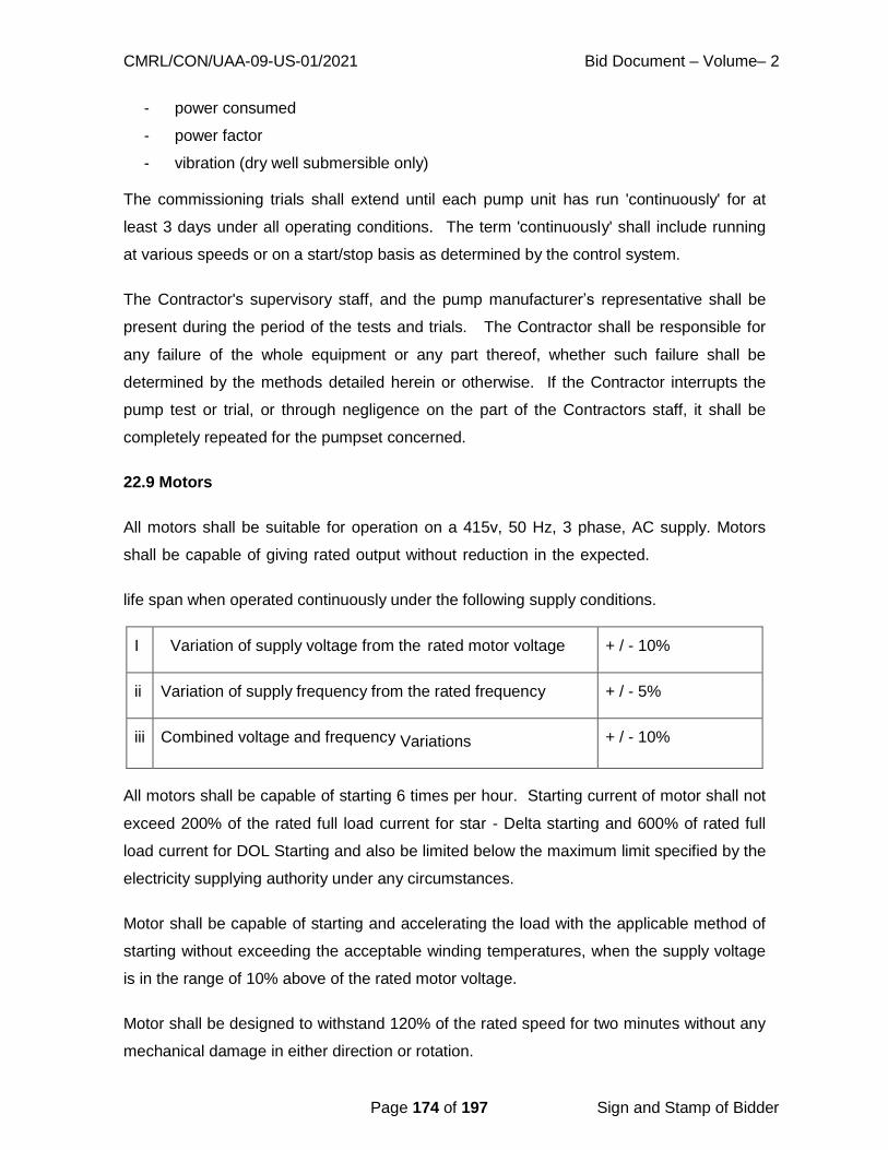
CMRL/CON/UAA-09-US-01/2021 Bid Document – Volume– 2
Page 174 of 197 Sign and Stamp of Bidder
- power consumed
- power factor
- vibration (dry well submersible only)
The commissioning trials shall extend until each pump unit has run 'continuously' for at
least 3 days under all operating conditions. The term 'continuously' shall include running
at various speeds or on a start/stop basis as determined by the control system.
The Contractor's supervisory staff, and the pump manufacturer’s representative shall be
present during the period of the tests and trials. The Contractor shall be responsible for
any failure of the whole equipment or any part thereof, whether such failure shall be
determined by the methods detailed herein or otherwise. If the Contractor interrupts the
pump test or trial, or through negligence on the part of the Contractors staff, it shall be
completely repeated for the pumpset concerned.
22.9 Motors
All motors shall be suitable for operation on a 415v, 50 Hz, 3 phase, AC supply. Motors
shall be capable of giving rated output without reduction in the expected.
life span when operated continuously under the following supply conditions.
I Variation of supply voltage from the rated motor voltage + / - 10%
ii Variation of supply frequency from the rated frequency + / - 5%
iii Combined voltage and frequency Variations + / - 10%
All motors shall be capable of starting 6 times per hour. Starting current of motor shall not
exceed 200% of the rated full load current for star - Delta starting and 600% of rated full
load current for DOL Starting and also be limited below the maximum limit specified by the
electricity supplying authority under any circumstances.
Motor shall be capable of starting and accelerating the load with the applicable method of
starting without exceeding the acceptable winding temperatures, when the supply voltage
is in the range of 10% above of the rated motor voltage.
Motor shall be designed to withstand 120% of the rated speed for two minutes without any
mechanical damage in either direction or rotation.

CMRL/CON/UAA-09-US-01/2021 Bid Document – Volume– 2
Page 175 of 197 Sign and Stamp of Bidder
The insulation class of motor winding shall conform to class - F and the maximum
temperature rise shall not exceed 950C, when measured by winding resistance method
and 850C, when measured by thermometer method for an ambient temperature of 45
0C.
Motor shall be offered for routine and type tests in accordance with IS: 4029 and IS: 325 at
the manufacturers works. Test certificates shall be endorsed to the effect that they are
properly balanced and free from vibration. In addition, a test shall be required to establish
the maximum transient starting current.
Pump motors shall be of the squirrel cage submersible type, protected to IP. 58 and
rated at 10 per cent above the calculated maximum power required on site.
The motor shaft shall be of large diameter, lightly stressed to ensure rigidity, with impeller
and bearing location shoulders and a keyway for location of the impeller.
The motor windings shall be protected with a waterproof material and shall incorporate a
thermistor in each phase to safeguard against high winding temperatures. The thermistor
shall be connected into the control circuit of the starter and arranged for hand reset only.
The motor shall incorporate a cut-out device to detect the presence of any liquid in the
motor enclosure.
The motor frame shall incorporate lifting points and shall be fitted with a galvanised lifting
chain, reaching to, and secured at the access point.
The terminal connections for the power and protective circuits shall be housed in a
completely sealed and waterproof junction box, complete with all external corrosion
resistant cable glands.
The pump units shall be provided with power and protection circuit cables of sufficient
length to reach from the motor junction box to the local isolator, located at the access
level.
The power cable shall be 600/1000V grade flexible stranded copper wire, insulated and
overall sheathed with under-water grade compound flexible insulation. The cable shall be
rated to take the full motor current under the prevailing liquid and ambient temperature
conditions.
22.10 Characteristic Curves
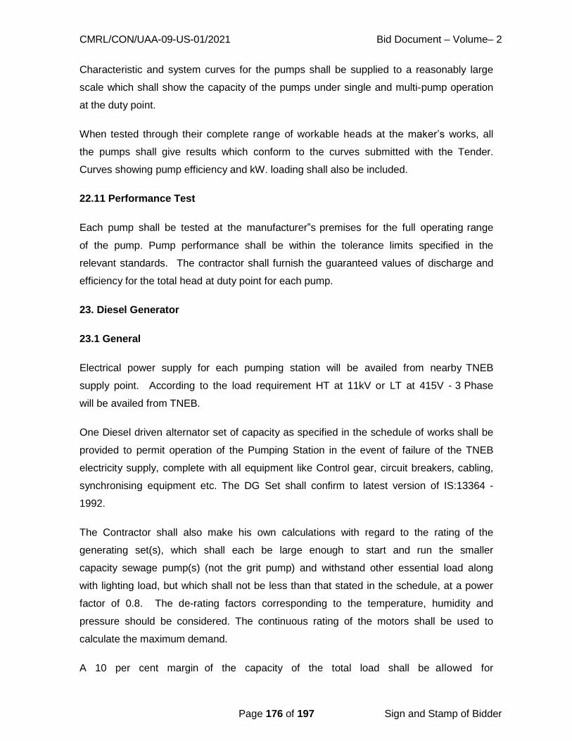
CMRL/CON/UAA-09-US-01/2021 Bid Document – Volume– 2
Page 176 of 197 Sign and Stamp of Bidder
Characteristic and system curves for the pumps shall be supplied to a reasonably large
scale which shall show the capacity of the pumps under single and multi-pump operation
at the duty point.
When tested through their complete range of workable heads at the maker’s works, all
the pumps shall give results which conform to the curves submitted with the Tender.
Curves showing pump efficiency and kW. loading shall also be included.
22.11 Performance Test
Each pump shall be tested at the manufacturer‟s premises for the full operating range
of the pump. Pump performance shall be within the tolerance limits specified in the
relevant standards. The contractor shall furnish the guaranteed values of discharge and
efficiency for the total head at duty point for each pump.
23. Diesel Generator
23.1 General
Electrical power supply for each pumping station will be availed from nearby TNEB
supply point. According to the load requirement HT at 11kV or LT at 415V - 3 Phase
will be availed from TNEB.
One Diesel driven alternator set of capacity as specified in the schedule of works shall be
provided to permit operation of the Pumping Station in the event of failure of the TNEB
electricity supply, complete with all equipment like Control gear, circuit breakers, cabling,
synchronising equipment etc. The DG Set shall confirm to latest version of IS:13364 -
1992.
The Contractor shall also make his own calculations with regard to the rating of the
generating set(s), which shall each be large enough to start and run the smaller
capacity sewage pump(s) (not the grit pump) and withstand other essential load along
with lighting load, but which shall not be less than that stated in the schedule, at a power
factor of 0.8. The de-rating factors corresponding to the temperature, humidity and
pressure should be considered. The continuous rating of the motors shall be used to
calculate the maximum demand.
A 10 per cent margin of the capacity of the total load shall be allowed for

CMRL/CON/UAA-09-US-01/2021 Bid Document – Volume– 2
Page 177 of 197 Sign and Stamp of Bidder
contingencies and spare capacity.
The engine alternator sets shall be designed such that the starting power peak shall
not exceed 10 per cent of the continuous engine rating and the voltage dip shall not
exceed 15 per cent whilst starting the connected load under the worst conditions.
The Contract Drawings show the building, floors and other details as they will be
constructed and the space allocated for the generating plant, control gear and circuit
breakers. If any departures from the proposed layout are necessary, the Contractor shall
show the modifications required on the drawings and shall call the Engineer‟s attention
to these proposed alterations.
Contractor‟s attention is specifically drawn to the operating conditions whereby
generator sets could be running at little or no load due to the intermittent and differing flow
rates and pump capacities. The diesel generator shall be capable of working at safe
minimum working levels.
The D.G. Set shall be enclosed in an acoustic enclosure and the noise levels while
operation shall be restricted to the levels as per the Pollution Control Board Norms.
23.2 Detailed Description of Generator Engine
Each engine shall be four strokes, naturally aspirated or pressure charged, water- cooled,
vertical diesel type, of the airless injection principle with all cylinders and valve gear totally
enclosed.
Each engine shall run at a speed not exceeding 1500 rpm. and be suitable for remote
operation provided with forced feed lubrication to all working parts including the camshaft,
rocker gear, valve guides etc. A strainer shall be located in a suitable position in each
system. The whole of the lubricating oil shall be cooled by means of an inter- cooler
situated adjacent to the engine with circulating water dissipating the heat taken from
the oil. The necessary circulating pumps shall be provided which shall be integral with the
engine together with all the appropriate pipework and appurtenances. Individual flow
indicators shall be provided for the jacket and lubricating oil circuits.
A sensitive Class A2 governor or a superior type shall be incorporated, and this shall be
capable of maintaining a constant speed under all conditions of load. Motor operated
speed regulating gear shall be provided to enable the speed of the engine to be varied by

CMRL/CON/UAA-09-US-01/2021 Bid Document – Volume– 2
Page 178 of 197 Sign and Stamp of Bidder
5 per cent up or down from normal speed while in operation. The remote control for
this regulating gear is to be operated from the switchboard.
Over-speed protection shall be provided so that in the event of the engine speed
exceeding 10 per cent above the maximum operating speed an audible warning and
indicator light shall be brought into operation, but should the speed still continue to rise
to a figure of 15 per cent above normal speed the fuel supply shall be automatically cut
off and the engine brought to rest. The audible warning and indicator light, together with
the other indicating lights and alarms specified hereafter, shall indicate on the monitoring
panel in the alternator switchboard.
A heavy type of flywheel shall be provided so that there will be a minimum of cyclic
irregularity throughout the working range of the engine. Distortion or vibration and
oscillation of the crankshaft shall be obviated under all normal working conditions.
The crankshaft shall be of solid forged steel statically and dynamically balanced to very
close limits. Hand operated barring gear shall be provided for each engine.
Aspiration air filters shall be mounted directly on each engine and shall be of the heavy-
duty type, suitable for a sand laden atmosphere.
Protected thermometers in suitable pockets shall be provided for measuring the
temperature of the inlet and outlet cooling ion water and lubricating oil. Each engine
shall be provided with a temperature indicator on each exhaust branch. Lubricating oil
and circulating water pressure gauges shall be provided on the local panel.
A positive driven tachometer and hours counter shall be provided and fixed in a
convenient place on each engine and the tachometer shall be connected to an
engine speed indicator mounted on a local panel to be mounted on each engine.
In addition to the over-speed alarm, protection devices shall be provided in the lubricating
oil circuits and cooling water circuits to operate alarms and indicator lights, in the event of
abnormal running conditions prevailing. These lights shall indicate on the remote
monitoring panel. The engine shall shut down under alarm conditions.
The whole of the design, rating and testing of each engine shall be in accordance with
IS:13364 for solid injection liquid fuel engines.

CMRL/CON/UAA-09-US-01/2021 Bid Document – Volume– 2
Page 179 of 197 Sign and Stamp of Bidder
Each engine shall be designed to operate with an ambient air temperature of 450C and be
capable of satisfactorily providing an output 10 per cent in excess of the BHp rating at
the same speed for any one hour in the duration of 12 hours of consecutive operation.
Each engine with flywheel and alternator shall be mounted and aligned on a common
under bed. Anti-vibration mountings shall be provided between the under bed and the
concrete foundation. Each cylinder shall have renewable wet liners and be fitted with
individual cylinder heads. Wet liners shall be treated on the water jacket side with a rust
inhibitor. Immersion heaters and thermostat control shall be incorporated in each
engine oil sump and water jacket to ensure rapid warm up on starting.
Each engine shall be provided with an oil drip tray complete with plugged outlet. The
engine shall be painted in accordance with the Manufacturer's recommendations, color
finish as advised by the Engineer.
23.3 Engine Cooling Equipment
Each engine shall be cooled by a bedplate mounted tropical rated radiator and cooling fan,
adequately rated to maintain the normal working temperature, under continuous, full load
operation, working in conjunction with a pressurized water system, thermostatically
controlled with centrifugal water circulating pump, valves and pipework.
23.4 Exhaust System
A complete engine exhaust system shall be provided for each engine and shall incorporate
a highly efficient residential quality silencer, expansion box, tubular lengths of exhaust
piping and all necessary flexible connections to lead the exhaust fumes to the open
atmosphere as per the recommendations of TNPCB.
The exhaust piping shall be adequately lagged and clad within the station with polished
aluminum sheeting. All the necessary supports shall be included. Closing plates to
apertures in walls shall also be provided. Very special attention shall be paid to the
preparation and protection of the exhaust system.
23.5 Bedplates and Couplings
A rigidly constructed, fabricated steel combined bedplate shall be provided for each
generator set to withstand the weight and shall be suitably machined on top for the
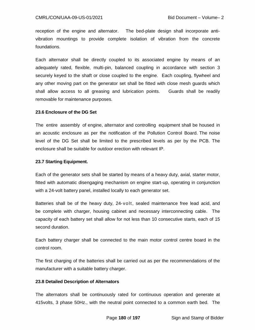
CMRL/CON/UAA-09-US-01/2021 Bid Document – Volume– 2
Page 180 of 197 Sign and Stamp of Bidder
reception of the engine and alternator. The bed-plate design shall incorporate anti-
vibration mountings to provide complete isolation of vibration from the concrete
foundations.
Each alternator shall be directly coupled to its associated engine by means of an
adequately rated, flexible, multi-pin, balanced coupling in accordance with section 3
securely keyed to the shaft or close coupled to the engine. Each coupling, flywheel and
any other moving part on the generator set shall be fitted with close mesh guards which
shall allow access to all greasing and lubrication points. Guards shall be readily
removable for maintenance purposes.
23.6 Enclosure of the DG Set
The entire assembly of engine, alternator and controlling equipment shall be housed in
an acoustic enclosure as per the notification of the Pollution Control Board. The noise
level of the DG Set shall be limited to the prescribed levels as per by the PCB. The
enclosure shall be suitable for outdoor erection with relevant IP.
23.7 Starting Equipment.
Each of the generator sets shall be started by means of a heavy duty, axial, starter motor,
fitted with automatic disengaging mechanism on engine start-up, operating in conjunction
with a 24-volt battery panel, installed locally to each generator set.
Batteries shall be of the heavy duty, 24-vo l t , sealed maintenance free lead acid, and
be complete with charger, housing cabinet and necessary interconnecting cable. The
capacity of each battery set shall allow for not less than 10 consecutive starts, each of 15
second duration.
Each battery charger shall be connected to the main motor control centre board in the
control room.
The first charging of the batteries shall be carried out as per the recommendations of the
manufacturer with a suitable battery charger.
23.8 Detailed Description of Alternators
The alternators shall be continuously rated for continuous operation and generate at
415volts, 3 phase 50Hz., with the neutral point connected to a common earth bed. The

CMRL/CON/UAA-09-US-01/2021 Bid Document – Volume– 2
Page 181 of 197 Sign and Stamp of Bidder
alternator neutral contactor shall be closed when the alternator is running.
The alternator enclosures shall be protected to IP.23. They shall be suitable in all
respects for operating in the climate as detailed elsewhere.
The alternator excitation equipment shall be of the quick response self-exciting, self-
regulating brush-less type, suitable for starting the motors.
The insulation of the stator and rotor shall be in accordance with British Standard Class ‘F'
but the alternator shall be designed for a Class ‘E' temperature rise. The efficiencies
of the alternator shall be stated in the Schedules and shall be determined in conformity
with the procedure laid down in IS:269 and shall be manufactured in accordance with
BS.2613.
Each alternator shall be capable of satisfactorily providing an output 10 per cent in
excess of the BS rating for one hour in any period of 12 hours‟ consecutive running.
The rotating parts shall be statically and dynamically balanced to close limits.
Each alternator shall be fitted with anti-condensation heaters of a size to maintain the
temperature of the windings 5o
above ambient. Each heater shall be provided with a
switch and automatic control to disconnect the heater when the alternator is running.
Terminal boxes shall be provided and arranged with sealing chambers for the reception of
the cables detailed in the relevant sections of the Specification. Terminals shall be clearly
marked to give phase identification.
The alternator shall be painted in accordance with Manufacture's recommendations,
finished colour as instructed by the Engineer.
23.9 Daily Storage Tanks
Each engine shall be provided with a free-standing daily tank of sufficient capacity to
allow 12 hours of continuous operation at full load. For permanent mounted sets each
daily tank shall be provided with the following fittings: -
Air vent of not less than 50mm. diameter.
Overflow piping of not less than 150 per cent diameter of the Fuel Delivery line.
Cleaning hand hole and cover of not less than 300mm. diameter.
Contents gauge graduated in Tamil and English to read “Full - 1/2 Full - Empty".
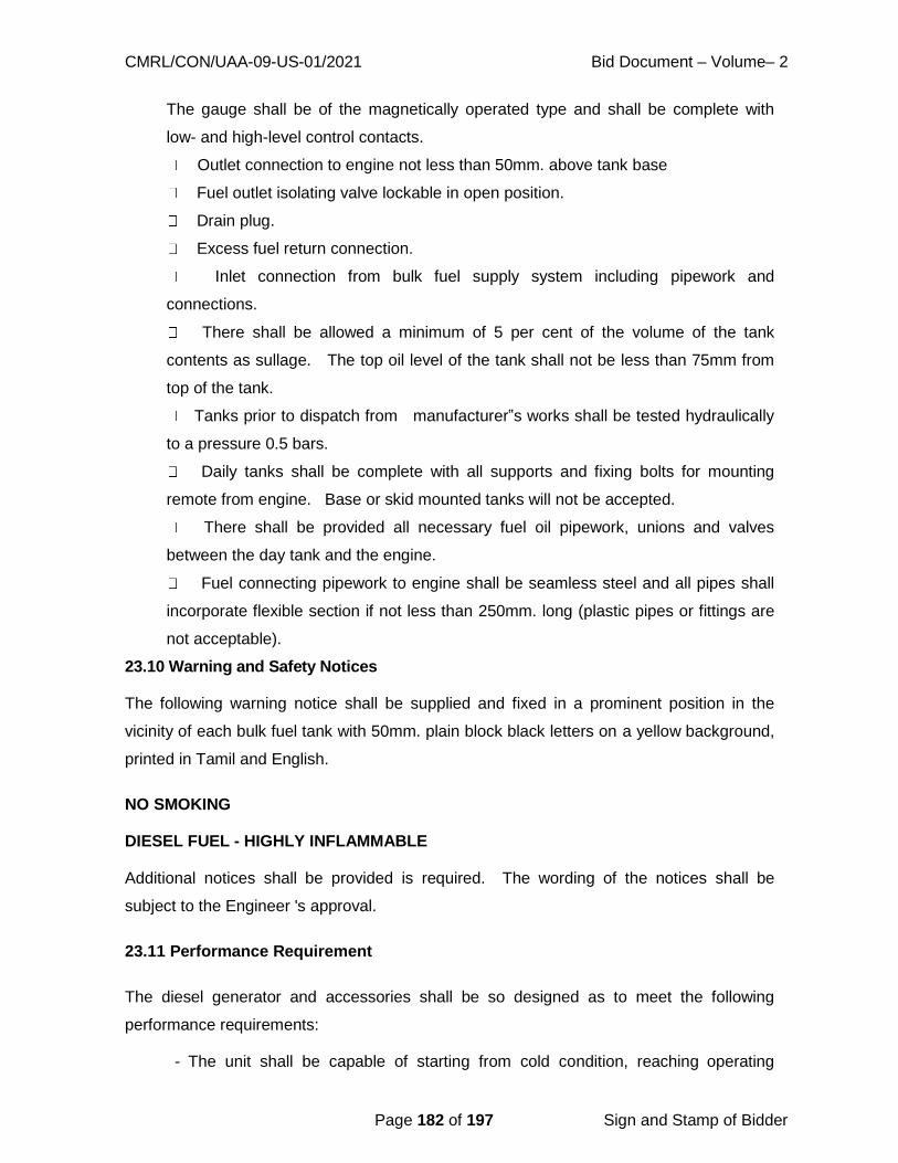
CMRL/CON/UAA-09-US-01/2021 Bid Document – Volume– 2
Page 182 of 197 Sign and Stamp of Bidder
The gauge shall be of the magnetically operated type and shall be complete with
low- and high-level control contacts.
Outlet connection to engine not less than 50mm. above tank base
Fuel outlet isolating valve lockable in open position.
Drain plug.
Excess fuel return connection.
Inlet connection from bulk fuel supply system including pipework and
connections.
There shall be allowed a minimum of 5 per cent of the volume of the tank
contents as sullage. The top oil level of the tank shall not be less than 75mm from
top of the tank.
Tanks prior to dispatch from manufacturer‟s works shall be tested hydraulically
to a pressure 0.5 bars.
Daily tanks shall be complete with all supports and fixing bolts for mounting
remote from engine. Base or skid mounted tanks will not be accepted.
There shall be provided all necessary fuel oil pipework, unions and valves
between the day tank and the engine.
Fuel connecting pipework to engine shall be seamless steel and all pipes shall
incorporate flexible section if not less than 250mm. long (plastic pipes or fittings are
not acceptable).
23.10 Warning and Safety Notices
The following warning notice shall be supplied and fixed in a prominent position in the
vicinity of each bulk fuel tank with 50mm. plain block black letters on a yellow background,
printed in Tamil and English.
NO SMOKING
DIESEL FUEL - HIGHLY INFLAMMABLE
Additional notices shall be provided is required. The wording of the notices shall be
subject to the Engineer 's approval.
23.11 Performance Requirement
The diesel generator and accessories shall be so designed as to meet the following
performance requirements:
- The unit shall be capable of starting from cold condition, reaching operating

CMRL/CON/UAA-09-US-01/2021 Bid Document – Volume– 2
Page 183 of 197 Sign and Stamp of Bidder
speed and taking up load within the shortest possible period.
- The u n i t s h a l l b e c a p a b l e o f d e l i v e r i n g c o n t i n u o u s l y a t t h e
generator terminals a net output specified. This net output shall be obtained after
necessary derating of engine due to site conditions and unit auxiliary power
requirements have been taken into consideration.
- The unit shall be capable of a peak output of 10% in excess of the rated output
for a period of one hour out of a total of twelve consecutive hours of operation,
without exceeding permissible temperature limits and with a fairly visible exhaust.
- The unit shall be continuously rated to supply power for the periods.
The following items of performance shall be guaranteed during site performance tests by
the supplier in respect of the diesel generator and the auxiliary for the specified site
conditions:
- Net electrical output
- Fuel oil consumption at 1/2, 3/4 and full load
- Jacket water temperature to and from engine
- Lubricating oil temperature to and from engine
- 10% overload for one hour out of a total of twelve consecutive hours of
operation without overheating or showing signs of undue stress and within specified
frequency variations
- Freedom from vibration and noise
- Governor response, over speed trip and speed gear capability
- Voltage regulator response
- Excitation at full load and under specified variation of voltage and speed
Window type annunciators shall be supplied and mounted on generator
control panel to give visual and audible indication for the following conditions.
- High jacket cooling water temperature
- High lubricating oil temperature
- Low lubricating oil pressure
- Low fuel oil tank level
- Engine over speed and trip
- Over current
- Earth fault
- Contact or on & off indication
- Voltage out of limit

CMRL/CON/UAA-09-US-01/2021 Bid Document – Volume– 2
Page 184 of 197 Sign and Stamp of Bidder
- Excitation failure
- Generator fault
23.12 Drawings and Data
The BIDDER shall furnish the following drawings/data in the Technical Bid.
- Control panel dimensions and drawing showing plan, front view, foundation
details, inside view, terminal block location etc.
- Schematic diagrams of the electrical circuitry
- General arrangement of the complete DG Set.
23.13 Testing and Commissioning
The supplier shall perform all the standard shop tests to ensure that the equipment
conforms to the specifications and meets the performance guarantees.
The installation / commissioning of the D. G set shall be as per the applicable
code of practice and the MANUFACTURER‟S instructions.
PREFERRED MANUFACTURERS
The bidder‟s can use equivalent makes provided its quality on par with preferred Makes.
Table – I
Sr.
No
Item Manufacturers
1. Pumps
(submersible & grit)
KSB / KISHOR / GRUNDFOS / AQUA/ XYLEM-
STEADY
2. Metering equipments like
C.T.P.T. and Trivectometer
GYRO/ IMP/ GE / UNIVERSAL / SIMCO / HPL
SOCOMEC
3. Switch Fuse Unit SIEMENS/ L & T/ JYOTI /
CROMPTON GREAVES, CONTROLS
& SWITCH GEAR / STANDARD / HPL
4. Cables CCI, ICC, ASIAN, GLOSTER, UNIVERSAL.,
OMEGA, HAVELLS /ASIAN/ UNIVERSAL/
GLOSTER/ TROPODUR/ FINOLEX/ INDIAN
CABLES/ INDUSTRIAL CABLES, HAVELLS / HPL

CMRL/CON/UAA-09-US-01/2021 Bid Document – Volume– 2
Page 185 of 197 Sign and Stamp of Bidder
5. Capacitors L.T. VOLTAS/ BHEL/ ABB / ENERGY CAPACITORS /
HAVELLS / EPCOS.
6. Electrical Motors, ABB / KIRLOSKAR/ JYOTI/ NGEF/ SIEMENS/
AEC/ BHARAT BIJLEE/ CROMPTON/ BHEL
7. Starters. L.T./ LK/ SIEMENS/ CUTLER HAMMER/
CROMPTON GREAVES / INNOVATIVE
TECHNOMICS / POWER BOSS.
8. ACB / M.C.C.B. / MCB ENGLISH ELECTRIC/ CROMPTON/ L&T /
STANDARD/ C AND S LTD / ANDREW-YULE
SPACEAGESWITCHGEAR/ HAVELLS / HPL
9. MCB Distribution Board MDS/ STANDARD / HPL
10. PVC 5A and 15A Switches ANCHOR/ PRECISION/ MK/ CPL
11. PVC 5A and 15A Sockets ANCHOR/ PRECISION/ MK/ CPL
12. D.G.SET ENGINE KIRLOSKAR / ASHOK LEYLAND / CATER PILLAR
/ CUMMINS
13 ALTERNATOR KEC / NGEF / CROMPTON / JYOTHI
14. GLS/ HPSV/ HPMV/
F lou re -
scent Tubes/ other type
lamps.
Philips / C r o m p t o n / B a j a j Mysore
Lamps / Sylvania-hazman / Osram/ WIPRO/
HAVELLS / HPL
15. Luminaires Philips / Crompton / Bajaj Lumex, GE/
WIPRO/ HAVELLS / HPL
16. Ceiling / Exhaust / FANS
Air
Circulators.
Crompton / Bajaj/ Khaitan Polar / Rallis
/ Almonard Orient / Usha/ HAVELLS.
17. Switches, SFV Anchor / R a d a r t / K h o s l a / V i n a y /
Pointer / MK / CPL.
18. Emergency Lights Prolite / Elite / Instalite.
19. HT Switchgear - VCB, RMG,
Unitised Substation, Load
Break Switch, LA, CT, PT,
HRC Fuses
SEIMENSES / BIECCO LAWRIE LTD/
CONTROLS & SWITCH GEAR / ESWARI
ELECTRICALS
20 Sluice Valve, Non-Return
Valve, Butterfly Valve
AUDCO, KIRLOSKAR, FOURESS,
DURGA, JUPITER, IVC
21. Electromechanical valve
actuators, Valves, Dampers
ROTORK, AUMA, SDTORK, MARSH
22. Double walled corrugated
pipes
ALOM / POLIECO / PIPELIFE/ Muna
Noor Plastic Industries LLC- EZEEDRANE.

CMRL/CON/UAA-09-US-01/2021 Bid Document – Volume– 2
Page 186 of 197 Sign and Stamp of Bidder
23. Polyethylene Manholes VECTUS / FLOTEKS
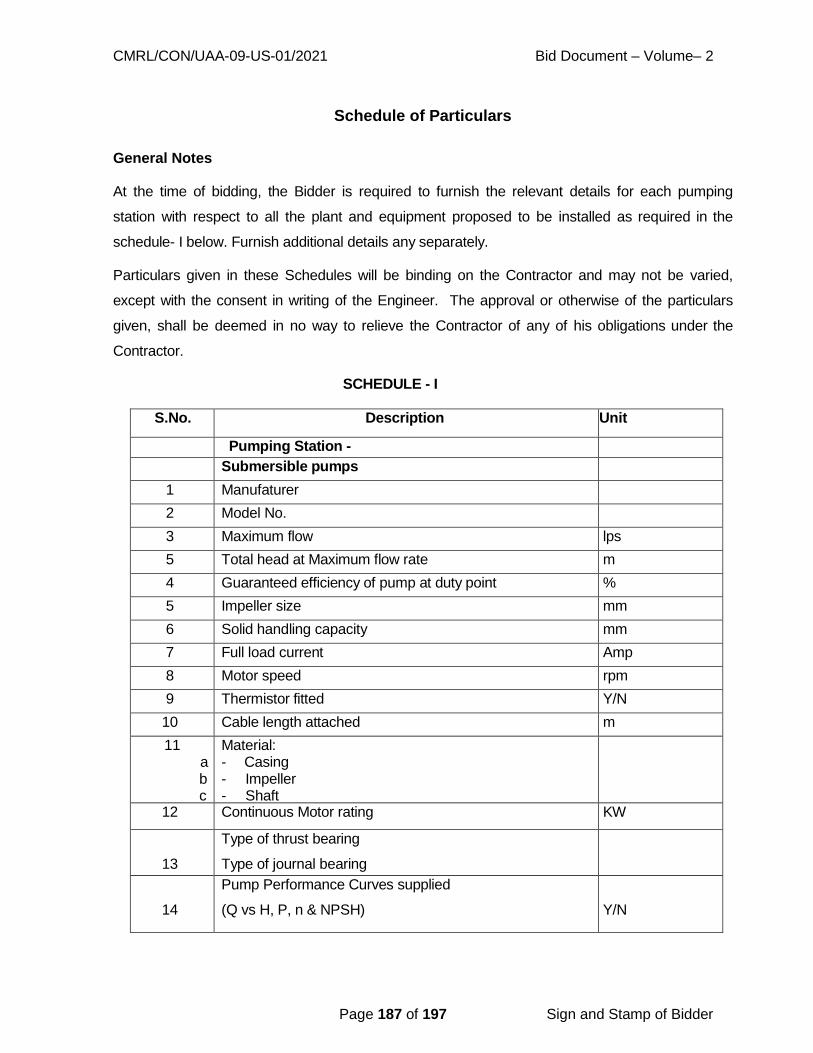
CMRL/CON/UAA-09-US-01/2021 Bid Document – Volume– 2
Page 187 of 197 Sign and Stamp of Bidder
Schedule of Particulars
General Notes
At the time of bidding, the Bidder is required to furnish the relevant details for each pumping
station with respect to all the plant and equipment proposed to be installed as required in the
schedule- I below. Furnish additional details any separately.
Particulars given in these Schedules will be binding on the Contractor and may not be varied,
except with the consent in writing of the Engineer. The approval or otherwise of the particulars
given, shall be deemed in no way to relieve the Contractor of any of his obligations under the
Contractor.
SCHEDULE - I
S.No. Description Unit
Pumping Station -
Submersible pumps
1 Manufaturer
2 Model No.
3 Maximum flow lps
5 Total head at Maximum flow rate m
4 Guaranteed efficiency of pump at duty point %
5 Impeller size mm
6 Solid handling capacity mm
7 Full load current Amp
8 Motor speed rpm
9 Thermistor fitted Y/N
10 Cable length attached m
11 a b c
Material: - Casing - Impeller - Shaft
12 Continuous Motor rating KW
13
Type of thrust bearing
Type of journal bearing
14
Pump Performance Curves supplied
(Q vs H, P, n & NPSH)
Y/N
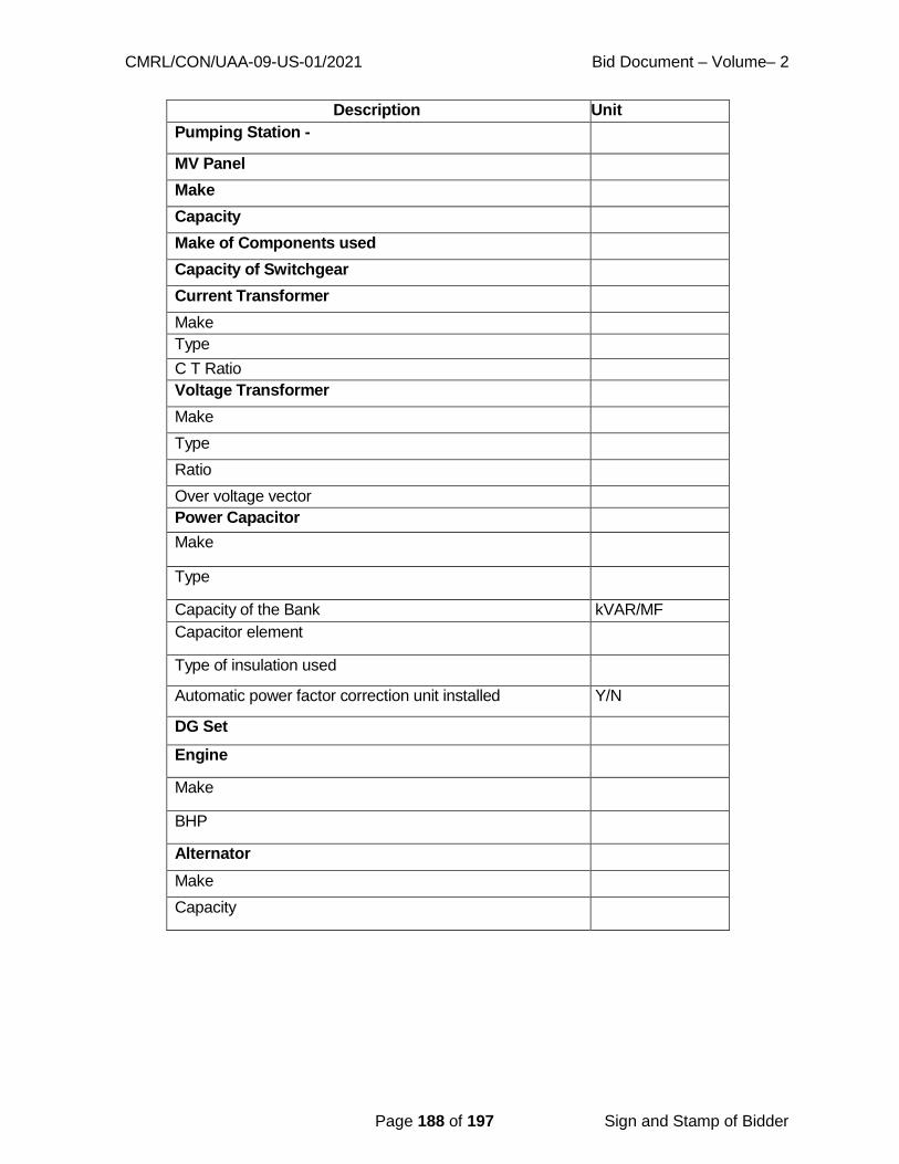
CMRL/CON/UAA-09-US-01/2021 Bid Document – Volume– 2
Page 188 of 197 Sign and Stamp of Bidder
Description Unit
Pumping Station -
MV Panel
Make
Capacity
Make of Components used
Capacity of Switchgear
Current Transformer
Make
Type
C T Ratio
Voltage Transformer
Make
Type
Ratio
Over voltage vector
Power Capacitor
Make
Type
Capacity of the Bank kVAR/MF
Capacitor element
Type of insulation used
Automatic power factor correction unit installed Y/N
DG Set
Engine
Make
BHP
Alternator
Make
Capacity
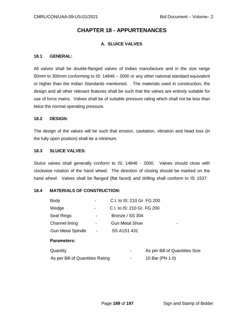
CMRL/CON/UAA-09-US-01/2021 Bid Document – Volume– 2
Page 189 of 197 Sign and Stamp of Bidder
CHAPTER 18 - APPURTENANCES
18.1 GENERAL:
A. SLUICE VALVES
All valves shall be double-flanged valves of Indian manufacture and in the size range
50mm to 300mm conforming to IS: 14846 – 2000 or any other national standard equivalent
or higher than the Indian Standards mentioned. The materials used in construction, the
design and all other relevant features shall be such that the valves are entirely suitable for
use of force mains. Valves shall be of suitable pressure rating which shall not be less than
twice the normal operating pressure.
18.2 DESIGN:
The design of the valves will be such that erosion, cavitation, vibration and head loss (in
the fully open position) shall be a minimum.
18.3 SLUICE VALVES:
Sluice valves shall generally conform to IS: 14846 - 2000. Valves should close with
clockwise rotation of the hand wheel. The direction of closing should be marked on the
hand wheel. Valves shall be flanged (flat faced) and drilling shall conform to IS: 1537.
18.4 MATERIALS OF CONSTRUCTION:
Body - C.I. to IS: 210 Gr. FG 200
Wedge - C.I. to IS: 210 Gr. FG 200
Seat Rings - Bronze / SS 304
Channel lining - Gun Metal Shoe -
Gun Metal Spindle - SS A1S1 431
Parameters:
Quantity - As per Bill of Quantities Size
As per Bill of Quantities Rating - 10 Bar (PN 1.0)

CMRL/CON/UAA-09-US-01/2021 Bid Document – Volume– 2
Page 190 of 197 Sign and Stamp of Bidder
Shop Testing Witnessing:
Seat leakage test - 10 bar (1.0 M Pa)
Body Hydrostatic test - 15 bar (1.5 M Pa)
Back Seat Leakage test - 15 bar (1.5 M Pa)
18.5 VALVE BODIES:
a. Castings:
The structure of the castings shall be homogeneous and free from non- metallic inclusions
and other injurious defects. All surface of casing which are not machined shall be smooth
and shall be carefully filed to remove all foundry irregularities.
b. Forgings:
All major stress bearing forgings shall be made to a standard specification,
which shall be submitted if required to the Engineer for approval before work is commenced.
Forgings shall be subjected to non-destructive tests to detect flaws if any. Forgings shall be
heat treated for the relief of residual stresses. The name of the maker and particulars of
the heat treatment proposed for such forging shall be submitted to the CMRL. The
Executive Engineer or his inspector may inspect such forgings at the place of manufacture
with a representative of the Contractor.
c. Workmanship:
Workmanship and general finish shall be of first-class commercial quality and in accordance
with best workshop practice.
All similar items of the valve and their component parts shall be completely interchangeable.
Spare parts shall be manufactured from the same materials as the originals and shall be
accurate and to specified tolerances so that replacements made to manufacturer‟s drawings
may be readily installed.
All parts, which can be worn or damaged by dust, shall be totally enclosed in dust proof
housings.
d. Protective coating:

CMRL/CON/UAA-09-US-01/2021 Bid Document – Volume– 2
Page 191 of 197 Sign and Stamp of Bidder
Protective coating shall comply with IS: 14846 - 2000.
18.6 LUBRICATION:
All the points where lubrication is needed, the Contractor shall furnish full details of the
method to be employed. The supply of the requisite lubricating equipment and lubricants
for commissioning and operating and maintaining the valves shall be furnished.
18.7 FLANGES:
Valves of sizes 80mm – 300mm shall have flat flanges as per IS: 1538 Part IV Table – I.
The flange-to-flange distances shall be as per IS 14846.
18.8 JOINTING MATERIALS:
Each valve shall be supplied under this Contract, with all requisite joint rings, nuts, bolts and
washers for making the joints on all the valves to be installed under this Contract. Jointing
material between the connecting flanges shall conform to the relevant IS code. Unless
otherwise specified bolting used for jointing exposed connections shall be of carbon steel,
conforming to IS: 210 Grade 20 Grade B, with galvanized finish.
18.9 FACTORY TESTS:
All the valves shall be tested at the factory for smooth, trouble free operation and operating
torque requirements by operating between fully open and fully closed position three times.
The hydrostatic tests shall consist of Closed End Tests where valve is held on both sides.
Each valve is subjected to three hydraulic tests.
a. Wedge open and pressure applied for 5 minutes to the whole body of the valve
pressure given in Section 19.4.
b. Second Test shall be applied to one face with pressure given in Section 19.4.
c. Third Test shall be similar to second, but pressure applied to the other side of the
wedge with same pressure.
For valves having terminal position shall be subjected to open-end test.
Testing for valves from Foreign Manufacturers:
i) Sampling: Each valve is recommended to be tested.
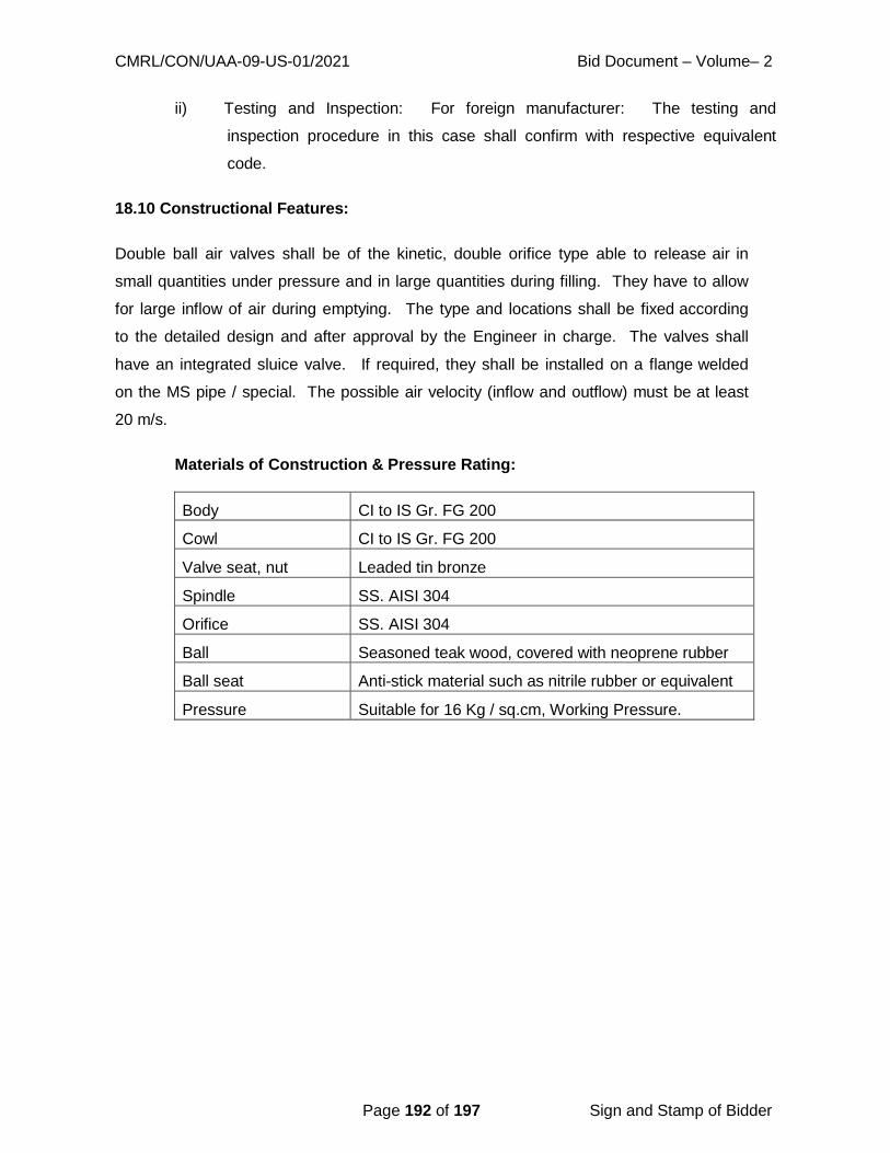
CMRL/CON/UAA-09-US-01/2021 Bid Document – Volume– 2
Page 192 of 197 Sign and Stamp of Bidder
ii) Testing and Inspection: For foreign manufacturer: The testing and
inspection procedure in this case shall confirm with respective equivalent
code.
18.10 Constructional Features:
Double ball air valves shall be of the kinetic, double orifice type able to release air in
small quantities under pressure and in large quantities during filling. They have to allow
for large inflow of air during emptying. The type and locations shall be fixed according
to the detailed design and after approval by the Engineer in charge. The valves shall
have an integrated sluice valve. If required, they shall be installed on a flange welded
on the MS pipe / special. The possible air velocity (inflow and outflow) must be at least
20 m/s.
Materials of Construction & Pressure Rating:
Body CI to IS Gr. FG 200
Cowl CI to IS Gr. FG 200
Valve seat, nut Leaded tin bronze
Spindle SS. AISI 304
Orifice SS. AISI 304
Ball Seasoned teak wood, covered with neoprene rubber
Ball seat Anti-stick material such as nitrile rubber or equivalent
Pressure Suitable for 16 Kg / sq.cm, Working Pressure.

CMRL/CON/UAA-09-US-01/2021 Bid Document – Volume– 2
Page 193 of 197 Sign and Stamp of Bidder
CHAPTER 19 - FIXING OF VALVES
19.1 FIXING OF SLUICE VALVES:
19.1.1 General:
The specification lays down the requirement for lowering, laying and jointing Sluice
valves.
19.1.2 Preparation:
The sluice valves and tailpieces shall be examined before laying for cracks and other flaws.
Only undamaged S.S. shall be used.
The sluice valve shall be operated and checked before laying. All grit and foreign
material shall be removed from the inside before placing. All the four faces shall be
thoroughly cleaned and coated with a thin layer of mineral grease. The tightening of gland
shall be checked with a pair of inside calipers. Clearance between the top of stuffing box
and the underside of the gland shall be uniform on all sides.
19.1.3 Jointing Materials:
The Contractor shall provide all the necessary jointing materials such as nuts, bolts, rubber
packing, white zinc, jute, lead wool etc. at his cost. All tools and plant required for
installation of sluice valve shall be provided by the Contractor at his cost. All the jointing
materials shall be got approved from the Engineer in charge before use. The nuts and bolts
shall conform to IS: 1364 and the rubber packing shall conform to IS: 638.
19.1.4 Installation:
The sluice valve shall be lowered into trench carefully, so that no part is damaged during
lowering operation. If necessary, tailpieces shall be fitted with sluice valve first outside the
trench and then lowered into the trench.
The rubber packing shall be three ply and of approved thickness. The packing shall be of
full diameter of the flange, with necessary holes and the sluice valve bore. It shall be even
at both the inner and outer edge. The flange faces shall be thoroughly greased. If flanges
are not free the Contractor shall use thin fibres of lead.

CMRL/CON/UAA-09-US-01/2021 Bid Document – Volume– 2
Page 194 of 197 Sign and Stamp of Bidder
After placing the packing, nuts and bolts shall be inserted and tightened to make the joint.
The valve shall be tightly closed being installed to prevent any foreign materials from getting
in between the working parts of the valve.
Each flange bolt shall be tightened a little at a time taking care to tighten diametrically
opposite bolts alternately.
The sluice valve shall be installed in such a way that spindle shall remain in truly vertical
position. The other end of the tailpiece shall be fitted with pipes so that continuous lines can
work. Extra excavation necessary to facilitate the lowering and fixing of sluice valve shall
not be paid for.
19.1.5 Testing:
After installation of sluice valve, the same is tested to 1 ½ times of its test pressure.
The joints of sluice valve shall withstand the test pressure of pipeline.
Defects noticed during test and operation of sluice valve shall be rectified by the Contractor
at his own cost, without any extra claim, to the entire satisfaction of the Engineer in charge.
19.1.6 Mode of Measurement and Payment:
The measurement shall be taken per number of sluice valves of specified size and payment
shall be on number basis for providing and fixing.
19.2 FIXING OF AIR VALVES:
19.2.1 General:
The specification placed down requirement for lowering laying and fixing Air Valves.
19.2.2 Preparation:
The air valves and the isolating valves shall be examined before laying for cracks and other
flaws. Only undamaged air valve shall be used. The air valves shall be opened and shaken
for the air opening below the vulcanite balls on the bronze seats of the balls before fixing.
All grid and foreign material shall be removed from the inside before placing. The flanged
face shall be thoroughly cleaned and coated with a thin layer of mineral grease. In case
of screw down type, the threads shall not be in damaged condition.

CMRL/CON/UAA-09-US-01/2021 Bid Document – Volume– 2
Page 195 of 197 Sign and Stamp of Bidder
19.2.3 Jointing Materials:
The Contractor shall provide all the necessary jointing materials, such as nuts, bolts, rubber
packing, white zinc jute, lead wool etc. at his cost. All tools and plant required for
installation of air valve shall be provided by the Contractor at his cost. All the jointing
materials shall be got approved from Engineer in charge before use. The nuts and bolts shall
conform to IS: 1364 and the rubber packing shall conform to IS: 638.
19.2.4 Installation:
The air valves shall be fixed on a branched flange Tee on the main pipeline. The air valve
and isolating sluice valve shall be housed in a chamber.
19.2.5 Testing:
The specification pertaining to sluice valve shall also apply to air valves.
19.2.6 Mode of measurement and payment:
The measurement shall be taken per number of air valves of specified size and payment
shall be on number basis for providing and fixing.
19.3 FIXING OF FRC. M.H. FRAME AND COVER IN RCC SLAB:
19.3.1 General:
The specification includes all requirements of fixing FRC. M.H. frame and cover of specified
size and weight in the RCC slab with locking arrangement. For fixing the FRC. M.H. frame
and cover of specified size and weight, the frame shall be fixed generally at the time of
casting RCC slab with proper anchoring.
After fixing the M.H. frame and cover locking arrangement shall be provided as per following
unless specified in the wording of the item. The size of the M.S. flat shall be 50mm x 10mm
with M.S. bar U shape of 16mm dia. The U shape M.S. bars shall be properly embedded in
the RCC roof slab and anchored. The FRC. M.H. frame and cover and the locking
arrangement after fixing shall be painted with anticorrosive black paint. The work shall be
done to the entire satisfaction of the Engineer in charge.

CMRL/CON/UAA-09-US-01/2021 Bid Document – Volume– 2
Page 196 of 197 Sign and Stamp of Bidder
19.3.2 Mode of measurement and payment:
The item shall include:
a) All labour for fixing M.H. frame and cover
b) All material and labour of locking arrangement
c) Painting of the frame, cover and locking arrangement

CMRL/CON/UAA-09-US-01/2021 Bid Document – Volume– 2
Page 197 of 197 Sign and Stamp of Bidder
ABBREVIATIONS AND ACRONYMS
C.M. Cement Mortar
Cm Centimetre
CMRL Chennai Metro Rail Ltd.
CMWSSB Chennai Metropolitan Water Supply &
Sewerage Board Cum Cubic metre
Dia. Diameter
D.I. Ductile Iron
Km Kilometre
M.H. Manhole
M.S. Mild steel
m Metre
mm Millimetre
R.C.C. Reinforced Cement Concrete
sq.cm Square centimeter
W.C. (ratio) Water Cement (ratio)

CHENNAI METRO RAIL LIMITED
NATIONAL COMPETITIVE BIDDING
BID DOCUMENT
FOR
TENDER NO: CMRL/CON/UAA-09-US-01/2021
VOLUME - III
PRICE BID
“Laying of sewer line, diversion of water supply line, house
connection works, testing, commissioning and other associated
works along TH Road near Tondiarpet Metro station from
Rettaikuzhi street junction to Tondiarpet ‘E’ pumping station’’
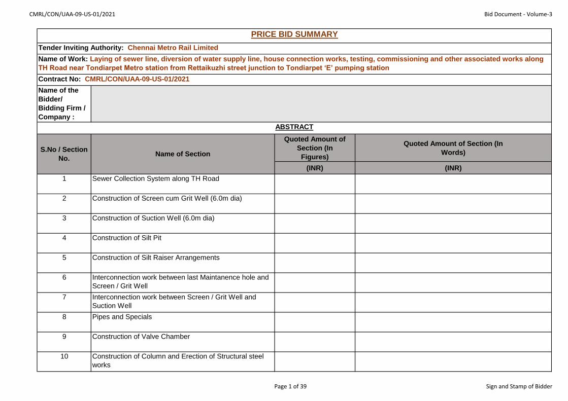
CMRL/CON/UAA-09-US-01/2021 Bid Document - Volume-3
Name of the
Bidder/
Bidding Firm /
Company :
Quoted Amount of
Section (In
Figures)
Quoted Amount of Section (In
Words)
(INR) (INR)
1 Sewer Collection System along TH Road
2 Construction of Screen cum Grit Well (6.0m dia)
3 Construction of Suction Well (6.0m dia)
4 Construction of Silt Pit
5 Construction of Silt Raiser Arrangements
6 Interconnection work between last Maintanence hole and
Screen / Grit Well
7 Interconnection work between Screen / Grit Well and
Suction Well
8 Pipes and Specials
9 Construction of Valve Chamber
10 Construction of Column and Erection of Structural steel
works
PRICE BID SUMMARY
Tender Inviting Authority: Chennai Metro Rail Limited
Name of Work: Laying of sewer line, diversion of water supply line, house connection works, testing, commissioning and other associated works along
TH Road near Tondiarpet Metro station from Rettaikuzhi street junction to Tondiarpet ‘E’ pumping station
Contract No: CMRL/CON/UAA-09-US-01/2021
S.No / Section
No.Name of Section
ABSTRACT
Page 1 of 39 Sign and Stamp of Bidder

CMRL/CON/UAA-09-US-01/2021 Bid Document - Volume-3
Name of the
Bidder/
Bidding Firm /
Company :
Quoted Amount of
Section (In
Figures)
Quoted Amount of Section (In
Words)
(INR) (INR)
PRICE BID SUMMARY
Tender Inviting Authority: Chennai Metro Rail Limited
Name of Work: Laying of sewer line, diversion of water supply line, house connection works, testing, commissioning and other associated works along
TH Road near Tondiarpet Metro station from Rettaikuzhi street junction to Tondiarpet ‘E’ pumping station
Contract No: CMRL/CON/UAA-09-US-01/2021
S.No / Section
No.Name of Section
ABSTRACT
11 Diversion of Waterline along TH Road
12 Sub-Total (Section 1 to 11 above)
13 Discount, ( If Any )
(Insert % )
14 Total quoted Amount with Discount
15 GST amount @ 12%
16 TOTAL AMOUNT with GST
Notes for the Bidder:
1. The Evaluation shall be done on Total quoted amount with discount in Sl.No. 14 above (excluding GST).
2. GST Shall be reimbursed separately on production of Proof of discharge of liability.
Page 2 of 39 Sign and Stamp of Bidder
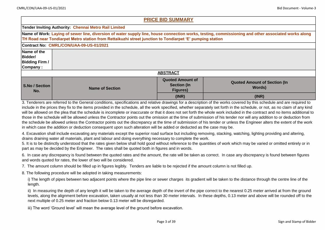
CMRL/CON/UAA-09-US-01/2021 Bid Document - Volume-3
Name of the
Bidder/
Bidding Firm /
Company :
Quoted Amount of
Section (In
Figures)
Quoted Amount of Section (In
Words)
(INR) (INR)
PRICE BID SUMMARY
Tender Inviting Authority: Chennai Metro Rail Limited
Name of Work: Laying of sewer line, diversion of water supply line, house connection works, testing, commissioning and other associated works along
TH Road near Tondiarpet Metro station from Rettaikuzhi street junction to Tondiarpet ‘E’ pumping station
Contract No: CMRL/CON/UAA-09-US-01/2021
S.No / Section
No.Name of Section
ABSTRACT
5. It is to be distinctly understood that the rates given below shall hold good without reference to the quantities of work which may be varied or omitted entirely or in
part as may be decided by the Engineer. The rates shall be quoted both in figures and in words.
3. Tenderers are referred to the General conditions, specifications and relative drawings for a description of the works covered by this schedule and are required to
include in the prices they fix to the items provided in the schedule, all the work specified, whether separately set forth in the schedule, or not, as no claim of any kind
will be allowed on the plea that the schedule is incomplete or inaccurate or that it does not set forth the whole work included in the contract and no items additional to
those in the schedule will be allowed unless the Contractor points out the omission at the time of submission of his tender nor will any addition to or deduction from
the schedule be allowed unless the Contractor points out the discrepancy at the time of submission of his tender or unless the Engineer alters the extent of the work
in which case the addition or deduction consequent upon such alteration will be added or deducted as the case may be.
4. Excavation shall include excavating any materials except the superior road surface but including removing, stacking, watching, lighting providing and altering,
drains draining water all materials, plant and labour and doing everything necessary to complete the work.
i) The length of pipes between two adjacent points where the pipe line or sewer charges its gradient will be taken to the distance through the centre line of the
length.
ii) In measuring the depth of any length it will be taken to the average depth of the invert of the pipe correct to the nearest 0.25 meter arrived at from the ground
levels, along the alignment before excavation, taken usually at not less than 30 meter intervals. In these depths, 0.13 meter and above will be rounded off to the
next multiple of 0.25 meter and fraction below 0.13 meter will be disregarded.
iii) The word ‘Ground level’ will mean the average level of the ground before excavation.
6. In case any discrepancy is found between the quoted rates and the amount, the rate will be taken as correct. In case any discrepancy is found between figures
and words quoted for rates, the lower of two will be considered.
7. The amount column should be filled up in figures legibly. Tenders are liable to be rejected if the amount column is not filled up.
8. The following procedure will be adopted in taking measurements:
Page 3 of 39 Sign and Stamp of Bidder

CMRL/CON/UAA-09-US-01/2021 Bid Document - Volume-3
Name of the
Bidder/
Bidding Firm /
Company :
Quoted Amount of
Section (In
Figures)
Quoted Amount of Section (In
Words)
(INR) (INR)
PRICE BID SUMMARY
Tender Inviting Authority: Chennai Metro Rail Limited
Name of Work: Laying of sewer line, diversion of water supply line, house connection works, testing, commissioning and other associated works along
TH Road near Tondiarpet Metro station from Rettaikuzhi street junction to Tondiarpet ‘E’ pumping station
Contract No: CMRL/CON/UAA-09-US-01/2021
S.No / Section
No.Name of Section
ABSTRACT
******
9. The quoted price is inclusive of all necessary testing charges and the third party inspection charges
iv) The depth of the invert will be the difference in levels between the level of the invert of the pipe and the average level of the ground vertically above the same
point before excavation.
v) Should the depth of the works at any part exceed the greatest depth given in the schedules by 0.25m, then the rate for it shall be calculated as follows:
The difference in rates between the two adjacent greatest depths shown in the schedule will be taken and 10% added thereto. This total shall be added to the
rates given for the greatest depth and the resulting total shall be the rate to be adopted. Similarly for other depth, should however, the depth of the work at any
part be less than the smallest depth shown in the schedule than the rates to be allowed shall be obtained by reversing the previous process.
Page 4 of 39 Sign and Stamp of Bidder

CMRL/CON/UAA-09-US-01/2021 Bid Document - Volume-3
Name of the
Bidder/
Bidding Firm
/Company :
RATE
(In Figures
and Words)
AMOUNT (In Figures and
Words)
(INR) (INR)
1 Supply, delivery, laying and jointing of Double wall corrugated
/structured wall plastic polyethylene/polypropylene pipes DWC PE or
PP of class SN-8 with non-smooth external Annular Corrugated and
Smooth lnternal Surfaces in Standard lengths with online coupler and
spigot type confirming to IS 16098 (Part-2) 2013 / EN: 13476-3 (latest
revision) including elastomeric sealing ring gasket suitable for DWC PE
or PP pipes conforming to IS: 5382 (latest revision), freight, insurance,
loading into the truck and transporting to the stores / site..etc including
earth work excavation in hard stiff clay, stiff black cotton, hard red earth,
shales, muram, gravel, stoney earth and earth mixed with small size
boulders and hard gravelly soil, depositing the earth on banks with
initial lead of 10m and lowering into trenches, aligning and testing of
DWC PE or PP pipes, watering and ramming to consolidation, etc.,
complete.
i) 295/250mm OD/ID DWC PE or PP Pipe
a i.a) at 1.5m deep m 370.00
b i.b) at 2.0m deep m 235.00
QUANTITY
Section-1: Sewer Collection System along TH Road
Name of Work: Laying of sewer line, diversion of water supply line, house connection works, testing, commissioning and other associated works along TH Road near
Tondiarpet Metro station from Rettaikuzhi street junction to Tondiarpet ‘E’ pumping station
Tender Inviting Authority: Chennai Metro Rail Limited
Contract No: CMRL/CON/UAA-09-US-01/2021
S.No Description of Work UNIT
Page 5 of 39 Sign and Stamp of Bidder
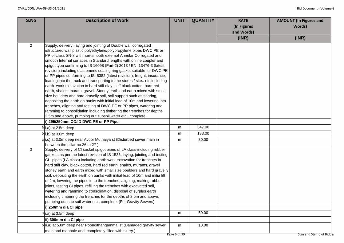
CMRL/CON/UAA-09-US-01/2021 Bid Document - Volume-3
RATE
(In Figures
and Words)
AMOUNT (In Figures and
Words)
(INR) (INR)
QUANTITYS.No Description of Work UNIT
2 Supply, delivery, laying and jointing of Double wall corrugated
/structured wall plastic polyethylene/polypropylene pipes DWC PE or
PP of class SN-8 with non-smooth external Annular Corrugated and
smooth Internal surfaces in Standard lengths with online coupler and
spigot type confirming to IS 16098 (Part-2) 2013 / EN: 13476-3 (latest
revision) including elastomeric sealing ring gasket suitable for DWC PE
or PP pipes conforming to IS: 5382 (latest revision), freight, insurance,
loading into the truck and transporting to the stores / site.. etc including
earth work excavation in hard stiff cIay, stiff black cotton, hard red
earth, shales, muram, gravel, Stoney earth and earth mixed with small
size boulders and hard gravelly soil, soil support such as shoring,
depositing the earth on banks with initial lead of 10m and lowering into
trenches, aligning and testing of DWC PE or PP pipes, watering and
ramming to consolidation including timbering the trenches for depths
2.5m and above, pumping out subsoil water etc., complete.
i) 295/250mm OD/ID DWC PE or PP Pipe
a i.a) at 2.5m deep m 347.00
b i.b) at 3.0m deep m 133.00
c i.c) at 3.0m deep near Avoor Muthaiya st (Disturbed sewer main in
between the pillar no.26 to 27 )
m 30.00
3 Supply, delivery of CI socket spigot pipes of LA class including rubber
gaskets as per the latest revision of IS 1536, laying, jointing and testing
CI pipes (LA class) including earth work excavation for trenches in
hard stiff clay, black cotton, hard red earth, shales, murams, gravel
stoney earth and earth mixed with small size boulders and hard gravelly
soil, depositing the earth on banks with initial lead of 10m and initia lift
of 2m, lowering the pipes in to the trenches, aligning, making rubber
joints, testing CI pipes, refilling the trenches with excavated soil,
watering and ramming to consolidation, disposal of surplus earth
including timbering the trenches for the depths of 2.5m and above,
pumping out sub soil water etc., complete. (For Gravity Sewers)
i) 250mm dia Cl pipe
a i.a) at 3.5m deep m 50.00
ii) 300mm dia CI pipe
b ii.a) at 5.0m deep near Poondithangammal st (Damaged gravity sewer
main and manhole and completely filled with slurry.)
m 10.00
Page 6 of 39 Sign and Stamp of Bidder

CMRL/CON/UAA-09-US-01/2021 Bid Document - Volume-3
RATE
(In Figures
and Words)
AMOUNT (In Figures and
Words)
(INR) (INR)
QUANTITYS.No Description of Work UNIT
iii) 400mm dia Cl pipe
c iii.a) at 2.5m deep m 20.00
d iii.b) at 3.0m deep m 232.00
e iii.c) at 3.5m deep m 329.00
f iii.d) at 4.0m deep m 210.00
iv) 450mm dia Cl pipe
g iv.a) at 4.0m deep m 181.00
h iv.a) at 4.5 m deep m 60.00
v) 600mm dia CI pipe
i v.a) at 4.5 m deep m 97.00
vi) 700mm dia CI pipe
j vi.a) at 4.5 m deep m 237.00
4 Cement concrete 1:3:6 using Crushed stone sand (M-sand) and 40mm
gauge hard broken stone jelly for plain cement concrete works including
laying in layers of not more than 15cm thick including ramming curing,
etc., complete for End concrete
cum 45.00
5 Construction of maintanence holes using sulphate resistant cement at
various depths to invert including earthwork excavation as per SS 20B,
laying cement concrete in C.M. 1:3:6 using Crushed stone sand (M
sand) and 40mm B.G.jelly for foundation, sinking well kerb below G.L.
for 4.5m depth and above, pumping, timbering charges for 2.5m depth
and above, stock brick work in C.M. 1:3, for 23cm thick wall and over
23cm thick wall, plastering interior with C.M. 1:3, 20mm thick and
exterior with C.M. 1:3, 12mm thick, laying plain cement concrete 1:3:6
using 12.0mm to 20mm B.G.jelly fixing the frame, providing C.I. steps,
maintanence hole cover and frame, benching and channelling including
refilling the trench with excavated earth and disposal of surplus earth
etc. complete for the following sizes for each maintanence hole.
i) 1.05mx 0.9m
a i.a) at 1.5m deep each 13.00
Page 7 of 39 Sign and Stamp of Bidder
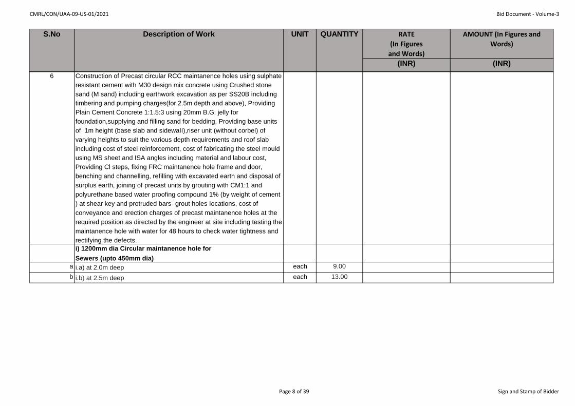
CMRL/CON/UAA-09-US-01/2021 Bid Document - Volume-3
RATE
(In Figures
and Words)
AMOUNT (In Figures and
Words)
(INR) (INR)
QUANTITYS.No Description of Work UNIT
6 Construction of Precast circular RCC maintanence holes using sulphate
resistant cement with M30 design mix concrete using Crushed stone
sand (M sand) including earthwork excavation as per SS20B including
timbering and pumping charges(for 2.5m depth and above), Providing
Plain Cement Concrete 1:1.5:3 using 20mm B.G. jelly for
foundation,suppIying and filling sand for bedding, Providing base units
of 1m height (base slab and sidewaII),riser unit (without corbel) of
varying heights to suit the various depth requirements and roof slab
including cost of steel reinforcement, cost of fabricating the steel mould
using MS sheet and ISA angles including material and labour cost,
Providing Cl steps, fixing FRC maintanence hole frame and door,
benching and channelling, refilling with excavated earth and disposal of
surplus earth, joining of precast units by grouting with CM1:1 and
polyurethane based water proofing compound 1% (by weight of cement
) at shear key and protruded bars- grout holes Iocations, cost of
conveyance and erection charges of precast maintanence holes at the
required position as directed by the engineer at site including testing the
maintanence hole with water for 48 hours to check water tightness and
rectifying the defects.
i) 1200mm dia Circular maintanence hole for
Sewers (upto 450mm dia)
a i.a) at 2.0m deep each 9.00
b i.b) at 2.5m deep each 13.00
Page 8 of 39 Sign and Stamp of Bidder

CMRL/CON/UAA-09-US-01/2021 Bid Document - Volume-3
RATE
(In Figures
and Words)
AMOUNT (In Figures and
Words)
(INR) (INR)
QUANTITYS.No Description of Work UNIT
7 Construction of RCC maintanence holes using sulphate resistant
cement with M30 design mix concrete using Crushed stone sand (M
sand) including earthwork excavation as per SS20B , providing point
edge to well kerb using ISA 150x75x10mm weighing at
16.9kg/m,sinking well kerb below 2m from G.L.or by open excavation
for various depth as per site condition with M30 mix for side wall, raft
and roof slab, incIuding cost of steel reinforcement, including bailing
and pumping out water, formwork, plugging the bottom with PCC 1:3:6
using 40mm hard broken granite jelly, laying plain cement concrete
1:3:6 using 12mm to 20mm hard broken granite jelly for fixing frame,
fixing FRC maintanence hole cover and frame, providing CI steps,
benching and channelling including refilling the trenches with excavated
earth and disposal of earth etc. including testing the maintanence hole
with water for 48hours to check water tightness and rectifying the
defects if any complete for the following size of maintanence holes.
i) 1200mm dia Circular maintanence hole for Sewers (upto 450mm
dia)
a i.a) at 3.0m deep each 14.00
b i.b) at 3.5m deep each 11.00
c i.c) at 4.0m deep each 15.00
d i.d) at 4.5m deep each 1.00
e i.e) at 5.0m deep near Poondithangammal st (Damaged gravity sewer
main and manhole and completely filled with slurry.)
each 1.00
ii) 1500mm dia Circular maintanence hole for Sewers (500mm dia &
above)
f ii.a) at 4.5m deep each 11.00
g ii.b) at 5.0m deep each 1.00
8 Supplying and fixing 150mm dia MS Ventilating columns 6.0m length
with CI Base for Ventilating column, Wire Cowl, Supplying, Laying,
Jointing and Testing of 150mm dia stoneware (SW) pipe to a length of
6m for each column with 100mm SW stopper including cost of joining
materials such as cement, sand and spun yarn with necessary civil
works for construction of Masonry Pillars, earthwork excavation, refilling
etc., complete.
each 8.00
Page 9 of 39 Sign and Stamp of Bidder
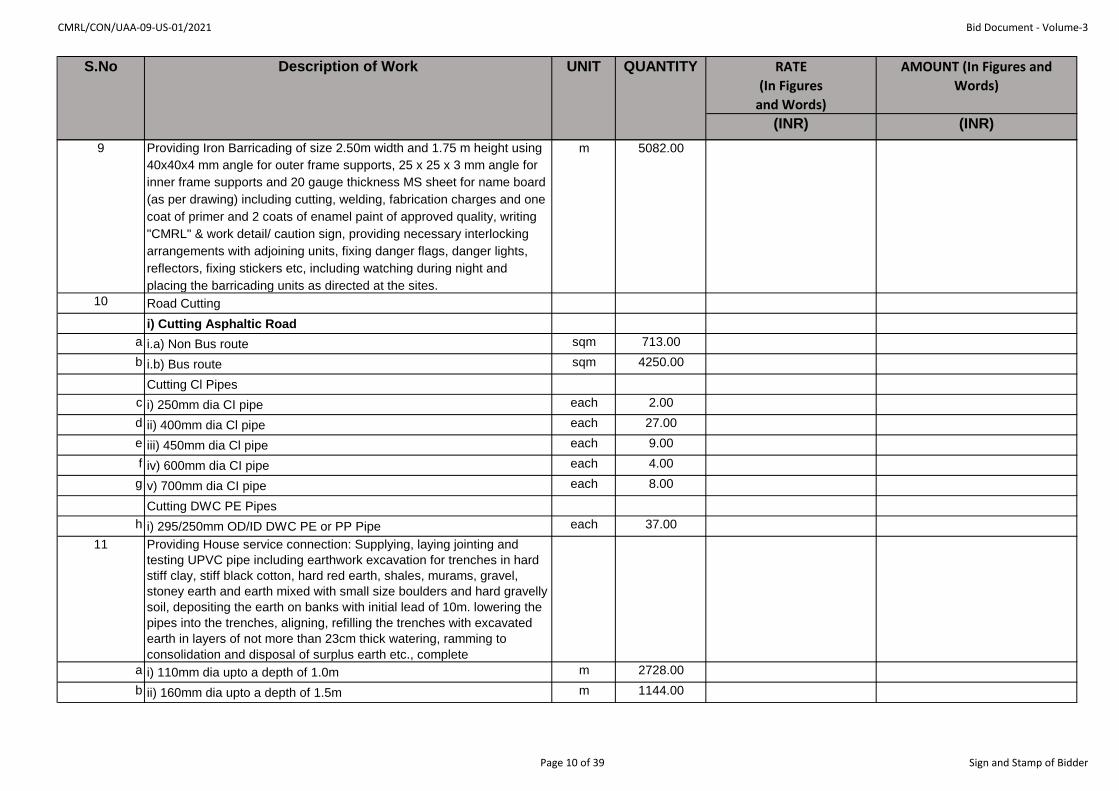
CMRL/CON/UAA-09-US-01/2021 Bid Document - Volume-3
RATE
(In Figures
and Words)
AMOUNT (In Figures and
Words)
(INR) (INR)
QUANTITYS.No Description of Work UNIT
9 Providing Iron Barricading of size 2.50m width and 1.75 m height using
40x40x4 mm angle for outer frame supports, 25 x 25 x 3 mm angle for
inner frame supports and 20 gauge thickness MS sheet for name board
(as per drawing) including cutting, welding, fabrication charges and one
coat of primer and 2 coats of enamel paint of approved quality, writing
"CMRL" & work detail/ caution sign, providing necessary interlocking
arrangements with adjoining units, fixing danger flags, danger lights,
reflectors, fixing stickers etc, including watching during night and
placing the barricading units as directed at the sites.
m 5082.00
10 Road Cutting
i) Cutting Asphaltic Road
a i.a) Non Bus route sqm 713.00
b i.b) Bus route sqm 4250.00
Cutting Cl Pipes
c i) 250mm dia CI pipe each 2.00
d ii) 400mm dia Cl pipe each 27.00
e iii) 450mm dia Cl pipe each 9.00
f iv) 600mm dia CI pipe each 4.00
g v) 700mm dia CI pipe each 8.00
Cutting DWC PE Pipes
h i) 295/250mm OD/ID DWC PE or PP Pipe each 37.00
11 Providing House service connection: Supplying, laying jointing and
testing UPVC pipe including earthwork excavation for trenches in hard
stiff clay, stiff black cotton, hard red earth, shales, murams, gravel,
stoney earth and earth mixed with small size boulders and hard gravelly
soil, depositing the earth on banks with initial lead of 10m. lowering the
pipes into the trenches, aligning, refilling the trenches with excavated
earth in layers of not more than 23cm thick watering, ramming to
consolidation and disposal of surplus earth etc., complete
a i) 110mm dia upto a depth of 1.0m m 2728.00
b ii) 160mm dia upto a depth of 1.5m m 1144.00
Page 10 of 39 Sign and Stamp of Bidder
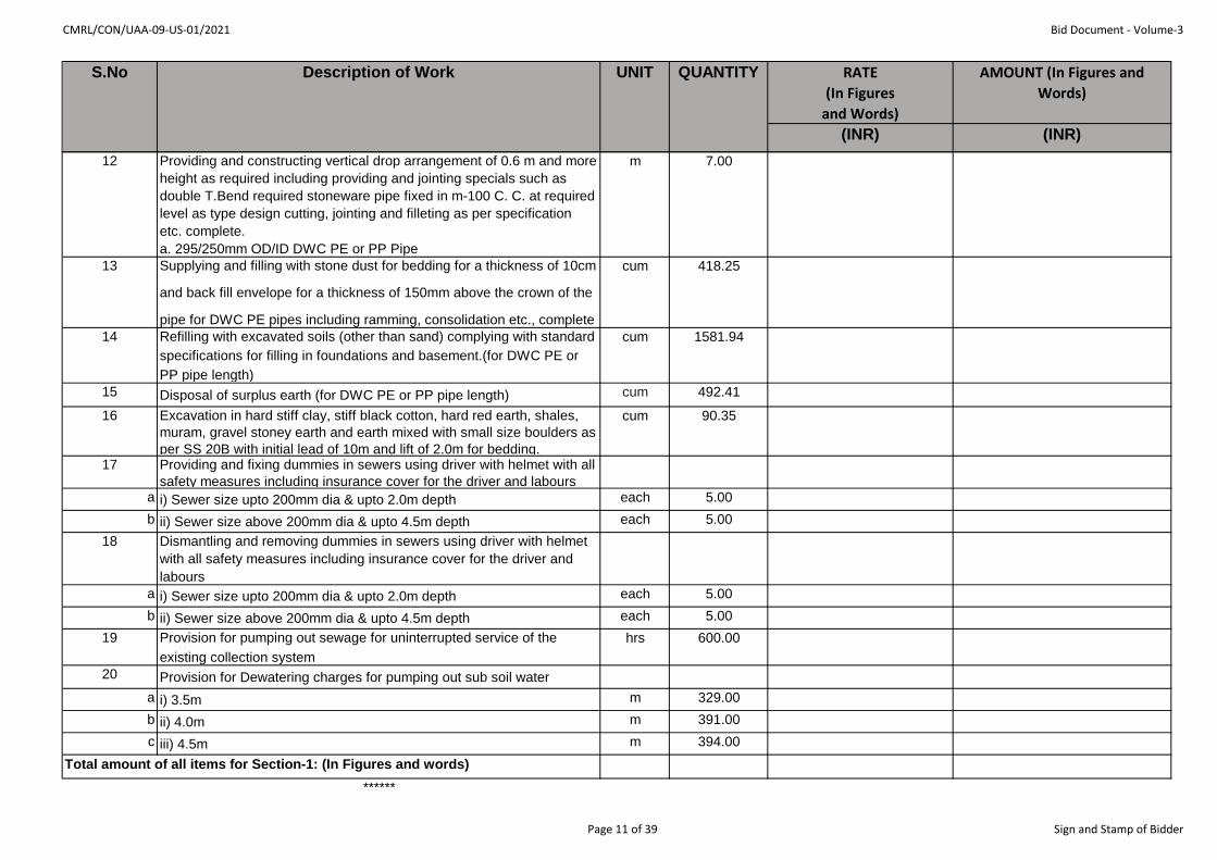
CMRL/CON/UAA-09-US-01/2021 Bid Document - Volume-3
RATE
(In Figures
and Words)
AMOUNT (In Figures and
Words)
(INR) (INR)
QUANTITYS.No Description of Work UNIT
12 Providing and constructing vertical drop arrangement of 0.6 m and more
height as required including providing and jointing specials such as
double T.Bend required stoneware pipe fixed in m-100 C. C. at required
level as type design cutting, jointing and filleting as per specification
etc. complete.
a. 295/250mm OD/ID DWC PE or PP Pipe
m 7.00
13 Supplying and filling with stone dust for bedding for a thickness of 10cm
and back fill envelope for a thickness of 150mm above the crown of the
pipe for DWC PE pipes including ramming, consolidation etc., complete
cum 418.25
14 Refilling with excavated soils (other than sand) complying with standard
specifications for filling in foundations and basement.(for DWC PE or
PP pipe length)
cum 1581.94
15 Disposal of surplus earth (for DWC PE or PP pipe length) cum 492.41
16 Excavation in hard stiff clay, stiff black cotton, hard red earth, shales,
muram, gravel stoney earth and earth mixed with small size boulders as
per SS 20B with initial lead of 10m and lift of 2.0m for bedding.
cum 90.35
17 Providing and fixing dummies in sewers using driver with helmet with all
safety measures including insurance cover for the driver and laboursa i) Sewer size upto 200mm dia & upto 2.0m depth each 5.00
b ii) Sewer size above 200mm dia & upto 4.5m depth each 5.00
18 Dismantling and removing dummies in sewers using driver with helmet
with all safety measures including insurance cover for the driver and
labours
a i) Sewer size upto 200mm dia & upto 2.0m depth each 5.00
b ii) Sewer size above 200mm dia & upto 4.5m depth each 5.00
19 Provision for pumping out sewage for uninterrupted service of the
existing collection system
hrs 600.00
20 Provision for Dewatering charges for pumping out sub soil water
a i) 3.5m m 329.00
b ii) 4.0m m 391.00
c iii) 4.5m m 394.00
Total amount of all items for Section-1: (In Figures and words)
******
Page 11 of 39 Sign and Stamp of Bidder

CMRL/CON/UAA-09-US-01/2021 Bid Document - Volume-3
Name of the
Bidder/
Bidding Firm
/Company :
RATE
(In Figures
and Words)
AMOUNT (In Figures and Words)
(INR) (INR)1 Earth work excavation in hard stiff clay, stiff black
cotton, hard red earth, shales, murum, gravel,
stoney earth or earth mixed with small size boulders
and hard gravely soil as per SS20B with initial lead
of 10m and lift of 2m etc. complete.
a i) For 0 to 2 m depth cum 101.00
2 Providing form work with centering for soffits of
reinforced cement concrete slabs or plain surfaces
including strutting upto 3m above and 3m below GL
for RCC well curb and well steining.
sqm 474.00
3 Providing and laying in position machine batched,
machine mixed and machine vibrated design mix.
Sulphate resistant cement concrete of M30 grade for
reinforced cement concrete structural elements
under controlled water cement ratio with plasticiser
using 20mm and down graded machine broken
granite stone jelly excluding the cost of centering
and shuttering and reinforcement but including
construction joint (water stopper), curing,etc. as per
standard specification and as directed at site.
a i) Up to 1.5m Below ground level & 1m above GL cum 144.00
S.No Description of Work UNIT QUANTITY
Section-2: Construction of Screen cum Grit Well (6.0m dia)
Tender Inviting Authority: Chennai Metro Rail Limited
Name of Work: Laying of sewer line, diversion of water supply line, house connection works, testing, commissioning and other associated works
along TH Road near Tondiarpet Metro station from Rettaikuzhi street junction to Tondiarpet ‘E’ pumping station
Contract No: CMRL/CON/UAA-09-US-01/2021
Page 12 of 39 Sign and Stamp of Bidder
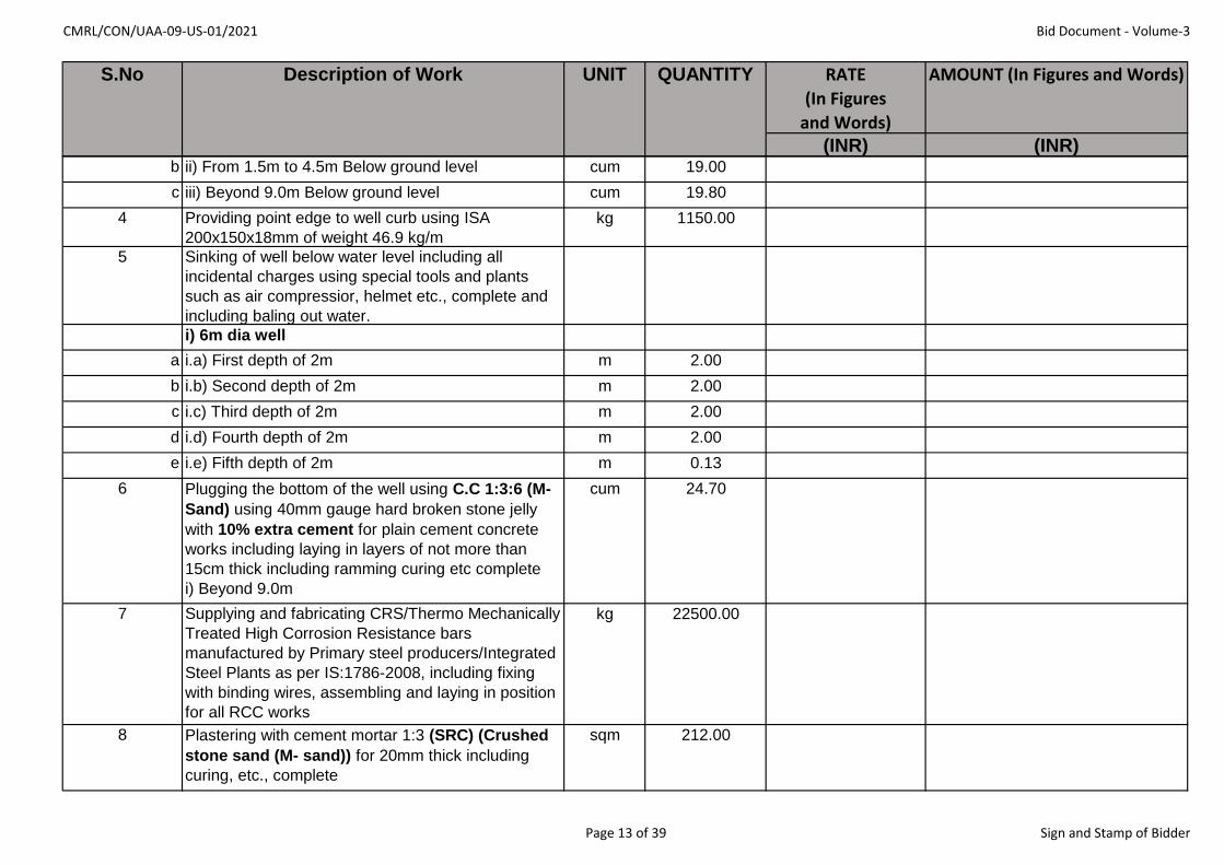
CMRL/CON/UAA-09-US-01/2021 Bid Document - Volume-3
RATE
(In Figures
and Words)
AMOUNT (In Figures and Words)
(INR) (INR)
S.No Description of Work UNIT QUANTITY
b ii) From 1.5m to 4.5m Below ground level cum 19.00
c iii) Beyond 9.0m Below ground level cum 19.80
4 Providing point edge to well curb using ISA
200x150x18mm of weight 46.9 kg/m
kg 1150.00
5 Sinking of well below water level including all
incidental charges using special tools and plants
such as air compressior, helmet etc., complete and
including baling out water.
i) 6m dia well
a i.a) First depth of 2m m 2.00
b i.b) Second depth of 2m m 2.00
c i.c) Third depth of 2m m 2.00
d i.d) Fourth depth of 2m m 2.00
e i.e) Fifth depth of 2m m 0.13
6 Plugging the bottom of the well using C.C 1:3:6 (M-
Sand) using 40mm gauge hard broken stone jelly
with 10% extra cement for plain cement concrete
works including laying in layers of not more than
15cm thick including ramming curing etc complete
i) Beyond 9.0m
cum 24.70
7 Supplying and fabricating CRS/Thermo Mechanically
Treated High Corrosion Resistance bars
manufactured by Primary steel producers/Integrated
Steel Plants as per IS:1786-2008, including fixing
with binding wires, assembling and laying in position
for all RCC works
kg 22500.00
8 Plastering with cement mortar 1:3 (SRC) (Crushed
stone sand (M- sand)) for 20mm thick including
curing, etc., complete
sqm 212.00
Page 13 of 39 Sign and Stamp of Bidder

CMRL/CON/UAA-09-US-01/2021 Bid Document - Volume-3
RATE
(In Figures
and Words)
AMOUNT (In Figures and Words)
(INR) (INR)
S.No Description of Work UNIT QUANTITY
9 Plastering with cement mortar 1:3 (SRC) (Crushed
stone sand (M- sand)) for 12mm thick including
curing, etc., complete
sqm 38.00
10 Refilling with excavated soil (other than sand)
complying with standard specifications for filling in
foundations & basement.
cum 15.00
11 Disposal of surplus earth including all lifts and leads cum 462.00
12 Supplying and fixing C.I.steps with minimum weight
of 4.5kg.
each 33.00
13 Colour washing two coats over one coat white
washing
sqm 38.00
14 Cement concrete 1:2:4 using Crushed stone sand
(M-Sand) and 20mm gauge hard broken stone jelly
& SRC for plain concrete works including laying
ramming curing, etc., complete. Beyond 9m depth
cum 8.00
15 Supply and erection of Cast Iron single faced
manually operated rising type 7mm dia penstock
with 11mm extension spindle conforming to relevant
IS and IS markings on it, having cast iron door and
frame with Gunmetal seating, spindle made of
Stainless steel, CI head stock with gear
arrangement and hand wheel fitted in well.
each 1.00
16 Supply and installation of SS open mesh flooring
with 25x6mm thick flats for outer frame and 25x3mm
SS and 12x3mm SS flats spaced at 30mm and
60mm respectively forming a mesh over half the
surface of the well.
kg 779.24
Page 14 of 39 Sign and Stamp of Bidder

CMRL/CON/UAA-09-US-01/2021 Bid Document - Volume-3
RATE
(In Figures
and Words)
AMOUNT (In Figures and Words)
(INR) (INR)
S.No Description of Work UNIT QUANTITY
17 Supplying and fixing SS screen of grade 316. The
screen shall be fabricated out of stainless steel flats
of 50 x 10mm. The outer frame also shall be of 50 x
10mm fixed inside the well for seating the screen.
The screen shall be so fabricated that the inclined
portion of the screen is fixed and the horizontal
portion of the screen is a removable one for lifting
the pump for maintenance pupose.
kg 3850.00
Total amount of all items for Section-2: (In Figures and words)
******
Page 15 of 39 Sign and Stamp of Bidder
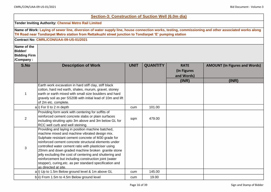
CMRL/CON/UAA-09-US-01/2021 Bid Document - Volume-3
Name of the
Bidder/
Bidding Firm
/Company :
RATE
(In Figures
and Words)
AMOUNT (In Figures and Words)
(INR) (INR)
1
Earth work excavation in hard stiff clay, stiff black
cotton, hard red earth, shales, murum, gravel, stoney
earth or earth mixed with small size boulders and hard
gravely soil as per SS20B with initial lead of 10m and lift
of 2m etc. complete.
a i) For 0 to 2 m depth cum 101.00
2
Providing form work with centering for soffits of
reinforced cement concrete slabs or plain surfaces
including strutting upto 3m above and 3m below GL for
RCC well curb and well steining.
sqm 479.00
3
Providing and laying in position machine batched,
machine mixed and machine vibrated design mix.
Sulphate resistant cement concrete of M30 grade for
reinforced cement concrete structural elements under
controlled water cement ratio with plasticiser using
20mm and down graded machine broken granite stone
jelly excluding the cost of centering and shuttering and
reinforcement but including construction joint (water
stopper), curing,etc. as per standard specification and
as directed at site.
a i) Up to 1.5m Below ground level & 1m above GL cum 145.00
b ii) From 1.5m to 4.5m Below ground level cum 19.00
S.No Description of Work UNIT QUANTITY
Section-3: Construction of Suction Well (6.0m dia)
Tender Inviting Authority: Chennai Metro Rail Limited
Name of Work: Laying of sewer line, diversion of water supply line, house connection works, testing, commissioning and other associated works along
TH Road near Tondiarpet Metro station from Rettaikuzhi street junction to Tondiarpet ‘E’ pumping station
Contract No: CMRL/CON/UAA-09-US-01/2021
Page 16 of 39 Sign and Stamp of Bidder

CMRL/CON/UAA-09-US-01/2021 Bid Document - Volume-3
RATE
(In Figures
and Words)
AMOUNT (In Figures and Words)
(INR) (INR)
S.No Description of Work UNIT QUANTITY
c iii) Beyond 9.0m Below ground level cum 19.80
4Providing point edge to well curb using ISA
200x150x18mm of weight 46.9 kg/mkg 1150.00
5
Sinking of well below water level including all incidental
charges using special tools and plants such as air
compressior, helmet etc., complete and including baling
out water.
i) 6m dia well
a i.a) First depth of 2m m 2.00
b i.b) Second depth of 2m m 2.00
c i.c) Third depth of 2m m 2.00
d i.d) Fourth depth of 2m m 2.00
e i.e) Fifth depth of 2m m 0.24
6
Plugging the bottom of the well using C.C 1:3:6 (M-
Sand) using 40mm gauge hard broken stone jelly with
10% extra cement for plain cement concrete works
including laying in layers of not more than 15cm thick
including ramming curing etc complete
i) Beyond 9.0m
cum 24.70
7
Supplying and fabricating CRS/Thermo Mechanically
Treated High Corrosion Resistance bars manufactured
by Primary steel producers/Integrated Steel Plants as
per IS:1786-2008, including fixing with binding wires,
assembling and laying in position for all RCC works
kg 22700.00
8
Plastering with cement mortar 1:3 (SRC) (Crushed
stone sand (M- sand)) for 20mm thick including curing,
etc., complete
sqm 214.00
9
Plastering with cement mortar 1:3 (SRC) (Crushed
stone sand (M- sand)) for 12mm thick including curing,
etc., complete
sqm 38.00
Page 17 of 39 Sign and Stamp of Bidder

CMRL/CON/UAA-09-US-01/2021 Bid Document - Volume-3
RATE
(In Figures
and Words)
AMOUNT (In Figures and Words)
(INR) (INR)
S.No Description of Work UNIT QUANTITY
10
Refilling with excavated soil (other than sand) complying
with standard specifications for filling in foundations &
basement.
cum 15.00
11 Disposal of surplus earth including all lifts and leads cum 467.00
12Supplying and fixing C.I.steps with minimum weight of
4.5kg.each 33.00
13 Colour washing two coats over one coat white washing sqm 38.00
14
Cement concrete 1:2:4 using Crushed stone sand (M-
Sand) and 20mm gauge hard broken stone jelly & SRC
for plain concrete works including laying ramming curing,
etc., complete. Beyond 9m depth
cum 8.00
15
Supply and erection of Cast Iron single faced manually
operated rising type 7mm dia penstock with 11mm
extension spindle conforming to relevant IS and IS
markings on it, having cast iron door and frame with
Gunmetal seating, spindle made of Stainless steel, CI
head stock with gear arrangement and hand wheel fitted
in well.
each 1.00
16 Supply and installation of SS open mesh flooring with
25x6mm thick flats for outer frame and 25x3mm SS and
12x3mm SS flats spaced at 30mm and 60mm
respectively forming a mesh over half the surface of the
well.
kg 779.24
Total amount of all items for Section-3: (In Figures and words)
******
Page 18 of 39 Sign and Stamp of Bidder

CMRL/CON/UAA-09-US-01/2021 Bid Document - Volume-3
Name of the
Bidder/
Bidding Firm
/Company :
RATE
(In Figures
and Words)
AMOUNT (In Figures and
Words)
(INR) (INR)1 Earth work excavation in all kinds of soils except
hard rock requiring blasting inclusing of shoring
strutting and bailing out water whereever necessary
refilling the sides of foundation with excavated earth
in layers of 15cm thick well rammed and
consolidated depositing surplus earth within in
compound in places as shown by the departmental
officers clearing and levelling the site with initial lead
of 10mts. and lift of 2m etc. complete.
cum 9.00
2 Supplying and filling Crushed stone sand (M sand)
for foundations and basement including watering
consolidating ramming, etc., complete
cum 1.00
S.No Description of Work UNIT QUANTIT
Y
Section-4: Construction of Silt Pit
Tender Inviting Authority: Chennai Metro Rail Limited
Name of Work: Laying of sewer line, diversion of water supply line, house connection works, testing, commissioning and other associated
works along TH Road near Tondiarpet Metro station from Rettaikuzhi street junction to Tondiarpet ‘E’ pumping station
Contract No: CMRL/CON/UAA-09-US-01/2021
Page 19 of 39 Sign and Stamp of Bidder
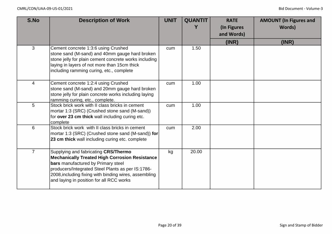
CMRL/CON/UAA-09-US-01/2021 Bid Document - Volume-3
RATE
(In Figures
and Words)
AMOUNT (In Figures and
Words)
(INR) (INR)
S.No Description of Work UNIT QUANTIT
Y
3 Cement concrete 1:3:6 using Crushed
stone sand (M-sand) and 40mm gauge hard broken
stone jelly for plain cement concrete works including
laying in layers of not more than 15cm thick
including ramming curing, etc., complete
cum 1.50
4 Cement concrete 1:2:4 using Crushed
stone sand (M-sand) and 20mm gauge hard broken
stone jelly for plain concrete works including laying
ramming curing, etc., complete.
cum 1.00
5 Stock brick work with II class bricks in cement
mortar 1:3 (SRC) (Crushed stone sand (M-sand))
for over 23 cm thick wall including curing etc.
complete
cum 1.00
6 Stock brick work with II class bricks in cement
mortar 1:3 (SRC) (Crushed stone sand (M-sand)) for
23 cm thick wall including curing etc. complete
cum 2.00
7 Supplying and fabricating CRS/Thermo
Mechanically Treated High Corrosion Resistance
bars manufactured by Primary steel
producers/Integrated Steel Plants as per IS:1786-
2008,including fixing with binding wires, assembling
and laying in position for all RCC works
kg 20.00
Page 20 of 39 Sign and Stamp of Bidder

CMRL/CON/UAA-09-US-01/2021 Bid Document - Volume-3
RATE
(In Figures
and Words)
AMOUNT (In Figures and
Words)
(INR) (INR)
S.No Description of Work UNIT QUANTIT
Y
8 Providing and laying in position machine batched,
machine mixed and machine vibrated design mix.
sulphate resistant cement concrete of M30 grade
(using SRC) for reinforced cement concrete
structural elements under controlled water cement
ratio with plasticiser using 20mm and down graded
machine broken granite stone jelly excluding the
cost of centering and shuttering and reinforcement
but including curing, etc. as per standard
specification and as directed at site
cum 1.00
9 Providing formwork with centering for soffits of
reinforced cement concrete slabs or plain surface
including strutting upto 3.0m high etc complete
complying with standard specifications.
sqm 5.00
10 Plastering with cement mortar 1:3 (SRC) (Crushed
stone sand (M-sand)) for 20mm thick including
curing, etc., complete
sqm 6.00
11 Plastering with cement mortar 1:3 (SRC) (Crushed
stone sand (M-sand)) for 12mm thick including
curing, etc., complete.
sqm 12.00
12 Refilling with excavated soil (other than sand)
compling with standard specification for filling in
foundation and basement etc. complete
cum 2.00
Total amount of all items for Section-4: (In Figures and words)
******
Page 21 of 39 Sign and Stamp of Bidder

CMRL/CON/UAA-09-US-01/2021 Bid Document - Volume-3
Name of the
Bidder/
Bidding Firm
/Company :
RATE
(In Figures
and Words)
AMOUNT (In Figures and
Words)
(INR) (INR)
1Supplying, conveying and fixing the following CI specials
as per IS 1538 etc. complete.
a i) 100mm dia D/F CI Pipe -1.0m length each 3.00
b ii) 100mm dia D/F CI Pipe -2.5m length each 3.00
c iii) 100 mm dia D/F CI bend 90° bend each 2.00
d iv) 100mm dia bell mouth each 1.00
2
Supplying and laying 100mm dia CI D/F pipe - 2m length
including earthwork excavation in all kinds of soil,
including refilling the excavated earth etc. complete.each 3.00
3Making flanged joints -100mm dia including cost of
jointing materialseach 12.00
S.No Description of Work UNIT QUANTITY
Section-5: Construction of Silt Raiser Arrangements
Tender Inviting Authority: Chennai Metro Rail Limited
Name of Work: Laying of sewer line, diversion of water supply line, house connection works, testing, commissioning and other associated works
along TH Road near Tondiarpet Metro station from Rettaikuzhi street junction to Tondiarpet ‘E’ pumping station
Contract No: CMRL/CON/UAA-09-US-01/2021
Page 22 of 39 Sign and Stamp of Bidder

CMRL/CON/UAA-09-US-01/2021 Bid Document - Volume-3
RATE
(In Figures
and Words)
AMOUNT (In Figures and
Words)
(INR) (INR)
S.No Description of Work UNIT QUANTITY
4
Supplying, laying , jointing and testing l00mm dia SW
pipe including earthwork excavation for trenches in hard
stiff clay, stiff black cotton, hard red earth, shales, muram,
gravel, stoney earth and earth mixed with small size
boulders and hard gravelly soil depositing the earth on
banks with initial lead of 10m, lowering the pipes into the
trenches, aligning, refilling the trenches with excavated
earth in layers of not more than 23 cm thick watering,
ramming to consolidation, depositing the surplus earth,
etc. complete at an average depth of 2.0m.
m 10.00
Total amount of all items for Section-5: (In Figures and words)
******
Page 23 of 39 Sign and Stamp of Bidder

CMRL/CON/UAA-09-US-01/2021 Bid Document - Volume-3
Name of the
Bidder/
Bidding Firm
/Company :
RATE
(In Figures
and Words)
AMOUNT (In Figures and Words)
(INR) (INR)1 Supply, laying, jointing and testing of C.I. Pipe of
700mm dia including testing of C.I pipes, earthwork
excavation in hard stiff clay, stiff black cottonhard
red earth and earth mixed with small size boulders
and hard gravelly soil, depositing the earth on banks
with initial lead of 10m, lowering into the trenches
and aligning, refilling with excavated soil, watering
and ramming to consolidation etc.complete at an
average depth of 4.4m
m 10.00
2 Cement concrete 1:3:6 using Crushed stone sand
(M-sand) and 40mm gauge hard broken stone jelly
for plain cement concrete works including laying in
layers of not more than 15cm thick including
ramming curing, etc., complete for End concrete.
4.5m to 9.0m depth
cum 0.70
3 Providing formwork with centering for soffits of
reinforced cement concrete slabs or plain surface
including strutting upto 3.0m high etc complete
complying with standard specifications
sqm 4.00
S.No Description of Work UNIT QUANTITY
Section-6: Interconnection work between last Maintanence hole and Screen / Grit Well
Tender Inviting Authority: Chennai Metro Rail Limited
Name of Work: Laying of sewer line, diversion of water supply line, house connection works, testing, commissioning and other associated works along
TH Road near Tondiarpet Metro station from Rettaikuzhi street junction to Tondiarpet ‘E’ pumping station
Contract No: CMRL/CON/UAA-09-US-01/2021
Page 24 of 39 Sign and Stamp of Bidder
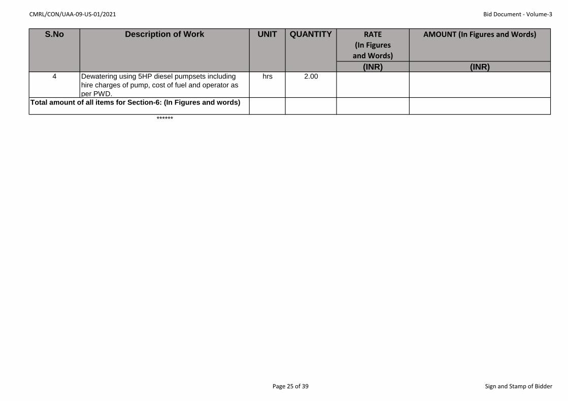
CMRL/CON/UAA-09-US-01/2021 Bid Document - Volume-3
RATE
(In Figures
and Words)
AMOUNT (In Figures and Words)
(INR) (INR)
S.No Description of Work UNIT QUANTITY
4 Dewatering using 5HP diesel pumpsets including
hire charges of pump, cost of fuel and operator as
per PWD.
hrs 2.00
Total amount of all items for Section-6: (In Figures and words)
******
Page 25 of 39 Sign and Stamp of Bidder

CMRL/CON/UAA-09-US-01/2021 Bid Document - Volume-3
Name of the
Bidder/
Bidding Firm
/Company :
RATE
(In Figures
and Words)
AMOUNT (In Figures and
Words)
(INR) (INR)1 Supply, laying, jointing and testing of C.I. Pipe of
700mm dia including testing of C.I pipes, earthwork
excavation in hard stiff clay, stiff black cottonhard
red earth and earth mixed with small size boulders
and hard gravelly soil, depositing the earth on banks
with initial lead of 10m, lowering into the trenches
and aligning, refilling with excavated soil, watering
and ramming to consolidation etc.complete at an
average depth of 4.4m
m 10.00
2 Cement concrete 1:3:6 using Crushed stone sand
(M-sand) and 40mm gauge hard broken stone jelly
for plain cement concrete works including laying in
layers of not more than 15cm thick including
ramming curing, etc., complete for End concrete.
4.5m to 9.0m depth
cum 0.70
S.No Description of Work UNIT QUANTITY
Section-7: Interconnection work between Screen / Grit Well and Suction Well
Tender Inviting Authority: Chennai Metro Rail Limited
Name of Work: Laying of sewer line, diversion of water supply line, house connection works, testing, commissioning and other associated
works along TH Road near Tondiarpet Metro station from Rettaikuzhi street junction to Tondiarpet ‘E’ pumping station
Contract No: CMRL/CON/UAA-09-US-01/2021
Page 26 of 39 Sign and Stamp of Bidder

CMRL/CON/UAA-09-US-01/2021 Bid Document - Volume-3
RATE
(In Figures
and Words)
AMOUNT (In Figures and
Words)
(INR) (INR)
S.No Description of Work UNIT QUANTITY
3 Providing formwork with centering for soffits of
reinforced cement concrete slabs or plain surface
including strutting upto 3.0m high etc complete
complying with standard specifications
sqm 4.00
4 Dewatering using 5HP diesel pumpsets including
hire charges of pump, cost of fuel and operator as
per PWD.
hrs 2.00
Total amount of all items for Section-7: (In Figures and words)
******
Page 27 of 39 Sign and Stamp of Bidder
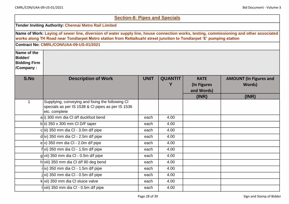
CMRL/CON/UAA-09-US-01/2021 Bid Document - Volume-3
Name of the
Bidder/
Bidding Firm
/Company :
RATE
(In Figures
and Words)
AMOUNT (In Figures and
Words)
(INR) (INR)1 Supplying, conveying and fixing the following Cl
specials as per IS 1538 & Cl pipes as per IS 1536
etc. complete
a i) 300 mm dia Cl d/f duckfoot bend each 4.00
b ii) 350 x 300 mm Cl D/F taper each 4.00
c iii) 350 mm dia Cl - 3.0m d/f pipe each 4.00
d iv) 350 mm dia Cl - 2.5m d/f pipe each 4.00
e v) 350 mm dia Cl - 2.0m d/f pipe each 4.00
f vi) 350 mm dia Cl - 1.5m d/f pipe each 4.00
g vii) 350 mm dia Cl - 0.5m d/f pipe each 4.00
h viii) 350 mm dia Cl d/f 90 deg bend each 4.00
i ix) 350 mm dia Cl - 1.5m d/f pipe each 4.00
j xi) 350 mm dia Cl - 0.5m d/f pipe each 4.00
k xii) 350 mm dia Cl sluice valve each 4.00
l xiii) 350 mm dia Cl - 0.5m d/f pipe each 4.00
S.No Description of Work UNIT QUANTIT
Y
Section-8: Pipes and Specials
Tender Inviting Authority: Chennai Metro Rail Limited
Name of Work: Laying of sewer line, diversion of water supply line, house connection works, testing, commissioning and other associated
works along TH Road near Tondiarpet Metro station from Rettaikuzhi street junction to Tondiarpet ‘E’ pumping station
Contract No: CMRL/CON/UAA-09-US-01/2021
Page 28 of 39 Sign and Stamp of Bidder
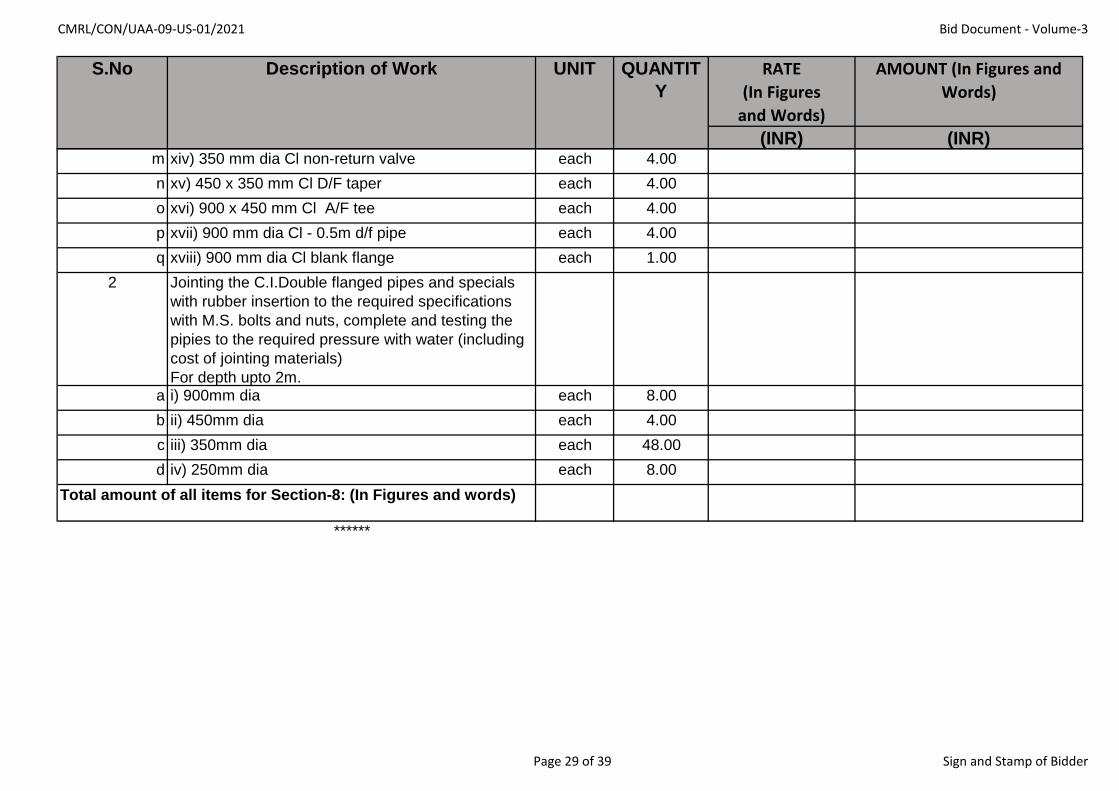
CMRL/CON/UAA-09-US-01/2021 Bid Document - Volume-3
RATE
(In Figures
and Words)
AMOUNT (In Figures and
Words)
(INR) (INR)
S.No Description of Work UNIT QUANTIT
Y
m xiv) 350 mm dia Cl non-return valve each 4.00
n xv) 450 x 350 mm Cl D/F taper each 4.00
o xvi) 900 x 450 mm Cl A/F tee each 4.00
p xvii) 900 mm dia Cl - 0.5m d/f pipe each 4.00
q xviii) 900 mm dia Cl blank flange each 1.00
2 Jointing the C.I.Double flanged pipes and specials
with rubber insertion to the required specifications
with M.S. bolts and nuts, complete and testing the
pipies to the required pressure with water (including
cost of jointing materials)
For depth upto 2m.a i) 900mm dia each 8.00
b ii) 450mm dia each 4.00
c iii) 350mm dia each 48.00
d iv) 250mm dia each 8.00
Total amount of all items for Section-8: (In Figures and words)
******
Page 29 of 39 Sign and Stamp of Bidder

CMRL/CON/UAA-09-US-01/2021 Bid Document - Volume-3
Name of the
Bidder/
Bidding Firm
/Company :
RATE
(In Figures
and Words)
AMOUNT (In Figures and
Words)
(INR) (INR)1 Excavation in hard stiff clay, stiff black cotton, hard
red earth, shales, muram, gravel stoney earth and
earth mixed with small size boulders as per SS 20B
with initial lead of 10m and lift of 2.0m etc. complete.
cum 76.00
2 Supplying and filling Crushed stone sand (M-sand) for
foundations and basement including watering
consolidating ramming, etc., complete
cum 3.30
3 Cement concrete 1:3:6 using Crushed stone sand (M-
sand) and 40mm gauge hard broken stone jelly for
plain cement concrete works including laying in layers
of not more than 15cm thick including ramming curing,
etc., complete
cum 3.30
4 Stock brick work with II class bricks in cement mortar
1:5 (Crushed stone sand (M sand)) for 23 cm thick
wall including curing etc. complete
cum 11.30
5 Supplying and fixing C.I.steps with minimum weight of
4.5kg.
each 11.00
S.No Description of Work UNIT QUANTITY
Section-9: Construction of Valve Chamber
Tender Inviting Authority: Chennai Metro Rail Limited
Name of Work: Laying of sewer line, diversion of water supply line, house connection works, testing, commissioning and other associated
works along TH Road near Tondiarpet Metro station from Rettaikuzhi street junction to Tondiarpet ‘E’ pumping station
Contract No: CMRL/CON/UAA-09-US-01/2021
Page 30 of 39 Sign and Stamp of Bidder
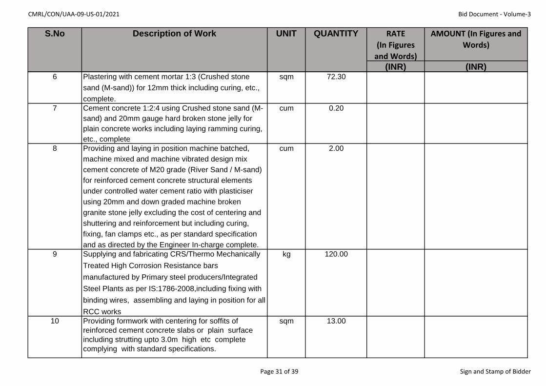
CMRL/CON/UAA-09-US-01/2021 Bid Document - Volume-3
RATE
(In Figures
and Words)
AMOUNT (In Figures and
Words)
(INR) (INR)
S.No Description of Work UNIT QUANTITY
6 Plastering with cement mortar 1:3 (Crushed stone
sand (M-sand)) for 12mm thick including curing, etc.,
complete.
sqm 72.30
7 Cement concrete 1:2:4 using Crushed stone sand (M-
sand) and 20mm gauge hard broken stone jelly for
plain concrete works including laying ramming curing,
etc., complete
cum 0.20
8 Providing and laying in position machine batched,
machine mixed and machine vibrated design mix
cement concrete of M20 grade (River Sand / M-sand)
for reinforced cement concrete structural elements
under controlled water cement ratio with plasticiser
using 20mm and down graded machine broken
granite stone jelly excluding the cost of centering and
shuttering and reinforcement but including curing,
fixing, fan clamps etc., as per standard specification
and as directed by the Engineer In-charge complete.
cum 2.00
9 Supplying and fabricating CRS/Thermo Mechanically
Treated High Corrosion Resistance bars
manufactured by Primary steel producers/Integrated
Steel Plants as per IS:1786-2008,including fixing with
binding wires, assembling and laying in position for all
RCC works
kg 120.00
10 Providing formwork with centering for soffits of
reinforced cement concrete slabs or plain surface
including strutting upto 3.0m high etc complete
complying with standard specifications.
sqm 13.00
Page 31 of 39 Sign and Stamp of Bidder

CMRL/CON/UAA-09-US-01/2021 Bid Document - Volume-3
RATE
(In Figures
and Words)
AMOUNT (In Figures and
Words)
(INR) (INR)
S.No Description of Work UNIT QUANTITY
11 Disposal of surplus earth including all lifts and leads cum 45.00
12 Refilling with excavated soil (other than sand)
complying with standard specifications for filling in
foundations & basement
cum 32.00
Total amount of all items for Section-9: (In Figures and words)
******
Page 32 of 39 Sign and Stamp of Bidder
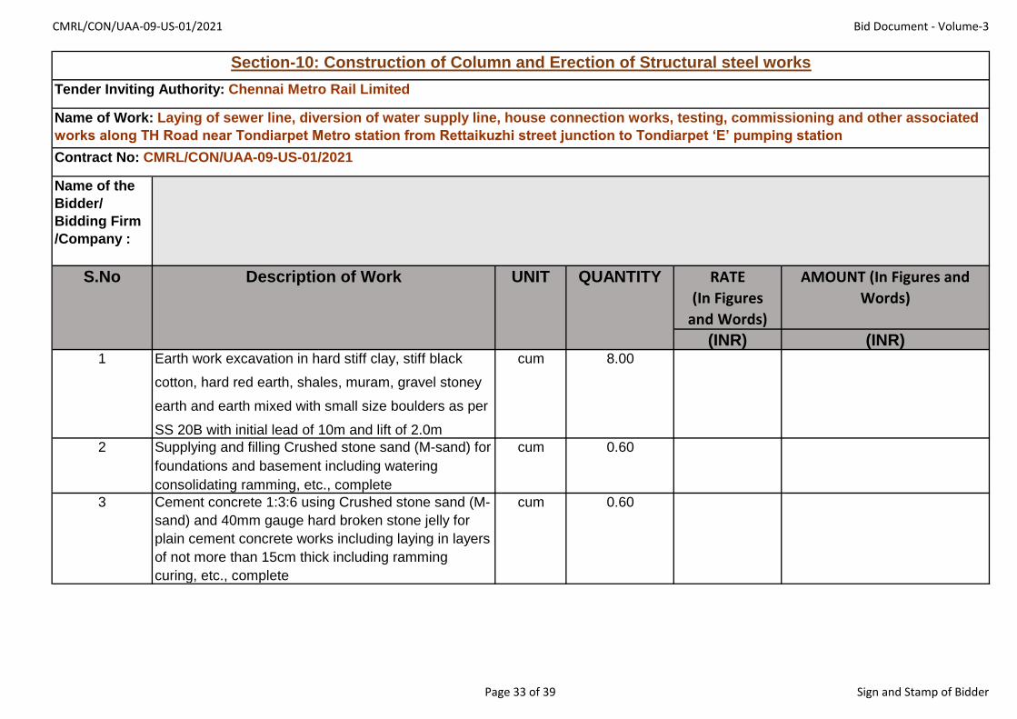
CMRL/CON/UAA-09-US-01/2021 Bid Document - Volume-3
Name of the
Bidder/
Bidding Firm
/Company :
RATE
(In Figures
and Words)
AMOUNT (In Figures and
Words)
(INR) (INR)1 Earth work excavation in hard stiff clay, stiff black
cotton, hard red earth, shales, muram, gravel stoney
earth and earth mixed with small size boulders as per
SS 20B with initial lead of 10m and lift of 2.0m
cum 8.00
2 Supplying and filling Crushed stone sand (M-sand) for
foundations and basement including watering
consolidating ramming, etc., complete
cum 0.60
3 Cement concrete 1:3:6 using Crushed stone sand (M-
sand) and 40mm gauge hard broken stone jelly for
plain cement concrete works including laying in layers
of not more than 15cm thick including ramming
curing, etc., complete
cum 0.60
S.No Description of Work UNIT QUANTITY
Section-10: Construction of Column and Erection of Structural steel works
Tender Inviting Authority: Chennai Metro Rail Limited
Name of Work: Laying of sewer line, diversion of water supply line, house connection works, testing, commissioning and other associated
works along TH Road near Tondiarpet Metro station from Rettaikuzhi street junction to Tondiarpet ‘E’ pumping station
Contract No: CMRL/CON/UAA-09-US-01/2021
Page 33 of 39 Sign and Stamp of Bidder

CMRL/CON/UAA-09-US-01/2021 Bid Document - Volume-3
RATE
(In Figures
and Words)
AMOUNT (In Figures and
Words)
(INR) (INR)
S.No Description of Work UNIT QUANTITY
4 Providing and laying in position machine batched,
machine mixed and machine vibrated design mix
cement concrete of M25 grade for reinforced cement
concrete structural elements under controlled water
cement ratio with plasticiser using 20mm and down
graded machine broken granite stone jelly excluding
the cost of centering and shuttering and
reinforcement but including curing, fixing, fan clamps
etc., as per standard specification and as directed by
the Engineer In-Charge complete
a i) upto 1.5m from G.L cum 1.08
b ii) 1.5m to 4.5m below G.L cum 1.20
c iii) 1.5m to 4.5m above G.L cum 0.54
5 Providing form work with centering for soffits of
reinforced cement concrete slabs or plain surfaces
including strutting upto 3m high.
sqm 22.00
6 Supplying and fabricating CRS/Thermo Mechanically
Treated High Corrosion Resistance bars
manufactured by Primary steel producers / Integrated
Steel Plants as per IS:1786-2008, including fixing with
binding wires, assembling and laying in position for all
RCC works
kg 290.00
7 Plastering with cement mortar 1:3 (Crushed stone
sand (M-sand)) for 12mm thick including curing, etc.,
complete.
sqm 15.00
8 Colour washing two coats over one coat of white
washing
sqm 15.00
Page 34 of 39 Sign and Stamp of Bidder

CMRL/CON/UAA-09-US-01/2021 Bid Document - Volume-3
RATE
(In Figures
and Words)
AMOUNT (In Figures and
Words)
(INR) (INR)
S.No Description of Work UNIT QUANTITY
9 Refilling with excavated soils (other than sand)
complying with standard specifications for filling in
foundations and basement
cum 6.00
10 Disposal of surplus earth including all lifts and leads cum 3.00
11 Supply and fixing ISMB 350mm of 52.4kg/m for
10.55m on column over screen/grit well
kg 560.00
12 Supply and fixing ISMB 400mm of 61.6kg/m for
10.55m on column over suction well
kg 650.00
13 Erecting pulley block of 2Tonne capacity with a 3m
chain including additional chain length of 13m to
facilitate for horizontal movement on the beam etc
complete
each 1.00
14 Erecting pulley block of lTonne capacity with a 3m
chain including additional chain length of 13m
facilitate for horizontal movement on the beam etc
complete
each 1.00
15 Painting with superior quality ready mixed paint of
chocolate, light green, grey or any other approved
colour over ISMB (for new iron work two coats).
sqm 30.00
Total amount of all items for Section-10: (In Figures and words)
******
Page 35 of 39 Sign and Stamp of Bidder

CMRL/CON/UAA-09-US-01/2021 Bid Document - Volume-3
Name of the
Bidder/
Bidding Firm
/Company :
RATE
(In Figures
and Words)
AMOUNT (In Figures and
Words)
(INR) (INR)
1Supply of 100mm dia DI pipe (Rates inclusive of transportation
and rubber gasket)
m 60.00
2
Laying DI pipe including earthwork excavation for trenches in
Hard stiff clay, black cotton, Hard red earth,sales, murams,
gravel,stoney earth and earth mixed with small size boulders
and hard hard gravelly soil dispositing the earth on banks with
initial lead of 10m and initial lift of 2m carting the pipes from
any of the board 's stores to the site of work lowering into the
trenches,aligning,refilling the trenches with excavated
soil,watering and ramming to consoildation,etc.,complete for
the pipes of following diametres.
a 100mm dia(Depth not exceeding 1.5m) m 70.00
b 100mm dia(Depth not exceeding 1.75m) m 20.00
c 100mm dia(Depth not exceeding 2 m) m 10.00
3Supply of 150mm dia DI pipe (Rates inclusive of transportation
and rubber gasket)
m 1000.00
S.No Description of Work UNIT QUANTIT
Y
Section-11: Diversion of Waterline along TH Road
Tender Inviting Authority: Chennai Metro Rail Limited
Name of Work: Laying of sewer line, diversion of water supply line, house connection works, testing, commissioning and other associated works along TH
Road near Tondiarpet Metro station from Rettaikuzhi street junction to Tondiarpet ‘E’ pumping station
Contract No: CMRL/CON/UAA-09-US-01/2021
Page 36 of 39 Sign and Stamp of Bidder

CMRL/CON/UAA-09-US-01/2021 Bid Document - Volume-3
RATE
(In Figures
and Words)
AMOUNT (In Figures and
Words)
(INR) (INR)
S.No Description of Work UNIT QUANTIT
Y
4
Laying DI pipe including earthwork excavation for trenches in
Hard stiff clay, black cotton, Hard red earth,sales, murams,
gravel,stoney earth and earth mixed with small size boulders
and hard hard gravelly soil dispositing the earth on banks with
initial lead of 10m and initial lift of 2m carting the pipes from
any of the board 's stores to the site of work lowering into the
trenches,aligning,refilling the trenches with excavated
soil,watering and ramming to consoildation,etc.,complete for
the pipes of following diametres.
a 150mm dia(Depth not exceeding 1.5m) m 400.00
b 150mm dia(Depth not exceeding 1.75m) m 300.00
c 150mm dia(Depth not exceeding 2 m) m 300.00
5
Construction of Chamber for 100mm to 250mm dia.sluice valve
including providing and fixing FRC Cover and frame of size
60cmx60cm for size1.35x1.2x1.55m
each 6.00
6 Supply of Sluice Valve with cap/wheel (150mm dia) each 2.00
7Conveying and fixing sluice valuves with tail pieces including
fixing the surface boxes/valves,covers(150mm dia)
each 2.00
8 Supply of Sluice Valve with cap/wheel (100mm dia) each 7.00
9Conveying and fixing sluice valuves with tail pieces including
fixing the surface boxes/valves,covers(100mm dia)
each 7.00
10Supply of 150 mm dia Ductile Iron socket/Spigot pipes as per IS
8329/2000. Class K9 pipe for metro water line shifting
m 50.00
12Supply of 100 mm dia Ductile Iron socket/Spigot pipes as per IS
8329/2000. Class K9 pipe for metro water line shifting
m 40.00
13Disjoining and refixing of specials Such as Tee branches, Tapers
and bends Excluding excavation( 150 mm dia)
each 10.00
Page 37 of 39 Sign and Stamp of Bidder

CMRL/CON/UAA-09-US-01/2021 Bid Document - Volume-3
RATE
(In Figures
and Words)
AMOUNT (In Figures and
Words)
(INR) (INR)
S.No Description of Work UNIT QUANTIT
Y
14 Mechanical Collar joint for 150mm DI Pipe each 3.00
15 Mechanical Collar joint for 100mm DI Pipe each 5.00
16 C.I Bend with Door (150mm) each 6.00
17 C.I TEE with Door (150mm) each 8.00
18Reducer 250x150 mm (1.78kg per no) rate is inclusive of
transpotation charges
kg 14.24
19 Providing House service connections in water mains
i
Supplying and laying of MDPE(PE80) Blue pipe (IS:4427) with
necessary specials including earth work excavtion laying
jointing testing ,refilling the trenches and disposal of surplus
earth work etc., complete.
a 20 mm OD m 160.00
b 25 mm OD m 400.00
c 32 mm OD m 160.00
II
Making bore and tapping in the D.I Pipe line ,supplying and
fixing of specials consisting of plastic moulded clamp saddle
with (SS 304) female threaded metal inserts,sealing rubber and
plastic wide strap including suitable bolts and
nuts,Ploypropylene compression fitting adopter with metal
inserts (SS 304-male threaded),Polyproplene compression
fittings 90 deg elbow,UPVC ball valve (stop cock) with
compression joint at one end and the female threaded at the
other end and suitable encloser (HDPE) with top side openable
for housing UPVC Ball valve (stop cock) and testing house
connections including cost of water etc., complete for following
sizes.
Page 38 of 39 Sign and Stamp of Bidder

CMRL/CON/UAA-09-US-01/2021 Bid Document - Volume-3
RATE
(In Figures
and Words)
AMOUNT (In Figures and
Words)
(INR) (INR)
S.No Description of Work UNIT QUANTIT
Y
a 20 mm OD each 40.00
b 25 mm OD each 100.00
c 32 mm OD each 40.00
20
Connection work to existing main including cutting existing
pipe, fixing branches, collars, lead jointing and bailing out
water etc.. Excluding excavation.
each 60.00
21fixing of specials Such as Tee branches, Tapers and bends
Excluding excavation( 150 mm dia)
each 10.00
22
Testing DI pipe with hydraulic testing equipment by filling with
the water including water cost @Rs.6 /KL and testing to
recommended pressure in conineint stretches and attending
the burst if any occurred during the test, excluding the cost of
pipes ,including other incidental and perational charges extra
complete for 150 mm dia DI pipe.
m 1000.00
23
Testing DI pipe with hydraulic testing equipment by filling with
the water including water cost @Rs.73/KL and testing to
recommended pressure in conineint stretches and attending
the burst if any occurred during the test, excluding the cost of
pipes ,including other incidental and perational charges extra
complete for 100mm dia DI pipe.
m 100.00
Total amount of all items for Section-11: (In Figures and words)
******
Page 39 of 39 Sign and Stamp of Bidder

CHENNAI METRO RAIL LIMITED
NATIONAL COMPETITIVE
BIDDING BID DOCUMENT
FOR
TENDER NO: CMRL/CON/UAA-09-US-01/2021
VOLUME - IV
DRAWINGS
“Laying of sewer line, diversion of water supply line, house
connection works, testing, commissioning and other associated
works along TH Road near Tondiarpet Metro station from
Rettaikuzhi street junction to Tondiarpet ‘E’ pumping station’’
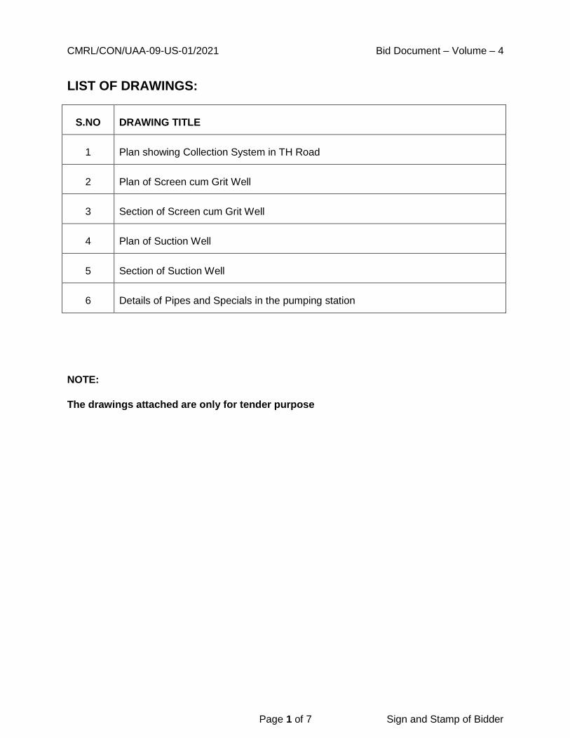
CMRL/CON/UAA-09-US-01/2021 Bid Document – Volume – 4
Page 1 of 7 Sign and Stamp of Bidder
LIST OF DRAWINGS:
S.NO DRAWING TITLE
1 Plan showing Collection System in TH Road
2 Plan of Screen cum Grit Well
3 Section of Screen cum Grit Well
4 Plan of Suction Well
5 Section of Suction Well
6 Details of Pipes and Specials in the pumping station
NOTE:
The drawings attached are only for tender purpose


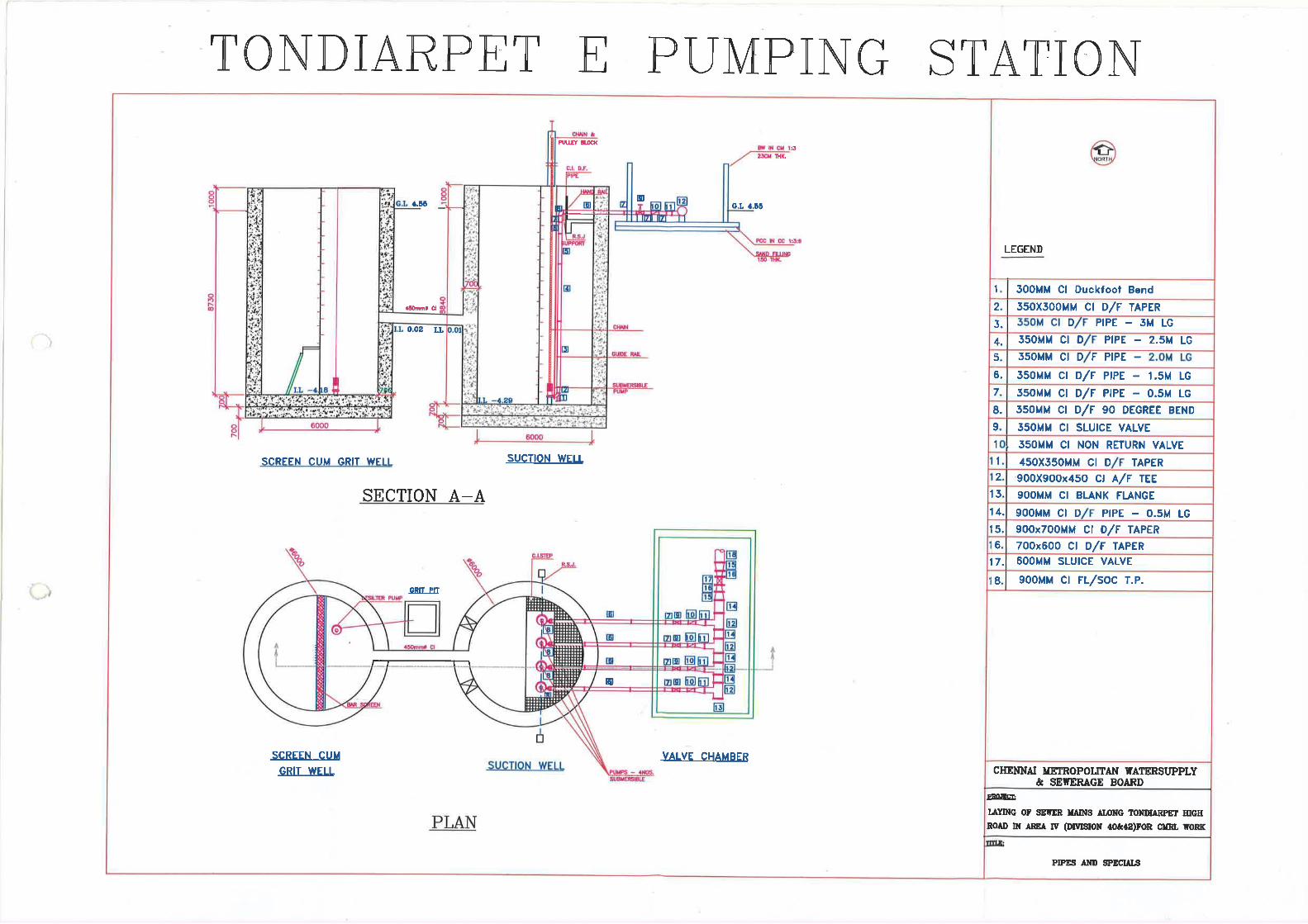
Copyright © 2022 FDOKUMEN