LASER PROCESSING OF SOFT MATERIALS
16
Romanian Reports in Physics, Vol. 59, No. 2, P. 483–498, 2007 Dedicated to Prof. Dorin N. Poenaru’s 70th Anniversary LASER PROCESSING OF SOFT MATERIALS T. LIPPERT 1 , D.B. CHRISEY 2 , A. PURICE 3 , C. CONSTANTINESCU 3 , M. FILIPESCU 3 , N.D. SCARISOREANU 3 , M. DINESCU 3 1 Paul Scherrer Institute, 5232 Villigen-PSI, Switzerland 2 Department of Material Science, Rensselaer Polytechnic Institute 110 8th Street, Troy, New York,12180-3590, USA 3 National Institute for Laser, Plasma and Radiation Physics P.O. Box MG-16 Magurele, 077125 Bucharest, Romania (Received March 12, 2007) Abstract. The paper presents a review of some of our results concerning laser pro- cessing of soft materials. Three examples are considered: i) deposition of polycarbosiloxane thin films by Matrix Assisted Pulsed Laser Evaporation (MAPLE) technique; ii) excimer laser patterning of viable B35 neuroblasts cells and iii) laser micromachining of hydrophobic agarose gel. Key words: laser, MAPLE, MAPLE DW, soft matter. 1. INTRODUCTION One of the main challenges in solid state physics and materials science fields is the discovery and integration of new materials in devices with a large area of applications such as biophysics, optoelectronic and nanotechnology. The novel thin films deposition techniques become very important, while the demands on the size and properties of the materials are increasing. Since 1960, pulsed lasers have proved to be a flexible instrument for applications in materials processing. One of the most important applications of the interaction laser light-matter is Pulsed Laser Deposition (PLD). Three years after Breech and Cross studied the laser-vaporization and excitation of atoms from solid surfaces, in 1965, Smith and Turner deposited the first thin films using a ruby laser. Starting with that moment, PLD became more and more popular for new materials thin films deposition [1, 2].
-
Upload
independent -
Category
Documents
-
view
2 -
download
0
Transcript of LASER PROCESSING OF SOFT MATERIALS

Romanian Reports in Physics, Vol. 59, No. 2, P. 483–498, 2007
Dedicated to Prof. Dorin N. Poenaru’s70th Anniversary
LASER PROCESSING OF SOFT MATERIALS
T. LIPPERT1, D.B. CHRISEY2, A. PURICE3, C. CONSTANTINESCU3,
M. FILIPESCU3, N.D. SCARISOREANU3, M. DINESCU3
1 Paul Scherrer Institute, 5232 Villigen-PSI, Switzerland2 Department of Material Science, Rensselaer Polytechnic Institute
110 8th Street, Troy, New York,12180-3590, USA3 National Institute for Laser, Plasma and Radiation Physics
P.O. Box MG-16 Magurele, 077125 Bucharest, Romania
(Received March 12, 2007)
Abstract. The paper presents a review of some of our results concerning laser pro-cessing of soft materials. Three examples are considered: i) deposition of polycarbosiloxanethin films by Matrix Assisted Pulsed Laser Evaporation (MAPLE) technique; ii) excimerlaser patterning of viable B35 neuroblasts cells and iii) laser micromachining of hydrophobicagarose gel.
Key words: laser, MAPLE, MAPLE DW, soft matter.
1. INTRODUCTION
One of the main challenges in solid state physics and materials sciencefields is the discovery and integration of new materials in devices with a largearea of applications such as biophysics, optoelectronic and nanotechnology.The novel thin films deposition techniques become very important, while thedemands on the size and properties of the materials are increasing.
Since 1960, pulsed lasers have proved to be a flexible instrument forapplications in materials processing. One of the most important applicationsof the interaction laser light-matter is Pulsed Laser Deposition (PLD). Threeyears after Breech and Cross studied the laser-vaporization and excitation ofatoms from solid surfaces, in 1965, Smith and Turner deposited the first thinfilms using a ruby laser. Starting with that moment, PLD became more andmore popular for new materials thin films deposition [1, 2].

484 T. Lippert, D.B. Chrisey, A. Purice, C. Constantinescu et al. 2
Pulsed laser deposition technique involves the interaction of a laser beamwith a target material (solid or liquid) having as result a plume which istransporting the particles on a substrate, where a thin film is formed.
Pulsed laser deposition method offers many advantages: 1. the energysource (the laser) is outside the reactive chamber, which provides a higherflexibility for the deposition parameters and regarding the geometry of thesystem; 2. it is possible to ablate almost every solid or liquid material; 3. thepulsed nature of the PLD involves an accurate control on the deposition rateand on the thickness of the grown films; 4. the target material is selectivelyablated, only in the laser irradiated areas; 5. the material transfer from thetarget to the substrate is stoichiometric; 6. due to the high energetic speciesin ablation plume, the deposition temperatures can be decreased; 7. newmaterials/ metastable states, impossible to obtain by other techniques, can beproduced by PLD.
Pulsed laser deposition cannot be used for all types of polymers, biopoly-mers and proteins, due to the high laser fluences that can generate strong pho-tochemical decompositions. Even at relatively low fluences, some polymers arevery photosensitive. To reduce the photochemical decomposition from the di-rect interaction of the UV laser light with organic and polymeric materials, amore gentle method has to be used.
Developed in the last years, Matrix Assisted Pulsed Laser Evaporation(MAPLE) has proved to be an attractive method for the organic thin filmsdeposition. MAPLE is similar to PLD technique, with a different way toproduce the target. In MAPLE, a material, for example a polymer or a pro-tein, is dissolved in a solvent in concentrations of 0.1–5%, and the mixtureis frozen, having as result a solid target. Only the solvent absorbs the laserradiation (ideal case). When the laser light irradiates the target, the solventis evaporated and the investigated material (the organic material or the poly-mer) is collected on a substrate, in the same way as for PLD. A version ofthe MAPLE technique is Matrix Assisted Pulsed Laser Evaporation DirectWriting (MAPLE DW); the material is transferred from a plate transparentsupport by irradiation from the backside, the laser beam non interacting di-rectly with the layer.
Laser is often used for patterning in different experimental configura-tion and processes. The simplest way is to use it just for material removing,following a desired pattern; in some conditions it can also functionalize theirradiated area.
Tissue engineering integrates biology and materials engineering in devel-oping next-generation medical technologies. Controlling cell adhesion/location,proliferation and patterning is critical in developing next-generation sensingdevices and advanced tissue engineered constructs. In this field laser is again
3 Laser processing of soft materials 485
an important tool, allowing non destructive cells manipulation. In this pa-per we present a review of some of our results concerning laser processingof soft materials. Three different examples are presented. The first exampleconcerns deposition of polycarbosiloxane thin films by MAPLE. The secondexample describes an experiment related to viable cells patterning by MAPLEDW. The third example discusses on the laser micromachining of hydrophobicagarose gel.
2. POLYSILOXANE THIN FILMS DEPOSITION
2.1. EXPERIMENTAL
The siloxanes are polymeric materials which have variable refraction in-dex, low losses, variable thermo-optic coefficient, low birefringence and a verygood thermal stability. Fluoro-alchool substituted carbopolysiloxane can beused for chemical sensors applications because of the hydroxyl group presencein its composition. For main part of application thin films of such materialare required.
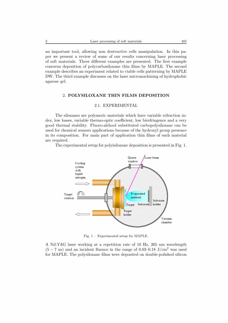
The experimental setup for polyisiloxane deposition is presented in Fig. 1.
Fig. 1 – Experimental setup for MAPLE.
A Nd:YAG laser working at a repetition rate of 10 Hz, 265 nm wavelength(5 − 7 ns) and an incident fluence in the range of 0.03–0.18 J/cm2 was usedfor MAPLE. The polysiloxane films were deposited on double-polished silicon

486 T. Lippert, D.B. Chrisey, A. Purice, C. Constantinescu et al. 4
substrate placed at a distance of 5 cm from the target. The substrates wereheld at room temperature during the deposition. The number of pulses was20 000, for most of the experiments. The laser beam was translated on thetarget, while the target was rotated with a motion feedthrough driven by amotor. For controlling the temperature two thermocouples were placed in twodifferent spots of the target holder. The depositions took place in a nitrogenbackground pressure in the range of 50 Pa – 1 000 Pa. During some depositionsthe pressure slightly varied, probably due to non concordance between theevaporated solvent and the pumping flux [3].
For preparing the target, three different solvents were used: tetrahydro-furan, acetone, and chloroform. We prepared solutions of 4% polymer and96% solvent. The target holder was chilled with liquid nitrogen. During depo-sition, the target temperature had to be smaller then the freezing temperatureof the solvent, so that the target can be kept solid. The freezing temperaturesfor the three solvents are: −108.4◦C for tetrahidrofuran, −94.9◦C for acetoneand −63.5◦C for chloroform.
The films surface aspect and roughness were analyzed using Atomic ForceMicroscopy. The chemical composition was investigated by Fourier TransformInfrared spectroscopy (FTIR).
2.2. RESULTS AND DISCUSSIONS
As seen in the AFM images some of the samples reveal a smooth sur-face, covering the entire exposed area of the substrate. The roughness (RMSdeviation) shown in Fig. 2 is 5.6 A approximately, which is extremely low forsuch type of materials [4].
Fig. 2 – AFM image on a 20 × 20 µm2 area of a sample deposited from achloroform and polymer target; RMS = 5.6 A; vertical scale 5.1 nm [3].
5 Laser processing of soft materials 487
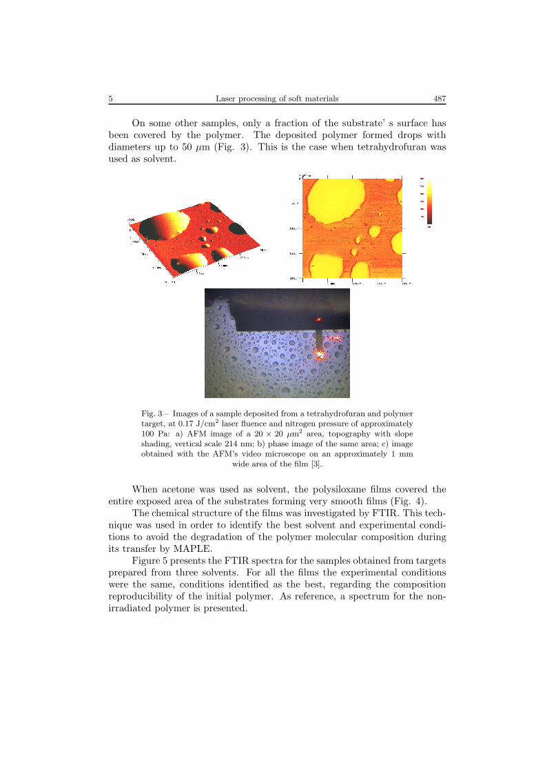
On some other samples, only a fraction of the substrate’ s surface hasbeen covered by the polymer. The deposited polymer formed drops withdiameters up to 50 µm (Fig. 3). This is the case when tetrahydrofuran wasused as solvent.
Fig. 3 – Images of a sample deposited from a tetrahydrofuran and polymertarget, at 0.17 J/cm2 laser fluence and nitrogen pressure of approximately100 Pa: a) AFM image of a 20 × 20 µm2 area, topography with slopeshading, vertical scale 214 nm; b) phase image of the same area; c) imageobtained with the AFM’s video microscope on an approximately 1 mm
wide area of the film [3].
When acetone was used as solvent, the polysiloxane films covered theentire exposed area of the substrates forming very smooth films (Fig. 4).
The chemical structure of the films was investigated by FTIR. This tech-nique was used in order to identify the best solvent and experimental condi-tions to avoid the degradation of the polymer molecular composition duringits transfer by MAPLE.
Figure 5 presents the FTIR spectra for the samples obtained from targetsprepared from three solvents. For all the films the experimental conditionswere the same, conditions identified as the best, regarding the compositionreproducibility of the initial polymer. As reference, a spectrum for the non-irradiated polymer is presented.

488 T. Lippert, D.B. Chrisey, A. Purice, C. Constantinescu et al. 6
Fig. 4 – a) AFM image of 40 × 40 µm2 on a sample deposited from anacetone and polymer target, at a fluence of 0.05 J/cm2; RMS = 9.8 nm;vertical scale 93 nm; b) image obtained with the AFM’s video microscope;
the width of the cantilever is 40 µm [3].
Fig. 5 – FTIR spectra of the resulted polymers evaporated from targetsprepared by using acetone, THF and chloroform as solvents [3].
It can be easily seen that when tetrahydrofuran is used as solvent, manyof the important infrared active band are not reproduced. After an accu-rate parametric study it resulted that the layers prepared from targets usingacetone as solvent reproduce better the initial composition.
For a more profound study, in Fig. 6 there are presented the FTIRspectra in the range of 2800 − 3100 cm−1 for samples deposited at differentfluences from 0.03 to 0.14 J/cm2. Each spectrum was amplified and shiftedalong the vertical axis to reveal the changes of the IR spectra resulted by

7 Laser processing of soft materials 489
increasing the laser fluence. The intensities of the absorption bands are notrelevant because the thickness of the resulted samples were different.
Fig. 6 – FTIR spectra in the range 2800 − 3100 cm−1 corresponding toCHn bond stretching vibrations of polymeric films deposited at laser flu-ences in the range of 0.03 − 0.14 J/cm2. Acetone was used as solvent for
target preparation [3].
Analyzing spectra from Fig. 6 by an extraction procedure of Gauss-ian components the principal absorption bands centered at the wavelength:2 864, 2 885, 2 970, 2 925 and 3 032 cm−1 were obtained. The ratio betweenthe components of CHn stretching vibration modes at 2 864, 2 885 cm−1 andthe most intense absorption band at 2 925 cm−1 has been determined in re-lation with the laser beam fluence. The fluences which determine the sameratio I/I2925 for the starting material and for the deposited film are around0.06 J/cm2.
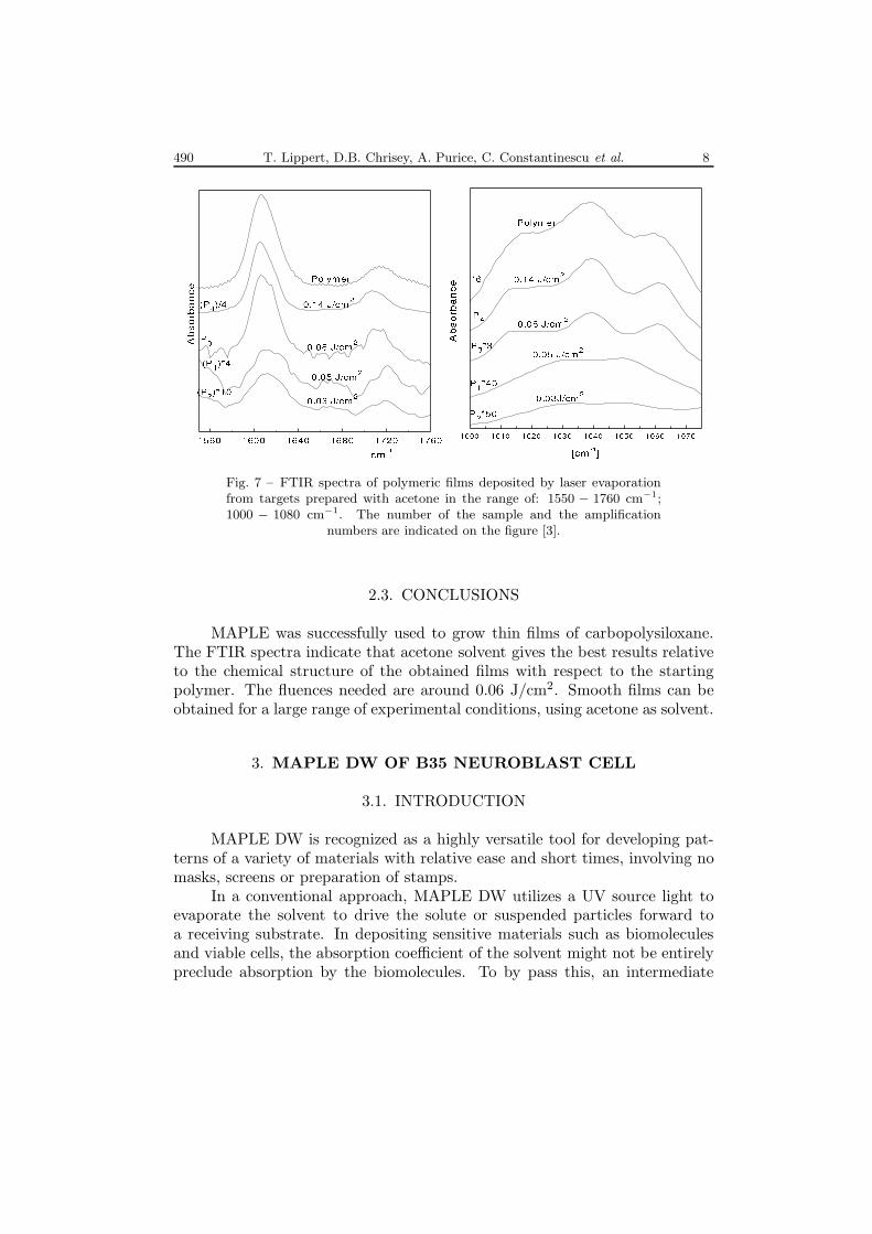
In Fig. 7 FTIR spectra in the ranges of 1 550 − 1 760 cm−1 and 1 000 −1 080 cm−1, respectively are presented. The peaks at 1 612 cm−1 and 1716cm−1 were assigned to C=C and C=O stretching bond vibrations respectively,by comparison with other reported data and spectra libraries [5]. Si−O bondstretching vibration can be found in the range of 970−1 095 cm−1 [5]. It seemsto correspond to the absorption band at 1 033 cm−1 for all the samples.
Analysing the bands centered at 1 716, 1 612, 1 033 cm−1 it was foundthat laser fluences between 0.03 and 0.08 J/cm2 determine almost the sameratios for the films and for the starting material.
490 T. Lippert, D.B. Chrisey, A. Purice, C. Constantinescu et al. 8
Fig. 7 – FTIR spectra of polymeric films deposited by laser evaporationfrom targets prepared with acetone in the range of: 1550 − 1760 cm−1;1000 − 1080 cm−1. The number of the sample and the amplification
numbers are indicated on the figure [3].
2.3. CONCLUSIONS
MAPLE was successfully used to grow thin films of carbopolysiloxane.The FTIR spectra indicate that acetone solvent gives the best results relativeto the chemical structure of the obtained films with respect to the startingpolymer. The fluences needed are around 0.06 J/cm2. Smooth films can beobtained for a large range of experimental conditions, using acetone as solvent.
3. MAPLE DW OF B35 NEUROBLAST CELL
3.1. INTRODUCTION
MAPLE DW is recognized as a highly versatile tool for developing pat-terns of a variety of materials with relative ease and short times, involving nomasks, screens or preparation of stamps.
In a conventional approach, MAPLE DW utilizes a UV source light toevaporate the solvent to drive the solute or suspended particles forward toa receiving substrate. In depositing sensitive materials such as biomoleculesand viable cells, the absorption coefficient of the solvent might not be entirelypreclude absorption by the biomolecules. To by pass this, an intermediate

9 Laser processing of soft materials 491
absorbing (decomposing) polymer layer can be inserted in the structure. Tri-azene Polymer (TP) is found to be most appropriate given the source lightand threshold fluence for ablation. The structure prepared, named ribbon,includes a transparent support coated with a layer of the explosive triazenepolymer and a layer containing the material to be transferred (viable cells).During the irradiation process from the glass side of the structure, the mainpart of the laser energy will be absorbed mainly by explosive layer, allowinggentle and safe transfer of viable cells. The resolution and pattern dimensioncan be controlled by the distance of separation between the ribbon/substrate,the laser fluence, the spot size, and stage transition. The process would beextended for co-deposition of viable cells and biomaterials as a heterogeneouslayer-by-layer approach.
3.2. EXPERIMENTAL
In Fig. 8 a schematic of the matrix assisted pulsed laser evaporation-direct write system process is presented. An ArF pulsed excimer laser(λ = 193 nm, f = 10 Hz) was focused onto the ribbon plane using a lens.A biomaterial-coated 1′′ diameter quartz disc is used as a ribbon, which is
Fig. 8 – Schematic of MAPLE DW. A novel variation in using absorbinglayer such as Triazene polymer allows a softer transfer [6].
placed directly above the substrate. The gap between the ribbon and sub-strate was controlled using a Z-translation stage. Patterns were created mov-ing the ribbon with a computer program-controlled X − Y translation stage.The diameter of the laser spot on the ribbon was maintained at 50 µm. Lasertransfer was observed using an inverted lens camera that was focused on thereceiving substrate. These experiments were performed under ambient air andat room temperature (25◦C). The B35 neuroblast clonal cell line isolated from

492 T. Lippert, D.B. Chrisey, A. Purice, C. Constantinescu et al. 10
the rat central nervous system (American Type Culture Collection. Manas-sas, VA, USA) were prepared for transfer using the protocol described in [6]by sub-culturing in a Dulbecco’s modified Eagle’s medium (DMEM) mediawith specific additives for maintaining them alive, trypsinized and split 1 : 5to maintain division of the cell line and avoid differentiation. The cells werestored in a 37◦C, 5 %CO2 culture incubator.
Quartz plates coated with tryazene polymer layer with thickness of 90nm, 110 nm and 140 nm respectively where coated with ECM (ExtracellularMatrix, American Type Culture Collection. Manassas, VA, USA) and thenleft in the incubator for 30 minutes to allow complete cross-linking of the ECM.The concentrated cell pellet at the bottom of the tube was reconstituted with0.25 ml media to a concentration of approximately 107 cells/ml and pipettedonto the prepared ribbon containing the ECM. The ribbon containing the cellswas then placed in the incubator for 10 minutes to allow cells to attach theECM, prior to transfer. The gap between the ribbon and substrate was setat 150 µm. The substrate was a glass plate coated with ECM layer preparedand conserved as it was previously described. A parametric study on thelaser fluence process control was carried out: values for triazene absorptionthreshold and cell transfer threshold were determined. The final value usedwas around 0.07 J/cm2. A CAD/CAM program was used for cells patterningand the plates containing transferred cells were stored in separate Petri dishescontaining pre-warmed media. Using an inverted optical microscope, the cellson the substrate viability and proliferation at various time points of 3h, 6h,12h, 24h, 48h was checked.
3.3. RESULTS AND DISCUSSION
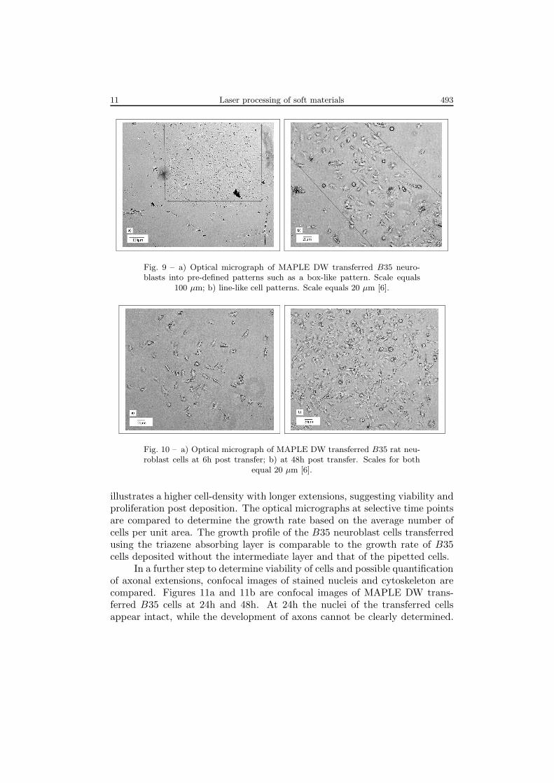
The triazene biocompatibility was first established by different cells ad-hesion (osteoblasts, neuroblasts, myoblasts, and endothelial cells) viability andgrowth studies. Results indicated good adhesion and growth compared withother known compatible surfaces such as polystyrene. In order to determinethe efficacy of B35 neuroblasts deposition, a capture device was setup andthe transfer monitored for various fluences. Cell transfer was found to occurat fluences above 0.05 J/cm2. Various cell-patterns were generated by usingdifferent algorithms for the stage movement. Figure 9 shows an optical mi-crograph of the MAPLE DW transferred B35 cells into a box-like pattern.Arrows are shown at the edges to guide the eye. The boundaries are fairlywell-defined, considering cell locomotion post transfer.
Optical micrograph of MAPLE DW transferred cells at 6h and 48h isshown in Fig. 10. The micrograph at 6h shows few neuroblasts cells at theinitial stage of growth with short axons. The image at 48h on the other hand
11 Laser processing of soft materials 493
Fig. 9 – a) Optical micrograph of MAPLE DW transferred B35 neuro-blasts into pre-defined patterns such as a box-like pattern. Scale equals
100 µm; b) line-like cell patterns. Scale equals 20 µm [6].
Fig. 10 – a) Optical micrograph of MAPLE DW transferred B35 rat neu-roblast cells at 6h post transfer; b) at 48h post transfer. Scales for both
equal 20 µm [6].
illustrates a higher cell-density with longer extensions, suggesting viability andproliferation post deposition. The optical micrographs at selective time pointsare compared to determine the growth rate based on the average number ofcells per unit area. The growth profile of the B35 neuroblast cells transferredusing the triazene absorbing layer is comparable to the growth rate of B35cells deposited without the intermediate layer and that of the pipetted cells.
In a further step to determine viability of cells and possible quantificationof axonal extensions, confocal images of stained nucleis and cytoskeleton arecompared. Figures 11a and 11b are confocal images of MAPLE DW trans-ferred B35 cells at 24h and 48h. At 24h the nuclei of the transferred cellsappear intact, while the development of axons cannot be clearly determined.

494 T. Lippert, D.B. Chrisey, A. Purice, C. Constantinescu et al. 12
The cells at 48h post transfer show intact preservation of nuclei with well de-veloped axonal extensions. These results demonstrate that the technique iscompetent in creating patterns of viable cells at low fluences.
Fig. 11 – a) Confocal micrograph of stained B35 neuroblasts shows viablenucleus and cytoskeleton at 24h post transfer; b) 48h post transfer. Scale
equals 10 µm [6].
3.4. CONCLUSIONS
We have demonstrated that patterns of viable B35 neuroblasts can beachieved at low fluences by incorporating high absorbing triazene polymer atthe operating wavelength. Because it involves no masks, stamps, etching, andother lithographic tools, MAPLE DW is arguably one of the most versatiletools for generating mesoscopic patterns for a wide range of materials, fromorganic to inorganic.
4. ADHERENCE OF NEUROBLASTS IN LASERMICROMACHINED CAD/CAM AGAROSE CHANNELS
4.1. INTRODUCTION
We have previously demonstrated (Chapter 3 of this paper [6]) a laserforward transfer approach termed MAPLE DW on viable cells. However,after adherent cells were deposited onto a two-dimensional substrate, theywere found to grow in all directions. To control cell movement and expansion,the system was coupled with a surface recognition tool, such as developing adifferentially adherent substrate.
13 Laser processing of soft materials 495
Microfluidic channels were obtained by laser micromachining hydrophilicagarose gel. Within these micromachined channels, we flow and polymerize ex-tracellular (ECM) matrix, a hydrophobic basement membrane mixture, whichhas known to induce cellular adhesion, growth and proliferation [7].
4.2. EXPERIMENTAL
A 1% agarose gel was prepared by a technique described in [8] and thenmicromashined; using an excimer laser (193 nm, ArF) at a spot size of 30 µmand energy per pulse of 1.0 mJ at a repetition rate of 10 Hz. Two repetitivescan cycles were applied for patterning channels of 60 to 400 µm wide and 1 cmlong using a CAD/CAM program for the stage movement. For allowing theeasy flow of the material, each channel was provided with a reservoir. In thenext step non-diluted extracellular matrix solution (ECM) (ATCC, Manassas,VA) was micro-pipetted into the channels and polymerized into a thin film inthe channel. B35 rat neuroblasts (ATCC) were grown in tissue culture flasksfollowing the recipe described in [6, 8]. The neuroblast suspension was pipettedover the ECM coated micromachined agarose channels together with a culturemedia to a ration of 1/10 − 1/15. The number of cells per 10µm× 10µm areawas equal to 0.22. The cells were maintained in a 37.8◦C, 5% CO2 incubator. Alive/dead cell staining kit (Biovision, Mountain View, CA) was used to stainthe templated neuroblasts. Staining solution, containing propidium iodideand Live-dyeTM stained dead cells red and live nuclei green, respectively. Thestained neuroblasts were viewed with an inverted optical microscope and adigital still camera with an epi-fluorescence attachment [8].
4.3. RESULTS AND DISCUSSION
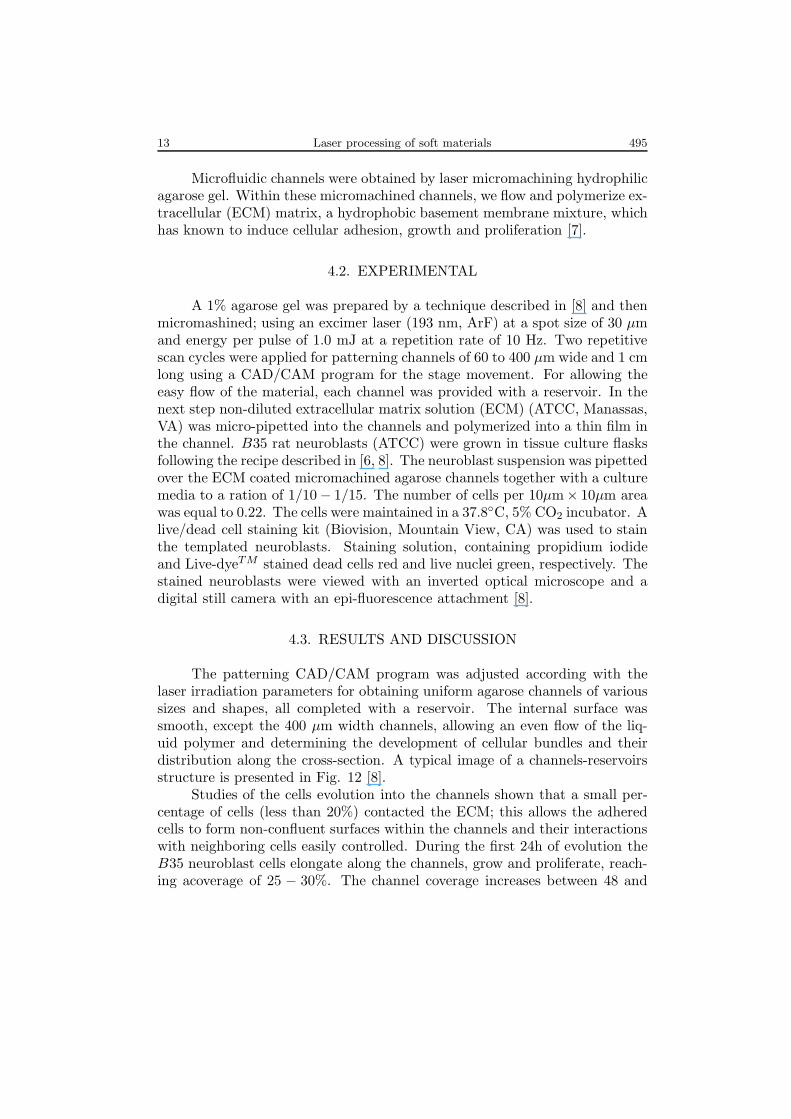
The patterning CAD/CAM program was adjusted according with thelaser irradiation parameters for obtaining uniform agarose channels of varioussizes and shapes, all completed with a reservoir. The internal surface wassmooth, except the 400 µm width channels, allowing an even flow of the liq-uid polymer and determining the development of cellular bundles and theirdistribution along the cross-section. A typical image of a channels-reservoirsstructure is presented in Fig. 12 [8].
Studies of the cells evolution into the channels shown that a small per-centage of cells (less than 20%) contacted the ECM; this allows the adheredcells to form non-confluent surfaces within the channels and their interactionswith neighboring cells easily controlled. During the first 24h of evolution theB35 neuroblast cells elongate along the channels, grow and proliferate, reach-ing acoverage of 25 − 30%. The channel coverage increases between 48 and

496 T. Lippert, D.B. Chrisey, A. Purice, C. Constantinescu et al. 14
Fig. 12 – Optical micrograph of CAD/CAM micromachined agarosechannels with reservoirs [8].
72h, reaching values close to 90%. Neuroblasts randomly align within thechannel for all the studied dimensions channels, while maintaining some align-ment with neighboring cells and near the wall. We can speculate that there isno cooperative signaling across the channel width, and cell networks greaterthan 10 cells wide are not able to effectively communicate over the channeldistance. From the increase of the coverage and cells density and packaging wecan suppose that some neuroblasts differentiate into multinucleated neurons(Figs. 13 and 14).
Fig. 13 – Optical micrograph of the 60µm channel with B35 neuroblastsmaintaining 25 − 30% coverage in the ECM, at 24h post seeding [8].
Multinucleate neuron bundles develop and between 72 and 96h, the in-creased cell density within the ECM channel caused the entire neuron bundle(cell + ECM network) delamination from the substrate. The aspect ratio forthe 100 µm width neuron bundle is 100 : 1 (Fig. 15). The neuron bundle

15 Laser processing of soft materials 497
dimensions were found to depend on the initial patterned agarose structure,which is dependent, on its turn, on the laser processing parameters.
Fig. 14 – Optical micrograph of confluent B35 cells at 72h post seedingin a 100 mm cell-ECM linear channel [8].
Fig. 15 – Optical micrograph of self-sustained B35 neuron bundles delam-inated from agarose substrate shown 72h post seeding for 150 µm neuron
bundle at higher magnification [8].
4.4. CONCLUSIONS
CAD/CAM laser micromachining was demonstrated to fulfill the require-ments for fabrication of channels with appropriate form and dimensions tofunctionalize surfaces for cellular growth. The two-dimensional differential ad-herence was used to promote neuroblast alignment and to obtain microscalethree-dimensional self-sustained freestanding neuron bundles. The method canbe developed for creating complex heterogeneous cellular networks.

498 T. Lippert, D.B. Chrisey, A. Purice, C. Constantinescu et al. 16
5. CONCLUSIONS
Laser processing was demonstrated to be an appropriate, versatile, cleanand effective technique for soft materials manipulation and patterning. Itopens a large prospective for application in medicine, biology, for sensors fab-rication and tissue engineering.
REFERENCES
1. D.B. Chrisey and G.K. Hubler (eds.), Pulsed Laser Deposition of Thin Films, John Wiley& Sons, New York, 1994.
2. R.W. Eason (Eds.), Pulsed Laser Deposition of Thin Films: Applications in Electronics,Sensors, and Biomaterials, John Wiley & Sons, 2006.
3. E.J. Houser, D.B. Chrisey, M. Bercu, N.D. Scarisoreanu, A. Purice, D. Colceag, C. Con-stantinescu, A. Moldovan, M. Dinescu, Functionalized polysiloxane thin films depositedby matrix assisted pulsed laser evaporation for advanced chemical sensor applications,Appl. Surf. Sci., 252, 4871–4876 (2006).
4. A. Purice, J. Schou, P. Kingshott, N. Pryds, M. Dinescu, High Fluence Deposition ofPolyethylene Glycol Films at 1064 nm by Matrix Assisted Pulsed Laser Evaporation(MAPLE), Appl. Surf. Sci., 2007 (in press).
5. ∗ ∗ ∗ , http://www.chem.uni-potsdam.de/tools/6. A. Doraiswamy, R.J. Narayan, T. Lippert, L. Urech, A. Wokaun, M. Nagel, B. Hopp,
M. Dinescu, R. Modi, R.C.Y. Auyeung, D.B. Chrisey, Excimer laser forward transferof mammalian cells using a novel triazene absorbing layer, Applied Surface Science,252 (13), pp. 4743–4747 (2006).
7. M. Maley, M.J. Davies, M.D. Grounds, Extracellular matrix, growth factors, genetics:their influence on cell proliferation and myotube formation in primary cultures of adultmouse skeletal muscle, Exp. Cell Res., 219, 169 (1995).
8. A. Doraiswamy, T. Patz, R.J. Narayan, M. Dinescu, R. Modi, R.C.Y. Auyeung,D.B. Chrisey, Two-dimensional differential adherence of neuroblasts in laser microma-chined CAD/CAM agarose channels, Applied Surface Science, 252 (13), 4748–4753(2006).