•L - T - P ( 4-0-0) - NIT Srinagar
63
Machine Design –II (MEC- 602) • L - T - P ( 4-0-0) Prof. M F Wani Prof. M F Wani Prof. M F Wani Prof. M F Wani • Tribology Laboratory, Mechanical Engineering Department, NIT Srinagar • Email. [email protected] • Skype: mfwani1
-
Upload
khangminh22 -
Category
Documents
-
view
3 -
download
0
Transcript of •L - T - P ( 4-0-0) - NIT Srinagar

Machine Design –II (MEC- 602)
•L - T - P ( 4-0-0)Prof. M F WaniProf. M F WaniProf. M F WaniProf. M F Wani
• Tribology Laboratory, Mechanical Engineering Department, NIT Srinagar
• Email. [email protected]• Skype: mfwani1

How to Fight COOVID - 19 We all have be brave and courageous enough as
scientist and technocrats to fight COVID 19.
Psychologically, must have confidence to win war against this disease
Follow adversaries issued by GOI HM and also Follow adversaries issued by GOI HM and also we have to help to make our health system more strong and robust.
Need of hour is to think creative to find solutions to fight this virus. ( Innovative ideas can help us)
In next disposal of used masks will be displayed (Safe Disposal of used masks is need of hour)


• Now we will discuss course coverage , as you know this is 2nd
course of Machine Design. • Do you know the Cos and POS• CO is course outcomes ( related • CO is course outcomes ( related
to this subject) and PO is programme outcomes
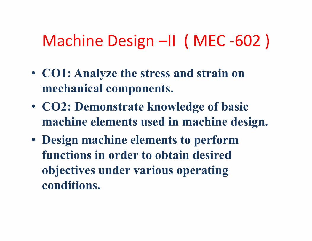
Machine Design –II ( MEC -602 )
• CO1: Analyze the stress and strain on mechanical components.
• CO2: Demonstrate knowledge of basic machine elements used in machine design.machine elements used in machine design.
• Design machine elements to perform functions in order to obtain desired objectives under various operating conditions.

DESIGN by Definition
It is defined as the process of obtaining a optimalsolution to problem within constraints i.e.,solution through technological developments atminimum cost without compromising with qualityand efficiency under specified constraints.and efficiency under specified constraints.OPTIMAL Solution ????????
f(z )= a1x1 + b2x2……bnxna = x1 + x2 and 1 < x < 100, ………
Z is cost or z is production or profit
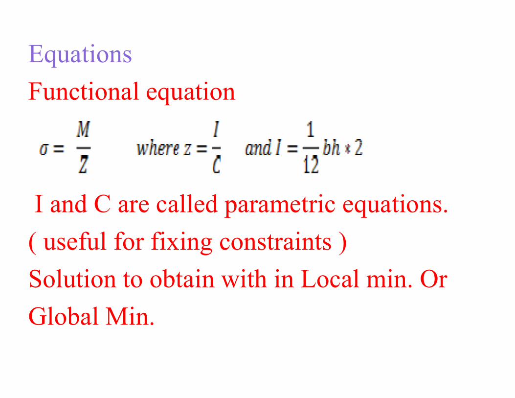
Equations
Functional equation
I and C are called parametric equations.I and C are called parametric equations.
( useful for fixing constraints )
Solution to obtain with in Local min. Or
Global Min.

First Chapter of this course is Design of Belts, Chains, etc
Next few classes to be used to Discuss these

BELT DRIVES AND CHAIN DRIVES
Belts and chains are the majortypes of flexible powertransmission elements. Beltstransmission elements. Beltsoperate on pulleys, whereas chainsoperate on toothed wheels calledsprockets.

Combination drive employing V-belts, a gear reducer, and a chain drive

Basicbelt drive geometry

Types of belt drives
• flat belts, • synchronous belt,• grooved or cogged belts, • grooved or cogged belts, • standard V-belts,• double-angle V-belts.

V-belt Drive

Synchronous Belt

Double Angle V-Belt
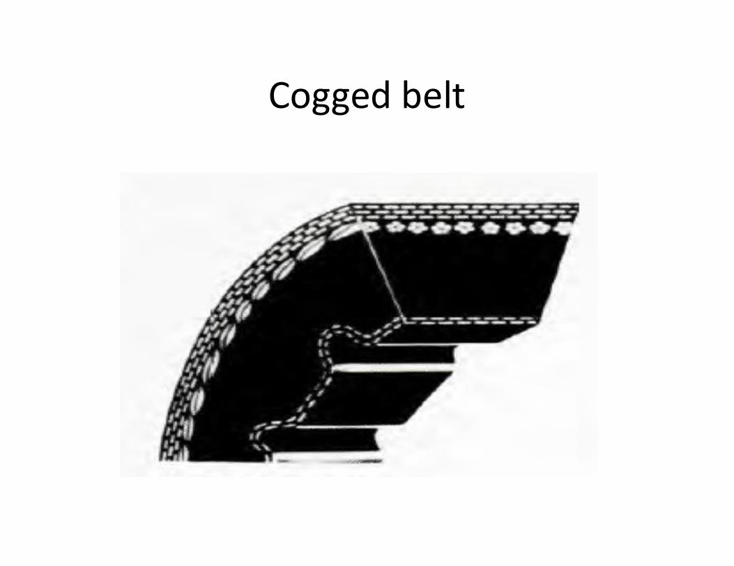
Cogged belt

Cross section of V-belt and sheave groove

Some important formulae
1. The relationships between pitch length, L, center C distance, C, and the sheave diameters are
2. The angular velocity ratio is

Formulae continued….Formulae continued….
3. The angle of contact of the belt on each sheave is
4. The length of the span between the two sheaves, over which the belt is unsupported, is

Design Procedure Cum Problem for V-belt drive
Design a V-belt drive that has the input sheave on the shaft of an electric motor (normal torque) rated at 50.0 hp at 1160-rpm, full-load speed. The drive is to a bucket elevator in a potash The drive is to a bucket elevator in a potash plant that is to be used 12 hours (h) daily at approximately 675 rpm.

Given:•Power transmitted = 50 hp to bucket elevator•Speed of motor = 1160 rpm; output speed = 675rpmStep1: compute design power by obtaining the service factor from the following table:service factor from the following table:

For a normal torque electric motor running 12 h For a normal torque electric motor running 12 h daily driving a bucket elevator the service factor daily driving a bucket elevator the service factor is 1.3 from the table below. Then the designis 1.3 from the table below. Then the designpower is 1.30power is 1.30××50.0 hp = 65.0 hp.50.0 hp = 65.0 hp.

Step 2. Step 2. Select the belt section. Select the belt section. From Figure below, a 5V belt is From Figure below, a 5V belt is recommended for 70.0 hp at 1160recommended for 70.0 hp at 1160--rpm input speed.rpm input speed.
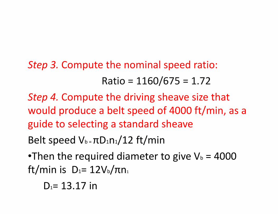
Step 3. Compute the nominal speed ratio:Ratio = 1160/675 = 1.72
Step 4. Compute the driving sheave size that would produce a belt speed of 4000 ft/min, as a would produce a belt speed of 4000 ft/min, as a guide to selecting a standard sheave Belt speed Vb = πD1n1/12 ft/min•Then the required diameter to give Vb = 4000 ft/min is D1= 12Vb/πn1
D1= 13.17 in
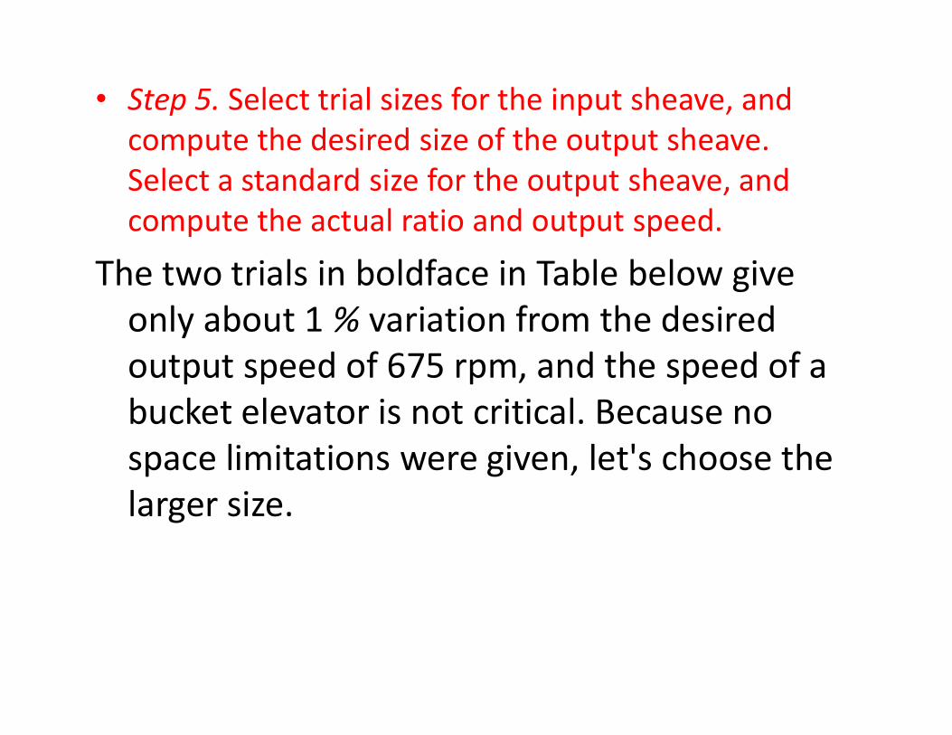
• Step 5. Select trial sizes for the input sheave, and compute the desired size of the output sheave. Select a standard size for the output sheave, and compute the actual ratio and output speed.
The two trials in boldface in Table below give only about 1 % variation from the desired output speed of 675 rpm, and the speed of a output speed of 675 rpm, and the speed of a bucket elevator is not critical. Because no space limitations were given, let's choose the larger size.


Step 6: Determine the rated power from following Step 6: Determine the rated power from following figures: figures: Power rating 3vPower rating 3v

Power rating: 5V belts

Power rating: 8V belts

Power added versusPower added versusspeed ratio: 5V beltsspeed ratio: 5V belts

• For a 12.4-in sheave at 1160 rpm, the basic rated power is 26.4 hp. Multiple belts will be required. The ratio is relatively high, indicating that some added power rating can be that some added power rating can be usedPower added is 1.15 hp. Then the actual rated power is 26.4 + 1.15 = 27.55 hp.

• Step 7. Specify a trial center distance. We can use following Equation to determine a nominal acceptable range for C:
• In the interest of conserving space, let's try C = 24.0 in.

Step 8. Compute the required belt length

Step 9. Select a standard belt length from the following table:Standard belt lengths for 3V, 5V, and 8V belts (in)

Compute the resulting actual center distance. In this problem, the nearest standard length is 100.0 in. Then,
Step 10. Compute the angle of wrap of the belt on the small sheave

• Step 11. Determine the correction factors from following Figures For 0 - 158°, Cθ = 0.94. For L = 100 in, CL = 0.96.

Angle of wrap correction factor, CAngle of wrap correction factor, Cθθ

Belt length correction factor CL

• Step 12. Compute the corrected rated power per belt and the number of belts required to carry the design power:
Corrected power = CθCLP = (0.94)(0.96)(27.55 hp) Corrected power = CθCLP = (0.94)(0.96)(27.55 hp) = 24.86 hpNumber of belts = 65.0/24.86 = 2.61 belts (Use 3 belts.)

CHAIN DRIVES

Rolling Chain styles

Z1 - No of teeth on drive sprocketZ2 - No of teeth on driven Z2 - No of teeth on driven sprocketC - Centre Distance in mmP - Chain Pitch in mmi = Z2/Z1 = Drive RatioL = Chain Length in Pitches

Selection of a chain drive
In order to select a chain drive the following essential information must be known:
(a) The power, in kilowatts, to be transmitted.(b) The speed of the driving and driven shafts in rev/min.(c) The characteristics of the drive.(d) Centre Distance.From this basic information, the driver sprocket speedand selection power to be applied to the ratings charts, are derived.

Horse Power Ratings… chain no. 40 (table 5)
Type A: Manual or drip lubrication ,Type B: Bath or disc lubrication,Type C: Oil stream lubrication

Horse Power Ratings… chain no. 60 (table 6)
Type A: Manual or drip lubrication ,Type B: Bath or disc lubrication, Type C: Oil stream lubrication

Horse Power Ratings… chain no. 80 (table 7)
Type A: Manual or drip lubrication ,Type B: Bath or disc lubrication, Type C: Oil stream lubrication

Drip feed lubrication

Shallow Bath lubrication

Disc lubrication

Oil Stream lubrication

The ratings in table 5, 6 & 7 are for a single strand of chain. Multiply the capacity in the tables by the following factors.• Two strands: Factor =1.7• Three strands: Factor = 2.5• Three strands: Factor = 2.5• Four strands: Factor = 3.3The ratings are for a service factor of 1.0. Specify a service factor for a given application according to Table 8(following)

Service factors for Chain drives(table 8)

General Recommendation for designing chain drives
1.The minimum number of teeth in a sprocket shouldbe 17 unless the drive is operating at a very lowspeed, under 100 rpm.2. The maximum speed ratio should be 7.0, although2. The maximum speed ratio should be 7.0, althoughhigher ratios are feasible. Two or more stages ofreduction can be used to achieve higher ratios.3. The center distance between the sprocket axesshould be approximately 30 to 50 pitches (30 to 50times the pitch of the chain).

Recommendations continued…..
4. The larger sprocket should normally have no more than 120 teeth.5. The preferred arrangement for a chain drive is with the centerline of the sprockets horizontal and with the the centerline of the sprockets horizontal and with the tight side on top.6.The chain length must be an integral multiple of the pitch, and an even number of pitches is recommended. The center distance should be made adjustable to accommodate the chain length and to take up for tolerances and wear.

A convenient relation between center distance (C), chain length (L), number of teeth in the small sprocket (N1), and number of teeth in the large sprocket (N2), expressed in pitches, is
The center distance for a given chain length, again in pitches, is

7. The pitch diameter of a sprocket with N teeth for a chain with a pitch of p is
8. The minimum sprocket diameter and 8. The minimum sprocket diameter and therefore the minimum number of teeth in a sprocket are often limited by the size of the shaft on which it is mounted.
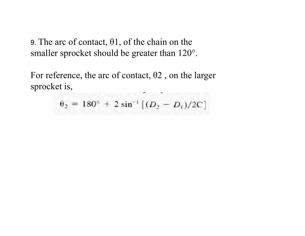
9. The arc of contact, θ1, of the chain on the smaller sprocket should be greater than 120°.
For reference, the arc of contact, θ2 , on the larger sprocket is,
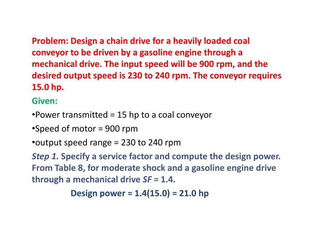
Problem: Design a chain drive for a heavily loaded coal conveyor to be driven by a gasoline engine through a mechanical drive. The input speed will be 900 rpm, and the desired output speed is 230 to 240 rpm. The conveyor requires 15.0 hp. Given: •Power transmitted = 15 hp to a coal conveyor•Speed of motor = 900 rpm•output speed range = 230 to 240 rpmStep 1. Specify a service factor and compute the design power. From Table 8, for moderate shock and a gasoline engine drive through a mechanical drive SF = 1.4.
Design power = 1.4(15.0) = 21.0 hp

Step 2. Compute the desired ratio. Using the middle of the required range of output speeds, we have
Ratio = (900 rpm)/(235 rpm) = 3.83Step 3. Refer to the tables for power capacity (Tables 5, 6, and 7), and select the chain pitch. For a single strand, the no. 60 chain with p= 3/4 in seems best. A I7-tooth sprocket is rated at 21.96 hp at 900 rpm by interpolation. At this speed, type B lubrication (oil bath) interpolation. At this speed, type B lubrication (oil bath) is required.Step 4. Compute the required number of teeth on the large sprocket:
N2 = N1 × ratio = 17(3.83) = 65.11Let's use the integer: 65 teeth.

Step 5. Compute the actual expected output speed:
Step 6. Compute the pitch diameters of the sprocketssprockets
Step 7. Specify the nominal center distance.

Step 8. Compute the required chain length in pitches

Step 9. Specify an integral number of pitches for the chain length, and compute the actual theoretical center distance. Let's use 122 pitches, an even number.
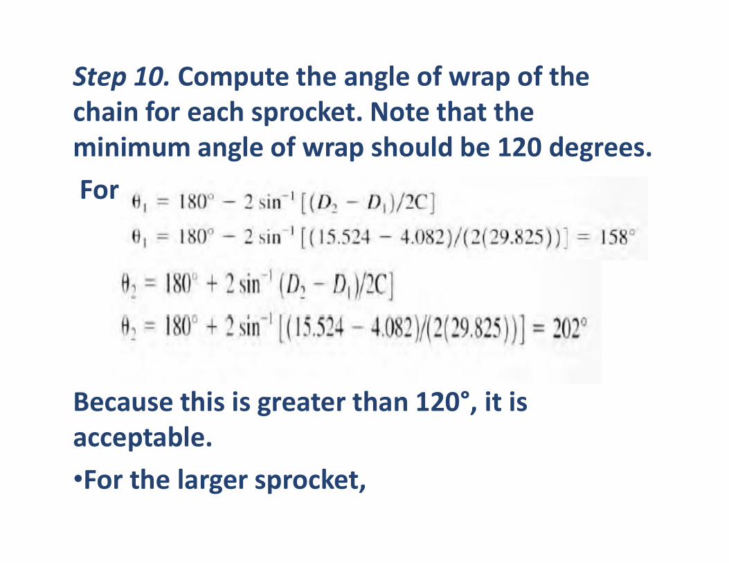
Step 10. Compute the angle of wrap of the chain for each sprocket. Note that the minimum angle of wrap should be 120 degrees.For the small sprocket,
Because this is greater than 120°, it is acceptable.•For the larger sprocket,