
ERHA Offline Activation Proposal_Jan2022.pptx - Projects.co.id
Upload
khangminh22Category
view
0download
0
Installation and
Programming Manual
Kreta3
FingerVein Offline
v. 1.24
Kimaldi Electronics, S.L.Ctra. Rubí, 292-B Pol.Ind. Can Guitard08228 Terrassa (Barcelona) CIF B61802302
www.kimaldi.comTel: 937 361 510 Fax: 937 361 511
E-mail: [email protected]
Table of Contents
Contents
1. About this Manual . . . . . . . . . . . . . . . . . . . . . . . . . . . . . . . . . . . . . . . . . . . . . . . 72. Description . . . . . . . . . . . . . . . . . . . . . . . . . . . . . . . . . . . . . . . . . . . . . . . . . . . . . 73. Technical Characteristics . . . . . . . . . . . . . . . . . . . . . . . . . . . . . . . . . . . . . . . . . 9
3.1. Specifications . . . . . . . . . . . . . . . . . . . . . . . . . . . . . . . . . . . . . . . . . . . . 93.2. User interface . . . . . . . . . . . . . . . . . . . . . . . . . . . . . . . . . . . . . . . . . . . 103.3. Supported identification methods . . . . . . . . . . . . . . . . . . . . . . . . . . . . 11
4. Installation . . . . . . . . . . . . . . . . . . . . . . . . . . . . . . . . . . . . . . . . . . . . . . . . . . . . 124.1. Circuit Diagram . . . . . . . . . . . . . . . . . . . . . . . . . . . . . . . . . . . . . . . . . 124.2. Connection details . . . . . . . . . . . . . . . . . . . . . . . . . . . . . . . . . . . . . . . 134.3. Auxiliary circuits . . . . . . . . . . . . . . . . . . . . . . . . . . . . . . . . . . . . . . . . 144.4. Actuation parts . . . . . . . . . . . . . . . . . . . . . . . . . . . . . . . . . . . . . . . . . . 15
5. Host communications . . . . . . . . . . . . . . . . . . . . . . . . . . . . . . . . . . . . . . . . . . . 165.1. Kreta-Classic protocol via RS-232 . . . . . . . . . . . . . . . . . . . . . . . . . . . 165.2. IP Communications . . . . . . . . . . . . . . . . . . . . . . . . . . . . . . . . . . . . . . 16
5.2.1. Kimaldi Localisation Service . . . . . . . . . . . . . . . . . . . . . . . . . . . . . . 175.2.2. Kreta-Classic protocol via TCP . . . . . . . . . . . . . . . . . . . . . . . . . . . . . 175.2.3. Kreta-Classic protocol via UDP . . . . . . . . . . . . . . . . . . . . . . . . . . . . 175.2.4. KSP protocol via UDP . . . . . . . . . . . . . . . . . . . . . . . . . . . . . . . . . . . 185.2.5. KSP via UDP protocol, Backchannel mode . . . . . . . . . . . . . . . . . . . 185.2.6. KSP via TCP protocol (TCP-client) . . . . . . . . . . . . . . . . . . . . . . . . . 19
5.3. Addressing and Localisation . . . . . . . . . . . . . . . . . . . . . . . . . . . . . . . 195.3.1. MAC Address . . . . . . . . . . . . . . . . . . . . . . . . . . . . . . . . . . . . . . . . . . 195.3.2. IP Address . . . . . . . . . . . . . . . . . . . . . . . . . . . . . . . . . . . . . . . . . . . . . 195.3.3. KSP Address . . . . . . . . . . . . . . . . . . . . . . . . . . . . . . . . . . . . . . . . . . . 19
5.4. Format for the data transmission to the reader (“Extra Data”) . . . . . . 205.4.1. “Extra Data” format through UART or TCP/IP . . . . . . . . . . . . . . . . 205.4.2. “Extra Data” format via UDP / KSP . . . . . . . . . . . . . . . . . . . . . . . . . 21
6. User interface configuration . . . . . . . . . . . . . . . . . . . . . . . . . . . . . . . . . . . . . . 226.1. Default user interface . . . . . . . . . . . . . . . . . . . . . . . . . . . . . . . . . . . . . 226.2. External user interface . . . . . . . . . . . . . . . . . . . . . . . . . . . . . . . . . . . . 236.3. Auxiliary Reader . . . . . . . . . . . . . . . . . . . . . . . . . . . . . . . . . . . . . . . . 246.4. Kreta3 with double user interface . . . . . . . . . . . . . . . . . . . . . . . . . . . . 24
7. Kreta3-UI module configuration . . . . . . . . . . . . . . . . . . . . . . . . . . . . . . . . . . 267.1. Programming method . . . . . . . . . . . . . . . . . . . . . . . . . . . . . . . . . . . . . 26
7.1.1. Configuration parameters . . . . . . . . . . . . . . . . . . . . . . . . . . . . . . . . . 267.1.2. Data formats . . . . . . . . . . . . . . . . . . . . . . . . . . . . . . . . . . . . . . . . . . . 27
Date19/9/11 Page 2 of 131

Table of Contents
7.2. Configuration examples, readers . . . . . . . . . . . . . . . . . . . . . . . . . . . . 287.2.1. Main Reader, Hexadecimal, RS-232 . . . . . . . . . . . . . . . . . . . . . . . . . 287.2.2. Auxiliary Reader, Hexadecimal, RS-232 . . . . . . . . . . . . . . . . . . . . . 287.2.3. Main Reader, Clock&Data . . . . . . . . . . . . . . . . . . . . . . . . . . . . . . . . 287.2.4. Auxiliary Reader, Clock&Data . . . . . . . . . . . . . . . . . . . . . . . . . . . . . 297.2.5. Primary or Auxiliary Readers, Decimal RS-232 . . . . . . . . . . . . . . . . 297.2.6. Stand-alone Readers, RS-232 (Mifare, chip) . . . . . . . . . . . . . . . . . . 297.2.7. Multiple reader configurations . . . . . . . . . . . . . . . . . . . . . . . . . . . . . 307.2.8. Activation of reading via digital input . . . . . . . . . . . . . . . . . . . . . . . 30
8. General presentation on Kreta3 module operation . . . . . . . . . . . . . . . . . . . 328.1. Attendance Control . . . . . . . . . . . . . . . . . . . . . . . . . . . . . . . . . . . . . . . 32
8.1.1. Main reader readings . . . . . . . . . . . . . . . . . . . . . . . . . . . . . . . . . . . . . 328.1.2. Auxiliary reader readings . . . . . . . . . . . . . . . . . . . . . . . . . . . . . . . . . 34
8.2. Access Control . . . . . . . . . . . . . . . . . . . . . . . . . . . . . . . . . . . . . . . . . . 348.2.1. Main reader accesses . . . . . . . . . . . . . . . . . . . . . . . . . . . . . . . . . . . . . 348.2.2. Auxiliary reader accesses . . . . . . . . . . . . . . . . . . . . . . . . . . . . . . . . . 35
8.3. Automatic Mode . . . . . . . . . . . . . . . . . . . . . . . . . . . . . . . . . . . . . . . . . 368.3.1. Through the main reader . . . . . . . . . . . . . . . . . . . . . . . . . . . . . . . . . . 368.3.2. Through the auxiliary reader . . . . . . . . . . . . . . . . . . . . . . . . . . . . . . . 36
8.4. Terminal locked. . . . . . . . . . . . . . . . . . . . . . . . . . . . . . . . . . . . . . . . . . 368.5. Free access . . . . . . . . . . . . . . . . . . . . . . . . . . . . . . . . . . . . . . . . . . . . . 378.6. Automatic change in access conditions . . . . . . . . . . . . . . . . . . . . . . . 378.7. Full capacity . . . . . . . . . . . . . . . . . . . . . . . . . . . . . . . . . . . . . . . . . . . . 37
9. Additional functions of the Kreta3 module . . . . . . . . . . . . . . . . . . . . . . . . . . 389.1. Alarm management . . . . . . . . . . . . . . . . . . . . . . . . . . . . . . . . . . . . . . 38
9.1.1. Door alarm . . . . . . . . . . . . . . . . . . . . . . . . . . . . . . . . . . . . . . . . . . . . . 389.1.2. Reader alarm . . . . . . . . . . . . . . . . . . . . . . . . . . . . . . . . . . . . . . . . . . . 389.1.3. Antipassback alarm . . . . . . . . . . . . . . . . . . . . . . . . . . . . . . . . . . . . . . 399.1.4. Alarm deactivation . . . . . . . . . . . . . . . . . . . . . . . . . . . . . . . . . . . . . . 399.1.5. Readings . . . . . . . . . . . . . . . . . . . . . . . . . . . . . . . . . . . . . . . . . . . . . . 409.1.6. Partial alarm deactivation . . . . . . . . . . . . . . . . . . . . . . . . . . . . . . . . . 40
9.2. Task Programmer . . . . . . . . . . . . . . . . . . . . . . . . . . . . . . . . . . . . . . . . 419.2.1. Shift Change Warning . . . . . . . . . . . . . . . . . . . . . . . . . . . . . . . . . . . . 419.2.2. Automatic change in access conditions . . . . . . . . . . . . . . . . . . . . . . . 439.2.3. Automatic adjustment to summer time . . . . . . . . . . . . . . . . . . . . . . . 45
9.3. Access control auxiliary functions . . . . . . . . . . . . . . . . . . . . . . . . . . . 459.3.1. Antipassback . . . . . . . . . . . . . . . . . . . . . . . . . . . . . . . . . . . . . . . . . . . 459.3.2. Multipost antipassback . . . . . . . . . . . . . . . . . . . . . . . . . . . . . . . . . . . 469.3.3. Access balance . . . . . . . . . . . . . . . . . . . . . . . . . . . . . . . . . . . . . . . . . 47
9.4. Capacity Control . . . . . . . . . . . . . . . . . . . . . . . . . . . . . . . . . . . . . . . . . 479.5. Personalised Messages . . . . . . . . . . . . . . . . . . . . . . . . . . . . . . . . . . . . 489.6. Online control . . . . . . . . . . . . . . . . . . . . . . . . . . . . . . . . . . . . . . . . . . . 48
9.6.1. Battery condition and digital input monitoring . . . . . . . . . . . . . . . . . 489.6.2. Relay activation . . . . . . . . . . . . . . . . . . . . . . . . . . . . . . . . . . . . . . . . . 489.6.3. Online reception of readings . . . . . . . . . . . . . . . . . . . . . . . . . . . . . . . 499.6.4. Semi-Online Access Control . . . . . . . . . . . . . . . . . . . . . . . . . . . . . . . 49
9.7. Battery monitoring . . . . . . . . . . . . . . . . . . . . . . . . . . . . . . . . . . . . . . . 49
Date19/9/11 Page 3 of 131

Table of Contents
9.8. Exit pushbutton . . . . . . . . . . . . . . . . . . . . . . . . . . . . . . . . . . . . . . . . . . 509.9. Access control semaphore . . . . . . . . . . . . . . . . . . . . . . . . . . . . . . . . . 50
9.9.1. “Three status” mode . . . . . . . . . . . . . . . . . . . . . . . . . . . . . . . . . . . . . 509.9.2. “Two status” mode . . . . . . . . . . . . . . . . . . . . . . . . . . . . . . . . . . . . . . 50
9.10. Remote FW updating . . . . . . . . . . . . . . . . . . . . . . . . . . . . . . . . . . . . 519.11. Information on exceptions . . . . . . . . . . . . . . . . . . . . . . . . . . . . . . . . 51
10. Programming model . . . . . . . . . . . . . . . . . . . . . . . . . . . . . . . . . . . . . . . . . . . 5210.1. Configuration . . . . . . . . . . . . . . . . . . . . . . . . . . . . . . . . . . . . . . . . . . 52
10.1.1. Parameter array, Kreta3-DB . . . . . . . . . . . . . . . . . . . . . . . . . . . . . . 5210.1.2. Parameter array, Kreta3-UI . . . . . . . . . . . . . . . . . . . . . . . . . . . . . . . 5610.1.3. Message array . . . . . . . . . . . . . . . . . . . . . . . . . . . . . . . . . . . . . . . . . 5710.1.4. Day array . . . . . . . . . . . . . . . . . . . . . . . . . . . . . . . . . . . . . . . . . . . . . 5810.1.5. Month array . . . . . . . . . . . . . . . . . . . . . . . . . . . . . . . . . . . . . . . . . . . 5910.1.6. IP Configuration - TCP and UDP Sockets . . . . . . . . . . . . . . . . . . . 5910.1.7. Printer message array . . . . . . . . . . . . . . . . . . . . . . . . . . . . . . . . . . . 62
10.2. Database . . . . . . . . . . . . . . . . . . . . . . . . . . . . . . . . . . . . . . . . . . . . . . 6210.2.1. Clock/Calendar Table . . . . . . . . . . . . . . . . . . . . . . . . . . . . . . . . . . . 6210.2.2. Public Holiday Table . . . . . . . . . . . . . . . . . . . . . . . . . . . . . . . . . . . . 6310.2.3. Schedules Table . . . . . . . . . . . . . . . . . . . . . . . . . . . . . . . . . . . . . . . . 6310.2.4. Weekly Table . . . . . . . . . . . . . . . . . . . . . . . . . . . . . . . . . . . . . . . . . 6410.2.5. Incidents Table . . . . . . . . . . . . . . . . . . . . . . . . . . . . . . . . . . . . . . . . 6410.2.6. Concepts Table. . . . . . . . . . . . . . . . . . . . . . . . . . . . . . . . . . . . . . . . . 6410.2.7. Permissions Table . . . . . . . . . . . . . . . . . . . . . . . . . . . . . . . . . . . . . . 6510.2.8. Exceptions Table . . . . . . . . . . . . . . . . . . . . . . . . . . . . . . . . . . . . . . . 6510.2.9. Readings . . . . . . . . . . . . . . . . . . . . . . . . . . . . . . . . . . . . . . . . . . . . . 6910.2.10. Personalised Messages . . . . . . . . . . . . . . . . . . . . . . . . . . . . . . . . . 71
11. Description of the instructions . . . . . . . . . . . . . . . . . . . . . . . . . . . . . . . . . . . 7211.1. General operations . . . . . . . . . . . . . . . . . . . . . . . . . . . . . . . . . . . . . . 72
11.1.1. Write . . . . . . . . . . . . . . . . . . . . . . . . . . . . . . . . . . . . . . . . . . . . . . . . 7311.1.2. Read . . . . . . . . . . . . . . . . . . . . . . . . . . . . . . . . . . . . . . . . . . . . . . . . . 74
11.2. Configuration operations . . . . . . . . . . . . . . . . . . . . . . . . . . . . . . . . . 7511.2.1. Write . . . . . . . . . . . . . . . . . . . . . . . . . . . . . . . . . . . . . . . . . . . . . . . . 7511.2.2. Read . . . . . . . . . . . . . . . . . . . . . . . . . . . . . . . . . . . . . . . . . . . . . . . . . 7611.2.3. Apply . . . . . . . . . . . . . . . . . . . . . . . . . . . . . . . . . . . . . . . . . . . . . . . . 7711.2.4. Default . . . . . . . . . . . . . . . . . . . . . . . . . . . . . . . . . . . . . . . . . . . . . . . 77
11.3. Data base operations . . . . . . . . . . . . . . . . . . . . . . . . . . . . . . . . . . . . . 7811.3.1. DeleteTable . . . . . . . . . . . . . . . . . . . . . . . . . . . . . . . . . . . . . . . . . . . 7911.3.2. DeleteRecord . . . . . . . . . . . . . . . . . . . . . . . . . . . . . . . . . . . . . . . . . . 7911.3.3. DeleteByCode . . . . . . . . . . . . . . . . . . . . . . . . . . . . . . . . . . . . . . . . . 8011.3.4. Store . . . . . . . . . . . . . . . . . . . . . . . . . . . . . . . . . . . . . . . . . . . . . . . . . 8011.3.5. Size . . . . . . . . . . . . . . . . . . . . . . . . . . . . . . . . . . . . . . . . . . . . . . . . . 8111.3.6. Size&Begin . . . . . . . . . . . . . . . . . . . . . . . . . . . . . . . . . . . . . . . . . . . 8111.3.7. Retrieve . . . . . . . . . . . . . . . . . . . . . . . . . . . . . . . . . . . . . . . . . . . . . . 8111.3.8. RetrieveNext . . . . . . . . . . . . . . . . . . . . . . . . . . . . . . . . . . . . . . . . . . 8211.3.9. RetrieveNextByCode . . . . . . . . . . . . . . . . . . . . . . . . . . . . . . . . . . . . 82
Date19/9/11 Page 4 of 131
Table of Contents
11.4. Operations on peripherals . . . . . . . . . . . . . . . . . . . . . . . . . . . . . . . . . 8311.4.1. Write CFG . . . . . . . . . . . . . . . . . . . . . . . . . . . . . . . . . . . . . . . . . . . . 8311.4.2. Read CFG . . . . . . . . . . . . . . . . . . . . . . . . . . . . . . . . . . . . . . . . . . . . 8411.4.3. Scan FP 8 . . . . . . . . . . . . . . . . . . . . . . . . . . . . . . . . . . . . . . . . . . . . . . 411.4.4. Firmware Version . . . . . . . . . . . . . . . . . . . . . . . . . . . . . . . . . . . . . . 8511.4.5. Database Size . . . . . . . . . . . . . . . . . . . . . . . . . . . . . . . . . . . . . . . . . 8511.4.6. Communications error . . . . . . . . . . . . . . . . . . . . . . . . . . . . . . . . . . . 85
11.5. Peripheral equipment operations (Stand-alone reader RS-232) . . . . 8611.5.1. Send Frame . . . . . . . . . . . . . . . . . . . . . . . . . . . . . . . . . . . . . . . . . . . 86
11.6. Operations on peripherals (Kreta3-UI module) . . . . . . . . . . . . . . . . 8711.6.1. Write CFG . . . . . . . . . . . . . . . . . . . . . . . . . . . . . . . . . . . . . . . . . . . . 8811.6.2. Read CFG . . . . . . . . . . . . . . . . . . . . . . . . . . . . . . . . . . . . . . . . . . . . 8811.6.3. Apply . . . . . . . . . . . . . . . . . . . . . . . . . . . . . . . . . . . . . . . . . . . . . . . . 8911.6.4. Default . . . . . . . . . . . . . . . . . . . . . . . . . . . . . . . . . . . . . . . . . . . . . . . 8911.6.5. Relay Outputs . . . . . . . . . . . . . . . . . . . . . . . . . . . . . . . . . . . . . . . . . 9011.6.6. Communication ports . . . . . . . . . . . . . . . . . . . . . . . . . . . . . . . . . . . 9011.6.7. Digital inputs . . . . . . . . . . . . . . . . . . . . . . . . . . . . . . . . . . . . . . . . . . 9011.6.8. Firmware Version . . . . . . . . . . . . . . . . . . . . . . . . . . . . . . . . . . . . . . 91
12. Biometric identification . . . . . . . . . . . . . . . . . . . . . . . . . . . . . . . . . . . . . . . . . 9212.1. Types of biometric identification . . . . . . . . . . . . . . . . . . . . . . . . . . . 9212.2. Configuration of biometric readers . . . . . . . . . . . . . . . . . . . . . . . . . . 9312.3. Configuration examples, biometrics . . . . . . . . . . . . . . . . . . . . . . . . . 94
12.3.1. Biometric identification modules . . . . . . . . . . . . . . . . . . . . . . . . . . 9412.3.2. Reduced biometric identification, 1:n . . . . . . . . . . . . . . . . . . . . . . . 95
12.4. Basic instructions . . . . . . . . . . . . . . . . . . . . . . . . . . . . . . . . . . . . . . . 9512.4.1. Retrieve sensor version . . . . . . . . . . . . . . . . . . . . . . . . . . . . . . . . . 95
12.5. Capture of biometric information . . . . . . . . . . . . . . . . . . . . . . . . . . . 9612.5.1. Capture of biometric information . . . . . . . . . . . . . . . . . . . . . . . . . . 96
12.6. Sensor memory management . . . . . . . . . . . . . . . . . . . . . . . . . . . . . . 9712.6.1. Add user . . . . . . . . . . . . . . . . . . . . . . . . . . . . . . . . . . . . . . . . . . . . . 9712.6.2. Request number of users . . . . . . . . . . . . . . . . . . . . . . . . . . . . . . . . 9712.6.3. Delete user . . . . . . . . . . . . . . . . . . . . . . . . . . . . . . . . . . . . . . . . . . . . 9812.6.4. Delete all users . . . . . . . . . . . . . . . . . . . . . . . . . . . . . . . . . . . . . . . . 98
12.7. Operation details . . . . . . . . . . . . . . . . . . . . . . . . . . . . . . . . . . . . . . . . 9912.7.1. Configuration of the FIM biometric module . . . . . . . . . . . . . . . . . . 9912.7.2. User database management . . . . . . . . . . . . . . . . . . . . . . . . . . . . . . 10012.7.3. Format for the biometric data transmission (“Extra Data”) . . . . . 10312.7.4. Local user creation procedures . . . . . . . . . . . . . . . . . . . . . . . . . . . 103
12.8. User permissions with “Biometric exceptions” . . . . . . . . . . . . . . . 10512.9. High level operation . . . . . . . . . . . . . . . . . . . . . . . . . . . . . . . . . . . . 106
12.9.1. Biometric identification module . . . . . . . . . . . . . . . . . . . . . . . . . . 10613. Printing of reading tickets . . . . . . . . . . . . . . . . . . . . . . . . . . . . . . . . . . . . . 108
13.1. Terminal configuration . . . . . . . . . . . . . . . . . . . . . . . . . . . . . . . . . . 10713.2. Ticket personalisation . . . . . . . . . . . . . . . . . . . . . . . . . . . . . . . . . . . 108
13.2.1. Message personalisation . . . . . . . . . . . . . . . . . . . . . . . . . . . . . . . . 10813.2.2. Modification of the design . . . . . . . . . . . . . . . . . . . . . . . . . . . . . . 109
Date19/9/11 Page 5 of 131

Table of Contents
AppendixA. Programming model summary . . . . . . . . . . . . . . . . . . . . . . . . . . 112A.1. Configuration diagram . . . . . . . . . . . . . . . . . . . . . . . . . . . . . . . . . . . 112A.2. List of commands . . . . . . . . . . . . . . . . . . . . . . . . . . . . . . . . . . . . . . 121
AppendixB. Templates for integration . . . . . . . . . . . . . . . . . . . . . . . . . . . . . . 128B.1. Kreta3 drills . . . . . . . . . . . . . . . . . . . . . . . . . . . . . . . . . . . . . . . . . . . 128
List of Tables . . . . . . . . . . . . . . . . . . . . . . . . . . . . . . . . . . . . . . . . . . . . . . . . . . . 130List of revisions . . . . . . . . . . . . . . . . . . . . . . . . . . . . . . . . . . . . . . . . . . . . . . . . . 130Notes . . . . . . . . . . . . . . . . . . . . . . . . . . . . . . . . . . . . . . . . . . . . . . . . . . . . . . . . . . 131
Date19/9/11 Page 6 of 131

Kreta3 - FingerVein OfflineInstallation and Programming Manual
1. About this Manual
This manual applies to the Kreta3 and FingerVein-OffLine terminals, dedicated toAttendance Control and Access Control. In terms of Firmware level, it corresponds tofirmware version 0x6B.32 (‘k2’) and after.
From this point onwards and unless otherwise stated, all the characteristics and functionsdescribed in this manual apply to the Kreta3, will also apply to the FingerVein-OffLine.
Reading this manual before installing the Kreta3 module is essential. In order to installthe OEM product, it is essential that you read chapter 6.: “User interface configuration”and chapter 7.: “Kreta3-UI module configuration” .
Kimaldi Electronics reserves the right to make any changes to the Hardware or Firmwareof the Kreta3 module, if deemed necessary. In such cases, a new version of this manualshall be published.
2. Description
The Kreta3 module is a high performance terminal, adaptable, by configuration, to manyvery different combinations of readers, actuators, and user interfaces.
It accepts two types of biometric identification technology:
- Fingerprint: using the FIM2030 sensor from Nitgen.- Vascular: using the FingerVein sensor from Hitachi.
Based on a product which is 100% compatible with the Kreta v1 both at interface,software and connectivity levels, the Kreta3 Module adds speed, flexibility andapplication features for Access and/or Attendance control in Offline operations:
• Offline Access Control Application• Offline Attendance Control Application
• Data base with 7,500 permissions, 3,000 exceptions and 15,000 readings1
• Double Access and/or Attendance Control or Entrances and Exits (allows up to 2identical user interfaces): 2x20 alphanumeric display and 4x4 keypad.
• Connectivity to Host: Integrated RS-2322 and Ethernet3, optional WiFI.• Connectivity with readers: each user interface supports a Clock&Data reader, a
biometric reader and/or RS-232 reader.
1. Other configurations of the Database available on special order2. It has a RS-232 output adaptable to USB. Contact Kimaldi for further details.3. TCP and UDP protocols.
www.kimaldi.com Page 7 of 131

Kreta3 - FingerVein OfflineInstallation and Programming Manual
• Biometrics support:- Up to 2 biometric identification sensors per terminal1.
- Possibility for using biometric technology2:- Fingerprint:
- Up to 4,000 users according to sensor.- Identification modes: 1:1, 1:N, 1:n
- Vascular biometrics:- Up to 1,000 users.- Identification modes: 1:1 and 1:N
• Security: segregatable user interfaces, leaving the Database and relays in a safearea.
• Extra functionalities:- Door control alarm- Shift change warning signal- Automatic change in access conditions- Antipassback- Capacity control- Personalised messages / hour totals- Remote FW updating.- Programming change to summer / winter time
Internally, the Kreta3 module is organised in two subelectronics capable of segregating,in the following manner:
1. DB module: includes the database, relays and connectivity to the Host. It isdesigned to be installed in a safe area, for example a false roof.
2. UI module (“Main UI”): includes all the part of the User Interface (card readers,biometrics, display, keypad, buzzer). It is designed to be exposed to interaction withthe user, generally assembled in a plastic box or panel.
3. If an auxiliary reader is required, it will constitute a second UI module (“AuxiliaryUI”), for which we can choose an equal (display and keypad) or lower (LEDs)degree of functionality than the Main UI.
1. Using an auxiliary UI electronics is necessary to use a second biometric reader.2. There is no biometric information compatibility between the different biometric technologies(fingerprint and vascular).
www.kimaldi.com Page 8 of 131

Kreta3 - FingerVein OfflineInstallation and Programming Manual
3. Technical Characteristics
3.1. Specifications
Dimensions: OEM electronics: 134 x 131 x 25 mm Stainless steel box: 142 x 209 x 82 mm; Weight 1.5 kgOffice box1: 160 x 220 x 65 mm; Weight 750 g.
Power Supply: Voltage: - Kreta3: 5 Vdc ± 10%
- FingerVein-OffLine: 12 Vdc ± 10% Current: 1A typical (according to amount and type of readers)
Contact relays: 42 contact relays, normally open, 24V / 1A
Display: LCD Display, 20x2 characters
Keypad: Matrix keypad with 4 rows x 4 columns
Digital inputs: 53 relay type digital inputs. In open circuit (contact open) itslogic value will be 0. In contact with earth (contact closed),logic value 1.
Buzzer: 1 Internal buzzer (operates together with the main reader andkeypad)
Clock & Data input: In the UI module, allows the connection of a device thattransmits in Clock&Data with ABA encoding, Track 2.
RS232 Interface: 3 configurable serial ports: communication with the Host orwith card readers. Baud Rate: 9600, 19200 or 38400. Otherparameters: n,8,1.
Output for external reader power supply: 5 Vdc for power supply of the auxiliary readerwith a current capacity of 200 mA.
Ethernet Connection: Protocols: TCP/IP, UDP, ARP, DHCP, ICMP (ping) Speed:10/100 BaseTConnector: RJ-45
Real Time Clock
Microcontroller: Double (DB + UI), 32 bit RISC architecture
Clock frequency: 60 MHz in DB electronics, 48 MHz in UI
Memory: 1024 kb, SRAM, non-volatile (with CR2032 lithium battery)
1. Option not yet available for FingerVein-OffLine.2. Four serial relays, two more optional3. There is a sixth input in the UI module, for an Anti-Tamper sensor
www.kimaldi.com Page 9 of 131
Kreta3 - FingerVein OfflineInstallation and Programming Manual
3.2. User interface
Input elements:
Green key (“Enter”) Indicates Incident 01 (“Entrance”), and is also used tovalidate the introduction of the incident code.
Red key (“Exit”) Indicates Incident 02 (“Exit”), and is also used to cancel andrestart the introduction of the incident code.
F1 key / Up Allows an incident other than that which is activated bydefault to be indicated (Mass Reading mode). Browsing keyfor incident selection.
F2 key / Down Browsing key for incident selection. Enables the input of anup to 8 digit identification code using the keypad, ifconfiguration allows.
CLR key Deletes and restarts the input of the 8 digit code using thekeypad.
0...9 keys Allows numeric codes to be input (normally the incident codeor PIN).
ENTER key Allows validating the incident code input.
Output elements:
LCD Display We have a 20 character x 2 line display. The first lineindicates the date and time, whilst the second line is used toguide the user through their interaction with the equipment.
Buzzer Signals correct operation of the keypad, as well as the successor failure of the user identification process.
www.kimaldi.com Page 10 of 131
Kreta3 - FingerVein OfflineInstallation and Programming Manual
3.3. Supported identification methods
The Kreta3 module comprises the following methods for identifying people:
• Proximity, 125 kHz: connection via Clock&Data or RS-232.• Proximity, 13.56 MHz, ISO 14443-A (Mifare): connection of a Kimaldi KRD13M
reader is possible via Clock&Data1 or RS-232.• Fingerprint biometrics: connection via RS-232 to FIM2030 modules for 4,000
users. 1:N or 1:1 identifications can be carried out in combination with aproximity reader.
• Vascular biometrics: connection via RS-232 to FIM2030 modules for 1,000 users.1:N or 1:1 identifications can be carried out in combination with a proximityreader.
• Microprocessed card (ISO 7816, T=0) or memory card (SLE4442): KimaldiSC6000 or SC42 readers allow connection via Clock&Data or RS-232.
• DNIe: Spanish electronic National Identity Document. can be connected viaClock&Data (ABA, Track 2) or RS-232 (decimal or ASCII-Hex format).
• Magnetic strip: can be connected via Clock&Data (ABA, Track 2) or RS-232(decimal or ASCII-Hex format).
• Bar code: normally via RS-232 (decimal format).• Other formats (DESFire, HiD, etc.) available according to project.
1. Only for Cascade Level 1 cards
www.kimaldi.com Page 11 of 131
Kreta3 - FingerVein OfflineInstallation and Programming Manual
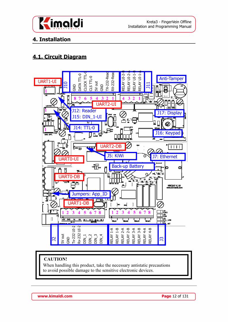
4. Installation
4.1. Circuit Diagram
CAUTION!When handling this product, take the necessary antistatic precautionsto avoid possible damage to the sensitive electronic devices.
J3
REL
AY 1
-A
REL
AY 1
-B
REL
AY 2
-A
REL
AY 2
-B
REL
AY 3
-A
REL
AY 3
-B
REL
AY 4
-A
REL
AY 4
-B
J2
5V o
ut
GN
D
Tx-2
32 U
I-2
Rx-
232
UI-
2
DIN
_1
DIN
_2
DIN
_3
DIN
_4
1 2 3 4 5 6 7 81 2 3 4 5 6 7 8
J14: TTL-0
1
J16: Keypad
J17: DisplayJ12: ReaderJ15: DIN_1-UI
J7: Ethernet
Back-up Battery
J11
REL
AY U
I-2-
B
REL
AY U
I-2-
A
REL
AY U
I-1-
B
REL
AY U
I-1-
A
J10
GN
D
DAT
A TT
L-0
CLO
CK T
TL-0
CLS
TTL-
0
5V o
ut
GN
D
TX-2
32-R
ead
RX-
232-
Read
8 7 6 5 4 3 2 1 4 3 2 1
Anti-Tamper
1
1
J5: KiWi
Jumpers: App_ID
UART1-DB
UART2-UI
UART1-UI
UART0-DB
UART0-UI
UART2-DB
www.kimaldi.com Page 12 of 131

Kreta3 - FingerVein OfflineInstallation and Programming Manual
4.2. Connection details
Power supply jack:Without FingerVein biometric reader the terminal is powered at 5V (jack on the
Kreta3-DB electronic board)With FingerVein biometric reader the terminal is powered at 12V (jack in the
KiWi terminal (12V to 5V voltage converter)J2 - Main Connector
Pin 1 - Positive power supply pole for Auxiliary UI (5 Vcc).Pin 2 - Negative power supply pole for Auxiliary UI (GND).Pin 3 - TX signal for communication with Auxiliary UI.Pin 4 - RX signal for communication with Auxiliary UI.Pin 5 - Entrance Door sensor (Digital Input 1)Pin 6 - Pushbutton for Main User Interface (Digital Input 2)Pin 7 - Exit Door sensor (Digital Input 3)Pin 8 - Pushbutton for Auxiliary User Interface (Digital Input 4)
J3 - Relay ConnectorPin 1 - Pole A of the Entrance Door Relay (Relay 1)Pin 2 - Pole B of the Entrance Door Relay (Relay 1)Pin 3 - Pole A of the Alarm Relay (Relay 2)Pin 4 - Pole B of the Alarm Relay (Relay 2)Pin 5 - Pole A of the Exit Door Relay (Relay 3)Pin 6 - Pole B of the Exit Door Relay (Relay 3)Pin 7 - Pole A of the Shift Change Signal Relay (Relay 4)Pin 8 - Pole B of the Shift Change Signal Relay (Relay 4)
J5: Connection to KiWi module.J7: Ethernet Connector (RJ45 connection)J10 - Connector to Card Readers / Printer
Pin 1 - Signal Rx 232 to the device (Pin no. 2 connector SubD male)Pin 2 - Signal Tx 232 to the device (Pin no. 3 connector SubD male)Pin 3 - Negative power supply pole (GND) (Pin no. 5 connector SubD male)Pin 4 - Output +5 VDCPin 5 - CLS signal (TTL_0)Pin 6 - Clock signal (TTL_0)Pin 7 - Data signal (TTL_0)Pin 8 - Power supply negative (GND)
J11 - Connector to Signal Relays (optional)
www.kimaldi.com Page 13 of 131

Kreta3 - FingerVein OfflineInstallation and Programming Manual
J12: Connection to FIM or FingerVein biometric identification module.Pin 1 - Output +5 VDC (Do not connect to FingerVein)Pin 2 - UART1-UI - Signal Tx 232 to readerPin 3 - UART1-UI - Signal Rx 232 to readerPin 4 - Power supply negative (GND)
J14 - Connector TTL_0 to Card Reader:Pin 1 - Data signal (TTL_0)Pin 2 - Clock signal (TTL_0)Pin 3 - CLS signal (TTL_0)Pin 4 - Output +5 VDCPin 5 - Power supply negative (GND)
J15: Digital input DIN_1-UI. Input activated when it is connected to GND, deacti-vated if left without connection.
Jumpers:Application_ID - Encoded by two jumpers. By default, the value is 3.
Back-up Battery: this is a 3V lithium battery, size CR2032. If a low battery level is detected, we recommend replacement of the battery whilst the equipment is on. This therefore avoids configuration and unit database losses.
In addition, we have the connections to Keypad and Display for the OEM version of theequipment:
J16: 4x4 Keypad connectorPin 1 - Column 3 (OUT) Pin 5 - Row 0 (IN)Pin 2 - Column 2 (OUT) Pin 6 - Row 1 (IN)Pin 3 - Column 1 (OUT) Pin 7 - Row 2 (IN)Pin 4 - Column 0 (OUT) Pin 8 - Row 3 (IN)
J17: Connector to 20x2, with incorporated Backlit.
4.3. Auxiliary circuits
The Kreta3 Module allows connection to an auxiliary User Interface (UI) thatimplements the elements required for identifying and signalling, either simply (KBio2-UI, KRD13M v2) or fully (BioMax2-UI).
For Attendance Control, these features allow user interfaces to be duplicated, thereforehaving two terminals in just one product.
www.kimaldi.com Page 14 of 131

Kreta3 - FingerVein OfflineInstallation and Programming Manual
4.4. Actuation parts
The Kreta3 Module has from 4 to 6 relays on the board itself. The functions of theserelays are as follows:
• Relay 1: opening the door. This relay is activated for both entry and exit, i.e. bothby a correct identification from the main reader and from the auxiliary reader. Ifthe unit is configured for two doors, Relay 1 acts on the entrance door (mainreader).
• Relay 2: alarm siren. This relay acts as the door alarm siren.• Relay 3: exit door opening. This relay is only activated if we have the unit
configured for two doors. Relay 3 corresponds to the exit door, activated by theauxiliary reader.
• Relay 4: shift change siren. This relay acts as the shift change siren, if the siren isactivated.
Low demand, with the possibility for assembling two extra relays on the main UI, forsignalling mass entrances/exits or signalling indicator:
• Relay 1-UI: “Entry” signal in “Mass Reading” mode. An indicator light can beactivated to indicate "Entry" mode. If CFG-UI_TimeRelay has a non-null value,it allows activating a luminous indicator corresponding to a green semaphore.
• Relay 2-UI: “Exit” signal in “Mass Reading” mode. An indicator light can beactivated to indicate "Exit" mode. If CFG-UI_TimeRelay has a non-null value, itallows activating a luminous indicator corresponding to a red semaphore.
www.kimaldi.com Page 15 of 131
Kreta3 - FingerVein OfflineInstallation and Programming Manual
5. Host communications
The Kreta3 module allows various communication routes with the Host. Establishingthis communication is the first step towards correctly configuring the Kreta3. The Kreta3module is permanently listening to these channels, and will return a response via thechannel from which the command was received.
The configuration parameters dealt with in this chapter are:
• $0D: CFG_ResponseChannel. Read only We can consult this field to know inwhich channel the last communication has occurred.
• $1C: CFG_SerialPortHost. Default value: $00The detailed programming model can be found in Table 12.1 and in chapter 11.2..
5.1. Kreta-Classic protocol via RS-232
The UART1 port relates, by default, to communications with the Host via RS-232. Thiscommunication is established, by default, at 9600 bps, with 8 bits, no parity and one stopbit. The serial frames are constructed by placing the starting character <STX> (ASCII$02) before the instruction and placing the character <ETX> (ASCII $03) at the end ofthe block. The unit will do the same with any responses that it issues.
For the configuration byte CFG_SerialPortHost, however, we have other alternatives:
• Communication speed can be configured to 9600, 19200 or 38400 baud. To do so,the CFG_SerialPortHost byte must take the following values $00, $01 or $02,respectively.
• Values other than those indicated above, are used for many purposes, as we will seelater. In these cases, the UART1 port stops interacting with the Host. If thisoccurs, the UART2 port is automatically configured with the value $00, so that a“back door” is left open to connect to the Kreta3. This UART2 is only availablein TTL levels and is accessed via the J5 connector (refer to section 4.1), bymeans of a USB adaptor cable supplied by Kimaldi.
In cases where the use of adapter boards for other protocols is required (for example,WiFi, TCP/IP, Bluetooth...), this will be done from this UART1 port.
The CFG_ResponseChannel parameter takes the value $01.
5.2. IP Communications
To access the IP communication services, the network parameters must be configuredcorrectly. Configuration can be carried out using the Kreta-Classic protocol, via RS-232,although we will normally use the Kimaldi Localisation Service detailed below. Oncethe equipment is configured, we will have two different protocols through TCP or UDPSockets.
www.kimaldi.com Page 16 of 131

Kreta3 - FingerVein OfflineInstallation and Programming Manual
5.2.1. Kimaldi Localisation Service
It is possible to detect the Kreta3 modules that are connected to our local area networkby using the Kimaldi Localisation Service:
• IP configuration: once the unit is localised from its MAC Address, we are able toconfigure its IP parameters and restart the unit.
• The localisation request from the Host to the Kreta3 module is done using port2000.
• The reception of frames at the Host from the Kreta3 module is done using port2001.
There is a DLL which allows this Service to be integrated into any software application.For more detailed information on the low level protocol, refer to the SLK ProgrammingManual.
5.2.2. Kreta-Classic protocol via TCP
The Kreta-Classic protocol is also available through a TCP Socket, so that it is totallycompatible with the KiWi2 converter module:
• The Kreta3 module is in server mode. Therefore, frames can be accepted from anyHost (refer to SLK-Security in Subsection 10.1.6.) The connection socket willalways be started by the Host. Kreta3 will only generate TCP events while thissocket is active.
• The transmission of commands from the host to the Kreta3 module is done throughthe port that we choose on the Host (Local Port of the Host). We will configureTCP Port-RemoteHost to 0000 (refer to Subsection 10.1.6., parameter $1E).
• The frames are received at the Kreta3 module using port 1001 (Remote Port fromthe Host).
Serial frames will consist of ASCII-Hex values according to the frame format describedin chapter 11. The <STX>,<ETX> delimiting characters will be included.
The CFG_ResponseChannel parameter does not apply in this case, as TCP events cannotbe generated spontaneously (i.e., events will not be generated until the Host has initiatedthe socket).
In contrast, it is possible to have an open TCP against a computer other than the one wehave declared as Remote Host. We have to be very cautious in this case, as there may betwo Hosts acting simultaneously on Kreta3.
5.2.3. Kreta-Classic protocol via UDP
The Kreta-Classic protocol is also available via a UDP Socket.
• We should define the IP address of our Host beforehand (IP-RemoteHost).• The transmission of commands from the host to the Kreta3 module is done through
the port that we choose on the Host (Local Port of the Host). From the Kreta3point of view, this is the Remote Host Port, which can be configured (Port-
www.kimaldi.com Page 17 of 131

Kreta3 - FingerVein OfflineInstallation and Programming Manual
RemoteHost; refer to Subsection 10.1.6., parameter $07) and which is 5001 bydefault.
• The frames are received at the Kreta3 module using port 5000 (Remote Port fromthe Host).
From then on, frames can be sent in an identical format to the serial frames, includingdelimiting characters <STX>,<ETX>.
The CFG_ResponseChannel parameter takes the value $07.
5.2.4. KSP protocol via UDP
Finally, the Kreta3 module allows operation with the new Kimaldi Stackable Protocol(KSP). KSP operates through another UDP Socket:
• The transmission of commands from the Host to the Kreta3 module is always donethrough Host port 60011, and using Broadcast IP frames. This means that aspecial block format will be used which will allows us to specify the node at KSPlevel.
• The frames are received at the Kreta3 module using port 6000 (Remote Port fromthe Host).
• One important advantage in relation to the Kreta-Classic protocol, is that the Hostmay receive all Online Event blocks, generated from any Kreta3, through onlyone Socket on port 6001. These blocks also carry the address of the node thatgenerated them.
There is an ActiveX control for interacting with the Kreta3 module through KSP. Referto the corresponding manual for more details.
The CFG_ResponseChannel parameter takes the value $08.
5.2.5. KSP via UDP protocol, Backchannel mode
The KSP Port-RemoteHost remote port can be configured (refer to Subsection 10.1.6.,parameter $1F) of the KSP-UDP protocol with the value 6000 instead of the normal6001. In this situation, all the Kreta3 units connected to the network will have visibilityof the frames sent to the Host. This will let us implement a Backchannel for the differentKreta3 units to share information from the Online events that are generated.
When the KSP-UDP operates in Backchannel mode, it is not advisable to have the Hostwith the 6000 port open. If it were to be necessary to establish this connection, consultKimaldi.
1. In reality, it is a configurable parameter, although modifying it is not advisable. Refer to KSP-Port-RemoteHost in Subsection 10.1.6.
www.kimaldi.com Page 18 of 131
Kreta3 - FingerVein OfflineInstallation and Programming Manual
5.2.6. KSP via TCP protocol (TCP-client)
In Subsection 5.2.2. we saw how the TCP Socket works in server mode, answeringrequests that may arrive from any Host. There is also an additional option, consisting ofenabling an application in server mode in the Host (this is obtained via the KSP-OCX)and configuring the Kreta3 terminals as clients. This function is very similar to theSubsection 5.2.4., but on TCP instead of UDP. To enable this channel, you should:
• Define the IP-RemoteHost (the same one used for the UDP sockets).• Define the Host port we will have to connect to (TCP Port-RemoteHost). We will
typically use the 6601 port.• Communication with Kreta3 is carried out via the 6600 port.
The CFG_ResponseChannel parameter takes the value $0C.
5.3. Addressing and Localisation
The Kreta3 module can be addressed from its IP, but also has a logical address to beintegrated in a KSP network. For this reason, there will several addressing modes. Thedifferent addresses of a Kreta3 module can be consulted in the Group 3 instructions(refer to chapter 11.2.: “Configuration operations” ) or at the Kimaldi LocalisationService (refer to the SLK Programming Manual).
5.3.1. MAC Address
The MAC Address of a Kreta3 module is unique and assigned by the manufacturer. It islabelled above the electronics in hexadecimal format.
5.3.2. IP Address
The IP address of each Kreta3 module will be assigned by the user based on thecharacteristics of the local area to which it is connected. It can also be assigned by theLAN server, if we have the DHCP protocol activated. This is generally a configurationfield, which can be modified by the user through the Kimaldi Localisation Service or anyservice for connection to the Host (refer to all configuration fields in Subsection 10.1.6.).
5.3.3. KSP Address
If we communicate with the Kreta3 module via KSP (Subsection 5.2.4.), itscorresponding address is also determined using the DIP Switches. This protocol always
www.kimaldi.com Page 19 of 131

Kreta3 - FingerVein OfflineInstallation and Programming Manual
uses extended addressing, so the module address will have two parts. From most to leastsignificant, they are:
- KSP Application ID: this has a value between 11 and 14 ($0B and $0E), obtainedby adding 11 to the JP1, JP2 value.
- KSP Node ID: it is a 8 bits value, ranging between 1 and 254, that we have storedin the configuration byte KSP-Address_Low.
JP2 is the heaviest bit, followed by JP1. The jumpers take logic value 1 when the bridgeis on and 0 if not. KSP-Address_Low takes by default the value of the lightest byte of theMAC Address, although it can be changed.
The Kreta3 module reads the configuration of the jumpers and KSP-Address_Low whenit receives power. Therefore, if the address is to be changed, the power should bemomentarily disconnected or code 313 should be sent in order for the changes to takeeffect.
5.4. Format for the data transmission to the reader (“Extra Data”)
In cases where dealing with biometric readers and in cases where we have to programmereading sequences on stand-alone readers such as KRD13M or KMD42Plus, or to sendthe scripts to the printer, we need to send information "through" the Kreta3 module.These frames will not be interpreted by the Kreta3 module, and they will therefore bedealt with in a different way to normal data blocks.
For the reasons already mentioned, the block sent directly to the readers will be called“Extra Data”, and will be transmitted after a block separating character (the “EndTransmission Block” character or <ETB>, ASCII $17)
The “Extra Data” format will be different, depending on whether the block is sent via theRS-232 port (or any communication converter connected via the RS-232) TCP/IP or viaUDP.
5.4.1. “Extra Data” format through UART or TCP/IP
[Length][Data][CRC]
- [Length]: 4 bytes in ASCII-Hex format. The maximum supported length is 912($0390).
- [Data]: String of 2*[Length] bytes. Contains the binary informationexpressed in ASCII Hex. For example, one byte with a value of $3F will beencoded as ‘3F’, which refers to bytes [$33 $46].
- [CRC]: 2 bytes in ASCII-Hex format. This constitutes the sum of all of theASCII-Hex [Length] and [Data] bytes in 255 module, this value is thenlater converted to ASCII-Hex.
Remember that “Extra Data” will be preceded by the <ETB> character (EndTransmission Block, ASCII $17), and the frame will be closed with the <ETX> (ASCII$03)character.
www.kimaldi.com Page 20 of 131

Kreta3 - FingerVein OfflineInstallation and Programming Manual
5.4.2. “Extra Data” format via UDP / KSP
UDP frames will send Extra Data in binary mode, both for the Kreta-Classic service(port 5000) and for KSP (port 6000 or 6600):
&b[Length][Data]
- ‘&b’: A binary format indicator for Extra-Data via UDP (as opposed to ASCII-Hex format used via the serial port).
- [Length]: 2 bytes in binary format. The maximum supported length is 912($0390).
- [Data]: String of [Length] bytes. This contains the information directlyexpressed in binary format.
Remember that “Extra Data” will be preceded by the <ETB> character (EndTransmission Block, ASCII $17). For Kreta-Classic only (port 5000) the block will beclosed with the <ETX> character (ASCII $03).
www.kimaldi.com Page 21 of 131

Kreta3 - FingerVein OfflineInstallation and Programming Manual
6. User interface configuration
The Kreta3 module tries to combine a lot of identification options that are easier toconfigure. This is obtained using a modular design, in which we will distinguish thefollowing parts:
1.- DB electronics: it is the Kreta3's central module and houses the database, relays,communications with the Host and readers or user interfaces.
2.- Main-UI electronics: this may come physically connected to the DB or segregated.It contains all the identification and information exchange with the user functions.
3.- Auxiliary reader: there are several possible implementations for the auxiliaryreader, as we will see below.
6.1. Default user interface
Figure 1: Default User Interface block diagram
The Kreta3's normal configuration is a single electronics consisting of the functional DBand UI blocks. We have a user interface with display and keypad, as well as ports forconnecting different types of readers (RFID, biometrics, chip) and optionally for theconnection of a ticket printer. The entrance door sensor and actuator part is also on thesame board.
www.kimaldi.com Page 22 of 131

Kreta3 - FingerVein OfflineInstallation and Programming Manual
In principle, we do not have an auxiliary reader, and we will therefore have to enable apushbutton for the exits.
The configuration parameters will be as follows:
• $15: CFG_Peripherals. Value: $00 (it is the default value)• $1B: CFG_UISerialPort. Value: $59 or $5B (read only, according to FW version)• $1C: CFG_SerialPortHost. Value: $00 (it is the defect value)• $1D: CFG_Main_UI. Value: $0A (defect value). Main UI associated to the UART0• $1E: CFG_AuxiliaryReader Value: $12. Pushbutton for exits.• $18: CFG_CodeByKeypad. Default value: $00. It can be activated to enter the user
code using the keypad, indicating a number of digits ranging from 1 to 8. Thedecimal value of the user code will be internally converted to ASCII-Hex.
The detailed programming model can be found from Table 12.2 and in chapter 11.2. Wealso have the Table 16 in Appendix A.1.
6.2. External user interface
Figure 2: Segregated user interface block diagram
Alternatively, we can opt to leave the Kreta3-DB module inside the building and use theKreta3-UI module outside. In this case, the configuration is identical to that presented inthe previous section, and the Kreta3 electronics just has to be divided into two modules:
• $15: CFG_Peripherals. Value: $00 (it is the default value)• $1B: CFG_UISerialPort. Value: $59 (defect value, it can be changed if the UI is
segregated)• $1C: CFG_SerialPortHost. Value: $00 (it is the default value)• $1D: CFG_Main_UI. Value: $0A (defect value). Main UI associated to the UART0
www.kimaldi.com Page 23 of 131

Kreta3 - FingerVein OfflineInstallation and Programming Manual
• $1E: CFG_AuxiliaryReader Value: $12. Pushbutton for exits.• $18: CFG_CodeByKeypad. Default value: $00. It can be activated to enter the user
code using the keypad, indicating a number of digits ranging from 1 to 8. Thedecimal value of the user code will be internally converted to ASCII-Hex.
The detailed programming model can be found from Table 12.2 and in chapter 11.2. Wealso have the Table 16 in Appendix A.1.
6.3. Auxiliary Reader
The cheapest way to have an auxiliary reader is simply connecting it to the UART1. Theentire Kimaldi reader family with RS-232 connectivity and stand-alone operation have aformat compatible with RD125K, so that we can connect it to the Kreta3 in the followingway:
• $15: CFG_Peripherals. Value: $00 (it is the default value)• $1B: CFG_UISerialPort. Value: $59 or $5B.• $1C: CFG_SerialPortHost. Value: $40. UART1 connects to a compatible
RD125K reader, at 9600 baud• $1D: CFG_Main_UI. Value: $0A (defect value). Main UI associated to the UART0• $1E: CFG_AuxiliaryReader Value: $01. RS-232 Auxiliary Reader, in UART1.
This configuration is limited as it does not have luminous or acoustic indicators for theuser. For this reason, it is better to use the configuration detailed below.
6.4. Kreta3 with double user interface
Kreta3's modularity allows us to reproduce the same operating diagram as we had for theMain Reader for connection to an Auxiliary Reader. Specifically, it is about connectingan additional electronics that carries out all the identification and signalling functions forthe user. Kimaldi Electronics offers several possibilities in this sense:
• BioMax-UI: a BioMax2 type electronics allows us to have a display and keypad forthe auxiliary reader as well. Likewise, it supports identification by means of fin-gerprint biometrics (FIM2030) and/or RFID, chip, etc. It allows connecting asecond ticket printer.
• KBio-UI: a KBio2 type electronics provides a simpler user interface, simply basedon LEDs and Beeper. Even so, it supports identification by means of fingerprintbiometrics (FIM2030) and/or RFID, chip, etc. It allows connecting a secondticket printer.
• KRD13Mv2: a single electronics provides signalling via LEDs to the user andallows identification by means of RFID (ISO 14443-A).
In all these cases, the Kreta3's configuration is as follows:
• $15: CFG_Peripherals. Value: $00 (it is the default value)• $1B: CFG_UISerialPort. Value: $59 or $5B.
www.kimaldi.com Page 24 of 131

Kreta3 - FingerVein OfflineInstallation and Programming Manual
• $1C: CFG_SerialPortHost. Value: $59. UART1 connects to the Auxiliary UI withprotocol compatible with BioMax2, at 19200 baud
• $1D: CFG_Main_UI. Value: $0A (defect value). Main UI associated to the UART0• $1E: CFG_AuxiliaryReader Value: $0B. Auxiliary UI associated to the UART1.
In all the cases, we are talking about 4 wire connection (power supply, GND, Rx andTx). If this communication were to be cut, the system alarm would go off.
www.kimaldi.com Page 25 of 131

Kreta3 - FingerVein OfflineInstallation and Programming Manual
7. Kreta3-UI module configuration
The Kreta3-UI module houses the function devoted to identifying and interchanginginformation with the user (display and keypad). It has many reader configurations, whichgives this equipment great flexibility. The user identification code is managed internallyas a 10 byte ASCII Hexadecimal code. In particular, the range of user identificationcodes will be from $00.0000.0001 up to $FF.FFFF.FFFE 1. This same range can beexpressed in ASCII Decimal format (in other words, characters between ‘0’ and ‘9’), andwill then include numbers of between 0000000000001 and 1099511627773.
Both for the main reader and for the auxiliary reader, the identification code must beobtained from one of the Clock&Data ports, or from one of the RS-232 ports.
If we are using biometric identification, we will have to be familiarised with the conceptsexplained in chapter 12, and it will be then when the configuration parameters withbiometrics are explained.
7.1. Programming method
7.1.1. Configuration parameters
A Kreta3-UI module (corresponding to the Main Reader) allows the connection of up tothree readers, one of them via Clock&Data, and the other two via RS-232. Theconfiguration process should bear in mind which combination of ports is going to beused.
The Kreta3-UI module replicates the configuration parameters existing in the Kreta3-DB, namely:
• $1B: CFG-UI_FIMSerialPort. Default value: $88. Normally, designed forconnection with the FIM2030 biometric module, via UART1-UI.
• $1C: CFG-UI_SerialPortReader. Default value: $40. Normally, designed forconnection to the RS-232 reader, via UART2-UI. It also allows the connection ofa ticket printer.
• $1D: CFG-UI_MainReader. This allows us to associate one or various reader portsfor the main reader. In the simplest case (default value: $02), we can connect areader via the Clock&Data port.
The detailed programming model can be found from Table 13.3 and in chapter 11.2..
It must be noted that these assigned values simply invoke functionalities which existwithin the Kreta3 module FW. The different configuration possibilities may increase assubsequent FW reviews take place, to date they are the following (refer to Table 1 for asummary, and each dedicated section):
1. We can see that user codes $00.0000.0000 and $FF.FFFF.FFFF are reserved for internal use by the Kreta3 module.
www.kimaldi.com Page 26 of 131

Kreta3 - FingerVein OfflineInstallation and Programming Manual
7.1.2. Data formats
Clock&Data Ports
The Clock&Data ports supply ASCII-Decimal readings compatible with ABA Track2format. This data must be preceded by ‘;’ and end with ‘?’. If the length of thesedata is less than 13 bytes, the system can be configured indicating the exact length ofthe frame (parameter CFG_CodeLength). If the length is more than 13 bytes, the restof the bytes will be ignored.
RS-232 Ports
Different readers on the market may provide different kinds of data strings. The datacan be in ASCII-Hex format or in ASCII-Decimal format. In the case of the first,ASCII-Hex, the first 10 bytes are taken, and for ASCII-Decimal only 13 digits aretaken. The Kreta3-UI module can also be configured to accept smaller lengths of data,in which case zeros are automatically added to the left of the string to complete therequired lengths mentioned.
The blocks must have one of the following ASCII characters as a starting character:$02 (<STX>), $23 (‘#’), $25 (‘%’), $3B (‘;’). The block must end with one of thefollowing ASCII characters: $03 (<ETX>), $0D (<CR>), $3F (‘?’).
Table 1: Reader configuration codes in Kreta3-UI
Type of Reader CFG-UI_FIMSerialPort a CFG-UI_SerialPortReader
a. CFG-UI_FIMSerialPort corresponds to UART1-UI, CFG-UI_SerialPortReader to UART2-UI
CFG-UI_MainReader.
RS-232 Reader, 10 Bytes, Hexadecimal
$40: 9600 baud$41: 19200 baud
$00: connects to a UART2-UI$01: connects to UART1-UI
RS-232 Reader, 13 Bytes, Hexadecimal
$40: 9600 baud$41: 19200 baud
$08: connects to a UART2-UI$09: connects to UART1-UI
Clock&Data Reader, 13 Bytes, Decimal
N. A. $02: connects to TTL_0
Clock&Data and RS-232 readers (10 Bytes, Hex)
$40: 9600 baud$41: 19200 baud
$0C: RS-232 reader in UART2-UI + TTL_0$0D: RS-232 reader in UART1-UI + TTL_0
www.kimaldi.com Page 27 of 131

Kreta3 - FingerVein OfflineInstallation and Programming Manual
7.2. Configuration examples, readers
7.2.1. Main Reader, Hexadecimal, RS-232
The main reader can be associated with a RS-232 device which transmits data in thefollowing format:
<STX>[CharHex0][CharHex1]...[CharHex9]...<ETX>
In other words, after the STX delimiting character, there must be 10 or more characterswith a value between ‘0’ to ‘9’, or between ‘A’ and ‘F’. The string must end with theETX delimiter.
In this way, for example, we can connect a Kimaldi RD125K reader via the UART2:
- CFG_MainReader = $00 (We associate UART2-UI in Hexadecimal format tothe main reader).
- CFG_SerialPortReader = $40 (Code corresponding to an RS-232 reader, at 9600baud).
In addition to reading via the reader, a user can enter a code of up to 8 digits on thekeypad, after pressing the F2 key (parameter CFG_CodeByKeypad).
We can also connect an RS-232 reader which gives us a shorter identification code. Todo so, we must also configure the byte CFG_CodeLength where the length of said codecan be specified (more than 0 and less than or equal to $0A).
7.2.2. Auxiliary Reader, Hexadecimal, RS-232
The auxiliary reader should be directly connected to the DB module. The simplest wayto do this is explained in section 6.3, or we should connect a second UI module to theKreta3-DB, and configure this auxiliary UI in the same way as the main one (refer toSubsection 7.2.1.).
7.2.3. Main Reader, Clock&Data
The Kreta3-UI can be associated with a Clock&Data (TTL) device which transmits datain the following format:
<;>[Dec0][Dec1]...[Dec12]...<?>
In other words, after the delimiter ‘;’, there must be 13 characters or more between thevalues ‘0’ and ‘9’. The string must end with the ‘?’ delimiter.
In this way, for example, we can connect a Kimaldi RD125K reader via the TTL_0:
- CFG-UI_MainReader = $02 (We associate TTL_0 with the main reader).As we enter through the TTL port, the configuration of the serial ports does not apply inthis case.
www.kimaldi.com Page 28 of 131

Kreta3 - FingerVein OfflineInstallation and Programming Manual
In addition to reading via the reader, a user can enter a code of up to 8 digits on thekeypad, after pressing the F2 key (parameter CFG_CodeByKeypad).
We can also connect a Clock&Data reader which gives us a shorter identification code.To do so, we must also configure the byte CFG_CodeLength where the length of saidcode can be specified (more than 0 and less than or equal to $0D).
7.2.4. Auxiliary Reader, Clock&Data
The auxiliary reader should be directly connected to the DB module. The simplest wayto do this is explained in section 6.3, or we should connect a second UI module to theKreta3-DB, and configure this auxiliary UI in the same way as the main one (refer toSubsection 7.2.3.).
7.2.5. Primary or Auxiliary Readers, Decimal RS-232
The main and/or auxiliary UI modules can be associated with an RS-232 device whichtransmits in the following format:
<STX>[Dec0][Dec1]...[Dec12]...<ETX>
In other words, after the delimiter STX, there must be 13 characters or more between thevalues ‘0’ and ‘9’. The string must end with the ETX delimiter.
In addition to reading via the reader, the main reader accepts a user entering a code of upto 8 digits on the keypad, after pressing the F2 key (parameter CFG_CodeByKeypad).
We can also connect an RS-232 reader which gives us a shorter identification code. Todo so, we must also configure the byte CFG_CodeLength where the length of said codecan be specified (more than 0 and less than or equal to $0D).
Therefore, we can connect a bar code reader, for example, which will deliver 9 decimalbytes, using the UART1-UI:
- CFG_MainReader = $09 (We associate UART1-UI in Hexadecimal format tothe main reader).
- CFG_SerialPortReader = $40 (UART1-UI connected to an RS-232 reader, at9600 baud).
- CFG_CodeLength = $09 (Identification code length).
7.2.6. Stand-alone Readers, RS-232 (Mifare, chip)
Under this heading, we consider the possibility of connecting readers that are capable ofautomatically extracting a subgroup of data from a card. There are in fact certain types ofcards which allow a large amount of data to be stored on them (Mifare, chip). In thesecases, there is usually a need for a protocol that requires a sequence of blocks to be sentand received, until the relevant data for identifying the person is finally received.
www.kimaldi.com Page 29 of 131

Kreta3 - FingerVein OfflineInstallation and Programming Manual
Kimaldi offers readers that are able to be programmed in such as way that this protocol iscarried out automatically and in the end the reader only generates one block to the Host,with the user identification code.
This type reader therefore operates exactly the same as the RS-232 reader inHexadecimal format (up to 10 bytes). And so, for it to operate as a main reader throughthe UART1:
- CFG_MainReader = $00 (We associate UART2-UI in Hexadecimal format tothe main reader RS-232).
- CFG_SerialPortReader = $40 or $41 (Code corresponding to an RS-232 reader,at 9600 or 19600 baud respectively).
We can see that in this case the baud rate can be 9600 or 19600. The CFG_CodeLengthbyte must also be configured in cases where the code length obtained is less than 10bytes.
The automatic mode programming should be carried out at the time when the Kreta3module is configured, based on the instructions detailed in chapter 11.5.
7.2.7. Multiple reader configurations
In some cases, identification systems go through a gradual transition. For example, wemay migrate from a base installed for magnetic strip cards to a new Mifare based system.In these cases it makes sense to have two simultaneous readers that therefore allow bothtypes of identification.
The Kreta3-UI module offers the possibility of combining an RS-232 reading and aClock&Data reading. Lets use the aforementioned situation as an example: the need toinstall a magnetic strip reader together with a Mifare reader, at the main reader position.
• We will use a Kimaldi KRD13M reader, configured for automatic UID readings,through UART2-UI, at 9600 baud:
- CFG-UI_SerialPortReader = $40• Which we are going to combine with a magnetic strip reader on port TTL_0:
- CFG-UI_MainReader = $0C (UART2-UI + TTL_0).If the magnetic strip code length is less than 13 decimal digits, we must indicate thisusing the configuration byte CFG_CodeLength.
In this case, the serial reader code length will be automatically adjusted to 10 bytesASCII-Hex, whether by adding ‘0’ to the left (in cases of blocks that are less than 10bytes) or by ignoring the bytes to the right (in cases of block that are more than 10 bytes).We can see that, in the case of the Mifare card UID, the most appropriate card to use isthe Cascade Level 1 which returns 8 bytes for identification.
7.2.8. Activation of reading via digital input
From FW 0x6B.31, it is possible to configure the Main and Auxiliary readers so thatthey only accept an identification if the DIN_1-UI digital input (refer to chapter 4.:“Installation” ) is activated.
www.kimaldi.com Page 30 of 131

Kreta3 - FingerVein OfflineInstallation and Programming Manual
A possible application is car park access control, so that the reading of a card is onlyaccepted if the presence of a vehicle has been detected by means of a magnetic loop.
This function is activated setting the most significant bit of the CFG-UI_MainReaderparameter to 1 (i.e., adding $80 to any of the values explained in Table 17). In this way,for example, we can connect a Kimaldi RD125K reader via the Clock&Data:
- CFG-UI_MainReader = $82 (We associate TTL-0 to the main reader, activatedvia a digital input).
If the card is presented without having the digital input activated, the terminal respondswith a Message03, Reading Error, without this event being logged.
www.kimaldi.com Page 31 of 131

Kreta3 - FingerVein OfflineInstallation and Programming Manual
8. General presentation on Kreta3 module operation
The Kreta3 module incorporates "Attendance Control" and "Access Control" in just onemodule. These functions can be performed separately or jointly according to the how theequipment is configured. Three configuration bytes (also refer toTable 12.4), CFG_List,CFG_Attendance and CFG_Accesses enable the different operation possibilities shownin the following table:
In all cases, a unique reading is generated which includes the information on allprocesses performed.
8.1. Attendance Control
The configuration byte CFG_Attendance instructs the Kreta3 unit to always perform theAttendance Control function. With this parameter set at "TRUE", the Kreta3 unit willregister a reading for each reading from its main reader. If, in addition, the configurationbyte CFG_AuxiliaryReader is set at "TRUE", records will also be made for the readingscaptured by the auxiliary reader. Each reading includes the card code, the date and timeof the reading, and an incident code to indicate the meaning of the event.
8.1.1. Main reader readings
The Kreta3 unit has two different algorithms for generating readings from the mainreader. The configuration byte CFG_MassReading allows the required algorithm to beselected. With CFG_MassReading set to "FALSE", the Kreta3 unit will request theincident code to be registered for each user. To reduce keystrokes in cases of largenumbers of users, configure CFG_MassReading to "TRUE". In this mode, the unit willautomatically associate an incident code, without the need to key it in. Let's now look atboth algorithms in more detail.
Table 2: General Operation
CFG_List CFG_Attendance
CFG_Accesses Operation
White or Free TRUE FALSE Attendance control only
White or Free FALSE TRUE Access control only
White or Free TRUE TRUE Attendance Control and Access Control.
White or Free FALSE FALSE Automatic: Attendance con-trol or Access Control
Black X X Terminal locked.
Green X X Open accesses.
www.kimaldi.com Page 32 of 131

Kreta3 - FingerVein OfflineInstallation and Programming Manual
Obtaining the incident code on Individual Readings
In this method, the reader will show the date and time on the first line of the screen,and on the second it will show a message inviting the user to reading in.
When a card is read the user is then asked for the incident code. They may key in one,two or up to three digits of the code and validate them with the green key or they canpress the Enter/Exit keys which abbreviate combinations 01+Green and 02+Greenrespectively.
Another alternative for not having to memorise the incident codes consists of pressingthe F1 and F2 keys to display the incidents, in ascending or descending orderrespectively. When the desired code has been found, press the green key to validate.
Obtaining the incident code on Mass Readings
The Kreta3 unit will also show the date and time on the first line of the screen, and onthe second line it will show one of the two mass reading mode messages, for example"ENTRY MODE" and "EXIT MODE". The mode may be selected by pressing theEntry/Exit keys. If a reading is made whilst the "ENTRY MODE" is shown, incidentcode 01 shall be associated with it, whilst if the "EXIT MODE" is shown, the 02incident code shall be associated with it.
These default values of the “ENTRY MODE” and “EXIT MODE” incidents areencoded in the CFG-UI_Incid_MassReading parameter of the respective UIs, and canbe changed if necessary.
If a different code needs to be input, then by simply pressing F1 the unit reverts, forone reading only, to the individual reading mode. The incident code can then bedirectly entered, or chosen with the F1, F2 keys.
Generating the event
Once the incident code has been obtained using either of the two methods, it will bechecked against the database. If it exists in the database, the text associated with thecode is shown on the screen and the event is generated with the information obtained.If it does not exist, this will be indicated on the screen and an error reading will begenerated.
The event is kept in the data base of the Kreta3 unit so that it can subsequently be readby the Host. In addition, the event may be immediately transmitted to the Host, if theparameter CFG_TraceReading is “TRUE”.
Once the Attendance Control is completed, if there have been no errors the system willevaluate whether to proceed with Access Control. If not, then the reading is identified asReading Correct. If Access Control should then be carried out, the reading identificationwill change depending on the Access Control algorithm, but the incident code will stillbe recorded.
www.kimaldi.com Page 33 of 131
Kreta3 - FingerVein OfflineInstallation and Programming Manual
8.1.2. Auxiliary reader readings
When a reading is made by an auxiliary reader which does not have a keypad, incidentcode 02 will always be associated with the reading, indicating exit. If the auxiliary readeris implemented via a UI module, this value can be modified (CFG-UI_Incid_MassReading parameter).
Taking this incident code, it will be checked to ensure it exists in the database. If it exists,an event will be generated with that information. If it does not exist it will generate anerror reading.
Once the Attendance Control is completed, if there have been no errors the system willevaluate whether to proceed with Access Control. If not, then the reading is identified asReading Correct. If Access Control should then be carried out, the reading identificationwill change depending on the Access Control algorithm, but the incident code will stillbe recorded.
8.2. Access Control
The configuration byte CFG_Accesses instructs the Kreta3 unit to always perform theAccess Control function. With this parameter set to "TRUE", the Kreta3 unit will applythe access control algorithm to each reading from the main reader. If, in addition, theconfiguration byte CFG_AuxiliaryReader is set at "TRUE", readings captured by theauxiliary reader will also be processed. Each event includes the card code, the date andtime of the reading, and a code to indicate the meaning of the event.
8.2.1. Main reader accesses
When a reading is taken by the main reader it shall be considered as an entrance.
If the equipment is operating under a Free List, entry will always be permitted. If itoperates under a White List, the following access algorithm will be applied:
1) First of all, the equipment will check that the card code read is contained in the per-missions table. If it is not included there, an error event will be saved.
2) If the permission exists and the configuration byte CFG_Antipassback is set at"TRUE", the Kreta3 unit will proceed to antipassback control. This checks thepresent/absent status on the permissions register. In cases where already presentinside the building access will be denied and an event will be generated.
2.b) If CFG_Antipassback is set at "TRUE" and the capacity limit(CFG_MaxCapacity_HH, CFG_MaxCapacity_LL) is not a null value, the capacitylimits will be applied as detailed in chapter 9.4.
3) Once the previous step is completed, a check will be carried out on whether there isany applicable $10 exception. If the exception denies access, the correspondingevent error is generated and the screen shows the concept due to which access isdenied.
If, on the other hand, the exception forces access, we will go directly to point 5.
www.kimaldi.com Page 34 of 131

Kreta3 - FingerVein OfflineInstallation and Programming Manual
4) At this point, a check is carried out to verify if the date on which the access occursis included on the public holidays table. If this were so, an event is generated indi-cating this type of error. If it is a working day a further check is carried out to verifywhether there is any applicable $20 exception.
If so, the schedule code to be applied will be taken. If not, the permissions register is consulted, the weekly code will be taken to be used for subsequent reading of the weekly register and to extract the time code to apply from it.
Once the time code has been obtained by one of the two methods, the time record is obtained and the current time is checked to ensure it pertains to one of the three inter-vals on the register. If so, we go to point 5. If not an error event is generated.
5) At this point the access PIN is requested, if so registered in the permissions register.If the PIN fails an error event is generated, if not we continue with point 6.
6) If CFG_PersonalisedMessage is a null value, we access the message associatedwith the permission in process and it is shown on the screen1. In all cases, we shallcontinue with point 7.
7)This is the point at which door opening is managed, if all of the previous checks aresuccessful. Also, if the antipassback option is enabled, the present/absent status willbe updated on the permissions register. If the capacity control option is activated,this will be increased by one unit.
8) Finally, the correct access can be signalled via a semaphore (refer to chapter 9.9).
8.2.2. Auxiliary reader accesses
Readings from the auxiliary readers are considered exits. If the equipment is operatingunder a Free List, exit will always be permitted. If it operates under a White List, thefollowing access algorithm will be applied:
1) First of all, the equipment will check that the card code read is contained in the per-missions table. If it is not included there, an error event will be saved.
2) If the permission exists and the configuration byte CFG_Antipassback is set at"TRUE", the Kreta3 unit will proceed to antipassback control. This checks thepresent/absent status on the permissions register. In cases where registered as absentthe exit will not be allowed and an error event will be generated.
3) If the public holidays, schedules and exceptions control for the auxiliary reader isactivated (CFG_AuxWithSchedules to "TRUE") the process will advance to point 4.If not a correct access event will be generated.
4) A check will be carried out to verify whether a $10 exception exists. If the excep-tion does not allow the exit, the corresponding error event will be generated.
If, on the other hand, the exception forces the exit, we will go directly to point 6.
1. Given that the personalised messages are associated with the processing of a permission, they will only appear if we are performing an access control.
www.kimaldi.com Page 35 of 131
Kreta3 - FingerVein OfflineInstallation and Programming Manual
5) A check is carried out to verify access on a public holiday. If this were so, an eventis generated indicating this type of error. If the date is a working day a further checkis carried out to verify whether there is any applicable $20 exception.
If so, the time code to be applied will be taken from it. If not, the permissions register is consulted, the weekly code is taken to be used for subsequent reading of the weekly register and to extract the time code to apply from it.
Once the time code has been obtained by one of the two methods, the time record is obtained and the current time is checked to ensure it pertains to one of the three inter-vals on the register. If so, we go to point 6. If not an error event will be generated.
6) If CFG_PersonalisedMessage is a null value, we access the message associatedwith the permission in process and it is shown on the screen1. In all cases, we shallcontinue with point 7.
7) The opening of the door is managed here. If the configuration byteCFG_AuxExitAlways is set to "FALSE", the door will only open if none of the pre-vious checks failed. If however, the CFG_AuxExitAlways is set to “TRUE”, the doorwill always open at this point, and the public holiday, schedule and exception con-trols will only have repercussions on the status code assigned to the event. Also, ifthe antipassback option is enabled, the present/absent status will be updated on thecorresponding permissions register. Finally, if the capacity control is activated, thiswill decrease by one unit.
8.3. Automatic Mode
8.3.1. Through the main reader
If CFG_Attendance and CFG_Accesses are both set to "FALSE", the reader will functionin automatic mode. Given that due to the configuration the performance of Attendancecontrol of access control is not essential, it will allow the actions of the user to decidewhich of the two controls should be applied. The display will show the Invitationmessage, waiting for the user to act. If the user inputs an incident code and passes theircard, the Attendance control will be performed. If the incident code is not input, this willindicate that the access control should be applied.
8.3.2. Through the auxiliary reader
Depending on the reader's or auxiliary UI module's capacities, the behaviour will be thesame as the main reader, or it will just allow access control.
8.4. Terminal locked.
If CFG_List is configured to Black List. The terminal is locked. In this status, the displayshows the “Access Denied” message, no card or fingerprint readings will be carried out
1. Given that the personalised messages are associated with the processing of a permission, they will only appear if we are performing an access control.
www.kimaldi.com Page 36 of 131

Kreta3 - FingerVein OfflineInstallation and Programming Manual
and no readings will be generated. The alarm system will operate normally (dependingon the value of the corresponding configuration parameters).
8.5. Free access
If CFG_List has been configured in Green List, the doors will be released for manualopening and closing. The alarm system suspends door control, but does control thecommunications Time-Out with the UI modules (Main and Auxiliary readers). Noidentifications or readings will occur.
NOTE: if we change the CFG_Ready value from $03 (Green List) to $00 (White List),the change will take CFG_TR1 seconds to occur.
8.6. Automatic change in access conditions
In the Kreta3 module, it is possible to define different access conditions depending onthe time zone, or day of the week. This will allow, for example, for locking the accessesat night, unconditionally (Black List), leaving the doors open in the morning (GreenList) and controlling accesses with permissions during the afternoon (White List).
The function that enables this automatic change is merged with the Task Programmerfunction, and more specifically it can be found in Subsection 9.2.2.
8.7. Full capacity
From FW 0x6B.31, we have two types of auxiliary list, $20 and $21, to signal the whiteor free list respectively, but with the full capacity condition. These values areautomatically encoded when, with the Antipassback plus Full Capacity functionsactivated, the maximum capacity of the building has been reached.
In these conditions, the Main Reader will display Message1B, Full Capacity, alsoenabling signalling via a red semaphore connect to Relay2-UI. Identification via theMain Reader will not be possible until an exit is made via the Auxiliary Reader (whichwill be maintained active at all times).
www.kimaldi.com Page 37 of 131

Kreta3 - FingerVein OfflineInstallation and Programming Manual
9. Additional functions of the Kreta3 module
9.1. Alarm management
The Kreta3-DB module has an alarm manager both for the access door and to control theUI modules (refer to configuration parameters in Table 12.9). When this manager isactivated (CFG_TR2 > 0) we can detect the following anomalies:
• Access to the building through entrance door.• Exit from the building, if this is different to the entrance door.• Connection failure with the UI module (Main or Auxiliary reader).• Activation of the Anti-tamper sensor of the UI module (Main or Auxiliary reader).• Multipost antipassback incorrectly synchronised.
From FW 0x6B.31, it is possible to select which of the previous modules will make thealarm go off, as seen below.
9.1.1. Door alarm
The entrance door management is carried from observing the DIN_1 digital input and theactivation process of the door's relay (Relay 1). The following situations are consideredas anomalies:
1.-That after the door closing relay has been activated, the door remains closed duringthe (CFG_TimeoutAlarm seconds) interval that is given to allow passage throughthe door.
2.-That after passing through the door, the user leaves the door open.3.-That the door is forced open without the lock having been activated.
These same considerations apply to the exit door, when this is different to the entrancedoor. In this case, the DIN_3 digital input is monitored and the activation processcorresponds to Relay 3.
Readings corresponding to an anomaly in the entrance or exit doors (without distinction)have an incident code 01. Furthermore, the CFG_AlarmTriggered parameter will havethe value (01+1)=02 during the entire incident.
9.1.2. Reader alarm
User interface (UI) monitoring corresponding to bother the Main Reader and theAuxiliary Reader can also give rise to certain anomalies:
1.- Interruption (time-out) of communications with the UI module.2.- Unlawful opening of the Kreta3-UI module's box (anti-tamper).
The readings corresponding to an anomaly in the Main Reader (due to bothtime-out and anti-tamper) have an incident code 07. Furthermore, the
www.kimaldi.com Page 38 of 131
Kreta3 - FingerVein OfflineInstallation and Programming Manual
CFG_AlarmTriggered parameter will have the value (07+1)=08 during the entireincident.
Readings corresponding to an anomaly in the Main Reader (due to bothtime-out and anti-tamper) have an incident code 08. Furthermore, theCFG_AlarmTriggered parameter will have the value (08+1)=09 during the entireincident.
9.1.3. Antipassback alarm
If the multipost Antipassback function is activated, it is also possible to control theanomalous situations that occur. Refer to section 9.3 for further details.
Readings corresponding to an anomaly in the Antipassback have an incident code $0B.Furthermore, the CFG_AlarmTriggered parameter will have the value ($0B+1)=$0Cuntil the alarm is deactivated.
9.1.4. Alarm deactivation
Although the alarm goes off, the unit maintains the attendance and access controlfunctions, as far as possible until the deactivation of the alarm.
On the top line of the display, Message19 will appear (Alarm) together with the time1. Ifthe alarm deactivation is not automatic, we will be asked for the deactivation code viathe keypad (Message17).
There are three ways of deactivating the alarm:
• If the configuration byte CFG_AutomDeactAlarm is at "TRUE", deactivation isautomatic, i.e. the alarm relay will open after the time CFG_TR2..
• If the least significant bit of CFG_AutomDeactAlarm is at 0, the deactivation willbe manual. In this case the unit requires the deactivation pin to be input using thekeypad, this code is comprised of four decimal digits expressed in BCD by theconfiguration bytes CFG_AlarmPinHH and CFG_AlarmPinLL.
• Finally, Online deactivation is possible setting the CFG_TriggeredAlarmconfiguration byte at 00, unless the conditions that caused the activation of thealarm are maintained (for example, the door is still open). Another form ofactivating or deactivating the alarm from the host is to act directly on the alarmrelay with the instructions 1510101 (activate), 1510100 (deactivate).
Alarm deactivation will generate, in any event, a new reading.
Any interruption of the power supply will not deactivate the alarm.
The alarm, on the contrary, will be automatically deactivated when the unit is in GreenList, and will be reactivated when any of the access control modes returns. Bothtransitions have their corresponding reading.
1. Except in the case of a loss of communication between Kreta3-UI and DB: in this case, Message27 appears (Connecting) displaying this loss of communication.
www.kimaldi.com Page 39 of 131

Kreta3 - FingerVein OfflineInstallation and Programming Manual
9.1.5. Readings
The manager will generate an event each time that the alarm is activated or deactivated.This event will always have card code 0000000000' and event code $FF. The value ofthe incident field allows us to differentiate between the following differentcircumstances:
$00 The alarm has been triggered because the byte CFG_AlarmTriggered is set atTRUE.
$01: The alarm has been triggered based on the door sensor observations.$02: The alarm has been deactivated because the host has forced the
CFG_AlarmTriggered value to FALSE.$03: The alarm has been deactivated because the user correctly introduced the alarm
PIN.$04: The alarm has been automatically deactivated (CFG_AlarmAutomDeact une-
ven). $05: The alarm has been activated online (using command 1510101). $06: The alarm has been deactivated online (using command 1510100).$07: The alarm has been activated due to an incident with the Kreta3-UI main reader
(Anti-Tamper or Time-Out).$08: The alarm has been activated due to an incident with the UI type auxiliary reader
(Anti-Tamper or Time-Out).$09: Alarm management has been suspended due to Green List activation (Free
access).$0A: Alarm management operates again due to deactivation of Green List (Free
access).$0B: The alarm has been activated due to having allowed a person to access the build-
ing who has previously accessed it through another Kreta3 terminal (reader networkimplementing multipost Antipassback).
9.1.6. Partial alarm deactivation
The CFG_AutomDeactAlarm parameter, initially allowed for specifying if the alarmshould be automatically deactivated (value “TRUE”) or not (value “FALSE”). Due to thedifferent substations controlled, this parameter has been evolved so that we can selectwhich subsystems will activate the alarm condition (as long as CFG_TR2 > 0).
www.kimaldi.com Page 40 of 131

Kreta3 - FingerVein OfflineInstallation and Programming Manual
Specifically, from FW 0x6B.31, the configuration of the CFG_AutomDeactAlarmshould be carried out bit by bit:
- Bit 0: specifies if the alarm deactivation is automatic (bit at 1) or not. In this sense,all the uneven values will automatically deactivate the alarm, including the $01and $FF values which are those normally used to implement the value “TRUE”.
- Bit 1: at 0, enables the alarm by multinode Antipassback.- Bit 2: at 0, enables the main access control (Relay 1, DIN_1).- Bit 3: at 0, enables the exit door control (Relay 3, DIN_3).- Bit 4: at 0, the alarm will activate if we lose communication with the Main
Reader.- Bit 5: at 0, the alarm will activate if we lose communication with the Auxiliary
Reader.- Bit 6: at 0, the alarm will activate if the Anti-tamper contact is opened for the
Main Reader.- Bit 7: at 0, the alarm will activate if the Anti-tamper contact is opened for the
Auxiliary Reader.NOTE: Bits 1 to 7 all being at 1 does not make sense (all modules deactivated), andtherefore in this case they are all set at 0. This means that value $FE will automaticallypass to $00 and value $FF will automatically pass to $01.
9.2. Task Programmer
The Kreta3-DB module allows programming a series of autonomous functionsassociated to user ‘0000000000’. When the electronics is started and each minute fromthen on, Kreta3-DB accesses the database to check the permission and exceptionsassociated to this fictitious user. Therefore, we can suitably encode these readings toimplement a series of functions described below.
The task programmer is enabled setting parameter CFG_ShiftBell at a value other than 0.
9.2.1. Shift Change Warning
From the permission associated to user ‘0000000000’, we can configure up to 6 sirenrings a day to signal the start and end of each shift. To do so, we must create user‘0000000000’ in the permissions table. To this user, as is normal, we will assign aweekly code. This weekly code can be assigned in the Permissions Table itself, orthrough the Exceptions Table ($20 exceptions).
Thus, we have six points in time assigned (the beginning and end of each of the threeshifts), to which we can assign a siren sound. The meaning of the Permissions Tablechanges slightly, in order to adapt to this special function:• Card_Code_Field: 000000000
User code reserved for the Task Programmer. • Configuration_Field: 020202
www.kimaldi.com Page 41 of 131

Kreta3 - FingerVein OfflineInstallation and Programming Manual
This six hexadecimal digit field, each of which has a value between ‘0’ and ‘3’, isrespectively assigned to the six time points which make up the day's shifts:
- ‘0’: The Shift Change Warning is not activated. It is also possible to use ‘F’.- ‘1’: The CFG_CourtesyIn warning is activated minutes before the time point.- ‘2’: The Warning is activated at exactly the time defined by the time point.- ‘3’: The CFG_CourtesyOut warning is activated minutes after the time point.- ‘F’: is equal to ‘0’.
• Weekly_Field: 01
The two hexadecimal digits in this field represent the weekly record number that isused by default for this permission in cases where the $20 type exception is not used,which will be further explained later.
• Present_Field: 00
• CFG_ShiftBell = $05. When the Kreta3 module's clock coincides with the shift change, the relay corresponding to the Siren will activate if this is determined by the Configuration_Field values. The activation time in seconds of this relay is controlled from the CFG_ShiftBell configuration byte. All the functions of the siren and the Task Programmer in general will only be activated if CFG_ShiftBell > 00.
For each shift change and event is generated, associated with user 0000000000. Theevent code is $BF and the incident code indicate the time point signalled, numbered from$01 to $06.
Example: permission ‘00000000000202020100’will activate the siren at the end ofeach shift. Said shift relates to the schedule encoded for week 01.
Online activation
It is also possible to activate the shift change siren with instruction ‘1510301’.Online activation of the associated relay lasts CFG_ShiftBell seconds and only occursif this parameter has a non-null value. Likewise, a reading with event code $BF andincident code $FF will be generated.
$10 exceptions
In addition to the six time points associated at the start and end of each shift, it ispossible to programme the activation of the shift change siren at any moment in theday. For each activation, it will be necessary to define a $10 and Field_Argument typeexception at $00, according to the format specified in Subsection 10.2.8. Theactivation programmed from a $10 type exception will leave a log with event code$BF and incident code $E0 and the exception will be deleted automaticallyimmediately after.
www.kimaldi.com Page 42 of 131

Kreta3 - FingerVein OfflineInstallation and Programming Manual
Example: exception ‘0000000000090402165709040218591000’will activate thesiren at 16:57:00 on 2 April 2009. The date and time that indicate the end of the intervalhave to allow an interval of at least one minute from the start of the interval. If the Kreta3terminal were out of service when the interval were to start, the siren ring will take placeas soon as possible within the defined interval.
$20 exceptions
The six time points associated to the start and end of each shift may change during aperiod of time without having to redefine the weekly coded associated to permission0000000000. This is possible with a $20 type exception, according to the formatspecified in Subsection 10.2.8. The generated reading will normally have event code$BF and incident code corresponding to the time point that is signalled, from $01 to$06. $20 type exceptions for user 0000000000 are not automatically deleted, andhave to be managed in the formal fashion.
Example: exception ‘0000000000090701000009083124002003’will associate theshift change siren to weekly 03 during July and August (summer continuous workingday).
9.2.2. Automatic change in access conditions
In the same way as we assigned siren rings at the start and end of each shift in theprevious section, we can also define the access conditions that apply to each of the sixresulting time intervals (three work shifts and up to three rest intervals). In other words,we can define different CFG_List values for different time intervals. To do so, we justhave to specify user permission 0000000000 in the following way:• Card_Code_Field: 000000000
User code reserved for the Task Programmer. • Configuration_Field: C5C5C9
www.kimaldi.com Page 43 of 131

Kreta3 - FingerVein OfflineInstallation and Programming Manual
This six hexadecimal digit field, each of which has a value between ‘4’ and ‘D’, isrespectively assigned to the six time points which make up the day's shifts:
- ‘4’: CFG_List = $00 (white list) is activated.- ‘5’: CFG_List = $00 (white list) and the shift change Siren are activated.- ‘6’: CFG_List = $01 (free list) is activated.- ‘7’: CFG_List = $01 (free list) and the shift change Siren are activated.- ‘8’: CFG_List = $02 (black list) is activated.- ‘9’: CFG_List = $02 (black list) and the shift change Siren are activated.- ‘A’, ‘B’:reserved. - ‘C’: CFG_List = $03 (green list) is activated.- ‘D’: CFG_List = $03 (green list) and the shift change Siren are activated.
• Weekly_Field: 01
The two hexadecimal digits in this field represent the weekly record number that isused by default for this permission in cases where the $20 type exception is not used,which will be further explained later.
• Present_Field: 00
• CFG_ShiftBell = $05. When the Kreta3 module's clock coincides with the shift change, value CFG_List will be modified, possibly the relay corresponding to the Siren if this is set in the Configuration_Field values. The activation time in seconds of this relay is controlled from the CFG_ShiftBell configuration byte. The automatic change of the access conditions will only be acti-vated if CFG_ShiftBell > 00.
For each shift change and event is generated, associated with user 0000000000. Theevent code is $BF and the incident code indicate the time point signalled, numbered from$01 to $06.
Example: permission ‘0000000000C5C5C90100’:
- will leave the access open during shifts (green list activated),- will signal with a siren ring the end of each shift,- will control access according to timetables and permissions in the intervals
between shifts, and- will disable access between the end of the last shift and the start of the first shift,
the morning after (black list).Said shift relates to the schedule encoded for week 01.
$20 exceptions
It is possible to define shifts for a given period of time in the same way as described inthe previous section.
www.kimaldi.com Page 44 of 131

Kreta3 - FingerVein OfflineInstallation and Programming Manual
9.2.3. Automatic adjustment to summer time
We will use a $10 type exception (refer to Subsection 10.2.8.) associated to user0000000000 to programme the changes in time due to the start and end of summer timebeforehand:
0000000000090328020009033123591002
• Card_Code_Field: 0000000000
We associate the automatic time adjustment to the Task Programmer.• Interval_Field: 09032802000903312359
This specifies an interval consisting of a start date-time and end date-time inYYMMDDhhmmYYMMDDhhmm format. The start time point is the moment whenthe time change will take place (in this case, Sunday, 28 March at 2 in the morning). Ifthe unit is not running at that moment, the time change will take place as soon aspossible, while we are within the defined interval.
• Type_Field: 10
This indicates that it is a type $10 exception.• Argument_Field: 02
When this field is $01, we enter in winter time (the clock goes back one hour). Whenthis field is $02, we enter in summer time (the clock goes forward one hour). Othervalues in this field may produce totally different effects, which will be described inother sections of this section 9.2.
When the time change has been carried out, the exception will be automatically deletedto avoid repeated changed. The time change generates a reading associated to user0000000000, with event and $BF and incident code $E1 to enter winter time and $E2 toenter summer time.
Any other programmed activity at the same time (coinciding with the time change) willbe put back one minute.
9.3. Access control auxiliary functions
The CFG_Antipassback configuration parameter has been renamed asCFG_ExtraFunction, so that we can impose new criteria in the access control, regardingmanaging the Present_Field of the user permission. Let's see the ones that are availablefrom version FW 0x6B.31:
9.3.1. Antipassback
If our building has only one entrance door and only one exit, the Antipassback controlmay be applied. This algorithm consists of having the Attendance byte for each userupdated on the Permissions Table. In this way, the access of a user who is already presentwill not be allowed.
www.kimaldi.com Page 45 of 131

Kreta3 - FingerVein OfflineInstallation and Programming Manual
To correctly implement the Antipassback control, we should configure the Kreta3Module with two readers, the main one for entrances and the auxiliary one for exits.Positive identifications from the first, register the users as present in the area. Positiveidentifications from the second reader, removes the user from the area.
The Antipassback control is activated setting to $01 or $FF the CFG_ExtraFunctionconfiguration byte (previously CFG_Antipassback).
If we are also controlling the correct opening of the door, we can detect the case in whicha user has been given access and finally does not enter. In this case, the alarm will beactivated and a reading associated to the reader will also occur associated to the reader(first digit of the event code ranging from ‘0’ and ‘7’, second digit at ‘C’) telling us thatthe field_Present has been re-established before the access attempt.
9.3.2. Multipost antipassback
If our building has several entrances and/or exits, it is possible to implement a globalantipassback control for the building, as long as the different access control terminals areconnected via LAN.
To activate this function, we should set to $02 the CFG_ExtraFunction (previouslyCFG_Antipassback) configuration byte. We should also activate the Backchannel KSP(refer to Subsection 5.2.5.), defining the 6000 port in parameter KSPPort-RemoteHost.We must make sure that all the posts share the same KSP Application ID and have adifferent Node ID (refer to Subsection 5.3.3. for further details on KSP addressing).
From this moment on, readings generated by a terminal will be visible for the rest of theterminals, that will update in their respective Permissions Table, the attendance byte foreach user. If in the singlepost Antipassback mode the attendance byte only rangesbetween $00 and $01 (indicating if the user is inside or outside the building,respectively), in this case we will indicate the KSP Node ID of the terminal that hasgiven the user access to the building (values between $01 and $FE). If we declare that auser is inside the building updating his or her permission from the host, we should fill inthe Present field with value $FF. Finally, value $00 will indicate that the user is outsidethe building.
The system has capacity for self correction, so that if a node is disconnected from thenetwork for a time and a reading is lost, conflicts such as the following can be solved:
- The user is denied access by Antipassback via terminal B. If the user haspreviously left through terminal A, the latter (A) will retransmit thecorresponding exit reading, with the intention of updating the terminal that hasgiven the wrong Antipassback (B). Therefore, the user can try to access againimmediately and through the same terminal (B).
- The building can be accessed through a terminal B, after having accessed throughanother terminal A. Then, terminal A will retransmit the last user reading inquestion, with to notify the error to terminal B. Terminal B can assume its error
www.kimaldi.com Page 46 of 131

Kreta3 - FingerVein OfflineInstallation and Programming Manual
and also activate the system alarm, given that a non-authorised access to thebuilding has occurred.
Whenever a self-correction occurs in the system, a reading with a ‘C’ will be generatedin the second digit of the event field. The incident field will contain the new present fieldvalue that has been assigned to the permission.
NOTE: self-correction is only possible based on the readings existing in the terminaldatabases. It is advisable not to recover all the readings, but always leave a remainder.Likewise, prevent the saturation of the reading table.
Likewise, alarms generated by an antipassback error produce a reading with incidentcode $0B.
The multipost antipassback also accepts capacity control (refer to section 9.4).
9.3.3. Access balance
It is also possible to use the Present_Field of the user's permission to preload a givennumber of authorised accesses. If the Kreta3 terminal is used in a Vending machine, wewould be talking about giving a balance for a maximum amount of dispenses.
To activate this function, we should set to $03 the CFG_ExtraFunction (previouslyCFG_Antipassback) configuration byte. From then on, access will only be given to theusers that have a non-null value in the Present_Field of their permission. This value willautomatically decrease by one unit.
If the Present_Field of the permission is 0, access will be denied via Message13 and areading with value ‘9’ will be generated in the second digit of the event code.
If we have the door sensor activated (alarm module), it will be possible to detectsituations where no access occurs after being given, and then the balance will not bededucted (in addition to the alarm reading, a reading will be generated with value ‘C’ inthe second digit of the event code, and the incident code will show us the updated valueof the entrance balance).
9.4. Capacity Control
After applying the Antipassback control (both singlepost and multipost), it is alsopossible to limit the building's capacity. To do so, just configure the bytesCFG_CapacityMax_HH and CFG_CapacityMax_LL to a value greater than 0000. Wemust also then establish the initial capacity conditions, writing the current amount ofpeople in the area in the CFG_CurrentCapacity_HH and CFG_CurrentCapacity_LLbytes. These can be read at all times in order to consult the room's occupancy level.
From the moment when bytes CFG_CurrentCapacity_HH andCFG_CurrentCapacity_LL coincide with CFG_CapacityMax_HH andCFG_CapacityMax_LL, no one else will have access to the area until an exit hasoccurred, even if all permissions and schedules allow the access. In this case the displaywill show Message1B (for e.g. “Full Capacity”).
www.kimaldi.com Page 47 of 131

Kreta3 - FingerVein OfflineInstallation and Programming Manual
The format of these configuration bytes is BCD, so if you wish to limit capacity to 1750people, we must configure:
- CFG_Capacity_HH = $17- CFG_Capacity_LL = $50
A simple way of having the capacity figures up to date, without limiting capacity, is toconfigure the capacity control to maximum capacity (9999).
Antipassback conflict solving (readings with second digit of event code at ‘C’) also actsagainst the capacity counting.
9.5. Personalised Messages
Using the configuration byte CFG_PersonalisedMessage, there are variouscombinations which allow messages to be programmed and personalised for the personmaking the reading or entering the centre:
• A personalised message of 20 characters in length can be written, which is differentfor each user. To do so, the message must be defined in the table of PersonalisedMessages, that are associated to each user's card code. These personalisedmessages allow us, for example, to show the name and surname of each user, orto provide information on the total of accumulated hours.
• A general message can be written for all users. In this case, it just needs to beconfigured using Message1A, for the end of the reading.
• The general message (Message1A) on the upper line of the Display can becombined with a personalised message for each user on the bottom line.
These possibilities correspond with values 01, 02 and 03 respectively, for configurationbyte CFG_PersonalisedMessage Value 00 deactivates this functionality.
9.6. Online control
The Kreta3 module allows a certain degree of Online control, which is basicallyreflected in the following four aspects:
9.6.1. Battery condition and digital input monitoring
Through Group 1 operations (refer to chapter 11.1), we can interrogate the Kreta3 inrelation to the modules own digital inputs and the condition of its back-up batteries.
9.6.2. Relay activation
Some Kreta3 relays respond to Online commands (refer to Subsection 11.1.1.):
• Entry ($00) and exit ($02) relays: allow access to be opened (entrance door and/orexit door) at the request of the Host. Using this system, access exceptions can bepermitted (for people who are not registered on the permissions table). Online
www.kimaldi.com Page 48 of 131

Kreta3 - FingerVein OfflineInstallation and Programming Manual
activation of the access relays generates a Message23 on the user interface and itis stored as a reading, assigning it to user ‘FFFFFFFFFF’ with event code ‘F’.
• Alarm relay ($01): allows the alarm bell to be activated and deactivated Online. Areading is stored with incident field value$05 or $06, respectively.
• Shift Change Warning relay ($03): allows the shift change relay to be activated anddeactivated. It only generates a reading if CFG_ShiftBell > 00.
• Mass Entry/Exit signal ($04, $05): these relays are not available for Onlinecontrol.
• General purpose relays in auxiliary electronics: not available at the moment.
9.6.3. Online reception of readings
When setting the byte CFG_TraceReading, to "TRUE" the Kreta3 module issues areading at the instant in which this occurs. This functionality therefore allows us tomonitor the real time of the readings that area being made.
The trace issued is sent to the Host via the last channel used by the Host to send acommand, no confirmation block is expected by the Host. The readings, in addition tobeing sent, are saved on the memory as normal.
NOTE: in the event of a power cut, the Kreta3 will try to emit online frames except if thecommunication was being carried out via TCP/IP (Kreta3 in server mode).
9.6.4. Semi-Online Access Control
From the Online reception of the readings, semi-online operations can be established forsome specific applications.
An alternative is to leave the access relay with null timing (CFG_TR1 = 0) and wait forthe reception of the Online reading to allow the access, also via an Online frame(CFG_TR1 > 0 will have to be modified first, and then an Online opening instructionsent, ‘1510001’).
Another possibility is to implement a antipassback control for a building with severaldoors: after receiving the Online reading, the permission of the person who has entered isupdated setting to ‘01’ the Present field in the Permissions Table of the other Kreta3units.
9.7. Battery monitoring
The Kreta3-DB module has SRAM memory with backup battery for the database. Anautomatic monitoring process of the battery level is included:
• Every 24 hours, the status of the backup battery of the database is monitored.• If the battery is low, a warning reading is generated every 10 minutes.• The reading is associated to user 0000000000 and its event code is $AF.
www.kimaldi.com Page 49 of 131
Kreta3 - FingerVein OfflineInstallation and Programming Manual
This reading can also be obtained Online, setting to “TRUE” the CFG_TraceReadingbyte. Refer to chapter 10.2.9 for further details on reading codes.
To replace the low battery the unit has to be running, so that it is the mains power supplythat maintains the integrity of the RAM during this process.
9.8. Exit pushbutton
The DIN_2 digital input can be used (refer to chapter 4.1.: “Circuit Diagram” ) as the exitpushbutton, so that an Online and anonymous exit command is generated (user$FFFFFFFFFF). The alarm management system will allow opening the door and thereading table registers the activation of the exit via the corresponding event code, from‘4F’ to ‘7F’.
9.9. Access control semaphore
On request, there are special modes that allow semaphore operation for the AccessControl (CFG_Accesses to “TRUE”, CFG_Presence to “FALSE”).
There are two possible modes:
9.9.1. “Three status” mode
If CFG_Accesses has a numerical value between $01 and $FE, the indicators willoperate as follows:
• Normally, the two indicators (relays 2 and 3) are off.• In the event of a correct access, relay 2 is activated, corresponding to a green
semaphore. The activation time will typically be CFG_MaxTMI tenths of asecond. Furthermore, access relay 0 will be activated during CFG_TR1 tenths ofa second.
• In the event of an incorrect access or reading error, relay 3 is activated,corresponding to the red semaphore. The activation time will typically beCFG_MaxTMI seconds.
9.9.2. “Two status” mode
If CFG_Accesses has a numerical value equal to $FF, the indicators will operate asfollows:
• Normally, relay 3 will be activated, corresponding to the red semaphore.• In the event of a correct access, relay 2 is activated, corresponding to a green
semaphore. The activation time will typically be CFG_MaxTMI tenths of asecond. Furthermore, access relay 0 will be activated during CFG_TR1 tenths ofa second.
This mode is particularly indicated for integration in an access control turnstile.
www.kimaldi.com Page 50 of 131
Kreta3 - FingerVein OfflineInstallation and Programming Manual
9.10. Remote FW updating
Not directly related to the function, is the Kreta3's capacity for being remotelyreprogrammed. Both the DB module and the UI are reprogrammable by the personresponsible for this in the building.
The reprogramming of the FW can be directly carried out via TCP/IP, except for thosecases where the TCP/IP stack has to be updated. Then, the electronics should beaccessed via UART0 or UART2 of Kreta3-DB.
NOTE: exceptionally, the FW 0x6B.31 entails modifications that affect all the Kreta3'sfunctional modules and it is not possible for older FW versions to be remotely updated to0x6B.31. Contact Kimaldi if you require this update.
For further technical details, visit the Kimaldi Professionals Area.
9.11. Information on exceptions
If an exception occurs in the operation of Kreta3-DB or Kreta3-UI's microcontroller, theinformation on it is stored in the data base as personalised information of user0000000000. At the same time, a reading is generated associated to this user. Its eventcode is ‘AC’ and its incident code will be ‘00’ if the exception has occurred in Kreta3-DB, ‘01’ for Kreta3-UI (main reader) and ‘02’ for Kreta3-UI (auxiliary reader). Twoconsecutive exceptions restart the corresponding module automatically.
Bear in mind that the user message will only save information associated to the lastreading we have on the event ‘AC’.
www.kimaldi.com Page 51 of 131

Kreta3 - FingerVein OfflineInstallation and Programming Manual
10. Programming model
The programming model is the group of data structures and instructions available to theprogrammer to access them. Several parts can be distinguished. In the Kreta3-DBmodule we have the configuration of the system and the database with its tables. Bothare stored on non-volatile SRAM. On the other hand, the Kreta3-UI module will alsohave non-volatile memory (EEPROM) to store configuration parameters.
10.1. Configuration
The unit configuration comprises the following structures:
- Parameter array both in Kreta3-DB and in Kreta3-UI- Message array both in Kreta3-DB and in Kreta3-UI- Day array both in Kreta3-DB and in Kreta3-UI- Week array both in Kreta3-DB and in Kreta3-UI- IP Configuration - UDP Socket: only in Kreta3-DB- Printer message array: only in Kreta3-UI
Let's see each of these structures in more detail.
10.1.1. Parameter array, Kreta3-DB
The parameter array in the Kreta3-DB module consists of 42 one byte positions. Theyare numbered from 1 to 42 (in hexadecimal format from $01 to $2A) and are expressedusing two hexadecimal digits. When a Boolean value is represented, the value $00 istaken as "FALSE" and any other is taken as "TRUE". This same list is grouped byfunctionalities, in Table 12 of the Appendix A.1.
The meaning of each configuration parameter is described below:
- $01 - CFG_Presence: A Boolean value. When set at "TRUE" it means that the unit'sAttendance control functions are always performed.
- $02 - CFG_Access: A Boolean value. When set at "TRUE" it means that the unit'saccess control functions are always performed.
- $03 - CFG_ExtraFunction 1: It allows adding different restrictions to the access con-trol. A $01 or $FF activates the Antipassback singlepost characteristic. A $02 acti-vates the Multipost antipassback. A $03 activates the Access balance. Other valuesactivate no extra function.
ATTENTION: do not activate singlepost Antipassback if you do not have an Auxil-iary Reader.
1. Compatibility Note: up to the FW 0x6B.61, this parameter was CFG_Antipassback. Its value should be ‘TRUE’ to activate the Antipassback function. This function is maintained for the $01 and $FF values, without distinction.
www.kimaldi.com Page 52 of 131
Kreta3 - FingerVein OfflineInstallation and Programming Manual
- $04 - CFG_MassReading: A Boolean value. When set at "TRUE" it enables the"Mass Entry" and "Mass Exit" modes, thereby avoiding that the incident code has tobe input for each reading.
- $05 - CFG_Enable_AuxiliaryReader: Obsolete. Refer to parameter $1E.- $06 - CFG_AuxWithSchedules: A Boolean value. When set at "TRUE" it configures
the auxiliary reader for applying public holiday, schedule and exception rules. Whenset to "FALSE" it only verifies that the code read is included in the permissionstable.
- $07 - CFG_AuxExitAlways: A Boolean value. When set at "TRUE" it instructs theauxiliary reader to allow exit after any correct reading, even if the code has no per-mission associated with it or the rules for public holidays, schedules or exceptionsare not met. This option is limited if the Antipassback controlAntipassback is acti-vated.
- $08 - CFG_RegisterErrors: A Boolean value. When set at "TRUE" it configures theunit so that it registers all events in the readings table, even those which indicatesome kind of error.
- $09 - CFG_Courtesyln: configures the courtesy time allowed on entry, in minuteswhich are applied to the entry times. Therefore, if a user entry is regulated by one ofthe intervals on the Schedules table, the unit will allow entry up to CFG_CourtesyInminutes before the start of the relevant interval, as long as this does not involve achange in date.
- $0A - CFG_CourtesyOut: Configures the courtesy time allowed on exit, in minuteswhich are applied to the exit times. In a similar way to the previous parameter, exitsare permitted up to CFG_CourtesyOut minutes after the corresponding interval onthe Schedules list has finished, provided also that this delay does not involve achange in date.
- $0B - CFG_MaxTMI: Configures the time, in tenths of a second, that the informationmessages will stay on the display in order for the user to comfortably read them.
- $0C - CFG_MaxTTU: Configures the time, in tenths of a second, that the reader willwait for the user to input the required information.
- $0D - CFG_ResponseChannel1: Read Only. Kreta3 will always send the responsesvia the same channel they have arrived in, and will save the response channel tosend events Online (refer to parameter $1A - CFG_TraceReading).
- $0E - CFG_TR1: Configures the activation time, in tenths of a second, for the elec-tric lock relay.
- $0F - CFG_TR2: Configures the activation time, in seconds for the alarm when itsactivation has been configured as automatic. If the value is zero, alarm managementis suspended.
1. Compatibility Note: in the Kreta v1, this parameter was CFG_TxCAN. Its value had to be ‘0’ (“FALSE”) to emit responses via the serial port, and ‘1’ (‘TRUE’) to emit them via the CAN bus. Currently, the CAN bus corresponds to value ‘3’ (not allowed in Kreta3).
www.kimaldi.com Page 53 of 131

Kreta3 - FingerVein OfflineInstallation and Programming Manual
- $10 - CFG_TriggeredAlarm: Reading value. At $00, the alarm is inactive. Valuesother than $00 indicate different causes that have caused the alarm to trigger. Theycorrespond to the incidents listed in section 9.1, plus 1.
- $11 - CFG_AlarmDeactAutom: Allows configuring different alarm activation anddeactivation options. SeeSubsection 9.1.4.
- $12 - CFG_AlarmTimeout: Configures the time, in seconds, that the door mayremain open after the door opening relay has be activated for the user to cross thethreshold and close the door.
- $13 - CFG_AlarmPinHH: Configures the first two PIN digits (BCD) for deactivat-ing the alarm.
- $14 - CFG_AlarmPinLL: Configures the last two PIN digits (BCD) for deactivatingthe alarm.
- $15 - CFG_Peripherals1: Allows establishing different combinations of door relays.SeeTable 16, “User interface configuration,” on page 118
- $16 - CFG_List: Configures the operation mode for access control. Value $00 meansWhite List, $01 Free List and $03 Green List. Finally, $02 or $FF means BlackList.
- $17 - CFG_LockingByMemory: If this is set to "TRUE" no accesses are allowedwhilst the memory is full of events. If it's set to "FALSE" accesses are allowed evenwith the memory full.
- $18 - CFG_CodeByKeypad2: For values between $01 and $08, it may emulate thereading of a card code by the main reader, keying in "F2" followed by up to 8numerical digits. The code is internally completed put the necessary zeros before ituntil a decimal code of 13 figures is generates, which is converted to a 10 figureASCII-Hex. Value $00 deactivates the possibility for entering a code using the key-pad, while values over $08 are equivalent to $08.
- $19 - CFG_LengthCode: If the value is greater than 0, it allows decimal codes of lessthan 13 bytes to be read, or hexadecimal codes of less than 10 bytes 3. If not, ($00or incorrect values), the readings must be standard length (13 decimal or 10 hexa-decimal).
- $1A - CFG_TraceReading: Set at "TRUE" it generates a trace toward the Host at thetime a reading is made. The trace has the same format as the operation response 587(refer to chapter 11.3).
1. Compatibility Note: on the Kreta v1, this parameter was CFG_KeypadModel and its value should always have been ‘0’ (“FALSE”).2. Compatibility Note: CFG_CodeByKeypad should be $08 or more to be compatible with the TRUE value of Kreta v1 and Kreta2.3. Compatibility Note: on the Kreta v1, this parameter was CFG_DNIReadingByTTL (On "TRUE" it allowed decimal codes of 8 digits through the TTL port). This byte must be ‘8’ and not “TRUE” if this functionality is being used and you wish to maintain the compatibility between Kreta v1 and v2.
www.kimaldi.com Page 54 of 131

Kreta3 - FingerVein OfflineInstallation and Programming Manual
- $1B - CFG_SerialPortUI 1: This may have different positive values, depending onthe functionality and baud rate associated with this port (UART0). Refer to Table 14,“Serial Port configuration values (Kreta3-DB),” on page 117.
- $1C - CFG_SerialPortHost: This may have different positive values, depending onthe functionality and baud rate associated with this port (UART1). Refer to Table 14.
- $1D - CFG_UI_Main: Configures the connection with the Main UI. Refer toTable 18, “Reader configuration values, DB module,” on page 121.
- $1E - CFG_AuxiliaryReader: This may have different values, depending on the func-tionality and type of reader associated with the auxiliary reader. Refer to Table 18.
- $1F - CFG_Green_LED: This configures the time, in tenths of a second, that thegreen LED remains lit, indicating a correct identification via the auxiliary reader.
- $20 - CFG_Red_LED: This configures the time, in tenths of a second, that the redLED remains lit, indicating an incorrect identification via the auxiliary reader.
- $21 - CFG_Beeper_OK: This configures the time, in tenths of a second, that theexternal beeper remains activated, indicating a correct identification via the auxil-iary reader.
- $22 - CFG_Beeper_Error: This configures the time, in tenths of a second, that theexternal beeper remains activated, indicating an incorrect identification via the aux-iliary reader.
- $23 - CFG_LCD_Backlit: Backlight timing, in tenths of a second, after user interac-tion with the terminal. The hexadecimal value $FF leaves the backlight permanentlylit, whilst the value $00 leaves it permanently off.
- $24 - CFG_DedicatedMessage: Allows the Kreta3terminal to show a personalised message. $01, shows a message depending on theidentification code; a $02, shows only one Message1A; at $03 shows generalMessage1A together with the personalised message. At $00, this function is deacti-vated.
- $25 - CFG_ShiftBell: Configures the activation time, in seconds, for the shift changesiren relay. If its value is zero, the entire function associated with the Task Program-mer (refer to section 9.2) is suspended.
- $26 - CFG_CapacityMax_HH: Configures the first two digits (BCD) of the localmaximum capacity (between 0001 and 9999).
- $27 - CFG_CapacityMax_LL: Configures the last two digits (BCD) of the localmaximum capacity (between 0001 and 9999). Capacity control also requires that theCFG_Antipassback is set to “TRUE”. If CapacityMax is 0000, no control is carriedout.
- $28 - CFG_CapacityCurrent_HH: Represents the first two digits (BCD) of thecapacity currently recorded for the area (between 0000 and 9999). This can bechanged from the Host, in order to start it at the real value.
1. Compatibility Note: this parameter was called CFG_SerialPortReader in Kreta2.
www.kimaldi.com Page 55 of 131

Kreta3 - FingerVein OfflineInstallation and Programming Manual
- $29 - CFG_CapacityCurrent_LL: Represents the last two digits (BCD) of the capac-ity currently recorded for the area (between 0000 and 9999). This can be changedfrom the Host, in order to start it at the real value.
- $2A - CFG_Printer: Byte to configure the behaviour of the printer. For furtherdetails, refer to chapter 13.
10.1.2. Parameter array, Kreta3-UI
The parameter array in the Kreta3-UI module consists of 36 one byte positions with thesame function as the BioMax2 and KBio2 electronics, although only a few are relevantfor the operation of the Kreta3. They are numbered from 1 to 36 (in hexadecimal formatfrom $01 to $24) and are expressed using two hexadecimal digits. When a Booleanvalue is represented, the value $00 is taken as "FALSE" and any other is taken as"TRUE". This same list is grouped by functionalities, in Table 13 of the Appendix A.1.
The meaning of each relevant configuration parameter is described below:
- $03 - CFG-UI_OPT_T_WATCHDOG: If its value is 0, the optical barrier of the bio-metric sensor is deactivated. To activate it, the default value is $80. If FIM5360 isinstalled, it is possible to activate its built-in Auto-ON sensor: value $FF.
- $05 - CFG_OPT_KeyCode: Leave default value, $41.- $06 - CFG-TimeBuzz_OK: Allows timing the key acceptance beep, or correct identi-
fication. It is measured in multiples of 10 ms and its default value is $06, corre-sponding to 60 ms.
- $07 - CFG-TimeBuzz_Fail: It allows timing the incorrect identification beep. It ismeasured in multiples of 10 ms and its default value is $78, corresponding to 1.2ms.
- $0E - CFG-UI_IDNT_BOOTUP_TIME: Configures the UI bootup time, in tenths ofa second, for when a biometric module is installed. Its default value is $18, corre-sponding to 2.4 bootup seconds, for the 1000 user FIM. A table with other options isshown below:
- $12 - CFG-UI_RelayTiming: If its value is 0, the Kreta3-UI relays indicate massreading.If its value is other than 0, it indicates timing in tenths of a second of greenor red semaphores for access control.
$18 2.4 seconds FIM2030 with 1000 users
$64 10 seconds FIM2030 with 2500 users
$A0 16 seconds FIM2030 with 4000 users
$50 8 seconds FingerVein with 1000 users
www.kimaldi.com Page 56 of 131

Kreta3 - FingerVein OfflineInstallation and Programming Manual
- $14 - CFG-UI_DisplayTMO: This value allows adjusting the interaction of theKreta3-UI module with different display models. Its default value is $0F.
- $1A - CFG-UI_SerialPortDB: This may have different values, depending on thebaud rate associated with this port (UART0). Its default value is $91, so that it con-nects to Kreta3-DB at 19200 baud.
- $1B - CFG-UI_SerialPortFIM: Corresponding to the UART1-UI, this port is dedi-cated to connection to the biometric module, although it can also be used to connectany type of RS-232 reader. Refer to Table 15, “Serial Port configuration values(Kreta3-UI),” on page 118.
- $1C - CFG-UI_SerialPortReader: Corresponding to UART2-UI, this port is dedi-cated to connection to any type of RS-232 reader or a ticket printer. Refer toTable 15.
- $1D - CFG-UI_MainReader: This may have different values, depending on the func-tionality and type of reader associated with the Kreta3-UI module reader. Refer toTable 17.
- $24 - CFG-UI_Incid_MassReading: It allows defining for the mass reading an inci-dent value other than ‘01’ or ‘02’.
10.1.3. Message array
The messages shown on the screen can be configured and are stored in an array of 40positions numbered from 1 to 40 (in hexadecimal format from $01 to $28). They are all20 characters long and are made up of ASCII printable characters.
Their meaning is the following:
Message01: Invites the user to insert card or key in incident. e.g. Operative.Message02: Invites user identification, either by moving the card or placing finger on
biometric sensor. e.g. Insert Card or Put finger on sensorMessage03: Reports a reading error. e.g. Reading error.Message04: Records missing from the database. e.g. Missing data… Message05: The SRAM of the unit is used up. e.g. Memory full. Message06: A memory error has occurred. e.g. Memory error.Message07: Indicates mass reading in Entry Mode e.g. Entrance mode.Message08: Indicates mass reading in Exit Mode e.g. Exit mode.Message09: Prompts the user to input the incident code. e.g. Key in Incident Message0A: Prompts the user to input the pin. e.g. Key in PINMessage0B: Incident code prompt. e.g. Incident:Message0C: Pin prompt e.g. PIN:Message0D: Has not receive input within the programmed time. e.g. Time-out Message0E: A correct reading has been recorded. e.g. Correct Reading.Message0F: Access is authorised. e.g. Correct Access
www.kimaldi.com Page 57 of 131

Kreta3 - FingerVein OfflineInstallation and Programming Manual
Message10: Access has been denied (includes Black List). e.g. Access Denied Message11: The card code has not been found. e.g. Card without permission.Message12: An incorrect incident was input. e.g. Wrong IncidentMessage13: Access has been denied to antipassback or lack of balance (refer to sec-
tion 9.3). e.g. Antipassback Message14: Access out of hours. e.g. Out of schedule Message15: An incorrect pin has been input. e.g. Wrong PINMessage16: Access on a public holiday. e.g. Public HolidayMessage17: Asks the user to input the alarm pin. e.g. Key in Alarm PINMessage18: Alarm Pin Prompt. e.g. Alarm PINMessage19: Signals that the alarm has gone off (normally, on the top line of the dis-
play). e.g. AlarmMessage1A: General message after reading. e.g. Welcome to KimaldiMessage1B: Access denied due to maximum capacity. e.g.: Full CapacityMessage1C: Biometric module start-up message. e.g. InitialisingMessage1D: Biometric module not detected during initialisation. e.g. e.g.: Initial-isation error
Message1E: Message inviting the user to place their finger on the biometric sensor, forlocal enrolment e.g. Place finger
Message1F: Fingerprint correctly detected (this does not imply access authorisation).e.g. e.g.: Correct fingerprint.
Message20: Fingerprint not correctly detected e.g. User not recognisedMessage21: The user has recorded both fingerprints correctly. e.g. : CorrectRecord
Message22: The user has not recorded both fingerprints correctly. e.g. : IncorrectRecord
Message23: Entry or exit relay activated Online from the Host. e.g. : Online AccessMessage24: Exit has been authorised (only for an auxiliary reader with display). e.g.Correct exit
Message25: Exit has not been authorised (only for an auxiliary reader with display).e.g. .: Exit denied
Message26: Free entrance (Green List). e.g. : Free EntranceMessage27: The Kreta3-UI module is attempting to connect to Kreta3-DB (it appears
during the first system bootup seconds). e.g.: ConnectingMessage28: The biometric module is scanning and processing the user's fingerprint.
e.g.: Identifying fingerprint
www.kimaldi.com Page 58 of 131

Kreta3 - FingerVein OfflineInstallation and Programming Manual
10.1.4. Day array
The names of the days of the week shown on screen can be configured and are stored inan array of seven positions, each of which has 3 ASCII printable characters.
The array has 7 names. With index number $01 as Monday and index number $07 asSunday.
10.1.5. Month array
The names of the months of the year that are shown on screen can be configured and arestored in an array of 12 positions, each of which has 3 ASCII printable characters.
The array has 12 names. With index number $01 relating to January and index number$0C to December.
10.1.6. IP Configuration - TCP and UDP Sockets
IP communications via the UDP Socket are configured using a different kind ofparameter array, they are numbered as follows:
- $01 - IP-Client: Eight ASCII-Hex characters, indicating the address of the Kreta3terminal being configured.
- $02 - IP-Gateway: Eight ASCII-Hex characters, indicating the gateway address ofour IP network.
- $03 - IP-NetMask: Eight ASCII-Hex characters that configure the subnetwork maskof our IP network.
- $04 - IP-Server: Eight ASCII-Hex characters, indicating the address of the DHCPserver. This parameter is usually configured automatically if DHCP is activated.
- $05 - IP-RemoteHost: Eight ASCII-Hex characters, indicating the Host address fromwhich we will communicate with our Kreta3 terminal through a UDP Socket. Tocommunicate via the TCP/IP socket, specifying this parameter is not necessary,although it is advisable (it increases the unit's security).
- $06 - IP-Context: Obsolete. Leaves the same value as the IP-Netmask.- $07 - Port-RemoteHost: Four BCD digits which indicated the Host port through
which communications will be established with the Kreta3 (Kreta-Classic protocolvia UDP). Its default value is 5001. If its value is 0000, the Kreta3 module will auto-matically respond to the Host port that originated the block.
- $08 - SLK-Security: if the most significant bit is at 1, we only allow TCP/IP commu-nication from the IP declared as IP-RemoteHost. If the most significant bit is at 0,communication can be established from any host. For security reasons, it is advisa-ble to filter the Host's IP, so that the default value of this parameter is $FF. Theseven least significant bits are reserved for future use.
- $09 - DHCP: If it is at "TRUE", the server is in charge of assigning the IP address tothe Kreta3 terminal. If it is "FALSE", the IP address will be fixed, and we will setthis ourselves.
www.kimaldi.com Page 59 of 131

Kreta3 - FingerVein OfflineInstallation and Programming Manual
- $0A - MAC-Address: Twelve ASCII-Hex characters which specify the 6 bytes of theMAC Address. This value can only be accessed as read only, not write.
- $0B - KSP-Address: They are two bytes that encode the KSP address. The top part isobtained adding $0B to the value encoded by jumpers JP1, JP2. The bottom part isdirectly the KSP-Address_Low byte (parameter $0F, after). This value can only beaccessed as read only, not write.
- $0C - CAN-Address: Obsolete.- $0D - Description: This is a string of text of up to 40 characters which enables us to
identify the terminal in human language. (for example: "Door Terminal 1").- $0E - TCP_TimeOut: It is a byte that encodes the time in seconds between retries at
transmission. In other words, after the transmission of a frame, the Kreta3 modulewill wait for an Acknowledge from the Host during TCP_TimeOut seconds. Afterthis time, the frame will be resent up to 3 times. After 3 failed retries, the Kreta3module will close the TCP/IP socket. This same parameter controls the Kreta3'sKeepAlive: every 10 x TCP_TimeOut seconds, the Kreta3 will send a frame with theASCII $06 byte to check that the communication with the Host continues to bevalid. If the KeepAlive frame is not acknowledged after 3 retries, the Socket willclose also.
If TCP_TimeOut equals 0, no retries occur, no KeepAlive frames are generated and the socket can only be closed from the Host.
- $0F - KSP-Address_Low: This byte encodes the Node_ID in a KSP network. Itwould be the equivalent to the 8 bit DIP-Switch of the CAN System Kimaldi prod-ucts. Its default value is the least significant byte of the MAC-Address 1.
- $10 - CFG_ePHY: This byte allows consulting and/or specifying the type of Ethernetwiring available for our electronics (10 or 100 BaseT).
- $1E - TCP Port-RemoteHost: Four BCD digits which indicated the Host port throughwhich communications will be established with the Kreta3 (Kreta-Classic protocolvia TCPKSP via TCP protocol (TCP-client)). Its default value is 0000, so that the ena-bled protocol corresponds to Kreta-Classic. If we enable a different value (typically,6601), we shall activate the TCP-client, KSP function.
- $1F - KSPPort-RemoteHost: Four BCD digits which indicated the Host port throughwhich communications will be established with the Kreta3 (KSP protocol via UDP).Its default value is 6001 and in any event requires a value other than 0000.
It is important to remember that the changes in the configuration of the IP will not takeeffect until the unit is rebooted, which can be carried out simply sending the instruc-tion ‘353’.
1. Compatibility Note: in Kreta2, parameter KSP-Address_Low is obtained from the DIP Switch on the board, and it was read only. In Kreta3, it is read and write.
www.kimaldi.com Page 60 of 131

Kreta3 - FingerVein OfflineInstallation and Programming Manual
Configuration of the ePHY
During the bootup phase and before starting IP communication, the Kreta3-DBelectronics needs to negotiate the transmission speed to the subnetwork where it isconnected. The process is as follows:
1. Self-negotiation: allows connection to 10 BaseT or 100 BaseT, Half-Duplex.2. Manual negotiation at 100 BaseT, Half-Duplex.3. Manual negotiation at 10 BaseT, Half-Duplex.4. Let's assume that there is no available IP connection. We configure ePHy to 100
BaseT.After a Apply (‘313’) instruction, we should renegotiate the Ethernet connection, whichmay last a few seconds in the worst case (corresponding to not having Ethernetconnection). The correct configuration of parameter $10 (CFG_ePHY) allowsoptimising the electronics bootup time.
Normal operation for this parameter is as follows:
1. We start from the default value ($07), which takes us through the three negotiationsteps: self-negotiation ($04), manual negotiation at 100 BaseT ($02) and manualnegotiation at 10 BaseT ($01).
2. After obtaining the negotiation, the value of parameter CFG_ePHY reflects its out-come (for example, a value of $06) indicates that we have managed to self-negotiateat 100 BaseT.
3. If we have not managed to negotiate a speed, the value $07 is maintained thatleaves all the alternatives open for the next time the electronics is started. Likewise,ePHY is configured at 100 BaseT, as the most normal speed.
The improvements introduced with this parameter are visible for the following cases:
• 10 BaseT without capacity for self-negotiation: we can manually set the value $01,and the electronics bootup will be quicker.
Table 3: ePHY configuration values
CFG_ePHY Ethernet Negotiation
$08 Ethernet connection disabled
$07 Allows all the cases (default value)
$06 Self-negotiation, 100 BaseT
$05 Self-negotiation, 10 BaseT
$02 Manual negotiation, 100 BaseT
$01 Manual negotiation, 10 BaseT
www.kimaldi.com Page 61 of 131

Kreta3 - FingerVein OfflineInstallation and Programming Manual
• Connection to Host via UART: we can manually set the value $08, and theelectronics bootup will be quicker.
Collateral effects: if we are going to change the connection speed, we should be carefulto restore value $07, or restart the electronics a couple of times.
In general, modifying parameter CFG_ePHY will not be necessary, and consulting it willtell us the type of Ethernet connection that has been established.
10.1.7. Printer message array
The unit has 9 configurable messages that can be used to print a reading ticket. Thesemessages are configurable and stored in a 9 position array numbered from 1 to 9 (inhexadecimal format from $01 to $09). They should have a maximum of 40 characters inlength, and consist of printable ASCII characters. Furthermore, the print script is savedin this same array in position $F0. For further details, refer to chapter 13.
10.2. Database
The unit's database is stored on SRAM and comprises 10 tables which are describedbelow.
Table 4: Printer messages
Position Default value
$01 KIMALDI electronics, S.L.
$02 Ctra. de Rubí, 292 B
$03 08228 - Terrassa
$04 Barcelona - Spain
$05 www.kimaldi.com
$06
$07 ID:
$08: EV:
$09 INC:
$F0 Command script for printing.
www.kimaldi.com Page 62 of 131

Kreta3 - FingerVein OfflineInstallation and Programming Manual
10.2.1. Clock/Calendar Table
This table contains only one record with the date, the time, and the day of the week. Itsvalue is automatically updated without power supply having to be disconnected.
This record is in the following format: YYMMDDhhmmssnn where YYMMDD is thedate, hhmmss relates to the time, and nn is the day of the week counting from 01 forMonday.
Example:
02050912453004
Relates to the 9th day of May of year 2002 at 12:45:30 which is Thursday.
10.2.2. Public Holiday Table
The public holiday table has a capacity for 32 records. Each record has only one fieldwhich specifies a public holiday in "YYMMDD" format. For example:
020101
Indicates that the 1st of January, 2002 is a public holiday.
For the database engine, this is a unique key field, so there can only be one record withany given date.
10.2.3. Schedules Table
The schedules table has capacity for 255 records numbered from $01 to $FF, each one ofthese records is formed by three equally formatted fields which represent the timeintervals for allowed access. Each interval is defined by its start time and end time inhhmm format. For a time to belong to a given interval it must be greater than or equal tothe interval's start time and strictly less than its end time. In order to generate 24 hourintervals, 24:00 is accepted as an interval end time.
Example:
Let's suppose that this is the record:
090010001200130015001600
Or:
- Interval_Field1: 09001000- Interval_Field2: 12001300- Interval_Field3: 15001600
This defines three intervals, the first from nine until ten in the morning. The second fromtwelve midday to one in the afternoon. And the third from three until four in theafternoon. Access is permitted within these periods.
www.kimaldi.com Page 63 of 131

Kreta3 - FingerVein OfflineInstallation and Programming Manual
If our application does not need one of the intervals it can be left as 00000000. Pleasenote that an interval with End Time = Start Time contains no time value, and thereforedoes not contain zero hours.
10.2.4. Weekly Table
The weekly table has capacity for 255 records numbered from $01 to $FF. Each recordcontains seven fields, one for each day of the week (from Monday to Sunday). Each fieldhas two hexadecimal digits which specify the schedule record number to be applied toeach day of the week. The schedule value 00 can be applied as the one with three nullintervals.
Example:
Record $01 contains:
01010101010200
Or:
- Monday_Schedule_Field: 01- Tuesday_Schedule_Field: 01- Wednesday_Schedule_Field: 01- Thursday_Schedule_Field:01- Friday_Schedule_Field: 01- Saturday_Schedule_Field: 02- Sunday_Schedule_Field: 00
This record specifies the use of schedule number 01 from Monday to Friday. OnSaturday schedule 02 will be used and on Sunday there is no schedule assigned.
10.2.5. Incidents Table
The incidents table has capacity for 255 records numbered from $01 to $FF. Each recordcontains only one field specifying a 20 character string with the text associated with eachpossible reading incident.
When the twentieth character of an incident is an asterisk, the Kreta3 unit willunderstand that it is an exit incident. Consequently access control not be carried outwhen read by the main reader. On the other hand, when read by the auxiliary reader theaccess control will only be carried out if it is an exit incident.
www.kimaldi.com Page 64 of 131

Kreta3 - FingerVein OfflineInstallation and Programming Manual
Example:
- Record $01 contains: Entry to centre...- Record $02 contains: Exit from centre..*
10.2.6. Concepts Table.
The concepts table has capacity for 32 records numbered from $01 to $20. Each recordcontains only one field used for specifying a string of 20 characters with the textassociated with each possible reason for denied access due to exception type $10.
Example:
- Record $01 contains: Holiday period..
10.2.7. Permissions Table
The permissions table has capacity for 7,500 records. Each record contains five fields.Let's look at their meaning in the following example:
Let's take record:
01234567890112340100
We have:• Card_Code_Field: 0123456789
This specifies the 10 digit hexadecimal code which relates to the user card code. Forthe database engine, this is a unique key field, so there can only be one record percard.
• User_Pin_Field: 01
This two hexadecimal digit field represents a Boolean value. Zero is taken as falseand any other digit is true. It indicates whether access control should ask for thisuser's PIN.
• PIN_Field: 1234
This field contains four digits representing the user PIN which must be input in orderto obtain access.
• Weekly_Field: 01
The two hexadecimal digits in this field represent the weekly record number that isused by default for this permission in cases where the $20 type exception is not used,which will be further explained later.
• Present_Field: 00
It is used by the different extra access control functions (Antipassback or Accessbalance). Refer to section 9.3 for further details on its operation and leave at 00 bydefault.
www.kimaldi.com Page 65 of 131

Kreta3 - FingerVein OfflineInstallation and Programming Manual
10.2.8. Exceptions Table
The exceptions table has capacity for 3000 records which may be either of two types,which we call $10 and $20.
$10 exceptions
The Schedules table in combination with the Weekly table defines a template of intervalsfor periods of seven days, however days without permission and holidays oftenconstitute an exception to this regularity. The $10 exception type allows access for a cardcode to be granted or denied during an established time interval.
Let's see a $10 exception record:
0123456789020501000002053023591001
• Card_Code_Field: 0123456789
This specifies the 10 digit hexadecimal code which relates to the user card code. Thedatabase engine allows as many exceptions for the same code as the memoryresources allow.
• Interval_Field: 020501000000205302359
This specifies an interval consisting of a start date-time and end date-time inYYMMDDhhmmYYMMDDhhmm format.
• Type_Field: 10
This indicates that it is a type $10 exception.• Argument_Field: 01
When this value is $00 the exception forces access to be granted. Values between $01and $FE do not allow access and also show the concept code due to which theexception will not allow access.
The database motor will not allow contradictions between the different type $10exception records specified for one same card code.
Let's see how the database engine acts in the following two examples.• Let's suppose that the exceptions table contains only one record for card code 0123456789 which is
the following (we have separated the fields with hyphens for better clarity):
0123456789-020501-0000-02053-02359-10-00
And the programmer sends the following exception:
0123456789-020501-0000-020530-2359-10-01
These exceptions both grant and deny access simultaneously. The database enginewill delete the old record and will replace it with the new record to maintain thecoherence of the table data. This is how it acts with all records that are completelyoverlapped with the new order.
www.kimaldi.com Page 66 of 131

Kreta3 - FingerVein OfflineInstallation and Programming Manual
• There may be cases that the new record only partially overlaps existing records.
Let's suppose that the exceptions table contains the following records:
- Record A 0123456789-020501-0000-020520-2359-10-00- Record B 0123456789-020522-1000-020522-1100-10-01
And the programmer sends a new record:
- Record C 0123456789-020515-0000-020530-0000-10-02As record B is completely eclipsed by the new record C, the database engine willdelete record B. However, not all of the interval relating to record A is affected. Thedatabase's engine will cut the A record, respecting the frame that is not affected by thenew C record. The exceptions table will be as follows:
- Record A1 0123456789-020501-0000-020515-0000-10-00- Record C 0123456789-020515-0000-020530-0000-10-02
The unit considers all exceptions received in this manner, and in cases of conflict themost recent exception is the one that prevails. For a particular card code and for adetermined instant of time at best, there will be an applicable exception record,thereby avoiding any type of confusion in the behaviour of the equipment.
One card code may have a number of exceptions which will only be limited by thesystem's memory capacity. As this is a limited resource we recommend that someprecautions are taken to avoid filling the memory with records that are not useful. Hereare some recommendations.• If we know that the exception that we want to sent is the only exception that said code should have, we
can delete all exceptions for that card code before sending the new record. In this way we only have one record occupied for that code.
• However, in normal practice, we may no know how may exceptions we have previously created, and we may not known how many of them have expired. In this case the most practical thing to do would be to send and exception with argument $FF, with an interval which covers from the beginning of time (0001010000) to the current date, in other words an exception which is completely expired but which will force the database engine to delete any other expired exceptions. Exceptions with argument $FF are not saved, they are only used to delete expired exceptions. Let's see an example of this.
Let's suppose that the exceptions table initially contains the following records:
0123456789-020501-0000-020505-2359-10-010123456789-020510-0000-020512-2359-10-020123456789-020515-0000-020518-2359-10-030123456789-020520-0000-020522-2359-10-040123456789-020525-0000-020531-2359-10-05
And we send this new record with argument $FF
0123456789-020511-0000-020521-2359-10-FF
www.kimaldi.com Page 67 of 131

Kreta3 - FingerVein OfflineInstallation and Programming Manual
The result would be this:
0123456789-020501-0000-020505-2359-10-010123456789-020510-0000-020511-0000-10-020123456789-020521-2359-020522-2359-10-040123456789-020525-0000-020531-2359-10-05
We can then send the new record to be recorded.
$20 exceptions
The combination of Schedule tables and Weekly tables allows scheduling requirementsfor a work shift to be specified. This shift will be represented by the record number in theWeekly table. In normal mode, the weekly code of each user is specified on theirpermissions record and therefore changing shift on any given day means that theprogrammer must update the permissions register at that particular time. The process ofsomeone changing shift is simplified by using the type $20 exception.
The type $20 exception allows us to indicate which record of the weekly table must beused in a certain time interval.
Let's see a method for changing shift. Let's suppose that a certain user has to work theshift represented by weekly code 01 until the Change_Date, when weekly code 02 willbe assigned. We could change the permissions record with the new weekly code 02 andactivate an exception from the Current_Date until the Change_Date which guarantee theuse of the old value 01 until the change date.
A better way of making the shift change, which also allows us to programme variousshifts of one user, consists of specifying the weekly code values to be used exclusivelythrough type $20 exception, therefore we will assign a static value of 00 for the weeklycode which appears in Permissions.
For example, let's suppose that today 01/07/02, we want to programme the followingshifts for a user:
- shift 01 until 06/07/02- shift 02 from 06/07/02 until 20/07/02 - shift 05 from 30/07/02 onwards
We must send the following exceptions for this user:
- one valid from 01/01/00 until 01/07/02 with argument $FF- another valid from 01/07/02 until 06/07/02 with argument $01- another valid from 06/07/02 until 20/07/02 with argument $02- another valid from 30/07/02 until 31/12/99 with argument $05
If this user tries to gain access on 25/07/02, he/she cannot gain access as there is noexception containing that date, the default value recorded in permissions and which waspreviously programmed to zero will be taken.
www.kimaldi.com Page 68 of 131

Kreta3 - FingerVein OfflineInstallation and Programming Manual
Let's see a $20 exception record:
0123456789020501000002053023592001
• Card_Code_Field: 0123456789
This specifies the 10 digit hexadecimal code which relates to the user card code. Thedatabase engine allows as many exceptions for the same code as the memoryresources allow.
• Interval_Field: 020501000000205302359
This specifies an interval consisting of a start date-time and end date-time inYYMMDDhhmmYYMMDDhhmm format.
• Type_Field: 20
This indicates that it is a type $20 exception.• Argument_Field: 01
This specifies the weekly record number that must be used for that permission andduring the specified interval.
The database engine treats type $20 exceptions in the same way as described for type$10 exceptions in the previous section in relation to coherence of data and the prevalenceof the most recent order received against previously received orders.
Also applicable are the recommendations for the correct use of memory resources,described for type $10 exceptions.
10.2.9. Readings
The readings table is a FIFO with capacity for 15,000 records. The module will store theevents strictly in the order in which they were generated and the programmer mayrecover them in the same order.
Let's look at a readings record.
01234567890205031810253821
• Card_Code_Field: 0123456789
This specifies the 10 digit hexadecimal code which relates to the user card code.• Date_Time_Field: 020503181025
This contains the date and time when the event was generated in YYMMDDhhmmssformat.
• Event_Code_Field: 38
This field contains two hexadecimal digits which show the type of event.
www.kimaldi.com Page 69 of 131

Kreta3 - FingerVein OfflineInstallation and Programming Manual
The first digit indicates the following:
- 0: Event generated by the main reader operating in automatic mode.- 1: Event generated by the main reader operating as attendance.- 2: Event generated by the main reader operating as access.- 3: Event generated by the main reader operating as attendance+access.- 4: Event generated by the auxiliary reader operating in automatic mode.- 5: Event generated by the auxiliary reader operating as attendance.- 6: Event generated by the auxiliary reader operating as access.- 7: Event generated by the auxiliary reader operating as attendance+access.- A. Event generated by the exception monitor (e.g., battery status).- B: Event generated by the shift change warning.- E: Incident code extension (refer to Practical Guide).- F: Event generated by the alarm manager.
The second digit has one of the following meanings:
- 0: Correct access event- 1: Correct reading event- 2: Correct access by exception event.- 3: Correct access by schedule event.- 4: Erroneous reading by incident event.- 5: Access denied by permission event.- 6: Access denied by PIN event.- 7: Access denied by exception event.- 8: Access denied by schedule event.- 9: Access denied by antipassback event.- A. Access denied due to public holiday event. - B: Access denied due to full capacity event. - D: Deferred biometric enrolment event.- C: Conflict resolution event (refer to section 9.3).- E: Incorrect biometric enrolment event.- F: For user $FFFFFFFFFF, Online activation event (accesses); for user
$0000000000, alarm or bell event.• Incident_Field: 21
For Attendance/Access events, the incident field contains two hexadecimal digitswith the incident number keyed in by the user, if this is the case. Otherwise, the fieldvalue will be zero.
For shift change events, the number of the shift that has ended is indicated (1, 2 or 3).
www.kimaldi.com Page 70 of 131

Kreta3 - FingerVein OfflineInstallation and Programming Manual
For alarm events, consult section 9.1 (Alarm management).
For conflict resolution events, the new value of Field_Present is indicated.
10.2.10. Personalised Messages
The personalised messages table allows us to associate a personalised message with eachuser that is created in the Permissions Table Said message consists of a string of 20characters which shall be shown to the user after correct identification via the mainreader, in access control mode.
The purpose of this table is to communicate a total of hours, although there may beanother type of message, or simply to show the complete name of each person.
www.kimaldi.com Page 71 of 131

Kreta3 - FingerVein OfflineInstallation and Programming Manual
11. Description of the instructions
The instructions issued by the Kreta3 module, and the responses that it shows have thefollowing format:
{Group}{Object}{Operation}{Data}
Where:
- {Group} is an ASCII decimal digit. - {Object} is an ASCII decimal digit. - {Operation} is an ASCII decimal digit. - {Data} is a string of ASCII characters.
11.1. General operations
The so-named general operations belong to {Group}='1' and their responses to{Group}='2'.
The defined objects are:
- Communications Tester: {Object}='1'- Firmware Version: {Object}='2'- Digital inputs: {Object}='3'- Battery Status: {Object}='4'- Relay Outputs: {Object}='5'- Communication ports: {Object}='6'
And the operations accepted are:
- Write: {Operation}='1'- Read: {Operation}='2'
www.kimaldi.com Page 72 of 131

Kreta3 - FingerVein OfflineInstallation and Programming Manual
11.1.1. Write
Function: Allows actions on any objects from group 1.
Instruction format:
- {Object}: 5- {Operation}: 1- {Data}: For object 5, the data will be specified in four digits: two hexadecimal
digits for the relay number, followed by two hexadecimal digits containing thetime period, in tenths of a second.
The relay number will be:- $00 main access relay. That assigned for entry. It must the be followed by a time
value greater than 0, but the real time interval will be set by parameterCFG_TR1.
- $01: alarm relay. A timing value of 0 will deactivate the relay, whilst a value otherthan 0 will activate it.
- $02: exit relay. To activate this, it must the be followed by a time value greaterthan 0, but the real time interval will be set by parameter CFG_TR1.
- $03: Shift Change Warning- $04, $05: mass reading signal relay. Not available online.
Response Format:
- {Object}: that which appears in the instruction.- {Operation}: that which appears in the instruction.- {Data}: For object 5, a response of 11 is given to indicate correct operation.
www.kimaldi.com Page 73 of 131

Kreta3 - FingerVein OfflineInstallation and Programming Manual
11.1.2. Read
Function: Allows access to objects from group 1.
Instruction format:
- {Object}: 1,2, 3, 4- {Operation}: 2- {Data}: In general, none.
For object 2, a value of 03 allows us to read the value of the firmware's “patch”.For object 6, different values allow us to access the port status. Use at the request of the Kimaldi Technical Support:
Response Format:
- {Object}: that which appears in the instruction.- {Operation}: that which appears in the instruction.- {Data}: For object 1, a response of 11 is given to indicate correct operation.
For object 2 a response of two ASCII characters is given with the firmware version. A third character may appear with the “patch” version.
For object 3 a response of four ASCII binary digits is given to indicate the status of the unit's digital inputs (Input 0 in the first digit, Input 1 in the second).
For object 4 a response of four ASCII binary digits is given to indicate the battery sta-tus (first digit is 1 if correct)
For object 6, it responds to a variable length chain.If we have the frames activated Online (CFG_TraceReading a TRUE), we can alsoobtain events.
Event Format:
- {Object}: 6- {Operation}: 2- {Data}: four ASCII characters specifying: reading port number and status.
. $1D corresponds to the main reader, $1E corresponds to the auxiliaryreader.
. $11 signifies correct, $EE signifies Error
www.kimaldi.com Page 74 of 131
Kreta3 - FingerVein OfflineInstallation and Programming Manual
11.2. Configuration operations
The configuration instructions belong to {Group}='3' and their responses to{Group}='4'.
The defined objects are:
- Parameters Record: {Object}='1'- Message Array: {Object}='2'- Day Array: {Object}='3'- Month Array: {Object}='4'- IP Configuration - UDP Socket: {Object}='5'- Database structure: {Object}='6'- Printer message array: {Object}='7'
And the operations accepted are:
- Write: {Operation}='1'- Read: {Operation}='2'- Apply: {Operation}='3'- Default: {Operation}='4'
11.2.1. Write
Function: Allows data to be store in the unit's memory.
Instruction format:
- {Object}: 1,2,3,4,5,7- {Operation}: 1- {Data}:
• Object ‘1’: two hexadecimal units will be used to specify the numberof parameters to be written ($01 to $2A) with two further digits for therequired parameter value.
• Object ‘2’: two hexadecimal digits will be used to specify messagenumber (from $01 to $28). Followed by 20 ASCII characterscontaining the message text.
• Object ‘3’: two hexadecimal digits will be used to specify the daynumber (from $01 to $07). Followed by 3 ASCII characters containingthe text.
• Object ‘4’: two hexadecimal digits will be used to specify the monthnumber (from $01 to $0C). Followed by 3 ASCII characters containingthe text.
• Object ‘5’: eight hexadecimal digits will be used to specify the IPaddress. In the case of Boolean values (parameter $09), twohexadecimal digits will be used. In the case of Description (parameter
www.kimaldi.com Page 75 of 131

Kreta3 - FingerVein OfflineInstallation and Programming Manual
$0D), up to 40 ASCII characters will be used.• Object ‘7’: two hexadecimal digits will be used for the position to be
modified, and then the new data. In the case of a message (parameters$01 to $09), up to 40 ASCII characters will be used, and in the case ofthe script (parameter $F0) the information travels using the Extra-datafield (refer to section 5.4).
Response Format:
- {Object}: that which appears in the instruction.- {Operation}: that which appears in the instruction.- {Data}:
• Objects ‘1’, ‘2’, ‘3’, ‘4’ and ‘5’: correct operation indicated by 11.• Object ‘7’: two hexadecimal digits indicate the written message
number, and then two hexadecimal digits indicate the outcome of theoperation (11 for correct operation).
11.2.2. Read
Function: Allows the values stored on the unit's memory to be read.
Instruction format:
- {Object}: 1,2,3,4,5,6,7- {Operation}: 2- {Data}: The array position that you wish to consult is specified using two
hexadecimal digits. - {Device}: Optionally, we add a hexadecimal digit which will enable us to
directly read from the Main UI (‘A’) or the Auxiliary UI (‘B’).Response Format:
- {Object}: that which appears in the instruction.- {Operation}: that which appears in the instruction.- {Data}: the content of the array position referred to.
• Object ‘6’: used to check the database structure (number ofpermissions, exceptions, etc., we have available). A value from 01 to 09will be specified, corresponding to the database objects as listed inchapter 11.3. Observe that this object is Read-Only.
• Object ‘7’: two hexadecimal digits indicated the read position, thentwo hexadecimal digits indicate the outcome of the operation (11 forcorrect operation), and then the information on the position. For position$F0 the information travels using the Extra-data format (refer to section5.4).
www.kimaldi.com Page 76 of 131

Kreta3 - FingerVein OfflineInstallation and Programming Manual
11.2.3. Apply
Function: Allows the values store in the unit's non-volatile memory to be applied,particularly those related to Hardware configuration (communication ports, readermanagement).
Instruction format:
- {Object}: 1, 5- {Operation}: 3- {Data}: None
Response Format1:
- {Object}: that which appears in the instruction.- {Operation}: that which appears in the instruction.- {Data}: It responds 11 to indicate correct operation.
11.2.4. Default
Function: Allows recovering the default configuration values from the OEM electronics(the configuration of the readers will not necessarily coincide with that of our unit).
Instruction format:
- {Object}: 1, 5, 7- {Operation}: 4- {Data}: None
Response Format:
- {Object}: that which appears in the instruction.- {Operation}: that which appears in the instruction.- {Data}: It responds 11 to indicate correct operation.
1. Compatibility Note: in Kreta2, this instruction did not return any response
www.kimaldi.com Page 77 of 131
Kreta3 - FingerVein OfflineInstallation and Programming Manual
11.3. Data base operations
The database instructions belong to {Group}='5' and their responses to{Group}='6'.
The defined objects are:
- Clock/Calendar: {Object}='0'- Public Holiday Table: {Object}='1'- Schedules Table: {Object}='2'- Weekly Table: {Object}='3'- Incident Table: {Object}='4'- Concepts Table:. {Object}='5'- Permissions Table: {Object}='6'- Exceptions Table: {Object}='7'- Readings Table: {Object}='8'- Personalised Messages: {Object}='9'
And the operations accepted are:
- DeleteTable: {Operation}='1'- DeleteRecord: {Operation}='2'- DeleteByCode: {Operation}='3'- Store: {Operation}='4'- Size: {Operation}='5'- Size&Begin: {Operation}='6'- Retrieve: {Operation}='7'- RetrieveNext: {Operation}='8'- RetrieveNextByCode: {Operation}='9'
www.kimaldi.com Page 78 of 131

Kreta3 - FingerVein OfflineInstallation and Programming Manual
11.3.1. DeleteTable
Function: Allows all records of a table to be deleted.
Instruction format:
- {Object}: 1,2,3,4,5,6,7,8,9- {Operation}: 1- {Data}: none.
Response Format:
- {Object}: that which appears in the instruction.- {Operation}: that which appears in the instruction.- {Data}: 11 to indicate correct operation.
11.3.2. DeleteRecord
Function: Allows a record from the database to be deleted.
Instruction format:
- {Object}: 1,2,3,4,5,6,8,9- {Operation}: 2- {Data}: For table 1, the date to be deleted will be specified.
For tables 2,3,4,5 the number of the record to be deleted will be specified using four hexadecimal digits.
For tables 6 and 9 the card code to be deleted will be specified using 10 hexadecimal digits.1
For table 8 no argument will be specified because the oldest record is always deleted.2
Response Format:
- {Object}: that which appears in the instruction.- {Operation}: that which appears in the instruction.- {Data}: 11 to indicate correct operation.
1. If the user is deleted from the permissions table (Object ‘6’), the corresponding personalised message will also automatically be deleted (Object ‘9’)2. Security NOTE: a reading cannot be deleted if it has not been read previously via instruction ‘587’.
www.kimaldi.com Page 79 of 131

Kreta3 - FingerVein OfflineInstallation and Programming Manual
11.3.3. DeleteByCode
Function: Allows all records from a table that have a specified Card_Code_Field to bedeleted.
Instruction format:
- {Object}: 7- {Operation}: 3- {Data}: The card code of the records to be deleted will be specified using 10
hexadecimal digits.Response Format:
- {Object}: that which appears in the instruction.- {Operation}: that which appears in the instruction.- {Data}: 11 to indicate correct operation.
11.3.4. Store
Function: Allows a record in a table to be saved/changed.
Instruction format:
- {Object}: 0,1,2,3,4,5,6,7,9- {Operation}: 4- {Data}: For table 1, the date to be saved will be specified.
For tables 2,3,4,5 the record number to be saved/changed will be specified using four hexadecimal digits followed by the record value.
For table 6, the value of the record to the saved/changed will be directly specified. In cases where a new user record is being created and biometric modules are being used, the biometric fingerprint must be analysed. (refer to chapter 12).
For table 9 the card code will be specified using 10 hexadecimal digits, this will be followed by a string of 20 ASCII characters which will comprise the personal mes-sage.
Response Format:
- {Object}: that which appears in the instruction.- {Operation}: that which appears in the instruction.- {Data}: 11 to indicate correct operation.
www.kimaldi.com Page 80 of 131

Kreta3 - FingerVein OfflineInstallation and Programming Manual
11.3.5. Size
Function: Returns the number of active records contained in a table.
Instruction format:
- {Object}: 8- {Operation}: 5- {Data}: None.
Response Format:
- {Object}: that which appears in the instruction.- {Operation}: that which appears in the instruction.- {Data}: four hexadecimal digits indicating the number of active records in the
table.
11.3.6. Size&Begin
Function: Returns the number of active records contained in a table and also places thecursor at the beginning of the table for sequential reading of that table.
Instruction format:
- {Object}: 1,4,6,7,9- {Operation}: 6- {Data}: None.
Response Format:
- {Object}: that which appears in the instruction.- {Operation}: that which appears in the instruction.- {Data}: four hexadecimal digits indicating the number of active records in the
table.
11.3.7. Retrieve
Function: Returns the content of a table record.
Instruction format:
- {Object}: 0,1,2,3,4,5,6,8,9- {Operation}: 7- {Data}: For tables 0 and 8 there are no arguments
For table 1, the date to be queried will be specified.
www.kimaldi.com Page 81 of 131
Kreta3 - FingerVein OfflineInstallation and Programming Manual
For tables 2,3,4,5 the number of the record to be queried will be specified using four hexadecimal digits.
For tables 6 and 9 the card code is specified.Table 6 has the option to retrieve the biometric fingerprint (refer to Subsection 12.7.2.).
Response Format:
- {Object}: that which appears in the instruction.- {Operation}: that which appears in the instruction.- {Data}: the content of the record indicated.
11.3.8. RetrieveNext
Function: Returns the content of the first active record found after the position selectedby the sequential reading cursor of that table.
Instruction format:
- {Object}: 1,4,6,7- {Operation}: 8- {Data}: There are no arguments
Response Format:
- {Object}: that which appears in the instruction.- {Operation}: that which appears in the instruction.- {Data}: the content of the record indicated, if it exists. Otherwise, a value of 00
is returned.
11.3.9. RetrieveNextByCode
Function: Returns the content of the first active record found with the same Card_Codefield as the one specified, after the position selected by the sequential reading cursor ofthat table.
www.kimaldi.com Page 82 of 131

Kreta3 - FingerVein OfflineInstallation and Programming Manual
Instruction format:
- {Object}: 7- {Operation}: 9- {Data}: The card code to be queried is specified using 10 hexadecimal digits.
Response Format:
- {Object}: that which appears in the instruction.- {Operation}: that which appears in the instruction.- {Data}: the content of the record indicated, if it exists. Otherwise, a value of 00
is returned.
11.4. Operations on peripherals
The instructions of some Kreta3 peripherals belong to {Group}='7' and theirresponses to the {Group}='8'.
In this chapter we deal with the operations related to the following objects:
- Biometric acting as Main Reader: {Object}='1'- Biometric acting as Auxiliary Reader: {Object}='2'
For objects ‘1’ and ‘2’ (biometric), the accepted operations are:
- Write CFG: {Operation}='1' (only biometric FIM2030)- Read CFG: {Operation}='2' (only biometric FIM2030)- Scan FP: {Operation}='3'- Firmware Version: {Operation}='4'- Database Size: {Operation}='5'
11.4.1. Write CFG
Function: Allows writing on the FIM2030 module's non-volatile configuration memory.
Instruction format:
- {Object}: 1,2- {Operation}: 1- {Data}: Two hexadecimal digits will be used to specify the number of the
parameter to be written, with two further digits for the required parametervalue.
The accessible parameters, and their ranges and the meanings of the associated val-ues, are described in Subsection 12.7.1..
www.kimaldi.com Page 83 of 131
Kreta3 - FingerVein OfflineInstallation and Programming Manual
Response Format:
- {Object}: that which appears in the instruction.- {Operation}: that which appears in the instruction.- {Data}: 11 to indicate correct operation.
11.4.2. Read CFG
Function: Allows the values stored on the FIM2030 module's non-volatile configurationmemory to be read.
Instruction format:
- {Object}: 1,2- {Operation}: 2- {Data}: The array position that you wish to consult is specified using two
hexadecimal digits.The accessible parameters, and their ranges and the meanings of the associated val-ues, are described in Subsection 12.7.1..
Response Format:
- {Object}: that which appears in the instruction.- {Operation}: that which appears in the instruction.- {Data}: the content of the array position referred to.
11.4.3. Scan FP
Function: It allows scanning a user's biometric information. This is an Online function,so that the enrolment process for a new user can be managed from the Host. Refer toSubsection 12.5.1. and Subsection 12.7.2. for more details.
Instruction format:
- {Object}: 1- {Operation}: 3- {Data}: None, ‘01’, ‘02’, ‘03’ or ‘04’.
Response Format:
- {Object}: that which appears in the instruction.- {Operation}: that which appears in the instruction.- {Data}: ‘11’ followed by a string in Extra Data format containing one or two
prints.
www.kimaldi.com Page 84 of 131

Kreta3 - FingerVein OfflineInstallation and Programming Manual
11.4.4. Firmware Version
Function: Allows the model and the version of the biometric module connected to theKreta3 to be read.
Instruction format:
- {Object}: 1, 2- {Operation}: 4- {Data}: None
Response Format:
- {Object}: that which appears in the instruction.- {Operation}: that which appears in the instruction.- {Data}: It will return using a chain the type of biometric device and the FW
version.
11.4.5. Database Size
Function: Returns the number of users registered on the biometric module.
Instruction format:
- {Object}: 1, 2- {Operation}: 5- {Data}: None.
Response Format:
- {Object}: that which appears in the instruction.- {Operation}: that which appears in the instruction.- {Data}: four hexadecimal digits indicating the number of users registered on the
biometric module.
11.4.6. Communications error
During the bootup of the Kreta3 module, an interrogation of the biometric modulesdeclared in the configuration occurs automatically (parameters CFG_MainReader,CFG_AuxiliaryReader). If these biometric modules do not respond to the interrogationlaunched by the Kreta3, obtaining a notification event is possible:
- CFG_TraceReading = $01 (We activate events Online).
www.kimaldi.com Page 85 of 131

Kreta3 - FingerVein OfflineInstallation and Programming Manual
Event Format:
- {Group}: 2 (general operations, response)- {Object}: 6.- {Operation}: 2 (reading).- {Data}: parameter $1D or $1E will be shown (CFG_Main_UI,
CFG_AuxiliaryReader respectively), with a value $EE that means ‘ReaderError’.
11.5. Peripheral equipment operations (Stand-alone reader RS-232)
The instructions of some Kreta3 peripherals belong to {Group}='7' and theirresponses to the {Group}='8'.
In this chapter we deal with the operations related to the following objects:
- Stand-alone RS-232 reader acting as Main Reader: {Object}='3'- Stand-alone RS-232 reader acting as Auxiliary Reader: {Object}='4'
A “Stand-alone RS-232 Reader” is one that can be configured so that, in a stand-alonemanner, it is capable of generating a data block in the following format:
<STX>[ASCII-Hex Code]<ETX>
In particular, included within this group are Mifare type proximity card readers (ISO14443A), or memory chip card readers (SLE4442) or microprocessed card readers. In allof these cases, obtaining the user code is the result of a sequence of commands, whichwe can programme into the reader so that they are carried out autonomously. Therefore,two-way RS-232 communication is needed with the Host for configuration operations.
For objects ‘3’ and ‘4’ (Stand-alone RS-232 Reader), the operations accepted are:
- Send Frame: {Operation}='1'These operations will only be possible if parameters CFG-UI_MainReader orCFG_AuxiliaryReader have values $00 or $01 (consult chapter 10.1. on page 52 andTable 17, Table 18 for further details).
11.5.1. Send Frame
Function: Allows an RS-232 block to be sent directly from the Host to the Main Reader(Object ‘3’) or Auxiliary Reader (Object ‘4’).
www.kimaldi.com Page 86 of 131

Kreta3 - FingerVein OfflineInstallation and Programming Manual
Instruction format:
- {Object}: 3,4- {Operation}: 1- {Data}: None.- <ETB> - Delimiting character (ASCII $17), indicates the start of the block to the
reader.- {Extra Data}: Data block for the RS-232 reader. Refer to chapter 5.4 for more
details on the “Extra Data” format.Response Format:
- {Object}: that which appears in the instruction.- {Operation}: that which appears in the instruction.- {Data}: 11 to indicate correct operation.- <ETB> - Delimiting character (ASCII $17), indicates the start of the block to the
reader.- {Extra Data}: Response data block, generate by the RS-232 reader. Refer to
chapter 5.4 for more details on the “Extra Data” format.
11.6. Operations on peripherals (Kreta3-UI module)
The instructions of some Kreta3 peripherals belong to {Group}='7' and theirresponses to the {Group}='8'.
In this chapter we deal with the operations related to the following objects:
- Kreta3-UI module acting as Main Reader: {Object}='5'- Kreta3-UI module acting as Auxiliary Reader: {Object}='6'
We group the group of operations that give us a certain amount of “direct” control on theKreta3's UI modules. For objects ‘5’ and ‘6’, the operations are:
- Write CFG: {Operation}='1'- Read CFG: {Operation}='2'- Apply CFG: {Operation}='3'- Default CFG: {Operation}='4'- Relay Outputs: {Operation}='5'- Communication ports: {Operation}='6'- Digital inputs: {Operation}='7'- Firmware Version: {Operation}='8'
www.kimaldi.com Page 87 of 131

Kreta3 - FingerVein OfflineInstallation and Programming Manual
11.6.1. Write CFG
Function: Allows writing on the Kreta3-UI module's non-volatile configuration memory.
Instruction format:
- {Object}: 5, 6- {Operation}: 1- {Data}: Two hexadecimal digits will be used to specify the number of the
parameter to be written, with two further digits for the required parametervalue.
The accessible parameters, and their ranges and the meanings of the associated val-ues, are described in Subsection 10.1.2..
Response Format:
- {Object}: that which appears in the instruction.- {Operation}: that which appears in the instruction.- {Data}: 11 to indicate correct operation.
11.6.2. Read CFG
Function: Allows the values stored on the Kreta3's module's non-volatile configurationmemory to be read.
Instruction format:
- {Object}: 5, 6- {Operation}: 2- {Data}: The array position that you wish to consult is specified using two
hexadecimal digits.The accessible parameters, and their ranges and the meanings of the associated val-ues, are described in Subsection 10.1.2..
Response Format:
- {Object}: that which appears in the instruction.- {Operation}: that which appears in the instruction.- {Data}: the content of the array position referred to.
www.kimaldi.com Page 88 of 131
Kreta3 - FingerVein OfflineInstallation and Programming Manual
11.6.3. Apply
Function: Allows the values store in the unit's non-volatile memory to be applied,particularly those related to Hardware configuration (communication ports, readermanagement).
Instruction format:
- {Object}: 5, 6- {Operation}: 3- {Data}: None
Response Format:
- {Object}: that which appears in the instruction.- {Operation}: that which appears in the instruction.- {Data}: It responds 11 to indicate correct operation.
11.6.4. Default
Function: Allows recovering the default configuration values from the OEM electronics(the configuration of the readers will not necessarily coincide with that of our unit).
Instruction format:
- {Object}: 5, 6- {Operation}: 4- {Data}: None
Response Format:
- {Object}: that which appears in the instruction.- {Operation}: that which appears in the instruction.- {Data}: It responds 11 to indicate correct operation.
www.kimaldi.com Page 89 of 131
Kreta3 - FingerVein OfflineInstallation and Programming Manual
11.6.5. Relay Outputs
Function: Allows Online activation of the Kreta3-UI module's relays.
Instruction format:
- {Object}: 5, 6- {Operation}: 5- {Data}: It will be specified by four digits: two hexadecimal digits for the relay
number, followed by two hexadecimal digits containing the time period, intenths of a second.
The relay number will be:- $01, $02: mass reading signal relay. Not available online.
Response Format:
- {Object}: that which appears in the instruction.- {Operation}: that which appears in the instruction.- {Data}: For object 5, a response of 11 is given to indicate correct operation.
11.6.6. Communication ports
Function: Allows knowing the status of the UI module's communication ports.
Event Format:
- {Object}: 5, 6- {Operation}: 6- {Data}: four ASCII characters specifying: reading port number and status.
. $1D corresponds to the main reader, $1E corresponds to the auxiliaryreader.
. $11 signifies correct, $EE signifies Error
11.6.7. Digital inputs
Function: It allows knowing Online the value of the digital inputs of the Kreta3-UImodule (for example, Anti-tamper).
www.kimaldi.com Page 90 of 131
Kreta3 - FingerVein OfflineInstallation and Programming Manual
Instruction format:
- {Object}: 5, 6- {Operation}: 7- {Data}: None.
Response Format:
- {Object}: that which appears in the instruction.- {Operation}: that which appears in the instruction.- {Data}: four ASCII binary digits indicating the status of the unit's digital inputs
(Input 0 in the first digit, Anti-tamper in the second).
11.6.8. Firmware Version
Function: Allows accessing the FW version of the Kreta3-UI module. We can also use itas a communications test.
Instruction format:
- {Object}: 5, 6- {Operation}: 8- {Data}: In general, none. A value of 03 lets us read the firmware's “patch”
firmware value.Response Format:
- {Object}: that which appears in the instruction.- {Operation}: that which appears in the instruction.- {Data}: two ASCII characters with the firmware version. A third character may
appear with the “patch” version.
www.kimaldi.com Page 91 of 131
Kreta3 - FingerVein OfflineInstallation and Programming Manual
12. Biometric identification
The Kreta3 terminal accepts two types of biometric identification technology:
- Fingerprint: using the FIM2030 sensor from Nitgen.- Vascular: using the FingerVein sensor from Hitachi.
An important aspect to bear in mind is that the biometric information acquired by thesensors is not compatible between different technologies.
12.1. Types of biometric identification
There are three fundamental types of biometric identification:
• Identification 1:N: the user's fingerprint is scanned and compared with the N printscontained in the biometric sensor's database.
• Identification 1:1: an auxiliary identification method is required in order to obtainthe user code (typically a proximity card, although the code could also be inputusing the keypad). With this information, it just scans the user's biometricinformation and compares it with the information stored in the database for thatuser. The complexity of the process increases, due to the fact that additionalidentification systems must be dealt with (for example, the proximity card).Therefore, use of this system is preferable only if the number of users is veryhigh
• Identification 1:n (con n<N): the user's fingerprint is scanned and compared with asubgroup of n fingerprints in the terminal's database. This process has anexecution time proportional to ‘n’, and is therefore a commitment between thetwo basic identification modes, 1:N and 1:1.
The Kreta3 module allows a total of four types of identification:
• With the user simply placing their finger on the biometric sensor, Identification 1:Nbegins. This operating mode is compatible with all those listed below, unless theconfiguration parameters specify otherwise.
• By presenting a card or pressing F2 and then inserting the eight digit code using thekeypad, identification 1:1 begins.
• Identification 1:10. after the presentation of a card, we end up with the lightest 9hexadecimal digits. This leaves us a maximum of 16 possible codes, but it makessense to store up to 10 fingerprints for a single user (and therefore, associated to asingle card). Using this mode together with the Antipassback is notrecommended, as up to 10 different identifiers correspond to a single user. Only,functional with FIM2030 finger biometric sensor.
• Identification 1:100 or 1:400 1: before putting a finger on the reader, we press F2and a keypad number (for example, ‘3’). In this way, we restrict the search to all
www.kimaldi.com Page 92 of 131
Kreta3 - FingerVein OfflineInstallation and Programming Manual
the user codes that end in ‘3’. If user codes are assigned ending from ‘0’ to ‘9’randomly distributed, we will get search times 10 times faster than with the 1:Noption. User codes ending from ‘A’ to ’F’ cannot be used, as these keys arenot available. Only, functional with FIM2030 finger biometric sensor.
It should be finally pointed out that by suitably configuring the CFG-UI_MainReaderparameter, we can force Identification 1:1, although we recommend accepting eitherIdentification 1:1 and 1:N, or 1:n and 1:N. Refer to Table 5 below, or Table 17 inAppendix A for further details.
12.2. Configuration of biometric readers
1. For the FIM2030 from 1,000 to 4,000 users, respectively.
Table 5: Reader configuration codes
Type of Reader CFG-UI_SerialPortFIMa
a. CFG-UI_SerialPortFIM corresponds to UART1-UI
CFG-UI_MainReader.
Biometric sensor: FIM2030
$8Ab
b. In the case of FIM2030, the configuration codes are usually preset at factory, and we do notrecommend changing them.
$05: UART1-UI (+TTL_0)
Biometric sensor: FingerVein
$BB c
c. In the case of FingerVein, the configuration codes are usually preset at factory, and we do notrecommend changing them.
$07: UART1-UI (+TTL_0)
Serial Reader in UART2-UI, FIM2030 in UART1-UI
$8ACFG-UI_SerialPortReader:
$40
$17: FIM in UART1-UI + reader in UART2-UI
www.kimaldi.com Page 93 of 131
Kreta3 - FingerVein OfflineInstallation and Programming Manual
NOTE: The CFG-UI_MainReader parameter indicated in Table 5 attached above can beincreased by:
- $20 to force identification 1:1. Therefore, it is obligatory to present identificationcard or key in F2 + code.
- $40 for reduced identification 1:n (instead of 1:1 and in addition to 1:N). Allowsassociating up to 10 prints to a single card (i.e., to a single user) and reduce theidentification time before pressing F2 + digit. Only for FIM2030.
- $80 to carry out the identification only if the DIN_1-UI digital input is validated.
12.3. Configuration examples, biometrics
Next, included below are the Kreta3 configuration parameters, so a biometricidentification is treated as just another type of reader.
12.3.1. Biometric identification modules
Main Reader
Generally, biometric identification will use a serial port (connection to the biometricsensor) and a Clock&Data port. We recommend the following configuration:
- CFG-UI_SerialPortReader = $8A - for FIM2030 in UART1-UI at 38400 baud.
$BB - for FingerVein in UART1-UI at 57600 baud.
- CFG-UI_MainReader = $05 - for FIM in UART1-UI and reader C&D in TTL0.
$07 - for FingerVein in UART1-UI and reader C&D in TTL0
On the Clock&Data port, we will connect a card reader to allow us to perform 1:1identification. A card reader is also useful if we are to enrol users on a BiometricException system. (refer to chapter 12.8).
If we activate identification code input using the keypad, it will be possible toperform 1:1 biometric identification after pressing F2 and inserting an 8 digit numericcode:
- CFG_CodeByKeypad = $08 (activates entering an 8 digit code, for example theSpanish National Identity Document)
Auxiliary Reader
It applies exactly the same parameters, but in the module that carries out the functionsof the Auxiliary UI (BioMax2-UI or KBio2-UI).
www.kimaldi.com Page 94 of 131
Kreta3 - FingerVein OfflineInstallation and Programming Manual
12.3.2. Reduced biometric identification, 1:n
To be able to use the “F2 + digit” option, the keypad has to be suitably configured:
- CFG_CodeByKeypad = $01. For 1:100 or 1:400 identification, you will have topress F2 and enter a single digit.
The rest is as normal:
- CFG-UI_SerialPortReader = $8A - for FIM2030 in UART1-UI at 38400 baud.
CFG-UI_MainReader =
$45 - FIM in UART1-UI and reader C&D in TTL0 / Identification 1:n +1:1.
Identical configuration can be carried out for the Auxiliary UI (if we have a keypad).
Attention: This identification mode is only available when a fingerprint biometric sensoris used (FIM2030).
12.4. Basic instructions
12.4.1. Retrieve sensor version
Function: Allows obtaining the type of biometric sensor installed in the BioMax, and itsfirmware version.
Instruction ‘714’
Description ‘714’ Instruction code.
No argument.
Response ‘814tttiii...iii’
Description ‘814’ Response code
‘ttt’ Type of sensor. Possible values: FIM - FIM type biometric sensor. UBR - FingerVein type biometric sensor.
‘hhh...hhh’ Information on sensor version.
www.kimaldi.com Page 95 of 131
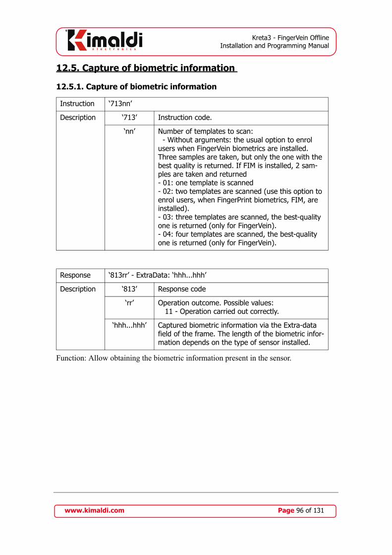
Kreta3 - FingerVein OfflineInstallation and Programming Manual
12.5. Capture of biometric information
12.5.1. Capture of biometric information
Function: Allow obtaining the biometric information present in the sensor.
Instruction ‘713nn’
Description ‘713’ Instruction code.
‘nn’ Number of templates to scan: - Without arguments: the usual option to enrol users when FingerVein biometrics are installed. Three samples are taken, but only the one with the best quality is returned. If FIM is installed, 2 sam-ples are taken and returned- 01: one template is scanned- 02: two templates are scanned (use this option to enrol users, when FingerPrint biometrics, FIM, are installed).- 03: three templates are scanned, the best-quality one is returned (only for FingerVein).- 04: four templates are scanned, the best-quality one is returned (only for FingerVein).
Response ‘813rr’ - ExtraData: ‘hhh...hhh’
Description ‘813’ Response code
‘rr’ Operation outcome. Possible values: 11 - Operation carried out correctly.
‘hhh...hhh’ Captured biometric information via the Extra-data field of the frame. The length of the biometric infor-mation depends on the type of sensor installed.
www.kimaldi.com Page 96 of 131

Kreta3 - FingerVein OfflineInstallation and Programming Manual
12.6. Sensor memory management
12.6.1. Add user
Function: Allows registering a user's biometric information in the sensor's memory.
12.6.2. Request number of users
Instruction ‘564nnnnnnnnnncccccccccct’ - ExtraData: “hhh...hhh”
Description ‘564’ Instruction code.
‘nnnnnnnnnn’ User identifier.
‘cccccccccc’ PIN|Weekly|Attendance
‘t’ Way of registering the user. Possible values: ‘1’- The biometric information travels in the Extra-Data field of the frame. Data sent to the Main UI. Use ‘3’ rather than ‘1’. ‘3’- The biometric information travels in the Extra-Data field of the frame. Data sent to both the Main UI and the Auxiliary UI. ‘A’ - The biometric information is obtained from the sensor.
‘hhh...hhh’ Biometric information of user to be registered. Only used when “t=1” or “t=3”.This information travels via the frame's Extra-data field (see section 5.4).
Response ‘664rr’
Description ‘664’ Response code
‘rr’ Operation outcome.11 - Operation carried out correctly.
Instruction ‘715’
Description ‘715’ Instruction code.
No argument.
Response ‘815nnnn’
Description ‘815’ Response code
‘nnnn’ Number of users stored in the sensor's memory.
www.kimaldi.com Page 97 of 131
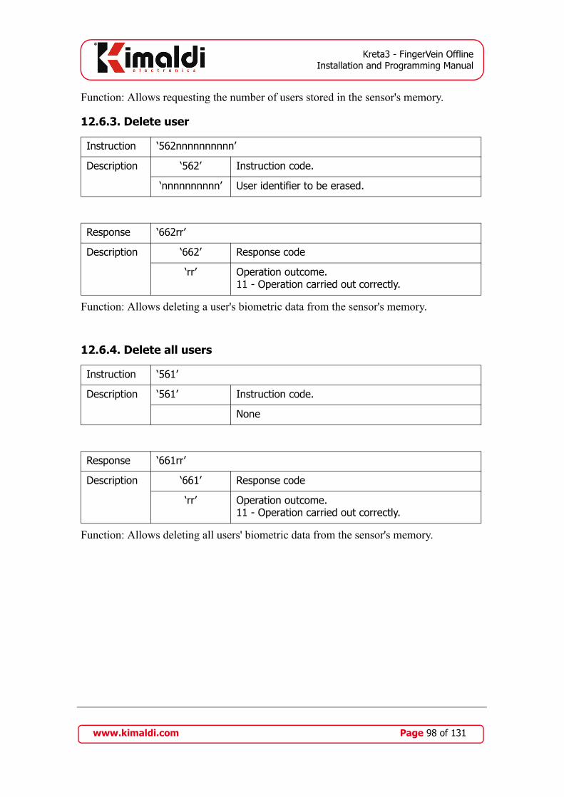
Kreta3 - FingerVein OfflineInstallation and Programming Manual
Function: Allows requesting the number of users stored in the sensor's memory.
12.6.3. Delete user
Function: Allows deleting a user's biometric data from the sensor's memory.
12.6.4. Delete all users
Function: Allows deleting all users' biometric data from the sensor's memory.
Instruction ‘562nnnnnnnnnn’
Description ‘562’ Instruction code.
‘nnnnnnnnnn’ User identifier to be erased.
Response ‘662rr’
Description ‘662’ Response code
‘rr’ Operation outcome.11 - Operation carried out correctly.
Instruction ‘561’
Description ‘561’ Instruction code.
None
Response ‘661rr’
Description ‘661’ Response code
‘rr’ Operation outcome.11 - Operation carried out correctly.
www.kimaldi.com Page 98 of 131

Kreta3 - FingerVein OfflineInstallation and Programming Manual
12.7. Operation details
The biometric sensor is a fairly complex device, capable of controlling two types offunctions:
• Fingerprint scanning functions.• Fingerprint recognition functions, based on its own database.
For this reason, the biometric module requires special attention when configuring theequipment and when administering the user permissions database.
12.7.1. Configuration of the FIM biometric module
This section only applies to the fingerprint biometric module (initially FIM2030,replaced by FIM5360).
The factory configuration for the biometric module is correct for operation, thereforeonly in very particular cases will access to this part of the configuration be necessary.
If required, it is possible to manage (read and write) some configuration parameters ofthe FIM biometric module using operations ‘1’ and ‘2’ of group ‘7’ (Write CFG and ReadCFG respectively). These parameters are:
Table 6: FIM Configuration parameters
Parameter Index
Meaning Value Ranges Default value
Observations
$17 Fingerprint identifica-tion Time-Out
10 - 250 25 Ticks of 0.1 sec-onds
$19 Fingerprint capture Time-Out
10 - 250 50 Ticks of 0.1 sec-onds
$20 Picture brightness 0 - 100 45 100 max.
$21 Picture gain 1, 2, 4, 8 2
$22 Picture contrast 0 - 100 20
$30 Security Level in Verifi-cation (1:1)
1 - 9 6
$31 Security Level in Iden-tification (1:N)
6 - 9 8
$48 Baud Rate RS-232(FIM2030 / FIM2260)
0 => 1152001 => 576002 => 384003 => 192004 => 9600
2 Should be coor-dinated with CFG-UI_SerialPort
www.kimaldi.com Page 99 of 131

Kreta3 - FingerVein OfflineInstallation and Programming Manual
12.7.2. User database management
The Kreta3 module contains a permissions database as did version v1, as described inSubsection 10.2.7.: in this database, each user that is created has a weekly code, a PINand an Attendance code. These details are sufficient for identifications using a card, butnot for biometric identifications. For biometric identifications, each user must also beassigned a pair of samples of one of the user's fingerprints.
Each fingerprint occupies 400 bytes of memory and is physically stored on the non-volatile memory of the biometric module. The reading and recovery of the biometricdata for each user is carried out in combination with the Permissions Table, with thefollowing operations:
User creation
A user is created with operation ‘564’ (refer to Subsection 11.3.4.). The blockformat will be the following:
<STX>564[CardCode|PIN|Weekly|Attendance]3<ETB>[Extra_Data]<ETX>
$49 Baud Rate RS-232(FIM5360)
0 => 1152001 => 576002 => 384003 => 192004 => 9600
2 Should be coor-dinated with CFG-UI_SerialPort
$50 Maximum number of users (LSB)
$E8 => 1K$A0 => 4K
Read only
$F0 Emulation mode (FIM 5360)
$01: FIM20$FF: No emul
$01 Do not modify
Table 6: FIM Configuration parameters
Parameter Index
Meaning Value Ranges Default value
Observations
www.kimaldi.com Page 100 of 131

Kreta3 - FingerVein OfflineInstallation and Programming Manual
In other words, just at the end of the command normally used for creating a user thefollowing is added:
- ‘3’: The address to which we are going to send the biometric data. ‘1’ wouldrelate to the Main biometric module, ‘2’ to the Auxiliary biometric and ‘3’ tothe two.
- <ETB> (End Transmission Block, ASCII $17): Ends the command block andbegins the Extra Data block.
- [Extra Data]: The two samples of the biometric fingerprint are transferred in aspecial format explained in Subsection 12.7.3.
Change of User Permission
Once a user is created, we can change their weekly code or their pin without having toattach their biometric fingerprint again. To do so we would use the same operation‘564’ (refer to Subsection 11.3.4.), but in its usual format:
<STX>564[CardCode|PIN|Weekly|Attendance]<ETX>
Deleting a User
The process for deleting a user is normally done based on their card code (refer tooperation ‘562’, Subsection 11.3.2.). The Kreta3 module will automatically delete thememory of the biometric module that operates as the main reader, and then theauxiliary. No biometric information needs to be processed.
<STX>562[CardCode]<ETX>
Reading the User Permission
Operation ‘567’ (refer to Subsection 11.3.7.) allows us to recover the record fromthe permissions table that relates to a particular card code:
<STX>567[CardCode]<ETX>
If we also want to recover the user's biometric information, we must add the addressof the biometric module at the end of the command (only available with FIM2030):
<STX>567[CardCode]0<ETX>
In other words, just at the end of the command normally used for recovery ofinformation, the following is added:
- ‘0’: The address from which we are going to read the biometric data. ‘0’ means“indifferent” and will therefore return the reading from the first FIM that hasthe information available (normally the Main FIM). ‘1’ relates exclusively to
www.kimaldi.com Page 101 of 131

Kreta3 - FingerVein OfflineInstallation and Programming Manual
the Main FIM, and ‘2’ will require the fingerprint to be recovered from theAuxiliary FIM.
The correct response will be evident. However, in the case of errors, the codes thatwill appear are the following:
- ‘667A0’: reading has failed on the Main FIM, and there is no Secondary FIM.- ‘667B0’: reading has failed on the Secondary FIM.- ‘667C0’: reading has failed on both FIMs.
Changing a User Print
There is no operation designed only for this task. We must delete the user in order tothen create the user once again with the same card code and the new biometric data.
Obtaining the User's biometric data
Before creating the user, the biometric data of the user to be registered must first beobtained. This process is controlled from the Host, and therefore this manual does notcover this issue in depth. However below are some brief indications of the process:
- Scan using FingKey Hamster: in applications with various Kreta3 modules, therewill be a central computer that will gather the information. When a FIM2030biometric sensor is going to be used, it is advisable to install a FingKeyHamster biometric scanner, obtain the user's fingerprint from the applicationsoftware, and transfer it from there on to the Kreta3 modules.
www.kimaldi.com Page 102 of 131
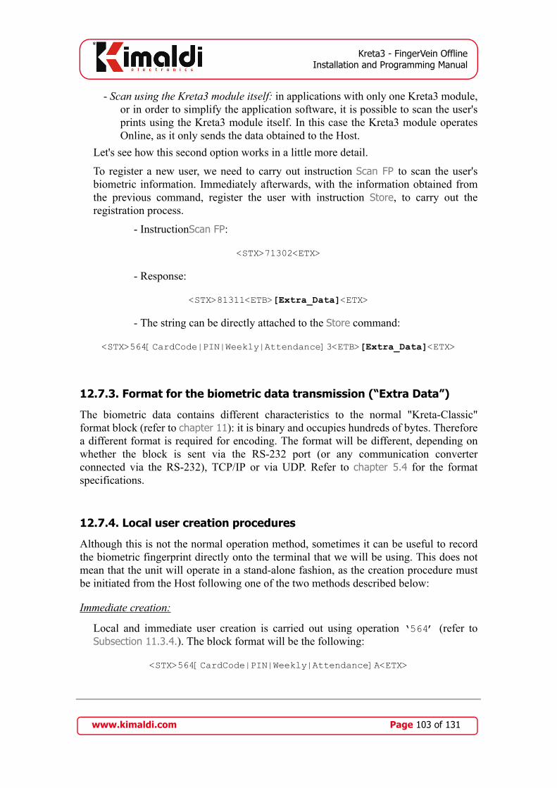
Kreta3 - FingerVein OfflineInstallation and Programming Manual
- Scan using the Kreta3 module itself: in applications with only one Kreta3 module,or in order to simplify the application software, it is possible to scan the user'sprints using the Kreta3 module itself. In this case the Kreta3 module operatesOnline, as it only sends the data obtained to the Host.
Let's see how this second option works in a little more detail.
To register a new user, we need to carry out instruction Scan FP to scan the user'sbiometric information. Immediately afterwards, with the information obtained fromthe previous command, register the user with instruction Store, to carry out theregistration process.
- InstructionScan FP:
<STX>71302<ETX>
- Response:
<STX>81311<ETB>[Extra_Data]<ETX>
- The string can be directly attached to the Store command:
<STX>564[CardCode|PIN|Weekly|Attendance]3<ETB>[Extra_Data]<ETX>
12.7.3. Format for the biometric data transmission (“Extra Data”)
The biometric data contains different characteristics to the normal "Kreta-Classic"format block (refer to chapter 11): it is binary and occupies hundreds of bytes. Thereforea different format is required for encoding. The format will be different, depending onwhether the block is sent via the RS-232 port (or any communication converterconnected via the RS-232), TCP/IP or via UDP. Refer to chapter 5.4 for the formatspecifications.
12.7.4. Local user creation procedures
Although this is not the normal operation method, sometimes it can be useful to recordthe biometric fingerprint directly onto the terminal that we will be using. This does notmean that the unit will operate in a stand-alone fashion, as the creation procedure mustbe initiated from the Host following one of the two methods described below:
Immediate creation:
Local and immediate user creation is carried out using operation ‘564’ (refer toSubsection 11.3.4.). The block format will be the following:
<STX>564[CardCode|PIN|Weekly|Attendance]A<ETX>
www.kimaldi.com Page 103 of 131

Kreta3 - FingerVein OfflineInstallation and Programming Manual
In other words, just at the end of the command normally used for creating a user thefollowing is added:
- ‘A’: Indicates Autonomous enrolment on the main biometric sensor. Autonomousenrolment is not supported on auxiliary biometric.
Immediately afterwards, the user to be created must place their finger on the Kreta3module, twice.
Deferred Creation:
Local creation can be deferred using the following process:
- The user code that we have to assign must be 8 decimal digits. The Kreta3 modulewill later convert it to 10 hexadecimal digits.
- We will store the permission relating to the user that we are creating, including aPIN. The deferred creation will be activated using the ‘A1’ code in theUse_Pin_Field.
- We will notify the user of their identification code and PIN.- The user may later go to the Kreta3 module, insert their code and PIN using the
keypad (this process can be activated by pressing F2). At that point the Kreta3module will request the scan of the user's fingerprint.
- Once the creation is complete, the user may directly identify themselvesbiometrically, as the PIN will therefore become void.
- The deferred registration does not work if we have the reduced identification 1:nactivated.
- Deferred registration is only possible in one of the unit's sensors (normally, themain one).
Example:
1.- We assign a user code 00256889, which appears in the Permissions Table as000003EB79.
2.- We assign PIN 1234 to the permission. The Use_Pin_Field must be ‘A1’.3.- Therefore, we will store the permission with the following block:
564000003EB79A112340100
4.- We will notify the user that their code is 00256889 and that their PIN is 1234.5.- We ensure that the CFG_CodeByKeypad parameter is set at $08.6.- The first time that the user accesses the Kreta3 module, they must press F2, insert
their 8 digit numeric code and then their PIN. They can finally register their finger-print.
www.kimaldi.com Page 104 of 131

Kreta3 - FingerVein OfflineInstallation and Programming Manual
12.8. User permissions with “Biometric exceptions”
In a sufficiently large group of users, there will always be some for which biometricidentification is a problem. Generally, it is usually a problem for people who have veryworn fingerprints, or have extremely dry skin. Therefore a "Biometric Exception"process is very useful, as it allows certain users to be identified using only their user codeand PIN.
Therefore, it is possible to configure the Kreta3 module for biometric identification bydefault, except for certain users. These users must be identified using a card (usually aproximity card) or by introducing an 8 digit code using the keypad (after pressing F2).The PIN code must then be entered.
The steps to follow in order to create such users are the following:
• We must select a Clock & Data port to connect the card reader. This Clock & Dataport will work together with the biometric module, as configured in theCFG_MainReader parameter (also refer to Table 17, “Main Reader configurationvalues, UI modules,” on page 119). In the following example, there is a FIM2030connected to the UART1-UI (SerialPort FIM) and it works with a Clock & Datareader connected in TTL_0:
7511B8A7511D05
• If we use an auxiliary reader, we must also install a card reader to operate with thesecond biometric module (again, refer toTable 17). Depending on the type of userinterface, only identifying oneself with the card will be necessary and the PINwill not be requested. In the auxiliary UI module, the FIM2030 is also connectedto UART1-UI and works with TTL_0:
7611B8A7611D05
• If we opt for identification via the keypad, we should allow entering a code of up to8 decimal figures configuring the CFG_CodeByKeypad parameter (Parameter$18, refer to Subsection 10.1.1.) 1:
3111808
• Finally, we just need to create the users who require a "biometric exception". Weidentify them with value ‘B1’ in the Use_Pin_Field in the Permissions Table:
5640100F39ABBB112340100
1. If we are using reduced identification 1:10, it will not be possible to identify the users with the keypad code with “Biometric Exception”
www.kimaldi.com Page 105 of 131

Kreta3 - FingerVein OfflineInstallation and Programming Manual
• It is also possible to register users with biometric exception without requiring theirPIN number. In this case, we identify them with value ‘B0’ in the Field_Use_Pinof Permissions Table 1:
5640100F39ABBB012340100
• Remember that the rest of the users must be enrolled for biometric identification asdetailed in Subsection 12.7.2.
12.9. High level operation
The biometric identification modules are connected to the Kreta3-UI module via a serialconnection. The communications protocol depends on the biometric sensor used,although it is totally transparent to the applications programmer for Kreta3. In otherwords, access to the biometrics modules is always granted via the Kreta3, in particularthrough {Group}='5' operations (refer to chapter 11.3) and {Group}='7' (refer tochapter 11.4).
At a configuration level, it is important to distinguish between configurations whichaffect the Kreta3 module and those which affect the biometric module:
• On the main board, the CFG-UI_MainReader and CFG-UI_SerialPortFIM(corresponding to UART1-UI) parameters should be configured.
• We also have messages that are directly related to biometric identification. Refer toSubsection 10.1.3. for a complete list.
• Configuration of the biometric module is managed through {Group}='7'instructions. These parameters basically affect the configuration of the opticalsensor. We do not recommend changing them, although we have access to themshould the need arise.
12.9.1. Biometric identification module
The Kreta3-UI module allows identification of people via biometrics techniques. Due tothe Offline character of the Kreta3 module, biometric identification is carried out on theterminal itself via an interconnection with the biometric module.
The interaction between the different subsystems is as follows:
1. When a finger is placed on the optical sensor, the biometric module carries out a 1:Nidentification.
2. As a result of the identification, the biometric module sends the Kreta-UI electron-ics the 10 byte code corresponding to the “Card Code”. At that moment, the biomet-ric sensor is acting in the same manner as a card reader.
1. Nevertheless, we recommend using PIN (‘B1’) for all users enrolled as biometric exception, with the aim of maintaining a comparable security level to the users with biometrics.
www.kimaldi.com Page 106 of 131

Kreta3 - FingerVein OfflineInstallation and Programming Manual
3. The Kreta3-UI module will process the “Card Code” as normal, consulting the resi-dent database in Kreta3-DB.
It is advisable to note that the Kreta3-DB module makes no distinction between theorigins of the identification code. This is due to the existence of two (or up to three)different databases.
1. The Kreta3-DB database manages the permission table, as detailed in Subsection10.2.7.. This table is compatible with Kreta v1, and is indifferent to the configura-tion of the readers.
2. The biometric module which is the main reader, has its own database, in which thebiometric fingerprint is related to a card code.
3. If we use a biometric reader for auxiliary access, we will find that it has an identicaldatabase to that of the main reader.
The programming method of the Kreta3 module provides a unitary user interface, so thatthere can be no discrepancies between the contents of the different databases.
The programming method also allows access to the different configuration parameters ofthe biometric sensors, as explained in chapter 11.4.
There is also an option for performing 1:1 identifications, using a combination of a cardreader via the TTL port and a biometric module via the serial port. Refer to chapter 12.1for more details on this matter.
www.kimaldi.com Page 107 of 131

Kreta3 - FingerVein OfflineInstallation and Programming Manual
13. Printing of reading tickets
The Kreta3-UI module can print reading tickets, with a printer with RS232 connectivity,normally connected to UART2-UI.
13.1. Terminal configuration
To be able to print reading tickets with a Kreta3 terminal, you should configure thefollowing two parameters:
• Communication port configuration: The serial port where the printer is connectedshould be correctly configured, via the CFG-UI_SerialPortReader.parameter.The detailed programming model can be found in Table 15 and inchapter 11.2..
• Configuration of the tickets to be printed: Using the CFG_Printer parameter, if youwant you can configure the unit to issue tickets for readings generated from themain or secondary access or both. The meaning of each of this byte's bits is asfollows:
.
Thus, for example, we can connect the printer to the UART2-UI and enable it to printentry tickets:
- CFG-UI_SerialPortReader = $A0 (We associate UART2-UI to the printer, at9600 baud).
- CFG_Printer = $01 (Ticket printing, main access).
Table 7: Parameter bits CFG_Printer
Bit 0 A ‘1’, prints ticket for readings generated by the main access.
Bit 1 A ‘1’, prints ticket for readings generated by the sec-ondary.
Bit 2 Reserved.
Bit 3 Reserved.
Bit 4 Reserved.
Bit 5 Reserved.
Bit 6 Reserved.
Bit 7 Reserved.
Bit 8 Reserved.
www.kimaldi.com Page 108 of 131

Kreta3 - FingerVein OfflineInstallation and Programming Manual
13.2. Ticket personalisation
The terminal is comes configured from the factory, to print reading tickets, in printerwith RS232 connectivity compatible with ESC/POS commands (for example EPSONTM-T88IV). The default design of the reading ticket is as follows:
This design can be changed on two levels:
• Message personalisation.• Design personalisation.
13.2.1. Message personalisation
Message personalisation allows modifying the value of all the set texts that appear on thelabel, and in this way create a ticket with personalised details for a client. The messagesthat are loaded by default are:
In chapter 11.2 how to consult and modify these messages is described.
Message Default value
01 KIMALDI electronics, S.L.
02 Ctra. de Rubí, 292 B
03 08228 - Terrassa
04 Barcelona - Spain
05 www.kimaldi.com
06
07 ID:
08 EV:
09 INC:
www.kimaldi.com Page 109 of 131

Kreta3 - FingerVein OfflineInstallation and Programming Manual
13.2.2. Modification of the design
The terminal terminal allows modifying the script it uses to print a reading ticket, tochange its design or adapt it to a printer.
A printing script is a series of binary characters that are sent in an ordered fashion to theprinter to print a reading ticket.
For a script to the valid, it should fulfil three rules:
• It should start with the script start indicator: “#S0”.• It should end with the script end indicator: “#F0”.• The total size should not be less than 464 bytes.
To be able to print variable information depending on the reading, some labels areinserted in the script that indicated the terminal that in that position should print thereading information or a set message. All the labels that can be inserted in a print scriptare listed below:
Table 8: Control labels
Label Description
#S0 Print script start indicator.
#F0 Print script end indicator.
Table 9: Labels for printing set messages
Label Description
#T1 Prints text message number 1.
#T2 Prints text message number 2.
#T3 Prints text message number 3.
#T4 Prints text message number 4.
#T5 Prints text message number 5.
#T6 Prints text message number 6.
#T7 Prints text message number 7.
#T8 Prints text message number 8.
#T9 Prints text message number 9.
## Prints the “#” character.
www.kimaldi.com Page 110 of 131
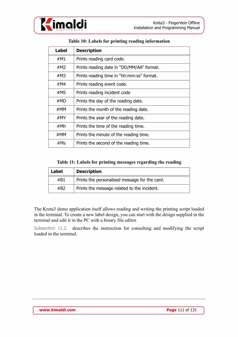
Kreta3 - FingerVein OfflineInstallation and Programming Manual
The Kreta3 demo application itself allows reading and writing the printing script loadedin the terminal. To create a new label design, you can start with the design supplied in theterminal and edit it in the PC with a binary file editor.
Subsection 11.2. describes the instruction for consulting and modifying the scriptloaded in the terminal.
Table 10: Labels for printing reading information
Label Description
#M1 Prints reading card code.
#M2 Prints reading date in “DD/MM/AA” format.
#M3 Prints reading time in “hh:mm:ss” format.
#M4 Prints reading event code.
#M5 Prints reading incident code
#MD Prints the day of the reading date.
#MM Prints the month of the reading date.
#MY Prints the year of the reading date.
#Mh Prints the time of the reading time.
#MM Prints the minute of the reading time.
#Ms Prints the second of the reading time.
Table 11: Labels for printing messages regarding the reading
Label Description
#B1 Prints the personalised message for the card.
#B2 Prints the message related to the incident.
www.kimaldi.com Page 111 of 131
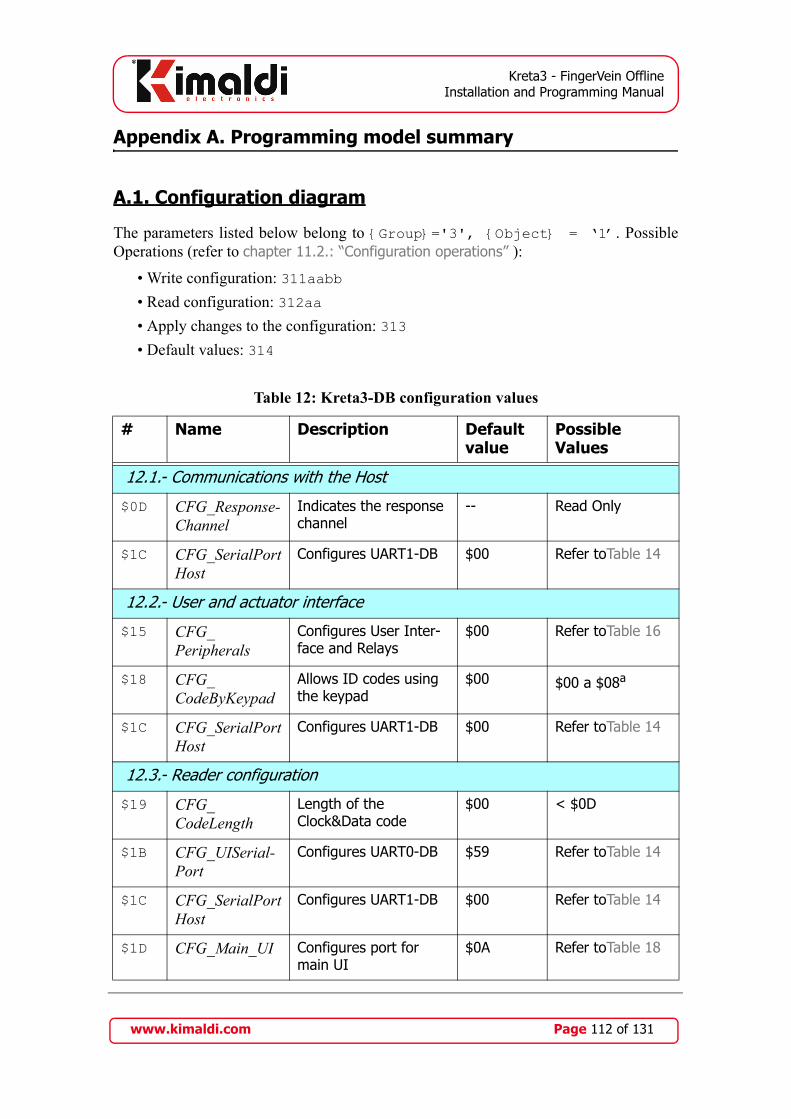
Kreta3 - FingerVein OfflineInstallation and Programming Manual
Appendix A. Programming model summary
A.1. Configuration diagram
The parameters listed below belong to {Group}='3', {Object} = ‘1’. PossibleOperations (refer to chapter 11.2.: “Configuration operations” ):
• Write configuration: 311aabb• Read configuration: 312aa• Apply changes to the configuration: 313• Default values: 314
Table 12: Kreta3-DB configuration values
# Name Description Defaultvalue
Possible Values
12.1.- Communications with the Host
$0D CFG_Response-Channel
Indicates the response channel
-- Read Only
$1C CFG_SerialPortHost
Configures UART1-DB $00 Refer toTable 14
12.2.- User and actuator interface
$15 CFG_Peripherals
Configures User Inter-face and Relays
$00 Refer toTable 16
$18 CFG_CodeByKeypad
Allows ID codes using the keypad
$00 $00 a $08a
$1C CFG_SerialPortHost
Configures UART1-DB $00 Refer toTable 14
12.3.- Reader configuration
$19 CFG_CodeLength
Length of the Clock&Data code
$00 < $0D
$1B CFG_UISerial-Port
Configures UART0-DB $59 Refer toTable 14
$1C CFG_SerialPortHost
Configures UART1-DB $00 Refer toTable 14
$1D CFG_Main_UI Configures port for main UI
$0A Refer toTable 18
www.kimaldi.com Page 112 of 131

Kreta3 - FingerVein OfflineInstallation and Programming Manual
$1E CFG_AuxiliaryReader
Configures Identifica-tion on the Auxiliary Reader
$12 Refer toTable 18
12.4.- Application Modes (refer to Table 2)
$01 CFG_Attendance
Attendance Control TRUE FALSE, TRUE
$02 CFG_Access Access Control TRUE FALSE, TRUE
$16 CFG_List Type of access $00 $00, $01, $02, $03, $FF
12.5.- Application configuration
$04 CFG_MassReading
Mass Reading TRUE FALSE, TRUE
$05 CFG_Enables-AuxiliaryReader
Obsolete TRUE
$08 CFG_RecordErrors
Also saves erroneous readings
TRUE FALSE, TRUE
$17 CFG_LockedByMemory
Avoids overwriting readings
TRUE FALSE, TRUE
$1A CFG_TraceReading
Online transmission of readings
FALSE FALSE, TRUE
$24 CFG_Persona-lisedMessage
Personalised Message (Only for Access Con-trol)
$00 (deac-tivated)
$00 to $03
12.6.- Extra functions and capacity control
$03 CFG_ ExtraFunction
Activates Antipassback or access balance
$00 $00, $01, $02, $03, $FF
$26 CFG_CapacityMax_HH
Capacity limiter (thou-sands and hundreds)
$00 $00 to $99:
$27 CFG_CapacityMax_LL
Capacity limiter (tens and units)
$00 $00 to $99:
$28 CFG_Current-Cap_HH
Current Capacity (thou-sands and hundreds)
$00 Recommended for Read Only
Table 12: Kreta3-DB configuration values
# Name Description Defaultvalue
Possible Values
www.kimaldi.com Page 113 of 131
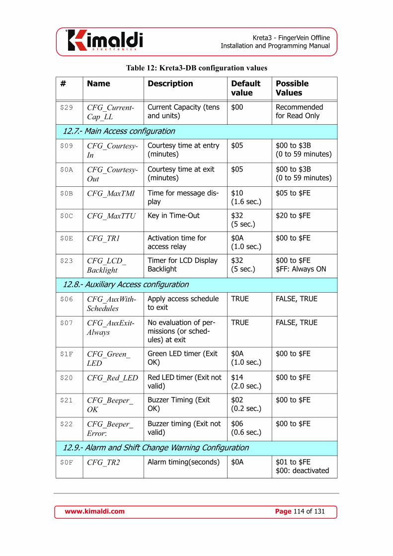
Kreta3 - FingerVein OfflineInstallation and Programming Manual
$29 CFG_Current-Cap_LL
Current Capacity (tens and units)
$00 Recommended for Read Only
12.7.- Main Access configuration
$09 CFG_Courtesy-In
Courtesy time at entry (minutes)
$05 $00 to $3B (0 to 59 minutes)
$0A CFG_Courtesy-Out
Courtesy time at exit (minutes)
$05 $00 to $3B (0 to 59 minutes)
$0B CFG_MaxTMI Time for message dis-play
$10(1.6 sec.)
$05 to $FE
$0C CFG_MaxTTU Key in Time-Out $32(5 sec.)
$20 to $FE
$0E CFG_TR1 Activation time for access relay
$0A(1.0 sec.)
$00 to $FE
$23 CFG_LCD_ Backlight
Timer for LCD Display Backlight
$32(5 sec.)
$00 to $FE$FF: Always ON
12.8.- Auxiliary Access configuration
$06 CFG_AuxWith-Schedules
Apply access schedule to exit
TRUE FALSE, TRUE
$07 CFG_AuxExit-Always
No evaluation of per-missions (or sched-ules) at exit
TRUE FALSE, TRUE
$1F CFG_Green_LED
Green LED timer (Exit OK)
$0A(1.0 sec.)
$00 to $FE
$20 CFG_Red_LED Red LED timer (Exit not valid)
$14(2.0 sec.)
$00 to $FE
$21 CFG_Beeper_ OK
Buzzer Timing (Exit OK)
$02(0.2 sec.)
$00 to $FE
$22 CFG_Beeper_Error:
Buzzer timing (Exit not valid)
$06(0.6 sec.)
$00 to $FE
12.9.- Alarm and Shift Change Warning Configuration
$0F CFG_TR2 Alarm timing(seconds) $0A $01 to $FE$00: deactivated
Table 12: Kreta3-DB configuration values
# Name Description Defaultvalue
Possible Values
www.kimaldi.com Page 114 of 131

Kreta3 - FingerVein OfflineInstallation and Programming Manual
We also include the parameters corresponding to the Kreta3-UI module, belonging to the{Group}='7', {Object} = ‘5’ or ‘6’. Possible Operations (refer to chapter 11.6.:“Operations on peripherals (Kreta3-UI module)” ):
• Write configuration: 751aabb• Read configuration: 752aa• Apply changes to the configuration: 753• Default values: 754
$10 CFG_Alarm-Triggered
Alarm status FALSE Recommended for Read Only
$11 CFG_Alarm-DeacAutom
Activation and deacti-vation options
$00 $00 at $FFb
(Subsection 9.1.6.)
$12 CFG_Alarm-Timeout
Door opening time win-dow (seconds)
$0A(10 sec.)
$00 to $FE
$13 CFG_Alarm-PINHH
Digits 1 and 2 of the alarm PIN
$12 $00 to $99:
$14 CFG_Alarm-PINLL
Digits 3 and 4 of the alarm PIN
$34 $00 to $99:
$25 CFG_Shift-Bell Signalling bell of shift change (seconds)
$00 $01 to $FE$00: deactivated
a. COMPATIBILITY NOTE: CFG_Code-ByKeypad should be $08 or more to be compatible withthe TRUE value of previous versions.b. COMPATIBILITY NOTE: the $FF value is automatically converted to $01
Table 12: Kreta3-DB configuration values
# Name Description Defaultvalue
Possible Values
www.kimaldi.com Page 115 of 131

Kreta3 - FingerVein OfflineInstallation and Programming Manual
Table 13: Kreta3-UI configuration values
# Name Description Defaultvalue
Possible Values
13.1.- Communications with the Kreta3-DB module
$1A CFG-UI_SerialPortDB
Configures UART0-UI $91 Reserved
13.2.- User and actuator interface
$03 CFG-UI_OPT_ T_WATCHDOG
Activates the optical barrier
$00 $FF: Auto-ON$80: Activated$00: Deactivated
$05 CFG_OPT_KeyCode
Character emitted by the optical barrier
$41 >$03
$06 CFG-TimeBuzz_OK
UI Buzzer timing in case OK
$06 $00 to $FE (multiples of 10 ms)
$07 CFG-TimeBuzz_Fail
UI Buzzer timing in case Error
$78 $00 to $FE(multiples of 10 ms)
$12 CFG-UI_TimeRelay
Timing of semaphore indicator
$00 $00: deactivated$01 to $FE
$14 CFG-UI_ Dis-play TMO
Maximum Display time-out
$0F $0F to $FF
13.3.- Reader configuration
$1B CFG-UI_SerialPortFIM
ConfiguresUART1-UI $88 Refer toTable 15
$1C CFG-UI_SerialPortReader
Configures UART2-DB $40 Refer toTable 15
$1D CFG-UI_MainReader
Configures Identifica-tion in Kreta3-UI mod-ule
$02 Refer toTable 17
www.kimaldi.com Page 116 of 131
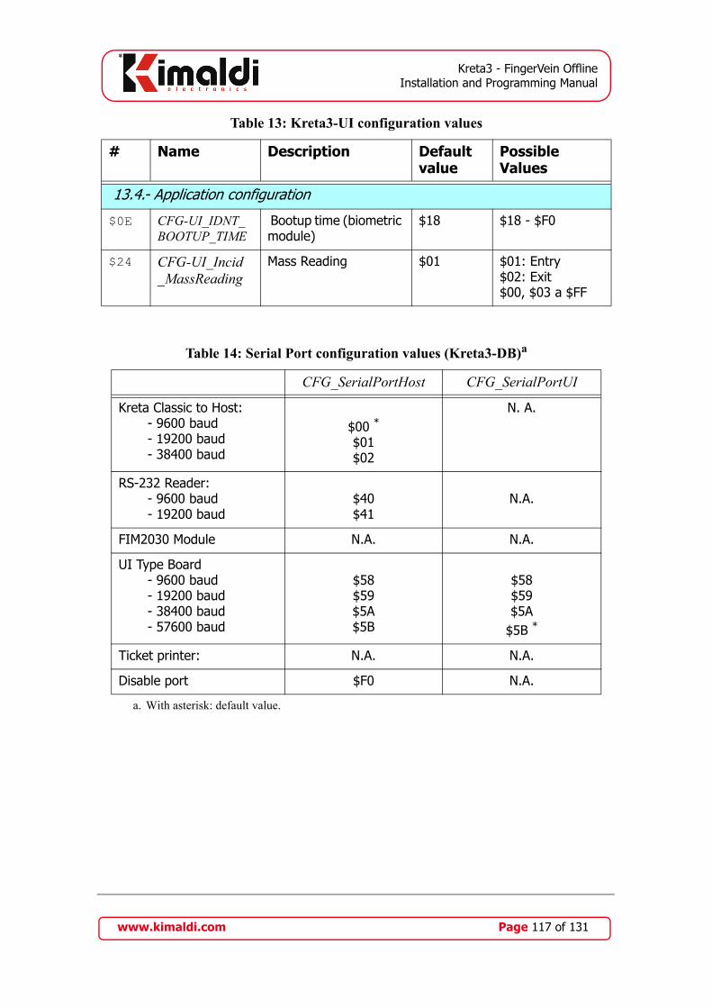
Kreta3 - FingerVein OfflineInstallation and Programming Manual
13.4.- Application configuration
$0E CFG-UI_IDNT_ BOOTUP_TIME
Bootup time (biometric module)
$18 $18 - $F0
$24 CFG-UI_Incid _MassReading
Mass Reading $01 $01: Entry$02: Exit$00, $03 a $FF
Table 14: Serial Port configuration values (Kreta3-DB)a
a. With asterisk: default value.
CFG_SerialPortHost CFG_SerialPortUI
Kreta Classic to Host: - 9600 baud - 19200 baud - 38400 baud
$00 *
$01$02
N. A.
RS-232 Reader: - 9600 baud - 19200 baud
$40$41
N.A.
FIM2030 Module N.A. N.A.
UI Type Board - 9600 baud - 19200 baud - 38400 baud - 57600 baud
$58$59$5A$5B
$58$59$5A
$5B *
Ticket printer: N.A. N.A.
Disable port $F0 N.A.
Table 13: Kreta3-UI configuration values
# Name Description Defaultvalue
Possible Values
www.kimaldi.com Page 117 of 131

Kreta3 - FingerVein OfflineInstallation and Programming Manual
Table 15: Serial Port configuration values (Kreta3-UI)a
a. With asterisk: default value.
CFG-UI_SerialPortFIM
CFG-UI_SerialPortReader
RS-232 Reader: - 9600 baud - 19200 baud
$40$41
$40 *
$41
FIM2030 Module - 9600 baud - 38400 baud
$88 *
$8A
N.A.
FingerVein Module - 57600 baud $BB
N.A.
Serial-1R Auxiliary Board N.A. N.A.
Ticket printer: - 9600 baud - 19200 baud - 38400 baud
N.A.$A0$A1$A2
Disable port $F0 $F0
Table 16: User interface configurationa
a. With asterisk: default value. Between square brackets: value for normally closed access relayN/C: relay not connected
CFG_Peripherals
Main Reader AuxiliaryReader
Actuators (relays)
$00 *
[$88]
User interface determined by
the UI
User interface determined by
the UI
[Input/Output, Alarm, N/C, Turn]
$02
[$0A]
User interface determined by
the UI
User interface determined by
the UI
[Input, Alarm, Output, Turn]
www.kimaldi.com Page 118 of 131

Kreta3 - FingerVein OfflineInstallation and Programming Manual
Table 17: Main Reader configuration values, UI modules
Peripheral device CFG-UI_Reader UART-UIa TTL
(Data format) Main b 2 1 0
RS-232 Reader $00
(10 Bytes, Hexadecimal) $01
Clock&Data Reader $02 *
(13 Bytes, Decimal) $03
FIM2030 module c $05
$04
FingerVein Module d $07
$06
RS-232 Reader $08
(13 Bytes, Decimal) $09
Clock & Data on Aux. board $0A
(13 Bytes, Decimal) $0B
UART or Clock & Data e $0C
$0D
$0E
$0F
FingerVein module UART1,RS-232 Reader in UART2
$15
FIM2030 module in UART1,RS-232 Reader in UART2
$17
FIM2030 Module $25
(force identification 1:1) $24, $26, $27
FIM2030 in UART1, Read.RS-232 in UART2, force 1:1
$37
FIM2030 Module $45
www.kimaldi.com Page 119 of 131
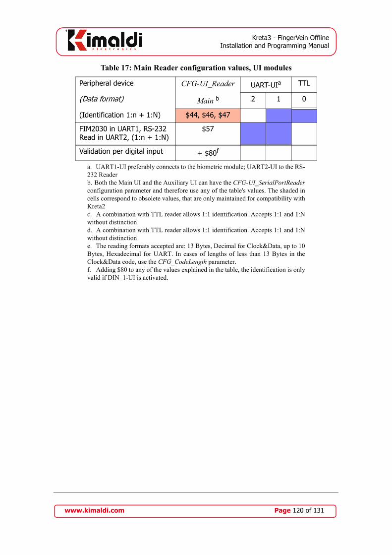
Kreta3 - FingerVein OfflineInstallation and Programming Manual
(Identification 1:n + 1:N) $44, $46, $47
FIM2030 in UART1, RS-232 Read in UART2, (1:n + 1:N)
$57
Validation per digital input + $80f
a. UART1-UI preferably connects to the biometric module; UART2-UI to the RS-232 Readerb. Both the Main UI and the Auxiliary UI can have the CFG-UI_SerialPortReaderconfiguration parameter and therefore use any of the table's values. The shaded incells correspond to obsolete values, that are only maintained for compatibility withKreta2c. A combination with TTL reader allows 1:1 identification. Accepts 1:1 and 1:Nwithout distinctiond. A combination with TTL reader allows 1:1 identification. Accepts 1:1 and 1:Nwithout distinctione. The reading formats accepted are: 13 Bytes, Decimal for Clock&Data, up to 10Bytes, Hexadecimal for UART. In cases of lengths of less than 13 Bytes in theClock&Data code, use the CFG_CodeLength parameter.f. Adding $80 to any of the values explained in the table, the identification is onlyvalid if DIN_1-UI is activated.
Table 17: Main Reader configuration values, UI modules
Peripheral device CFG-UI_Reader UART-UIa TTL
(Data format) Main b 2 1 0
www.kimaldi.com Page 120 of 131
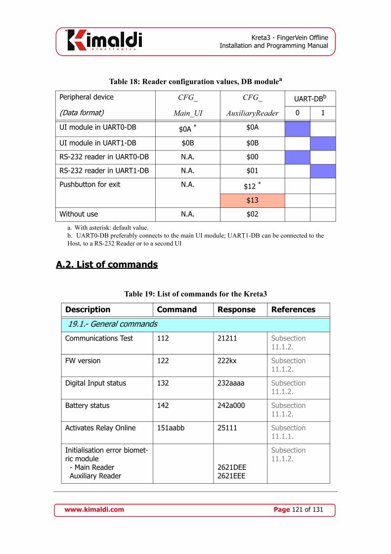
Kreta3 - FingerVein OfflineInstallation and Programming Manual
A.2. List of commands
Table 18: Reader configuration values, DB modulea
a. With asterisk: default value.
Peripheral device CFG_ CFG_ UART-DBb
b. UART0-DB preferably connects to the main UI module; UART1-DB can be connected to theHost, to a RS-232 Reader or to a second UI
(Data format) Main_UI AuxiliaryReader 0 1
UI module in UART0-DB $0A * $0A
UI module in UART1-DB $0B $0B
RS-232 reader in UART0-DB N.A. $00
RS-232 reader in UART1-DB N.A. $01
Pushbutton for exit N.A. $12 *
$13
Without use N.A. $02
Table 19: List of commands for the Kreta3
Description Command Response References
19.1.- General commands
Communications Test 112 21211 Subsection 11.1.2.
FW version 122 222kx Subsection 11.1.2.
Digital Input status 132 232aaaa Subsection 11.1.2.
Battery status 142 242a000 Subsection 11.1.2.
Activates Relay Online 151aabb 25111 Subsection 11.1.1.
Initialisation error biomet-ric module - Main Reader Auxiliary Reader
2621DEE2621EEE
Subsection 11.1.2.
www.kimaldi.com Page 121 of 131

Kreta3 - FingerVein OfflineInstallation and Programming Manual
19.2.- Configuration
Writes CFG parameter 311aabb 41111 Subsection 11.2.1.
Reeds CFG parameter 312aa 412bb Subsection 11.2.2.
Applies configuration 313 41311 Subsection 11.2.3.
Default configuration 314 41411 Subsection 11.2.4.
Writes Message 321aasss....ssss 42111 Subsection 11.2.1.
Reads Message 322aa 422sss....ssss Subsection 11.2.2.
Writes Day of the Week 331aasss 43111 Subsection 11.2.1.
Reads Day of the Week 332aa 432sss Subsection 11.2.2.
Writes Month 341aasss 44111 Subsection 11.2.1.
Reads Month 342aa 442sss Subsection 11.2.2.
Writes IP CFG 351aaxx... 45111 Subsection 11.2.1.
Reads IP CFG 352aa 452xx... Subsection 11.2.2.
Applies IP configuration 353 45311 Subsection 11.2.3.
Default IP config. 354 45411 Subsection 11.2.4.
Reads Database structure 362aa 462nnnn Subsection 11.2.2.
Writes printer
CFG (PRN)
371aaxx... 471aa11 Subsection 11.2.1.
Table 19: List of commands for the Kreta3
Description Command Response References
www.kimaldi.com Page 122 of 131
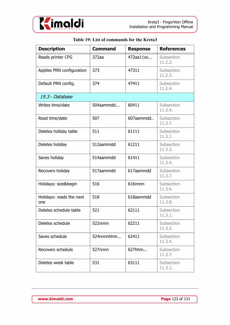
Kreta3 - FingerVein OfflineInstallation and Programming Manual
Reads printer CFG 372aa 472aa11xx... Subsection 11.2.2.
Applies PRN configuration 373 47311 Subsection 11.2.3.
Default PRN config. 374 47411 Subsection 11.2.4.
19.3.- Database
Writes time/date 504aammdd... 60411 Subsection 11.3.4.
Read time/date 507 607aammdd.. Subsection 11.3.7.
Deletes holiday table 511 61111 Subsection 11.3.1.
Deletes holiday 512aammdd 61211 Subsection 11.3.2.
Saves holiday 514aammdd 61411 Subsection 11.3.4.
Recovers holiday 517aammdd 617aammdd Subsection 11.3.7.
Holidays: size&begin 516 616nnnn Subsection 11.3.6.
Holidays: reads the next one
518 618aammdd Subsection 11.3.8.
Deletes schedule table 521 62111 Subsection 11.3.1.
Deletes schedule 522nnnn 62211 Subsection 11.3.2.
Saves schedule 524nnnnhhm... 62411 Subsection 11.3.4.
Recovers schedule 527nnnn 627hhm... Subsection 11.3.7.
Deletes week table 531 63111 Subsection 11.3.1.
Table 19: List of commands for the Kreta3
Description Command Response References
www.kimaldi.com Page 123 of 131
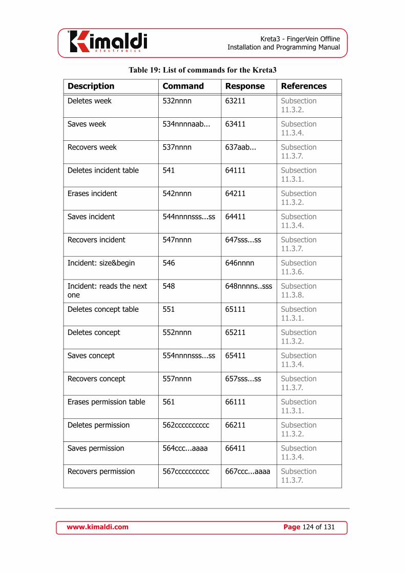
Kreta3 - FingerVein OfflineInstallation and Programming Manual
Deletes week 532nnnn 63211 Subsection 11.3.2.
Saves week 534nnnnaab... 63411 Subsection 11.3.4.
Recovers week 537nnnn 637aab... Subsection 11.3.7.
Deletes incident table 541 64111 Subsection 11.3.1.
Erases incident 542nnnn 64211 Subsection 11.3.2.
Saves incident 544nnnnsss...ss 64411 Subsection 11.3.4.
Recovers incident 547nnnn 647sss...ss Subsection 11.3.7.
Incident: size&begin 546 646nnnn Subsection 11.3.6.
Incident: reads the next one
548 648nnnns..sss Subsection 11.3.8.
Deletes concept table 551 65111 Subsection 11.3.1.
Deletes concept 552nnnn 65211 Subsection 11.3.2.
Saves concept 554nnnnsss...ss 65411 Subsection 11.3.4.
Recovers concept 557nnnn 657sss...ss Subsection 11.3.7.
Erases permission table 561 66111 Subsection 11.3.1.
Deletes permission 562cccccccccc 66211 Subsection 11.3.2.
Saves permission 564ccc...aaaa 66411 Subsection 11.3.4.
Recovers permission 567cccccccccc 667ccc...aaaa Subsection 11.3.7.
Table 19: List of commands for the Kreta3
Description Command Response References
www.kimaldi.com Page 124 of 131

Kreta3 - FingerVein OfflineInstallation and Programming Manual
Permissions: size&begin 566 666nnnn Subsection 11.3.6.
Permissions: reads the next one
568 668ccc...aaaa Subsection 11.3.8.
Deletes exceptions table 571 67111 Subsection 11.3.1.
Except.: deletes by code 573cccccccccc 67311 Subsection 11.3.3.
Saves exception 574ccc...aaaa 67411 Subsection 11.3.4.
Exception: size&begin 576 666nnnn Subsection 11.3.6.
Exception: reads the next one
578 668ccc...aaaa Subsection 11.3.8.
Exception: reads the next one associated to the code
579cccccccccc 679ccc...aaaa Subsection 11.3.9.
Deletes reading table 581 68111 Subsection 11.3.1.
Deletes last read reading 582 68211 Subsection 11.3.2.
Number of readings pend-ing reading
585 685nnnn Subsection 11.3.5.
Recovers reading 587 687ccc...aaxx Subsection 11.3.7.
Deletes personalised mes-sage table
591 69111 Subsection 11.3.1.
Deletes person. message 592cccccccccc 69211 Subsection 11.3.2.
Saves person. message 594ccc...ssss 69411 Subsection 11.3.4.
Recovers pers. message 597cccccccccc 697ccc...ssss Subsection 11.3.7.
Pers. mess.: size&begin 596 666nnnn Subsection 11.3.6.
Table 19: List of commands for the Kreta3
Description Command Response References
www.kimaldi.com Page 125 of 131
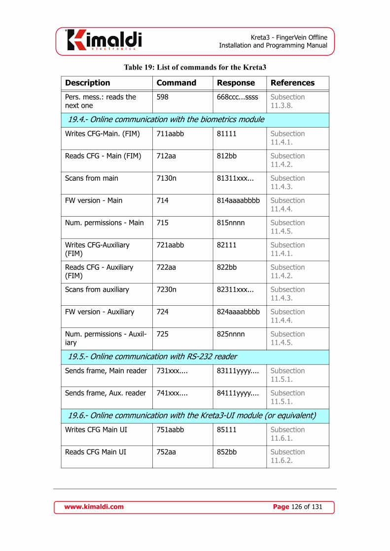
Kreta3 - FingerVein OfflineInstallation and Programming Manual
Pers. mess.: reads the next one
598 668ccc...ssss Subsection 11.3.8.
19.4.- Online communication with the biometrics module
Writes CFG-Main. (FIM) 711aabb 81111 Subsection 11.4.1.
Reads CFG - Main (FIM) 712aa 812bb Subsection 11.4.2.
Scans from main 7130n 81311xxx... Subsection 11.4.3.
FW version - Main 714 814aaaabbbb Subsection 11.4.4.
Num. permissions - Main 715 815nnnn Subsection 11.4.5.
Writes CFG-Auxiliary (FIM)
721aabb 82111 Subsection 11.4.1.
Reads CFG - Auxiliary (FIM)
722aa 822bb Subsection 11.4.2.
Scans from auxiliary 7230n 82311xxx... Subsection 11.4.3.
FW version - Auxiliary 724 824aaaabbbb Subsection 11.4.4.
Num. permissions - Auxil-iary
725 825nnnn Subsection 11.4.5.
19.5.- Online communication with RS-232 reader
Sends frame, Main reader 731xxx.... 83111yyyy.... Subsection 11.5.1.
Sends frame, Aux. reader 741xxx.... 84111yyyy.... Subsection 11.5.1.
19.6.- Online communication with the Kreta3-UI module (or equivalent)
Writes CFG Main UI 751aabb 85111 Subsection 11.6.1.
Reads CFG Main UI 752aa 852bb Subsection 11.6.2.
Table 19: List of commands for the Kreta3
Description Command Response References
www.kimaldi.com Page 126 of 131
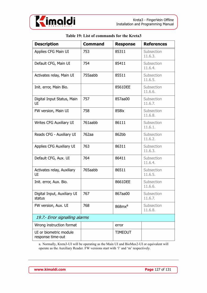
Kreta3 - FingerVein OfflineInstallation and Programming Manual
Applies CFG Main UI 753 85311 Subsection 11.6.3.
Default CFG, Main UI 754 85411 Subsection 11.6.4.
Activates relay, Main UI 755aabb 85511 Subsection 11.6.5.
Init. error, Main Bio. 8561DEE Subsection 11.6.6.
Digital Input Status, Main UI
757 857aa00 Subsection 11.6.7.
FW version, Main UI 758 858lx Subsection 11.6.8.
Writes CFG Auxiliary UI 761aabb 86111 Subsection 11.6.1.
Reads CFG - Auxiliary UI 762aa 862bb Subsection 11.6.2.
Applies CFG Auxiliary UI 763 86311 Subsection 11.6.3.
Default CFG, Aux. UI 764 86411 Subsection 11.6.4.
Activates relay, Auxiliary UI
765aabb 86511 Subsection 11.6.5.
Init. error, Aux. Bio. 8661DEE Subsection 11.6.6.
Digital Input, Auxiliary UI status
767 867aa00 Subsection 11.6.7.
FW version, Aux. UI 768 868mxa Subsection 11.6.8.
19.7.- Error signalling alarms
Wrong instruction format error
UI or biometric module response time-out
TIMEOUT
a. Normally, Kreta3-UI will be operating as the Main UI and BioMax2-UI or equivalent willoperate as the Auxiliary Reader. FW versions start with ‘l’ and ‘m’ respectively.
Table 19: List of commands for the Kreta3
Description Command Response References
www.kimaldi.com Page 127 of 131

Kreta3 - FingerVein OfflineInstallation and Programming Manual
Appendix B. Templates for integration
B.1. Kreta3 drills
Valid for the PCB Kreta3 v1.0 version. Dimensions in millimetres (mm):
J6 / J7
U5
U4
Relé
J8
U6 / U7
Re
lé
JP1 JP2
4 LE
DS
U12
U2
J5
U15
Lec. TTL
OptDinJ13
J14
U11
FIMJ12
U14U13
XTAL2
J18
Relé Relé
C20
J17
LD1LD2
DISPLAY
J15DIN
SW1
Re
lé
Re
lé
J10 J11
J9J4
J3J2 BT1 C2
1
Buzzer
Altura del conjunto: 25 mm
www.kimaldi.com Page 128 of 131

Kreta3 - FingerVein OfflineInstallation and Programming Manual
The drilling template with a scale of 1:1 is presented below.
www.kimaldi.com Page 129 of 131
Kreta3 - FingerVein OfflineInstallation and Programming Manual
List of Tables
Table 1: Reader configuration codes in Kreta3-UI . . . . . . . . . . . . . . . . . . . . . . . . 27Table 2: General Operation . . . . . . . . . . . . . . . . . . . . . . . . . . . . . . . . . . . . . . . . . . 32Table 3: ePHY configuration values . . . . . . . . . . . . . . . . . . . . . . . . . . . . . . . . . . . 61Table 4: Printer messages . . . . . . . . . . . . . . . . . . . . . . . . . . . . . . . . . . . . . . . . . . . 62Table 5: Reader configuration codes . . . . . . . . . . . . . . . . . . . . . . . . . . . . . . . . . . . 93Table 6: FIM Configuration parameters . . . . . . . . . . . . . . . . . . . . . . . . . . . . . . . . 99Table 7: Parameter bits CFG_Printer . . . . . . . . . . . . . . . . . . . . . . . . . . . . . . . . . 108Table 8: Control labels . . . . . . . . . . . . . . . . . . . . . . . . . . . . . . . . . . . . . . . . . . . . . 110Table 9: Labels for printing set messages . . . . . . . . . . . . . . . . . . . . . . . . . . . . . . 110Table 10: Labels for printing messages regarding the reading . . . . . . . . . . . . . . 111Table 11: Labels for printing reading information . . . . . . . . . . . . . . . . . . . . . . . 111Table 12: Kreta3-DB configuration values . . . . . . . . . . . . . . . . . . . . . . . . . . . . . 112Table 13: Kreta3-UI configuration values . . . . . . . . . . . . . . . . . . . . . . . . . . . . . . 116Table 14: Serial Port configuration values (Kreta3-DB) . . . . . . . . . . . . . . . . . . . 117Table 15: Serial Port configuration values (Kreta3-UI) . . . . . . . . . . . . . . . . . . . 118Table 16: User interface configuration . . . . . . . . . . . . . . . . . . . . . . . . . . . . . . . . 118Table 17: Main Reader configuration values, UI modules . . . . . . . . . . . . . . . . . 119Table 18: Reader configuration values, DB module . . . . . . . . . . . . . . . . . . . . . . 121Table 19: List of commands for the Kreta3 . . . . . . . . . . . . . . . . . . . . . . . . . . . . . 121
List of revisions
Version No. Date Description
Version 1.0 20 February 2009 Initial drafting, for FW 0x6B.30 (‘k0’). Performance equiva-lent to Kreta2, reorganised in two functional modules.
Version 1.01 23 February 2009 Correction of cross references to tables. Added Table 18
Version 1.11 19 May 2009 FW 0x6B.31 (‘k1’). Corrects pin-out of J16 (section 4.2). Semaphore signalling (section 4.4). Added TCP_Client and KSP-Backchannel (section 5.2). Validation of reading by dig-ital input (Subsection 7.2.8.). Full Capacity Signalling (section 8.7). Automatic change to summer time (Subsection 9.2.3.). Multinode antipassback and entrance balance (section 9.3). Information on exceptions (Subsection 9.11.). ePHY configu-ration tableSubsection 10.1.6. More parameters for the config-uration of the FIM module (Table 6).
Version 1.12 19 August 2009 Correction of the pin-out of the J10 connector.
Version 1.20 12 November 2009 Adds operation of the FingerVein (FW 0x65.32).
Version 1.21 16 February 2010 Improved explanation of Subsection 12.6.1.
www.kimaldi.com Page 130 of 131

Kreta3 - FingerVein OfflineInstallation and Programming Manual
Notes• The Mifare KRD13M reader and the BioMax2-UI, Serial-xR and KBio2-UI electronics are products
from Kimaldi Electronics, S.L
• The biometric module FIM2030, FIM5360 and the desktop FingKey Hamster I and II scanners are Nitgen Co., Ltd products.
• The FingerVein biometrics module is a product from Hitachi-Omron Terminal Solutions, Corp.
• EPSON and ESC/POS are Seiko Epson Corporation registered brands.
• KiWi Ethernet, KiWi WiFi and KRD13M are Kimaldi Electronics, S.L. products.
Version 1.22 22 February 2010 Added combination of FingerVein + Reader on Table 17
Version 1.23 29 October 2010 Ammended explanation relative to instruction 713 (template scan), in particular Subsection 12.5.1.
Version 1.24 23 June 2011 Auto-ON activation value is added, for FIM5360 (Subsection 10.1.2., Subsection 12.7.1.)
This symbol indicates that the Electrical and Electronic Equipment Waste (WEEE) should be thrown away separately from domestic waste. This measure is adopted to encourage the reuse, recycling and other forms of recovery, and for the prevention of possible damage to the environment and personal health. When you throw this product away, go to a recycling plant. If in doubt, contact your distributor or consult section "Environ
This information is only applicable to consumers in the European Union. In other countries, contact the local authorities to see if this product can be recycled.
ment" in our website www.kimaldi.com
www.kimaldi.com Page 131 of 131
Copyright © 2022 FDOKUMEN