KRAM EH 03M303H - BSEE Data Center
113
In Reply Refer To: MS 5231 February 27, 1991 Conoco Inc. Attention: Mr. Jay A. Johnsnr 3500 General DeGaulle Drive New Orleans, Louisiana 70114 Gentlemen: NOTED - KRAMEH Reference is mads to the following pian received February 6, 1991: Type Plar. - Initial Plan of Exploration Lease - OCS-C 5922 Block - Area - Green Canyon Activities Proposed - Wells A, B, and In accordance with 30 CFR 250.33, this plan is hereby deemed submitted and is now being considet d for approval. Your control number is N-4000 and should be referenced in your communication and correspondence concerning this plan. S incerely, D. J. Bourgeois Regional Supervisee Field Operations bcc: Lease OCS-G 59.2 POD File (MS 5032) IMS 5034 w/public info, copy of the plan I and accomp. info. MTolbert:cck:02/25/91:POECOM 03M303H
-
Upload
khangminh22 -
Category
Documents
-
view
0 -
download
0
Transcript of KRAM EH 03M303H - BSEE Data Center

I n Reply Refer To: MS 5231 February 27, 1991
Conoco Inc . A t t e n t i o n : Mr. Jay A. Johnsnr 3500 General DeGaulle Drive New Orleans, Louis iana 70114
Gentlemen: NOTED - KRAM EH
Reference is mads t o the f o l l o w i n g pian received February 6, 1991:
Type Plar. - I n i t i a l Plan of Exploration Lease - OCS-C 5922 Block -Area - Green Canyon A c t i v i t i e s Proposed - Wells A, B, and
I n accordance w i t h 30 CFR 250.33, t h i s plan i s hereby deemed submitted and i s now being considet d f o r approval.
Your control number i s N-4000 and should be referenced i n your communication and correspondence concerning t h i s plan.
S in c e r e l y ,
D. J . Bourgeois Regional Supervisee F i e l d Operations
bcc: Lease OCS-G 59.2 POD F i l e (MS 5032) IMS 5034 w / p u b l i c i n f o , copy of the p lan I and accomp. i n f o .
MTolbert:cck:02/25/91:POECOM
03M303H

N«w Orleans Diviwon Exploration and Production. North America
Conoco Inc. 3500 Ge. w a i DeGaulte D m * New Orteene. LA 70114 1504) 368 3000
F e b r u a r y 19, 1991
Mike T o l b e r t F i e l d O p e r a t i o n s M i n e r a l s Management S e r v i c e G u l f o f Mexico , OCS Region 1201 Elmwood Park B l v d . New O r l e a n s , LA 7012T-2394
PLAN OF EXPLORATION FOR GREEN CANYON BLOCK 47 3 , 0C80 5922, PLAN • N-4000, ADDITIONAL INFORMATION
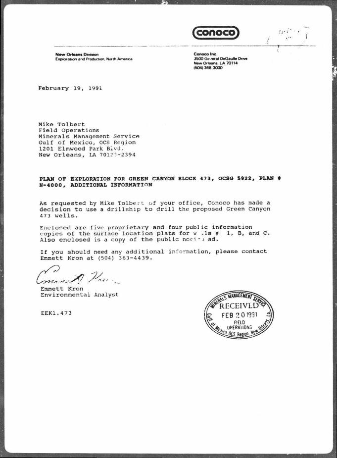
As r e q u e s t e d by Mike T o l b e r t , o f your o f f i c e , Conoco has made a d e c i s i o n t o use a d r i l l s h i p t o d r i l l the proposed Green Canyon 473 w e l l s .
E n c l o s e d are f i v e p r o p r i e t a r y and f o u r p u b l i c i n f o r m a t i o n c o p i e s o f t he sur face l o c a t i o n p l a t s f o r w ..Is # 1 , B, and C. A l s o e n c l o s e d i s a copy o f t h e p u b l i c n o v s - j ad .
I f you s h o u l d need any a d d i t i o n a l i n f o n n a t i o n , p lease c o n t a c t Emmett Kron a t (504) 363-4439.
Emmett K r o n E n v i r o n m e n t a l Analyst
EEK1.473

I n Reply Refer To: MS 5231 February 27. 1991
Conoco Inc. A t t e n t i o n : Mr. Jay A. Johnsnr 3500 General DeGaulle Dr ive Nev Orleans, Louisiana 70114
Gentlemen: NOTED - KRAMER
Reference is mad* to the f o l l o w i n g plan received February 6, 1991:
Type Plan - I n i t i a l Plan o f Exp lo ra t i on Lease - OCS-G 5922 Block - 4~'3 Area - Green Canyon A c t i v i t i e s Proposed - Wells A, B, and -J
I n accordance w i t h 30 CFR 250.33, t h i s p lan i s hereby deemed submitted and i s now being considet d f o r approval.
Your control number i s N-4000 and should be referenced i n your communication and correspondence concerning t h i s p l a n .
S incere ly
3m D. J . Bourgeois Regional Supervisor F i e l d Operations
bcc : Lease OCS-G 59.2 POD F i l e (MS 5032) IMS 5034 w / p u b l i c i n f o , copy of the p lan | and accomp. i n f o .
MTolber t : cck :02 /25 /91 : POEC0M
IB.W OU BZ834
(conoco)
New Orleans DrviMon E «p*oration and Pfoducnon. North A n w tea
Conoco Inc. 3500 Ge.«rai DeGaulte Drive New Orleans LA 70114 (504)368 3000
F e b r u a r y 1 9 , 1991
M i k e T o l b e r t F i e l d O p e r a t i o n s M i n e r a l s Management S e r v i c e G u l f o f M e x i c o , OCS R e g i o n 1201 E l m w o o d Park B l v d . New O r l e a n s , LA 70123-2394
PLAN OF EXPLORATION FOR GREEN CANYON BLOCK 47 3 , OC8G 5922 , PLAN # N-4000 , ADDITIONAL INFORMATION
As r e q u e s t e d by Mike T o l b e r t o f y o u r o f f i c e , Conoco has made a d e c i s i o n t o use a d r i l l s h i p t o d r i l l t h e p r o p o s e d G r e e n Canyon 473 w e l l s .
E n c l o s e d a r e f i v e p r o p r i e t a r y a n d f o u r p u b l i c i n f o r m a t i o n c o p i e s o f t h e s u r f a c e l o c a t i o n p l a t s f o r w L I S # 1 , B , and C . A l s o e n c l o s e d i s a c o p y o f t h e p u b l i c nc\- i - J a d .
I f y o u s h o u l d need any a d d i t i o n a l i n f o r m a t i o n , p l e a s e c o n t a c t Emmet t K r o n a t (504) 3 6 3 - 4 4 3 9 .
Emmet t K r o n E n v i r o n m e n t a l A n a l y s t
E E K 1 . 4 7 3

4550'-
CONOCO G.C. BLOCK 473
OCS-G S922
WELL #1 3HL
SURFACE LOCATION #1 7100* FSL & 4550' FWL OF G.C. BLOCK 473
472 A73
PROPOSED LOCATION PLAT
GREEN CANYON BLOCK 473 AREA SREEN CANYON BLOCK 473
<VELL No. 1
SCALE; 1" - 2000*
APPROVED: SCA bgd
CONOCO Inc. N o . GC473-.L 32/18/91

472 473
WELL Q CM 3HL
4O0*
SURFACE LOCATION B 2400' FNL Jr. 400* FWL OF G.C BLOCK 473
CONOCO G.C. BLOCK 473
OCS-G 5922
PROPOSED LOCATION PLAT
iREEN CANYON BLOCK 473 AREA 3REEN CANYON BLOCK 4~3
i B l i No. a SCALE: 1" - 2000*
APPROVED: EEK bqd
CONOCO Inc. N o . GC473-2L 02/18/91

6750'-
C 0 N 0 C 0 G.C. SLOCK 4 7 3
OC S- G 5 9 2 2
^ 1
WELL C O 3HL
SURFACE LOCATION C 4950' FSL fc 6750* FWL :F G C. BLOCK •*73
472 473
PROPOSED .OCATION PLAT
iREEN CANYON BLOCK 473 AREA 3REEN CAf4YON BLOCK 473
AELL NO. C
SCALE: 1" - 2000*
APPROVED: EEK bg<
CONOCO Inc. N o . GC473-3L 02 /18 /91

(conoco)
N w O r m M O M U M g o J M M and Proaueucn. Monti America
Conoco Inc 3500 General DeGautte Dnve New Orlaana. LA 70114 (5041368-3000
February 4,1991
The State Times Legal Ad Oepartment Baton Rouge. LA 70804
RE: REQUEST FOR PUBUC NOTICE - GREEN CA. I'ON BLOCK 473
Please publish the attached public notice as a legal ad on February 22,1 and proof of publication to my attention at the above address.
Should you have any questions, please call me at (504) 363-4439.
Thank you.
Emmett E. Kron Environmental Analyst
EEK 4 IOC.bib

PUBLIC NOTICE
Public Notice of Federal Consistency Review of a Proposed Exploratory Plan by the Coastal Management Section/Louisiana Department of Natural Resources for the plan's consistency with the Louisiana Coastal Resources Program.
Applicant: Conoco Inc. 3500 General DeGaulle Drive New Orleans, Louisiana 70114
Location: Green Canyon Blk 473 OCS-G 5922
Lease Effective Date: July 1, 1983
Description: Proposed exploratory plans for the above area provide for exploration for oil & gas. Exploration activities will include drilling from a semi-submersible or dynamically stationed drillship and transport of drilling crew and equipment by helicopter and/or cargo vessel from onshore bases located at Louisiana. No ecologically sensitive species or habitats are expected to be affected by these activities.
A copy the p'an described above is available for inspection at the Coastal Management Section Office located on the 10th Floor of the State Lands and Natural Resources Building, 625 North 4th Street. Baton P.ouge. Louisiana. Office Hours: 8 AM to 4:30 PM. Monday through Friday. The public is requested to submit comments to the Coastal Management Section Attention OCS Plans. P. O. Box 44396, Baton Rouge, LA 70804. Comments must be received within 15 days of the date of this notice or 15 days after the Coastal Management Section obtains a copy of the plan and it is available for public inspection. This public notice is provided to meet the requirements of the NOAA Regulations on Federal Consistency with approved Coastal Management Programs.

conoco)
N e w O r l e a n s D iv is ion Exploration and Productmn. Nor in America
Conoco Inc. 3500 General OeGeuMe Drive Naw Orleans LA 70114 ib04) 368 3000
February 1. 1991
Regional Supervisor Field Operations F0-2-1 Minerals Management Service ^ ^ s = x — > = z ^ ^ Gulf of Mexico. OCS Region 1201 Elmwood Park Blvd. New Orleans. LA 70123-2394
INITIAL PLAN OF EXPLORATION FOR GREEN CANYON BLOCK 473, OCS-G 5922
Conoco Inc. submits the enclosed Plan of Exploration for the Green Canyon Block 473
Enclosed are five proprietary and four public information copies of the plan, each including copies of the environmental report prepared for the area. Also enclosed are three copies of the shallow hazard study (Hign Resolution Geophysical Survey Report) and one set of the high resolution line data for the proposed wolls.
Please direct any questions to Emmett Kron at (504) 363-4439 or Bill Ibarra at (504) 363 4390.
Jay^AJohnsor, Coordinator - Environmental Affairs & Regulatory Compliance
cEK 4 lOC:blb

INITIAL PLAN OF EXPLORATION
GULF OF MEXICO GREEN CANYON AREA BLOCK 473 OCS-G 5922
PUBLIC INFORMATION COPY
CONOCO INC. 3500 GENERAL DEGAULLE DR.
NEW ORLEANS. LA 70114
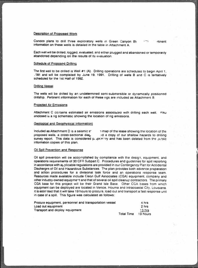
Description of Proposed Work
Conoco plans to drill three exploratory wells in Green Canyon Bh • "3 rtinent information on these wells is detailed in the table in Attachment A.
Each well will be drilled, logged, evaluated, ana either plugged and abandoned or temporarily abandoned depending on the results of its evaluation
Schedule of Proposed Drillinq
The first well to be drilled is Well #1 (A). Drilling operations are scheduled to begin April 1. .091 and will be completed by June 19. 1991. Drilling of wells B and C <s tentatively scheduled for the 1st Half of 1992.
Drillinq Vessel
The wells will be drilled by an undetermined semi-submersible or dynamically positioned drillship. Pertinent information for each of these rigs are included as Attachment B
Projected Air Emissions
Attachment C contains estimated air emissions associated with dulling each well. &fftu enclosed is a rig schematic showing the location of rig emissions.
Geological and Geophysical Information)
Included as Attachment D is a seismic s* -) map of the lease showing the location ot the proposed weiis, a cross-sectional aiac, .id a copy ot our shallow hazards to drilling survey report. This data is considered p. jpr;s* 'ry and has been deleted from the public information copies o< this plan.
Oil Spill Prevention and Response
Oil spill prevention will oe accomplished by compliance with the design, equipment, and operations requirements of 30 CFR Subpart C. Procedures and guidelines for spill reporting in accordance with applicable regulations are provided in our Contingency Plan tor Accidental Discharges of Oil and Hazardous Substances. The plan provides both advance preparation and action procedures for a divisional task force and an operations response team. Resources made available include Clean Gulf Associates (CGA) equipment, company and other industry-owned equipment and that of several oil spill cleanup contractors The primary CGA base for this project will be their Grand isle Base Other CGA bases from which equipment can be deployed are located in Venice. Houma and Intracoastal City. Louisiana. It is estirr-ited that it will take 19 hours to procure, load out and transport a fast response unit in case of a spill. This figure was calculated as follows:
Procure equipment, personnel and transportation vessel 4 hrs Load out equipment 2 hrs Transport and deploy equipment 13 hrs
Total Time 19 hours

An on soni trajectory analysis FS inducted m attacnment E.
General Information
The lease is locatec approximatory l12 miles south of the Louisiana coa«>t of the area is included as Attachment F. Operations will be conduced f*or- cr.."'Gc.'s shore base at Grano Isle. Louisiana a"d Martin Fuel DOCK in curcr.on. uouisiana. T'c -.«w shore bases will be built or expanded nor additional base employees r.ired as a lesuri 9! «ho*i operations.
'.ease StipMayons
OCS-G 5922. is a j * ; ;»ct to leji3e. stipulations No 1 and No 4 Stipulation No. 1 • Cultural Resources. The Regional Supervisor has not invoked the ccvis 'on? •» ;his stipulation, if dunng tne conduct of any operations in the lease area, any c u r u i '• ic M ces are discovered, the Supervisor wni t e miormed immediately and every reasc "-ccie atfort will be made to prot<?CT tne cutturai resource.
Stipulation No. 4 • .Yarning Area W-92. As per this stipulation Conoco ;x 1 oanners assumes liability for any miury to personis) n» -ravage to property wmcn c :cui in connection with program.s and activities of the NavJ A.. Sw.cn. New Orleans. Louisiana. Conoco will contact the Commander cf the Naval Aw ~"'»i.on. New Orleans to determine tne level of electromagnetic emissions that will be i.,jwec. if ! :s necessary trot coat or aircraft enter tne warning area Conoco will enter an agreement with Naval Air Station. Nav* C.-ieans pi. or to commencing such traffic.
LJaste Ciscnarqe and Qisposa.'
Each well will be drilled witn wi t r t jase drilling mud only Water oasey rr id and cuit:n ;-• wn. be oiscnargrd at the drill site n accordance with the U.S. EPYH 01 ;jr.?n*: -rotecti" 1 Aoenc. NPDES General Permit No. GMG 28QO0O. It is estimated na', ar , ,• if 8(\A» ol: . ot .vater case rt?i.,d snd 3800 bbls ot cuttings wm be aiscn.irgu ; fr-i i ». • ' he di.-ch.irge -ate 01. <a >aa drilling muus ana an- cuttings v ~zi exce. . CO'J * 21: hour as per iPA reau- fCert f j . . list of drilling mud c impanents ana additives mat R « ' Q* - s.ed is included as / Uutf. - - i t G.
>-iyo a p i Sulfide Determination
bc Kf j on the available data for Green Canyon Blcck** 473. C^r JCO has determined the j f , >s to be penetrated as zones wnere the aosenoe of H.S has oeen confirmed. This j . tr .inination is based on the review of drilling data '.or well #1 in GC 472. Drilling data for wete in GC 301. 254. 167 were aiso reviewed.
New Technology
No new or unusual technology will be used to he proposed wens
Consistency Certification
included as Attachment H is a C jastal Zone Management Ccnsistencv Certifcation for the

S'jfri Tt Louisiana.
Environmental Repon
Nina copi« of an e ivironmental report prepare far tne exptort toi j ancto* d attacnment t.
EEK 4 lOC:blb


Ran of Exploration h \ f c 'nforrnaflon Copy
Green Canyon Block 473 EXh- .ORATORY WELL INFORMATION
Total Depth Water
Wefl Name Surface Location TVD Pactf*
Well 1 (A) 7100' . S L & 4550' FWL 15.000 3,870'
WellB 2400' FNL & 400' FWL 14.500' 3.S*.T
Well C 4950' FSL & 6750' FWL 15,000' ; 890'

Plan Q* 5xp|oration Green Canyon Block 473
ATTACHMENT B
RIG DATA

DYNAMICALLY STATIONED DRILLSHIP
SEDCO 472
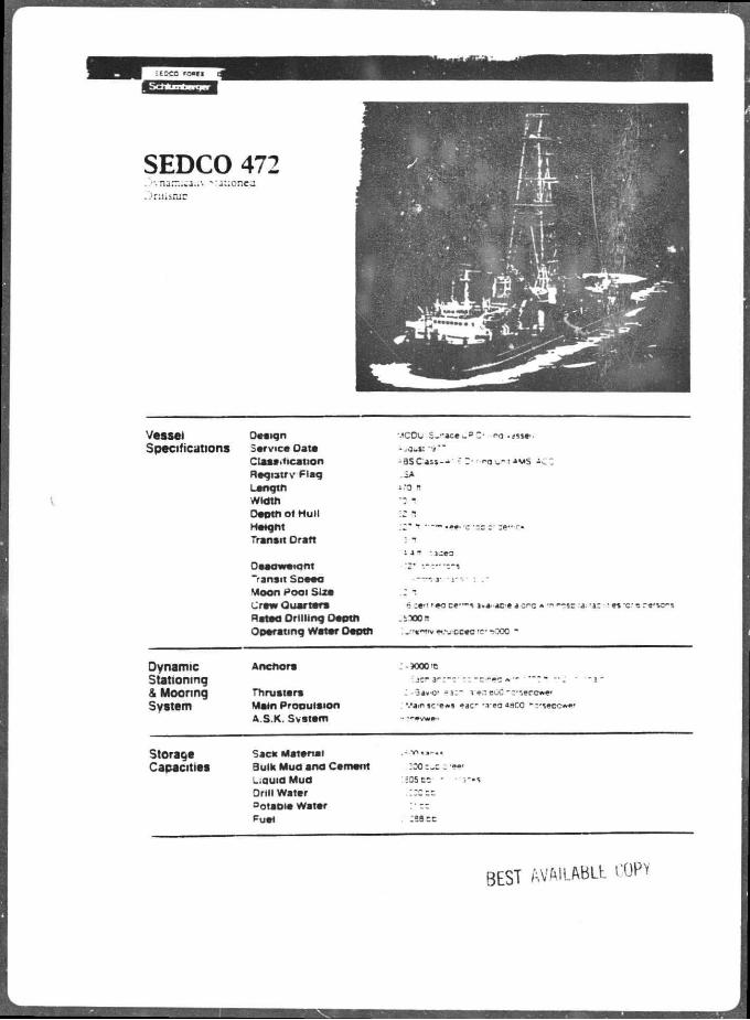
SEDCO 472 ..-• narr.;cau\ vauonea ..'ruisruc
V e s s e l O e a i g n MCOl. S . - » c e ^ s Z - no .<«»••.
S p e c i f i c a t i o n s S e r v i c e O a t e - ,gus: C ;as !» . i i ca t i on - 3 S C a s s - - ' 5 Z- r o . - t ^ M S i ^ . :
R e g i s t r y F l a g L a n q t n i.-O !t
W i d t h •3 1 D e p t h o f H u l l
Height r •-— .ee- 'c m-.z :• ZVT*
Trans i t O r a t t - ueo
O e i o w e i a n t
~rans i t S O M A . — u ' - i - - . - : . -
M o o n P o o l S U e ; ~. - r e w Q u a r t e r s 6 ; e - ' ' «o ce"-% i>« <c e a crc * — >--sr -a- - a : '• es 'C 5 re -vc*-»
R a t e d D r i l l i n g D e p t h .iTOOn
O p e r a t i n q W a t e r O e o t n
Dynamic A n c h o r s :-90cc<e
Stationing & M o o r i n g T h r u a t a r s - -•3*vO' - 1 : ~ T M eOC-:--,ercv»e'
System M a t n P r o D u i a i o n ' . ' a m j c f * ) e j c - -veaaaco N5*S»OCwe< System A S K. S v s t e m - •"•/*»"
Storage S a c k M a t e r i a l
Capacities B u l k M u d a n o C e m e n t ~ZQ : «»•
L i a u i d M u d Dr i l l W a t e r : : c : : s o t a D i a W a t a r
:• — PUSH
BEST ftVWLABLt COPV
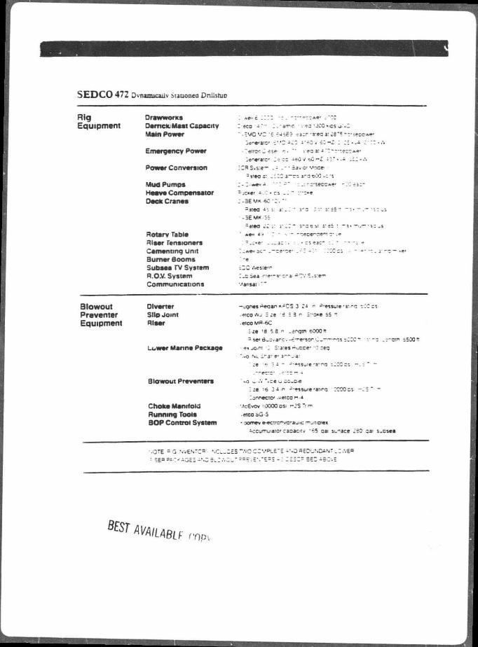
S E D C O 472 Dynamically Mauonca Onilsruo
Rig OrawworKs i «a»t : • -c*t"cs-«a» .""C
Equipment Derrick Mast Capacity I sco - * • ' I . -arwc ' r . t a 'J00"JCSij>'<C
Main Power • -5M0MC "6 •EJ-je? ?acr -3:*s a: i S " ? - r s e c e - * * ' janarsio' £ ' . ' 2 a i j i " - 0 « c 3 - £ : I ; - - A c' - 3 • .'•
Emergency Power i*«era!C' _ - -eO «sC 1 1 " « i i i • A
Power Conversion :33S.s:e— - i • savor Voce
- j i e o a : I T : r a e O C c i
Mud Pumps I-C-ix*"•* - . . - : - secc»e- - X e a c
Heave Compensator - ;c«tr •» : • cs " :••-•«
Deck Cranes ; - 3 E 60 • : . ••
= atea a: . . • i"3 JV i : • ~ " l • — - — ' iC _S -3E M K j :
3 «taa 11 . i .3 ~ J - : D Y. J : i i : •"»> —uf~-j3 _&
Rotary Tabla *•>• *'-J •• :r»ce"^e*" .»
Riaar renaionars - . ; - e - ac : . : • cs eac- -
Cementing Unit : .*«•• sc- .-ze-ze- .-2 - ' : ::cocs ••• - a - - - «•?•
S u m t r Booms *« Subaaa r v System £20 rVesiem
R.O.V. System I . csea ne * " v era -CVS.s:e**<
Communicati ons "•••r i ia i
Blowout Diverter -iuonee Aeoan «FCS 3 * 4 ° ^'assure »»w"0 sCOcji
Preventer Silo Joint •4ICOWJ : ;e "d ! 3 n S:-o«e i s "
Equipment meat .ateoMfl-eC I « 'd 5 a " - j r q t n fcOOO" 3 serB-car-c-c-^e'sor-C-———~.i-ZZC~ r - 3 .e-etn sSOOfl
war Manna Package • a«jOJW '2 S :a :« i - i . cce- • : :«a '.»o NL Srare* a — . a:
:e rj 3 a i- -••ssu'e 'S-HQ : ; C C C S ~ . S " • -
. — e c - : - .**cs — -»
Blowout Preventers " vo C-'V*«ceu -o-c-e '. :e '© 3 a n - • •s jK/e 'aura :C30 cs -3S "• — lonnectc* -vetco n-4
Choke Manifold Mc£vOv ' 0000 os> - JS Tl m
Running Too la •atcoau-5
BOP Control System - Domev •••ctrcf vc' iui ic munrom
tceuniuiaiorcaoaeitv '63 cai s_-ace £20 cai s.csaa
••OTE = Q NV6N7CR' ' . C . ; £ 5 " f tQ C C ' . " 5 ' . : ' : - " -0 agOUNOANT . 3 .VE«>
: SEP^C'AQSS -"-3
BEST AVAILABLE nm

'•ZP 28 -96 13.41
3SDC0 4 72 MEMO
TC: 5.EDCO 70REX - uET Attn: Oary Low*. Tary Leacn EROM: D r i l l i n g E n g l n s e r . Sad Corbatt DATE. 23 September 1986 SUBJECT ^ueetlone on Diverter ? lpo . Squlpment.Procedure
BENDS & SEHD RADIOS: There are 2 eacn 20 dec eibowe. and 4 eacn 45 dec aibcwe .r. -ne - i n x i a -tern jverboarrt 12"* piping run. A l l sibowa are !3" bend redluetlona radiue pipe f t g a ) . The 23 decree bende are forward of the pipe raokar . routing pipe up and under I t . The dec *.urna are aft of the pipe racker routing the pipe down ana port to the machine ahop/warenouae s e o t l o n l t s s tern diacharce uelow the heii-deos)
12" "IPIMG SPECIFICATIONS: Mltaui DUG "0105OOB. ?mf»414. Piping Schematic: L iquid Bud h ^•aant Syatem. C12"llne rune f i v e n by LK*)
Material.Carbon e t c e i J I 8 G3464 STPQ 38. Nominal 12". 300mm
LM5 . LM6. LM7 . LM9 : 318.5am0D x 10.3mm thk. ( 12.54*0D x 0. •iOS"«ell) Sch 40(etd) aala blk pipe(equiv ASTM A53)(I3fe) Barlow a C a l c . min curat( 54kei) a 3488 pei Z"t
C a l c . mln y i e l d O l k e i ) a 2002 pal ~ LMB(warehouse): 318.5mmOD x 17.4mm thk.(12.54"0D x 0 . 6 8 5 " w « l l )
Sob 60(xai enla b lkCBfe) Barlow's Calo. uin t>uret( 5 4kel) - *96t> pat
Calc . -nin / i e l d ( 31kai) = 3387 r a i
VALVE SPEC IF1 CAT I OMB: FHC-WKC0 Automated S l i d i n g Gate Line B l i n d Valve SIZE 12~. Modal BOLB15. CH? 288. Flanged ANSI 1S0» Aeey * 3217818 1 vslvee t o t a l uemd f o r T r i p Tank. Overboard. Shaker poeitione.
CONTROL/1NSTBOWINT ATI ON LOGIC 4 SCHEMATIC; Eaoh cf the three 12" gate valvea can te cpened -nd = *-o««* . --are-centiv. -nd In my ~omblnstion. v/drauilo centre-c -.ay _e activated nenuall/ from the eubitruciure uiverter panel -r. the smcaanlne lack *r... or remotely at the drill floor panel. Valve poaition le verified on the l«=al pane* <Vf separate open and close proximity a v i t c h / l i g h t indicetore for saon valve.
When diverter le c loee from the d r i l l f l o o r e l e c t r i c panel, the ' I ; " ; t r i p >g*fc valvee ere eet to cloee and the overoomrd valve if aat to open.
See attached layout end a m p l i f i e d acnaaat i ca attecned.
8 F c ; RVWLABLt COPV

_ i ^ M g s s a t , C - M » / T ^ j e ^ k L f r ^ c - - f c r f —
:: 1 "" !-4r-—
" 7 " ; ' . ' ' - i t r—.—j -, t 4 "
-3773-
; ccosc : « u •-1 —
! • * * I 1 ! 1 , 1 I • I aPc«* , v
n l i P r rq»j |<.
. L
spca dyLMkaaC
3 FCH
: i u. .
II .
i
; 1 i ;
| L i 1 1
1 i... ; i
• i
I r! T i *• i" • '

, W W
axoAt^Maur -T^ixjiTtTtrs. CONTROL.
3 - I f 41 P
H I! ^ 1
i H l U . FlxoC. BJSCTCiU
ttri l b.

s
>
f ^ \ . \
,</! if; i '?• * * * * * *
.5/ I f ; ! I'" '
BEST AVAILABLE COPY

7 « w l i l l i - i a g £ j = i . r : ^ T g
; i3d
S KT AVA/l/\BLf: copy
su i ; r.

WKLLHKAO SONNKCTOM
S E D C O 472 BLOWOUT PREVENTER ARRANGEMENT
16 3 / 4 10 .000PSI S T A C K
- C I I -
SEST AVAILABLE COPY

SEMI-SUBMERSIBLE VESSEL
SOVEREIGN EXPLORER

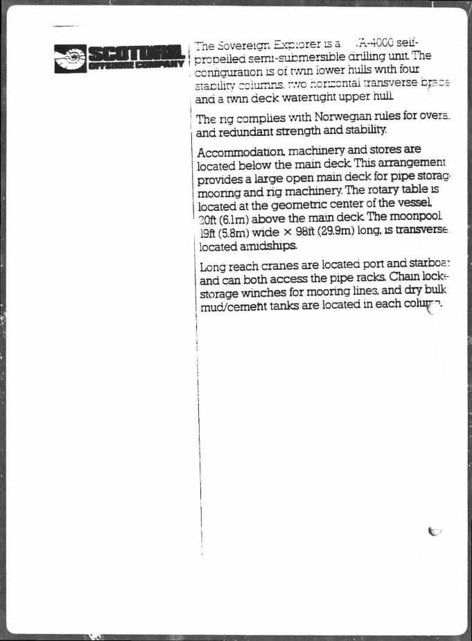
Tne Sovereign Explorer is a .'A-40C0 seii-prcpeiied serm-submersible ariiing unit The ccnngurauon is oi rwin iower hulls with four sicibility columns, r.vc honzontal transverse bpce and a twin deck waterught upper hull
The ng compiles with Norwegian rules for overa. and redundant strength and stability.
Accommodation machinery and stores are located below the main deck This arrangement provides a large open main deck for pipe storag-moonng and rig machinery. The rotary table is located at the geometnc center of the vessel 20ft (6.1m) above the main deck The moonpooi 19ft (5.8m) wide x 98ft (29.9m) long, is transverse located amidships Long reach cranes are located port and starboa: and can both access the pipe racks Chain lock-storage winches for mooring linea and dry bulk mud/cemeht tanks are located in each colu+r

Commending Officer (dd) 1440 Canal Street U.S. Coast Guam New Orleans, LA 70112-2711 Marine Safety O'flce (504 ) 589-6273
16710/SOVEREIGN EXPLORER Issued: 6 Deceooer 1989 Expires: 6 December 1990
LETTER OF COMPLIANCE
FOREIGN MOBILE OFFSHORE DRILLING UNIT
MOOU SOVEREIGN EXPLORER. I.D. NO. 705461; BRITISH REGISTRY! GROSS TONS 18.708; BUILT IN 15*84
Owner: Scotdrlll Offshore Company 901 Threadneedle, Suit* 106 Houston, TX 77079-2902
The MOOU SOVEREIGN EXPLORER has been Inspected 1n accordance with 33 CFR 140.102. 143.207(c), ind 146.205(c). and found to be 1n compliance with the design end equipment standards for MOOUs contained 1n the IMO Code for Corstructlon end Equipment of MOOUs (IMO Assembly Resolution A.414(XI) and the operating i-equlrements ef 4* CFR 108.
MINIMUM NUMBER OF LIFEBQATWEN REQUIRED: 6
MAXIMUM NUMBER OF PERSONS ALLOWED: 100
DATE DRY90CKED: 26 March 1984
All ' "eboits will be reoulred to be weight tested at the next renewal of your (.etter of Compliance.
This Letter of Compliance 1s viHd only for operations on the Outer Continental Shelf of the United States and so long as tha vessel 1s maintained In accordance with the standards applied et the time of Issuance. The requirements of 33 CFR 155 and 33 CFS 156 are currently being cooejHed with. If the vessel enters United States ports, terrltorlel waters, or the contiguous zone additional requirements may apol.".
This Letter of Compliance 1s velld fcr one year after the date of Issue cr until the vessel departs the Outer Continental Shelf for foreign operations, whichever occurs f irst . Tt shall be posted under glass 1n the pilothouse, control csnter, or other suitable location tnd must be surrendered to the U.S. Coast Guaro upon expiration or upon departure from the United States OCS for foreign operations.
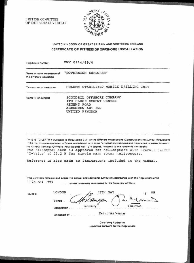
BRITISH COMMITTEE OF DET NORSKE VERITAS
J N I T E D K I N G D O M OP G R E A T BRITA IN ANO N O R T H E R N I R E L A N D
CERTIFICATE OF FITNESS OF OFFSHORE INSTALLATION
Cert i f ica te NumDer D N V 0 1 1 4 / 8 9 / 0
N . m e o ' o t n r W o n o t "SOVEREIGN EXPLORER" tnt> offshore installation
Cescr.ot.on or installation COLUMN STABILIZED MOBILE DRILLING UNIT
Nameis l of ownertll SCOTDRIL OFFSHORE COMPANY 4TH FLOOR REGENT CENTRE REGENT ROAD ABERDEEN AB1 2NS UNITED KINGDOM
" W I S iS TQ CERTIFY pursuant t o Regu la t ion 9 i l ) of t h t Offsnora instal lat ions (Construct ion and Sufvavi Regulations
3 71 rwj t : -e joove-cescnoea o f f s h o r t ins ta l la t ion is f i t to o t ' es tao l i sn td /s ta t ion td ana mamta in to m waters t o »vnicn
- e M ine r j i .vormngs iOff<nore Ins ta l la t ions! A c t 1971 aooiits. ' - .uoiect to t n t fo l low ing l imitat ions:
7.u.o nei icoptex deck i j approved f o r r . e i i c o p t e r s w i t h o v e r a l l Ler.ctr. ' D-Vaiue ' of 22.2 M f o r s i n g l e naan r o t o r h e l i c c o t e r s .
Reference i s a l s o made t o l i m i t a t i o n s i n c l u d e d i n the Manual.
THt l Certificate remains val id sub)act t o annual and addit ional surveys m accordance w i t n t n t Regulations un t i l
• 1 ~»u v iv '994 _ u n i t s * p r tv ious iv t t rm ina t t d bv 0>t Secretary of State.
LONDON
Signed
Designation .
On benaif o f
:2TH MAY
Secretary — ' Chairman
Det norsJce Ventas
Cert i fy ing A u t h o r i t y
aoDomtea our sua nt t o tne Regulations

• J L S - REPORT ON ' S f f ' MAJOR SURVEY FOR RECERTIFICATION
DETNORSKE FOR CERTIFICATE OF FITNESS U.K.
VERITAS Under the provisions of t h e
Tho Offshore ins ta l la t ions (Construct ion and Survey ! Regulat ions 1974 STATUTORY INSTRUMENT 1974 No. 289
-orm No S '3a
- • m a s 3 NO
Name or »«J ' . j 'apn—t> ana
o* Raqatjw - " O * No or
133'S* I R T I S H / ' 1
-as a scneouie of insoectton and tests oeen arewn uo' I2.JJ
-avo Damcuiars of destructive ana non-aestructrve testing, •-eauencv or circumstances in wntcn tne •ests snouw oa made oeen agreed uoon> '2.21.
Have me oertormtt ana organisations concemea witn testing satisfactory comea'anee' *2..2i
i r e rne results of tne tests satisfactory? '2.JJ.
-ave cooies of ail test reoorts oeen retained' 2 2:
-ave f 3ooroortatt 'ecorcs of service nistor. mctuding cas. esons test certificates carnage ana •oairs 'eoons or nsoections ana tests cameo out cv Cwners -eoresentatives. tne use ana nter-
cretation of any instruments installed to monitor structural oenaviour. vvatertignt ntegnty •cunaation ronaitions ana anv otner oata factors relevant to tne continued safetv or tne ng. ana any ctr.er cata e<ative to :ne condition of :ne ng ana its oenaviour m service oeen scrutinized ; 2 2.'
-ave tne tests oeen monitored, soot eneexs oeen maae ana confirmatory tests oeen maae to an extent luageo necessary; _ ,
3. - re tne results of tne scrutiny mentionea aoove acceotaole , 2 2)
3 -as tne maror survey oeen earned out at a suitaote location arefereotv m a arv a OCK or alongside a . _ sniovara or otnameee >n sneiterea waters ; '2 2.2! "5>vfiiJf ero r-ATf a_j , ^
'C -as it oeen ensured ov examination mat any aeiencration of me onmarv structure is witnm acceota- - f
aie limits''2.3.31
zentmuma • • » • * '
;tempi wnmrw soacimttv mtnnonma. a// 'erermnan rarer to Part i. Section 2 of tnm *Qffshorm institutions juiamnce on amor ana Construction*.
COPY OF THIS j > w ^ i » C ( i o f f ^ f x i C J
zr :r-m ah* i • to *w«n;a
BEST AVAILABLE COPY-- , l3$+J,\* . 'ar rr— Omi in no—mmm to ^ C a r ^ a n w

- a * it seen ensurea ov examination tnat tne secondary structure anc fitting* concerned wnn tne sa-•?tv of tne ng ana tne safety ot oersonnet are m sound conation' '2.3-31.
2 - J S it oeen ensured ov eKamination tnat an ti»ea eauioment comones witn me 'eauirements set out in " te Guidance Note Part u. Section 3 IAU fixed eauiomenti Pan in <&<trrn;- - jratus ana conauctc-s/ •~a Pan iV Mecnamcai eduiomenti <exceot tnase of the lifting aoc»ances/' '2.3.2! .
' 3 -*as it oeen ensured ov examination tnat servicing ana maintenance record* are satisfactory' 2 2.2).
" - - a * it Oeen ensured, as far as reesoneorv orecttcai tnat no significant alteration na* oeen maae tnat -aa not oeen notified to tne Certifying Autnontv ;
;a. - a * reoorts oeen presented stating tnat tne 6-montnty surveys of iftmg aoo»ances tn accordance witn SI 1019 nave oeen cameo out witn satisfactory result ov a .competent, raeoenoentx ooov or =erson witmn tne "est o montn*? 0*<i-~5 * \ w * » m \ , . ; w « 4 . e ^ m o v t r f i O * .
UK. rvxs-r««0'
'5b- if the answer to '5a is «nor "as it Oeen ensured Ov examination tnat tne structure ana fitt ing* ot the • rung aooaance* are m so una conaitian. ana mat tne lifting aoonances mecnentcat ana etectncai eau-;men i ana installations nave oeen mamtainea to a satisfactory stanaara-' <2-3.-»>- .

HOU 131
BRITISH COMMITTEE OF DET NORSKE VERITAS
n auoiicate VO. 243A
CARGO SHIP SAFETY CONSTRUCTION CERTIFICATE
UNITED KINGDOM OF GREAT BRITAIN ANO NORTHERN IRELAND
issued unoer tne Drovisions of trie
IMTERNATIONAL CC^WE^JT10^I FOR THE SAFETY OF LIFE AT SEA. :974
N a m e * Snag | Ot tawa* N u m e r F a n Of Rag w r y | G r o t * Tanwaaj Oat t on M R I O I ket t M M I M
| ia» NOTE 1 M o >
SOVEREIGN EXPLORER , 705461/GOJZ LONDON '8708 j 11.8!
This is to certify
Dr i l l i ng Vessel
Thtt t n t aoove-mentionta »JQ» has oetn auiv surveyed in accordance witn tht provisions ot Regulation 10 of CMaoter I c the Convention r t t t r r td to »oove. ana that th t survey snowed that tht conaition of tht hull machinery ana eauioment 3
:ef mea m tne aoove Regulation «as in ail rtsoects satisfactory ana that tne M B complied witn tne aooncaoie reouiremen-j t Chaoter n-1 and Chaoter I I 2 iotner than tnat relating to fire-cxtinguisning aoonancts ana fir* control oiansi
' T I S cert. t 1 Catt n issued under tne authority ot the Government of the United Kingdom of Great Britain end feethem Ireland.
I ww remain .n force, uniess previoustv cancelled, jnta tne ~ r < *
tsueaat L o n d o n tne ? * 5 3 , v of ... 'S ? ° ...
DETNOPSKE VERITi
The undersigned declares mat tnt B rrt itn Committee of Det noma Veritas s dulv authorized ov tne Deoanmtnt ot TraOe t i IUUC this certificate

BRITISH COMMITTEE OF DET NORSKE VERITAS
ATTACHMENT TO THE CARGO SHIP SAFETY CONSTRUCTION CERTIFICAT
UNITED KINGDOM OF GREAT BRITAIN AND NORTHERN IRELAND
ssueo under t r e orev is ions o f the
PROTOCOL OF 1978 RELATING TO THE INTERNATIONAL CONVENTION FOR THE SAFETY OF LIFE AT SEA. 1974
N a m . * She Ooaa Tonneee ^ I
SOVEREIGN EXPLORER 705461/GDJZ 18708 04.84
- - o i r ^ c n i i t i o n ot Woquieuoo elbi of Chaoter • of t-w Protoc m i m g to tne ir.t«m»twnji Convention for the Safety of u.'e at
'974 m« Government of tne urn too Hmgoom of Grttrt o r i . . • • . j m u m iroieno net mstnuteo Menoetorv annual aunrtnrs
Tha i n n i v i r i a r t oata far tha auipeaa o t mawoetorv •-nrwel eurvev 3 r d Mav
~>-e survav •» to M camad out t 3 montna f rom t ra anniversary oatei. R a n g e : 3 r d F e b r u a r y - 3 r d A u g u s t
Th«a is t o cer t i f y mat tn* snio nas oeen surveveo •« icccroance w-tn Regulation 6 o- of Cnaoter • of *ne ?»otocoi of '978 Relating ot the -ternationai Convention for the Se'etv o» L>fe at f ea 374 ana me aooroonaie provisions of 'MCC ae-so<ui.on A a 13 letl as arnenoeo ov
aeso«ution A 465 <•»•
st Mandatory annuai survey Sgneo
»ece
2ate
1 -n "vtanoator' annual survev i>gneo
"ace
rate
~ " u * i Purvey . 3 "eO 3 e c e
: * t e
V a n a . u * survev S.gnea
"ace
2ate
DET NORSKE ( I v ^ ^ ^ ^ ^T/yLO^^J" VERITAS
3th 3 a v 0 , ."arc-
">e unoaratgneo oeciaree mat me Bntisn Commmee of Det - e r n e Veritas
s ouiv eutnanzeo ov tne Oepartment of T ' i a « to tsue tna Attacnment.
•'SOVEREIGN EXPLORER"
Pare I V - BOP C o n f i g u r a t i o n
A-94-L8
9001007.EXG Page 6 o f 8

"!SES iGAPTE??
• CP CF -_zx ~C;NT
2.1'
4 jPPER ANNULAR
-t >.OWER ANNULAR
13*
- j jPPER CCNNECTOR
"CP CF SHEAR RAM
- J — "CP CF VBR
*.65'
2
f
"CP C" 3 IPE SAM
Z? C r 5 IPE =AM
:CNNECTOR
! — X S X >
->o<:-
N.L SHAFFER 3-3. ' - '5,000 PSI r.C.P.
HF.ST AVAILABLE COPY
SCQTDRIL arrsaoRi COMPANY
SOVEREIGN EXPLORER
20P CCNfiGURATICN
OATE
:RAWN
' S.3U°.NS
8 JUL 39
CHECKED -P3ROVED SCALE
NONE
DRAWING NUMBER
A-94-L8


3WELL -NIT
STANOPIPE MANIFOLD
C X 3 :5.ooo PSI. : i / r CA; ON VALVE
r x :0.000 PSI. 3 i /a r ou JTY VALVE
1*4 13.000 PSl 1 13/16" -AMERON VALVE
3UFFER CHAMBERS
DERRICK VENT
DRAIN
CHOKE UNE
SCOTDRIL •rrSHQIIE COMPANY
SOVEREIGN EXPLORER
CHOKE MANIFOLD DIAGRAM
-RAWING NUMBER 2 £ i
3ATE ] : a JUL 29
"80VEREIGP EXPLORES"
P a r t VT - D i v e r t e r Pipe Arrangement
A-94-L9
9001007.EXG Page 8 of 8

2** RADIUS 9 0 DEGREE SENDS
STARB0AR0 Cr/ERTER LINE 9' ABOVE MAIN CECK „
3IVERTES ' SUPPORTS
• r RADIUS A 5 OECREE 2ENDS I
HYORAUUC i VALVE
" ELEVATION C.-:OP
~L0W UNE
- ~_CW INOICATNG TEMP. TRANSDUCER
*' ELEVATION DROP
"2* STARBOARD DIVERTER UNE
SCOTDRIL
DRAWN CHECKED -PPROVED SCALE DRAWING NUMBER
1 -Y '.S.BURNS
I DATE 18 JUL 69 NONE A-94-L9
SOVEREIGN EXPLORER
DIVERTER PIPE ARRANGEMENT

:-2

Ecfoipnieiit Mooring system ; * KsDOUXB purpose cieagnea ccrncinaoor. "racoon winca wtricttass ana storage reei ior : em :sm.Tii ana im iTTmm) cnain Stcraae reej :cr wire rope iccaiea in pontoons
Moonaa ct—i wuee mad mmemarm Ancno r i x 12M ton man noioina
ecwer ancnors Thorns 3 x Jm (77mm) K4 chain
£acn lenotfl 3940ft (1200m I
Wne feces - * 3-^ (99mm) Eacn lenotn 6906ft (21C5mi
Chain enasers - Dermaneni cnain erasers
Drilling equipment 60ft (4a 8m) crannam oemot wnn 40ft x 40ft 122a x -2.2ml case, rateaai 1.400.0001b 63SM ton: areas caoaarr
National 162SDE (IMO HP) electric irawwortcs ccmciete witn sua reei. ba vie r 7338 auxiuaxY crane man up ana creax ou: aineaas ana twee 350 HP DC electnc
:notors
S!55CVDvnaDiex :a-ea 454M tons Swivel riaucnai P650
Drill | ISOOOflfTtOOmi -;n: 2Smmi CC Craae
- automatic : arm raciona svstem
• .-net _ i bOO -5." 7 Emi stroice suG dOClt '."ZM '.cr. i capacity
7-aser Rucxct twin nser tenaoner svstem - • .cC'CCClb 7CrM:ori)iensioners.=Cft
: Cm; wire une trave) ?:tai cacae.tv -jO.OOOlc (435M ton. C-Jioeunes r.ucicer o-,60001b(7SMicni 4Cft CCT.I wire ane travel ana coa ur.es
Rotary Saoonaa J 455 4S' in i i2S9mm) rctarv -acie •.-.tn -/.-.ze ce- 3 mi anw with 950 HP CC rsectrtc meter ana rwc soeea aaasnssson
Mndpmsta 1 < National -Z-F- 60 tnciex sir.aie acanc r.ua curxs eacn anven cv -wo -50 HP C 7 .ectr.c meters
- • Magnum cw * -ini iimm * _ J4mm rnaicftns pumps anven cv r.C HP eiecer.e meters Cementing unit Ccweu acruumceroer C ?C 507 vnta 7e mac: Taxer ana uauta accitrve svstem
.1 zz. eater. :anx
BEST AVAILABLE WPY
Mud conditioning equipment Brandt atcie tanuem snaie snaxe: Cemcc ;23 aesanoei •Veico aegaaser •Vetco mud/gas separator Thuie V SM-200 mua cisaner j x Magnum 6m x 6in i i53mm x a 04 mm i rumps anven ov 100 HP <*tectr.c meters
Subsea equipment WOW i | — :8V«u (476mm j 15.000 pa BOP stage ana ewer manne nser pacjeage witn tour iS.000 ea rams ana two 5.000 pa spnencais as le-uows . < Vetco H4 EXF 15.000 pa nvorauiic 'iielllwn nrnrterrr : x 18*un (476mm) NL Shafler tvpe SL 15000 pa acuDle ram preventers 3 x 3*in (79mm) NL Sbafler ctuai iai) sale .mvea 15,000 pa tor emote ana lai! . x I8*un (476rnm) Vefco 1Q000 pa man angie M s M mandrel
wer mannb nser paoeage as toUows . * ir*V«in (476mm) Vetco H-4 10 000 oa man >nate release connector
« i8V»ui (476mm) NL Shaie: aan scnencai - 000 pa preventer . x iBfcun 1476mm) disrates lienoir.t
C30M ton transponer witn test stump irranoea to move BOP stacx Ln venicai ana •ransverse curecnon ••
Operational Hait i
•Vina Operenon Survival 55 knots "0 knot:
Maximum wave neiaru 50ft (I5mi fft (35n •Vi ve penoa 9 seconds
mmm*
\
r 1
s o I J
_;in (535mmi Regan FD8 eauiDpea witn Icil ina cnoKe unes ana nser DOC si unes
• iOm (762mm) Vetco nvarauuc ^tcn :c: .lm 1535mmi nser svstem wttn uexiomi
•enevweii Moaei R5S02 aeeasuc psaoonino -••stem
Accommodation -arconcuaonea for ;00 men in smaie ana r.vc eertn ear ms. incluaes scameus crbce suites •:r Cperator ana Contractor ceraonnei. : ecreauon ana reaaina rooms a-minaaum. --.ema ana nospiiai
Propulsion and power Fr-cuiaon I • 1400 lC'A Kamewa iZimutrunq tnrusters cuaacnauv ecposea Pnme movers 4 < Suston 2 r.KCC eaesei -names rateo at i.800ICWeaen Cmeraencv generator i < Cammms KTC2CC e.esei encrme ratea at 6S0KW
Helicopter deck Icaoonat 83ft (2E3mj across uats wnn rerueuino svstem •i -aippea to acccrnmocate aikorsrv a i -ti
Cranes ; * MAN e«ctro- nvorauiic peoesrai cranes -:5M tons at 66ft (20m) radius or
= M tons at WW f43m) radius
-V- 1
VanabU loeal (M teat Tranar Cnllina .arviv
Cecx 1059 ":302 .302
Cabimns - ::o Pontoons -34 1500 :=u0
Storage CapeaatlM Water Inlling 1840M tons
,craDie 390M tons eallast .4 620Mtons
Mud aaua 1250 fcbls (516m-1 balk .5420 curt (465m-
Cement 7.500 cuft (210m-1
Sac* storage 7.500 sacKS
The Sovereign tjcoiorer 3 cnanerea ov Scciani Offshore Cofflowrry a ecrrroanv ?wnea iO.'SO bv The Dow Chemical Corncanv ana Reacting a« Bates
J:ana Place, fairaeid Avenue iar.es Middlesex TW 18 4SX £nciana Tel (0784)61600 Telex 934626— Reg. No. 2295239 (ESQanc
901 Threaoneeoie Suae 200 Houston Texas 77079. USA TfeL (7131496-5000 Telex 762305
to
I

Sovereign Explorer Deepwater semisubmersible
Key features
BEST AVAfUiBLE COPY
If ' \\
I Cbntmuoa drilling operaaons in me moorea moae in UD ro 1500ft (lC67m; water aeptn, Dnliina aepm uo to .25 300ft (7600ml
I BV«rn (476mm; x ;5.000 pa BOP stacn
I High Dertormance exjtit point ancncr cnaavwrre eomouufun moonna svstem ma Kamewa auiomanc aamuuuna •-Tiruster asnst svstem enanie accurare ana reliable staoomreeomg m aeepwater ana sirring severe weatner ccnaicons
I Srmnallv desrenwn rnaoppg rnvr'n winches Dermit maximum pull on '«ue regardless ot waier aeota ana lengtn outboara Dynamic Dratcaa proviae eorrrroliea payout speea at moonrxj cnain ana mre Conanuous pay-out cf wire arxi cham, lu *ec permanently by a specal nm—La3K
I Long reacn cranes allow efficient wonanc ofsuppry boats capacity SM tons at 14 Ift (43ml
I Sate-of-the-an automatic bndge conrrcL environmental cata momtonna svstem ana aommunicaaons equipme r.i
I Hoffman Manne computer oasea Helm svstem aias m reai-ame assessment ct load, staDuirv moonng. nser environmental ana related operaocnai parameters
I Dec* ana column cavioaa of 4.CO0M :zr. Large storace spaces oeiow aecic ana .r. roiumns

Mateaacfc Principal particulars Charterer Scotdnl Oflsncre
Company
.nancea 11 £64
^'LABLE COPy
Ljencnn overall irvrtudinq r.euaecx 301ft (31 Srr.)
M a c h i n e r y deck
.' idth cverau| less nCBOB] 2SE9tr7&2mi
length a: main aecx 30UI(tL8nj
Width ot main aecx 351.88 <76.8mi
Keei to main aecic ;34.Sft(4l0mi
Pontoons (2) lengw 264.25ft (806m>
Beam i i5f t (16.0m)
Deptn 246ft <7.5ni)
Ope rata— Iran (ODeranr.c ^05ft!24 5mi
Craft I survival: •x 5ft '20 3m
Iran inans;: sTsnrii 4m " -ore arans incuse I mutters Transit sceec crocuisicn asms: - 5 tenets
—gmsnic liSDiacemeni ;17B0M tons
Maximum aniline arrow 35.000ft (7 600m1
Iperauna water aeotn uo to 3500ft (1067m
Classification OotNeokaVesitM Column sariiisea nor: aacincnai rotations ICaas + lA. riELCK.TlFS'DELCRANE-Adcncnai ciass nerancn HELDK Helicooter aecx CRAIVE Cranes CFS Cnllflocr CRL Crulino aemcx EC renodicailv unanenaea

E X H I B I T * C
SCHEDULE C - l DESCRIPTION OF D R I L L I N G V E S S E L
"SOVEREIGN EXPLORER"
n r M l i n a U n i t D M e r i o t i o n
Type
Enhanced GVA-4000 designed by Gotavericen Arendal A.B. semi-sufiaersible d r i l l i n g u n i t , s e l f - p r o p e l l e d . The configuration consists of twin l o v e r h u l l s with four s t a b i l i t y columns, two horizontal transverse braces and t w i n deck watert: ght upper h u l l .
Principal Dimensions
Length, overall width, overall Main deck length Main deck width Depth to main deck Column diameter Pontoon height Pontoon beam Draft, operating displacement
at d r i l l i n g d r a f t Lightship displacement
Two Kameva azimuthing thrusters with c o n t r o l l a b l e p i t c h propeller i n nozzle w i t h angular capacity of 260*, each rr.otor 2400 KW. Thrusters are remotely c o n t r o l l e d froa the bridge, one located on forward starboard pontoon and other on port aft pontoon.
The r i g i s of B r i t i s h Registry and f u l l y c e r t i f i e d by Det Norske Veritas t o meet U.K. DEN requirements for year round operations i n United Kingdom waters.
The vessel also meets U.S. Coast Guard compliance and most of the Norwegian Maritime Directorate requirements, including loss of buoyancy of one column.
2 8 0 ' - 1 0 " 2 5 2 ' - 0 0 " 214 ' - 1 0 " 1 8 8 ' - 0 8 " 1 3 4 ' - 0 6 "
42 ' - 0 6 " 2 4 ' - 0 7 " 5 2 ' - 0 6 "
2 7 , 4 1 6 MT 1 3 , 7 8 0 MT
9001007.SCI ?age 1 of 25

samaaac aX Registration United Xinqdoa
variable Lwad Liaits Variable load i s de f ined as a l l items except t h a t aa< .nery permanently f i x e d to the v e s s e l , i n c l u d i n g but not 1 i t e d to. d r i l l p ipe , d r i l l c o l l a r s , t o o l s , v a t e r (both f r e s h id s ea ) , fue l , d r i l l i n g mud (both l i q u i d and d r y ) , cement, r «or*r.£»I, r ig s u p p l i e s , e t c .
aaaclm variable, operating Load ir^mw&m& a^j'.iiiilag graft L25LU Deck Columns Pontoons
-•547 K r 703 ifx'
2-Z"> MT
Maxiaua vaxiaaifi rigid, rjaaai • L .'.asi L3&fflKfeevn8 *• '2346 f T
BUfli Anchor glnsii windlass
Deck Columns Pontocns
3 - Two on each column, Hepburn combination t r a c t i o n winch/ windlass and storage r e e l f o r 3-1/2" wire rope ar.d 3" cha in .
Hommal r a t e d p u l l
Low speed
Intermediate
High
S t a l l p u l l
S ta t i c Brake Holding
Capacity (tons) Maximum dynamic brake capacity Deployment speed
Storage drum capacity
•onnesj Traction wjn.cn
200 MT at 3 0 FT./MIN 97 MT
at 85 FT./MIN 49 MT
at 180 FT. MIN 210 MT
Windlass
215 MT at 3 6 FT./MIN
105 *T at 75 FT./MIN
53 MT at 157 FT./MIS
227 HT
520 MT 107 hJ 0 to 492 FT./MIN
65*"" (3-1/2" v: -t
615 MT 80 MT 0 to
4 92 FT./MIN
9001007.SCI Page 2 of 25

Power
iach dual u n i t driven by hydraulic powar u n i t AC notor drive
controls Operator c o n t r o l cabin equipped w i t h c o n t r o l s t a t i o n f o r each dual winch/windlass u n i t . Tension, and l i n e payout monitors included w i t h remote readout t o bridge and co n t r o l room.
Tual Wire Pnna and C*«in FfllrlCad,S,
a - Two per column, swivel type combination gyp.y/sheave for 3-1/2" wire rope and 3" chain f o r submerged operation, size i s 9 whelp wildcats f o r 3" chain capacity 584 Ton.
Mooring c ^ i n s Wirt* and Anchors
Anchors
8 - 1 2 MT high holding capacity Bruce type anchors
Chain
8 - 3 " Grade 4 (K4) chain, t o t a l length each chain 3936'
Wire Rope
2 - 6562', 3-1/2", 6 X 49 IWRC galvanized wire rope
rhain Chasers 3 - Permanent chain chasers with pendant wires l i h s i
1 - spare 6562- X 2-1/2", 6 X 49 mooring wire
Towina »nri Mooring Gear Tnwing Sv.tem
2 4 - 1 - 2-11/16" ORQ f l a s h welded chains, t o t a l i«*9th 245-.breaking load 98000 LBS., connected with three shackles; --.rai
2 - 1 - 3" 6 X 37 IWRC galvanized steel W 1 " " P « - ~-*a-length of each l i n e 134', breaking .oad. =57000 LBS. ;
1 * 3 - 3« 6 x 37 IWT galvanized s t e e l wire ropes, t o t a l length of eaT» l i n e 82 FT., breaking load 857000
LBS.
9Q01007.SCI ? a < ? « 3 o f 2 5

Towing system connected with flounder plate and three 125 ton shackles.
IqVir.-; Retrieving Svstem
1 - i 6 X 19 galvanized s t e e l wire retrieval rope, total length 245', creaking load 98000 LBS., connected with three shackles;
2 - 5/8", 6 X 19 g?-anized steel wire retrievel rope, total length 360', breeding load 37000 LBS.;
1 - Electro-hydraulic winch for tow bridal recovery;
1 - Air winch for tow bridal recovery, Ingersol1-Rand K6UL 50 FT./MIN.
3allast Svstem
Four e l e c t r i c a l l y driven centrifugal ballast pumps are provided, two f i t t e d in the port pontoon and two starooard. The pump rooms are interconnected on the pressure side of the ballast pumps insuring maximum operational f l e x i b i l i t y .
All valves are hydraulically operated with manual override. The valves can be actuated either from the central control panel manually at the solenoid racks in the f i r s t tween deck corner column*, o-- at the valves themselves.
Baiiaat Eumi Hamworth, Dolphin C8 X 6V Vertical, capacity cf each 13 5000 GALS/HR
3ilae Svstem
Bilge pumping requirements are met by two e l e c t r i c a l l y driver, centrifugal pumps capable of 17200 GALS/HR each, one situated in the port pontoon pump room and one starboard.
Four compressed a i r driven membrane type pumps capable of 1585 GALS/HR are provided, one situated in each -?-toon pump room and one each in the engine room and mud pun- oom.
A bilge water separator complete with pump and f i l t e r capable of 264 GALS/HR.
EUfli 211 The vessel i s equipped with a comprehensive fuel o i l system including bumper tanks, transfer pumps, settling tanks, supply pumps, service pump, separation unit and sludge pump.
3001007.SCI Page 4 of 25
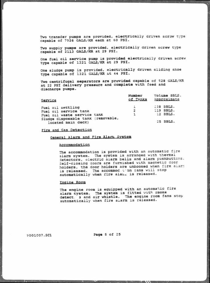
Two transfer pumps are provided, e l e c t r i c a l l y driven scraw type capable of 7926 GALS/HR eacn at 60 PSI.
Two supply pumps are provided, e l e c t r i c a l l y driven screw type capable of 2113 GALS/HR at 29 PSI.
One fuel o i l service pump i s provided e l e c t r i c a l l y driven screw type capable of 1321 GALS/HR at 29 PSI.
One sludge pump i s provided, e l e c t r i c a l l y driven sliding shoe type capable of 1321 GALS/HR at 44 PSI.
Two centrifugal separators are provided capable of 528 GALS/HR at 22 PSI delivery pressure and complete with feed and discharge pumps.
Number volume BBLS. S^ECififi oXJlajiks. Approximate
Fuel o i l settling Fuel o i l service tanx Fuel o i l waste service tanx Sludge disposable tank (removable,
located main deck)
Fire and Gas Detection
rTfn«T-»l Xlerm and Fire Alanz Svstem
Accommodation
The accommodation i s provided with an automatic fire alarm system. The system i s arranged with thermal detectors, electric alarm bell s and alarm pushbuttons. Self-closing doors are furnished with magnetic door holders, the door holders are unhooked when f i r e alarr. i s released. The accommod .on tans w i l l stop automatically when fire a l a i - i s released.
Engine Room
The engine room i s equipped with an automatic f i r e alarm system. The system i s fitted with smoke detect. 3 and a i r whistle. The engine room fans stop automatically when fire a*ara i s released.
1 228 BBLS. 2 119 BBLS. 1 12 BBLS.
25 BBLS.
9 0 0 1 0 0 7 . S C I Page 5 o f 25

The general alarm i s coabined with che re alarm system with a switch In p i l o t house. otal of four red flashing light installed in tha enr -.e room, mud pump room and emergency generator room e connected tc this system to supplement the alarm be s.
Fire Fighting control Station i s aanv .ctured by Minerva.
A f i r e fighting control station i s located in the engine control room on a separate console. This station has a repeater panel inside the port f i r e station.
Hydrogen sulphide and combustible gas detection system i s manufactured by "ieger and i s a 34 channel unit protecting the following areas:
Mud roam; c e l l a r decic; D r i i l floor; Shale shaker room; Accommodation; Machinery space.
The HjS system control and alarm panel i s located in the engine control room with an alarm panel at the d r i l l e r ' s console. I f gas i s detect 2d at any of the quarters' inlet ventilation ducts, a l l quarters* fans are automatically shut down.
compressed Air Svstem
starting Air Compressors
2 - Com^cir Reavell VMP8, two stage, a i r cooled, oapacif. each approximately 1172 FT.3/HR, free a i r working pressure 435 PSI. The compressors are e l e c t r i c a l l y driven and fitted with inter-stage and discharge a i r cooling.
Service, Mr Compressors
3 - Compair Type single stage, o i l injected, asymmetrical screw RAI5owe, water cooled, capacity each approximately 35698 FT. /HR. a i r working pressure 119 PSI. The compressors are e l e c t r i c a l l y driven and fit t e d with inter-stage and discharge a i r cooling.
OC1007.SC1 Page 6 of 25

Staging Air Recovers 2 - Receivers 3 5. J FT. eacn
service. Air Receivers
2 - Receivers 141.2 FT.1 each
Air Dryer f o r Control A i r
1 - Dryer 132 FT.VMTN capacity (approximate), free a i r dew point a t 101 PSI at 104* F. , i n l e t temperature -40* F. Tne a i r dryer i s non-heat absorption type consisting cf two d r y i n g towers, one of which i s used while the other i s regenerated with d r i e d a i r .
Air Dryer rer Service Air 1 - Dryer, 8800 FT.VMIN, free a i r dew point at 116 PSI at
104* F., i n l e t temperature 36' F.
Bulk Air coapresscrs 2 - con-pair s ingle stage, o i l injected, asymmetric, hel ical
screw RA150W, water cooled, 55083 FT. i/HR capacity each (approximate) . Free a i r working pressure 116 PSI. The compressors are e l e c t r i c a l l y driven and f i t ted with fresh water after-coolers . 116 to 44 PSI reducing station i s located downstream of tha compressor.
BMJJS Air Receivers 2 - Farrar receivers, 900 FT.J, 44 PSI WP The a i r
receivers are a i l welded s t e e l construction f i t t e d with safety valve, i n in valve and pressure gauge.
Drvers f o r Sulk A i r
2 - Deltech dryers, 55083 FT.J/HR capacity each :approximate) , free a i r dew po i n t at 46.4 PSI and 124" F., i n l e t temperature 36* F. , the dryers are r e f r i g e r a t i o n type.
Materials Handling LOSS'S crane) Ears and Starboard cranea The r i g cranes ?.re manufactured by M.A.M. These are electro-hydraul; z pedestal cranes, with rated h o i s t i n g capacity of mai " block at 61 Tons and a radius up to 65 FT. at speeds up t o 33 FT./MIN. 3oth cranes f i t t e d w i th marine (FM) VHP radios, telephones and crew attention public
00100'. . SCI Page 7 of 25

address.
The crant main blocJc has a l i f t i n g capacity of 22 Tons u to 88 FT. rad ius , ratad hoisting capacity of tha whip Lin* hoist, with a s ingle l ine , i s 17 Tons at a radius of 141 FT. at a speed up to 98 FT./MIN.
Ear* Lirt The r ig i s supplied with c 4 Ton capacity fork l i f t truck with d i e se l engine, power s n i f t transmission and hydraulic power s t eer ing .
The fork l i f t working areas are sack storage area and main deck crane landing area.
1 - Boiler, Aalborg Type AQ-3, 13900 BTU/HR or 14300 LBS./HR capacity (approximate). Operating pressure 102 ps i , desicr. pressure 123 PSI . Feed water temperature 122' F . , diesel fuel o i l . The boi ler supplies saturated steam for heating in * e accommodation, heating of fue l ( i f required), heating the fresh water generators and a i r heaters on d r i l l floor, c e l l a r decx, mud p i t room, etc .
Fresh Water C w r a t n r j
2 " Caird k Rayner "Movac" MK2, capacity each of 33 Tons/DA., sa l in i ty maximum 10 Mg MaCl/1. The fresh water generators are single stage, low pressure, submerged co i l type, the mam unit cons i s t s of one she l l divided into two areas, vacuum side and condenser.
wgqe find waste, BiMaaaal vacuum s e w a ? « anq yfl*;em
1 - Hamvorthy Super Trident, service for total of ICO persons.
Sludae Pump
1 - Negator s l i d i n g shoe, 1321 GALS/HR capacity (approximate) , delivery pressure 5 PSI (approximate) .
900100".SCI p»^»

i n c i n e r a t o r
The i n c i n e r a t i o n p lant c o n s i s t s c i . a t o r . mixing tank, a f u e l o i l tank, a f u a l gaa am aa transport system.
1 - Hamworth Neptune, s o l i d waste l o a d capac i ty 400 LBS / h o u r , s ludga waste load c a p a c i t y 29 GALS/HR. -he i n c i n e r a t i o n p l a n t burns o i l y s ludge , sewage sludge and s o l i d w a s t e .
Sjoraaj P a r i l i t i a s
r ntl rnnncitin Bulk mud and cement Sack m a t e r i a l s Liquid mud , , Pipe racks (500 l b / F T . , l oca l ) Potable water D r i l l water Fuel o i l Bal last water
giiiaoxs
Designed to accommodate S ikorsky S-61
Power
23600 FT. 7500 Sacks 2500 BBLS.
6450 F T . " . 1344 Tons 2400 BBLS.
17600 BBLS. 12500 BBLS. 94300 BBLS.
Manufacturer Number c f SCR c o n v e r t e r s Input Voltage Rated C uput E a c h
Hill-3 rana o
6000 volt. 60 hertt A 1200 Amps at 720 volt C
The SCK units supply power to the following DC motors:
Drawworks Mud Pumps Rotary Tables
Pnwer D i s t r i b u t i o n
Make Brusa E l e c t r i c Macm.-e
9001007.SCI Page 9 of 25

SVBtBB Ql SUBPlY
power Voltage
3 phase 6000, 600 and 4 50 volt. ^0 hertz AC, 720 olt CC
r.tohtina Voltage
3 phase, 220 volt, 60 hertz AC
Shore Supply
600 A, 440 volt, 60 hertz AC
Number of Ratio Ratio Hertz Transformers Volt AC 3 Phall Rating EflCP
2 6000/600 60 3 Kva 2 6000/440 60 3 Kva 3 440/220 60 225 Kva 1 440/220 60 60 Kva
The transformers are a i r cooled, double wound with terminal box, outside the enclosure.
Tht. transformers are rated for continuous service at fu load.
Shore SUBPlY
The shore connection cox i s sized for 600 A, 3 X 4 00 volt; the box contains a three pole c i r c u i t breaker and terminates to fac i l i t a t e connection of flexible cables from the shore.
Permanent cables are run from the shore supply box to the main switchboard.
Motor control centers Magnetically controlled MCCs with overload trips ars located adjacent to motor load groups throughout the vessel.
Main generator Sets 4 - Brush E l e c t r i c a l Machines Ltd., 1800 KW, 2571.5 a CMR
(Dlus 10% for one hour at 0.7 power factor), 900 RPM, 6000 volt. 3 phase, 60 hertz, 45/BP horizontal shaft-foot mounted, salient pole, revolving f i e l d , brushless, marine AC generator with outboard AC exciter.
?001007.SC1 Page 10 of 25

Emergency Ganarator Set
Electric Construction, 650 KW, 687.5 Kve at 0.8 power factor. 1800 RPM, 440 volt, 2 phase, 50 hertz, brushless, revolving field, narine type generator with internal brushless AC exciter
IV. Derrick and Substructure
pfrricfr Branhas Inc., dynamic bolted beam leg derrick, 160 FT. high, 40 FT. X 40 FT. bass, and 18 FT. X 18 FT. top with a s t a t i c hook load capacity of 1400000 LBS. Derrick designed to accommodate a BJ vertical racking system and Rucker compensator. Crown block i s National 860-K, API rated for 650 Tons hook load, 8 X60" diameter sheaves grooved for 1-1/2" di* rer wire.
The derrick i s designed to withstand dynamic .oads of ioo knots wind with 660000 LBS. of d r i l l pipe racked in the derrick.
s/ubatructtire The substructure i s a Gotaverken Ardenal design capable of supporting the f u l l load capacity of the derrick and d r i l l floor.
All welded s t e e l structure to withstand, in addition to normal equipment, 1400000 LBS. hook load, 600000 LBS. setback, 12 X 80000 LBS, r i s e r tension, and 6 X 16000 LBS. guideline tension.
Hoisting and Rotary Eauipment
Jrawworka
l - National 1625-DE (3000 HP) e l e c t r i c drawworks ith sand reel, Baylor MOL auxiliary brake, make-up out catheads and equipped with three 950 HP DC else-, -s
Traveling Equipment
Hook
1 - BJ 500 Dynaplex hook with automatic positioner and oir swivel, rated 500 Tona
SMiyji
1 - Nat iona l P-650, rated 650 Tons
9001007.SCI Page 11 of 25
Bloek
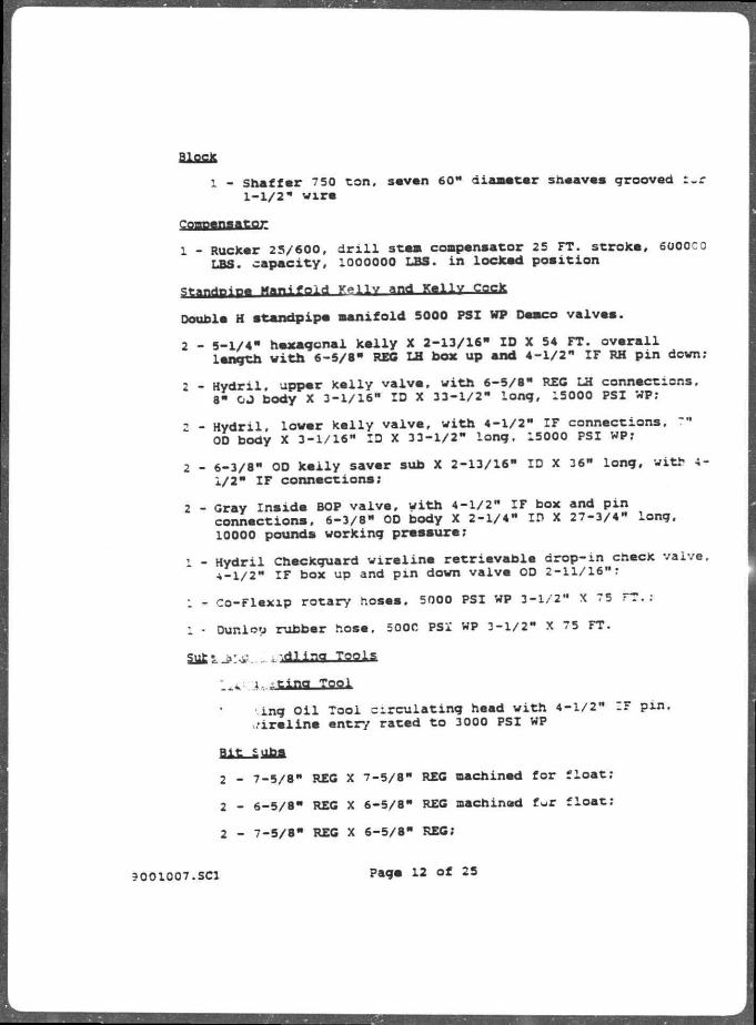
1 - Shaffer 7 50 ton. savan 60" diameter sheaves grooved r-r 1-1/2" wire
1 - Rucker 25/600, d r i l l stem compensator 25 FT. stroke, 6000C0
LBS. capacity, 1000000 LBS. in locked position
Sfanripjpe M a n i f o l d K - l l v and K e l l Y CQCX
Double H standplpe manifold 5000 PSI WP Demco valvea.
2 - 5-1/4" hexagonal kelly X 2-13/16" ID X 54 FT. overall length with 6-5/8" REG LH box up and 4-1/2" IF RH pin down;
2 - Hydril, upper kelly valve, with 6-5/8" REC LH connections. 8" OJ body X 3-1/16" ID X 33-1/2" long, 15000 PSI WP;
2 - Hydril. lower kelly valve, with 4-1/2" I F connections, ?" OD body X 3-1/16" ID X 33-1/2" long. 15000 PSI WP;
2 - 6-3/8" OD kelly saver sub X 2-13/16" ID X 36" long, with 4-1/2" I F connections;
2 - Gray Insids BOP valve, with 4-1/2" I F box and pin connections, 6-3/8" 00 body X 2-1/4" ID X 27-3/4" long, 10000 pounds working pressure;
1 - Hydril Chsckguard wireline retrievable drop-in check vaive, 4-1/2" I F box up and pin down valve OD 2-11/16":
1 - Co-Flexip rotary hoses, 5000 PSI WP 3-1/2" X 75 FT.;
1 - Dunlop rubber hose, 500C PSI WP 3-1/2" X 75 FT.
Sj£Lj>:^. . i d l i n g iflflia
• Toal
•ing O i l Tool circulating head with 4-1/2" IF pm, M-ireline entry rated to 3000 PSI WP
ait £oba
2 - 7-5/8" REG X 7-5/8" REG machined for float;
2 - 6-5/8" REG X 6-5/8" REG machined fur float;
2 - 7-5/8" REG X 6-5/8" REG;
9001007.SCI Page 12 of 25

2 - 4-1/2"
aaiagna
IF X 4-1/2" REC machined f o r f l o a t .
2 - 7-5/8" REG pin X 6-5/8" REC box;
2 - 7-5/8" REG p i n X 4-1/2" IF box;
2 - 6-5/f" REG p i n X 4-1/2" I F box;
6 - 4-1/2" I F box X 4-1/2" IF p i n ;
1 - 4-1/2" I F box X 4-1/2" I F p i n *
1 - 4-1/2" I F p i n X 4-1/2" I F p i n ;
1 - 6-5/8" REG box X 4-1/2" I F p i n ;
1 - 4-1/2" I F box X 1502 Waco thread union;
2 - 4-1/2" I F pin X 1502 Waco thread union.
SalltY aim
1 - 4-1/2" I F box X 7-5/8" REG p i n ;
1 - 4-1/2" I F box X S-5/r* REG p i n .
Jit subi
1 - 4-1/2" IF box
Lili SMBl
1 - "-5/8" REG p i n ;
1 - 6-5/8" REG p i n ;
1 - 4-1/2" I F pi n .
D r i l l i n g BjJMBgX * u p«
1 - Brash Rosa 6SI bumper sub, 8" X 3" ID, 60" stroke 6-5/8" REG connections;
2 - Baaah Ross 6SI bumper sub, 6-1/2" X 2" ID, 60" stroke 4-1/2" I F connectiona.
9001007.SCI Page 13 of 25

•4,nriTinef T o o l s
1 - Dri lco Ezy-Torqu* (h draui ic /cable torqua control u n i t ) ;
1 - A6C-2 International ke l ly spinner with two ac rs 'for r ight or l e f t hand rotation) ;
1 - weatherford Lanb a i r powered d r i l l pipe spinr.^r, size range 2-7/8" to 7";
2 - varco Type SDXL 5" d r i l l pipe a l ipa;
2 - varco DCS-L d r i l l co l l ar s l i p a for 6-3 4" to 8-1/2" OD c o l l a r s ;
2 - varco DCS-L d r i l l c o l l a r s l i p a for 5-1/2" to 7" OD c o l l a r s ;
2 - varco MF—R safety clamp for 8" to 9-1/4" CD;
2 - Varco MP-4 safety claffip for 6-1/2" OD;
2 - ft! air operated "GG" 3 50 ton CL elevators for 5" drill j xpe s
8J a i r operated TA 15' ZL elevators for b-1/2" tip groove d r i l l co l lars ;
3J a i r operated TA 150 CL elevators lor 8" t ip groove d r i l l c o l l a r s ;
1 - BJ SL BB 500 ton SD elevator for SOP handling;
1 - BJ MG 100 ton CL elevator for 5" d r i l l pipe:
1 - BJ GG 3 50 ton CL elevator for 5" d r i l l pipe:
1 - BJ TA 150 ton CL elevator for 6-1/2" col lars with tip groove;
1 - BJ TA 150 ton CL elevator for 8" col lars with zip groove;
1 - BJ d r i l l co l lar dolly assembly for < elevators;
1 - set Perfection l inks , rated for 80 t .a;
2 - BJ SSD t i ; s '." tn 8-1/2". 3-1/2" to 12" jaw assemblies
2 -
2 -
3001007.SCI "age 14 of 25

2 - BJ DB tonga with 3-1/2" t o 8-1/4" to 11-1/4", 11-2/4" to 14-3/8" and 11-3/4" t o 17" jaw assemblies:
2 - BJ S tongs with 13-3/8" to 19" and 20" to 21-1/2" jaw assemblies;
l - BJ 500 ton l i n k s ;
1 - BJ 350 ton l i n k s .
p j j ^ Racking Svstam
BJ pipe racking system complete w i t h upper, intermediate and l o v e r racker arms, racker and l i f t i n g heads f c r 3-1/2" and 5" d r i l l pipe an**- up t o 9-1/2" c o l l a r s . Casing heads fo r i n t e r m e d i n i ev«a lower racker arua f o r 5" through 13-3/8" casing wit:, a *ntors f o r 20" and 30" casing. Racker head f o r lower rao. arm f o r marine r i s e r with and withou buoyancy material, ...ock r e t r a c t o r , fingerboard, hydraulic power u n i t and control consoles.
The racking system incorporatea a warning i n d i c a t o r f o r upper, intermediate or lower arm interference with th. r a v e l i n g block, plus closed c i r c u i t TV monitoring sya..#m.
A remote control casing stabbing board operated from thi. intermediate arm.
i r i l l S t r i n g and Tools
ZOOOO fe e t of 5" 0D d r i l l pipe, 19.50 LBS./FT. Grace "G-10S \ Range 2. Armco SMLS SPl IEU upset d r i l l pipe with 6-3/8" CD a . : - l / 2 " ID welded tool ;oints 4-1/2" IF connections.
- r i l l c o l l a r s
24 - a" OD s p i r a l groove d r i l l c o l l a r s 2-13/16" ID X 31'-6" long w i t h 6-5/8" REG connections, zip grooves;
20 - 6-1/2" OD s p i r a l groove d r i l l c o l l a r s 2-13/16" ID X ?.l'-6 long w i t h 4-1/2" IF connectiona, zip grooves;
• 9 _ 9-1/2" OD s p i r a l groove d r i l l c o l l a r s 3" ID X l ' - 6 " long w i t h 7-5/8" REG connections, zip grooves.
; - Bowen 11-1/4" OD Series 150 releasing and c i r c u l a t i n g overshot c/w s p i r a l grapple, packer extension, w a l l ho guidee, and l i p guides to catch 9-1/2" and 8" CD d r i l l c o l l a r s i n 26", 17-1/2" and 12-1/4" hole;
7. SCI Pags 15 of 2 5

1 - Bow«n 8-1/8" OD Series 150 releasing and c i r c u l a t i n g overshot c/w s p i r a l grapple, packer extensions wall hor guides and l i p guides to catch 6-1/2" OD c o l l a r s i n 26", 17-1/2", 12-1/4" and 8-1/2" hole;
1 - Bowen Typa Z o i l f i s h i n g j a r s 7-3/4" OD, 6-5/8" *"~G connections;
1 - Bowen Type Z o i l f i s h i n g j a r s 6-1/4" OD, 4-1/2" :r box up x pin down;
1 - 8" OD X 20" stroke Bowen f i s h i n g bumper sub, 4-1/2" IF box up and p i n down;
1 - 6-1/2" OD X 20" stroks Bowen f i s h i n g tump sub, 4-1/2" ID box up and p i n down;
1 - 15" OD Bowen reverse c i r c u l a t i n g junk baskat f o r 17-1/2" hole, 6-5/8" REG;
l - i l " OD Bowen reverse c i r c u l a t i n g junk basket f o r 12-1/4" hole, 6-5/E" REG;
l - 7-7/8" OD Bowen reverse c i r c u l a t i n g junk backet fo r 8-1/2" hole, 4-1/2" IF box up;
1 - Bowen junk sub f o r operating i n 17-1/2" hole (6-5/8" REG) ;
1 - Bowen junk sub f o r operating i n 12-1/4" hole;
1 - Bowen junk sub f o r operations i n 8-1/2" hole;
- - 14" OD Bowen K&G magnet for operating i n 17-1/2" hole;
L - 10-1/2" CD Boven K&G magnet for operating i n 12-".. 4" hole;
1 - 7 " OD Bowen K&G magnet f o r operating in 8-1/2" hole;
l - 12" OD Bowen junk m i l l f o r operating i n 12-1/4" hole;
l - 8-1/4" OD Bowen junk m i l l f o r operating i n 8-1/2" hole;
1 - 7-1/4" OD Bowen rotary taper tap to catch 9-1/2" and 3" d r i l l c o l l a r s i n 17-1/2" and 12-1/4" hole;
1 - 8-1/2" OD Bowen rotary taper tap to catch 6-1/2" d r i l l c o l l a r s and 5" d r i l l pipe i n 8-1/2" hole.
9001007.SCI Page 16 of 25

-/xi. Mud SYJtaa SBtf Bum 2 - National 12-P-160 s i u s n pumps, 7-1/4" X 12" t r i p l e x s ing le
act ing , each pump d r i v e n by tvo 950 HP DC e l e c t r i c motors, Hydri l p u l s a t i o n dampeners;
2 - Magnum 6" X 8" charge pumps with 14** impe l l er , dr iven by 100 HP exp los ion proof e l e c t r i c motor, 1800 RPM, 440 v o l t , 60 hertz; .
1 - Mud booster pump.
Mud Proce«« ina gemiment
1 - Shale shaker , Brandt t r i p l e tandem, operat ing speed 1750 RPM, subjec t to mud propert ies and d r i l l i n g condit ions , the syatea i s c a p a b l e of processing approximately 1500 GPM of 10 PPG ud u s i n g 80 mesh screens ;
1 - Desander. Demco Model 123, three " cones. 1350 GPM;
1 - Thule VSM 2 00 mud c leaner with s i x t e e n 4" X 80 GPM cones, t o t a l c a p a c i t y 1280 GPM;
1 - welco Model 5200 degasser;
1 - Welco mud/gas s epara tor , c o n s i s t i n g of a heavy wal led 4 FT. X 10 FT. v e r t i c a l t -nk with i n t e r n a l b a f f l a a , f l o a t operated l i q u i d l e v e l control and dump s ten, 411 sa fe ty vent, and u n i t i z e d back pressure gaa vent manifold with bypass;
3 - Mud t r e a t i n g pumpa, 3" X 6" x 14" Miss ion Magnum driven ty a 150 HP. 3 phase 60 hertz . 400 v o l t explos ion proof e l e c t r i c motor;
5 - Mud a g i t a t o r s . L i g h t i n g Model 7 5Q, 2 0 HP:
2 - Mud a g i t a t o r s . L i g h t i n g model 73Q, 10 HP;
9 - Mud guns, Demco, 3" low pressure bottom type;
3 - Mud mixing pumps, 3" X 6" X 14" M i s s i o n Magnum driven by 100 HP. 1800 RPM, 3 phase, 60 h e r t z , 440 v o l t , explosion proof e l e c t r i c motor;
2 - Trip tank pump, 2 X 3 X 12 Miss ion Magnum pump dr iven by 2 5 HP, 1800 RPM, 3 phase, 60 h e r t z , 440 v o l t , explosion proof e l e c t r i c motor;
9001007.SCI Page 17 of 25

2 - Geo-Source S idewinder S800 hoppers;
1 - Desco 6IB 6" mud hopper comes w i t n V e n t u n
V I I I . n.;pv»ut Preventer and Control FaulPMn*C
PvP S t»g* a p « * t^wer Marine R i s e r
NL Shaf fer 1 8 - 3 / 4 • BOP s tack and lower mari r i s e r package with four 150X30 P S I WP rams and two 5000 P r r s p h e r i c a l preventers; a l l equipment i s s u i t a b l e f o r * s e r v i c e .
control system meets NPD requirements w i t h accumulator storage to operate a l l f u n c t i o n s plus 25%.
Main components aa f o l l o w s :
2 - 18-3/4" SL double ram p r e v e n t e r s ;
I _ 18-3/8" bore d u a l s p h e r i c a l preventer*
1 - Hydraul ic upper connector, Vetco H4 10000 PSI WP;
1 - BOP s tack mandre l ;
l - Hydraul ic w e l l h e a d connect Vetco H4 EXF 15000 PSI WP-
1 - Regan marine r i s m r connector;
l - Flex j o i n t ;
1 - 30" h y d r a u l i c l a t c h f c r 21" r i s e r system omplete with i l ex :omt and r i s e r adaptor:
l - Master c o n t r o l panel with g r a p h i c i l l u s t r a t i o n of BOP stack and d i v e r t e r system;
1 - M i n i - c o n t r o l p a n e l ;
1 - D iver ter c o n t r o l pane l ;
2 - A i r powered subsea-hose bundle r e e l s , one manifold on each r e e l f o r f i v e l i v e func t ions ;
2 - Hose sheaves , one f o r each hose;
2 - Subsea hoae bundles of 2500 F T . l ength with junct ion p l a t e s ;
9001007.SCI P*9« 1» Of 25
rsTetS

2 - BOP mounted retrievable control poda;
: - KL Shaffer (Partec L-74 tr ip lex pump) BOP testing unit, rated to 20000 PSI WP;
1 - Interocean 171C/1750 interactive acoustic control system, four functions, control pipe rams, blind shsar rams and upper and lower connectors.
Choke and K i l l Manifold
15000 X 10C00 PSI WP l ins s and valvea auitabie for H s service consisting of:
2 - Adjustable chokes, remote centre led with control panel;
1 - Adjustable choke, manually operated;
2 - 7 5 FT. Co-Flexip choke k i l l hoeee, 15000 PSI WP, H S service.
:x. wellhead Equipment and Tubular goods 21" X 0.625" w a l l thicknaaa fumished w i t h two 3" bore 15000 PSI WP integrated choke and k i l l l i n e s , and a 5" bore 1500 PSI wp booster l i n e , chokn and^-kill l i n e s are trimmed f o r H2S service.
Tha r i s e r i s Regan Type FD-8 and Vetco MR6-C designed for use in 3 300 FT. water depth and consists of:
=1 - Marine r i s e r j o i n t s , 50 FT. length. 0.62 5" wall thickness with buoyancy modules;
15 - Marine r i s e r j o i n t s with 50 FT. length, J.625" wall thickness;
l - Marine r i s e r - o i n t s 3 0 FT. length, 0.625" wall thickness;
1 - Marine r i s e r j o i n t s 15 FT. length, 0.625" wall thickness;
1 - Marine r i s e r j o i n t s 10 FT. length. 0.625" wall thickness;
1 - Marin** r i s e r j o i n t s 5 FT. length. 0.625" wall thickness;
1 - Marine r i s e r crossover Regan FD-8 box to Vetco 21" MR-6C pin 20 FT. length;
1 - Marine r i s e r crossover Fegan FD-8 p i n to vetco 21" MR-6C box 20 FT. length;
9001007.SCI Page 19 of 25

1 - Telescoping jo i n t 21" diameter, maximum stroke 5 5 FT.;
l - Tension ring for twelve r i s e r tensionsr canlea;
1 - Handling spider for 21 FT. r i s e r , with gimeal supoort:
2 - Handling subs for 21m r i s e r ;
2 - Test cape for choke and k i l l l i n e ;
1 - Regan KFDS diverter assembly (24" nominal).
Regan guide Line Toola ' - Mandrel assembly, slotted gui'ie post 8-5/6" OD Type GLS-4;
4 - Latch assembly, guide line latch Typa GL-4 8-5/8**, 3/4" diameter wire li n e ;
1 - Releaaing tool guide line latch Type GL nominal 3-5/8", 3/4" wire line;
1 - Retrieving tool assembly Type GLF-2;
1 - running tool assembly Type GLF-2;
1 - Wire lien cutter Type GLF-2 guide line latch;
1 - Frame, guide line latch tool assembly;
1 - Test box 5-1/4", SUN hydraulic connector Type FC-3;
1 - Test pin, hydraulic connection Type FC-3, 5-1/4". 3 CM;
2 - Pin, test, hydraulic line connection box.
• Subsea Systems wellhead inspection television system, remote controlled with d r i l l e r * 3 console cr moonpool area
Position Indicator system 1 - Honeywell Model RS/902 re-entry poeitioning system
including two subsea beacons and one r i s e r angle beacon
Tensioner System Riser
6 - Rucker twin r i s e r tensloner system consisting of 160000 pound dual tensionsrs, 50 FT. wire line travel
3OO1007.SC1 Page 20 of 25

r.uida L j na and Poo L i n e
6 - Rucker quid, line tensloners system consisting cf 16000 pounds tensloners, 40 FT. wire lins travsi
X. TP«rin«. Lfmg^na. con no and (TaBintlnq
- Dov.il C P.S. 600, powered by twin 12V71 Dstroit dieaels, ^ ttMlk Allison automatic torque converters <Free Placamanruni?, please sea Cementing unit letter attached) . S a fluid ands ara drassad with 3- and 4- pistons, a ^ J u r i z a d ^ u r q a tank feeds a tornado mxxar. tha there is a"££«rf four*?ank liquid additive sy.tem, and a 100 B3L. batch tank.
xi. fin nnr^^-nt;atliQn
PXliiiaa Trmtrtt-ntation
Martin Decker d r i l l floor inatrumentation »y«tem, driller's console contains the following instrumentation:
1 - veight indicator: 2 - mud pump preaaure gauges; 1 - Ton torque indicator; l - RPM tachometer; 1 - SPM tachometer; l - Rotary table torque indicator; l - Mud volume totalizer indicator: 1 - Mud volume totalizer indicator; 1 - Flow f i l l and stroke indicator; l - Trip tank indicator; 1 - Audio alarm horn.
Drill floor "Record-o-Graph" system, ^ " c f n £ i r S 0
r t e r
to record weight, aud pressure, rotary torque, RPM.two SPM! E r r a t a of penetration, fitted with twelve hour clocks.
3001007.SCI Page 21 o f 25
L

xiv. Tranapgrwipn and c aaurucanons Radio and Telephone
The radio s t a t i o n i s equipped as fo l l o w s :
I - Conqueror HS, 1500 watt;
1 - Pacific X, synthesized main receiver;
l - Tele-typewriter.
One marina VHF radio s t a t i o n complete w i t h :
1 - Natulis 0-25 watt 61 channel VHF FM transceiver capable of remote c o n t r o l t o wheelhouse, AC w i t h OC bacJcup;
2 - s a i l o r RT145 VHF radios with d i g i t a l readout, one i n s t a l l e d in the wheelhouse, one i n s t a l l e d i n the control room;
1 - Synthesized air/ground VHF AM transceiver, io watt, 720 channel w i t h backup;
1 - Watder 4C, KHz watch keeping receiver;
1 - Clock complete w i t h day/date, 24/12 hour i n t e r n a t i o n a l silence period markings, quartz movement, analog readout:
1 - ABX 4 00 aeronautical radio beacon, frequency range 200 to 650 KHz.
Saergency Equipae".*;
1 - salvus 2182 KHz transceiver and located beacons complying with i n t e r n a t i o n a l ana/or l o c a l marine regulations provided;
1 - Survivor 3 portable transceiver operated at 500 KHz, 2132 KHz and 836 KHz.
A-utgaatic Telephone Syatea 1 - Mitel SX20 automatic telephone system is arranged with 7 2
l ine automatic so l id ..tate exchange for approximately 63 extensions, 5 simultaneously.
Al l of tha telephones are integrated with the public address system in such a way that the telephone can give orders over the public address system.
?001007.SC1 Page 22 of 25
3]

Sound Powtnd Telephone System
1 - D r i l l i n g u n i t equipped with sound powered automatic d i a l telephone
g r i l l F loor Svatem
1 - F i r e a t a t i o n intercom system, d r i l l f l o o r , BJ rackinq
system, monkey board, c e l l a r deck, pump room
MaxiM VBT FW Walkie T a l k i e s
2 - COP 813 V, i n t r i n s i c a l l y aa fe f i v e channel hand portable VHF t r a n s c e i v e r frequency range 146 to 174 MHz;
6 - IC 12 Icom hand portable VHP t r a n s c e i v e r s with twelve preset c h a n n e l s ;
1 - Walter D i t t e l 720 channel f u l l y synthee ized portable t r a n s c e i v e r Type FSG-5 with headse t for H . L . O .
aadar and Nav igat ion
1 - Sparry MK 4016S-312-9 r e l a t i v e motions;
1 - Sperry MK 3012-57-9 r e l a t i v e motiona.
Dual i n t e r s w i t c h e d radars a r e prov ided for 3 60* coverage, one 10 cm s-band and one 3 cm X-band with respect ive 16" and 12" p e d e e t a l mounted d i s p l a y s .
Tha f o l l o w i n g navigat ion data can be read of f on the control p a n e l s :
R e l a t i v e head up, north up, range s c a l e i r .aut ica i m i l e s ) , d ia tance between range markers, d i g i t a l v a r i a b l e range marker, r e l a t i v e or true bearings , one radar i s connected to the gyro compass.
Radio D i r e c t i o n F inder
1 - Lodestar H I D
Svro Compass Svstem
1 - Sperry SR 220, cons i s t ing of one master compass, e l ec tron control u n i t complete with power adaptor transmiss ion unj power f a i l u r e alarm, coapenaator u n i t , gyro compass repeater , connect ion for b e a r i n g repeater in radio d i r e c t i o n f i n d e r .
OO1007.SC1 Page 23 of 25

connection for bearing repeater in the radar unit .
Tha gyro compass i s also connected to tha maneuvering system.
Sfinfl Sounder 1 - Recorder (scale ranges 0 to 1000 meters) with built-in
digital depth indicator, depth alarm (audible and visual) between 1 and 999 meters;
1 - Digital depth indicator for diatance reading; 1 - Transducer placed i n starboard forward pontoon compartments
XV. General
Liriattving
2 - 5 0 man each Watercraft XL f u l l y enclosed diesel engine driven;
1-60 man Watercraft XL f u l l y enclosed diesel engine driven
Rescue Boat
1 - 2 0 man watercraft -David S t i l l - Type R12 semi-rigid inf latable s e l f - r i g h t i n g fast rescue boat (not supplied)
Lire Raits 4 - 2 5 man eacn automatically inflatable
Lire BUOYS 8 - A l l provided with smoke signals and self-igniting
battery light, and with 60 meter buoyant l i f e l i n e s
Lift Jackets
126 - DOT approved
Survival Sui ts
150 - Strentex surv iva l s u i t s
Line Throwing Apparatus
1 - "our p r o j e c t i l e a and four i inea
9001007.SCI Page 24 of 25
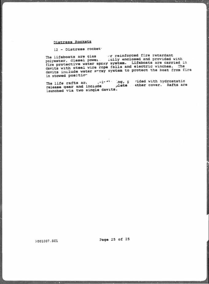
12 - Dis tress rocket-
The l i feboats are glaa r reinforced f i r e ratardant polyeetar, d i e s e l p o m . i u l l y enclosed and provided with fire protective water spray system. Lifeboata are carried in davits with s t e e l wire rope f a l l s and e l e c t r i c winchea. The davits include water s-ray system to protect the boat from f i re in stowed pos i t io -
The l i f e r a f t s ar . . - i - * " ng, c 'ided with hydrostatic release gear and include A * * * c o v « r - ***** a r e
launched v i a two single davits .
3001007.SCI Page 25 of 25

Plan of Exploration Green Canyon Block 473
ATTACHMENT C
AIR EMISSIONS DATA

Plan of Exploration Grean Canyon Block 473
ATTACHMENT C
AIR EMISSIONS DATA

r rH JEGTia) AIR EMISSIONS G e ^ i Canyon 473 Weii No. *.
DRILLINQ RIQ EMISSIONS
Pollutants Lbs/Day Total Tons/80 Days
CO 46.85 1.87 1 TSP N/A i v ; A
S3, 215.7 0.86 J
NO, 31'.176 12.79 *
VOC 10.66 •3.43 H — . — , ,_ . -J
The above figures are based upon 80 rig days and dr /'ina jf new hole. Emission estimates are based upon EPA's publication AP-42 i r j PB-27226B entitled "Atmospheric Emissions from Offshore Oil and Gas Development and Prodyctjori'1 - June 1977.
OTHER EMISSIONS
Pollutants Lbs/Day | tt " Hill I I I . II III
To;al Tor.a/80 Days
CO 40.34 1.60
TSP 0.75 0.02
SO, 4.14 0.16
NO, 56.47 2.2*3
VOC 20.76 3.83
The above figu-es were :alcuhted as per EPA Publication AH -Z and includes er .sr ^.Sf jle'.ed to helicopter lar.ding/tak «jff cyc-ar, and boat activity including fuel loading and t ran* less and emissions while uinnmg loac g .nd standing oy.
TOTAL EMISSIONS
Pollutants T ' - V Tons/80 Days
CO 3.4T
TSP G.02
SO, 1.G2
NO, 15.05
VOC 1 26
NOTE. Distance from nearest state land is approximately 112 staiute miles.
WHI 4.FRM
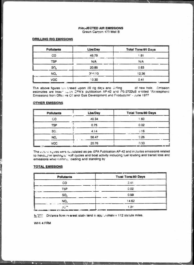
PROJECTED AIR EMISSIONS Green Canyon 473 Well B
DRILLINQ RIG EMISSIONS
Pollutants Lbs/Day Total Tons/80 Daya
CO 45.79 1.81
TSP N/A N/A
| so, 20.85 083
NO, 3/-MO 12.36
J VOC '0.30 0.41
The above figures -..'i cased upon W) rig days ana J.:'iing of new hole. Emission estimates are base- ui.cn Z°A's publication AP-42 and PB-2722bB entitled "Atr.iospheric Emissions fron Offs.i >re O' and Gas Development and Production' - June 1977
OTHER EMISSIONS
Pollutants Lbs/Day Total Tons/80 Daya
n r
CO 40 34 1 60
TSP 0.75 0.02
SO. 4.14 ) 16
NO. 56.47 '2.26
VOC 20.76 r>.33
The c.-c-v l i t r e s we^a Cu mulated as pei EPA Publication AP-42 and includes emissions related to heii tx^'cf lancfiny/ii. =off cycles and boat activity including fuel loading and transit loss and emissions whiio runniru. oading and standing by
TOTAL EMISSIONS
Pollutants Total Tons, 80 Days
CO 341
TSP 0.02
SO, 0.99
NO, 14.62
JC \2*
NTT|; Dis.'ancafrom nearest statn land ir. app'.>.imate<v 112 st&'ute miles.
WHI 4.FRM

PROJECTED AIR EMISSIONS Green Canyon 473 Well C
DRILLING RIO EMISSIONS
Pollutsnts Lbs/Day Total Tone, 30 Oeyfj
CO 46.85 187
TSP N/A N/A
SO, 215.7 0.86
NO, 3 19.76 12.79
VOC 10.66 0.43 |
The above figures are based upon 80 rig days ant drilling of new hole. Emission estimates are based upon EPA 's publication A P - 4 2 and PB-272263 entitle J Atmospheric Emissions from Offshore Oil and Gas Development and Production" - June 1977.
OTHER EMISSIONS
Pollutsnts Lbs/Day rot»l Tons/80 Days
CO 40.34 1 60
TSP 075 0.02
SO, 4.14 0.16
NO, 56.47 2.2e
VOC 20.76 0.83
The above figures were calculated as per EPA Publican on AP-42 and includes emissions re'ated to hei.copier landing/takeoff cycles and boat activity induding fuel loading and transit loss ar J emissions while running, loading and standing by.
TOTAL EMISSIONS
Pollutants Total Tons/80 Days
CO 3.47
TSP 0.02
SO, 1.02
NO, IS ,3
1.26
NOTE: Distance from nearest state land is approximately 112 statute miles.
WHI 4.FRM


OIL SPILL TRAJECTORY ANALYSIS
FOR
GREEN CANYON AREA BLOCK 473
OCS-G-05922
SUBMITTED TO:
MR. EffllETT KRON
ENVIRONMENTAL ANAL-ST
CONOCO INC.
3500 GENERAL DEGAULLE DRIVE
NEW ORLEANS, Ln ISIANA 70114
JANUARY 25. 1991
PREPARED BY:
JOHN E. CHANCE & ASSOCIATES, INC.
REGULATORY & ENVIRONMENTAL DIVISION
PROJECT NO. 90-8014

The Minerals Management Service published Oil-Spill Risk Estimates for
Proposed Lease Sales 131/135/137 (Hannon and Lear. 1990). The results of that
analysis as i t related to Green Canyon Area Block 473 and a brief description
of the Oil Soill Risk Analysis Model are summarized in the following
paragraphs. A detailed description of the model used in the MMS analysis can
be found in papers by Smith et al. (1982). Lanfear and Samuels (1931). LaBelle
and Anderson (1985), and LaBelle (1986).
rive nunorea hypothetical oii spill trajectories, that collectively
reoresented both the general trend and the variability of winds and currents
in the area of analysis, were developed for each of the four seasons of the
year. *hese trajectories were simulated for each of the potential launch
sites. Movement of the oil slick for each spill was simulated as a series of
displacements resulting from the influence of winds and currents at three hour
increments. The s-.mulations continued until the hypothetical spill hit land,
-oveo ou: of the study area, or thirty days elapsed. Potential land f a l l
-ites were estaoiisned by dividing tne coastline into 54 land segments
corresponding to county and/or parisn boundaries.
The oil slick trajectories simulated by the referenced oil spill model
represent hypothetical pathways and do not consider any containment, cleanup,
dispersion, or weathering processes that might affect the Quantity or
properties of a slick that would contact an environmental resource,
weathering and decay of the slick can be inferred by notina the time elaosed
sefore tne slick encounters the target resource, "hree time periods are
presented by the model (3. 10. and 30 days) to indicate oil weathering and to

f a c i l i t a t e oi l sp i l l response planning. The probabi l i ty that an o i l sp i l l
w i l l contact various environmental targets and lana segments i f i t occurs
w i th in a specific launch s i t s is provided by the model.
Green Canyon Area Block 473 fa l l s in Launch Site C44. There is a less
than 0.5% chance that a s p i l l occurring in th is block w i l l contact land
segments at 10 days.

LITERATURE CITfD
Hannon, L. J. and E. M. Lear 1990 Draft oil-spill risk estimates: Gulf of Hexico icroposed le-se
sales 131/135/137) Outer Continental Shelf. USDOI. MMS. Branch of Environmental Modeling, Herndon, Va. OCS Report KMS 90-0011.
LaBelle. R. P. 1986 Use of applied oceanography in stochastic modeling of oil spills on
the outer continental shelf. Proceedings of OCEANS 85 Conference. Septemoer. 1986.
.aBelle, R. P. and C. M. Anderson 1985 The application of oceanography to o i l - s p i l 1 noaehng for the outer
continental snelf oil and gas leasing program, ''arine Tech. Soc. Journ. 19(2):19-25.
_anfear, K. J. and W. 5. Samuels 1981 Documentation and user s guide to tne U. S. Geological Survey
oilspill risk analysis model: o i l s p i l l trajectories ana the calculation of conditional probabilities, USGS Ooen-rile Reoort 81-316. 95 pp.
Smith, R. A., j . R. Slack, T. Wyant. and K. J. Lanfear 1982 The oilspill --isk analysis model of the U. S. Geological Survey.
USGS Professional Paper 1227. 40 pp.

Plan of Exploration Green Canyon Block 473
ATTACHMENT F
VICINITY PLAT

GREEN CANYON BLOCK 473
COVCT021 'bqd

Plan of Exploration Green Canyon Block 473
ATTACHMENT G
LIST OF MUD COMPONENTS & ADDITIVES

The following is a list ot drilling ana completion fluid additives that may oe used onsite in the Gulf of Mexico. Discharge of any of these materials w»il be in compliance with U S EPA General Permrt No. GMG280000.
PRODUCT
Aluminum Stearate Barite Baranex Bentonite Bicarbonate of Soda CMC Calcium Carbonate Caustic Soda Cement Clay Clean-Soot Diesel Fuel Drispac Gold Furv Gumbo duster Hwii^ute KCL OH
Kwik-beai Ugnite Lignosulfonate (Cb'CLS. Q-Broxin
Spersene. etc.) Lignox Ume LVT Mica Mon-Pac Mor-Rex Nutpiug PHPA Polymer (ID Bona New Drill) Pipe Lax
Resinex
Sacked Fishing Tocis
Salt
Salt Gel SAM-5 Soda Ash Soltex Starch XCD
Aluminum Saits reacted with Stearic Add Barium Sulfate Poh/menzed Ugnin Wyoming Bentonite Sodium Bicarbonate Sodium Carboxymethyl Cellulose Calcium Carbonate
Mixture of Calcium Aluminates and Silicates Sub-Bentonite Mineral oil mua additive
Polyanionic Cellulose Degreaser. six more surtonic N-60 surfactant Dete 71 nt iron C. i Potassium Chloriae Potassium Hydroxide LCM: granules, flakes and fibers Ugnite Mixture of Calcium Aluminates and Silicates
Polymer Grafted CaJciu Lignosulfonate Calcium Hydrox de Non-toxic Mineral Oil Mica Flakes (Silicates) Polyanionic Cellulose Carbohydrate Foivmer (water soluble) Ground Walnut jhells Hydrolyzed Pul> acrylimide Azoline ana wool grease, contains 2%
.sopropyl alcohol Co-polymer of a Sulfonated Lignite and a
Phenol Formaldehyde Air Blown asphalt, calcium hydroxide and
fatty acids Sodium Crlorida Attapulgite Clay Spacer Sodium Carbonate Sulfonated Aspnaitines Pre-gelantinizec Starch Bio-polymer from Xanthan Gum

Plan of Exploration Green Canyon Block 473
ATTACHMENT H
LOUISIANA CZM CONSISTENCY CERTIFICATION

(Use f c .eases off the State of Louisiana)
COASTAL ZONE MANAGEMENT
CONSISTENCY CERTIFICATION
Plan of Exploration Type of Plan
2reen Canyon 473 Area ana BIOCK
OCSG 5923 Lease Number
The proposed activities described it. 'letail in the attached Plan of Exploration comply with Louisiana s approved Coastal Manag nnent program and will be conducted in a manner consistent with such Program.
Arrangements have been maae to publish Public Notices regarding the proposed activity no later tnan February 22. 1991 with the Baton Rouge STATE TIMES, with THE DAILY COMET, the oriioal journal of Lafourcne Parish, ana with the JEFFERSON PARISH TIMES & DEMOCRAT/KENNER CITY NEWS, the official journal of Jefferson Parish.
Conoco inc. Lessee or Operator
Emmett Kron Certifying Official
February 1 J 991 Date

Plan of Exploration Giean Canyon Block 473
ATTACHMENT I
ENVIRONMENTAL REPORT

ENVIRONMENTAL REPORT
COASTAL MANAGEMENT CONSISTENCY DETERMINATION
PLAN OF EXPLORATION
GULF OF MEXICO
FOR
GREEN CANYON AREA BLOCK 473 (OCS-G-5922)
SUBMITTED TO:
MR. EMMETT KRON
ENVIRONMENTAL ANALYST
CONOCO INC.
3500 GENERAL DEGAULLE DRIVE
NEW ORLEANS. LOUISIANA 70114
.504-263-4439;
JANUARY 23. 1991
PREPARED BY:
JOHN E. CHANCE i ASSOCIATES. INC.
REGULATORY & ENVIRONMENTAL DIVISION
PROJECT NO. 91-8014
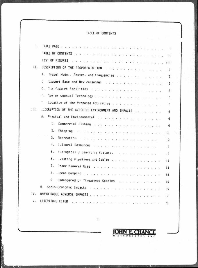
TABLE OF CONTENTS
I TITLE PAGE i
TABLE OF CONTENTS . . . J i
LIST OF FIGURES
I I . DESCRIPTION OF THE PROPOSED ACTION
A. Travel Mode.. Routes, and Frequencies . 3
L -apeort Base and New Personnel 3
C. ••.*» -" jppcrt F a c i l i t i e s 4
• '. *.ew or unusual Technology
Location of the Proposed A c t i v i t i e s -
I I I . --^CF.iPTION OF THE AKFECTED ENVIRONMENT AND IMPACTS 5
A. Physical and Environmental
! . Commercial Fishing
•J
9
?. Shipping , j
3. Recreat ion
4. C j l t u r a i Resources -
5. : . o ' o g i c a l l v Sensit ive Fsatu te i
~ . J
6. l i s t i n g P ipe l ines and Cables 14
7. I t . i e r Mineral Uses l 4
8. Jcean Dumping ^
9 Endangered or Threatened Species j5
B. Socio-Economic Impacts
IV. UNAVO DABLE ADVERSE IMPACTS , 7
V. LITERATURE CITED
i i
IQHN E.C:HANCF 4» A S S O C I A T E S I N C

LIST OF FIGURES
FIGURE
1 -- Vicinity Map of Green Canyon Area Block 473 2
i i i
- JOHN E, CHANCE ar A S S O C I A T E S I N C

I I . DESCRIPTION OF THE PROPOSED ACTION
This report addresses the a c t i v i t y proposed by Conoco Inc. f o r Green
Canyon Area Block 473 (OCS-G-5922). The approximate loca t ion of the a c t i v i t y
i s presented on Figure 1, a general v i c i n i t y map of the Outer Cont inental
S h e l f (OCS) lease areas o f f the coast of Louis iana.
I t is ant ic ipated t h a t a semi-submersible or dynamical ly pos i t ioned
d r i l l s h i p type r i g w i l l be used to d r i l l three w e l l j . The a c t i v i t i e s proposed
by Conoco inc. fo r t h i s b lock are addressed in the attacned Plan of
E x p l o r a t i o n .
The proposed a c t i v i t i e s w i l l be ca r r ied out by Conoco inc . wi th a
guarantee of the f o l l o w i n g :
1. The best ava i l ab le and safest technologies w i l l be u t i l i z e d
throughout the p r o j e c t . This includes meeting a l l aop l i cab le
•eouirements f o r eauipment types, aenerai p ro jec t layout ,
safety systems, eauipment ana moni tor ing systems.
2 . A l l operations w i l l be covered by H.M.S. approved Oi l S p i l l
Contingency P lan .
3. All appl icable Federa l . Sta te , and local requirements
regarding a i r emiss ions , water Qua l i t y , ana discharge f o r the
proposed a c t i v i t i e s , as wel l as any other permit cond i t i ons .
vi 11 be complied v i t h .
a r A S S O C I X T E S I N C
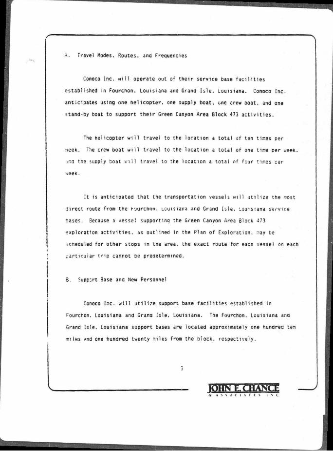
A. Travel Modes. Routes, and Frequencies
Conoco Inc. will operate out of their service base facilities
established in Fourchon. Louisiana and Grand Isle. Louisiana. Conoco Inc.
anticipates using one helicopter, one supply beat, one crew boat, and one
stand-by boat to support their Green Canyon Area Block 473 activities.
The helicopter will travel to the location a total of ten times per
week. The crew boat will travel to the location a total of one time per week,
ina the suopiy boat will travel to the location a total of four times cer
week.
It is anticipated that the transportation vessels will utilize the most
direct route from the rourchon, Louisiana and Grand Isle. Louisiana service
bases. Because a vessel supporting the Green Canyon Area Block 473
exploration activities, as outlined in the Plan of Exploration, may be
icneauled for other stops in the area, the exact route for eacn vessel on each
particular trip cannot De preaetermmed.
3. Supp:rt Base and New Personnel
Conoco Inc. will utilize support base facilities established in
Fourchon. Louisiana and Grana Isle. Louisiana. The Fourchon. Louisiana ana
Grana Isle. Louisiana support bases are located approximately one hunorea ten
miles *nd one hundred twenty miles from the block, respectively.
3
IQHN E. CHANCE i A S S O C I A T E S I N C

Because helicopter and marine facilities are currently available at the
service bases ana are presently ana continuously manned, no additional onsnore
employment is expected to be generated as a result of these activities.
The initial OCS Socio-Economic Data Base Report for the service base
-aci 1 ities utilized by Conoco Inc. will be prepared for submission pursuant to
tne specific parameters to be established by the DOI/MMS ana scheduled to be
1 ssuea at a later date.
".ew Support Facilities
'he oroposea exploration activities for Green Canyon Area Block 473 will
not require the aevelopment of any new support f a c i l i t i e s .
D. rjew or Unusuai Technology
The exploration activities for Green Canyon Area Block 473 will not
.arrant utilizing any new or unusual technology that may affect coastal
uers.
E. Location of the Proposed Activities
Ireen Canyon Area Block 473 is located approximately cne hurdred ten
miles from Fourchon. Louisiana, one hundred twenty miles from Grand Isle.
Louisiana and approximately one hundred eight miles from the Louisiana coast
of Lifourcne Parish. Figure I presents the location of the DIOCK in relation
4
IQHN E. CHANCE -at A S S O C I A T E S i > C
to t.ie Louisiana t o a s t , as we l l as the geographic r e l a t i o n s h i p between Green
Canyon Area BIOCK 473 and the other OCS lease areas.

I I I . DESCRIPTION OF THE AFFECTED ENVIRONMENT AND IMPACTS
A. Physical and Environmental
1. Commercial F ish ing
The Miss iss ipp i De l ta area is known as the " F e r t i l e F isher ies Crescent '
because i t is one of the most product ive commercial f i s n e r y grounds in the
wor ld . As a r e s u l t . Louis iana is t r a d i t i o n a l l y one of the too s ta tes in tiie
nat ion in terms of commercial f i s h e r i e s . v.nicn amounted to 1.234.884.407
sounds worth S118.754.742 in 1984 ana 1.8*2.321.060 pounds worth S109.755.223
in 1983 (USDC. NMFS. 1985). Ten species of f i n f i s h ana s h e l l f i s h represent 99
percent of Louisiana s commercial f i she ry land ings: brown shrimp (Penaeus
aztecus). white si . • „ (P. s e t i f e r u s ) . blue crab (Ca l l i nec tes sao idus) .
oysters (Crassostrea v i r q i n i c a ) . Gulf rH- . .den (Brevoor t ia pa t ronus ) . rea
snapper (Lutianus c> • • chanus). black arum (Pogonias c romis ) . --ed drum
;Scianops o c e l l a t u s ) . shotted seatrout (Cynoscion nebulosus) . and s t r i o e a
mul let (Muqi 1 ceonalus) . -11 but one of these species are es tua r ine
dependent.
The most va luab le species to Louisiana are the brown shrimp and whi te
shrimo. wnich togeth. iroduce Dy ta r the g rea tes t shrimp harvest in the l i u l f
Of Mexico. Louisiana s i r imp fishermen harvested 106.681.071 pounds (heads-on)
of shrimp worth S143.115.739 in 1984 (USDC. NMFS. 1985). Although he^/est
data for these species are not separated f o r s t a t i s t i c a l purposes, the brown
snrimp dominates the LOJisiana shrimp harvest , as i t is the most abunaant
1QHN E. CHANCE * A S S O C I A T E S I N C

iDecid .,at reg ion of the g u l f (White ana Boudreaux. 1977). Both of these
shrimp are es tua r i ne dependent and have s i m i l a r l i f e h i s t o r i e s , w i t h the major
dif ferences being the time and loca t ion t ha t the var ious l i f e stages begin and
•each t h e i r maximum l e v e l * . General ly , spawning occurs o f fshore w i t h the
resu l t ing larvae migra t ing inshcre to devel :o in es tuar ies . Brown s no
spawn from November to Apr i l in 30 to 120 meters of water, whi le wh i te shrimp
spawn from March to October in 8 to 34 meters (Benson, 19E2). Juven i le ana
idu l t brown shrimp migrate of fshore from May to J u l y , and white shrimp migrate
oetween June and Novemoer (Benson. !<?82).
"he proposed petroleum a c t i v i t i e s in Green Canyon Area Block 473 are
-xoected to have no lmoact or. the narvest of brown or white shrimp as t h i s
olocK is beyona the outer l i m i t s of the harvest area fo r these species (USDOI.
'•IMS. 1986. Visual No. 2 ) .
'he Gul f menhaden or "pogy1' f i she ry is Louisia-ia s second most valuable
* ishery. account ing fo r 1.756.235.053 pounas worth S68.801. 155 in 1984 (USDC.
'.MFS. 1385). ^ u l f mennaaen scawn o f f sho re from mid-October tnrougn Marcn in
-0 to 140 meters of water, wi th the larvae subsequently moving in to shal low,
low s a l i n i t y es tua r i es from February to May (Benson. 1982). -tore in the
shallow e s t u a r i e s , the larvae metamorpnose in to juven i les ana change from
seing carn ivore* to f i l t e r - f e e d i n g onn ivores. The juven i les and subadults
n g r a t e from the estuar ies into o f f shore waters from Oecemoer *hrough February
(3enson. 1982). The aaults oniy r a r e l y venture fa r of fshore (Hoese and Moore.
1977): indeed, about 93 percent c f the commercial n s h i n g e f e * * occurs . . i t h in
•en miles of shore idSDOI. MMS. 1983).
IQHN F. C HANCE M » > s o i i v r t N I N C
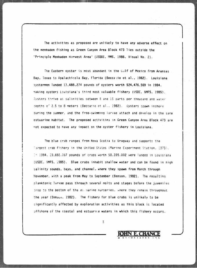
The a c t i v i t i e s as proposed are un l i ke l y to have any adverse e f f e c t on
the menhaden f i s h i n g as Green Canyon Area Block 473 l i e s outside the
"P r inc ip le Menhaden Harvest Area'' (USDOI. MMS, 1986. Visual No. 2 ) .
The Eastern oyster is most adundant in the Gul f o f Mexico from Aransas
Bay, Texas to Apalach ico la Bay, Flor ida (Becca ; io e t a l . , 1982). Louis iana
oystermen landed 13,488,274 pounds of oysters worth 524,476.569 in 1984.
making oysters Lou is iana 's t h i r d most valuable f i s h e r y (USOC, NMFS. 1985).
Oysters t h r i ve at s a l i n i t i e s oetween 5 ana 15 aa r t s per thousana ana water
:ebths o r 2.5 to 8 meters (Beccar.io et a l . . 1982). Oysters spawn inshore
l u r i n g the summer, and the free-swimming iaryae at tach ana develop in the sane
es tuar ine hab i ta t . The proposed a c t i v i t i e s in Green Canyon Area Block 473 are
not expected to have any impact on the oyster f i s h e r y in Louisiana.
The blue crab ranges from Nova Scotia to Uruguay and supports the
la rges t crab f i she ry in the United States (Marine Experiment S ta t i on . 19731.
: i 1984. 29.692.Q57 pounds of craps wortn S3.395.002 were lanaed in Louisiana
(USDC. NMFS. i 985 ) . Blue crabs inhabi t shal low water and can be found in nigh
s a l i n i t y sounds, bays, and channels where they spawn from March through
November, wi th a peak f rom May to September (Benson. 1982). The r e s u l t i n a
o lank ton ic larvae pass throuch several molts and stages before the j uven i l es
?roD to the bottom of the e i . - i a r i ne nurser ies , where they remain througnout
the year (Benson. 1982). The f i shery fo r blue crabs i s un l i ke l y to be
s i g n i f i c a n t l y a f fec ted by exp lo ra t ion a c t i v i t i e s as t h i s block is located
o f f shore c f the coastal and es tua r i t e waters in which t h i s f i shery occurs.
3
IQHN E. CHANGE ar A S S O C I A T E S I ^ C

Red snapper land ings i n Louisiana amounted to 1.487.456 pounds worth
S2.479.817 in 1984 (USDC. NMFS. 1985). Snappers are demersal predatory f i s h
tha t are common over or near banks, coral reef*, and outcrops, submarine
r idges , rocks, and man-made s t ruc tures such as shipwrecks and of fshore
d r i l l i n g p lat forms, e s p e c i a l l y of fsnore Louisiana (Benson. 1982; Hardy. 1978).
Red snapper spawn in the Gu l f o f Hexico from June t o Mid-Septemoer. in water
depths of 15-37 meters, over bottoms of hard Sind and ;»he11 w i t h rocky reef
areas: pawning .nay a c t u a l l y take place at the sur face (Hardy. 1978). L i t t l e
or no information is a v a i l a b l e aoout arval r e i snaooer. out juveni les are
•yp icd i l y found inshore i n h igh s a l i n i t y (24 to 40 Dpt) water 9-91 meters in
depth (Benson. 1982). The proposed a c t i v i t i e s should create a su i tab le
habi ta t for red snapper.
The arums (Sc ian idae) are one of the three most abundant fami l ies of
f ishes in the Gulf o f Mexico in terms cf biomass. and they outnumber a l l other
fami l ies -n the number or" species (Hoese and Mcore. 1977). Three SDecies or
jrums are commercially imoor tant to Louisiana. These include blactc brum. . ea
drum, ana spotted s e a t r o u t . In 1984. Louisiana lanaed a t o t a l o f 5.557.259
pounds of diums worth S4,290.068 (USDC. NMFS. 1985). The red drum f i she ry is
the most valuable, account ing fo r 51 percent of the t o t a l drum catch wh i le the
spotted seatrout and b l ack drum account fo r equal amounts of the remainder.
Typical ly, s c i a m d s are euryhal ine species t ha t spawn in shallow
nearsnore Gulf wa te rs , producing larvae tha t en ter coastal estuar ies fo r
deveiooment (Benson. 1982: Johnson. 1978; Hoese ana Moore, i977) . Spotted
&l A i i O C I A l f S I S C

seatrout soawn at n igh t i n deep channels and depressions adjacent to shallow
f l a t s , grass beds, and bayous in the estuary , from March to September w i th a
peak from Apr i l through J u l y (Benson. 1982). The larvae associate w i t h bottom
vegetation (predominantly sea grasses) or she l l rubble in channel bottoms
(Johnson. 1978). The j u v e n i l e s spend at least t h e i r f i r s t 6 to 8 weeks on the
nursery grounds, usua l l y w i t h i n 50 meters of the sho re l i ne , u n t i l l a t e f a l l
when they move into the deeper par ts of the es t -a ry (Benson. ;982 ) . Adult
spotted seatrout r a r e l y leave the estuar ies (Benson 1982).
3UCK drum spawn from February to A p r i l in or near t i d a l Dasses ana -fi
-pen bays ana estuar ies (Benson. 1982). The larvae are t ransDorted to shallow
estuar ine marshes, but may move to deeoer es tuar ine waters or shal low waters
o f f sandy beaches as la rae j u v e n i l e s (Johnson. 19/8) . Adult m ig ra t ion is
y res t r i c ted to sp r i ng and f a l l movement through the passes between
.ua< " ind nearshore environments (Beccasio et a l . . 1982).
Red drum inhab i t e s t u a r i e s and coastal waters out t j 22 k i lometers from
.nore . at oeoths up to 40 meters (Becassio et a i . . 1982). pawning occurs :;<
the f a l l and w in te r , p r i m a r i l y from September to November. ;na the larvae are
ca r r i ed by currents i n t o sha l low estuar ies and bays where thev tend to
associate with sea^rasses and marshes (Johnson, 1978). They usua l l y remain in
or near estuaries u n t i l they are three years o l d . but some leave at the ena of
t h e i r f i r s t year, m ig ra t i ng i n t o the Gulf in the f a l l (Benson. 1982).
Louisiana harvested 3,157.215 rounds o f mu l le t worth S999.936 in 1984
(USDC. .\MFS. 1985). Mu l l e t s are one of the most abunaant f i shes in the Gulf
10
iftttN E.CHAW A S S O C I A T E S i \ c
I -

of Mexico (Hoese ana Moore. 1977). Mullet have been observea in Alabama
inland as far as 607 kilrrneters from the Gulf, and offshore as far as 80
kilometers and as deep 1.385 meters (Benson. 1382). Mullet spawn from
October to May, and some females spawn more than once in a season (Benson.
1982). Larvae move inshore in the spring and the juveniles are found in the
shallow areas of the estuaries. Offshore movement from the estuaries occurs
during the fall (Beccasio et al., 1982).
Overall, commercial fishermen have benefited from the growth of the
oetroleum industry in the OCS waters of the Gulf of Mexico. >.'hile
technological improvements have enabled commercial fishermen to increase the
volume of landings, development of the petroleum industry has also haO a
positive impact on fishing. Because OCS petroleum development is dependent or
extensive marine vessel utilization, harbors and ports have been imornvfec
port access waterways have been expanded and improved, and the availability
and quality of marine vessel maintenance and repair facilities have '-crja^ej
significantly. These imorovements nave aefinitely haa a positive effect in
fishermen (Lassiter. 1980).
2. Shipping
A designated shipping fairway is located approximately thirty-three
miles north of Green Canyon Area Block 473. !t is likely rhat marine vessels
supporting this block will utilize the shipping fairway to gain access to the
support bases; however, i t is unlikely that the marine vessels will have a
significant effect on fairway traff i c . The dri11ing rig and each of the
II
IQHNE CHANCE t€ A •» •» o ( i * r r s I N C :

marine vessels w i l l be equipped with a i l U. S Coast Guard required
navigational safety aids.
3. Recreation
The open Gulf encompasses a broad expanse of . =»ltwatr .nich is u t i l i zed
by numerous sports fishermen and a small but rapidly increc^nc, numoer of
SCUBA divers. Many fishermen charter boats to deep-sea fish and sport dive 1:1
the northern Gulf. The states of Alabama. Mississippi, and Louisiana support
approximately 120 charter boats which condict a major-ty of their f i sh i -g
act iv i t ies in the waters of the OCS (USDOI. MMS. 1983). Petroleum oiatforms
in the northern Gulf provide recreation for fishermen ana scuoa oivers oecause
they act as a r t i f i c i a reefs attracting and establishing aauatic communities
including highly sought af ter food and sport f ishes. The reef effect created
by petroleum platforms is well known and is evidenced by the numerous c i v a t e
boat owners who regular ly v i s i t offshore f a c i l i t i e s to harvest f-oa and - :c r t
fishes.
Frequently, offshore rigs and platforms serve as navigation points for
small commercial and recreational marine c r a f t . Manned d r i l l i n g rigs and
oiatforms can also provide a haven for small c ra f t operators forced to abanaon
their vessels during storms or following boat accidents. The ins ta l la t ion and
•jse of navigational aids, lifesaving eguipment. and other safety requirements
pursuant to Coast Guard regulations are standard procedure for d r i l l i n g rigs
and marine vessels u t i l i zed by Conoco Inc.
12
J » A S i O C I * r i S I N C

4. Cultural Resources
Visuai No. 4 from the Final Environmental Impact Statement (USDOI. MMS.
1986) indicates tha t Green Canyon Area Block 473 f a l l s outs ide the zone
designated as an area w i t h a high p robab i l i t y of h i s t o r i c and p r e - h i s t o r i c
c u l t u r a l resources; t h e r e f o r e , i t is un l i ke l y tha t there w i l l be any
s i g n i f i c a n t impacts upon c u l t u r a l l y s i gn i f i can t f e a t u r e s .
5. Ecological ly S e n s i t i v e Features
3reen Canyon Area B lock 473 i i located approximately f o r t y - f i v e miles
:outheast of Diapnus Bank (USDOI. MMS. 1986. Visual No. 4 ) . There are no
o ther known eco log i ca l l y s e n s i t i v e areas near Green Canyon Area Block 473.
The Fourcnon, Lou is iana and the Grand I s l e , Louis iana support bases
which w i l l be u t i l i z e d as operat ions bases f o r the Green Canyon Area Block 473
exp lora t ion a c t i v i t i e s are located \Dproximately two mi les south and four
- l i e s east, r e s p e c t i v e l y , of the Wisner W i l d l i f e Management Area (USDOI. "MS.
1986. - isual No. 3 ) .
In general, i f a l l a c t i v i t i e s are executed as planned, encountering no
unusual circumstances, the environmental ly s e n s i t i v e areas w i l l not be
a f f ec ted .
1QHN E. CHANCE «* A S S O C I A T E S I N C

6. Exist ing P ipe l ines and Cables
A review of company f i l e data ind icates tha t there are no known
p i p e l i n e s or cables located i n Green Canyon Area Block 473. Conoco Inc . is
no t aware of any p i p e l i n e s or cables located in Green Canyon Area Block 473.
7. Other Mineral Uses
There are no ot l .er known mineral resources located in or near Green
Canyon Area Block 473.
8. Ccean Dumping
The major sources o f ocean dumping re la ted to OCS petroleum exp lo ra t ion
a c t i v i t y are d r i l l i n g f l u i d s , or "muds", and d r i l l . u t t i n g s . A f t e r the
exp lo ra to ry d r i l l i n g in Green Canyon Area Block 473 i s completed. Conoco Inc.
3oes ant ic ipate dumping t h e i r excess water-based d r i l l i n g f l u i d s
(approximately 8000 b b l s . ) . I f any o i l -basea mud is used in the d r i l l i n g
opera t ions , i t w i l l be t ranspo r ted to shore fo r proper d i sposa l .
D r i l l cut t ings are brought up by the d r i l l i n g mud and range in s ize from
g r a i n s of sand to pebbles. These cu t t ings are separated and s i f t e d and then
disposed overboard. Treated domestic wastes and d r i l l waters w i l l a lso be
disposed at the proposed d r i l l i n g s i t e . There w i l l be no i n ten t i ona l
d ischarge of any o i l y or hazardous mater ia ls in v i o l a t i o n of DOI or EPA
regu la t i ons .
14
tt A S S O C I A T E S I N C

I I
9. Endangered or Threatened Species
Endangered or th reatened species which might occur in Green Canyon Area
Block 473 are blue whale (Balaenoptera musculus). f inback whale (Balaenoptera
physalus) . humpback whale (Megaptera novaeangl iae) . sei whale (Balaenoptera
b o r e a l i s ) . sperm whale (Phvseter catodon). Kemp's r i d l e y t u r t l e (Lepidochelys
kemp i i ) . green t u r t l e (Chelonia mvdas). hawksb i l l t u r t l e (Eretmpchelvs
imbr i ca ta ) . leatherback t u r t l e (Dermochelvs cor iacea) and loggerhead t u r t l e
'Care t ta caret ta) (USDOI. Region IV Endangered Species Notebook).
Endangered or threatened species expected to occur in the v i c i n i t y of
the Fourchon, Louisiana and Grand I s l e , Louis iana inshore bases are A r c t i c
peregrine falcon (F . lco peregr inus t u n d r i u s ) . brown pel ican (Pelecanus
occidental i s ) . and American a l l i g a t o r ( A l l i g a t o r m iss iss ipp iens is ) (USDOI.
Region IV Endangered Species Notebook).
The brown pe l i can was a common res ident of Louisiana Dut t h i s species
became v i r t u a l l y e x t i n c t i n the l a te 1950's ( F r i t t s et a l . . 1983). By 1960.
the estimated l o p u l a t i o n of brown pel icans was four b i rds (NFWL. 1980). Se-
establ Ishment of a breeding populat ion in Louisiana has met w i th vary ing
success ( F r i t t s et a l . , 1983). A rc t i c peregr ine falcons are migrants through
the area and are not considered a component o f the resident b i r d popu la t i on ,
rhe American a l l - g a t o r i s c l a s s i f i e d as threatened in Louisiana due to
s i m i l a r i t y of appearance. This species i s n e i t h e r endangered nor threatened
b i o l o g i c a l l y in Louis iana and a regulated harvest is permitted under State Law
15
A S S O C I A T E S I S C

(USDOI. Region IV Endangered Species Notebook). No impacts on American
alligators are expected. The presence of marine manuals in coastal Louisiana
is considered sporadic and probably no resident populations exist. It is
unlikely that onshore or exploration activities related to Green Canyon Area
Block 473 will have any effect on the previously named species.
3. Socio-Economic Impacts
In accordance with DOI/MMS guidelines (OS-7-01), dated November 20.
1980. the initial OCS Data Base Report will be developed for suomission on or
before the prescribed due date. Subsequent Environmental Reports provided by
Conoco Inc. will address this data and related activity impacts as required.

IV. UNAVOIDABLE ADVERSE IMPACTS
The greatest t h r e a t to the natural environment is caused by inadequate
operational safeguards t h a t may cause or c o n t r i b u t e to an o i l s p i l l or wel l
blowout. These acc iden t ' , can be great ly reduced in number by u t i l i z i n g
trained operat ional p e r s o n e l .ind employing a l l a v a i l a b l e safety and p o l l u t i o n
control systems. Thes Tenu res are standard opera t ing procedure fo r Conoco
Inc. Conoco Inc. has an approved Oi l S p i l l Contingency Plan.
It snould be noted t ha t most large crude o i l ana re f ined Drooucts : D I ! : .
nave occurred du r i ng t r a n s p o r t a t i o n and not du r i ng d r i l l i n g or product ion
operations. Fur thermore, the p robab i l i t y of an o i l s p i l l occur r ing dur ing
exploratory d r i 11 i ng opera t ions is low (Danenberger, 1976). Transportat ion
ano r iver runof f c o n t r i b u t e an estimated 34.9 percent and 26.2 percent,
respectively, to the hyurocarbon contamination of the wor ld ' s oceans whi le
offshore oroduct ion a c t i v i t i e s account f o r on iy 1.3 percent (National Academy
I of Sciences. 1975). Natura l seeps of petroleum ana natura l gas. which occur
througnout tne no r the rn Gul f of Mexico (Zo B e l l . 1954: ^eyer. 1979).
contribute an es t imated 9.8 percent to the contaminat ion of the wor ld 's oceans
(National Academy o f Sciences. 1975). A d d i t i o n a l l y , i t was noted in the
executive summary of a recent study of petroleum proauct ion plat forms in tne
central G u l f o f Mexico (Bedinger. 1981). that na tura l disturbances ( i . e . r i v e r
f looaing ana storms) c m mere great ly a f f e c t normal b i o l o g i c a l communities
than the current i n d u s t r i a l development of the Louisiana OCS. The preceding
discussion is not in tended to minimize the s i g n i f i c a n c e of major o i l s p i l l s
17
,v A S S O C I A T E S I N C

r e s u l t i n g from petroleum exp lo ra t i on and product ion a c t i v i t i e s but i s provided
t o establ ish a perspec t i ve r e l a t i v e to t h e i r probable occurrence.
Thirteen of the f o r t y - s i x blow-outs on the OCS between 1971 and 1978
were associated w i t h e x p l o r a t o r y d r i l l i n g a c t i v i t i e s , none of which released
any to the marine environment (Danenoerger. 1980). The IXTOC I s p i l l of
1979, however, demonstrates t ha t advanced d r i l l i n g technology and ava i l ab le
sa fe ty and po l l u t i on c o n t r o l systems are not i n f a l l i b l e . Host s p i l l s are
subjected to immediate containment and clean jp e f f o r t s . The u l t i m a t e far.- o-
z t ) so i l lea in the marine environment is genera l ly ccnsiaerea to oe one r r
comoination of the f o l l o w i n g : evaporation ana decomposit ion in the
atmosphere, a ispersal in the water column, incorpora t ion in to edimoi. is. * ,v
ox ida t i on hy chemical o r b i o l o g i c a l means (Nat ional Academy of Sei i n . i ,
1975).
The unavoidable adverse impacts that w i l l occur as a r e s u l t of the
exploratory d r i l l i n g and d ischarg ing of d r i l l i n g f l u i a s , and t rea ted sewage
w i l l be few in numoer and temporary in nature. The primary aaverse impacts
inc lude a local ized degradat ion of water and a i r q u a l i t y in the v i c i n i t y of
the d r i 11ing s i t e , the p o t e n t i a l obs t ruc t ion to commercial and rec rea t iona l
f i s h i n g vessels, and the d i s r u p t i o n and/or k i l l i n g of benthic and/or pelagic
organisms during l o c a t i o n of the a r i l ! i n g r i g ana dur ing aisposal o f muas.
t t m g s . ana domestic wastes ana sewage.
Discharging from the d r ' 1 1 s i t e is i n e v i t a b l e dur ing OCS opera t ions ,
p a r t i c u l a r l y during e x p l o r a t i o n . Any mater ia ls tha t may conta in o i l or other
13
JOHN E. CHANCE at A S S O C l A T f S I N C

hazardous materials, and therefore would have a muci. greater adverse impact on
the environment, will not be discharged intentionally. Any discharging will
De done pursuant to all DOI and EPA regulations. The discharges to be
disposed overboard as a result of the exploration activity will include
domestic *aste and -'.ewage that is treated or, the rig before discnarging, d r i l l
cuttings, and excess water-based mud.
The environmental fate and effects of drilling muds anr1 cuttings has
aeen extensively addressed in a symposium (See Ayers et al.. 1980 for detailed
:iscussionsi. The discharging of d r i l l cuttings and water-oased mud will
result in an increase in water turbidity, ourial of benthic organisms, and
possible toxic effects on marine organisms in the immediate vicinity of the
drilling rig. A reduction in photosynthetic activity and plankton populations
can also be expected as a result of discharging. It Is expected, however,
that pelagic and benthic organisms will repopulate the area rapidly after
discharging i f tha effects are minimal and intermittent as exoected.
Offshore activities generate a smail but significant amount or air
pollutants due to the emissions of diesel engines: therefore, the
deterioration of air quality is unav-.idable in an OCS operation area. In most
instances, these emissions affect only the immediate exploration activity site
and are rapidly dissipated by the atmosphere depending upon climatic
conditions. An Air Quality Review Report has been prepared for Green Canyon
Area Block 473 and is included as an attachment to the Plan of Exploration.
!9
lOHNE. CHANCE at A S S O C I A T E S I S C

Commercial and recreatioral fishing would be affected by OCS
development, but pr imari ly in terms of inconvenience and interference.
Although the unavoidable adverse impacts could include some smothering of
she l l f i sh , snagging of trawl nets, reduction of area presently used for
unrestricted f ish ing, and minimal f in f i sh k i l l i n g , commercial f ishing
ac t i v i t i es would not be sigr. i f icant.y affect J . except in the unlikely event
of an o i l s p i l l . >> o i l sp i l l would result in serious econom losses due to
the contamination of commercial f ish species over a large a r c
There is a remote poss ib i l i t y that offshore areas of h is tor ica l ,
cu l tu ra l , or bioioaical significance could be damaged or destroyed by OCS
exploration operations. Visual No. 3 from the Final Environmental Impact
Statement (USDOI. MMS. 1986) indicates that no archeological, cu l tu ra l , or
h is tor ic areas are in the v i c in i t y of Green Canyon Area Block 473. Conoco
Inc. w i l l make every e f f o r t to avoid disturbing any h is tor ica l ly , cu l tu ra l l y ,
or biological ly s igni f icant feature.
20
JOHN E. CHANCE tt A S S O C I A T E S I > t

V. LITERATURE CITED
Ayf . R. C , Fi. L. Richards and J . R. Gould .980 Proceedings o f a symposium. Research on environmental fa te and
e f fec ts o f d r i l l i n g f l u i d s and c u t t i n g s . Washington, D.C. 1,122 pp.
Beccasio. A. D.. t i . Fotheringham. A. E. Red f i e ld , e t . a l . 19£2 Gulf coast eco log i ca l inventory: user ' s guide and in format ion base.
B io log i ca l Serv ices Program. U. S. Fish and W i l d l i f e Serv ice, Washington, D . C : FWS/OBS-82'55. 191 pp.
Bedingsr. C. A . , J r . 1981 Ecological i n ves t i ga t i ons of petroleum product ion p lat forms 1n the
centra l Gu l f o f Mexico. Volume I I I : Execut ive Summary. Submitted to the Bureau o f Land Management, New Or leans, Louis iana. Contract No. AA551-CT8-17. 29 pp.
Benson. U. G.. e i . 1982 L i fe h i s t o r y reauirements of selected f i n f i s h and s h e l l f i s h in
M iss iss ipp i Souna ana adjacent areas. U. S. Fish and W i l d l i f e Service. O f f i c e of B io log ica l Serv ices. Washington. D . C : FWS/OBS-81/51. 57 pp.
Danenberger, E. P. 1976 u i t s p i l l s . 1971 - 1 )75, Gulf of Mexico Outer Continental Shelf .
Geological Survey Ci 'cu lar 741. 47 pp.
Danenoeraer, E. P. 1980' Outer Con t i nen ta l Shelf Oi l and Gas Blowouts. U.S.G.S. Open-F" i e
Report. 30 -101 . 15pp.
r r - i t t s . T. H.. A. B. I r v i n e . R. D. Jennings. L A. Col lum. w. Hoffman, ana M. A. McGehee
1983 Tu r t l es , b i r d s , and mammals in the nor thern Gulf of Mexico and nearby A t l a n t i c waters. U. S. Fish and W i l d l i f e Service, D iv is ion of B i o l o g i c a l Serv ices , Washington. D. C. FWS/OBS-Pc/65. 455 pp.
Geyer. R. 1979 Natura l l y o c c u r r i n g hydrocarbon seeps in the Gulf of Mexico ana
Caribbean Sea. College S ta t ion , Texas: Texas A & M Un ivers i t y Press.
Hardy, j . 0. J r . 1978 Development o f f i shes of the M i d - A t l a n t i c B igh t . Volume I U .
Aphreaoaeridae through Rachycertr idae. d . S. Fish and W i l d l i f e Service. O f f i c e of B io log ica l Serv ices, * . . h i n g t o n , D. C : FWS/OBS-78/12. 394 pp.
21
lOHNE. CHANCE S f A S S O C I \ I E S I N C

Hoese. H. D. and R. H. Moore 1977 Fishes of the Gu l f o f Mexico. Texas A & M U n i v e r s i t y Press. Colieae
Stat ion. Texas. 327 pp.
Johnson. G. 0. 1978 Development o f f i s h e s of the M id -A t l an t i c B i g h t . Volume IV:
Carangidae through Ephippidae. U. S. Fish and W i l d l i f e Serv ice, Off ice of B i o l o g i c a l Serv ices. Washington. D. C : TWS/OBS-78/112. 314 pp.
Lass i te r . Ronald C. 1980 The Georges Bank: F ish and Fuel .
HIT. Cambridge. Massachusetts. Ninth Annual Sea Grant Lecture.
Marine Experiment S ta t i on 1973 Co?stal and o f f s h o r e environmental inventory Cape Hateras to
Nantucket Shoals . Marine Pub l i ca t ion Ser ies No. 2. Un i ve rs i t y of Rhode I s l and .
National Academy of Sciences 1975 Petroleum in the marine environment. Washington. D.C. 107 pp.
National Fish and W i l d l i f e Laboratory (NFWL) 1980 Selected v e r t e b r a t e endangered species of the seacoast of the United
States: Brown P e l i c a n , eastern and C a l i f o r n i a subspecies. U. Fish and W i l d l i f e Serv ice , B io log ica l Services Program FWS/OBS-80/01.40. IG pp.
U. S. Department of Commerce, Nat ional Marine F isher ies Service 1985 Louisiana land ings in 1984 and 1983. Unpublished r e p o r t . National
Marine F isher ies Se rv i ce . New Orleans. LA.
U. S. Department of the I n t e r i o r . Fish and W i l d l i f e Service 1976 Endangered and threatened specie: of the southeastern United States.
Region IV. A t l a n t a . Georgia ( p e r i o d i c a l l y updated) .
U. S. Department of the I n t e r i o r , M ine ra l : 1an„iement Serv.c.e 1983 Final Regional Environment.:: Impact Statement. Gulf of Mexico. Vol .
1. Prepared by Minera ls Management Serv ice . Gulf c f Mexico OCS Region. M e t a i r i e , Lou is iana. 527 pp.
U. S. Department of the I n t e r i o r , Minerals Management Service 1986 Final Environmental Impact Statement. Proposed O i l and Gas Lease
Sales 110 and 112, Gu l f o f Mexico OCS Region. Prepared by Minerals 'lansqement S e r v i c e . Gulf of Mexico OCS Region. New Orleans. Louisiana.
White, C. J . and C. J . Boudreaux 1977 Development o f an areal management concept f o r Gulf penaeid shrimp.
Louisiana W i l d l i f e and Fisher ies Commission, Technical B u l l e t i n Nc. 22.
22
JOHN E. CHANCE tt A S S O C I A T E . * I N C
J

Zo Bell. C. E. 1954 Marine bacteria and fungi. Fisheries Bulletin 55 (891: 217 - 222.
23
- IQHN F CHANCE , s i A S > O C I * r E 4 I N C