Knowledge Based Topology Discovery and Geo-localization ...
173
Knowledge Based Topology Discovery and Geo-localization Thesis Presented in Partial Fulfillment of the Requirements for the Degree Master of Science in the Graduate School of The Ohio State University By Yuri Rajendra Shelke, B.E. Graduate Program in Computer Science & Engineering The Ohio State University 2010 Dissertation Committee: Dr. Rajiv Ramnath, Advisor Dr. Ola Ahlqvist Dr. Jay Ramanathan
-
Upload
khangminh22 -
Category
Documents
-
view
1 -
download
0
Transcript of Knowledge Based Topology Discovery and Geo-localization ...

Knowledge Based Topology Discovery and Geo-localization
Thesis
Presented in Partial Fulfillment of the Requirements for the Degree Master of
Science in the Graduate School of The Ohio State University
By
Yuri Rajendra Shelke, B.E.
Graduate Program in Computer Science & Engineering
The Ohio State University
2010
Dissertation Committee:
Dr. Rajiv Ramnath, Advisor
Dr. Ola Ahlqvist
Dr. Jay Ramanathan

Copyright by
Yuri Rajendra Shelke
2010

ii
Abstract
Cable networks demand a high level of reliability as critical services are carried
over them. Maintenance operations will be greatly facilitated if faults can be
geographically located on the network topology. We demonstrate the application
of knowledge-based techniques and a novel ontology based software framework
for topology discovery and geo-localization by integrating topology data with
data from GIS based systems, where these databases have incomplete, obsolete
or inaccurate information. In addition to addressing this specific problem this
framework may be generalized for integration of data from multiple sources
with syntactic heterogeneity.

iii
Dedication
Dedicated to the Almighty God, my Guruji and my loving Parents

iv
Acknowledgements
I am immensely grateful to Prof. Dr. Rajiv Ramnath, my advisor. He has been a
real Guru during my academic career at The Ohio State University. His
encouraging support at all times and in all aspects at OSU has been invaluable.
He has been a constant source of inspiration and motivation to maintain my
momentum in the academic and research field at OSU. With his strong expertise
in the field of enterprise architecture, he inculcated the essential quality to look at
a bigger picture while solving a problem and thinking big and innovative. Not
only academic, his teachings, guidance and advice have also built up my
professional skill sets positively.
I am grateful to Dr. Jay Ramanathan for instilling the virtue of concentrating at
the research perspective of the problem. Her teachings of enterprise architecture
and complex adaptive enterprise services have been priceless.

v
I am greatly thankful to my parents. Their support, in all senses, has been
precious. This encouragement and support proved as a major motivation to lead
the work in high spirits.
I am thankful to Dr. Ola Ahlqvist for suggesting the adaptability of the ontology
based framework and its application to transportation problem. I am thankful to
Chowdary Davuluri and Thomas Loffing for their discussions on ontology and
rule based inference engines.
I am thankful to CableLabs, Inc for giving me an opportunity to gain an insight
in the field of cable networks and providing me with insightful domain
knowledge.
I am thankful to my room-mates and friends for their constant support and
motivation during my academic studies at OSU.

vi
Vita
March 1999…… Dnyanmata High School, Amravati, India
July 2005 …….. B.E. Computer Science & Engineering, Government College of
Engineering, Amravati University, India
2005 – 2006…... Lecturer, College of Engineering & Technology, Amravati, India
2006 – 2008 …. Programmer Analyst, Cognizant Corporation, India
2009 – 2009 ..... Graduate Fellow, NSF-CETI, The Ohio State University
Field of Study
Major Field: Computer Science & Engineering

vii
Table of Contents
Abstract ..................................................................................................................................... ii
Dedication................................................................................................................................ iii
Acknowledgements ................................................................................................................ iv
Vita…. ...................................................................................................................................... vi
Table of Figures ........................................................................................................................ix
1.0 Introduction .................................................................................................................... 1
1.1 Problem Statement ................................................................................................ 5
1.2 Solution Approach .................................................................................................. 7
1.3 Contributions ......................................................................................................... 8
2.0 Related Work .................................................................................................................. 9
2.1 Data Fusion ............................................................................................................ 9
2.2 Ontology .............................................................................................................. 16
2.3 Geographic Topology ............................................................................................ 22
2.4 Ontology-based Data Integration .......................................................................... 29
3.0 Contributions ................................................................................................................ 33
4.0 Solution Approach & Implementation ........................................................................... 39
4.1 Software Tools...................................................................................................... 48
4.1.1 DxGrep ........................................................................................................ 48

viii
4.1.2 Normalization ............................................................................................. 52
4.1.3 Geo-translation ........................................................................................... 56
4.1.4 Ontology and Rule based Inference Engine .................................................. 61
4.2 Evaluation of Architecture .................................................................................... 69
5.0 Conclusion ..................................................................................................................... 74
6.0 Future Work .................................................................................................................. 75
7.0 References .................................................................................................................... 78
Appendix A: Environment set for the development of DxGrep Tool ........................................... 85
Appendix B: Code Implementation ........................................................................................... 91
B.1 DxGrep Tool ......................................................................................................... 92
B.2 Normalization Component.................................................................................. 154
B.3 Geo-translation Component ............................................................................... 159

ix
Table of Figures
Figure 1: Cable Network Infrastructure with multiple topological layers ..............4
Figure 2: Different layers of General Knowledge representation [24] ..................... 17
Figure 3: High Level View of Proactive Network Maintenance Model [1] ............. 41
Figure 4: Cable Topology Plant model for high level representation of plant elements [12]
...................................................................................................................................... 42
Figure 5: Generating Fiber Node Topology Maps with geo-location Workflow [12]
...................................................................................................................................... 44
Figure 6: General Description of a methodology to achieve standardization and
visualization of CAD maps over GIS maps .............................................................. 46
Figure 7: Component-based architecture depicting the transformation from
detailed As-built maps to Geo-localization on the GIS maps ................................. 47
Figure 8: Normalization process using mapping provided by operator ............... 53
Figure 9: Process to geo-localize the network topology on the GIS ....................... 57
Figure 10: UML Representation of an ontology developed for cable network
topology discovery ..................................................................................................... 63
Figure 11: Ontology and Rule-based inference engine for topology discovery .... 66
Figure 12 Ontology-based Data Integration ............................................................. 71
Figure 13: Additional Include directories for DxGrep development ..................... 87
Figure 14: Additional library directories for DxGrep development ...................... 88

x
Figure 15 Additional dependencies for DxGrep development .............................. 89

1
1.0 Introduction
A unique knowledge based software architecture approach can be applied to
achieve topology discovery. This approach exploits domain knowledge to
provide formal representations of a set of concepts within a domain and the
relationships between those concepts and make the knowledge explicit.
Ontology based data integration and rule based inference engine are the
knowledge based approaches that play a pivotal role in accomplishing the
complex task of topology discovery and geo-localization. This research
hypothesis has been illustrated by applying a novel software architecture
approach to a practical problem of cable network topology discovery and geo-
localization.
As cable networks evolve, and many diverse services such as telephony, data,
video, business and advanced services (i.e., Tele-medicine, remote education,
home monitoring) are carried over them, the demand for maintaining a high
level of reliability for services increases. To achieve such high reliability,
operators have to fix problems before they have any impact on service.

Increasingly, intelligent end devices are deployed in cable networks such as
termination devices and monitoring instruments installed in Headends (HE) and
hubs. Also, new devices being deployed by operators such as Set Top Boxes
(STB), Multimedia Terminal Adapters (MTA), Hybrid Monitoring Systems and
even high end TV sets comply with the Data Over Cable Service Interface
Specification (DOCSIS) standard, resulting in ubiquity of this standard [1].
As DOCSIS devices evolve and are equipped with elaborate monitoring tools, it
becomes practical to use them for plant monitoring purposes. By using these
devices as network probes, the operators can collect device and network
parameters. Combining the analysis of data along with the network topology
and device location, it is possible to isolate the source of a problem. By analyzing
the pre-equalization coefficients and correlating multiple channel data, the
operator can determine the gravity of the problem and geographically isolate the
source of the problem.
The cable network infrastructure [12] can be composed of multiple topological
layers.

3
1. Physical Location: This layer corresponds to the physical location of several
network elements like the Cable Modem (CM), Cable Modem Termination
System (CMTS), amplifiers, taps, couplers, etc. This physical address can
be located on a Geographical Information System (GIS) map.
2. Utility Plant: This consists of shared or private infrastructure for public
utilities and communication services (such as cable services). It includes
manholes, poles, ducts, buildings, where the physical network elements
are placed.
3. Physical Cable Plant: This is the Hybrid Fiber Coaxial (HFC) physical
network from the Fiber Node to the customer premise. The Subscriber
feed consists of branches derived from the fiber node through amplifiers,
splitters and taps. This information has the context of civil constructions
from the utility plant described above.
4. Data Service Layer: Within a fiber node, the CM is tied to a set of upstream
and downstream channels. These sub-layers represent CMTS Media
Access Control (MAC) Domains and, CMTS Blades containment. This
layer is responsible for conveying the data on health metrics of the
network.

4
Figure 1: Cable Network Infrastructure with multiple topological layers
5. IP Network Layer: It corresponds to the Internet Protocol (IP) topology and
sub-network arrangements within the service area from the customer to
the Fiber node equipment.
6. Service layer: For each individual service, there is a link between IP
network topology and content servers & management servers associated
within the user premises where the service is to be delivered.

5
Fault localization is conducted at the plant level, and therefore draws
information from geographical location, the utility plant layer, and the cable
physical plant layer. The data service layer is the source of data for the fault
localization. The common signature & patterns of the impairments in the CM
and CMTS within the context of a service help locate the failures.
For the proactive network maintenance process to remain viable, the plant
design databases have to be analyzed and kept up to date so that the information
obtained from them is valid. Plant design databases, along with customer
databases, have to be analyzed such that, for every end-device that is installed,
the correlation between the street address and the network path that the
customer‘s end-device goes through to receive service is obtained.
1.1 Problem Statement
The research and development work leading to this thesis at the Center for
Enterprise Transformation and Innovation (CETI) at The Ohio State University
focuses on the geo-localization aspect of this Proactive Network Maintenance
project at Cable Labs, Inc. Localization of failures with a topology aware
structure is a compelling tool that facilitates operations and better ticket
6
handling. The goal of our work is to completely automate the fault identification
and resolution through the usage of geo-location to correlate and localize failures
within a small area. The ideal problem statement for this project is to account for
all the topology layers mentioned to move most of the inferences from
technicians into automated systems based on geo-localized network maps that
could not only prioritize but also expedite the resolution of critical and latent
problems of overtime.
Even though good geo-location information (customer addresses mapped to a
geo-position) is typically available, in many cases operator‘s information on the
topology layers above is unreliable, incomplete, obsolete or not accurate as the
technologies used for maintenance and updates are very costly. The successful
usage of proactive network maintenance methodologies requires operators to
have accurate, or near to accurate network topology information. But, some of
the times, operators do not have accurate cable network topology information or
as-built maps.

7
1.2 Solution Approach
The thesis proposes a knowledge based software architecture for topology
discovery to create usable network topology information, when only limited
topology information is available. This solution approach is achieved using the
domain ontology and rule based inference engine to solve the topology
discovery problem. The process first includes geo-localization of the available
network topology information (usually in the form of as-built CAD maps). This
geo-localization is achieved through extraction of the as-built map, normalization
of that extraction and geo-translation of that normalized extracted topology
information. This information then should be fed to a knowledge based system,
an ontology in this case, built on a domain knowledge available. With this
ontology, the inference engine in the knowledge based system works towards
the goal of topology discovery and infers the geo-locations of the missing
elements in the network topology depending on the domain rules. Ontology then
integrates the inferred data with the data from other sources and creates a single
amalgamated view to achieve fault identification and resolution.

8
1.3 Contributions
The thesis successfully illustrates the ontology based data integration and data
fusion approach to design and specify the geo-localization processes to allow
operators to integrate topology data coming from databases and digital maps
(e.g. ―As-Built‖ maps) with GIS based systems. This helps the operators get an
integrated view of all the data sets and localize segments of the network where
the frequency response analysis determines existing problem plant condition that
can lead to future service interruption. The research work applies the novel
concept of knowledge engineering to leverage the plant topology and geo-
location information for the automation of processes that would otherwise be
conducted manually relying on field technician. The thesis also designs a
framework whose software building blocks are interoperable and are open for
the use in future maintenance systems.

9
2.0 Related Work
For the implementation of the knowledge based approach to accomplish
topology discovery and geo-localization, four major research areas are studied in
detail. The thesis has made significant contribution and an excellent employment
of these computer science areas. The four major research areas are:
Data fusion
Ontology
Geographic topology
Ontology-based data integration
2.1 Data Fusion
Data fusion is the process of putting together information obtained from many
heterogeneous data sources, on many platforms, into a single composite picture
of the environment. Data fusion is an efficient method that improves accuracy of
sensor network localization. A key effect of data fusion is the ability to deal with

10
conflicting data, producing intermediate results that the algorithm can revise as
more data becomes available.
This localization concept is mainly used in the field of sensor networking to
determine the positions or the physical coordinates of the sensor nodes in a
network given incomplete and inaccurate pair-wise distance measurements.
Many sensor network applications like habitat monitoring, smart building failure
detection and reporting, and target tracking make it necessary to accurately
orient the nodes with respect to a global coordinate system. This data can be
reported in a geographically meaningful way. The sensor node localization
employs many algorithms that deal with localizing many missing sensor nodes
with the help of some limited information of some anchor nodes, relative
distances and signal strengths.
The concept of revising the location information of the sensor on the availability
of more data is widely used in sensor network localization. This is done by
injecting a pattern of chirps or a signals in the network and the time, angles and
distances are calculated with respect to the listening nodes or the anchor nodes.
Anchor nodes, also known as beacon nodes, are the typical prerequisites to
localize a sensor network in a coordinate system. Anchor nodes are nodes whose

11
position in the sensor network is already known. At a minimum, three non-
collinear beacon nodes are required to define a global coordinate system in two
dimensions. In a three dimensional coordinate system at least four non-coplanar
beacons must be present [11].
The energy of a radio signal decreases with the square of the distance from the
signal‘s source. Consequently, a sensor node listening to a signal transmission
from one of the other sensor nodes in the network should be able to use the
strength of the received signal, known as Received Signal Strength Indication, to
calculate its distance from the transmitter. Many researchers find hop count to be
useful measure to computer the inter-node distances. If the hop count between si
and sj is hij, then the distance between si and sj, dij , is less than R*hij , where R is
again the maximum radio range. The local connectivity information provided by
the radio defines an un-weighted graph, where the vertices are sensor nodes, and
edges represent direct radio links between nodes. The hop count hij between
sensor nodes si and sj is then defined as the length of the shortest path in the
graph between si and sj[11].
Time Difference of Arrival (TDoA) and Angle of Arrival (AoA) have also been
important factors in determining the location of the sensor node in the sensor

12
network. Angle of Arrival data allows the listening node to determine the
direction of a transmitting node. A digital compass, along with the Angle of
arrival data, helps determine the global orientation of the node. In TDoA, the
transmitter first sends a radio message. It waits some fixed interval of time, tdelay,
and then produces a fixed pattern of ―chirps‖ on its speaker. The listening nodes
note the current time, tradio,. Then, they note the current time, tsound on detection of
the chirp pattern. Then the listeners compute the distance d between themselves
and the transmitter using [11]
d = (sradio − ssound) _ (tsound − tradio − tdelay)
TDoA is more effective in practice than RSSI is due to the difference between
using signal travel time and signal magnitude. TDoA is vulnerable only to
occlusion while the RSSI is vulnerable to both occlusion and multipath.
Many algorithms and papers have been studied in order to understand the
process of sensor network localization to approximate the positions of the
network elements and refine the earlier inferences as additional information
becomes available and then use that analogy for the topology discovery process.
Srirangarajan S. et al. [5], have researched on a method to accomplish distributed
sensor network localization using Second order cone programming relaxation.

13
They show that the positions of sensor nodes can be estimated based on local
information, a technique that also compensates for anchor position errors. The
localization process starts with the sensor nodes estimating their positions using
information from their neighbors. The anchors then refine their positions using
relative distance information exchanged with their neighbors and finally, the
sensors refine their position estimates. Kannan A. et al. [7], have talked about the
wireless sensor network localization based on the Simulated Annealing
approach. This research also takes care of the flip ambiguity mitigations.
Simulated annealing (SA) is a technique for combinatorial optimization
problems. This process defined by Kannan et al., is a two phase simulated
annealing based localization. Here, an initial location estimate is obtained in the
first phase using the SA and the large error due to flip ambiguity is mitigated in
the refinement phase using neighborhood information of nodes. Flip ambiguity
arises when a node's neighbors are placed nearly collinear such that the node can
be reflected across the line connecting its neighbors while satisfying the distance
constraint.
Pratik Biswas et al. [8], have concentrated on the centralized localization
algorithm approach. Centralization allows an algorithm to undertake much more
complex mathematics than is possible in a distributed setting. Biswas et al., have

14
researched on Semi-definite Programming (SDP) approach for sensor network
localization. In a semi-definite programming approach, as explained by Doherty
[13], geometric constraints between nodes are represented as linear matrix
inequalities (LMIs). Once all the constraints in the network are expressed in this
form, the LMIs can be combined to form a single semi-definite program. This is
solved to produce a bounding region for each node [11]. In the approach used by
Biswas et al. [8], distance data is acquired by a sensor node by communicating
with its neighbors. Their approach uses the points estimated from the SDP
solution as the initial iterate for a gradient-descent method to further refine the
estimated points. Zhang, Q. [9], et al have improved on the Semi-definite
programming approach by suggesting a two-phase localization algorithm for
wireless sensor network. In the first phase, they use a genetic algorithm to get an
accurate estimation of location. In the second phase, Simulated Annealing
algorithm refines the location estimates of those nodes that are likely to have a
flip ambiguity problem. This method of localization achieves higher accurate
position estimation than semi-definite programming with gradient search
localization.
The methods of sensor network localization employ an underlying principle that
the chirps injection and nodes communication with anchor nodes. Depending on

15
the time, delay, angle and signal strengths, the positions of the remaining nodes
are determined. However, when it comes to a cable network, all the network and
all the devices are not DOCSIS enabled to transmit the information back. Also, all
the cable network elements do not communicate with each other. Also, the data
is collected just from the cable modems and not from other entities like taps.
However, the concept of data fusion and sensor network localization has been
applied in the context of topology discovery of a cable network. The common
impairment signature shared among the network elements signify that these
network elements are connected to each other. So, with notion of sensor chirps
injection, the faults or certain impairments are injected in the network. The
common signature of the impairments confirms the connectivity information. On
the availability of such information and with the perception of data fusion, the
location of the network elements and their connectivity information is revised
and then geo-localized on a GIS map. So, the topology discovery is achieved by
combining multiple data from disparate sources in order to produce information
of tactical value. But, there was a need to research for a new approach to achieve
the cable network elements localization or more accurate topology discovery
when only limited topology information is available.

16
2.2 Ontology
Ontology refers to a formal representation of knowledge and a shared
understanding of a domain of interest. This ontology may be used as a unifying
framework to solve the domain specific problems. Ontology necessarily involves
some sort of conceptualization, a conceptualization of a set of concepts. A body
of formally represented knowledge is based on that conceptualization. These
concepts would include entities, attributes, processes, their definitions and their
inter-relationships [10]. A conceptualization is an abstract view of the domain.
Every system or a domain can be represented and is attached to some kind of
conceptualization, explicitly or implicitly. Ontology is an explicit specification of
a conceptualization.
The definitions in ontology associate the names of entities with human-readable
text describing what the names mean, and rules that constrain the interpretation
and well-formed use of these entities [5]. The quote from electronic mailing list of
shared reusable knowledge bases [25] states that ontology is an agreement about
shared conceptualizations. These conceptualizations include conceptual
frameworks for modeling domain knowledge, content specific protocols for

17
communication among inter-operating agents, and agreements about the
representation of particular domain theories [10].
Figure 2: Different layers of General Knowledge representation [24]
A general methodology to develop an ontology includes four major steps. The
first step is to identify the purpose and scope. This step identifies the motive and
characterizes the range of intended users of the ontology. The second step is to
build an ontology. This step can be broadly divided into Capturing, Coding and
Integration sub-steps. In ontology capture phase, the key concepts and their

18
relationships in the domain are identified. The definitions for these concepts are
produced and the rules governing these concepts and the relationships are
identified. In coding, the concepts, which are captured, are explicitly represented
confirming to the terms that were agreed upon during the ontology capture step.
Once this is complete, the ontology is merged or integrated with any existing
ontology. The third step is the evaluation of an ontology. The last step is the
documentation step. In this step, all the important assumptions about the main
concepts defined in an ontology and the about the primitives used to express the
definitions are explained [10]. The methodology used in the Enterprise Integration
Laboratory [23] for the design and evaluation of integrated ontologies consists of
the following steps:
1. Capture of motivating scenarios
2. Formulation of informal competency questions
3. Specification of the terminology of the ontology within a formal language
4. Formulation of formal competency questions using the terminology of the
ontology.
5. Specification of axioms and definitions for the terms in the ontology
within the formal language.
6. Justification of the axioms and definitions by proving characterization
theorems.

19
This mechanism of guiding the design of ontologies allows a more precise
evaluation of different proposals for an ontology, by demonstrating the
competency of each proposal with respect to the set of questions that arise from
the applications.
Silvana Castano [15], et al have proposed a knowledge discovery-based approach
to ontology concept design. Concept design is the activity of defining a new
concept into an ontology, by setting name, properties and semantic relations that
are required to frame the new concept in the ontology. It is an important activity
for both the creation and evolution of an ontology for adaptation to
requirements. This paper exploits ontology matching techniques in order to
retrieve useful external concepts semantically related to the design at hand. The
resulting ontology knowledge space is open towards external knowledge sources
by complementing the ontology expert knowledge with domain knowledge
stored in other external sources. This approach is expressed in two main phases.
Concept commitment is the activity of defining final ontology concepts by
refining the initial concept definitions through the integration of knowledge
fragments related to the retrieved matching concepts. This adds new ontology
axioms in the current ontology to enrich the current domain conceptualization.

20
Researching on improving communication among computers and human users,
Raymond Y.K. Lau [16], et al researched on context sensitive domain ontology
extraction. They exploited the contextual information of the knowledge sources
for the extraction of high quality domain ontologies. As per the paper, by
combining lexico-syntactic and statistical learning approaches, the accuracy and
the computational efficiency of the extraction process can be improved. Gloss [17],
et al discusses the service and design considerations of an ontology for a multi-
agent system. They use a Protégé-based ontology to convey the semantic
structure and to drive the actual Java Agent Development Framework (JADE)-
based demonstration.
We show that a knowledge based system approach, such as ontology and rule
based inference engine can be employed to solve the topology discovery
problem. The problem of topology discovery is a knowledge inference problem.
The cable network has different network elements, and these are treated as
entities of the ontology. Their inter-relationships and processes are also
represented as a part of an ontology. The set of laws that apply to the cable
network are captured in the ―Rules‖ module of the ontology using the SWRL.
The reasoner helps infer the inferences, which are later processed to output the
missing network elements‘ positions. The positions of the elements are refined

21
with the availability of more information in the form of rules and constraints in
an ontology. For example, the impairment signatures collected from the first 5
phases of the proactive network maintenance process make a strong positive
assertion that there is a network link joining all the network elements sharing the
same impairment signatures. Also, ontologies take care of all the domain
constraints and requirements and help the process of topology discovery.
The ontology based data integration of the data with syntactic heterogeneity has
been achieved in this thesis. The data coming from multiple sources in different
syntactic forms is integrated with the help of ontology to achieve more accurate
estimation of topology. As demonstrated in the case of cable network topology
discovery problem, the data comes from different sources, such as, the utility
pole databases, the limited cable network topology, some pre-existing geo-
localized network topologies and other GIS databases. These different sources
are integrated with the use of an ontology and the rule based inference engine
which associates the different data sources as per the rules defined and gives you
the final integrated topology with the geographic locations of missing network
elements.

22
2.3 Geographic Topology
In a GIS, topology is a set of rules which define the geometric relationship
between objects located in space, represented by points, lines and polygons. The
geometric characteristics of these objects do not change under transformations
such as stretching or bending, and are independent of any coordinate system. A
topological map refers to a map that has been simplified so that only vital
information remains and unnecessary detail has been removed. The topological
characteristics of an object are also independent of scale of measurement. A GIS
can recognize and analyze the spatial relationships that exist within digitally
stored spatial data. These topological relationships allow complex spatial
modeling and analysis to be performed. Topological relationships between
geometric entities traditionally include adjacency (what adjoins what),
containment (what encloses what), and proximity (how close something is to
something else). Adjacency and containment describe the geometric
relationships that exist between area features. Areas can be described as
‗adjacent‘ when they share common boundaries. Connectivity is a geometric
property used to describe the linkages between line features, e.g. roads are
connected to form a road network. The method to determine spatial
relationships is vector data models. It conveys the information as to what is
23
inside or outside a polygon or which nodes are connected by arcs and turns
vector nodes, arcs, and polygons into intelligent maps. Topology rules are
particularly important within GIS, and are used for a variety of correction and
analytical procedures. Principles of connectivity associated with topology lead to
applications in hydrology, urban planning, and logistics, as well as other fields;
as such, topological analyses offer unique modeling capabilities, defining the
vector nature of topological features and correcting spatial data errors from
digitizing.
Topological data structures include points, lines, vertices, nodes, chain, arcs,
rings and polygons. Points are either isolated or linked to form lines in which
case they are vertices. A line is a sequence of ordered vertices, having a start
node and an end node. A chain is a line which is part of one or more polygons. It
can have (left, right) polygon identifiers as well as (start, end) nodes. Chains are
also called arcs or edges. A node is point where lines or chains meet or terminate.
A polygon consists of one outer rings and zero or more inner rings. A ring
consists of one or more chains. A simple has no inner ring, whereas complex
polygon has one or more inner rings.
24
Van Roessel [28] described a topological structure in the relational normal form. It
was intended to be used as a basis for an interchange structure for changing from
one vector structure to another. It provides unambiguous description of
topological relationships. In his approach, the polygons are defined in terms of
rings by a polygon topology table. If there is more than one ring per polygon, the
first one is the outer ring, and all the others are inner rings. The second table,
which is ring topology table links rings to chains. The third links chains to nodes
and polygons. The other two tables provide linkages from nodes and chains,
respectively, to a table of vertices and coordinates. In the last table, the spatial
coordinates are held in one table only, quite separate from topological attributes.
The set of six tables completely defines the spatial and topological relationships
found on the map. Non-spatial attributes can be added additionally to link any
spatial object to thematic attributes. So, vertices are not directly linked to
polygons or rings, nor there is a direct link between nodes and rings. So, major
advantages of this structure are firstly, there is no repetition of spatial
coordinates between one polygon and the next and, secondly, the topological
information is explicitly stored and is separated from the spatial coordinates,
facilitating search that requires adjacency, containment and connectivity
information. Using the relational form for topological tables has the advantage of
being very clear and unambiguous. In addition, editing lines is relatively simple,

25
because the coordinates are kept separate, repeating groups of attributes are
eliminated, each tuple is unambiguously associated with a unique key.
Another operational topological structure is POLYVRT structure developed by
Peucker and Chrisman [32]. This structure uses polygons, chains, nods and
points. The polygon topology table specifies chains directly, without using
intervening rings. Chains that form inner rings are flagged. The chain topology
table contains (start, end) node pointers and (left, right) polygon pointers.
Coordinate data is held separately from topological data in two tables for
vertices and nodes. This structure can be used for both areal and network objects.
As compared to can Roessel relational tables, the sequence of records in the
tables is important.
One more topological structure is NCGIA core curriculum [33], suggested by
Goodchild and Kemp. It is a description of pair of simple structures for area and
network relationships. The topological information is reduced. For area
relationships, an arc topology table contains (left, right) polygons, and an arc
geometry table holds the coordinate strings. For network relationships, an arc
topology table specifies (start, end) nodes and a node topology table specifies a

26
list of arcs. Polygon information and nodes coordinates are not stored separately,
but they can be derived from other tables.
The TIGER [34] (Topologically Integrated Geographic Encoding and Referencing)
structure is more complex. It allows threading from one table to another and
minimizes data redundancy. Extensive non-spatial attribute data forms an
integral part of the data structure, organized according to the 0-, 1- and 2-cell
clssification. In CANSIS topological structure, developed by Canadian
Department of Agriculture in 1970s, there are tables linking object to polygons,
polygons to arcs and objects, arcs to polygons and an arc geometry table
containing coordinates of vertices. Nodes and node topology are not used in this
structure, because the design is for areal objects rather than networks.
A network topology is a description of the layout of physical connections of a
network, or the description of the possible logical connections between nodes,
indicating which nodes are able to communicate. It is a logical characterization of
how the devices on the network are connected and the distances between them.
A network layer must stay abreast of the current network topology to be able to
facilitate the process of fault identification and resolution. In the case of cable

27
network topology, the different topology structures are the network elements.
The cable network topology bears resemblance to the geographic topological
structures and the relational form of the topological structures as discussed by
van Roessel [28]. The data of the topology are kept at different levels and maintain
the hierarchical form to conform to the goal of clear and unambiguous
description of topological relationships. The as-built CAD maps are the cable
network topology information. These CAD maps are arranged in the form of
block table, block references, lines, poly-lines, vertices, arcs, solids and circles.
The block table keeps the definition or the template of all the block references
and other structures such as lines, poly-lines, arcs, solids, etc. Each of the block
references, lines, poly-lines, arcs, solids and circles are the instances of the
templates created in the block table. The block references form the network
elements like taps, telephone poles, fiber node, amplifier, couplers, etc. and the
lines, poly-lines, arcs, etc form the connectivity among the network elements. All
of these components are put in different layers and put together they form a
single cable network topology in the form of the as-built CAD map.
The DxGrep tool converts the cable network topology from the CAD map format
into a knowledge based XML format. It formats the cable network topology into

28
a more unambiguous and comprehensible hierarchical topological structure. This
knowledge based format is formatted in such a way that the network elements
lie at the top level and the following tuples describe the network element with
the characteristics such as, its position coordinates, extent, name and identifier
key. The attributes for these network elements are expressed further at another
level description. The lines, poly-lines, arcs, solids, circles are expressed under
different topological structure other than the block references. This gives the user
the freedom to mine in more and more information as per the requirement than
complicating thing into a spaghetti structure. As the relational form suggested
by van Roessel [28], this knowledge based format of the topology structure
provides with clear advantages that there is no repetition of spatial coordinates
and the topological information is stored separately from the spatial coordinates
at a level deeper than the spatial coordinates, facilitating operations that require
adjacency, containment and connectivity information.

29
2.4 Ontology-based Data Integration
It is an approach to use ontologies to effectively integrate data from multiple
heterogeneous sources. These sources can be databases as well as unstructured
information such as files, HTML pages, XML, etc. A data integration system
provides a uniform interface to distributed and heterogeneous sources. The
effectiveness of ontology based data integration is closely tied to the consistency
and expressivity of the ontology used in the integration process. Ontologies
enable the unambiguous identification of entities in heterogeneous information
systems and assertion of applicable named relationships that connect these
entities together [35].
Ontology might play roles for content explication, query modeling and
verification. During content explication, the ontology enables accurate
interpretation of data from multiple sources through the explicit definition of
terms and relationships in the ontology. During verification, the ontology verifies
the mappings used to integrate data from multiple sources. These mappings may
either be user specified or generated by a system. During query modeling, the
query is formulated using the ontology as a global query schema. In order to

30
establish efficient information sharing, the information sources must be
identified as they are the one that work with the system that query the
information. Data integration is concerned with unifying data that share some
common semantics but originate from unrelated sources. Necessarily, when we
work on data integration, we must take into account a more important and
complex concept called ―heterogeneity‖. Heterogeneity might be classified into
four categories: (1) structural heterogeneity, involving different data models; (2)
syntactical heterogeneity, involving different languages and data
representations; (3) systemic heterogeneity, involving hardware and operating
systems; and (4) semantics heterogeneity, involving different concepts and their
interpretations.
The vocabulary provided by the ontology serves as a stable conceptual interface
to the databases and is independent of the database schemas and the language
used by the ontology is expressive enough to address the complexity of queries
typical of decision-support applications. The knowledge represented by the
ontology is sufficiently comprehensive to support translation of all the relevant
information sources into its common frame of reference. So, being a knowledge
based approach, ontology has many advantages for performing data integration
31
over other approaches. Buccella et al. [36], and Wache et al. [37], have compared
and contrasted different approaches for ontology based data integration. Wache
et al., have explained different roles of ontologies for single and multiple
ontologies. They have also surveyed on hybrid approaches of ontology, which
were developed to overcome the drawbacks of single and multiple ontologies. Li
Dong and Huang linpeng [21], have suggested a framework for ontology based
data integration that is capable of deriving an ontology from a collection of XML
schemas in a semiautomatic manner and integrating heterogeneous XML sources
at the semantic level. In this framework, the ontology is constructed following a
layered approach where an intermediate model is introduced to explicate the
underlying semantics of XML schemas and to reduce the complexity of ontology
derivation. This two-phase approach is performed semi-automatically by
applying a set of heuristic rules and by interpreting mapping information
defined by users. The resulting ontology serves as a global semantic view over a
set of data sources to be integrated.
On the similar lines of the framework suggested by Li Dong and Huang linpeng
[21], the knowledge based approach developed in this thesis uses ontologies for
the integration of heterogeneous data. Our work has an ontology approach,

32
where data with syntactic heterogeneity from multiple sources is integrated. In
our framework, the data integration is performed based on the domain rules
provided to the ontology. With the capability and strength of a knowledge based
approach, the ontology and rule based inference engine provide a uniform
interface to distributed and heterogeneous sources. For the illustration of this
knowledge based approach to the cable network domain, available cable
network topologies are converted into the KML layers, which conform to the
XML with KML schema. The other databases that are and can be integrated with
the help of ontology are the utility pole databases, pre-existing topological
information and other GIS databases, such as Census data, weather data, etc.
Depending on the rules and input provided, the ontology figures the inferences
and does the data integration to provide a unified view to facilitate the inference
process and topology discovery.

33
3.0 Contributions
The thesis successfully shows that a knowledge based software approach can be
applied to achieve topology discovery and geo-localization. This has been
demonstrated by solving the cable network topology discovery problem using an
ontology and a rule based inference engine. Knowledge based approach, such as,
ontology based data integration has also been successfully applied to achieve
Geo-localization. The thesis also widely incorporates the concept of data fusion
to combine heterogeneous data from disparate sources in order to produce
information of tactical value. Also, the thesis shows that the concept of fault
injection based inferences and the notion of refining the inferences on the
availability of more information helps in the topology discovery inference
process.
The thesis has largely incorporated the computer science concept of data fusion
in the area of topology discovery and geo-localization. The process of geo-
localization combines data from multiple sources into a single unified data set,
which includes data points from all the input sources like cable network

34
topology as-built CAD maps, GIS maps and other utility pole information maps.
The information is gathered from these sources in order to achieve inferences to
make it more efficient and potentially more accurate than if they were achieved
by means of a individual source separately [19]. Data fusion provides a way to
deal with data that is redundant, inconsistent and conflicting and is dependent
on the user requirements. Data fusion is examined as a means to prevent
information overload and to expedite processing of the vast amounts of data. So,
the data fusion architecture in the thesis has been decentralized. The thesis
makes it possible to bring in different topology databases depending on the user
requirements and fuse them into the existing data fusion created earlier. This is
illustrated by converting the available network topology information into the
form of KML layers. These KML layers may be varied or decentralized enough to
keep network element information separate from road and connecting lines
information separately. In addition to that, utility pole, road maps information
and physical address information may be stored separately in different topology
databases. The thesis formats each of the topology databases in the form of a
layer and fuses them together by creating an overlay on-demand. So, the
dynamic data fusion can be achieved as per the requirements of the user. This
way, it adds more intelligence to the inference process and creates a single
coordinated view of the data from various sources.

35
Our work also demonstrates ontology based data-integration. The process of
topology discovery successfully deals with data having different representation
formats to accomplish integration of data with syntactic heterogeneity. The data
integration of the data from sources with system heterogeneity has been
achieved through the DxGrep tool. The ontology framework in the thesis is
capable of deriving a complete fulfilled topology from a collection of XMLs and
integrating heterogeneous XML sources at the semantic level. On the similar
lines of the framework suggested by Li Dong [21], et al, the ontology based data
integration in the system, specified in the thesis, is achieved by following a
layered approach where an rule-based inference engine model is introduced to
clarify the underlying semantics of XML schemas and assist in the ontology
derivation. This is performed by applying a set of domain specific rules and by
interpreting mapping information defined by users. The resultant ontology acts
as a global semantic view over a set of multiple data sources to be integrated.
The components of the software developed include the DxGrep Tool,
normalization component, a geo-translation component, a domain ontology and,
a rule based inference engine.
36
The extraction of the network elements information is done using the DxGrep
tool. This tool uses the C++ library support by Open Design Alliance and extracts
the elements information and attributes and puts them in XML format. However,
the names used in these as-built CAD maps are varied and do not follow specific
standards. Every operator has his own nomenclature for the network
components. These names are normalized as per the nomenclature standards
provided by the SCTE (Society for Cable Telecommunication Engineers). The
normalization component developed takes the mapping of the non-standard
names of the network elements to the standard names as provided by the SCTE.
This normalization component does the translation and outputs the standard
normalized mapping for the operator to take on to the next phase of Geo-
translation.
The geo-translation component of the thesis takes the normalized XML
extraction of the as-built CAD map and translates them. This is done by
converting the maps with xyz coordinates system into KML formatted GIS maps
having geographic coordinates. The operator provides the geographic
coordinates of the origin in the cable network plant topology map. If the operator
does not have that, then the translation is done using the geo-coding and creating
an anchor-point scale estimation method. The anchor-point scale estimation is

37
further explained in detail in the Implementation part of the thesis. This KML
document can then be rendered on any GIS based software like Google Earth or
Arc GIS to create an overlay of the as-built map over the GIS maps. These
different KML layers for each of the topology database are then employed in a
knowledge based system for data fusion and ontology based data integration to
achieve topology discovery and geo-localization.
Topology discovery is done using cable network domain ontology and a rule-
based inference engine. The ontology part of the thesis describes basic rules
specific to the cable network domain. In case, only limited topology information
is available, the reasoning in the ontology develops inferences. The inference
engine handles these inferences and calculates accurate or almost accurate
geographic positions of the missing network elements from the limited cable
network plant topology.
The thesis, thus, demonstrates that knowledge based software architecture can
be employed to carry out the process of topology discovery and geo-localization.
This solution proves to be a very cost-effective way to correlate and geo-localize
failures within an area of a possible or real trouble. This solution suggested is
scalable to a larger scale and is able to handle growing amounts of work in a
38
graceful manner. The solution has appreciable extensibility to the application
development and is open to carry-forward of customizations to achieve that.
Considering the usability of this framework, this architecture has huge
implications in many domains, particularly in domains that strive to determine
the geographic positions of the elements in the domain. The thesis suggests best
practices and builds interoperable software that is open for future enhancements
and reuse. The software part developed as a part of the thesis is able to be
integrated with the existing technologies of the cable operators. This suggested
framework has applicability to future maintenance of network.

39
4.0 Solution Approach & Implementation
The thesis work mainly aims to demonstrate that a knowledge based solution
approach can be applied to achieve accurate or near accurate cable network
topology discovery and geo-localization of the cable network topology.
Considering geo-localization of the cable network topology, we aim to achieve a
location-rich network information. With location-rich network information, the
operator or technician can accurately locate all the network elements on the
ground and thus finds the bad devices that cause or can lead to interruptions. We
attempt to achieve geo-localization through creating an overlay of the cable
network topology layer over the GIS maps.
In case of limited topology information is fed to a knowledge model in the form
of an ontology and rule based inference engine. The ontology has a rule-base of
the cable network domain-specific rules that bind the cable network elements,
their inter-relationships and the behavior, which they follow. The rule based
inference engine of the ontology calculates accurate or almost accurate

40
geographic coordinates of the missing network elements in the cable network
plant topology.
In this section we describe a structured knowledge-based process and best
practices that should be followed to achieve topology discovery and geo-
localization of a fault in the cable network topology. The work done in this thesis
falls in the Fault Location Identification section, which is the last part of the
Proactive Network Maintenance [1] model developed done at CableLabs, Inc.
With a given detailed network plant topology and impairment signatures with
complete assessment and analysis, this fault can be geo-localized in this fault
location identification process of the Proactive Network Maintenance process.
As per the Proactive Network Maintenance process, the micro-reflection relative
amplitude level and delay signature obtained are used to evaluate the
uniqueness of the impairments. A list of all the cable modems and their
corresponding CMTS indexes compiled during network performance monitoring
and data collection is a pre-dispatch list. The micro-reflection signature of each of
the CMs that is in the pre-dispatch list is compared against other CMs in the list.
The CMs with the same uniqueness attribute are analyzed using their path
information to obtain an accurate location of the impairment. This accurate

41
localization of the impairment is the module which needs the geo-localization of
all the network elements in the topology.
Figure 3: High Level View of Proactive Network Maintenance Model [1]
This cable plant topology can be represented as a XML tree structure with some
basic elements: the plant, region, head-end, fiber node and element. The element
node is generic and multiple types are defined. The proposed XML schema
definition of the topological elements enables commercial XML parsers to extract
common path of the affected Cable Modems and eliminate the path of unaffected

42
ones. This approach optimizes CM correlation tasks enabling the processing of
large numbers of CMs, thus facilitating scalability and automation.
Figure 4: Cable Topology Plant model for high level representation of plant elements [12]
The XML representation is used for modeling purposes and quick prototyping of
use cases and scenarios. Large scale solutions may take into account other
representations more efficient on memory and topology convergence. The figure
below represents a plant model that allows the inference of the naming
convention format.

43
Knowing the limitations of as-built maps, this thesis proposes generalizations of
the problem of fault localization at the plant topology level with an incremental
approach. The tool available for troubleshooting is the geo-location maps if the
impairments were located within the neighborhood. The full solution will be able
to determine the possible troublesome component at the very deep network
element level e.g., at the tap level. However such detail information is not
practically available from the beginning. An accurate plant topology could offer
further narrowing of the problem saving time and better assessment of the
problem. Thus, it provides a methodology that allows the slow improvement of
the fault localization accuracy as more plant topology components are
introduced and managed by operators. This notion of slowly discovering the
topology is implemented in a knowledge based approach using a rule based
inference engine. The rules in the ontology help in most of the inference process
for the topology discovery. However, one of the rules specifies that network
elements sharing common impairment signatures share a common connecting
network link. To deduce a connectivity between network elements in absence of
any impairment event, a fault is injected in the network and the impairment
signatures help in deducing the locations of the missing elements as well as their
connections.

44
The GIS information provides street location for the area where the fault is being
analyzed and provides a way to achieve data fusion with the contextual
information of fault localization data. This layer enhances the user experience as
could enhance the workflow of a troubleshooting task like route scheduling
assistance for technicians, logs of activities with geo-position context, etc.
Figure 5: Generating Fiber Node Topology Maps with geo-location Workflow [12]

45
The Cable Topology Maps are the engine behind the routing the problems. The
as-built maps are components that can be slowly added to the geo-map as tagged
values or as a connected graph of objects creating context. The impairments are
placed in context of as-built maps components and then merged with the GIS
maps for user presentation.
A prototype of anonimized fiber nodes and contextual maps with streets,
network components and impairments for visualization has been developed here
in this thesis. The document generated from DWG extractions from as-built CAD
maps is a full XML and not simple mashups of data from different sources in
order to provide automated or assisted operations, trending, route optimizations,
etc. This project defines frameworks of possible interoperable use cases based on
the rules to define the data models and dependencies between GIS and network
information.
A methodology has been introduced to bring Geo-location in context of cable
modems plant topology, in the form of network feeds and network components.
This is accomplished by a merge of As-Built Maps and topology database
occurring on demand (e.g., no cached process based on updates to CAD files or
DBs).

46
Figure 6: General Description of a methodology to achieve standardization and
visualization of CAD maps over GIS maps
The CAD maps provided by the operators are the As-built maps that are overlaid
over the GIS maps to achieve the visualization of the network. These CAD maps
are used to extract the information of the network and the network elements in a
full XML file. This XML file is further used to render a KML file that is used over
the GIS maps. Keyhole Markup Language (KML) is a candidate format for

47
merging contextual information and GIS information. KML was proposed by
Google and will be harmonized with GML (existing GIS standards).
Figure 7: Component-based architecture depicting the transformation from
detailed As-built maps to Geo-localization on the GIS maps
The CAD file extraction is done with the help of C++ libraries provided by Open
Design Alliance. This DWG extraction done for CAD maps for each operator‘s
standards is then standardized with normalized network components standards
available from SCTE. As a result of this, a full XML available from DWG

48
extraction from CAD maps is translated into a standardized XML file ready for
GIS maps visualization. The network components obtained from the DWG
extraction of the CAD maps are displayed on the GIS maps with all the
attributes. These attributes are displayed with the help of Extended Data feature
of the KML. So, the technician can get that extra information about the network
elements along with the geo-location of that element.
The topology discovery module of the thesis is implemented with the help of
Ontology, rule-based inference engine and then geo-localizing the inferred or the
approximated network element locations.
4.1 Software Tools
4.1.1 DxGrep
The DxGrep is a C++ tool that helps extract the information from the Autodesk
CAD files. The CAD maps provided in this regard would be the network
topology maps. The network elements information is extracted and put in a well
defined XML. This tool is developed using the Open DWG library support

49
provided by the Open Design Alliance. This library has been renamed as Teigha,
a C++ development platform specifically designed for creating CAD
applications. This tool was developed was developed in Visual Studio 2005 IDE
using ―VS2005 MT Release libraries‖. This tool was later ported to Visual Studio
2008 IDE to get the latest support of IDE and was run successfully using ―VS2008
MT Release libraries‖. This tool was later ported and run successfully on Linux
with GCC 3.4 compiler using ―Teigha for .DWG files for Linux x86 - GCC 3.4
static‖ library support.
The DxGrep is a command line execution tool which accepts the arguments of
options, types of extraction and the CAD drawing file to be extracted. The
different options in the tool pertain to help (-h OR --help), version (-v OR --
version) and extraction type (-e OR --extract). This extraction type arguments
goes further to receive one of the types (block, blockRef, line, polyline, text, arc,
circle, hatch, solid OR all). The tool also automatically detects whether the
platform on which it is run is a Windows 32-bit, Windows 64-bit or a Mac.
Depending on that, it runs the proper code and gets the execution correct.
It dumps all the entities and their corresponding attributes in a text file. Every
single entity displayed under a <AcDbBlockReference> tag. Every tag has a

50
unique identifier number in hexadecimal corresponding to the entity. Under this
tag, all the information for this entity is dumped. The name of the entity comes in
―Name‖. Position of the entity in the drawing is at ―Position‖. Layer information
is at ―Layer‖ bullet. The tag <AcDbBlockReference> is further elaborated with
the attributes for that specific entity. All the values of a attribute are grouped
under <AcDbAttribute> tag. The attributes in the entity are numbered starting
from 0. For example, TAP_2EQ has 2 attributes TAPVALUE and EQVALUE. So,
first <AcDbAttribute> tag has serial number = 0 and second one has serial
number = 1. Every attribute tag has a unique hexadecimal value under ―Handle‖
tag. The name of the attribute is kept under ―TAG‖ tag. Some entities may have
some value displayed on the drawing. For example, TAP_2EQ displays the
TAPVALUE and EQVALUE. So, these values are kept as ―Text String‖ under the
attribute as these strings are displayed. These entities and their attributes need to
be extracted and then placed on the map as extended data. They are also
required for other fault isolation process.
Once the extraction type is selected using switch-case statements in DxGrep main
program, the corresponding extraction method is called using the DbDumper
program. Depending upon the argument, it extracts the blocks or block
references or lines or polylines from the drawing file. Depending upon the

51
argument to extract the lines, blocks or block references, it calls the dumper
functions in DbDumper.CPP to dump the specific types‘ information in a XML
file. The main program DxGrep.cpp passes an object of class OdDbDatabase as
argument to the DbDumper.cpp program. Each of the dumper methods in
DbDumper.CPP creates a Block Table pointer as each of the element type is
covered by a Block Table record. So, for every block table, the dumper methods
create an entity iterator. This entity iterator calls a method to dump the
information of each of the entities. Depending upon the type of entity, the entity
pointer calls the respective function to dump the information of blocks, block
references, lines, polylines, text, arc, circle, hatch, solid OR all. The dumping of
each of the entities‘ information takes place in the ExProtocolExtension.cpp
program. This program extracts all the elements pertaining to that specific type
in that drawing file. It prints all the values and the attributes, along with their
values, for that specific network element. Each of the entity type is defined as a
class in this program. Each of those classes has a dump method that creates the
object pointers depending on the class and calls the methods defined for those
classes for dumping the specified information. The block references class also
creates an attribute data pointer to dump the attribute definition corresponding
to the specific block reference. The detailed implementation to use the tool is
specified in Appendix B.

52
4.1.2 Normalization
The thesis demonstrates the knowledge based approach to achieve the geo-
localization. In this complete framework, the knowledge based system approach
is also applied to the process of normalization. The domain rules are provided to
the normalization module of the knowledge based software architecture. These
domain rules, in this case mapping rules, are applied to the input topology
extraction XML files. As a result of this, these extraction files are normalized with
knowledge based approach. This approach to achieve normalization has been
demonstrated by its successful application to the cable network domain, where
the nomenclatures of the network elements are not standard.
The operators have different nomenclature schemes for every network element
they have in their detailed plant topology network maps. So, these maps are not
interoperable among different operators. So, the SCTE (Society of Cable
Telecommunications Engineers) suggested a standard nomenclature scheme for
every cable network element any operator would use in their As-built maps.

53
The thesis suggests a normalization process which takes a mapping of operator
specific network elements to standard names of network elements and applies
that mapping to the extraction acquired from the DxGrep tool. The figure below
Figure 8 describes architecture to achieve this normalization process.
Figure 8: Normalization process using mapping provided by operator

54
The mapping rules are the rules specified in a XML format and are provided by
the operators. If the extraction or dump acquired from the DxGrep tool is of the
type ―BlockRef‖, then it would be of the format:
The operators can create mapping program which can result into a XML file
specifying rules in a specific format. The example below specifies the format of
the rule or network element mapping XML document.
<Rule>
<Element path="AcDbBlockReference" ID="[4774]">
<Item path="Id" compareTo="NoChange" nName="NoChange"/>
<Item path="Name" compareTo="TAP_2EQ" nName="TAP2EQ"/>
<Item path="Linetype" compareTo="625CABLE" nName="Cable625"/>
<Item path="Position" compareTo="NoChange" nName="NoChange"/>
<Item path="Rotation" compareTo="NoChange" nName="NoChange"/>
<Item path="Attribute" handle="[4775]">
<AcDbBlockReference>
<Id>...</Id>
<Name>...</Name>
<Linetype >...</Linetype >
<Attribute>
<Tag>AttributeVal1</Tag>
<Color>....</Color>
<Normal>....</Normal>
</Attribute>
<Attribute>
<Tag>AttributeVal2</Tag>
<Color>....</Color>
<Normal>....</Normal>
</Attribute>
</AcDbBlockReference>

55
<AttrItem path="Tag" compareTo="EQVALUE" nAttr="eqValue"/>
<AttrItem path="Color" compareTo="Foreground"
nAttr="FGround"/>
<AttrItem path="Normal" compareTo="NoChange"
nAttr="NoChange"/>
<AttrItem path="MinExtents" compareTo="NoChange"
nAttr="NoChange"/>
<AttrItem path="MaxExtents" compareTo="NoChange"
nAttr="NoChange"/>
<AttrItem path="Layer" compareTo="NoChange"
nAttr="NoChange"/>
<AttrItem path="u-Axis" compareTo="NoChange"
nAttr="NoChange"/>
<AttrItem path="v-Axis" compareTo="NoChange"
nAttr="NoChange"/>
</Item>
</Element>
</Rule>
Here, for every network element with an ID, the information about the element,
including the name of the element, is specified in the <Item> tags under the
<Element> tag. The item whose value is to be changed is specified in
‗compareTo‗ and the new value for that specific tag is specified in ‗nName‗. If the
value is to remain constant and does not change, then both the fields for
‗compareTo‗ and ‗nName‗ remain at NoChange. The Attributes from the Block
Reference XML are covered under <AttrItem>. They have the same guidelines
as the <Item> tags have for them.
The rules from the operator come in this specified fixed format in an XML named
―Rules.xml‖. A XSL file named ―RulesTransform.xsl‖ has been written as a part
of the implementation of the normalization process. This XSL file takes any
56
―Rules.xml‖ with a specified format as above and applies a transformation to the
rules file provided by the operator. So, the XSL transformation should be setup
such that ―RulesTransform.xsl‖ is applied to a ―Rules.xml‖ to get ―RulesOut.xsl‖
as output. This XSL file is further applied to the non-normalized
―BlockReference.xml‖ dump, which is acquired from the DxGrep application to
the cable network plant topology maps. A second XSL transformation should be
setup such that ―RulesOut.xsl‖ is applied to non-standard ―BlockReference.xml‖
to get the normalized extraction of the CAD map. The result would be named as
―BlockReferenceOut.xml‖ and this would have all the elements standardized as
per the SCTE standards. This normalized output from the normalization process
is now ready for the geo-localization process.
4.1.3 Geo-translation
For the normalized extraction dump of the cable network plant topology to be
geo-localized, the thesis implementation has developed a XSL file named
―geolocate.xsl‖. This XSL is applied to the normalized XML output of the
normalization process. So, a XSL transformation should be setup such that
―geolocate.xsl‖ is applied to ―BlockReferenceOut.xml‖ and the result is a KML

57
file ―Geo-Localization.kml‖. This KML is the file that is ready to be rendered on
GIS software.
This ―Geo-Localization.kml‖ file creates an overlay over the GIS map and makes
an illusion to the observer that the cable network topology or the As-built map is
in-built in the GIS maps. The As-built CAD maps are built in three-dimensional
xyz coordinate system. These maps need to be converted into three-dimensional
latitude, longitude, altitude coordinate system to be geo-localized.
Figure 9: Process to geo-localize the network topology on the GIS

58
The ―geolocate.xsl‖ has a major logic of extracting the Cartesian coordinates of a
network element from the normalized ―BlockReferenceOut.xml‖ and converting
them into geospatial coordinates in the form of longitude, latitude and altitude.
This logic of conversion from Cartesian coordinates to geo-coordinates has been
suggested by National Deep Submerge Facility (NDSF) of Woods Hole
Oceanographic Institution (WHOI)[3]. This logic was suggested in Java Script.
This JavaScript logic was then converted into XSL as a part of this thesis. The XSL
logic for conversion in this ―geolocate.xsl‖ program is as follows:
<xsl:function name="func:getResult"> <xsl:param name="olat" /> <xsl:param name="olon" /> <xsl:param name="Xcord" /> <xsl:param name="Ycord" /> <xsl:param name="Zcord" /> <xsl:variable name="sx" select="$Xcord div 3.2808399" />
<xsl:variable name="sy" select="$Ycord div 3.2808399" /> <xsl:variable name="temp1" select="($sx * $sx) + ($sy * $sy)" />
<xsl:variable name="r" select="math:sqrt($temp1)" />
<xsl:variable name="ct" select="$sx div $r" />
<xsl:variable name="st" select="$sy div $r" />
<xsl:variable name="sx1" select="$r * $ct" />
<xsl:variable name="sy1" select="$r * $st" />
<xsl:variable name="deg2radLat" select="$olat div 57.2957795" />
<xsl:variable name="deg2radLatx3" select="$deg2radLat * 3" />
<xsl:variable name="deg2radLatx5" select="$deg2radLat * 5" />
<xsl:variable name="deg2radLatcos" select="math:cos($deg2radLat)" />
<xsl:variable name="deg2radLatx3cos" select="math:cos($deg2radLatx3)" />
<xsl:variable name="deg2radLatx5cos" select="math:cos($deg2radLatx5)" />
<xsl:variable name="deg2radLon" select="$olon div 57.2957795" />
<xsl:variable name="deg2radLonx2" select="$deg2radLon * 2" />
<xsl:variable name="deg2radLonx4" select="$deg2radLon * 4" />

59
<xsl:variable name="deg2radLonx6" select="$deg2radLon * 6" />
<xsl:variable name="deg2radLonx2cos" select="math:cos($deg2radLonx2)" />
<xsl:variable name="deg2radLonx4cos" select="math:cos($deg2radLonx4)" />
<xsl:variable name="deg2radLonx6cos" select="math:cos($deg2radLonx6)" />
<xsl:variable name="metDegLon" select="((111415.13 * $deg2radLatcos) - (94.55 *
$deg2radLatx3cos) + (0.12 * $deg2radLatx5cos))" /> <xsl:variable name="metDegLat" select="(111132.09 - (566.05 * $deg2radLonx2cos) + (1.20 * $deg2radLonx4cos) - (0.002 * $deg2radLonx6cos))" />
<xsl:variable name="plon" select="($olon + ($sx1 div $metDegLon))" /> <xsl:variable name="plat" select="($olat + ($sy1 div $metDegLat))" />
<xsl:value-of select="concat($plon,',',$plat,',',$Zcord)" />
</xsl:function>
While calling the function to convert the Cartesian coordinates to geospatial
coordinates, the user needs to pass the geographic coordinates of the origin in the
CAD as-built map, which is to be geo-localized.
<Point>
<coordinates>
<xsl:value-of select="func:getResult(38.983073,-
77.05617,$PosXcord,$PosYcord, $PosZcord)" />
</coordinates>
</Point>
Here, the user passes the geo-coordinates of the origin as (38.983073,-77.05617). If
the geo-coordinates of the origin in the as-built CAD maps are not known, then
the process of Geocoding is implemented. Geocoding is the process of finding
associated geographic coordinates (often expressed as latitude and longitude)
from other geographic data, such as street addresses. Here, the user would have
to provide the street addresses of any two adjacent subscribers. The street

60
addresses of the subscribers correspond to the location of the Cable Modems at
that street address or in that subscriber‘s home. The user would also have to
provide the [ID] of these network elements. The program extracts the Cartesian
coordinates of these network elements and then compares the distance between
these two network elements on the Cartesian coordinates with the distance
between those on the geographic coordinates. This logic provides the scale to do
the inference process for inferring the geographic coordinates of the origin in the
cable network topology map. Once the origin in the as-built CAD map is known,
the further process of the function getResult is performed in the same way as
before. The geographic coordinates once obtained are placed into a <Point> tag
and more specifically into the <coordinates> tag of the KML.
Once the network elements in the as-built CAD maps are geographically
localized, all the information, including the attributes and their values, of these
network elements which was dumped in the normalized
―BlockReferenceOut.xml‖, needs to be shown on the GIS map overlay created by
the geo-localizing the network elements. This information attachment to the
network elements on the GIS maps is done using the <Placemark> tag[4]. A
Placemark is a Feature with associated Geometry. In Google Earth, a Placemark
appears as a list item in the Places panel. A Placemark with a Point has an icon

61
associated with it that marks a point on the Earth in the 3D viewer. This tag
pertains to the GIS namespace provided by Google:
http://earth.google.com/kml/2.1. The <description> tag of the Placemark
element offers techniques for adding custom data to a KML Feature. In this case,
the custom data is data specific to each of the network elements. This is attached
to the <description> element and displayed in a HTML format using the
<![CDATA …]>.
4.1.4 Ontology and Rule based Inference Engine
This section covers the description of a knowledge based approach for the
topology discovery. The knowledge based system employed in our work is
ontology and rule based inference engine. This section illustrates how an
ontology based approach was used to achieve the topology discovery of the cable
network and accurately geo-locate the missing network elements in the cable
network topology.
Ontology is a formal specification of a shared conceptualization. These
conceptualizations include conceptual frameworks for modeling domain
knowledge, content specific protocols for communication among inter-operating

62
agents, and agreements about the representation of particular domain theories
[10]. In other words, ontology is a description of the concepts and relationships
that can exist for an agent or a community of agents [14]. It refers to a formal
representation of general knowledge and shared understanding of a domain of
interest. The ontology in the thesis has been developed in four major steps,
namely Identification, Building, Evaluation and Documentation.
The first step Identification in the development of the ontology is to identify the
purpose and scope of the ontology. This step identifies the motive to achieve the
topology discovery in the cable network domain and characterizes the range of
intended users of the ontology. This step also explores the space of possible uses
of the ontology. The ontology has been developed in order to achieve the
accurate geographic positions of the missing network elements in view of limited
topology information available. The ontology also intended to achieve
knowledge based data integration to integrate data from varied sources like
utility pole databases, the limited cable network topology, some pre-existing geo-
localized network topologies and other GIS databases.

63
Figure 10: UML Representation of an ontology developed for cable network
topology discovery
The second step in the development of the ontology is to build the ontology. This
step is further subdivided into 3 sub-steps namely, Ontology capture, Ontology
coding and integrating with existing ontologies. In the capture sub-step, the key
concepts and relationships in the domain of interest are defined, precise
unambiguous text definitions for such concepts and relationships are produced,
and the terms to refer to such concepts and relationships are identified [10]. This
phase identifies the network element types, such as fiber nodes, amplifiers, taps,

64
and splitters as the entities or classes and specified the relationships between
these different network entities. The domain knowledge of is captured using the
domain rules, which are used to express the legal steps of inference. The rules in
the ontology are represented using the SWRL (Semantic Web Rule Language).
Some of the rules that have been identified in the cable network domain and put
in the ontology‘s rules module are:
Every tap is associated with a telephone pole and vice-versa.
The cable modem is associated to the nearest tap.
If the cable modem is equidistant to two taps, then it is associated to the
tap having the highest value.
If you have a common impairment signature, there must be a joint
connectivity
Coaxial cable flows joining all the taps. If there is no tap on the corner of
the street block, probability is less that coaxial cable flows through that
corner.
The second step of building the ontology includes coding the ontology. The
OWL-2 ontology for this thesis was developed using a tool Protégé 4.1. Ontology
in an OWL-file (Web Ontology Language) as a whole is represented in a XML

65
format, obeying the RDF-XML schema. The ontology uses a Pellet OWL
Reasoner for reasoning and testing what rules prove true for the given input.
The rule based inference engine has been written in Java using the OWL-API
support. The OWL API, primarily maintained at the University of Manchester, is
a Java API and a reference implementation for creating, manipulating and
serializing the OWL 2 ontology. The output of the Pellet OWL Reasoner is taken
by the rule based inference engine. Depending on the qualifying and satisfying
rules, the Inference engine program extracts the information from the input and
creates the geo-localizable KML output. In this way, the information missing in
the limited topology information provided as input to the ontology is fulfilled by
the rule-based Inference engine and becomes ready for rendering on any GIS
software.

66
Figure 11: Ontology and Rule-based inference engine for topology discovery
If the operator has the limited topology information and expects to use the
Ontology and rule based inference engine process to fulfill this information, then
the input must be formatted. The limited topology information in the form of as-
built CAD maps must go through the process of DxGrep Tool, Normalization
and Geo-localization. This way, the operator gets a KML format for its as-built
map. The information in this KML would be incomplete as was the input as-built

67
CAD map. This KML format input is then fed to the ontology. The ontology then
implements the knowledge based approach to achieve the topology discovery
process. For the input available, the reasoner in the ontology identifies the rules
and deduces the inferences for that input. The inference engine takes these
Boolean inference values and calculates the geographic positions of the network
elements. For example, in case of discovering the geographic location of the
missing tap in the network topology, the inference engine searches for the
inferences that relate to the entity ‗tap‘ in the ontology. The inference engine,
then, takes the inference of the association of tap with the utility pole and
calculates the geographic position of the ‗tap‘. This geographic position is then
put into the KML file that is compiled after calculating the geo-locations of all the
missing network elements.
The notion of fault injection inferences is also used in the knowledge based
topology discovery process. The connections between the network elements in
the topology may be unknown. This approach of fault injection introduces
impairment into the network on purpose. With the concept of data fusion of
improving the inferences on availability of additional data is employed to
deduce the inference that there is a connecting network link between all the
network elements sharing the common impairment signature. This coded

68
ontology is then merged with the other existing ontologies in the third sub-step
to build the ontology. In this way, the geographic locations of the missing
network elements and their connectivity completes the topology discovery
process and outputs the complete network topology.
The third step in the development of the ontology is evaluation of the ontology
developed. This ontology confirms completely to the requirement specifications
and non-functional requirements. The ontology is open for more adaptability as
the user can add more rules and requirements to even more refine the inference
process and help in realizing more accurate topology. The Ontology approach of
the framework successfully captures the domain knowledge via providing
relevant concepts and relations between them and impeccably leverages the
process of topology discovery.
The last step in development of the ontology is documentation of the ontology.
In this step, all the important assumptions about the main concepts defined in an
ontology and about the primitives used to express the definitions are explained.
This step has considerable benefits to achieve effective knowledge sharing when
this developed ontology is integrated with ontology of different domain. The

69
ontology editor used to develop the ontology facilitates the formal and informal
documentation.
4.2 Evaluation of Architecture
The thesis has suggested a framework to achieve topology discovery and geo-
localization with the use of ontologies. This complete framework can be
implemented to almost any problem of any domain that strives to determine the
geographic positions of the entities in the domain. Every domain has certain
domain specific entities, relationships, processes and rules that govern the
behavior of the entities and processes of that domain. These domain specifics can
be captured in the concepts and rules modules of the Ontology. With this small
change to the ontology‘s building block modules and the rule based inference
engines, which captures the ontology inferences and processes it further as per
the user requirements, this framework can be applied to almost every domain to
discover the domain based topology or estimate the geographic positions of all
the entities in the domain almost accurately.
This evaluation has been successfully demonstrated by cable network topology
discovery. However, suppose if we have another topology discovery problem in

70
the domain transportation. In this domain, the different entities are the trucks,
warehouses, factories, production houses and local offices and headquarters.
These entities are related to each other with some inter-relationship and some
processes. There are certain rules that these entities and their relationships follow
such as, trucks drive only to and from between factories and warehouses. The
warehouse manager and factory manager has to report the status of the truck
channelized in a particular direction. This information might be reported to the
headquarters. With this different inter-relationships, processes and rules, the
topology discovery problem might be to determine the current position of the
truck in the situations when the tracking devices in the truck do not work and
the topology maps of the routes followed by trucks is incomplete or inaccurate.
So, this framework can be successfully implemented with minimal changes to the
framework. The changes would include concepts module, domain rules module
and the rule based inference engine. With this revived ontology, the architecture
would be able to solve the topology discovery and geo-localization problem in
the transportation domain also.

71
Figure 12 Ontology-based Data Integration
The thesis also makes a provision to attain the data integration of data belonging
to completely different domains. The obvious example of this application is in
the field of defense. The defense command might need to approximate the
geographic positions of the opponent‘s assets, soldiers and bunkers. These
positions might be the function of the weather conditions, hardness to move the
troop and probability of the position being identified. So, the weather conditions
belong to a different domain. With the ontology based data integration in the

72
project, the army command can create overlays of each domain and use them to
provide it to the rule based inference to give the inferences of the opponent‘s
positions properly and almost accurately. So, data from multiple domains can be
integrated together to get a unified view of the data.
The framework suggested is scalable and able to handle growing amounts of
work in a graceful manner and has an ability to be enlarged. It has an ability to
maintain performance and usefulness of expansion and is open to carry-forward
of customizations to achieve that. This solution has considerable extensibility to
extend the solution to future growth with minimal modification in the existing
software framework and minimal impact to existing system functions. This
framework can be applied to almost any domain that endeavors to discover the
geographic locations by merely changing the domain entities and their inter-
relationships. Since the framework is based on ontology based data integration,
the software system‘s behavior is modifiable at the run-time as the user has the
liberty to integrate data from different domains depending on his requirements
and achieving the topology discovery accordingly. The solution, thus, builds
highly interoperable software that is able to be integrated with the existing
technologies of the cable operators and is open for future enhancements and
reuse. Since, the complete framework is developed using a knowledge based

73
software architecture approach, it is not rigidly bound to any specific data format
and has significant syntactic interoperability.

74
5.0 Conclusion
The thesis has successfully provided a framework for topology discovery to
create usable network topology information. This thesis accomplishes a process
to discover accurate, or near to accurate network topology information. This
framework effectively helps the operators to localize segments of the network
where the frequency response analysis determines existing problem plant
condition that can lead to future service interruption and performance
degradation due to defects or deterioration of the cable plant. It adds more
intelligence to develop the network topology.
The thesis successfully demonstrates the ontology based data integration process
for the data with syntactic heterogeneity and system heterogeneity. The ontology
based approach also facilitates the ontology integration from different domains.
The data fusion of the data from multiple sources and multiple domains, where
in the data can be added on-demand from different topologies, is achieved in the
software.

75
6.0 Future Work
The thesis tries to simulate the human thinking process in the topology discovery
part of the thesis. This thinking process is then converted into domain specific
rules, which are used to infer the positions of the network elements in the cable
network topology. Future models can take research on features and factors of the
network that will help represent cable network more precisely and model that
human perception much more accurately.
In this thesis, a novel methodology has been presented to accomplish the task of
topology discovery with the ontology being manually provided with rules of the
domain. This thesis also presents a process to optimize the fault localization
techniques in the cable network domain using Geo-localization. The future work
to this thesis would be to accomplish the automated ontology extraction. The
researcher can make use of SMART (System for the Mechanical Analysis and
Retrieval of Text) Information Retrieval System, Part-of-Speech tagging, Token
stemming followed by Token Analysis to understand the domain constraints and
concepts and then place them into the ontology. A research has been done on the

76
similar lines by Lau, R.Y.K. [16], et al. The research in automated ontology
extraction would further help the application of the knowledge based approach
for topology discovery. For example, it is always considered a better practice to
document all the requirements in a document. In that case, the domain
knowledge is captured in a document with functional specifications and domain
rules. The formal functional specification documents tend to be more perfect and
precise in nature. The research in automated ontology extraction would make it
possible to extract the domain rules automatically from the formal documents.
As a result of this, the knowledge based software architecture would be able to
achieve a more accurate topology discovery.
The future work would also include the usage of knowledge based approach to
support object oriented analysis. Object oriented analysis is a knowledge
intensive process. Lin [26], et al have discussed on coupling object-oriented
analysis with domain knowledge by using Information Process Unit (IPU) and
Knowledge Process Unit (KPU) to achieve the object oriented analysis. Two
kinds of knowledge are involved in this approach, i.e., static semantic and
dynamic control knowledge. Static semantic knowledge, which constitutes
domain knowledge, refers to application-specific concepts, constraints and their
relationships. Dynamic control knowledge describes the techniques, processes,

77
and notations for the analysis method that we use to model this application. For
example, if we have a domain system which is based on object oriented
discipline and we want to apply the knowledge based framework developed in
the thesis. So, to gain proper domain knowledge of the system, object oriented
analysis needs to be done which can be done in knowledge based way. This
analysis gives a way to formalize and elaborate them into concrete requirement
specifications. With this concrete requirement specification, the domain rule
section of the ontology can be more precise as per the requirement specification
and be automated. More research needs to be done in knowledge-based object-
oriented analysis for applying these knowledge based techniques to the problem
of identifying, specifying, and formalizing software requirement that uses the
object-oriented discipline. Schaschinger [27], on the other hand, proposes an object
oriented analysis approach to collect and classify all relevant information to
identify proper objects required for knowledge engineering. This can be a future
work to support an analyst starting at the collection of the requirements for the
knowledge based software architecture.

78
7.0 References
1. Campos A., Cardona E., and Raman L. "Pre-Equalization based Pro-active
Network Maintenance Model (Ver.3)", Cable Television Laboratories, Inc.,
Sep 2007.
2. Cardona E. and Campos A. " CATV network topology discovery
mechanism for fault localization and network map updating when limited
network information is available", CableLabs Invention Disclosure (filed
Jan 2010),
3. NDSF Coordinate Conversion Utility; National Deep Submerge Facility
(NDSF) of Woods Hole Oceanographic Institution (WHOI);, URL:
http://www.whoi.edu/marine/ndsf/utility/NDSFutility.html
4. Google‘s KML Reference Documentation;, URL:
http://code.google.com/apis/kml/documentation/kmlreference.html
(accessed September 2009).
5. Knowledge Systems Lab: Stanford University;, URL: http://www-
ksl.stanford.edu/kst/what-is-an-ontology.html (accessed April 2010)

79
6. Srirangarajan, S.; Tewfik, A.; Zhi-Quan Luo; , "Distributed sensor network
localization using SOCP relaxation," Wireless Communications, IEEE
Transactions on , vol.7, no.12, pp.4886-4895, December 2008
7. Kannan, A.A.; Guoqiang Mao; Vucetic, B.; , "Simulated Annealing based
Wireless Sensor Network Localization with Flip Ambiguity Mitigation,"
Vehicular Technology Conference, 2006. VTC 2006-Spring. IEEE 63rd ,
vol.2, no., pp.1022-1026, 7-10 May 2006
8. Biswas, P.; Tzu-Chen Liang; Kim-Chuan Toh; Ye, Y.; Ta-Chung Wang; ,
"Semidefinite Programming Approaches for Sensor Network Localization
With Noisy Distance Measurements," Automation Science and
Engineering, IEEE Transactions on , vol.3, no.4, pp.360-371, Oct. 2006
9. Qingguo Zhang; Jingwei Huang; Jinghua Wang; Cong Jin; Junmin Ye; Wei
Zhang; Jing Hu; , "A two-phase localization algorithm for wireless sensor
network," Information and Automation, 2008. ICIA 2008. International
Conference on , vol., no., pp.59-64, 20-23 June 2008
10. Uschold, M.; Gruninger, M.; , "Ontologies: Principles, Methods and
Applications", Knowledge Engineering Review, Vol. 11, No. 2, June 1996
11. Bachrach, J.; Taylor, C.;, "Localization in Sensor Networks", Computer
Science and Artificial Intelligence Laboratory, MIT

80
12. CableLabs Devzone; Project Proactive Network Maintenance;, URL:
https://devzone.cablelabs.com (accessed August 2009).
13. Doherty, L.; Ghaoui, E.; Pister, K. S. J. ;, ―Convex position estimation in
wireless sensor networks‖, In Proceedings of Infocom 2001, April 2001.
14. Gruber, T. R. ;, "Toward principles for the design of ontologies used for
knowledge sharing", International Journal of Human-Computer Studies,
Vol. 43, Issues 4-5, November 1995, pp. 907-928
15. Castano, S.; Ferrara, A.; ,"Enhancing Ontology Concept Design by
Knowledge Discovery," Database and Expert Systems Applications, 2007.
DEXA '07. 18th International Conference on , vol., no., pp.480-484, 3-7
Sept. 2007
16. Raymond Y.K. Lau; Jin Xing Hao; Maolin Tang; Xujuan Zhou; , "Towards
Context-Sensitive Domain Ontology Extraction," System Sciences, 2007.
HICSS 2007. 40th Annual Hawaii International Conference on , vol., no.,
pp.60-60, Jan. 2007
17. Gloss, L.; Mason, B.; McDowall, J.;, "Multi-agent System Service and
Ontology Design Methods," E-Commerce Technology and the Fifth IEEE
Conference on Enterprise Computing, E-Commerce and E-Services, 2008
10th IEEE Conference on , vol., no., pp.453-456, 21-24 July 2008

81
18. Akita, R.M.;, "User based data fusion approaches," Information Fusion,
2002. Proceedings of the Fifth International Conference on , vol.2, no., pp.
1457- 1462 vol.2, 2002
19. Klein, L.A.;, "Sensor and data fusion: A tool for information assessment
and decision making", SPIE Press, 2004, p.51, ISBN 0819454354, URL:
http://books.google.co.za/books?id=-782bo4u_ogC
20. "Data fusion - Wikipedia, the free encyclopedia", URL:
http://en.wikipedia.org/wiki/Data_fusion (accessed April 2010).
21. Li dong; Huang linpeng;, "A Framework for Ontology-Based Data
Integration," Internet Computing in Science and Engineering, 2008.
ICICSE '08. International Conference on , vol., no., pp.207-214, 28-29 Jan.
2008
22. Gómez-Pérez, A.; Fernández-López, M.; Corcho, O.;, "Ontological
Engineering: With Examples from the Areas of Knowledge Management,
E-commerce and the Semantic Web", Springer, 2004
23. Grüninger, M.; Fox, M.;, "Methodology for the Design and Evaluation of
Ontologies", 1995
24. Herman, I.; ―Rule Interchange Format (RIF) Highlight‖, Banff AC
Meeting, May 2007, URL: http://www.w3.org/2007/Talks/0507-rif
(accessed June 2010)

82
25. "Shared Reusable Knowledge Bases - Electronic Mailing", Knowledge
Systems Laboratory, Stanford University, URL: http://www-
ksl.stanford.edu/email-archives/srkb.messages/132.html (accessed April
2010)
26. Chau-Young Lin; Chih-Cheng Chien; Cheng-Seen Ho; Chien-Tsung
Huang; , "A knowledge-based approach to support object-oriented
analysis," Computer Software and Applications Conference, 1994.
COMPSAC 94. Proceedings., Eighteenth Annual International , vol., no.,
pp.104, 9-11 Nov 1994
27. Schaschinger, H.; , "Expert-supported object-oriented analysis in
knowledge engineering," Software Engineering and Knowledge
Engineering, 1992. Proceedings., Fourth International Conference on , vol.,
no., pp.116-122, 15-20 Jun 1992
28. van Roessel, J.W., "Design of a spatial data structure using the relational
normal form", International Journal of Geographical Information
Sysytems, v.1, p. 33-50, 1987.
29. ―Statistical Geography – Wikipedia, the free encyclopedia‖, URL:
http://en.wikipedia.org/wiki/Statistical_geography, (accessed June,
2010)

83
30. Egenhofer, M. J.; Dube, M. P., "Topological relations from metric
refinements.", In Proceedings of the 17th ACM SIGSPATIAL international
Conference on Advances in Geographic information Systems, (Seattle,
Washington, November 04 - 06, 2009), GIS '09, ACM, New York, NY, 158-
167, 2009
31. Aurenhammer, F.; , "Voronoi diagrams—a survey of a fundamental
geometric data structure.", ACM Computer Survey 23, 345-405, Sep. 1991
32. Peucker, T.K.; Chrisman, N.;, ―Geographic data structures: American
Cartographer‖, v. 2, p. 55-69, 1975.
33. Goodchild, M.F.; Grandfield, A.W.; ―NCGIA core curriculum project‖,
National Center for Geographic Information and Analysis, University of
California, Santa Barbara, California, 1990.
34. Marx, R.W.; ―The TIGER system: automating the geographic structure of
the United States census‖, 1986.
35. ―Ontology-based Data Integration – Wikipedia, the free encyclopedia‖,
URL: http://en.wikipedia.org/wiki/Ontology_based_data_integration,
(accessed April 2010)
36. Buccella, A.; Cechich, A; Brisaboa, N.R.;, "Ontology-Based Data
Integration Methods: A Framework for Comparison", URL:

84
http://citeseerx.ist.psu.edu/viewdoc/download?doi=10.1.1.88.6139&rep
=rep1&type=pdf
37. Wache, H.; Vögele, T.; Hübner, S.; Visser,U.; Stuckenschmidt,H.; Schuster,
G.; Neumann; H.;, ―Ontology-Based Integration of Information — A
Survey of Existing Approaches‖, 2001, URL:
http://www.let.uu.nl/~paola.monachesi/personal/papers/wache.pdf
(accessed April 2010)

85
Appendix A: Environment set for the development of
DxGrep Tool

86
1. Environment set for the development of DxGrep Tool
The DxGrep tool was developed using Teigha, a C++ development platform
specifically designed for creating CAD applications. To use these C++ libraries
from the Open Design Alliance, we need to set the project properties with the
proper Include directories. Here, we need to specify the path of the Include
directories where these directories are copied.

87
Figure 13: Additional Include directories for DxGrep development
The Additional Include Directories should have the following paths included:
1. ..\DWGdirect\Extensions\Exservices
2. ..\DWGdirect\Examples\Common
3. ..\DWGdirect\Include

88
Figure 14: Additional library directories for DxGrep development
The Additional Library Directories should include the path to the ‗lib‘ folder
(..\lib\vc9mt) or (..\lib\vc8mt).
The names of all the library files must be put in Additional Dependencies section
of the Project Property page. The libraries to be copied in this section of
Additional Dependencies are:

89
Jpeg.lib DD_Br.lib DD_Gs.lib
DD_Db.lib DD_BrepRenderer.lib DD_DbRoot.lib
DD_Ge.lib SpatialIndex.lib DD_Root.lib
DD_AcisBuilder.lib ExFieldEvaluator.lib DD_Gi.lib
DD_Alloc.lib ModelerGeometry.lib DD_ExamplesCommon.lib
RecomputeDimBlock.lib
Figure 15 Additional dependencies for DxGrep development

90
The Include directories‘ path must be copied in the Options window. Also, the
Extensions/ExServices path must also be copied.
Following these steps, all the libraries and Include files were included during the
build of the C++ project.

91
Appendix B: Code Implementation

92
Appendix B: Code Implementation
B.1 DxGrep Tool
DxGrep.cpp
/**
* This console application reads a DWG file and dumps its contents
* to the console.
*
* Usage: DxGgrep [options] FILE
* -v, --version show version and license information
* -h, --help show usage information
* -e, --extract=<extract> CAD Entities Types to extract
* -t, --cadType=types Autodesk, Bentley etc file formats
*
*Supported CAD entities:
* blocks : AutoDesk block entities ... bently ....
* blockRefs : AutoDesk block entities ... bently ....
*
*Supported CAD file Types:
* DWG :AutoDesk file format
* XYZ :Bentley file format
**/
//#ifdef _MSC_VER
//#define _WIN32_WINNT 0x0400 // to enable Windows Cryptographic API
//#endif
#include <map>
#include <string>
#include <iostream>
#include "OdaCommon.h"
#include "diagnostics.h"
#include "DbDatabase.h"
#include "DbEntity.h"
#include "DbDimAssoc.h"
#include "OdCharMapper.h"
#include "RxObjectImpl.h"
#include "ExSystemServices.h"
#include "ExHostAppServices.h"
#include "ExProtocolExtension.h"

93
#include "OdFileBuf.h"
#include "RxDynamicModule.h"
#include "FdField.h"
#include <string.h>
using namespace std;
#define STL_USING_IOSTREAM
#include "OdaSTL.h"
#define STD(a) std:: a
#ifndef _DWG_DB_DUMPER_H_
#include "DwgDbDumper.h"
#endif
#if defined(TARGET_OS_MAC) && !defined(__MACH__)
#include <console.h>
#endif
static enum StringValue {evNotDefined, all, blockref, line, block,
polyline, header, arc, circle, hatch, solid};
static std::map<std::string, StringValue> s_mapStringValues;
static enum StringValue2 {eevNotDefined, eall, eblockref, eline,
eblock, epolyline, eheader, earc, ecircle, ehatch, esolid};
static std::map<std::string, StringValue2> s_mapStringValues2;
static char* szInput;
static void Initialize();
/**
* This is a Custom Services class. It combines the platform
* dependent functionality of ExSystemServices and ExHostAppServices.
* @extends ExSystemServices
* @extends ExHostAppServices
**/
class MyServices : public ExSystemServices, public ExHostAppServices
{
protected:
ODRX_USING_HEAP_OPERATORS(ExSystemServices);
private:
};
/**********************************************************************
**/
/* Define a module map for statically linked modules:
*/
/**********************************************************************
**/
#ifndef _TOOLKIT_IN_DLL_
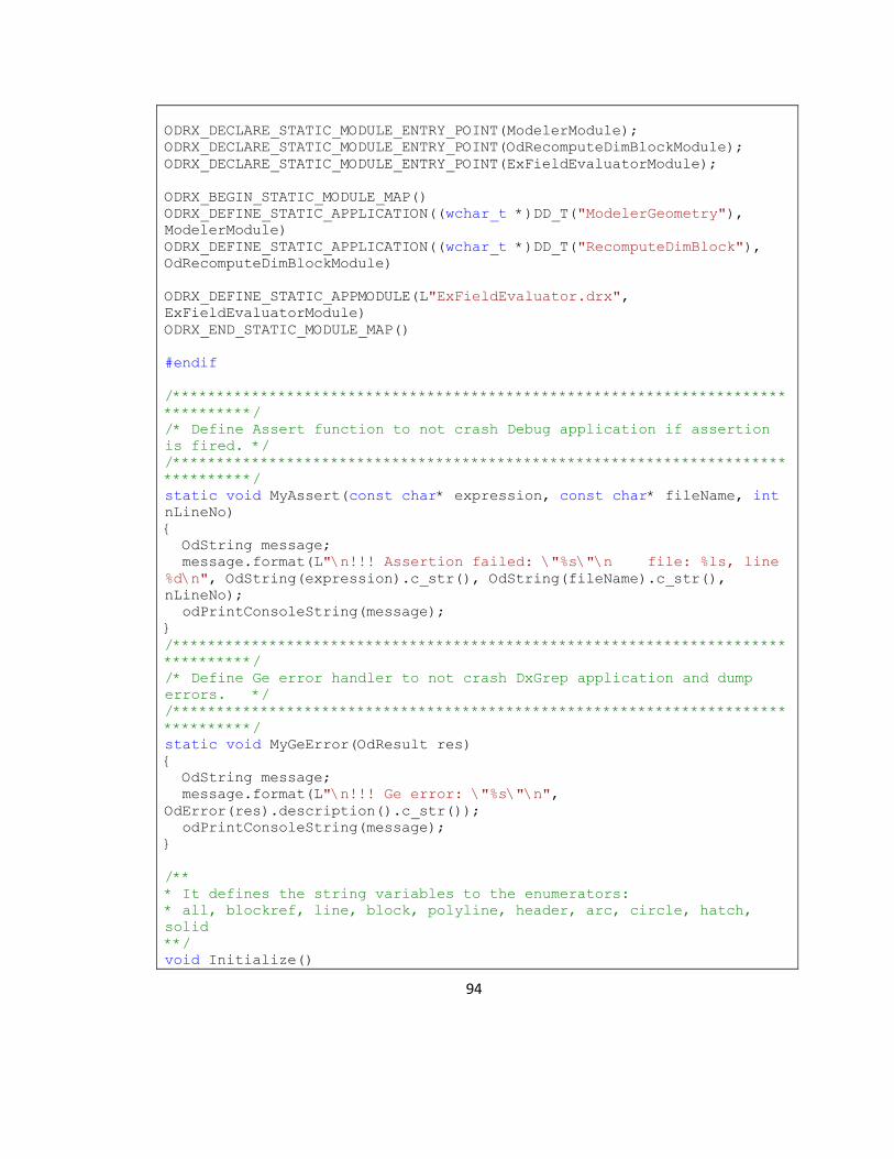
94
ODRX_DECLARE_STATIC_MODULE_ENTRY_POINT(ModelerModule);
ODRX_DECLARE_STATIC_MODULE_ENTRY_POINT(OdRecomputeDimBlockModule);
ODRX_DECLARE_STATIC_MODULE_ENTRY_POINT(ExFieldEvaluatorModule);
ODRX_BEGIN_STATIC_MODULE_MAP()
ODRX_DEFINE_STATIC_APPLICATION((wchar_t *)DD_T("ModelerGeometry"),
ModelerModule)
ODRX_DEFINE_STATIC_APPLICATION((wchar_t *)DD_T("RecomputeDimBlock"),
OdRecomputeDimBlockModule)
ODRX_DEFINE_STATIC_APPMODULE(L"ExFieldEvaluator.drx",
ExFieldEvaluatorModule)
ODRX_END_STATIC_MODULE_MAP()
#endif
/**********************************************************************
**********/
/* Define Assert function to not crash Debug application if assertion
is fired. */
/**********************************************************************
**********/
static void MyAssert(const char* expression, const char* fileName, int
nLineNo)
{
OdString message;
message.format(L"\n!!! Assertion failed: \"%s\"\n file: %ls, line
%d\n", OdString(expression).c_str(), OdString(fileName).c_str(),
nLineNo);
odPrintConsoleString(message);
}
/**********************************************************************
**********/
/* Define Ge error handler to not crash DxGrep application and dump
errors. */
/**********************************************************************
**********/
static void MyGeError(OdResult res)
{
OdString message;
message.format(L"\n!!! Ge error: \"%s\"\n",
OdError(res).description().c_str());
odPrintConsoleString(message);
}
/**
* It defines the string variables to the enumerators:
* all, blockref, line, block, polyline, header, arc, circle, hatch,
solid
**/
void Initialize()

95
{
s_mapStringValues["all"] = all;
s_mapStringValues["blockref"] = blockref;
s_mapStringValues["line"] = line;
s_mapStringValues["block"] = block;
s_mapStringValues["polyline"] = polyline;
s_mapStringValues["header"] = header;
s_mapStringValues["arc"] = arc;
s_mapStringValues["circle"] = circle;
s_mapStringValues["hatch"] = hatch;
s_mapStringValues["solid"] = solid;
s_mapStringValues2["--extract=all"] = eall;
s_mapStringValues2["--extract=blockref"] = eblockref;
s_mapStringValues2["--extract=line"] = eline;
s_mapStringValues2["--extract=block"] = eblock;
s_mapStringValues2["--extract=polyline"] = epolyline;
s_mapStringValues2["--extract=header"] = eheader;
s_mapStringValues2["--extract=arc"] = earc;
s_mapStringValues2["--extract=circle"] = ecircle;
s_mapStringValues2["--extract=hatch"] = ehatch;
s_mapStringValues2["--extract=solid"] = esolid;
}
/**********************************************************************
**/
/* Main
*/
/**********************************************************************
**/
#if (defined(WIN32) || defined(WIN64))
int wmain(int argc, wchar_t* argv[])
//int wmain(int argc, char* argv[])
#else
int main(int argc, char* argv[])
#endif
{
#if defined(TARGET_OS_MAC) && !defined(__MACH__)
argc = ccommand(&argv);
#endif
/**********************************************************************
/
/* Verify the argument count and display an error message as required
*/
/**********************************************************************
/
Initialize();
OdString argstr1(argv[1]);
if (argc < 3)

96
{
if ((argstr1.compare("-h") == 0) || (argstr1.compare("--help") ==
0))
{
//printf("The option selected by string is %s", argv[1]);
printf("\n Usage: DWGgrep [options] FILE");
printf("\n\t -v, --version show version and license
information");
printf("\n\t -h, --help show usage information");
printf("\n\t -e, --extract=<extract> CAD Entities Types to
extract");
printf("\n\t -t, --cadType=types Autodesk, Bentley etc file
formats");
printf("\n");
printf("\n Supported CAD entities:");
printf("\n\t block : AutoDesk block entities. ");
printf("\n\t blockRef : AutoDesk block reference entities.
");
printf("\n\t line : AutoDesk Line entities. ");
printf("\n\t polyline : AutoDesk Polyline entities. ");
printf("\n\t text : AutoDesk Text entities. ");
printf("\n\t arc : AutoDesk Arc entities. ");
printf("\n\t circle : AutoDesk circle entities. ");
printf("\n\t hatch : AutoDesk hatch entities. ");
printf("\n\t solid : AutoDesk hatch entities. ");
printf("\n\t all : All AutoDesk entities above. ");
printf("\n");
printf("\n Supported CAD file Types: ");
printf("\n\t DWG :AutoDesk file format");
printf("\n\t DNG :Bentley file format - Not yet-");
printf("\n ");
exit(0);
}
else if ((argstr1.compare("-v") == 0) || (argstr1.compare("--
version") == 0))
{
printf("\n DxGrep version: 1.0\n");
exit(0);
}
else
{
printf("\n");
return 1;
}
}
#ifndef _TOOLKIT_IN_DLL_
ODRX_INIT_STATIC_MODULE_MAP();
#endif
/********************************************************************/

97
/* Create a custom Services instance.
*/
/********************************************************************/
OdStaticRxObject<MyServices> svcs;
svcs.disableOutput(true);
/**********************************************************************
/
/* Set customized assert function
*/
/**********************************************************************
/
odSetAssertFunc(MyAssert);
/**********************************************************************
/
/* Set customized Ge exception processing
*/
/**********************************************************************
/
OdGeContext::gErrorFunc = MyGeError;
/********************************************************************/
/* Initialize DWGdirect.
*/
/********************************************************************/
odInitialize(&svcs);
/********************************************************************/
/* This ExProtocolExtension class defines an OdDbEntity_Dumper
*/
/* protocol extension for each of the supported OdDbEntity classes
*/
/* and a default dumper for the non-supported classes.
*/
/********************************************************************/
ExProtocolExtension theProtocolExtensions;
/********************************************************************/
/* Initialize protocol extensions
*/
/********************************************************************/

98
theProtocolExtensions.initialize();
bool bSuccess = true;
try
{
::odrxDynamicLinker()->loadModule(L"ExFieldEvaluator.drx");
/******************************************************************/
/* Create a database and load the drawing into it.
*/
/*
*/
/* Specified arguments are as followed:
*/
/* filename, allowCPConversion, partialLoad, openMode
*/
/******************************************************************/
OdString argstr2(argv[1]);
OdString leftargstr2 = argstr2.left(9);
if ((argstr2.compare("-e") == 0) && (leftargstr2.compare("--
extract") != 0))
{
OdString f(argv[3]); // for UNIX UNICODE support
printf("<Results source=\"%ls\">\n", f.c_str());
fflush(stdout);
DwgDbDumper dumper;
OdDbDatabasePtr pDb = svcs.readFile(f.c_str(), true, false,
Oda::kShareDenyNo);
if (!pDb.isNull())
{
oddbEvaluateFields(pDb, OdDbField::kOpen);
/****************************************************************/
/* Dump the database
*/
/****************************************************************/
char* szInput = new char[wcslen(argv[2]) + 1];
wcstombs( szInput, argv[2], wcslen(argv[2]) );
switch(s_mapStringValues[szInput])
{
case all:
try
{
dumper.dumpHeader(pDb);
dumper.dumpBlocks(pDb);
dumper.dumpBlockRefs(pDb);
dumper.dumpLines(pDb);
dumper.dumpPolylines(pDb);
dumper.dumpText(pDb);
99
dumper.dumpArcs(pDb);
dumper.dumpCircles(pDb);
dumper.dumpHatches(pDb);
dumper.dumpSolids(pDb);
}
catch (OdError& e)
{
printf("<Status Error=\"Yes\"
ErrorDescription=\"%ls\"/>\n", OdString(e.description()).c_str());
printf("</Results>");
exit(0);
}
break;
case blockref:
try
{
dumper.dumpBlockRefs(pDb);
}
catch (OdError& e)
{
printf("<Status Error=\"Yes\"
ErrorDescription=\"%ls\"/>\n", OdString(e.description()).c_str());
printf("</Results>");
exit(0);
}
break;
case line:
try
{
dumper.dumpLines(pDb);
}
catch (OdError& e)
{
printf("<Status Error=\"Yes\"
ErrorDescription=\"%ls\"/>\n", OdString(e.description()).c_str());
printf("</Results>");
exit(0);
}
break;
case block:
try
{
dumper.dumpBlocks(pDb);
}
catch (OdError& e)
{
printf("<Status Error=\"Yes\"
ErrorDescription=\"%ls\"/>\n", OdString(e.description()).c_str());
printf("</Results>");
exit(0);
}

100
break;
case polyline:
try
{
dumper.dumpPolylines(pDb);
}
catch (OdError& e)
{
printf("<Status Error=\"Yes\"
ErrorDescription=\"%ls\"/>\n", OdString(e.description()).c_str());
printf("</Results>");
exit(0);
}
break;
case header:
try
{
dumper.dumpHeader(pDb);
}
catch (OdError& e)
{
printf("<Status Error=\"Yes\"
ErrorDescription=\"%ls\"/>\n", OdString(e.description()).c_str());
printf("</Results>");
exit(0);
}
break;
case arc:
try
{
dumper.dumpArcs(pDb);
}
catch (OdError& e)
{
printf("<Status Error=\"Yes\"
ErrorDescription=\"%ls\"/>\n", OdString(e.description()).c_str());
printf("</Results>");
exit(0);
}
break;
case circle:
try
{
dumper.dumpCircles(pDb);
}
catch (OdError& e)
{
printf("<Status Error=\"Yes\"
ErrorDescription=\"%ls\"/>\n", OdString(e.description()).c_str());
printf("</Results>");
exit(0);
}

101
break;
case hatch:
try
{
dumper.dumpHatches(pDb);
}
catch (OdError& e)
{
printf("<Status Error=\"Yes\"
ErrorDescription=\"%ls\"/>\n", OdString(e.description()).c_str());
printf("</Results>");
exit(0);
}
break;
case solid:
try
{
dumper.dumpSolids(pDb);
}
catch (OdError& e)
{
printf("<Status Error=\"Yes\"
ErrorDescription=\"%ls\"/>\n", OdString(e.description()).c_str());
printf("</Results>");
exit(0);
}
break;
default:
printf("<Status Error=\"Yes\"
ErrorDescription=\"Invalid option\"/>\n");
printf("</Results>\n");
exit(0);
break;
}
}
}
else if (leftargstr2.compare("--extract") == 0)
{
OdString f(argv[2]); // for UNIX UNICODE support
printf("<Results source=\"%ls\">\n", f.c_str());
fflush(stdout);
DwgDbDumper dumper;
OdDbDatabasePtr pDb = svcs.readFile(f.c_str(), true,
false, Oda::kShareDenyNo);
if (!pDb.isNull())
{
oddbEvaluateFields(pDb, OdDbField::kOpen);
/*******************************************/
/* Dump the database */
/*******************************************/
char* szInput = new char[wcslen(argv[1]) + 1];
102
wcstombs( szInput, argv[1], wcslen(argv[1]) );
switch(s_mapStringValues2[szInput])
{
case eall:
try
{
dumper.dumpHeader(pDb);
dumper.dumpBlocks(pDb);
dumper.dumpBlockRefs(pDb);
dumper.dumpLines(pDb);
dumper.dumpPolylines(pDb);
dumper.dumpText(pDb);
dumper.dumpArcs(pDb);
dumper.dumpCircles(pDb);
dumper.dumpHatches(pDb);
dumper.dumpSolids(pDb);
}
catch (OdError& e)
{
printf("<Status Error=\"Yes\"
ErrorDescription=\"%ls\"/>\n", OdString(e.description()).c_str());
printf("</Results>");
exit(0);
}
break;
case eblockref:
try
{
dumper.dumpBlockRefs(pDb);
}
catch (OdError& e)
{
printf("<Status Error=\"Yes\"
ErrorDescription=\"%ls\"/>\n", OdString(e.description()).c_str());
printf("</Results>");
exit(0);
}
break;
case eline:
try
{
dumper.dumpLines(pDb);
}
catch (OdError& e)
{
printf("<Status Error=\"Yes\"
ErrorDescription=\"%ls\"/>\n", OdString(e.description()).c_str());
printf("</Results>");
exit(0);
}

103
break;
case eblock:
try
{
dumper.dumpBlocks(pDb);
}
catch (OdError& e)
{
printf("<Status Error=\"Yes\"
ErrorDescription=\"%ls\"/>\n", OdString(e.description()).c_str());
printf("</Results>");
exit(0);
}
break;
case epolyline:
try
{
dumper.dumpPolylines(pDb);
}
catch (OdError& e)
{
printf("<Status Error=\"Yes\"
ErrorDescription=\"%ls\"/>\n", OdString(e.description()).c_str());
printf("</Results>");
exit(0);
}
break;
case eheader:
try
{
dumper.dumpHeader(pDb);
}
catch (OdError& e)
{
printf("<Status Error=\"Yes\"
ErrorDescription=\"%ls\"/>\n", OdString(e.description()).c_str());
printf("</Results>");
exit(0);
}
break;
case earc:
try
{
dumper.dumpArcs(pDb);
}
catch (OdError& e)
{
printf("<Status Error=\"Yes\"
ErrorDescription=\"%ls\"/>\n", OdString(e.description()).c_str());
printf("</Results>");
exit(0);
}

104
break;
case ecircle:
try
{
dumper.dumpCircles(pDb);
}
catch (OdError& e)
{
printf("<Status Error=\"Yes\"
ErrorDescription=\"%ls\"/>\n", OdString(e.description()).c_str());
printf("</Results>");
exit(0);
}
break;
case ehatch:
try
{
dumper.dumpHatches(pDb);
}
catch (OdError& e)
{
printf("<Status Error=\"Yes\"
ErrorDescription=\"%ls\"/>\n", OdString(e.description()).c_str());
printf("</Results>");
exit(0);
}
break;
case esolid:
try
{
dumper.dumpSolids(pDb);
}
catch (OdError& e)
{
printf("<Status Error=\"Yes\"
ErrorDescription=\"%ls\"/>\n", OdString(e.description()).c_str());
printf("</Results>");
exit(0);
}
break;
default:
printf("<Status Error=\"Yes\"
ErrorDescription=\"Invalid option\"/>\n");
printf("</Results>\n");
exit(0);
break;
}
}
}
else
{
printf("<Results>\n<Status Error=\"Yes\"

105
ErrorDescription=\"Invalid option\"/>\n");
printf("</Results>\n");
exit(0);
}
}
/********************************************************************/
/* Display the error
*/
/********************************************************************/
catch (OdError& e)
{
printf("<Results>\n<Status Error=\"Yes\"
ErrorDescription=\"%ls\">",OdString(svcs.getErrorDescription(e.code()))
.c_str());
printf("</Status>\n");
bSuccess = false;
}
catch (...)
{
printf("<Results>\n<Status Error=\"Yes\"
ErrorDescription=\"UnknownError\">");
printf("</Status>\n");
}
/********************************************************************/
/* Uninitialize protocol extensions
*/
/********************************************************************/
theProtocolExtensions.uninitialize();
/********************************************************************/
/* Uninitialize DWGdirect
*/
/********************************************************************/
odUninitialize();
printf("</Results>");
return 0;
}
DwgDbDumper.cpp
#define STL_USING_IOSTREAM
#include "OdaSTL.h"
#define STD(a) std:: a

106
#ifndef _DWGDBDUMPER_H_
#include "DwgDbDumper.h"
#endif
#ifndef _TOSTRING_H_
#include "toString.h"
#endif
#include "DbProxyObject.h"
#include "DbProxyExt.h"
#include "DbAttribute.h"
#include "DbAttributeDefinition.h"
#pragma once
/**
* This function is used to write a XML tag-value pair.
* @param tag It is a XML tag for the entity.
* @param value It is the value for that XML tag.
**/
void writeTag(OdString tag, OdString value)
{
try
{
//OdString buffer;
//buffer.format(L"<%s>%s<//%s>", tag, value, tag );
//printf("\n%ls", (OdString)buffer.c_str());
OdString buffer = "<" + tag + ">" + value + "</" + tag + ">";
odPrintConsoleString(L"%ls\n", buffer.c_str());
}
catch (OdError& e)
{
printf("\n<Status Error=\"Yes\" ErrorDescription=\"%ls\">",
OdString(e.description()).c_str());
printf("\n</Status>");
printf("\n</Results>");
exit(0);
}
}
/**
* This function is used to write an open tag for the entity.
* @param tag It is the tag that is to be opened.
**/
void writeOpenTag(OdString tag)
{
//OdString buffer;
//buffer.format(L"<%s>", tag );

107
//printf("\n%ls", (OdString)buffer.c_str());
OdString buffer = "<" + tag + ">";
odPrintConsoleString(L"%ls\n", buffer.c_str());
}
/**
* This function is used to write a close tag for the entity.
* @param tag It is the tag that is to be closed.
**/
void writeCloseTag(OdString tag)
{
//OdString buffer;
//buffer.format(L"<//%s>", tag );
//printf("\n%ls", (OdString)buffer.c_str());
OdString buffer = "</" + tag + ">";
odPrintConsoleString(L"%ls\n", buffer.c_str());
}
/**********************************************************************
**/
/* Dump the Entity
*/
/**********************************************************************
**/
void DwgDbDumper::dumpEntity(OdDbObjectId id, int indent)
{
/**********************************************************************
/
/* Get a SmartPointer to the Entity
*/
/**********************************************************************
/
OdDbEntityPtr pEnt = id.safeOpenObject();
/**********************************************************************
/
/* Retrieve the Protocol Extension registered for this object type
*/
/**********************************************************************
/
OdSmartPtr<OdDbEntity_Dumper> pEntDumper = pEnt;
/**********************************************************************
/
/* Dump the entity

108
*/
/**********************************************************************
/
try
{
pEntDumper->dump(pEnt, indent);
}
catch (OdError& e)
{
printf("\n<Status Error=\"Yes\" ErrorDescription=\"%ls\">",
OdString(e.description()).c_str());
printf("\n </Status>");
printf("\n</Results>");
exit(0);
}
}
/**
* This function is used to dump the Block Table Record entity
information.
* @param pDb This is OdDbDatabase pointer object to point to every
OdDbObjectId object iteratively.
* @param indent This is the space indent.
**/
void DwgDbDumper::dumpBlocks(OdDbDatabase* pDb, int indent)
{
/**********************************************************************
/
/* Get a SmartPointer to the BlockTable
*/
/**********************************************************************
/
OdDbBlockTablePtr pTable = pDb->getBlockTableId().safeOpenObject();
/**********************************************************************
/
/* Dump the Description
*/
/**********************************************************************
/
writeOpenTag("BlockTables");
/**********************************************************************
/
/* Get a SmartPointer to a new SymbolTableIterator

109
*/
/**********************************************************************
/
OdDbSymbolTableIteratorPtr pBlkIter = pTable->newIterator();
/**********************************************************************
/
/* Step through the BlockTable
*/
/**********************************************************************
/
for (pBlkIter->start(); ! pBlkIter->done(); pBlkIter->step())
{
/********************************************************************/
/* Open the BlockTableRecord for Reading
*/
/********************************************************************/
OdDbBlockTableRecordPtr pBlock = pBlkIter-
>getRecordId().safeOpenObject();
/********************************************************************/
/* Dump the BlockTableRecord
*/
/********************************************************************/
writeOpenTag("AcDbBlockTableRecord");
writeTag("Id", pBlock->getDbHandle().ascii());
writeTag("Name", toString(pBlock->getName()));
if((toString(pBlock->comments())) == "\"\"")
//TBD Turn off in case of no attributes, so XSLT are easier
writeTag("Comments","");
else
writeTag("Comments",toString(pBlock->comments()));
//Turned off in case of no attributes, so XSLT are easier
// if ((toString(pBlock->hasAttributeDefinitions())) == "false")
// {
// writeTag("Attribute", "");
// }
/********************************************************************/
/* Get a SmartPointer to a new ObjectIterator
*/
/********************************************************************/

110
OdDbObjectIteratorPtr pEntIter = pBlock->newIterator();
/********************************************************************/
/* Step through the BlockTableRecord
*/
/********************************************************************/
for (; !pEntIter->done(); pEntIter->step())
{
/********************************************************************/
/* Dump the Entity
*/
/********************************************************************/
OdDbObjectId id = pEntIter->objectId();
OdDbEntityPtr pEnt = id.safeOpenObject();
if (toString(pEnt->isA()) == "<AcDbAttributeDefinition>")
{
try
{
writeOpenTag("Attribute");
OdDbAttributeDefinitionPtr pAttr = pEnt;
writeTag("Name", toString(pAttr->tag()));
dumpEntity(pEntIter->objectId(), indent+1);
//dumpEntity(pEnt, indent+1);
writeCloseTag("Attribute");
}
catch (OdError& e)
{
printf("\n<Status Error=\"Yes\"
ErrorDescription=\"%ls\">", OdString(e.description()).c_str());
printf("\n </Status>");
printf("\n</Results>");
exit(0);
}
}
}
writeCloseTag("AcDbBlockTableRecord");
}
writeCloseTag("BlockTables");
}
/**
* This function is used to dump the File header.
* @param pDb This is OdDbDatabase pointer object to point to every
OdDbObjectId object iteratively.
* @param indent This is the space indent.
**/
/**********************************************************************

111
**/
/* Dump the Header Variables
*/
/**********************************************************************
**/
void DwgDbDumper::dumpHeader(OdDbDatabase* pDb, int indent)
{
writeOpenTag("Header");
writeTag("FileName", shortenPath(pDb->getFilename()));
writeTag("Version", toString(pDb-
>originalFileVersion()));
writeTag("Created", toString(pDb->getTDCREATE()));
writeTag("Updated", toString(pDb->getTDUPDATE()));
OdGePoint3d corner;
corner = pDb->getEXTMAX();
writeOpenTag("ExtMax");
writeTag("x", toString(corner.x));
writeTag("y", toString(corner.y));
writeTag("z", toString(corner.z));
writeCloseTag("ExtMax");
corner = pDb->getEXTMIN();
writeOpenTag("ExtMin");
writeTag("x", toString(corner.x));
writeTag("y", toString(corner.y));
writeTag("z", toString(corner.z));
writeCloseTag("ExtMin");
writeCloseTag("Header");
}
/**
* This function is used to dump the Block References entity
information.
* @param pDb This is OdDbDatabase pointer object to point to every
OdDbObjectId object iteratively.
* @param indent This is the space indent.
**/
void DwgDbDumper::dumpBlockRefs(OdDbDatabase* pDb, int indent)
{
/**********************************************************************
/
/* Get a SmartPointer to the BlockTable
*/
/**********************************************************************
/
OdDbBlockTablePtr pTable = pDb->getBlockTableId().safeOpenObject();

112
/**********************************************************************
/
/* Dump the Description
*/
/**********************************************************************
/
writeOpenTag("BlockRefs");
/**********************************************************************
/
/* Get a SmartPointer to a new SymbolTableIterator
*/
/**********************************************************************
/
OdDbSymbolTableIteratorPtr pBlkIter = pTable->newIterator();
/**********************************************************************
/
/* Step through the BlockTable
*/
/**********************************************************************
/
for (pBlkIter->start(); ! pBlkIter->done(); pBlkIter->step())
{
/********************************************************************/
/* Open the BlockTableRecord for Reading
*/
/********************************************************************/
OdDbBlockTableRecordPtr pBlock = pBlkIter-
>getRecordId().safeOpenObject();
/********************************************************************/
/* Get a SmartPointer to a new ObjectIterator
*/
/********************************************************************/
OdDbObjectIteratorPtr pEntIter = pBlock->newIterator();
/********************************************************************/
/* Step through the BlockTableRecord
*/
/********************************************************************/
113
for (; !pEntIter->done(); pEntIter->step())
{
/********************************************************************/
/* Dump the Entity
*/
/********************************************************************/
OdDbObjectId id = pEntIter->objectId();
OdDbEntityPtr pEnt = id.safeOpenObject();
if (toString(pEnt->isA()) == "<AcDbBlockReference>")
{
try
{
dumpEntity(pEntIter->objectId(), indent+1);
}
catch (OdError& e)
{
printf("\n<Status Error=\"Yes\"
ErrorDescription=\"%ls\">", OdString(e.description()).c_str());
printf("\n </Status>");
printf("\n</Results>");
exit(0);
}
}
}
}
writeCloseTag("BlockRefs");
}
/**
* This function is used to dump the Lines entity information.
* @param pDb This is OdDbDatabase pointer object to point to every
OdDbObjectId object iteratively.
* @param indent This is the space indent.
**/
void DwgDbDumper::dumpLines(OdDbDatabase* pDb, int indent)
{
/**********************************************************************
/
/* Get a SmartPointer to the BlockTable
*/
/**********************************************************************
/
OdDbBlockTablePtr pTable = pDb->getBlockTableId().safeOpenObject();
/**********************************************************************
/

114
/* Dump the Description
*/
/**********************************************************************
/
writeOpenTag("BlockLines");
/**********************************************************************
/
/* Get a SmartPointer to a new SymbolTableIterator
*/
/**********************************************************************
/
OdDbSymbolTableIteratorPtr pBlkIter = pTable->newIterator();
/**********************************************************************
/
/* Step through the BlockTable
*/
/**********************************************************************
/
for (pBlkIter->start(); ! pBlkIter->done(); pBlkIter->step())
{
/********************************************************************/
/* Open the BlockTableRecord for Reading
*/
/********************************************************************/
OdDbBlockTableRecordPtr pBlock = pBlkIter-
>getRecordId().safeOpenObject();
/********************************************************************/
/* Get a SmartPointer to a new ObjectIterator
*/
/********************************************************************/
OdDbObjectIteratorPtr pEntIter = pBlock->newIterator();
/********************************************************************/
/* Step through the AcDbLine Record
*/
/********************************************************************/
for (; !pEntIter->done(); pEntIter->step())
{

115
/********************************************************************/
/* Dump the Entity
*/
/********************************************************************/
OdDbObjectId id = pEntIter->objectId();
OdDbEntityPtr pEnt = id.safeOpenObject();
if (toString(pEnt->isA()) == "<AcDbLine>")
{
try
{
dumpEntity(pEntIter->objectId(), indent+1);
}
catch (OdError& e)
{
printf("\n<Status Error=\"Yes\"
ErrorDescription=\"%ls\">", OdString(e.description()).c_str());
printf("\n </Status>");
printf("\n</Results>");
exit(0);
}
}
}
}
writeCloseTag("BlockLines");
}
/**
* This function is used to dump the Polyline entity information.
* @param pDb This is OdDbDatabase pointer object to point to every
OdDbObjectId object iteratively.
* @param indent This is the space indent.
**/
void DwgDbDumper::dumpPolylines(OdDbDatabase* pDb, int indent)
{
/**********************************************************************
/
/* Get a SmartPointer to the BlockTable
*/
/**********************************************************************
/
OdDbBlockTablePtr pTable = pDb->getBlockTableId().safeOpenObject();
/**********************************************************************
/
/* Dump the Description
*/

116
/**********************************************************************
/
writeOpenTag("BlockPolyLines");
/**********************************************************************
/
/* Get a SmartPointer to a new SymbolTableIterator
*/
/**********************************************************************
/
OdDbSymbolTableIteratorPtr pBlkIter = pTable->newIterator();
/**********************************************************************
/
/* Step through the BlockTable
*/
/**********************************************************************
/
for (pBlkIter->start(); ! pBlkIter->done(); pBlkIter->step())
{
/********************************************************************/
/* Open the BlockTableRecord for Reading
*/
/********************************************************************/
OdDbBlockTableRecordPtr pBlock = pBlkIter-
>getRecordId().safeOpenObject();
/********************************************************************/
/* Get a SmartPointer to a new ObjectIterator
*/
/********************************************************************/
OdDbObjectIteratorPtr pEntIter = pBlock->newIterator();
/********************************************************************/
/* Step through the AcDbLine Record
*/
/********************************************************************/
for (; !pEntIter->done(); pEntIter->step())
{
/********************************************************************/
/* Dump the Entity

117
*/
/********************************************************************/
OdDbObjectId id = pEntIter->objectId();
OdDbEntityPtr pEnt = id.safeOpenObject();
if (toString(pEnt->isA()) == "<AcDbPolyline>")
{
try
{
dumpEntity(pEntIter->objectId(), indent+1);
}
catch (OdError& e)
{
printf("\n<Status Error=\"Yes\"
ErrorDescription=\"%ls\">", OdString(e.description()).c_str());
printf("\n </Status>");
printf("\n</Results>");
exit(0);
}
}
}
}
writeCloseTag("BlockPolyLines");
}
/**
* This function is used to dump the Text entity information.
* @param pDb This is OdDbDatabase pointer object to point to every
OdDbObjectId object iteratively.
* @param indent This is the space indent.
**/
void DwgDbDumper::dumpText(OdDbDatabase* pDb, int indent)
{
/**********************************************************************
/
/* Get a SmartPointer to the BlockTable
*/
/**********************************************************************
/
OdDbBlockTablePtr pTable = pDb->getBlockTableId().safeOpenObject();
/**********************************************************************
/
/* Dump the Description
*/
/**********************************************************************
/

118
writeOpenTag("BlockTexts");
/**********************************************************************
/
/* Get a SmartPointer to a new SymbolTableIterator
*/
/**********************************************************************
/
OdDbSymbolTableIteratorPtr pBlkIter = pTable->newIterator();
/**********************************************************************
/
/* Step through the BlockTable
*/
/**********************************************************************
/
for (pBlkIter->start(); ! pBlkIter->done(); pBlkIter->step())
{
/********************************************************************/
/* Open the BlockTableRecord for Reading
*/
/********************************************************************/
OdDbBlockTableRecordPtr pBlock = pBlkIter-
>getRecordId().safeOpenObject();
/********************************************************************/
/* Get a SmartPointer to a new ObjectIterator
*/
/********************************************************************/
OdDbObjectIteratorPtr pEntIter = pBlock->newIterator();
/********************************************************************/
/* Step through the AcDbLine Record
*/
/********************************************************************/
for (; !pEntIter->done(); pEntIter->step())
{
/********************************************************************/
/* Dump the Entity
*/

119
/********************************************************************/
OdDbObjectId id = pEntIter->objectId();
OdDbEntityPtr pEnt = id.safeOpenObject();
if (toString(pEnt->isA()) == "<AcDbText>")
{
try
{
writeOpenTag("AcDbText");
dumpEntity(pEntIter->objectId(), indent+1);
writeCloseTag("AcDbText");
}
catch (OdError& e)
{
printf("\n<Status Error=\"Yes\"
ErrorDescription=\"%ls\">", OdString(e.description()).c_str());
printf("\n </Status>");
printf("\n</Results>");
exit(0);
}
}
}
}
writeCloseTag("BlockTexts");
}
/**
* This function is used to dump the AcDbArc entity information.
* @param pDb This is OdDbDatabase pointer object to point to every
OdDbObjectId object iteratively.
* @param indent This is the space indent.
**/
void DwgDbDumper::dumpArcs(OdDbDatabase* pDb, int indent)
{
/**********************************************************************
/
/* Get a SmartPointer to the BlockTable
*/
/**********************************************************************
/
OdDbBlockTablePtr pTable = pDb->getBlockTableId().safeOpenObject();
/**********************************************************************
/
/* Dump the Description
*/
/**********************************************************************
/
writeOpenTag("Arcs");

120
/**********************************************************************
/
/* Get a SmartPointer to a new SymbolTableIterator
*/
/**********************************************************************
/
OdDbSymbolTableIteratorPtr pBlkIter = pTable->newIterator();
/**********************************************************************
/
/* Step through the BlockTable
*/
/**********************************************************************
/
for (pBlkIter->start(); ! pBlkIter->done(); pBlkIter->step())
{
/********************************************************************/
/* Open the BlockTableRecord for Reading
*/
/********************************************************************/
OdDbBlockTableRecordPtr pBlock = pBlkIter-
>getRecordId().safeOpenObject();
/********************************************************************/
/* Get a SmartPointer to a new ObjectIterator
*/
/********************************************************************/
OdDbObjectIteratorPtr pEntIter = pBlock->newIterator();
/********************************************************************/
/* Step through the AcDbLine Record
*/
/********************************************************************/
for (; !pEntIter->done(); pEntIter->step())
{
/********************************************************************/
/* Dump the Entity
*/
/********************************************************************/

121
OdDbObjectId id = pEntIter->objectId();
OdDbEntityPtr pEnt = id.safeOpenObject();
if (toString(pEnt->isA()) == "<AcDbArc>")
{
try
{
dumpEntity(pEntIter->objectId(), indent+1);
}
catch (OdError& e)
{
printf("\n<Status Error=\"Yes\"
ErrorDescription=\"%ls\">", OdString(e.description()).c_str());
printf("\n </Status>");
printf("\n</Results>");
exit(0);
}
}
}
}
writeCloseTag("Arcs");
}
/**
* This function is used to dump the AcDbCircle entity information.
* @param pDb This is OdDbDatabase pointer object to point to every
OdDbObjectId object iteratively.
* @param indent This is the space indent.
**/
void DwgDbDumper::dumpCircles(OdDbDatabase* pDb, int indent)
{
/**********************************************************************
/
/* Get a SmartPointer to the BlockTable
*/
/**********************************************************************
/
OdDbBlockTablePtr pTable = pDb->getBlockTableId().safeOpenObject();
/**********************************************************************
/
/* Dump the Description
*/
/**********************************************************************
/
writeOpenTag("Circles");
/**********************************************************************

122
/
/* Get a SmartPointer to a new SymbolTableIterator
*/
/**********************************************************************
/
OdDbSymbolTableIteratorPtr pBlkIter = pTable->newIterator();
/**********************************************************************
/
/* Step through the BlockTable
*/
/**********************************************************************
/
for (pBlkIter->start(); ! pBlkIter->done(); pBlkIter->step())
{
/********************************************************************/
/* Open the BlockTableRecord for Reading
*/
/********************************************************************/
OdDbBlockTableRecordPtr pBlock = pBlkIter-
>getRecordId().safeOpenObject();
/********************************************************************/
/* Get a SmartPointer to a new ObjectIterator
*/
/********************************************************************/
OdDbObjectIteratorPtr pEntIter = pBlock->newIterator();
/********************************************************************/
/* Step through the AcDbLine Record
*/
/********************************************************************/
for (; !pEntIter->done(); pEntIter->step())
{
/********************************************************************/
/* Dump the Entity
*/
/********************************************************************/
OdDbObjectId id = pEntIter->objectId();
OdDbEntityPtr pEnt = id.safeOpenObject();
if (toString(pEnt->isA()) == "<AcDbCircle>")
123
{
try
{
dumpEntity(pEntIter->objectId(), indent+1);
}
catch (OdError& e)
{
printf("\n<Status Error=\"Yes\"
ErrorDescription=\"%ls\">", OdString(e.description()).c_str());
printf("\n </Status>");
printf("\n</Results>");
exit(0);
}
}
}
}
writeCloseTag("Circles");
}
void DwgDbDumper::dumpHatches(OdDbDatabase* pDb, int indent)
{
/**********************************************************************
/
/* Get a SmartPointer to the BlockTable
*/
/**********************************************************************
/
OdDbBlockTablePtr pTable = pDb->getBlockTableId().safeOpenObject();
/**********************************************************************
/
/* Dump the Description
*/
/**********************************************************************
/
writeOpenTag("Hatches");
/**********************************************************************
/
/* Get a SmartPointer to a new SymbolTableIterator
*/
/**********************************************************************
/
OdDbSymbolTableIteratorPtr pBlkIter = pTable->newIterator();

124
/**********************************************************************
/
/* Step through the BlockTable
*/
/**********************************************************************
/
for (pBlkIter->start(); ! pBlkIter->done(); pBlkIter->step())
{
/********************************************************************/
/* Open the BlockTableRecord for Reading
*/
/********************************************************************/
OdDbBlockTableRecordPtr pBlock = pBlkIter-
>getRecordId().safeOpenObject();
/********************************************************************/
/* Get a SmartPointer to a new ObjectIterator
*/
/********************************************************************/
OdDbObjectIteratorPtr pEntIter = pBlock->newIterator();
/********************************************************************/
/* Step through the AcDbLine Record
*/
/********************************************************************/
for (; !pEntIter->done(); pEntIter->step())
{
/********************************************************************/
/* Dump the Entity
*/
/********************************************************************/
OdDbObjectId id = pEntIter->objectId();
OdDbEntityPtr pEnt = id.safeOpenObject();
if (toString(pEnt->isA()) == "<AcDbHatch>")
{
try
{
dumpEntity(pEntIter->objectId(), indent+1);
}
catch (OdError& e)
{
printf("\n<Status Error=\"Yes\"
ErrorDescription=\"%ls\">", OdString(e.description()).c_str());

125
printf("\n </Status>");
printf("\n</Results>");
writeCloseTag("Hatches");
exit(0);
}
}
}
}
writeCloseTag("Hatches");
}
void DwgDbDumper::dumpSolids(OdDbDatabase* pDb, int indent)
{
/**********************************************************************
/
/* Get a SmartPointer to the BlockTable
*/
/**********************************************************************
/
OdDbBlockTablePtr pTable = pDb->getBlockTableId().safeOpenObject();
/**********************************************************************
/
/* Dump the Description
*/
/**********************************************************************
/
writeOpenTag("Solids");
/**********************************************************************
/
/* Get a SmartPointer to a new SymbolTableIterator
*/
/**********************************************************************
/
OdDbSymbolTableIteratorPtr pBlkIter = pTable->newIterator();
/**********************************************************************
/
/* Step through the BlockTable
*/
/**********************************************************************
/
for (pBlkIter->start(); ! pBlkIter->done(); pBlkIter->step())

126
{
/********************************************************************/
/* Open the BlockTableRecord for Reading
*/
/********************************************************************/
OdDbBlockTableRecordPtr pBlock = pBlkIter-
>getRecordId().safeOpenObject();
/********************************************************************/
/* Get a SmartPointer to a new ObjectIterator
*/
/********************************************************************/
OdDbObjectIteratorPtr pEntIter = pBlock->newIterator();
/********************************************************************/
/* Step through the AcDbLine Record
*/
/********************************************************************/
for (; !pEntIter->done(); pEntIter->step())
{
/********************************************************************/
/* Dump the Entity
*/
/********************************************************************/
OdDbObjectId id = pEntIter->objectId();
OdDbEntityPtr pEnt = id.safeOpenObject();
if (toString(pEnt->isA()) == "<AcDbSolid>")
{
try
{
dumpEntity(pEntIter->objectId(), indent+1);
}
catch (OdError& e)
{
printf("\n<Status Error=\"Yes\"
ErrorDescription=\"%ls\">", OdString(e.description()).c_str());
printf("\n </Status>");
printf("\n</Results>");
writeCloseTag("Solids");
exit(0);
}
}
}
}
127
writeCloseTag("Solids");
}
ExProtocolExtension.cpp
/**
* This is a Implementation of the ExProtocolExtension class
*/
#include "OdaCommon.h"
#include "ExProtocolExtension.h"
#include "RxObjectImpl.h"
#include "Db2LineAngularDimension.h"
#include "Db2dPolyline.h"
#include "Db3PointAngularDimension.h"
#include "Db3dPolyline.h"
#include "Db3dPolylineVertex.h"
#include "Db3dSolid.h"
#include "DbAlignedDimension.h"
#include "DbArc.h"
#include "DbArcAlignedText.h"
#include "DbArcDimension.h"
#include "DbAttribute.h"
#include "DbAttributeDefinition.h"
#include "DbBlockReference.h"
#include "DbBlockTableRecord.h"
#include "DbBody.h"
#include "DbCircle.h"
#include "DbDiametricDimension.h"
#include "DbEllipse.h"
#include "DbFace.h"
#include "DbFaceRecord.h"
#include "DbFcf.h"
#include "DbHatch.h"
#include "DbIndex.h"
#include "DbLine.h"
#include "DbMInsertBlock.h"
#include "DbMText.h"
#include "DbMline.h"
#include "DbOle2Frame.h"
#include "DbOrdinateDimension.h"
#include "DbPoint.h"
#include "DbPolyFaceMesh.h"
#include "DbPolyFaceMeshVertex.h"
#include "DbPolygonMesh.h"
#include "DbPolygonMeshVertex.h"
#include "DbPolyline.h"
#include "DbProxyEntity.h"
#include "DbRadialDimension.h"
#include "DbRasterImage.h"
#include "DbRay.h"

128
#include "DbRegion.h"
#include "DbRotatedDimension.h"
#include "DbShape.h"
#include "DbSolid.h"
#include "DbSpatialFilter.h"
#include "DbSpline.h"
#include "DbTable.h"
#include "DbTrace.h"
#include "DbViewport.h"
#include "DbWipeout.h"
#include "DbXline.h"
#include "Ge/GeCircArc2d.h"
#include "Ge/GeCircArc3d.h"
#include "Ge/GeCurve2d.h"
#include "Ge/GeEllipArc2d.h"
#include "Ge/GeKnotVector.h"
#include "Ge/GeNurbCurve2d.h"
#include "GeometryFromProxy.h"
#include "GiWorldDrawDumper.h"
#include "Gs/Gs.h"
#include "OdFileBuf.h"
#include "StaticRxObject.h"
#include "toString.h"
/**********************************************************************
**/
/* Construction/Destruction
*/
/**********************************************************************
**/
ODRX_NO_CONS_DEFINE_MEMBERS(OdDbEntity_Dumper, OdRxObject)
/**
* This is a constructor for class ExProtocolExtension.
**/
ExProtocolExtension::ExProtocolExtension()
{
}
/**
* This is a destructor for class ExProtocolExtension.
* If m_pDumpers is set, then it uninitializes it.
**/
ExProtocolExtension::~ExProtocolExtension()
{
if(m_pDumpers)
uninitialize();
}

129
/**
* This method dumps the common data and WorldDraw information for all
* entities without explicit dumpers
* @param pEnt This is an instance of OdDbEntity
* @param indent This is a margin that is to be left.
**/
void OdDbEntity_Dumper::dump(OdDbEntity* pEnt, int indent) const
{
//writeLine(indent++, toString(pEnt->isA()),toString(pEnt-
>getDbHandle()));
dumpEntityData(pEnt, indent);
//writeLine(indent, DD_T("WorldDraw()"));
/**********************************************************************
/
/* Create an OdGiContext instance for the vectorization
*/
/**********************************************************************
/
OdGiContextDumper ctx(pEnt->database());
/**********************************************************************
/
/* Create an OdGiWorldDraw instance for the vectorization
*/
/**********************************************************************
/
OdGiWorldDrawDumper wd(indent + 1);
/**********************************************************************
/
/* Set the context
*/
/**********************************************************************
/
wd.setContext(&ctx);
/**********************************************************************
/
/* Call worldDraw()
*/
/**********************************************************************
/
pEnt->worldDraw(&wd);
}

130
/**
* This method dumps the data common to all entities.
* @param pEnt This OdDbEntity pointer points to the certain entity type
object dynamically.
* @param indent This is a space indent
**/
void dumpEntityData(OdDbEntity* pEnt, int indent)
{
OdGeExtents3d extents;
if (eOk == pEnt->getGeomExtents(extents)) {
writeOpenTag("MinExtents");
writeTag("x", toString(extents.minPoint().x));
writeTag("y", toString(extents.minPoint().y));
writeTag("z", toString(extents.minPoint().z));
writeCloseTag("MinExtents");
writeOpenTag("MaxExtents");
writeTag("x", toString(extents.minPoint().x));
writeTag("y", toString(extents.minPoint().y));
writeTag("z", toString(extents.minPoint().z));
writeCloseTag("MaxExtents");
}
writeTag("Layer", toString(pEnt->layer()));
writeTag("ColorIndex", toString(pEnt->colorIndex()));
writeTag("Color", toString(pEnt->color()));
writeTag("Linetype", toString(pEnt->linetype()));
writeTag("LTscale", toString(pEnt->linetypeScale()));
writeTag("Lineweight", toString(pEnt->lineWeight()));
writeTag("PlotStyle", toString(pEnt->plotStyleName()));
writeTag("TransparencyMethod", toString(pEnt-
>transparency().method()));
writeTag("Visibility", toString(pEnt->visibility()));
writeTag("Planar", toString(pEnt->isPlanar()));
OdGePlane plane;
OdDb::Planarity planarity = OdDb::kNonPlanar;
pEnt->getPlane(plane, planarity);
writeTag("Planarity", toString(planarity));
if (pEnt->isPlanar())
{
OdGePoint3d origin;
OdGeVector3d uAxis;
OdGeVector3d vAxis;
plane.get(origin, uAxis, vAxis);
writeOpenTag("Origin");
writeTag("x", toString(origin.x));
writeTag("y", toString(origin.y));
writeTag("z", toString(origin.z));
writeCloseTag("Origin");
writeOpenTag("u-Axis");

131
writeTag("x", toString(uAxis.x));
writeTag("y", toString(uAxis.y));
writeTag("z", toString(uAxis.z));
writeCloseTag("u-Axis");
writeOpenTag("v-Axis");
writeTag("x", toString(vAxis.x));
writeTag("y", toString(vAxis.y));
writeTag("z", toString(vAxis.z));
writeCloseTag("v-Axis");
}
}
/**
* This function dumps Block Text data for OdDbAttributeDefinition class
object.
* @param pText This is a OdDbText pointer.
* @param indent This is a space indent.
**/
void dumpBlockTextData(OdDbText* pText, int indent)
{
//OdDbAttributeDefinitionPtr pAttr = pText;
};
/**
* This function dumps Text data depending for the entity that pText
pointer is pointing.
* @param pText This is a OdDbText pointer
* @param indent This is a space indent.
**/
void dumpTextData(OdDbText* pText, int indent)
{
writeTag("TextString", toString(pText->textString()));
OdGePoint3d x;
writeOpenTag("TextPosition");
writeTag("x", toString(pText->position().x));
writeTag("y", toString(pText->position().y));
writeTag("z", toString(pText->position().z));
writeCloseTag("TextPosition");
writeTag("DefaultAlignment", toString(pText-
>isDefaultAlignment()));
writeOpenTag("AlignmentPoint");
writeTag("x", toString(pText->alignmentPoint().x));
writeTag("y", toString(pText->alignmentPoint().y));

132
writeTag("z", toString(pText->alignmentPoint().z));
writeCloseTag("AlignmentPoint");
writeTag("Height", toString(pText->height()));
writeTag("Rotation", toDegreeString(pText->rotation()));
writeTag("HorizontalMode", toString(pText->horizontalMode()));
writeTag("VerticalMode", toString(pText->verticalMode()));
writeTag("MirroredInX", toString(pText->isMirroredInX()));
writeTag("MirroredInY", toString(pText->isMirroredInY()));
writeTag("Oblique", toDegreeString(pText->oblique()));
writeTag("TextStyle", toString(pText->textStyle()));
writeTag("WidthFactor", toString(pText->widthFactor()));
/*********************************************************************/
/* Dump Bounding Points
*/
/**********************************************************************
/
OdGePoint3dArray points;
pText->getBoundingPoints(points);
writeOpenTag("TLBoundingPoint");
writeTag("x", toString(points[0].x));
writeTag("y", toString(points[0].y));
writeTag("z", toString(points[0].z));
writeCloseTag("TLBoundingPoint");
writeOpenTag("TRBoundingPoint");
writeTag("x", toString(points[1].x));
writeTag("y", toString(points[1].y));
writeTag("z", toString(points[1].z));
writeCloseTag("TRBoundingPoint");
writeOpenTag("BLBoundingPoint");
writeTag("x", toString(points[2].x));
writeTag("y", toString(points[2].y));
writeTag("z", toString(points[2].z));
writeCloseTag("BLBoundingPoint");
writeOpenTag("BRBoundingPoint");
writeTag("x", toString(points[2].x));
writeTag("y", toString(points[2].y));
writeTag("z", toString(points[2].z));
writeCloseTag("BRBoundingPoint");
writeOpenTag("Normal");
writeTag("x", toString(pText->normal().x));
writeTag("y", toString(pText->normal().y));
writeTag("z", toString(pText->normal().z));

133
writeCloseTag("Normal");
writeTag("Thickness", toString(pText->thickness()));
try
{
dumpEntityData(pText, indent);
}
catch (OdError& e)
{
printf("\n<Status Error=\"Yes\" ErrorDescription=\"%ls\">",
OdString(e.description()).c_str());
printf("\n </Status>");
printf("\n</Results>");
exit(0);
}
};
/**
* This function dumps the Attribute data.
* @param indent This is a space indent.
* @param pAttr This is OdDbAttribute pointer to read the attribute
data.
* @param i This is serial number of the attribute passed by the calling
function.
**/
void dumpAttributeData(int indent, OdDbAttribute* pAttr, int i)
{
writeOpenTag("Attribute");
writeTag("Handle", toString(pAttr-
>getDbHandle().ascii()));
writeTag("Tag", toString(pAttr->tag()));
writeTag("FieldLength", toString(pAttr->fieldLength()));
writeTag("Invisible", toString(pAttr->isInvisible()));
writeTag("Preset", toString(pAttr->isPreset()));
writeTag("Verifiable", toString(pAttr->isVerifiable()));
writeTag("LockedInPosition", toString(pAttr-
>lockPositionInBlock()));
writeTag("Constant", toString(pAttr->isConstant()));
try
{
dumpTextData(pAttr, indent);
}
catch (OdError& e)
{
printf("\n<Status Error=\"Yes\" ErrorDescription=\"%ls\">",
OdString(e.description()).c_str());
printf("\n </Status>");
printf("\n</Results>");
exit(0);
}
writeCloseTag("Attribute");

134
};
/**
* This function dumps the Block Reference Data.
* @param pBlkRef This is a OdDbBlockReference pointer.
* @param indent This is a space indent.
**/
void dumpBlockRefData(OdDbBlockReference* pBlkRef, int indent)
{
writeOpenTag("Position");
writeTag("x", toString(pBlkRef->position().x));
writeTag("y", toString(pBlkRef->position().y));
writeTag("z", toString(pBlkRef->position().z));
writeCloseTag("Position");
writeTag("Rotation", toDegreeString(pBlkRef-
>rotation()));
writeOpenTag("ScaleFactors");
writeTag("x", toString(pBlkRef->scaleFactors().sx));
writeTag("y", toString(pBlkRef->scaleFactors().sy));
writeTag("z", toString(pBlkRef->scaleFactors().sz));
writeCloseTag("ScaleFactors");
writeOpenTag("Normal");
writeTag("x", toString(pBlkRef->normal().x));
writeTag("y", toString(pBlkRef->normal().y));
writeTag("z", toString(pBlkRef->normal().z));
writeCloseTag("Normal");
try
{
dumpEntityData(pBlkRef, indent);
}
catch (OdError& e)
{
printf("\n<Status Error=\"Yes\" ErrorDescription=\"%ls\">",
OdString(e.description()).c_str());
printf("\n </Status>");
printf("\n</Results>");
exit(0);
}
/**********************************************************************
/
/* Dump the attributes
*/
/**********************************************************************
/
OdDbObjectIteratorPtr pIter = pBlkRef->attributeIterator();
for (int i=0; !pIter->done(); i++, pIter->step())

135
{
OdDbAttributePtr pAttr = pIter->entity();
if (!pAttr.isNull())
{
try
{
dumpAttributeData(indent, pAttr, i);
}
catch (OdError& e)
{
printf("\n<Status Error=\"Yes\" ErrorDescription=\"%ls\">",
OdString(e.description()).c_str());
printf("\n </Status>");
printf("\n</Results>");
exit(0);
}
}
}
}
/**********************************************************************
**/
/* Dump data common to all OdDbCurves
*/
/**********************************************************************
**/
void dumpCurveData(OdDbEntity* pEnt, int indent)
{
OdDbCurvePtr pEntity = pEnt;
OdGePoint3d startPoint;
if (eOk == pEntity->getStartPoint(startPoint))
{
writeOpenTag("StartPoint");
writeTag("x", toString(startPoint.x));
writeTag("y", toString(startPoint.y));
writeTag("z", toString(startPoint.z));
writeCloseTag("StartPoint");
}
OdGePoint3d endPoint;
if (eOk == pEntity->getEndPoint(endPoint))
{
writeOpenTag("EndPoint");
writeTag("x", toString(endPoint.x));
writeTag("y", toString(endPoint.y));
writeTag("z", toString(endPoint.z));
writeCloseTag("EndPoint");
}
writeTag("Closed", toString(pEntity-
>isClosed()));
136
writeTag("Periodic", toString(pEntity-
>isPeriodic()));
double area;
if (eOk == pEntity->getArea(area))
{
writeTag("Area", toString(area));
}
dumpEntityData(pEntity, indent);
}
/**
* This class is a basic Block Reference Dumper inherited from the Class
OdDbEntity_Dumper.
* @extends OdDbEntity_Dumper
**/
class OdDbBlockReference_Dumper : public OdDbEntity_Dumper
{
public:
/**
* This function initializes the dumping of the Block Reference
information.
* @param pEnt This is a OdDbEntity pointer pointing to a
OdDbBlockReference_Dumper object.
* @param indent This is a space indent.
**/
void dump(OdDbEntity* pEnt, int indent) const
{
OdDbBlockReferencePtr pBlkRef = pEnt;
writeOpenTag("AcDbBlockReference");
OdDbBlockTableRecordPtr pRecord = pBlkRef-
>blockTableRecord().safeOpenObject();
writeTag("Id", toString(pBlkRef->getDbHandle().ascii()));
writeTag("Name", toString(pRecord->getName()));
try
{
dumpBlockRefData(pBlkRef, indent);
}
catch (OdError& e)
{
printf("\n<Status Error=\"Yes\" ErrorDescription=\"%ls\">",
OdString(e.description()).c_str());
printf("\n </Status>");
printf("\n</Results>");
exit(0);
}
OdDbSpatialFilterPtr pFilt =
OdDbIndexFilterManager::getFilter(pBlkRef,
OdDbSpatialFilter::desc(), OdDb::kForRead);

137
/********************************************************************/
/* Dump the Spatial Filter (Xref Clip)
*/
/********************************************************************/
if(pFilt.get())
{
writeTag(toString(pFilt->isA()), toString(pFilt-
>getDbHandle()));
OdGePoint2dArray points;
OdGeVector3d normal;
double elevation, frontClip, backClip;
bool enabled;
pFilt->getDefinition(points, normal, elevation, frontClip,
backClip, enabled);
writeOpenTag("Normal");
writeTag("x", toString(normal.x));
writeTag("y", toString(normal.y));
writeTag("z", toString(normal.z));
writeCloseTag("Normal");
writeTag("Elevation",
toString(elevation));
writeTag("FrontClipDistance", toString(frontClip));
writeTag("BackClipDistance", toString(backClip));
writeTag("Enabled", toString(enabled));
for (int i = 0; i < (int) points.size(); i++)
{
writeOpenTag("ClipPoints");
writeTag("ClipPoint", toString(points[i]));
writeCloseTag("ClipPoints");
}
}
writeCloseTag("AcDbBlockReference");
}
};
/**
* This class is a basic Body Dumper inherited from the Class
OdDbEntity_Dumper.
* @extends OdDbEntity_Dumper
**/
class OdDbBody_Dumper : public OdDbEntity_Dumper
{
public:
/**
* This function initializes the dumping of the Body information.
* @param pEnt This is a OdDbEntity pointer pointing to a
OdDbBody_Dumper object.
* @param indent This is a space indent.

138
**/
void dump(OdDbEntity* pEnt, int indent) const
{
OdDbBodyPtr pBody = pEnt;
try
{
dumpEntityData(pBody, indent);
}
catch (OdError& e)
{
printf("\n<Status Error=\"Yes\" ErrorDescription=\"%ls\">",
OdString(e.description()).c_str());
printf("\n </Status>");
printf("\n</Results>");
exit(0);
}
}
};
/**
* This class is a basic Line Dumper inherited from the Class
OdDbEntity_Dumper.
* @extends OdDbEntity_Dumper
**/
class OdDbLine_Dumper : public OdDbEntity_Dumper
{
public:
/**
* This function dumps the Line entity information.
* @param pEnt This is a OdDbEntity pointer pointing to a
OdDbLine_Dumper object.
* @param indent This is a space indent.
**/
void dump(OdDbEntity* pEnt, int indent) const
{
OdDbLinePtr pLine = pEnt;
writeOpenTag("AcDbLine");
OdString idTxt = toString(pLine->getDbHandle().ascii());
writeTag("Id", idTxt.mid(1, idTxt.getLength() -2));
writeOpenTag("Normal");
writeTag("x", toString(pLine->normal().x));
writeTag("y", toString(pLine->normal().y));
writeTag("z", toString(pLine->normal().z));
writeCloseTag("Normal");
writeTag("Thickness", toString(pLine->thickness()));
try
{
dumpEntityData(pLine, indent);
}

139
catch (OdError& e)
{
printf("\n<Status Error=\"Yes\" ErrorDescription=\"%ls\">",
OdString(e.description()).c_str());
printf("\n </Status>");
printf("\n</Results>");
exit(0);
}
writeCloseTag("AcDbLine");
}
};
/**
* This class is a basic Polyline Dumper inherited from the Class
OdDbEntity_Dumper.
* @extends OdDbEntity_Dumper
**/
class OdDbPolyline_Dumper : public OdDbEntity_Dumper
{
public:
/**
* This function dumps the polyline entity information.
* @param pEnt This is a OdDbEntity pointer pointing to a
OdDbPolyline_Dumper object.
* @param indent This is a space indent.
**/
void dump(OdDbEntity* pEnt, int indent) const
{
OdDbPolylinePtr pPoly = pEnt;
writeOpenTag("AcDbPolyline");
writeTag("Id", pPoly->getDbHandle().ascii());
writeTag("HasWidth", toString(pPoly->hasWidth()));
if (!pPoly->hasWidth())
{
writeTag("ConstantWidth", toString(pPoly-
>getConstantWidth()));
}
writeTag("HasBulges", toString(pPoly->hasBulges()));
writeTag("Elevation", toString(pPoly->elevation()));
writeOpenTag("Normal");
writeTag("x", toString(pPoly->normal().x));
writeTag("y", toString(pPoly->normal().y));
writeTag("z", toString(pPoly->normal().z));
writeCloseTag("Normal");
writeTag("Thickness", toString(pPoly->thickness()));
/********************************************************************/

140
/* dump vertices
*/
/********************************************************************/
writeOpenTag("Vertices");
for (int i = 0; i < (int) pPoly->numVerts(); i++)
{
writeOpenTag("Vertice");
writeTag("SegmentType", toString(pPoly->segType(i)));
OdGePoint3d pt;
pPoly->getPointAt(i, pt);
writeOpenTag("Point");
writeTag("x", toString(pt.x));
writeTag("y", toString(pt.y));
writeTag("z", toString(pt.z));
writeCloseTag("Point");
if (pPoly->hasWidth())
{
double startWidth;
double endWidth;
pPoly->getWidthsAt(i, startWidth, endWidth);
writeTag("StartWidth", toString(startWidth));
writeTag("EndWidth", toString(endWidth));
}
if (pPoly->hasBulges())
{
writeTag("Bulge", toString(pPoly-
>getBulgeAt(i)));
if (pPoly->segType(i) == OdDbPolyline::kArc)
{
writeTag("BulgeAngle", toDegreeString(pPoly-
>getBulgeAt(i)));
}
}
writeCloseTag("Vertice");
}
writeCloseTag("Vertices");
try
{
dumpEntityData(pPoly, indent);
}
catch (OdError& e)
{
printf("\n<Status Error=\"Yes\" ErrorDescription=\"%ls\">",
OdString(e.description()).c_str());
printf("\n </Status>");
printf("\n</Results>");
exit(0);
}
writeCloseTag("AcDbPolyline");
}

141
};
/**
* This class is a basic Block Text Dumper inherited from the Class
OdDbEntity_Dumper.
* @extends OdDbEntity_Dumper
**/
class OdDbText_Dumper : public OdDbEntity_Dumper
{
public:
/**
* This function dumps the Block Text entity data.
* @param pEnt This is a OdDbEntity pointer pointing to a
OdDbText_Dumper object.
* @param indent This is a space indent.
**/
void dump(OdDbEntity* pEnt, int indent) const
{
OdDbTextPtr pText = pEnt;
try
{
dumpTextData(pText, indent);
}
catch (OdError& e)
{
printf("\n<Status Error=\"Yes\" ErrorDescription=\"%ls\">",
OdString(e.description()).c_str());
printf("\n </Status>");
printf("\n</Results>");
exit(0);
}
}
};
/**
* This class is a basic Arc Dumper inherited from the Class
OdDbEntity_Dumper.
* @extends OdDbEntity_Dumper
**/
class OdDbArc_Dumper : public OdDbEntity_Dumper
{
public:
/**
* This function dumps the Arc entity data.
* @param pEnt This is a OdDbEntity pointer pointing to a OdDbArc_Dumper
object.
* @param indent This is a space indent.
**/
void dump(OdDbEntity* pEnt, int indent) const
{

142
writeOpenTag("AcDbArc");
OdDbArcPtr pArc = pEnt;
writeOpenTag("Center");
writeTag("x", toString(pArc->center().x));
writeTag("y", toString(pArc->center().y));
writeTag("z", toString(pArc->center().z));
writeCloseTag("Center");
writeTag("Radius", toString(pArc->radius()));
writeTag("StartAngle", toDegreeString(pArc-
>startAngle()));
writeTag("EndAngle", toDegreeString(pArc-
>endAngle()));
writeOpenTag("Normal");
writeTag("x", toString(pArc->normal().x));
writeTag("y", toString(pArc->normal().y));
writeTag("z", toString(pArc->normal().z));
writeCloseTag("Normal");
writeTag("Thickness", toString(pArc->thickness()));
dumpCurveData(pArc, indent);
writeCloseTag("AcDbArc");
}
};
/**
* This class is a Hatch Dumper inherited from the Class
OdDbEntity_Dumper.
* @extends OdDbEntity_Dumper
**/
/**********************************************************************
**/
/* Hatch Dumper
*/
/**********************************************************************
**/
class OdDbHatch_Dumper : public OdDbEntity_Dumper
{
private:
/**********************************************************************
*/
/* Dump Polyline Loop
*/
/**********************************************************************
*/
static void dumpPolylineType(int loopIndex , OdDbHatchPtr &pHatch,int
indent){

143
OdGePoint2dArray vertices;
OdGeDoubleArray bulges;
pHatch->getLoopAt (loopIndex, vertices, bulges);
bool hasBulges = (bulges.size() > 0);
writeOpenTag("PolyLineLoop");
writeOpenTag("Bulges");
for (int i = 0; i < (int) vertices.size(); i++)
{
writeOpenTag("Bulge");
writeTag("x", toString(vertices[i].x));
writeTag("y", toString(vertices[i].y));
if (hasBulges)
{
writeTag("BulgeValue", toString(bulges[i]));
writeTag("BulgeAngle", toDegreeString(4*atan(bulges[i])));
}
writeCloseTag("Bulge");
}
writeCloseTag("Bulges");
writeCloseTag("PolyLineLoop");
}
/**********************************************************************
/
/* Dump Circular Arc Edge
*/
/**********************************************************************
/
static void dumpCircularArcEdge(int indent, OdGeCurve2d* pEdge) {
OdGeCircArc2d* pCircArc = (OdGeCircArc2d*)pEdge;
writeOpenTag("CircularArcEdge");
writeOpenTag("Center");
writeTag("x", toString(pCircArc->center().x));
writeTag("y", toString(pCircArc->center().y));
writeCloseTag("Center");
writeTag("Radius", toString(pCircArc->radius()));
writeTag("StartAngle", toDegreeString(pCircArc-
>startAng()));
writeTag("EndAngle", toDegreeString(pCircArc-
>endAng()));
writeTag("Clockwise", toString(pCircArc-
>isClockWise()));
writeCloseTag("CircularArcEdge");
}

144
/**********************************************************************
/
/* Dump Elliptical Arc Edge
*/
/**********************************************************************
/
static void dumpEllipticalArcEdge(int indent, OdGeCurve2d* pEdge) {
OdGeEllipArc2d* pEllipArc = (OdGeEllipArc2d*)pEdge;
writeOpenTag("EllipticalArcEdge");
writeOpenTag("Center");
writeTag("x", toString(pEllipArc->center().x));
writeTag("y", toString(pEllipArc->center().y));
writeCloseTag("Center");
writeTag("MajorRadius", toString(pEllipArc-
>majorRadius()));
writeTag("MinorRadius", toString(pEllipArc-
>minorRadius()));
writeTag("MajorAxis", toString(pEllipArc-
>majorAxis()));
writeTag("MinorAxis", toString(pEllipArc-
>minorAxis()));
writeTag("StartAngle", toDegreeString(pEllipArc-
>startAng()));
writeTag("EndAngle", toDegreeString(pEllipArc-
>endAng()));
writeTag("Clockwise", toString(pEllipArc-
>isClockWise()));
writeCloseTag("EllipticalArcEdge");
}
/**********************************************************************
/
/* Dump NurbCurve Edge */
/**********************************************************************
/
static void dumpNurbCurveEdge(int indent, OdGeCurve2d* pEdge) {
OdGeNurbCurve2d* pNurbCurve = (OdGeNurbCurve2d*)pEdge;
int degree;
bool rational, periodic;
OdGePoint2dArray ctrlPts;
OdGeDoubleArray weights;
OdGeKnotVector knots;
pNurbCurve->getDefinitionData (degree, rational, periodic, knots,
ctrlPts, weights);
writeOpenTag("NurbCurveEdge");

145
writeTag("Degree", toString(degree));
writeTag("Rational", toString(rational));
writeTag("Periodic", toString(periodic));
int i;
writeOpenTag("ControlPoints");
for (i = 0; i < (int) ctrlPts.size(); i++)
{
writeTag("ControlPoint", toString(ctrlPts[i]));
}
writeCloseTag("ControlPoints");
writeOpenTag("Knots");
for (i = 0; i < knots.length(); i++)
{
writeTag("Knot", toString(knots[i]));
}
writeCloseTag("Knots");
if (rational)
{
writeOpenTag("Weights");
for (i = 0; i < (int) weights.size(); i++)
{
writeTag("Weight", toString(weights[i]));
}
writeCloseTag("Weigthts");
}
writeCloseTag("NurbCurveEdge");
}
/**********************************************************************
*/
/* Dump Edge Loop
*/
/**********************************************************************
*/
static void dumpEdgesType(int loopIndex , OdDbHatchPtr &pHatch , int
indent){
EdgeArray edges;
pHatch->getLoopAt (loopIndex, edges);
// writeLine(indent++, DD_T("Edges"));
writeOpenTag("Edges");
for (int i = 0; i < (int) edges.size(); i++)
{
OdGeCurve2d* pEdge = edges[i];
writeOpenTag("Edge");
writeTag("Type", toString(pEdge->type()));
switch (pEdge->type ())
146
{
case OdGe::kLineSeg2d :
break;
case OdGe::kCircArc2d : dumpCircularArcEdge(indent + 1,
pEdge); break;
case OdGe::kEllipArc2d : dumpEllipticalArcEdge(indent + 1,
pEdge); break;
case OdGe::kNurbCurve2d : dumpNurbCurveEdge(indent + 1, pEdge);
break;
}
/******************************************************************/
/* Common Edge Properties
*/
/******************************************************************/
OdGeInterval interval;
pEdge->getInterval(interval);
double lower;
double upper;
interval.getBounds(lower, upper);
writeOpenTag("StartPoint");
writeTag("x", toString(pEdge->evalPoint(lower).x));
writeTag("y", toString(pEdge->evalPoint(lower).y));
writeCloseTag("StartPoint");
writeOpenTag("EndPoint");
writeTag("x", toString(pEdge->evalPoint(upper).x));
writeTag("y", toString(pEdge->evalPoint(upper).y));
writeCloseTag("EndPoint");
writeTag("Closed", toString(pEdge->isClosed()));
writeCloseTag("Edge");
}
writeCloseTag("Edges");
}
public:
/**
* This function dumps the Hatch entity data.
* @param pEnt This is a OdDbEntity pointer pointing to a
OdDbHatch_Dumper object.
* @param indent This is a space indent.
**/
void dump(OdDbEntity* pEnt, int indent) const
{
OdDbHatchPtr pHatch = pEnt;
//writeLine(indent++, toString(pHatch->isA()),
toString(pHatch->getDbHandle()));

147
writeOpenTag("AcDbHatch");
writeTag("Id", pHatch->getDbHandle().ascii());
writeTag("Style", toString(pHatch-
>hatchStyle()));
writeTag("ObjectType", toString(pHatch-
>hatchObjectType()));
writeTag("IsHatch", toString(pHatch-
>isHatch()));
writeTag("IsGradient", toString(!pHatch-
>isGradient()));
if (pHatch->isHatch())
{
/******************************************************************/
/* Dump Hatch Parameters
*/
/******************************************************************/
writeTag("PatternType", toString(pHatch-
>patternType()));
switch (pHatch->patternType())
{
case OdDbHatch::kPreDefined:
case OdDbHatch::kCustomDefined:
writeTag("PatternName", toString(pHatch-
>patternName()));
writeTag("SolidFill", toString(pHatch-
>isSolidFill()));
if (!pHatch->isSolidFill())
{
writeTag("PatternAngle",
toDegreeString(pHatch->patternAngle()));
writeTag("PatternScale", toString(pHatch-
>patternScale()));
}
break;
case OdDbHatch::kUserDefined:
writeTag("PatternAngle", toDegreeString(pHatch-
>patternAngle()));
writeTag("PatternDouble", toString(pHatch-
>patternDouble()));
writeTag("PatternSpace", toString(pHatch-
>patternSpace()));
break;
}
}
if (pHatch->isGradient())
{
/******************************************************************/
/* Dump Gradient Parameters
148
*/
/******************************************************************/
writeTag("GradientType", toString(pHatch-
>gradientType()));
writeTag("GradientName", toString(pHatch-
>gradientName()));
writeTag("GradientAngle", toDegreeString(pHatch-
>gradientAngle()));
writeTag("GradientShift", toString(pHatch-
>gradientShift()));
writeTag("GradientOne-ColorMode", toString(pHatch-
>getGradientOneColorMode()));
if (pHatch->getGradientOneColorMode()) {
writeTag("ShadeTintValue", toString(pHatch-
>getShadeTintValue()));
}
OdCmColorArray colors;
OdGeDoubleArray values;
pHatch->getGradientColors(colors, values);
writeOpenTag("Colors");
for (int i = 0; i < (int) colors.size(); i++)
{
writeTag("Color", toString(colors[i]));
writeTag("Interpolation", toString(values[i]));
}
writeCloseTag("Colors");
}
/********************************************************************/
/* Dump Associated Objects
*/
/********************************************************************/
//writeLine(indent, DD_T("Associated objects"), toString(pHatch-
>associative()));
OdDbObjectIdArray assocIds;
pHatch->getAssocObjIds(assocIds);
int i;
writeOpenTag("AssociatedObjects");
for (i = 0; i < (int) assocIds.size(); i++)
{
OdDbEntityPtr pAssoc = assocIds[i].safeOpenObject();
writeTag("Id", pAssoc->getDbHandle().ascii());
}
writeCloseTag("AssociatedObjects");
/********************************************************************/
/* Dump Seed Points

149
*/
/********************************************************************/
writeOpenTag("SeedPoints");
for (i = 0; i < pHatch->numSeedPoints(); i++)
{
writeOpenTag("SeedPoint");
writeTag("x", toString(pHatch->getSeedPointAt(i).x));
writeTag("y", toString(pHatch->getSeedPointAt(i).y));
writeCloseTag("SeedPoint");
}
writeCloseTag("SeedPoints");
/********************************************************************/
/* Dump Loops
*/
/********************************************************************/
writeOpenTag("Loops");
for (i = 0; i < pHatch->numLoops(); i++)
{
writeOpenTag("Loop");
writeTag("type", toLooptypeString((int) pHatch-
>loopTypeAt(i)));
/******************************************************************/
/* Dump Loop
*/
/******************************************************************/
if(pHatch->loopTypeAt(i) & OdDbHatch::kPolyline)
{
dumpPolylineType(i , pHatch, indent + 2);
}
else
{
dumpEdgesType(i , pHatch , indent + 2);
}
/******************************************************************/
/* Dump Associated Objects
*/
/******************************************************************/
if (pHatch->associative())
{
assocIds.clear();

150
pHatch->getAssocObjIdsAt(i, assocIds);
writeOpenTag("AssociatedObjects");
for (int j = 0; j < (int) assocIds.size(); j++)
{
OdDbEntityPtr pAssoc = assocIds[j].safeOpenObject();
writeTag("Id", pAssoc->getDbHandle().ascii());
}
writeCloseTag("AssociatedObjects");
}
writeCloseTag("Loop");
}
writeCloseTag("Loops");
writeTag("Elevation", toString(pHatch->elevation()));
writeOpenTag("Normal");
writeTag("x", toString(pHatch->normal().x));
writeTag("y", toString(pHatch->normal().y));
writeTag("z", toString(pHatch->normal().z));
writeCloseTag("Normal");
dumpEntityData(pHatch, indent);
writeCloseTag("AcDbHatch");
}
private:
};
/**
* This class is a basic Circle Dumper inherited from the Class
OdDbEntity_Dumper.
* @extends OdDbEntity_Dumper
**/
class OdDbCircle_Dumper : public OdDbEntity_Dumper
{
public:
/**
* This function dumps the Circle entity data.
* @param pEnt This is a OdDbEntity pointer pointing to a
OdDbCircle_Dumper object.
* @param indent This is a space indent.
**/
void dump(OdDbEntity* pEnt, int indent) const
{
writeOpenTag("AcDbCircle");
OdDbCirclePtr pCircle = pEnt;
writeOpenTag("Center");
writeTag("x", toString(pCircle->center().x));
writeTag("y", toString(pCircle->center().y));
writeTag("z", toString(pCircle->center().z));
writeCloseTag("Center");

151
writeTag("Radius", toString(pCircle->radius()));
writeTag("Diameter", toString(2*pCircle-
>radius()));
writeOpenTag("Normal");
writeTag("x", toString(pCircle->normal().x));
writeTag("y", toString(pCircle->normal().y));
writeTag("z", toString(pCircle->normal().z));
writeCloseTag("Normal");
writeTag("Thickness", toString(pCircle-
>thickness()));
dumpCurveData(pCircle, indent);
writeCloseTag("AcDbCircle");
}
};
/**********************************************************************
**/
/* Solid Dumper
*/
/**********************************************************************
**/
class OdDbSolid_Dumper : public OdDbEntity_Dumper
{
public:
void dump(OdDbEntity* pEnt, int indent) const
{
OdDbSolidPtr pSolid = pEnt;
//writeLine(indent++, toString(pSolid->isA()), toString(pSolid-
>getDbHandle()));
writeOpenTag("AcDbSolid");
writeTag("Id", pSolid->getDbHandle().ascii());
writeOpenTag("Points");
for (int i = 0; i < 4; i++)
{
OdGePoint3d pt;
pSolid->getPointAt(i, pt);
writeOpenTag("Point");
writeTag("x", toString(pt.x));
writeTag("y", toString(pt.y));
writeTag("z", toString(pt.z));
writeCloseTag("Point");
}
writeCloseTag("Points");
dumpEntityData(pSolid, indent);
writeCloseTag("AcDbSolid");
}

152
};
class Dumpers
{
OdStaticRxObject< OdDbBlockReference_Dumper >
m_blockReference;
OdStaticRxObject< OdDbBody_Dumper >
m_bodyDumper;
OdStaticRxObject< OdDbLine_Dumper >
m_lineDumper;
OdStaticRxObject< OdDbPolyline_Dumper >
m_polylineDumper;
OdStaticRxObject< OdDbText_Dumper >
m_textDumper;
OdStaticRxObject< OdDbArc_Dumper >
m_arcDumper;
OdStaticRxObject< OdDbCircle_Dumper >
m_circleDumper;
OdStaticRxObject< OdDbHatch_Dumper >
m_hatchDumper;
OdStaticRxObject< OdDbSolid_Dumper >
m_solidDumper;
public:
/**********************************************************************
/
/* Add Protocol Extensions
*/
/**********************************************************************
/
void addXs()
{
OdDbBlockReference ::desc()-
>addX(OdDbEntity_Dumper::desc(), &m_blockReference);
OdDbBody ::desc()-
>addX(OdDbEntity_Dumper::desc(), &m_bodyDumper);
OdDbLine ::desc()-
>addX(OdDbEntity_Dumper::desc(), &m_lineDumper);
OdDbPolyline ::desc()-
>addX(OdDbEntity_Dumper::desc(), &m_polylineDumper);
OdDbText ::desc()-
>addX(OdDbEntity_Dumper::desc(), &m_textDumper);
OdDbArc ::desc()-
>addX(OdDbEntity_Dumper::desc(), &m_arcDumper);
OdDbCircle ::desc()-
>addX(OdDbEntity_Dumper::desc(), &m_circleDumper);
OdDbHatch ::desc()-
>addX(OdDbEntity_Dumper::desc(), &m_hatchDumper);
OdDbSolid ::desc()-

153
>addX(OdDbEntity_Dumper::desc(), &m_solidDumper);
} // end addXs
/**********************************************************************
/
/* Delete Protocol Extensions
*/
/**********************************************************************
/
void delXs()
{
OdDbBlockReference ::desc()-
>delX(OdDbEntity_Dumper::desc());
OdDbBody ::desc()-
>delX(OdDbEntity_Dumper::desc());
OdDbEntity ::desc()-
>delX(OdDbEntity_Dumper::desc());
OdDbLine ::desc()-
>delX(OdDbEntity_Dumper::desc());
OdDbPolyline ::desc()-
>delX(OdDbEntity_Dumper::desc());
OdDbText ::desc()-
>delX(OdDbEntity_Dumper::desc());
OdDbArc ::desc()-
>delX(OdDbEntity_Dumper::desc());
OdDbCircle ::desc()-
>delX(OdDbEntity_Dumper::desc());
OdDbHatch ::desc()-
>delX(OdDbEntity_Dumper::desc());
OdDbSolid ::desc()-
>delX(OdDbEntity_Dumper::desc());
}
};
/**********************************************************************
**/
/* Initialize protocol extensions
*/
/**********************************************************************
**/
void ExProtocolExtension::initialize()
{
// Register OdDbEntity_Dumper with DWGdirect
OdDbEntity_Dumper::rxInit();
m_pDumpers = new Dumpers;
m_pDumpers->addXs();
}
/**********************************************************************
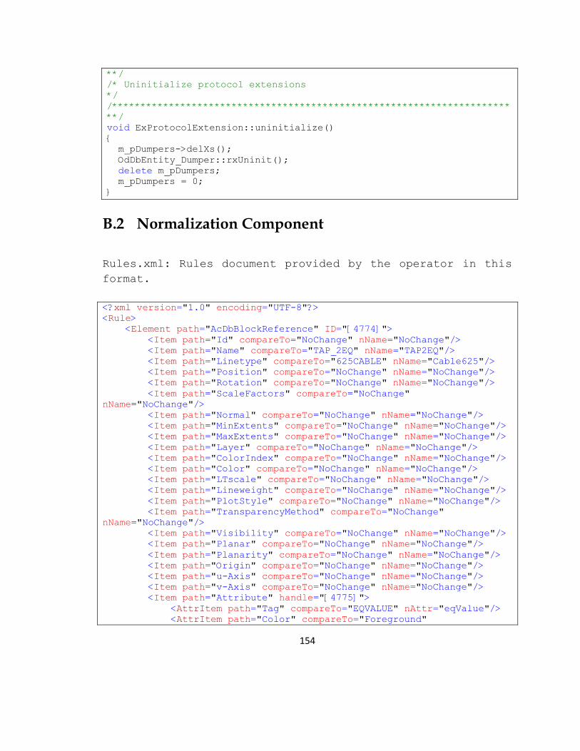
154
**/
/* Uninitialize protocol extensions
*/
/**********************************************************************
**/
void ExProtocolExtension::uninitialize()
{
m_pDumpers->delXs();
OdDbEntity_Dumper::rxUninit();
delete m_pDumpers;
m_pDumpers = 0;
}
B.2 Normalization Component
Rules.xml: Rules document provided by the operator in this
format.
<?xml version="1.0" encoding="UTF-8"?>
<Rule>
<Element path="AcDbBlockReference" ID="[4774]">
<Item path="Id" compareTo="NoChange" nName="NoChange"/>
<Item path="Name" compareTo="TAP_2EQ" nName="TAP2EQ"/>
<Item path="Linetype" compareTo="625CABLE" nName="Cable625"/>
<Item path="Position" compareTo="NoChange" nName="NoChange"/>
<Item path="Rotation" compareTo="NoChange" nName="NoChange"/>
<Item path="ScaleFactors" compareTo="NoChange"
nName="NoChange"/>
<Item path="Normal" compareTo="NoChange" nName="NoChange"/>
<Item path="MinExtents" compareTo="NoChange" nName="NoChange"/>
<Item path="MaxExtents" compareTo="NoChange" nName="NoChange"/>
<Item path="Layer" compareTo="NoChange" nName="NoChange"/>
<Item path="ColorIndex" compareTo="NoChange" nName="NoChange"/>
<Item path="Color" compareTo="NoChange" nName="NoChange"/>
<Item path="LTscale" compareTo="NoChange" nName="NoChange"/>
<Item path="Lineweight" compareTo="NoChange" nName="NoChange"/>
<Item path="PlotStyle" compareTo="NoChange" nName="NoChange"/>
<Item path="TransparencyMethod" compareTo="NoChange"
nName="NoChange"/>
<Item path="Visibility" compareTo="NoChange" nName="NoChange"/>
<Item path="Planar" compareTo="NoChange" nName="NoChange"/>
<Item path="Planarity" compareTo="NoChange" nName="NoChange"/>
<Item path="Origin" compareTo="NoChange" nName="NoChange"/>
<Item path="u-Axis" compareTo="NoChange" nName="NoChange"/>
<Item path="v-Axis" compareTo="NoChange" nName="NoChange"/>
<Item path="Attribute" handle="[4775]">
<AttrItem path="Tag" compareTo="EQVALUE" nAttr="eqValue"/>
<AttrItem path="Color" compareTo="Foreground"

155
nAttr="FGround"/>
<AttrItem path="Normal" compareTo="NoChange"
nAttr="NoChange"/>
<AttrItem path="MinExtents" compareTo="NoChange"
nAttr="NoChange"/>
<AttrItem path="MaxExtents" compareTo="NoChange"
nAttr="NoChange"/>
<AttrItem path="Layer" compareTo="NoChange"
nAttr="NoChange"/>
<AttrItem path="ColorIndex" compareTo="NoChange"
nAttr="NoChange"/>
<AttrItem path="LTscale" compareTo="NoChange"
nAttr="NoChange"/>
<AttrItem path="Lineweight" compareTo="NoChange"
nAttr="NoChange"/>
<AttrItem path="PlotStyle" compareTo="NoChange"
nAttr="NoChange"/>
<AttrItem path="TransparencyMethod" compareTo="NoChange"
nAttr="NoChange"/>
<AttrItem path="Visibility" compareTo="NoChange"
nAttr="NoChange"/>
<AttrItem path="Planar" compareTo="NoChange"
nAttr="NoChange"/>
<AttrItem path="Planarity" compareTo="NoChange"
nAttr="NoChange"/>
<AttrItem path="Origin" compareTo="NoChange"
nAttr="NoChange"/>
<AttrItem path="u-Axis" compareTo="NoChange"
nAttr="NoChange"/>
<AttrItem path="v-Axis" compareTo="NoChange"
nAttr="NoChange"/>
</Item>
<Item path="Attribute" handle="[4776]">
<AttrItem path="Tag" compareTo="TAPVALUE"
nAttr="tapValue"/>
</Item>
<CadProp name="BlockRef"/>
</Element>
<Element path="AcDbBlockReference" ID="[142B]">
<Item path="Name" compareTo="POLE_JOINT" nName="JointPole"/>
<Item path="Attribute" handle="[142C]">
<AttrItem path="Tag" compareTo="DETAG" nAttr="Detag"/>
</Item>
<CadProp name="BlockRef"/>
</Element>
<Element path="AcDbPolyline" ID="[46AF]">
<Item path="Layer" compareTo="CABLE_625" nName="Cable625"/>
<CadProp name="PolyLine"/>
</Element>
</Rule>

156
RulesTransform.xsl
<?xml version="1.0" encoding="UTF-8"?>
<xsl:stylesheet version="2.0"
xmlns:xsl="http://www.w3.org/1999/XSL/Transform">
<xsl:output indent="yes" method="xml"/>
<xsl:template match="/">
<xsl:element name="xsl:stylesheet">
<xsl:namespace name="xsl"
select="'http://www.w3.org/1999/XSL/Transform'"/>
<xsl:attribute name="version" select="'2.0'"/>
<xsl:apply-templates/>
</xsl:element>
</xsl:template>
<xsl:template match="Rule">
<xsl:element name="xsl:output">
<xsl:attribute name="indent" select="'yes'"/>
<xsl:attribute name="method" select="'xml'"/>
</xsl:element>
<xsl:element name="xsl:template">
<xsl:attribute name="match" select="'/'"/>
<xsl:for-each select="Element">
<xsl:variable name="AcDb">
<xsl:value-of select="@ID"/>
</xsl:variable>
<xsl:variable name="Elemvar">
<xsl:value-of select="@path"/>
</xsl:variable>
<xsl:element name="xsl:apply-templates">
<xsl:attribute name="select" select="concat('//',
$Elemvar, '[Id', "='", $AcDb, "']")"/>
</xsl:element>
</xsl:for-each>
</xsl:element>
<xsl:apply-templates/>
</xsl:template>
<xsl:template match="Rule/Element">
<xsl:variable name="Acdbvarp">
<xsl:value-of select="@path"/>
</xsl:variable>
<xsl:variable name="Acdbvarn">
<xsl:value-of select="@ID"/>
</xsl:variable>
<xsl:variable name="ItComTo">
<xsl:value-of select="Item/@compareTo"/>
</xsl:variable>
<xsl:element name="xsl:template">

157
<xsl:attribute name="match" select="concat('//', $Acdbvarp,
'[Id', "='", $Acdbvarn, "']")"/>
<xsl:element name="{$Acdbvarp}">
<xsl:for-each select="//Element/Item">
<xsl:if test="../@ID = $Acdbvarn">
<xsl:variable name="Itpath">
<xsl:value-of select="@path"/>
</xsl:variable>
<xsl:variable name="ItCompTo">
<xsl:value-of select="@compareTo"/>
</xsl:variable>
<xsl:if test="$ItCompTo = 'NoChange'">
<xsl:element name="xsl:copy-of">
<xsl:attribute name="select"
select="@path"/>
</xsl:element>
</xsl:if>
<xsl:if test="$ItCompTo != 'NoChange'">
<xsl:element name="{$Itpath}">
<xsl:value-of select="@nName"/>
<xsl:if test="$Itpath = 'Attribute'">
<xsl:variable name="AttrHand">
<xsl:value-of
select="@handle"/>
</xsl:variable>
<xsl:if test="@handle = $AttrHand">
<xsl:for-each
select="//Item/AttrItem[../@handle=$AttrHand]">
<xsl:if test="@compareTo = 'NoChange'">
<xsl:element name="xsl:copy-of">
<xsl:attribute name="select"
select="@path"/>
</xsl:element>
</xsl:if>
<xsl:if test="@compareTo != 'NoChange'">
<xsl:variable name="AttrItpath">
<xsl:value-of select="@path"/>
</xsl:variable>
<xsl:element name="{$AttrItpath}">
<xsl:value-of select="@nAttr"/>
</xsl:element>
</xsl:if>
</xsl:for-each>
</xsl:if>
</xsl:if>
</xsl:element>
</xsl:if>
</xsl:if>
</xsl:for-each>
</xsl:element>

158
</xsl:element>
<xsl:apply-templates/>
</xsl:template>
</xsl:stylesheet>
RulesOut.xsl
<?xml version="1.0" encoding="UTF-8"?>
<xsl:stylesheet xmlns:xsl="http://www.w3.org/1999/XSL/Transform"
version="2.0">
<xsl:output indent="yes" method="xml"/>
<xsl:template match="/">
<xsl:apply-templates select="//AcDbBlockReference[Id='[4774]']"/>
<xsl:apply-templates select="//AcDbBlockReference[Id='[142B]']"/>
<xsl:apply-templates select="//AcDbPolyline[Id='[46AF]']"/>
</xsl:template>
<xsl:template match="//AcDbBlockReference[Id='[4774]']">
<AcDbBlockReference>
<xsl:copy-of select="Id"/>
<Name>TAP2EQ</Name>
<Linetype>Cable625</Linetype>
<xsl:copy-of select="Position"/>
<xsl:copy-of select="Rotation"/>
<xsl:copy-of select="ScaleFactors"/>
<xsl:copy-of select="Normal"/>
<xsl:copy-of select="MinExtents"/>
<xsl:copy-of select="MaxExtents"/>
<xsl:copy-of select="Layer"/>
<xsl:copy-of select="ColorIndex"/>
<xsl:copy-of select="Color"/>
<xsl:copy-of select="LTscale"/>
<xsl:copy-of select="Lineweight"/>
<xsl:copy-of select="PlotStyle"/>
<xsl:copy-of select="TransparencyMethod"/>
<xsl:copy-of select="Visibility"/>
<xsl:copy-of select="Planar"/>
<xsl:copy-of select="Planarity"/>
<xsl:copy-of select="Origin"/>
<xsl:copy-of select="u-Axis"/>
<xsl:copy-of select="v-Axis"/>
<Attribute>
<Tag>eqValue</Tag>
<Color>FGround</Color>
<xsl:copy-of select="Normal"/>
<xsl:copy-of select="MinExtents"/>
<xsl:copy-of select="MaxExtents"/>
<xsl:copy-of select="Layer"/>
<xsl:copy-of select="ColorIndex"/>
<xsl:copy-of select="LTscale"/>
<xsl:copy-of select="Lineweight"/>
<xsl:copy-of select="PlotStyle"/>

159
<xsl:copy-of select="TransparencyMethod"/>
<xsl:copy-of select="Visibility"/>
<xsl:copy-of select="Planar"/>
<xsl:copy-of select="Planarity"/>
<xsl:copy-of select="Origin"/>
<xsl:copy-of select="u-Axis"/>
<xsl:copy-of select="v-Axis"/>
</Attribute>
<Attribute>
<Tag>tapValue</Tag>
</Attribute>
</AcDbBlockReference>
</xsl:template>
<xsl:template match="//AcDbBlockReference[Id='[142B]']">
<AcDbBlockReference>
<Name>JointPole</Name>
<Attribute>
<Tag>Detag</Tag>
</Attribute>
</AcDbBlockReference>
</xsl:template>
<xsl:template match="//AcDbPolyline[Id='[46AF]']">
<AcDbPolyline>
<Layer>Cable625</Layer>
</AcDbPolyline>
</xsl:template>
</xsl:stylesheet>
B.3 Geo-translation Component
geoLocate.xsl
<?xml version="1.0" encoding="UTF-8"?>
<xsl:stylesheet xmlns:xsl="http://www.w3.org/1999/XSL/Transform"
xmlns:xalan="http://xml.apache.org/xalan"
xmlns:math="http://exslt.org/math"
xmlns:func="http://exslt.org/functions"
xmlns:kmln="http://earth.google.com/kml/2.1"
exclude-result-prefixes="xalan math func"
version="2.0">
<xsl:template match="/">
<kml>
<Document id="0" xmlns="">
<name>CAD Geolocalization</name>

160
<Snippet maxLines="0" />
<Style id="khStyle_0">
<IconStyle>
<color>FF00AAFF</color>
<scale>1</scale>
<Icon>
<href>root://icons/palette-4.png</href>
<x>32</x>
<y>128</y>
<w>32</w>
<h>32</h>
</Icon>
</IconStyle>
<LabelStyle>
<color>FFFFFFFF</color>
<scale>1</scale>
</LabelStyle>
</Style>
<xsl:apply-templates/>
</Document>
</kml>
</xsl:template>
<xsl:function name="func:getResult">
<xsl:param name="olat"/>
<xsl:param name="olon"/>
<xsl:param name="Xcord"/>
<xsl:param name="Ycord"/>
<xsl:param name="Zcord"/>
<xsl:variable name="sx" select="$Xcord div 3.2808399"/>
<xsl:variable name="sy" select="$Ycord div 3.2808399"/>
<xsl:variable name="temp1" select="($sx * $sx) + ($sy * $sy)"/>
<xsl:variable name="r" select="math:sqrt($temp1)"/>
<xsl:variable name="ct" select="$sx div $r"/>
<xsl:variable name="st" select="$sy div $r"/>
<xsl:variable name="sx1" select="$r * $ct"/>
<xsl:variable name="sy1" select="$r * $st"/>
<xsl:variable name="deg2radLat" select="$olat div 57.2957795"
/>
<xsl:variable name="deg2radLatx3" select="$deg2radLat * 3"/>
<xsl:variable name="deg2radLatx5" select="$deg2radLat * 5"/>
<xsl:variable name="deg2radLatcos"
select="math:cos($deg2radLat)"/>
<xsl:variable name="deg2radLatx3cos"
select="math:cos($deg2radLatx3)"/>
<xsl:variable name="deg2radLatx5cos"
select="math:cos($deg2radLatx5)"/>
<xsl:variable name="deg2radLon" select="$olon div 57.2957795"
/>

161
<xsl:variable name="deg2radLonx2" select="$deg2radLon * 2"/>
<xsl:variable name="deg2radLonx4" select="$deg2radLon * 4"/>
<xsl:variable name="deg2radLonx6" select="$deg2radLon * 6"/>
<xsl:variable name="deg2radLonx2cos"
select="math:cos($deg2radLonx2)"/>
<xsl:variable name="deg2radLonx4cos"
select="math:cos($deg2radLonx4)"/>
<xsl:variable name="deg2radLonx6cos"
select="math:cos($deg2radLonx6)"/>
<xsl:variable name="metDegLon" select="((111415.13 *
$deg2radLatcos) - (94.55 * $deg2radLatx3cos) + (0.12 *
$deg2radLatx5cos))"/>
<xsl:variable name="metDegLat" select="(111132.09 - (566.05 *
$deg2radLonx2cos) + (1.20 * $deg2radLonx4cos) - (0.002 *
$deg2radLonx6cos))"/>
<xsl:variable name="plon" select="($olon + ($sx1 div
$metDegLon))"/>
<xsl:variable name="plat" select="($olat + ($sy1 div
$metDegLat))"/>
<xsl:value-of select="concat($plon,',',$plat,',',$Zcord)"/>
</xsl:function>
<xsl:template match="//AcDbBlockReference">
<Placemark>
<name>
<xsl:value-of select="Id" />
</name>
<styleUrl>#khStyle_0</styleUrl>
<Snippet maxLines="0" />
<description>
<xsl:text disable-output-
escaping="yes"><![CDATA[<]]></xsl:text>
<xsl:value-of select="'![CDATA['" />
<xsl:for-each select="*">
<xsl:if test="compare(name(),'Attribute') = 0">
<xsl:text disable-output-
escaping="yes"><![CDATA[<b>Attribute</b>]]></xsl:text>
<xsl:for-each select="../Attribute/*">
<xsl:value-of select="concat(name(.),' =
')" />
<xsl:value-of select="." />
<xsl:text disable-output-
escaping="yes"><![CDATA[ <br>]]></xsl:text>
</xsl:for-each>
</xsl:if>
<xsl:if test="compare(name(),'Attribute') != 0">
<xsl:value-of select="concat(name(),' = ')" />
<xsl:value-of select="." />
<xsl:text disable-output-
escaping="yes"><![CDATA[ <br>]]></xsl:text>

162
</xsl:if>
</xsl:for-each>
<xsl:value-of select="']]'" />
<xsl:text disable-output-
escaping="yes"><![CDATA[>]]></xsl:text>
</description>
<xsl:variable name="PosXcord" select="number(substring-
before(Position,' '))" />
<xsl:variable name="parsVar" select="substring-
after(Position,' ')" />
<xsl:variable name="PosYcord" select="number(substring-
before($parsVar,' '))" />
<xsl:variable name="PosZcord" select="number(substring-
after($parsVar,' '))" />
<!--
<Pars1>
<xsl:value-of select="$PosXcord"/>
</Pars1>
<Pars2>
<xsl:value-of select="$PosYcord"/>
</Pars2>
<Pars3>
<xsl:value-of select="$PosZcord"/>
</Pars3>
-->
<Point>
<coordinates>
<xsl:value-of select="func:getResult(38.983073,-
77.05617,$PosXcord,$PosYcord,$PosZcord)" />
</coordinates>
</Point>
</Placemark>
</xsl:template>
</xsl:stylesheet>