
King of the Pylons: ReMeMBeRing steve WittMan
84
KING OF THE PYLONS: REMEMBERING STEVE WITTMAN ® JANUARY 2017 www.kitplanes.com In the Shop: • CNC Mold Blanks • Labeling Wires • Silicone Tape • Solid Rivets KITPLANES JANUARY 2017 Super Legend HP • Steve Wittman • Hangar Floors • Aerosport Interiors • Lycoming School 2 • Bearhawk Progress • Silicone Tape • Inverted Oil • Mr. Anvil Head BELVOIR PUBLICATIONS PARTS OFF, PARTS ON Lycoming Assembly School HANGAR TIPS Wooden Floors BEARHAWK LSA PROJECT Fuel Tanks and Wingtips MR. ANVIL HEAD… Is Not Your Friend
-
Upload
khangminh22 -
Category
Documents
-
view
0 -
download
0
Transcript of King of the Pylons: ReMeMBeRing steve WittMan

King of the Pylons: ReMeMBeRing steve WittMan
®
JANUARY 2017
www.kitplanes.com
In the Shop: •CNCMoldBlanks•LabelingWires•SiliconeTape•SolidRivets
KITPLA
NESJA
NUARY2017SuperLegendH
P•SteveWittm
an•HangarFloors•A
erosportInteriors•LycomingSchool2•Bearhaw
kProgress•SiliconeTape•InvertedOil•M
r.AnvilH
eadBELVO
IRPUBLIC
ATIONS
Parts Off, Parts On lycoming assembly school
Hangar tiPs Wooden floors
BearHawk Lsa PrOject fuel tanks and Wingtips
Mr. anviL Head… is not your friend

DynonAvionics.com (425) [email protected]
Meet SkyView HDX - the new
flagship from the market leaders in
experimental and light sport avionics.
Clear, Vibrant DisplaysBeautiful DesignUnrivaled Control Ergonomics Improved Touch InterfaceCapable and Compatible

20
14
6
On the cover: Super Legend HP with 180-hp Titan O-340 Engine. Photographed by Darin Hart.
January 2017 | Volume 34, Number 1
KITPLANES January 2017 1
Flight Review6 Super Legend Hp: The ASTM Titan engine finds another
home in a new kit from American Legend. And yeah, it’s a hotrod. By Paul Bertorelli.
Builder Spotlight14 partS Off, partS On! Learning how to disassemble and
assemble Lycoming engines. By Paul Dye.20 JuSt CaLL Him mr. pyLOn: Homebuilt aircraft builder Steve
Wittman was one of America’s greatest air racers. By Amy Laboda.28 BuiLding tHe BearHawk LSa: Fuel tanks and wingtips.
By Ken Scott.32 wOOden Hangar fLOOrS: Yes, it’s unusual, but for my
hangar it makes perfect sense. By Steve Kessinger.36 tHe inverted OiL diLemma: Adding more equipment is
never as easy as you think. By Paul Dye.40 HOmeBuiLt Or StOre-BOugHt? Raising the bar for
RV-10 interiors to an entirely different level. By Bruce Eicher.44 rapid prOtOtyping and experimentaL deSign:
CNC mold blank fabrication, part 2. By Eric Stewart.68 COmpLetiOnS: Builders share their successes.74 aSk tHe dar: Complying with the 51% rule, bringing Canadian
aircraft into the U.S., adding auxiliary fuel tanks, using non-TSO’d ADS-B in an Ercoupe. By Mel Asberry.
Shop Talk50 pLane and SimpLe: Silicone tape—it’s for a lot more than just
emergencies. By Jon Croke.58 BeSt praCtiCeS: Solid rivet selection and installation.
By Dave Prizio.65 HOme SHOp maCHiniSt: Be steady. By Bob Hadley.78 aerO ’LeCtriCS: Wired at Oshkosh. By Jim Weir.
Shop Tips63 aLignment aidS fOr LyCOming OiL SCreen
HOuSingS: By William Rynone, Ph.D., P.E.77 LaBeLing: By Larry Larson.
Designer’s Notebook75 wind tunneL: More about trikes. By Barnaby Wainfan.
Exploring2 editOr’S LOg: No two rivets alike. By Paul Dye.52 CHeCkpOintS: Mr. Anvil Head is not your friend.
By Vic Syracuse.55 riSky BuSineSS: Surviving the unplanned pitch trim loop.
By Sid Mayeux.
Kit Bits4 LetterS69 LiSt Of advertiSerS70 BuiLderS’ marketpLaCe80 kit Stuff: Drawing on experience. By cartoonist Robrucha.
For subscription information, contact KITPLANES® at 800/622-1065 or visit www.kitplanes.com/cs.

2 KITPLANES January 2017 www.kitplanes.com & www.facebook.com/kitplanes
No two rivets alike.
Paul Dye, KitPlanes® editor in Chief, retired as a lead Flight Director for nasa’s Human space Flight program, with 40 years of aerospace experience on everything from Cubs to the space shuttle. an avid homebuilder, he began flying and working on airplanes as a teen, and has experience with a wide range of construction techniques and materials. He flies an RV-8 that he built in 2005, and an RV-3 that he built with his pilot wife, as well as a Dream tundra they recently completed. Currently, they are building a Xenos motorglider. a commercially licensed pilot, he has logged over 5000 hours in many different types of aircraft and is an eaa tech Counselor and Flight advisor, and a member of the Homebuilder’s Council. He consults and collaborates in aerospace operations and flight-testing projects across the country.
Paul Dye
Editor’s log
It’s a first-world problem—I admit it. With too many airplanes in our little fleet, there is always something to be worked on, or an airplane that just needs to be flown to keep the fluids fluid and the battery charged. That means that we have been violating Rule #1 in finish-ing a homebuilt airplane project when it comes to our Xenos motorglider: Make sure to do a little work on it every single day, even if it’s just cleaning up the shop. Life (and other airplanes) tend to get in the way, so the Xenos gets attention in fits and spurts, when we seem to be caught up (or at least gaining on) all of the other little chores associated with airplane ownership and airpark living. Like I said, first-world problem.
But recently, we’ve been enjoying a little more time with the project plane, specifically, building the main wing-spars. With a 46-foot wingspan, the Xenos presents ample opportunity to work on spars because, well, they’re ample! Since the root end of each spar crosses the cockpit, overlapping the other, the total length of the two spars exceed the finished span of the airplane, making for even more fun.
Built from custom aluminum extru-sions, the caps are works of art, and they change shape and size constantly from root to tip. The webs are built up of different layers of aluminum sheet, varying from .032-inch thick out near the tips to a combined thickness of 1/8-inch layers measuring over ¾ inch at
the root. Various lightening holes, bolt blocks, rib flanges, and other accesso-ries make them quite complicated for such a simple airplane.
Before we even started assembling the spars themselves, we spent a fair amount of time fabricating compo-nents. The inner wing rib attachment flanges, for instance, are about 7-inch long aluminum sheet angles, each with its own unique dimensions, shape, and rivet pattern. Forward and aft pieces for each rib station are unique, of course, and the overall shapes of the seven or eight stations are at least symmetrical for the left and right spars. These flanges are attached to the spar when it is built (and the ribs themselves scabbed on later) because they get fastened to the primary spar assembly with the big -5 (5/32-inch diameter) rivets that predomi-nate throughout the structure. Driving those -5 rivets takes a little more work then the -4 (1/8-inch diameter) pulled riv-ets that are used to primarily build the rest of the airplane.
Mocking up the spar and match drill-ing the holes was a job that took most of two months’ worth of spare time. The drawings are complete and very dense when it comes to important information, and the spar is far more complicated that you might expect. Getting all of the layers of pre-punched web material in the right order and located in the proper spots from root to tip was a lovely puzzle, satisfying in the
end when it was complete. Upsizing all of the pre-punched holes and match-drilling the spar caps into the assembly took varying sizes and lengths of drill bits and constant reference to those drawings. While the thin sandwich at the tip end could be fastened with
This custom-built pneumatic squeezer made it easy to set large -5 rivets. The spar travels through the yoke and is supported on each side by roller stands like you’d use to handle long boards on either side of a table saw.

KITPLANES January 2017 3
regular -5 Clecoes, the thick root ends presented a bit of a conundrum. Wing-nut Clecoes cost about $3.50 each, and there were hundreds of holes that needed to be filled. But many of them were so close to the spar cap that there wasn’t room for the body of the long-reach temporary fasteners. For-tunately, the -5 rivets require a #21 drill bit, which happens to match perfectly with a metric 4mm machine screw, so we obtained a box of those, along with appropriate washers and nuts, to tem-porarily fasten things together. A little more tedious than Clecoes, yes, but much more economical and a small fraction of the overall time it will take to build the spar.
Let’s just skip over the part where we had to disassemble everything, deburr (for a week of evenings) and reassem-ble…shall we?
Finally, we are in the process of driv-ing home the hundreds of rivets that will hold these miracles of engineering
together for good. Solid rivets don’t phase us at all; we’ve been working with them for many years on lots of differ-ent airplanes. The -5 rivets do, however, require a bit more oomph to set than the little -3 or -4 fasteners used in build-ing most light-aircraft assemblies. But where there is a need, the right tool can be found. Enter a custom-built pneu-matic squeezer provided by a builder/craftsman we know just over the moun-tains from us. When I went to pick it up in my RV-8, I had to go alone because its weight took up the passenger allow-ance (and that seat). Set on a small bench stand in the middle of the workspace, the spar travels through the yoke and is supported on each side by roller stands like you’d use to handle long boards on either side of a table saw.
So now we’re driving rivets—but there are very few alike, making it hard to get into “production mode.” With the thickness of the spar web varying from root to tip, the length of the rivets
change also. Just when you think you’ve got everything set and you’re rolling along, you have to change the setup. Then one of those rib flanges comes along, and you have to open up the yoke to get around it, then hunt for your setting again. It’s a fine misery as they say. Being in the shop is rewarding, but you have to put up with the little things that slow you down at every step. It’s all part of the game.
I figure that with our current sched-ule, we’ve got another few weeks to go to get this left spar finished. Then we will pull out all the virgin parts for the right side and get started on that one. In retrospect, it’s a good thing we’ve got other airplanes to fly, for this could take awhile. But we love to build, and love to fly—so having both options available at the same time is the best of both worlds.
Excuse me now, I hear some rivets call-ing to me from out in the shop. A home-builder’s work is never done… J
Web site information: General homebuilt aircraft information, back issue availability, online directories ordering info, plus a Kitplanes® article index and selected articles can be found at www.kitplanes.com.Unsolicited manuscripts: are welcome on an exclusive basis, but none can be acknowledged or returned unless accompanied by a stamped, self-addressed envelope. no responsibility is assumed for loss or damage to unsolicited material.Kitplanes® (issn 0891-1851) is published monthly by aviation publishing Group, llC, an affiliate of belvoir publications, 535 Connecticut avenue, norwalk, Ct 06854-1713, robert englander, Chairman and Ceo; timothy H. Cole, exec. Vice pres./editorial Director; philip l. penny, Coo; Greg King, exec. Vice pres./marketing Dir.; ron Goldberg, Cfo; tom Canfield, Vice pres., Circulation.
periodicals postage paid at norwalk, Ct, and at additional mailing offices. Copyright ©2017 aviation publishing Group, llC. all rights reserved. reproduction in whole or in part is strictly prohibited. printed in Usa. revenue Canada Gst account #128044658. Canada publishing agreement #40016479.
subscriptions: one year (12 issues) is $29.95 U.s. $41.95 in U.s. funds in Canada, includes Gst. $41.95 in U.s. funds for foreign surface mail or $57.95 in U.s. funds for foreign air mail. single copy price $4.99 U.s., $5.99 Canadian.postmaster: please send address changes and subscription inquiries to: Kitplanes®, p.o. box 8535, big sandy, tX 75755-8535, or Canada post: return undeliverables to p.o. box 2601, 6915 Dixie rd, mississauga, on l4t 0a9 or call 800/622-1065. Kitplanes® is a registered trademark of aviation publishing Group, llC.
4 KITPLANES January 2017 www.kitplanes.com & www.facebook.com/kitplanes
eDitorial Editor in Chief paul Dye [email protected] Managing Editor mark schrimmer Art Direction Dan maher Editorial Director paul bertorelli Contributing Editors larry anglisano, marc ausman, roy beisswenger, Chuck berthe, David boeshaar, leroy Cook, robert Hadley, Dan Horton, louise Hose, amy laboda, Dave martin, sid mayeux, David paule, Dave prizio, Dean sigler, Dick starks, eric stewart, Vic syracuse, barnaby Wainfan, Jim Weir, tom Wilson. Web Editor omar filipovic Cartoonist robrucha
aDVertisinG Sr. Advertising Manager Chuck preston 805/382-3363 [email protected]
bUsiness offiCebelvoir media Group, llC535 Connecticut avenuenorwalk, Ct 06854-1713
eDitorial offiCe535 Connecticut avenuenorwalk, Ct [email protected]
CirCUlationCirculation Manager laura mcmann
sUbsCription Department800/622-1065www.kitplanes.com/csp.o. box 8535, big sandy, tX 75755-8535for Canada: po box 328, norwich, ontario n0J 1p0
reprints for pUbliCation anD Web postinG aVailableminimum order: 500Contact Jennifer Jimolka, 203/857-3144
Change of address?Missing issue?subsCription Question? Visit www.kitplanes.com/cs. Or call 800/622-1065 from the u.s. and Canada.
foreign 903/636-1112 or fax 203/857-3100.
Weight ReductionI enjoyed David Paule’s article about saving weight in aircraft construction [“Stressing Structure,” October 2016]. However, I would like to add another perspective. The average American adult is 17 pounds overweight. If you fly with your average friend in the right seat, that’s 34 pounds of potential weight savings without touching your airframe or replacing the engine. Not only is this weight savings free, but the non-flying benefits are immeasurable.
DaviD Fisichella
We at the magazine wholeheartedly agree that along with saving weight in airframe construction, losing a little of our personal weight will make both the airplane and the occupants perform better. But it’s hard to resist that deluxe bacon cheeseburger at the airport diner when you’ve spent $100 flying there to get it, isn’t it? Fly healthy, fly longer!—Ed.
small Trim TabsI appreciated Barnaby Wainfan’s col-umn [“Wind Tunnel,” September 2016] where he explained trim tabs in easily understood terms. When I worked for Interstate Aircraft, the new owner told me he wanted to make the Tern a “half-ton pickup of the sky.” I looked at the trim tab and replied that he’d have to redesign the forward stabilizer attach to incorporate a jackscrew trim system, like Piper Cubs have, because the Tern didn’t have enough pitch trim with the one tab, and adding a second tab to the other elevator wouldn’t be enough. Years later, the “new” Tern prototype flew with the same little trim tab…and was certi-fied with a useful load of 800 pounds.
So much for the flying half-ton pickup truck, but only due to inadequate trim.
anDy GelsTon
Better enginesI greatly enjoy your technical articles. Tom Wilson’s story on what you can do for a better engine [“Engine Theory,” November 2016] is a perfect example. The only comment I have comes from my experience with a Lycoming O-320 in a Spezio Tuholer that I flew for 10 years. At one point, I installed a cross-over exhaust manifold and a wooden prop. Combined, a seat-of-the-pants estimate suggests it went from 150 hp to around 175–180 hp. While it really didn’t do much for speed, takeoff and climb improved dramatically. I think many people would be sur-prised by the potential increased perfor-mance that comes with a more efficient propeller and exhaust system. It might be worth further investigation and a fol-low-up article. The best part is, neither of these require you to open up the engine.
Tim c. KinG Form 8050-1 now onlineIn “Preparing for Your First Flight” [November 2016], it is stated that Air-craft Registration Application Form 8050-1 is not available online. This is not correct. The form is available online, however, it cannot be filled out and sub-mitted online. It must be mailed in.
BaRRy GloGeR
We recently heard this good news as well. The wheels of modernization within the FAA turn slowly, but it is good to know that they are turning. A link to the form is http://tinyurl.com/hcto6x3—Ed. J

www.continentalmotors.aero
BE SUREFLY NiC3
©2016 Continental Motors. All rights reserved.
™
Continental Nickel Silicon Carbide (NiC3™) coated cylinders are now
available for most general aviation piston engines. These coated cylin-
ders mean you can be sure of enhanced corrosion protection, extend-
ed cylinder life, reduced wear and smoother performance, to name
just a few bene� ts. Nickel Silicon Carbide coating is used to enhance
the performance of car racing engines, and is now increasingly in
demand in General Aviation.
Now you can enjoy a nice � ight with NiC3 coated cylinders, perfect
for pilots who � y infrequently, those in maritime or high humidity
areas, and planes in climates that demand overwinter hangaring.
So when you want to be sure, be sure to fl y NiC3. IMMEDIATELY AVAILABLE FROM STOCK
CM_NiC3_all_languages_210x265mm_noLycoming.indd 1 20/10/16 11:46

www.kitplanes.com & www.facebook.com/kitplanes6 KITPLANES January 2017
The ASTM Titan engine finds another home in a new kit from Legend.
And yeah, it’s a hotrod.By Paul Bertorelli
Super Legend HP

Photos: Paul Bertorelli. Air-to-air photos: Ed Hicks, Flyer magazine. KITPLANES January 2017 7
A decade ago, when the FAA and ASTM were dickering over what became the Light Sport Aircraft rule, limita-tions on weight and performance—but not power—bubbled to the top of the discussion. The airplanes were supposed to be less expensive, light, and simple, but the rule didn’t say they couldn’t have neck-snapping power-to-weight ratios, and thus the era of the 180-hp produc-tion Light Sport is upon us.
And the bubbling continues as Amer-ican Legend gears up to offer the Super Legend HP as a kit, including a builder-assist option. The Super Legend HP is essentially the Super Legend airframe fitted with Continental’s increasingly popular 180-hp O-340 Titan engine, a stroked version of the Lycoming-style O-320 that has proven a mainstay powerplant for half a century. This engine has found wide acceptance in the Experimental market, and when
CubCrafters jollied it through the ASTM approval process, it became the first such engine of its type to find prac-tical application in LSAs. Just for the record, the CubCrafters version is a dif-ferent engine, lighter and with slightly different accessories than Continental offers for everyone else. The Titan’s development has proven somewhat of a bonanza for homebuilders because there’s a wide variety of accessories and configurations for this engine. (See the engine sidebar for more details.)
That buyers are choosing this engine in what passes for droves these days, proves what aircraft manufacturers and salesmen have known all along: When writing a low six-figure check for a new airplane, owners want all the options and, no disrespect to ASTM, they don’t want pokey, underpowered airframes. Neither do builders, apparently, who are still investing most of a hundred
grand to bring these projects to comple-tion. Just because a would-be LSA or E/A-B driver will never need tundra tires and a 50-foot takeoff roll for a Sat-urday morning toot around the county, doesn’t mean they’re not willing to pay for such things.
Enduring Super CubWith its Cub-type airframes, American Legend has attracted a small but loyal customer base, plying the same market as CubCrafters, Aerotrek, RANs and Kitfox—the taildragging rag-and-tube crowd. (Oh, and did we mention Kitfox and RANs also have their own versions of Titan-powered airframes?)
The original Legend, available as a kit and fly-away LSA, has the Conti-nental O-200-D, a lightened version of the original 100-hp O-200. The Super Legend followed, with the Lycoming YO-233, a lighter version of the 115-hp

float work, sometimes saving the need to dance across a walk wire when dock-ing or mooring.
With the Titan’s higher power comes higher weight, and that chews into the airplane’s useful load for the LSA ver-sion. But for the E/A-B, think of Super Cub-type useful loads and a higher empty weight by whatever equipment and accessories a builder wants to add that an LSA owner can’t. And because the Super Legend has payload to burn, there’s more than enough margin to lard it up with stuff, even if it’s hauling floats. (Legend offers its own in-house carbon amphibious float system.)
Weight wise, Hart told us the origi-nal O-200 weighs about 199 pounds and the Lycoming O-233 used in the Super Legend adds 15 pounds to that. The Titan tips in at 248 pounds, which means the airplane went on a serious
diet to stay inside the 1320-pound LSA weight limit.
The heaver weight up front does shift the CG forward slightly, but it still stays within 3 inches of the forward limit when the airplane is occupied by two pilots. (The pilot weight is concentrated on or aft of the CG datum point.)
The original Legend has about a 500-pound LSA useful load on an empty weight of 825 pounds, but the Titan-equipped HP is at least 80 pounds heavier than that, with an empty weight of about 905 pounds. In fact, it pushes the limit on LSA empty weight require-ments. E/A-B builders needn’t be con-strained by the stingy empty limit, and the airframe itself is engineered to the same gross weight as the Super Cub—1750 pounds. That translates to 800 pounds of useful load. With 30 gallons of useful fuel aboard, the airplane can
O-235. When it appeared four years ago, half of Legend’s sales were Super Legends, and the company’s Darin Hart expects similar response to the Titan-powered Super Legend HP, with a smat-tering of those shipped as E/A-B kits.
The airframe construction is conven-tional, with Ceconite 102 fabric and Poly-Tone coating over a welded 4130 fuselage cage. For builders, that fuse comes pre-welded as one of four discrete kits in a four-kit package.
When the Super Legend first appeared, the company increased the size of the horizontal stab/elevator to provide about 18% more surface area. That’s not too noticeable just looking at the airplanes side-by-side, but does provide some increased pitch authority. Unique to the Legend design are doors on both sides of the cabin, a welcome feature for hot-day ground ops and transformational for
8 KITPLANES January 2017 www.kitplanes.com & www.facebook.com/kitplanes
The HP’s panel is well designed with sufficient—if not generous—room for basic avionics. Builders can eliminate analog instruments in favor of an all-digital installation.
With space on the right side of the panel tight, the LSA version we flew had a Trig transponder and com radio. Trig offers ADS-B capability with its transponders.
The Legend HP (left), like the Super Legend, has larger tail surfaces than the original Legend and is very similar to the Piper Super Cub. The Titan O-340 can be fitted with one of two Catto props, an 80x50 cruise prop or an 84x42 climb prop (above).

KITPLANES January 2017 9
Stroking an engine is the classic hot-rodder’s technique of coaxing more power out of an engine by modifying it. But tinkering with the basic geometry of crankshafts, connecting rods, and pistons requires manipulating a complex set of variables.
When ECI—now a Continental unit—went at it, they decided to keep it simple by increasing the stroke of an O-320 marginally, solely by machining the crankshaft journals to a different size, and thus was born the X-340 Experimental engine. According to Bob Looper, the company originally had in mind a high-performance mod for the Cessna 172’s O-320. When the engine was at overhaul, the crank could be replaced with the stroked version, increasing displacement and horsepower without requiring an upgrade to the O-360.
That project still hasn’t sifted through certification, but in the meantime, the X-340 has become the most popular engine in the company’s Titan line and has spawned a stroked version of the O-360 called the X-370.
For homebuilders, these are highly customizable engines. Continental offers choices in crankshafts and cases, accessory cases, electronic or magneto ignition systems, constant-speed props and several fuel injection systems. Although engines offered for the LSA market are similar, there’s less variation in accessories.
For its version of the 340 strokers, CubCrafters joined then-ECI to lighten the engine and guide it through the ASTM approval process. Working together, the companies lightened the 340 with a lighter accessory case and a smaller, lighter sump that has less oil capacity to save weight. That engine became the X-340CC, which is unique to the Carbon Cub, LSA and kit. The X-340s used in other LSAs, including the Super Legend HP, are slightly different and are a bit heavier, lacking the lightened sump, which is a proprietary CubCrafters’ feature.
On a power-to-weight ratio, the benefit of stroking is obvious. The dry weight of the X-340, at 180 hp, is 245 pounds, according to Conti-nental’s data. A stock Lycoming O-320, at 150 hp, weighs between 244 and 255 pounds, depending on model and configuration. The power-to-weight delta isn’t huge, but it goes in the right direction, making the X-340 the torque equivalent of an O-360.
Continental’s Looper told us that other than increased torque, the X-340 is identical to the O-320 in all respects, including rpm and operating temperatures. In addition to two stroked models, the Titan line includes three conventional configurations of popular Lycoming displacements, the O-320, O-360, and O-540.
—P.B.
Titan Stroker: Squeezing More From Four Cylinders
Continental has found a winner in the Titan O-340 stroker engine. It’s finding wind application in EAB and LSA applications.

That takeoff performance may be achievable with the proper technique, but it requires a bit of nerve, using power to jack the tail up against the brakes and hauling the airplane off the runway with an abrupt tug. At Sebring earlier this year, we might have used 100 feet of runway without trying very hard. Similarly, with two aboard, we climbed at 1500 fpm with no heroics required. But that also means you get to pattern altitude by the turn from cross-wind to downwind and better grab a handful of throttle reduction to keep from overrunning the altitude.
Although the Cub airframe wouldn’t be confused with something slick, it actually takes determination to slow it down on final approach. With a full-flap stall speed of 28 mph, the airplane can be flown at 50 mph or even slower on short final. Getting there takes effort, however, because until the airframe is dirtied up and slowed up, all it wants to do is glide at an angle that’s surprisingly flat. It will slip, of course, even with full flaps, but that didn’t seem to add much to the descent rate.
Nonetheless, a max-performance short-field landing with full flaps and power on can get the airplane into a postage-stamp runway. With its surplus power, there’s little worry about getting unre-coverably behind the power curve.
steam along on reduced power at 5 gph and cruise for five hours comfortably at about 92 to 95 mph.
And this gets us to the dirty little secret of Light Sport Aircraft that the E/A-B world can rightfully snicker at. The arbitrarily low gross weight is the most oft-ignored rule in aviation. The blunt truth is that with full fuel and two 200-pounders aboard, the E/A-B ver-sion would still be 250 pounds under that limit. Make your own moral judg-ment on the advisability of doing this or not, but the airplane can be flown safely at that loading, and pilots who have flown the Super Cub in the Alaska outback will note that it has been flown heavier. By a lot.
Flying the HPAerodynamics being what they are, stuffing this much power into a light airframe doesn’t do much for cruise speed. Legend gives the maximum cruise speed of the HP as 104 mph or about 5 to 7 mph faster than the Super Legend. For cross-country flying, think of it as an 80- to 90-mph airplane and plan accordingly.
But takeoffs, well, they’re something else entirely. The company claims a minimum takeoff roll of 35 feet, fol-lowed by a maximum climb rate of up to 2000 fpm.
10 KITPLANES January 2017 www.kitplanes.com & www.facebook.com/kitplanes
(Above) The HP’s gear is standard Cub fare, an X-frame strut assembly with damping springs. (Right) The Legend HP sports Grove brakes that can be either heel or toe activated. Either way, they have sufficient energy to put the airplane on its nose.
AmericAn Legend Super Legend Hp
Kit Price. . . . . . . . . . . . . . . . . . . . . . . . . . . . . . . . . . . . . . . . . $57,250Estimated completed price with avionics and lighting . . . . . . . . . . . . . . . . . . . . . . . . . . . $135,000Estimated build time . . . . . . . . . . . . . . . . . . . . . . . . . . 750 hoursNumber flying (at press time) . . . . . . . . . . . . . . . . . . . . . . . . . . .3Powerplant . . . . . . . . . . . . . . . . . . . . . . . . . . Titan O-340, 180 hpPropeller. . . . . . . . . . . . . . . . . . . . . . . . . . . . . . . . Catto composite
AIRFRAMEWingspan . . . . . . . . . . . . . . . . . . . . . . . . . . . . . . . . . . 35 ft 6 inLength . . . . . . . . . . . . . . . . . . . . . . . . . . . . . . . . . . . . . 22 ft 5 inFuel capacity. . . . . . . . . . . . . . . . . . . . 32 gal (30 gal usable)Maximum gross weight (LSA) . . . 1320 lb (1430 lb on floats)Maximum gross weight (E/A-B). . . . . . . . . . . . . . . . 1750 lbTypical empty weight. . . . . . . . . . . . . . . . . . . . . . . . . . 904 lbTypical useful load (LSA) . . . . . . . . . . . . . . . . . . . . . . . 416 lbTypical useful load (E/A-B). . . . . . . . . . . . . . . . . . . . . . 846 lbFull-fuel payload (LSA). . . . . . . . . . . . . . . . . . . . . . . . . 236 lbFull-fuel payload (E/A-B) . . . . . . . . . . . . . . . . . . . . . . . 666 lbSeating capacity . . . . . . . . . . . . . . . . . . . . . . . . . . 2, tandemCabin width. . . . . . . . . . . . . . . . . . . . . . . . . . . . . . . . . . . . 29 inBaggage capacity . . . . . . . . . . . . . . . . . . . . . . . . . . . . . . 75 lb
PERFORMANCECruise speed. . . . . . . . . . . . . . . . . . . . . . . . 104 mph @ 2150 rpmMaximum rate of climb. . . . . . . . . . . . . . . . . . . . . . . . 2000 fpmStall speed (landing configuration). . . . . . . . . . . . . . . 28 mphStall speed (clean) . . . . . . . . . . . . . . . . . . . . . . . . . . . . . . . 32 mphTakeoff ground roll . . . . . . . . . . . . . . . . . . . . . . . . . . . . . . . . . 35 ftTakeoff distance (50-foot obstacle). . . . . . . . . . . . . . . . . 200 ft
Specifications are manufacturer’s estimates and are based on the configuration of the demonstrator aircraft.

KITPLANES January 2017 11
Legend gives the maximum cruise speed of the HP as 104 mph. For cross-country flying, think of it as an 80- to 90-mph airplane and plan accordingly.

The demo airplane we f lew was equipped with Desser’s 28-inch tun-dra tires, which may or may not absorb bounces on landings. The outcome depends on what kind of descent rate you’re expecting them to absorb. Damp-ing springs in the landing gear help, but what springs give, they return if they’re compressed too abruptly.
The tires are mounted on 8-inch rims from Grove. Frankly, we’re not fans of these big tires unless they’re necessary for operating over rough or soft terrain. Yeah, they look cool, but they make the airplane more difficult to ingress and egress and, in our view, seem to move the center of mass higher, making the airplane feel less planted during ground handling. Skittish isn’t the right word, but you get the picture.
The Grove brakes are powerful and require deft footwork because they’re more than capable of putting the air-plane on its nose. And indeed, that hap-pened on another press demo flight of the HP we flew, although it wasn’t clear if it related to brake application. The air-planes can have either toe or heel brakes. From the front seat, we found the heel brakes a little tricky to apply because of the distance from the rudder pedals to the brake pedals. But that’s typical Super Cub and maybe a good thing to avoid the aforementioned nose prangs. But toe
12 KITPLANES January 2017 www.kitplanes.com & www.facebook.com/kitplanes
For its kits, American Legend has followed the à la carte strategy many other companies offer. All of the kits are sold and delivered in four basic components, a fuselage kit, a wing kit, a tail surface kit and a firewall forward kit for whatever engine the builder wants. These are delivered by a company specializing in kit airplane shipping, not by common carrier.
The Super Legend HP is the fourth kit in the Legend line, the other three being the Classic Cub, the Cub Special and the Super Legend.
The largest component is the fuselage kit which, at $22,500, is shipped fully welded, just as Legend’s production aircraft are. The 4130 tubing is CNC cut and TIG welded, so it’s prob-ably as precise an assembly as is possible. Next up is the wing kit at $19,900, which includes ribs built up on a preassembled spar. The builder does the control cables, fuel tanks, and final assembly. The tail surface kit costs $5,600 and the firewall-forward group is $9,250.
“The parts are just like it is on the production floor. All bolts and components in the kit are labeled, so you don’t have to dig into boxes to find the right size bolt. They’re all packaged,” says Legend’s Darin Hart.
Legend considers all of its kits quickbuild, but Hart said it also offers a factory assist program, as it has with previous kits. (See “Family Affair: Building a Legend Cub at the Factory,” September 2015, for an account of building a 100-hp ELSA Legend Cub.) It’s a 28-day program for both the Super Legend and HP—that’s working days—spread out over several months.
The program is divided into two phases. In the first, the builder does all the basic work to get the airplane assembled and covered. Then he or she leaves for four or five weeks to do the second phase. In the builder’s absence, Legend paints the airplane, installs the panel, and readies the airplane for engine hanging and assembly when the builder returns.
The builder does all the work at the company’s Sulphur Springs, Texas, factory north of Dallas and works through phases of construction.
Hart said this is a one-on-one process between a Legend staffer and the builder. “We make it clear we’re not building the airplane. They’re building the airplane,” Hart said.
When it’s completed, Hart says, the Super Legend HP kit will look just like a production airplane, less whatever the owner has spec’d for his or her own purposes. The airplane can be built as an ELSA or E-A/B airplane. Interestingly, now that the Third Class medical appears soon to be a thing of the past, Hart says more owners are opting for the E/A-B version, with its higher weight. Nice idea, but there’s a complication. The E/A-B version requires the standard 40-hour flyoff, while the ELSA requires only five hours. The SLSA version can be flown off in 30 minutes. If there’s logic to any of this, it escapes us.
—P.B.
What’s in the Box
Tundra tires have become a bold fashion statement for Cubs. Nice if you need them, but they cost a bundle and rob speed.

brakes have the advantage of being easier to get to and apply gently for a pilot used to them. Given the choice, we would take modern toe brakes, thanks.
Cabin appointments in the Legend HP are comfortable, if not luxurious. The seats are the same weight-saving bungee designs Legend introduced in the Super Legend. The windows open in flight, held fast by a new clip that’s easier to use than the previous design. Visibility in flight and on the ground is excellent from the front seat. There’s no need for S-turns.
One thing we would like to see improved is the hinge point for the flap handle. It’s almost aligned with the pilot’s shoulder axis, and we found it awkward to manipulate for that last notch of flap. Rotator cuff patients might feel a twinge. A forward bend in the handle might help.
With the higher-performance air-plane comes a higher price, of course. The four basic kits (see “What’s in the
Box” sidebar) come to $57,250. That includes a firewall forward kit, but not the engine. Add $29,500 for the Titan, and you come to $86,750 less paint, prop, avionics, and basic electrics.
For comparison, the base price of the flyaway LSA Legend with the classic Cub cowl is $136,900, while the Super
Legend base is $154,900. The Super Legend HP starts at $164,900 and the version we flew—with Garmin avion-ics, Trig ADS-B Out, AeroLED landing lights, and a leather interior spec’d out at $195,000. For more information, con-tact American Legend at www.legend.aero or 903-885-7000. J
KITPLANES January 2017 13 Photos:
The view over the nose is typical Cub, albeit good enough that no S-turning is required on the ground. Solo is from the front.

www.kitplanes.com & www.facebook.com/kitplanes14 KITPLANES January 2017
Parts Off, Parts On!Learning how to disassemble and assemble
Lycoming engines.By Paul Dye

Photos: Paul Dye KITPLANES January 2017 15
When Lycoming Engines had to respond to the downturn in general avia-tion production in the 1980s, it devoted more of its business to rebuilding, over-hauling, and zero-timing engines for customers. This meant that its employ-ees had to learn how to disassemble engines as well as assemble them—and while everyone thought taking them apart must be easy, that turned out not to be the case.
A number of engine cases were ruined when well-meaning but inexperienced employees started trying to take them apart without the proper understand-ing of how this should be done. The answer? The company developed a class to teach their reassigned assemblers how to become disassemblers. Within a short time, hundreds of them had been trained, and mistakes dropped to almost zero.
It wasn’t long before requests for this class from outside the factory began to roll in. Lycoming had already been teaching their Service School (see “Learning about Lycomings,” Sep-tember 2016) for several years, and the clamor for the new course became too loud to ignore. What started out as a four-times-per-year class grew into eight, and instructor Jim Doebler had to put his foot down at that point because
they only had so many practice engines available. The class is now taught at the Pennsylvania Technical College, located at the Williamsport, Pennsylva-nia, airport those eight times each year, and on request it has been taught over-seas once or twice each year. Tuition is $775.00 per student, and the class takes three days.
Doebler is quick to point out that this is not an overhaul class. Students are not taught how to measure and/or recondi-tion parts to overhaul or manufactur-ing limits. They are, however, taught the proper techniques for pulling these engines apart without causing any dam-age, and the best ways to put them back
together using techniques and tricks developed by the factory itself. The emphasis throughout the class is on the many little details that make the process easier and produce consistent results in engine performance and longevity.
Lycoming is the first to admit that these engines are not the high-tech, tight-tolerance engines you find in today’s automobiles. Horizontally-opposed, direct-drive Lycomings are fundamentally simple machines that were designed two generations ago, and while there have been upgrades and refinements along the way, they are not terribly complicated when it comes to design, construction, or parts count.
Parts Off, Parts On!(Above) The shop used for the class is plenty roomy for the 12 students (two per engine) allowed in each session. Each pair has its own table and workspace. (Right) Each pair of students has their own toolbox with the necessary tools to work on their engine. Some spe-cialty tools are shared among the class, and often disappear between glances at your box.
Instructor Jim Doebler (now retired) shows the class the ins and outs of removing the valve train.

They do, however, have more subtleties than might be obvious, and it is these obscure little nuances that Doebler likes to emphasize throughout the process of taking one apart and putting it back together. As simple as they are, one does not get all of the important information from the overhaul manual alone—and there are many ways to get into trouble.
Taking it ApartThe course consists of one day of disas-sembly and two days of reassembly, and things get started as soon as the students finish their registration paperwork. Part of this paperwork is filling out a form to receive a complete Overhaul Manual and Table of Limits. These are not pro-vided at the school, but mailed to the student’s home so that they don’t have to haul things back from Pennsylvania. Once the forms are complete, the class heads to the engine lab to find “their” powerplants waiting for them. The motors used in the class are, to put it kindly, well used. Doebler said that these engines mostly came from Lycoming as returns from a mis-fueling incident on the west coast a couple of decades back. The engines were in good physical shape, but deemed unairworthy, so the school got to put them in class, where they have been taken apart and put back together countless times. Yes, a few bits and pieces have gone missing over the years, nuts and bolts show the wear inherent in being removed and replaced
countless times, and mating surfaces are getting scratched and a bit frayed. But these engines will never be run, and the learning process is about techniques, not building a perfect engine.
Students are paired up, with each pair receiving an engine on a stand, a workspace, and a box of tools. Surpris-ingly enough, it takes a pretty limited number of tools to fully disassemble a piston Lycoming, but there are a few tools that are specialized, including a slide hammer that can screw onto case through-studs to remove them and then help to separate the case halves. Add some cylinder-base wrenches and a modified deep socket to remove the rod
bolts, and the rest of the tools are stan-dard wrenches and screwdrivers. There is ample space in the lab classroom for each pair of students to have two work-tables and access to a hoist to help move the engine from build stand to table without heavy lifting.
Doebler believes in letting students use their own knowledge and ingenuity to do the work. He only steps in to keep the class in sync and offer advice based on his years of experience, or non-intu-itive items from the Lycoming knowl-edge base. For instance, separating the cases without damaging the mating surfaces requires a couple of clever tricks using the aforementioned slide hammer.
16 KITPLANES January 2017 www.kitplanes.com & www.facebook.com/kitplanes
The author uses a school-made slide hammer to extract through-bolts as Doebler looks on. Many of the key unique tools for Lycoming work can be made in the field.
(Left) The school has six parallel-valve O-360 engines with various accessories and con-figurations. The class is about the core engine, so specific accessories are not important. (Above) The students, working in pairs, begin to pull their engines apart on day 1. Author Paul Dye (on the right) worked with DAR and A&P Gary Sobek on their engine.

KITPLANES January 2017 17
Done his way, the engine comes apart easily. Without that technique, a person could bang away or use pry bars for quite some time, with little to show for their efforts but a hacked up case.
He also took the time to show the class the easy way to remove hydrau-lic lifters using nothing but a piece of safety wire made into a tiny hook and graciously noted that this is one tool the students should feel free to take home with them.
Proceeding from external parts and accessories, the students tackle the sump and accessory case removal before transferring the core motor to the worktable. There, the cylinders are
removed and the pistons and piston pins taken off the rods, and finally the case is split (after removing the case bolts and checking that you haven’t forgotten the one hidden behind the camshaft gear). With the crankcase moved to a wooden set of blocks, disassembly is completed by removing the connecting rods, then cleaning up all of the components to get them ready for reassembly.
At this point, if the mechanic was doing a complete overhaul, parts would be sent out for non-destructive test-ing (NDT) and regrinding if required.
Parts that don’t go out for rework would be cleaned up, and all the parts required to be replaced at overhaul, including seals, would be prepared and organized for the build. Since actual overhaul is outside the scope of the course, the dis-assembly ends the first day, and students head out with the start of reassembly awaiting them on day number two.
One Part at a TimeThe assembly portion of the course is a good example of Doebler’s teaching style. He likes to let students solve problems on
Some of the engines used have roller tap-pets, so students get to see the new tech-nology as well as the older solid tappets.
(Left) While many disassembly and assembly tasks are done on the engine stand, it is often easier to put the engine flat on the work-table. The overhead crane makes this job much easier. (Right) While Lycoming engines are conceptually quite simple, there are little surprises that need to be remembered—like the bolt behind the camshaft gear that will hold the case halves together when all the obvious bolts are removed.
Another good example of the course answering the question “Why?” is the use of temporary torque plates when removing cylinders for maintenance. While many mechan-ics remove cylinders and leave the studs empty while working on the jugs, Lycoming recommends using steel torque plates to replace the cylinder, even if it is off for just a little while, and replacing the nuts with the appropriate torque as if the cylinder were in place. Why? Because the six through-bolts that hold the cylinders on also do the lion’s share of the work in holding the case together, and therefore holding the bearings in their proper position around the crankshaft. Leaving the bolts not torqued and then rotating the prop could conceivably spin a main bearing, and that would be terribly bad—so keeping those bolts torqued is a very good idea.
Now, Doebler was the first to admit that the prices on many of Lycoming’s special tools—like torque plates—are astronomical, and was not averse to pointing out that a similar tool can easily be made of ¼-inch steel plate (see “Maintenance Matters: Torque Plates,” October 2016), with holes drilled in the proper positions. But many mechanics, who know enough to put the nuts back on, simply use a stack of steel washers. Why isn’t this a good idea? Because the steel washers against the aluminum crankcase can spin, galling the surface where the cylinder mounts and causing future leaks. A steel plate, even if it is only a strap connecting two bolts, cannot spin, and therefore it can’t damage the case.
So…where is that scrap ¼-inch steel I have lying around? I need to make some tooling! —P.D.
Special Tools Can Be Made

their own and only steps in when there is a particularly non-intuitive step to the process. He generally gives the class just enough guidance to get them started and tells them at what point to stop—then brings the class together to show an inter-esting trick where builders in the field usually get stuck.
Putting together the Lycoming starts with reassembly of the crankshaft and rods. Reading the manual, it is apparent that some anti-seize is important when putting the bearings on the rods—but most who read the words are still stuck as to what they mean. Doebler steps in and makes it easy, showing just how little
anti-seize is required between the bear-ing and the rod (and cap), and how you then use a little oil between the bearing and the crank. Easy—once you’ve seen it. Techniques for lubing bolt threads are also shown, and these same processes carry through the entire build.
When it is time to put the case together, the factory method is used, assembling the halves on the workbench, rather than on an engine stand. Rubber bands are used to hold the camshaft in place, a trick I had not seen before. Engines with both flat and roller tap-pets are available, so students get to see both the new and old technology, and
torque values were made simple when it was pointed out that there were really only three values to be used for most of the work: 25 and 50 foot-pounds for the larger bolts, and about 100 inch-pounds for the rest of the smaller bolts. “Ger-man torque” (make it guten-tight!) is actually recommended for several bolts where a torque wrench simply won’t fit. Common sense clearly rules in this class, a refreshing departure from simply “do what the book says.” After all, the last revision of the Overhaul Manual was in 1974—they’ve learned a lot since then.
Lower end assembly was followed by torquing instructions for all the case
18 KITPLANES January 2017
Lycoming-type powerplants have often been called “simple.” But for such simple engines, there are quite a few little tricks of the trade that should be used when taking one apart or putting it together. These tips can make or break the chances of an engine going to full TBO without a problem, and that’s a very good reason to go to the Lycoming engine school. Here are a few of the many pages of notes taken at random during the three- day class. For all of my notes, visit www.kitplanes. com/lycoming-notes. —P.D.
Notes From Class
Students are taught the factory “rubber band technique” for holding the camshaft in place during crankcase assembly.
The proper use of torque wrenches is emphasized throughout the course. There are also a few places where “good and tight” is taught as well.
1. Stripping the engine starts by removing all external accessories, such as mags, filters, carbs, starter, alternator,
etc. Intake tubes, oil return lines, and anything else that isn’t
part of the core motor come off next.2. Organization is a good idea—use boxes for parts, nuts, and
bolts. Keep cylinder assemblies together, and separate intake
from exhaust.3. Removing the inter-cylinder baffles is done with a bent
probe or special tool. It is not as hard as it looks.
4. If the hydraulic lifter comes out in two pieces, use a
pencil eraser to get the second half out.5. Put engine on table to remove jugs and split case—take it
off the engine stand.6. Remove all of the case edge bolts—and don’t forget the one
behind the camshaft gear!7. Most people use way too much anti-seize when installing
rod bearings—a thin film is all it takes.
Lycoming Engine School
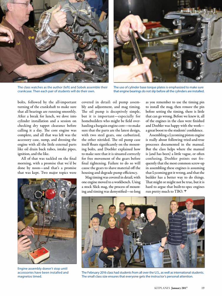
bolts, followed by the all-important turning of the crankshaft to make sure that all bearings are running smoothly. After a break for lunch, we dove into cylinder installation and a session on checking dry tappet clearance before calling it a day. The core engine was complete, and all that was left was the accessory case, sump, and dressing the engine with all the little external parts like oil drain back tubes, intake pipes, ignition, and the like.
All of that was tackled on the final morning, with a promise that we’d be done by noon—and that’s a promise that was kept. Two major topics were
covered in detail: oil pump assem-bly and adjustment, and mag timing. The oil pump is deceptively simple, but it is important—especially for homebuilders who might be field over-hauling a bargain engine core—to make sure that the parts are the latest design, with two steel gears, one carburized, the other nitrided. The oil pump case itself floats significantly on the mount-ing bolts, and Doebler explained how to make sure that it is situated correctly for free movement of the gears before final tightening. Failure to do so will cause the gears to shave material off the housing and degrade pump efficiency.
Mag timing was covered in detail, with one engine moved to a workbench. Using a stock Slick mag, the process of mount-ing and timing was demystified—so long
as you remember to use the timing pin to install the mag, then remove the pin before setting the timing, there is little that can go wrong. Before we knew it, all of the engines in the class were finished and Doebler was happy with the work—a great boost to the students’ confidence.
Assembling a Lycoming piston engine is really about following tried-and-true processes documented in the manual. But the class helps where the manual is (and has been) a little vague, or often confusing. Doebler points out fre-quently that the most common screw-up in assembling these engines is assuming that Lycoming got it wrong, and that the builder has a better way to do things. That might or might not be true, but it is hard to argue that built-to-spec engines run pretty much to TBO. J
KITPLANES January 2017 19
The use of cylinder base torque plates is emphasized to make sure that engine bearings do not slip before all the cylinders are installed.
The class watches as the author (left) and Sobek assemble their crankcase. Then each pair of students will do their own.
The February 2016 class had students from all over the U.S., as well as international students. The small class size ensures that everyone gets the instructor’s personal attention.
Engine assembly doesn’t stop until accessories have been installed and magnetos timed.

www.kitplanes.com & www.facebook.com/kitplanes20 KITPLANES January 2017
Homebuilt aircraft builder Steve Wittman was one of America’s greatest air racers. By Amy LABodA
Roscoe Turner, Jimmy Doolittle, A.J. Foyt, Mario Andretti, and a guy named Sylvester “Steve” Wittman all have one thing in common: They are inductees to the Motorsports Hall of Fame of America. Why? They all gave in to a dire need: speed.
For a midwestern kid with a mild dis-ability born into humble beginnings, Sylvester “Steve” Wittman managed to make quite a name for himself in avia-tion. You might know him because of the airport named after him, Wittman Regional Airport, in Oshkosh, Wiscon-sin, the site of arguably the largest annual
aviation gathering in the world. Then again you might know him because of the plans he sold for the two-seat rapid cruisers he designed and built: the Wit-tman Tailwind (originally known as The Flying Carpet) or Buttercup. You might not know, however, that Steve Witt-man, “Witt” to his friends, was one of the most long-lived, fearsome, and successful pylon airplane racing pilots, well, ever.
The HopperIt was his need to go fast that con-vinced him to design and build his first airplane. As a teen, Witt frequented
the dusty airstrips where barnstorming pilots hung out.
“He rode out to the strips on his motorcycle—something else he liked to go very fast on—and spent time with the pilots learning about flying, the air-planes, and how to fix them. And since
Just Call Him Mr. Pylon

Photos: Amy Laboda and courtesy of EAA KITPLANES January 2017 21
those WW-I surplus machines were pretty rough, there was lots of fixing to do,” said Jim Cunningham, University of Illinois professor and Wittman biog-rapher. “That’s where he heard, probably from the other pilots, that you had to have two good eyes to be a pilot. Witt had lost sight in one eye as a child. He really never thought he could fly because of that, so he focused on the engineering side and decided to design and build air-planes instead,” he continued.
Even in those days, an engineering degree from a university was a handy tool for an aircraft designer, but Witt’s hum-ble beginnings precluded such luxuries. He just designed and built with what he had, and what he knew. That first air-plane? The Hardley Ableson was about as rough as the biplanes Witt studied from. (You can find a replica of it in the Wit-tman Hangar at EAA’s Pioneer Airport in Oshkosh, Wisconsin.) It had a 12-hp Harley Davidson motor, and according to Cunningham, it never really flew.
“If he was going across a field and hit a bump he might have gotten airborne for a bit,” he laughed. “After a few of those ‘flights’ the landing gear came apart and he decided maybe it was better to go out and buy something professionally designed,” smiled Cunningham.
Witt eventually learned to fly for real, ignoring his visual impairment, in a WW-I surplus Standard J-1 biplane he and friend Perry Anderson bought in 1924. They found a guy who claimed that he had hundreds of hours in the aircraft (he did, as a gunner, not as a pilot) to teach him. Not such a great
plan, but it did work out, eventually. When the so-called instructor up and left town, Witt decided that meant he must be done learning, and at that point he soloed. As he told it in an interview filmed in 1988, he took his first passen-ger for a ride, a relative, the day after.
And the day after that? “We started our ride-hopping business,” Witt chuck-led. Of course there were no pilots cer-tificates issued in the early days of the roaring ’20s, making self-determined commercial pilots pretty common.
We Have a Race!By the time he discovered air racing, two years later, Witt had matured into a pretty good pilot. He studied the action of the souped-up airplanes zipping around the pylons and figured he could do that. So he took the J-1 to Milwaukee and raced it, placing second the first time out. Of course, Witt wanted to win, but the J-1 wasn’t the kind of airplane that
even a great race pilot could consistently win with. Besides, with the Air Act coming out, the J-1 wasn’t certifiable. Pilot’s certificates were becoming the norm, as well, and that left Witt with a bad feeling in the pit of his stomach.
“The story goes that government guys from this new air agency were going around issuing licenses to ‘certify’ pilots all over the country, and eventually they got to the Fond du Lac area,” said Cun-ningham. “Witt avoided them, until one day an agency guy caught up with him and asked him point-blank ‘why?’ Witt told him about his bad eye, and the guy was unimpressed. He told Witt, ‘I’ve seen you fly; the bad eye doesn’t seem to bother you,’ and sent him to some Mil-waukee doctor who proved it. With that he issued Witt a license with a waiver of demonstrated ability.”
He was a pilot, and could’ve earned a perfectly respectable living that way, but Witt had a problem. He was hooked on air racing, and with a fresh license signed by Orville Wright, Witt needed a better racer. He found the H-10 Pheasant in Memphis, Missouri. The H-10 was designed by Orville Hick-man, who made it for Lee R. Biggs, company owner. It was a clean, light biplane, made from a welded steel tube fuselage with a fabric covering and a tailskid, powered by a 90-hp water-cooled Curtiss OX-5 engine.
A new factory-built airplane wasn’t easy to finance, though. Undaunted, Witt decided to become the regional Pheasant sales representative, securing
Wittman used what he had on hand to design and build his first airplane: the Hardley Ableson. This replica is in the Wittman Hangar at EAA’s Pioneer Airport.
Wittman needed a faster airplane. The H-10 Pheasant had a welded steel tube fuselage with fabric covering and a 90-hp water-cooled Curtiss OX-5 engine.

his airplane at a significant discount (ostensibly for demos), according to Cunningham. He flew the H-10 Pheas-ant to the absolute limit, and he was winning races. Just 11 Pheasants were built, however, before Biggs died in a fly-ing accident on December 5, 1927. Witt helped relocate the company to his home in Fond du Lac, Wisconsin.
A Steady JobMeanwhile, the folks up the road in Oshkosh, Wisconsin, were looking for a good airport manager for their airfield located off 20th Street, and someone had their eye on Witt. The now locally famous air racer was known to have a steady personality. The way Witt told it, when interviewed, the job wasn’t for him, but eventually, in 1931, he took it, figuring it was a good place to be as he began construction on what would be his first successful hand-built air racer, Chief Oshkosh.
Turns out the job was a career, and Witt nailed it as airport manager, and as the proprietor of Wittman Flying Ser-vices (sold to Warren Basler in 1957), for the next 48 years. Oh, yeah, and as a very early member of a little organization called the Experimental Aircraft Asso-ciation, Witt eventually put Oshkosh, Wisconsin, with that airport off of 20th Street, onto the maps.
A Building FiendBut first there was Chief Oshkosh. This airplane was not the bumbling effort of youth; no, the Chief was the culmina-tion of years of experience flying and studying the other air racers of the day. Witt wanted something light and lean—really just a fuselage wrapped around the American Cirrus engine, with 19-foot wings attached midway up the fuselage and a unique heart-shaped elevator on the tail to keep it all flying. Chief Oshkosh, decked out in red, took third in the 1931 National Air Races with a speed of 150.27 mph, but was plagued with potentially fatal
aileron flutter. It was back to the draw-ing board for Witt.
A year later he returned with a 349-cubic-inch British Cirrus Hermes engine tucked in the fuselage and adjustments to the control linkages that allowed him to push the airplane to nearly 167 mph. It was good enough to beat his nemesis, Ben Howard, at the National Air Races, and later that year to win the Glenn Curtiss Trophy in Miami, Florida. If anyone had doubted Steve Wittman’s ability to either design, build, or fly air racers, they were think-ing differently by then.
The records of the 1930s show Witt as a champion on the circuit. To stay on top took constant refinements to the Chief. The wings got shorter (eventually down to a 13-foot span).
“No, he did not cut them off,” laughed Cunningham. “Doing research we found five sets of wings that he used with that fuselage over time.” The wings did get progressively shorter as the engines became more powerful, resulting in pre-dictably quicker race speeds.
In 1934 Wittman created another racer, this time purpose-built for the Thompson Trophy race, which had no limits on the size or power of the aircraft. The machine, dubbed Bonzo, was powered with a veritable antique, the V-12 Curtiss D-12 engine, and again the flying surfaces and cockpit were wrapped around it. Wittman used tightly spaced wooden wing ribs
22 KITPLANES January 2017 www.kitplanes.com & www.facebook.com/kitplanes
Wittman stands next to Bonzo, his 1934 purpose-built racer with a Curtiss D-12 engine, designed to win him the Thompson Trophy.
Rumor had it that Wittman kept clipping Chief Oshkosh’s wings, but that wasn’t true. Fact was, the airplane had five sets of wings that were used with its fuselage over time.

and doped fabric on the wings, novelty construction for a racer at that time. As goofy as the airplane looked (some com-pared it to a flying barn door), it came in second the first time Witt raced it, in the 1935 Thompson Trophy race. The next year, the airplane didn’t make it to the race, experiencing an engine fire en route to Los Angeles.
It wasn’t the first or the only time Witt had to rebuild a racer. Let’s just say ’36 was a tough year. Chief Oshkosh, now sporting a Menasco CS-4 363-cubic-inch engine, doubled spring leaf landing gear, and stubby wings, developed prob-lems during its debut at Nationals and ended up skipping off another airplane and crash-landing.
No matter. Wittman’s shop at the air-field got to work on both airplanes, and they were back racing in time for the 1937 circuit. But here’s the thing—nei-ther racer was really the same.
The Chief returned in 1937 with a single-piece leaf-type steel landing gear that Witt would patent (then license to Cessna), and its tiny cockpit sat up a bit, giving its pilot much better visibility. The aircraft won race after race, eventually setting a new world’s record for its class over a 100-kilome-ter course at Detroit with a speed of 238.22 mph. But just a year later Wit-tman hit the dirt in the Chief at the races in Oakland, California. It was 1947 before a revamped airplane with yet another set of wings turned up at the races, and this time the Chief had a new name: Buster.
Bonzo was rebuilt as well, and Witt found his way into the lead more than once (though he didn’t necessarily win, he was typically “in the money”). Eking 325 miles per hour out of 485 hp, Bonzo was faster than the fastest U.S. military fighter planes of the day.
An Airplane Built for TwoBacking up for a minute, one other thing happened in the busy 1936-37 year: Witt took time to design and build another airplane, something with two seats that he dubbed Buttercup. It was supposed to be a quick little machine that could fly support for the race planes. Turns out,
KITPLANES January 2017 23

with that patented landing gear from Chief Oshkosh and side-by-side seating for two, it was a comfortable 150-mph airplane that was forgiving to land, courtesy of an innovative leading-edge slat and flap system, and it frankly out-flew anything in its class.
The Fairchild Aircraft Company expressed interest in a four-seat con-figuration and Wittman obliged, con-ceptualizing The Big X, with a 130-hp Franklin engine, but the war inter-vened, and Fairchild had to abandon the project. (Buttercup did fly support for the Wittman air race team for years
and was painstakingly restored in 1980 by Forrest Loveley.)
Acquiring PartnersWW-II put a temporary end to air rac-ing. Wittman went to work teaching Army Air pilot-recruits basic flying with a young man named Bill Bren-nand, who had grown up sweeping the hangar floors and learning about build-ing race airplanes in Wittman’s shop at the airfield. It was a relationship that would endure. Speaking of which, he also married Dorothy Rady, who ran the school and the FBO while Witt flew.
She learned to fly, too, and flew those support aircraft to races all over the U.S.
Post WW-IIWhen racing started up again after the war, Wittman invited the jockey-sized Brennand to fly the reincarnation of Chief Oshkosh, called Buster, in a new midget racer class, starting in 1947. Fit-ted with a Continental C-85 engine and its new pilot, Buster won, and won, and won. Finally retired in 1954, the air-plane now hangs in the National Air and Space Museum in Washington, D.C.
Wittman, in the meantime, was fly-ing a hand-built speedster named Lit-tle Bonzo, which tipped the scales at a diminutive 508 pounds empty. This air-plane, in numerous configurations and with countless engines (because, come on, the guy was a homebuilder), won races from 1949 straight through 1973, the last Goodyear race. But get this, in 1978 Witt decided to race a little more, so he dusted off the fuselage (and you can bet added a couple tweaks) and went back at it. It wasn’t until 1987 that Witt returned Little Bonzo to its original
24 KITPLANES January 2017 www.kitplanes.com & www.facebook.com/kitplanes
Earl Luce’s replica Buttercup is almost identical to the original. LuceAir LLC sells plans, with materials available from Aircraft Spruce. (Photo by FlugKerl2 [CC BY-SA 4.0], via Wikimedia Commons)
Buttercup flew race support for Wittman’s team for years. The original (shown here) was painstakingly restored in 1980 by Forrest Loveley.

configuration, with that Continental C-85 engine, and donated it to EAA for its Air Racing Gallery in the museum.
On a Flying CarpetAs for his two-seaters? Buttercup, of which Witt once said, “It’s the only air-craft I ever built that was a little faster than I thought it would be,” evolved into The Flying Carpet, aka The Wit-tman Tailwind. The Tailwind was a breakthrough: the first airplane to be certified amateur-built under the new CAR 174-3 rule in 1953.
Wittman had joined up with a young builder named Paul Poberezny from Hales Corners, Wisconsin, who wrote a newsletter called “The Experimenter.” Poberezny’s new Experimental Aircraft Association lobbied the CAA hard for an amateur-built aircraft category that would, for the first time in years, legal-ize aircraft that were built outside of the factory setting.
Poberezny wrote in “The Experi-menter” in 1953 that “it is a stepping stone for homebuilders and will encour-age an increasing number of individuals to design and build two- and four-place aircraft.” The two men continued their friendship, and when EAA was look-ing for a larger venue for its annual get-together, Witt suggested the Winnebago
County Airport in Oshkosh. (Well, you know the story from there.)
The Tailwind is a fast, efficient, high-wing, braced-cabin monoplane with a traditional tailwheel. The fuse-lage is steel tubing, while its wood-rib wings are covered in fabric. It turned heads at EAA gatherings for years as Witt refined it, adding more fuel, more power, and eventually, by version W-9L, a nosewheel. An April 1954 “Experi-menter” noted that Witt was averaging five gallons-per-hour fuel burn at a 154.6 mph average airspeed. At a time when automobiles barely managed 10 miles per gallon, that kind of efficiency was unheard of, and people wanted in on
the game. Witt finally acquiesced and hired an engineer to draw up plans for the Tailwind, but with one caveat. He chose a NACA wing for the plansbuilt design. Turns out that unlike its docile predecessor, Buttercup, this prototype (for lack of a better word, most of Witt’s airplanes were perpetual prototypes) hid nasty stall characteristics, he later admitted, and he wasn’t confident it was meant for the general pilot public to fly.
Builders scooped up the plans in the 1960s, many making their own modifi-cations (there was even a retractable gear version) and ultimately Witt flew one with an Oldsmobile V-8 engine until the airframe itself started to wear out.
KITPLANES January 2017 25
Buster now hangs in the air racing hall of the Smithsonian National Air and Space Museum in Washington, D.C. (Photo by xiquinhosilva [CC BY 2.0], via Wikimedia Commons)
Wittman’s Tailwind was the first amateur-built airplane to be be certified under the CAR 174-3 rule in 1953; it was the predecessor to our homebuilt certification rules of today.

He never did get around to having plans for his and Dorothy’s beloved But-tercup drawn up; however, EAA mem-ber Earl Luce of Brockport, New York, reverse-engineered one. In 2003 his LuceAir, Inc. began selling plans for the airplane, which stalls at less than 40 mph and tops out at 150 mph on 85 hp.
Plans for both airplanes are available today from Aircraft Spruce & Specialty.
Wittman was great about talking to builders, offering his expertise during countless EAA conventions, even as he continued flying air races and aerobatic shows long after he retired from his posi-tion as manager of Winnebago County Airport, now Wittman Regional Air-port. He remained a vibrant participant in the organization and was a key partic-ipant in helping the EAA Museum find its home adjacent to the airfield.
The Last ShipsThough his racers and ubiquitous Tail-wind (of which there are hundreds of successful builds today) were best known, he never did rest well on his laurels. In the last 20 years of his life, Wittman worked on several projects, building and flying the Witt-V, a single-seat midwing monoplane powered by a 96-cubic-inch converted Volkswagen engine, for Formula V air racing, for which many consider him one of the founding fathers. He piloted the air-craft to several air race victories right up through 1989. Plans for the machine, as well as roughly 10 copies in various states of airworthiness exist today.
In the two-place arena Witt continued to expand on the Tailwind mode, creat-ing the O & O Special as he turned 80 years old. The machine, which first flew in 1986, was designed to weigh less than 1100 pounds empty and top out at 180 mph. Being a true cross-country airplane, Witt wanted a 1200-mile range from the bird, and he got close with a Continen-tal O-470J engine and 50 gallons of fuel onboard. He and his wife Dorothy, and, after her death, his second wife Paula, commuted between his home in Wiscon-sin and a winter retreat at Leeward Air Ranch, Florida, with the airplane.
It was on that commute in 1995 that the Wittmans went missing. Friends and rescuers searched for days, finally dis-covering the remains of the aircraft and its occupants strewn across a couple of miles of Alabama hills. An NTSB inves-tigation determined that the fabric on the O & O’s wing delaminated and the aircraft came apart in the ensuing dive.
The world of light aviation was stunned speechless by the loss of Syl-vester “Steve” Wittman and his wife Paula. There was tribute after tribute to his life in Florida and in Wisconsin, but really the healing took years. His legacy is honored in Halls of Fame and museum pieces, in the rows of Wittman Tailwinds that return to now Wittman Regional Airport each year for EAA’s AirVenture gathering, in the shadows of a homebuilder’s workshop where someone fabricates the innovative slats that makes a Buttercup such a fine STOL airplane, and in what most likely would’ve made Witt the happiest: the Oshkosh AirVenture Cup cross-coun-try race, culminating in those wonder-ful race planes, individuals, every one, screaming by the flight line in a burst of light and sound and speed. J
Special thanks to Jim Cunningham for his generous help with this article.
26 KITPLANES January 2017 www.kitplanes.com & www.facebook.com/kitplanes
Wittman was considered by many to be the father of Formula V air racing. The Witt-V was purpose-built for it, sporting a converted Volkswagen engine.
A Wittman Tailwind prototype sits ready in the Wittman hangar at EAA’s Pioneer Airport (left). Steve Wittman surrounded by the people he once employed at Wittman Flying Service, the FBO he founded at the airfield that now bears his name (right).

G5 electronic fl ight instrument for certifi cated aircraft. Exceptional performance and reliability as a standalone primary attitude indicator or turn coordinator. Plus airspeed and altitude for enhanced situational awareness.
Garmin.com/Aviation
Attitude awareness you can bank on.
©2016 Garmin Ltd. or its subsidiaries
34452 G5 Certified Ad-7.875x10.5-Kitplanes.indd 1 10/6/16 4:43 PM

www.kitplanes.com & www.facebook.com/kitplanes28 KITPLANES January 2017
As you might remember from the last exciting episode, the Pudding River Bearhawk crew was closing in—however slowly—on completing their Bearhawk LSA.
Well…remember how Charles Schul-tz’s cartoon dog Snoopy looks when he’s happy—feet flying, ears twirling as he dances with delight? Well, none of us exactly “twirl” anymore, but we can appreciate the emotion…because…
The wings are done! Even as we were riveting up the skins
on the second wing, we knew that there were still two major projects ahead before we could call the wings really done: fuel tanks and wingtips.
Building the TanksThe construction plans barely show the tanks and have no details at all of how
they are built or installed, but the rudi-mentary construction booklet that came with them gave enough information to form a basic picture: The Bearhawk uses a 15-gallon tank in an inboard bay of each wing. They are suspended between the spars by steel straps, tensioned by adjustable clamps, and accessed by a removable panel of lower wingskin.
The “plans” call for them to be welded from formed bulkheads and skins made of 6061 aluminum—a weldable alloy—0.040-inch thick. We didn’t have a ready source of 6061 in .040—although it would have been possible to get some—and we certainly didn’t know how to weld aluminum. Between us, though, we’d built several tanks for RVs using the Van’s method of riveting with tank sealant between all the pieces. Even though we’d learned some lessons about
departing from designer Bob Barrows’ plans—his methods usually worked better than ours!—a conversation with Barrows at Oshkosh let us know he had no objection to riveted/sealed tanks…he just preferred welding to messing with tank sealant. We decided to go with what we knew and build riveted tanks. Because they were separate, stand-alone structures, we figured if we got the strength and shape right, the construc-tion method was secondary.
In most RVs the tanks do double duty as the inboard section of the wing leading edge, so they are riveted with flush, solid rivets. In the Light Sport
Fuel tanks and wingtips.By Ken Scott
Building the Bearhawk LSA
A riveted fuel tank ready for the top skin. The blue-capped fittings are outlets, and the upper fitting is part of the sight gauge that will be installed after the wing is installed.

Photos: Ken Scott KITPLANES January 2017 29
RV-12, though, the tank is a simple aluminum box riveted with sealant and blind rivets. The latter was the most similar to the Bearhawk tanks. Neither contribute to the shape or structure of the airframe—they are just containers strapped into the airplane for the sole purpose of holding fuel. We chose to copy RV-12 construction.
I made form blocks for the tank ribs and pounded out three per tank, using .032 Alclad 2024-T3. We bent skins on a simple brake, forming the top and front from one piece, the rear and bottom out of another. There’s nothing tricky about assembling the tanks—clamp the
parts together, drill the hole patterns for the rivets that will hold them together, deburr and clean all the parts, apply tank sealant and blind rivet the “box” together, using the same closed-end blind rivets used in the RV-12 tank.
We installed two RV-10 fuel pickups in each tank, one at the forward corner and the other at the rear. I put them as close to the bottom skin of the tank as I could, but we suspect that testing will reveal at least a gallon of unusable fuel in each tank. The pickups are plumbed together just outside the tank with a single aluminum fuel line running to the selector valve. By having one forward and
one aft, one should always be submerged in fuel, whatever the airplane’s attitude.
A simple push drain was installed on the inboard aft corner of the tank and a hole cut in the access panel to let it protrude. The filler neck was located by strapping the tank in place and using a long drill bit to poke a hole through the top wingskin and tank. We cut the hole in the wingskin to 2.25 inches to accommodate the 2-inch filler neck—the strapping method isn’t precise, and we wanted a little wiggle room.
Although the construction booklet gave complete plans for making the multi-part vented gas caps on a metal
Tensioning “buckles” for the tank straps were made from bolts with the heads removed. One side is drilled and tapped for stainless steel Allen-head bolts.
Rion fits one of the upper straps that suspend the fuel tank within the wing. Getting the exact length was tricky.
A pneumatic blind rivet gun makes short work of closing the tank.
With the straps in place, the tank can be fitted into the wing.

lathe, we weren’t looking for ways to make the wings take longer and bought the pre-made caps from Bearhawk. They’re nicely made, fairly priced, and fit perfectly.
The most difficult part of tank building and installation, to our sur-prise, was nothing on the tank itself…rather it was the straps holding the tanks into the wings. We made these out of steel banding material used to hold shipping crates together, covered with shrink tube. The exact lengths of both the short and long sections of the straps turned out to be quite impor-tant, and there are no dimensions on the plans—actually, given the realities of scratch-built airplanes, it probably isn’t possible to give one. We figured it out through trial and error. Allen-head bolts threaded into drilled and tapped steel rods (simply large bolts with the heads and threads cut off) pulled the straps together and provided the ten-sion to hold the tanks. These are buried between the rear of the tank and the rear spar of the wing and are difficult to reach. Way too much practice tak-ing the tanks in and out finally led us to develop a technique that worked, but we hope we don’t find ourselves remov-ing the tanks very often. If I’d made the tanks about ½-inch shorter, access would have been quite a bit easier.
With the tanks and fuel lines finally installed and buttoned up, we turned
our attention to the last big project on the wings—the wingtips.
Building the WingtipsBearhawk wingtips are more or less left to the builder. The construction booklet suggests you could carve a wingtip out of blocks of foam glued to the end of the wing, cover that with fiberglass, fin-ish that out to a smooth surface, make a fiberglass mold off the “positive” tip, and make the actual fiberglass tip in the “negative” mold. Nothing to it.
In my long ago Malibu youth, I’d shaped and glassed several surfboards so carving and finishing the tip didn’t intimidate me…but I knew it would be messy (not a good thing in the TajMa-hangar with its polished floor) and tedious. Making a blank, pulling a mold, and making the part inside that seemed reasonable if we were going to be making several sets of tips, but it’s an awful lot of work for just one set. I just knew that if we made our tips this way we’d have four or five months of part-time work in one set of tips, and worse, that time would be spent working with fiberglass. Does any-body really like working with that? None of us do…so we looked for alternatives.
The best was right in front of us. Phil-lip recently had worked up a set of metal tips for his other project: a super-light RV-9A. Both the KK-1 and the RV-12 that I’d built earlier had used some clev-erly shaped aluminum parts to form
very light and aerodynamically clean tips with no compound curves. It helped that both those airplanes were designed on CAD systems, so the complicated metal shapes that bend into a graceful tip were accurately designed and manu-factured. We decided to go for it, and build metal wingtips.
The RV-12 wing has almost exactly the same chord and thickness as the Bearhawk, so our first thought was, let’s just copy that. That didn’t work exactly, because the airfoil shapes are quite dif-ferent. The Ribblet airfoil chosen for the Bearhawk LSA has a concave, cam-bered, lower surface, which complicates the shape of the tip.
30 KITPLANES January 2017 www.kitplanes.com & www.facebook.com/kitplanes
Phillip drills one of the five pieces making up the all-metal wingtip.
RV-12 parts were used as patterns for our all-metal wingtip (left). The high-wing Bearhawk won’t have the rectangular handhold used on the RV-12. The flat top of the wingtip (right) was fairly simple, but the bottom was complicated by the airfoil shape.

KITPLANES January 2017 31
We didn’t have a CAD system, so we bought a few parts of the RV-12 wingtips from Van’s and used them as disposable patterns, cutting them as necessary to fit the new shape. Phil-lip, with his engineering background and recent experience, was appointed geometer-in-chief, and using his eye, some basic math, and some cut-and-try pattern making, he came up with a five-piece wingtip that simply riveted together. We were able to use a couple of the RV-12 parts without alteration, which pleased us.
The geometry isn’t simple, and we were surprised how very small changes in almost any dimension made big changes
in the final shape. Eventually, we burned through enough scrap aluminum and cardboard and arrived at a sleek flush-riveted wingtip that weighs less than a fiberglass unit, took a lot less time, and was much more fun to build. It gives a unique touch to our airplane.
When the last rivet went into the wingtip, we poured a glass of home-brew (brewing beer is a close second to aviation as an approved activity on our airpark!) and celebrated. The wings are done! In a phrase made famous in the Pacific Northwest by William Clark (during his expedition with Meriwether Lewis) 212 years ago:
O! the joy! J
Some days you just have to set down the tools, step outside, and realize how lucky you are to live in a place like this.
Rion sets up the blind rivets for the final installation of the wingtip.

www.kitplanes.com & www.facebook.com/kitplanes32 KITPLANES January 2017
Yes, it’s unusual, but for my hangar it makes perfect sense.
By Steve KeSSinger
“You have got to be kidding me! Whoever heard of a wooden floor in a hangar?” I looked at my friend, expect-ing to see Einar Ketilsson’s usual gentle smile, but this time he wasn’t smiling. Instead, he peered over his spectacles and started listing the reasons I should put a wooden floor in my hangar. After the third one, I had to admit, he might be on to something…
In order to tell this story, we first have to step into our Wayback machine and return to 2009. As we remember (no matter how hard we try to forget), in
2009 the economy was in hard times. People all over were looking to cut expenses, and one easy way was to sell planes and hangars. By mid-2009 five hangars at my airport had come up for sale. Five. At an airport where a single hangar might come up for rent every few years, and the waiting list to purchase a hangar moved at a pre-global-warming glacial pace, having five hangars for sale at the same time was unprecedented.
What pilot hasn’t dreamed of having a hangar of their own, a man (or woman) cave to put up airplane posters and have
a beat-up couch to lay around on, read-ing old Richard Bach, Ernie Gann, and Gordon Baxter books and back issues of KITPLANES®? In 2009 I had been volunteering at a local warbird museum, and had learned that (except for the price tag) working on real airplanes was very similar to working on the radio controlled models I had been building all my life. Encouraged by the mechan-ics at the museum, and with promises of help and support from them, I was start-ing to think that maybe, just maybe, I had the ability to build my own airplane.
Wooden Hangar Floors

Photos: Steve Kessinger KITPLANES January 2017 33
A long time ago, in a city far, far away, as a starving flight instructor, I had fallen in love with the X-Wing-like Rutan Long-EZ, but I was also infatuated with the Progressive Aerodyne Searey. Hav-ing been recalled from furlough to my airline, and with a miserable divorce long behind me, I was starting to look for a new challenge. But even though I was single, running the numbers showed that I was at least another year from being able to reasonably swing a major financial purchase like a hangar, let alone an airplane or a kit.
Of course, it was a measure of how hard the times were in 2009 that the five hangars moved slowly. As each For Sale sign disappeared, and I saw others happily moving airplanes into their new homes, I kicked myself, talked to myself, and ran my financial numbers over and over again. Reason kept winning out, but my heart…Ah, if I had listened to reason would I have even become a pilot, chasing the dream that had kept me from a normal life and instead rewarded me with a much, much richer one?
Finally, only one hangar was left. I decided that if I didn’t mind eating ramen again for a while, and took out a second mortgage on my house, and only wore blue jeans and airshow T-shirts away from work…maybe I could swing it. I talked to my bank, talked to the owner of the last hangar for sale, stayed up late a couple nights grinding my teeth and thinking, What if? and finally made a decision. On October 10, 2009, I swore myself to poverty, signed a stack of papers, and Hangar 21 in the Strato
row (the rows of hangars are named after clouds) was mine.
Home Sweet HangarStrato 21 had been around for a while. While relatively new construction at 25 years young, it was built over the origi-nal airport tarmac that dated back to the 1940s, and a previous owner had finished the interior with plywood and insulation, giving a rustic, semi-finished look. Sheets of 11/8-inch ply-wood underlayment for the nose- and maingear had been spiked in place to keep the plane above any water that might seep in during a storm, but I was assured by the seller not to worry. Even during the worst storms, he had never seen any water encroachment. “That’s one advantage of being on the north side, Steve,” he said. “The wind and rain come from the southwest, and the wind drives the rain into the hangars on the other side, while we stay dry.” Sounded good to me.
The first project was to paint the walls. I wasn’t sure what I was going to put in my hangar, but I knew it was going to be a kit of some kind, which meant I was going to be spending a lot of time there, and I wanted a nice work-ing environment. Two days of renting a tankless sprayer gave the walls an even, off-white coat of paint, which left just one slight problem: the floor.
Actually, it was a big problem. A prior owner had sprayed a layer of oil-based sealant over the old tarmac, giving the hangar floor an even, black covering. But since it was black, it soaked up the
light and made the hangar a dark pit. And because the sealant was oil based, I couldn’t paint it. The two bids I took for a concrete floor were cost prohibi-tive, and I received mixed opinions if an epoxy coating would stick, or if the coat-ing would have to be stripped.
I was in my hangar one day, frustrated and kicking the plywood floor strips when Einar stopped by. “Look,” he said, “You’ve got bad knees and can barely spend an entire day at the museum anymore. Why don’t you just lay down a wood floor?” Einar started listing the reasons: the wood would be easy on my knees, more comfortable to lay on, give a nice look, and he continued with several more reasons as I listened.
I have to say, at first I was pretty skep-tical about the idea. Whoever heard of a wooden floor in a hangar? But when we carefully examined the asphalt, we saw it was level, with only a couple of small ripples, so 4x8-foot plywood sheets would lay flat, and the price would be far less than a concrete floor. We taped some small plastic drop cloths down, closed the hangar up, and after a couple weeks came back for a look. It had been a rainy winter and spring in the Pacific Northwest, but despite that, we found that there was no condensation under the drop cloths, alleviating any worries about the wood rotting from under-neath. A wood floor was looking more and more like the way to go.
Installing the FloorA local lumberyard agreed to deliver to the airport. It was a beautiful spring day
A Proctor Enterprises Antic radio-controlled airplane was the first kit aircraft in the hangar.
Airless sprayers are fun, messy, and a fast way to paint. It took about two days to give the walls an even, off-white coat of paint.

when their truck pulled up to the gate with a flatbed of plywood sheets, the driver asking, “What the heck is going on?” He was the first of many who laughed at our idea and, to be honest, I still had a bit of lingering uncertainty, too. We briefly tried to remove the “legacy” plywood strips, but they had been tightly spiked into the concrete, possibly even cemented into place, and we could not even get a crowbar under them to start the removal process. By this time I had become fond of the darkened worn wood and was actually happy to see them stay, so we decided to just fit the new 4x8 sheets around them.
We measured once, cut twice, remem-bered it was the other way around, and redid the first sheet. Laying the new wood out and around the legacy wood on the floor became a giant jigsaw puz-zle, with each sheet interlocking into an intricate design with overlapping seams. As we had hoped, there were only a few spots where the floor was less than level. Since it was only off by ½ inch or so, it was something I could live with, but we used Tapcon screws to secure the plywood anyway.
The floor looked great when it was all laid out, but it had to be sealed, too. I rented a large floor sander, but even a fine grit quickly ate into the soft ply-wood. I bit the bullet and got my palm finishing sander out, spending an after-noon moving side to side from the back
to the front of the hangar, smoothing each sheet. I’ll confess I settled for a good vacuuming in place of wiping each sheet with a tack cloth, though. I hoped, and it has turned out, that any grit left over would just become a bit of built-in nonskid on the floor.
I’m no great woodworker, but I do love working with it. As pretty as the raw floor looked (and smelled), I knew it would look and hold up even better with a coating of varnish sealing it. Taking the advice of a contractor friend, we decided a good satin polyurethane would do nicely. I’d just dump a sploosh right from the can onto a sheet before spreading and smoothing it with a lambswool brush.
It was Zen and the art of hangar floor maintenance as I’d dole out the varnish, spread it out, look for runs, and go back and try to smooth them out without messing things up. Yup, there are a few spots where the varnish is less than per-fect, but it’s an amateur-laid floor, and…well…it’s a hangar floor. Over a few days, I laid four coats of varnish down with a very light hand sanding after each one, then let the whole thing dry for a couple more weeks while I went off to my night job flying for the airlines. When I came home and reopened the hangar, I was knocked over by the fumes from the var-nish, but I was also delighted by the way the floor had turned out.
Long-Term ResultsIt’s been six years since the floor was laid. One mistake I made was not put-ting a vapor barrier down over the entire hangar footprint before laying the wood, but every year I lift a few pan-els and check underneath. So far, there’s been no sign of rot. The wood has gradually pulled up and away from the Tapcon screws, resulting in a couple of small trip hazards that are, fortunately, far away from the main work area. I use them as fatigue checks: If I forget about them and stumble, I know I’m too tired to be working on the airplane and call it quits for the day.
The floor has performed beyond my expectations, staying warm in the winter
34 KITPLANES January 2017 www.kitplanes.com & www.facebook.com/kitplanes
The raw wood looked beautiful when it was all laid out, but there was still work to do.
The adventure begins: With the floor in place, it was time to get started building the Searey. The kit was delivered in April 2010.

and cool during the summer. As a cush-ion for my knees, it’s just what the doc-tor ordered. If I get rolling on a section of the build, I can spend an entire day and most of a night working in the han-gar without hurting the next day. And I’ve found other benefits, like if you drop a cordless drill from the top of a ladder, the drill will not break, but will only make a small dent in the floor—at least hypothetically.
The plan had been to rent the hangar out for a year, but a couple of medical scares made me decide not to wait until things were financially reasonable, lest I totally miss out on building a plane. In April 2010 Searey kit #509 was
delivered. Several months later, on a fine Autumn day, I pushed the doors open to reveal a half-built set of Searey wings. I looked to my right, at my girlfriend Giuliana, and explained that this was something very important to me, and I hoped she would understand. Giuliana took it all in and looked back at me. “My dad was a master machinist,” she said, “and you missed him by a year. He would have loved you.”
We’ve been together ever since. J
Steve and Giuliana were married shortly afterward and are six years into the build of their Searey. It will fly on Wednesday—they’re just not sure which one.
KITPLANES January 2017 35
After a lot of sanding and a few coats of varnish later, the wood floor really glowed.
Teamwork: Jim “The Searey Specialist” Ratte (left), Einar Ketilsson (visible inside the hatch opening) and the author work on the avionics.

www.kitplanes.com & www.facebook.com/kitplanes36 KITPLANES January 2017
Adding more equipment is never as easy as you think.
By Paul Dye
The Inverted Oil Dilemma

Photos: Paul Dye KITPLANES January 2017 37
So here was the problem. The won-derful little airplane we were building, an RV-3B, is well known for its nimble responsiveness and excellent handling qualities. The RV-8 I had been flying for over 1300 hours remained my favorite airplane, partly because we would go out and do aerobatics several times every week. But the -8 was built with a tried-and-true carburetor and a standard oil system, limiting me to positive-G aero-batics—unless I wanted to burp oil all over the belly every time I “pushed.” It was fine for what I did with it and, to be quite honest, negative G hurts when you get older, so I didn’t really miss it. Yet I wanted to be able to fly a truly ver-tical line or a hammerhead that doesn’t require a little positive-G cheating.
Enter the RV-3B! While we were building the airplane with lightweight advanced avionics to make it a good traveling machine, it was still an RV-3 at heart and would prove quite perky with an IO-320 on the nose. And I wanted to avoid “building the airplane that I already had”—that is, making the same decisions on this one as I did on the last airplane I put together. So while I didn’t go all the way for flop tubes in the tank, I did decide up front to go with fuel
injection, to help keep the engine run-ning on those vertical lines, and planned for a Christen inverted oil system to keep it lubed and the prop under control for those “pushy” maneuvers. Both choices involved extra cost and weight, but I felt that they were worth keeping on the list as long as I could.
Well, the fuel injection system had been a piece of cake throughout the build. The engine came well equipped and checked out, the high-pressure fuel pump added cost, but the installation was clean, and I was glad that I didn’t have to find a place for a carb-heat knob on our crowded panel. I was able to get a very good deal on a new, never-installed Christen inverted oil system and purchased the necessary hose and ends to build up the oil lines that would be needed. Everything was in a box waiting…then the challenge of installation arose.
You see, this was an RV-3. The engine nestled up to the firewall nice and friendly-like. In fact, we needed a firewall recess to allow the prop gov-ernor to fit. Throughout the firewall-forward integration, I kept room for the needed Christen equipment: the oil tank, oil valve, and T-fitting for the oil vent lines. It was an up-and-down
thing—one day, I felt I could get it to fit; the next day, the trades just seemed to overwhelm. While I was quite cer-tain that I could physically mount the components, routing the large-diameter hoses was going to be very, very tough. The engine compartment would be packed, with very little space left over. On top of that, I wasn’t sure that I could fit the cabin heat box and the Christen oil valve on the firewall, which led to the following conversation with my building partner (and wife):
“Honey, I am afraid that we are going to come down to a choice between inverted oil and cabin heat. Yes, we have the heated seat installed, and yes, we are going to have all that solar heat coming in the bubble canopy, but I just don’t know how we can add a heat box and still fit the oil lines.”
“Well then,” she replied, “there really is only one choice, you know.”
“Yes, I know…I guess—”“We have to install the inverted oil sys-
tem! I just want to make sure I can buy some heated socks for when I am flying!”
Have I said how much I love Louise?
The Raven oil tank is smaller than the Christen (on the right), making it easier to fit in a tight installation.
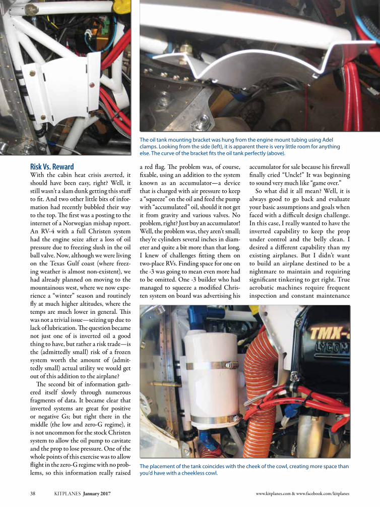
Risk Vs. RewardWith the cabin heat crisis averted, it should have been easy, right? Well, it still wasn’t a slam dunk getting this stuff to fit. And two other little bits of infor-mation had recently bubbled their way to the top. The first was a posting to the internet of a Norwegian mishap report. An RV-4 with a full Christen system had the engine seize after a loss of oil pressure due to freezing slush in the oil ball valve. Now, although we were living on the Texas Gulf coast (where freez-ing weather is almost non-existent), we had already planned on moving to the mountainous west, where we now expe-rience a “winter” season and routinely fly at much higher altitudes, where the temps are much lower in general. This was not a trivial issue—seizing up due to lack of lubrication. The question became not just one of is inverted oil a good thing to have, but rather a risk trade—is the (admittedly small) risk of a frozen system worth the amount of (admit-tedly small) actual utility we would get out of this addition to the airplane?
The second bit of information gath-ered itself slowly through numerous fragments of data. It became clear that inverted systems are great for positive or negative Gs; but right there in the middle (the low and zero-G regime), it is not uncommon for the stock Christen system to allow the oil pump to cavitate and the prop to lose pressure. One of the whole points of this exercise was to allow flight in the zero-G regime with no prob-lems, so this information really raised
a red flag. The problem was, of course, fixable, using an addition to the system known as an accumulator—a device that is charged with air pressure to keep a “squeeze” on the oil and feed the pump with “accumulated” oil, should it not get it from gravity and various valves. No problem, right? Just buy an accumulator! Well, the problem was, they aren’t small; they’re cylinders several inches in diam-eter and quite a bit more than that long. I knew of challenges fitting them on two-place RVs. Finding space for one on the -3 was going to mean even more had to be omitted. One -3 builder who had managed to squeeze a modified Chris-ten system on board was advertising his
accumulator for sale because his firewall finally cried “Uncle!” It was beginning to sound very much like “game over.”
So what did it all mean? Well, it is always good to go back and evaluate your basic assumptions and goals when faced with a difficult design challenge. In this case, I really wanted to have the inverted capability to keep the prop under control and the belly clean. I desired a different capability than my existing airplanes. But I didn’t want to build an airplane destined to be a nightmare to maintain and requiring significant tinkering to get right. True aerobatic machines require frequent inspection and constant maintenance
38 KITPLANES January 2017 www.kitplanes.com & www.facebook.com/kitplanes
The placement of the tank coincides with the cheek of the cowl, creating more space than you’d have with a cheekless cowl.
The oil tank mounting bracket was hung from the engine mount tubing using Adel clamps. Looking from the side (left), it is apparent there is very little room for anything else. The curve of the bracket fits the oil tank perfectly (above).

KITPLANES January 2017 39
when operated to their limits. A good inverted oil system is often just a begin-ning as the valves are tuned, accumula-tors added, and experience shows the need for even further modifications and/or improvements. As one of my friends put it, “A Formula One car does not make a good daily driver!” No kid-ding…and who was I kidding? I knew the RV-3 was going to be a blast to fly, and I felt certain that I could do just about anything that I wanted with the slight penalty of adding a quart of oil through the filler tube while clean-ing it off the belly with a rag. Talking with an old friend who had previously built and owned a Christen Eagle, and then flew a well-known RV-8 with full inverted oil (plus an accumulator), I learned that if he were to build the -8 again, he’d probably just leave the inverted system off, because even with the accumulator, he gets a bit of a prop surge at “zero.” There is, after all, no magic bullet. There rarely is when it comes to real-world engineering.
Something DifferentAs part of re-evaluating the goals in this case, I came to one more realiza-tion, and this became the path through the woods. What I really wanted in an inverted system was not so much the capability to operate under any “G” con-dition, but merely to avoid dumping all that oil on the belly! And lo and behold, there was a solution for that, a modified inverted oil system referred to by many as the “Half Raven” system. This idea uses the inverted oil tank from Raven (which is smaller than the Christen tank), a riser fitting in the sump, and hoses to connect the crankcase breather to the tank and the tank to the sump. Effectively, this provides a catch basin for oil when inverted Gs are applied and lets them return to the sump when you get back to upright conditions. No, it doesn’t ensure lubrication, but then, short periods of lubrication loss are probably OK (as evidenced by millions of hours of Lycoming flight under tur-bulent conditions)—a few seconds at
most. This option eliminates the com-plexities of the oil valve, lots of hoses, and frees up the firewall for that heater box we keep dreaming about.
So there I was, suddenly free of the burden of having to make it all fit and work to meet my design goals—because I re-evaluated the goals. The Half-Raven system gave me the capability that I really wanted in the first place and allowed us to build the airplane as a reasonable aerobatic machine, while retaining the creature comforts necessary to travel in the northern latitudes in most seasons. Building an airplane that can be easily maintained is a plus in any book. While I have no doubt I could have fit the full Christen system in, we’d have built more of a “point design” airplane that was good for airshows, and not much else. And I’m too old to be an airshow performer anyway; did I mention how much negative Gs hurt these days?
And there’s an extra benefit—I haven’t needed to buy those heated socks for my lovely wife! J
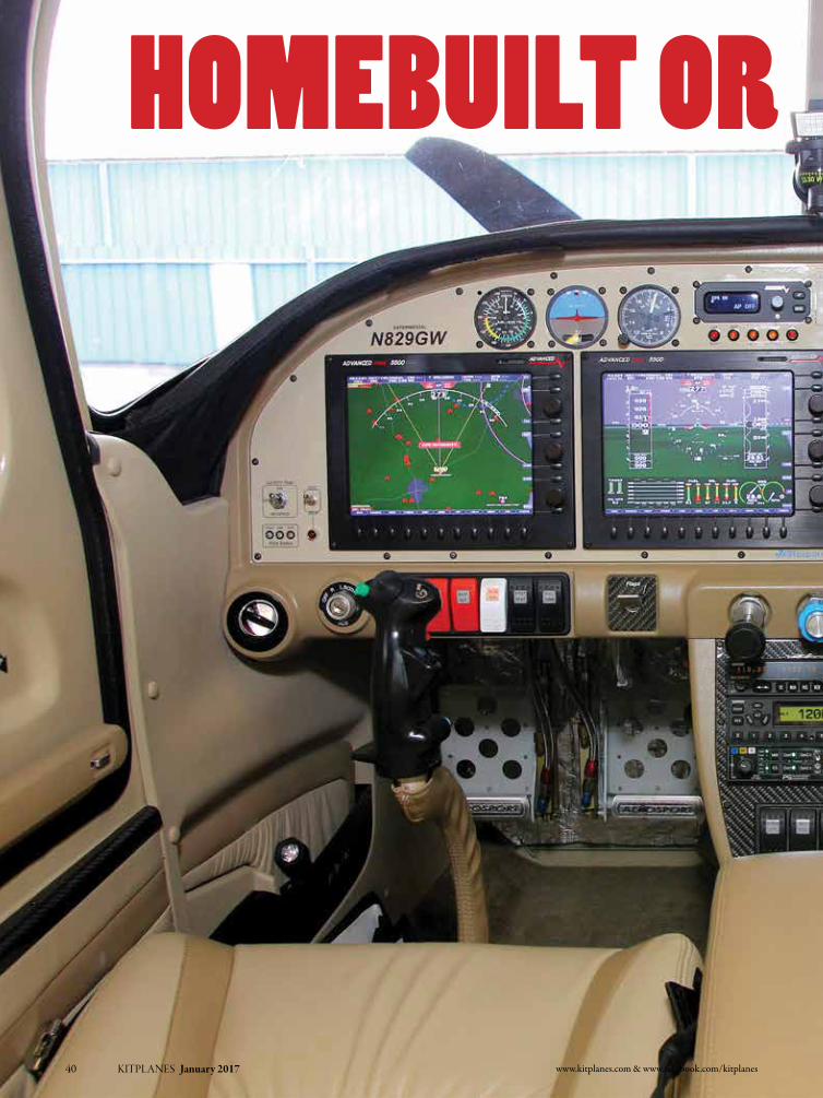
www.kitplanes.com & www.facebook.com/kitplanes40 KITPLANES January 2017
Homebuilt or Store-bougHt?

Photos: Bruce Eicher KITPLANES January 2017 41
Raising the bar for RV-10 interiors to an entirely different level.
By Bruce eicher
Homebuilt or Store-bougHt?

We gain many new skills when we build an airplane. The freedom of doing it yourself and learning is what Experi-mental aviation is all about. But for many of us, there’s a point where we would like a quicker and easier path to a finished product. Also, some processes are beyond the realm of our skill set, or we don’t have the equipment to produce professional-looking results. Good examples of this are interior panels, seats, and flooring. For these items you might want a plusher look and feel than bare aluminum, and there are plenty of sources that can help.
In addition to numerous third-party vendors, some kit manufacturers, such as RANS, Sonex, and Zenith, offer seats, side panels, and other interior components as options. Van’s Aircraft includes seat cushions as standard equip-ment in the RV-10 and -12. Nice as the Oregon Aero seats and seat cushions in the RV-10 kit may be, some builders and pilots are looking for something more. In a plane with the size and performance of the RV-10, it’s easy to understand why you might want an interior that’s simi-lar to what you might find in a Cirrus or other high-end certificated aircraft. That niche is filled by Aerosport Products.
Aerosport Products was originally started in 1988. Founder Geoff Combs was a competitive aerobatic RC pilot, and this passion developed into design-ing and producing competition-quality composite radio control aircraft and accessories. After leaving behind the RC hobby, Geoff’s business evolved into Aerosport Modeling & Design, a broader design, engineering, and proto-type facility serving aerospace and con-sumer product companies.
Not forgetting his love for avia-tion, in 1994 Geoff met Ed Gillespie,
a retired 30-year veteran and chief test pilot for Rockwell International. Geoff helped Ed make appearance models for some private four-place single-engine jets. Over the next few years, Ed started building an RV-9. Once the -9 was completed, Geoff flew several times with Ed. Compelled with this catalyst, Geoff completed his private pilot lessons started years ago, purchased a Piper Challenger, and picked up an IFR rating.
Then in 2007 Geoff began to con-struct an RV-10. During the build, he
42 KITPLANES January 2017 www.kitplanes.com & www.facebook.com/kitplanes
Aerosport seats and center console installed in Rob Hickman’s RV-10. Rob is founder of EFIS manufacturer Advanced Flight Systems.
Seat manufacturing is CAD 3D designed, then CAD 2D flattened to pattern the material, then sewn back to finished 3D for an exact fit to the foam and backing.
Aerosport Products’ modern facility is located in the 200-year-old village of Canal Win-chester, just 60 nautical miles east of Dayton Ohio, “the birthplace of aviation.”
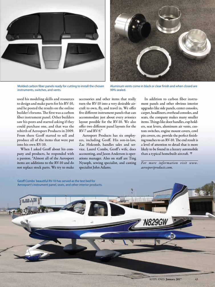
KITPLANES January 2017 43
used his modeling skills and resources to design and make parts for his RV-10, and he posted the results on the online builder’s forums. The first was a carbon fiber instrument panel. Other builders saw his posts and started asking if they could purchase one, and that was the rebirth of Aerosport Products in 2009. From there Geoff started to sell and produce all of the items that were put into his own RV-10.
When I asked Geoff about his com-pany and products, he responded with a passion. “Almost all of the Aerosport items are additions to the RV-10 and do not replace stock parts. We try to make
accessories and other items that really turn the RV-10 into a very desirable air-craft to own, fly, and travel in. We offer five different instrument panels that can accommodate just about every avionics layout possible for the RV-10. We also offer two different panel layouts for the RV-7 and RV-9.”
Aerosport Products has six employ-ees, including Geoff. His son-in-law, Zac Holcomb, handles sales and ser-vice. Laurel Combs, Geoff’s wife, does accounting, and Jason Anderson is oper-ations manager. Also on staff are Ting Nyuoph, sewing specialist, and casting specialist John Adams.
In addition to carbon fiber instru-ment panels and other obvious interior upgrades like side panels, center consoles, carpet, headliners, overhead consoles, and seats, the company makes many smaller items. Things like door handles, cup hold-ers, seat levers, aluminum air vents, cus-tom switches, engine mount covers, cowl pin covers, etc. provide the perfect finish-ing touches to an RV-10. The end result is a level of attention to detail that is more likely to be found in a luxury automobile than a typical homebuilt aircraft. J
For more information visit www. aerosportproducts.com.
Geoff Combs’ beautiful RV-10 has served as the test bed for Aerosport’s instrument panel, seats, and other interior products.
Molded carbon fiber panels ready for cutting to install the chosen instruments, switches, and vents.
Aluminum vents come in black or clear finish and when closed are 99% sealed.

By Eric StEwart
In last month’s article we discussed making relatively cheap, simple tool-ing blanks for rapid prototyping of CNC’d composite parts. In that arti-cle we discussed the overall approach to fabricating the blanks, as well as a more detailed description of the mold substructure. In this month’s article, we’ll look at bonding the tooling foam blanks to the frames and mounting them to the CNC table, as well as some other approaches to rapid prototyping of composite parts.
Vacuum Bagging the BlanksFor long, narrow mold blanks such as control surfaces, the easiest method of bagging is to simply use Aerospace Com-posite Products (ACP) nylon vacuum bag tube and quick-lock seals. For larger blanks, such as a wing or fuselage, a cus-tom bag should be assembled before-hand. Although you can use Stretchlon or one of ACP’s similar bagging plastics, I have found that 6-mil plastic sheeting from the aviation department at Lowe’s works OK if you handle it with care. Cut the bag so that when folded in half, you have a 12-inch margin around the perimeter of your mold. In other words, the bag for a 2x5-foot mold would be a sheet of plastic 8x7 feet that folds into a bag 4x7 feet. Apply ACP’s low-temp sealant tape around the bottom half of the bag, leaving the wax paper in place until you close the bag.
After making the bag, place the mold frame on one half of the bag, with the other half of the bag neatly rolled up, ready to unfold to form an
CNC Mold Blank Fabrication
The author with the first mold CNC’d for the SR-1 Project raceplane.
44 KITPLANES January 2017 www.kitplanes.com & www.facebook.com/kitplanes
Part 2

KITPLANES January 2017 45 Photos: Eric Stewart
CNC Mold Blank Fabrication
envelope once you are ready to bag the foam to the base. Regardless of which bagging method you use, be sure to allow several inches of slack around the edges so that the bag can pull tight against the blank without bridging large unsupported gaps. In addition, inserting cheap, low-density foam sheet on the backside of the mold between the frame members will help avoid bag holes caused by excessive bridging between the frame and base.
In order to ensure even distribution of vacuum, apply a spider of breather cloth on top of the foam blank, with arms that extend to the base. These arms will bond to the mold at the squeeze-out line, so use only enough to distribute vacuum evenly—one arm every 18–24 inches is adequate. Because the foam has a tendency to shift on the base when vacuum is pulled, you may also wish to screw formers to the base to lock the foam in place once it is assem-bled. In contrast to an actual part layup, it is not necessary to pull full vacuum on the assembly—15 inches Hg is suf-ficient. The goal is to get a small amount of squeeze-out between the foam and base. Here are some additional tips for bonding Precision Board to melamine-surfaced particleboard:1. Although PB Bond sticks quite
well to melamine, quickly sanding the base with a random-orbit palm sander with 60-grit sandpaper will dull/roughen the surface slightly. This gives an even stronger bond between the PB Bond and melamine.
2. PB Bond is activated by moisture. As such, surfaces must be moistened with water before applying the adhe-sive. However, surfaces should be just barely moist. For the base, wipe the melamine with a damp rag immedi-ately before applying PB Bond. This is sufficient. Visible droplets indicate excessive moisture. On the foam surface, spritz with a mister and then view the surface at an oblique angle. Any visible moisture should be dabbed dry with a paper towel—don’t worry, the pores of the foam will retain sufficient moisture. Ide-ally, the surface will appear dry, but
(Left) Spritz water onto both the foam and frame base. Visible puddling should be dabbed with a paper towel. (Right) Next, pour a single strip of PB Bond down the center of the part to be bonded.
Squeegee the PB Bond so that excess flows evenly on both sides of the squeegee. Work the length of the part, always pushing excess resin to the edge. Since the resin is activated by the surface moisture, avoid excessive squeegeeing, as that will shorten the working time of the resin. A single pass, as shown here, is ideal.
(Left) PB Bond of the foam blank almost finished. (Right) Trim tape removed from the mold base after applying PB Bond.
when you press your lips against the foam, you should be able to feel the moisture in the pores. (Yeah, I know, kissing your molds is probably not in the Boeing production manual, but it works. I love my molds!)
3. PB Bond expands significantly, so per the Coastal Enterprises video, apply only enough PB Bond to change the color of the surface. Do not work the adhesive around excessively: Pour a single thick line down the center of your foam, then
squeegee towards the edge of the part once. The more you move the adhesive around by squeegeeing, the more quickly the adhesive is acti-vated and begins expanding. Scrape excess adhesive into a paper cup to discard; do not return to the original bottle! Also be sure to cap the bottle when finished to avoid absorbing atmospheric moisture.
4. Uncured PB Bond is a sticky mess. If immediate cleanup is required, use a solvent. Otherwise, spritz with water,

which accelerates the cure, then peel/scrape off once it has cured.
5. One gallon of PB Bond will cover approximately 200–250 square feet.
6. Be sure to place a hard shim under-neath your vacuum pickup inside the bag to make sure not to suck it into and dent the tooling foam.
7. For foam blanks that are smaller than the base to which they are mounted, tape off that part of the base that doesn’t need to be bonded before applying PB Bond. This mini-mizes adhesive waste, makes debag-ging easier, and results in a more professional looking mold.
Fixture to CNC tableOnce you have bonded the tooling foam to your frame, you will need to weld feet (2x2-inch angle, about 1.5 inches wide works well) to the frame in order to bolt it to the CNC table.
You want to avoid warping the blank when you bolt it down, so the first step (if you have access to the machine dur-ing downtime) is to place the blank on the table in the exact position and orientation you want it located for
(Left) Red Bull Air Race Technical Director, Wade Hammond, applies foil tape to a control surface mold. (Right) The quickie method can be used with male molds as well. Here an elevator end cap was shaped directly on the airplane from blue foam, then removed and wrapped with foil tape, waxed, and misted with Frekote. It’s ready for a layup.
46 KITPLANES January 2017 www.kitplanes.com & www.facebook.com/kitplanes
In certain instances we need to manufacture parts on a very aggressive schedule. If these are single-pull parts, where we don’t see using the mold again and don’t necessarily need high-level accuracy, or the parts are flexible anyway, we have a few techniques for really rapid prototyping.
The first technique is to simply glue up a stack of MDF sheets (white or wood glue, clamped along the edges), bolt the sheet/block to the CNC table, and machine the mold directly into the MDF. The machined surface quality will be marginal and probably a bit fuzzy. This can be addressed by painting the surface with dope and sanding. This process is repeated until you have achieved your desired level of smoothness/porosity. The surface is then waxed with a release agent, just like a typical fiberglass mold. The disadvantage of this method is that surface quality/accuracy is not fantastic, the molds can become quite heavy, and the molds can warp quickly with humidity changes.
Since the dope/sanding step can consume a fair amount of time (both waiting for the dope to dry and then sanding it smooth), an even
faster method is to do just a single dope/sanding step, then cover the mold with aluminum tape to create a smooth release surface. This obviously works best for simple (vs. compound) curved surfaces. In my experience, parts do not release terribly well from aluminum tape, even when waxed, so either do a really good job with multiple waxings, or apply a release coat like Frekote or PVA.
The second technique we use is even simpler: Glue a sheet/block of 2-pounds-per-cubic-foot blue insulating foam to a sheet of MDF, bolt the MDF to the CNC, and machine the mold. The mold is then removed and covered in aluminum tape and a release, as described above. When using this method with vacuum bagging, you will want to limit vacuum pressure to no more than 10 inches Hg, or you risk compressing the foam. This method also works well with sac-rificial molds, where you will encapsulate the mold with the layup and remove it later by carving out the foam or dissolving it with a solvent. It’s cheap and relatively lightweight, but is pretty crude as a production technique.
—E.S.
Really Rapid Prototyping
Foam Weight 10 Pound 30 Pound
Tool 3/8” diameter, 2 flute 3/8” diameter, 4 flute
RPM 8000 8000
Tool speed 300 inches/min 120 inches/min
Stepover 0.02” 0.007”
Sample CNC Settings for Machining Tooling Foam

machining. Then apply pressure at the corners, looking for any wobble, and shim as necessary so that the blank is uniformly supported (the CNC opera-tor should have brass shims for this). Then place the feet in their respec-tive positions and mark the bolt hole centers based on crosshairs extended from the hole (you can draw these on the table with an ultra-fine-tip Sharpie and remove later with rubbing alco-hol). Remove the feet, drill the bolt holes, replace the feet on the table to check proper alignment with the bolt holes, and weld in place.
It is quite possible the CNC opera-tor may not want you welding in situ on their table (!), so be sure to discuss before arriving at the shop how they suggest affixing the feet. Another option is to simply weld the feet on according to the table hole diagram, and shim the feet/drill attachment holes once the blank is on the table. The main point is to firmly affix the blank to the table without inducing any frame warping when bolting down.
TroubleshootingOccasionally you will encounter prob-lems machining the blank: forgetting to change tool heads, inadvertent tool paths, or mismatching the file with the foam blank. Here are several tips for dealing with such issues:1. Avoid them. Be sure to take a few
minutes to preview the mold file on the computer to make sure it’s the right one. It is advisable to machine a small “L”/“R”/“T”/“B” (left/right/top/bottom) into your
mold to distinguish between sym-metrical, chiral, or similar molds.
2. Have the CNC operator run a toolpath simulation to ensure there won’t be problems with tool depth or collet interference on deep molds. This is standard procedure in most shops. Most molds with an upper and lower/left and right part (i.e., wing or fuselage molds) typi-cally have some kind of locator pins or balls incorporated into the mold.
If you place these features at the corners or extremities of the mold, you can machine them (along with the mold identifier letters) as a sepa-rate file before the main surfacing file. This will allow you to see that you have the right surfacing file loaded, and that it will fall within the boundaries of the foam blank.
3. When sizing foam, give yourself at least half an inch of foam between the base and the lowest surface cut.
KITPLANES January 2017 47
Affixing the mold blank to the CNC table: 1. Mark the bolt hole with extended line crosshairs. 2. Place the foot over the crosshairs and transfer the lines to the foot. 3. Drill bolt hole in foot and check for fit with bolt. 4. Leaving bolt in place to ensure proper alignment, weld foot to frame.

This ensures two things: first, if for whatever reason there is a pocket of missing adhesive between the foam and the base, sufficiently thick foam will maintain enough struc-tural integrity to resist warping during machining. On the other hand, if you have only 1/8 inch of foam floating above an air pocket between the foam and base, it’s likely to deform as the tool head moves over it. Secondly, a thick base provides a margin to lower the tool head slightly and resurface/recut if necessary.
4. Heavier-density foams may chip if the speed or draft of cut is too aggressive. If you damage an other-wise acceptable mold this way, you can “bondo” a filler such as 3M Plat-inum Plus Glaze and re-machine. Additionally, if you are doing a low profile recut and want to ensure that indeed you have removed material, you can paint the part with a black guide coat.
5. Dents or other imperfections in otherwise finished molds should be filled with a filler of similar den-sity, to avoid high or low spots when sanding back to f lush. Revchem Composites offers surface densi-fiers that mimic gel coat, although be aware that PB Board is a closed-cell foam, and surface treatments will only penetrate about 1 mm, so they will only be as structurally sound as the foam supporting them. A gel-coat like surface finish can be achieved on molds by painting high-density (30 pounds or higher) foam with several coats of two-part epoxy primer like PPG’s DP90LV.
6. The cost of a mold is probably sig-nificantly higher than the cost of the part it will make. For this reason, treat the mold assembly process with as much, or even greater, quality con-trol as you would apply to a molded part. Make sure you have backup supplies and manpower if things go awry and backup power/vacuum
pumps when you assemble the foam to the base.
That’s it for assembling foam blanks. In the next pair of articles, Ken Krueger will describe how to use 3D printing to fabricate molds for small parts. That will complete our look at mold making, and then we’ll move on to fabricating cou-pons to dial in your layup process. J
48 KITPLANES January 2017 www.kitplanes.com & www.facebook.com/kitplanes
Eric StEwart
Eric Stewart is designing and building the SR-1, a speed plane for setting records in the FAI c-1a/0 category (takeoff weight less than 661 pounds, including pilot and fuel). You can see more at facebook.com/TheSR1Project, including additional photos and videos of the subjects in this series of articles.
Products/Vendors listed in this article:
Coastal Enterprises Precision Board Plus tooling foam, PB Bond adhesives www.precisionboard.com
Revchem Composites (Distributor of Coastal Enterprises products) www.revchem.com
Aerospace Composite Products: nylon vacuum bagging tubes, quick lock seals, low-temp sealant tape, breather cloth, PVA release, Frekote 770www.acp.com
3M: Platinum Plus Glaze, pn 03180
Evercoat: Ever-Glaze Spot Putty
PPG: DP90LV Epoxy Primer
SEM: Guide Coat Black, pn 38203
Many thanks to Catto Propellers, Coastal Enterprises, Revchem Composites, and Aerospace Composite Products for sponsoring the SR-1 Project.
2-inch square tubing: 32 linear feet @ $1.25 per foot = $40Melamine-faced particleboard: 32 square feet = $3710-pound Precision Board: 32 square feet x 4 inches = $731PB Bond adhesive: 0.3 gallons @$120 gallon = $36Bagging consumables, etc: $20Machine time: 13 hours
Total: $864 ($26 per square foot) + machine time
Sample Mold Materials and Costs (4x8-foot panel mold)
This mold needed reprofiling, so a light coat of black guide coat was applied to ensure the toolhead was cutting new material.

Avemco Insurance Company will be there through all of the long days and long nights, insuring your baby as you build it, while you fl y it and even if you should ever sell it. We never charge extra for liability-only coverage and we automatically include Bodily Injury and Property Damage Liability for covered claims up to one year after you sell*. Call us and one of our Aviation Insurance Specialists will handcraft a policy for you.
*Not all coverages or products may be available in all jurisdictions. The description of coverage in these pages is for information purposes only. Actual coverages will vary based on local law requirements and the terms and conditions of the policy issued. The information described herein does not amend, or otherwise affect, the terms and conditions of any insurance policy issued by Avemco. In the event that a policy is inconsistent with the information described herein, the language of the policy will take precedence. Bodily Injury and Property Damage Liability coverage for up to one year after the date of sale, or the period that the aircraft was insured by Avemco,whichever is less. Free hat offer not available in New Mexico. A subsidiary of HCC Insurance Holdings, Inc. ADS0148 (10/15)
Call (888) 241 7890 or visit Avemco.com/Kitplanes Get a quote and a free hat.
Avemco.com/Kitplanes

At the risk of sounding like a late-night TV infomercial, judge for yourself how self-fusing silicone tape can provide a wide range of useful functions in the construction of your aircraft project. It traditionally has a popular following for its ability to provide emergency repairs to leaky hoses around the home and garage. But let’s look at some of the uses specifically geared toward our needs as aircraft builders.
Here are the characteristic proper-ties of this thin tape made from special silicone rubber that sets it apart from other tapes: • It does not stick to much of any-
thing—but will fuse to itself—quickly and naturally. This allows it to be used on any surface: wet, dry, or oily. It simply needs to be wrapped upon itself for adhesion. No sticky adhesive is used.
• It isnaturallyanexcellentelectri-cal insulator—about 8000 volts per wrap. It can be used for covering and protecting anything electrical in the aircraft.
• Itcanwithstandtemperaturesfrom500°F down to -85°F. This makes it suitable for just about anywhere in the engine compartment.
Keeping these unique properties in mind, let’s consider some uses around our aircraft.
Preventing Short CircuitsThere are instances where we desire to insulate electrical studs used on wire buses to prevent accidental short cir-cuits. There are insulated boots made for single wire terminals, but often we have complex or multi-wire termina-tions for which boots cannot be used. A few wraps of silicone tape is the perfect
solution and can accommodate any size or shape challenge encountered. If you ever forget to install heat shrink tubing on a wire termination, silicone tape can always be added after the fact and pro-vide a professional seal and insulation against the elements.
An Alternative to Zip TiesWhen it comes to wire bundling and cable support on the engine side of the firewall, we often reluctantly use plas-tic wire ties, knowing these are not the best solution. Heat and age keep these plastics as a temporary solution at best. Using silicone tape instead is a wonder-ful alternative. Its high temperature rating allows it to secure the sensor wir-ingnext to the enginemanifoldwith-out complaint. As quickly as it can be installed, it is easily removed by slitting with a knife.
Silicone Tape
At home with high temperatures in the engine compartment, silicone tape is a
wonderful solution for cable and wire bundles. It’s easy to install and remove.
50 KITPLANES January 2017 www.kitplanes.com & www.facebook.com/kitplanes
PLANE SIMPLEand
It’s for a lot more than just emergencies.By Jon Croke

KITPLANES January 2017 51 Photos: Jon Croke
Preventing AbrasionAbrasion protection for your engine mount or other structures is easily added by wrapping a layer of the tape around the mount tubes. Control cables and wire bundles can be safely routed against your mount with the silicone tape protecting the finish from damage caused by hundreds of hours of vibration and movement.
Sealing FiresleeveFiresleeve used on fuel lines requires the ends to be sealed to prevent oil and other fluids from being wicked into the sleeve. Typically this is addressed bydipping the ends into an expensiveliquid material made for this purpose. An inexpensive, effective alternativeto this method is to tightly wrap the ends of the firesleeve with silicone tape, sealing the ends from any possibility of contacting fluids. This simple step
really makes the firesleeve installation complete, compared to just leaving the ends unprotected (as we have all seen on more than a few engine installations).
Protection From Frayed CablesThe frayed ends of steel cable after they have passed through a thimble (e.g., at the ends of your rudder cables) can be easily and neatly covered with a few wraps of silicone tape to protect fingers and toes from inadvertent contact.Theseaircraftspecificexamplesdon’t
take into account the myriad of uses that include emergency repair of leak-ing coolant, oil, and vacuum hoses. Keep in mind the tape’s unique prop-erties when putting it to use—espe-cially the fact that it sticks to almost nothing—but can be used on anything because it fuses to itself without any adhesive. Add to that a high resistance to heat and electric potential, and you
have a versatile product that any late-night infomercial hawker would be proud to sell! Known as self-fusing sili-cone tape, it is available at your favorite aircraft supplier or at online retailers like Amazon.com. J
PLANE SIMPLEand
(Left) Electrical mounting studs cannot always be covered with pre-manufactured insulating boots due to their irregular shapes and complexity. (Right) A few wraps of silicone tape provide any electrical hazard with a neat, inexpensive solution for electrical insulation and safety from wandering metal tools.
To keep the layers of tape from fusing together, a thin plastic cover is removed prior to dispensing.
A single wrap of tape will protect engine mount tubes from abrasion with control cables in an environment rich with vibration and heat.
Jon
CRo
KE
As the founder of Homebuilt HELP.com, Jon Croke has produced instructional videos for Experimental aircraft builders for over 10 years. He has built (and helped others build) over a dozen kit aircraft of all makes and models. Jon is a private pilot and currently owns and flies a Zenith Cruzer.

52 KITPLANES January 2017 www.kitplanes.com & www.facebook.com/kitplanes
Mr. Anvil Head is not your friend.
CHECKPOINTS
Vic is a Commercial Pilot and CFII with ASMEL/ASES ratings, an A&P, DAR, and EAA Technical Advisor and Flight Counselor. Passionately involved in aviation for over 39 years, he has built 10 award-winning aircraft and has logged over 8000 hours in 70 different kinds of aircraft. Vic had a career in technology as a senior-level executive and volunteers as a Young Eagle pilot and Angel Flight pilot. He also has his own sport aviation business called Base Leg Aviation.
Vic Syracuse
I know last month I said I would write a series on maintenance, but a trip this week to Central Florida to perform some maintenance on an RV-10 reminded me of a not-so-fun trip to Florida many years ago. On the trip this time I saw firsthand how all of the technology in the cockpit enabled a much safer and less stressful flight, albeit not the kind I care to do very often, if at all.
Flying in a light plane in Florida dur-ing the summertime, especially in the middle of the day, can be challenging and uncomfortable. It is usually hot and bumpy, and you can count on the daily afternoon thunderstorms. Throw in some fast-moving fronts, and the weather can get downright wicked, sometimes in a hurry. Having lived in the Southeast now for over 25 years, I understand this. Back in 1980 as a fledg-ling, part-time flight instructor near Cleveland, Ohio, my level of experience, understanding of weather, and light plane limitations were on a whole differ-ent level. On top of that, and I had just spent the last 1½ years achieving all of my ratings in Tuscon, Arizona, where 50 miles visibility was a bad day (yes, they gave the actual visibility back then, and most every day it was 75–100 miles). Thunderstorms were mainly isolated, and you could see them from a great dis-tance. Actually, we really didn’t discuss much weather avoidance during my time there. The only thing that stuck in my mind was a sign over one of the han-gars that read, “There is no need to fly through a thunderstorm in peacetime.”
Florida BoundIn the late ’70s and early ’80s, the general aviation market was certainly booming, as was the housing industry. Some of the more successful builders were buying airplanes and having their employees trained to fly them. I happened to be giv-ing flight instruction to a really nice gen-tleman who was an architect for a local builder who had purchased a brand new Cessna 182 with long-range fuel tanks. Besides having an airplane back then, the craze was to have a second home in Florida. What better way to get there than in your own airplane?
So, one Easter weekend the builder had already gone to Florida with a buddy and wanted the student and I to bring
his son down for the weekend, leaving on Friday and returning Sunday. It was only a couple of days’ notice, and I spent a lot of time with flight service over the next few days, including being awake for most of the night prior to the trip getting updates every 4 hours. It seems there was a fast-moving front that was really wreaking havoc across the South. Only today do I understand how violent these springtime fronts can be in the South-east. On the morning of the departure I was given an optimistic briefing by the FSS, and so we departed, using Macon, Georgia, as our first stop.
The new C-182 had all of the bells and whistles for the time, including DME, which of course provided our
Here I’m at 14,500 feet, on my way to 16,500 feet, while giving the anvil head a very wide berth. I was perpendicular to it at this time, so the view is not as distinct as earlier. However, I had no intention of going back to get a better picture.

KITPLANES January 2017 53
groundspeed. We were on an IFR flight plan at 11,000 feet, tracking the VOR air-ways, and riding in smooth air above a bunch of broken cumulus clouds. What was interesting to me is that the farther South we traveled, the groundspeed read-out in the DME proceeded to decrease, until it finally stabilized at 75 knots. This was with a 142-knot true airspeed! We did finally make it to Macon and landed with a pretty blue sky and calm winds. I mentioned to the tower how beautiful it was (remember, coming from Cleveland, Ohio in April, any sunshine and blue sky is beautiful!) and the controller responded that it wasn’t that way earlier. Obviously, the front had gone through.
After refueling and a quick bite to eat, I again got a briefing from FSS, and we were on our way. The briefer had assured me that the front had passed and we could continue, but might need some deviations due to some straggling storms. So, I developed a plan in my mind to deviate farther to the southwest if needed, just to be sure and get behind the front. Soon after takeoff, I heard way too many other pilots asking for devia-tions, along with a warning from ATC regarding severe weather. I immediately asked for radar vectors to Tallahassee and then radar vectors to Sarasota, which we were given. For the next hour or so we had a nice smooth ride cruising in IMC at 11,000 feet. About 20-30 minutes after having made the turn at Tallahassee to
head out over the Gulf, still in IMC, I heard the controller say, “Cessna 86J, start an immediate left turn.” Without asking any questions I started the left turn, and it was like someone turned the lights out, completely. It went from cloud white to midnight black immediately. By the way, it was 3:05 on Good Friday afternoon. The controller followed up by saying a pop-up storm had just shown up on his scope, and he had missed it with regards to us. Yikes. Then the rain and hail started, with the rain so hard that the engine quit mul-tiple times from water ingestion. I could hardly hear anything on the radio with the volume up to the maximum.
I asked for a 2000-foot block altitude, as all I could do was really fly attitude and attempt to hold a heading. For the next 45 minutes we were tossed around in turbulence that I had never imagined was possible, with constant engine stops and surges, and a lightning dis-play that rivaled any fireworks show I had ever seen. We were up and down 2000 feet in altitude, with me just try-ing to hold a wings-level attitude and not overstress the aircraft. I was certain the wings were going to come off at any minute. And here’s the funny part, if you want to call it that—I kept thinking about the sharks in the water beneath
Photos: Vic Syracuse
This was the view toward the west as I was northbound. As you can see, I had good ground contact and cloud clearance, along with a very smooth ride.
Having electronic ignition and oxygen, coupled with a nicely per-forming RV-10, allows for lots of options. I kept the fuel load light for the return trip to allow for quicker climbs if needed. At 16,500 feet, the electronic ignition was showing 38 degrees of advanced timing.
Here is the view presented by the XM weather. I couldn’t see a good way to penetrate it to get on the west side, so I carefully navigated northbound up the east side of the weather.

54 KITPLANES January 2017 www.kitplanes.com & www.facebook.com/kitplanes
us! Jaws had left an indelible impression upon many of us during that era.
Clearly, the gods smiled on us that day. At 4 o’clock we were spit out into a beau-tiful blue sky and smooth air. A glance backwards showed the most ugly, dark thunderstorm cloud and anvil head I had ever seen in my life. I still don’t know how we survived, although I did hear later that C-182s were actually used for thun-derstorm penetration and research at one time. During our time in the storm, I caught the student praying (couldn’t blame him), and the builder’s son was glued to the window in the back seat. As soon as we were tossed out, I turned around to apologize and couldn’t believe his response—“That was cool!” I left it at that, re-established contact with ATC, and continued on our way. After that trip I never flew on Good Friday for almost 20 years, and never cared to fly when any thunderstorms were forecasted along my route of flight.
Florida Bound AgainOn the most recent trip to Florida, I real-ized it was a flight I never would have attempted just a few short years ago. I left Atlanta early in the morning, intending to get the customer’s RV-10 fixed and being airborne for the return flight by noon. The trip down was uneventful, with just a few deviations around buildups, although
I could see quite a mess over the Gulf that was clearly moving east. Flying IFR at 11,000 feet, right down the center of Florida, provided a very nice view of both coasts. I would have a very different view on the way home a few short hours later.
As luck would have it, I did finish by noon and was quickly on my way back. As I thought, the mess over the Gulf had moved inland, but between the view out the window and the picture on the weather screen, the route looked doable. A little nagging voice reminded me that here I was again, in Florida, in the afternoon, in the summertime, with
thunderstorms. I promised my wife I would be careful and launched.
I always use Flight Following, even when VFR, but I won’t file IFR when there are thunderstorms, as I want some flex-ibility in maneuvering if needed. Florida airspace is crowded enough without the weather constricting everyone. I also make certain I always have ground con-tact or I will turn around. In this case, for the next 1½ hours, I was up and down between 12,000 and 16,000 feet by choice, on oxygen and autopilot, had a very smooth ride, and never even got wet! I won’t say it was enjoyable, as any time thunderstorms are in the same state as I am when flying, I get uncomfortable. ATC was super about allowing any devia-tions I needed, which were constant. But I always had ground contact and excellent visibility, and I never went between any two columns unless I saw blue sky on the other side. I did deviate a little farther to the east than planned, as the storms were moving at about 45 knots perpendicular to my path. You can see the view on the screen in the picture, as well as some of the views out of the window. In their own way the clouds were very majestic, but not a force to be reckoned with. I learned that lesson a long time ago.
I saw at least three anvil heads on this trip, and I gave them a very wide berth of 20 miles or so, all the while smiling and saying, “I see you, Mr. Anvil Head, and we are not going to be friends today!” J
The view at 16,500 feet was excellent, allowing for fewer deviations and a much clearer view of the bigger picture. Most of the individual cells topped out at 15,000–18,000 feet and were much easier to deviate around as I could see them much farther ahead.
With the screen zoomed in, you can see how easy it was to deviate around the individual cells while never really getting that far off course (magenta line on left side of center).

Sidney Mayeux
Risky Business
Sid “Scroll” Mayeux has over 25 years of experience in aviation training, safety, and risk management in the military, civilian, airline, and general aviation sectors. He currently trains Boeing 777 pilots, and he built and is flying a Van’s RV-7A.
sure the VHF transmit light was blink-ing. Indeed, I saw no flashing transmit light, so I shifted my glance over to his left hand on the Infinity grip to be sure he was squeezing the red PTT trigger. He was not squeezing the trigger. All of this took about 5 seconds.
I looked up at Sam and was about to point out his radio transmit error…and couldn’t believe what I saw. The horizon behind him was tilted about 45 degrees off level. We were nose high, climbing through 45 degrees and getting steeper.
“What are you doing, Sam?” I asked. The nose kept rising.
“I’m not doing it. You are,” he replied. Uh-oh.
Surviving the unplanned pitch trim loop.
A smart pilot always secures the bag-gage area cargo. Why? Because you never know when you’ll end up upside down.
Not long ago, I flew a friend in my RV-7A to eat lunch at Cedar Mills Airport (3T0) on the Texas shore of Lake Texoma. In the spirit of E-Mag’s brown bag con-fessions, I’ll call my friend “Sam.” Now let me tell you a little about Sam. He’s not a professional pilot, but has flown general aviation for decades, including owning a few Cessna 172s as lease-backs. He’s a very meticulous and precise VFR pilot and even flies a steadier heading and altitude than I usually can command. However, all of his flying time has been in Cessnas. He flies the right seat of my Van’s RV-7A quite well, but the RV is still new territory for him.
After lunch, Sam and I swung into Gainesville Airport (GLE) to beat up the pattern, then land and fill up with some of the lowest-priced avgas in Texas. I flew the first box pattern, talking him through the configurations, speeds, power set-tings, and such. After my touch-and-go, he said he’d like to fly a couple. I reminded him that the red “guns” trigger switch on my Infinity stick grip is the push-to-talk switch, and the top toggle runs the flaps. After two reasonably impressive pat-terns, we full-stopped and gassed up.
For the return leg to Northwest Regional Airport (52F, our home airfield), I urged Sam to fly in the left seat. Sam eagerly agreed. I talked him through an uneventfully smooth takeoff and climb-out southward toward 52F. Actually, I didn’t need to say much of anything,
because Sam flew beautifully. I had him climb to 3000 feet and track the aircraft toward the western half of Denton’s Class D, so we could shoot the gap above the Class D, but below DFW’s Class B wed-ding cake shelf. At the proper range from home plate, I prompted him to make the “10-mile” call on CTAF.
And that’s when things got really inter-esting in the literal blink of an eye.
The Pitch Trim LoopSam made his 10-mile call, although it was sort of a jumbled call as he tried to remember our N-number. While he spoke, I glanced at the PAR-100EX for no good reason other than to make
Forty-five degrees nose high and climbing. The author (pictured above) asks, “What are you doing, Sam?”
Photos: Sid Mayeux KITPLANES January 2017 55

56 KITPLANES January 2017 www.kitplanes.com & www.facebook.com/kitplanes
A whole lot of Air Force training kicked in at that moment, starting with my stern declaration, “I’ve got the jet.” (I know, the RV-7A is no jet, but habit patterns are what they are.) He immediately released the stick as I took control while shoving the throttle full forward. We were about 80 degrees nose high now, slowing, as I handled the control stick for the first time. The nose kept wanting to rise, but I still had about 70 KIAS. This RV wanted to loop—and had the speed to complete the loop—so I let the loop continue.
We topped out at 3970 feet MSL according to my Dynon SkyView PFD. As we came out the loop’s back side with airspeed increasing and throttle properly managed, a significant amount of aft-stick load pressed into my hand. “Signifi-cant” load, meaning a lot of aft pressure, but not so much that I couldn’t counter it with forward stick. We completed the loop 20 degrees off heading and within 50 feet of our original altitude, wings level, and still managing the aft-stick loading. Mashing the pitch trim coolie hat forward alleviated the aft-stick loads, and I re-trimmed the aircraft for level flight. This was my first clue into what caused our nose-high unusual attitude.
With the aircraft under control, I took a couple of deep breaths and scanned for traffic. We were directly over Denton Air-port’s Class D, but we never busted it, nor did we penetrate the Class B shelf over-head. Sam was a little white-faced: He had never flown through a loop, whether
intentional or not. I asked him if he’d like to fly back, but he was happy for me to take it the rest of the way home.
We landed, pushed her back into the T-hangar, popped open a couple of beers (tastier than usual, for some reason), and I led Sam through a detailed debrief. As any fighter aviator will tell you, the real learning happens in the debrief, and this event was a human factors smorgasbord. I’ll spare you the finer points and get down to the actual human factors we finally identified.
The Human Factors DebriefDesign was the first up-front factor. They say, with some truth, that no two Experi-mental aircraft are alike. Like Private Pyle and Joker said, “There are many others like her, but this one is mine.” I designed my Infinity Stick Grip switches’ functions precisely the way I wanted them to work. The gun trigger activates radio trans-mission, and the coolie hat runs the Ray Allen pitch and roll trim.
However, Sam’s flying time is in Cess-nas, and his Cessnas used a thumb-pressed switch to transmit. Therefore, my aircraft systems design presented a hidden upfront human factors hurdle for Sam. I was subconsciously aware of the design factor—I watched for Sam to actually transmit the radio, but we had already stepped onto the first human factors landmine.
Which brings us to regression. A pilot suffers regression when he inadvertently
slips back to an old habit pattern that’s inappropriate for the current situation. Consider a Harrier pilot from the ’90s who, after leaving older AV-8As for a non-fly-ing assignment, had just recently requali-fied in the more modern AV-8B. The older AV-8A Harrier featured a guarded pushbutton to extend the landing gear, but no gear handle. The B-model Harrier also had a similar guarded pushbutton, but it was for emergency stores jettison (and it was positioned right next to the actual landing gear handle). One day, while flying in a four-ship pitchout, this Harrier pilot reverted to his AV-8A habit pattern and pushed the guarded button to lower the gear: However, his AV-8B dutifully jettisoned both empty external fuel tanks into some poor lady’s front yard. That’s regression.
While Sam made his 10-mile radio call, rather than squeeze the PTT trig-ger, he regressed to his Cessna muscle memory and pressed what he thought was the thumb-actuated PTT button: It was actually the pitch trim coolie hat. Sam ran the elevator trim fully aft, which pitched the aircraft nose up higher and higher. I didn’t catch the unusual atti-tude because I had gone heads down to check the transmit light. But why didn’t Sam catch the pitch-up? Because he was heads down too.
Remember that he stumbled his radio call trying to recall our call letters? In the debrief, I learned that Sam also looked inside the cockpit to read the N-number
The push-to-talk switch in a Cessna similar to the one Sam used to fly.
The Infinity stick grip in the author’s RV-7A. Note the red trigger and the trim coolie hat.

off the panel while I was heads down watching the transmit light. Due to dis-traction and task division failure, nei-ther of us had our eyes outside minding the horizon.
Finally, I include proficiency and lim-ited recent experience as key human factors in this episode, for two reasons. Sam’s a fairly experienced pilot, but he hadn’t flown much over the last two years. He certainly has no RV or E/A-B experience other than in my right seat. Therefore, right up front, he’s flying in a cockpit and operating environment quite foreign to his more-familiar high-wing experience.
Additionally, Sam had zero proficiency or experience in loops or other aerobat-ics. In fact, he admitted to never receiving more than basic private pilot training for unusual attitudes, and that was decades ago. Sam looked up expecting to see blue up/brown down, but he found nothing but blue and became disoriented.
Spatial disorientation is a failure to correctly sense a position, motion, or attitude of the aircraft or of oneself in relation to the earth’s surface or vertical component of gravity. Flying air-to-air with lieutenants in F-4 Phantoms gave me a ton of experience swiftly recog-nizing unusual attitudes and aggres-sively recovering the jet. Frequently flying aerobatics in my RV-7A meant I knew where my airplane’s energy state lay, and whether it could or couldn’t complete the loop. Sam had none of
this experience. By the time I had com-pleted the loop, he was still trying to decide which way was up.
And we got in that situation in less than 10 seconds. On a beautiful VMC day.
TakeawaysUnusual attitude training is vital, even more so in your own aircraft. Learn how to recognize its many forms (uphill, downhill, inverted, etc.), and how best to recover safely and expeditiously. I’m glad
I had been flying aerobatics; it instilled in me a more intimate knowledge of my RV-7A’s capabilities. But I didn’t make it up on the fly: I got aerobatics training from Gary Platner, an experienced Navy pilot and CFI with loads of aerobatics experi-ence in RVs and many other aircraft.
Finally, I was shocked at how quickly I ended up almost inverted on a clear-and-a-million VMC day. It’s a good thing I had stowed the bits and pieces in the baggage hold. J
The stick-grip functions placard on the author’s RV-7A panel. The red trigger is the push-to-talk switch.
KITPLANES January 2017 57

58 KITPLANES January 2017 www.kitplanes.com & www.facebook.com/kitplanes
BEST PRACTICESSolid rivet selection
and installation.A large number of builders will get plenty of opportunities to hone their riveting skills over the course of their project. That’s because a large number of kit aircraft are made from metal. The builders of these aircraft will have liter-ally thousands of rivets to drive, buck, replace, and in many instances pull.
Even if you’re not building a metal air-plane, there may well be opportunities to drive a few rivets. In any case, this is a skill that airplane builders should have, at least at a modest level. With that basic knowledge and a few tools, most any airplane builder can do a good job of installing rivets with a little practice. Best practices will entail doing this correctly, with the correct rivets installed at the correct spacing and edge clearance.
Types of RivetsThere are lots of different types of riv-ets, but only a relatively few are of inter-est to amateur airplane builders, so we will keep our focus on those and refer you to AC43.13-1B for more information on the many types of rivets that do not apply to us. The rivets we are likely to use can be roughly grouped into solid rivets and pull or blind rivets. Since we covered blind rivets in a previous arti-cle, we will focus on solid aircraft rivets in this article. Solid rivets come in many different metals and alloys, but the ones most commonly used by Experi-mental builders are made of aluminum or Monel.
Monel RivetsMonel rivets have limited use, that being mainly to join stainless steel parts together. They can also be used to join titanium parts. These metals will be found almost exclusively in the firewall area of most planes. They are preferred for this application because they are fairly fire resistant, and they have a low ten-dency to corrode when in contact with stainless steel or titanium. Monel has a melting point of about 2400°F, versus alu-minum at 1040°F. Monel universal head rivets carry the designation MS20615. Sizes are indicated by a suffix such as this: -4M4, where the first 4 is the diameter in 1/32 inch, the M is for Monel, and the last 4 is for the length in 1/16 inch. Thus a 1/8-inch Monel rivet that is ¼-inch long will be shown as MS20615-4M4. Monel rivets will be harder to drive and buck than alu-minum rivets due to their higher strength and tendency to work harden.
Aluminum RivetsThe most common aircraft rivets, known as “AD” rivets, are made from a hard alu-minum alloy. They are easily identified by
the small dimple found in the center of their heads. Soft rivets, made from pure aluminum, are called “A” rivets and have no such dimple. Other types of rivets have other markings, which are more thoroughly described in AC43.13-1B. As a general rule, do not use any aluminum rivet that does not have a small dimple in the center of its head, except under very specific circumstances.
Aluminum AD rivets come in these main configurations: universal head (similar to but not exactly the same as round-head), designated as AN470AD or MS20470, and flush or countersink rivets that are shaped to fit in a 100-degree countersunk hole, designated as AN426AD or MS20426. Lengths and diameters are shown in the suffix, with the first number being the diameter in 1/32 inch and the second number being the grip length in 1/16 inch. A universal head AD rivet that is 1/8-inch in diameter with a ¼-inch grip length will be desig-nated as AN470AD-4-4 or MS20470-4-4. Softer A rivets will be designated the same except the AD will be replaced with an A.
Dave Prizio has been plying the skies of the L.A. basin and beyond since 1973. Born into a family of builders, it was only natural that he would make his living as a contractor and spend his leisure time building airplanes. He has so far completed three—a GlaStar, a Glasair Sportsman, and a Texas Sport Cub—and is helping a friend build an RV-8. When he isn’t building some-thing, he shares his love of aviation with others by flying Young Eagles or volunteering as an EAA Technical Counselor. He is also an A&P mechanic, Designated Airworthiness Representative (DAR), and a member of the EAA Homebuilt Aircraft Council.
Dave Prizio
Strengths of AN470AD Rivets— Shear 26,000 psi, Tensile 38,000 psi
Rivet Size Shear per rivet (lbs.) Tensile per rivet (lbs.)
AN470AD-3 3/32 in. 179 262
AN470AD-4 1/8 in. 319 466
AN470AD-5 5/32 in. 499 729
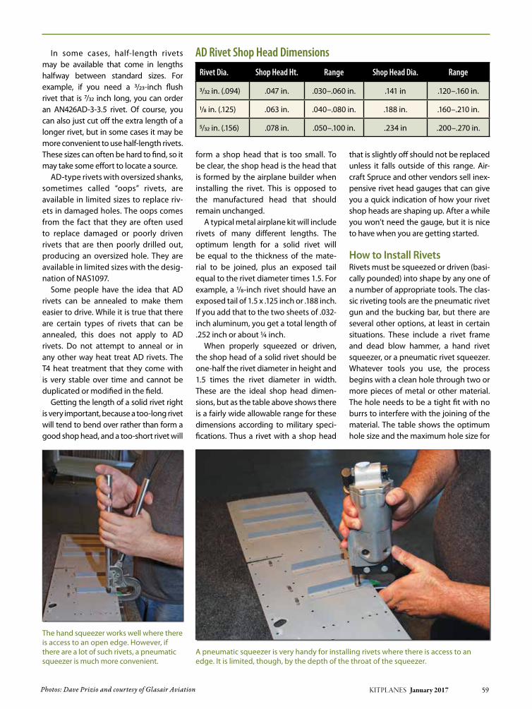
In some cases, half-length rivets may be available that come in lengths halfway between standard sizes. For example, if you need a 3/23-inch flush rivet that is 7/32 inch long, you can order an AN426AD-3-3.5 rivet. Of course, you can also just cut off the extra length of a longer rivet, but in some cases it may be more convenient to use half-length rivets. These sizes can often be hard to find, so it may take some effort to locate a source.
AD-type rivets with oversized shanks, sometimes called “oops” rivets, are available in limited sizes to replace riv-ets in damaged holes. The oops comes from the fact that they are often used to replace damaged or poorly driven rivets that are then poorly drilled out, producing an oversized hole. They are available in limited sizes with the desig-nation of NAS1097.
Some people have the idea that AD rivets can be annealed to make them easier to drive. While it is true that there are certain types of rivets that can be annealed, this does not apply to AD rivets. Do not attempt to anneal or in any other way heat treat AD rivets. The T4 heat treatment that they come with is very stable over time and cannot be duplicated or modified in the field.
Getting the length of a solid rivet right is very important, because a too-long rivet will tend to bend over rather than form a good shop head, and a too-short rivet will
form a shop head that is too small. To be clear, the shop head is the head that is formed by the airplane builder when installing the rivet. This is opposed to the manufactured head that should remain unchanged.
A typical metal airplane kit will include rivets of many different lengths. The optimum length for a solid rivet will be equal to the thickness of the mate-rial to be joined, plus an exposed tail equal to the rivet diameter times 1.5. For example, a 1/8-inch rivet should have an exposed tail of 1.5 x .125 inch or .188 inch. If you add that to the two sheets of .032-inch aluminum, you get a total length of .252 inch or about ¼ inch.
When properly squeezed or driven, the shop head of a solid rivet should be one-half the rivet diameter in height and 1.5 times the rivet diameter in width. These are the ideal shop head dimen-sions, but as the table above shows there is a fairly wide allowable range for these dimensions according to military speci-fications. Thus a rivet with a shop head
that is slightly off should not be replaced unless it falls outside of this range. Air-craft Spruce and other vendors sell inex-pensive rivet head gauges that can give you a quick indication of how your rivet shop heads are shaping up. After a while you won’t need the gauge, but it is nice to have when you are getting started.
How to Install RivetsRivets must be squeezed or driven (basi-cally pounded) into shape by any one of a number of appropriate tools. The clas-sic riveting tools are the pneumatic rivet gun and the bucking bar, but there are several other options, at least in certain situations. These include a rivet frame and dead blow hammer, a hand rivet squeezer, or a pneumatic rivet squeezer. Whatever tools you use, the process begins with a clean hole through two or more pieces of metal or other material. The hole needs to be a tight fit with no burrs to interfere with the joining of the material. The table shows the optimum hole size and the maximum hole size for
Photos: Dave Prizio and courtesy of Glasair Aviation KITPLANES January 2017 59
AD Rivet Shop Head DimensionsRivet Dia. Shop Head Ht. Range Shop Head Dia. Range
3/32 in. (.094) .047 in. .030–.060 in. .141 in .120–.160 in.
1/8 in. (.125) .063 in. .040–.080 in. .188 in. .160–.210 in.
5/32 in. (.156) .078 in. .050–.100 in. .234 in .200–.270 in.
The hand squeezer works well where there is access to an open edge. However, if there are a lot of such rivets, a pneumatic squeezer is much more convenient.
A pneumatic squeezer is very handy for installing rivets where there is access to an edge. It is limited, though, by the depth of the throat of the squeezer.

60 KITPLANES January 2017 www.kitplanes.com & www.facebook.com/kitplanes
common rivets. If the hole size exceeds the maximum, then the hole must be drilled out to the next larger size and a larger rivet used.
In the case of flush rivets, the hole is countersunk or dimpled after drilling to accommodate the flush head. The deci-sion to dimple or countersink should be based on the thickness of each piece of material being joined. In some cases, one piece may be dimpled and the other countersunk. In that case, the counter-sink must be large enough to allow the dimpled sheet to set properly into the countersink in the other piece, but not so large as to allow any movement of the dimpled sheet in the countersunk hole. Countersinks or dimples should be sized to have not more than .006 inch of the rivet head extending above the surface or below it. Needless to say, the coun-tersink cutter needs to be held squarely with the hole to produce an even recess for the flush rivet head.
With the rivet hole properly drilled and deburred (and countersunk if nec-essary), it is time to install a rivet. Place a rivet of the correct diameter and length in the hole. Many builders like to tape rivets into place with riveting tape or blue masking tape. This holds the rivet in place and affords some minor pro-tection to the head of the rivet and the surrounding material. As an alternative, other builders apply tape to the end of the rivet set.
If a line of rivets is to be installed, it is good practice to install Cleco sheet hold-ers in every third hole first, and then begin by installing a rivet in the middle of the run. Next rivet each end, and then go to the point midway between the middle and one end. Try to maintain a pattern where you are always riveting the midpoint between the rivets that have already been installed. After that, remove the Clecoes and fill those holes. This will keep things in proper alignment
and avoid buckling that could occur if you simply started at one end and kept going.
When driving or squeezing rivets, always keep the tool square with the rivet. Set the end of the tool squarely on the manufactured head and make sure the other end of the bucking bar is squarely set on the tail. This will prevent the tool from sliding off and damaging the rivet and/or the surrounding mate-rial. A special note to those working together as a team to drive rivets: The person holding the bucking bar should press on the tail of the rivet first to let the person holding the rivet gun know that he or she is set up on the correct rivet. Only after feeling that pressure should the riveter press on the trigger of the rivet gun. By the way, you will need hearing protection whenever you use a rivet gun. The process is very loud.
Back riveting is a popular way to drive flush rivets. This method is preferred by many RV-series aircraft builders. With
RV-8 builder Eddie Rohwedder demon-strates back riveting on this floor section. The metal plate embedded in his work-bench top makes this work well. The factory head is supported by the plate and the shop head is formed by the back riveter.
Rivet tape (shown here) or blue masking tape helps hold rivets in place and protects the skin around the rivets. It is easier to see the rivets with rivet tape, but blue masking tape is cheaper and works well enough.
Drill Sizes for Selected Rivets Dimple vs. Countersink
Rivet Dia. Optimum Hole Size
Maximum Hole Size
3/32 in. #40 .098 in. .103 in.
1/8 in. #30 .129 in. .135 in.
5/32 in. #20 .161 in. .171 in.
Rivet Dia. Dimple material up to this thickness
Countersink material this thick or more
3/32 in. .032 in. .040 in.
1/8 in. .040 in. .051 in.
5/32 in. .060 in. .064 in.

KITPLANES January 2017 61
this method the bucking bar or bucking surface is applied to the manufactured head, and the rivet set pounds on the tail of the rivet. This method prevents a lot of marring of the finished surface of the airplane skin. It obviously will not work where there is limited access to the tail of the rivet. Universal head rivets can also be back riveted with a special bucking bar, but the process is much less common.
Riveting ToolsRivet squeezers work very well when installing rivets near open edges, usu-ally within a few inches of the edge of the material. Hand squeezers work well for a few rivets, but pneumatic squeezers provide welcome relief for hands and arms if a lot of rivets are to be squeezed at one sitting. Pneumatic squeezers come in C-type and alligator
type, with the C-type being much more popular, because of how easy it is to change setups with them.
An alternative to the squeezer is the rivet frame. With a working depth of up to two feet, the rivet frame will allow work to be done far away from the edge of the material. They are particularly pop-ular for dimpling fuselage and wingskins prior to installation of flush rivets. The
A section of RV-8 floor is an ideal piece to back rivet. The back-rivet set is shown here in the rivet gun.
A back-riveting plate set in a carpeted tabletop. This is an ideal setup for back riveting smaller pieces. Note the back-riveting rivet set in the rivet gun.
Kitplanes subscriber alert!several of our Kitplanes subscribers have received what appear to be “renewal notices” or “automatic renewal notices” from a company known as preMier subscriptiOn serVice, 5star subscriptiOns, rapiD MaGaZine cOllectiOn, MaGaZine billinG serVices, publisHer’s billinG serVices, circulatiOn billinG center or other
similar names. Addresses for these firms include Dallas, tX; lincoln, ne; Omaha, ne; san luis Obispo, ca; salt lake city, ut; White city, Or and prescott, Fl.
These firms have nOt been authorized by us to sell subscriptions or renewals for Kitplanes and we cannOt Guarantee that any order or payment sent to them will be forwarded to us.
Kitplanes does nOt offer a subscription term of more than 2 years, nor do we retain your bank account information. if you see an offer for 3 or more years or if you receive a notice that references your subscription anD your banking information, it is nOt an authorized offer. We urge you to report these notices to us, as well as to your state’s attorney General and better business bureau. any offer you receive that does not bear our
company logo or corporate/customer service address or 800 numbers should not be considered approved by us.
the only autHOriZeD inFOrMatiOn for Kitplanes is:toll free via telephone 1-800-622-1065, Dial america renewal telemarketing, or www.kitplanes.com/cs
Our texas customer service center: 1-800-622-1065, pO box 8535, big sandy tX 75755
Or our corporate offices at:belvoir Media Group, llc.
aviation publishing Group535 connecticut ave norwalk ct 06854
should you have any questions at all about mail that you receive, please contact us at our web site: www.kitplanes.com/cs or call us toll free to speak to customer service.

62 KITPLANES January 2017 www.kitplanes.com & www.facebook.com/kitplanes
rivet frame can be activated with a dead blow hammer or a pneumatic rivet gun.
When all else fails, the pneumatic rivet gun and bucking bar can usually get the job done. This part of the riveting pro-cess takes the most skill and practice, but most anyone can learn it with some instruction and a little patience.
Rivet guns come in sizes, so it is impor-tant to match the size of your gun to the size of the rivets to be driven. As a general
rule, a 2X gun is ideal for 3/32-inch rivets and works for 1/8-inch rivets. A 3X gun is ideal for 1/8-inch rivets, but also works well with 3/32-inch rivets and marginally on 5/32-inch rivets. This is the size rivet gun that Van’s recommends. If you actually have more than a very few 5/32-inch rivets to drive, you really need a 4X gun, but this would not be likely for most amateur air-plane builders.
Besides rivet guns and rivet squeezers, you will also need various rivet sets and dimple dies. A number of aviation parts and tool vendors have sets of these tools designed to work well with kits from vari-ous manufacturers. One can argue about
whether these are the best tools for the job, but they represent a good place to get started for the first-time builder. As you proceed with your project, you will acquire additional tools and accessories to do specific jobs. The various builder forums can be very helpful in deciding just what to get to do a certain job.
Removing RivetsRivets that didn’t come out so well will need to be removed. Start by center punching the head of the rivet (the shop head with the dimple in it). Then slowly drill straight into the rivet head with a drill that is the same size or
Bucking bars are used to form the shop heads on driven rivets. Different shapes will work for different access situations. The bucking bar in the upper left corner is made of tungsten carbide. Bucking bars made of this material can be very compact due to the metal’s much greater density. The downside is that they are rather expensive. This one cost $70.
Hand rivet squeezers work well for many applications where there is access from an edge. The one on the left has interchange-able yokes, while the other squeezer (top right) has a fixed yoke.
Pneumatic rivet squeezers come in two types. The more popular “C” type is shown here. There is also an “A” or alligator type, but it is less common. Changing the yoke on the rivet squeezer will allow it to be used in different situations where clear-ances dictate one option or another.
A pneumatic rivet gun with a number of different rivet sets for different applications. The one in the gun and most of the others are for universal head rivets, and the one opposite the gun is for flush rivets. The bent rivet sets allow access to tight spaces.

KITPLANES January 2017 63
slightly smaller than the one used to drill the original hole. When you are just about at the point where the rivet head ends and the stem begins, stop drill-ing and gently move the drill bit from side to side to break off the rivet head. The tricks are, one, to drill straight into the rivet head, and two, to stop drilling
before you get into the stem of the rivet where you will start to enlarge the orig-inal hole. It is best to practice this on pieces you aren’t using in your project. Once you get the feel for it, you can do it without damaging the hole, but don’t try it for the first time on something you want to keep.
Classes at AirVenture or traveling EAA Sportair workshops are good places to get started with riveting. All new air-plane builders should attend one or more of these classes before starting on their project. There is no need to be in any hurry to start your scrap pile with real kit parts. J
A Rivet frame is very nice for dimpling skins for flush rivets. This one uses a lever with an over-center design. Others use a rivet set activated by a dead blow hammer.
This drawing from Glasair’s assembly manual for the Sportsman shows when dimpling should be used versus when countersinking is allowable consistent with best practices. Never countersink if the top skin is not thick enough to fully contain the countersink.
Part of changing the oil in my Lycoming aircraft engine requires removal of the oil screen housing and checking to see if and how much metal appears in the washed screen sediment. The oil screen housing is located below the vacuum pump, and the space between the housing and engine firewall is limited. It is difficult to hold the screen, line-up the bolts with four holes, and insert the 1/4-20 bolts into the threaded holes in the acces-sory case. To eliminate the alignment challenge, I cut a piece of 3/32 -inch diameter brass tubing (K&S Metals #8155) into a pair of 4-inch-long pieces. If each pin is inserted into one of the two top accessory case threaded holes, and if the oil pressure screen housing is slid over these alignment pins until firmly against the accessory case, the insertion and tightening of the bottom bolts is very easily achieved (followed by the upper bolts).
Other materials may be used for the alignment pins such as steel or aluminum rod. However, aluminum may not provide suf-ficient strength. Selecting the diameter of the rod is a tradeoff. If
you select too small a diameter, the rods will fit too loosely in the holes and the pins will wobble, thus increasing the alignment challenge. Also, thin diameter rods may be too weak and will bend. To enhance the insertion of thicker rods into the accessory case, the insertion end of each may be slightly tapered via a file.
The photo shows the oil screen held temporarily in-place via the two alignment pins (painted white). The use of the align-ment pins almost completely eliminates both the alignment problem plus the juggling act of holding the screen housing while inserting the bolts. J
Alignment Aids for Lycoming Oil Screen Housings
By William Rynone, Ph.D., P.e.
SHOPTIPS

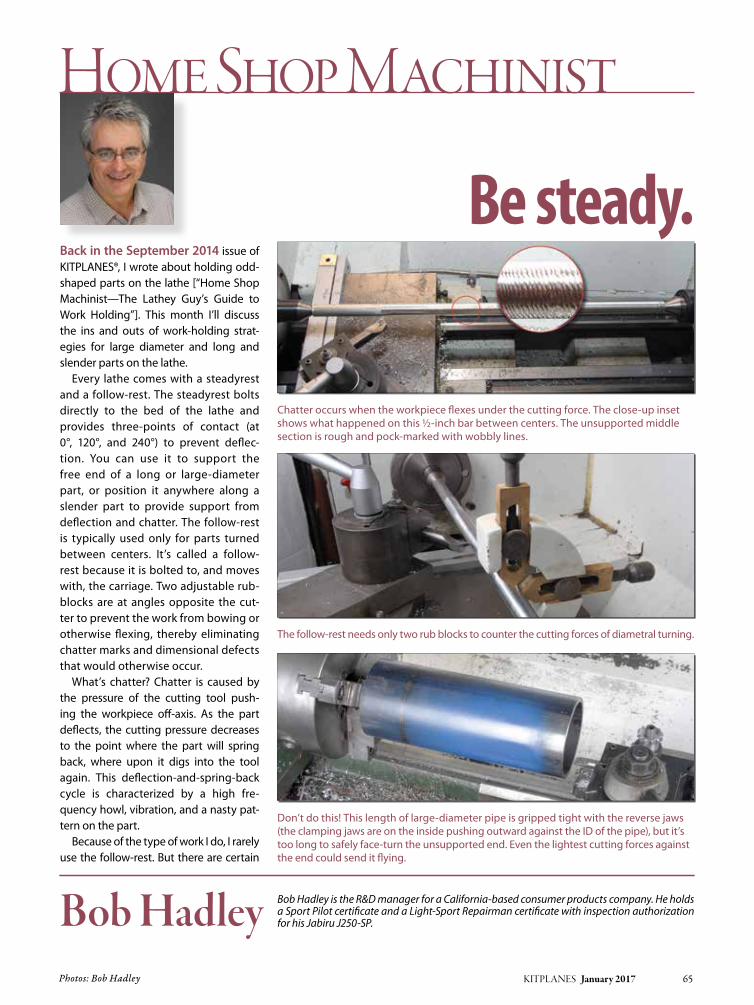
Photos: Bob Hadley KITPLANES January 2017 65
Bob Hadley is the R&D manager for a California-based consumer products company. He holds a Sport Pilot certificate and a Light-Sport Repairman certificate with inspection authorization for his Jabiru J250-SP. Bob Hadley
Be steady. Back in the September 2014 issue of KITPLANES®, I wrote about holding odd-shaped parts on the lathe [“Home Shop Machinist—The Lathey Guy’s Guide to Work Holding”]. This month I’ll discuss the ins and outs of work-holding strat-egies for large diameter and long and slender parts on the lathe.
Every lathe comes with a steadyrest and a follow-rest. The steadyrest bolts directly to the bed of the lathe and provides three-points of contact (at 0°, 120°, and 240°) to prevent deflec-tion. You can use it to support the free end of a long or large-diameter part, or position it anywhere along a slender part to provide support from deflection and chatter. The follow-rest is typically used only for parts turned between centers. It’s called a follow-rest because it is bolted to, and moves with, the carriage. Two adjustable rub-blocks are at angles opposite the cut-ter to prevent the work from bowing or otherwise flexing, thereby eliminating chatter marks and dimensional defects that would otherwise occur.
What’s chatter? Chatter is caused by the pressure of the cutting tool push-ing the workpiece off-axis. As the part deflects, the cutting pressure decreases to the point where the part will spring back, where upon it digs into the tool again. This deflection-and-spring-back cycle is characterized by a high fre-quency howl, vibration, and a nasty pat-tern on the part.
Because of the type of work I do, I rarely use the follow-rest. But there are certain
Home Shop Machinist
Chatter occurs when the workpiece flexes under the cutting force. The close-up inset shows what happened on this ½-inch bar between centers. The unsupported middle section is rough and pock-marked with wobbly lines.
Don’t do this! This length of large-diameter pipe is gripped tight with the reverse jaws (the clamping jaws are on the inside pushing outward against the ID of the pipe), but it’s too long to safely face-turn the unsupported end. Even the lightest cutting forces against the end could send it flying.
The follow-rest needs only two rub blocks to counter the cutting forces of diametral turning.

66 KITPLANES January 2017 www.kitplanes.com & www.facebook.com/kitplanes
jobs where the follow-rest would be a necessity: such as threading a long lead screw or making plane shafting. But if your bar has steps or a taper, or has other features, like a keyway or flat, the follow-rest is not going to work. That’s where the steadyrest comes in. Since the steadyrest doesn’t traverse with the carriage, you can fix it wherever you need support. It all depends on what you want to do.
Say you want to face off the end of a large pipe or tube. It can be clamped in
the reverse jaws no problem, but if it is a bit too long, the force of even the lightest cut can leverage it right out of the chuck.
Long bars or tubes are sometimes less than perfectly straight. It’s possible to chuck a long bar in the lathe and set the steady at the distant end and have it off-axis. So it’s a good idea to reference the centerline of the spindle. You can do this with a dial- or test-indicator. Zero the indicator at the chuck, then traverse the length of the bar to see if it’s running true (this is done with the lathe off). A
slight discrepancy can be corrected using the rub blocks on the steady-rest to coax it back in line. About 0.005 inch per foot is my personal limit, but it depends on the material. Extruded alu-minum bars can be out of round by that much. If a ground or drawn 4130 bar is out that much, you should check to make sure it’s not warped or bent, or if it’s being compromised by some debris in one of the chuck jaws.
If your workpiece is straight and on center, set the steadyrest into position
Do this! The same pipe, this time supported at the free end by the steadyrest. With the rub-blocks adjusted to prevent any deflection, any type of cut (facing, boring or turning) can be made safely.
Mounted in tool-holder, this dial indicator is used to verify the centerline is on target for drilling.

KITPLANES January 2017 67
and adjust each rub block until they’re almost touching. About 0.004 inch, which is the thickness of a piece of paper, is perfect. Then carefully adjust each rub block until it just touches the work, but with no pressure. Dab some heavy oil on the block, and you’re ready to turn. Ideally, the rub blocks should just barely touch the workpiece. Even then they will burnish the part where they’re rubbing. Keeping the blocks well-oiled with heavy oil (30W or higher, or way oil) will prevent them from heat-ing up and binding.
Steadyless TurningOften long parts can be satisfactorily turned without using a steady. As long as they fit through the spindle, you can turn a segment, reposition the part in
the chuck, turn the next segment, and so on. The drawback is there will be tell-tale signs you used this procedure. If dimensional accuracy is not that impor-tant, the evidence can be eliminated by polishing it on the lathe with 180- then 220-grit sandpaper.
I recently had an occasion to employ a version of the turn-reposition-turn method to repair a broken cam buckle for the battery hold-down strap on my Jabiru. The buckle went limp when the crossbar—the part that keeps spring tension on the clasp—snapped off.
Since a new strap would likely have the same weak point, I repaired it with a 0.100-inch diameter stainless-steel crossbar turned from a two-inch long 8-32 fillister head screw. I left about 3/16-inch worth of threads near the head. This design allows the screw to be tight-ened securely, but without tensioning the frame (see photos). I considered using a spring pin, but decided the die-cast frame might be too fragile. J
Turning this 8-32 screw into a 1¼-inch long crossbar required nibbling ¼ inch at a time and as close to the chuck as possible. Note the positioning of the diamond insert and use of the left-hand tool holder to reach the narrow gap between the screw head and chuck.
The repaired buckle. Hopefully better than new!
Once enough space allowed, I switched to the right-hand tool holder to continue to nibble the threads away until the bar was long enough to cut to length. Prior to cutting off, I polished the tool marks away with 320- and 400-grit sandpaper.
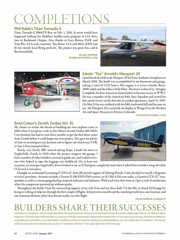
68 KITPLANES January 2017 www.kitplanes.com & www.facebook.com/kitplanes
Submissions to “Completions” should include a description (250 words maximum) of the project and the finished aircraft. Also include a digital image of the aircraft. Minimum digital image size is 1500 pixels wide x 900 pixels high (5 x 3 print size at 300 dpi). Please include a daytime phone number where we can contact you if necessary. Also indicate whether we may publish your email address in case other builders would like to contact you. Email text and photos to [email protected] with a subject line of “Completions.” You may also submit electronically at www.kitplanes.com; just click on “Completions: Add Yours” in the upper right corner of the home page.
Phil Rabb’s Titan Tornado-STitan Tornado-S N866TP flew on Feb. 1, 2016. It never would have happened without Joe Sheldon’s builder-assist program at LSA Avia-tion in Redmond, Oregon. Also thanks to Gary Brown, DAR, and Tom Phy, EAA tech counselor. The Rotax ULS and MGL iEFIS Lite fit our mostly local flying perfectly. The project was great fun, and it flies beautifully.
Salem, [email protected]
edwin “Tex” arnold’s nieuport 28I purchased this full-scale Nieuport 28 kit from Airdome Aeroplanes in March 2010. The build was accomplished in my basement and garage, taking a total of 2235 hours. The engine is a seven-cylinder Rotec 2800 radial and the fabic is Poly-Fiber. The livery is that of Lt. Douglas Campbell, the first American-trained pilot to become an ace in WW-I. He was a member of the American 94th Aero Squadon and scored his first aerial victory on his first day in combat operations, April 14, 1918. On May 31 he was credited with his fifth confirmed kill and became an ace. My Nieuport 28 is currently on display at Wings Over the Rockies Air and Space Museum in Denver, Colorado.
brad cohen’s Zenith Zodiac 601 xlMy chance to realize the dream of building my own airplane came in 2004 when I was given a ride in Jim Olsen’s Zenith Zodiac 601 HDS. I was hooked, but had to wait three months to get the first three crates from Zenith before I could begin my own project. This gave me plenty of time to second guess my decision and to figure out which year I’d fly to Sun ’n Fun instead of drive. Slowly, very slowly, 9BC started taking shape. I made the move to Zephyrhills, Forida in 2010 when the project outgrew the garage. I had a number of other builders around to guide me, and I asked every-one who helped to sign the baggage area bulkhead. On at least one occasion, an unsuspecting FedEx driver looked at me as if I had gone completely mad when I asked him to hold a wing rib while I Clecoed it into place. I bought an overhauled Lycoming O-235-L2C from JB aircraft engines of Sebring Florida. I also decided to install a Magnum recovery parachute. Avionics include a Dynon D-180 EFIS/EMS system, an ICOM A210 com radio, a Garmin GTX-327 tran-sponder, as well as a steam gauge backup airspeed indicator and altimeter. With each item that went in, I got a rush of satisfaction when the component powered up without sparks. Throughout the build, I had the unwavering support of my wife Erin and my three kids. I’d also like to thank Ed Knapp for being so willing to help me through the first couple of flights. Ed proved to myself and the watching world (me, one lineman, and one transient Mooney pilot) that dreams really can take flight.
Palm haRbOR, FlORida J

KITPLANES January 2017 69
Aircraft Spruce & Specialty CV4 877-4SPRUCE
Avemco Insurance Company 49 888-241-7890
California Power Systems 35 800-AIRWOLF
Continental Motors 5 See Advertisement
CubCrafters 39 509-248-9491
Dynon Avionics CV2 425-402-0433
Garmin International 27 913-397-8200
Grand Rapids Technologies 23 616-245-7700
Grand Rapids Technologies 47 616-245-7700
KITPLAnES® Bookstore 31 800-780-4115
Murphy Aircraft CV3 604-792-5855
Progressive Aerodyne 67 352-253-0108
Sonex Aircraft, LLC 35 920-231-8297
Stewart Systems 57 888-356-3490
Van’s Aircraft 3 503-678-6545
Viking Aircraft Engines 57 386-566-2616
Builders’ Marketplace
Aircraft Covers 72 800-777-6405
Airflow Performance 70 864-576-4512
Bearhawk Aircraft 71 877-528-4776
Bede Corp. 70 See Advertisement
Beringer 71 864-214-4274
Better Half VW 71 281-383-0113
Carlson Aircraft 73 330-426-3934
Falconar Avia Inc 71 780-465-2024
Flight Data Systems 72 831-325-3131
Flight Grip 71 800-204-7625
Funkwerk Avionics 73 812-384-4972
Glen-L 73 888-700-5007
Grove Aircraft 73 619-562-1268
Homebuilt Help 70 See Advertisement
InFInITY Aerospace 72 See Advertisement
Innovator Technologies 72 403-669-3101
Kuntzleman Electronics Inc. 71 610-326-9068
Matco Manufacturing 73 801-335-0582
Osprey Aircraft 72 See Advertisement
Out of the Basement 73 See Advertisement
RAM Aircraft 70 254-752-8381
Recreational Power Engineering 73 800-583-3306
Stewart Aircraft 73 See Advertisement
TCW Technologies 70 See Advertisement
WhirlWind Propellers 70 619-562-3725
advertiser page # telephone advertiser page # telephone
List of AdvertisersPlease tell them you saw their ad in KITPLANES® Magazine.
KITPLANES® interactive makes it quick and easy for you to receive instant information about products or services directly from our advertisers’ web sites.
➥ Go to: www.kitplanes.com/links for a virtual shopping tour via links to their web sites.
➥ Call the phone numbers listed below and be sure to tell them you saw their ad in KITPLANES® Magazine.
❏December 2016 2017 Homebuilt Aircraft Directory, Pedal Power, Resin Infusion, Pre-Built Panels
❏november 2016 BD-17L, Spitfire Squadron, Preparing for First Flight, Driving Down the Cost of Ownership
❏October 2016 Merlin PSA, Pre-Buys, Grass Runways, Custom Maintenance Manuals, Vibration Problems
❏September 2016 The Secrets of Speed at Reno, Findlay’s Flyer, Learning About Lycomings, Pre-buys
❏August 2016 Celebrating the RV-6, Avidyne IFD540 vs. Garmin GTn 750, The Other OshKosh
❏July 2016 Hummel H5, national Test Pilot School, Smart Transponders, Top Overhaul, Ray Stits
❏June 2016 Javron Super Cub, ADS-B Options, Emergency Parachutes, Stall-Warning Device, Hand Propping
❏May 2016 Tucano Replica, Light Aircraft Company’s Sherwood Ranger, ECO-nomical Auto Pilot
❏April 2016 Thatcher CX5, Remembering Jim Bede Sr., Speed Deburring, 3D Parts Printing, Vacuum Forming
❏March 2016 Carbon Cub EX on Amphibious Floats, Audio Control Panels, Bendix and Beyond
BACK ISSUESONEW eBOOK O
eBook download is exactly the same magazine as on the newsstand.
The difference is:
you get it now! &
no shipping costs for e-books!
(a big savings for our international customers)
eBooks download as a single, full size, full color .pdf document which you can view on your desktop, laptop or tablet computer.
PDF eMagazine issues are fully searchable and are compatible with all Adobe Acrobat functions such as highlighting, page notes
and spoken word audio.
O Individual monthly issues are $6.95
O A compiled Aircraft Buyer’s Guide is $12.95
Visit:
www.kitplanesbooks.com
to order

70 KITPLANES January 2017 www.kitplanes.com & www.facebook.com/kitplanes
buiLders’ mArketpLAce
619-562-3725
• ROTAX
• JABIRU
• CONTINENTAL
• LYCOMING
GROUND ADJUSTABLECOMPOSITE PROPELLERS
www.whirlwindpropellers.com
111 Airflow DriveSpartanburg, SC 29306(864) 576-4512(864) 576-0201 (Fax)www.airflowperformance.comEmail: [email protected]
Aircraft Multi-point Fuel Injection• Operates all engines from 65 to 800 HP• Applications for V6/V8 engines• Manual Mixture Control• Bolt on Kits for Lycoming Engines• No Carburetor heat required• Instant throttle response• All Mechanical, No Electronics• Increases mid-range HP• Approved for Aerobatic use• Compatible with all Fuels• Precise Fuel Metering under all conditions
1204-8 Airflow 1/10/05 2:35 PM Page 1
Builders’ Marketplace reaches tens of thousands of homebuilders
and pilots who are eager to buy new products and services.
Call 805-382-3363 or email: [email protected]
Working With a tight Budget?
KITPLANES January 2017 71
Highlights: • Revamped and expanded Aircraft Buyer’s Guide for quicker, better search results • All New Classifi ed Ads section for deals on aircraft and accessories • Unlimited access to back issues as an easy- to-use, tablet-friendly downloadable PDFIt’s easy to register. Just visit WWW.KITPLANES.COM and click on GET WEB ACCESS.
Have You Seen Us Lately?
The KITPLANES® web site is now better than ever!KITPLANES.COM is YOUR guide to the most comprehensive homebuilt information available, and access to our archives and aircraft database are FREE to registered subscribers!
®
“Like” us on Facebook, follow us on Twitter and get an RSS feed from our Newsline
INTRODUCING THE “DOUBLE EAGLE”
2 Place Sports Plane powered by reliable 4 cyl. VW.Empty wt. 385#. Plans, videos, propeller hubs:
L.E. MILHOLLANDPO Box 747, Brookshire, TX 77423
Email: [email protected] • www.betterhalfvw.comKits & materials pkgs., welded fuselages: John Bolding,
281-383-0113. Estimated cost $5,000-$7,500.
2/3 Mustang
and 10 other all wood designs
F12 Cruiser
PLANS - KITS - PARTS
Info Packs $10/ea + $4 Postage HIPEC Covering System - no ribstitching, no taping.
Lo cost — Lo labor — proven
www.falconaravia.comEmail: [email protected]
FALCONAR AVIA INC. Ph: 780-465-2024
CUSTOMIZE OUR GRIP FOR YOUR AIRCRAFT
Easy Installation
Comfortable
Rocker (shown) or push button trigger style
Thumb Switches:Push Button, Toggleand/or 4-Way Trim
Fit to 5/8" thru 1-1/8" sticks
Next day shipping for virtually any confi guration you desire.
push button trigger style
sticks
Next day shipping for virtually any confi guration you desire.
812 Jacquelyn St. • Milton-Freewater, Oregon 97862800-204-7625 • 541-938-0533 • Fax: 541-938-7242

72 KITPLANES January 2017 www.kitplanes.com & www.facebook.com/kitplanes
buiLders’ mArketpLAce continued
“OSPREY 2” AMPHIBIAN
2-Place, all wood, 12 sec. water take-off, full builder support, Oshkosh award winner. Info Pak $14 ($17 overseas), Plans $250 ($290 overseas).
OSPREY AIRCRAFT3741 El Ricon Way, Sacramento, CA 95864
Email: [email protected] must-read for the
GA Community!
Log-in for
FREE News Alertswww.avweb.com/kit
Follow us on Facebook at www.facebook.com/kitplanes
Share Your Enthusiasm for

KITPLANES January 2017 73
Buy a Plane or Sell a
Plane with a Free ad online.
Any individual may post a flying homebuilt
or partial project complete with photos at no cost for quick
global response. www.kitplanes.com/classifieds
www.groveaircraft.com1800 Joe Crosson Dr.
El Cajon, CA 92020619.562.1268Aircraft Landing Gear Systems Inc.
Grove
LANDING GEAR
Factory Direct
Your Complete Source for Wheels, Brakes
& Landing Gear
SPARS, STREAMLINE STRUTS, RIBS 6061T6 - EXTRUDED - CERTIFIED ANALYSIS
SPARS - 6 sections - 3” to 6 5/8” STRUTS - Large, Small, Heavy Duty, Jury
RIBS - Stc’d, Experimental, Custom Write/Call for free info:
CARLSON AIRCRAFT INC.330-426-3934 • [email protected]
www.carlsonaircraft.com
Out of the BasementA collection of more than 200 of your favorite cartoons by Robrucha, most from the back pages of KITPLANES® Magazine.
Price: Book $19.95E-book $16.95
Books are available from: www.Kitplanesbooks.com
HIRTH AIRCRAFT ENGINES 15 thru 110 hp. 1000 hour rated TBO. One year warranty. Sales, service, and parts. Highest power to weight ratio in the industry. BlueMax 2-cycle aviation oil. Contact:
RECREATIONAL POWER ENGINEERING5479 East County Rd. 38, Tiffin, Ohio 44883 Tel: 800-583-3306 • Fax: 419-585-6004. Visit us on the web at www.recpower.com
Get the latest. Follow us on Twitter at #Kitplanes.
Can’t Get Enough
?

74 KITPLANES January 2017 Photo: Mel Asberry
Please send your questions for DAR Asberry to [email protected] with “Ask the DAR” in the subject line.
Question: How do you determine if a person who buys an unfinished kit complies with the 51% rule? If the original buyer dies and the plane is complete, but not signed off, how does the 51% rule affect getting the plane signed off?
Answer: Actually, one builder does not have to build 51%. The rule says that the aircraft must be 51% amateur built. Any number of people may par-ticipate in the project; you just need to be able to show that 51% of the con-struction and fabrication was com-pleted by amateurs.
If the original builder has passed away and didn’t keep a builder’s log, you could have a problem. However, even in an extreme case, usually a family member or relative should be able to testify to his build participation.
Question: I want to buy an E/A-B aircraft that was built and regis-tered in Canada. Several sources have told me I will have to pay some very high fees to bring the plane to the U.S. Is this correct?
Answer: I’m not quite sure what fees you are referring to. The normal way to
bring an E/A-B aircraft from Canada into the U.S. is to de-register the aircraft in Canada and re-register it in the U.S.
Once the aircraft is registered in the U.S., you will need to submit an appli-cation for a U.S. airworthiness certifi-cate. From that point, the aircraft will be treated like any other Amateur-Built. That is, the owner must be able to show proof that the aircraft is truly amateur built by submitting a builder’s log or other proof, and FAA form 8130-12 (eli-gibility statement).
If the owner cannot show proof of meeting the “major portion” rule, the aircraft cannot be certificated as Experi-mental/Amateur-Built in the U.S.
Question: I have an E/A-B Zodiac 601 HDS. I recently installed a 7-gal-lon fuel tank in one of the wing bag-gage lockers. This is an option that is designed and supplied by Zenith Aircraft. Does this modification require that I put the airplane back into Phase I for testing?
Answer: Yes, you will need to return your aircraft to Phase I flight testing. You have made a major change to the fuel system and significantly changed
the weight and balance. You’ll also need to placard the instrument panel as to the operation of the auxiliary fuel tank.
Question: I own and fly a certified 1947 Ercoupe 415-C that qualifies as an LSA. I want to comply with the FAA rules for ADS-B Out before 2020, but TSO’d equipment is expensive—20 to 50% of the cost of most Ercoupes. The mandate allows LSAs and Experimental aircraft to use less-costly non-TSO’d equip-ment. Since my Ercoupe qualifies as an LSA, can I add non-TSO’d equip-ment? Would it make sense to re-register the plane as Experimental?
Answer: Unfortunately the answer to both questions is no. Your Ercoupe is a certified aircraft and must be maintained as such. There is also no practical route to re-register your aircraft as Experimental.
The LSA compliance factor is simply to allow a sport pilot to fly the aircraft. All aircraft must be maintained in accor-dance with their original certification. J
Complying with the 51% rule, bringing Canadian aircraft into the U.S., adding auxiliary fuel tanks,
using non-TSO’d ADS-B in an Ercoupe.By Mel AsBerry

Charts: Barnaby Wainfan KITPLANES January 2017 75
is a principal aerodynamics engineer for Northrop Grumman’s Advanced Design organization. A private pilot with single engine and glider ratings, Barnaby has been involved in the design of unconventional airplanes including canards, joined wings, flying wings, and some too strange to fall into any known category.
Barnaby Wainfan
More about trikes.Last month, we started to look at the stability and control characteristics of trikes. We saw that trikes behave very differently than conventional airplanes because of the large vertical offset between the wing and the center of gravity, and got a look at how controlling pitch with weight shift differs from using aerodynamic control surfaces.
We now turn our attention to one of the most important aerodynamic char-acteristics of a trike wing: its pitching moment behavior.
On a conventional airplane, the pilot can change the pitching moment gen-erated by the airflow over the flying sur-faces. Moving the stick deflects control surfaces that change the shape of the airplane and thus change the aerody-namic forces acting on it. A trike pilot cannot do this. Moving the control bar shifts the CG fore and aft relative to the wing, but does not change the shape of the wing.
As we saw last month, this inability to change the shape of the wing means that the pilot has zero pitch-control authority if the wing is unloaded due
to a down gust or an overshoot caused by an aggressive nose-down control input. If the wing unloads, the pilot cannot command the wing to a higher angle of attack to regain lift. The abil-ity of the vehicle to recover to positive lift is entirely dependent on whether the wing itself generates a nose-up moment at zero lift.
The importance of this was discov-ered the hard way during the early years of hang gliding. At first, the rule in hang gliding was “don’t fly any higher than you are willing to fall.” Simple Rogallo wings became the primary form of hang gliders in use. When flown very low and slow, they worked acceptably. Flights were short, and crashes were gentle enough to be survivable.
Inevitably, glider designers started using better materials, improved aerody-namic efficiency, and made higher-per-formance gliders. As pilot skill increased, some hang glider pilots began to vio-late the “no higher than you are willing to fall” rule and began doing soaring flights. Soon there were a series of acci-dents where the glider lost lift due to a
down gust or nose-down control input and locked into a low angle of attack dive, often all the way to the ground.
This phenomenon, called “luffing in,” was caused by the flexible nature of early hang glider wings. They had no ribs or battens to allow any portion of the wing to generate down load, so at some critical angle of attack, the air pressure across the sail was lost, and the sail lost lift. As we have already seen, due to the lack of control power in the absence of wing load, the pilot had no way to recover.
The solution was to add battens and bracing to control the shape of the wing. The battens kept the sail from going limp at low angles of attack. Bracing held the tip battens in place to produce washout in the wing, so the tips would produce a down load at low angles of attack. This down load at the tips produced the nose-up moment required to drive the angle of attack back up and regain lift.
These modifications ensured that the wing would produce a nose-up moment when unloaded. They do not change the fact that a trike or hang glider is unstable
Figure 1: Effect of wing pitching moment on trike stability and trim.

76 KITPLANES January 2017 www.kitplanes.com & www.facebook.com/kitplanes
at negative lift, but the positive zero-lift pitching moment makes recovery from a momentary unload possible.
Examples:Figures 1 and 2 show the character-
istics of three example trikes with the same characteristics except for the zero-lift pitching moment (Cm0) of the wing. All three aircraft are trimmed to fly at the same airspeed (65 knots), so they all trim at different control bar angles. (Please note that the specific airspeeds and angles of attack refer to the example vehicles and are not universal.)
Looking first at Figure 1, we can see that all three are trimmed at the same angle of attack (AOA).
For the trike with a positive Cm0, the curve shows a stable slope of pitch-ing moment vs. AOA around the trim
point. The aircraft becomes neutrally stable at just below 1 degree AOA, and is unstable below that. Because of the positive Cm0 of the wing, the net pitching moment is nose up to several degrees AOA below zero. This aircraft can fly safely as long at the pilot does not attempt to deliberately fly inverted or force it to negative G.
Looking next at the curve for zero wing Cm0, we can see that the stability and trim situation is not as good. The air-craft is still stable around the trim angle of attack, but the slope is shallower than that of the positive-pitching-moment wing and the aircraft is thus less stable.
The region of low angle of attack instability starts at a higher angle of attack. Also note that at zero angle of attack, the vehicle is unstable and the
pitching moment is zero. There is no net moment driving the wing back to positive lift. Because of the instability, any pitch rate will tend to increase. If the machine ever reaches this angle of attack with a nose-down pitch rate, it will tuck under uncontrollably. This is very dangerous.
Even more dangerous is the machine with a negative Cm0 wing. As the figure shows, this vehicle is neutrally stable at the trim point and will tuck under at an angle of attack less than 2 degrees below the trim point.
Figure 2 shows pitching moment vs. airspeed for the same three trikes. Note in particular that the negative-pitching-moment aircraft will start to tuck under at airspeeds slightly above the trim point.
Figure 2: Effect of wing pitching on trike pitching moment vs. airspeed.
Figure 3: Effect of control bar angle on pitching moment for a trike with a negative pitching-moment wing (Cm0=-.02).
Figure 4: Effect of control bar angle on pitching moment and airspeed for a trike with negative pitching-moment wing (Cm0=-.02).

KITPLANES January 2017 77
The example we just looked at is for all three aircraft trimmed at the same airspeed. To see just how dangerous a negative-pitching-moment wing on a trike can be, look at Figures 3 and 4.
Looking at Figure 3, we can see how the characteristics of this machine change as the trimmed angle of attack changes. With the bar pushed out to trim at the angle of attack for 45 knots (about 7.5 degrees AOA), the aircraft is reasonably well behaved. It’s stable around the trim point. It still exhibits a tuck-under at 1 degree AOA, but there is an angle of attack range with strong nose-up moments below the trim point that will tend to arrest any dangerous nose-down pitch rate. The tuck-under angle of attack is far enough below the trim point that it’s unlikely the aircraft will get driven there by a gust.
As the pilot pulls in the bar to trim to 60 knots, the situation changes. The aircraft is now much less stable around the trim point. The nose-up pitching moment at lower angles of attack is very small, and tuck-under occurs less than 3 degrees AOA below the trim point. Fly-ing at this airspeed, the machine will be very sensitive in pitch, and a relatively small movement of the control bar, or a down gust can easily precipitate a nose-down loss of control.
If the pilot attempts to trim this air-craft to fly at 75 knots, it is on the brink of disaster all of the time. Any change in angle of attack will cause the nose to drop, and if the angle of attack change is negative, the aircraft will tuck under.
What makes an aircraft like this partic-ularly dangerous is the fact that it is quite flyable at lower airspeeds. It’s entirely possible for a pilot to fly this machine successfully as long as the airspeed is kept low. This can produce an unmerited confidence in the airworthiness of the craft. When the pilot gets a little more adventurous and tries to fly faster or initi-ate a dive, the rapid degradation of pitch stability and control will quickly lead to an uncontrollable tuck-under and a severe mishap.
Next month we will look at the effects of mast height, and other parameters on the safety and controllability of trikes. J
As builders, we often have a pile of parts to turn into something resembling a fly-ing machine. The pile often contains dozens of similar, if not exactly matching, parts. Every part has to end up in the exact location intended. Labeling is important, but what to do about part prep, priming, and painting? How do we label so they make sense, and how do we protect the label so it’s visible after paint? Here’s my solution.
My first requirement is the part number. Unfortunately with some parts, “R” and “L” don’t always mean right or left side of the aircraft. Sometimes it’s just the direction of the part. I use the part number, but always add “R” or “L” to designate the side of the aircraft. A group of the same part, such as stiffeners, will get a numerical sequence as well.
My second requirement is a clue to help me understand exactly how the part is oriented in the airplane. Notice in the photo that each part number has a right-angle set of vector arrows. On my labels, I always point the arrows “up” or “for-ward” and “inboard.” Looking at the parts in the photo, it’s pretty clear they are all right-side parts and exactly which way the parts will end up when installed.
My third requirement is labels that won’t show. Labels are placed on flanges and locations where parts will mate and hide the label after final assembly. Notice in the photo the label on the seat back at the bottom and the stiffener angle just above it. When the stiffener angle is rolled into place, it completely covers the label on both parts.
My fourth requirement is to keep things simple. During the initial assembly, parts are temporarily labeled with a Sharpie in an obvious location. Next comes disassembly, deburring and scuffing with Scotch-Brite. At this stage, the label area is thoroughly cleaned and the permanent labels are written. Temporary labels are then wiped off. Before priming, care is taken to clean the parts, but not remove the permanent label. If necessary, the label is overwritten again before priming.
Since the seat back parts in the photo would be sprayed black, the labels were masked after priming, but before paint. It looks goofy, but no one will ever see it. I painted before assembly so the rivets would contrast against the black interior. It really pops!
So find a method that works for you and be consistent. You’ll never wonder again where a part should be installed. J
LabelingBy Larry LarsonSHOP
TIPS
The labels on these seat back parts include the part number and a right-angle set of vector arrows that indicate which way the parts will end up when installed.

78 KITPLANES January 2017 www.kitplanes.com & www.facebook.com/kitplanes
is the chief avioniker at RST Engineering. He answers avionics questions in the internet news-group www.pilotsofamerica.com–Maintenance. His technical advisor, Cyndi Weir, got her Masters degree in English and Journalism and keeps Jim on the straight and narrow. Check out their web site at www.rst-engr.com/kitplanes for previous articles and supplements.
Jim Weir
Wired at Oshkosh.It was a perfectly wonderful Oshkosh ’16. Weather wasn’t horrible, mosquitos were way down, airplane registrations were up, food on the field wasn’t half bad, and if I may say so, the forums were very well attended.
However, if you didn’t make the trip to “Wonderland on the Winnebago” this year, you may have missed some very interesting forum topics, one of which we will talk about this month: wire identification.
With the explosive growth of aircraft electronic devices, major changes in lighting, and a general overall increase in electrical and electronic devices, has come a major increase in the amount of wiring in our aircraft. While it is not com-mon in light aircraft to identify the wires as it is in large turbine aircraft, it is still a cheap, easy way for you to keep from spending literally hundreds of hours later troubleshooting the electrical sys-tem in your aircraft if both ends of each wire have a unique identification. This is about the least expensive of any way I’ve been able to come up with.
The basic idea is to print a whole bunch of sequential numbers in a word processing program (there are automatic serialization routines in Microsoft Word, ask any fourth grader how to do it) and then print those numbers onto small return address “sticky” labels cut to size.
If we simply stopped here, the first time those labels got wet or treated harshly, those idents would be long gone. However, if we use clear shrink sleeving over the wire, then both the
label and the numbering should last for a long time.
The last remaining problem is what numbers to use. So far as I have been able to determine, there is no stan-dard numbering system, so I’ll throw out something that seems reasonable. If anybody wants to elaborate on this idea, I’ll be glad to post it as an update on my personal KITplaneS® page (www.rstengineering.com/kitplanes).
How the System WorksFigure 1 shows the number range used for each application. as an example, the range for wires connected to instru-ments, such as electric gyros, eFISes, fuel gauges, clocks, etc., is 300–399.
looking at Figure 2, we see that the 46th wire in the instrument category goes
between the right fuel gauge and the sender. Those of you who are proficient in excel will probably make up a similar table for your own wire assignments.
and for those of you who have taken my advice to download the free sche-matic drawing program from my col-lege web site (www.rstengineering.com/sierra, then click on MeCH14 and down-load CMTM pCB & Schematic), here is another reason to do so.
Continuing with the saga of wire #346, Figure 3 is what the partial sche-matic in your aircraft maintenance man-ual might look like for this circuit done with CMTM. note that the wire between the terminal strip connecting the fuel sender to the right fuel gauge has been labeled #346-4-22. This is wire #346, with color #4.
Figure 1: The number range used for each application in a typical electrical system.
Number Range Application
000-099 Engine Wiring (magnetos, carb temp, electric oil gauges)
100-199 Electrical Power System (battery, alternator, regulator, voltmeter)
200-299 Lighting (nav & landing lights, anticollision, strobes, panel lights)
300-399 Instruments (electric gyros, EFIS, fuel gauges, clocks)
400-499 Communication Radios
500-599 Navigation Radios
600-699 Other Radios (transponder, altitude encoder, ADS-B, entertainment)
700-799 Miscellaneous not covered elsewhere
800-899 (Reserved for future use)
900-999 (Reserved for future use)

KITPLANES January 2017 79
What is color #4 you ask? Simply a yel-low wire with the color of the wire des-ignated by the plain old resistor color code that we’ve been using since for-ever, in accordance with Figure 4.
and the 22? Simply the aWG size of the wire used.
Shrink SleevingHere’s what you need to know about shrink sleeving:• It is available from a lot of the usual
sources: Mouser, Digikey, Jameco, and the like. The best and most available in small quantities is the plain old clear pVC sleeving.
• It shrinks about 2:1 in diameter andalmost nothing in length. The diam-eter given in the ordering sheets is the unshrunk diameter.
• Whileaprofessionalshrinkheatgunisbest, in a pinch a good high-heat hair dryer will do the job.
• Please don’t use a match, a ciglighter, a propane torch, etc. to do the shrinking—not unless you want to re-run half of the wires you are try-ing to label.
• Overlap the label itself abouthalf thelength of the label on both ends with shrink. This should keep out water, gas-oline, hydraulic fluid, and everything else short of battery acid.Oh, the little four-section terminal strip
between the gauge wire and the sender wire? We will be talking a lot about that little part in a few months when we tackle the whole subject of aircraft wir-ing. For right now, just understand that I will almost never wire up an aircraft with a wire directly from part to part. That wire will nearly always have some sort of intermediate connector so that if I ever have to re-wire a circuit, I only have to wire from the intermediate connector to the affected part.
not that I’ve ever had to rewire an airplane.
In the coming months we are going to be talking about that rubber duckie I promised last month, some way of making color-coded connectors, and a brand new design for a lighted whirligig wind indicator. It’s going to be a good year. Until then, stay tuned… J
Photos and schematic: Jim Weir
Figure 2: a small sample (#344 through #351) of individual wires in the instrument category. The complete range of wires for this category goes from #300 to #399.
Figure 4: Wire colors match the same color codes that have been used with resistors for years.
Figure 3: Wire #346-4-22 is the 46th wire in the instrument category. The 4 indicates the color is yellow, and 22 is the wire’s aWG size.
a yellow wire with the sticky-back label applied to it.
The same wire with shrink sleeving over the label and a crimp terminal applied.
Wire Number Application
344 Clock to keep-alive breaker bus
345 Left fuel gauge to sender
346 Right fuel gauge to sender
347 Directional gyro to instrument breaker bus
348 Artificial horizon to instrument breaker bus
349 Not used
350 Not used
351 Not used
0 1 2 3 4 5 6 7 8 9 Black Brown Red Orange Yellow Green Blue Violet Gray White
Print & DigitalEither Format– Great Savings!Subscribe now at www.kitplanes.com/subscribe
www.kitplanes.com & www.facebook.com/kitplanes80 KITPLANES January 2017
By RoBRucha