KING TIGER
9
@ KING TIGER KAN Series LOCKNUTS Preload and tension can be adjusted. Most endurable to vibration. Accuracy can be adjusted. Poweful fitting. USAGE General, precise Bearing, Ball Screw Support Bearing. SPECIFICATIONS Material : S45C Hardness : HRC 22-28 Surface treatment : Black phosphated coating Screw preciseness : ISO4H Screw angularity :J- 0.002-0.007mm FOLLOW THE STEPS TO CLAIIP THE KAN NUT. . Clean up the screw of the shaft. . Loosen up each bolt. . Put the KAN nut into the screw and tighten it to the space of 1-2mm against the other . Section (see the figure 1). . Tighten the bolt in the sequence of diagonal uniformly to get rid of any slit between shaft and nut. (see the figure 2). . Assemble provisionally at the axial force of 3-5 times the actually required axial force. This processing is very important for initial adoption of the nut. . Tighten the bolts in the sequence of diagonal uniformly with them loosen and then get rid of the space until the nut can be turned. . Tighten the nut with required axial force. . Tighten all the bolts with the standard torque in the sequence of diagonal uniformly and then fix them on the shaft. (see the figure 3). . The shaft cannot be vibrated by adjusting the bolts if necessary. Dont make the bolt too loosened for dimensioning the shaft. Ensure that all the bolts must have a tension when closing the work. FEATURE 1-2mm 1-2mm F-rglre 1 Figue2 FigLre3 (Note)The centrifugal force on the moving shaft results in the KAN nut being loosened.
-
Upload
khangminh22 -
Category
Documents
-
view
0 -
download
0
Transcript of KING TIGER

@
KING TIGER
KAN Series LOCKNUTS
Preload and tension can be adjusted. Most endurable to vibration.Accuracy can be adjusted. Poweful fitting.
USAGEGeneral, precise Bearing, Ball Screw Support Bearing.
SPECIFICATIONSMaterial : S45CHardness : HRC 22-28Surface treatment : Black phosphated coatingScrew preciseness : ISO4HScrew angularity :J- 0.002-0.007mm
FOLLOW THE STEPS TO CLAIIP THE KAN NUT.
. Clean up the screw of the shaft.
. Loosen up each bolt.
. Put the KAN nut into the screw and tighten it to the space of 1-2mm against the other
. Section (see the figure 1).
. Tighten the bolt in the sequence of diagonal uniformly to get rid of any slit between shaft andnut. (see the figure 2).
. Assemble provisionally at the axial force of 3-5 times the actually required axial force. Thisprocessing is very important for initial adoption of the nut.
. Tighten the bolts in the sequence of diagonal uniformly with them loosen and then get rid ofthe space until the nut can be turned.
. Tighten the nut with required axial force.
. Tighten all the bolts with the standard torque in the sequence of diagonal uniformly and thenfix them on the shaft. (see the figure 3).
. The shaft cannot be vibrated by adjusting the bolts if necessary. Dont make the bolt tooloosened for dimensioning the shaft. Ensure that all the bolts must have a tension whenclosing the work.
FEATURE
1-2mm 1-2mm
F-rglre 1 Figue2 FigLre3
(Note)The centrifugal force on the moving shaft results in the KAN nut being loosened.
KING TIGER
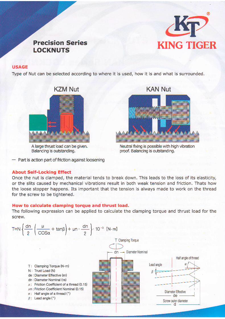
USAGE
Type of Nut can be selected according to where it is used, how it is and what is surrounded.
About Self-Locking EffectOnce the nut is clamped, the material tends to break down. This leads to the loss of its elasticity,or the slits caused by mechanical vibrations result in both weak tension and friction. Thats howthe loose stopper happens. Its important that the tension is always made to work on the threadfor the screw to be tightened.
How to calculate clamping torque and thrust load.The following expression can be applied to calculate the clamping torque and thrust load for thescrew.
10 -3
KZM Nut KAN Nut
A lage thrust load can be given.Balancing is ourBtand ing.
- Paft is action paftof fricUon against loosening
Neubal fixing is possible with high vibrctionproof, Balancing is ontstanding.
'=' {+ ( "..* + tano) * un + }lN'ml
T Clamping
1,..- l\Torque
T: Clamping Torque (N.m)
N: Trust Load (N)
de : Diameter Effective (mm)
dn :Diameter Nominal (mm)
p : Friction Coefficient of a thread (0.15)
/n :Friction Coefficient Nominal (0.15)
a : Half angle of athread (')6: Leadangle(')

@
KING TIGER
What makes clamping force in fixing precision bearings?Clamp a spacer or the minimum bearing aiea on the inner race with the axial force which cangenerate an internal force of 10-15MPa.
Clamping force = the minimum areax 10-15MPa.
Note : When the heat shrink fitting is applied, the product can be clamped with a force of 20MBkept cool at room temperature and then clamped again with the standard torque after beingloosened.
About functions of Set ScrewThe Screw can adjust any angularity on the section. The loose stopping lock of a set screw canwork only when it is clamped, and once the machine stalts, take care to keep it working.
It cannot be replaced with any gauge
Locknut has a high precision in designing, but cannot be replaced with any gauge due to its lowrigidity and a large wear on the nut. Several replacements may result in a deviation in thediameter effective from the standard.
About Precision LevelThe level describes 'Any slit' between an external thread and a nut, as well as the shape anddimensions. The combined thread with narrow slits in it can have a good level in the precision.
A good example includes a combination of external thread 59 and nut 5H, external 4h and Nut4H.
Note : Combination of 4h and 4H has the smallest slit (Or the highest precision level)
HOW TO REFER TO THE LEVEL
Male screw
A sampling confirmation has(Referred to as the deviation
Female screw Nuts
4H 5H 4G 5G
Level of intolerance (Difference in tolerance)
been conducted inprecision for each
terms of the level of pitch.thread)
Precision SeriesLOCKNUTS
lf theslitis0 ((( lf thereareslitsfound
Grade of Male screw
lf they are small ((( lf theyare large

KING TIGER LOCKNUTS
Precision Locknut has the Following FeaturesIt can be used to clamp the main axis for the machine tool, and the ball screw suppoftbearing for high precision, compatible with other common nuts. Our product can be
safely used against green procurements such as RoHS and JIG24, Which have fully metthe standard. Also, Locknut can be produced in the Process of checking precision on
each product for improved quality control. Loose stopping nut(KAN) has a high precision
and a good vibration proof.
Locknut SpecificationMaterialMain bodySet Screw
Hardness
Surface process
Nut Precision Class
perpendicularity
Brass pin C3604(environmentally supplied)
s45CscM440HRC 22*28,Black oxide coatingISO 4H
I 0.002-0.007mm
Any product has no set screw with it.
Locknut has been produced according to the ISO standardFor its shape and dimension, The following promises can be declared. The shape ofscrew thread will be decided automatically not by nominal diameter, but by screw pitch.
PitchHeight : the total height of screw thread(measured from the Pitch)
^nH = r*p= 0.866025404.P
zDiameter(nominal diameter) =The outerdiameter of external thread
De, de (Diameter effective)d1 >The root diameter of external threadDl The inner diameter of female screwD, d < The root diameter of internalthread
ffi Colored side(on the top)
ffi Colored side(on the bottom)
Notes:r . Make sure that the nut is larger than the blue line.
. Make sure that external thread is smaller than the blue line.
. Above promises should be kept in terms of the thread and nut
PH
d,D

@
&2KING TIGER
Product No.Dimension
HolesSet Screw Mass
D d1 d2 d3 H
KAN16x 1.5 34 4 24.5 4.5 8 5 4 M4x z 4 80
KAN18X 1.5 4 .AR 4.5 I 5 4 M4x / a7
KAN2OX 1,5 40 ?nq 4.5 8 5 I M4x 2 4 3 107
KAN22X 1.5 40 4 30.5 4.5 r8 5 4 M4x z 4 lo0
KAN24X 1.5 42 4 32.5 4.5 8 4 M4x 2 A ? 107
KAN25X 1.5 45 5 36.5 4.5 20 6.5 4 M4x 4 137
KAN28X 1.5 46 f, 38.5 4.5 20 6.5 A M4x 12 4 r36
KAN30x 1.5 48 5 40.5 4.5 20 6.5 4 M4x 2 4 141
KAN32x 1.5 50 5 42.5 AF 22 7 1114x 16 163
KAN35x 1.5 q? 5 45.5 4.5 22 7 4 M4x.l5 4 175
KAN38x 1.5 5 48.5 4.5 22 7 ^ M4x l6 4 212
KAN40X 1.5 58 s0.5 4.5 22 7 M4x 6 4 195
KAN42X 1.5 60 5 52.5 4.5 22 7 4 M4x 6 4 204
KAN45X 1.5 68 6 EQ 4.5 22 7 6 M4x 6 6 2aa
KAN48X 1.5 68 o 59.5 4.5 25 I o M4x 8 6 294
KANsoX'1.5 70 6 61.5 4.5 25 9 6 M4x 8 6 303
KAN52X 1.5 72 6 63.5 4.5 25 9 6 M4x I o 314
KANssX 1.5 71 6 66.5 4.5 25 9 6 M4X B 6 327
KAN58X 1.5 82 o 72.5 5.5 26 9 6 M5X 8 o o 446
KAN6OX 1.5 84 6 74.5 26 9 6 M5x 8 6 6 479
KAN62X 1.5 86 6 76.5 5.5 28.r0.5
6 1'15x 20 6 6 505
KAN65X 1.5 88 6 5.5 28 r 0.5 6 p15x 20 6 6 500
KAN6BX 1.5 95 8 83 5.5 z r 0.5 6 1ir15x 20 6 o 625
KAN70x 1.5 95 8 85 z r 0.5 6 1r15x 20 6 6 536
KAN72x 1.5 98 8 86 6.5 U.J 6 M6x 20 6 0 626
KAN75X 1.5 00 I 88 6.5 2.r0.5
6 M6x20 6 l0 623
KANBOX 2.0 0 8 6.5 32 1 6 M6x22 6 l0 890
KAN85x 2.0 r.l5 8 00 6.5 32 t'l 6 M6x22 6 t0 963
KAN90x 2.0 120 8 08 6.5 JZ t.l o M6x22 6 10 1,O20
KAN95X 2.0 25 8 l3 6.5 32 1t 6 M6x22 6 0 r,050
KAN100x 2.0 r30 8 r 18 6.5 JZ.l
I 6 M6x22 6 0.r ,100
KANlOSX 2.0 aq I 123 6.5 32 l1 6 M6x22 6 0 1,r 50
KAN110x 2.0 40 8 124 6.5 JZ.l
1 o M6x22 6 r0 1,210
KAN115x 2.0 45 8 r33 6.5 36 2 6 M6x25 6 r0 1.430
KAN120x 2.0 55 8 r40 6.5 JO z o M6x25 6 l0 1.740
KAN125x 2.0 60 8 r48 6.5 JO 2 6 M6x25 6 r0 1,820
KAN130x 3.0 65 8 6.5 JO 6 146x25 6 l0 1,940
KANl40X 3.0 80 t0 160 t0 ?q 8 M6x25 8 t0 2,33s
KANl50X 3.0 90 10 70 '10 38 8 61r6x25 8 t0 2,44O
KAN160x 3.0 205.10
7A 10 40 12 8 1r1gx 3O d 25 3,380
KAN170x 3.0 215 l0 93 l0 40 12 8 MBX 30 8 25 3,580
KAN180x 3.0 230 '10 210 lo 40 8 M8X 30 8 25 4,110
KANl90X 3.0 240 r0 224 t0 40 8 M8X 30 8 25 4,330
KAN200x 3.0 245 10 229 l0 40 8 M8X 30 8 25 4,410
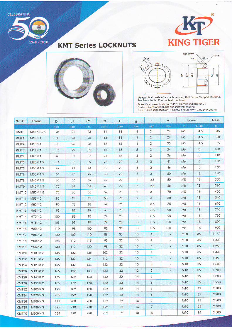
KMT SETiCS LOCKNUTS
@
&2KING TIGER
Usage: Main Axis of a machine tool, Ball Screw Support Bearing.Precise spindle, Precise test machine.
Specifications: Material / s45C, Hardness/HRC 22-28surface treatment/Black phosphated coatingScrew preciseness/IS04H, Screw angularity/r0.002-0'0O7mm
Sr. No. Thread D d1 d2 d3 H v M Screw Mass
KMro I
KMrl ]
-KIVTT2 ]
KMT3
M10x 0.75
M12x 1
f"ff S. f
M17x1
28
JU
33
37
21
23
26
29
I
25 1
I
28 1nl
ll
IJ
14
14
16
4
4
^
2
2
,z
l+
zl30
34
M5
M5
M5
M6
4.5
4.5
4.5
8
i1
-50/)100
16
l8 l8
KMT4 M20x 1 40 32 35 21
26
JZ
t8 5 a M6 8 110
KMTS
KMT6
M25x 1.5
M30x 1.5
fufgsr( S
44
49
JO
41
39
44
20
20
5
.
5
2
,
41
46
M6
M6
I8
8
t8
re
t8
t8
r30
r60
190KMTT
KMTS
KMT9
KMTlO
KMT11
54 40
56
49
59
64
68
78
38
42
48
22
22
22
25
25
50
60
65
70
80
M6
M40x 1.5
M45 x '1.5
vso)( rsM55x 2
65
70.:/5
85
o
o
7
7
2.5
2.5
M8
M8
M&
M8
300
330
400
540
61
65
74
52
KMT12 M60x 2 90 78 6Z 62 26 8 3.5 85 M8 t8 610
KMT13
KMT14
KMT15
KMT16
KMT,I7
M65x 2
M70x 2
r,,tti"iM80x 2
M85x 2
95
r00
65
88
93
87
92
97
'100
68
n83
28
28
28
JZ
8
8
I8
3.5
Q4
3;3.5
90
95
100
r00
M8
M8
M8
M8
1q
r8
r8_18
710
750
eoo -
900
r05
1',I0
120
98
107 lt0 88 32 t0 4 Mr0 35 rrt19
1,200
1,250
xM-|,8
KMT19
r90" 2
M95x 2
125
r30
112
117
r t5 o?
s{32
32T:l0
A
4
Mr0
M]0 35120
KMT2O M100 x 2 r35 122 125 r03 32 t0 f, M]0 35 r,300
KMT22
KMT24
M110 x 2
M120x 2
145
155
132
142
134
144
112
llz
32
5Z
l0
10
A
j
Mr0
Mt0 35
'l ./t5f)
-1,600KMT26
KMT28
. KMT3O
M130 x 2
M140x 2
trrttSO r. Z
r65
v:r85
Y162
154 132
142
32 12 5
6
Ml0
Mto
Mr0
ll_35
1]00
r,800160 32 14
14172 170 152 5l 6 r,950
KMT32 M160 x 3 195 182
192
180 162 14 6 M]0 2,100
KMT34 M170 x 3 205 190 172 5t 14 6 M]0 35 2,200
KMT36 M180 x 3 215 200 200 182 JZ l6 7 Mr0 35 2,300
XMT38
KMT4O
M190 x 3 225 210 210 192 32 t6 7
8
Mr0
Mr0
35
35
2,400
M200 x 3 235 220 220 202 5Z l8 2,500

KZM Series LOCKNUTS
@62KING TIGER
Usage: Main Axis of a machine tool, Ball Screw Support Beartng.Precise spindle, Precise test machine.
Specificationss Material/S45C, Hardness/HRC 22-28Surface treatment/Black phosphated coatingScrew preciseness/ISO4H, Screw angularity/r0.002-0.007mm
d x pitch mm mm mm mm mm n-m N.m s
KZMSX 0.75 16 8 tl 2-M4 2 4
KZM'i0x 0.75 l8 I 13 2-M4 8
KZM10X 1 l8 I 3 2 l3 2-M4 I R
KZM12X 1 22 6 3 2 t6 2-M4 2 l4KZM15x 1 25 I 3 I 20 2-M4 I I8KZM17X 1 28 0 4 2 23 2-M5 4.5 28
KZM20X 1 JI o 4 2 26 3-M5 4.5 34
KZMZ2X 1 38 0 4 a 27 3-M4 8 5l
KZMZ5)(',l.s 38 2 32 3-M6 8 58
KZM30X 1.5 AR 2 I 39 3-M6 I 78
KZM35X 1.5 52 2 5 I 46 3-M6 8 r04
KZM40)( 1.5 58 , 6 2-3 5t 3-M6 tt r48
KZM4sX,I.5 65 4 6 2.5 58 3-M6 tt '184
KZM5oX't.5 7A
6
6 2.5 63 3-M6 2ffiKZMssX 2 75 67 3.MB q 246
KZM60X 2 80 6 7 J 3-MB 270
KZM65X 2 6 77 3-M8 .J 290
KZ'M70)(2 92 I 3.5 83 3-M8 I 398
KZM75X2 98 8 3.5 a9 3-M8 8 434
KZMEOX 2 105 8 6 Qq 96 3-M8 B 5MKZMBSy.2 l0 I I 3.5 l0l 3-M8 8 532
KZM9oX 2 20 20 0 4 l08 3-M8 I 762
KZMgsX 2 25 20 o 4 t3 3-M8 I 796
KZM1OOX 2 30 20 0 4 Itt 3.MB 836
KZM105)<2 40 22 2 5 25 3-M8 8 1.130
KZM110x 2 45 22 2 JI 3-M8 tt 1.172
KZM115X2 50 22 5 37 3-M8 8 1.270
t<Z.u120x2 55 24 2 42 3-MB I r.390
KZM125)<2 50 24 5 47 3-M8 8 L450
KZM13A)<2 65 24 2 5 52 3-M8 8 r.500
KZM135x 2 75 26 4 6 60 3-Mr0 35 1.930
l<zu14Ax2 80 26 4 6 65 3-Mr0 35 r.950
KZM145X2 90 26 1 6 75 3-M 0 2,380
Kz,M150)(2 95 25 4 6 80 3-M o 35 2.440
KZM155X 3 200 2A 6 80 3-M n ?q 2.760
KZMt60x 3 210 28 6 7 90 3-M 35 3.r60
KZM165x 3 210 2A 6 7 90 3-M o 35 3.300
KZM17r])( 3 224 2a o 2AO 3-M o 35 3.3'15
KZM1BOX 3 230 30 18 6 205 3-M I 60 3.690
KZM1gOX 3 240 30 IR a 215 3-M I 60 3.880
KZM200X 3 250 32 19 8 225 3-M 2 6U 4374

@
KING TIGER
GUK NYLON INSERT LOCKNUTS
GUK SERIES LOCKNUTS
GUK Lock Nut, Round self-locking nuts with nylon inseft, prevailing torque. made of steel.
Self-Locking Nuts manufactured with Polyamide Insert with Zinc Plated, Passivated Finish & metricISO Fine Thread as standard. These Lock Nuts eliminates milling of the shaft and the use of a Lock
Washers. Reduces assemble time and allows a greater degree of adjustment.The bore of the threadless polyamide insert is a little smaller than the nuts inner diameter whichincreases friction between the nut and shaft. Hence it is secured against unscrewing even with highvibrations. NOT recommended for use above 100oC
Surface treatment: Zinc Plated Material: Steel Size: GUKO-GUK20 ( M10-M100)
GUKOO M10x0.75 7.6 4.5 18 15 15 3 4
GUKOl M12x1.0 7.6 4.5 2L 18 18 3 4
GUKO2 M15x1.0 8.6 5.5 24 27 2l 4 4
GUKO3 M17x1.0 8.7 5.5 28 24 24 4 4
GUKO4 M20x1.0 9.6 6.0 32 27 27 4 4
GUKO5 M25x1.5 10.5 6.5 38 33 33 5 4
GUKO6 M30x1.5 ro.7 6.6 44 38 38 5 4
GUKOT M35x1.5 11.3 7.O 50 44 44 5 4
GUKOS M4Ox1.5 L2.3 7.7 56 50 50 6 4
GUKOg M45x1.5 12.3 7.8 62 55 55 6 4
GUKlO M50x1.5 L2.9 8.1 68 61 61 6 4
GUK11 M55x2.0 L3.4 8.2 75 68 68 7 6
GUK12 M60x2.0 L3.4 8.2 80 73 73 7 6
GUK13 M65x2.0 14.5 9.0 85 77 77 7 6
GUK14 M70x2.0 14.5 9.2 92 84 84 8 6
GUK15 M75x2.0 15.5 10.0 98 89 89. 8 6
GUK16 M80x2.0 16.5 tr.2 105 96 96 10 8
GUKl7 M85x2.0 17.5 t2.r 110 100 100 10 IGUK18 M90x2.0 L7.7 t2.5 L20 110 110 10 8
GUK19 M95x2.0 LB.7 13.5 L25 115 115 10 8
GUK2O M100x2.0 t9.7 14.5 130 t20 L20 10 8

@
&2KING TIGER
SLOTTED LOCKNUTS DIN 1804Description of a locknut with d1 = M 18 xl.5 thread; untempered version (w) locknut M 18 x 1,5 DIN1804 - w material (strength category) at least 5 according to DIN 267
Version w = untempered and unpolisneO oilt tgO+
Application: lock of bearings on shafts, fit of bearings to conis shatsend, the mounting by wrenchacc. to DIN 1810
Material: Steel.
Form H hardened and ground both sides.
Version: Form W black oxidised.
Form P CNC plain finish no coating.
M8x1 20 L6 4 5 1.5 0.5 4
M10x1 25 2A 5 5 2 0.5 4
M12x1.5 28 23 5 5 2 0.5 4
M14x1.5 30 25 5 7 2 0.5 4
M16x1.5 32 27 5 7 2 0.5 4
M18x1.5 34 28 6 8 2.5 0.5 4
M20x1.5 36 30 6 8 2.5 0.5 4
M22xL.5 40 34 6 I 2.5 0.5 4
M24x1.5 42 36 6 o 2.5 0.5 4
M26x1.5 45 38 7 10 3 0.5 4
M28x1.5 50 43 7 10 3 0.5 4
M30x1.5 50 43 7 10 3 0.5 4
M32x1.5 52 45 7 tt 3 0.5 4
M35x1.5 55 48 7 TL 3 0.5 4
M38x1.5 58 50 8 11 3.s 0.5 4
M4Ox1.5 62 54 8 t2 3.5 0.s 4
M42xL.5 62 54 8 tz 3.5 0.5 4
M45x1.5 68 60 8 t2 3.5 0.5 o
M48x1.5 75 67 8 13 3.5 0.5 o
M50x1.5 75 67 I 13 3.5 0.5 6
M52x1.5 80 7A 10 L3 4 0.5 6
M55x1.5 80 70 10 13 4 0.5 6
M58x1.5 90 80 1n 13 4 0.5
M60x1.5 90 80 10 13 4 0.5 6
M62x1.5 95 85 L0 L4 4 0.5 6
M65x1.5 95 85 10 14 4 0.5 6
M68x1.5 100 90 10 t4 4 0.5 6
M70x1.5 100 90 10 t4 4 0.5 o
M72x1.5 110 100 10 t4 4 0.5 6
M75x1.5 110 100 1 14 4 0.5 6
M8Ox2 115 105 10 16 4 L 6
M85x2 120 110 10 16 4 1 6
M90x2 1-30 LzA 10 15 4 1 o
M95x2 135 L2A 72 16 5 I 6
M100x2 145 130 T2 16 5 L 6
M105x2 155 140 T2 16 5 L 6
M110x2 155 140 L2 16 5 1 6
M115x2 165 150 12 18 5 7 6
M120x2 165 150 L2 18 5 1 D
M125x2 180 165 t2 18 5 1 8
M130x3 1-80 1-65 L2 18 5 1 8
M140x3 195 180 L2 18 5 1 8
M150x3 205 190 t2 18 E 1 8
Form W
Form H
Form P
L