Kineto-Elasto-Static Design of Underactuated Chopstick-Type ...
23
http://www.diva-portal.org This is the published version of a paper published in Robotics. Citation for the original published paper (version of record): Oka, T., Solis, J., Lindborg, A-L., Matsuura, D., Sugahara, Y. et al. (2020) Kineto-elasto-static Design of UnderactuatedChopstick-type Gripper Mechanism forMeal-Assistance Robot Robotics, 9(3)(50) https://doi.org/10.3390/robotics9030050 Access to the published version may require subscription. N.B. When citing this work, cite the original published paper. This is an open access article distributed under the Creative Commons Attribution License which permits unrestricted use, distribution, and reproduction in any medium, provided the original work is properly cited. Permanent link to this version: http://urn.kb.se/resolve?urn=urn:nbn:se:kau:diva-79203
-
Upload
khangminh22 -
Category
Documents
-
view
0 -
download
0
Transcript of Kineto-Elasto-Static Design of Underactuated Chopstick-Type ...

http://www.diva-portal.org
This is the published version of a paper published in Robotics.
Citation for the original published paper (version of record):
Oka, T., Solis, J., Lindborg, A-L., Matsuura, D., Sugahara, Y. et al. (2020)Kineto-elasto-static Design of UnderactuatedChopstick-type Gripper MechanismforMeal-Assistance RobotRobotics, 9(3)(50)https://doi.org/10.3390/robotics9030050
Access to the published version may require subscription.
N.B. When citing this work, cite the original published paper.
This is an open access article distributed under the Creative Commons Attribution Licensewhich permits unrestricted use, distribution, and reproduction in any medium, provided theoriginal work is properly cited.
Permanent link to this version:http://urn.kb.se/resolve?urn=urn:nbn:se:kau:diva-79203

robotics
Article
Kineto-Elasto-Static Design of UnderactuatedChopstick-Type Gripper Mechanism forMeal-Assistance Robot
Tomohiro Oka 1,* , Jorge Solis 2 , Ann-Louise Lindborg 3,4, Daisuke Matsuura 1, Yusuke Sugahara 1
and Yukio Takeda 1
1 Department of Mechanical Engineering, Tokyo Institute of Technology, Tokyo 152-8552, Japan;[email protected] (D.M.); [email protected] (Y.S.); [email protected] (Y.T.)
2 Department of Engineering and Physics, Karlstad University, 651 88 Karlstad, Sweden; [email protected] Camanio Care AB, 131 30 Nacka, Sweden; [email protected] or [email protected] School of Innovation, Design and Engineering, Mälardalen University, 721 23 Västerås, Sweden* Correspondence: [email protected]; Tel.: +81-3-5734-2177
Received: 28 May 2020; Accepted: 28 June 2020; Published: 30 June 2020�����������������
Abstract: Our research aims at developing a meal-assistance robot with vision system and multi-gripperthat enables frail elderly to live more independently. This paper presents a development of achopstick-type gripper for a meal-assistance robot, which is capable of adapting its shape and contactforce with the target food according to the size and the stiffness. By solely using position control of thedriving motor, the above feature is enabled without relying on force sensors. The gripper was designedbased on the concept of planar 2-DOF under-actuated mechanism composed of a pair of four-bar chainshaving a torsion spring at one of the passive joints. To clarify the gripping motion and relationshipamong the contact force, food’s size and stiffness, and gripping position, kineto-elasto-static analysis ofthe mechanism was carried out. It was found from the result of the analysis that the mechanism was ableto change its gripping force according to the contact position with the target object, and this mechanicalcharacteristic was utilized in its grasp planning in which the position for the gripping the object wasdetermined to realize a simple control system, and sensitivity of the contact force due to the error of thestiffness value was revealed. Using a three-dimensional (3D) printed prototype, an experiment to measurethe gripping force by changing the contact position was conducted to validate the mechanism feature thatcan change its gripping force according to the size and the stiffness and the contact force from the analysisresults. Finally, the gripper prototype was implemented to a 6-DOF robotic arm and an experiment tograsp real food was carried out to demonstrate the feasibility of the proposed grasp planning.
Keywords: mechanism design; meal-assistance robot; chopstick-type gripper; under-actuated mechanism;kineto-elasto-static analysis; grasp planning
1. Introduction
WHO (World Health Organization), or rather the WHOQOL (World Health Organization Qualityof Life) group, has developed a test instrument to evaluate the quality of life, as a complement to astandard health assessment. The instrument had questions within the following domains: physical,psychological, level of independence, social relationships, environment, and spirituality/religion/personalbeliefs. Within the domain “level of independence” WHO has the following facets: mobility, activities
Robotics 2020, 9, 50; doi:10.3390/robotics9030050 www.mdpi.com/journal/robotics

Robotics 2020, 9, 50 2 of 22
of daily living, dependence on medicinal substances and medical aids, dependence on non-medicalsubstances (alcohol, tobacco, drugs), communication capacity, and work capability [1]. The independencyand possibility to manage activities of daily living are taken into account as one of the important abilities.
Undernutrition is a serious problem amongst the elderly. For example, elderly people in Scandinaviahave a high risk of malnutrition and eating difficulty is a risk factor for it according to Nyberg et al. [2].Japan and Sweden share the same problem with the demographical development, and both countries arerobot and technical-friendly. This gives a common goal to manage to take care of the elderly.
Up to now, several robotic systems for eating have been introduced. Handy 1 is an assisting roboticsystem, which is composed of a robotic arm that works with different trays, depending on the task.For eating, it has a tray with different compartments, where different kinds of food can be placed and theuser chooses what compartment to take from. It was also designed to assist other activities than eating,such as drinking, and make-up application, which requires different kinds of detachable slide-on traysections and end effectors [3]. Developments of robotic assistive eating devices with chopstick-type gripperhave been done in Japan [4]. The mechanism in [4] is based on an industrial robot-like arm. The mealassistance robot “My Spoon” is composed of a manipulator arm with 5-DOFs and an end-effector that iscontrolled by a joystick. As the end effector has a spoon and a fork that together work as a pincer, it picksup food between the spoon and fork and lifts it up to the mouth and, when the user touches the spoon,the fork folds back to release the bite. The food is put into a box with four compartments [5,6]. The “NeaterEater” started as a 2-DOF arm robot with a spoon as the end-effector, which is moved by the user with adamping mechanism that absorbs tremor [7]. Now that the Neater Eater robotic V6 has been developed [8].It takes the food by turning the plate and scrape towards the brim and can be controlled by a touch screen.The “Meal Buddy” has a 3-DOF robotic arm and a spoon as the end-effector, and it has three bowls forthe food that are mounted on a board using magnets. It is possible to choose different ways of controldevices [9]. “Obi” is one of the newest eating devices on the market. Obi’s base shape has similarities to adrop and the arm is situated on the right side of the plate that has four compartments/bowls to put thefood in. It is white and has 6-DOF. It is controlled by the user with two buttons, one for choosing whichone of the four compartments with food to take from, and the other button for starting the grasping offood and lifting to the mouth. The LARM [10] clutched arm is driven by a single actuator from whichthe motion is transmitted to its joints with the help of gears and electromagnetic clutches. The arm hasa parallelogram-based mechanism for the limb part, which drives the upper arm and forearm from theshoulder. Even though the kinematic design has been considerably simplified, the system can be only usedfor eating and the end-effector cannot adapt to the stiffness of the grasped food. An assistive robot forself-feeding that is capable of handling Korean food, including sticky rice, has been introduced in [11]. It iscomposed of a dual-arm manipulator with a total of 6-DOF (without the gripper). The first robotic arm(spoon-arm) uses a spoon to transfer the food from a container on a table to the user’s mouth. The secondrobotic arm picks food up from a container and then puts it on the spoon of a spoon-arm. The level ofcognitive load to the user increases and two different tools are required while eating due to the use of thedual-arm manipulation.
In most cases mentioned above, meal assistant robots/systems are basically composed of a robot armto move the gripping tool of foods, such as spoon and chopsticks. From the point of view of real use ofmeal assistant robot for the promotion of independent life of elderly, it is very important to consider safety,how it looks, sounds, and so on, as well as the complexity of the mechanical design, the total cost of thesystem and power consumption.
Based on the background and discussions mentioned above, we have undertaken development/researchin order to promote an independent life of elderly people by a multi grip tool to facilitate eating. To raisethe standard of living of the elderly from the viewpoint of eating habits, Japan–Swedish industry-academiacollaboration program began in 2017 [12]. In this project, we used the eating aid Bestic. The initiative
Robotics 2020, 9, 50 3 of 22
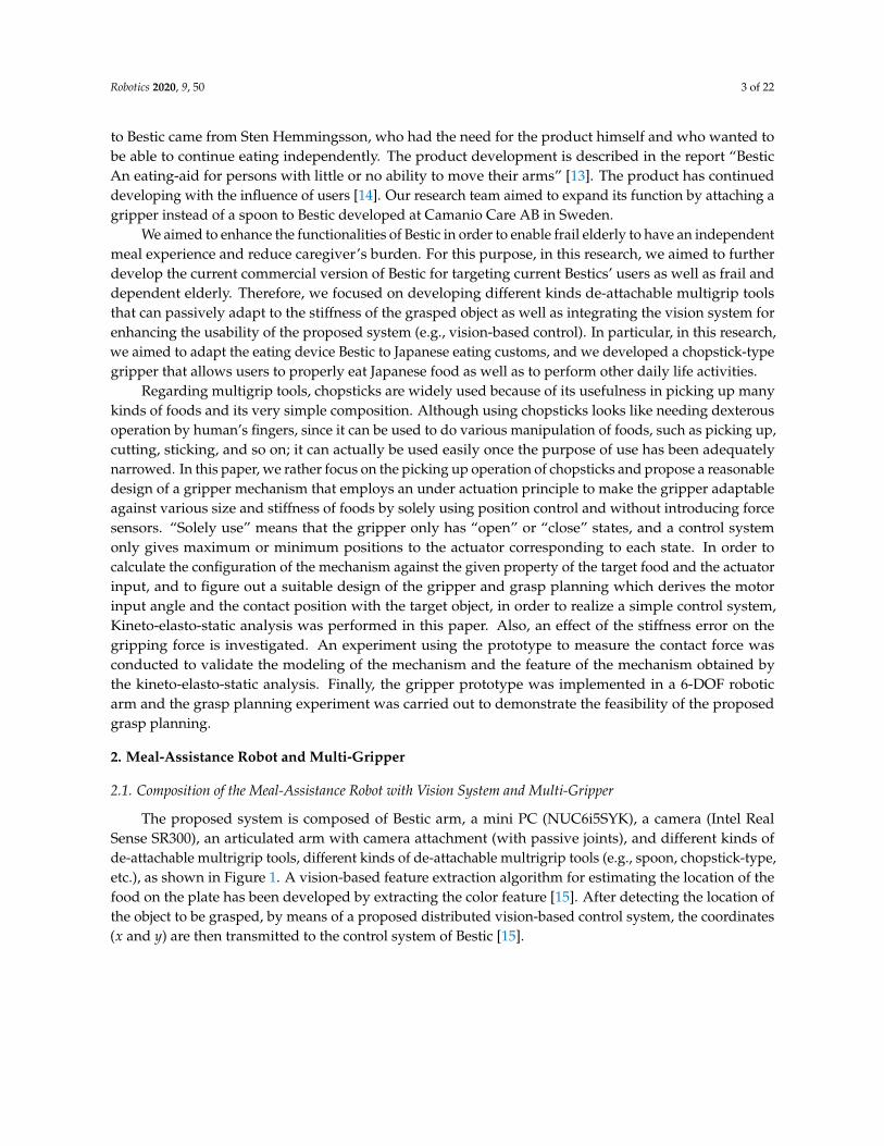
to Bestic came from Sten Hemmingsson, who had the need for the product himself and who wanted tobe able to continue eating independently. The product development is described in the report “BesticAn eating-aid for persons with little or no ability to move their arms” [13]. The product has continueddeveloping with the influence of users [14]. Our research team aimed to expand its function by attaching agripper instead of a spoon to Bestic developed at Camanio Care AB in Sweden.
We aimed to enhance the functionalities of Bestic in order to enable frail elderly to have an independentmeal experience and reduce caregiver’s burden. For this purpose, in this research, we aimed to furtherdevelop the current commercial version of Bestic for targeting current Bestics’ users as well as frail anddependent elderly. Therefore, we focused on developing different kinds de-attachable multigrip toolsthat can passively adapt to the stiffness of the grasped object as well as integrating the vision system forenhancing the usability of the proposed system (e.g., vision-based control). In particular, in this research,we aimed to adapt the eating device Bestic to Japanese eating customs, and we developed a chopstick-typegripper that allows users to properly eat Japanese food as well as to perform other daily life activities.
Regarding multigrip tools, chopsticks are widely used because of its usefulness in picking up manykinds of foods and its very simple composition. Although using chopsticks looks like needing dexterousoperation by human’s fingers, since it can be used to do various manipulation of foods, such as picking up,cutting, sticking, and so on; it can actually be used easily once the purpose of use has been adequatelynarrowed. In this paper, we rather focus on the picking up operation of chopsticks and propose a reasonabledesign of a gripper mechanism that employs an under actuation principle to make the gripper adaptableagainst various size and stiffness of foods by solely using position control and without introducing forcesensors. “Solely use” means that the gripper only has “open” or “close” states, and a control systemonly gives maximum or minimum positions to the actuator corresponding to each state. In order tocalculate the configuration of the mechanism against the given property of the target food and the actuatorinput, and to figure out a suitable design of the gripper and grasp planning which derives the motorinput angle and the contact position with the target object, in order to realize a simple control system,Kineto-elasto-static analysis was performed in this paper. Also, an effect of the stiffness error on thegripping force is investigated. An experiment using the prototype to measure the contact force wasconducted to validate the modeling of the mechanism and the feature of the mechanism obtained bythe kineto-elasto-static analysis. Finally, the gripper prototype was implemented in a 6-DOF roboticarm and the grasp planning experiment was carried out to demonstrate the feasibility of the proposedgrasp planning.
2. Meal-Assistance Robot and Multi-Gripper
2.1. Composition of the Meal-Assistance Robot with Vision System and Multi-Gripper
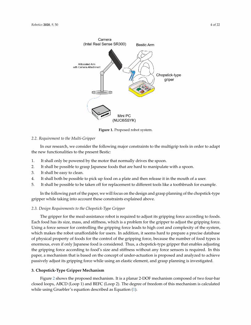
The proposed system is composed of Bestic arm, a mini PC (NUC6i5SYK), a camera (Intel RealSense SR300), an articulated arm with camera attachment (with passive joints), and different kinds ofde-attachable multrigrip tools, different kinds of de-attachable multrigrip tools (e.g., spoon, chopstick-type,etc.), as shown in Figure 1. A vision-based feature extraction algorithm for estimating the location of thefood on the plate has been developed by extracting the color feature [15]. After detecting the location ofthe object to be grasped, by means of a proposed distributed vision-based control system, the coordinates(x and y) are then transmitted to the control system of Bestic [15].
Robotics 2020, 9, 50 4 of 22
Figure 1. Proposed robot system.
2.2. Requirement to the Multi-Gripper
In our research, we consider the following major constraints to the multigrip tools in order to adaptthe new functionalities to the present Bestic:
1. It shall only be powered by the motor that normally drives the spoon.2. It shall be possible to grasp Japanese foods that are hard to manipulate with a spoon.3. It shall be easy to clean.4. It shall both be possible to pick up food on a plate and then release it in the mouth of a user.5. It shall be possible to be taken off for replacement to different tools like a toothbrush for example.
In the following part of the paper, we will focus on the design and grasp planning of the chopstick-typegripper while taking into account these constraints explained above.
2.3. Design Requirements to the Chopstick-Type Gripper
The gripper for the meal-assistance robot is required to adjust its gripping force according to foods.Each food has its size, mass, and stiffness, which is a problem for the gripper to adjust the gripping force.Using a force sensor for controlling the gripping force leads to high cost and complexity of the system,which makes the robot unaffordable for users. In addition, it seems hard to prepare a precise databaseof physical property of foods for the control of the gripping force, because the number of food types isenormous, even if only Japanese food is considered. Thus, a chopstick-type gripper that enables adjustingthe gripping force according to food’s size and stiffness without any force sensors is required. In thispaper, a mechanism that is based on the concept of under-actuation is proposed and analyzed to achievepassively adjust its gripping force while using an elastic element, and grasp planning is investigated.
3. Chopstick-Type Gripper Mechanism
Figure 2 shows the proposed mechanism. It is a planar 2-DOF mechanism composed of two four-barclosed loops, ABCD (Loop 1) and BEFC (Loop 2). The degree of freedom of this mechanism is calculatedwhile using Gruebler’s equation described as Equation (1).

Robotics 2020, 9, 50 5 of 22
F = 3(N − J − 1) +J
∑i=1
fi
= 3(7− 8− 1) + 8 = 2
(1)
where, N is the number of links, and J is the number of joints, and fi(i = 1 ∼ J) is the degree of thefreedom of the joint. In this case, all of joints are revolute pairs, thus fi = 1(i = 1 ∼ J).
Figure 2. Proposed mechanism of the gripper.
A pair of chopsticks is comprised of the base link AD with an extension and the coupler link FQ.All joints A to F are revolute-type, and only one of them, A, is actuated. Thus, te entire mechanism isunder-actuated [16–19], but, since a torsion spring is attached at joint F, connecting the links FC and FE, itsconfiguration is statically determined once the actuator’s input angle and external force on the end-effector(gripping force between chopsticks) are specified. When the chopsticks are not in contact with the foodand no external force is applied, joint F is considered to remain at a neutral angle determined by the torsionspring, and the mechanism’s configuration is thus only determined by the input angle of the actuator.In contrast, when the chopsticks contact with the food, the shape of Loop 2 changes according to thedeformation of the torsion spring due to a deterministic motion of Loop 1. Thus, Loop 1 generates thepath of the tip of the chopsticks part, and Loop 2 regulates the gripping force with an object to be grasped.Therefore, the gripping force is adjustable by the position control of the driving motor, and each of theloops can be separately designed. Additionally, the proposed mechanism has a feature to grasp an objectat the tip part and adjust its force with deformation of the torsion spring, while the other underactuatedmechanisms, such as [16–19], were designed to wrap around an object to grasp it.
4. Kineto-Elasto-Static Analysis of the Mechanism
This section addresses the kineto-elasto-static analysis of the proposed gripper mechanism. For theanalysis, the model includes the contact point with the object to be grasped, and the object is modeled as asimple compression spring. The solution of the analysis is obtained from the condition that satisfies boththe geometrical and mechanical relationship of the system. A simple computational scheme is needed inorder to reduce the calculation time. In our previous paper [20], we presented an analysis scheme whereL and φ are estimated from an assumed w and the assumed w is iteratively adjusted until the contactforce is converged. However, it suffered a high computational cost. In the present paper, a new analysisscheme that needs less calculation cost is introduced, and the calculation performance is compared with

Robotics 2020, 9, 50 6 of 22
our previous analysis scheme. Using the analysis, the relationship among the contact force of the gripper,the size and the stiffness of food, and the contact position is obtained to propose a grasp planning scheme.
4.1. Modeling of the Mechanism Including the Contact point
Under the assumption that food to be picked up is an elastic body, a kineto-elasto-static model,including the chopstick mechanism and food, is set as shown in Figure 3. In order to take the relativemotion between the food and the chopsticks into account, a prismatic pair and a revolute pair are set at thecontact point between the food and the end-effector of the mechanism on the link FQ, and the joint is set asP. A distance between joint F and joint P, and an angle of FP against the horizontal (x) axis are denoted asL and φ, respectively, and these parameters are set as unknown. f stands for the contact force. Its directionis considered to be normal to FQ, and the magnitude is denoted by a scalar f [N]. A target food is modeledas a vertical spring of which the length is set as w and the spring constant is set as K [N/m], and with itsone end point fixed on the base link AD at (xP, 0). Subsequently, the position of P is set as (xP, w), usingh, which is set as the distance from the tip and the P in x-axis direction. The initial size and deformationof the food are denoted as wo [mm] and ∆w [mm], respectively. The angle θB between links BE and BCand the virtual external torque MEX , which is added for the sake of convenience and its value should bezero, are introduced. In this paper, assumptions are made that the mechanism moves quasi-statically inthe horizontal plane where the inertial and gravitational forces and viscosity of the food can be neglected.Additionally, as for the balance of forces between the contact force and the reaction force from the food,only the y-axis component is considered, and the x-axis component is ignored, since the one end of thespring is considered being fixed on the base link AD.
Figure 3. Modeling of the mechanism including the contact point.
4.2. Analysis Scheme Introducing a Virtual Torque
The analysis scheme is referenced to [21,22] in that an additional parameter of force is set to satisfythe mechanical condition. When the input motor angle θin is given, using one parameter, all of the positionof the joints can be determined, since the whole system has 2-DOF. In the analysis scheme, the angle θB isset as the convergence parameter for determining the joint positions of the system.
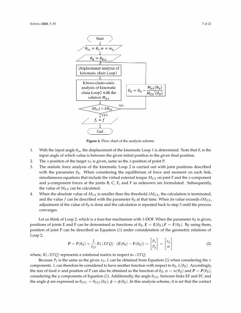
Once the x-position (xP), initial size wo, and the stiffness K of the target food are given,the configuration of the mechanism and contact force for a given input angle θin can be obtained accordingto the procedure described below and are shown in Figure 4.
Robotics 2020, 9, 50 7 of 22
Figure 4. Flow chart of the analysis scheme.
1. With the input angle θin, the displacement of the kinematic Loop 1 is determined. Note that θi is theinput angle of which value is between the given initial position to the given final position.
2. The x-position of the target xP is given, same as the x-position of point P.3. The statistic force analysis of the kinematic Loop 2 is carried out with joint positions described
with the parameter θB. When considering the equilibrium of force and moment on each link,simultaneous equations that include the virtual external torque MEX on joint F and the x-componentand y-component forces at the joints B, C, E, and F as unknown are formulated. Subsequently,the value of MEX can be calculated.
4. When the absolute value of MEX is smaller than the threshold δMEX , the calculation is terminated,and the value f can be described with the parameter θB at that time. When its value exceeds δMEX ,adjustment of the value of θB is done and the calculation is repeated back to step 3 until the processconverges.
Let us think of Loop 2, which is a four-bar mechanism with 1-DOF. When the parameter θB is given,positions of joints E and F can be determined as functions of θB, E = E(θB),F = F(θB). By using them,position of joint P can be described as Equation (2) under consideration of the geometric relations ofLoop 2,
P = F(θB) +L
lEFR( 6 EFQ) · (E(θB)− F(θB)) =
[Px
Py
]=
[xp
w
](2)
where, R( 6 EFQ) represents a rotational matrix in respect to 6 EFQ.Because Px is the same as the given xP, L can be obtained from Equation (2) when considering the x
components. L can therefore be considered to have another function with respect to θB, L(θB). Accordingly,the size of food w and position of P can also be obtained as the function of θB, w = w(θB) and P = P(θB),considering the y components of Equation (2). Additionally, the angle θEFC between links EF and FC andthe angle φ are expressed as θEFC = θEFC(θB), φ = φ(θB). In this analysis scheme, it is set that the contact

Robotics 2020, 9, 50 8 of 22
force from the gripper and the reaction force from the food are balanced in the y-direction, then theirrelationship is described as;
f cos φ = K(wo − w). (3)
From these geometrical and mechanical relations, the magnitude f and the torque τk of the torsionspring are obtained as;
f (θB) =K(wo − w(θB))
cos φ(θB),
τk(θB) = kt(θEFC,initial − θEFC(θB)).(4)
From the free body diagram of Loop 2 that is shown in Figure 5, the equilibrium of the force andmoment on each link is formulated, as follows.
Figure 5. Free body diagram included virtual torque MEX .
Link BE:FB − FE = 0
(E(θB)− B(θB))× (−FE) = 0
}(5)
Link EFQ:
FE − FF + f (θB)e(θB) = 0
τk(θB) + (E(θB)− F(θB))× FE − f (θB)L(θB) + MEX = 0
}(6)
Link FC:FF − FC = 0
−τk + (C(θB)− F(θB))× (−FC) = 0
}(7)
From Equations (4) to (7), simultaneous equations are obtained as the following Equation (8).

Robotics 2020, 9, 50 9 of 22
A(θB)
FB
FE
FF
FC
MEX
= b(θB) (8)
where,
A(θB) =
1 0 −1 0 0 0 0 0 00 1 0 −1 0 0 0 0 00 0 yE(θB)− yB −(xE(θB)− xB(θB)) 0 0 0 0 00 0 1 0 −1 0 0 0 00 0 0 1 0 −1 0 0 00 0 −(w(θB)− yF(θB)) xP(θB)− xF(θB) 0 0 0 0 10 0 0 0 1 0 −1 0 00 0 0 0 0 1 0 −1 00 0 0 0 0 0 yC − yF(θB) −(xC − xF(θB)) 0
b(θB) =[0 0 0 0 0 −τk(θB) + f (θB)L(θB) 0 0 τk(θB)
]T
By solving Equation (8), MEX = MEX(θB) is obtained. When the reaction force from the target foodand torque of the torsional spring are balanced, value of MEX should be zero. A numerical computationbased on Newton-Raphson method [21] can solve this equation regarding MEX(θB) = 0.
4.3. Comparison of the Computational Efficiency
In Figure 6, the computational efficiency of the analysis scheme is compared with the scheme of [20].Design parameter values, such as link lengths, are given in Table 1. By using the simulation based on thekinematic analysis, the initial position of the motor as 109 deg and the final position as 117.5 deg weredecided. As the motor angle is 117.5 deg, the gripper is closed and the tip of the chopstick part (point Q)reaches the other tip of the chopstick part of link AD, when there is no target object between the chopstickparts. These parameters are obtained through the process that is explained in the following section.
(a) Scale of threshold value is 1.0× 10⁻³. (b) Scale of threshold value is 1.0× 10⁻⁴.
Figure 6. Comparison of iteration times among the analysis schemes.

Robotics 2020, 9, 50 10 of 22
Table 1. Parameters of the mechanism.
Parameter Value Parameter ValuelAB 31 mm lBE 24 mmlBC 24 mm lEF 12 mmlCD 24 mm lFC 22 mmlDA 34.5 mm lFQ 115.5 mm
kt = 3.52× 10⁻² Nm/rad 6 EFC = π/2 rad
Figure 6 shows the iteration times against the sampling time (which corresponds to the inputmotor angle). The sampling time is set as 0 when the motor input angle is initial position (109 deg)and as 100 when the motor input angle reaches the final position (117.5 deg), and intermediate values arelinearly ramped. The parameters used in the analysis methods are set as wo = 15 mm, K = 1.0× 10³ N/m,h = 5 mm. Note that δ f is the threshold vale for the convergence judgement used in [20]. In order tomatch the scales of threshold value used in the two analysis schemes, in Figure 6a δ f = 1.0× 10⁻³N,δMEX = 1.0 × 10⁻³ Nm are used, and in Figure 6b δ f = 1.0 × 10⁻⁴ N, δMEX = 1.0 × 10⁻⁴ Nm areused for the computations. Figure 6a shows that the iteration times in the new scheme are constant as 2,while the iteration times in the previous scheme are decreasing from 10 as the sampling time increases,and the new scheme’s computational times are less than the previous scheme’s ones. Figure 6b showsthat the iteration times in the new scheme are constant as 2, likewise Figure 6a, while the iteration timesin the previous scheme are decreasing from 100 as the sampling time increases, and the new scheme’scomputational times are less than the previous scheme’s ones. These results are caused by that in theprevious scheme the parameter w is changed by the fixed value, while in the new scheme the parameter θBis changed by Newton-Raphson method. Also, in the previous scheme, it is needed to solve the complexnon-linear simultaneous equation, while, in new scheme, it is needed to solve the simple equation asEquation (8), and then it can be said that the cost of calculation of the new scheme is less than the one ofthe previous scheme. Therefore, the new analysis scheme is better than the previous scheme with respectto the computational efficiency. The new analysis scheme is used in the following part of this paper.
4.4. Numerical Example
Numerical examples are shown, in which the analysis scheme that is described in the previoussection is applied. The results are obtained by a numerical software MATLAB. Design parameter values,such as link lengths, are given in Table 1, and δMEX and δθB are set as δMEX = 1.0 × 10⁻¹⁰ Nm,δθB = 1.0× 10⁻¹⁰ rad, respectively.
Figure 7 shows a result of the magnitude of contact force f against the initial food size wo and thefood stiffness K when the input angle reaches the preliminarily determined target value (θin = 117.5 deg).In this analysis, ranges of wo and K are set as 1 mm to 20 mm and 0.01× 10³ N/m to 1.0× 10³ N/m,respectively. The numerical calculation was carried out with 100 divisions on each parameter. From theresult, it is figured out that the bigger initial size and stiffness result in the larger magnitude of the contactforce. The contact force seems to be constant for a wide range of stiffness among the range of wo between2 mm and 4 mm. In the range of wo between 4 mm and 11 mm, the contact force increases according to theincrements of the stiffness. Among the range of wo between 11 mm and 20 mm, while the contact forceincreases sharply within the range of K up to around 0.3× 10³ N/m, it increases smoothly in the otherrange of K. Additionally, the magnitude of force f increases monotonically as the value of the initial foodsize wo increases.
Figure 8 shows the relation between contact force f [N], food’s stiffness K [N/m] and the contactpoint h [mm]. At this time, the input angle of the driving motor θin is set as 117.5 deg, and the initial size offood wo is varied as 5 mm, 10 mm, 15 mm, 20 mm. From these results, it is figured out that the magnitude

Robotics 2020, 9, 50 11 of 22
of force f increases monotonically as the value of the distance from the tip h [mm] increases. In otherwords, it can be said that the larger distance between the contact point and the tip of the chopstick part,the larger force the mechanism outputs. Additionally, it can be said that the gripper mechanism is ableto change its gripping force actively by changing the position of the contact point, and this mechanism’sfeature can be utilized for a grasping planning in the following section.
Figure 7. Relation between contact force f and food’s size wo, food’s stiffness K as θin = 117.5 deg.
(a) wo = 5 mm (b) wo = 10 mm
(c) wo = 15 mm (d) wo = 20 mm
Figure 8. Contact force related to the stiffness and the contact position as θin = 117.5 deg.

Robotics 2020, 9, 50 12 of 22
5. Grasp Planning Considering the Characteristic of the Mechanism
This section addresses grasp planning utilizing the feature of the mechanism, that is the mechanismcan change the contact force with changing the contact position. The proposed grasp planning derives theinput motor angle and the contact position to grasp up food in order to realize a simple control system.
5.1. Grasp Planning Algorithm
The grasping of the chopstick-type gripper is modeled in order to know how much force is neededto pick up a food. The proposed mechanism is a planar mechanism, and the gripping of the target foodis established by the equilibrium of forces between the gravitational force of the food and the frictionforces from the gripper, as shown in Figure 9. Subsequently, the equilibrium of the forces is described asEquations (9) and (10) under the assumption that the two friction forces Ff riction are equal. In this case,m, g, µ are set as the mass of the food, the gravitational acceleration, and the coefficient of static friction,respectively.
2Ff riction = mg (9)
Ff riction ≤ µ fgripping (10)
Thus, to pick up the food, the gripping force is described as Equation (11) with the safety factor s(> 1)for the maximum friction force.
fgripping = smg2µ
(11)
Figure 9. Simple modeling of the grasping.
In the following, the gripping force to pick up food will be obtained by the position control of thedriving motor of the gripper mechanism and the end-effector of the manipulator in order to implement asimple control system, and the grasp planning is proposed based on it. In other words, the grasp planningaims to obtain the required force in order to pick up the food without feedback control.
The grasp planning algorithm is proposed from the results obtained from the analysis. In the paper,the grasp planning is regarded as the planning to decide the contact position and the input motor anglefor the gripper to grasp the food. Figure 10 shows the algorithm of the proposed grasp planning. For thegrasp planning, it is considered that the magnitude of the contact force f (h) = f cos φ monotonicallyincreases with respect to the contact position h when the stiffness of the food is known, as Figure 8 shows.Additionally, the range of contact point is set as 0 ≤ h ≤ hlimit. The procedure of grasp planning issummarized, as follows.

Robotics 2020, 9, 50 13 of 22
1. For the given wo, K, m and µ, the gripping force to pick up food, fgripping, is calculated byEquation (11).
2. The motor input angle θin is given, and the function f (h) is derived using the analysis.3. It is determined if the solution h exists, which satisfies f (h) = fgripping in the assumed contact range
(0 ≤ h ≤ hlimit). When the solution h exists in the range, the h is obtained by solving the equationf (h) = fgripping. When the solution h does not exist, the motor input angle is updated and thecalculation goes back to step.2.
Figure 10. Flowchart of the grasp planning based on the analysis.
5.2. Case Study of the Grasp Planning
Case studies to decide the input motor angle and the contact position by the proposed grasp planningare described. For the examples, the safety factor is set as s = 2.0, the update value of the input motorangle is set as δθin = 1 deg, and the range of the contact is set as 0 ≤ h ≤ 50 mm.
(case.1) As K = 0.5× 10³ N/m, wo = 20 mm, m = 0.025 kg, µ = 0.40
From Equation (11), the required force for grasping is fgripping = 0.613 N. From Figure 11a, when theinput motor angle is θin = 117.5 deg, h which satisfies f (h) = fgripping exists, and the solution ish = 33.43 mm. Figure 11b shows that the calculation is converged.

Robotics 2020, 9, 50 14 of 22
(a) The result of grasp point (b) Convergence of the calculation
Figure 11. The result of grasp planning of case.1.
(case.2) As K = 0.1× 10³ N/m, wo = 10 mm, m = 0.020 kg, µ = 0.35
From Equation (11), the required force for grasping is fgripping = 0.420 N. From Figure 12a, when theinput motor angle is θin = 117.5 deg, h, which satisfies f (h) = fgripping does not exist, then the inputmotor angle is updated. From Figure 12a, when the input motor angle is θin = 118.5 deg, the h whichsatisfies f (h) = fgripping exists, and the solution is h = 40.89 mm. Figure 12b shows that the calculationis converged.
(a) The result of grasp point (b) Convergence of the calculation
Figure 12. The result of grasp planning of case.2.
In this paper, it is assumed that the parameters of the food such as dimensions, mass and stiffnessare obtained from the database based on the measurement by the vision system. Then, the error ofthese parameter values is inevitable. Here, let us investigate the effect of the error of stiffness value,which seems the most difficult to get precise value among the parameters, on the gripping performancethrough examples. The error of the stiffness K is considered under an assumption that its value includes

Robotics 2020, 9, 50 15 of 22
maximum error by 20 % of its nominal value. Two cases of nominal stiffness values: K = 0.5× 10³ N/mand K = 0.1× 10³ N/m for θin = 117.5 deg, and h = 5 mm are considered. Taking into considerationthe maximum 20 % error in stiffness, we obtained that the contact forces vary between 0.314 N (−0.94%)and 0.319 N (+0.63 %) (nominal value: 0.317 N) for K = 0.5× 10³ N/m, and between 0.267 N (−3.96 %)and 0.285 N (+2.52 %) (nominal value: 0.278 N) for K = 0.1× 10³ N/m, respectively. From these results,it is known that the sensitivity of the stiffness error on the contact force error is low while the stiffnessfor soft food is more sensitive to the contact force than for hard food. Therefore, it can be said that theproposed mechanism can achieve a stable gripping under the existence of the estimated stiffness valueerror. In the case where a quite sensitive force control is required to handle a very delicate food, in order toavoid hurting the food, a feedback control system, such as an impedance control system, may be applied.Even in such a case, a low-cost control system may be constructed by adding an angular displacementsensor at joint F to measure the spring force, which is based on the advantage of the proposed mechanism.
6. Design, Prototyping and Experiment
6.1. Design of the Prototype
The design process for determining the parameter values as shown in such as Table 1 is described.As for the design of the mechanism, the property of the food is set as Table 2. First of all, the whole size ofthe mechanism is determined. The length of chopstick is set on 100 mm considering on the length of realchopsticks, and the mechanism should be small enough to set as the end-effector of the meal assistancerobot. In this case, the total size of two loops was set to be about 40 mm× 40 mm. Subsequently, the lengthof each link of Loop 1(lAB, lBC, lCD, lDA) was determined so that the path of the chopstick part is close to theactual movement of chopsticks. Next, the length of each link of Loop 2 (lBE, lEF, lFC) is determined, so thatthe larger the size of the food is, the lager the contact force outputs. At this time, the parameters were set,so that the contact force monotonously increases according to the increase of the motor input angle θin whenthe stiffness of food K is constant and the size is changed. In addition, the range of the motor input angleθin is set so that the tip of the chopstick part matches when the maximum θin is given in the initial loop withthe grasp planning algorithm in Figure 10 when there is no target object. Finally, the spring constant of thetorsion spring installed kt was determined. The used torsion spring is a linear spring, and the order of thecontact force is determined by the value of the spring constant. From Equation (11) and Table 2, the order ofthe required gripping force was determined and, with the safety factor s = 2.0, the maximum force wasdetermined as fgripping = 0.98 N, then the spring constant was determined. The prototype was fabricatedusing 3D printer as shown in Figure 13. The prototype has a double supported structure, and the actuatorused for the prototype was VS-12M servo (Vigor Precision Ltd.).
Table 2. Parameter of target food.
Mass m [g] 0 < m ≤ 30Initial width wo [mm] 5 ≤ wo ≤ 20
Friction coefficient µ [-] 0.3 ≤ µStiffness K[×103 N/m] 0.01 ≤ K ≤ 1.0

Robotics 2020, 9, 50 16 of 22
Figure 13. Gripper prototype fabricated using 3D printer (bird’s eye view).
6.2. Experiment Using the Gripper Prototype with Changing the Contact Point
An experiment to measure the contact force with changing the contact position and the stiffness ofthe contacted object was carried out in order to validate the modeling of the mechanism including thecontact point and the results of the kineto-elasto-static analysis that the gripper can change its contact forceaccording to the size and the stiffness of food, and the contact position. In the experiment, the reactionforce from the food (K∆w [N]) was measured through a force gauge with an attachment including acompression spring, and the measured values were compared with the theoretical result of the analysis( f cos φ [N]) based on Equation (3). Figure 14 shows the experimental setup with the gripper prototype tomeasure the contact force from link EFQ. The experimental setup was composed of the gripper prototype,a linear guide with a measure, and a force gauge with an attachment having a compression spring.The input angle of the motor was controlled by PWM control using a microcomputer Arduino Mega.The resolution of the motor angle was 0.1 deg. The linear guide enabled the gripper to change the contactpoint. The displacement was measured by the scale alongside the linear guide. The attachment of the forcegauge is shown in Figure 15, and it was fabricated with a three-dimensional (3D) printer. This attachmentreproduced the characteristic of the food having an stiffness and the modeling of the mechanism, as shownin Figure 3. The force gauge was DS2-20N (IMADA), and the resolution was 0.01 N. The compressionspring in the attachment was replaced to change the spring constant, and the linear bushes inside theattachment made the contact point move smoothly. The experiment was carried out with changing thespring constant, using five kinds of spring, of which spring constant: 0.05× 10³ N/m, 0.1× 10³ N/m,0.3× 103 N/m, 0.5× 10³ N/m,and 1.0× 10³ N/m. Additionally, the contact point was changed in thearea as 0 mm ≤ h ≤ 50 mm, and the contact force was measured at every 10 mm of h. As for the inputangle of the driving motor of the gripper, the input was set as θin = 117.5, 118.5, 119.5, and 120.5 deg.In the experiment, the measured values were set as the average of the five times measurement values.

Robotics 2020, 9, 50 17 of 22
Figure 14. Experimental setup to measure the contact force with changing the contact position.
Figure 15. Attachment of the force gauge.
Figure 16 shows examples of the experimental results to measure the contact force with comparing theresults of the theoretical analysis. In the figures, the theoretical value was calculated by f cos φ [N], and themeasured value was obtained by K∆w [N] in Equation (3).The maximum difference between the measuredvalue and the theoretical value was 0.06 N when wo = 15 mm, K = 1.0× 10³ N/m, θin = 120, h = 40 mm.The main reason of these differences is considered to come from the x-component of the contact forcef sin φ. In the analysis, the x-component of the contact force f sin φ was neglected. The value is small whenthe value φ is small, so the influence seems small. However, when the φ becomes big, the influence ofx-component of the contact force f sin φ cannot be neglected, and the force seems to affect the movementof the attachment of the force gauge. When considering that the resolution of the force gauge was 0.01 N,the deviations between the theoretical values and measured values were small when the spring constantwas set as K = 0.05× 10³ N/m, K = 0.1× 10³ N/m and K = 0.5× 10³ N/m. Thus, it can be said that theanalysis is validated through the experiment.

Robotics 2020, 9, 50 18 of 22
(a) wo = 5 mm, K = 0.05× 10³ N/m (b) wo = 10 mm, K = 0.1× 10³ N/m
(c) wo = 15 mm, K = 0.3× 10³ N/m (d) wo = 20 mm, K = 0.5× 10³ N/m
Figure 16. Comparisons between the experimental value and the theory value (Example).
6.3. Experiment of the Grasp Planning with 6-DOF Robot Arm
An experiment using 6-DOF robot arm was carried out in order to demonstrate the feasibility ofthe grasp planning proposed in the previous section. Figure 17 shows the experimental set up, which iscomposed of 6-DOF robot arm (LR Mate 200iD/4S, FANUC) and the gripper prototype, which is the sameas the one used for the experiment in the previous section. The gripper prototype was implementedto the robot arm with the connected part which was fabricated by a 3D printer. In this experiment,the displacement of the gripper was controlled by the manual controller of the robot arm, and theorientation of the gripper was kept constant (the value of the orientation of the end-effector was set asroll = 33, pitch = −67, yaw = −176). The motor angle of the gripper was controlled through ArduinoMega, which the same one used in the previous experiment.

Robotics 2020, 9, 50 19 of 22
Figure 17. Experimental setup with 6-DOF robot arm
In the experiment, the target food was sushi roll, as shown in Figure 18, and the width to be graspedwas measured as 16.6 mm, and the mass was measured as m = 0.0131 kg. From [23], the stiffness of sushiroll was obtained as K = 0.31× 10³ N/m, and the viscosity of the food was neglected in the experiment.Additionally, the coefficient of friction was roughly set as µ = 0.4 referencing [24]. From Equation (11),the required force for grasping was fgripping = 0.320 N. From Figure 19a, when the input motor angle isθin = 117.5 deg, h, which satisfies f (h) = fgripping exists, and the solution was obtained as h = 2.10 mm.Figure 19b shows that the calculation is converged.
Figure 18. Target food.
Figure 20 shows the grasping experiment using the 6-DOF robot arm. From the grasp planning,the input parameters were obtained as θin = 117.5 deg and h = 2.1 mm, and these parameters were usedin the experiment. Note that the actual contact point was not point contact, and the grasping was carriedout at the area where 0 ≤ h ≤ 10 mm. From the figure, it was observed that the gripper successfullypicked up the target food. From the result, the proposed grasp planning was confirmed to be effectiveunder the experimental condition.

Robotics 2020, 9, 50 20 of 22
(a) The result of grasp point. (b) Convergence of the calculation.
Figure 19. The result of grasp planning.
Figure 20. Grasping test with 6-DOF robot arm.
7. Conclusions
In this paper, a chopstick-type gripper mechanism based on the concept of under-actuation andsolely use of position control, which is capable of adapting its shape and contact force according to sizeand stiffness of target foods, was proposed. Modeling of the mechanism, including the contact withtarget food having stiffness, has been done in order to design a practical gripper. Based on this model,an analysis scheme based on iterative calculations of kineto-elasto-static analysis has been formulated andshown to be improved through comparison with the other analysis scheme of our previous work fromthe point of view of the computational efficiency. Based on the result of analysis, it is revealed that theproposed mechanism is able to adjust its contact force according to the size and stiffness of target foods,

Robotics 2020, 9, 50 21 of 22
and that the gripper mechanism is able to change its gripping force according to the contact position withthe target object, which is utilized for the grasp planning that determines the contact position suitable forits grasping. Through examples, it has been revealed that the contact force of the proposed mechanismis less sensitive against the stiffness error. While using the gripper prototype, the contact force wasmeasured by a force gauge with an attachment having a spring with changing the contact point with alinear guide. From the result of the experiment, the modeling of mechanism in the kineto-elasto-staticanalysis and the mechanism’s feature that the mechanism can change its contact force according to the sizeand stiffness and the contact position with the object was validated. Additionally, using the 6-DOF robotarm, the grasping test of a real food was conducted utilizing the proposed grasp planning. The gripperwas able to lift up the food using the input parameters obtained by the grasp planning, and the feasibilityof the grasp planning was confirmed. For future works, experiments to grasp other kinds of food will becarried out in order to decide the scope of the application of the gripper. Additionally, a control systemutilizing some feedback signal without implementing complex and expensive instruments based on theimpedance control will be introduced to achieve more stable and appropriate gripping a wide variety offoods. Furthermore, in addition to the gripper mechanism and its control system, future work includes thedesign of the gripper with different shape of the end-effector for more practical development.
Author Contributions: Conceptualization, T.O.; Investigation, T.O.; Methodology, T.O.; Project administration,J.S., A.-L.L. and Y.T. Resources, T.O., Supervision, D.M. and Y.S.; Validation, Y.T.; Writing—original draft, T.O.;Writing-Review & Editing, J.S., A.-L.L., D.M., Y.S. and Y.T. All authors have read and agreed to the published versionof the manuscript.
Funding: This work was carried out as a part of the SICORP under the responsibility of the Japan Science andTechnology Agency (JST) and was supported in part by JSPS KAKENHI JP17H03162.
Conflicts of Interest: The authors declare no conflict of interest.
References
1. The WHOQOL Group. The World Health Organization quality of life assessment (WHOQOL): Developmentand general psychometric properties. Soc. Sci. Med. 1998, 46, 1569–1585. [CrossRef]
2. Nyberg, M.; Olsson, V.; Pajalic, Z.; Örtman, G.; Andersson, H.S.; Blücher, A.; Wendin, K.; Westergren, A.Eating difficulties, nutrition, meal preferences and experiences among elderly: A literature overview from aScandinavian context. J. Food Res. 2015, 4, 22–37. [CrossRef]
3. Topping, M.; Smith, J. The development of Handy 1, a rehabilitation robotic system to assist the severely disabled.Ind. Rob. 1998, 25, 316–320 [CrossRef]
4. Yamasaki, A.; Fukushima, M.; Masuda, R. Trial manufacture of the meal assistance robot using chopsticks andcontrol of grasp force for foods. Rob. Soc. Jpn. 2012, 30, 917–923. [CrossRef]
5. Soyama, R. The development of meal-assistance robot ’My Spoon’. In Proceedings of the 8th InternationalConference on Rehabilitation Robotics, Taejon, Korea, 23–25 April 2003; pp. 88–91.
6. Secom. My spoon. Available online: https://www.secom.co.jp/english/myspoon/ (accessed on 25 January 2020).7. Michaelis, J. Introducing the neater eater. Action Res. 1988, 6, 2–3.8. NeaterSolutions. Neater Eater. Available online: https://neater.co.uk/neater-eater/ (accessed on 25 January 2020).9. Products Incorporated 2003, R. Meal buddy. Available online: http://www.richardsonproducts.com/mealbud
dy.html (accessed on 25 January 2020).10. Copilusi, C.; Ceccarelli, M. An application of LARM clutched arm for assisting disabled people. Int. J.
Mech. Control 2015, 16, 57–66.11. Song, W.K.; Kim, J. Novel assistive robot for self-feeding. Rob. Syst. Appl. Control Program. 2012, 1, 43–60.12. EU-Japan Centre for Industrial Cooperation. Japan-Sweden Academia-Industry International Collaboration.
Available online: https://www.eu-japan.eu/news/bilateral-call-japan-sweden-academia-industry-international-collaboration (accessed on 25 January 2020).

Robotics 2020, 9, 50 22 of 22
13. Norén A-L. Bestic: An Eating-Aid for Persons with Little or No Ability to Move Their Arms. Master’s Thesis,Chalmers University of Technology, Gothenburg, Sweden, 2005.
14. Lindborg, A.L.; Lindén, M. Development of an eating aid - from the user needs to a product. Stud. HealthTechnol. Inf. 2015, 211, 191–198.
15. Solis, J.; Karlsson, C.; Ogenvall, M.; Lindborg, A.L.; Takeda, Y.; Zhang, C. Development of a vision-based featureextraction for food intake estimation for a robotic assistive eating device. In Proceedings of the 2018 IEEE 14thInternational Conference on Automation Science and Engineering (CASE). Munich, Germany, 20–24 August 2018;pp. 1105–1109.
16. Birglen, L.; Gosselin, C.M. Kinetostatic analysis of underactuated fingers. IEEE Trans. Rob. Autom. 2004,20, 211–221. [CrossRef]
17. Stavenuiter, R.A.; Birglen, L.; Herder, J.L. A planar underactuated grasper with adjustable compliance.Mech. Mach. Theory 2017, 112, 295–306. [CrossRef]
18. Fukaya, N.; Asfour, T.; Dillmann, R.; Toyama, S. Development of a five-finger dexterous hand without feedbackcontrol: The TUAT/Karlsruhe humanoid hand. In Proceedings of the 2013 IEEE/RSJ International Conferenceon Intelligent Robots and Systems, Tokyo, Japan, 3–7 November 2013; pp. 4533–4540.
19. Ueno, T.; Oda, M. Development of an index finger for the dexterous hand for space. J. Rob. Soc. Jpn. 2010,28, 349–359. [CrossRef]
20. Oka, T.; Matsuura, D.; Sugahara, Y.; Solis, J.; Lindborg, A.; Takeda, Y. Chopstick-type Gripper Mechanism forMeal-Assistance Robot Capable of Adapting to Size and Elasticity of Foods. In Mechanism Design for Robotics;Springer: Cham,Switzerland, 2018; pp. 284–292.
21. Suwa, T.; Iwatsuki, N.; Ikeda, I. Kinematic Analysis and synthesiS of Flexible Mechanism Composed ofUnderactuated Mechanism Constrained with Elastic Element. In Proceedings of the Mechanical EngineeringCongress, Hokkaido, Japan, 14 September 2015; S1170203.
22. Iwatsuki, N.; Kotte, T.; Morikawa, K. Simultaneous control of the motion and stiffness of redundant closed-looplink mechanisms with elastic elements. J. Mech. Sci. Technol. 2010, 24, 285–288. [CrossRef]
23. Sakamoto, N.; Yuya, M.; Higashimori, M.; Kaneko, M. An Optimum Design for Handling a Visco-elastic ObjectBased on Maxwell Model. J. Rob. Soc. Jpn. 2007, 25, 166–172. [CrossRef]
24. Editorical Commitee of “Shokuhin-kagaku-binran”. Shokuhin-Kagaku-Binran; Kyoritsu Shuppan Co, Ltd.: Tokyo,Japan, 1978; p. 265. (In Japanese)
c© 2020 by the authors. Licensee MDPI, Basel, Switzerland. This article is an open accessarticle distributed under the terms and conditions of the Creative Commons Attribution (CCBY) license (http://creativecommons.org/licenses/by/4.0/).