


Wind models for simulation of power fluctuations from wind farms
Upload
khangminh22Category
view
4download
0
i
Wind BoardMS-7314 (v1.X) Mainboard
G52-73141X1
PDF created with pdfFactory Pro trial version www.pdffactory.com

ii
Copyright Notice
The material in this document is the in tellectual property of MICRO-STARINTERNATIONAL. We take every care in the preparation of this document, but noguarantee is given as to the correctness of its contents. Our products are undercontinual improvement and we reserve the right to make changes without notice.
Trademarks
All trademarks are the properties of their respective owners.
NVIDIA, the NVIDIA logo, DualNet, and nForce are registered trademarks or trade-marks of NVIDIA Corporation in the United States and/or other countries.AMD, Athlon™, Athlon™ XP, Thoroughbred™, and Duron™ are registered trade-marks of AMD Corporation.Intel® and Pentium® are registered trademarks of Intel Corporation.PS/2 and OS®/2 are registered trademarks of International Business MachinesCorporation.Windows® 95/98/2000/NT/XP/Vista are reg istered trademarks of MicrosoftCorporation.Netware® is a registered trademark of Novell, Inc.Award® is a registered trademark of Phoenix Technologies Ltd.AMI® is a registered trademark of American Megatrends Inc.
Revision History
Revision Revision History DateV1.0 First release for PCB 1.X June 2008
Technical Support
If a problem arises with your system and no solution can be obtained from the user’smanual, please contact your place of purchase or local distributor. Alternatively,please try the following help resources for further guidance.
Visit the MSI website for FAQ, technical guide, BIOS updates, driver updates,and oth er in formation : http:/ /glob al.msi.com.tw /ind ex.p hp?func=serviceContact our technical staff at: http://ocss.msi.com.tw
PDF created with pdfFactory Pro trial version www.pdffactory.com

iii
Safety Instructions
CAUTION: Danger of exp losion if battery is incorrect ly rep laced.Replace only with the same or equivalent type recommended by themanufacturer.
1. Always read the safety instructions carefully.2. Keep this User’s Manual for future reference.3. Keep this equipment away from humidity.4. Lay this equipment on a reliable flat surface before setting it up.5. The openings on the enclosure are for air convection hence protects the equip-
ment from overheating. DO NOT COVER THE OPENINGS.6. Make sure the voltage of the power source and adjust properly 110/220V be-
fore connecting the equipment to the power inlet.7. Place the power cord such a way that people can not step on it. Do not place
anything over the power cord.8. Always Unplug the Power Cord before inserting any add-on card or module.9. All cautions and warnings on the equipment should be noted.10. Never pour any liquid into the opening that could damage or cause electrical
shock.11. If any of the following situations arises, get the equipment checked by service
personnel:Ü The power cord or plug is damaged.Ü Liquid has penetrated into the equipment.Ü The equipment has been exposed to moisture.Ü The equipment does not work well or you can not get it work according to
User’s Manual.Ü The equipment has dropped and damaged.Ü The equipment has obvious sign of breakage.
12. DO NOT LEAVE THIS EQUIPMENT IN AN ENVIRONMENT UNCONDITIONED, STOR-AGE TEMPERATURE ABOVE 600 C (1400F), IT MAY DAMAGE THE EQUIPMENT.
PDF created with pdfFactory Pro trial version www.pdffactory.com

iv
FCC-B Radio Frequency Interference Statement
This equipment has beentested and found to complywith the limits for a Class Bdigital device, pursuant to Part15 of the FCC Rules. These limits are designed to provide reasonable protectionagainst harmful interference in a residential installation. This equipment generates,uses and can radiate radio frequency energy and, if not installed and used in accor-dance with the instructions, may cause harmful interference to radio communications.However, there is no guarantee that interference will not occur in a particularinstallation. If this equipment does cause harmful interference to radio or televisionreception, which can be determined by turning the equipment off and on, the user isencouraged to try to correct the interference by one or more of the measures listedbelow.
Ü Reorient or relocate the receiving antenna.
Ü Increase the separation between the equipment and receiver.
Ü Connect the equipment into an outlet on a circuit different from that towhich the receiver is connected.
Ü Consult the dealer or an experienced radio/television technician for help.
Notice 1The changes or modifications not expressly approved by the party responsible forcompliance could void the user’s authority to operate the equipment.
Notice 2Shielded interface cables and A.C. power cord, if any, must be used in order tocomply with the emission limits.
VOIR LA NOTICE D’INSTALLATION AVANT DE RACCORDER AU RESEAU.
Micro-Star InternationalMS-7314
This device complies with Part 15 of the FCC Rules. Operation is subject to thefollowing two conditions:(1) this device may not cause harmful interference, and(2) this device must accept any interference received, including interference that
may cause undesired operation.
PDF created with pdfFactory Pro trial version www.pdffactory.com

v
WEEE (Waste Electrical and Electronic Equipment) Statement
PDF created with pdfFactory Pro trial version www.pdffactory.com
viii
CONTENTSCopyright Notice .................................................................................................... iiTrademarks ............................................................................................................ iiRevision History .................................................................................................... iiTechnical Support ................................................................................................. iiSafety Instructions ................................................................................................ iiiFCC-B Radio Frequency Interference Statement ................................................... ivWEEE (Waste Electrical and Electronic Equipment) Statement ................................ vChapter 1. Getting Started ............................................................................. 1-1
Mainboard Specifications ............................................................................. 1-2Mainboard Layout ........................................................................................ 1-4Packing Checklist ......................................................................................... 1-5
Chapter 2. Hardware Setup ............................................................................ 2-1Quick Components Guide ............................................................................. 2-2Memory ....................................................................................................... 2-3Power Supply .............................................................................................. 2-7Back Panel ................................................................................................. 2-10Connectors ................................................................................................ 2-12Jumper ...................................................................................................... 2-17Slot ............................................................................................................ 2-18
Chapter 3 BIOS Setup ...................................................................................... 3-1Entering Setup ............................................................................................. 3-2The Main Menu ............................................................................................. 3-4Standard CMOS Features ............................................................................ 3-6Advanced BIOS Features ............................................................................ 3-9Integrated Peripherals ................................................................................ 3-12Power Management Setup ......................................................................... 3-14H/W Monitor ............................................................................................... 3-17BIOS Setting Password .............................................................................. 3-18Cell Menu ................................................................................................... 3-19Load Fail-Safe/ Optimized Defaults ............................................................ 3-22
PDF created with pdfFactory Pro trial version www.pdffactory.com
1-1
Getting Started
Getting StartedChapter 1
Thank you for choosing the Wind Board (MS-7314 v1.X) Micro-ATX mainboard. The Wind Board is based onIntel® brand new Atom CPU and 945GC + ICH7 chipsetsfor optimal system efficiency. The Wind Board deliversa high performance and professional desktop platformsolution.
PDF created with pdfFactory Pro trial version www.pdffactory.com
MS-7314 Mainboard
1-2
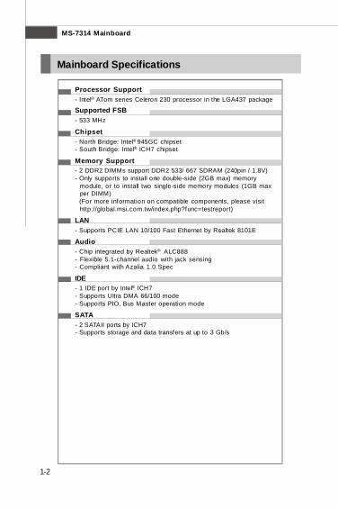
Mainboard Specifications
Processor Support- Intel® ATom series Celeron 230 processor in the LGA437 package
Supported FSB- 533 MHz
Chipset- North Bridge: Intel® 945GC chipset- South Bridge: Intel® ICH7 chipset
Memory Support- 2 DDR2 DIMMs support DDR2 533/ 667 SDRAM (240pin / 1.8V)- Only supports to install one double-side (2GB max) memory
module, or to install two single-side memory modules (1GB maxper DIMM)
(For more information on compatible components, please visithttp://global.msi.com.tw/index.php?func=testreport)
LAN- Supports PCIE LAN 10/100 Fast Ethernet by Realtek 8101E
Audio- Chip integrated by Realtek® ALC888- Flexible 5.1-channel audio with jack sensing- Compliant with Azalia 1.0 Spec
IDE- 1 IDE port by Intel® ICH7- Supports Ultra DMA 66/100 mode- Supports PIO, Bus Master operation mode
SATA- 2 SATAII ports by ICH7- Supports storage and data transfers at up to 3 Gb/s
PDF created with pdfFactory Pro trial version www.pdffactory.com
1-3
Getting Started
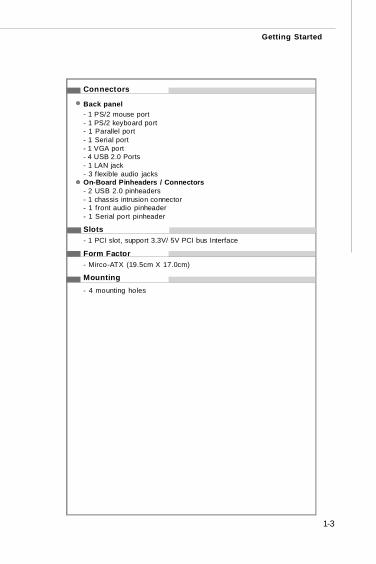
Connectors
Back panel- 1 PS/2 mouse port- 1 PS/2 keyboard port- 1 Parallel port- 1 Serial port- 1 VGA port- 4 USB 2.0 Ports- 1 LAN jack- 3 f lexible audio jacksOn-Board Pinheaders / Connectors- 2 USB 2.0 pinheaders- 1 chassis intrusion connector- 1 front audio pinheader- 1 Serial port pinheader
Slots- 1 PCI slot, support 3.3V/ 5V PCI bus Interface
Form Factor- Mirco-ATX (19.5cm X 17.0cm)
Mounting- 4 mounting holes
PDF created with pdfFactory Pro trial version www.pdffactory.com
MS-7314 Mainboard
1-4
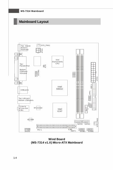
Wind Board(MS-7314 v1.X) Micro-ATX Mainboard
Mainboard Layout
PCI 1JAUD1
ALC888
RTL8101E IntelICH7
IDE
1
ATX
1DIM
M1
DIM
M2
JFP
1JF
P2
SY
S_F
AN
2
JUSB2JUSB1JBAT1
SATA1 SATA2
JCI1
JPW
1
JCO
M1
BAT
T+
Top: LAN jackBottom: USB ports
USB ports
Top : mouse Bottom:keyboard
Top : Parallel Port
Bottom: COM port VGA port
T:M:B:
Line-InLine-OutMic
Intel945GC
IntelDiamondville
CPU
SYS_FAN1
PDF created with pdfFactory Pro trial version www.pdffactory.com
1-5
Getting Started
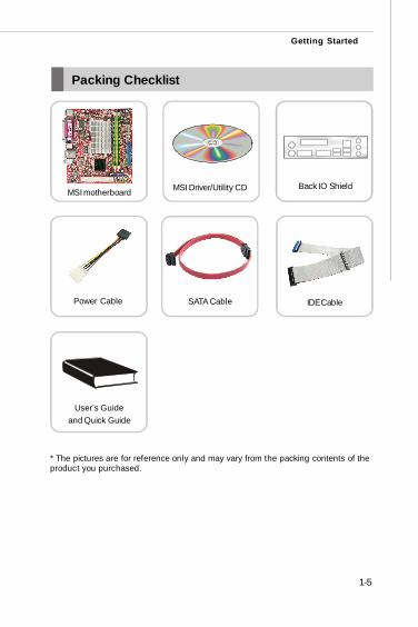
Packing Checklist
* The pictures are for reference only and may vary from the packing contents of theproduct you purchased.
Power Cable
User’s Guideand Quick Guide
MSI motherboard MSI Driver/Utility CD
IDE Cable
Back IO Shield
SATA Cable
PDF created with pdfFactory Pro trial version www.pdffactory.com
2-1
Hardware Setup
Hardware SetupChapter 2
This chapter provides you with the information abouthardware setup procedures. While doing the installation,be careful in holding the components and follow theinstallation procedures. For some components, if youinstall in the wrong orientation, the components will notwork properly.
Use a grounded wrist strap before handling computercomponents. Static electricity may damage thecomponents.
PDF created with pdfFactory Pro trial version www.pdffactory.com
MS-7314 Mainboard
2-2
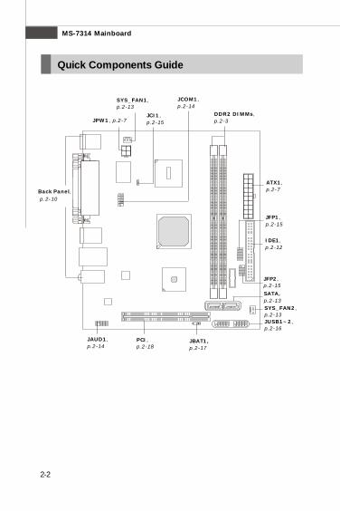
Quick Components Guide
DDR2 DIMMs,p.2-3
ATX1,p.2-7
SATA,p.2-13
JUSB1~2,p.2-16
JAUD1,p.2-14
PCI,p.2-18
Back Panel, p.2-10
JPW1, p.2-7
SYS_FAN2,p.2-13
IDE1,p.2-12
JBAT1,p.2-17
JCOM1,p.2-14
JFP1,p.2-15
JFP2,p.2-15
JCI1,p.2-15
SYS_FAN1,p.2-13
PDF created with pdfFactory Pro trial version www.pdffactory.com
2-3
Hardware Setup
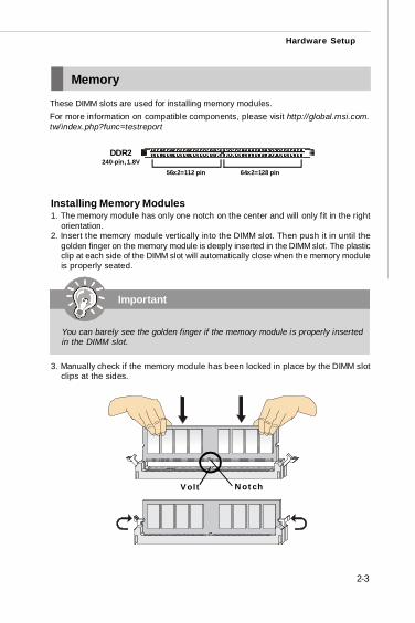
Memory
These DIMM slots are used for installing memory modules.For more information on compatible components, please visit http://global.msi.com.tw/index.php?func=testreport
DDR2240-pin, 1.8V
64x2=128 pin56x2=112 pin
Installing Memory Modules1. The memory module has only one notch on the center and will only fit in the right
orientation.2. Insert the memory module vertically into the DIMM slot. Then push it in until the
golden finger on the memory module is deeply inserted in the DIMM slot. The plasticclip at each side of the DIMM slot will automatically close when the memory moduleis properly seated.
3. Manually check if the memory module has been locked in place by the DIMM slotclips at the sides.
Important
You can barely see the golden finger if the memory module is properly insertedin the DIMM slot.
Volt Notch
PDF created with pdfFactory Pro trial version www.pdffactory.com
MS-7314 Mainboard
2-4
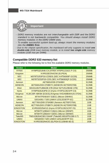
Important
- DDR2 memory modules are not interchangeable with DDR and the DDR2standard is not backwards compatible. You should always instal l DDR2memory modules in the DDR2 DIMM slots.
- To enable successful system boot-up, always insert the memory modulesinto the DIMM1 first.
- Due to the chipset specification, the mainboard will only supports to install onedouble-side (2GB max) memory module, or to install two single-side memorymodules (1GB max per DIMM).
Compatible DDR2 533 memory listPlease refer to the following list to find the available DDR2 memory modules.
Vendor Model SizeHYNIX HYMP532U646-C4 (HYNIX HY5PS121621 F-C4) 256MB
Kingston KVR533D2N4/256 (ELPIDA) 256MBSEC M378T3253FG0-CD5DS (SEC K4T56083F-GCD5) 256MBSEC M378T3253FG0-CD5 (SEC K4T56083QF-GCD5) 256MB
Aeneon AET660UD00-370A98X 512MBAENEON AET660UD00-370B97X (AENEON AET93R370B) 512MB
Elixir M2U51264TU88A2B-37B (Elixir N2TU51280AE-37B) 512MBHynix HYMP564U64P8-C4 (Hynix HY5PS12821FP-C4) 512MB
Kingmax KLBC28F-A8KB4 [EGES] (Kingmax KKEA88B4IAUG-37DA) 512MBMicron MT4HTF6464AY-53EE1 (Micron D9HNV) 512MBUMAX 53014051-7100 (UMAX U2S12D30TP-5C) 512MB
Aeneon AET760UD00-370A98X (Aeneon AET93F370A) 1GBAENEON AET760UD00-370B97X (AENEON AET93R370B) 1GB
KINGSTON KVR533D2N4/1G (Hynix HY5PS12821CFP-Y5) 1GBMicron MT8HTF12864AY-53EA1 (Micron D9DMT) 1GBMicron MT8HTF12864AY-53EE1 (Micron D9HNH) 1GB
TakeMS TMS1GB264C081-534AP (TakeMS MS18T51280-3.7) 1GBUMAX 53016033-7100 (UMAX U2S12D30TP-5C) 1GB
KINGSTON KVR533D2N4/2G (ELPIDA E1108AB-6E-E) 2GB
PDF created with pdfFactory Pro trial version www.pdffactory.com
2-5
Hardware Setup
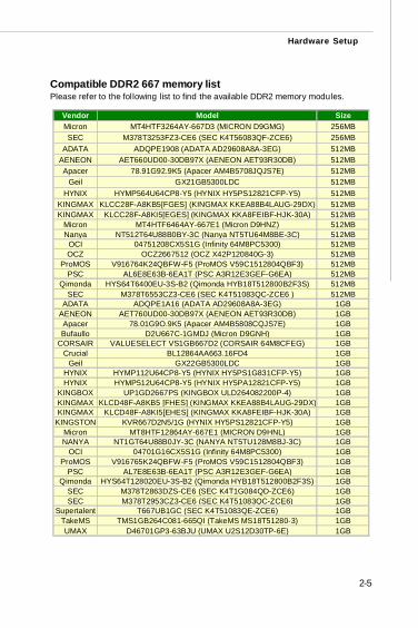
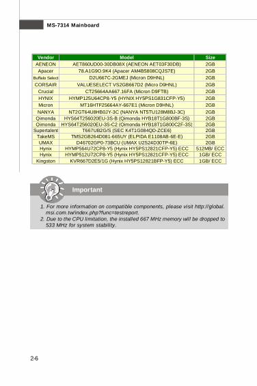
Compatible DDR2 667 memory listPlease refer to the following list to find the available DDR2 memory modules.
Vendor Model SizeMicron MT4HTF3264AY-667D3 (MICRON D9GMG) 256MBSEC M378T3253FZ3-CE6 (SEC K4T56083QF-ZCE6) 256MB
ADATA ADQPE1908 (ADATA AD29608A8A-3EG) 512MBAENEON AET660UD00-30DB97X (AENEON AET93R30DB) 512MBApacer 78.91G92.9K5 (Apacer AM4B5708JQJS7E) 512MB
Geil GX21GB5300LDC 512MBHYNIX HYMP564U64CP8-Y5 (HYNIX HY5PS12821CFP-Y5) 512MB
KINGMAX KLCC28F-A8KB5[FGES] (KINGMAX KKEA88B4LAUG-29DX) 512MBKINGMAX KLCC28F-A8KI5[EGES] (KINGMAX KKA8FEIBF-HJK-30A) 512MB
Micron MT4HTF6464AY-667E1 (Micron D9HNZ) 512MBNanya NT512T64U88B0BY-3C (Nanya NT5TU64M8BE-3C) 512MB
OCI 04751208CX5S1G (Infinity 64M8PC5300) 512MBOCZ OCZ2667512 (OCZ X42P120840G-3) 512MB
ProMOS V916764K24QBFW-F5 (ProMOS V59C1512804QBF3) 512MBPSC AL6E8E63B-6EA1T (PSC A3R12E3GEF-G6EA) 512MB
Qimonda HYS64T6400EU-3S-B2 (Qimonda HYB18T512800B2F3S) 512MBSEC M378T6553CZ3-CE6 (SEC K4T51083QC-ZCE6 ) 512MB
ADATA ADQPE1A16 (ADATA AD29608A8A-3EG) 1GBAENEON AET760UD00-30DB97X (AENEON AET93R30DB) 1GBApacer 78.01G9O.9K5 (Apacer AM4B5808CQJS7E) 1GBBufaullo D2U667C-1GMDJ (Micron D9GNH) 1GB
CORSAIR VALUESELECT VS1GB667D2 (CORSAIR 64M8CFEG) 1GBCrucial BL12864AA663.16FD4 1GB
Geil GX22GB5300LDC 1GBHYNIX HYMP112U64CP8-Y5 (HYNIX HY5PS1G831CFP-Y5) 1GBHYNIX HYMP512U64CP8-Y5 (HYNIX HY5PA12821CFP-Y5) 1GB
KINGBOX UP1GD2667PS (KINGBOX ULD264082200P-4) 1GBKINGMAX KLCD48F-A8KB5 [FHES] (KINGMAX KKEA88B4LAUG-29DX) 1GBKINGMAX KLCD48F-A8KI5[EHES] (KINGMAX KKA8FEIBF-HJK-30A) 1GB
KINGSTON KVR667D2N5/1G (HYNIX HY5PS12821CFP-Y5) 1GBMicron MT8HTF12864AY-667E1 (MICRON D9HNL) 1GBNANYA NT1GT64U88B0JY-3C (NANYA NT5TU128M8BJ-3C) 1GB
OCI 04701G16CX5S1G (Infinity 64M8PC5300) 1GBProMOS V916765K24QBFW-F5 (ProMOS V59C1512804QBF3) 1GB
PSC AL7E8E63B-6EA1T (PSC A3R12E3GEF-G6EA) 1GBQimonda HYS64T128020EU-3S-B2 (Qimonda HYB18T512800B2F3S) 1GB
SEC M378T2863DZS-CE6 (SEC K4T1G084QD-ZCE6) 1GBSEC M378T2953CZ3-CE6 (SEC K4T51083QC-ZCE6) 1GB
Supertalent T667UB1GC (SEC K4T51083QE-ZCE6) 1GBTakeMS TMS1GB264C081-665QI (TakeMS MS18T51280-3) 1GBUMAX D46701GP3-63BJU (UMAX U2S12D30TP-6E) 1GB
PDF created with pdfFactory Pro trial version www.pdffactory.com
MS-7314 Mainboard
2-6
Vendor Model SizeAENEON AET860UD00-30DB08X (AENEON AET03F30DB) 2GBApacer 78.A1G9O.9K4 (Apacer AM4B5808CQJS7E) 2GB
Buffalo Select D2U667C-2GMEJ (Micron D9HNL) 2GBCORSAIR VALUESELECT VS2GB667D2 (Micro D9HNL) 2GB
Crucial CT25664AA667.16FA (Micron D9FTB) 2GBHYNIX HYMP125U64CP8-Y5 (HYNIX HY5PS1G831CFP-Y5) 2GBMicron MT16HTF25664AY-667E1 (Micron D9HNL) 2GBNANYA NT2GT64U8HB0JY-3C (NANYA NT5TU128M8BJ-3C) 2GB
Qimonda HYS64T256020EU-3S-B (Qimonda HYB18T1G800BF-3S) 2GBQimonda HYS64T256020EU-3S-C2 (Qimonda HYB18T1G800C2F-3S) 2GB
Supertalent T667UB2G/S (SEC K4T1G084QD-ZCE6) 2GBTakeMS TMS2GB264D081-665UY (ELPIDA E1108AB-6E-E) 2GBUMAX D46702GP0-73BCU (UMAX U2S24D30TP-6E) 2GBHynix HYMP564U72CP8-Y5 (Hynix HY5PS12821CFP-Y5) ECC 512MB/ ECCHynix HYMP512U72CP8-Y5 (Hynix HY5PS12821CFP-Y5) ECC 1GB/ ECC
Kingston KVR667D2E5/1G (Hynix HY5PS12821BFP-Y5) ECC 1GB/ ECC
Important
1. For more information on compatible components, please visit http://global.msi.com.tw/index.php?func=testreport.
2. Due to the CPU limitation, the installed 667 MHz memory will be dropped to533 MHz for system stability.
PDF created with pdfFactory Pro trial version www.pdffactory.com

2-7
Hardware Setup
Power Supply
ATX 20-Pin Power Connector: ATX1This connector allows you to connect to an ATX power supply. To connect to the ATXpower supply, make sure the plug of the power supply is inserted in the properorientation and the pins are aligned. Then push down the power supply firmly into theconnector.
ATX 4-pin Power Connector: JPW1This power connector is used to provide power to the CPU.
PIN SIGNAL
1 GND2 GND3 12V4 12V
Pin Definition
JPW1
PIN SIGNAL
11 3.3V12 -12V13 GND14 PS_ON15 GND16 GND17 GND18 -5V19 5V20 5V
PIN SIGNAL
1 3.3V2 3.3V3 GND4 5V5 GND6 5V7 GND8 PW_OK9 5V_SB10 12V
ATX1 Pin Definition
ATX1
10
1
20
11
1
34
2
Important
Make sure that all the connectors are connected to proper ATX power suppliesto ensure stable operation of the mainboard.
PDF created with pdfFactory Pro trial version www.pdffactory.com
MS-7314 Mainboard
2-8
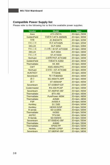
Compatible Power Supply listPlease refer to the following list to find the available power supplies.
Vendor Model Spec.Asus ATX-250YA 20+4pin; 250W
GoldenField 勁霸傳奇ATX-300WB 20+4pin; 300W勁馳 JC-B323ATX 20+4pin; 323W
世紀之星 風雲 ATX325 20+4pin; 325WDELUX DLP-328A 20+4pin; 328W世紀之星 自由戰士III ST-ATX330 20+4pin; 330WDELUX DLP-330A 20+4pin; 330W世紀之星 ST-ATX330 20+4pin; 330WHechuan 金剛戰神ST-ATX340 20+4pin; 340W
GoldenField 勁霸ATX-S350 20+4pin; 350WThermaltake KK 400 20+4pin; 400W
CWT KMG-4000LPPC 20+4pin; 400WHechuan 皇家騎士ST-ATX340 20+4pin; 400W
HUNTKEY 多核DH6 20+4pin; 400WSeventeam 戰天戟400SD 20+4pin; 400W鑫谷 SG-400ATX-APF 20+4pin; 400W鑫谷 ST-400WAP 20+4pin; 400W
Seventeam ST-420BKP-02F 20+4pin; 420WCoolermaster RS-430-PCAP 20+4pin; 430WSeventeam ST-450PAF-05F 20+4pin; 450WThermaltake BTX-450 20+4pin; 450WThermaltake PurePower 460W 20+4pin; 460WThermaltake AH580 20+4pin; 480W
FSP AX500-A 20+4pin; 500WHuntkey 磐石500 20+4pin; 500WHuntkey HK500-52SP 20+4pin; 500WR-senda SD-JL580S 20+4pin; 500W
Thermaltake KK500 20+4pin; 500WANTEC TP3-550 20+4pin; 550W
R-Senda SD-550WS 20+4pin; 550WSeventeam ST-550EAG-05F 20+4pin; 550WThermaltake AH680 20+4pin; 550WThermaltake XP550 PP 20+4pin; 550W
Hunkey HK560-11PEP 20+4pin; 560WSeventeam ST-580PAF-05F 20+4pin; 580W
PDF created with pdfFactory Pro trial version www.pdffactory.com
2-9
Hardware Setup
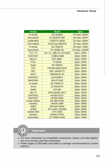
Vendor Model Spec.R-senda SD-JL680S 20+4pin; 600W
Seventeam ST-620PAF-05F 20+4pin; 620WGoldenfield 勁霸ATX-S650 20+4pin; 650WThermaltake PurePowe-680APD 20+4pin; 680W
R-senda SD-760EPS 20+4pin; 760WSeventeam ST-1000E-AD 20+4pin; 1000W世紀之星 鐵甲勇士300 ST-ATX325 20pin, 325W
HUNTKEY 百盛BS-2000 20pin; 200WDELUX DLP-388A 20pin; 250WFTek FT-B318 20pin; 300WSuper SP-300WA 20pin; 300WFSP FSP300-60BTV(PF) 20pin; 300WHEC HEC-300ER-PT 20pin; 300W
HEDY H300S(P4)+3C 20pin; 300WHUNTKEY LW-6228P4 20pin; 300WMINDONG MD-ATX300 20pin; 300WR-senda SD-P300ATX 20pin; 300WJinChi JC-B320ATX 20pin; 320WSAMA ATX330 20pin; 330WDELTA GPS-350AB-200 C 20pin; 350W
HUNTKEY HK350-51CP 20pin; 350WHUNTKEY HK350-13BP 20pin; 350W
Cooler Master RS-380-PCAP 24pin; 380WHuntkey HK400-13BP 24pin; 400WUMEC UPF400-400AF 24pin; 400WACBel ATX-450C-A2SNN) 24pin; 450W
Golden field ATX-S600 24pin; 600WHuntkey HK650-11PEP 24pin; 650W
Seventeam ST-750EAJ-05G 24pin; 750W
Important
1. For more information on compatible components, please visit http://global.msi.com.tw/index.php?func=testreport.
2. Power supply of 500 watts (and lower) is strongly recommended for systemstability.
PDF created with pdfFactory Pro trial version www.pdffactory.com
MS-7314 Mainboard
2-10
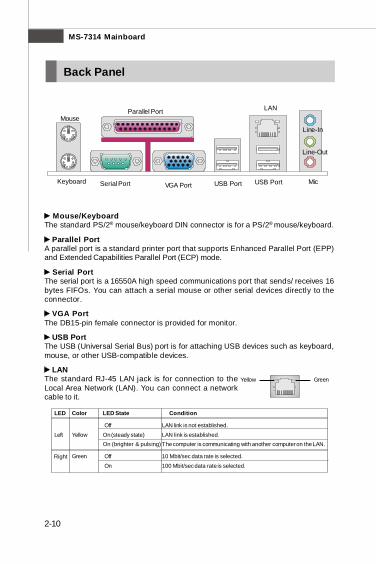
LED Color LED State Condition
Off LAN link is not established.
Left Yellow On (steady state) LAN link is established.On (brighter & pulsing) The computer is communicating with another computer on the LAN.
Green Off 10 Mbit/sec data rate is selected.
On 100 Mbit/sec data rate is selected.Right
GreenYellow
Back Panel
Mouse/KeyboardThe standard PS/2® mouse/keyboard DIN connector is for a PS/2® mouse/keyboard.
Parallel PortA parallel port is a standard printer port that supports Enhanced Parallel Port (EPP)and Extended Capabilities Parallel Port (ECP) mode.
Serial PortThe serial port is a 16550A high speed communications port that sends/ receives 16bytes FIFOs. You can attach a serial mouse or other serial devices directly to theconnector.
VGA PortThe DB15-pin female connector is provided for monitor.
USB PortThe USB (Universal Serial Bus) port is for attaching USB devices such as keyboard,mouse, or other USB-compatible devices.
LANThe standard RJ-45 LAN jack is for connection to theLocal Area Network (LAN). You can connect a networkcable to it.
Keyboard Mic
Line-Out
Line-In
MouseLANParallel Port
Serial Port USB Port USB PortVGA Port
PDF created with pdfFactory Pro trial version www.pdffactory.com

2-11
Hardware Setup
Audio PortsThese audio connectors are used for audio devices. It is easy to differentiate be-tween audio effects according to the color of audio jacks.
Line-In (Blue) - Line In is used for external CD player, tapeplayer orother audio devices.
Line-Out (Green) - Line Out, is a connector for speakers or headphones. Mic (Pink) - Mic, is a connector for microphones.
Important
The Realtek audio provided to offer support for 5.1-channel audio operationand can turn rear audio connectors from 2-channel to 4-/ 5.1-channel audio.
PDF created with pdfFactory Pro trial version www.pdffactory.com
MS-7314 Mainboard
2-12
Connectors
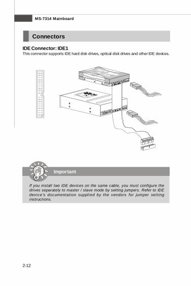
IDE Connector: IDE1This connector supports IDE hard disk drives, optical disk drives and other IDE devices.
Important
If you install two IDE devices on the same cable, you must configure thedrives separately to master / slave mode by setting jumpers. Refer to IDEdevice’s documentat ion suppl ied by the vendors for jumper sett inginstructions.
PDF created with pdfFactory Pro trial version www.pdffactory.com
2-13
Hardware Setup
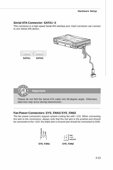
Fan Power Connectors: SYS_FAN1/ SYS_FAN2The fan power connectors support system cooling fan with +12V. When connectingthe wire to the connectors, always note that the red wire is the positive and shouldbe connected to the +12V; the black wire is Ground and should be connected to GND.
SYS_FAN2
SENSOR+12VGND
SYS_FAN1
Serial ATA Connector: SATA1~2This connector is a high-speed Serial ATA interface port. Each connector can connectto one Serial ATA device.
SATA2SATA1
Important
Please do not fold the Serial ATA cable into 90-degree angle. Otherwise,data loss may occur during transmission.
SEN
SOR
+12V
GN
D
PDF created with pdfFactory Pro trial version www.pdffactory.com
MS-7314 Mainboard
2-14
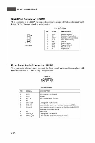
Serial Port Connector: JCOM1This connector is a 16550A high speed communication port that sends/receives 16bytes FIFOs. You can attach a serial device.
PIN SIGNAL DESCRIPTION
1 DCD Data Carry Detect 2 SIN Serial In or Receive Data 3 SOUT Serial Out or Transmit Data 4 DTR Data Terminal Ready 5 GND Ground 6 DSR Data Set Ready 7 RTS Request To Send 8 CTS Clear To Send 9 RI Ring Indicate
Pin Definition
JCOM1
Front Panel Audio Connector: JAUD1This connector allows you to connect the front panel audio and is compliant withIntel® Front Panel I/O Connectivity Design Guide.
Pin Definition
PIN SIGNAL DESCRIPTION
1 MIC_L Microphone - Left channel2 GND Ground3 MIC_R Microphone - Right channel4 NC5 LINE out_R Analog Port - Right channel6 MIC_JD Jack detection return from front panel microphone JACK17 Front_JD Jack detection sense line from the High Definition Audio CODEC
jack detection resistor network8 NC No control9 LINE out_L Analog Port - Left channel10 LINEout_JD Jack detection return from front panel JACK2
JAUD112
910
1
9
2
PDF created with pdfFactory Pro trial version www.pdffactory.com
2-15
Hardware Setup
PIN SIGNAL DESCRIPTION
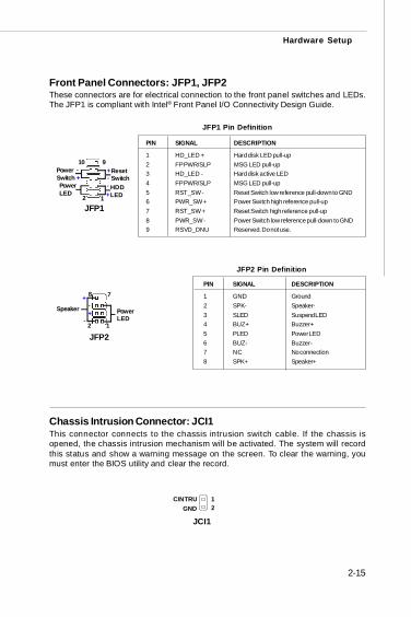
1 HD_LED + Hard disk LED pull-up2 FP PWR/SLP MSG LED pull-up3 HD_LED - Hard disk active LED4 FP PWR/SLP MSG LED pull-up5 RST_SW - Reset Switch low reference pull-down to GND6 PWR_SW + Power Switch high reference pull-up7 RST_SW + Reset Switch high reference pull-up8 PWR_SW - Power Switch low reference pull-down to GND9 RSVD_DNU Reserved. Do not use.
JFP1 Pin Definition
Front Panel Connectors: JFP1, JFP2These connectors are for electrical connection to the front panel switches and LEDs.The JFP1 is compliant with Intel® Front Panel I/O Connectivity Design Guide.
PIN SIGNAL DESCRIPTION
1 GND Ground2 SPK- Speaker-3 SLED Suspend LED4 BUZ+ Buzzer+5 PLED Power LED6 BUZ- Buzzer-7 NC No connection8 SPK+ Speaker+
JFP2 Pin Definition
Chassis Intrusion Connector: JCI1This connector connects to the chassis intrusion switch cable. If the chassis isopened, the chassis intrusion mechanism will be activated. The system will recordthis status and show a warning message on the screen. To clear the warning, youmust enter the BIOS utility and clear the record.
JCI121
GNDCINTRU
78
PowerLED
Speaker
12
JFP2
+
+-
-
12
910
JFP1
HDDLED
ResetSwitch
PowerLED
PowerSwitch
+
++
--
-
PDF created with pdfFactory Pro trial version www.pdffactory.com
MS-7314 Mainboard
2-16
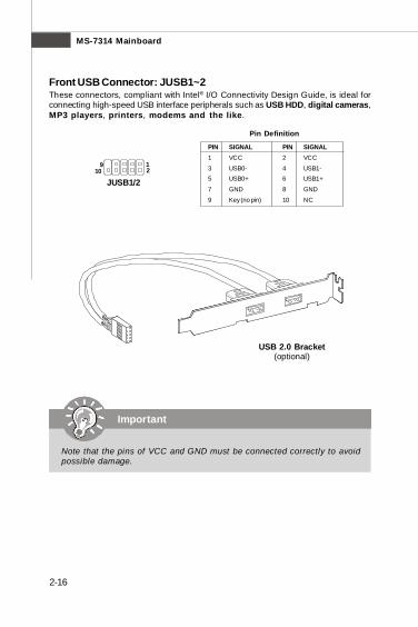
Front USB Connector: JUSB1~2These connectors, compliant with Intel® I/O Connectivity Design Guide, is ideal forconnecting high-speed USB interface peripherals such as USB HDD, digital cameras,MP3 players, printers, modems and the like.
PIN SIGNAL PIN SIGNAL1 VCC 2 VCC
3 USB0- 4 USB1-5 USB0+ 6 USB1+
7 GND 8 GND
9 Key (no pin) 10 NC
Pin Definition
Important
Note that the pins of VCC and GND must be connected correctly to avoidpossible damage.
USB 2.0 Bracket(optional)
1 9 2 10
JUSB1/2
PDF created with pdfFactory Pro trial version www.pdffactory.com
2-17
Hardware Setup
Jumper
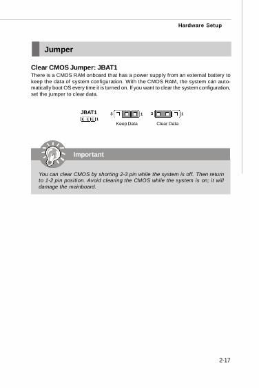
Clear CMOS Jumper: JBAT1There is a CMOS RAM onboard that has a power supply from an external battery tokeep the data of system configuration. With the CMOS RAM, the system can auto-matically boot OS every time it is turned on. If you want to clear the system configuration,set the jumper to clear data.
Important
You can clear CMOS by shorting 2-3 pin while the system is off. Then returnto 1-2 pin position. Avoid clearing the CMOS while the system is on; it willdamage the mainboard.
JBAT11
Keep Data Clear Data
3 13 1
PDF created with pdfFactory Pro trial version www.pdffactory.com
MS-7314 Mainboard
2-18
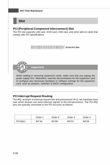
32-bit PCI Slot
Important
When adding or removing expansion cards, make sure that you unplug thepower supply first. Meanwhile, read the documentation for the expansion cardto configure any necessary hardware or software settings for the expansioncard, such as jumpers, switches or BIOS configuration.
PCI (Peripheral Component Interconnect) SlotThe PCI slot supports LAN card, SCSI card, USB card, and other add-on cards thatcomply with PCI specifications.
Slot
PCI Interrupt Request RoutingThe IRQ, acronym of interrupt request line and pronounced I-R-Q, are hardware linesover which devices can send interrupt signals to the microprocessor. The PCI IRQpins are typically connected to the PCI bus pins as follows:
Order 1 Order 2 Order 3 Order 4
PCI Slot 1 INT A# INT B# INT C# INT D#
PDF created with pdfFactory Pro trial version www.pdffactory.com
3-1
BIOS Setup
Chapter 3
BIOS Setup
This chapter provides information on the BIOS Setupprogram and allows you to configure the system foroptimum use.You may need to run the Setup program when:
² An error message appears on the screen during thesystem booting up, and requests you to run SETUP.
² You want to change the default settings for cus-tomized features.
PDF created with pdfFactory Pro trial version www.pdffactory.com
3-2
MS-7314 Mainboard
Entering Setup
Important
1. The items under each BIOS category described in this chapter are undercontinuous update for better system performance. Therefore, the descrip-tion may be slightly different from the latest BIOS and should be held forreference only.
2. Upon boot-up, the 1st line appearing after the memory count is the BIOSversion. It is usually in the format:
A7314IMS V1.0 042308 where:
1st digit refers to BIOS maker as A = AMI, W = AWARD, and P =PHOENIX.2nd - 5th digit refers to the model number.6th digit refers to the chipset as I = Intel, N = nVidia, and V = VIA.7th - 8th digit refers to the customer as MS = all standard customers.V1.0 refers to the BIOS version.042308 refers to the date this BIOS was released.
Power on the computer and the system will start POST (Power On Self Test) process.When the message below appears on the screen, press <DEL> key to enter Setup.
Press DEL to enter SETUP
If the message disappears before you respond and you still wish to enter Setup,restart the system by turning it OFF and On or pressing the RESET button. You mayalso restart the system by simultaneously pressing <Ctrl>, <Alt>, and <Delete> keys.
PDF created with pdfFactory Pro trial version www.pdffactory.com

3-3
BIOS Setup
Getting HelpAfter entering the Setup menu, the first menu you will see is the Main Menu.
Main MenuThe main menu lists the setup functions you can make changes to. You can use thearrow keys ( ↑↓ ) to select the item. The on-line description of the highlighted setupfunction is displayed at the bottom of the screen.
Sub-MenuIf you find a right pointer symbol (as shown in the right view)appears to the left of certain fields that means a sub-menucan be launched from this field. A sub-menu contains addi-tional options for a field parameter. You can use arrow keys ( ↑↓ ) to highlight thefield and press <Enter> to call up the sub-menu. Then you can use the control keysto enter values and move from field to field within a sub-menu. If you want to returnto the main menu, just press the <Esc >.
General Help <F1>The BIOS setup program provides a General Help screen. You can call up this screenfrom any menu by simply pressing <F1>. The Help screen lists the appropriate keysto use and the possible selections for the highlighted item. Press <Esc> to exit theHelp screen.
Control Keys
<↑> Move to the previous item<↓> Move to the next item<←> Move to the item in the left hand<→> Move to the item in the right hand<Enter> Select the item<Esc> Jumps to the Exit menu or returns to the main menu from a
submenu<+/PU> Increase the numeric value or make changes<-/PD> Decrease the numeric value or make changes<F6> Load Optimized Defaults<F10> Save all the CMOS changes and exit
PDF created with pdfFactory Pro trial version www.pdffactory.com
3-4
MS-7314 Mainboard
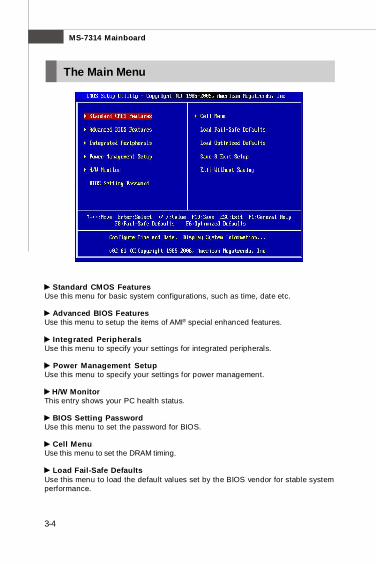
Standard CMOS FeaturesUse this menu for basic system configurations, such as time, date etc.
Advanced BIOS FeaturesUse this menu to setup the items of AMI® special enhanced features.
Integrated PeripheralsUse this menu to specify your settings for integrated peripherals.
Power Management SetupUse this menu to specify your settings for power management.
H/W MonitorThis entry shows your PC health status.
BIOS Setting PasswordUse this menu to set the password for BIOS.
Cell MenuUse this menu to set the DRAM timing.
Load Fail-Safe DefaultsUse this menu to load the default values set by the BIOS vendor for stable systemperformance.
The Main Menu
PDF created with pdfFactory Pro trial version www.pdffactory.com
3-5
BIOS Setup
Load Optimized DefaultsUse this menu to load the default values set by the mainboard manufacturer specifi-cally for optimal performance of the mainboard.
Save & Exit SetupSave changes to CMOS and exit setup.
Exit Without SavingAbandon all changes and exit setup.
PDF created with pdfFactory Pro trial version www.pdffactory.com
3-6
MS-7314 Mainboard
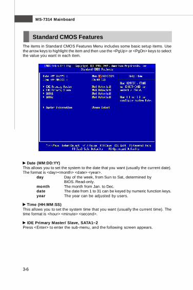
The items in Standard CMOS Features Menu includes some basic setup items. Usethe arrow keys to highlight the item and then use the <PgUp> or <PgDn> keys to selectthe value you want in each item.
Date (MM:DD:YY)This allows you to set the system to the date that you want (usually the current date).The format is <day><month> <date> <year>.
day Day of the week, from Sun to Sat, determined byBIOS. Read-only.
month The month from Jan. to Dec.date The date from 1 to 31 can be keyed by numeric function keys.year The year can be adjusted by users.
Time (HH:MM:SS)This allows you to set the system time that you want (usually the current time). Thetime format is <hour> <minute> <second>.
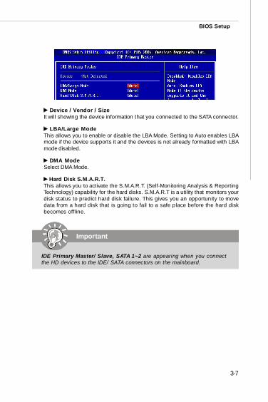
IDE Primary Master/ Slave, SATA1~2Press <Enter> to enter the sub-menu, and the following screen appears.
Standard CMOS Features
PDF created with pdfFactory Pro trial version www.pdffactory.com
3-7
BIOS Setup
Device / Vendor / SizeIt will showing the device information that you connected to the SATA connector.
LBA/Large ModeThis allows you to enable or disable the LBA Mode. Setting to Auto enables LBAmode if the device supports it and the devices is not already formatted with LBAmode disabled.
DMA ModeSelect DMA Mode.
Hard Disk S.M.A.R.T.This allows you to activate the S.M.A.R.T. (Self-Monitoring Analysis & ReportingTechnology) capability for the hard disks. S.M.A.R.T is a utility that monitors yourdisk status to predict hard disk failure. This gives you an opportunity to movedata from a hard disk that is going to fail to a safe place before the hard diskbecomes offline.
Important
IDE Primary Master/ Slave, SATA 1~2 are appearing when you connectthe HD devices to the IDE/ SATA connectors on the mainboard.
PDF created with pdfFactory Pro trial version www.pdffactory.com
3-8
MS-7314 Mainboard
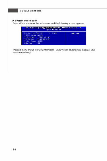
This sub-menu shows the CPU information, BIOS version and memory status of yoursystem (read only).
System InformationPress <Enter> to enter the sub-menu, and the following screen appears.
PDF created with pdfFactory Pro trial version www.pdffactory.com
3-9
BIOS Setup
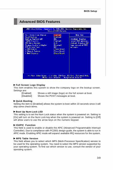
Full Screen Logo DisplayThis item enables this system to show the company logo on the bootup screen.Settings are:
[Enabled] Shows a still image (logo) on the full screen at boot.[Disabled] Shows the POST messages at boot.
Quick BootingSetting the item to [Enabled] allows the system to boot within 10 seconds since it willskip some check items.
Boot Up Num-Lock LEDThis setting is to set the Num Lock status when the system is powered on. Setting to[On] will turn on the Num Lock key when the system is powered on. Setting to [Off]will allow users to use the arrow keys on the numeric keypad.
IOAPIC FunctionThis field is used to enable or disable the APIC (Advanced Programmable InterruptController). Due to compliance with PC2001 design guide, the system is able to run inAPIC mode. Enabling APIC mode will expand available IRQ resources for the system.
MPS Table VersionThis field allows you to select which MPS (Multi-Processor Specification) version tobe used for the operating system. You need to select the MPS version supported byyour operating system. To find out which version to use, consult the vendor of youroperating system.
Advanced BIOS Features
PDF created with pdfFactory Pro trial version www.pdffactory.com
3-10
MS-7314 Mainboard
Primary Graphic’s AdapterThis setting specifies which graphic card is your primary graphics adapter.
PCI Latency TimerThis item controls how long each PCI device can hold the bus before another takesover. When set to higher values, every PCI device can conduct transactions for alonger time and thus improve the effective PCI bandwidth. For better PCI performance,you should set the item to higher values.
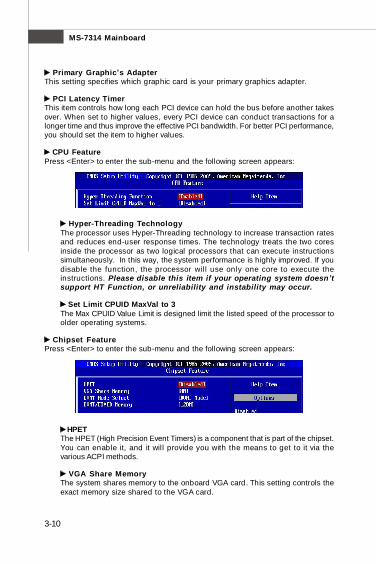
CPU FeaturePress <Enter> to enter the sub-menu and the following screen appears:
Hyper-Threading TechnologyThe processor uses Hyper-Threading technology to increase transaction ratesand reduces end-user response times. The technology treats the two coresinside the processor as two logical processors that can execute instructionssimultaneously. In this way, the system performance is highly improved. If youdisable the function, the processor will use only one core to execute theinstructions. Please disable this item if your operating system doesn’tsupport HT Function, or unreliability and instability may occur.
Set Limit CPUID MaxVal to 3The Max CPUID Value Limit is designed limit the listed speed of the processor toolder operating systems.
Chipset FeaturePress <Enter> to enter the sub-menu and the following screen appears:
HPETThe HPET (High Precision Event Timers) is a component that is part of the chipset.You can enable it, and it will provide you with the means to get to it via thevarious ACPI methods.
VGA Share MemoryThe system shares memory to the onboard VGA card. This setting controls theexact memory size shared to the VGA card.
PDF created with pdfFactory Pro trial version www.pdffactory.com

3-11
BIOS Setup
DVMT Mode SelectThis item allows you to set the mode for the graphics core.[Fixed] mode, a fixed-size fragment of the system memory is allocated to thegraphics core. It can only be used by the graphics core.[DVMT] mode, the driver of the graphics core uses the system memory like anyother OS component or application does.[Combo] mode, DVMT mode + Fixed mode
DVMT/FIXED MemorySpecify the size of DVMT/FIXED memory to allocate for video memory.
Boot SequencePress <Enter> to enter the sub-menu and the following screen appears:
1st Boot DeviceThe items allow you to set the first boot device where BIOS attempts to load thedisk operating system.
Boot From Other DeviceSetting the option to [Yes] allows the system to try to boot from other device, ifthe system fails to boot from 1st boot device.
PDF created with pdfFactory Pro trial version www.pdffactory.com
3-12
MS-7314 Mainboard
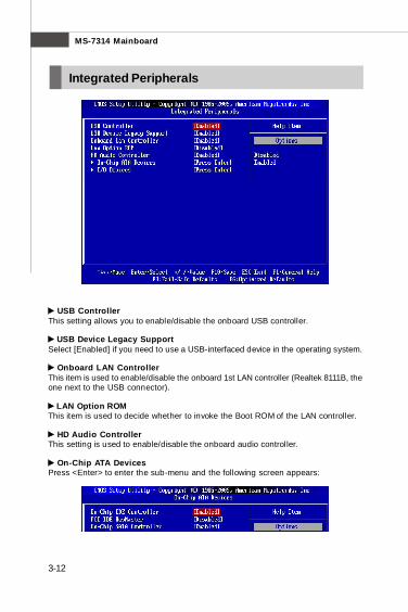
USB ControllerThis setting allows you to enable/disable the onboard USB controller.
USB Device Legacy SupportSelect [Enabled] if you need to use a USB-interfaced device in the operating system.
Onboard LAN ControllerThis item is used to enable/disable the onboard 1st LAN controller (Realtek 8111B, theone next to the USB connector).
LAN Option ROMThis item is used to decide whether to invoke the Boot ROM of the LAN controller.
HD Audio ControllerThis setting is used to enable/disable the onboard audio controller.
On-Chip ATA DevicesPress <Enter> to enter the sub-menu and the following screen appears:
Integrated Peripherals
PDF created with pdfFactory Pro trial version www.pdffactory.com
3-13
BIOS Setup
On-Chip IDE ControllerThese items allow users to enable or disable the IDE controller.
PCI IDE BusMasterThis item allows you to enable/ disable BIOS to used PCI busmastering forreading/ writing to IDE drives.
On-Chip SATA ControllerThese items allow users to enable or disable the SATA controller.
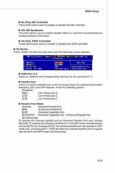
I/O DevicePress <Enter> to enter the sub-menu and the following screen appears:
COM Port 1/ 2Select an address and corresponding interrupt for the serial port1/ 2.
Parallel PortThere is a built-in parallel port on the on-board Super I/O chipset that providesStandard, ECP, and EPP features. It has the following options:
[Disabled][3BC] Line Printer port 0[278] Line Printer port 2[378] Line Printer port 1
Parallel Port Mode[Normal] Standard Parallel Port[EPP] Enhanced Parallel Port[ECP] Extended Capability Port[ECP & EPP] Extended Capability Port + Enhanced Parallel Port[Bi-Directional]
To operate the onboard parallel port as Standard Parallel Port only, choose[Normal]. To operate the onboard parallel port in the EPP mode simultaneously,choose [EPP]. By choosing [ECP], the onboard parallel port will operate in ECPmode only. Choosing [ECP + EPP] will allow the onboard parallel port to supportboth the ECP and EPP modes simultaneously.
PDF created with pdfFactory Pro trial version www.pdffactory.com
3-14
MS-7314 Mainboard
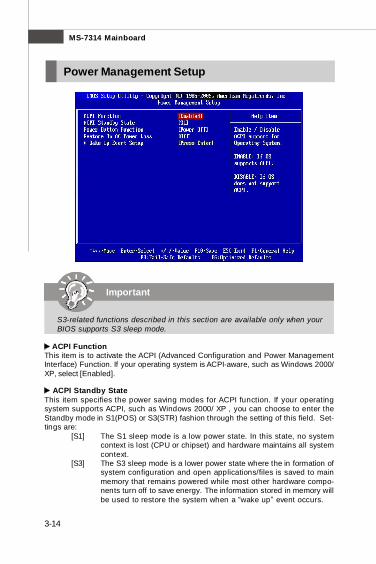
ACPI FunctionThis item is to activate the ACPI (Advanced Configuration and Power ManagementInterface) Function. If your operating system is ACPI-aware, such as Windows 2000/XP, select [Enabled].
ACPI Standby StateThis item specifies the power saving modes for ACPI function. If your operatingsystem supports ACPI, such as Windows 2000/ XP , you can choose to enter theStandby mode in S1(POS) or S3(STR) fashion through the setting of this field. Set-tings are:
[S1] The S1 sleep mode is a low power state. In this state, no systemcontext is lost (CPU or chipset) and hardware maintains all systemcontext.
[S3] The S3 sleep mode is a lower power state where the in formation ofsystem configuration and open applications/files is saved to mainmemory that remains powered while most other hardware compo-nents turn off to save energy. The information stored in memory willbe used to restore the system when a “wake up” event occurs.
Important
S3-related functions described in this section are available only when yourBIOS supports S3 sleep mode.
Power Management Setup
PDF created with pdfFactory Pro trial version www.pdffactory.com
3-15
BIOS Setup
Power Button FunctionThis feature sets the function of the power button. Settings are:
[Power On/ Off] The power button functions as normal power off button.[Suspend] When you press the power button, the computer enters the
suspend/sleep mode, but if the button is pressed for morethan four seconds, the computer is turned off.
Restore On AC Power LossThis item specifies whether your system will reboot after a power failure or interruptoccurs. Settings are:
[Off] Always leaves the computer in the power off state.[On] Always leaves the computer in the power on state.[Last State] Restores the system to the status before power failure
or interrupt occurred.
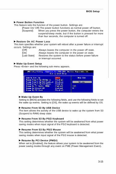
Wake Up Event SetupPress <Enter> and the following sub-menu appears.
Wake Up Event BySetting to [BIOS] activates the following fields, and use the following fields to setthe wake up events. Setting to [OS], the wake up events will be defined by OS.
Resume From S3 By USB DeviceThe item allows the activity of the USB device to wake up the system from S3(Suspend to RAM) sleep state.
Resume From S3 By PS/2 KeyboardThis setting determines whether the system will be awakened from what powersaving modes when input signal of the PS/2 keyboard is detected.
Resume From S3 By PS/2 MouseThis setting determines whether the system will be awakened from what powersaving modes when input signal of the PS/2 mouse is detected.
Resume By PCI Device (PME#)When set to [Enabled], the feature allows your system to be awakened from thepower saving modes through any event on PME (Power Management Event).
PDF created with pdfFactory Pro trial version www.pdffactory.com

3-16
MS-7314 Mainboard
Resume By Onboard LANWhen set to [Enabled], the feature allows your system to be awakened from thepower saving modes through onboard LAN.
Resume By RTC AlarmThe field is used to enable or disable the feature of booting up the system on ascheduled time/date.
PDF created with pdfFactory Pro trial version www.pdffactory.com
3-17
BIOS Setup
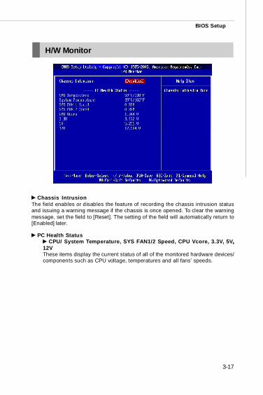
Chassis IntrusionThe field enables or disables the feature of recording the chassis intrusion statusand issuing a warning message if the chassis is once opened. To clear the warningmessage, set the field to [Reset]. The setting of the field will automatically return to[Enabled] later.
PC Health Status CPU/ System Temperature, SYS FAN1/2 Speed, CPU Vcore, 3.3V, 5V,,
12VThese items display the current status of all of the monitored hardware devices/components such as CPU voltage, temperatures and all fans’ speeds.
H/W Monitor
PDF created with pdfFactory Pro trial version www.pdffactory.com
3-18
MS-7314 Mainboard
BIOS Setting Password
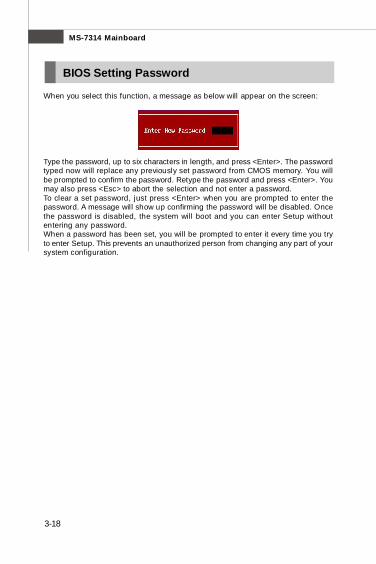
When you select this function, a message as below will appear on the screen:
Type the password, up to six characters in length, and press <Enter>. The passwordtyped now will replace any previously set password from CMOS memory. You willbe prompted to confirm the password. Retype the password and press <Enter>. Youmay also press <Esc> to abort the selection and not enter a password.To clear a set password, just press <Enter> when you are prompted to enter thepassword. A message will show up confirming the password will be disabled. Oncethe password is disabled, the system will boot and you can enter Setup withoutentering any password.When a password has been set, you will be prompted to enter it every time you tryto enter Setup. This prevents an unauthorized person from changing any part of yoursystem configuration.
PDF created with pdfFactory Pro trial version www.pdffactory.com
3-19
BIOS Setup
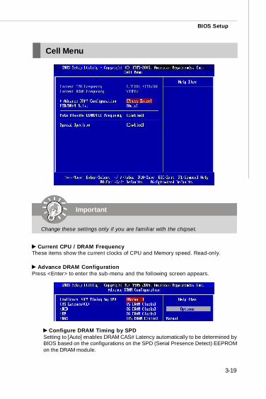
Current CPU / DRAM FrequencyThese items show the current clocks of CPU and Memory speed. Read-only.
Advance DRAM ConfigurationPress <Enter> to enter the sub-menu and the following screen appears.
Configure DRAM Timing by SPDSetting to [Auto] enables DRAM CAS# Latency automatically to be determined byBIOS based on the configurations on the SPD (Serial Presence Detect) EEPROMon the DRAM module.
Cell Menu
Important
Change these settings only if you are familiar with the chipset.
PDF created with pdfFactory Pro trial version www.pdffactory.com
3-20
MS-7314 Mainboard
CAS# Latency (CL)When the Configure DRAM Timing by SPD sets to [Manual], the field isadjustable. This controls the CAS latency, which determines the timing delay (inclock cycles) before SDRAM starts a read command after receiving it.
tRCDWhen the Configure DRAM Timing by SPD sets to [Manual], the field isadjustable. When DRAM is refreshed, both rows and columns are addressedseparately. This setup item allows you to determine the timing of the transitionfrom RAS (row address strobe) to CAS (column address strobe). The less theclock cycles, the faster the DRAM performance.
tRPWhen the Configure DRAM Timing by SPD sets to [Manual], this field isadjustable. This setting controls the number of cycles for Row Address Strobe(RAS) to be allowed to precharge. If insufficient time is allowed for the RAS toaccumulate its charge before DRAM refresh, refresh may be incomplete andDRAM may fail to retain data. This item applies only when synchronous DRAM isinstalled in the system.
tRASWhen the Configure DRAM Timing by SPD sets to [Manual], this field isadjustable. This setting determines the time RAS takes to read from and write tomemory cell.
FSB/DRAM RatioThis item will allow you to adjust the ratio of FSB to memory.
Auto Disable DRAM/PCI FrequencyWhen set to [Enabled], the system will remove (turn off) clocks from empty DIMM andPCI slots to minimize the electromagnetic interference (EMI).
Spread SpectrumWhen the mainboard’s clock generator pulses, the extreme values (spikes) of thepulses create EMI (Electromagnetic Interference). The Spread Spectrum functionreduces the EMI generated by modulating the pulses so that the spikes of the pulsesare reduced to flatter curves. If you do not have any EMI problem, leave the setting atDisabled for optimal system stability and performance. But if you are plagued by EMI,set to Enabled for EMI reduction. Remember to disable Spread Spectrum if you areoverclocking because even a slight jitter can introduce a temporary boost in clockspeed which may just cause your overclocked processor to lock up.
PDF created with pdfFactory Pro trial version www.pdffactory.com
3-21
BIOS Setup
1. If you do not have any EMI problem, leave the setting at [Disabled] foroptimal system stability and performance. But if you are plagued by EMI,select the value of Spread Spectrum for EMI reduction.
2. The greater the Spread Spectrum value is, the greater the EMI is reduced,and the system will become less stable. For the most suitable SpreadSpectrum value, please consult your local EMI regulation.
3. Remember to disable Spread Spectrum if you are overclocking becauseeven a slight jitter can introduce a temporary boost in clock speed whichmay just cause your overclocked processor to lock up.
Important
PDF created with pdfFactory Pro trial version www.pdffactory.com
3-22
MS-7314 Mainboard
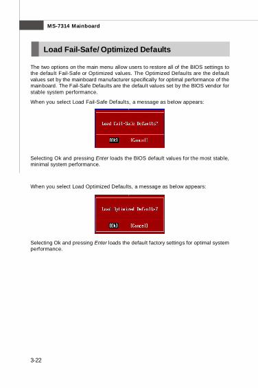
The two options on the main menu allow users to restore all of the BIOS settings tothe default Fail-Safe or Optimized values. The Optimized Defaults are the defaultvalues set by the mainboard manufacturer specifically for optimal performance of themainboard. The Fail-Safe Defaults are the default values set by the BIOS vendor forstable system performance.
When you select Load Fail-Safe Defaults, a message as below appears:
Selecting Ok and pressing Enter loads the BIOS default values for the most stable,minimal system performance.
When you select Load Optimized Defaults, a message as below appears:
Selecting Ok and pressing Enter loads the default factory settings for optimal systemperformance.
Load Fail-Safe/ Optimized Defaults
PDF created with pdfFactory Pro trial version www.pdffactory.com
Copyright © 2022 FDOKUMEN