Kim 12 Removal of malaria-infected
20
Removal of malaria-infected red blood cells using magnetic cell separators: A computational study Jeongho Kim (1) , Mehrdad Massoudi (2) , James F. Antaki (1) , and Alberto Gandini (1) (1) Department of Biomedical Engineering, Carnegie Mellon University, Pittsburgh, PA, 15213 USA (2) U. S. Department of Energy, National Energy Technology Laboratory (NETL), P. O. Box 10940, Pittsburgh, PA, 15236 USA Abstract High gradient magnetic field separators have been widely used in a variety of biological applications. Recently, the use of magnetic separators to remove malaria-infected red blood cells (pRBCs) from blood circulation in patients with severe malaria has been proposed in a dialysis- like treatment. The capture efficiency of this process depends on many interrelated design variables and constraints such as magnetic pole array pitch, chamber height, and flow rate. In this paper, we model the malaria-infected RBCs (pRBCs) as paramagnetic particles suspended in a Newtonian fluid. Trajectories of the infected cells are numerically calculated inside a micro- channel exposed to a periodic magnetic field gradient. First-order stiff ordinary differential equations (ODEs) governing the trajectory of particles under periodic magnetic fields due to an array of wires are solved numerically using the 1 st –5 th order adaptive step Runge-Kutta solver. The numerical experiments show that in order to achieve a capture efficiency of 99% for the pRBCs it is required to have a longer length than 80 mm; this implies that in principle, using optimization techniques the length could be adjusted, i.e., shortened to achieve 99% capture efficiency of the pRBCs. Keywords cell separator; red blood cells (RBC); malaria; microfluidics; magnetic forces; particle trajectory; micro-channel 1. Introduction Malaria is a parasitic disease transmitted by the bite of an infected mosquito, which afflicts 300 to 500 million people, consuming 40% of the health expenditures of over 100 countries. The malaria parasite lives by feeding off the hemoglobin. To avoid death from the toxic hemoglobin’s “heme”, the parasite converts it into an insoluble highly compacted crystal known as hemozoin. Since each heme contains one atom of iron, the hemozoin becomes paramagnetic [1–4]. Studies of Paul et al. [5] have shown that malaria infected red blood cells (pRBCs), which contain the parasite and the hemozoin, behave like paramagnetic particles in a magnetic field. This discovery has motivated investigation of magnetic cell separation to isolate in-vitro grown malaria-infected cells from the whole blood [5–10]. Publisher's Disclaimer: This is a PDF file of an unedited manuscript that has been accepted for publication. As a service to our customers we are providing this early version of the manuscript. The manuscript will undergo copyediting, typesetting, and review of the resulting proof before it is published in its final citable form. Please note that during the production process errors may be discovered which could affect the content, and all legal disclaimers that apply to the journal pertain. NIH Public Access Author Manuscript Appl Math Comput. Author manuscript; available in PMC 2013 February 15. Published in final edited form as: Appl Math Comput. 2012 February 15; 218(12): 6841–6850. doi:10.1016/j.amc.2011.12.057. NIH-PA Author Manuscript NIH-PA Author Manuscript NIH-PA Author Manuscript
Transcript of Kim 12 Removal of malaria-infected
Removal of malaria-infected red blood cells using magnetic cellseparators: A computational study
Jeongho Kim(1), Mehrdad Massoudi(2), James F. Antaki(1), and Alberto Gandini(1)
(1)Department of Biomedical Engineering, Carnegie Mellon University, Pittsburgh, PA, 15213 USA(2)U. S. Department of Energy, National Energy Technology Laboratory (NETL), P. O. Box 10940,Pittsburgh, PA, 15236 USA
AbstractHigh gradient magnetic field separators have been widely used in a variety of biologicalapplications. Recently, the use of magnetic separators to remove malaria-infected red blood cells(pRBCs) from blood circulation in patients with severe malaria has been proposed in a dialysis-like treatment. The capture efficiency of this process depends on many interrelated designvariables and constraints such as magnetic pole array pitch, chamber height, and flow rate. In thispaper, we model the malaria-infected RBCs (pRBCs) as paramagnetic particles suspended in aNewtonian fluid. Trajectories of the infected cells are numerically calculated inside a micro-channel exposed to a periodic magnetic field gradient. First-order stiff ordinary differentialequations (ODEs) governing the trajectory of particles under periodic magnetic fields due to anarray of wires are solved numerically using the 1st –5th order adaptive step Runge-Kutta solver.The numerical experiments show that in order to achieve a capture efficiency of 99% for thepRBCs it is required to have a longer length than 80 mm; this implies that in principle, usingoptimization techniques the length could be adjusted, i.e., shortened to achieve 99% captureefficiency of the pRBCs.
Keywordscell separator; red blood cells (RBC); malaria; microfluidics; magnetic forces; particle trajectory;micro-channel
1. IntroductionMalaria is a parasitic disease transmitted by the bite of an infected mosquito, which afflicts300 to 500 million people, consuming 40% of the health expenditures of over 100 countries.The malaria parasite lives by feeding off the hemoglobin. To avoid death from the toxichemoglobin’s “heme”, the parasite converts it into an insoluble highly compacted crystalknown as hemozoin. Since each heme contains one atom of iron, the hemozoin becomesparamagnetic [1–4]. Studies of Paul et al. [5] have shown that malaria infected red bloodcells (pRBCs), which contain the parasite and the hemozoin, behave like paramagneticparticles in a magnetic field. This discovery has motivated investigation of magnetic cellseparation to isolate in-vitro grown malaria-infected cells from the whole blood [5–10].
Publisher's Disclaimer: This is a PDF file of an unedited manuscript that has been accepted for publication. As a service to ourcustomers we are providing this early version of the manuscript. The manuscript will undergo copyediting, typesetting, and review ofthe resulting proof before it is published in its final citable form. Please note that during the production process errors may bediscovered which could affect the content, and all legal disclaimers that apply to the journal pertain.
NIH Public AccessAuthor ManuscriptAppl Math Comput. Author manuscript; available in PMC 2013 February 15.
Published in final edited form as:Appl Math Comput. 2012 February 15; 218(12): 6841–6850. doi:10.1016/j.amc.2011.12.057.
NIH
-PA Author Manuscript
NIH
-PA Author Manuscript
NIH
-PA Author Manuscript

Recently, the magnetic separation of malaria-infected red blood cells (RBCs) from bloodcirculation in patients with severe malaria has been proposed in a dialysis-like treatment -known as the mPharesis™ system (Fig. 1). In severe malaria, 5% or higher (up to 60% inworst cases) of the patient’s red blood cells (RBCs) may be infected [11]. Even whenoptimally treated, severe malaria results in mortality rates of 15%–22% [12, 13]. Whenavailable, blood exchange transfusion and erythropheresis have been effectively used tosignificantly accelerate the clearance of parasites - so that intravenous drug therapies may bemore efficacious [14–19]. Unfortunately, current exchange transfuser (ET) andelectrophoresis (EP) systems used in these treatments are not engineered to selectivelyseparate the infected RBCs (pRBCs) from healthy RBCs, and consequently result in theconsumption of donor blood up to 95% greater than necessary, increasing cost and the risksof transfusion trauma. The mPharesis™ system (Figure 1) - a patent-pending technology [20]- developed by Tropical Health Systems, LLC and Carnegie Mellon University targets thepRBCs based on their unique magnetic properties. It represents the first medical device of itskind to employ magnetic separation technology [19, 21] to clear these toxic cells fromcirculation. This study was conducted to determine optimal parameters of such a device.
Cell separation has been considered as a key element in the diagnosis and treatment ofhuman disease; it is an initial step for further experimental analyses to disclose moreinformation about the disease. However, manipulating of a cell still is a challenging task.The main needs are to achieve higher performance, lower cost of cell isolation systems, anda novel technique to manipulate some of the cells. Kumar and Lykke [22] reviewed variouscell separation techniques using cell properties such as cell density (centrifugation), cell size(sedimentation and filtration), and cell charge (magnetism). For example, centrifugation cangenerate density gradients and is widely used for cell separation. Other separationtechniques are based on surface properties (adherence and affinity) and functional properties(proliferation, phagoctosis, and antigen recognition). Among cell manipulation techniques,magnetic cell sorting has received more attention for cell separation. Melville et al. [23]showed erythrocytes can be isolated from other cells because of its different paramagneticproperties. Paul et al [5] used this principle to filtrate malaria-infected red blood cells fromthe whole blood. Magnetic forces are used to transport, position, isolate, and sort magneticmicro-/nano- particles as well as non-magnetic objects, i.e., diamagnetic particles in micro-fluidic systems.
In this paper, we report the use of numerical technique of the novel mPharesis™ dialysis-likedevice for removal of malaria-infected, parasitized RBCs (pRBCs). These cells, known toexhibit a magnetic dipole moment, are modeled as paramagnetic particles suspended in aNewtonian fluid. Trajectories of the infected cells are numerically calculated inside a micro-channel exposed to a periodic magnetic gradient field. In Section 2, we briefly discuss themechanics of a magnetic cell separator. In Section 3, we look at the mathematicalformulation of forces acting on an idealized malaria infected RBC in a fluid, and in Section4, we derive the equations of motion for a population of pRBCs flowing in a micro-channelsubject to a magnetic field. Section 5 provides numerical simulations of particle trajectoriesfor various cases. In addition, we have included the lift and Faxen forces in the particleequation; these terms are normally ignored. With the approach taken in this study, we caneasily determine the dimensions of the microchannel, the size of the magnetic wire, thepitch, etc.
2. The mechanics of a magnetic cell separatorInglis et al [24] discussed two methods of using high gradient magnetic (HGM) cellseparation. One is to use the native susceptibility of cells and effectively separate the RBCsfrom the whole blood. Han et al. [25] showed the continuous separation of red and white
Kim et al. Page 2
Appl Math Comput. Author manuscript; available in PMC 2013 February 15.
NIH
-PA Author Manuscript
NIH
-PA Author Manuscript
NIH
-PA Author Manuscript

blood cells (WBCs) in microdevices. They considered the three-stage cascade micro-separator on order to increase the efficiency of the separation of red and white blood cells,creating higher gradient magnetic fields [26]. Their experimental results showed that thethree-stage cascade micro-separator achieved 93.5 % separation of red blood cells and 97.4% of white blood cells while for the single-stage micro-separator, 91.1 % of red blood cellsand 87.7 % of white blood cells were separated. A mathematical model indicated thatdeoxygenated RBCs can be separated from WBCs in plasma [27]. Zborowski et al. [28]considered deoxygenated and metHb-containing erythrocytes for cell separation. The othermethod is using magnetic beads where the specific cells which attach themselves to thesemagnetic beads are separated. Xia et al. [29] used HGMC-microfluidic separator to removeliving E. coli bacteria (1×10⁷ cells/ml) bound to 130 nm magnetic nanoparticles fromphosphate buffer solution (PBS) and saline containing a concentration of RBCs (2×10⁹ cells/ml). They introduced a triangular saw-tooth configuration to create high gradient magneticfields. Shinha et al. [30] compared numerical prediction with measured data for magneticparticle trajectories and showed a very good agreement where they introduced adimensionless ratio of the magnetic and the drag forces determining the capture efficiency ofparticles. Chen et al. [31] and Brandl et al. [32] have developed detoxification systems as atherapeutic tool for selective and rapid removal of biohazards using a magnetic separator.Convection-diffusion equations governing the concentration of magnetic beads have beenintegrated with numerical models for cell separation system (Mikkelsen and Bruus [33] andLi et al. [34]. Mohanty et al. [35]). Two good review papers on magnetic cell separation areTonner and Irimia [36], and Pamme [37].
The mPharesis™ (magnetic aphaeresis) system operates similar to a dialysis machine, wherethe patient’s peripheral blood is continuously withdrawn, purified, and returned to thecirculation (Figure 1 top). The design of the mPharesis™ filter features a series of cascadedlaminar flow channels (Figure 1 bottom) through which the infected blood is transported andexposed to a high magnetic field gradient (> 1000 Tesla/m). The latter is created by an arrayof micro-sized ferromagnetic structures, placed in close proximity to the blood, that creates alocalize force field, causing the infected cells to migrate or “marginate,” whereupon they areskimmed off by a side branch (bleed-slit, in Figure 1 bottom). A magnetic field is appliedusing a 0.3 Tesla permanent magnet adjacent to the array of micro-sized ferromagneticstructures. The purified blood is then returned to the patient from a return outlet, (C inFigure 1 bottom). This design allows continuous filtration, analogous to renal dialysis. Theengineering challenge is to optimize the efficiency of this magnetic separator to maintain theoverall size of the system within the desired envelope. The filtration efficiency of this devicedepends on many design variables and constraints such as magnetic pole array pitch,chamber height, and flow rate. In the next section we provide a brief review of the variousforces acting on a particle flowing in a viscous fluid.
3. Mathematical formulation of forces acting on a particle in a fluidFluid dynamics of multiphase (or multi-component) problems employs two distinctapproaches. In the first case, the amount of the dispersed component is so small that themotion of this component (usually referred to as the dispersed phase) does not greatly affectthe motion of the continuous phase (the host fluid). This method is used extensively inapplications such as atomization, sprays, and in flows where bubbles, droplets, and particlesare treated as the dispersed phase. This approach is known as the Dilute Phase or theLagrangian approach to particle studies. The second approach is employed when the twocomponents interact to such an extent that each component directly influences the motionand the behavior of the other component. This is known as the Dense Phase approach, or theEulerian (two-fluid) approach. This method is used extensively in fluidization, gas-solid
Kim et al. Page 3
Appl Math Comput. Author manuscript; available in PMC 2013 February 15.
NIH
-PA Author Manuscript
NIH
-PA Author Manuscript
NIH
-PA Author Manuscript

flows, pneumatic conveying, and suspensions. For a review and discussion of the relevantissues, see the two recent articles by Massoudi [38, 39].
To describe the behavior of particles suspended or entrained in a fluid, most researchersresort to the equation of motion of a single (spherical) particle in a fluid. Tchen [40]synthesized the work of Basset, Boussinesq, Stokes, and Oseen on the motion of a spheresettling under the force of gravity in a fluid at rest. The resulting force balance, sometimesknown as the Basset-Boussinesq-Oseen (BBO) equation, is given by:
(1)
where vp is the velocity of the particle, ρf and ρp are density of the fluid and particle,respectively, a is the particle radius, g is the acceleration of gravity, μf and νf are thedynamic viscosity and the kinematic viscosity of the fluid, respectively. The terms on theright-hand side of equation (1) reflect the presence of virtual mass, Stokes drag, Bassethistory effects, and buoyancy. Tchen (1947) modified equation (1) to describe the unsteadymotion of a solid spherical particle in a fluid with a uniform flow field. His modificationsinclude replacing the particle velocity by its relative velocity, and the addition of a termaccounting for the pressure gradient in the fluid. The resulting expression is:
(2)
where vf is the velocity of the fluid in the neighborhood of the particle but far enough awayto be unaffected by it.
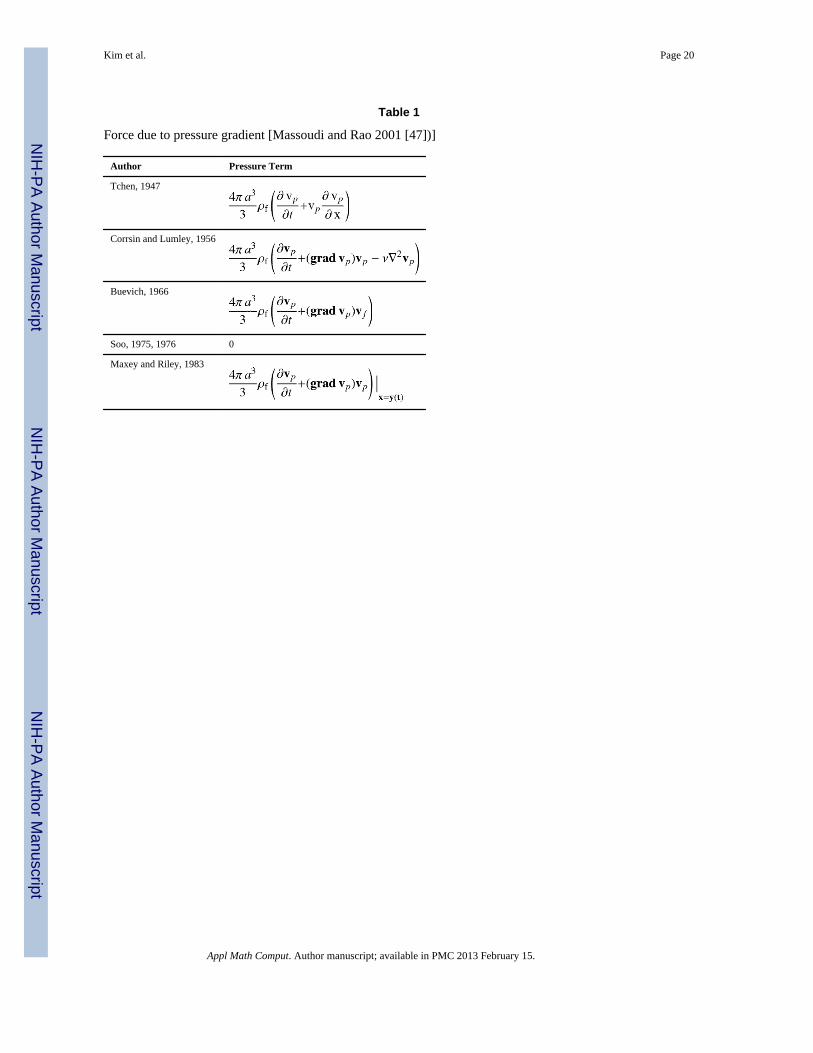
It should be noted that equation (2) is a scalar component of a more general vector equation.Corrsin and Lumley [41] argued that, for a nonuniform flow field, the full Navier-Stokesequations should be used to determine the pressure gradient. Buevich [42] criticized bothprevious studies by pointing out that adding a term to the BBO equation is not necessary.Soo [43, 44] argued that the pressure gradient force is exactly balanced by the fluid inertiaforces and should not appear in the force balance in any form. The importance of the forcedue to the fluid pressure gradient is still a subject of study and disagreement [see Table 1].Maxey and Riley [45], based on an analysis similar to that of Buevich, proposed thefollowing equation for the force on a sphere in a nonuniform flow:
(3)
It is noted that the inclusion of velocity gradients in their analysis results in modifications tothe virtual mass, Stokes drag, and Basset history terms in order to account for the effect of anonuniform flow field. These velocity gradients correspond to the physical effect known asFaxen forces (Happel and Brenner [46]).
Though equation (3) appears to be complete for a single particle in Stokes flow, there are, ingeneral, other forces that must be considered - even for a purely mechanical system. Forexample, in flows with high relative velocity between phases, or large velocity gradients in
Kim et al. Page 4
Appl Math Comput. Author manuscript; available in PMC 2013 February 15.
NIH
-PA Author Manuscript
NIH
-PA Author Manuscript
NIH
-PA Author Manuscript

the fluid, lift may become an important effect (see McLaughlin [48], Ounis and Ahmadi[49]).
It is observed [50–52] that spheres in laminar Poiseuille flow through a pipe (at low Re)accumulate in an annulus some distance from the tube axis. Following the initialobservations, a number of investigators verify this ‘tubular pinch’ effect and attempt toexplain the lateral (or lift) force acting on the spheres. Though some authors attempt toexplain the radial migrations in terms of particle spin (i.e., Magnus force), spheres preventedfrom spinning also reached equilibrium positions between wall and centerline. Saffman [53,54] deduces that, since experimental results contradicted this conclusion, inertial effectsmust be involved. Saffman obtains the result for ‘slip-shear’ lift on a particle at lowReynolds number analogous to a result derived earlier for the ‘spin’ lift by Rubinow andKeller [55]. Saffman [53] includes particle spin in his analysis and shows that undercircumstances where his results and Rubinow and Keller’s result strictly apply, the ‘shear’lift dominates the ‘spin’ lift. The Saffman lift force is normal to the slip vector and the spinvector of the particle. If the particle lags the fluid, the lift will move the particle toward thefaster adjacent fluid and vice versa if the particle leads the fluid. Ho and Leal [56] calculateanother form of lift force on a single particle in a channel. This force is apparently a result ofthe wall effects. A detailed analysis, including experimental observation of lift forces inCouette systems is given by Halow and Wills [57, 58]. For an updated review of Saffman’scontribution to this field, we refer the reader to the recent article by Stone [59]. In majorityof multiphase studies, lift forces are neglected. Massoudi [60] discusses the importance ofthese forces and through a simple order of magnitude analysis concludes that these forces,especially in the flows or in the regions of high velocity gradients (such as swirling flows),cannot be assumed to be negligible a priori. Massoudi [61] also provides a brief review ofthe interaction mechanisms. Ounis and Ahmadi [49] suggested the following equation:
(4)
where as before the subscripts f and p denote the fluid and the particle, respectively; v is thevelocity vector, t is time, μf is the dynamic viscosity, υf is the kinematic viscosity, m is the
mass ( ), ρ is the density, d is the particle diameter (=2a), K=2.594 is the constant
coefficient of Saffman lift force, , the time derivate for the moving
particle is , the fluid acceleration is defined as , and xp =xp ex ⫑ ypey. A generalized form of the Saffman shear lift force was proposed by Drew [62],Ahmadi [63], McTigue et al. [64]. Equation (4) is reduced to the lift force in a uniform shearfield provided by Saffman [53, 54]. This form of the lift force is intended for Stokes flowregime and only valid for small particles. Also, spin of the particle is not taken into accountin the above equations. In the next section, we look at a simplified case of magnetic particlesflowing in a micro-channel subject to a magnetic field. The structure of this magnetic forceis obtained from the work of Han et al. [65]. In reality, however, one must solve theMaxwell’s equations in conjunction with the equation of motion for the particles.
Kim et al. Page 5
Appl Math Comput. Author manuscript; available in PMC 2013 February 15.
NIH
-PA Author Manuscript
NIH
-PA Author Manuscript
NIH
-PA Author Manuscript

4. Flow of magnetic particles in a micro-channelWe consider a paramagnetic particle (representing the malaria-infected RBCs) in a steadyfully-developed laminar flow between two plates (micro-channel). As the firstapproximation, we neglect the terms due to the pressure gradient, virtual mass, and Bassethistory force. However, we add a magnetic force on the right-hand side of equation 4. Thatis, only the Stokes drag, buoyancy, shear-lift and magnetic forces including the velocitygradients known Faxen force are considered. Thus equation (4) becomes:
(5)
We also adopt the magnetic force derived by Han et al. [65] for a ferromagnetic cylindricalwire placed under a uniform magnetic field H0 applied normal to the axis of the wire.However, unlike Han, which prescribed the direction of flow parallel to the longitudinal axisof the wire, the flow is taken here across the wire. (See Figure 2) The correspondingcomponents of magnetic force in the Cartesian coordinates are given as:
(6)
where , μw and μ0 are the magnetic permeability of the ferromagnetic wire andfree space respectively, χf and χp are the magnetic susceptibilities of the fluid solution andthe paramagnetic particle (or pRBC), Vp is the volume of the paramagnetic particle (orpRBC); and aw is the radius of the wire.
Let us consider an array of Nw wires located on the top of the permanent magnet shown inFigure 2. The center of the first wire is positioned at the origin of the x–y plane (x=w0=0 andy=0), and all other wires are displayed side by side along the x-axis. The magnetic forcedistribution of the first wire (n=1) is given by Eq. 6. The center of the nth wire is located atx=wn and its magnetic force distribution can be written in terms of Eq. 6 as:
(7)
where we can label each conductor using the index n=1,2,3,4,…, Nw. Therefore, we candefine the total magnetic force distribution for the Nw array of wires by superposition:
(8)
To solve Eq. 5, we need an expression for the fluid velocity vf in the micro-channel whereflow is two-dimensional. It is known that the velocity profile for the flow between twoplates is different from the flow through a channel (with side walls) with a square cross-section. In this problem, we assume a parabolic flow profile for a wide channel(width≫height), where L denotes the length of the channel, and hc and wc denote the half-height and the half-width of the cross section as shown in Figure 2. For the fully developedpressure-driven steady flow between two fixed plates, the velocity is given as [66],
Kim et al. Page 6
Appl Math Comput. Author manuscript; available in PMC 2013 February 15.
NIH
-PA Author Manuscript
NIH
-PA Author Manuscript
NIH
-PA Author Manuscript

(9)
where is the pressure drop and μf is the viscosity of a fluid, aw and hc are defined andshown in Figure 3. The volumetric flow rate Q is defined as Q = A v̄f where the crosssectional area of the channel is A=4hcwc. The average velocity v̄f is determined byintegrating the velocity over the cross section, i.e., v̄f = 1/A∫vf dA = 2/3 vmax. Themaximum velocity vmax occurs at the centerline, y = a ⫞ hc, i.e., vmax = −(dp/dx)(hc
2/2μf).
Thus, the velocity profile can be rewritten as,
(10)
Finally, by substituting Eq. (8) and Eq. (10) into Eq. (5) we obtain the expression for thecomponents of the forces acting on the particle. Thus the equations for a paramagneticparticle/RBC moving through the cell separator can be rewritten as:
(11)
and
(12)
where is the volume of the particle and
(13)
(14)
and
(15)
Kim et al. Page 7
Appl Math Comput. Author manuscript; available in PMC 2013 February 15.
NIH
-PA Author Manuscript
NIH
-PA Author Manuscript
NIH
-PA Author Manuscript
Note that vp = vp,x ex ⫞ vp,y ey at any position xp = xp ex ⫞ ypey. In these expressions, vp,xand vp,y are the components of the particle velocity.
5. Numerical simulations and particle trajectoriesEquations (11) – (14) represent a coupled system of first-order ordinary differentialequations (ODEs) that are to be solved with appropriate initial conditions for the positionxp(0), yp(0), and the velocity vp,x(0)=vf, and vp,y(0)=0 of the particle. These equations weresolved numerically using the 1st–5th order adaptive step Runge-Kutta solver for stiff ODEsystems (ode15s in MATLAB ODE solver). The relative and absolute error tolerances wereset to 1e-5 and 1e-4 respectively. An alternative approach to simulate particle motion couldbe a discrete particle method when particle-fluid and particle-particle interactions areimportant.
The magnetic force in the y-direction is illustrated in Figure 3. (The x-axis is shifted by 50micron to reference the magnetic force field in the channel.) A cubic regression to theseresults show that the force scales as 1/x3. The x-component of the magnetic force plotted inFigure 4, at y=100 micron illustrates an approximately sinusoidal fluctuation along the x-direction.
Figure 5 shows the trajectories of paramagnetic particles where Faxen and lift forces areincluded. It is observed that as the strength of the magnetic field decreases, the Faxen andthe lift forces do not play a significant role on the motion of the particles. Therefore, theexternal magnetic flux was set to be 0.3 Tesla and we assumed that the Faxen and lift forcesare negligible in the remainder of the numerical studies.
Figure 6 shows the trajectory of five ferromagnetic particles seeded at the entrance of themicro-channel, illustrating their deflection due to the magnetic force. The ferromagneticparticle has diameter of 0.3 micron and susceptibility of 0.26. The susceptibility of plasma is−7.7×10⁻⁶. The numerical results also show that most of the particles are captured at thebottom of the channel near the wires within 13mm (for 1 cc/min) and 65mm (for 5 cc/min),thus suggesting a minimum length of the channel could be achieved by optimizing thedesign parameters.
Next we considered the malaria-infected red blood cells (pRBCs) with diameter of 8 micronand susceptibility of −6.2×10⁻⁶ (See Figure 7). The susceptibility of plasma is −7.7×10⁻⁶.pRBC becomes paramagnetic due to its susceptibility with respect to plasma susceptibility.Some of the particles are not captured within the channel length of 75 mm for flow rates of 1cc/min and 5 cc/min, since the infected RBCs are more paramagnetic than the ferromagneticbeads of the previous simulation. Paramagnetic particles are less deflected than theferromagnetic particles by a permanent magnet. Paramagnetic substances have linearmagnetization curves under normal circumstances and have no magnetism when the externalmagnetic field is removed, where the susceptibility is small and positive. Ferromagneticmagnetization curve is nonlinear. Its susceptibility is positive and large, which changes withH [67].
6. Concluding remarksThe main assumptions in our simulations of particle trajectory are: (1) no particle-particleinteraction (no collisions); and (2) the behavior or the response of the particle is affected bythe fluid motion whereas the fluid motion is unaffected by the presence of the particle, (one-way interaction). For a system of dense particles, these assumptions would not be valid. Inmost studies the forces due to pressure gradient and lift force are neglected; however it isknown that the lift forces could be important in a small scale geometry [53, 60, 62, 68].
Kim et al. Page 8
Appl Math Comput. Author manuscript; available in PMC 2013 February 15.
NIH
-PA Author Manuscript
NIH
-PA Author Manuscript
NIH
-PA Author Manuscript

In this study, we have used the Lagrangian approach to study the particle trajectory whileestimating design dimensions of the cell separation device. For a complete three dimensionalgeometry, we can use a Lagrangian-Eulerian CFD approach. However, these methods do notconsider particle-particle interactions that can affect the cell aggregation and deformabilityof the cells. To better predict the phase separation of the RBCs and the plasma, one shouldconsider alternative approaches such as the mixture theory [47, 60, 61, 69–71] or theparticulate dynamics [72–74]. In this paper, we modeled the malaria infected RBCs(pRBCs) as paramagnetic particles suspended in a Newtonian fluid. Trajectories of theinfected cells are numerically calculated inside a micro-channel exposed to a periodicmagnetic field gradient. First order stiff ordinary differential equations (ODEs) governingparticle’s trajectory under periodic magnetic fields due to an array of wires were solvednumerically using a the 1st –5th order adaptive step Runge-Kutta solver. The numericalexperiments show that in order to achieve a capture efficiency of 99% for the pRBCs it isrequired to have a longer length than 80 mm; this implies that in principle, usingoptimization techniques the length could be adjusted, i.e., shortened to achieve 99% captureefficiency of the pRBCs.
For future study, we will consider more general cases using Eq. (4) for unsteady flowproblems in complex geometries. We need to consider a 3-dimensional Lagrangian-Eulerianapproach to investigate behavior of the pRBC in complex geometries where the magneticfield generated by a series of wires due to the external uniform field magnet also has to beconsidered using the Maxwell’s equations. We will also perform numerical optimizationstudies on the height of the chancel and the magnetic pitch.
AcknowledgmentsThis project was supported by NIH R01 HL089456-01.
References1. Gligorijevic B, McAllister R, Urbach JS, Roepe PD. Spinning disk confocal microscopy of live,
intraerythrocytic malarial parasites. 1. Quantification of hemozoin development for drug sensitiveversus resistant malaria. Biochemistry. 2006; 45:12400–12410. [PubMed: 17029396]
2. Moore LR, Fujioka H, Williams PS, Chalmers JJ, Grimberg B, Zimmerman PA, Zborowski M.Hemoglobin degradation in malaria-infected erythrocytes determined from live cellmagnetophoresis. The FASEB journal. 2006; 20:747–749. [PubMed: 16461330]
3. Hackett S, Hamzah J, Davis TE, St Pierre TG. Magnetic susceptibility of iron in malaria-infectedred blood cells. Biochimica et Biophysica Acta. 2009; 1792:93–99. [PubMed: 19056489]
4. Zborowski M, Ostera GR, Moore LR, Milliron S, Chalmers JJ, Schechter AN. Red blood cellmagnetophoresis. Biophysical journal. 2003; 84:2638–2645. [PubMed: 12668472]
5. Paul F, Roath S, Melville D, Warhurst DC, Osisanya JOS. Separation of malaria-infectederythrocytes from whole blood - Use of a selective high-gradient magnetic separation technique.Lancet. 1981; 2:70–71. [PubMed: 6113443]
6. Gascoyne P, Satayavivad J, Ruchirawat M. Microfluidic approaches to malaria detection. ActaTrop. 2004; 89:357–369. [PubMed: 14744562]
7. Zimmerman PA, Thomson JM, Fujioka H, Collins WE, Zborowski M. Diagnosis of malaria bymagnetic deposition microscopy. Am J Trop Med Hyg. 2006; 74:568–572. [PubMed: 16606985]
8. Ribaut C, Berry A, Chevalley S, Reybier K, Morlais I, Parzy D, Nepveu F, Benoit-Vical F, ValentinA. Concentration and purification by magnetic separation of the erythrocytic stages of all humanPlasmodium species. Malar J. 2008; 7:45. [PubMed: 18321384]
9. Ahn SY, Shin MY, Kim YA, Yoo JA, Kwak DH, Jung YJ, Jun G, Ryu SH, Yeom JS, Ahn JY, ChaiJY, Park JW. Magnetic separation: a highly effective method for synchronization of culturederythrocytic Plasmodium falciparum. Parasitol Res. 2008; 102:1195–1200. [PubMed: 18320226]
Kim et al. Page 9
Appl Math Comput. Author manuscript; available in PMC 2013 February 15.
NIH
-PA Author Manuscript
NIH
-PA Author Manuscript
NIH
-PA Author Manuscript

10. Bhakdi S, Ottinger A, Somsri S, Sratongno P, Pannadaporn P, Chimma P, Malasit P,Pattanapanyasat K, Neumann H. Optimized high gradient magnetic separation for isolation ofPlasmodium-infected red blood cells. Malar J. 2010; 9:38. [PubMed: 20122252]
11. Trampuz A, Jereb M, Muzlovic I, Prabhu RM. Clinical review: severe malaria. Critical Care. 2003;7:315–323. [PubMed: 12930555]
12. Omari AA, Garner P. Malaria: severe, life-threatening. Clinical evidence. 2007; 7:913.13. Campagna AM, Patnaik MM. Advances in global biotechnology and local resources to treat
malaria. Minnesota medicine. 2009; 92:44–45. [PubMed: 19331290]14. Deshpande A, Kalgutkar S, Udani S. Red cell exchange using cell separator (therapeutic
erythrocytapheresis) in two children with acute severe malaria. Journal of Association ofPhysicians of India. 2003; 51:925–926. [PubMed: 14710987]
15. Van Genderen PJJ, Hesselink DA, Bezemer JM, Wismans PJ, Overbosch D. Efficacy and safety ofexchange transfusion as an adjunct therapy for severe Plasmodium falciparum malaria innonimmune travelers: a 10 year single center experience with a standardized treatment protocol.Transfusion. 2010; 50:787–794. [PubMed: 19951317]
16. Shelat SG, Lott JP, Braga MS. Considerations on the use of adjunct red blood cell exchangetransfusion in the treatment of severe Plasmodium falciparum malaria. Transfusion. 2010; 50:875–880. [PubMed: 20003050]
17. Boctor F, Diaz-Fuentes G, Mohandas K, Uehlinger J. Plasmodium falciparum and RBC exchange.Transfusion. 2003; 43:549–549. [PubMed: 12702171]
18. Boctor FN, Dorion RP. Malaria and hereditary elliptocytosis. American Journal of Hematology.2008; 83:753–753. [PubMed: 17696197]
19. Phillips P, Nantel S, Benny WB. Exchange transfusion as an adjunct to the treatment of severefalciparum malaria: case report and review. Review of Infectious Diseases. 1990; 12:1100–1108.
20. Gandini, A.; Weinstein, R.; Parks, D.; Shaw, R. A Blood Purification Method and Apparatus forthe Treatment of Malaria. Patent application number. 20100331753. 2009. www.uspto.gov
21. White NJ. What is the future of exchange transfusion in severe malaria? Journal of Infection. 1999;39:185–186. [PubMed: 10714792]
22. Kumar RK, Lykke AWJ. Cell separation - A review. Pathology. 1984; 16:53–62. [PubMed:6371684]
23. Melville D, Paul F, Roath S. Direct magnetic separation of red cells from whole blood. Nature.1975; 255:706–706. [PubMed: 1134566]
24. Inglis DW, Riehn R, Sturm JC, Austin RH. Microfluidic high gradient magnetic cell separation. JAppl Phys. 2006; 99
25. Han KH, Frazier AB. Continuous magnetophoretic separation of blood cells in microdeviceformat. J Appl Phys. 2004; 96:5797–5802.
26. Han KH, Frazier AB. Paramagnetic capture mode magnetophoretic microseparator for highefficiency blood cell separations. Lab Chip. 2006; 6:265–273. [PubMed: 16450037]
27. Furlani EP. Magnetophoretic separation of blood cells at the microscale. J Phys D-Appl Phys.2007; 40:1313–1319.
28. Zborowski M, Ostera GR, Moore LR, Milliron S, Chalmers JJ, Schechter AN. Magnetophoreticseparation of red blood cells. Abstr Pap Am Chem Soc. 2003; 225:991.
29. Xia N, Hunt TP, Mayers BT, Alsberg E, Whitesides GM, Westervelt RM, Ingber DE. Combinedmicrofluidic-micromagnetic separation of living cells in continuous flow. Biomed Microdevices.2006; 8:299–308. [PubMed: 17003962]
30. Sinha A, Ganguly R, De AK, Puri IK. Single magnetic particle dynamics in a microchannel. PhysFluids. 2007; 1910.1063/1061.2780191
31. Chen H, Bockenfeld D, Rempfer D, Kaminski MD, Rosengart AJ. Three-dimensional modeling ofa portable medical device for magnetic separation of particles from biological fluids. Phys MedBiol. 2007; 52:5205–5218. [PubMed: 17762081]
32. Brandl M, Mayer M, Hartmann J, Posnicek T, Fabian C, Falkenhagen D. Theoretical analysis offerromagnetic microparticles in streaming liquid under the influence of external magnetic forces. JMagn Magn Mater. 2010; 322:2454–2464.
Kim et al. Page 10
Appl Math Comput. Author manuscript; available in PMC 2013 February 15.
NIH
-PA Author Manuscript
NIH
-PA Author Manuscript
NIH
-PA Author Manuscript

33. Mikkelsen C, Bruus H. Microfluidic capturing-dynamics of paramagnetic bead suspensions. LabChip. 2005; 5:1293–1297. [PubMed: 16234954]
34. Li XL, Yao KL, Liu ZL. CFD study on the magnetic fluid delivering in the vessel in high-gradientmagnetic field. J Magn Magn Mater. 2008; 320:1753–1758.
35. Mohanty S, Baier T, Schonfeld F. Three-dimensional CFD modelling of a continuousimmunomagnetophoretic cell capture in BioMEMs. Biochemical Engineering Journal. 2010;51:110–116.
36. Toner M, Irimia D. Blood-on-a-chip. Annu Rev Biomed Eng. 2005; 7:77–103. [PubMed:16004567]
37. Pamme N. Magnetism and microfluidics. Lab Chip. 2006; 6:24–38. [PubMed: 16372066]38. Massoudi M. A note on the meaning of mixture viscosity using the classical continuum theories of
mixtures. International Journal of Engineering Science. 2008; 46:677–689.39. Massoudi M. A Mixture Theory formulation for hydraulic or pneumatic transport of solid particles.
International Journal of Engineering Science. 2010; 48:1440–1461.40. Tchen, CM. Mean value and correlation problems connected with the motion of small particles
suspended in a turbulent fluid. Martinus Nijhoff; The Hague: 1947.41. Corrsin S, Lumley J. On the equation of motion for a particle in turbulent fluid. Applied Scientific
Research. 1956; 6:114–116.42. Buevich YA. Motion resistance of a particle suspended in a turbulent medium. Fluid Dynamics.
1966; 1:119–119.43. Soo SL. Equation of motion of a solid particle suspended in a fluid. Phys Fluids. 1975; 18:263.44. Soo SL. Net effect of pressure gradient on a sphere. Phys Fluids. 1976; 19:757.45. Maxey MR, Riley JJ. Equation of motion for a small rigid sphere in a nonuniform flow. Phys
Fluids. 1983; 26:883.46. Happel, J.; Brenner, H. Low Reynolds number hydrodynamics. Noordhoff Intl. Pub; Leiden: 1973.47. Massoudi M, Rao CL. Vertical flow of a multiphase mixture in a channel. Mathematical Problems
in Engineering. 2001; 6:505–526.48. McLaughlin JB. Aerosol particle deposition in numerically simulated channel flow. Physics of
Fluids A: Fluid Dynamics. 1989; 1:1211.49. Ounis H, Ahmadi G. Motions of small rigid spheres in simulated random velocity field. Journal of
Engineering Mechanics. 1989; 115:2107.50. Segre G, Silberberg A. Radial particle displacements in Poiseuille flow of suspensions. Nature.
1961; 189:209–210.51. Segre G, Silberberg A. Behaviour of macroscopic rigid spheres in Poiseuille flow 1. Determination
of local concentration by statistical analysis of particle passages through crossed light beams.Journal of Fluid Mechanics. 1962; 14:115–135.
52. Segre G, Silberberg A. Behaviour of macroscopic rigid spheres in Poiseuille flow 2. Experimentalresults and interpretation. Journal of Fluid Mechanics. 1962; 14:136–157.
53. Saffman PG. Lift on a small sphere in a slow shear flow. Journal of Fluid Mechanics. 1965;22:385–400.
54. Saffman PG. Correction. Journal of Fluid Mechanics. 1968; 31:624.55. Rubinow SI, Keller JB. The transverse force on a spinning sphere moving in a viscous fluid.
Journal of Fluid Mechanics. 1961; 11:447–459.56. Ho BP, Leal LG. Inertial migration of rigid spheres in 2-dimensional unidirectional flows. Journal
of Fluid Mechanics. 1974; 65:365–400.57. Halow JS, Wills GB. Experimental observations of sphere migration in couette systems. Industrial
& Engineering Chemistry Fundamentals. 1970; 9:603–607.58. Halow JS, Wills GB. Radial migration of spherical particles in couette systems. Aiche Journal.
1970; 16:281–286.59. Stone H. Philip Saffman and viscous flow theory. Journal of Fluid Mechanics. 2000; 409:165–183.60. Massoudi M. On the importance of material frame-indifference and lift forces in multiphase flows.
Chemical Engineering Science. 2002; 57:3687–3701.
Kim et al. Page 11
Appl Math Comput. Author manuscript; available in PMC 2013 February 15.
NIH
-PA Author Manuscript
NIH
-PA Author Manuscript
NIH
-PA Author Manuscript
61. Massoudi M. Constitutive relations for the interaction force in multicomponent particulate flows.International Journal of Non-Linear Mechanics. 2003; 38:313–336.
62. Drew DA. Two-phase flows: constitutive equations for lift and Brownian motion and some basicflows. Archive for Rational Mechanics and Analysis. 1976; 62:149–163.
63. Ahmadi G. A generalized continuum theory for granular materials. International Journal ofNonLinear Mechanics. 1982; 17:21–33.
64. McTigue DF, Givler RC, Nunziato JW. Rheological effects of nonuniform particle distributions indilute suspensions. Journal of Rheology. 1986; 30:1053.
65. Han KH, Frazier AB. Paramagnetic capture mode magnetophoretic microseparator for blood cells.IEE Proc-Nanobiotechnol. 2006; 153:67–73. [PubMed: 16948490]
66. White, FM. Fluid Mechanics. 4. McGraw-Hill; 1999.67. Cullity, BD.; Graham, CD. Introduction to magnetic materials. Wiley-IEEE Press; 2008.68. Eichhorn R, Small S. Experiments on the lift and drag of spheres suspended in a Poiseuille flow.
Journal of Fluid Mechanics. 1964; 20:513–527.69. Johnson G, Massoudi M, Rajagopal KR. Flow of a fluid-solid mixture between flat plates.
Chemical Engineering Science. 1991; 46:1713–1723.70. Massoudi M, Rajagopal KR, Phuoc TX. On the fully developed flow of a dense particulate mixture
in a pipe. Powder technology. 1999; 104:258–268.71. Massoudi M, Antaki JF. An anisotropic constitutive equation for the stress tensor of blood based
on mixture theory. Mathematical Problems in Engineering. 200810.1155/2008/57917272. Zhang J, Johnson PC, Popel AS. Effects of erythrocyte deformability and aggregation on the cell
free layer and apparent viscosity of microscopic blood flows. Microvascular Research. 2009;77:265–272. [PubMed: 19323969]
73. Veerapaneni SK, Gueyffier D, Zorin D, Biros G. A boundary integral method for simulating thedynamics of inextensible vesicles suspended in a viscous fluid in 2D. J Comput Phys. 2009;228:2334–2353.
74. Jin Q, Verdier C, Singh P, Aubry N, Chotard-Ghodsnia R, Duperray A. Migration and deformationof leukocytes in pressure driven flows. Mechanics Research Communications. 2007; 34:411–422.
Kim et al. Page 12
Appl Math Comput. Author manuscript; available in PMC 2013 February 15.
NIH
-PA Author Manuscript
NIH
-PA Author Manuscript
NIH
-PA Author Manuscript

Figure 1.The direction of the flow and the magnetic field in the magnetic cell separator. The origin ofthe x-y plane is located at the center of the first wire with a diameter of aw and each wire isdisplaced horizontally by the pitch (lw). Wn−1 is the x-directional displacement for the nth
wire. The magnetic force is distributed about a circular wire under a uniform magnetic
Kim et al. Page 13
Appl Math Comput. Author manuscript; available in PMC 2013 February 15.
NIH
-PA Author Manuscript
NIH
-PA Author Manuscript
NIH
-PA Author Manuscript

Figure 2.The direction of the flow and the magnetic field in the magnetic cell separator.
Kim et al. Page 14
Appl Math Comput. Author manuscript; available in PMC 2013 February 15.
NIH
-PA Author Manuscript
NIH
-PA Author Manuscript
NIH
-PA Author Manuscript

Figure 3.The y component of the magnetic force along y direction from edge of the wire.
Kim et al. Page 15
Appl Math Comput. Author manuscript; available in PMC 2013 February 15.
NIH
-PA Author Manuscript
NIH
-PA Author Manuscript
NIH
-PA Author Manuscript

Figure 4.The x component of the magnetic force along x direction at y=100 micron.
Kim et al. Page 16
Appl Math Comput. Author manuscript; available in PMC 2013 February 15.
NIH
-PA Author Manuscript
NIH
-PA Author Manuscript
NIH
-PA Author Manuscript

Figure 5.Plot of ferromagnetic bead trajectories at 5 cc flow rate and 0.05 Tesla magnetic flux at theparticle seeding point of x=0, y=100 micron. The wire pitch (lw) is 200 micron and thediameter of the wire (aw) is 100 micron. The height of the micro-channel is 200 micron.
Kim et al. Page 17
Appl Math Comput. Author manuscript; available in PMC 2013 February 15.
NIH
-PA Author Manuscript
NIH
-PA Author Manuscript
NIH
-PA Author Manuscript

Figure 6.Plot of ferromagnetic bead trajectories at 1 cc/min (left) and 5 cc/min (right) flow rate. Themagnetic flux is 0.3 Tesla. The wire pitch (lw) is 200 micron and the diameter of the wire(aw) is 100 micron. The height of the micro-channel is 200 micron.
Kim et al. Page 18
Appl Math Comput. Author manuscript; available in PMC 2013 February 15.
NIH
-PA Author Manuscript
NIH
-PA Author Manuscript
NIH
-PA Author Manuscript

Figure 7.Plot of pRBC trajectories at 1 cc/min (left) and 5 cc/min (right) flow rate. The magnetic fluxis 0.3 Tesla. The wire pitch (lw) is 200 micron and the diameter of the wire (aw) is 100micron. The height of the micro-channel is 200 micron.
Kim et al. Page 19
Appl Math Comput. Author manuscript; available in PMC 2013 February 15.
NIH
-PA Author Manuscript
NIH
-PA Author Manuscript
NIH
-PA Author Manuscript
NIH
-PA Author Manuscript
NIH
-PA Author Manuscript
NIH
-PA Author Manuscript
Kim et al. Page 20
Table 1
Force due to pressure gradient [Massoudi and Rao 2001 [47])]
Author Pressure Term
Tchen, 1947
Corrsin and Lumley, 1956
Buevich, 1966
Soo, 1975, 1976 0
Maxey and Riley, 1983
Appl Math Comput. Author manuscript; available in PMC 2013 February 15.