


June 2009 | MasterTechnician Online 1
136
June 2009 | MasterTechnician Online 1
-
Upload
khangminh22 -
Category
Documents
-
view
4 -
download
0
Transcript of June 2009 | MasterTechnician Online 1

June 2009 | MasterTechnician Online 1
Conte
nts
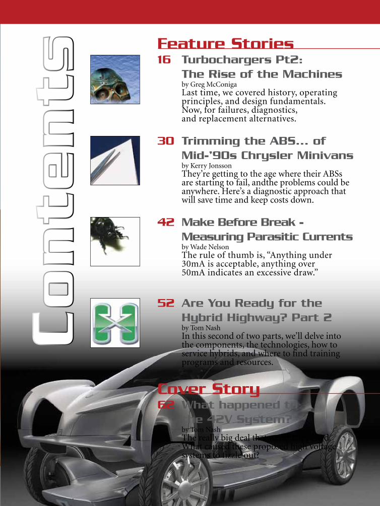
Feature Stories 16 Turbochargers Pt2:
The Rise of the Machinesby Greg McConigaLast time, we covered history, operating principles, and design fundamentals. Now, for failures, diagnostics, and replacement alternatives.
30 Trimming the ABS... of Mid-’90s Chrysler Minivansby Kerry JonssonThey’re getting to the age where their ABSs are starting to fail, andthe problems could be anywhere. Here’s a diagnostic approach that will save time and keep costs down.
42 Make Before Break - Measuring Parasitic Currentsby Wade NelsonThe rule of thumb is, “Anything under 30mA is acceptable, anything over 50mA indicates an excessive draw.”
52 Are You Ready for the Hybrid Highway? Part 2by Tom NashIn this second of two parts, we’ll delve into the components, the technologies, how to service hybrids, and where to find training programs and resources.
Cover Story62 What happened to
the 42V System?by Tom NashThe really big deal that never happened. What caused these proposed high voltage systems to fizzle out?
4 MasterTechnician Online | www.mastertechmag.com
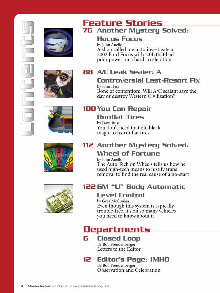
Feature Stories 76 Another Mystery Solved:
Hocus Focusby John AnelloA shop called me in to investigate a 2002 Ford Focus with 2.0L that had poor power on a hard acceleration.
88 A/C Leak Sealer: A Controversial Last-Resort Fixby John HessBone of contention: Will A/C sealant save the day or destroy Western Civilization?
100 You Can Repair Runflat Tiresby Dave RussYou don’t need that old black magic to fix runflat tires.
112 Another Mystery Solved: Wheel of Fortuneby John AnelloThe Auto Tech on Wheels tells us how he used high-tech means to justify trans removal to find the real cause of a no-start
122 GM “U” Body Automatic Level Controlby Greg McConigaEven though this system is typically trouble-free, it’s on so many vehicles you need to know about it
Departments6 Closed Loop
By Bob Freudenberger Letters to the Editor
12 Editor’s Page: IMHOBy Bob Freudenberger Observation and Celebration
Conte
nts
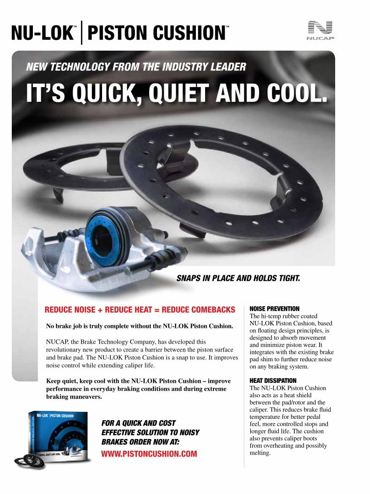
IT’S QUICK, QUIET AND COOL.
REDUCE NOISE + REDUCE HEAT = REDUCE COMEBACKS
NEW TECHNOLOGY FROM THE INDUSTRY LEADER
No brake job is truly complete without the NU-LOK Piston Cushion.
NUCAP, the Brake Technology Company, has developed this revolutionary new product to create a barrier between the piston surface and brake pad. The NU-LOK Piston Cushion is a snap to use. It improves noise control while extending caliper life.
Keep quiet, keep cool with the NU-LOK Piston Cushion – improve performance in everyday braking conditions and during extreme braking maneuvers.
Noise PreveNtioNThe hi-temp rubber coated NU-LOK Piston Cushion, based on floating design principles, is designed to absorb movement and minimize piston wear. It integrates with the existing brake pad shim to further reduce noise on any braking system.
Heat DissiPatioNThe NU-LOK Piston Cushion also acts as a heat shield between the pad/rotor and the caliper. This reduces brake fluid temperature for better pedal feel, more controlled stops and longer fluid life. The cushion also prevents caliper boots from overheating and possibly melting.
SNAPS IN PLACE AND HOLDS TIGHT.
www.PISTONCUSHION.COM
For A QUICK AND CoST EFFECTIVE SoLUTIoN To NoISY BrAKES orDEr NoW AT:

6 MasterTechnician Online | www.mastertechmag.com
(Editor’s Note: We could’ve filled
up this new section with praise
from readers on what a great job
Master Technician is doing. Our
mission, however, is to use all the
space we can to give you info that
will help you in your demanding
profession. So, we’ll concentrate
on useful comments and criticism.)
Go-no-go and low pedal
Dear Mr. Freudenberger,
I read your article on valve
adjustments (Jan., ’07 MT), and
you did a great job on covering
a wide range of vehicles and
problems. I am so glad there is
a new magazine out there for
the complex automotive world
we work in.
Please do not take this the
wrong way, but I was surprised
that you did not suggest the go-
no-go feeler gauge. I am sure you
are aware that even the greenest
of technicians can get the proper
clearances with a go-no-go
feeler gauge. If that technician is
looking for a 0.010 in. clearance,
all he/she needs to do is grab a
0.009/0.011 in. go-no-go feeler
gauge and adjust to a perfect 0.010
because the 0.009 part of the feeler
gauge will slide in between the
components being adjusted, but
the 0.011 feeler gauge cannot slide
in if the adjustment is 0.010. As
you also know, if you can slide a
0.010 feeler gauge between two
items the clearance is greater than
the feeler gauge.
I also enjoyed your article on the
low brake pedal problems. With the
increased heat conditions and traffic
conditions a brake system has to
go through each day it is extremely
important to completely inspect the
brake system before doing a brake
service, and flushing the fluid is an
June 2009 | MasterTechnician Online 7
You are right -- I certainly should’ve
mentioned go-no-go gauges. I
believe I bought my first set maybe
35 years ago, and I know they can
help anybody who hasn’t developed
the “feel” for this kind of work. But
I’ve been comfortable with my own
skills in this regard for so many years
that I simply never thought of it.
Maybe I’ll dig around in one of my
rollaways to see if I can find my old
set, and start using it again.
Just as you say, helping our comrades
avoid mistakes helps our whole
industry, and gives our profession a
better reputation with society at large.
We pledge to try as hard as we can
to “keep up the good work.” It’s
committed, responsible people like
you who make the incredible effort
involved worthwhile. By the way, I’d
thought working as a line tech was
about as difficult a job as there is, but
trying to put out the best magazine is
beyond anything I ever imagined. At
least it doesn’t beat up my old hands
so much. B.F.
excellent suggestion for all vehicles,
especially the ones that have ABS/
traction control systems.
Thank you for your articles
because even someone like me who
has been in the automotive field for
over 45 years needs to update his
knowledge and share with other
technicians to bring respect back to
this most important trade.
As you know, if you take twenty
mechanics they will all have
a different feel or outlook on
anything. I am not concerned
with the experienced mechanic
such as yourself. I am concerned
about our industry helping the
inexperienced, or the experienced
mechanic who will not admit he
does not know how to do the job
right the first time. Any steps we
can take as an industry to avoid
mistakes is important to us all.
Keep up the good work, my friend.
Sincerely,
Eugene Field
8 MasterTechnician Online | www.mastertechmag.com
More Mode $06
Hey, when are you guys going to
get off the pot and give us more?
I want more.
I want more of Mode $06 -- every
person I talk to goes, “Huh, what
are you talking about?”
So please in your infinite wisdom
tell me where I can find Mode $06
info on Japanese and German cars.
Thank you.
Eric Radloff
Believe me, Eric, we tried to get
something out of both M-B and
BMW on Mode $06, but neither
seems to think it has any value except
in the engineering process. We have
especially close relationships with
those companies since we at CmA
produce technical magazines for
them. But our service training and
other tech contacts haven’t been able
to help us. We’ll keep after them.
As far as Asian vehicles are
concerned, we had a story on Toyota’s
use of this mode assigned to the
foremost expert we know of, but he
was unable to do it because of a job
change. We’re still investigating it on
our own (Honda, too) and will try to
produce an article for a future issue,
but we can’t say when. Magazine
publishing is just like any other
business: You’ve got to have the right
people available at the right time. B.F.
CVT Omissions
Bob,
A couple of comments, not meant
to be negative. The magazine is
excellent as usual, but the CVT
article [in the January issue of MT]
makes no mention at all of service
intervals, special oils, or anything
that an independent shop can do in
the form of service. My neighbor is
a Chrysler tech. He claims that a
quick lube added one qt. of Dex3 to
a CVT trans and it was toast in 50
miles. The warranty was void. The
quick lube had to pay for a trans at
Chrysler. I would have liked to have
seen some information like that in
the article, assuming it is true.
Closed Loop
June 2009 | MasterTechnician Online 9
Keep up the great work.
Phil Fournier
Phil’s Auto Service
Hemet, CA
A serious omission, indeed, Phil,
which just proves that we can’t think
of everything. That’s why we’re
encouraging all of our readers to
make the effort to tell us when we’ve
missed something. We want MT to
be as interactive as possible. B.F.
H2O
In re-reading your article
on antifreezes, I found a great
discrepancy about using tap water:
not enough coverage about it.
I have never seen a shop that
would take the time or money to
buy distilled water. That is to say
that I have not seen all shops. Most
shops do not take this time as they
find that it is too cumbersome to
do and takes up valuable space.
And they believe that the customer
will never figure it out.
I personally use unmixed and
distilled water in my own vehicles
as I have only older vehicles, the
newest being a ’96, and have had
to replace the radiators in all. I do
trust premix. I am like all other
mechanics, I HATE WORKING
ON MY OWN DAILY DRIVER.
It really needs to be explained to
these shops why it is bad and how
they can really gain customers if the
proper mix is done.
The other thing I would like to
know is if there is a litmus test for
antifreeze to check for clorinate/
flouride in the system.
Anonymous
We heartily agree that the subject
of the water that’s half of the coolant
mix is important. We’re planning a
feature on it in an upcoming issue.
We try to have a dozen tech articles
in each issue, many more than our
competing magazines have. Still, it’s
impossible to cover every possible
topic in every issue.
10 MasterTechnician Online | www.mastertechmag.com
While we don’t know of a particular
litmus test for water, you can go to
your local Home Depot or Lowe’s
and get a kit for about 10 bucks that
will allow you to test for hardness,
chlorine, pH, alkalinity, iron, etc. B.F.
More on low brake pedal
Hi Bob,
First, I want to thank you
for making Master Technician
available. I own an independent
repair shop and have signed up
all four of my techs as I feel it is a
valuable resource for them and
want them to take advantage of it.
I am going to institute a standard
practice of having each of them
responsible for talking about an
article from MT each month at our
shop meetings.
Next, I wanted to add my two-
cents worth regarding the “Low
Pedal Lament” article. It was very
informative and should help many
techs with this common problem.
Another thing I commonly see
that causes a low pedal feeling, but
wasn’t mentioned, is brake pads
sticking or seized in their mounting
bracket. Subarus and Toyota trucks
are the most common ones I see. On
Toyota truck/SUV front calipers of
the rigidly mounted/multi piston
design, if the pads aren’t seized in
their brackets, then one or more
pistons are stuck, which are almost
impossible to detect unless the
caliper or pads are removed so
piston movement can be evaluated.
This is such a common problem that
when I’m on a road test unrelated
to the brakes, I can detect with a
high degree of success when this
condition is present. I’m not sure if
it is more of a regional thing with the
road salt used here in the northeast.
Visually inspecting the pads, rotors,
etc. all looks fine, but when braking
the pedal travels much farther
than normal. This is the result of
the additional hydraulic pressure
needed to move the pads enough to
provide adequate braking. When
Closed Loop

I drive one of these cars I see it
more as diminished braking power,
but the customer and techs often
interpret it as just a low pedal issue.
Nathan Walker
Recertified ASE Master Technician
& L1
Walker Automotive, Inc.
Wilmot, NH
Dear Nathan,
Your interesting comments just go
to prove what I’ve always said: This
is a regional business. I don’t see the
same things in Florida that you do in
N.H., esp. where undercar corrosion
is concerned.
Your points are so well taken that, if
you don’t mind, I’d like to run them in
a new “Closed Loop” section we have
planned. All we at Master Technician
want to do is help our readers get cars
fixed right the first time, and info like
this can sure help.
Thanks for taking the time to write.
-B.F.
Christopher M. Ayers, Jr.President/Publisher
Bob FreudenbergerEditor
John Anello • Steve CampbellPaul Cortes • Kerry JonssonPhil Fournier • Chip Keen
Greg McGoniga • Tony Molla Tom Nash • Henry Olsen
Matt Ragsdale • Dave RussContributing Editors
Christopher Ayers IIIArt Director, Project Mgr.
Joann TurnerCirculation Manager
Kyle AyersWeb Master
Editorial, Circulation, Advertising Sales and Business Office:
Master Technician Magazine598 Pine Point Drive / Akron, OH / 44333
P.330.666.9886 • F.330.666.8912
If you have a letter to the editor, a Tech Tip or story idea, click here: [email protected], or on this website at www.mastertechmag.com.
Master Technician is published by CmA Communications, LLC. The publisher and editors of this magazine accept no responsibility for statements made herein by advertisers or for the opinions expressed by authors of bylined articles or contributed text.
The online version of Master Technician magazine is free to qualified automotive repair shop owners, managers and technicians. All other content on www.mastertechmag.com is available on a subscription basis. Visit www.mastertechmag.com for subscription information.

12 MasterTechnician Online | www.mastertechmag.com
IMHOby Bob Freudenberger
Editor ’s Page
(In My Humble Opinion)
Back when Master Technician was
a print publication, a reader wrote us
this message:
In the March, ‘07 issue, Bob
Freudenberger mentioned an
upcoming article on tech salaries. I
loved working on customers’ cars in
auto repair shops, especially mom-
and-pop shops [but] they don’t want
to (or can’t afford to) pay a decent
salary, or benefits for a family, or
pension, or anything else. That is why
I now work for the city transit division.
I don’t like the work! But they supply
all the other aforementioned perks.
The only way to stay in the auto repair
business is to own your own business.
I am considering leaving the auto
repair business altogether because the
local union employer is hiring and
willing to pay almost DOUBLE the
average repair shop and supply all the
Payday
perks on top of that. YES, I do miss the
challenge and the feel of figuring out
the tough ones and the appreciation
of a loyal customer. But if you read
between the lines even the shops you
talk about in your articles don’t want
to pay a GOOD wage. That’s why
Ron Ananian doesn’t have “an extra
highly-trained technician available
to help around the shop” And a lot of
you guys are working more than one
job. Fixing cars is great, but living life
comfortably is the main reason we all
get out of bed in the morning.
Bill Hannigan
While the situation has changed
somewhat now with dealership
closings putting many techs on the
street, I think my response is still
worthy of consideration, to wit:

TRADE MULTIPLE PART NUMBERS FOR ONE.
© 2008 CRP Industries Inc. All rights reserved.
When you order a Pro Series Timing Kit from CRP Automotive, you’ll not only get a genuine ContiTech belt — you’ll also receive all the other parts needed to do a complete timing belt and water pump service, including a hydraulic damper when one is required. All in one box, with one SKU number.
Pro Series Timing Kits also come with a limited warranty identical to the original car manufacturer specified timing belt change interval. Just another reason to ask your Parts Supplier or a CRP representative for a complete list of applications today.
CONTITECH REIN AUTOMOTIVE PENTOSIN
For more information, visit www.proserieskit.com © 2009 CRP Industries Inc. All rights reserved.
Available through participating:
www.proserieskit.com
TRADE MULTIPLE PART NUMBERS FOR ONE.
© 2008 CRP Industries Inc. All rights reserved.
When you order a Pro Series Timing Kit from CRP Automotive, you’ll not only get a genuine ContiTech belt — you’ll also receive all the other parts needed to do a complete timing belt and water pump service, including a hydraulic damper when one is required. All in one box, with one SKU number.
Pro Series Timing Kits also come with a limited warranty identical to the original car manufacturer specified timing belt change interval. Just another reason to ask your Parts Supplier or a CRP representative for a complete list of applications today.
CONTITECH REIN AUTOMOTIVE PENTOSIN
For more information, visit www.proserieskit.com © 2009 CRP Industries Inc. All rights reserved.
Available through participating:

14 MasterTechnician Online | www.mastertechmag.com
It’s obviously time for me to bite the bullet and at least start a discussion on this difficult subject, which seems to be taboo among polite people in this business. Sometimes you’ve just got to look the truth in the eye no matter how awkward or uncomfortable it is. And the truth is this: Most technicians aren’t paid nearly enough considering how much they have to know, how hard they have to work, and their investment in tools, not to mention their value to society at large. Even though most of us love the challenge and the satisfaction of this profession, many, many are leaving every day for greener, easier pastures.
One of my neighbors once said, “I think mechanics are some of the smartest people in the world.” I agree, but, as the old retort goes, “If you’re so smart, why ain’t you rich?”
While some people are simply swept along into a career path by life circumstances, most of us do make choices along the way. I, for one, could’ve made a lot more money over the years if I’d switched to being an ad salesman or publisher instead of remaining an automotive writer/editor/photographer and technician, but those pursuits aren’t where my
meager talents, or my interests, lie. I wanted satisfaction from my work. I’m thinking it’s the same with many techs. You could be doing something else that pays better, but you’re in love with fixing cars. Face it.
The last place I worked as a line tech was indeed a mom-and-pop, just as Mr. Hannigan mentioned, although very technically sophisticated and profitable. Four bays, four lifts, two full-time techs, plus the proprietor, who is a tech and a half with great marketing skills, and his wife, who took care of day-to-day business.
Well, everybody liked that friendly, family atmosphere, and customers became friends and grateful patrons who brought us pies, coffee cakes, cigars, wine, etc. Since there was plenty of lucrative business, everybody was well paid, too.
I’m excruciatingly well-aware that I was blessed, and that the money part isn’t always that good elsewhere. That shop is in a location that had been all farms and woods when I was young, but has become an upscale bedroom community -- we call it the “wealth belt.”
Editor ’s Page
So, we could charge enough so that
everybody made a good living. This
shop owner is so good he’d do well
anywhere, but there’s no doubt that this
“boom town” environment fostered
success. For example, I remember a
day when a young customer brought
in both his new Mercedes-Benz
roadster and his wife’s Hummer for
routine maintenance. That was maybe
a hundred and fifty thousand dollars
worth of vehicles that we were taking
on, probably for life, from just one
household. That’s certainly not the
norm across the country.
Bottom line: Independent shop
owner are going to have to learn to
charge enough to support the great
talent that keeps their businesses alive.
I’m sure I’m going to get a “shipload”
of e-mail messages and letters about
this column, and how I didn’t really
get into the problem, or suggest much
in the way of solutions. Fine. That’s
just what I want. Let’s see if we can
fire up this discussion out there in
the real world and make a difference.
Advertisers June 2009(Click Name to visit site.
Click page number to view ad.)
AIRSEPT ........................... 93
Autel Auto Link ................ 47
Autologic US .................... 41
BMW ................................ 85
Castrol............................... 81
CRP ................................... 13
Dayco ................................ 23
Fel-Pro .............................. 55
GRACO ........................... 135
Henry Rifles ...................... 19
HUNTER ........................ 117
Mercedes-Benz ................... 2
MOHAWK ...................... 103
NISSAN .......................... 125
NUCAP ............................... 5
RAE ................................. 131
Raybestos .......................... 33
SEMA ................................ 27
SKF .................................... 99
Tracer Products ................ 87
Volkswagen ....................... 71
Volvo ................................. 37

16 MasterTechnician Online | www.mastertechmag.com
by Greg McConiga
Last time, we covered history, operating principles, and design fundamentals. Now, for failures, diagnostics, and replacement alternatives.

June 2009 | MasterTechnician Online 17
when the cylinder pressure and
temperature cause the last bit of
unburned fuel in the cylinder –
called “end gases” – to spontaneously
explode in uncontrolled combustion.
Normally, a flame front rolls or
proceeds through the air-fuel mixture
in a few thousandths of a second
– depending on air-fuel ratio and
cylinder design it varies between .001
and .004 seconds – but the explosion
of detonation occurs so quickly it’s
measured in microseconds – literally
thousands of times faster than a
normal combustion process.
Detonation exists in three phases:
Inaudible (can’t even hear it over
normal engine sounds), audible
(the BBs or marbles-in-a-can sound
we’re all familiar with), and hard
detonation, which sounds like a
really bad rod knock or someone
with a big ball-peen under the hood.
Trust me, you’ll know it if you hear it,
and you won’t hear it long before you
end up walking! In over thirty years
I’ve only seen it a couple of times in
a street vehicle, and in both cases it
was too late. Depending on severity,
detonation unseats rings, anneals
parts, turns valves inside-out, sets
Let’s start by putting detonation
into perspective: It’s the biggest
problem with the high cylinder
pressures that turbocharging can
produce. Charge air coolers, proper
compression ratios, proper turbo
sizing and waste gate settings, engine
temperature and fuel control, timing
rates, quality fuels and tight oil control
all help stave off these explosions.
Sub or supersonic
While we’re on the topic, detonation
is NOT and never has been colliding
flame fronts. Flame fronts do not
make noise when they hit. You can
collide flame fronts all day long
and never enter detonation. Ford
twin-plug 2.3 and Nissan Nap-Z
engines intentionally created two
flame fronts, as have innumerable
aircraft, racing and specialty engines.
Normal combustion proceeds at
subsonic speeds and spreads by
thermal conductivity. Detonation
is supersonic and spreads by
shock compression. Subsonic and
supersonic: propagated by heat,
propagated by shock; that’s the
difference. Detonation occurs

18 MasterTechnician Online | www.mastertechmag.com
up violent ringing vibrations in the
assembly, breaks rings, cracks heads
and blocks, destroys head gaskets,
fractures piston tops and pounds the
tar out of the reciprocating assembly.
Diagnosing detonation is easy --
the damage is so pervasive it’s like
diagnosing a tornado. On a teardown,
the piston top will be clean and
appear almost sandblasted. The land
above the upper ring may be beaten
down and the top ring pinched. In a
lot of cases, the piston will be burned
down the side or have a hole burned
through the dome. The upper half of
the rod bearings and the lower half of
the mains will show signs of fretting
or damage. Piston pins may be stuck
or sticky, rods twisted or cracked
and crankshafts fractured. On spark
plugs, you’ll see clean, almost sand-
blasted appearing porcelain and
under magnification you’ll see tiny
blue-black balls of molten aluminum
stuck to the insulator. In loud high-
performance engines, you’ll feel it
before you hear it, and if it’s hard
detonation you can’t lift fast enough
to keep from tearing something
up. For causes, think lean (less
evaporative cooling during the gas
exchange cycle), insufficient octane
(the numerical measure of a fuel’s
ability to withstand detonation),
secondary ignition sources and over-
advanced timing (lights the mixture
early, and pressure builds while the
piston is still trying to rise in the bore),
too much compression or boost (or
any other cause of high cylinder
pressures), cam timing and profiles
(early or late intake closing affects
cylinder pressure) and overheating,
either generally or locally (heat is
pressure in a closed system.)
Brave new world
Growing population aside, there are
a lot of things looming on the horizon.
Like all old technologies that grew into
Turbochargers Part 2
If you spin it too fast, it comes apart! Now you know what a burst wheel failure looks like.
20 MasterTechnician Online | www.mastertechmag.com
modern applications, turbocharging
is evolving. The improved efficiencies
of variable nozzle turbines, wastegate
elimination and ball bearing center
housing rotating assemblies are just
the start. Compressor and turbine
wheel shapes are evolving, housing
designs with multiple flow paths are
on the market, and lighter titanium
wheels and machined-from-solid
parts are just entering the world of
automotive turbocharging (you’ll
recognize the titanium compressors
– they will have cast iron compressor
housings instead of alloy to meet burst
wheel containment requirements --
think a scattershield for 20 times the
rpm of an engine).
Even wheel-to-shaft attachment
methods are changing. The oldest
design bore is smooth, with no
threads in the wheel, retained on the
shaft by a nut.
The treaded bore is just that;
the wheel bore is threaded and screws
right onto the shaft. The latest wheels
are boreless; they are bored and
threaded part way through the wheel to
eliminate the stress risers that emanate
from a through-bored wheel face,
which is a good thing at 100,000 RPM.
Expect to see even more advances in
gas and air flow control, and more
improved oil control, better cooling,
and reduced turbo lag.
Diagnosis and repeat failure prevention
Given good fuel control and
normal exhaust temperatures,
clean, properly maintained and
undiluted engine oil, water-
cooled center housings, properly
maintained air filtration and just a
few precautions on the part of the
owner, a turbocharger will last the
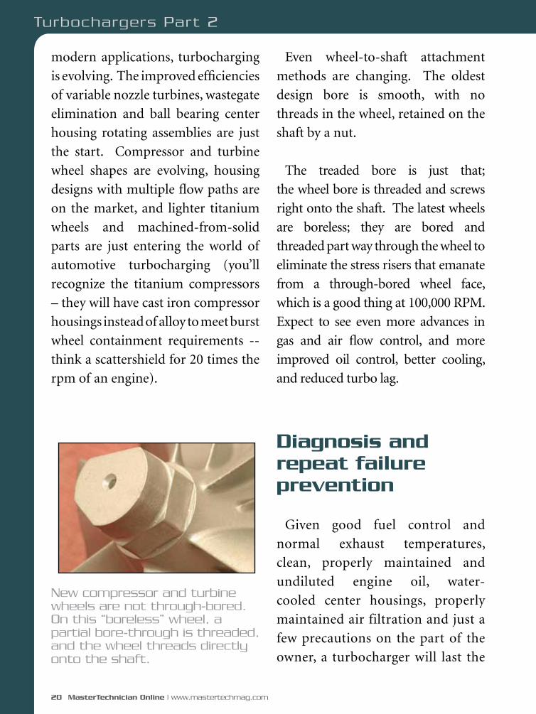
New compressor and turbine wheels are not through-bored. On this “boreless” wheel, a partial bore-through is threaded, and the wheel threads directly onto the shaft.
Turbochargers Part 2
June 2009 | MasterTechnician Online 21
life of the car. If these conditions
aren’t met, there will be a failure,
and if there is a failure there is very
often little left to rebuild, especially
in the event of foreign object damage
(FOD), or lack of lubrication, the
two most common turbo disasters.
This is one reason that more and
more rebuilding is moving to the
manufacturers. Shafts, housings,
wheels and bearings are often
completely destroyed, making field
rebuilding financially impractical.
Before grabbing a fistful of tools and
tearing something apart, stop, look
and listen. Most people know what
a turbo-equipped vehicle sounds
like. There’s that characteristic
turbo sound, sort of a low pitched
whistle that rises in pitch with engine
speed. Take the time to road test
the vehicle and see if you’re hearing
and feeling what you should be
hearing and feeling. You might just
uncover an exhaust or intake system
leak by listening, or you might hear
something whirring or screeching
that ought to be silent. Plus, if you
know what it did before you’ll know
that you fixed it when you do your
final quality control road test.
Oil-related failures are usually due
to some manufacturer’s incredibly
long recommended oil drain interval
(What the hell are they thinking? Let’s
see… $30 oil change , or $2,000 turbo?
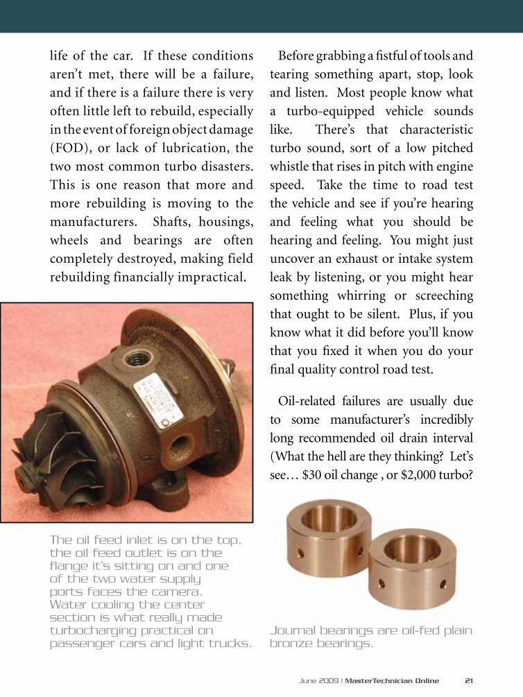
Journal bearings are oil-fed plain bronze bearings.
The oil feed inlet is on the top, the oil feed outlet is on the flange it’s sitting on and one of the two water supply ports faces the camera. Water cooling the center section is what really made turbocharging practical on passenger cars and light trucks.

22 MasterTechnician Online | www.mastertechmag.com
Brains not necessary, apparently),
or poor maintenance on the part of
the owner. Turbos handle and retain
a huge amount of heat, even after
shutdown. You must use the correct
oil type and viscosity. Many of these
engines specify synthetic oils, so pay
attention. After the oil change, never
rev the engine until oil pressure
builds. If you don’t get proper gauge
movement, or the engine low-pressure
oil light isn’t out in 15 seconds, shut
‘er down and investigate. Even at
idle speeds it only takes about thirty
seconds to damage the turbocharger
bearings. If you rev the engine right
after oil change, you might damage
the bearings instantly. Don’t do it! If
you get a lubrication-related turbo
failure and it’s a water-cooled unit
make sure the cooling supply in and
out is unrestricted and that the cooling
system is operating properly. It’s also a
good idea to replace the oil supply and
return lines at the same time since there
have been many instances of these lines
coking shut with heat. I’d advise any
customers with turbocharged cars to
allow 30 seconds of idle time prior to
each shutdown after a normal drive
cycle. I know it’s a pain, but those few
seconds will extend turbo life and save
It’s not uncommon to seize bearings and snap shafts. Look for discoloration and tiny “welded” spots any time you have one apart.
Turbochargers Part 2
24 MasterTechnician Online | www.mastertechmag.com
them money. I’d also advise customers
that if they’ve been out “whuppin’ it
up” to allow two or three minutes of
cool-down time prior to securing the
engine. It’s a small price to pay.
FOD
The second most common failure
is foreign object damage (or FOD.)
Make sure that during routine
service all shop towels, nuts, bolts
and wrenches are accounted for prior
to startup. Foreign objects may be
introduced by others, may fall off the
turbo itself – like the nut holding the
compressor wheel on the shaft – or in
the case of a severely restricted air filter
they may come from the inlet system.
A restricted air filter could collapse
and shred and become the source of
all kinds of debris in the intake tract,
and anything that touches either
wheel guarantees instant shrapnel.
There is no forgiveness if something
is ingested into a wheel spinning at
50,000-125,000 rpm. If you have a
FOD failure, you’ll need to clean the
inlet and charge air cooler to prevent
a repeat. If there’s any question about
whether the charge air cooler got
clean, replace it. On diesel engines,
remember that whatever you used to
clean the charge air cooler cannot be
combustible unless you’re willing to
risk a runaway engine.
Weakling?
Low-power concerns are often
assigned to the turbocharger
immediately, but that’s not always a
good idea. First of all, see if there’s a
lot of detonation sensor activity. On
late-model turbocharged vehicles,
not only will timing be retarded, but
boost may be shut off or limited. I’d
certainly put a pressure gauge on the
intake side, but don’t forget to look at
overheating, timing belt/cam timing
issues, restricted exhaust systems,
fuel pressure and volume and base
timing, if adjustable. Don’t step over
the obvious to get to the obscure.
Once the basics are covered, check
waste gate operation. I don’t have a
dedicated tester for waste gates, but I
do have a radiator pressure tester that
I’ve adapted to check the pressure at
which the waste gate starts to open.
If that’s good, and you’re still not
making boost, then you may find
Turbochargers Part 2

June 2009 | MasterTechnician Online 25
yourself pulling the turbo off to
examine the wheels and shaft, which
is not always a pleasant job.
If you have to pull the turbo, now’s
the time to check for oil in the intake
manifold after the turbo, and the
exhaust system ahead of the turbine
and after. Even if you don’t have oil
consumption complaints, remember
that most people don’t check their
oil and that catalytic converters may
“eat” the oil smoke. Some turbos
use a mechanical oil seal, some use a
labyrinth seal and others rely on the
high shaft speed combined with dams
and diverters to sling the oil away
from the area where the shaft passes
through to the wheel. In most cases,
oil consumption will be the result
of shaft and bearing damage, which
should also show up as rub marks on
wheels and housings. If you find a
compressor or turbine wheel coked
or carboned up, it’s okay to clean
it, but never with any kind of metal
object, including a wire brush. The
slightest scoring on the wheel will
create a stress riser that will lead to
a burst wheel. Soft bristled brushes
and solvent only, please.
It doesn’t take a lot to trim off the ends of the blades. Even opening up the relationship between wheel and housing a few thousands will dramatically change the pump efficiency.
The gas/oil seal is a simple metal part resembling a piston ring.
Once removed, examine the
compressor wheel, turbine wheel
and their respective housings for
signs of damage or rubbing. Using
a bright light, take a careful look at
the compressor wheel. It should not
have a sandblasted or “softened edges”
appearance. If it does, it may have
been damaged by running without an
26 MasterTechnician Online | www.mastertechmag.com
air filter. Turn the turbo by
hand. It should spin freely
with no scraping or rubbing.
Next, push in on one of the
wheels and turn it by hand.
Again, there should be no
rubbing. Finally, push in
on the other wheel and turn
it by hand and check for
rubbing. Any failure that
changes the shape of the
wheel or the contour bore
renders the turbo useless.
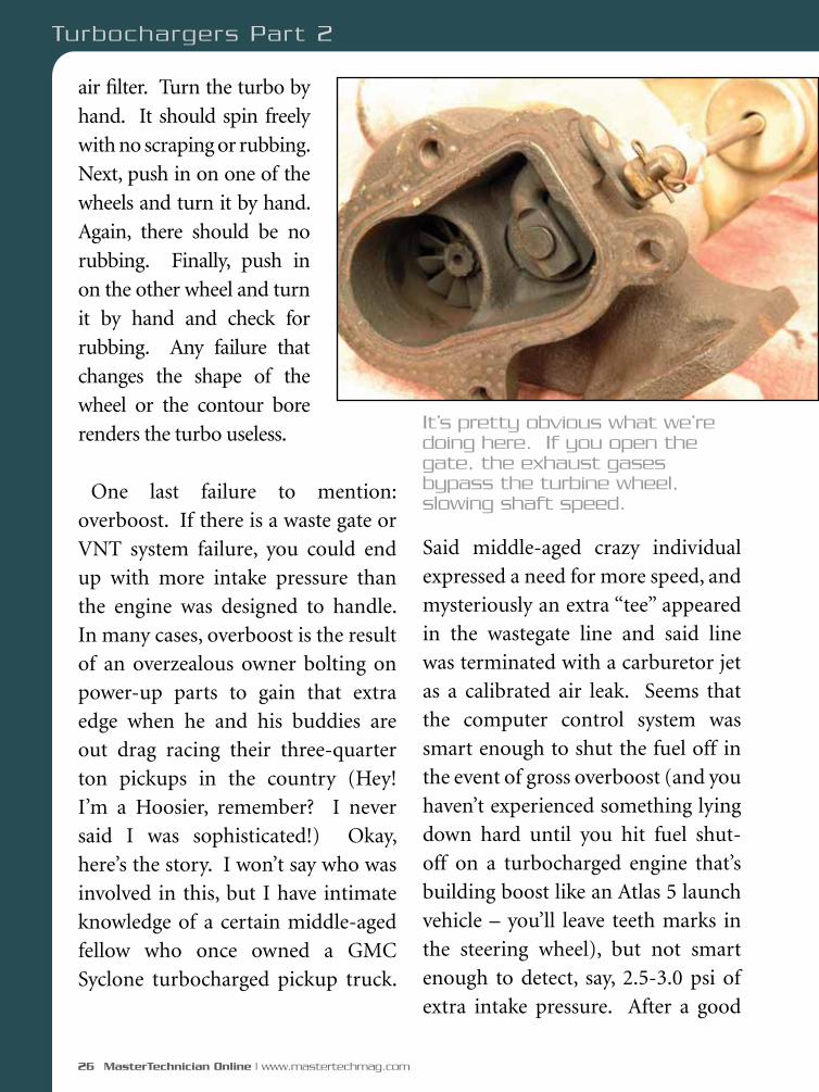
One last failure to mention: overboost. If there is a waste gate or VNT system failure, you could end up with more intake pressure than the engine was designed to handle. In many cases, overboost is the result of an overzealous owner bolting on power-up parts to gain that extra edge when he and his buddies are out drag racing their three-quarter ton pickups in the country (Hey! I’m a Hoosier, remember? I never said I was sophisticated!) Okay, here’s the story. I won’t say who was involved in this, but I have intimate knowledge of a certain middle-aged fellow who once owned a GMC Syclone turbocharged pickup truck.
Said middle-aged crazy individual expressed a need for more speed, and mysteriously an extra “tee” appeared in the wastegate line and said line was terminated with a carburetor jet as a calibrated air leak. Seems that the computer control system was smart enough to shut the fuel off in the event of gross overboost (and you haven’t experienced something lying down hard until you hit fuel shut-off on a turbocharged engine that’s building boost like an Atlas 5 launch vehicle – you’ll leave teeth marks in the steering wheel), but not smart enough to detect, say, 2.5-3.0 psi of extra intake pressure. After a good
It’s pretty obvious what we’re doing here. If you open the gate, the exhaust gases bypass the turbine wheel, slowing shaft speed.
Turbochargers Part 2

SEMA SHOW: Like a Pit Stop for Your Business.
EVERYTHING YOU NEED NOW, ALL IN ONE PLACE.
Las Vegas Convention Center, Las Vegas, Nevada
Exhibit Days: Tuesday, Nov. 3 - Friday, Nov. 6, 2009
Education Week: Monday, Nov. 2 - Thursday, Nov. 5, 2009
New Products. Manufacturers. Technology. Ideas. Answers.Keep your business strong.
Register Now at SEMAShow.com
09_SS_General_ad_MasterTechnician.indd 1 6/4/09 1:38:06 PM

28 MasterTechnician Online | www.mastertechmag.com
many fun Fridays nights laying waste to members of the local street-racing crowd, the truck appeared one day with a rather annoying ticking sound going on in the engine. On further investigation, it was determined that the noise was low, and seemed to be at crankshaft cadence. On teardown, we discovered that one connecting rod was twisted about 8-10 degrees, and shortened just enough for the
pin boss to hit the counterweight of the crankshaft as the piston swung through bottom dead center. Now THAT is cutting it pretty close! Moral of the story? If you get complaints of sudden violent shut down, or if you see overboost occurring during your diagnosis, remember there may be some other clown like that (moi?) out there trying to get that extra little
edge by modifying the boost map.
A non-removable backplate rebuilt Holset turbocharger.
Turbochargers Part 2

June 2009 | MasterTechnician Online 29
locations; check the website below),
but Googling “remanufactured
turbocharger” brought up dozens of
potential suppliers. Depending on
the application and mileage, having
a good reman supplier could save
you and your customers a lot of
time and money. The majority of
remanufactured units out there are
probably going to have a new center
housing rotating assembly with used
compressor and turbine housings
around it, so service life should be
good. Keep it oiled, keep it cooled,
and keep debris out and you and
your customer will be happy.
Special thanks to Pat Kiel of Fort Wayne Diesel (part of Diesel
Injection Service Company - http://www.dieselusa.com/) for
several hours of help. Pat donated three boxes of parts and pieces,
new and used for my use over a weekend to get this story done.
I would also like to thank an extraordinarily professional group
of people at Garrett Turbo (http://www/turbobygarrett.com),
including Kyle Snyder and Craig Gibbs for sending us photos and
answering some very technical questions on short notice. Check out
their website for more technical information about turbocharging.
If these guys don’t know it, it isn’t worth knowing!
Finding replacments
Turbochargers aren’t really that
complicated. For the most part, they
are no longer field-serviceable, and
repairs are confined to replacement
AND making sure that the root cause
of failure is identified – nothing is
worse than calling your supplier with
a “defective part” only to find that the
swarf from the last failure clobbered
your new unit. In my case, I’d see
our friends at Fort Wayne Diesel
for remanufactured replacement
turbos (and they have other
30 MasterTechnician Online | www.mastertechmag.com
To diagnose any system, you
need to understand how it
works. For this article, we’ll
assume you know the basic principles
of ABS so we can move right to
exploring the particulars of the Teves
Mark IV system and looking at some
of its common problems.
Trio
There are three major components
starting with the electronic control
module, which Chrysler refers to as
a CAB (Controller Anti-Lock Brake).
This monitors the wheel speed
sensors along with other inputs, and
controls the ABS hydraulic valve
unit, the next component. This
houses all of the isolation and decay
solenoids (four of each). Finally, we
have the ABS pump motors, which
create the hydraulic pressure needed
to reapply the brakes during an ABS
stop. There are two motors and two
accumulators, one set for each brake
circuit. The pumps don’t have their
own electrical connector and power
supply relay, but are connected to the

June 2009 | MasterTechnician Online 31
hydraulic valve unit and are serviced
together. Unlike other manufacturers,
the pump motor relay is mounted
in the power distribution center
and is not part of the motor or the
hydraulic valve unit. So, that pump
motor or relay circuit code does not
necessarily mean you have to replace
the whole ABS hydraulic assembly.
Brainpower
The ABS control unit is mounted
underneath the driver’s side of the
dash to the right of the brake pedal.
It gets power input directly from the
ignition switch. Once it sees that the
ignition is on, it grounds the ABS
main relay, which is mounted in the
junction block -- that is, the fuse box
underneath the dash on the left side
of the steering column. The relay
is in position #7. If you look at the
wiring diagram, you’ll see that once
This is the power distribution center. It houses the ABS pump motor relay, the light grey one in the middle of the box on the right. Since this relay is separate from the CAB and the hydraulic valve unit, we can test it for causing a pump motor failure message.
Here’s the ABS control unit or the CAB. You can remove the black connector cover and perform most of your electrical tests right here providing you can stand being wedged underneath the dash.
32 MasterTechnician Online | www.mastertechmag.com
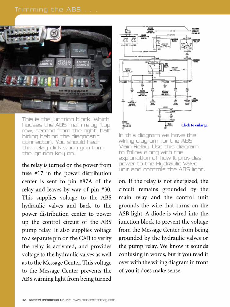
the relay is turned on the power from
fuse #17 in the power distribution
center is sent to pin #87A of the
relay and leaves by way of pin #30.
This supplies voltage to the ABS
hydraulic valves and back to the
power distribution center to power
up the control circuit of the ABS
pump relay. It also supplies voltage
to a separate pin on the CAB to verify
the relay is activated, and provides
voltage to the hydraulic valves as well
as to the Message Center. This voltage
to the Message Center prevents the
ABS warning light from being turned
on. If the relay is not energized, the
circuit remains grounded by the
main relay and the control unit
grounds the wire that turns on the
ASB light. A diode is wired into the
junction block to prevent the voltage
from the Message Center from being
grounded by the hydraulic valves or
the pump relay. We know it sounds
confusing in words, but if you read it
over with the wiring diagram in front
of you it does make sense.
Tr imming the ABS . . .
This is the junction block, which houses the ABS main relay (top row, second from the right, half hiding behind the diagnostic connector). You should hear this relay click when you turn the ignition key on.
In this diagram we have the wiring diagram for the ABS Main Relay. Use this diagram to follow along with the explanation of how it provides power to the Hydraulic Valve unit and controls the ABS light.
Click to enlarge.
A member of the Affi nia family of brands: AIMCO, BrakePro, McQuay-Norris, Nakata, Raybestos, Wix.
Affi nia Group Inc.’s affi liated companies include Brake Parts Inc., Wix Filtration Corp LLC, Affi nia Products Corp LLC and other high quality manufacturers of the Affi nia family of brands.
IndyCar (and Design) are registered trademarks of Brickyard Trademarks, Inc., used with permission.
STOPPING POWERFROM ’08 CHARGER TO ’68 CHEVELLE
OLD-SCHOOL OR MODERN MUSCLE, RAYBESTOS HAS YOU COVEREDWhether for your muscle car, restoration project, or late model daily driver,
Raybestos® has the brake parts you need. For more than 100 years, professional
mechanics and championship-caliber race teams have trusted Raybestos® for quality,
performance and coverage. Our full line includes brake pads, rotors, shoes, drums,
calipers, master cylinders, wheel cylinders, and more. www.raybestos.com
• Vehicle-specifi c custom brake pad formulations defeat noise, dust and fade while delivering improved stopping power
• Exclusive Black Fusion™ coating on Advanced Technology® rotors prevents premature rusting
OLD-SCHOOL OR MODERN MUSCLE, RAYBESTOS HAS YOU COVERED
• Vehicle-specifi c custom brake pad formulations defeat noise, dust and fade while delivering improved stopping power
Find more than half a million listings and 3,000 brake parts for vintage cars & trucks (1928-1972) at Raybestos.com!
AVAILABLE AT:
Raybestos_ATFR_HotRod_MT.indd 1 4/15/09 5:22:25 PM
34 MasterTechnician Online | www.mastertechmag.com
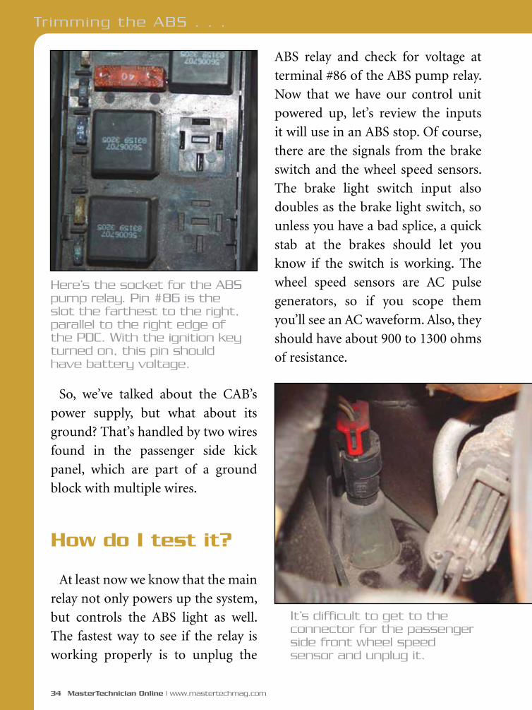
ABS relay and check for voltage at
terminal #86 of the ABS pump relay.
Now that we have our control unit
powered up, let’s review the inputs
it will use in an ABS stop. Of course,
there are the signals from the brake
switch and the wheel speed sensors.
The brake light switch input also
doubles as the brake light switch, so
unless you have a bad splice, a quick
stab at the brakes should let you
know if the switch is working. The
wheel speed sensors are AC pulse
generators, so if you scope them
you’ll see an AC waveform. Also, they
should have about 900 to 1300 ohms
of resistance.
So, we’ve talked about the CAB’s
power supply, but what about its
ground? That’s handled by two wires
found in the passenger side kick
panel, which are part of a ground
block with multiple wires.
How do I test it?
At least now we know that the main
relay not only powers up the system,
but controls the ABS light as well.
The fastest way to see if the relay is
working properly is to unplug the
Here’s the socket for the ABS pump relay. Pin #86 is the slot the farthest to the right, parallel to the right edge of the PDC. With the ignition key turned on, this pin should have battery voltage.
It’s difficult to get to the connector for the passenger side front wheel speed sensor and unplug it.
Tr imming the ABS . . .

June 2009 | MasterTechnician Online 35
Watch out for cracked tone rings,
which may give you low speed
activation of the ABS for no reason.
Also, check if the vehicle has had
the axles replaced because he wrong
number of teeth on the replacement
will throw off the ABS.
If your scan tool is capable of
talking to the CAB module, you’re
in luck. You can monitor the wheel
speed sensors in data and see which
one is setting the code or not reading
properly. If the scope pattern looks
good and the resistance is within
specs, one problem often overlooked
is RFI. Check if any high-current wires
are running near the speed sensor
wiring. The sensors use twisted pair
wires to reduce interference, but high
current loads can still induce a code.
A problem that may come up is
“No Communication” with the CAB
module. Keep in mind the CAB is on
a CAN (Controller Area Network)
and any of the other control units
on the CAN may bring down
communications. First, try to talk to
other control units on the CAN and
see who’s talking back. Another way
to test the CAB through the CAN is to
unplug each control unit on the CAN
until you can start talking to the CAB.
You may find that when you unplug
the CAB you can talk to the other
control units. This would indicate a
bad CAB, or a loose power or ground
supply. One important item to know
is that the red brake warning light
does not have an input to the ABS
control unit, so the hydraulic portion
of the brake system will not turn on
the ABS light and visa versa.
Here’s the other side of the wheel speed sensor connector. The best way to get at it is to remove the 10mm bolt holding down the retaining bracket and pull the sensor through the hole. You’ll find you have much more room to work.

36 MasterTechnician Online | www.mastertechmag.com
What about the hydraulic part?
What does the brain do with those
inputs? During an ABS stop, depending
on which wheel(s) is locking up, the
CAB module will ground any or all of
the four isolation and the four decay
solenoids to apply and reduce brake
pressure to the individual calipers.
As we said, the hydraulic unit also
houses the ABS pump motor and
accumulators, which make and store
hydraulic pressure for an ABS stop.
The hydraulic valves are supplied
voltage with the key on. To check
the solenoids and wiring, all you
have to do is check the eight pins at
the CAB for battery voltage. Keep in
mind that you must have the CAB
module plugged in -- otherwise, the
ABS main relay will not be energized.
The solenoids should have about 5
to 9 ohms each. The hydraulic valve
assembly is mounted under the van,
but you can check resistance without
putting the vehicle on a lift. Measure
between terminal #30 of the ABS
main relay and each of the eight pins
on the CAB.
If you just want to bleed the system
after a brake job, or for maintenance,
you can bleed them like conventional
brakes. Start off with the left rear
wheel followed by the right front, then
the right rear wheel followed by the
left front. If you’re replacing the ABS
hydraulic valve unit, however, you
will need a scan tool capable of the
“Bleed ABS” routine. This will activate
the solenoids while the brake pedal
is applied and purge the hydraulic
assembly of any air. For those of you
without this type of scan tool, you
The hydraulic valve unit and pump motor assembly is mounted underneath the vehicle, which makes R&R fairly easy. Notice the lettering stamped on the aluminum bracket outlining the four different brake circuits.
Tr imming the ABS . . .

38 MasterTechnician Online | www.mastertechmag.com
Tr imming the ABS . . .
can carefully drive the vehicle in
an empty area with no traffic and
perform some ABS stops. This will
cycle the air out of the system as the
ABS solenoids energize. However,
this is time-consuming -- you may
have to go out and drive it four or
five times and bleed it after each road
test. So, it’s not recommended, but it
may get you out of a pinch.
Under pressure!
Although the ABS pump motor
is part of the hydraulic assembly,
there are other parts to check before
replacing it. We mentioned earlier
that the ABS pump motor relay is
mounted in the Power Distribution
Center on the right side, the fifth
relay from the bottom of the box.
It gets voltage from maxi-fuse #7 in
the same box on terminal #30 of the
relay. This relay is only activated by
the CAB when the ignition is turned
on and during an ABS stop. You could
jump pins #30 and #87 and provide
power to the pump motor, but only
for a few seconds. These motors were
not designed to run for very long and
[8] testing like this may damage the
pump. The pump should draw 3.5 to
4.0 amps. Any more than that and it
may be on the way out.
You do have to make sure that you
have a good power supply to the pump.
If the voltage is too low, the amp draw
will read abnormally high and you
may believe the hydraulic assembly
needs to be replaced. The high pump
current draw will cause the ABS
(Below) You can monitor the amperage draw of the motor by jumping terminals #30 and #87. This unit settled down at about 3.8 amps.
June 2009 | MasterTechnician Online 39
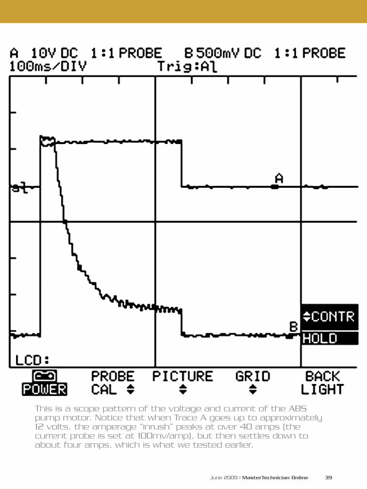
This is a scope pattern of the voltage and current of the ABS pump motor. Notice that when Trace A goes up to approximately 12 volts, the amperage “inrush” peaks at over 40 amps (the current probe is set at 100mv/amp), but then settles down to about four amps, which is what we tested earlier.
40 MasterTechnician Online | www.mastertechmag.com
Tr imming the ABS . . .
light to come on. Unplug the pump
and activate the relay. You should
only see .1 of a volt drop from fuse
#7 to the power supply to the pump.
You can also leave the pump motor
plugged in and measure the voltage to
the pump while energizing the relay,
but, again, only for a few seconds.
One of the reasons we stress voltage
drop testing is that since the relay is
mounted in the Power Distribution
Center corrosion can build up in
the wiring under the PDC -- we’ve
seen copper oxide on the pins of the
relays where the wires connect. This
can lead to voltage drop and failure
of electrical components, including
the ABS pump motor. This is just
another problem to watch out for so
that expensive parts are not replaced
for no good reason. Ditto for the
ground side.
You have a code?
We mentioned using a scan-tool
to pull codes, but this is not entirely
true. Chrysler does not use numeric
trouble codes to identify the problem
in its self-diagnostic check. Instead, we
just get the description. Your best bet
is to match the scan tool’s description
with Chrysler’s description and
follow that flow-chart. Oh, we forgot:
Chrysler doesn’t call them flow-
charts. They’re diagnostic charts
or test charts or whatever else the
company wants to call them. The
chart numbers range from Test 1A
to 22A. Once again, match the scan
tool description with the test chart
description and you should be on the
right path to fixing this “code”.
Also, keep in mind that when a CAB
module gets replaced on later models
it must be programmed with info on
wheel and tires size, as well as engine
and transmission. Be prepared.
These vans are getting older, but we
still work on a lot of them. Keeping
the ABS system functioning, even on
a 10 year-old-vehicle, will keep your
customers coming back, whereas
the purchase of new minivan may
have them going to a dealer for a few
years. A fast and accurate diagnosis
will save you time and the customer
money, making the vehicle more
cost-effective to keep, and it’ll still be
a safe ride. What could be better?

With the increasing complexity of today’s automobiles... It pays to specialize.
Dealer Performance. Complete Independence.
Coding and Programming, that works!
© 2009 AUTOLOGIC.US. All Rights Reserved. All trademarks belong to respective owners.
www.autologic.us • 1-877-945-6442
Call today to schedule an online demonstrationBMW (OEM)TRAINING CLASSES ARE NOW BEING OFFERED!
SEE WEBSITE FOR DETAILS
For a distributor or BMW training classes in your area contact:

42 MasterTechnician Online | www.mastertechmag.com
Determining the reason
a battery keeps going
dead includes testing for
parasitic draws. The rule of thumb is,
“Anything under 30mA is acceptable,
anything over 50mA indicates
an excessive draw.” The greatest
difficulties in measuring parasitic
draws are mostly practical matters.
Having a third hand would make
taking a parasitic draw measurement
much easier. Mistakes are easy to
make, like inadvertently opening a
car door, or leaving the keys in the
ignition. The first will blow the fuse in
your DMM, the second will give you
an incorrect reading. Here are some
tips and tools to make parasitic draw
testing faster, easier, and perhaps save
you a few meter fuses.
The primary difficulty in making a
parasitic draw measurement lies in
establishing the “shunt” connection
through your ammeter (DMM) prior
to disconnecting the terminal from
the battery post, without accidentally
breaking that shunt connection
The rule of thumb is, “Anything under
30mA is acceptable, anything over 50mA
indicates an excessive draw.”
Make Before Break --
Measuring Parasitic Currents
Make Before Break --
Measuring Parasitic Currents
by Wade Nelson
June 2009 | MasterTechnician Online 43
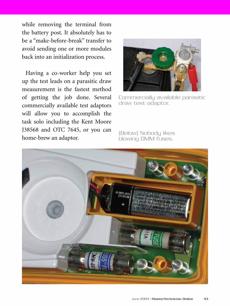
(Below) Nobody likes blowing DMM fuses.
while removing the terminal from
the battery post. It absolutely has to
be a “make-before-break” transfer to
avoid sending one or more modules
back into an initialization process.
Having a co-worker help you set
up the test leads on a parasitic draw
measurement is the fastest method
of getting the job done. Several
commercially available test adaptors
will allow you to accomplish the
task solo including the Kent Moore
J38568 and OTC 7645, or you can
home-brew an adaptor.
Commercially available parasitic draw test adaptor.
44 MasterTechnician Online | www.mastertechmag.com
One eBay vendor, “A-fluke,” offers
a parasitic draw tester, similar to an
OTC7645, but with test leads already
attached. If you were to cut one
of the two leads, and insert a 10A
blade fuse holder or circuit breaker,
you’d have an almost perfect tool
for parasitic draw testing – one that
would prevent you from ever again
blowing an expensive meter fuse.
As with all measurements of
electrical current, you sever the
circuit, and insert your ammeter in-
line between the two severed ends.
But in this case, you can’t ever allow
the two ends to become completely
electrically disconnected. Current
must always be able to flow, either
through the battery cable itself, or
“shunted” through your DMM. If
the circuit gets completely opened
and you re-connect the leads, one or
modules in the vehicle will go into
an initialization routine, boosting
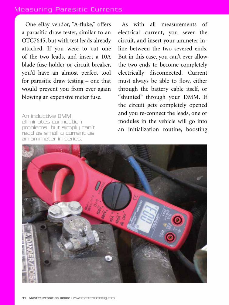
An inductive DMM eliminates connection problems, but simply can’t read as small a current as an ammeter in series.
Measuring Parasit ic Currents

June 2009 | MasterTechnician Online 45
current flow considerably. This may
or may not blow your meter fuse, but
it will definitely give you an incorrect
reading. You have to wait until that
process completes and they are ready
to go to sleep before you can try again.
On some vehicles, you can use a scan
tool to command modules to quickly
go to sleep, which is a time-saver
Calibration Run
You need to determine what
amperage range the parasitic draw
is in immediately after the ignition
is turned off, and approximately
how long it takes before the vehicle
goes to sleep. It could be 45 seconds,
or 15 minutes on different vehicles.
Baseline information from testing
similar vehicles can be invaluable,
and save you time on a “problem”
vehicle.
Suppose that for 30 seconds after
ignition off, you’ve got a current
draw of 2.2 amps, or 2200 milliamps.
After 45 seconds it goes down to
.12A, or 120mA. After five minutes
it then decreases to 17 milliamperes.
You may need to change the range
on your DMM, perhaps even which
jacks the probes are plugged into
to accommodate measuring such a
wide range of current levels. Since
changing the jacks, or even switching
the range, can momentarily break the
circuit, you may need to plan ahead,
and NOT insert your DMM into the
circuit until an appropriate time.
Pre-Test
GM’s parasitic draw test procedure
recommends road testing the
vehicle and activating ALL electrical
accessories, including the radio and
air conditioning prior to parking,
turning the ignition switch to the
OFF position and removing the key.
With today’s feature-laden cars, that
can be a lot of button pressing.
Be sure to unplug any accessories
from the cigarette lighter outlet and
any accessory outlets in the rear
of the vehicle. Most importantly,
remove the keys from the ignition.
46 MasterTechnician Online | www.mastertechmag.com
Otherwise, some systems may stay
powered-up. Consider the effect on
the factory security system of having
the hood up. Look for hood switches,
and defeat them. Unhook any
underhood trouble lamps. If having
the hood up doesn’t prevent its use,
use the remote (key fob) to lock the
vehicle, just as you would if you were
leaving it in a parking lot. Make sure
all doors and hatches are shut.
Get Ready:
The most time-consuming
mistake you can make is starting the
measurement process with the fuse
in your meter already blown. Test it
beforehand by measuring the current
through an #1156 tail lamp bulb
set on one of the battery terminals,
using your meter leads to form the
other connection. It should read
approximately 1.6 amps. Have some
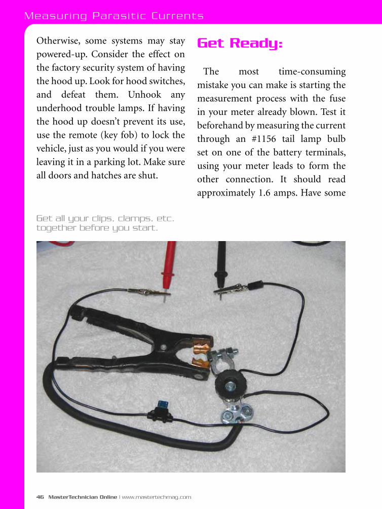
Get all your clips, clamps, etc. together before you start.
Measuring Parasit ic Currents
T o m o r r o w ’ s T e c h n o l o g y f o r T o d a y ’ s T e c h n i c i a n s
© 2009 AUTEL.US. All Rights Reserved. All trademarks belong to respective owners.www.autel.us • 1-877-Autel-US
Visit our website to view our full product line. Distributors welcome.
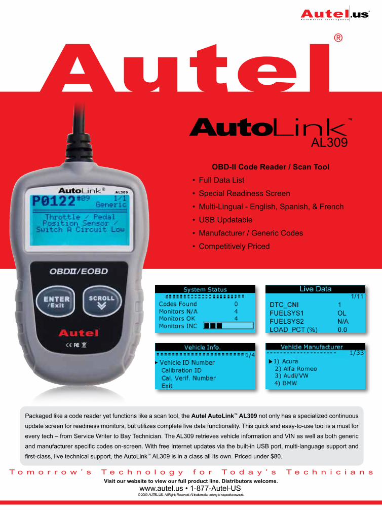
Packaged like a code reader yet functions like a scan tool, the Autel AutoLink™ AL309 not only has a specialized continuous
update screen for readiness monitors, but utilizes complete live data functionality. This quick and easy-to-use tool is a must for
every tech – from Service Writer to Bay Technician. The AL309 retrieves vehicle information and VIN as well as both generic
and manufacturer specific codes on-screen. With free Internet updates via the built-in USB port, multi-language support and
first-class, live technical support, the AutoLink™ AL309 is in a class all its own. Priced under $80.
AL309
OBD-II Code Reader / Scan Tool• Full Data List
• Special Readiness Screen
• Multi-Lingual - English, Spanish, & French
• USB Updatable
• Manufacturer / Generic Codes
• Competitively Priced

48 MasterTechnician Online | www.mastertechmag.com
extra meter fuses available in case
you screw up. Courtesy lamps alone
may not pull more than 10A, but
other onboard systems may “wake
up” if a door is inadvertently opened,
immediately putting the shunted
draw over your meter’s fuse limit.
Second, have all the alligator clips
and jumpers you could possibly
need, including perhaps some battery
charging clips or side post adapters,
so after getting everything hooked
up you can set your meter down and
walk away. Having to stand there and
firmly press a DMM probe into a lead
battery terminal gets very old after
very few minutes, especially the third
or fourth time you do it! This is where
a DMM with min/max recording
ability proves its value, since you can
walk away, and come back anywhere
from 10-30 minutes later and hit the
button to see the value.
Since you can’t simply pull a fuse for the alternator if you suspect it’s the cause of the draw, simply disconnect it.
Measuring Parasit ic Currents
June 2009 | MasterTechnician Online 49
Parasitic Measurement Gotchas:
The auto manufacturers seem to
be intent on making parasitic draw
measurements ever more difficult
to make. Here are some of the “land
mines” they’ve left behind:
•Reportedly, some Chryslers are
programmed to burn off the MAF
sensor wire in the middle of the
night, causing a noticeable increase
in current – several amps. A similar
report claims some Chryslers test 02
sensor heaters at oh-dark twenty.
•NVLD (Natural Vacuum Leak
Detection) can run on GMs for up to
45 minutes after Key Off.
•Toyota’s EVAP pump can run for
10-12 minutes starting five hours
after the engine is turned off.
•On Ford Escape hybrids, the antilock
brake system reportedly does a self-test
with the key off. But when?
•Boomerang 1 [theft recovery]
devices draw between 35 and 55 mA.
Boomerang 2 units “lay low” for 15
minutes when power is removed.
Details on LoJack current draws
aren’t available.
•Some GM regulated voltage control
(RVC) systems are designed to wake-
up, perform a task, and fall back to
sleep at regular intervals.
•OnStar will create draws for the
first 48 hours after turning the
ignition off. The system will cycle
every 10 minutes and spike to 250 mA
for about ten seconds, taper down to
75 mA for another 45 seconds and go
to less than 1 mA until the next cycle
begins. This cycle stops if power is
removed from the OnStar system for
a short period and will resume once
a GPS signal is reacquired.
•Some Chevy Dual Zone Automatic
A/C systems were designed to “stay
awake” for up to four hours after the
ignition is turned off.
•As always, check for TSBs.
50 MasterTechnician Online | www.mastertechmag.com
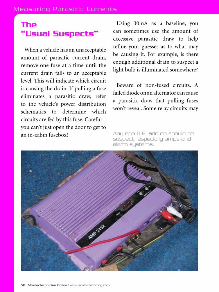
The “Usual Suspects”
When a vehicle has an unacceptable
amount of parasitic current drain,
remove one fuse at a time until the
current drain falls to an acceptable
level. This will indicate which circuit
is causing the drain. If pulling a fuse
eliminates a parasitic draw, refer
to the vehicle’s power distribution
schematics to determine which
circuits are fed by this fuse. Careful –
you can’t just open the door to get to
an in-cabin fusebox!
Using 30mA as a baseline, you
can sometimes use the amount of
excessive parasitic draw to help
refine your guesses as to what may
be causing it. For example, is there
enough additional drain to suspect a
light bulb is illuminated somewhere?
Beware of non-fused circuits. A
failed diode on an alternator can cause
a parasitic draw that pulling fuses
won’t reveal. Some relay circuits may
Any non-O.E. add-on should be suspect, especially amps and alarm systems.
Measuring Parasit ic Currents

June 2009 | MasterTechnician Online 51
not be fused. Improperly installed
audio amplifiers staying powered up
all night long are some of the most
common causes of parasitic draws.
You’ll often see the power leads for
“suspect” systems “MacGuyvered”
directly to the battery terminals.
Before you pull a single fuse, unhook
these bad boys and re-check the
parasitic current levels.
Future of Parasitic Draw Testing
The future of parasitic draw testing
is either very dim or very bright,
depending on how you look at it.
The latest BMWs and Toyotas and
most hybrids incorporate a sensitive
battery current monitor directly
on the battery terminal. Combined
with the PCM, this is capable of
monitoring and recording parasitic
draws. All the tech need do is hook up
a scan tool and view recorded data.
Multiple battery setups can
complicate parasitic draw testing.
Hybrids aren’t the only vehicles
equipped with dual batteries these
days. Others vehicles include the
Mercedes McLaren SLR and Lexus
460, and “mild” hybrids like the
Chevrolet Silverado. Unlike large
trucks and RVs where two or more
12V batteries are simply connected
in parallel, various electronics
may greatly complicate parasitic
testing on these vehicles. Virtually
all hybrid “main” batteries
incorporate battery current
monitoring features, fortunately.
Summary:
Parasitic draws are one of the
three most common causes of
dead batteries. Any parasitic draw
over 50mA is suspect. With a little
practice making parasitic draw
measurements becomes secondhand.
The usual suspects in parasitic draw
measurements are aftermarket
stereos, amplifiers, and security
systems. Homebrew or aftermarket
adapters help make parasitic draw
tests easier. The key technique is
a “make-before-break” shunt of
battery current through the DMM
used to measure parasitic draws.

52 MasterTechnician Online | www.mastertechmag.com
In the first part of this article,
we looked at the history and
development of gasoline engine/
electric motor hybrids, how they
function and which vehicles employ
hybrid drive systems.
In this second part, we’ll explore
hybrid technology, the service aspects
and where you can procure training
and resources for launching into
hybrid service and repair.
The basic message is that you
can service hybrids and need to
be knowledgeable about how they
operate, how to diagnose them, and
skilled in repair techniques – if you
want to be competitive.
Over a million gasoline hybrids are on the road and need service. Are you ready to handle the repair needs of this growing market? In this second of two parts, we’ll delve into the components, the technologies, how to service hybrids, and where to find training programs and resources. (Image Courtesy Cadillac.)
June 2009 | MasterTechnician Online 53
Components & technology
The components that set hybrids
apart from standard I.C. engine-
only vehicles are the high-voltage
generation, drive, control and storage
devices. Some of these components
range from 144-650 volts and should
be considered lethal. They are
indicated by bright orange wiring and
harness covers. Never attempt service
on these components unless you are
properly trained and experienced in
the technology. Always refer to the
specific service information for the
vehicle you are servicing.
In most cases, malfunctioning
or failed electric and electronic
components are simply removed
and replaced, with the exception of
some control modules, which can
be re-programmed.
Here are some generic descriptions
of these components found on
hybrid vehicles:
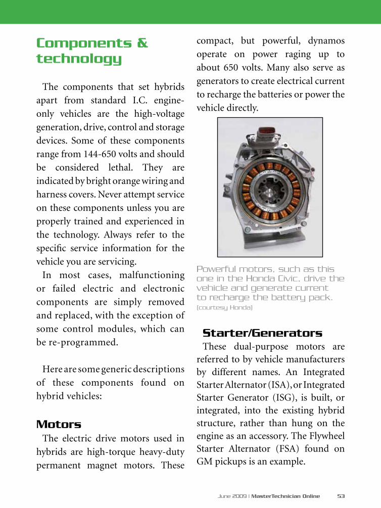
MotorsThe electric drive motors used in
hybrids are high-torque heavy-duty
permanent magnet motors. These
compact, but powerful, dynamos
operate on power raging up to
about 650 volts. Many also serve as
generators to create electrical current
to recharge the batteries or power the
vehicle directly.
Starter/GeneratorsThese dual-purpose motors are
referred to by vehicle manufacturers by different names. An Integrated Starter Alternator (ISA), or Integrated Starter Generator (ISG), is built, or integrated, into the existing hybrid structure, rather than hung on the engine as an accessory. The Flywheel Starter Alternator (FSA) found on GM pickups is an example.
Powerful motors, such as this one in the Honda Civic, drive the vehicle and generate current to recharge the battery pack. (courtesy Honda)

54 MasterTechnician Online | www.mastertechmag.com
Are you ready for the Hybrid Highway?
What’s called a Belt Alternator Starter (BAS), however, is usually mounted on the engine like a standard belt-driven alternator. Presently, only GM uses BAS-type starter/generators. A good example is the Malibu Hybrid.
ConvertersConverters (DC-to-DC) alter
voltage up or down as needed for various components. This may require changing the battery voltage – which may range from 144V to 488V – to as low as 12V to power the lights, accessories and convenience systems, or step it up to as high as 650V to power drive motors.
InvertersInverters convert DC to AC for the
purpose of driving AC motors or other
devices, as well as to power 120V outlets
to run convenience items such as power
tools, or household appliances.
Regenerative braking technology
Regenerative braking allows a motor
to act as a generator when coasting or
braking. Kinetic energy that normally
would be wasted during braking is
converted into electrical energy to
recharge the battery.
DC-to-DC converters change the voltage level for various uses in a hybrid system. (courtesy Denso)
Inverters change DC current to AC flow for powering AC motors, or provide 120V AC current outlets. (courtesy Toyota)

©2009 Federal-Mogul Corporation. All rights reserved.
Now more than ever, it pays to install Fel-Pro®!
Limited time offer, April 15 – May 31, 2009!
Visit www.felpro-only.com for complete details.
* Our most popular applications - see catalog for the complete application listing for each part number.
REBATE$20 each
Applications* Engine Part NumberExplorer 1991-1997; Ranger 1990-1997 Ford 4.0L OHV V6 1990-1997 MS98005T
Explorer 1998-2001; Ranger 1998-2001 Ford 4.0L OHV V6 1998-2001 MS98006T
Chevrolet Malibu 2004-2006; Pontiac G6 2005-2006 GM 3.5L V6 VIN L & 8 2004-2008 MS98013T
Buick LeSabre 1995-2005; Pontiac Grand Prix 1997-2008 GM 3.8L V6 1995-2008 MS98014T
Chevrolet Silverado 1999-2008; Chevrolet Express Van 2003-2008
GM Truck 4.8L, 5.3L, 6.0L V8 1999-2008 MS98016T
Qualifying Fel-Pro® PermaDryPlus® Intake Manifold Gasket Sets
NEW
NEW
NEW
Applications* Engine Part NumberF Series truck 1969-1987;
Mustang 1963-1987 Ford 5.0L & 289 V8 1962-1987 OS13260T
F Series truck 1969-1987; F Series van 1969-1987 Ford 5.8L 351W V8 1969-1987 OS30214T
Qualifying Fel-Pro® PermaDryPlus® Oil Pan Gasket Sets
REBATE$10 each
Applications* Engine Part NumberChevrolet Lumina APV 1990-1995;
Chevrolet Camaro 1990-1995 GM 2.8L, 3.1L, 3.4L 1985-1998 VS50272T
Cherokee 1987-1995; Wrangler 1987-1995 Jeep 4.0L & 4.2L L6 1986-1995 VS50522T
Qualifying Fel-Pro® PermaDryPlus® Valve Cover Gasket Sets
REBATE$10 each
For a limited time, during the Fel-Pro Seal and Save Event, we are offering $10 and $20 cash rebates on the industry’s best Leak Repair gaskets – Fel-Pro PermaDryPlus!
Professional Technicians! Just purchase and install these qualifying Fel-Pro PermaDryPlus Gasket Sets – available for both older and late-model vehicles – and you’ll qualify for cash back! It really does pay to install Fel-Pro!
www.felpro-only.com
How it works: Professional repair technicians purchase and install a premium Fel-Pro PermaDryPlus Set listed here between April 15 and May 31, 2009. Then visit www.felpro-only.com and complete the online rebate form. Send in the rebate form along with the carton part number end flaps and receipt(s) by 6/30/09. Limit one rebate redemption per technician.

56 MasterTechnician Online | www.mastertechmag.com
Are you ready for the Hybrid Highway?
The energy conversion is not
achieved by producing waste heat in
the pads and rotors as in traditional
braking systems, but within the
integrated motor/generator units.
While the brake pads and rotors
stop the wheels at high speed
or in emergency situations, the
regenerative braking system slows
the vehicle in normal driving.
Regenerative braking takes place
when the foot is lifted from the
accelerator pedal, or the driver applies
the brake pedal. To visualize this effect,
think of the engine braking and drag
experienced when you downshift
with a manual transmission.
An important note on brake service:
Since the regular hydraulic service
brakes on hybrids get little use in
normal driving, especially around
town, the calipers and rotors can rust
to an extent that you’ve never seen
before. So, every time you’ve got
any hybrid on the lift, do a thorough
A monitor screen on this 2007 Toyota Camry Hybrid continually displays the hybrid operation and function, including the level of regenerated power (Courtesy Toyota).
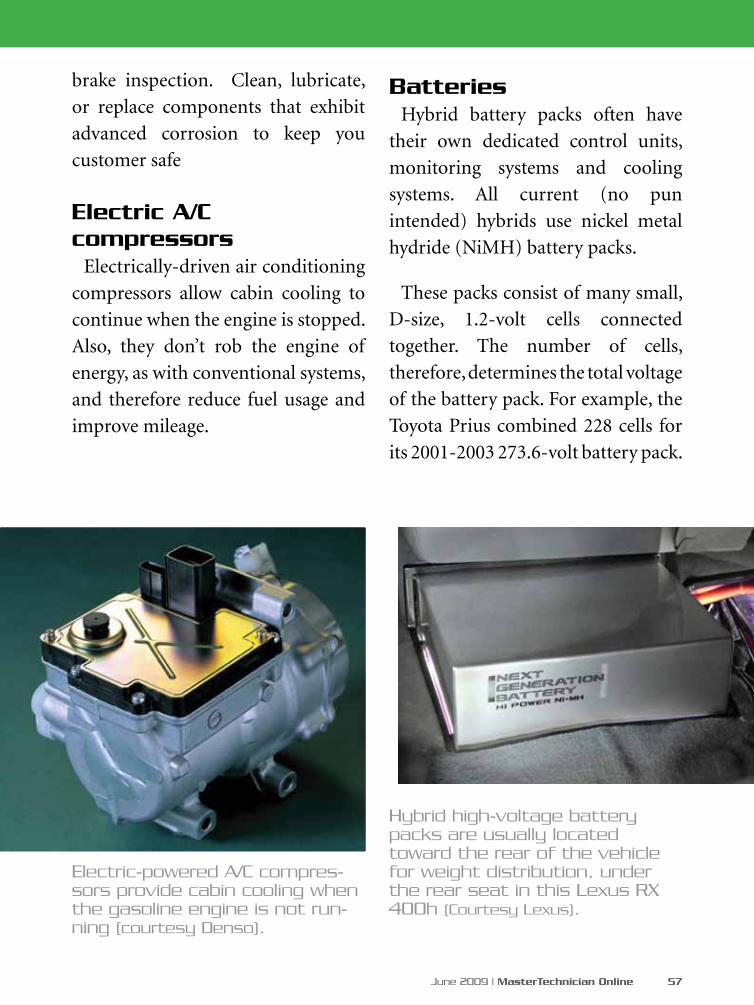
June 2009 | MasterTechnician Online 57
brake inspection. Clean, lubricate,
or replace components that exhibit
advanced corrosion to keep you
customer safe
Electric A/C compressors
Electrically-driven air conditioning
compressors allow cabin cooling to
continue when the engine is stopped.
Also, they don’t rob the engine of
energy, as with conventional systems,
and therefore reduce fuel usage and
improve mileage.
BatteriesHybrid battery packs often have
their own dedicated control units,
monitoring systems and cooling
systems. All current (no pun
intended) hybrids use nickel metal
hydride (NiMH) battery packs.
These packs consist of many small,
D-size, 1.2-volt cells connected
together. The number of cells,
therefore, determines the total voltage
of the battery pack. For example, the
Toyota Prius combined 228 cells for
its 2001-2003 273.6-volt battery pack.
Electric-powered A/C compres-sors provide cabin cooling when the gasoline engine is not run-ning (courtesy Denso).
Hybrid high-voltage battery packs are usually located toward the rear of the vehicle for weight distribution, under the rear seat in this Lexus RX 400h (Courtesy Lexus).
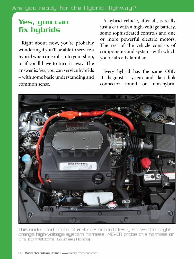
58 MasterTechnician Online | www.mastertechmag.com
Are you ready for the Hybrid Highway?
Yes, you can fix hybrids
Right about now, you’re probably
wondering if you’ll be able to service a
hybrid when one rolls into your shop,
or if you’ll have to turn it away. The
answer is: Yes, you can service hybrids
– with some basic understanding and
common sense.
A hybrid vehicle, after all, is really just a car with a high-voltage battery, some sophisticated controls and one or more powerful electric motors. The rest of the vehicle consists of components and systems with which you’re already familiar.
Every hybrid has the same OBD II diagnostic system and data link connector found on non-hybrid
This underhood photo of a Honda Accord clearly shows the bright orange high-voltage system harness. NEVER probe this harness or the connectors (Courtesy Honda).
June 2009 | MasterTechnician Online 59
vehicles, so you can easily connect a scan tool and read codes.
Just as you would with any type of vehicle you’ve never serviced, take the time to read the owner’s manual, log onto your service information provider’s system, and/or visit the manufacturer’s technical information website to educate yourself about the vehicle before beginning work.
Better, you should gain some knowledge and a little practical experience working on hybrids if you plan to make them part of your business. Taking a class in hybrid service is strongly recommended for a full working knowledge of hybrids.
That being said, let’s cover some important factors you should keep in mind when servicing hybrids.
Safety first! No kidding
You’re going to be working around very high voltage. Always take proper precautions.
1. NEVER – under any circumstances – probe the bright orange high-voltage system harness or connectors.
2. ALWAYS shut the high-voltage system down when working anywhere near a hybrid system-related component. The shut-off switch can be located by reading the owner’s manual. It may be in the trunk, behind the rear seat, or elsewhere. Be sure to wait the appropriate 5-10 minutes after flipping the switch for the system’s capacitors to discharge. Refer to the correct service information for specific details.
3. BE SURE to remove the key from the ignition and make sure the vehicle is in park before working around the accelerator. On models that incorporate a proximity key system that doesn’t require the insertion of a key, only that the fob transmitter is within a certain range before the START button is pushed, make sure the fob is out of range. Examples include later models of Toyota or Lexus vehicles.
4. ALWAYS educate yourself about the intricacies of the specific vehicle you intend to service, just as you would any other vehicle. Access the correct service information from your service information provider, or log onto the manufacturer’s technical information website.
60 MasterTechnician Online | www.mastertechmag.com
Are you ready for the Hybrid Highway?
Manufacturer technical information websites
For basic maintenance and service information, you can access your regular service information provider, but most don’t include detailed information on hybrid components and specifications. The best sources for hybrid diagnostics, repair and parts information are the technical information websites of the vehicle manufacturers. Each, of course, requires a fee for use. These websites may be accessed through the National Automotive Service Task Force (NASTF) website at www.nastf.org, or individually as listed below:
Chrysler www.techauthority.com
Ford www.motorcraft.com
GM (Chevrolet, GMC, Saturn) www.gmtechinfo.com
Honda www.ServiceExpress.Honda.com
Mazda www.mazdatechinfo.comNissan www.nissantechinfo.com
Toyota www.techinfo.toyota.com
Hybrid system parts
Because there are no aftermarket sources yet, all new or remanufactured hybrid components must be purchased through OE dealers. The 2000 EPA mandate and the NASTF agreement ensure that every automobile manufacturer will make parts, tools and service information available to aftermarket service sources.
Special tools
Special tools for servicing hybrid components are also available under the NASTF ruling by visiting the OE websites listed above. In most cases, you do not have to log onto the website, thereby incurring a fee, to access the tool source information.
Hybrid training courses
Auto Career Development Center
(ACDC)Craig Van Batenburg’s popular
multi-day in-depth hybrid classes are available for technician groups on
Are you ready for the Hybrid Highway?

June 2009 | MasterTechnician Online 61
Even before 1900, vehicles powered by electric motors and gasoline engines were developed
and sold to the public. In 1898, carriage maker Jacob Lohner & Co in Vienna, Austria asked employee Ferdinand Porsche to create drive system that incorporated both electrical and gasoline engine propulsion.
Porsche’s series hybrid system fitted a motor to each of the front drive wheels. A gasoline engine powered a generator to power the motors. Porsche proved the system himself by driving prototype vehicles to several European speed records and won a few races. Over 300 of the Lohner-Porsche “hybrids” were sold to buyers from 1901 to 1906, before the competition from lower-priced gasoline-only vehicles eliminated them from the scene. Over the next few decades, other gasoline/electric vehicles entered the marketplace; only to meet the same fate (courtesy National Automotive History Archives).
request, or are regularly scheduled at various locations. He also has several books and manuals on the subject of servicing hybrids. Check the website or call for more information.
www.auto-careers.org 800-939-7909
CARQUESTThe CARQUEST Technical Institute occasionally offers classes in hybrid
maintenance, generic hybrid service and specialized Toyota THS and HSD system diagnosis. These are eight-hour sessions taught at various locations around the country. Check the website, or ask your local CARQUEST provider for specifics. www.carquest.com
The 1898 Lohner-Porsche is considered to be the first successful electric/gasoline hybrid
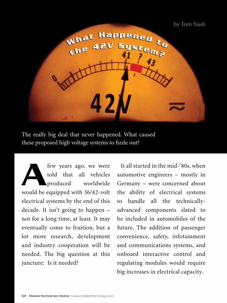
62 MasterTechnician Online | www.mastertechmag.com
A few years ago, we were
told that all vehicles
produced worldwide
would be equipped with 36/42-volt
electrical systems by the end of this
decade. It isn’t going to happen –
not for a long time, at least. It may
eventually come to fruition, but a
lot more research, development
and industry cooperation will be
needed. The big question at this
juncture: Is it needed?
The really big deal that never happened. What caused
these proposed high voltage systems to fizzle out?
by Tom Nash
It all started in the mid-‘80s, when
automotive engineers – mostly in
Germany – were concerned about
the ability of electrical systems
to handle all the technically-
advanced components slated to
be included in automobiles of the
future. The addition of passenger
convenience, safety, infotainment
and communications systems, and
onboard interactive control and
regulating modules would require
big increases in electrical capacity.
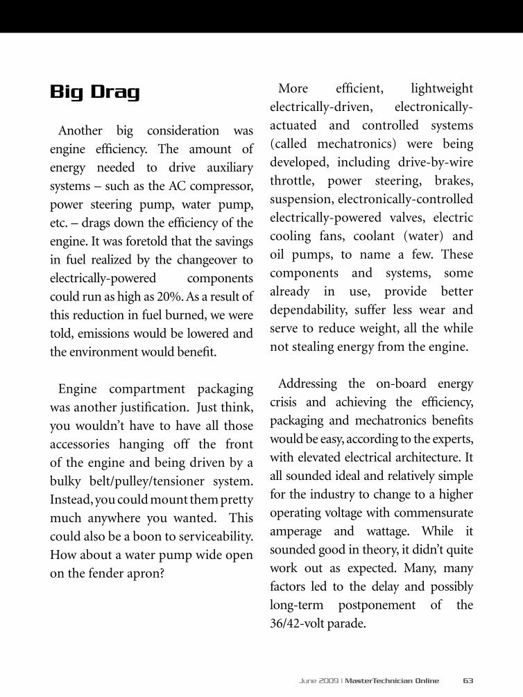
June 2009 | MasterTechnician Online 63
More efficient, lightweight
electrically-driven, electronically-
actuated and controlled systems
(called mechatronics) were being
developed, including drive-by-wire
throttle, power steering, brakes,
suspension, electronically-controlled
electrically-powered valves, electric
cooling fans, coolant (water) and
oil pumps, to name a few. These
components and systems, some
already in use, provide better
dependability, suffer less wear and
serve to reduce weight, all the while
not stealing energy from the engine.
Addressing the on-board energy
crisis and achieving the efficiency,
packaging and mechatronics benefits
would be easy, according to the experts,
with elevated electrical architecture. It
all sounded ideal and relatively simple
for the industry to change to a higher
operating voltage with commensurate
amperage and wattage. While it
sounded good in theory, it didn’t quite
work out as expected. Many, many
factors led to the delay and possibly
long-term postponement of the
36/42-volt parade.
Big Drag
Another big consideration was
engine efficiency. The amount of
energy needed to drive auxiliary
systems – such as the AC compressor,
power steering pump, water pump,
etc. – drags down the efficiency of the
engine. It was foretold that the savings
in fuel realized by the changeover to
electrically-powered components
could run as high as 20%. As a result of
this reduction in fuel burned, we were
told, emissions would be lowered and
the environment would benefit.
Engine compartment packaging
was another justification. Just think,
you wouldn’t have to have all those
accessories hanging off the front
of the engine and being driven by a
bulky belt/pulley/tensioner system.
Instead, you could mount them pretty
much anywhere you wanted. This
could also be a boon to serviceability.
How about a water pump wide open
on the fender apron?

64 MasterTechnician Online | www.mastertechmag.com
What’s a 36/42-Volt System?
First, let’s clarify what is meant by
36/42 volts. The present automotive
electrical architecture is actually 14
volts, as you know. We all refer to it as
a “12 volt” system because the battery
has six 2.1 volt cells for a total of 12.6
volts, which charges just right at 14
V. A more accurate name would
probably be the “12/14 volt” system.
Triple that and you’ve got 36/42.
When automotive engineers began
looking for a higher system voltage to
establish as a standard, they wanted
to raise the level as high as possible,
but not so high as to create a shock
danger to humans.
Mercedes-Benz is credited as
being the first automaker to call for
higher voltage systems. An industry-
wide research consortium was
formed, led by the Massachusetts
Institute of Technology. The MIT/
Industry Consortium on Advanced
Automotive Electrical/Electronic
Components and Systems began
to address the technical issues of
changing over to 36/42 volts. The
research was financed by automotive
companies, which ponied up $50k
each to be part of the consortium.
After establishing that human tissue
can be damaged at around 56-60
volts (wattage and amperage levels
being considered), and assuming
that present components could easily
be adapted, the architecture point of
36/42 volts was derived. It sounded
simple and eminently logical.
Cast of Thousands
The first entities to get on board
would be the planning, standards and
regulation associations, organizations
and societies. In Europe, automakers
and suppliers formed a working
group known as “Fourum Bordnetz”
to create standards for the Euro-
based International Organization of
Standardization (ISO).
On this side of the pond, the Society of
Automotive Engineers (SAE) became
the leader in gathering and sorting
out the various methods, devices
and knowledge for development
of standards. Working with the
top engineers from international
What Happened to the 42V System?
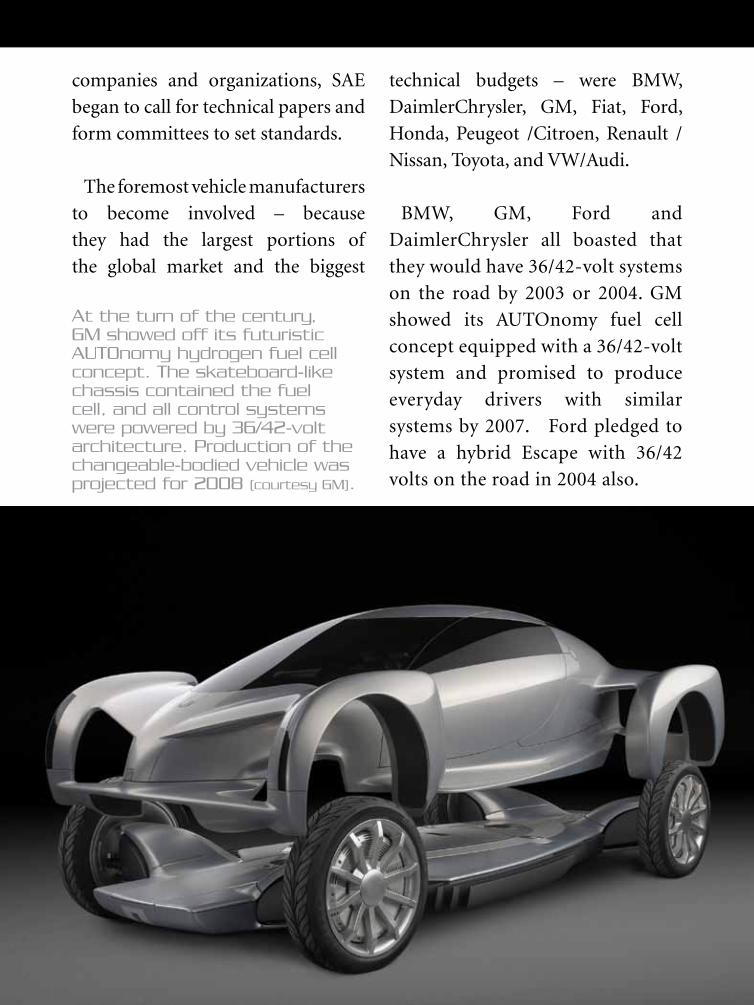
June 2009 | MasterTechnician Online 65
companies and organizations, SAE
began to call for technical papers and
form committees to set standards.
The foremost vehicle manufacturers
to become involved – because
they had the largest portions of
the global market and the biggest
technical budgets – were BMW,
DaimlerChrysler, GM, Fiat, Ford,
Honda, Peugeot /Citroen, Renault /
Nissan, Toyota, and VW/Audi.
BMW, GM, Ford and
DaimlerChrysler all boasted that
they would have 36/42-volt systems
on the road by 2003 or 2004. GM
showed its AUTOnomy fuel cell
concept equipped with a 36/42-volt
system and promised to produce
everyday drivers with similar
systems by 2007. Ford pledged to
have a hybrid Escape with 36/42
volts on the road in 2004 also.
At the turn of the century, GM showed off its futuristic AUTOnomy hydrogen fuel cell concept. The skateboard-like chassis contained the fuel cell, and all control systems were powered by 36/42-volt architecture. Production of the changeable-bodied vehicle was projected for 2008 (courtesy GM).
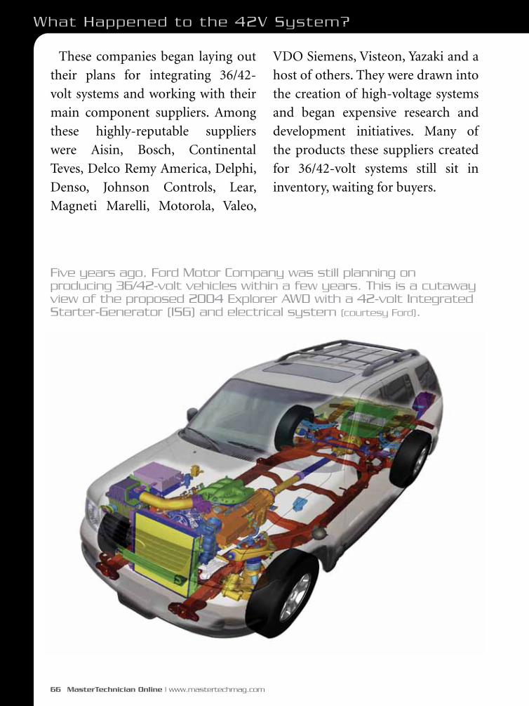
66 MasterTechnician Online | www.mastertechmag.com
These companies began laying out
their plans for integrating 36/42-
volt systems and working with their
main component suppliers. Among
these highly-reputable suppliers
were Aisin, Bosch, Continental
Teves, Delco Remy America, Delphi,
Denso, Johnson Controls, Lear,
Magneti Marelli, Motorola, Valeo,
VDO Siemens, Visteon, Yazaki and a
host of others. They were drawn into
the creation of high-voltage systems
and began expensive research and
development initiatives. Many of
the products these suppliers created
for 36/42-volt systems still sit in
inventory, waiting for buyers.
Five years ago, Ford Motor Company was still planning on producing 36/42-volt vehicles within a few years. This is a cutaway view of the proposed 2004 Explorer AWD with a 42-volt Integrated Starter-Generator (ISG) and electrical system (courtesy Ford).
What Happened to the 42V System?

June 2009 | MasterTechnician Online 67
Implementation Imagination
The steps in implementation were
to have followed this pattern:
•The 36/42-volt architecture would
be initially applied to high-end
luxury vehicles where the cost would
readily be accepted. The technology
would then trickle down to entry-
level vehicles over a few years, once
the technologies were perfected and
made cost-effective.
•The European manufacturers –
primarily the German companies
– were slated to convert to the new
standards first.
Denso developed many components for 36/42-volt vehicles including (Left to Right) an integrated starter generator (ISG), a battery electronic control unit (ECU) and a DC-DC converter. (courtesy Denso)
integrated starter generator (ISG)
battery electronic control unit (ECU)
DC-DC converter
•Dual voltage systems were to be
used as an interim solution. Until
the design and production of 36-
volt components was perfected, 12-
volt sub-systems would be used to
power devices that have not been
redesigned for the higher voltage.
This could be achieved by the use of
two batteries – one 12-volt and one
36-volt – and coupling them with
a DC-to-DC converter, stepping
down the electrical pressure to
power those components still
functioning on 12 volts.
What Went Wrong?
There are many reasons why 36/42-
volt standards have not yet been
adopted and produced. The three
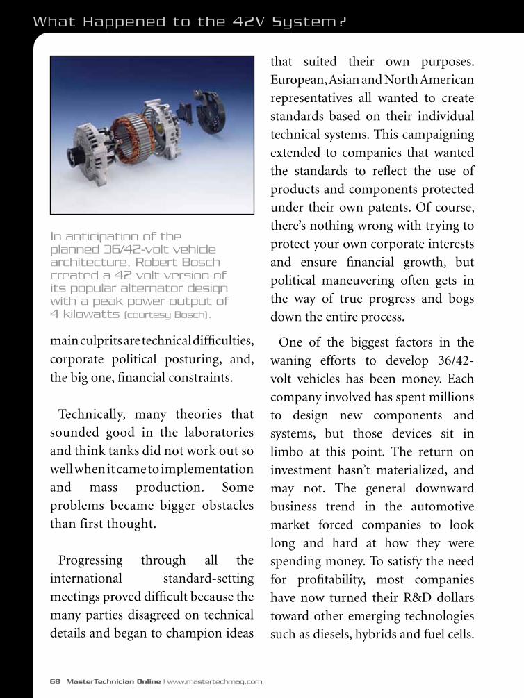
68 MasterTechnician Online | www.mastertechmag.com
main culprits are technical difficulties,
corporate political posturing, and,
the big one, financial constraints.
Technically, many theories that sounded good in the laboratories and think tanks did not work out so well when it came to implementation and mass production. Some problems became bigger obstacles than first thought.
Progressing through all the international standard-setting meetings proved difficult because the many parties disagreed on technical details and began to champion ideas
that suited their own purposes. European, Asian and North American representatives all wanted to create standards based on their individual technical systems. This campaigning extended to companies that wanted the standards to reflect the use of products and components protected under their own patents. Of course, there’s nothing wrong with trying to protect your own corporate interests and ensure financial growth, but political maneuvering often gets in the way of true progress and bogs down the entire process.
One of the biggest factors in the waning efforts to develop 36/42-volt vehicles has been money. Each company involved has spent millions to design new components and systems, but those devices sit in limbo at this point. The return on investment hasn’t materialized, and may not. The general downward business trend in the automotive market forced companies to look long and hard at how they were spending money. To satisfy the need for profitability, most companies have now turned their R&D dollars toward other emerging technologies such as diesels, hybrids and fuel cells.
In anticipation of the planned 36/42-volt vehicle architecture, Robert Bosch created a 42 volt version of its popular alternator design with a peak power output of 4 kilowatts (courtesy Bosch).
What Happened to the 42V System?

June 2009 | MasterTechnician Online 69
Problems, Problems
Dr. David J. Perreault, a research
Scientist at MIT’s Laboratory for
Electromagnetic and Electronic
Systems initially led the MIT/
Industry Consortium on Advanced
Automotive Electrical/Electronic
Components and Systems. Dr.
Perreault presented a technical paper
and spoke at the Convergence 2000
conference on October 17, in Detroit.
He stated that the higher power
would allow many new systems to
be introduced and many existing
systems to work better.
“It doesn’t sound like it would be
that difficult to do,” Dr. Perreault
said. “But it turns out that there are
several subtle technical problems.”
This comment turned out to be
somewhat understated.
Some of these technical
difficulties were clearly explained
by Paul Nicastri of Ford Motor
Company’s Research Laboratory at
the 2001 International Automotive
Technician Network (iATN)
Convention in Dearborn, Michigan.
Nicastri exposed the problems with
electrical connections under a 36-volt
load. He stated that the entire system
will have to be redesigned to handle
the high voltage. Wires, relays, and
connectors will need improvements
to function without damage. Arcing
of 36-volt current is the primary
concern. Unlike 12-volt arcing,
which is fairly low in amperage, short
in arc length and easily disrupted, the
arc in a 36-volt system can be much
longer and reach extremely high
temperatures – over 4,000 deg. F –
posing a dangerous situation.
He demonstrated these arcing
problems with a video showing
normal and slow motion views of a
36-volt connector under load being
disconnected. The resulting arc and
flash entirely disintegrated the tip of
the male connector. The female end
was badly damaged and unusable.
Special arc-suppressing connectors,
he stated, would have to be developed,
and, most likely, the system will
necessarily need to be shut off before
servicing, using the types of switches
found on existing hybrid vehicles.

70 MasterTechnician Online | www.mastertechmag.com
Nicastri also demonstrated the
increased corrosion factor of wires under
a 36-volt load, compared to 12-volts.
Enclosed, protected connections, he said,
will have to be devised.
18 Cells!
Batteries pose a number of problems.
High voltage batteries will need to
be durably encased for protection in
case of collision. The connectors will
have to be designed to cut the threat
of arcing. Special dual-stage relay-
controlled connections that shut off
power while the main contacts wed,
then reconnect have been proposed.
Delphi developed a prototype a few
years ago, but it was never produced
for the mass market.
The need to jump or charge 36 volt
batteries is another concern. Special
connections and devices will need to
be designed. The ability of a 36 volt
lead acid battery to safely withstand
even momentary reversal of polarity
has not been established. Mistakes
can happen, even with professionals.
Just imagine the possibilities with a
non-savvy vehicle owner.
The SAE began to address these obstacles in the late ‘90s by setting up standards committees. The Electrical Distribution Systems Standards Committee authored a standard known as J2622 - Battery Connections. Its purpose was to “define test methods and set standards for development, production, and field analysis of electrical terminals, connectors, and components that constitute the direct connection to the storage battery of road vehicles having 42 volt nominal electrical systems.” At last check, the committee had developed a model for a safe battery connection, but has not met in some time.
Another obstacle is the adaptation of lighting systems to the proposed 36/42 volt architecture. Preliminary testing indicated many problems with interior lighting, which would need to be stepped down to a lower voltage. Exterior lighting, especially headlamps, require further research to find cheap and efficient ways to utilize 36/42-volt energy. Without some basic redesign, headlamp filaments would have to be much longer and thinner, resulting in increased fragility and shorter burn life.
What Happened to the 42V System?

LM&T AD: VW9-1286“VW WS Alternator” Ad • 4C Bleed
Pub: CmA CommunicationsBleed: 8.125 x 11 inchesTrim: 7.875 x 10.5 inches
Safety: 6.875 x 9.75 inchesCK • June 9, 2009 • 12:10
AE: Jason Collected by: PRODUCTION NOTES:VW9 WHOLESALE > VW9-1286 WS Ads_CmA Communications > 1286 VW WS Ad_CmA_Alternator.indd
LM&T AD ROUTINg SIgNATURESROUTING NUMBER
1JANE PETE TIM JASON DERRICK JIM D.
JIM JULIE DEBBIE CATHy CLIENT CLIENT
Please check the people who are to be included in each routing. Jim must be included in every routing.
Right part.Right people.Right price.Right away.
When you buy Genuine Volkswagen Parts
you get more than Autobahn-tested, precision-
engineered OEM parts. You also get the
technical expertise and support of a dedicated
team whose job is to get you the parts you
need when you need them.
Genuine VW Parts are competitively priced.
They may not always be the least expensive,
but they give you the best quality and the best
value. Genuine VW Parts help you do the job right
the first time, and eliminate comebacks. What’s
that worth to your business?
We have access to over 150,000 parts for new
and older models and we can get them to you
fast. That’ll keep your shop moving and keep
your customers coming back.
1286 VW WS Ad_CmA_Alternator.indd 1 6/9/09 1:42:49 PM
72 MasterTechnician Online | www.mastertechmag.com
One possible answer is adapting the
technology known as Pulse Width
Modulation (PWM). Used in other
areas for years (remember feedback
carbs?), PWM is simply a switching
on and off of the voltage, resulting
in a square wave form. With the
duty cycle cut in half, many of the
problems associated with arcing and
corrosion could be addressed. Much
research and engineering would,
however, be needed to develop PWM
devices suited to automobiles.
The SAE launched a program
to investigate the use of PWM in
late 1999. The SAE 42V Exterior
and Interior Lighting Cooperative
Research Program brought together
automakers and electrical suppliers
to discuss PWM adaptation, testing
and use on incandescent lamps.
These lighting problems are another
reason to advocate dual 12/14 and
36/42-volt systems within a vehicle.
Even the top automotive business
analysts were way off in their
predictions, prognostications and
projections. At the beginning of the
decade, Standard & Poor’s estimated
that car makers would build 46,000
vehicles with 36/36/42-volt electrical
systems in 2002. This number was
expected by S&P to increase to nearly
13 million by 2010. It isn’t going
to happen – at least not anywhere
near that quickly.
What’s Out There Now
There are vehicles operating with
36/42-volt systems on the road today.
General Motors began building and
selling light hybrid models of its full
sized Chevrolet Silverado and GMC
Sierra pickups with dual 36/42-volt
and 12/14-volt systems in 2004. The
sales numbers have been miniscule
and GM has used these trucks as a
sort of test fleet.
GM eliminated the conventional
starter and generator in favor
of a compact integrated starter/
alternator (ISA) located in the
transmission bell housing. This
flywheel/ISA/torque converter
creates up to 14,000 watts of
continuous power, which is stored
What Happened to the 42V System?
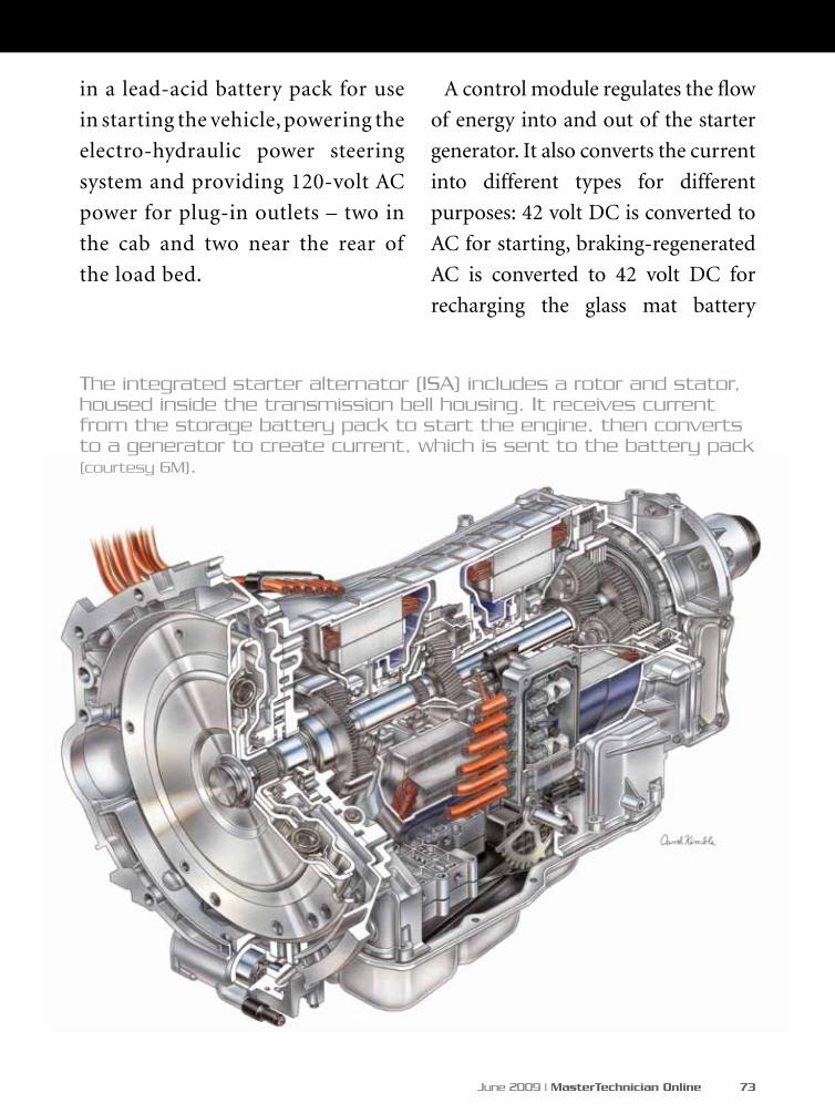
June 2009 | MasterTechnician Online 73
in a lead-acid battery pack for use
in starting the vehicle, powering the
electro-hydraulic power steering
system and providing 120-volt AC
power for plug-in outlets – two in
the cab and two near the rear of
the load bed.
A control module regulates the flow
of energy into and out of the starter
generator. It also converts the current
into different types for different
purposes: 42 volt DC is converted to
AC for starting, braking-regenerated
AC is converted to 42 volt DC for
recharging the glass mat battery
The integrated starter alternator (ISA) includes a rotor and stator, housed inside the transmission bell housing. It receives current from the storage battery pack to start the engine, then converts to a generator to create current, which is sent to the battery pack (courtesy GM).

74 MasterTechnician Online | www.mastertechmag.com
pack, 14-volt power is converted to
42 volt for jump-starting, 42 volt is
converted to 14 volt for the alternator
function, and 42 volt DC is converted
to 120 volts AC for powering the
electrical outlets. Does this system
sound complicated enough for you?
Regardless, this complex technology
makes the two GM pickups ideal
for construction, agricultural and
industrial uses.
As of last October, Ford, MIT and
others were still working on “The
acceleration of the development of
new 42-volt high-voltage vehicle
electrical system standards through
the use of virtual engineering concepts
and global consensus.” Delphi and
many other deeply-involved supplier
companies have put 42-volt research
on the back burner, or are no longer
pursuing it at all.
The control module, shown here in the corner of the engine compartment, regulates the types and levels of electrical current used in the GM light hybrid system (courtesy GM).
What Happened to the 42V System?

June 2009 | MasterTechnician Online 75
As It Stands
Many requests for interviews and
information on the status of 36/42-
volt initiatives to tier one suppliers,
automakers and involved associations
in the preparation of this article
went unanswered or were tersely
dismissed. This leads one to believe
that the whole idea of converting to
36/42-volt architecture may have
been mistakenly undertaken. That
nobody in these organizations wishes
to openly discuss their conversion
efforts speaks loudly.
Perhaps it was premature. or the
perceived need caused a competitive
panic that resulted in depletion of
monetary and human resources.
Maybe the rapid advances in ultra-
high voltage hybrid technology have
leap-frogged the need for 36/42-volt
systems. It is to be hoped that the
annual global gathering of automotive
engineers at the SAE World Congress
in Detroit this month will shed new
light on the future of these systems.
We’ll let you know.
The integration of 36/42-volts – if
it ever comes – will impact the entire
industry from top to bottom, from
beginning to end, involving vehicle
manufacturers, tier one suppliers,
parts makers and service suppliers,
tool and equipment sources and the
aftermarket and independent service
facilities. It will be the most costly,
most time-consuming and most
radical event ever to happen in the
automotive industry. It would make
the switch to automatic transmission,
electronic ignition, or disc brakes
seem like a walk in the park.
The 12/14-volt architecture we’ve
used since the mid-‘50s continues to
evolve and still serves us well enough.
But, it does have limitations. Just as
6-volt systems needed to be raised
after almost half a century, perhaps
it’s time to move forward again, fifty
years later. The onus rests on those
who have the most to gain from
the change – the automakers. Once
they find it necessary, feasible and
cost-effective to make the change to
36/42 volts, we in the aftermarket
will have to follow with training and
lots of new tools and equipment if we
want to keep pace with the rapidly-
marching parade of technology.
76 MasterTechnician Online | www.mastertechmag.com
A shop called me in to
investigate a 2002 Ford
Focus with 2.0L that had
poor power on a hard acceleration
(Figure 1). The vehicle, which only
had about 53,000 miles on it, idled
fine with no misfires or codes stored
in memory. It just didn’t have the
horsepower it should have had.
The shop had already replaced the
fuel filter and performed a back-
pressure check to rule out a clogged
catalytic convertor. The owner was
told by the garage that there was a
possibility that the fuel pump was
bad and it was suggested that he go
to the new car dealership to have it
changed under warranty. When the
Ford dealer’s tech checked the car,
he had a different opinion of what
was needed to fix the complaint. He
recommended a new transmission
because of the lack of torque and
a concurrent condition of engine
flare-up on acceleration. The torque
multiplication at the wheels just did
not seem to be adequate.
At this point, the customer called the
garage owner to let him know about
the outcome at the dealership, and the
garage owner recommended a local
transmission shop for a second opinion.
The trans shop proved the dealer
wrong, and now the vehicle was back
at the garage for further investigation.
This poor car was like a carnival ride
-- everybody wanted to take a turn in
the driver seat. There were too many
opinions and no solid answers.
Another Mystery Solved:
Hocus FocusT h e l i t t l e F o r d t h a t c o u l d n ’ t
by John Anello
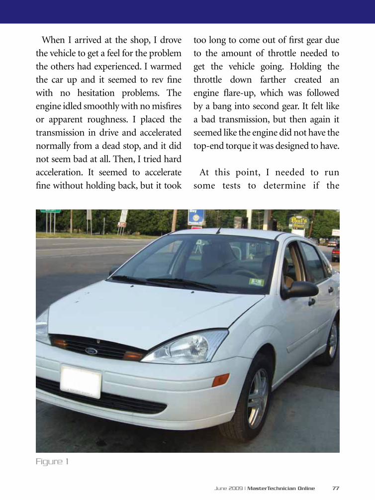
June 2009 | MasterTechnician Online 77
too long to come out of first gear due
to the amount of throttle needed to
get the vehicle going. Holding the
throttle down farther created an
engine flare-up, which was followed
by a bang into second gear. It felt like
a bad transmission, but then again it
seemed like the engine did not have the
top-end torque it was designed to have.
At this point, I needed to run
some tests to determine if the
When I arrived at the shop, I drove
the vehicle to get a feel for the problem
the others had experienced. I warmed
the car up and it seemed to rev fine
with no hesitation problems. The
engine idled smoothly with no misfires
or apparent roughness. I placed the
transmission in drive and accelerated
normally from a dead stop, and it did
not seem bad at all. Then, I tried hard
acceleration. It seemed to accelerate
fine without holding back, but it took
Figure 1
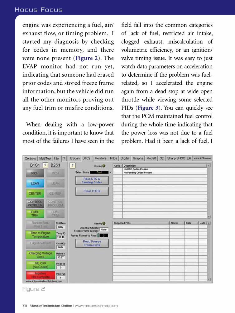
78 MasterTechnician Online | www.mastertechmag.com
engine was experiencing a fuel, air/
exhaust flow, or timing problem. I
started my diagnosis by checking
for codes in memory, and there
were none present (Figure 2). The
EVAP monitor had not run yet,
indicating that someone had erased
prior codes and stored freeze frame
information, but the vehicle did run
all the other monitors proving out
any fuel trim or misfire conditions.
When dealing with a low-power
condition, it is important to know that
most of the failures I have seen in the
field fall into the common categories
of lack of fuel, restricted air intake,
clogged exhaust, miscalculation of
volumetric efficiency, or an ignition/
valve timing issue. It was easy to just
watch data parameters on acceleration
to determine if the problem was fuel-
related, so I accelerated the engine
again from a dead stop at wide open
throttle while viewing some selected
PIDs (Figure 3). You can quickly see
that the PCM maintained fuel control
during the whole time indicating that
the power loss was not due to a fuel
problem. Had it been a lack of fuel, I
Figure 2
Hocus Focus

June 2009 | MasterTechnician Online 79
Figure 3
would have seen fuel trims maxed out
with an O2 sensor value constantly
below 500mV. Providing that the O2
is working properly, this quick test
eliminates the need to get too intrusive
by hooking up a fuel analyzer to check
fuel pressure and volume.
Now that I had eliminated the
possibility of a fuel delivery problem,
my next step was to perform a
volumetric efficiency test to check
air flow through the engine. After
all, the engine is nothing more than
an air pump and the PCM will use
the MAF calculation to determine
the proper fuel and ignition timing
mapping to keep the engine at peak
performance. The correct air flow
reading is dependant on the proper
calibration of the MAF, the amount
of restriction in the air inlet and
exhaust system, and valve train
integrity. To be accurate, this test has
to be done at wide open throttle while
driving. You also need to take into
consideration the ambient air temp,
altitude and engine size. This can
be done by recording your captured
scan data into a VE calculator, or by

80 MasterTechnician Online | www.mastertechmag.com
simply plugging your engine and
ambient conditions into the Escan
VE program and letting it do all the
work for you while you concentrate
on your driving skills to maintain a
steady wide open throttle acceleration
to capture the data you need.
Once the proper information was
entered into the VE program, I put
the pedal to the metal from a dead
stop and captured the air flow data
(Figure 4). The actual volume of
air was 30% below the calculated
specification. There were no fuel
trim issues, which indicated that the
MAF was correct in its findings. The
exhaust back pressure had already
been checked by the garage and
found to be below three psi, and the
air inlet and air filter were checked
for restrictions and were okay. This
problem was valve train related.
I next hooked up my scope and
tagged the crank and cam sensors
to perform a correlation check by
viewing the signals in a superimposed
format (Figure 5) to prove my
suspicions. By pulling up a known-
Figure 4
Hocus Focus
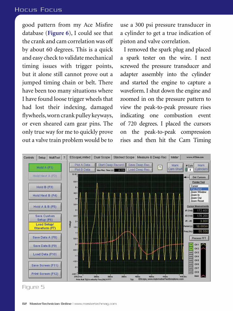
82 MasterTechnician Online | www.mastertechmag.com
Hocus Focus
good pattern from my Ace Misfire
database (Figure 6), I could see that
the crank and cam correlation was off
by about 60 degrees. This is a quick
and easy check to validate mechanical
timing issues with trigger points,
but it alone still cannot prove out a
jumped timing chain or belt. There
have been too many situations where
I have found loose trigger wheels that
had lost their indexing, damaged
flywheels, worn crank pulley keyways,
or even sheared cam gear pins. The
only true way for me to quickly prove
out a valve train problem would be to
use a 300 psi pressure transducer in
a cylinder to get a true indication of
piston and valve correlation.
I removed the spark plug and placed
a spark tester on the wire. I next
screwed the pressure transducer and
adapter assembly into the cylinder
and started the engine to capture a
waveform. I shut down the engine and
zoomed in on the pressure pattern to
view the peak-to-peak pressure rises
indicating one combustion event
of 720 degrees. I placed the cursors
on the peak-to-peak compression
rises and then hit the Cam Timing
Figure 5

June 2009 | MasterTechnician Online 83
button within the EScope program
(Figure 7). The program automatically
placed five large purple cursors
creating four divisions of 180 degree
of crankshaft rotation and five smaller
purple cursors creating six subdivisions
of 30 degrees on the screen. You could
now see that the exhaust valve was
opening at about 75 degrees before
BDC of the power stroke (note that the
lowest fall after the compression rise is
where the exhaust valve begins to open).
Having seen many waveforms showing
exhaust valve openings between 30-
45 degrees before BDC of the power
stroke, this engine’s valve timing was
definitely off by 30 degrees or better.
It was now safe to instruct the garage
to pull apart the front timing cover,
which involved supporting the engine
with a jack, removing an upper engine
support and removing an upper metal
timing housing cover -- all that just to
expose the timing belt.
Once the timing belt cover was
removed, I marked the sprockets
with White Out (Figure 8). The cam
gear was off by about two teeth. Also,
the belt had some slop indicating that
Figure 6
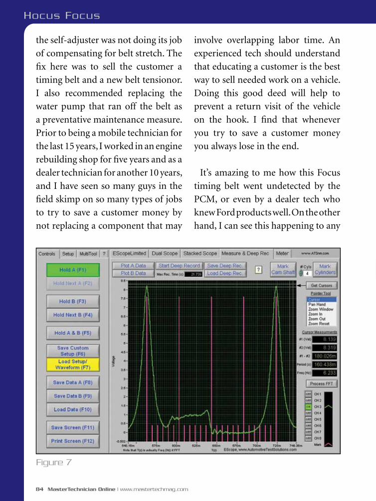
84 MasterTechnician Online | www.mastertechmag.com
Hocus Focus
the self-adjuster was not doing its job
of compensating for belt stretch. The
fix here was to sell the customer a
timing belt and a new belt tensionor.
I also recommended replacing the
water pump that ran off the belt as
a preventative maintenance measure.
Prior to being a mobile technician for
the last 15 years, I worked in an engine
rebuilding shop for five years and as a
dealer technician for another 10 years,
and I have seen so many guys in the
field skimp on so many types of jobs
to try to save a customer money by
not replacing a component that may
involve overlapping labor time. An
experienced tech should understand
that educating a customer is the best
way to sell needed work on a vehicle.
Doing this good deed will help to
prevent a return visit of the vehicle
on the hook. I find that whenever
you try to save a customer money
you always lose in the end.
It’s amazing to me how this Focus
timing belt went undetected by the
PCM, or even by a dealer tech who
knew Ford products well. On the other
hand, I can see this happening to any
Figure 7 * Details available at your authorized BMW center.©2008 BMW of North America, LLC. The BMW name, model names and logo are registered trademarks. All rights reserved.
* Details available at your authorized BMW center.©2008 BMW of North America, LLC. The BMW name, model names and logo are registered trademarks. All rights reserved.
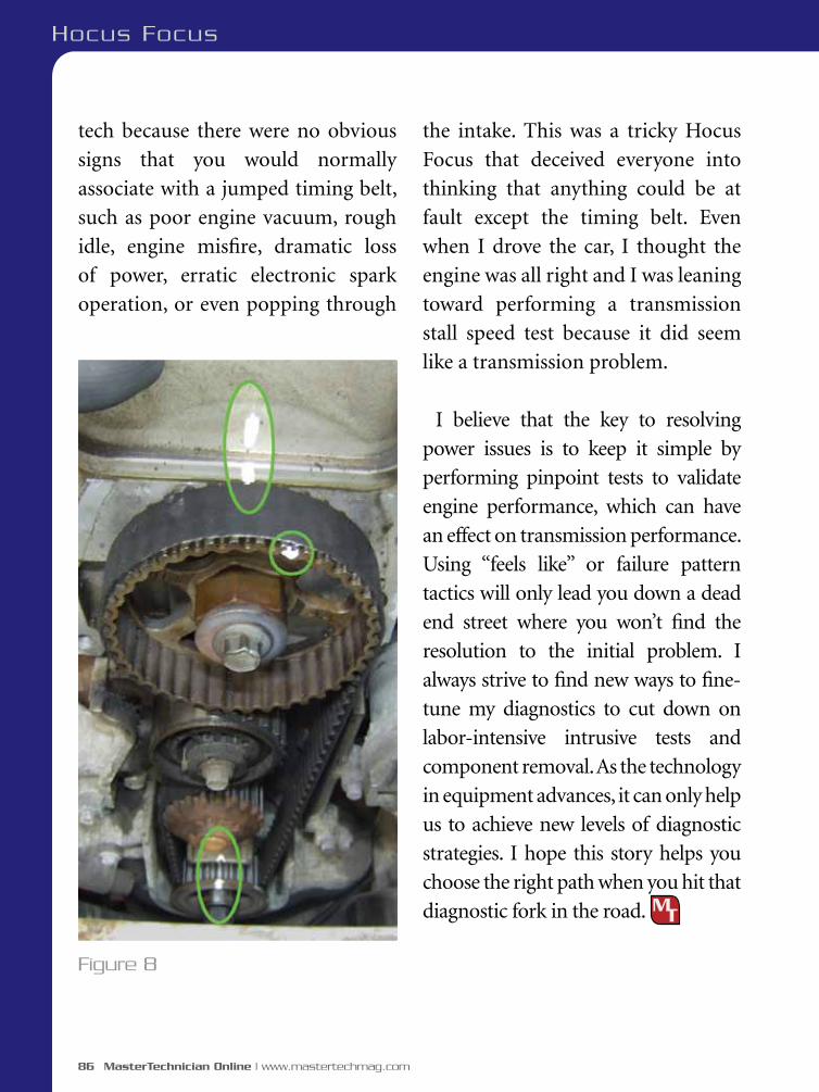
86 MasterTechnician Online | www.mastertechmag.com
Hocus Focus
tech because there were no obvious
signs that you would normally
associate with a jumped timing belt,
such as poor engine vacuum, rough
idle, engine misfire, dramatic loss
of power, erratic electronic spark
operation, or even popping through
the intake. This was a tricky Hocus
Focus that deceived everyone into
thinking that anything could be at
fault except the timing belt. Even
when I drove the car, I thought the
engine was all right and I was leaning
toward performing a transmission
stall speed test because it did seem
like a transmission problem.
I believe that the key to resolving
power issues is to keep it simple by
performing pinpoint tests to validate
engine performance, which can have
an effect on transmission performance.
Using “feels like” or failure pattern
tactics will only lead you down a dead
end street where you won’t find the
resolution to the initial problem. I
always strive to find new ways to fine-
tune my diagnostics to cut down on
labor-intensive intrusive tests and
component removal. As the technology
in equipment advances, it can only help
us to achieve new levels of diagnostic
strategies. I hope this story helps you
choose the right path when you hit that
diagnostic fork in the road.
Figure 8

To learn more, call 1-800-641-1133 or visit www.tracerline.com
PRO-Alert 2791™ This “next generation” electronic refrigerant leak detector utilizes a state-of-the-art infrared sensor for enhanced sensitivity and long life! It features a user selectable, three-position sensitivity switch to minimize false triggering, while allowing for easy diagnosis of small, medium and large leaks. Powered by a long-life, rechargeable NiMH battery. Certified to meet new SAE J2791 standard for electronic refrigerant leak detectors.
Detects leaks down to 0.1 oz/year Works with all refrigerants 1,000 + hour sensor life High-efficiency air sampling pump provides quicker
response and clearing NiMH battery provides over six hours of use between
charges. Detector also works with AC and DC power adapters.
Introducing the
The TP-9364 PRO-Alert 2791™ comes complete with infrared sensor, replacement
filters, rechargeable NiMH battery, AC power adapter, DC power adapter with cigarette lighter plug
and rugged carrying case.
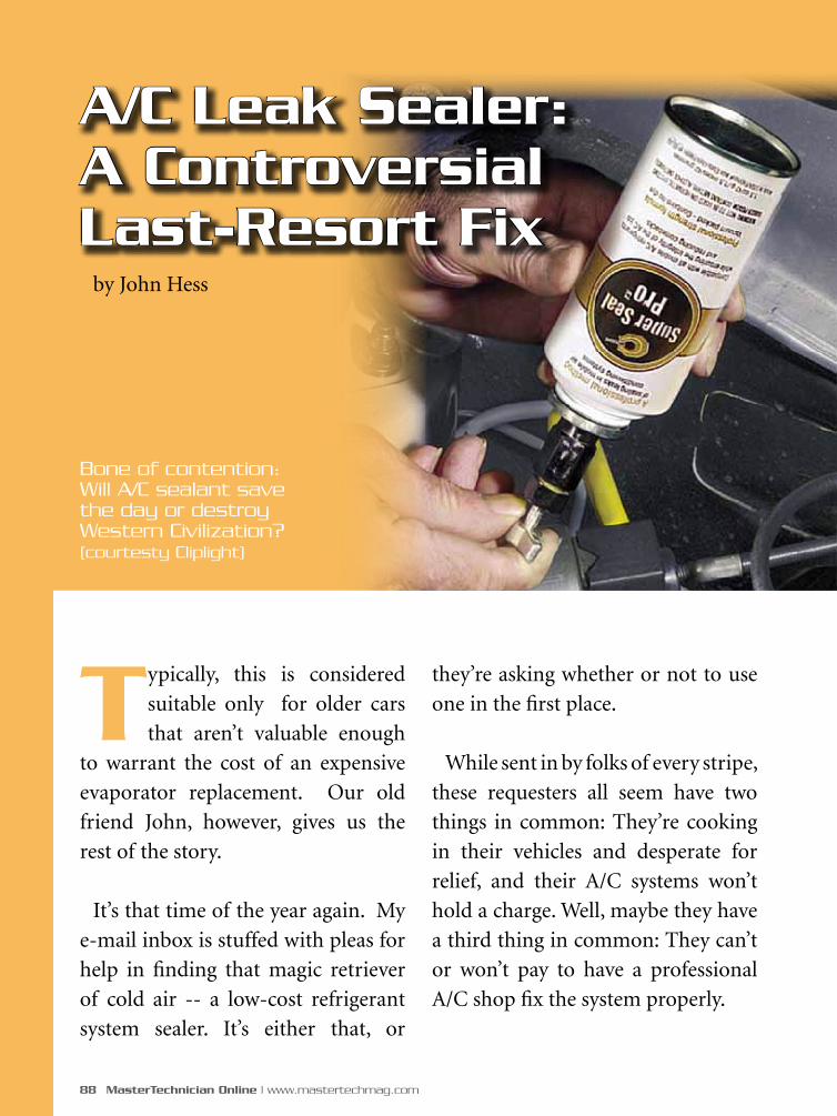
88 MasterTechnician Online | www.mastertechmag.com
Typically, this is considered
suitable only for older cars
that aren’t valuable enough
to warrant the cost of an expensive
evaporator replacement. Our old
friend John, however, gives us the
rest of the story.
It’s that time of the year again. My
e-mail inbox is stuffed with pleas for
help in finding that magic retriever
of cold air -- a low-cost refrigerant
system sealer. It’s either that, or
they’re asking whether or not to use
one in the first place.
While sent in by folks of every stripe,
these requesters all seem have two
things in common: They’re cooking
in their vehicles and desperate for
relief, and their A/C systems won’t
hold a charge. Well, maybe they have
a third thing in common: They can’t
or won’t pay to have a professional
A/C shop fix the system properly.
Bone of contention: Will A/C sealant save the day or destroy Western Civilization? (courtesty Cliplight)
A/C Leak Sealer: A Controversial Last-Resort Fix
by John Hess

June 2009 | MasterTechnician Online 89
is leaking (has a crack) and
he thinks this might get
him thru the summer. Will
this damage the system in
anyway? Thanx in advance!”
Forget it -- a cracked compressor
and he’s worried about something
damaging the system?
Here’s another:
“I own a 1995 Plymouth
Voyager and I have been told
that I have a small leak in my
evaporator. What I would like
to know is if there is a way to
fix this without having to take
the dash off of my car. The air
conditioner is located behind
the dash. I have been given an
estimate of $500.00 to replace
the evaporator. I am basically
looking for some information
that would tell me if there
is something my husband
could do to fix it ourselves.
Any help you could give me
would be greatly appreciated.
Thank you, Jane”
The normal reasons given for not
having the shop fix it are:
1. They don’t have the money.
2. The vehicle isn’t worth the
cost of a righteous repair.
3. They only need it for
one more season.
Or, all three (Number 2 is especially
applicable in states like California
where older vehicles may not pass
their next smog check).
Here are examples of the messages
I get. While some are definite
candidates for a sealant, others
obviously aren’t:
”My buddy is thinking
about putting some air
conditioner stop leak on his
‘95 Grand Am. I have never
heard of this before and my
first impression is don’t do
it. I’ve always heard not
to get anything in the air
conditioning system. Has
anybody tried this stuff
before? The compressor itself

90 MasterTechnician Online | www.mastertechmag.com
Wow, talk about a tough sale. Though
that price is couple of years old, it was
still quiet reasonable at the time. Most
evaporator replacement jobs then were
at least $1,000. But Jane still wouldn’t
go for it. As Tony Soprano would say,
“Whatareyougonnadoaboutit?” Since
most Chrysler and Jeep evaporators are
good candidates for sealing, how about
someone offering to take a shot at fixing
it with a professional leak sealer?
You can find more testimonials,
both pro and con at:
http://www.imcool.com/articles/aircondition/ac_sealants_p2.htm
Up front, I’m well aware of the
negative feelings (to say it nicely)
that most A/C shop owners and techs
have about sealers. I also hear from
the other side, however, brethren
of the above who are using sealers
quite successfully. Joe Fortunato
(Automotive Air & Specialty, Jupiter,
FL), for instance, a 39-year A/C tech
and 25-year shop owner, is not shy
about using the Cryo-Chem product.
He’s been installing it for several years
and gets a 98% success rate when
used on true candidate vehicles,
such as the Plymouth Voyager above.
Joe doesn’t offer a warranty on the
service, but if the sealing job doesn’t
hold, he will credit the cost toward a
full evaporator replacement service.
How A/C sealants entered the vehicle market
As additional support for the viability of Cryo-Chem and sealants in general, I offer snippets from a post to the bulletin board at www.aircondition.com by George H. Goble, better known a few years on the internet as “ghg.”
We got this shot of a clogged orifice tube from the field. A do-it-yourselfer didn’t follow the proper procedures and really loaded the system up with sealer.
A/C Leak Sealer
June 2009 | MasterTechnician Online 91
Background: George is the
inventor of several R-12 alternative
refrigerants, one of which is GHG-X3
that he introduced in 1990. Later
classified by ASHRAE, it became
known as R-406A, and eventually by
the trade name “Autofrost.” Yes, it is a
“blend” refrigerant (more on blends
in a future MT article).
Here’s how George described his
first “fix” in 1982 of his 1978 Datsun
810’s leaking A/C system:
“At first, I ran small tubing
(1/8” copper), and put a
manifold and dry-eye in the
passenger compartment. And
drove around with a 30lb
cylinder of R12 in the back
seat…and when the system
got low, just opened up the
low side manifold valve and
put in another pound of 12
while I was driving! Hell,
a 30lb cyl of R12 was only
$30 back then and lasted all
summer! What ozone hole?
When fully charged, and hot,
it lost about 1 pound/week.”
George was ready for a leak sealer,
and lo and behold:
“I met up with JJ Packo around
that time. My home central A/C
(R22) had started leaking about
1-2 lb/month (4 years old)…
They had a SSR12 “kit”, that was
two cans of R12, one with some
“dry-pak” dissolved in the R12,
and the 2nd with some cryo-
silane (gaseous epoxy) dissolved
in the R12. Kit was about $100.”
Take one “Home” A/C system leak
sealer kit, try it in a leaky car, and voila!
“Instructions were to put
on a new dryer, and change
the orifice tube (this car had
an expansion valve). I didn’t
change the dryer, but did a
10 min. vacuum, charged
in the 1 lb can of dry-
pak (about 2% dry-pack
concentrate, rest is R12),
put in a can of R12 (now at
2/3 charge)... and ran car
for 1/2 hour to circulate the
dry-pak, which converts the
free moisture into silicone
92 MasterTechnician Online | www.mastertechmag.com
A/C Leak Sealer
oil (so it doesn’t form acids
anymore, and in this case,
removes the moisture, so the
cryo-silane won’t activate).
Next, added the Cryo-silane
(about 3% cryo-silane
concentrate in 12oz of R12),
and now at full charge.
For a couple of days, I noticed the
cryo-silane “dead fish” odor when
starting up the A/C (evap leak). After
two days, odor was gone, voila, it
worked. It self-sealed the evap leak!
And it held. That car never leaked
again. And in 1990 it became
the “development” car for GHG
refrigerants: GHG-X1, X2 (HCs),
GHG-X3 (R-406A/Autofrost), and
GHG-HP. In 1993, the fuel pump
died (but the A/C still worked), so I
junked the car.”
Interested readers are encouraged
to read ghg’s entire post at:
http://www.aircondition.com/wwwboard/current/18951.html
For those needing more evidence
of George’s refrigeration bona fides,
he is a senior systems engineer
for the Engineering Computer
Network department at Purdue
University. Besides inventing,
patenting and developing several
substitutes for Freon, check out the
paper he and colleagues presented
at the Purdue 1992 International
Refrigeration Conference -- Energy
Efficiency and New Refrigerants:
http://www.autofrost.com/peoples/ghg/ghg-ternary.pdf.
For those of you techs who
believe you know everything there
is to know about R-12, R-134a, and
associated lubricants, I challenge
you to read this piece and not learn
something new.
If you’re still convinced that sealants aren’t a viable service for “legitimate” A/C shops, I ask you, would a man who understands more about refrigerant systems—including vehicular—than most of us could absorb in a lifetime, flippantly suggest the usage of something that would damage them? Not hardly.

www.airsept.com 800.999.1051 678.987.0500
Problem
Line Splice
Fix Line Leaks In 5 Minutes
Fits in tight spaces
Shown here larger than actual size
TURNER TOOL!STOP!
Professional ComPressorTurner Tool™Prevent Damage to New Compressors!
Before PlaCing The BelT on The
ComPressoruse The
ComPressor Turner Tool™!
© 2009 AutoZone, Inc. All Rights Reserved. AutoZone and AutoZone & Design are
SKU Description AvailableCOMPRESSOR TURNER TOOL204042 In Stock
ProBlemLubricant drains down during warehouse storage leaving an a/c compressor’s moving parts unprotected at initial startup.
feaTures>> Fits all compressors with a threaded opening in the clutch hub including R, H, and V series compressors
>> Uses a standard 19mm (3/4”) wrench
>> Won’t slip, and allows use of greater torque than a spanner wrench
soluTionRotate the compressor 2 turns using the Compressor Turner Tool, before attaching the drive belt to the compressor.
ComPressormanufaCTurers
ReCommeNDeD By
patent pending
©2009 AutoZone, Inc. All Rights Reserved. AutoZone and AutoZone & design are registered marks of AutoZone Parts, Inc. All other marks are property of their respective owners.
New! Increase Your repaIr revenue & customer satIsfactIon
®®
call 1-800-999-1051 or 678-987-0500 to order >>www.aIrsept.com
®®
Line SpLice - new Metric SizeSFix Leaks in 5 Minutes! >>click here for more information
probLeM SoLution
kits avaiLabLe For:
Honda (Crv) trs090 & Hs110 Ford 10s20F (Crown victoria) 10Pa-17 (import) GM (r4 & H-series) Ford (Fs-10 & Fx-15) Chrysler (a590 & C171)
coMpreSSor Guard stoP CoMPressor CoMebaCks! >>click here for more information
coMpreSSor turner tooL Prevent DaMaGe to new CoMPressors! >>click here for more information
FaSter recycLe Guard ProteCt a/C serviCe MaCHines FroM seaLant & Debris>>click here for more information
d440a r134a Leak detectorFinD sMaLL reFriGerant Leaks Fast! J2791-CertiFieD>>click here for more information
tranSGuard tranSMiSSion FiLter ProteCt transMission rePairs FroM Debris
LINE SPLICE - NEW METRIC SIZESFIX LEAKS IN 5 MINUTES! >>Click here for more information
COMPRESSOR GUARD STOP COMPRESSOR COMEBACKS! >>Click here for more information
COMPRESSOR TURNER TOOL PREVENT DAMAGE TO NEW COMPRESSORS! >>Click here for more information
FASTER RECYCLE GUARD PROTECT A/C SERVICE MACHINES FROM SEALANT & DEBRIS>>Click here for more information
D440A R134A LEAK DETECTORFIND SMALL REFRIGERANT LEAKS FAST! J2791-CERTIFIED>>Click here for more information

94 MasterTechnician Online | www.mastertechmag.com
Do-it-yourselfers are the problem
So far, the sealant manufacturers
and parts houses have probably been
cheering this piece. Here, however,
is where we will probably part
company (I might even regain some
shop owner/technician supporters).
While it’s not illegal (where are the
environmentalists?), it certainly is
somewhat unethical, in my humble
opinion, to offer these products to
the DIY public. Why? For one thing,
because of the age-old human adage
that if one shot didn’t do it, give it
another [Editor’s note: How abour,
Too much is not enough?]. That’s
how systems truly do get fouled.
Then, if you need a certificate to buy
refrigerant and work on refrigeration
systems, why don’t you need a certificate
to buy refrigerant-sealing products
that circulate within the refrigerant?
I’ve not (yet) asked the manufacturers,
nor reps from the EPA, that question,
but someone really should.
Cliplight, a manufacturer of two A/C
sealants, Super Seal HVACR 944Kit
and the Super Seal Premium 946Kit,
has commented publicly on what DIY
sales of sealant products can bring:
“It should be appreciated
that the marketplace is full of
A/C leak sealers that are sold
directly to the DIY segment
and these products are injected
into an A/C system without
any measure of pre-inspection
of the system or control during
the injection process. It’s
also worth noting that these
products often contain:
· Hydrocarbon propellants
that will contaminate
a reclaim bottle.
· Dyes visible to the naked eye
without the use of a UV light
source that, under certain For some people, too much is not enough.
A/C Leak Sealer

June 2009 | MasterTechnician Online 95
conditions, can develop
crystalline formations in the
system and neutralize the
fluorescent dye intensity.”
Should the a/c system fail to respond
successfully to this DIY treatment, the
consumer -- in final desperation --
contacts a qualified service technician.
Most professional techs will refuse to
work on a vehicle that has had DIY
“cocktails” injected into the system.
If he does the first stage evacuation
process, it could present him with
nasty surprises! Especially if the
system had been contaminated with
moisture saturation (undetectable by
the DIY consumer).
Protecting the compressor
Understandably, most vehicle
manufacturers, along with A/C
component and recovery equipment
makers, are not proponents of A/C
sealers. As a rule of thumb, if they
find remnants of a sealer in anything
returned for warranty, the claim will
be denied. When a shop uses a sealer
in a system, either the shop or the
vehicle owner assumes responsibility
if contamination causes a problem.
Most technicians who use the product
will advise the customer that it is a
last ditch effort; there is no warranty.
Note: Cryo-Chem, SSR
International does offer dealers a
limited one-year warranty with its
SSR134Kit. It covers corrosion leaks
in condensers and evaporators. The
dealer must be 608/609 certified,
follow SSR’s installation directions
and satisfy other requirements.
Cliplight Manufacturing not only
offers a limited one-year warranty on
its product, but also, under “Coverage
B,” covers many A/C components. For
instance, if SUPER SEAL PREMIUM
was found (by Cliplight) to have
caused the failure of the compressor,
Cliplight will reimburse the dealer up
to $350. Since several conditions and
exclusions apply, be sure to check the
web page for the details:
http://cliplight.com/automotive/products.php?pageID=Warranty&productID=16&catID=4

96 MasterTechnician Online | www.mastertechmag.com
Contamination protective devices
Recycle Guard from AirSept: To
protect your refrigerant recovery
equipment and clean jugs of
refrigerant, you do not want to
recover sealer-laden or otherwise
contaminated refrigerant. Airsept’s
Recycle Guard uses high-tech
filtration to separate and remove
sealant, dye, lubricant and solid
contaminants from the refrigerant.
These remain in the canister while
the vapor refrigerant exits to your
A/C machine (www.airsept.com/).
System Guard from
SYSTEMGUARD: To show if
someone has tampered with your A/C
service job (such as a vehicle owner
adding contaminated refrigerant or
DIY “stop leak,” then blaming you
for the disastrous results), slip either
a heat-shrinkable System Guard
sleeve or plastic tie wrap over each
service port. They’re color coded
and serial numbered. Once heat
shrunk or crimped to the port, any
disturbance will be clearly visible
(http://www.acsystemguard.com/).
(Above) This recycling machine solenoid is plugged with A/C system sealant. Not good.
(Left) Here’s the best way we know of to keep sealer and other contaminants out of your A/C machine (courtesy AirSept).
A/C Leak Sealer

June 2009 | MasterTechnician Online 97
Neutronics QuickDetect A/C
Sealant Detection Kit: QuickDetect
is designed to act as an A/C leak. If
sealant is present in the system, it
quickly solidifies in the disposable
test cartridge causing the flow meter
to show “no flow.” When attached
to the high-side port, if the flow
meter shows constant flow for two
to three minutes, it’s most likely
sealant free. If the flow rate visibly
decreases, the refrigerant contains a
sealant. Other than the low-cost test
cartridges, all of the QuickDetect
components are reusable
(http://www.refrigerantid.com/).
Whether you strap them on as shown, or heat-shrink the sleeve type, tamper-evident service port protectors will let you know if somebody’s been in there since you last worked on the vehicle (courtesy Systemguard).

98 MasterTechnician Online | www.mastertechmag.com
John Hess, a Viet Nam vet, entered the radiator repair business in 1971. He is the editor and publisher of Cool Profit$ magazine
(www.imcool.com), a professional journal targeted to radiator and A/C technicians and shop owners, and the Heat Transfer Service Network (www.goHTSN.com).
This cleverly-conceived kit tells you whether or not there’s any sealant in the system so you can decide how to proceed (courtesy Neutronics).
For more information
about sealants, check out
the air conditioning pages of
www.imcool.com. Not only will
we offer a “Blog,” but also your
“Comments” can be added to our
articles that contain controversial
subject matter.
A/C Leak Sealer

Your reputation is in your hands.
As a supplier of original equipment hub units to most of the world’s automakers, SKF knows better than anyone what goes into making a premium quality hub unit.
So how can some manufacturers claim to offer OE quality hubs and sell them at half the price? The truth is, they can’t.
To prove it, we purchased a large sampling of these so-called OE quality hubs currently available in the aftermarket. We examined every component, and then tested each hub to every one of its actual OE performance specifications.
The results were clear: these hubs were not OE quality hubs. They were “value” grade hubs, which are no real value. Not only do they fail quickly, they can result in excessive NVH (noise, vibration and harshness), braking and handling problems, and expose drivers to potential safety risks.
Don’t compromise your customer’s vehicle safety. Always install SKF premium quality hubs!
See the results of our test at www.vsm.skf.com
Protect it with premium hubs by SKF.
2609888_Full Page Ad Resize.indd 1 4/7/09 12:44:27 PM
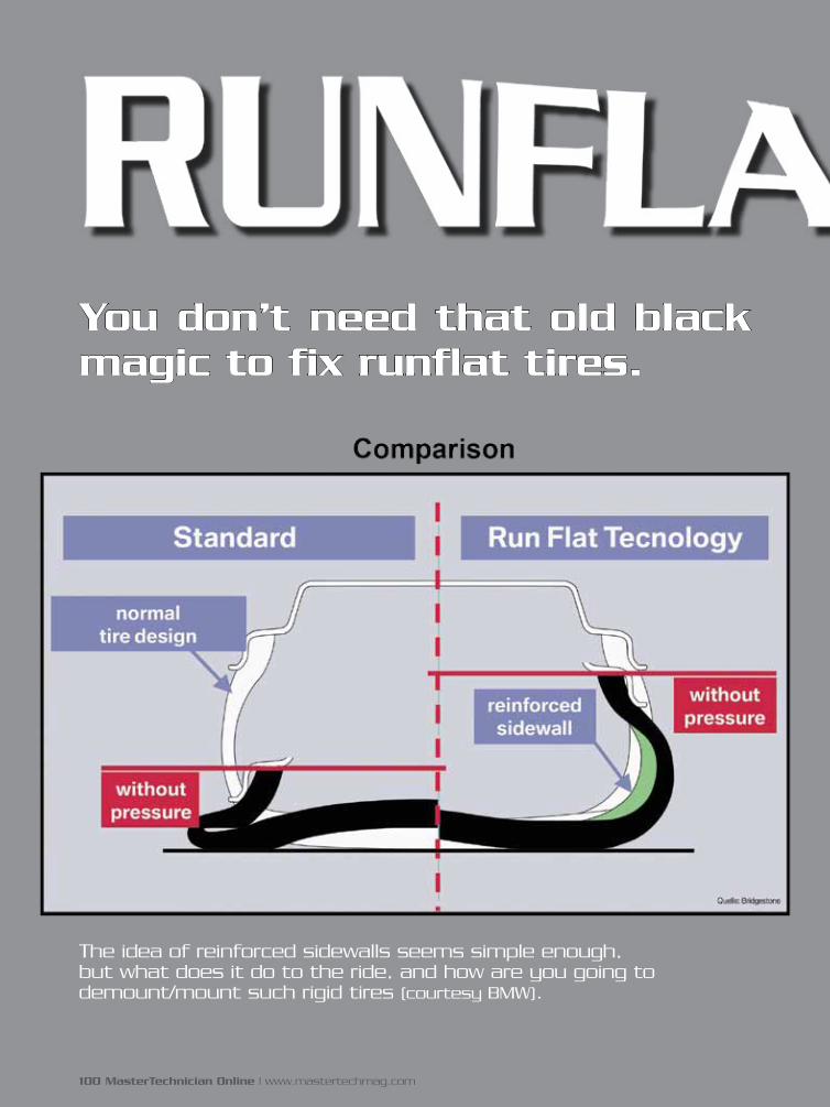
You don’t need that old black magic to fix runflat tires.
The idea of reinforced sidewalls seems simple enough, but what does it do to the ride, and how are you going to demount/mount such rigid tires (courtesy BMW).
100 MasterTechnician Online | www.mastertechmag.com

June 2009 | MasterTechnician Online 101
Aaaaaaaaahhhh, runflat
tires . . . No more jack, no
more spare. No more air,
no more repair. And you can ride on
‘em forever, right?
Not quite. Most self-supporting-
type runflat tires -- for example,
Goodyear and Dunlop Extended
Mobility Tires (EMTs) -- are
essentially tires with ultra-stiff
sidewalls that don’t flex very
much when there’s little or no
air pressure, and thus can be run
“flat.” (DISCLAIMER TO TIRE
ENGINEERS: There’s a ton of
extremely sophisticated material
and construction engineering
involved, okay?)
Runflat tires can be driven at up to 50
miles per hour for 150 miles or so (your
mileage may vary; see owner’s manual
for details. . . .). The idea is to get you to
a repair facility in case of a flat.
Assuming you don’t exceed the
limits above and don’t shred the tire,
they can be repaired. CAUTION:
Some car manufacturers, BMW for
example, don’t recommend repairing
runflat tires, which makes for some
interesting conversation on BMW
owner blogs.
Beemer bloggers blast away
For example, “Louis,” Member
#2567, wrote in January that he was
considering leasing “a 2007 328i
sedan, which (like most or all new
BMWs) comes with runflat tires. Like
most people, I don’t like the idea of
runflat tires. I just can’t stop thinking
about the problems I will have to deal
with if one of the tires goes flat. What
I have heard is that one can drive 50
miles or so on the flat.”
by Dave Russ
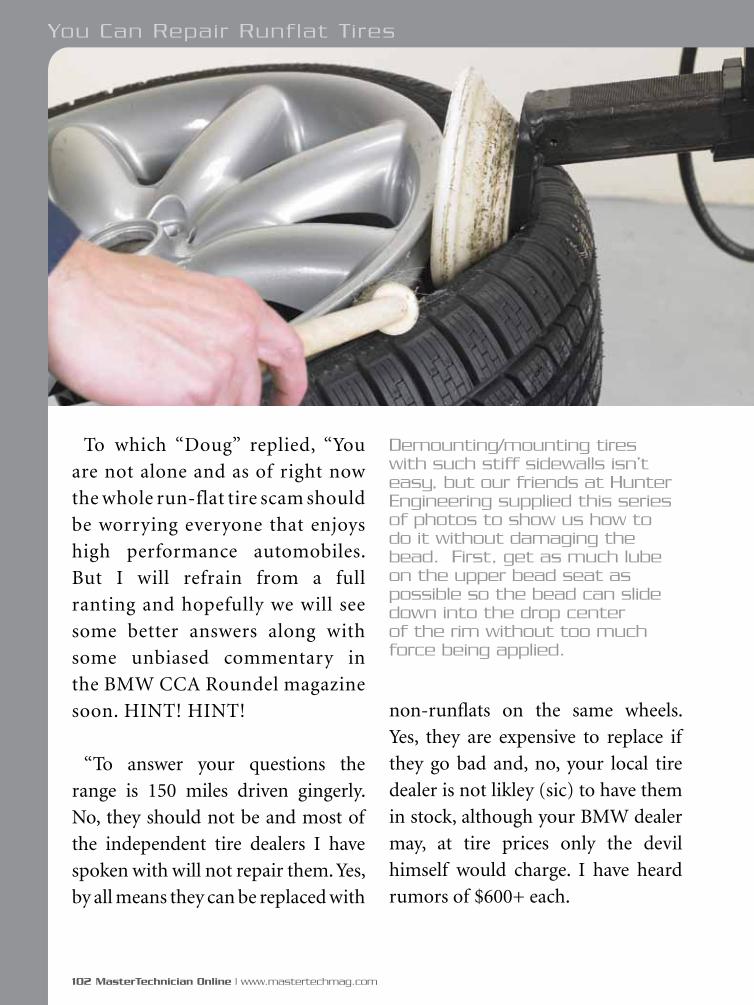
102 MasterTechnician Online | www.mastertechmag.com
To which “Doug” replied, “You
are not alone and as of right now
the whole run-flat tire scam should
be worrying everyone that enjoys
high performance automobiles.
But I will refrain from a full
ranting and hopefully we will see
some better answers along with
some unbiased commentary in
the BMW CCA Roundel magazine
soon. HINT! HINT!
“To answer your questions the
range is 150 miles driven gingerly.
No, they should not be and most of
the independent tire dealers I have
spoken with will not repair them. Yes,
by all means they can be replaced with
non-runflats on the same wheels.
Yes, they are expensive to replace if
they go bad and, no, your local tire
dealer is not likley (sic) to have them
in stock, although your BMW dealer
may, at tire prices only the devil
himself would charge. I have heard
rumors of $600+ each.
Demounting/mounting tires with such stiff sidewalls isn’t easy, but our friends at Hunter Engineering supplied this series of photos to show us how to do it without damaging the bead. First, get as much lube on the upper bead seat as possible so the bead can slide down into the drop center of the rim without too much force being applied.
You Can Repair Runflat Tires
MODEL SYSTEM I
MOHAWK
10,000 LB. CLEAR FLOOR 2 POST LIFT
Americas Best Lift Investment...Because Quality Lasts A Lifetime
Made and welded in the U.S.A.
TO MEET THE ONE ANDONLY NATIONAL STANDARD
FOR VEHICLE LIFTS
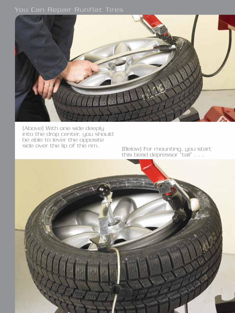
104 MasterTechnician Online | www.mastertechmag.com
(Above) With one side deeply into the drop center, you should be able to lever the opposite side over the lip of the rim.
(Below) For mounting, you start this bead depressor “tail” . . .
You Can Repair Runflat Tires
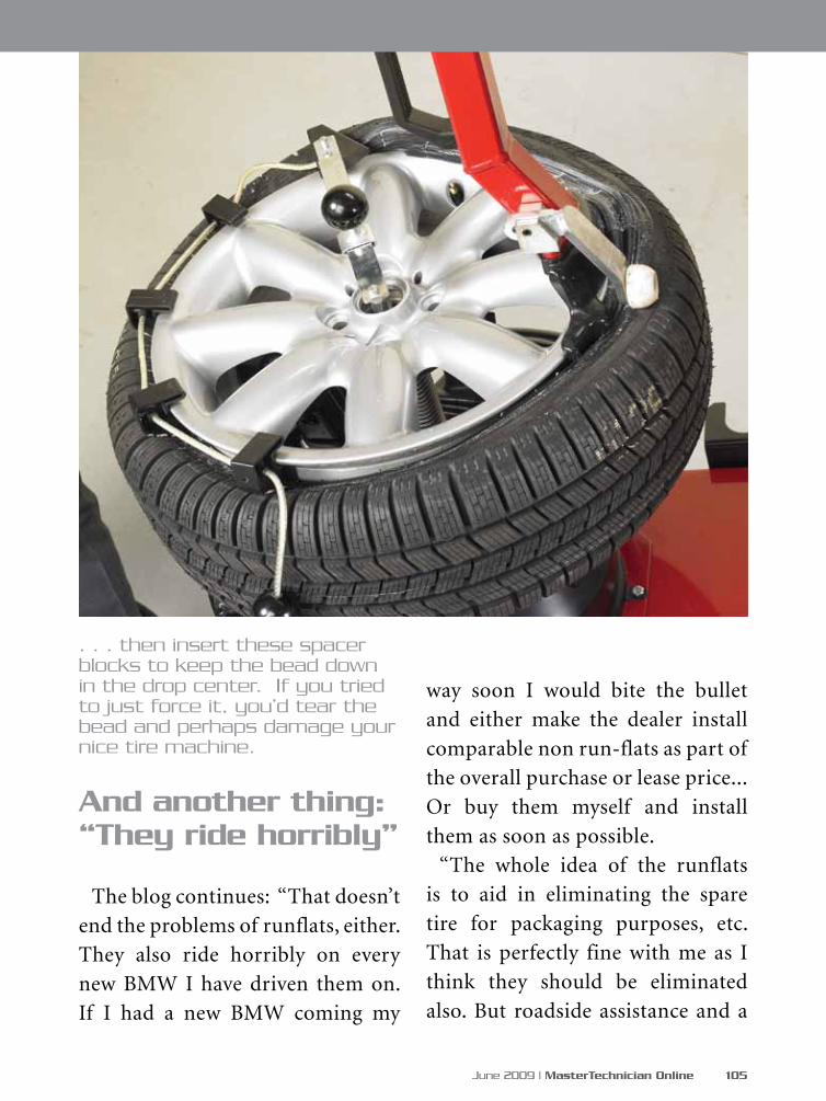
June 2009 | MasterTechnician Online 105
And another thing: “They ride horribly”
The blog continues: “That doesn’t
end the problems of runflats, either.
They also ride horribly on every
new BMW I have driven them on.
If I had a new BMW coming my
way soon I would bite the bullet
and either make the dealer install
comparable non run-flats as part of
the overall purchase or lease price...
Or buy them myself and install
them as soon as possible.
“The whole idea of the runflats
is to aid in eliminating the spare
tire for packaging purposes, etc.
That is perfectly fine with me as I
think they should be eliminated
also. But roadside assistance and a
. . . then insert these spacer blocks to keep the bead down in the drop center. If you tried to just force it, you’d tear the bead and perhaps damage your nice tire machine.
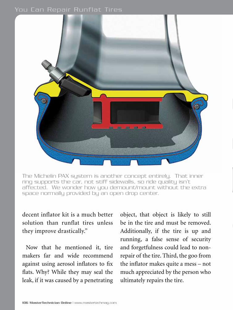
106 MasterTechnician Online | www.mastertechmag.com
object, that object is likely to still
be in the tire and must be removed.
Additionally, if the tire is up and
running, a false sense of security
and forgetfulness could lead to non-
repair of the tire. Third, the goo from
the inflator makes quite a mess – not
much appreciated by the person who
ultimately repairs the tire.
decent inflator kit is a much better
solution than runflat tires unless
they improve drastically.”
Now that he mentioned it, tire
makers far and wide recommend
against using aerosol inflators to fix
flats. Why? While they may seal the
leak, if it was caused by a penetrating
You Can Repair Runflat Tires
The Michelin PAX system is another concept entirely. That inner ring supports the car, not stiff sidewalls, so ride quality isn’t affected. We wonder how you demount/mount without the extra space normally provided by an open drop center.
s i d e b a rs i d e b a r
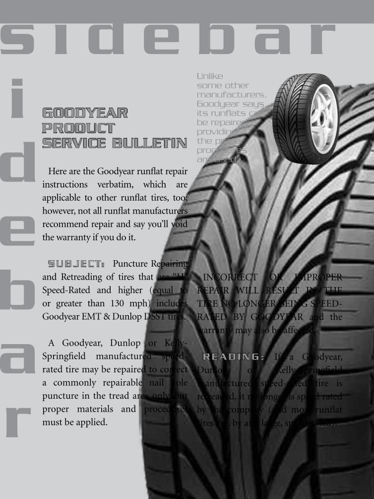
INCORRECT OR IMPROPER
REPAIR WILL RESULT IN THE
TIRE NO LONGER BEING SPEED-
RATED BY GOODYEAR and the
warranty may also be affected.
READ ING : If a Goodyear,
Dunlop or Kelly-Springfield
manufactured speed-rated tire is
retreaded, it no longer is speed rated
by the company (and most runflat
tires are, by and large, speed-rated).
GOODYEAR PRODUCT SERVICE BULLETIN
Here are the Goodyear runflat repair
instructions verbatim, which are
applicable to other runflat tires, too;
however, not all runflat manufacturers
recommend repair and say you’ll void
the warranty if you do it.
SUBJECT: Puncture Repairing
and Retreading of tires that are “H”
Speed-Rated and higher (equal to
or greater than 130 mph) includes
Goodyear EMT & Dunlop DSST tires.
A Goodyear, Dunlop or Kelly-
Springfield manufactured speed-
rated tire may be repaired to correct
a commonly repairable nail hole
puncture in the tread area only, but
proper materials and procedures
must be applied.
Unlike some other manufacturers, Goodyear says its runflats can be repaired providing the proper procedures are used.
s i d e b a rs i d e b a r
108 MasterTechnician Online | www.mastertechmag.com
The French way
There is another type of runflat tire, the Michelin PAX System, consisting of a conventional tire and an inner composite-type ring mated to the wheel. When the tire goes down, the weight is supported by the ring. As for repair, Michelin advises that the tire should be taken to an authorized Michelin PAX System repair outlet. Michelin has set up service centers around the United States, including all Honda dealers. A toll-free number finds the nearest one. Part of the PAX warranty is to replace any PAX wheel-tire system that has incurred air loss.
Goodyear says, “Like any other Goodyear speed-rated high performance tires, the Goodyear runflat EMT tire may be repaired to correct a nail hole puncture in the tread, but proper materials and procedures must be used.”
Goodyear supplies runflats for a number of OEM vehicles, including Corvette, Mini Cooper, Cadillac CTS-V, Rolls Royce, Lexus SC430, Maserati Quattroporte, Ferrari F360, Jeep Grand Cherokee SRT8 and several BMW and Mercedes models.
Goodyear’s attitude
“Some tire makers disallow puncture repairs on runflat tires,” says Goodyear spokesman Jim Davis. “However, punctures in our runflat tires can be repaired, according to the same guidelines as other tires. The servicing outlet needs to obtain information from the driver, and inspect the tire to make certain there are no signs of the tire being degraded due to being run at zero pressure for an extended period, much the same as an outlet would treat any other punctured tire. In any case, there is a product service bulletin on the proper repair of speed-rated tires, which includes EMTs” (see the sidebar).
If you want to bag it and send the customer to a Goodyear Run-Flat EMT service facility, or to get information on proper repairs, call 1-800-RUN-FLAT.
For other tires, be sure the repair doesn’t void the warranty, although even if it does, the customer may want you to go ahead and repair the tire so he or she can get back on the road.
You Can Repair Runflat Tires
DETAILED POLICY
Puncture Repair of Speed-Rated Tires
A. The puncture must be confined
to the tread area only.
B. Restrictions on the number and
size of repairs must be followed.
C. A detailed repair procedure must
be followed.
D. A speed-rated tire repaired in
strict accordance with items II-A,
B & C will retain its speed rating.
REPAIR PROCEDURE FOR SPEED-RATED TIRES
GENERAL
The objective of the puncture
repair is to seal the tire against loss
of inflation pressure and to prevent
damage to the carcass from moisture.
In all puncture repairs, approved
by Goodyear, Dunlop and Kelly-
Springfield, the hole must be filled
with a plug, and a patch covering
the hole must be applied according
to repair material manufacturer
instructions to the inside of the tire.
Never repair tires which are worn
below 2/32” tread depth.
NOTE: NO TIRE IS TO BE
REPAIRED WITHOUT FIRST BEING
REMOVED FROM THE RIM.
REPAIR AREA
Repairing is limited to the tread area
only within the outside grooves. No
repairs are allowed in the tread area
beyond the outside grooves or in the
sidewall area of the tire.
D. MATERIALS NEEDED
1. Precured rubber plugs - 1/4”
(6mm) diameter
2. Precured patches
3. Precured plug/patch combi-units
4. Chemical vulcanizing cement
5. Pre-buff cleaner
E. REPAIR PROCEDURE
1. Carefully remove the tire
completely from the rim.
June 2009 | MasterTechnician Online 109
2. Locate the puncture on the inside
of the tire and circle with crayon.
3. Remove puncturing object if it is
still in the tire.
4. Carefully inspect tire on a good
tire spreader, with ample light,
that will show any cracks, breaks,
punctures, damaged or broken beads.
5. Check liner for cuts, cracks, or
holes which may cause the tubeless
liner to lose air.
6. Check the injury with an
inspection awl:
a. Determine size and angle
of injury.
b. Check for ply or belt separation.
7. Reject any tire that has separation,
loose cords, damaged bead(s), or any
other non-repairable injury.
8. If the hole is simple and round,
steps 9 through 17 of the puncture
repair procedure will be successful.
NOTE: If the hole shows evidence
of fabric splitting, such an injury
cannot be properly repaired using
this puncture repair procedure. Such
an injury must be skived out and
repaired as a section (reinforced)
repair, which will maintain the
serviceability of the tire, but will
invalidate the tire’s speed rating. If
a section repair is necessary, the
customer must be advised, before the
repair is made, that the tire will lose
its speed rating, and must not exceed
operation at normal highway speeds.
9. Use a pre-buff cleaner and a
scraper to remove contaminants
from the liner in the area to be buffed
around the injury.
10. Use a 7/32”carbide cutter for ¼”
repairs to clean out the puncture.
a. Make sure that the drill follows the
direction of the puncturing object.
b. Always drill from inside
to outside of tire.
You Can Repair Runflat Tires
110 MasterTechnician Online | www.mastertechmag.com
111April 2009 | MasterTechnician Online
11. Using chemical vulcanizing
cement, lightly coat at least 1/2 of
tapered end of the repair plug. Install
the plug in the prepared puncture
according to the manufacturer’s
instructions. Trim the liner side of the
plug slightly higher than the surface of
the liner without stretching the plug.
12. Center the patch (or patch
template) over the injury without
removing the backing. Adhere to
patch or template instructions, as
to positioning as related to bead
location. Using a marking crayon,
mark around the outside edge of
the patch, approximately 1/4” larger
than the patch.
13. Buff the liner and plug at the
puncture location. The buffed area
should be slightly larger than the
patch. The buffed surface should be
finely grained (RMA 1 or 2 texture)
and even for proper bonding. Use
care to prevent burning the rubber
with the buffing tool. Do not buff
through the liner. Do not buff into
the marking crayon.
Clean the buffing dust from the tire
using only a vacuum or brush. Do
not use gasoline or other petroleum
solvents on the buffed area.
Coat the buffed liner surface and
the patch with one evenly applied
coat of chemical vulcanizing
cement in accordance with the
recommendations of the repair
materials manufacturer. Allow the
cement to dry thoroughly. Do not
touch the cemented areas.
Install the patch with the beads
of the tire in the relaxed position.
Position the patch over the puncture
according to the markings on the
patch. Stitch the entire patch starting
from the center, keeping the strokes
close together to avoid trapping air
under the patch.
17. Cut off the protruding end
of the plug about 1/8” above the
tread surface.
FINAL INSPECTION -- The repair
must seal the inner liner and fill
the injury. After remounting and
inflating check the repair, both beads
and valve with a soap solution to
assure a complete seal.
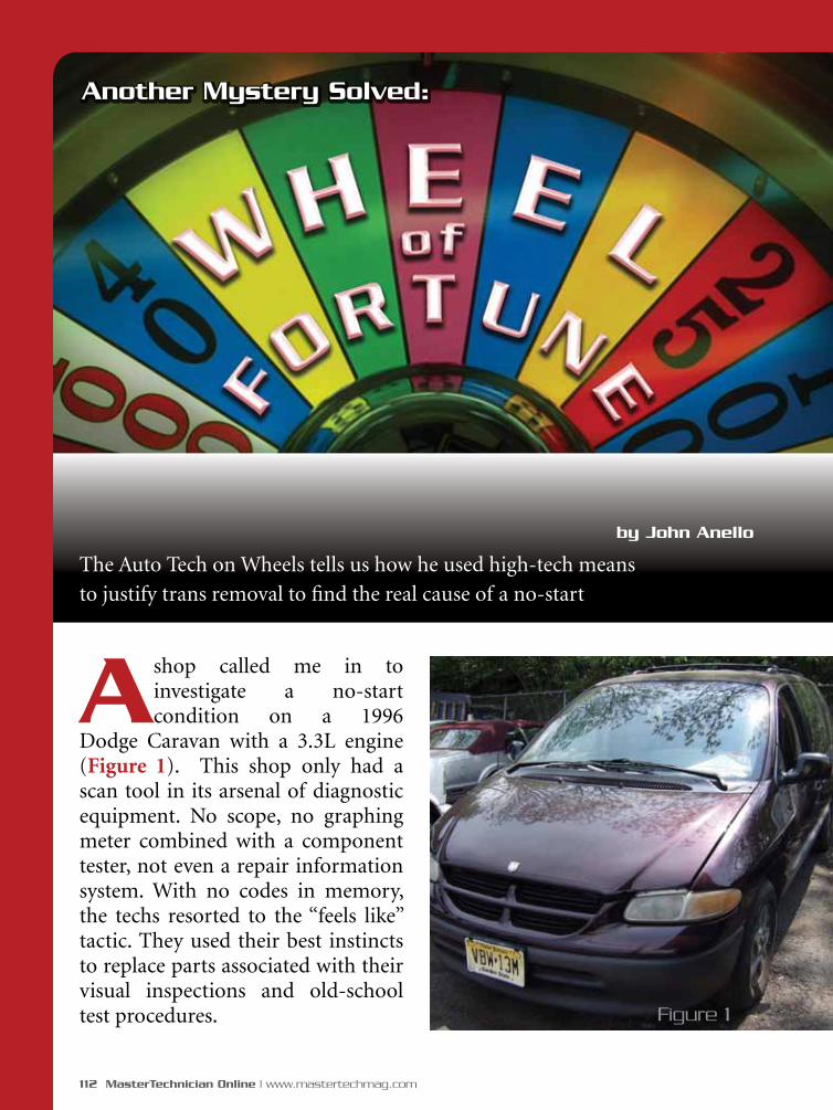
112 MasterTechnician Online | www.mastertechmag.com
A shop called me in to investigate a no-start condition on a 1996
Dodge Caravan with a 3.3L engine (Figure 1). This shop only had a scan tool in its arsenal of diagnostic equipment. No scope, no graphing meter combined with a component tester, not even a repair information system. With no codes in memory, the techs resorted to the “feels like” tactic. They used their best instincts to replace parts associated with their visual inspections and old-school test procedures.
by John Anello
The Auto Tech on Wheels tells us how he used high-tech means
to justify trans removal to find the real cause of a no-start
Figure 1
Another Mystery Solved:

June 2009 | MasterTechnician Online 113
Bad PCM, but why?
The spark tester they were using
only showed spark on one coil, so the
list of parts replaced included the coil
pack, crank sensor, cam sensor and a
PCM. The old PCM was bad due to a
damaged coil driver that was holding
one coil primary constantly on. I’ve
seen this many times in the field
caused by a bad coil assembly with a
shorted coil primary winding. So, I
could justify their replacement of the
coil assembly and the PCM, but the
vehicle still wouldn’t start. This shop
is not alone in the way it diagnoses
cars. All too often I cater to this type
of shop, and I try my best to educate
on-site how important it is for the
technicians to keep themselves up to
date on training and to have the proper
equipment available for performing
the tasks that will save them time and
avoid replacing perfectly good parts.
Figure 2

114 MasterTechnician Online | www.mastertechmag.com
This will obviously make them better
technicians in the long run. It’s never
too late to step up and take it to the
next level. The worst thing in any
business is to let technology surpass
you. You will only find yourself stuck
in the past with not much of a future
ahead of you.
When I arrived at the shop I attempted
to start the car, but it only spit back a
few times as if it wanted to start. The
tech told me that #2/5 ignition coil was
the only one firing during cranking.
The other coils did not fire at all. At this
point I decided to hook my scope up to
some selected signal lines to get a visual
concept of what was going on exactly. I
used my EScope Limited 4-trace scope
and placed my channels on the cam
sensor and all three coil drivers. As I
cranked the engine, I could see that the
cam sensor was providing the proper
signal pattern, but the PCM had a
problem controlling the coil drivers
(Figure 2). One driver attempted to
Wheel of Fortune
Figure 3

June 2009 | MasterTechnician Online 115
ground the coil while another driver
was held on for as long as 600mS of
on-time. By current ramping the one
working coil against the crank and
cam signals (Figure 3) I could see that
the coil driver was maintaining about
8.5 amps of current for almost one
camshaft revolution. There is no way
any driver would hold a coil primary
that long unless that driver was in love
and just did not want to let the coil go.
It was a relationship that went bad,
and no one was around to give advice
to just let go. That got me wondering
if this might have caused the failure of
the coil driver in the old PCM.
Out of synch
This erratic coil operation could
only be caused by a defective PCM
with an internal driver failure, a
corrupted crank/cam signal input,
or a crank/cam sensor correlation
problem. The cam and crank sensors
Figure 4
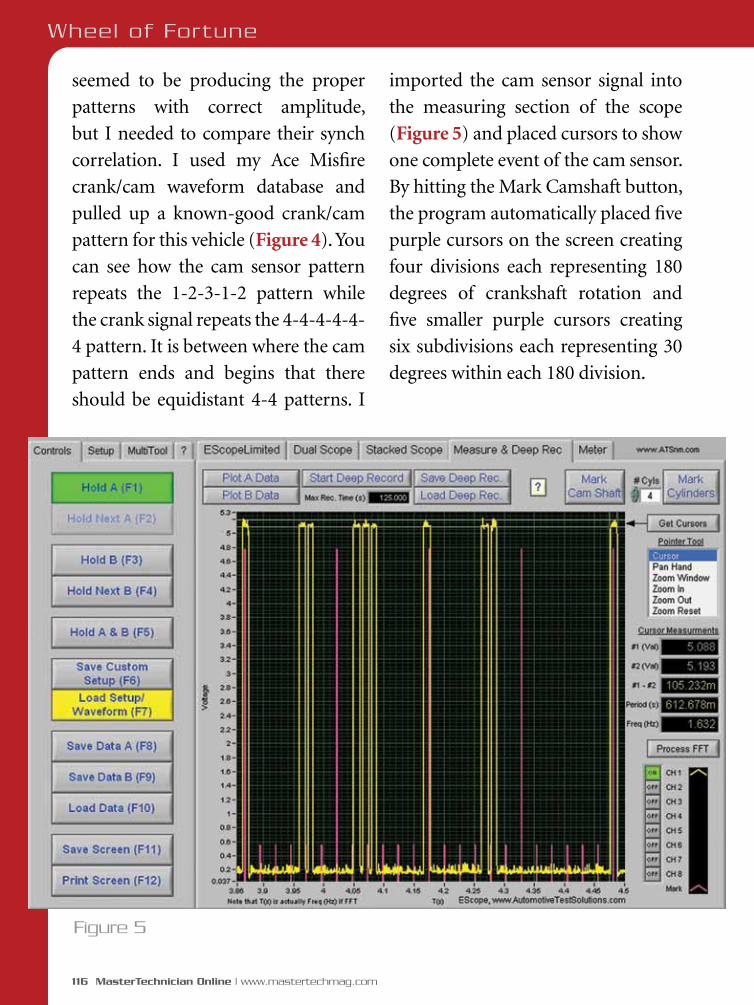
116 MasterTechnician Online | www.mastertechmag.com
Wheel of Fortune
seemed to be producing the proper
patterns with correct amplitude,
but I needed to compare their synch
correlation. I used my Ace Misfire
crank/cam waveform database and
pulled up a known-good crank/cam
pattern for this vehicle (Figure 4). You
can see how the cam sensor pattern
repeats the 1-2-3-1-2 pattern while
the crank signal repeats the 4-4-4-4-4-
4 pattern. It is between where the cam
pattern ends and begins that there
should be equidistant 4-4 patterns. I
imported the cam sensor signal into
the measuring section of the scope
(Figure 5) and placed cursors to show
one complete event of the cam sensor.
By hitting the Mark Camshaft button,
the program automatically placed five
purple cursors on the screen creating
four divisions each representing 180
degrees of crankshaft rotation and
five smaller purple cursors creating
six subdivisions each representing 30
degrees within each 180 division.
Figure 5
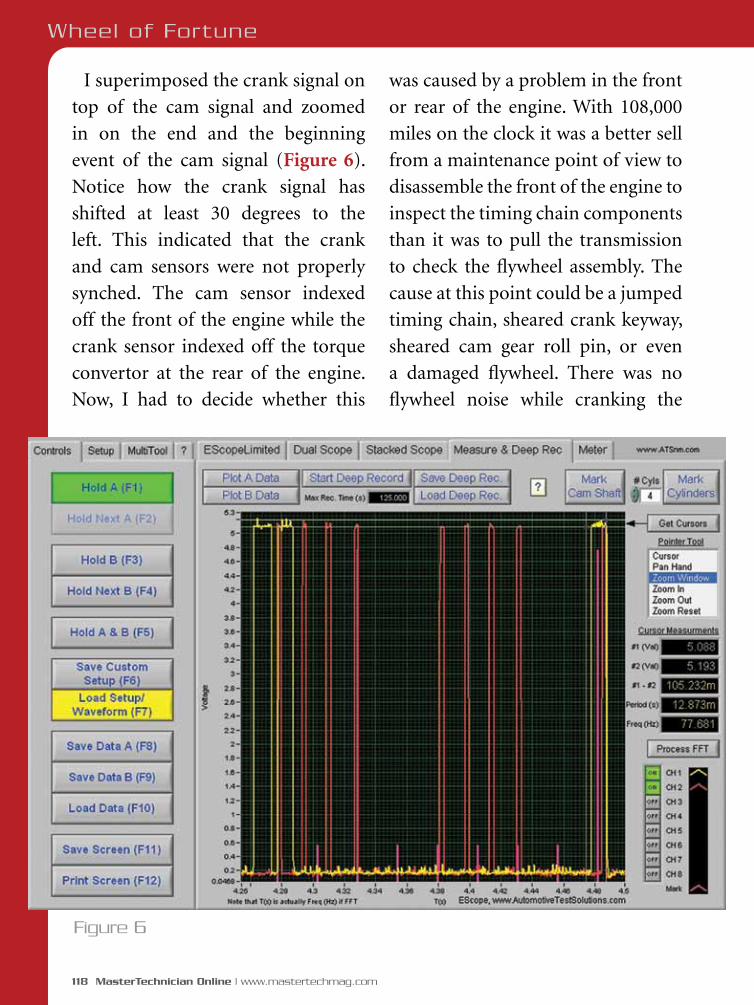
118 MasterTechnician Online | www.mastertechmag.com
Wheel of Fortune
Figure 6
I superimposed the crank signal on
top of the cam signal and zoomed
in on the end and the beginning
event of the cam signal (Figure 6).
Notice how the crank signal has
shifted at least 30 degrees to the
left. This indicated that the crank
and cam sensors were not properly
synched. The cam sensor indexed
off the front of the engine while the
crank sensor indexed off the torque
convertor at the rear of the engine.
Now, I had to decide whether this
was caused by a problem in the front
or rear of the engine. With 108,000
miles on the clock it was a better sell
from a maintenance point of view to
disassemble the front of the engine to
inspect the timing chain components
than it was to pull the transmission
to check the flywheel assembly. The
cause at this point could be a jumped
timing chain, sheared crank keyway,
sheared cam gear roll pin, or even
a damaged flywheel. There was no
flywheel noise while cranking the
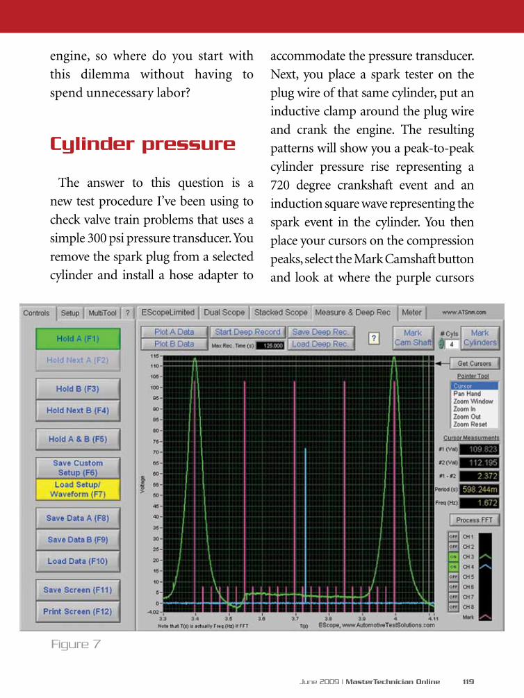
June 2009 | MasterTechnician Online 119
engine, so where do you start with
this dilemma without having to
spend unnecessary labor?
Cylinder pressure
The answer to this question is a
new test procedure I’ve been using to
check valve train problems that uses a
simple 300 psi pressure transducer. You
remove the spark plug from a selected
cylinder and install a hose adapter to
accommodate the pressure transducer.
Next, you place a spark tester on the
plug wire of that same cylinder, put an
inductive clamp around the plug wire
and crank the engine. The resulting
patterns will show you a peak-to-peak
cylinder pressure rise representing a
720 degree crankshaft event and an
induction square wave representing the
spark event in the cylinder. You then
place your cursors on the compression
peaks, select the Mark Camshaft button
and look at where the purple cursors
Figure 7
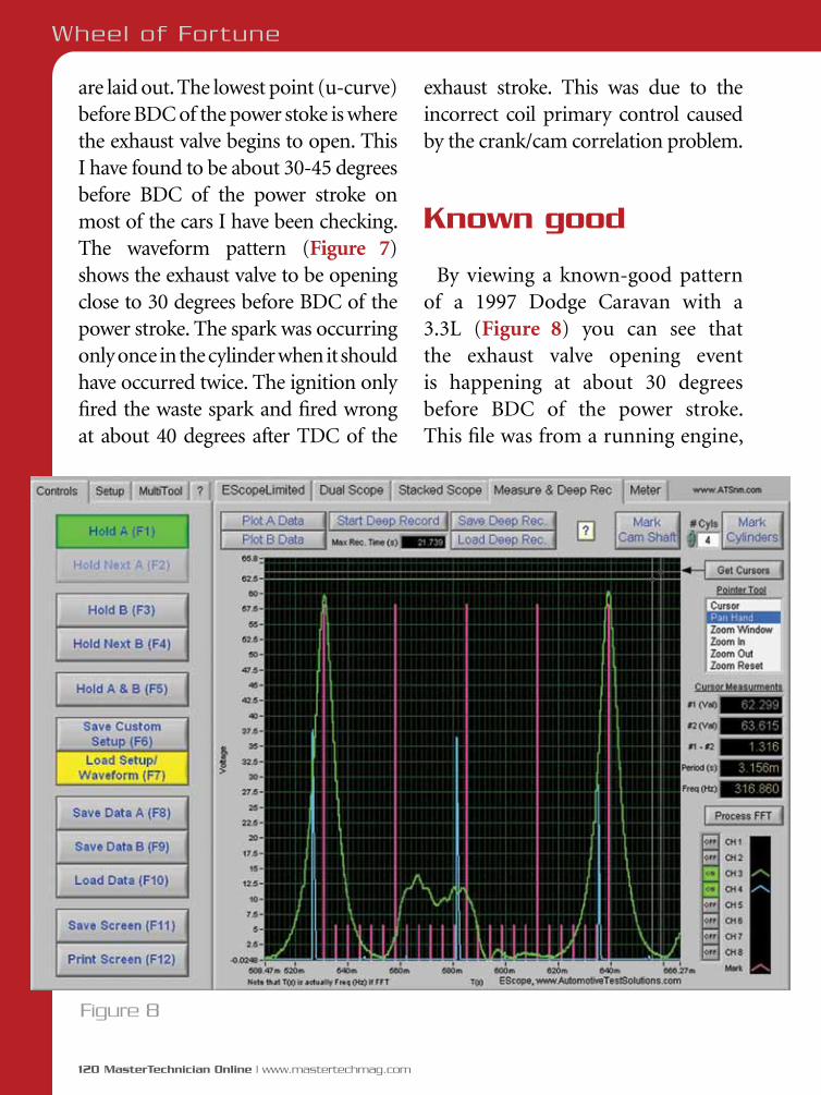
120 MasterTechnician Online | www.mastertechmag.com
are laid out. The lowest point (u-curve) before BDC of the power stoke is where the exhaust valve begins to open. This I have found to be about 30-45 degrees before BDC of the power stroke on most of the cars I have been checking. The waveform pattern (Figure 7) shows the exhaust valve to be opening close to 30 degrees before BDC of the power stroke. The spark was occurring only once in the cylinder when it should have occurred twice. The ignition only fired the waste spark and fired wrong at about 40 degrees after TDC of the
Wheel of Fortune
Figure 8
exhaust stroke. This was due to the incorrect coil primary control caused by the crank/cam correlation problem.
Known good
By viewing a known-good pattern of a 1997 Dodge Caravan with a 3.3L (Figure 8) you can see that the exhaust valve opening event is happening at about 30 degrees before BDC of the power stroke. This file was from a running engine,
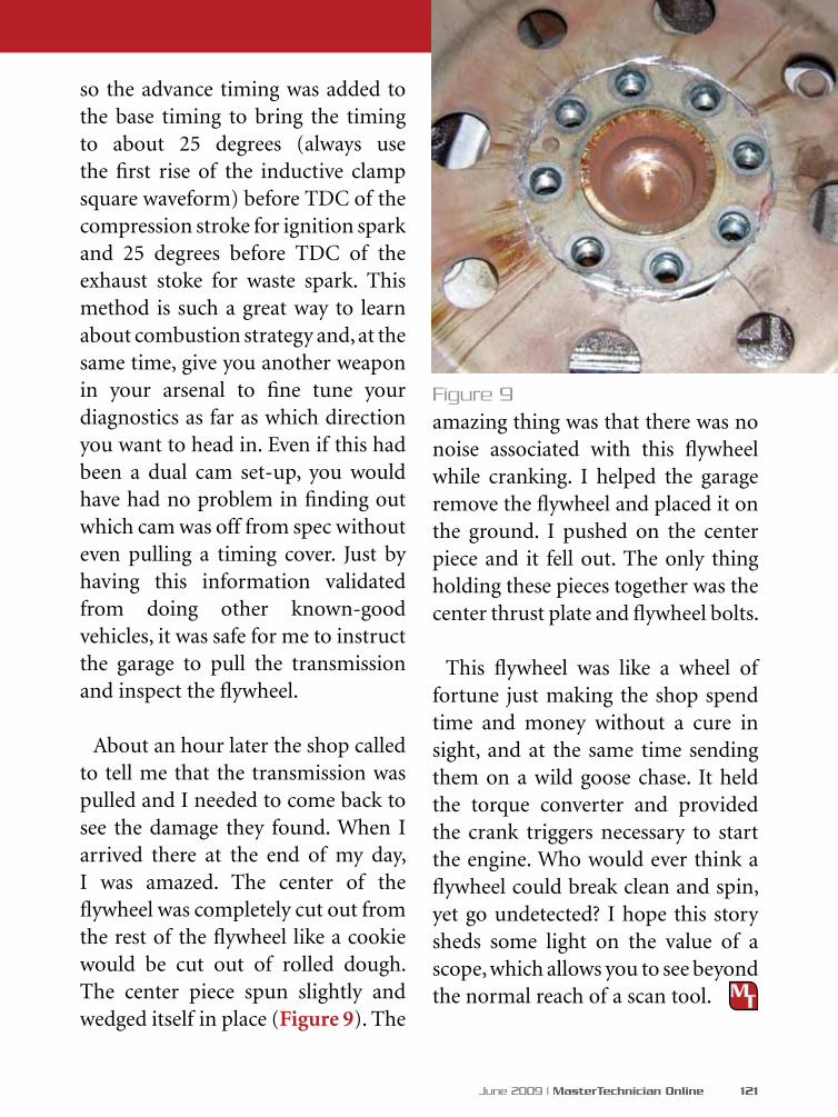
June 2009 | MasterTechnician Online 121
so the advance timing was added to the base timing to bring the timing to about 25 degrees (always use the first rise of the inductive clamp square waveform) before TDC of the compression stroke for ignition spark and 25 degrees before TDC of the exhaust stoke for waste spark. This method is such a great way to learn about combustion strategy and, at the same time, give you another weapon in your arsenal to fine tune your diagnostics as far as which direction you want to head in. Even if this had been a dual cam set-up, you would have had no problem in finding out which cam was off from spec without even pulling a timing cover. Just by having this information validated from doing other known-good vehicles, it was safe for me to instruct the garage to pull the transmission and inspect the flywheel.
About an hour later the shop called to tell me that the transmission was pulled and I needed to come back to see the damage they found. When I arrived there at the end of my day, I was amazed. The center of the flywheel was completely cut out from the rest of the flywheel like a cookie would be cut out of rolled dough. The center piece spun slightly and wedged itself in place (Figure 9). The
amazing thing was that there was no noise associated with this flywheel while cranking. I helped the garage remove the flywheel and placed it on the ground. I pushed on the center piece and it fell out. The only thing holding these pieces together was the center thrust plate and flywheel bolts.
This flywheel was like a wheel of fortune just making the shop spend time and money without a cure in sight, and at the same time sending them on a wild goose chase. It held the torque converter and provided the crank triggers necessary to start the engine. Who would ever think a flywheel could break clean and spin, yet go undetected? I hope this story sheds some light on the value of a scope, which allows you to see beyond the normal reach of a scan tool.
Figure 9

122 MasterTechnician Online | www.mastertechmag.com
Even though this
system is typically
trouble-free, it’s on
so many vehicles you
need to know about it
GM “U” Body Automatic Level Control
by Greg McConiga
Every so often somebody
actually thinks ahead and
designs a system to overcome
a problem that just might arise.
Appearing in two versions on GM’s
second and third generation kid-
haulers (1997 to current production
Venture/Uplander, Transport/
Montana, Terraza and Silhouette,
as well as the 2001-2005 Aztec and
2002 and up Rendezvous), the rear-
only automatic level control system
came about because someone
thought about how these famously
utilitarian and cavernous family
cargo haulers would actually end
up being used. I had one, and it
transported everyone and everything
at one point or another. From four-
by-eight sheet stock to ladders and
tools, it cheerfully moved everything
we stuffed into it while getting about

June 2009 | MasterTechnician Online 123
Here’s what you see with all the fasteners removed and the compressor hanging from its safety bracket. The drier, relay, harness and compressor are in one package.
seat are candidates, as well as our topic
du jour, the minivan and its SUV
spinoffs. If you think about it, you’ll
see that automatic rear level control
systems are actually safety systems
-- crash safety, vehicle dynamics and
braking are all dramatically affected
by vehicle trim.
In a collision, maintaining proper
ride height is one key to making
19 mpg city and 24 highway – not
bad for a blunt-nosed, flat-sided
aerodynamic nightmare on wheels.
Level’s important
Rear level control systems are likely
to appear where vehicle loading varies
considerably. Large cars with room
for three plus-size people in the back
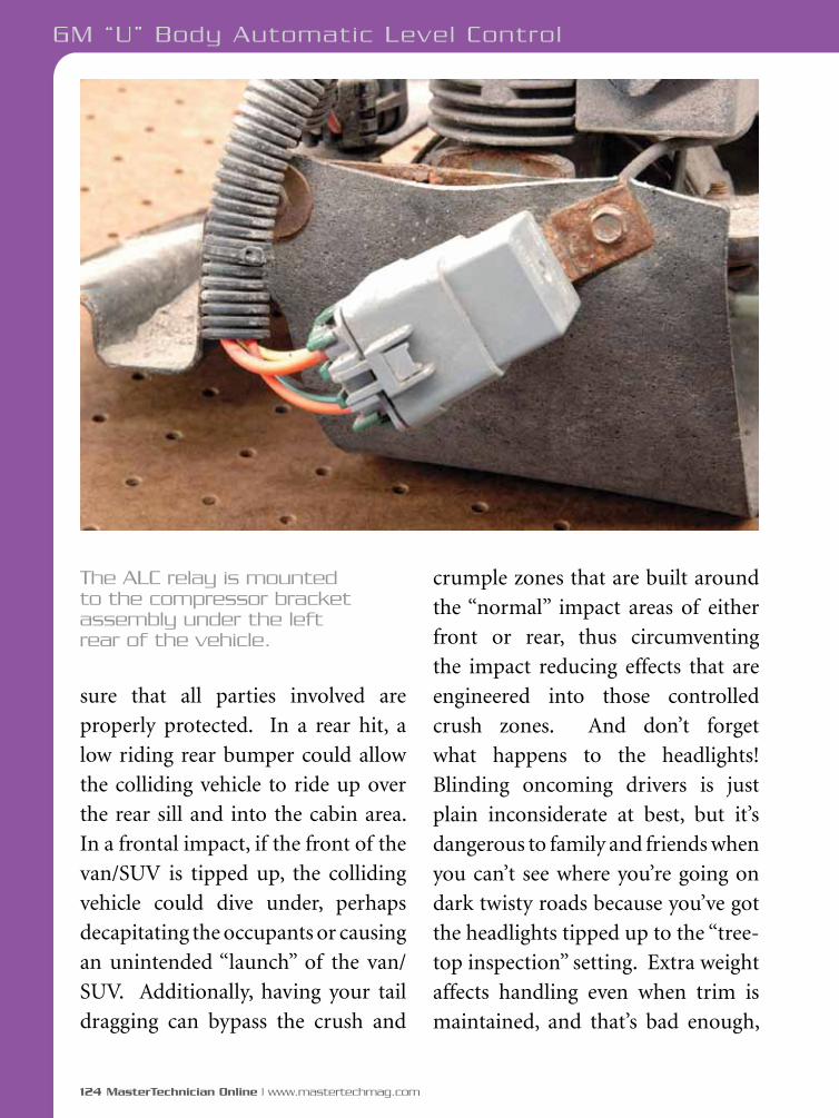
124 MasterTechnician Online | www.mastertechmag.com
GM “U” Body Automatic Level Control
sure that all parties involved are
properly protected. In a rear hit, a
low riding rear bumper could allow
the colliding vehicle to ride up over
the rear sill and into the cabin area.
In a frontal impact, if the front of the
van/SUV is tipped up, the colliding
vehicle could dive under, perhaps
decapitating the occupants or causing
an unintended “launch” of the van/
SUV. Additionally, having your tail
dragging can bypass the crush and
crumple zones that are built around
the “normal” impact areas of either
front or rear, thus circumventing
the impact reducing effects that are
engineered into those controlled
crush zones. And don’t forget
what happens to the headlights!
Blinding oncoming drivers is just
plain inconsiderate at best, but it’s
dangerous to family and friends when
you can’t see where you’re going on
dark twisty roads because you’ve got
the headlights tipped up to the “tree-
top inspection” setting. Extra weight
affects handling even when trim is
maintained, and that’s bad enough,
The ALC relay is mounted to the compressor bracket assembly under the left rear of the vehicle.

THESE RACERS RELIED ON NISSAN MOTORSPORTSCOMPETITION PARTS
We look forward to helping you win your next championship. Ask us about the Nissan Racer Support program.
See our full line of competition parts at nissan4parts.com or call now to order our 124-page catalog.
Toll-free order line and technical assistance: 888.833.3225 (Nissan Motorsports Competition Parts only)
24-hour fax line: 615.223.3341 email: [email protected]
Mailing/Shipping address: Nissan Motorsports - 2198 Midway Lane - Smyrna, TN 37167
PETER ZEKERTNISSAN 200SXSCCA GT-L CHAMPION
CHRIS FORSBERGNISSAN 350ZFORMULA DRIFT
JIM GOUGHARYNISSAN 350ZSCCA GT-2 CHAMPION
SHIFT–the way you move
CHECK OUT OUR NEW 124-PAGE CATALOG
Nissan Motorsports Competition Parts do not carry any type of warranty, and have been designed and are intended for off-highway applications only. Nissan, the Nissan Brand Symbol, "SHIFT_" tagline and Nissan model names are Nissan trademarks. Always wear your seat belt, and please don't drink and drive. ©2009 Nissan North America, Inc.
HOW DO YOU WINCHAMPIONSHIPS?
TODD CUFFARONISSAN FRONTIERCORR PRO-LITEROOKIE OF THE YEAR
Nissan MS_Champion ad_GRM 2/10/09 1:53 PM Page 2

126 MasterTechnician Online | www.mastertechmag.com
but tilting the weight distribution
rearward and off the front tires
makes a mildly under-steering
vehicle misbehave even more. Vehicle
handling and roll characteristics also
change for the worse, as does braking
performance. All good reasons to
keep the vehicle at or near a standard
trim specification.
There are two variants of the system,
one from 1997 until 2002, and another
from 2003 through the current model
year. Both systems are available with
or without the inflator option, which
allows you access to the onboard air
compressor for chores like pumping
up tires or inflatable toys. From 1997
until 2002, the system had no self-
diagnostics, but starting in 2003 a
limited self-diagnostic capability was
embedded into the height sensor.
The actual function of both systems is
identical, with the exception of being
able to flash codes at the inflator
GM “U” Body Automatic Level Control
Here’s the brains of the outfit. The ALC sensor does nearly all the work. The sensor mounts to the body, the non-adjustable arm to the axle and the electronics do the rest.

control switch, and the addition of
a circuit to the height sensor that
controls the inflator solenoid valve,
so we’ll discuss the later system in this
article. When working on the first
generation system you’ll simply stick
to symptom-based diagnostics and
follow the appropriate flow chart.
Components
The air shocks are conventional
with the addition of a rubber sleeve
that’s attached between the dust
tube and the reservoir, which creates
a flexible air chamber -- you’ll
never see them leak unless the boot
fails. Minimum residual pressure is
maintained at eight psi by the air drier
assembly. The shocks are connected
to the compressor by plastic lines and
couplers that are double o-ringed and
The inflator adds a switch and the inflator control solenoid to the system. With the inflator option you also get limited self-diagnostic capability.
Click to enlarge.
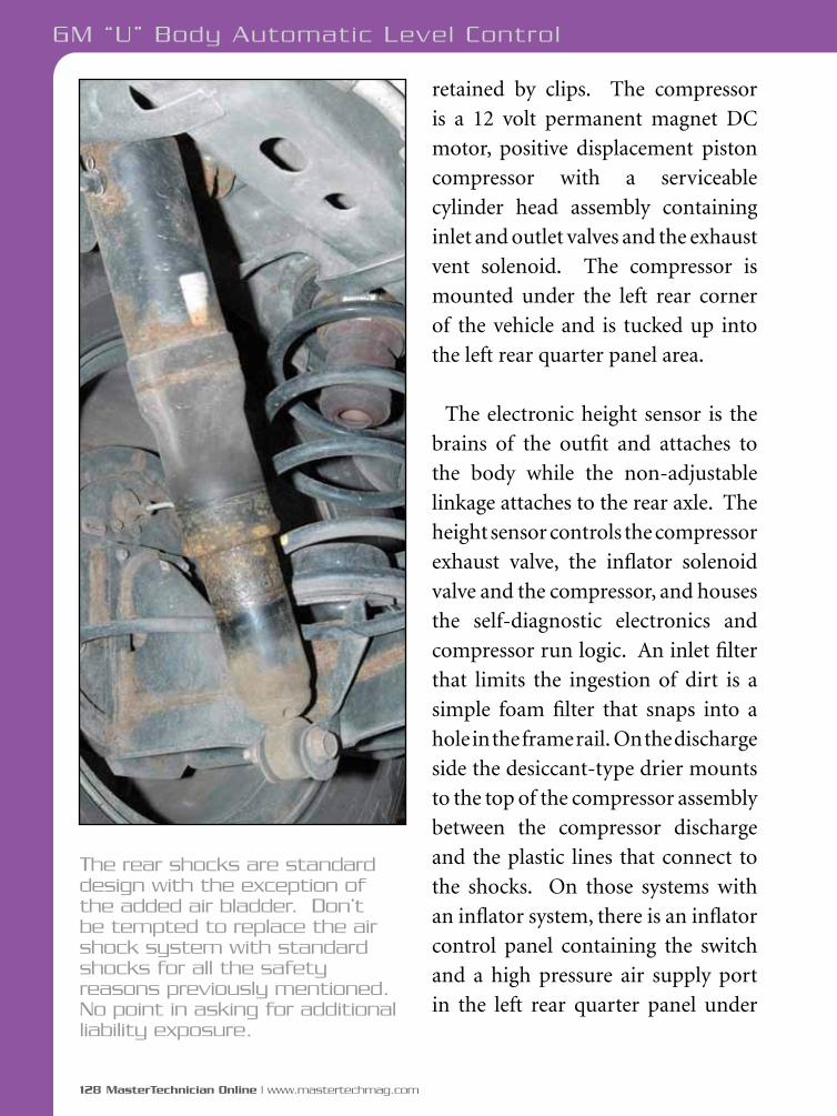
128 MasterTechnician Online | www.mastertechmag.com
GM “U” Body Automatic Level Control
The rear shocks are standard design with the exception of the added air bladder. Don’t be tempted to replace the air shock system with standard shocks for all the safety reasons previously mentioned. No point in asking for additional liability exposure.
retained by clips. The compressor
is a 12 volt permanent magnet DC
motor, positive displacement piston
compressor with a serviceable
cylinder head assembly containing
inlet and outlet valves and the exhaust
vent solenoid. The compressor is
mounted under the left rear corner
of the vehicle and is tucked up into
the left rear quarter panel area.
The electronic height sensor is the
brains of the outfit and attaches to
the body while the non-adjustable
linkage attaches to the rear axle. The
height sensor controls the compressor
exhaust valve, the inflator solenoid
valve and the compressor, and houses
the self-diagnostic electronics and
compressor run logic. An inlet filter
that limits the ingestion of dirt is a
simple foam filter that snaps into a
hole in the frame rail. On the discharge
side the desiccant-type drier mounts
to the top of the compressor assembly
between the compressor discharge
and the plastic lines that connect to
the shocks. On those systems with
an inflator system, there is an inflator
control panel containing the switch
and a high pressure air supply port
in the left rear quarter panel under
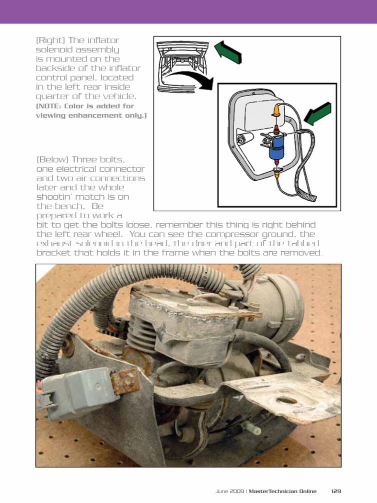
June 2009 | MasterTechnician Online 129
(Right) The inflator solenoid assembly is mounted on the backside of the inflator control panel, located in the left rear inside quarter of the vehicle. (NOTE: Color is added for viewing enhancement only.)
(Below) Three bolts, one electrical connector and two air connections later and the whole shootin’ match is on the bench. Be prepared to work a bit to get the bolts loose, remember this thing is right behind the left rear wheel. You can see the compressor ground, the exhaust solenoid in the head, the drier and part of the tabbed bracket that holds it in the frame when the bolts are removed.

130 MasterTechnician Online | www.mastertechmag.com
GM “U” Body Automatic Level Control
a removable cover. The inflator
solenoid is attached to the backside
of the inflator control panel in the
left rear.
Operation
At key up the height sensor checks
ride height. If it’s within four
millimeters of the set point, there’ll be
a 30 second wait, then the compressor
runs for four seconds to guarantee
adequate reserve air pressure of eight
psi. If the vehicle is out of trim, after
20 seconds the compressor will start
and run until the desired attitude is
reached – or 255 seconds, whichever
comes first. The compressor
protection portion of the height
sensor logic limits run time to 255
seconds at each key cycle to prevent
compressor damage in the event of
a pressure leak. The start is always
The drier keeps moisture out of line and shocks. Technically it should be replaced periodically, but I didn’t find any published recommendations for replacement.

132 MasterTechnician Online | www.mastertechmag.com
GM “U” Body Automatic Level Control
delayed 20 seconds from the call for
ride height adjustment to compensate
for normal vehicle movement and
suspension travel, thereby avoiding
compressor short cycling or needless
starts. The exhaust solenoid valve
actuates for 1.5 seconds with each
compressor start to reduce pressure
in the compressor head cavity and
reduce startup current.
Diagnosis
The system has ten DTCs you can
call up using the inflator switch.
To extract codes, press and hold
the accessory inflator switch for
three seconds. From initiation
the self-test takes 200 seconds to
complete. The number of flashes
on the switch LED represents the
currently present codes and all
codes will flash until acknowledged
by pressing the inflator switch,
or until the module goes to sleep.
The LED will flash the first digit of
Located on the left rear inside quarter panel trim the inflator panel has an auxiliary power outlet, the control switch and an air fitting. These vehicles have a hose and inflator kit supplied with them that can stretch to reach all four tires.

June 2009 | MasterTechnician Online 133
1- The foam air filter clips on the end of the intake line and snaps into the frame high up to avoid water ingestion.
2- Rubber splash shield
3- Mounting bracket

134 MasterTechnician Online | www.mastertechmag.com
the two digit trouble code at half
second intervals followed by a one
second delay and then the second
digit will flash. Each code cycle
will be separated by a three second
delay. Once the conditions that
set the code are repaired, the codes
will automatically clear when the
ignition is cycled.
Real world
This system can only be called
reliable and robust. Of all the
people I spoke with, not one saw
any significant failure patterns,
which mirrors my experience. We’ve
replaced a few lines attacked by
rodents (if someone can explain the
affinity rodents have for plastic and
wiring insulation, I’d sure like to
hear it!), and a few shock units that
were worn out, or with blown out air
bags, but that’s about it. The ability
to pump up a flat tire with your own
vehicle is a great idea (I’ve done that
at least once), and it’s nice to be able
pump up pool toys and bike tires as
well. It’s a good system that is well
executed. Really, I’m on the level!
Diagnostic Trouble Codes
DTC 11 is related to the accessory inflator solenoid, and will set for short to power, short to ground or a malfunctioning solenoid.
DTC 12 is the system okay code.
DTC 13 sets if the ride height is out of specification.
DTC 21 sets if the compressor relay coil control circuitry shorts to ground.
DTC 22 sets if the compressor relay coil circuitry opens or shorts to battery.
DTC 23 sets if the compressor runs for 255 seconds during a leveling function.
DTC 31 sets if the exhaust solenoid control circuit shorts to ground.
DTC 32 sets if the exhaust solenoid control circuit opens or shorts to battery.
DTC 33 sets if the exhaust solenoid has been energized for 255 seconds and the height sensor did not detect the proper downward movement.
As is typical, each of these trouble codes refers you to a multiple-page diagnostic flow chart to accurately complete the diagnosis.
GM “U” Body Automatic Level Control

136 MasterTechnician Online | www.mastertechmag.com
a mastertechmag.com online publicationApril 2009 VOL. #15 N0.1
Needle in a Haystack
Another Mystery Solved
Current issues of Master Technician ONLINE are
free of charge to qualified automotive repair shop owners,
managers and technicians. Send this website link
- www.mastertechmag.com - to your tech buddies so they
can sign up for their free subscription too!
Inside the Insider
Five Ways to Limit LiabilityBy stepping out into the business world, every step has exposure. While you cannot stop people from suing, you can insulate your business, personal assets and wallet from most liability if you take some steps to protect yourself.
(Turn to page 1)
Human PotentialThe mind is a strange and powerful tool. Psychologists tell us some very interesting things about its function. First, 90% of its activity is subconscious.
(Turn to page 1)
In Times Like TheseSmall business is the skeleton of our economy. Businesses like ours.
(Turn to page 3)
Sole ProprietorshipIt does not matter whether the individual is just getting started in a new business or is a twenty year business veteran this question comes up on a regular basis. My answer to this dilemma has always been the same, it depends.
(Turn to page 6)
MT Business Insider Pricing MatrixBusinesses are based on percentages, but customers look at prices. How do you reconcile your business’ need to make a decent profit margin on parts with your customers’ need to pay a fair price?
(Turn to page 8)
ASE Certification: The Competitive AdvantageOne of the most powerful influences on choosing a repair facility is word-of-mouth recommendations from family, friends, and neighbors. Existing customers usually recommend a business based on trust and positive past experience.
(Turn to page 10)
Volume 1 | Issue 1
Five Ways to Limit Liability For Business Owners
By David V. Allen, Esq.
By stepping out into the business world, every step has exposure. While you cannot stop people from suing, you can insulate your business, personal assets and wallet from
most liability if you take some steps to protect yourself.
First, incorporate or form a limited liability company.
This requires that you file articles of incorporation, or in the case of a limited liability company (LLC), articles of organization with the Secretary of State, or whatever governmental office handles business filings in your state. Once you incorporate or form an LLC, you must hold your business out to the public as a corporation or LLC. This means
Continue p.2: Five Ways
Continue p.5: Potential
Human Potential Using What You’ve Got
by Greg McConiga
The mind is a strange and powerful tool. Psychologists tell us some very interesting things about its function. First, 90% of its activity is subconscious. Let’s define that. “Sub,” as in
“below,” and conscious, as in an individual sense of recognition of things within or without oneself. 90%! Think about that. It says if -- IF -- you are 100% in control during your waking hours, the very best you are capable of achieving is still only 10%. It’s generally agreed that a human’s learning ability is physically unlimited. Remember that a scrap of brain tissue no larger than this “o” can store more information than a computer the size of a Honda. Now, consider that an average person’s brain weighs about three pounds. How many ounces of yours do you actually use?