Journal ofTechnology - Aramco
100
-
Upload
khangminh22 -
Category
Documents
-
view
0 -
download
0
Transcript of Journal ofTechnology - Aramco

www.saudiaramco.com/jot
Journal of Technology | SUM
MER
2021
page 2 /A Novel Approach to Improve Acid Diversion U�lizing In Situ Foam Genera�ng FluidsAyman R. Al-Nakhli, Ibrahim M. El-Zefzafy, Danish Ahmed and Wassim Kharrat
page 15 /A New Methodology for Calcula�ng Wellbore Pressure of Shut-in Wells in Numerical Reservoir Simula�onBabatope O. Kayode and Dr. Mahmoud Jamiolamahdi
2021SU
MM
ER
Aramco
JournalofTechnology
49108araD1R1.Cvr.indd 1-3 6/16/21 8:22 PM

49108araD1R1.Cvr.indd 4-6 6/16/21 8:23 PM

The Aramco Journal of Technology is published quarterly by the Saudi Arabian Oil Company, Dhahran, Saudi Arabia, to provide the company’s scien��c and engineering communi�es a
forum for the exchange of ideas through the presenta�on of technical informa�on aimed at advancing knowledge in the hydrocarbon industry.
Management
Amin NasserPresident & CEO, Saudi Aramco
Nabeel A. Al-Jama’Senior Vice President, HR and Corporate Services
Fahad K. Al DhubaibGeneral Manager, Public A�airs
Editorial Advisors
Ahmad O. Al-KhowaiterVice President, Technology Oversight and Coordina�on
Abdullah M. Al-GhamdiVice President, Gas Opera�ons
Abdul Hameed A. Al-RushaidVice President, Drilling and Workover
Khalid M. Al-AbdulqaderVice President, Unconven�onal Resources
Khaled A. Al AbdulgaderChief Drilling Engineer
Omar S. Al-HusainiGeneral Manager, Drilling and Workover Opera�ons
Jamil J. Al-BagawiChief Engineer
Waleed A. Al MulhimChief Petroleum Engineer
Ammar A. Al-NahwiManager, Research and Development Center
Ashraf M. Al-TahiniManager, EXPEC ARC
Editor
William E. [email protected]
tel: +966-013-876-0498
Produ�ion Coordina�on
Richard E. DoughtyCorporate Publica�ons, Aramco Americas
Design
Graphic Engine Design StudioAus�n, Texas, U.S.A.
No ar�cles, including art and illustra�ons, in the Aramco Journal of Technology except those from copyrighted sources, may be reproduced or printed without the written permission of
Saudi Aramco. Please submit requests for permission to reproduce items to the editor.
The Aramco Journal of Technology gratefully acknowledges the assistance, contribu�on and coopera�on of numerous opera�ng organiza�ons throughout the company.
ISSN 1319-2388 © Copyright 2021 Aramco Services Company, all rights reserved.
49108araD2R1.indd 1 6/16/21 8:27 PM

49108araD2R1.indd 2 6/16/21 8:27 PM

Contents
p. 2 A Novel Approach to Improve Acid Diversion Ulizing In Situ Foam Generang Fluids
Ayman R. Al-Nakhli, Ibrahim M. El-Zefzafy, Danish Ahmed and Wassim Kharrat
p. 9 A Deep Learning WAG Inje�ion Method for CO2 Recovery Opmizaon
Dr. Klemens Katterbauer, Dr. Alberto F. Marsala and Dr. Abdulaziz S. Al Qasim
Lena Petrozziello, Dr. Christoph Kayser, Dr. Cyril Okocha, Dr. Tao Chen and Dr. Qiwei Wang
p. 15 A New Methodology for Calculang Wellbore Pressure of Shut-in Wells in Numerical Reservoir Simulaon
Babatope O. Kayode and Dr. Mahmoud Jamiolahmady
p. 24 Rock Mechanical Chara�erizaon of Shale Drilling Fluid Intera�ions to Migate Borehole Instability Problems
Dr. Mohammad H. Alqam, Dr. Md. Amanullah, Antonio Santaga�, Salem H. Al-Garni,
Adnan H. Al-Makrami, and Dr. Sinan Caliskan
p. 34 Thermochemical Acid Fra�uring of Tight and Unconvenonal Rocks: Experimental and Modeling Invesgaons
Dr. Zeeshan Tariq, Dr. Murtada S. Al-Jawad, Dr. Mohamed Mahmoud,
Dr. Abdulazeez Abdulraheem and Ayman R. Al-Nakhl
p. 50 New Catalyst-free Polycrystalline Diamond with Industry Record Wear Resistance
Dr. Guodong Zhan, Dr. Bodong Li, Timothy E. Moellendick, Dr. Duanwei He
and Dr. Jianhui Xu
p. 57 Design Opmizaon for Hydraulically Driven Agitaon Tool in Extended Coiled Tubing Reach Applicaon
Hussain A. Al-Saiood, Laurie S. Duthie, Ahmed H. Albaqshi and Muhammad Ahsan
p. 66 A New Aramco Record in PatentsMichael J. Ives
49108araD2R1.indd 1 6/16/21 8:27 PM

2 The Aramco Journal of Technology Summer 2021
Acidizing is a common stimulation treatment in carbonate reservoirs. Acid distribution over all lay-ers and areas around a treated well is crucial for the matrix stimulation success. E�ective acidizing, especially for long horizontal wells, requires an acid diverting technique to ensure uniform distribu-tion along the wellbore intervals. Mechanical diversion is costly, while chemical diversion using in situ gelled acid and viscoelastic surfactants (VES) have been widely applied during matrix stimulation. These chemical methods showed not only limited e ciency, but can introduce damage to the treat-ed formation. Several chemical additives and complex formulations are usually used to ensure sta-bility and success of diverting the uid application. This exercise greatly increases the treatment cost.
This study introduces a novel solution to improve acid diversion using in situ foam generation. Thermochemical uid is used to generate foam in situ at downhole conditions, which will divert acid stages into non-treated sections of the reservoirs. In this article, two field treatments of two water injector wells — a vertical and a horizontal — were demonstrated using the new system. The in situ foam generating uid was used to divert acid in several pumping stages to ensure homogenous treat-ment. The pumping sequence and treatment mechanisms are described.
The results showed that the in situ foam generation approach has a very e�ective performance in diverting acid, with superior results compared to conventional diversion using a VES. As the new system generates foam downhole, it showed very practical operation procedures. No pumping di -culties are experienced, compared with surface pumping to the foam. Having the reaction activated downhole made the whole treatment safe and user-friendly to apply. Foam can occupy large areas, so less uid is required to divert the acid stage. No complex formulation was required with several additives to ensure uid activation downhole, which significantly reduced the overall treatment cost.
The novel method will enable e�ective and homogenous acidizing of carbonate reservoirs and eliminate the need for VES, which is expensive, and provides a limited e�ect. This work presents an e�ective method to place acid uniformly across a treated well using in situ foam generation.
A Novel Approach to Improve Acid Diversion Ulizing In Situ Foam Generang FluidsAyman R. Al-Nakhli, Ibrahim M. El-Zefzafy, Danish Ahmed and Wassim Kharrat
Abstra� /
Introdu�ionE�ective acidizing of carbonate reservoirs requires a diversion mechanism to have a uniform acid treatment along the stimulated interval1-5. This is crucial, especially for long horizontal wells. Ine�ective diversion will let acid stimulate and propagate into only one area, leaving most of the horizontal section untreated.
There are two types of diversion mechanisms in the industry, either mechanical or chemical. One of the chemical diverting mechanisms is the application of viscoelastic surfactants (VES), which had widely been used as an acid diverter during stimulation treatments. The concept of this application is that VES can chelate with metal ions, such as calcium ions, once neutralized, and when the acidic hydrogen is removed6-9.
Figure 1 shows the titration of cationic and amphoteric surfactants in an acidic solution, using hydroxide. When the pH is plotted against the change of pH, the graph will show the neutralization of the VES, and the removal of acidic hydrogen. The titration curve showed that the amphoteric VES had two peaks, as the surfactant actually had two functional groups. The cationic VES had one dominant peak, as the surfactant had only one acidic hydrogen. During actual field application, this neutralization process takes place inside the reservoir, as the acid is spent when reacting with calcium carbonate, and generates calcium chloride (CaCl2). The calcium ion (Ca2+) will chelate with the VES, and will form a solidified gel10.
In actual field treatments, the VES is mixed with hydrochloric (HCl) acid during pumping, with low viscosity. As the acid reacts with carbonate formations, CaCl2 will be generated, and the pH will increase above 3.0, Fig. 1. As the pH increases, the VES starts to bond to the calcium ions and form a viscous gel, to divert the acid to untreated areas, Fig. 2.
One of the drawbacks of applying a VES is that they can chelate with ferric ions (Fe3+) and form sludge, which is a damaging material during pumping. This phenomenon can happen even at acidic solution with a zero
49108araD3R1.indd 2 6/16/21 8:36 PM

3 The Aramco Journal of TechnologySummer 2021
pH. So, corrosion products, such as iron, can chelate with the VES to form a gel, even before spending the acid, at zero pH.
Figure 3 shows the sludge formation out of the VES chelating with Fe3+. As a result, not only will no diver-sion take place, but also the formed sludge material will plug and damage the formation. Several field applications of VES, during acidizing, show limited results. The VES are quite expensive chemicals, and increases the overall stimulation cost10.
Discussion In situ Foam Diversion This study introduces a novel acid diversion method using in situ foam generation chemicals. Thermochem-ical �uids are pumped with very low viscosity, as a diverting agent, at the end of each acid stage, Fig. 4. A reaction will be activated downhole to generate in situ foam and create high viscous contrast, which will divert new acid stages into the untreated areas, Fig. 5.
Foam can expand, fill, and block large fractures after acidizing, and e�ectively divert the acid. The VES
Fig. 1 The acid-based �tra�on of the amphoteric and ca�onic surfaants10.
Fig. 2 The cross-linking of the amphoteric VES with calcium carbonate forms a gel.
Saudi Aramco: Company General Use
Fig. 1 The acid- ased titration of the amphoteric and cationic surfactants10.
Fig. The cross-lin ing of the amphoteric with calcium car onate forms a gel.
Fig. 3 The cross-linking of the amphoteric VES with corrosion produs, Fe (III) forms sludge 10.
Saudi Aramco: Company General Use
Fig. The cross-lin ing of the amphoteric with corrosion products e ( ) forms sludge10.
Fig. n situ foam generating system pre-acti ation.
49108araD3R1.indd 3 6/17/21 12:44 PM

4 The Aramco Journal of Technology Summer 2021
requires large chemical volumes to block the fracture, which is usually unpractical and expensive. One ad-vantage of this method is that foam is not a damaging material and can completely collapse, post-acid treat-ment. So, neither damaging material nor leftovers are expected, compared to the use of a VES.
Pumping foam from service is also a challenge and not a very practical treatment for service companies. Pumping foam requires high pumping pressure, which sometimes exceeds pumping limitations, as the foam has very low hydrostatic pressure. Therefore, squeez-ing the foam into a fracture is a challenge. When a thermochemical �uid is used to generate in situ foam, hydrostatic pressure will help with the pumping pres-sure to squeeze the foam into placed fractures. Not only that, but foam can also be generated inside the fracture. So, from field applications, this method is very practical and showed superior results.
Recording of the distributed temperature sensing (DTS) — during actual well treatment — showed an in situ generation of foam, which forced �uid �ow diversion into another interval, Fig. 6. DTS was useful and used as the in situ foam generation system that generated heat, which is detectable by the DTS. The gray lines show the �uid’s �ow progress — pre-reaction on the left and post-reaction on the right. It is shown that as foam was generated, �uid was diverted from the upper to the lower interval.
Treatment of a Ver�cal Well (Well-A)Well-A is a water injector in a carbonate formation, which was damaged and requires acidizing. The well is located far from oil producers, in a high-pressurized area. The application of conventional acidizing for 20 years, using VES, showed the injection rate increase
by onefold to twofold, maximum. When the in situ foam generation system was applied,
the well injectivity increased by fivefold, which was unprecedented. During the treatment, a pre�ush stage was conducted to remove any corrosion products, and organic and inorganic damages. Then, HCl acid was injected in the well, in four stages. After each acid stage, in situ foam generation �uid was injected to provide a uniform distribution of the acid along the vertical well. The injection of an in situ foam system was to divert the new acid stage to a new well interval, Fig. 7.
In situ foam generation was indicated from a slight increase in wellhead pressure. No di�culties were faced during the pumping of the in situ foam gener-ating system. Not only was the stimulation treatment more e�ective, but also the cost was reduced by 65% compared to the VES applications.
Well-A Treatment Sequence
The treatment sequence for Well-A consisted of the following:
A: The pumping of the pre�ush stage of organic dis-solver, HCl acid, and displacement with treated water.
B-1: First stage of pumping in situ foam generation system.
B-2: Second stage of pumping in situ foam gener-ation system.
B-3: Third stage of pumping in situ foam generation system.
C: Pumping three stages of HCl acid.
Treatment of a Horizontal Well (Well-B)
Well-B is a horizontal water injection well. Conven-tional acidizing using VES did not show significant
Fig. 4 In situ foam genera�ng system pre-a iva�on. Fig. 5 Genera�on of the in situ foam by an a iva�ng rea ion.
Saudi Aramco: Company General Use
Fig. eneration of the in situ foam y an acti ating reaction.
Fig. The T of in situ foam generation downhole.
Saudi Aramco: Company General Use
Fig. The cross-lin ing of the amphoteric with corrosion products e ( ) forms sludge10.
Fig. n situ foam generating system pre-acti ation.
49108araD3R1.indd 4 6/16/21 8:36 PM

5 The Aramco Journal of TechnologySummer 2021
Fig. 6 The DTS of in situ foam genera�on downhole.
Fig. 7 The matrix acidizing of a ver�cal well (Well-A) using an in situ foam genera�on system.
Fig. 8 The pre�ush stage of matrix acidizing of a horizontal well (Well-B) using an in situ foam genera�on system.
49108araD3R1.indd 5 6/16/21 8:36 PM

6 The Aramco Journal of Technology Summer 2021
improvement to stimulate the well. So, it was decided to apply an in situ foam generating system, as a diverting agent during acidizing. The treatment consisted of 15 stages, including pre�ush and post-�ush. During the pre�ush, a weak acid was pumped for pickling, and an organic dissolver was pumped for well condition-ing, Fig. 8.
Then, alternating stages of acid and an in situ foam generating system were pumped in 13 stages. At each stage, a slight increase in wellhead pressure indicated to the operators the generation of in situ foam, and acid diversion to a new interval, Fig. 9. As shown in Fig. 9, the overall wellhead pressure is decreasing with the progress of the treatment, which indicates the ef-fectiveness of acidizing.
Post-treatment, well injectivity was increased by more
than sevenfold, which is relatively high in horizontal wells. Figure 10 shows normalized injectivity tests pre- and post-treatment. The cost was also reduced by 65% compared to conventional VES acidizing.
ConclusionsIn this study, in situ foam generation �uid was de-veloped as an acid diverter and applied in two water injectors. Based on the results achieved, the following conclusions can be drawn:
• Application of an in situ foam generating system — as a diverting agent — during acidizing was very successful in a vertical and a horizontal well. Well injectivity of the vertical and horizontal wells were increased by fivefold and sevenfold, respectively.
• The new system is friendly without any pumping issues. The treatment is also more cost-e�ective compared to applying conventional VES as a di-verting agent.
• The in situ foam generation �uid generates down-hole foam that invades acidized and high perme-ability areas, allowing the next acid stage to treat new areas.
• Gas and foam form an excellent diversion mech-anism as the foam expands up to 10 times of the original �uid volume. Therefore, less volume will be required to divert the acid �uid to new areas and a uniform stimulation will be achieved.
• Neither damaging material nor residual is left after the foam collapse, leaving an e�ective stimulated area.
• Generating foam in situ is more practical from an operational point of view compared to the surface pumping of foam. When foam is pumped from the service, high back pressure will be observed in the surface pump. Squeezing foam into the for-mation is not a very practical step, as foam has a very low hydrostatic pressure. When generating foam downhole, the wellbore is filled with liquid
Fig. 9 The matrix acidizing of a horizontal well (Well-B) using an in situ foam genera�on system.
Fig. 10 The pretreatment and post-matrix s�mula�on using an in situ foam genera�on system.
11
1.021.02 1.021.021.031.03
1.041.041.04 1.041.041.041.04
1.101.10
1.081.08
1.121.121.131.13
1.141.141.141.151.15
1.191.191.19
1.241.24
1
1.05
1.1
1.15
1.2
1.25
1.3
0 1 2 3 4 5 6 7 8
Norm
aliz
ed W
HP(P
SI)
Rate (BPM)
Post TreatmentPost Treatment
PretreatmentPretreatment
49108araD3R1.indd 6 6/16/21 8:36 PM

7 The Aramco Journal of TechnologySummer 2021
�uid, where foam is generated downhole. The hydrostatic pressure of the liquid will provide an extra pressure that supports the pumping pressure, which will make it practical to squeeze foam into the stimulated area.
• The in situ generation of foam will eliminate the use of chemical and mechanical diverters, and will significantly reduce treatment cost.
• The application of DTS is practical to monitor acid diversion during in situ foam generation, as the �uid generates heat.
References1. Taylor, K.C. and Nasr-El-Din, H.A.: “Laboratory Evalu-
ation of in Situ Gelled Acids for Carbonate Reservoirs,” SPE Journal, Vol. 8, Issue 4, December 2003, pp. 426-434.
2. MaGee, J., Buijse, M.A. and Pongratz, R.: “Method for E�ective Fluid Diversion when Performing a Matrix Acid Stimulation in Carbonate Formations,” SPE paper 37736, presented at the Middle East Oil Show and Con-ference, Manama, Kingdom of Bahrain, March 15-18, 1997.
3. Chang, F., Qu, Q. and Frenier, W.: “A Novel Self-Divert-ing Acid Developed for Matrix Stimulation of Carbonate Reservoirs,” SPE paper 65033, presented at the SPE International Symposium on Oil Field Chemistry, Houston, Texas, February 13-16, 2001.
4. Lungwitz, B., Fredd, C., Brady, M., Miller, M., et al.: “Diversion and Cleanup Studies of Viscoelastic Sur-factant-Based Self-Diverting Acid,” SPE paper 86504, presented at the SPE International Symposium and Exhibition on Formation Damage Control, Lafayette, Louisiana, February 18-20, 2004.
5. Nasr-El-Din, H.A., Al-Ghamdi, A.H., Al Qahtani, A.A. and Samuel, M.M: “Impact of Acid Additives on the Rheological Properties of a Viscoelastic Surfactant and their In�uence on Field Application,” SPE Journal, Vol. 13, Issue 1, March 2008, pp. 35-47.
6. Buijse, M.A. and van Domelen, M.S.: “Novel Application of Emulsified Acids to Matrix Stimulation of Heteroge-neous Formations,” SPE Production and Facilities, Vol. 15, Issue 3, August 2000, pp. 208-213.
7. Fadele, O., Zhu, D. and Hill, A.D.: “Matrix Acidizing in Gas Wells,” SPE paper 59771, presented at the SPE/CERI Gas Technology Symposium, Calgary, Alberta, Canada, April 3-5, 2000.
8. Nasr-El-Din, H.A., Al-Dirweesh, S. and Samuel, M.M.: “Development and Field Application of a New, Highly Stable Emulsified Acid,” SPE paper 115926, presented at the SPE Annual Technical Conference and Exhibition, Denver, Colorado, September 21-24, 2008.
9. Hill, A.D. and Rossen, W.R.: “Fluid Placement and Diversion in Matrix Acidizing,” SPE paper 27982, pre-sented at the University of Tulsa Centennial Petroleum Engineering Symposium, Tulsa, Oklahoma, August 29-31, 1994.
10. Al-Nakhli, A.R., Nasr-El-Din, H.A. and Al-Baiyat, I.A.: “Interactions of Iron and Viscoelastic Surfactants: A New Formation Damage Mechanism,” SPE paper 112465, presented at the SPE International Symposium and Exhibition on Formation Damage Control, Lafay-ette, Louisiana, February 13-15, 2008.
49108araD3R1.indd 7 6/16/21 8:36 PM

8 The Aramco Journal of Technology Summer 2021
Danish Ahmed
M.S. in Petroleum Engineering, Heriot-Watt Ins�tute of Petroleum Engineering
Danish Ahmed has been working at Saudi Arabia Schlumberger since 2007. He is the technical expert currently working with Schlumberger Well Services – Coiled Tubing Services. Danish’s experience involves working as a Field Engineer with Well Produ�ion Services (Fra�uring and Pumping Services) based in ‘Udhailiyah, where he designed, executed and evaluated the proppant/acid
fra�uring and matrix acidizing jobs. Danish also worked as a Produ�ion Technologist with Petro-Technical Services (formerly called Data and Consul�ng Services) in Dhahran, Saudi Arabia.
In 2007, he received his M.S. degree in Petroleum Engineering from the Heriot-Watt Ins�tute of Petroleum Engineering, Edinburgh, Scotland, U.K.
Wassim Kharrat
M.S. in Mechanical and Industrial Engineering, École Na�onale Supérieure d’Arts et Mé�ers
Wassim Kharrat has been working with Schlumberger since September 1998 in several countries around the world, including Tunisia, Germany, Libya, the United States and Saudi Arabia. He built his technical and opera�onal exper�se in coiled tubing and matrix s�mula-�on. Currently, Wassim is working as a Coiled Tubing Distri� Technical Engineer in ‘Udhailiyah
with a focus on introducing and implemen�ng ACTive new technology (real-�me monitoring with �ber op�cs) for all types of coiled tubing jobs.
In 1998, he received his M.S. degree in Mechanical and Industrial Engineering from École Na�onale Supérieure d’Arts et Mé�ers (ENSAM), Paris, France.
About the Authors
Ayman R. Al-Nakhli
M.S. in Entrepreneurship for New Business Development, Open University Malaysia
Ibrahim M. El-Zefzafy
B.S. in Petroleum Engineering, Al-Azhar University
Ibrahim M. El-Zefzafy is a Petroleum Engineer-ing Specialist with Saudi Aramco’s South Ghawar Produ�ion Engineering Division of the Southern Area Produ�ion Engineering Department.
He has 26 years of experience in the oil and gas industry in rigless well interven�on, oil ar��cial li¡ design, well performance and produ�ion op�miza�on, well comple�on and tes�ng, and workover interven�ons. Ibrahim also has comprehensive well services and produ�ion enhancement experience in onshore and o¢shore opera�ons.
Since joining Saudi Aramco in 2006, he has been involved in a wide variety of technical proje�s and planning a�ivi�es as part of oil development and enhanced oil recovery proje�s. Ibrahim manages a team responsible
for the introdu�ion and implementa�on of new technology applica�ons, including developing engineered solu�ons to improve produ�ivity, in collabora�on with Saudi Aramco’s Explora�on and Petroleum Engineering Center – Advanced Research Center (EXPEC ARC) and the Research and Development Center (R&DC).
Prior to joining Saudi Aramco, he worked as a Distri� Produ�ion Engineer with Gulf of Suez Petroleum Company’s joint venture with BP in Egypt.
Ibrahim is a registered member of the Society of Petroleum Engineers (SPE), and he has authored and coauthored numerous SPE papers.
In 1995, Ibrahim received his B.S. degree in Petroleum Engineering from Al-Azhar University, Cairo, Egypt.
Ayman R. Al-Nakhli is a Petroleum Scien�st in Saudi Aramco’s Explora�on and Petroleum Engineering Center – Advanced Research Center (EXPEC ARC), where he leads the research program on thermochemicals and develops technologies related to conven�onal and unconven�onal reservoirs such as pulse fra�uring, s�mula�on, diver�ng agents, and heavy oil.
Ayman has developed and �eld deployed several novel technologies, with four of them being commercialized with interna�onal service
companies. He received the World Oil Award for Best Produ�ion Chemical in 2015.
Ayman has �led more than 20 patents, published 35 journal papers, and 40 conference papers.
He received his B.S. degree in Industrial Chemistry from King Fahd University of Petroleum and Minerals (KFUPM), Dhahran, Saudi Arabia, and an M.S. degree in Entrepre-neurship for New Business Development from Open University Malaysia, Bahrain.
49108araD3R1.indd 8 6/16/21 8:36 PM

9 The Aramco Journal of TechnologySummer 2021
Carbon dioxide (CO2) has some critical technical and economic reasons for its use as an injection gas for oil recovery. CO2 is very soluble in crude oil at reservoir pressures; it contributes to sweep e�-ciency enhancement as it swells the oil and significantly reduces its viscosity. Although the mechanism of CO2 �ooding is the same as that for other gases, CO2 is easier to handle, it is cheaper, and it is an environmentally better candidate than other gases.
The low density of CO2 relative to the reservoir �uid (oil and water) results in gravity override, whereby the injected CO2 gravitates toward the top of the reservoir, leaving the bulk of the reservoir uncontacted. This may lead to poor sweep e�ciency and poor oil recovery; this criticality can be minimized by alternating CO2 injection with water or similar chase �uids. This process is known as water alternating gas (WAG).
A major challenge in the optimization of the WAG process is to determine the cycle periods and the injection levels to optimize recovery and production ranges. In this work we present a data-driv-en approach to optimizing the WAG process for CO2 enhanced oil recovery (EOR).
The framework integrates a deep learning technique for estimating the output levels of the produc-er wells from the injection parameters set at the injector wells. The deep learning technique is incor-porated into a stochastic nonlinear optimization framework for optimizing the overall oil production over various WAG cycle patterns and injection levels.
The framework was examined on a realistic synthetic field test case with several producer and in-jection wells. The results were promising, allowing to e�ciently optimize various injection scenarios. The results outline a process to optimize CO2 EOR from the reservoir formation via the utilization of CO2 as compared to sole water injection.
The novel framework presents a data-driven approach to the WAG injection cycle optimization for CO2 EOR. The framework can be easily implemented and assists in the pre-selection of various injection scenarios to validate their impact with a full feature reservoir simulation. A similar process may be tailored for other improved oil recovery mechanisms.
A Deep Learning WAG Inje�ion Method for CO2 Recovery Op�miza�onDr. Klemens Katterbauer, Dr. Alberto F. Marsala and Dr. Abdulaziz S. Al Qasim
Abstra� /
Introdu�ionDevelopments in deep learning have profoundly impacted the oil and gas industry, allowing the accurate anal-yses and interpretation of reservoir data1, 2. Deep learning and machine learning concern a computers’ ability to learn without being explicitly programmed and represents a core area of modern computational techniques. Machine learning can generally be classified into three major categories that distinguish themselves in terms of the response signal available to them.
The three major categories are supervised and unsupervised learning as well as reinforcement learning. Supervised learning is the broadest category and implies that both input and target data may consist of nu-merical values or string labels, and the responses are known3. Nwachuku et al. (2018)4 presented a supervised XGBoost-based framework for optimizing water alternating gas (WAG) injection and adjusting both controls and injection simultaneously. This allowed them to optimize the economics of the pilot based on adjusting the well location, water and gas injection rates, and production rates. The study’s main conclusion was that the data-driven proxy models can capture the dynamics of the reservoir simulation, which provided certainty about the quality of the optimization results.
Supervised learning allows the comparison of the responses to the target labels and learn from the di�erence to improve the models. Unsupervised learning learns from the data without having available any associated response. The algorithms try to cluster the data to related features and provide more in-depth analysis and correlations between them. The challenge of unsupervised learning is that the feature extraction may depend strongly on the underlying algorithm given the lack of ground truth. Reinforcement learning is a significant area for improving unsupervised learning via providing positive or negative feedback for decisions the algo-rithms take5.
49108araD4R1.indd 9 6/16/21 8:39 PM

10 The Aramco Journal of Technology Summer 2021
This approach is similar to trial and error and pe-nalizes the estimates for errors. For example, this may be the utilization of di�erent strategies for the choke size opening to optimize production from reservoirs. Recently, semi-supervised learning has attracted signif-icant attention, as there are ways to utilize incomplete training data where some of the target outputs are missing. Machine learning problems may be di�er-entiated into classification, regression, and clustering approaches. Classification requires that the inputs are subdivided into di�erent classes, and the classes have to be known in advance. Regression problems focus on the continuous estimate of outputs from inputs, and clustering requires the division of input into separate groups6.
For the challenge of optimizing carbon dioxide (CO2) assisted recovery optimization, conventional approach-es are to develop a reservoir model and history match the reservoir to the existing production and injection data. While such an approach allows us to accurate-ly model the reservoir structure, the computational time required to run a simulation makes an automatic optimization approach with several hundreds of sim-ulations an infeasibility.
Data-driven approaches utilizing machine learning and artificial intelligence have the advantage of cap-turing the dynamics in the well production data, while being e�cient to be executed. A significant advantage for data-driven approaches is that the biases incorpo-rated by false subsurface modeling or interpretations significantly a�ecting reservoir simulation results are avoided, and the algorithms solely base their learning on the collected data.
MethodologyThe developed advanced deep learning framework for WAG injection optimization consists of a feedfor-ward neural network that is connected to a genetic algorithm-based integer optimization framework. As displayed in Fig. 1, the framework takes the historical well and reservoir data and then incorporates them into a delay network for the estimation of production
from the producer wells. The arising estimates are then utilized to optimize switching cycles and injec-tion quantities.
The deep learning framework consists of hundreds of fully connected layers and a sigmoid activation function for the forecasting of the production of single wells. The input data for the framework are time series pro-duction and injection data, as well as indicator vari-ables for the switching cycle length. A crucial part of the framework is the feedback loop incorporated into the forecasted estimates as the input features’ weight factors. To optimize the WAG injection with respect to the deep learning provided — a highly nonlinear objective function — we utilized a modified version of a genetic algorithm for global optimization.
Genetic algorithms are a class of global optimization methods that model the search for a global optimum via a natural evolution process. The optimization pro-cess is similar to natural evolution, where the fittest individual is selected for reproduction to produce an o�spring of the next generation. The o�spring inherits the characteristics of the parent and will be added to the next generation. If the parents’ fitness is high, then the o�spring will have even better fitness and a better chance at surviving. The process is iterated until a generation is found with the fittest individual.
The algorithm follows five phases that start with the initial population that is evaluated on the fitness function. Based on the results of the fitness function, the selection of the population is then performed, and crossover and mutations are generated to create a new population from it. A crucial part of genetic algorithms is the crossover and mutation that is by its design similar to genes mutating where some of the genes are interchanged. In the framework’s case, the mutation is the modification of the injectors’ injection quantities and switching cycle.
We examined the framework on a realistic field case with four injector and four producer wells as outlined in Fig. 2. The four injector wells are either gas or water injecting with a maximum capacity of 20,000 bbl or 50 MMscf per day. The maximum injection
Fig. 1 A framework illustra�on of the deep learning op�miza�on framework.
Saudi Aramco: Company General Use
Fig. A framewor illustration of the deep learning optimi ation framewor .
Fig. A graphical representation of the reservoir and the four injector wells blue and the four producer wells green .
Fig. 2 A graphical representa�on of the reservoir and the four inje or wells (blue) and the four producer wells (green).
49108araD4R1.indd 10 6/16/21 8:39 PM

11 The Aramco Journal of TechnologySummer 2021
quantities for both CO2 and water injection are in line with conventionally maximum reachable well limits without experiencing massive well damage even when the well choke is opened 100%. All four producers may produce oil, water, and gas.
A crucial step for optimizing the WAG injection pro-cess is developing an accurate deep learning model for relating injection patterns to their corresponding production levels of the producer wells. We employed a neural network for the estimation of production given the injection quantities.
The neural network consists of 100 hidden layers that are fully connected and utilize sigmoid activation functions to estimate production levels. Oil, water, and gas production from all four producer wells are esti-mated simultaneously, ensuring consistency between the estimates and avoiding potential biases that may occur during the training process. The input layer consists of the injection quantities for CO2 and water for each of the four injector wells.
The framework is then connected to a genetic algo-rithm that optimizes the cycle length and injection quantities for each of the injector wells to maximize overall oil production from the reservoir.
ResultsThe framework was trained on production and injection data for the reservoir from the last 4.5 years, and the objective is to estimate the WAG injection for the next five years. Production and injection rates were record-ed on a daily level and incorporated into the training process data set. For the neural network training, the neural network was trained on 80% of the data and then validated and tested on the remaining 20%.
As outlined in Fig. 3, the deep learning framework is well reproducing the production patterns from the four producer wells, which provides a strong confidence in the model’s quality for optimizing the WAG injection process. Comparing the estimates to the actual pro-duction data, one observes that the framework deals well with the noise in the production data and follows the major trends for gas production. Similarly, on-o� patterns with sharp rises in the water and oil production are realized as well.
To investigate in greater detail the dependency of the injection setup on the overall oil production, we compared two di�erent optimization scenarios. In the first scenario, we assumed that operational constraints require that each of the injection wells funnel the same amount of injection quantities, which implies that the injection rates are identical for each of the wells. The number of optimization variables then reduces neces-sarily to four variables, which are the injection cycle length and the daily rates for water, CO2, and natural gas liquids for each of the injector wells.
While this reduces the number of variables and there-by improves the optimization routine’s performance, it restricts the �exibility to adapt the injection patterns across the di�erent injector wells via the adjustment of the in�ow. For the study’s sake, we did not take into
account di�erent cycle lengths for the di�erent wells or simultaneous injection of water and CO2 into the field via di�erent injection amounts. The reasoning behind this is that this may be rather challenging to be executed in practice or may be prohibitive in terms of its cost. We will refer this to a fixed injection pattern when the injection quantities are equal for all the wells,
(a)
(b)
(c)
Fig. 3 A comparison of the training data and the framework es�mates for (a) water, (b) oil, and (c) gas produ ion rates for the producer wells.
49108araD4R1.indd 11 6/16/21 8:39 PM

12 The Aramco Journal of Technology Summer 2021
while variable injection patterns allow for the variation in injection between the wells.
We performed an optimization of the framework for both scenarios. For the fixed injection scenario, the optimal cycle length is three days. This corresponds to the general assumption that without utilizing the optimization of injection to take advantage of the res-ervoir geometry, the lower the cycle length, the better
the hydrocarbon recovery will be. On the other hand, allowing for the di�erent injection quantities for each of the wells enables us to increase the cycle length as the impact of each well on the production can be adjusted and optimized. This leads to a cycle length of 83 days when the injection is variable among the di�erent wells. A major question arises as to what extent that a change in the cycle leads to a change in
Fixed Production Variable Injection
Oil Production
Water Production
Gas Production
Fig. 4 A comparison of the total produ ion of oil, water, and gas for the xed and variable inje ion patterns for each well.
49108araD4R1.indd 12 6/16/21 8:39 PM

13 The Aramco Journal of TechnologySummer 2021
the overall recovery. In other words, how sensitive the solution is to changes in the cycle length.
Figure 4 displays a comparison of the total produc-tion for oil, gas, and water for various cycle lengths for a fixed injection and variable injection pattern. The optimal cycle length for fixed injection is three days, while for a variable injection it is 83 days. Comparing the production levels for cumulative oil, water, and gas production for every single well, one observes a great di�erence in the e�ectiveness of di�erent cycle lengths. Specifically, production levels from the third producer well may di�er significantly between the di�erent wells for the fixed injection system, contributing the most in terms of cumulative oil production with a cycle length of three days.
A comparison between the di�erent cycle lengths outlines the trend that the optimization of the cycle is crucial to minimize water production while maximizing hydrocarbon extraction for fixed injection scenarios. An exciting trend is that a slight variation from the optimum cycle for fixed injection may lead to lower per-formance, while this is less of a challenge for a variable injection approach. An exciting data behavior is that a variable injection leads to a more even distribution of production across the di�erent wells. In contrast, for a fixed injection technique, there may be substantial di�erences, with some wells being solely gas producing while others are primarily oil producing.
ConclusionsWe have developed a new framework for the opti-mization of WAG injection and demonstrated it on a realistic eight well reservoir case. The framework incorporates a deep learning network approach to forecast well production levels from injection levels, which is subsequently incorporated into a mixed inte-ger optimization problem to optimize the cycle length and injection quantities. The results demonstrate the importance of WAG optimization via allowing to sig-nificantly increase oil production from the reservoir while minimizing water production from the reservoir.
AcknowledgmentsThis article was prepared for presentation at the Middle East Oil and Gas Show and Conference, Manama, Kingdom of Bahrain, November 28-December 1, 2021.
References1. Gu, Y., Bao, Z., Song, X., Wei, M., et al.: “Permeability
Prediction for Carbonate Reservoir Using a Data-Driven Model Comprising Deep Learning Network, Particle Swarm Optimization, and Support Vector Regression: A Case Study of the LULA Oil Field,” Arabian Journal of Geosciences, Vol. 12, Issue 20, October 2019.
2. Cheung, C.M., Goyal, P., Prasanna, V.K. and Tehrani, A.S.: “OReONet: Deep Convolutional Network for Oil Reservoir Optimization,” paper presented at the IEEE International Conference on Big Data (Big Data), Boston, Massachusetts, December 11-14, 2017.
3. Singh, H., Seol, Y. and Myshakin, E.M.: “Automated Well-Log Processing and Lithology Classification by Identifying Optimal Features through Unsupervised and Supervised Machine Learning Algorithms,” SPE Journal, Vol. 25, Issue 5, October 2020, pp. 2778-2800.
4. Nwachukwu, A., Jeong, H., Sun, A., Pyrcz, M., et al.: “Machine Learning-Based Optimization of Well Loca-tions and WAG Parameters under Geologic Uncertain-ty,” SPE paper 190239, presented at the SPE Improved Oil Recovery Conference, Tulsa, Oklahoma, April 14-18, 2018.
5. Katterbauer, K., Al-Yousif, A.A. and Marsala, A.F.: “Intelligent Reconciliation of Well Logs — A Pathway toward 4IR Assisted Log Interpretation,” SPE paper 202621, presented at the Abu Dhabi International Petro-leum Exhibition and Conference, Abu Dhabi, UAE, November 9-12, 2020.
6. Katterbauer, K. and Marsala, A.F.: “A Novel Sparsity Deploying Reinforcement Deep Learning Algorithm for Saturation Mapping of Oil and Gas Reservoirs,” Arabian Journal for Science and Engineering, October 2020.
49108araD4R1.indd 13 6/16/21 8:39 PM

14 The Aramco Journal of Technology Summer 2021
Dr. Abdulaziz S. Al-Qasim
Ph.D. in Petroleum Engineering, University of Tulsa
Dr. Abdulaziz S. Al-Qasim is a Petroleum Engineer and a Champion of Enhanced Oil Recovery Monitoring and Surveillance on the Reservoir Engineering Technology team of Saudi Aramco’s Explora on and Petroleum Engineer-ing Center – Advanced Research Center (EXPEC ARC). Since joining Saudi Aramco in 2007, he has been involved in enhanced oil recovery and improved oil recovery proje�s, reservoir management, �eld development, and produ�ion related challenges. Abdulaziz’s experience includes working in a variety of departments within Saudi Aramco.
He has more than 40 patents, disclosed and granted, with many providing innova ve sustainability and decarboniza on solu ons. Abdulaziz has written more than 30 technical papers and journals, and deployed many technologies.
He was sele�ed to serve as a member of the Saudi Ministry of Energy (MoE) and King Abdulaziz City for Science and Technology (KACST) joint CCUS committee. Abdulaziz was sele�ed as one of the Hart Energy E&P’s “40
under Forty” 2021 honoree for his contribu ons to advancing E&P innova ons. He was sele�ed to join the CERAWeek 2021 Future Energy Leaders program.
Abdulaziz is a member of the World Energy Council Future Energy Leaders (FEL-100) Board. He was named as one of Standard & Poors 2020 Global Platts Energy Rising stars and as one of the “World Oil” innova ve thinkers of the year.
In 2020, Abdulaziz was recognized by the Energy Ins tute in 2019 as one of the young energy professionals of the year. He previously served as a Vice Chairman of the Society of Petroleum Engineers-Young Professionals (SPE-YP) regional symposium held in Oman in February 2009. Abdulaziz has also served in numerous SPE events at di¥erent levels.
He received his B.S. degree in 2007 from King Fahd University of Petroleum and Minerals (KFUPM), Dhahran, Saudi Arabia; his M.S. degree in 2011 from the University of Texas at Aus n, Aus n, TX; and his Ph.D. degree in 2016 from the University of Tulsa, Tulsa, OK, all in Petroleum Engineering.
About the Authors
Dr. Klemens Katterbauer
Ph.D. in Petroleum Engineering, King Abdullah University of Science and Technology
Dr. Alberto F. Marsala
Ph.D. in Nuclear Physics, University of Milan
Dr. Alberto F. Marsala has more than 29 years of oil industry experience. For the last 15 years, he has been working in Saudi Aramco’s Explora on and Petroleum Engineering Center – Advanced Research Center (EXPEC ARC) as the Deep Diagnos cs Focus Area Champion, with responsibili es covering R&D and innova on in forma on evalua on and deep reservoir chara�eriza on.
Alberto previously work with Eni and Agip, where he had technical and managerial responsibili es in geoscience, including 4D seismic, reservoir chara�eriza on, petrophysics, geomechanics, core analysis, drilling, and constru�ion in environmentally sensi ve areas. Alberto worked in the Technology Planning and R&D committee of Eni. He was also the Head of Performance Improvement of the KCO Joint
Venture (Shell, ExxonMobil, Total, and others) for the development of giant �elds in the northern Caspian Sea.
Alberto has authored a book on Value of Innova�on, 100+ papers, and 30+ patents.
In 1991, Alberto received his Ph.D. degree in Nuclear Physics from the University of Milan, Milan, Italy, and in 1996, he received an MBA in Quality Management from the University of Pisa, Pisa, Italy. He also holds a Specializa on in Innova on Management, received in 2001.
Some of Alberto’s recent recogni ons are the Society of Petrophysics and Well Log Analysts (SPWLA) Meritorious Award, the Society of Petroleum Engineers (SPE) Regional Forma on Evalua on Award, Hart’s E&P Engineering Innova on Award, and the World Oil Award for Best Explora on Technology.
Dr. Klemens Katterbauer is a Petroleum Scien st working in the Reservoir Engineering Technolo-gy Division of Saudi Aramco’s Explora on and Petroleum Engineering Center – Advanced Research Center (EXPEC ARC), where he uses his experience as a Petroleum Engineer and so¬ware developer to focus on the development of the latest Fourth Industrial Revolu on IR 4.0 technologies for reservoir engineering applica ons.
Klemens has a proven track record having developed data driven uncertainty frameworks for enhancing oil recovery and strengthening sustainability of exis ng oil and gas reservoirs. A strong focus was laid on solar and wind energy and providing dedicated solu ons for op miz-ing grid transfer rates, reduce down me, and enhance e¥iciency in the power transmission.
He has in recent years developed some major technologies, such as enhanced ar �cial intelligence technologies for tracking water-
fronts in subsurface reservoirs, and forecas ng their movements. Furthermore, Klemens has developed robo cs systems for enabling real- me logging while drilling, as well as subsurface sensing and logging opera ons.
Having been an experienced young professional member in several energy related socie es, he has been an a�ive member and heavily focused on mentoring young students that may dream to go into the oil and gas industry. In doing so, Klemens has advised several students and assisted them in broaden-ing their exper se to focus on learning about new digital technologies, code development, as well as robo cs.
He received his M.S. degree in Petroleum Engineering from Heriot-Watt University, Edinburgh, Scotland, U.K. Klemens received his Ph.D. degree in Petroleum Engineering from King Abdullah University of Science and Technology, Thuwal, Saudi Arabia.
49108araD4R1.indd 14 6/16/21 8:39 PM

15 The Aramco Journal of TechnologySummer 2021
In low permeability reservoirs, the pressure transient response of the buildup takes a longtime to stabilize. During the history matching process, the observed non-stabilized buildup pressure cannot be compared to simulated well block pressure. This challenge arises because most reservoir simula-tors convert the well block pressure of �owing wells to wellbore pressure using Peaceman’s equation, but do not perform this conversion for buildup pressure data. Such conversion is particularly import-ant for low permeability reservoirs. This article discusses a new method to calculate the wellbore pressure of shut-in wells and highlights its benefits.
A full superposition equation for analytical wellbore pressure, without the usual logarithmic ap-proximation of an Ei function, is the basis of the mathematical formulation proposed here. A modified equivalent radius concept, together with the superposition principle, are used to arrive at an expres-sion to calculate the wellbore pressure from simulated well block pressure. To verify the validity of the approach, the calculated wellbore pressure is compared with analytical wellbore pressure de-scribed by the Horner function.
The results show that this calculated wellbore pressure is in better agreement with the non-stabilized observed pressure data than well block pressure. The well block pressure, which is currently used, is an average pressure over a spatial distance in which theoretical pressure varies as a logarithmic function of distance. Therefore, when the grid size is large and the spatial pressure gradient is signif-icant (as the case in low permeability reservoirs), the simulated shut-in well block pressure may be very di�erent from the observed shut-in wellbore pressure measured by a downhole gauge. Our results demonstrate that this di�erence increases with increasing grid size. If, during numerical well testing, the calculated wellbore pressure is used for the log-log pressure derivative plot instead of the well block pressure, the early distortions of infinite acting radial �ow stabilization, which has been observed by some investigators is eliminated.
The presented methodology to calculate shut-in wellbore pressure is practically attractive to com-plement existing simulator capabilities for relating wellbore pressure to well block pressure. The use of the wellbore pressure, calculated using the method proposed here, instead of well block pressure, eliminates the need to apply the time-shift proposed by some investigators to correct the infinite acting radial �ow signature deviation, and observe the true �ow regime.
A New Methodology for Calculang Wellbore Pressure of Shut-in Wells in Numerical Reservoir SimulaonBabatope O. Kayode and Dr. Mahmoud Jamiolahmady
Abstra� /
Introdu�ionWhen we lower a pressure gauge into a well, it measures the wellbore bottom-hole pressure (BHP), which may be �owing or shut-in wellbore pressure. For �owing wells, numerical simulators explicitly calculate, in general, well block pressure at each time step. Simulators then use Peaceman’s equation1, 2 to convert simulated well block pressure to equivalent wellbore pressure. During shut-in, most numerical simulators continue to calculate well block pressure, and report it as the wellbore pressure.
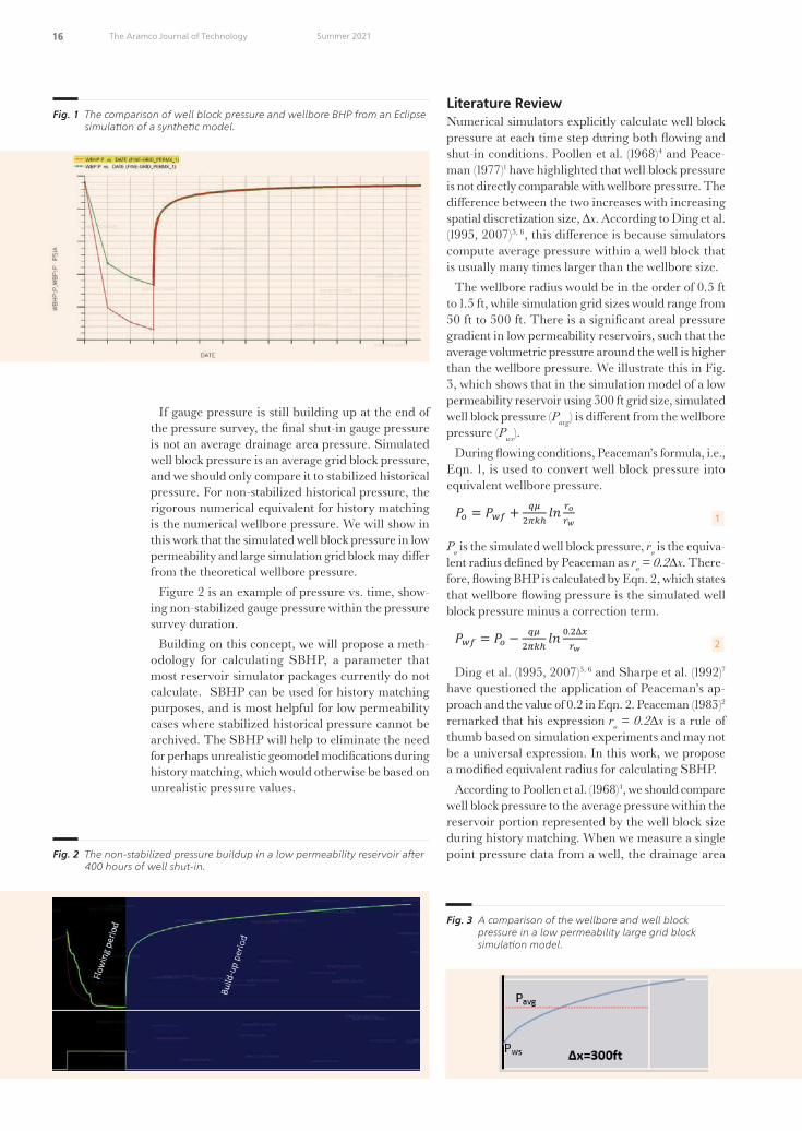
Figure 1 is an example of the Eclipse simulation results of pressure vs. time data from a synthetic model. It shows that during the �ow period, the well block pressure is di�erent from the wellbore pressure.
As shown in Fig. 1, the Eclipse simulator sets the wellbore pressure to well block pressure during well shut-in, because the wellbore pressure is assumed to be applicable only to �owing wells3. In this article, we will propose a methodology for calculating the wellbore pressures during the shut-in period following a numeri-cal simulation exercise. We will denote this wellbore pressure during shut-in as static BHP (SBHP); it is the wellbore equivalent of well block pressure during shut-in, which can be used for history matching purposes.
A key objective of history matching is to calibrate a model to historical datum pressures. If the final gauge reading during buildup stabilizes, the measured pressure represents the average drainage area pressure and is comparable to well block pressure.
49108araD5R1.indd 15 6/16/21 8:43 PM
16 The Aramco Journal of Technology Summer 2021
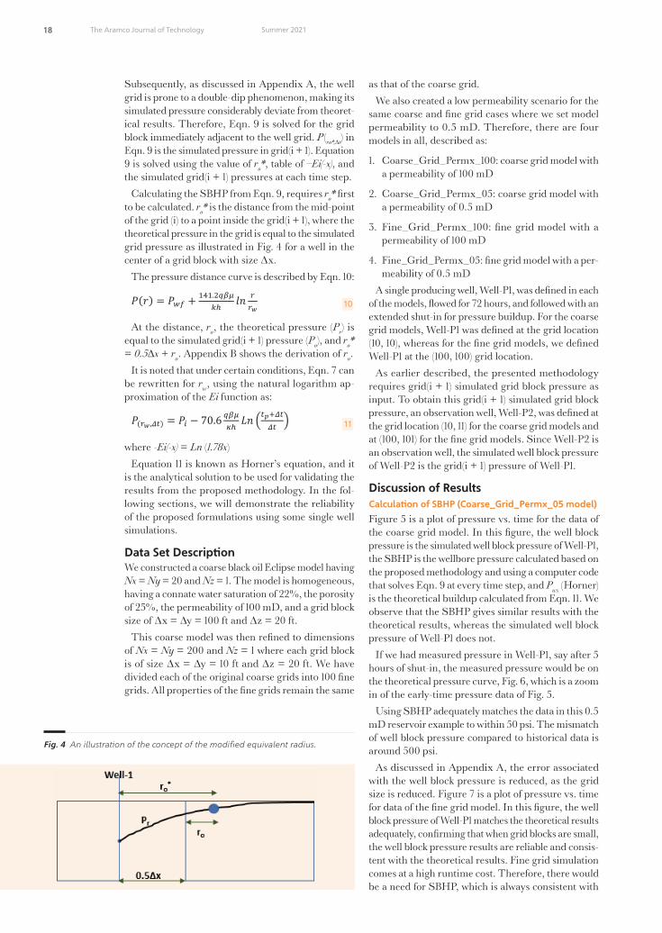
If gauge pressure is still building up at the end of the pressure survey, the final shut-in gauge pressure is not an average drainage area pressure. Simulated well block pressure is an average grid block pressure, and we should only compare it to stabilized historical pressure. For non-stabilized historical pressure, the rigorous numerical equivalent for history matching is the numerical wellbore pressure. We will show in this work that the simulated well block pressure in low permeability and large simulation grid block may di�er from the theoretical wellbore pressure.
Figure 2 is an example of pressure vs. time, show-ing non-stabilized gauge pressure within the pressure survey duration.
Building on this concept, we will propose a meth-odology for calculating SBHP, a parameter that most reservoir simulator packages currently do not calculate. SBHP can be used for history matching purposes, and is most helpful for low permeability cases where stabilized historical pressure cannot be archived. The SBHP will help to eliminate the need for perhaps unrealistic geomodel modifications during history matching, which would otherwise be based on unrealistic pressure values.
Literature ReviewNumerical simulators explicitly calculate well block pressure at each time step during both �owing and shut-in conditions. Poollen et al. (1968)4 and Peace-man (1977)1 have highlighted that well block pressure is not directly comparable with wellbore pressure. The di�erence between the two increases with increasing spatial discretization size, ∆x. According to Ding et al. (1995, 2007)5, 6, this di�erence is because simulators compute average pressure within a well block that is usually many times larger than the wellbore size.
The wellbore radius would be in the order of 0.5 ft to 1.5 ft, while simulation grid sizes would range from 50 ft to 500 ft. There is a significant areal pressure gradient in low permeability reservoirs, such that the average volumetric pressure around the well is higher than the wellbore pressure. We illustrate this in Fig. 3, which shows that in the simulation model of a low permeability reservoir using 300 ft grid size, simulated well block pressure (Pavg) is di�erent from the wellbore pressure (Pws).
During �owing conditions, Peaceman’s formula, i.e., Eqn. 1, is used to convert well block pressure into equivalent wellbore pressure.
Saudi Aramco: Company General Use
𝑜𝑜 = 2𝜋𝜋 𝑙𝑙𝑙𝑙 𝑟𝑟𝑜𝑜𝑟𝑟𝑤𝑤
(1)
= 𝑜𝑜 − 2𝜋𝜋 𝑙𝑙𝑙𝑙 .2 𝛥𝛥𝑟𝑟𝑤𝑤
(2)
= 𝑟𝑟. 2 (3)
= ( ) 2. ∗ 𝑙𝑙 2 𝛥𝛥𝑜𝑜
(4)
− (𝑟𝑟 𝛥𝛥 ) = −𝐸𝐸 𝑟𝑟𝛥𝛥 − −𝐸𝐸 𝑟𝑟
𝛥𝛥 (5)
= 0.6
= 4
(𝑟𝑟𝑜𝑜∗ 𝛥𝛥 ) = − −𝐸𝐸 𝑟𝑟𝑜𝑜∗𝛥𝛥 −𝐸𝐸 𝑟𝑟𝑜𝑜∗
𝛥𝛥 (6)
(𝑟𝑟𝑤𝑤 𝛥𝛥 ) = − −𝐸𝐸 𝑟𝑟𝑤𝑤𝛥𝛥 −𝐸𝐸 𝑟𝑟𝑤𝑤
𝛥𝛥 (7)
(𝑟𝑟𝑜𝑜∗ 𝛥𝛥 ) − (𝑟𝑟𝑤𝑤 𝛥𝛥 ) = −𝐸𝐸 𝑟𝑟𝑜𝑜∗(𝛥𝛥 ) − −𝐸𝐸 𝑟𝑟𝑜𝑜∗
𝛥𝛥 − −𝐸𝐸 𝑟𝑟𝑤𝑤(𝛥𝛥 )
−𝐸𝐸 𝑟𝑟𝑤𝑤𝛥𝛥 (8)
(𝑟𝑟𝑤𝑤 𝛥𝛥 ) = (𝑟𝑟𝑜𝑜∗ 𝛥𝛥 ) − −𝐸𝐸 𝑟𝑟𝑜𝑜∗(𝛥𝛥 ) − −𝐸𝐸 𝑟𝑟𝑜𝑜∗
𝛥𝛥 − −𝐸𝐸 𝑟𝑟𝑤𝑤(𝛥𝛥 )
−𝐸𝐸 𝑟𝑟𝑤𝑤𝛥𝛥 (9)
(𝑟𝑟) = .2 𝑙𝑙𝑙𝑙 𝑟𝑟𝑟𝑟𝑤𝑤
(10)
1
Po is the simulated well block pressure, ro is the equiva-lent radius defined by Peaceman as ro = 0.2∆x. There-fore, �owing BHP is calculated by Eqn. 2, which states that wellbore �owing pressure is the simulated well block pressure minus a correction term.
Saudi Aramco: Company General Use
𝑜𝑜 = 2𝜋𝜋 𝑙𝑙𝑙𝑙 𝑟𝑟𝑜𝑜𝑟𝑟𝑤𝑤
(1)
= 𝑜𝑜 − 2𝜋𝜋 𝑙𝑙𝑙𝑙 .2 𝛥𝛥𝑟𝑟𝑤𝑤
(2)
= 𝑟𝑟. 2 (3)
= ( ) 2. ∗ 𝑙𝑙 2 𝛥𝛥𝑜𝑜
(4)
− (𝑟𝑟 𝛥𝛥 ) = −𝐸𝐸 𝑟𝑟𝛥𝛥 − −𝐸𝐸 𝑟𝑟
𝛥𝛥 (5)
= 0.6
= 4
(𝑟𝑟𝑜𝑜∗ 𝛥𝛥 ) = − −𝐸𝐸 𝑟𝑟𝑜𝑜∗𝛥𝛥 −𝐸𝐸 𝑟𝑟𝑜𝑜∗
𝛥𝛥 (6)
(𝑟𝑟𝑤𝑤 𝛥𝛥 ) = − −𝐸𝐸 𝑟𝑟𝑤𝑤𝛥𝛥 −𝐸𝐸 𝑟𝑟𝑤𝑤
𝛥𝛥 (7)
(𝑟𝑟𝑜𝑜∗ 𝛥𝛥 ) − (𝑟𝑟𝑤𝑤 𝛥𝛥 ) = −𝐸𝐸 𝑟𝑟𝑜𝑜∗(𝛥𝛥 ) − −𝐸𝐸 𝑟𝑟𝑜𝑜∗
𝛥𝛥 − −𝐸𝐸 𝑟𝑟𝑤𝑤(𝛥𝛥 )
−𝐸𝐸 𝑟𝑟𝑤𝑤𝛥𝛥 (8)
(𝑟𝑟𝑤𝑤 𝛥𝛥 ) = (𝑟𝑟𝑜𝑜∗ 𝛥𝛥 ) − −𝐸𝐸 𝑟𝑟𝑜𝑜∗(𝛥𝛥 ) − −𝐸𝐸 𝑟𝑟𝑜𝑜∗
𝛥𝛥 − −𝐸𝐸 𝑟𝑟𝑤𝑤(𝛥𝛥 )
−𝐸𝐸 𝑟𝑟𝑤𝑤𝛥𝛥 (9)
(𝑟𝑟) = .2 𝑙𝑙𝑙𝑙 𝑟𝑟𝑟𝑟𝑤𝑤
(10)
2
Ding et al. (1995, 2007)5, 6 and Sharpe et al. (1992)7 have questioned the application of Peaceman’s ap-proach and the value of 0.2 in Eqn. 2. Peaceman (1983)2 remarked that his expression ro = 0.2∆x is a rule of thumb based on simulation experiments and may not be a universal expression. In this work, we propose a modified equivalent radius for calculating SBHP.
According to Poollen et al. (1968)4, we should compare well block pressure to the average pressure within the reservoir portion represented by the well block size during history matching. When we measure a single point pressure data from a well, the drainage area
Fig. 1 The comparison of well block pressure and wellbore BHP from an Eclipse simula�on of a synthe�c model.
Saudi Aramco: Company General Use
Fig. he comparison of well block pressure and wellbore bottom hole pressure from an clipse simulation of a synthetic model.
Fig. he non stabili ed pressure buildup in a low permeability reservoir after hours of well shut in.
Fig. 2 The non-stabilized pressure buildup in a low permeability reservoir a�er 400 hours of well shut-in.
Fig. 3 A comparison of the wellbore and well block pressure in a low permeability large grid block simula�on model.
49108araD5R1.indd 16 6/16/21 8:43 PM

17 The Aramco Journal of TechnologySummer 2021
associated with the observed pressure is unknown. Therefore, contrary to the requirement proposed by Poolen et al. (1968)4, simulated well block pressure could correspond to a larger reservoir area — depending on the well block size — than that associated with the non-stabilized single point pressure.
To make a historical non-stabilized pressure usable, Miller et al. (1949)8, Dietz (1965)9, and Kazemi (1974)10 proposed methodologies to convert it to an equivalent drainage area pressure. These approaches require as-sumptions about the drainage area and geometrical location of the well. They also require continuous pressure buildup data to determine P* — required for Pavg calculation — from Horner’s semi-log plot. Therefore, when only a single point of pressure data is available, non-stabilized pressure data cannot be converted to an equivalent drainage area pressure using any of these approaches.
Poollen et al. (1968)4 proposed a shut-in duration equation, Eqn. 3, at which theoretical buildup pressure would be comparable to simulated well block pressure. They defined the corresponding buildup pressure at this time as the dynamic pressure.
Saudi Aramco: Company General Use
𝑜𝑜 = 2𝜋𝜋 𝑙𝑙𝑙𝑙 𝑟𝑟𝑜𝑜𝑟𝑟𝑤𝑤
(1)
= 𝑜𝑜 − 2𝜋𝜋 𝑙𝑙𝑙𝑙 .2 𝛥𝛥𝑟𝑟𝑤𝑤
(2)
= 𝑟𝑟. 2 (3)
= ( ) 2. ∗ 𝑙𝑙 2 𝛥𝛥𝑜𝑜
(4)
− (𝑟𝑟 𝛥𝛥 ) = −𝐸𝐸 𝑟𝑟𝛥𝛥 − −𝐸𝐸 𝑟𝑟
𝛥𝛥 (5)
= 0.6
= 4
(𝑟𝑟𝑜𝑜∗ 𝛥𝛥 ) = − −𝐸𝐸 𝑟𝑟𝑜𝑜∗𝛥𝛥 −𝐸𝐸 𝑟𝑟𝑜𝑜∗
𝛥𝛥 (6)
(𝑟𝑟𝑤𝑤 𝛥𝛥 ) = − −𝐸𝐸 𝑟𝑟𝑤𝑤𝛥𝛥 −𝐸𝐸 𝑟𝑟𝑤𝑤
𝛥𝛥 (7)
(𝑟𝑟𝑜𝑜∗ 𝛥𝛥 ) − (𝑟𝑟𝑤𝑤 𝛥𝛥 ) = −𝐸𝐸 𝑟𝑟𝑜𝑜∗(𝛥𝛥 ) − −𝐸𝐸 𝑟𝑟𝑜𝑜∗
𝛥𝛥 − −𝐸𝐸 𝑟𝑟𝑤𝑤(𝛥𝛥 )
−𝐸𝐸 𝑟𝑟𝑤𝑤𝛥𝛥 (8)
(𝑟𝑟𝑤𝑤 𝛥𝛥 ) = (𝑟𝑟𝑜𝑜∗ 𝛥𝛥 ) − −𝐸𝐸 𝑟𝑟𝑜𝑜∗(𝛥𝛥 ) − −𝐸𝐸 𝑟𝑟𝑜𝑜∗
𝛥𝛥 − −𝐸𝐸 𝑟𝑟𝑤𝑤(𝛥𝛥 )
−𝐸𝐸 𝑟𝑟𝑤𝑤𝛥𝛥 (9)
(𝑟𝑟) = .2 𝑙𝑙𝑙𝑙 𝑟𝑟𝑟𝑟𝑤𝑤
(10)
3
This approach has the advantage that when continu-ous pressure buildup data are available, we can extract the appropriate dynamic pressure corresponding to the simulation grid size. The limitation is that when only a single point of pressure is available, we cannot compare that piece of historical pressure data with simulated well block pressure for history matching if the historical data’s shut-in duration is di�erent from the shut-in duration computed from Eqn. 3.
Peaceman (1983)2 and Eaulougher (1972)11 attempted to resolve the limitation pointed out about the Pool-len et al. (1968)4 methodology by deriving Eqn. 4 to calculate dynamic pressure when only single point pressure data is available.
Saudi Aramco: Company General Use
𝑜𝑜 = 2𝜋𝜋 𝑙𝑙𝑙𝑙 𝑟𝑟𝑜𝑜𝑟𝑟𝑤𝑤
(1)
= 𝑜𝑜 − 2𝜋𝜋 𝑙𝑙𝑙𝑙 .2 𝛥𝛥𝑟𝑟𝑤𝑤
(2)
= 𝑟𝑟. 2 (3)
= ( ) 2. ∗ 𝑙𝑙 2 𝛥𝛥𝑜𝑜
(4)
− (𝑟𝑟 𝛥𝛥 ) = −𝐸𝐸 𝑟𝑟𝛥𝛥 − −𝐸𝐸 𝑟𝑟
𝛥𝛥 (5)
= 0.6
= 4
(𝑟𝑟𝑜𝑜∗ 𝛥𝛥 ) = − −𝐸𝐸 𝑟𝑟𝑜𝑜∗𝛥𝛥 −𝐸𝐸 𝑟𝑟𝑜𝑜∗
𝛥𝛥 (6)
(𝑟𝑟𝑤𝑤 𝛥𝛥 ) = − −𝐸𝐸 𝑟𝑟𝑤𝑤𝛥𝛥 −𝐸𝐸 𝑟𝑟𝑤𝑤
𝛥𝛥 (7)
(𝑟𝑟𝑜𝑜∗ 𝛥𝛥 ) − (𝑟𝑟𝑤𝑤 𝛥𝛥 ) = −𝐸𝐸 𝑟𝑟𝑜𝑜∗(𝛥𝛥 ) − −𝐸𝐸 𝑟𝑟𝑜𝑜∗
𝛥𝛥 − −𝐸𝐸 𝑟𝑟𝑤𝑤(𝛥𝛥 )
−𝐸𝐸 𝑟𝑟𝑤𝑤𝛥𝛥 (8)
(𝑟𝑟𝑤𝑤 𝛥𝛥 ) = (𝑟𝑟𝑜𝑜∗ 𝛥𝛥 ) − −𝐸𝐸 𝑟𝑟𝑜𝑜∗(𝛥𝛥 ) − −𝐸𝐸 𝑟𝑟𝑜𝑜∗
𝛥𝛥 − −𝐸𝐸 𝑟𝑟𝑤𝑤(𝛥𝛥 )
−𝐸𝐸 𝑟𝑟𝑤𝑤𝛥𝛥 (9)
(𝑟𝑟) = .2 𝑙𝑙𝑙𝑙 𝑟𝑟𝑟𝑟𝑤𝑤
(10)
4
This approach does not require continuous pressure buildup data, which are not routinely available. It has the limitation that dynamic pressure may be laborious to calculate for every historical pressure in a typical history matching project that comprises hundreds of wells, each having several (non-stabilized) single point pressures (Pws)obs.
Another limitation of the Peaceman (1983)2 and Ear-lougher (1972)11 approach is that Eqn. 4 is only valid on the assumption that (Pws)obs be on the straight line portion of Horner’s semi-log plot. We cannot know in advance if (Pws)obs meets the required condition unless continuous pressure buildup data is available.
Instead of applying these correction procedures on historical, non-stabilized pressure to make it com-parable to simulated well block pressure, a di�erent approach taken by the current work is to simulate the historical data’s numerical equivalent and directly
compare both. The numerical wellbore pressure at ∆t corresponds to ∆tobs of the historical pressure data.
Methodology Descrip�onFor infinite acting well producing at a rate of q bbl/d for tp hours and then shut-in, we can write the super-position equation as shown in Eqn. 5:
Saudi Aramco: Company General Use
𝑜𝑜 = 2𝜋𝜋 𝑙𝑙𝑙𝑙 𝑟𝑟𝑜𝑜𝑟𝑟𝑤𝑤
(1)
= 𝑜𝑜 − 2𝜋𝜋 𝑙𝑙𝑙𝑙 .2 𝛥𝛥𝑟𝑟𝑤𝑤
(2)
= 𝑟𝑟. 2 (3)
= ( ) 2. ∗ 𝑙𝑙 2 𝛥𝛥𝑜𝑜
(4)
− (𝑟𝑟 𝛥𝛥 ) = −𝐸𝐸 𝑟𝑟𝛥𝛥 − −𝐸𝐸 𝑟𝑟
𝛥𝛥 (5)
= 0.6
= 4
(𝑟𝑟𝑜𝑜∗ 𝛥𝛥 ) = − −𝐸𝐸 𝑟𝑟𝑜𝑜∗𝛥𝛥 −𝐸𝐸 𝑟𝑟𝑜𝑜∗
𝛥𝛥 (6)
(𝑟𝑟𝑤𝑤 𝛥𝛥 ) = − −𝐸𝐸 𝑟𝑟𝑤𝑤𝛥𝛥 −𝐸𝐸 𝑟𝑟𝑤𝑤
𝛥𝛥 (7)
(𝑟𝑟𝑜𝑜∗ 𝛥𝛥 ) − (𝑟𝑟𝑤𝑤 𝛥𝛥 ) = −𝐸𝐸 𝑟𝑟𝑜𝑜∗(𝛥𝛥 ) − −𝐸𝐸 𝑟𝑟𝑜𝑜∗
𝛥𝛥 − −𝐸𝐸 𝑟𝑟𝑤𝑤(𝛥𝛥 )
−𝐸𝐸 𝑟𝑟𝑤𝑤𝛥𝛥 (8)
(𝑟𝑟𝑤𝑤 𝛥𝛥 ) = (𝑟𝑟𝑜𝑜∗ 𝛥𝛥 ) − −𝐸𝐸 𝑟𝑟𝑜𝑜∗(𝛥𝛥 ) − −𝐸𝐸 𝑟𝑟𝑜𝑜∗
𝛥𝛥 − −𝐸𝐸 𝑟𝑟𝑤𝑤(𝛥𝛥 )
−𝐸𝐸 𝑟𝑟𝑤𝑤𝛥𝛥 (9)
(𝑟𝑟) = .2 𝑙𝑙𝑙𝑙 𝑟𝑟𝑟𝑟𝑤𝑤
(10)
5
Saudi Aramco: Company General Use
𝑜𝑜 = 2𝜋𝜋 𝑙𝑙𝑙𝑙 𝑟𝑟𝑜𝑜𝑟𝑟𝑤𝑤
(1)
= 𝑜𝑜 − 2𝜋𝜋 𝑙𝑙𝑙𝑙 .2 𝛥𝛥𝑟𝑟𝑤𝑤
(2)
= 𝑟𝑟. 2 (3)
= ( ) 2. ∗ 𝑙𝑙 2 𝛥𝛥𝑜𝑜
(4)
− (𝑟𝑟 𝛥𝛥 ) = −𝐸𝐸 𝑟𝑟𝛥𝛥 − −𝐸𝐸 𝑟𝑟
𝛥𝛥 (5)
= 0.6
= 4
(𝑟𝑟𝑜𝑜∗ 𝛥𝛥 ) = − −𝐸𝐸 𝑟𝑟𝑜𝑜∗𝛥𝛥 −𝐸𝐸 𝑟𝑟𝑜𝑜∗
𝛥𝛥 (6)
(𝑟𝑟𝑤𝑤 𝛥𝛥 ) = − −𝐸𝐸 𝑟𝑟𝑤𝑤𝛥𝛥 −𝐸𝐸 𝑟𝑟𝑤𝑤
𝛥𝛥 (7)
(𝑟𝑟𝑜𝑜∗ 𝛥𝛥 ) − (𝑟𝑟𝑤𝑤 𝛥𝛥 ) = −𝐸𝐸 𝑟𝑟𝑜𝑜∗(𝛥𝛥 ) − −𝐸𝐸 𝑟𝑟𝑜𝑜∗
𝛥𝛥 − −𝐸𝐸 𝑟𝑟𝑤𝑤(𝛥𝛥 )
−𝐸𝐸 𝑟𝑟𝑤𝑤𝛥𝛥 (8)
(𝑟𝑟𝑤𝑤 𝛥𝛥 ) = (𝑟𝑟𝑜𝑜∗ 𝛥𝛥 ) − −𝐸𝐸 𝑟𝑟𝑜𝑜∗(𝛥𝛥 ) − −𝐸𝐸 𝑟𝑟𝑜𝑜∗
𝛥𝛥 − −𝐸𝐸 𝑟𝑟𝑤𝑤(𝛥𝛥 )
−𝐸𝐸 𝑟𝑟𝑤𝑤𝛥𝛥 (9)
(𝑟𝑟) = .2 𝑙𝑙𝑙𝑙 𝑟𝑟𝑟𝑟𝑤𝑤
(10)
Equation 5 can then be written for distances ro* (radius corresponding to the pressure for a grid block) and rw as:
Saudi Aramco: Company General Use
𝑜𝑜 = 2𝜋𝜋 𝑙𝑙𝑙𝑙 𝑟𝑟𝑜𝑜𝑟𝑟𝑤𝑤
(1)
= 𝑜𝑜 − 2𝜋𝜋 𝑙𝑙𝑙𝑙 .2 𝛥𝛥𝑟𝑟𝑤𝑤
(2)
= 𝑟𝑟. 2 (3)
= ( ) 2. ∗ 𝑙𝑙 2 𝛥𝛥𝑜𝑜
(4)
− (𝑟𝑟 𝛥𝛥 ) = −𝐸𝐸 𝑟𝑟𝛥𝛥 − −𝐸𝐸 𝑟𝑟
𝛥𝛥 (5)
= 0.6
= 4
(𝑟𝑟𝑜𝑜∗ 𝛥𝛥 ) = − −𝐸𝐸 𝑟𝑟𝑜𝑜∗𝛥𝛥 −𝐸𝐸 𝑟𝑟𝑜𝑜∗
𝛥𝛥 (6)
(𝑟𝑟𝑤𝑤 𝛥𝛥 ) = − −𝐸𝐸 𝑟𝑟𝑤𝑤𝛥𝛥 −𝐸𝐸 𝑟𝑟𝑤𝑤
𝛥𝛥 (7)
(𝑟𝑟𝑜𝑜∗ 𝛥𝛥 ) − (𝑟𝑟𝑤𝑤 𝛥𝛥 ) = −𝐸𝐸 𝑟𝑟𝑜𝑜∗(𝛥𝛥 ) − −𝐸𝐸 𝑟𝑟𝑜𝑜∗
𝛥𝛥 − −𝐸𝐸 𝑟𝑟𝑤𝑤(𝛥𝛥 )
−𝐸𝐸 𝑟𝑟𝑤𝑤𝛥𝛥 (8)
(𝑟𝑟𝑤𝑤 𝛥𝛥 ) = (𝑟𝑟𝑜𝑜∗ 𝛥𝛥 ) − −𝐸𝐸 𝑟𝑟𝑜𝑜∗(𝛥𝛥 ) − −𝐸𝐸 𝑟𝑟𝑜𝑜∗
𝛥𝛥 − −𝐸𝐸 𝑟𝑟𝑤𝑤(𝛥𝛥 )
−𝐸𝐸 𝑟𝑟𝑤𝑤𝛥𝛥 (9)
(𝑟𝑟) = .2 𝑙𝑙𝑙𝑙 𝑟𝑟𝑟𝑟𝑤𝑤
(10)
6
Saudi Aramco: Company General Use
𝑜𝑜 = 2𝜋𝜋 𝑙𝑙𝑙𝑙 𝑟𝑟𝑜𝑜𝑟𝑟𝑤𝑤
(1)
= 𝑜𝑜 − 2𝜋𝜋 𝑙𝑙𝑙𝑙 .2 𝛥𝛥𝑟𝑟𝑤𝑤
(2)
= 𝑟𝑟. 2 (3)
= ( ) 2. ∗ 𝑙𝑙 2 𝛥𝛥𝑜𝑜
(4)
− (𝑟𝑟 𝛥𝛥 ) = −𝐸𝐸 𝑟𝑟𝛥𝛥 − −𝐸𝐸 𝑟𝑟
𝛥𝛥 (5)
= 0.6
= 4
(𝑟𝑟𝑜𝑜∗ 𝛥𝛥 ) = − −𝐸𝐸 𝑟𝑟𝑜𝑜∗𝛥𝛥 −𝐸𝐸 𝑟𝑟𝑜𝑜∗
𝛥𝛥 (6)
(𝑟𝑟𝑤𝑤 𝛥𝛥 ) = − −𝐸𝐸 𝑟𝑟𝑤𝑤𝛥𝛥 −𝐸𝐸 𝑟𝑟𝑤𝑤
𝛥𝛥 (7)
(𝑟𝑟𝑜𝑜∗ 𝛥𝛥 ) − (𝑟𝑟𝑤𝑤 𝛥𝛥 ) = −𝐸𝐸 𝑟𝑟𝑜𝑜∗(𝛥𝛥 ) − −𝐸𝐸 𝑟𝑟𝑜𝑜∗
𝛥𝛥 − −𝐸𝐸 𝑟𝑟𝑤𝑤(𝛥𝛥 )
−𝐸𝐸 𝑟𝑟𝑤𝑤𝛥𝛥 (8)
(𝑟𝑟𝑤𝑤 𝛥𝛥 ) = (𝑟𝑟𝑜𝑜∗ 𝛥𝛥 ) − −𝐸𝐸 𝑟𝑟𝑜𝑜∗(𝛥𝛥 ) − −𝐸𝐸 𝑟𝑟𝑜𝑜∗
𝛥𝛥 − −𝐸𝐸 𝑟𝑟𝑤𝑤(𝛥𝛥 )
−𝐸𝐸 𝑟𝑟𝑤𝑤𝛥𝛥 (9)
(𝑟𝑟) = .2 𝑙𝑙𝑙𝑙 𝑟𝑟𝑟𝑟𝑤𝑤
(10)
7
where the SBHP = P (rw, ∆t).Subtracting Eqn. 6 from Eqn. 7 allows us to eliminate
Pi and obtain:
Saudi Aramco: Company General Use
𝑜𝑜 = 2𝜋𝜋 𝑙𝑙𝑙𝑙 𝑟𝑟𝑜𝑜𝑟𝑟𝑤𝑤
(1)
= 𝑜𝑜 − 2𝜋𝜋 𝑙𝑙𝑙𝑙 .2 𝛥𝛥𝑟𝑟𝑤𝑤
(2)
= 𝑟𝑟. 2 (3)
= ( ) 2. ∗ 𝑙𝑙 2 𝛥𝛥𝑜𝑜
(4)
− (𝑟𝑟 𝛥𝛥 ) = −𝐸𝐸 𝑟𝑟𝛥𝛥 − −𝐸𝐸 𝑟𝑟
𝛥𝛥 (5)
= 0.6
= 4
(𝑟𝑟𝑜𝑜∗ 𝛥𝛥 ) = − −𝐸𝐸 𝑟𝑟𝑜𝑜∗𝛥𝛥 −𝐸𝐸 𝑟𝑟𝑜𝑜∗
𝛥𝛥 (6)
(𝑟𝑟𝑤𝑤 𝛥𝛥 ) = − −𝐸𝐸 𝑟𝑟𝑤𝑤𝛥𝛥 −𝐸𝐸 𝑟𝑟𝑤𝑤
𝛥𝛥 (7)
(𝑟𝑟𝑜𝑜∗ 𝛥𝛥 ) − (𝑟𝑟𝑤𝑤 𝛥𝛥 ) = −𝐸𝐸 𝑟𝑟𝑜𝑜∗(𝛥𝛥 ) − −𝐸𝐸 𝑟𝑟𝑜𝑜∗
𝛥𝛥 − −𝐸𝐸 𝑟𝑟𝑤𝑤(𝛥𝛥 )
−𝐸𝐸 𝑟𝑟𝑤𝑤𝛥𝛥 (8)
(𝑟𝑟𝑤𝑤 𝛥𝛥 ) = (𝑟𝑟𝑜𝑜∗ 𝛥𝛥 ) − −𝐸𝐸 𝑟𝑟𝑜𝑜∗(𝛥𝛥 ) − −𝐸𝐸 𝑟𝑟𝑜𝑜∗
𝛥𝛥 − −𝐸𝐸 𝑟𝑟𝑤𝑤(𝛥𝛥 )
−𝐸𝐸 𝑟𝑟𝑤𝑤𝛥𝛥 (9)
(𝑟𝑟) = .2 𝑙𝑙𝑙𝑙 𝑟𝑟𝑟𝑟𝑤𝑤
(10)
8
Finally, we can compute the SBHP by re-arranging Eqn. 8 as:
Saudi Aramco: Company General Use
𝑜𝑜 = 2𝜋𝜋 𝑙𝑙𝑙𝑙 𝑟𝑟𝑜𝑜𝑟𝑟𝑤𝑤
(1)
= 𝑜𝑜 − 2𝜋𝜋 𝑙𝑙𝑙𝑙 .2 𝛥𝛥𝑟𝑟𝑤𝑤
(2)
= 𝑟𝑟. 2 (3)
= ( ) 2. ∗ 𝑙𝑙 2 𝛥𝛥𝑜𝑜
(4)
− (𝑟𝑟 𝛥𝛥 ) = −𝐸𝐸 𝑟𝑟𝛥𝛥 − −𝐸𝐸 𝑟𝑟
𝛥𝛥 (5)
= 0.6
= 4
(𝑟𝑟𝑜𝑜∗ 𝛥𝛥 ) = − −𝐸𝐸 𝑟𝑟𝑜𝑜∗𝛥𝛥 −𝐸𝐸 𝑟𝑟𝑜𝑜∗
𝛥𝛥 (6)
(𝑟𝑟𝑤𝑤 𝛥𝛥 ) = − −𝐸𝐸 𝑟𝑟𝑤𝑤𝛥𝛥 −𝐸𝐸 𝑟𝑟𝑤𝑤
𝛥𝛥 (7)
(𝑟𝑟𝑜𝑜∗ 𝛥𝛥 ) − (𝑟𝑟𝑤𝑤 𝛥𝛥 ) = −𝐸𝐸 𝑟𝑟𝑜𝑜∗(𝛥𝛥 ) − −𝐸𝐸 𝑟𝑟𝑜𝑜∗
𝛥𝛥 − −𝐸𝐸 𝑟𝑟𝑤𝑤(𝛥𝛥 )
−𝐸𝐸 𝑟𝑟𝑤𝑤𝛥𝛥 (8)
(𝑟𝑟𝑤𝑤 𝛥𝛥 ) = (𝑟𝑟𝑜𝑜∗ 𝛥𝛥 ) − −𝐸𝐸 𝑟𝑟𝑜𝑜∗(𝛥𝛥 ) − −𝐸𝐸 𝑟𝑟𝑜𝑜∗
𝛥𝛥 − −𝐸𝐸 𝑟𝑟𝑤𝑤(𝛥𝛥 )
−𝐸𝐸 𝑟𝑟𝑤𝑤𝛥𝛥 (9)
(𝑟𝑟) = .2 𝑙𝑙𝑙𝑙 𝑟𝑟𝑟𝑟𝑤𝑤
(10)
9
The first term on the right-hand side of Eqn. 9 is simulated grid pressure, while the remaining terms on the right-hand side are the rock, �uid, rate, and time data, which are readily available during the simulation run time. Therefore, the strategy for computing the SBHP is the application of a correction term to the simulated pressure for a chosen grid block.
We would ordinarily expect that the simulated grid pressure to be corrected is the well grid pressure.
49108araD5R1.indd 17 6/16/21 8:43 PM
18 The Aramco Journal of Technology Summer 2021
Subsequently, as discussed in Appendix A, the well grid is prone to a double-dip phenomenon, making its simulated pressure considerably deviate from theoret-ical results. Therefore, Eqn. 9 is solved for the grid block immediately adjacent to the well grid. P (ro*,∆t) in Eqn. 9 is the simulated pressure in grid(i + 1). Equation 9 is solved using the value of ro*, table of –Ei(-x), and the simulated grid(i + 1) pressures at each time step.
Calculating the SBHP from Eqn. 9, requires ro* first to be calculated. ro* is the distance from the mid-point of the grid (i) to a point inside the grid(i + 1), where the theoretical pressure in the grid is equal to the simulated grid pressure as illustrated in Fig. 4 for a well in the center of a grid block with size Δx.
The pressure distance curve is described by Eqn. 10:
Saudi Aramco: Company General Use
𝑜𝑜 = 2𝜋𝜋 𝑙𝑙𝑙𝑙 𝑟𝑟𝑜𝑜𝑟𝑟𝑤𝑤
(1)
= 𝑜𝑜 − 2𝜋𝜋 𝑙𝑙𝑙𝑙 .2 𝛥𝛥𝑟𝑟𝑤𝑤
(2)
= 𝑟𝑟. 2 (3)
= ( ) 2. ∗ 𝑙𝑙 2 𝛥𝛥𝑜𝑜
(4)
− (𝑟𝑟 𝛥𝛥 ) = −𝐸𝐸 𝑟𝑟𝛥𝛥 − −𝐸𝐸 𝑟𝑟
𝛥𝛥 (5)
= 0.6
= 4
(𝑟𝑟𝑜𝑜∗ 𝛥𝛥 ) = − −𝐸𝐸 𝑟𝑟𝑜𝑜∗𝛥𝛥 −𝐸𝐸 𝑟𝑟𝑜𝑜∗
𝛥𝛥 (6)
(𝑟𝑟𝑤𝑤 𝛥𝛥 ) = − −𝐸𝐸 𝑟𝑟𝑤𝑤𝛥𝛥 −𝐸𝐸 𝑟𝑟𝑤𝑤
𝛥𝛥 (7)
(𝑟𝑟𝑜𝑜∗ 𝛥𝛥 ) − (𝑟𝑟𝑤𝑤 𝛥𝛥 ) = −𝐸𝐸 𝑟𝑟𝑜𝑜∗(𝛥𝛥 ) − −𝐸𝐸 𝑟𝑟𝑜𝑜∗
𝛥𝛥 − −𝐸𝐸 𝑟𝑟𝑤𝑤(𝛥𝛥 )
−𝐸𝐸 𝑟𝑟𝑤𝑤𝛥𝛥 (8)
(𝑟𝑟𝑤𝑤 𝛥𝛥 ) = (𝑟𝑟𝑜𝑜∗ 𝛥𝛥 ) − −𝐸𝐸 𝑟𝑟𝑜𝑜∗(𝛥𝛥 ) − −𝐸𝐸 𝑟𝑟𝑜𝑜∗
𝛥𝛥 − −𝐸𝐸 𝑟𝑟𝑤𝑤(𝛥𝛥 )
−𝐸𝐸 𝑟𝑟𝑤𝑤𝛥𝛥 (9)
(𝑟𝑟) = .2 𝑙𝑙𝑙𝑙 𝑟𝑟𝑟𝑟𝑤𝑤
(10) 10
At the distance, ro, the theoretical pressure (Pr) is equal to the simulated grid(i + 1) pressure (Po), and ro* = 0.5∆x + ro. Appendix B shows the derivation of ro.
It is noted that under certain conditions, Eqn. 7 can be rewritten for rw, using the natural logarithm ap-proximation of the Ei function as:
Saudi Aramco: Company General Use
(𝑟𝑟𝑤𝑤 𝛥𝛥 ) = − 0.6 𝑙𝑙 𝛥𝛥𝛥𝛥 (11)
= (𝑟𝑟) (A1)
(𝑟𝑟) = .2 𝑙𝑙𝑙𝑙 𝑟𝑟
𝑟𝑟𝑤𝑤 (A2)
= .2 𝑙𝑙𝑙𝑙 𝑟𝑟
𝑟𝑟𝑤𝑤− 0.5 (A3)
= .2 𝑙𝑙𝑙𝑙 𝛥𝛥𝑟𝑟𝑤𝑤− 0.5 (A4)
= .2 𝑙𝑙𝑙𝑙 . 𝛥𝛥𝑟𝑟𝑤𝑤
− 0.5 (A5)
= .2 𝑙𝑙𝑙𝑙 . 𝛥𝛥𝑟𝑟𝑤𝑤
− 0.5 (A6)
− = . (A7) 𝑟𝑟 = 2𝜋𝜋 𝑙𝑙𝑙𝑙 𝑟𝑟
𝑟𝑟𝑤𝑤 (B 1)
= 2𝜋𝜋 𝑙𝑙𝑙𝑙 𝑟𝑟𝑟𝑟𝑤𝑤− 0.5 (B 2)
= 2𝜋𝜋 𝑙𝑙𝑙𝑙 𝛥𝛥𝛥𝛥2𝑟𝑟𝑤𝑤
− 0.5 (B 3) 𝑜𝑜 = 2𝜋𝜋 𝑙𝑙𝑙𝑙 𝑟𝑟𝑜𝑜
𝑟𝑟𝑤𝑤 (B 4)
𝑙𝑙𝑙𝑙 𝑟𝑟𝑜𝑜
𝑟𝑟𝑤𝑤= 𝑙𝑙𝑙𝑙 𝛥𝛥𝛥𝛥
2𝑟𝑟𝑤𝑤− 0.5 (B 5)
11
where -Ei(-x) = Ln (1.78x)Equation 11 is known as Horner’s equation, and it
is the analytical solution to be used for validating the results from the proposed methodology. In the fol-lowing sections, we will demonstrate the reliability of the proposed formulations using some single well simulations.
Data Set Descrip�on We constructed a coarse black oil Eclipse model having Nx = Ny = 20 and Nz = 1. The model is homogeneous, having a connate water saturation of 22%, the porosity of 25%, the permeability of 100 mD, and a grid block size of Δx = Δy = 100 ft and Δz = 20 ft.
This coarse model was then refined to dimensions of Nx = Ny = 200 and Nz = 1 where each grid block is of size Δx = Δy = 10 ft and Δz = 20 ft. We have divided each of the original coarse grids into 100 fine grids. All properties of the fine grids remain the same
as that of the coarse grid.We also created a low permeability scenario for the
same coarse and fine grid cases where we set model permeability to 0.5 mD. Therefore, there are four models in all, described as:
1. Coarse_Grid_Permx_100: coarse grid model with a permeability of 100 mD
2. Coarse_Grid_Permx_05: coarse grid model with a permeability of 0.5 mD
3. Fine_Grid_Permx_100: fine grid model with a permeability of 100 mD
4. Fine_Grid_Permx_05: fine grid model with a per-meability of 0.5 mD
A single producing well, Well-P1, was defined in each of the models, �owed for 72 hours, and followed with an extended shut-in for pressure buildup. For the coarse grid models, Well-P1 was defined at the grid location (10, 10), whereas for the fine grid models, we defined Well-P1 at the (100, 100) grid location.
As earlier described, the presented methodology requires grid(i + 1) simulated grid block pressure as input. To obtain this grid(i + 1) simulated grid block pressure, an observation well, Well-P2, was defined at the grid location (10, 11) for the coarse grid models and at (100, 101) for the fine grid models. Since Well-P2 is an observation well, the simulated well block pressure of Well-P2 is the grid(i + 1) pressure of Well-P1.
Discussion of ResultsCalcula�on of SBHP (Coarse_Grid_Permx_05 model)
Figure 5 is a plot of pressure vs. time for the data of the coarse grid model. In this figure, the well block pressure is the simulated well block pressure of Well-P1, the SBHP is the wellbore pressure calculated based on the proposed methodology and using a computer code that solves Eqn. 9 at every time step, and Pws (Horner) is the theoretical buildup calculated from Eqn. 11. We observe that the SBHP gives similar results with the theoretical results, whereas the simulated well block pressure of Well-P1 does not.
If we had measured pressure in Well-P1, say after 5 hours of shut-in, the measured pressure would be on the theoretical pressure curve, Fig. 6, which is a zoom in of the early-time pressure data of Fig. 5.
Using SBHP adequately matches the data in this 0.5 mD reservoir example to within 50 psi. The mismatch of well block pressure compared to historical data is around 500 psi.
As discussed in Appendix A, the error associated with the well block pressure is reduced, as the grid size is reduced. Figure 7 is a plot of pressure vs. time for data of the fine grid model. In this figure, the well block pressure of Well-P1 matches the theoretical results adequately, confirming that when grid blocks are small, the well block pressure results are reliable and consis-tent with the theoretical results. Fine grid simulation comes at a high runtime cost. Therefore, there would be a need for SBHP, which is always consistent with
Fig. 4 An illustra�on of the concept of the modi�ed equivalent radius.
49108araD5R1.indd 18 6/16/21 8:43 PM

19 The Aramco Journal of TechnologySummer 2021
theoretical results regardless of the grid block size.
Calculaon of SBHP (Coarse_Grid_Permx_100 model)
As discussed in Appendix A, the di�erence between average drainage area pressure and wellbore pressure is small in a large permeability reservoir owing to the minimal areal pressure gradient. The same conclusion is supported by looking at Fig. 8, which is a plot of pressure vs. time for the coarse grid model having a permeability of 100 mD. In this figure, the well block pressure of Well-P1 becomes consistent with the theoret-ical buildup and SBHP within 2 hours of well shut-in.
These results could be summarized as:
1. In high permeability reservoirs (and regardless of grid block size), the well block pressure is consistent with theoretical wellbore pressure after a few hours of shut-in.
2. In low permeability reservoirs, the well block pres-sure is consistent with the theoretical wellbore pres-sure only if simulation uses finely gridded blocks.
3. Regardless of permeability and grid block size, the SBHP is consistent with the theoretical wellbore pressure.
Pra�ical ApplicaonThis section tests the proposed method’s application on a simulation model’s history matching process of a low permeability reservoir. Several pieces of pressure transient data acquired on this reservoir indicate a slow buildup, where pressure is still increasing after 400 hours of well shut-in. The shut-in duration for most of the acquired single point shut-in pressure data is 72 hours. A coarse grid single well numerical simulation model of the reservoir, which was available, is used here.
Pressure in the grid(i + 1) was extracted through a dummy well defined in that location. We extracted average permeability, porosity, viscosity, and formation volume factor from the simulation model and calculated the numerical SBHP using Eqn. 9. The parameter, pseudo-producing time (tp) in Eqn. 9 was obtained by dividing the cumulative production by the most recent average production rate.
Figure 9 is a plot of pressure vs. date. This figure shows the comparison between the simulated well block pressure, grid(i + 1) pressure, and the SBHP. In this particular example, while the well block pressure is higher than the observed pressure, the SBHP matches the observed data.
If history matching precedes using the well block pressure data, then the engineer would need to make an adjustment like reducing either the geomodel aquifer size/strength or the geomodel hydrocarbon pore vol-ume or other possibly unsubstantiated corrections to calibrate the well block pressure data to the observed pressure data. Consequently, by using the SBHP, it can be concluded that no geomodel adjustment is necessary around this particular well because the SBHP is match-ing the observed pressure data adequately. Therefore,
Pres
sure
(psi
)Elapsed Time (hours)
WBP SBHP Pws (Horner)
Fig. 5 A comparison of the well block, the SBHP, and the theore�cal pressure buildup for the coarse grid low permeability model.
Pres
sure
(psi
)
Elapsed Time (hours)WBP SBHP Pws (Horner)
Fig. 6 The zoom of the early-�me region of data shown in Fig. 5.
Fig. 7 The comparison of the well block, SBHP, and theore�cal pressure buildup in the �ne grid low permeability model.
2000
2500
3000
3500
4000
4500
5000
0 10 20 30 40 50
Pres
sure
(psi
)
Elapsed Time (hours)WBP SBHP Pws(Horner)
49108araD5R1.indd 19 6/16/21 8:43 PM

20 The Aramco Journal of Technology Summer 2021
the use of SBHP will help avoid using unnecessary geomodel modifications during history matching.
Conclusions and Recommenda�ons1. In this article, a methodology was described to ob-
tain wellbore pressure of shut-in wells and SBHP, a parameter not reported by most numerical reservoir simulators.
2. In coarse grid simulation models of the two con-sidered low permeability reservoirs, we showed that the well block pressure is not consistent with theoretical results. Although, the calculation of the SBHP using the presented methodology gives results that are consistent with theoretical results. In a 0.5 mD reservoir example, the mismatch of well block pressure compared to historical data is approximately 500 psi while SBHP was matching to within 50 psi.
3. The methodology presented in this article is also applicable to injectors (wellbore pressure fall-o�).
4. Subsequently, the presented methodology’s back-bone equations contain an inherent assumption that wells are vertical and pressure transient is infinite acting. Further work would be required to adopt this methodology to other scenarios, including deviated and horizontal wells, which are currently under investigation.
NomenclaturePo: simulated grid-block pressurePwf: �owing bottom-hole pressurePi: initial reservoir pressurePavg: average reservoir pressurerw: wellbore radiusro: equivalent radius ro*: modified equivalent radiusr: distance from wellboreq: surface �ow ratek: reservoir permeabilityh: reservoir thicknesstp: pseudo-producing time∆t: shut-in timeµ: viscosityβ: formation volume factorφ: porosityc: compressibilityrb: grid block equivalent radiuskh: permeability-thickness
Fig. 8 The comparison of the well block, SBHP, and theore�cal pressure buildup for the coarse grid high permeability model.
Pres
sure
(psi
)
Elapsed Time (hours)WBP SBHP Pws(Horner)
Fig. 9 The comparison between the well block pressure and the SBHP on a producing well of a low permeability reservoir.
Pres
sure
(psi
a)
DateGrid(i+1) pressure
Well block pressure
Calculated SBHP
Observed pressure
49108araD5R1.indd 20 6/16/21 8:44 PM

21 The Aramco Journal of TechnologySummer 2021
Appendix A: Limita�on of Comparing Historical Single Point Shut-in Pressure to Well Block PressureAs previously noted by Ding et al. (1995)2, simulated well block pressure during �ow is not consistent with the theoretical results. The authors attributed the in-consistency to the large size of the simulation grid block wellbore size. This section shows that the simulated well block pressure during shut-in is not consistent with the theoretical results. The inconsistency is pronounced at low permeability and large grid size.
We show in Fig. A-1a the reservoir well configuration used to develop the theoretical solution. The well is at the grid block’s outer face, and pressure varies away from the wellbore as a logarithmic function of distance.
Equation A1 gives the average volumetric pressure of the well block in Fig. A-1a:
Saudi Aramco: Company General Use
(𝑟𝑟𝑤𝑤 𝛥𝛥 ) = − 0.6 𝑙𝑙 𝛥𝛥𝛥𝛥 (11)
= (𝑟𝑟) (A1)
(𝑟𝑟) = .2 𝑙𝑙𝑙𝑙 𝑟𝑟
𝑟𝑟𝑤𝑤 (A2)
= .2 𝑙𝑙𝑙𝑙 𝑟𝑟
𝑟𝑟𝑤𝑤− 0.5 (A3)
= .2 𝑙𝑙𝑙𝑙 𝛥𝛥𝑟𝑟𝑤𝑤− 0.5 (A4)
= .2 𝑙𝑙𝑙𝑙 . 𝛥𝛥𝑟𝑟𝑤𝑤
− 0.5 (A5)
= .2 𝑙𝑙𝑙𝑙 . 𝛥𝛥𝑟𝑟𝑤𝑤
− 0.5 (A6)
− = . (A7) 𝑟𝑟 = 2𝜋𝜋 𝑙𝑙𝑙𝑙 𝑟𝑟
𝑟𝑟𝑤𝑤 (B 1)
= 2𝜋𝜋 𝑙𝑙𝑙𝑙 𝑟𝑟𝑟𝑟𝑤𝑤− 0.5 (B 2)
= 2𝜋𝜋 𝑙𝑙𝑙𝑙 𝛥𝛥𝛥𝛥2𝑟𝑟𝑤𝑤
− 0.5 (B 3) 𝑜𝑜 = 2𝜋𝜋 𝑙𝑙𝑙𝑙 𝑟𝑟𝑜𝑜
𝑟𝑟𝑤𝑤 (B 4)
𝑙𝑙𝑙𝑙 𝑟𝑟𝑜𝑜
𝑟𝑟𝑤𝑤= 𝑙𝑙𝑙𝑙 𝛥𝛥𝛥𝛥
2𝑟𝑟𝑤𝑤− 0.5 (B 5)
A1
If we assume steady-state �ow of single-phase, slightly compressible �uids, then:
Saudi Aramco: Company General Use
(𝑟𝑟𝑤𝑤 𝛥𝛥 ) = − 0.6 𝑙𝑙 𝛥𝛥𝛥𝛥 (11)
= (𝑟𝑟) (A1)
(𝑟𝑟) = .2 𝑙𝑙𝑙𝑙 𝑟𝑟
𝑟𝑟𝑤𝑤 (A2)
= .2 𝑙𝑙𝑙𝑙 𝑟𝑟
𝑟𝑟𝑤𝑤− 0.5 (A3)
= .2 𝑙𝑙𝑙𝑙 𝛥𝛥𝑟𝑟𝑤𝑤− 0.5 (A4)
= .2 𝑙𝑙𝑙𝑙 . 𝛥𝛥𝑟𝑟𝑤𝑤
− 0.5 (A5)
= .2 𝑙𝑙𝑙𝑙 . 𝛥𝛥𝑟𝑟𝑤𝑤
− 0.5 (A6)
− = . (A7) 𝑟𝑟 = 2𝜋𝜋 𝑙𝑙𝑙𝑙 𝑟𝑟
𝑟𝑟𝑤𝑤 (B 1)
= 2𝜋𝜋 𝑙𝑙𝑙𝑙 𝑟𝑟𝑟𝑟𝑤𝑤− 0.5 (B 2)
= 2𝜋𝜋 𝑙𝑙𝑙𝑙 𝛥𝛥𝛥𝛥2𝑟𝑟𝑤𝑤
− 0.5 (B 3) 𝑜𝑜 = 2𝜋𝜋 𝑙𝑙𝑙𝑙 𝑟𝑟𝑜𝑜
𝑟𝑟𝑤𝑤 (B 4)
𝑙𝑙𝑙𝑙 𝑟𝑟𝑜𝑜
𝑟𝑟𝑤𝑤= 𝑙𝑙𝑙𝑙 𝛥𝛥𝛥𝛥
2𝑟𝑟𝑤𝑤− 0.5 (B 5)
A2
According to Dakes12, Eqn. A1, and Eqn. A2 can be solved to give Eqn. A3:
Saudi Aramco: Company General Use
(𝑟𝑟𝑤𝑤 𝛥𝛥 ) = − 0.6 𝑙𝑙 𝛥𝛥𝛥𝛥 (11)
= (𝑟𝑟) (A1)
(𝑟𝑟) = .2 𝑙𝑙𝑙𝑙 𝑟𝑟
𝑟𝑟𝑤𝑤 (A2)
= .2 𝑙𝑙𝑙𝑙 𝑟𝑟
𝑟𝑟𝑤𝑤− 0.5 (A3)
= .2 𝑙𝑙𝑙𝑙 𝛥𝛥𝑟𝑟𝑤𝑤− 0.5 (A4)
= .2 𝑙𝑙𝑙𝑙 . 𝛥𝛥𝑟𝑟𝑤𝑤
− 0.5 (A5)
= .2 𝑙𝑙𝑙𝑙 . 𝛥𝛥𝑟𝑟𝑤𝑤
− 0.5 (A6)
− = . (A7) 𝑟𝑟 = 2𝜋𝜋 𝑙𝑙𝑙𝑙 𝑟𝑟
𝑟𝑟𝑤𝑤 (B 1)
= 2𝜋𝜋 𝑙𝑙𝑙𝑙 𝑟𝑟𝑟𝑟𝑤𝑤− 0.5 (B 2)
= 2𝜋𝜋 𝑙𝑙𝑙𝑙 𝛥𝛥𝛥𝛥2𝑟𝑟𝑤𝑤
− 0.5 (B 3) 𝑜𝑜 = 2𝜋𝜋 𝑙𝑙𝑙𝑙 𝑟𝑟𝑜𝑜
𝑟𝑟𝑤𝑤 (B 4)
𝑙𝑙𝑙𝑙 𝑟𝑟𝑜𝑜
𝑟𝑟𝑤𝑤= 𝑙𝑙𝑙𝑙 𝛥𝛥𝛥𝛥
2𝑟𝑟𝑤𝑤− 0.5 (B 5)
A3
Based on Fig. A-1a, Eqn. A4 is an expression for the theoretically calculated average pressure within the well block.
Saudi Aramco: Company General Use
(𝑟𝑟𝑤𝑤 𝛥𝛥 ) = − 0.6 𝑙𝑙 𝛥𝛥𝛥𝛥 (11)
= (𝑟𝑟) (A1)
(𝑟𝑟) = .2 𝑙𝑙𝑙𝑙 𝑟𝑟
𝑟𝑟𝑤𝑤 (A2)
= .2 𝑙𝑙𝑙𝑙 𝑟𝑟
𝑟𝑟𝑤𝑤− 0.5 (A3)
= .2 𝑙𝑙𝑙𝑙 𝛥𝛥𝑟𝑟𝑤𝑤− 0.5 (A4)
= .2 𝑙𝑙𝑙𝑙 . 𝛥𝛥𝑟𝑟𝑤𝑤
− 0.5 (A5)
= .2 𝑙𝑙𝑙𝑙 . 𝛥𝛥𝑟𝑟𝑤𝑤
− 0.5 (A6)
− = . (A7) 𝑟𝑟 = 2𝜋𝜋 𝑙𝑙𝑙𝑙 𝑟𝑟
𝑟𝑟𝑤𝑤 (B 1)
= 2𝜋𝜋 𝑙𝑙𝑙𝑙 𝑟𝑟𝑟𝑟𝑤𝑤− 0.5 (B 2)
= 2𝜋𝜋 𝑙𝑙𝑙𝑙 𝛥𝛥𝛥𝛥2𝑟𝑟𝑤𝑤
− 0.5 (B 3) 𝑜𝑜 = 2𝜋𝜋 𝑙𝑙𝑙𝑙 𝑟𝑟𝑜𝑜
𝑟𝑟𝑤𝑤 (B 4)
𝑙𝑙𝑙𝑙 𝑟𝑟𝑜𝑜
𝑟𝑟𝑤𝑤= 𝑙𝑙𝑙𝑙 𝛥𝛥𝛥𝛥
2𝑟𝑟𝑤𝑤− 0.5 (B 5)
A4
In the numerical simulator, Fig. A-1b shows the well and reservoir model configuration for a case where the
well is at the center of the well block, thereby giving rise to two equal wings of pressure-distance profiles within the well block. By applying Eqn. A3 to each wing of the pressure-distance curve, we obtain:
Saudi Aramco: Company General Use
(𝑟𝑟𝑤𝑤 𝛥𝛥 ) = − 0.6 𝑙𝑙 𝛥𝛥𝛥𝛥 (11)
= (𝑟𝑟) (A1)
(𝑟𝑟) = .2 𝑙𝑙𝑙𝑙 𝑟𝑟
𝑟𝑟𝑤𝑤 (A2)
= .2 𝑙𝑙𝑙𝑙 𝑟𝑟
𝑟𝑟𝑤𝑤− 0.5 (A3)
= .2 𝑙𝑙𝑙𝑙 𝛥𝛥𝑟𝑟𝑤𝑤− 0.5 (A4)
= .2 𝑙𝑙𝑙𝑙 . 𝛥𝛥𝑟𝑟𝑤𝑤
− 0.5 (A5)
= .2 𝑙𝑙𝑙𝑙 . 𝛥𝛥𝑟𝑟𝑤𝑤
− 0.5 (A6)
− = . (A7) 𝑟𝑟 = 2𝜋𝜋 𝑙𝑙𝑙𝑙 𝑟𝑟
𝑟𝑟𝑤𝑤 (B 1)
= 2𝜋𝜋 𝑙𝑙𝑙𝑙 𝑟𝑟𝑟𝑟𝑤𝑤− 0.5 (B 2)
= 2𝜋𝜋 𝑙𝑙𝑙𝑙 𝛥𝛥𝛥𝛥2𝑟𝑟𝑤𝑤
− 0.5 (B 3) 𝑜𝑜 = 2𝜋𝜋 𝑙𝑙𝑙𝑙 𝑟𝑟𝑜𝑜
𝑟𝑟𝑤𝑤 (B 4)
𝑙𝑙𝑙𝑙 𝑟𝑟𝑜𝑜
𝑟𝑟𝑤𝑤= 𝑙𝑙𝑙𝑙 𝛥𝛥𝛥𝛥
2𝑟𝑟𝑤𝑤− 0.5 (B 5)
A5
Therefore, the average pressure in the well block would be the sum of each wing’s average pressure divided by two, resulting in Eqn. A6:
Saudi Aramco: Company General Use
(𝑟𝑟𝑤𝑤 𝛥𝛥 ) = − 0.6 𝑙𝑙 𝛥𝛥𝛥𝛥 (11)
= (𝑟𝑟) (A1)
(𝑟𝑟) = .2 𝑙𝑙𝑙𝑙 𝑟𝑟
𝑟𝑟𝑤𝑤 (A2)
= .2 𝑙𝑙𝑙𝑙 𝑟𝑟
𝑟𝑟𝑤𝑤− 0.5 (A3)
= .2 𝑙𝑙𝑙𝑙 𝛥𝛥𝑟𝑟𝑤𝑤− 0.5 (A4)
= .2 𝑙𝑙𝑙𝑙 . 𝛥𝛥𝑟𝑟𝑤𝑤
− 0.5 (A5)
= .2 𝑙𝑙𝑙𝑙 . 𝛥𝛥𝑟𝑟𝑤𝑤
− 0.5 (A6)
− = . (A7) 𝑟𝑟 = 2𝜋𝜋 𝑙𝑙𝑙𝑙 𝑟𝑟
𝑟𝑟𝑤𝑤 (B 1)
= 2𝜋𝜋 𝑙𝑙𝑙𝑙 𝑟𝑟𝑟𝑟𝑤𝑤− 0.5 (B 2)
= 2𝜋𝜋 𝑙𝑙𝑙𝑙 𝛥𝛥𝛥𝛥2𝑟𝑟𝑤𝑤
− 0.5 (B 3) 𝑜𝑜 = 2𝜋𝜋 𝑙𝑙𝑙𝑙 𝑟𝑟𝑜𝑜
𝑟𝑟𝑤𝑤 (B 4)
𝑙𝑙𝑙𝑙 𝑟𝑟𝑜𝑜
𝑟𝑟𝑤𝑤= 𝑙𝑙𝑙𝑙 𝛥𝛥𝛥𝛥
2𝑟𝑟𝑤𝑤− 0.5 (B 5)
A6
For a fixed simulation grid size, we can show the impact of permeability by taking a di�erence of Eqn. A4 and Eqn. A6 to obtain Eqn. A7:
Saudi Aramco: Company General Use
(𝑟𝑟𝑤𝑤 𝛥𝛥 ) = − 0.6 𝑙𝑙 𝛥𝛥𝛥𝛥 (11)
= (𝑟𝑟) (A1)
(𝑟𝑟) = .2 𝑙𝑙𝑙𝑙 𝑟𝑟
𝑟𝑟𝑤𝑤 (A2)
= .2 𝑙𝑙𝑙𝑙 𝑟𝑟
𝑟𝑟𝑤𝑤− 0.5 (A3)
= .2 𝑙𝑙𝑙𝑙 𝛥𝛥𝑟𝑟𝑤𝑤− 0.5 (A4)
= .2 𝑙𝑙𝑙𝑙 . 𝛥𝛥𝑟𝑟𝑤𝑤
− 0.5 (A5)
= .2 𝑙𝑙𝑙𝑙 . 𝛥𝛥𝑟𝑟𝑤𝑤
− 0.5 (A6)
− = . (A7) 𝑟𝑟 = 2𝜋𝜋 𝑙𝑙𝑙𝑙 𝑟𝑟
𝑟𝑟𝑤𝑤 (B 1)
= 2𝜋𝜋 𝑙𝑙𝑙𝑙 𝑟𝑟𝑟𝑟𝑤𝑤− 0.5 (B 2)
= 2𝜋𝜋 𝑙𝑙𝑙𝑙 𝛥𝛥𝛥𝛥2𝑟𝑟𝑤𝑤
− 0.5 (B 3) 𝑜𝑜 = 2𝜋𝜋 𝑙𝑙𝑙𝑙 𝑟𝑟𝑜𝑜
𝑟𝑟𝑤𝑤 (B 4)
𝑙𝑙𝑙𝑙 𝑟𝑟𝑜𝑜
𝑟𝑟𝑤𝑤= 𝑙𝑙𝑙𝑙 𝛥𝛥𝛥𝛥
2𝑟𝑟𝑤𝑤− 0.5 (B 5)
A7
Equation A7 shows that the di�erence between the numerical average block pressure and the average an-alytical pressure increases at low permeability.
Appendix B: Deriva�on of the Modi�ed Equivalent RadiusFor a steady-state radial �ow of slightly compressible �uid in a circular reservoir, the equation governing the pressure distribution around a well is given as:
Saudi Aramco: Company General Use
(𝑟𝑟𝑤𝑤 𝛥𝛥 ) = − 0.6 𝑙𝑙 𝛥𝛥𝛥𝛥 (11)
= (𝑟𝑟) (A1)
(𝑟𝑟) = .2 𝑙𝑙𝑙𝑙 𝑟𝑟
𝑟𝑟𝑤𝑤 (A2)
= .2 𝑙𝑙𝑙𝑙 𝑟𝑟
𝑟𝑟𝑤𝑤− 0.5 (A3)
= .2 𝑙𝑙𝑙𝑙 𝛥𝛥𝑟𝑟𝑤𝑤− 0.5 (A4)
= .2 𝑙𝑙𝑙𝑙 . 𝛥𝛥𝑟𝑟𝑤𝑤
− 0.5 (A5)
= .2 𝑙𝑙𝑙𝑙 . 𝛥𝛥𝑟𝑟𝑤𝑤
− 0.5 (A6)
− = . (A7) 𝑟𝑟 = 2𝜋𝜋 𝑙𝑙𝑙𝑙 𝑟𝑟
𝑟𝑟𝑤𝑤 (B 1)
= 2𝜋𝜋 𝑙𝑙𝑙𝑙 𝑟𝑟𝑟𝑟𝑤𝑤− 0.5 (B 2)
= 2𝜋𝜋 𝑙𝑙𝑙𝑙 𝛥𝛥𝛥𝛥2𝑟𝑟𝑤𝑤
− 0.5 (B 3) 𝑜𝑜 = 2𝜋𝜋 𝑙𝑙𝑙𝑙 𝑟𝑟𝑜𝑜
𝑟𝑟𝑤𝑤 (B 4)
𝑙𝑙𝑙𝑙 𝑟𝑟𝑜𝑜
𝑟𝑟𝑤𝑤= 𝑙𝑙𝑙𝑙 𝛥𝛥𝛥𝛥
2𝑟𝑟𝑤𝑤− 0.5 (B 5)
B1
The average volumetric pressure is the integral of the pressure distribution over the entire reservoir and given by Eqn. 2:
Saudi Aramco: Company General Use
(𝑟𝑟𝑤𝑤 𝛥𝛥 ) = − 0.6 𝑙𝑙 𝛥𝛥𝛥𝛥 (11)
= (𝑟𝑟) (A1)
(𝑟𝑟) = .2 𝑙𝑙𝑙𝑙 𝑟𝑟
𝑟𝑟𝑤𝑤 (A2)
= .2 𝑙𝑙𝑙𝑙 𝑟𝑟
𝑟𝑟𝑤𝑤− 0.5 (A3)
= .2 𝑙𝑙𝑙𝑙 𝛥𝛥𝑟𝑟𝑤𝑤− 0.5 (A4)
= .2 𝑙𝑙𝑙𝑙 . 𝛥𝛥𝑟𝑟𝑤𝑤
− 0.5 (A5)
= .2 𝑙𝑙𝑙𝑙 . 𝛥𝛥𝑟𝑟𝑤𝑤
− 0.5 (A6)
− = . (A7) 𝑟𝑟 = 2𝜋𝜋 𝑙𝑙𝑙𝑙 𝑟𝑟
𝑟𝑟𝑤𝑤 (B 1)
= 2𝜋𝜋 𝑙𝑙𝑙𝑙 𝑟𝑟𝑟𝑟𝑤𝑤− 0.5 (B 2)
= 2𝜋𝜋 𝑙𝑙𝑙𝑙 𝛥𝛥𝛥𝛥2𝑟𝑟𝑤𝑤
− 0.5 (B 3) 𝑜𝑜 = 2𝜋𝜋 𝑙𝑙𝑙𝑙 𝑟𝑟𝑜𝑜
𝑟𝑟𝑤𝑤 (B 4)
𝑙𝑙𝑙𝑙 𝑟𝑟𝑜𝑜
𝑟𝑟𝑤𝑤= 𝑙𝑙𝑙𝑙 𝛥𝛥𝛥𝛥
2𝑟𝑟𝑤𝑤− 0.5 (B 5)
B2
Appendix B-1: Maximum Reservoir Radius Assump�onSuppose we assume re in Eqn. B2 represents the max-imum radius of the circle that we can inscribe within a square simulation grid of sides ∆x, then re = 0.5∆x and Eqn. B2 becomes:
Saudi Aramco: Company General Use
(𝑟𝑟𝑤𝑤 𝛥𝛥 ) = − 0.6 𝑙𝑙 𝛥𝛥𝛥𝛥 (11)
= (𝑟𝑟) (A1)
(𝑟𝑟) = .2 𝑙𝑙𝑙𝑙 𝑟𝑟
𝑟𝑟𝑤𝑤 (A2)
= .2 𝑙𝑙𝑙𝑙 𝑟𝑟
𝑟𝑟𝑤𝑤− 0.5 (A3)
= .2 𝑙𝑙𝑙𝑙 𝛥𝛥𝑟𝑟𝑤𝑤− 0.5 (A4)
= .2 𝑙𝑙𝑙𝑙 . 𝛥𝛥𝑟𝑟𝑤𝑤
− 0.5 (A5)
= .2 𝑙𝑙𝑙𝑙 . 𝛥𝛥𝑟𝑟𝑤𝑤
− 0.5 (A6)
− = . (A7) 𝑟𝑟 = 2𝜋𝜋 𝑙𝑙𝑙𝑙 𝑟𝑟
𝑟𝑟𝑤𝑤 (B 1)
= 2𝜋𝜋 𝑙𝑙𝑙𝑙 𝑟𝑟𝑟𝑟𝑤𝑤− 0.5 (B 2)
= 2𝜋𝜋 𝑙𝑙𝑙𝑙 𝛥𝛥𝛥𝛥2𝑟𝑟𝑤𝑤
− 0.5 (B 3) 𝑜𝑜 = 2𝜋𝜋 𝑙𝑙𝑙𝑙 𝑟𝑟𝑜𝑜
𝑟𝑟𝑤𝑤 (B 4)
𝑙𝑙𝑙𝑙 𝑟𝑟𝑜𝑜
𝑟𝑟𝑤𝑤= 𝑙𝑙𝑙𝑙 𝛥𝛥𝛥𝛥
2𝑟𝑟𝑤𝑤− 0.5 (B 5)
B3
Fig. A-1 (a) The reservoir well con�gura�on in theore�cal solu�on, and (b) the reservoir well con�gura�on in the numerical solu�on.
Fig. B-1 An illustra�on of a circular reservoir having a radius to boundary equal to the minimum distance to the boundary of a well in the center of a square grid block.
49108araD5R1.indd 21 6/16/21 8:44 PM

22 The Aramco Journal of Technology Summer 2021
From Eqn. B1, we can write an expression for the the-oretical pressure at distance ro within the well block as:
Saudi Aramco: Company General Use
(𝑟𝑟𝑤𝑤 𝛥𝛥 ) = − 0.6 𝑙𝑙 𝛥𝛥𝛥𝛥 (11)
= (𝑟𝑟) (A1)
(𝑟𝑟) = .2 𝑙𝑙𝑙𝑙 𝑟𝑟
𝑟𝑟𝑤𝑤 (A2)
= .2 𝑙𝑙𝑙𝑙 𝑟𝑟
𝑟𝑟𝑤𝑤− 0.5 (A3)
= .2 𝑙𝑙𝑙𝑙 𝛥𝛥𝑟𝑟𝑤𝑤− 0.5 (A4)
= .2 𝑙𝑙𝑙𝑙 . 𝛥𝛥𝑟𝑟𝑤𝑤
− 0.5 (A5)
= .2 𝑙𝑙𝑙𝑙 . 𝛥𝛥𝑟𝑟𝑤𝑤
− 0.5 (A6)
− = . (A7) 𝑟𝑟 = 2𝜋𝜋 𝑙𝑙𝑙𝑙 𝑟𝑟
𝑟𝑟𝑤𝑤 (B 1)
= 2𝜋𝜋 𝑙𝑙𝑙𝑙 𝑟𝑟𝑟𝑟𝑤𝑤− 0.5 (B 2)
= 2𝜋𝜋 𝑙𝑙𝑙𝑙 𝛥𝛥𝛥𝛥2𝑟𝑟𝑤𝑤
− 0.5 (B 3) 𝑜𝑜 = 2𝜋𝜋 𝑙𝑙𝑙𝑙 𝑟𝑟𝑜𝑜
𝑟𝑟𝑤𝑤 (B 4)
𝑙𝑙𝑙𝑙 𝑟𝑟𝑜𝑜
𝑟𝑟𝑤𝑤= 𝑙𝑙𝑙𝑙 𝛥𝛥𝛥𝛥
2𝑟𝑟𝑤𝑤− 0.5 (B 5)
B4
Now we seek to determine the distance ro, such that Po = Pavg by equating Eqn. B3 to Eqn. B4 and solving for ro:
Saudi Aramco: Company General Use
(𝑟𝑟𝑤𝑤 𝛥𝛥 ) = − 0.6 𝑙𝑙 𝛥𝛥𝛥𝛥 (11)
= (𝑟𝑟) (A1)
(𝑟𝑟) = .2 𝑙𝑙𝑙𝑙 𝑟𝑟
𝑟𝑟𝑤𝑤 (A2)
= .2 𝑙𝑙𝑙𝑙 𝑟𝑟
𝑟𝑟𝑤𝑤− 0.5 (A3)
= .2 𝑙𝑙𝑙𝑙 𝛥𝛥𝑟𝑟𝑤𝑤− 0.5 (A4)
= .2 𝑙𝑙𝑙𝑙 . 𝛥𝛥𝑟𝑟𝑤𝑤
− 0.5 (A5)
= .2 𝑙𝑙𝑙𝑙 . 𝛥𝛥𝑟𝑟𝑤𝑤
− 0.5 (A6)
− = . (A7) 𝑟𝑟 = 2𝜋𝜋 𝑙𝑙𝑙𝑙 𝑟𝑟
𝑟𝑟𝑤𝑤 (B 1)
= 2𝜋𝜋 𝑙𝑙𝑙𝑙 𝑟𝑟𝑟𝑟𝑤𝑤− 0.5 (B 2)
= 2𝜋𝜋 𝑙𝑙𝑙𝑙 𝛥𝛥𝛥𝛥2𝑟𝑟𝑤𝑤
− 0.5 (B 3) 𝑜𝑜 = 2𝜋𝜋 𝑙𝑙𝑙𝑙 𝑟𝑟𝑜𝑜
𝑟𝑟𝑤𝑤 (B 4)
𝑙𝑙𝑙𝑙 𝑟𝑟𝑜𝑜
𝑟𝑟𝑤𝑤= 𝑙𝑙𝑙𝑙 𝛥𝛥𝛥𝛥
2𝑟𝑟𝑤𝑤− 0.5 (B 5) B5
The analogy used to obtain Eqn. B5 is not ex- act because from Fig. B-1; the radial area is less than the grid block area. Therefore, the average pressure within the circular reservoir assumption is less than.the well block pressure
Appendix B-2: Equivalent Reservoir Area Assump�onThe second assumption is to take re in Eqn. B2 as the radius of a circle having an equivalent area as the simulation grid block:
Saudi Aramco: Company General Use
𝑟𝑟𝑜𝑜 = 𝐸𝐸𝐸𝐸𝐸𝐸(−0.5) ∗ 𝛥𝛥𝐸𝐸2
𝑟𝑟𝑜𝑜 = 0.303𝛥𝛥𝐸𝐸 𝜋𝜋𝑟𝑟𝑒𝑒2 = 𝛥𝛥𝐸𝐸2 (B 6)
𝑟𝑟𝑒𝑒 =𝛥𝛥𝐸𝐸√𝜋𝜋
𝑟𝑟𝑒𝑒 = 0.564𝛥𝛥𝐸𝐸 𝑙𝑙𝑙𝑙 𝑟𝑟𝑜𝑜
𝑟𝑟𝑤𝑤= 𝑙𝑙𝑙𝑙 𝛥𝛥𝛥𝛥
√𝜋𝜋𝑟𝑟𝑤𝑤− 0.5 (B 7)
xr
xExpr
o
o
342.0
*)5.0(
B6
Saudi Aramco: Company General Use
𝑟𝑟𝑜𝑜 = 𝐸𝐸𝐸𝐸𝐸𝐸(−0.5) ∗ 𝛥𝛥𝐸𝐸2
𝑟𝑟𝑜𝑜 = 0.303𝛥𝛥𝐸𝐸 𝜋𝜋𝑟𝑟𝑒𝑒2 = 𝛥𝛥𝐸𝐸2 (B 6)
𝑟𝑟𝑒𝑒 =𝛥𝛥𝐸𝐸√𝜋𝜋
𝑟𝑟𝑒𝑒 = 0.564𝛥𝛥𝐸𝐸 𝑙𝑙𝑙𝑙 𝑟𝑟𝑜𝑜
𝑟𝑟𝑤𝑤= 𝑙𝑙𝑙𝑙 𝛥𝛥𝛥𝛥
√𝜋𝜋𝑟𝑟𝑤𝑤− 0.5 (B 7)
xr
xExpr
o
o
342.0
*)5.0(
Saudi Aramco: Company General Use
𝑟𝑟𝑜𝑜 = 𝐸𝐸𝐸𝐸𝐸𝐸(−0.5) ∗ 𝛥𝛥𝐸𝐸2
𝑟𝑟𝑜𝑜 = 0.303𝛥𝛥𝐸𝐸 𝜋𝜋𝑟𝑟𝑒𝑒2 = 𝛥𝛥𝐸𝐸2 (B 6)
𝑟𝑟𝑒𝑒 =𝛥𝛥𝐸𝐸√𝜋𝜋
𝑟𝑟𝑒𝑒 = 0.564𝛥𝛥𝐸𝐸 𝑙𝑙𝑙𝑙 𝑟𝑟𝑜𝑜
𝑟𝑟𝑤𝑤= 𝑙𝑙𝑙𝑙 𝛥𝛥𝛥𝛥
√𝜋𝜋𝑟𝑟𝑤𝑤− 0.5 (B 7)
xr
xExpr
o
o
342.0
*)5.0(
We can rewrite Eqn. B2 by substituting for re:By equating Eqn. B4 to Eqn. B6 and solving for ro
gives:
Saudi Aramco: Company General Use
𝑟𝑟𝑜𝑜 = 𝐸𝐸𝐸𝐸𝐸𝐸(−0.5) ∗ 𝛥𝛥𝐸𝐸2
𝑟𝑟𝑜𝑜 = 0.303𝛥𝛥𝐸𝐸 𝜋𝜋𝑟𝑟𝑒𝑒2 = 𝛥𝛥𝐸𝐸2 (B 6)
𝑟𝑟𝑒𝑒 =𝛥𝛥𝐸𝐸√𝜋𝜋
𝑟𝑟𝑒𝑒 = 0.564𝛥𝛥𝐸𝐸 𝑙𝑙𝑙𝑙 𝑟𝑟𝑜𝑜
𝑟𝑟𝑤𝑤= 𝑙𝑙𝑙𝑙 𝛥𝛥𝛥𝛥
√𝜋𝜋𝑟𝑟𝑤𝑤− 0.5 (B 7)
xr
xExpr
o
o
342.0
*)5.0(
B7
Saudi Aramco: Company General Use
𝑟𝑟𝑜𝑜 = 𝐸𝐸𝐸𝐸𝐸𝐸(−0.5) ∗ 𝛥𝛥𝐸𝐸2
𝑟𝑟𝑜𝑜 = 0.303𝛥𝛥𝐸𝐸 𝜋𝜋𝑟𝑟𝑒𝑒2 = 𝛥𝛥𝐸𝐸2 (B 6)
𝑟𝑟𝑒𝑒 =𝛥𝛥𝐸𝐸√𝜋𝜋
𝑟𝑟𝑒𝑒 = 0.564𝛥𝛥𝐸𝐸 𝑙𝑙𝑙𝑙 𝑟𝑟𝑜𝑜
𝑟𝑟𝑤𝑤= 𝑙𝑙𝑙𝑙 𝛥𝛥𝛥𝛥
√𝜋𝜋𝑟𝑟𝑤𝑤− 0.5 (B 7)
xr
xExpr
o
o
342.0
*)5.0(
This answer is also an approximation. As seen from Fig. B-2, the distance to the boundary of a circular reservoir with the same area as a square simulation
Fig. B-2 An illustra�on showing that the distance to the boundary of a circular reservoir having the same area as a square grid block is larger than the radius to the boundary of a well centered in the square grid block.
grid block is larger than the grid block, and has a larger average pressure than well block pressure.
A final and philosophical approach is to consider that since pressure follows a logarithmic function of distance, then, strictly speaking, ro should be the cen-troid of a logarithmic scale, that is, Antilog (0.5) = 0.32. This value is exactly midway between the two earlier derived approximate values.
Therefore, the current work proposes a new definition for equivalent radius as ro = 0.32∆x.
When this is applied to grid (i + 1), the modified equivalent radius becomes:
ro* = 0.5∆x + ro
ro* = 0.5∆x + 0.32∆xFigure B-3 illustrates the concept for a grid block the
size of 50 ft * 50 ft * 5 ft.
Fig. B-3 An illustra�on of the modi�ed equivalent radius.
49108araD5R1.indd 22 6/16/21 8:44 PM

23 The Aramco Journal of TechnologySummer 2021
References1. Peaceman, D.W.: “Interpretation of Well Block Pressures
in Numerical Reservoir Simulation,” Society of Petroleum Engineers Journal, Vol. 18, Issue 3, June 1978, pp. 183-194.
2. Peaceman, D.W.: “Interpretation of Well Block Pressure in Numerical Reservoir Simulation with non-Square Grid Blocks and Anisotropic Permeability,” Society of Petroleum Engineers Journal, Vol. 23, Issue 3, June 1983, pp. 531-543.
3. ECLIPSE Reference Manual, ver. 2014.1, Schlumberger, 2014, 2831 p.
4. Van Poollen, H.K., Breitenbach, E.A. and Thurnau, D.H.: “Treatment of Individual Wells and Grids in Res-ervoir Modeling,” Society of Petroleum Engineers Journal, Vol. 8, Issue 4, December 1968, pp. 341-346.
5. Ding, Y., Renard, G. and Weill, L.: “Representation of Wells in Numerical Reservoir Simulation,” SPE Reservoir Evaluation and Engineering, Vol. 1, Issue 1, February 1998, pp. 18-23.
6. Ding, Y. and Renard, G.: “A New Representation of Wells in Numerical Reservoir Simulation,” SPE Reservoir Engineering, Vol. 9, Issue 2, May 1994, pp. 140-144.
7. Sharpe, H.N. and Ramesh, B.A.: “Development and Validation of a Modified Well Model Equation for Non-uniform Grids with Application to Horizontal Well and Coning Problems,” SPE paper 24896, presented at the SPE Annual Technical Conference and Exhibition, Washington, D.C., October 4-7, 1992.
8. Miller, C.C., Dyes, A.B. and Hutchinson Jr., C.A.: “The Estimation of Permeability and Reservoir Pressure from Bottom-hole Pressure Buildup,” paper presented at the Petroleum Branch Meeting, San Antonio, Texas, October 5-7, 1949.
9. Dietz, D.N.: “Determination of Average Reservoir Pres-sure from Buildup Surveys,” Journal of Petroleum Technol-ogy, Vol. 17, Issue 8, August 1965, pp. 955-959.
10. Kazemi, H.: “Determining Average Reservoir Pressure from Pressure Buildup Tests,” Society of Petroleum Engi-neers Journal, Vol. 14, Issue 1, February 1974, pp. 55-62.
11. Earlougher, R.C.: “Comparing Single Point Pressure Buildup Data with Reservoir Simulator Results,” Jour-nal of Petroleum Technology, Vol. 24, Issue 6, June 1972, pp. 711-712.
12. Dake, L.P.: Fundamentals of Reservoir Engineering, Elsevier Sciences B.V., Netherlands, 1983, 464 p.
About the Authors
Babatope O. Kayode
M.S. in Petroleum Engineering, Heriot-Watt University
Prof. Mahmoud Jamiolahmady
Ph.D. in Petroleum Engineering, Heriot-Watt University
Prof. Mahmoud Jamiolahmady is a Professor of Petroleum Engineering at Heriot-Watt University Ins�tute of Geo-energy Engineering, where he leads gas condensate recovery and well test a�ivi�es and delivers a number of petroleum engineering courses.
Mahmoud is also the Dire�or of the Heriot-Watt University Petroleum Engineering M.S. program, a fellow member of the U.K. Higher Educa�on Academy, and the Technical Dire�or of Petroc Technologies.
He has over 25 years of experience studying �uid �ow in porous media with more than 140 conference and technical papers to his name.
Mahmoud received his B.S. degree and M.S. degree in Reservoir Engineering from the Petroleum University of Technology and University of Tehran, Iran. He received his Ph.D. degree in Petroleum Engineering from Heriot-Watt University, Edinburgh, Scotland, U.K.
Babatope O. Kayode is a Senior Reservoir Engineer working in Saudi Aramco’s Reservoir Descrip�on & Simula�on Department, where he works as a Simula�on Engineer.
Babatope has 20 years of oil and gas industry experience primarily devoted to reservoir simula�on studies. His research interests include methodologies for improved reservoir chara�er-iza�on and work�ows for faster and better history matching.
Babatope is the author of 10 conference and
journal papers. He has �led 12 U.S. patents in his research areas, of which three have been granted.
Babatope received his B.S. degree in Petroleum Engineering from the University of Ibadan, Ibadan, Nigeria, and his M.S. degree in Petroleum Engineering from Heriot-Watt University, Edinburgh, Scotland, U.K. Babatope is currently working on his Ph.D., researching methodologies for history matching.
49108araD5R1.indd 23 6/16/21 8:44 PM

24 The Aramco Journal of Technology Summer 2021
Borehole instability is one of the biggest problems faced by the oil and gas industry when drilling shale formations, mud rocks, marl, or a combination of them using water-based muds (WBMs).
The physiochemical interaction of WBMs and the rock formations along with their micro- and macro-scale mechanical degradation are some of the root causes for instantaneous and time-depen-dent borehole instability problems. Though there are comprehensive studies of the physiochemical aspect of shale drilling �uid interactions, only a few studies are available that describe the rock me-chanical aspect of shale drilling �uid interactions. This R&D will concentrate on the testing and evaluation of the geomechanical aspect of shale drilling �uid interactions by conducting rock me-chanical testing of original shale cores, water-saturated shale cores, and two WBM saturated shale cores to develop a comparative assessment of the rock-�uid interaction’s e ect on the mechanical properties of reactive shales/mud rocks.
This article describes the rock mechanical diagnostic signatures of rock-�uid interactions that were related to instantaneous and time-dependent borehole instability problems. This study will provide a tool for field engineers to predict the nature of the borehole instability problems and provide ap-propriate technical guidelines to the mud engineers and drilling �uid consultants to reduce the probability and the likelihood of creating instantaneous and time-dependent borehole instability problems.
Rock Mechanical Chara�eriza�on of Shale Drilling Fluid Intera�ions to Mi�gate Borehole Instability ProblemsDr. Mohammad H. Alqam, Dr. Md. Amanullah, Antonio Santaga�, Salem H. Al-Garni, Adnan H. Al-Makrami
and Dr. Sinan Caliskan
Abstra� /
Introdu�ionThe terminology “shale” is a driller’s term1 that is obsolete and was used to describe fissile claystones. Similarly, mud rock is a general term that focuses on the grain-size of the lithified sediment. Although both terms are still used, their use is inaccurate in describing the rocks. “Shale” is primarily used to mud rocks that are fissile irrespective of their mineralogical composition. The more accurate nomenclature of a rock that is composed mud-sized (clay and silt) siliciclastics is “claystone (> 66% clay),” “siltstone” (> 66% silt), or “mudstone” (mixture of clay- and silt-sized particles). In the case of carbonate, the mud-sized carbonates are termed “mudstone,” or may be used with a prefix, e.g., lime mudstone to discriminate di erent types of mudstones if they exist in the context of the study. The samples used in this study are mostly an argillaceous mudstone with mainly calcite and dolomite as components, with minor percentages of kaolinite and pyrite.
Drilling mud is an inseparable part of the rotary drilling process and was routinely used to drill boreholes for exploration of oil and gas resources. These muds are nontoxic, of an eco-friendly nature, and high bio-degradation characteristics2. Also, the preparation and handling of both in the field and the lab are low-cost compared to oil-based mud (OBM) systems. Commonly freshwater or salt water-based muds (WBMs) were used in drilling onshore and o shore.
These drilling mud systems were used for both drilling operations to explore and exploit oil and gas resources without causing any damage or degradation to other valuable resources. Moreover, due to the high a�nity of the water molecules of WBMs to clay containing subsurface rocks such as shales, mud rocks and marls, they often create various time independent and time-dependent drilling problems such as borehole collapse, hole enlargement, heaving, shale sloughing, hole reduction, mud quality degradation, etc.3-5.
This is why the industry often switches to OBM for trouble-free drilling operations in the presence of shales, mud rocks, marls and other troublesome formations. Although, due to the negative environmental impact, poor biodegradation, and an undesirable e ect on the occupational health and safety of workers and rig site professionals, and the virtually toxic nature of OBMs6, the industry is very interested to replace the OBMs and develop high performance WBMs to be in the forefront of the best drilling practices.
Mud engineers, mud chemists, and mud consultants often evaluate the physiochemical e ect of shale drilling
49108araD6R1.indd 24 6/16/21 8:48 PM

25 The Aramco Journal of TechnologySummer 2021
mud interactions by evaluating the shale swelling po-tential7-9, cuttings dispersion tendency10 and capillary suction time11, membrane generating capacity12 and mud pressure penetration, and petrographic aspects of rock-�uid interactions, etc. These experimental results are used for chemical treatment of the mud systems to reduce or neutralize the chemical interactions of the water molecules with the reactive clays of the shales/mud rocks, and thereby stabilize the near wellbore shale formations. The results are also used to design superior and high performance WBMs, evaluate the strength of rock-�uid interactions, and provide tech-nical guidelines for trouble-free drilling operations.
Root cause analyses of various drilling problems en-countered while drilling using non-inhibitive or poor quality WBMs highlighted the major factors trigger-ing the problems. Scientists and the mud engineers found that the problems arise when the reactive water molecules of the mud systems interact with the water loving clays of shale and the mud rock matrix. Due to the high water a�nity of the clays of the shale for-mations, the water phase of non-inhibitive or poorly inhibitive WBMs was easily attracted. This can lead to the WBMs inundating the clay surfaces, leading to high swelling, interparticle bond weakening, and the softening of the clays, and finally, the shale formation.
It creates not only a physiochemical e�ect with chang-es, but also rock mechanical degradation such as the strength reduction, a decrease in load-bearing capacity, a drop in interparticle adhesion and cohesion, and also the tensile, compressive and shear strength of the shale matrix. Due to these changes, there is a dramatic reduction in mechanical properties and biaxial and triaxial load behavior of the near wellbore formations. This is why shale formations frequently create drilling problems in the presence of WBMs.
The mechanical properties of subsurface rocks are very important for geomechanical modeling and me-chanical stabilization of near wellbore formations for safe and trouble-free drilling operations13. Typically, the original rock mechanical properties such as the virgin unconfined compressive strength (UCS), Young’s modulus and Poisson’s ratios were used for modeling and the prediction of mechanical stability without considering the geomechanical e�ect of rock-�uid interactions.
As reactive WBM can cause significant damage and degradation of subsurface rocks — especially reactive shale and mud rocks — the use of the rock mechanical properties of the original non-damaged rock may lead to misleading information with disastrous consequences. Therefore, evaluation of the geomechanical aspect of rock-�uid interactions is very important for modeling, borehole stabilization, and safe drilling operations. This highlights the importance of the evaluation of the geomechanical aspects of rock-�uid interactions for safe and trouble-free drilling operations.
A review of published literature shows the abundance of publications related to physiochemical and miner-alogical aspects of rock-�uid interactions to control
borehole instability problems, design superior WBMs to reduce nonproductive time and the operational cost. Only limited studies were conducted by the industry to evaluate the rock mechanical aspect of shale drilling �uid interactions14, 15 to use as a design tool for high performance and highly e�cient WBMs.
This article describes the e�ect of shale drilling mud interactions on the rock mechanical properties of sev-eral shales/mud rock samples in the presence of water and two WBMs frequently used in drilling operations to highlight the degree of mechanical degradation of the shale samples, due to shale drilling mud interac-tions. The experimental data will provide valuable input parameters for the mechanical stabilization of near wellbore formations by a combination of phys-iochemical and mechanical approaches of wellbore stabilization by designing a new generation of WBM for current and future drilling operations.
WBMs that can prevent physiochemical interactions and enhance rock mechanical properties simultane-ously will be highly e�ective in the stabilization of near wellbore formations, especially the reactive and vulnerable shale and mud rock formations for safe and trouble-free operations. The findings of this study will also help design superior inhibitive mud systems due to the consideration of the physiochemical and mechanical factors associated with shale drilling mud interactions.
Experimental StudyDrilling Mud Systems
Freshwater, potassium chloride (KCl) polymer, and low solids non-dispersed (LSND) mud systems were used in this study to evaluate the e�ect of water molecule interactions on UCS, angle of friction, and interparticle cohesion force. Freshwater was selected to represent the most aggressive environment. KCl-polymer and LSND muds are two common inhibitive mud systems that have some inhibition potential to prevent physiochemical and mechanical damage of the reactive shale samples. The addition of salt in the mud enhanced the shale inhibition potential of other inhibitors. Each mud was prepared by mixing the components in the proportions given in the formulation, Table 1. The components were used to match the field formulation and create a functional mud system with good rheological, filtra-tion, and thixotropic properties and fulfill their various functional requirements in drilling reactive shales/mud rocks. It was assumed that the high-density solid phase of the drilling mud would have no significant e�ect in changing the mechanical properties of the rock. Therefore, no high-density materials were included in preparing the mud systems.
Core and Plug Prepara�on
Core Preservation: Mineral oil was used for coring and core preservation. The preservation of the core was made on the rig by removing the shale from the core barrel, cut it, put in tubes, fill the tube with same coring �uid, then seal the tube. The methodology was adapted to minimize exposure to the atmosphere and
49108araD6R1.indd 25 6/16/21 8:48 PM

26 The Aramco Journal of Technology Summer 2021
su�ciently seal the core under controlled conditions.Plug Preparation: Six samples, with a diameter of 1.5” and a length of 3”, were plugged horizontally from a full core diameter (4”). These samples were drilled from a reactive shale section, Figs. 1 and 2.
The end faces of the plugged samples underwent grinding on the surface to become parallel and at to within 0.001”.Vacuum Saturation of Shale Samples: Four shale samples of the same geological formations with rough-ly a similar mineralogical composition and physical condition were selected for the test. One sample was tested without any saturation to use as the benchmark sample for comparative evaluation of the interaction e�ect of the selected mud systems. Three samples were used to saturate with water, KCl-polymer mud, and LSND mud to simulate the interaction e�ect of a real borehole environment. A vacuum pump was used periodically to allow the infiltration of the mud into the shale matrix. CT Scan Analysis: The analysis were carried out by computerized tomography (CT). Table 2 summarizes the details of the core samples and the parameters of
scanning.The whole core samples listed in Table 2 were scanned
in a nondestructive manner using a medical-type X-ray CT scanner at continuous mode starting from the top end of the sample. This CT scanning report of the overall core samples provides the following deliverables:
• CT scanning of the whole core samples to pro-duce slice images at a close spacing of 1 mm in continuous mode.
• Analysis (histogram for each slice) and the images (slice and vertical/horizontal reconstructed slabs) have been reported.
• Additionally, high resolution CT slice images for the fracture detection purposes have also been prepared and presented in this report.
KCl-polymer Composi�on
Materials Quan�ty
Water (ml) 332
Soda Ash (g) 0.25
Bentonite (g) 5
PAC LV (g) 3
XC Polymer (g) 1
KCl (g) 20
pH 9.5
Table 1 Formula�ons of the KCl-polymer and LSND mud systems used in the study.
LSND Mud Composi�on
Materials Quan�ty
Water (ml) 332
Soda Ash (g) 0.3
Bentonite (g) 6
PAC L (g) 3
XC Polymer (g) 1
KCl (g) 20
Soltex (g) 3
Sodium Sul�te (g) 1
Fig. 1 Images of the rea ive shale se ions where the plugs were drilled horizontally to be used as samples.
Saudi Aramco: Company General Use
Fig. mages of the plugs rille from the full ore sample.
1 Core si e and state 4 diameter, 6 lon
artial rine saturated 2 3 ull dimeter plu s : samples: 8, 26, and 35 2 C slice t ic ness and space 1 mm in continuous mode 3 ray ener y 135 100 mA 4 C scanner used os i a L medical type 5 i el si e 0.234 0.234 mm 6 C scale Min: 1,000, Ma : 3,000
Table ummary of the CT s anning of the hole ore samples.
Formatted: Font: 10 pt, Italic
Formatted: Font: Italic
Formatted: Font: 10 pt, Italic
Formatted: Font: Italic
Fig. 2 Images of the plugs drilled from the full core sample.
49108araD6R1.indd 26 6/16/21 8:48 PM

27 The Aramco Journal of TechnologySummer 2021
Color-coding has been adopted to di erentiate among minerals present in the scanned samples based on the variation of the densities. Based on the CT scale number, any cracks, vugs, or minerals on these slices smaller than a minimum CT number would be seen as black, and minerals higher than the maximum CT number would be seen as dark red.
To enable a direct comparison between all the scanned rock samples and to highlight the various minerals of di erent densities as well as vugs with a di erent color representation, a minimum CT number and maximum CT number given in Table 2 were determined and used. This means that the color code represents the CT numbers (Hounsfield units) based on the density of the sample, i.e., samples with a higher density produce higher CT numbers.
It helps to understand and interpret the definitions of the colors over the slices and slab images. For example, the blue color blended with black on a slice image in-dicates the lower density, while a yellow color blended with red indicates the higher density. A single color on a slice image indicates the higher homogeneity.
On the other hand, a combination of di erent colors, e.g., blue, green, yellow, and red, or combination of two or three colors on the same slice image indicates the higher heterogeneity, i.e., di erent densities. Sub-sequently, it is essential that when interpretations were made based on the CT slice images; color codes should always be used as a reference. Figures 3, 4, and 5 are the CT images for the scanned samples.Samples Preparation: The samples were crushed to fine powder using a McCrone Micronizing Mill. The clay size fractions of the sample are separated and dried in air on the glass slide. The air-dried glass slide was glycolated in a desiccator containing ethylene glycol at 60 °C in an oven.Shale Mineralogy: The X-ray powder di raction (XRD) technique was used to determine the compo-sition of core samples from Well-X. The result showed the analyzed samples consisted of sandstone (quartz) and carbonate minerals (calcite/dolomite) with minor quantities of clay minerals (kaolinite, halite), and iron sulfide (pyrite), Table 3.
The three samples indicate a carbonate rock, in which samples 8 and 53 are calcite (limestone), whereas sample 26 is dolomite. The minor quartz and phyllosilicates (kaolinite, palygorskite), rutile and pyrite may have environmental information such as the site of depo-sition, sedimentation processes, etc., but the entire sedimentology and geochemistry need to be looked at in parallel to draw any conclusions in that regard.
1 Core size and state 4” diameter, 6” longParal brine saturated
2 3 full diameter core samples: 8, 26, and 35
3 CT slice thickness and space 1 mm in connuous mode
4 X-ray energy 135 kV/100 mA
5 CT scanner used Toshiba RXL (medical type)
6 Pixel size 0.234 × 0.234 mm
7 CT scale Min: 1,000, Max: 3,000
Table 2 Summary of the CT scanning of the whole core samples.
Fig. 3 The CT scan image, Sample 8.
Fig. 4 The CT scan image, Sample 26.
49108araD6R1.indd 27 6/16/21 8:48 PM

28 The Aramco Journal of Technology Summer 2021
Rock Mechanics Tes�ngAfter completing the sample preparation as per the procedure, the plug is equipped and loaded onto the testing frame of a rock mechanical testing apparatus as follows:
• The jacket is clamped to the transducers from both ends to allow for hydraulic application of the con-fining pressure around the sample, Fig. 6.
• Radial and axial linear variable di�erential trans-formers (LVDTs) are positioned around and along the sample to measure radial and axial strains, respectively, Fig. 6.
• Confining pressure is applied hydrostatically around the sample. The confining pressures were selected to simulate the approximate stress condi-tion found in the wellbore.
A series of multistage triaxial tests were performed on the selected samples.
For multistage testing, at first the sample is loaded hydrostatically to a specific confining pressure. Then the di�erential axial stress was increased slowly until a nonlinear stress-strain relationship was reached. At
this point, correspondent to the onset of plastic defor-mation, yield point (Yp), the axial load acting on the sample is released and a new confining pressure (Pc-i) is applied before going through a new loading stage with the same procedure.
In the final cycle, the axial load was increased until full sample failure was reached to determine the dif-ference between the Yp and the peak stress at failure for this plug and then define the failure envelope for the tested sample. For this project, the Mohr-Coulomb failure envelope was constructed from three loading cycles according to the following procedure:
1. First, the di�erence between the di�erential peak stress (Pdev-3) and the di�erential yield stress for stage 3 (Ydev-3) is calculated.
2. The result is then added to the di�erential yield stress for each of the other i-stages (stage 1 and stage 2): Pdev-i = Ydev-i + (Pdev-3-Ydev-3).
3. The total peak stress (Ptot) at each stage was calcu-lated adding the Pc-i to Pdev-i, where -i stands for the stage number.
Mineral Sample #8 (wt%)
Sample #26 (wt%)
Sample #53 (wt%)
Calcite (CaCO3) 91 1 89
Kaolinite (Al2Si2O5(OH)4) 7 6 1
Quartz (SiO2) 1 26 6
Pyrite (FeS2) 1 1 —
Dolomite (CaMg(CO3)2) — 66 2
Halite (NaCl) — traces —
Rule (TiO2) — traces —
Palygorskite (MgAlSi4O10(OH)(H2O)4) — — 2
Table 3 The XRD semi-quan�ta�ve phase analysis results for the samples.
Fig. 5 The CT scan image, Sample 53.
Fig. 6 Experimental setup for the triaxial tests.
49108araD6R1.indd 28 6/16/21 8:48 PM
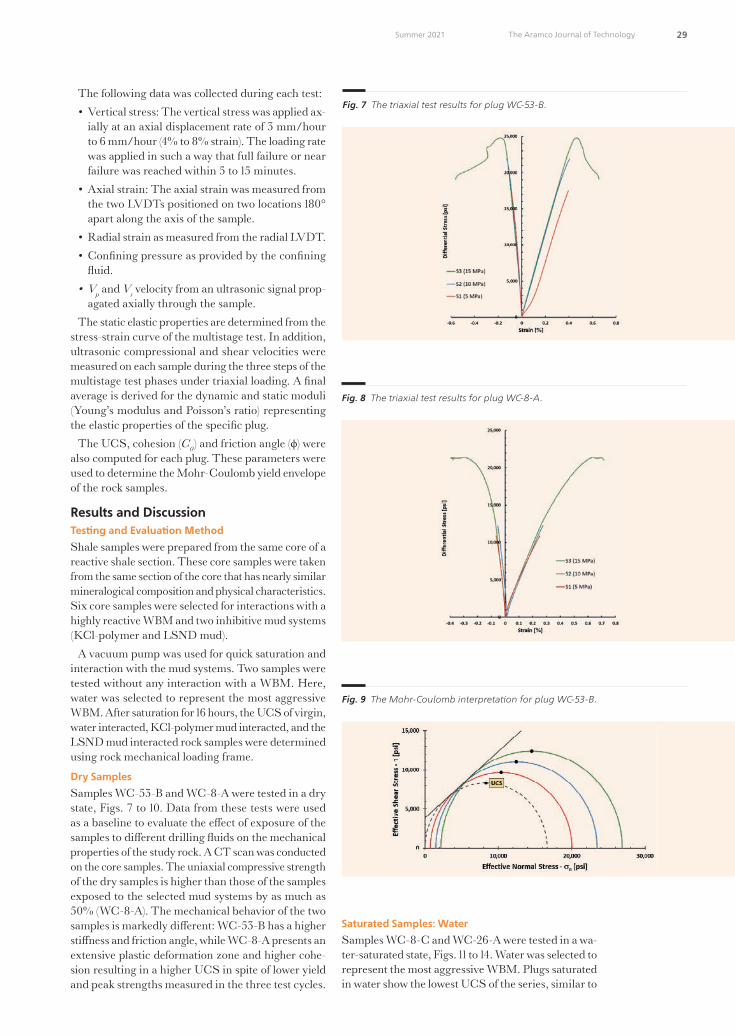
29 The Aramco Journal of TechnologySummer 2021
The following data was collected during each test:• Vertical stress: The vertical stress was applied ax-
ially at an axial displacement rate of 3 mm/hour to 6 mm/hour (4% to 8% strain). The loading rate was applied in such a way that full failure or near failure was reached within 5 to 15 minutes.
• Axial strain: The axial strain was measured from the two LVDTs positioned on two locations 180° apart along the axis of the sample.
• Radial strain as measured from the radial LVDT. • Confining pressure as provided by the confining
�uid.• Vp and Vs velocity from an ultrasonic signal prop-
agated axially through the sample. The static elastic properties are determined from the
stress-strain curve of the multistage test. In addition, ultrasonic compressional and shear velocities were measured on each sample during the three steps of the multistage test phases under triaxial loading. A final average is derived for the dynamic and static moduli (Young’s modulus and Poisson’s ratio) representing the elastic properties of the specific plug.
The UCS, cohesion (C0) and friction angle (ϕ) were also computed for each plug. These parameters were used to determine the Mohr-Coulomb yield envelope of the rock samples.
Results and DiscussionTes�ng and Evalua�on Method
Shale samples were prepared from the same core of a reactive shale section. These core samples were taken from the same section of the core that has nearly similar mineralogical composition and physical characteristics. Six core samples were selected for interactions with a highly reactive WBM and two inhibitive mud systems (KCl-polymer and LSND mud).
A vacuum pump was used for quick saturation and interaction with the mud systems. Two samples were tested without any interaction with a WBM. Here, water was selected to represent the most aggressive WBM. After saturation for 16 hours, the UCS of virgin, water interacted, KCl-polymer mud interacted, and the LSND mud interacted rock samples were determined using rock mechanical loading frame.
Dry Samples
Samples WC-53-B and WC-8-A were tested in a dry state, Figs. 7 to 10. Data from these tests were used as a baseline to evaluate the e�ect of exposure of the samples to di�erent drilling �uids on the mechanical properties of the study rock. A CT scan was conducted on the core samples. The uniaxial compressive strength of the dry samples is higher than those of the samples exposed to the selected mud systems by as much as 50% (WC-8-A). The mechanical behavior of the two samples is markedly di�erent: WC-53-B has a higher sti�ness and friction angle, while WC-8-A presents an extensive plastic deformation zone and higher cohe-sion resulting in a higher UCS in spite of lower yield and peak strengths measured in the three test cycles.
Saturated Samples: WaterSamples WC-8-C and WC-26-A were tested in a wa-ter-saturated state, Figs. 11 to 14. Water was selected to represent the most aggressive WBM. Plugs saturated in water show the lowest UCS of the series, similar to
Fig. 7 The triaxial test results for plug WC-53-B.
Fig. 8 The triaxial test results for plug WC-8-A.
Fig. 9 The Mohr-Coulomb interpreta�on for plug WC-53-B.
49108araD6R1.indd 29 6/16/21 8:48 PM

30 The Aramco Journal of Technology Summer 2021
the strength of the KCl saturated samples, but lower than that of LSND saturated samples. Plug WC-8-C exhibits a very low friction angle; it is possible that the test results are a�ected by the possible presence of a discontinuity not detected before the test. The same feature may also cause the large value in Poisson’s ratio.
Saturated Samples: KCl and LSND
Sample WC-26-B was tested in a KCl saturated state. Sample WC-26-C was tested in an LSND saturated state. Exposure to di�erent mud systems is a�ecting the shale rock in di�erent fashions, with the KCl-poly-mer brine having an e�ect on the strength of the rock similar to that of water, and the LSND brine displaying a somehow intermediate e�ect on the plug strength,
Fig. 10 The Mohr-Coulomb interpreta�on for plug WC-8-A.
Fig. 11 The triaxial test results for plug WC-8-C.
Fig. 12 The triaxial test results for plug WC-26-A.
Fig. 13 The Mohr-Coulomb interpreta�on for plug WC-8-C.
Fig. 14 The Mohr-Coulomb interpreta�on for plug WC-26-A.
Fig. 15 The triaxial test results for plug WC-26-B.
49108araD6R1.indd 30 6/16/21 8:48 PM

31 The Aramco Journal of TechnologySummer 2021
Figs. 15 to 18.In all the cases, the sti�ness of the plugs do not seem
to be a�ected by exposure to di�erent mud systems as compared to the dry sample (WC-53-B), except in the case of plugs originated from the WC-8 whole core sample. Table 4 provides a summary of all tests.
In general, the data indicates the mechanical degra-dation of the rocks, especially clay containing rocks due
to the interactions of water molecules with the clays and other reactive and water sensitive components of the rock samples. Subsequently, the strength of the interactions varies depending on the sample quality, sample characteristics, and the inhibition potential of the WBMs.
Conclusions1. The rock mechanical testing shows that simple
water or non-inhibitive WBM represents the most aggressive �uids compared to the KCl-polymer and the LSND muds.
2. All WBMs cause some degradation and damage of subsurface rock formations, especially the clay containing shales and mud rocks. Although, the degradation amount varies depending on the in-hibition potential of the WBM.
3. In this study, the traditional KCl-polymer mud showed lower performance than the LSND mud, probably due to the reduced infiltration of the in-hibitors into the sample matrix.
4. The LSND mud showed the least degradation of the rock mechanical properties compared to water and the KCl-polymer mud. Therefore, it is a bet-ter alternative to drill formations that have simi-lar mineralogical composition and geomechanical characteristics.
Fig. 16 The triaxial test results for plug WC-26-C.
Fig. 17 The Mohr-Coulomb interpreta�on for plug WC-26-B.
Fig. 18 The Mohr-Coulomb interpreta�on for plug WC-26-C.
Sample # Satura�ng Fluid
Estat Edynvstat vdyn
UCS Φ C0
(psi) (psi) (psi) (deg) (psi)WC-53-B Dry 5.65E+06 8.01E+06 0.301 0.295 16,644 40.3 3,850
WC-8-A Dry 4.14E+06 7.12E+06 0.289 0.276 17,575 28.6 5,216
WC-26-A Water 4.38E+06 8.67E+06 0.346 0.287 11,226 37.0 2,799
WC-26-B KCl 4.35E+06 8.77E+06 0.355 0.274 11,500 36.8 2,882
WC-26-C LSND 4.62E+06 8.23E+06 0.363 0.292 13,047 34.4 3,440
Table 4 A summary of the triaxial test results.
49108araD6R1.indd 31 6/16/21 8:48 PM

32 The Aramco Journal of Technology Summer 2021
5. A comprehensive study using cores containing low, high, very high, and extremely high clays and various shale inhibitors can provide very useful data about the mechanical aspect of rock-�uid interactions.
AcknowledgmentsThe authors would like to acknowledge the support provided by the Drilling Technology Division Lab technicians in preparing the mud samples, and the Petrophysics Department personal in testing and eval-uating the rock samples.
References1. Holmes, A.: The Age of the Earth, 2nd edition,
Thomas Nelson & Sons Ltd., London, 1937, 277 p.
2. Amanullah, M. and Yu, L.: “Environment Friendly Flu-id Loss Additives to Protect the Marine Environment from the Detrimental E�ect of Mud Additives,” Journal of Petroleum Science and Engineering, Vol. 48, Issues 3-4, September 2005, pp. 199-208.
3. Chenevert, M.E. and Osisanya, S.O.: “Shale/Mud Inhibition Defined with Rig Site Methods,” SPE Drilling Engineering, Vol. 4, Issue 3, September 1989, pp. 261-268.
4. Lomba, R.F.T., Chenevert, M.E. and Sharma, M.M.: “The Role of Osmotic E�ects in Fluid Flow through Shales,” Journal of Petroleum Science and Engineering, Vol. 25, Issues 1-2, January 2000, pp. 23-25.
5. Maury, V.M. and Sauzay, J-M.: “Borehole Instability: Case Histories, Rock Mechanics Approach, and Results,” SPE/IADC paper 16051, presented at the SPE/IADC Drilling Conference, New Orleans, Louisiana, March 15-18, 1987.
6. Amanullah, M.: “Physiochemical Characterization of Vegetable Oils and Preliminary Test Results of Vegeta-ble Oil-Based Muds,” SPE/IADC paper 97008, present-ed at the Middle East Drilling Technology Conference and Exhibition, Dubai, UAE, September 12-14, 2005.
7. O’Brien, D.E. and Chenevert, M.E.: “Stabilizing Sen-sitive Shales with Inhibited, Potassium-Based Drilling Fluids,” Journal of Petroleum Technology, Vol. 25, Issue 9, September 1973.
8. Amanullah, M., Marsden, J.R. and Shaw, H.F.: “An Experimental Study of the Swelling Behavior of Mud Rocks in the Presence of Drilling Mud Systems,” Canadian Journal of Petroleum Technology, Vol. 36, No. 3, March 1997, pp 45-50.
9. Berry, S.L., Boles, J.L., Brannon, H.D. and Beall, B.B.: “Performance Evaluation of Ionic Liquids as a Clay Sta-bilizer and Shale Inhibitor,” SPE paper 112540, present-ed at the SPE International Symposium and Exhibition on Formation Damage Control, Lafayette, Louisiana, February 13-15, 2008.
10. Emmanuel, O.E. and Dosunmu, A.: “Experimental Analysis of Shale for Evaluating Shale Drilling Fluid Interaction in Agbada Formation,” British Journal of Applied Science & Technology, Vol. 4, Issue 35, 2014, pp. 4878-4907.
11. Sethi, R., Hinkel, J.J. and Mackay, B.: “An Alternative to the Capillary Suction Time Test,” SPE paper 173789, presented at the SPE International Symposium on Oil Field Chemistry, The Woodlands, Texas, April 13-15, 2015.
12. Tan, C.P., Amanullah, M., Mody, F.K. and Tare, U.M.: “Novel High Membrane E¥ciency Water-Based Drill-ing Fluids for Alleviating Problems in Troublesome Shale Formations,” SPE paper 77192, presented at the IADC/SPE Asia Pacific Drilling Technology, Jakarta, Indonesia, September 9-11, 2002.
13. Amanullah, M., Marsden, J.R. and Shaw, H.F.: “E�ects of Rock-Fluid Interactions on the Petrofabric and Stress-Strain behavior of Mud Rocks,” SPE paper 28030, presented at the Rock Mechanics in Petroleum Engineering, Delft, the Netherlands, August 29-31, 1994.
14. Mody, F.K. and Hale, A.H.: “Borehole Stability Model to Couple the Mechanics and Chemistry of Drilling Fluid Shale Interaction,” Journal of Petroleum Technology, Vol. 45, Issue 11, November 1993, pp. 1093-1101.
15. Lal, M.: “Shale Stability: Drilling Fluid Interaction and Shale Strength,” SPE paper 54356, presented at the SPE Asia Pacific Oil and Gas Conference, Jakarta, Indonesia, April 20-22, 1999.
About the Authors
Dr. Mohammad H. Alqam
Ph.D. in Petroleum Engineering, King Fahd University of Petroleum and Minerals
Dr. Mohammad H. Alqam is currently a Research Consultant in the Rock Mechanics Laboratory in the Advanced Technical Services Division within Saudi Aramco’s Explora�on and Petroleum Engineering Center – Advanced Research Center (EXPEC ARC).
He has more than 35 years of experience with Saudi Aramco and has been involved in an emulsion study, forma�on damage, hydraulic
fra�uring studies and rock mechanics studies.In 1991, Mohammad received his B.S. degree
in Chemistry from California State University, Fresno, CA, and in 1997, he received his M.S. degree in Chemistry from King Fahd University of Petroleum and Minerals (KFUPM), Dhahran, Saudi Arabia. Mohammad received his Ph.D. degree in Petroleum Engineering from KFUPM.
49108araD6R1.indd 32 6/16/21 8:48 PM

33 The Aramco Journal of TechnologySummer 2021
Antonio A. Santaga�
M.S. in Geological Engineering, University of Oklahoma
Antonio A. Santaga� is a Geological Specialist leading the Rock Mechanics Team in the Advanced Technical Services Division within Saudi Aramco’s Explora�on and Petroleum Engineering Center – Advanced Research Center (EXPEC ARC). His opera�onal focus is with the expansion of the Rock Mechanics Laboratory produ�ivity and service portfolio.
Currently, Antonio is collabora�ng in opera�onal and research e�orts with the Reservoir Management Department, the Unconven�onal Resources Department, and
other EXPEC ARC teams. He has almost 25 years of global experience
in geomechanics and geotechnical engineering across Europe, North America, the Middle East, India, and Southeast Asia.
Antonio’s main interests lie in the analysis of fra�ure behavior under a triaxial state of stress and in the development of quality control procedures for rock mechanical data.
He received his M.S. degree in Geological Engineering from the University of Oklahoma, Norman, OK.
Salem H. Algarni
B.S. in Mechanical Engineering, King Fahd University of Petroleum and Minerals
Salem H. Algarni is a Geomechanics Scien�st working in the Advanced Technical Services Division within Saudi Aramco’s Explora�on and Petroleum Engineering Center – Advanced Research Center (EXPEC ARC). He is currently leading the hydraulic fra�uring tes�ng area in the RM laboratory, where he is working on developing a lab work�ow and tes�ng procedure for geomechanical property modeling for hydraulic fra�uring.
In 2013, Salem received his B.S. degree in Mechanical Engineering from King Fahd Univer-sity of Petroleum and Minerals (KFUPM), Dhahran, Saudi Arabia. He is currently studying for his M.S. degree in Petroleum Engineering at KFUPM as a part �me student.
Salem received his Society of Petroleum Engineers (SPE) cer��ca�on and became a cer��ed Petroleum Engineer in 2019.
Dr. Md. Amanullah
Ph.D. in Petroleum Engineering, Imperial College
Dr. Md. Amanullah was a Senior Petroleum Engineering Consultant working at Saudi Aramco’s Explora�on and Petroleum Engineer-ing Center – Advanced Research Center (EXPEC ARC) before his re�rement. Prior to joining Saudi Aramco, he worked as a Principal Research Scien�st at CSIRO in Australia.
Aman is the lead inventor of a vegetable oil-based diele�ric �uid (patented) that led to the forma�on of a spino� company in Australia for commercializa�on of the produ�.
He has published more than 100 technical papers and �led more than 75 patents, with 30
already granted. He is a member of the Society of Petroleum Engineers (SPE). In 2018, Aman received the Middle East Oil and Gas Technical Innova�on of the Year Award, and he also received the Board of Engineers Recogni�on Cer��cate for Date Seed-based ARC Plug development.
Aman received his M.S. degree (First Class) in Mechanical Engineering from the Moscow Oil and Gas Ins�tute, Moscow, Russia, and his Ph.D. degree in Petroleum Engineering from Imperial College, London, U.K.
Adnan H. Al-Makrami
B.S. in Petroleum and Natural Gas Engineering, Pennsylvania State University
Adnan H. Al-Makrami is an Engineer working at the Rock Mechanics Laboratory in the Advanced Technical Services Division within Saudi Aramco’s Explora�on and Petroleum Engineer-ing Center – Advanced Research Center (EXPEC ARC). His focus is on stress dependent permea-bility tes�ng on low permeability samples.
As part of Adnan’s development program in
geomechanics, he completed two years of training during his assignments with the Produc-�on Engineering Department and the Uncon-ven�onal Resources Department.
In 2013, Adnan received his B.S. degree in Petroleum and Natural Gas Engineering from Pennsylvania State University, State College, PA.
Dr. Sinan Caliskan
Ph.D. in Civil Engineering, Cardi University
Dr. Sinan Caliskan is a Petroleum Engineering Specialist working in the Petrophysics Unit within Saudi Aramco’s Explora�on and Petroleum Engineering Center – Advanced Research Center (EXPEC ARC). Since joining Saudi Aramco in 2007, he has been the Group Leader of the Computerized Tomography Unit.
During his postgraduate studies, Sinan inves�gated fra�ure proper�es of composite materials, by means of experimental, numerical
as well as visualiza�on techniques. He then moved to academia and worked for six years in Dundee University, Dundee, Scotland, later earning an Associate Professor �tle.
Sinan received his M.S. degree (1997) and his Ph.D. degree (2001) in Civil Engineering from Cardi� University, Cardi�, U.K.
He has been granted several patents, published more than 40 technical ar�cles and edited two books.
49108araD6R1.indd 33 6/16/21 8:48 PM

34 The Aramco Journal of Technology Summer 2021
The exploitation of unconventional formations requires propped hydraulic fracturing treatments. Propped fracturing is an expensive process that usually su�ers from operational challenges. In this study, a new technology is proposed, which targets implementing thermochemical �uids to stimulate unconventional formations. These �uids release large pressure pulses upon a reaction that creates networks of cracks along the fracture. Triggering thermochemical �uids with acid creates di�erential etching along the fracture surfaces due to the acid/rock dissolution.
The new technology was tested experimentally through core�ooding on Indiana limestone and Kentucky sandstone samples, and through breakdown pressure experiments on Eagle Ford shale samples. The breakdown pressure of the Eagle Ford shale samples was reduced from 2,400 psia to 900 psia using thermochemical �uids triggered with acid. It was also observed that the acid triggered thermochemical �uids could maintain the permeability of the fractures at high closure stresses due to the acid/rock dissolution.
Laboratory and field-scale models were also developed in this study to understand the thermo-chemical reactions. The laboratory-scale model could capture the pressure pulses generated exper-imentally and the system temperature. The field-scale model was then used to understand the ther-mochemical reactive transport in a hydraulic fracture. The model showed that thermochemical concentration is the most significant parameter in controlling the temperature and pressure magni-tudes in the field.
Thermochemical Acid Fra�uring of Tight and Unconven�onal Rocks: Experimental and Modeling Inves�ga�onsDr. Zeeshan Tariq, Dr. Murtada S. Al-Jawad, Dr. Mohamed Mahmoud, Dr. Abdulazeez Abdulraheem and Ayman R. Al-Nakhli
Abstra� /
Introdu�ionUnconventional reservoirs are those that need special methods to produce hydrocarbons economically. Hori-zontal drilling combined with multistage hydraulic fracturing is one of the best stimulation methods to produce from tight unconventional reservoirs. Hydrocarbon reserves trapped within these types of low permeability formations exhibit little to negligible production. Accessing these reserves requires large fracture networks with high conductivity to maximize well performance when implementing existing conventional recovery methods. Recovery from these unconventional reservoirs requires assertive and expensive solutions, such as hydraulic fracturing stimulation methods1. Some of the examples of unconventional reservoirs may include tight sands, coal bed methane, tar sands, heavy oil, gas hydrates, and oil-rich shales2-4.
Production from unconventional formations require special techniques to enhance the stimulated reservoir volume. Stimulated reservoir volume is a term used to quantify the stimulated area in an unconventional reservoir by the creation of multiple complex fracture networks. The combination of horizontal drilling and hydraulic fracturing has allowed access to previously inaccessible hydrocarbon sources. Consequently, stimulation of the unconventional hydrocarbon resources with horizontal drilling and conventional hydraulic fracturing methods could be challenging, due to several reasons such as high breakdown pressure of the rock, huge reservoir compaction, high rock integrity, large rock sti�ness, huge overburden pressure, etc.5, 6.
To address the di�culties and challenges associated with conventional fracturing methods, an alternative way to treat unconventional resources is by generating synthetic hotspots — pockets of high porosity and high permeability regions — using pulse fracturing treatments. Pulse fracturing is a relatively new technique, in which the injection pressure rises in a fraction of seconds to create multiple microfractures. Pulse fracturing, also called dynamic loading, can be executed by several methods such as explosive shooting, impact loading, by the release of high-energized gases, and by means of thermochemical �uids7-9.
Thermochemical �uids are those �uids upon which reaction can cause a strong exothermic reaction. The reaction can simultaneously generate high-pressure and high temperature (HPHT). For the past many years, the oil and gas industry has witnessed many thermochemical �uid applications in di�erent areas. The first application of thermochemical reaction in the petroleum industry appeared in 1986 when McSpadden et al.
49108araD7R1.indd 34 6/16/21 8:54 PM
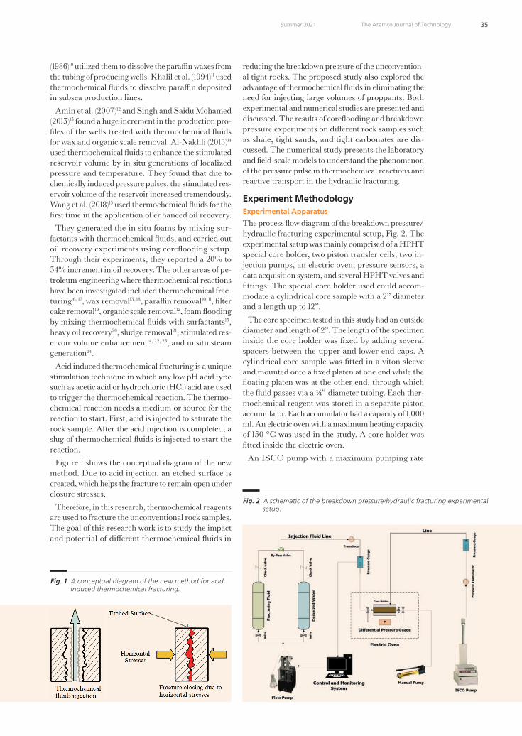
35 The Aramco Journal of TechnologySummer 2021
(1986)10 utilized them to dissolve the para�n waxes from the tubing of producing wells. Khalil et al. (1994)11 used thermochemical �uids to dissolve para�n deposited in subsea production lines.
Amin et al. (2007)12 and Singh and Saidu Mohamed (2013)13 found a huge increment in the production pro-files of the wells treated with thermochemical �uids for wax and organic scale removal. Al-Nakhli (2015)14 used thermochemical �uids to enhance the stimulated reservoir volume by in situ generations of localized pressure and temperature. They found that due to chemically induced pressure pulses, the stimulated res-ervoir volume of the reservoir increased tremendously. Wang et al. (2018)15 used thermochemical �uids for the first time in the application of enhanced oil recovery.
They generated the in situ foams by mixing sur-factants with thermochemical �uids, and carried out oil recovery experiments using core�ooding setup. Through their experiments, they reported a 20% to 34% increment in oil recovery. The other areas of pe-troleum engineering where thermochemical reactions have been investigated included thermochemical frac-turing16, 17, wax removal13, 18, para�n removal10, 11, filter cake removal19, organic scale removal12, foam �ooding by mixing thermochemical �uids with surfactants15, heavy oil recovery20, sludge removal21, stimulated res-ervoir volume enhancement14, 22, 23, and in situ steam generation24.
Acid induced thermochemical fracturing is a unique stimulation technique in which any low pH acid type such as acetic acid or hydrochloric (HCl) acid are used to trigger the thermochemical reaction. The thermo-chemical reaction needs a medium or source for the reaction to start. First, acid is injected to saturate the rock sample. After the acid injection is completed, a slug of thermochemical �uids is injected to start the reaction.
Figure 1 shows the conceptual diagram of the new method. Due to acid injection, an etched surface is created, which helps the fracture to remain open under closure stresses.
Therefore, in this research, thermochemical reagents are used to fracture the unconventional rock samples. The goal of this research work is to study the impact and potential of di�erent thermochemical �uids in
reducing the breakdown pressure of the unconvention-al tight rocks. The proposed study also explored the advantage of thermochemical �uids in eliminating the need for injecting large volumes of proppants. Both experimental and numerical studies are presented and discussed. The results of core�ooding and breakdown pressure experiments on di�erent rock samples such as shale, tight sands, and tight carbonates are dis-cussed. The numerical study presents the laboratory and field-scale models to understand the phenomenon of the pressure pulse in thermochemical reactions and reactive transport in the hydraulic fracturing.
Experiment Methodology Experimental ApparatusThe process �ow diagram of the breakdown pressure/hydraulic fracturing experimental setup, Fig. 2. The experimental setup was mainly comprised of a HPHT special core holder, two piston transfer cells, two in-jection pumps, an electric oven, pressure sensors, a data acquisition system, and several HPHT valves and fittings. The special core holder used could accom-modate a cylindrical core sample with a 2” diameter and a length up to 12”.
The core specimen tested in this study had an outside diameter and length of 2”. The length of the specimen inside the core holder was fixed by adding several spacers between the upper and lower end caps. A cylindrical core sample was fitted in a viton sleeve and mounted onto a fixed platen at one end while the �oating platen was at the other end, through which the �uid passes via a ¼” diameter tubing. Each ther-mochemical reagent was stored in a separate piston accumulator. Each accumulator had a capacity of 1,000 ml. An electric oven with a maximum heating capacity of 150 °C was used in the study. A core holder was fitted inside the electric oven.
An ISCO pump with a maximum pumping rate
Fig. 1 A conceptual diagram of the new method for acid induced thermochemical fra�uring.
Fig. 2 A schemac of the breakdown pressure/hydraulic fra�uring experimental setup.
49108araD7R1.indd 35 6/16/21 8:54 PM

36 The Aramco Journal of Technology Summer 2021
capacity of 50 ml/min was used to transfer fracturing �uid from the piston transfer cell to the core holder. The maximum injection pressure of the ISCO pump was 10,000 psi. All HPHT connections and fittings were used in the experimental setup. The overburden pressure and the injection pressure were applied from independent lines; therefore, the injection pressure was assumed not to interfere with the overburden pressure. To record the overburden and injection pressures, a high-resolution pressure sensor was installed at the inlet of the core holder. The pressure sensor could record 10 readings/sec. The data was then processed at the computer operating software.
A similar setup was used for the core�ooding exper-iments. The core�ooding experimental setup consists of an ISCO injection pump, two transfer cells, a core holder, a back pressure regulator, an overburden pres-sure pump, pressure transducers, and an electric oven.
Thermochemical Fluids
In this study, the thermochemical �uids used were comprised of salts of nitrogen, such as sodium ni-trite (NaNO2) and ammonium chloride (NH4Cl). The two reagents were used in the proportion of one to one. The solution mixture was prepared at an ambi-ent temperature and pressure conditions. When one mole of NaNO2 reacts with one mole of NH4Cl, a strong exothermic chemical reaction happened and sodium chloride salt, water (steam), and nitrogen gas is released. The release of nitrogen gas is the reason for high-pressure generation. This thermochemical reaction can be defined by Eqn. 1:
Saudi Aramco: Company General Use
NH4Cl + NaNO2 → [𝑁𝑁𝐻𝐻4𝑁𝑁𝑂𝑂2 + 𝑁𝑁𝑁𝑁𝑁𝑁𝑁𝑁. 𝑁𝑁𝐻𝐻4𝑁𝑁𝑂𝑂2𝑇𝑇ℎ𝑒𝑒𝑒𝑒𝑒𝑒𝑁𝑁𝑁𝑁𝑒𝑒𝑒𝑒𝑁𝑁𝑒𝑒 ] → NaCl + 2H2O + N2(gas) + ∆H(heat) (1)
NH4Cl + NaNO2 → NaCl + H2O + Heat + Pressure (2) NH4Cl + NaNO2 + Acid → NaCl + H2O + Heat + Pressure + Acid (3) k = 14,700 𝑞𝑞𝑞𝑞𝑞𝑞𝐴𝐴∆𝑃𝑃 (4) 𝑑𝑑𝐶𝐶𝑇𝑇𝑇𝑇𝑑𝑑𝑑𝑑 = –krCTC (5)
kr = 𝑘𝑘𝑟𝑟0𝑒𝑒𝑒𝑒𝑒𝑒(−
∆𝐸𝐸𝑅𝑅𝑅𝑅) (6)
𝜌𝜌�̂�𝑐𝑝𝑝̅̅ ̅̅ ̅𝑉𝑉𝑐𝑐
𝑑𝑑𝑅𝑅𝑑𝑑𝑑𝑑 = krCTC ∆Hr,TCVc – ScU(T –Tb) (7)
VL – VL,i = –cLVL,i(P – Pi) (8) P = znRT/Vg (9) Vg = Vc – VL (10) n = (CTC,i – CTC)Vc (11) (𝜕𝜕𝐶𝐶𝑇𝑇𝑇𝑇𝜕𝜕𝑑𝑑 + 𝒖𝒖. ∇𝑁𝑁𝑅𝑅𝐶𝐶) = ∇. (𝑫𝑫𝑻𝑻𝑻𝑻∇𝑁𝑁𝑅𝑅𝐶𝐶) +𝑘𝑘𝑟𝑟𝑁𝑁𝑅𝑅𝐶𝐶 (12) 𝜌𝜌𝑓𝑓�̂�𝑁𝑒𝑒𝑓𝑓 (
𝜕𝜕𝑅𝑅𝑓𝑓𝜕𝜕𝑑𝑑 + 𝒖𝒖. ∇𝑇𝑇𝑓𝑓) = ∇. (𝒌𝒌𝒇𝒇∇𝑇𝑇𝑓𝑓) + 𝑘𝑘𝑟𝑟𝑁𝑁𝑅𝑅𝐶𝐶∆𝐻𝐻𝑟𝑟,𝑅𝑅𝐶𝐶 (13)
−𝑘𝑘𝑓𝑓
𝜕𝜕𝑅𝑅𝑓𝑓𝜕𝜕𝜕𝜕 |𝑤𝑤
= |𝑟𝑟(∆𝐻𝐻𝑟𝑟,𝐴𝐴)| + 𝑞𝑞𝑟𝑟 (14)
1
This reaction resulted in the generation of an in-termediate product named Themolabile, which im-mediately transformed into sodium chloride (brine), nitrogen gas, and steam. Comprehensive reaction kinetics of thermochemical �uids were investigated and the reaction parameters, such as enthalpy change, thermal conductivity, and specific heat capacity, were determined in the laboratory, which are listed in Table 1. These parameters were determined to produce the thermal energy required to dissolve filter cake formed with water-based and oil-based drilling �uids.
This reaction could generate HPHTs as recorded
from laboratory experiments and field practices. The thermochemical reaction was studied under a batch system in an insulated HPHT micro-reactor. The setup for the monitoring progress of a thermochemical re-action consists of a heater, a nitrogen gas cylinder for pressure control, a HPHT batch micro-reactor, and the pressure and temperature sensors coupled with a data acquisition system. The advancement of the re-action was followed by collecting data for the increase in pressure and temperature at equal intervals of time.
Figure 3 shows the e�ect of the molar concentration on achieving the pressure peak vs. time. With one molar concentration of thermochemical �uid, the re-action could generate a pressure peak of up to 3,500 psi in 40 seconds while with two molar concentration of thermochemical �uids, the reaction could generate a pressure peak of up to 5,500 psi in 30 seconds. The experiment was conducted in an aging cell with a 20 cc volume. The experiment began with an initial pres-sure of 1,000 psi and the preheated temperature of 100 °C. The figure essentially shows that increasing the molar concentration of the reactants could enhance the pressure generation.
The pressure pulse was generated due to the liberation of nitrogen gas. The pressure pulse declined due to the �uid conversion to hot water and gas. The curve was declined because nitrogen gas was dissolved as the reaction product. After declination of the pres-sure curve, it became �attened and aligned with an
Rea ion Parameters Values Units
Enthalpy change (∆H) 369 kJ/mol
Thermal condu�ivity (λ) 0.1 – 0.6 W/m.K
Speci�c heat capacity (C) 85 – 110 J/mol.K
Table 1 Rea�ion parameters obtained from the thermochemical rea�ion when one molar concentra�on of reagents was u�lized.
Fig. 3 The e�e� of one and two molar concentra�ons on the pressure pulse genera�on, due to thermochemical �uids.
49108araD7R1.indd 36 6/16/21 8:54 PM

37 The Aramco Journal of TechnologySummer 2021
approximate initial cell pressure. The pressure pulse was generated a few seconds after the reaction. In the rock, this pulse could create microfractures, and that would reduce the breakdown pressure of the rock.
This figure essentially shows that increasing the molar concentration of the reactants could enhance the pressure generation. The thermochemical reaction could be initiated by preheating a cell to 100 °C or by using any low pH acid. This generated pressure pulse from the release of nitrogen gas was logged in an aging cell with a capacity of 20 cc.
Rock Chara�eriza�onShale, sandstone, and limestone rock samples were tested in this study. Specifically, Eagle Ford shale, Indiana limestone, and Kentucky sandstone were collected and characterized in the laboratory. X-ray di�raction (XRD) analysis was utilized in the labo-ratory to determine the mineralogical composition of the studied samples.
The Eagle Ford shale and Indiana limestone were predominantly composed of calcite content, 82% and 99.29%, respectively, whereas the Kentucky sandstone comprised mainly of quartz content (61%). A moderate amount of Illite was present in the Kentucky sandstone (14%) while a very small amount of 1.4% of Illite was found in the Eagle Ford shale.
Table 2 lists the complete XRD analysis of the Eagle Ford shale, the Indiana limestone, and the Kentucky sandstone samples. Routine core analysis was con-ducted on the rock samples and the petrophysical properties such as porosity, permeability, and density
were measured. Table 3 shows the petrophysical properties of the
three samples.
Samples Prepara�onThe Kentucky sandstone and Indiana limestone sam-ples had a length of 3” and a diameter of 1½”. The Eagle Ford shale sample had a length of 2” and a diameter of 2”. A 6 mm diameter hole was drilled at the center of the shale sample to a depth of 0.75”. A stainless steel casing was inserted inside the drilled hole to a depth of 0.5”, leaving an open hole section of 0.25”, and then cemented to the rock sample using epoxy. Figure 4 is an image of the prepared shale rock sample with the steel tubing fixed with epoxy.
Experimental Results and DiscussionCore�ooding ExperimentsCore�ooding experiments with two types of ther-mochemical �uids were conducted on the Kentucky sandstone and Indiana limestone. An overburden pressure between 500 psi to 2,500 psi was applied in all core�ooding experiments. The two types of ther-mochemical �uids were thermochemical �uid A and thermochemical �uid B. Thermochemical �uid A was triggered with a heat mechanism and thermochemical �uid B was triggered with acid.
Thermochemical A presents the following compositions:
NH4Cl + NaNO2 → NaCl + H2O + Heat + Pressure 2
Mineral Name Chemical FormulaWeight Percentage (%)
Eagle Ford Shale
Indiana Limestone
Kentucky Sandstone
Calcite CaCO3 82.7 99.29 —
Quartz SiO2 5.1 — 61
Gypsum CaSO4.2H2O 4 — —
Dolomite CaMg(CO3)2 4 — —
Kaolinite Al4[Si4O10](OH)8 2.4 — —
Illite (K1–1.5Al4)[Si7–6.5Al1–1.5O20](OH)4 1.4 — 14
Potassium Feldspar KAlSi3O8 — — 3
Plagioclase (Na, Ca)(Si, Al)4O8 — — 5
Sodium Feldspar NaAlSi3O8 — — 17
Ankerite Ca(Fe2+, Mg, Mn)(CO3)2 — 0.1 —
Biote K(Mg, Fe2+)3(Al, Fe3+)Si3O10(OH, F)2 — 0.1 —
Muscovite KAl2(Si3Al)O10(OH, F)2 — 0.5 —
Anhydrite CaSO4 — 0.01 —
Table 2 The complete XRD analysis of the Eagle Ford shale, the Indiana limestone, and the Kentucky sandstone samples.
49108araD7R1.indd 37 6/16/21 8:54 PM

38 The Aramco Journal of Technology Summer 2021
Thermochemical B presents the following compositions:
NH4Cl + NaNO2 + Acid → NaCl + H2O + Heat + Pressure + Acid 3
The acid could be HCl acid, citric acid, acetic acid, formic acid, L-glutamic acid-N,N-diacetic acid tetrasodium (GLDA) chelating agent, ethy-lethylene-di-amine-tetra-acetic acid (HEDT), nitri-lo-tri-acetic acid (NTA), methyl-glycine-di-acetic acid (MGDA), ethylene-di-amine-tetra-acetic acid (EDTA), or any low pH chelant. The pH of the latter reaction should be below 4, and the acid concentration range could be from 3 wt% to 10 wt%. The pressure pulse will create the fracture and the heat will increase the acid reactivity with the rock surface and create a newly etched surface.
Core�ooding experiments were conducted to measure the permeability under di�erent overburden pressure
with a di�erent type of thermochemical �uid (A and B). All core�ooding experiments were conducted at a pore pressure of 1,000 psi and at a temperature of 26 °C. In all experiments, an initial permeability was measured with the thermochemical �uids at three di�erent �ow rates: 0.5 cc/min, 0.75 cc/min, and 1.00 cc/min.
The pressure drop readings were recorded when the �ow rates stabilized. Permeability measurements were repeated with di�erent overburden pressures. In each �ooding period, the �uid was injected with a constant �ow rate until the stabilized pressure drop is achieved. Then values of the stabilized pressure drop with the corresponding �ow rate values were plotted and the slope was calculated. The permeability to the �uid was calculated using the Darcy law, Eqn. 4:
k = 14,700
Saudi Aramco: Company General Use
NH4Cl + NaNO2 → [𝑁𝑁𝐻𝐻4𝑁𝑁𝑂𝑂2 + 𝑁𝑁𝑁𝑁𝑁𝑁𝑁𝑁. 𝑁𝑁𝐻𝐻4𝑁𝑁𝑂𝑂2𝑇𝑇ℎ𝑒𝑒𝑒𝑒𝑒𝑒𝑁𝑁𝑁𝑁𝑒𝑒𝑒𝑒𝑁𝑁𝑒𝑒 ] → NaCl + 2H2O + N2(gas) + ∆H(heat) (1)
NH4Cl + NaNO2 → NaCl + H2O + Heat + Pressure (2) NH4Cl + NaNO2 + Acid → NaCl + H2O + Heat + Pressure + Acid (3) k = 14,700 𝑞𝑞𝑞𝑞𝑞𝑞𝐴𝐴∆𝑃𝑃 (4) 𝑑𝑑𝐶𝐶𝑇𝑇𝑇𝑇𝑑𝑑𝑑𝑑 = –krCTC (5)
kr = 𝑘𝑘𝑟𝑟0𝑒𝑒𝑒𝑒𝑒𝑒(−
∆𝐸𝐸𝑅𝑅𝑅𝑅) (6)
𝜌𝜌�̂�𝑐𝑝𝑝̅̅ ̅̅ ̅𝑉𝑉𝑐𝑐
𝑑𝑑𝑅𝑅𝑑𝑑𝑑𝑑 = krCTC ∆Hr,TCVc – ScU(T –Tb) (7)
VL – VL,i = –cLVL,i(P – Pi) (8) P = znRT/Vg (9) Vg = Vc – VL (10) n = (CTC,i – CTC)Vc (11) (𝜕𝜕𝐶𝐶𝑇𝑇𝑇𝑇𝜕𝜕𝑑𝑑 + 𝒖𝒖. ∇𝑁𝑁𝑅𝑅𝐶𝐶) = ∇. (𝑫𝑫𝑻𝑻𝑻𝑻∇𝑁𝑁𝑅𝑅𝐶𝐶) +𝑘𝑘𝑟𝑟𝑁𝑁𝑅𝑅𝐶𝐶 (12) 𝜌𝜌𝑓𝑓�̂�𝑁𝑒𝑒𝑓𝑓 (
𝜕𝜕𝑅𝑅𝑓𝑓𝜕𝜕𝑑𝑑 + 𝒖𝒖. ∇𝑇𝑇𝑓𝑓) = ∇. (𝒌𝒌𝒇𝒇∇𝑇𝑇𝑓𝑓) + 𝑘𝑘𝑟𝑟𝑁𝑁𝑅𝑅𝐶𝐶∆𝐻𝐻𝑟𝑟,𝑅𝑅𝐶𝐶 (13)
−𝑘𝑘𝑓𝑓
𝜕𝜕𝑅𝑅𝑓𝑓𝜕𝜕𝜕𝜕 |𝑤𝑤
= |𝑟𝑟(∆𝐻𝐻𝑟𝑟,𝐴𝐴)| + 𝑞𝑞𝑟𝑟 (14)
4
where k is the permeability in mD, q is the �ow rate in cc/min, L is the length of the sample in cm, A is the cross-sectional area in cm2, ∆P is the pressure drop (inlet pressure minus outlet pressure) in psi. Once the stabilized pressure drop was achieved with the final �ow rate, the overburden pressure was increased.
Figures 5 and 6 show the e�ect of overburden pressure on the core permeability, which resulted from thermo-chemical fracturing. When the pressure is released, the rock permeability is maintained, due to the etched surface for thermochemical B. From thermochemical A the reaction created a fracture with no etching, due to the absence of the acid, and the resulting permeability is due to the fracturing decrease due to the overburden. The original permeability of tight sandstone was 0.12 mD, and after the acid fracturing, it increased to 280 mD in the case of thermochemical B (with acid). The permeability increased from 0.12 mD to 180 mD in the case of thermochemical A. Similar trends were observed in the case of tight carbonate (Indiana lime-stone) in which the original rock permeability of the sample was 1 mD.
Breakdown Pressure Experiments
Breakdown pressure experiments were conducted on the Eagle Ford shale samples. Three breakdown pres-sure experiments were conducted. The first one was
Samples Sample IDs
Diameter (in)
Length (in)
Porosity (%)
Permeability (mD)
Bulk Volume
(ml)PV
Eagle Ford Shale
Sh-3 2.01 1.998 8.7 0.07 103.90 9.04
Sh-4 1.997 2.002 8.5 0.03 102.77 8.74
Sh-5 1.991 2.012 9.01 0.056 102.66 9.25
Indiana Limestone LS 1.5 3.01 11 1 87.18 9.59
Kentucky Sandstone SS 1.5 3 14 0.12 86.89 12.16
Table 3 The petrophysical proper�es of the three studied rock samples.
Saudi Aramco: Company General Use
Samples Sample IDs
Diameter (in)
Length (in)
Porosity (%)
Permeability (mD)
Bulk Volume
(ml) PV
Eagle Ford Shale
Sh-3 2.01 1.998 8.7 0.07 103.90 9.04 Sh-4 1.997 2.002 8.5 0.03 102.77 8.74 Sh-5 1.991 2.012 9.01 0.056 102.66 9.25
Indiana Limestone LS 1.5 3.01 11 1 87.18 9.59
Kentucky Sandstone SS 1.5 3 14 0.12 86.89 12.16
Table 3 The petrophysical properties of the three studied rock samples.
Fig. 4 A view of the prepared shale rock sample.
Fig. 4 A view of the prepared shale rock sample.
49108araD7R1.indd 38 6/16/21 8:54 PM

39 The Aramco Journal of TechnologySummer 2021
a reference base case experiment with conventional hydraulic fracturing, the second breakdown pressure experiment was using temperature activating thermo-chemical �uid A, and the third experiment was with acid triggering thermochemical �uid B. The breakdown pressure experiments with thermochemical �uid B was conducted with citric acid as an activating agent. The performance of the thermochemical �uid experiments were compared with each other and with the conven-tional hydraulic fracturing technique. Hydraulic Fracturing with Conventional Fluid: A base case experiment was conducted at a room tem-perature of 26 °C with distilled water as the fracturing �uid. The experiment was conducted on the Eagle Ford shale sample with a 6 mm drilled hole. The pH of the distilled water was 7.0. A constant injection rate of 5 cc/min was maintained throughout the experiment. The overburden pressure used was 1,000 psia.
Figure 7 shows the injection pressure profile with respect to time. The breakdown pressure observed for the base case experiment was 2,167 psia. Fracturing with Thermochemical Fluid A: The fracturing experiment with thermochemical �uid A proceeded with a constant injection rate of 0.1 ml/min.
The whole experiment was completed in three phases: injection, soaking, and reaction. A constant overbur-den pressure of 1,000 psi was maintained throughout the experiment, at an ambient temperature of 26 °C. The initial pressure during the injection phase was 10 psi. The injection of thermochemical �uid A con-tinued for 40 minutes until it reached an injection pressure of 100 psi. During that phase, a 0.45 pore volume (PV) of thermochemical �uid A was injected. Once the pressure reached 100 psi, the injection of the thermochemical �uid was stopped, and the soaking period was started in which the �uid was allowed to soak inside the core sample.
An electric oven was used to heat the sample; set to a reaction triggering temperature of 90 °C for the soaking phase. The soaking period lasted for approximately 60 minutes. During the soaking period, the pressure inside the core sample was increased from 100 psi to 285 psi, due to the heating. Once the sample reached 90 °C (at 101.01 minutes), a strong exothermic reaction happened and the pressure inside the core sample increased from 285 psi to the pressure at which the sample was fractured (992 psi) instantaneously. When the reaction happened, it took the pressure 1 minute to reach to the rock breakdown pressure of 992 psi.
Figure 8 shows the complete injection pressure profile obtained from the breakdown pressure experiment with the thermochemical �uid A.Fracturing with Thermochemical Fluid B: The fracturing with an acid triggering thermochemical �uid B proceeded with the pre-injection of the citric acid. Citric acid was selected to trigger the thermochemical reaction because it is a weak acid, an excellent chelating agent, and easy to handle in the laboratory. A constant injection rate of 0.1 ml/min was implemented to initially �ood the core sample. The injection was conducted at an ambient temperature of 26 °C under a constant overburden pressure of 1,000 psi. Approximately 0.3 PVs of citric acid was injected.
0
0
100
1 0
200
2 0
00
0
0 00 1000 1 00 2000 2 00 000
Perm
eii
t
ter T
retm
ent (
m)
er ur en Pressure (psi)
ermoc emical ermoc emical
Fig. 5 The e�e� of thermochemicals A and B on the fra�ure permeability in �ght sandstone rocks (Kentucky sandstone).
0
0
100
1 0
200
2 0
00
0
400
4 0
0 00 1000 1 00 2000 2 00 000
Perm
eii
t
ter T
retm
ent (
m)
er ur en Pressure (psi)
ermoc emical ermoc emical
Fig. 6 The e�e� of thermochemicals A and B on the fra�ure permeability in �ght carbonate rocks (Indiana limestone).
0
400
800
1200
1600
2000
2400
0 0.2 0.4 0.6 0.8 1
Inje
ctio
n Pr
essu
re (p
si)
Time (mins)
Experimental Parameters
Fluid Injection Rate = 5.0 ml/min
Overburden Pressure = 1,000 psia
Breakdown Pressure = Pressure = 2,167 psia
Fig. 7 The inje�ion pressure pro�le with respe� to �me and the breakdown pressure from conven�onal hydraulic fra�uring with water.
49108araD7R1.indd 39 6/16/21 8:54 PM

40 The Aramco Journal of Technology Summer 2021
After injecting 0.3 PVs of citric acid, the thermo-chemical �uid was injected inside the core sample. As soon as the thermochemical �uid mixed with citric acid on the surface of the rock sample, a strong in situ exothermic reaction took place. Due to this exothermic reaction, the pressure started rising rapidly until the rock fractured. When the reaction happened, it took pressure 0.65 minutes to reach to the rock breakdown
pressure of 900 psi. The breakdown pressure recorded for an acid-induced thermochemical fracturing was 900 psi, which was 92 psi lower than what was observed with thermochemical �uid A.
Figure 9 shows the complete injection pressure profile of thermochemical �uid B.Comparative Analysis: The thermochemical �u-ids were injected through a borehole inside the core
Fig. 8 The inje�ion pressure pro�le obtained from the breakdown pressure of thermochemical �uid A in the Eagle Ford shale sample.
Fig. 9 The inje�ion pressure pro�le obtained from the inje�ion of thermochemical �uid B in the Eagle Ford shale sample.
49108araD7R1.indd 40 6/16/21 8:54 PM

41 The Aramco Journal of TechnologySummer 2021
samples of Eagle Ford shale to create the in situ chem-ical reaction. Due to the in situ chemical reaction, an exothermic reaction took place and a pressure pulse was generated, due to the liberation of nitrogen gas. This nitrogen gas created several microfractures, which resulted in the significant reduction of breakdown pres-sure when compared to the base case experiment with conventional hydraulic fracturing with distilled water.
Figure 10 shows the fracture pattern obtained from conventional hydraulic fracturing, thermochemical fracturing with �uid A, and thermochemical fracturing with �uid B. The images show extensive fractures and complete fracture paths. Figure 10a shows a single tiny axial channel created due to an ordinary hydraulic frac-turing experiment, whereas Figs. 10b and 10c show of a thick major fracture after use of a thermochemical �uid.
Figure 11 shows cross-sectional views of the core sample after fracturing with heat triggering thermo-chemical �uid (type A), and an acid triggering thermo-chemical �uid (type B). Figure 11a shows the regular plane after fracturing with thermochemical �uid A while Fig. 11b shows that the thermochemical �uid B creates di�erential etching along the fracture surface due to the acid/rock dissolution after pre-injection of a citric acid. Thermochemical �uid B resulted in an uneven surface on the fracture plane.
The new technique, if applied on the real reservoir, could result in an irregular pattern of etched surfaces. Therefore, this could prevent the fracture closure due to the formation of minimum horizontal stress. In addition to that, the thermochemical injection could result in the generation of synthetic sweet spots by creating multiple microfractures around the region of the wellbore, which helped in the reduction of break-down pressure.
Rea ive Modeling of Thermochemical Fluids This section provides insight regarding modeling ther-mochemical reactions at lab-scale and field-scale. The lab-scale model shows how to capture the pressure pulses, temperature, and concentration profiles at a static condition. The matched parameters from the
lab-scale were used in the field-scale study. The purpose of the field study was to show the penetration length of thermochemical �uids within the hydraulic fracture, temperature magnitude, and heat propagation distance.
MethodologyLab-Scale Model: The thermochemical �uids stim-ulate the reservoir by generating high-pressure puls-es. Predicting the magnitude of pulse generation as a function of concentration and temperature of the thermochemical �uid is an essential parameter for field operations. Based on the lab provided data, the pressure pulses previously shown in Fig. 3 were matched to a good extent.
The thermochemical �uids generate pluses by pro-ducing a large quantity of nitrogen gas and heat. The rate of thermochemical reaction in the closed aging cell can be defined as:
Saudi Aramco: Company General Use
NH4Cl + NaNO2 → [𝑁𝑁𝐻𝐻4𝑁𝑁𝑂𝑂2 + 𝑁𝑁𝑁𝑁𝑁𝑁𝑁𝑁. 𝑁𝑁𝐻𝐻4𝑁𝑁𝑂𝑂2𝑇𝑇ℎ𝑒𝑒𝑒𝑒𝑒𝑒𝑁𝑁𝑁𝑁𝑒𝑒𝑒𝑒𝑁𝑁𝑒𝑒 ] → NaCl + 2H2O + N2(gas) + ∆H(heat) (1)
NH4Cl + NaNO2 → NaCl + H2O + Heat + Pressure (2) NH4Cl + NaNO2 + Acid → NaCl + H2O + Heat + Pressure + Acid (3) k = 14,700 𝑞𝑞𝑞𝑞𝑞𝑞𝐴𝐴∆𝑃𝑃 (4) 𝑑𝑑𝐶𝐶𝑇𝑇𝑇𝑇𝑑𝑑𝑑𝑑 = –krCTC (5)
kr = 𝑘𝑘𝑟𝑟0𝑒𝑒𝑒𝑒𝑒𝑒(−
∆𝐸𝐸𝑅𝑅𝑅𝑅) (6)
𝜌𝜌�̂�𝑐𝑝𝑝̅̅ ̅̅ ̅𝑉𝑉𝑐𝑐
𝑑𝑑𝑅𝑅𝑑𝑑𝑑𝑑 = krCTC ∆Hr,TCVc – ScU(T –Tb) (7)
VL – VL,i = –cLVL,i(P – Pi) (8) P = znRT/Vg (9) Vg = Vc – VL (10) n = (CTC,i – CTC)Vc (11) (𝜕𝜕𝐶𝐶𝑇𝑇𝑇𝑇𝜕𝜕𝑑𝑑 + 𝒖𝒖. ∇𝑁𝑁𝑅𝑅𝐶𝐶) = ∇. (𝑫𝑫𝑻𝑻𝑻𝑻∇𝑁𝑁𝑅𝑅𝐶𝐶) +𝑘𝑘𝑟𝑟𝑁𝑁𝑅𝑅𝐶𝐶 (12) 𝜌𝜌𝑓𝑓�̂�𝑁𝑒𝑒𝑓𝑓 (
𝜕𝜕𝑅𝑅𝑓𝑓𝜕𝜕𝑑𝑑 + 𝒖𝒖. ∇𝑇𝑇𝑓𝑓) = ∇. (𝒌𝒌𝒇𝒇∇𝑇𝑇𝑓𝑓) + 𝑘𝑘𝑟𝑟𝑁𝑁𝑅𝑅𝐶𝐶∆𝐻𝐻𝑟𝑟,𝑅𝑅𝐶𝐶 (13)
−𝑘𝑘𝑓𝑓
𝜕𝜕𝑅𝑅𝑓𝑓𝜕𝜕𝜕𝜕 |𝑤𝑤
= |𝑟𝑟(∆𝐻𝐻𝑟𝑟,𝐴𝐴)| + 𝑞𝑞𝑟𝑟 (14)
5
where CTC is the concentration of thermochemical �u-ids, kr is the reaction rate constant, and t is time. The reaction is assumed to be first-order based on the study provided)20. Notice that the reaction rate “constant” is a strong function of temperature according to the Arrhenius equation:
Fig. 10 The fra�ure pattern obtained from three di�erent methods: (a) conven�onal hydraulic fra�uring, (b) thermochemical �uid A, and (c) thermochemical �uid B.
Fig. 11 Fra�ures created due to fra�uring with thermochemical �uids, (a) Type A, and (b) Type B.
Saudi Aramco: Company General Use
Fig. 11 Fractures created due to fracturing with thermochemical fluids, (a) Type A, and (b) Type B.
Fig. 12 A schematic showing the boundary conditions of the thermochemical fluid concentration and temperature in the hydraulic fracture domain.
(a) (b)
Saudi Aramco: Company General Use
Fig. 11 Fractures created due to fracturing with thermochemical fluids, (a) Type A, and (b) Type B.
Fig. 12 A schematic showing the boundary conditions of the thermochemical fluid concentration and temperature in the hydraulic fracture domain.
(a) (b)
49108araD7R1.indd 41 6/16/21 8:54 PM

42 The Aramco Journal of Technology Summer 2021
Saudi Aramco: Company General Use
NH4Cl + NaNO2 → [𝑁𝑁𝐻𝐻4𝑁𝑁𝑂𝑂2 + 𝑁𝑁𝑁𝑁𝑁𝑁𝑁𝑁. 𝑁𝑁𝐻𝐻4𝑁𝑁𝑂𝑂2𝑇𝑇ℎ𝑒𝑒𝑒𝑒𝑒𝑒𝑁𝑁𝑁𝑁𝑒𝑒𝑒𝑒𝑁𝑁𝑒𝑒 ] → NaCl + 2H2O + N2(gas) + ∆H(heat) (1)
NH4Cl + NaNO2 → NaCl + H2O + Heat + Pressure (2) NH4Cl + NaNO2 + Acid → NaCl + H2O + Heat + Pressure + Acid (3) k = 14,700 𝑞𝑞𝑞𝑞𝑞𝑞𝐴𝐴∆𝑃𝑃 (4) 𝑑𝑑𝐶𝐶𝑇𝑇𝑇𝑇𝑑𝑑𝑑𝑑 = –krCTC (5)
kr = 𝑘𝑘𝑟𝑟0𝑒𝑒𝑒𝑒𝑒𝑒(−
∆𝐸𝐸𝑅𝑅𝑅𝑅) (6)
𝜌𝜌�̂�𝑐𝑝𝑝̅̅ ̅̅ ̅𝑉𝑉𝑐𝑐
𝑑𝑑𝑅𝑅𝑑𝑑𝑑𝑑 = krCTC ∆Hr,TCVc – ScU(T –Tb) (7)
VL – VL,i = –cLVL,i(P – Pi) (8) P = znRT/Vg (9) Vg = Vc – VL (10) n = (CTC,i – CTC)Vc (11) (𝜕𝜕𝐶𝐶𝑇𝑇𝑇𝑇𝜕𝜕𝑑𝑑 + 𝒖𝒖. ∇𝑁𝑁𝑅𝑅𝐶𝐶) = ∇. (𝑫𝑫𝑻𝑻𝑻𝑻∇𝑁𝑁𝑅𝑅𝐶𝐶) +𝑘𝑘𝑟𝑟𝑁𝑁𝑅𝑅𝐶𝐶 (12) 𝜌𝜌𝑓𝑓�̂�𝑁𝑒𝑒𝑓𝑓 (
𝜕𝜕𝑅𝑅𝑓𝑓𝜕𝜕𝑑𝑑 + 𝒖𝒖. ∇𝑇𝑇𝑓𝑓) = ∇. (𝒌𝒌𝒇𝒇∇𝑇𝑇𝑓𝑓) + 𝑘𝑘𝑟𝑟𝑁𝑁𝑅𝑅𝐶𝐶∆𝐻𝐻𝑟𝑟,𝑅𝑅𝐶𝐶 (13)
−𝑘𝑘𝑓𝑓
𝜕𝜕𝑅𝑅𝑓𝑓𝜕𝜕𝜕𝜕 |𝑤𝑤
= |𝑟𝑟(∆𝐻𝐻𝑟𝑟,𝐴𝐴)| + 𝑞𝑞𝑟𝑟 (14)
6
where
Saudi Aramco: Company General Use
NH4Cl + NaNO2 → [𝑁𝑁𝐻𝐻4𝑁𝑁𝑂𝑂2 + 𝑁𝑁𝑁𝑁𝑁𝑁𝑁𝑁. 𝑁𝑁𝐻𝐻4𝑁𝑁𝑂𝑂2𝑇𝑇ℎ𝑒𝑒𝑒𝑒𝑒𝑒𝑁𝑁𝑁𝑁𝑒𝑒𝑒𝑒𝑁𝑁𝑒𝑒 ] → NaCl + 2H2O + N2(gas) + ∆H(heat) (1)
NH4Cl + NaNO2 → NaCl + H2O + Heat + Pressure (2) NH4Cl + NaNO2 + Acid → NaCl + H2O + Heat + Pressure + Acid (3) k = 14,700 𝑞𝑞𝑞𝑞𝑞𝑞𝐴𝐴∆𝑃𝑃 (4) 𝑑𝑑𝐶𝐶𝑇𝑇𝑇𝑇𝑑𝑑𝑑𝑑 = –krCTC (5)
kr = 𝑘𝑘𝑟𝑟0𝑒𝑒𝑒𝑒𝑒𝑒(−
∆𝐸𝐸𝑅𝑅𝑅𝑅) (6)
𝜌𝜌�̂�𝑐𝑝𝑝̅̅ ̅̅ ̅𝑉𝑉𝑐𝑐
𝑑𝑑𝑅𝑅𝑑𝑑𝑑𝑑 = krCTC ∆Hr,TCVc – ScU(T –Tb) (7)
VL – VL,i = –cLVL,i(P – Pi) (8) P = znRT/Vg (9) Vg = Vc – VL (10) n = (CTC,i – CTC)Vc (11) (𝜕𝜕𝐶𝐶𝑇𝑇𝑇𝑇𝜕𝜕𝑑𝑑 + 𝒖𝒖. ∇𝑁𝑁𝑅𝑅𝐶𝐶) = ∇. (𝑫𝑫𝑻𝑻𝑻𝑻∇𝑁𝑁𝑅𝑅𝐶𝐶) +𝑘𝑘𝑟𝑟𝑁𝑁𝑅𝑅𝐶𝐶 (12) 𝜌𝜌𝑓𝑓�̂�𝑁𝑒𝑒𝑓𝑓 (
𝜕𝜕𝑅𝑅𝑓𝑓𝜕𝜕𝑑𝑑 + 𝒖𝒖. ∇𝑇𝑇𝑓𝑓) = ∇. (𝒌𝒌𝒇𝒇∇𝑇𝑇𝑓𝑓) + 𝑘𝑘𝑟𝑟𝑁𝑁𝑅𝑅𝐶𝐶∆𝐻𝐻𝑟𝑟,𝑅𝑅𝐶𝐶 (13)
−𝑘𝑘𝑓𝑓
𝜕𝜕𝑅𝑅𝑓𝑓𝜕𝜕𝜕𝜕 |𝑤𝑤
= |𝑟𝑟(∆𝐻𝐻𝑟𝑟,𝐴𝐴)| + 𝑞𝑞𝑟𝑟 (14)
is the pre-exponential factor, ∆E is the acti-vation energy, R is the universal gas constant, and T is the absolute temperature. Therefore, the reaction rate depends strongly on the cell temperature, which can be obtained based on the following equation:
Saudi Aramco: Company General Use
NH4Cl + NaNO2 → [𝑁𝑁𝐻𝐻4𝑁𝑁𝑂𝑂2 + 𝑁𝑁𝑁𝑁𝑁𝑁𝑁𝑁. 𝑁𝑁𝐻𝐻4𝑁𝑁𝑂𝑂2𝑇𝑇ℎ𝑒𝑒𝑒𝑒𝑒𝑒𝑁𝑁𝑁𝑁𝑒𝑒𝑒𝑒𝑁𝑁𝑒𝑒 ] → NaCl + 2H2O + N2(gas) + ∆H(heat) (1)
NH4Cl + NaNO2 → NaCl + H2O + Heat + Pressure (2) NH4Cl + NaNO2 + Acid → NaCl + H2O + Heat + Pressure + Acid (3) k = 14,700 𝑞𝑞𝑞𝑞𝑞𝑞𝐴𝐴∆𝑃𝑃 (4) 𝑑𝑑𝐶𝐶𝑇𝑇𝑇𝑇𝑑𝑑𝑑𝑑 = –krCTC (5)
kr = 𝑘𝑘𝑟𝑟0𝑒𝑒𝑒𝑒𝑒𝑒(−
∆𝐸𝐸𝑅𝑅𝑅𝑅) (6)
𝜌𝜌�̂�𝑐𝑝𝑝̅̅ ̅̅ ̅𝑉𝑉𝑐𝑐
𝑑𝑑𝑅𝑅𝑑𝑑𝑑𝑑 = krCTC ∆Hr,TCVc – ScU(T –Tb) (7)
VL – VL,i = –cLVL,i(P – Pi) (8) P = znRT/Vg (9) Vg = Vc – VL (10) n = (CTC,i – CTC)Vc (11) (𝜕𝜕𝐶𝐶𝑇𝑇𝑇𝑇𝜕𝜕𝑑𝑑 + 𝒖𝒖. ∇𝑁𝑁𝑅𝑅𝐶𝐶) = ∇. (𝑫𝑫𝑻𝑻𝑻𝑻∇𝑁𝑁𝑅𝑅𝐶𝐶) +𝑘𝑘𝑟𝑟𝑁𝑁𝑅𝑅𝐶𝐶 (12) 𝜌𝜌𝑓𝑓�̂�𝑁𝑒𝑒𝑓𝑓 (
𝜕𝜕𝑅𝑅𝑓𝑓𝜕𝜕𝑑𝑑 + 𝒖𝒖. ∇𝑇𝑇𝑓𝑓) = ∇. (𝒌𝒌𝒇𝒇∇𝑇𝑇𝑓𝑓) + 𝑘𝑘𝑟𝑟𝑁𝑁𝑅𝑅𝐶𝐶∆𝐻𝐻𝑟𝑟,𝑅𝑅𝐶𝐶 (13)
−𝑘𝑘𝑓𝑓
𝜕𝜕𝑅𝑅𝑓𝑓𝜕𝜕𝜕𝜕 |𝑤𝑤
= |𝑟𝑟(∆𝐻𝐻𝑟𝑟,𝐴𝐴)| + 𝑞𝑞𝑟𝑟 (14)
7
where
Saudi Aramco: Company General Use
NH4Cl + NaNO2 → [𝑁𝑁𝐻𝐻4𝑁𝑁𝑂𝑂2 + 𝑁𝑁𝑁𝑁𝑁𝑁𝑁𝑁. 𝑁𝑁𝐻𝐻4𝑁𝑁𝑂𝑂2𝑇𝑇ℎ𝑒𝑒𝑒𝑒𝑒𝑒𝑁𝑁𝑁𝑁𝑒𝑒𝑒𝑒𝑁𝑁𝑒𝑒 ] → NaCl + 2H2O + N2(gas) + ∆H(heat) (1)
NH4Cl + NaNO2 → NaCl + H2O + Heat + Pressure (2) NH4Cl + NaNO2 + Acid → NaCl + H2O + Heat + Pressure + Acid (3) k = 14,700 𝑞𝑞𝑞𝑞𝑞𝑞𝐴𝐴∆𝑃𝑃 (4) 𝑑𝑑𝐶𝐶𝑇𝑇𝑇𝑇𝑑𝑑𝑑𝑑 = –krCTC (5)
kr = 𝑘𝑘𝑟𝑟0𝑒𝑒𝑒𝑒𝑒𝑒(−
∆𝐸𝐸𝑅𝑅𝑅𝑅) (6)
𝜌𝜌�̂�𝑐𝑝𝑝̅̅ ̅̅ ̅𝑉𝑉𝑐𝑐
𝑑𝑑𝑅𝑅𝑑𝑑𝑑𝑑 = krCTC ∆Hr,TCVc – ScU(T –Tb) (7)
VL – VL,i = –cLVL,i(P – Pi) (8) P = znRT/Vg (9) Vg = Vc – VL (10) n = (CTC,i – CTC)Vc (11) (𝜕𝜕𝐶𝐶𝑇𝑇𝑇𝑇𝜕𝜕𝑑𝑑 + 𝒖𝒖. ∇𝑁𝑁𝑅𝑅𝐶𝐶) = ∇. (𝑫𝑫𝑻𝑻𝑻𝑻∇𝑁𝑁𝑅𝑅𝐶𝐶) +𝑘𝑘𝑟𝑟𝑁𝑁𝑅𝑅𝐶𝐶 (12) 𝜌𝜌𝑓𝑓�̂�𝑁𝑒𝑒𝑓𝑓 (
𝜕𝜕𝑅𝑅𝑓𝑓𝜕𝜕𝑑𝑑 + 𝒖𝒖. ∇𝑇𝑇𝑓𝑓) = ∇. (𝒌𝒌𝒇𝒇∇𝑇𝑇𝑓𝑓) + 𝑘𝑘𝑟𝑟𝑁𝑁𝑅𝑅𝐶𝐶∆𝐻𝐻𝑟𝑟,𝑅𝑅𝐶𝐶 (13)
−𝑘𝑘𝑓𝑓
𝜕𝜕𝑅𝑅𝑓𝑓𝜕𝜕𝜕𝜕 |𝑤𝑤
= |𝑟𝑟(∆𝐻𝐻𝑟𝑟,𝐴𝐴)| + 𝑞𝑞𝑟𝑟 (14)
is the average density and specific heat ca-pacity for the two-phase system, Vc is the cell volume, T is the system temperature, ∆Hr,TC is the thermo-chemical �uid heat of reaction, Sc is the cell surface area, Tb is the room temperature, and U is the overall heat transfer coe�cient. The equation states that the increase in the system temperature is equal to the heat generated due to the exothermic reaction minus the heat loss to the surroundings.
Predicting the system pressure might require two-phase equilibrium calculations. Nevertheless, the fol-lowing assumptions, made in this study, proved to be reasonable for predicting the pressure pulses:
1. All the generated nitrogen molecules will be in the gaseous phase assuming negligible nitrogen solu-bility in the liquid phase.
2. The sudden pressure pulse results in negligible water content in the vapor phase.
3. The pressure in the liquid phase is equivalent to that of the vapor phase.
Based on these assumptions, the change in the liquid phase volume can be estimated based on the integrated liquid compressibility equation, defined as:
VL – VL,i = –cLVL,i(P – Pi) 8
where VL is the liquid phase volume, P is the system pressure, cL is the liquid phase compressibility, and the subscript i stands for the initial value. The system pressure can be estimated through the real gas law as:
P = znRT/Vg 9
where z is the gas compressibility, n is the number of gas moles, and Vg is the volume of the gas phase, which can be obtained as:
Vg = Vc – VL 10
The reaction generates nitrogen where the number of moles can be estimated as:
n = (CTC,i – CTC)Vc 11
where CTC,i is the initial thermochemical concentration. The ordinary di�erential equations, Eqns. 5 and 7, is solved using the forward Euler method. The system of Eqns. 8 to 10 are solved using Newton’s method. The solver estimates the thermochemical �uids concentra-tion, temperature, and amount of nitrogen generated by solving Eqns. 5, 6, 7, and 11, sequentially. Then, Eqns. 8 to 10 are solved simultaneously to find the system pressure.
Field-Scale: A dynamic model was built to understand the impact of thermochemical reaction on acid fractur-ing. The input data produced a good match with the lab experiments that were used for the field model. The model integrates �ow dynamics, mass conservation, and heat transfer in the wellbore, hydraulic fracture, and reservoir. The reaction is assumed to take place inside the hydraulic fracture, i.e., no reaction is trig-gered in the wellbore. The model is based on the work done by Aljawad et al. (2020)25; nevertheless, thermo-chemical reactive transport was added in this study. Subsequently, only a description of thermochemical reactive transport within the hydraulic fracture was provided.
A fracture propagation model was used to determine the size of the hydraulic fracture at each time step. To obtain the thermochemical �uid’s concentration profile, the thermochemical �uid’s mass balance is solved, which can be written as:
Saudi Aramco: Company General Use
NH4Cl + NaNO2 → [𝑁𝑁𝐻𝐻4𝑁𝑁𝑂𝑂2 + 𝑁𝑁𝑁𝑁𝑁𝑁𝑁𝑁. 𝑁𝑁𝐻𝐻4𝑁𝑁𝑂𝑂2𝑇𝑇ℎ𝑒𝑒𝑒𝑒𝑒𝑒𝑁𝑁𝑁𝑁𝑒𝑒𝑒𝑒𝑁𝑁𝑒𝑒 ] → NaCl + 2H2O + N2(gas) + ∆H(heat) (1)
NH4Cl + NaNO2 → NaCl + H2O + Heat + Pressure (2) NH4Cl + NaNO2 + Acid → NaCl + H2O + Heat + Pressure + Acid (3) k = 14,700 𝑞𝑞𝑞𝑞𝑞𝑞𝐴𝐴∆𝑃𝑃 (4) 𝑑𝑑𝐶𝐶𝑇𝑇𝑇𝑇𝑑𝑑𝑑𝑑 = –krCTC (5)
kr = 𝑘𝑘𝑟𝑟0𝑒𝑒𝑒𝑒𝑒𝑒(−
∆𝐸𝐸𝑅𝑅𝑅𝑅) (6)
𝜌𝜌�̂�𝑐𝑝𝑝̅̅ ̅̅ ̅𝑉𝑉𝑐𝑐
𝑑𝑑𝑅𝑅𝑑𝑑𝑑𝑑 = krCTC ∆Hr,TCVc – ScU(T –Tb) (7)
VL – VL,i = –cLVL,i(P – Pi) (8) P = znRT/Vg (9) Vg = Vc – VL (10) n = (CTC,i – CTC)Vc (11) (𝜕𝜕𝐶𝐶𝑇𝑇𝑇𝑇𝜕𝜕𝑑𝑑 + 𝒖𝒖. ∇𝑁𝑁𝑅𝑅𝐶𝐶) = ∇. (𝑫𝑫𝑻𝑻𝑻𝑻∇𝑁𝑁𝑅𝑅𝐶𝐶) +𝑘𝑘𝑟𝑟𝑁𝑁𝑅𝑅𝐶𝐶 (12) 𝜌𝜌𝑓𝑓�̂�𝑁𝑒𝑒𝑓𝑓 (
𝜕𝜕𝑅𝑅𝑓𝑓𝜕𝜕𝑑𝑑 + 𝒖𝒖. ∇𝑇𝑇𝑓𝑓) = ∇. (𝒌𝒌𝒇𝒇∇𝑇𝑇𝑓𝑓) + 𝑘𝑘𝑟𝑟𝑁𝑁𝑅𝑅𝐶𝐶∆𝐻𝐻𝑟𝑟,𝑅𝑅𝐶𝐶 (13)
−𝑘𝑘𝑓𝑓
𝜕𝜕𝑅𝑅𝑓𝑓𝜕𝜕𝜕𝜕 |𝑤𝑤
= |𝑟𝑟(∆𝐻𝐻𝑟𝑟,𝐴𝐴)| + 𝑞𝑞𝑟𝑟 (14)
12
where CTC is the reactant concentration, DTH is the di�usion coe�cient of thermochemical �uids, and u is velocity vector. The first term represents the transient accumulation of the thermochemical �uids, the second term is the convection due to �ow, the third term is the di�usion, and the last term is the reaction. The model assumed that there is no concentration gradient,
Saudi Aramco: Company General Use
NH4Cl + NaNO2 → [𝑁𝑁𝐻𝐻4𝑁𝑁𝑂𝑂2 + 𝑁𝑁𝑁𝑁𝑁𝑁𝑁𝑁. 𝑁𝑁𝐻𝐻4𝑁𝑁𝑂𝑂2𝑇𝑇ℎ𝑒𝑒𝑒𝑒𝑒𝑒𝑁𝑁𝑁𝑁𝑒𝑒𝑒𝑒𝑁𝑁𝑒𝑒 ] → NaCl + 2H2O + N2(gas) + ∆H(heat) (1)
NH4Cl + NaNO2 → NaCl + H2O + Heat + Pressure (2) NH4Cl + NaNO2 + Acid → NaCl + H2O + Heat + Pressure + Acid (3) k = 14,700 𝑞𝑞𝑞𝑞𝑞𝑞𝐴𝐴∆𝑃𝑃 (4) 𝑑𝑑𝐶𝐶𝑇𝑇𝑇𝑇𝑑𝑑𝑑𝑑 = –krCTC (5)
kr = 𝑘𝑘𝑟𝑟0𝑒𝑒𝑒𝑒𝑒𝑒(−
∆𝐸𝐸𝑅𝑅𝑅𝑅) (6)
𝜌𝜌�̂�𝑐𝑝𝑝̅̅ ̅̅ ̅𝑉𝑉𝑐𝑐
𝑑𝑑𝑅𝑅𝑑𝑑𝑑𝑑 = krCTC ∆Hr,TCVc – ScU(T –Tb) (7)
VL – VL,i = –cLVL,i(P – Pi) (8) P = znRT/Vg (9) Vg = Vc – VL (10) n = (CTC,i – CTC)Vc (11) (𝜕𝜕𝐶𝐶𝑇𝑇𝑇𝑇𝜕𝜕𝑑𝑑 + 𝒖𝒖. ∇𝑁𝑁𝑅𝑅𝐶𝐶) = ∇. (𝑫𝑫𝑻𝑻𝑻𝑻∇𝑁𝑁𝑅𝑅𝐶𝐶) +𝑘𝑘𝑟𝑟𝑁𝑁𝑅𝑅𝐶𝐶 (12) 𝜌𝜌𝑓𝑓�̂�𝑁𝑒𝑒𝑓𝑓 (
𝜕𝜕𝑅𝑅𝑓𝑓𝜕𝜕𝑑𝑑 + 𝒖𝒖. ∇𝑇𝑇𝑓𝑓) = ∇. (𝒌𝒌𝒇𝒇∇𝑇𝑇𝑓𝑓) + 𝑘𝑘𝑟𝑟𝑁𝑁𝑅𝑅𝐶𝐶∆𝐻𝐻𝑟𝑟,𝑅𝑅𝐶𝐶 (13)
−𝑘𝑘𝑓𝑓
𝜕𝜕𝑅𝑅𝑓𝑓𝜕𝜕𝜕𝜕 |𝑤𝑤
= |𝑟𝑟(∆𝐻𝐻𝑟𝑟,𝐴𝐴)| + 𝑞𝑞𝑟𝑟 (14)
Saudi Aramco: C
ompany G
eneral Use
NH
4 Cl + N
aNO
2 → [ 𝑁𝑁𝐻𝐻
4 𝑁𝑁𝑂𝑂2 +
𝑁𝑁𝑁𝑁𝑁𝑁𝑁𝑁.𝑁𝑁𝐻𝐻4 𝑁𝑁𝑂𝑂
2𝑇𝑇ℎ𝑒𝑒𝑒𝑒
𝑒𝑒𝑁𝑁𝑁𝑁𝑒𝑒𝑒𝑒𝑁𝑁𝑒𝑒] →
NaC
l + 2H2 O
+ N2 (gas) + ∆H
(heat) (1) N
H4 C
l + NaN
O2 →
NaC
l + H2 O
+ Heat + Pressure (2)
NH
4 Cl + N
aNO
2 + Acid →
NaC
l + H2 O
+ Heat + P
ressure + Acid (3)
k = 14,700 𝑞𝑞𝑞𝑞𝑞𝑞𝐴𝐴∆𝑃𝑃 (4)
𝑑𝑑𝐶𝐶𝑇𝑇𝑇𝑇𝑑𝑑𝑑𝑑
= –kr C
TC (5) k
r = 𝑘𝑘𝑟𝑟 0𝑒𝑒𝑒𝑒𝑒𝑒(−∆𝐸𝐸𝑅𝑅𝑅𝑅 ) (6)
𝜌𝜌𝑐𝑐𝑝𝑝̅̅̅̅̅𝑉𝑉𝑐𝑐
𝑑𝑑𝑅𝑅𝑑𝑑𝑑𝑑 = kr C
TC ∆Hr,TC V
c – Sc U
(T –Tb ) (7)
VL – V
L,i = –cL V
L,i (P – P
i ) (8) P = znR
T/Vg (9)
Vg = V
c – VL (10)
n = (CTC
,i – CTC )V
c (11) ( 𝜕𝜕𝐶𝐶𝑇𝑇𝑇𝑇
𝜕𝜕𝑑𝑑+𝒖𝒖.∇𝑁𝑁
𝑅𝑅𝐶𝐶 )=∇. (𝑫𝑫
𝑻𝑻𝑻𝑻 ∇𝑁𝑁𝑅𝑅𝐶𝐶 )+
𝑘𝑘𝑟𝑟 𝑁𝑁𝑅𝑅𝐶𝐶 (12)
𝜌𝜌𝑓𝑓 𝑁𝑁𝑒𝑒𝑓𝑓 ( 𝜕𝜕𝑅𝑅𝑓𝑓𝜕𝜕𝑑𝑑
+𝒖𝒖.∇𝑇𝑇𝑓𝑓 )=
∇.( 𝒌𝒌𝒇𝒇 ∇𝑇𝑇𝑓𝑓 ) +
𝑘𝑘𝑟𝑟 𝑁𝑁𝑅𝑅𝐶𝐶 ∆𝐻𝐻
𝑟𝑟,𝑅𝑅𝐶𝐶 (13) −𝑘𝑘𝑓𝑓
𝜕𝜕𝑅𝑅𝑓𝑓𝜕𝜕𝜕𝜕 |𝑤𝑤
=| 𝑟𝑟(∆𝐻𝐻
𝑟𝑟,𝐴𝐴 )| +𝑞𝑞𝑟𝑟 (14)
, at the fracture walls. This is a reasonable assumption in an unconventional formation as the �uid loss is limited. It is also assumed that the reaction takes place inside the fracture where the inlet concentration is the initial TC concentration, CTC I inlet = CTC,i, Fig. 12. It should be noted that the thermochemical di�usion term has no impact on the solution; therefore, knowledge of a thermochemical di�usion is of negligible importance.
A heat transfer model was coupled, as the reaction term in Eqn. 12 is temperature dependent. Equation 13 defines the energy balance in the hydraulic fracture:
Saudi Aramco: Company General Use
NH4Cl + NaNO2 → [𝑁𝑁𝐻𝐻4𝑁𝑁𝑂𝑂2 + 𝑁𝑁𝑁𝑁𝑁𝑁𝑁𝑁. 𝑁𝑁𝐻𝐻4𝑁𝑁𝑂𝑂2𝑇𝑇ℎ𝑒𝑒𝑒𝑒𝑒𝑒𝑁𝑁𝑁𝑁𝑒𝑒𝑒𝑒𝑁𝑁𝑒𝑒 ] → NaCl + 2H2O + N2(gas) + ∆H(heat) (1)
NH4Cl + NaNO2 → NaCl + H2O + Heat + Pressure (2) NH4Cl + NaNO2 + Acid → NaCl + H2O + Heat + Pressure + Acid (3) k = 14,700 𝑞𝑞𝑞𝑞𝑞𝑞𝐴𝐴∆𝑃𝑃 (4) 𝑑𝑑𝐶𝐶𝑇𝑇𝑇𝑇𝑑𝑑𝑑𝑑 = –krCTC (5)
kr = 𝑘𝑘𝑟𝑟0𝑒𝑒𝑒𝑒𝑒𝑒(−
∆𝐸𝐸𝑅𝑅𝑅𝑅) (6)
𝜌𝜌�̂�𝑐𝑝𝑝̅̅ ̅̅ ̅𝑉𝑉𝑐𝑐
𝑑𝑑𝑅𝑅𝑑𝑑𝑑𝑑 = krCTC ∆Hr,TCVc – ScU(T –Tb) (7)
VL – VL,i = –cLVL,i(P – Pi) (8) P = znRT/Vg (9) Vg = Vc – VL (10) n = (CTC,i – CTC)Vc (11) (𝜕𝜕𝐶𝐶𝑇𝑇𝑇𝑇𝜕𝜕𝑑𝑑 + 𝒖𝒖. ∇𝑁𝑁𝑅𝑅𝐶𝐶) = ∇. (𝑫𝑫𝑻𝑻𝑻𝑻∇𝑁𝑁𝑅𝑅𝐶𝐶) +𝑘𝑘𝑟𝑟𝑁𝑁𝑅𝑅𝐶𝐶 (12) 𝜌𝜌𝑓𝑓�̂�𝑁𝑒𝑒𝑓𝑓 (
𝜕𝜕𝑅𝑅𝑓𝑓𝜕𝜕𝑑𝑑 + 𝒖𝒖. ∇𝑇𝑇𝑓𝑓) = ∇. (𝒌𝒌𝒇𝒇∇𝑇𝑇𝑓𝑓) + 𝑘𝑘𝑟𝑟𝑁𝑁𝑅𝑅𝐶𝐶∆𝐻𝐻𝑟𝑟,𝑅𝑅𝐶𝐶 (13)
−𝑘𝑘𝑓𝑓
𝜕𝜕𝑅𝑅𝑓𝑓𝜕𝜕𝜕𝜕 |𝑤𝑤
= |𝑟𝑟(∆𝐻𝐻𝑟𝑟,𝐴𝐴)| + 𝑞𝑞𝑟𝑟 (14)
13
where Tf is the fracture temperature,
Saudi Aramco: Company General Use
NH4Cl + NaNO2 → [𝑁𝑁𝐻𝐻4𝑁𝑁𝑂𝑂2 + 𝑁𝑁𝑁𝑁𝑁𝑁𝑁𝑁. 𝑁𝑁𝐻𝐻4𝑁𝑁𝑂𝑂2𝑇𝑇ℎ𝑒𝑒𝑒𝑒𝑒𝑒𝑁𝑁𝑁𝑁𝑒𝑒𝑒𝑒𝑁𝑁𝑒𝑒 ] → NaCl + 2H2O + N2(gas) + ∆H(heat) (1)
NH4Cl + NaNO2 → NaCl + H2O + Heat + Pressure (2) NH4Cl + NaNO2 + Acid → NaCl + H2O + Heat + Pressure + Acid (3) k = 14,700 𝑞𝑞𝑞𝑞𝑞𝑞𝐴𝐴∆𝑃𝑃 (4) 𝑑𝑑𝐶𝐶𝑇𝑇𝑇𝑇𝑑𝑑𝑑𝑑 = –krCTC (5)
kr = 𝑘𝑘𝑟𝑟0𝑒𝑒𝑒𝑒𝑒𝑒(−
∆𝐸𝐸𝑅𝑅𝑅𝑅) (6)
𝜌𝜌�̂�𝑐𝑝𝑝̅̅ ̅̅ ̅𝑉𝑉𝑐𝑐
𝑑𝑑𝑅𝑅𝑑𝑑𝑑𝑑 = krCTC ∆Hr,TCVc – ScU(T –Tb) (7)
VL – VL,i = –cLVL,i(P – Pi) (8) P = znRT/Vg (9) Vg = Vc – VL (10) n = (CTC,i – CTC)Vc (11) (𝜕𝜕𝐶𝐶𝑇𝑇𝑇𝑇𝜕𝜕𝑑𝑑 + 𝒖𝒖. ∇𝑁𝑁𝑅𝑅𝐶𝐶) = ∇. (𝑫𝑫𝑻𝑻𝑻𝑻∇𝑁𝑁𝑅𝑅𝐶𝐶) +𝑘𝑘𝑟𝑟𝑁𝑁𝑅𝑅𝐶𝐶 (12) 𝜌𝜌𝑓𝑓�̂�𝑁𝑒𝑒𝑓𝑓 (
𝜕𝜕𝑅𝑅𝑓𝑓𝜕𝜕𝑑𝑑 + 𝒖𝒖. ∇𝑇𝑇𝑓𝑓) = ∇. (𝒌𝒌𝒇𝒇∇𝑇𝑇𝑓𝑓) + 𝑘𝑘𝑟𝑟𝑁𝑁𝑅𝑅𝐶𝐶∆𝐻𝐻𝑟𝑟,𝑅𝑅𝐶𝐶 (13)
−𝑘𝑘𝑓𝑓
𝜕𝜕𝑅𝑅𝑓𝑓𝜕𝜕𝜕𝜕 |𝑤𝑤
= |𝑟𝑟(∆𝐻𝐻𝑟𝑟,𝐴𝐴)| + 𝑞𝑞𝑟𝑟 (14)
is the �uid specific heat capacity, kf is the �uid thermal conduc-tivity, and ∆Hr,TC is the thermochemical heat of reac-tion. Observe that the first term accounts for the heat storage, the second term is the convection of heat, the third term is the heat conduction, and the last term is the heat of reaction released within the fracture. When the thermochemical reaction is triggered with acid, its impact should be coupled. For instance, the HCl acid reaction with the minerals releases heat; therefore, it mathematically appears in the boundary of the domain. Equation 14 defines the wall boundary condition for the heat transfer:
Saudi Aramco: Company General Use
NH4Cl + NaNO2 → [𝑁𝑁𝐻𝐻4𝑁𝑁𝑂𝑂2 + 𝑁𝑁𝑁𝑁𝑁𝑁𝑁𝑁. 𝑁𝑁𝐻𝐻4𝑁𝑁𝑂𝑂2𝑇𝑇ℎ𝑒𝑒𝑒𝑒𝑒𝑒𝑁𝑁𝑁𝑁𝑒𝑒𝑒𝑒𝑁𝑁𝑒𝑒 ] → NaCl + 2H2O + N2(gas) + ∆H(heat) (1)
NH4Cl + NaNO2 → NaCl + H2O + Heat + Pressure (2) NH4Cl + NaNO2 + Acid → NaCl + H2O + Heat + Pressure + Acid (3) k = 14,700 𝑞𝑞𝑞𝑞𝑞𝑞𝐴𝐴∆𝑃𝑃 (4) 𝑑𝑑𝐶𝐶𝑇𝑇𝑇𝑇𝑑𝑑𝑑𝑑 = –krCTC (5)
kr = 𝑘𝑘𝑟𝑟0𝑒𝑒𝑒𝑒𝑒𝑒(−
∆𝐸𝐸𝑅𝑅𝑅𝑅) (6)
𝜌𝜌�̂�𝑐𝑝𝑝̅̅ ̅̅ ̅𝑉𝑉𝑐𝑐
𝑑𝑑𝑅𝑅𝑑𝑑𝑑𝑑 = krCTC ∆Hr,TCVc – ScU(T –Tb) (7)
VL – VL,i = –cLVL,i(P – Pi) (8) P = znRT/Vg (9) Vg = Vc – VL (10) n = (CTC,i – CTC)Vc (11) (𝜕𝜕𝐶𝐶𝑇𝑇𝑇𝑇𝜕𝜕𝑑𝑑 + 𝒖𝒖. ∇𝑁𝑁𝑅𝑅𝐶𝐶) = ∇. (𝑫𝑫𝑻𝑻𝑻𝑻∇𝑁𝑁𝑅𝑅𝐶𝐶) +𝑘𝑘𝑟𝑟𝑁𝑁𝑅𝑅𝐶𝐶 (12) 𝜌𝜌𝑓𝑓�̂�𝑁𝑒𝑒𝑓𝑓 (
𝜕𝜕𝑅𝑅𝑓𝑓𝜕𝜕𝑑𝑑 + 𝒖𝒖. ∇𝑇𝑇𝑓𝑓) = ∇. (𝒌𝒌𝒇𝒇∇𝑇𝑇𝑓𝑓) + 𝑘𝑘𝑟𝑟𝑁𝑁𝑅𝑅𝐶𝐶∆𝐻𝐻𝑟𝑟,𝑅𝑅𝐶𝐶 (13)
−𝑘𝑘𝑓𝑓
𝜕𝜕𝑅𝑅𝑓𝑓𝜕𝜕𝜕𝜕 |𝑤𝑤
= |𝑟𝑟(∆𝐻𝐻𝑟𝑟,𝐴𝐴)| + 𝑞𝑞𝑟𝑟 (14)
14
49108araD7R1.indd 42 6/16/21 8:54 PM

43 The Aramco Journal of TechnologySummer 2021
where ∆Hr,A is the acid heat of reaction (if acid is used to trigger the reaction), and qr is the heat lost to the reservoir.
The boundary illustrates that the heat lost from the fracture is equal to the acid/rock heat of reaction and heat lost to the formation. Obtaining the heat lost from the fracture to the reservoir requires a reservoir heat transfer model, which is implemented in this research. Details of coupling the hydraulic fracture and reservoir heat transfer models were provided by Aljawad (2020)26. A finite volume scheme is implemented to obtain the temperature and concentration profiles.
Model Match with ExperimentsFigure 13 shows that the proposed static model could capture the experimentally generated pulse in the aging cell shown in Fig. 3. Tables 4 and 5 shows the data used in the model to capture the pulses given; the reaction kinetics were obtained from20. Liquid compressibil-ity is used as a matching parameter for the pressure magnitude. Notice that the compressibility is a func-tion of the pressure, temperature, and salinity. The compressibility range produced from the model was
from 1 × 10⁻⁶ to 2.5 × 10⁻⁶ 1/psi, which is a reasonable range for water compressibility. The sudden sharp increase in the pressure is due to the sudden release of a large amount of nitrogen gas and heat.
Figure 14a shows the predicted concentration profile as a function of time. One might observe that the ther-mochemical �uids were consumed within 50 seconds. The two molar thermochemical �uids were consumed faster as higher concentrations speed the reaction and release larger heat magnitudes. Notice that the peaks of the pulses in Fig. 13 correspond to the moment where the thermochemical �uids were completely consumed. This is logical as no more nitrogen was released to pressurize the cell.
Figure 14b shows the temperature response produced from the model. As expected, a higher concentration resulted in higher temperature magnitude. These simu-lations agree with the average temperature magnitudes recorded in the lab even though a continuous profile was not generated. The temperature peak also corre-sponds to the time where the thermochemical �uids were completely consumed. The sharp increase in
Fig. 12 A schema�c showing the boundary condi�ons of the thermochemical uid concentra�on and temperature in the hydraulic fra�ure domain.
Fig. 13 The sta�c model match with the pressure pluses obtained from the experiments for (a) one molar, and (b) two molar cases.
0 50 100 150 200 250Time (s)
0
1000
2000
3000
4000
5000
6000
Pres
sure
(psi
)
Model MatchExperimental Data
0 50 100 150 200 250Time (s)
0
1000
2000
3000
4000
5000
6000
Pres
sure
(psi
)
Model MatchExperimental Data
(a) (b)
49108araD7R1.indd 43 6/16/21 8:54 PM

44 The Aramco Journal of Technology Summer 2021
temperature corresponds to the fast generation of heat upon reaction while the relatively at curve thereafter represents the temperature decline due to heat loss to the surroundings.
Field-Scale AnalysisA sensitivity analysis was performed to evaluate the performance of thermochemical uids at the field-scale. Temperature, concentration, injection rate, and acid impact were investigated. The base case for this study assumes an injection of 210 gal/ft of 3 molar concen-trated thermochemical uids at 25 bbl/min. Such a treatment volume and injection rate are suitable for hydraulic fracturing operations as the purpose is to extend a hydraulic fracture. The reservoir temperature was assumed to be 100 °C, while the injected uid temperature was 25 °C.
Temperature. Both thermochemical uids and res-ervoir temperatures have a significant impact on the reactivity. This is a major parameter that determines how long the thermochemical uids can penetrate inside a hydraulic fracture. Figure 15 shows that the thermochemical uids could reach 12 ft inside the hydraulic fracture when injected at 25 °C, while only reaching 5 ft when the uid temperature was 100 °C. Remember that the reaction rate constant depends exponentially on temperature as descripted by the Arrhenius equation.
Figure 16a shows a sound relationship between the uid temperature and concentration profile. A rule of thumb is that a longer penetration could be achieved at lower uid injection temperatures. It is interesting that the injected uids’ temperature also has an impact
Rea ion nr
NH4Cl + NaNO2 1 9.99 × 10³ 4.58 × 10³ 369
Table 4 The rea�ion kine�cs constants and heat of rea�ion for TC.
Input Data SI Unit Field Unit
Overall heat transfer coe�icient (Ut) 0.1 KJ/(s.m2 °C) 0.0048 Btu/(hr.�2.°F)
Ambient temperature (Tb) 25 °C 77 °F
Fluid speci�c heat capacity (Cp) 4.13 KJ/(Kg °C) 0.964 Btu/(lbm °F)
Fluid thermal condu�ivity (kf) 6 × 10⁻⁴ KJ/(s.m °C) 0.347 Btu/(hr.� °F)
Forma�on speci�c heat capacity (Cma) 0.879 KJ/(Kg °C) 0.2099 Btu/(lb °F)
Forma�on thermal condu�ivity (kma) 1.57 × 10⁻³ KJ/(s.m °C) 0.907 Btu/(hr.� °F)
Table 5 The �uid and rock’s thermal proper�es.
Fig. 14 For the one and two molar cases as simulated by the model: (a) The predi�ed concentra�on pro�le as a fun�ion of �me, and (b) the temperature response produced from the model.
0 50 100 150 200 250Time, s
0
0.5
1
1.5
2
Con
cent
ratio
n, m
ol/L
One Molar ConcentrationTwo Molar Concentration
0 50 100 150 200 250Time, s
50
100
150
200
250
300
Tem
pera
ture
,o C
One Molar ConcentrationTwo Molar Concentration
(a) (a) (a) (a) (b)
49108araD7R1.indd 44 6/16/21 8:54 PM

45 The Aramco Journal of TechnologySummer 2021
on the maximum temperature magnitude inside the fracture as indicated in Fig. 16b. For instance, 300 °C was achieved when the thermochemical �uids were injected at 25 °C while 350 °C was reached when the �uid temperature was 100 °C. Notice that the heat provided by the exothermic reaction could reach to more than 100 ft inside the hydraulic fracture, provid-ing advantage in terms of hydraulic fracture clean up during �ow back operations.
Though the thermochemical �uids could penetrate only a couple of feet within the hydraulic fracture, the heat of reaction reached an order of magnitude longer distance. The location of the temperature peak coincides with the location of the thermochemical �uid consumption and probably is the location of the peak of pressure pulse. This observation is similar to the one obtained from lab experiments, Figs. 13 and 14.
The impact of the reservoir temperature, Fig. 17, was also investigated assuming a constant injected �uid tem-perature of 35 °C. The same conclusion was perceived for reservoir temperature impacts as colder tempera-tures allowed for longer thermochemical penetration,
Fig. 17a. Nevertheless, the reservoir temperature did not a ect the temperature peak magnitude as it was 300 °C for all studied cases in Fig. 17b. Concentration. The concentration of thermochemical �uids is the most significant parameter in controlling the pressure pulse and temperature magnitudes. Figure 18a shows that the thermochemical penetration could range from 7 ft to 50 ft based on the concentration magnitude. Higher concentrations surge the reaction rate and result in a larger amount of heat released, which also speeds the reaction. For instance, a 4 molar of thermochemical �uids could increase the temperature close to 400 °C, while the 1 molar could only increase the temperature to 150 °C, Fig. 18b. The thermochem-ical concentration should be carefully designed based on the required temperature and pressure magnitudes. Injection Rate. The injection rate is significant in determining the penetration length of thermochem-ical �uids within the hydraulic fracture. Figure 19a shows that a higher injection rate leads to a higher penetration within the fracture. In addition, the injec-tion rate controls the e�ciency of heat transfer within
Fig. 15 The impa� of the temperature of the thermochemical �uids on their penetra�on inside a hydraulic fra�ure.
0 5 10 15Fracture half-length, ft
0
0.02
0.04
0.06
0.08
0.1
0.12Fr
actu
re w
idth
, inc
h
0
0.5
1
1.5
2
2.5
3C, mol/L
0 5 10 15Fracture half-length, ft
0
0.02
0.04
0.06
0.08
0.1
0.12
Frac
ture
wid
th, i
nch
0
0.5
1
1.5
2
2.5
3C, mol/L
Fig. 16 (a) The concentra�on pro�le, and (b) the temperature pro�le along the hydraulic fra�ure at di�erent inje�ed thermochemical temperatures.
0 5 10 15Fracture half-length, ft
0
0.5
1
1.5
2
2.5
3
Con
cent
ratio
n, m
ol/L
25406080100
TI (oC)
0 50 100 150Fracture half-length, ft
50
100
150
200
250
300
350
Tem
pera
ture
,o C
25406080100
TI (oC)
(a) (a) (b) (b)
49108araD7R1.indd 45 6/16/21 8:54 PM

46 The Aramco Journal of Technology Summer 2021
the fracture, Fig. 19b. A higher injection rate leads to less �uid leako�, and therefore, the hot �uids could reach longer distances. For the low injection rate, heat propagation within the reservoir matrix surrounding the fracture is higher.
Notice that the fracture half-length was less than 50 ft for the 5 bpm injection case while it was larger than 150 ft for the 40 bpm as the fracture length was not constant. Lower injection rates could be targeted if cleaning near the wellbore zone is required.
Fig. 17 (a) The concentra�on pro�le, and (b) the temperature pro�le along the hydraulic fra�ure at di�erent reservoir temperatures.
0 5 10 15 20Fracture half-length, ft
0
0.5
1
1.5
2
2.5
3
Con
cent
ratio
n, m
ol/L
80100140180
TR (oC)
0 50 100 150 200Fracture half-length, ft
50
100
150
200
250
300
350
Tem
pera
ture
,o C
80100140180
TR (oC)
(a) (a) (b)
Fig. 18 (a) The concentra�on pro�le, and (b) the temperature pro�le along the hydraulic fra�ure at di�erent thermochemical �uid concentra�ons.
0 10 20 30 40 50Fracture half-length, ft
0
0.5
1
1.5
2
2.5
3
3.5
4
Con
cent
ratio
n, m
ol/L
1234
C (mol/L)
0 50 100 150 200Fracture half-length, ft
50
100
150
200
250
300
350
400
Tem
pera
ture
,o C
1234
C (mol/L))
(a) (b)
Fig. 19 (a) The concentra�on pro�le, and (b) the temperature pro�le along the hydraulic fra�ure at di�erent inje�ion rates.
0 5 10 15 20Fracture half-length, ft
0
0.5
1
1.5
2
2.5
3
Con
cent
ratio
n, m
ol/L
403020105
q (bpm)
0 50 100 150 200Fracture half-length, ft
50
100
150
200
250
300
350
Tem
pera
ture
,o C
403020105
q (bpm)
(a) (b)
49108araD7R1.indd 46 6/16/21 8:54 PM
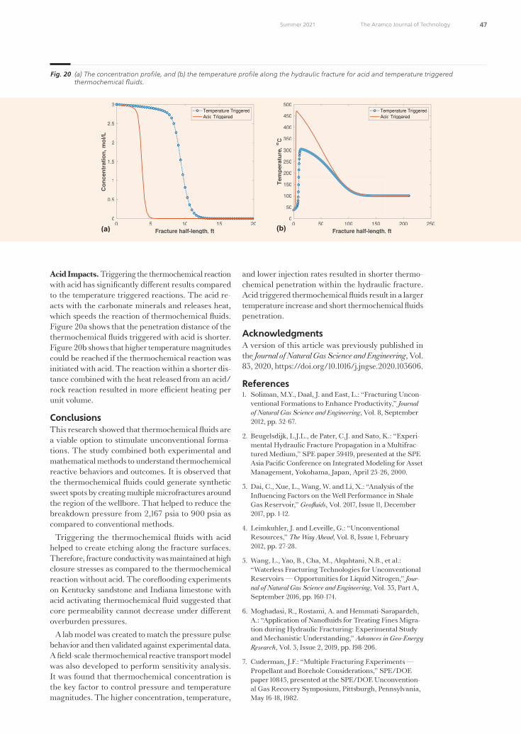
47 The Aramco Journal of TechnologySummer 2021
Acid Impacts. Triggering the thermochemical reaction with acid has significantly di�erent results compared to the temperature triggered reactions. The acid re-acts with the carbonate minerals and releases heat, which speeds the reaction of thermochemical �uids. Figure 20a shows that the penetration distance of the thermochemical �uids triggered with acid is shorter. Figure 20b shows that higher temperature magnitudes could be reached if the thermochemical reaction was initiated with acid. The reaction within a shorter dis-tance combined with the heat released from an acid/rock reaction resulted in more e�cient heating per unit volume.
ConclusionsThis research showed that thermochemical �uids are a viable option to stimulate unconventional forma-tions. The study combined both experimental and mathematical methods to understand thermochemical reactive behaviors and outcomes. It is observed that the thermochemical �uids could generate synthetic sweet spots by creating multiple microfractures around the region of the wellbore. That helped to reduce the breakdown pressure from 2,167 psia to 900 psia as compared to conventional methods.
Triggering the thermochemical �uids with acid helped to create etching along the fracture surfaces. Therefore, fracture conductivity was maintained at high closure stresses as compared to the thermochemical reaction without acid. The core�ooding experiments on Kentucky sandstone and Indiana limestone with acid activating thermochemical �uid suggested that core permeability cannot decrease under di�erent overburden pressures.
A lab model was created to match the pressure pulse behavior and then validated against experimental data. A field-scale thermochemical reactive transport model was also developed to perform sensitivity analysis. It was found that thermochemical concentration is the key factor to control pressure and temperature magnitudes. The higher concentration, temperature,
and lower injection rates resulted in shorter thermo-chemical penetration within the hydraulic fracture. Acid triggered thermochemical �uids result in a larger temperature increase and short thermochemical �uids penetration.
AcknowledgmentsA version of this article was previously published in the Journal of Natural Gas Science and Engineering, Vol. 83, 2020, https://doi.org/10.1016/j.jngse.2020.103606.
References1. Soliman, M.Y., Daal, J. and East, L.: “Fracturing Uncon-
ventional Formations to Enhance Productivity,” Journal of Natural Gas Science and Engineering, Vol. 8, September 2012, pp. 52-67.
2. Beugelsdijk, L.J.L., de Pater, C.J. and Sato, K.: “Experi-mental Hydraulic Fracture Propagation in a Multifrac-tured Medium,” SPE paper 59419, presented at the SPE Asia Pacific Conference on Integrated Modeling for Asset Management, Yokohama, Japan, April 25-26, 2000.
3. Dai, C., Xue, L., Wang, W. and Li, X.: “Analysis of the In�uencing Factors on the Well Performance in Shale Gas Reservoir,” Geofluids, Vol. 2017, Issue 11, December 2017, pp. 1-12.
4. Leimkuhler, J. and Leveille, G.: “Unconventional Resources,” The Way Ahead, Vol. 8, Issue 1, February 2012, pp. 27-28.
5. Wang, L., Yao, B., Cha, M., Alqahtani, N.B., et al.: “Waterless Fracturing Technologies for Unconventional Reservoirs — Opportunities for Liquid Nitrogen,” Jour-nal of Natural Gas Science and Engineering, Vol. 35, Part A, September 2016, pp. 160-174.
6. Moghadasi, R., Rostami, A. and Hemmati-Sarapardeh, A.: “Application of Nano�uids for Treating Fines Migra-tion during Hydraulic Fracturing: Experimental Study and Mechanistic Understanding,” Advances in Geo-Energy Research, Vol. 3, Issue 2, 2019, pp. 198-206.
7. Cuderman, J.F.: “Multiple Fracturing Experiments — Propellant and Borehole Considerations,” SPE/DOE paper 10845, presented at the SPE/DOE Unconvention-al Gas Recovery Symposium, Pittsburgh, Pennsylvania, May 16-18, 1982.
Fig. 20 (a) The concentra�on pro�le, and (b) the temperature pro�le along the hydraulic fra�ure for acid and temperature triggered thermochemical �uids.
0 5 10 15 20Fracture half-length, ft
0
0.5
1
1.5
2
2.5
3 C
once
ntra
tion,
mol
/LTemperature TriggeredAcid Triggered
0 50 100 150 200 250Fracture half-length, ft
0
50
100
150
200
250
300
350
400
450
500
Tem
pera
ture
,o C
Temperature TriggeredAcid Triggered
(a) (b)
49108araD7R1.indd 47 6/16/21 8:54 PM

48 The Aramco Journal of Technology Summer 2021
8. Cuderman, J.F. and Northrop, D.A.: “A Propellant-Based Technology for Multiple Fracturing Wellbores to Enhance Gas Recovery: Application and Results in Devonian Shale,” SPE Production Engineering, Vol. 1, Issue 2, March 1986, pp. 97-103.
9. Malhotra, S., Rijken, P. and Sanchez, A.: “Experimental Investigation of Propellant Fracturing in a Large Sand-stone Block,” SPE Drilling and Completion, Vol. 33, Issue 2, pp. 87-99.
10. McSpadden, H.W., Tyler, M.L. and Velasco, T.T.: “In Situ Heat and Para�n Inhibitor Combination Prove Cost-E�ective in NPR #3, Casper, Wyoming,” SPE paper 15098, presented at the SPE California Regional Meeting, Oakland, California, April 2-4, 1986.
11. Khalil, C.N., Neumann, L.F., Linard, C.A. and Santos, I.G.: “Thermochemical Process to Remove Para�n De-posits in Subsea Production Lines,” OTC paper 7575, presented at the O�shore Technology Conference, Houston, Texas, May 2-5, 1994.
12. Amin, R.A.M., Halim, N.H., Rosli, K.A., Ali, M.I., et al.: “Production Profile of Wells before and after Treat-ment Using Novel Thermochemical Technique,” SPE paper 107663, presented at the European Formation Damage Conference, Scheveningen, the Netherlands, May 30-June 1, 2007.
13. Singh, K., Mohamed, A.S., Alian, S.S., Ismail, M., et al.: “Thermochemical in Situ Heat Generation Tech-nique to Remove Organic Solid Deposition: E�ective Tool for Production Enhancement and Flow Assur-ance,” OTC paper 23933, presented at the O�shore Technology Conference, Houston, Texas, May 6-9, 2013.
14. Al-Nakhli, A.R.: “Chemically Induced Pressure Pulse: A New Fracturing Technology for Unconventional Reservoirs,” SPE paper 172551, presented at the SPE Middle East Oil and Gas Show and Conference, Mana-ma, Kingdom of Bahrain, March 8-11, 2015.
15. Wang, F., Chen, H., Alzobaidi, S. and Li, Z.: “Applica-tion and Mechanisms of Self-Generated Heat Foam for Enhanced Oil Recovery,” Energy Fuels, Vol. 32, Issue 9, August 2018, pp. 9093-9105.
16. Tariq, Z., Mahmoud, M., Abdulraheem, A., Al-Nakhli, A.R., et al.: “An Experimental Study to Reduce the Breakdown Pressure of the Unconventional Carbonate Rock by Cyclic Injection of Thermochemical Fluids,” Journal of Petroleum Science and Engineering, Vol. 187, December 2019.
17. Tariq, Z., Mahmoud, M., Abdulraheem, A., Al-Nakhli, A.R., et al.: “An Experimental Study to Reduce the Fracture Pressure of High Strength Rocks Using a Nov-el Thermochemical Fracturing Approach,” Geofluids, Vol. 2019, August 2019.
18. Rocha, N.O., Khalil, C.N., Leite, L.C.F. and Bastos, R.M.: “A Thermochemical Process for Wax Damage Removal,” SPE paper 80266, presented at the SPE International Symposium on Oil Field Chemistry, Houston, Texas, February 5-7, 2003.
19. Mahmoud, M.: “Well Clean-Up Using a Combined Thermochemical/Chelating Agent Fluids,” Journal of Energy Resources Technology, Vol. 141, Issue 10, October 2019.
20. Alade, O.S., Mahmoud, M., Hassan, A., Al-Shehri, D., et al.: “Evaluation of Kinetics and Energetics of Ther-mochemical Fluids for Enhanced Recovery of Heavy
Oil and Liquid Condensate,” Energy Fuels, Vol. 33, Issue 6, April 2019, pp. 5538-5543.
21. Rocha, N.O., Khalil, C.N., Leite, L.F. and Ferreira, A.M.G.: “Thermochemical Process to Remove Sludge from Storage Tanks,” SPE paper 105765, presented at the International Symposium on Oil Field Chemistry, Houston, Texas, February 28-March 2, 2007.
22. Al-Nakhli, A.R., BaTaweel, M., Mustafa, A., Tariq, Z., et al.: “Novel Methodology to Reduce the Strength of High Stress Tight Gas Reservoirs Using Thermochem-ical,” paper presented at the 53rd U.S. Rock Mechanics/Geomechanics Symposium, New York City, New York, June 23-26, 2019.
23. Mustafa, A., Tariq, Z., Abdulraheem, A., Mahmoud, M., et al.: “Increasing Stimulated Reservoir Volume SRV in Unconventional Reservoirs: Microstructural and Rock Mechanical Study,” SPE paper 192808, presented at the Abu Dhabi International Petroleum Exhibition and Conference, Abu Dhabi, UAE, Novem-ber 12-15, 2018.
24. Mahmoud, M., Alade, O.S., Hamdy, M., Patil, S., et al.: “In Situ Steam and Nitrogen Gas Generation by Thermochemical Fluid Injection: A New Approach for Heavy Oil Recovery,” Energy Conversion and Manage-ment, Vol. 202, December 2019.
25. Aljawad, M.S., Schwalbert, M.P., Zhu, D. and Hill, A.D.: “Optimizing Acid Fracture Design in Calcite For-mations: Guidelines Using a Fully Integrated Model,” SPE Production and Operations, Vol. 35, Issue 1, February 2020, pp. 161-177.
26. Aljawad, M.S.: “Identifying Formation Mineralogy Composition in Acid Fracturing from Distributed Tem-perature Measurements,” SPE Reservoir Evaluation and Engineering, Vol. 23, Issue 1, February 2020, pp. 200-211.
49108araD7R1.indd 48 6/16/21 8:54 PM

49 The Aramco Journal of TechnologySummer 2021
Dr. Mohamed Mahmoud
Ph.D. in Petroleum Engineering, Texas A&M University
Dr. Mohamed Mahmoud is an Associate Professor working in the Petroleum Engineering Department with King Fahd University of Petroleum and Minerals (KFUPM), Dhahran, Saudi Arabia. Prior to assuming this posi on in 2016, he had been a Research Assistant in the same department since 2008.
From 2004 to 2008, Mohamed worked as a Petroleum Engineer at Belayim Petroleum Co. in Egypt. During the period from 2001 to 2004, he
was a Drilling Engineer at Magawish Petroleum Co., Egypt.
Mohamed’s research interests are varied and cover several subje�s, including well simula- on, enhanced oil recovery, and mul phase �ow in ver cal and horizontal wells.
He received his Ph.D. degree in Petroleum Engineering from Texas A&M University, College Sta on, TX, in 2011
Dr. Abdulazeez Abdulraheem
Ph.D. in Geotechnical Engineering, University of Oklahoma
Dr. Abdulazeez Abdulraheem is an Associate Professor in the Department of Petroleum Engineering at King Fahd University of Petroleum and Minerals (KFUPM), Dhahran, Saudi Arabia. His focus is mainly on geome-chanics and the applica ons of ar �cial intelligence in di�erent areas of petroleum engineering.
Prior to joining the department, Abdulazeez worked as a Research Engineer in the Research Ins tute at KFUPM for almost 18 years, addressing �eld challenges in areas such as
wellbore instability, sand produ�ion, and exper-imental rock mechanics.
He has published/presented almost 200 journal and conference papers in the area of geomechanics and the applica on of ar �cial intelligence in petroleum engineering.
Abdulazeez received his M.S. degree in Stru�ural Engineering from the Indian Ins tute of Science, Bangalore, India. He received his Ph.D. degree in Geotechnical Engineering from the University of Oklahoma, Norman, OK.
About the Authors
Dr. Zeeshan Tariq
Ph.D. in Petroleum Engineering, King Fahd University of Petroleum and Minerals
Dr. Murthadha S. Al-Jawad
Ph.D. in Petroleum Engineering, Texas A&M University
Dr. Murthadha S. Al-Jawad is an Assistant Professor in the Department of Petroleum Engineering at King Fahd University of Petroleum and Minerals (KFUPM), Dhahran, Saudi Arabia. He was instrumental in the development of a concentra on in unconven- onal hydrocarbon resources. Also, Murthadha established a fully equipped, state-of-the-art lab to study acid s mula on and hydraulic fra�uring.
He has been a�ively involved in research proje�s regarding acid s mula on, hydraulic fra�uring, and unconven onal reservoirs.
Since joining KFUPM in 2018, Murthadha has been a member of several internally and
externally funded proje�s. He has taught several undergraduate and graduate courses in Petroleum Engineering.
Murthadha has published several technical papers and reports on various areas of research. He is a technical reviewer for several di�erent pres gious journals.
Murthadha received his B.S. degree in Chemical Engineering from KFUPM, and his M.S. degree in Petroleum Engineering from Texas A&M University, College Sta on, TX. In 2018, Murthadha received his Ph.D. degree in Petroleum Engineering, also from Texas A&MUniversity.
Dr. Zeeshan Tariq is an Associate Professor working at the King Fahd University of Petroleum and Minerals (KFUPM). His areas of research interests are geomechanics, hydraulic fra�uring, ar �cial intelligence, and petro-physics.
Zeeshan has published more than 20 peer- reviewed journal ar cles and �led several patents.
He is an a�ive member of various socie es,
such as the Society of Petroleum Engineers (SPE), the Society of Petrophysicists and Well Log Analysts (SPWLA), the Society of Explora on Geophysicists (SEG), and the American Rock Mechanics Associa on (ARMA).
Zeeshan received his M.S. degree in Petroleum Engineering from KFUPM, Dhahran, Saudi Arabia. He received his Ph.D. degree at the College of Petroleum Engineering and Geosciences, KFUPM.
Ayman R. Al-Nakhli
M.S. in Entrepreneurship for New Business Development, Open University Malaysia
Ayman R. Al-Nakhli is a Petroleum Scien st in Saudi Aramco’s Explora on and Petroleum Engineering Center – Advanced Research Center (EXPEC ARC), where he leads the research program on thermochemicals and develops technologies related to conven onal and unconven onal reservoirs such as pulse fra�uring, s mula on, diver ng agents, and heavy oil.
Ayman has developed and �eld deployed several novel technologies, with four of them being commercialized with interna onal service
companies. He received the World Oil Award for Best Produ�ion Chemical in 2015.
Ayman has �led more than 20 patents, published 35 journal papers, and 40 conference papers.
He received his B.S. degree in Industrial Chemistry from King Fahd University of Petroleum and Minerals (KFUPM), Dhahran, Saudi Arabia, and an M.S. degree in Entrepre-neurship for New Business Development from Open University Malaysia, Bahrain.
49108araD7R1.indd 49 6/16/21 8:54 PM

50 The Aramco Journal of Technology Summer 2021
Polycrystalline diamond compact (PDC) drill bits are key drilling tools for oil and gas exploration and drilling. As semiconductor chips are key components for the manufacturing of high performance electronics, PDC cutters are key drilling components of PDC drill bits. Subsequently, drilling very hard and highly abrasive formations poses a big challenge for today’s PDC drill bits. The weakness in the current technology is due to the unavoidable use of metallic catalysts to bond the diamond grains that comprise the PDC cutters. The thermal expansion of the metallic catalysts resulting from high frictional heat at the cutter/rock interface during drilling operation breaks the PDC cutters. Development of catalyst-free PDC cutters would be a game changing technology for drill bits by delivering a significant increase in performance, durability, and drilling economics.
In this study, an innovative ultra high-pressure and high temperature (UHPHT) technology was developed through a two-stage multi-anvil apparatus capable of generating ultra high-pressures up to 35 GPa — seven times higher than current PDC cutter technology — to make ultra-strong and catalyst-free PDC cutting materials.
Here, we report a new type of catalyst-free PDC cutting material, synthesized under an ultra high-pressure of 16 GPa. The new material breaks all single crystal diamond indenters in Vickers hardness testing, and sets a new world record as the hardest diamond material to date. The material also possesses the highest thermal stability in the family of diamonds in air at 1,200 °C, which is about 600 °C higher than current PDC cutters. More importantly, the new material exhibited industry recorded wear resistance, 300% higher than current PDC cutters.
All of these demonstrated a breakthrough in PDC cutter technology development and presented a feasibility for the goal of “One Run to Total Depth” game changing drilling technology.
New Catalyst-free Polycrystalline Diamond with Industry Record Wear ResistanceDr. Guodong Zhan, Dr. Bodong Li, Timothy E. Moellendick, Dr. Duanwei He and Dr. Jianhui Xu
Abstra /
Introdu ionPolycrystalline diamond compact (PDC) drill bits are key drilling tools for oil and gas exploration and drilling in most of formations, with a market of more than $4.5 billion per year. PDC cutters are the primary and critical components in the PDC drill bits to cut these formations, due to their outstanding properties such as high hardness, thermal conductivity, and impact and wear resistance. Subsequently, there is a significant challenge for PDC drill bits in the market when drilling very hard and abrasive formations1-3. Currently available PDC cutters in the market do not provide su�cient wear resistance, impact resistance, or thermal stability to survive this challenging drilling environment. The low rate of penetration and short bit life push the use of multiple bits to drill a single interval, which is not optimal for well economics4-6.
The main weakness in the current technology comes from the unavoidable use of metallic catalyst (typically cobalt) during the manufacturing of the PDC cutters4. Traditionally, due to the metallic catalyst, PDC cutters can be manufactured at relatively lower pressure and temperature, which are approximately 5.5 GPa and 1,400 °C, respectively. Consequently, these metallic binders reduce the hardness of the polycrystalline diamond (PCD) material to approximately 50 GPa to 70 GPa7.
More severely, the metallic catalyst binder in the diamond can adversely assist to convert the diamond back to graphite when high heat is generated from drilling operations. In addition, the cutting and drilling process exposes the PCD material to high stress, where the PDC cutting edges with cobalt binders tend to produce microcracks and diamond particle falling/chipping when the stress is greater than the bonding strength of the diamond grains within the PDC compact at the specific temperature.
The reason can be explained by the di�erences of elastic modulus and thermal expansion coe�cients between the cobalt metallic binder and diamond, which can lead to mismatched volume changes between the diamond and the binder in the operating environment with high stress and high temperature. As a result, large stresses would be produced inside the PDC materials to cause early failure.
Development of a catalyst-free PDC cutter for drill bits would be an ideal and game changing technical solution to potentially realize the goal of “One Run to Total Depth” in drilling technology. The ultra high-pressure and
49108araD8R1.indd 50 6/16/21 9:01 PM

51 The Aramco Journal of TechnologySummer 2021
high temperature (UHPHT) technology makes this possibility true. UHPHT technology is a cutting-edge technology for research and development of many ad-vanced superhard materials. At present, the technol-ogy is mainly focused on the study of nanocrystalline diamonds, however, their industrial applications are limited by the small size and/or high cost.
Irifune et al. (2003)8 made use of a Kawai-type 2-6-8 large cavity static pressure device to successfully achieve a high-pressure of about 15 GPa in synthesizing mil-limeter-grade nanocrystalline PDC material. Since then, the size of synthetic nanocrystalline PDC was successfully increased to a centimeter level after near-ly 10 years of further development9. Larger tonnage high-pressure devices are required to obtain larger sample sizes and to ensure reasonable high-pressure e�ciency. The high-pressure e�ciency is mainly af-fected by the load loss in the transmission process in the anvil design where the structural design of the anvil assembly and the anvil material strength of the final stage matters the most.
In this study, we applied a newly developed UHPHT technology to generate ultra high-pressures up to 35 GPa for the first time10-12. Using this newly developed UHPHT technology, we successfully synthesized cat-alyst-free PDC materials to a centimeter size under an ultra high-pressure of 16 GPa and ultra high tem-perature of 2,300 °C. The physical and mechanical properties of the newly synthesized catalyst-free PCD (CFPCD) compact materials are systematically evalu-ated, including wear resistance, hardness, and thermal stability.
The material shows great thermal stability in air at 1,200 °C, which is about 600 °C higher than current PDC cutters. Also, it is found that the wear resistance of the CFPCD material is 300% more than that of the commercially available PDC cutters currently used in the industry using the industry standard granite turning test method. As is commonly known, it usually takes a decade to increase wear resistance of PDC cutters by 30% to 50%. At such a conversion rate, our develop-ment will reduce technology investment by 50 years.
Experimental Procedures and Materials Chara�eriza�onWe used diamond powder as the starting material. Figure 1 shows the diamond powder particle size dis-tribution. The diamond powder with average grain sizes of 10 µm were first treated in a vacuum furnace at 2 × 10⁻⁴ Torr and 1,200 °C, with a rate of tempera-ture increase by 15 °C/min. After a certain time of maintaining the peak temperature, the sample was cooled to room temperature in the furnace. Next, the treated powder was packed into cylindrical capsules with a diameter of 13 mm and thickness of 6.3 mm. They were then put in in the newly developed two-stage multi-anvil large volume high-pressure apparatus based on a DS6X25 MN cubic press to be sintered at a pressure of 16 GPa and temperature of 2,300 °C4. More details can be found in Li et al. (2020)12.
An X-ray di�ractometer (XRD) was then applied to determine the phases of the starting diamond powder, CFPCD, and commercial PDC materials12. The grain structures of the CFPCD material and commercially available PDC materials were investigated using a scanning electron microscope (SEM). The hardness of polished specimens was tested with di�erent loading forces up to 9.8 N and a fixed dwell time of 15 seconds by a Vickers hardness tester. A numerical control lathe was used to carry out the wear resistance performance tests. The thermal stability and oxidation resistance were evaluated under a high temperature in situ XRD (λ = 0.15406 nm) at di�erent temperatures, from room temperature to 1,400 °C.
Results and DiscussionsIn our study, we successfully achieved the CFPCD samples with dimensions of ~11 mm in diameter and up to 6 mm in thickness for the first time, Fig. 2. These are large enough to be used to make parts and components for a wide range of industrial applications, including drill bits. Previously, all research and industry developments by using UHPHT technology were only able to make miniature samples that limit their use in many potential applications. Our success is attributed to the novel structural design of the anvil assembly and the anvil material strength of the final stage. A lot of e�ort has been invested to make it work.
SEM images showed that the diamond grain sizes are approximately 10 µm in both the CFPCD material,
Fig. 1 The par�cle size distribu�on of the star�ng material of diamond powder.
Saudi Aramco: Public
Fig. 1 The particle size distribution of the starting material of diamond powder.
Fig. 2 The world’s hardest catalyst-free PDCs made by an ultra high-pressure of 16 GPa and an ultra high temperature of 2,300 °C. The dimension of 11 mm in diameter and 6 mm in thickness could be large enough for drill bit application and other industrial applications.
Fig. 2 The world’s hardest catalyst-free PDCs made by an ultra high-pressure of 16 GPa and an ultra high temperature of 2,300 °C. The dimension of 11 mm in diameter and 6 mm in thickness could be large enough for drill bit applica�on and other industrial applica�ons.
49108araD8R1.indd 51 6/16/21 9:01 PM

52 The Aramco Journal of Technology Summer 2021
Fig. 3a, and the commercial PDC materials, Fig. 3b. The similar grain sizes are purposely designed in the comparison in this study to eliminate the e�ect of grain size on the properties. Therefore, the di�erence of the properties between these tested samples are mainly attributed to the di�erent manufacturing processes.
The XRD results indicate that both the starting material and sintered CFPCD material are pure and well crystallized diamonds12. On the other hand, the commercial PDC material contains not only diamond phase but also a cobalt binder, as is well expected. The cobalt catalyst is dispersed at the diamond grain boundaries in the commercial PDC material. It can break the diamond-diamond bonds during harsh cut-ting or drilling in high temperature and high stress environments.
Hardness is a key performance index of materials, and is mainly tested by the indentation method. The Vickers hardness indentations were performed on the polished samples of these materials under an applied load of up to 9.8 N and a dwelling time of 15 seconds.
Figures 4a and 4b show the Vickers hardness indenters before testing with a standard indenter made of single crystal diamond, and the damaged indenter after it is pressed into the CFPCD sample. We repeated the tests on four di�erent specimens, and all the four new indenters made of the single crystal diamond were broken in the same pattern as Fig. 4b.
It was found that even if the load is increased from 1 N to 9.8 N, the Vickers dentations on the polished CFPCD samples are too small to be accurately mea-sured. As a good comparison, the standard diamond indenter was still in good condition after the test of the commercial PDC sample. The comparison re-sults show that the hardness of the CFPCD sample exceeds the Vickers hardness limit of a single crystal diamond (120 GPa)13, indicating the hardest material in the world, so far. The hardness of the commercial PDC material is only about 64 GPa. The higher hardness observed in the CFPCD samples can be attributed to nanostructure defects caused by high-pressure work hardening, such as stacked nanolamellaes, stacked faults, and twin microstructures4.
Saudi Aramco: Public
Fig. a secondary electron image shows the microstructure of the polished C PCD sample prepared under 16 GPa and 2,300 °C, and b a backscatter electron image shows the microstructure of the commercial PDC cutter. The dark gray region in ig. 3 b is diamond and the bright region is cobalt catalyst.
Fig. The optical images of single crystal diamond indenters a before the hardness testing, and b after the testing on C PCD material, showing the hardness of the C PCD material is higher than single crystal diamond 120 GPa . The arrow in ig. b indicates the damage on the indenter tip.
(a) (b)
(a) (b)
Fig. 3 (a) A SEM secondary ele�ron image shows the microstru�ure of the polished CFPCD sample prepared under 16 GPa and 2,300 °C, and (b) a SEM backscatter ele�ron image shows the microstru�ure of the commercial PDC cutter. The dark gray region in Fig. 3 (b) is diamond and the bright region is cobalt catalyst.
Saudi Aramco: Public
Fig. a secondary electron image shows the microstructure of the polished C PCD sample prepared under 16 GPa and 2,300 °C, and b a backscatter electron image shows the microstructure of the commercial PDC cutter. The dark gray region in ig. 3 b is diamond and the bright region is cobalt catalyst.
Fig. The optical images of single crystal diamond indenters a before the hardness testing, and b after the testing on C PCD material, showing the hardness of the C PCD material is higher than single crystal diamond 120 GPa . The arrow in ig. b indicates the damage on the indenter tip.
(a) (b)
(a) (b)
Fig. 4 The op�cal images of single crystal diamond indenters (a) before the hardness tes�ng, and (b) a�er the tes�ng on CFPCD material, showing the hardness of the CFPCD material is higher than single crystal diamond (120 GPa). The arrow in Fig. 4b indicates the damage on the indenter �p.
49108araD8R1.indd 52 6/16/21 9:01 PM

53 The Aramco Journal of TechnologySummer 2021
The cutting performance of the samples were evalu-ated by cutting a turning granite log in a numerically controlled lathe, which is the most widely used method. The granite has high hardness and wear resistance, and low thermal conductivity. The cutting parameters utilized for the granite log turning test were as follows: cutting speed of 100 m/min, depth of cut of 0.5 mm, and feed rate (f ) of 0.4 mm/revolution. The CFPCD and the commercial PDC samples were processed into cylindrical cutting tools with a diameter of 11 mm and height of 6 mm.
Figures 5a and 5b shows the optical images of the cutting edges of the CFPCD sample and the commer-cial PDC sample when the cutting length is 1,260 m, respectively. We can clearly see that the wear areas of the commercial PDC sample are uneven and sig-nificantly larger than those of the CFPCD sample, especially when the turning length reaches 1,260 m.
The wear resistance of the CFPCD and commercial PDC samples is quantified using the abrasion wear ratio, E, and the wear rate or ratio is calculated using the following equation:
Saudi Aramco: Company General Use
𝐸𝐸 = 𝑉𝑉1
𝑉𝑉2 (1)
1
where E is abrasion ratio; V1 is the volume loss from granite, (mm3); and V2 is the volume loss from cutting tools (mm3). The higher E means the higher wear re-sistance of the material.
It was found that the average abrasion ratio of the CFPCD sample is more than four times that of the commercial PDC sample, which is the best diamond materials currently used in the industry. The CFPCD sample is at a stable level with the increase of cutting length, as there is no falling o� of diamond blocks in the process of turning granite testing. The extraordinary wear resistance of the CFPCD material is directly related to its ultra high hardness, which is because of the fact that it is catalyst free.
The wearing surfaces of the CFPCD and commer-cially available PDC materials were also inspected by SEM after each stop before finishing the total test up to 1,260 m of cutting12. The commercial PDC sample
su�ered serious breakage and chipping damage after 1,260 minutes of cutting, and there are also many microcracks and grain falling in the cutting edge of the sample. This could be because of the large mismatch of the elastic modulus and thermal expansion coe�cient between the diamond grains and cobalt catalyst, and the graphitization of the diamond by reaction under high temperature and with the existence of cobalt catalyst, owing to the increasing temperature and high stress at the cutting point.
Consequently, the CFPCD sample shows very du-rable wear surfaces, demonstrating unprecedented wear resistance. It is also worth noting that the wear resistance of a cutter is a combination property com-ing from hardness and toughness. If the material has good hardness, but inferior toughness, it is not able to survive the intensive wear test; or otherwise. Therefore, the toughness of this newly developed material should be very high too, even though no metallic catalyst is used in the manufacturing. It is echoed by the obser-vation in the hardness indentation measurement where we did not observe the cracking at the corners of the indented marks. A further and direct test using K1c methodology is still ongoing now, and will be published when available.
A further impact test on the CFPCD sample exhibits intragranular grain failure mode on the fracture sur-faces, showing an extremely strong diamond-diamond bond12. It is another indication of high toughness of the newly developed CFPCD material.
High temperature thermal stability and oxidation resistance are important to the applications, especially in hard and abrasive formation drilling in the oil and gas industry. The thermal stability and oxidation re-sistance tests were carried out under in situ XRD at various temperatures from room temperature to 1,400 °C. For comparison, a commercial PDC material was also tested.
Figure 6a shows that the starting oxidation tempera-ture of the commercial PDC is severe at approximately 806 °C. On the other hand, the new CFPCD material does not show oxidation at 1,000 °C, Fig. 6b. In another
Saudi Aramco: Public
Fig. The wear surfaces at the cutting edges of the commercial PCD compact a , and b the C PCD compact. The turning length on the granite log is 1,260 m. The pictures are taken at the same distance from the optical microscope.
Fig. The high temperature in situ D spectra of a a commercial PDC material, and b a P T C PCD material at temperatures up to 1,000 °C.
Two – Theta (deg)
Inte
nsity
(a.u
.)
Commercial PDC
CFPCD
(a) (b)
(a) (b)
Two – Theta (deg)
Inte
nsity
(a.u
.)
Fig. 5 The wear surfaces at the cut�ng edges of the commercial PCD compa� (a), and (b) the CFPCD compa�. The turning length on the granite log is 1,260 m. The pi�ures are taken at the same distance from the op�cal microscope.
49108araD8R1.indd 53 6/16/21 9:01 PM

54 The Aramco Journal of Technology Summer 2021
article12, it was tested up to 1,400 °C and found that it is even stable at 1,200 °C — the highest recorded in the industry, which is much higher than those of natural diamond (~800 °C)14, nano-grained diamond (~680 °C)9, nanotwinned diamond (~1,056 °C)14, and commercial PDC (~600 °C)4.
Conclusions With an extremely high-pressure of 16 GPa and an ultra high temperature of 2,300 °C, a centimeter-sized CFPCD compact has been successfully synthesized. The wear resistance, hardness, and thermal stability were symmetrically evaluated. The results show that the newly developed material has extremely high wear resistance — four times that of the best commercial PDC materials used in the industry. The material also broke all the indenters during the Vickers hardness tests, indicating that it is by far the hardest material in the world. In addition, the material has the highest thermal stability in an oxygen containing environment, with a temperature up to 1,200 °C.
The new CFPCD material has the superior combi-nation of the highest hardness, unprecedented wear resistance, and maximum thermal stability in the diamond family. It is expected to play an important role in scientific research as well as in the oil and gas exploration and drilling industries. The PDC cutters made of these ultra-strong, CFPCD materials in this study bring forward a breakthrough in the oil and gas drilling industry. Further research has been continuing to produce UHPHT cutting materials in larger sizes and implement these full-sized cutters on the drill bits for field-testing, with the targeted goal to achieve a “One Run to Total Depth” game changing drill bit technology.
AcknowledgmentsThis article was prepared for presentation at the Middle East Oil and Gas Show and Conference, Manama, Kingdom of Bahrain, November 28-December 1, 2021.
References1. Scott, D.E.: “The History and Impact of Synthetic Dia-
mond Cutters and Diamond Enhanced Inserts on the Oil and Gas Industry,” Industrial Diamond Review, Vol. 66, Issue 1, January 2006.
2. Bruton, G., Crockett, R., Taylor, M. and DenBoer, D.: “PDC Bit Technology for the 21st Century,” Oilfield Review, Vol. 26, Issue 2, June 2014, pp. 48-57.
3. Bellin, F., Dourfaye, A., King, W. and Thigpen, M.: “The Current State of PDC Bit Technology,” World Oil, September 2010, pp. 41-46.
4. Zhan, G., Patin, A., Pillai, R., Gilleylen, R., et al.: “In-Si-tu Analysis of the Microscopic Thermal Fracture Behav-ior of PDC Cutters Using Environmental Scanning Electron Microscope,” SPE paper 168004, presented at the IADC/SPE Drilling Conference and Exhibition, Fort Worth, Texas, March 4-6, 2014.
5. Zhan, G., Moellendick, T.E., Li, B., Gooneratne, C., et al.: “New Ultra-Strong and Catalyst-Free PDC Cutting Element Technology,” IPTC paper 19764, presented at the International Petroleum Technology Conference, Dhahran, Saudi Arabia, January 13-15, 2020.
6. Rassenfoss, S.: “Seeking Ways to Make Better Dia-monds by Tending to the Tiniest Details,” Journal of Petroleum Technology, Vol. 66, Issue 6, June 2014, pp. 38-47.
7. Wilks, J. and Wilks, E.: Properties and Applications of Dia-mond, Butterworth-Heinemann, Oxford, 1991, 525 p.
8. Irifune, T., Kurio, A., Sakamoto, S., Inoue, T., et al.: “Ultrahard Polycrystalline Diamond from Graphite,” Nature, Vol. 421, February 2003, pp. 599-600.
9. Shatskiy, A., Katsura, T., Litasov, K.D., Shcherbakova, A.V., et al.: “High Pressure Generation Using Scaled Up Kawai-Cell,” Physics of the Earth and Planetary Interiors, Vol. 189, Issue 1-2, November 2011, pp. 92-108.
10. Liu, J., Zhan, G., Wang, Q., Yan, X., et al.: “Superstrong Micro-Grained Polycrystalline Diamond Compact through Work Hardening under High Pressure,” Ap-plied Physics Letters, Vol. 112, Issue 6, February 2018.
11. Liu, Y., Zhan, G., Wang, Q., He, D., et al.: “Hardness of Polycrystalline Wurtzite Boron Nitride (wBN) Com-pacts,” Scientific Reports, Vol. 9, Issue 1, July 2019.
CFPCD (b)
Two Two – Theta (deg)Theta (deg)Theta (deg)
Inte
nsity
(a.u
.) In
tens
ity (a
.u.)
Fig. 6 The high temperature in situ XRD spe�ra of: (a) a commercial PDC material, and (b) a UHPHT CFPCD material at temperatures up to 1,000 °C.
49108araD8R1.indd 54 6/16/21 9:02 PM

55 The Aramco Journal of TechnologySummer 2021
12. Li, Q., Zhan, G., Li, D., He, D., et al.: “Ultrastrong Cat-alyst-Free Polycrystalline Diamond,” Scientific Reports, Vol. 10, December 2020.
13. Brookes, C.A. and Brookes, E.J.: “Diamond in Perspec-tive: A Review of Mechanical Properties of Natural Diamond,” Diamond and Related Materials, Vol. 1, Issue 1, August 1991, pp. 13-17.
14. Huang, Q., Yu, D., Xu, B., Hu, W., et al.: “Nanotwinned Diamond with Unprecedented Hardness and Stabili-ty,” Nature, Vol. 510, June 2014, pp. 250-253.
About the Authors
Dr. Guodong “David” Zhan
Ph.D. in Metallurgical Engineering, Huazhong University of Science and Technology
Dr. Guodong “David” Zhan is a Science Specialist and the Team Leader of the Advanced Drilling Tools team in the Drilling Technology Division at Saudi Aramco’s Explora�on and Petroleum Engineering Center – Advanced Research Center (EXPEC ARC). David is a world-renowned materials scien�st and expert in advanced drilling tools/technology. He has over 25 years of experience in industrial R&D and managerial posi�ons, including posi�ons as Chief Engineer and R&D Manager at top oil/gas and semicondu�or global companies, such as Schlumberger, NOV, and Applied Materials.
Addi�onally, David has held academic posi�ons at the University of London and the University of Colorado at Boulder, and sta� scien�st posi�ons at the Japan Na�onal Ins�tute for Materials Science.
He is an a�ive member of the Society of Petroleum Engineers (SPE) where he serves on several conferences such as the SPE Interna�on-
al Petroleum Technology Conference and the Asia Paci�c Drilling Technology Conference/Interna�onal Associa�on of Drilling Contra�ors as co-chair and technical committee member. David is also serving as an editorial board member and reviewer for a number of interna�onal scien��c journals published by The Minerals, Metals and Materials Society and the Material Research Society.
He has published 95 peer-reviewed ar�cles in journals such as Nature Materials and Nature Scien��c Reports, 98 conference proceedings, and has more than 100 �led/published/granted U.S. patents, with an H-index of 37.
In 1994, David received his Ph.D. in Metallur-gical Engineering from Huazhong University of Science and Technology, Wuhan, China, and completed a postdo�oral fellowship in Nanomaterials and Nanotechnology at the University of California at Davis.
49108araD8R1.indd 55 6/16/21 9:02 PM

56 The Aramco Journal of Technology Summer 2021
Timothy E. Moellendick
B.S. in Petroleum Engineering, Marietta College
Timothy E. Moellendick is the Chief Technologist for the Drilling Technology Division at Saudi Aramco’s Explora�on and Petroleum Engineer-ing Center – Advanced Research Center (EXPEC ARC). Timothy is considered the industry expert in casing and liner drilling applica�ons and engineering.
In his previous role as Dire�or of Technology for Schlumberger, he was responsible for growing the technical and opera�onal knowledge base used to develop, plan, and exe-cute this technology worldwide. Timothy has also held drilling opera�ons and engineering
posi�ons, including Senior Drilling Engineer, Drilling Manager for North America, Senior Field Engineer/Dire�ional Driller and Opera-�ons Coordinator for the Gulf Coast of Mexico.
With more than 25 years of oil and gas industry experience, he leads a team of world-class researchers in developing the next genera�on of drilling technology required by Saudi Aramco’s Drilling and Workover stakeholders.
In 1996, Timothy received his B.S. degree in Petroleum Engineering from Marietta College, Marietta, OH.
Dr. Duanwei He
Ph.D. in Condensed Matter Physics, Ins�tute of Physics
Dr. Duanwei He is a Professor at the Ins�tute of Atomic and Molecular Physics, Sichuan University. He is a world-renowned scien�st and expert in hard materials and high pressure phys-ics.
Duanwei’s current research interests include advanced superhard materials and bulk nanostru�ured ceramics, development of technology for large volume high-pressure systems, and elas�c and plas�c behavior of strong materials under high pressure.
He has also held several posi�ons as a Senior Research Engineer at Schlumberger MegaDia-mond, Research Sta� from Los Alamos Na�onal Ins�tute for Materials Research, and Princeton University.
Duanwei has published 150 journal papers with an H-index of 32, and holds 15 granted patents.
He received his Ph.D. degree in Condensed Matter Physics from the Ins�tute of Physics, Chinese Academy of Sciences, Shanghai, China.
Dr. Bodong Li
Ph.D. in Ele rical Engineering, King Abdullah University of Science and Technology
Dr. Bodong Li joined Saudi Aramco in 2015. He is the Technology Leader on Internet-of-Things (IoT) and Robo�cs at Saudi Aramco’s Upstream Advanced Research Center. Bodong is also a member of the Drilling Technology Division focusing on research and development of advanced drilling tools.
He has 12 granted U.S. patents, and has authored and coauthored numerous ar�cles published in scien��c journals and conference papers covering the areas of sensing and
downhole technologies. Bodong is an a�ive member of the Society of
Petroleum Engineers (SPE) and the Ins�tute of Ele�rical and Ele�ronics Engineers.
He received the Discovery Scholarship and Fellowship from King Abdullah University of Science and Technology (KAUST).
Bodong received his M.S. degree in Mechani-cal Engineering and his Ph.D. degree in Ele�rical Engineering, both from KAUST, Thuwal, Saudi Arabia.
Dr. Jianhui Xu
Ph.D. in Materials Science and Engineering, University of Kentucky
Dr. Jianhui Xu is a Materials Engineer with the Drilling Technology Division at Saudi Aramco’s Explora�on and Petroleum Engineering Center – Advanced Research Center (EXPEC ARC). He joined Saudi Aramco in 2019. Prior to that, Jianhui worked at Schlumberger as a Materials Engineer for 6 years and at the CNPC USA Corpora�on as a Senior Materials Engineer/Group Lead for another 6 years.
His research interests are smart materials, nano-technologies, hard materials, degradable materials, coa�ng materials, and process. Jianhui is an expert in the material and process solu�ons for applica�ons to work in specialty and hos�le environments within the oil and gas
industry, including drilling tools and comple�on tools.
He has published 25 scien��c publica�ons and holds 20 patents and applica�ons. Jianhui has been serving as a reviewer for several interna�onally pres�gious journals, including Materials Science and Engineering and Philosophical Magazine Letters. He is an a�ive member of The Minerals, Metals and Materials Society (TMS) and the Society of Petroleum Engi-neers (SPE).
In 2008, Jianhui received his Ph.D. degree in Materials Science and Engineering from the University of Kentucky, Lexington, KY.
49108araD8R1.indd 56 6/16/21 9:02 PM

57 The Aramco Journal of TechnologySummer 2021
As the boundaries are pushed with the increased length of horizontal wells, coiled tubing (CT) well intervention capabilities are challenged requiring new technologies to expand existing capabilities. When utilizing CT, standard best practice is to first utilize CT modeling software to optimize the size and weight for maximum reach. After choosing the right CT size, the next and most critical factor to address in extending the reach is to drag the frictional forces between the CT and the well-bore. Reducing friction and delaying helical buckling will significantly increase the reach. Several versions have been created utilizing various pressure pulse tools in the CT bottom-hole assembly to accomplish this task.
These tools work by creating vibration or pressure pulses that allow for a delay in the onset of the helical buckling of the CT, and are widely utilized and accepted as solutions, however, existing agi-tation tool limitations have been reached. A newly designed and developed hydraulically driven ag-itation tool (HDAT) to extend CT reach delivers continuous frequency pressure waves along the entire length of the CT. The HDAT provides a reduction in static friction and converts that to a dynamic friction form along the CT string. The continuous hydraulic agitation reduces the onset of helical buckling, and thereby reduces CT helical contact points, resulting in a lower resistance force.
The development, design, and lab testing for the HDAT has been through extensive development stages resulting in three generations of the tool, with each version providing an incrementally improved performance. The latest generation HDAT has been designed to function at optimum operational frequencies and produce excitation that works on a longer section of the CT. The performance ad-vancement of the newly designed HDAT generation was achieved after extensive lab testing with a field run reaching a total depth of 24,500 ft over a 4,600 ft open hole lateral section.
The new HDAT was redesigned to improve performance and reliability to achieve an e�ective matrix acid stimulation treatment. The lessons learned from previous generations were imbedded to extend the reach of the CT in the most challenging extended reach wells.
Design Opmizaon for Hydraulically Driven Agitaon Tool in Extended Coiled Tubing Reach ApplicaonHussain A. Al-Saiood, Laurie S. Duthie, Ahmed H. Albaqshi and Muhammad Ahsan
Abstra� /
Introdu�ionThe global pressure on oil and gas demand has pushed the development of new concepts to increase the opera-tional e�ciency and to decrease the production cost. With this demand, the drilled well profiles became more complex with time. This added complexity makes the drilling and intervention operations more challenging, requiring continuous enhancement and optimization of the technologies used.
This article will study the technology, design enhancement, and performance optimization for the multiple hydraulically driven agitation tool (HDAT) generations used with coiled tubing (CT) to perform intervention jobs, and the challenges faced in operations. The subjected applications are focused mainly on three meth-odologies that were followed in the design for the well profiles. The HDAT was used where the wells were drilled with extended reach multilateral and horizontal profiles.
Extended Reach WellsThe number of extended reach wells has increased rapidly because of their benefits and value. Extended reach applications are technically challenging, costly, and in some cases, will require the use of special techniques and equipment to reach the targets. Subsequently, with the right planning and execution of the drilling and intervention operations, designing the well with extended reach profiles can add value.
By drilling an extended reach well, the long length of the drilled hole will capitalize on the increased reservoir interval exposed, enhance the production rate, improve reservoir control and management, and reduce the drilled well count, optimizing producing field’s economics.
From the standard oil field criteria, any well with the ratio of measured depth (MD) to the true vertical depth that is greater than 2.0 will be considered an extended reach well. From the definition, the extended reach well can have a long MD and relatively short and shallow vertical depth1.
49108araD9R1.indd 57 6/16/21 9:07 PM
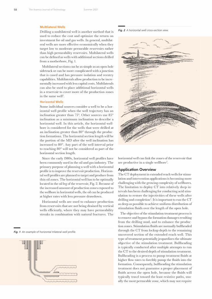
58 The Aramco Journal of Technology Summer 2021
Mul�lateral WellsDrilling a multilateral well is another method that is used to reduce the cost and optimize the return on investment for oil and gas wells. In general, multilat-eral wells are more e�ective economically when they target low to moderate permeable reservoirs rather than high permeability reservoirs. Multilateral wells can be defined as wells with additional sections drilled from a motherbore, Fig. 1.
Multilateral sections can be as simple as an open hole sidetrack or can be more complicated with a junction that is cased and has pressure isolation and reentry capabilities. Multilaterals allow production to be incre-mentally increased with less capital costs. Multilaterals can also be used to place additional horizontal wells in a reservoir to cover more of the production zones in the same well2.
Horizontal Wells Some individual sources consider a well to be a hor-izontal well profile when the well trajectory has an inclination greater than 75°. Other sources use 85° inclination as a minimum inclination to describe a horizontal well. In this article, the horizontal well-bore is considered for the wells that were drilled at an inclination greater than 80° through the produc-tion formations. The horizontal section length will be the portion of the MD after the well inclination has increased to 80°. Any part of the well interval prior to reaching 80° will not be considered as part of the horizontal section length.
Since the early 1980s, horizontal well profiles have been commonly used in the oil and gas industry. The primary purpose of planning a well with a horizontal profile is to improve the reservoir production. Horizon-tal well profiles are planned to target and produce from thin oil zones. The horizontal well has to be optimally located in the oil leg of the reservoir, Fig. 2. Because of the increased amount of production zones exposed to the wellbore in horizontal wells, the oil can be produced at higher rates with less pressure drawdown.
Horizontal wells are used to enhance production from reservoirs that are not being drained by vertical wells e�ciently, where they may have permeability streaks in combination with natural fractures. The
horizontal well can link the zones of the reservoir that are productive in a single wellbore2.
Applica�on OverviewThe CT deployment in extended reach wells for stimu-lation and intervention applications is becoming more challenging with the growing complexity of wellbores. The limitation to deploy CT into relatively deep in-tervals has been challenging for conducting acid stim-ulation to restore the injectivities of these wells after drilling and completion3. It is important to run the CT as deep as possible to achieve uniform distribution of stimulation �uids over the length of the open hole.
The objective of the stimulation treatment process is to remove and bypass the formation damages resulting from the drilling mud, and to enhance the produc-tion zones. Stimulation �uids are normally bullheaded through the CT from lockup depth to the remaining uncovered section of the extended reach well. This type of treatment potentially jeopardizes the ultimate objective of the stimulation treatment. Bullheading is typically conducted after multiple attempts to run the CT to the desired depth of stimulation treatment. Bullheading is a process to pump treatment �uids at higher �ow rates to forcibly pump the �uids into the formation. Consequently, bullheading the stimulation treatment does not guarantee a proper placement of �uids across the open hole, because the �uids will typically travel toward the least resistive paths, usu-ally the most permeable zone, which may not require
Fig. 1 An example of horizontal trilateral well profile.
Fig. 2 A horizontal well cross-section view.
49108araD9R1.indd 58 6/18/21 3:23 PM

59 The Aramco Journal of TechnologySummer 2021
any treatment4. Maximizing the reach of the open hole interval is essential for a successful stimulation treatment.
The challenges related to limited CT reach for stim-ulation �uids placement have been widely addressed through the use of various techniques. These tech-niques include the use of nitrogen through the CT to make it lighter and more buoyant, the use of larger diameter CT, the use of friction reducing �uids, and the use of friction reduction tools.
Challenges
One of the most significant problems related to ex-tended reach or horizontal wells are frictional force and drag, which are caused by the friction between the CT and the walls of the wellbore. The magnitude of the drag is determined by the extent with which the CT contacts the borehole and the friction between the wall and the CT.
The friction coe�cient depends on the type of �uid in the wellbore and the roughness of the wellbore’s walls. The cased hole will mostly show a lower fric-tion coe�cient than the open hole and a higher �uid density will yield a higher friction coe�cient due to the presence of higher solid contents.
One of the challenges during intervention for CT is reaching the maximum depth in extended reach wells. The factors that contribute to this challenge are well depth, horizontal lateral length, open hole interval, drag/friction between the wellbore and the CT, hole size, and the limitation of the CT size, due to the minimum restriction in the wellbore. As the depth of the well increases, the friction between the CT and wellbore increases. This increased friction first induces sinusoidal buckling that progresses to helical buckling as the CT is being pushed further in the wellbore.
This helical buckling ultimately leads to lockup, where no further advancement to the depth can be achieved, Fig. 3. The helical buckling plays the most important part in the development of the lockup stage when it is attempted to run the CT deeper in the well. Therefore, delaying of helical buckling by utilizing a friction reduction system to reduce the friction between the wellbore and the CT will prevent lockup in the early stages, enabling the CT to reach the desirable deeper depths.
The targeted wells had higher friction coe�cients due
to the presence of denser �uids or components such as tar and asphaltenes. This refers to the increased resis-tance for the CT to run in such wellbore conditions. Another major challenge is to reach target depth while running a smaller size of CT due to the minimum restriction in the wellbore. Bigger open hole sizes, i.e., 6⅛” and 8½”, also contribute to the struggle to reach targeted depths to conduct acid stimulation operation. The presence of hydrogen sulfide also limits the use of available resources and technologies to address the challenges for extended reach application.
Long multilateral and horizontal sections are the other challenges associated with the CT runs. A larg-er open hole size with the open hole section ranging from 8,000 ft to 9,500 ft adds to the complication of deploying the CT to the maximum targeted depth.
HDAT Technology PrincipleIn such applications, the amount of friction and drag will limit the reachability of the CT to the final target well depth. The cumulative friction and drag will cause the CT to buckle at early stages, contributing to lockup. The buckling state of the CT string can be eliminated or delayed by reducing the induced friction due to the CT string and wellbore contact area.
The HDAT is used as a friction reduction tool to reduce the drag and frictional forces between the well-bore and the CT string while running in the hole. The HDAT working principle is to break the static friction and convert it to a lower amount of friction in a dynamic form. This is accomplished by generating continuous pressure pulses while pumping �uid through the tool. The CT string will be reacting with these traveling excitation waves as continuous mechanical motions. The friction will be reduced in the part of the string where the pressure waves are traveling through the system. This friction reduction mechanism will result in improved weight transfer, faster CT tripping in speed, delayed CT buckling occurrence, and extending the CT reach.
The HDAT consists of two main sections: a power section and a valve assembly. The tool is activated by pumping a �uid through it and both tool sections work together converting the hydraulic energy to produce a series of pressure �uctuation waves that travel up and down in the coil.
When the pumped �uid is passing through the tool, the rotor inside the power section rotates. The rotor’s
Fig. 3 How helical buckling of the CT can lead to lockup development.
Lockup
49108araD9R1.indd 59 6/16/21 9:07 PM

60 The Aramco Journal of Technology Summer 2021
rotation, which occurs at a frequency proportional to the �ow rate, will drive the oscillation valve plate in a continuous dynamic track relative to a stationary valve plate. This movement creates cyclic variation of the �uid’s total �ow area. This total �ow area variation initiates a series of repetitive pressure pulses that are carried by the pumped �uid, Fig. 4.
Demand for Performance and Op�miza�on The HDAT has been run to aid extending the reach and to improve CT placement in the reservoir in wells that have open hole intervals ranging from 3,500 ft MD to 9,500 ft MD lengths, and with 12,000 ft to 25,000 ft target depths.
Because of the challenges experienced to extend the CT reach, multiple application studies and laboratory prototype trial tests were implemented. This resulted in three design improvement phases; all three gener-ations were introduced to optimize the results and to achieve the main objectives of extending the reach.
The main objective of the three tool design genera-tions was to meet the latest application challenges. This objective was achieved, resulting in a tool with higher energy output, greater reduction of friction forces, a streamlined manufacturing process, an increased torsional and tensile capacities, and overall increased tool reliability.
HDAT: First-Genera�on
The first-generation of the HDAT design technology was built based on the legacy tool structure with more enhanced friction reduction rates. The first-generation of the HDAT has a single lobe power section config-uration that delivers high frequency rates — up to 18 Hz. The valve assembly section was redesigned in a way to allow setting the tool with a wider range of pressure pulse values and more controlled performance options. Based on the application requirements, the HDAT was adjusted to generate the desired pressure waves at the specific pumped �ow rates.
HDAT: Second-Genera�on
The development continued, resulting in the introduc-tion of the second-generation of the HDAT with the
purpose of providing more energized technology to aid in extending the CT reach in the same application.
The power section was reconfigured with a multi-lobe design in the second-generation, which facilitated higher �ow rates with the same di�erential pressure and pressure pulses. The multi-lobe power section design enables slower rotor rotational speed at the same �ow rates, improving performance by allowing better pressure pulse frequency control and optimum operation of the valve system. The valve assemblies were designed to create higher excitation that work on a longer length of the CT string.
HDAT: Third-Genera�on
With the growing complexity of wellbores, the third-generation of the HDAT was introduced to address the challenges of long laterals and extreme doglegs. The newly designed third-generation tool’s stronger and more reliable design was the result of the data gathered and experience gained from runs of the previous generations.
The third-generation of the HDAT tool was designed after full research and observation of the tool’s behav-ior/performance with di�erent activation �ow rates, variable di�erential pressure across the system, as well as with di�erent cyclic wave speed.
During the design phase, a series of prototypes and testing regimes were implemented to enhance the op-timization process.
The resulting tool design incorporated a multi-lobe power section configuration and a redesigned valve assembly, which reduced the di�erential pressure across the tool, and increased while increasing e�ciency and power. The new tool design was allowed to customize the parameters to fit the application requirements, achieving up to 100% more energy output compared to the previous generations.
Research and Development Laboratory Tes�ng
As part of the in-house research and development of the technology, a horizontal test rig was used to per-form multiple cycles of di�erent designs to achieve the desired functionality of the tool.
The horizontal test rig, Fig. 5, was set to simulate the
Saudi Aramco: Company General Use
Fig. 3 How helical buckling of the CT can lead to lockup development.
Fig. 4 The HDAT schematic and cyclic pressure waves signature.
Fig. 5 The horizontal test rig equipment.
Lockup
Fig. 4 The HDAT schematic and cyclic pressure waves signature.
49108araD9R1.indd 60 6/16/21 9:07 PM

61 The Aramco Journal of TechnologySummer 2021
closest possible conditions and environment to that in the real-time application. In testing the horizontal test rig, the tool was run in the string and activated by pumping �uid through the system. Several measure-ment devices were connected to monitor the output parameters, which were used to compare the test results of each tool’s design improvement and to verify the design modifications.
A closed test loop with 20,000 ft of metallic tubu-lar, Fig. 6, was attached to the horizontal test rig unit and oriented horizontally to simulate the challenges that the tool would be run in. This allowed for a bet-ter understanding of the theory and provided wider capabilities for the research and development process.
Service Center Tes�ngWith every new tool assembly, a function test of the tool is conducted using a dynamometer, Fig. 7a. During the
Saudi Aramco: Company General Use
Fig. 3 How helical buckling of the CT can lead to lockup development.
Fig. 4 The HDAT schematic and cyclic pressure waves signature.
Fig. 5 The horizontal test rig equipment.
Lockup
Fig. 5 The horizontal test rig equipment.
Fig. 6 The closed research and development test loop.
Fig. 7 The dynamometer stand (a), and the dynamometer parameter control panel (b).
Saudi Aramco: Company General Use
Fig. The closed research and development test loop.
Fig. The dynamometer stand a and the dynamometer parameter control panel b .
(a) (b)
49108araD9R1.indd 61 6/18/21 3:07 PM

62 The Aramco Journal of Technology Summer 2021
0%
20%
40%
60%
80%
100%
1 1 1 2 1 3 1 4 1 5 1 6 1 7 1 8 1 9 1 100
5,000
10,000
15,000
20,000
25,000
30,000
MD
(ft)
OH SectionLength (ft)
Casing ShoeDepth (ft)
Open HoleCoverage withHDAT
Fig. 8 The performance of the first-generation HDAT from relatively low to high challenging applications.
0%
20%
40%
60%
80%
100%
1 1 1 2 1 3 1 4 1 5 1 6 1 7 1 8 1 9 1 100
2,000
4,000
6,000
8,000
10,000
12,000
14,000
16,000
18,000
20,000
MD
(ft)
OH SectionLength (ft)
Casing ShoeDepth (ft)
Open HoleCoveragewith HDAT
Fig. 9 The performance of the first-generation HDAT, as the tool enabled the CT to cover an average 83% open hole interval in 10 runs.
10,12511,600
3,384
3,574
89%
100%
0%
20%
40%
60%
80%
100%
G2-M1 G2-M20
2,000
4,000
6,000
8,000
10,000
12,000
14,000
16,000
MD
(ft)
OH SectionLength (ft)
Casing ShoeDepth (ft)
Open HoleCoveragewith HDAT
Fig. 10 The HDAT exhibited notable performance covering 89% and 100% of the open hole interval, respectively, in two runs.
49108araD9R1.indd 62 6/16/21 9:07 PM

63 The Aramco Journal of TechnologySummer 2021
8,576 8,806 8,806
8,417 8,5548,554 8,804
30% 47%
100%
0%
20%
40%
60%
80%
100%
G2-K1 G2-K2 G2-K30
2,000
4,000
6,000
8,000
10,000
12,000
14,000
16,000
18,000
20,000
MD
(ft)
OH SectionLength (ft)
Casing ShoeDepth (ft)
Open HoleCoveragewith HDAT
Fig. 11 The performance development for the three runs using the second-generation HDAT.
10,820 11,45013,285 12,758 12,470
14,748
20,277
3,563 3,910
3,292 4,079 4,530
3,002
4,628
100% 100% 100% 100% 100% 100%96%
0%
20%
40%
60%
80%
100%
G3-M1 G3-M2 G3-M3 G3-M4 G3-M5 G3-M6 G3-M70
5,000
10,000
15,000
20,000
25,000
30,000
MD
(ft)
OH SectionLength (ft)
Casing ShoeDepth (ft)
Open HoleCoveragewith HDAT
Fig. 12 The third-generation of the HDAT delivered exceptional performance in covering 100% of the open hole in most of the runs while reaching more than 24,500 ft MD in one of the runs.
9,060 8,324 9,000 9,150 8,585 8,300 8,874
7,852 8,974 8,376 8,287 8,856 9,200 8,710
96%96%100% 100% 100% 100% 100% 100%
0%
20%
40%
60%
80%
100%
G3-K1 G3-K2 G3-K3 G3-K4 G3-K5 G3-K6 G3-K70
2,000
4,000
6,000
8,000
10,000
12,000
14,000
16,000
18,000
20,000
MD
(ft)
OH SectionLength (ft)
Casing ShoeDepth (ft)
Open HoleCoveragewith HDAT
Fig. 13 The consistent high performance for the third-generation HDAT, overcoming the challenge of a long lateral and big open hole size while reaching target depth in most of the runs.
49108araD9R1.indd 63 6/16/21 9:07 PM

64 The Aramco Journal of Technology Summer 2021
dynamometer test, the tool is assembled into a closed loop �ow system that continuously pumps through the tool at various controlled �ow rates. The parameters measured during the dynamometer test allow for opti-mal setup of the tool, which is not achievable without the dynamometer parameter control panel, Fig. 7b.
First-Genera�on Runs The first-generation of the HDAT was designed con-sidering the need for reaching target depths with a relatively less challenging application at that time. The tool still achieved the desired results, meeting the target depth in most of the runs. Figure 8 shows the perfor-mance of the first-generation tool from relatively low to high challenging applications. The tool achieved average a 98% open hole coverage in the first five runs. But as the well depth increased with the length of the open hole section, the need for a more robust tool was realized to meet the target depth.
Figure 9 shows the performance of the first-generation tool, as the tool enabled the CT to cover an average 83% open hole interval in 10 runs. While the application became more challenging, it was required to optimize the tool to work for more challenging applications.
Second-Genera�on Runs The HDAT exhibited notable performance covering 89% and 100% of the open hole interval, respectively, in two runs, Fig. 10. Consequently, the slow running in hole speed for the CT recognized the requirement for a stronger tool that could generate a higher energy and increase the CT running in hole speed.
Figure 11 shows performance development for the three runs using the second-generation HDAT. The chart shows an average 39% open hole coverage in the first two runs, and 100% open hole coverage in the third run for the similar interval.
Third-Genera�on Runs The third-generation of the HDAT delivered excep-tional performance in covering 100% of the open hole in most of the runs while reaching more than 24,500 ft MD in one of the runs, Fig. 12. During these runs, the third-generation HDAT improved weight transfer and run in hole speed as compared to the previous generations.
Figure 13 shows the consistent high performance for the third-generation HDAT, overcoming the challenge of a long lateral and big open hole size while reaching target depth in most of the runs.
ConclusionsMany challenges were experienced during the execu-tion of the acid stimulation jobs that limited the CT reach. Field research and lab testing were conducted to optimize the performance and achieving the ob-jectives. The HDAT went through a series of design improvements that helped to address the application’s challenges.
The latest HDAT was redesigned to improve perfor-mance and reliability to achieve an e�ective matrix acid stimulation treatment. The newly developed HDAT
has repeatedly proven to be an e�cient solution for CT extended reach applications. The recent consis-tent and exceptional performance is the testimony that the tool has overcome the challenges associated with extended reach and frictional forces. The tool achieved total depth in most of the runs to e�ectively acid stimulate the pay zones.
AcknowledgmentsThis article was presented at the virtual SPE/ICoTA Virtual Well Intervention Conference and Exhibition, March 22-25, 2021.
References1. Bhalla, K.: “Coiled Tubing Extended Reach Technol-
ogy,” SPE paper 30404, presented at the SPE Oshore Europe Conference, Aberdeen, U.K., September 5-8, 1995.
2. Carden, R.S. and Grace, R.D.: Horizontal and Directional Drilling, Petroskills LLC, 2007, 409 p.
3. Al-Meshal, F., Sabut, B., Bawaked, W., Beheiri, F., et al.: “Enhanced Coiled Tubing Intervention Practices on Extended Reach Open Hole Completion in a Field in Saudi Arabia,” SPE paper 136946, presented at the SPE/DGS Saudi Arabia Section Technical Symposium and Exhibition, al-Khobar, Saudi Arabia, April 4-7, 2010.
4. Al-Najim, A., Zahedi, A., Al-Khonaini, T., Al-Sharqawi, A.I., et al.: “A New Methodology for Stimulation of a High Water Cut Horizontal Oil Well through the Com-bination of a Smart Chemical System with Real-Time Temperature Sensing: A Case Study of South Umm Gudair Field, PZ Kuwait,” SPE paper 154387, presented at the SPE/ICoTA Coiled Tubing and Well Intervention Conference and Exhibition, The Woodlands, Texas, March 27-28, 2012.
49108araD9R1.indd 64 6/16/21 9:07 PM

65 The Aramco Journal of TechnologySummer 2021
Hussain A. Al-Saiood
B.S. in Petroleum Engineering, University of Oklahoma
Hussain A. Al-Saiood is a Produ�ion Engineer working in the Manifa Produ�ion Engineering Division of Saudi Aramco’s Northern Area Produ�ion Engineering and Well Services Department. He joined Saudi Aramco as a Petro-leum Engineer, but has also held several drilling and reservoir engineering posions, covering several onshore and o�shore �elds. Hussain’s areas of interest include rigless intervenon with coiled tubing (CT), wireline, and hydraulic workover operaons.
Throughout his career, he has worked on mulple proje�s, including the change out of ele�ric submersible pumps ulizing the hydraulic workover unit, and developing downhole equipment to enhance the CT reach, i.e., CT tra�ors and pulsaon tools, in extended reach wells for smulaon and logging applicaons.
Hussain received his B.S. degree in Petroleum Engineering from the University of Oklahoma, Norman, OK.
Laurie S. Duthie
M.S. in Petroleum Engineering, University of New South Wales
Laurie S. Duthie joined Saudi Aramco in 2011 as a Petroleum Engineer and works in the Manifa Produ�ion Engineering Unit of the Northern Area Produ�ion Engineering Department. His focus is on the development and produ�ion of a large o�shore �eld in the Northern Area.
Laurie started his career in 1986 working on o�shore installaons in the U.K. North Sea as a Field Engineer in well tesng and wireline operaons. He has a strong background in reservoir surveillance, well intervenon, acid
smulaon, well tesng, compleons, and cased hole logging. Laurie has gained extensive operaonal experience in diverse remote onshore and o�shore locaons — across Africa, Central Asia, the former Soviet Union, Asia Paci�c, and in the Middle East region — since 2009.
In 2005, Laurie received his M.S. degree in Petroleum Engineering from the University of New South Wales, Sydney, Australia.
Ahmed H. Albaqshi
B.S. in Applied Mechanical Engineering, King Fahd University of Petroleum and Minerals
Ahmed H. Albaqshi joined Naonal Oilwell Varco in Dhahran, Saudi Arabia in 2014 as a Drilling Soluons Engineer and joined the Internaonal Development Training Program with an intensive focus on drilling and intervenon operaons. During his training, Ahmed worked with produ� design engineer-ing, operaons technical support, and manufa�uring teams in Dubai, Aberdeen, and Houston.
Ahmed’s interests are in drilling, �shing and coiled tubing tools and accessories design and
opmizaon in the oil and gas industry. He is currently involved in downhole tools operaon planning, analyzing, and �eld execuon in Saudi Arabia’s oil and gas operaons.
Ahmed is a member of the Society of Petroleum Engineers (SPE) and a�ively parcipates in di�erent workshops and conferences.
He received his B.S. degree in Applied Mechanical Engineering from King Fahd University of Petroleum and Minerals (KFUPM), Dhahran, Saudi Arabia.
Muhammad Ahsan
B.S in Petroleum and Gas Engineering, University of Engineering and Technology
Muhammad Ahsan joined Naonal Oilwell Varco in 2019 as a Sales Engineer for coiled tubing (CT) and intervenon tools. He has more than 7 years of experience in CT and smulaon operaons in mulple locaons.
Muhammad is handling the CT downhole tools account and provides technical support for
CT and well intervenon operaons in Saudi Arabia.
He received his B.S degree in Petroleum and Gas Engineering from the University of Engineering and Technology (UET), Lahore, Pakistan.
About the Authors
49108araD9R1.indd 65 6/16/21 9:07 PM

66 The Aramco Journal of Technology Summer 2021
Saudi Aramco continued to accelerate the growth of its patent portfolio in 2020, receiving 1,588 granted patents globally, including 683 from the U.S. Patent & Trademark O�ce, a significant increase on the 524 patents granted in 2019, Fig. 1. Approximately 62% of these U.S. granted patents origi-nated from new ideas, with the remainder from continuation or divisional of previous patents.
Our Upstream business continues to receive the largest portion of granted U.S. patents with 63%. This is driven by the technology domains of Drilling, Production and Reservoir Engineering.
A total of 1,192 new patent filings were made with 79% originating from new ideas. Our Upstream business also leads new filings with 65%. Analysis of the technology domains shows carbon manage-ment within the top 10 for new filed patents.
Figure 2 compares the 2020 U.S. granted patents among international oil companies and shows Saudi Aramco having a leading position with 683 granted patents. ExxonMobil follows with 367, followed by Shell with 121.
Figure 3 shows the top technology domain distribution of the granted U.S. patents in 2020 for Saudi Aramco with upstream technology domains of drilling and production leading.
A New Aramco Record in PatentsMichael J. Ives
Fig. 1 Saudi Aramco �led and granted patent numbers (2015-2020).
177
134
6762 59
3227
17 15 15 15 14
rillin
r dtin
ei al
eer
irnr
etrnte
rit
e inin
radin
Ge
i
ne
tati nal
delin ti
ilGa
reatent
Gel
Fig. 3 Saudi Aramco’s 2020 U.S. granted patents by technology domain.
150209
255
335
524
683
271323
590637
1048
1192
2015 2016 2017 2018 2019 2020
Granted Filed
46100 102 121
367
683683
Fig. 2 A comparison of the U.S. granted patents in 2020 between the leading interna�onal oil companies.
49108araD10R1.indd 66 6/16/21 9:11 PM

67 The Aramco Journal of TechnologySummer 2021
2020 Granted Patents
Polymer Blended Membranes for Sour Gas Separa�on
Granted Patent: U.S. Patent 10,525,406, Grant Date: January 7, 2020Junyan Yang
Processing Systems for Produced Water and Methods for Recovering Organic Compounds from the Produced Water
Granted Patent: U.S. Patent 10,525,415, Grant Date: January 7, 2020Regis Vilagines and Guillaume Raynel
Gellable, Non-Aqueous Oil Well Treatment Fluids Comprising Elastomeric Maleic Anhydride Copolymers
Granted Patent: U.S. Patent 10,526,458, Grant Date: January 7, 2020B. Raghava Reddy and Matthew G. Hil�ger
An�-Bit Balling Drilling Fluids, and Methods of Making and Use Thereof
Granted Patent: U.S. Patent 10,526,520, Grant Date: January 7, 2020 Abdullah S. Al-Yami, Ahmed A. Bahamdan, Saleh A. Haidary, Vikrant B. Wagle, Hussain Al-Bahrani, Ali M. Al-Safran, Nasser Al-Hareth and Abdulla H. Awadh
Invert Emulsion Drilling Fluids with Fatty Acid and Fatty Diol Rheology Modi�ers
Granted Patent: U.S. Patent 10,526,521, Grant Date: January 7, 2020Vikrant B. Wagle and Abdullah S. Al-Yami
Cement Having Cross-Linked PolymersGranted Patent: U.S. Patent 10,526,522, Grant Date: January 7, 2020Elizabeth Q. Contreras
Settable, Form-Filling Loss Circula�on Control Composi�ons Comprising In Situ Foamed Non-Hydraulic Sorel Cement Systems and Method of Use
Granted Patent: U.S. Patent 10,526,524, Grant Date: January 7, 2020B. Raghava Reddy
Systems and Methods for Cracking Hydrocarbon Streams U�lizing Cracking Catalysts
Granted Patent: U.S. Patent 10,526,546, Grant Date: January 7, 2020Anas Aqeeli and Aaron Akah
Upgrading of Heavy Oil for Steam Cracking Process
Granted Patent: U.S. Patent 10,526,552, Grant Date: January 7, 2020Ki-Hyouk Choi, Bander M. Alotaibi, Mazin M. Fathi and Muneef F. Alqarzouh
Chara�erizing Crude Oil Using Laser Induced Ultraviolet Fluorescence Spe�roscopy
Granted Patent: U.S. Patent 10,527,546, Grant Date: January 7, 2020Omer R. Koseoglu, Adnan Al-Hajji and Ezzat M. Hegazi
Dual Catalyst System for Propylene Produ�ion
Granted Patent: U.S. Patent 10,532,347, Grant Date: January 14, 2020Sohel Shaikh, Sulaiman S. Al-Khattaf, Arudra Palani, Tazul I. Bhuiyan, Mohammad N. Akhtar, Abdullah M. Aitani and Mohammed A. Al-Yami
Method for Traversing Surface with Magne�c Omni-Wheel
Granted Patent: U.S. Patent 10,532,609, Grant Date: January 14, 2020Ali Outa, Brian J. Parrott, Pablo Carrasco Zanini, Fadl H. Abdel La�f and Hassane A. Trigui
Modular Thru-Tubing Subsurface Comple�on Unit
Granted Patent: U.S. Patent 10,533,393, Grant Date: January 14, 2020Muhammad Arsalan and Mohamed N. Noui-Mehidi
Centrifugal Pump with Adap�ve Pump Stages
Granted Patent: U.S. Patent 10,533,558, Grant Date: January 14, 2020Rafael A. Lastra and Chidirim E. Ejim
Nuclear Magne�c Resonance Gas Isotherm Technique to Evaluate Reservoir Rock Wettability
Granted Patent: U.S. Patent 10,533,933, Grant Date: January 14, 2020Hyung T. Kwak and Ahmad M. Al Harbi
Cloud-Based Machine Learning System and Data Fusion for the Predi�ion and Dete�ion of Corrosion under Insula�on
Granted Patent: U.S. Patent 10,533,937, Grant Date: January 14, 2020Ayman Amer, Ali Al Shehri, Ser Nam Lim, Mustafa Uzunbas, Ahmad Aldabbagh, Muhammad Ababtain and Vincent Cunningham
Systems and Methods for Mapping Hydrocarbon Reservoirs Using Ele�romagne�c Transmissions
Granted Patent: U.S. Patent 10,534,103, Grant Date: January 14, 2020Howard K. Schmidt, Jesus M. Felix-Servin and Erika S. Ellis
Method and Apparatus for Promo�ng Droplets Coalescence in Oil Con�nuous Emulsions
Granted Patent: U.S. Patent 10,537,830, Grant Date: January 21, 2020Abderrazak Traidia, Sebas�en A. Duval, Simone Less and Regis Vilagines
Prote�ion System for Sulfur Storage Apparatus
Granted Patent: U.S. Patent 10,538,383, Grant Date: January 21, 2020Mohammed Al-Mehthel, Saleh Al-Idi, Mohammed Maslehuddin, Mohammed Shameem and Mohammed Ibrahim
Butyl Ionomer BlendsGranted Patent: U.S. Patent 10,538,650, Grant Date: January 21, 2020Dana K. Adkinson and Jon Bielby
Development of An�-Bit Balling FluidsGranted Patent: U.S. Patent 10,538,692, Grant Date: January 21, 2020Abdullah S. Al-Yami, Ahmed A. Bahamdan, Saleh A. Haidary, Vikrant B. Wagle, Hussain Al-Bahrani, Ali M. Al-Safran, Nasser Al-Hareth and Abdulla H. Awadh
Stabiliza�on of Petroleum Surfa�ants for Enhancing Oil Recovery
Granted Patent: U.S. Patent 10,538,693, Grant Date: January 21, 2020Yun Chang
Determining a Mud Weight of Drilling Fluids for Drilling through Naturally Fra�ured Forma�ons
Granted Patent: U.S. Patent 10,539,014, Grant Date: January 21, 2020Younane Abousleiman, Yanhui Han, Chao Liu and Shawn Rimassa
High-Pressure/High Temperature Dynamic Mul�phase Corrosion Erosion Simulator
Granted Patent: U.S. Patent 10,539,498, Grant Date: January 21, 2020Turki A. Al-Khaldi and Yahya T. Al-Janabi
Systems and Methods for Mapping Hydrocarbon Reservoirs Using Ele�romagne�c Transmissions
Granted Patent: U.S. Patent 10,539,704, Grant Date: January 21, 2020Howard K. Schmidt, Jesus M. Felix-Servin and Erika S. Ellis
Supercri�cal Rea�or Systems and Processes for Petroleum Upgrading
Granted Patent: U.S. Patent 10,543,468, Grant Date: January 28, 2020Ki-Hyouk Choi, Abdullah T. Al-Abdulhadi and Mohammed A. Al-Abdullah
Systems and Methods for Con�guring Field Devices Using a Con�gura�on Device
Granted Patent: U.S. Patent 10,543,594, Grant Date: January 28, 2020Brian J. Parrott and Pablo Carrasco Zanini
Fun�ionalized Copolymer Rubber Containing Nitrile Groups
Granted Patent: U.S. Patent 10,544,234, Grant Date: January 28, 2020Susanna Lieber, Karola Schneiders, Christoph Kins and Werner Obrecht
Methods and Systems for Neutralizing Hydrogen Sul�de during Drilling
Granted Patent: U.S. Patent 10,544,344, Grant Date: January 28, 2020Ossama Sehsah and Ihab Elhabrouk
Flaky Date Fruit CAP for Moderate to Severe Loss Control
Granted Patent: U.S. Patent 10,544,345, Grant Date: January 28, 2020Md Amanullah
Fra�uring Fluids Comprising Alkanolamine Borates as Crosslinkers for Polysaccharides
Granted Patent: U.S. Patent 10,544,347, Grant Date: January 28, 2020B. Raghava Reddy, Feng Liang and Leiming Li
49108araD10R1.indd 67 6/16/21 9:11 PM

68 The Aramco Journal of Technology Summer 2021
Systems and Methods for Sealing a Wellbore
Granted Patent: U.S. Patent 10,544,648, Grant Date: January 28, 2020Vi�or Costa de Oliveira, Ramon Rodriguez and Khaled Abouelnaaj
Mul�phase Flow Meter with Tuning ForkGranted Patent: U.S. Patent 10,544,674, Grant Date: January 28, 2020Brett W. Bouldin, Robert Turner, Frode Hveding and Mohamed N. Noui-Mehidi
Spe�acle Blinds Swinging DeviceGranted Patent: U.S. Patent 10,544,867, Grant Date: January 28, 2020Bandar B. Al-Harbi and Fahad A. Al-Harthi
Flow Line Insert with Indenta�onsGranted Patent: U.S. Patent 10,545,037, Grant Date: January 28, 2020Lahdan F. Al-Faihan
Es�ma�ng Forma�on Proper�es Using Satura�on Pro�les
Granted Patent: U.S. Patent 10,545,105, Grant Date: January 28, 2020Jun Gao, Hyung T. Kwak and Ahmad M. Al Harbi
Distributed Agent to Colle� Input and Output Data along with Source Code for Scien��c Kernels of Single-Process and Distributed Systems
Granted Patent: U.S. Patent 10,545,740, Grant Date: January 28, 2020Mazen A. Al-Hagri
Mul�ple Stage Catalyst System for Self-Metathesis with Controlled Isomeriza�on and Cracking
Granted Patent: U.S. Patent 10,550,048, Grant Date: February 4, 2020Noor A. Sulais, Faisal H. Alshafei, Munir D. Khokhar, Mohammed R. Alalouni and Sohel Shaikh
Acryloyl-Based Copolymers, Terpolymers, and Use as Hydrate Inhibitors
Granted Patent: U.S. Patent 10,550,215, Grant Date: February 4, 2020Khalid Majnouni, Abdullah R. Al-Malki, Mohamed S. Elanany, Manal Al-Eid, Mohammed Al-Daous and Shaikh A. Ali
Sulfur Asphalt in Roo�ng, Damp-Proo�ng and Water Proo�ng
Granted Patent: U.S. Patent 10,550,267, Grant Date: February 4, 2020Mohammed H. Al-Mehthel, Saleh H. Al-Idif, Ibnelwaleed A. Hussein and Hamad I. Al-Abdulwahhab
Encapsulated Nanocomposi�ons for Increasing Hydrocarbon Recovery
Granted Patent: U.S. Patent 10,550,310, Grant Date: February 4, 2020Yun Chang
Encapsulated Nanocomposi�ons for Increasing Hydrocarbon Recovery
Granted Patent: U.S. Patent 10,550,311, Grant Date: February 4, 2020Yun Chang
Oil Recovery Process Using an Oil Recovery Composi�on of Aqueous Salt Solu�on and Dilute Polymer for Carbonate Reservoirs
Granted Patent: U.S. Patent 10,550,312, Grant Date: February 4, 2020Subhash C. Ayirala, Abdulkareem M. Al-So� and Ali A. Yousef
High Temperature Fra�uring Fluids with Nanopar�cles
Granted Patent: U.S. Patent 10,550,314, Grant Date: February 4, 2020Feng Liang, Ghaithan A. Al-Muntasheri and Leiming Li
Downhole Chemical Inje�ion Method and System for Use in ESP Applica�ons
Granted Patent: U.S. Patent 10,550,678, Grant Date: February 4, 2020Jinjiang Xiao and Hattan Banjar
Supercri�cal CO2 Cycle Coupled to Chemical Looping Arrangement
Granted Patent: U.S. Patent 10,550,733, Grant Date: February 4, 2020Mourad Younes, Aadesh Harale and Aqil Jamal
Integrated Ultrasonic Tes�ng and Cathodic Prote�ion Measurement Probe
Granted Patent: U.S. Patent 10,551,296, Grant Date: February 4, 2020Hassane A. Trigui, Sahejad Patel, Ali Outa, Ayman Amer, Fadl H. Abdel La�f, Ameen Obedan and Hamad Al-Saiari
Thermography Image Processing with Neural Networks to Iden�fy Corrosion under Insula�on (CUI)
Granted Patent: U.S. Patent 10,551,297, Grant Date: February 4, 2020Ayman Amer, Ali Alshehri, Brian J. Parrott and Muhammad Sarraj
Geochemical Water Analysis Element Concentra�on Predi�ion for Oil Field Waters
Granted Patent: U.S. Patent 10,551,367, Grant Date: February 4, 2020Ibrahim El-Zefzafy and Mohammed H. Al-Hanabi
Apparatus and Methods of Evalua�ng Rock Proper�es while Drilling Using Acous�c Sensors Installed in the Drilling Fluid Circula�on System of a Drilling Rig
Granted Patent: U.S. Patent 10,551,516, Grant Date: February 4, 2020Yunlai Yang
Wellbore Non-Retrieval Sensing SystemGranted Patent: U.S. Patent 10,551,800, Grant Date: February 4, 2020Bodong Li, Chinthaka P. Gooneratne and Shaohua Zhou
Capillary Pressure Analysis for Petrophysical Sta�s�cal Modeling
Granted Patent: U.S. Patent 10,552,553, Grant Date: February 4, 2020David Forsyth, Yusuf Pamukcu and Nasr-Eddine Hammou
Integrated PCS Fun�ional Competency Assessment
Granted Patent: U.S. Patent 10,554,625, Grant Date: February 4, 2020Fouad M. Al-Khabbaz
System for Tail Gas Treatment of Sulfur Recovery Units
Granted Patent: U.S. Patent 10,556,805, Grant Date: February 11, 2020Mourad Younes, Maytham Musawi and Aadesh Harale
Cement Slurries, Cured Cement and Methods of Making and Use of These
Granted Patent: U.S. Patent 10,556,829, Grant Date: February 11, 2020B. Raghava Reddy
Diluent for the Produ�ion of Butyl RubberGranted Patent: U.S. Patent 10,556,977, Grant Date: February 11, 2020Steven J. Teertstra and Gilles Arsenault
Nanosilica Dispersion Well Treatment FluidGranted Patent: U.S. Patent 10,557,071, Grant Date: February 11, 2020Vikrant B. Wagle and Abdullah S. Al-Yami
Loss Circula�on Composi�ons (LCM) Having Portland Cement Clinker
Granted Patent: U.S. Patent 10,557,076, Grant Date: February 11, 2020B. Raghava Reddy
Systems and Methods for Pipe Concentricity, Zonal Isola�on, and Stuck Pipe Preven�on
Granted Patent: U.S. Patent 10,557,317, Grant Date: February 11, 2020Abdulaziz S. Al-Qasim and Ahmed Y. Bukhamseen
Systems and Methods for Stuck Pipe Mi�ga�on
Granted Patent: U.S. Patent 10,557,326, Grant Date: February 11, 2020Abdulaziz S. Al-Qasim, Raed A. Alouhali and Sunil L. Kokal
Interchangeable Wellbore Cleaning Modules
Granted Patent: U.S. Patent 10,557,330, Grant Date: February 11, 2020Vi�or Costa de Oliveira, Mario Rivas, Khaled Abouelnaaj and Ossama Sehsah.
Es�ma�ng Measures of Forma�on Flow Capacity and Phase Mobility from Pressure Transient Data under Segregated Oil and Water Flow Condi�ons
Granted Patent: U.S. Patent 10,557,333, Grant Date: February 11, 2020Hasan A. Nooruddin and Noor M. Anisur Rahman
Flow Meter Well ToolGranted Patent: U.S. Patent 10,557,334, Grant Date: February 11, 2020Rafael A. Lastra
49108araD10R1.indd 68 6/16/21 9:11 PM

69 The Aramco Journal of TechnologySummer 2021
Downhole Centrifugal Separa�on and Removal of Sand from Wells Using Progressing Cavity Pump
Granted Patent: U.S. Patent 10,557,337, Grant Date: February 11, 2020Muhammad Ayub and Rafael A. Lastra Melo
Systems and Methods to Predi� and Inhibit Broken-Out Drilling-Induced Fra�ures in Hydrocarbon Wells
Granted Patent: U.S. Patent 10,557,345, Grant Date: February 11, 2020Mohammed S. Ameen
Locally A�uated Par�al Stroke Tes�ng System
Granted Patent: U.S. Patent 10,557,564, Grant Date: February 11, 2020Fawaz A. Al-Sahan
Flexible Strap Antenna Arrays for Tank Volume Calibra�on and Resonance Frequency Shi� Measuring Methods Using Same
Granted Patent: U.S. Patent 10,557,698, Grant Date: February 11, 2020Brian J. Parrott, Ali Alshehri and Ayman Amer
Alterna�ng Magne�c Field Flow Meters with Embedded Quality Assurance and Control
Granted Patent: U.S. Patent 10,557,730, Grant Date: February 11, 2020Fouad M. Alkhabbaz and Maatoug Al-Maatoug
Modeling Angle Domain Common Image Gathers from Reverse Time Migra�on
Granted Patent: U.S. Patent 10,557,954, Grant Date: February 11, 2020Thierry-Laurent D. Tonellot and Vincent Eenne
Logging Tool with Ele�ric Dipole Source and Magne�c Sensor for Forward and Lateral Imaging
Granted Patent: U.S. Patent 10,557,961, Grant Date: February 11, 2020Teruhiko Hagiwara
Method for Measurement of Hydrocarbon Content of Tight Gas Reservoirs
Granted Patent: U.S. Patent 10,557,962, Grant Date: February 11, 2020Jin-Hong Chen, Stacey M. Althaus, Daniel T. Georgi and Hui-Hai Liu
Dire�ional Sensi�ve Fiber Op�c Cable Wellbore System
Granted Patent: U.S. Patent 10,558,105, Grant Date: February 11, 2020Damian P. San-Roman-Alerigi and Frode Hveding
Role-Based Locking System for Plants Unattended Premises
Granted Patent: U.S. Patent 10,559,146, Grant Date: February 11, 2020Fouad M. Alkhabbaz, Hussain Al-Salem, Zakarya A. Abu Al Saud and Nabil Ouchn
High Temperature Downhole Power Genera�ng Device
Granted Patent: U.S. Patent 10,560,038, Grant Date: February 11, 2020Chinthaka P. Gooneratne, Bodong Li and Shaohua Zhou
Harves�ng Energy from Fluid FlowGranted Patent: U.S. Patent 10,560,039, Grant Date: February 11, 2020Talha J. Ahmad, Muhammad Arsalan, Michael J. Black and Mohamed N. Noui-Mehidi
Harves�ng Energy from Fluid FlowGranted Patent: U.S. Patent 10,560,040, Grant Date: February 11, 2020Talha J. Ahmad, Muhammad Arsalan, Michael J. Black and Mohamed N. Noui-Mehidi
Methods of Using Drilling Fluid Composi�ons with Enhanced Rheology
Granted Patent: U.S. Patent 10,563,110, Grant Date: February 18, 2020Hussain Al-Bahrani, Abdullah S. Al-Yami, Ali M. Al-Safran and Abdulaziz Alhelal
Removal of Barite Weighted MudGranted Patent: U.S. Patent 10,563,113, Grant Date: February 18, 2020Mubarak A. Al-Dhufairi and Saif A. Al-Thabi
Methods for Producing Seawater-Based, High Temperature Viscoelas�c Surfa�ant Fluids with Low Scaling Tendency
Granted Patent: U.S. Patent 10,563,119, Grant Date: February 18, 2020Leiming Li, Feng Liang and Tao Chen
Method for Op�mizing Catalyst Loading for Hydrocracking Process
Granted Patent: U.S. Patent 10,563,138, Grant Date: February 18, 2020Omer R. Koseoglu, Adnan Al-Hajji, Hendrik Muller, Masaru Ushio and Koji Nakano
Conversion of Crude Oil to PetrochemicalsGranted Patent: U.S. Patent 10,563,141, Grant Date: February 18, 2020Lianhui Ding, Essam Sayed, Duhaiman U. Al-Yami, Abdennour Bourane, Alberto L. Ballesteros and Ibrahim A. Abba
Colle�ing Drilling MicrochipsGranted Patent: U.S. Patent 10,563,469, Grant Date: February 18, 2020Mohammad S. Al-Badran and Bodong Li
Colle�ing Drilling MicrochipsGranted Patent: U.S. Patent 10,563,470, Grant Date: February 18, 2020Mohammad S. Al-Badran and Bodong Li
Sealing a Por�on of a WellboreGranted Patent: U.S. Patent 10,563,475, Grant Date: February 18, 2020Shaohua Zhou
Thru-Tubing Retrievable Subsurface Comple�on System
Granted Patent: U.S. Patent 10,563,478, Grant Date: February 18, 2020Muhammad Arsalan and Mohamed N. Noui-Mehidi
Determining a Rock Forma�on ContentGranted Patent: U.S. Patent 10,563,504, Grant Date: February 18, 2020Anas Al-Marzoug
Flow Distribu�on Device and MethodGranted Patent: U.S. Patent 10,563,527, Grant Date: February 18, 2020Farooq N. Al-Jwesm
Rotary Conta�or for Vehicle Carbon Dioxide Capture
Granted Patent: U.S. Patent 10,563,555, Grant Date: February 18, 2020Esam Z. Hamad
Tool-Less Spring Attachment to C-Channel and Method of Using Same
Granted Patent: U.S. Patent 10,563,686, Grant Date: February 18, 2020Brian J. Parrott, Ali Shehri and Pablo Carrasco Zanini
Analyzing Drilling Fluid Rheology at a Drilling Site
Granted Patent: U.S. Patent 10,564,083, Grant Date: February 18, 2020Hermann F. Spoerker
Apparatus and Method for Nondestru�ively Inspe�ing Fiberglass and Nonmetallic Pipes
Granted Patent: U.S. Patent 10,564,108, Grant Date: February 18, 2020Ahmed S. Al-Omari
Systems and Methods for Core Data Shi�ingGranted Patent: U.S. Patent 10,564,109, Grant Date: February 18, 2020Marwah Al Ismail, Mokhles Mezghani and Abdullah Qasem
Quan�fying Organic and Inorganic Sulfur Components
Granted Patent: U.S. Patent 10,564,142, Grant Date: February 18, 2020Harry D. Oduro
Processing Methodology for Full Waveform Sonic Wave�eld Separa�on
Granted Patent: U.S. Patent 10,564,304, Grant Date: February 18, 2020Xuekai Sun, Christopher Ayadiuno and Carlos Planchart
Membrane-Based Process for Butanols Produ�ion from Mixed Butenes
Granted Patent: U.S. Patent 10,570,071, Grant Date: February 25, 2020Marwah Al Ismail, Mokhles Mezghani and Abdullah Qasem
49108araD10R1.indd 69 6/16/21 9:11 PM

70 The Aramco Journal of Technology Summer 2021
Emulsi�er Composi�ons for Invert Emulsion Fluids and Methods of Using the Same
Granted Patent: U.S. Patent 10,570,324, Grant Date: February 25, 2020Vikrant B. Wagle and Abdullah S. Al-Yami
Invert Emulsion Drilling Fluids with Fatty Acid and Fatty Amine Rheology Modi�ers
Granted Patent: U.S. Patent 10,570,326, Grant Date: February 25, 2020Vikrant B. Wagle and Abdullah S. Al-Yami
Thru-Tubing Retrievable Intelligent Comple�on System
Granted Patent: U.S. Patent 10,570,696, Grant Date: February 25, 2020Muhammad Arsalan and Mohamed N. Noui-Mehidi
Insula�ng Fluid for Thermal Insula�onGranted Patent: U.S. Patent 10,570,699, Grant Date: February 25, 2020Vikrant B. Wagle, Abdullah S. Al-Yami and Abdullah Awadh
Parallel Processing of Invasion Percola�on for Large-Scale, High-Resolu�on Simula�on of Secondary Hydrocarbon Migra�on
Granted Patent: U.S. Patent 10,570,706, Grant Date: February 25, 2020Suha N. Kayum and Larry S. Fung
Prote�ing a Hydrocarbon Fluid Piping System
Granted Patent: U.S. Patent 10,570,712, Grant Date: February 25, 2020Pedro A. Mujica and Herman Cipriano
Controlling Hydrocarbon Produ�ionGranted Patent: U.S. Patent 10,570,716, Grant Date: February 25, 2020Huseyin O. Balan, Anuj Gupta, Ali Al-Khab and Alberto F. Marsala
Data Processing System for Mapping Fra�ure Length Using Downhole Ground Penetra�ng Radar
Granted Patent: U.S. Patent 10,570,727, Grant Date: February 25, 2020Jesus M. Felix-Servin, Erika S. Ellis, Ersan Turkoglu and Howard K. Schmidt
Methods and Systems for Determining Gas Permeability of a Subsurface Forma�on
Granted Patent: U.S. Patent 10,571,384, Grant Date: February 25, 2020Hui-Hai Liu, Bitao Lai, Jilin J. Zhang, Daniel T. Georgi and Xinwo Huang
Sensor for Monitoring for the Presence and Measurement of Aqueous Aldehyde Biocides
Granted Patent: U.S. Patent 10,571,401, Grant Date: February 25, 2020Mohammed A. Al-Moniee, Naim Akmal and Peter F. Sanders
Chara�eriza�on of Crude Oil by High-Pressure Liquid Chromatography
Granted Patent: U.S. Patent 10,571,452, Grant Date: February 25, 2020Omer R. Koseoglu, Adnan Al-Hajji and Saroj Kumar Panda
False Image Removal in Reverse Time Migra�on
Granted Patent: U.S. Patent 10,571,586, Grant Date: February 25, 2020Jiarui Yang, Tong W. Fei and Yi Luo
Ele�rical Submersible Pump Monitoring and Failure Predi�ion
Granted Patent: U.S. Patent 10,571,590, Grant Date: February 25, 2020Mohamed N. Noui-Mehidi and Ahmed Y. Bukhamseen
Two-Dimensional Reservoir Pressure Es�ma�on with Integrated Sta�c Bottom-Hole Pressure Survey Data and Simula�on Modeling
Granted Patent: U.S. Patent 10,571,604, Grant Date: February 25, 2020Omar A. Al-Nahdi, Ali A. Al-Turki, Badr M. Al-Harbi and Sami A. Al-Nuaim
Dire�ional Sensi�ve Fiber Op�c Cable Wellbore System
Granted Patent: U.S. Patent 10,571,773, Grant Date: February 25, 2020Damian P. San-Roman-Alerigi and Frode Hveding
Automated Safety KPI EnhancementGranted Patent: U.S. Patent 10,572,796, Grant Date: February 25, 2020Zakarya Abu Al Saud, Fouad Alkhabbaz, Soloman M. Almadi and Abduladhim H. Al-Abdullaf
Harves�ng Energy from Fluid FlowGranted Patent: U.S. Patent 10,574,157, Grant Date: February 25, 2020Talha J. Ahmad, Muhammad Arsalan, Michael J. Black and Mohamed N. Noui-Mehidi
Harves�ng Energy from Fluid FlowGranted Patent: U.S. Patent 10,574,158, Grant Date: February 25, 2020Talha J. Ahmad, Muhammad Arsalan, Michael J. Black and Mohamed N. Noui-Mehidi
Synthesis of Sodium Formate and Drilling Fluid Comprising the Same
Granted Patent: U.S. Patent 10,577,300, Grant Date: March 3, 2020Abdullah S. Al-Yami, Vikrant B. Wagle, Zainab Alsaiha, Ali Alsafran, Nasser Alhareth and Abdulaziz Alhelal
Loss Circula�on Material Composi�on Having an Acidic Nanopar�cle-Based Dispersion and Polyamine
Granted Patent: U.S. Patent 10,577,526, Grant Date: March 3, 2020Vikrant B. Wagle, Abdulaziz Alhelal, Abdullah S. Al-Yami and Zainab Alsaiha
Waste Vegetable Oil-Based Emulsi�er for Invert Emulsion Drilling Fluid
Granted Patent: U.S. Patent 10,577,527, Grant Date: March 3, 2020Jothibasu Ramasamy, Md Amanullah and Mujtaba M. Al-Saiha
Flash Point Adjustment of Wettability Altera�on Chemicals in Hydrocarbon Solvents
Granted Patent: U.S. Patent 10,577,528, Grant Date: March 3, 2020Mohammed Ali Ibrahim Sayed and Ghaithan A. Al-Muntasheri
Systems and Processes for Deasphal�ng OilGranted Patent: U.S. Patent 10,577,546, Grant Date: March 3, 2020Ki-Hyouk Choi, Mazin M. Fathi and Abdullah T. Alabdulhadi
Apparatus for Mapping Fra�ure Length Using Downhole Ground Penetra�ng Radar
Granted Patent: U.S. Patent 10,577,925, Grant Date: March 3, 2020Jesus M. Felix-Servin, Erika S. Ellis, Ersan Turkoglu and Howard K. Schmidt
Dete�ing Subterranean Stru�uresGranted Patent: U.S. Patent 10,577,926, Grant Date: March 3, 2020Andrey Bakulin, Pavel Golikov and Ilya Silvestrov
Modi�ed Goswami Cycle-Based Conversion of Gas Processing Plant Waste Heat into Power and Cooling
Granted Patent: U.S. Patent 10,577,981, Grant Date: March 3, 2020Mahmoud B. Noureldin and Akram H. Kamel
Wellbore Debris Handler for Ele�ric Submersible Pumps
Granted Patent: U.S. Patent 10,578,111, Grant Date: March 3, 2020Jinjiang Xiao, Chidirim E. Ejim and Randall A. Shepler
Decontamina�ng Rock Samples by Thermovaporiza�on
Granted Patent: U.S. Patent 10,578,600, Grant Date: March 3, 2020Sedat Inan
Secure Enterprise Emergency No��ca�on and Managed Crisis Communica�ons
Granted Patent: U.S. Patent 10,580,283, Grant Date: March 3, 2020Rashed Al-Yami
Dual Catalyst System for Propylene Produ�ion
Granted Patent: U.S. Patent 10,583,423, Grant Date: March 10, 2020Sohel Shaikh, Sulaiman S. Al-Khattaf, Arudra Palani, Tazul I. Bhuiyan, Mohammad N. Akhtar, Abdullah M. Aitani and Mohammed A. Al-Yami
Ultra-Pure RubberGranted Patent: U.S. Patent 10,584,195, Grant Date: March 10, 2020David Thompson
Pulverulent Mixtures Containing Low Emission Nitrile Rubbers
Granted Patent: U.S. Patent 10,584,226, Grant Date: March 10, 2020Andreas Kaiser, Sven Brandau and Robert Staber
49108araD10R1.indd 70 6/16/21 9:11 PM

71 The Aramco Journal of TechnologySummer 2021
In Situ Genera�on of Glass-Like Materials Inside Subterranean Forma�on
Granted Patent: U.S. Patent 10,584,274, Grant Date: March 10, 2020Mohammed A. Bataweel, Prasad B. Karadkar, Ayman Al-Mohsen and Haitham A. Othman
Process to Produce Blown AsphaltGranted Patent: U.S. Patent 10,584,285, Grant Date: March 10, 2020Mazin M. Fathi and Ki-Hyouk Choi
Subsurface Hanger for Umbilical Deployed Ele�rical Submersible Pump
Granted Patent: U.S. Patent 10,584,543, Grant Date: March 10, 2020Rafael A. Lastra
Oil Swellable, Surface Treated Elastomeric Polymer and Methods of Using the Same for Controlling Losses of Non-Aqueous Wellbore Treatment Fluids to the Subterranean Forma�on
Granted Patent: U.S. Patent 10,584,547, Grant Date: March 10, 2020B. Raghava Reddy
Oil Swellable, Surface Treated Elastomeric Polymer and Methods of Using the Same for Controlling Losses of Non-Aqueous Wellbore Treatment Fluids to the Subterranean Forma�on
Granted Patent: U.S. Patent 10,584,548, Grant Date: March 10, 2020B. Raghava Reddy
Thru-Tubing Subsurface Comple�on Unit Employing Detachable Anchoring Seals
Granted Patent: U.S. Patent 10,584,556, Grant Date: March 10, 2020Muhammad Arsalan and Mohamed N. Noui-Mehidi
In Situ Reservoir Deple�on Management-Based on Surface Chara�eris�cs of Produ�ion
Granted Patent: U.S. Patent 10,584,577, Grant Date: March 10, 2020Me�ah Tiss, Amjad Ashri, Abdullah Al-Utaibi, Abdulrahman Al-Nutai� and Bestman Somairi
Equal Walled Gerotor Pump for Wellbore Applica�ons
Granted Patent: U.S. Patent 10,584,702, Grant Date: March 10, 2020Rafael A. Lastra and Jinjiang Xiao
Processing Methodology for Full Waveform Sonic Wave�eld Separa�on
Granted Patent: U.S. Patent 10,585,200, Grant Date: March 10, 2020Xuekai Sun, Christopher Ayadiuno and Carlos Planchart
Addi�ves for Gas Phase Oxida�ves Desulfuriza�on Catalysts
Granted Patent: U.S. Patent 10,589,259, Grant Date: March 17, 2020Omer R. Koseoglu, Yaming Jin, Zinfer Ismagilov, Svetlana Yashnik, Mikhail Kerzhentsev and Valen�n Parmon
Underwater Pipeline Inspe�ion CrawlerGranted Patent: U.S. Patent 10,589,432, Grant Date: March 17, 2020Fadl H. Abdel La�f, Ali Outa, Ammar Al-Nahwi and Ihsan Al-Taie
Underwater Pipeline Inspe�ion CrawlerGranted Patent: U.S. Patent 10,589,433, Grant Date: March 17, 2020Fadl H. Abdel La�f, Ali Outa, Ammar Al-Nahwi and Ihsan Al-Taie
Spacer Fluid Composi�ons that Include Surfa�ants
Granted Patent: U.S. Patent 10,590,325, Grant Date: March 17, 2020Hussain Al-Bahrani, Abdullah S. Al-Yami and Vikrant B. Wagle
Storable Gas Genera�ng Composi�onsGranted Patent: U.S. Patent 10,590,326, Grant Date: March 17, 2020B. Raghava Reddy
Removal of Barite Weighted MudGranted Patent: U.S. Patent 10,590,328, Grant Date: March 17, 2020Mubarak A. Al-Dhufairi and Saif A. Al-Thabit
Oil Recovery Process Using an Oil Recovery Composi�on of Aqueous Salt Solu�on and Dilute Polymer for Carbonate Reservoirs
Granted Patent: U.S. Patent 10,590,329, Grant Date: March 17, 2020Subhash C. Ayirala, Abdulkareem M. Al-So� and Ali A. Yousef
Oil Recovery Process Using an Oil Recovery Composi�on of Aqueous Salt Solu�on and Dilute Polymer for Carbonate Reservoirs
Granted Patent: U.S. Patent 10,590,330, Grant Date: March 17, 2020Subhash C. Ayirala, Abdulkareem M. Al-So� and Ali A. Yousef
Automated Preven�ve and Predi�ive Maintenance of Downhole Valves
Granted Patent: U.S. Patent 10,590,752, Grant Date: March 17, 2020Al-Waleed A. Al-Gouhi, Soliman Almadi and Obiomalotaoso L. Isichei
Methods for Analyzing Natural Gas Flow in Subterranean Reservoirs
Granted Patent: U.S. Patent 10,591,399, Grant Date: March 17, 2020Hui-Hai Liu, Bitao Lai, Jin-Hong Chen and Daniel T. Georgy
Emu Impulse AntennaGranted Patent: U.S. Patent 10,591,626, Grant Date: March 17, 2020Howard K. Schmidt, Jesus M. Felix-Servin, Erika S. Ellis, Mazen Kanj and Abdullah Al Shehri
Wellbore Non-Retrieval Sensing SystemGranted Patent: U.S. Patent 10,591,874, Grant Date: March 17, 2020Bodong Li, Chinthaka P. Gooneratne and Shaohua Zhou
Cored Rock Analysis Planning through CT Images
Granted Patent: U.S. Patent 10,593,107, Grant Date: March 17, 2020Sinan Caliskan and Abdullah Shebatalhamd
Systems and Methods Comprising Smart Auto Cleaning Pipe Screen for Drilling Opera�ons
Granted Patent: U.S. Patent 10,596,496, Grant Date: March 24, 2020Ossama Sehsah, Vi�or Costa de Oliveira and Mario Rivas
Catalyst to Attain Low Sulfur GasolineGranted Patent: U.S. Patent 10,596,555, Grant Date: March 24, 2020Ki-Hyouk Choi, Sameer A. Al-Ghamdi, Ali H. Al-Shareef and Ali H. Al-Hamadah
Enriched Acid Gas for Sulfur RecoveryGranted Patent: U.S. Patent 10,597,297, Grant Date: March 24, 2020Nasser A. Al-Qahtani
Coupling Photovoltaic, Concentrated Solar Power, and Wind Technologies for Desalina�on
Granted Patent: U.S. Patent 10,597,309, Grant Date: March 24, 2020Yazeed S. Alshahrani
Chlorina�on Assisted Coagula�on Processes for Water Puri�ca�on
Granted Patent: U.S. Patent 10,597,313, Grant Date: March 24, 2020Guillaume Raynel and Regis Vilagines
Cross-Linking Agents Containing Isocyanate Groups for Nitrile Rubbers
Granted Patent: U.S. Patent 10,597,467, Grant Date: March 24, 2020Sven Brandau, Michael Klimpel and Hans Magg
Loss Circula�on Material for Seepage to Moderate Loss Control
Granted Patent: U.S. Patent 10,597,572, Grant Date: March 24, 2020Jothibasu Ramasamy and Md Amanullah
Date Tree Trunk-Based Super�ne Fibrous Materials for Seepage Loss Control
Granted Patent: U.S. Patent 10,597,575, Grant Date: March 24, 2020Md Amanullah and Jothibasu Ramasamy
Drilling with a Whipstock SystemGranted Patent: U.S. Patent 10,597,962, Grant Date: March 24, 2020Ossama Sehsah, Vi�or Costa de Oliveira and Mario Rivas
Systems and Methods for Opera�ng Downhole In�ow Control Valves
Granted Patent: U.S. Patent 10,597,988, Grant Date: March 24, 2020Mohammed D. Al-Ajmi and Nasser M. Al-Hajri
49108araD10R1.indd 71 6/16/21 9:11 PM

72 The Aramco Journal of Technology Summer 2021
Heat Exchanger Con�gura on for Adsorp on-Based Onboard O�ane On-Demand and Cetane On-Demand
Granted Patent: U.S. Patent 10,598,100, Grant Date: March 24, 2020Eman Tora, Amer A. Amer, Junseok Chang and Esam Z. Hamad
Measuring Source Rock Poten al Using Terahertz Analysis
Granted Patent: U.S. Patent 10,598,814, Grant Date: March 24, 2020Sebas�an Csutak
Cogen-mom Integra on Using Tabulated Informa on Recogni on
Granted Patent: U.S. Patent 10,602,099, Grant Date: March 24, 2020Hussain Al-Salem, Fouad Alkhabbaz and Srinidhi Mallur
Nano-Sized Zeolite Supported Catalysts and Methods for Their Produ�ion
Granted Patent: U.S. Patent 10,603,657, Grant Date: March 31, 2020Lianhui Ding, Essam Sayed, Manal Al-Eid and Hanaa Habboubi
Method and Apparatus for Smart Ele�romagne c Screen System for Use in Drilling Opera ons
Granted Patent: U.S. Patent 10,603,607, Grant Date: March 31, 2020Ossama Sehsah, Vi or Costa de Oliveira and Mario Rivas
Reversible Aminal Gel Composi ons, Methods, and Use
Granted Patent: U.S. Patent 10,604,691, Grant Date: March 31, 2020Peter J. Boul, B. Raghava Reddy, Matthew G. Hil�ger and Carl J. Thaemlitz
A�iva ng a Well System ToolGranted Patent: U.S. Patent 10,605,034, Grant Date: March 31, 2020Michael A�leck
System and Method for Isola ng a Wellbore Zone for Rigless Hydraulic Fra�uring
Granted Patent: U.S. Patent 10,605,041, Grant Date: March 31, 2020Mohamed N. Noui-Mehidi
Mul -Ve�or Engineering Methods and Apparatus for Isolated Process Control Systems
Granted Patent: U.S. Patent 10,606,249, Grant Date: March 31, 2020Fouad M. Al-Khabbaz and Osama Bahwal
Evalua ng Well S mula on to Increase Hydrocarbon Produ�ion
Granted Patent: U.S. Patent 10,606,967, Grant Date: March 31, 2020Karam S. Yateem, Mubarak Dhufairi, Saleh Ghamdi and Ramy Ahmed
Subsurface Reservoir Model with 3D Natural Fra�ures Predi�ion
Granted Patent: U.S. Patent 10,607,043, Grant Date: March 31, 2020Otto E. Meza Camargo, Tariq Mahmood and Khalid Hawas
Adjus ng a Fuel On-Board a VehicleGranted Patent: U.S. Patent 10,611,238, Grant Date: April 7, 2020Esam Z. Hamad and Abdullah S. Alramadan
Heteroatom Containing Modi�ed Diene Polymers
Granted Patent: U.S. Patent 10,611,855, Grant Date: April 7, 2020Heike Kloppenburg and Thomas Ruenzi
An -Agglomerants for the Rubber IndustryGranted Patent: U.S. Patent 10,611,886, Grant Date: April 7, 2020David Thompson and Clinton Lund
Fun�ionalized Nanosilica as Shale Inhibitor in Water-Based Fluids
Granted Patent: U.S. Patent 10,611,942, Grant Date: April 7, 2020Peter J. Boul, Carl J. Thaemlitz and B. Raghava Reddy
Acid-Soluble Plug Forming Rapidly Dehydra ng Loss Control Slurry
Granted Patent: U.S. Patent 10,611,943, Grant Date: April 7, 2020Md Amanullah
Acid-Soluble Plug Forming Rapidly Dehydra ng Loss Control Slurry
Granted Patent: U.S. Patent 10,611,944, Grant Date: April 7, 2020Md Amanullah
Acid-Soluble Plug Forming Rapidly Dehydra ng Loss Control Slurry
Granted Patent: U.S. Patent 10,611,945, Grant Date: April 7, 2020Md Amanullah
Acid-Soluble Plug Forming Rapidly Dehydra ng Loss Control Slurry
Granted Patent: U.S. Patent 10,611,946, Grant Date: April 7, 2020Md Amanullah
Pyrolysis to Determine Hydrocarbon Expulsion E�iciency of Hydrocarbon Source Rock
Granted Patent: U.S. Patent 10,611,967, Grant Date: April 7, 2020Sedat Inan
Smart Skidding System for Land Opera onsGranted Patent: U.S. Patent 10,612,315, Grant Date: April 7, 2020Ibrahim Ghamdi, Ossama Sehsah and Mahmoud Alqurashi
S mula ng U-Shape WellboresGranted Patent: U.S. Patent 10,612,355, Grant Date: April 7, 2020Khalid M. Alruwaili and Mohamed N. Noui-Mehidi
Ring Assembly for Measurement while Drilling, Logging while Drilling and Well Interven on
Granted Patent: U.S. Patent 10,612,360, Grant Date: April 7, 2020Abdulaziz S. Al-Qasim and Alberto F. Marsala
Coiled Tubing Mul fun�ional Quad-Axial Visual Monitoring and Recording
Granted Patent: U.S. Patent 10,612,362, Grant Date: April 7, 2020Mohammed Alshehri and Ossama Sehsah
Dete�ing Landing of a Tubular HangerGranted Patent: U.S. Patent 10,612,366, Grant Date: April 7, 2020Monty Gilleland and Michael A�leck
Open Smart Comple onGranted Patent: U.S. Patent 10,612,370, Grant Date: April 7, 2020Brett W. Bouldin, Rob Turner and Jonathan Brown
Internal Combus on Engines Which U lize Mul ple Fuels and Methods for the Opera on of Such
Granted Patent: U.S. Patent 10,612,476, Grant Date: April 7, 2020Yoann Viollet, Kai J. Morgan� and Robert A. Head
Water Inje�ion to Increase Hydrogen Produ�ion by On-Board Reforming of Fuel for Automo ve Internal Combus on Engines
Granted Patent: U.S. Patent 10,612,497, Grant Date: April 7, 2020Alexander K. Voice and Vincent S. Costanzo
Determining Stru�ural Tomographic Proper es of a Geologic Forma on
Granted Patent: U.S. Patent 10,612,968, Grant Date: April 7, 2020Howard K. Schmidt, Jesus M. Felix-Servin, Frode Hveding and Daniele Colombo
Determining Stru�ural Tomographic Proper es of a Geologic Forma on
Granted Patent: U.S. Patent 10,612,969, Grant Date: April 7, 2020Howard K. Schmidt, Jesus M. Felix-Servin, Frode Hveding and Daniele Colombo
Ele�rophoresis Analysis to Iden fy Tracers in Produced Water at a Wellhead
Granted Patent: U.S. Patent 10,613,053, Grant Date: April 7, 2020Al-Waleed A. Al-Gouhi and Mohamed N. Noui-Mehidi
Systems and Methods for Real-Time Spe�rophotometric Quan �ca on of Crude Oil
Granted Patent: U.S. Patent 10,613,074, Grant Date: April 7, 2020Dmitry Kosynkin and Mohammed Al-Askar
Intelligent Distributed Industrial Facility Safety System
Granted Patent: U.S. Patent 10,613,505, Grant Date: April 7, 2020Mohammed Al-Juaid
Halogenated Polyisoole�ns with Reduced Halogenated Oligomers
Granted Patent: U.S. Patent 10,618,985, Grant Date: April 14, 2020Dana K. Adkinson and Sarah Elliott
49108araD10R1.indd 72 6/16/21 9:11 PM

73 The Aramco Journal of TechnologySummer 2021
Nanosilica Dispersion Lost Circula�on Material (LCM)
Granted Patent: U.S. Patent 10,619,083, Grant Date: April 14, 2020Vikrant B. Wagle, Abdullah S. Al-Yami and Nassar Al-Hareth
Material Design for the Encapsula�on of Addi�ves and Release
Granted Patent: U.S. Patent 10,619,085, Grant Date: April 14, 2020Elizabeth Q. Contreras
Composi�ons of and Methods for Using Hydraulic Fra�uring Fluid for Petroleum Produ�ion
Granted Patent: U.S. Patent 10,619,089, Grant Date: April 14, 2020Fakuen F. Chang, Paul D. Berger and Chris�e H. Lee
Fra�uring Fluid Composi�ons having Portland Cement Clinker and Methods of Use
Granted Patent: U.S. Patent 10,619,090, Grant Date: April 14, 2020B. Raghava Reddy and Feng Liang
Hydrocracking and Hydrotrea�ng Cataly�c Composi�ons Comprising Azeolite and Regenerated, Spent Catalyst and Uses Thereof
Granted Patent: U.S. Patent 10,619,110, Grant Date: April 14, 2020Omer R. Koseoglu and Robert P. Hodgkins
Process and System for Conversion of Crude Oil to Petrochemicals and Fuel Produ�s Integra�ng Vacuum Gas Oil Hydrotrea�ng and Steam Cracking
Granted Patent: U.S. Patent 10,619,112, Grant Date: April 14, 2020Mohammad S. Al-Ghamdi
Oil Swellable, Surface Treated Elastomeric Polymer and Methods of Using the Same for Controlling Losses of Non-Aqueous Wellbore Treatment Fluids to the Subterranean Forma�on
Granted Patent: U.S. Patent 10,619,432, Grant Date: April 14, 2020B. Raghava Reddy
ARC Perm-Squeeze RDF — A Permeable Plug Forming Rapidly Dehydra�ng Fluid
Granted Patent: U.S. Patent 10,619,433, Grant Date: April 14, 2020Md Amanullah
Hydraulic Fra�uring in Kerogen-Rich Unconven�onal Forma�ons
Granted Patent: U.S. Patent 10,619,469, Grant Date: April 14, 2020Yanhui Han, Leiming Li, Ghaithan A. Al-Muntasheri, Younane N. Abousleiman, Katherine L. Hull and David Jacobi
Remotely Operated In�ow Control ValveGranted Patent: U.S. Patent 10,619,474, Grant Date: April 14, 2020Kenechukwu O. Ufondu, Auda K. Al-Dulaijan and Ali A. Al-Hajji
Systems and Methods for Wirelessly Monitoring Well Condi�ons
Granted Patent: U.S. Patent 10,619,475, Grant Date: April 14, 2020Chinthaka P. Gooneratne, Bodong Li and Shaohua Zhou
Incorporate Wall Thickness Measurement Sensor Technology into Aerial Visual Inspe�ion Intrinsically Safe Drones
Granted Patent: U.S. Patent 10,620,002, Grant Date: April 14, 2020Saad A. Al-Jabr
Microwave Horn Antennas-Based Transducer System for CUI Inspe�ion without Removing the Insula�on
Granted Patent: U.S. Patent 10,620,115, Grant Date: April 14, 2020Ali Shehri and Ayman Amer
Systems and Methods for Real-Time Spe�rophotometric Quan��ca�on of Crude Oil
Granted Patent: U.S. Patent 10,620,183, Grant Date: April 14, 2020Dmitry Kosynkin and Mohammed Al-Askar
Three-Dimensional Elas�c Frequency-Domain Itera�ve Solver for Full Waveform Inversion
Granted Patent: U.S. Patent 10,621,266, Grant Date: April 14, 2020Belonosov Mikhail, Dmitriev Maxim, Cheverda Vladimir and Neklyudov Dmitry
Method and System for Capturing High-Purity CO2 in a Hydrocarbon Facility
Granted Patent: U.S. Patent 10,622,656, Grant Date: April 14, 2020Ali Shakir Al-Hunaidy and Stama�os Souen�e
Removing Debris from a Hydrocarbon FluidGranted Patent: U.S. Patent 10,625,181, Grant Date: April 21, 2020Aslan Bulekbay, Mustafa Al-Zaid, Manaf Al-Aithan and Khalid Al-Khamed
Butyl Rubber with New Sequence Distribu�on
Granted Patent: U.S. Patent 10,626,201, Grant Date: April 21, 2020Steven J. Teertstra
Double Emulsi�ed Acids and Methods for Producing and Using the Same
Granted Patent: U.S. Patent 10,626,323, Grant Date: April 21, 2020Mohammed H. Al-Khaldi and Tariq A. Al-Mubarak
Double Emulsi�ed Acids and Methods for Producing and Using the Same
Granted Patent: U.S. Patent 10,626,324, Grant Date: April 21, 2020Mohammed H. Al-Khaldi and Tariq A. Al-Mubarak
Cement Squeeze Well ToolGranted Patent: U.S. Patent 10,626,698, Grant Date: April 21, 2020Ahmed Al-Mousa and Ahmed Al-Ramadhan
Steam Driven Submersible PumpGranted Patent: U.S. Patent 10,626,709, Grant Date: April 21, 2020Faisal M. Al-Dossary
Natural Gas Liquid Fra�iona�on Plant Waste Heat Conversion to Power Using Dual Turbines Organic Rankine Cycle
Granted Patent: U.S. Patent 10,626,756, Grant Date: April 21, 2020Mahmoud B. Noureldin and Akram H. Kamel
Chara�eriza�on of Crude Oil by Near Infrared Spe�roscopy
Granted Patent: U.S. Patent 10,627,345, Grant Date: April 21, 2020Omer R. Koseoglu and Adnan Al-Hajji
Systems and Methods for Acquiring and Employing Resiliency Data for Leadership Development
Granted Patent: U.S. Patent 10,628,770, Grant Date: April 21, 2020Samantha Horseman and Brent Mattson
Composi�ons and Methods to Recover Irreducible Water for Enhanced forma�on Evalua�on
Granted Patent: U.S. Patent 10,633,574, Grant Date: April 28, 2020Shouxiang M. Ma and Nedhal Mushar�
Double Emulsi�ed Acids and Methods for Producing and Using the Same
Granted Patent: U.S. Patent 10,633,577, Grant Date: April 28, 2020Mohammed H. Al-Khaldi and Tariq A. Al-Mubarak
Removing Submerged Piles of O�shore Produ�ion Platforms
Granted Patent: U.S. Patent 10,633,817, Grant Date: April 28, 2020Prakasha Kuppalli
Mi�ga�on of Sand Produ�ion in Sandstone Reservoir Using Thermally Expandable Beads
Granted Patent: U.S. Patent 10,633,954, Grant Date: April 28, 2020Yanhui Han, Mohammad H. Haque and Feng Liang
Hybrid Distributed Acous�c Tes�ngGranted Patent: U.S. Patent 10,634,553, Grant Date: April 28, 2020Frode Hveding, Islam Ashry, Mao Yuan, Mohd S. Bin Alias, Boon Siew Ooi and Muhammad Arsalan
Water Crest Monitoring Using Ele�romagne�c Transmissions
Granted Patent: U.S. Patent 10,634,809, Grant Date: April 28, 2020Jesus M. Felix-Servin and Howard K. Schmidt
Cored Rock Analysis Planning through CT Images
Granted Patent: U.S. Patent 10,636,204, Grant Date: April 28, 2020Sinan Caliskan and Abdullah Shebatalhamd
49108araD10R1.indd 73 6/16/21 9:11 PM

74 The Aramco Journal of Technology Summer 2021
Composi�ons and Methods of Making of Shale Inhibi�on Fluids
Granted Patent: U.S. Patent 10,640,694, Grant Date: May 5, 2020Abdullah S. Al-Yami, Vikrant B. Wagle, Hussain Al-Bahrani, Ali Al-Safran and Naser Al-Hareth
Dispersant in Cement Formula�ons for Oil and Gas Wells
Granted Patent: U.S. Patent 10,640,695, Grant Date: May 5, 2020Abdullah S. Al-Yami, Hussain Al-Bahrani, Vikrant B. Wagle and Ali Al-Safran
Oil-Based Drilling Fluids for High-Pressure and High Temperature Drilling Opera�ons
Granted Patent: U.S. Patent 10,640,696, Grant Date: May 5, 2020Mona Al Batal, John A. Hall, Andrew Whi�ng, Gasan Alabedi, Hugh C. Greenwell, Musarrat H. Mohammed and Michael Hodder
High Temperature Cross-Linked Fra�uring Fluids
Granted Patent: U.S. Patent 10,640,700, Grant Date: May 5, 2020Ghaithan A. Al-Muntasheri, Leiming Li, Feng Liang and B. Raghava Reddy
Supercri�cal Rea�or Systems and Processes for Petroleum Upgrading
Granted Patent: U.S. Patent 10,640,715, Grant Date: May 5, 2020Ki-Hyouk Choi, Abdullah T. Alabdulhadi and Mohammed A. Alabdullah
Reverse Circula�on Well ToolGranted Patent: U.S. Patent 10,641,052, Grant Date: May 5, 2020Shaohua Zhou
Apparatus and Method for In Situ Stabiliza�on of Unconsolidated Sediment in Core Samples
Granted Patent: U.S. Patent 10,641,055, Grant Date: May 5, 2020Nikolaos A. Michael, Maher I. Marhoon and Peng Lu
Thru-Tubing Retrievable Subsurface Comple�on System
Granted Patent: U.S. Patent 10,641,060, Grant Date: May 5, 2020Muhammad Arsalan and Mohamed N. Noui-Mehidi
Consolidated Material to Equalize Fluid Flow into a Wellbore
Granted Patent: U.S. Patent 10,641,071, Grant Date: May 5, 2020Abdulrahman A. Al-Mulhem
Isola�on Techniques for Fra�uring Rock Forma�ons in Oil and Gas Applica�ons
Granted Patent: U.S. Patent 10,641,074, Grant Date: May 5, 2020Ali H. Alabdulmuhsin, Jon E. Hansen and Hamad F. Al-Kulaib
Solidifying Filler Material for Well Integrity Issues
Granted Patent: U.S. Patent 10,641,079, Grant Date: May 5. 2020Mohammad Aljubran, Hussain Al-Bahrani, Sameeh I. Batarseh and Timothy E. Moellendick
Systems and Methods for Wirelessly Monitoring Well Condi�ons
Granted Patent: U.S. Patent 10,641,085, Grant Date: May 5, 2020Chinthaka P. Gooneratne, Bodong Li and Shaohua Zhou
Pre-Processing Chara�eriza�on of Residual Oil
Granted Patent: U.S. Patent 10,641,759, Grant Date: May 5, 2020Omer R. Koseoglu
Devices, Methods and Computer Medium to Provide Real Time 3D Visualiza�on Bio-Feedback
Granted Patent: U.S. Patent 10,642,955, Grant Date: May 5, 2020Samantha Horseman and Linda Gilligan
Machine Learning System and Data Fusion for Op�miza�on of Deployment Condi�ons for Dete�ion of Corrosion under Insula�on
Granted Patent: U.S. Patent 10,643,324, Grant Date: May 5. 2020Ali Al Shehri, Ser Nam Lim, Ayman Amer, Mustafa Uzunbas, Ahmad Aldabbagh, Muhammad Ababtain, Vincent Cunningham, John Boot and Godine Chan
System and Method for Image Processing and Feature Recogni�on
Granted Patent: U.S. Patent 10,643,325, Grant Date: May 5, 2020Enrico Bovero
Novel An�-Agglomerants for Elastomeric Ethylene/A-Ole�n Copolymers
Granted Patent: U.S. Patent 10,647,842, Grant Date: May 12, 2020David Thompson and Clinton Lund
Oil-Based Drilling Fluid Composi�ons Which Include Layered Double Hydroxides as Rheology Modi�ers and Amino Amides as Emulsi�ers
Granted Patent: U.S. Patent 10,647,903, Grant Date: May 12, 2020Andrew Whi�ng, Michael Hodder, Mona Al Batal, Musarrat H. Mohammed, Hugh C. Greenwell, Manohara G. Veerabhadrappa, John A. Hall and Gasan Alabedi
Hydraulic Fra�uring FluidGranted Patent: U.S. Patent 10,647,909, Grant Date: May 12, 2020Leiming Li, Feng Liang, Ghaithan A. Al-Muntasheri and Amy J. Cairns
Desulfuriza�on of Hydrocarbon Feed Using Gaseous Oxidant
Granted Patent: U.S. Patent 10,647,926, Grant Date: May 12, 2020Abdennour Bourane and Omer R. Koseoglu
Wellbore Parted Casing Access ToolGranted Patent: U.S. Patent 10,648,278, Grant Date: May 12, 2020Adib A. Al-Mumen, Ibrahim A. Al-Obaidi, Nelson O. Pinero Zambrano and Abdullah E. Al-Noaimi
Polyurethane Foamed Annular Chemical Packer
Granted Patent: U.S. Patent 10,648,280, Grant Date: May 12, 2020Prasad B. Karadkar and Mohammed A. Bataweel
Systems and Methods for Carbonated Water Flooding of Hydrocarbon Reservoirs
Granted Patent: U.S. Patent 10,648,305, Grant Date: May 12, 2020Subhash Ayirala, Ali Yousef, Sultan Al-Enezi and Ahmed Al-Eidan
Mul�phase Flow Meter Combining Extended Throat Venturi with Microwave Resonators
Granted Patent: U.S. Patent 10,648,841, Grant Date: May 12, 2020Muhammad A. Karimi, A�f Shamim and Muhammad Arsalan
Evalua�ng Black Powder Forma�on of Hydrocarbon Gas Flowed through Pipelines
Granted Patent: U.S. Patent 10,648,891, Grant Date: May 12, 2020Yufeng He and Rohit Patwardhan
Power Management of Compu�ng and Communica�ons Systems during Power Flu�ua�on and Sudden Power Failure Events
Granted Patent: U.S. Patent 10,649,515, Grant Date: May 12, 2020Khalid K. Al-Aqeel and Syed K. Javaid
Hydrocarbon Migra�on and Accumula�on Methods and Systems
Granted Patent: U.S. Patent 10,650,175, Grant Date: May 12, 2020Larry S. Fung and Shouhong Du
Self-Healing Durable CementGranted Patent: U.S. Patent 10,655,044, Grant Date: May 19, 2020Abdullah S. Al-Yami, Vikrant B. Wagle, Hussain Albahrani, Zainab Alsaiha�, Antonio Santaga�, Mohammad Al-Alqam, Ali Alsafran, Abdulaziz Alhelal, Nasser Alhareth and Abdullah Al-Awadh
Self-Healing Durable CementGranted Patent: U.S. Patent 10,655,045, Grant Date: May 19, 2020Abdullah S. Al-Yami, Vikrant B. Wagle, Hussain Albahrani, Zainab Alsaiha�, Antonio Santaga�, Mohammad Al-Alqam, Ali Alsafran, Abdulaziz Alhelal, Nasser Alhareth and Abdullah Al-Awadh
Cement Having Cross-Linked PolymersGranted Patent: U.S. Patent 10,655,046, Grant Date: May 19, 2020Elizabeth Q. Contreras
49108araD10R1.indd 74 6/16/21 9:11 PM

75 The Aramco Journal of TechnologySummer 2021
Method and Materials to Convert a Drilling Mud into a Solid Gel-Based Lost Circula�on Material
Granted Patent: U.S. Patent 10,655,049, Grant Date: May 19, 2020Vikrant B. Wagle, Rajendra A. Kalgaonkar and Abdullah S. Al-Yami
Method and Materials to Convert a Drilling Mud into a Solid Gel-Based Lost Circula�on Material
Granted Patent: U.S. Patent 10,655,050, Grant Date: May 19, 2020Vikrant B. Wagle, Rajendra A. Kalgaonkar and Abdullah S. Al-Yami
Methods and Composi�ons for Diversion during Enhanced Oil Recovery
Granted Patent: U.S. Patent 10,655,053, Grant Date: May 19, 2020Ahmed N. Rizq and Badr H. Zahrani
Methods and Materials for Trea�ng Subterranean Forma�ons Using a Three-Phase Emulsion-Based Fra�uring Fluid
Granted Patent: U.S. Patent 10,655,057, Grant Date: May 19, 2020Rajendra A. Kalgaonkar
Well Bit AssemblyGranted Patent: U.S. Patent 10,655,400, Grant Date: May 19, 2020Ahmad M. Al-Abduljabbar
Vehicle Mounted Blowout Preventer Equipment
Granted Patent: U.S. Patent 10,655,419, Grant Date: May 19, 2020Mohammad Al-Badran
Thru-Tubing Retrievable Intelligent Comple�on System
Granted Patent: U.S. Patent 10,655,429, Grant Date: May 19, 2020Muhammad Arsalan and Mohamed N. Noui-Mehidi
Pulsed Hydraulic Fra�uring with Geopolymer Precursor Fluids
Granted Patent: U.S. Patent 10,655,443, Grant Date: May 19, 2020Ahmed M. Gomaa, Khalid R. Noaimi and Ghaithan A. Muntasheri
Systems, Apparatuses, and Methods for Downhole Water Separa�on
Granted Patent: U.S. Patent 10,655,446, Grant Date: May 19, 2020Muhammad Ayub
Measuring Source Rock Poten�al Using a Quantum Ele�ronic Scanner
Granted Patent: U.S. Patent 10,656,108, Grant Date: May 19, 2020Sebas an Csutak
Genera�ng a Velocity Model Using Subsurface Azimuth and Re�e�ion Angle Dependent Full Waveform Inversion
Granted Patent: U.S. Patent 10,656,294, Grant Date: May 19, 2020Constan nos X. Tsingas, Woodon Jeong and Young S. Kim
Maintaining a Solar Power ModuleGranted Patent: U.S. Patent 10,658,970, Grant Date: May 19, 2020James C. Hassell and Luiz Do Val
Method and System for Blending Wellbore Treatment Fluids
Granted Patent: U.S. Patent 10,661,236, Grant Date: May 26, 2020Mohamed N. Noui-Mehidi
Zeolite Composite Catalysts for Conversion of Heavy Reformate to Xylenes
Granted Patent: U.S. Patent 10,661,260, Grant Date: May 26, 2020Syed A. Ali, Sulaiman S. Al-Khattaf, Rabindran J. Balasamy, Raed Abudawoud and Abdullah M. Aitani
Molten Metal Anode Solid Oxide Fuel Cell for Transporta�on-Related Auxiliary Power Units
Granted Patent: U.S. Patent 10,661,736, Grant Date: May 26, 2020Nadimul H. Faisal, Rehan Ahmed, Matheus Goosen, Sai P. Ka kaneni and Stama os Souen e
Two-Stage Adsorp�on Process for Claus Tail Gas Treatment
Granted Patent: U.S. Patent 10,662,061, Grant Date: May 26, 2020Yuguo Wang, Rashid M. Othman and Georgios Lithoxoos
Catalysts and Methods for Polymer Synthesis
Granted Patent: U.S. Patent 10,662,211, Grant Date: May 26, 2020Geo�rey W. Coates, Robert E. Lapointe, Chris A. Simoneau, Scott D. Allen, Anna E. Cherian, Jay J. Farmer and Alexei A. Gridnev
Reversible Aminal Gel Composi�ons, Methods, and Use
Granted Patent: U.S. Patent 10,662,362, Grant Date: May 26, 2020Peter J. Boul, B. Raghava Reddy, Matthew G. Hil�ger, Carl J. Thaemlitz and Diana Rasner
Lubricants for Water-Based Drilling FluidsGranted Patent: U.S. Patent 10,662,363, Grant Date: May 26, 2020Abdullah S. Al-Yami, Hussain Al-Bahrani, Vikrant B. Wagle, Ali M. Al-Safran, Nasser Al-Hareth, Abdulaziz Alhelal and Abdulla H. Awadh
Cement Having Cross-Linked PolymersGranted Patent: U.S. Patent 10,662,367, Grant Date: May 26, 2020Elizabeth Q. Contreras
Method and Apparatus for Stuck Pipe Mi�ga�on
Granted Patent: U.S. Patent 10,662,728, Grant Date: May 26, 2020Ali Hajji and Ossama Sehsah
Evalua�on of Cased Hole Perfora�ons in Under-Pressured Gas Sand Reservoirs with Stoneley Wave Logging
Granted Patent: U.S. Patent 10,662,761, Grant Date: May 26, 2020Mohammed S. Ameen
Casing System Having SensorsGranted Patent: U.S. Patent 10,662,762, Grant Date: May 26, 2020Faisal N. Al-Nughaimish, Jonathan M. Jimenez and Ossama R. Sehsah
Measuring Transmissivity of Wells from Mul�ple Logs
Granted Patent: U.S. Patent 10,662,763, Grant Date: May 26, 2020Mohammed H. Alshawaf, Mickey Warlick and Fahad A. Al-Ajmi
Natural Gas Liquid Fra�iona�on Plant Waste Heat Conversion to Power Using Organic Rankine Cycle
Granted Patent: U.S. Patent 10,662,824, Grant Date: May 26, 2020Mahmoud B. Noureldin and Akram H. Kamel
Staged Chemical Looping Process with Integrated Oxygen Genera�on
Granted Patent: U.S. Patent 10,663,163, Grant Date: May 26, 2020Tidjani Niass and Mourad V. Younes
Natural Gas Liquid Fra�iona�on Plant Waste Heat Conversion to Simultaneous Cooling Capacity and Potable Water Using Kalina Cycle and Modi�ed Mul�-E�e� Dis�lla�on System
Granted Patent: U.S. Patent 10,663,234, Grant Date: May 26, 2020Mahmoud B. Noureldin and Akram H. Kamel
Combining Mul�ple Geophysical Attributes Using Extended Quan�za�on
Granted Patent: U.S. Patent 10,663,609, Grant Date: May 26, 2020Saleh A. Al-Dossary and Jinsong Wang
High Integrity Prote�ion System for Hydrocarbon Flow Lines
Granted Patent: U.S. Patent 10,663,988, Grant Date: May 26, 2020Mohammad R. Al-Khunaizi, Rashid D. Al-Hajri, Anthony E. Kakpovbia and Fahad A. Al-Hindas
Cement Having Cross-Linked PolymersGranted Patent: U.S. Patent 10,669,469, Grant Date: June 2, 2020Elizabeth Q. Contreras
Addi�ves to Minimize Viscosity Redu�ion for Guar/Borate System under High Pressure
Granted Patent: U.S. Patent 10,669,472, Grant Date: June 2, 2020Feng Liang, Ghaithan A. Al-Muntasheri and Abdulrahman F. Al-Harbi
49108araD10R1.indd 75 6/16/21 9:11 PM

76 The Aramco Journal of Technology Summer 2021
Integrated Process for Producing Anode Grade Coke
Granted Patent: U.S. Patent 10,669,485, Grant Date: June 2, 2020Omer R. Koseoglu
Method to Mi�gate a Stuck Pipe during Drilling Opera�ons
Granted Patent: U.S. Patent 10,669,798, Grant Date: June 2, 2020Abdulaziz S. Al-Qasim, Mohammed K. Al-Arfaj and Sunil L. Kokal
Swellable Seals for Well TubingGranted Patent: U.S. Patent 10,669,806, Grant Date: June 2, 2020Ahmad M. Al-Abduljabbar and Kamal E. Aghazada
Controlling Water In�ow in a WellboreGranted Patent: U.S. Patent 10,669,810, Grant Date: June 2, 2020Peter Egbe and Fawaz AlShuraim
In Situ Hea�ng Fluids with Eleromagne�c Radia�on
Granted Patent: U.S. Patent 10,669,814, Grant Date: June 2, 2020Sameeh I. Batarseh and Mohamed N. Noui-Mehidi
Using Eleromagne�c Waves to Remove Near Wellbore Damages in a Hydrocarbon Reservoir
Granted Patent: U.S. Patent 10,669,829, Grant Date: June 2, 2020Jin-Hong Chen, Hui-Hai Liu, Feng Liang and Rajesh K. Saini
Apparatus, Computer Readable Medium, and Program Code for Evalua�ng Rock Proper�es While Drilling Using Downhole Acous�c Sensors and a Downhole Broadband Transmit�ng System
Granted Patent: U.S. Patent 10,669,846, Grant Date: June 2, 2020Yunlai X. Yang
Methods and Systems of Fluid Flow Rate Measurement Based on Magne�za�on
Granted Patent: U.S. Patent 10,670,436, Grant Date: June 2, 2020Juan D. Escobar
Method for Determining Unconven�onal Liquid Imbibi�on in Low Permeability Materials
Granted Patent: U.S. Patent 10,670,506, Grant Date: June 2, 2020Hui-Hai Liu, Bitao Lai and Jin-Hong Chen
Impedance-Based Flow Line Water Cut Measurement System
Granted Patent: U.S. Patent 10,670,544, Grant Date: June 2, 2020Jana M. Al-Jindan and Mohamed N. Noui-Mehidi
History Matching of Time-Lapse Crosswell Data Using Ensemble Kalman Filtering
Granted Patent: U.S. Patent 10,670,753, Grant Date: June 2, 2020Fabio Ravanelli and Ibrahim Hoteit
Gas Assisted Chemical Injeion SystemGranted Patent: U.S. Patent 10,671,099, Grant Date: June 2, 2020Nisar Ansari, Samusideen Salu, Talal Al-Zahrani and Mohamed Soliman
Silicone Rubber Foam BrushGranted Patent: U.S. Patent 10,673,376, Grant Date: June 2, 2020Pablo Carrasco Zanini, Brian J. Parrott and Ali Alshehri
Interface for Integra�on of Radio SystemsGranted Patent: U.S. Patent 10,674,324, Grant Date: June 2, 2020Mustafa Jar, Naif Daafas and Mohammed Khara�
Advanced Heat Integra�on in Sulfur Recovery Unit — Safarclaus
Granted Patent: U.S. Patent 10,676,356, Grant Date: June 9, 2020Yazeed S. Al-Shahrani
Oil-Based Drilling Fluids for High-Pressure and High Temperature Drilling Opera�ons
Granted Patent: U.S. Patent 10,676,658, Grant Date: June 9, 2020Andrew Whi�ng, Musarrat H. Mohammed, Hugh C. Greenwell, Michael Hodder, Mona Al Batal, John A. Hall and Gasan Alabedi
Downhole In Situ Heat Genera�on to Remove Filter Cake
Granted Patent: U.S. Patent 10,677,001, Grant Date: June 9, 2020Pubudu Gamage and Matthew G. Hil�ger
Downhole In Situ Heat Genera�on to Remove Filter Cake
Granted Patent: U.S. Patent 10,677,002, Grant Date: June 9, 2020Pubudu Gamage and Matthew G. Hil�ger
Apparatus and Method Employing Retrievable Landing Base with Guide for Same Loca�on Mul�ple Perfora�ng Gun Firings
Granted Patent: U.S. Patent 10,677,025, Grant Date: June 9, 2020Alwaleed A. Al-Gouhi
Click Together Elerical Submersible PumpGranted Patent: U.S. Patent 10,677,030, Grant Date: June 9, 2020Abdullah M. Al-Zahrani
Integrated Pump and Compressor and Method of Producing Mul�phase Well Fluid Downhole and at Surface
Granted Patent: U.S. Patent 10,677,031, Grant Date: June 9, 2020Jinjiang Xiao and Randall Shepler
Controlling Hydrocarbon ProduionGranted Patent: U.S. Patent 10,677,034, Grant Date: June 9, 2020Huseyin O. Balan, Anuj Gupta, Daniel T. Georgi, Ali Al-Kha�b and Alberto F. Marsala
Controlling Hydrocarbon ProduionGranted Patent: U.S. Patent 10,677,035, Grant Date: June 9, 2020Huseyin O. Balan, Anuj Gupta, Daniel T. Georgi, Ali Al-Kha�b and Alberto F. Marsala
Natural Gas Liquid Fraiona�on Plant Waste Heat Conversion to Simultaneous Power, Cooling, and Potable Water Using Integrated Mono-Refrigerant Triple Cycle and Modi�ed Mul�-E�e Dis�lla�on System
Granted Patent: U.S. Patent 10,677,104, Grant Date: June 9, 2020Mahmoud B. Noureldin and Akram H. Kamel
Smart Drilling JarGranted Patent: U.S. Patent 10,677,009, Grant Date: June 9, 2020Vi�or Costa de Oliveira, Mario Rivas and Khaled Abouelnaaj
Method for Sealing a Wellbore Liner Hanger Tie-Back System
Granted Patent: U.S. Patent 10,677,011, Grant Date: June 9, 2020Ahmad M. Al-Abduljabbar and Kamal E. Aghazada
Removing Scale from a WellboreGranted Patent: U.S. Patent 10,677,020, Grant Date: June 9, 2020Aslan Bulekbay, Sultan At�ah, Talal Al-Mutairi and Abdulrahman Al-Sousy
Removing Scale from a WellboreGranted Patent: U.S. Patent 10,677,021, Grant Date: June 9, 2020Aslan Bulekbay, Sultan At�ah, Talal Al-Mutairi and Abdulrahman Al-Sousy
Charaeriza�on of Crude Oil by Near Infrared Speroscopy
Granted Patent: U.S. Patent 10,677,718, Grant Date: June 9, 2020Omer R. Koseoglu and Adnan Al-Hajji
Genera�ng Unconstrained Voronoi Grids in a Domain Containing Complex Internal Boundaries
Granted Patent: U.S. Patent 10,677,960, Grant Date: June 9, 2020Xiang Y. Ding, Larry S. Fung and Ali H. Dogru
Mul�layer Aroma�c Polyamide Thin-Film Composite Membranes for Separa�on of Gas Mixtures
Granted Patent: U.S. Patent 10,682,606, Grant Date: June 16, 2020Seung-Hak Choi, Mohammad S. Al-Qahtani and Eyad A. Qasem
Reversible Aminal Gel Composi�ons, Methods, and Use
Granted Patent: U.S. Patent 10,683,445, Grant Date: June 16, 2020Peter J. Boul, B. Raghava Reddy, Matthew G. Hil�ger and Carl J. Thaemlitz
49108araD10R1.indd 76 6/16/21 9:11 PM

77 The Aramco Journal of TechnologySummer 2021
Reversible Aminal Gel Composi ons, Methods, and Use
Granted Patent: U.S. Patent 10,683,446, Grant Date: June 16, 2020Peter J. Boul, B. Raghava Reddy, Matthew G. Hil�ger and Carl J. Thaemlitz
Invert Emulsion-Based Drilling Fluid and Methods of Using Same
Granted Patent: U.S. Patent 10,683,447, Grant Date: June 16, 2020Vikrant B. Wagle, Abdullah S. Al-Yami and Nasser Al-Hareth
Alkyl Ester Spot ng Fluid Composi ons for Dieren al S cking
Granted Patent: U.S. Patent 10,683,448, Grant Date: June 16, 2020Md Amanullah
Cement Having Cross-Linked PolymersGranted Patent: U.S. Patent 10,683,450, Grant Date: June 16, 2020Elizabeth Q. Contreras
Cement Composi ons Comprising Aqueous Latex Containing Dispersed Solid and Liquid Elastomer Phases
Granted Patent: U.S. Patent 10,683,451, Grant Date: June 16, 2020B. Raghava Reddy
Nanosilica Dispersion for Thermally Insula ng Packer Fluid
Granted Patent: U.S. Patent 10,683,452, Grant Date: June 16, 2020Vikrant B. Wagle, Abdullah S. Al-Yami, Zainab Alsaiha� and Abdulaziz Alhelal
Curing a Lost Circula on Zone in a WellboreGranted Patent: U.S. Patent 10,683,724, Grant Date: June 16, 2020Sergey Kozodeev and Pavel Golikov
Isola on Polymer PackerGranted Patent: U.S. Patent 10,683,726, Grant Date: June 16, 2020Abdulrahman A. Al-Mulhem and Ayman M. Almohsin
Caliper Steerable Tool for Lateral Sensing and Accessing
Granted Patent: U.S. Patent 10,683,732, Grant Date: June 16, 2020Abdulrahman A. Al-Mulhem
Natural Gas Liquid Fra�iona on Plant Waste Heat Conversion to Simultaneous Power and Cooling Capaci es Using Modi�ed Goswami System
Granted Patent: U.S. Patent 10,684,079, Grant Date: June 16, 2020Mahmoud B. Noureldin and Akram H. Kamel
Chara�eriza on of Crude Oil by NMR Spe�roscopy
Granted Patent: U.S. Patent 10,684,239, Grant Date: June 16, 2020Omer R. Koseoglu, Adnan Al-Hajji, Mohammed A. Al-Ghamdi and Alexander Rebrov
Genera ng Target Oriented Acquisi on Imprint-Free Prestack Angle Gathers Using Common Focus Point Operators
Granted Patent: U.S. Patent 10,684,382, Grant Date: June 16, 2020Hongwei Liu and Mustafa Al-Ali
Simultaneous Cement Enhancement and Carbon Dioxide U liza on by Moun ng a Carbon Dioxide Capture System Onboard a Concrete Mixer Vehicle
Granted Patent: U.S. Patent 10,688,686, Grant Date: June 23, 2020Ahmad D. Hammad, Issam T. Amr, Bandar A. Fadhel and Rami Bamagain
Cement Slurries, Cured Cement and Methods of Making and Use of These
Granted Patent: U.S. Patent 10,689,293, Grant Date: June 23, 2020B. Raghava Reddy
Manufa�uring Polymers of Thiophene, Benzothiophene, and their Alkylated Deriva ves
Granted Patent: U.S. Patent 10,689,466, Grant Date: June 23, 2020Abdullah R. Al-Malki
Flexible Durable CementGranted Patent: U.S. Patent 10,689,559, Grant Date: June 23, 2020Abdullah S. Al-Yami, Vikrant B. Wagle, Hussain Albahrani, Zainab Alsaiha�, Antonio Santaga�, Mohammad Al-Alqam, Ali Alsafran, Abdulaziz Alhelal, Nasser Alhareth and Abdullah Al-Awadh
Flexible Durable CementGranted Patent: U.S. Patent 10,689,560, Grant Date: June 23, 2020Abdullah S. Al-Yami, Vikrant B. Wagle, Hussain Albahrani, Zainab Alsaiha�, Antonio Santaga�, Mohammad Al-Alqam, Ali Alsafran, Abdulaziz Alhelal, Nasser Alhareth and Abdullah Al-Awadh
ARC Perm-Squeeze RDF — A Permeable Plug Forming Rapidly Dehydra ng Fluid
Granted Patent: U.S. Patent 10,689,561, Grant Date: June 23, 2020Md Amanullah
ARC Perm-Squeeze RDF — A Permeable Plug Forming Rapidly Dehydra ng Fluid
Granted Patent: U.S. Patent 10,689,562, Grant Date: June 23, 2020Md Amanullah
Systems and Methods for Processing Heavy Oils
Granted Patent: U.S. Patent 10,689,585, Grant Date: June 23, 2020Kareemuddin M. Shaik, Lianhui Ding, Mazin Tamimi, Ibrahim A. Abba and Abdennour Bourane
Systems and Processes for Conversion of Crude Oil
Granted Patent: U.S. Patent 10,689,587, Grant Date: June 23, 2020Abdennour Bourane, Essam Al-Sayed, Lianhui Ding, Alberto L. Ballesteros, Omer R. Koseoglu and Furquan Al Jumah
Suppor ng a String within a Wellbore with a Smart Stabilizer
Granted Patent: U.S. Patent 10,689,913, Grant Date: June 23, 2020Vi�or Costa de Oliveira, Mario Rivas, Khaled Abouelnaaj and Bader S. Zahrani
Opening a Wellbore with a Smart Hole Opener
Granted Patent: U.S. Patent 10,689,914, Grant Date: June 23, 2020Vi�or Costa de Oliveira, Mario Rivas, Khaled Abouelnaaj and Bader S. Zahrani
Lost Circula on Zone Isola ng LinerGranted Patent: U.S. Patent 10,689,926, Grant Date: June 23, 2020Shaohua Zhou
Method for Determining Gela on Time in a Core Plug
Granted Patent: U.S. Patent 10,689,978, Grant Date: June 23, 2020Abdulkareem M. Al-So�, Jinxun Wang and Hassan W. Al Hashim
Natural Gas Liquid Fra�iona on Plant Waste Heat Conversion to Simultaneous Power and Potable Water Using Organic Rankine Cycle and Modi�ed Mul -Ee� Dis lla on Systems
Granted Patent: U.S. Patent 10,690,407, Grant Date: June 23, 2020Mahmoud B. Noureldin and Akram H. Kamel
Piezoele�ric Alterna ng Magne c Field Flow Meters
Granted Patent: U.S. Patent 10,690,531, Grant Date: June 23, 2020Fouad M. Alkhabbaz, Maatoug Al-Maatoug and Luay H. Al-Awami
Method and Device for Tes ng a Material Sample in a Standard Test for in-Plane Fra�ure Toughness Evalua on
Granted Patent: U.S. Patent 10,690,575, Grant Date: June 23, 2020Abderrazak Traidia, Mustapha Jouiad and Elias Chatzidouros
Giant Diele�ric Nanopar cles as High Contrast Agents for Ele�romagne c (EM) Fluids Imaging in an Oil Reservoir
Granted Patent: U.S. Patent 10,690,798, Grant Date: June 23, 2020Erika S. Ellis, Howard K. Schmidt and Jesus Manuel Felix-Servin
Dire�ional Sensi ve Fiber Op c Cable Wellbore System
Granted Patent: U.S. Patent 10,690,871, Grant Date: June 23, 2020Frode Hveding
Building Flexible Rela onships between Reusable So�ware Components and Data Obje�s
Granted Patent: U.S. Patent 10,691,426, Grant Date: June 23, 2020Abdullah K. Ibrahim
49108araD10R1.indd 77 6/16/21 9:11 PM

78 The Aramco Journal of Technology Summer 2021
End-To-End IT Service Performance Monitoring
Granted Patent: U.S. Patent 10,693,751, Grant Date: June 23, 2020Hamed A. Al-Shafei, Baher Al-Ramady, Nawaf I. Al-Dossary and Hussain Al-Nasser
Providing Secure Data Transfer between Networks
Granted Patent: U.S. Patent 10,693,906, Grant Date: June 23, 2020Abdulmajeed A. Al-Abdulhadi and Saleem E. Al-Harthi
Oil Field Well Downhole DroneGranted Patent: U.S. Patent 10,696,365, Grant Date: June 30, 2020Mohammed Al-Dabbous and David R. Lewis
Integrated Process for Maximizing Produion of Para-Xylene from Full Reformate
Granted Patent: U.S. Patent 10,696,609, Grant Date: June 30, 2020Qi Xu and Raed Abudawoud
Lost Circula�on Material Composi�ons and Methods of Isola�ng a Lost Circula�on Zone of a Wellbore
Granted Patent: U.S. Patent 10,696,888, Grant Date: June 30, 2020Abdullah S. Al-Yami, Ali Alsafran, Vikrant B. Wagle and Zainab Alsaiha
Enhancements of Gelled Hydrocarbon Systems
Granted Patent: U.S. Patent 10,696,892, Grant Date: June 30, 2020Sehmus Ozden, Leiming Li, Ghaithan A. Al-Muntasheri and Feng Liang
Systems and Methods for Processing Heavy Oils by Oil Upgrading Followed by Steam Cracking
Granted Patent: U.S. Patent 10,696,909, Grant Date: June 30, 2020Kareemuddin M. Shaik, Lianhui Ding, Mazin Tamimi, Ibrahim A. Abba and Abdennour Bourane
Systems and Methods for Processing Heavy Oils by Oil Upgrading Followed by Dis�lla�on
Granted Patent: U.S. Patent 10,696,910, Grant Date: June 30, 2020Kareemuddin M. Shaik, Lianhui Ding, Mazin Tamimi, Ibrahim A. Abba and Abdennour Bourane
Methods, Systems, and Computer Medium Having Computer Programs Stored Thereon to Op�mize Reservoir Management Decisions Based on Reservoir Proper�es
Granted Patent: U.S. Patent 10,697,283, Grant Date: June 30, 2020Ghazi D. Al-Qahtani, Abdulhameed A. Faleh, Khalid A. Nasser, Fouad F. Abouheit and Cihan Alan
Adjus�ng a Fuel On-Board a VehicleGranted Patent: U.S. Patent 10,697,380, Grant Date: June 30, 2020Esam Z. Hamad and Ibrahim M. Al-Gunaibet
Onboard Fuel Separa�on for Oane-On-Demand Using Membrane Dis�lla�on
Granted Patent: U.S. Patent 10,697,412, Grant Date: June 30, 2020Esam Z. Hamad and Husain A. Baaqel
Self-Calibra�ng Base Sta�on for O�set Measurements
Granted Patent: U.S. Patent 10,697,820, Grant Date: June 30, 2020Sahejad Patel, Brian J. Parrott, Abdullah Arab, Fadl H. Abdel Laf and Pablo Carrasco Zanini
Two-Stage Corrosion under Insula�on Deteion Methodology and Modular Vehicle with Dual Locomo�on Sensory Systems
Granted Patent: U.S. Patent 10,697,935, Grant Date: June 30, 2020Ayman Amer, Ali Shehri and Brian J. Parrott
Produced Water Treatment Process at Crude Oil and Natural Gas Processing Facili�es
Granted Patent: U.S. Patent 10,703,644, Grant Date: July 7, 2020Mourad Younes, Regis Vilagines and Guillaume Raynel
Highly Pure Halogenated RubbersGranted Patent: U.S. Patent 10,703,865, Grant Date: July 7, 2020Gilles J. Arsenault, David Thompson and Clinton Lund
Development of Retarded Acid SystemGranted Patent: U.S. Patent 10,703,957, Grant Date: July 7, 2020Abdullah S. Al-Yami, Vikrant B. Wagle and Ali Al-Safran
Methods and Systems for Proaively Monitoring Crude Quality Assurance
Granted Patent: U.S. Patent 10,703,987, Grant Date: July 7, 2020Emad F. Al-Seraihi, Adeeb H. Bukhari, Saad Y. Mousa and Khaled K. Al-Yousef
System to Remove Sulfur and Metals from Petroleum
Granted Patent: U.S. Patent 10,703,988, Grant Date: July 7, 2020Ki-Hyouk Choi, Ashok K. Punetha and Muneef F. Al-Qarzouh
Conserving Fresh Wash Water Usage in Desal�ng Crude Oil
Granted Patent: U.S. Patent 10,703,989, Grant Date: July 7, 2020Vilas S. Koleshwar and Saif F. Albluwi
Cataly�c Demetalliza�on and Gas Phase Oxida�ve Desulfuriza�on of Residual Oil
Granted Patent: U.S. Patent 10,703,998, Grant Date: July 7, 2020Omer R. Koseoglu
Integrated Supercri�cal Water and Steam Cracking Process
Granted Patent: U.S. Patent 10,703,999, Grant Date: July 7, 2020Ki-Hyouk Choi, Abdullah T. Alabdulhadi, Mohammed A. Alabdullah, Essam Al-Sayed, Gonzalo Marnez and Ali M. Alsomali
Preven�ng Hydrate Forma�on in a Flow Line
Granted Patent: U.S. Patent 10,704,005, Grant Date: July 7, 2020Jana M. Aljindan
Reverse Circula�on Well ToolGranted Patent: U.S. Patent 10,704,348, Grant Date: July 7, 2020Shaohua Zhou
Zonal Isola�on of a Subterranean WellboreGranted Patent: U.S. Patent 10,704,354, Grant Date: July 7, 2020Saad Hamid and Scott F. Ashby
Simultaneous Injeion and Frauring Interference Tes�ng
Granted Patent: U.S. Patent 10,704,369, Grant Date: July 7, 2020Mohamed Larbi Zeghlache and Mark Proett
Polymeric TracersGranted Patent: U.S. Patent 10,704,381, Grant Date: July 7, 2020Jason R. Cox
Polymeric TracersGranted Patent: U.S. Patent 10,704,382, Grant Date: July 7, 2020Jason R. Cox
Choke Valve with Internal Sleeve for Erosion Proteion
Granted Patent: U.S. Patent 10,704,702, Grant Date: July 7, 2020Abdullah A. Al-Salam
Capaci�ve Eleromagne�c Forma�on Surveillance Using Passive Source
Granted Patent: U.S. Patent 10,705,240, Grant Date: July 7, 2020Daniele Colombo, Gary W. McNeice and Bouldin W. Brett
Process Scheme for the Produion of Op�mal Quality Dis�llate for Ole�n Produion
Granted Patent: U.S. Patent 10,711,208, Grant Date: July 14, 2020Vinod Ramaseshan, Bruce R. Beadle, Marcus J. Killingworth and Abdulaziz S. Al-Ghamdi
Traversing Across a Wash-Out Zone in a Wellbore
Granted Patent: U.S. Patent 10,711,548, Grant Date: July 14, 2020Frode Hveding and Saeed M. AlMubarak
Milling Downhole TubularsGranted Patent: U.S. Patent 10,711,551, Grant Date: July 14, 2020Ahmed A. Al-Ramadhan
Wellbore Cemen�ng SystemGranted Patent: U.S. Patent 10,711,566, Grant Date: July 14, 2020Ziyad Alsahlawi and Ossama R. Sehsah
Well Debris Handling SystemGranted Patent: U.S. Patent 10,711,575, Grant Date: July 14, 2020Chidirim E. Ejim and Jinjiang Xiao
49108araD10R1.indd 78 6/16/21 9:11 PM

79 The Aramco Journal of TechnologySummer 2021
Real-Time On-site Mechanical Chara�erizaon of Wellbore Cutngs
Granted Patent: U.S. Patent 10,711,606, Grant Date: July 14, 2020Katherine L. Hull and Younane N. Abousleiman
Salinated Wastewater for Enhancing Hydrocarbon Recovery
Granted Patent: U.S. Patent 10,711,582, Grant Date: July 14, 2020Mohammed J. Al-Shakhs and Anthony R. Kovscek
Optomechanical Part for Parabolic Mirror Fine Rotaon and On-Axis Linear Posioning
Granted Patent: U.S. Patent 10,712,269, Grant Date: July 14, 2020Ezzat M. Hegazi, Vincent Cunningham, Christoph Stamm and Christof Brunner
Frequency-Based Horizon Interpretaon Based on Seismic Data
Granted Patent: U.S. Patent 10,712,459, Grant Date: July 14, 2020Mohammed Bin Gubair and Maher Al Marhoon
Iterave and Repeatable Work�ow for Comprehensive Data and Processes Integraon for Petroleum Exploraon and Produ�ion Assessments
Granted Patent: U.S. Patent 10,713,398, Grant Date: July 14, 2020Mokhles Mezghani, Nazih Najjar, Mahdi AbuAli, Rainer Zuhlke, Sedat Inan and Conrad Allen
Cored Rock Analysis Planning through CT Images
Granted Patent: U.S. Patent 10,713,843, Grant Date: July 14, 2020Sinan Caliskan and Abdullah Shebatalhamd
Mul-Pollutant Exhaust Treatment Using Seawater for Marine Applicaons
Granted Patent: U.S. Patent 10,717,044, Grant Date: July 21, 2020Christos M. Kalamaras and Esam Z. Hamad
Composion and Method for Smulaon of Sandstone Wells
Granted Patent: U.S. Patent 10,717,922, Grant Date: July 21, 2020Abdullah M. Al-Dhafeeri and Nader M. Obeid
Supercrical Carbon Dioxide Emulsi�ed Acid
Granted Patent: U.S. Patent 10,717,924, Grant Date: July 21, 2020Bader G. Al-Harbi, Fawaz M. Al-Otaibi and Mohammed H. Al-Khaldi
Process and System for Conversion of Crude Oil to Petrochemicals and Fuel Produ�s Integrang Steam Cracking and Fluid Catalyc Cracking
Granted Patent: U.S. Patent 10,717,941, Grant Date: July 21, 2020Bader Bahammam, Naif Al Osaimi, Sami Barnawi and Mohammad S. Al-Ghamdi
Thermochemical Method for Removing Organic and Inorganic Deposits from a Wellbore
Granted Patent: U.S. Patent 10,718,184, Grant Date: July 21, 2020Abdullah M. Al Harith
Dynamic Conta� Angle MeasurementGranted Patent: U.S. Patent 10,718,702, Grant Date: July 21, 2020Amar J. Alshehri and Abdulkarim M. Al-So�
Systems and Methods Comprising Smart Sample Catcher for Drilling Operaons
Granted Patent: U.S. Patent 10,722,819, Grant Date: July 28, 2020Ossama Sehsah, Vi�or Costa de Oliveira and Mario Rivas
Water Separaon in Flow Lines or Trunk Lines
Granted Patent: U.S. Patent 10,722,854, Grant Date: July 28, 2020Alwaleed A. Al-Gouhi, Nabil S. Al-Khanaifer, Abdullah M. Al-Zahrani, Mutaz A. Al-Daas, Riyad S. Al-Anazi, Yaseen A. Bokhamseen, Abdullah S. Al-Saddah and Jana M. Aljindan
Preparaon of Ele�rodes on CFRP Composites with Low Conta� Resistance Comprising Laser-Based Surface Pre-Treatment
Granted Patent: U.S. Patent 10,722,984, Grant Date: July 28, 2020Khaled H. Al-Muhammadi, Gilles H. Fernard Lubineau, Marco F. Alfano and Ulrich Buttner
Methods of Producing Composite Zeolite Catalysts for Heavy Reformate Conversion into Xylenes
Granted Patent: U.S. Patent 10,723,630, Grant Date: July 28, 2020Mohamed Elanany, Raed Abudawoud, Avelino Corma Canos, M. Teresa Por�lla, Vincente J. Margarit Benavent, M. Teresa Navarro Villalba, M. Cris�na Mar�nez, Ibrahim M. Al-Zahrani and Khalid Ali Al-Majnouni
Methods of Producing Composite Zeolite Catalysts for Heavy Reformate Conversion into Xylenes
Granted Patent: U.S. Patent 10,723,631, Grant Date: July 28, 2020Raed Abudawoud, Vincente J. Margarit Benavent, M. Teresa Navarro Villalba, M. Cris�na Mar�nez, Ibrahim M. Al-Zahrani, Avelino Corma Canos and M. Teresa Por�lla
Capsule Design for the Capture of ReagentsGranted Patent: U.S. Patent 10,723,932, Grant Date: July 28, 2020Elizabeth Q. Contreras
Capsule Design for the Capture of ReagentsGranted Patent: U.S. Patent 10,723,933, Grant Date: July 28, 2020Elizabeth Q. Contreras
Oil Recovery Process Using an Oil Recovery Composion of Aqueous Salt Soluon and Dilute Polymer for Carbonate Reservoirs
Granted Patent: U.S. Patent 10,723,937, Grant Date: July 28, 2020Subhash C. Ayirala, Abdulkareem M. Al-So� and Ali A. Yousef
Produ�ion of Upgraded Petroleum by Supercrical Water
Granted Patent: U.S. Patent 10,723,962, Grant Date: July 28, 2020Ki-Hyouk Choi, Joo-Hyeong Lee, Mohammad S. Garhoush and Ali H. Alshareef
Integrated Residuum Hydrocracking and Hydro�nishing
Granted Patent: U.S. Patent 10,723,963, Grant Date: July 28, 2020Vinod Ramaseshan, Yufeng He, Hiren Shethna and Mohammed Wohaibi
Thru-Tubing Retrievable Subsurface Compleon System
Granted Patent: U.S. Patent 10,724,329, Grant Date: July 28, 2020Muhammad Arsalan and Mohamed N. Noui-Mehidi
Sphere-Shaped Lost Circulaon Material (LCM) having Hooks and Latches
Granted Patent: U.S. Patent 10,724,327, Grant Date: July 28, 2020Raed A. Alouhali, Timothy E. Moellendick, Md Amanullah, Mohammed K. Al-Arfaj and Mohammed Al Rashead
Rapidly Cooling a Geologic Formaon in which a Wellbore is Formed
Granted Patent: U.S. Patent 10,724,337, Grant Date: July 28, 2020Aslan Bulekbay, Abdulkareem Harbi and Abdullah Khamees
Rapidly Cooling a Geologic Formaon in which a Wellbore is Formed
Granted Patent: U.S. Patent 10,724,338, Grant Date: July 28, 2020Aslan Bulekbay, Abdulkareem Harbi and Abdullah Khamees
Mul-Fuel Internal Combuson Engines and Methods for their Operaon
Granted Patent: U.S. Patent 10,724,448, Grant Date: July 28, 2020Yoann Viollet, Junseok Chang and Amer A. Amer
Single A�uaon Probe or Tool Deployment Mechanisms for in-Pipe Applicaons
Granted Patent: U.S. Patent 10,724,669, Grant Date: July 28, 2020Abdoulelah Al-Hannabi, Mohamed Abdelkader, Hassane A. Trigui, Sahejad Patel and Fadl H. Abdel La�f
Plugging a Heat Exchanger TubeGranted Patent: U.S. Patent 10,724,808, Grant Date: July 28, 2020Ridha Alhassan, Jalal Ramdhan, Shadi Hazmi and Abdullah Al-Otaibi
49108araD10R1.indd 79 6/16/21 9:11 PM
80 The Aramco Journal of Technology Summer 2021
Method and Apparatus for CT Scanning of Longer Whole Cores
Granted Patent: U.S. Patent 10,724,972, Grant Date: July 28, 2020Sinan Caliskan and Abdullah Shebatalhamd
Determining Chemical Oxygen DemandGranted Patent: U.S. Patent 10,725,011, Grant Date: July 28, 2020Nasir Ullattumpoyil and Abdulaziz M. Rueshed
Chara�eriza�on of Crude Oil by Fourier Transform Ion Cyclotron Resonance Mass Spe�rometry
Granted Patent: U.S. Patent 10,725,013, Grant Date: July 28, 2020Omer R. Koseoglu, Adnan Al-Hajji, Hendrik Muller and Hanadi H. Jawad
Salt Analyzer for Crude OilGranted Patent: U.S. Patent 10,725,014, Grant Date: July 28, 2020Fahad A. Al-Amri
Determining Permeability Varia�onGranted Patent: U.S. Patent 10,725,198, Grant Date: July 28, 2020Hassan W. Al Hashim, Jinxun Wang, Abdulkareem M. Al-So� and Amar J. Alshehri
Hybrid Par�cle Mix for Seal and Plug Quality Enhancement
Granted Patent: U.S. Patent 10,731,068, Grant Date: August 4, 2020Md Amanullah, Mohammed K. Al-Arfaj and Turki T. Alsubaie
Well Treatment Fluid Having an Acidic Nanopar�cle-Based Dispersion and a Polyamine
Granted Patent: U.S. Patent 10,731,069, Grant Date: August 4, 2020Vikrant B. Wagle, Rajendra A. Kalgaonkar, Abdullah S. Al-Yami and Zainab Alsaiha�
Systems and Methods for Stuck Drill String Mi�ga�on
Granted Patent: U.S. Patent 10,731,432, Grant Date: August 4, 2020Krzysztof Machocki and Michael A�leck
Induced Cavita�on to Prevent Scaling on Wellbore Pumps
Granted Patent: U.S. Patent 10,731,441, Grant Date: August 4, 2020Jinjiang Xiao
Laser-Induced Plasma ToolGranted Patent: U.S. Patent 10,731,450, Grant Date: August 4, 2020Damian P. San-Roman-Alerigi and Sameeh I. Batarseh
Wellbore Analysis Using Tm01 and Te01 Mode Radar Waves
Granted Patent: U.S. Patent 10,731,457, Grant Date: August 4, 2020Sunder Ramachandran and Aydin Babakhani
Apparatus and Method for the Nondestru�ive Measurement of Hydrogen Di�usivity
Granted Patent: U.S. Patent 10,732,163, Grant Date: August 4, 2020Mohamed Shibly, Kaamil Ur Rahman, Abderrazak Traidia and Abdullah Enezi
Assessment of Inaccessible Pore Volume for Polymer Flooding
Granted Patent: U.S. Patent 10,732,316, Grant Date: August 4, 2020Ahmad M. Alharbi, Hyung T. Kwak and Jun Gao
Ele�ronic Document Work�owGranted Patent: U.S. Patent 10,733,178, Grant Date: August 4, 2020Majid Al-Roqaie
Power Control SystemGranted Patent: U.S. Patent 10,734,821, Grant Date: August 4, 2020Mohamed Y. Haj-Maharsi and Altalhi A. Abdulaziz
Invert Emulsion Drilling FluidsGranted Patent: U.S. Patent 10,738,230, Grant Date: August 11, 2020Vikrant B. Wagle and Abdullah S. Al-Yami
Pressure Pulse Assisted Inje�ion WaterFlooding Processes for Carbonate Reservoirs
Granted Patent: U.S. Patent 10,738,233, Grant Date: August 11, 2020Ali Yousef and Subhash Ayirala
High Temperature Fra�uring Fluids with Nano-Crosslinkers
Granted Patent: U.S. Patent 10,738,236, Grant Date: August 11, 2020Ghaithan A. Al-Muntasheri, Feng Liang, Hooisweng Ow, Jason Cox and Mar�n E. Poitzsch
Drilling a Rock Forma�on with a Drill Bit Assembly with Ele�rodes
Granted Patent: U.S. Patent 10,738,536, Grant Date: August 11, 2020Scott Fraser and Ben Bamford
Repulsion Force Systems and Methods for Metal Fish Retrieval
Granted Patent: U.S. Patent 10,738,554, Grant Date: August 11, 2020Ali Al-Safwany
Apparatus and Method for Producing Oil and Gas Using Buoyancy E�e�
Granted Patent: U.S. Patent 10,738,572, Grant Date: August 11, 2020Mari H. Alqahtani
Methods of Using a Laser-Induced Plasma Tool
Granted Patent: U.S. Patent 10,738,579, Grant Date: August 11, 2020Sameeh I. Batarseh and Damian P. San-Roman-Alerigi
Monitoring Opera�ng Condi�ons of a Rotary Steerable System
Granted Patent: U.S. Patent 10,738,587, Grant Date: August 11, 2020Ossama Sehsah and Mohammed Al-Khowaildi
In Situ Thermal Response Fluid Chara�eriza�on
Granted Patent: U.S. Patent 10,738,602, Grant Date: August 11, 2020Mohamed N. Noui-Mehidi and Sameeh I. Batarseh
Locally A�uated Par�al Stroke Tes�ng System
Granted Patent: U.S. Patent 10,738,912, Grant Date: August 11, 2020Fawaz A. Al-Sahan
Analyzing a Rock SampleGranted Patent: U.S. Patent 10,739,326, Grant Date: August 11, 2020David Jacobi, John Longo, Quishi Sun and Jordan Kone
Controlling Flow of Black Powder in Hydrocarbon Pipelines
Granted Patent: U.S. Patent 10,744,514, Grant Date: August 18, 2020James C. Hassell
Apparatus and Method for In Situ Cathodic Prote�ion of Piggable Water Pipelines
Granted Patent: U.S. Patent 10,744,543, Grant Date: August 18, 2020Husain M. Al-Mahrous
Oil-Based Drilling Fluid Composi�ons Which Include Layered Double Hydroxides as Rheology Modi�ers
Granted Patent: U.S. Patent 10,745,606, Grant Date: August 18, 2020Andrew Whi�ng, Michael Hodder, Manohara G. Veerabhadrappa, John A. Hall, Musarrat H. Mohammed, Hugh C. Greenwell and Gasan Alabedi
Method and Composi�on for Sealing a Subsurface Forma�on
Granted Patent: U.S. Patent 10,745,610, Grant Date: August 18, 2020Rajendra A. Kalgaonkar and Vikrant B. Wagle
Forma�on Fra�uring Using Heat TreatmentGranted Patent: U.S. Patent 10,746,005, Grant Date: August 18, 2020Khaled A. Al-Buraik
Weight on Bit Calcula�ons with Automa�c Calibra�on
Granted Patent: U.S. Patent 10,746,008, Grant Date: August 18, 2020Hermann F. Spoerker
Weight on Bit Calcula�ons with Automa�c Calibra�on
Granted Patent: U.S. Patent 10,746,010, Grant Date: August 18, 2020Hermann F. Spoerker
49108araD10R1.indd 80 6/16/21 9:11 PM

81 The Aramco Journal of TechnologySummer 2021
Smart Coa�ng Device for Storage Tank Monitoring and Calibra�on
Granted Patent: U.S. Patent 10,746,534, Grant Date: August 18, 2020Ali Outa, Ihsan Al-Taie and Enrico Bovero
RFID Triangulated Tank Gauging and Inventory Management System
Granted Patent: U.S. Patent 10,746,866, Grant Date: August 18, 2020Fouad M. Alkhabbaz
Systems and Methods for Preven�ng Damage to Unseen U�lity Assets
Granted Patent: U.S. Patent 10,748,427, Grant Date: August 18, 2020Muhammad Al-Juaid, Mazen A. Baragaba and Marek Ziderk
Methods for Producing Mesoporous Zeolite Mul�fun�ional Catalysts for Upgrading Pyrolysis Oil
Granted Patent: U.S. Patent 10,751,709, Grant Date: August 25, 2020Veera Venkata R Tammana, Ke Zhang and Miao Sun
Methods for Producing Mul�fun�ional Catalysts for Upgrading Pyrolysis Oil
Granted Patent: U.S. Patent 10,751,710, Grant Date: August 25, 2020Miao Sun
Processes for Fra�uring Using Shape Memory Alloys
Granted Patent: U.S. Patent 10,752,828, Grant Date: August 25, 2020Ahmed M. Gomaa, Khalid M. Alruwaili and Ghaithan A. Al-Muntasheri
Integrated Hydrothermal Process to Upgrade Heavy Oil
Granted Patent: U.S. Patent 10,752,847, Grant Date: August 25, 2020Ali S. Al-Nasir, Ki-Hyouk Choi, Mazin M. Fathi and Bader M. Al-Otaibi
Forming Mineral in Fra�ures in a Geological Forma�on
Granted Patent: U.S. Patent 10,753,190, Grant Date: August 25, 2020Desmond Schipper, Katherine L. Hull and Mohammad H. Haque
Systems and Methods to Iden�fy and Inhibit Spider Web Borehole Failure in Hydrocarbon Wells
Granted Patent: U.S. Patent 10,753,203, Grant Date: August 25, 2020Mohammed S. Ameen
Photonic Sensing Analy�cal DeviceGranted Patent: U.S. Patent 10,753,729, Grant Date: August 25, 2020Enrico Bovero, Hawraa Bin Saad, Tim Briggs and Dan Linehan
Smart High Integrity Prote�ion SystemGranted Patent: U.S. Patent 10,753,852, Grant Date: August 25, 2020Pedro A. Mujica
Physical Reservoir Rock Interpreta�on in a 3D Petrophysical Modeling Environment
Granted Patent: U.S. Patent 10,753,918, Grant Date: August 25, 2020Roger R. Sung
Methods and Systems of Upgrading Heavy Aroma�cs Stream to Petrochemical Feedstock
Granted Patent: U.S. Patent 10,759,723, Grant Date: September 1, 2020Omer R. Koseoglu and Robert P. Hodgkins
Ca�onic Polymers and Porous MaterialsGranted Patent: U.S. Patent 10,759,881, Grant Date: September 1, 2020Yu Han, Wei Xu, Miao Sun, Qiwei Tian, Xinglong Dong, Zhaohui Liu, Jean-Marie Basset, Youssef Saih and Sohel Shaikh
Rapidly Dehydra�ng Lost Circula�on Material (LCM)
Granted Patent: U.S. Patent 10,759,984, Grant Date: September 1, 2020Md Amanullah
Loss Circula�on Material Composi�on having Alkaline Nanopar�cle-Based Dispersion and Water-Soluble Hydrolysable Ester
Granted Patent: U.S. Patent 10,759,986, Grant Date: September 1, 2020Vikrant B. Wagle, Rajendra A. Kalgaonkar, Abdullah S. Al-Yami and Zainab Alsaiha
System for Conversion of Crude Oil to Petrochemicals and Fuel Produ�s Integra�ng Vacuum Gas Oil Hydrocracking and Steam Cracking
Granted Patent: U.S. Patent 10,760,011, Grant Date: September 1, 2020Mohammad S. Al-Ghamdi
System for Conversion of Crude Oil to Petrochemicals and Fuel Produ�s Integra�ng Steam Cracking and Conversion of Naphtha into Chemical Rich Reformate
Granted Patent: U.S. Patent 10,760,012, Grant Date: September 1, 2020Bader Bahammam, Naif Al Osaimi, Sami Barnawi and Mohammad S. Al-Ghamdi
Preven�ng Hydrate Forma�on in a Flow Line
Granted Patent: U.S. Patent 10,760,025, Grant Date: September 1, 2020Jana M. Aljindan
System and Method for Subsurface Cable Inser�on for the Prote�ion of Underground Assets
Granted Patent: U.S. Patent 10,760,244, Grant Date: September 1, 2020Thibault Villette, Iqbal Hussain and Waheed Alrafaei
Condi�oning a Subterranean Forma�onGranted Patent: U.S. Patent 10,760,395, Grant Date: September 1, 2020Jilin J. Zhang, Feng Liang, Leiming Li and Bitao Lai
Using Radio Waves to Fra�ure Rocks in a Hydrocarbon Reservoir
Granted Patent: U.S. Patent 10,760,396, Grant Date: September 1, 2020Jin-Hong Chen, Daniel T. Georgi, Hui-Hai Liu and Davis L. Arthur
Solvent-Based Adsorbent Regenera�on for Onboard O�ane On-Demand and Cetane On-Demand
Granted Patent: U.S. Patent 10,760,507, Grant Date: September 1, 2020Esam Z. Hamad, Eman Tora, Amer A. Amer and Junseok Chang
Fluid Evalua�on Devices for Oil and Gas Applica�ons
Granted Patent: U.S. Patent 10,760,935, Grant Date: September 1, 2020Fahad S. Al-Namasi
Fabrica�ng Calcite Nano�uidic ChannelsGranted Patent: U.S. Patent 10,761,428, Grant Date: September 1, 2020Dong Kyu Cha, Mohammed B. Al-Otaibi and Ali A. Al-Yousef
Parallel Solu�on for Fully Coupled Fully Implicit Wellbore Modeling in Reservoir Simula�on
Granted Patent: U.S. Patent 10,762,258, Grant Date: September 1, 2020Larry S. Fung
Helium Recovery from Gaseous StreamsGranted Patent: U.S. Patent 10,765,995, Grant Date: September 8, 2020Feras Hamad, Taib Abang, Sebasen A. Duval, Megat A. Ritahuddeen and Milind Vaidya
Reusable Buoyancy Modules for Buoyancy Control of Underwater Vehicles
Granted Patent: U.S. Patent 10,766,147, Grant Date: September 8, 2020Hassane A. Trigui, Ali H. Outa, Fadl H. Abdel Laf and Sahejad Patel
Ultra�ltra�on of Polyisoole�n Copolymers and Polyisoole�n Copolymers with Reduced Oligomer Content
Granted Patent: U.S. Patent 10,766,974, Grant Date: September 8, 2020Conrad Siegers
Nanosilica Dispersion Well Treatment FluidGranted Patent: U.S. Patent 10,767,094, Grant Date: September 8, 2020Vikrant B. Wagle and Abdullah S. Al-Yami
Hybrid Par�cle Mix for Seal and Plug Quality Enhancement
Granted Patent: U.S. Patent 10,767,095, Grant Date: September 8, 2020Md Amanullah, Mohammed K. Al-Arfaj and Turki T. Alsubaie
Date Tree Waste-Based Binary Fibrous Mix for Moderate to Severe Loss Control
Granted Patent: U.S. Patent 10,767,096, Grant Date: September 8, 2020Md Amanullah
49108araD10R1.indd 81 6/16/21 9:11 PM

82 The Aramco Journal of Technology Summer 2021
Invert Emulsion Drilling Fluids with Fatty Acid and Fatty Diol Rheology Modi�ers
Granted Patent: U.S. Patent 10,767,097, Grant Date: September 8, 2020Vikrant B. Wagle and Abdullah S. Al-Yami
Composi�ons and Methods for Sealing o� Flow Channels in Conta� with Wet Cement
Granted Patent: U.S. Patent 10,767,099, Grant Date: September 8, 2020B. Raghava Reddy and Matthew G. Hil�ger
Enhanced Light Ole�n Yield via Steam Cataly�c Downer Pyrolysis of Hydrocarbon Feedstock
Granted Patent: U.S. Patent 10,767,117, Grant Date: September 8, 2020Muased S. Al-Ghrami, Wei Xu and Aaron Akah
Simultaneous Crude Oil Dehydra�on, Desal�ng, Sweetening and Stabiliza�on
Granted Patent: U.S. Patent 10,767,121, Grant Date: September 8, 2020Mohamed Soliman
Liner Installa�on with In�atable PackerGranted Patent: U.S. Patent 10,767,452, Grant Date: September 8, 2020Muhammad Arsalan, Henrik W. Clayborough, Jarl A. Fellinghaug and Brett W. Bouldin
Chara�eriza�on of Crude Oil-Water Interfacial Film Rigidity to Enhance Oil Recovery
Granted Patent: U.S. Patent 10,767,458, Grant Date: September 8, 2020Subhash Ayirala and Ali Yousef
Systems and Methods for Dete�ion of Induced Micro Fra�ures
Granted Patent: U.S. Patent 10,767,473, Grant Date: September 8, 2020Jilin J. Zhang, Hui-Hai Liu and Gary Eppler
Recovery and Reuse of Waste Energy in Industrial Facili�es
Granted Patent: U.S. Patent 10,767,932, Grant Date: September 8, 2020Mahmoud B. Noureldin and Hani M. Al-Saed
Thermography Image Processing with Neural Networks to Iden�fy Corrosion under Insula�on (CUI)
Granted Patent: U.S. Patent 10,768,094, Grant Date: September 8, 2020Ayman Amer, Ali Alshehri, Brian J. Parrott and Muhammad Sarraj
Parallel Solu�on for Fully Coupled Fully Implicit Wellbore Modeling in Reservoir Simula�on
Granted Patent: U.S. Patent 10,769,326, Grant Date: September 8, 2020Larry S. Fung
Robo�c Solar Panel Cleaning SystemGranted Patent: U.S. Patent 10,771,008, Grant Date: September 8, 2020Abdullah M. Al-Otaibi
Maintaining a Solar Power ModuleGranted Patent: U.S. Patent 10,771,009, Grant Date: September 8, 2020James C. Hassell and Luiz Do Val
Zeolites, the Produ�ion Thereof, and Their Uses for Upgrading Heavy Oils
Granted Patent: U.S. Patent 10,773,248, Grant Date: September 15, 2020Essam Al-Sayed, Lianhui Ding, Kareemuddin M. Shaik, Abdennour Bourane and Manal Al-Eid
Process for Epoxida�on of Unsaturated Polymer
Granted Patent: U.S. Patent 10,774,158, Grant Date: September 15, 2020Brianna Binder, Sarah Elliott, Gregory J.E. Davidson and Sharon Guo
Polymer Gel with Nanocomposite Crosslinker
Granted Patent: U.S. Patent 10,774,211, Grant Date: September 15, 2020Ayman Al-Mohsin, Mohammed A. Bataweel, Faheem Ahmed and Edreese Al-Sharaeh
High Performance Brine Viscosi�erGranted Patent: U.S. Patent 10,774,255, Grant Date: September 15, 2020Peter J. Boul
Mul�stage Fra�iona�on of FCC Naphtha with Post Treatment and Recovery of Aroma�cs and Gasoline Fra�ions
Granted Patent: U.S. Patent 10,774,276, Grant Date: September 15, 2020Ali H. Alshareef
Apparatus and Method for In Situ Stabiliza�on of Unconsolidated Sediment in Core Samples
Granted Patent: U.S. Patent 10,774,605, Grant Date: September 15, 2020Nikolaos A. Michael, Maher I. Marhoon and Peng Lu
Method and System for Microannulus Sealing by Galvanic Deposi�on
Granted Patent: U.S. Patent 10,774,611, Grant Date: September 15, 2020Atallah N. Harbi
Systems and Methods for Ex�nguishing Oil and Gas Wells
Granted Patent: U.S. Patent 10,774,616, Grant Date: September 15, 2020Mohammad S. Al-Badran
Method of Producing from a Hydrocarbon Bearing Zone with Laterals Extending from an Inclined Main Bore
Granted Patent: U.S. Patent 10,774,625, Grant Date: September 15, 2020Mohamed N. Noui-Mehidi and Fakuen F. Chang
Anisotropy and Dip Angle Determina�on Using Ele�romagne�c (EM) Impulses from Tilted Antennas
Granted Patent: U.S. Patent 10,774,636, Grant Date: September 15, 2020Teruhiko Hagiwara
Mul�phase Produ�ion Boost Method and System
Granted Patent: U.S. Patent 10,774,822, Grant Date: September 15, 2020Jinjiang Xiao and Shoubo Wang
Nano-Indenta�on Test to Determine Mechanical Proper�es of Reservoir Rock
Granted Patent: U.S. Patent 10,775,360, Grant Date: September 15, 2020Yanhui Han, Younane N. Abousleiman, Katherine L. Hull and Ghaithan A. Al-Muntasheri
Simultaneous Wave�eld Reconstru�ion and Receiver De-Ghos�ng of Seismic Streamer Data Using an L1 Inversion
Granted Patent: U.S. Patent 10,775,524, Grant Date: September 15, 2020Yimin Sun and Dirk J. Verschuur
Systems and Methods for Dete�ing Obfuscated Malware in Obfuscated Just-in-Time (JIT) Compiled Code
Granted Patent: U.S. Patent 10,776,487, Grant Date: September 15, 2020Aminullah S. Tora, Faisal A. Al-Mansour, Faisal S. Al-Ghamdi and Rana Y. Al-Nujaidi
Aerosol Processing Method for Controlled Coa�ng of Surface Species to Generate Catalysts
Granted Patent: U.S. Patent 10,780,421, Grant Date: September 22, 2020Michele L. Ostraat and Maxim Bukhovko
Oxidized Disul�de Oil Solvent Composi�onsGranted Patent: U.S. Patent 10,781,168, Grant Date: September 22, 2020Omer R. Koseoglu, Robert P. Hodgkins, Adnan Al-Hajji, Hendrik Muller, Nadrah A. Alawani, Frederick M. Adam and Qaseem Saleem
Polymer Composi�ons Having a Halo-Containing Polymer with a Mul�fun�ional Phosphine Linkage
Granted Patent: U.S. Patent 10,781,301, Grant Date: September 22, 2020Mark Ingratta, Sharon Guo, Phil Magill and Gregory J.E. Davidson
Date Tree Waste-Based Compound Fibrous LCMs
Granted Patent: U.S. Patent 10,781,354, Grant Date: September 22, 2020Md Amanullah
Cement Slurries, Cured Cement and Methods of Making and Use Thereof
Granted Patent: U.S. Patent 10,781,356, Grant Date: September 22, 2020Zainab Alsaiha�, Abdullah S. Al-Yami, Vikrant B. Wagle, Abdullah Al-Awadh, Abdulaziz Alhelal and Nasser Alhareth
Kerogen and Organic Matter Degrading Addi�ve for Hydraulic Fra�uring Fluids
Granted Patent: U.S. Patent 10,781,360, Grant Date: September 22, 2020Katherine L. Hull, Younane N. Abousleiman, Ghaithan A. Al-Muntasheri and David Jacobi
49108araD10R1.indd 82 6/16/21 9:11 PM

83 The Aramco Journal of TechnologySummer 2021
Stabilized Nanopar�cle Composi�ons Comprising Ions
Granted Patent: U.S. Patent 10,781,361, Grant Date: September 22, 2020Jason R. Cox, Hooisweng Ow and Dmitry Kosynkin
Oil Recovery Process Using an Oil Recovery Composi�on of Aqueous Salt Solu�on and Dilute Polymer for Carbonate Reservoirs
Granted Patent: U.S. Patent 10,781,362, Grant Date: September 22, 2020Subhash C. Ayirala, Abdulkareem M. Al-So� and Ali A. Yousef
Self-Adjus�ng Downhole MotorGranted Patent: U.S. Patent 10,781,639, Grant Date: September 22, 2020Peter I. Egbe
Thixotropic Cement Slurry and Placement Method to Cure Lost Circula�on
Granted Patent: U.S. Patent 10,781,648, Grant Date: September 22, 2020Joseph M. Shine Jr.
Thru-Tubing Retrievable Intelligent Comple�on System
Granted Patent: U.S. Patent 10,781,660, Grant Date: September 22, 2020Muhammad Arsalan and Mohamed N. Noui-Mehidi
Systems and Methods for Op�mizing Rate of Penetra�on in Drilling Opera�ons
Granted Patent: U.S. Patent 10,781,682, Grant Date: September 22, 2020Mohammad M. Al-Rubaii, Ossama Sehsah and Eno Itam Omini
Smoothing Seismic DataGranted Patent: U.S. Patent 10,782,431, Grant Date: September 22, 2020Saleh Al-Dossary, Jinsong Wang and Bander Jumah
Seismic Image Orienta�on Using 3D Integra�on Opera�ons
Granted Patent: U.S. Patent 10,783,693, Grant Date: September 22, 2020Saleh Al-Dossary and Jinsong Wang
Composi�on of Encapsulated Chemical Addi�ves and Methods for Prepara�on of the Same
Granted Patent: U.S. Patent 10,787,600, Grant Date: September 29, 2020Elizabeth Q. Contreras and B. Raghava Reddy
Modi�ed USY-Zeolite Catalyst for Reforming Hydrocarbons
Granted Patent: U.S. Patent 10,787,618, Grant Date: September 29, 2020Omer R. Koseoglu, Robert P. Hodgkins, Ali H. Al-Shareef, Koji Uchida, Mitsunori Watabe and Kenji Nita
Magne�c Proppants for Enhanced Fra�uring
Granted Patent: U.S. Patent 10,787,893, Grant Date: September 29, 2020Sameeh I. Batarseh
Sampling Techniques to Dete� Hydrocarbon Seepage
Granted Patent: U.S. Patent 10,787,903, Grant Date: September 29, 2020Mahdi AbuAli, Maher Marhoon and Khaled Arouri
Gela�on Chara�eriza�on in Slim TubesGranted Patent: U.S. Patent 10,788,410, Grant Date: September 29, 2020Jinxun Wang, Abdulkareem M. Al-So� and Amar J. Alshehri
Genera�ng a Re�e�ivity Model of Subsurface Stru�ures
Granted Patent: U.S. Patent 10,788,597, Grant Date: September 29, 2020Young Seo Kim, Ali A. Almomin, Woodon Jeong and Constan�ne Tsingas
Solid Oxide Fuel Cell Stack with Reduced Leakage Unit Cells
Granted Patent: U.S. Patent 10,790,519, Grant Date: September 29, 2020Sai P. Ka�kaneni, Inyong Kang, Jinwoo Park, Hyumdal Song, Hyunbae Park and Byungwook Park
Modi�ca�on of Bentonite Proper�es for Drilling Fluids
Granted Patent: U.S. Patent 10,793,760, Grant Date: October 6, 2020Mansour A. Al-Shafei, Akram A. Al�iow, Awadh M. Al-Mo�eh, Jamal M. Al-Aamri, Syed Rehan Ahmad Zaidi and Amer A. Al-Tuwailib
Layered Double Hydroxides for Oil-Based Drilling Fluids
Granted Patent: U.S. Patent 10,793,762, Grant Date: October 6, 2020Andrew Whi�ng, Michael Hodder, Manohara G. Veerabhadrappa, John A. Hall, Musarrat H. Mohammed, Hugh C. Greenwell and Gasan Alabedi
Stabilized Foams with Tailored Water Chemistry for Mobility Control in Gas Inje�ion Processes
Granted Patent: U.S. Patent 10,793,767, Grant Date: October 6, 2020Zuhair AlYousif, Subhash Ayirala and Mustafa Alkhowaildi
Solvent for Use in Aroma�c Extra�ion Process
Granted Patent: U.S. Patent 10,793,782, Grant Date: October 6, 2020Omer R. Koseoglu, Robert P. Hodgkins, Adnan Al-Hajji, Hendrik Muller and Nadrah A. Alawani
Systems and Methods for the Conversion of Heavy Oils to Petrochemical Produ�s
Granted Patent: U.S. Patent 10,793,792, Grant Date: October 6, 2020Lianhui Ding, Sherif Mohamed, Ibrahim Al-Nutai�, Alberto L. Ballesteros, Ibrahim A. Abba and Essam Al-Sayed
Process and System for Conversion of Crude Oil to Petrochemicals and Fuel Produ�s Integra�ng Solvent Deasphal�ng of Vacuum Residue
Granted Patent: U.S. Patent 10,793,794, Grant Date: October 6, 2020Bader Bahammam, Naif Al Osaimi, Sami Barnawi and Mohammad S. Al-Ghamdi
Well Debris Handling SystemGranted Patent: U.S. Patent 10,794,151, Grant Date: October 6, 2020Chidirim E. Ejim and Jinjiang Xiao
Downhole Tool for Fra�uring a Forma�on Containing Hydrocarbons
Granted Patent: U.S. Patent 10,794,164, Grant Date: October 6, 2020Sameeh I. Batarseh and Haitham A. Othman
Smart System for Sele�ion of Wellbore Drilling Fluid Loss Circula�on Material
Granted Patent: U.S. Patent 10,794,170, Grant Date: October 6, 2020Hugo Cuellar, Rafael Pino Rojas, Vi�or Costa de Oliveira and Khaled Abouelnaaj.
Conta� Angle Measurement with Sonica�on
Granted Patent: U.S. Patent 10,794,807, Grant Date: October 6, 2020Mohammed Al-Geer and Amar Al-Shehri
Dynamically Determining a Rock Wettability Altera�on
Granted Patent: U.S. Patent 10,794,812, Grant Date: October 6, 2020Ahmed Gmira and Mohammed El Geer
Chara�eriza�on of Crude Oil by Ultraviolet Visible Spe�roscopy
Granted Patent: U.S. Patent 10,794,821, Grant Date: October 6, 2020Omer R. Koseoglu, Adnan Al-Hajji and Gordon Jamieson
Combined Water Cut and Salinity MeterGranted Patent: U.S. Patent 10,794,846, Grant Date: October 6, 2020Michael J. Black and Mohamed N. Noui-Mehidi
Combined Water Cut and Salinity MeterGranted Patent: U.S. Patent 10,794,847, Grant Date: October 6, 2020Michael J. Black and Mohamed N. Noui-Mehidi
Date Tree Waste-Based Compound Fibrous LCMs
Granted Patent: U.S. Patent 10,800,959, Grant Date: October 13, 2020Md Amanullah
Date Tree Lea�et-Based Flaky Lost Circula�on Material
Granted Patent: U.S. Patent 10,800,960, Grant Date: October 13, 2020Md Amanullah
49108araD10R1.indd 83 6/16/21 9:11 PM

84 The Aramco Journal of Technology Summer 2021
System for Conversion of Crude Oil to Petrochemicals and Fuel Produ�s Integra�ng Delayed Coking of Vacuum Residue
Granted Patent: U.S. Patent 10,800,977, Grant Date: October 13, 2020Bader Bahammam, Naif Al Osaimi, Sami Barnawi and Mohammad S. Al-Ghamdi
Non-Solvent Asphaltene Removal from Crude Oil Using Solid Heteropoly Compounds
Granted Patent: U.S. Patent 10,800,979, Grant Date: October 13, 2020Miao Sun, Faisal M. Melebari and Mohammed Al-Daous
Non-Solvent Asphaltene Removal from Crude Oil Using Solid Heteropoly Compounds
Granted Patent: U.S. Patent 10,800,980, Grant Date: October 13, 2020Miao Sun, Faisal M. Melebari and Mohammed Al-Daous
Process for Producing Diesel Fuel from Ole�nic Re�nery Feedstreams
Granted Patent: U.S. Patent 10,800,981, Grant Date: October 13, 2020Omer R. Koseoglu
System for Conversion of Crude Oil to Petrochemicals and Fuel Produ�s Integra�ng Vacuum Residue Condi�oning and Base Oil Produ�ion
Granted Patent: U.S. Patent 10,800,983, Grant Date: October 13, 2020Bader Bahammam, Naif Al Osaimi, Sami Barnawi and Mohammad S. Al-Ghamdi
Adsorbent Circula�on for Onboard O�ane on-Demand and Cetane on-Demand
Granted Patent: U.S. Patent 10,801,422, Grant Date: October 13, 2020Esam Z. Hamad, Eman Tora, Amer A. Amer and Junseok Chang
Mul�phase Produ�ion Boost Method and System
Granted Patent: U.S. Patent 10,801,482, Grant Date: October 13, 2020Jinjiang Xiao and Shoubo Wang
Recovery and Reuse of Waste Energy in Industrial Facili�es
Granted Patent: U.S. Patent 10,801,785, Grant Date: October 13, 2020Mahmoud B. Noureldin and Hani M. Al-Saed
Method of Synthesis of Nano-Sized Beta Zeolites Containing Mesopores and Uses Thereof
Granted Patent: U.S. Patent 10,807,078, Grant Date: October 20, 2020Manal Eid, Lianhui Ding and Kareemuddin Shaik
Controlled Cataly�c Oxida�on of MEROX Process Byprodu�s in Integrated Re�nery Process
Granted Patent: U.S. Patent 10,807,947, Grant Date: October 20, 2020Omer R. Koseoglu and Robert P. Hodgkins
Rubber Composi�onGranted Patent: U.S. Patent 10,808,113, Grant Date: October 20, 2020Mar�n Van Duin, Vi�or F. Quiroga Norambuena and Maria Alvarez-Grima
Date Tree Waste-Based Binary Fibrous Mix for Moderate to Severe Loss Control
Granted Patent: U.S. Patent 10,808,160, Grant Date: October 20, 2020Md Amanullah
Ecofriendly Emulsi�er Synthesis from Esteri�ed Waste Vegetable Oil for Wellbore Drilling Fluids
Granted Patent: U.S. Patent 10,808,161, Grant Date: October 20, 2020Jothibasu Ramasamy and Md Amanullah
Integrated Gas Oil Separa�on Plant for Crude Oil and Natural Gas Processing
Granted Patent: U.S. Patent 10,808,180, Grant Date: October 20, 2020Mohamed Soliman, Samusideen Salu, Talal Al-Zahrani and Nisar Ansari
Systems and Methods for Separa�on and Extra�ion of Heterocyclic Compounds and Polynuclear Aroma�c Hydrocarbons from a Hydrocarbon Feedstock
Granted Patent: U.S. Patent 10,808,186, Grant Date: October 20, 2020Ahmad Hammad, Alberto L. Ballesteros and Zaki Yusuf
System for Conversion of Crude Oil to Petrochemicals and Fuel Produ�s Integra�ng Vacuum Residue Hydroprocessing
Granted Patent: U.S. Patent 10,808,187, Grant Date: October 20, 2020Bader Bahammam, Naif Al Osaimi, Sami Barnawi and Mohammad S. Al-Ghamdi
Modeling Interse�ing Faults and Complex Wellbores in Reservoir Simula�on
Granted Patent: U.S. Patent 10,808,501, Grant Date: October 20, 2020Larry S. Fung, Xiang Y. Ding and Ali H. Dogru
Self-Winding Power Genera�ng Systems and Methods for Downhole Environments
Granted Patent: U.S. Patent 10,808,504, Grant Date: October 20, 2020Chinthaka P. Gooneratne and Bodong Li
Surface Logging Wells Using Depth Tagging of Cut�ngs
Granted Patent: U.S. Patent 10,808,529, Grant Date: October 20, 2020Hooisweng Ow, Jason R. Cox, Mar�n E. Poitzsch, Daniel Georgi and Alberto F. Marsala
Photoacous�c Gas Dete�ionGranted Patent: U.S. Patent 10,809,229, Grant Date: October 20, 2020Weichang Li, Sebas�an Csutak, Angelo Sampedro and Gregory D. Ham
Apparatus and Method for the Nondestru�ive Measurement of Hydrogen Di�usivity
Granted Patent: U.S. Patent 10,809,241, Grant Date: October 20, 2020Abderrazak Traidia, Mohammed Al-Shahrani and Sebas�en A. Duval
System and Method for Using a Unidire�ional Watermark for Informa�on Leak Iden��ca�on
Granted Patent: U.S. Patent 10,811,018, Grant Date: October 20, 2020Peter Magdina, Hussain A. Al-Nasser, Kashif Khawaja and Abdullah Al-Makki
Attachment Mechanisms for Stabiliza�on of Subsea Vehicles
Granted Patent: U.S. Patent 10,814,495, Grant Date: October 27, 2020Fadl H. Abdel La�f, Ali Outa, Sahejad Patel, Hassane A. Trigui and Abdullah Arab
Nanocomposite Comprising a Layer Silicate and a Rubber
Granted Patent: U.S. Patent 10,815,359, Grant Date: October 27, 2020Thomas Fruh, Nadine Gottlieb, Alex Lucassen, Andreas Bischo�, Robert Hans Schuster and Marion Schellenberg
Sealing Gels, Process for Produ�ion Thereof and Use Thereof in Sealing Compounds for Self-Sealing Tires
Granted Patent: U.S. Patent 10,815,364, Grant Date: October 27, 2020Christopher Kohl, Udo Schmidt, Jiawen Zhou, Thomas Frueh and Alex Lucassen
Systems and Processes for Power Genera�on
Granted Patent: U.S. Patent 10,815,434, Grant Date: October 27, 2020Ki-Hyouk Choi, Muneef F. Al-Qarzouh, Abdullah T. Alabdulhadi and Mohannad H. Alabsi
Wellbore Parted Casing Access ToolGranted Patent: U.S. Patent 10,815,751, Grant Date: October 27, 2020Adib A. Al-Mumen, Ibrahim A. Al-Obaidi, Nelson O. Pinero Zambrano and Abdullah E. Al-Noaimi
Unicode Conversion with Minimal Down�me
Granted Patent: U.S. Patent 10,817,649, Grant Date: October 27, 2020Alaa Tashkandi, Fayez Soufyani and Abdulaziz Mulhim
Butyl Rubber Containing Allylic AlcoholGranted Patent: U.S. Patent 10,822,439, Grant Date: November 3, 2020Sarah Elliott, Gregory J.E. Davidson and Sharon Guo
Retarded Acid Systems, Emulsions, and Methods for Using in Acidizing Carbonate Forma�ons
Granted Patent: U.S. Patent 10,822,534, Grant Date: November 3, 2020Abdullah S. Al-Yami, Vikrant B. Wagle and Ali Al-Safran
49108araD10R1.indd 84 6/16/21 9:11 PM

85 The Aramco Journal of TechnologySummer 2021
Re�nery Preheat Train Systems and Methods
Granted Patent: U.S. Patent 10,822,551, Grant Date: November 3, 2020Mahmoud B. Noureldin and Zeeshan Farooq
Prevenng Hydrate Formaon in a Flow Line
Granted Patent: U.S. Patent 10,822,564, Grant Date: November 3, 2020Jana M. Aljindan
Laser Tool that Combines Purging Medium and Laser Beam
Granted Patent: U.S. Patent 10,822,879, Grant Date: November 3, 2020Sameeh I. Batarseh
Curing a Lost Circulaon Zone in a WellboreGranted Patent: U.S. Patent 10,822,916, Grant Date: November 3, 2020Saad S. Al-Shammari
Determining Pressure Distribuon in Heterogeneous Rock Formaons for Reservoir Simulaon
Granted Patent: U.S. Patent 10,822,925, Grant Date: November 3, 2020Ali H. Dogru
Migang Corrosion of Carbon Steel Tubing and Surface Scaling Deposion in Oil Field Applicaons
Granted Patent: U.S. Patent 10,822,926, Grant Date: November 3, 2020Qiwei Wang and Tao Chen
Determining Hydrocarbon Gas MaturityGranted Patent: U.S. Patent 10,823,716, Grant Date: November 3, 2020Feng Hu Lu
Intelligent Personal Prote�ive EquipmentGranted Patent: U.S. Patent 10,824,132, Grant Date: November 3, 2020Samantha J. Horseman, Mohammed Al-Abdrabbuh and Yasser F. Alem
Spring-Based Magnec Attachment Method for Crawling Vehicle
Granted Patent: U.S. Patent 10,829,171, Grant Date: November 10, 2020Brian J. Parrott
Systems and Processes for Producing Hydrogen from Sour Gases
Granted Patent: U.S. Patent 10,829,371, Grant Date: November 10, 2020Aadesh Harale, Mourad Younes, Maytham Musawi and Aqil Jamal
Oxycombuson Systems and Methods with Thermally Integrated Ammonia Synthesis
Granted Patent: U.S. Patent 10,829,384, Grant Date: November 10, 2020Mourad Younes and Tidjani Niass
Wellbore Drill Bit NozzleGranted Patent: U.S. Patent 10,830,001, Grant Date: November 10, 2020Ahmad M. Al-Abduljabbar
In Situ Heang Fluids with Ele�romagnec Radiaon
Granted Patent: U.S. Patent 10,830,017, Grant Date: November 10, 2020Sameeh I. Batarseh and Mohamed N. Noui-Mehidi
System and Method to Evaluate Kerogen-Rich Shale
Granted Patent: U.S. Patent 10,830,027, Grant Date: November 10, 2020Katherine L. Hull, Younane N. Abousleiman, Shannon L. Eichmann and David Jacobi
Wet Well Predi�ion Using Real Time DataGranted Patent: U.S. Patent 10,832,152, Grant Date: November 10, 2020Muhammad S. Khakwani, Abbas W. Al-Beshri and Abdullah H. Bar
Non-Catalyc Hydrogen Generaon Process for Delivery to a Hydrodesulfurizaon Unit and a Solid Oxide Fuel Cell System Combinaon for Auxiliary Power Unit Applicaon
Granted Patent: U.S. Patent 10,833,341, Grant Date: November 10, 2020Thang V. Pham, Hasan Imran and Mohamed Daoudi
Methods for Producing Mesoporous Zeolite Mulfun�ional Catalysts for Upgrading Pyrolysis Oil
Granted Patent: U.S. Patent 10,835,894, Grant Date: November 17, 2020Veera Venkata R Tammana, Ke Zhang and Miao Sun
Polycarbonate Polyol Composions and Methods
Granted Patent: U.S. Patent 10,836,859, Grant Date: November 17, 2020Geo�rey W. Coates, Chris A. Simoneau, Scott D. Allen, Anna E. Cherian, Jay J. Farmer and Alexei A. Gridnev
Method for Improving Cement ToughnessGranted Patent: U.S. Patent 10,836,950, Grant Date: November 17, 2020Hasmukh A. Patel and Carl Joseph Thaemlitz
Polysaccharide Coated Nanoparcle Composions Comprising Ions
Granted Patent: U.S. Patent 10,836,953, Grant Date: November 17, 2020Jason R. Cox, Hooisweng Ow, Howard K. Schmidt and Shannon L. Eichmann
Enhancing Acid Fra�ure Condu�ivityGranted Patent: U.S. Patent 10,836,956, Grant Date: November 17, 2020Aslan Bulekbay and Ahmed M. Gomaa
Converng Carbon-Rich Hydrocarbons to Carbon-Poor Hydrocarbons
Granted Patent: U.S. Patent 10,836,967, Grant Date: November 17, 2020Mohammed A. Al-Wohaibi, Vinod Ramaseshan, Marcus J. Killingworth and Hisham T. Al-Bassam
Liner Hanger SystemGranted Patent: U.S. Patent 10,837,245, Grant Date: November 17, 2020Syed M. Ali and Yassar K. Zia
Tandem Cement Retainer and Bridge PlugGranted Patent: U.S. Patent 10,837,254, Grant Date: November 17, 2020Ahmed A. Al-Mousa, Marius Neacsu and Ahmed A. Al-Ramadhan
Well Kicko� Systems and MethodsGranted Patent: U.S. Patent 10,837,267, Grant Date: November 17, 2020Jinjiang Xiao, Rafael A. Lastra and Brian A. Roth
Determining a Mud Weight of Drilling Fluids for Drilling through Naturally Fra�ured Formaons
Granted Patent: U.S. Patent 10,837,279, Grant Date: November 17, 2020Younane Abousleiman, Yanhui Han, Chao Liu and Shawn Rimassa
Generang Images of a Reservoir Based on Introdu�ion of a Polymer-Based Contrast Agent
Granted Patent: U.S. Patent 10,838,101, Grant Date: November 17, 2020Erika S. Ellis, Howard K. Schmidt, Jason Cox and Jesus M. Felix-Servin
Paleo Fossil and Sedimentary Stru�ure Data Mining and Datum for Biostragraphy
Granted Patent: U.S. Patent 10,838,976, Grant Date: November 17, 2020Roger R. Sung
Membrane Conta�orGranted Patent: U.S. Patent 10,843,128, Grant Date: November 24, 2020Seung-Hak Choi, Sebas�en A. Duval, Abdulaziz Y. Ammar and Sarah N. Almahfoodh
Systems and Methods for Synthesis of ZSM-22 Zeolite
Granted Patent: U.S. Patent 10,843,930, Grant Date: November 24, 2020Emad N. Al-Shafei, Oki Muraza, Anas K. Jamil, Ki-Hyouk Choi and Zain H. Yamani
Methods and Systems for Producing Para-Xylene from C8-Containing Composions
Granted Patent: U.S. Patent 10,843,983, Grant Date: November 24, 2020Zhang Zhonglin, Shaikh Sohel, Tammana V. Venkata R, Abudawoud Raed, Beadle B. Richard, Bassam H. Taw�q and Bilaus R. Sulaiman
Composions Containing NBR-Based Microgels
Granted Patent: U.S. Patent 10,844,181, Grant Date: November 24, 2020Udo Schmidt, Christopher Kohl, Jiawen Zhou and Thomas Fruh
Loss Circulaon Material for Seepage to Moderate Loss Control
Granted Patent: U.S. Patent 10,844,265, Grant Date: November 24, 2020Jothibasu Ramasamy and Md Amanullah
49108araD10R1.indd 85 6/16/21 9:11 PM

86 The Aramco Journal of Technology Summer 2021
Spacer Fluids and Cement Slurries That Include Surfa�ants
Granted Patent: U.S. Patent 10,844,266, Grant Date: November 24, 2020Abdullah S. Al-Yami, Vikrant B. Wagle and Hussain Al-Bahrani
Cement Slurries, Cured Cement and Methods of Making and Use Thereof
Granted Patent: U.S. Patent 10,844,271, Grant Date: November 24, 2020Zainab Alsaiha�, Abdullah S. Al-Yami, Vikrant B. Wagle, Abdullah Al-Awadh, Abdulaziz Alhelal and Nasser Alhareth
Cement Slurries, Cured Cement and Methods of Making and Use Thereof
Granted Patent: U.S. Patent 10,844,272, Grant Date: November 24, 2020Zainab Alsaiha�, Abdullah S. Al-Yami, Vikrant B. Wagle, Abdullah Al-Awadh, Abdulaziz Alhelal and Nasser Alhareth
Chemical Looping Processes for Cataly�c Hydrocarbon Cracking
Granted Patent: U.S. Patent 10,844,289, Grant Date: November 24, 2020Wei Xu, Ibrahim A. Abba, Rodrigo Sandoval Rivera and Ali Ola
Systems and Processes to Deolenate Aroma�c-Rich Hydrocarbon Streams
Granted Patent: U.S. Patent 10,844,295, Grant Date: November 24, 2020Omer R. Koseoglu and Robert P. Hodgkins
Conversion of Crude Oil to Aroma�c and Olenic Petrochemicals
Granted Patent: U.S. Patent 10,844,296, Grant Date: November 24, 2020Thamer A. Mohammad, Raed Abudawoud, Alberto L. Ballesteros and Essam Al-Sayed
Fiber Reinforced and Powered Coil TubingGranted Patent: U.S. Patent 10,844,673, Grant Date: November 24, 2020Rafael A. Lastra, Jinjiang Xiao and Brian A. Roth
Downhole Ultrasonic A�uator System for Mi�ga�ng Lost Circula�on
Granted Patent: U.S. Patent 10,844,689, Grant Date: November 24, 2020Jothibasu Ramasamy and Chinthaka P. Gooneratne
Self-Powered Miniature Mobile Sensing Device
Granted Patent: U.S. Patent 10,844,694, Grant Date: November 24, 2020Chinthaka P. Gooneratne, Bodong Li and Shaohua Zhou
Bypass System and Method for Inverted ESP Comple�on
Granted Patent: U.S. Patent 10,844,699, Grant Date: November 24, 2020Jinjiang Xiao and Rafael A. Lastra
Removing Water Downhole in Dry Gas Wells
Granted Patent: U.S. Patent 10,844,700, Grant Date: November 24, 2020Alwaleed A. Al-Gouhi
Balancing Axial Thrust in Submersible Well Pumps
Granted Patent: U.S. Patent 10,844,701, Grant Date: November 24, 2020Jinjiang Xiao and Chidirim E. Ejim
Ultrasonic Flow Measurement for Mul�phase Fluids Using Swirl Blade Se�ion Causing Vor�cal Flow for Central Gas Flow Region
Granted Patent: U.S. Patent 10,845,224, Grant Date: November 24, 2020Mohamed N. Noui-Mehidi
Method for Corre�ing Low Permeability Laboratory Measurements for Leaks
Granted Patent: U.S. Patent 10,845,292, Grant Date: November 24, 2020Daniel T. Georgi, Haungye Chen and Hui-Hai Liu
Determining Composi�on of a SampleGranted Patent: U.S. Patent 10,845,306, Grant Date: November 24, 2020Ezzat M. Hegazi and Vincent B. Cunningham
Determining Composi�on of a SampleGranted Patent: U.S. Patent 10,845,307, Grant Date: November 24, 2020Ezzat M. Hegazi and Vincent B. Cunningham
Rela�ve Valua�on Method for Naphtha Streams
Granted Patent: U.S. Patent 10,845,355, Grant Date: November 24, 2020Omer R. Koseoglu
Virtual Source Redatuming Using Radia�on Pattern Corre�ion
Granted Patent: U.S. Patent 10,845,494, Grant Date: November 24, 2020Yang Zhao, Roy M. Burnstad and Weichang Li
Drone-Based Ele�romagne�cs for Early Dete�ion of Shallow Drilling Hazards
Granted Patent: U.S. Patent 10,845,498, Grant Date: November 24, 2020Daniele Colombo, Ersan Turkoglu and Gary W. McNeice
Op�cal Master Unit Alarm Colle�or and Translator
Granted Patent: U.S. Patent 10,847,019, Grant Date: November 24, 2020Badie A. Guwaisem and Hassan Al-Helal
Method and Materials to Convert a Drilling Mud into a Solid Gel-Based Lost Circula�on Material
Granted Patent: U.S. Patent 10,851,279, Grant Date: December 1, 2020Vikrant B. Wagle, Abdullah S. Al-Yami, Rajendra A. Kalgaonkar and Zainab Alsaiha�
Development of An�-Bit Balling FluidsGranted Patent: U.S. Patent 10,851,281, Grant Date: December 1, 2020Abdullah S. Al-Yami, Ahmed A. Bahamdan, Saleh A. Haidary, Vikrant B. Wagle, Hussain Al-Bahrani, Ali M. Al-Safran, Nasser Al-Hareth and Abdulla H. Awadh
Method to Improve the E�iciency of Pipeline Transporta�on of Heavy Oils
Granted Patent: U.S. Patent 10,851,314, Grant Date: December 1, 2020Robert P. Hodgkins and Omer R. Koseoglu
Conversion of Crude Oil to Aroma�c and Olenic Petrochemicals
Granted Patent: U.S. Patent 10,851,316, Grant Date: December 1, 2020Thamer A. Mohammad and Raed Abudawoud
Mul�-Level Wellhead Support PlatformGranted Patent: U.S. Patent 10,851,596, Grant Date: December 1, 2020Brian A. Roth and Jinjiang Xiao
Wellbore Zonal Isola�onGranted Patent: U.S. Patent 10,851,612, Grant Date: December 1, 2020Alwaleed A. Al-Gouhi, Mohamed N. Noui-Mehidi, Qais M. Al Hennawi and Fadhil N. Alsayegh
Polyurethane Foamed Annular Chemical Packer
Granted Patent: U.S. Patent 10,851,617, Grant Date: December 1, 2020Prasad B. Karadkar and Mohammed A. Bataweel
Acous�c Tes�ng of Core SamplesGranted Patent: U.S. Patent 10,851,641, Grant Date: December 1, 2020Yunlai Yang and Maher I Almarhoon
Natural Gas Liquid Fra�iona�on Plant Waste Heat Conversion to Potable Water Using Modied Mul�-E�e� Dis�lla�on System
Granted Patent: U.S. Patent 10,851,679, Grant Date: December 1, 2020Mahmoud B. Noureldin and Akram H. Kamel
Measuring Source Rock Poten�al Using a Quantum Ele�ronic Scanner
Granted Patent: U.S. Patent 10,852,260, Grant Date: December 1, 2020Sebas�an Csutak
Refra�ion-Based Surface Consistent Amplitude Compensa�on and Deconvolu�on
Granted Patent: U.S. Patent 10,852,450, Grant Date: December 1, 2020Daniele Colombo and Diego Rovetta
Metal Organic Framework Absorbent Platforms for Removal of CO2 and H2S from Natural Gas
Granted Patent: U.S. Patent 10,857,500, Grant Date: December 8, 2020Mohamed Eddaoudi, Amandine Cadiau, Prashant M. Bhatt, Karim Adil and Youssef Belmabkhout
Process for the Produ�ion of Water and Solvent-Free Nitrile Rubbers
Granted Patent: U.S. Patent 10,858,455, Grant Date: December 8, 2020Hanns-Ingolf Paul, Paul Wagner, Rolf Feller, Jorg Kirchho�, John Lovegrove, Florian Forner, Michael Klimpel, Peter Weuta and Sven Brandau
49108araD10R1.indd 86 6/16/21 9:11 PM

87 The Aramco Journal of TechnologySummer 2021
Gas Genera�ng Composi�onsGranted Patent: U.S. Patent 10,858,565, Grant Date: December 8, 2020B. Raghava Reddy
Rheology Modier for Organoclay-Free Invert Emulsion Drilling Fluid Systems
Granted Patent: U.S. Patent 10,858,568, Grant Date: December 8, 2020Jothibasu Ramasamy, Vikrant B. Wagle and Md Amanullah
Material Design for the Encapsula�on of Addi�ves and Release
Granted Patent: U.S. Patent 10,858,572, Grant Date: December 8, 2020Elizabeth Q. Contreras
Enhancing Acid Fra ure Condu ivityGranted Patent: U.S. Patent 10,858,578, Grant Date: December 8, 2020Aslan Bulekbay and Ahmed M. Gomaa
Separa�on of Fra ions in Hydrocarbon Samples Using an Accelerated Solvent Extra or
Granted Patent: U.S. Patent 10,858,596, Grant Date: December 8, 2020Frederick Adam, Zahra Almisbaa, Mansour Alzayer and Faisal Alrasheed
Core Sampler with Impregna�on Windows and Method for Stabiliza�on of Unconsolidated Sediment in Core Samples
Granted Patent: U.S. Patent 10,858,899, Grant Date: December 8, 2020Nikolaos A. Michael
Enhancing Reservoir Produ ion Op�miza�on through Integra�ng Inter-Well Tracers
Granted Patent: U.S. Patent 10,858,931, Grant Date: December 8, 2020Hsieh Chen and Marn Poitzsch
Determining Geologic Forma�on Permeability
Granted Patent: U.S. Patent 10,858,936, Grant Date: December 8, 2020Stacey Althaus, Jin-Hong Chen and Hui-Hai Liu
Machine Learning-Based Models for Phase Equilibria Calcula�ons in Composi�onal Reservoir Simula�ons
Granted Patent: U.S. Patent 10,859,730, Grant Date: December 8, 2020Vinay Raman and Todd R. Ferguson
Iden�fying Network Issues Using an Agentless Probe and End-Point Network Loca�ons
Granted Patent: U.S. Patent 10,862,781, Grant Date: December 8, 2020Baher Ramady, Marek Zidek, Mawada Felemban and Mohammad Munea
Mul�-Modal Polyisoolen Composi�ons and Processes Therefor
Granted Patent: U.S. Patent 10,865,299, Grant Date: December 15, 2020Sharon Guo, Gregory J.E. Davidson and Brianna Binder
Coa�ngs for Corrosion Prote ionGranted Patent: U.S. Patent 10,865,340, Grant Date: December 15, 2020Abdullah A. Al-Shahrani, Gasan Alabedi and Ihsan Al-Taie
Enhanced High Temperature Cross-Linked Fra uring Fluids
Granted Patent: U.S. Patent 10,865,342, Grant Date: December 15, 2020Leiming Li and Feng Liang
Downhole Ultraviolet System for Mi�ga�ng Lost Circula�on
Granted Patent: U.S. Patent 10,865,620, Grant Date: December 15, 2020Jothibasu Ramasamy and Chinthaka P. Gooneratne
Shrouded Ele rical Submersible PumpGranted Patent: U.S. Patent 10,865,627, Grant Date: December 15, 2020Abdullah M. Al-Zahrani
Downhole Tool with CATRGranted Patent: U.S. Patent 10,865,640, Grant Date: December 15, 2020Jose O. Alvarez
Natural Gas Liquid Fra iona�on Plant Waste Heat Conversion to Simultaneous Power, Cooling, and Potable Water Using Modied Goswami Cycle and New Modied Mul�-E�e Dis�lla�on System
Granted Patent: U.S. Patent 10,865,661, Grant Date: December 15, 2020Mahmoud B. Noureldin and Akram H. Kamel
In Situ HIC Growth Monitoring ProbeGranted Patent: U.S. Patent 10,866,183, Grant Date: December 15, 2020Abderrazak Traidia and Abdelmounam Sherik
Forma�on Clay Typing from Ele romagne�c Measurements
Granted Patent: U.S. Patent 10,866,335, Grant Date: December 15, 2020Shouxiang M. Ma, Ping Zhang, Wael Abdallah and Chengbing Liu
Congurable System for Resolving Requests Received from Mul�ple Client Devices in a Network System
Granted Patent: U.S. Patent 10,868,751, Grant Date: December 15, 2020Mohammad D. Shammari, Adnan O. Haidar, Abdullah A. Tamimi, Mohammad A. Qahtani, Hussain H. Hajjaj and Sami H. Buri
Processes for Analysis and Op�miza�on of Mul�phase Separators, Par�cularly in Regard to Simulated Gravity Separa�on of Immiscible Liquid Dispersions
Granted Patent: U.S. Patent 10,870,070, Grant Date: December 22, 2020Sharon Guo, Gregory J.E. Davidson and Brianna Binder
Methods for Producing Mul�fun ional Catalysts for Upgrading Pyrolysis Oil
Granted Patent: U.S. Patent 10,870,106, Grant Date: December 22, 2020Jothibasu Ramasamy and Chinthaka P. Gooneratne
Date Tree Trunk-Based Fibrous Loss Circula�on Materials
Granted Patent: U.S. Patent 10,870,787, Grant Date: December 22, 2020Abdullah M. Al-Zahrani
Thermally Stable Surfa ants for Oil-Based Drilling Fluids
Granted Patent: U.S. Patent 10,870,788, Grant Date: December 22, 2020Mahmoud B. Noureldin and Akram H. Kamel
High-Severity Fluidized Cataly�c Cracking Systems and Processes Having Par�al Catalyst Recycle
Granted Patent: U.S. Patent 10,870,802, Grant Date: December 22, 2020Leiming Li and Feng Liang
Removal of Olens from Hydrothermally Upgraded Heavy Oil
Granted Patent: U.S. Patent 10,870,805, Grant Date: December 22, 2020Jothibasu Ramasamy and Chinthaka P. Gooneratne
Process and System for Conversion of Crude Oil to Petrochemicals and Fuel Produ s Integra�ng Steam Cracking, Fluid Cataly�c Cracking and Conversion of Naphtha into Chemical Rich Reformate
Granted Patent: U.S. Patent 10,870,807, Grant Date: December 22, 2020Shouxiang M. Ma, Ping Zhang, Wael Abdallah and Chengbing Liu
Hydraulic Fra uring in Kerogen-Rich Unconven�onal Forma�ons
Granted Patent: U.S. Patent 10,871,060, Grant Date: December 22, 2020Abderrazak Traidia and Abdelmounam Sherik
Treatment of Kerogen in Subterranean Zones
Granted Patent: U.S. Patent 10,871,061, Grant Date: December 22, 2020Mohammad D. Shammari, Adnan O. Haidar, Abdullah A. Tamimi, Mohammad A. Qahtani, Hussain H. Hajjaj and Sami H. Buri
Flow Tes�ng Wellbores while DrillingGranted Patent: U.S. Patent 10,871,069, Grant Date: December 22, 2020Jose O. Alvarez
Porous Micromodel Network to Simulate Forma�on Flows
Granted Patent: U.S. Patent 10,871,431, Grant Date: December 22, 2020Jothibasu Ramasamy and Chinthaka P. Gooneratne
49108araD10R1.indd 87 6/16/21 9:11 PM

88 The Aramco Journal of Technology Summer 2021
Inspe�ion and Failure Dete�ion of Corrosion under Fireproo�ng Insulaon Using a Hybrid Sensory System
Granted Patent: U.S. Patent 10,871,444, Grant Date: December 22, 2020Abdullah A. Al-Shahrani, Gasan Alabedi and Ihsan Al-Taie
Real Time Analysis of Fluid Properes for Drilling Control
Granted Patent: U.S. Patent 10,871,762, Grant Date: December 22, 2020Jothibasu Ramasamy and Chinthaka P. Gooneratne
Systems and Methods for Desalinang Aqueous Composions through Hetero-Azeotropic Disllaon
Granted Patent: U.S. Patent 10,874,957, Grant Date: December 29, 2020Guillaume Jean-François R. Raynel, Regis Didier Alain Vilagines and Duaa J. Al Saeed
Methods for Preparing Mixed Metal Oxide Diamondoid Nanocomposites and Catalyc Systems including the Nanocomposites
Granted Patent: U.S. Patent 10,875,092, Grant Date: December 29, 2020Hugh C. Greenwell, Manohara G. Veerabhadrappa, John A. Hall, Andrew Whi�ng and Gasan Alabedi
Enhanced Filtraon Control Packages, Wellbore Servicing Fluids Ulizing the Same, and Methods of Maintaining the Stru�ure of a Wellbore
Granted Patent: U.S. Patent 10,876,028, Grant Date: December 29, 2020Abdullah S. Al-Yami, Vikrant B. Wagle, Hussain Al-Bahrani, Ali M. Al-Safran and Nasser Al-Hareth
Consolidaon of Formaon ParculatesGranted Patent: U.S. Patent 10,876,037, Grant Date: December 29, 2020Frank F. Chang and Xiaoyu Tan
Thermally Stable Surfa�ants for Oil-Based Drilling Fluids
Granted Patent: U.S. Patent 10,876,039, Grant Date: December 29, 2020Mona Al Batal, John A. Hall, Andrew Whi�ng, Gasan Alabedi, Hugh C. Greenwell, Musarrat H. Mohammed and Michael Hodder
Oil Produ�ion and Recovery with Supercrical Water
Granted Patent: U.S. Patent 10,876,385, Grant Date: December 29, 2020Abdulrahman A. Al-Mulhem
Method of Fabricang Smart Photonic Stru�ures for Material Monitoring
Granted Patent: U.S. Patent 10,877,192, Grant Date: December 29, 2020Aziz Fihri, Abdullah A. Al-Shahrani and Enrico Bovero
Depressurizing a Branch PipeGranted Patent: U.S. Patent 10,877,494, Grant Date: December 29, 2020Abdulaziz M. Al-Otaibi
Simultaneous Distributed Temperature and Vibraon Sensing Using Mulmode Opcal Fiber
Granted Patent: U.S. Patent 10,880,007, Grant Date: December 29, 2020Frode Hveding, Islam Ashry, Mao Yuan, Boon Siew Ooi and Muhammad Arsalan
Root Cause Analysis for Uni�ed Communicaons Performance Issues
Granted Patent: U.S. Patent 10,880,152, Grant Date: December 29, 2020Baher Ramady, Zahrah Almousa and Mawada Felemban
49108araD10R1.indd 88 6/16/21 9:11 PM

89 The Aramco Journal of TechnologySummer 2021
Notes
49108araD10R1.indd 8949108araD10R1.indd 89 6/16/21 9:11 PM6/16/21 9:11 PM

Notes
49108araD10R1.indd 8949108araD10R1.indd 89 6/16/21 9:11 PM6/16/21 9:11 PM
90 The Aramco Journal of Technology Summer 2021

Notes
49108araD10R1.indd 8949108araD10R1.indd 89 6/16/21 9:11 PM6/16/21 9:11 PM
91 The Aramco Journal of TechnologySummer 2021

The Aramco Journal of Technology Summer 2021
These guidelines are designed to simplify and help standardize submissions. They need not be followed rigorously. If you have any questions, please call us.
LengthAverage of 2,500-4,000 words, plus illustrations/photos and captions. Maximum length should be 5,000 words. Articles in excess will be shortened.
What to sendSend text in Microsoft Word format via email. Illustrations/photos should be clear and sharp. Editable files are requested for graphs, i.e., edit-able in Excel.
ProcedureNotification of acceptance is usually within three weeks after the submission deadline. The article will be edited for style and clarity and returned to the author for review. All articles are subject to the company’s normal review. No paper can be published without a signature at the manager level or above.
FormatNo single article need include all of the following parts. The type of article and subject covered will determine which parts to include.
Working Title Lorem Ipsum here.
Abstract Usually 150-300 words to summarize the main points.
Introduction Different from the abstract in that it sets the stage for the content of the article, rather than telling the reader what it is about.
Main body May incorporate subtitles, artwork, photos, etc.
Conclusion/Summary Assessment of results or restatement of points in introduction.
Endnotes/References/Bibliography Use only when essential. Use author/date citation method in the main body. Numbered footnotes or endnotes will be converted. Include complete publication information. Standard is The Associated Press Stylebook, 52nd ed. and Wesbter’s New World College Dictionary, 5th ed.
Acknowledgments Use to thank those who helped make the article possible.
Illustration/Tables/Photos and explanatory textIf the files are large, these can be submitted sep-arately, due to email size limits. Initial submission may include copies of originals; however, publi-cation will require the originals. When possible, submit original images. Color is preferable.
File FormatIllustration files with .EPS extensions work best. Other acceptable extensions are .TIFF/.JPEG/.PICT.
Permission(s) to reprint, if appropriatePreviously published articles are acceptable but can be published only with written permission from the copyright holder.
Author(s)/Contibutor(s)Please include a brief biographical statement.
Submission/Acceptance ProceduresPapers are submitted on a competitive basis and are evaluated by an editorial review board comprised of various department managers and subject matter experts. Following initial selec-tion, authors whose papers have been accepted for publication will be notified by email.
Papers submitted for a particular issue but not accepted for that issue may be carried forward as submissions for subsequent issues, unless the author specifically requests in writing that there be no further consideration.
Submit articles to:Editor The Saudi Aramco Journal of Technology C-10B, Room AN-1080 North Admin Building #175 Dhahran 31311, Saudi Arabia Tel: +966-013-876-0498 Email: [email protected]
Submission deadlines
Have an article you would like to publish? Here are our guidelines.
Issue Paper submission Release deadline date
Winter 2021 August 12, 2021 December 31, 2021
Spring 2022 November 15, 2021 March 31, 2022
Summer 2022 February 8, 2022 June 30, 2022
Fall 2022 May 17, 2022 September 30, 2022
49108araD11R1.indd 9049108araD11R1.indd 90 6/16/21 9:15 PM6/16/21 9:15 PM
92

9 The Aramco Journal of TechnologySummer 2021
To read these articles and others, go to www.saudiaramco.com/jot
There is more.
Evaluation of Machine Learning Methods for Prediction of Multiphase Production RatesDr. Anton Gryzlov, Liliya Mironova, Dr. Sergey Safonov and Dr. Muhammad Arsalan
Abstract / Multiphase flow metering is an important tool for production monitoring and optimization. Although there are many technologies available on the market, the existing multiphase meters are only accurate to a certain extent and generally are expensive to purchase and maintain.
Use of virtual flow meters are a low-cost alternative to conventional production monitoring tools, which relies on mathematical modeling rather than the use of hardware instrumentation. Supported by the availability of the data from different sensors and production history, the development of different virtual flow metering systems has become a focal point for many companies.
SmartWater Synergy with Microsphere Injection for Permeable CarbonatesDongqing Cao, Dr. Ming Han, Salah H. Saleh, Dr. Subhash C. Ayirala and Dr. Ali A. Yousef
Abstract / This article presents a laboratory study on the combination of SmartWater with microsphere injection to improve oil production in carbonates, which increases the sweep efficiency and oil displacement efficiency. In this study, the properties of a micro-sized polymeric microsphere were investigated, including size distribution, rheology, and zeta potential in SmartWater, compared with conventional high salinity water (HSW). Coreflooding tests using natural permeable carbonate cores were performed to evaluate flow performance and oil production potential at 95 °C and 3,100 psi pore pressure. The flow performance was evaluated by the injection of 1 pore volume (PV) microspheres, followed by excessive water injection. Oil displacement tests were also performed by injecting 1 PV of microspheres dissolved in SmartWater after conventional waterflooding.
49108araD11R1.indd 9149108araD11R1.indd 91 6/16/21 9:15 PM6/16/21 9:15 PM
3

9 The Aramco Journal of Technology Summer 2021
Liked this issue? Sign up. It’s free.
To begin receiving the Aramco Journal of Technology please complete this form, scan and send by email to [email protected].
Got questions?Just give us a call at +966-013-876-0498 and we’ll be happy to help!
Name
Title
Organization
Address
City
State/Province
Postal code
Country
Email address
Phone number
Number of copies
Subscription Form
Scan the QR code to go straight to your email and attach the form!
Saudi Arabian Oil Company (Saudi Aramco), is a company formed by Royal Decree No. M/8 dated 04/04/1409H, and is a joint stock company, with certificate of registration number 2052101150 having its principal office at P.O. Box 5000, Dhahran, Postal Code 31311, Kingdom of Saudi Arabia, and a fully paid capital of SAR 60,000,000,000.
49108araD11R1.indd 9249108araD11R1.indd 92 6/16/21 9:15 PM6/16/21 9:15 PM
4

49108araD1R1.Cvr.indd 4-6 6/16/21 8:23 PM

www.saudiaramco.com/jot
Journal of Technology | SUM
MER
2021
page 2 /A Novel Approach to Improve Acid Diversion U�lizing In Situ Foam Genera�ng FluidsAyman R. Al-Nakhli, Ibrahim M. El-Zefzafy, Danish Ahmed and Wassim Kharrat
page 15 /A New Methodology for Calcula�ng Wellbore Pressure of Shut-in Wells in Numerical Reservoir Simula�onBabatope O. Kayode and Dr. Mahmoud Jamiolamahdi
2021SU
MM
ER
Aramco
JournalofTechnology
49108araD1R1.Cvr.indd 1-3 6/16/21 8:22 PM