.THEARUP JOURNAL
64
.THEARUP JOURNAL ARUP
-
Upload
khangminh22 -
Category
Documents
-
view
0 -
download
0
Transcript of .THEARUP JOURNAL
.THEARUP JOURNAL
ARUP

CLIENT: Union Railways (wholly-owned subsidiary of London & Continental Railways Ltd)
DESIGNER AND PROJECT MANAGER: Rail Link Engineering (Arup, Bechtel, Halcrow, Systra)
................ ._ ___ .. Jtn..._
un on RAILWAYS LCR
Published by Arup, 13 Fitzroy Street, London WH 4BQ, UK. Tel: +44 (0)20 7636 1531 Fax: +44 (0)20 7580 3924 e-mail: [email protected]
Foreword Terry Hill Chairman, Arup
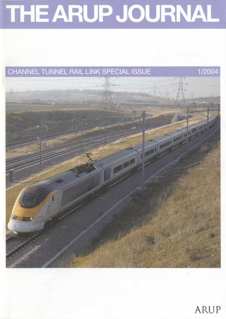
Section 1 of the 109km Channel Tunnel Rail Link was opened by the UK Prime Minister Tony Blair on 28 September 2003. With this opening came the first and long-awaited benefits of high-speed rail travel in Britain.
Safety - an industry-high safety record for construction - has been achieved and now travel will become safer and more convenient. Since the opening, the number of passengers using Eurostar, the London to Paris/Brussels high-speed rail seNice, has increased by 20%, and reliability has soared.
This is due to the commitment of a tremendous team of people in Arup and our partners in Rail Link Engineering, and the client's team in Union Railways, who have brought a new catch phrase to railway construction -'on time, on budget'.
It is also due in no small way to the creativity and innovation of Arup, for it was our firm that perceived the need for this project, conceived the solution, and has been delivering the result. This special edition of The Arup Journal marks a special moment when our creative capability, design flare, and ability to deliver have become tangible.
I have been personally and closely involved in the CTRL and know the many achievements and challenges. I hope that you will now read and enjoy this Arup Journal.
'There are not, frankly, many Prime Ministers, or indeed many Ministers, that launch an infrastructure project or accept its
completion in front of the words "on time" and "on budget".'
The Rt Hon Tony Blair at the official opening of Section 1 of the CTRL, at the Eurostar Terminal, Waterloo,
on 28 September 2003.
2 THE ARUP JOURNAL 1/2004
2
3
6
9
10
12
18
22
29
" 33 ::l
~ t')
la
~ cl 40 0
$ ,:
8
46
55
60
62
63
RfEl/11/llll I/Ill/Ill
l/1/1/l lll RAILUNK
www.arup.com
Contents
Foreword Terry Hill
The CTRL and Arup: Introduction to the history Mike Glover
Involving the communities Lisa Doughty
Media relations Lisa Doughty Paul Ravenscroft
Rail safety Lorna Small
CTRL and the environment Paul Johnson
Ground engineering Nick O'Riordan
Bored tunnels Eddie Woods
Cut-and-cover tunnels David Twine
Bridges Steve Dyson
Railway engineering Duncan Wilkinson
St Pancras Station and Kings Cross Railway Lands Ray Bennett Ian Gardner Martin Gates-Sumner Alastair Lansley
Project delivery Rob Saunders
Chronology
Arup people
CTRL contracts and contractors

The CTRL and Arup: Introduction to the history
Mike Glover Technical Director and Deputy Project Director,
Channel Tunnel Rail Link
The route to construction
I have great pleasure and pride in introducing this special issue of The Arup Journal, devoted to the Channel Tunnel Rail Unk and Arup's 15-year involvement to date with the project. It celebrates not only the CTRL's many specific planning, project management, and engineering achievements, but also Arup's pursuit of what seemed to be the best overall solution to the challenge of linking the UK to Europe's high-speed rail network through the crowded south-east corner of England. This introduction sets the scene for the more specific technical articles in this issue. Books are doubtless already being written about the CTRL; here we offer some papers by Arup staff.
Mega-projects like the CTRL take a long time to come to fruition. The idea of a rail link to Europe goes back many decades, but today's built reality was born out of the Channel Tunnel Act in 1986. That Act, however, only embraced the short-term upgrading of existing rail infrastructure: it omitted the powers required to build a new rail link. This omission was probably deliberate, given the Act's drafting and passing at the peak of Thatcherite ideology, the agenda of which was that such a link could only be economically created through the private sector with no financial support from Government.
Nonetheless British Rail (BR), the then publicly-owned national rail operator, pushed on in the late 1980s with a public consultation process on several possible routes for only international trains from the Channel Tunnel to Waterloo, the northern ends of which all passed through south-east London. In March 1989 BR settled on its preferred route corridor.
In October 1989 Arup decided on its own initiative and cost to examine alternative rout.es between the Channel Tunnel and London, due to the perceived difficulties in tunnelling under south-east London and/or in building a new international railway above ground and in an existing rail corridor. There had to be an alternative to BR's route.
Arup's solution was published1 in March 1990, and after considerable further lobbying, negotiation, discussion, and commission (detailed in a previous issue2), Government decided in October 1991 to select the 'Arup route'.
The principal features of our route lay in its focus on issues beyond a purely international train link to London. It developed the concept of a 'domestic'/ commuter rail capability interspersed with international trains travelling to and beyond London, involving the regeneration of three urban areas: north Kent, Stratford in east London, and St Pancras in central London. Thus the introduction of wider private sector interests and the Government contribution of political support and grant funding for the public facilities portion together essentially shaped the project's feasibility.
A further four years of consultation led by the BR subsidiary Union Railways followed, plus a Parliamentary Bill and a competition to win the concession to finance, build, and operate the CTRL. Arup was active in setting up London & Continental Railways Ltd (LCR), and in delivering its winning strategy. The shareholders in LCR {August 1996) were: Bechtel Ltd, SG Warburg & Co Ltd, Virgin Group Ltd, National Express Group PLC, SNCF, London Electricity PLC, Arup, Sir William Halcrow & Partners Ltd, and Systra Sofueta Sofrerail.
The contract to build the CTRL and run the UK arm of the Eurostar international train service was awarded to LCR in February 1996. LCR would take over Union Railways and Eurostar UK, and draw revenue from Eurostar UK and the use of the CTRL by domestic train services. At the back of this, Government agreed to provide LCR with grants for the construction.
By the end of 1997 it became clear that the overly optimistic Eurostar UK forecast had undermined LCR's efforts to raise the money it needed from private investors to contribute to the cost of building. In January 1998 the company asked for additional Government funds.
THE ARUP JOURNAL 1/2004 3

Route description
Section 1: Channel Tunnel to Fawkham Junction
The railway leaves the Channel Tunnel complex at Cheriton, and its two tracks separate to pass either side of the Dollands Moor freight yard, where there is a junction for freight trains. The CTRL then follows the existing railway corridor to Ashford International Station in the centre of the town. Here, junctions enable domestic express trains from east and north-east Kent to join the new railway.
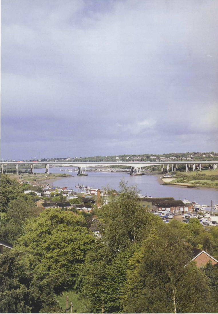
West of Ashford the CTRL crosses the M20 motorway and follows its corridor to Detling in the Boxley Valley north of Maidstone, after which it passes beneath the North Downs in the 3km twin-track North Downs Tunnel, emerging alongside the M2 motorway south of Rochester. It follows the M2 corridor and crosses the River Medway on its new viaduct alongside the existing and new motorway bridges.
The line continues alongside the M2 and A2 as far as Pepper Hill, between Gravesend and Southfleet, where a junction enables the new railway to turn south along the alignment of the disused Gravesend West Branch railway, to join the existing network at Fawkham Junction, about 8km east of Swanley. From here Eurostar trains use existing tracks to reach Waterloo International Terminal until Section 2 opens in 2007.
Section 2: Fawkham Junction to St Pancras
Section 2 starts at Southfleet Junction and runs north-west through the Ebbsfleet Valley. A major international and domestic station is being built at Ebbsfleet. plus a junction with the existing North Kent railway to allow domestic express trains to use the new line for fast journeys between north Kent, the Medway towns, and London.
After Ebbsfleet, the CTRL route passes under the Thames in two 2.5km single-track tunnels to emerge at West Thurrock just east of the Queen Elizabeth II Bridge.
It will continue beneath the bridge approach spans and over the exit from the Dartford Tunnel, before running alongside Purfleet by-pass and the existing railway through Rainham to Dagenham. Here, a junction is being built to the Network Rail network for use by freight trains.
Twin single-track tunnels then carry the CTRL 19km underground to the Kings Cross Railway Lands north of St Pancras. These generally run beneath the corridors of existing railway lines and will have ventilation shafts -also serving as emergency access points - at roughly 3km intervals.
The tunnels rise to a large retained cutting in the Stratford railway lands, where a combined international and domestic station is being built. In its intended role as a London stop for Eurostar services running beyond London, Stratford Station will be a significant transport hub for East London, Docklands and East Anglia, linking together international and regional rail services, the Docklands Light Railway, the Jubilee and Central Line Underground services, buses, and the M11 motorway.
Approaching the Kings Cross Railway Lands, the CTRL will emerge from the tunnels just east of the East Coast Main Line railway, which it will cross over before swinging south over the railway lands toward St Pancras. A direct route is planned between the new railway and the West Coast Main Line, using a link to the North London Line across the railway lands. The East Coast Main Line will have a connection to the CTRL via St Pancras.
4 THEARUP JOURNAL l/2004
Facts and figures
Distance
Channel Tunnel to St Pancras: 109km Section 1: Channel Tunnel to Fawkham Junction: 74km Section 2: Southfleet to St Pancras: 39km
Distance in tunnel: 26km (25% of route)
Maximum design speed: 300kmlhour
Performance: Section 1 (September 2003 to 2007)
Maximum usage: Up to four Eurostars/hour each way
Journey times:
Waterloo to Channel Tunnel: 55 minutes
Waterloo to Paris: 2 hours 35 minutes
Waterloo to Brussels: 2 hours 25 minutes
Performance: Whole line (2007 onwards)
Maximum usage: Eight Eurostars/hour each way
Journey times:
St Pancras to Channel Tunnel: 35 minutes
St Pancras to Paris: 2 hours 15 minutes
St Pancras to Brussels: 2 hours
Tunnels
London Tunnels (Islington to Dagenham): total 19km
Longest single London Tunnel: 10.5km (Stratford to Ripple Lane)
Thames Tunnel: 3km
North Downs Tunnel: 3.2km
Stratford Station Box: 1. 1 km
Ashford International Station Box: 1. lkm
A Eurostar takes 38.4 seconds to go through North Downs Tunnel at 300km/hr.
Bridges and viaducts
Rail bridges: 60
Road bridges: 62
Footbridges: 30
Thurrock Viaduct: 1.3km (beneath the Queen Elizabeth II Bridge)
Medway Viaduct: 1.2km (alongside the existing and new M2 bridges, with a main span of 152m)
Ashford Viaduct: 1.4km (over Great and East Stour Rivers and Ashford-Canterbury line)
The CTRL has a total of 152 bridges.
A Eurostar takes 15 seconds to cross the Medway Viaduct at 300km/hr.
Quantities Ballast used: 850 OOO tonnes
General excavation: 14Mm3 (enough to fill London's Wembley Stadium 12 times) Structural fill: 5Mm3 (formation of embankments/increase height of embankments)
Mitigation fill: 7Mm3 (formation of bunds for landscaping and to reduce airborne noise) Material transferred to non-CTRL uses: 1 Mm3
The CTRL created 8000 new construction jobs.

The subsequent restructuring deal is not covered in this Arup Joumal, but its key consequence was to split the project into two parts.
Section 1 and Section 2
As detailed opposite, Section 1 extends from the Channel Tunnel to Southfleet (with Eurostar trains thereafter continuing for the time being on existing lines to the International Terminal at Waterloo), whilst Section 2 continues from Southfteet under the Thames and thence to Stratford and London St Pancras and beyond.
This special edition of The Arup Joumal follows the completion and opening of Section 1 in late 2003. Section 2 of the rail project will be completed in 2007, and the regeneration project will go on beyond. In all, over 20 years will have elapsed since Arup first involved itself with the project.
Project organization
To achieve success, a mega-project like the CTRL needs a strong multidisciplinary organization that can develop in size and capability as the project progresses. This organization for the CTRL involves a client body, Union Railways, and a project manager, Rail Link Engineering. RLE, a consortium of Arup, Bechtel, Halcrow, and Systra, is an unincorporated association responsible for the project management, consenting, design, procurement, construction management, and commissioning of the CTRL.
Although community relations, environmental, and planning issues are most visible at the outset, the essential backbone of a mega-project is high-quality engineering, conceptual and delivery skills, and hands-on project management. It is the blend of the~e skills from inception to completion that ensures the success of the project.
Innovation and initiatives
The project has been a leader in the introduction of new initiatives into the UK construction industry, particularly: • in procurement, the use of the New Engineering
Contract (NEC) Target Contract with contractor incentivization and emphasis on partnering
• in quality management. the introduction of a contractor self-certification regime within a formal quality assurance programme
• in communications and IT, an increasing reliance on electronic-only communication, storage, and archiving.
With Section 1 open and the whole of the CTRL aiming for completion to budget and time, the contribution and success of these initiatives is self-evident. In the Section 2 works currently under construction, RLE has been at the forefront of developing these initiatives further, particularly in the direction of alliancing, quality surveillance, and total electronic communication.
Railway works
A hard-won experience has been in working in and around the complex existing railway infrastructure of this part of south-east England, and to a lesser extent its motorway highway network. These interfaces have been a dominant feature of the Section 1 works, since the routing of the CTRL places it against or between the alignments of both these existing infrastructures for practically the whole length of Section 1. The overall costs of planning, approvals, design, and construction to modify existing railway works in possessions approach an order of magnitude more than those for new railway works. This is a lesson in basic realities and economics that many of our European counterparts have already learned, but is only now becoming properly understood in the UK.
Standards
The CTRL is the first new railway in the UK for over 100 years, and the country's first high-speed railway. This has required the project to develop and bring into use a totally new set of standards and procedures, which have now become the UK national standards for high-speed railways. Many have required fundamental research and development to validate them; for example, aerodynamics in tunnels, the dynamic performance of structures and earth-support structures, and noise and vibration impacts. Some of these are touched on in the following articles. A further development being incorporated in the CTRL is the European high-speed railway interoperability regulation aimed at ensuring open access for train traffic to all parts of Europe.
Safety
Lastly, it is vital to emphasize the Importance of the approval/consents and safety regime in railways, particularly against the backcloth of the fatal incidents on Britain's railways in recent years. As In any rail project these skills necessarily need to pervade all our activities: a difficult but essential reality to achieve. The CTRL has a formalized specialist group which focuses entirely on the issues of rail safety, risk analysis, and technical approvals, and RAMS (reliability, availability, maintainability, and safety): the culmination of this effort is the production of the Railway Safety Case which will be the key document for allowing LCR to bring the CTRL into use and being granted the PtU (Permit to Use) Certificate by Government.
References
(1) OVE ARUP PARTNERSHIP. Proposal for a Channel Tunnel Rail Link leading to an integrated, international rail system for passengers and freight serving the whole of Britain. Arup, March 1990.
(2) BOSTOCK, M and HILL, T. Planning high-speed railways into Europe. TheArupJoumal, 28(4), pp3-7, 4/1993.
THEARUP JOURNAL 112<Xl4 5
Involving the communities Lisa Doughty
The need to work with communities
Good community relations can make all the difference between working in an environment of mistrust and confrontation, and one of trust, goodwill and co-operation.
From the outset of its role as the CTRL project manager, Rail Link Engineering recognized the need for effective community relations. Contractors on site have the most immediate contact with local people, and so ALE has consistently required its contractors to employ community relations representatives. They act as the project's first point of contact for local residents and businesses.
The community relations team for Area 100 (St Pancras) is led by the ALE community relations co-ordinator and includes four community relations representatives, as well as the Visitor Centre co-ordinator. Each of the four community relations representatives is employed by a different contractor working in the St Pancras area, but because the area is so densely populated and the contract areas overlap, the four also work as a team and support one another for the benefit of Area 100 as a whole.
6 THE ARUP JOURNAL 1/2004
Knowing that building a major new infrastructure through the heart of the Camden community would cause some disturbance, the whole team (including the project manager and construction supervisors) committed itself to engaging the community. The aim has been to involve local people in the project, and inform them as thoroughly as possible about it through a thoughtful and sensitive approach in conjunction with carefully planning the works and equipment used on the site.
Prior to the start of works for Section 2 in July 2001 , the community relations team undertook a programme of public meetings for those residents living closest to the works sites. The top concerns raised included whether local roads would be affected by the works, which properties would be eligible for secondary glazing, and getting information on the programme, including key dates. These public meetings also enabled the team to network and set up relationships with key residents' representatives. The meetings were vital in establishing a forum where residents understood that the project would listen and take action where and when it could.
Implementation of the community relations initiative was set at three levels: Level One centering on networking, Level Two on information provision, and Level Three on setting the standards for accountability.
Level One: Networking
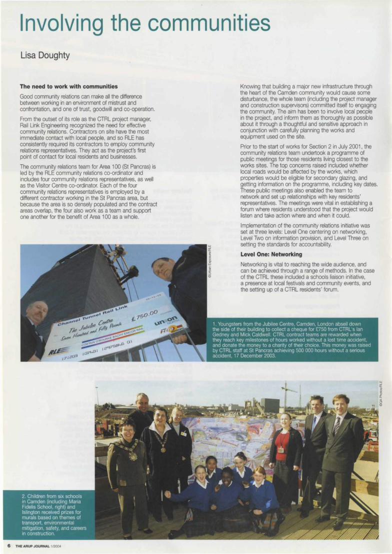
Networking is vital to reaching the wide audience, and can be achieved through a range of methods. In the case of the CTRL these included a schools liaison initiative, a presence at local festivals and community events, and the setting up of a CTRL residents' forum.

Through networking, the community relations team has developed important relationships with resident representatives or individuals living closest to the works sites. These relationships help the team to deal more effectively with residents' concerns, to minimize miscommunication, and ensure that complaints or problems are dealt with swiftly and efficiently.
Investing in this way in relationship-building can lead to those involved becoming part of the community, which helps to build trust and a more relaxed forum where issues can be aired in a co-operative and friendly manner.
As well as communicating with local schoolchildren, the St Pancras team's schools liaison initiative has also opened up lines of communication with families who have no English or where English is a second language. The team has visited children between the ages of seven and 11 with a safety message to highlight the hazards of playing near construction sites, and it has also helped GCSE, A Level and degree students with the use of presentations, information packs and tours of the site.
Level Two: Information
Lessons learnt from work on Section 1 in Kent proved that local residents are happier when they are kept informed. Initial notification is in the form of a flyer to the community at the start of works. Further flyers continue to be distributed throughout the construction period at least two weeks in advance of any works that the team feels may have an effect, or when an explanation of construction activities is necessary.
Other useful tools of communication are posters, information packs, local press coverage, and public information boards at the entrance to every works site giving contact information and description of the works. Also, as the following article explains, providing information for local journalists and media is an important part of ensuring residents are kept informed, with progress updates using photographs and interviews with contract managers. Regional newspapers are keen to receive regular updates because the project's progress directly impacts on their readers.
THE ARUP JOURNAL 1/2004 7

8 THE ARUP JOURNAL 1/2004
Level Three: accountability
The project has a responsibility to be open, honest, and accountable to those it affects. To ensure that the local communities feel they are taken seriously, effective ways to communicate with the project have been developed.
Direct contact and - most importantly, as with any partnership - a sense of ownership, are essential. This has been achieved through the effective operation of the CTRL 24-hour help line, a low-cost telephone service (0845 60 40 246) that allows members of the public direct contact for information, enquiries, or complaints about how the works have affected them. Any complaint is handled within 24 hours, with the help of key personnel on site who can solve the problem and then call on the resident concerned to apologize and explain why the problem has occurred.
Asking the engineer responsible for the work to speak to the people living and working closest to the site helps them to understand how their decisions affect others. Being a good neighbour is vital when working within the heart of any community.
Accountability is also achieved through public meetings, meeting with the local authorities, and site tours - in fact any venue where local people are given the chance to speak to project personnel one-to-one.
Unique to Area 100 on the CTRL project is the Visitor Centre, a 'one-stop shop' with information about both Section 1 and Section 2. The Centre opened to the public in Brill Place, Camden, in November 2001 and now receives on average 150 visitors per week, mostly local residents interested in the works and wanting further details. The Centre Co-ordinator provides advice about the works with the help of flyers, architects' models, videos, and maps.
This popular facility is also used for public meetings at which residents are invited to join CTRL engineers for project updates. Local interest groups, other rail projects, and overseas engineering companies keen to learn about the project have also requested presentations.
Recently a partnership between the two local councils, Islington and Camden, the Learning & Skills Council, and the CTRL itself has been developed to give local people access to local construction jobs. Funding has been secured to build a Construction Training Centre on the CTRL site, and a Workplace Co-ordinator funded by Camden Council now works with the project to match site vacancies with local unemployed people looking for a career in construction.
As the lead enforcer of major change to the St Pancras area, the CTRL project is working hard to fulfil its duty and responsibility to keep local people informed and reassured about its activities. Success will be measured by the goodwill the project leaves behind.

Media relations Lisa Doughty Paul Ravenscroft
Objectives
Union Railways' intention for the CTRL media relations department is not to sell an 'eighth wonder of the world', but to deepen and broaden understanding of the first new railway to be built in the UK since the Victorian age. The aim is to help journalists and the public understand and appreciate as many aspects of the project as possible. Recognizing that media relations are best conducted with a single 'voice', the Union Railways and ALE teams were merged in 2003, bringing together both policy matters and day-to-day construction operations.
Media coverage of the CTRL has grown steadily from the early days of route selection to today, with Section 1 open and construction of Section 2 in full swing. The objective has been to communicate what makes it a benchmark project: not just a successful construction enterprise but also a leader in health and safety, environmental management, and community relations.
The CTRL is on time and on budget; it holds safety as a priority; it is sympathetic to its neighbours and the environment; and it will deliver the continental-style highspeed railway that for decades has been the envy of British commuters. Demonstrating all this, and establishing a consensus that the CTRL is broadly a 'good thing' has been the core of the media relations strategy.
Comparisons with other major rail projects dogged by delays and cost overruns have undoubtedly earned the CTRL column inches. But such comparisons have highlighted its delivery mechanism - a private sector 'special purpose vehicle' (SPV) with public sector support under the Government's PPP (Public-Private Partnership) programme. The PPP is now widely accepted as the way forward, certainly for major rail projects in the UK, and the perception of SPVs as the answer to the nation's rail problems is in part down to the successful portrayal of the CTRL achieving its delivery goals.
Strategy
The mechanisms for creating this perception were fairly straightforward. From the outset the press team cultivated contacts in the national, local and trade press, organized site visits to demonstrate progress, and disseminated numerous press releases highlighting contract awards, progress, and safety and environmental aspects. Specific campaigns were organized to communicate news about ecological initiatives or innovative schemes to promote safety, whilst milestones such as the completion ceremony of the Medway Viaduct attracted wide interest.
I !
The event to mark the breakthrough of the North Downs Tunnel was commended in the 2001 Institute of Public Relations Excellence Awards, but much media relations work has been on a more local scale, bolstering the community relations programmes. CTRL's integrated team of media relations, community relations, and internal communications people have worked closely to help the project achieve its aims from the outset. Positive coverage in local media - newspapers, and regional TV and radio - is often the best way to communicate to geographically discrete audiences. An enthusiastic article in a local paper often achieves more in terms of creating understanding than two minutes on the national news.
Improved communication channels have made it easier to disseminate media information. Specialist database software incorporating e-mail allows circulation of press releases to the full range of media at the touch of a button • no more standing over a hot fax machine. CTRL's own website also allows journalists to glean independently a basic understanding of the project.
Perhaps the biggest success of the media relations team has been to persuade often-sceptical engineers of the value of communication with the wider world. Today most engineers have been converted, get involved, and understand why it is worthwhile to do so. Many have realised that participation can lead to personal prominence in their professional journals! Persuading a sceptical media of the benefits of the CTRL is key, but without internal support, the task would be virtually impossible.
Dealing with difficulties
If and when things go wrong on major projects in the public eye, media criticism is always less severe when the transgression is perceived as the exception rather than the norm. Crisis management is infinitely more effective when a project is not perceived to be in a permanent state of crisis. Up to spring 2004, the CTRL has had only two fatalities and two serious personal injury accidents. No such incidents should have happened, and hindsight always suggests how things might have been done differently. However nearly all the coverage set both incidents in the context of a highly safety-conscious project with an accident rate less than half the industry average, that actively seeks innovative ways to minimize accidents, and endeavours to ensure that lessons are learned and mistakes not repeated - the very essence of CTRL's Target Zero Accidents programme.
Most recently the media relations team has had to deal with two big stories - one negative and one positive. In February 2003 several back gardens in Stratford subsided into a large void above one of the drives for the London Tunnels. Believed to have been caused by uncharted and disused deep well-shafts, the incident was prominently featured by the national media in the immediate aftermath, and by the construction press and the local papers over a longer timescale. Responding to the constant stream of requests for updates kept the press office on its toes for days. Then in September 2003 came the opening of CTRL Section 1 in Kent, the culmination of several months of 'teaser' activity co-ordinated with Eurostar, including the setting of a new UK rail speed record which achieved widespread positive publicity.
Conclusion
As the civil engineering on much of Section 2 draws towards a conclusion, to be replaced by the less publicly-obvious railway equipment phase, the team expects media attention to focus on St Pancras, where the massive extension and refurbishment works are very high-profile for the media: much-loved heritage buildings, disruption for long-suffering rail travellers, traffic jams in the surrounding streets and, not least, a high profile campaign waged by local residents against night and extendedhours working on the project. So busy times ahead are expected, leading up to the opening of Section 2 early in 2007, and the completion of the UK's first high-speed line and first new rail route for more than a century.
THEARUPJOURNAL l/2004 9

Rail safety Lorna Small
To be involved in ensuring the operational safety of the first new high-speed line in the UK could hardly have been a more exciting challenge for RLE's rail safety team. And to be doing this at a time when the public's awareness of railway safety has been heightened following a succession of accidents makes it all the more important to get it right. This article describes the process for ensuring safety that has been followed for the CTRL, and also highlights some of the design's key features that contribute to this.
The process
The safety policy objective for the CTRL, in relation to members of the public including customers and employees, is to design, construct, and commission a safe railway, having due regard to cost. This is being achieved by:
• meeting all relevant statutory health and safety requirements as a minimum
• reducing risks to as low a level as reasonably practicable.
The first of these objectives - to obtain safety approvals -has involved 'shooting at a moving target'.
For example, the update of the Railways (Safety Case) Regulations1 in 2000 required Railway Safety Cases to undergo an independent assessment as well as being reviewed by Her Majesty's Railway Inspectorate (HMRI), whereas further changes to the Regulations removed this requirement in 2003.
However, the biggest regulatory change for the project occurred in 2002. Up until mid-2002 the route for regulatory approval for railways, prior to their coming into service, was via the Railways and Other Transport Systems (Approval of Works, Plant and Equipment) Regulations 19942 (ROTS). But the introduction of the Railways (Interoperability) (High-Speed) Regulations3 in 2002 changed the process mid-project. The interoperability regulations apply throughout the EU and define essential requirements (one of which relates to safety) for sub-systems which make up a railway. A sub-system which has been approved under these regulations in one member state of the EU can be introduced into another member state without requiring further approval. Thus, the CTRL is subject to the same arrangements as the rest of Europe's high-speed railway network, requiring a technical file to be prepared explaining how the technical standards for interoperability have been met. This technical file is prepared and presented on behalf of the project by a notified body to the supervisor authority. The notified body confirms that the appropriate standards have been met, with due regard having been paid to safety.
However, compliance with the interoperability regulations is not the end of the approvals story. The way in which the subsystems are fitted together to form a safe operating railway is still subject to approval under the Railway (Safety Case) Regulations. Also, interoperability ends at the platform edge! Facilities at stations for the safety of passengers and staff are still covered by the ROTS process, which means that non-objection to the design and approval of the completed works must still be sought from HMRI. Throughout these regulatory changes, the project's commitment to reducing risks to as low as reasonably practicable has remained, and continues to remain, unchanged.
10 THE ARUP JOURNAL 1/2004
The main activities of the Rail Safety Department within ALE associated with achieving this objective are to:
• advise designers on the safety of the operational railway and the railway safety approvals process
• co-ordinate safety review, hazard identification, and risk assessment studies
• prepare the project safety case to support safety approvals
• assist Union Railways, the ultimate owner of the CTRL infrastructure, in developing the rail safety management interface arrangements with HMRI, emergency services, Network Rail, and other regulatory bodies
• assist Union Railways in ensuring that the CTRL meets the requirements of the Railways (Safety Case) Regulations, and in preparing the operation's railway safety case for the CTRL.

The way the safety group's work has been carried out mirrors the design process. The civil engineering design for the CTRL - the earthworks, tunnels, bridges, and viaducts - has largely been undertaken within RLE, whereas for the railway systems, the trackworks, overhead catenary system, track circuits and signalling, etc, the detailed design has been carried out by the contractors installing these systems. Thus for the civils design the railway safety team has worked closely with the designers, carrying out hazard identification, design safety reviews, and risk assessments in justification of the design. For the systemwide components of the railway, BS EN 501264 has been followed, whereby the onus of demonstrating safety is placed on the contractors designing, supplying ,and installing the systems. The RLE railway safety team has been overseeing the process.
Safety design features
What principal features of the railway contribute to its safety? The most obvious is the combination of track circuits, cab-based signalling, and automatic train protection which, while allowing trains to run at up to 300km/hr with a minimum time between trains of four minutes, prevents two trains from occupying the same piece of track at the same time.
The reliability of this system is safety-critical and one of the major safety assurance tasks of the RLE railway safety group is to make sure that the designers of these systems can demonstrate reliability and safety to the satisfaction of the regulatory authorities. All trains that are allowed to use the CTRL are fitted with onboard systems compatible with the TVM 430 cab signalling system in use on the CTRL.
Carrying high-speed passenger traffic places heavy burdens on the track systems, the rails, the sleepers, and the track formation. This burden will increase when freight traffic is introduced. A regime of preventative as well as corrective maintenance is critical to ensure that problems do not arise.
Fortunately, wear and tear on the track systems lead to a decrease in passenger comfort - a rough ride - long before safety is compromised! While not being as noticeably hightech as the state-of-the art-signalling system, several elements of the civil engineering design have a major impact on operational safety. Designing the railway without level crossings, and ensuring high levels of protection for errant vehicles on bridges and along the roads that run parallel to the CTRL, should reduce the risk of incursions onto the track, leading to derailments and collisions.
Prominent security fencing should deter both trespassers and vandals, and a risk-based approach was used to match the level of fencing to the local railway environment.
Sensitive areas such as tunnel portals and signalling rooms have higher levels of fencing. Greater security is also provided in those areas deemed more prone to vandalism.
One of the project's major safety commitments was to make the CTRL a 'personless railway' . Key to achieving this was the provision of a continuous walkway on either side of the track, giving an even, trip-free surface for railway maintenance workers to get to all the locations they need to reach in safety. In the unlikely event of passengers having to leave a failed train in a tunnel , they will find that instead of having to jump down from the train to the track, they can step down onto a walkway and there the way will be illuminated by emergency lighting. In the even more unlikely event of a train on fire stopping in one of the London or Thames tunnels, then additionally the ventilation systems will operate to maintain a smoke-free environment until passengers can make their way to a place of safety. A fire watermain is also provided for the fire fighting teams.
Train accident risk model
Finally, any account of the work of the RLE rail safety team would not be complete without mentioning the train accident risk model. This is a spreadsheet-based fault tree and event tree model of train derailments, collisions, and fires. The model is populated with historical data from train accidents in the UK, modified to account for the differences between the Network Rail and CTRL infrastructure and the different types of trains which will be run. It has been used in several ways to demonstrate that the design of the CTRL reduces risks to as low a level as is reasonably practicable. For example, it has been used to justify the spacing of cross-passages in tunnels, and also the installation of derailment containment at several high-risk locations such as viaducts and in tunnels. It was also used to justify the safety integrity levels specified for critical systems such as track circuits and the signalling systems.
References
(1) HER MAJESTY'S STATIONERY OFFICE. Statutory Instrument 1994 No. 237. The Railways (Safety Case) Regulations 1994, revised 2000. HMSO, 2000.
(2) HER MAJESTY'S STATIONERY OFFICE. Statutory Instrument 1994 No. 157. The Railways and Other Transport Systems (Approval of Works, Plant and Equipment) Regulations 1994. HMSO, 1994.
(3) HER MAJESTY'S STATIONERY OFFICE. Statutory Instrument 2002 No. 1166. The Railways (Interoperability) (High-Speed) Regulations 2002. The Stationery Office, 2002.
(4) BRITISH STANDARDS INSTITUTION. BS EN 50126: 1999. Railway applications - the specification and demonstration of reliability, availability, maintainability and safety [RAMS]. BSI, 1999.
;! m
~ c ,, .... 0 c :0 z I!
11
CTRL and the environment Paul Johnson
Introduction
The environmental regime on the CTRL is complex and unique. At the same time, the project's large scale, long history, and close involvement with many statutory bodies and the public in route option planning made inevitable its high visibility and expectations of a comparable standard of environmental management and performance.
Thus environment is a key component of the CTRL integrated design and management programme. It is that part of the project design - a fundamental part - for which planning consent is sought. The environmental concerns intrinsic to the CTRL project management processes include risk and value management, environmental quality and safety management, procurement, cost control, and design change and construction management.
Environmental control
Much of the project's environmental activity stems from commitments in the CTRL Environmental Statement (1994), and subsequently as undertakings to third parties as the hybrid bill (part public, part private) to authorize it passed through the Parliamentary process. When the CTRL Act received Royal Assent in 1996, it gave outline consent to construct specified railway works within set boundaries and the powers to acquire the necessary land. The Act also established a streamlined planning regime to allow detailed 'reserved' matters to be agreed subsequently with the planning authorities along the route.
Obtaining the necessary planning consents for 'plans and specifications' and 'construction arrangements' was a massive undertaking in its own right. Over 1 OOO planning consents for detailed designs have been obtained from the local authorities along the route, whilst several thousand other 'environmental' consents covering highways, water resources, utilities, and listed buildings, etc, have also been obtained. The main environmental commitments were outlined in the Government document 'Environmental Minimum Requirements' (EMRs) which the project's promoters were required to implement. The key principle underpinning the EMRs was 'NEWT', ie the project must be designed and constructed with environmental effects 'not environmentally worse than' those described in the Environmental Statement.
12 THE ARUP JOURNAL 1/2004
Annexed to the EMRs are requirements for an environmental management system (EMS), a code of construction practice (COCP), and memoranda agreed with external agencies on the environmental, planning, heritage, and spoil disposal strategy.
The EMRs established three standing fora for open discussion by a range of parties:
• High Level Forum (held annually and chaired by a Government minister at which local authority elected leaders are present)
• Planning Forum (meeting every six weeks or so, attended by the local authority planning and environmental health officers)
• Environment Forum (meeting every six months or so, attended by the statutory environmental agencies).
Environmental risk management
Environmental parameters are a potential risk to fulfilling project commitments, gaining consents, achieving the construction programme, and hence delivery of the project on time and budget. These are, therefore, powerful reasons to invest heavily in appropriate levels of environmental design and management - and the 'plus side' is that environmental opportunities can lead to cost and programme savings. The innovations developed on the CTRL are outlined later in this article.
Mitigating risk has been central to Arup's work on the CTRL. Understanding the risk environment and drawing up the project's risk register highlighted its degree of exposure to various risk categories. The Project Executive drew up action plans and regularly reviewed progress towards closing out items.
In the early days, environmental risks were high on the agenda in terms of potential scale of impact, archaeology and ecology being two risk areas where unknowns and seasonal effects could have significantly damaged the project programme. The need for large-scale advance works prior to construction proper was clear.
The EMS, operating throughout design and construction, controlled the risk. Interlinked with the project's quality and safety management systems, the EMS is described in greater detail later.
COA Photos LldlRlE
Characteristics of the route corridor
Section 1 's 7 4km lie completely within the county of Kent, the 'Garden of England'. The route was very carefully planned to run close to existing motorways (principally the M20 and A2/M2 corridors) to minimize impact on the landscape. Apart from a relatively short section through urban Ashford, it generally crosses undulating agricultural land (much of high quality) interspersed with woodlands, some classified as 'ancient' (in continuous use as woodland for at least 400 years). Much of the route therefore was depressed into the landscape or placed within false cuttings to minimize environmental intrusion.
A tunnel was driven under the North Downs Area of Outstanding Natural Beauty to link between the M20 and M2 corridors, and the River Medway valley spanned by a major viaduct. Where necessary, small hamlets were protected from environmental intrusion by building short cut-and-cover tunnels.
In contrast, Section 2, some 35km long, crosses the more industrial landscape of north Kent and south Essex, skirting the northern edge of the Inner Thames Marshes on viaduct and piled slab before entering the long London Tunnels. These take the railway under East London, emerging at the new St Pancras terminus. This section also contains the Thames Tunnel and two new stations, at Ebbsfleet in north Kent and Stratford in East London. Clearly for Section 2 there are greater concerns over potential effects on the large urban population and the disposal of substantial amounts of tunnel spoil, compared with the more rural environmental issues characteristic of Section 1 .
Landscape design and planting
Like most linear projects, the CTRL imposes a significant new landscape feature. and the combination of alignment constraints and the need to depress the railway in the landscape for environmental reasons necessitated excavating a great deal of spoil. Some was needed for engineered embankments but the remainder was reused in mitigation earthworks like noise bunds, false cuttings, and agricultural land restoration. In some locations, especially woodlands, cutting side-slopes were steepened to avoid excessive land-take from sensitive habitats.
The challenge for the landscape architects was to integrate the CTRL into the countryside and mitigate adverse visual effects on communities. Maximum use was made of surplus spoil and the land available within the project's formal 'limit of deviation' to design flowing contours that merged the new landform into the old, and maximized opportunities to productively reuse surplus restored land. The reuse of spoil was a major cost saving, eliminating the need for road transport of large amounts of surplus materials to remote disposal locations.
Details of the newly-proposed landform and planting and seeding arrangements were all subject to detailed discussion with the local authorities prior to receipt of formal planning consent.
The strategy for planting and seeding reflected the natural geology, soil types and surrounding habitats and also the required functionality, for example, whether visual screening or amenity woodland was appropriate. The species chosen (trees, shrubs, grass and wild flowers) reflected ecological objectives, the desire to increase bio-diversity, and minimizing of the long-term maintenance burden. All species were native to the UK and as much seed as practicable (some 98%) was sourced from woodlands and meadows in Kent and the south and east of England.
The 1 .2M trees needed were contracted from a single nursery, whilst the 14 specialist grass and grass/wildflower seed mixes were sourced from only two UK suppliers. Four main planting contractors undertook the planting, fencing, rabbit protection, and weed control works. On some low fertility soils, mycorrhizal fungal inoculants, native to Kent, were used to improve root growth of transplanted trees. In total, some 255ha of woodland, 450ha of species-rich grassland, and 40km of hedgerow were created in Section 1 .
Not all landscape restoration is in rural areas. In urban Ashford, and near the station developments at Ebbsfleet, Stratford, and St Pancras, a more formal approach has been taken, in keeping with the surroundings and the wishes of the local authorities. Particularly at St Pancras, development of the new townscape has recognized the importance of the public spaces around the station, and the choice of paving materials, street furniture, signage, lighting and tree planting will reflect both the functionality and significance of the terminus.
Agricultural restoration
One project commitment was to ensure that the 200ha of 'best and most versatile' agricultural land (Grades 1, 2 and 3a) taken temporarily for construction was restored to its previous quality. Strict controls were imposed through the civils contracts to ensure that on the 100 or so parcels of such high-grade agricultural land, topsoils and subsoils were stripped, stored separately, and carefully replaced in dry conditions to prevent damage to soil structure. Where necessary, under-drainage was also installed. Care in the early stages of earthworks has meant a very successful restoration record, with minimal requirement for extensive aftercare. This has resulted both in cost savings and a rapid return of land to the previous owners to resume cropping as soon as practicable.
Biodiversity
The principal ecological resource encountered by the CTRL in Kent was its (often ancient) woodland. Significant tracts, often chestnut and hazel, are managed by coppicing (cutting the trees down to a base 'stool' from which new growth arises and is harvested regularly as poles for fencing or other uses). Other areas such as at Ashenbank and Cobham in west Kent were designated as Sites of Special Scientific Importance because of their flora, mammal, bird, invertebrate and fungal populations. Relatively little grassland and wetland occurs along the route in Section 1 , although in Section 2 the route traverses the edges of the Swanscombe and Inner Thames Marshes, wetlands of national significance.
Some disturbance to nature conservation areas was inevitable, and following extensive field surveys, various strategies to deal sensitively with protected species and their habitats were developed together with English Nature, the Environment Agency, and Kent Wildlife Trust. Protected water voles were displaced to adjacent habitat by techniques like spreading predator odour and vegetation management.
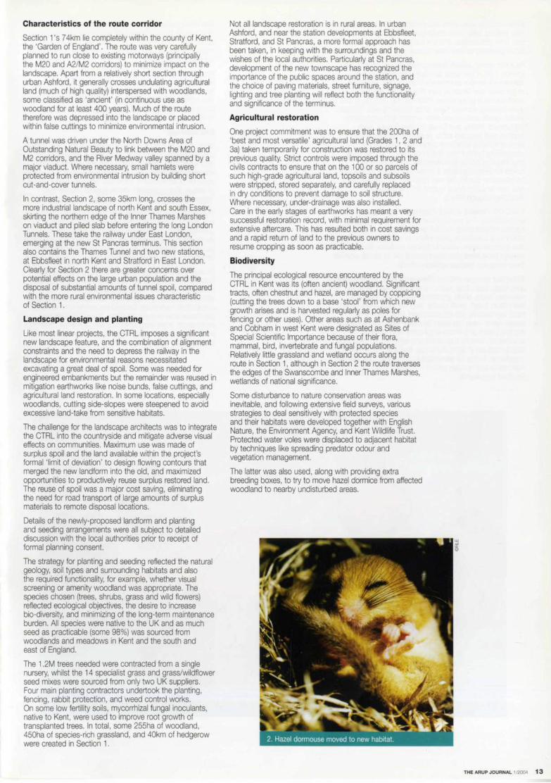
The latter was also used, along with providing extra breeding boxes, to try to move hazel dormice from affected woodland to nearby undisturbed areas.
THE ARUP JOURNAL 1/2004 13
Where badger setts were encountered in the working area, new artificial setts were constructed in appropriate habitat safe from disturbance, and the badgers encouraged to move gradually to their new homes.
As a last resort, certain species were translocated under licence. 100 of the hazel dormice were trapped and released in ancient woodlands in the English Midlands to colonize new areas as part of a national species re-introduction programme. Post-release monitoring and radio tracking showed them to be breeding well. Reptiles (mainly grass snakes and slow worms) and amphibians (eg Smooth Newts and Great Crested Newts) were trapped and released either at suitable existing sites in Kent or in newly-prepared ponds with appropriate surrounding habitat near the route. Also provided were new roosting boxes and hibernacula for bats, nest boxes for breeding birds, a protected reserve including a translocation site for the very rare Grey Mouse-Ear plant, and new brackish pond habitat for the protected Tentacled Lagoon Worm.
The CTRL crosses several important coarse fishery watercourses. Pre-construction surveys of water quality, aquatic invertebrates and fish populations were undertaken to act as a baseline against which to assess any changes due to construction work. Follow up post-construction surveys have been also been carried out to check whether there were any residual adverse effects.
All habitat replacement has been on at least a one-to-one area basis, and often much more. These have included new reed beds, chalk grassland, wild flower meadow, flood plain forest. small ponds. and deciduous woodland. Most significantly, the establishment of woodland of conservation value has been speeded, with soils containing the seed bank and micro-organisms from ancient woodlands carefully recovered and replaced on prepared sites previously in agricultural use. but adjacent to other woodlands. Some 15 translocation sites have been planted with native tree species grown from seed collected in the Kent woodlands.
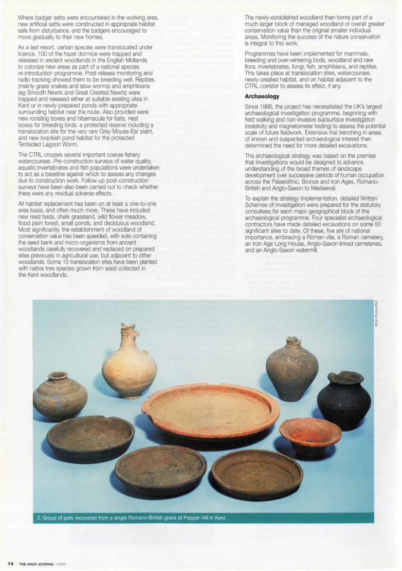
3. Group of pots recovered from a single Romano-Bnt1sh grave at Pepper Hill in Kent
14 THE ARUP JOURNAL 1!2004
The newly-established woodland then forms part of a much larger block of managed woodland of overall greater conservation value than the original smaller individual areas. Monitoring the success of the nature conservation is integral to this work.
Programmes have been implemented for mammals, breeding and over-wintering birds, woodland and rare flora, invertebrates, fungi, fish, amphibians, and reptiles. This takes place at translocation sites, watercourses. newly-created habitat, and on habitat adjacent to the CTRL corridor to assess its effect. if any.
Archaeology
Since 1996, the project has necessitated the UK's largest archaeological investigation programme, beginning with field walking and non-invasive subsurface investigation (resistivity and magnetometer testing) to assess the potential scale of future fieldwork. Extensive trial trenching in areas of known and suspected archaeological interest then determined the need for more detailed excavations.
The archaeological strategy was based on the premise that investigations would be designed to advance understanding of the broad themes of landscape development over successive periods of human occupation across the Palaeolithic, Bronze and Iron Ages, RomanoBritish and Anglo-Saxon to Mediaeval.
To explain the strategy implementation, detailed Written Schemes of Investigation were prepared for the statutory consultees for each major geographical block of the archaeological programme. Four specialist archaeological contractors have made detailed excavations on some 50 significant sites to date. Of these, five are of national importance, embracing a Roman villa, a Roman cemetery, an Iron Age Long House. Anglo-Saxon linked cemeteries. and an Anglo-Saxon watermill.

5 right: 6th century gold coin used as a 7th century pendant;
6 below: 7th century Anglo-Saxon brooch.
Both were found during CTRL excavations at Saltwood.
Alongside the 'set piece' excavations, archaeologists have kept a watching brief on the entire civil works, working closely with the earthworks contractors. During removal of topsoil and subsoils, any archaeological remains uncovered are recorded and recovered. Where finds are considered significant, a 'work around' is arranged with the contractor within the overall programme to allow sufficient time for recording. Completing the excavation is only the first phase, however. Recovered artefacts are conserved and recorded and detailed reports made on the excavations, the archaeological context, environmental samples (pollen, soil sequence, etc), as well as the finds themselves. Ultimately, the work will be published and disseminated in both hard copy and electronic forms, with the physical and digital archive lodged in an appropriate museum facility.
Listed buildings
Some 18 listed buildings and structures are directly affected by the CTRL, ranging from the Grade 1 listed St Pancras terminus itself to mediaeval timber-framed domestic properties in Kent. Here the project has also successfully dismantled, relocated, and re-erected several Grade II listed buildings.
The work was undertaken following receipt of heritage deed consents from the Secretary of State and considerable advance consultation with local authorities, English Heritage, and potential future owners. The project actively sought a long-term, viable, and productive after-use for each building whether for residential, agricultural, or educational purposes.
The domestic buildings included the 17th century Brockton Barn re-erected for agricultural use, the early 19th century Yonsea Farm (a Georgian model farm complex being progressively rebuilt as an educational facility at Woodchurch Rare Breeds Centre), the Old and Water Street cottages, reconstructed at the Museum of Kent Life, and Talbot House, a Wealden Hall house from the 15th century, reconstructed using traditional materials and techniques at Sellindge, Kent.
All were carefully surveyed and then dismantled brick by brick, timber by timber, the components being individually marked and stored for later re-use.
Where materials such as timber beams were decayed and unable to be re-used, replacement sections were made by specialist restorers using locally-grown oak.
THE ARUP JOURNAL 1/2004 15

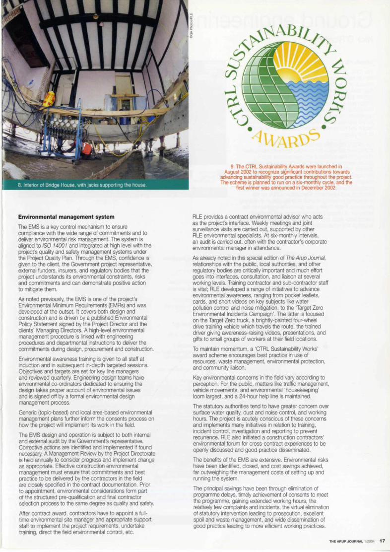
In contrast, it was considered that dismantling the 16th century Bridge House in Mersham would be too damaging, and so it was jacked up on a pre-installed concrete ringbeam foundation before being slid on prepared steel runners some 55m to its new location and then jacked back down again.
The challenge for the specialist restorers of these domestic buildings was to undertake the work as sympathetically as possible, retaining all the historic features but incorporating as unobtrusively as possible the necessary modern building regulation requirements to allow use as private homes.
At the other end of the route in London, close to the St Pancras terminus stood three distinctive linked Grade II listed gasholder guide structures. These had to be removed to allow the station to be extended, the columns being carefully encased in a protective framework before being unbolted in sections and stored nearby pending a decision on their future reuse.
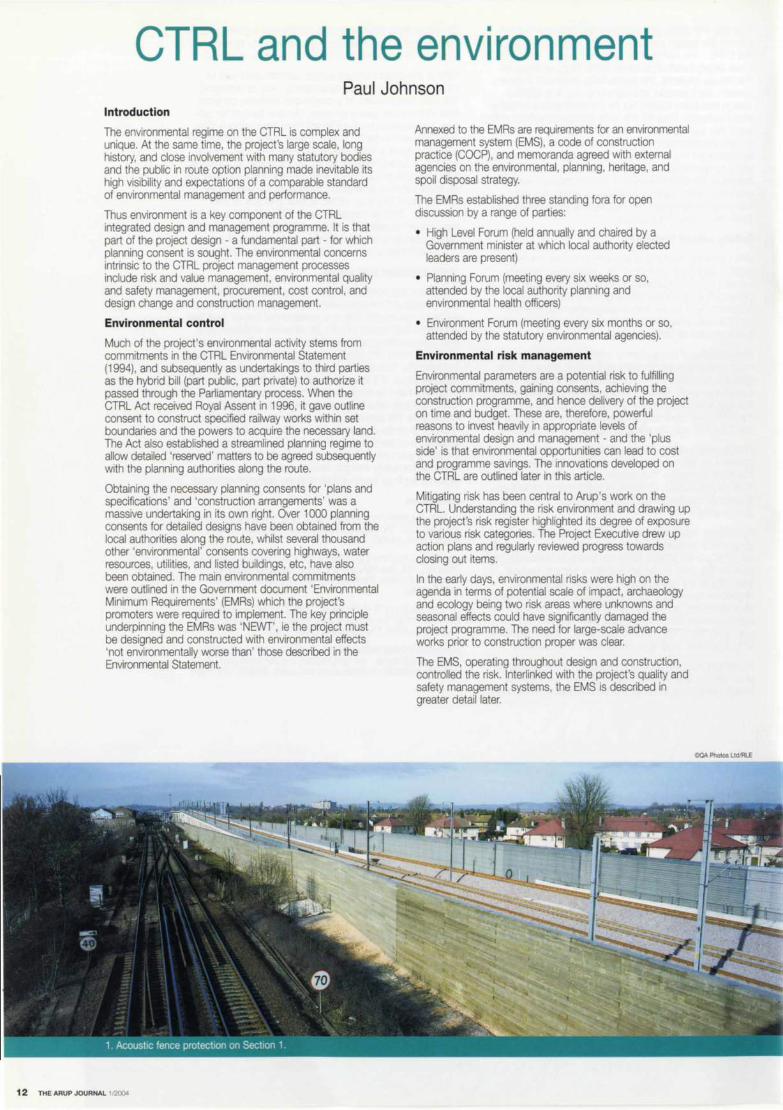
Noise and vibration
Noise and vibration issues were amongst the most significant environmental risks to the project. Protection of communities from noise and vibration due to construction works and the operation of trains and fixed equipment has been a formidable technical and managerial challenge.
Using the Environmental Statement as a baseline, RLE assessed the noise impact on communities from alignment and other design changes, and proposed mitigation works where appropriate in the form of noise bunds (earthworks), utilizing surplus spoil in a carefully-designed new landscape form. Their design was an integrated exercise with civil engineers, noise specialists, landscape architects, and agriculturalists combining to ensure that the new landform was functional both in terms of noise control and subsequent after-use. The use of surplus spoil in this way generated enormous cost savings and environmental benefits to the project by removing the need for taxable offsite waste disposal at remote locations, thus keeping many heavy lorries off the public highway.
Another challenge was in the design of acoustic barriers. The nature of the noise generated by high-speed trains necessitated performance levels beyond 'off the shelf' solutions. The answer was another innovative integrated exercise between noise specialists, architects, landscape architects, structural and geotechnical engineers, and materials specialists. Two types of solution were developed.
The first was a 'family' of wayside timber barriers up to 5m high comprising machined tongue-and-groove softwood timber planks 35mm thick, nailed to vertical supports. In places an absorbent lining, secured by perforated steel panels, further enhanced the acoustic performance of these reflective barriers. The location, height, type, and visual appearance of the barriers was subject to close scrutiny and planning consent from the relevant local authorities. Most of them look like plain timber fences, but in some urban locations a coloured pattern was requested and applied. These timber panels were very cost-effective, with a design life of some 30 years. They were closely specified so that individual contractors could procure the timber from suppliers using managed plantations and easily erect them using semi-skilled staff.
The second type is a low-level barrier installed closer to the wheel-rail interface, which generates much of the noise. This type is used exclusively on structures, mounted on the track ballast retention kerb, and are 1 .4m high, galvanized steel panels with absorbent linings protected by profiled perforated covers. Acoustically-sealed gates are installed at intervals to allow emergency egress. Modelling showed these low-level barriers to be as effective as the 2m-high concrete outer parapet barriers originally planned. The major advance in this innovative design was that moving to a smaller in-board barrier allowed the design of bridges and viaducts to incorporate more sustainable, lighter, and lower-cost structures with greater visual appeal.
16 THE ARUP JOURNAL t/2004
Other design efforts focused on the mitigation of noise and vibration from the trackform in tunnels, pressurerelief/ventilation shafts, and stations and fixed plant. For surface track, a conventional ballasted trackform is installed, consistent with the project's noise commitments. However in tunnels, especially the London Tunnels, the need to control the rumble caused by ground-borne noise transmitted from the wheels to the track and thence into the ground and overlying properties required the specification of a 'resilient' trackform, involving a synthetic rubber material to reduce noise transmission.
At the pressure relief/ventilation shafts, the passage of high-speed trains in the tunnels below will, if not untreated, generate a rush of air causing intrusive noise at the surface. Modelling and design is specifying the necessary grilles and dampers to mitigate this.
Within stations, especially St Pancras where trains enter at first floor level, the track and the structural elements of support systems are designed so that station spaces can be used to their full potential without the intrusion of train noise. It is also essential to ensure that passenger address and voice alarm systems are clearly audible inside the stations but do not spread to surrounding residential areas.
The control of noise and vibration from civil, structural, and system-wide construction works is a continuing issue requiring close and effective management to prevent complaint from surrounding communities. RLE provides the noise 'envelope' for construction works that is given planning consent by the local authorities. The construction contractors, however, are required to get further consents (under S61 of the Control of Pollution Act) which specify the need for Best Practicable Means to be employed in terms of use of equipment, hours of work, use of temporary mitigation work, and the possible need for noise insulation or temporary rehousing, etc.
The project has pioneered the assessment of various construction techniques (for example, monitoring the performance of alternative types of piling operation) and also the development of cumulative noise assessment from multi-contractor operations on single sites to betterinformed regulatory and site management processes.
Environmental management system
The EMS is a key control mechanism to ensure compliance with the wide range of commitments and to deliver environmental risk management. The system is aligned to ISO 74001 and integrated at high level with the project's quality and safety management systems under the Project Quality Plan. Through the EMS, confidence is given to the client, the Government project representative, external funders, insurers, and regulatory bodies that the project understands its environmental constraints, risks and commitments and can demonstrate positive action to mitigate them.
As noted previously, the EMS is one of the project's Environmental Minimum Requirements (EMRs) and was developed at the outset. It covers both design and construction and is driven by a published Environmental Policy Statement signed by the Project Director and the clients' Managing Directors. A high-level environmental management procedure is linked with engineering procedures and departmental instructions to deliver the commrtments during design, procurement and construction.
Environmental awareness training is given to all staff at induction and in subsequent in-depth targeted sessions. Objectives and targets are set for key line managers and reviewed quarterly. Engineering design teams have environmental co-ordinators dedicated to ensuring the design takes proper account of environmental issues and is signed off by a formal environmental design management process.
Generic (topic-based) and local area-based environmental management plans further inform the consents process on how the project will implement its work in the field.
The EMS design and operation is subject to both internal and external audit by the Government's representative. Corrective actions are identified and implemented if found necessary. A Management Review by the Project Directorate is held annually to consider progress and implement change as appropriate. Effective construction environmental management must ensure that commitments and best practice to be delivered by the contractors in the field are closely specified in the contract documentation. Prior to appointment, environmental considerations form part of the structured pre-qualification and final contractor selection process to the same degree as quality and safety.
After contract award, contractors have to appoint a fulltime environmental site manager and appropriate support staff to implement the project requirements, undertake training, direct the field environmental control, etc.
9. The CTRL Sustainability Awards were launched in August 2002 to recognize significant contributions towards
advancing sustainability good practice throughout the project. The scheme is planned to run on a six-monthly cycle, and the
first winner was announced in December 2002.
RLE provides a contract environmental advisor who acts as the project's interface. Weekly meetings and joint surveillance visits are carried out, supported by other RLE environmental specialists. At six-monthly intervals, an audit is carried out, often with the contractor's corporate environmental manager in attendance.
As already noted in this special edrtion of The Arup Journal, relationships with the public, local authorities, and other regulatory bodies are critically important and much effort goes into interfaces, consultation, and liaison at several working levels. Training contractor and sub-contractor staff is vital; RLE developed a range of initiatives to advance environmental awareness, ranging from pocket leaflets, cards, and short videos on key subjects like water pollution control and noise mitigation, to the 'Target Zero Environmental Incidents Campaign'. The latter is focused on the Target Zero truck, a brightly-painted four-wheel drive training vehicle which travels the route, the trained driver giving awareness-raising videos, presentations, and gifts to small groups of workers at their field locations.
To maintain momentum, a 'CTRL Sustainability Works' award scheme encourages best practice in use of resources, waste management, environmental protection, and community liaison.
Key environmental concerns in the field vary according to perception. For the public, matters like traffic management, vehicle movements, and environmental 'housekeeping' loom largest, and a 24-hour help line is maintained.
The statutory authorities tend to have greater concern over surface water quality, dust and noise control, and working hours. The project is acutely conscious of these concerns and implements many initiatives in relation to training, incident control, investigation and reporting to prevent recurrence. RLE also initiated a construction contractors' environmental forum for cross-contract experiences to be openly discussed and good practice disseminated.
The benefits of the EMS are extensive. Environmental risks have been identified, closed, and cost savings achieved, far outweighing the management costs of setting up and running the system.
The principal savings have been through elimination of programme delays, timely achievement of consents to meet the programme, gaining extended working hours, the relatively few complaints and incidents, the virtual elimination of statutory intervention leading to prosecution, excellent spoil and waste management, and wide dissemination of good practice leading to more efficient working practices.
THE ARUP JOURNAL ll2004 17

Ground engineering Nick O'Riordan
Introduction
The CTRL places new demands on engineers. Hitherto, the UK railway industry has been characterized by a reliance on precedent, and a culture of maintenance rather than innovation and technical advancement. But on this project, geotechnical engineers comfortable with the design and construction of foundations for dead and nearly-dead loading were challenged by a client brief that emphasizes reliability, availability, maintenance, and safety for the end use of the track by Eurostar, as well as heavy freight and local commuter services, over a design life of 120 years.
Fortunately the challenge to create a 21 st century, high-speed railway in the crowded south-eastern corner of England has coincided with geotechnical and gee-environmental engineering maturing as engineering science. Within this project, technological innovation can be explored and implemented to the benefit of the whole industry. The CTRL has to a considerable extent driven the production of seminal reports by the Construction Industry Research and Information Association (CIRIA) on the engineering properties of chalk and the design of retaining structures. Fresh thinking has given new insights into the behaviour of integral bridge abutments and repetitively loaded piled slabs, and this has resulted in greater economy in design and construction.
Woolwich- • Chalk Reading. Thanet Beds
•Upper Greensand and Chalk
1. Geology around the CTRL route.
Geological Geological Thickness Depth General description stratum unit IT' (m)
0 Made ground 5 Variable /ill material
Superficial Allwium 12 Soft clays and peats depostts
Terrace gravels 6 Sand and gravel Head 5 Variable; usually chalk
gravel deposits
5 Thames Group London Clay ">40 Stiff fissured clay
Harwich Formation Fme sand +/- shells
Lambeth Group Woolwich -Reading 2 Sands and clays
Thanet Beds Thane/ Beds 9 Rne-medium silty sand with Bullhead Beds at base
75 Seaford Cha/le 40 Solt white chalk with flints
Upper Chalk Upper Lewes Chalk 30 lnterbedded soft and hard nodular Lower Lewes chalks with flints and mart seams Chall< 28 lnterbedded soft and hard nodular
chalks with flints and mart seams
Middle Chalk I New Pit Chalk 42 8/ocky white to pale green chalk; no flints
Holywel/ Chalk 17 Massive nodular cha/le with flaser marls; Melboum Rock at base
Lower Chalk Lower Chalk 60 Greyish chalks, marJy chalks and marts. Plenus Mart at top
292 Gault Clay Gault Clay 62 Very stiff fissured blue-grey clay
Folkestone Beds 36 Sands, pebbly sands and sandstone
Lower Sandgate Beds 15 Clays, silts with sands, sandstones Greensand and mudstones
HytheBeds 12 Alternating limestones and calcareous sandstones
Atherlield Clay 14 Very stiff fissured chocolate brown clays
Weald Clay Weald Clay 25 F1SSured laminated occ. mottled clays with thin limestone bands
456
2. Geological sequence.
18 THE ARUP JOURNAL 1/200<!
I
Lower Greensand
Areas
LONDON
St Pancras
• Weald Clay • London Clay
London Tunnels
North Kent/Essex
Thames Tunnel
North Downs Tunnel
South Kent
FOLKESTONE

The team and ground risk management
RLE's 30-strong ground engineering team, drawn principally from Arup, comprises geotechnical designers and analysts, contaminated land and hydrogeological specialists, a baseline monitoring team, and data management for the whole route (Figs 1, 2). The geotechnical designers tend to follow their designs out into the construction works, and this facilitates the close attention to self-certification of groundworks by contractors.
Access, particularly in areas occupied by live railway, was a particular difficulty throughout the many investigation phases (Fig 5). The overall cost of all these was £17M: approximately 0.8% of the total cost of the CTRL civil engineering works.
The delivery of foundation, retaining wall, and earthworks design tor a project of this magnitude by a comparatively small design team was made possible by using an electronic database for all borehole stratigraphy, field and laboratory tests, and groundwater quality data.
Phase Period Boreholes Trial pits Other
January-July 1994 193 230 184
2 July-November 1994 424 488 335 3 October 1995-November 1996 450 390 291
4 April 1997-July 1998 492 598 93
5 August 1998-July 1999 279 281 301
6 August2000-December2001 343 225 333
'Histonc'
5. CTRL ground invest1gat1ons.
This was supplied to geotechnical engineers in both the design office and the field.
Early in RLE's design process, groundwater quality and water levels were incorporated into a baseline monitoring program. Again the data is held in digital format. This database is accessed and used routinely in office and field, supporting temporary works and groundwater protection activities.
Full-scale preliminary pile testing was necessary to prove the design assumptions, particularly where foundations were subjected to unusually high lateral or cyclic loads, as at the Medway Bridge (Fig 3) and for the piled slab across the Thames Marshes.
Ground risk management was exercised by a combination of progressive site investigation, benchmark reporting, structure and earthworks-specific design notes, design transfer to contractor's self-certification, and feedback from construction (Fig 4).
. .. . "'
3. The river pier foundation; 1.8m diameter piles for the Medway Viaduct, formed after detailed vertical and lateral preliminary pile testing onshore. ,,
- -----· __ ._L __ ._, .. :,}
Preliminary design
Geotechnocal design basis reports
Cootam,nated land nsk assessment reports
Earthworl< materials reports
Detailed design
Geotechnieal design notes
Contract documents
Phased site 1nvest,gattons
Construction
Contractors' construction records
Feedback reports
4. Ground risk management. Graphic: Daniel Blackhall.
Totals
607
1247
1131
1183
861
901
5930
2739
THE ARUP JOURNAL t/2004 19

Trains Axle toad Mean line Minimum axle (kN) load (kN/m) spacing (m)
Eurostar 170 21 .5 3.0
Commuter 130 22.5 2.5
UIC 71 250 80 1.6
Heavy freight 225 80 1.8
6. Design loading for fatigue analyses.
8-
i:-1---~ 4 +-~~~~~~~~~~~~~~~-.g
i : -+-~~,,._~~~ ···-~~~~~~~~ 0-+-~~~~~~~~~~~~~~~~
0
1.4
1.2
s j 1
l 0.8
t .!!I 0.6
~ @ 0.4 (!)
0.2
0
200
Train speed (km/h)
• Stilton Fen'
Ledsgara·
Amsterdam-Utrecht'
/ Piled slab
/ LI and Selig (1998)
7. Variation in track displacement with train speed (data reported by Woldnngh and New2).
. ... ... p,t.5>1.5 >1.5 > t.5
- -~
i...,..--
/ I .. ·-- ..,
400
0 20 40 60 80 100 120
• Design life (years)
Staoc wheel load = 250kN
Dynamic Wheel load = 350kN
Dynamic wheel load = 683kN (AREA. 1996)
8. Variation of thickness of trackbed layers {ballast, sub-ballast and prepared subgrade) with design life, after Li and Selig3, modified by O'Riordan and Phears. A dynamic wheel load effect of 350kN is appropriate for the selected case of a stiff clay subgrade subjected to the design loading shown in Fig 6.
Graphics: Daniel Blackhall.
20 THE ARUP JOURNAL 1/2004
140
cycles/ day
1400
660
750
cycles/ Maximum weeks/ months/ years/ year speed 100 OOO 1M 10M
(km/hr) cycles cycles cycles
511000 300 10 24 20
240900 160 22 51 42
273750 150 19 44 37
Trackbed support
A vital part of the work is the provision of trackbed support for trains travelling at 300krn/hr, at a defined quality of ride. Fig 6 summarizes the pattern of cyclic loading from the various trains in service.
The dynamic behaviour of structural foundations and earthworks requires a detailed understanding of the soil/structure interaction that differentiates a high-speed railway from more conventional highways or lower speed railways. Fig 9 shows a visualization from a dynamic analysis of the 0.45m thick West Thames piled slab on Contract 310, where the ratio of peak live to dead load is around 1.5. From such analyses can be predicted longterm pile settlements under these very high and repetitive train loads,.
Fig 7 shows results of measurements of track movement on earthworks, as well as data from other sources2, 3.
The team extended this work, using a combination of static and quasi-static analysis to produce coherent prediction of track movements. The team adapted UIC 719R4, the international design code for earthworks and track-bed layers, and used Selig's work3 to relate track-bed layer thickness, control of cumulative plastic strains in the subgrade, and design life (Fig 8).
Soil-structure interaction
The CTRL design teams are consciously following in the footsteps of earlier railway builders. The published difficulties6 encountered in the mid-1800s during construction of the Saltwood tunnels (Contract 440, the Ashford to Folkestone Line), in the variably cemented and water-bearing Folkestone Beds, were relived in the analysis of the brickwork lining, and in the eventual remodelling of the landscape around the live railway that passes beneath and to the side of the CTRL.

Another instance has been the new station box forming part of the Thameslink 2000 project, located under Midland Road between the basements of the British Ubrary and St Pancras Chambers. This widens an existing cut-and-cover tunnel under the existing St Pancras Station complex. Trial and error, and the winnowing of experience that typified much of the Victorian railway age, cannot be part of today's risk management philosophy. This puts increasing pressure on the ground engineer to learn from the past, and predict future behaviour.
Nowhere is soil/structure interplay more important than in bridge design and construction. High-speed railway bridges can be characterized by their low tolerance to movement during train braking and accelerating, and the required rigidity can result in high forces generated by long-term thermal cycling of the bridge deck. Thus the foundation system can be neither too soft nor too stiff. Full-scale lateral and vertical load tests on foundations for critical structures are necessary for design verification. Numerical analysis enables such field tests to be interpreted so that future behaviour can be predicted.
Groundwater control
The cut-and-cover tunnels lie in up to 15m of soft alluvium over gravel and chalk at the Thames Tunnel , in variably weathered Gault Clay at Boxley, in Atherfield and Weald Clay at Ashford, and in Lambeth Group clays overlain by river deposits and variably contaminated made ground at Stratford. Groundwater control around them has been a significant part of design and construction.
Clear spans between permanent propping slabs are very large, at around 8m, to give sufficient clearance for trains, trackbed, power, and other services. Maximum excavation depth is normally well over 12m and lengths typically exceed 1 km. In each case, ground permeability was found to be sufficiently high for water pressures to dominate both short-term and long-term performance of the walls and props. This meant that assumptions of groundwater pressures during and after construction were explicitly addressed for incorporation into construction sequence and programme. Full-scale pumping trials and in situ permeability testing figured high in the ground investigations.
Prediction and back-analysis of water pressures within and around deep excavations in ground of highly anisotropic permeability were made using 30 finite element programs such as MODFLOW.
Earthworks and waste minimization
The ground engineering team was responsible for specifying the earthworks for the whole route, which required and
enabled a very detailed analysis, earthwork by earthwork, of the probability of acceptance of the various materials to be excavated. In turn, materials could be identified for structural earthworks or mitigation fills, to minimize waste. A crucial milestone was identifying the need for a landraise at Stratford, so that the 2.5Mm3 of spoil from the London Tunnels could be used as regeneration enabling works for a development on a podium above the surrounding non-CTRL track layout.
At the Thames Tunnel, it was established that the very wet chalk slurry produced by the TBMs could be converted into an engineered material for infilling a nearby quarry. Recycling upwards of 0.3Mm3 of slurry to form a platform for future development involved the use of separation screens, hydrocyclones, centrifuges, and conveyors?.
The challenge to provide a 21 st century railway at lowest first cost, consistent with defined reliability, availability, maintainability and safety (RAMS) criteria, led to the pioneering use of dry deep soil mixing in the UK. This built on the experience of stabilizing embankments for the Swedish high-speed railway at Ledsgard, after large displacements (Fig 7) were recorded. This technique has been used for short lengths of embankment on soft clays and peats adjacent to the live Ashford to Folkestone railway, and similar treatments will be adopted for non high-speed works in Section 2.
Off-line, a trial of wet soil mixing was carried out on a methane-producing, unlined landfill at Runham Lane in Kent where the alignment passed in a 1 Orn deep cutting. The technique was used in an attempt to produce a cemented block that would support the landfill to the north of the railway. This would have saved the wholesale removal of the landfill contents to a. new, fully-engineered site. In the event, the trial did not produce a sufficiently robust product, but enabled design and verification tools to be developed that were later used for soil mixing and stabilizing elsewhere on the project.
Conclusions
As in any major project on which designers from many backgrounds and organizations collaborate, there has been major effort to harmonize design standards and develop a uniform design philosophy. Deficiencies in existing standards and guidance have been addressed, particularly in relation to the design of the trackbed support, retaining walls and propping slabs, the engineering properties of chalk, and waste minimization. The ground engineering team has made and, as the project reaches completion, will continue fo make significant contributions to new industry guidance documents and practice.
References
(1) O'RIORDAN, Net al. Long term settlement of piles under repetitive loading from trains. Symposium on structures for high-speed railway Transportation, IABSE, Antwerp 2003.
(2) WOLDRINGH, RF and NEW, BM. Embankment design for high-speed trains in soft soils. Geotechnical engineering for transportation infrastructure, Vo/ V3, pp1703-1712, 1999.
(3) LI, D and SELIG, ET Method for railroad track foundation design; 1 : development; 2: applications. In: ASCE Journal of geotechnical and geoenvironmental engineering, 124(4), pp.316-329, (April), 1998.
(4) INTERNATIONAL UNION OF RAILWAYS. Recommendatory leaflet 719. Earthworks and trackbed construction for railway lines. Second edition, UIC 1994.
(5) O'RIORDAN, NJ, and PHEAR, AG. Design and construction control for ballasted track formation and subgrade under high-speed lines. Keynote paper. Railway Engineering 2001. London 2001.
(6) SIMMS, PN. Practical tunnelling: Explaining in detail the setting out of the works; shaft sinking, and heading driving ... levelling under ground; sub-excavating, timbering; and the construction of the brickwork of tunnels ... as exemplified by the particulars of Blechingley and Saltwood tunnels. Troughton & Simms, 1844.
(7) WARREN, CD, et al. Treatment and placement of chalk spoil from the CTRL Thames Tunnel. Proceedings of the Underground Construction 2003 Conference, ExCel, London Docklands.
THE ARUP JOURNAL 1/2004 21

Bored tunnels Eddie Woods
Introduction The key tunnelling works on Section 1 are the North Downs Tunnel under Blue Bell Hill and the protection works for the existing Saltwood Tunnel. The Section 2 works are far more extensive, comprising the Thames Tunnel and then the complex of London Tunnels leading to the Kings Cross Railway Lands. The Section 2 contracts were awarded in January 2001 ; following six months preconstruction planning, they began on site in July 2001.
The key factor in the design of all the tunnels has been the high train speeds: 300km/hr for Section 1 and 230km/hr for Section 2. This has influenced all aspects including the size of the tunnels, derailment containment, the alignment, and driving tolerances.
67%
London Clay I ~% I . . )
Woolwich & Readlng clays{ Harwich Formation sands
- ------- 1610m
Made gro,..oo D WooWch & Reading BedslHa/wid1 foonatlon
• LondonOay
Corsica Graham Street shaft Road shaft
I 21% I 29% I .. ) . )
Woolwich & Upnor & Thanet Reading Sands: 1 7% with
Clays chalk/flints in invert
I • Upnor & .::t Sands: • I 18% with chalkfflints
in inven
- --5900m----1012m -s•1-tl+-• --4700m---
• London Clay
Chalk
O Gravels and superficial deposits
D Woolwich & Readlng/Thanet Sands & Upnor Beds
Be<rington Road shaft Wayside shaft
Ripple Lane portal
I· 50% ·I· e .,~~1 Woolwich & Reading Beds/ Lo Clay
Thanet Sands Gravel
2950m 2300m 420m .j
• London Clay D Gravels and superficial dep<>Sits
Woolwich & Reading Beds.flnanet Sands & Upnor Formation
1. Geological conditions through which the London Tunnels run. Graphic: Daniel Blackhall/Thomas Graham.
22 niE ARUP JOURNAL 1/2004
London Tunnels These are twin 7 .15m internal diameter tunnels lined with precast concrete segments, initially running 7.5km from the west portal at Kings Cross to the west end of the 1 km long Stratford Box, and then continuing from the east end of the Stratford Box for another 1 Okm under Barking before they emerge at the Ripple Lane portal. The construction was awarded under contracts C220, C230, C240, and C250 (detailed on p62).
Procurement
A key development on the CTRL has been the formation of the T2A alliance. All the London Tunnel contractors and the client allied together, with the client adding his risk allowances into the alliance budget and the contractors agreeing to do away with compensation events under the ECC Conditions of Contract. The contract essentially became a fixed price for the client, apart from increases/ decreases in scope, and the client and the contractors share in any savings or cost overruns. To safeguard the programme and interfaces, milestones were introduced which the contractors have had to meet to accrue a 1 /40th increment of any saving.
A major benefit of this has been the working arrangements between C220, C230, C240, and C250, including:
• C230 providing the entire tunnel spoil treatment for C220 and C240 at Stratford
• contractors working together to overcome interface programme delays, saving the client eight weeks of additional costs
• shared office facilities and resources
• agreements to manage labour across the area to avoid ransom demands and spiralling costs
• rescheduling resources and material deliveries between contracts to ensure the overall area milestones are met
• minimizing staff costs by combining resources, with each contract team combining to form a single integrated team to complete all the civil finishing works in the tunnel under one contract director, reducing staff by over 50% and saving £4.5M.
Alliancing has also required RLE designers to work as part of an integrated team with the contractors to resolve problems, ensure constructability, and minimize costs. The mitigation works for structures included in the contracts were transferred back to the RLE design team, who were best placed to develop cost-effective mitigation measures.
Tunnel boring
Given the geology through which the London Tunnels pass (Fig 1), pre-tender risk assessments identified earth pressure balance (EPB) machines as the most appropriate tunnel boring machines (TBM). These use an Archimedes screw conveyor to remove the spoil from the tunnel face; by regulating the flow within the screw (excavation rate) they balance ground face pressures. At the outset RLE recognized that the TBMs were critical for the project's success in terms of control of settlement, programme, and cost risk. To avoid TBMs being used by tenderers to gain competitive advantage, a high performance 'minimum' specification was developed. This assembled worldwide best practice in reliability, safety, durability and control of settlement. The TBMs thus included several special features beyond those normally provided, to increase performance and reliability:
• 10 OOO-hour life for high-risk items (1600 actual usage)
• additional ports for injecting foam into the cutting head to improve EPB at the face and spoil handling characteristics
• hardened surfaces - use of special tri-form plate steel
• injection around shield skin
• bearing design specified
• triple brush sealing
• interlock grouting.

42 THE ARUP JOURNAL 1/2004
The rails were laid out on the sub-grade to a gauge that enables special large portal-framed plant to run on them. These frames replaced the temporary panels with permanent sleepers. Once these were placed, the rails on the first line were 'zipped' into place and fastened to the sleepers with hand-held plant to form the permanent track. The first layer of ballast was then hoppered and vibrated into position (Fig 4).
With the first line in place, the adjacent line could be built. With both tracks in place, the profile of the rails was brought to the precise line and level tolerances necessary for high-speed running using ballast, including the necessary canting on curves. A modern fleet of hoppers was used, shooting the ballast directly to within a few centimetres of the final position.
Ballasting and tamping were carefully controlled to achieve the required degree of consolidation under the sleepers. After tamping, the ballast was regulated, or brushed into place using another on-track machine. Periodically the track was stabilized to improve consolidation, again using an on-track machine. With the levelling substantially complete, the switches and crossings (S&C) and their control systems including points motors were inserted into the line by substitution, using rail-mounted cranes.
Internal track possession arrangements had to be established to enable this S&C work to accommodate the daily flow of engineering trains to their work sites. Pre-assembly areas for the S&C - which were needed during both construction and subsequent permanent operation of the railway - were identified and constructed at several locations along the route by the main civil engineering contractors.
To deal with the high-speed and freight trains, and as a result of the heavier UIC rail, special S&C was developed with high specification geometry and control systems including M&E control. These were specially fabricated to a high specification to permit the passage of trains turning out at 180km/hr. The 180km/hr turnouts are over 200m long and almost every single sleeper is a different length.
After the S&C was installed, the rails were prestressed between them to prevent buckling in hot weather.
Settlement and mitigation
The tunnels pass under a densely urbanized area (Fig 4) with over 3000 domestic properties, 67 bridges, 12km of surface railways, six railway stations, 600 utility crossings, and 12 operational railway tunnels. Some infrastructure dates from the 19th century (Fig 6) and is in poor repair. RLE's approach was to develop a high-performance TBM specification specifically to minimize tunnel settlement.
TME ARUP JOURNAL 1/2004 23

The critical risks included:
• the Central Line. which was only 35m from the start of tunnel construction from the Stratford East portal; the CTRL tunnels pass within 4m beneath the operational tunnel (Figs 7, 8)
• Highbury and Islington Station, where the CTRL tunnels pass beneath four operational railway tunnels and two escalators serving the station, which had a movement tolerance of less than 1mm.
The Arup RLE team led the assessment of impact on the existing tunnels and the design of mitigation works and real time instrumentation systems. To obtain LUL approval, risk workshops were held with all stakeholders including LUL departments. the operations companies. the contractor, and RLE. The workshops identified all the risks, and mitigation measures were implemented to reduce the risk to an acceptable level.
Real time instrumentation was used to monitor the impact of tunnelling on the ground equivalent to the relative position of the existing tunnels and the movement within them. This, combined with the computer displays of TBM parameters including face pressure, grout pressure, tunnel advance, amount of spoil excavated, and torque, allowed adjustments to the drive parameters to control movements within the existing tunnels.
The tunnels have been driven successfully beneath the existing infrastructure with settlements of the Central Line limited to <Bmm (equivalent to a volume loss of 0.25%). Tunnel volume loss, which equates to ground movement, has traditionally been around 1-2%. The CTRL has managed to limit this to less than 1 % and generally to less than 0.5% (Fig 9). Where it was necessary to control settlement for specific structures this was limited to 0.25%.
LUL's Jubilee Line Extension showed that local dewatering for ventilation shafts had a widespread influence and lowered the water tables for the tunnels connecting the shafts. Modelling and dewatering trials were therefore carried out by RLE before the tunnel contracts were tendered to confirm that the water table could be lowered below the tunnel horizon.
1% -
2
C220 up line
9. Volume loss.
24 T HE \RUP JOURNAL 1/2004
3 km
Originally expected
4 5
C220 down line
Graphic: Thomas Graham.
7. & 8. The proximity of the London Tunnels to other infrastructure at Stratford. Graphics: Thomas Graham.
Stratford Box
Angel lane
Central Line ,,,Q ,t.~nnels
,,O :,' Zoneof ',, ,' ,' ', influence ', , , ', ..
London Tunnels - 1.5m segments
The running tunnels are connected by 26 cross-passages, of 3.5m internal diameter lined with spheroidal graphite iron (SGI) segments, at an average spacing of 680m, and constructed by hand after the TBMs have passed. Lowering the water table enables these to be constructed in dewatered conditions so that newly excavated ground is stable for a considerable time before it relaxes and collapses (stand up time), increasing safety and reducing risks, costs, programme, and surface settlement.
Ventilation shafts
The London Tunnels have five ventilation shafts up to 500m2 in plan area: Corsica Street, Graham Road, Woodgrange Road. Barrington Road, and Wayside. They are designed to:
• give pressurized stair and lift access for emergencies
• accommodate emergency ventilation fans to control smoke and provide safe conditions for fire evacuation from the incident to the non-incident tunnel
• give pressure relief for the piston effect from the highspeed trains to control transient pressures to less than 2.5kPa in four seconds (required for passenger comfort)
• accommodate electrical and mechanical equipment and low point sumps where appropriate.
The limited sites available within the urban area resulted in different geometrical relationships between the shafts and the running tunnels, requiring in turn bespoke arrangements and construction methods.
The Corsica Street shaft is 17m internal diameter by 35m deep, sunk in London Clay using a sprayed concrete primary lining with an in situ concrete secondary lining. The down line tunnel passes through the shaft, which accommodates all necessary connections. The up line is beneath the North London Line surface railway and connected to the shaft by sprayed concrete lined (SCL) access, ventilation, and pressure relief adits.
Graham Road, Woodgrange Road, and Barrington Road are rectangular shafts and have been constructed by diaphragm walls and permanent steel frames to depths of over 50m - a UK record. The connections occur in Thanet Sands, and to minimize tunnel works the rectangular shape was adopted to accommodate all the shaft/running tunnel inter-connections without the need for hand-built access tunnels. Permanent heavy steel frames and props were needed, however, and these were difficult to manufacture and construct. They were installed as the shaft was excavated to eliminate the need for temporary supports within the shafts.
The Wayside shaft (Fig 1 0 right) is an elliptical reinforced contiguous pile construction, built off the line of the tunnels. Connecting adits were constructed with sprayed concrete and a secondary in situ concrete lining, 5m below the operational London Tilbury and Southend Line.

Stratford International Station The platforms for Stratford Station are contained within a 1 km long, 35m-52m wide, 12m-25m deep underground box constructed using diaphragm walls and an in situ concrete base slab. The box accommodates two 425mlong international, two 290m-long domestic platforms, and associated up and down lines. There are also up and down fast lines for through trains and a rail connection from the middle of the box to the surface to a future depot at Temple Mills. The box is long to accommodate the platform lengths and the fast 160km/hr turnouts that enable trains to transfer from the main through lines onto the platforms, and into the tunnels. The station slab that supports the station spanning across the box at ground level is carried on the box walls and intermediate columns supported on plunge columns and barrettes.
The box base slab is not designed to withstand uplift pressures, and permanent dewatering has been provided with redundancy of systems to safeguard the station. The dewatering system is located in the chalk underlying the Thanet Sands beneath the base slab, and was used to draw down the water for box excavation. The 120m at each end of the box were completed first to provide the launch chambers and work sites for the four TBM drives. Here the base slab was reinforced to accommodate the high thrust loads from the TBMs and transfer them into the walls. The base slab in the centre of the box acts as a compression strut and is generally mass concrete. In addition two rail lines and two road bridges cross the box.
Spoil is a key issue in tunnelling. The large excavation works and the disused railway infrastructure on Stratford Lands are being reclaimed, and the contamination from refuelling depots and a gas works removed/treated. The material from the box and the tunnels is being used to raise the level of Stratford Lands, which is currently in a flood plane, by up to 6m for development. This site is being proposed for the 2012 London Olympic bid.
Ripple Lane Portal This major structure (see next article) comprises a 200mlong cut-and-cover portal and 300m of retained cut, all built within a sheet-piled cofferdam incorporated into the permanent works to provide resistance to flotation . It was designed by the contractor as a value engineering initiative compared with ALE's diaphragm wall solution. This resulted in £4.5M estimated savings. A deliberate policy was adopted to make the contractor responsible for both the design and checking of value engineering, to avoid ALE being in the supply chain for these programme critical deliverables. ALE undertook due diligence to ensure the designs complied with contract requirements.
Thames Tunnel The Thames Tunnel was built under contract C320 (see p62). These twin 2.5km-long bored tunnels, plus their approach structures, carry the CTAL beneath the Thames estuary at depths of up to 40m below mean river level. The tunnels were driven from Swanscombe Marshes on the south side to West Thurrock marshes on the north side by a Herrenknecht mixshield slurry TBM. These TBMs use bentonite slurry to support the excavated face, the spoil being removed hydraulically through pipes. This was more suited to maintaining face stability and controlling settlement in the open river gravel at the start of the drive, as well as dealing with high inflows of water associated with fissures in the chalk under the Thames and high water pressures up to 4bar.
The contract also includes the construction of over 600m of cut-and-cover tunnels, 300m of retained cut, and 295m of in situ box, retained cut structures in the Thames riverside marshes. The tunnel approach structures were excavated with the assistance of extensive dewatering within the approach structure box. The tunnel spoil -primarily slurrified chalk - was treated, compacted, and placed in a local abandoned chalk quarry to form a platform for future development.
THE ARUP JOURNAL 1/20()4 25
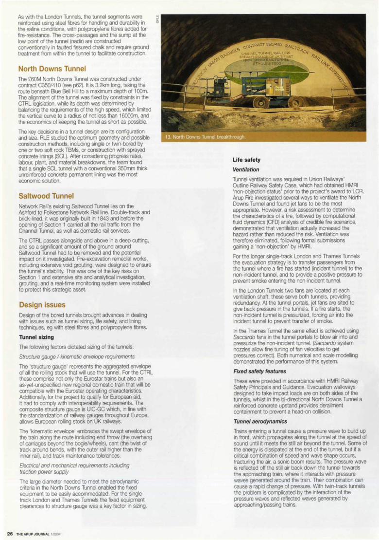
As with the London Tunnels, the tunnel segments were j
reinforced using steel fibres for handling and durability in ii the saline conditions, with polypropylene fibres added for fire-resistance. The cross-passages and the sump at the low point of the tunnel (nadir) are constructed conventionally in faulted fissured chalk and require ground treatment from within the tunnel to facilitate construction.
North Downs Tunnel The £60M North Downs Tunnel was constructed under contract C350/410 (see p62). It is 3.2km long, taking the route beneath Blue Bell Hill to a maximum depth of 1 OOm. The alignment of the tunnel was fixed by constraints in the CTRL legislation, while its depth was determined by balancing the requirements of the high speed, which limited the vertical curve to a radius of not less than 16000m. and the economics of keeping the tunnel as short as possible.
The key decisions in a tunnel design are its configuration and size. RLE studied the optimum geometry and possible construction methods, including single or twin-bored by one or two soft rock TBMs, or construction with sprayed concrete linings (SCL). After considering progress rates, labour, plant, and material breakdowns, the team found that a single SCL tunnel with a conventional 350mm thick unreinforced concrete permanent lining was the most economic solution.
Saltwood Tunnel Network Rail 's existing Saltwood Tunnel lies on the Ashford to Folkestone Network Rail line. Double-track and brick-lined, it was originally built in 1843 and before the opening of Section 1 carried all the rail traffic from the Channel Tunnel, as well as domestic rail services.
The CTRL passes alongside and above in a deep cutting, and so a significant amount of the ground around Saltwood Tunnel had to be removed and the potential impact on it investigated. Pre-excavation remedial works, including extensive void grouting, were designed to ensure the tunnel's stability. This was one of the key risks on Section 1 and extensive site and analytical investigation, grouting, and a real-time monitoring system were installed to protect this strategic asset.
Design issues Design of the bored tunnels brought advances in dealing with issues such as tunnel sizing, life safety, and lining techniques, eg with steel fibres and polypropylene fibres.
Tunnel sizing
The following factors dictated sizing of the tunnels:
Structure gauge I kinematic envelope requirements
The 'structure gauge' represents the aggregated envelope of all the rolling stock that will use the tunnel. For the CTRL these comprise not only the Eurostar trains but also an as-yet-unspecified new regional domestic train that will be compatible with the Eurostar operating characteristics. Additionally, for the project to qualify for European aid, it had to comply with interoperability requirements. The composite structure gauge is UIC-GC which, in line with the standardization of railway gauges throughout Europe, allows European rolling stock on UK railways.
The 'kinematic envelope' embraces the swept envelope of the train along the route including end throw (the overhang of carriages beyond the bogie/wheels), cant (the twist of track around bends, with the outer rail higher than the inner rail), and track maintenance tolerances.
Electrical and mechanical requirements including traction power supply
The large diameter needed to meet the aerodynamic criteria in the North Downs Tunnel enabled the fixed equipment to be easily accommodated. For the singletrack London and Thames Tunnels the fixed equipment clearances to structure gauge was a key factor in sizing.
26 THE AAUP JOURNAL 1/2004
Life safety
Ventilation
Tunnel ventilation was required in Union Railways' Outline Railway Safety Case, which had obtained HMRI 'non-objection status' prior to the project's award to LCR. Arup Fire investigated several ways to ventilate the North Downs Tunnel and found jet fans to be the most appropriate. However, a risk assessment to determine the characteristics of a fire, followed by computational fluid dynamics (CFO) analysis of credible fire scenarios, demonstrated that ventilation actually increased the hazard rather than reduced the risk. Ventilation was therefore eliminated, following formal submissions gaining a 'non-objection' by HMRI.
For the longer single-track London and Thames Tunnels the evacuation strategy is to transfer passengers from the tunnel where a fire has started Oncident tunnel) to the non-incident tunnel, and to provide a positive pressure to prevent smoke entering the non-incident tunnel.
In the London Tunnels two fans are located at each ventilation shaft; these serve both tunnels, providing redundancy. At the tunnel portals, jet fans are sited to give back pressure in the tunnels. If a fire starts, the non-incident tunnel is pressurized, forcing air into the incident tunnel to prevent transfer of smoke.
In the Thames Tunnel the same effect is achieved using Saccardo fans in the tunnel portals to blow air into and pressurize the non-incident tunnel. (Saccardo system nozzles allow fine tuning of fan velocities to get pressures correct). Both numerical and scale modelling demonstrated the performance of this system.
Fixed safety features
These were provided in accordance with HMRI Railway Safety Principals and Guidance. Evacuation walkways designed to take impact loads are on both sides of the tunnels, whilst in the bi-directional North Downs Tunnel a reinforced concrete upstand provides derailment containment to prevent a head-on collision.
Tunnel aerodynamics
Trains entering a tunnel cause a pressure wave to build up in front, which propagates along the tunnel at the speed of sound until it meets the still air beyond the tunnel. Some of the energy is dissipated at the end of the tunnel, but if a critical combination of speed and wave shape occurs, fracturing the air, a sonic boom results. The pressure wave is reflected off the still air back down the tunnel towards the approaching train, where it interacts with pressure waves generated around the train. Their combination can cause a rapid change of pressure. With twin-track tunnels the problem is complicated by the interaction of the pressure waves and reflected waves generated by approaching/passing trains.
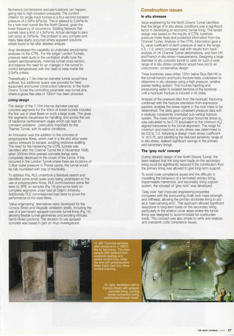
Numerous combinations and permutations can happen, giving rise to high transient pressures. The comfort criterion for single-track tunnels is a four-second transient pressure of 2.5kPa (kPa/4s). This is relaxed to 3.5kPa/4s for a twin-train tunnel like the North Downs, given the lower frequency of occurrence. Existing Network Rail tunnels have a limit of 4.5kPa/4s. Actual damage to ears can occur at 7kPa/4s. The problem is very complex and many false starts occurred where apparent solutions where found to fail after detailed analysis.
Arup developed the capability to undertake aerodynamic analyses on the CTRL. For the longer London Tunnels, pressure relief ducts in the ventilation shafts tune the system aerodynamically, minimize tunnel cross-section, and balance the need for air changes in the tunnel to control temperatures with the need to keep inside the 2.5kPa criteria.
Theoretically a 7.0m internal diameter tunnel would have sufficed, but additional space was provided for fixed equipment and tunnel construction tolerance. In the North Downs Tunnel the controlling parameter was tunnel size, where a gross free area of 1 oom2 has been provided.
Lining design
The design of the 7 .15m internal diameter precast concrete segments for the 40km of bored tunnels included the first use of steel fibres on such a large scale. This gives the segments robustness for handling, and avoids the use of traditional reinforcement cages which can lead to corrosion problems - particularly important for the Thames Tunnel, with its saline conditions.
An innovation was the addition to the concrete of polypropylene fibres, which melt in a fire and allow water vapour pressure to escape, avoiding explosive spalling. The need for fire-hardening the CTRL tunnels was identified after the Channel Tunnel fire in November 1996, when 500mm-thick precast concrete linings were completely destroyed in the crown of the tunnel. If this occurred in the London Tunnel where there are locations of 3.3bar water pressure in Thanet sands, the tunnel would be fully inundated with loss of the facility.
To address this, RLE undertook a literature search and identified some small-scale work being undertaken on the use of polypropylene fibres. RLE commissioned some fire tests by BRE on samples (Fig 14) and some tests on complete segments under load at Delphi University. Additionally RLE commissioned load tests to prove the performance of the steel fibres.
'Value engineering' alternatives were developed for the Corsica Street and Wayside ventilation shafts, including the use of a permanent sprayed-concrete tunnel lining (Fig 15), allowing flexible tunnel geometries and avoiding intricate hand-mined junctions. The decision to use sprayed concrete was based in part on Arup investigations.
Construction issues In situ stresses
Value engineering for the North Downs Tunnel identified that the range of in situ stress conditions was a significant factor in developing an economic tunnel lining. The tender design was based on the results of CTRL borehole pressure meter tests and published information from the Channel Tunnel. Analysis of the CTRL information gave a Ko value coefficient of earth pressure at rest in the range 0.5 - 1.5, which compared well with results from back analysis of UK Channel Tunnel deformations, and from UK and French in situ stress measurements. Designing a large diameter in situ concrete tunnel to cater for such a wide range of in situ stress conditions would have led to an uneconomic, conservative design.
Three boreholes were drilled 120m below Blue Bell Hill to the tunnel horizon and hydro-fracture tests undertaken to determine in situ stresses using a high pressure, wireline packer testing system. This involves injecting and pressurizing water in isolated sections of the borehole until a hydraulic fracture is induced in its sides.
Analysis of the pressure data from the hydraulic fracturing, combined with the fracture orientation from impression packers, enables the stress regime in the rock mass to be determined. The tests gave consistent pressure data with a relatively consistently orientated sub-vertical fracture system. The mean minimum principal horizontal stress cr was calculated to be 0.75 (equivalent to the minimum Ko) aligned transverse to the tunnel alignment. The range for minimum and maximum in situ stress was determined to be 0.6 to 1.0. Adopting a design mean stress coefficient 'k' of 0.75, and identifying the reduced sensitivity range of in situ stress, realized significant savings in the primary and secondary linings.
The 'grey rock' concept
During detailed design of the North Downs Tunnel, the team realized that the long-term loads on the secondary lining could be significantly reduced if the contribution from the primary lining was allowed to give long-term support.
To avoid code compliance issues and the difficulty in modelling the behaviour of a laminated primary lining, impermeable membrane, and secondary lining support system, the concept of 'grey rock' was developed.
'Grey rock' had improved engineering properties compared with the surrounding chalk rock mass (strength and stiffness), allowing the primary shotcrete lining to act as a 'load-carrying arch' . This approach allowed significant reductions in long-term loads on the secondary lining, particularly in the shallow cover areas where the tunnel lining was designed to accommodate full overburden loads. This concept was also simple to verify and analyze, and overcame code compliance issues.
THE ARUP JOURNAL 1/2004 27

Following completion of the detailed design using the 'grey rock' approach and other value engineering proposals, the secondary lining thickness was reduced from 500mm to 350mm, and all structural and crack control reinforcement was removed.
This allowed a flat invert slab to be used for 2883m of tunnel from the south portal, as the need for a dished invert for the tunnel was reduced by the combination of lower horizontal stresses in the ground and the arching effect of the primary shotcrete lining. By contrast, the tender design required a dished invert for the entire tunnel.
The combined effect of the value engineering during design resulted in a reduction of:
• tunnel excavation by 21 000m3 of chalk spoil
• secondary lining and invert concrete of about 37 QOOm3
• secondary lining and invert reinforcement: 5900 tonnes.
Continuous base slab pour
One of the most successful construction-related value engineering developments on the North Downs Tunnel was the excavation and construction of the tunnel invert. Following completion of the bulk excavation to subformation level, the final invert excavation was prepared using a surface mining planing machine, which planed over 350m of the tunnel invert in a 12-hour day shift to an accuracy of +/- 10mm using a laser control system. The chalk spoil was removed directly from the planer by dump trucks. The surface was then cleaned by an air lance and the formation logged and trafficking banned. Plate load tests were carried out at regular intervals to confirm the formation bearing capacity and any soft spots excavated and filled with lean mix concrete. The quality of the formation surface achieved was exceptional.
150mm of dry-mix blinding was then placed using a roadpaving machine (Fig 16) during night shifts and compacted to an accuracy of+/- 5mm, the central section with a Bomag BW161 vibrating roller and the edges by a small Bomag BW120 roller (Flgs 17 & 18).
Constructability of the concrete invert - 3km long, 11 m wide, and 600mm thick - was analyzed jointly by the design and construction value engineering teams. The simple design developed comprised removal of construction joints, offsite fabrication and rapid assembly of reinforcement, and continuous invert concrete placement. Reinforcement for the central derailment containment barrier and the walkways was provided using Kwikastrip starter bars laid flat in a 2m-long, 40mm-high stainless punched-steel box (Fig 19). The continuous pouring method allowed a maximum of 82m and an average of 50m per day to be achieved.
28 TliE ARUP JOURNAL 1 '21X,4
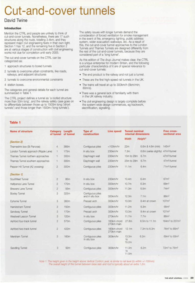
Cut-and-cover tunnels David Twine
Introduction
Mention the CTRL and people are unlikely to think of cut-and-cover tunnels. Nonetheless, there are 17 such structures along the route, totalling 3.4km, and they represent major civil engineering feats in their own right. Section 1 has 12, and the remaining five in Section 2 are at various stages of construction with civil engineering works not due for completion until early 2005.
The cut-and-cover tunnels on the CTRL can be categorized as:
1 approach structures to bored tunnels
2 tunnels to overcome urban constraints, like roads, railways, and adjacent structures
3 tunnels to overcome environmental constraints
4 station boxes.
The categories and general details for each tunnel are summarized in Table 1.
The CTRL project defines a tunnel as 'a roofed structure more than 50m long', and the railway safety case goes on to differentiate between those up to 1500m long ('short tunnels') and those longer than 1500m ('long tunnels').
Table 1
Name of structure Category Length of tunnel of tunnel
[Section 2]
Thameslink box {St Pancras) 4 380m
The safety issues with longer tunnels demand the consideration of forced ventilation for smoke management in the event of fire, emergency lighting, public address system, wider evacuation walkways, etc. As a result of this, the cut-and-cover tunnel approaches to the London Tunnels and Thames Tunnels are designed differently from the rest of the cut-and-cover tunnels, because they are considered part of a 'long tunnel '.
As this edition of The Arup Journal makes clear, the CTRL is a unique enterprise for modern Britain, and the following particular characteristics of it are of special relevance to cut-and-cover tunnels:
• The end product is the railway and not just a tunnel.
• These are the first high-speed rail tunnels in the UK.
• The trains will travel at up to 300km/h (5km/min; 80rn/s).
• There was a general lack of familiarity with them in the UK railway industry.
• The civil engineering design is largely complete before the system-wide design commences, eg trackwork, electrification, signalling.
Type of Line speed Tunnel nominal construction internal dimensions
Width Height1
Contiguous piles <100km/hr 22m 6.6m & 4.6m {min)
Free cross-sectional area
145m2
London Tunnels approach {Ripple Lane) 175m In situ box 230kmlhr 7.3m 6.6m {varies slightly) 47m2/tunnel
Thames Tunnel northern approaches 300m Diaphragm wall 230kmlhr 15m to 29m 6.7m 47m2/tunnel
Thames Tunnel southern approaches 300m Diaphragm wall 230kmlhr 25m to29m 6.7m 47m2/tunnel
Pepper Hill Tunnel {A2 crossing) 2 300m Contiguous piles 230km/hr 11 .1m 6.4m 71 m2/tunnel
[Section 1)
Southfleet Tunnel 2 85m In situ box 230kmlhr 10.4m 6.4m 67m2
Halfpence Lane Tunnel 2 170m In sttu box 300kmlhr 10.7m 6.3m 68m2
Brewers Lane Tunnel 2 55m Contiguous piles 300kmlhr 11 .3m 6.5m 74m2
Boxley Tunnel 3 325m Contiguous piles and in situ box 300kmlhr 12.3m 7.1m 86m2
Eyhorne Tunnel 3 360m Precast arch 300kmlhr 13.3m 8.4m at crown 107m2
Harrietsham Tunnel 3 150m Contiguous piles 300kmlhr 11 .2m 6.3m 68m2
Sandway Tunnel 3 170m Precast arch 300km/hr 13.3m 8.4m at crown 107m2
WestweU Leacon Tunnel 3 120m In situ box 270kmlhr 11 .7m 7.7m 86m2
Ashford four-track tunnel 2 570m Contiguous piles 160km chord 27.8m 6.5m to 11. 1 m 164m2 to 237m2 270km main
Ashford two-track tunnel 2 422m Contiguous piles 160km chord 12.1m 7.3m to6.3m 76m2 to 85m2 270km main
Mersham Tunnel 3 160m Contiguous piles 300kmlhr 13.3m 6.2m 69m2 to93m2 In situ box to
15.2m
Sandling Tunnel 3 92m Contiguous piles 300kmlhr 11 .3m 6.2m 72m2 to 76m2 to
11 .5m
Note 1. The height g,ven ,s the height above Vertical Control Level, ,e similar to rail level (to w,thm +l-1 OOmm) The overall height of the tunnel between base slab and roof is typically about an extra 1.2m.
THEARUPJOURNAL 1/2ll04 29

Some of the cut-and-cover tunnelling works for Section 2 are illustrated on this page.
30 THE ARUP JOURNAL 1/2004
Establishing the design brief
The design of the 17 cutand-cover tunnels involved the production of some 2000 drawings and related specifications. The structural and geotechnical design work required to produce these drawings was an enormous task. The overall key to the successful production of the construction drawings, however, was the early establishment of the design brief, and the tight control of any subsequent changes to it. The four key steps in establishing the design brief were: 1 . defining the basic geometry for the railway tunnel. eg minimum rail safety clearances for the design line speed 2. defining the constraints as follows:
• design life • ground conditions • existing utilities • existing roads and
railways (possessions) • third parties • environmental • cost and programme.
3. establishing the best method of construction to be assumed for the design 4. finalizing the geometry based on the first three key steps 1, 2, and 3 above. Details of the considerations for each step are summarized in Table 2 on the facing page.
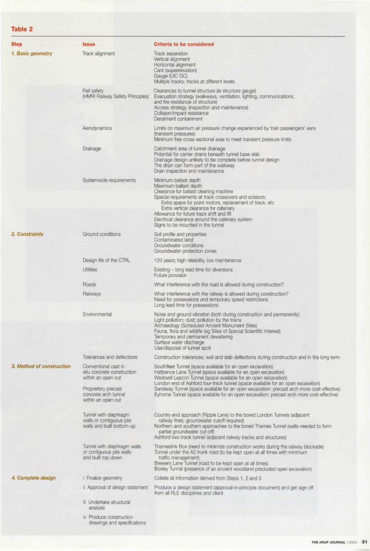
Table 2
Step
1. Basic geometry
2 Constraints
3. Method of construction
4. Complete design
Issue
Track alignment
Rail safety (HMRI Railway Safety Principles)
Aerodynamics
Drainage
Systemwide requirements
Ground conditions
Design life of the CTRL
Utilities
Roads
Railways
Environmental
Tolerances and deflections
Conventional cast in situ concrete construction within an open cut
Proprietary precast concrete arch tunnel within an open cut
Tunnel with diaphragm walls or contiguous pile walls and built bottom ·up
Tunnel with diaphragm walls or contiguous pile walls and built top-down
i Finalize geometry
Criteria to be considered
Track separation Vertical alignment Horizontal alignment Cant (superelevation) Gauge (UIC GC) Multiple tracks; tracks at different levels
Clearances to tunnel structure Oe structure gauge) Evacuation strategy (walkways, ventilation, lighting, communications, and fire resistance of structure) Access strategy Onspection and maintenance) Collision/impact resistance Derailment containment
Limits on maximum air pressure change experienced by train passengers' ears (transient pressures) Minimum free cross-sectional area to meet transient pressure limits
Catchment area of tunnel drainage Potential for carrier drains beneath tunnel base slab Drainage design unlikely to be complete before tunnel design The drain can form part of the walkway Drain inspection and maintenance
Minimum ballast depth Maximum ballast depth Clearance for ballast cleaning machine Special requirements at track crossovers and scissors:
Extra space for point motors, replacement of track, etc Extra vertical clearance for catenary
Allowance for future track shift and lift Electrical clearance around the catenary system Signs to be mounted in the tunnel
Soil profile and properties Contaminated land Groundwater conditions Groundwater protection zones
120 years; high reliability, low maintenance
Existing - long lead time for diversions Future provision
What interference with the road is allowed during construction?
What interference with the railway is allowed during construction? Need for possessions and temporary speed restrictions Long lead time for possessions
Noise and ground vibration (both during construction and permanently) Light pollution; dust; pollution by the trains Archaeology (Scheduled Ancient Monument Sites) Fauna, flora and wildlife (eg Sites of Special Scientific Interest) Temporary and permanent dewatering Surface water discharge Use/disposal of tunnel spoil
Construction tolerances; wall and slab deflections during construction and in the long term
Southffeet Tunnel (space available for an open excavation) Halfpence Lane Tunnel (space available for an open excavation) Westwell Leacon Tunnel (space available for an open excavation) London end of Ashford four-track tunnel (space available for an open excavation) Sandway Tunnel (space available for an open excavation: precast arch more cost-effective) Eyhorne Tunnel (space available for an open excavation; precast arch more cost-effective)
Country end approach (Ripple Lane) to the bored London Tunnels (adjacent railway lines; groundwater cutoff required)
Northern and southern approaches to the bored Thames Tunnel (walls needed to form partial groundwater cut -off)
Ashford two-track tunnel (adjacent railway tracks and structures)
Thameslink Box (need to minimize construction works during the railway blockade) Tunnel under the A2 trunk road (to be kept open at all times with minimum
traffic management) Brewers Lane Tunnel (road to be kept open at all times) Boxley Tunnel (presence of an ancient woodland precluded open excavation)
Collate all information derived from Steps 1. 2 and 3
ii Approval of design statement Produce a design statement (approval-in-principle document) and get sign off from all ALE disciplines and client
iii Undertake structural analysis
iv Produce construction drawings and specifications
THE ARUP JOURNAL 1/2004 31
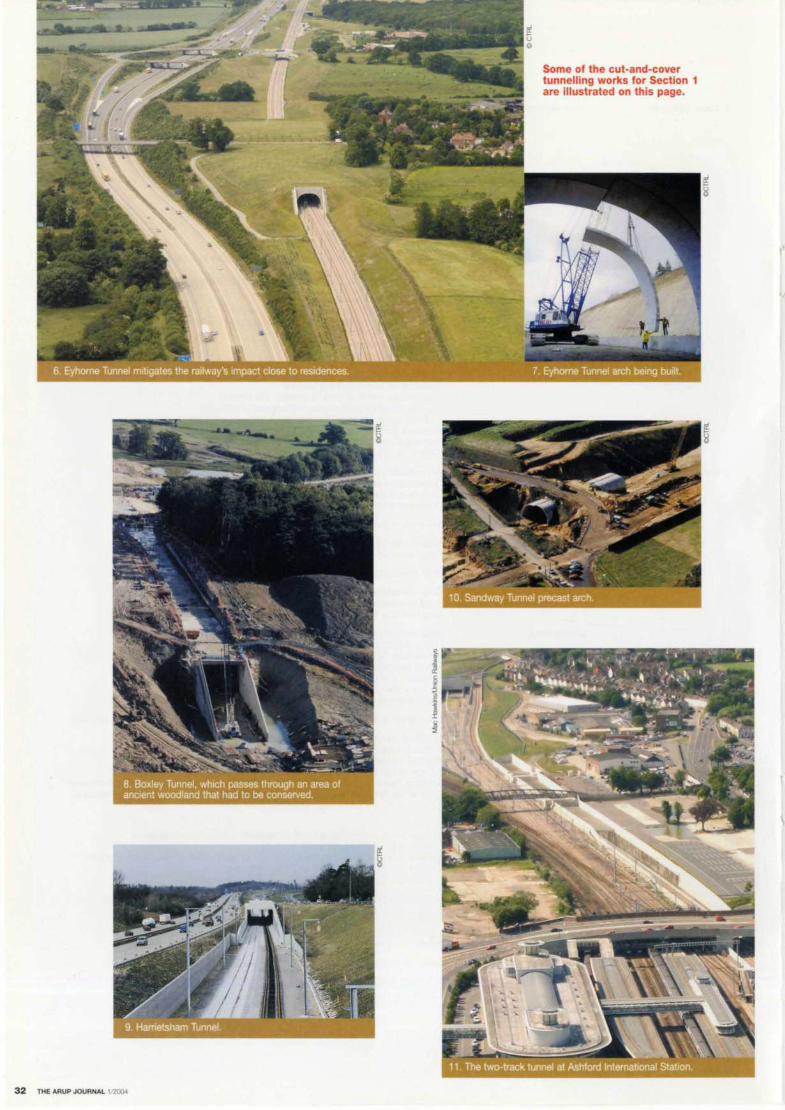
l I I
32 THE ARUP JOURNAL 1!2004
Some of the cut-and-cover tunnelling works for Section 1 are illustrated on this page.

Bridges Steve Dyson Introduction
The CTRL includes a multiplicity of above-ground civil engineering structures, ranging from the signature Medway Viaduct to numerous foot and bridleway bridges. This article outlines some of the constraints, design considerations, and features of the bridges and associated structures on the project. Arup members of the RLE team were central to the bridge design process, and many other Arup groups also contributed to the design and checking or gave specialist advice and expertise, including Arup Research + 1. Development, Arup Computing, the Advanced Technology Group, Infrastructure, Industrial, the Arup Campus, Edinburgh, Newcastle, Cardiff, Bristol, Dublin, and Brisbane.
Route and constraints
The differences in geography between Section 1 and Section 2 mean that very different constraints apply to the design of bridges in these highly contrasted locations. Section 1 's route, generally through open terrain and often alongside existing motorways, means that most of its structures are at isolated locations to allow existing roads and footpaths to cross the CTRL trace.
In Section 2, however, most of the structures are in the complex areas of Ebbsfteet, West Thames, Stratford, and St Pancras, lying close to existing railways. The St Pancras area is particularly congested with existing railways, canals, and other Victorian infrastructure (Figs 1-5).
In West Thames the route crosses the M25 (over the north-bound carriageway and under the elevated south-bound carriageway) and further west passes through the Ford factory complex at Dagenham.
Scope
There are 134 bridges on Section 1 and 70 on Section 2. Of this total of 204, 88 are road bridges, 82 are rail bridges, and 34 are foot or bridleway bridges. The longest single span is the main span of the Medway Viaduct at 152m; the shortest are the 5m spans of the piled slabs that support the railway over the West Thames marshes.
In addition to bridges, the CTRL has numerous ancillary structures of the sort associated with a major transport project. Also, assessments of many existing bridges and structures were carried out to determine the effect of the proposed works on the existing infrastructure.
Design standards for bridges
These have been based on the Department of Transport's 'Design manual for roads and bridges' , which incorporates British Standard BS5400 'Steel, concrete and composite bridges' . However, those documents do not cover aspects of the design that are specific to high-speed railways, and so CTRL standards have been developed by the project team to cover these requirements, in particular 'Loading and particular criteria for CTRL railway bridges' and 'Design of derailment containment' .
In some areas, railways constructed as part of the project form part of the Network Rail system or are shared between Network Rail and the CTRL; in these cases Network Rail standards are also applicable.
2.
3.
1-4. The East Coast Mam Line bridge at the gateway to St Pancras was pushed into position during a single 55-hour possession of the ECML at Christmas 2003. Unusually on the CTRL, this is a covered bridge, for environmental reasons.
THE ARUP JOURNAL 1/2004 33

34 THE ARUP JOURNAL 1/2004
Features of bridges specific to high-speed railways
A railway is considered to be 'high-speed' if trains travel at more than 220krn/hr, and so the maximum design speeds for Eurostar trains of 300krn/hr on Section 1 and 230krn/hr on Section 2 place the entire route firmly in this category. The structures have a 120-year design life.
Railway loadings
For ultimate and serviceability design (excluding fatigue), the loads are from UIC Code 776-1: 'Loads to be considered in railway bridge design':
• 'Normal' rail loading is U/C 71 , which is the same as the loading designated 'RU' in BS5400.
• 'Special ' heavy load transporters are designated 'SW/0' and 'SW/2' (distributed loads of 133kN/m and 150kN/m respectively).
These loads are multiplied by an impact factor; in most cases this is a simple factor that is a function of span and dead load deflection but is evaluated from a transient dynamic analysis for long-span structures. For fatigue design, the loads are international Eurostar trains (at speeds up to 300km/hr). domestic commuter trains, and heavy freight trains (at speeds up to 140krn/hr). These loads are defined as series of axle loads with equivalent distributed load values between 21 and 88kN/m.
Dynamic criteria
Transient dynamic analysis of bridges is carried out for high-speed trains (ie Eurostars at 220+km/hr) to control vertical accelerations as follows:
• for ballast stability, vertical accelerations of the deck to be less than 3.5m/sec/sec for frequencies up to 20Hz
• for passenger comfort, vertical acceleration within carriages of the Eurostar trains to be less than 0.5rn/sec/sec.
Movement criteria
Limitations on span deflection and joint rotation are applied to control the ride quality of the track. Limitations on twist of the track also apply, particularly at crossovers and turnouts.
Articulation I rail joints
The track is continuously welded rail ; it is preferable to avoid rail joints, which are expensive and constitute a maintenance liability. Without rail joints, rail bridges are limited to between 60m and 90m long (depending on the form of construction) to avoid excessive stress build-up in the continuous rail ; relative longitudinal movement at joints between adjacent bridge decks is limited to 5mm under braking/traction forces.
Where bridges are longer than 90m (ie long continuous viaducts) rail joints have to be provided. These come in two sections about 36m apart. and the bridge deck is jointed at the same two locations, separated by a simply supported span. Such a joint will cater for an expansion length of about 2 x 400m. Relative longitudinal movement under braking and traction is limited in this case to 30mm.
Derailment containment
Most of the CTRL bridges have some built-in derailment protection through the provision of the upstand walls that contain the ballast. These walls project 1 OOmm above rail Jevel and can withstand a concentrated lateral load of 200kN.
However, risk assessment identified certain structures that required a higher level of derailment containment - generally either long viaducts or bridges where the consequences of derailment could be particularly severe. For these structures, the upstand kerbs are increased in height to 200mm above the rails and designed for an increased horizontal force of 300kN, criteria that were established from a study of European practice.
Train impact
The supports to the bridges that cross the CTRL are designed for train impact to UIC Code 777-2: 'Structures built over railway lines- Construction in the track zone',
adapted to the particular circumstances of the CTRL. This code identifies a 'danger zone' within 4.5m of the rail , inside which it is preferable to avoid having supports. Where piers have to be present in the danger zone, they are designed as walls rather than columns to resist forces of 4000kN parallel to the track and 1500kN perpendicular to the track; such piers are also designed to remain functional if a section 1m long x 3.7m high above track level is removed by train impact.
High containment parapets
Where roads cross the CTRL, high containment parapets (designated 'P6' in the Department of Transport 'Design manual for roads and bridges') are provided.
These are generally of precast concrete to a height of 1.5m, increased to 1 .Bm over the line itself to provide additional security with a stainless steel capping piece. Like all metal parts of bridges, the metal capping pieces are earthed to the railway catenary system to avoid touch potential developing from the overhead power supply. The visual design of the P6 parapets was developed as part of an overall design strategy for bridges with Arup's architectural adviser WilkinsonEyre. This design strategy gives consistent visual style and detailing for the bridges, so that the 'CTRL brand' can be recognized wherever structures are encountered along the trace.
Clearances
Clearances are critical to safety and were one of the prime considerations when designs were submitted to HMRI as part of the process leading to 'permit to use' for the railway. Vertical clearances above rail are generally 6.2m but may be reduced to 5.Bm, provided that the design is co-ordinated with the overhead catenary system. These figures include an allowance for lifting track during maintenance.
Lateral clearance requirements vary with train speed, track curvature, cant, and walkway requirements up to about 4.5m from the centreline of the track. The required clearance depends on whether maintenance staff need access to the track during railway operations. whether any speed restrictions apply in those circumstances, and whether a safety fence is provided between the walkway and the track.
Some aspects of the design process for bridges
Interface with railway design
The interface between the bridges and the whole railway system - track, overhead catenary system, signalling, and telecommunications - was fundamental to achieving an integrated design that meets the operational requirements of the railway.
Most of the design criteria already discussed arise from this interface, the management of which is made more complex by the time lag between civil and railway works programmes and the conventions of contractor input to the detailed design of railway systems.
Consents
The CTRL Act of 1996 gave powers to construct the project, but the detailed design has been subject to consents from numerous bodies such as local planning authorities. local highway authorities, the Environment Agency, the Highways Agency, Transport for London, Railtrack and its successor, Network Rail, etc. Submissions for bridges have been made throughout the design process such that the necessary consents are obtained.
Partnering with contractors
The form of contract adopted for the CTRL - the New Engineering Contract, Option C - encourages 'partnering ' in relationships with the contractors. This has influenced the design of bridges on certain contracts, particularly on Section 2. As noted in other articles in this special issue, value engineering has been an integral part of the design and construction process. Regular value engineering workshops have been held with contractors with the objective of reducing costs and project risks. On some contracts, bidders put forward alternative designs which gave benefits from a particular construction technique or expertise which that contractor had available.
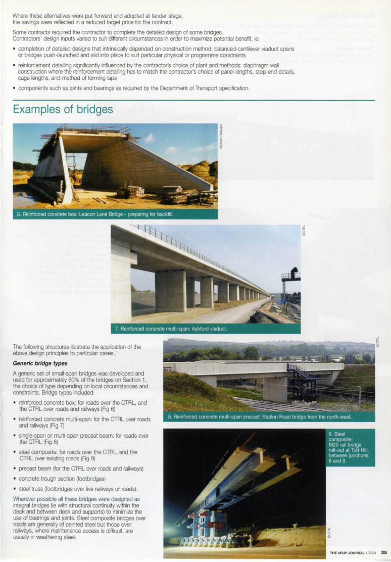
Where these alternatives were put forward and adopted at tender stage, the savings were reflected in a reduced target price for the contract.
Some contracts required the contractor to complete the detailed design of some bridges. Contractors' design inputs varied to suit different circumstances in order to maximize potential benefit, ie:
• completion of detailed designs that intrinsically depended on construction method: balanced-cantilever viaduct spans or bridges push-launched and slid into place to suit particular physical or programme constraints
• reinforcement detailing significantly influenced by the contractor's choice of plant and methods: diaphragm wall construction where the reinforcement detailing has to match the contractor's choice of panel lengths, stop-end details, cage lengths, and method of forming laps
• components such as joints and bearings as required by the Department of Transport specification.
Examples of bridges
The following structures illustrate the application of the above design principles to particular cases.
Generic bridge types
A generic set of small-span bridges was developed and used for approximately 60% of the bridges on Section 1, the choice of type depending on local circumstances and constraints. Bridge types included:
• reinforced concrete box: for roads over the CTRL, and the CTRL over roads and railways (Fig 6)
• reinforced concrete multi-span: for the CTRL over roads and railways (Fig 7)
• single-span or multi-span precast beam: for roads over the CTRL (Fig 8)
• steel composite: for roads over the CTRL, and the CTRL over existing roads (Fig 9)
• precast beam (for the CTRL over roads and railways)
• concrete trough section (footbridges)
• steel truss (footbridges over live railways or roads).
Wherever possible all these bridges were designed as integral bridges (ie with structural continuity within the deck and between deck and supports) to minimize the use of bearings and joints. Steel composite bridges over roads are generally of painted steel but those over railways, where maintenance access is difficult, are usually in weathering steel.
THE ARUP JOURNAL 1/'2004 35
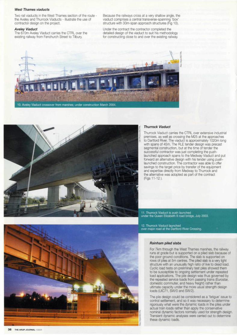
West Thames viaducts
Two rail viaducts in the West Thames section of the route -the Aveley and Thurrock Viaducts - illustrate the use of contractor design on the project.
Aveley Viaduct The 670m Aveley Viaduct carries the CTRL over the existing railway from Fenchurch Street to Tilbury.
36 THE ARUP JOURNAL 1/2004
Because the railways cross at a very shallow angle, the viaduct comprises a central transverse-spanning 'box' structure with 30m-span approach structures (Fig 10).
Under the contract the contractor completed the detailed design of the viaduct to suit his methodology for constructing close to and over the existing railway.
Thurrock Viaduct
Thurrock Viaduct carries the CTRL over extensive industrial premises, as well as crossing the M25 at the approaches to Dartford River. The viaduct is approximately 1020m long with spans of 45m. The RLE tender design was precast segmental construction, but at the time of tender the successful contractor was just completing the pushlaunched approach spans to the Medway Viaduct and put forward an alternative design with his tender using pushlaunched construction. The contractor was able to offer savings to the target price by transfer of the equipment and expertise directly from Medway to Thurrock and the alternative was adopted as part of the contract (Figs 11-12 ).
Rainham piled slabs
For ?km through the West Thames marshes, the railway runs at grade but is supported on a piled slab because of the poor ground conditions. The slab is supported on rows of piles at 5m centres. The piled slab is a very light structure with an unusually high ratio of live to dead load. Cyclic load tests on preliminary test piles showed them to be susceptible to ongoing settlement under repeated load applications. The pile design was thus governed by the repeated service loads from passing trains (Eurostar, domestic commuter, and heavy freight) rather than ultimate capacity under the more usual strength design loads (UIC71, SW/0 and SW/2).
The pile design could be considered as a 'fatigue' issue to control settlement, and so it was necessary to determine rigorously what were the dynamic loads in the piles under actual train loads rather than apply the conservative nominal dynamic factors normally used for strength design. Transient dynamic analyses were carried out to determine these dynamic loads.

St Pancras bridges
The Carnley Street and Regents Canal bridges (Fig 13) are both rebuilds of existing sub-standard steel bridges on old brick abutments. Although simple short-span bridges, they illustrate many of the complexities that impact on designs at St Pancras. The structures are built over the line of the existing (operational) brick Thameslink tunnel - in fact the existing abutments are partially supported on the existing tunnel, and the existing road and canal have only a small clearance above the top of the tunnel. The piles at Carnley Street are also spaced to allow the construction of future Thameslink tunnels that will form part of the Thameslink 2000 project. In addition, the bridges are at the throat of the railway tracks into St Pancras station. Construction in this area involves complex trackwork staging, and the bridges are being built in phases to match.
Ford service bridges
Advance contracts were let to demolish and rebuild several existing bridges to clear the CTRL route through the Ford factory complex at Dagenham. One of these contracts was to build two utility bridges to carry Ford services, passing over several existing roads and railways as well as the CTRL trace itself. These bridges are single-span steel trusses, 60m and 70m span respectively, containing double-storey spaces to accommodate the many Ford services (Fig 14).
In each case the decks were erected by assembling the steelwork (together with some of the primary pipework) on adjacent road bridges and jacking the assembled trusses along temporary sliding beams into their final position on previously built piers.
Choats Manor Way bridge
This steel composite road bridge (Fig 15) was also built under an advance contract in Dagenham, to carry a new road over the CTRL to a development area to the south. The beams are in weathering steel and the approach embankments of reinforced earth, supported on vibrated concrete columns through shallow depths of alluvium.
Brewers Road bridge
Brewers Road bridge occurs where the CTRL runs close to the A2 dual carriageway but at a significantly lower level. The route passes beneath the approach embankment of an existing bridge carrying a local road over the A2 (Fig 16). The structure is a box with bored pile walls built 'top-down'. Because of the environmental surroundings, it is designed to allow the existing embankment arrangement to be re-created on top of the box. The structure is thus a two-storey structure, with the lower cell accommodating the CTRL.
As with all such construction, the phasing was an integral part of the design. The sequence of excavation and propping was defined as part of the design, incorporated in the box analysis, and issued on drawings to the contractor. An assessment of the existing bridge allowed 'amber' and 'red' trigger levels to be identified and agreed with the owner of the structure, and then issued to the contractor to establish compatible construction methods and monitoring.
North Kent Line bridge
The existing North Kent Line at Ebbsfleet runs on a 'chalk spine' left after past quarrying operations. The CTRL passes through the spine beneath the existing railway, and to minimize disruption to it, the entire bridge - both deck and substructure - was constructed alongside the chalk spine. During a three-day possession, the chalk was removed from the spine at the bridge site and the structure slid into place. The structure weighed 9200 tonnes and during the possession 32000m3 of chalk was removed (Fig 17).
THE ARUP JOURNAL 1/2004 37

The Medway Viaduct
38 THE ARUP JOURNAL 1/2004
The Medway Viaduct over the River Medway near Rochester is arguably the key signal structure on the whole of the CTRL. Certainly it is the most prominent visual feature of Section 1. Its total length is 1250m with a main river span of 152m and 40m approach spans. The river section is of in situ segmental cantilever construction, built out from each river pier, whilst the approaches were push-launched (Figs 18-22). The river piers are continuous with the deck; the approaches are continuous throughout except at the location of expansion joints in each approach to accommodate a rail expansion joint. The deck is stressed down to the abutments to provide ntegral construction.
The viaduct is an outstanding example of integrated design, meeting all the objectives of structural efficiency, constructability, aesthetics, and compliance with operational criteria. Passengers have outstanding views over the Medway Valley as they cross the viaduct. Unfortunately the opportunity to enjoy the view is brief since at 300km/hr a Eurostar takes only 15 seconds to travel the full 1250m length of the viaduct, which won the Concrete Society Civil Engineering Award 2002.
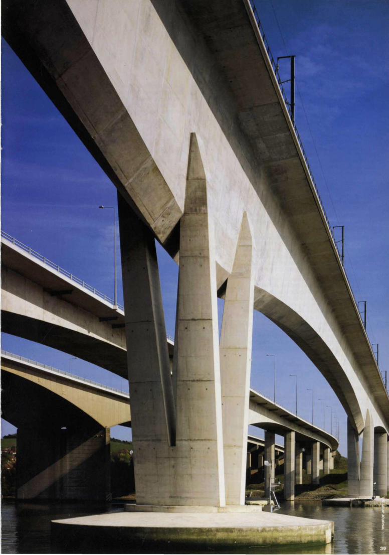

Railway engineering Duncan Wilkinson
Introduction
Running trains to, on, or through the CTRL requires a multiplicity of integrated systems to guide, power, and control the rolling stock, so as to give a failsafe environment for transporting passengers and goods.
These systems and the railway engineering skills required to integrate them fall into two categories. The first provides for the high-speed railway itself - an overhead line electricpowered railway, with train speeds up to 300km/hr on 21 st century technology infrastructure. This category of railway engineering is termed 'system-wide' because the contracts it comprises for the track, power, signalling, and communications systems are not geographically fixed like the civil engineering contracts, but are delivered system-wide.
The second category of railway engineering is termed 'Network Rail [formerly Railtrack] interface': this provides a mix of systems for diesel, DC electric third rail, or AC overhead line electric-powered trains permitting speeds up to 160km/hr on 19th century technology infrastructure. . The CTRL thus integrates a new 21 st century technology high-speed railway system into an existing 19th century railway network.
Specialist expertise in standard systems generally lies with suppliers. Some are based around custom and practice, as with permanent way design; others are state-of-the-art technology, eg in-cab signalling. The critical issues on the CTRL have been the appropriate system specification, systems integration, and management of the interfaces.
As this is the first high-speed railway in the UK, the RLE designers including Arup have effectively written the rulebook for the operational requirements, based on French experience and practice on their TGV. However, at the interfaces with the existing network it has been necessary to comply with existing railway line standards. These have accumulated over the last 150 years and often relate to the technology of the period in which they were written. Operational safety is paramount, and all aspects of the project must satisfy the requirements of the UK Railway Inspectorate (HMRI) to have a safe railway for which they will issue a 'no objection' certificate to allow trains to run on the system.
The cost of these systems for the CTRL is estimated to be £650M at 1997 prices, approximately 30% of the total project costs.
Section 1
This is very much the '21 st century railway', and the interfaces with Network Rall are confined to a few discrete locations where the key issue is to immunize the traction power for both the old and new railways to stop them polluting each other electrically.
The RLE design effort on Section 1 therefore focused on developing a high-speed operational railway concept. This included determining:
• the geometrical alignment of the trackwork, and designing the permanent way to suit both high-speed passenger trains and freight
• a power system, its supply strategy and the associated electro-magnetic compatibility and interference issues with other systems
• signalling and communications systems for controlling high-speed passenger and freight trains operating on both the CTRL and the interfacing Network Rail lines.
From these concepts a series of detailed specifications was developed with the appropriate contractual framework for their delivery.
40 THE ARUP JOURNAL 1/20(),0
Due to the interdependence of all of the systems - not only with themselves but also with the civil infrastructure -the design, delivery, installation, testing, and commissioning of each system had to be integrated and the interfaces managed throughout project delivery.
This is well demonstrated by the testing and commissioning strategy, which started with individual product simulation and factory bench testing, continuing through individual subsystem tests to total operational integrated systems testing.
Contract strategy
The contracts for delivering the Section 1 railway systems were:
Contract 550: permanent way, traction power, and other mechanical and electrical (M&E) engineering works (points motors, pumping stations, etc)
Contract 570: high-speed train in-cab signalling, signalling controls, data transmission network (DTN), M&E information systems (EMMIS), radio and telephone communications (GSM-R), closed-circuit television (CC1V)
Contract 434: Network Rail interfaces: permanent way, power, and line-side signalling at Eurotunnel connection, Dollands Moor freight terminal connection, access to Ashford International Station (Fig 1), and access to infrastructure maintenance depot at Beechbrook Farm
Contract 330: Fawkham Junction Link to Waterloo Line.
When these were formulated it was believed that integrating all the signalling and communications systems into Contract 570, requiring the contractor to manage the interfaces, would facilitate delivery of the most technically demanding systems. However, the consortium of companies providing the specialist equipment and complex software required to drive the different systems did not have the management skills required, so RLE took over the interface management role: the flexibility of the NEC Form of Contract and strength of RLE's engineer, procure, construction management (EPC) organization allowed for such major contractual changes when required to ensure delivery.
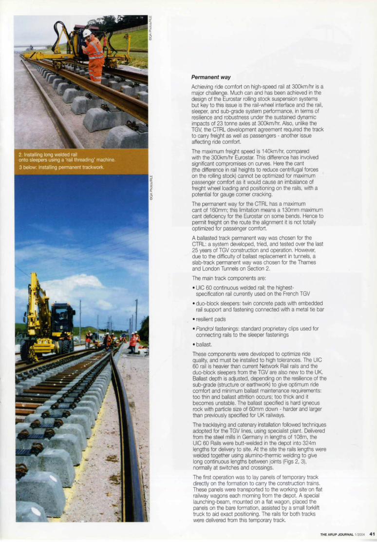
. \
Permanent way
Achieving ride comfort on high-speed rail at 300km/hr is a major challenge. Much can and has been achieved in the design of the Eurostar rolling stock suspension systems but key to this issue is the rail-wheel interface and the rail, sleeper, and sub-grade system performance, in terms of resilience and robustness under the sustained dynamic impacts of 23 tonne axles at 300km/hr. Also, unlike the TGV, the CTRL development agreement required the track to carry freight as well as passengers - another issue affecting ride comfort.
The maximum freight speed is 140km/hr, compared with the 300km/hr Eurostar. This difference has involved significant compromises on curves. Here the cant (the difference in rail heights to reduce centrifugal forces on the rolling stock) cannot be optimized for maximum passenger comfort as it would cause an imbalance of freight wheel loading and positioning on the rails, with a potential for gauge corner cracking.
The permanent way for the CTRL has a maximum cant of 160mm; this limitation means a 130mm maximum cant deficiency for the Eurostar on some bends. Hence to permit freight on the route the alignment it is not totally optimized for passenger comfort.
A ballasted track permanent way was chosen for the CTRL: a system developed, tried, and tested over the last 25 years of TGV construction and operation. However, due to the difficulty of ballast replacement in tunnels, a slab-track permanent way was chosen for the Thames and London Tunnels on Section 2 .
The main track components are:
• UIC 60 continuous welded rail ; the highestspecification rail currently used on the French TGV
• duo-block sleepers: twin concrete pads with embedded rail support and fastening connected with a metal tie bar
• resilient pads
• Pandrol fastenings: standard proprietary clips used for connecting rails to the sleeper fastenings
• ballast.
These components were developed to optimize ride quality, and must be installed to high tolerances. The UIC 60 rail is heavier than current Network Rail rails and the duo-block sleepers from the TGV are also new to the UK. Ballast depth is adjusted, depending on the resilience of the sub-grade (structure or earthwork) to give optimum ride comfort and minimum ballast maintenance requirements: too thin and ballast attrition occurs; too thick and it becomes unstable. The ballast specified is hard igneous rock with particle size of 60mm down - harder and larger than previously specified for UK railways.
The tracklaying and catenary installation followed techniques adopted for the TGV lines, using specialist plant. Delivered from the steel mills in Germany in lengths of 108m, the UIC 60 Rails were butt-welded in the depot into 324m lengths for delivery to site. At the site the rails lengths were welded together using alumino-thermic welding to give long continuous lengths between joints (Figs 2, 3), normally at switches and crossings.
The first operation was to lay panels of temporary track directly on the formation to carry the construction trains. These panels were transported to the working site on flat railway wagons each morning from the depot. A special launching-beam, mounted on a flat wagon, placed the panels on the bare formation, assisted by a small forklift truck to aid exact positioning. The rails for both tracks were delivered from this temporary track.
THEARUPJOURNAL l/2004 41

42 THE ARUP JOURNAL 1/2Q()4
The rails were laid out on the sub-grade to a gauge that enables special large portal-framed plant to run on them. These frames replaced the temporary panels with permanent sleepers. Once these were placed, the rails on the first line were 'zipped' into place and fastened to the sleepers with hand-held plant to form the permanent track. The first layer of ballast was then hoppered and vibrated into position (Fig 4).
With the first line in place. the adjacent line could be built. With both tracks in place. the profile of the rails was brought to the precise line and level tolerances necessary for high-speed running using ballast, including the necessary canting on curves. A modern fleet of hoppers was used, shooting the ballast directly to within a few centimetres of the final position.
Ballasting and tamping were carefully controlled to achieve the required degree of consolidation under the sleepers. After tamping, the ballast was regulated, or brushed into place using another on-track machine. Periodically the track was stabilized to improve consolidation, again using an on-track machine. With the levelling substantially complete. the switches and crossings (S&C) and their control systems including points motors were inserted into the line by substitution, using rail-mounted cranes.
Internal track possession arrangements had to be established to enable this S&C work to accommodate the daily flow of engineering trains to their work sites. Pre-assembly areas for the S&C - which were needed during both construction and subsequent permanent operation of the railway - were identified and constructed at several locations along the route by the main civil engineering contractors.
To deal with the high-speed and freight trains. and as a result of the heavier UIC rail, special S&C was developed with high specification geometry and control systems including M&E control. These were specially fabricated to a high specification to permit the passage of trains turning out at 180km/hr. The 180km/hr turnouts are over 200m long and almost every single sleeper is a different length.
After the S&C was installed, the rails were prestressed between them to prevent buckling in hot weather.

Traction power
The CTRL takes its power from the national grid via dedicated CTRL substations, purpose-built by London Electricity Services. Here the power is converted to the +25--0-25kV AC power supply (twin 25kV lines 180° out of phase) adopted for the CTRL for delivery to the overhead catenary supply (OCS) system (Fig 6) .
The power demand from 400m long, 14-car Eurostars trains weighing 400 tonnes and accelerating to 300km/hr in three minutes is significant. The -25--0-+25kV AC power supply with auto-transformers as developed for the TGV provides 17.5MW of power, compared with 7.5MW from 25kV AC OCS and 5.1 MW from 750V DC 3rd rail , the systems used elsewhere in the UK. A high-voltage AC power supply has less power loss, less line-side equipment, and less stray current issues, but transformers are required on board the train to regulate the voltage for the motors. The twin feeder system (-25--0-+25) optimizes the current by flattening out peaks where the pantograph is in contact with the wire, and hence smooths out the power demand along the route.
Technically the key issue with power is electromagnetic compatibility and electromagnetic interference (EMC/EMI). With 50kV of electric power running linearly along the route parallel to other transport routes, rail and road, the electromagnetic field generated causes signrficant induced current effects in each and every bit of metal within the magnetic field. Existing railway lines, steel and reinforced concrete structures, buried pipes, adjacent motorway communications networks, fences, etc. are all at risk from induced currents.
There are also a host of other high-voltage and low-voltage power supplies for signalling and points control for the CTRL itself. Apart from the need to immunize these currents to ensure safe operation of other systems and protect the public and railway staff from electric shocks, stray currents are highly corrosive.
Providing the power as +25kV--0-25kV with the twin feeders 180° out of phase helps reduce these effects. However, it was necessary to undertake numerous electrical studies to determine the risks. These allowed the team to immunize the interfacing systems against the effects of the CTRL power supply.
Table 1
Bulk materials
Ballast
Construction logistics
Key to the provision of the track and OCS was the timely delivery of materials and specialist equipment for its installation. Track-laying activities proceeded at around 1200m of single track per day, and the bulk materials for the project (fable 1) could only effectively be delivered along the trace.
Special materials-handling depots were needed to marshal the materials to the moving work site; one for Section 1 at Beechbrook Farm just north of Ashford, and one for Section 2 adjacent to the Thames Tunnel portal at Swanscombe Marshes.
These depots were major constructions in their own right. The layout design was a function of the materials sourcing and delivery strategy, optimizing on delivery and storage times with provisions for delays, together with rolling stock operational requirements. The scale and cost of the depots had a major but unavoidable impact on the cost of the systemwide contracts. Compared with France's TGV, the 109km of the CTRL is quite short and the supply depots have cost much more per km than the TGV. Beechbrook Farm was used for constructing only 75km of track whereas a typical TGV depot - only slightly larger than this - would be used for 300km of track and then re-used as the future infrastructure maintenance depot.
Section 1
Sleepers duo block for ballasted track Sleepers duo block for slab-track
700 OOO tonnes
270 OOO units
Section 2
275 OOO tonnes
67 OOO units 70 092 units
UIC continuous welded rail 333 500m
Turnouts swing nose, 180km/hr, 130km/hr, 1 OOkm/hr 38 fixed nose 1 OOkm/hr, 40km/hr 13
25-0-25kV OCS 75km
Catenary wire
Masts
Portal structures
3600
80
171 162m
25 19
35km
128km
1000
79
THE ARUP JOURNAL 1/2004 43
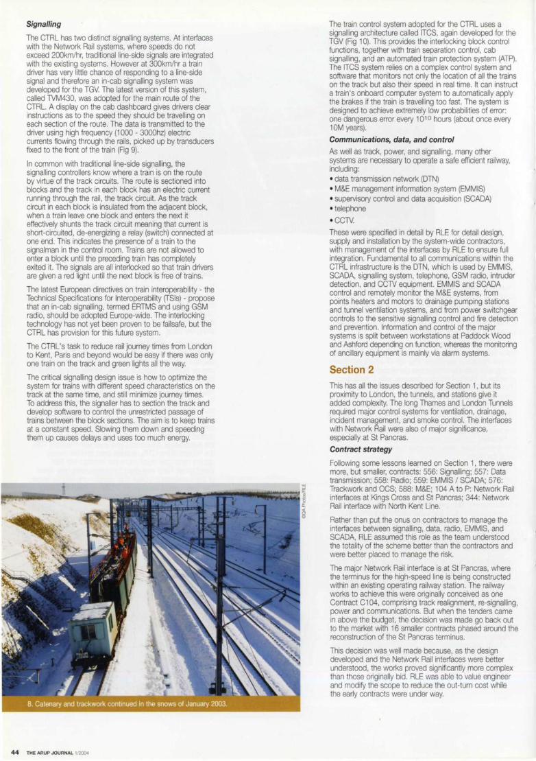
Signalling
The CTRL has two distinct signalling systems. At interfaces with the Network Rail systems, where speeds do not exceed 200km/hr, traditional line-side signals are integrated with the existing systems. However at 300km/hr a train driver has very little chance of responding to a line-side signal and therefore an in-cab signalling system was developed for the TGV. The latest version of this system, called TVM430, was adopted for the main route of the CTRL. A display on the cab dashboard gives drivers clear instructions as to the speed they should be travelling on each section of the route. The data is transmitted to the driver using high frequency (1 OOO - 3000hz) electric currents flowing through the rails, picked up by transducers fixed to the front of the train (Fig 9).
In common with traditional line-side signalling, the signalling controllers know where a train is on the route by virtue of the track circuits. The route is sectioned into blocks and the track in each block has an electric current running through the rail, the track circuit. As the track circuit in each block is insulated from the adjacent block, when a train leave one block and enters the next it effectively shunts the track circuit meaning that current is short-circuited, de-energizing a relay (switch) connected at one end. This indicates the presence of a train to the signalman in the control room. Trains are not allowed to enter a block until the preceding train has completely exited it. The signals are all interlocked so that train drivers are given a red light until the next block is free of trains.
The latest European directives on train interoperability - the Technical Specifications for Interoperability (TSls) - propose that an in-cab signalling, termed ERTMS and using GSM radio, should be adopted Europe-wide. The interlocking technology has not yet been proven to be failsafe, but the CTRL has provision for this future system.
The CTRL's task to reduce rail journey times from London to Kent, Paris and beyond would be easy if there was only one train on the track and green lights all the way.
The critical signalling design issue is how to optimize the system for trains with different speed characteristics on the track at the same time, and still minimize journey times. To address this, the signaller has to section the track and develop software to control the unrestricted passage of trains between the block sections. The aim is to keep trains at a constant speed. Slowing them down and speeding them up causes delays and uses too much energy.
44 THE ARUP JOURNAL 1/2004
The train control system adopted for the CTRL uses a signalling architecture called ITCS, again developed for the TGV (Fig 10). This provides the interlocking block control functions, together with train separation control, cab signalling, and an automated train protection system (ATP). The ITCS system relies on a complex control system and software that monitors not only the location of all the trains on the track but also their speed in real time. It can instruct a !rain's onboard computer system to automatically apply the brakes if the train is travelling too fast. The system is designed to achieve extremely low probabilities of error: one dangerous error every 1010 hours (about once every 10M years). Communications, data, and control
As well as track, power, and signalling, many other systems are necessary to operate a safe efficient railway, including: • data transmission network (DTN) • M&E management information system (EMMIS) • supervisory control and data acquisition (SCADA) • telephone
• CCTV. These were specified in detail by RLE for detail design, supply and installation by the system-wide contractors, with management of the interfaces by RLE to ensure full integration. Fundamental to all communications within the CTRL infrastructure is the DTN, which is used by EMMIS, SCADA, signalling system, telephone, GSM radio, intruder detection, and CCTV equipment. EMMIS and SCADA control and remotely monitor the M&E systems, from points heaters and motors to drainage pumping stations and tunnel ventilation systems, and from power switchgear controls to the sensitive signalling control and fire detection and prevention. Information and control of the major systems is split between workstations at Paddock Wood and Ashford depending on function, whereas the monitoring of ancillary equipment is mainly via alarm systems.
Section 2 This has all the issues described for Section 1, but its proximity to London, the tunnels, and stations give it added complexity. The long Thames and London Tunnels required major control systems for ventilation, drainage, incident management, and smoke control. The interfaces with Network Rail were also of major significance, especially at St Pancras. Contract strategy
Following some lessons learned on Section 1, there were more, but smaller, contracts: 556: Signalling; 557: Data transmission; 558: Radio; 559: EMMIS I SCADA; 576: Trackwork and OCS; 588: M&E; 104 A to P: Network Rail interfaces at Kings Cross and St Pancras; 344: Network Rail interface with North Kent Line.
Rather than put the onus on contractors to manage the interfaces between signalling, data, radio, EMMIS, and SCADA, RLE assumed this role as the team understood the totality of the scheme better than the contractors and were better placed to manage the risk.
The major Network Rail interface is at St Pancras, where the terminus for the high-speed line is being constructed within an existing operating railway station. The railway works to achieve this were originally conceived as one Contract C104, comprising track realignment, re-signalling, power and communications. But when the tenders came in above the budget, the decision was made go back out to the market with 16 smaller contracts phased around the reconstruction of the St Pancras terminus.
This decision was well made because, as the design developed and the Network Rail interfaces were better understood, the works proved significantly more complex than those originally bid. RLE was able to value engineer and modify the scope to reduce the out-turn cost while the early contracts were under way.
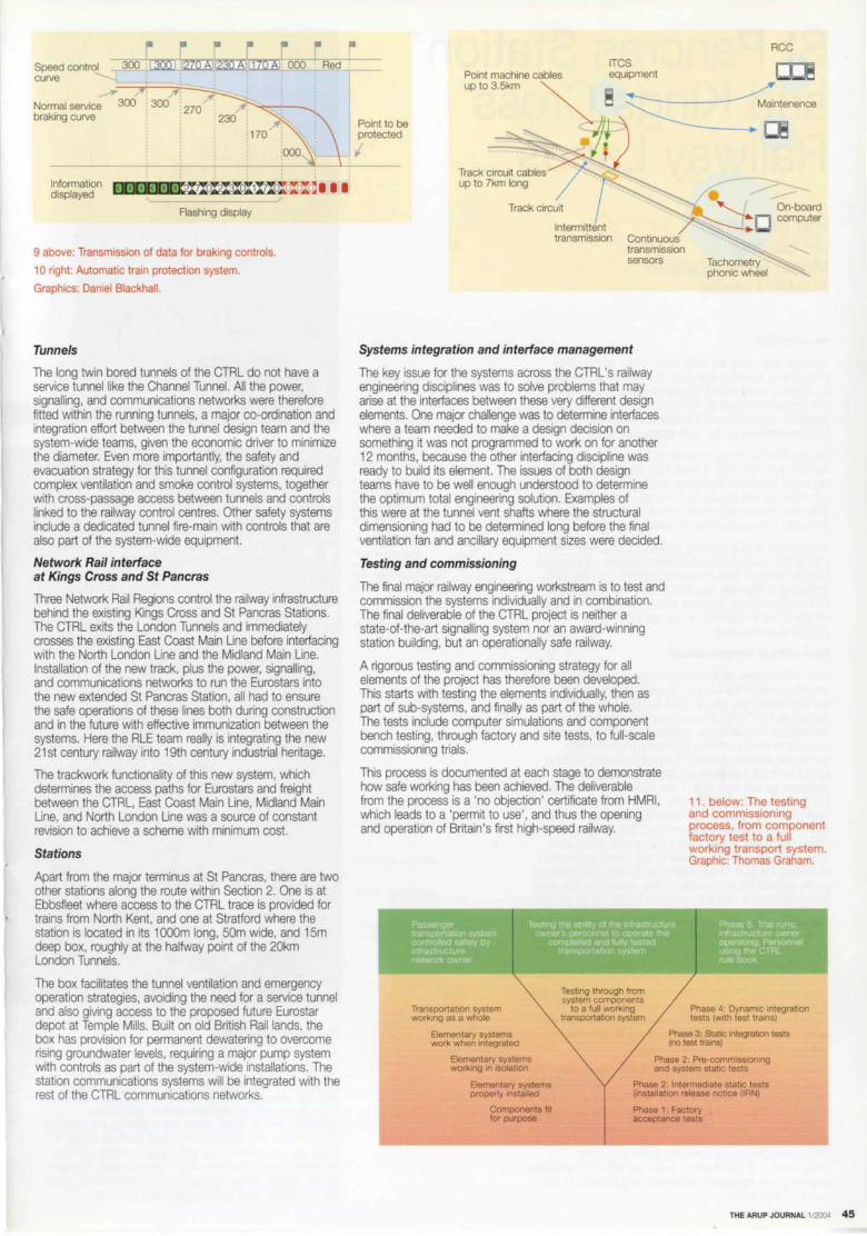
"' "' "' ,. "' "' Speed control curve
300 mr m.1230 Ail 170 Ai: OOO Red
Normal service 300 300 braking curve
170
OOO
Information displayed 300300 ~ ot?I:3I oI 1M oX0I oI 0) 1 I I
Flashing display
9 above: Transmission of data for braking controls.
10 right: Automatic train protection system.
Graphics: Daniel Blackhall.
Tunnels
The long twin bored tunnels of the CTRL do not have a service tunnel like the Channel Tunnel. All the power, signalling, and communications networks were therefore fitted within the running tunnels, a major co-ordination and integration effort between the tunnel design team and the system-wide teams, given the economic driver to minimize the diameter. Even more importantly, the safety and evacuation strategy for this tunnel configuration required complex ventilation and smoke control systems, together with cross-passage access between tunnels and controls linked to the railway control centres. Other safety systems include a dedicated tunnel fire-main with controls that are also part of the system-wide equipment.
Network Rail interface at Kings Cross and St Pancras
Three Network Rail Regions control the railway infrastructure behind the existing Kings Cross and St Pancras Stations. The CTRL exits the London Tunnels and immediately crosses the existing East Coast Main Line before interfacing with the North London Line and the Midland Main Line. Installation of the new track, plus the power, signalling, and communications networks to run the Eurostars into the new extended St Pancras Station, all had to ensure the safe operations of these lines both during construction and in the future with effective immunization between the systems. Here the RLE team really is integrating the new 21st century railway into 19th century industrial heritage.
The trackwork functionality of this new system, which determines the access paths for Eurostars and freight between the CTRL, East Coast Main Line, Midland Main Line, and North London Line was a source of constant revision to achieve a scheme with minimum cost.
Stations
Apart from the major terminus at St Pancras, there are two other stations along the rou1e within Section 2. One is at Ebbsfleet where access to the CTRL trace is provided for trains from North Kent, and one at Stratford where the station is located in its 1 OOOm long, 50m wide, and 15m deep box, roughly at the halfway point of the 20km London Tunnels.
The box facilitates the tunnel ventilation and emergency operation strategies, avoiding the need for a service tunnel and also giving access to the proposed future Eurostar depot at Temple Mills. Built on old British Rail lands, the box has provision for permanent dewatering to overcome rising groundwater levels, requiring a major pump system with controls as part of the system-wide installations. The station communications systems will be integrated with the rest of the CTRL communications networks.
Point to be protected
Point machine cables up to3.5km
Track circuit cables up to 7km long
Track circuit
Continuous transmission sensors
Systems integration and interface management
The key issue for the systems across the CTRL's railway engineering disciplines was to solve problems that may arise at the interfaces between these very different design elements. One major challenge was to determine interfaces where a team needed to make a design decision on something it was not programmed to work on for another 12 months, because the other interfacing discipline was ready to build its element. The issues of both design teams have to be well enough understood to determine the optimum total engineering solution. Examples of this were at the tunnel vent shafts where the structural dimensioning had to be determined long before the final ventilation fan and ancillary equipment sizes were decided.
Testing and commissioning
The final major railway engineering workstream is to test and commission the systems individually and in combination. The final deliverable of the CTRL project is neither a state-of-the-art signalling system nor an award-winning station building, but an operationally safe railway.
A rigorous testing and commissioning strategy for all elements of the project has therefore been developed. This starts with testing the elements individually, then as part of sub-systems, and finally as part of the whole. The tests include computer simulations and component bench testing, through factory and site tests, to full-scale commissioning trials.
This process is documented at each stage to demonstrate how safe working has been achieved. The deliverable from the process is a 'no objection' certificate from HMRI, which leads to a 'permit to use', and thus the opening and operation of Britain's first high-speed railway.
Transportation system working as a whole
Testing through from system components
to a full working transportation system
RCC
11 . below: The testing and commissioning process, from component factory test to a full working transport system. Graphic: Thomas Graham.
Phase 4: Dynamic integration tests (with test trains)
Elementary systems work when integrated
Phase 3: Static 1ntegrat,on tests
Elementary systems working 1n isolation
Elementary systems properly installed
Components fit for purpose
(no test trains)
Phase 2: Pre-commissioning and system static tests
Phase 2: Intermediate static tests (installation release notice (IRN)
Phase 1: Factory acceptance tests
THE ARUP JOURNAL 1/2004 45

St Pancras Station and Kings Cross Railway Lands Ray Bennett Ian Gardner Martin Gates-Sumner Alastair Lansley
Introduction
Summer 2001 saw the start of the major construction programme to realize the vision for the new St Pancras as Britain's international rail gateway to Europe. By 2007, this Grade One listed St Pancras Station will have been massively extended and transformed to become the main London terminus for the high-speed Eurostars.
The smallest but most complex of the three sectors forming Section 2 of the CTRL is Area 100, the new railways and highways infrastructure across the Kings Cross Lands and the works to and around St Pancras - one of the largest and most challenging development schemes anywhere in the world in modern times on a working railway.
Throughout, RLE is working in close collaboration with the station owner LCR, the London Borough of Camden, English Heritage, three zones of Network Rail, the train operating companies, London Underground, Transport for London and the statutory utilities, to keep the existing infrastructure in operation whilst carrying out over £600M of construction.
New railway infrastructure
Area 100 includes all the works between St Pancras itself and the portal of the London Tunnels at Gifford Street, on the east side of the Kings Cross Railway Lands (Fig 2). As well as the CTRL Up and Down lines connecting to six international platforms, grade-separated approaches connect to three platforms for high-speed domestic commuter services from Kent, and the existing Midland Main Line (MML) services are realigned into four new platforms on the west side of the extended station, having first been moved into an interim station on the east side in April 2004. New railway connections are being formed both from St Pancras and from the CTRL to the West Coast Main Line via the North London Line (NLL), and CTRL services will also be able to use a new connection to access the East Coast Main Line (ECML). The existing, poorly aligned, North London Incline connection between the North London Line (NLL) and the ECML will be replaced.
The whole railway layout in Area 100 was originally to have been fabricated in 113A rail (each section weighs 1131b or 51.3kg/m), the standard rail for the old nationalized British Rail and subsequently Railtrack, now superseded by Network Rail. This was partly for easier compatibility with existing lines in the area, partly because it allowed the use of tighter radiuses and thus greater ease in fitting the complex layout of over 20km of railway into the site, and partly because the low speeds near the station made a heavier rail operationally unnecessary.
However, half-way through 2000, following rail breaks associated with corner gauge cracking and section fatigue, the decision was taken to use the new heavier RT60 rail throughout. This is Network Rail's version of the established UIC60 form (60kg/m), for which the RLE team including Arup is now helping to develop the RT60 range of fittings and type-approvals for turnouts, drives and other components. To achieve this, some redesign of the railway geometry was necessary, with minor adjustments to the layout's functionality.
46 THE ARUP JOURNAL 1/2004
CTRL domestic and international
Reahgned North London Incline
Link to West Coast Ma,n Line
Midland Mam Une
Thameslink 2000 cross-site tunnels to
East Coast Main Une/ Great Northern Railway
Existing Thameslink
New deck extension
New Thameslink box
King ·s Cross Station
St Pancras Station (Barlow tralnshed)
St Pancras Chambers
The design challenge
Area 100 has additional challenges, over and above complying with the CTRL Act 1996 and the LCR Development Agreement. A new below-ground station and twin cross-site tunnels linking to the ECML for the Thameslink 2000 project are needed; St Pancras Chambers (Fig 1), which fronts the station to the south on Euston Road, and Barlow's trainshed itself are Grade 1 listed; and the cement and aggregate batching plants in the Kings Cross Lands needed to be relocated. The latter are the closest rail-fed ready-mix concrete facilities to the City of London, and thus strategically important.
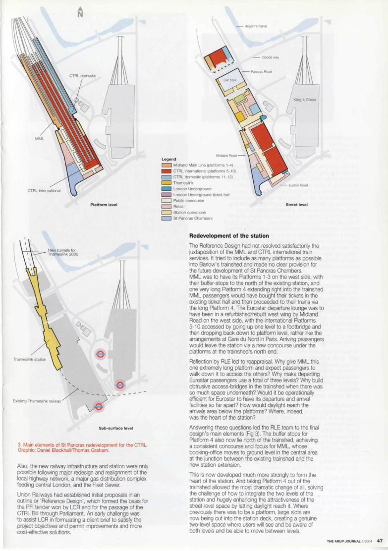
• N
MML
CTRL international
Platform level
Thameslink station
'
Sub-surface level
3. Main elements of St Pancras redevelopment for the CTRL. Graphic: Daniel Blackhall!Thomas Graham.
Also, the new railway infrastructure and station were only possible following major redesign and realignment of the local highway network, a major gas distribution complex feeding central London. and the Fleet Sewer.
Union Railways had established initial proposals in an outline or 'Reference Design', which formed the basis for the PFI tender won by LCR and for the passage of the CTRL Bill through Parliament. An early challenge was to assist LCR in formulating a client brief to satisfy the project objectives and permit improvements and more cost -effective solutions.
- Regerrs canal
- Goods way
Midland Road -Legend
c::::J Midland Main Line (platforms 1-4)
- CTRL international (platforms 5-10) c::::J CTRL domestic (platforms 11 -13)
c::::J Thameslink
London Underground
c::::J London Underground ticket hall
c::::J Public concourse
c::::J Retail Street level
c::::J Station operations
c::::J St Pancras Chambers
Redevelopment of the station
The Reference Design had not resolved satisfactorily the juxtaposition of the MML and CTRL international train services. It tried to include as many platforms as possible into Barlow's trainshed and made no clear provision for the future development of St Pancras Chambers. MML was to have its Platforms 1-3 on the west side, with their buffer-stops to the north of the existing station, and one very long Platform 4 extending right into the trainshed. MML passengers would have bought their tickets in the existing ticket hall and then proceeded to their trains via the long Platform 4. The Eurostar departure lounge was to have been in a refurbished/rebuilt west wing by Midland Road on the west side, with the international Platforms 5-10 accessed by going up one level to a footbridge and then dropping back down to platform level , rather like the arrangements at Gare du Nord in Paris. Arriving passengers would leave the station via a new concourse under the platforms at the trainshed's north end.
Reflection by RLE led to reappraisal. Why give MML this one extremely long platform and expect passengers to walk down it to access the others? Why make departing Eurostar passengers use a total of three levels? Why build obtrusive access-bridges in the trainshed when there was so much space underneath? Would it be operationally efficient for Eurostar to have its departure and arrival facilities so far apart? How would daylight reach the arrivals area below the platforms? Where, indeed, was the heart of the station?
Answering these questions led the RLE team to the final design's main elements (Fig 3). The buffer stops for Platform 4 also now lie north of the trainshed, achieving a consistent concourse and focus for MML, whose booking-office moves to ground level in the central area at the junction between the existing trainshed and the new station extension.
This is now developed much more strongly to form the heart of the station. And taking Platform 4 out of the trainshed allowed the most dramatic change of all , solving the challenge of how to integrate the two levels of the station and hugely enhancing the attractiveness of the street-level space by letting daylight reach it. Where previously there was to be a platform, large slots are now being cut into the station deck, creating a genuine two-level space where users will see and be aware of both levels and be able to move between levels.
THE ARUP JOURNAL 1/2004 47

The perceived volume of the station is thus being increased from platform level down to street level, to transform the area below the station deck from a liability (Fig 4) into a major asset (Figs 5 & 6).
The station 's new main entrance will be at ground level on the east side (Fig 7). There will be a corresponding major entrance on the west side on Midland Road, and it will still be possible to enter from the south via the forecourt to Pancras Chambers. Pancras Road will become one-way northbound along the station's east side and diverted east of the nearby German Gymnasium and Stanley Buildings, giving space for the station entrance facilities and the wider station extension. On the west side (Fig 8), Midland Road will become one-way southbound, creating an overall gyratory system around the extended station. This cleverly solves a common problem at major city-centre transport interchanges - including a dedicated taxi lane. Here taxis will naturally queue for the pick-up point in Midland Road, having set down passengers arriving for trains on the Pancras Road side. New bus stops will be located near the station entrances in Pancras Road and Midland Road.
Passenger circulation
Most pedestrian circulation will be at street level, from which people will never need to go up or down by more than one level - up to the platforms and the platform-level retail outlets, and down to Thameslink. At the Euston Road end of these street-level facilities, beneath the Chambers forecourt, the main north-south circulation concourse leads directly into London Underground's new western ticket-hall, giving access to the sub-surface lines and linked on to the refurbished and extended Underground central ticket hall.
At the northern end of this north-south concourse, the heart of the extended station will be the central concourse running east-west across the full width between the entrances, and linking via a subway connection to the new Underground northern ticket hall and Kings Cross Station. Access to the MML Platforms 1-4 and CTRL Domestic Platforms 11 -13 will be directly from this central concourse. as will access down to the new Thameslink station.
Beneath the tracks, north of the pedestrian concourses and retail outlets, is a coach station, complete with group baggage and left luggage facilities. North again is a twostorey car park, accessed from the realigned Pancras Road, which then joins with Goods Way (straightened and lowered) to pass under the train deck as the public highway link to Midland Road and the continuation northwards of Pancras Road towards Camden. Finally, north of this road, the space under the train deck will house a servicing facility for the trains, with direct access up to the 'country ends' of all 13 platforms.
The very long Eurostar trains require long platforms -over 400m. Given that the train deck is elevated at St Pancras (due to the historical decision for the track approaches to bridge over the Regent's Canal, rather than under as at Kings Cross), the ALE team was keen to prevent the station forming a major barrier in the townscape. Opening up the ground level and making much use of its features greatly helps here.
48 THE ARUP JOURNAL 1/2004

For international departures, all the facilities are now immediately under the trains, with multiple travelator links up to the platforms. After analysis of the working of Waterloo International terminal, the team opted for travelators only, rather than escalators as well. Travelators are much better for passengers with baggage trolleys and child-buggies and through statistical risk analyses presented to HMRI the team managed to establish new standards to use 12° travelators for upward travel in a UK station, getting passengers close to the middle of the platforms.
Arriving international passengers are dealt with di1fferently. The natural tendency for passengers leaving a train at a city terminus is to walk forwards towards the buffer-stops. The time passengers take to walk down platforms from the carriages naturally controls the flow through any barriers -in this case the immigration and customs controls . So by having long 6° inclined travelators only at the ends of the platforms, it should be possible to avoid large queues through passport control in the arrivals hall (where there is space for up to 20 desks). It is stationary queuing, rather than walking alongside the train, that people find really irritating.
Sophisticated computer modelling of pedestrian circulation was used to analyze the capacity of the public spaces and vertical passenger movement, so as to satisfy the station operators and HMRI of the adequacy and safety of the station layout, and to establish footfall figures for the optimum location of retail facilities. Airports use the need for security screening as an excuse to make passengers arrive early and wait as a captive market with nothing better to do than shop, and then plan circulation as a labyrinth to maximize exposure to retail. For international train travel to compete with short-haul flights, the team realized St Pancras had to be planned for circulation efficiency as well as good passenger facilities. It is therefore possible to board a train within five minutes of arriving at the international taxi set-down.
At peak periods, the station circulation allows for over 50 trains per hour, with up to three international train departures within 15 minutes, two of them separated by only three minutes. The international capacity roughly equates to the passenger numbers using Heathrow Terminal 4, and this in turn is only a third of the total numbers expected to use the station.
The station structure
Completed in 1868, 20 years before the Eiffel Tower, the 7 4m clear span of the trainshed designed by William Henry Barlow (Fig 9) made it the largest such enclosure, a record it held for the next quarter-century. In the redevelopment the arched roof is being cleaned, restored, repainted, and reglazed. Investigation of the paintwork showed the original colour to be dark brown - soon replaced by blue - and blue is being used again. The glazing to the crown of the arch is restored to the pattern originally chosen by Barlow, with slate roofing to either side, allowing much more light into the space below.
At platform level, the west wall is already pierced by several openings, and more are being formed, in sympathetic style, to link the platform area directly with the upper level west-side retail area.
The original intention at the lower level was to retain the Barlow column/girder/plate structure almost in its entirety.
As is well known, the ceiling level of this undercroft provides the tie for the roof-arch, and so its integrity has to be preserved. Barlow was far-sighted enough to realize that platform layouts would change over the lifetime of his station, and so he designed the ceiling level of the undercroft as a horizontal deck structure to carry the track beds, with platforms built up off it. The platforms, originally in timber (Fig 10), are therefore not part of the primary structure. Investigations showed that although the cast-iron columns and their foundations are in excellent shape and perfectly fit to be reused, the strength of the horizontal beams was questionable, in terms of maximum load-bearing capacity and expected lifespan. Additionally, improved vibration isolation was necessary between the platforms and the undercroft space below.
THE ARUP JOURNAL 1/2004 49
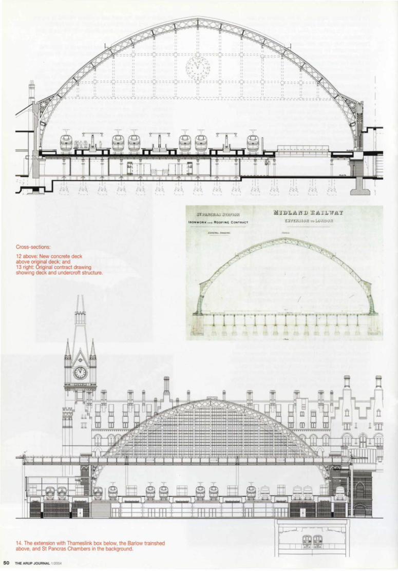
Cross-sections:
12 above: New concrete deck above original deck; and 13 right: Original contract drawing showing deck and undercroft structure.
y •
14. The extension with Thameslink box below, the Barlow trainshed above, and St Pancras Chambers in the background.
50 THE ARUP JOURNAL 1/2004
t '•
---~--. I
,;;c- =:. :(r
_-0:-: - -I I
- .I'.r. - .• -CC ••• cr

The chosen solution was to cast a new concrete deck across the full width of the station on top of the existing deck, so that its load is transmitted directly onto the columns (Figs 12 & 13). Such a concrete structure has large in-plane stiffness, unlike the existing beam grillage. This allows large holes to be designed into it, allowing the levels to be opened up.
English Heritage endorsed these changes, seeing as strongly positive the revealing of the station's undercroft areas and the opening up of new vistas in the building to create a still greater sense of space.
The new St Pancras needs more and longer platforms, achievable only by extension to the north, and the importance of the original buildings raised a major stylistic question. There was never any particular symmetry between Barlow's great arch and St Pancras Chambers -the combination works by juxtaposition rather than by integration (Fig 14). So it was agreed that there should be no attempt at pastiche; the extension would be a new and unashamedly modern structure to the north of Barlow's trainshed (Fig 17 overleaq. This has been designed by RLE, based upon a masterplan prepared in 1997 in conjunction with Foster and Partners.
Covering all 13 platforms, the new extension is an aluminium-clad louvre-blade and glass roof, giving north light. Unlike the existing station. massive and heavy at street level, the extension has a lightweight canopy floating clear above the platform deck. It is carried some 20m above street level on minimal vertical columns on a large 30m grid, to avoid any danger of passengers standing under the Barlow arch feeling 'shut in'. Continuity comes from the soffit level of the new roof being set at the lower
chord level of the wind-truss north gable of the existing arch. The soffit of the lightweight new roof floating out at this level seems almost to disappear when viewed from the old trainshed (Fig 15).
The old and the new are separated by a great glass transept extending 22.5m from the north gable to the extension roof, and more than 100m across. At each end are the new main entrances - also in glass to provide natural light deep into the station - down into the LUL subway on the east side, and for the descent to the new Thameslink platforms on the west. Passengers using this space will see above them the international trains and an end-on view of Barlow's north gable, and will look north to the new roof and through its glazing to the sky.
The platform deck of the station extension will be built of a mix of precast and in situ concrete, using the platform edges as the primary north-south beams. The vocabulary of ribbed soffits and lighting reflect the geometry of Barlow's undercroft to the south, to maintain the theme for the pedestrian concourses.
Construction of the new Thameslink box on the line of the existing tunnel does not affect the main Barlow trainshed, but conflicts with the rather ramshackle range of buildings on the west side, north of St Pancras Chambers. After a lengthy debate with English Heritage, it was agreed that to build the box safely these buildings should be demolished and replaced by new construction.
The new work, though not identical, reflects the style of the previous buildings. Its design will open up the view from Midland Road towards the majestic porte-cochere at St Pancras western entrance (Fig 16).
There is a further heritage benefit. St Pancras Chambers was built as the Midland Grand Hotel between 1868 and 1876 to designs by Sir George Gilbert Scott and, having survived the threat of demolition by British Rail in the 1960s, is generally regarded as one of the grandest and greatest Victorian Gothic buildings in London. It shut its doors to paying guests in 1935, and after further life as offices finally closed down in the 1980s for fire regulation reasons. There is enthusiasm to find a long-term use for Scott's hotel building, but it has been enormously difficult given the constraints of the 1960s Grade 1 listing. One way to ease the problem is to attach a new and efficient building to the old structure. The new west-side building above Thameslink has enhanced foundations capable of carrying extra building on top (subject of course to acceptance from English Heritage). The large new servicebay for the station, accessed from Midland Road, could also be used by an easy vertical connection to provide for the hotel. (Interestingly, the team has been able to demonstrate that Barlow's structural grid forms quite an efficient basis for a modern hotel.)
THE ARUP JOURNAL 1/2004 51
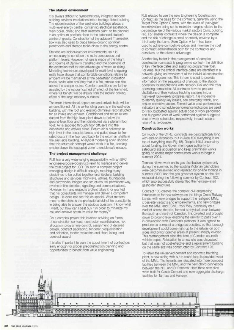
52 THE ARUP JOURNAL 1/2004
The station environment
It is always difficult to sympathetically integrate modern building services installations into a heritage-listed building. The reconstruction of the west-side buildings allows a multi-level energy centre, containing electrical substation, main boiler, chiller, and heat rejection plant, to be planned in an optimum position close to the extended station's centre of gravity. Construction of the adjacent Thameslink box was also used to place below-ground sprinkler plantrooms and storage tanks close to the energy centre.
Stations are indoor/outdoor environments, so it is unnecessary to condition the main concourses and platform levels. However, full use is made of the height and volume of Barlow's trainshed and the openness of the extension roof to take advantage of warm air rising. Modelling techniques developed for multi-level shopping malls have shown that comfortable conditions relative to ambient will be maintained at the pedestrian circulation levels, whilst also ensuring that in a fire, smoke can rise above the escape routes. Comfort conditions are further assisted by the natural 'cathedral' effect of the trainshed, where full benefit will be drawn from the radiant cooling effect of the large masonry surfaces.
The main international departures and arrivals halls will be air-conditioned. All the air-handling plant is in the east-side building, with the roof and existing chimneys reconstructed for air intake and exhaust. Conditioned and return air are ducted from the high-level plant down to below the ground-level floor and then distributed via a plenum floor void. Air is supplied through floor diffusers into the departures and arrivals areas. Return air is collected at high level in the occupied areas and pulled down to firerated ducts in the floor void back to the return air shafts in the east-side building. Analytical modelling again showed that this return air concept would work in a fire, keeping smoke above the occupied zone to enable safe escape.
The project management challenge
RLE has a very wide-ranging responsibility, with an EPC (engineer-procure-construct) remit to manage and deliver the total project for LCR. On such a complex project managing design is difficult enough, requiring many disciplines to be pulled together (architecture, building structures and services, highways, utilities, foundations and earthworks, bridges and structures, rail permanent-way, overhead line electrics, signalling and communications). However, in many respects a client takes it for granted that his consultants will manage and deliver a competent design. He does not see this as special. What matters most to the client is the professional skill of his consultants in being able to answer the obvious question: 'I know what I want, but how can I best buy it in order to minimize my risk and achieve optimum value for money?'
On a complex project this involves advising on forms of construction contract, contractor incentivization, risk allocation, programme control, assignment of detailed design, contract packaging, tenderer prequalification and selection, tender evaluation and short-listing, and contract award.
It is also important to plan the appointment of contractors early enough for proper preconstruction planning and opportunities to benefit from value engineering.
RLE elected to use the new Engineering Construction Contract as the basis for the contracts, generally using the Target Price Option C form, with the levels of 'pain/gain' incentivization being set to maintain margins relative to the percentage fee of the various market sectors (civils, building, rail). For smaller contracts where the design is complete and the risk of change is small or entirely covered by a third party, the Lump Sum Option A form has been used to achieve competitive prices and minimize the cost of contract administration both for the contractor and ourselves, to the client's advantage.
Another key factor in the management of complex construction contracts is programme control - the definition of key interface dates and assigning programme float. For Area 100 the critical interface dates are identified in a network, giving an overview of all the individual construction contract programmes. This in turn is used to provide information on the sequence of changes to the station operation for negotiations with Network Rail and the train operating companies. All contracts have to prepare distillations of their various tracking systems into a high-level four-weekly progress report. It is imperative to identify quickly key issues, see emerging trends, and ensure corrective action. Earned-value cost-performance indicators and schedule-performance indicators are used to track budgeted against actual cost of work performed, and budgeted cost of work performed against budgeted cost of work scheduled, respectively; in each case a ratio > 1 is favourable.
Construction works
On much of the CTRL, contracts are geographically long with end-on interfaces, but in Area 100 everything is on top of everything else (Fig 18). Despite initial uncertainty about funding, the Government gave authority to safeguard site acquisition and keep preliminary works going, to enable major construction works to begin in summer 2001.
Transco allows work on its gas distribution system only during the summer, so the existing Victorian gasholders were decommissioned and replaced by on-line storage in summer 2000, and the gas governor system on the site replaced during the following summer by Contract 102, which also successfully dismantled the heritage-listed gasholder structures.
Contract 103 creates the complex civil engineering infrastructure for new railways on the Kings Cross Railway Lands, with new bridges to support the realigned MML, cross-site viaducts and embankments, and new bridges over the MML and ECML. York Way, previously on a viaduct across the site, formed a physical break between the south and north of Camden. It is diverted and brought down to ground level enabling the railway to pass over it; in conjunction with Camden's planners, it was agreed to produce as compact a bridge as possible, so that borough development could come right up to the railway on both sides and bring together areas at present sharply divided. This rearrangement clips the front of Camden council 's vehicle depot. Relocation to a new site was discussed, but that was not cost-effective and a replacement building on the same site was constructed by Contract 125.
To retain the rail-served cement and concrete batching plant, a new siding with a run-round loop is provided west of the MML. The tenants are relocated into more compact facilities between the MML and the new chord connection between the NLL and St Pancras. Here three new silos were built for Castle Cement and new aggregate discharge facilities for Tarmac and Hanson.
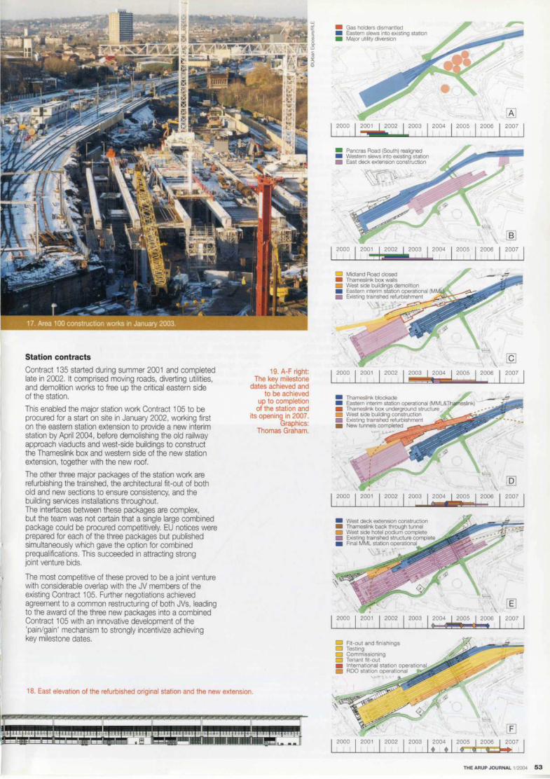
II
Station contracts
Contract 135 started during summer 2001 and completed late in 2002. It comprised moving roads, diverting utilities, and demolition works to free up the critical eastern side of the station.
This enabled the major station work Contract 105 to be procured for a start on site in January 2002, working first on the eastern station extension to provide a new interim station by April 2004, before demolishing the old railway approach viaducts and west-side buildings to construct the Thameslink box and western side of the new station extension, together with the new roof.
The other three major packages of the station work are refurbishing the trainshed, the architectural fit-out of both old and new sections to ensure consistency, and the building services installations throughout. The interfaces between these packages are complex, but the team was not certain that a single large combined package could be procured competitively. EU notices were prepared for each of the three packages but published simultaneously which gave the option for combined prequalifications. This succeeded in attracting strong joint venture bids.
The most competitive of these proved to be a joint venture with considerable overlap with the JV members of the existing Contract 105. Further negotiations achieved agreement to a common restructuring of both JVs, leading to the award of the three new packages into a combined Contract 105 with an innovative development of the 'pain/gain' mechanism to strongly incentivize achieving key milestone dates.
19. A-Fright: The key milestone
dates achieved and to be achieved
up to completion of the station and
its opening in 2007. Graphics:
Thomas Graham.
18 E f h b' h d . . I ast e evat1on a t e refur 1s e angina station an d h t enewe xt ens1on.
II II II --- ·- -~--.. -~ - --
• Gas holders dismantled • Eastern slews into existing stat,on • Maier ubhty diversion
I 2000 I 2001 I 2002 I 2003 I 2004 I 2005 2006 2007
• Pancras Road (South) realigned • Western slews Into existing station • East deck extension construction
2000 2001 2002 2003 2004 2005 2006 2007
D Midland Road closed • Thameslink box walls • West side buildings demolition , • Eastern interim station operat,onal (MM • Existing tra,nshed refurbiShment
I 2000 I 2001 I 2002 I 2003 ! 2004 I 2005 2006
• Thameslink blockade • Eastern Interim station operational (MML& • Thameslink box underground structure , • West side building construction • Existing trainshed refurbishment • New tunnels completed
I 2000 I 200, I 2002 I 2003 I 2004 2005 I 2006
• West deck extension construction • Thameslink back through tunnel • West side hotel podium complete • Existing trainshed structure complete • Rnal MML station operat,onal
'\, ~
I 2000 I 2001 I 2002 I 2003 I ; 004 2005 : I 20~6
D Fit -out and finishings Testing Commissioning
D Tenant fit-out • International station operational • ROO station operational
2000 2001 2002
2007
2007
2007
THE ARUP JOURNAL 1/2004 53

Railway contracts
A single contract (104) was originally intended for all the railway works, for everything from the early lift-and-shift staging works right through to the design, development, and completion of the final complex layout. However, contractors were not prepared to accept the range of risks involved in this work scope, given the current overheated rail sector market, and few contractors in this sector have the proven capability to manage multi-disciplinary works. Recognizing this, the ALE team elected to split the scope by discipline (signalling, permanent way electrification and power, and telecommunications) and into a series of stages, and then provide the interface management and planning skills itself.
MML was guaranteed that at least four platforms at St Pancras would remain available for its trains at all stages, accessed via a two-track approach to meet the service levels of the summer 1994 timetable. A major risk to railway staging works would have been maintaining the overhead line electrics into St Pancras station (MML runs only diesel trains so does not need these). Negotiations with Railtrack and the Thameslink resulted in an advance Contract 124 to provide a turnback location at Kentish Town station for Thameslink train services should they not be able to continue through the tunnel to Farringdon. Two additional platform faces and reversible signalling on all lines were provided. This work, additional to the original CTRL project scope, was cost-effective to permit dewiring of the MML south of the NLL, with subsequent benefits to programme and risk in subsequent contracts.
In the first stages the signalling remained Westpac, with TPWS (train protection warning system) installed to improve safety. The interim station included a switchover to WestCad Solid State Interlocking, and TGV430 with ATP (automatic train protection) will be added at the end. West Hampstead signal box will continue to control the MML lines, but the rest of the station and its approaches will be supervised from the CTRL control centre at Ashford. Throughout all of the stages, Contract 104c modifies the railway operational telecommunications infrastructure.
54 THE ARUP JOURNAL 1,=
MML strongly supported the redevelopment plans - its terminal will move from having been just about the worst interchange with Eurostar to by far the best. The key to ensuring continuing goodwill during construction is for ALE to ensure that everything is done in the least disruptive manner possible. Close collaboration has been essential both with Network Rail's Midland Zone and with MML and Thameslink throughout planning, aiming to work towards optimizing discussions rather than polarizing them. Liaison groups work at site level and at senior management level with all third-parties across Area 100, demonstrating a real willingness to work together for mutual benefit.
The first package, in late-2001, was the Eastern Slew (Contracts 104a & b), to take the MML approach lines to the eastern side of the existing formation north of the station, thus releasing the site for construction of the new aggregate siding. The MML lines were moved onto decks of the Carnley Street and Regent's Canal bridges that had not been in use for some years, to free the bridges' western sides to allow new bridge decks to be constructed under Contract 103.
The next major stage on the MML, the Western Slew (Contracts 104e & Q, pulled the approach lines and station throat over as far as possible in the other direction, taking the original Platforms 6 and 7 out of use and allowing the eastern part of the station extension to be built under Contract 105. Following this, the first stage of Contracts 104g & h saw the MML slewed east again, into the interim station (Fig 20) on the new eastern deck extension. MML is using this from April 2004 until mid-2006.
This cleared the way for the major works on the existing station and on the west of the extension (all by the combined Contract 105). In mid-2006 the second stage of Contracts 1049 & h moves the MML lines into their final position on platforms 1-4 and gives MML occupation of its new station. The rest of the extended and refurbished station can then be prepared for its final role as the home of high-speed domestic services to Kent on platforms 11-13 and the international station using platforms 5-1 O can be completed in readiness for opening in early 2007.
I !
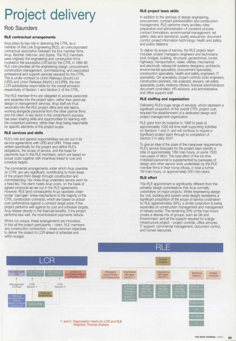
Project delivery Rob Saunders
RLE contractual arrangements
Arup plays its key role in delivering the CTRL as a member of Rail Link Engineering (RLE), an unincorporated contractual association between the four member firms Arup, Bechtel, Halcrow, and Systra. The RLE members were originally the engineering and construction firms involved in the successful LCR bid for the CTRL in 1995-96. RLE now provides all the engineering design, procurement, construction management, commissioning, and associated professional and support services required for the CTRL. This is under contract to Union Railways (South) Ltd (URS) and Union Railways (North) Ltd (URN), the two LCR subsidiaries responsible for the overall provision respectively of Section 1 and Section 2 of the CTRL.
The RLE member firms are obligated to provide personnel and expertise into the project team, rather than particular design or management services. Arup staff are thus seconded into the RLE project office and site teams, working alongside personnel from the other partner firms and the client. A key factor in the consortium's success has been sharing skills and opportunities for learning with the consortium partners, rather than Arup being responsible for specific elements of the project scope.
RLE services and skills
RLE's role and general responsibilities are set out in its service agreements with URS and URN. These were written specifically for the project and define RLE's obligations, the scope of service, and the basis for payments due to the RLE members, which are based on actual costs together with incentives linked to cost and schedule targets.
The commercial arrangements under which Arup operates on CTRL are very significant, contributing to most areas of the project from design through construction and commissioning. Nor does Arup undertake service work for a fixed fee. The client meets Arup costs, on the basis of agreed protocols as set out in the RLE agreements. However, RLE (and consequently Arup) operates under similar 'pain/gain' share mechanisms to the majority of the CTRL construction contracts, which are based on actual cost performance against a contract target price. If the project performs well against its cost and schedule targets, Arup shares directly in the financial benefits. If the project performs less well, the incentivization payments reduce.
Whilst not unique, these arrangements are innovative, in that all the project participants - client, RLE members and construction contractors - share common objectives to deliver the project to LCR ahead of schedule and within budget.
Management CTRL Contract Section 1
CTRL Section 2
1. and 2. Organization charts for LCR and ALE. Graphics: Thomas Graham.
Operat,ons Manager Sect,on 1
RLE project team skills
In addition to the services of design engineering, procurement. contract administration and construction management, RLE performs many ancillary roles: preparation and administration of consents process; contract formulation; environmental management; rail safety; data and standards; quality assurance; document control; project information technology; health and safety; and public relations.
To deliver its scope of service, the RLE project team includes: project managers; engineers and technicians (civil, bridges, building, structural, geotechnical, tunnel, highways, transportation, water, utilities, mechanical and electrical); railway/rail systems designers; architects; environmental specialists; procurement specialists; construction specialists; health and safety engineers; IT specialists; QA specialists; project controls (cost engineers, construction planners, risk analysts); lawyers; rail safety specialists; public relations officers; financial administrators; document controllers; HR advisors; and administrative and office support staff.
RLE staffing and organization
Delivering RLE's huge range of services, which represent a significant proportion of the overall CTRL project cost, required the establishment of a dedicated design and project management organization.
RLE grew from its inception in 1996 to peak at approximately 1 OOO full-time staff supporting activities on Sections 1 and 2, and will continue to require a significant project team through to completion of Section 2 in early 2007.
To give an idea of the scale of the manpower requirements, RLE's service forecasts for the project team identify a total of approximately 15M man-hours, or some 7500 man-years of effort. The total effort of the full-time mobilized personnel is supplemented by packages of design and other service work undertaken by the RLE member firms in their home offices, in total a further 1 M man-hours, or approximately 500 man-years.
RLE effort
This RLE appointment is significantly different from the primarily design commissions that Arup normally undertakes on major projects. Whilst engineering design (for civil, building and system-wide design) represents a significant proportion of the scope of service undertaken by RLE (approximately 39%), a similar proportion is being expended on construction management and management of railway works. The remaining 20% of the man-hours covers a diverse mix of groups, such as QA and Environment, and all the support required for a large infrastructure project - project controls, office services, IT support, commercial management, document control, and human resources.
PrOject Controls
THE ARUP JOURNAL 1/2004 55

Procurement
Traditional procurement of infrastructure projects
In the traditional model, the client would finance the project and develop an organization to deal with project definition, legal, commercial, and land access/acquisition issues. It would appoint a consulting engineer, under a professional services contract, to act on its behalf to undertake certain design, procurement, construction supervision, and contract administration activities, in return for which the consulting engineer would be paid a fee. The client would place construction contracts following a competitive tendering process, which typically would aim to pass the majority of construction risk to the contractor. The client effectively pays the contractor for taking on risk, irrespective of whether the risk actually transpires.
CTRL target cost procurement model
The procurement model proposed and embraced by the CTRL is that of an integrated target cost arrangement, with much more visible risk allocation and alignment of objectives between client, project manager, and contractors.
The model works within a partnering framework:
Several working definitions of partnering exist, but essentially it requires the project participants to work together co-operatively to achieve the project objectives and then share the benefits of doing so.
The partnering philosophy on the CTRL requires the participants to:
• manage risks jointly and fairly • discuss and jointly agree targets before setting them • share information and knowledge openly • share resources and co-locate where appropriate • address issues as one team and actively resolve conflicts • share the benefits/losses. The CTRL uses target price contracts. with all parties (client, RLE. and contractors) sharing in the benefits of effective contract delivery.
The aims of the target cost procurement model are:
• tangible financial benefits for all participants as a result of effective collaboration and partnering, rather than an adversarial approach
• comprehensive risk identification, realistic risk sharing among the parties, and allocation to those best able to manage and control them, rather than passing all risk to contractors and encouraging a claims-focused relationship
• clear responsibility for performance and accountability for quality management and self-certification
• effective risk mitigation and control for realistic confidence in forecast delivery of the project on time and to budget.
The main principles of the CTRL procurement model are:
• RLE is responsible for packaging and managing all construction contracts on behalf of UR.
• Contractors for CTRL capital construction contracts are selected by a competitive tendering process, following EU procurement rules.
56 THE ARUP JOURNAL 1 /2004
Whilst attractive to some clients, the shortfalls of the traditional approach are well known, particularly on large infrastructure projects. Adversarial relationships between project participants, cost overruns, and significant extensions to project schedules are by no means unusual on recent UK transport infrastructure projects such as the Jubilee Line Extension and the Channel Tunnel. With the traditional contract forms, there is significant potential for protracted disputes over responsibility for events, to the detriment of the progress of the physical works. The client. its agents, and the works contractors are subject to different commercial risks and potentially conflicting commercial objectives.
• Construction contracts are generally modelled on the Engineering and Construction Contract (ECC - formerly called NEC) Option C Target Cost with Activity Schedules. The standard ECC contract has been modified with CTRL-specific terms and conditions, setting out allocation of risk between the Employer (UR) and the Contractor.
• Work under the construction contracts may include aspects of engineering design and/or detailing.
• Contractors are responsible for quality management and se~-certification.
• Insurance cover is provided by UR.
• Contractors are paid actual costs plus a management fee.
• Contractors are incentivized to deliver the contract below a budget target cost.
• Each contract is performed within its own contract target cost, which generally applies to the aggregate of all actual construction costs (management, plant, labour and materials and other costs incurred).
• Each contract has a defined target cost mechanism defined - similar for all the major CTRL contracts though they vary in size from £8M for utility diversions, to almost £400M for the refurbishment, extension and fitout of St Pancras Station.
• The contracts often allow for a 'preconstruction' period, to actively encourage value engineering.
• Compensation events provide for prompt adjustments to the contract target cost.
• Any saving realised by an actual cost less than the target at completion is shared between UR and the contractor.
• Contractors are obligated to reimburse a proportion of any cost overruns against the contract target to UR.
• All costs and entitlement to shares of savings or obligation to meet cost overruns are controlled by translation at prescribed base dates and adjustments according to changes in published official indices as set out in individual contracts. RLE is incentMzed against an
overall project out-turn cost.
The consequence of the target cost procedure is that the participants are paid their actual costs, but ultimately the financial rewards to both RLE as project manager and the construction contractors are linked to performance, and aligned with the interests of the client.

Staffing the project
The project team comprises both staff and agency personnel from each of the RLE member firms. Resourcing a team of this scale is a significant undertaking, and it has been achieved by a dedicated full-time group of HR specialists within RLE who take staff requisitions and job descriptions, Identify potential candidates through the member firms, arrange Interviews, and make the necessary steps to mobilize successful candidates.
Similarly, Arup has full-time staff responding to requests from RLE for particular resources, identifying appropriate candidates, and dealing with the practical and commercial arrangements for individual staff assignments.
These Arup staff are also responsible for actively managing the process of demobilization of staff back into the firm.
Staffing the project has not been without incident. Initial mobilization required a major commitment by all the RLE members to achieve the rate of build-up of personnel demanded over a very short period. Similarly, when the project hit funding shortfalls at the beginning of 1998, and the RLE team was temporarily demobilized, a similar effort was needed to manage the return of Arup personnel to other parts of the firm, and then remobilize the team when the funding issues were resolved.
A major implication is that the CTRL represents a significant resource commitment of staff at all levels. The duration of many assignments is years, not months. Some key staff in senior management and engineering positions will be on the project for 10 years.
With Section 1 completed, engineering activity has passed to Section 2, and with construction well advanced, RLE personnel are being demobilized back to member firms. However there remains a significant resource requirement through to project completion, and the recruitment efforts continue to fill positions for the systemwide works.
How does Arup contribute?
In round numbers, approximately one in five of the project personnel is either directly employed by Arup or engaged by the firm on an agency basis. The latter was a deliberate policy, both to meet resource commitments and to enable Arup to balance the needs of the project with its ongoing infrastructure businesses.
Arup has also given the project team flexibility through delivering packages of design and other work using 'work orders', under which work is carried out in Arup offices across the UK. This allows the firm to provide both part -time specialist services such as acoustics and M&E advice, and also major packages of design and detailing for stations and structures that demand large design groups. Engineering design is obviously a major focus of Arup's contribution, as set out in several of the articles in this issue of The Arup Journal.
More surprising perhaps is the wide variety of non-design roles undertaken by Arup staff - lead roles in project management, cost control, engineering management, risk management, project planning, environmental management, and the consents processes. Arup also leads the engineering management, including the major geotechnical, structural, tunnelling, building engineering, and architectural disciplines. In certain instances the firm had to recruit to extend and further develop its skills base, notably in station planning, cost management, planning, construction management, and signalling design.
In all, some 1400 Arup members have contributed to the CTRL since its inception; some of those making particularly significant contributions are listed on p63.
The management of RLE
RLE has developed and implemented a 'matrix' management organization. The project team is led by the Project Director, whose primary responsibilities are to direct the activities of RLE and undertake the key client and external body liaison roles. The management roles undertaken include:
Project controls • design and construction planning and progress reporting • financial planning, budgeting, trends and cost reporting • risk management • change controls
Financial administration • invoice and payment processing for goods and services
for the project
Contract administration • notices, determinations and compliance records • financial administration, design liaison and
progress reporting
Human resources • planning, recruitment, terms and conditions,
assignment and re-assignment
Document controls • recording, distribution, accessing and archiving
Facilities management • project and site office servicing, health
and safety and security.
Role of project controls
Project controls is a central support group in RLE, comprising cost engineers, construction planners, and estimators, with the functional responsibility for the work undertaken by cost engineers and planners assigned by RLE to each of the construction contracts. The role of project controls is to provide the project's management, the client, and relevant third parties with a clear objective view about the status of the individual contracts and the overall project.
This is achieved through the following reports:
• RLE weekly contract progress reports, which highlight major issues and key productivity indicators
• RLE four-weekly formal progress reports • periodic reports to project insurers • quarterly forecasts of project costs and
contingency usage, and RLE staff forecasts • four-weekly cost reports • four-weekly trend reports • reports of RLE staffing and costs against. Project control adds value by focusing management attention, giving regular and frequent updates on live and upcoming project issues to allow open discussion with client and contractor, and ensuring that there are 'no surprises'.
Engineering planning and reporting
A major schedule and cost risk to the project is the very real consequence of failure to deliver engineering design on time, given the potentially very large compensation events for delay and disruption once on site caused by late delivery of 'issued for construction' (IFC) information. As the contracts are typically put out to bid with engineering design approximately 25% and let at 40% complete, the preparation and release of information for construction continues after contract award and well into the construction operations. This approach minimizes the overall project duration, allows detailed design development to be incorporated, and facilitates value engineering ideas and construction phasing and processes to minimize the overall project cost.
The engineering delivery plan is defined typically at contract award but can change significantly afterwards, with the many engineering disciplines involved in the need to fully integrate the (changing) construction requirements of the contractors.
A robust process for planning engineering deliverables and reporting engineering progress is essential, as it is important to know the major engineering production issues so that actions can be taken to minimize any potential disruption to construction.
THE ARUP JOURNAL 1/2004 57

58 THE ARUP JOURNAL 1/2004
On Section 2, an engineering progress and performance reporting database was adopted, and subsequently extended and customized by the project team to suit the particular requirements of the CTRL. scheduling out some 15 OOO deliverables, primarily drawings, but also calculations, specifications, reports and other documents.
Each deliverable is tagged with attributes, such as unique reference, title, discipline, and other attributes that uniquely identify it, and also its purpose, ie whether it is a drawing to be issued for construction, or for a consents submission. In all, some 30 different generic types of deliverable were identified.
Each deliverable has a set of predetermined milestones -'issued for tender', 'issued for construction', 'as-built drawing', etc, with each milestone having associated scheduled, forecast. and actual dates. The actual issues of information are logged into the database, thereby allowing package managers, discipline leads, and engineers to track the progress of individual engineering deliverables.
The project controls team can also assess earned value at discipline, contract, and overall project levels. The summary statistics (for example overall progress and progress with the issue of construction drawings) are compiled, reported, and reviewed four-weekly. The progress measures are used to identify problem areas and target management actions to mitigate any potential delays.
Whilst this level of planning and monitoring requires significant effort by the engineering teams, it does provide a clear plan and sound basis for regularly assessing progress and tracking deliverable production, to ensure engineering delivery is available in good time for physical construction works.
Schedule management
The client defines the overall project requirements, aimed at practical completion in early 2007 for Section 2. RLE generates the project master programme, with key milestone dates and contract access, sectional completion and handover dates. In turn, the contractors create programmes to manage their contract scope, which are consolidated and used to update the master programme.
As well as this, there is regular monitoring and reporting of contract progress and update overview programmes to identify problem areas and mitigate delays. To facilitate these tasks, construction planners are generally deployed by RLE for each construction contract. In addition to the master programme, other planning tools used on the project are time chainage charts and interface diagrams.
Cost forecasting
For Section 2 of the CTRL, the project budget was set at Forecast 1 in June 2001. The base figure comprised the anticipated final cost (AFC) at that time and a contingency amount generated through a quantitative risk analysis (ORA). Every four months, a re-forecast is carried out and compared with the project budget. The total project budget is only varied with the incorporation of client instructions, whereas the AFC at each forecast accounts for the current level of trends. The ORA at each forecast incorporates the current list of risks from the risk register.
Cost management/trends
Costs are managed under the headings of RLE services and capital construction budgets. with the RLE target price being the sum of these. Capital construction costs are in turn tracked through various contracts measuring actual cost against the budgeted cost for that work included in the target price. These analyses by contract are consolidated and included in the project cost report.
The trend process runs in parallel. Trends are evaluated under each contract and added to the target price for re-forecasting, resulting in an adjusted AFC. Project trends are consolidated periodically into the project trend report.
Role of cost engineers
Cost engineers are generally deployed by RLE for each construction contract. Their main roles are:
• cost estimates for design changes • evaluation of estimates for proposed scope transfers
and 'early warnings'/proposed compensation events • management of the trend process for the contract • compilation and analysis of actual costs periodically for
inclusion in the project cost report.
Managing risk
The CTRL is a flagship private finance initiative (PFI) project, and is subject to complex financing and funding arrangements. The funding for the project is raised by LCR, partly through loans and bond issues, and partly from Government and EU grants.
The target cost arrangements in place mean that all participants - client. RLE, and the individual construction contractors - bear some financial risk. Some of these risks are offset using the normal vehicles of professional indemnity insurance and construction contract insurance. Other means of offsetting risk are more innovative, such as the project's cost overrun protection programme.
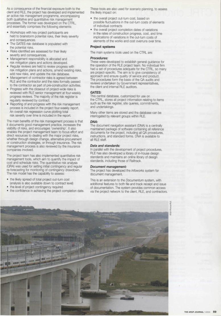
As a consequence of the financial exposure both to the client and RLE, the project has developed and implemented an active risk management programme, encompassing both qualitative and quantitative risk management processes. The former was developed on the CTRL, and essentially comprises the following elements:
• Workshops with key project participants are held to brainstorm potential risks, their likely severity and consequences.
• The GATES risk database is populated with the potential risks.
• Risks identified are assessed for their likely severity and consequences.
• Management responsibility is allocated and risk mitigation plans and actions developed.
• Regular reviews are held to review progress with risk mitigation plans and actions, amend existing risks, add new risks, and update the risk database.
• Management of contractor risks is agreed between RLE and the contractor and the risks formally passed to the contractor as part of pre-construction activities.
• Progress with the closeout of project-wide risks is reviewed with RLE senior management at four-weekly progress reviews. The majority of the risk register is regularly reviewed by contract.
• Reporting of and progress with the risk management process is included in the project four-weekly report. An overall risk regression curve plotting total risk severity over time is included in the report.
The main benefits of the risk management process is that it documents good management practice, increases the visibility of risks, and encourages 'ownership'. It also enables the project management team to focus effort and direct resources to dealing with the major project risks, whether through design change, alternative procurement or construction strategies, or through insurance. The risk management process is also reviewed by the insurance companies involved.
The project team has also implemented quantitative risk management tools, which aim to quantify the impact of cost and schedule risks. The quantitative risk analysis (ORA) was used for setting initial contingency and regular re-forecasting for monitoring of contingency drawdown. The risk model has the capability to assess:
• the likely spread of total project out-turn cost (analysis is also available down to contract level)
• the level of project contingency required • the confidence in achieving the project completion date.
These tools are also used for scenario planning, to assess the likely impact on:
• the overall project out-turn cost, based on possible fluctuations in the out-turn costs of elements of individual contracts
• the overall project completion dates of variations in the rates of construction progress, cost, and time implications of variations in the out-turn costs of elements of the works and cost overruns over time.
Project systems
The main systems tools used on the CTRL are:
Procedures: These were developed to establish general guidance for the operation of the RLE project team. No individual firm had a set of procedures adequate for the CTRL, so many are project-specific. The aim is to give consistency of approach and ensure quality of service and product. The procedures form the basis of the OA audits and reviews undertaken by Government representatives, the client and internal RLE auditors.
GATES: This central database, customized for use on the CTRL, stores all project information relating to items such as the risk register, site queries, commitments, and undertakings.
Many other items are stored and the database can be interrogated by relevant groups within RLE.
DNA: The document navigation assistant (DNA) is a centrally maintained package of software containing all reference documents for the project, including all OA procedures, instructions, and standard forms. DNA is available to all RLE staff.
Data and standards: In parallel with the development of project procedures, RLE has also developed a library of in-house design standards and maintains an online library of design standards, including those of Railtrack.
Document management: The project has developed the lnfoworks system for document management.
This is an extension to the Documentum system, with additional features to both file and track receipt and issue of documentation. The system provides common access via the project network to the client, RLE, and contractors.
THE ARUP JOURNAL 1/2000 59

CTRL chronology February 1986
February 1987
July 1987
July 1988
December 1988
January 1989
March 1989
October 1989
March 1990
April 1990
June 1990
August 1990
May 1991
October 1991
March 1992
July 1992
JanuaryFebruary 1993
March 1993
MarchOctober 1993
October 1993
January 1994
JanuaryMarch 1994
April 1994
May 1994
The Channel Tunnel Treaty is signed by Margaret Thatcher and Frarn,ois Mitterand.
The Channel Tunnel Act receives Royal Assent. Waterloo is identified as the first terminal for international trains.
British Rail begins search for additional rail capacity to cope with Channel Tunnel trains: Kings Cross is chosen as a second terminal.
BR identifies four potential route corridors through Kent.
The Government establishes the principal of private sector involvement. and six consortia are invited to tender for a build, operate, and transfer scheme. Arup responds (Kent Rail submission); Eurorail (Trafalgar House + BICC) is picked as BR's chosen partner.
BR's Channel Tunnel Rail Link Team is set up.
BR announces its preferred route corridor.
Arup decides to examine alternative routes, because of perceived difficulties in tunnelling under or building an above-ground line through south-east London.
Arup publishes its solution, taking the route into London and beyond from the east via Stratford.
BR and Eurorail .N submit their proposals to the Government.
BR/Eurorail JV proposals are rejected by the Government.
BR's Rail Link Project invites Arup, and two other promoters, to develop their alternative route proposals for evaluation by them.
BR reports to the Government that its southerly approach is superior in economic terms, whilst the Arup route is the better of the two easterly alternatives. Arup challenges BR on its conclusions.
Government preference is announced for a route 'along the lines put forward by Ove Arup' .
The Rail Link Project is reorganized to refine the Eastern Approach Route. Arup joins BR's existing set of consultants.
The Rail Link Project becomes Union Railways (URL), a BR agency company comprising public and private sector staff. Arup is one of six consultancies involved, together with 11 environmental consultancies. The team's remit comprises the safety, business strategy, environment, design, operation, planning and consultation for Arup's eastern Approach Route.
The Union Railways team reports to the Government.
The Secretary of State for Transport reports to Parliament. confirming that the project will go ahead as a public/private joint venture following public consultation. The route for public consultation is defined as passing north of Ashford, following the Arup alignment on a bridge across the Medway, and including two alternative routes from the Barking Portal to London Kings Cross/St Pancras.
Arup and SG Warburg and Co Ltd put together a transport operator-focused consortium to bid for the CTRL.
Public consultation.
URL reports to the Government on the 'refined route', including appraisal of options and mitigation measures following consultation.
The Government confirms most of the route. and St Pancras as the London terminus.
Further public consultation.
Nine bids are received to pre-qualify for a competition to select the private sector promoter to design, build, finance, and operate the CTRL.
The Channel Tunnel is officially opened.
60 THE ARUP JOURNAL 1/2004
June 1994
August 1994
November 1994
April 1995
June 1995
December 1995
February 1996
December 1996
February 1997
February 1997
March 1997
April 1997
June 1997
February 1998
June 1998
October 1998
February 1999
March 1999
December 1999
January 2000
February 2000
Four consortia pre-qualify and are invited to submit proposals: Green Arrow (Hochtief, Costain, Nishimatsu, Siemens); Eurorail (BICC. GEC, HSBC Holdings, National Westminster Bank, Seeboard, Trafalgar House); LCR (Arup, Bechtel, Blue Circle, Halcrow, National Express. Virgin, Warburg); Union Link (AEG, WS Atkins, Holzmann, Mowlem, Spie Batignolles, Taylor Woodrow)
The Government announces that an intermediate station will be located at Ebbsfleet. and launches the competition to select the private sector consortium that will deliver and operate the CTRL. Bid documents are Issued to the four pre-qualifying groups.
The CTRL Bill is introduced to the House of Commons.
Ownership of URL is transferred from BR to the Department of Transport (Do 1).
The Government announces that LCR and Eurorail are shortlisted.
The announcement date for the winner is postponed, to allow further time for revised bids.
The Government and LCR sign the contract for the project to design, build, finance and operate the 109km Channel Tunnel Rail Link, with LCR acquiring ownership of Union Railways Ltd (by now a Government company) and European Passenger Services Ltd (the UK arm of the Eurostar train services).
Royal Assent is granted for the Channel Tunnel Rail Link Bill.
The DoT is notified by LCR that its plans for a public flotation would be delayed from October 1997 to April 1998, and that LCR would exhaust its funds from the Initial financing in January 1998. To bridge this gap, LCR proposes selling Eurostar trainsets and leasing them back from the new owner.
It is announced that the New Engineering Contract (NEC) will be used for the CTRL.
Rail Link Engineering is named as the consortium that will design and project manage construction of CTRL for LCR.
The first tenders are issued for the CTRL.
Advanced works start, diverting 15km of electricity cables under the A2. near Gravesend, Kent.
LCR presents the outline of a financing proposal that the DoT finds acceptable enough to grant an extension to the 30-day cure period granted in January 1998.
The Government accepts LCR's restructuring proposals for the construction, operation and financing of the CTRL. DoT, LCR, and Railtrack sign a Statement of Principles to this effect.
Work begins on site to construct Section 1 under a frve-year contract to complete by 30 September 2003. Contracts are awarded for the first main civil engineering contracts, valued at approximately £340M: Contract 330: Alfred McAlpine/Amec JV; Contract 350: Eurolink .N; Contract 410: Eurolink JV; Contract 430: Skanska Construction UK Ltd.
Re-financing is completed with successful bond issue (£2.65bn) and signature of agreements between LCR, Railtrack. ALE. DETR and Inter Capital and Regional Railways (Eurostar Management Consortium). Union Railways (North) Ltd and Union Railways (South) Ltd, were set up as the organizations responsible for Section 1 and Section 2 respectively.
Contract 420 for mid-Kent section is awarded to Hochtief/Norwest Holst, valued at around £85M.
The first contract for advanced works for Section 2 - C365, valued at £1 M, to construct undertrack crossings at Ripple Lane, Dagenham - is awarded to AMEC CM! Engineering Ltd, with works beginning in January 2000.
The £120M systemwide Contract 570 to design and supply track, overhead electrification systems and electrical and mechanical systems for Section 1 is awarded to AMEC Spie Rail Systems.
The last major Section 1 contract • systemwide Contract 550, valued at £56M, to procure, install, test and commission signalling, train control and communications -is awarded to the CCA Consortium (CSEE Transport, Corning Communications and Amey RaiQ.

February 2000
May2000
June 2000
June 2000
July 2000
October 2000
November 2000
December 2000
January 2001
February 2001
April 2001
May2001
July 2001
July 2001
August 2001
January 2002
June 2002
July 2002
July 2002
July 2002
July 2002
August 2002
August 2002
September 2002
October 2002
The 1.3km Medway Viaduct begins to take shape as the first of the incrementally-launched deck sections is slid into place over the piers by a pair of 800-tonne hydraulic jacks.
Union Railways invites tenders from organizations for £600M-worth of tunnelling contracts, a major element of Section 2. Contracts are planned to be awarded in early 2001 and work on site is scheduled to start from mid-2001.
The 'Target Zero Accidents' safety campaign is launched across the CTRL.
The Deputy Prime Minister, John Prescott, is guest of honour at the breakthrough of the North Downs Tunnel.
Bridge House, a 16th century listed timber-framed house, is slid 55m to a new location away from the route of the CTRL.
CTRL celebrates its second anniversary of site works and reaches the halfway mark for completion of Section 1.
Contractors are invited to attend a briefing outlining the scope of the main packages of work at St Pancras.
A major archaeological find is unearthed in Saltwood near Folkestone; artefacts include a gold and silver disk brooch set with garnets and blue glass.
First major contracts are awarded for Section 2: Contract 230: Skanska; Construction UK Ltd; Contract 320: Hochtief/J Murphy & Sons
More contracts worth almost £400M are awarded to Section 2: Contract 135: Edmund Nuttall Ltd; Contract 220: Nishimatsu/Cementation/Skanska Joint Venture; Contract 240: Costain/Skanska/Bachy; Contract 250: Edmund NuttallNv'ayss & Freytag/Kier Consortium
The final 'deck section' of the Medway Viaduct is successfully slid into place. The Deputy Prime Minister, John Prescott, signs agreement to secure completion of the CTRL.
The first dedicated tracks for the CTRL are laid at Fawkham Junction in North Kent.
The North Downs Tunnel is completed five months ahead of schedule and at a cost saving of over £5M.
The Transport Minister, John Spellar, gives the signal for work to begin on Section 2 at the ground-breaking ceremony in Stratford, marking the start of construction work for the new International station, and to complete the CTRL into London.
· St Pancras station extension contract 105 is awarded to Costain/ O'Rourke/ Bachy Soletanche, later combined with Contract 108.
Ebbsf!eet civils contract worth £120M is awarded. Contract 342 covers the construction of 3.5km of the CTRL between the southern end of the Thames Tunnel and the interface with Section 1 at Pepper Hill.
LCR reaches agreement with Railtrack Group PLC to acquire the entire share capital of Railtrack (UK) Ltd for £375M.
Systemwide contract 588 for mechanical and electrical systems for Section 2 is awarded to EMCOR Drake and Scull Group pie.
First CTRL TBM is launched. The 95m long, 1100 tonne 'Milly the Muncher Cruncher' sets off from Swanscombe in north Kent towards Essex on the far banks of the Thames on a 2.5km drive that will take around eight months.
The CTRL celebrates the first anniversary of the start of major construction on Section 2.
An Anglo-Saxon waterwheel unearthed on a CTRL construction site is a find of national significance, according to Government archaeological advisers.
Contract 576 for track and overhead catenary systems for Section 2 is awarded to ACT JV (Alstom Transportation Projects Ltd, Carillion Construction Ltd, and Travaux du Sud-Ouest).
The first TBM for the London Tunnels, 'Annie', is launched from the Stratford box as part of Contract 220.
The first maintenance contract - M01 - is awarded for Section 1 to Carillion Rail.
Tender invitations sent out for Contract 232, Stratford international station, and for Contract 340, Ebbsfleet international station.
October 2002
November 2002
November 2002
January 2003
February 2003
February 2003
March 2003
March 2003
April 2003
April 2003
April 2003
May 2003
July 2003
August2003
September 2003
September 2003
November 2003
December 2003
December 2003
January 2004
February 2004
February 2004
March 2004
March 2004
April 2004
July 2004
September 2004
February 2005
November 2005
March 2006
June 2006
First quarter 2007
Contract 250 TBM 'Maysam' is launched from Dagenham.
Contract 240 TBM 'Hudson' is launched from Stratford box.
Contract 220 TBM 'Bertha' is launched from Stratford box.
Contract 250 TBM 'Judy' is launched from Dagenham.
Section 1 is energized; the 25 OOOV overhead current will power trains between Fawkham Junction and the Channel Tunnel.
Contract 240 TBM 'Brunel' is launched from Stratford box.
UK gardening celebrity Alan Titchmarsh plants the CTRL's millionth tree.
Contract 320 Thames tunnel TBM breaks though to Thurrock ahead of schedule.
Energization of Section 1 complete.
Thames Tunnel TBM no 2, named 'Susie the Dirt Digger' by local schoolchildren, commences the drive for the up-line tunnel.
Contract 125 - the transport depot for Camden Council -is opened.
Contract 342 slides a 111 m, 9000 tonne bridge into place on the North Kent Line. They also move into place a second structure - a 2200 tonne inverted 'box' - under the North Kent Line during the same weekend.
A Eurostar breaks the UK rail land speed record on Section 1 of the CTRL, reaching 334.?km/hr.
The main CTRL route from Fawkham Junction to Cheriton (excluding Ashford and the Freight chord into Dollands Moor) is accepted by URS from RLE. Section 1 is now considered an operational railway.
The Prime Minister, the Rt Hon Tony Blair, opens Section 1 for commercial services 'on time and on budget'.
TBM 'Susie the Dirt Digger' breaks through to Thurrock, completing the second of the Thames Tunnels ahead of schedule.
Contract 310, Thurrock viaduct, reaches its final abutment, taking the CTRL under the Queen Elizabeth II bridge.
A CTRL bridge connecting Contract 220 tunnel with the Kings Cross Railway Lands, is successfully pushed over the East Coast Main Line during a Christmas possession.
The second Contract 240 TBM breaks through to Barrington Road vent shaft.
Contract 220 TBM 'Annie' breaks through the London West Portal onto the Kings Cross Railway Lands.
Contract 250 TBM 'Maysam' breaks through into the Barrington Road auxiliary vent shaft.
Southbound bore of the Thameslink tunnel is completed.
Contract 250 TBM 'Judy' breaks through into Barrington Road ventilation shaft.
Contract 220 TBM 'Bertha' breaks through the London West Portal onto the Kings Cross Railway Lands.
St Pancras interim station opens on time, ready for the first Midland Mainline train to leave the new station.
The systemwide railhead is scheduled for completion.
The Thameslink blockade - a break in the line through Central London to allow construction to continue at St Pancras - begins for 35 weeks.
The North London incline railway blockade and York Way blockade north of St Pancras begin for five weeks.
The podium to enable proposed extension of the St Pancras Chambers hotel is completed.
Train running testing begins on Section 2.
The Midland Main Line final station platforms 1-4 are completed.
Opening of Section 2 and completion of the CTRL.
THE ARUP JOURNAL 1/2004 61

The following past and present staff members from Arup offices worldwide are among those who made a significant contribution to the many projects within the Channel Tunnel Rail Link.
Robert Abernethy Davar Abi-Zadeh Kevin Acosta George Addo Dele Afuape PovlAhm John Aitchison Thomas Aldridge Wilham Algaard Rachel Allan Bruce Allen Came Allen Joanna Allen Rod Allwright Gail Altmann Chns Ambrose Barbara Ancliff David Anderson Neil Anderson Sara Anderson Gert Andreson Loma Andrews Samuel Appafram Andrew Archer Richard Archer Mark Arkinstall Tom Armour Chris Armstrong Michael Armstrong Steve Armstrong David Ashurst Clive Aubrey Annel1se Baillie Lloyd Bair Ian Baker Paul Baldwin Mike Barbato Paul Barlow Don Barron Aooy Bascombe Ranirt Basu Jon Beech Claire Beedle Jon Bell Kirsten Bell Jonathan Ben-Ami Ray Bennett Daniel Bernasconi Tony Bevan Katnn Beyer Jay Bharadava Jaswant Birdi Simon Birkbeck Andrea Blackie Christine Blanch Ken Blanch Sue BlanlCh Carol Bloxome Jason Boddy Joanne Bole Nancy Bono Kemper Booher John Border Jean-Marie Bordier Dave Bosher Mark Bostock Ahmed Bouariche Natalie Bowkett Danny Boxell Darren Bradford Ellie Bradley Gill Brazier Colin Breen Simon Brimble Antony Britteon Peter Brooke Elaine Brown Rebekah Brown Kevin Brunton Christopher Buck Matthew Bumpass Dick Burge Martin Burgess Jenny Burridge John Burrows Ingrid Byng Glen Galow Bryan Cannon Nie Cariss1mo Robert Carmichael Destree Carolus Mike Carr John Carroll
Neil Garstairs Matt Carter Andrew Cason Roger Caswell Heather Geney FiTitpo CerflS Alan Chadwick Neil ChadwlCk EbrimaCham David Charters Geraldine Cheung Adam ChodorowskJ Bob Clapham Paul Claridge Toby Clark Ed Clarke Steve Clarke John Clar.!on Daniel Chfford Paul Coates Justin Coe Ken Cole Hugh Collis Louise Conroy Grant Cook, Steven Cook Richard Cooke Lee Copley John Couch Alan Couling Andrew Coultate Mark Cowieson Bnan Coyle DaVld Cross Connna CrosskJII Gavin Cruddas Harry Crummy Andrew Cunningham Gm Curtis Verner Cutter Stephen Dadswell Robert Dagnall Christefle D' Arco Lucy Darkin Mark Danow Philip Dauncey Alan Wrtton Dauns Antoine DaVld An(fy Davidson Rebecca Davies Ian Davis Lee Davison Gabby De Mamie! Fred Deacon Helen Debio Marco Del Fedele Brian Dennis Leslie Dep Mike Dickens Jennifer Dimambro Edward Dixon Leszek Dobrovolsky Graham Dodd Martin Doherty David Dollman Jim Donoghue Joseph Donohue Lisa Doughty Chns Downs Crispin Downs Karen Dnscoll Stephen Duck, Paul Duckworth Brian Dunlop William Dunn Tara Dum1n John Dyer Tamsin Dyer Steve Dyson Marcial Echenique David Edwards David EIIIS Richard Ellis sue Epps, Val Erdos. Mike Evans Peter Evans Ian Everson Rob Evlson Mo Ezzat Katnne Falbe-Hansen Stephen Fallace George Faller
Joan Fans Sita Faternl-Ardakan1 Ian Fellingham Ian Feltham Steven Fink Paul Foo Andrzei Formaniak Paul Foskett Richard Foster Nick Foundoukos Michael Francescon Pietro Francornero Suzanne Freed Christopher Fulford Asim Gaba Clive Gatti Bob Gallop Andrew Gardiner Ian Gardner Ken Garmson Steve Garry Martin Gates-8umner Gianluca Gatti Lindsay Gauntlett Derek Gibbs Alistair Giffen John Gilbert Louise Giles Craig Gill Fiona Gillan Fraser Gillespte Anne GilPITT Steven Gilpin Mike Glover Samantha Godden Bob Goldsbrough David Gordon Adrian Gould Michael Grant David Gration Alan Gray James Gray Martin Greenacre Richard Greer Len Griffin Andrew Grigsby Kathy Gubbins Bruno Guillaume Adrian Gurney Tony Hack Mustafa Hadi Nigel Hailey Mick Hall Simon Ham John Hamilton James Hargreaves Andrew Harland Simon Harris Phil Hamson Mike Hart Rob Hartshorne Neil Harwood Mike Havelock Andi Hawes Stephen Haynes John Hayns Ian Hazard Richard Hazell Louise Hearn John Henderson Des Hendrick John Henry Michael Herbert Graeme Herd Kubilay Hicyilmaz Patrick Higgins Lois Higginson Richard Hill Slephen Hill Terry Htll David Hiiier Kelvtn Hindson John Hirst Lucy Hirst Nicola Hoad TtmHocombe Stuart Hodgson Trevor Hodgson Martin Holt Martin Hooton Bill Hom Aooy Horton
Ronald Howell Gareth Hughes David Hurton Naeem Hussain Rebecca Hutt Ginny Hyde Roger Hyde Pete Ingram Chnstopher James Piers James Chris Jarman Deepak Jayaram Alan Jefcoat Gordon Jehu Nell Jenkins Steve Jenkins Stuart Jenkins Dominic Jennings Les Jephson Stella Job Paul Johnson Francis Joseph VOJkan Jovicic David Joy Mark Judge Crowe Kachil<wu Avtar Kandola Peter Karabin Gearoid Kavanagh Phineas Keane Vince Keating Dan Kelly DaVld Kelly Michael Kemp Tom Kennedy Angela Khalil NlckKhosla Laura Kidd Richard Killer Claire Kimber Phil King Martin Kirk Denis Kirtley Steve Kite Tim Knee-Robinson Peter Knight Sophia Kral John Kurzawski John Lacey Juhe Lacombe Venessa lam Andrew Lambert David Lancaster Mike Lang Alastair Lansley Jim Larkin Mtke Larvin Benjamin Lau Coner Lavery Martin Lawlor Cheryl Lawrence Damen Layton Deborah Lazarus Bob Lea David Leal G Lee Sam Levine DaVld lewtn Michael L9W1S Julia Li 8enJan11n ltm Wee Meng Urn Robert Unthorst Rob Livesey Nian Lloyd Tanya locks Mike long Ketth Longley David loosemore Andrew Lord Angus Low David Lowes Ross Lyons Jon Mabbett Paul Malpas Chris Manning Jason Manning Alan Mansfteld Massimo Marcelll Geoff Marchant Andrew Marsay Maureen Marsden
Roger Marshall Tony Marshall Andrew Martin Chris Martin Julia Martin Andrew Maskell Allan Mason Hannah Maw Andrew McCulloch Tristan McDonnell Kate McDougall Rory McEwan Jonathan Mckiernan Paul McMahon Andrew McNulty Ian McRobbie Colin Mendelowitz Sdole Menezes Neil Messenger Keith Metcalfe Robert Meyer Juliet Mian Ian Miller Paul Miller Charles Milloy Strachan Mitchell Chns Moore Enc Morgan Phil Morley Simon Morley Michael Moroney Clem Morris Luke Morton Edtth Mueller Astrid Muenzlnger Adam Mutj1 Neal Mumford Masao Muraji Tm Murnane Graham Murray Martin Murray Timothy Murung, Claudio Nebbia Ed Newman-Sanders Meng Ng James Nicholls Duncan Nicholson Neil Nicholson JorQ90 Nissen Chnstopher Nobbs Joanna Nobbs Paul Noble Mike Nolan Peter Nono-Bwomono Fiona Norman Malcolm Noyce Joe Nunan Stuart Nutton Rachel Oates Allan Oatley John O'Connell Aooy Officer Maya Oh Mike Oldham Peter Oldroyd Riccardo Oprandi Nick O'Riordan DaVld Osborne David Owen Michael Page lnnaPalmer John Parham Robert Paris Richard Parker Andy Passmgham An1I Patel RaJ Patel tan Paterson Allen Paul Colin Pearce Colin Peart Navin Peiris Daniel Perez Alan Phear AJed Phillips Richard Ph1U1ps Adam Pickles Anton Pillat Graham Pitman Jonathan Plant Gary Podd Lizzie Pomeroy
Esad Porovic Vicky Potts Mansoor Pour Colin Powell Jim Powell Simon Power Ashu Prabhu Mark Praciak Adrian Pragas Steven Pragnell Kart Pratt Martin Preene Keith Prentice Ben Price Alan Pridmore Howard Proctor Nick Rabin Raman Rai Simon Rainsbury John Ralph Paul Ravenscroft Terry Rawnsley Kulvinder Rayat John Redding Toby Reid GuyReviO Craig Rew Dave Reynolds Rachel Reynolds Simon Reynolds Peter Richardson Oliver Riches Hennetta Ridgeon Steve Riglar Sean Ring Jon Roberts Paul Robinson Nathan Aollason Thomas Ronholt Sharon Rose Andrew Ross Rupert Rowland Stuart Rudd Simon Rule Corey Russell Fredenck Russell Glen Rust John Ruthertoord Diane Sadletr Frank Sahota Matt SarlSbury John Salter Stephanos Sarnaras Sunll Sangakkara Nick Sartain Julian Saunders Rob Saunders Julian Saunders YayaSawoy Dermo! Scanlon Rudi Scheuermann Antony Schofield Paul Scott John Seaman Kar1 Seiring9' Amlan Sengupta Steve Seymour-Jones Robyn Sharwood John Shaw Michael Shears Neil Shepherd Sheldon Sherman Hilary Shields Peter Shuttleworth Keith Sibilia John Sibley Yvonne Siddle Nick Sidhu Mark Siezen Tamsin Silvester John Sim Tristan Simmonds Maurice Simms Loma Small Austin Smith Mark Smith Rob Smith SteveSm,tn Stuart Smith David Snowball Emily So Eddie Spence
Ewa Spohn Gopal SnniVasan Guy Stabler Robert Stack Leigh Stark Angus Stephen Paul Stephenson Richard Stephenson Callum Stewart Colin Stewart Brenden Stockdale Simon Stocks Chad Stnckland Joe Sumne<s Damon Sunderland Connne Swain Kostas Talaiporou Andrew Talbot Jamie Talbot Serena Tanoh Ian Taylor Luke Taylor Graham Thomas Aooy Thompson Peter Thompson Tim Thompson Lucinda Thornton Will Tipper Graham Tivey Simon Tomes Roger Tomlinson Les Tonge Paul Tonkin Laura Townsend Richard Tregaskes Jason Trenchfield Ed Tutton Sally Turnbull David Twine MIChael Tyrrell Hugh Unsworth Chnstopher Uzzell David Van Bruggen Clanssa van der Pullen Mohsen Vaz1ri Nigel Vokes Braden VOil Bibra Louise Waddingham Guy Waddington Susan Wade DaVld Wainwright Amy Walker Gary Walker Jonathan Walker Kelvtn Ward, Emma Wares Ben Walkins Rob Watkins Ian Watson Maree Watson Richard Watson Gary Webb Owen Webber Stephen West Antonia Whatmore Paul White Dean Whitwell Eric Wilde Duncan Wilkinson Michael Willford Gavin Williams Liz Williams Ray Williams Kevin Williamson RayWdlis Colin Wilson Jan Wilson Adam Wintle Biol W1shlade Jonathan Wong Michelle Wong Roger Wong Liz Wood·Gnffrths Eddie Woods Stuart Woods Dominic Woolnough Stephen Wren Stuart Yalden Mehdi Yazdchl Hoe Chlan Yeow Phil York Ying Zhou
CTRL contracts and contractors Contract 102: Removal of gas holders and gas govemer relocations Contractor: Edmund Nuttall Ltd
Contract 103: Civil engineering works at Kings Cross Railway Lands Joint venture contractors: Kier Construction Ltd, Edmund Nuttall Ltd
Contract 104A: Signalling and associated telecommunications work on eastern track slew, St Pancras Station Contractor: Westinghouse Signals Ltd
Contract 1048: Trackwork at eastern track slew, St Pancras Station Contractor: Motherwell Bridge Construction
Contract 104C: Telecommunications for eastern track slew, St Pancras Station Contractor: Tales Telecommunication Services Ltd
Contract 104E: Midland Main Line slewing at St Pancras Station Contractor: Westinghouse Rail Systems Ltd
Contract 104F: Slewing of Midland Main Line to the west at St Pancras station Contractor: Mowlem Railways
Contract 104G: Signalling and associated telecommunications for St Pancras Station Contractor: Westinghouse Rail Systems Ltd
Contract 104H: Design and installation of overhead lines at St Pancras Station Contractor: J Mowlem & Company pie
Contract 105 (combined}: St Pancras Station Joint venture contractors: Costain Ltd, O'Rourke Civil Engineering, Bachy Soletanche Ltd, Emcor Drake & Scull Group pie
Contract 124: Railway staging and interface enabling works at Kentish Town Contractor: Railtrack Midland Zone
Contract 125: Camden Depot, York Way Contractor: J Mowlem & Co pie
Contract 135: Highways and utilities diversions, St Pancras Station Contractor: Edmund Nuttall Ltd
Contract 137: Lifts at the international stations Contractor: Fujitec UK
Contract 138: Escalators at the international stations Contractor: Otis
Contract 220: London Portal (edge of Kings Cross Railway Lands} to Stratford Box Joint venture contractors: Skanska Construction UK Ltd, Nishimatsu Construction Co Ltd
Contract 230: Stratford Box Contractor: Skanska Construction (UK) Ltd
Contract 240: Stratford to Barrington Road Joint venture contractors: Costain Ltd, Skanska JV Projects Ltd, Bachy Soletanche Ltd
Contract 250: Barrington Road to Ripple Lane Joint venture contractors: Edmund Nuttall Ltd, Kier Construction Ltd, Wayss & Freytag lngenieur Bau AG
Contract 302: Diversion of utilities at Thames & Kent Avenues: Ford Motor Company Joint venture contractors: Alfred McAlpine, AMEC Civil Engineering Ltd
Contract 303: Ford and Choats Manor Way bridges Contractor: Kier Construction Ltd
Contract 310: West Thames: Ripple Lane to Thames Joint venture contractors: Morgan Est pie, Vinci Construction Grands Projets
THE ARUP JOURNAL
Contract 320: Thames Tunnel and route civil engineering works Joint venture contractors: J Murphy & Sons, Hochtief Aktiengesellschaft
Contract 330: East Thames to the Medway Valley and Waterloo connection Joint venture contractors: Alfred McAlpine, AMEC Civil Engineering Ltd
Contract 339A: Trackwork at Fawkham Junction Contractor: GrantRail
Contract 3398: Upgrading works at Fawkham Junction Contractor: Westinghouse Signals Ltd
Contract 339C: Power supply upgrade at Fawkham Junction Contractor: Seeboard Contracting Services
Contract 340: Stratford & Ebbsfleet International Stations Construction manager: Rail Link Engineering (for 13 trade contracts)
Contract 342: Highways work connecting A2 to Ebbsfleet station Joint venture contractors: Hochtief (UK) Construction Ltd, Norwest Holst Construction Ltd
Contract 350: Medway Crossing Joint venture contractor: Eurolink JV (Belon und Monierbau GMBH, Morgan Est pie, Vinci Construction Grands Projets)
Contract 361: Pipe diversions: Thames utilities Contractor: J Murphy & Sons
Contract 365: Ripple Lane undertrack crossing Contractor: AMEC Civil Engineering Ltd
Contract 41 O: North Downs Tunnel Joint venture contractor: Eurolink JV (Belon und Monierbau GMBH, Morgan Est pie, Vinci Construction Grands Projets)
Contract 420: Mid-Kent: Boxley to Lenham Heath Joint venture contractor: Hochtief (UK) Construction Ltd, Norwest Holst Construction Ltd
Contract 430: Ashford Contractor: Skanska Construction UK Ltd
Contract 434: Railway infrastructure modifications Contractor: J Mowlem & Co pie
Contract 440: East Kent-Ashford (town centre) to Cheriton Contractor: Balfour Beatty Major Projects
Contract 550: Signalling, train control and communications Joint venture contractor: CCA (CSEE Transport, Corning Communications Ltd, Amey Rail Ltd)
Contract 552: Ashford resignalling Contractor: Westinghouse Signals
Contract 556: Signalling and control, Section 2 Contractor: CSEE transport
Contract 557 Communications systems, Section 2 Contractor: Optilan (UK) Ltd
Contract 570: Trackwork, catenary, mechanical and electrical systems Contractor: AMEC Spie Rail Systems Ltd
Contract 576: Track and overhead catenary systems, Section 2 Joint venture contractor: ACT JV (Alstom Transportation Projects Ltd, Carillion Construction Ltd, Travaux du Sud-Ouest)
Contract 588: Mechanical and electrical systems, Section 2 Joint venture contractor: EMCOR Drake, Skull Group pie
Contract CTRL M01 - Infrastructure maintenance, Section 1 Contractor: Carillion Rail
Vol.39 No.1, 1/2004, Editor: David J Brown Art Editor and Designer: Desmond Wyeth FCSD, Deputy Editor: Karen Svensson Editorial: Tel: +44 (0)20 7755 3828 Fax: +44 (0)20 7755 3716 e-mail: [email protected]
Arup is a global organization of designers. It has a constantly evolving skills base, and works for local and international cl ients throughout the world.
We shape a better world.
All articles c Arup Group 2004. We have endeavoured to determine the copyright holders of all images. Those uncredited have been sourced from within Arup. Front cover and opposite: Eurostar on CTRL Section 1 in Kent: OOA Photos/ALE; Back cover: The Medway Viaduct: CArup/Central.
THE ARUP JOURNAL 112004 63