Jéssyka Flavyanne Ferreira Vilela Uni-REPM SCS - RI UFPE
309
Jéssyka Flavyanne Ferreira Vilela Uni-REPM SCS: A SAFETY MATURITY MODEL FOR REQUIREMENTS ENGINEERING PROCESS Universidade Federal de Pernambuco [email protected] http://cin.ufpe.br/~posgraduacao Recife 2018
-
Upload
khangminh22 -
Category
Documents
-
view
0 -
download
0
Transcript of Jéssyka Flavyanne Ferreira Vilela Uni-REPM SCS - RI UFPE
Jéssyka Flavyanne Ferreira Vilela
Uni-REPM SCS: A SAFETY MATURITY MODEL FOR REQUIREMENTSENGINEERING PROCESS
Universidade Federal de [email protected]
http://cin.ufpe.br/~posgraduacao
Recife2018
Jéssyka Flavyanne Ferreira Vilela
Uni-REPM SCS: A SAFETY MATURITY MODEL FOR REQUIREMENTSENGINEERING PROCESS
A Ph.D. Thesis presented to the Center of Infor-matics of Universidade Federal de Pernambuco inpartial fulfillment of the requirements for the de-gree of Philosophy Doctor in Computer Science.
Main Area: engenharia de software
Advisor: Jaelson Freire Brelaz de CastroCo-Advisor: Luiz Eduardo Galvão Martins
Recife2018
Catalogação na fonteBibliotecária Arabelly Ascoli CRB 4-2068
V699u Vilela, Jéssyka Flavyanne Ferreira Uni-REPM SCS: a safety maturity model for requirementsengineering process / Jéssyka Flavyanne Ferreira Vilela – 2018. 308 f.: fig., tab.
Orientador: Jaelson Freire Brelaz de Castro Tese (Doutorado) – Universidade Federal de Pernambuco. Cin.
Ciência da Computação. Recife, 2018.Inclui referências.
1. Engenharia de software. 2. Engenharia de segurança. 3.Sistemas críticos. I. Castro, Jaelson Freire Brelaz de (orientador)II. Título.
005.1 CDD (22. ed.) UFPE-MEI 2019-02
Jéssyka Flavyanne Ferreira Vilela
Uni-REPM SCS: A Safety Maturity Model for Requirements Engineering Process
A Ph.D. Thesis presented to the Center of
Informatics of Universidade Federal de
Pernambuco in partial fulfillment of the
requirements for the degree of Philosophy
Doctor in Computer Science.
Approved in: 13/12/2018.
______________________________________________
Advisor: Prof. Dr. Jaelson Freire Brelaz de Castro
EXAMINATION COMITTEE
_________________________________________________
Prof. Dr. Alexandre Marcos Lins de Vasconcelos
Centro de Informática/ UFPE
_________________________________________________
Prof. Dr. Robson do Nascimento Fidalgo
Centro de Informática / UFPE
_________________________________________________
Prof. Dr. Paulo Cesar Masiero
Instituto de Ciências Matemáticas e de Computação / USP
_________________________________________________
Prof. Dr. Tony Gorschek
Blekinge Tekniska Högskola, Suécia
_________________________________________________
Prof. Dr. João Baptista da Silva Araújo Junior
Departamento de Informática / Universidade Nova Lisboa

I dedicate this work to God, to my parents Mário Vilela and Fátima Vilela, to my sisterFrancynne Vilela and to my fiancé Marcus Queiroz.
ACKNOWLEDGEMENTS
To GOD, its omnipotence and omnipresence, and all spiritual forces for guidance and sup-port in every moment that I needed, for allowing my academic progress and for includingpeople in my life who encouraged me.
To Fátima and Mário Vilela, my parents, my thanks for everything! Thanks for un-derstand the life I live: always between books and computers. They have always takencare of me and my sister and they dedicated their lives to provide to us the conditions sothat we could achieve our goals. I also thank my sister Francynne Vilela. I love you guys.
To my fiance Marcus Queiroz for all attention, affection, understanding, support andlove received over these years.
To my family and friends who have always believed in my capacity to accomplishanother mission and accompanied me from near or far.
To Jaelson Castro (advisor) and Luiz Eduardo Martins (co-advisor), for the freedom,guidance, opportunities and trust that with their expertise and experience provided tome the opportunity to work on this project.
To professor Dr. Tony Gorschek for the partnership, patience, ideas, and opportunityto work in this area and for the financial support during the validation of the proposal.
To FACEPE (Fundação de Amparo à Ciência e Tecnologia do Estado de Pernambuco)for the financial support.
To my friends of Laboratório de Engenharia de Requisitos (LER) for the friendship,support and sharing of their knowledge and experiences.
To my collegues at Universidade Federal do Ceará (UFC) for all discussions, collabo-rations and support.
To all lectures of Centro de Informatica (CIN) that, in one way or another, contributedto my academic and personal growth.
To thank the subjects of module validation for their availability to contribute to ourresearch.
To my examination committee for their availability.To all people who helped me directly or indirectly to the achievement of my goals.
ABSTRACT
Context: Software is an important part in safety-critical system (SCS) develop-ment since it is becoming a major source of hazards. Software has been responsible toimplement innovative and complex functions and to send instructions to the hardware.Requirements-related hazards have been associated with many accidents and safety in-cidents. Requirements issues tend to be mitigated in companies with high processes ma-turity levels since they adopt good practices from software engineering in a systematic,consistent and proactive way. However, requirements engineers need systematic guidanceto consider safety concerns early in the development process. Objective: This thesisinvestigates which safety practices/actions are suitable to be used in the RequirementsEngineering process of SCS as well as to propose a safety maturity model to this area.Method: A set of empirical studies were used in this work. The data collection was donethrough systematic literature review and case studies. We followed the Design Sciencemethodology to propose Uni-REPM SCS, a safety module for Unified Requirements En-gineering Process Maturity Model (Uni-REPM), and the technology transfer frameworkto perform the safety module validation. Besides, comprehensive literature review wasalso conducted to provide background and support for the empirical studies. Results:The safety module has seven main processes, 14 sub-processes and 148 safety actionsdescribing principles and practices that form the basis of safety processes maturity. More-over, we describe its usage through a tool. We conducted a static validation with twopractitioners and nine academic experts to evaluate its coverage, correctness, usefulnessand applicability. Furthermore, we performed a dynamic validation with seven industrypractitioners to evaluate the safety maturity level of seven industry projects. Conclu-sions: The validation indicates a good coverage of practices and good receptivity by theexperts. Finally, the module can help companies in evaluating their current practices aswell as offers a step-wise improvement strategy to reach higher maturity.
Key-words: Safety-critical systems. Requirements Engineering. Maturity Models. Uni-REPM. Safety Engineering.
RESUMO
Contexto: Software tem um papel importante no desenvolvimento de sistemas críti-cos visto que está se tornando uma fonte importante de perigos. Software tem sido re-sponsável por implementar funcionalidades inovadoras e complexas e por enviar instruçõesao hardware. Perigos relacionados a requisitos têm sido associados a muitos acidentes eincidentes de segurança. Os problemas de requisitos tendem a ser atenuados em organi-zações com altos níveis de maturidade de processos, pois elas adotam boas práticas daengenharia de software de forma sistemática, consistente e pró-ativa. Portanto, processosmaduros contribuem para tornar o processo de desenvolvimento do sistema menos desafi-ador. No entanto, os engenheiros de requisitos precisam de orientação sistemática paraconsiderar preocupações de segurança no início do processo de desenvolvimento. Obje-tivo: Esta tese investiga quais práticas/ações de segurança são adequadas para seremusadas no processo de engenharia de requisitos de sistemas críticos bem como propor ummodelo de maturidade de segurança para esta área. Método: Um conjunto de estudosempíricos foi utilizado neste trabalho. A coleta de dados foi realizada por meio de revisãosistemática da literatura e estudos de caso. Nós seguimos a metodologia Design Sciencepara propor o Uni-REPM SCS, um módulo de segurança para o Unified RequirementsEngineering Process Maturity Model (Uni-REPM). Nós adotamos o framework de trans-ferência de tecnologia para realizar a validação do módulo de segurança. Além disso, umarevisão abrangente da literatura também foi realizada para fornecer referencial teóricoe suporte para os estudos empíricos. Resultados: O módulo de segurança possui seteprocessos principais, 14 subprocessos e 148 ações de segurança que descrevem princípios epráticas que constituem a base da maturidade dos processos de segurança. Ademais, nósdescrevemos seu uso por meio de uma ferramenta. Também realizamos uma avaliação es-tática com dois profissionais e nove especialistas da academia para avaliar sua cobertura,corretude, utilidade e aplicabilidade. Além disso, realizamos uma validação dinâmica comsete profissionais da indústria para avaliar o nível de maturidade de segurança de seteprojetos industriais. Conclusões: O módulo pode ajudar as organizações na avaliação desuas atuais práticas de segurança no processo de RE, bem como oferecer uma estratégiade melhoria passo a passo para alcançar um nível mais alto de maturidade.
Palavras-chaves: Sistemas Críticos. Engenharia de Requisitos. Modelos de Maturidade.Uni-REPM. Engenharia de Segurança.
LIST OF FIGURES
Figure 1 – Input and outputs of the RE process (adapted from (KOTONYA; SOM-
MERVILLE, 1998)). . . . . . . . . . . . . . . . . . . . . . . . . . . . . . 36Figure 2 – Requirements Engineering Process (adapted from (KOTONYA; SOM-
MERVILLE, 1998)). . . . . . . . . . . . . . . . . . . . . . . . . . . . . . 36Figure 3 – A generic requirements elicitation process (adapted from (KOTONYA;
SOMMERVILLE, 1998)). . . . . . . . . . . . . . . . . . . . . . . . . . . . 37Figure 4 – Input and outputs of the Validation phase (adapted from (KOTONYA;
SOMMERVILLE, 1998)). . . . . . . . . . . . . . . . . . . . . . . . . . . . 38Figure 5 – Example of module use to continuous improvement (adapted from (PIGOSSO;
ROZENFELD; MCALOONE, 2013)). . . . . . . . . . . . . . . . . . . . . . 40Figure 6 – Uni-REPM Components. . . . . . . . . . . . . . . . . . . . . . . . . . . 41Figure 7 – Uni-REPM Model Structure (GORSCHECK, 2011). . . . . . . . . . . . . 42Figure 8 – Example of an action of Uni-REPM (SVAHNBERG et al., 2015). . . . . . 43Figure 9 – Design science framework (adapted from Moraes (2014)). . . . . . . . . 47Figure 10 – The engineering design cycle (adapted from Wieringa (2010)). . . . . . 48Figure 11 – Methodology for creating the Uni-REPM Safety module. . . . . . . . . 49Figure 12 – Technology transfer model (GORSCHEK et al., 2006). . . . . . . . . . . . 56Figure 13 – Case study research process. . . . . . . . . . . . . . . . . . . . . . . . . 57Figure 14 – Systematic review steps (adapted from (MARTINS; GORSCHEK, 2016a)
and (KITCHENHAM; CHARTERS, 2007)). . . . . . . . . . . . . . . . . . . 58Figure 15 – Paper selection flowchart. . . . . . . . . . . . . . . . . . . . . . . . . . 63Figure 16 – Temporal view of the studies. . . . . . . . . . . . . . . . . . . . . . . . 68Figure 17 – Types of contributions on integration and communication between RE
and safety engineering. . . . . . . . . . . . . . . . . . . . . . . . . . . . 70Figure 18 – Rigor and Relevance of the approaches. . . . . . . . . . . . . . . . . . . 72Figure 19 – Conceptual model of general techniques used in the safety analysis ac-
cording to the selected studies. . . . . . . . . . . . . . . . . . . . . . . 77Figure 20 – Conceptual model of techniques used in the hazard analysis according
to the selected studies. . . . . . . . . . . . . . . . . . . . . . . . . . . . 78Figure 21 – Safety information conceptual models according to the selected studies. 79Figure 22 – Hazard information conceptual models according to the selected studies. 80Figure 23 – Tools used in safety analysis. . . . . . . . . . . . . . . . . . . . . . . . 84Figure 24 – Components of Uni-REPM. . . . . . . . . . . . . . . . . . . . . . . . . 95Figure 25 – Safety module and its relationship with Uni-REPM (VILELA et al., 2018b). 99Figure 26 – Example of an Uni-REPM Safety module action. . . . . . . . . . . . . 100

Figure 27 – Dependencies among the MPAs of Uni-REPM and the SPAs of thesafety module. . . . . . . . . . . . . . . . . . . . . . . . . . . . . . . . . 100
Figure 28 – Partial view of Uni-REPM SCS assessment instrument. . . . . . . . . . 120Figure 29 – Assessment results of SPA “Safety Planning”. . . . . . . . . . . . . . . 121Figure 30 – Example of a graphical presentation of assessment results of SPA “Safety
Planning”. . . . . . . . . . . . . . . . . . . . . . . . . . . . . . . . . . . 122Figure 31 – Tool overview. . . . . . . . . . . . . . . . . . . . . . . . . . . . . . . . . 128Figure 32 – Use Case Diagram of the Uni-REPM tool. . . . . . . . . . . . . . . . . 129Figure 33 – Tool Architecture. . . . . . . . . . . . . . . . . . . . . . . . . . . . . . 132Figure 34 – Database Logical Model of Uni-REPM tool. . . . . . . . . . . . . . . . 134Figure 35 – Statechart of Uni-REPM tool. . . . . . . . . . . . . . . . . . . . . . . . 135Figure 36 – Partial view of Uni-REPM assessment instrument structure. . . . . . . 137Figure 37 – Uni-REPM tool repository. . . . . . . . . . . . . . . . . . . . . . . . . . 138Figure 38 – Domain of experience. . . . . . . . . . . . . . . . . . . . . . . . . . . . 142Figure 39 – Results of the question whether subjects had already followed a matu-
rity model. . . . . . . . . . . . . . . . . . . . . . . . . . . . . . . . . . 144Figure 40 – Opinion of subjects about the importance of maturity models. . . . . . 144Figure 41 – Opinion of subjects whether the SPAs are easy to understand. . . . . . 146Figure 42 – Opinion of subjects whether the actions are easy to understand. . . . . 148Figure 43 – Opinion of subjects about the usefulness of Uni-REPM SCS. . . . . . . 149Figure 44 – Opinion of subjects about the adoption of Uni-REPM SCS. . . . . . . . 150Figure 45 – Case Study Design. . . . . . . . . . . . . . . . . . . . . . . . . . . . . . 154Figure 46 – Time that the company is established in the market. . . . . . . . . . . 158Figure 47 – Comparison of the total number of actions of all MPAs of the current
process of each project/company. . . . . . . . . . . . . . . . . . . . . . 161Figure 48 – Comparison of the total number of actions of each SPA of the current
process of each project/company. . . . . . . . . . . . . . . . . . . . . . 162Figure 49 – Practitioners’ opinion whether the SPAs are easy to understand. . . . . 166Figure 50 – Opinion of practitioners whether the actions are easy to understand. . . 167Figure 51 – Opinion about the usefulness of Uni-REPM SCS. . . . . . . . . . . . . 168Figure 52 – Opinion of Practitioners whether they would adopt Uni-REPM SCS. . 168Figure 53 – Opinion of subjects if they could effectively complete a safety evaluation
using the Uni-REPM tool. . . . . . . . . . . . . . . . . . . . . . . . . . 170Figure 54 – Opinion of subjects if they felt comfortable using the tool. . . . . . . . 170Figure 55 – Opinion of subjects if could become productive quickly using the Uni-
REPM tool. . . . . . . . . . . . . . . . . . . . . . . . . . . . . . . . . . 170Figure 56 – Opinion of subjects if the tool has all the functions and capabilities
they expected it to have. . . . . . . . . . . . . . . . . . . . . . . . . . . 171
Figure 57 – Opinion of subjects if they are satisfied with how easy it is to use thetool. . . . . . . . . . . . . . . . . . . . . . . . . . . . . . . . . . . . . . 171
Figure 58 – Latency by maturity level of project 1. . . . . . . . . . . . . . . . . . . 173Figure 59 – Latency by maturity level of project 2. . . . . . . . . . . . . . . . . . . 173Figure 60 – Latency by maturity level of project 3. . . . . . . . . . . . . . . . . . . 173Figure 61 – Latency by maturity level of project 4. . . . . . . . . . . . . . . . . . . 174Figure 62 – Latency by maturity level of project 5. . . . . . . . . . . . . . . . . . . 174Figure 63 – Latency by maturity level of project 6. . . . . . . . . . . . . . . . . . . 174Figure 64 – Latency by maturity level of project 7. . . . . . . . . . . . . . . . . . . 175Figure 65 – List of papers included in the review along with their quality scores
and number of citations. . . . . . . . . . . . . . . . . . . . . . . . . . . 216Figure 66 – List of papers included in the review along with their quality scores
and number of citations - part 2. . . . . . . . . . . . . . . . . . . . . . 217

LIST OF TABLES
Table 1 – Chronological summary of research on the importance of requirements(adapted from Haddad et al. (2016)). . . . . . . . . . . . . . . . . . . . 26
Table 2 – Thesis structure: chapters and research questions. . . . . . . . . . . . . 31Table 3 – Traceability steps of adopted methodology. . . . . . . . . . . . . . . . . 50Table 4 – Research questions and motivations. . . . . . . . . . . . . . . . . . . . . 59Table 5 – Inclusion/exclusion criteria. . . . . . . . . . . . . . . . . . . . . . . . . . 62Table 6 – Extraction form . . . . . . . . . . . . . . . . . . . . . . . . . . . . . . . 64Table 7 – Study quality assessment criteria. . . . . . . . . . . . . . . . . . . . . . 65Table 8 – Research types of the selected studies. . . . . . . . . . . . . . . . . . . . 69Table 9 – Average number of rigor and relevance per type of contribution. . . . . . 73Table 10 – Activities that should be performed in safety analysis. . . . . . . . . . . 74Table 11 – Techniques that should be used in the safety analysis by RE and safety
teams. . . . . . . . . . . . . . . . . . . . . . . . . . . . . . . . . . . . . 76Table 12 – Benefits of the approaches for integration between RE and safety engi-
neering. . . . . . . . . . . . . . . . . . . . . . . . . . . . . . . . . . . . . 86Table 13 – Challenges/Problems in the integration and communication between RE
and safety engineering. . . . . . . . . . . . . . . . . . . . . . . . . . . . 88Table 14 – Source of actions. . . . . . . . . . . . . . . . . . . . . . . . . . . . . . . 94Table 15 – Overview of new functional safety sub-processes, i.e. extensions, to UNI-
REPM. . . . . . . . . . . . . . . . . . . . . . . . . . . . . . . . . . . . . 97Table 16 – SPA: Supplier Management. . . . . . . . . . . . . . . . . . . . . . . . . 101Table 17 – SPA: Human Factors . . . . . . . . . . . . . . . . . . . . . . . . . . . . 102Table 18 – SPA: Safety Documentation. . . . . . . . . . . . . . . . . . . . . . . . . 102Table 19 – SPA: Preliminary Safety Analysis. . . . . . . . . . . . . . . . . . . . . . 103Table 20 – SPA: Failure Handling. . . . . . . . . . . . . . . . . . . . . . . . . . . . 104Table 21 – SPA: Safety Certification. . . . . . . . . . . . . . . . . . . . . . . . . . . 104Table 22 – SPA: Safety Validation and Verification. . . . . . . . . . . . . . . . . . . 105Table 23 – SPA: Safety Planning. . . . . . . . . . . . . . . . . . . . . . . . . . . . . 106Table 24 – SPA: General Safety Management. . . . . . . . . . . . . . . . . . . . . . 107Table 25 – SPA: Safety Tool support. . . . . . . . . . . . . . . . . . . . . . . . . . . 107Table 26 – SPA: Safety Knowledge Management. . . . . . . . . . . . . . . . . . . . 108Table 27 – SPA: Safety Configuration Management . . . . . . . . . . . . . . . . . . 108Table 28 – SPA: Safety Communication. . . . . . . . . . . . . . . . . . . . . . . . . 109Table 29 – SPA: Safety Traceability. . . . . . . . . . . . . . . . . . . . . . . . . . . 109Table 30 – Uni-REPM Safety module overview - part 1. . . . . . . . . . . . . . . . 110Table 31 – Uni-REPM Safety module overview - part 2. . . . . . . . . . . . . . . . 111

Table 32 – Uni-REPM Safety module overview - part 3. . . . . . . . . . . . . . . . 117Table 33 – Uni-REPM Safety module overview - part 4. . . . . . . . . . . . . . . . 118Table 34 – Comparison among Uni-REPM SCS, +Safe-CMMI-DEV, and ISO 15504-
10 (part 1). . . . . . . . . . . . . . . . . . . . . . . . . . . . . . . . . . . 125Table 35 – Comparison among Uni-REPM SCS, +Safe-CMMI-DEV, and ISO 15504-
10 (part 2). . . . . . . . . . . . . . . . . . . . . . . . . . . . . . . . . . . 126Table 36 – Uni-REPM tool non-functional requirements. . . . . . . . . . . . . . . . 130Table 37 – Uni-REPM tool functional requirements. . . . . . . . . . . . . . . . . . 131Table 38 – Time of experience - by type and with safety-critical systems (years). . . 142Table 39 – Experience - Roles. . . . . . . . . . . . . . . . . . . . . . . . . . . . . . 143Table 40 – Experience with safety standards. . . . . . . . . . . . . . . . . . . . . . 143Table 41 – Opinion of the experts about the SPAS of Uni-REPM SCS. . . . . . . . 145Table 42 – Opinion about the practices. . . . . . . . . . . . . . . . . . . . . . . . . 147Table 43 – Suggestions about the maturity level of the practices. . . . . . . . . . . 148Table 44 – Number of actions in conflict based on subjects opinion per SPA. . . . . 149Table 45 – Implemented changes in maturity levels by SPA. . . . . . . . . . . . . . 152Table 46 – Research General Purpose. . . . . . . . . . . . . . . . . . . . . . . . . . 153Table 47 – Tools used in the case study. . . . . . . . . . . . . . . . . . . . . . . . . 155Table 48 – Association among dynamic validation RQs and open-ended and close-
ended questions of interview questionnaire of Appendix F. . . . . . . . . 157Table 49 – Position and time of experience of the Practitioners. . . . . . . . . . . . 158Table 50 – Domain and number of employees in the company/business unit. . . . . 159Table 51 – Product developed in the project. . . . . . . . . . . . . . . . . . . . . . 159Table 52 – Project Details. . . . . . . . . . . . . . . . . . . . . . . . . . . . . . . . 160Table 53 – Maturity level of the projects. . . . . . . . . . . . . . . . . . . . . . . . 160Table 54 – Maturity level of the MPAs. . . . . . . . . . . . . . . . . . . . . . . . . 162Table 55 – Maturity level of the SPAs per project. . . . . . . . . . . . . . . . . . . 163Table 56 – Complete actions by level in Requirements Elicitation MPA. . . . . . . . 163Table 57 – Complete actions by level in Documentation and Requirements Specifi-
cation MPA. . . . . . . . . . . . . . . . . . . . . . . . . . . . . . . . . . 164Table 58 – Complete actions by level in Requirements Analysis MPA. . . . . . . . . 164Table 59 – Complete actions by level in Release Planning MPA. . . . . . . . . . . . 164Table 60 – Complete actions by level in Requirements Validation MPA. . . . . . . . 165Table 61 – Complete actions by level in Organizational Support MPA. . . . . . . . 165Table 62 – Complete actions by level in Requirements Process Management MPA. . 166Table 63 – Safety practices to improve in the safety module. . . . . . . . . . . . . . 168Table 64 – Questions used to evaluate the usability of Uni-REPM tool. . . . . . . . 169Table 65 – Module lag summary. . . . . . . . . . . . . . . . . . . . . . . . . . . . . 176Table 66 – Suggestions for changing actions. . . . . . . . . . . . . . . . . . . . . . . 178
Table 67 – Number of employees and number of requirements in typical projects ofthe investigated companies. . . . . . . . . . . . . . . . . . . . . . . . . . 186
Table 68 – Number of complete actions by maturity level. . . . . . . . . . . . . . . 187Table 69 – Safety practices that need to be more documented according to the
practitioners in their RE processes. . . . . . . . . . . . . . . . . . . . . . 189Table 70 – Infrastructure to share knowledge. . . . . . . . . . . . . . . . . . . . . . 190

LIST OF ABBREVIATIONS AND ACRONYMS
CMMI Capability Maturity Model Integration
IIPS Infusion Insulin Pump
MDREPM Market-Driven Requirements Engineering Process Maturity Model
MPA Main process area
RE Requirements Engineering
REGPG Requirements Engineering Good Practice Guide
REPM Requirement Engineering Process Maturity Model
SCS Safety-Critical Systems
SLR Systematic Literature Review
SPA Sub-process area
SPICE Software Process Improvement and Capability Determination
Uni-REPM Unified Requirements Engineering Process Maturity Model

CONTENTS
1 INTRODUCTION . . . . . . . . . . . . . . . . . . . . . . . . . . . . 211.1 CONTEXT . . . . . . . . . . . . . . . . . . . . . . . . . . . . . . . . . . 211.2 MOTIVATION AND RATIONALE . . . . . . . . . . . . . . . . . . . . . . 231.3 OBJECTIVES . . . . . . . . . . . . . . . . . . . . . . . . . . . . . . . . . 271.4 RESEARCH QUESTIONS . . . . . . . . . . . . . . . . . . . . . . . . . . 281.5 OVERVIEW OF THE PROPOSAL . . . . . . . . . . . . . . . . . . . . . . 291.6 SUMMARY OF PUBLICATIONS . . . . . . . . . . . . . . . . . . . . . . 301.7 THESIS STRUCTURE . . . . . . . . . . . . . . . . . . . . . . . . . . . . 30
2 BACKGROUND . . . . . . . . . . . . . . . . . . . . . . . . . . . . . 322.1 SAFETY-CRITICAL SYSTEMS . . . . . . . . . . . . . . . . . . . . . . . 322.2 REQUIREMENTS ENGINEERING . . . . . . . . . . . . . . . . . . . . . . 352.2.1 Requirements Elicitation . . . . . . . . . . . . . . . . . . . . . . . . . . 362.2.2 Requirements Analysis and Negotiation . . . . . . . . . . . . . . . . . 362.2.3 Requirements Documentation . . . . . . . . . . . . . . . . . . . . . . 372.2.4 Requirements Validation . . . . . . . . . . . . . . . . . . . . . . . . . . 372.2.5 Requirements Management . . . . . . . . . . . . . . . . . . . . . . . . 382.3 MATURITY MODELS . . . . . . . . . . . . . . . . . . . . . . . . . . . . 382.4 UNI-REPM . . . . . . . . . . . . . . . . . . . . . . . . . . . . . . . . . . 402.5 RELATED WORK . . . . . . . . . . . . . . . . . . . . . . . . . . . . . . 432.5.1 Software maturity models . . . . . . . . . . . . . . . . . . . . . . . . . 432.5.2 RE maturity models . . . . . . . . . . . . . . . . . . . . . . . . . . . . 442.5.3 Safety maturity models . . . . . . . . . . . . . . . . . . . . . . . . . . 442.5.4 Systematic literature reviews about safety-critical systems . . . . . . 452.6 FINAL CONSIDERATIONS . . . . . . . . . . . . . . . . . . . . . . . . . 46
3 METHODOLOGY . . . . . . . . . . . . . . . . . . . . . . . . . . . . 473.1 KNOWLEDGE ACQUISITION . . . . . . . . . . . . . . . . . . . . . . . . 503.2 PROBLEM DEFINITION . . . . . . . . . . . . . . . . . . . . . . . . . . . 513.3 IDENTIFICATION OF INFORMATION SOURCES . . . . . . . . . . . . . 533.4 DEFINITION OF MODULE DESIGN/ARCHITECTURE . . . . . . . . . . 543.5 DEVELOPMENT OF A DRAFT MODEL - PROCESS DIMENSION . . . . 543.6 DEVELOPMENT OF A DRAFT MODEL - MATURITY DIMENSION . . . 553.7 CONSOLIDATE THE MODULE . . . . . . . . . . . . . . . . . . . . . . . 553.8 COMPARISON WITH EXISTING MATURITY MODELS . . . . . . . . . . 553.9 MODULE EVALUATION AND REFINEMENTS . . . . . . . . . . . . . . . 55
4 INTEGRATION BETWEEN REQUIREMENTS ENGINEERING ANDSAFETY ANALYSIS: A SYSTEMATIC LITERATURE REVIEW . . 58
4.1 RESEARCH METHODOLOGY . . . . . . . . . . . . . . . . . . . . . . . . 584.1.1 Research questions . . . . . . . . . . . . . . . . . . . . . . . . . . . . . 604.1.2 Search Strategy . . . . . . . . . . . . . . . . . . . . . . . . . . . . . . . 604.1.3 Inclusion and exclusion criteria . . . . . . . . . . . . . . . . . . . . . . 624.1.4 Procedure for Studies Selection . . . . . . . . . . . . . . . . . . . . . 624.1.5 Data extraction and synthesis . . . . . . . . . . . . . . . . . . . . . . 634.1.6 Quality assessment . . . . . . . . . . . . . . . . . . . . . . . . . . . . . 644.1.7 Threats to validity . . . . . . . . . . . . . . . . . . . . . . . . . . . . . 664.2 RESULTS AND ANALYSIS . . . . . . . . . . . . . . . . . . . . . . . . . . 674.2.1 Quality assessment results . . . . . . . . . . . . . . . . . . . . . . . . 674.2.2 Overview of the Studies . . . . . . . . . . . . . . . . . . . . . . . . . . 674.2.3 RQ1: What are the approaches proposed to improve the integra-
tion and communication between RE and safety engineering in therequirements engineering process of safety-critical systems? . . . . . 70
4.2.4 RQ1.1: What activities can be performed by requirements engi-neers as a part of safety analysis in the approaches that integraterequirements and safety engineering? . . . . . . . . . . . . . . . . . . 73
4.2.5 RQ1.2: What techniques can be used by requirements engineersduring safety analysis in the approaches that integrate requirementsand safety engineering? . . . . . . . . . . . . . . . . . . . . . . . . . . 75
4.2.6 RQ1.3: What data/information artifacts can be created by require-ments engineers in the analysis and specification of SCS in theapproaches that integrate requirements and safety engineering? . . 78
4.2.7 RQ1.4: What are the tools used by the approaches that integraterequirements and safety engineering in safety analysis? . . . . . . . . 84
4.2.8 RQ1.5: What are the benefits of the approaches that integraterequirements and safety engineering identified in RQ1? . . . . . . . 85
4.2.9 RQ2: What challenges/problems are identified in research literaturerelating to SCS and RE? . . . . . . . . . . . . . . . . . . . . . . . . . 86
4.3 SUMMARY OF SYSTEMATIC LITERATURE REVIEW RESULTS . . . . . 894.4 FINAL CONSIDERATIONS . . . . . . . . . . . . . . . . . . . . . . . . . 92
5 UNI-REPM SCS: A SAFETY MODULE FOR UNI-REPM MATU-RITY MODEL . . . . . . . . . . . . . . . . . . . . . . . . . . . . . . 93
5.1 SOURCES OF THE ACTIONS . . . . . . . . . . . . . . . . . . . . . . . . 935.2 MODULE OVERALL STRUCTURE . . . . . . . . . . . . . . . . . . . . . 955.2.1 Process area view . . . . . . . . . . . . . . . . . . . . . . . . . . . . . 955.2.2 RE - Requirements Elicitation . . . . . . . . . . . . . . . . . . . . . . 98

5.2.2.1 RE.SM - Supplier Management . . . . . . . . . . . . . . . . . . . . . . . . 1005.2.3 DS - Documentation and Requirements Specification . . . . . . . . 1015.2.3.1 DS.HF - Human Factors . . . . . . . . . . . . . . . . . . . . . . . . . . . 1015.2.3.2 DS.SDO - Safety Documentation . . . . . . . . . . . . . . . . . . . . . . 1015.2.4 RA - Requirements Analysis . . . . . . . . . . . . . . . . . . . . . . . 1025.2.4.1 RA.PSA - Preliminary Safety Analysis . . . . . . . . . . . . . . . . . . . . 1025.2.4.2 RA.FH - Failure Handling . . . . . . . . . . . . . . . . . . . . . . . . . . . 1035.2.5 RP - Release Planning . . . . . . . . . . . . . . . . . . . . . . . . . . . 1045.2.5.1 RP.SC - Safety Certification . . . . . . . . . . . . . . . . . . . . . . . . . 1045.2.6 RV - Requirements Validation . . . . . . . . . . . . . . . . . . . . . . 1045.2.6.1 RV.SVV - Safety Validation and Verification . . . . . . . . . . . . . . . . . 1055.2.7 OS - Organizational Support . . . . . . . . . . . . . . . . . . . . . . . 1055.2.7.1 OS.SP - Safety Planning . . . . . . . . . . . . . . . . . . . . . . . . . . . 1065.2.7.2 OS.GSM - General Safety Management . . . . . . . . . . . . . . . . . . . 1065.2.7.3 OS.STO - Safety Tool support . . . . . . . . . . . . . . . . . . . . . . . . 1065.2.7.4 OS.SKM - Safety Knowledge Management . . . . . . . . . . . . . . . . . 1065.2.8 PM - Requirements Process Management . . . . . . . . . . . . . . . 1075.2.8.1 PM.SCM - Safety Configuration Management . . . . . . . . . . . . . . . . 1075.2.8.2 PM.SCO - Safety Communication . . . . . . . . . . . . . . . . . . . . . . 1085.2.8.3 PM.ST - Safety Traceability . . . . . . . . . . . . . . . . . . . . . . . . . 1095.2.9 Maturity Level view . . . . . . . . . . . . . . . . . . . . . . . . . . . . 1095.2.10 Examples of definition of actions . . . . . . . . . . . . . . . . . . . . . 1135.2.11 Examples of definition of SPAs . . . . . . . . . . . . . . . . . . . . . . 1145.2.11.1 SPA: Safety Knowledge Management (SKM) . . . . . . . . . . . . . . . . 1145.2.11.2 SPA: Safety Tool support (STO) . . . . . . . . . . . . . . . . . . . . . . . 1155.2.11.3 SPA: General Safety Management (GSM) . . . . . . . . . . . . . . . . . . 1155.2.11.4 SPA: Safety Planning (SP) . . . . . . . . . . . . . . . . . . . . . . . . . . 1165.2.11.5 SPA: Preliminary Safety Analysis (PSA) . . . . . . . . . . . . . . . . . . . 1165.3 MODULE USAGE . . . . . . . . . . . . . . . . . . . . . . . . . . . . . . 1195.4 COMPARISON WITH RELATED SOLUTIONS . . . . . . . . . . . . . . . 1225.5 FINAL CONSIDERATIONS . . . . . . . . . . . . . . . . . . . . . . . . . 127
6 SUPPORT TOOL . . . . . . . . . . . . . . . . . . . . . . . . . . . . 1286.1 REQUIREMENTS DEFINITION . . . . . . . . . . . . . . . . . . . . . . . 1296.1.1 Use Case Diagram . . . . . . . . . . . . . . . . . . . . . . . . . . . . . 1296.1.2 Functional and Non-Functional Requirements . . . . . . . . . . . . . 1306.2 SYSTEM AND SOFTWARE DESIGN . . . . . . . . . . . . . . . . . . . . 1316.2.1 Software Architecture . . . . . . . . . . . . . . . . . . . . . . . . . . . 1326.2.2 Database Logical Model . . . . . . . . . . . . . . . . . . . . . . . . . . 1326.2.3 Behavioral View . . . . . . . . . . . . . . . . . . . . . . . . . . . . . . 133
6.3 IMPLEMENTATION AND TEST . . . . . . . . . . . . . . . . . . . . . . 1366.3.1 Using Uni-REPM Tool . . . . . . . . . . . . . . . . . . . . . . . . . . . 1366.4 INTEGRATION AND SYSTEM TESTING . . . . . . . . . . . . . . . . . . 1376.5 OPERATION AND MAINTAINANCE . . . . . . . . . . . . . . . . . . . . 1386.5.1 Version Control System . . . . . . . . . . . . . . . . . . . . . . . . . . 1386.6 FUTURE IMPROVEMENT ROADMAP . . . . . . . . . . . . . . . . . . . 1396.7 FINAL CONSIDERATIONS . . . . . . . . . . . . . . . . . . . . . . . . . 139
7 MODULE VALIDATION . . . . . . . . . . . . . . . . . . . . . . . . 1407.1 STATIC VALIDATION . . . . . . . . . . . . . . . . . . . . . . . . . . . . 1407.1.1 Static validation design . . . . . . . . . . . . . . . . . . . . . . . . . . 1407.1.2 Subjects Profile . . . . . . . . . . . . . . . . . . . . . . . . . . . . . . . 1417.1.3 Results from module validation . . . . . . . . . . . . . . . . . . . . . . 1447.1.4 Response Actions and Model Improvements . . . . . . . . . . . . . . 1487.1.4.1 Regarding new SPAs . . . . . . . . . . . . . . . . . . . . . . . . . . . . . 1497.1.4.2 Regarding new actions . . . . . . . . . . . . . . . . . . . . . . . . . . . . 1507.1.4.3 Regarding the maturity level of actions . . . . . . . . . . . . . . . . . . . . 1517.2 DYNAMIC VALIDATION . . . . . . . . . . . . . . . . . . . . . . . . . . . 1527.2.1 Design and Planning . . . . . . . . . . . . . . . . . . . . . . . . . . . . 1537.2.2 Ethical Considerations . . . . . . . . . . . . . . . . . . . . . . . . . . . 1547.2.3 Preparation for data collection . . . . . . . . . . . . . . . . . . . . . . 1557.2.3.1 Data Collection . . . . . . . . . . . . . . . . . . . . . . . . . . . . . . . . 1557.2.3.2 Analysis of collected data . . . . . . . . . . . . . . . . . . . . . . . . . . . 1567.2.3.3 Reporting . . . . . . . . . . . . . . . . . . . . . . . . . . . . . . . . . . . 1567.2.4 Results of dynamic validation . . . . . . . . . . . . . . . . . . . . . . . 1577.2.4.1 Practitioners Profile . . . . . . . . . . . . . . . . . . . . . . . . . . . . . . 1577.2.5 Projects Details . . . . . . . . . . . . . . . . . . . . . . . . . . . . . . . 1587.2.6 Evaluation Results . . . . . . . . . . . . . . . . . . . . . . . . . . . . . 1597.2.7 Feedback about the module . . . . . . . . . . . . . . . . . . . . . . . 1627.2.7.1 Terminology . . . . . . . . . . . . . . . . . . . . . . . . . . . . . . . . . . 1637.2.7.2 Comprehension . . . . . . . . . . . . . . . . . . . . . . . . . . . . . . . . 1657.2.7.3 Module coverage . . . . . . . . . . . . . . . . . . . . . . . . . . . . . . . 1667.2.7.4 Usefulness . . . . . . . . . . . . . . . . . . . . . . . . . . . . . . . . . . . 1677.2.7.5 Safety practices that company could improve . . . . . . . . . . . . . . . . 1687.2.8 Feedback about the support tool . . . . . . . . . . . . . . . . . . . . . 1697.3 SAFETY MATURITY LEVEL ACHIEVED BY INVESTIGATED SOFTWARE
DEVELOPMENT COMPANIES . . . . . . . . . . . . . . . . . . . . . . . 1727.4 ANALYSIS OF THE SAFETY MODULE APPLICABILITY . . . . . . . . . 1757.5 IMPROVEMENTS PERFORMED BASED ON THE FINDINGS . . . . . . 1777.5.1 Comprehension . . . . . . . . . . . . . . . . . . . . . . . . . . . . . . . 177
7.5.2 Regarding new actions . . . . . . . . . . . . . . . . . . . . . . . . . . . 1777.5.3 Regarding new answer options and new evaluation format . . . . . . 1777.6 VALIDITY THREATS . . . . . . . . . . . . . . . . . . . . . . . . . . . . 1787.6.1 Static Validation . . . . . . . . . . . . . . . . . . . . . . . . . . . . . . 1787.6.2 Dynamic Validation . . . . . . . . . . . . . . . . . . . . . . . . . . . . 1807.7 FINAL CONSIDERATIONS . . . . . . . . . . . . . . . . . . . . . . . . . 181
8 DISCUSSIONS AND CONCLUSIONS . . . . . . . . . . . . . . . . . 1828.1 RQ1: WHICH SAFETY PRACTICES/ACTIONS ARE SUITABLE TO BE
USED IN THE REQUIREMENTS ENGINEERING PROCESS OF SAFETY-CRITICAL SYSTEMS? . . . . . . . . . . . . . . . . . . . . . . . . . . . . 183
8.2 RQ2: HOW TO DESIGN A SAFETY MATURITY MODEL FOR THE RE-QUIREMENTS ENGINEERING PROCESS OF SAFETY-CRITICAL SYS-TEMS? . . . . . . . . . . . . . . . . . . . . . . . . . . . . . . . . . . . . 184
8.3 RQ3: HOW DOES THE PROPOSED SAFETY MATURITY MODULECOMPARE WITH RELATED SOLUTIONS? . . . . . . . . . . . . . . . . 185
8.4 RQ4: WHAT IS THE EFFECT OF APPLYING UNI-REPM SAFETY MOD-ULE WHEN IT IS INSTANTIATED IN DIFFERENT SAFETY-CRITICALDOMAINS? . . . . . . . . . . . . . . . . . . . . . . . . . . . . . . . . . . 185
8.5 RQ5: HOW IS THE PERCEIVED USEFULNESS AND EASE OF USE OFTHE UNI-REPM SAFETY MODULE? . . . . . . . . . . . . . . . . . . . . 187
8.6 RQ6: HOW TO EVALUATE WHETHER THE MODULE HAS A SUFFI-CIENT COVERAGE OF SAFETY PRACTICES? . . . . . . . . . . . . . . 188
8.7 SUMMARY OF FINDINGS . . . . . . . . . . . . . . . . . . . . . . . . . . 1888.7.1 Summary of assessments . . . . . . . . . . . . . . . . . . . . . . . . . 1898.8 CONTRIBUTIONS . . . . . . . . . . . . . . . . . . . . . . . . . . . . . . 1908.8.1 Benefits to academia . . . . . . . . . . . . . . . . . . . . . . . . . . . 1918.8.2 Benefits to industry . . . . . . . . . . . . . . . . . . . . . . . . . . . . 1918.8.3 Evaluation regarding specific concerns . . . . . . . . . . . . . . . . . 1918.8.4 Module could be used as a diagnostic tool . . . . . . . . . . . . . . . 1918.8.5 Availability of assessment instrument . . . . . . . . . . . . . . . . . . 1918.8.6 Tool Support . . . . . . . . . . . . . . . . . . . . . . . . . . . . . . . . 1928.8.7 Determination of organization weakness . . . . . . . . . . . . . . . . 1928.8.8 Using the module to continuous improvement . . . . . . . . . . . . . 1928.8.9 Module could be used in different types of companies . . . . . . . . 1928.8.10 Validation . . . . . . . . . . . . . . . . . . . . . . . . . . . . . . . . . . 1938.9 MODULE LIMITATIONS . . . . . . . . . . . . . . . . . . . . . . . . . . . 1938.10 FURTHER RESEARCH . . . . . . . . . . . . . . . . . . . . . . . . . . . 1948.11 FINAL CONSIDERATIONS . . . . . . . . . . . . . . . . . . . . . . . . . 195
REFERENCES . . . . . . . . . . . . . . . . . . . . . . . . . . . . . . 196
APPENDIX A – QUALITY ASSESSMENT OF THE ACCEPTEDPAPERS IN THE SLR . . . . . . . . . . . . . . . 212
APPENDIX B – UNI-REPM SAFETY MODULE – COMPLETEDESCRIPTION . . . . . . . . . . . . . . . . . . . 218
APPENDIX C – USE CASE DESCRIPTIONS . . . . . . . . . . . . 259
APPENDIX D – TOOL USER MANUAL . . . . . . . . . . . . . . . 273
APPENDIX E – ARTIFACTS USED IN STATIC VALIDATION . . 293
APPENDIX F – QUESTIONNAIRE USED IN DYNAMIC VALI-DATION . . . . . . . . . . . . . . . . . . . . . . . 305
21
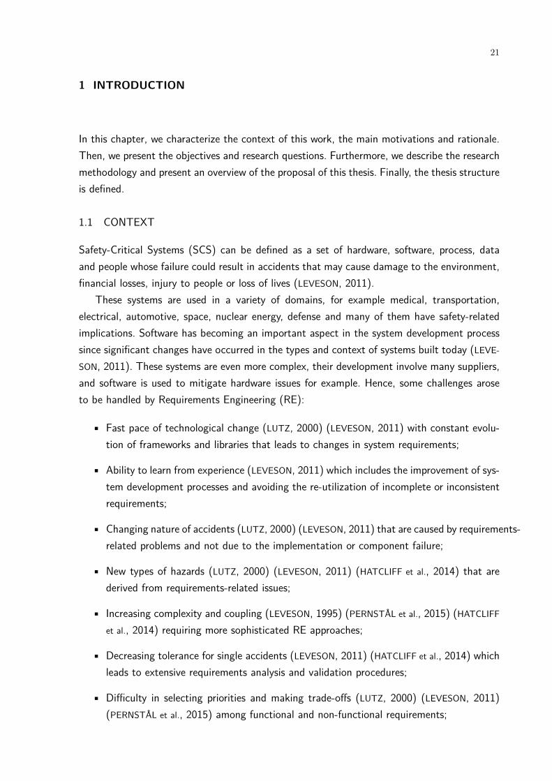
1 INTRODUCTION
In this chapter, we characterize the context of this work, the main motivations and rationale.Then, we present the objectives and research questions. Furthermore, we describe the researchmethodology and present an overview of the proposal of this thesis. Finally, the thesis structureis defined.
1.1 CONTEXT
Safety-Critical Systems (SCS) can be defined as a set of hardware, software, process, dataand people whose failure could result in accidents that may cause damage to the environment,financial losses, injury to people or loss of lives (LEVESON, 2011).
These systems are used in a variety of domains, for example medical, transportation,electrical, automotive, space, nuclear energy, defense and many of them have safety-relatedimplications. Software has becoming an important aspect in the system development processsince significant changes have occurred in the types and context of systems built today (LEVE-
SON, 2011). These systems are even more complex, their development involve many suppliers,and software is used to mitigate hardware issues for example. Hence, some challenges aroseto be handled by Requirements Engineering (RE):
• Fast pace of technological change (LUTZ, 2000) (LEVESON, 2011) with constant evolu-tion of frameworks and libraries that leads to changes in system requirements;
• Ability to learn from experience (LEVESON, 2011) which includes the improvement of sys-tem development processes and avoiding the re-utilization of incomplete or inconsistentrequirements;
• Changing nature of accidents (LUTZ, 2000) (LEVESON, 2011) that are caused by requirements-related problems and not due to the implementation or component failure;
• New types of hazards (LUTZ, 2000) (LEVESON, 2011) (HATCLIFF et al., 2014) that arederived from requirements-related issues;
• Increasing complexity and coupling (LEVESON, 1995) (PERNSTÅL et al., 2015) (HATCLIFF
et al., 2014) requiring more sophisticated RE approaches;
• Decreasing tolerance for single accidents (LEVESON, 2011) (HATCLIFF et al., 2014) whichleads to extensive requirements analysis and validation procedures;
• Difficulty in selecting priorities and making trade-offs (LUTZ, 2000) (LEVESON, 2011)(PERNSTÅL et al., 2015) among functional and non-functional requirements;
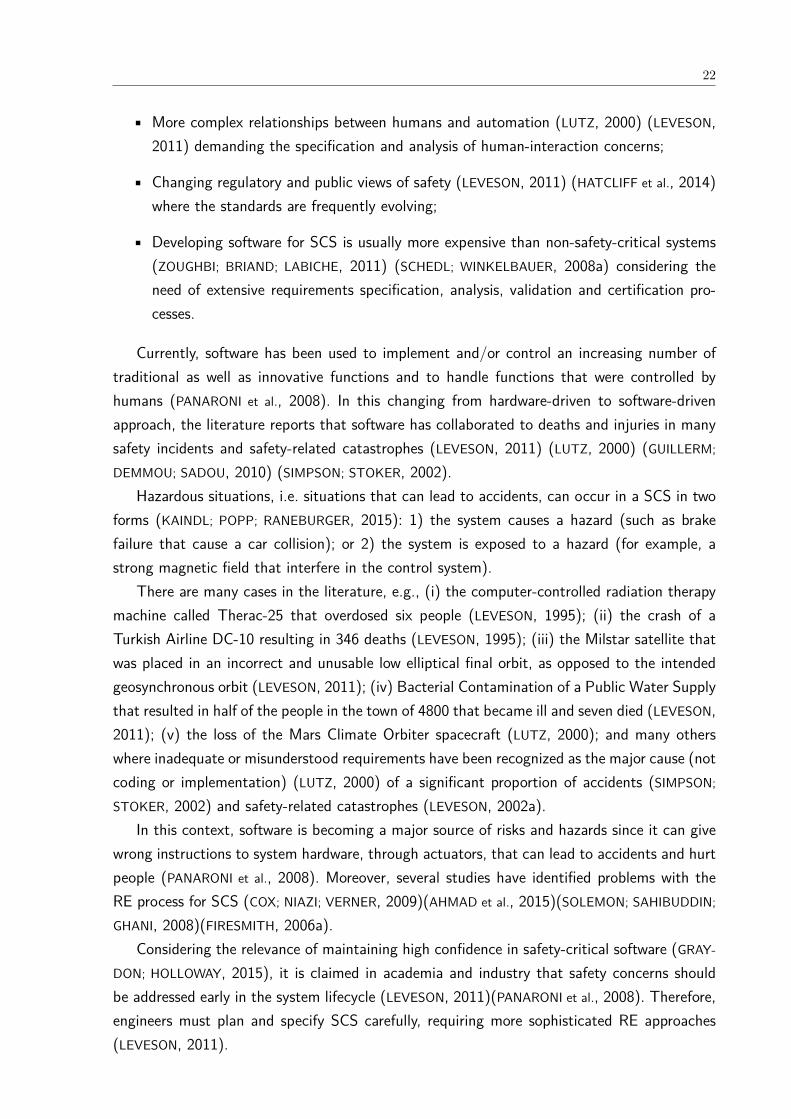
22
• More complex relationships between humans and automation (LUTZ, 2000) (LEVESON,2011) demanding the specification and analysis of human-interaction concerns;
• Changing regulatory and public views of safety (LEVESON, 2011) (HATCLIFF et al., 2014)where the standards are frequently evolving;
• Developing software for SCS is usually more expensive than non-safety-critical systems(ZOUGHBI; BRIAND; LABICHE, 2011) (SCHEDL; WINKELBAUER, 2008a) considering theneed of extensive requirements specification, analysis, validation and certification pro-cesses.
Currently, software has been used to implement and/or control an increasing number oftraditional as well as innovative functions and to handle functions that were controlled byhumans (PANARONI et al., 2008). In this changing from hardware-driven to software-drivenapproach, the literature reports that software has collaborated to deaths and injuries in manysafety incidents and safety-related catastrophes (LEVESON, 2011) (LUTZ, 2000) (GUILLERM;
DEMMOU; SADOU, 2010) (SIMPSON; STOKER, 2002).Hazardous situations, i.e. situations that can lead to accidents, can occur in a SCS in two
forms (KAINDL; POPP; RANEBURGER, 2015): 1) the system causes a hazard (such as brakefailure that cause a car collision); or 2) the system is exposed to a hazard (for example, astrong magnetic field that interfere in the control system).
There are many cases in the literature, e.g., (i) the computer-controlled radiation therapymachine called Therac-25 that overdosed six people (LEVESON, 1995); (ii) the crash of aTurkish Airline DC-10 resulting in 346 deaths (LEVESON, 1995); (iii) the Milstar satellite thatwas placed in an incorrect and unusable low elliptical final orbit, as opposed to the intendedgeosynchronous orbit (LEVESON, 2011); (iv) Bacterial Contamination of a Public Water Supplythat resulted in half of the people in the town of 4800 that became ill and seven died (LEVESON,2011); (v) the loss of the Mars Climate Orbiter spacecraft (LUTZ, 2000); and many otherswhere inadequate or misunderstood requirements have been recognized as the major cause (notcoding or implementation) (LUTZ, 2000) of a significant proportion of accidents (SIMPSON;
STOKER, 2002) and safety-related catastrophes (LEVESON, 2002a).In this context, software is becoming a major source of risks and hazards since it can give
wrong instructions to system hardware, through actuators, that can lead to accidents and hurtpeople (PANARONI et al., 2008). Moreover, several studies have identified problems with theRE process for SCS (COX; NIAZI; VERNER, 2009)(AHMAD et al., 2015)(SOLEMON; SAHIBUDDIN;
GHANI, 2008)(FIRESMITH, 2006a).Considering the relevance of maintaining high confidence in safety-critical software (GRAY-
DON; HOLLOWAY, 2015), it is claimed in academia and industry that safety concerns shouldbe addressed early in the system lifecycle (LEVESON, 2011)(PANARONI et al., 2008). Therefore,engineers must plan and specify SCS carefully, requiring more sophisticated RE approaches(LEVESON, 2011).

23
Nevertheless, requirements engineers traditionally are not familiar with system safety anal-ysis processes which are usually performed by safety engineers. One reason is the gap thatexists among the traditional development processes, methodologies, notations and tools usedin safety engineering (SCHOLZ; THRAMBOULIDIS, 2013)(STANDARDIZATION, 2011c)(SEI, 2007).This gap makes the safety analysis process by the requirements engineers a hard and chal-lenging activity (SCHOLZ; THRAMBOULIDIS, 2013). Among the implications of the insufficientguidance, we can cite (LEVESON, 2011): safety activities are isolated from RE and developersresponsible for constructing the system; engineers face significant safety subjects just after itis too late or too costly to make significant changes; obstacles during the system certification.
Safety-related activities can create risks to acquisition cost and schedule performance if notmanaged and performed with discipline. These risks arise from a variety of causes including:lack of training, inability to provide guidance to acquirer project offices, insufficient consultationbetween acquirers and stakeholders, and a lack of understanding of safety requirements andsafety engineering (SEI, 2007).
In addition to the consequences of lack of guidance, companies face some issues duringsystem development such as (i) absence of systematization of available safety actions/prac-tices (LAMI; FABBRINI; FUSANI, 2011a)(JOHANNESSEN; HALONEN; ÖRSMARK, 2011); (ii) needof integration among safety, RE and the broad context of product development, manage-ment and corporate strategy (MARTINS; GORSCHEK, 2016b)(LEVESON, 2011); (iii) lack of amodel to guide them on how to apply their efforts systematically to achieve safety goalsand to maintain continual improvements in safety implementation (LAMI; FABBRINI; FUSANI,2011a)(JOHANNESSEN; HALONEN; ÖRSMARK, 2011), which can continually drive actions to-wards higher safety maturity levels; (iv) difficulties in establishing priorities to safety action-s/practices to be followed (LAMI; FABBRINI; FUSANI, 2011a).
1.2 MOTIVATION AND RATIONALE
In order to ensure a safety progress, engineers should handle several features (e.g. organiza-tional, technical, strategic) (SOLEMON; SAHIBUDDIN; GHANI, 2008) and this requires specializedprocesses, techniques, skills and experience (STANDARDIZATION, 2011c) (SEI, 2007). Aimingto unify the development process and give guidance to companies, some safety standards, suchas ISO 61508 (STANDARDIZATION, 2011a) and ISO 2626-2 (STANDARDIZATION, 2011b), areavailable.
However, problems are described with standards usage (FUSANI; LAMI, 2014). For example,lack of management guidance (on how to interpret the standard and satisfy the requirements),conflicts among stakeholders views regarding the standard and issues related to conformancedemonstration. Moreover, they have contributed to the development of systems historicallydepicted as mature or highly-evolved. This makes their implementation challenging for thosecompanies starting to follow standards aiming to increase their systems safety (STANDARDIZA-
TION, 2012a).

24
In this context, determining the capability or maturity of safety processes has been iden-tified as necessary to have more technical results that can be used in a continuous processimprovement (JOHANSSON; NEVALAINEN, 2012) (JOHANNESSEN; HALONEN; ÖRSMARK, 2011).The evaluation of safety processes is necessary since there specific practices to be adoptedduring the development of a SCS that are not covered by generic software maturity models.Improving the software process quality is a strategy adopted by many companies as a wayto increase the confidence in the quality of the resulting software product (SOMMERVILLE,2011)(LAMI; FABBRINI; FUSANI, 2011b).
In order to achieve such improvement, companies need methods to assess the strengthsand weaknesses of their processes, and to develop strategies to mitigate the problems found(REIS; MATHIAS; OLIVEIRA, 2016). Additionally, they pursue well-structured and systematicprocesses to achieve their goals, with a set of resources or practices, resulting in a moremature organization or system.
Literature reports an increasing interest in maturity models (PÖPPELBUSS; RÖGLINGER,2011) (REIS; MATHIAS; OLIVEIRA, 2016) to fill the gap of safety standards (PANARONI et al.,2008). A maturity model allows a company to determine its maturity level based on theperformances of the companies’ process areas or process capabilities (REIS; MATHIAS; OLIVEIRA,2016) (NGAI et al., 2013).
Process capability is defined as a characterization of the ability of a process to achievecurrent or projected business goals (LAMI; FABBRINI; FUSANI, 2011b). Nevertheless, there isa risk that an organization that has been evaluated as adequately capable using a genericmaturity model such as Capability Maturity Model Integration (CMMI) (TEAM, 2010) mayhave inadequate process capability for safety management and safety engineering (SEI, 2007).
Varkoi (2013) arguments that safety should be treated as a new process quality dimension.Although safety is usually considered as a characteristic of a product or system, the develop-ment process certainly can affect the safety of the product. Lawrence (1993) complements byemphasizing software life cycle to improve safety and reliability.
In this context, the development process is considered as one source of safety risks (VARKOI,2013). The author also states that process assessment models can be developed to considersafety requirements and to address dependability including reliability issues. Hence, process-related safety refer to definition of important process attributes that contributes to developsafer products and systems.
Some safety maturity models have been proposed such as +SAFE-CMMI-DEV (SEI, 2007),and ISO 15504-10 (STANDARDIZATION, 2011c). However, these models are general (PEREIRA;
SILVA, 2011), i.e. they cover the entire software development process, (such as software ar-chitecture, V & V among others), hence they have few RE-related practices compared withspecific RE maturity models (GORSCHEK; SVAHNBERG; TEJLE, 2003).
The problems related to safety in RE, such as incomplete specifications, lack of systematicprocesses, definition of requirements impossible or expensive to implement, for example, have

25
a tendency of decreasing in higher maturity RE process (SVAHNBERG et al., 2015)(LEVESON,2002a). Thus, companies should improve their RE process with the purpose of overcome thedifficulties they face during the construction of SCS.
Handling safety concerns early in software development contributes to ensure that safetyproblems do not propagate through subsequent phases (SAEED; LEMOS; ANDERSON, 1995)(PERN-
STÅL; FELDT; GORSCHEK, 2013a)(SECHSER, 2011). Furthermore, if changes in the system arestopped early, it is more likely to have the opportunity of mitigating errors and obtaining astable software version (LEVESON, 2011)(GLINZ; FRICKER, 2015)(SECHSER, 2011).
Accordingly, the early consideration of safety issues in RE should be a top priority in thedevelopment of SCS since RE is essential for software quality (SHAKEEL et al., 2014)(HADDAD
et al., 2016), and effectiveness of the software development process (SOLEMON; SAHIBUDDIN;
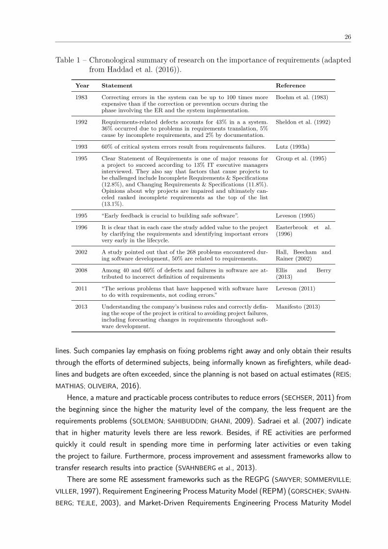
GHANI, 2008).Haddad et al. (2016) present a chronological summary with some research that highlight
the importance of requirements in software development. The importance of early feedbackhas been demonstrated empirically from both an economic and a safety point of view (EAST-
ERBROOK et al., 1996). In Table 1, we observe the need of proper requirements elicitation anda rigorous requirements engineering process to mitigate failures in the requirements process.
Moreover, high safety levels are typically better achieved by addressing safety from thebeginning; not by trying to add protection components and additional complexities after thesystem has been developed (LEVESON, 2011)(HEIMDAHL, 2007). Mature organizations do theirbusiness in a systematic and proactive approach (KONTOGIANNIS; LEVA; BALFE, 2016a)(REIS;
MATHIAS; OLIVEIRA, 2016). Empirical studies investigated the benefits of adopting a maturitymodel (ELLIS; BERRY, 2013) and reported that the most effective approach is software pro-cess improvement (SPI) (KHAN et al., 2018). The benefits include improved software productquality, improved productivity of developers, reduced project cycle time and cost, enhancedbusiness growth, and improved customer satisfaction (CLARKE; O’CONNOR, 2012)(IVERSEN;
NGWENYAMA, 2006)(STAPLES; NIAZI, 2008) (CHEVERS, 2017).Ellis and Berry (2013) conducted a survey and compared the performance of independent
organizations at different RDM (Requirements Definition and Management) maturity levels.They noticed that the average organization at a RDM maturity level outperforms the averageorganization at a lower RDM maturity level. They also found a correlation between an orga-nization’s return on assets (a measure of the organization’s efficiency in turning assets intocash) and its RDM maturity.
Chevers (2017) conducted an online survey approach to gather data from InformationSystems professionals. From the 69 answers received, they conclude several benefits of SPIprograms such as improved software product quality, improved customer satisfaction, improvedstaff productivity, reduced development cost, and reduced project cycle time.
On the other hand, immature companies can and do produce good quality requirementsdocuments, but they may not be able to do so consistently or when working to tight dead-
26
Table 1 – Chronological summary of research on the importance of requirements (adaptedfrom Haddad et al. (2016)).
Year Statement Reference
1983 Correcting errors in the system can be up to 100 times moreexpensive than if the correction or prevention occurs during thephase involving the ER and the system implementation.
Boehm et al. (1983)
1992 Requirements-related defects accounts for 43% in a a system.36% occurred due to problems in requirements translation, 5%cause by incomplete requirements, and 2% by documentation.
Sheldon et al. (1992)
1993 60% of critical system errors result from requirements failures. Lutz (1993a)
1995 Clear Statement of Requirements is one of major reasons fora project to succeed according to 13% IT executive managersinterviewed. They also say that factors that cause projects tobe challenged include Incomplete Requirements & Specifications(12.8%), and Changing Requirements & Specifications (11.8%).Opinions about why projects are impaired and ultimately can-celed ranked incomplete requirements as the top of the list(13.1%).
Group et al. (1995)
1995 “Early feedback is crucial to building safe software”. Leveson (1995)
1996 It is clear that in each case the study added value to the projectby clarifying the requirements and identifying important errorsvery early in the lifecycle.
Easterbrook et al.(1996)
2002 A study pointed out that of the 268 problems encountered dur-ing software development, 50% are related to requirements.
Hall, Beecham andRainer (2002)
2008 Among 40 and 60% of defects and failures in software are at-tributed to incorrect definition of requirements
Ellis and Berry(2013)
2011 “The serious problems that have happened with software haveto do with requirements, not coding errors.”
Leveson (2011)
2013 Understanding the company’s business rules and correctly defin-ing the scope of the project is critical to avoiding project failures,including forecasting changes in requirements throughout soft-ware development.
Manifesto (2013)
lines. Such companies lay emphasis on fixing problems right away and only obtain their resultsthrough the efforts of determined subjects, being informally known as firefighters, while dead-lines and budgets are often exceeded, since the planning is not based on actual estimates (REIS;
MATHIAS; OLIVEIRA, 2016).Hence, a mature and practicable process contributes to reduce errors (SECHSER, 2011) from
the beginning since the higher the maturity level of the company, the less frequent are therequirements problems (SOLEMON; SAHIBUDDIN; GHANI, 2009). Sadraei et al. (2007) indicatethat in higher maturity levels there are less rework. Besides, if RE activities are performedquickly it could result in spending more time in performing later activities or even takingthe project to failure. Furthermore, process improvement and assessment frameworks allow totransfer research results into practice (SVAHNBERG et al., 2013).
There are some RE assessment frameworks such as the REGPG (SAWYER; SOMMERVILLE;
VILLER, 1997), Requirement Engineering Process Maturity Model (REPM) (GORSCHEK; SVAHN-
BERG; TEJLE, 2003), and Market-Driven Requirements Engineering Process Maturity Model

27
(MDREPM) (GORSCHEK et al., 2012), and others that allow organizations to evaluate thestrengths and weaknesses regarding the RE process. However, they do not cover market-drivenand bespoke RE practices in the same model (SVAHNBERG et al., 2015).
Therefore, the Unified Requirements Engineering Process Maturity Model (Uni-REPM)was proposed to fill this gap. It is a universal lightweight model to evaluate the maturityof a RE process structured in two views: Process Area and Maturity Level that covers bothmarket-driven and bespoke (SVAHNBERG et al., 2015) practices and has been well acceptedin companies. However, it does not consider the safety aspects required for the developmentof a SCS. Hence, it does not currently provide a sufficient basis for performing a processcapability assessment of processes involved in the development of such systems or for its usein a safety-related context.
Systematic Literature Review (SLR)s about maturity models were conducted by Reis et al.(REIS; MATHIAS; OLIVEIRA, 2016) and Wendler (WENDLER, 2012). Besides, the integration ofRE and safety was investigated in the SLR of by Martins and Gorschek (MARTINS; GORSCHEK,2016a). Another SLR conducted by us (VILELA et al., 2017a) pointed out many types of con-tributions such as Approach, Framework, Method, Tool, Process, Model among others (seeFigure 17) aiming to improve the integration between RE and safety analysis, however, no ma-turity model for safety was discovered. Therefore, we noticed a demand for a safety maturitymodel for the RE process.
1.3 OBJECTIVES
The industry challenges about the RE process of safety-critical systems mentioned previouslymotivated the investigation about how the quality of this process, with respect to the safetyof such systems, can be improved.
The main goal of this thesis was defined using the template of Wieringa (2010):Improve the quality of safety requirements engineering process by developing a safety
module for Uni-REPM maturity model which is useful and suitable to domain-independentsystems in order to increase the safety processes maturity levels and further develop safersystems.
It is important to note that to evaluate the usefulness of the proposal, we considered theopinion of domain experts if the proposal could be used to improve the requirements processof safety-critical systems.
In order to achieve this goal, we defined the following specific objectives:
• Contribute to the state-of-the-practice by defining a set of safety practices suitable tobe used in the requirements engineering process of safety-critical systems.
• Define a safety maturity module for evaluating the maturity of safety processes duringRE phase of the system development process compatible with Uni-REPM.
28
• Develop a tool to support the maturity evaluations.
• Investigate the maturity levels achieved by the companies when applying the proposedUni-REPM safety module in different safety-critical domains.
• Explore the completeness, perceived usefulness, and ease of use of the proposed Uni-REPM safety module.
1.4 RESEARCH QUESTIONS
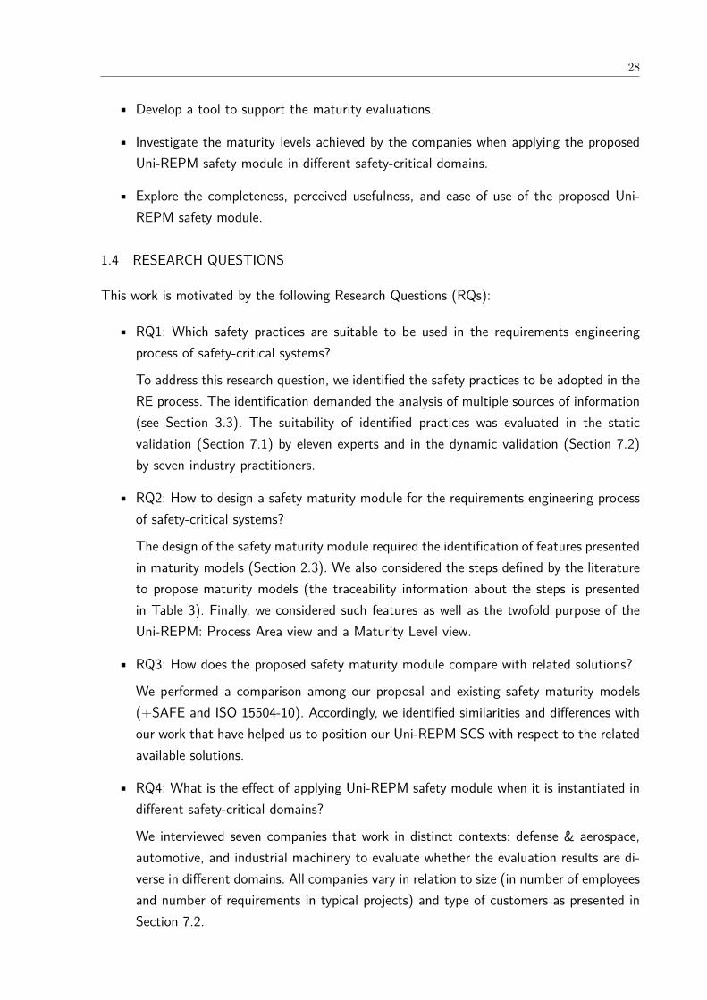
This work is motivated by the following Research Questions (RQs):
• RQ1: Which safety practices are suitable to be used in the requirements engineeringprocess of safety-critical systems?
To address this research question, we identified the safety practices to be adopted in theRE process. The identification demanded the analysis of multiple sources of information(see Section 3.3). The suitability of identified practices was evaluated in the staticvalidation (Section 7.1) by eleven experts and in the dynamic validation (Section 7.2)by seven industry practitioners.
• RQ2: How to design a safety maturity module for the requirements engineering processof safety-critical systems?
The design of the safety maturity module required the identification of features presentedin maturity models (Section 2.3). We also considered the steps defined by the literatureto propose maturity models (the traceability information about the steps is presentedin Table 3). Finally, we considered such features as well as the twofold purpose of theUni-REPM: Process Area view and a Maturity Level view.
• RQ3: How does the proposed safety maturity module compare with related solutions?
We performed a comparison among our proposal and existing safety maturity models(+SAFE and ISO 15504-10). Accordingly, we identified similarities and differences withour work that have helped us to position our Uni-REPM SCS with respect to the relatedavailable solutions.
• RQ4: What is the effect of applying Uni-REPM safety module when it is instantiated indifferent safety-critical domains?
We interviewed seven companies that work in distinct contexts: defense & aerospace,automotive, and industrial machinery to evaluate whether the evaluation results are di-verse in different domains. All companies vary in relation to size (in number of employeesand number of requirements in typical projects) and type of customers as presented inSection 7.2.

29
• RQ5: How is the perceived usefulness and ease of use of the Uni-REPM safety module?
The usefulness and ease of use were evaluated in academia as well as in industry. Toachieve this goal, we followed the technology transfer framework proposed by Gorscheket al. (2006). Accordingly, we performed a static validation (Section 7.1) and a dynamicvalidation (Section 7.2). These types of validation are based on the utility stakeholderopinion also used by important authors in the field such as (WIERINGA, 2010).
• RQ6: How to evaluate whether the module has a sufficient coverage of safety practices?
To answer this research question, we performed a dynamic validation (Section 7.2) andwe included question in the interview questionnaire (see Appendix F). In Section 7.2.7.3,we described the subjects answers regarding the coverage of the safety practices in Uni-REPM SCS (Question #16).
1.5 OVERVIEW OF THE PROPOSAL
This thesis proposes a safety maturity module for Uni-REPM, called Uni-REPM SCS. Compa-nies can use it as a guide to assess and improve their current safety practices and processes. Itis relevant to note that as the original Uni-REPM, the safety module is not purely prescriptive,but rather both the evaluation aspect and the improvement part of the model are contextaware, i.e. companies can define based on the project context what is relevant for them touse, and what is not.
We used multiple information sources (see Section 5.1) to collect data and to define thepractices to be included in a RE module for SCS, including two Systematic Literature Reviews(SLR) (MARTINS; GORSCHEK, 2016a)(VILELA et al., 2017a), one large interview study withcompanies (MARTINS; GORSCHEK, 2018), technical reports (MARTINS; GORSCHEK, 2016c), andan inventory and extraction from several safety standards.
The module follows the tree-structure of Uni-REPM where Main process area (MPA)s arethe top nodes and the Actions are the bottom ones. Sub-process area (SPA)s allow to furthergranulate the MPAs into different subprocesses. Every Action is mapped to a certain maturitylevel spanning from 1 to 3. Further details about Uni-REPM structure is found at Section 2.4)and regarding Uni-REPM SCS at Section 5.2.
We evaluated the safety module in terms of coverage, correctness, usefulness, and ap-plicability. This evaluation followed the technology transfer model (GORSCHEK et al., 2006)explained in Section 3.9. It consisted of a static evaluation and a dynamic validation. Theformer relied on the feedback of two practitioners and nine academic experts regarding thestructure and safety practices presented in the module. The latter was conducted with sevenpractitioners from different companies located in three countries.
30
1.6 SUMMARY OF PUBLICATIONS
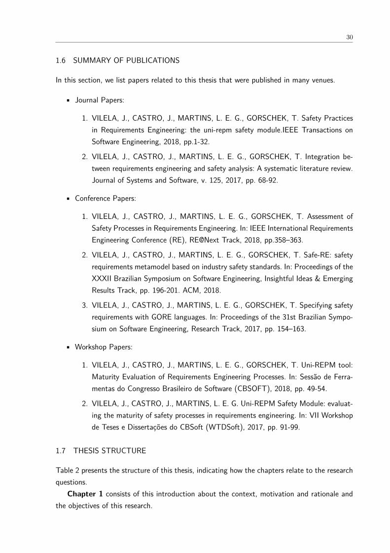
In this section, we list papers related to this thesis that were published in many venues.
• Journal Papers:
1. VILELA, J., CASTRO, J., MARTINS, L. E. G., GORSCHEK, T. Safety Practicesin Requirements Engineering: the uni-repm safety module.IEEE Transactions onSoftware Engineering, 2018, pp.1-32.
2. VILELA, J., CASTRO, J., MARTINS, L. E. G., GORSCHEK, T. Integration be-tween requirements engineering and safety analysis: A systematic literature review.Journal of Systems and Software, v. 125, 2017, pp. 68-92.
• Conference Papers:
1. VILELA, J., CASTRO, J., MARTINS, L. E. G., GORSCHEK, T. Assessment ofSafety Processes in Requirements Engineering. In: IEEE International RequirementsEngineering Conference (RE), RE@Next Track, 2018, pp.358–363.
2. VILELA, J., CASTRO, J., MARTINS, L. E. G., GORSCHEK, T. Safe-RE: safetyrequirements metamodel based on industry safety standards. In: Proceedings of theXXXII Brazilian Symposium on Software Engineering, Insightful Ideas & EmergingResults Track, pp. 196-201. ACM, 2018.
3. VILELA, J., CASTRO, J., MARTINS, L. E. G., GORSCHEK, T. Specifying safetyrequirements with GORE languages. In: Proceedings of the 31st Brazilian Sympo-sium on Software Engineering, Research Track, 2017, pp. 154–163.
• Workshop Papers:
1. VILELA, J., CASTRO, J., MARTINS, L. E. G., GORSCHEK, T. Uni-REPM tool:Maturity Evaluation of Requirements Engineering Processes. In: Sessão de Ferra-mentas do Congresso Brasileiro de Software (CBSOFT), 2018, pp. 49-54.
2. VILELA, J., CASTRO, J., MARTINS, L. E. G. Uni-REPM Safety Module: evaluat-ing the maturity of safety processes in requirements engineering. In: VII Workshopde Teses e Dissertações do CBSoft (WTDSoft), 2017, pp. 91-99.
1.7 THESIS STRUCTURE
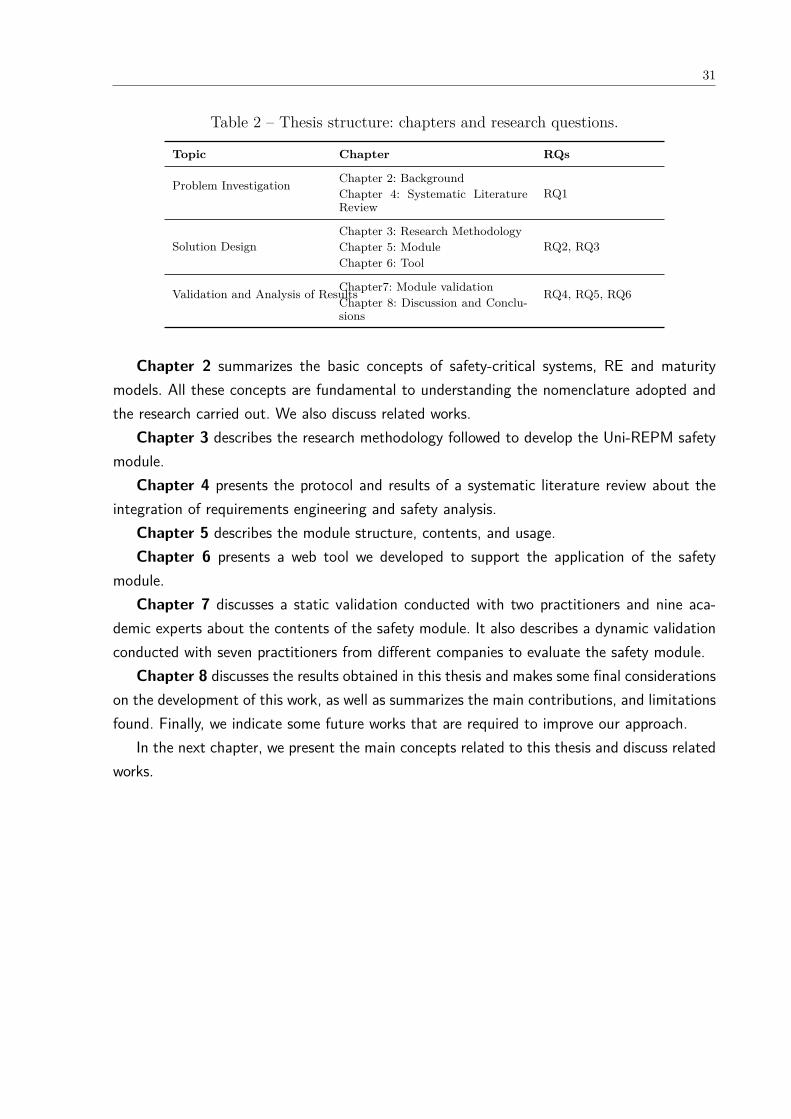
Table 2 presents the structure of this thesis, indicating how the chapters relate to the researchquestions.
Chapter 1 consists of this introduction about the context, motivation and rationale andthe objectives of this research.
31
Table 2 – Thesis structure: chapters and research questions.
Topic Chapter RQs
Problem Investigation Chapter 2: BackgroundRQ1Chapter 4: Systematic Literature
Review
Solution DesignChapter 3: Research Methodology
RQ2, RQ3Chapter 5: ModuleChapter 6: Tool
Validation and Analysis of ResultsChapter7: Module validation RQ4, RQ5, RQ6Chapter 8: Discussion and Conclu-sions
Chapter 2 summarizes the basic concepts of safety-critical systems, RE and maturitymodels. All these concepts are fundamental to understanding the nomenclature adopted andthe research carried out. We also discuss related works.
Chapter 3 describes the research methodology followed to develop the Uni-REPM safetymodule.
Chapter 4 presents the protocol and results of a systematic literature review about theintegration of requirements engineering and safety analysis.
Chapter 5 describes the module structure, contents, and usage.Chapter 6 presents a web tool we developed to support the application of the safety
module.Chapter 7 discusses a static validation conducted with two practitioners and nine aca-
demic experts about the contents of the safety module. It also describes a dynamic validationconducted with seven practitioners from different companies to evaluate the safety module.
Chapter 8 discusses the results obtained in this thesis and makes some final considerationson the development of this work, as well as summarizes the main contributions, and limitationsfound. Finally, we indicate some future works that are required to improve our approach.
In the next chapter, we present the main concepts related to this thesis and discuss relatedworks.
32
2 BACKGROUND
In this chapter, we define some concepts used in this work to ensure consistency throughoutthis thesis.
2.1 SAFETY-CRITICAL SYSTEMS
Safety-critical systems are composed of a set of hardware, software, process, data and peoplewhose failure could result in accidents that cause damage to the environment, injury to people,and loss of lives (LEVESON, 2011). But, it may also involve other major losses, includingmission, equipment, financial, and information losses (LEVESON, 2011)(MARTINS; GORSCHEK,2016b)(LEVESON, 1995).
During the development of SCS, safety engineers typically review the requirements spec-ifications in order to perform safety analysis to ensure that the hazardous situations weremitigated (MARTINS; GORSCHEK, 2016b). Such reviews are periodically repeated throughoutthe entire development process in order to align the safety analysis with requirements changes.As a major result of the safety analysis, safety engineers define many concepts such as, forexample, accident, environmental condition, hazard, cause of hazard, safety requirement, andfunctional safety requirement.
Considering the need of integrate safety concerns in RE and a common nomenclature toimprove the specification of SCS, we have proposed Safe-RE (VILELA et al., 2018a) which isnot the safety module but this model can be used during safety requirements elicitation anddocumentation. It is a safety requirements model based on industry safety standards whoseaim is to support the specification of safety-related concepts in the RE process. We describesome of these concepts using as an example an Infusion Insulin Pump (IIPS) (MARTINS et al.,2015)(MARTINS; OLIVEIRA, 2014a).
An insulin infusion pump is a medical device that simulates the functioning of the pancreas(SOMMERVILLE, 2011) being used for the treatment of patients with Diabetes Mellitus type 1(DM1). An embedded safety-critical system collects information from a sensor and controls apump that provides a controlled dose of insulin to the user (MARTINS; OLIVEIRA, 2014b). Thesystem goal is to provide safe and effective treatment for people suffering from Diabetes Mel-litus (DM1) and to enhance the long-term health of the patients. The prototype developmentof the IIP described in this section results from a partnership between Brazilian academia andthe Brazilian companies DeltaLife and CNA Desenvolvimento.
A safety-critical system has Safety Goals which are high-level objectives related to achiev-ing safety in the system. Such goals can be refined during the development process varyingthe level of abstraction (details). Examples of Safety Goals in the infusion insulin pump are:
• The system must be available to provide insulin when required;

33
• The system must perform reliably and provide the correct amount of insulin to controlblood sugar level;
• Discuss safety with employees;
• Incorporate safety into system components.
Some Accidents can occur due to use of a SCS. They are defined as an undesired andunplanned (but not necessarily unexpected) event that results in (at least) a specified levelof loss (LEVESON, 1995). This includes loss of human life or injury, property damage, envi-ronmental pollution, and so on (LEVESON, 2002b) (MEDIKONDA; PANCHUMARTHY, 2009). Inthe insulin pump, accidents can be User receives incorrect treatment, User infection, ElectricalShock, and Environmental.
A Harm can occur to Assets (People, Property, Environment, Service) of the system orto the Mission. A Harm can be of the following types:
• Harm to People: people in the system can be Human beings, roles played or organi-zations which can suffer with Death, Injury, Illness.
• Harm to Property: it can be Destruction, Damage, Corruption, Theft, UnauthorizedAccess or Unauthorized Disclosure. A Property has two attributes Property Type andProperty Owner. A Property Type can be Tangible or Not Tangible and the PropertyOwner can be Private, Public or Commercial.
• Harm to Environment: it can be Destruction, Loss of Use or Damage.
• Harm to Service: it can be Corruption, Unauthorized Usage, Accidental Loss of Service,Denial of Service or Repudiation of Transaction.
• Harm to Mission: it compromises the satisfaction of some system goals.
The incorrect treatment can lead to deficient blood sugar levels (if there is too much insulin)or too high blood sugar (if too little insulin is present) (MARTINS; OLIVEIRA, 2014b). Low bloodsugar can result in temporary brain malfunction and, in extreme cases, unconsciousness anddeath. On the other hand, high levels of blood sugar can cause fatigue in the short term,but, in the long term, cause damage to the eyes, kidneys and heart problems (SOMMERVILLE,2011).
These consequences that can occur to the use of a SCS determine the Safety integritylevel. It corresponds to a range of safety integrity values that represent the probability ofa safety-related system accomplish the specified safety functional requirements under all thedefined conditions within a stated period of time. IEC 61508 (STANDARDIZATION, 2011a)defines four levels (1-4) where the 4th level is the highest of safety integrity and 1st is thelowest. Accordingly, in case of the software in the IIP is not executed, or not correctly executed,
34
or whose anomalous behavior can cause or contribute to a system failure results in catastrophicconsequences such as user insulin overdose/underdose, it has the Safety integrity level A(STANDARDIZATION, 2013).
Accidents are caused by a combination of Hazard and Environmental conditions (con-text). Hazard is a system state (MEDIKONDA; PANCHUMARTHY, 2009) or set of conditionsthat, together with a particular set of worst-case environmental conditions, will lead to anaccident or some loss (LEVESON, 1995) (LEVESON, 2002b). Several hazards can occur in theIIP such as:
• Overdose: the user receives more insulin than required;
• Underdose: the user receives less insulin than required;
• Excessive thermal energy generation by the pump;
• Electrical shock: the pump transfers electric current to accessible surfaces during oper-ation;
• Excessive electromagnetic emissions by the pump: affects the pump itself, another device(s) worn by the user, or other users and their devices;
• Excessive sound frequencies generated by the pump;
• User allergic reaction/rash to pump materials or insulin;
• Presence of sharp edges or scissor points;
• Excessive pump vibration;
• Unsafe disposal of the pump or pump components.
Environmental conditions consist of the set of factors including physical, cultural, de-mographic, economic, political, regulatory, or technological elements surrounding the systemthat could affect its safety (LEVESON, 2002b). For example, in the IIPS, examples of suchconditions are:
• Valves in the delivery path are broken;
• Air pressure within the pump is much lower/higher than ambient air pressure;
• The Pump is positioned much higher than the infusion site, causing unintentional drugflow;
• Delivery path is damaged, creating a vent on the path that allows unintentional gravityflow;
35
• Large temperature changes causing a mismatch between drug reservoir volume changeand insulin density change.
All Hazard have a Cause of hazard which is the reason that produces hazard as ef-fect (SCHOLZ; THRAMBOULIDIS, 2013). It occurs due to environmental hazard, proceduralhazard, interface hazard, human factor or system cause (SCHOLZ; THRAMBOULIDIS, 2013)(MEDIKONDA; PANCHUMARTHY, 2009). A free flow is one cause of the overdose hazard in theIIP.
Safety Requirements are also presented in the development of a SCS. They are typicallyof the form of a quality criterion (a system-specific statement about the existence of a sub-factor of safety) combined with a minimum or maximum required threshold along some qualitymeasure. They directly specify how safe the system must be (MEDIKONDA; PANCHUMARTHY,2009). In the IIPS, the difference between the programmed infusion and the delivered infusionshall not be greater than 0.5% by hour.
Functional Safety Requirements consist of the requirements to prevent or mitigate theeffects of failures identified in safety analysis (MARTINS; GORSCHEK, 2016b). To mitigate theoverdose hazard caused by free flow, the system can monitor the insulin reservoir in the IIPS.
2.2 REQUIREMENTS ENGINEERING
Requirements Engineering (RE) is the first stage of software development process (SOM-
MERVILLE, 2011) that address all of the activities involved in discovering, documenting, andmaintaining a set of requirements for a software (KOTONYA; SOMMERVILLE, 1998).
The RE process is a design process with input and outputs (KOTONYA; SOMMERVILLE,1998). The inputs of the RE process are: Existing system information (information about thefunctionality of the system to be replaced or that will interact with the proposed system),Stakeholder needs (descriptions of what the stakeholders require), Organisational standards(standards used in the organization regarding system development practice), Regulations (ex-ternal regulations like safety standards), Domain Information (general information about thedomain).
The outputs consists of Agreed requirements (description of system requirements under-standable by stakeholders), System specification (detailed document containing system re-quirements) and System Models (a set of models which describes the system from differentperspectives). The RE process, inputs and outputs are shown in Figure 1.
A structured set of activities compose the RE process that include requirements elicitation,requirements analysis and negotiation, requirements documentation, requirements validation,and requirements management as shown in Figure 2. According to Kotonya and Sommerville(1998), there are no distinct boundaries between the five activities. They also state that theactivities are interleaved and conducted iteratively considering feedback from one activity fromanother.

36
Figure 1 – Input and outputs of the RE process (adapted from (KOTONYA; SOM-MERVILLE, 1998)).
Figure 2 – Requirements Engineering Process (adapted from (KOTONYA; SOMMERVILLE,1998)).
The activities of RE process Kotonya and Sommerville (1998) are explained in the nextsections.
2.2.1 Requirements Elicitation
It corresponds to the stage of requirements acquisition from many stakeholders, artifacts,domain knowledge, and market studies. According to Kotonya and Sommerville (1998), agood elicitation process should include four critical activities (illustrated in Figure 3): Establishobjectives, Understanding background, Organise knowledge, and Collect requirements.
2.2.2 Requirements Analysis and Negotiation
This phase comprehends activities aiming to discover problem with the system requirementsand reach agreements on changes to satisfy all stakeholders. Hence, the elicited requirements
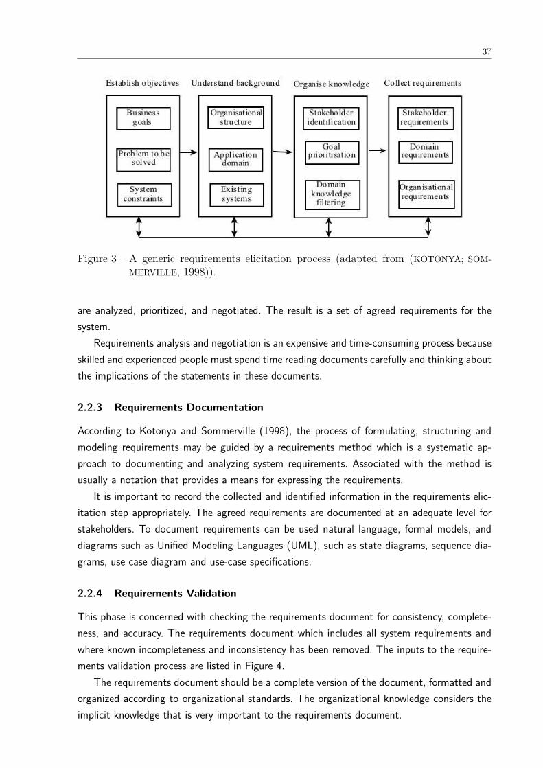
37
Figure 3 – A generic requirements elicitation process (adapted from (KOTONYA; SOM-MERVILLE, 1998)).
are analyzed, prioritized, and negotiated. The result is a set of agreed requirements for thesystem.
Requirements analysis and negotiation is an expensive and time-consuming process becauseskilled and experienced people must spend time reading documents carefully and thinking aboutthe implications of the statements in these documents.
2.2.3 Requirements Documentation
According to Kotonya and Sommerville (1998), the process of formulating, structuring andmodeling requirements may be guided by a requirements method which is a systematic ap-proach to documenting and analyzing system requirements. Associated with the method isusually a notation that provides a means for expressing the requirements.
It is important to record the collected and identified information in the requirements elic-itation step appropriately. The agreed requirements are documented at an adequate level forstakeholders. To document requirements can be used natural language, formal models, anddiagrams such as Unified Modeling Languages (UML), such as state diagrams, sequence dia-grams, use case diagram and use-case specifications.
2.2.4 Requirements Validation
This phase is concerned with checking the requirements document for consistency, complete-ness, and accuracy. The requirements document which includes all system requirements andwhere known incompleteness and inconsistency has been removed. The inputs to the require-ments validation process are listed in Figure 4.
The requirements document should be a complete version of the document, formatted andorganized according to organizational standards. The organizational knowledge considers theimplicit knowledge that is very important to the requirements document.
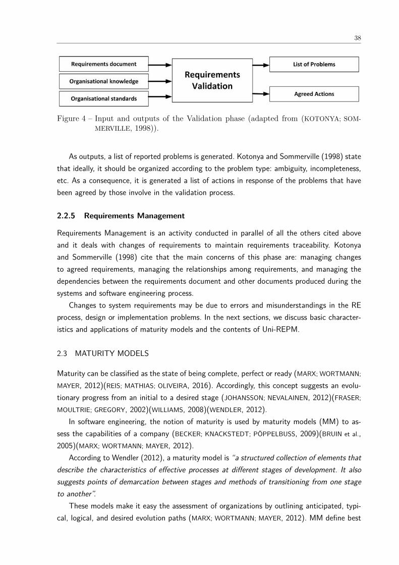
38
Figure 4 – Input and outputs of the Validation phase (adapted from (KOTONYA; SOM-MERVILLE, 1998)).
As outputs, a list of reported problems is generated. Kotonya and Sommerville (1998) statethat ideally, it should be organized according to the problem type: ambiguity, incompleteness,etc. As a consequence, it is generated a list of actions in response of the problems that havebeen agreed by those involve in the validation process.
2.2.5 Requirements Management
Requirements Management is an activity conducted in parallel of all the others cited aboveand it deals with changes of requirements to maintain requirements traceability. Kotonyaand Sommerville (1998) cite that the main concerns of this phase are: managing changesto agreed requirements, managing the relationships among requirements, and managing thedependencies between the requirements document and other documents produced during thesystems and software engineering process.
Changes to system requirements may be due to errors and misunderstandings in the REprocess, design or implementation problems. In the next sections, we discuss basic character-istics and applications of maturity models and the contents of Uni-REPM.
2.3 MATURITY MODELS
Maturity can be classified as the state of being complete, perfect or ready (MARX; WORTMANN;
MAYER, 2012)(REIS; MATHIAS; OLIVEIRA, 2016). Accordingly, this concept suggests an evolu-tionary progress from an initial to a desired stage (JOHANSSON; NEVALAINEN, 2012)(FRASER;
MOULTRIE; GREGORY, 2002)(WILLIAMS, 2008)(WENDLER, 2012).In software engineering, the notion of maturity is used by maturity models (MM) to as-
sess the capabilities of a company (BECKER; KNACKSTEDT; PÖPPELBUSS, 2009)(BRUIN et al.,2005)(MARX; WORTMANN; MAYER, 2012).
According to Wendler (2012), a maturity model is “a structured collection of elements thatdescribe the characteristics of effective processes at different stages of development. It alsosuggests points of demarcation between stages and methods of transitioning from one stageto another”.
These models make it easy the assessment of organizations by outlining anticipated, typi-cal, logical, and desired evolution paths (MARX; WORTMANN; MAYER, 2012). MM define best

39
actions/practices for software lifecycle processes, based on good engineering and process-management principles, and process-attribute sets for capability/maturity design aspects (WAN-
GENHEIM et al., 2010b). Therefore, the objective in using MM is to detect and remove badcapabilities (PÖPPELBUSS; RÖGLINGER, 2011). Hence, the application of this concept is notlimited to any particular domain (WENDLER, 2012).
Typically, maturity models:
• define capability areas, process areas or design objects (WILLIAMS, 2008)(JOHANSSON;
NEVALAINEN, 2012)(BRUIN et al., 2005);
• consist of sequential maturity stages (JOHANSSON; NEVALAINEN, 2012)(WILLIAMS, 2008)(WENDLER,2012);
• have a hierarchical progression from an initial to a desired stage (REIS; MATHIAS; OLIVEIRA,2016)(FRASER; MOULTRIE; GREGORY, 2002) (WENDLER, 2012);
• involve a wide range of organizational activities and actions/practices (BRUIN et al.,2005)(WANGENHEIM et al., 2010b), (WENDLER, 2012);
• have an assessment instrument that can either be qualitative or quantitative (MARX;
WORTMANN; MAYER, 2012)(FRASER; MOULTRIE; GREGORY, 2002).
In Figure 5, we illustrate the usage of a maturity model for continuous improvement.First, the company should evaluate its capabilities, then, define the projects with low maturity,prioritize them, plan the improvement (scope, responsible, risks, resources, and other variables),manage changes in people and company culture by implementing the improvement project,evaluate the results, and proceed with continuous improvement.
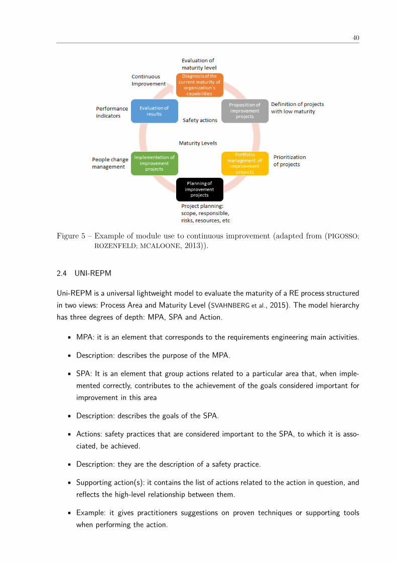
40
Figure 5 – Example of module use to continuous improvement (adapted from (PIGOSSO;ROZENFELD; MCALOONE, 2013)).
2.4 UNI-REPM
Uni-REPM is a universal lightweight model to evaluate the maturity of a RE process structuredin two views: Process Area and Maturity Level (SVAHNBERG et al., 2015). The model hierarchyhas three degrees of depth: MPA, SPA and Action.
• MPA: it is an element that corresponds to the requirements engineering main activities.
• Description: describes the purpose of the MPA.
• SPA: It is an element that group actions related to a particular area that, when imple-mented correctly, contributes to the achievement of the goals considered important forimprovement in this area
• Description: describes the goals of the SPA.
• Actions: safety practices that are considered important to the SPA, to which it is asso-ciated, be achieved.
• Description: they are the description of a safety practice.
• Supporting action(s): it contains the list of actions related to the action in question, andreflects the high-level relationship between them.
• Example: it gives practitioners suggestions on proven techniques or supporting toolswhen performing the action.
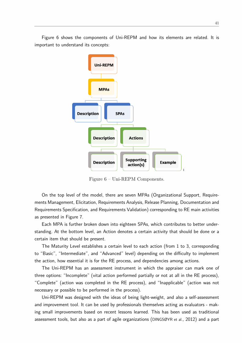
41
Figure 6 shows the components of Uni-REPM and how its elements are related. It isimportant to understand its concepts:
Figure 6 – Uni-REPM Components.
On the top level of the model, there are seven MPAs (Organizational Support, Require-ments Management, Elicitation, Requirements Analysis, Release Planning, Documentation andRequirements Specification, and Requirements Validation) corresponding to RE main activitiesas presented in Figure 7.
Each MPA is further broken down into eighteen SPAs, which contributes to better under-standing. At the bottom level, an Action denotes a certain activity that should be done or acertain item that should be present.
The Maturity Level establishes a certain level to each action (from 1 to 3, correspondingto “Basic”, “Intermediate”, and “Advanced” level) depending on the difficulty to implementthe action, how essential it is for the RE process, and dependencies among actions.
The Uni-REPM has an assessment instrument in which the appraiser can mark one ofthree options: “Incomplete” (vital action performed partially or not at all in the RE process),“Complete” (action was completed in the RE process), and “Inapplicable” (action was notnecessary or possible to be performed in the process).
Uni-REPM was designed with the ideas of being light-weight, and also a self-assessmentand improvement tool. It can be used by professionals themselves acting as evaluators - mak-ing small improvements based on recent lessons learned. This has been used as traditionalassessment tools, but also as a part of agile organizations (DINGSØYR et al., 2012) and a part

42
Figure 7 – Uni-REPM Model Structure (GORSCHECK, 2011).
of previous works on maturity models (SVAHNBERG et al., 2013).An example of an action is presented in Figure 8. It presents the identifier of MPA (OS),
SPA (OS.GP), and action (OS.GP.a1, OS.GP.a2). The names of MPA (Organizational Sup-port), SPA (General Practices), and Action (Create a Product-wide Glossary of Terms, Trainpersonnel in Requirements Management Process and Speciality) are also present in Figure 8.Finally, it also contains the maturity level of the actions.
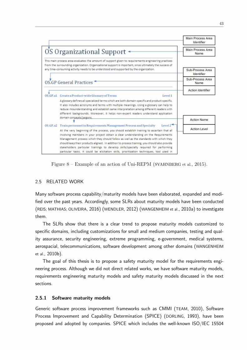
43
Figure 8 – Example of an action of Uni-REPM (SVAHNBERG et al., 2015).
2.5 RELATED WORK
Many software process capability/maturity models have been elaborated, expanded and modi-fied over the past years. Accordingly, some SLRs about maturity models have been conducted(REIS; MATHIAS; OLIVEIRA, 2016) (WENDLER, 2012) (WANGENHEIM et al., 2010a) to investigatethem.
The SLRs show that there is a clear trend to propose maturity models customized tospecific domains, including customizations for small and medium companies, testing and qual-ity assurance, security engineering, extreme programming, e-government, medical systems,aerospacial, telecommunications, software development among other domains (WANGENHEIM
et al., 2010b).The goal of this thesis is to propose a safety maturity model for the requirements engi-
neering process. Although we did not direct related works, we have software maturity models,requirements engineering maturity models and safety maturity models discussed in the nextsections.
2.5.1 Software maturity models
Generic software process improvement frameworks such as CMMI (TEAM, 2010), SoftwareProcess Improvement and Capability Determination (SPICE) (DORLING, 1993), have beenproposed and adopted by companies. SPICE which includes the well-known ISO/IEC 15504
44
that was replaced by ISO 33000. Although they address RE in some extent, they do it shallowlysince their scope is to cover all phases of development process having a larger scope than justRE (SVAHNBERG et al., 2015).
The above maturity models emphasize bespoke RE which is related to the development ofa customized software system for a specific customer (GORSCHEK et al., 2012). Nevertheless,a company may be classified as advanced in a generic software maturity model, but may beimmature in their safety processes.
2.5.2 RE maturity models
There are some RE assessment frameworks, for example, the Requirements Engineering GoodPractice Guide (REGPG) (SAWYER; SOMMERVILLE; VILLER, 1997), REPM (GORSCHEK; SVAHN-
BERG; TEJLE, 2003), MDREPM (GORSCHEK et al., 2012) that allow organizations to evaluatethe strengths and weaknesses (REIS; MATHIAS; OLIVEIRA, 2016) regarding the RE process.
The REGPG guide (SAWYER; SOMMERVILLE; VILLER, 1997) suggests a requirements ma-turity model based on 66 good requirements practices, where 36 are classified as basic, 21 asintermediate and 9 as advanced. The advanced practices are concerned with formal specifi-cation which is recommended for critical systems development. However, the model proposesonly 9 practices for SCS being very succinct. Moreover, its implementation is very challengingfor small/immature companies aiming to increase the safety of their systems.
The MDREPM model (GORSCHEK et al., 2012) is an evolution of REPM (GORSCHEK;
SVAHNBERG; TEJLE, 2003) to consider market-driven practices. Market-driven RE is applicableto software companies that develop software to a determined market, which can be a combina-tion of a number of known customers or, on another extreme, a mass market where customerscannot be clearly indicated (GORSCHEK et al., 2012).
However, REGPG, REPM, and MDREPM do not cover both market-driven and bespokeRE practices in the same maturity model as required by industry (SVAHNBERG et al., 2015).To fill this gap, the Uni-REPM (SVAHNBERG et al., 2015) was proposed. Nevertheless, it doesnot consider safety issues required for the development of a safety-critical system. Therefore,in this work, we propose Uni-REPM SCS which is a safety module for the Uni-REPM model.
2.5.3 Safety maturity models
Safety culture maturity models are available in literature (FLEMING, 2000)(FILHO; ANDRADE;
MARINHO, 2010). Fleming (FLEMING, 2000) developed a model with the objective of helpingorganizations to identify the level of maturity of their safety culture. Filho, Andrade andMarinho (2010) proposed a framework to measure safety culture maturity in the Brazilian oiland gas companies based on the model of Hudson (HUDSON, 2001).
However, safety culture is a characteristic of groups and organizations that handle organi-zational collective practices to avoid accidents during the work in factories (FILHO; ANDRADE;
MARINHO, 2010) and not about developing SCS.
45
Some safety maturity models have been developed, for example, +SAFE-CMMI-DEV (SEI,2007) and ISO 15504-10 (STANDARDIZATION, 2011c). However, these models are too general(PEREIRA; SILVA, 2011), usually adopted by safety engineers, and do not consider the integrationbetween safety and RE as well as the particularities of these two areas that are necessary toimprove safety from the beginning of software development process. In Section 5.4, we analyzein details the similarities and differences among these models and the safety module.
2.5.4 Systematic literature reviews about safety-critical systems
Few SLRs about the development of SCS are found in the literature (VILELA et al., 2017a)(MARTINS; GORSCHEK, 2016a) (QUEIROZ; BRAGA, 2014) (NAIR et al., 2014). Queiroz and Braga(2014) conducted a SLR with the purpose of obtaining the state-of-the-art of the approaches,methods and methodologies whose goal was the combination of product line engineering andmodel-driven engineering for the development of safety-critical embedded systems. They alsoanalyzed the existence of empirical studies on the use of these techniques in this type ofdevelopment.
A SLR about safety evidence (the artifacts generated as indication that the developedsystem is safe) is presented in Nair et al. (2014). The main objective of their work is tosynthesize the existing knowledge in the academic literature about safety evidence, concen-trating on three facets: the information that constitutes evidence; structuring of evidence; andevidence assessment.
RE for SCS is the main investigation topic of a systematic literature review conducted byMartins and Gorschek (2016a). Their work investigated which approaches have been proposedto elicit, model, specify and validate safety requirements in the context of SCS, as well asto what extent such approaches have been validated in industrial settings. Moreover, theyanalyzed how the usability and usefulness of the reported approaches had been explored, andto what extent they enabled requirements communication among the development projec-t/team actors in the SCS domain. Although they emphasize the need to further investigatethe communication in the RE process among different parties when developing SCS, theirwork does not investigate deeply the collaboration of requirements and safety engineers. Infact, in this work, we restricted our search string to capture the results related to requirementscommunication.
Although above works explore several challenges related to the integration of RE andsafety (LUTZ, 2000) (HEIMDAHL, 2007) (SIKORA; TENBERGEN; POHL, 2012) (HATCLIFF et al.,2014), little has been done to date to perform an extensive identification and mapping, in acomprehensive manner of the state-of-the-art on the integration between safety analysis andrequirements engineering. Hence, to the best of our knowledge, the SLR conducted in thisthesis (see Chapter 4 is the first with such specific focus.
46
2.6 FINAL CONSIDERATIONS
Developing a maturity model is a complex and hard task. When designing a model, the softwareengineer needs to deal with issues associated with: defining process areas and maturity stages,establishing the organizational activities and actions/practices and developing an assessmentinstrument.
This chapter described the main concepts required for the understanding of this thesis.We defined aspects of the safety-critical domain commonly used in safety analysis. In orderto define the maturity model for which is proposed the safety module, we presented the UNI-REPM structure. Finally, we discussed related works. In the next chapter, we describe theresearch methodology followed to develop the Uni-REPM safety module.

47
3 METHODOLOGY
The maturity model development is an issue that should be treated as a design problem(WIERINGA, 2010) by some researchers (PÖPPELBUSS; RÖGLINGER, 2011) (REIS; MATHIAS;
OLIVEIRA, 2016). This requires changes in the world and requests an analysis of actual orhypothetical stakeholder goals. Design problem is part of the design science methodology thatdefines that solutions must be iteratively proposed, refined, evaluated, and, if necessary, en-hanced (BECKER; KNACKSTEDT; PÖPPELBUSS, 2009)(WIERINGA, 2010). Hence, following therecommendations of the literature, we also adopted this methodology to develop the safetymodule.
According to Wieringa (2010), design problems demand modifications in the world andclaim an analysis of actual or hypothetical stakeholder goals. A solution is a design, and mayexist a large number of distinct solutions that should be assessed by their utility with respectto the stakeholder goals, and there is no single best solution.
Solving a design problem in design science requires the interaction between an artifact anda problem context for producing effects (WIERINGA, 2010), as shown in Figure 9.
Figure 9 – Design science framework (adapted from Moraes (2014)).
In the context of this thesis, we defined the artifact, context and effects as follows:
• Artifact: safety maturity module;
• Context: Safety-Critical Systems and the several stakeholders, such as requirementsengineering, safety analysts, quality engineering, testers among others involved in thedevelopment;
• Effect: evaluating the safety maturity level in the requirements engineering process ofSCS projects.
Design problems are treated by following the design cycle that is decomposed into threetasks: problem investigation, treatment design, and treatment validation. Such cycle is part of a

48
larger one, called engineering cycle, in which the result of the former, i.e. a validated treatment,is transferred to the real world, used, and evaluated (WIERINGA, 2010). The engineering cycleis illustrated in Figure 10.
Figure 10 – The engineering design cycle (adapted from Wieringa (2010)).
Someone may question why not rather do e.g. a root-cause analysis of the actual “de-fects” (like mistakes, misunderstandings, wrong requirements, etc) to figure out what the rootcause is and then invent a solution to fix it. To perform such analysis, the action researchmethodology (COUGHLAN; COGHLAN, 2002) should be used. Although action research anddesign science generate scientific knowledge by intentionally modifying a real setting and bycarefully evaluating the result as well as both share an ability to adopt prototyping as anunderlying approach, these features do not mean that these research approaches are the same(BASKERVILLE; PRIES-HEJE; VENABLE, 2009).
We adopted the design science research because the goal of this thesis is to proposea safety module for Uni-REPM maturity model to be used by several types of companies.Considering that the development of a maturity model is viewed as a design problem (PÖP-
PELBUSS; RÖGLINGER, 2011) (REIS; MATHIAS; OLIVEIRA, 2016), we followed a well-establishedmethodology used by the literature to propose maturity models. Design science is used todevelop new technologies for solving problems (BASKERVILLE; PRIES-HEJE; VENABLE, 2009).Accordingly, during the research is generated an artifact that represents a general solution to aclass of problems shown to operate in some instances of that class of problems (BASKERVILLE;
PRIES-HEJE; VENABLE, 2009). If the goal was to develop a solution for a specific company,the action research methodology could be used. Action research aims creating organizationalchanges in order to discover new knowledge to a specific situation. Design science, on theother hand, proposes the creation of an artifact in order to discover new knowledge applied inseveral contexts.
The steps of the methodology adopted to construct the Uni-REPM SCS is presented in Fig-ure 11. This methodology was defined by considering the engineering design cycle (WIERINGA,2010), the technology transfer framework (GORSCHEK et al., 2006) and by adapting method-ologies for creating maturity models available in literature that inspired our model.

49
Figure 11 – Methodology for creating the Uni-REPM Safety module.
The basis of the methodology derived from Wangenheim et al. (2010b) that proposed areference model for how to develop software process capability/maturity models (SPCMMs)that consists of five phases and 17 steps. We adopted this reference model because it relieson a survey with answers from 18 authors of previous SPCMMs.
The survey results of Wangenheim et al. (2010b) show a stronger presence of steps relatedto knowledge identification, specification, and refinement phases than to knowledge usage andevolution phases Wangenheim et al. (2010b).
We deleted/renamed steps, as needed, based on our experience/opinion, along the wayconsidering the well-adopted engineering cycle from (WIERINGA, 2010) in several scientificstudies and technology transfer framework (GORSCHEK et al., 2006). The latter was proposedthrough a partnership between academia and industry and it has been cited more than 244

50
times in Google scholar 1. The traceability information regarding the steps of the methodologyis presented in Table 3.
Table 3 – Traceability steps of adopted methodology.
Step Source/Inspiration
Step 1: Knowledge Acquisition Wangenheim et al. (2010b)
Step 2: Problem definition Wangenheim et al. (2010b), Pöppelbuß and Röglinger (2011), Becker,Knackstedt and Pöppelbuß (2009), Bruin et al. (2005)
Step 3: Identification of informationsources
Wangenheim et al. (2010b), Becker, Knackstedt and Pöppelbuß (2009)
Step 4: Definition of module de-sign/architecture
Wangenheim et al. (2010b), Becker, Knackstedt and Pöppelbuß (2009),Bruin et al. (2005)
Step 5: Development of a draftmodel - process dimension
Wangenheim et al. (2010b), Bruin et al. (2005)
Step 6: Development of a draftmodel - capability/maturity dimen-sion
Wangenheim et al. (2010b)
Step 7: Consolidate the module Wangenheim et al. (2010b)
Step 8: Comparison with existingmaturity models
Pöppelbuß and Röglinger (2011), Becker, Knackstedt and Pöppelbuß(2009)
Step 9: Module evaluation and re-finements
Wangenheim et al. (2010b), Becker, Knackstedt and Pöppelbuß (2009),(WIERINGA, 2010), (GORSCHEK et al., 2006)
Each step of the adopted methodology is presented in the next sections.
3.1 KNOWLEDGE ACQUISITION
The first step consisted in understanding the phenomena that must be improved, the rationale,and prior knowledge. According to Wieringa (2010), there are many sources for prior knowledge(knowledge available prior to the project) such as scientific literature, technical literature,professional literature, and oral communication.
We used multiple sources to learn and collect data as to define what should be included ina RE module for SCS. Our first step was to investigate the literature regarding RE in safety-critical systems to become familiar with the domain, study the problem space, comprehend theconcepts involved in the safety domain as well as to investigate the problems in the integrationbetween RE and SCS.
We also analyzed the international quality standard ISO/IEC 25010 (STANDARDIZATION;
COMMISSION, 2011) that is part of Systems and software Quality Requirements and Evalua-tion (SQuaRE) — System and software quality models. ISO/IEC 25010 cancels and replacesISO/IEC 9126-1 (STANDARDIZATION; COMMISSION, 2004) and extends quality models to in-clude computer systems, and quality in use from a system perspective.1 Date of search: October, 24th of 2018
51
3.2 PROBLEM DEFINITION
Nancy Leveson in 1986 brought the notion of “software safety” to the broader computerscience community and laid the foundation for a research area rich with challenging problems(LEVESON, 1986). Nine years later, in 1995, she published the book “Safeware: System Safetyand Computers” that became the reference about safety-critical systems area.
Then, Lutz (2000) in the journal Future of Software Engineering (FOSE) published “Soft-ware engineering for safety: a roadmap”. The paper provides a snapshot of six key areas instate-of-the-art software engineering for safety by defining concepts, citing techniques andtools (Hazard analysis, Safely requirements specification and analysis, Designing for safetyTesting, Certification and standards, and Resources). She also discusses some directions forneeded work:
• Further integration of informal and formal methods. This integration should consider theautomatic translation of informal notations (descriptive notations most widely used bysoftware developers) into lightweight formal methods. This challenge refers to automatedanalysis approaches that involve rapid, low-cost use of formal methods tailored to theimmediate needs of a project. This usually means limited modeling, flexible use, buildingon existing products, highly selective scope, and forgoing the extended capabilities oftheorem provers or model checkers.
• Constraints on safe product families and safe reuse. This topic highlights the need andchallenges of performing safety analysis of product families.
• Testing and evaluation of safety-critical systems. The evaluation activities of those sys-tems requires different types of tests: Requirements-based testing, Model consistency,Evaluation from multiple sources, and Virtual environments.
• Runtime Monitoring. Requirements and architectural analysis are needed for autonomoussoftware and the system should be able to adapt itself considering the environmentalconditions.
• Education. Few courses are currently offered in universities on the software engineering ofsafety. There is a need for courses in safety that build on prior education in fault tolerance,security, systems engineering, experimental techniques, and specific application domains.
• Collaboration with Related Fields. Problems in related fields such as RE whose solutionshave potential benefits for safety are described.
Seven years later than the work of Lutz (2000), Heimdahl (2007) also published in the sameperiodic (FOSE) the paper “Safety and software intensive systems: Challenges old and new”.He stated that Lutz’s challenges persisted valid and they have been only partially addressed
52
since then. Therefore, he did not revisit these challenges. He singled out 4 issues to be addressedin the following years:
• the nature of safety is continuing to be widely misunderstood and known system safetytechniques are not applied. He argued that education and training of the software engi-neering professionals were necessary.
• the ability to demonstrate (certify) that safety requirements have been met is inadequate.Then he advocated a move towards evidence-based certification and some notion ofsafety-cases.
• the move towards various forms of model-based development with its increased relianceon tools rather than people in the software development process introduces new andpoorly understood problems; (1) validation of the artifacts (models) forming the basisfor tool intensive development, (2) assuring correctness of our automated tools, and (3)investigating the effect of replacing human activities with automated tools.
• incorrect data of data-driven safety-critical systems could have catastrophic and widespreadconsequences. Hence, techniques to assure the validity of the data are needed as well asto closely monitor the convergence of the critical control systems and large informationsystems.
Sikora, Tenbergen and Pohl (2012) in Requirements Engineering Journal conducted an in-dustrial study to gain an in-depth understanding of practitioners’ needs concerning RE researchand method development. The study involved qualitative interviews as well as quantitative datacollection by means of questionnaires.
The main results are related to five aspects of RE approaches: (1) the use of requirementsmodels, (2) the support for high system complexity, (3) quality assurance for requirements,(4) the transition between RE and architecture design, (5) the interrelation of RE and safetyengineering.
Hatcliff et al. (2014) in FOSE highlighted many problems related to the development ofa safety-critical system: Certification of tools Developing foundational principles (still need oftraining), The nature of criteria in safety, Increasing automation in hazard analysis, Buildingcompetence to engineer software for safety critical systems and RE-related problems. Amongthe latter, they state that RE should facilitate the validation needed for assurance by thirdparties before deployment, many safety-critical systems developed today are built on (or de-rived from or modifications of) previous versions, the processes of system engineering, safetyengineering, and software engineering are not well-integrated.
After the comprehensive investigation of the domain (STATE-OF-THE-ART2), consider-ing the results of the SLR we performed (see Chapter 4) and based on the identified existing2 We adopted these codes to make explicit the information source category we are referring to during
this thesis.
53
safety maturity models (EXISTING-MATURITY-MODS), we investigated the problem rele-vance (BECKER; KNACKSTEDT; PÖPPELBUSS, 2009), i.e. the gap that a maturity model cancontribute to solve.
Therefore, we concluded that there was a need for proposing the Uni-REPM safety moduleaccording to the objectives and scope of our work.
3.3 IDENTIFICATION OF INFORMATION SOURCES
We performed a comprehensive literature review (STATE-OF-THE-ART) to identify and selectthe information sources for the safety actions/practices and the maturity module.
We relied on several works in RE and SCS to define the sources of information for theUni-REPM Safety module:
1. SLRs conducted by Martins and Gorschek (2016b) (SLR1) and by us (VILELA et al.,2017a; VILELA et al., 2017b) (SLR2);
2. empirical studies (INTERVIEW-STUDY) with 11 companies (MARTINS; GORSCHEK,2018) (MARTINS; GORSCHEK, 2017) and technical reports (TECH-REPORT) (MARTINS;
GORSCHEK, 2016c);
3. safety standards (SAFETY-STD): ISO 61508, ISO 26262-6, ISO 9126, ISO 15998, ISO15998-2, 20474-1, ECSS-E-HB-40A, ECSS-E-ST-40C, ISO 13849-1, ISO 13849-2, MIL-STD-882C, MIL-STD-882D, MIL-STD-882E, ISO 14639-1, ISO 14639-2;
4. existing maturity models (EXISTING-MATURITY-MODS): ISO 15504-10, +SAFE-CMMI-DEV;
5. comprehensive analyis of important authors in the field (STATE-OF-THE-ART) (LEVE-
SON, 1995) (LEVESON, 2002b) (SCHEDL; WINKELBAUER, 2008b) (KIM; NAZIR; ØVERGÅRD,2016) (KAZARAS; KIRYTOPOULOS, 2011) (BOSSE; MOGLES, 2013) (EKBERG et al., 2014a)(WHITEHEAD, 2007) (HALL; SILVA, 2008) (GRILL; BLAUHUT, 2008) (FIRESMITH, 2006b)(KONTOGIANNIS; LEVA; BALFE, 2016b) (PERNSTÅL; FELDT; GORSCHEK, 2013b) (SAWYER;
SOMMERVILLE; VILLER, 1997) (LEVESON, 2011) (LAMI; BISCOGLIO; FALCINI, 2016).
Safety standards were analyzed considering that the practitioners highlighted the need andimportance of following an adequate safety standard:
“the certification process pushes us to define requirements with more details” (MARTINS;
GORSCHEK, 2018).“We have a set of international specific standards we have to follow to build the machines.
We really need to identify what parts of the standards are applicable for the machinery we aredesigning (cutting, laminator, printing machine, and so on)” (MARTINS; GORSCHEK, 2017).
54
“the certification process improves the relationship with suppliers, because everyone mustfollow the same safety standards, which are used as artifacts of communicating between thecompany and its suppliers” (MARTINS; GORSCHEK, 2018).
The list of information sources is presented in Section 5.1.
3.4 DEFINITION OF MODULE DESIGN/ARCHITECTURE
After the analysis of the information sources and data extraction, we established the design/ar-chitecture of the module (BECKER; KNACKSTEDT; PÖPPELBUSS, 2009). To decide whether weshould have a new stand-alone maturity model or a module for an existing model, we analyzedexisting maturity models with the problem definition. We concluded that we should adopt theenhancement of a well-established, adopted and a complete RE existing model as a designstrategy.
Accordingly, we proposed a module following the structure of Uni-REPM. We opted tofollow its structure since we are designing a safety module for a universal lightweight maturitymodel, capable of evaluating the maturity of RE process, that has been used and well acceptedin some companies. This model is considered lightweight because it has a reduced number ofRE practices compared to other maturity models and a reduced number of maturity levels,besides, it allows the requirements engineer evaluates himself a RE process in a couple ofhours. Moreover, the SPAs (Sub Process Area) already present in the Uni-REPM cover themain process involved in the RE process (KOTONYA; SOMMERVILLE, 1998).
In the module definition process, existing safety maturity models (EXISTING-MATURITY-MODS) were used as a starting point for the design process because they already cover someRE aspects for the safety-critical domain. In this context, we identified the features thatmaturity models typically have.
Uni-REPM SCS follows the same hierarchical structure of multiple layers adopted by manymaturity models (BRUIN et al., 2005)(FRASER; MOULTRIE; GREGORY, 2002) and Uni-REPM(SVAHNBERG et al., 2015) as well as the features listed in Section 2.3.
3.5 DEVELOPMENT OF A DRAFT MODEL - PROCESS DIMENSION
The next step consisted in the development of a draft module in the process dimension. Hence,we defined the 14 sub-processes areas of the module, their respective actions as well as howthey would be connected to the Uni-REPM model.
After the comprehensive literature review performed and the safety standards analysis, weconcluded that the proposed 14 SPAs represent the areas that should be addressed by SCScompanies. They cover human factors, failure handling, safety knowledge management amongothers areas highlighted as critical by the safety standards and many authors, for example, wecan cite Leveson (1995), Lutz (2000) and Hatcliff et al. (2014).
55
3.6 DEVELOPMENT OF A DRAFT MODEL - MATURITY DIMENSION
We updated the draft module considering the maturity dimension by assigning a fixed numberof maturity levels for the actions already determined. We opted to maintain the Likert scale withthree levels of Uni-REPM (Basic, Intermediate, Advanced), as adopted by other MM (SAWYER;
SOMMERVILLE; VILLER, 1997)(WIEGERS, 2003), considering the difficulties that users have ininterpreting among five options (JACKO, 2012) with very discrete differences as adopted inmany maturity models.
Accordingly, we want users to be aware and can clearly distinct among the stages, reducingimplications on module application and improving interpretation of stages (SVAHNBERG et al.,2015). This reduced number of maturity levels makes it easier for practitioners to understandthe improvements in their RE processes by increasing the maturity level.
3.7 CONSOLIDATE THE MODULE
The last step was the consolidation of the module in a understandable way for the targetgroup (PÖPPELBUSS; RÖGLINGER, 2011) by discussing it with the research group and refiningthe module several times.
3.8 COMPARISON WITH EXISTING MATURITY MODELS
We performed a comparison among existing maturity models in safety (EXISTING-MATURITY-MODS), whose results are described in Section 5.4. All maturity models analyzed cover theentire project lifecycle. Hence, they do not go into detail into any particular practice area, suchas RE. Therefore, the maturity model we propose is more descriptive and detailed because itwas designed specifically for safety in RE and contains a comprehensive assessment instrument.The other maturity models have safety practices for other areas like safety management andsafety qualification.
Therefore, we used the knowledge obtained in steps 1-3 in Figure 11 to determine whatcharacteristics a maturity model for safety in RE process should have.
3.9 MODULE EVALUATION AND REFINEMENTS
We adopted the technology transfer framework proposed by Gorschek et al. (2006) to performthe safety module validation. This model (GORSCHEK et al., 2006) (see Figure 12) was proposedthrough a partnership between academia and industry and it has been cited more than 244times in Google scholar 3.
The seven steps of the technology transfer model are described below.3 Date of search: October, 24th of 2018

56
Figure 12 – Technology transfer model (GORSCHEK et al., 2006).
(1) Problem Issue: it corresponds to the identification of potential improvement areas basedon industry needs, through process assessment and observation activities.
(2) Study the state of the art: in this step, it is formulated a research agenda using severalassessments to find research topics, and formulate problem statements while studyingthe state of the art.
(3) Candidate solution: it involves the formulation of a candidate solution in cooperation withindustry.
(4) Validation in academia: in this step, it should be performed a validation in academia (forexample, through laboratory experiments).
(5) Static validation: it comprehends the conduction of a static validation (for example,interviews and seminars).
(6) Dynamic Validation: in this step, a dynamic validation (for example, pilot projects andcontrolled small tests) is performed.
(7) Release solution: it addresses the release of the solution step by step, while remainingopen to smaller changes and additions.
In this step, we collected feedback regarding the contents of the module and its coverageof safety practices from eleven subjects (nine academic experts and two practitioners). Theresults of this validation are presented and discussed in Section 7.1.
A dynamic validation (See Section 7.2) was conducted with seven practitioners from dif-ferent companies to evaluate the safety module in seven case studies.
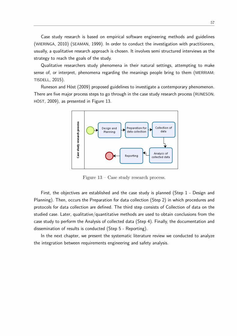
57
Case study research is based on empirical software engineering methods and guidelines(WIERINGA, 2010) (SEAMAN, 1999). In order to conduct the investigation with practitioners,usually, a qualitative research approach is chosen. It involves semi structured interviews as thestrategy to reach the goals of the study.
Qualitative researchers study phenomena in their natural settings, attempting to makesense of, or interpret, phenomena regarding the meanings people bring to them (MERRIAM;
TISDELL, 2015).Runeson and Höst (2009) proposed guidelines to investigate a contemporary phenomenon.
There are five major process steps to go through in the case study research process (RUNESON;
HÖST, 2009), as presented in Figure 13.
Figure 13 – Case study research process.
First, the objectives are established and the case study is planned (Step 1 - Design andPlanning). Then, occurs the Preparation for data collection (Step 2) in which procedures andprotocols for data collection are defined. The third step consists of Collection of data on thestudied case. Later, qualitative/quantitative methods are used to obtain conclusions from thecase study to perform the Analysis of collected data (Step 4). Finally, the documentation anddissemination of results is conducted (Step 5 - Reporting).
In the next chapter, we present the systematic literature review we conducted to analyzethe integration between requirements engineering and safety analysis.
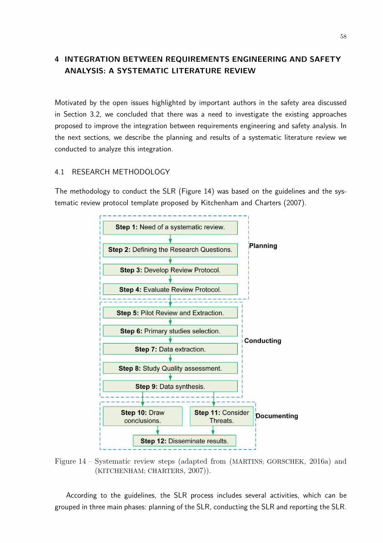
58
4 INTEGRATION BETWEEN REQUIREMENTS ENGINEERING AND SAFETYANALYSIS: A SYSTEMATIC LITERATURE REVIEW
Motivated by the open issues highlighted by important authors in the safety area discussedin Section 3.2, we concluded that there was a need to investigate the existing approachesproposed to improve the integration between requirements engineering and safety analysis. Inthe next sections, we describe the planning and results of a systematic literature review weconducted to analyze this integration.
4.1 RESEARCH METHODOLOGY
The methodology to conduct the SLR (Figure 14) was based on the guidelines and the sys-tematic review protocol template proposed by Kitchenham and Charters (2007).
Figure 14 – Systematic review steps (adapted from (MARTINS; GORSCHEK, 2016a) and(KITCHENHAM; CHARTERS, 2007)).
According to the guidelines, the SLR process includes several activities, which can begrouped in three main phases: planning of the SLR, conducting the SLR and reporting the SLR.

59
Table 4 – Research questions and motivations.Research Question Description and MotivationRQ1. What are the approaches proposedto improve the integration and communi-cation between RE and safety engineeringin the requirements engineering process ofsafety-critical systems?
The purpose of this question is to identify and analyzethe approaches proposed to improve the integration andcommunication between RE and safety engineering. Fromthe identification of these approaches, we want to inves-tigate how the integration between these two areas hasbeen performed and types of the approaches (methodolo-gies, tools, techniques, maturity models, etc.)
RQ1.1. What activities can be performedby requirements engineers as a part ofsafety analysis in the approaches that inte-grate requirements and safety engineering?
This question intends to detect which activities (actions,tasks) are proposed by approaches that integrate require-ments and safety engineering to be conducted require-ments engineers during the safety analysis. The investi-gation of the activities is necessary to detect which oneswe can include in a safety requirements engineering ma-turity model.
RQ1.2. What techniques can be used byrequirements engineers during safety anal-ysis in the approaches that integrate re-quirements and safety engineering?
This question aims to identify the techniques (systematicprocedures, methods, formulas, routines by which a taskis accomplished) can be used by requirements engineersin the the approaches that integrate requirements andsafety engineering for performing the safety analysis ofthe systems. This information will be used to developtwo conceptual models to classify the techniques usedin hazard/safety analysis. Furthermore, the investigationof the techniques is necessary to detect which ones wecan include in a safety requirements engineering maturitymodel.
RQ1.3. What data/information artifactscan be created by requirements engineersin the analysis and specification of SCS inthe approaches that integrate requirementsand safety engineering?
The aim of this question is to identify the various piecesof safety-related information (data, concepts, knowledge,facts) can be created by requirements engineers in theapproaches that integrate requirements and safety en-gineering to document the safety concerns during thespecification of SCS. The data/information obtained inthis research question are used to develop two concep-tual models regarding safety requirements classification.The conceptual models could be used during the safetyanalysis and to develop artifacts in the RE process.
RQ1.4. What are the tools used by the ap-proaches that integrate requirements andsafety engineering in safety analysis?
This question maps the Computer-Aided Software Engi-neering (CASE) tools used in the approaches that inte-grate requirements and safety engineering in the analysisof the safety requirements specifications of safety-criticalsystems. The identification of tools is necessary to im-prove the RE process, make the analysis more automatic,and the quality of analysis performed.
RQ1.5. What are the benefits of the ap-proaches that integrate requirements andsafety engineering identified in RQ1?
The purpose of this question is to analyze the benefitsof the approaches (selected in RQ1) for integration andcommunication between RE and safety engineering ex-tracted from the selected studies. The analysis of benefitsis necessary to justify the need of integrating these twoareas and the expected gains that could be achieved.
RQ2. What challenges/problems are iden-tified in research literature relating to SCSand RE?
This question aims to identify works needed in this area.The identified issues could be used in future works tiaddress the problems faced in the RE process of SCS.
The SLR was motivated (Step 1, Figure 14) by the tighter integration of safety engineeringconcerns into the RE process desired by academia and industry as reported in many studies(LUTZ, 2000) (MARTINS; GORSCHEK, 2016a) (LEVESON, 2011) (HEIMDAHL, 2007) (SIKORA;
TENBERGEN; POHL, 2012) (HATCLIFF et al., 2014). The gap that exists between the tradi-tional development processes, methodologies, notations and tools and the ones used in safetyengineering also contributes to the need of this SLR.
In order to determine if a SLR about integration and communication between RE and safety
60
engineering had already been performed, we searched the ACM, Springer, IEEE and GoogleScholar digital libraries (performed in September, 2015). None of the retrieved studies weredirectly related to the objectives expressed in the research questions (Step 2, Defining ResearchQuestions). In fact, few systematic literature reviews about the development of safety-criticalsystems are found in the literature.
We tested the string in 2018, however, we only found three new papers and we decidednot to include them in this thesis.
4.1.1 Research questions
This systematic review’s purpose is to analyze the approaches proposed to improve the inte-gration and communication between RE and safety engineering as well as to understand whichinformation regarding safety requirements should be specified by requirements engineers inorder to reduce the gap between these two areas. Thus, we intend to answer the researchquestions described in Table 4.
4.1.2 Search Strategy
The search strategy included an automatic search, using a string validated by experts on theRE and safety-critical areas and a manual inclusion of papers well-known about requirementscommunication.
The development of our review protocol (Step 3, Figure 14) followed the PICOC (Popula-tion, Intervention, Comparison, Outcome, Context) criteria as suggested by Kitchenham andCharters (2007) as well as Petticrew and Roberts (2008):
• Population: peer-reviewed publications reporting approaches to improve the integrationand communication between RE and safety engineering;
• the aim of the intervention was to collect empirical evidence in relation to approachesproposed to improve the integration and communication among requirements and safetyengineers during the development of SCS.
• Comparison: it does not apply.
• Outcomes: activities that should be performed by requirements engineering duringsafety analysis, the hazard/safety techniques they could use, the relationships betweensafety information that they should specify, the tools that can be used to support safetyanalysis as well as the benefits of the integration between RE and safety engineering.The activities, techniques and safety information should be performed, used or specifiedin the RE process. These activities and techniques have better results by RE and safetyengineering working jointly.

61
• Context: any context in which engineers in the RE process or safety analysis create ormodify the specifications of safety-critical systems.
Moreover, the selected resources chosen were Science Direct, SpringerLink, ACM DigitalLibrary, IEEE Xplore, Scopus, and Compendex; and the search method consisted of websearch in digital libraries.
Our search string was specified considering the main terms of the phenomena under inves-tigation (safety-critical systems, requirements engineering, safety requirements, and integra-tion/communication).
We conducted pilot searches to refine the search string in an iterative way. We excludedkeywords whose inclusion did not return additional papers in the automatic searches. Afterseveral iterations, we defined the following search string used to search within keywords, title,abstract and full text of the publications:
(1) (“safety critical system” OR “safety critical systems” OR “safety-critical system” OR“safety-critical systems”) AND
(2) (“requirements engineering" OR “requirements engineer” OR “requirements team” OR“requirements specification”) AND
(3) (“safety requirements” OR “safety engineering” OR “safety engineer” OR “safety team”OR “safety analysis” OR “safety specification”) AND
(4) (“communication” OR “integration” OR “interaction” OR “collaboration” OR “align-ment” OR “understanding” OR “relationship” OR “share” OR “sharing” OR “combina-tion” OR “interrelation” OR “interplay” OR “interdependency”)
Keywords related to safety-critical systems are presented in the first group of terms. Thesecond one concerns to the requirements engineering, and the third group to the specificationof safety requirements. Finally, the last group of terms are related to integration and com-munication. In this SLR, we want to collect information that should be shared by RE andsafety engineering. Therefore, such information should be collected and specified early in thedevelopment process by requirements engineers to reduce the causes of accidents related toinadequate, incomplete or misunderstood requirements. If we had focused on words in thesafety area, we would have extracted information that is beyond the scope and competence ofrequirements engineers, that is, more focused on tasks and competences of design engineersand safety engineers for example. Furthermore, we adapted the string for each search engineto consider their peculiarities.
We adopted the StArt (State of the Art through Systematic Reviews) tool (LAPES, 2014) tosupport the protocol definition and SLR conduction due to the positive results in the executionof SLRs reported in Hernandes et al. (2012).
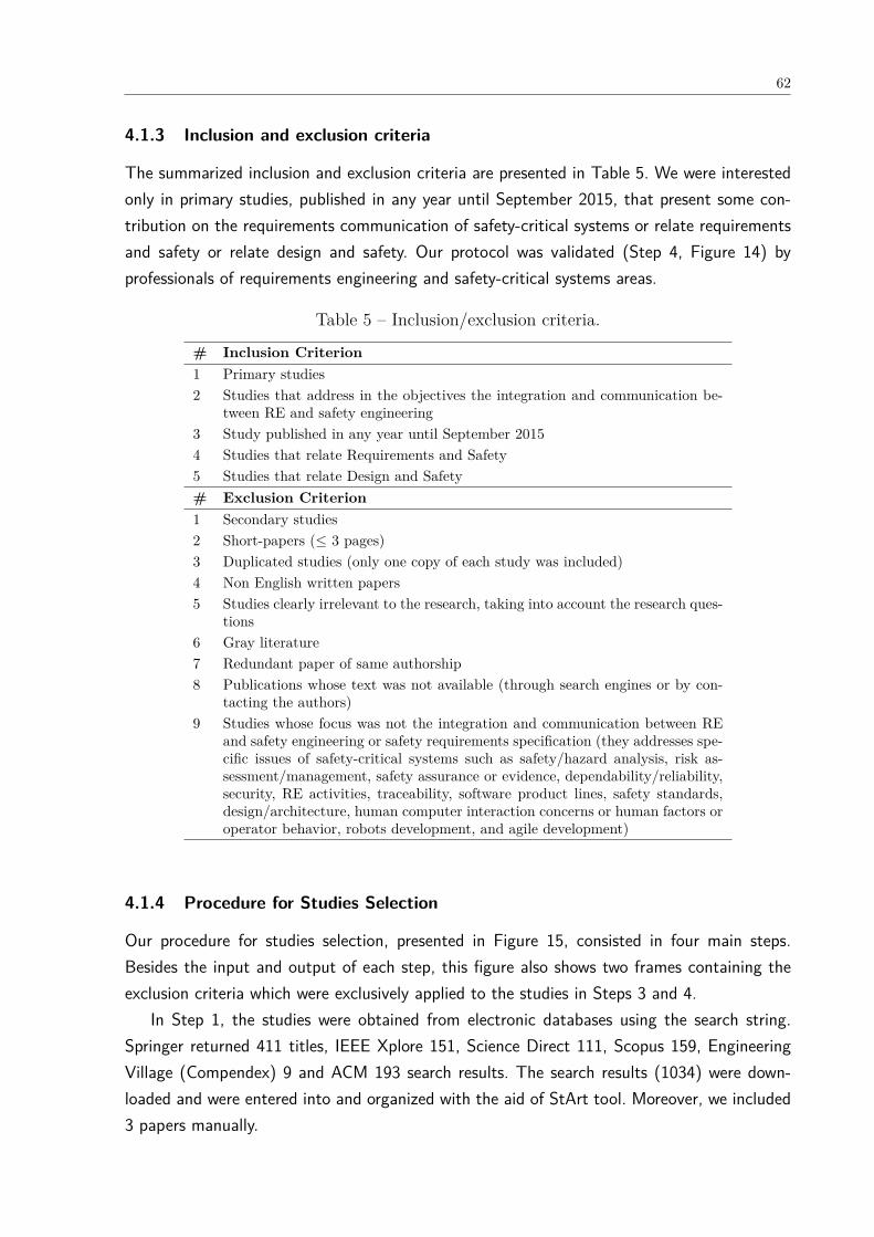
62
4.1.3 Inclusion and exclusion criteria
The summarized inclusion and exclusion criteria are presented in Table 5. We were interestedonly in primary studies, published in any year until September 2015, that present some con-tribution on the requirements communication of safety-critical systems or relate requirementsand safety or relate design and safety. Our protocol was validated (Step 4, Figure 14) byprofessionals of requirements engineering and safety-critical systems areas.
Table 5 – Inclusion/exclusion criteria.
# Inclusion Criterion1 Primary studies2 Studies that address in the objectives the integration and communication be-
tween RE and safety engineering3 Study published in any year until September 20154 Studies that relate Requirements and Safety5 Studies that relate Design and Safety# Exclusion Criterion1 Secondary studies2 Short-papers (≤ 3 pages)3 Duplicated studies (only one copy of each study was included)4 Non English written papers5 Studies clearly irrelevant to the research, taking into account the research ques-
tions6 Gray literature7 Redundant paper of same authorship8 Publications whose text was not available (through search engines or by con-
tacting the authors)9 Studies whose focus was not the integration and communication between RE
and safety engineering or safety requirements specification (they addresses spe-cific issues of safety-critical systems such as safety/hazard analysis, risk as-sessment/management, safety assurance or evidence, dependability/reliability,security, RE activities, traceability, software product lines, safety standards,design/architecture, human computer interaction concerns or human factors oroperator behavior, robots development, and agile development)
4.1.4 Procedure for Studies Selection
Our procedure for studies selection, presented in Figure 15, consisted in four main steps.Besides the input and output of each step, this figure also shows two frames containing theexclusion criteria which were exclusively applied to the studies in Steps 3 and 4.
In Step 1, the studies were obtained from electronic databases using the search string.Springer returned 411 titles, IEEE Xplore 151, Science Direct 111, Scopus 159, EngineeringVillage (Compendex) 9 and ACM 193 search results. The search results (1034) were down-loaded and were entered into and organized with the aid of StArt tool. Moreover, we included3 papers manually.

63
Figure 15 – Paper selection flowchart.
Out of 1037 search results, 761 were unique (step 2, Figure 15). Afterwards, reading thetitle and the abstract of the papers, we excluded 591 studies, based on the 9 exclusion criteria(step 3), as indicated on the left side of Figure 15. If there was insufficient data, the paper wasleft for the next step. After finishing the Step 3, 170 papers remained in the selection process.
After reading and analyzing 170 papers left for the full-text reading (step 4), we obtained57 relevant papers (listed in appendix A). In this step, the papers were excluded according tothe same 16 exclusion criteria (-111 papers) considered in the previous step, as also indicatedin the right frame of Figure 15. Given that the systematic literature review results returned agreat number of studies for extraction (57 papers), we limited the search procedures and wedid not performed snowballing.
We excluded many studies from this SLR that address mainly hazard analysis, safety assur-ance, security or dependability. Hence, we selected papers that only propose the integration andcommunication between RE and safety engineering. The conduction of the SLR was performedby one person under supervision of senior researchers.
4.1.5 Data extraction and synthesis
We prepared digital forms to accurately record any information needed to answer the researchquestions. We extracted the data described in Table 6 from each of the 57 primary studiesincluded in this systematic review. As well as the selection process, the data extraction wasfully aided by the StArt tool.
During the synthesis phase, we normalized the terms describing the same phenomenon andwe continued to use the most common term. We built four conceptual models using theseterms: (1) the techniques that can be used by requirements engineers in the hazard analysis;(2) the techniques that can be used by requirements engineers in the safety analysis; (3) the
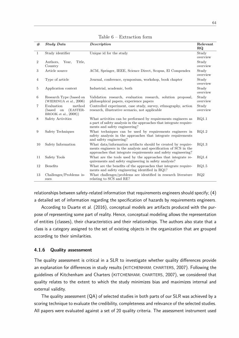
64
Table 6 – Extraction form# Study Data Description Relevant
RQ1 Study identifier Unique id for the study Study
overview2 Authors, Year, Title,
CountryStudyoverview
3 Article source ACM, Springer, IEEE, Science Direct, Scopus, El Compendex Studyoverview
4 Type of article Journal, conference, symposium, workshop, book chapter Studyoverview
5 Application context Industrial, academic, both Studyoverview
6 Research Type (based on(WIERINGA et al., 2006)
Validation research, evaluation research, solution proposal,philosophical papers, experience papers
Studyoverview
7 Evaluation method(based on (EASTER-BROOK et al., 2008))
Controlled experiment, case study, survey, ethnography, actionresearch, illustrative scenario, not applicable
Studyoverview
8 Safety Activities What activities can be performed by requirements engineers asa part of safety analysis in the approaches that integrate require-ments and safety engineering?
RQ1.1
9 Safety Techniques What techniques can be used by requirements engineers insafety analysis in the approaches that integrate requirementsand safety engineering?
RQ1.2
10 Safety Information What data/information artifacts should be created by require-ments engineers in the analysis and specification of SCS in theapproaches that integrate requirements and safety engineering?
RQ1.3
11 Safety Tools What are the tools used by the approaches that integrate re-quirements and safety engineering in safety analysis?
RQ1.4
12 Benefits What are the benefits of the approaches that integrate require-ments and safety engineering identified in RQ1?
RQ1.5
13 Challenges/Problems is-sues
What challenges/problems are identified in research literaturerelating to SCS and RE?
RQ2
relationships between safety-related information that requirements engineers should specify; (4)a detailed set of information regarding the specification of hazards by requirements engineers.
According to Duarte et al. (2016), conceptual models are artifacts produced with the pur-pose of representing some part of reality. Hence, conceptual modeling allows the representationof entities (classes), their characteristics and their relationships. The authors also state that aclass is a category assigned to the set of existing objects in the organization that are groupedaccording to their similarities.
4.1.6 Quality assessment
The quality assessment is critical in a SLR to investigate whether quality differences providean explanation for differences in study results (KITCHENHAM; CHARTERS, 2007). Following theguidelines of Kitchenham and Charters (KITCHENHAM; CHARTERS, 2007), we considered thatquality relates to the extent to which the study minimizes bias and maximizes internal andexternal validity.
The quality assessment (QA) of selected studies in both parts of our SLR was achieved by ascoring technique to evaluate the credibility, completeness and relevance of the selected studies.All papers were evaluated against a set of 20 quality criteria. The assessment instrument used
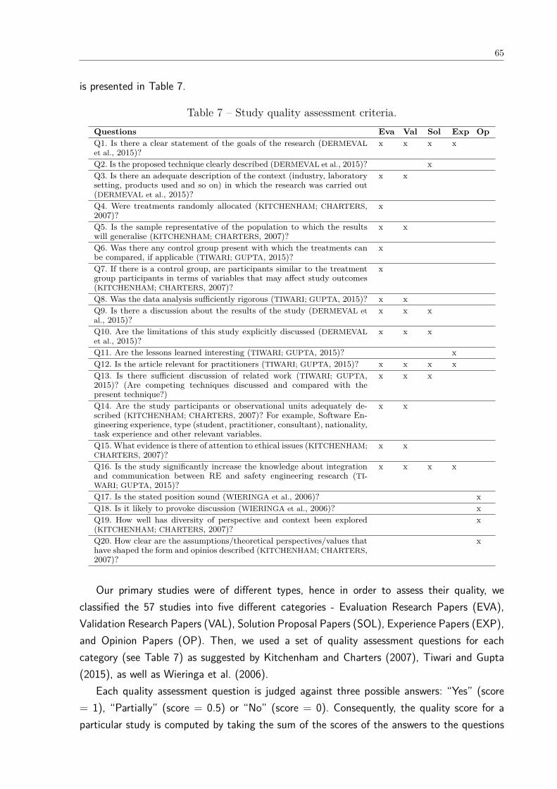
65
is presented in Table 7.
Table 7 – Study quality assessment criteria.Questions Eva Val Sol Exp OpQ1. Is there a clear statement of the goals of the research (DERMEVALet al., 2015)?
x x x x
Q2. Is the proposed technique clearly described (DERMEVAL et al., 2015)? xQ3. Is there an adequate description of the context (industry, laboratorysetting, products used and so on) in which the research was carried out(DERMEVAL et al., 2015)?
x x
Q4. Were treatments randomly allocated (KITCHENHAM; CHARTERS,2007)?
x
Q5. Is the sample representative of the population to which the resultswill generalise (KITCHENHAM; CHARTERS, 2007)?
x x
Q6. Was there any control group present with which the treatments canbe compared, if applicable (TIWARI; GUPTA, 2015)?
x
Q7. If there is a control group, are participants similar to the treatmentgroup participants in terms of variables that may affect study outcomes(KITCHENHAM; CHARTERS, 2007)?
x
Q8. Was the data analysis sufficiently rigorous (TIWARI; GUPTA, 2015)? x xQ9. Is there a discussion about the results of the study (DERMEVAL etal., 2015)?
x x x
Q10. Are the limitations of this study explicitly discussed (DERMEVALet al., 2015)?
x x x
Q11. Are the lessons learned interesting (TIWARI; GUPTA, 2015)? xQ12. Is the article relevant for practitioners (TIWARI; GUPTA, 2015)? x x x xQ13. Is there sufficient discussion of related work (TIWARI; GUPTA,2015)? (Are competing techniques discussed and compared with thepresent technique?)
x x x
Q14. Are the study participants or observational units adequately de-scribed (KITCHENHAM; CHARTERS, 2007)? For example, Software En-gineering experience, type (student, practitioner, consultant), nationality,task experience and other relevant variables.
x x
Q15. What evidence is there of attention to ethical issues (KITCHENHAM;CHARTERS, 2007)?
x x
Q16. Is the study significantly increase the knowledge about integrationand communication between RE and safety engineering research (TI-WARI; GUPTA, 2015)?
x x x x
Q17. Is the stated position sound (WIERINGA et al., 2006)? xQ18. Is it likely to provoke discussion (WIERINGA et al., 2006)? xQ19. How well has diversity of perspective and context been explored(KITCHENHAM; CHARTERS, 2007)?
x
Q20. How clear are the assumptions/theoretical perspectives/values thathave shaped the form and opinios described (KITCHENHAM; CHARTERS,2007)?
x
Our primary studies were of different types, hence in order to assess their quality, weclassified the 57 studies into five different categories - Evaluation Research Papers (EVA),Validation Research Papers (VAL), Solution Proposal Papers (SOL), Experience Papers (EXP),and Opinion Papers (OP). Then, we used a set of quality assessment questions for eachcategory (see Table 7) as suggested by Kitchenham and Charters (2007), Tiwari and Gupta(2015), as well as Wieringa et al. (2006).
Each quality assessment question is judged against three possible answers: “Yes” (score= 1), “Partially” (score = 0.5) or “No” (score = 0). Consequently, the quality score for aparticular study is computed by taking the sum of the scores of the answers to the questions

66
related to its research type. The quality scores of the selected studies are presented in Table65 (see Appendix).
4.1.7 Threats to validity
We used the categorization of threats presented by Wohlin et al. (2000), which includes fourtypes of validity threats, namely, conclusion, internal, construct, and external validity threats.
Construct validity : Construct validity is related to generalization of the result to the con-cept or theory behind the study execution (WOHLIN et al., 2000). Aiming to minimize threatsof this nature, we used many synonyms for the main constructs in this review: “safety-criticalsystems”, “requirements engineering”, “safety requirements”, and “communication”. Duringthe synthesis phase, we normalized the terms describing the same phenomenon and we con-tinued to use the most common term (GASPARIC; JANES, 2016). We built four conceptualmodels using these terms: (1) the techniques that can be used by requirements engineers inthe hazard analysis; (2) the techniques that can be used by requirements engineers in thesafety analysis; (3) the relationships between safety-related information that requirements en-gineers should specify; (4) a detailed set of information regarding the specification of hazardsby requirements engineers.
Internal validity threats are related to possible wrong conclusion about causal relationshipsbetween treatment and outcome (WOHLIN et al., 2000). The primary objective of conducting aSLR is to minimize internal validity threats in the research. We tried to mitigate threats due topersonal bias on study understanding by conducting the selection process iteratively. Moreover,the first author is a PhD student in Requirements Engineering, and the other three authorsare experienced researchers with expertise in Requirements Engineering, Software Engineeringor Safety-Critical Systems.
External validity is concerned with establishing the generalizability of the SLR results, whichis related to the degree to which the primary studies are representative for the review topic. Inthe case of a literature review, the external validity depends on the identified literature: if theidentified literature is not externally valid, neither is the synthesis of its content (GASPARIC;
JANES, 2016). By the choice of our exclusion criteria, we excluded gray literature papers. Inorder to mitigate external threats, our search process was defined after several trial searchesand validated with the consensus of the authors.
Conclusion validity : The used methodology of Kitchenham and Charters (2007) alreadyassumes that not all relevant primary studies that exist can be identified. To mitigate thisthreat, the research protocol was carefully designed and validated by the authors to minimizethe risk of exclusion of relevant studies. Besides, we used many synonyms for the constructsof this SLR to improve high coverage of possibly important studies from automatic search.Furthermore, we did not conduct a complementary manual search since the main venuesabout requirements engineering and safety-critical systems are indexed by the search enginesadopted in our protocol. Therefore, we only added 3 well-known studies (PERNSTÅL et al., 2015)
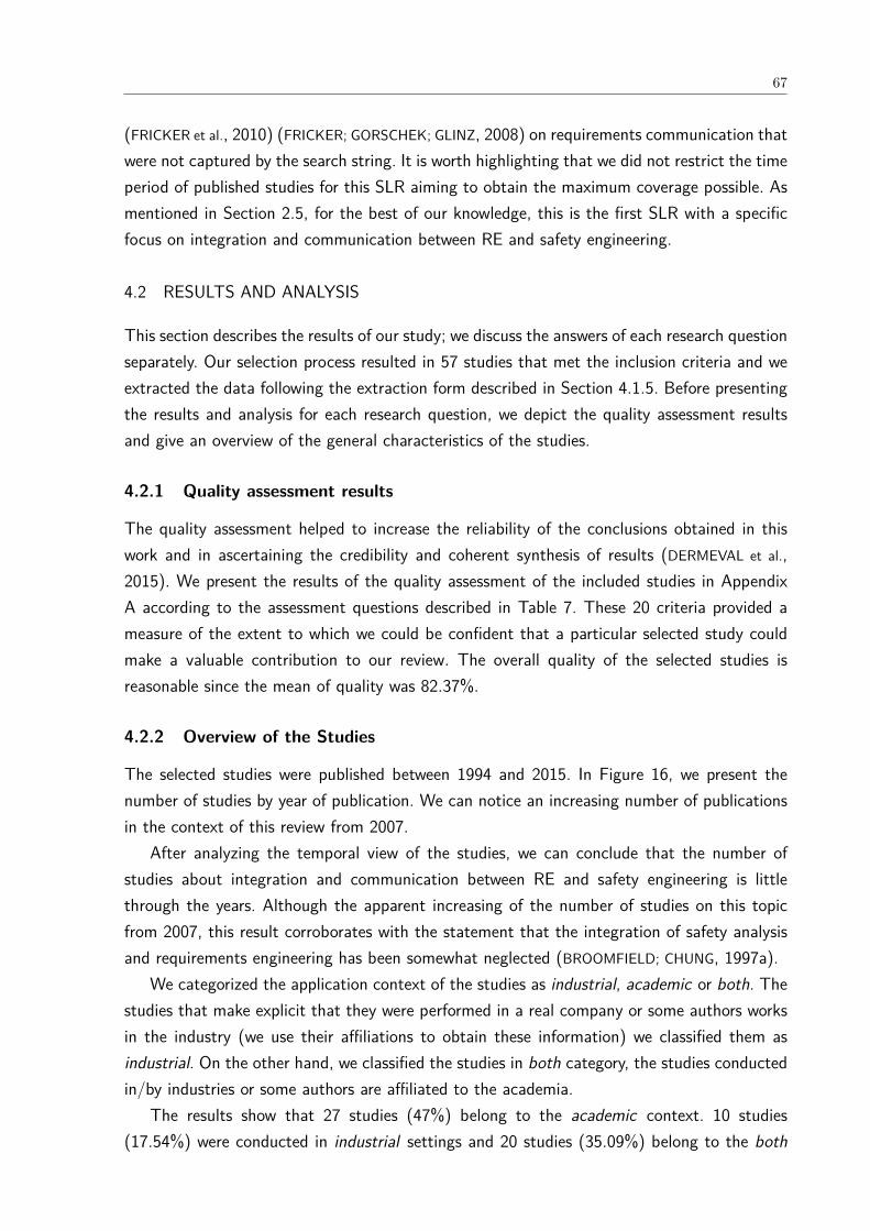
67
(FRICKER et al., 2010) (FRICKER; GORSCHEK; GLINZ, 2008) on requirements communication thatwere not captured by the search string. It is worth highlighting that we did not restrict the timeperiod of published studies for this SLR aiming to obtain the maximum coverage possible. Asmentioned in Section 2.5, for the best of our knowledge, this is the first SLR with a specificfocus on integration and communication between RE and safety engineering.
4.2 RESULTS AND ANALYSIS
This section describes the results of our study; we discuss the answers of each research questionseparately. Our selection process resulted in 57 studies that met the inclusion criteria and weextracted the data following the extraction form described in Section 4.1.5. Before presentingthe results and analysis for each research question, we depict the quality assessment resultsand give an overview of the general characteristics of the studies.
4.2.1 Quality assessment results
The quality assessment helped to increase the reliability of the conclusions obtained in thiswork and in ascertaining the credibility and coherent synthesis of results (DERMEVAL et al.,2015). We present the results of the quality assessment of the included studies in AppendixA according to the assessment questions described in Table 7. These 20 criteria provided ameasure of the extent to which we could be confident that a particular selected study couldmake a valuable contribution to our review. The overall quality of the selected studies isreasonable since the mean of quality was 82.37%.
4.2.2 Overview of the Studies
The selected studies were published between 1994 and 2015. In Figure 16, we present thenumber of studies by year of publication. We can notice an increasing number of publicationsin the context of this review from 2007.
After analyzing the temporal view of the studies, we can conclude that the number ofstudies about integration and communication between RE and safety engineering is littlethrough the years. Although the apparent increasing of the number of studies on this topicfrom 2007, this result corroborates with the statement that the integration of safety analysisand requirements engineering has been somewhat neglected (BROOMFIELD; CHUNG, 1997a).
We categorized the application context of the studies as industrial, academic or both. Thestudies that make explicit that they were performed in a real company or some authors worksin the industry (we use their affiliations to obtain these information) we classified them asindustrial. On the other hand, we classified the studies in both category, the studies conductedin/by industries or some authors are affiliated to the academia.
The results show that 27 studies (47%) belong to the academic context. 10 studies(17.54%) were conducted in industrial settings and 20 studies (35.09%) belong to the both

68
Figure 16 – Temporal view of the studies.
category. These results shows that more than half of the studies were classified as the industrialcontext. This may indicate that the studies are attempting to solve challenges faced by theindustries. Besides, it also suggests that there is some approximation between industries anduniversities.
The selected studies were classified according to the applied research types defined byWieringa et al. (2006), as can be seen in Table 8. The most adopted research type is SolutionProposal with 85.19% (46 studies) followed by Evaluation Research with 12.96% (7 studies),Validation Research with 7.41% (4 studies), and Experience Papers and Opinion Papers tiedwith 3.7% (2 studies) each. None of the selected studies belongs to Philosophical Papers cat-egory of research types. According to Wieringa et al. (2006), the difference between validationresearch and evaluation research is that in the first, techniques not yet implemented in practiceare investigated, whereas in the second, techniques-in-practice are investigated.
We propose our classification of the evaluation method based on the categories (controlledexperiment, case study, survey, ethnography and action research) defined by Easterbrook etal. (2008). In addition, we adopted two extra categories used in a previous work (DERMEVAL et
al., 2015): illustrative scenario and not applicable. The first category is used to classify papersthat only evaluate their contributions using small examples. The second extra category refersto the papers that do not contain any kind of evaluation method in the study.
Despite more than half of the selected studies were classified in the industry context,84.21% of the studies were not evaluated empirically. 39 studies (68.42%) were evaluated onlyusing small examples and 9 studies (15.79%) did not mention any kind of evaluation methodor it does not apply since it is an opinion paper. Only 22.81% were evaluated empirically where
69
Table 8 – Research types of the selected studies.ResearchType
Studies Count %
Solution Pro-posal
(KAISER et al., 2010) (SAEED; LEMOS; ANDERSON, 1995) (DAVID;IDASIAK; KRATZ, 2010) (MOSTERT; SOLMS, 1994) (LUTZ, 1993b)(RATAN et al., 1996) (THRAMBOULIDIS; SCHOLZ, 2010) (BLACK;KOOPMAN, 2008) (NAVARRO et al., 2006)(KIM; CHUNG, 2005)(MANNERING; HALL; RAPANOTTI, 2008) (MEDIKONDA; PANCHU-MARTHY, 2009) (WU; KELLY, 2007) (NEJATI et al., 2012) (MARTIN-GUILLEREZ et al., 2010) (LEVESON, 2002a) (HANSEN; RAVN; STAVRI-DOU, 1998) (SCHOLZ; THRAMBOULIDIS, 2013) (MARKOVSKI;MORTEL-FRONCZAK, 2012) (BECKERS et al., 2013) (AROGUN-DADE et al., 2012) (ARISS; XU; WONG, 2011) (GUIOCHET; MARTIN-GUILLEREZ; POWELL, 2010) (CHANDRASEKARAN et al., 2009)(BRIONES et al., 2007) (BROOMFIELD; CHUNG, 1997a) (GÓRSKI;WARDZIŃSKI, 1996) (DU; WANG; FENG, 2014) (ZOUGHBI; BRIAND;LABICHE, 2011) (JüRJENS, 2003) (SIMPSON; STOKER, 2002) (BIGGS;SAKAMOTO; KOTOKU, 2014) (LU; HALANG, 2007) (MUSTAFIZ;KIENZLE, 2009) (EKBERG et al., 2014b) (GUILLERM; DEMMOU;SADOU, 2010) (RAFEH, 2013) (CHEN et al., 2011) (TSCHüRTZ;SCHEDL, 2010) (ELLIOTT et al., 1995) (CROLL et al., 1997) (CANT etal., 2006) (MURALI; IRELAND; GROV, 2015) (PERNSTÅL et al., 2015)(FRICKER et al., 2010) (FRICKER; GORSCHEK; GLINZ, 2008)
46 85.19%
EvaluationResearch
(MARTINS; OLIVEIRA, 2014b) (STÅLHANE; SINDRE, 2014) (STÅL-HANE; SINDRE, 2007) (MUSTAFIZ; KIENZLE, 2009)(PAIGE et al., 2008) (JURKIEWICZ et al., 2015) (STÅLHANE; SINDRE;BOUSQUET, 2010)
7 12.96%
ValidationResearch
(NEJATI et al., 2012) (HATCLIFF et al., 2014) (PERNSTÅL et al., 2015)(FRICKER et al., 2010)
4 7.41%
OpinionPapers
(HEIMDAHL, 2007) (SIKORA; TENBERGEN; POHL, 2012) 2 3.7%
ExperiencePapers
(WILIKENS; MASERA; VALLERO, 1997) (SCHEDL; WINKELBAUER,2008a)
2 3.7%
5 studies (8.77%) presented a controlled experiment and 8 studies (14.04%) adopted the casestudy strategy.
We noticed that there are few real experiments even though there is some empirical studiespublished on integration and communication between RE and safety engineering. In addition,we find that a lot of what is labelled as case study is really a proof of concept discussionsrelated to simple examples. Hence, we classified them in the illustrative scenario category.
These findings reveal the need of applying the approaches in practice with real users inorder to assess to what extent they contribute to integration and communication between REand safety engineering. However, there are many difficulties faced when conducting controlledsoftware engineering experiments in realistic environments that we are aware of. The absenceof professionals as subjects in (software engineering) experiments is directly related to the highcosts and large organizational effort spent in the conduction of such experiments as recognizedby many authors, such as Basili, Selby and Hutchens (1986), Fenton (1993) as well as Sjoberget al. (2002). In the next sections, we present and discuss the results of each research question.
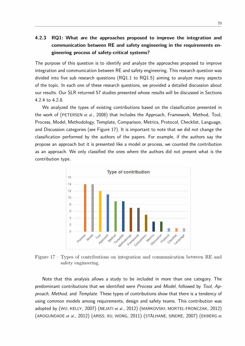
70
4.2.3 RQ1: What are the approaches proposed to improve the integration andcommunication between RE and safety engineering in the requirements en-gineering process of safety-critical systems?
The purpose of this question is to identify and analyze the approaches proposed to improveintegration and communication between RE and safety engineering. This research question wasdivided into five sub research questions (RQ1.1 to RQ1.5) aiming to analyze many aspectsof the topic. In each one of these research questions, we provided a detailed discussion aboutour results. Our SLR returned 57 studies presented whose results will be discussed in Sections4.2.4 to 4.2.8.
We analyzed the types of existing contributions based on the classification presented inthe work of (PETERSEN et al., 2008) that includes the Approach, Framework, Method, Tool,Process, Model, Methodology, Template, Comparison, Metrics, Protocol, Checklist, Language,and Discussion categories (see Figure 17). It is important to note that we did not change theclassification performed by the authors of the papers. For example, if the authors say thepropose an approach but it is presented like a model or process, we counted the contributionas an approach. We only classified the ones where the authors did not present what is thecontribution type.
Figure 17 – Types of contributions on integration and communication between RE andsafety engineering.
Note that this analysis allows a study to be included in more than one category. Thepredominant contributions that we identified were Process and Model, followed by Tool, Ap-proach, Method, and Template. These types of contributions show that there is a tendency ofusing common models among requirements, design and safety teams. This contribution wasadopted by (WU; KELLY, 2007) (NEJATI et al., 2012) (MARKOVSKI; MORTEL-FRONCZAK, 2012)(AROGUNDADE et al., 2012) (ARISS; XU; WONG, 2011) (STÅLHANE; SINDRE, 2007) (EKBERG et
71
al., 2014b) (CHEN et al., 2011) (MURALI; IRELAND; GROV, 2015) to improve integration andcommunication between RE and safety engineering.
UML profiles were proposed by the works of Beckers et al. (2013), Zoughbi, Briand andLabiche (2011) as well as Lu and Halang (2007). The SysML language has been used by theworks of Scholz and Thramboulidis (2013) as well as Biggs, Sakamoto and Kotoku (2014) asan approach to integrate safety engineering with an SysML-based development process.
An approach for safety management which can be used in different phases of softwaredevelopment before implementation and disposal phase is described in Rafeh (2013). In theproposed approach, safety begins from requirements as the infrastructure of design and con-tinues through other phases of software production.
The shortcomings of the existing safety analysis techniques in software safety analysis wereinvestigated by the works of Martins and Oliveira (2014b) as well as Du, Wang and Feng(2014). The former described a case study adopting a protocol to help requirements engineersto derive safety functional requirements from Fault Tree Analysis. The latter proposed a safetyrequirement elicitation technique combined with scenario to refine the system-level safetyanalysis into software behaviors in specific scenarios.
The variety of requirements specification languages motivated some works such as Stålhaneand Sindre (2014) as well as Jurkiewicz et al. (2015) to perform experiments to identify whichare the ones that best support non-experts in identifying hazards of safety-critical systems.
Finally, the work of Pernstål et al. (2015) presented a lightweight RE framework, demon-strated and evaluated its industrial applicability in response to the needs of a Swedish automo-tive company for improving specific problems in inter-departmental requirements coordinationand communication in large-scale development of software-intensive systems.
We performed a rigor and relevance analysis of the approaches following the model pro-posed by Ivarsson and Gorschek (2011) for evaluating the rigor and industrial relevance oftechnology evaluations in software engineering. The results of rigor and relevance analysis ofthe approaches described in the selected studies are depicted in Figure 18.
The rigor is not the actual rigor of studies, e.g. use of a correct analysis method, that isconsidered in the model, but rather the extent to which aspects related to rigor are presented(IVARSSON; GORSCHEK, 2011). According to the model, the rigor is evaluated through threeaspects: Context described, Study design described, and Validity discussed. All these aspectsare scored with the same three score levels in a three point scale: 0 (weak), 0.5 (medium),and 1 (strong) description.
The relevance is evaluated by analyzing four aspects: Subjects that participated in thestudies; (2) the Context in which the studies were performed; (3) the Research Method adoptedin the studies; and (4) the Scale used in the studies evaluation. If the aspect contributes toindustrial relevance it receives the score 1, otherwise, it receives 0. Therefore, the maximumvalue for rigor an approach can have is three, while relevance has a maximum of four (IVARSSON;
GORSCHEK, 2011).

72
Figure 18 – Rigor and Relevance of the approaches.
Figure 18 shows that the majority of evaluations end up in the lower left quadrant ofthe bubble chart, indicating a lack of both rigor and relevance. Only 2 approaches have zerorigor and relevance, on the other hand, 13 studies (22.81%) have 0.5 rigor and 0 relevance.Moreover, 17 studies (29.82%) have 1 rigor and 0 relevance. This means that more than halfof the studies (52.63%) of all approaches included in this review did not provide a description,or provided a weak one, of the context, study design or validity threats.
31 studies (54.39%) have 0 relevance. This means that they are examples of application of aproposal done by either students or researchers in academia in toy examples. This combinationof low rigor and relevance is disappointing from a technology transfer perspective, as theseevaluations have less potential for actually influencing practice (IVARSSON; GORSCHEK, 2011).
12 studies (21.05%) have the highest rigor (2.5 or 3) and relevance (3 or 4), but only threestudies have the maximum rigor and relevance. These well classified studies proposed differ-ent types of contributions: framework, method, tool, process, model, template, comparisonwith other approaches, protocol or discussed challenges in the integration and communicationbetween RE and safety engineering. All these papers were published in the last ten years (2006-2016) and classified as industrial or both (academic and industrial) context. Only 2 paperswere written and published in the academic context. These results means that the year ofpublication might indicate that the quality of the studies changed over time and the relevanceis affected by the affiliation of the researchers and the context in which the study is conducted.Furthermore, they also show that the levels of validation are increasing.
We present in Table 9 the average of each aspect regarding rigor (Context described(C), Study design described (SD), and Validity discussed (V)) and relevance (Context (CO),Research method (RM), User/Subject (U), and Scale (S)) per type of contribution. We alsopresent the average of the sum of the aspects.

73
Table 9 – Average number of rigor and relevance per type of contribution.Rigor Relevance
Type C SD V Sum -Rigor
CO RM U S Sum - Rele-vance
Approach 0.36 0.23 0.50 1.09 0.18 0.09 0.09 0.00 0.36Framework0.64 0.36 0.64 1.64 0.29 0.29 0.29 0.29 1.14Method 0.44 0.33 0.50 1.28 0.33 0.33 0.22 0.22 1.11Tool 0.42 0.25 0.54 1.21 0.33 0.17 0.17 0.17 0.83Process 0.61 0.39 0.50 1.50 0.50 0.29 0.50 0.43 1.71Model 0.43 0.32 0.57 1.32 0.36 0.14 0.21 0.14 0.86Methodology0.36 0.07 0.57 1 0.14 0 0.14 0 0.29Template 0.56 0.22 0.56 1.33 0.33 0.11 0.22 0.22 0.89Comparison1 1 0.90 2.90 1 1 0.40 0.40 2.80Metrics 0.33 0 0.33 0.67 0.33 0 0.33 0.33 1Protocol 1 1 0.5 2.5 1 1 1 1 4Checklist 0.5 0 0.5 1 0 0 0 0 0Language 0 0 0.5 0.5 0 0 0 0 0Discussion 0.50 0.33 0.50 1.33 0.33 0.33 0.33 0.33 1.33
The results of Table 9 show that the studies that proposed Metrics and Language havethe smallest number of rigor meaning that they are poor described. These papers discussedsome limitations but they did not present the study design or research methodology adopted.
The types of contribution that have the worst relevance are Approach, Methodology,Checklist and Language. The scale of all papers in these categories do not contribute torelevance. This means that the evaluation is performed using applications of unrealistic size(down-scaled industrial) or toy examples.
4.2.4 RQ1.1: What activities can be performed by requirements engineers as apart of safety analysis in the approaches that integrate requirements andsafety engineering?
This question intends to detect which activities can be conducted by requirements engineersduring the safety analysis. In Table 10, we list the safety activities proposed by the selectedstudies that should have be conducted by RE and safety engineering working jointly to getbetter results during the development of safety-critical systems.
The results confirmed that there is no unified vocabulary among the approaches as wellas they are not in compliance with safety standards. This lack of unified terminology hampersexchanging information between stakeholders contributing to a poor requirements analysis andspecifications.
Several of these activities have the same purpose, for example Safety analysis, AssessingSafety, Safety verification, and Safety Assessment. Risk analysis is another activity with manyvariations: Risk assessment, Risk identification, Risk evaluation, and Risk management.
Many approaches do not explicitly mention which activities should be undertaken by re-quirements team or they generalize all activities as Safety analysis. Therefore, safety analysisis the activity reported in 37 studies (64.91%) as shown in Table 10.
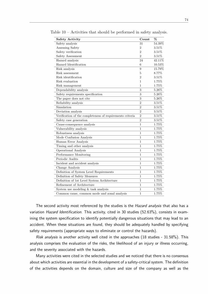
74
Table 10 – Activities that should be performed in safety analysis.Safety Activity Count %Safety analysis 31 54.39%Assessing Safety 2 3.51%Safety verification 2 3.51%Safety Assessment 2 3.51%Hazard analysis 24 42.11%Hazard Identification 6 10.53%Risk analysis 9 15.79%Risk assessment 5 8.77%Risk identification 2 3.51%Risk evaluation 1 1.75%Risk management 1 1.75%Dependability analysis 3 5.26%Safety requirements specification 3 5.26%The paper does not cite 3 5.26%Reliability analysis 2 3.51%Simulation 2 3.51%Deviation analysis 2 3.51%Verification of the completeness of requirements criteria 2 3.51%Safety case generation 2 3.51%Cause-consequence analysis 1 1.75%Vulnerability analysis 1 1.75%Robustness analysis 1 1.75%Mode Confusion Analysis 1 1.75%Human Error Analysis 1 1.75%Timing and other analysis 1 1.75%Operational Analysis 1 1.75%Performance Monitoring 1 1.75%Periodic Audits 1 1.75%Incident and accident analysis 1 1.75%Change Analysis 1 1.75%Definition of System Level Requirements 1 1.75%Definition of Safety Measures 1 1.75%Definition of 1st Level System Architecture 1 1.75%Refinement of Architecture 1 1.75%System use modeling & task analysis 1 1.75%Common cause, common mode and zonal analysis 1 1.75%
The second activity most referenced by the studies is the Hazard analysis that also has avariation Hazard Identification. This activity, cited in 30 studies (52.63%), consists in exam-ining the system specification to identify potentially dangerous situations that may lead to anaccident. When these situations are found, they should be adequately handled by specifyingsafety requirements (appropriate ways to eliminate or control the hazards).
Risk analysis is another activity well cited in the approaches (18 studies - 31.58%). Thisanalysis comprises the evaluation of the risks, the likelihood of an injury or illness occurring,and the severity associated with the hazards.
Many activities were cited in the selected studies and we noticed that there is no consensusabout which activities are essential in the development of a safety-critical system. The definitionof the activities depends on the domain, culture and size of the company as well as the

75
knowledge and experience of the requirements and safety engineers. Moreover, few studiesconsider the guidelines and restrictions imposed by the safety standards.
4.2.5 RQ1.2: What techniques can be used by requirements engineers during safetyanalysis in the approaches that integrate requirements and safety engineer-ing?
The safety analysis in the development of safety-critical systems requires the use of a techniqueto help finding the hazards of the system. Therefore, this question aims to identify whattechniques that can be used by requirements engineers in the approaches for performing thehazard and safety analysis of the systems. These techniques are listed in the selected studiesas having better results if RE and safety engineering work jointly. Accordingly, we did notinvestigate in this SLR the techniques for safety analysis that are used only by the safetyengineering team.
The techniques obtained from the extracted data, the distribution of selected studies overthe techniques including their count (i.e., the number of selected studies from each source),and the percentage of selected studies are presented in Table 11.
These techniques should be used in safety analysis to discover the hazards of a system,their causes and consequences. Such techniques can be classified according to the forms oflogic and reasoning during the hazard analysis in Deductive (D), Inductive (I) or Both. TheTable 11 also shows the General (G) category in which the techniques do not have the aim ofdiscover hazards but another aspect of SCS. Besides the classification according to the typeof hazard analysis, the techniques can be classified following the analytical styles that havetwo perspectives: qualitative and quantitative analysis.
In Figure 19, we present a conceptual model we created to classify the techniques used inthe safety analysis but their main goal is not to discover hazards but some other aspect ofSCS, for instance risk, safety criteria, usability of interface. On the other hand, the techniquesused in the hazard analysis are listed in Figure 20.
The conceptual models of Figures 19 and 20 provide an intuitive and yet comprehensiveway to present and summarize the techniques used in hazard/safety analysis. Furthermore,a conceptual model is an effective means for communicating the results in a more struc-tured manner (NAIR et al., 2014). Experts in RE and safety engineering reviewed and providedfeedback on the extracted safety techniques.
Some papers adopt techniques for safety analysis that their main objective is not discoveringhazards but analyze other aspects of the SCS such as risk, safety criteria, usability of interface.Such techniques are exhibited in the conceptual model of Figure 19 and comprise Mind stormsand historical information, Preliminary controller task analysis (PTA), Risk analysis (RA),Interface analysis and human error analysis, Indirect Control Path Analysis (ICPA), SafetyRequirements/Criteria Analysis (SRCA), Misuse cases (MUC), and Scenario-based analysis.They are cited 23 times in the selected studies corresponding to 15.75%. On the other hand,
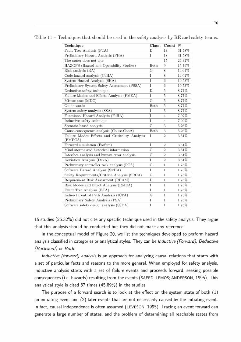
76
Table 11 – Techniques that should be used in the safety analysis by RE and safety teams.Technique Class. Count %Fault Tree Analysis (FTA) D 18 31.58%Preliminary Hazard Analysis (PHA) I 18 31.58%The paper does not cite 15 26.32%HAZOPS (Hazard and Operability Studies) Both 9 15.79%Risk analysis (RA) G 8 14.04%Code hazard analysis (CoHA) I 8 14.04%System Hazard Analysis (SHA) I 6 10.53%Preliminary System Safety Assessment (PSSA) I 6 10.53%Deductive safety technique D 5 8.77%Failure Modes and Effects Analysis (FMEA) I 5 8.77%Misuse case (MUC) G 5 8.77%Guide-words Both 5 8.77%System safety analysis (SSA) I 5 8.77%Functional Hazard Analysis (FuHA) I 4 7.02%Inductive safety technique I 4 7.02%Scenario-based analysis G 3 5.26%Cause-consequence analysis (Cause-ConA) Both 3 5.26%Failure Modes Effects and Criticality Analysis(FMECA)
I 2 3.51%
Forward simulation (ForSim) I 2 3.51%Mind storms and historical information G 2 3.51%Interface analysis and human error analysis G 2 3.51%Deviation Analysis (DevA) I 2 3.51%Preliminary controller task analysis (PTA) G 1 1.75%Software Hazard Analysis (SwHA) I 1 1.75%Safety Requirements/Criteria Analysis (SRCA) G 1 1.75%Requirement Risk Assessment (RRAM) D 1 1.75%Risk Modes and Effect Analysis (RMEA) I 1 1.75%Event Tree Analysis (ETA) I 1 1.75%Indirect Control Path Analysis (ICPA) G 1 1.75%Preliminary Safety Analysis (PSA) I 1 1.75%Software safety design analysis (SSDA) I 1 1.75%
15 studies (26.32%) did not cite any specific technique used in the safety analysis. They arguethat this analysis should be conducted but they did not make any reference.
In the conceptual model of Figure 20, we list the techniques developed to perform hazardanalysis classified in categories or analytical styles. They can be Inductive (Forward), Deductive(Backward) or Both.
Inductive (forward) analysis is an approach for analyzing causal relations that starts witha set of particular facts and reasons to the more general. When employed for safety analysis,inductive analysis starts with a set of failure events and proceeds forward, seeking possibleconsequences (i.e. hazards) resulting from the events (SAEED; LEMOS; ANDERSON, 1995). Thisanalytical style is cited 67 times (45.89%) in the studies.
The purpose of a forward search is to look at the effect on the system state of both (1)an initiating event and (2) later events that are not necessarily caused by the initiating event.In fact, causal independence is often assumed (LEVESON, 1995). Tracing an event forward cangenerate a large number of states, and the problem of determining all reachable states from
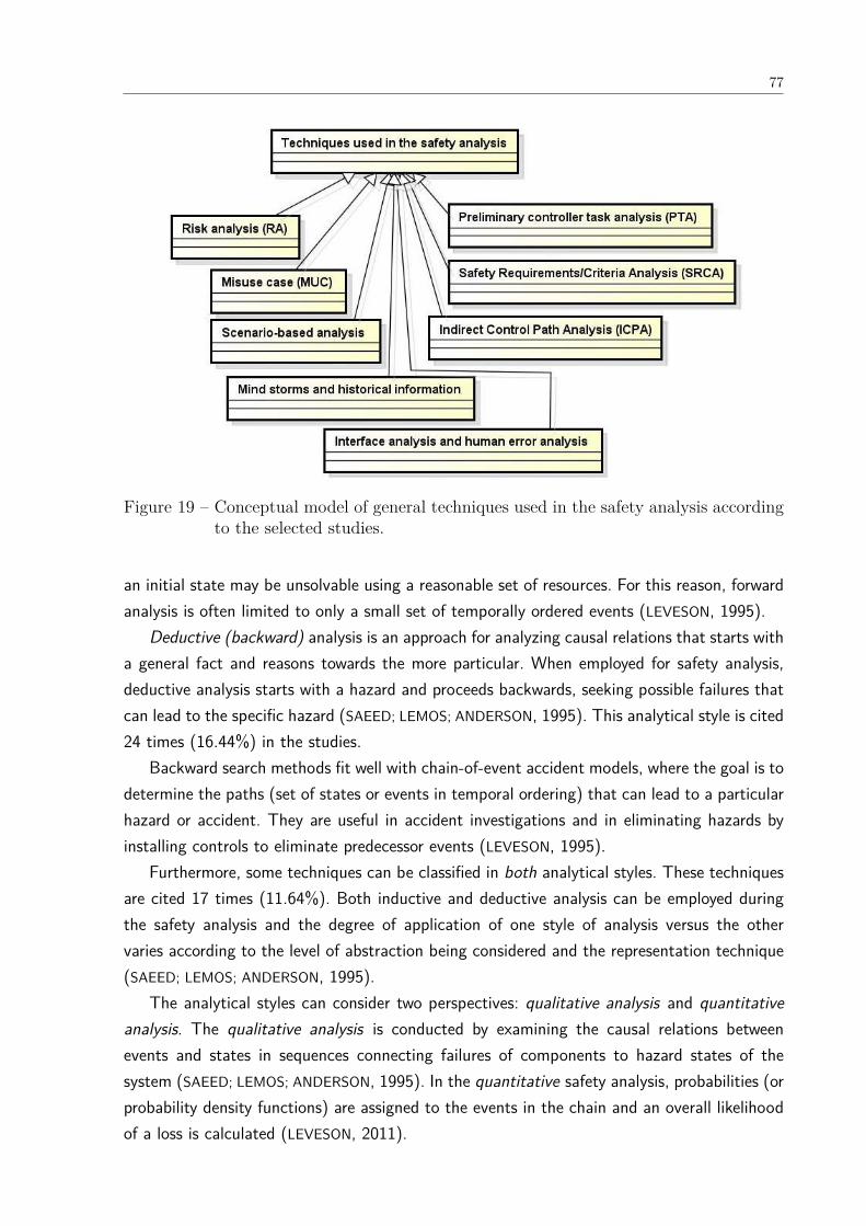
77
Figure 19 – Conceptual model of general techniques used in the safety analysis accordingto the selected studies.
an initial state may be unsolvable using a reasonable set of resources. For this reason, forwardanalysis is often limited to only a small set of temporally ordered events (LEVESON, 1995).
Deductive (backward) analysis is an approach for analyzing causal relations that starts witha general fact and reasons towards the more particular. When employed for safety analysis,deductive analysis starts with a hazard and proceeds backwards, seeking possible failures thatcan lead to the specific hazard (SAEED; LEMOS; ANDERSON, 1995). This analytical style is cited24 times (16.44%) in the studies.
Backward search methods fit well with chain-of-event accident models, where the goal is todetermine the paths (set of states or events in temporal ordering) that can lead to a particularhazard or accident. They are useful in accident investigations and in eliminating hazards byinstalling controls to eliminate predecessor events (LEVESON, 1995).
Furthermore, some techniques can be classified in both analytical styles. These techniquesare cited 17 times (11.64%). Both inductive and deductive analysis can be employed duringthe safety analysis and the degree of application of one style of analysis versus the othervaries according to the level of abstraction being considered and the representation technique(SAEED; LEMOS; ANDERSON, 1995).
The analytical styles can consider two perspectives: qualitative analysis and quantitativeanalysis. The qualitative analysis is conducted by examining the causal relations betweenevents and states in sequences connecting failures of components to hazard states of thesystem (SAEED; LEMOS; ANDERSON, 1995). In the quantitative safety analysis, probabilities (orprobability density functions) are assigned to the events in the chain and an overall likelihoodof a loss is calculated (LEVESON, 2011).
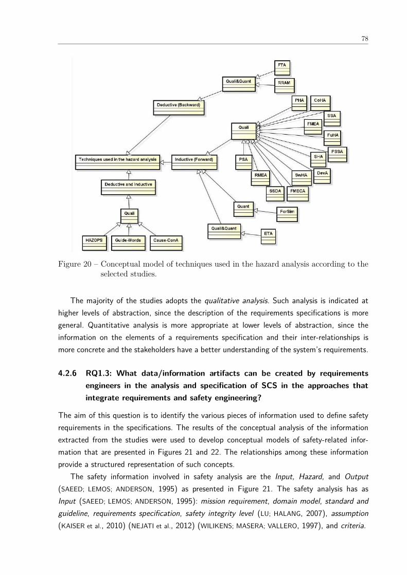
78
Figure 20 – Conceptual model of techniques used in the hazard analysis according to theselected studies.
The majority of the studies adopts the qualitative analysis. Such analysis is indicated athigher levels of abstraction, since the description of the requirements specifications is moregeneral. Quantitative analysis is more appropriate at lower levels of abstraction, since theinformation on the elements of a requirements specification and their inter-relationships ismore concrete and the stakeholders have a better understanding of the system’s requirements.
4.2.6 RQ1.3: What data/information artifacts can be created by requirementsengineers in the analysis and specification of SCS in the approaches thatintegrate requirements and safety engineering?
The aim of this question is to identify the various pieces of information used to define safetyrequirements in the specifications. The results of the conceptual analysis of the informationextracted from the studies were used to develop conceptual models of safety-related infor-mation that are presented in Figures 21 and 22. The relationships among these informationprovide a structured representation of such concepts.
The safety information involved in safety analysis are the Input, Hazard, and Output(SAEED; LEMOS; ANDERSON, 1995) as presented in Figure 21. The safety analysis has asInput (SAEED; LEMOS; ANDERSON, 1995): mission requirement, domain model, standard andguideline, requirements specification, safety integrity level (LU; HALANG, 2007), assumption(KAISER et al., 2010) (NEJATI et al., 2012) (WILIKENS; MASERA; VALLERO, 1997), and criteria.
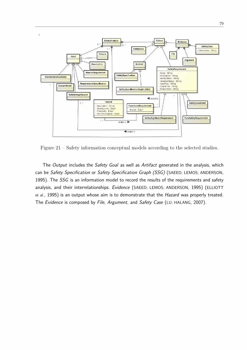
79
Figure 21 – Safety information conceptual models according to the selected studies.
The Output includes the Safety Goal as well as Artifact generated in the analysis, whichcan be Safety Specification or Safety Specification Graph (SSG) (SAEED; LEMOS; ANDERSON,1995). The SSG is an information model to record the results of the requirements and safetyanalysis, and their interrelationships. Evidence (SAEED; LEMOS; ANDERSON, 1995) (ELLIOTT
et al., 1995) is an output whose aim is to demonstrate that the Hazard was properly treated.The Evidence is composed by File, Argument, and Safety Case (LU; HALANG, 2007).
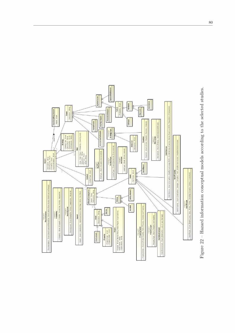
80
Figu
re22
–H
azar
din
form
atio
nco
ncep
tual
mod
els
acco
rdin
gto
the
sele
cted
stud
ies.
81
Safety Requirement, which constitutes another type of Output of safety analysis, is typicallyof the form of a quality criterion (a system-specific statement about the existence of a sub-factor of safety) combined with a minimum or maximum required threshold along some qualitymeasure. It directly specifies how safe the system must be (MEDIKONDA; PANCHUMARTHY,2009).
The Safety Requirement has the following attributes (WILIKENS; MASERA; VALLERO, 1997):Name, Description, satisfyStatus, validationStatus, InputFlow, Outputflow, and a Responsible.Moreover, it can be of three types (MEDIKONDA; PANCHUMARTHY, 2009): Safety-significantrequirement, Pure safety requirement, and Safety constraint as shown in Figure 21.
Safety-significant requirement is a normal functional, data, interface, and non-safety qualityrequirement that is relevant to the achievement of the safety requirements. In other words,a safety-significant requirement can lead to hazards and accidents when not implementedcorrectly (MEDIKONDA; PANCHUMARTHY, 2009).
Pure safety requirement is a requirement that describe what actions and/or constraintsshould or should not be performed to maintain the system in a safe state (MEDIKONDA;
PANCHUMARTHY, 2009). Finally, Safety constraint is an architecture or design constraint man-dating the use of specific safety mechanism or safeguards (MEDIKONDA; PANCHUMARTHY,2009). Moreover, Safety Requirement and Hazard are related to Functional Requirement(PAIGE et al., 2008).
Figure 22 depicts the information related to Hazard. It is a system state that might,under certain environmental or operational conditions (Context (WU; KELLY, 2007) (BIGGS;
SAKAMOTO; KOTOKU, 2014)), lead to a Mishap or cause a Harm (MEDIKONDA; PANCHU-
MARTHY, 2009) (BIGGS; SAKAMOTO; KOTOKU, 2014).Hazard has four attributes (see Figure 22): Description (BECKERS et al., 2013) (WILIKENS;
MASERA; VALLERO, 1997), Severity Level, Probability, and Recommendation (THRAMBOULIDIS;
SCHOLZ, 2010). The Severity Level (LEVESON, 1995) (THRAMBOULIDIS; SCHOLZ, 2010) canbe Catastrophic (may cause death or system loss), Critical (may cause severe injury, severeoccupational illness, or major system damage), Marginal (may cause minor injury, minor occu-pational illness or minor system damage), and Negligible (will not result in injury, occupationalillness, or system damage).
The Probability of a hazard (WILIKENS; MASERA; VALLERO, 1997) can be Frequent (likelyto occur frequently to an individual item, continuously experienced throughout the fleet orinventory); Probable (will occur several times during the life of an individual item, frequentlythroughout the fleet or inventory); Occasional (likely to occur sometime during the life of anindividual item, several times throughout the fleet or inventory); Remote (unlikely to occurbut possible during the life of an individual item; unlikely but reasonable expected to occurin a fleet or inventory); and Implausible (extremely unlikely to occur to an individual item;possible for a fleet or inventory).
Recommendation can be classified in the following categories (GUIOCHET; MARTIN-GUILLEREZ;

82
POWELL, 2010): modification of allowed use, modification of the specification, and modifica-tion of the design as depicted in Figure 22.
Risk is associated with Hazard and it is a combination of consequence (severity hazard)and likelihood of the hazard (risk = probability hazard x severity hazard) (THRAMBOULIDIS;
SCHOLZ, 2010) (SIMPSON; STOKER, 2002).Some strategies should be defined to minimize the consequence or probability of the haz-
ard. A Strategy has the following attributes: Strategy Type, Description, Responsible, andRefinement.
The Strategy Type (KAISER et al., 2010) can be Reaction or Detection through mechanisms(Timeout, Value outside of a valid scope) (KIM; CHUNG, 2005). The strategy of Reaction canbe Arrest, Mitigation, Recovery, and Analysis.
Hazard also has at least one Cause (THRAMBOULIDIS; SCHOLZ, 2010). It occurs due toEnvironmental Hazard, Procedural Hazard, Interface Hazard, Human Factor or System Cause(MEDIKONDA; PANCHUMARTHY, 2009). The last one can be Failure or System MisBehavior(SCHOLZ; THRAMBOULIDIS, 2013).
Failure is an event where a system or subsystem component does not exhibit the expectedexternal behavior. Failure has a Probability (PAIGE et al., 2008) and it is related to Hardware(Electronic or Mechanical) or Software (MARTINS; OLIVEIRA, 2014b).
Hazard also has Effect or consequence in five levels of Impact (ZOUGHBI; BRIAND; LABICHE,2011): Catastrophic, Hazardous/Severe-Major, Major, Minor or No Effect. This Effect orconsequence can be a Mishap (MEDIKONDA; PANCHUMARTHY, 2009) or a Harm. Mishapcan be a Accident (GÓRSKI; WARDZIŃSKI, 1996) or a Safety Incident (BROOMFIELD; CHUNG,1997a).
An Accident is an undesired and unplanned (but not necessarily unexpected) event thatresults in (at least) a specified level of loss. On the other hand, a Safety Incident (BROOMFIELD;
CHUNG, 1997a) is an event that involves no loss (or only minor loss) but with the potentialfor loss under different circumstances (MEDIKONDA; PANCHUMARTHY, 2009).
A Harm has a Type which occurs to (BIGGS; SAKAMOTO; KOTOKU, 2014) People, Property,Environment or Service (MUSTAFIZ; KIENZLE, 2009). Each type is an Asset of a system.
Harm to People (Human beings, roles played or organizations) can be Death (Loss), In-jury (GUIOCHET; MARTIN-GUILLEREZ; POWELL, 2010), Illness, Kidnap, Hardship, or Corruption(bribery or extortion).
Harm to Property can be Destruction, Damage, Corruption, Theft, Unauthorized accessor Unauthorized disclosure. A Property has two attributes PropertyType and PropertyOwner.A PropertyType can be Tangible or Not Tangible and the PropertyOwner can correspond toPrivate Property, Public Property or Commercial Property.
Harm to Environment can be Destruction, Loss of Use or Damage. Finally, Harm to Servicecan be Corruption, Unauthorized usage (theft), Accidental loss of service, Denial of service(DOS) or Repudiation of transaction.
83
Terms related to system safety are not used consistently in the selected studies. Differencesexist among countries and industries. The confusion is compounded by the use of the sameterms, but with different definitions, by engineering, computer science and natural language(LEVESON, 1995).
To promote the effective integration of safety analysis and requirements analysis, a commonformal basis should be provided for the results of these techniques (SIMPSON; STOKER, 2002).The conceptual models presented in our SLR provide a more solid background for requirementsengineers during safety analysis at system level. Our goal is to create an agreed-upon vocabularyand semantic structure containing all the relevant concepts, their relations and axioms withinsafety domain for the purpose of exchanging information and facilitating reasoning.
With the conceptual models, presented in Figures 21 and 22, we aim to capture in particularinformation that is shared by RE and safety engineering. The structuring of concepts thatbelong to different areas is a challenging task since we have to consider the non-standardizationof nomenclature, synonyms, redundancies and the relationships between the various pieces ofinformation. Although we expect that the conceptual model can be refined and extended sincewe consider only the data extracted from the selected studies, we believe that the conceptualmodels can be used during the requirements elicitation process and preliminary safety analysisand contribute to a better integration and communication between RE and safety engineering.
Besides the communication among requirements and safety engineers, there is also thecommunication with certification authorities. The certification process of a system requiresdemonstrating that appropriate safety standard was followed during the development process.
Many standards require that a safety assessment be performed when developing or mod-ifying a safety-critical system (ZOUGHBI; BRIAND; LABICHE, 2011). However, the differencesamong standards make it hard to translate evidence of compliance among them (HATCLIFF
et al., 2014). In this context, the proposed conceptual models although did not consideredthe constraints proposed by the safety standards, they may help understanding and applyingthe safety standards and regulations since they provide the information that both engineeringgroups have to exchange for system safety analysis, during design and in the preparation ofreports for certification. This common basis contributes to ensure that sufficient correct ev-idence has been collected to satisfy the relevant standards for certifying a system and thusimprove the certification process (BIGGS; SAKAMOTO; KOTOKU, 2014) (HATCLIFF et al., 2014).
The conceptual models representing the safety-related information proposed in this SLRcan contribute to researchers and practitioners to elicit (MAIDEN et al., 1999)(FIRESMITH,2005), organize, and manage safety requirements. Moreover, conceptual models can be usedin many purposes (FIRESMITH, 2005): training; improve communications through the use ofcommon terms and concepts of the conceptual model and thereby improving the collaboration(UNTERKALMSTEINER; FELDT; GORSCHEK, 2014); verify requirements completeness in systemsspecification against the terms presented in the conceptual model (MAIDEN et al., 1999); struc-ture the table of contents of the requirements specification related to safety requirements; as
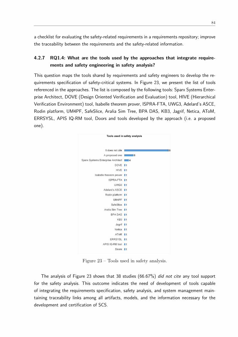
84
a checklist for evaluating the safety-related requirements in a requirements repository; improvethe traceability between the requirements and the safety-related information.
4.2.7 RQ1.4: What are the tools used by the approaches that integrate require-ments and safety engineering in safety analysis?
This question maps the tools shared by requirements and safety engineers to develop the re-quirements specification of safety-critical systems. In Figure 23, we present the list of toolsreferenced in the approaches. The list is composed by the following tools: Sparx Systems Enter-prise Architect, DOVE (Design Oriented Verification and Evaluation) tool, HIVE (HierarchicalVerification Environment) tool, Isabelle theorem prover, ISPRA-FTA, UWG3, Adelard’s ASCE,Rodin platform, UM4PF, SafeSlice, Aralia Sim Tree, BPA DAS, KB3, Jagrif, Netica, AToM,ERRSYSL, APIS IQ-RM tool, Doors and tools developed by the approach (i.e. a proposedone).
Figure 23 – Tools used in safety analysis.
The analysis of Figure 23 shows that 38 studies (66.67%) did not cite any tool supportfor the safety analysis. This outcome indicates the need of development of tools capableof integrating the requirements specification, safety analysis, and system management main-taining traceability links among all artifacts, models, and the information necessary for thedevelopment and certification of SCS.
85
The proposal of new tools is presented in 14.04% of the approaches (8 studies). It istoo soon to affirm that there is a tendency in the academia and the market regarding to thedevelopment of tools for improving the safety analysis as required by the industry.
The lack of (commercial) tool support that would allow integrating requirements modelsin a seamless development process as well as the insufficient guidance, pointed by Sikora,Tenbergen and Pohl (2012), lead to uncertainty about how models should be used in the REprocess.
The results about the tools cited in the selected studies demonstrate the absence of infor-mation on tools in the academic literature. Accordingly, we cannot draw conclusions about tooluse with only the extracted information. One possible reason of these few number of tools canbe the fact that regulatory agencies have been quite reluctant to qualify any tools for use oncritical systems projects and they are actively debating how to address the issue (HEIMDAHL,2007). In this context, Heimdahl (2007) complements stating that it is “highly unlikely thatthe researchers be able to provide the level of confidence necessary to trust a specific tool asa development tool in SCS development. Moreover, there are others aspects involved such asthe tool evolution (maintenance, upgrades, and migration to new platforms)”.
According to Hatcliff et al. (2014), researchers are not encouraged to engineer their toolsto support certification (HEIMDAHL, 2007) (HATCLIFF et al., 2014). Moreover, the certificationrequirement vary significantly across safety standards for different domains. This requires toolvendors to develop different versions of their tool and qualification kits for each standardsupported (HATCLIFF et al., 2014). Finally, another problem pointed out by Hatcliff et al.(2014) is that most of the tools are not standalone and rely on other tools and libraries thathave their own independent life.
4.2.8 RQ1.5: What are the benefits of the approaches that integrate requirementsand safety engineering identified in RQ1?
In Table 12, we present the benefits of the approaches for the integration and communica-tion between requirements engineering and safety engineering from the extracted data of theselected studies.
The use of software in safety-critical systems, in particular in control systems, has increasedto such an extent that failures in the software can impair system safety. In this context, analysisof software-related errors in computer based safety-critical systems have shown that mistakesmade during the requirements analysis phase can easily introduce faults which subsequentlylead to accidents (SAEED; LEMOS; ANDERSON, 1995).
A tendency we observed in the direction of decreasing the ambiguity and inconsistencyof natural language specifications is to use common models for requirements specificationand safety/hazard analysis shared by the requirements and safety engineers. This contributespartially to improve the process of exchanging information, increasing completeness, and cor-rectness of the requirements specifications (FRICKER; GORSCHEK; GLINZ, 2008).
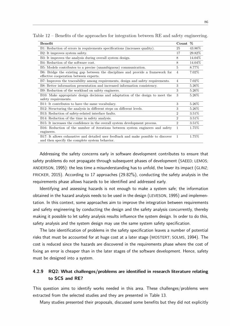
86
Table 12 – Benefits of the approaches for integration between RE and safety engineering.Benefit Count %B1: Reduction of errors in requirements specifications (increases quality). 25 43.86%B2: It improves system safety. 17 29.82%B3: It improves the analysis during overall system design. 8 14.04%B4: Reduction of the software cost. 8 14.04%B5: Models contributes to a precise (unambiguous) communication. 5 8.77%B6: Bridge the existing gap between the disciplines and provide a framework foreffective cooperation between experts.
4 7.02%
B7: Improves the traceability among requirements, design and safety requirements. 4 7.02%B8: Better information presentation and increased information consistency. 3 5.26%B9: Reduction of the workload on safety engineers. 3 5.26%B10: Make appropriate design decisions and adaptation of the design to meet thesafety requirements.
3 5.26%
B11: It contributes to have the same vocabulary. 3 5.26%B12: Structuring the analysis in different steps on different levels. 3 5.26%B13: Reduction of safety-related interface faults. 2 3.51%B14: Reduction of the time in safety analysis. 2 3.51%B15: It increases the confidence in the overall system development process. 2 3.51%B16: Reduction of the number of iterations between system engineers and safetyengineers.
1 1.75%
B17: It allows exhaustive and detailed user feedback and make possible to discoverand then specify the complete system behavior.
1 1.75%
Addressing the safety concerns early in software development contributes to ensure thatsafety problems do not propagate through subsequent phases of development (SAEED; LEMOS;
ANDERSON, 1995): the less time a misunderstanding has to unfold, the lower its impact (GLINZ;
FRICKER, 2015). According to 17 approaches (29.82%), conducting the safety analysis in therequirements phase allows hazards to be identified and addressed early.
Identifying and assessing hazards is not enough to make a system safe; the informationobtained in the hazard analysis needs to be used in the design (LEVESON, 1995) and implemen-tation. In this context, some approaches aim to improve the integration between requirementsand safety engineering by conducting the design and the safety analysis concurrently, therebymaking it possible to let safety analysis results influence the system design. In order to do this,safety analysis and the system design may use the same system safety specification.
The late identification of problems in the safety specification leaves a number of potentialrisks that must be accounted for at huge cost at a later stage (MOSTERT; SOLMS, 1994). Thecost is reduced since the hazards are discovered in the requirements phase where the cost offixing an error is cheaper than in the later stages of the software development. Hence, safetymust be designed into a system.
4.2.9 RQ2: What challenges/problems are identified in research literature relatingto SCS and RE?
This question aims to identify works needed in this area. These challenges/problems wereextracted from the selected studies and they are presented in Table 13.
Many studies presented their proposals, discussed some benefits but they did not explicitly

87
discussed challenges/problems in integration between requirements engineering and safety en-gineering as well as in requirements communication. This corresponds to 64.91% of the studies(37 studies).
The most cited challenges/problems are Analysis of scalability of the technique aboutintegration and communication between RE and safety engineering in real case studies (O1)and Conduction of more empirical studies about integration and communication between REand safety engineering (O2). They were referenced in 4 studies (7.02%) each and are theconsequence of the low number of proposals evaluated in the industrial context. These resultsshow the need of applying the proposal in practice with real users in order to evaluate theextension of the contributions.
Develop safety analysis tools integrated with requirements specification (O3) is a concernmentioned in 3 studies (5.26%). Considering that 66.67% of the studies did not cite any kind oftool support (see Section 4.2.7), this outcome might indicate the need of development of toolscapable of integrating the requirements specification, safety analysis, and system managementmaintaining traceability links among all artifacts, models, and the information necessary forthe development and certification of SCS. This challenge about Maintaining the traceabilityamong (safety) requirements, architecture and implementation along with system developmentand evolution (O4) is pointed out by 2 approaches (3.51%).
The above open issues may be useful in different contexts. For example, a newcomer (eg.new student research) will be able to identify new research opportunities and they can becomethe subject of new research projects.
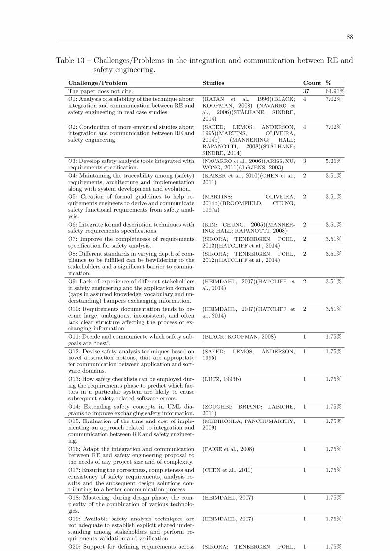
88
Table 13 – Challenges/Problems in the integration and communication between RE andsafety engineering.
Challenge/Problem Studies Count %The paper does not cite. 37 64.91%O1: Analysis of scalability of the technique aboutintegration and communication between RE andsafety engineering in real case studies.
(RATAN et al., 1996)(BLACK;KOOPMAN, 2008) (NAVARRO etal., 2006)(STÅLHANE; SINDRE,2014)
4 7.02%
O2: Conduction of more empirical studies aboutintegration and communication between RE andsafety engineering.
(SAEED; LEMOS; ANDERSON,1995)(MARTINS; OLIVEIRA,2014b) (MANNERING; HALL;RAPANOTTI, 2008)(STÅLHANE;SINDRE, 2014)
4 7.02%
O3: Develop safety analysis tools integrated withrequirements specification.
(NAVARRO et al., 2006)(ARISS; XU;WONG, 2011)(JüRJENS, 2003)
3 5.26%
O4: Maintaining the traceability among (safety)requirements, architecture and implementationalong with system development and evolution.
(KAISER et al., 2010)(CHEN et al.,2011)
2 3.51%
O5: Creation of formal guidelines to help re-quirements engineers to derive and communicatesafety functional requirements from safety anal-ysis.
(MARTINS; OLIVEIRA,2014b)(BROOMFIELD; CHUNG,1997a)
2 3.51%
O6: Integrate formal description techniques withsafety requirements specifications.
(KIM; CHUNG, 2005)(MANNER-ING; HALL; RAPANOTTI, 2008)
2 3.51%
O7: Improve the completeness of requirementsspecification for safety analysis.
(SIKORA; TENBERGEN; POHL,2012)(HATCLIFF et al., 2014)
2 3.51%
O8: Different standards in varying depth of com-pliance to be fulfilled can be bewildering to thestakeholders and a significant barrier to commu-nication.
(SIKORA; TENBERGEN; POHL,2012)(HATCLIFF et al., 2014)
2 3.51%
O9: Lack of experience of different stakeholdersin safety engineering and the application domain(gaps in assumed knowledge, vocabulary and un-derstanding) hampers exchanging information.
(HEIMDAHL, 2007)(HATCLIFF etal., 2014)
2 3.51%
O10: Requirements documentation tends to be-come large, ambiguous, inconsistent, and oftenlack clear structure affecting the process of ex-changing information.
(HEIMDAHL, 2007)(HATCLIFF etal., 2014)
2 3.51%
O11: Decide and communicate which safety sub-goals are “best”.
(BLACK; KOOPMAN, 2008) 1 1.75%
O12: Devise safety analysis techniques based onnovel abstraction notions, that are appropriatefor communication between application and soft-ware domains.
(SAEED; LEMOS; ANDERSON,1995)
1 1.75%
O13: How safety checklists can be employed dur-ing the requirements phase to predict which fac-tors in a particular system are likely to causesubsequent safety-related software errors.
(LUTZ, 1993b) 1 1.75%
O14: Extending safety concepts in UML dia-grams to improve exchanging safety information.
(ZOUGHBI; BRIAND; LABICHE,2011)
1 1.75%
O15: Evaluation of the time and cost of imple-menting an approach related to integration andcommunication between RE and safety engineer-ing.
(MEDIKONDA; PANCHUMARTHY,2009)
1 1.75%
O16: Adapt the integration and communicationbetween RE and safety engineering proposal tothe needs of any project size and of complexity.
(PAIGE et al., 2008) 1 1.75%
O17: Ensuring the correctness, completeness andconsistency of safety requirements, analysis re-sults and the subsequent design solutions con-tributing to a better communication process.
(CHEN et al., 2011) 1 1.75%
O18: Mastering, during design phase, the com-plexity of the combination of various technolo-gies.
(HEIMDAHL, 2007) 1 1.75%
O19: Available safety analysis techniques arenot adequate to establish explicit shared under-standing among stakeholders and perform re-quirements validation and verification.
(HEIMDAHL, 2007) 1 1.75%
O20: Support for defining requirements acrossdifferent abstraction layers to improve sharedunderstanding.
(SIKORA; TENBERGEN; POHL,2012)
1 1.75%

89
4.3 SUMMARY OF SYSTEMATIC LITERATURE REVIEW RESULTS
Our SLR draws on 57 studies, selected out of 1037, through a multistage process. A key featureof the review is that it does not restrict itself to a particular domain or safety standard. Thisbroad scope in the search gives us deeper insights on the state-of-the-art about the contentof the integration of RE and safety engineering.
The most important findings of this review and their implications for further research areas follows.
Non-standardization of nomenclature. There is a gap that exists between the tradi-tional development processes, methodologies, notations and tools and the ones used in safetyengineering. This gap makes the integration and communication between RE and safety en-gineering a difficult and challenging task. Hence, we believe a first step to this direction isthe definition of a common nomenclature in order to satisfy system correctness and safetyrequirements and to provide a framework for effective cooperation between experts. Moreover,it is also necessary to look over safety standards to compare the nomenclature use in practiceand what is required by the standards.
Need of improving the completeness of requirements specification for safetyanalysis. Providing the document details assists in getting complete and consistent docu-ments. Absolute completeness may be unnecessary or uneconomical for many situations (GLINZ;
FRICKER, 2015) (LEVESON, 1995). Hence, the requirements specification must simply be suit-able to specify safe behavior in all circumstances in which the system is to operate (LEVESON,1995). Therefore, RE approaches for SCS need to provide a significantly improved account ofsafety engineering concerns (SIKORA; TENBERGEN; POHL, 2012). We noticed that UML profilesand modeling languages have been used aiming to improve these specifications.
Compliance with safety standards. Different standards have to be fulfilled by the com-panies. Nevertheless, RE approaches do not provide explicit guidelines whether they complywith specific safety integrity levels or how the approach should be tailored to achieve compliance(SIKORA; TENBERGEN; POHL, 2012). Hence, standardization can be seen as a key coordina-tion mechanism, enabling organizations to deal with inter dependencies in development work(PERNSTÅL et al., 2015).
Need of improving safety analysis techniques. Available safety analysis techniquesare not adequate to establish explicit shared understanding among stakeholders and performrequirements validation and verification. Due to the implicit shared understanding in the sys-tem’s specifications, too much information about the system is hidden. It might be useful todocument which requirements and design decisions have not been documented in detail due toreliance on implicit shared understanding so that this information is not lost when the devel-oped system evolves. Furthermore, it is necessary to improve the safety analysis techniques tohandle with implicit shared understanding to allow the safety engineers to perform an adequatesafety analysis.
Need of developing and maintaining traceability mechanisms for safety require-

90
ments specification. Consistency checking in large safety requirements specification demandsdifferent approaches than uncovering ambiguity or checking for testability (SIKORA; TENBER-
GEN; POHL, 2012). Furthermore, engineers consider tedious and error prone to deal with largebodies of natural language requirements. Since checking the consistency of the natural lan-guage requirements specification must be done manually by means of inspections, this leadsto an enormous effort (SIKORA; TENBERGEN; POHL, 2012).
Need of integration tools. Many artifacts are generated by the requirements and safetyteams during the development of SCS. The results of our SLR presented some tools thatsupport safety analysis. Although 66.67% of the studies did not cite any kind of tool support,27 tools were mentioned in the safety analysis. This outcome suggests the need of developmentof tools capable of integrating the requirements specification, safety analysis, and systemmanagement maintaining traceability links among all artifacts, models, and the informationnecessary for the development and certification of SCS.
Need of more integration between researchers and practitioners. The few number ofreal experiments on integration and communication between RE and safety engineering revealthe need of applying the approaches in practice with real users in order to assess to whatextent they contribute to integration and communication between RE and safety engineering.This fact is corroborated by the rigor and industrial relevance we performed. The results ofour analysis showed that more than half of the studies have 0 relevance meaning that theyare examples of application of a proposal done by either students or researchers in academiain toy examples. Such results highlight the need of more integration between researchers andpractitioners in order to improve the relevance of the research.
Communication format. The communication format most used by the included studieswas model-based collaboration (42 papers) consisting of the use of models shared by differentteams. The Process support was the second communication format most adopted by theapproaches. It consists of collaborating through a predefined structure for the sequence of stepsto be performed, the roles stakeholders must fulfill, and the artifacts that must be created.Artifacts (all documents that were not based on models) were adopted by 21 studies. In thiscommunication format, several stakeholders contribute to the construct the artifacts, workingto understand what each other has done, eliminate errors, and add their contributions. Analysistools were adopted as a communication format by 19 studies. This category comprehends toolsshared by stakeholders involved in the requirements specification and safety analysis as well astools that support some kind of safety analysis. The Face-to-face verbal communication, usedby 4 studies, includes meetings, informal conversations in hallways, doorways, and offices. TheCollaboration infrastructure category comprises the technologies developed for the integrationof software tools. Major forms of tool integration may be data integration, ensuring that toolscan exchange data, and control integration, ensuring that tools are aware of the activitiesof other tools, and can take action based on that knowledge. Only three studies explicitlydiscussed this communication format. The last communication form adopted was Awareness

91
only explicitly used in two studies. It consists of providing information about the currentactivities of stakeholders.
Need of approaches to improve shared understanding. Many of challenges of require-ments communication are related with the concept of shared understanding either explicit(interpreting explicit specifications, such as requirements, design documents, and manuals,in the same way by all group members) or implicit (common understanding of non-specifiedknowledge, assumptions, opinions, and values). The shared context provided by implicit sharedunderstanding reduces the need for explicit communication and, at the same time, lowers therisk of misunderstandings. Shared understanding is important for efficient communication andfor minimizing the risk of stakeholder dissatisfaction and rework in software projects. How-ever, achieving a shared understanding among stakeholders and development team is not easy(GLINZ; FRICKER, 2015).
Adoption of new languages. Textual requirements is the dominant documentation stylefor requirements, but it does not imply that natural language is considered a satisfactoryspecification technique. Besides, many embedded systems practitioners are dissatisfied withusing natural language for requirements specification. In this context, the UML language hasbeen used in many academic and industrial works. A possible reason concluded through theselected studies is that the improvement of the requirements communication among engineershas been mainly a concern of requirements and software engineers, who are more familiarwith UML. Furthermore, there is also the education concern. The engineers mostly learn UMLduring their education and to many of them, it now seems that the only design techniqueavailable is object oriented and the only design notation is the UML. Therefore, it is necessaryto empirically investigate the ability of other languages to contribute to a better systemspecification.
Safety standards adoption. Different standards have to be fulfilled by the companies.The presence of so many standards, and the differences among standards, can be bewilderingto anybody operating in the domain as well as a significant barrier to communication and inthe education of new practitioners and researchers. In addition, RE approaches do not provideexplicit guidelines whether they comply with specific safety integrity levels or how the approachshould be tailored to achieve compliance. Finally, it is desirable to establish foundationalprinciples that provide a common basis for software safety assurance across domains andapplications. This common basis or an explicitly shared terminology reduces the probabilityof misunderstandings when concepts using this terminology are not specified or only coarselyspecified (GLINZ; FRICKER, 2015).
Absence of tools to support the entire RE process and safety concerns. Many of theselected studies did not explicitly discuss how the tools support the communication through-out the RE activities (elicitation, analysis, specification, validation, management). This is asubstantial issue for the requirements communication since tools can contribute to the require-ments communication and mainly consider safety concerns to improve shared understanding.

92
4.4 FINAL CONSIDERATIONS
In this chapter, we presented the planning, conduction and analysis of the results obtainedthrough a systematic literature review. The focus of the SLR was to investigate the integrationof requirements engineering and safety analysis.
The results showed several types of contributions that includes Approach, Framework,Method, Tool, Process, Model, Methodology, Template, Comparison, Metrics, Protocol, Check-list, Language. However no maturity model that integrated RE and safety was found.
We also observed many benefits and open issues regarding the integration of these twoareas. In the next chapter, e present the safety module for the Uni-REPM maturity model tohandle safety concerns in the RE process.
93
5 UNI-REPM SCS: A SAFETY MODULE FOR UNI-REPM MATURITY MODEL
RE issues such as vague initial requirements, ambiguities in requirements specification, un-defined requirements process, requirements growth, requirements traceability, and confusionamong methods and tools (SVAHNBERG et al., 2013) (HALL; BEECHAM; RAINER, 2002) (JU-
RISTO; MORENO; SILVA, 2002) (KAMSTIES; HÖRMANN; SCHLICH, 1998) have a huge impact inthe quality of a system, especially in a safety-critical one.
In this context, it is claimed that the most cost-efficient place to fix many of the men-tioned problems is in the RE phase (SVAHNBERG et al., 2013)(SOMMERVILLE, 2011)(LEFFIN-
GWELL, 1997). Despite these issues, RE remains somehow a neglected area with respect tosafety (SVAHNBERG et al., 2013)(HALL; BEECHAM; RAINER, 2002)(JURISTO; MORENO; SILVA,2002)(NIKULA; SAJANIEMI; KÄLVIÄINEN, 2000).
Communication inside and between teams may be an alternative to reduce requirements-related problems during the development of a SCS. However, in such systems, we have multi-disciplinary teams with large number of people involved. Accordingly, it is difficult to coordinatethe interaction and communication among them. In this context, requirements problems areless frequent in organizations with high maturity levels (SOLEMON; SAHIBUDDIN; GHANI, 2009).Therefore, the Uni-REPM safety module aims to reduce issues in RE during SCS developmentby addressing safety actions/practices that should be covered in the RE process to reduce thegap between these areas. We considered a process as a set of activities performed to achievesome goal. In the next sections, we describe the sources of actions, module structure, itscontents and how to use it to evaluate the maturity level of an organization.
5.1 SOURCES OF THE ACTIONS
The sources of the safety actions/practices of Uni-REPM module are presented in Table 14.Uni-REPM SCS is based on several sources listed in Table 14: SLRs (SLR1, SLR2), em-pirical studies (INTERVIEW-STUDY), technical reports (TECH-REPORT), safety standards(SAFETY-STD), existing maturity models (EXISTING-MATURITY-MODS), and comprehen-sive literature reviews (STATE-OF-THE-ART).
During the selection of safety actions/practices, we considered the definition of require-ments practice of Davis and Zowghi (2006). They classify it as to be the use of a principle,tool, notation, and/or method in order to perform a requirements activity. When a practicereduces the cost of the development project or increases the quality of the resulting product,it is labeled as good requirements practice (DAVIS; ZOWGHI, 2006)(SOLEMON; SAHIBUDDIN;
GHANI, 2009). In this context, we select safety practices capable of raising the likelihood thatthe right system will be built (DAVIS; ZOWGHI, 2006).
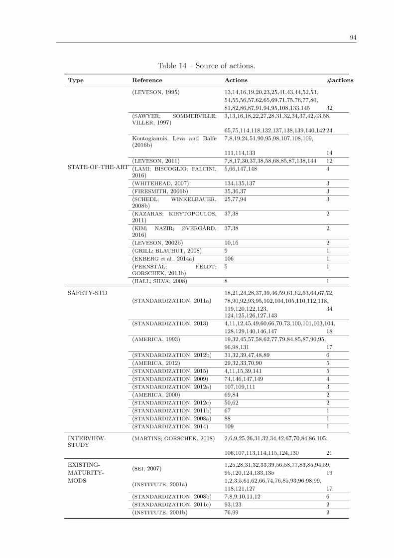
94
Table 14 – Source of actions.
Type Reference Actions #actions
STATE-OF-THE-ART
(LEVESON, 1995) 13,14,16,19,20,23,25,41,43,44,52,53,54,55,56,57,62,65,69,71,75,76,77,80,81,82,86,87,91,94,95,108,133,145 32
(SAWYER; SOMMERVILLE;VILLER, 1997)
3,13,16,18,22,27,28,31,32,34,37,42,43,58,
65,75,114,118,132,137,138,139,140,142 24Kontogiannis, Leva and Balfe(2016b)
7,8,19,24,51,90,95,98,107,108,109,
111,114,133 14(LEVESON, 2011) 7,8,17,30,37,38,58,68,85,87,138,144 12(LAMI; BISCOGLIO; FALCINI,2016)
5,66,147,148 4
(WHITEHEAD, 2007) 134,135,137 3(FIRESMITH, 2006b) 35,36,37 3(SCHEDL; WINKELBAUER,2008b)
25,77,94 3
(KAZARAS; KIRYTOPOULOS,2011)
37,38 2
(KIM; NAZIR; ØVERGÅRD,2016)
37,38 2
(LEVESON, 2002b) 10,16 2(GRILL; BLAUHUT, 2008) 9 1(EKBERG et al., 2014a) 106 1(PERNSTÅL; FELDT;GORSCHEK, 2013b)
5 1
(HALL; SILVA, 2008) 8 1
SAFETY-STD(STANDARDIZATION, 2011a)
18,21,24,28,37,39,46,59,61,62,63,64,67,72,78,90,92,93,95,102,104,105,110,112,118,119,120,122,123,124,125,126,127,143
34
(STANDARDIZATION, 2013) 4,11,12,45,49,60,66,70,73,100,101,103,104,128,129,140,146,147 18
(AMERICA, 1993) 19,32,45,57,58,62,77,79,84,85,87,90,95,96,98,131 17
(STANDARDIZATION, 2012b) 31,32,39,47,48,89 6(AMERICA, 2012) 29,32,33,70,90 5(STANDARDIZATION, 2015) 4,11,15,39,141 5(STANDARDIZATION, 2009) 74,146,147,149 4(STANDARDIZATION, 2012a) 107,109,111 3(AMERICA, 2000) 69,84 2(STANDARDIZATION, 2012c) 50,62 2(STANDARDIZATION, 2011b) 67 1(STANDARDIZATION, 2008a) 88 1(STANDARDIZATION, 2014) 109 1
INTERVIEW-STUDY
(MARTINS; GORSCHEK, 2018) 2,6,9,25,26,31,32,34,42,67,70,84,86,105,
106,107,113,114,115,124,130 21
EXISTING- (SEI, 2007) 1,25,28,31,32,33,39,56,58,77,83,85,94,59,MATURITY- 95,120,124,133,135 19MODS (INSTITUTE, 2001a) 1,2,3,5,61,62,66,74,76,85,93,96,98,99,
118,121,127 17(STANDARDIZATION, 2008b) 7,8,9,10,11,12 6(STANDARDIZATION, 2011c) 93,123 2(INSTITUTE, 2001b) 76,99 2

95
5.2 MODULE OVERALL STRUCTURE
The Uni-REPM SCS is a safety module for the existing Uni-REPM maturity model. It is awell-established, adopted and a complete RE existing model as a design strategy. The safetymodule follows the components of Uni-REPM illustrated in Figure 24.
Figure 24 – Components of Uni-REPM.
We opted to follow Uni-REPM structure since we are designing a safety module for auniversal lightweight maturity model, capable of evaluating the maturity of RE process, thathas been used and well accepted in some companies. Moreover, the SPAs already present inthe Uni-REPM cover the main process involved in the RE process (KOTONYA; SOMMERVILLE,1998).
Aiming to maintain compability with Uni-REPM, the safety module follow its dual-view-approach: Process Area view and Maturity Level view. Accordingly, we proposed a modulefollowing the structure of Uni-REPM.
The process area view allows to visualize the hierarchy of processes that consist the modeland faster discover actions/practices of the same group. The maturity level view, on the otherhand, defines sets of practices that compose a consistent and coherent RE process, and wherethe practices in one level supports each other as well as the more advanced practices on thenext level (SVAHNBERG et al., 2015).
5.2.1 Process area view
The safety module follows the same hierarchy of Uni-REPM that defines three levels: Mainprocess area (MPA), Sub-process area (SPA) and Action. Since we want to integrate safety inthe RE process, we maintained the seven MPAs of Uni-REPM that were defined consideringwell-adopted processes such as Kotonya and Sommerville (KOTONYA; SOMMERVILLE, 1998).The MPAs of Uni-REPM, which are the same for Uni-REPM SCS, are described below:
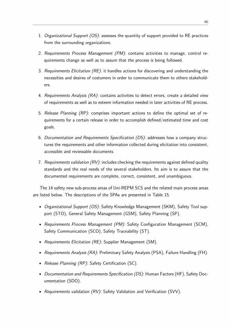
96
1. Organizational Support (OS): assesses the quantity of support provided to RE practicesfrom the surrounding organizations.
2. Requirements Process Management (PM): contains activities to manage, control re-quirements change as well as to assure that the process is being followed.
3. Requirements Elicitation (RE): it handles actions for discovering and understanding thenecessities and desires of costumers in order to communicate them to others stakehold-ers.
4. Requirements Analysis (RA): contains activities to detect errors, create a detailed viewof requirements as well as to esteem information needed in later activities of RE process.
5. Release Planning (RP): comprises important actions to define the optimal set of re-quirements for a certain release in order to accomplish defined/estimated time and costgoals.
6. Documentation and Requirements Specification (DS): addresses how a company struc-tures the requirements and other information collected during elicitation into consistent,accessible and reviewable documents.
7. Requirements validation (RV): includes checking the requirements against defined qualitystandards and the real needs of the several stakeholders. Its aim is to assure that thedocumented requirements are complete, correct, consistent, and unambiguous.
The 14 safety new sub-process areas of Uni-REPM SCS and the related main process areasare listed below. The descriptions of the SPAs are presented in Table 15.
• Organizational Support (OS): Safety Knowledge Management (SKM), Safety Tool sup-port (STO), General Safety Management (GSM), Safety Planning (SP).
• Requirements Process Management (PM): Safety Configuration Management (SCM),Safety Communication (SCO), Safety Traceability (ST).
• Requirements Elicitation (RE): Supplier Management (SM).
• Requirements Analysis (RA): Preliminary Safety Analysis (PSA), Failure Handling (FH).
• Release Planning (RP): Safety Certification (SC).
• Documentation and Requirements Specification (DS): Human Factors (HF), Safety Doc-umentation (SDO).
• Requirements validation (RV): Safety Validation and Verification (SVV).
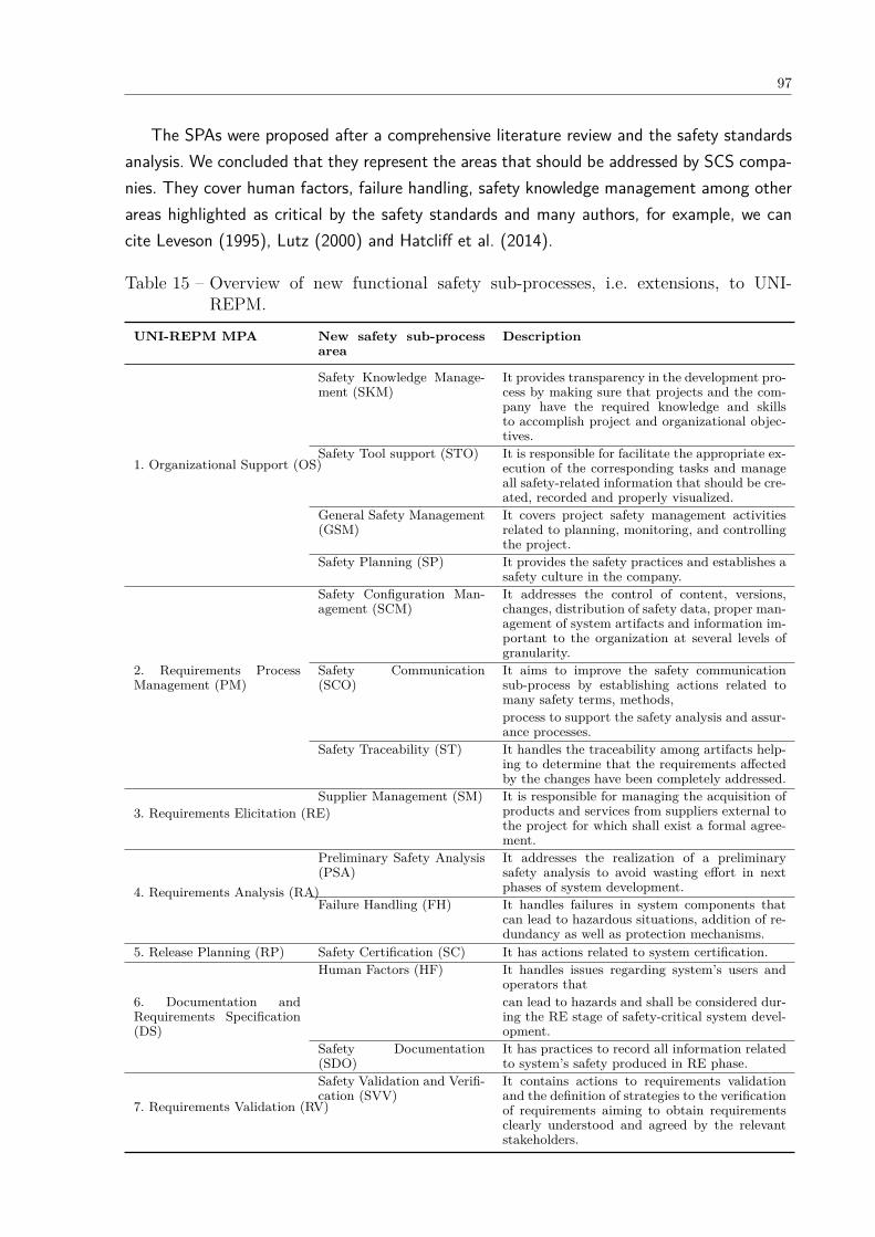
97
The SPAs were proposed after a comprehensive literature review and the safety standardsanalysis. We concluded that they represent the areas that should be addressed by SCS compa-nies. They cover human factors, failure handling, safety knowledge management among otherareas highlighted as critical by the safety standards and many authors, for example, we cancite Leveson (1995), Lutz (2000) and Hatcliff et al. (2014).
Table 15 – Overview of new functional safety sub-processes, i.e. extensions, to UNI-REPM.
UNI-REPM MPA New safety sub-processarea
Description
1. Organizational Support (OS)
Safety Knowledge Manage-ment (SKM)
It provides transparency in the development pro-cess by making sure that projects and the com-pany have the required knowledge and skillsto accomplish project and organizational objec-tives.
Safety Tool support (STO) It is responsible for facilitate the appropriate ex-ecution of the corresponding tasks and manageall safety-related information that should be cre-ated, recorded and properly visualized.
General Safety Management(GSM)
It covers project safety management activitiesrelated to planning, monitoring, and controllingthe project.
Safety Planning (SP) It provides the safety practices and establishes asafety culture in the company.
Safety Configuration Man-agement (SCM)
It addresses the control of content, versions,changes, distribution of safety data, proper man-agement of system artifacts and information im-portant to the organization at several levels ofgranularity.
2. Requirements ProcessManagement (PM)
Safety Communication(SCO)
It aims to improve the safety communicationsub-process by establishing actions related tomany safety terms, methods,process to support the safety analysis and assur-ance processes.
Safety Traceability (ST) It handles the traceability among artifacts help-ing to determine that the requirements affectedby the changes have been completely addressed.
3. Requirements Elicitation (RE)Supplier Management (SM) It is responsible for managing the acquisition of
products and services from suppliers external tothe project for which shall exist a formal agree-ment.
4. Requirements Analysis (RA)
Preliminary Safety Analysis(PSA)
It addresses the realization of a preliminarysafety analysis to avoid wasting effort in nextphases of system development.
Failure Handling (FH) It handles failures in system components thatcan lead to hazardous situations, addition of re-dundancy as well as protection mechanisms.
5. Release Planning (RP) Safety Certification (SC) It has actions related to system certification.Human Factors (HF) It handles issues regarding system’s users and
operators that6. Documentation andRequirements Specification(DS)
can lead to hazards and shall be considered dur-ing the RE stage of safety-critical system devel-opment.
Safety Documentation(SDO)
It has practices to record all information relatedto system’s safety produced in RE phase.
7. Requirements Validation (RV)
Safety Validation and Verifi-cation (SVV)
It contains actions to requirements validationand the definition of strategies to the verificationof requirements aiming to obtain requirementsclearly understood and agreed by the relevantstakeholders.
98
Sub-process area (SPA) contains closely related actions, which help to achieve a biggergoal. The unique identifier assigned to each SPA is composed of the MPA identifier to whichthe SPA attaches and its abbreviation. For example, “OS.SKM” represents a sub-process areacalled “Safety Knowledge Management (SKM)” which resides under MPA “OrganizationalSupport”.
Figure 25 presents the Safety module and its relationship with Uni-REPM. The moduleextends the Uni-REPM model by adding 14 new SPAs highlighted through dashed lines. Theexisting process artifacts were not altered and none were removed.
At the low-level of module structure, we have “actions” that represent a specific goodpractice. By performing the action, the organization can improve their process and gain certainbenefits (SVAHNBERG et al., 2015).
In the safety module, actions also follow the same format assigned to sub-processes to de-fine their unique identifiers and also used to define safety extensions (JOHANNESSEN; HALONEN;
ÖRSMARK, 2011). Actions are identified by the MPA/SPA under which they reside, followedby an “a” which stands for “action” and their position in the group. For example, action“OS.SP.a1 Develop an integrated system safety program plan” of Figure 26 means the firstaction under MPA “Organizational Support” and SPA “Safety Planning”.
Besides the action identifier, every action has a description to explain what should beperformed and can have recommendations (SVAHNBERG et al., 2015) that provide suggestionson well-adopted techniques or supporting tools to practitioners implement an action. It canalso can have supporting actions that define links to other actions which will benefit thepractitioners if they are implemented together. The complete description of 148 actions ofUni-REPM SCS following the structure of Figure 26 can be found in Appendix B. The onlinesoftware tool developed to conduct RE/Safety evaluations using Uni-REPM and the safetymodule is described in Chapter 6.
The dependencies among the main process areas of Uni-REPM and the subprocess areas ofthe safety module are illustrated in Figure 27. They represent that to achieve the safety prac-tices some RE practices (represented by the MPAs) are necessary as well as the relationshipswith other safety practices. From these figure, we can observe that the Safety Certification(SC) is the SPA that most depends of other components.
In the next sections, we describe each MPA and SPA and the traceability information of allactions. This information is presented so that the reader may locate the sources of individualactions in the module.
5.2.2 RE - Requirements Elicitation
Elicitation is the process of discovering, understanding, anticipating and forecasting the needsand wants of the potential stakeholders in order to convey this information to the systemdevelopers. The potential stakeholders can include customers, end-users and other peoplewho have the stake in the system development. In the process, the application domain and
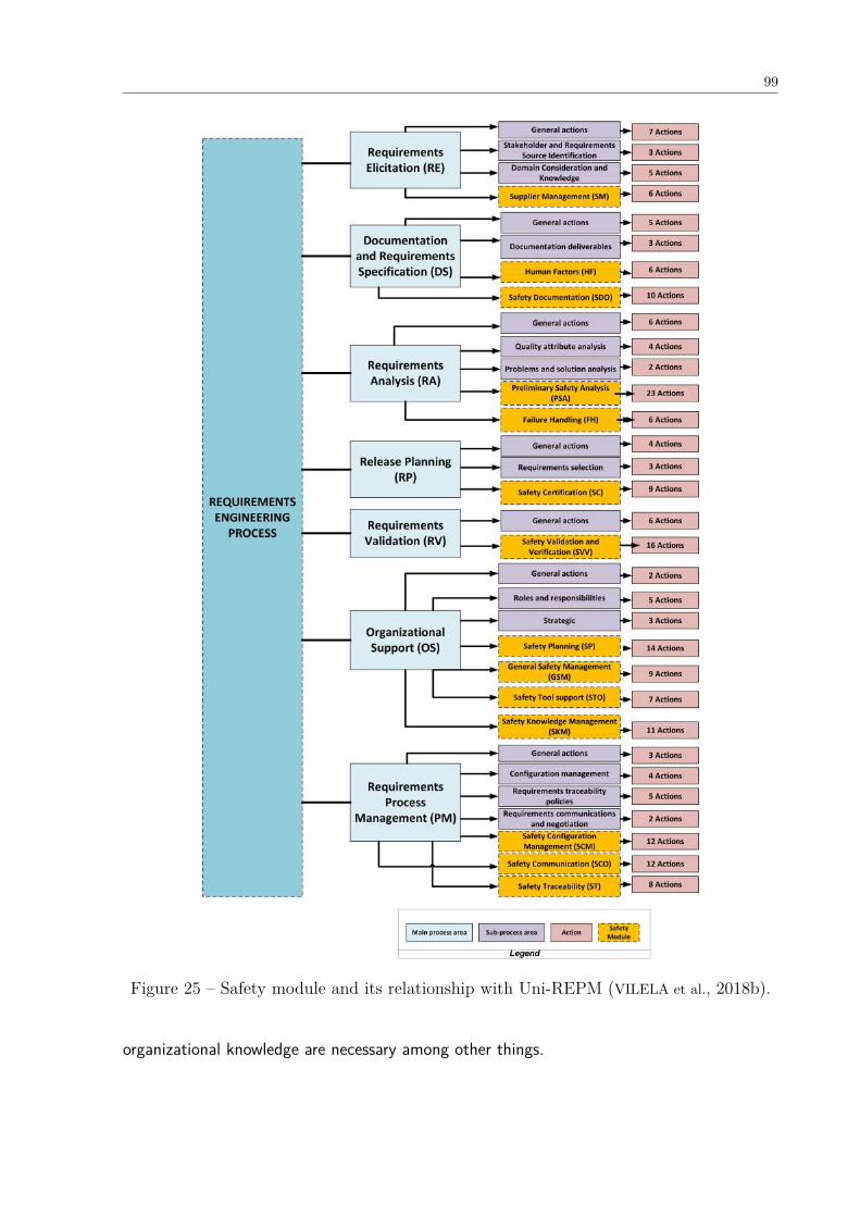
99
Figure 25 – Safety module and its relationship with Uni-REPM (VILELA et al., 2018b).
organizational knowledge are necessary among other things.

100
Figure 26 – Example of an Uni-REPM Safety module action.
Figure 27 – Dependencies among the MPAs of Uni-REPM and the SPAs of the safetymodule.
5.2.2.1 RE.SM - Supplier Management
The development of safety-critical systems usually requires a combination of internal softwareand third-party systems. Therefore, in the Requirements Engineering phase, it is necessary toelicit and specify the requirements that suppliers must satisfy.
Suppliers correspond to internal or external organizations that develop, manufacture, orsupport products being developed or maintained that will be delivered to other companies or
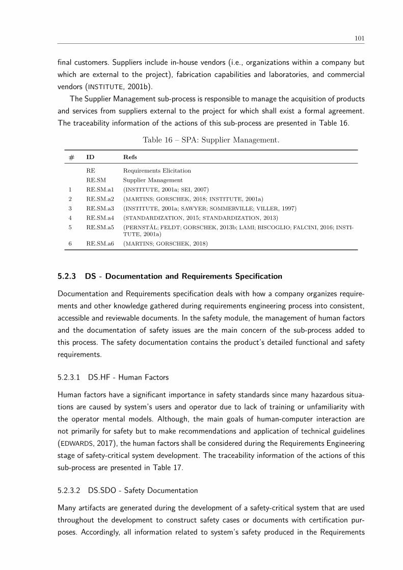
101
final customers. Suppliers include in-house vendors (i.e., organizations within a company butwhich are external to the project), fabrication capabilities and laboratories, and commercialvendors (INSTITUTE, 2001b).
The Supplier Management sub-process is responsible to manage the acquisition of productsand services from suppliers external to the project for which shall exist a formal agreement.The traceability information of the actions of this sub-process are presented in Table 16.
Table 16 – SPA: Supplier Management.
# ID Refs
RE Requirements ElicitationRE.SM Supplier Management
1 RE.SM.a1 (INSTITUTE, 2001a; SEI, 2007)2 RE.SM.a2 (MARTINS; GORSCHEK, 2018; INSTITUTE, 2001a)3 RE.SM.a3 (INSTITUTE, 2001a; SAWYER; SOMMERVILLE; VILLER, 1997)4 RE.SM.a4 (STANDARDIZATION, 2015; STANDARDIZATION, 2013)5 RE.SM.a5 (PERNSTÅL; FELDT; GORSCHEK, 2013b; LAMI; BISCOGLIO; FALCINI, 2016; INSTI-
TUTE, 2001a)6 RE.SM.a6 (MARTINS; GORSCHEK, 2018)
5.2.3 DS - Documentation and Requirements Specification
Documentation and Requirements specification deals with how a company organizes require-ments and other knowledge gathered during requirements engineering process into consistent,accessible and reviewable documents. In the safety module, the management of human factorsand the documentation of safety issues are the main concern of the sub-process added tothis process. The safety documentation contains the product’s detailed functional and safetyrequirements.
5.2.3.1 DS.HF - Human Factors
Human factors have a significant importance in safety standards since many hazardous situa-tions are caused by system’s users and operator due to lack of training or unfamiliarity withthe operator mental models. Although, the main goals of human-computer interaction arenot primarily for safety but to make recommendations and application of technical guidelines(EDWARDS, 2017), the human factors shall be considered during the Requirements Engineeringstage of safety-critical system development. The traceability information of the actions of thissub-process are presented in Table 17.
5.2.3.2 DS.SDO - Safety Documentation
Many artifacts are generated during the development of a safety-critical system that are usedthroughout the development to construct safety cases or documents with certification pur-poses. Accordingly, all information related to system’s safety produced in the Requirements
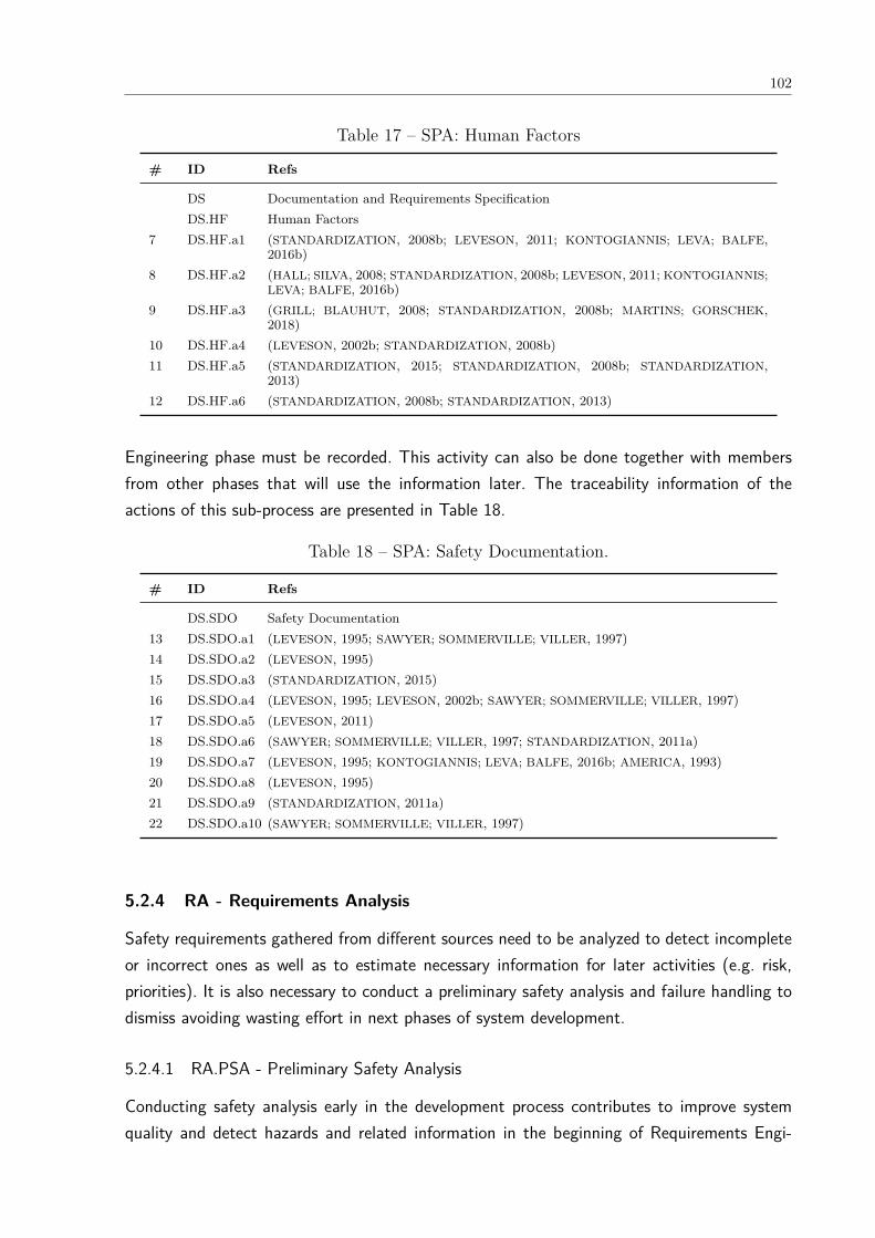
102
Table 17 – SPA: Human Factors
# ID Refs
DS Documentation and Requirements SpecificationDS.HF Human Factors
7 DS.HF.a1 (STANDARDIZATION, 2008b; LEVESON, 2011; KONTOGIANNIS; LEVA; BALFE,2016b)
8 DS.HF.a2 (HALL; SILVA, 2008; STANDARDIZATION, 2008b; LEVESON, 2011; KONTOGIANNIS;LEVA; BALFE, 2016b)
9 DS.HF.a3 (GRILL; BLAUHUT, 2008; STANDARDIZATION, 2008b; MARTINS; GORSCHEK,2018)
10 DS.HF.a4 (LEVESON, 2002b; STANDARDIZATION, 2008b)11 DS.HF.a5 (STANDARDIZATION, 2015; STANDARDIZATION, 2008b; STANDARDIZATION,
2013)12 DS.HF.a6 (STANDARDIZATION, 2008b; STANDARDIZATION, 2013)
Engineering phase must be recorded. This activity can also be done together with membersfrom other phases that will use the information later. The traceability information of theactions of this sub-process are presented in Table 18.
Table 18 – SPA: Safety Documentation.
# ID Refs
DS.SDO Safety Documentation13 DS.SDO.a1 (LEVESON, 1995; SAWYER; SOMMERVILLE; VILLER, 1997)14 DS.SDO.a2 (LEVESON, 1995)15 DS.SDO.a3 (STANDARDIZATION, 2015)16 DS.SDO.a4 (LEVESON, 1995; LEVESON, 2002b; SAWYER; SOMMERVILLE; VILLER, 1997)17 DS.SDO.a5 (LEVESON, 2011)18 DS.SDO.a6 (SAWYER; SOMMERVILLE; VILLER, 1997; STANDARDIZATION, 2011a)19 DS.SDO.a7 (LEVESON, 1995; KONTOGIANNIS; LEVA; BALFE, 2016b; AMERICA, 1993)20 DS.SDO.a8 (LEVESON, 1995)21 DS.SDO.a9 (STANDARDIZATION, 2011a)22 DS.SDO.a10 (SAWYER; SOMMERVILLE; VILLER, 1997)
5.2.4 RA - Requirements Analysis
Safety requirements gathered from different sources need to be analyzed to detect incompleteor incorrect ones as well as to estimate necessary information for later activities (e.g. risk,priorities). It is also necessary to conduct a preliminary safety analysis and failure handling todismiss avoiding wasting effort in next phases of system development.
5.2.4.1 RA.PSA - Preliminary Safety Analysis
Conducting safety analysis early in the development process contributes to improve systemquality and detect hazards and related information in the beginning of Requirements Engi-
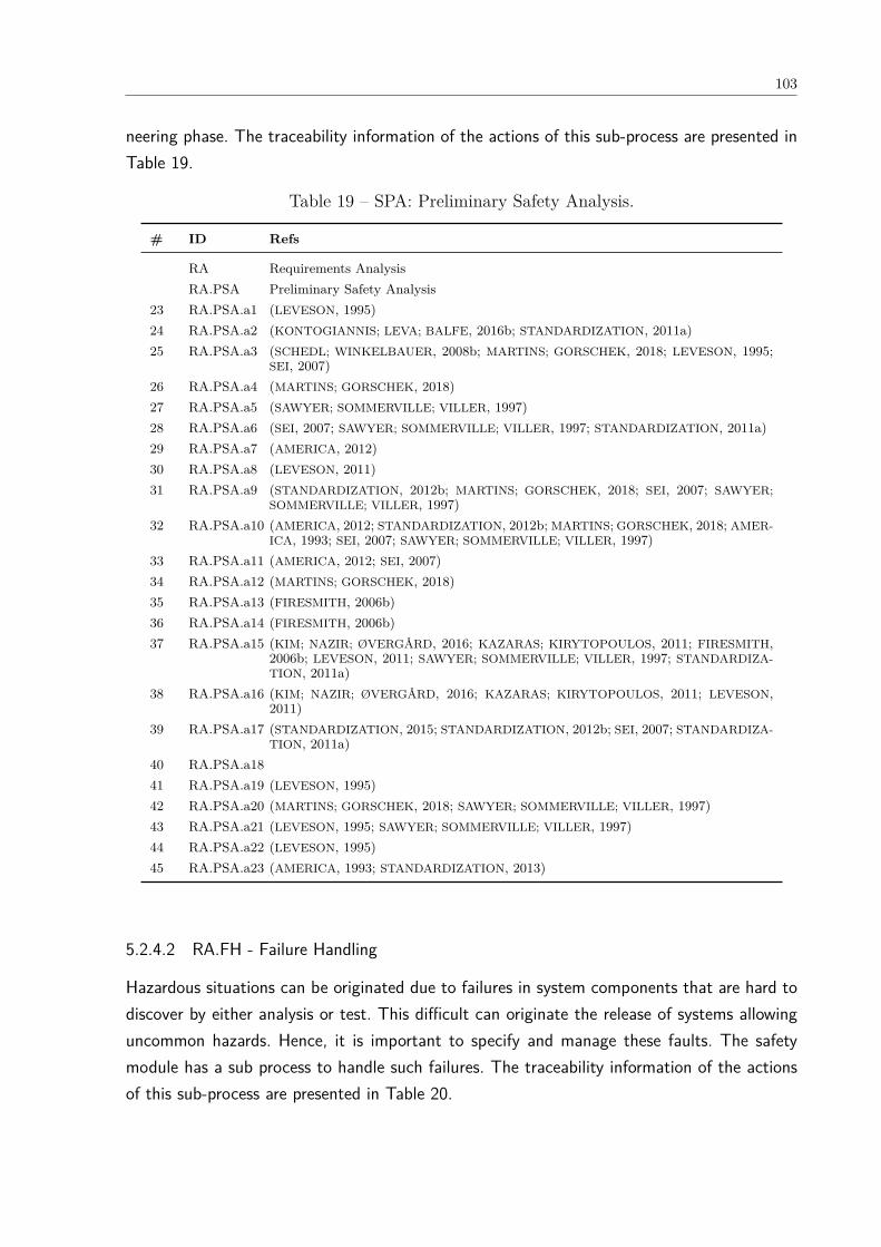
103
neering phase. The traceability information of the actions of this sub-process are presented inTable 19.
Table 19 – SPA: Preliminary Safety Analysis.
# ID Refs
RA Requirements AnalysisRA.PSA Preliminary Safety Analysis
23 RA.PSA.a1 (LEVESON, 1995)24 RA.PSA.a2 (KONTOGIANNIS; LEVA; BALFE, 2016b; STANDARDIZATION, 2011a)25 RA.PSA.a3 (SCHEDL; WINKELBAUER, 2008b; MARTINS; GORSCHEK, 2018; LEVESON, 1995;
SEI, 2007)26 RA.PSA.a4 (MARTINS; GORSCHEK, 2018)27 RA.PSA.a5 (SAWYER; SOMMERVILLE; VILLER, 1997)28 RA.PSA.a6 (SEI, 2007; SAWYER; SOMMERVILLE; VILLER, 1997; STANDARDIZATION, 2011a)29 RA.PSA.a7 (AMERICA, 2012)30 RA.PSA.a8 (LEVESON, 2011)31 RA.PSA.a9 (STANDARDIZATION, 2012b; MARTINS; GORSCHEK, 2018; SEI, 2007; SAWYER;
SOMMERVILLE; VILLER, 1997)32 RA.PSA.a10 (AMERICA, 2012; STANDARDIZATION, 2012b; MARTINS; GORSCHEK, 2018; AMER-
ICA, 1993; SEI, 2007; SAWYER; SOMMERVILLE; VILLER, 1997)33 RA.PSA.a11 (AMERICA, 2012; SEI, 2007)34 RA.PSA.a12 (MARTINS; GORSCHEK, 2018)35 RA.PSA.a13 (FIRESMITH, 2006b)36 RA.PSA.a14 (FIRESMITH, 2006b)37 RA.PSA.a15 (KIM; NAZIR; ØVERGÅRD, 2016; KAZARAS; KIRYTOPOULOS, 2011; FIRESMITH,
2006b; LEVESON, 2011; SAWYER; SOMMERVILLE; VILLER, 1997; STANDARDIZA-TION, 2011a)
38 RA.PSA.a16 (KIM; NAZIR; ØVERGÅRD, 2016; KAZARAS; KIRYTOPOULOS, 2011; LEVESON,2011)
39 RA.PSA.a17 (STANDARDIZATION, 2015; STANDARDIZATION, 2012b; SEI, 2007; STANDARDIZA-TION, 2011a)
40 RA.PSA.a1841 RA.PSA.a19 (LEVESON, 1995)42 RA.PSA.a20 (MARTINS; GORSCHEK, 2018; SAWYER; SOMMERVILLE; VILLER, 1997)43 RA.PSA.a21 (LEVESON, 1995; SAWYER; SOMMERVILLE; VILLER, 1997)44 RA.PSA.a22 (LEVESON, 1995)45 RA.PSA.a23 (AMERICA, 1993; STANDARDIZATION, 2013)
5.2.4.2 RA.FH - Failure Handling
Hazardous situations can be originated due to failures in system components that are hard todiscover by either analysis or test. This difficult can originate the release of systems allowinguncommon hazards. Hence, it is important to specify and manage these faults. The safetymodule has a sub process to handle such failures. The traceability information of the actionsof this sub-process are presented in Table 20.
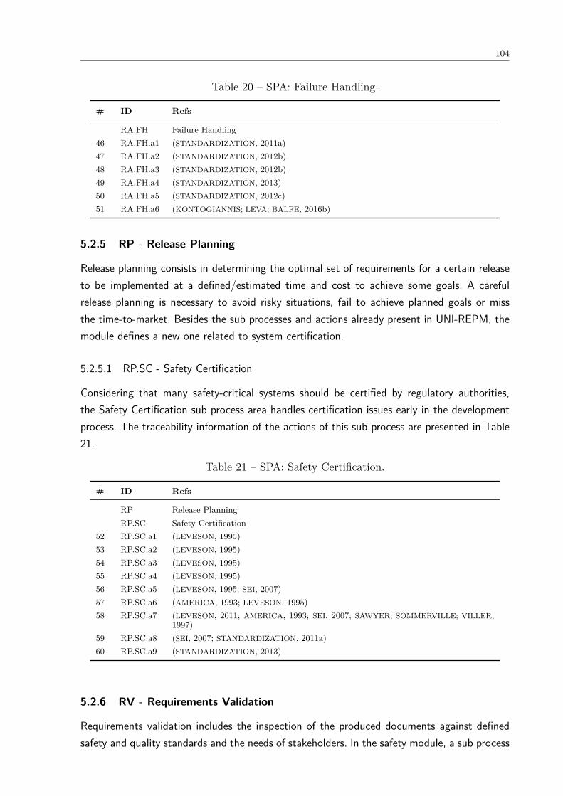
104
Table 20 – SPA: Failure Handling.
# ID Refs
RA.FH Failure Handling46 RA.FH.a1 (STANDARDIZATION, 2011a)47 RA.FH.a2 (STANDARDIZATION, 2012b)48 RA.FH.a3 (STANDARDIZATION, 2012b)49 RA.FH.a4 (STANDARDIZATION, 2013)50 RA.FH.a5 (STANDARDIZATION, 2012c)51 RA.FH.a6 (KONTOGIANNIS; LEVA; BALFE, 2016b)
5.2.5 RP - Release Planning
Release planning consists in determining the optimal set of requirements for a certain releaseto be implemented at a defined/estimated time and cost to achieve some goals. A carefulrelease planning is necessary to avoid risky situations, fail to achieve planned goals or missthe time-to-market. Besides the sub processes and actions already present in UNI-REPM, themodule defines a new one related to system certification.
5.2.5.1 RP.SC - Safety Certification
Considering that many safety-critical systems should be certified by regulatory authorities,the Safety Certification sub process area handles certification issues early in the developmentprocess. The traceability information of the actions of this sub-process are presented in Table21.
Table 21 – SPA: Safety Certification.
# ID Refs
RP Release PlanningRP.SC Safety Certification
52 RP.SC.a1 (LEVESON, 1995)53 RP.SC.a2 (LEVESON, 1995)54 RP.SC.a3 (LEVESON, 1995)55 RP.SC.a4 (LEVESON, 1995)56 RP.SC.a5 (LEVESON, 1995; SEI, 2007)57 RP.SC.a6 (AMERICA, 1993; LEVESON, 1995)58 RP.SC.a7 (LEVESON, 2011; AMERICA, 1993; SEI, 2007; SAWYER; SOMMERVILLE; VILLER,
1997)59 RP.SC.a8 (SEI, 2007; STANDARDIZATION, 2011a)60 RP.SC.a9 (STANDARDIZATION, 2013)
5.2.6 RV - Requirements Validation
Requirements validation includes the inspection of the produced documents against definedsafety and quality standards and the needs of stakeholders. In the safety module, a sub process

105
to plan the verification and validation activities was added since they often run concurrentlyand may use portions of the same environment.
5.2.6.1 RV.SVV - Safety Validation and Verification
In the Safety Validation and Verification (V&V) there are actions to validation of the require-ments and the definition of strategies to the verification of safety requirements. V&V activitiesshould be available early in the development process so that the safety requirements are clearlyunderstood and agreed by the relevant stakeholders. The traceability information of the actionsof this sub-process are presented in Table 22.
Table 22 – SPA: Safety Validation and Verification.
# ID Refs
RV Requirements ValidationRV.SVV Safety Validation and Verification
61 RV.SVV.a1 (INSTITUTE, 2001a; STANDARDIZATION, 2011a)62 RV.SVV.a2 (STANDARDIZATION, 2012c; INSTITUTE, 2001a; AMERICA, 1993; LEVESON, 1995;
STANDARDIZATION, 2011a)63 RV.SVV.a3 (STANDARDIZATION, 2011a)64 RV.SVV.a4 (STANDARDIZATION, 2011a)65 RV.SVV.a5 (LEVESON, 1995; SAWYER; SOMMERVILLE; VILLER, 1997)66 RV.SVV.a6 (LAMI; BISCOGLIO; FALCINI, 2016; INSTITUTE, 2001a; STANDARDIZATION, 2013)67 RV.SVV.a7 (STANDARDIZATION, 2011b; MARTINS; GORSCHEK, 2018; AMERICA, 1993; STAN-
DARDIZATION, 2013)68 RV.SVV.a8 (LEVESON, 2011)69 RV.SVV.a9 (AMERICA, 2000; LEVESON, 1995)70 RV.SVV.a10 (AMERICA, 2012; MARTINS; GORSCHEK, 2018)71 RV.SVV.a11 (LEVESON, 1995)72 RV.SVV.a12 (STANDARDIZATION, 2011a)73 RV.SVV.a13 (STANDARDIZATION, 2013)74 RV.SVV.a14 (STANDARDIZATION, 2009; INSTITUTE, 2001a)75 RV.SVV.a15 (LEVESON, 1995; SAWYER; SOMMERVILLE; VILLER, 1997)76 RV.SVV.a16 (INSTITUTE, 2001b; INSTITUTE, 2001a; LEVESON, 1995)
5.2.7 OS - Organizational Support
This main process area evaluates the amount of support given to requirements engineeringpractices from the surrounding organization. Organizational support is important, since ulti-mately the success of any time-consuming activity needs to be understood and supported bythe organization. This main process area is aimed to enable organizational support, but alsomake the importance of requirements engineering clear to the development organization atlarge. The safety module added three new areas: Safety Planning, General Safety Manage-ment, Safety Tool Support, Safety Knowledge Management.
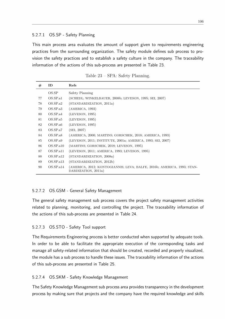
106
5.2.7.1 OS.SP - Safety Planning
This main process area evaluates the amount of support given to requirements engineeringpractices from the surrounding organization. The safety module defines sub process to pro-vision the safety practices and to establish a safety culture in the company. The traceabilityinformation of the actions of this sub-process are presented in Table 23.
Table 23 – SPA: Safety Planning.
# ID Refs
OS.SP Safety Planning77 OS.SP.a1 (SCHEDL; WINKELBAUER, 2008b; LEVESON, 1995; SEI, 2007)78 OS.SP.a2 (STANDARDIZATION, 2011a)79 OS.SP.a3 (AMERICA, 1993)80 OS.SP.a4 (LEVESON, 1995)81 OS.SP.a5 (LEVESON, 1995)82 OS.SP.a6 (LEVESON, 1995)83 OS.SP.a7 (SEI, 2007)84 OS.SP.a8 (AMERICA, 2000; MARTINS; GORSCHEK, 2018; AMERICA, 1993)85 OS.SP.a9 (LEVESON, 2011; INSTITUTE, 2001a; AMERICA, 1993; SEI, 2007)86 OS.SP.a10 (MARTINS; GORSCHEK, 2018; LEVESON, 1995)87 OS.SP.a11 (LEVESON, 2011; AMERICA, 1993; LEVESON, 1995)88 OS.SP.a12 (STANDARDIZATION, 2008a)89 OS.SP.a13 (STANDARDIZATION, 2012b)90 OS.SP.a14 (AMERICA, 2012; KONTOGIANNIS; LEVA; BALFE, 2016b; AMERICA, 1993; STAN-
DARDIZATION, 2011a)
5.2.7.2 OS.GSM - General Safety Management
The general safety management sub process covers the project safety management activitiesrelated to planning, monitoring, and controlling the project. The traceability information ofthe actions of this sub-process are presented in Table 24.
5.2.7.3 OS.STO - Safety Tool support
The Requirements Engineering process is better conducted when supported by adequate tools.In order to be able to facilitate the appropriate execution of the corresponding tasks andmanage all safety-related information that should be created, recorded and properly visualized,the module has a sub process to handle these issues. The traceability information of the actionsof this sub-process are presented in Table 25.
5.2.7.4 OS.SKM - Safety Knowledge Management
The Safety Knowledge Management sub process area provides transparency in the developmentprocess by making sure that projects and the company have the required knowledge and skills
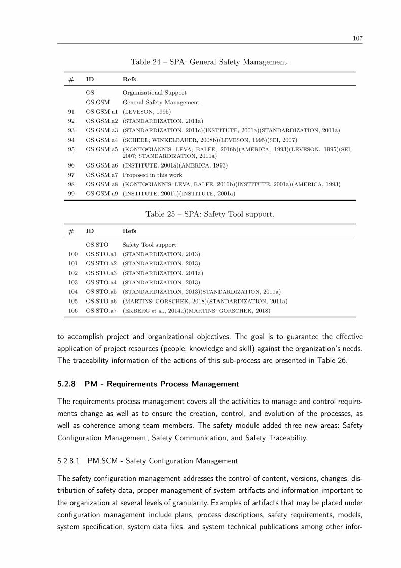
107
Table 24 – SPA: General Safety Management.
# ID Refs
OS Organizational SupportOS.GSM General Safety Management
91 OS.GSM.a1 (LEVESON, 1995)92 OS.GSM.a2 (STANDARDIZATION, 2011a)93 OS.GSM.a3 (STANDARDIZATION, 2011c)(INSTITUTE, 2001a)(STANDARDIZATION, 2011a)94 OS.GSM.a4 (SCHEDL; WINKELBAUER, 2008b)(LEVESON, 1995)(SEI, 2007)95 OS.GSM.a5 (KONTOGIANNIS; LEVA; BALFE, 2016b)(AMERICA, 1993)(LEVESON, 1995)(SEI,
2007; STANDARDIZATION, 2011a)96 OS.GSM.a6 (INSTITUTE, 2001a)(AMERICA, 1993)97 OS.GSM.a7 Proposed in this work98 OS.GSM.a8 (KONTOGIANNIS; LEVA; BALFE, 2016b)(INSTITUTE, 2001a)(AMERICA, 1993)99 OS.GSM.a9 (INSTITUTE, 2001b)(INSTITUTE, 2001a)
Table 25 – SPA: Safety Tool support.
# ID Refs
OS.STO Safety Tool support100 OS.STO.a1 (STANDARDIZATION, 2013)101 OS.STO.a2 (STANDARDIZATION, 2013)102 OS.STO.a3 (STANDARDIZATION, 2011a)103 OS.STO.a4 (STANDARDIZATION, 2013)104 OS.STO.a5 (STANDARDIZATION, 2013)(STANDARDIZATION, 2011a)105 OS.STO.a6 (MARTINS; GORSCHEK, 2018)(STANDARDIZATION, 2011a)106 OS.STO.a7 (EKBERG et al., 2014a)(MARTINS; GORSCHEK, 2018)
to accomplish project and organizational objectives. The goal is to guarantee the effectiveapplication of project resources (people, knowledge and skill) against the organization’s needs.The traceability information of the actions of this sub-process are presented in Table 26.
5.2.8 PM - Requirements Process Management
The requirements process management covers all the activities to manage and control require-ments change as well as to ensure the creation, control, and evolution of the processes, aswell as coherence among team members. The safety module added three new areas: SafetyConfiguration Management, Safety Communication, and Safety Traceability.
5.2.8.1 PM.SCM - Safety Configuration Management
The safety configuration management addresses the control of content, versions, changes, dis-tribution of safety data, proper management of system artifacts and information important tothe organization at several levels of granularity. Examples of artifacts that may be placed underconfiguration management include plans, process descriptions, safety requirements, models,system specification, system data files, and system technical publications among other infor-

108
Table 26 – SPA: Safety Knowledge Management.
# ID Refs
OS.SKM Safety Knowledge Management107 OS.SKM.a1 (STANDARDIZATION, 2012a)(KONTOGIANNIS; LEVA; BALFE, 2016b)(MARTINS;
GORSCHEK, 2018)108 OS.SKM.a2 (KONTOGIANNIS; LEVA; BALFE, 2016b)(LEVESON, 1995)109 OS.SKM.a3 (STANDARDIZATION, 2014; STANDARDIZATION, 2012a; KONTOGIANNIS; LEVA;
BALFE, 2016b)110 OS.SKM.a4 (STANDARDIZATION, 2011a)111 OS.SKM.a5 (STANDARDIZATION, 2012a)(KONTOGIANNIS; LEVA; BALFE, 2016b)112 OS.SKM.a6 (STANDARDIZATION, 2011a)113 OS.SKM.a7 (MARTINS; GORSCHEK, 2018)114 OS.SKM.a8 (KONTOGIANNIS; LEVA; BALFE, 2016b)LuizTSE(SAWYER; SOMMERVILLE;
VILLER, 1997)115 OS.SKM.a9 (MARTINS; GORSCHEK, 2018)116 OS.SKM.a10 Proposed in this work117 OS.SKM.a11 Proposed in this work
mation (INSTITUTE, 2001b). The traceability information of the actions of this sub-process arepresented in Table 27.
Table 27 – SPA: Safety Configuration Management
# ID Refs
PM Requirements Process ManagementPM.SCM Safety Configuration Management
118 PM.SCM.a1 (INSTITUTE, 2001a; SAWYER; SOMMERVILLE; VILLER, 1997; STANDARDIZATION,2011a)
119 PM.SCM.a2 (STANDARDIZATION, 2011a)120 PM.SCM.a3 (SEI, 2007; STANDARDIZATION, 2011a)121 PM.SCM.a4 (INSTITUTE, 2001a)122 PM.SCM.a5 (STANDARDIZATION, 2011a)123 PM.SCM.a6 (STANDARDIZATION, 2011c; STANDARDIZATION, 2011a)124 PM.SCM.a7 (MARTINS; GORSCHEK, 2018; SEI, 2007; STANDARDIZATION, 2011a)125 PM.SCM.a8 (STANDARDIZATION, 2011a)126 PM.SCM.a9 (STANDARDIZATION, 2011a)127 PM.SCM.a10(INSTITUTE, 2001a; STANDARDIZATION, 2011a)128 PM.SCM.a11(STANDARDIZATION, 2013)129 PM.SCM.a12(STANDARDIZATION, 2013)
5.2.8.2 PM.SCO - Safety Communication
The safety analysis and assurance processes requires knowledge of many safety terms, methods,and processes from requirements engineers. However, they generally are unfamiliar with all suchinformation. Aiming to minimize this problem, the safety module add actions to improve thesafety communication sub process. The traceability information of the actions of this sub-process are presented in Table 28.

109
Table 28 – SPA: Safety Communication.
# ID Refs
PM.SCO Safety Communication130 PM.SCO.a1 (MARTINS; GORSCHEK, 2018)131 PM.SCO.a2 (AMERICA, 1993)132 PM.SCO.a3 (SAWYER; SOMMERVILLE; VILLER, 1997)133 PM.SCO.a4 (KONTOGIANNIS; LEVA; BALFE, 2016b; LEVESON, 1995; SEI, 2007)134 PM.SCO.a5 (WHITEHEAD, 2007)135 PM.SCO.a6 (WHITEHEAD, 2007; SEI, 2007)136 PM.SCO.a7 Proposed in this work137 PM.SCO.a8 (WHITEHEAD, 2007; SAWYER; SOMMERVILLE; VILLER, 1997)138 PM.SCO.a9 (LEVESON, 2011; SAWYER; SOMMERVILLE; VILLER, 1997)139 PM.SCO.a10 (SAWYER; SOMMERVILLE; VILLER, 1997)140 PM.SCO.a11 (STANDARDIZATION, 2013; SAWYER; SOMMERVILLE; VILLER, 1997)141 PM.SCO.a12 (STANDARDIZATION, 2015)
5.2.8.3 PM.ST - Safety Traceability
Changes in requirements will probably occur during the system development. Therefore, it isnecessary to ensure consistency among system artifacts. This sub process area of safety modulehandles the traceability among artifacts helping to determine that the requirements affectedby the changes have been completely addressed. The traceability information of the actionsof this sub-process are presented in Table 29.
Table 29 – SPA: Safety Traceability.
# ID Refs
PM.ST Safety Traceability142 PM.ST.a1 (SAWYER; SOMMERVILLE; VILLER, 1997)143 PM.ST.a2 (STANDARDIZATION, 2011a)144 PM.ST.a3 (LEVESON, 2011)145 PM.ST.a4 (LEVESON, 1995)146 PM.ST.a5 (STANDARDIZATION, 2009; STANDARDIZATION, 2013)147 PM.ST.a6 (LAMI; BISCOGLIO; FALCINI, 2016; STANDARDIZATION, 2009; STANDARDIZA-
TION, 2013)148 PM.ST.a7 (LAMI; BISCOGLIO; FALCINI, 2016)149 PM.ST.a8 (STANDARDIZATION, 2009)
All actions of the Uni-REPM Safety module, their identifier and maturity level are presentedin Table 30, Table 31, Table 32, Table 33. In these tables, the actions are grouped accordingto the subprocess areas.
5.2.9 Maturity Level view
Following the structure of Uni-REPM Svahnberg et al. (2015), the safety module, the MaturityLevel View is developed by assigning a level to each action in a likert scale from 1 to 3,
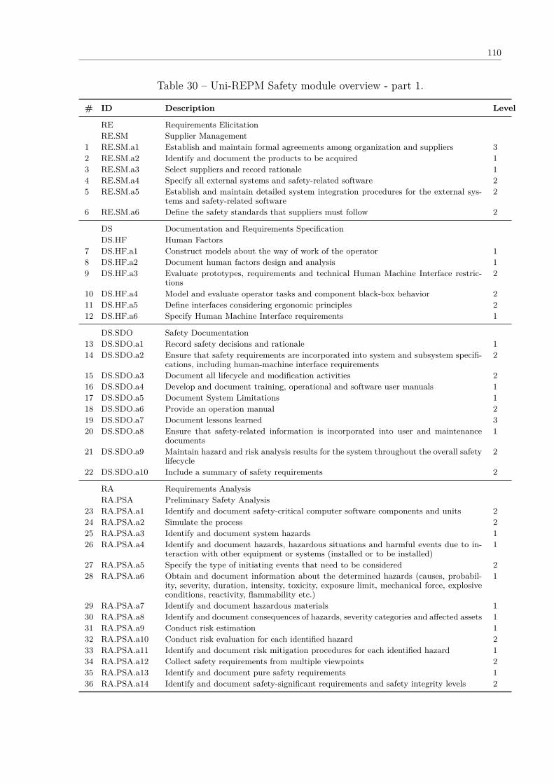
110
Table 30 – Uni-REPM Safety module overview - part 1.
# ID Description Level
RE Requirements ElicitationRE.SM Supplier Management
1 RE.SM.a1 Establish and maintain formal agreements among organization and suppliers 32 RE.SM.a2 Identify and document the products to be acquired 13 RE.SM.a3 Select suppliers and record rationale 14 RE.SM.a4 Specify all external systems and safety-related software 25 RE.SM.a5 Establish and maintain detailed system integration procedures for the external sys-
tems and safety-related software2
6 RE.SM.a6 Define the safety standards that suppliers must follow 2
DS Documentation and Requirements SpecificationDS.HF Human Factors
7 DS.HF.a1 Construct models about the way of work of the operator 18 DS.HF.a2 Document human factors design and analysis 19 DS.HF.a3 Evaluate prototypes, requirements and technical Human Machine Interface restric-
tions2
10 DS.HF.a4 Model and evaluate operator tasks and component black-box behavior 211 DS.HF.a5 Define interfaces considering ergonomic principles 212 DS.HF.a6 Specify Human Machine Interface requirements 1
DS.SDO Safety Documentation13 DS.SDO.a1 Record safety decisions and rationale 114 DS.SDO.a2 Ensure that safety requirements are incorporated into system and subsystem specifi-
cations, including human-machine interface requirements2
15 DS.SDO.a3 Document all lifecycle and modification activities 216 DS.SDO.a4 Develop and document training, operational and software user manuals 117 DS.SDO.a5 Document System Limitations 118 DS.SDO.a6 Provide an operation manual 219 DS.SDO.a7 Document lessons learned 320 DS.SDO.a8 Ensure that safety-related information is incorporated into user and maintenance
documents1
21 DS.SDO.a9 Maintain hazard and risk analysis results for the system throughout the overall safetylifecycle
2
22 DS.SDO.a10 Include a summary of safety requirements 2
RA Requirements AnalysisRA.PSA Preliminary Safety Analysis
23 RA.PSA.a1 Identify and document safety-critical computer software components and units 224 RA.PSA.a2 Simulate the process 225 RA.PSA.a3 Identify and document system hazards 126 RA.PSA.a4 Identify and document hazards, hazardous situations and harmful events due to in-
teraction with other equipment or systems (installed or to be installed)1
27 RA.PSA.a5 Specify the type of initiating events that need to be considered 228 RA.PSA.a6 Obtain and document information about the determined hazards (causes, probabil-
ity, severity, duration, intensity, toxicity, exposure limit, mechanical force, explosiveconditions, reactivity, flammability etc.)
1
29 RA.PSA.a7 Identify and document hazardous materials 130 RA.PSA.a8 Identify and document consequences of hazards, severity categories and affected assets 131 RA.PSA.a9 Conduct risk estimation 132 RA.PSA.a10 Conduct risk evaluation for each identified hazard 233 RA.PSA.a11 Identify and document risk mitigation procedures for each identified hazard 134 RA.PSA.a12 Collect safety requirements from multiple viewpoints 235 RA.PSA.a13 Identify and document pure safety requirements 136 RA.PSA.a14 Identify and document safety-significant requirements and safety integrity levels 2
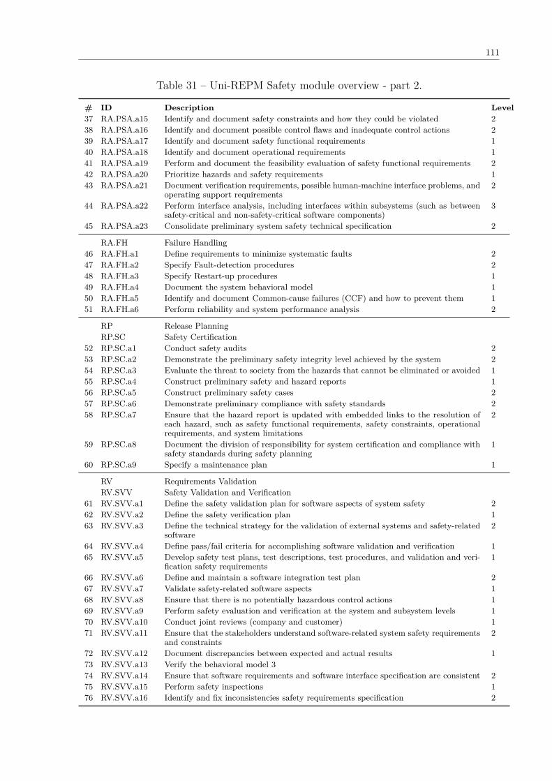
111
Table 31 – Uni-REPM Safety module overview - part 2.
# ID Description Level37 RA.PSA.a15 Identify and document safety constraints and how they could be violated 238 RA.PSA.a16 Identify and document possible control flaws and inadequate control actions 239 RA.PSA.a17 Identify and document safety functional requirements 140 RA.PSA.a18 Identify and document operational requirements 141 RA.PSA.a19 Perform and document the feasibility evaluation of safety functional requirements 242 RA.PSA.a20 Prioritize hazards and safety requirements 143 RA.PSA.a21 Document verification requirements, possible human-machine interface problems, and
operating support requirements2
44 RA.PSA.a22 Perform interface analysis, including interfaces within subsystems (such as betweensafety-critical and non-safety-critical software components)
3
45 RA.PSA.a23 Consolidate preliminary system safety technical specification 2
RA.FH Failure Handling46 RA.FH.a1 Define requirements to minimize systematic faults 247 RA.FH.a2 Specify Fault-detection procedures 248 RA.FH.a3 Specify Restart-up procedures 149 RA.FH.a4 Document the system behavioral model 150 RA.FH.a5 Identify and document Common-cause failures (CCF) and how to prevent them 151 RA.FH.a6 Perform reliability and system performance analysis 2
RP Release PlanningRP.SC Safety Certification
52 RP.SC.a1 Conduct safety audits 253 RP.SC.a2 Demonstrate the preliminary safety integrity level achieved by the system 254 RP.SC.a3 Evaluate the threat to society from the hazards that cannot be eliminated or avoided 155 RP.SC.a4 Construct preliminary safety and hazard reports 156 RP.SC.a5 Construct preliminary safety cases 257 RP.SC.a6 Demonstrate preliminary compliance with safety standards 258 RP.SC.a7 Ensure that the hazard report is updated with embedded links to the resolution of
each hazard, such as safety functional requirements, safety constraints, operationalrequirements, and system limitations
2
59 RP.SC.a8 Document the division of responsibility for system certification and compliance withsafety standards during safety planning
1
60 RP.SC.a9 Specify a maintenance plan 1
RV Requirements ValidationRV.SVV Safety Validation and Verification
61 RV.SVV.a1 Define the safety validation plan for software aspects of system safety 262 RV.SVV.a2 Define the safety verification plan 163 RV.SVV.a3 Define the technical strategy for the validation of external systems and safety-related
software2
64 RV.SVV.a4 Define pass/fail criteria for accomplishing software validation and verification 165 RV.SVV.a5 Develop safety test plans, test descriptions, test procedures, and validation and veri-
fication safety requirements1
66 RV.SVV.a6 Define and maintain a software integration test plan 267 RV.SVV.a7 Validate safety-related software aspects 168 RV.SVV.a8 Ensure that there is no potentially hazardous control actions 169 RV.SVV.a9 Perform safety evaluation and verification at the system and subsystem levels 170 RV.SVV.a10 Conduct joint reviews (company and customer) 171 RV.SVV.a11 Ensure that the stakeholders understand software-related system safety requirements
and constraints2
72 RV.SVV.a12 Document discrepancies between expected and actual results 173 RV.SVV.a13 Verify the behavioral model 374 RV.SVV.a14 Ensure that software requirements and software interface specification are consistent 275 RV.SVV.a15 Perform safety inspections 176 RV.SVV.a16 Identify and fix inconsistencies safety requirements specification 2
112
corresponding to “Basic”, “Intermediate”, and “Advanced” level where 3 represents the highestlevel of maturity.
These different levels of maturity are specified according to the difficulty to implement theaction, how essential it is for the RE process, and dependencies among actions (SVAHNBERG
et al., 2015).The maturity levels of safety module are:
1. 0 (Incipient): The evaluated requirements engineering process does not satisfy all safetyactions from basic level. Accordingly, the project does not receive any maturity level.
2. 1 (Basic): The aim of this level is to achieve a rudimentary repeatable safety requirementsengineering process. The process in this level is defined and followed. Basic usability andinterface aspects are considered, basic safety-related information is incorporated intosystem artifacts, responsibility, accountability and authority are identified, a lifecycle forprojects artifacts is defined, and it also contains initial practices to establish a safetyculture in the company. Moreover, in this level, preliminary safety and hazard reports aswell as a maintenance plan are constructed, the system behavioral model and restart-upprocedures are specified, and a preliminary safety analysis is performed. Initial projectmonitoring and take corrective actions are implemented and a common nomenclature isestablished. In this level there is no activity performed to collect and analyze data/feed-back for future improvement of the process.
3. 2 (Intermediate): in this level, the process is more rigorous because it involves variousperspectives and is led by product strategies/goals. Operator task models are evalu-ated, ergonomic principles are considered. Lifecycle and modification activities, systemdevelopment methodology, competence requirements, safety policy and safety goals areclearly defined and documented. Safety manual is elaborated, hazard and risk analy-sis results are maintained throughout the overall safety lifecycle, the hazards auditingand log file as well as working groups and structures are established, safety experi-ence on similar systems are considered, and tools are used to support the processes.The preliminary level of safety achieved by the system and preliminary compliance withsafety standards are demonstrated, safety audits are conducted and initial traceabilitymechanisms are considered in system artifacts. Also considered are requirements for theavoidance of systematic faults and fault-detection procedures. Moreover, external sys-tems and safety-related software concerns as well as system integration procedures arehandled, and communication among stakeholders is also considered.
4. 3 (Advanced): it denotes the most mature process. The improvements in the process areshown in the advanced way of documenting lessons learned, sharing knowledge in theorganization, specifying the general safety control structure, formal agreements amongorganization and suppliers are established and maintained. Moreover, formal communi-

113
cation channels among different organizational levels and common safety informationsystem for system specification and safety analysis are used.
It is important to note that Uni-REPM SCS is not intended to be used as part of a productassessment. While safety standards require the definition of safety integrity level of the systemunder development to set requirements for the project and the system, the module providesa way to evaluate the capability of safety-related processes as well as a scheme for theirimprovement.
Therefore, the maturity level achieved is not related with the safety integrity level theproject has to fulfill. Accordingly, an evaluation based on safety maturity models, such asUni-REPM SCS, +SAFE or ISO 15504-10, is not analogous to a functional safety assessment.Hence, using a maturity model does not provide any guarantee of compliance with any safetystandard.
Moreover, Uni-REPM SCS does not prescribe any specific technique, method or tool. Itsgoal is to consider the process (the “what”) and it does not require the adoption of any specifictechnique or method (the “how”).
These different levels of maturity were specified according to the difficulty to implement theaction, how essential it is for the RE process, dependencies among actions, the frequency theyappear in different information sources as well as the ability to optimize the safety processesconsidering our experience and the results of literature reviews and safety standards.
This view shows the actions from all process areas which the organization should implementin order to achieve a specific maturity level.
5.2.10 Examples of definition of actions
The definition of the actions considered the sources of information listed in Table 14. The differ-ent sources and their terminologies were reconciled by reading the full description of the actionand adopting the most common term. For example, the description of action OS.SP.Developan integrated system safety program plan is presented in Figure 26. This action was identifiedthrough both SAFETY-STD (AMERICA, 1993), EXISTING-MATURITY-MODS (SEI, 2007),and STATE-OF-THE-ART (SCHEDL; WINKELBAUER, 2008b)(LEVESON, 1995).
In the SAFETY-STD source, the MIL-STD-882C (AMERICA, 1993) requires the develop-ment of a System Safety Program Plan (SSPP) that should specify in detail activities requiredto identify, evaluate, and eliminate/control hazards, or reduce the associated risk to an ac-ceptable level.
+SAFE (SEI, 2007) of EXISTING-MATURITY-MODS category declares that elements ofthe plan for performing the safety engineering process are part of the safety plan that maytake on various formats according to the requirements of regulatory agencies.
Studies in the STATE-OF-THE-ART also address the need of conducting a proper safetyplanning. Schedl and Winkelbauer (2008b) say that the process related to customer require-
114
ments have to be assessed and resources planning should be performed and detailed in aSystem Safety Plan. Leveson (1995) also states that in the early stage of system development,the system safety program plan should be developed.
Another example of an action is #95 (see Table 24) “Identify and document responsibility,accountability and authority” that was inspired in SAFETY-STD, EXISTING-MATURITY-MODS, STATE-OF-THE-ART.
In the SAFETY-STD category, the IEC 61508 safety standard (STANDARDIZATION, 2011a)requires that a company developing an electrical/electronic/programmable electronic safety-related system must designate one or more persons to assume responsibility for safety activities.In the same way, the MIL-STD-882C (AMERICA, 1993) defines that a safety plan shoulddepict the responsibility and authority of safety team, other contractor organizational elementsinvolved in the system safety effort, subcontractors, and system safety groups.
EXISTING-MATURITY-MODS also requires evident specification of responsibility. +SAFESEI (2007) demands the definition of who or what should be assigned responsibility andauthority for performing the processes, developing the work products, and providing the servicesof the safety management process.
Responsibility and authority are also a concern reported in STATE-OF-THE-ART. Leveson(LEVESON, 1995) determines in her proposal of elements in a safeware program that a safetypolicy should include a well-defined assertion of responsibilities, authority, accountability, andscope of activities. Finally, Kontogiannis et al. (KONTOGIANNIS; LEVA; BALFE, 2016a) statesthat risk management should be comprehensive and clear about accountability.
In the next sections, we explain some examples of how we grouped the actions in sub-process areas of Uni-REPM SCS.
5.2.11 Examples of definition of SPAs
5.2.11.1 SPA: Safety Knowledge Management (SKM)
The SKM sub-process provides transparency in the development process by making sure thatprojects and the company have the required knowledge and skills to accomplish project andorganizational objectives. The definition of this SPA was inspired in the presence of safetypractices related with knowledge sharing in an organization as described in the works of theSAFETY-STD, INTERVIEW-STUDY, STATE-OF-THE-ART categories.
In the SAFETY-STD, for example, we noticed the need of an infrastructure to share knowl-edge (OS.SKM.a1) in (STANDARDIZATION, 2012a), control access mechanisms to the safetyinformation system (OS.SKM.a3) in (STANDARDIZATION, 2014)(STANDARDIZATION, 2012a),and maintain employees’ competence information (OS.SKM.a4) (STANDARDIZATION, 2011a).
In the INTERVIEW-STUDY (MARTINS; GORSCHEK, 2018), the practitioners highlightedthe need to define and maintain a strategy for reuse (OS.SKM.a7), reuse the stored knowl-edge (OS.SKM.a8), and document the use of stored knowledge (OS.SKM.a9). On the other

115
hand, the development of a safety information system to share knowledge in the organization(OS.SKM.a2) is emphasized by (KONTOGIANNIS; LEVA; BALFE, 2016b)(LEVESON, 1995) in theSTATE-OF-THE-ART.
Finally, we propose two actions: OS.SKM.a10 Notify users about problems, new versionsand exclusions of artifacts in use, and OS.SKM.a11 Manage assets.
5.2.11.2 SPA: Safety Tool support (STO)
This sub-process is responsible for facilitating the proper execution of the corresponding tasksand manage all safety-related information that should be created, recorded and properly visual-ized. We included this SPA in the module considering some SAFETY-STD request, for exam-ple, the specification of the reasons for the selection of the off-line support tools (OS.STO.a2)(STANDARDIZATION, 2013), the assessment of such tools that can directly or indirectly con-tribute to the executable code of the safety related system (OS.STO.a3) (STANDARDIZATION,2011a), the use of tools with support to cross reference and maintain the traceability amongsafety information in the software specification (OS.STO.a5) (STANDARDIZATION, 2013; STAN-
DARDIZATION, 2011a).In the INTERVIEW-STUDY (MARTINS; GORSCHEK, 2018) and STATE-OF-THE-ART (EK-
BERG et al., 2014a), the requirement of defining and using tools to support the safety processand workflow management (OS.STO.a7) is presented.
5.2.11.3 SPA: General Safety Management (GSM)
GSM covers project safety management activities related to planning, monitoring, and con-trolling the project. We defined this SPA considering the practices presented in works ofSTATE-OF-THE-ART, SAFETY-STD, and EXISTING-MATURITY-MODS categories.
The works of STATE-OF-THE-ART cite, for example, the identification and documenta-tion of the system development methodology (OS.GSM.a1) (LEVESON, 1995), responsibility,accountability and authority (OS.GSM.a5) (KONTOGIANNIS; LEVA; BALFE, 2016b)(LEVESON,1995) as well as setting safety policy and defining safety goals (OS.GSM.a4) (SCHEDL; WINKEL-
BAUER, 2008b)(LEVESON, 1995).SAFETY-STD (STANDARDIZATION, 2011a)(AMERICA, 1993) and EXISTING-MATURITY-
MODS (STANDARDIZATION, 2011c)(INSTITUTE, 2001a) require the identification and docu-mentation of safety lifecycle for the system development (OS.GSM.a), the competence require-ments for the safety activities (OS.GSM.a3), and defining system safety program milestonesand relate these to major program milestones, program element responsibility, and requiredinputs and outputs.
116
5.2.11.4 SPA: Safety Planning (SP)
This is one of the most important SPA in the module since it provides the safety practicesand establishes a safety culture in the company. The development of a SCS requires a carefulplanning and safety analysis (described in next section). Therefore, the SP was proposedconsidering the actions in SAFETY-STD, EXISTING-MATURITY-MODS, STATE-OF-THE-ART, and INTERVIEW-STUDY.
Several actions are cited in different categories such as develop an integrated system safetyprogram plan (OS.SP.a1) which is presented in the STATE-OF-THE-ART (SCHEDL; WINKEL-
BAUER, 2008b)(LEVESON, 1995) and EXISTING-MATURITY-MODS (SEI, 2007). Moreover,the identification of certification requirements for software, safety or warning devices or otherspecial safety feature (OS.SP.a8) is presented in the INTERVIEW-STUDY (MARTINS; GORSCHEK,2018) as well as in SAFETY-STD (AMERICA, 2000)(AMERICA, 1993).
Finally, the identification and documentation of the hazard analysis to be performed; theanalytical techniques (qualitative or quantitative) to be used; and depth within the system atwhich each analytical technique will be used (e.g., system level, subsystem level, componentlevel) (OS.SP.a14) is required in SAFETY-STD (AMERICA, 2012)(AMERICA, 1993; STANDARD-
IZATION, 2011a) and STATE-OF-THE-ART (KONTOGIANNIS; LEVA; BALFE, 2016b).
5.2.11.5 SPA: Preliminary Safety Analysis (PSA)
The PSA is the sub-process with more actions in the module since we grouped all actionsrelated to performing a preliminary safety analysis. Someone may argue that some actionsmay be in other SPA like elicitation for example. We agree that they may be included in suchSPA, but we argue that the elicitation and analysis are generally done in parallel.
Furthermore, PSA is usually performed when some system functionalities are alreadyelicited and documented, i.e. using a preliminary system specification as a basis. Therefore,we opted to classify all practices of safety analysis only in this group aiming to improve un-derstandability of the module.
This SPA has practices from SAFETY-STD such as conduct risk evaluation for each iden-tified hazard (RA.PSA.a10) (AMERICA, 2012)(STANDARDIZATION, 2012b)(AMERICA, 1993),EXISTING-MATURITY-MODS like identify and document safety functional requirements (RA.PSA.a17)(STANDARDIZATION, 2015)(STANDARDIZATION, 2012b)(SEI, 2007; STANDARDIZATION, 2011a),STATE-OF-THE-ART such as identify and document safety constraints and how they could beviolated (RA.PSA.a15) (KIM; NAZIR; ØVERGÅRD, 2016)(KAZARAS; KIRYTOPOULOS, 2011)(FIRE-
SMITH, 2006b)(LEVESON, 2011)(SAWYER; SOMMERVILLE; VILLER, 1997), and INTERVIEW-STUDY like identify and document system hazards (RA.PSA.a3) (MARTINS; GORSCHEK, 2018).
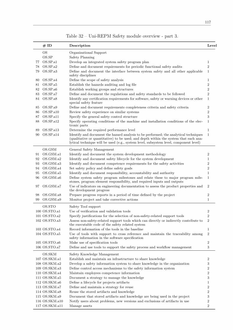
117
Table 32 – Uni-REPM Safety module overview - part 3.
# ID Description Level
OS Organizational SupportOS.SP Safety Planning
77 OS.SP.a1 Develop an integrated system safety program plan 178 OS.SP.a2 Define and document requirements for periodic functional safety audits 279 OS.SP.a3 Define and document the interface between system safety and all other applicable
safety disciplines1
80 OS.SP.a4 Define the scope of safety analysis 181 OS.SP.a5 Establish the hazards auditing and log file 282 OS.SP.a6 Establish working groups and structures 283 OS.SP.a7 Define and document the regulations and safety standards to be followed 284 OS.SP.a8 Identify any certification requirements for software, safety or warning devices or other
special safety feature1
85 OS.SP.a9 Define and document requirements completeness criteria and safety criteria 286 OS.SP.a10 Review safety experience on similar systems 287 OS.SP.a11 Specify the general safety control structure 388 OS.SP.a12 Specify operating conditions of the machine and installation conditions of the elec-
tronic parts1
89 OS.SP.a13 Determine the required performance level 190 OS.SP.a14 Identify and document the hazard analysis to be performed; the analytical techniques
(qualitative or quantitative) to be used; and depth within the system that each ana-lytical technique will be used (e.g., system level, subsystem level, component level)
1
OS.GSM General Safety Management91 OS.GSM.a1 Identify and document the system development methodology 292 OS.GSM.a2 Identify and document safety lifecycle for the system development 193 OS.GSM.a3 Identify and document competence requirements for the safety activities 294 OS.GSM.a4 Set safety policy and define safety goals 295 OS.GSM.a5 Identify and document responsibility, accountability and authority 196 OS.GSM.a6 Define system safety program milestones and relate these to major program mile-
stones, program element responsibility, and required inputs and outputs1
97 OS.GSM.a7 Use of indicators on engineering documentation to assess the product properties andthe development progress
2
98 OS.GSM.a8 Prepare progress reports in a period of time defined by the project 299 OS.GSM.a9 Monitor project and take corrective actions 1
OS.STO Safety Tool support100 OS.STO.a1 Use of verification and validation tools 2101 OS.STO.a2 Specify justifications for the selection of non-safety-related support tools 2102 OS.STO.a3 Assess non-safety-related support tools which can directly or indirectly contribute to
the executable code of the safety related system2
103 OS.STO.a4 Record information of the tools in the baseline 1104 OS.STO.a5 Use of tools with support to cross reference and maintain the traceability among
safety information in the software specification2
105 OS.STO.a6 Make use of specification tools 2106 OS.STO.a7 Define and use tools to support the safety process and workflow management 3
OS.SKM Safety Knowledge Management107 OS.SKM.a1 Establish and maintain an infrastructure to share knowledge 2108 OS.SKM.a2 Develop a safety information system to share knowledge in the organization 3109 OS.SKM.a3 Define control access mechanisms to the safety information system 2110 OS.SKM.a4 Maintain employees competence information 2111 OS.SKM.a5 Document a strategy to manage the knowledge 3112 OS.SKM.a6 Define a lifecycle for projects artifacts 1113 OS.SKM.a7 Define and maintain a strategy for reuse 2114 OS.SKM.a8 Reuse the stored artifacts and knowledge 2115 OS.SKM.a9 Document that stored artifacts and knowledge are being used in the project 3116 OS.SKM.a10 Notify users about problems, new versions and exclusions of artifacts in use 2117 OS.SKM.a11 Manage assets 2
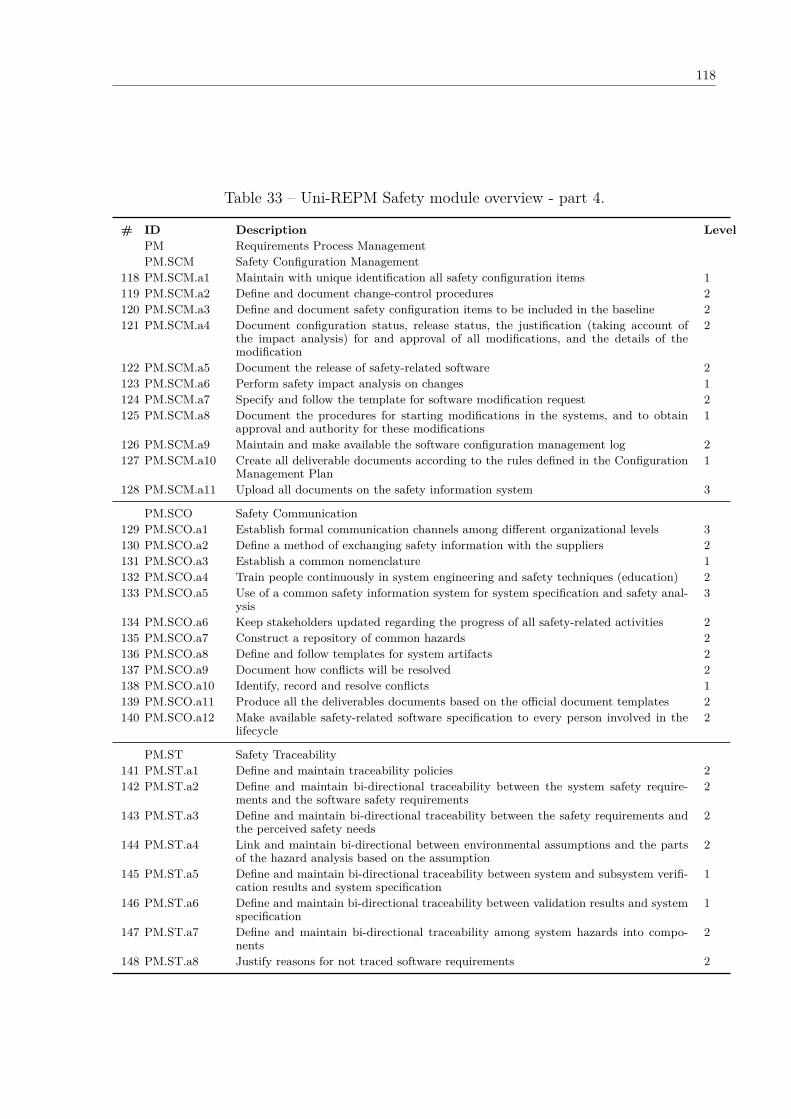
118
Table 33 – Uni-REPM Safety module overview - part 4.
# ID Description LevelPM Requirements Process ManagementPM.SCM Safety Configuration Management
118 PM.SCM.a1 Maintain with unique identification all safety configuration items 1119 PM.SCM.a2 Define and document change-control procedures 2120 PM.SCM.a3 Define and document safety configuration items to be included in the baseline 2121 PM.SCM.a4 Document configuration status, release status, the justification (taking account of
the impact analysis) for and approval of all modifications, and the details of themodification
2
122 PM.SCM.a5 Document the release of safety-related software 2123 PM.SCM.a6 Perform safety impact analysis on changes 1124 PM.SCM.a7 Specify and follow the template for software modification request 2125 PM.SCM.a8 Document the procedures for starting modifications in the systems, and to obtain
approval and authority for these modifications1
126 PM.SCM.a9 Maintain and make available the software configuration management log 2127 PM.SCM.a10 Create all deliverable documents according to the rules defined in the Configuration
Management Plan1
128 PM.SCM.a11 Upload all documents on the safety information system 3
PM.SCO Safety Communication129 PM.SCO.a1 Establish formal communication channels among different organizational levels 3130 PM.SCO.a2 Define a method of exchanging safety information with the suppliers 2131 PM.SCO.a3 Establish a common nomenclature 1132 PM.SCO.a4 Train people continuously in system engineering and safety techniques (education) 2133 PM.SCO.a5 Use of a common safety information system for system specification and safety anal-
ysis3
134 PM.SCO.a6 Keep stakeholders updated regarding the progress of all safety-related activities 2135 PM.SCO.a7 Construct a repository of common hazards 2136 PM.SCO.a8 Define and follow templates for system artifacts 2137 PM.SCO.a9 Document how conflicts will be resolved 2138 PM.SCO.a10 Identify, record and resolve conflicts 1139 PM.SCO.a11 Produce all the deliverables documents based on the official document templates 2140 PM.SCO.a12 Make available safety-related software specification to every person involved in the
lifecycle2
PM.ST Safety Traceability141 PM.ST.a1 Define and maintain traceability policies 2142 PM.ST.a2 Define and maintain bi-directional traceability between the system safety require-
ments and the software safety requirements2
143 PM.ST.a3 Define and maintain bi-directional traceability between the safety requirements andthe perceived safety needs
2
144 PM.ST.a4 Link and maintain bi-directional between environmental assumptions and the partsof the hazard analysis based on the assumption
2
145 PM.ST.a5 Define and maintain bi-directional traceability between system and subsystem verifi-cation results and system specification
1
146 PM.ST.a6 Define and maintain bi-directional traceability between validation results and systemspecification
1
147 PM.ST.a7 Define and maintain bi-directional traceability among system hazards into compo-nents
2
148 PM.ST.a8 Justify reasons for not traced software requirements 2
119
5.3 MODULE USAGE
The Uni-REPM Safety module aims to assess the safety maturity in the RE process; hence, itcan be used by people who are involved in RE process, deeply understand it and are in chargeof process improvement in general.
Examples of users are:
• Requirements Engineer
• Safety Engineer
• Software Engineer
• Quality assurance engineer
• Project manager
• Product manager
Since we designed a module for an existing maturity model, aiming to maintain com-patibility with Uni-REPM, the safety maturity evaluation is performed using an assessmentinstrument. The instrument consists of questions, available in the tool (see Chapter 6) aftersign in, grouped according to the MPA and SPA.
The instrument has a query to evaluate each safety action in which the evaluator can selectone of three options:
1. “Incomplete” (IC) - the action was deemed vital but was done partially or not at all inthis RE process.
2. “Complete” (C) - the action was done in this RE process.
3. “Inapplicable” (IA) - the action was not necessary or possible to be done in the process.
Safety-critical systems are developed in several domains by companies with different sizes,infrastructure and maturity. Hence, some organizations may not benefit from implementing allthe actions in the module or some actions are deemed unnecessary to be done in particularsituations of organizations.
For example, in small systems, prototypes may be not useful since the system can be verysimple. In this case, the action “OS.SKM.a4 Evaluate prototypes, requirements and technicalUI restrictions (Basic Level)” might not be useful for some companies. If we consider it as“Incomplete”, the process may not reach the Basic level because not all actions in this level arefulfilled. This is even more unfair if all other actions in higher maturity levels are completed.
Accordingly, safety processes of the companies should not be “devalued” if they do notperform a certain non-essential action (in their point of view). In order to consider situations

120
like these, the option “Inapplicable” is provided. In this way, the module fits more real processand the evaluation result is less distorted.
Therefore, in some cases, the organization may find some actions only applicable in oneof the settings. Whether an action is “Inapplicable” or not is solely based on the judgment ofthe project evaluator. Reasons for marking the action with this option should be consideredcarefully to avoid accidentally skipping an important action. Moreover, lack of time, resourceor unawareness cannot be used as a reason to mark an action as being “Inapplicable”.
The assessment instrument is implemented in an online software tool aiming to facilitateand automate the evaluation process. The tool, whose features are described in Chapter 6, isavailable at <http://www.cin.ufpe.br/~ler/unirepm>. The tool supports the evaluation of theentire Uni-REPM (requirements and safety module) and it has three types of user: (1) externalevaluator - this user can insert companies, projects and perform Safety/RE evaluations; (2)internal evaluator - this user only can insert projects to the company he/she belongs andperform Safety/RE evaluations; (3) admin - besides the functionalities of external evaluators,this user can manage users and different versions of RE/Safety models.
In Figure 28, we present an example of the Uni-REPM SCS assessment instrument. TheAction ID in the checklist links the question(s) to the associated action in the model. Thishelps the users in case they need to locate the item for further information or clarification.
Figure 28 – Partial view of Uni-REPM SCS assessment instrument.
After answering all questions present in the assessment instrument, the tool determinesand presents the evaluation results. To define the maturity level, the tool consider that: (1)for each SPA, all actions at a certain level must be Completed (or Inapplicable) in order tothe MPA achieve such level; (2) for the whole process, all actions at a certain level must beCompleted (or Inapplicable) to the process achieve such level.
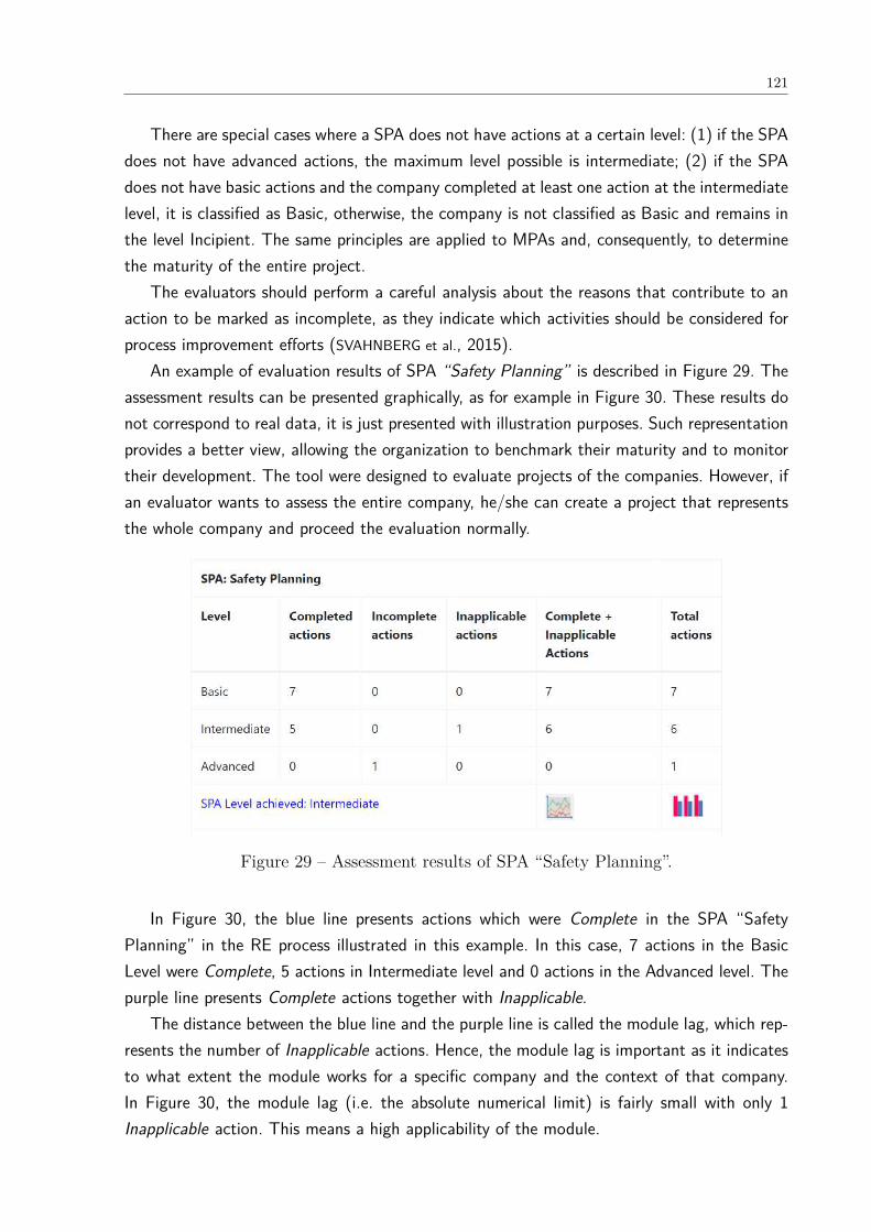
121
There are special cases where a SPA does not have actions at a certain level: (1) if the SPAdoes not have advanced actions, the maximum level possible is intermediate; (2) if the SPAdoes not have basic actions and the company completed at least one action at the intermediatelevel, it is classified as Basic, otherwise, the company is not classified as Basic and remains inthe level Incipient. The same principles are applied to MPAs and, consequently, to determinethe maturity of the entire project.
The evaluators should perform a careful analysis about the reasons that contribute to anaction to be marked as incomplete, as they indicate which activities should be considered forprocess improvement efforts (SVAHNBERG et al., 2015).
An example of evaluation results of SPA “Safety Planning” is described in Figure 29. Theassessment results can be presented graphically, as for example in Figure 30. These results donot correspond to real data, it is just presented with illustration purposes. Such representationprovides a better view, allowing the organization to benchmark their maturity and to monitortheir development. The tool were designed to evaluate projects of the companies. However, ifan evaluator wants to assess the entire company, he/she can create a project that representsthe whole company and proceed the evaluation normally.
Figure 29 – Assessment results of SPA “Safety Planning”.
In Figure 30, the blue line presents actions which were Complete in the SPA “SafetyPlanning” in the RE process illustrated in this example. In this case, 7 actions in the BasicLevel were Complete, 5 actions in Intermediate level and 0 actions in the Advanced level. Thepurple line presents Complete actions together with Inapplicable.
The distance between the blue line and the purple line is called the module lag, which rep-resents the number of Inapplicable actions. Hence, the module lag is important as it indicatesto what extent the module works for a specific company and the context of that company.In Figure 30, the module lag (i.e. the absolute numerical limit) is fairly small with only 1Inapplicable action. This means a high applicability of the module.

122
Figure 30 – Example of a graphical presentation of assessment results of SPA “SafetyPlanning”.
Besides, in Figure 30, the green line presents the total actions that should be completedin “Safety Planning” SPA. For example, at Advanced level, there is 1 action that should befinished. The difference between the purple and green lines is important because it denotes theimprovement area of the process. It shows how many additional actions should be conductedto achieve a certain level of maturity.
Overall, the graph of Figure 30 denotes that, in this SPA, the process has not done all theactions at Advanced level. Hence, the SPA received Intermediate Level. In order to reach theAdvanced level, 1 more action has to be done. Similar work can be done with other SPAs toachieve the result for the whole process.
It is important to highlight that the graphical presentation of Figure 30 does not includecumulative action counts. It only shows the total number of actions and the number of com-pleted + inapplicable actions by maturity level. So, even if the company complete all actionsof higher levels, for example intermediate level, but did not complete the actions of basic level,the company does not achieve the basic level, remaining at level Incipient.
5.4 COMPARISON WITH RELATED SOLUTIONS
Maturity models that explicitly address safety in RE process could not be identified. Instead,we found only two safety maturity models that address RE and safety engineering as separatefields. In Tables 34 and 35, we present a comparison among them.
The Uni-REPM Safety module differs from existing safety maturity models such as +SAFE-CMMI-DEV (SEI, 2007), and ISO 15504-10 (STANDARDIZATION, 2011c) in terms of purpose,scope, intended usage and number of practices.
+SAFE-CMMI-DEV, developed in 2007, is an extension to CMMI for Development (CMMI-DEV) developed for standalone use, i.e. it is not intended to be embedded in a CMMI model,

123
but can be modified to support different safety standards. It covers two process areas thathave Generic Goals, Specific Goals and Specific Practices: Safety Management and SafetyEngineering (JOHANNESSEN; HALONEN; ÖRSMARK, 2011).
The Generic Goals of Safety Management are Achieve Specific Goals (1 practice), Institu-tionalize a Managed Process (10 practices), Institutionalize a Defined Process (2 practices),Institutionalize a Quantitatively Managed Process (2 practices), and Institutionalize an Op-timizing Process (2 practices). Specific Goals include Develop Safety Plans (4 practices),Monitor Safety Incidents (1 practice), and Manage Safety-Related Suppliers (2 practices).
The Safety Engineering process area has the same five Generic Goals (and their practices)of Safety Management. Its Specific Goals are Identify Hazards, Accidents, and Sources ofHazards (2 practices), Analyze Hazards and Perform Risk Assessments (1 practices), Defineand Maintain Safety Requirements (3 practices), Design for Safety (3 practices), and SupportSafety Acceptance (4 practices).
ISO/IEC 15504-10 (STANDARDIZATION, 2011c), developed in 2011 as a standalone docu-ment, was conceived to be used in conjunction with ISO/IEC 15504-5 (An exemplar ProcessAssessment Model) and/or ISO/IEC TR 15504-6 (An exemplar system life cycle process as-sessment model) process assessment models by experienced assessors with minimal supportfrom safety domain experts (LAMI; FABBRINI; FUSANI, 2011c).
The structure of ISO/IEC 15504-10 has the same process areas of +SAFE-CMMI-DEV.However, the number of practices is higher. Safety Management has 10 base practices, SafetyEngineering has 11 practices. Moreover, it has one more process than +SAFE-CMMI-DEV:Safety Qualification (JOHANNESSEN; HALONEN; ÖRSMARK, 2011) with 5 practices. Finally, itclaims that the defined processes are consistent with five different safety standards: IEC 61508,+SAFE-CMMI-DEV, ISO 26262, IEC 60880, UK MoD Def Stan 00-56.
None of the models are intended to be used as part of a product assessment. While safetystandards require the definition of safety integrity level of the system under development to setrequirements for the project and the system, the maturity models provide a way to evaluatethe capability of safety-related processes as well as a scheme for their improvement (LAMI;
FABBRINI; FUSANI, 2011c). Hence, the maturity level achieved is not related with the safetyintegrity level the project has to fulfill. Accordingly, an evaluation based on any of these modelsis not analogous to a functional safety assessment (SEI, 2007).
Besides, standards do not have the feature of making possible for practitioners and acompany to state “this specific practice is not relevant for us”. Safety maturity models do,and thus, the model applicability to a real industrial context is better. Therefore, we share theview of +SAFE-CMMI-DEV and ISO 15504-10 that there is no relationship between safetyintegrity levels and maturity levels.
Another common feature of the maturity models is that they do not prescribe any specifictechnique, method or tool. Their goal is to consider the process (the “what”) and not requirethe adoption of any specific technique or method (the “how”) (LAMI; FABBRINI; FUSANI, 2011c).
124
+SAFE-CMMI-DEV and ISO/IEC 15504-10 cover the entire project lifecycle. Hence, theydo not go into detail into any particular practice area, such as RE. In introduction section, wediscuss presenting references which show that requirements problems have been associated withmany accidents and safety incidents. The need of integrating safety and RE teams has been welldiscussed by very seminal papers in SCS area, and now a consensus in academia and industry isbeing established that addressing safety concerns early in software development contributes toensuring that safety problems do not propagate through subsequent phases. Furthermore, theearly consideration of safety concerns in RE should be a top priority in the development of SCSsince RE is essential for software quality, and the effectiveness of the software developmentprocess. Moreover, high safety levels are typically best achieved by addressing safety from thebeginning; not by trying to add protection components and additional complexities after systemhas been developed. Accordingly, such requirements issues tend to be mitigated in companieswith high process maturity levels since they do their business in a systematic, consistent andproactive approach.
Uni-REPM SCS proposes 148 safety actions while +SAFE-CMMI-DEV has 20 in which 13actions have a correspondence with our model; and ISO/IEC 15504-10 has 26 actions being16 present in Uni-REPM SCS. The other actions involve later stages of system developmentthat are not the scope of our model. These demonstrate that Uni-REPM SCS has a goodcoverage of safety practices when compared with related solutions.
Therefore, the maturity model we propose is more descriptive and detailed as stated bythe practitioners in the static validation (Section 7.1) and in the dynamic validation (Section7.2). It was designed specifically for safety in RE and contains a comprehensive assessmentinstrument considering the total number of safety practices 148 against 20 (+SAFE) and 26(ISO 15504-10).

125
Table 34 – Comparison among Uni-REPM SCS, +Safe-CMMI-DEV, and ISO 15504-10(part 1).
Uni-REPM SCS +SAFE-CMMI-DEV ISO 15504-10
Year 2017 2007 2011
Motivationfor creatingthe model
In order to ensure a well-ordered safety progress, en-gineers should handle sev-eral features (e.g. organiza-tional, technical, strategic).Thus, companies should im-prove their RE process withthe purpose of overcome thedifficulties they face duringthe construction of SCS. Re-quirements engineers needsystematic guidance to con-sider safety concerns early inthe development process.
The extension was devel-oped because the AustralianDefense Materiel Organiza-tion recognized that CMMIis a generically structuredframework that requiresamplification for special-ized areas of engineeringsuch as safety engineering.Developing safety-criticalproducts requires special-ized processes, techniques,skills, and experience withinan organization.
ISO/IEC 15504 process as-sessment models for systemsand software do not cur-rently provide a sufficientbasis for performing a pro-cess capability assessmentof processes with respectto the development of com-plex safety-related systems.Developing safety-relatedsystems requires specializedprocesses, techniques, skillsand experience. Processamplifications are neededin the area of safety man-agement, safety engineeringand the safety qualification.
Full Availableto download
Yes Yes No
Independentof anydomain-specific stan-dard
Yes Yes Yes
Intended us-age
RE phase System lifecycle System lifecycle
Independentof safetyintegrity level
Yes Yes Yes
Goals of themodel
It aims to reduce issues inRE during SCS developmentby addressing safety action-s/practices that should becovered in the RE processto reduce the gap betweenthese areas.
Its purpose is to extendCMMI to provide an ex-plicit, specific framework forfunctional safety with re-spect to developing complexsafety-critical products.
It presents these amplifica-tions (a safety extension) asthree process descriptions toprovide additional life-cycleverification activities relatedto the methods and tech-niques selected relevant tosafety requirements adoptedand tailoring guidance forusers intending to use thesafety extension as part of aprocess assessment.
Number oflevels
3 (Basic, Intermediate, Ad-vanced)
5 (Initial, Managed, De-fined, Quantitatively Man-aged, Optimizing)
5 (Initial, Managed, De-fined, Quantitatively Man-aged, Optimizing)
Lowest matu-rity level
It contains actions of primi-tive but repeatable RE pro-cess. Although the actionsare basic, the RE process inthis level is defined and fol-lowed.
The processes are usually adhoc and chaotic. The organi-zation usually does not pro-vide a stable environment tosupport processes. Maturitylevel 1 companies are char-acterized by a tendency toover commit, abandon theirprocesses in a time of cri-sis, and be unable to repeattheir successes.
The process achieves the ob-jectives in some way andgenerates the expected workproducts.
Highest matu-rity level
It is the most mature REprocess that cover prede-fined and structured proce-dures as well as pays ad-equate attention to futureprocesses and work prod-ucts.
An organization focuses oncontinually improving pro-cess performance throughincremental and innovativeprocess and technologicalimprovements. The organi-zation’s quality and pro-cess performance objectivesare established, continuallyrevised to reflect chang-ing business objectives andorganizational performance,and used as criteria in man-aging process improvement.
The process, in addition tobeing executed, managed,defined and executed withinquantitative limits, can becontinuously improved.
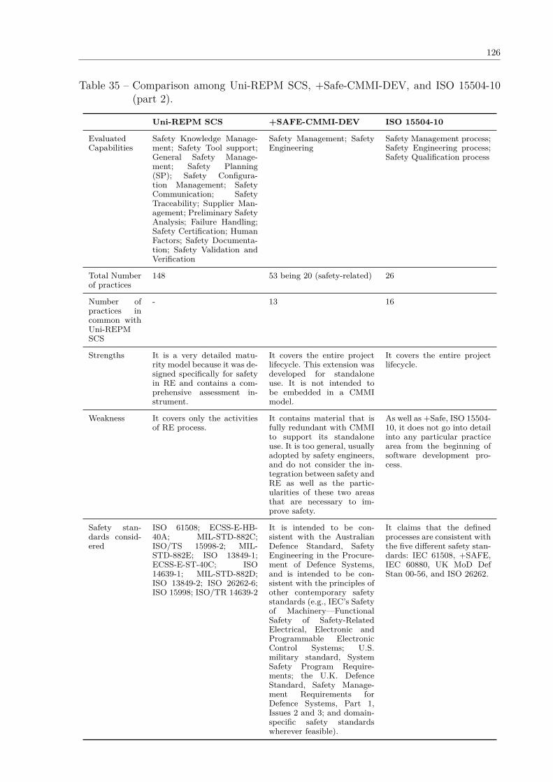
126
Table 35 – Comparison among Uni-REPM SCS, +Safe-CMMI-DEV, and ISO 15504-10(part 2).
Uni-REPM SCS +SAFE-CMMI-DEV ISO 15504-10
EvaluatedCapabilities
Safety Knowledge Manage-ment; Safety Tool support;General Safety Manage-ment; Safety Planning(SP); Safety Configura-tion Management; SafetyCommunication; SafetyTraceability; Supplier Man-agement; Preliminary SafetyAnalysis; Failure Handling;Safety Certification; HumanFactors; Safety Documenta-tion; Safety Validation andVerification
Safety Management; SafetyEngineering
Safety Management process;Safety Engineering process;Safety Qualification process
Total Numberof practices
148 53 being 20 (safety-related) 26
Number ofpractices incommon withUni-REPMSCS
- 13 16
Strengths It is a very detailed matu-rity model because it was de-signed specifically for safetyin RE and contains a com-prehensive assessment in-strument.
It covers the entire projectlifecycle. This extension wasdeveloped for standaloneuse. It is not intended tobe embedded in a CMMImodel.
It covers the entire projectlifecycle.
Weakness It covers only the activitiesof RE process.
It contains material that isfully redundant with CMMIto support its standaloneuse. It is too general, usuallyadopted by safety engineers,and do not consider the in-tegration between safety andRE as well as the partic-ularities of these two areasthat are necessary to im-prove safety.
As well as +Safe, ISO 15504-10, it does not go into detailinto any particular practicearea from the beginning ofsoftware development pro-cess.
Safety stan-dards consid-ered
ISO 61508; ECSS-E-HB-40A; MIL-STD-882C;ISO/TS 15998-2; MIL-STD-882E; ISO 13849-1;ECSS-E-ST-40C; ISO14639-1; MIL-STD-882D;ISO 13849-2; ISO 26262-6;ISO 15998; ISO/TR 14639-2
It is intended to be con-sistent with the AustralianDefence Standard, SafetyEngineering in the Procure-ment of Defence Systems,and is intended to be con-sistent with the principles ofother contemporary safetystandards (e.g., IEC’s Safetyof Machinery—FunctionalSafety of Safety-RelatedElectrical, Electronic andProgrammable ElectronicControl Systems; U.S.military standard, SystemSafety Program Require-ments; the U.K. DefenceStandard, Safety Manage-ment Requirements forDefence Systems, Part 1,Issues 2 and 3; and domain-specific safety standardswherever feasible).
It claims that the definedprocesses are consistent withthe five different safety stan-dards: IEC 61508, +SAFE,IEC 60880, UK MoD DefStan 00-56, and ISO 26262.
127
5.5 FINAL CONSIDERATIONS
RE problems during the development of SCS may be reduced in higher mature processes.Accordingly, we propose a safety module for the Uni-REPM maturity model to handle safetyconcerns in the RE process. The safety module proposed in this thesis breaks down RE practicesand actions and balances them for the SCS development which is an activity that has not donebefore. Hence, it brings RE knowledge into sync with many traditional safety standards thatoften omit details about RE.
In this chapter, we described the structure, contents and usage of the Uni-REPM Safetymodule. The module consists of seven main process areas, 14 sub-process areas and 148actions. These action are classified in a maturity level in a Likert scale (1-Basic, 2-Intermediate,3-Advanced).
Besides, we compared the module with the only two existing safety maturity models found.In the next chapter, we describe the web tool we developed to support the assessments usingthe Uni-REPM and its safety module.

128
6 SUPPORT TOOL
This chapter describes the Uni-REPM Tool that supports the Uni-REPM (Universal Require-ments Engineering Process Maturity Model) as well as its safety module.
Uni-REPM tool can be used by practitioners who are involved in software development,such as requirements, safety, software or quality assurance engineers as well as project andproduct managers. An overview of the solution is presented in Figure 31.
Figure 31 – Tool overview.
The tool was developed following the waterfall software development process model (SOM-
MERVILLE, 2011). We chose this methodology since we had well-defined requirements, mainlyderived from the literature review. Accordingly, requirement changing was not a risk to handle.Hence, there was no need of following an iterative and incremental approach like an agilemethodology. Moreover, we needed the complete system to develop the assessments withpractitioners.
According to Sommerville (2011), the waterfall model takes the fundamental process activ-
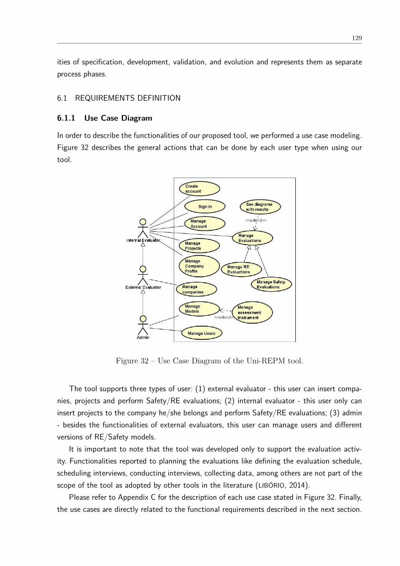
129
ities of specification, development, validation, and evolution and represents them as separateprocess phases.
6.1 REQUIREMENTS DEFINITION
6.1.1 Use Case Diagram
In order to describe the functionalities of our proposed tool, we performed a use case modeling.Figure 32 describes the general actions that can be done by each user type when using ourtool.
Figure 32 – Use Case Diagram of the Uni-REPM tool.
The tool supports three types of user: (1) external evaluator - this user can insert compa-nies, projects and perform Safety/RE evaluations; (2) internal evaluator - this user only caninsert projects to the company he/she belongs and perform Safety/RE evaluations; (3) admin- besides the functionalities of external evaluators, this user can manage users and differentversions of RE/Safety models.
It is important to note that the tool was developed only to support the evaluation activ-ity. Functionalities reported to planning the evaluations like defining the evaluation schedule,scheduling interviews, conducting interviews, collecting data, among others are not part of thescope of the tool as adopted by other tools in the literature (LIBÓRIO, 2014).
Please refer to Appendix C for the description of each use case stated in Figure 32. Finally,the use cases are directly related to the functional requirements described in the next section.

130
6.1.2 Functional and Non-Functional Requirements
After the Use case diagram elaboration, we identified the system’s functional and non-functionalrequirements. To facilitate the search and reference of requirements throughout this thesis willbe adopted a convention for each type of requirement. The functional requirements will berepresented in [FRxx] format and non-functional requirements in [NFRxx] format, where “FR”and “NFR” are the acronyms for each type and “xx” represents the requirement number.
The requirements were classified as:
• Essential: It is the requirement indispensable to the system’s operation. This type ofrequirement must be implemented, otherwise the project will lose its usefulness.
• Important: Without this requirement, the system is still capable of being used. However,such use occurs unsatisfactorily by the customer.
• Desirable: This type of requirement can be implemented in later versions of the system,since even without its implementation the system fulfills its basic functionalities.
The non-functional requirements as well as functional requirements are presented in Table36 and Table 37 respectively.
Table 36 – Uni-REPM tool non-functional requirements.
Code Description Priority
NRF01 The system must allow users to sign in. Essential
NRF02 Compatilibty: The system must execute in the following browsers: GoogleChrome, Internet Explorer, Mozilla Firefox.
Important
NRF03 The system must be developed using the PHP language. Essential
NRF04 The system must use the MySQL database. Essential
NRF05 The system must be a web application. Essential
NFR06 The projects and assessment shall only be accessible by owner if owner islogged in.
Essential
NFR07 The admin user can access all assessments of all users. Essential
NFR08 The system shall validate user input for required input to prevent empty data. Essential
NFR09 Persistence: It is necessary that the data generated by users are stored for lateruse.
Essential
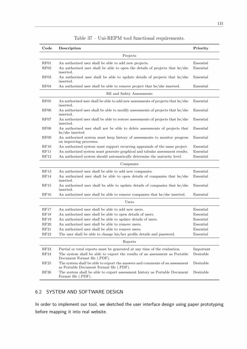
131
Table 37 – Uni-REPM tool functional requirements.
Code Description Priority
Projects
RF01 An authorized user shall be able to add new projects. EssentialRF02 An authorized user shall be able to open the details of projects that he/she
inserted.Essential
RF03 An authorized user shall be able to update details of projects that he/sheinserted.
Essential
RF04 An authorized user shall be able to remove project that he/she inserted. Essential
RE and Safety Assessments
RF05 An authorized user shall be able to add new assessments of projects that he/sheinserted.
Essential
RF06 An authorized user shall be able to modify assessments of projects that he/sheinserted.
Essential
RF07 An authorized user shall be able to restore assessments of projects that he/sheinserted.
Essential
RF08 An authorized user shall not be able to delete assessments of projects thathe/she inserted.
Essential
RF09 An authorized system must keep history of assessments to monitor progresson improving processes.
Essential
RF10 An authorized system must support recurring appraisals of the same project. EssentialRF11 An authorized system must generate graphical and tabular assessment results. EssentialRF12 An authorized system should automatically determine the maturity level. Essential
Companies
RF13 An authorized user shall be able to add new companies. EssentialRF14 An authorized user shall be able to open details of companies that he/she
inserted.Essential
RF15 An authorized user shall be able to update details of companies that he/sheinserted.
Essential
RF16 An authorized user shall be able to remove companies that he/she inserted. Essential
Users
RF17 An authorized user shall be able to add new users. EssentialRF18 An authorized user shall be able to open details of users. EssentialRF19 An authorized user shall be able to update details of users. EssentialRF20 An authorized user shall be able to remove users. EssentialRF21 An authorized user shall be able to remove users. EssentialRF22 The user shall be able to change his/her profile details and password. Essential
Reports
RF23 Partial or total reports must be generated at any time of the evaluation. ImportantRF24 The system shall be able to export the results of an assessment as Portable
Document Format file (.PDF).Desirable
RF25 The system shall be able to export the answers and comments of an assessmentas Portable Document Format file (.PDF).
Desirable
RF26 The system shall be able to export assessment history as Portable DocumentFormat file (.PDF).
Desirable
6.2 SYSTEM AND SOFTWARE DESIGN
In order to implement our tool, we sketched the user interface design using paper prototypingbefore mapping it into real website.
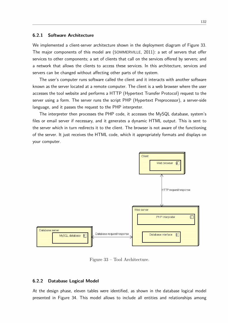
132
6.2.1 Software Architecture
We implemented a client-server architecture shown in the deployment diagram of Figure 33.The major components of this model are (SOMMERVILLE, 2011): a set of servers that offerservices to other components; a set of clients that call on the services offered by servers; anda network that allows the clients to access these services. In this architecture, services andservers can be changed without affecting other parts of the system.
The user’s computer runs software called the client and it interacts with another softwareknown as the server located at a remote computer. The client is a web browser where the useraccesses the tool website and performs a HTTP (Hypertext Transfer Protocol) request to theserver using a form. The server runs the script PHP (Hypertext Preprocessor), a server-sidelanguage, and it passes the request to the PHP interpreter.
The interpreter then processes the PHP code, it accesses the MySQL database, system’sfiles or email server if necessary, and it generates a dynamic HTML output. This is sent tothe server which in turn redirects it to the client. The browser is not aware of the functioningof the server. It just receives the HTML code, which it appropriately formats and displays onyour computer.
Figure 33 – Tool Architecture.
6.2.2 Database Logical Model
At the design phase, eleven tables were identified, as shown in the database logical modelpresented in Figure 34. This model allows to include all entities and relationships among
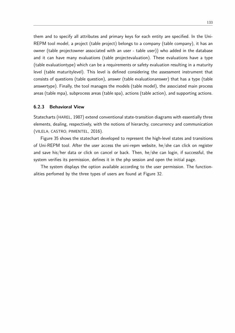
133
them and to specify all attributes and primary keys for each entity are specified. In the Uni-REPM tool model, a project (table project) belongs to a company (table company), it has anowner (table projectowner associated with an user - table user)) who added in the databaseand it can have many evaluations (table projectevaluation). These evaluations have a type(table evaluationtype) which can be a requirements or safety evaluation resulting in a maturitylevel (table maturitylevel). This level is defined considering the assessment instrument thatconsists of questions (table question), answer (table evaluationanswer) that has a type (tableanswertype). Finally, the tool manages the models (table model), the associated main processareas (table mpa), subprocess areas (table spa), actions (table action), and supporting actions.
6.2.3 Behavioral View
Statecharts (HAREL, 1987) extend conventional state-transition diagrams with essentially threeelements, dealing, respectively, with the notions of hierarchy, concurrency and communication(VILELA; CASTRO; PIMENTEL, 2016).
Figure 35 shows the statechart developed to represent the high-level states and transitionsof Uni-REPM tool. After the user access the uni-repm website, he/she can click on registerand save his/her data or click on cancel or back. Then, he/she can login, if successful, thesystem verifies its permission, defines it in the php session and open the initial page.
The system displays the option available according to the user permission. The function-alities perfomed by the three types of users are found at Figure 32.
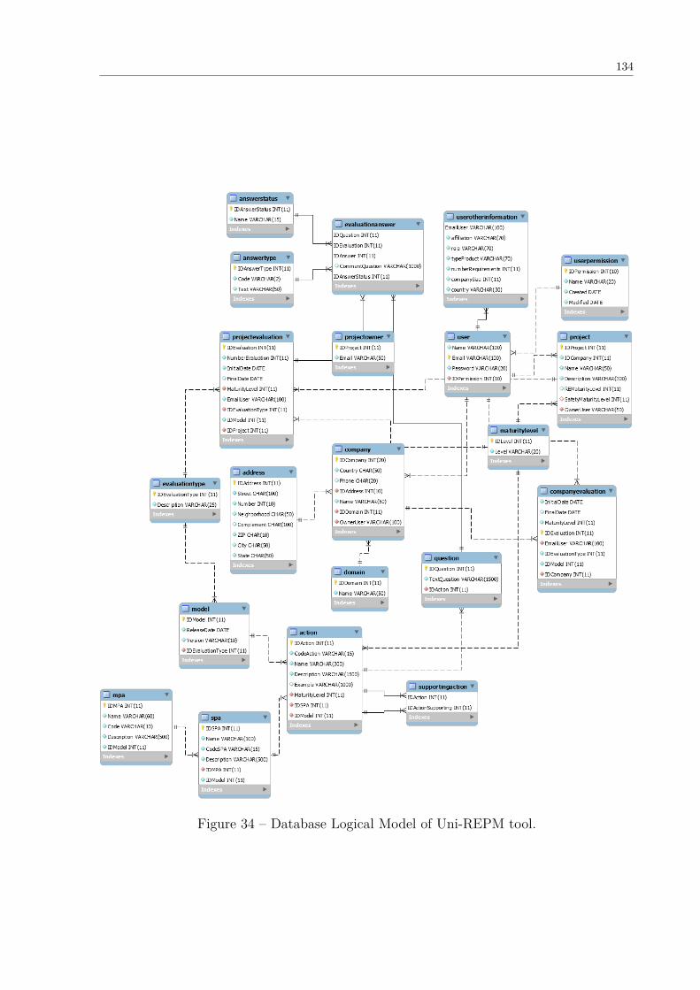
134
Figure 34 – Database Logical Model of Uni-REPM tool.

135
Figure 35 – Statechart of Uni-REPM tool.

136
6.3 IMPLEMENTATION AND TEST
The Uni-REPM web-based tool was coded in PHP (GROUP, 2018) as back-end programminglanguage, JavaScript (KANTOR, 2018) as front-end programming language, and HTML asHypertext Markup Language. The main libraries used in the tool were: Bootstrap (MIT, 2018),Sweetalert (EDWARDS, 2018), and Google Charts (GOOGLE, 2018). All the data is stored in aMySQL database (ORACLE, 2018).
In the last decades, several techniques for software Validation and Verification (V & V) haveemerged. The V & V technique chosen to be used in this work was functional test, also knownas black-box test, since it evaluates the external behavior of the software component, withoutconsidering its code (DELAMARO; JINO; MALDONADO, 2017). In this technique, implementationdetails are not considered and the system is tested from the user’s point of view.
The criteria we used to perform functional test in Uni-REPM were equivalence class par-titioning and Boundary Value Analysis for being the ones most adopted in this type of test(DELAMARO; JINO; MALDONADO, 2017).
Equivalence class partitioning is a testing criterion that splits the input of a software unitinto partitions of equivalent data from which test cases can be derived (DELAMARO; JINO;
MALDONADO, 2017).The Boundary Value Analysis is a software testing criterion in which tests are designed to
verify the boundary values in a range. The case tests are derived from the equivalence classpartitioning criterion (DELAMARO; JINO; MALDONADO, 2017).
In the next section, we present an overview of how to use the Uni-REPM tool.
6.3.1 Using Uni-REPM Tool
The main goal of Uni-REPM Tool is to provide users with a web-based questionnaire toevaluate the maturity of their RE and/or safety-critical projects. For the organization of theseprocesses and practices within the tool, a structure in sections, according to Figure 36 isprovided. Each MPA has related SPAs presented as subsections. When selecting one SPA, thesystem presents all the questions related to the selected SPA. The questions that are part ofthe assessment questionnaire are described at: <http://www.cin.ufpe.br/~ler/unirepm>.
From the structure shown in Figure 36, the evaluator can insert information about eachpractice evaluated, informing whether it “Incomplete”, “Complete” or “Inapplicable” as wellas insert additional comments on the action. The Action ID in the checklist, for exampleDS.DD.a1, links the question (s) to the associated action in the model. This helps the usersin case they need to locate the item for further information or clarification.
After answering all questions present in assessment instrument, the tool determines andpresents the evaluation results. Based on the information provided by the evaluator, the systemenables the extraction of information such as the maturity level reached in each SPA and MPA,and a summary of the answers to all questions as well as graphical visualization of maturity

137
Figure 36 – Partial view of Uni-REPM assessment instrument structure.
level.In order to provide the assessment, some functionalities were needed to be developed, such
as registration of users, questions, options of answers, MPA, SPA, and actions. Moreover,there is the possibility to create new versions of the model using the tool (available only toadmin users), which can support different companies’ profiles.
The link (for tool demo) can be found at <https://youtu.be/nvZCdUmA61U>.
6.4 INTEGRATION AND SYSTEM TESTING
The Uni-REPM Tool was evaluated by potential users. Section 7.2 presents the validationcarried out from the point of view of industry practitioners.
The evaluation of the tool usability was based on the PSSUQ (The Post-Study SystemUsability Questionnaire) (LEWIS, 1995). This method provides a 19-item questionnaire, withadministration and scoring instructions, that were used in usability measurement at IBM.
The PSSUQ analyzes the system usability through four factors (overall satisfaction, systemusefulness, information quality and interface quality) from the answers obtained from the eval-uation questionnaire. Although it has 19 questions, we used only five closed-ended questions(presented below) that we consider the most important and one open question to subjectsexpress their opinion. We made this choice due to the time constraints of the practitioners.
Accordingly, The practitioners filled in a questionnaire form which evaluates the tool fromthe aspects below:
“I could effectively complete a safety evaluation using this software tool.”( ) Strongly agree ( ) Agree ( ) Neither agree nor disagree ( ) Disagree ( ) Strongly disagree
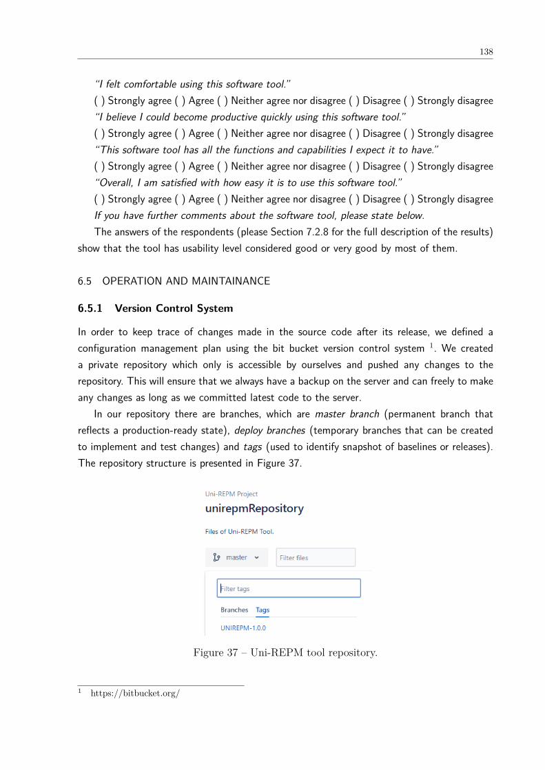
138
“I felt comfortable using this software tool.”( ) Strongly agree ( ) Agree ( ) Neither agree nor disagree ( ) Disagree ( ) Strongly disagree“I believe I could become productive quickly using this software tool.”( ) Strongly agree ( ) Agree ( ) Neither agree nor disagree ( ) Disagree ( ) Strongly disagree“This software tool has all the functions and capabilities I expect it to have.”( ) Strongly agree ( ) Agree ( ) Neither agree nor disagree ( ) Disagree ( ) Strongly disagree“Overall, I am satisfied with how easy it is to use this software tool.”( ) Strongly agree ( ) Agree ( ) Neither agree nor disagree ( ) Disagree ( ) Strongly disagreeIf you have further comments about the software tool, please state below.The answers of the respondents (please Section 7.2.8 for the full description of the results)
show that the tool has usability level considered good or very good by most of them.
6.5 OPERATION AND MAINTAINANCE
6.5.1 Version Control System
In order to keep trace of changes made in the source code after its release, we defined aconfiguration management plan using the bit bucket version control system 1. We createda private repository which only is accessible by ourselves and pushed any changes to therepository. This will ensure that we always have a backup on the server and can freely to makeany changes as long as we committed latest code to the server.
In our repository there are branches, which are master branch (permanent branch thatreflects a production-ready state), deploy branches (temporary branches that can be createdto implement and test changes) and tags (used to identify snapshot of baselines or releases).The repository structure is presented in Figure 37.
Figure 37 – Uni-REPM tool repository.
1 https://bitbucket.org/

139
6.6 FUTURE IMPROVEMENT ROADMAP
As a closure for this project, we had planned a roadmap for future improvement of this tool.The following features are not included in our project, but it will be helpful to be added toovercome the limitations of this tool. To improve this tool, we may add other functionalitiessuch as:
• Collaboration Features: literature reports that experienced users tend to use collabo-rative tool in their requirement specification process. This suggested that in the industry,requirement specification process are most likely conducted by few persons. Hence, wepropose to allow multiple users assessing the same project.
• Support adding/editing evidence: documents that support the completion of prac-tices (evidences) may be upload or edited in the tool to increase the reliability of answers.This will allow to store the evidences that the action is in fact complete and not onlyrely on respondent answers.
• Calculate the average of assessments: the tool may keep history of assessments andcalculate an average of assessment performed previously.
• Sending reports by email: the tool may allow adding a set of emails to be notifiedeach time evaluation results are submitted to the tool. This would make communicationbetween the assessment team faster and more agile, where all stakeholders would havereal-time knowledge of data submissions to the tool (LIBÓRIO, 2014).
• Export evaluations: besides having the option to export the results in PDF format, thetool could provide means of construction customized reports. Accordingly, the user couldchoose what data would be displayed, the form of display (source, positioning, etc.), aswell as characterize the report according to the evaluated organization, for example.
6.7 FINAL CONSIDERATIONS
The Uni-REPM tool provides an interactive environment for evaluating the maturity of REprocesses of software development organizations. Uni-REPM SCS is crossing boundaries con-sidering its goal of integrating the RE and safety areas increasing its impact in academia andindustry.
In general, the interviewees considered the proposed tool useful and easy to conduct as-sessments. Future work will concentrate on adding new features to the tool, such as newkinds of visualization and reports such as the evaluations history. We are also looking to neworganizations to perform new evaluations and collect feedback from practitioners about thetool usability.
In the next chapter, we describe the static validation performed to evaluate the complete-ness and usefulness of Uni-REPM SCS.
140
7 MODULE VALIDATION
In this chapter, we describe the planning and results of the validation we performed to validateUni-REPM SCS. We adopted the concept of validation of Wieringa et al. (2006) that definesvalidation research as the investigation by a thorough ad methodologically sound research setupof the properties of a novel solution proposal that has not yet been implemented in RE practice.The solution may have been proposed by the author or by someone else. Furthermore, we arefollowing the framework of technology transfer of Gorschek et al. (2006) that also adopts theterm validation for a candidate solution.
Aiming to validate Uni-REPM SCS and ensure that the model quality is suitable for com-panies to pilot, we performed a static validation following the technology transfer frameworkdescribed in Section 3.9. After we formulated the candidate solution, which was the version0.1 of UniREPM SCS, we conducted a static validation (Section 7.1). This type of validationproposes collecting experts’ opinion in order to analyze whether the knowledge in literaturewas reasonably transferred and presented in the model (NGUYEN, 2010).
Conducting the static validation made possible to improve the candidate solution by gen-erating the version 0.2 and preparing it for the next step - dynamic validation (GORSCHEK et
al., 2006) described in Section 7.2.
7.1 STATIC VALIDATION
The static validation provides an early feedback that helps to identify potential problems with-out using industry resources (NGUYEN, 2010). Hence, it is possible to improve the candidatesolution and prepare it for the next step - dynamic validation (GORSCHEK et al., 2006).
7.1.1 Static validation design
We conducted the validation considering the aspects listed below. We decided to use theseaspects since they already have been used in the literature (NGUYEN, 2010) and we consideredthem sufficient to evaluate a candidate solution to a industry problem (GORSCHEK et al., 2006).
• Coverage: to make sure the module presents the necessary safety practices and to detectothers that might not be captured in the sources of information used to propose themodule.
• Correctness: to ensure the names and maturity levels of the proposed practices arecorrectly presented.
• Usefulness and Applicability: to collect the experts opinion about the module applicationin industrial settings and to what extent.
141
Considering the aspects above, the validation design was guided by the research questionsbelow:
RQ1: Does Uni-REPM SCS have a sufficient coverage of safety practices?RQ2: To what extent is Uni-REPM SCS suitable for companies, in terms of its correctness,
usefulness and applicability?RQ3: What improvements can be done to Uni-REPM SCS based on the findings from RQ1
and RQ2?To answer these research questions, we interviewed two industry practitioners and con-
ducted a survey with nine domain experts that work in academia and have partnerships withindustry. The subjects provided their opinion about the SPAs, actions, and their maturity levelsto validate its accuracy and adequacy.
The interviews were conducted in face-to-face meetings and the survey consisted in contact-ing domain experts using self-administered questionnaires sent by email. All subjects answeredthe same profile and module evaluation questionnaires and received a copy of Uni-REPM SCSfull description. The artifacts used are presented in Appendix E.
We adopted the self-administered questionnaire survey strategy because the subjects couldspend their most convenient time to analyze the module and answer the module evaluationquestionnaire. Besides, we collected subjects background aiming to better contextualize thefeedback received. These questions aimed to extract information about their knowledge andexperience in the area as well as to help to draw a better view about them.
The subjects were selected using random sampling after a previous analysis of their profile.We considered their research interest in SCS, embedded systems and RE, their experiencein these areas, and if they have publications in these areas. We searched for experts frommany sources (publications, personal recommendation) and contacted them through emails.After four months, 11 out of 137 experts contacted accepted to participate and returned theirfeedback.
7.1.2 Subjects Profile
Eleven experts participated in this validation. Considering their affiliation, they are from fourcountries: Brazil (eight experts), Norway, Poland, and South Korea with one subject each. Themajority of them has PhD (eight subjects) and three have Master degree. In order to easilyrefer to their comments, an ID that consisted of S# was assigned to each experts.
They have experience in academia, industry (working or with partnership), research insti-tute, and spin-off company as presented in Table 38. We have mainly academics participatingin this static validation as required by the technology transfer model (GORSCHEK et al., 2006)that defines that we should formulate a candidate solution, evaluate it in academia and im-prove it before using/validating in industry. Although the subjects are mainly academics, manyof them have previous industrial experience and also work actively with industry collaboratorsin the field. Considering that they have such experience, we asked them about the module
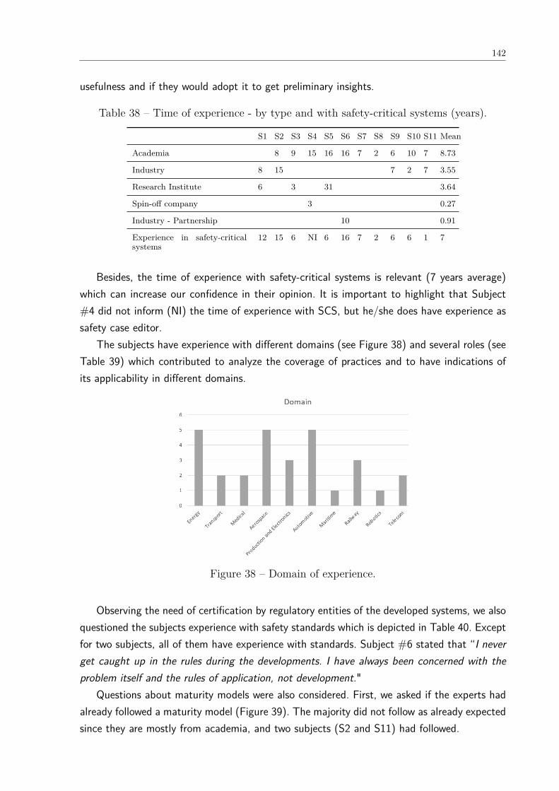
142
usefulness and if they would adopt it to get preliminary insights.
Table 38 – Time of experience - by type and with safety-critical systems (years).
S1 S2 S3 S4 S5 S6 S7 S8 S9 S10 S11 Mean
Academia 8 9 15 16 16 7 2 6 10 7 8.73
Industry 8 15 7 2 7 3.55
Research Institute 6 3 31 3.64
Spin-off company 3 0.27
Industry - Partnership 10 0.91
Experience in safety-criticalsystems
12 15 6 NI 6 16 7 2 6 6 1 7
Besides, the time of experience with safety-critical systems is relevant (7 years average)which can increase our confidence in their opinion. It is important to highlight that Subject#4 did not inform (NI) the time of experience with SCS, but he/she does have experience assafety case editor.
The subjects have experience with different domains (see Figure 38) and several roles (seeTable 39) which contributed to analyze the coverage of practices and to have indications ofits applicability in different domains.
Figure 38 – Domain of experience.
Observing the need of certification by regulatory entities of the developed systems, we alsoquestioned the subjects experience with safety standards which is depicted in Table 40. Exceptfor two subjects, all of them have experience with standards. Subject #6 stated that “I neverget caught up in the rules during the developments. I have always been concerned with theproblem itself and the rules of application, not development."
Questions about maturity models were also considered. First, we asked if the experts hadalready followed a maturity model (Figure 39). The majority did not follow as already expectedsince they are mostly from academia, and two subjects (S2 and S11) had followed.
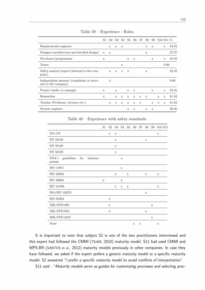
143
Table 39 – Experience - Roles.
S1 S2 S3 S4 S5 S6 S7 S8 S9 S10 S11 %
Requirements engineer x x x x x x 54.55
Designer (architecture and detailed design) x x x 27.27
Developer/programmer x x x x x 45.45
Tester x 9.09
Safety analyst/expert (internal to the com-pany)
x x x x x 45.45
Independent assessor (consultant or exter-nal to the company)
x 9.09
Project leader or manager x x x x x x 45.45
Researcher x x x x x x x x x 81.82
Teacher (Professor, lecturer etc.) x x x x x x x x x 81.82
System engineer x x x x 36.36
Table 40 – Experience with safety standards.
S1 S2 S3 S4 S5 S6 S7 S8 S9 S10 S11
DO-178 x x x
EN 50126 x x
EN 50128 x
EN 50129 x
FDA’s guidelines for infusionpumps
x
ISO 14971 x
ISO 26262 x x x x
IEC 60601 x x
IEC 61508 x x x x
ISO/IEC 62279 x
ISO 62304 x
MIL-STD-498 x x
MIL-STD-882 x x
MIL-STD-2167 x
None x x x
It is important to note that subject S2 is one of the two practitioners interviewed andthis expert had followed the CMMI (TEAM, 2010) maturity model. S11 had used CMMI andMPS.BR (SANTOS et al., 2012) maturity models previously in other companies. In case theyhave followed, we asked if the expert prefers a generic maturity model or a specific maturitymodel. S2 answered “I prefer a specific maturity model to avoid conflicts of interpretation”.
S11 said : “Maturity models serve as guides for customizing processes and selecting prac-
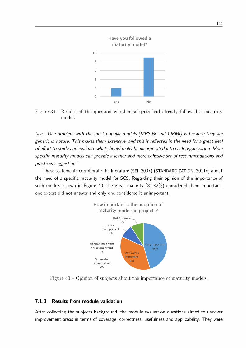
144
Figure 39 – Results of the question whether subjects had already followed a maturitymodel.
tices. One problem with the most popular models (MPS.Br and CMMI) is because they aregeneric in nature. This makes them extensive, and this is reflected in the need for a great dealof effort to study and evaluate what should really be incorporated into each organization. Morespecific maturity models can provide a leaner and more cohesive set of recommendations andpractices suggestion.”
These statements corroborate the literature (SEI, 2007) (STANDARDIZATION, 2011c) aboutthe need of a specific maturity model for SCS. Regarding their opinion of the importance ofsuch models, shown in Figure 40, the great majority (81.82%) considered them important,one expert did not answer and only one considered it unimportant.
Figure 40 – Opinion of subjects about the importance of maturity models.
7.1.3 Results from module validation
After collecting the subjects background, the module evaluation questions aimed to uncoverimprovement areas in terms of coverage, correctness, usefulness and applicability. They were
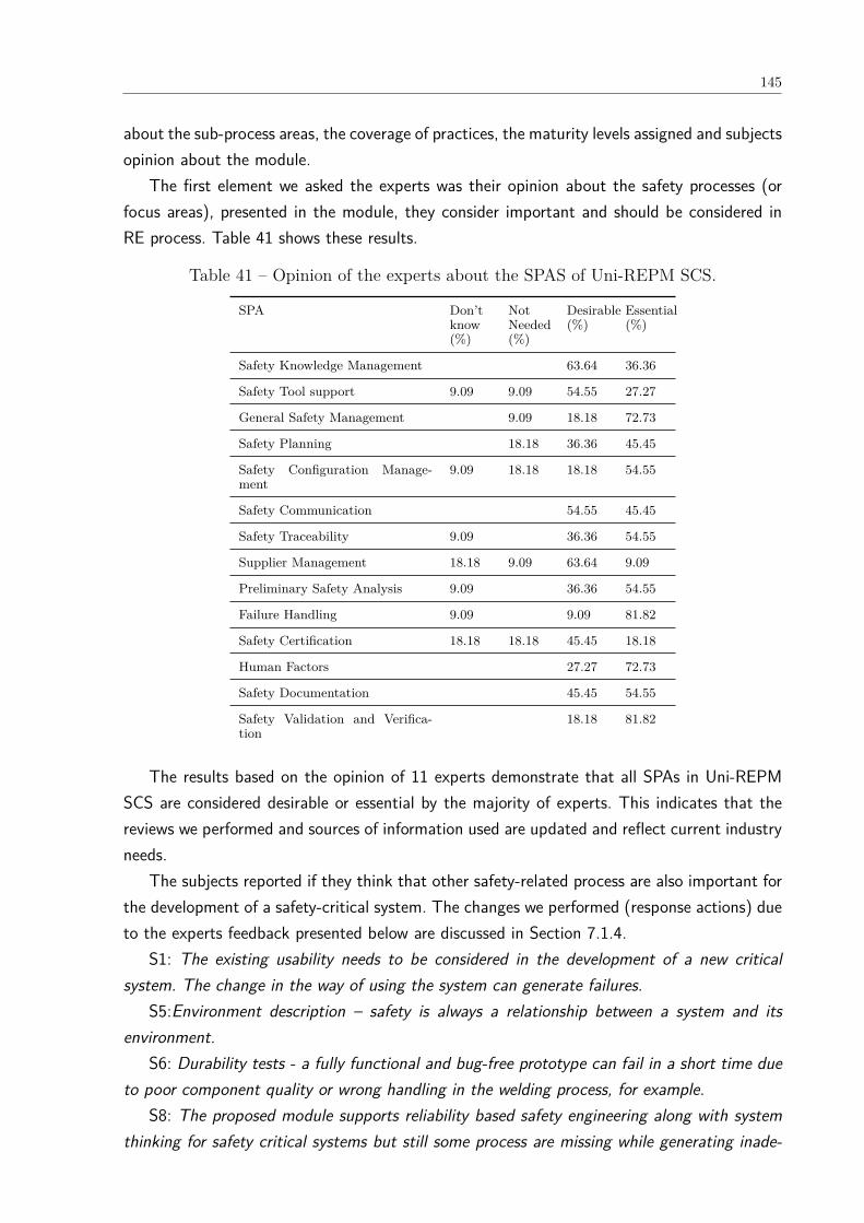
145
about the sub-process areas, the coverage of practices, the maturity levels assigned and subjectsopinion about the module.
The first element we asked the experts was their opinion about the safety processes (orfocus areas), presented in the module, they consider important and should be considered inRE process. Table 41 shows these results.
Table 41 – Opinion of the experts about the SPAS of Uni-REPM SCS.
SPA Don’tknow(%)
NotNeeded(%)
Desirable(%)
Essential(%)
Safety Knowledge Management 63.64 36.36
Safety Tool support 9.09 9.09 54.55 27.27
General Safety Management 9.09 18.18 72.73
Safety Planning 18.18 36.36 45.45
Safety Configuration Manage-ment
9.09 18.18 18.18 54.55
Safety Communication 54.55 45.45
Safety Traceability 9.09 36.36 54.55
Supplier Management 18.18 9.09 63.64 9.09
Preliminary Safety Analysis 9.09 36.36 54.55
Failure Handling 9.09 9.09 81.82
Safety Certification 18.18 18.18 45.45 18.18
Human Factors 27.27 72.73
Safety Documentation 45.45 54.55
Safety Validation and Verifica-tion
18.18 81.82
The results based on the opinion of 11 experts demonstrate that all SPAs in Uni-REPMSCS are considered desirable or essential by the majority of experts. This indicates that thereviews we performed and sources of information used are updated and reflect current industryneeds.
The subjects reported if they think that other safety-related process are also important forthe development of a safety-critical system. The changes we performed (response actions) dueto the experts feedback presented below are discussed in Section 7.1.4.
S1: The existing usability needs to be considered in the development of a new criticalsystem. The change in the way of using the system can generate failures.
S5:Environment description – safety is always a relationship between a system and itsenvironment.
S6: Durability tests - a fully functional and bug-free prototype can fail in a short time dueto poor component quality or wrong handling in the welding process, for example.
S8: The proposed module supports reliability based safety engineering along with systemthinking for safety critical systems but still some process are missing while generating inade-

146
quate control actions in Requirements Analysis.S10: Since safety standards in both aerospace (DO-178C and SAE ARP 4754A) and auto-
motive (ISO 26262) domains recommend or mandate the development of an Assurance/SafetyCase (Kelly, 2003) as a requirement for certification of a safety-critical system, The Safety As-surance process should be considered during the development of a given safety-critical systemto obtain certification credits. An Assurance Case is a clear, comprehensive, and justifiableargument supported by a body of evidence that a system is acceptably safe to operate in aparticular context.
S11: No, the process relationship is already comprehensive.The easiness of understand the SPAs in the module in experts opinion is presented in Figure
41. We observed that great majority (72.73%) agree that the SPAs are easy to understand.This was a concern we have when defining the SPAs since we wanted to adopt the terms thatare in fact used in the SCS domain. This may be an indication that such goal was achieved.
Figure 41 – Opinion of subjects whether the SPAs are easy to understand.
The experts classified the practices using the following scale: “Don’t know”, “Not Needed”,“Desirable”, and “Essential”. The number of practices indicated by the experts in each categoryare listed in Table 42.
All experts, including the industry practitioners interviewed, considered the great majorityof safety practices of the module are desirable or essential. The exceptions were S4 that didnot answer this question and S6 that opted to not answer once he/she said that “I do nothave practical experience to answer this question”.
We asked the subjects whether there are actions important for RE process of safety-criticalsystems that are missing in the module. Our response actions to their answers, describedbelow, are discussed in Section 7.1.4.
S1: Verification of existing products.S3: For assessing the completeness of the module, safety standards could be checked. For
example, some prescribe traceability between requirements and code.

147
Table 42 – Opinion about the practices.
Subject Not Answered Don’t know Not Needed Desirable Essential
S1 0 10 1 62 75
S2 0 0 0 24 124
S3 0 0 0 62 86
S4 148 0 0 0 0
S5 0 0 14 41 93
S6 0 10 23 65 50
S7 0 146 0 0 2
S8 1 0 11 80 56
S9 4 18 8 69 49
S10 0 0 2 24 122
S11 0 12 0 70 66
S4: Security analysis - it is hard to find a domain/application where those 2 topics wouldn’tinterrelated. Here, the main focus is: can safety be compromised by malicious actions.
S5: Formal communication is mentioned several (3) times in the document. However IMHO,the informal communication in a project is more important, mainly because it is much morefrequent.
S8: In my view, all the processes are well reflected in proposed module.S9: It would be interesting to define a set of basic requirements that should be verified in
each new software version (shakedown). There is a compromise between cost and coverage sothere is a minimum test for releasing a new version.
The easiness of understanding the actions in the module in experts opinion is presented inFigure 42. We noticed that the actions were considered as easy to understand by almost 70% ofthe subjects. We believe that the understanding of actions across domains is not compromisedsince we provide explanations for each action and examples. This is an important result sincemost of them analyzed the actions considering only their names and not the description.
The maturity level we defined to each action was also evaluated by the subjects. Thenumber of changes proposed by them is presented in Table 43. Excepting S4, S5, S8, andS11 there was a tendency in the experts to reduce the maturity level we proposed to theactions. This occurred mostly with the two practitioners (S1 and S2) that during the interviewsconstantly repeated that the actions are the common procedure and are required by safetystandards. Nevertheless, we observed a tendency of academic experts in proposing to increasethe maturity level. It is important to highlight that the total number of changes is higher than148 once many suggestions referred to the same action by different subjects.
During the analysis of subjects opinions, we observed some conflicting suggestions for thesame action (increase and decrease). The number of actions in conflict per SPA is listed inTable 44. The number of conflicts was low, only 29 actions in a total of 148. We did not
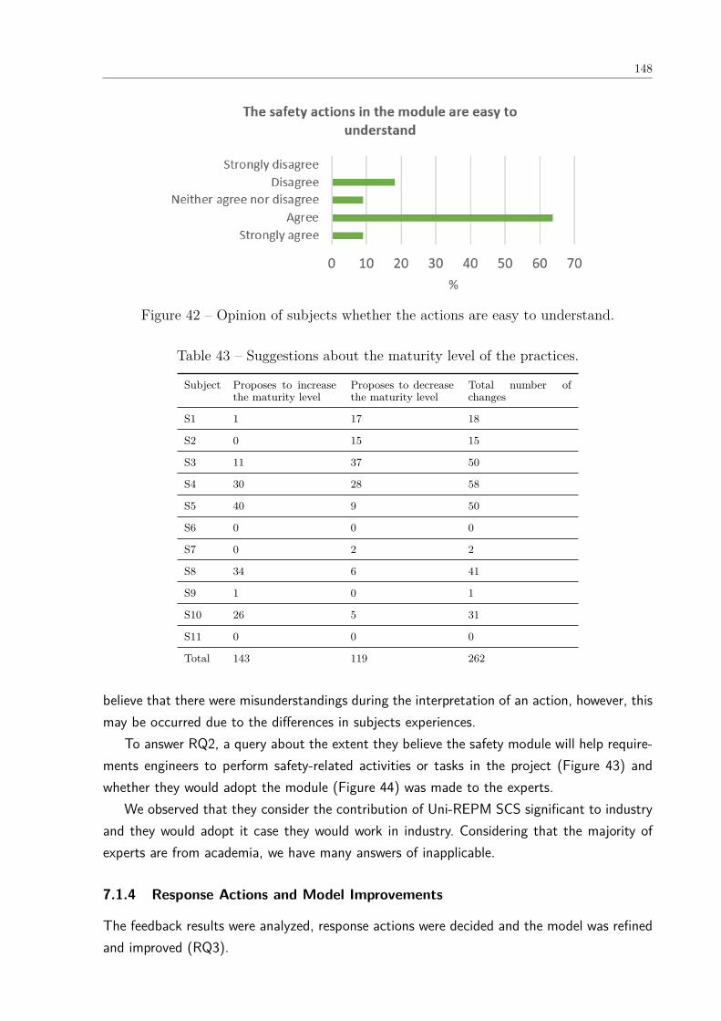
148
Figure 42 – Opinion of subjects whether the actions are easy to understand.
Table 43 – Suggestions about the maturity level of the practices.
Subject Proposes to increasethe maturity level
Proposes to decreasethe maturity level
Total number ofchanges
S1 1 17 18
S2 0 15 15
S3 11 37 50
S4 30 28 58
S5 40 9 50
S6 0 0 0
S7 0 2 2
S8 34 6 41
S9 1 0 1
S10 26 5 31
S11 0 0 0
Total 143 119 262
believe that there were misunderstandings during the interpretation of an action, however, thismay be occurred due to the differences in subjects experiences.
To answer RQ2, a query about the extent they believe the safety module will help require-ments engineers to perform safety-related activities or tasks in the project (Figure 43) andwhether they would adopt the module (Figure 44) was made to the experts.
We observed that they consider the contribution of Uni-REPM SCS significant to industryand they would adopt it case they would work in industry. Considering that the majority ofexperts are from academia, we have many answers of inapplicable.
7.1.4 Response Actions and Model Improvements
The feedback results were analyzed, response actions were decided and the model was refinedand improved (RQ3).

149
Table 44 – Number of actions in conflict based on subjects opinion per SPA.
SPA # actionswith conflicts
Safety Knowledge Management 3
Safety Tool support 0
General Safety Management 1
Safety Planning 1
Safety Configuration Management 2
Safety Communication 0
Safety Traceability 3
Supplier Management 0
Preliminary Safety Analysis 10
Failure Handling 0
Safety Certification 0
Human Factors 0
Safety Documentation 2
Safety Validation and Verification 7
Total 29
Figure 43 – Opinion of subjects about the usefulness of Uni-REPM SCS.
7.1.4.1 Regarding new SPAs
We discarded the following suggestions to add new SPAs because they are already covered bythe safety module:
• usability needs (S1) - there is no need to add a new SPA specific to the issues becausethey are already addressed in the Human Factors SPA;
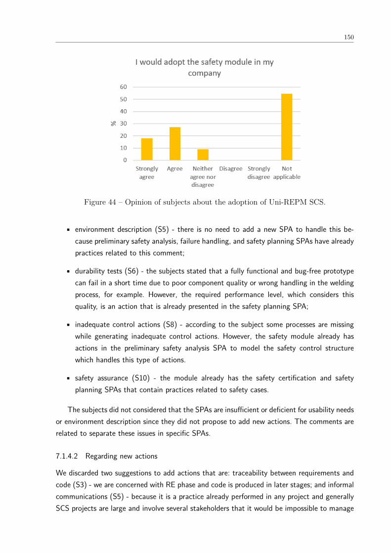
150
Figure 44 – Opinion of subjects about the adoption of Uni-REPM SCS.
• environment description (S5) - there is no need to add a new SPA to handle this be-cause preliminary safety analysis, failure handling, and safety planning SPAs have alreadypractices related to this comment;
• durability tests (S6) - the subjects stated that a fully functional and bug-free prototypecan fail in a short time due to poor component quality or wrong handling in the weldingprocess, for example. However, the required performance level, which considers thisquality, is an action that is already presented in the safety planning SPA;
• inadequate control actions (S8) - according to the subject some processes are missingwhile generating inadequate control actions. However, the safety module already hasactions in the preliminary safety analysis SPA to model the safety control structurewhich handles this type of actions.
• safety assurance (S10) - the module already has the safety certification and safetyplanning SPAs that contain practices related to safety cases.
The subjects did not considered that the SPAs are insufficient or deficient for usability needsor environment description since they did not propose to add new actions. The comments arerelated to separate these issues in specific SPAs.
7.1.4.2 Regarding new actions
We discarded two suggestions to add actions that are: traceability between requirements andcode (S3) - we are concerned with RE phase and code is produced in later stages; and informalcommunications (S5) - because it is a practice already performed in any project and generallySCS projects are large and involve several stakeholders that it would be impossible to manage
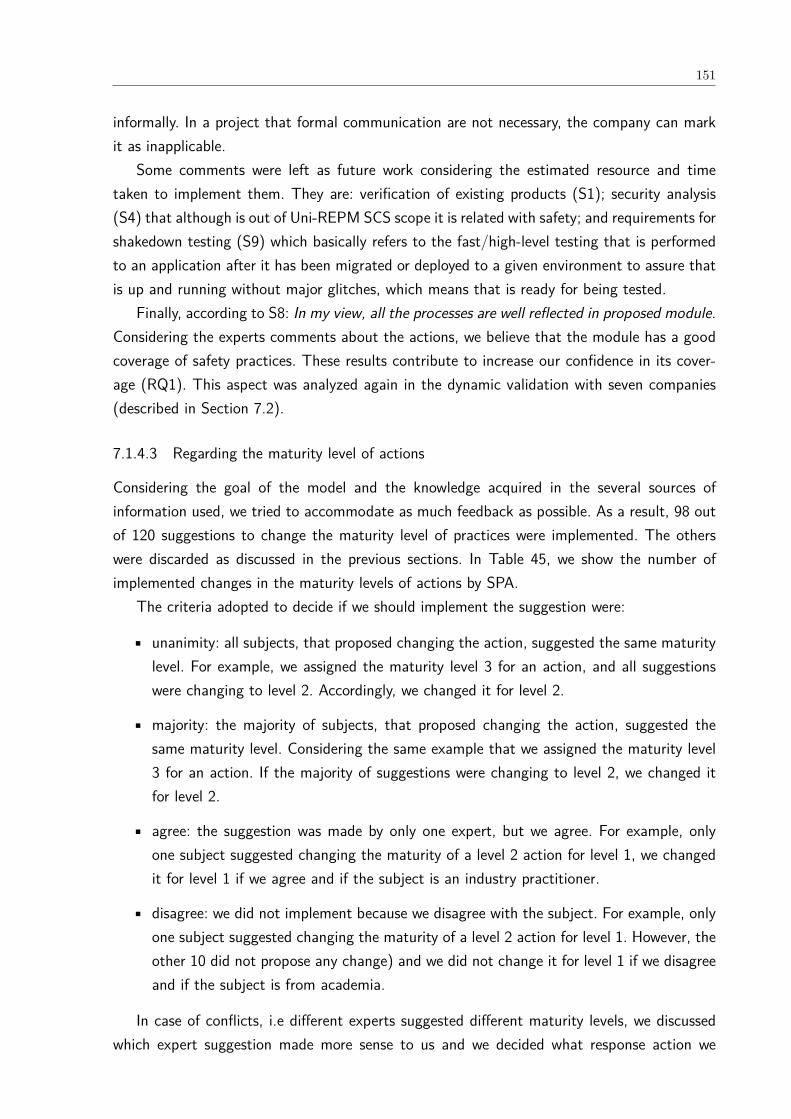
151
informally. In a project that formal communication are not necessary, the company can markit as inapplicable.
Some comments were left as future work considering the estimated resource and timetaken to implement them. They are: verification of existing products (S1); security analysis(S4) that although is out of Uni-REPM SCS scope it is related with safety; and requirements forshakedown testing (S9) which basically refers to the fast/high-level testing that is performedto an application after it has been migrated or deployed to a given environment to assure thatis up and running without major glitches, which means that is ready for being tested.
Finally, according to S8: In my view, all the processes are well reflected in proposed module.Considering the experts comments about the actions, we believe that the module has a goodcoverage of safety practices. These results contribute to increase our confidence in its cover-age (RQ1). This aspect was analyzed again in the dynamic validation with seven companies(described in Section 7.2).
7.1.4.3 Regarding the maturity level of actions
Considering the goal of the model and the knowledge acquired in the several sources ofinformation used, we tried to accommodate as much feedback as possible. As a result, 98 outof 120 suggestions to change the maturity level of practices were implemented. The otherswere discarded as discussed in the previous sections. In Table 45, we show the number ofimplemented changes in the maturity levels of actions by SPA.
The criteria adopted to decide if we should implement the suggestion were:
• unanimity: all subjects, that proposed changing the action, suggested the same maturitylevel. For example, we assigned the maturity level 3 for an action, and all suggestionswere changing to level 2. Accordingly, we changed it for level 2.
• majority: the majority of subjects, that proposed changing the action, suggested thesame maturity level. Considering the same example that we assigned the maturity level3 for an action. If the majority of suggestions were changing to level 2, we changed itfor level 2.
• agree: the suggestion was made by only one expert, but we agree. For example, onlyone subject suggested changing the maturity of a level 2 action for level 1, we changedit for level 1 if we agree and if the subject is an industry practitioner.
• disagree: we did not implement because we disagree with the subject. For example, onlyone subject suggested changing the maturity of a level 2 action for level 1. However, theother 10 did not propose any change) and we did not change it for level 1 if we disagreeand if the subject is from academia.
In case of conflicts, i.e different experts suggested different maturity levels, we discussedwhich expert suggestion made more sense to us and we decided what response action we
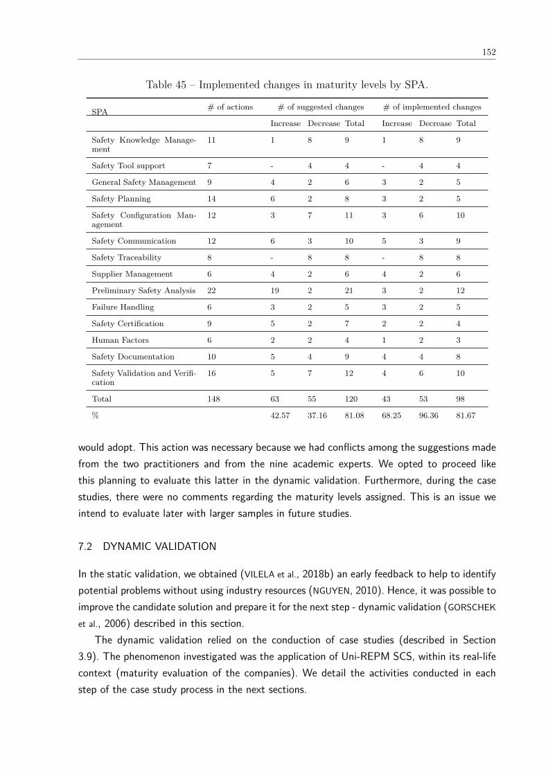
152
Table 45 – Implemented changes in maturity levels by SPA.
SPA # of actions # of suggested changes # of implemented changes
Increase Decrease Total Increase Decrease Total
Safety Knowledge Manage-ment
11 1 8 9 1 8 9
Safety Tool support 7 - 4 4 - 4 4
General Safety Management 9 4 2 6 3 2 5
Safety Planning 14 6 2 8 3 2 5
Safety Configuration Man-agement
12 3 7 11 3 6 10
Safety Communication 12 6 3 10 5 3 9
Safety Traceability 8 - 8 8 - 8 8
Supplier Management 6 4 2 6 4 2 6
Preliminary Safety Analysis 22 19 2 21 3 2 12
Failure Handling 6 3 2 5 3 2 5
Safety Certification 9 5 2 7 2 2 4
Human Factors 6 2 2 4 1 2 3
Safety Documentation 10 5 4 9 4 4 8
Safety Validation and Verifi-cation
16 5 7 12 4 6 10
Total 148 63 55 120 43 53 98
% 42.57 37.16 81.08 68.25 96.36 81.67
would adopt. This action was necessary because we had conflicts among the suggestions madefrom the two practitioners and from the nine academic experts. We opted to proceed likethis planning to evaluate this latter in the dynamic validation. Furthermore, during the casestudies, there were no comments regarding the maturity levels assigned. This is an issue weintend to evaluate later with larger samples in future studies.
7.2 DYNAMIC VALIDATION
In the static validation, we obtained (VILELA et al., 2018b) an early feedback to help to identifypotential problems without using industry resources (NGUYEN, 2010). Hence, it was possible toimprove the candidate solution and prepare it for the next step - dynamic validation (GORSCHEK
et al., 2006) described in this section.The dynamic validation relied on the conduction of case studies (described in Section
3.9). The phenomenon investigated was the application of Uni-REPM SCS, within its real-lifecontext (maturity evaluation of the companies). We detail the activities conducted in eachstep of the case study process in the next sections.

153
7.2.1 Design and Planning
In this stage, the case study protocol was elaborated. We conducted the validation consideringthe following aspects (NGUYEN, 2010):
• Coverage: to make sure the module presents the necessary safety practices and to detectothers that might not be captured in the sources of information used to propose themodule.
• Usefulness and Applicability: to collect the experts opinion about the module applicationin industrial settings and to what extent.
Considering the aspects above, the validation design was guided by the research questionsbelow:
RQ1: Which safety maturity level is achieved by the requirements engineering processes ofthe investigated software development companies?
RQ2: Does Uni-REPM SCS have a sufficient coverage of safety practices?RQ3: What is the effect of applying Uni-REPM SCS when it is instantiated in different
safety-critical domains?RQ4: What is the level of acceptance of Uni-REPM SCS by practitioners?RQ5: What improvements can be done to Uni-REPM SCS based on the findings?The goal of this study is presented in Table 46.
Table 46 – Research General Purpose.
Analyze the safety processes of companies that develop safety-critical systems.
With the purpose of investigate the maturity level of their projects.
In the point of view of Project Managers, Technical and Project Leaders, Tech-nical Cordinators, Software Engineers.
In the context of view safety-critical systems development.
According to Yin (2003), the case may in general be virtually anything which is a “contem-porary phenomenon in its real-life context”. In this work, we have seven separate holistic casessince our context is considered being the seven companies from three different countries thatwork with the safety-critical systems development. Each case has an unit of analysis whichis the project that each practitioner chose to evaluate using Uni-REPM SCS. This design isillustrated in Figure 45.
We adopted the strategy of previous works (MARTINS; GORSCHEK, 2017)(SVENSSON et al.,2012) where the sampling strategy was a combination of convenience sampling (SVENSSON
et al., 2012) and variation sampling. The former means that the nearest and most convenientpersons were selected as subjects, using our industrial collaboration network.
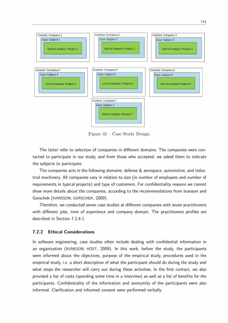
154
Figure 45 – Case Study Design.
The latter refer to selection of companies in different domains. The companies were con-tacted to participate in our study, and from those who accepted, we asked them to indicatethe subjects to participate.
The companies acts in the following domains: defense & aerospace, automotive, and indus-trial machinery. All companies vary in relation to size (in number of employees and number ofrequirements in typical projects) and type of customers. For confidentiality reasons we cannotshow more details about the companies, according to the recommendations from Ivarsson andGorschek (IVARSSON; GORSCHEK, 2009).
Therefore, we conducted seven case studies at different companies with seven practitionerswith different jobs, time of experience and company domain. The practitioners profiles aredescribed in Section 7.2.4.1.
7.2.2 Ethical Considerations
In software engineering, case studies often include dealing with confidential information inan organization (RUNESON; HÖST, 2009). In this work, before the study, the participantswere informed about the objectives, purpose of the empirical study, procedures used in theempirical study, i.e. a short description of what the participant should do during the study andwhat steps the researcher will carry out during these activities. In the first contact, we alsoprovided a list of costs (spending some time in a interview) as well as a list of benefits for theparticipants. Confidentiality of the information and anonymity of the participants were alsoinformed. Clarification and informed consent were performed verbally.
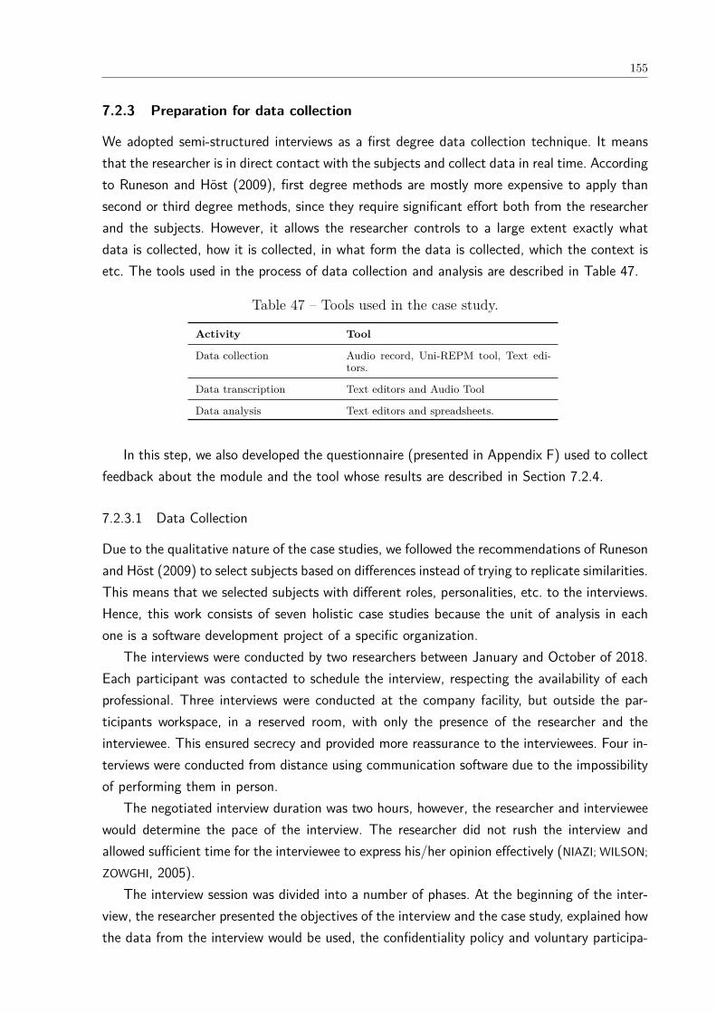
155
7.2.3 Preparation for data collection
We adopted semi-structured interviews as a first degree data collection technique. It meansthat the researcher is in direct contact with the subjects and collect data in real time. Accordingto Runeson and Höst (2009), first degree methods are mostly more expensive to apply thansecond or third degree methods, since they require significant effort both from the researcherand the subjects. However, it allows the researcher controls to a large extent exactly whatdata is collected, how it is collected, in what form the data is collected, which the context isetc. The tools used in the process of data collection and analysis are described in Table 47.
Table 47 – Tools used in the case study.
Activity Tool
Data collection Audio record, Uni-REPM tool, Text edi-tors.
Data transcription Text editors and Audio Tool
Data analysis Text editors and spreadsheets.
In this step, we also developed the questionnaire (presented in Appendix F) used to collectfeedback about the module and the tool whose results are described in Section 7.2.4.
7.2.3.1 Data Collection
Due to the qualitative nature of the case studies, we followed the recommendations of Runesonand Höst (2009) to select subjects based on differences instead of trying to replicate similarities.This means that we selected subjects with different roles, personalities, etc. to the interviews.Hence, this work consists of seven holistic case studies because the unit of analysis in eachone is a software development project of a specific organization.
The interviews were conducted by two researchers between January and October of 2018.Each participant was contacted to schedule the interview, respecting the availability of eachprofessional. Three interviews were conducted at the company facility, but outside the par-ticipants workspace, in a reserved room, with only the presence of the researcher and theinterviewee. This ensured secrecy and provided more reassurance to the interviewees. Four in-terviews were conducted from distance using communication software due to the impossibilityof performing them in person.
The negotiated interview duration was two hours, however, the researcher and intervieweewould determine the pace of the interview. The researcher did not rush the interview andallowed sufficient time for the interviewee to express his/her opinion effectively (NIAZI; WILSON;
ZOWGHI, 2005).The interview session was divided into a number of phases. At the beginning of the inter-
view, the researcher presented the objectives of the interview and the case study, explained howthe data from the interview would be used, the confidentiality policy and voluntary participa-
156
tion. The informed consent was verbally exposed and the audios of the face-to-face interviewswere recorded. Only after verbal authorization to record the recording interviews was initiated.However, there were no denials.
In the beginning of the study, we also did a brief explanation/presentation about the SCSmodule. The presentation lasted 15 minutes approximately and it contained ten slides. Then,a set of introductory questions were asked about the subjects profile (see Section 7.1.2). Thequestions were relatively simple to answer.
After the introduction, we asked the subject to evaluate himself/herself the maturity level ofthe selected project using the Uni-REPM tool, which take up the largest part of the interview.Each interview varied from 90 to 150 minutes in which each safety practice of Uni-REPMSCS was answered by the subjects. The module assessment instrument is detailed with 148actions1 and in the Appendix B.
When answering the questions, the subjects may encounter one of the following situations:- The action was deemed vital but was performed partially or not at all in this RE process.
It should be marked as “Incomplete” (IC).- The action was completed in this RE process. It should be marked as “Complete” (C).- The action was not necessary or possible to be performed in the process. It should be
marked as “Inapplicable” (IA).After evaluating the maturity level, we asked the subjects to answer the questions related
to the feedback about the module and tool.
7.2.3.2 Analysis of collected data
We combined qualitative methods of data analysis (SEAMAN, 1999) with some charts to close-ended questions. To analyze the audios record, we used an audio tool. The analysis wascomplemented using word processors and spreadsheet tools.
The analysis process was performed based on a set of answers obtained from the seveninterviewees (all answers were considered during the analysis process). They answered the open-ended and close-ended questions, which were associated to one or more Research Questions(RQs) of this case study. Table 48 shows the association between the dynamic validationRQs and the open-ended and close-ended questions of interview questionnaire of Appendix F.The interviewees did not have access to the RQs, but only to the questions available in thequestionnaire (available in Appendix F).
7.2.3.3 Reporting
The results obtained from the case studies are described in Section 7.2.4.1 The complete module description and assessment instrument can be found at project website: <http:
//www.cin.ufpe.br/~ler/unirepm>
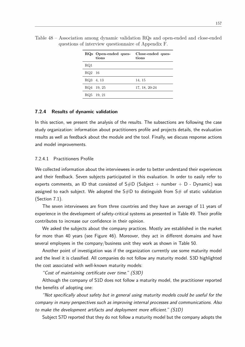
157
Table 48 – Association among dynamic validation RQs and open-ended and close-endedquestions of interview questionnaire of Appendix F.
RQs Open-ended ques-tions
Close-ended ques-tions
RQ1
RQ2 16
RQ3 4, 13 14, 15
RQ4 19, 25 17, 18, 20-24
RQ5 19, 21
7.2.4 Results of dynamic validation
In this section, we present the analysis of the results. The subsections are following the casestudy organization: information about practitioners profile and projects details, the evaluationresults as well as feedback about the module and the tool. Finally, we discuss response actionsand model improvements.
7.2.4.1 Practitioners Profile
We collected information about the interviewees in order to better understand their experiencesand their feedback. Seven subjects participated in this evaluation. In order to easily refer toexperts comments, an ID that consisted of S#D (Subject + number + D - Dynamic) wasassigned to each subject. We adopted the S#D to distinguish from S# of static validation(Section 7.1).
The seven interviewees are from three countries and they have an average of 11 years ofexperience in the development of safety-critical systems as presented in Table 49. Their profilecontributes to increase our confidence in their opinion.
We asked the subjects about the company practices. Mostly are established in the marketfor more than 40 years (see Figure 46). Moreover, they act in different domains and haveseveral employees in the company/business unit they work as shown in Table 50.
Another point of investigation was if the organization currently use some maturity modeland the level it is classified. All companies do not follow any maturity model. S3D highlightedthe cost associated with well-known maturity models:
“Cost of maintaining certificate over time.” (S3D)Although the company of S1D does not follow a maturity model, the practitioner reported
the benefits of adopting one:“Not specifically about safety but in general using maturity models could be useful for the
company in many perspectives such as improving internal processes and communications. Alsoto make the development artifacts and deployment more efficient.” (S1D)
Subject S7D reported that they do not follow a maturity model but the company adopts the
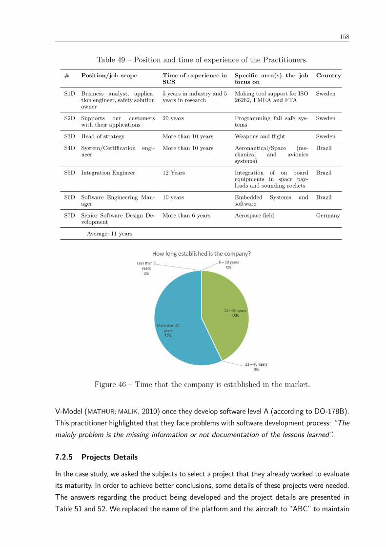
158
Table 49 – Position and time of experience of the Practitioners.
# Position/job scope Time of experience inSCS
Specific area(s) the jobfocus on
Country
S1D Business analyst, applica-tion engineer, safety solutionowner
5 years in industry and 5years in research
Making tool support for ISO26262, FMEA and FTA
Sweden
S2D Supports our customerswith their applications
20 years Programming fail safe sys-tems
Sweden
S3D Head of strategy More than 10 years Weapons and flight Sweden
S4D System/Certification engi-neer
More than 10 years Aeronautical/Space (me-chanical and avionicssystems)
Brazil
S5D Integration Engineer 12 Years Integration of on boardequipments in space pay-loads and sounding rockets
Brazil
S6D Software Engineering Man-ager
10 years Embedded Systems andsoftware
Brazil
S7D Senior Software Design De-velopment
More than 6 years Aerospace field Germany
Average: 11 years
Figure 46 – Time that the company is established in the market.
V-Model (MATHUR; MALIK, 2010) once they develop software level A (according to DO-178B).This practitioner highlighted that they face problems with software development process: “Themainly problem is the missing information or not documentation of the lessons learned”.
7.2.5 Projects Details
In the case study, we asked the subjects to select a project that they already worked to evaluateits maturity. In order to achieve better conclusions, some details of these projects were needed.The answers regarding the product being developed and the project details are presented inTable 51 and 52. We replaced the name of the platform and the aircraft to “ABC” to maintain
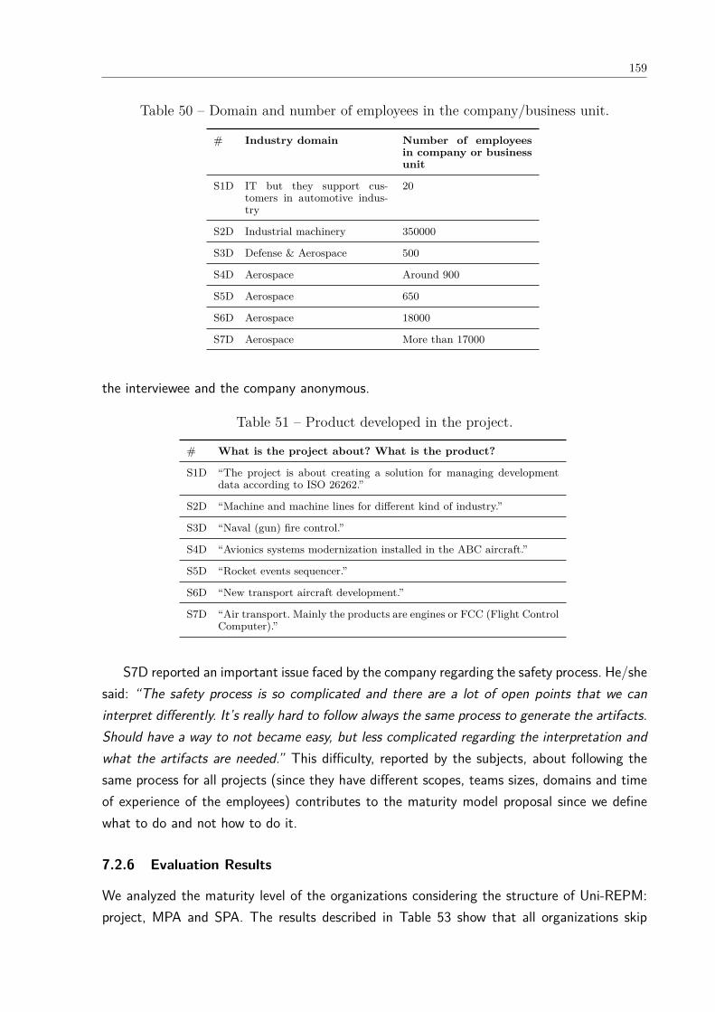
159
Table 50 – Domain and number of employees in the company/business unit.
# Industry domain Number of employeesin company or businessunit
S1D IT but they support cus-tomers in automotive indus-try
20
S2D Industrial machinery 350000
S3D Defense & Aerospace 500
S4D Aerospace Around 900
S5D Aerospace 650
S6D Aerospace 18000
S7D Aerospace More than 17000
the interviewee and the company anonymous.
Table 51 – Product developed in the project.
# What is the project about? What is the product?
S1D “The project is about creating a solution for managing developmentdata according to ISO 26262.”
S2D “Machine and machine lines for different kind of industry.”
S3D “Naval (gun) fire control.”
S4D “Avionics systems modernization installed in the ABC aircraft.”
S5D “Rocket events sequencer.”
S6D “New transport aircraft development.”
S7D “Air transport. Mainly the products are engines or FCC (Flight ControlComputer).”
S7D reported an important issue faced by the company regarding the safety process. He/shesaid: “The safety process is so complicated and there are a lot of open points that we caninterpret differently. It’s really hard to follow always the same process to generate the artifacts.Should have a way to not became easy, but less complicated regarding the interpretation andwhat the artifacts are needed.” This difficulty, reported by the subjects, about following thesame process for all projects (since they have different scopes, teams sizes, domains and timeof experience of the employees) contributes to the maturity model proposal since we definewhat to do and not how to do it.
7.2.6 Evaluation Results
We analyzed the maturity level of the organizations considering the structure of Uni-REPM:project, MPA and SPA. The results described in Table 53 show that all organizations skip

160
Table 52 – Project Details.
S#D How many man-hours for the project? (how many people in-volved in the project? How long does it last?)
S1D “More than 1500 hours by 4-5 people so far spread on 4 years thatwork directly with this project. This project is also supported by thegeneral development of the ABC platform as well. Those numbers arenot included in this figure. The project continues to evolve and includesan increasing number of customers and users.”
S2D “Around 1000 man hours (8 for me), usually around five people.”
S3D “25000 man hours, 15 people, 1 year.”
S4D “For the certification process, more than 20 people was involved andthe process was finished in 2017 (initiated in 2009).”
S5D “Approximately 10000h (worked) during 2 years and 20 people in-volved.”
S6D “10 years, 800 employees involved.”
S7D “We support the development team with tools to certification, likeSCADE and MATLAB. The team is really volatile, but at most wehave 10 engineers.”
important steps during RE and all obtained level Incipient, i.e. none of the seven investigatedcompanies satisfied all the actions of level 1 (Basic).
Table 53 – Maturity level of the projects.
CompanyDomain Project maturitylevel
1 Automotive Incipient2 Industrial ma-
chineryIncipient
3 Defense &Aerospace
Incipient
4 Aerospace Incipient5 Aerospace Incipient6 Aerospace Incipient7 Aerospace Incipient
Figure 47 shows the total number of safety actions performed by each project/companyin its current process per MPAs, according to the Uni-REPM SCS, namely: RequirementsElicitation (RE), Documentation and Requirements Specification (DS), Requirements Analysis(RA), Release Planning (RP), Requirements Validation (RV), Organizational Support (OS),and Requirements Process Management (PM). In the X axis are arranged MPAs, in the Y axisis the amount of safety practices performed by MPA, and the number of complete practicesby project is represented by colors according to the legend of the chart.
We noticed that Requirements Validation (RV) is completely satisfied by projects 1, 4,and 5; Requirements Analysis by projects 2 and 3; Release Planning (RP) by projects 2, 3and 4; Documentation and Requirements Specification by project 5. Requirements Elicitation(RE) is the one MPA that the great majority of projects (five out of seven) performs all safety
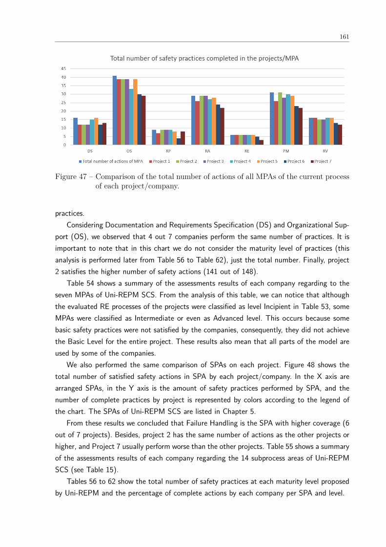
161
Figure 47 – Comparison of the total number of actions of all MPAs of the current processof each project/company.
practices.Considering Documentation and Requirements Specification (DS) and Organizational Sup-
port (OS), we observed that 4 out 7 companies perform the same number of practices. It isimportant to note that in this chart we do not consider the maturity level of practices (thisanalysis is performed later from Table 56 to Table 62), just the total number. Finally, project2 satisfies the higher number of safety actions (141 out of 148).
Table 54 shows a summary of the assessments results of each company regarding to theseven MPAs of Uni-REPM SCS. From the analysis of this table, we can notice that althoughthe evaluated RE processes of the projects were classified as level Incipient in Table 53, someMPAs were classified as Intermediate or even as Advanced level. This occurs because somebasic safety practices were not satisfied by the companies, consequently, they did not achievethe Basic Level for the entire project. These results also mean that all parts of the model areused by some of the companies.
We also performed the same comparison of SPAs on each project. Figure 48 shows thetotal number of satisfied safety actions in SPA by each project/company. In the X axis arearranged SPAs, in the Y axis is the amount of safety practices performed by SPA, and thenumber of complete practices by project is represented by colors according to the legend ofthe chart. The SPAs of Uni-REPM SCS are listed in Chapter 5.
From these results we concluded that Failure Handling is the SPA with higher coverage (6out of 7 projects). Besides, project 2 has the same number of actions as the other projects orhigher, and Project 7 usually perform worse than the other projects. Table 55 shows a summaryof the assessments results of each company regarding the 14 subprocess areas of Uni-REPMSCS (see Table 15).
Tables 56 to 62 show the total number of safety practices at each maturity level proposedby Uni-REPM and the percentage of complete actions by each company per SPA and level.

162
Table 54 – Maturity level of the MPAs.
MPA Project1
Project2
Project3
Project4
Project5
Project6
Project7
Requirements Elici-tation
Advanced Advanced Advanced Advanced Advanced Incipient Incipient
Documentation andRequirements Speci-fication
Advanced Incipient Advanced IntermediateAdvanced Incipient Incipient
Requirements Analy-sis
Advanced Incipient Advanced Incipient Incipient Incipient Incipient
Release Planning IntermediateBasic IntermediateIntermediateIncipient Incipient Basic
Requirements Vali-dation
Incipient Advanced Incipient Advanced Advanced Incipient Incipient
Organizational Sup-port
Incipient Incipient Incipient Incipient Incipient Incipient Incipient
Requirements Pro-cess Management
Incipient Incipient Advanced Incipient Incipient Incipient Incipient
Figure 48 – Comparison of the total number of actions of each SPA of the current processof each project/company.
7.2.7 Feedback about the module
Considering the practitioners busy schedule, the feedback questionnaire was sent to themby email. We received the answers of six out of seven practitioner (S6 did not send thequestionnaire). We sent reminders, but one practitioner did not return. Therefore, the feedbackand percentages were calculated considering six answers.

163
Table 55 – Maturity level of the SPAs per project.
MPASPA 1 2 3 4 5 6 7
RE Supplier Manage-ment
Advanced Advanced Advanced Advanced Advanced Incipient Incipient
DS Human Factors IntermediateIntermediateIntermediateIntermediateIntermediateIncipient IncipientSafety Documenta-tion
Advanced Incipient Advanced IntermediateAdvanced IntermediateIncipient
RA Preliminary SafetyAnalysis
Advanced Incipient Advanced Advanced Incipient Incipient Incipient
Failure Handling IntermediateIntermediateIntermediateIncipient IntermediateIntermediateIntermediate
RP Safety Certification IntermediateBasic IntermediateIntermediateIncipient Incipient Basic
RV Safety Validationand Verification
Incipient Advanced Incipient Advanced Advanced Incipient Incipient
OSSafety Planning Advanced Incipient Advanced Advanced Incipient Incipient IncipientGeneral Safety Man-agement
Basic IntermediateBasic Basic IntermediateIncipient Incipient
Safety Tool support Incipient Advanced Advanced Incipient Advanced IntermediateIntermediateSafety KnowledgeManagement
Advanced IntermediateIncipient Incipient Advanced Incipient Incipient
PMSafety ConfigurationManagement
Advanced Incipient Advanced Advanced Advanced IntermediateIncipient
Safety Communica-tion
Incipient Incipient Advanced Incipient Incipient Incipient Incipient
Safety Traceability Basic Basic IntermediateIntermediateIntermediateBasic Incipient
Table 56 – Complete actions by level in Requirements Elicitation MPA.
MPA: Requirements Elicitation
1 2 3 4 5 6 7
Level # To-tal
% Complete
SPA: Supplier Management
Basic 2 100 100 100 100 100 100 50Intermediate3 100 100 100 100 100 66.67 33.33Advanced 1 100 100 100 100 100 100 100
7.2.7.1 Terminology
We asked the subjects if they are familiar with the terminology used in the Uni-REPM SCS.We observed that they understand mostly of the terminology and where actions needed someclarifications they put an observation in the tool as described in Section 7.5.1. Their answerswere:
“Working with ISO 26262 I am familiar with most of the concepts discussed by UNI-REPM.Although sometimes another terminology was more familiar for me. I have made a note in myanswers in these cases where I found something ambiguous.” (S1D)
“Mostly.” (S2D)“Terminology is not hard to understand. ” (S3D)
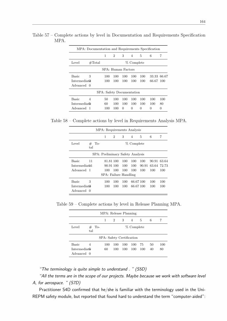
164
Table 57 – Complete actions by level in Documentation and Requirements SpecificationMPA.
MPA: Documentation and Requirements Specification
1 2 3 4 5 6 7
Level #Total % Complete
SPA: Human Factors
Basic 3 100 100 100 100 100 33.33 66.67Intermediate3 100 100 100 100 100 66.67 100Advanced 0
SPA: Safety Documentation
Basic 4 50 100 100 100 100 100 100Intermediate5 60 100 100 100 100 100 80Advanced 1 100 100 0 0 0 0 0
Table 58 – Complete actions by level in Requirements Analysis MPA.
MPA: Requirements Analysis
1 2 3 4 5 6 7
Level # To-tal
% Complete
SPA: Preliminary Safety Analysis
Basic 11 81.81 100 100 100 100 90.91 63.64Intermediate11 90.91 100 100 100 90.91 63.64 72.73Advanced 1 100 100 100 100 100 100 100
SPA: Failure Handling
Basic 3 100 100 100 66.67 100 100 100Intermediate3 100 100 100 66.67 100 100 100Advanced 0
Table 59 – Complete actions by level in Release Planning MPA.
MPA: Release Planning
1 2 3 4 5 6 7
Level # To-tal
% Complete
SPA: Safety Certification
Basic 4 100 100 100 100 75 50 100Intermediate5 60 100 100 100 100 40 80Advanced 0
“The terminology is quite simple to understand . ” (S5D)“All the terms are in the scope of our projects. Maybe because we work with software level
A, for aerospace. ” (S7D)Practitioner S4D confirmed that he/she is familiar with the terminology used in the Uni-
REPM safety module, but reported that found hard to understand the term “computer-aided”:
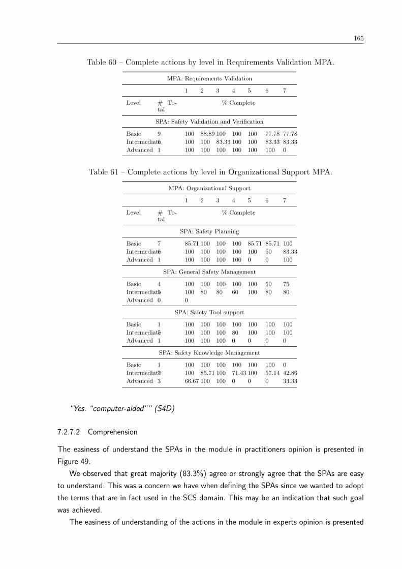
165
Table 60 – Complete actions by level in Requirements Validation MPA.
MPA: Requirements Validation
1 2 3 4 5 6 7
Level # To-tal
% Complete
SPA: Safety Validation and Verification
Basic 9 100 88.89 100 100 100 77.78 77.78Intermediate6 100 100 83.33 100 100 83.33 83.33Advanced 1 100 100 100 100 100 100 0
Table 61 – Complete actions by level in Organizational Support MPA.
MPA: Organizational Support
1 2 3 4 5 6 7
Level # To-tal
% Complete
SPA: Safety Planning
Basic 7 85.71 100 100 100 85.71 85.71 100Intermediate6 100 100 100 100 100 50 83.33Advanced 1 100 100 100 100 0 0 100
SPA: General Safety Management
Basic 4 100 100 100 100 100 50 75Intermediate5 100 80 80 60 100 80 80Advanced 0 0
SPA: Safety Tool support
Basic 1 100 100 100 100 100 100 100Intermediate5 100 100 100 80 100 100 100Advanced 1 100 100 100 0 0 0 0
SPA: Safety Knowledge Management
Basic 1 100 100 100 100 100 100 0Intermediate7 100 85.71 100 71.43 100 57.14 42.86Advanced 3 66.67 100 100 0 0 0 33.33
“Yes. “computer-aided”” (S4D)
7.2.7.2 Comprehension
The easiness of understand the SPAs in the module in practitioners opinion is presented inFigure 49.
We observed that great majority (83.3%) agree or strongly agree that the SPAs are easyto understand. This was a concern we have when defining the SPAs since we wanted to adoptthe terms that are in fact used in the SCS domain. This may be an indication that such goalwas achieved.
The easiness of understanding of the actions in the module in experts opinion is presented
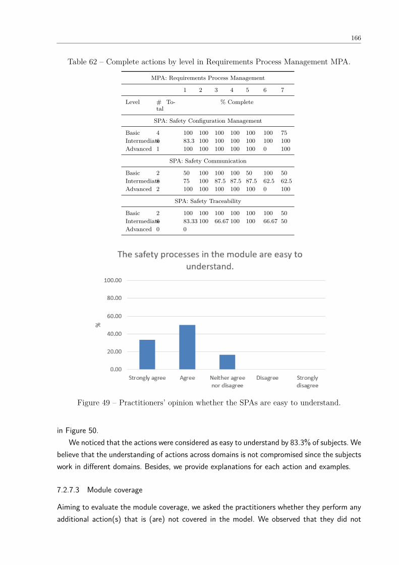
166
Table 62 – Complete actions by level in Requirements Process Management MPA.
MPA: Requirements Process Management
1 2 3 4 5 6 7
Level # To-tal
% Complete
SPA: Safety Configuration Management
Basic 4 100 100 100 100 100 100 75Intermediate6 83.3 100 100 100 100 100 100Advanced 1 100 100 100 100 100 0 100
SPA: Safety Communication
Basic 2 50 100 100 100 50 100 50Intermediate8 75 100 87.5 87.5 87.5 62.5 62.5Advanced 2 100 100 100 100 100 0 100
SPA: Safety Traceability
Basic 2 100 100 100 100 100 100 50Intermediate6 83.33 100 66.67 100 100 66.67 50Advanced 0 0
Figure 49 – Practitioners’ opinion whether the SPAs are easy to understand.
in Figure 50.We noticed that the actions were considered as easy to understand by 83.3% of subjects. We
believe that the understanding of actions across domains is not compromised since the subjectswork in different domains. Besides, we provide explanations for each action and examples.
7.2.7.3 Module coverage
Aiming to evaluate the module coverage, we asked the practitioners whether they perform anyadditional action(s) that is (are) not covered in the model. We observed that they did not
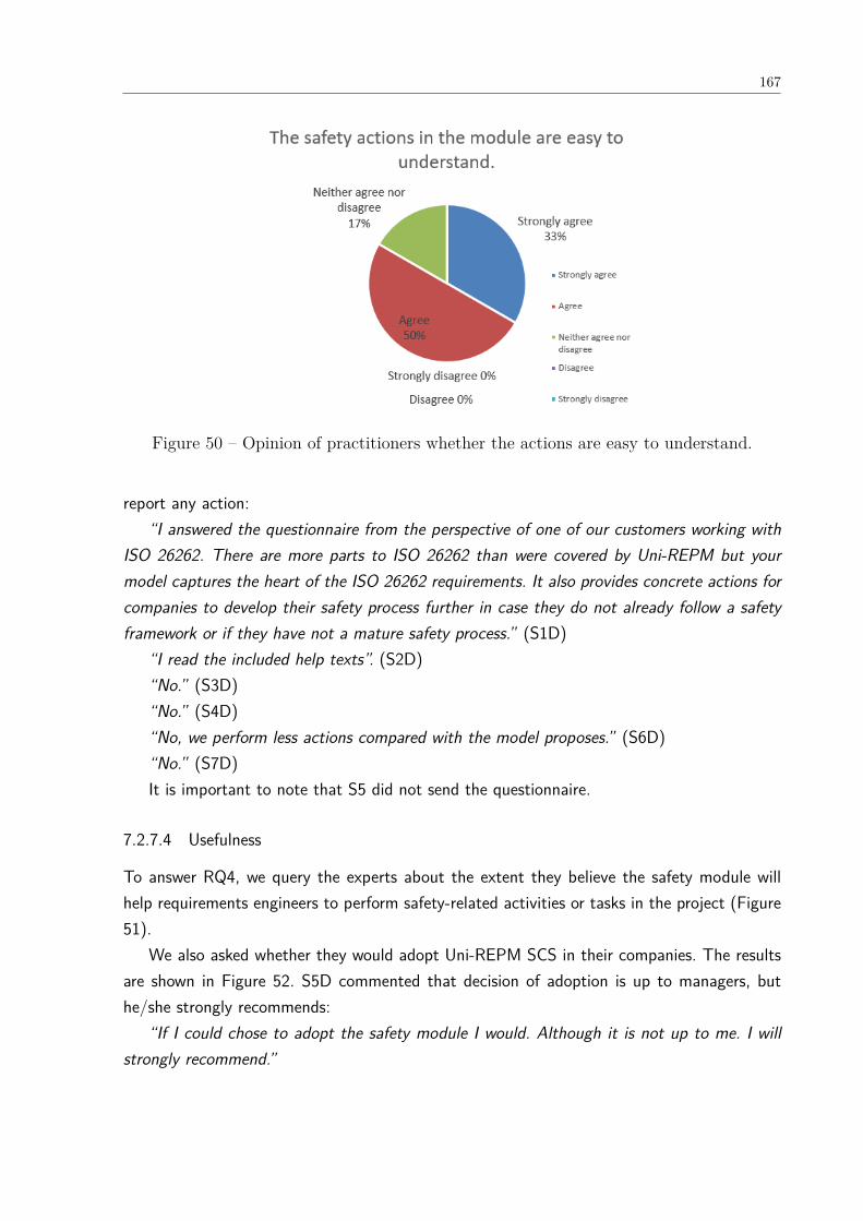
167
Figure 50 – Opinion of practitioners whether the actions are easy to understand.
report any action:“I answered the questionnaire from the perspective of one of our customers working with
ISO 26262. There are more parts to ISO 26262 than were covered by Uni-REPM but yourmodel captures the heart of the ISO 26262 requirements. It also provides concrete actions forcompanies to develop their safety process further in case they do not already follow a safetyframework or if they have not a mature safety process.” (S1D)
“I read the included help texts”. (S2D)“No.” (S3D)“No.” (S4D)“No, we perform less actions compared with the model proposes.” (S6D)“No.” (S7D)It is important to note that S5 did not send the questionnaire.
7.2.7.4 Usefulness
To answer RQ4, we query the experts about the extent they believe the safety module willhelp requirements engineers to perform safety-related activities or tasks in the project (Figure51).
We also asked whether they would adopt Uni-REPM SCS in their companies. The resultsare shown in Figure 52. S5D commented that decision of adoption is up to managers, buthe/she strongly recommends:
“If I could chose to adopt the safety module I would. Although it is not up to me. I willstrongly recommend.”
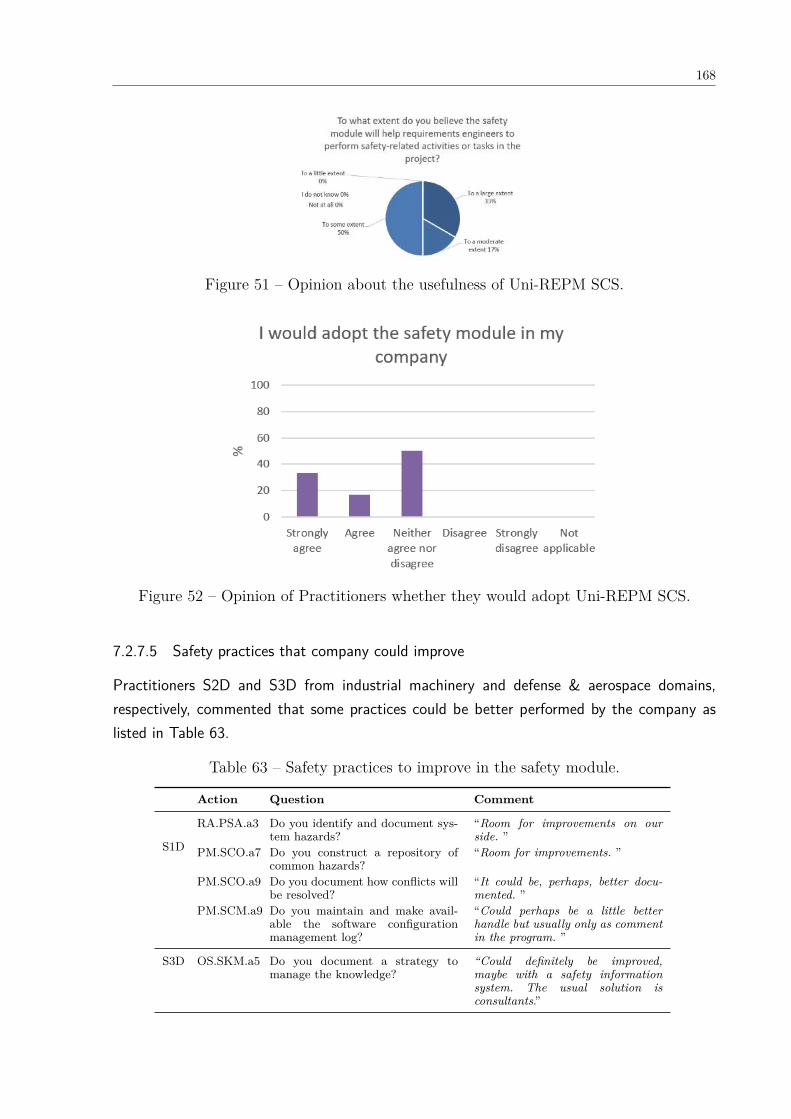
168
Figure 51 – Opinion about the usefulness of Uni-REPM SCS.
Figure 52 – Opinion of Practitioners whether they would adopt Uni-REPM SCS.
7.2.7.5 Safety practices that company could improve
Practitioners S2D and S3D from industrial machinery and defense & aerospace domains,respectively, commented that some practices could be better performed by the company aslisted in Table 63.
Table 63 – Safety practices to improve in the safety module.
Action Question Comment
S1D
RA.PSA.a3 Do you identify and document sys-tem hazards?
“Room for improvements on ourside. ”
PM.SCO.a7 Do you construct a repository ofcommon hazards?
“Room for improvements. ”
PM.SCO.a9 Do you document how conflicts willbe resolved?
“It could be, perhaps, better docu-mented. ”
PM.SCM.a9 Do you maintain and make avail-able the software configurationmanagement log?
“Could perhaps be a little betterhandle but usually only as commentin the program. ”
S3D OS.SKM.a5 Do you document a strategy tomanage the knowledge?
“Could definitely be improved,maybe with a safety informationsystem. The usual solution isconsultants.”
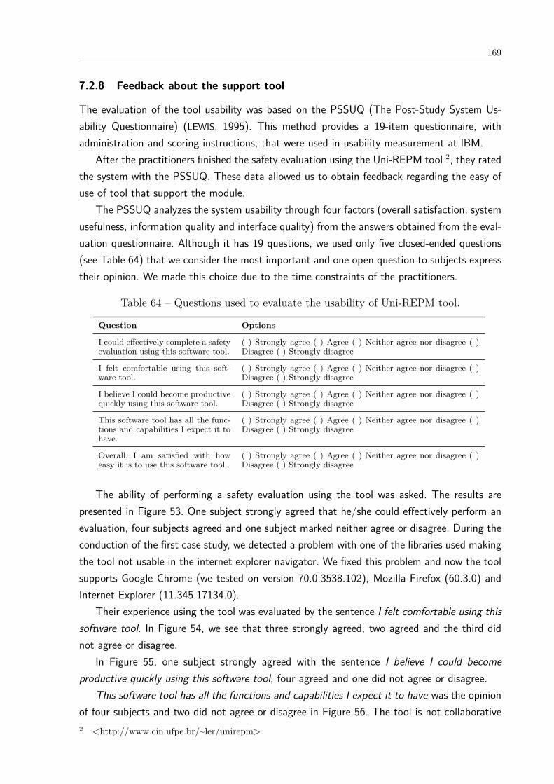
169
7.2.8 Feedback about the support tool
The evaluation of the tool usability was based on the PSSUQ (The Post-Study System Us-ability Questionnaire) (LEWIS, 1995). This method provides a 19-item questionnaire, withadministration and scoring instructions, that were used in usability measurement at IBM.
After the practitioners finished the safety evaluation using the Uni-REPM tool 2, they ratedthe system with the PSSUQ. These data allowed us to obtain feedback regarding the easy ofuse of tool that support the module.
The PSSUQ analyzes the system usability through four factors (overall satisfaction, systemusefulness, information quality and interface quality) from the answers obtained from the eval-uation questionnaire. Although it has 19 questions, we used only five closed-ended questions(see Table 64) that we consider the most important and one open question to subjects expresstheir opinion. We made this choice due to the time constraints of the practitioners.
Table 64 – Questions used to evaluate the usability of Uni-REPM tool.
Question Options
I could effectively complete a safetyevaluation using this software tool.
( ) Strongly agree ( ) Agree ( ) Neither agree nor disagree ( )Disagree ( ) Strongly disagree
I felt comfortable using this soft-ware tool.
( ) Strongly agree ( ) Agree ( ) Neither agree nor disagree ( )Disagree ( ) Strongly disagree
I believe I could become productivequickly using this software tool.
( ) Strongly agree ( ) Agree ( ) Neither agree nor disagree ( )Disagree ( ) Strongly disagree
This software tool has all the func-tions and capabilities I expect it tohave.
( ) Strongly agree ( ) Agree ( ) Neither agree nor disagree ( )Disagree ( ) Strongly disagree
Overall, I am satisfied with howeasy it is to use this software tool.
( ) Strongly agree ( ) Agree ( ) Neither agree nor disagree ( )Disagree ( ) Strongly disagree
The ability of performing a safety evaluation using the tool was asked. The results arepresented in Figure 53. One subject strongly agreed that he/she could effectively perform anevaluation, four subjects agreed and one subject marked neither agree or disagree. During theconduction of the first case study, we detected a problem with one of the libraries used makingthe tool not usable in the internet explorer navigator. We fixed this problem and now the toolsupports Google Chrome (we tested on version 70.0.3538.102), Mozilla Firefox (60.3.0) andInternet Explorer (11.345.17134.0).
Their experience using the tool was evaluated by the sentence I felt comfortable using thissoftware tool. In Figure 54, we see that three strongly agreed, two agreed and the third didnot agree or disagree.
In Figure 55, one subject strongly agreed with the sentence I believe I could becomeproductive quickly using this software tool, four agreed and one did not agree or disagree.
This software tool has all the functions and capabilities I expect it to have was the opinionof four subjects and two did not agree or disagree in Figure 56. The tool is not collaborative2 <http://www.cin.ufpe.br/~ler/unirepm>

170
Figure 53 – Opinion of subjects if they could effectively complete a safety evaluation usingthe Uni-REPM tool.
Figure 54 – Opinion of subjects if they felt comfortable using the tool.
Figure 55 – Opinion of subjects if could become productive quickly using the Uni-REPMtool.
yet, but we intend to add collaborative features as discussed in Section 6.6.Two subjects strongly agreed that they were satisfied with how easy it is to use this software
tool, three agreed and one did not agree or disagree.Question #25 was an open-ended question to subjects provide further comments about
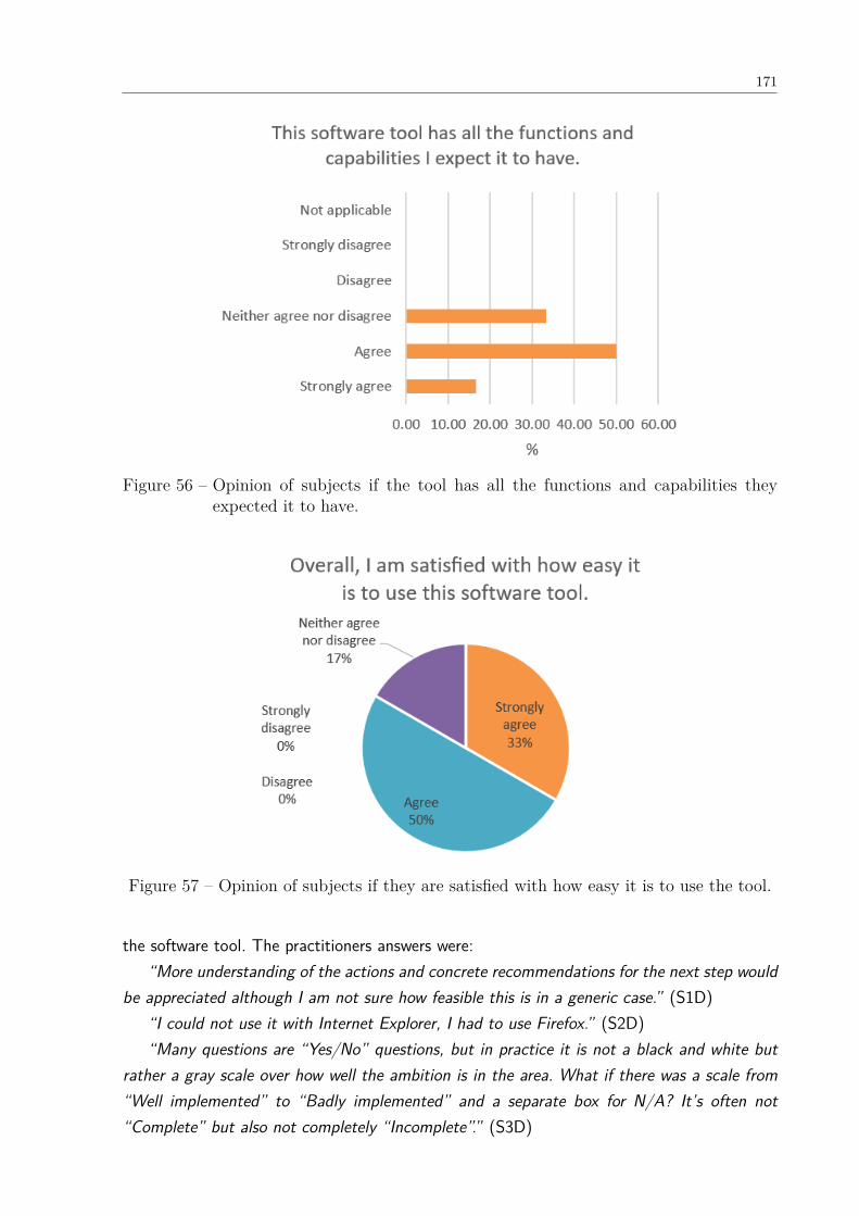
171
Figure 56 – Opinion of subjects if the tool has all the functions and capabilities theyexpected it to have.
Figure 57 – Opinion of subjects if they are satisfied with how easy it is to use the tool.
the software tool. The practitioners answers were:“More understanding of the actions and concrete recommendations for the next step would
be appreciated although I am not sure how feasible this is in a generic case.” (S1D)“I could not use it with Internet Explorer, I had to use Firefox.” (S2D)“Many questions are “Yes/No” questions, but in practice it is not a black and white but
rather a gray scale over how well the ambition is in the area. What if there was a scale from“Well implemented” to “Badly implemented” and a separate box for N/A? It’s often not“Complete” but also not completely “Incomplete”.” (S3D)
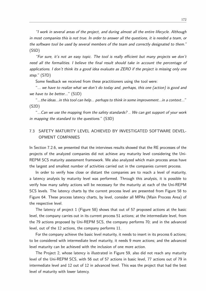
172
“I work in several areas of the project, and during almost all the entire lifecycle. Althoughin most companies this is not true. In order to answer all the questions, it is needed a team, orthe software tool be used by several members of the team and correctly designated to them.”(S5D)
“For sure, it’s not an easy topic. The tool is really efficient but many projects we don’tneed all the formalities. I believe the final result should take in account the percentage ofapplications. I don’t think its a good idea evaluate as ZERO if the project is missing only onestep.” (S7D)
Some feedback we received from these practitioners using the tool were:“... we have to realize what we don’t do today and, perhaps, this one (action) is good and
we have to be better...” (S1D)“...the ideas...in this tool can help... perhaps to think in some improvement...in a context...”
(S2D)“...Can we use the mapping from the safety standards? .. We can get support of your work
in mapping the standard to the questions.” (S3D)
7.3 SAFETY MATURITY LEVEL ACHIEVED BY INVESTIGATED SOFTWARE DEVEL-OPMENT COMPANIES
In Section 7.2.6, we presented that the interviews results showed that the RE processes of theprojects of the analyzed companies did not achieve any maturity level considering the Uni-REPM SCS maturity assessment framework. We also analyzed which main process areas havethe largest and smallest number of activities carried out in the companies current process.
In order to verify how close or distant the companies are to reach a level of maturity,a latency analysis by maturity level was performed. Through this analysis, it is possible toverify how many safety actions will be necessary for the maturity at each of the Uni-REPMSCS levels. The latency charts by the current process level are presented from Figure 58 toFigure 64. These process latency charts, by level, consider all MPAs (Main Process Area) ofthe respective level.
The latency of project 1 (Figure 58) shows that out of 57 proposed actions at the basiclevel, the company carries out in its current process 51 actions; at the intermediate level, fromthe 79 actions proposed by Uni-REPM SCS, the company performs 70; and in the advancedlevel, out of the 12 actions, the company performs 11.
For the company achieve the basic level maturity, it needs to insert in its process 6 actions;to be considered with intermediate level maturity, it needs 9 more actions; and the advancedlevel maturity can be achieved with the inclusion of one more action.
The Project 2, whose latency is illustrated in Figure 59, also did not reach any maturitylevel of the Uni-REPM SCS, with 56 out of 57 actions in basic level, 77 actions out of 79 inintermediate level and 12 out of 12 in advanced level. This was the project that had the bestlevel of maturity with lower latency.
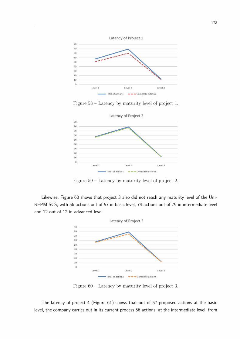
173
Figure 58 – Latency by maturity level of project 1.
Figure 59 – Latency by maturity level of project 2.
Likewise, Figure 60 shows that project 3 also did not reach any maturity level of the Uni-REPM SCS, with 56 actions out of 57 in basic level, 74 actions out of 79 in intermediate leveland 12 out of 12 in advanced level.
Figure 60 – Latency by maturity level of project 3.
The latency of project 4 (Figure 61) shows that out of 57 proposed actions at the basiclevel, the company carries out in its current process 56 actions; at the intermediate level, from

174
the 79 actions proposed by Uni-REPM SCS, the company performs 72; and in the advancedlevel, out of the 12 actions, the company performs 8.
Figure 61 – Latency by maturity level of project 4.
Figure 63 presents the latency of project 5. The company performs 54 out of 57 actionsin basic level, 77 actions out of 79 in intermediate level and 6 out of 12 in advanced level.
Figure 62 – Latency by maturity level of project 5.
The Project 6, whose latency is illustrated in Figure 63, also did not reach any maturitylevel of the Uni-REPM SCS, with 47 out of 57 actions in basic level, 57 actions out of 79 inintermediate level and 3 out of 12 in advanced level.
Figure 63 – Latency by maturity level of project 6.
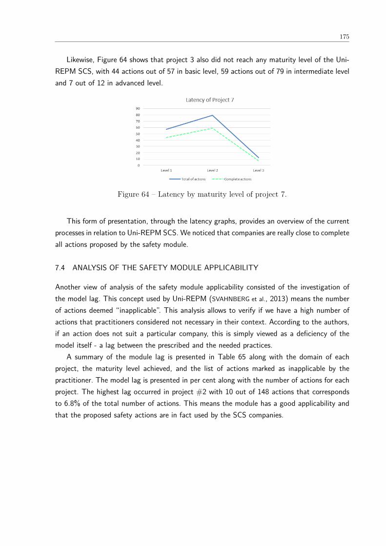
175
Likewise, Figure 64 shows that project 3 also did not reach any maturity level of the Uni-REPM SCS, with 44 actions out of 57 in basic level, 59 actions out of 79 in intermediate leveland 7 out of 12 in advanced level.
Figure 64 – Latency by maturity level of project 7.
This form of presentation, through the latency graphs, provides an overview of the currentprocesses in relation to Uni-REPM SCS. We noticed that companies are really close to completeall actions proposed by the safety module.
7.4 ANALYSIS OF THE SAFETY MODULE APPLICABILITY
Another view of analysis of the safety module applicability consisted of the investigation ofthe model lag. This concept used by Uni-REPM (SVAHNBERG et al., 2013) means the numberof actions deemed “inapplicable”. This analysis allows to verify if we have a high number ofactions that practitioners considered not necessary in their context. According to the authors,if an action does not suit a particular company, this is simply viewed as a deficiency of themodel itself - a lag between the prescribed and the needed practices.
A summary of the module lag is presented in Table 65 along with the domain of eachproject, the maturity level achieved, and the list of actions marked as inapplicable by thepractitioner. The model lag is presented in per cent along with the number of actions for eachproject. The highest lag occurred in project #2 with 10 out of 148 actions that correspondsto 6.8% of the total number of actions. This means the module has a good applicability andthat the proposed safety actions are in fact used by the SCS companies.
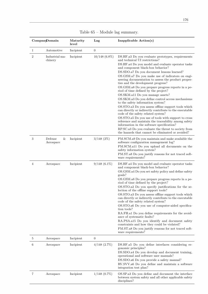
176
Table 65 – Module lag summary.
CompanyDomain Maturitylevel
Lag Inapplicable Action(s)
1 Automotive Incipient 0
2 Industrial ma-chinery
Incipient 10/148 (6.8%) DS.HF.a3 Do you evaluate prototypes, requirementsand technical UI restrictions?DS.HF.a4 Do you model and evaluate operator tasksand component black-box behavior?DS.SDO.a7 Do you document lessons learned?OS.GSM.a7 Do you make use of indicators on engi-neering documentation to assess the product proper-ties and the development progress?OS.GSM.a8 Do you prepare progress reports in a pe-riod of time defined by the project?OS.SKM.a11 Do you manage assets?OS.SKM.a3 Do you define control access mechanismsto the safety information system?OS.STO.a3 Do you assess offline support tools whichcan directly or indirectly contribute to the executablecode of the safety related system?OS.STO.a5 Do you use of tools with support to crossreference and maintain the traceability among safetyinformation in the software specification?RP.SC.a3 Do you evaluate the threat to society fromthe hazards that cannot be eliminated or avoided?
3 Defense &Aerospace
Incipient 3/148 (2%) PM.SCM.a9 Do you maintain and make available thesoftware configuration management log?PM.SCM.a11 Do you upload all documents on thesafety information system?PM.ST.a8 Do you justify reasons for not traced soft-ware requirements?
4 Aerospace Incipient 9/148 (6.1%) DS.HF.a4 Do you model and evaluate operator tasksand component black-box behavior?OS.GSM.a4 Do you set safety policy and define safetygoals?OS.GSM.a8 Do you prepare progress reports in a pe-riod of time defined by the project?OS.STO.a2 Do you specify justifications for the se-lection of the offline support tools?OS.STO.a3 Do you assess offline support tools whichcan directly or indirectly contribute to the executablecode of the safety related system?OS.STO.a6 Do you use of computer-aided specifica-tion tools?RA.FH.a1 Do you define requirements for the avoid-ance of systematic faults?RA.PSA.a15 Do you identify and document safetyconstraints and how they could be violated?PM.ST.a8 Do you justify reasons for not traced soft-ware requirements?
5 Aerospace Incipient 0
6 Aerospace Incipient 4/148 (2.7%) DS.HF.a5 Do you define interfaces considering er-gonomic principles?DS.SDO.a4 Do you develop and document training,operational and software user manuals?DS.SDO.a6 Do you provide a safety manual?RV.SVV.a6 Do you define and maintain a softwareintegration test plan?
7 Aerospace Incipient 1/148 (0.7%) OS.SP.a3 Do you define and document the interfacebetween system safety and all other applicable safetydisciplines?
177
7.5 IMPROVEMENTS PERFORMED BASED ON THE FINDINGS
Considering the practitioners comments during the interviews and their feedback in the open-ended questions #19 and #21, response actions were decided and the model was refined andimproved. We discuss them in the next subsections.
7.5.1 Comprehension
During the interviews, the practitioners suggested the rewriting of some questions to makethem more clear. Ten suggestions, described in Table 66, were made being 5 from S1, 2 fromS2 and 3 from S3. We agreed with them, and we have changed these questions. The updatedsafety module description presented in Appendix B.
7.5.2 Regarding new actions
Considering the practitioners comments about the actions, we believe that the module has agood coverage of safety practices. These results contribute to increase our confidence in itscoverage (RQ2). Such results are aligned with our previous study with nine academic expertsand two practitioners in the static validation (see Section 7.1). Since the practitioners didnot report any additional action (s) or suggested remove any action, we maintained the 148actions.
7.5.3 Regarding new answer options and new evaluation format
S3 suggested adding new answer options:“Many questions are “Yes/No” questions, but in practice it is not a black and white but
rather a gray scale over how well the ambition is in the area. What if there was a scale from“Well implemented” to “Badly implemented” and a separate box for N/A? It’s often not“Complete” but also not completely “Incomplete”.” (S3)
We agree with the practitioner that, in some cases, an action is partially incomplete. Hence,we are discussing the possibility and viability of implementing this new scale in a future versionof Uni-REPM SCS.
S7 suggested changing the evaluation format:“I believe the final result should take in account the percentage of applications. I don’t
think its a good idea evaluate as ZERO if the project is missing only one step.” (S7)We understand that this may be seen as not fair, if a company performs all actions of
a MPA or SPA and does not just one basic action, in this current version of Uni-REPM, itwas classified as Zero Level. However, considering this suggestion, we change Zero level toIncipient level. Changing the evaluation format for ranges in each maturity level requires alot of effort and changes. We are discussing the feasibility of this changing and how we canimplement it in a future version of the module.
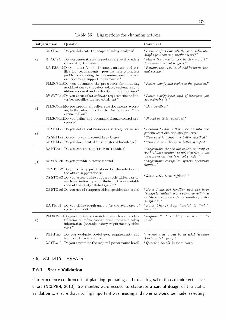
178
Table 66 – Suggestions for changing actions.
SubjectAction Question Comment
S1
OS.SP.a4 Do you delineate the scope of safety analysis? “I was not familiar with the word delineate.Maybe you can use another word?”
RP.SC.a2 Do you demonstrate the preliminary level of safetyachieved by the system?
“Maybe the question can be clarified a bit.An example would be good.”
RA.PSA.a21Do you identify and document analysis and ver-ification requirements, possible safety-interfaceproblems, including the human-machine interface,and operating support requirements?
“Perhaps the question should be more clearand specific.”
PM.SCM.a8Do you document the procedures for initiatingmodifications to the safety-related systems, and toobtain approval and authority for modifications?
“Please clarify and rephrase the question.”
RV.SVV.a14Do you ensure that software requirements and in-terface specification are consistent?
“Please clarify what kind of interface youare referring to.”
S2 PM.SCM.a10Do you appoint all deliverable documents accord-ing to the rules defined in the Configuration Man-agement Plan?
‘‘Bad wording.”
PM.SCM.a2Do you define and document change-control pro-cedures?
“Should be better specified.”
S3OS.SKM.a7 Do you define and maintain a strategy for reuse? “Perhaps to divide this question into one
general level and one specific level.”OS.SKM.a8 Do you reuse the stored knowledge? “This question should be better specified.”OS.SKM.a9 Do you document the use of stored knowledge? “This question should be better specified.”
S4
DS.HF.a1 Do you construct operator task models? “Suggestion: change the action to “way ofwork of the operator” to not give rise to theinterpretation that is a tool (model)”
DS.SDO.a6 Do you provide a safety manual? “Suggestion: change to system operationmanual.”
OS.STO.a2 Do you specify justifications for the selection ofthe offline support tools?
“Remove the term “offline” ”OS.STO.a3 Do you assess offline support tools which can di-rectly or indirectly contribute to the executablecode of the safety related system?
OS.STO.a6 Do you use of computer-aided specification tools? “Note: I am not familiar with the term“computer-aided”. Not applicable within acertification process. More suitable for de-velopment.”
RA.FH.a1 Do you define requirements for the avoidance ofsystematic faults?
“Note: Change from “avoid” to “mini-mize.” ”
S5PM.SCM.a1Do you maintain accurately and with unique iden-
tification all safety configuration items and safetyinformation (hazards, safety requirements, risks,etc.) ?
“Improve the text a bit (make it more di-rect)”
S7DS.HF.a3 Do you evaluate prototypes, requirements and
technical UI restrictions?“We are used to call UI as HMI (HumanMachine Interface).”
OS.SP.a13 Do you determine the required performance level? “Question should be more clear.”
7.6 VALIDITY THREATS
7.6.1 Static Validation
Our experience confirmed that planning, preparing and executing validations require extensiveeffort (NGUYEN, 2010). Six months were needed to elaborate a careful design of the staticvalidation to ensure that nothing important was missing and no error would be made; selecting
179
and contacting experts; and analyzing the results.The aim of the static validation was to identify possible improvements that can be done to
the Uni-REPM SCS. With the help and feedback from two practitioners and nine experts fromacademia coming from various countries with diversified expertise, significant improvementin the module were performed. With this validation, we evaluated all aspects of the modulestructure (SPAs, actions and maturity levels).
The module was analyzed in terms of correctness, coverage, usefulness, and applicability.The majority of the suggestions were regarding the maturity levels of actions. We addressed98 of 120 suggestions and a revised version of the module was generated and it is available at<http://www.cin.ufpe.br/~ler/unirepm>. We did not perform follow-up interviews with thesubjects nor different set of experts to obtain feedback about this revised version. We plan toperform this in future studies.
We acknowledge that there is some subjectivity in deciding which actions would be includedin the module and the maturity level assigned. However, this is an issue of any proposedmaturity model. Well-adopted maturity models such as ISO 15504, CMMI, and MPS.BR andbodies of knowledge such as PMBOK just state that their set of practices reflects currentindustry best practices. Furthermore, they are frequently updated and new practices/actionsare added or removed in each release. Thus, maturity models should be seen as constantlyevolving – just like all models of this type.
We believe that domain-dependent safety maturity models are not feasible since safety-critical systems share many practices as present in different safety-standards. Related solutionssuch as ISO 15504-10, +Safe-CMMI are domain-independent as well. If a practice is notapplicable in a particular context, the evaluator can mark it as Inapplicable. This “feature” isbuilt into the framework of this model. Moreover, the improved model was fairly complete asthere were no suggestions about adding new actions. According to the experts opinions, theactions in the model are applicable in real settings. Therefore, our research questions wereanswered and our goal to validate the module was successfully achieved.
The fact we had more academic experts than practitioners in the static validation maybe a threat to validity. In our opinion, this is not a major threat since the framework oftechnology transfer states that the first validation in a candidate solution should be performedin academia. Therefore, in our vision, having two practitioners is a benefit for this validationand not a threat.
Finally, the purpose of this model is to present good practices that give an organizationideas to improvement. However, it is the organization responsibility to decide whether therecommended practices are indeed beneficial and suitable and when to implement them. Weobserved in our interview with one of the practitioners that the actions that most attractedhim/her were those of the subprocesses “Safety Tool support” and “Safety Traceability”. Thereasons were that the company does not yet use a support tool for requirements engineering orsafety analysis; and they do almost nothing in terms of traceability. Therefore, we noticed that
180
they have learned these practices after participating of Uni-REPM SCS’ validation process.
7.6.2 Dynamic Validation
Case studies do not generate the same results of controlled experiments like the possibility oftesting causal relationships, but they provide deeper understanding of the phenomena understudy in its real context (WOHLIN et al., 2012). This critique were addressed by applying properresearch methodology practices and accepting that knowledge is not only statistical significance(FLYVBJERG, 2006)(WOHLIN et al., 2012).
It is important to consider the validity of the case study from the beginning. To achievethis, we chose a classification scheme to discuss the validity threats which is also used byRuneson and Höst (2009) and Yin (2003) that it is similar to what is usually used in controlledexperiments in software engineering (WOHLIN et al., 2012). This classification distinguishesamong four aspects of the validity discussed below.
Construct validity: it is concerned with the extent to which the study setting reflects theconstruct under study that include the potential problem of evaluation apprehension, amongothers. In our study, threats were mitigated by the anonymity of the participants, as well asthe guarantee that all information obtained during the interviews would be used only by theresearchers.
Internal validity: threats in this type are related to the possibility of uncontrolled factorsinfluencing the results obtained. Therefore, in the evaluation, we did not perform a previoustraining on how to use the module and the tool. The knowledge of each participant in Uni-REPM SCS could have been decisive in their evaluation. Therefore, to mitigate this threat,it was ensured that the selected participants did not know the maturity model. Moreover, toensure that the results represent the reality, we interviewed team members with different rolesin each study. According to Niazi, Wilson and Zowghi (2005), the variety in company type,size, nature of business, age, type of applications and other aspects can limit sample bias.Therefore, the collection of data from different companies and the rigor used in the executionof the case studies and analysis process contributes to reinforce the internal validity. We testedthe module by using the tool at the same time due to the availability of the practitioners. Thiscan be a threat to validity, hence, in future works, we intend to perform separately tests forthe module and for the tool to verify if we have the same acceptance for the tool and themodule as we obtained in the seven case studies presented in this thesis.
External validity: it is concerned with the extent to which the research findings can be ap-plied or used in contexts different from those in which the study was conducted. To mitigatethreats of this type, we detailed the research method so that other researchers can use theprocedures to produce similar and comparable studies. Moreover, we sampled the participantsto achieve maximum variation since this would provide richer data. Furthermore, the general-ization in the statistical sense (from a random sample for the population) is not possible inqualitative research. This occurs because cases are selected purposely because the researcher
181
wants to understand the facts in depth and not find out what is usually true for many cases.Therefore, the qualitative results are generalizable to the theoretical propositions and not tothe populations or universes. Our study has achieved results that are compatible with otherstudies that evaluate the maturity level of organizations. For example, Haddad et al. (2016)presents the evaluation of 20 companies in Brazil using Uni-REPM and none of the companiesachieved some maturity level.
Reliability: it is related to the extent to which the research findings can be replicated bythe same or other researchers. We believe that following the same procedures, data collectiontechniques and conditions will result in similar data if the same set of projects were selectedto evaluation. Hence, the results of other studies may lead to similar or identical theoreticalexplanations. To reduce threats in replications of the study all material used in the case studiesis available in this thesis. Therefore, other researchers may also replicate the assessment.
7.7 FINAL CONSIDERATIONS
This chapter described the planning and results of a static validation that we conductedwith 11 subjects (two practitioners and nine academic experts). We evaluated the Uni-REPMSCS considering its coverage of safety practices; correctness of the proposed maturity levels;usefulness and applicability by collecting the experts opinion about the module application inindustrial settings and to what extent.
We also described seven case studies that we conducted to evaluate the maturity levelof safety processes in requirements engineering. It presented seven holistic cases studies withcompanies of defense & aerospace, automotive, and industrial machinery. The practitionersevaluate the RE process of seven projects and provide feedback about the safety moduleregarding its coverage and usefulness and applicability and about the tool developed to supportthe Uni-REPM. In the next chapter, we discuss the results obtained in this thesis.

182
8 DISCUSSIONS AND CONCLUSIONS
Investigations into the causes of accidents suggest that more rigour is required in setting therequirements and specification of safety-related systems. In this context, safety engineeringis effective when it participates in and provides input to the RE process and to the systemdesign. The main objective of the SLR we conducted (Chapter 4) was to synthesize the existingknowledge about the integration between RE and safety engineering. Different aspects of suchintegration was analyzed such as activities, hazard/safety techniques, relationships betweensafety information, tools to support safety analysis as well as the benefits of the integration.
When developing SCS, RE activities and processes are critical to avoid the introduction ofdefects and misunderstandings among engineers and developers (LEVESON, 2011) (FIRESMITH,2004) (PERNSTÅL et al., 2015). An elaborated RE approach is crucial in order to meet time,cost, and quality goals in safety-critical systems development (SIKORA; TENBERGEN; POHL,2012)(HATCLIFF et al., 2014). Therefore, the integration between RE and safety engineeringis desired by academia and industry (LEVESON, 2011) (LUTZ, 2000) (MARTINS; GORSCHEK,2016a) (HEIMDAHL, 2007) (SIKORA; TENBERGEN; POHL, 2012) (HATCLIFF et al., 2014).
However, requirements engineers, traditionally, are not well familiar with system safetyanalysis processes which are usually performed by safety engineers. One reason is the gapthat exists among the traditional development processes, methodologies, notations and toolsused in safety engineering (SCHOLZ; THRAMBOULIDIS, 2013)(STANDARDIZATION, 2011c)(SEI,2007).
Furthermore, according to Leveson (1995), for practical reasons, training a software en-gineer in system safety may be more successful than training a safety engineer in softwareengineering. This work is a step in this direction to reduce the gap between RE and safety en-gineering. Accordingly, requirements engineers need systematic guidance to consider the safetyconcerns early in the development process of a safety-critical system.
In this context, determining the capability or maturity of safety processes has been iden-tified as necessary to have more technical results that can be used in a continuous processimprovement (JOHANSSON; NEVALAINEN, 2012) (JOHANNESSEN; HALONEN; ÖRSMARK, 2011).Improving the software process quality is a strategy adopted by many companies as a way toincrease the confidence in the quality of the resulting software product (SOMMERVILLE, 2011)(LAMI; FABBRINI; FUSANI, 2011b).
In order to achieve such improvement, companies need methods to assess the strengthsand weaknesses of their processes, and to develop strategies to mitigate the problems found(REIS; MATHIAS; OLIVEIRA, 2016).
The goal of this research is to Improve the quality of safety requirements engineeringprocess by developing a safety module for Uni-REPM maturity model that is useful andsuitable to domain-independent systems in order to help to increase safety processes maturity

183
levels and further develop safer systems.In this thesis, we propose a Safety Module (described in Chapter 5), which consists in an
enhancement of the Uni-REPM maturity model. The module has seven main processes, 14sub-processes and 148 safety actions describing principles and practices that form the basis ofsafety processes maturity.
In Chapter 7, we presented the design and results of a static validation conducted withtwo practitioners and nine academic experts to evaluate the module usefulness, correctnessand completeness. Seven case studies we conducted to evaluate the maturity level of safetyprocesses in requirements engineering were also described. It presented seven holistic casesstudies with companies of defense & aerospace, automotive, and industrial machinery.
In next sections, we discuss the contributions of this thesis by reflecting on the results anddescribe how we addressed the research questions presented in Section 1.4.
8.1 RQ1: WHICH SAFETY PRACTICES/ACTIONS ARE SUITABLE TO BE USED IN THEREQUIREMENTS ENGINEERING PROCESS OF SAFETY-CRITICAL SYSTEMS?
The module construction process started with the investigation of literature available aboutRE in SCS. Accordingly, we performed a SLR (VILELA et al., 2017a) and analyzed others foundin the literature (MARTINS; GORSCHEK, 2016b) to investigate the problem domain, learn theconcepts involved as well as to explore the problems in the integration of these RE and safety(SLR1, SLR2).
With this investigation, we have gained the necessary knowledge to be able to select theinformation sources of the safety practices proposed in this Uni-REPM Safety module. Thesources, see Table 14, comprised well-known authors of the field (STATE-OF-THE-ART),international standards (SAFETY-STD), existing maturity models (EXISTING-MATURITY-MODS), and empirical studies (INTERVIEW-STUDY, TECH-REPORT). Hence, we chosesources from academia and industry.
We have selected 148 safety practices capable of raising the likelihood that the right systemwill be built (DAVIS; ZOWGHI, 2006). The practices are presented in Table 30, Table 31, Table32, Table 33.
During the selection of safety actions/practices, we considered the definition of require-ments practice of Davis and Zowghi (2006). They classify requirements practices as the adop-tion of a principle, tool, notation, and/or method in order to perform a RE activity. Whena practice reduces the cost of the development project or increases the quality of the result-ing product, it is labeled as good requirements practice (DAVIS; ZOWGHI, 2006)(SOLEMON;
SAHIBUDDIN; GHANI, 2009).The practices were evaluated in the static validation by two practitioners and nine academic
experts (Section 7.1); and in the dynamic validation by practitioners of seven companies(Section 7.2).
184
8.2 RQ2: HOW TO DESIGN A SAFETY MATURITY MODEL FOR THE REQUIREMENTSENGINEERING PROCESS OF SAFETY-CRITICAL SYSTEMS?
To define the architectural structure of our module, we have identified a set of requirementsand characteristics presented in maturity models, described in Section 2.3. Accordingly, weconsidered such characteristics as well as the twofold purpose of the Uni-REPM: Process Areaview and a Maturity Level view.
The process area view allows to visualize the hierarchy of processes that consists the modeland to facilitate the discovery of practices of the same group. The maturity level view, on theother hand, defines sets of practices that compose a consistent and coherent RE process, andwhere the practices in one level supports each other as well as the more advanced practiceson the next level (SVAHNBERG et al., 2015).
The safety practices (RQ1) were organized in sub-process areas to separate activities thatbelong to the same group. We did not performed any change in the seven (RequirementsElicitation, Documentation and Requirements Specification, Requirements Analysis, ReleasePlanning, Requirements validation, Organizational Support, and Requirements Process Man-agement) main process areas of the Uni-REPM that were defined considering well-adopted REprocesses.
From the list of safety actions/practices previously elicited, we group them in fourteen sub-process areas (Safety Planning - SP, Supplier Management - SM, Preliminary Safety Analysis- PSA, Failure Handling - FH, Safety Validation and Verification - SVV, Safety Certification- SC, General Safety Management - GSM, Safety Configuration Management - SCM, SafetyCommunication - SCO, Human Factors - HF, Safety Tool support - STO, Safety Documen-tation - SDO, Safety Traceability - ST, Safety Knowledge Management - SKM).
In the Maturity Level View, we assigned a level (“Basic”, “Intermediate”, and “Advanced”)to each action considering the difficulty to implement the action, how essential it is for theRE process, and dependencies among them (SVAHNBERG et al., 2015).
Our module has 148 safety actions to be adopted in the RE process. These actions shouldbe used as a guide in the development process. Hence, the module is focused on what to doinstead of how to do. It can not be considered as a process itself, as this would be very difficultto propose one because of the many different contexts in several organizations from differentapplication domains where it would be applied. This focus provides flexibility for differentorganizations to use established “in-house” procedures or processes.
For example, we say that hazards, safety requirements, accidents, risks, and other conceptsmust be documented as defined in Section 2.1. However, it is out of the module scope toprescribe which technique the company should use to elicit these information, the safetyanalysis method it will adopt, as for example FTA (BROOMFIELD; CHUNG, 1997b), HAZOP(KLETZ, 1997), STAMP (LEVESON, 2011), etc.; or how the company will document (naturallanguage, model-based, which language etc).
Therefore, by proposing a comprehensive set of safety practices, our aim is to provide clear

185
guidance addressing some critics that maturity models do not look deeply enough into allorganizational practices (SOLEMON; SAHIBUDDIN; GHANI, 2009).
8.3 RQ3: HOW DOES THE PROPOSED SAFETY MATURITY MODULE COMPARE WITHRELATED SOLUTIONS?
In Section 2.5, we have discussed the body of knowledge with respect to maturity models andwe present a comprehensive comparison among Uni-REPM SCS, + SAFE and ISO 15504-10in Section 5.4. Therefore, we identified similarities, and differences with our work that havehelped us to position our Uni-REPM SCS with respect to the related available solutions.
Hence, it is out of scope with the module to provide evidence of meeting regulatory require-ments/standards. First, some of them have domain-specific requirements that are not coveredby our proposal. There are several works of safety evidence, traceability and certification in theliterature. Our aim is to improve the development process by addressing many safety practicesearly in the development process, i.e. adopt practices in Requirements Engineering phase, in-stead of handling in later stages of software development. Since they will be handled in thebeginning, many artifacts and evidence will be produced and documented when satisfying thepractices in the module. This is an indirect contribution.
Independently of domain, companies can and do develop successful systems without matu-rity models. However, literature reports (SOMMERVILLE, 2011)(REIS; MATHIAS; OLIVEIRA, 2016)that deadlines and budgets are routinely exceeded, resources are wasted, and there are a lotof rework. For very large systems that include separate subsystems such as SCS, developedby teams who may be working in different locations, an important factor that affects productquality is the software process. The major problems with large projects are integration, projectmanagement, and communication (SOMMERVILLE, 2011). There is usually a mix of abilitiesand experience in the team members and, because the development process usually takes placeover a number of years, the development team is volatile. It may change completely over thelifetime of the project.
Accordingly, our goal in proposing this maturity model is to contribute to a companyto evaluate its strengths and weaknesses, to develop improvement plans when compared toother organizations standards and best practices. The maturity model we propose is moredetailed than others, and useful because it was designed specifically for SCS and contains acomprehensive assessment instrument. This model can be used to help an organization definingwhat to improve or implement next in order to make their processes more efficient.
8.4 RQ4: WHAT IS THE EFFECT OF APPLYING UNI-REPM SAFETY MODULE WHENIT IS INSTANTIATED IN DIFFERENT SAFETY-CRITICAL DOMAINS?
In order to evaluate whether the results are diverse in different domains, we interviewed sevencompanies from three countries that work in distinct contexts: defense & aerospace, automo-

186
tive, and industrial machinery. All companies vary in relation to size (in number of employeesand number of requirements in typical projects) as listed in Table 67 and type of customers.
Table 67 – Number of employees and number of requirements in typical projects of theinvestigated companies.
Number of em-ployees
Number of require-ments in typicalprojects
Company1
20 ∼2000
Company2
∼4000 ∼300
Company3
∼14500 ∼1000
Company4
∼900 ∼50
Company5
∼650 ∼27
Company6
∼18000 Not informed
Company7
∼17000 Not informed
We did a comparison about the number of complete actions by maturity level per company.These results, described in Table 68, show: from 57 actions of basic level, companies performan average of 52 with a standard deviation of 4.86; from 79 actions of intermediate level,companies satisfy 69.43 with 8.22 of standard deviation; and, from 12 actions of advancedlevel, two companies perform all of them, but in general they perform an average of 8.43 witha standard deviation of 3.41.
Therefore, we tend to conclude that the domain does not have a significant influencein the maturity level achieved by the companies. Moreover, the size of companies appearsnot influence either. The latter is a result somewhat expected, that despite the number ofemployees the systems should be certified by regulatory entities.
We also analyzed whether the practitioners understand the terminology used by the safetymodule in Section 7.2.7.1 as well as the comprehension of SPAs and safety actions in Section7.2.7.2. We observed that great majority (83.33%) in Figure 41 agree that the SPAs are easyto understand. Besides, we noticed that the actions were considered as easy to understandby the subjects (Figure 42). Therefore, we believe that the understanding of actions acrossdomains is not compromised since the subjects work in different domains. Besides, we provideexplanations for each action and examples in the tool.

187
Table 68 – Number of complete actions by maturity level.
Domain Level 1 Level 2 Level 3
Project 1 Automotive 51 70 11Project 2 Industrial ma-
chinery56 77 12
Project 3 Defense &Aerospace
56 74 12
Project 4 Aerospace 56 72 8Project 5 Aerospace 54 77 6Project 6 Aerospace 47 57 3Project 7 Aerospace 44 59 7
Total of ac-tions
57 79 12
Average 52 69.43 8.43
Standard De-viation
4.86 8.22 3.41
8.5 RQ5: HOW IS THE PERCEIVED USEFULNESS AND EASE OF USE OF THE UNI-REPM SAFETY MODULE?
The validation and evaluation of Uni-REPM SCS occured in academia as well as in industry inorder to prepare it for widespread industry use. To achieve this goal, we followed the technologytransfer framework proposed by Gorschek et al. (2006) explained in Section 3.9. Accordingly,we performed a static validation (Section 7.1) and a dynamic validation (Section 7.2).
In the literature, there are many argumentation that maturity models describe “what ac-tivities to implement” instead of “how to implement” these activities. However, subject S1commented that Uni-REPM SCS has an adequate level:
“...It also provides concrete actions for companies to develop their safety process furtherin case they do not already follow a safety framework or if they have not a mature safetyprocess.” (S1)
In the static validation, the usefulness and applicability were evaluated through the expertsopinion about the extent they believe the safety module will help requirements engineers toperform safety-related activities or tasks in the project (Figure 43) and whether they wouldadopt the module (Figure 44). We observed that they consider the contribution of Uni-REPMSCS significant to industry and they would adopt it case they would work in industry.
We included a question (#17) in the questionnaire of the dynamic validation (Appendix F)about the extent they believe the safety module will help requirements engineers to performsafety-related activities or tasks in the project. 33% said it can contribute to a large extent,17% to a moderate extent and 50% said some extent as shown in Figure 43.
In question #19, we asked if they would adopt the safety module in the company. 33.33%strongly agreed, 16.67% agreed and 50% did not agree or disagree. We believe it is necessaryto conduct more case studies to understand these answers. Probably, they did not see yet thebenefits of maturity models and process improvements initiatives. On the other hand, they
188
perform the great majority of safety practices presented in Uni-REPM SCS.Questions #20-25 of the questionnaire aim to collect their feedback about the Uni-REPM
tool we developed. These questions were used to evaluate the tool usability considering thePSSUQ (LEWIS, 1995).
The PSSUQ analyzes the system usability through four factors (overall satisfaction, systemusefulness, information quality and interface quality) from the answers obtained from theevaluation questionnaire. The results, described in Section 7.2.8, showed that the tool hasgood usability.
8.6 RQ6: HOW TO EVALUATE WHETHER THE MODULE HAS A SUFFICIENT COVER-AGE OF SAFETY PRACTICES?
To answer this research question, we included question #16 in the interview questionnaire(see Appendix F) of dynamic validation (Section 7.2). In Section 7.2.7.3, we described thesubjects answers regarding the coverage of the safety practices in Uni-REPM SCS (Question#16). The practitioners reported that they do not perform any additional action(s) that is(are) not covered in the model. Therefore, we tend to conclude that the safety module has asufficient coverage.
In the next sections, we describe some conclusions from the case studies.
8.7 SUMMARY OF FINDINGS
Subjects reported some practices that the company need to better document or highlightedsome problems in their processes that they should have to perform better as presented in Table69.
The needs of improvements reported by four practitioners in their RE processes belong tosix out of seven main process areas, except Requirements Validation. The main process areathat had more space to improve was Requirements Analysis with three comments.
Regarding subprocess areas, the one that need more improvements according to the feed-back of the practitioners was Preliminary Safety Analysis with three comments being two fromthe same subject (S2D).
The need of improving system development methodology adopted by the company wasreported by S3D when we asked:
Do you identify and document the system development methodology? which is the actionOS.GSM.a1.
Subject S3D said:“Different for different parts of the system, which is a problem.” (S3D)We observed that there is need of involving more the customer in the system development
process when S2D answered the question:

189
Table 69 – Safety practices that need to be more documented according to the practition-ers in their RE processes.
SubjectAction Question Comment
S1D PM.SCO.a9Do you document how conflicts will be re-solved?
“Sometimes no. If the artifacts are releasedthen the conflict resolution is more clearbut if you mean the conflicts during the de-velopment and assessment then the answeris varied in different group.”
S2D
RE.SM.a3 Do you select suppliers and record ratio-nale?
“Perhaps not record rationale. ”
PM.SCO.a10Do you identify, record and resolve con-flicts?
“Only resolve the conflicts. Not recordthem. ”
RP.SC.a2 Do you demonstrate the preliminary levelof safety achieved by the system?
“Not done for the software today, only forhardware. ”
RA.PSA.a10Do you conduct risk evaluation for eachidentified hazard?
“But only for the major hazards. Not forall hazards. ”
RA.PSA.a11Do you identify and document risk mitiga-tion procedures for each identified hazard?
“But only for the major hazards. Not forall hazards. ”
S3D OS.GSM.a8 Do you prepare progress reports in a periodof time defined by the project?
“Progress reports are done periodically de-pends on the activity.”
S7D
DS.SDO.a7 Do you document lessons learned? “We only talk about it.”OS.GSM.a9 Do you monitor project and take corrective
actions?“Should work better if the lessons learnedware documented.”
OS.STO.a7 Do you define and use tools to support thesafety process and workflow management?
“Just to support the safety process.”
RA.PSA.a6 Do you obtain and document informa-tion about the determined hazards (causes,probability, severity, duration, intensity,toxicity, exposure limit, mechanical force,explosive conditions, reactivity, flammabil-ity etc.)?
“Not all of this examples.”
RE.SM.a4 Do you specify all external systems andsafety-related software?
“Not the safety-related software.”
PM.SCO.a3Do you establish a common nomenclature? “Sometimes the nomenclature from thesuppliers are not following our standard.”
Do you conduct joint reviews (company and customer)? which corresponds to the actionRV.SVV.a10:
“End customer not always involved.” (S2D)Subject S1D reported in action RA.PSA.a2 whose question is:Do you simulate the process?“There is tool support but we don’t have a one click simulation.”An infrastructure to share knowledge is necessary to manage any project, but this is more
important when developing SCS since the projects usually take years to be delivered andemployees may leave the company. In Table 70, we present some comments of the practitioners.
8.7.1 Summary of assessments
With the seven assessments conducted we may conclude the following:
• All organizations did not achieve any maturity level. This means they are skipping impor-

190
Table 70 – Infrastructure to share knowledge.
SubjectAction Question Comment
S2 OS.SKM.a1 Do you establish and maintain an infras-tructure to share knowledge?
“Informal information sharing, meetingsbut no formal way.”
S3
OS.SKM.a1 Do you establish and maintain an infras-tructure to share knowledge?
“No specific tools are used. ”
OS.SKM.a2 Do you develop a safety information sys-tem to share knowledge in the organiza-tion?
“No presence of centralised tools or repos-itories for Safety information.”
OS.SKM.a5 Do you document a strategy to manage theknowledge?
“Could definitely be improved, maybe witha safety information system. The usual so-lution is consultants.”
OS.SKM.a3 Do you define control access mechanismsto the safety information system?
“Access to the analysis are company clas-sified i.e. availability if access is allowed.However no safety information system ispresent.”
tant safety practices at requirements engineering phase when developing safety-criticalsystems.
• Companies perform the great majority of safety practices presented in Uni-REPM SCS.
• The Uni-REPM SCS has a sufficient coverage of safety practices since the practitionersreported that they do not perform any additional action(s) that is (are) not covered inthe model.
• From the latency analysis, we could conclude that the domain did not have a significantinfluence in the maturity level achieved by the companies. Furthermore, the size ofcompanies did not influence either.
• The SPAs and actions presented in Uni-REPM SCS are easy to understand. Therefore,we believe that the understanding of actions across domains is not compromised.
• All experts said that Uni-REPM SCS can contribute to some extent the requirementsengineers to perform safety-related activities or tasks in the project.
• The tool has a good usability.
• Subjects suggested to change only 22 actions to make them more clear. Uni-REPM SCShas 148 actions, hence, this corresponds to 14.86%. Accordingly, we can say that ourgoal of making the model understandable regardless the domain was achieved.
In the next sections, we discuss some contributions of this thesis.
8.8 CONTRIBUTIONS
Companies with high maturity levels tend to reduce requirements issues and make the sys-tem development process less challenging. Although maturity models are not “silver bullets”,

191
they may be used for several purposes providing useful benefits (WENDLER, 2012)(BECKER;
KNACKSTEDT; PÖPPELBUSS, 2009)(SVAHNBERG et al., 2015).
8.8.1 Benefits to academia
For researchers, we hope that the safety module offers a comprehensive summary of state ofthe art, by providing the identification and systematization of existing safety practices being aknowledge base.
8.8.2 Benefits to industry
For industry practitioners, the module may provide a process evaluation model of safety con-cerns targeted at the RE process. Accordingly, it may guide requirements and safety engineersto develop SCS with high quality by providing a very practical structure with which to assesstheir maturity and reduce RE issues in the process.
8.8.3 Evaluation regarding specific concerns
Uni-REPM SCS addresses the problem space by identifying relevant safety actions and detailedfactors that determine maturity of companies that develop SCS. Being structured in MPAsand SPAs, the module gives the potential to evaluate the maturity of whole RE process, butalso specific areas in order to address the needs of several stakeholders.
8.8.4 Module could be used as a diagnostic tool
The module enables the determination of the current state (“as-is”) of companies processes.The determination of company status quo allows a better decision-making processs since itcontributes to instruct managers regarding their current processes and service’ status (REIS;
MATHIAS; OLIVEIRA, 2016). Besides, such evaluation enables the elaboration of a roadmap forimproving the domain position from ’as-is’ (where they are) to what they should do (the state’to-be’) (BRUIN et al., 2005).
8.8.5 Availability of assessment instrument
The safety module has an instrument to evaluate the maturity that is important for SCS devel-opment. It consists in a checklist allowing to provide a reminder of what to look for and reducethe chances of forgetting some safety action (COX; NIAZI; VERNER, 2009). The instrument isfully supported by online software tool. Besides, the subjects of the static validation agree thatthe safety practices/questions are easy to understand.
192
8.8.6 Tool Support
We designed and implement a software tool to support the usage of Uni-REPM and the safetymodule available at <http://www.cin.ufpe.br/~ler/unirepm>. The main features of the toolwere discussed in Section 6. The tool has three types of users that can perform RE/Safetyevaluations and all maturity levels achieved (SPA, MPA, and at project level) are calculatedautomatically. This tool support helps reducing time and effort in assessing the maturity.
8.8.7 Determination of organization weakness
The module allows the analysis of work processes rather than the analysis of isolated safety-critical activities. Therefore, the maturity evaluation should reveal areas of weakness (KON-
TOGIANNIS; LEVA; BALFE, 2016a; REIS; MATHIAS; OLIVEIRA, 2016). For example, an importantarea or activity (e.g. requirements management) may be conducted in ad-hoc way, with fewgood safety actions, or left to ‘individual’ discretion. This indicates an area where improve-ment efforts may be focused in order to achieve substantial improvement considering thatthe benefits of high maturity levels increase in larger and more complex systems (SAWYER;
SOMMERVILLE; VILLER, 1997).
8.8.8 Using the module to continuous improvement
Maturity models may be defined as artifacts which allow to minimize the challenges of deter-mining a company status quo of its capabilities and give directions for continuous improvement(BRUIN et al., 2005; PIGOSSO; ROZENFELD; MCALOONE, 2013).
The Uni-REPM Safety maturity module guides the development by outlining an evolutionfrom a basic maturity level (level 1), to a balanced maturity level (level 2), and a comprehensivematurity level (level 3). Hence, the module may be used as reference frame to implement asystematic and well-directed approach (WENDLER, 2012) offering a continuous improvementculture that affects all levels in the organization (KONTOGIANNIS; LEVA; BALFE, 2016a). Thiscontributes to ensure a certain quality, avoid errors, and assess organizations own capabilitieson a comparable basis.
8.8.9 Module could be used in different types of companies
We adopted the definition of Leveson (1995) which a SCS consists of a set of hardware andsoftware. Accordingly, several non-SCS can be combined to create a system that becomesa SCS like self-driving cars. Hence, if the system had a hardware controlled by software, thesafety module could be used in its development. Therefore, we argue that the module will workfor companies and domains not traditionally under the same regulations as SCS companies ifthe developed system follows this definition.
It is important to note that it is not necessary to implement all safety actions to have arepeatable RE process (SAWYER; SOMMERVILLE; VILLER, 1997). Furthermore, some practices
193
may not be appropriate for an organization and need never be implemented. Accordingly,the company should mark them as inapplicable during the maturity evaluation, making thesafety module appropriate for organizations of different types, sizes, market, or geographicallocalization.
8.8.10 Validation
The static validation we performed with the help of two practitioners and nine academic expertsprovided to us valuable contributions to our model and an improved version was elaborated andit is already available. The improved version was used for dynamic validation, i.e. to evaluatethe maturity of seven projects from different companies, domains and countries.
The careful designs of the validations performed contributed to collect relevant feedback,to assure that the model was of good quality and usable before its release. Despite this carefuldesign and potential benefits, we highlight some limitations of this proposal.
8.9 MODULE LIMITATIONS
(1) Improve actions’ descriptions: a follow-up investigation to be conducted could be deter-mine how the companies implement the safety practices, collect which tools, techniquesand methods they use to satisfy the practices.
(2) Some subjectivity in deciding which actions would be included in the module and thematurity level assigned. This is always an issue when developing maturity models, tomitigate some threats, we have performed a static and a dynamic validation in thesafety module.
(3) Conduct Studies with more companies. We performed seven case studies with companiesof three companies, more case studies are required in other countries and in differentdomains.
(4) Answer options: S3 suggested adding new answer options: “Many questions are “Yes/No”questions, but in practice it is not a black and white but rather a gray scale over howwell the ambition is in the area. What if there was a scale from “Well implemented”to “Badly implemented” and a separate box for N/A? It’s often not “Complete” butalso not completely “Incomplete”.” (S3) This is a significant change in the evaluationinstrument that we need to deeply discuss it in the research group.
(5) Evaluation format: S7 suggested changing the evaluation format: “I believe the finalresult should take in account the percentage of applications. I don’t think its a goodidea evaluate as ZERO if the project is missing only one step.” (S7) This is also asignificant change in the evaluation instrument that we need to deeply discuss it in theresearch group.
194
In the next section, we suggest further research regarding maturity models for safety-criticalsystems.
8.10 FURTHER RESEARCH
This work has generated some research directions that should be explored in future efforts:
[(1)] Which are the contextual factors that influence the maturity level of anorganization? A study involving before/after assessments of organizations that engagedin safety processes improvement projects will enable the analysis of contextual factorsthat influence the maturity level of an organization. Among these factors, there can bethe size of the organization, culture, domain or coordination form, which influence theweighting of certain components or factors determining maturity (FITTERER; ROHNER,2010). Hence future research will also need to be directed towards the identification ofsuch context factors.
[(2)] What is the module impact in the safety processes considering before/afterassessments of companies? Considering that maturity evaluations can be a competi-tive advantage (JUGDEV; THOMAS, 2002), a subsequent study could be the investigationof the impact of adopting the safety module in the projects success rates. Hence, athroughout analysis of in which extent maturity evaluations can help companies to im-prove in a long term.
[(3)] Can practitioners reconcile the actions in the module with what they alreadyneed to do in order to comply with mandatory standards in their applicationdomain? Further research could be conducted to investigate if are there any conflictsamong the module and the standards/existing company practices. The initial validationperformed with the seven practitioners did not reveal any conflict so far. However, morecase studies are necessary to make substantial conclusions.
[(4)] Which are the benefits of using the safety module in the developed system?Uni-REPM SCS offers an initial paradigm with which to evaluate organizations andtheir safety capabilities (JUGDEV; THOMAS, 2002). Further research could be conductedto evaluate in what extent the safety assessment contributed to the quality of thedevelopment system. Aspects, for example, system development time, number of errors,changes due to requirements problems could be evaluated.
[(5)] What is the core set of activities to be performed by requirements engineersin safety analysis? In the SLR we conducted (Chapter 4) we analyzed the activitiesthat can be performed by requirements engineers as a part of safety analysis in theapproaches that integrate requirements and safety engineering. We found more than 26activities (see Section 4.2.4), hence, future studies should investigate which of these
195
activities should be conducted by requirements engineers. However, a trade-off mustbe established in order to not overwhelming them and still get benefits in the systemdevelopment.
[(6)] How to evaluate the implicit shared understanding in the safety analysistechniques? From the results of SLR, we observed that implicit shared understandingmay be a problem in the development of a SCS (see Section 4.2.9). In the system’sspecifications, too much information about the system is hidden and many informationis lost when the developed system evolves. Accordingly, usually, during safety analysis, theevaluator does not have information and further research could evaluate how to detectwhether relevant information is missing and which is the granularity level adequate todocument this implicit shared understanding.
[(7)] In what extent are the tools used in the requirements specification capable ofimproving integration and communication between RE and safety engineeringand safety analysis? The SLR results showed that 66.67% of the studies did not citeany kind of tool support (see Section 4.2.7). Therefore, a follow up study could focuson the analysis of the extent the existing tools used in the requirements specificationare capable of improving integration and communication in these two areas.
[(8)]How to measure the costs and benefits of improving the integration and com-munication between RE and safety engineering in safety-critical systems? Thebenefits reported by the literature regarding the integration these two areas is listed inSection 4.2.8. Despite we have collected some potential benefits, further research couldbe evaluate empirically such benefits as well as the costs of such integration.
[(9)] Post-Mortem analysis Conduct the safety maturity assessment of ended projects andcorrelate the maturity levels with the quality of the developed system.
We intend to address such questions in future works.
8.11 FINAL CONSIDERATIONS
The Uni-REPM Safety module presented in this thesis has provided an initial insight intoimproving the requirements/safety engineering integration through maturity management. Thischapter presented the answer to our research questions, the main contributions. Moreover, weindicate some future works that can be conducted to improve our approach.

196
REFERENCES
AHMAD, R. B.; NASIR, M. H. N. M.; IQBAL, J.; ZAHID, S. M. High perceived-valuerequirements engineering practices for outsourced software projects. JSW, v. 10, n. 10, p.1199–1215, 2015.
AMERICA, D. of Defense of United States of. MIL-STD-882C: Military Standard - SystemSafety Program Requirements. [S.l.], 1993.
AMERICA, D. of Defense of United States of. MIL-STD-882D: Military Standard - StandardPractice for System Safety. [S.l.], 2000.
AMERICA, D. of Defense of United States of. MIL-STD-882E: Military Standard - SystemSafety. [S.l.], 2012.
ARISS, O. E.; XU, D.; WONG, W. Integrating safety analysis with functional modeling.Systems, Man and Cybernetics, Part A: Systems and Humans, IEEE Transactions on, v. 41,n. 4, p. 610–624, 2011.
AROGUNDADE, O.; AKINWALE, A.; JIN, Z.; YANG, X. A unified use-misuse case modelfor capturing and analysing safety and security requirements. Privacy Solutions and SecurityFrameworks in Information Protection, IGI Global, p. 202, 2012.
BASILI, V. R.; SELBY, R. W.; HUTCHENS, D. Experimentation in software engineering.IEEE Transactions on Software Engineering, SE-12, n. 7, p. 733–743, 1986.
BASKERVILLE, R.; PRIES-HEJE, J.; VENABLE, J. Soft design science methodology.In: ACM. Proceedings of the 4th international conference on design science research ininformation systems and technology. [S.l.], 2009. p. 9.
BECKER, J.; KNACKSTEDT, R.; PÖPPELBUSS, J. Developing maturity models for itmanagement. Business & Information Systems Engineering, Springer, v. 1, n. 3, p. 213–222,2009.
BECKERS, K.; HEISEL, M.; FRESE, T.; HATEBUR, D. A structured and model-basedhazard analysis and risk assessment method for automotive systems. In: IEEE. SoftwareReliability Engineering (ISSRE), 2013 IEEE 24th International Symposium on. [S.l.], 2013. p.238–247.
BIGGS, G.; SAKAMOTO, T.; KOTOKU, T. A profile and tool for modelling safetyinformation with design information in sysml. Software & Systems Modeling, Springer BerlinHeidelberg, p. 1–32, 2014. ISSN 1619-1366.
BLACK, J.; KOOPMAN, P. Indirect control path analysis and goal coverage strategies forelaborating system safety goals in composite systems. In: Dependable Computing, 2008.PRDC ’08. 14th IEEE Pacific Rim International Symposium on. [S.l.: s.n.], 2008. p. 184–191.
BOEHM, B. et al. The economics of software maintenance. Proceeding of SoftwareMaintenance Workshop, IEEE Comput. Soc. Press, p. 9–37, 1983.
197
BOSSE, T.; MOGLES, N. Comparing modelling approaches in aviation safety. In: CITESEER.Proceedings of the 4th International Air Transport and Operations Symposium (ATOS2013),Toulouse, France. [S.l.], 2013.
BRIONES, J. F.; MIGUEL, M. Á. D.; SILVA, J. P.; ALONSO, A. Application of safety analysesin model driven development. In: Software Technologies for Embedded and UbiquitousSystems. [S.l.]: Springer, 2007. p. 93–104.
BROOMFIELD, E.; CHUNG, P. Safety assessment and the software requirementsspecification. Reliability Engineering & System Safety, Elsevier, v. 55, n. 3, p. 295–309, 1997.
BROOMFIELD, E.; CHUNG, P. Safety assessment and the software requirementsspecification. Reliability Engineering & System Safety, Elsevier, v. 55, n. 3, p. 295–309, 1997.
BRUIN, T. D.; FREEZE, R.; KAULKARNI, U.; ROSEMANN, M. Understanding the mainphases of developing a maturity assessment model. Australasian Chapter of the Associationfor Information Systems, 2005.
CANT, T.; MAHONY, B.; MCCARTHY, J.; VU, L. Hierarchical verification environment.In: Proceedings of the 10th Australian Workshop on Safety Critical Systems and Software- Volume 55. Darlinghurst, Australia, Australia: Australian Computer Society, Inc., 2006.(SCS ’05), p. 47–57. ISBN 1-920-68237-6. Available at: <http://dl.acm.org/citation.cfm?id=1151816.1151821>.
CHANDRASEKARAN, S.; MADHUMATHY, T.; APARNA, M.; JAIN, R. S. A safetyenhancement model of software system for railways. In: Systems Safety 2009. Incorporatingthe SaRS Annual Conference, 4th IET International Conference on. [S.l.: s.n.], 2009. p. 1–6.
CHEN, D.; JOHANSSON, R.; LØNN, H.; BLOM, H.; WALKER, M.; PAPADOPOULOS,Y.; TORCHIARO, S.; TAGLIABO, F.; SANDBERG, A. Integrated safety and architecturemodeling for automotive embedded systems*. e & i Elektrotechnik und Informationstechnik,Springer, v. 128, n. 6, p. 196–202, 2011.
CHEVERS, D. Software process improvement: Awareness, use, and benefits in canadiansoftware development firms. Revista de Administração de Empresas, SciELO Brasil, v. 57,n. 2, p. 170–177, 2017.
CLARKE, P.; O’CONNOR, R. V. The influence of spi on business success in software smes:An empirical study. Journal of Systems and Software, Elsevier, v. 85, n. 10, p. 2356–2367,2012.
COUGHLAN, P.; COGHLAN, D. Action research for operations management. Internationaljournal of operations & production management, MCB UP Ltd, v. 22, n. 2, p. 220–240, 2002.
COX, K.; NIAZI, M.; VERNER, J. Empirical study of sommerville and sawyer’s requirementsengineering practices. IET software, IET, v. 3, n. 5, p. 339–355, 2009.
CROLL, P.; CHAMBERS, C.; BOWELL, M.; CHUNG, P. Towards safer industrial computercontrolled systems. In: Safe Comp 97. [S.l.]: Springer, 1997. p. 321–331.
DAVID, P.; IDASIAK, V.; KRATZ, F. Reliability study of complex physical systems usingsysml. Reliability Engineering & System Safety, Elsevier, v. 95, n. 4, p. 431–450, 2010.
198
DAVIS, A. M.; ZOWGHI, D. Good requirements practices are neither necessary nor sufficient.Requirements Engineering, Springer, v. 11, n. 1, p. 1–3, 2006.
DELAMARO, M.; JINO, M.; MALDONADO, J. Introdução ao teste de software. [S.l.]:Elsevier Brasil, 2017.
DERMEVAL, D.; VILELA, J.; BITTENCOURT, I.; CASTRO, J.; ISOTANI, S.; BRITO, P.;SILVA, A. Applications of ontologies in requirements engineering: a systematic review of theliterature. Requirements Engineering, Springer London, p. 1–33, 2015.
DINGSØYR, T.; NERUR, S.; BALIJEPALLY, V.; MOE, N. B. A decade of agilemethodologies: Towards explaining agile software development. [S.l.]: Elsevier, 2012.
DORLING, A. Spice: Software process improvement and capability determination. SoftwareQuality Journal, Springer, v. 2, n. 4, p. 209–224, 1993.
DU, J.; WANG, J.; FENG, X. A safety requirement elicitation technique of safety-criticalsystem based on scenario. In: HUANG, D.-S.; BEVILACQUA, V.; PREMARATNE, P. (Ed.).Intelligent Computing Theory. [S.l.]: Springer International Publishing, 2014. (Lecture Notesin Computer Science, v. 8588), p. 127–136.
DUARTE, R.; SILVEIRA, D. S. da; ARAÚJO, J.; WANDERLEY, F. Towards a non-conformitydetection method between conceptual and business process models. In: IEEE. InternationalConference onResearch Challenges in Information Science (RCIS). [S.l.], 2016. p. 1–6.
EASTERBROOK, S.; LUTZ, R.; COVINGTON, R.; KELLY, J.; AMPO, Y.; HAMILTON, D.Experiences Using Formal Methods for Requirements Modeling. [S.l.], 1996.
EASTERBROOK, S.; SINGER, J.; STOREY, M.-A.; DAMIAN, D. Selecting empiricalmethods for software engineering research. In: SHULL, F.; SINGER, J.; SJøBERG, D. (Ed.).Guide to Advanced Empirical Software Engineering. [S.l.]: Springer London, 2008. p. 285–311.ISBN 978-1-84800-043-8.
EDWARDS, B. Best safety practices now and in the future. In: Pharmacovigilance. [S.l.]:Springer, 2017. p. 35–48.
EDWARDS, T. Sweetalert. 2018. Available at: <https://sweetalert.js.org/>.
EKBERG, J.; INGELSSON, U.; L"̈ONN, H.; SKOOG, M.; S"̈ODERBERG, J. Collaborativedevelopment of safety-critical automotive systems: Exchange, views and metrics. In: ComputerSafety, Reliability, and Security. [S.l.]: Springer, 2014. p. 55–62.
EKBERG, J.; INGELSSON, U.; LØNN, H.; SKOOG, M.; SØDERBERG, J. Collaborativedevelopment of safety-critical automotive systems: Exchange, views and metrics. In: ComputerSafety, Reliability, and Security. [S.l.]: Springer, 2014. p. 55–62.
ELLIOTT, J.; BROOKS, S.; HUGHES, P.; KANURITCH, N. A framework for enhancing thesafety process for advanced robotic applications. In: Achievement and Assurance of Safety.[S.l.]: Springer, 1995. p. 131–152.
ELLIS, K.; BERRY, D. M. Quantifying the impact of requirements definition and managementprocess maturity on project outcome in large business application development. RequirementsEngineering, Springer, v. 18, n. 3, p. 223–249, 2013.
199
FENTON, N. How effective are software engineering methods? Journal of Systems andSoftware, Elsevier, v. 22, n. 2, p. 141–146, 1993.
FILHO, A. P. G.; ANDRADE, J. C. S.; MARINHO, M. M. d. O. A safety culture maturitymodel for petrochemical companies in brazil. Safety science, Elsevier, v. 48, n. 5, p. 615–624,2010.
FIRESMITH, D. Engineering safety requirements, safety constraints, and safety-criticalrequirements. Journal of Object technology, v. 3, n. 3, p. 27–42, 2004.
FIRESMITH, D. Engineering safety-related requirements for software-intensive systems. In:ACM. Proceedings of the 28th international conference on Software engineering. [S.l.], 2006.p. 1047–1048.
FIRESMITH, D. Engineering safety-related requirements for software-intensive systems. In:ACM. Proceedings of the 28th international conference on Software engineering. [S.l.], 2006.p. 1047–1048.
FIRESMITH, D. G. A taxonomy of security-related requirements. In: CITESEER. InternationalWorkshop on High Assurance Systems (RHAS’05). [S.l.], 2005.
FITTERER, R.; ROHNER, P. Towards assessing the networkability of health care providers: amaturity model approach. Information Systems and E-Business Management, Springer, v. 8,n. 3, p. 309–333, 2010.
FLEMING, M. Safety culture maturity model. Offshore Technology Report-Health and SafetyExecutive OTH, Health and Safety Executive, 2000.
FLYVBJERG, B. Five misunderstandings about case-study research. Qualitative inquiry, SagePublications Sage CA: Thousand Oaks, CA, v. 12, n. 2, p. 219–245, 2006.
FRASER, P.; MOULTRIE, J.; GREGORY, M. The use of maturity models/grids as a tool inassessing product development capability. In: IEEE. International Engineering ManagementConference. [S.l.], 2002. v. 1, p. 244–249.
FRICKER, S.; GORSCHEK, T.; BYMAN, C.; SCHMIDLE, A. Handshaking withimplementation proposals: Negotiating requirements understanding. IEEE software, IEEE,n. 2, p. 72–80, 2010.
FRICKER, S.; GORSCHEK, T.; GLINZ, M. Goal-oriented requirements communication in newproduct development. In: Second International Workshop on Software Product Management(IWSPM). [S.l.: s.n.], 2008. p. 27–34.
FUSANI, M.; LAMI, G. On the efficacy of safety-related software standards. arXiv preprintarXiv:1404.6805, 2014.
GASPARIC, M.; JANES, A. What recommendation systems for software engineeringrecommend: A systematic literature review. Journal of Systems and Software, Elsevier, v. 113,p. 101–113, 2016.
GLINZ, M.; FRICKER, S. A. On shared understanding in software engineering: an essay.Computer Science-Research and Development, Springer, v. 30, n. 3-4, p. 363–376, 2015.

200
GOOGLE. About Google chart tools. 2018. Available at: <https://developers.google.com/chart/>.
GORSCHECK, T. Uni-REPM entire model. 2011. Available at: <http://www.bth.se/tek/mdrepm.nsf>.
GORSCHEK, T.; GARRE, P.; LARSSON, S.; WOHLIN, C. A model for technology transferin practice. IEEE software, IEEE, v. 23, n. 6, p. 88–95, 2006.
GORSCHEK, T.; GOMES, A.; PETTERSSON, A.; TORKAR, R. Introduction of a processmaturity model for market-driven product management and requirements engineering. Journalof software: Evolution and Process, v. 24, n. 1, p. 83–113, 2012.
GORSCHEK, T.; SVAHNBERG, M.; TEJLE, K. Introduction and application of a lightweightrequirements engineering process. In: Ninth International Workshop on RequirementsEngineering: Foundation for Software Quality. [S.l.: s.n.], 2003.
GÓRSKI, J.; WARDZIŃSKI, A. Deriving real-time requirements for software from safetyanalysis. In: IEEE. Real-Time Systems, 1996., Proceedings of the Eighth Euromicro Workshopon. [S.l.], 1996. p. 9–14.
GRAYDON, P. J.; HOLLOWAY, C. M. Planning the unplanned experiment: Assessingthe efficacy of standards for safety critical software. 2015. Available at: <https://ntrs.nasa.gov/search.jsp?R=20150018918>.
GRILL, T.; BLAUHUT, M. Design patterns applied in a user interface design (uid) processfor safety critical environments (sces). [S.l.]: Springer, 2008.
GROUP, S. et al. The chaos report. http://www.standishgroup.com, 1995.
GROUP, T. P. PHP Guide. 2018. Available at: <php.net>.
GUILLERM, R.; DEMMOU, H.; SADOU, N. Information model for model driven safetyrequirements management of complex systems. In: Complex Systems Design & Management.[S.l.]: Springer, 2010. p. 99–111.
GUIOCHET, J.; MARTIN-GUILLEREZ, D.; POWELL, D. Experience with model-baseduser-centered risk assessment for service robots. In: IEEE. High-Assurance SystemsEngineering (HASE), 2010 IEEE 12th International Symposium on. [S.l.], 2010. p. 104–113.
HADDAD, F. B. B. et al. Avaliação do processo de engenharia de requisitos em empresas dedesenvolvimento de software. Master’s Thesis (Master’s Thesis) — Mestrado em Informática,Universidade Tecnológica Federal do Paraná, 2016.
HALL, J. G.; SILVA, A. A conceptual model for the analysis of mishaps in human-operatedsafety-critical systems. Safety science, Elsevier, v. 46, n. 1, p. 22–37, 2008.
HALL, T.; BEECHAM, S.; RAINER, A. Requirements problems in twelve software companies:an empirical analysis. IEE Proceedings-Software, IET, v. 149, n. 5, p. 153–160, 2002.
HANSEN, K. M.; RAVN, A. P.; STAVRIDOU, V. From safety analysis to softwarerequirements. Software Engineering, IEEE Transactions on, IEEE, v. 24, n. 7, p. 573–584,1998.

201
HAREL, D. Statecharts: A visual formalism for complex systems. Science of computerprogramming, Elsevier, v. 8, n. 3, p. 231–274, 1987.
HATCLIFF, J.; WASSYNG, A.; KELLY, T.; COMAR, C.; JONES, P. Certifiably safesoftware-dependent systems: challenges and directions. In: ACM. Proceedings of the onFuture of Software Engineering. [S.l.], 2014. p. 182–200.
HEIMDAHL, M. P. E. Safety and software intensive systems: Challenges old and new. In:IEEE COMPUTER SOCIETY. Future of Software Engineering. [S.l.], 2007. p. 137–152.
HERNANDES, E. M.; ZAMBONI, A.; FABBRI, S.; THOMMAZO, A. D. Using gqm and tamto evaluate start - a tool that supports systematic review. CLEI Electron. J., v. 15, n. 1, 2012.
HUDSON, P. Aviation safety culture. In: Safeskies Conference, Canberra, Australia. [S.l.:s.n.], 2001.
INSTITUTE, S. E. CMMI for Systems Engineering/Software Engineering (CMMI-SE/SW),version 1.2. [S.l.], 2001.
INSTITUTE, S. E. A Systems Engineering Capability Maturity Model (SE-CMMW), version1.1. [S.l.], 2001.
IVARSSON, M.; GORSCHEK, T. Technology transfer decision support in requirementsengineering research: a systematic review of rej. Requirements engineering, Springer, v. 14,n. 3, p. 155–175, 2009.
IVARSSON, M.; GORSCHEK, T. A method for evaluating rigor and industrial relevance oftechnology evaluations. Empirical Software Engineering, Springer, v. 16, n. 3, p. 365–395,2011.
IVERSEN, J.; NGWENYAMA, O. Problems in measuring effectiveness in software processimprovement: A longitudinal study of organizational change at danske data. InternationalJournal of Information Management, Elsevier, v. 26, n. 1, p. 30–43, 2006.
JACKO, J. A. Human computer interaction handbook: Fundamentals, evolving technologies,and emerging applications. [S.l.]: CRC press, 2012.
JOHANNESSEN, P.; HALONEN, Ö.; ÖRSMARK, O. Functional safety extensions toautomotive spice according to iso 26262. In: SPRINGER. International Conference onSoftware Process Improvement and Capability Determination. [S.l.], 2011. p. 52–63.
JOHANSSON, M.; NEVALAINEN, R. Additional requirements for process assessment insafety-critical software and systems domain. Journal of Software: Evolution and Process,v. 24, n. 5, p. 501–510, 2012.
JUGDEV, K.; THOMAS, J. Project management maturity models: The silver bullets ofcompetitive advantage? Project management journal, SAGE Publications Sage CA: LosAngeles, CA, v. 33, n. 4, p. 4–14, 2002.
JURISTO, N.; MORENO, A. M.; SILVA, A. Is the european industry moving toward solvingrequirements engineering problems? IEEE software, [Los Alamitos, CA: IEEE ComputerSociety, c1984-, v. 19, n. 6, p. 70–77, 2002.

202
JURKIEWICZ, J.; NAWROCKI, J.; OCHODEK, M.; GłOWACKI, T. Hazop-basedidentification of events in use cases. Empirical Software Engineering, Springer US, v. 20, n. 1,p. 82–109, 2015. ISSN 1382-3256.
JüRJENS, J. Developing safety-critical systems with uml. In: STEVENS, P.; WHITTLE, J.;BOOCH, G. (Ed.). UML 2003 - The Unified Modeling Language. Modeling Languages andApplications. [S.l.]: Springer Berlin Heidelberg, 2003. (Lecture Notes in Computer Science,v. 2863), p. 360–372.
KAINDL, H.; POPP, R.; RANEBURGER, D. Towards reuse in safety risk analysis based onproduct line requirements. In: IEEE. Requirements Engineering Conference (RE), 2015 IEEE23rd International. [S.l.], 2015. p. 241–246.
KAISER, B.; KLAAS, V.; SCHULZ, S.; HERBST, C.; LASCYCH, P. Integrating systemmodelling with safety activities. [S.l.]: Springer, 2010.
KAMSTIES, E.; HÖRMANN, K.; SCHLICH, M. Requirements engineering in small andmedium enterprises. Requirements engineering, Springer, v. 3, n. 2, p. 84–90, 1998.
KANTOR, I. An Introduction to JavaScript. 2018. Available at: <https://javascript.info/>.
KAZARAS, K.; KIRYTOPOULOS, K. Applying stamp in road tunnels hazard analysis. In:6th IET International Conference on System Safety 2011. [S.l.: s.n.], 2011.
KHAN, A. A.; KEUNG, J.; NIAZI, M.; HUSSAIN, S.; SHAMEEM, M. Gsepim: A roadmap forsoftware process assessment and improvement in the domain of global software development.Journal of Software: Evolution and Process, Wiley Online Library, p. e1988, 2018.
KIM, H.-K.; CHUNG, Y.-K. Automatic translation form requirements model into use casesmodeling on uml. In: GERVASI, O.; GAVRILOVA, M. L.; KUMAR, V.; LAGANà, A.; LEE,H.; MUN, Y.; TANIAR, D.; TAN, C. (Ed.). Computational Science and Its Applications –ICCSA 2005. [S.l.]: Springer Berlin Heidelberg, 2005. (Lecture Notes in Computer Science,v. 3482), p. 769–777. ISBN 978-3-540-25862-9.
KIM, T.-e.; NAZIR, S.; ØVERGÅRD, K. I. A stamp-based causal analysis of the korean sewolferry accident. Safety Science, Elsevier, v. 83, p. 93–101, 2016.
KITCHENHAM, B.; CHARTERS, S. Guidelines for performing Systematic Literature Reviewsin Software Engineering. [S.l.], 2007.
KLETZ, T. A. Hazop—past and future. Reliability Engineering & System Safety, Elsevier,v. 55, n. 3, p. 263–266, 1997.
KONTOGIANNIS, T.; LEVA, M.; BALFE, N. Total safety management: Principles, processesand methods. Safety Science, Elsevier, 2016.
KONTOGIANNIS, T.; LEVA, M.; BALFE, N. Total safety management: Principles, processesand methods. Safety Science, Elsevier, 2016.
KOTONYA, G.; SOMMERVILLE, I. Requirements engineering: processes and techniques.[S.l.]: Wiley Publishing, 1998.
LAMI, G.; BISCOGLIO, I.; FALCINI, F. An empirical study on software testing practices inautomotive. In: SPRINGER. International Conference on Software Process Improvement andCapability Determination. [S.l.], 2016. p. 301–315.
203
LAMI, G.; FABBRINI, F.; FUSANI, M. An extension of iso/iec 15504 to address safetyprocesses. In: IET. System Safety, 2011 6th IET International Conference on. [S.l.], 2011.p. 1–6.
LAMI, G.; FABBRINI, F.; FUSANI, M. Iso/iec 15504-10: motivations for another safetystandard. Computer Safety, Reliability, and Security, Springer, p. 284–295, 2011.
LAMI, G.; FABBRINI, F.; FUSANI, M. ISO/IEC 15504-10: motivations for another safetystandard. Computer Safety, Reliability, and Security, Springer, p. 284–295, 2011.
LAPES. StArt ?- State of the Art through Systematic Review Tool. 2014. Available inhttp://lapes.dc.ufscar.br/tools/start_tool. Accessed in October, 2013.
LAWRENCE, J. D. Software reliability and safety in nuclear reactor protection systems. [S.l.],1993.
LEFFINGWELL, D. Calculating your return on investment from more effective requirementsmanagement. American Programmer, v. 10, n. 4, p. 13–16, 1997.
LEVESON, N. Engineering a safer world: Systems thinking applied to safety. [S.l.]: Mit Press,2011.
LEVESON, N. G. Software safety: Why, what, and how. ACM Computing Surveys (CSUR),ACM, v. 18, n. 2, p. 125–163, 1986.
LEVESON, N. G. Safeware: system safety and computers. [S.l.]: ACM, 1995.
LEVESON, N. G. An approach to designing safe embedded software. In: SPRINGER.Embedded Software. [S.l.], 2002. p. 15–29.
LEVESON, N. G. An approach to designing safe embedded software. In: SPRINGER.Embedded Software. [S.l.], 2002. p. 15–29.
LEWIS, J. R. Ibm computer usability satisfaction questionnaires: psychometric evaluation andinstructions for use. International Journal of Human-Computer Interaction, Taylor & Francis,v. 7, n. 1, p. 57–78, 1995.
LIBÓRIO, L. F. d. O. Desenvolvimento baseado em modelos de ferramentas para avaliaçãoda aderência de processos de software em relação a modelos de maturidade. Master’s Thesis(Master’s Thesis) — Universidade Federal de Pernambuco, 2014.
LU, S.; HALANG, W. A. A uml profile to model safety-critical embedded real-time controlsystems. In: Contributions to Ubiquitous Computing. [S.l.]: Springer, 2007. p. 197–218.
LUTZ, R. R. Analyzing software requirements errors in safety-critical, embedded systems. In:IEEE. Proceedings of IEEE International Symposium on Requirements Engineering. [S.l.],1993. p. 126–133.
LUTZ, R. R. Targeting safety-related errors during software requirements analysis. In:Proceedings of the 1st ACM SIGSOFT Symposium on Foundations of Software Engineering.New York, NY, USA: ACM, 1993. (SIGSOFT ’93), p. 99–106. ISBN 0-89791-625-5.
LUTZ, R. R. Software engineering for safety: a roadmap. In: ACM. Proceedings of theConference on The Future of Software Engineering. [S.l.], 2000. p. 213–226.
204
MAIDEN, N.; MINOCHA, S.; SUTCLIFFE, A.; MANUEL, D.; RYAN, M. A co-operativescenario based approach to acquisition and validation of system requirements: How exceptionscan help! Interacting with Computers, Oxford University Press, v. 11, n. 6, p. 645–664, 1999.
MANIFESTO, C. Think big, act small. The Standish Group International Inc, v. 176, 2013.
MANNERING, D.; HALL, J.; RAPANOTTI, L. Safety process improvement with pose andalloy. In: REDMILL, F.; ANDERSON, T. (Ed.). Improvements in System Safety. [S.l.]:Springer London, 2008. p. 25–41. ISBN 978-1-84800-099-5.
MARKOVSKI, J.; MORTEL-FRONCZAK, J. van de. Modeling for safety in a synthesis-centricsystems engineering framework. In: Computer Safety, Reliability, and Security. [S.l.]: Springer,2012. p. 36–49.
MARTIN-GUILLEREZ, D.; GUIOCHET, J.; POWELL, D.; ZANON, C. A uml-based methodfor risk analysis of human-robot interactions. In: ACM. Proceedings of the 2nd InternationalWorkshop on Software Engineering for Resilient Systems. [S.l.], 2010. p. 32–41.
MARTINS, L. E. G.; FARIA, H. de; VECCHETE, L.; CUNHA, T.; OLIVEIRA, T. de;CASARINI, D. E.; COLUCCI, J. A. Development of a low-cost insulin infusion pump: Lessonslearned from an industry case. In: IEEE. International Symposium on Computer-BasedMedical Systems. [S.l.], 2015. p. 338–343.
MARTINS, L. E. G.; GORSCHEK, T. Requirements engineering for safety-critical systems: Asystematic literature review. Information and Software Technology, Elsevier, v. 75, p. 71–89,2016.
MARTINS, L. E. G.; GORSCHEK, T. Requirements engineering for safety-critical systems: Asystematic literature review. Information and Software Technology, Elsevier, v. 75, p. 71–89,2016.
MARTINS, L. E. G.; GORSCHEK, T. Requirements Engineering for Safety-Critical Systems:Interview Study with Industry Practitioners. [S.l.], 2016.
MARTINS, L. E. G.; GORSCHEK, T. Requirements engineering for safety-critical systems:Overview and challenges. IEEE Software, IEEE, v. 34, n. 4, p. 49–57, 2017.
MARTINS, L. E. G.; GORSCHEK, T. Requirements engineering for safety-critical systems:An interview study with industry practitioners. IEEE Transactions on Software Engineering,IEEE, 2018.
MARTINS, L. E. G.; OLIVEIRA, T. de. A case study using a protocol to derive safetyfunctional requirements from fault tree analysis. In: IEEE. IEEE 22nd InternationalRequirements Engineering Conference (RE). [S.l.], 2014. p. 412–419.
MARTINS, L. G.; OLIVEIRA, T. D. A case study using a protocol to derive safety functionalrequirements from fault tree analysis. In: Requirements Engineering Conference (RE), 2014IEEE 22nd International. [S.l.: s.n.], 2014. p. 412–419.
MARX, F.; WORTMANN, F.; MAYER, J. H. A maturity model for management controlsystems. Business & information systems engineering, Springer, v. 4, n. 4, p. 193–207, 2012.
MATHUR, S.; MALIK, S. Advancements in the v-model. International Journal of ComputerApplications, Citeseer, v. 1, n. 12, 2010.
205
MEDIKONDA, B. S.; PANCHUMARTHY, S. R. A framework for software safety insafety-critical systems. SIGSOFT Softw. Eng. Notes, ACM, New York, NY, USA, v. 34, n. 2,p. 1–9, Feb. 2009. ISSN 0163-5948.
MERRIAM, S. B.; TISDELL, E. J. Qualitative research: A guide to design and implementation.[S.l.]: John Wiley & Sons, 2015.
MIT. Bootstrap. 2018. Available at: <https://getbootstrap.com>.
MORAES, J. L. C. de. Methodological support to develop interoperable applications forpervasive healthcare. [S.l.]: University of Twente, 2014.
MOSTERT, D.; SOLMS, S. H. von. A methodology to include computer security, safetyand resilience requirements as part of the user requirement. Computers & Security, Elsevier,v. 13, n. 4, p. 349–364, 1994.
MURALI, R.; IRELAND, A.; GROV, G. A rigorous approach to combining use case modellingand accident scenarios. In: NASA Formal Methods. [S.l.]: Springer, 2015. p. 263–278.
MUSTAFIZ, S.; KIENZLE, J. Drep: A requirements engineering process for dependablereactive systems. In: Methods, Models and Tools for Fault Tolerance. [S.l.]: Springer, 2009.p. 220–250.
NAIR, S.; VARA, J. L. D. L.; SABETZADEH, M.; BRIAND, L. An extended systematicliterature review on provision of evidence for safety certification. Information and SoftwareTechnology, Elsevier, v. 56, n. 7, p. 689–717, 2014.
NAVARRO, E.; SANCHEZ, P.; LETELIER, P.; PASTOR, J.; RAMOS, I. A goal-orientedapproach for safety requirements specification. In: Engineering of Computer Based Systems,2006. ECBS 2006. 13th Annual IEEE International Symposium and Workshop on. [S.l.: s.n.],2006. p. 8 pp.–326.
NEJATI, S.; SABETZADEH, M.; FALESSI, D.; BRIAND, L.; COQ, T. A sysml-basedapproach to traceability management and design slicing in support of safety certification:Framework, tool support, and case studies. Information and Software Technology, Elsevier,v. 54, n. 6, p. 569–590, 2012.
NGAI, E.; CHAU, D.; POON, J.; TO, C. Energy and utility management maturity model forsustainable manufacturing process. International Journal of Production Economics, Elsevier,v. 146, n. 2, p. 453–464, 2013.
NGUYEN, M. Empirical Evaluation of a Universal Requirements Engineering Process MaturityModel. Master’s Thesis (Master’s Thesis) — Blekinge Institute of Technology, 2010.
NIAZI, M.; WILSON, D.; ZOWGHI, D. A maturity model for the implementation of softwareprocess improvement: an empirical study. Journal of systems and software, Elsevier, v. 74,n. 2, p. 155–172, 2005.
NIKULA, U.; SAJANIEMI, J.; KÄLVIÄINEN, H. A State-of-the-practice Survey onRequirements Engineering in Small-and Medium-sized Enterprises. [S.l.]: LappeenrantaUniversity of Technology Lappeenranta, Finland, 2000.
ORACLE. MYSQL Documentation. 2018. Available at: <https://dev.mysql.com/doc/>.
206
PAIGE, R. F.; CHARALAMBOUS, R.; GE, X.; BROOKE, P. J. Towards agile engineering ofhigh-integrity systems. In: Computer Safety, Reliability, and Security. [S.l.]: Springer, 2008. p.30–43.
PANARONI, P.; SARTORI, G.; FABBRINI, F.; FUSANI, M.; LAMI, G. Safety in automotivesoftware: an overview of current practices. In: IEEE. Computer Software and Applications,2008. COMPSAC’08. 32nd Annual IEEE International. [S.l.], 2008. p. 1053–1058.
PEREIRA, R.; SILVA, M. M. da. A maturity model for implementing itil v3 in practice. In:IEEE. Enterprise Distributed Object Computing Conference Workshops (EDOCW), 201115th IEEE International. [S.l.], 2011. p. 259–268.
PERNSTÅL, J.; FELDT, R.; GORSCHEK, T. The lean gap: A review of lean approaches tolarge-scale software systems development. Journal of Systems and Software, v. 86, n. 11, p.2797–2821, 2013.
PERNSTÅL, J.; FELDT, R.; GORSCHEK, T. The lean gap: A review of lean approaches tolarge-scale software systems development. Journal of Systems and Software, Elsevier, v. 86,n. 11, p. 2797–2821, 2013.
PERNSTÅL, J.; GORSCHEK, T.; FELDT, R.; FLORÉN, D. Requirements communicationand balancing in large-scale software-intensive product development. Information andSoftware Technology, Elsevier, v. 67, p. 44–64, 2015.
PETERSEN, K.; FELDT, R.; MUJTABA, S.; MATTSSON, M. Systematic mapping studiesin software engineering. In: Proceedings of the 12th International Conference on Evaluationand Assessment in Software Engineering. Swinton, UK, UK: British Computer Society, 2008.(EASE’08), p. 68–77.
PETTICREW, M.; ROBERTS, H. Systematic reviews in the social sciences: A practicalguide. [S.l.]: John Wiley & Sons, 2008.
PIGOSSO, D. C.; ROZENFELD, H.; MCALOONE, T. C. Ecodesign maturity model: amanagement framework to support ecodesign implementation into manufacturing companies.Journal of Cleaner Production, Elsevier, v. 59, p. 160–173, 2013.
PÖPPELBUSS, J.; RÖGLINGER, M. What makes a useful maturity model? a frameworkof general design principles for maturity models and its demonstration in business processmanagement. In: ECIS. [S.l.: s.n.], 2011.
QUEIROZ, P. G. G.; BRAGA, R. T. V. Development of critical embedded systems usingmodel-driven and product lines techniques: A systematic review. In: IEEE. SoftwareComponents, Architectures and Reuse (SBCARS), 2014 Eighth Brazilian Symposium on.[S.l.], 2014. p. 74–83.
RAFEH, R. A proposed approach for safety management in medical software design. Journalof Medical Systems, Springer US, v. 37, n. 1, 2013. ISSN 0148-5598.
RATAN, V.; PARTRIDGE, K.; REESE, J.; LEVESON, N. Safety analysis tools forrequirements specifications. In: Computer Assurance, 1996. COMPASS ’96, Systems Integrity.Software Safety. Process Security. Proceedings of the Eleventh Annual Conference on. [S.l.:s.n.], 1996. p. 149–160.
207
REIS, T. L.; MATHIAS, M. A. S.; OLIVEIRA, O. J. de. Maturity models: identifying thestate-of-the-art and the scientific gaps from a bibliometric study. Scientometrics, Springer, p.1–30, 2016.
RUNESON, P.; HÖST, M. Guidelines for conducting and reporting case study research insoftware engineering. Empirical software engineering, Springer, v. 14, n. 2, p. 131, 2009.
SADRAEI, E.; AURUM, A.; BEYDOUN, G.; PAECH, B. A field study of the requirementsengineering practice in australian software industry. Requirements Engineering, Springer,v. 12, n. 3, p. 145–162, 2007.
SAEED, A.; LEMOS, R. de; ANDERSON, T. On the safety analysis of requirementsspecifications for safety-critical software. {ISA} Transactions, v. 34, n. 3, p. 283 – 295, 1995.ISSN 0019-0578.
SANTOS, G.; KALINOWSKI, M.; ROCHA, A. R.; TRAVASSOS, G. H.; WEBER, K. C.;ANTONIONI, J. A. MPS.BR program and MPS model: main results, benefits andbeneficiaries of software process improvement in brazil. In: IEEE. Quality of Information andCommunications Technology (QUATIC), 2012 Eighth International Conference on the. [S.l.],2012. p. 137–142.
SAWYER, P.; SOMMERVILLE, I.; VILLER, S. Requirements process improvement throughthe phased introduction of good practice. Software Process: Improvement and Practice, v. 3,n. 1, p. 19–34, 1997.
SCHEDL, G.; WINKELBAUER, W. Practical ways of improving product safety in industry.In: Improvements In system Safety. [S.l.]: Springer, 2008. p. 177–193.
SCHEDL, G.; WINKELBAUER, W. Practical ways of improving product safety in industry.In: Improvements In system Safety. [S.l.]: Springer, 2008. p. 177–193.
SCHOLZ, S.; THRAMBOULIDIS, K. Integration of model-based engineering with systemsafety analysis. International Journal of Industrial and Systems Engineering, v. 15, n. 2, p.193–215, 2013.
SEAMAN, C. B. Qualitative methods in empirical studies of software engineering. IEEETransactions on software engineering, IEEE, v. 25, n. 4, p. 557–572, 1999.
SECHSER, B. Functional safety-spice for professionals? In: SPRINGER. InternationalConference on Software Process Improvement and Capability Determination. [S.l.], 2011. p.212–216.
SEI, S. E. I. +SAFE: A Safety Extension to CMMI-DEV, version 1.2. [S.l.], 2007.
SHAKEEL, R.; SHAFI, M.; GHANI, K.; JEHAN, B. Requirement engineering trends insoftware industry of pakistan. IEEE Student Conference on Engineering Sciences andTechnology (SCONEST), 2014.
SHELDON, F. T.; KAVI, K. M.; TAUSWORTH, R. C.; JAMES, T. Y.; BRETTSCHNEIDER,R.; EVERETT, W. W. Reliability measurement: From theory to practice. IEEE Software,IEEE, n. 4, p. 13–20, 1992.
208
SIKORA, E.; TENBERGEN, B.; POHL, K. Industry needs and research directions inrequirements engineering for embedded systems. Requirements Engineering, Springer, v. 17,n. 1, p. 57–78, 2012.
SIMPSON, A.; STOKER, J. Will it be safe? an approach to engineering safety requirements.In: Components of System Safety. [S.l.]: Springer, 2002. p. 140–164.
SJOBERG, D. I.; ANDA, B.; ARISHOLM, E.; DYBA, T.; JORGENSEN, M.; KARA-HASANOVIC, A.; KOREN, E.; VOKAC, M. Conducting realistic experiments in softwareengineering. In: Proceedings of 2002 International Symposium in Empirical SoftwareEngineering. [S.l.: s.n.], 2002. p. 17–26.
SOLEMON, B.; SAHIBUDDIN, S.; GHANI, A. A. A. Requirements engineering problems in63 software companies in malaysia. In: IEEE. Information Technology, 2008. ITSim 2008.International Symposium on. [S.l.], 2008. v. 4, p. 1–6.
SOLEMON, B.; SAHIBUDDIN, S.; GHANI, A. A. A. Requirements engineering problemsand practices in software companies: An industrial survey. In: SPRINGER. InternationalConference on Advanced Software Engineering and Its Applications. [S.l.], 2009. p. 70–77.
SOMMERVILLE, I. Software Engineering. [S.l.]: Addison Wesley, 2011.
STÅLHANE, T.; SINDRE, G. A comparison of two approaches to safety analysis based onuse cases. In: Conceptual Modeling-ER 2007. [S.l.]: Springer, 2007. p. 423–437.
STÅLHANE, T.; SINDRE, G. An experimental comparison of system diagrams and textualuse cases for the identification of safety hazards. International Journal of Information SystemModeling and Design (IJISMD), IGI Global, v. 5, n. 1, p. 1–24, 2014.
STÅLHANE, T.; SINDRE, G.; BOUSQUET, L. D. Comparing safety analysis based onsequence diagrams and textual use cases. In: SPRINGER. Advanced Information SystemsEngineering. [S.l.], 2010. p. 165–179.
STANDARDIZATION, E. C. for S. Ecss-e-st-40c: Space engineering - software. ESARequirements and Standards Division, 2009.
STANDARDIZATION, E. C. for S. Ecss-e-hb-40a: Space engineering - software engineeringhandbook. ESA Requirements and Standards Division, 2013.
STANDARDIZATION, I. O. for. Iso 15998: Earth-moving machinery - machine-controlsystems (mcs) using electronic components ? performance criteria and tests for functionalsafety. International electrotechnical commission, 2008.
STANDARDIZATION, I. O. for. Iso 20474-1. earth-moving machinery - safety - part 1:General requirements. International electrotechnical commission, 2008.
STANDARDIZATION, I. O. for. 61508 functional safety of electrical/electronic/programmableelectronic safety-related systems. International electrotechnical commission, 2011.
STANDARDIZATION, I. O. for. Iso 26262-6: Road vehicles, functional safety part 6: Productdevelopment at the software level. International electrotechnical commission, 2011.
STANDARDIZATION, I. O. for. ISO/IEC TS 15504-10:2011 - Information technology -Process assessment - Part 10: Safety extension. [S.l.], 2011.
209
STANDARDIZATION, I. O. for. 14639-1: Health informatics ? Capacity-based eHealtharchitecture roadmap ? Part 1: Overview of national eHealth initiatives. [S.l.], 2012.
STANDARDIZATION, I. O. for. Iso/ts 15998-2. earth-moving machinery - machine controlsystems (mcs) using electronic components. International electrotechnical commission, 2012.
STANDARDIZATION, I. O. for. Safety of machinery ? Safety-related parts of control systems? Part 2: Validation. [S.l.], 2012.
STANDARDIZATION, I. O. for. 14639-2: Health informatics ? Capacity-based eHealtharchitecture roadmap ? Part 2: Architectural components and maturity model. [S.l.], 2014.
STANDARDIZATION, I. O. for. Safety of machinery ? Safety-related parts of control systems? Part 1: General principles for design. [S.l.], 2015.
STANDARDIZATION, I. O. for; COMMISSION, I. E. Iso/iec 9126: Software engineering -product quality. International electrotechnical commission, 2004.
STANDARDIZATION, I. O. for; COMMISSION, I. E. Iso/iec 25010: Systems and softwareengineering - systems and software quality requirements and evaluation (square) - system andsoftware quality models. International electrotechnical commission, 2011.
STAPLES, M.; NIAZI, M. Systematic review of organizational motivations for adoptingcmm-based spi. Information and software technology, Elsevier, v. 50, n. 7-8, p. 605–620,2008.
SVAHNBERG, M.; GORSCHEK, T.; NGUYEN, T. T. L.; NGUYEN, M. Uni-repm: validatedand improved. Requirements Engineering, Springer, v. 18, n. 1, p. 85–103, 2013.
SVAHNBERG, M.; GORSCHEK, T.; NGUYEN, T. T. L.; NGUYEN, M. Uni-repm: aframework for requirements engineering process assessment. Requirements Engineering,Springer, v. 20, n. 1, p. 91–118, 2015.
SVENSSON, R. B.; GORSCHEK, T.; REGNELL, B.; TORKAR, R.; SHAHROKNI, A.;FELDT, R. Quality requirements in industrial practice—an extended interview study at elevencompanies. IEEE Transactions on Software Engineering, IEEE, v. 38, n. 4, p. 923–935, 2012.
TEAM, C. P. CMMI for Development, version 1.3. [S.l.], 2010.
THRAMBOULIDIS, K.; SCHOLZ, S. Integrating the 3+ 1 sysml view model with safetyengineering. In: IEEE. Emerging Technologies and Factory Automation (ETFA), 2010 IEEEConference on. [S.l.], 2010. p. 1–8.
TIWARI, S.; GUPTA, A. A systematic literature review of use case specifications research.Information and Software Technology, Elsevier, v. 67, p. 128–158, 2015.
TSCHüRTZ, H.; SCHEDL, G. An integrated project management life cycle supporting systemsafety. In: DALE, C.; ANDERSON, T. (Ed.). Making Systems Safer. [S.l.]: Springer London,2010. p. 71–83.
UNTERKALMSTEINER, M.; FELDT, R.; GORSCHEK, T. A taxonomy for requirementsengineering and software test alignment. ACM Transactions on Software Engineering andMethodology (TOSEM), ACM, v. 23, n. 2, p. 16, 2014.
210
VARKOI, T. Safety as a process quality characteristic. In: SPRINGER. InternationalConference on Software Process Improvement and Capability Determination. [S.l.], 2013. p.1–12.
VILELA, J.; CASTRO, J.; MARTINS, L. E. G.; GORSCHEK, T. Integration betweenrequirements engineering and safety analysis: A systematic literature review. Journal ofSystems and Software, Elsevier, v. 125, p. 68–92, 2017.
VILELA, J.; CASTRO, J.; MARTINS, L. E. G.; GORSCHEK, T. Requirements communicationin safety-critical systems: A systematic literature review. Under Submission. For a copy:[email protected]. 2017.
VILELA, J.; CASTRO, J.; MARTINS, L. E. G.; GORSCHEK, T. Safe-re: a safety requirementsmetamodel based on industry safety standards. Proceedings of the 32nd Brazilian Symposiumon Software Engineering, ACM, p. 196–201, 2018.
VILELA, J.; CASTRO, J.; MARTINS, L. E. G.; GORSCHEK, T. Safety practices inrequirements engineering: The uni-repm safety module. IEEE Transactions on SoftwareEngineering, IEEE, 2018.
VILELA, J.; CASTRO, J.; PIMENTEL, J. A systematic process for obtaining the behaviorof context-sensitive systems. Journal of Software Engineering Research and Development,Springer, v. 4, n. 1, p. 2, 2016.
WANGENHEIM, C. G. von; HAUCK, J. C. R.; SALVIANO, C. F.; WANGENHEIM, A. von.Systematic literature review of software process capability/maturity models. In: Proceedingsof International Conference on Software Process Improvement and Capabity Determination(SPICE), Pisa, Italy. [S.l.: s.n.], 2010.
WANGENHEIM, C. G. von; HAUCK, J. C. R.; ZOUCAS, A.; SALVIANO, C. F.; MCCAFFERY,F.; SHULL, F. Creating software process capability/maturity models. IEEE software, IEEE,v. 27, n. 4, p. 92–94, 2010.
WENDLER, R. The maturity of maturity model research: A systematic mapping study.Information and software technology, Elsevier, v. 54, n. 12, p. 1317–1339, 2012.
WHITEHEAD, J. Collaboration in software engineering: A roadmap. In: IEEE COMPUTERSOCIETY. 2007 Future of Software Engineering. [S.l.], 2007. p. 214–225.
WIEGERS, K. E. Software requirements: Practical techniques for gathering and managingrequirement through the product development cycle. Microsoft Corporation, 2003.
WIERINGA, R. Relevance and problem choice in design science. In: SPRINGER. InternationalConference on Design Science Research in Information Systems. [S.l.], 2010. p. 61–76.
WIERINGA, R.; MAIDEN, N.; MEAD, N.; ROLLAND, C. Requirements engineering paperclassification and evaluation criteria: a proposal and a discussion. Requirements Engineering,Springer, v. 11, n. 1, p. 102–107, 2006.
WILIKENS, M.; MASERA, M.; VALLERO, D. Integration of safety requirements in theinitial phases of the project lifecycle of hardware/software systems. In: Safe Comp 97. [S.l.]:Springer, 1997. p. 83–97.
211
WILLIAMS, P. A practical application of cmm to medical security capability. InformationManagement & Computer Security, Emerald Group Publishing Limited, v. 16, n. 1, p. 58–73,2008.
WOHLIN, C.; RUNESON, P.; HöST, M.; OHLSSON, M. C.; REGNELL, B.; WESSLÉN,A. Experimentation in software engineering: an introduction. Norwell, MA, USA: KluwerAcademic Publishers, 2000. ISBN 0-7923-8682-5.
WOHLIN, C.; RUNESON, P.; HÖST, M.; OHLSSON, M. C.; REGNELL, B.; WESSLÉN, A.Experimentation in software engineering. [S.l.]: Springer Science & Business Media, 2012.
WU, W.; KELLY, T. Towards evidence-based architectural design for safety-critical softwareapplications. In: Architecting dependable systems IV. [S.l.]: Springer, 2007. p. 383–408.
YIN, R. Case study research: Design and methods. Sage Publications, Inc, v. 5, p. 11, 2003.
ZOUGHBI, G.; BRIAND, L.; LABICHE, Y. Modeling safety and airworthiness (rtcado-178b) information: conceptual model and uml profile. Software & Systems Modeling,Springer-Verlag, v. 10, n. 3, p. 337–367, 2011. ISSN 1619-1366.
212
APPENDIX A – QUALITY ASSESSMENT OF THE ACCEPTED PAPERS INTHE SLR
This chapter presents the list of accepted papers in the systematic literature review and theirquality scores (described in Chapter 4). We adopted the numerical citation style to improvetable presentation since the name of author/year presentation does not fit in the table makingdifficult readability.
[1] B. Kaiser, V. Klaas, S. Schulz, C. Herbst, and P. Lascych, Integrating system modellingwith safety activities. Springer, 2010.
[2] A. Saeed, R. de Lemos, and T. Anderson, “On the safety analysis of requirementsspecifications for safety-critical software,” ISA Transactions, vol. 34, no. 3, pp. 283 – 295,1995.
[3] P. David, V. Idasiak, and F. Kratz, “Reliability study of complex physical systems usingsysml,” Reliability Engineering & System Safety, vol. 95, no. 4, pp. 431–450, 2010.
[4] D. Mostert and S. H. von Solms, “A methodology to include computer security, safetyand resilience requirements as part of the user requirement,” Computers & Security, vol. 13,no. 4, pp. 349–364, 1994.
[5] R. R. Lutz, “Targeting safety-related errors during software requirements analysis,” inProceedings of the 1st ACM SIGSOFT Symposium on Foundations of Software Engineering,1993, pp. 99–106.
[6] V. Ratan, K. Partridge, J. Reese, and N. Leveson, “Safety analysis tools for requirementsspecifications,” in Proceedings of the Eleventh Annual Conference on Computer Assurance,Systems Integrity, Software Safety, Process Security, 1996, pp. 149–160.
[7] K. Thramboulidis and S. Scholz, “Integrating the 3+ 1 sysml view model with safetyengineering,” in IEEE Conference on Emerging Technologies and Factory Automation (ETFA),2010, pp. 1–8.
[8] J. Black and P. Koopman, “Indirect control path analysis and goal coverage strate-gies for elaborating system safety goals in composite systems,” in 14th IEEE Pacific RimInternational Symposium on Dependable Computing, 2008, pp. 184–191.
[9] E. Navarro, P. Sanchez, P. Letelier, J. Pastor, and I. Ramos, “A goal-oriented approachfor safety requirements specification,” in 13th Annual IEEE International Symposium andWorkshop on Engineering of Computer Based Systems, 2006, pp. 8 pp.–326.
[10] L. Galvao Martins and T. De Oliveira, “A case study using a protocol to derive safetyfunctional requirements from fault tree analysis,” in IEEE 22nd International RequirementsEngineering Conference (RE)„ 2014, pp. 412–419.
[11] H.-K. Kim and Y.-K. Chung, “Automatic translation form requirements model intouse cases modeling on uml,” in Computational Science and Its Applications ICCSA 2005, ser.Lecture Notes in Computer Science, O. Gervasi, M. L. Gavrilova, V. Kumar, A. Lagan, H.
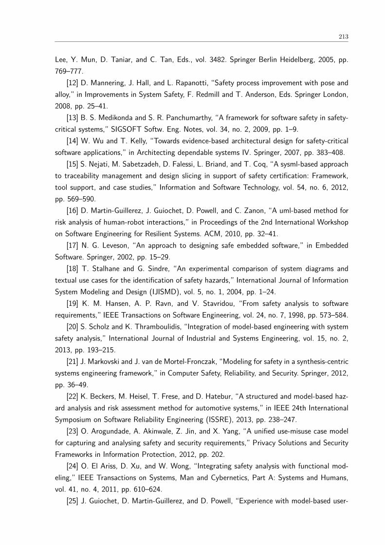
213
Lee, Y. Mun, D. Taniar, and C. Tan, Eds., vol. 3482. Springer Berlin Heidelberg, 2005, pp.769–777.
[12] D. Mannering, J. Hall, and L. Rapanotti, “Safety process improvement with pose andalloy,” in Improvements in System Safety, F. Redmill and T. Anderson, Eds. Springer London,2008, pp. 25–41.
[13] B. S. Medikonda and S. R. Panchumarthy, “A framework for software safety in safety-critical systems,” SIGSOFT Softw. Eng. Notes, vol. 34, no. 2, 2009, pp. 1–9.
[14] W. Wu and T. Kelly, “Towards evidence-based architectural design for safety-criticalsoftware applications,” in Architecting dependable systems IV. Springer, 2007, pp. 383–408.
[15] S. Nejati, M. Sabetzadeh, D. Falessi, L. Briand, and T. Coq, “A sysml-based approachto traceability management and design slicing in support of safety certification: Framework,tool support, and case studies,” Information and Software Technology, vol. 54, no. 6, 2012,pp. 569–590.
[16] D. Martin-Guillerez, J. Guiochet, D. Powell, and C. Zanon, “A uml-based method forrisk analysis of human-robot interactions,” in Proceedings of the 2nd International Workshopon Software Engineering for Resilient Systems. ACM, 2010, pp. 32–41.
[17] N. G. Leveson, “An approach to designing safe embedded software,” in EmbeddedSoftware. Springer, 2002, pp. 15–29.
[18] T. Stalhane and G. Sindre, “An experimental comparison of system diagrams andtextual use cases for the identification of safety hazards,” International Journal of InformationSystem Modeling and Design (IJISMD), vol. 5, no. 1, 2004, pp. 1–24.
[19] K. M. Hansen, A. P. Ravn, and V. Stavridou, “From safety analysis to softwarerequirements,” IEEE Transactions on Software Engineering, vol. 24, no. 7, 1998, pp. 573–584.
[20] S. Scholz and K. Thramboulidis, “Integration of model-based engineering with systemsafety analysis,” International Journal of Industrial and Systems Engineering, vol. 15, no. 2,2013, pp. 193–215.
[21] J. Markovski and J. van de Mortel-Fronczak, “Modeling for safety in a synthesis-centricsystems engineering framework,” in Computer Safety, Reliability, and Security. Springer, 2012,pp. 36–49.
[22] K. Beckers, M. Heisel, T. Frese, and D. Hatebur, “A structured and model-based haz-ard analysis and risk assessment method for automotive systems,” in IEEE 24th InternationalSymposium on Software Reliability Engineering (ISSRE), 2013, pp. 238–247.
[23] O. Arogundade, A. Akinwale, Z. Jin, and X. Yang, “A unified use-misuse case modelfor capturing and analysing safety and security requirements,” Privacy Solutions and SecurityFrameworks in Information Protection, 2012, pp. 202.
[24] O. El Ariss, D. Xu, and W. Wong, “Integrating safety analysis with functional mod-eling,” IEEE Transactions on Systems, Man and Cybernetics, Part A: Systems and Humans,vol. 41, no. 4, 2011, pp. 610–624.
[25] J. Guiochet, D. Martin-Guillerez, and D. Powell, “Experience with model-based user-

214
centered risk assessment for service robots,” in 12th International Symposium on High-AssuranceSystems Engineering (HASE), 2010, pp. 104–113.
[26] S. Chandrasekaran, T. Madhumathy, M. Aparna, and R. Shilpa Jain, “A safety en-hancement model of software system for railways,” in 4th IET International Conference onSystems Safety, 2009, pp. 1–6.
[27] J. F. Briones, M. A. De Miguel, J. P. Silva, and A. Alonso, “Application of safetyanalyses in model driven development,” in Software Technologies for Embedded and UbiquitousSystems. Springer, 2007, pp. 93–104.
[28] E. Broomfield and P. Chung, “Safety assessment and the software requirements spec-ification,” Reliability Engineering & System Safety, vol. 55, no. 3, 1997, pp. 295–309.
[29] J. Gorski and A. Wardzinski, “Deriving real-time requirements for software from safetyanalysis,” in Proceedings of the Eighth Euromicro Workshop on Real-Time Systems, 1996, pp.9–14.
[30] J. Du, J. Wang, and X. Feng, “A safety requirement elicitation technique of safety-critical system based on scenario,” in Intelligent Computing Theory, ser. Lecture Notes inComputer Science, D.-S. Huang, V. Bevilacqua, and P. Premaratne, Eds., vol. 8588. SpringerInternational Publishing, 2014, pp. 127–136.
[31] G. Zoughbi, L. Briand, and Y. Labiche, “Modeling safety and airworthiness (rtca do-178b) information: conceptual model and uml profile,” Software & Systems Modeling, vol. 10,no. 3, pp. 337–367, 2011.
[32] J. Jrjens, “Developing safety-critical systems with uml,” in UML 2003 - The UnifiedModeling Language. Modeling Languages and Applications, ser. Lecture Notes in ComputerScience, P. Stevens, J. Whittle, and G. Booch, Eds., vol. 2863. Springer Berlin Heidelberg,2003, pp. 360–372.
[33] A. Simpson and J. Stoker, “Will it be safe? an approach to engineering safety require-ments,” in Components of System Safety. Springer, 2002, pp. 140–164.
[34] G. Biggs, T. Sakamoto, and T. Kotoku, “A profile and tool for modelling safetyinformation with design information in sysml,” Software & Systems Modeling, 204, pp. 1–32.
[35] S. Lu and W. A. Halang, “A uml profile to model safety-critical embedded real-timecontrol systems,” in Contributions to Ubiquitous Computing. Springer, 2007, pp. 197–218.
[36] T. Stalhane and G. Sindre, “A comparison of two approaches to safety analysis basedon use cases,” in Conceptual Modeling-ER. Springer, 2007, pp. 423–437.
[37] S. Mustafiz and J. Kienzle, “Drep: A requirements engineering process for dependablereactive systems,” in Methods, Models and Tools for Fault Tolerance. Springer, 2009, pp.220–250.
[38] J. Ekberg, U. Ingelsson, H. Lønn, M. Skoog, and J. Søderberg, “Collaborative de-velopment of safety-critical automotive systems: Exchange, views and metrics,” in ComputerSafety, Reliability, and Security. Springer, 2014, pp. 55–62.
[39] M. Wilikens, M. Masera, and D. Vallero, “Integration of safety requirements in the

215
initial phases of the project lifecycle of hardware/software systems,” in Safe Comp 97. Springer,1997, pp. 83–97
[40] R. F. Paige, R. Charalambous, X. Ge, and P. J. Brooke, “Towards agile engineeringof high-integrity systems,” in Computer Safety, Reliability, and Security. Springer, 2008, pp.30–43.
[41] R. Guillerm, H. Demmou, and N. Sadou, “Information model for model driven safetyrequirements management of complex systems,” in Complex Systems Design & Management.Springer, 2010, pp. 99–111.
[42] G. Schedl and W. Winkelbauer, “Practical ways of improving product safety in indus-try,” in Improvements In system Safety. Springer, 2008, pp. 177–193.
[43] R. Rafeh, “A proposed approach for safety management in medical software design,”Journal of Medical Systems, vol. 37, no. 1, 2013.
[44] D. Chen, R. Johansson, H. Lønn, H. Blom, M. Walker, Y. Papadopoulos, S. Torchiaro,F. Tagliabo, and A. Sandberg, “Integrated safety and architecture modeling for automotive em-bedded systems,” e & i Elektrotechnik und Informationstechnik, vol. 128, no. 6, pp. 196–202,2011.
[45] H. Tschrtz and G. Schedl, “An integrated project management life cycle supportingsystem safety,” in Making Systems Safer, C. Dale and T. Anderson, Eds. Springer London,2010, pp. 71–83.
[46] J. Elliott, S. Brooks, P. Hughes, and N. Kanuritch, “A framework for enhancing thesafety process for advanced robotic applications,” in Achievement and Assurance of Safety.Springer, 1995, pp. 131–152.
[47] P. Croll, C. Chambers, M. Bowell, and P. Chung, “Towards safer industrial computercontrolled systems,” in Safe Comp 97. Springer, 1997, pp. 321–331.
[48] T. Cant, B. Mahony, J. McCarthy, and L. Vu, “Hierarchical verification environment,”in Proceedings of the 10th Australian Workshop on Safety Critical Systems and Software -Volume 55, ser. SCS ’05. Darlinghurst, Australia, Australia: Australian Computer Society, Inc.,2006, pp. 47–57.
[49] J. Jurkiewicz, J. Nawrocki, M. Ochodek, and T. Gowacki, “Hazop-based identificationof events in use cases,” Empirical Software Engineering, vol. 20, no. 1, 2015, pp. 82–109.
[50] T. Staalhane, G. Sindre, and L. Du Bousquet, “Comparing safety analysis based onsequence diagrams and textual use cases,” in Advanced Information Systems Engineering.Springer, 2010, pp. 165–179.
[51] R. Murali, A. Ireland, and G. Grov, “A rigorous approach to combining use casemodelling and accident scenarios,” in NASA Formal Methods. Springer, 2015, pp. 263–278.
[52] J. Pernstal, T. Gorschek, R. Feldt, and D. Floren, “Requirements communication andbalancing in large-scale software-intensive product development,” Information and SoftwareTechnology, vol. 67, pp. 44–64, 2015.
[53] S. Fricker, T. Gorschek, C. Byman, and A. Schmidle, “Handshaking with implemen-
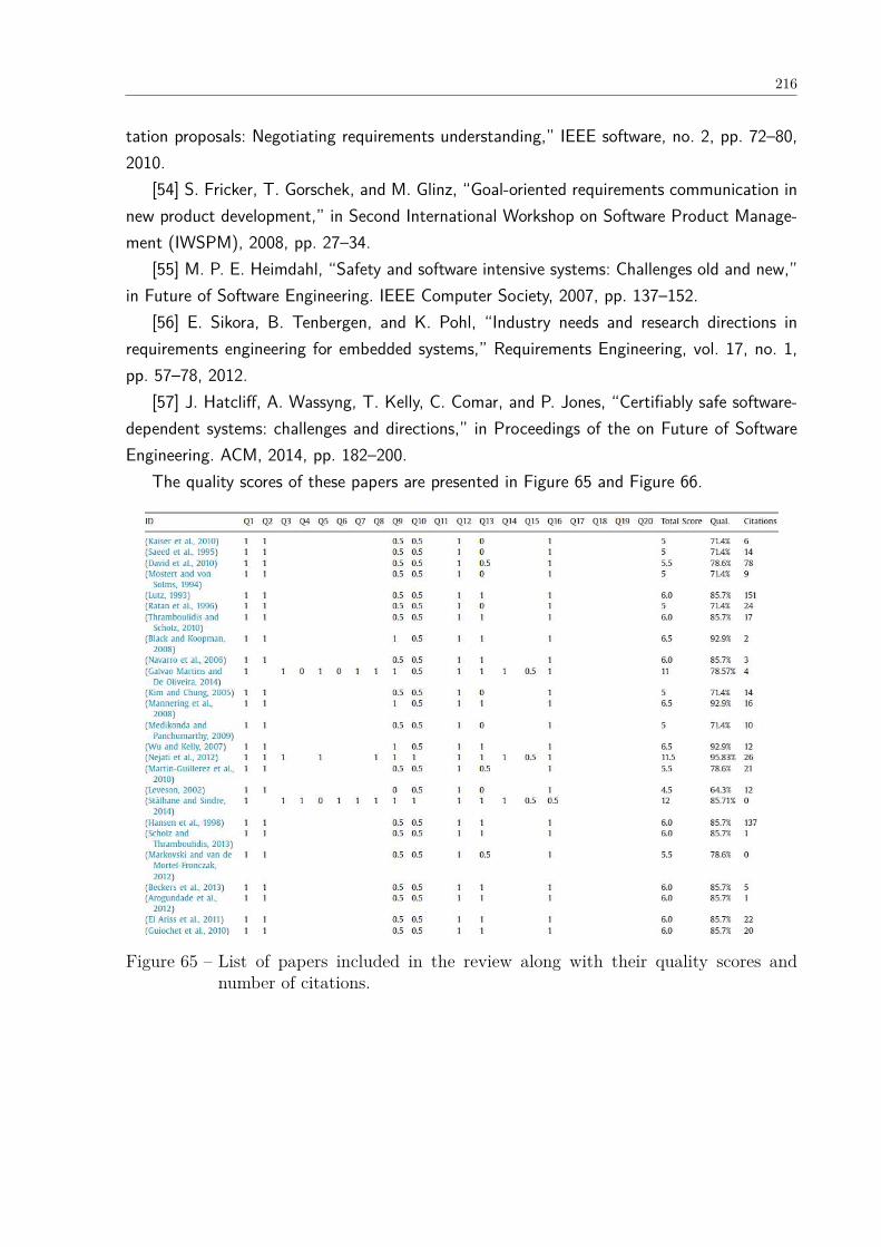
216
tation proposals: Negotiating requirements understanding,” IEEE software, no. 2, pp. 72–80,2010.
[54] S. Fricker, T. Gorschek, and M. Glinz, “Goal-oriented requirements communication innew product development,” in Second International Workshop on Software Product Manage-ment (IWSPM), 2008, pp. 27–34.
[55] M. P. E. Heimdahl, “Safety and software intensive systems: Challenges old and new,”in Future of Software Engineering. IEEE Computer Society, 2007, pp. 137–152.
[56] E. Sikora, B. Tenbergen, and K. Pohl, “Industry needs and research directions inrequirements engineering for embedded systems,” Requirements Engineering, vol. 17, no. 1,pp. 57–78, 2012.
[57] J. Hatcliff, A. Wassyng, T. Kelly, C. Comar, and P. Jones, “Certifiably safe software-dependent systems: challenges and directions,” in Proceedings of the on Future of SoftwareEngineering. ACM, 2014, pp. 182–200.
The quality scores of these papers are presented in Figure 65 and Figure 66.
Figure 65 – List of papers included in the review along with their quality scores andnumber of citations.
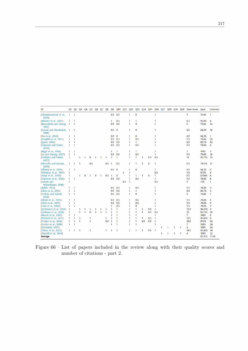
217
Figure 66 – List of papers included in the review along with their quality scores andnumber of citations - part 2.

218
APPENDIX B – UNI-REPM SAFETY MODULE – COMPLETE DESCRIPTION
This appendix presents the full description of all 148 actions of Uni-REPM SCS.
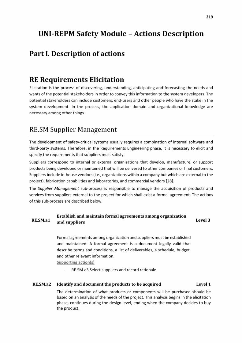
219
UNI-REPM Safety Module – Actions Description
Part I. Description of actions
RE Requirements Elicitation Elicitation is the process of discovering, understanding, anticipating and forecasting the needs and
wants of the potential stakeholders in order to convey this information to the system developers. The
potential stakeholders can include customers, end-users and other people who have the stake in the
system development. In the process, the application domain and organizational knowledge are
necessary among other things.
RE.SM Supplier Management
The development of safety-critical systems usually requires a combination of internal software and
third-party systems. Therefore, in the Requirements Engineering phase, it is necessary to elicit and
specify the requirements that suppliers must satisfy.
Suppliers correspond to internal or external organizations that develop, manufacture, or support
products being developed or maintained that will be delivered to other companies or final customers.
Suppliers include in-house vendors (i.e., organizations within a company but which are external to the
project), fabrication capabilities and laboratories, and commercial vendors [28].
The Supplier Management sub-process is responsible to manage the acquisition of products and
services from suppliers external to the project for which shall exist a formal agreement. The actions
of this sub-process are described below.
RE.SM.a1 Establish and maintain formal agreements among organization
and suppliers Level 3
Formal agreements among organization and suppliers must be established
and maintained. A formal agreement is a document legally valid that
describe terms and conditions, a list of deliverables, a schedule, budget,
and other relevant information.
Supporting action(s)
- RE.SM.a3 Select suppliers and record rationale
RE.SM.a2 Identify and document the products to be acquired Level 1
The determination of what products or components will be purchased should be based on an analysis of the needs of the project. This analysis begins in the elicitation phase, continues during the design level, ending when the company decides to buy the product.
220
DS Documentation and Requirements Specification Documentation and Requirements specification deals with how a company organizes requirements
and other knowledge gathered during requirements engineering process into consistent, accessible
and reviewable documents. In the safety module, the management of human factors and the
documentation of safety issues are the main concern of the sub-process added to this process. The
safety documentation contains the product’s detailed functional and safety requirements.
DS.HF Human Factors
Human factors have a significant importance in safety standards since many hazardous situations are
caused by system’s users and operator due lack of training or unfamiliarity with the operator mental
RE.SM.a3 Select suppliers and record rationale Level 1
The selection of suppliers and its rationale, for example, advantages and disadvantages, should be recorded. The list of products to be acquired can provide a direction for such selection.
Supporting action(s)
RE.SM.a2 Identify and document the products to be acquired
RE.SM.a4 Specify all external systems and safety-related software Level 2
The characteristics of all external systems (e.g. data bus, computer, ground interface, communication protocol, the concurrency and real-time model) that interact with the system as well as safety-related software used to implement functions intended to achieve or maintain a safe state in a safety-critical system must be properly documented.
Supporting action(s)
RE.SM.a2 Identify and document the products to be acquired
RE.SM.a5 Establish and maintain detailed system integration procedures
for the external systems and safety-related software
Level 2
Detailed system integration procedures, for example the number of iterations to be performed and details of the expected tests and other types of information, for the components of external systems and safety-related software must be established and maintained.
Supporting action(s)
RE.SM.a4 Specify all external systems and safety-related software
RE.SM.a6 Define the safety standards that suppliers must follow Level 2
The safety standards to be followed by suppliers must be defined and properly
specified. This information will be necessary during the construction of safety cases
and certification process of the system being developed.
Supporting action(s)
- RE.SM.a1 Establish and maintain formal agreements among organization and
suppliers
221
models. Although, the main goals of human-computer interaction are not primarily for safety but to
make recommendations and application of technical guidelines [29], the human factors shall be
considered during the Requirements Engineering stage of safety-critical system development.
DS.HF.a1 Construct models about the way of work of the operator Level 1
Operator’s task models regarding the way of work of the operator impact fundamental
dimensions of system usage such as workload, situation awareness, performance, stress,
and tiredness, etc. Therefore, such models must be adequately constructed. The
representation of such models using visual task-modeling language allows integrated
simulation and analysis of the entire system, including human – computer interactions.
DS.HF.a2 Document human factors design and analysis Level 1
Developing safety-critical systems requires integrating human factors into the basic
Requirements Engineering process, which in turn has important implications for system
requirements. The human factors design and analysis should be performed to ensure that
the system is designed for the user, regardless the type of user. This analysis should
consider the comfort of the users, fit the human body and their cognitive abilities and
the system’s functionalities. The results of such analysis should be documented.
DS.HF.a3 Evaluate prototypes, requirements and technical Human Machine
Interface restrictions
Level 2
When the first version of system specification is available or whenever occurs changes
on it, the prototypes, requirements and technical Human Machine Interface
restrictions should be evaluated with the user. This evaluation, which can be with user in
labs or using questionnaires, should consider the system specification. If problems in
prototypes, in requirements or in Human Machine Interface are identified, new
human factors requirements must be specified.
Supporting action(s)
- DS.HF.a1 Construct models about the way of work of the operator
- DS.HF.a2 Document human factors design and analysis
DS.HF.a4 Model and evaluate operator tasks and component black-box
behavior
The component black-box behavior describe the inputs and outputs of each
component and their relationships only in terms of externally visible behavior.
Black-box behavioral specifications as well as operator tasks can be used to
maintain the system and to specify and validate changes before the actual
development of the system.
Supporting action(s)
DS.HF.a1 Construct models about the way of work of the operator
Level 2
222
DS.SDO Safety Documentation
Many artifacts are generated during the development of a safety-critical system that are used
throughout the development to construct safety cases or documents with certification purposes.
Accordingly, all information related to system’s safety produced in Requirements Engineering phase
must be recorded. This activity can also be done together with members from other phases that will
use the information later.
DS.HF.a5 Define interfaces considering ergonomic principles Level 2
The interfaces of the safety-critical system should consider ergonomic principles to
ensure that the system, including the safety-related parts, is easy to use, and so that the
operator is not tempted to act in a hazardous manner.
Supporting action(s)
- DS.HF.a6 Specify Human Machine Interface requirements
DS.HF.a6 Specify Human Machine Interface requirements Level 1
The Human-Machine Interfaces specify the connection between user and system.
Designing a good interface is a challenging Requirements Engineering task since the
construction of a well-operable, user-friendly and ergonomic interface presumes great
expertise. The human machine interface requirements, including all elements that a user
will touch, see, hear, or use to perform safety control functions and receive feedback on
those actions, should be described. These requirements allow providing details about the
controls by which a user operates the system.
DS.SDO.a1 Record safety decisions and rationale Level 1
Safety analysis encompasses trade-offs and decision making to provide safety to the
system. Therefore, all safety decisions and rationale for them must be documented
and included in the safety requirements specification for later analysis and
certification.
Supporting action(s)
- DS.SDO.a9 Maintain hazard and risk analysis results for the system
throughout the overall safety lifecycle
DS.SDO.a2 Ensure that safety requirements are incorporated into
system and subsystem specifications, including human-
machine interface requirements
Level 2
The safety requirements defined to mitigate the hazards should be traced to (sub)
systems and components to improve safety communication and to construct the
safety cases.
Supporting action(s)
- DS.HF.a6 Specify Human Machine Interface requirements
223
DS.SDO.a3 Document all lifecycle and modification activities Level 2
The company should define a software and safety lifecycle and record the activities
and modification occurred in each of the lifecycle.
Supporting action(s)
- OS.GSM.a2 Identify and document safety lifecycle for the system
development
DS.SDO.a4 Develop and document training, operational and
software user manuals
Level 1
Training, operational and software user manuals must be developed and properly
maintained. These manuals will be updated and improved in the next stages of
system development.
DS.SDO.a5 Document System Limitations Level 1
Sometimes not all hazards and risks are possible or viable to be eliminated or controlled, so, the system is released with limitations (accepted risks). Limitations can be associated, for example, with basic functional requirements, environment assumptions, hazards or hazard causal factors, problems encountered or tradeoffs made during Requirements Engineering. Such limitations should be recorded with links to the pertinent portions of the hazard analysis along with an explanation of why they could not be eliminated or adequately controlled. The limitations are used by management and stakeholders to determine whether the system is adequately safe to use; and, hence, affect both acceptance and system certification.
Supporting action(s)
- DS.SDO.a1 Record safety decisions and rationale
- DS.SDO.a9 Maintain hazard and risk analysis results for the system
throughout the overall safety lifecycle
DS.SDO.a6 Provide an operation manual Level 2
A safety manual describing the functions as well as the inputs and outputs interfaces of an external element must be provided. The manual also should contain the identification of the hardware and/or software configuration of the compliant element to enable configuration management of safety-related system. Moreover, it is also necessary to relate constraints on the use of the element and/or assumptions on which analysis of the behavior or failure rates of the item are based. Such manual may be derived from the supplier’s own documentation and records, or may be created or supplemented by the company. If available, reverse engineering can be used.
Supporting action(s)
- RE.SM.a1 Establish and maintain formal agreements among organization
and suppliers
- RE.SM.a4 Specify all external systems and safety-related software
- RE.SM.a5 Establish and maintain detailed system integration procedures
for the external systems and safety-related software
- RE.SM.a6 Define the safety standards that suppliers must follow
224
RA Requirements Analysis Requirements gathered from different sources need to be analyzed to detect incomplete or incorrect
ones as well as to estimate necessary information for later activities (e.g. risk, priorities…). It is also
necessary to conduct a preliminary safety analysis and failure handling to dismiss avoiding wasting
effort in next phases of system development.
RA.PSA Preliminary Safety Analysis
Conducting safety analysis early in the development process contributes to improve system quality
and detect hazards and related information in the beginning of Requirements Engineering phase.
DS.SDO.a7 Document lessons learned Level 3
Many times the company develops new versions of existing systems with new functionalities or constructs new systems but in the same area. In this context, a better safety analysis can be conducted by collecting information from previous projects. Hence, the company should document lessons learned to prevent or mitigate risks already identified.
Supporting action(s)
- DS.SDO.a1 Record safety decisions and rationale
DS.SDO.a8 Ensure that safety-related information is incorporated
into user and maintenance documents
Level 1
Safety-related information must be included into user and maintenance documents
as long as they are produced. Moreover, periodic reviews should be conducted to
ensure that such information were incorporated.
Supporting action(s)
- DS.SDO.a1 Record safety decisions and rationale
- DS.SDO.a9 Maintain hazard and risk analysis results for the system
throughout the overall safety lifecycle
DS.SDO.a9 Maintain hazard and risk analysis results for the system
throughout the overall safety lifecycle
Level 2
The results of hazard and risk analysis must be maintained throughout the overall safety lifecycle, from the Requirements Engineering phase to the disposal phase.
DS.SDO.a10 Include a summary of safety requirements Level 2
To improve the communication among stakeholders a summary of safety
requirements with their associated page numbers in the document must be
produced and maintained.
Supporting action(s)
- DS.SDO.a9 Maintain hazard and risk analysis results for the system
throughout the overall safety lifecycle

225
RA.PSA.a1 Identify and document safety-critical computer software
components and units
Level 2
Improving system safety requires the identification of safety-critical computer software
components and units that demand special attention. Safety engineers and the quality
assurance staff will be responsible to monitoring of the strategies to reduce hazardous
situations associated with these elements.
RA.PSA.a2 Simulate the process Level 2
Better safety analysis can be performed by simulating the process related to the system.
The process simulation enable modeling complex tasks providing a representative
environment to elaborate and test hypotheses. The system can also be simulated by
analyzing its inputs and outputs, anticipated occurrences as well as undesired conditions
requiring system action.
RA.PSA.a3 Identify and document system hazards Level 1
The identification of hazards should be identified using appropriate methods and tools for the type of system and be properly recorded.
Possible documents/sources to be consulted or analyzed to achieve this task may be:
- system specification; - lessons learned; - pertinent standards and regulations; - safety design checklists; - safety related interface considerations among various elements of the system; - environmental constraints; - facilities; - real property installed equipment; - support equipment and training; - safety-related equipment - safeguards; and - possible malfunctions to the system, subsystems, or software.
Supporting action(s)
- DS.SDO.a7 Document lessons learned - OS.SP.a14 Identify and document the hazard analysis to be performed; the
analytical techniques (qualitative or quantitative) to be used; and depth within the system that each analytical technique will be used (e.g., system level, subsystem level, component level)
RA.PSA.a4 Identify and document hazards, hazardous situations and harmful
events due to interaction with other equipment or systems (installed
or to be installed)
Level 1
Besides system hazards, a safety-critical system can suffer from hazards, hazardous
situations or harmful events due to interaction with other equipment or systems (installed
or to be installed). Therefore, it is necessary perform the analysis related to this
information.
Supporting action(s)

226
RA.PSA.a3 Identify and document system hazards
RA.PSA.a5 Specify the type of initiating events that need to be considered Level 2
Hazards generally are initiated by some event. Hence, the type of these event must be
considered during safety analysis.
Example of events may be:
- component failures
- procedural faults
- human error; and
- dependent failure mechanisms that can cause hazardous events.
Supporting action(s)
- RA.PSA.a3 Identify and document system hazards
- RA.PSA.a4 Identify and document hazards, hazardous situations and harmful
events due to interaction with other equipment or systems (installed or to be
installed)
RA.PSA.a6 Obtain and document information about the determined hazards
(causes, probability, severity, duration, intensity, toxicity, exposure
limit, mechanical force, explosive conditions, reactivity,
flammability etc.)
Level 1
Once hazards are identified, the next step is to specify details about them. Some
information are required during the construction of safety cases and certification of the
system.
Example of data that should be recorded are [33]:
- cause of hazard
- probability
- severity
- duration
- intensity
- toxicity
- exposure limit
- mechanical force
- explosive conditions
- reactivity
- flammability etc.
Supporting action(s)
- RA.PSA.a3 Identify and document system hazards
- RA.PSA.a4 Identify and document hazards, hazardous situations and harmful
events due to interaction with other equipment or systems (installed or to be
installed)
RA.PSA.a7 Identify and document hazardous materials Level 1
227
Some safety-critical systems, specially the medical ones, can be constructed using
materials that can cause allergic reactions. Therefore, it is necessary to specify any item or
substance that, due to its chemical, physical, toxicological, or biological nature, could cause
harm to people, equipment, or the environment. Moreover, this information should be
present in system specification and available to potential users.
RA.PSA.a8 Identify and document consequences of hazards, severity categories
and affected assets
Level 1
When a hazardous situation occurs, it may result in consequences for people and
environment. Accordingly, the types of such consequences, for example incident and
accident, should recorded.
The severity categories may be specified following the classification of safety standards.
The MIL-STD-882D [32] for example define four categories:
- Catastrophic
- Critical
- Marginal
- Negligible
Moreover, the affected assets should also be specified.
Supporting action(s)
- RA.PSA.a3 Identify and document system hazards
- RA.PSA.a4 Identify and document hazards, hazardous situations and harmful
events due to interaction with other equipment or systems (installed or to be
installed)
- RA.PSA.a6 Obtain and document information about the determined hazards
(causes, probability, severity, duration, intensity, toxicity, exposure limit,
mechanical force, explosive conditions, reactivity, flammability etc.)
RA.PSA.a9 Conduct risk estimation Level 1
After the identification of hazards, a risk analysis should be conducted. It involves the risk
estimation and risk evaluation. Risk estimation corresponds to the identification of risks
presented by hazards, barrier failures and human errors and their quantification.
Supporting action(s)
- RA.PSA.a3 Identify and document system hazards
- RA.PSA.a4 Identify and document hazards, hazardous situations and harmful
events due to interaction with other equipment or systems (installed or to be
installed)
- RA.PSA.a6 Obtain and document information about the determined hazards
(causes, probability, severity, duration, intensity, toxicity, exposure limit,
mechanical force, explosive conditions, reactivity, flammability etc.)
228
RA.PSA.a10 Conduct risk evaluation for each identified hazard Level 2
The risk evaluation addresses decision making about the risk level and its priority during
the mitigation specification phase through the application of the criteria developed when
the context was established.
The ISO 15998 [33] safety standard recommends the use of risk assessment methodologies
such as presented in ISO 14121-1 or IEC 61508-5.
Supporting action(s)
- RA.PSA.a3 Identify and document system hazards
- RA.PSA.a4 Identify and document hazards, hazardous situations and harmful
events due to interaction with other equipment or systems (installed or to be
installed)
- RA.PSA.a6 Obtain and document information about the determined hazards
(causes, probability, severity, duration, intensity, toxicity, exposure limit,
mechanical force, explosive conditions, reactivity, flammability etc.)
RA.PSA.a11 Identify and document risk mitigation procedures for each
identified hazard
Level 1
Risk mitigation procedures should be defined to handle the hazards and reduce the risks
previously identified. Examples of procedures are prevention, detection, reaction, and
adaptation.
Supporting action(s)
- RA.PSA.a9 Conduct risk estimation
- RA.PSA.a10 Conduct risk evaluation for each identified hazard
RA.PSA.a12 Collect safety requirements from multiple viewpoints Level 2
The development of safety-critical system requires multidisciplinary teams (computer
science, medical, electrical, mechanical, among others) that have different backgrounds
and expertise. Accordingly, better safety analysis will be achieved if safety requirements
were collected from multiple viewpoints.
The safety requirements can be of different types [34]: pure safety requirements, safety-
significant requirements, and safety functional requirements.
Supporting action(s)
- OS.SP.a3 Define and document the interface between system safety and all other
applicable safety disciplines
- RA.PSA.a13 Identify and document pure safety requirements
- RA.PSA.a14 Identify and document safety-significant requirements and safety
integrity levels
- RA.PSA.a15 Identify and document safety constraints and how they could be
violated
229
- RA.PSA.a16 Identify and document possible control flaws and inadequate control
actions
- RA.PSA.a17 Identify and document safety functional requirements
- RA.PSA.a18 Identify and document operational requirements
RA.PSA.a13 Identify and document pure safety requirements Level 1
Pure safety requirements should be identified and specified. These requirements are a
kind of quality requirement.
Example
“The system shall not cause more than 3 amount of accidental harm per year.”
RA.PSA.a14 Identify and document safety-significant requirements and safety
integrity levels
Level 2
Sometimes, some requirements are not originally defined to mitigate some hazard, but
they can have significant safety ramifications. They are non-safety primary mission
requirements and due to their relationship with safety, they should be identified and
documented.
Safety-significant requirements can be identified based on hazard analysis results and
sources of such requirements can be [34]:
- Functional Requirements
- Data Requirements
- Interface Requirements
- Non-safety Quality Requirements
- Constraints
Safety-significant requirements are classified according to the safety integrity level (SIL)
which corresponds to a range of safety integrity values representing a category of required
safety. In IEC 61508, SIL can be in a range of 1-4 where level 4 has the highest level of safety
integrity and level 1 has the lowest.
Example(s)
Requirements for controlling elevator doors.
Requirements to control insulin infusion.
RA.PSA.a15 Identify and document safety constraints and how they could be
violated
Level 2
The safety requirements specification may have safety constraints that are engineering
decisions that have been chosen to be mandated as a requirement intended to ensure a
minimum level of safety. Therefore, any safety-related or relevant constraints between the
hardware and the software should be identified and documented.
Example of sources of safety constraints are [34]:
230
- Architecture constraints
- Design constraints
- Implementation (e.g., coding) constraints
- Testing constraints
Moreover, it is necessary to conduct an analysis about how the safety constraints of a
system could be violated and add mechanisms to enforce them.
Supporting action(s)
- RA.PSA.a16 Identify and document possible control flaws and inadequate control
actions
RA.PSA.a16 Identify and document possible control flaws and inadequate
control actions
Level 2
Following control theory principles, the system must be analyzed to identify possible
control flaws and inadequate control actions. Inadequate control actions can be hazardous
in four ways [35]:
- A control action required for safety is not provided;
- An unsafe control action is provided;
- A potentially safe control action is provided too late, or out of sequence;
- A correct action is stopped too soon.
RA.PSA.a17 Identify and document safety functional requirements Level 1
Safety functional requirements are functions to be implemented in a safety-critical system
that is intended to achieve or maintain a safe state for the system, in respect of a specific
hazardous situation. These requirements should be identified and properly specified.
Example
- Emergency core coolant system for nuclear power plant
RA.PSA.a18 Identify and document operational requirements Level 1
Operational requirements, which are the basis for system requirements, of a safety-critical
system should be identified and recorded. These requirements describes how to run the
system.
Example
- Logging, startup/shutdown controls, monitoring, resource consumption, backup,
availability among others.
RA.PSA.a19 Perform and document the feasibility evaluation of safety functional
requirements
Level 2
Occasionally, the safety functional requirements defined are not viable or impossible to
implement. Therefore, stakeholders should conduct a feasibility evaluation of such
231
requirements. In such analysis trade-offs are performed aiming to achieve a best
combination of viability, safety and cost. Sometimes, the definition of new safety
functional requirements are necessary.
Supporting action(s)
- RA.PSA.a17 Identify and document safety functional requirements
- RA.PSA.a20 Prioritize hazards and safety requirements
RA.PSA.a20 Prioritize hazards and safety requirements Level 1
Hazards in a system have different levels of severity and consequences. The lack of
prioritization can severely limit the Requirements Engineering process, and the success of
the project, because such activities helps to identify critical requirements and contributes
to the decision making process [36]. Therefore, some hazards should have high priority and
more resources allocated to mitigate them. In this step, hazards and safety requirements
are prioritized and the results recorded.
Supporting action(s)
- RA.PSA.a8 Identify and document consequences of hazards, severity categories
and affected assets
- RA.PSA.a17 Identify and document safety functional requirements
RA.PSA.a21 Document verification requirements, possible human-machine
interface problems, and operating support requirements
Level 2
In this step, analysis and verification requirements, possible safety-interface problems,
including the human-machine interface, and operating support requirements should be
defined. The specification of such requirements in the Requirements Engineering process
is necessary to avoid defining a hazard that may be implemented correctly but whose test
is impossible or very costly [37].
RA.PSA.a22 Perform interface analysis, including interfaces within subsystems
(such as between safety-critical and non-safety-critical software
components)
Level 3
In this step, the hazard analysis should be reviewed and updated to consider problems with
hardware-software and their interfaces.
Supporting action(s)
- RA.PSA.a3 Identify and document system hazards
- RA.PSA.a4 Identify and document hazards, hazardous situations and harmful
events due to interaction with other equipment or systems (installed or to be
installed)
RA.PSA.a23 Consolidate preliminary system safety technical specification Level 2
In this step, it is necessary to ensure that the results of all analysis conducted and the
information identified are consolidated in a preliminary system safety technical
specification.
232
RA.FH Failure Handling
Hazardous situations can be originated due to failures in system components that are hard to discover
by either analysis or test. This difficult can originate the release of systems allowing uncommon
hazards. Hence, it is important to specify and manage these faults. The safety module has a sub
process to handle such failures.
RA.FH.a1 Define requirements to minimize systematic faults Level 2
Systematic faults can happen in the system due to their complexity. In this step, an analysis
should be conducted to define requirements for the avoidance or control of those faults.
The definition of such requirements depend on the expertise of the requirements
engineer and judgment from practical experience gained in industry.
Supporting action(s)
- RA.FH.a2 Specify Fault-detection procedures
- RA.FH.a3 Specify Restart-up procedures
RA.FH.a2 Specify Fault-detection procedures Level 2
To avoid hazards and maintain a safe state in the system, it is important to monitor a
system, identifying when a fault has occurred, and presenting its type and location. This
early detection of a fault contributes to avoid systematic faults and providing time to the
system to recover from the fault.
RA.FH.a3 Specify Restart-up procedures Level 1
Sometimes, hazards can be eliminated by taking restart-up procedures. This step of the
safety module concerns to the specification of such automatic procedures.
RA.FH.a4 Document the system behavioral model Level 1
The specification of the system behavioral model allows to verifying early its behavior
against the one expected. This analysis contributes to detect early the errors and
inconsistencies in the system specification as well as to anticipate the correct behavior of
the system.
RA.FH.a5 Identify and document Common-cause failures (CCF) and how to
prevent them
Level 1
Some failures may have a shared cause and its repeatability is known. Such failures are
called Common-cause failures (CCF) and due to the presence of many electronic parts in
the system, they should be identified and documented.

233
RP Release planning Release planning consists in determining the optimal set of requirements for a certain release to be
implemented at a defined/estimated time and cost to achieve some goals. A careful release planning
is necessary to avoid risky situations, fail to achieve planned goals or miss the time-to-market. Besides
the sub processes and actions already present in UNI-REPM, the module defines a new one related to
system certification.
RP.SC Safety Certification
Considering that many safety-critical systems should be certified by regulatory authorities, the
Safety Certification sub process area handles certification issues early in the development process.
RA.FH.a6 Perform reliability and system performance analysis Level 2
The time to failure as well as to repair some component impact in system recovery and
avoidance of hazardous situations. Accordingly, reliability and system performance
analysis should be conducted and its results recorded.
Supporting action(s)
- OS.SP.a13 Determine the required performance level
RP.SC.a1 Conduct safety audits Level 2
Safety audits should be conducted to examine whether the requirements are being
achieved and the desired level of safety is preserved. This step should be a periodic
activity during the Requirements Engineering process as well as the next stages of
system development.
Supporting action(s)
- OS.SP.a2 Define and document requirements for periodic functional safety
audits
RP.SC.a2 Demonstrate the preliminary safety integrity level achieved by
the system
Level 2
From the results of safety audits is possible to demonstrate the preliminary level of
safety achieved by the system. The level should be compared against the one desired
and can be improved still in Requirements Engineering process or in the next stages
of development.
Example of safety integrity level are:
IEC 61508 defines four levels (1-4) where the 4th level is the highest of safety
integrity and 1st is the lowest.
ECSS-E-HB-40A defines the following categories of software criticality:
category A, B, C, D.

234
Supporting action(s)
- RP.SC.a1 Conduct safety audits
- OS.SP.a7 Define and document the regulations and safety standards to be
followed
RP.SC.a3 Evaluate the threat to society from the hazards that cannot be
eliminated or avoided
Level 1
Stakeholders should be aware of the risks caused by hazards that cannot be eliminated or avoided and are present in the system. Hence, the threats to society should be evaluated and properly documented.
Supporting action(s)
- RA.PSA.a3 Identify and document system hazards
- RA.PSA.a4 Identify and document hazards, hazardous situations and harmful
events due to interaction with other equipment or systems (installed or to be
installed)
- RA.PSA.a6 Obtain and document information about the determined hazards
(causes, probability, severity, duration, intensity, toxicity, exposure limit,
mechanical force, explosive conditions, reactivity, flammability etc.)
- RA.PSA.a9 Conduct risk estimation
- RA.PSA.a10 Conduct risk evaluation for each identified hazard
RP.SC.a4 Construct preliminary safety and hazard reports Level 1
During the development of safety-critical systems results in many iterations of hazard
analysis, that generates a lot of safety and hazard reports. In Requirements
Engineering phase, a preliminary version of such documents should be constructed
and updated during system lifecycle.
RP.SC.a5 Construct preliminary safety cases Level 2
At the end of Requirements Engineering stage, all information gathered during safety
and hazard analysis should be used to construct preliminary safety cases.
Supporting action(s)
- RA.PSA.a3 Identify and document system hazards
RP.SC.a6 Demonstrate preliminary compliance with safety standards Level 2
The safety level achieved at Requirements Engineering phase should be used to demonstrate preliminary compliance with safety standards. The demonstration may be performed by developing a document describing the safety requirements, listing the safety standards and system specifications containing requirements to be satisfy by suppliers among other relevant information.
Supporting action(s)
- RP.SC.a2 Demonstrate the preliminary safety integrity level achieved by the system
- DS.SDO.a10 Include a summary of safety requirements
235
RV Requirements Validation Requirements validation includes the inspection of the produced documents against defined safety
and quality standards and the needs of stakeholders. In the safety module, a sub process to plan the
verification and validation activities was added since they often run concurrently and may use portions
of the same environment.
- RE.SM.a6 Define the safety standards that suppliers must follow - OS.SP.a8 Identify any certification requirements for software, safety or
warning devices or other special safety feature
RP.SC.a7 Ensure that the hazard report is updated with embedded links to
the resolution of each hazard, such as safety functional
requirements, safety constraints, operational requirements, and
system limitations
Level 2
The information about hazards should be easy to find to improve the communication
among stakeholders and the traceability in the development process. Accordingly,
safety functional requirements, safety constraints, operational requirements, and
system limitations should be inserted in the hazard report and periodically updated.
Supporting action(s)
- RP.SC.a4 Construct preliminary safety and hazard reports - PM.SCM.a1 Maintain with unique identification all safety configuration items - OS.STO.a5 Use of tools with support to cross reference and maintain the
traceability among safety information in the software specification
RP.SC.a8 Document the division of responsibility for system certification
and compliance with safety standards during safety planning
Level 1
Division of responsibility is necessary in the development of safety-critical systems especially in large and complex projects. This division of activities among personnel should be documented during safety planning and include the specification of people responsible for system certification and to demonstrate compliance with safety standards.
Supporting action(s)
- OS.SP.a7 Define and document the regulations and safety standards to be followed
RP.SC.a9 Specify a maintenance plan Level 1
A maintenance plan is necessary to release of a safety-critical system. This plan should describe the development and testing activities required to be undertaken on each new release of software including the obsolescence of development equipment, test environments and software among other relevant information.
236
RV.SVV Safety Validation and Verification
In the Safety Validation and Verification (V&V) there are actions to validation of the requirements and
the definition of strategies to the verification of requirements. V&V activities should be available early
in the development process so that the safety requirements are clearly understood and agreed by the
relevant stakeholders.
RV.SVV.a1 Define the safety validation plan for software aspects of system
safety
Level 2
The objective of this action is to define a safety validation plan for software aspects
of system safety. This plan should contain [38]:
- details of when the validation will be conducted;
- details of personnel responsible for performing the validation;
- identification of the relevant modes of system operation such as
preparation for use including setting and adjustment, startup, automatic,
manual, re-setting, shut down, maintenance, and uncommon conditions;
- identification of the safety-significant software which needs to be validated;
- the technical strategy for the validation;
- the required environment in which the validation activities will be
performed;
- the pass/fail criteria;
- the policies and procedures for evaluating the results of the validation,
particularly failures.
Supporting action(s)
- RA.SVV.a3 Define the technical strategy for the validation of external
systems and safety-related software
- RA.SVV.a4 Define pass/fail criteria for accomplishing software validation
and verification
RV.SVV.a2 Define the safety verification plan Level 1
The demonstration that safety will be properly achieved encompasses the definition
of a safety verification plan. This plan comprises planning inspection, testing,
analyses, and demonstration activities and should describe the following
information [28][39][40]:
- methods of verification (for example, inspections, peer reviews, audits,
walkthroughs, analyses, simulations, testing, and demonstrations);
- support tools, test equipment and software, simulations, prototypes, and
facilities;
- safety test specifications;
- required outcome of the tests for compliance;
- chronology of the tests.
Supporting action(s)

237
- RV.SVV.a5 Develop safety test plans, test descriptions, test procedures, and
validation and verification safety requirements.
- RA.PSA.a21 Document verification requirements, possible human-machine
interface problems, and operating support requirements
RV.SVV.a3 Define the technical strategy for the validation of external
systems and safety-related software
Level 2
A technical strategy for the validation (for example analytical methods, statistical
tests etc.) should be defined and the rationale for choosing it recorded. The strategy
should include [38]:
- choice of manual or automated techniques or both;
- choice of static or dynamic techniques or both;
- choice of analytical or statistical techniques or both;
- choice of acceptance criteria based on objective factors or expert judgment
or both.
RV.SVV.a4 Define pass/fail criteria for accomplishing software validation
and verification
Level 1
A part of safety V&V activities consists in defining pass/fail criteria for accomplishing
them. The criteria should address [38]:
- the required input signals with their sequences and their values;
- the anticipated output signals with their sequences and their values;
- other acceptance criteria, for example memory usage, timing and value
tolerances.
RV.SVV.a5 Develop safety test plans, test descriptions, test procedures,
and validation and verification safety requirements
Level 1
The goal of this step is to define and document preliminary versions of safety test
plans, test descriptions, test procedures, and validation and verification of safety
requirements. The definition of such documents and requirements to be used in
V&V activities aims to ensure that no hazards are introduced by test procedures
[37]. Therefore, this should be careful planned and begin early in the development
process.
Supporting action(s)
- RA.PSA.a21 Document verification requirements, possible human-machine
interface problems, and operating support requirements
RV.SVV.a6 Define and maintain a software integration test plan Level 2
Since there are many systems and subsystems as well as third-party software and equipment communicating with the safety-critical system it is necessary to define and maintain a software integration test plan. A successful integration strategy should use a combination of techniques, depending on the complexity of components [28].
238
Some factors to be considered during the elaboration of this plan are availability of the product components, test equipment, procedures, integration environment, and personnel skills [28].
RV.SVV.a7 Validate safety-related software aspects Level 1
The safety-related software aspects described in the safety validation plan should
be validated and the results documented.
Supporting action(s)
- RV.SVV.a1 Define the safety validation plan for software aspects of system
safety
RV.SVV.a8 Ensure that there is no potentially hazardous control actions Level 1
The aim of this step is to analyze whether the safety control actions provided in the
system design previously defined there is no potential for inadequate control,
leading to a hazard.
Supporting action(s)
- RA.PSA.a16 Identify and document possible control flaws and inadequate
control actions
RV.SVV.a9 Perform safety evaluation and verification at the system and
subsystem levels
Level 1
The safety evaluation and verification of the safety-critical system should be
performed at system and subsystem levels to ensure that there is no hazardous
situation remains in the system.
Supporting action(s)
- RA.PSA.a21 Document verification requirements, possible human-machine
interface problems, and operating support requirements
RV.SVV.a10 Conduct joint reviews (company and customer) Level 1
The validation and verification of the system should be performed in meeting with
company and customer together. Conducting non-jointly reviews rises the risk to
find late disagreements among stakeholders on the product capability or quality,
causing substantial reengineering and increasing its cost and time to develop [41].
RV.SVV.a11 Ensure that the stakeholders understand software-related
system safety requirements and constraints
Level 2
Stakeholders involved in the development of a safety-critical system, particularly
Requirements engineers, should understand the software-related system safety
requirements and constraints in order to produce better system specification. These
requirements should not be merely included in the specification, it is necessary to
properly and clearly specify them in details. This will contribute to avoid that
developers or other stakeholders involuntarily disable or override system safety
features or implement the functionalities erroneously [30].
239
OS Organizational Support This main process area evaluates the amount of support given to requirements engineering practices
from the surrounding organization. Organizational support is important, since ultimately the success
of any time-consuming activity needs to be understood and supported by the organization. This main
RV.SVV.a12 Document discrepancies between expected and actual results Level 1
Any discrepancies between expected and obtained results of V&V should be documented. It is also necessary to record the analysis made of such discrepancies such as the decisions taken about continuing the validation, the change requests and the return to an earlier part of system development [38].
Supporting action(s)
- RV.SVV.a7 Validate safety-related software aspects
RV.SVV.a13 Verify the behavioral model Level 3
The verification of system behavior should use the system behavioral model defined
previously aiming to ensure the correctness of the system or detect errors and
inconsistencies in the system specification.
Supporting action(s)
- RA.FH.a4 Document the system behavioral model
RV.SVV.a14 Ensure that software requirements and software interface
specification are consistent
Level 2
The objective of this action is to analyze whether the software requirements and
software interface specification are compatible and they do not have contradictory
issues. The non-consistent parts should be documented and corrected.
RV.SVV.a15 Perform safety inspections Level 1
Stakeholders should implement controls and to inspect the Requirements
Engineering process and operations in order to discover and correct any additional
hazards [30].
RV.SVV.a16 Identify and fix inconsistencies in safety requirements
specification
Level 2
The safety requirements specification should be examined in order to find
inconsistencies that must be recorded and solved. The documentation of such
inconsistencies should include the sources, conditions, rationales, as well as
corrective action requirements and actions.
Supporting action(s)
- RV.SVV.a12 Document discrepancies between expected and actual
results
- RV.SVV.a13 Verify the behavioral model
240
process area is aimed to enable organizational support, but also make the importance of requirements
engineering clear to the development organization at large. The safety module added three new areas:
Safety Planning, General Safety Management, Safety Tool Support, Safety Knowledge Management.
OS.SP Safety Planning
This main process area evaluates the amount of support given to requirements engineering practices
from the surrounding organization. The safety module defines sub process to provision the safety
practices and to establish a safety culture in the company.
OS.SP.a1 Develop an integrated system safety program plan Level 1
An integrated system safety program plan must be developed to define in detail tasks
and activities of system safety management and system safety engineering essential
to identify, evaluate, and eliminate/control hazards, or reduce the associated risk to
a level acceptable during the safety lifecycle. This plan offers a formal basis of
understanding between the customer and organization about the system safety
program; it will be executed to meet contractual requirements [39].
OS.SP.a2 Define and document requirements for periodic functional safety
audits
Level 2
Periodic functional safety audits should be performed during safety lifecycle.
Accordingly, it is necessary to define and document requirements for such audits. The
requirements should include [38]:
- assumptions, limitations, hazard analysis results, constraints and safety
decisions;
- the frequency of the functional safety audits;
- the level of independence of those carrying out the audits;
- the necessary documentation and follow-up activities.
OS.SP.a3 Define and document the interface between system safety and all
other applicable safety disciplines
Level 1
Considering that there are many disciplines involved in the development of a safety-
critical system, the interface between system safety and other safety disciplines such
as nuclear, range, explosive, chemical, biological, among others should be defined and
recorded.
OS.SP.a4 Define the scope of safety analysis Level 1
At the very beginning of Requirements Engineering process, the scope and objectives
of safety analysis should be defined. This includes an analysis of system boundaries,
assumptions to be considered as well as data/information sources and documents to
be consulted.
OS.SP.a5 Establish the hazards auditing and log file Level 2

241
The template for the hazards auditing and log file should be created. This file will be
periodically updated and should contain corrective actions, waivers, and verification
efforts [30].
OS.SP.a6 Establish working groups and structures Level 2
In complex systems, special organizational structures such as the definition of working
groups that are necessary but do not already exist must be established at this step.
OS.SP.a7 Define and document the regulations and safety standards to be
followed
Level 2
The regulations and safety standards to be followed should be defined and
documented. Compliance with such standards is necessary for the certification and
release of many safety-critical systems.
OS.SP.a8 Identify any certification requirements for software, safety or
warning devices or other special safety feature
Level 1
The certification requirements for software, safety or warning devices or other special
safety features should be identified and documented in this step.
Safety features or devices are define to protect the system when it is not possible to
eliminate the hazard. Warning devices, on the other hand, are used to alert personnel
to the particular hazard if safety devices do not adequately lower the risk of the
hazard. These certification requirements will be used to demonstrate the level of
safety achieved by the system and compliance with safety standards.
OS.SP.a9 Define and document requirements completeness criteria and
safety criteria
Level 2
Ensuring completeness in a system is a challenging task. A system must not be
complete in the mathematical sense, but rather in the sense of a lack of ambiguity.
Accordingly, the system specification may be sufficiently complete with respect to
safety without being absolutely complete: it just have to achieve the safe behavior in
all circumstances in which the system operates [30]. In this step, criteria for
requirements completeness and safety should be defined.
OS.SP.a10 Review safety experience on similar systems Level 2
Lessons learned and safety experience on similar systems of the stakeholders should
be reviewed, including mishap/incident hazard tracking logs (if accessible), among
other information to identify possible sources of hazards and their risks.
Supporting action(s)
- DS.SDO.a7 Document lessons learned
OS.SP.a11 Specify the general safety control structure Level 3
Safety-critical systems can be described as hierarchical structures, where each level
imposes constraints on the activity of the level beneath it [30]. Such structures
describe control processes that should enforce the safety constraints for which the
control process is responsible. The determination of a safety control structure is
242
important for safety analysis since accidents occur when these processes provide
inadequate control and the safety constraints are violated in the behavior of the
lower-level components.
For details about how to elaborate the safety control structure, please see [30].
OS.SP.a12 Specify operating conditions of the machine and installation
conditions of the electronic parts
Level 1
Some operating conditions of the machine and installation conditions of the electronic
parts as well as other environmental conditions should be specified by the company.
This specification may include:
- Environment temperature and humidity
- Degree of protection
- Electromagnetic compatibility
- Mechanical vibration and shock
- Emergency stop function
OS.SP.a13 Determine the required performance level Level 1
The performance level that should be satisfied by the system in order to achieve the
required risk reduction for each safety requirements should be determined and
recorded. This performance level will be used in the reliability analysis of the system.
OS.SP.a14 Identify and document the hazard analysis to be performed; the
analytical techniques (qualitative or quantitative) to be used; and
depth within the system that each analytical technique will be
used (e.g., system level, subsystem level, component level)
Level 1
The techniques to be used in hazard analysis should be identified. The techniques are
classified as qualitative or quantitative. Qualitative analysis concerns with examining
the causal relations between events and states in sequences connecting failures of
components to hazard states of the system [43]. In the quantitative safety analysis,
probabilities (or probability density functions) are assigned to the events in the chain
and an overall likelihood of a loss is calculated [30].
The choice of such techniques depend on [31][38] their goals and limitations (i.e., the
level of uncertainty, possible unexpected outcomes, assumptions, team knowledge,
system complexity, the application sector and its accepted good practices, legal and
safety regulatory requirements; and the availability of accurate data upon which the
hazard and risk analysis is to be based.
Moreover, the depth within the system that each analytical technique will be used
should be specified. The level can be associated for example with [39]: the system,
subsystem, components, software, hazardous materials, personnel, ground support
equipment, non-developmental items, facilities, and their interrelationship in the
logistic support, training, maintenance, operational environments.
243
OS.GSM General Safety Management
The general safety management sub process covers the project safety management activities related
to planning, monitoring, and controlling the project.
OS.GSM.a1 Identify and document the system development methodology Level 2
The system development methodology should be defined and properly documented. There are different types of process models to develop software such as traditional methodologies (waterfall model), agile methodologies (XP, Scrum, FDD e Crystal), evolutionary (incremental, prototyping, spiral), and emergent methodologies (based on reuse, components) among others. The company should choose the one that most fit the project goals and needs of organization.
OS.GSM.a2 Identify and document safety lifecycle for the system
development
Level 1
A safety lifecycle should be defined by the company and followed during system development.
Example
- Initial concept, design, implementation, operation and maintenance, and disposal [38].
OS.GSM.a3 Identify and document competence requirements for the safety
activities
Level 2
The competence requirements for the safety activities during the project should be
determined. These requirements depends on the knowledge and skills of the
employees available to support the development of the project [38]. A two-
dimensional matrix with the competences along one-axis and project activities along
the other axis may be a suitable format for achieving this identification [38].
Some factors impacts the definition of the competence requirements [38]:
- responsibilities
- level of supervision required
- potential consequences in the event of failure of systems
- novelty of the design
- previous experience and its relevance to the specific duties to be performed
and the technology being employed
- type of competence appropriate to the circumstances
- safety engineering knowledge appropriate to the technology
- knowledge of the legal and safety standards
- relevance of qualifications to specific activities to be performed.
Supporting action(s)
- OS.SKM.a4 Maintain employees’ competence information
OS.GSM.a4 Set safety policy and define safety goals Level 2
Safety Policy, which correspond to strategic decision that establishes a safety goal [34], should be defined. The description of such information may include the

244
relationships of safety to other organizational goals and provide the scope for the discretion, initiative, and judgment in deciding what should be done in specific situations [37].
OS.GSM.a5 Identify and document responsibility, accountability and
authority
Level 1
Responsibility, accountability and authority for which activity to be performed during development should be assigned and documented.
Supporting action(s)
- OS.SKM.a4 Maintain employees’ competence information
OS.GSM.a6 Define system safety program milestones and relate these to
major program milestones, program element responsibility, and
required inputs and outputs
Level 1
A schedule of system safety activities including required inputs and outputs, start and completion dates that support the Requirements Engineering process should be determined. This schedule will contain the system safety program milestones and the relationships to major program milestones, program element responsibility.
Supporting action(s)
- OS.GSM.a5 Identify and document responsibility, accountability and authority
OS.GSM.a7 Make use of indicators on engineering documentation to assess
the product properties and the development progress
Level 2
Indicators about the percentage of requirements allocation, implement, verification, and about the engineering documentation to assess the product properties and the development progress should be identified and recorded.
OS.GSM.a8 Prepare progress reports in a period of time defined by the
project
Level 2
Progress reports are the basis for monitoring activities, communicating status, and
taking corrective action. Progress is defined by comparing actual work product and
task attributes, effort, cost, and schedule to the plan at prescribed milestones or
control levels within the project schedule or work breakdown structure [28]. The
elaboration of these reports in a period of time defined by the project allows taking
corrective actions early.
The progress reports may describe the implementation status of recommended
mitigation measures [44], hazard status among other information.
Supporting action(s)
- OS.GSM.a7 Make use of indicators on engineering documentation to assess
the product properties and the development progress
OS.GSM.a9 Monitor project and take corrective actions Level 1
The defined indicators and the progress reports should be used to monitor the
project and take corrective actions when progress varies significantly from that
planned. Corrective action may include [28]:
245
OS.STO Safety Tool support
The Requirements Engineering process is better conducted when supported by adequate tools. In
order to be able to facilitate the appropriate execution of the corresponding tasks and manage all
safety-related information that should be created, recorded and properly visualized, the module has
a sub process to handle these issues.
- changing the process(es), changing the plan, or both;
- adjusting resources, including people, tools, and other resources;
- negotiating changes to the established commitments;
- changing the requirements and standards that have to be satisfied;
- finishing the project if necessary.
Supporting action(s)
- OS.GSM.a8 Progress reports should be prepared in a period of time defined
by the project
OS.STO.a1 Make use of verification and validation tools Level 2
Tools to be used during the verification and validation such as static code analyzers, test coverage monitors, theorem proving assistants, and simulators should be determined and their use documented.
OS.STO.a2 Specify justifications for the selection of non-safety-related
support tools
Level 2
The software tools that supports a phase of the software development lifecycle and that cannot directly influence the safety-related system during its run time must be specified. These tools can be of three types [38]:
1. the ones that generates no outputs which can directly or indirectly contribute to the executable code (including data) of the safety related system, for example, text editors or a requirements or design support tool with no automatic code generation capabilities; configuration control tools;
2. tools that supports the test or verification of the design or executable code, where errors in the tool can fail to reveal defects but cannot directly create errors in the executable software such as test harness generators, test coverage measurement tools; and static analysis tools;
3. the ones that generate outputs which can directly or indirectly contribute to the executable code of the safety related system. Examples of these types may be an optimizing compiler or a compiler that incorporates an executable run-time package into the executable code.
OS.STO.a3 Assess non-safety-related support tools which can directly or
indirectly contribute to the executable code of the safety related
system
Level 2
The non-safety-related support tools selected previously should be evaluated to
determine the level of reliance that can be provided by the tools, and their potential
failure mechanisms that may affect the executable software. In case of identifying

246
OS.SKM Safety Knowledge Management
The Safety Knowledge Management sub process area provides transparency in the development
process by make sure that projects and the company have the required knowledge and skills to
accomplish project and organizational objectives. The goal is to guarantee the effective application of
project resources (people, knowledge and skill) against the organization's needs.
such mechanisms, they must be documented and suitable mitigation procedures
must be carried out.
Supporting action(s)
- OS.STO.a2 Specify justifications for the selection of non-safety-related
support tools
OS.STO.a4 Record information of the tools in the baseline Level 1
Information about the tools (such as version, installation and execution requirements, name of vendor) used in each baseline must be recorded.
OS.STO.a5 Make use of tools with support to cross reference and maintain
the traceability among safety information in the software
specification
Level 2
Cross referencing is fundamental for establish and maintain traceability among safety
information in the software specification. Therefore, it is necessary to select and use
tools that supports this feature.
Supporting action(s)
- OS.STO.a6 Make use of specification tools
OS.STO.a6 Make use of specification tools Level 2
The use of specification tools contributes for developing high-quality systems since methods for the development of systems together with automated mechanisms can be provided. Such tools facilitates the development, reduce the probability of introducing errors in the system through the use of syntax checks, and other functionalities.
OS.STO.a7 Define and use tools to support the safety process and workflow
management
Level 3
Project management activities can be facilitated using tools to support the safety process and workflow management. Accordingly, the tools that will be used by the project should be defined and documented.
OS.SKM.a1 Establish and maintain an infrastructure to share knowledge Level 2
Collecting and disseminating knowledge about safety concerns across organizational levels can improve safety practices [31]. To achieve this, it is necessary to establish and maintain an infrastructure to support the system capable of sharing knowledge.

247
OS.SKM.a2 Develop a safety information system to share knowledge in the
organization
Level 3
A safety information system capable of maintain the organization knowledge into a
single database contributes to better integration of documents, and teams. Among
the benefits a safety information system are a more efficient analysis of tasks and
hazards, better transfer of data with subsequent methods of risk quantification, and
better monitoring of safety measures [31].
Supporting action(s)
- OS.SKM.a1 Establish and maintain an infrastructure to share knowledge
OS.SKM.a3 Define control access mechanisms to the safety information
system
Level 2
Control access mechanisms to the safety information system should be
implemented to enable stakeholders locate and consume only the data adequate
for their roles.
Supporting action(s)
- OS.SKM.a2 Develop a safety information system to share knowledge in the
organization
OS.SKM.a4 Maintain employees’ competence information Level 2
The competence, i.e. skills, previous training, technical knowledge, experience and qualifications of company employees should be maintained in the safety information system. This information will be used to identify and document competence requirements for the safety activities, allocate people in teams and responsibility.
Supporting action(s)
- OS.SKM.a2 Develop a safety information system to share knowledge in the organization
OS.SKM.a5 Document a strategy to manage the knowledge Level 3
The strategy to manage the knowledge such as procedures to insert information in
the system, personnel responsible for such activity, periodicity of updates must be
defined and document.
Supporting action(s)
- OS.SKM.a2 Develop a safety information system to share knowledge in the
organization
OS.SKM.a6 Define a lifecycle for projects artifacts Level 1
A lifecycle of project artifacts describing the possible states in which an artifact can
be located should be defined and documented.
Supporting action(s)
- OS.SKM.a2 Develop a safety information system to share knowledge in the organization
248
OS.SKM.a7 Define and maintain a strategy for reuse Level 2
The data stored in the safety information system should be reused at system and
component levels to reduce time of development, costs and develop better
systems. A strategy for reuse should be defined describing in details the procedures
for conducting such activity.
Supporting action(s)
- OS.SKM.a2 Develop a safety information system to share knowledge in the organization
OS.SKM.a8 Reuse the stored artifacts and knowledge Level 2
The reuse strategy defined must be followed and the stored knowledge should be
reused.
Supporting action(s)
- OS.SKM.a2 Develop a safety information system to share knowledge in the
organization
- OS.SKM.a7 Define and maintain a strategy for reuse
OS.SKM.a9 Document that stored artifacts and knowledge are being used
in the project
Level 3
The use of artifacts in a given moment should be documented to improve the
communication among stakeholders. The registration that an artifact is being used
allows notifying users about problems, new versions and exclusions of artifacts in
use.
Supporting action(s)
- OS.SKM.a2 Develop a safety information system to share knowledge in the organization
OS.SKM.a10 Notify users about problems, new versions and exclusions of
artifacts in use
Level 2
The safety information system should notify the users about problems, updates and
exclusions that many occur with artifacts in use.
Supporting action(s)
- OS.SKM.a2 Develop a safety information system to share knowledge in the organization
- OS.SKM.a9 Document that stored artifacts and knowledge are being used in the project
OS.SKM.a11 Manage assets Level 2
The assets of the organization and the system, for example people, property,
environment or service should be documented and managed.
Supporting action(s)
- OS.SKM.a2 Develop a safety information system to share knowledge in the organization

249
PM Requirements Process Management The requirements process management covers all the activities to manage and control requirements
change as well as to ensure the creation, control, and evolution of the processes, as well as coherence
among team members. The safety module added three new areas: Safety Configuration Management,
Safety Communication, and Safety Traceability.
PM.SCM Safety Configuration Management
The safety configuration management addresses the control of content, versions, changes,
distribution of safety data, proper management of system artifacts and information important to the
organization at several levels of granularity. Examples of artifacts that may be placed under
configuration management include plans, process descriptions, safety requirements, models, system
specification, system data files, and system technical publications among other information [28].
PM.SCM.a1 Maintain with unique identification all safety configuration items Level 1
The safety configuration items (artifacts) and safety information, such as hazards, safety requirements, risks, among others, required to achieve the safety integrity requirements of the safety-related system should be maintained accurately and with unique identification. A configuration item is an element designated for configuration management, which may consist of multiple related work products.
Supporting action(s)
- OS.STO.a5 Use of tools with support to cross reference and maintain the traceability among safety information in the software specification
PM.SCM.a2 Define and document change-control procedures Level 2
Change-control procedures that regulate changes to hardware and software maintained by the project and the strategy to control these changes that will be adopted must be defined and recorded.
PM.SCM.a3 Define and document safety configuration items to be included in
the baseline
Level 2
The safety configuration items that will be included in the baseline should be defined and documented. Examples of criteria for selecting such items may be artifacts/information used by two or more groups, the ones that are expected to change over time either because of errors or change of requirements, dependent on each other and a change in one mandates a change in others and the ones critical for the project [28].
Supporting action(s)
- PM.SCM.a1 Maintain with unique identification all safety configuration items
PM.SCM.a4 Document configuration status, release status, the justification
(taking account of the impact analysis) for and approval of all
modifications, and the details of the modification
Level 2
250
The configuration status, release status, the justification (taking account of the impact
analysis) for an approval of all modifications, and the details of the modification should
be recorded.
Supporting action(s)
- PM.SCM.a6 Perform safety impact analysis on changes
PM.SCM.a5 Document the release of safety-related software Level 2
The release of safety-related software, changes in the agreements with the suppliers, and other relevant information should be documented.
PM.SCM.a6 Perform safety impact analysis on changes Level 1
Change request may occur at any phase of the software safety lifecycle regarding artifacts or information specified earlier in the safety lifecycle. In this case, an impact analysis must be conducted to determine [38][45]: (1) which software modules are impacted; and (2) which earlier safety lifecycle activities shall be repeated.
Supporting action(s)
- PM.SCM.a7 Specify and follow the template for software modification request
PM.SCM.a7 Specify and follow the template for software modification request Level 2
A template for software modification request should be defined by the configuration management area and followed by all stakeholders of the organization.
PM.SCM.a8 Document the procedures for starting modifications in the
systems, and to obtain approval and authority for these
modifications
Level 1
The procedures for initiating modifications to the safety-related systems, and to obtain approval and authority for modifications should be determined and recorded. Supporting action(s)
- PM.SCM.a7 Specify and follow the template for software modification request
PM.SCM.a9 Maintain and make available the software configuration
management log
Level 2
A log with all commands executed in the artifacts, such as insertion, exclusion and update, must be maintained. This log must be accessible by all authorized stakeholder so they can be aware of all changes in such artifacts. Supporting action(s)
- PM.SCM.a1 Maintain with unique identification all safety configuration items
PM.SCM.a10 Create all deliverable documents according to the rules defined in
the Configuration Management Plan
Level 1
A standard for naming the deliverable documents established in the configuration management plan should be followed.
Supporting action(s)
- PM.SCM.a1 Maintain with unique identification all safety configuration items
251
PM.SCO Safety Communication
The safety analysis and assurance processes requires knowledge of many safety terms, methods,
process from requirements engineers. However, they generally are unfamiliar with all such
information. Aiming to minimize this problem, the safety module add actions to improve the safety
communication sub process.
PM.SCM.a11 Upload all documents on the safety information system Level 3
The safety information system must be used to manage all documents produced during the development process.
PM.SCO.a1 Establish formal communication channels among different
organizational levels
Level 3
Formal communication channels (for example email, face-to-face, meeting,
collaboration infrastructure) among different organizational levels are also
necessary to maintain continuous communication with internal stakeholders,
including comprehensive reporting of safety performance.
Supporting action(s)
- OS.GSM.a8 Progress reports should be prepared in a period of time defined
by the project
PM.SCO.a2 Define a method of exchanging safety information with the
suppliers
Level 2
Exchanging safety information with the suppliers is fundamental for the development of safety-critical systems. Therefore, adequate method for communication with suppliers must be defined.
PM.SCO.a3 Establish a common nomenclature Level 1
Common nomenclature is of paramount importance for specifying safety to avoid misunderstandings, redundancies and errors in system specification. Hence, the company should define a glossary and adopt at all levels of organization.
PM.SCO.a4 Train people continuously in system engineering and safety
techniques (education)
Level 2
Stakeholders should be trained continuously about methods, techniques, terms of system engineering and safety techniques to improve the safety analysis and the Requirements Engineering process.
PM.SCO.a5 Make use of a common safety information system for system
specification and safety analysis
Level 3
The safety information should be shared with the purpose of specifying the system and conducting safety analysis. The use of a common system improves the communication among personnel improving the system safety.
252
PM.SCO.a6 Keep stakeholders updated regarding the progress of all safety-
related activities
Level 2
Stakeholders must be aware of the status of system development process. In order
to achieve this, progress reports should be elaborated and published.
Supporting action(s)
- PM.SCO.a1 Establish formal communication channels among different organizational levels
PM.SCO.a7 Construct a repository of common hazards Level 2
A repository listing the common hazards can reduce the time spent in safety analysis contributing to a better analysis. Accordingly, such repository should be constructed and maintained.
PM.SCO.a8 Define and follow templates for system artifacts Level 2
Templates are important to optimize the specification, provide stakeholders with acquaintance about the artifacts and processes adopted by the company. Hence, templates for system artifacts must be established and followed.
PM.SCO.a9 Document how conflicts will be resolved Level 2
Misunderstandings and conflicts among safety goals or mission goals and safety goals for example may occur during system specification. Therefore, procedures to solve such conflicts must be established.
PM.SCO.a10 Identify, record and resolve conflicts Level 1
When conflicts are identified, they should be recorded and solved following the
procedures defined previously.
Supporting action(s)
- PM.SCO.a9 Document how conflicts will be resolved
PM.SCO.a11 Produce all the deliverables documents based on the official
document templates
Level 2
All deliverables documents should be produced according the templates defined by the company.
Supporting action(s)
- PM.SCO.a8 Define and follow templates for system artifacts
PM.SCO.a12 Make available safety-related software specification to every
person involved in the lifecycle
Level 2
The personnel involved in the system lifecycle must be able to visualize to the safety-related software specification with control access.
253
PM.ST Safety Traceability
Changes in requirements will probably occur during the system development. Therefore, it is
necessary to ensure consistency among system artifacts. This sub process area of safety module
handles the traceability among artifacts helping to determine that the requirements affected by the
changes have been completely addressed.
PM.ST.a1 Define and maintain traceability policies Level 2
Traceability policies to be followed during the development process must be elaborated.
PM.ST.a2 Define and maintain bi-directional traceability between the system
safety requirements and the software safety requirements
Level 2
The safety-critical system is composed not only by software, hence, bi-directional
traceability between the system safety requirements and the software safety
requirements must be defined and maintained.
Supporting action(s)
- PM.ST.a1 Define and maintain traceability policies
PM.ST.a3 Define and maintain bi-directional traceability between the safety
requirements and the perceived safety needs
Level 2
The relationships between the safety requirements and the perceived safety needs must
be identified and maintained. If such relationships will be possible to determine which
safety requirements satisfy some safety needs and vice-versa.
Supporting action(s)
- PM.ST.a1 Define and maintain traceability policies
PM.ST.a4 Link and maintain bi-directional traceability between environmental
assumptions and the parts of the hazard analysis based on the
assumption
Level 2
Environmental assumptions play an important role in safety analysis since their occurrence
assumed by the requirements engineer may compromise the system safety. Hence, the
links between the environmental assumptions and the parts of the hazard analysis based
on the assumption must be properly maintained.
Supporting action(s)
- PM.ST.a1 Define and maintain traceability policies
PM.ST.a5 Define and maintain bi-directional traceability between system and
subsystem verification results and system specification
Level 1
Bi-directional traceability between system and subsystem verification results and system
specification must be established and maintained.
Supporting action(s)
- PM.ST.a1 Define and maintain traceability policies

254
Part II. Glossary Accident: an undesired and unplanned (but not necessarily unexpected) event that results in (at least)
a specified level of loss (including loss of human life or injury, property damage, environmental
pollution, and so on). In an insulin infusion pump, an accident can be incorrect treatment received by
the patient.
Environmental conditions: the state of the environment. The set of factors including physical, cultural,
demographic, economic, political, regulatory, or technological elements surrounding the system that
could affect its safety. For example, in an insulin infusion pump, an environmental condition can be
obstruction in the delivery path.
Harm: physical injury or damage to the health of people or damage to property or the environment.
Hazard: system state or set of conditions that, together with a particular set of worst-case
environmental conditions, will lead to an accident (loss). One hazard in an insulin infusion pump can
be an insulin overdose.
Pure safety requirements: are typically of the form of a quality criterion (a system-specific statement
about the existence of a sub-factor of safety) combined with a minimum or maximum required
threshold along some quality measure. They directly specify how safe the system must be. In an insulin
infusion pump, the difference between the programmed infusion and the delivered infusion shall not
be greater than 0.5%.
Safety-significant requirements: non-safety primary mission requirements, i. e. requirements that are
not originally defined to mitigate some hazard, but they can have significant safety ramifications.
PM.ST.a6 Define and maintain bi-directional traceability between validation
results and system specification
Level 1
The relationships between the validation results and system specification must be
established.
Supporting action(s)
- PM.ST.a1 Define and maintain traceability policies
PM.ST.a7 Define and maintain bi-directional traceability among system
hazards into components
Level 2
The back and forth traceability between system hazards and its components must be
defined and maintained.
Supporting action(s)
- PM.ST.a1 Define and maintain traceability policies
PM.ST.a8 Justify reasons for not traced software requirements Level 2
The software requirements that are not traced must be documented and the reasons for
such decision must be recorded.
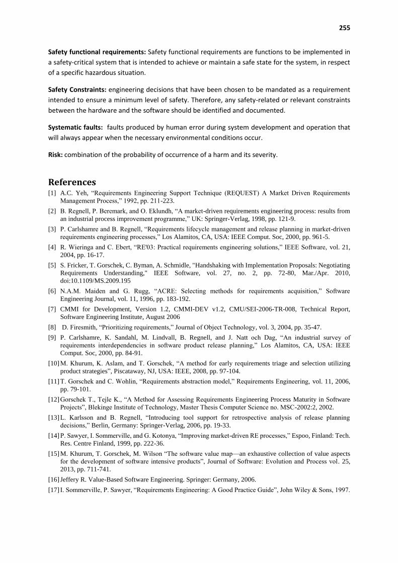
255
Safety functional requirements: Safety functional requirements are functions to be implemented in
a safety-critical system that is intended to achieve or maintain a safe state for the system, in respect
of a specific hazardous situation.
Safety Constraints: engineering decisions that have been chosen to be mandated as a requirement
intended to ensure a minimum level of safety. Therefore, any safety-related or relevant constraints
between the hardware and the software should be identified and documented.
Systematic faults: faults produced by human error during system development and operation that
will always appear when the necessary environmental conditions occur.
Risk: combination of the probability of occurrence of a harm and its severity.
References [1] A.C. Yeh, “Requirements Engineering Support Technique (REQUEST) A Market Driven Requirements
Management Process,” 1992, pp. 211-223.
[2] B. Regnell, P. Beremark, and O. Eklundh, “A market-driven requirements engineering process: results from
an industrial process improvement programme,” UK: Springer-Verlag, 1998, pp. 121-9.
[3] P. Carlshamre and B. Regnell, “Requirements lifecycle management and release planning in market-driven
requirements engineering processes,” Los Alamitos, CA, USA: IEEE Comput. Soc, 2000, pp. 961-5.
[4] R. Wieringa and C. Ebert, “RE'03: Practical requirements engineering solutions,” IEEE Software, vol. 21,
2004, pp. 16-17.
[5] S. Fricker, T. Gorschek, C. Byman, A. Schmidle, "Handshaking with Implementation Proposals: Negotiating
Requirements Understanding," IEEE Software, vol. 27, no. 2, pp. 72-80, Mar./Apr. 2010,
doi:10.1109/MS.2009.195
[6] N.A.M. Maiden and G. Rugg, “ACRE: Selecting methods for requirements acquisition,” Software
Engineering Journal, vol. 11, 1996, pp. 183-192.
[7] CMMI for Development, Version 1.2, CMMI-DEV v1.2, CMU/SEI-2006-TR-008, Technical Report,
Software Engineering Institute, August 2006
[8] D. Firesmith, “Prioritizing requirements,” Journal of Object Technology, vol. 3, 2004, pp. 35-47.
[9] P. Carlshamre, K. Sandahl, M. Lindvall, B. Regnell, and J. Natt och Dag, “An industrial survey of
requirements interdependencies in software product release planning,” Los Alamitos, CA, USA: IEEE
Comput. Soc, 2000, pp. 84-91.
[10] M. Khurum, K. Aslam, and T. Gorschek, “A method for early requirements triage and selection utilizing
product strategies”, Piscataway, NJ, USA: IEEE, 2008, pp. 97-104.
[11] T. Gorschek and C. Wohlin, “Requirements abstraction model,” Requirements Engineering, vol. 11, 2006,
pp. 79-101.
[12] Gorschek T., Tejle K., “A Method for Assessing Requirements Engineering Process Maturity in Software
Projects”, Blekinge Institute of Technology, Master Thesis Computer Science no. MSC-2002:2, 2002.
[13] L. Karlsson and B. Regnell, “Introducing tool support for retrospective analysis of release planning
decisions,” Berlin, Germany: Springer-Verlag, 2006, pp. 19-33.
[14] P. Sawyer, I. Sommerville, and G. Kotonya, “Improving market-driven RE processes,” Espoo, Finland: Tech.
Res. Centre Finland, 1999, pp. 222-36.
[15] M. Khurum, T. Gorschek, M. Wilson “The software value map—an exhaustive collection of value aspects
for the development of software intensive products”, Journal of Software: Evolution and Process vol. 25,
2013, pp. 711-741.
[16] Jeffery R. Value-Based Software Engineering. Springer: Germany, 2006.
[17] I. Sommerville, P. Sawyer, “Requirements Engineering: A Good Practice Guide”, John Wiley & Sons, 1997.
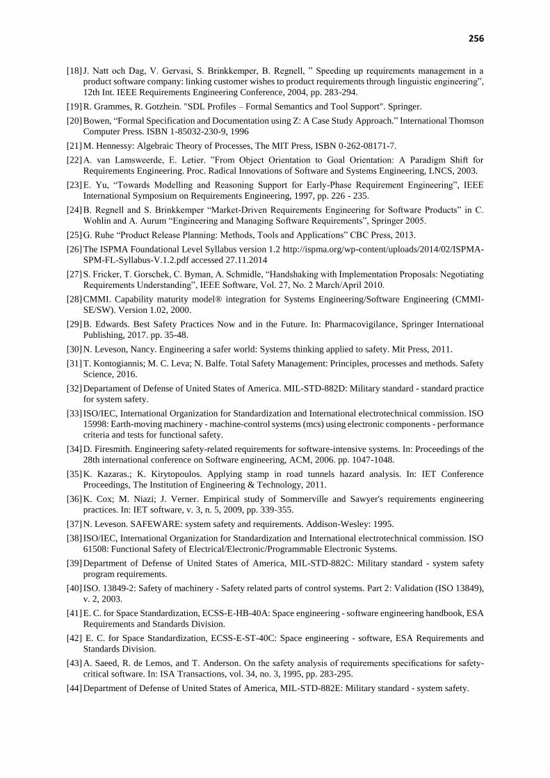
256
[18] J. Natt och Dag, V. Gervasi, S. Brinkkemper, B. Regnell, ” Speeding up requirements management in a
product software company: linking customer wishes to product requirements through linguistic engineering”,
12th Int. IEEE Requirements Engineering Conference, 2004, pp. 283-294.
[19] R. Grammes, R. Gotzhein. "SDL Profiles – Formal Semantics and Tool Support". Springer.
[20] Bowen, “Formal Specification and Documentation using Z: A Case Study Approach.” International Thomson
Computer Press. ISBN 1-85032-230-9, 1996
[21] M. Hennessy: Algebraic Theory of Processes, The MIT Press, ISBN 0-262-08171-7.
[22] A. van Lamsweerde, E. Letier. ”From Object Orientation to Goal Orientation: A Paradigm Shift for
Requirements Engineering. Proc. Radical Innovations of Software and Systems Engineering, LNCS, 2003.
[23] E. Yu, “Towards Modelling and Reasoning Support for Early-Phase Requirement Engineering”, IEEE
International Symposium on Requirements Engineering, 1997, pp. 226 - 235.
[24] B. Regnell and S. Brinkkemper “Market-Driven Requirements Engineering for Software Products” in C.
Wohlin and A. Aurum “Engineering and Managing Software Requirements”, Springer 2005.
[25] G. Ruhe “Product Release Planning: Methods, Tools and Applications” CBC Press, 2013.
[26] The ISPMA Foundational Level Syllabus version 1.2 http://ispma.org/wp-content/uploads/2014/02/ISPMA-
SPM-FL-Syllabus-V.1.2.pdf accessed 27.11.2014
[27] S. Fricker, T. Gorschek, C. Byman, A. Schmidle, “Handshaking with Implementation Proposals: Negotiating
Requirements Understanding”, IEEE Software, Vol. 27, No. 2 March/April 2010.
[28] CMMI. Capability maturity model® integration for Systems Engineering/Software Engineering (CMMI-
SE/SW). Version 1.02, 2000.
[29] B. Edwards. Best Safety Practices Now and in the Future. In: Pharmacovigilance, Springer International
Publishing, 2017. pp. 35-48.
[30] N. Leveson, Nancy. Engineering a safer world: Systems thinking applied to safety. Mit Press, 2011.
[31] T. Kontogiannis; M. C. Leva; N. Balfe. Total Safety Management: Principles, processes and methods. Safety
Science, 2016.
[32] Departament of Defense of United States of America. MIL-STD-882D: Military standard - standard practice
for system safety.
[33] ISO/IEC, International Organization for Standardization and International electrotechnical commission. ISO
15998: Earth-moving machinery - machine-control systems (mcs) using electronic components - performance
criteria and tests for functional safety.
[34] D. Firesmith. Engineering safety-related requirements for software-intensive systems. In: Proceedings of the
28th international conference on Software engineering, ACM, 2006. pp. 1047-1048.
[35] K. Kazaras.; K. Kirytopoulos. Applying stamp in road tunnels hazard analysis. In: IET Conference
Proceedings, The Institution of Engineering & Technology, 2011.
[36] K. Cox; M. Niazi; J. Verner. Empirical study of Sommerville and Sawyer's requirements engineering
practices. In: IET software, v. 3, n. 5, 2009, pp. 339-355.
[37] N. Leveson. SAFEWARE: system safety and requirements. Addison-Wesley: 1995.
[38] ISO/IEC, International Organization for Standardization and International electrotechnical commission. ISO
61508: Functional Safety of Electrical/Electronic/Programmable Electronic Systems.
[39] Department of Defense of United States of America, MIL-STD-882C: Military standard - system safety
program requirements.
[40] ISO. 13849-2: Safety of machinery - Safety related parts of control systems. Part 2: Validation (ISO 13849),
v. 2, 2003.
[41] E. C. for Space Standardization, ECSS-E-HB-40A: Space engineering - software engineering handbook, ESA
Requirements and Standards Division.
[42] E. C. for Space Standardization, ECSS-E-ST-40C: Space engineering - software, ESA Requirements and
Standards Division.
[43] A. Saeed, R. de Lemos, and T. Anderson. On the safety analysis of requirements specifications for safety-
critical software. In: ISA Transactions, vol. 34, no. 3, 1995, pp. 283-295.
[44] Department of Defense of United States of America, MIL-STD-882E: Military standard - system safety.

257
[45] ISO/IEC, International Organization for Standardization and International electrotechnical commission. ISO
15504-10: Information technology - Process assessment - Part 10: Safety extension.
[46] Somerville I., ”Software Engineering”, Addison-Wesley, 1995.
[47] Wohlin C., Aurum A., “Engineering and Managing Software Requirements”, Springer, 2005.
[48] Karlsson, L., Dahlstedt, A.G., Regnell, B., Natt och Dag, J., Persson, Requirements engineering challenges
in market-driven software development - An interview study with practitioners, In the Journal of Information
and Software Technology, 49, 6, pp. 588-604, 2007.
[49] Regnell B., Beremark P., and Eklundh O., “A Market-driven Requirements Engineering Process - Results
from an Industrial Process Improvement Programme”, Springer, pp. 121-129, 1998.
[50] Juristo N., Moreno A.M, Silva A., "Is the European Industry Moving Toward Solving Requirements
Engineering Problems?", IEEE Software, vol.19, no.6, pp. 70-77, Nov/Dec 2002.
[51] Beecham, S., Hall, T., & Rainer, A., Software process problems in twelve software companies: An empirical
analysis, Empirical Software Engineering, 8, 7–42, 2003
[52] Niazi, M., An empirical study for the improvement of requirements engineering process, The 17th
International Conference on Software Engineering and Knowledge Engineering , pp. 396–399, 2005.
[53] Hall T., Beecham S., Rainer A., “Requirements Problems in Twelve Companies: An Empirical Analysis”,
IEE Proceedings for Software, October, vol.149, no.5, pp.153-160, 2002.
[54] Gorschek T., “Requirements Engineering Supporting Technical Product Management”, Karlskrona :
Blekinge Institute of Technology, 2006.
[55] Villalón C., Agustín C., Gilabert S., Seco D., Sánchez G., and Cota P., “Experiences in the Application of
Software Process Improvement in SMES,” Software Quality Journal, vol. 10, pp. 261 – 273, 2002.
[56] Paulk M.C., Curtis B., Chrissis M.B. and Weber C., Capability Maturity Model TM for Software Version
1.1, 1993.
[57] CMMI for Development, Version 1.2, CMMI-DEV v1.2, CMU/SEI-2006-TR-008, Technical Report,
Software Engineering Institute, August 2006, URL:
http://www.sei.cmu.edu/pub/documents/06.reports/pdf/06tr008.pdf.
[58] The TickIT Guide – Using ISO 9001:2000 for Software Quality Management System, Construction,
Certification and Continual Improvement, Issue 5.0, 2001.
[59] Ian Somerville and Pete Sawyer, Requirements Engineering – A Good Practice Guide, John Wiley & Sons,
Chichester UK, 2000.
[60] Gorschek T., Tejle K., “A Method for Assessing Requirements Engineering Process Maturity in Software
Projects”, Blekinge Institute of Technology, Master Thesis Computer Science no. MSC-2002:2, 2002.
[61] Wiegers K., Software requirements: Practical techniques for gathering and managing requirement through
the product development cycle, Microsoft Press. Redmond, Washington, 2003.
[62] M. Svahnberg, T. Gorschek, T. T. L. Nguyen, and M. Nguyen, “Unirepm: a framework for requirements
engineering process assessment,” Requirements Engineering, vol. 20, no. 1, pp. 91–118, 2015.
[63] M. Svahnberg, T. Gorschek, T. T. L. Nguyen, and M. Nguyen, “Unirepm: validated and improved,”
Requirements Engineering, vol. 18, no. 1, pp. 85–103, 2013.
[64] P. Sawyer, I. Sommerville, and S. Viller, “Requirements process improvement through the phased
introduction of good practice,” Software Process: Improvement and Practice, vol. 3, no. 1, pp. 19–34, 1997.
[65] T. Gorschek, M. Svahnberg, and K. Tejle, “Introduction and application of a lightweight requirements
engineering process,” in Ninth International Workshop on Requirements Engineering: Foundation for
Software Quality, 2003.
[66] T. Gorschek, A. Gomes, A. Pettersson, and R. Torkar, “Introduction of a process maturity model for market-
driven product management and requirements engineering,” Journal of software: Evolution and Process, vol.
24, no. 1, pp. 83–113, 2012.
[67] T. L. Reis, M. A. S. Mathias, and O. J. de Oliveira, “Maturity models: identifying the state-of-the-art and the
scientific gaps from a bibliometric study,” Scientometrics, pp. 1–30, 2016.
[68] N. Leveson, Engineering a safer world: Systems thinking applied to safety. Mit Press, 2011.
[69] J. Vilela, J. Castro, L. E. G. Martins, and T. Gorschek, “Integration between requirements engineering and
safety analysis: A systematic literature review,” Journal of Systems and Software, 2016.
[70] N. G. Leveson, Safeware: system safety and computers. ACM, 1995.

258
[71] R. R. Lutz, “Software engineering for safety: a roadmap,” in Proceedings of the Conference on The Future
of Software Engineering. ACM, 2000, pp. 213–226.
[72] R. Guillerm, H. Demmou, and N. Sadou, “Information model for model driven safety requirements
management of complex systems,” in Complex Systems Design & Management. Springer, 2010, pp. 99–111.
[73] A. Simpson and J. Stoker, “Will it be safe??an approach to engineering safety requirements,” in Components
of System Safety. Springer, 2002, pp. 140–164.
[74] N. G. Leveson, “An approach to designing safe embedded software,” in Embedded Software. Springer, 2002,
pp. 15–29.
[75] K. Cox, M. Niazi, and J. Verner, “Empirical study of sommerville and sawyer’s requirements engineering
practices,” IET software, vol. 3, no. 5, pp. 339–355, 2009.
[76] R. B. Ahmad, M. H. N. M. Nasir, J. Iqbal, and S. M. Zahid, “High perceived-value requirements engineering
practices for outsourced software projects.” JSW, vol. 10, no. 10, pp. 1199–1215, 2015.
[77] B. Solemon, S. Sahibuddin, and A. A. A. Ghani, “Requirements engineering problems in 63 software
companies in malaysia,” in Information Technology, 2008. ITSim 2008. International Symposium on, vol. 4.
IEEE, 2008, pp. 1–6.
[78] D. Firesmith, “Engineering safety-related requirements for software-intensive systems,” in Proceedings of
the 28th international conference on Software engineering. ACM, 2006, pp. 1047–1048.
[79] P. Panaroni, G. Sartori, F. Fabbrini, M. Fusani, and G. Lami, “Safety in automotive software: an overview of
current practices,” in Computer Software and Applications, 2008. COMPSAC’08. 32nd Annual IEEE
International. IEEE, 2008, pp. 1053–1058.
[80] P. J. Graydon and C. M. Holloway, “Planning the unplanned experiment: Assessing the efficacy of standards
for safety critical software,” 2015.
[81] L. E. G. Martins and T. Gorschek, “Requirements engineering for safety-critical systems: A systematic
literature review,” Information and Software Technology, vol. 75, pp. 71–89, 2016.
[82] B. Solemon, S. Sahibuddin, and A. A. A. Ghani, “Requirements engineering problems and practices in
software companies: An industrial survey,” in International Conference on Advanced Software Engineering
and Its Applications. Springer, 2009, pp. 70–77.
[83] M. Lubars, C. Potts, and C. Richter, “A review of the state of the practice in requirements modeling,” in
Proceedings of IEEE International Symposium on Requirements Engineering. IEEE, 1993, pp. 2–14.
[84] U. Nikula, J. Sajaniemi, and H. Kalviainen, A State-of-the-practice Survey on Requirements Engineering in
Small-and Medium-sized Enterprises. Lappeenranta University of Technology Lappeenranta, Finland, 2000.

259
APPENDIX C – USE CASE DESCRIPTIONS
This appendix contains the Use Case Descriptions of Uni-REPM tool.
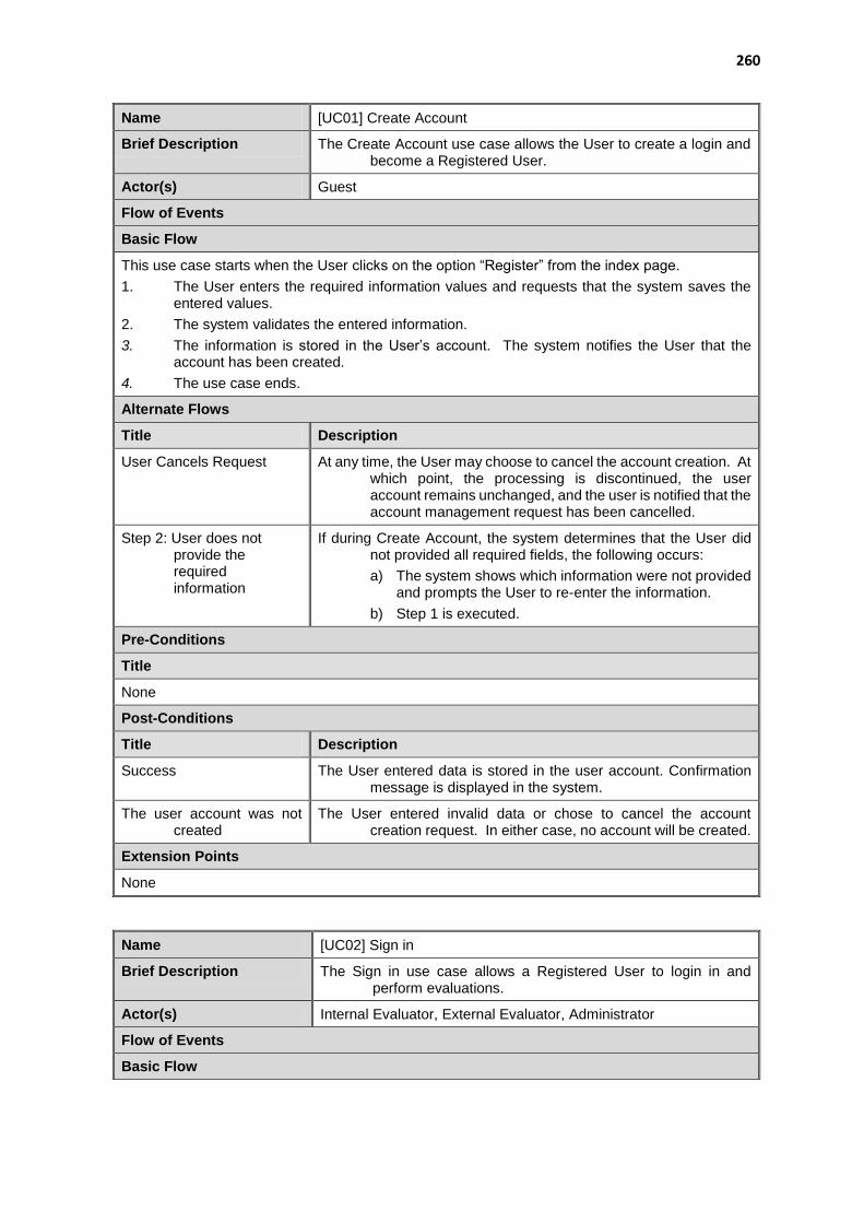
260
Name [UC01] Create Account
Brief Description The Create Account use case allows the User to create a login and become a Registered User.
Actor(s) Guest
Flow of Events
Basic Flow
This use case starts when the User clicks on the option “Register” from the index page.
1. The User enters the required information values and requests that the system saves the entered values.
2. The system validates the entered information.
3. The information is stored in the User’s account. The system notifies the User that the account has been created.
4. The use case ends.
Alternate Flows
Title Description
User Cancels Request At any time, the User may choose to cancel the account creation. At which point, the processing is discontinued, the user account remains unchanged, and the user is notified that the account management request has been cancelled.
Step 2: User does not provide the required information
If during Create Account, the system determines that the User did not provided all required fields, the following occurs:
a) The system shows which information were not provided and prompts the User to re-enter the information.
b) Step 1 is executed.
Pre-Conditions
Title
None
Post-Conditions
Title Description
Success The User entered data is stored in the user account. Confirmation message is displayed in the system.
The user account was not created
The User entered invalid data or chose to cancel the account creation request. In either case, no account will be created.
Extension Points
None
Name [UC02] Sign in
Brief Description The Sign in use case allows a Registered User to login in and perform evaluations.
Actor(s) Internal Evaluator, External Evaluator, Administrator
Flow of Events
Basic Flow
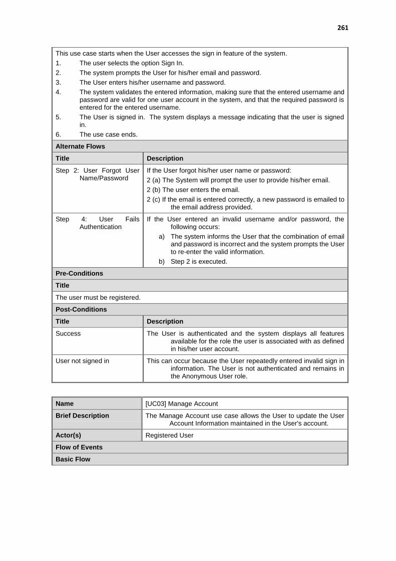
261
This use case starts when the User accesses the sign in feature of the system.
1. The user selects the option Sign In.
2. The system prompts the User for his/her email and password.
3. The User enters his/her username and password.
4. The system validates the entered information, making sure that the entered username and password are valid for one user account in the system, and that the required password is entered for the entered username.
5. The User is signed in. The system displays a message indicating that the user is signed in.
6. The use case ends.
Alternate Flows
Title Description
Step 2: User Forgot User Name/Password
If the User forgot his/her user name or password:
2 (a) The System will prompt the user to provide his/her email.
2 (b) The user enters the email.
2 (c) If the email is entered correctly, a new password is emailed to the email address provided.
Step 4: User Fails Authentication
If the User entered an invalid username and/or password, the following occurs:
a) The system informs the User that the combination of email and password is incorrect and the system prompts the User to re-enter the valid information.
b) Step 2 is executed.
Pre-Conditions
Title
The user must be registered.
Post-Conditions
Title Description
Success The User is authenticated and the system displays all features available for the role the user is associated with as defined in his/her user account.
User not signed in This can occur because the User repeatedly entered invalid sign in information. The User is not authenticated and remains in the Anonymous User role.
Name [UC03] Manage Account
Brief Description The Manage Account use case allows the User to update the User Account Information maintained in the User's account.
Actor(s) Registered User
Flow of Events
Basic Flow

262
This use case starts when the User accesses the option Change Profile that enables him/her to update the information that is maintained in the User's account.
1. The system displays information currently stored for the User.
2. The User enters the desired information values and requests that the system saves the entered values.
3. The system validates the entered information.
4. The values for the information are stored in the User’s account. The system notifies the User that the account has been updated.
5. The use case ends.
Alternate Flows
Title Description
User Cancels Request At any time, the User may choose to cancel the account update/deactivation. At which point, the processing is discontinued, the user account remains unchanged.
Step 3: User Enters Invalid User Account Information
If during Modify Account, the system determines that the User did not provided all required fields, the following occurs:
a) The system shows which information were not provided and prompts the User to re-enter the information.
b) Step 1 is executed.
Pre-Conditions
Title
The User must be signed in before the User can edit or deactivate his/her account.
Post-Conditions
Title Description
Success The User entered data is stored in the user account.
The user account was not updated
The User entered invalid data or chose to cancel the account management request. In either case, there is no change to the user account.
Extension Points
None
Name Manage Projects
Brief Description The Manage Projects use case allows the User to add, edit, view and delete projects.
Actor(s) Registered User
Flow of Events
Basic Flow
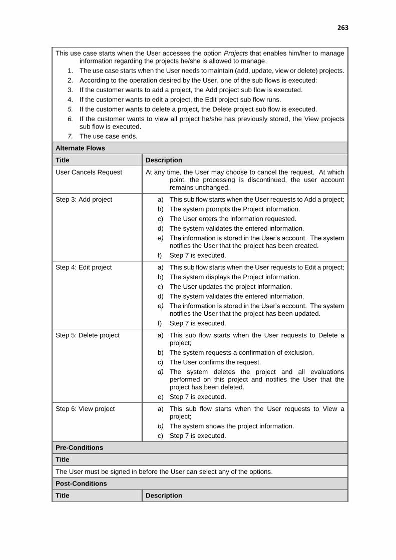
263
This use case starts when the User accesses the option Projects that enables him/her to manage information regarding the projects he/she is allowed to manage.
1. The use case starts when the User needs to maintain (add, update, view or delete) projects.
2. According to the operation desired by the User, one of the sub flows is executed:
3. If the customer wants to add a project, the Add project sub flow is executed.
4. If the customer wants to edit a project, the Edit project sub flow runs.
5. If the customer wants to delete a project, the Delete project sub flow is executed.
6. If the customer wants to view all project he/she has previously stored, the View projects sub flow is executed.
7. The use case ends.
Alternate Flows
Title Description
User Cancels Request At any time, the User may choose to cancel the request. At which point, the processing is discontinued, the user account remains unchanged.
Step 3: Add project a) This sub flow starts when the User requests to Add a project;
b) The system prompts the Project information.
c) The User enters the information requested.
d) The system validates the entered information.
e) The information is stored in the User’s account. The system notifies the User that the project has been created.
f) Step 7 is executed.
Step 4: Edit project a) This sub flow starts when the User requests to Edit a project;
b) The system displays the Project information.
c) The User updates the project information.
d) The system validates the entered information.
e) The information is stored in the User’s account. The system notifies the User that the project has been updated.
f) Step 7 is executed.
Step 5: Delete project a) This sub flow starts when the User requests to Delete a project;
b) The system requests a confirmation of exclusion.
c) The User confirms the request.
d) The system deletes the project and all evaluations performed on this project and notifies the User that the project has been deleted.
e) Step 7 is executed.
Step 6: View project a) This sub flow starts when the User requests to View a project;
b) The system shows the project information.
c) Step 7 is executed.
Pre-Conditions
Title
The User must be signed in before the User can select any of the options.
Post-Conditions
Title Description
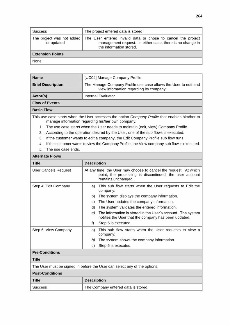
264
Success The project entered data is stored.
The project was not added or updated
The User entered invalid data or chose to cancel the project management request. In either case, there is no change in the information stored.
Extension Points
None
Name [UC04] Manage Company Profile
Brief Description The Manage Company Profile use case allows the User to edit and view information regarding its company.
Actor(s) Internal Evaluator
Flow of Events
Basic Flow
This use case starts when the User accesses the option Company Profile that enables him/her to manage information regarding his/her own company.
1. The use case starts when the User needs to maintain (edit, view) Company Profile.
2. According to the operation desired by the User, one of the sub flows is executed:
3. If the customer wants to edit a company, the Edit Company Profile sub flow runs.
4. If the customer wants to view the Company Profile, the View company sub flow is executed.
5. The use case ends.
Alternate Flows
Title Description
User Cancels Request At any time, the User may choose to cancel the request. At which point, the processing is discontinued, the user account remains unchanged.
Step 4: Edit Company a) This sub flow starts when the User requests to Edit the company;
b) The system displays the company information.
c) The User updates the company information.
d) The system validates the entered information.
e) The information is stored in the User’s account. The system notifies the User that the company has been updated.
f) Step 5 is executed.
Step 6: View Company a) This sub flow starts when the User requests to view a company;
b) The system shows the company information.
c) Step 5 is executed.
Pre-Conditions
Title
The User must be signed in before the User can select any of the options.
Post-Conditions
Title Description
Success The Company entered data is stored.

265
The company was not added or updated
The User entered invalid data or chose to cancel the company management request. In either case, there is no change in the information stored.
Extension Points
None
Name [UC05] Manage Companies
Brief Description The Manage Companies use case allows the User to add, edit, view and delete companies.
Actor(s) External Evaluator, Administrator
Flow of Events
Basic Flow
This use case starts when the User accesses the option Companies that enables him/her to manage information regarding the companies he/she is allowed to manage.
6. The use case starts when the User needs to maintain (add, update, view or delete) companies.
7. According to the operation desired by the User, one of the sub flows is executed:
8. If the customer wants to add a company, the Add company sub flow is executed.
9. If the customer wants to edit a company, the Edit company sub flow runs.
10. If the customer wants to delete a company, the Delete company sub flow is executed.
11. If the customer wants to view all companies he/she has previously stored, the View companies sub flow is executed.
12. The use case ends.
Alternate Flows
Title Description
User Cancels Request At any time, the User may choose to cancel the request. At which point, the processing is discontinued, the user account remains unchanged.
Step 3: Add Company a) This sub flow starts when the User requests to Add a company;
b) The system prompts the Company information.
c) The User enters the information requested.
d) The system validates the entered information.
e) The information is stored in the User’s account. The system notifies the User that the company has been created.
f) Step 7 is executed.
Step 4: Edit Company g) This sub flow starts when the User requests to Edit a company;
h) The system displays the company information.
i) The User updates the company information.
j) The system validates the entered information.
k) The information is stored in the User’s account. The system notifies the User that the company has been updated.
l) Step 7 is executed.
Step 5: Delete Company a) This sub flow starts when the User requests to Delete a company;
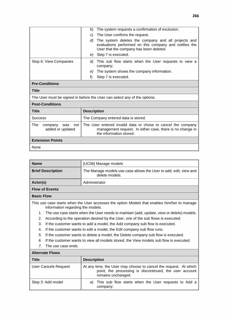
266
b) The system requests a confirmation of exclusion.
c) The User confirms the request.
d) The system deletes the company and all projects and evaluations performed on this company and notifies the User that the company has been deleted.
e) Step 7 is executed.
Step 6: View Companies d) This sub flow starts when the User requests to view a company;
e) The system shows the company information.
f) Step 7 is executed.
Pre-Conditions
Title
The User must be signed in before the User can select any of the options.
Post-Conditions
Title Description
Success The Company entered data is stored.
The company was not added or updated
The User entered invalid data or chose to cancel the company management request. In either case, there is no change in the information stored.
Extension Points
None
Name [UC06] Manage models
Brief Description The Manage models use case allows the User to add, edit, view and delete models.
Actor(s) Administrator
Flow of Events
Basic Flow
This use case starts when the User accesses the option Models that enables him/her to manage information regarding the models.
1. The use case starts when the User needs to maintain (add, update, view or delete) models.
2. According to the operation desired by the User, one of the sub flows is executed:
3. If the customer wants to add a model, the Add company sub flow is executed.
4. If the customer wants to edit a model, the Edit company sub flow runs.
5. If the customer wants to delete a model, the Delete company sub flow is executed.
6. If the customer wants to view all models stored, the View models sub flow is executed.
7. The use case ends.
Alternate Flows
Title Description
User Cancels Request At any time, the User may choose to cancel the request. At which point, the processing is discontinued, the user account remains unchanged.
Step 3: Add model a) This sub flow starts when the User requests to Add a company;
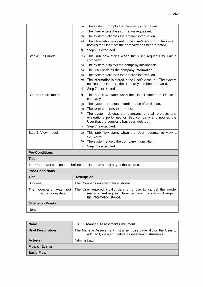
267
b) The system prompts the Company information.
c) The User enters the information requested.
d) The system validates the entered information.
e) The information is stored in the User’s account. The system notifies the User that the company has been created.
f) Step 7 is executed.
Step 4: Edit model m) This sub flow starts when the User requests to Edit a company;
n) The system displays the company information.
o) The User updates the company information.
p) The system validates the entered information.
q) The information is stored in the User’s account. The system notifies the User that the company has been updated.
r) Step 7 is executed.
Step 5: Delete model f) This sub flow starts when the User requests to Delete a company;
g) The system requests a confirmation of exclusion.
h) The User confirms the request.
i) The system deletes the company and all projects and evaluations performed on this company and notifies the User that the company has been deleted.
j) Step 7 is executed.
Step 6: View model g) This sub flow starts when the User requests to view a company;
h) The system shows the company information.
i) Step 7 is executed.
Pre-Conditions
Title
The User must be signed in before the User can select any of the options.
Post-Conditions
Title Description
Success The Company entered data is stored.
The company was not added or updated
The User entered invalid data or chose to cancel the model management request. In either case, there is no change in the information stored.
Extension Points
None
Name [UC07] Manage Assessment instrument
Brief Description The Manage Assessment instrument use case allows the User to add, edit, view and delete assessment instruments.
Actor(s) Administrator
Flow of Events
Basic Flow
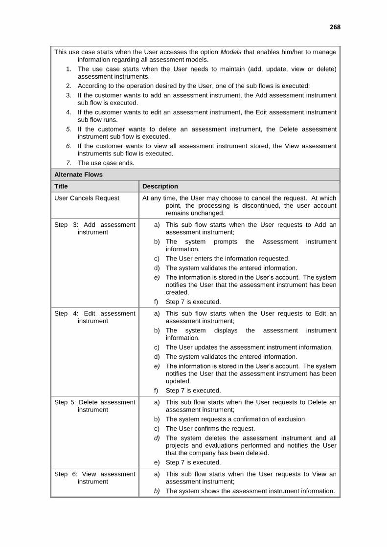
268
This use case starts when the User accesses the option Models that enables him/her to manage information regarding all assessment models.
1. The use case starts when the User needs to maintain (add, update, view or delete) assessment instruments.
2. According to the operation desired by the User, one of the sub flows is executed:
3. If the customer wants to add an assessment instrument, the Add assessment instrument sub flow is executed.
4. If the customer wants to edit an assessment instrument, the Edit assessment instrument sub flow runs.
5. If the customer wants to delete an assessment instrument, the Delete assessment instrument sub flow is executed.
6. If the customer wants to view all assessment instrument stored, the View assessment instruments sub flow is executed.
7. The use case ends.
Alternate Flows
Title Description
User Cancels Request At any time, the User may choose to cancel the request. At which point, the processing is discontinued, the user account remains unchanged.
Step 3: Add assessment instrument
a) This sub flow starts when the User requests to Add an assessment instrument;
b) The system prompts the Assessment instrument information.
c) The User enters the information requested.
d) The system validates the entered information.
e) The information is stored in the User’s account. The system notifies the User that the assessment instrument has been created.
f) Step 7 is executed.
Step 4: Edit assessment instrument
a) This sub flow starts when the User requests to Edit an assessment instrument;
b) The system displays the assessment instrument information.
c) The User updates the assessment instrument information.
d) The system validates the entered information.
e) The information is stored in the User’s account. The system notifies the User that the assessment instrument has been updated.
f) Step 7 is executed.
Step 5: Delete assessment instrument
a) This sub flow starts when the User requests to Delete an assessment instrument;
b) The system requests a confirmation of exclusion.
c) The User confirms the request.
d) The system deletes the assessment instrument and all projects and evaluations performed and notifies the User that the company has been deleted.
e) Step 7 is executed.
Step 6: View assessment instrument
a) This sub flow starts when the User requests to View an assessment instrument;
b) The system shows the assessment instrument information.

269
c) Step 7 is executed.
Pre-Conditions
Title
The User must be signed in before the User can select any of the options.
Post-Conditions
Title Description
Success The assessment instrument entered data is stored.
The assessment instrument was not added or updated
The User entered invalid data or chose to cancel the assessment instrument management request. In either case, there is no change in the information stored.
Extension Points
None
Name [UC08] Manage Users
Brief Description The Manage Users use case allows the User to edit, view and delete users.
Actor(s) Administrator
Flow of Events
Basic Flow
This use case starts when the Administrator accesses the option Users that enables him/her to manage information of all users.
1. The use case starts when the User needs to maintain (edit, view or delete) users.
2. According to the operation desired by the User, one of the sub flows is executed:
3. If the customer wants to edit a user, the Edit user sub flow runs.
4. If the customer wants to delete a user, the Delete user sub flow is executed.
5. If the customer wants to view all users stored, the View Users sub flow is executed.
6. The use case ends.
Alternate Flows
Title Description
User Cancels Request At any time, the User may choose to cancel the request. At which point, the processing is discontinued, the user account remains unchanged.
Step 3: Edit user a) This sub flow starts when the User requests to Edit a company;
b) The system displays the user information.
c) The User updates the user information.
d) The system validates the entered information.
e) The information is stored in the selected user account. The system notifies the User that the selected user has been updated.
f) Step 6 is executed.
Step 4: Delete user a) This sub flow starts when the User requests to Delete a company;
b) The system requests a confirmation of exclusion.
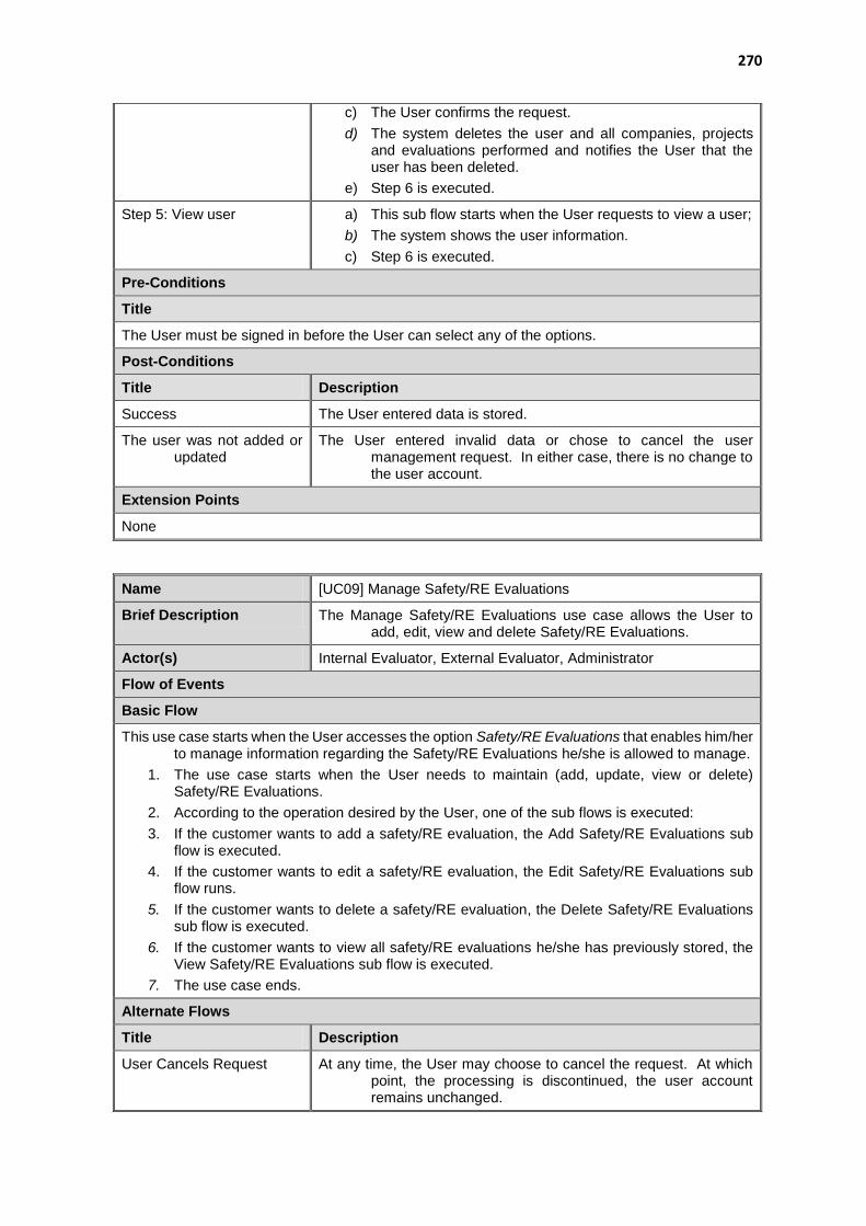
270
c) The User confirms the request.
d) The system deletes the user and all companies, projects and evaluations performed and notifies the User that the user has been deleted.
e) Step 6 is executed.
Step 5: View user a) This sub flow starts when the User requests to view a user;
b) The system shows the user information.
c) Step 6 is executed.
Pre-Conditions
Title
The User must be signed in before the User can select any of the options.
Post-Conditions
Title Description
Success The User entered data is stored.
The user was not added or updated
The User entered invalid data or chose to cancel the user management request. In either case, there is no change to the user account.
Extension Points
None
Name [UC09] Manage Safety/RE Evaluations
Brief Description The Manage Safety/RE Evaluations use case allows the User to add, edit, view and delete Safety/RE Evaluations.
Actor(s) Internal Evaluator, External Evaluator, Administrator
Flow of Events
Basic Flow
This use case starts when the User accesses the option Safety/RE Evaluations that enables him/her to manage information regarding the Safety/RE Evaluations he/she is allowed to manage.
1. The use case starts when the User needs to maintain (add, update, view or delete) Safety/RE Evaluations.
2. According to the operation desired by the User, one of the sub flows is executed:
3. If the customer wants to add a safety/RE evaluation, the Add Safety/RE Evaluations sub flow is executed.
4. If the customer wants to edit a safety/RE evaluation, the Edit Safety/RE Evaluations sub flow runs.
5. If the customer wants to delete a safety/RE evaluation, the Delete Safety/RE Evaluations sub flow is executed.
6. If the customer wants to view all safety/RE evaluations he/she has previously stored, the View Safety/RE Evaluations sub flow is executed.
7. The use case ends.
Alternate Flows
Title Description
User Cancels Request At any time, the User may choose to cancel the request. At which point, the processing is discontinued, the user account remains unchanged.
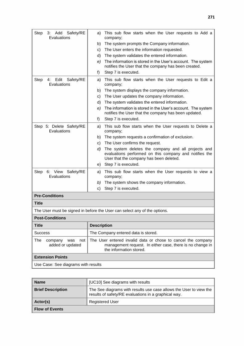
271
Step 3: Add Safety/RE Evaluations
a) This sub flow starts when the User requests to Add a company;
b) The system prompts the Company information.
c) The User enters the information requested.
d) The system validates the entered information.
e) The information is stored in the User’s account. The system notifies the User that the company has been created.
f) Step 7 is executed.
Step 4: Edit Safety/RE Evaluations
a) This sub flow starts when the User requests to Edit a company;
b) The system displays the company information.
c) The User updates the company information.
d) The system validates the entered information.
e) The information is stored in the User’s account. The system notifies the User that the company has been updated.
f) Step 7 is executed.
Step 5: Delete Safety/RE Evaluations
a) This sub flow starts when the User requests to Delete a company;
b) The system requests a confirmation of exclusion.
c) The User confirms the request.
d) The system deletes the company and all projects and evaluations performed on this company and notifies the User that the company has been deleted.
e) Step 7 is executed.
Step 6: View Safety/RE Evaluations
a) This sub flow starts when the User requests to view a company;
b) The system shows the company information.
c) Step 7 is executed.
Pre-Conditions
Title
The User must be signed in before the User can select any of the options.
Post-Conditions
Title Description
Success The Company entered data is stored.
The company was not added or updated
The User entered invalid data or chose to cancel the company management request. In either case, there is no change in the information stored.
Extension Points
Use Case: See diagrams with results
Name [UC10] See diagrams with results
Brief Description The See diagrams with results use case allows the User to view the results of safety/RE evaluations in a graphical way.
Actor(s) Registered User
Flow of Events

272
Basic Flow
1. This use case starts when the User accesses the option See results from View Safety/Re evaluations.
2. The system displays the information requested.
Alternate Flows
Title
None
Pre-Conditions
Title
The User must be signed in before selecting the option.
Post-Conditions
Title Description
Success Diagrams would be displayed on the current page.
Extension Points
None
273
APPENDIX D – TOOL USER MANUAL
This chapter presents the user manual of Uni-REPM Tool.
274
Uni-REPM Tool User Manual
1 CONTACT .................................................................................................................................... 275
2 ACESSING UNI-REPM TOOL .................................................................................................. 275
3 REGISTERING ............................................................................................................................ 276
4 SIGN IN ......................................................................................................................................... 279
5 OVERVIEW OF INTERFACE ................................................................................................... 279
6 MANAGING COMPANIES ........................................................................................................ 280
6.1 VIEW COMPANIES ............................................................................. 280 6.2 ADD A NEW COMPANY ......................................................................... 281
7 MANAGING PROJECTS ............................................................................................................ 281
7.1 ADD A NEW PROJECT .......................................................................... 282 7.2 VIEW PROJECTS................................................................................ 283
8 PERFORMING EVALUATIONS ............................................................................................... 285
9 VISUALIZING EVALUATIONS ............................................................................................... 286
10 VISUALIZING THE EVALUATION RESULTS ..................................................................... 287
10.1 TABULAR ........................................................................................ 288 10.2 LINE CHART .................................................................................... 289 10.3 BAR CHART ..................................................................................... 290
11 VISUALIZING THE SELECTED ANSWERS AND COMMENTS ....................................... 290
12 MANAGING USER PROFILE ................................................................................................... 291
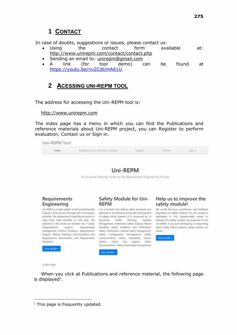
275
1 CONTACT
In case of doubts, suggestions or issues, please contact us:
Using the contact form available at: http://www.unirepm.com/contact/contact.php
Sending an email to: [email protected] A link (for tool demo) can be found at
https://youtu.be/nvZCdUmA61U.
2 ACESSING UNI-REPM TOOL
The address for accessing the Uni-REPM tool is:
http://www.unirepm.com
The index page has a menu in which you can find the Publications and
reference materials about Uni-REPM project, you can Register to perform evaluation, Contact us or Sign in.
When you click at Publications and reference material, the following page
is displayed1.
1 This page is frequently updated.
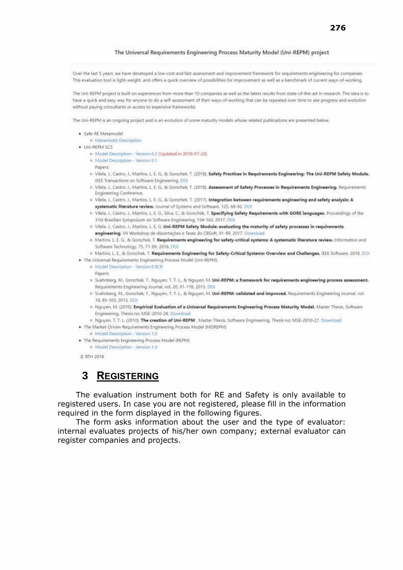
276
3 REGISTERING
The evaluation instrument both for RE and Safety is only available to registered users. In case you are not registered, please fill in the information
required in the form displayed in the following figures. The form asks information about the user and the type of evaluator:
internal evaluates projects of his/her own company; external evaluator can register companies and projects.
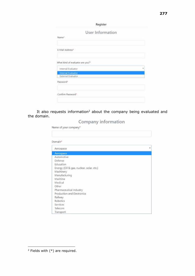
277
It also requests information2 about the company being evaluated and
the domain.
2 Fields with (*) are required.
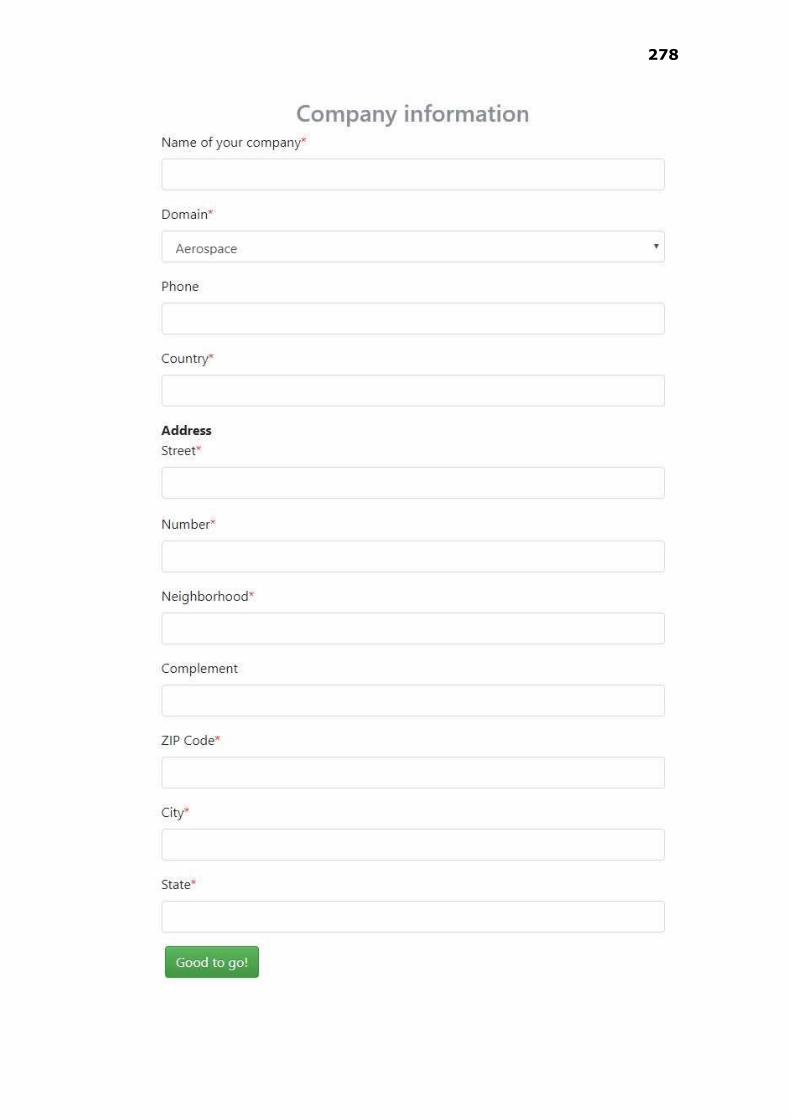
278
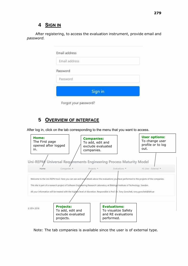
279
4 SIGN IN
After registering, to access the evaluation instrument, provide email and
password.
5 OVERVIEW OF INTERFACE
After log in, click on the tab corresponding to the menu that you want to access.
Note: The tab companies is available since the user is of external type.
Companies:
To add, edit and
exclude evaluated
companies.
Home:
The First page
opened after logged
in.
Projects:
To add, edit and
exclude evaluated
projects.
Evaluations:
To visualize Safety
and RE evaluations
performed.
User options:
To change user
profile or to log
out.

280
6 MANAGING COMPANIES
6.1 View Companies
To see the companies already saved, the user must be logged in, and click on Companies/View Companies. A form similar to figure below is
displayed. The Edit option is available to update the information about the selected company.

281
6.2 Add a new company
To add a new company, the user must be logged in, and click on Companies/New Company. The form below is displayed.
7 MANAGING PROJECTS

282
7.1 Add a new Project
To add a new Project, the user must be logged in, and click on
Projects/New project. The form below is displayed.

283
7.2 View Projects
To see the projects already saved, the user must be logged in, and click on Projects/View Projects. A form similar to figure below is displayed.
The name of the project corresponds to a link. When we click on it, the projects details are shown.
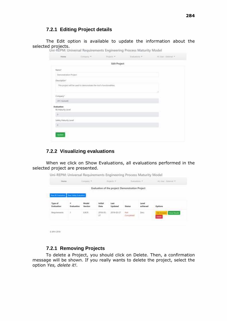
284
7.2.1 Editing Project details
The Edit option is available to update the information about the
selected projects.
7.2.2 Visualizing evaluations
When we click on Show Evaluations, all evaluations performed in the
selected project are presented.
7.2.1 Removing Projects
To delete a Project, you should click on Delete. Then, a confirmation message will be shown. If you really wants to delete the project, select the
option Yes, delete it!.
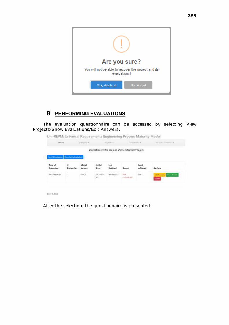
285
8 PERFORMING EVALUATIONS
The evaluation questionnaire can be accessed by selecting View Projects/Show Evaluations/Edit Answers.
After the selection, the questionnaire is presented.
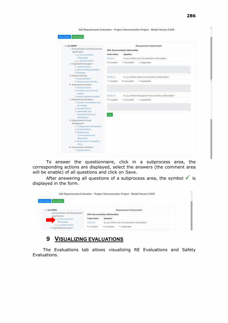
286
To answer the questionnaire, click in a subprocess area, the
corresponding actions are displayed, select the answers (the comment area will be enable) of all questions and click on Save.
After answering all questions of a subprocess area, the symbol is displayed in the form.
9 VISUALIZING EVALUATIONS
The Evaluations tab allows visualizing RE Evaluations and Safety Evaluations.
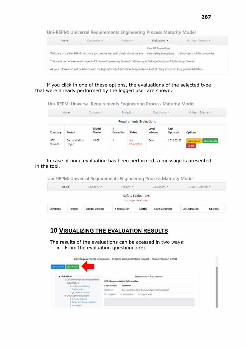
287
If you click in one of these options, the evaluations of the selected type
that were already performed by the logged user are shown.
In case of none evaluation has been performed, a message is presented
in the tool.
10 VISUALIZING THE EVALUATION RESULTS
The results of the evaluations can be acessed in two ways:
From the evaluation questionnaire:
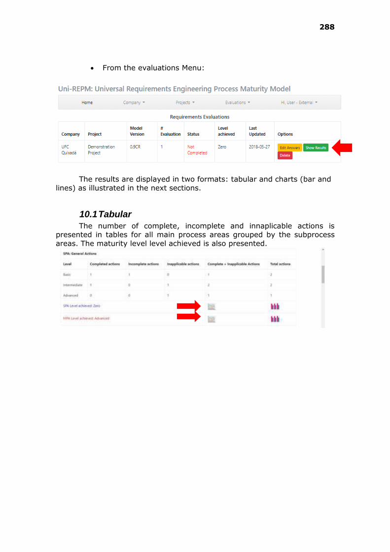
288
From the evaluations Menu:
The results are displayed in two formats: tabular and charts (bar and
lines) as illustrated in the next sections.
10.1 Tabular
The number of complete, incomplete and innaplicable actions is presented in tables for all main process areas grouped by the subprocess
areas. The maturity level level achieved is also presented.
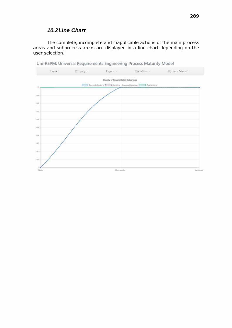
289
10.2 Line Chart
The complete, incomplete and inapplicable actions of the main process
areas and subprocess areas are displayed in a line chart depending on the
user selection.
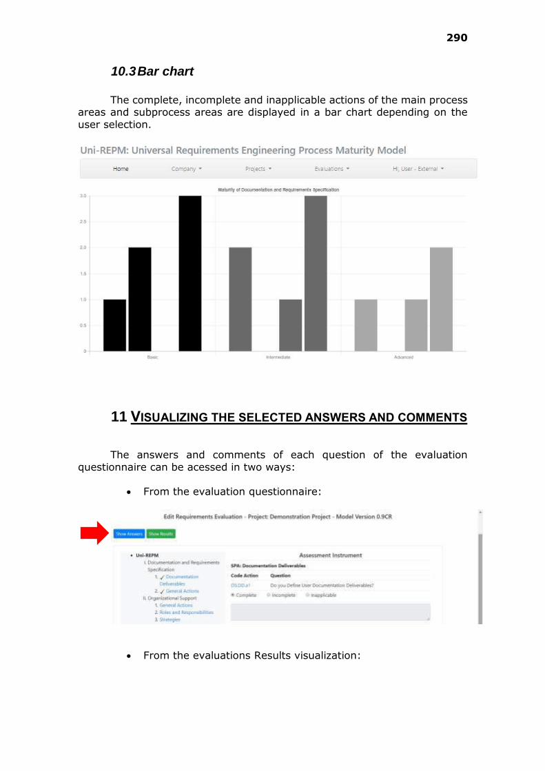
290
10.3 Bar chart
The complete, incomplete and inapplicable actions of the main process
areas and subprocess areas are displayed in a bar chart depending on the
user selection.
11 VISUALIZING THE SELECTED ANSWERS AND COMMENTS
The answers and comments of each question of the evaluation
questionnaire can be acessed in two ways:
From the evaluation questionnaire:
From the evaluations Results visualization:
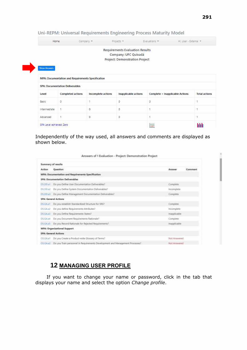
291
Independently of the way used, all answers and comments are displayed as
shown below.
12 MANAGING USER PROFILE
If you want to change your name or password, click in the tab that
displays your name and select the option Change profile.

292
Then, the following form will be presented.
293
APPENDIX E – ARTIFACTS USED IN STATIC VALIDATION
This appendix contains the artifacts (profile questionnaire, and module evaluation question-naire) we used to conduct the static validation.
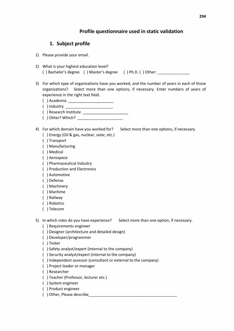
294
Profile questionnaire used in static validation
1. Subject profile
1) Please provide your email.
2) What is your highest education level?
( ) Bachelor’s degree ( ) Master’s degree ( ) Ph.D. ( ) Other: _______________
3) For which type of organizations have you worked, and the number of years in each of those
organizations? Select more than one options, if necessary. Enter numbers of years of
experience in the right text field.
( ) Academia _____________________
( ) Industry ______________________
( ) Research Institute _____________________
( ) Other? Which? _____________________
4) For which domain have you worked for? Select more than one options, if necessary.
( ) Energy (Oil & gas, nuclear, solar, etc.)
( ) Transport
( ) Manufacturing
( ) Medical
( ) Aerospace
( ) Pharmaceutical Industry
( ) Production and Electronics
( ) Automotive
( ) Defense
( ) Machinery
( ) Maritime
( ) Railway
( ) Robotics
( ) Telecom
5) In which roles do you have experience? Select more than one option, if necessary.
( ) Requirements engineer
( ) Designer (architecture and detailed design)
( ) Developer/programmer
( ) Tester
( ) Safety analyst/expert (internal to the company)
( ) Security analyst/expert (internal to the company)
( ) Independent assessor (consultant or external to the company)
( ) Project leader or manager
( ) Researcher
( ) Teacher (Professor, lecturer etc.)
( ) System engineer
( ) Product engineer
( ) Other, Please describe_________________________________________
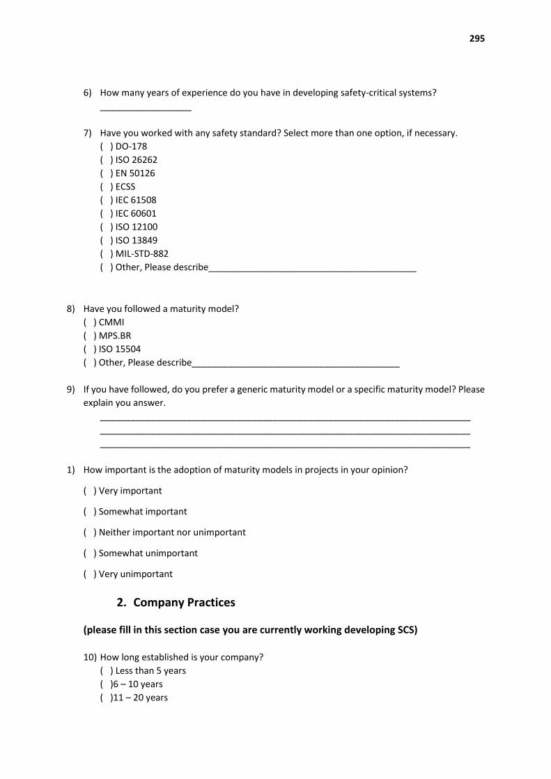
295
6) How many years of experience do you have in developing safety-critical systems?
__________________
7) Have you worked with any safety standard? Select more than one option, if necessary.
( ) DO-178
( ) ISO 26262
( ) EN 50126
( ) ECSS
( ) IEC 61508
( ) IEC 60601
( ) ISO 12100
( ) ISO 13849
( ) MIL-STD-882
( ) Other, Please describe_________________________________________
8) Have you followed a maturity model?
( ) CMMI
( ) MPS.BR
( ) ISO 15504
( ) Other, Please describe_________________________________________
9) If you have followed, do you prefer a generic maturity model or a specific maturity model? Please
explain you answer.
_________________________________________________________________________
_________________________________________________________________________
_________________________________________________________________________
1) How important is the adoption of maturity models in projects in your opinion?
( ) Very important
( ) Somewhat important
( ) Neither important nor unimportant
( ) Somewhat unimportant
( ) Very unimportant
2. Company Practices
(please fill in this section case you are currently working developing SCS)
10) How long established is your company?
( ) Less than 5 years
( )6 – 10 years
( )11 – 20 years

296
( ) 21 – 50 years
( ) Other: _________________________________________
11) How many employees work in your company?
__________________
12) How many employees work with requirements definition?
__________________
13) How many employees work with safety analysis and safety requirements specification?
__________________
14) Do you know what is the project success ratio in your company? If yes, please write an average
percentage. __________________
15) What is your current role and responsibilities?
_________________________________________________________________________
_________________________________________________________________________
_________________________________________________________________________
16) How many years of experience do you have in your current role?
__________________
17) How many requirements are there in a typical project you work?
__________________
18) How many safety requirements are there in a typical project you work?
__________________
19) Have your company had problems in the system developments due to errors in the safety
requirements specification? If yes, please provide some examples.
_________________________________________________________________________
_________________________________________________________________________
_________________________________________________________________________
20) Does your organization currently use some Maturity Model? Which one? If yes, in which level
is it classified?
_________________________________________________________________________
21) Does the company face problems with the adoption of maturity models? If yes, please
describe
_________________________________________________________________________
_________________________________________________________________________
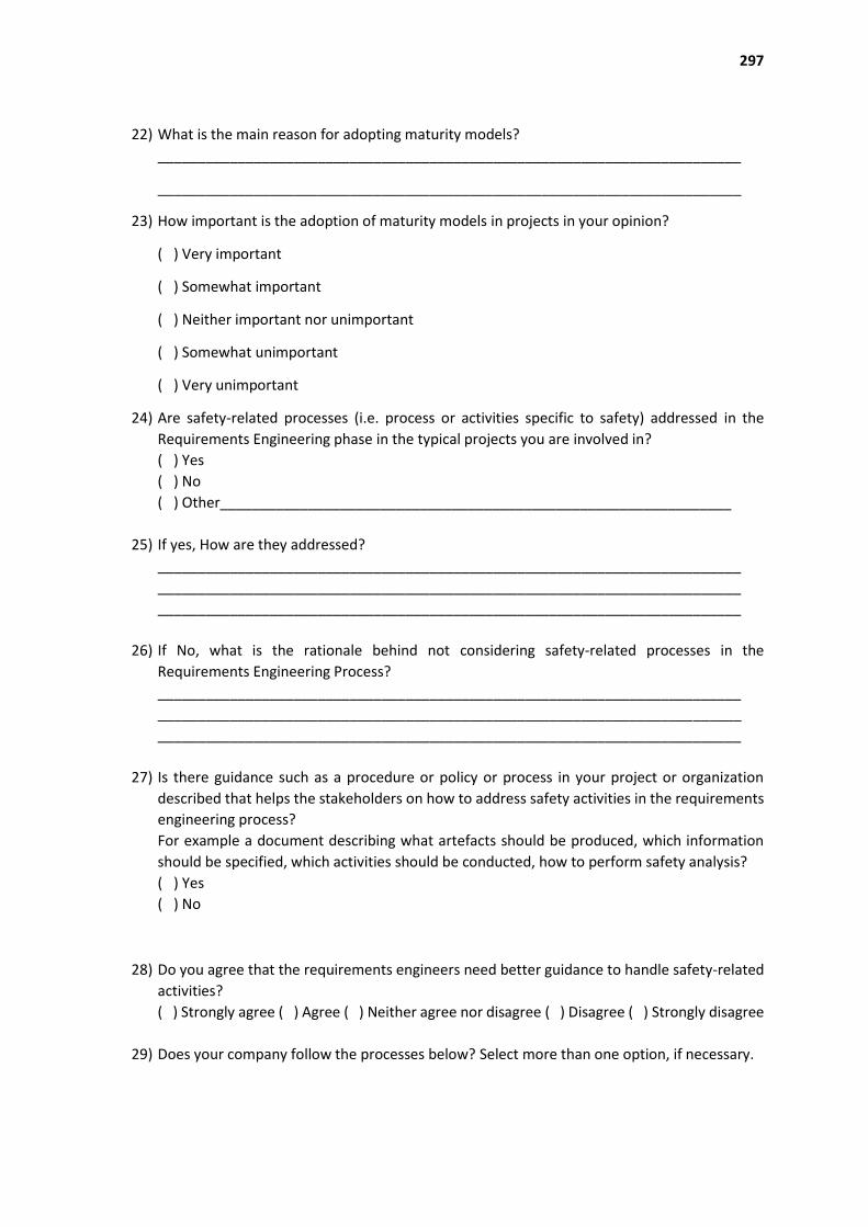
297
22) What is the main reason for adopting maturity models?
_________________________________________________________________________
_________________________________________________________________________
23) How important is the adoption of maturity models in projects in your opinion?
( ) Very important
( ) Somewhat important
( ) Neither important nor unimportant
( ) Somewhat unimportant
( ) Very unimportant
24) Are safety-related processes (i.e. process or activities specific to safety) addressed in the
Requirements Engineering phase in the typical projects you are involved in?
( ) Yes
( ) No
( ) Other________________________________________________________________
25) If yes, How are they addressed?
_________________________________________________________________________
_________________________________________________________________________
_________________________________________________________________________
26) If No, what is the rationale behind not considering safety-related processes in the
Requirements Engineering Process?
_________________________________________________________________________
_________________________________________________________________________
_________________________________________________________________________
27) Is there guidance such as a procedure or policy or process in your project or organization
described that helps the stakeholders on how to address safety activities in the requirements
engineering process?
For example a document describing what artefacts should be produced, which information
should be specified, which activities should be conducted, how to perform safety analysis?
( ) Yes
( ) No
28) Do you agree that the requirements engineers need better guidance to handle safety-related
activities?
( ) Strongly agree ( ) Agree ( ) Neither agree nor disagree ( ) Disagree ( ) Strongly disagree
29) Does your company follow the processes below? Select more than one option, if necessary.
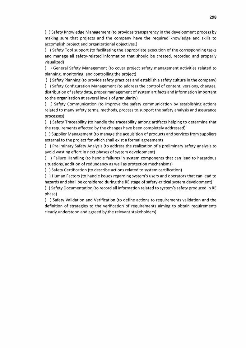
298
( ) Safety Knowledge Management (to provides transparency in the development process by
making sure that projects and the company have the required knowledge and skills to
accomplish project and organizational objectives.)
( ) Safety Tool support (to facilitating the appropriate execution of the corresponding tasks
and manage all safety-related information that should be created, recorded and properly
visualized)
( ) General Safety Management (to cover project safety management activities related to
planning, monitoring, and controlling the project)
( ) Safety Planning (to provide safety practices and establish a safety culture in the company)
( ) Safety Configuration Management (to address the control of content, versions, changes,
distribution of safety data, proper management of system artifacts and information important
to the organization at several levels of granularity)
( ) Safety Communication (to improve the safety communication by establishing actions
related to many safety terms, methods, process to support the safety analysis and assurance
processes)
( ) Safety Traceability (to handle the traceability among artifacts helping to determine that
the requirements affected by the changes have been completely addressed)
( ) Supplier Management (to manage the acquisition of products and services from suppliers
external to the project for which shall exist a formal agreement)
( ) Preliminary Safety Analysis (to address the realization of a preliminary safety analysis to
avoid wasting effort in next phases of system development)
( ) Failure Handling (to handle failures in system components that can lead to hazardous
situations, addition of redundancy as well as protection mechanisms)
( ) Safety Certification (to describe actions related to system certification)
( ) Human Factors (to handle issues regarding system’s users and operators that can lead to
hazards and shall be considered during the RE stage of safety-critical system development)
( ) Safety Documentation (to record all information related to system’s safety produced in RE
phase)
( ) Safety Validation and Verification (to define actions to requirements validation and the
definition of strategies to the verification of requirements aiming to obtain requirements
clearly understood and agreed by the relevant stakeholders)

299
Module evaluation questionnaire used in static validation
1. Uni-REPM Safety Module
1) Which the following processes (or focus areas) presented in the module do you consider
important and should it be considered in the requirements engineer process?
Process Don’t
know
Not Needed Desirable Essential
Safety Knowledge
Management
Safety Tool support
General Safety
Management
Safety Planning
Safety Configuration
Management
Safety Communication
Safety Traceability
Supplier Management
Preliminary Safety
Analysis
Failure Handling
Safety Certification
Human Factors
Safety Documentation
Safety Validation and
Verification
2) Do you think that other safety-related process is also important for the development of a
safety-critical systems? If so, list the processes and briefly explain why you consider them to
be important.
_________________________________________________________________________
_________________________________________________________________________
_________________________________________________________________________
3) The safety processes in the module are easy to understand.
( ) Strongly agree ( ) Agree ( ) Neither agree nor disagree ( ) Disagree ( ) Strongly disagree
4) To all safety actions below, mark with an X the alternative that seems most appropriate.
Legend:
DN = Don’t Know, ND=Not Needed, D= Desirable, E = Essential
1- Basic Level, 2- Intermediate Level, 3- Advanced Level
Practice Level Opinion level a-
dequate
change to
1,2 or 3
ND D E Y
Requirements Elicitation
Supplier Management Establish and maintain formal agreements among organization
and suppliers 2
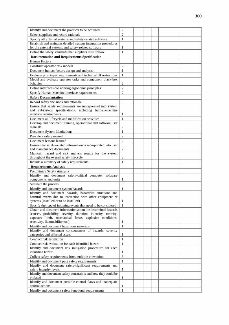
300
Identify and document the products to be acquired 2
Select suppliers and record rationale 2
Specify all external systems and safety-related software 1 Establish and maintain detailed system integration procedures
for the external systems and safety-related software 1
Define the safety standards that suppliers must follow 1
Documentation and Requirements Specification
Human Factors
Construct operator task models 2
Document human factors design and analysis 1
Evaluate prototypes, requirements and technical UI restrictions 1 Model and evaluate operator tasks and component black-box
behavior 2
Define interfaces considering ergonomic principles 2
Specify Human Machine Interface requirements 2
Safety Documentation
Record safety decisions and rationale 3 Ensure that safety requirements are incorporated into system
and subsystem specifications, including human-machine
interface requirements 1
Document all lifecycle and modification activities 1 Develop and document training, operational and software user
manuals 2
Document System Limitations 1
Provide a safety manual 2
Document lessons learned 2 Ensure that safety-related information is incorporated into user
and maintenance documents 2
Maintain hazard and risk analysis results for the system
throughout the overall safety lifecycle 3
Include a summary of safety requirements 1
Requirements Analysis
Preliminary Safety Analysis Identify and document safety-critical computer software
components and units 1
Simulate the process 3
Identify and document system hazards 1 Identify and document hazards, hazardous situations and
harmful events due to interaction with other equipment or
systems (installed or to be installed) 1
Specify the type of initiating events that need to be considered 1 Obtain and document information about the determined hazards
(causes, probability, severity, duration, intensity, toxicity,
exposure limit, mechanical force, explosive conditions,
reactivity, flammability etc.) 1
Identify and document hazardous materials 1 Identify and document consequences of hazards, severity
categories and affected assets 1
Conduct risk estimation 1
Conduct risk evaluation for each identified hazard 1 Identify and document risk mitigation procedures for each
identified hazard 1
Collect safety requirements from multiple viewpoints 3
Identify and document pure safety requirements 1 Identify and document safety-significant requirements and
safety integrity levels 1
Identify and document safety constraints and how they could be
violated 1
Identify and document possible control flaws and inadequate
control actions 1
Identify and document safety functional requirements 1

301
Identify and document operational requirements 1 Perform and document the feasibility evaluation of safety
functional requirements 2
Prioritize hazards and safety requirements 2 Identify and document analysis and verification requirements,
possible safety-interface problems, including the human-
machine interface, and operating support requirements 1
Perform interface analysis, including interfaces within
subsystems (such as between safety-critical and non-safety-
critical software components) 2
Consolidate preliminary system safety technical specification 1
Failure Handling
Define requirements for the avoidance of systematic faults 1
Specify Fault-detection procedures 1
Specify Restart-up procedures 1
Document the system behavioral model 2 Identify and document Common-cause failures (CCF) and how
to prevent them 2
Perform reliability and system performance analysis 1
Release Planning
Safety Certification
Conduct safety audits 2 Demonstrate the preliminary level of safety achieved by the
system 1
Evaluate the threat to society from the hazards that cannot be
eliminated or avoided 1
Construct preliminary safety and hazard reports 1
Construct preliminary safety cases 1
Demonstrate preliminary compliance with safety standards 2 Ensure that the hazard report is updated with embedded links to
the resolution of each hazard, such as safety functional
requirements, safety constraints, operational requirements, and
system limitations 3
Document the division of responsibility for system certification
and compliance with safety standards during safety planning 2
Specify a maintenance plan 1
Requirements Validation
Safety Validation and Verification Define the safety validation plan for software aspects of system
safety 1
Define the safety verification plan 1 Define the technical strategy for the validation of external
systems and safety-related software 2
Define pass/fail criteria for accomplishing software validation
and verification 2
Develop safety test plans, test descriptions, test procedures, and
validation and verification safety requirements 2
Define and maintain a software integration test plan 1
Validate safety-related software aspects 2
Ensure that there is no potentially hazardous control actions 2 Perform safety evaluation and verification at the system and
subsystem levels 1
Conduct joint reviews (company and customer) 2 Ensure that the stakeholders understand software-related
system safety requirements and constraints. 2
Document discrepancies between expected and actual results 2
Verify the behavioral model 2 Ensure that software requirements and interface specification
are consistent 2
Perform safety inspections 2 Identify and fix inconsistencies safety requirements
specification 2

302
Organizational Support
Safety Planning
Develop an integrated system safety program plan 1 Define and document requirements for periodic functional
safety audits 2
Define and document the interface between system safety and
all other applicable safety disciplines 1
Delineate the scope of safety analysis 1
Establish the hazards auditing and log file 1
Establish working groups and structures 1 Define and document the regulations and safety standards to be
followed 1
Identify any certification requirements for software, safety or
warning devices or other special safety feature 1
Define and document requirements completeness criteria and
safety criteria 3
Review safety experience on similar systems 2
Specify the general safety control structure 3 Specify operating conditions of the machine and installation
conditions of the electronic parts 1
Determine the required performance level 1 Identify and document the hazard analysis to be performed; the
analytical techniques (qualitative or quantitative) to be used;
and depth within the system that each analytical technique will
be used (e.g., system level, subsystem level, component level) 1
General Safety Management
Identify and document the system development methodology 1 Identify and document safety lifecycle for the system
development 1
Identify and document competence requirements for the safety
activities 1
Set safety policy and define safety goals 1 Identify and document responsibility, accountability and
authority 1
Define system safety program milestones and relate these to
major program milestones, program element responsibility, and
required inputs and outputs 1
Use of indicators on engineering documentation to assess the
product properties and the development progress 3
Prepare progress reports in a period of time defined by the
project 2
Monitor project and take corrective actions 2
Safety Tool support
Use of verification and validation tools 2 Specify justifications for the selection of the off-line support
tools 3
Assess offline support tools which can directly or indirectly
contribute to the executable code of the safety related system 3
Record information of the tools in the baseline 2 Use of tools with support to cross reference and maintain the
traceability among safety information in the software
specification 3
Use of computer-aided specification tools 2 Define and use tools to support the safety process and workflow
management 3
Safety Knowledge Management
Establish and maintain an infrastructure to share knowledge 3 Develop a safety information system to share knowledge in the
organization 3
Define control access mechanisms to the safety information
system 3
Maintain employees competence information 3
Document a strategy to manage the knowledge 2
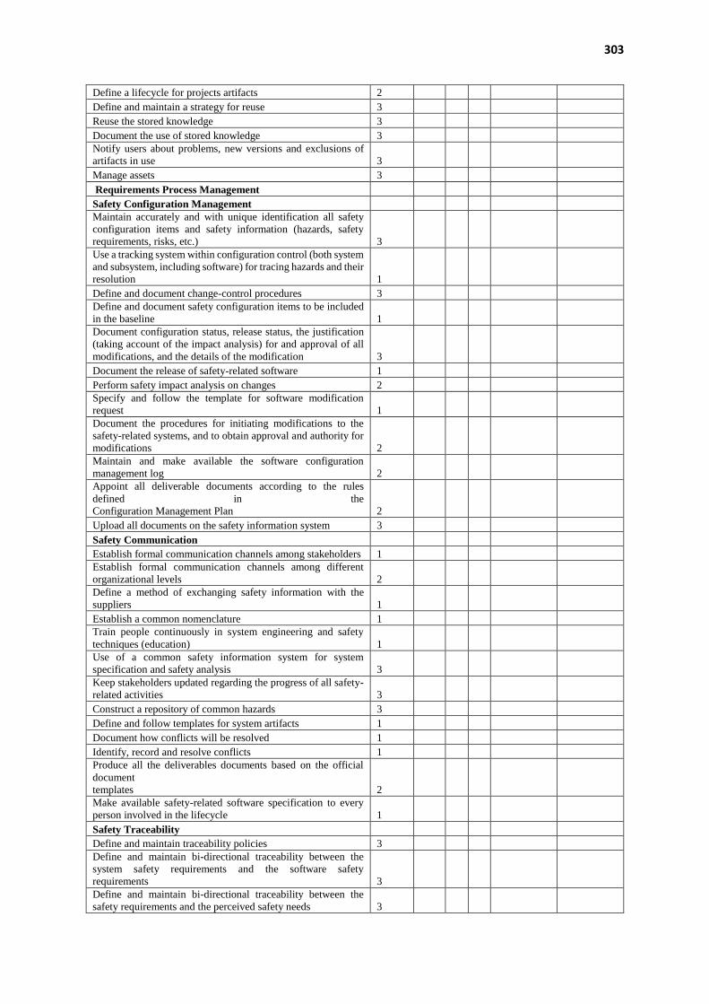
303
Define a lifecycle for projects artifacts 2
Define and maintain a strategy for reuse 3
Reuse the stored knowledge 3
Document the use of stored knowledge 3 Notify users about problems, new versions and exclusions of
artifacts in use 3
Manage assets 3
Requirements Process Management
Safety Configuration Management Maintain accurately and with unique identification all safety
configuration items and safety information (hazards, safety
requirements, risks, etc.) 3
Use a tracking system within configuration control (both system
and subsystem, including software) for tracing hazards and their
resolution 1
Define and document change-control procedures 3 Define and document safety configuration items to be included
in the baseline 1
Document configuration status, release status, the justification
(taking account of the impact analysis) for and approval of all
modifications, and the details of the modification 3
Document the release of safety-related software 1
Perform safety impact analysis on changes 2 Specify and follow the template for software modification
request 1
Document the procedures for initiating modifications to the
safety-related systems, and to obtain approval and authority for
modifications 2
Maintain and make available the software configuration
management log 2
Appoint all deliverable documents according to the rules
defined in the
Configuration Management Plan 2
Upload all documents on the safety information system 3
Safety Communication
Establish formal communication channels among stakeholders 1 Establish formal communication channels among different
organizational levels 2
Define a method of exchanging safety information with the
suppliers 1
Establish a common nomenclature 1 Train people continuously in system engineering and safety
techniques (education) 1
Use of a common safety information system for system
specification and safety analysis 3
Keep stakeholders updated regarding the progress of all safety-
related activities 3
Construct a repository of common hazards 3
Define and follow templates for system artifacts 1
Document how conflicts will be resolved 1
Identify, record and resolve conflicts 1 Produce all the deliverables documents based on the official
document
templates 2
Make available safety-related software specification to every
person involved in the lifecycle 1
Safety Traceability
Define and maintain traceability policies 3 Define and maintain bi-directional traceability between the
system safety requirements and the software safety
requirements 3
Define and maintain bi-directional traceability between the
safety requirements and the perceived safety needs 3

304
Link and maintain bi-directional traceability between
environmental assumptions and the parts of the hazard analysis
based on the assumption 3
Define and maintain bi-directional traceability between system
and subsystem verification results and system specification 3
Define and maintain bi-directional traceability between
validation results and system specification 3
Define and maintain bi-directional traceability among system
hazards into components. 3
Justify reasons for not traced software requirements 3
5) Do you think that other actions are also important for the requirements engineering process
of safety-critical systems that are not presented in the module? If so, list other actions and
briefly explain why you consider them to be important.
_________________________________________________________________________
_________________________________________________________________________
_________________________________________________________________________
6) The safety actions in the module are easy to understand.
( ) Strongly agree ( ) Agree ( ) Neither agree nor disagree ( ) Disagree ( ) Strongly disagree
7) To what extent do you believe the safety module will help requirements engineers to perform
safety-related activities or tasks in the project?
( ) To a large extent
( ) To a moderate extent
( ) To some extent
( ) To a little extent
( ) Not at all
8) I would adopt the safety module in my company.
( ) Strongly agree ( ) Agree ( ) Neither agree nor disagree ( ) Disagree ( ) Strongly disagree
9) If you have further comments about the module, please state below.
_________________________________________________________________________
_________________________________________________________________________
_________________________________________________________________________
10) Do you want to participate in future studies? If yes, please provide your email address.
_________________________________________________________________________

305
APPENDIX F – QUESTIONNAIRE USED IN DYNAMIC VALIDATION
This appendix contains the questionnaire of the Case Study: Evaluation of the “Uni-REPM -Safety Module” and Tool from the point of view of the practitioners.
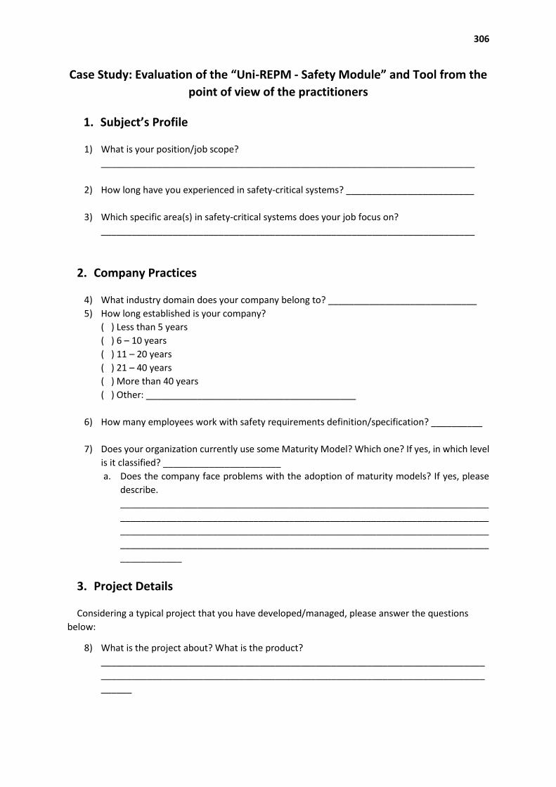
306
Case Study: Evaluation of the “Uni-REPM - Safety Module” and Tool from the
point of view of the practitioners
1. Subject’s Profile
1) What is your position/job scope?
_________________________________________________________________________
2) How long have you experienced in safety-critical systems? _________________________
3) Which specific area(s) in safety-critical systems does your job focus on?
_________________________________________________________________________
2. Company Practices
4) What industry domain does your company belong to? _____________________________
5) How long established is your company?
( ) Less than 5 years
( ) 6 – 10 years
( ) 11 – 20 years
( ) 21 – 40 years
( ) More than 40 years
( ) Other: _________________________________________
6) How many employees work with safety requirements definition/specification? __________
7) Does your organization currently use some Maturity Model? Which one? If yes, in which level
is it classified? _______________________
a. Does the company face problems with the adoption of maturity models? If yes, please
describe.
________________________________________________________________________
________________________________________________________________________
________________________________________________________________________
________________________________________________________________________
____________
3. Project Details
Considering a typical project that you have developed/managed, please answer the questions
below:
8) What is the project about? What is the product?
___________________________________________________________________________
___________________________________________________________________________
______
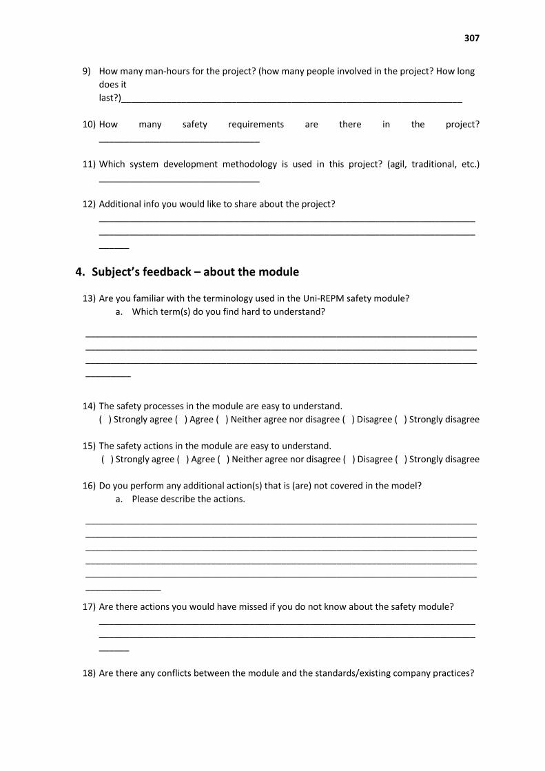
307
9) How many man-hours for the project? (how many people involved in the project? How long
does it
last?)____________________________________________________________________
10) How many safety requirements are there in the project?
________________________________
11) Which system development methodology is used in this project? (agil, traditional, etc.)
________________________________
12) Additional info you would like to share about the project?
___________________________________________________________________________
___________________________________________________________________________
______
4. Subject’s feedback – about the module
13) Are you familiar with the terminology used in the Uni-REPM safety module?
a. Which term(s) do you find hard to understand?
______________________________________________________________________________
______________________________________________________________________________
______________________________________________________________________________
_________
14) The safety processes in the module are easy to understand.
( ) Strongly agree ( ) Agree ( ) Neither agree nor disagree ( ) Disagree ( ) Strongly disagree
15) The safety actions in the module are easy to understand.
( ) Strongly agree ( ) Agree ( ) Neither agree nor disagree ( ) Disagree ( ) Strongly disagree
16) Do you perform any additional action(s) that is (are) not covered in the model?
a. Please describe the actions.
______________________________________________________________________________
______________________________________________________________________________
______________________________________________________________________________
______________________________________________________________________________
______________________________________________________________________________
_______________
17) Are there actions you would have missed if you do not know about the safety module?
___________________________________________________________________________
___________________________________________________________________________
______
18) Are there any conflicts between the module and the standards/existing company practices?
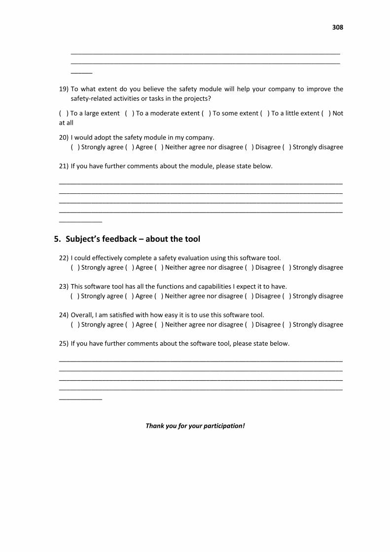
308
___________________________________________________________________________
___________________________________________________________________________
______
19) To what extent do you believe the safety module will help your company to improve the
safety-related activities or tasks in the projects?
( ) To a large extent ( ) To a moderate extent ( ) To some extent ( ) To a little extent ( ) Not
at all
20) I would adopt the safety module in my company.
( ) Strongly agree ( ) Agree ( ) Neither agree nor disagree ( ) Disagree ( ) Strongly disagree
21) If you have further comments about the module, please state below.
_______________________________________________________________________________
_______________________________________________________________________________
_______________________________________________________________________________
_______________________________________________________________________________
____________
5. Subject’s feedback – about the tool
22) I could effectively complete a safety evaluation using this software tool.
( ) Strongly agree ( ) Agree ( ) Neither agree nor disagree ( ) Disagree ( ) Strongly disagree
23) This software tool has all the functions and capabilities I expect it to have.
( ) Strongly agree ( ) Agree ( ) Neither agree nor disagree ( ) Disagree ( ) Strongly disagree
24) Overall, I am satisfied with how easy it is to use this software tool.
( ) Strongly agree ( ) Agree ( ) Neither agree nor disagree ( ) Disagree ( ) Strongly disagree
25) If you have further comments about the software tool, please state below.
_______________________________________________________________________________
_______________________________________________________________________________
_______________________________________________________________________________
_______________________________________________________________________________
____________
Thank you for your participation!