jersey central power & light
17
Page 1 of 17 JERSEY CENTRAL POWER & LIGHT UNIFORM TECHNICAL AND PROCEDURAL INTERCONNECTION REQUIREMENTS FOR NET METERING FACILITIES FOR INVERTER BASED WIND AND PHOTOVOLTAIC SYSTEMS OF 100 kW OR SMALLER for Atlantic City Electric Company d/b/a Conectiv Power Delivery, Jersey Central Power & Light a FirstEnergy Company, Public Service Electric & Gas Company, and Rockland Electric Company December 13, 2002 TABLE OF CONTENTS 1.0 OBJECTIVES .......................................................................................................... 1 2.0 DEFINITIONS .......................................................................................................... 2 3.0 INTERCONNECTION TECHNICAL REQUIREMENTS ........................................... 3 3.1 GENERAL .................................................................................................................. 3 3.2 CODE COMPLIANCE AND INSPECTIONS ......................................................................... 4 3.3 PHOTOVOLTAIC SYSTEMS ........................................................................................... 4 3.4 ALL SYSTEMS (WIND OR PV) ...................................................................................... 4 3.5 DISCONNECT SWITCH ................................................................................................. 5 3.6 WARNING LABEL ........................................................................................................ 5 3.7 INVERTER SET POINTS................................................................................................ 5 3.8 INTERCONNECTION STUDY .......................................................................................... 6 4.0 INTERCONNECTION APPLICATION PROCESS ................................................... 6 ATTACHMENT A – APPLICATION .................................................................................. 10 ATTACHMENT B – FLOWCHART ................................................................................... 12 ATTACHMENT C – STANDARDIZED COSTS................................................................. 13 ATTACHMENT D - SAMPLE WARNING LABEL AND SIGNS ......................................... 14 ATTACHMENT E – UTILITY CONTACT LIST .................................................................. 17 1.0 Objectives This document has been prepared by Atlantic City Electric Company d/b/a Conectiv Power Delivery, Jersey Central Power & Light a FirstEnergy Company, Public Service Electric & Gas Company and Rockland Electric Company for Customers installing This document was filed with the Board of Public Utilities on December 13, 2002. It is awaiting final approval by BPU staff.
-
Upload
khangminh22 -
Category
Documents
-
view
0 -
download
0
Transcript of jersey central power & light

Page 1 of 17
JERSEY CENTRAL POWER & LIGHTUNIFORM TECHNICAL AND PROCEDURAL
INTERCONNECTION REQUIREMENTS FOR NET METERING FACILITIESFOR INVERTER BASED WIND AND PHOTOVOLTAIC SYSTEMS
OF 100 kW OR SMALLERfor
Atlantic City Electric Company d/b/a Conectiv Power Delivery,Jersey Central Power & Light a FirstEnergy Company,
Public Service Electric & Gas Company,and Rockland Electric Company
December 13, 2002
TABLE OF CONTENTS
1.0 OBJECTIVES .......................................................................................................... 1
2.0 DEFINITIONS.......................................................................................................... 2
3.0 INTERCONNECTION TECHNICAL REQUIREMENTS ........................................... 3
3.1 GENERAL .................................................................................................................. 33.2 CODE COMPLIANCE AND INSPECTIONS ......................................................................... 43.3 PHOTOVOLTAIC SYSTEMS ........................................................................................... 43.4 ALL SYSTEMS (WIND OR PV) ...................................................................................... 43.5 DISCONNECT SWITCH ................................................................................................. 53.6 WARNING LABEL ........................................................................................................ 53.7 INVERTER SET POINTS................................................................................................ 53.8 INTERCONNECTION STUDY .......................................................................................... 6
4.0 INTERCONNECTION APPLICATION PROCESS ................................................... 6
ATTACHMENT A – APPLICATION .................................................................................. 10
ATTACHMENT B – FLOWCHART................................................................................... 12
ATTACHMENT C – STANDARDIZED COSTS................................................................. 13
ATTACHMENT D - SAMPLE WARNING LABEL AND SIGNS ......................................... 14
ATTACHMENT E – UTILITY CONTACT LIST.................................................................. 17
1.0 Objectives
This document has been prepared by Atlantic City Electric Company d/b/a Conectiv
Power Delivery, Jersey Central Power & Light a FirstEnergy Company, Public Service
Electric & Gas Company and Rockland Electric Company for Customers installing
This document was filed with the Board of Public Utilities on December 13, 2002.It is awaiting final approval by BPU staff.

Page 2 of 17
inverter based wind and Photovoltaic (PV) systems up to 100kW that are eligible for
interconnection under net metering. This document addresses the technical
requirements, and the procedural process for the interconnection between the Utility’s
distribution system and a Customer’s Wind or PV System.
2.0 Definitions
Customer - Anyone taking electric delivery service from, and desiring to interconnect
generation with, the Utility.
Inverter - A solid-state power converter with control, protection and filtering functions
that converts Direct Current (DC) to Alternating Current (AC) output. Inverters must
be of the anti-islanding type as defined and tested in accordance with IEEE 929 and
UL1741.
Inverter Based Generation - The production of AC electrical energy by solid state
inverters, operating in parallel with and connected to the Utility’s electrical distribution
system either directly or through a step-up transformer, producing energy from a DC
source supplied by a Wind or PV System.
Interconnection Point - The point at which the Utility and Customer interface occurs.
Typically, this is the Customer side of the Utility revenue meter and is commonly
referred to as the Point of Common Coupling.
Photovoltaic (PV) System - A renewable energy generation system also called a
solar electric system utilizing the DC output from solar electric modules in the
production of AC electrical energy via a DC to AC inverter.
Wind System - A renewable energy generation system utilizing the DC output from
wind turbine generators in the production of AC electrical energy via a DC to AC
inverter.
Utility - The electric delivery company to which the Customer is interconnected, i.e.
Atlantic City Electric Company d/b/a Conectiv Power Delivery, Jersey Central Power
& Light a FirstEnergy Company, Public Service Electric & Gas Company or Rockland
Electric Company.

Page 3 of 17
3.0 Interconnection Technical Requirements
3.1 General
Interconnection with the Utility’s distribution system requires utilization of
generation equipment meeting the requirements outlined in Section 3.3 and 3.4
of this document. The system must be equipped with either integral protective
functionality or with external protective devices, which provides safety for
personnel, affords adequate protection against damage to the Utility’s system or
to the Customer’s property and prevents any interference with the Utility’s supply
of service to other customers. Such protective equipment shall be installed,
owned and maintained by the Customer at the Customer’s expense. The
Customer’s equipment must be installed and configured so that parallel
operation must cease immediately and automatically during system outages or
loss of the Utility’s electric source. The Customer must also cease parallel
operation upon notification by the Utility of a system emergency, abnormal
condition or in cases where such operation is determined to be unsafe,
interferes with the supply of service to other customers or interferes with the
Utility’s system maintenance or operation. Generation systems and equipment
that comply with the following requirements and standards shall be deemed by
the Utility to have generally complied with the technical provisions of this section.
The Utility will not assume any responsibility for protection of the Customer's
generating equipment, or any portion of the Customer's equipment. The
Customer is solely responsible for protecting its equipment in such a manner
that faults, imbalances or other disturbances on the Utility’s system do not cause
damage to the Customer's equipment.
There may be instances where there may be significant costs associated with
the interconnection, which are the Customer’s responsibility. In order to be
aware of all potential costs, it is strongly recommended that the Customer follow
the submittal procedure outlined in Section 4 and illustrated in Attachment B.

Page 4 of 17
3.2 Code Compliance and Inspections
It is the responsibility of the Customer to insure that their Wind or PV System
complies with all applicable Federal, State and Local Regulatory Agencies and
all applicable electrical and safety codes including the latest revision of the
National Electrical Code‚ (“NEC”). The Customer must obtain, at the
Customer’s expense, all necessary inspections and approvals required by the
local public authorities before the electric generation facility can be connected to
the Utility’s electric system.
3.3 Photovoltaic Systems
PV Systems must be in compliance with the latest revisions of the following
standards:
1) Underwriters Laboratories (UL) 1741, Standard for Static Inverters and
Charge Controllers for Use in Photovoltaic Systems;
2) UL 1703, Standard of Safety: Flat-Plate Photovoltaic Modules and Panels;
3) IEEE 1262-1995, IEEE Recommended Practice for Qualification of
Photovoltaic (PV) Modules
4) IEEE Standard 929-2000, Recommended Practice of Utility Interface of
Photovoltaic (PV) Systems.
3.4 All Systems (Wind or PV)
All Systems must be in compliance with the latest revisions of the following
standards:
1) All systems must utilize anti-islanding inverters as defined and tested in
accordance with IEEE Std. 929 and UL-1741.
2) The inverter output must conform to IEEE Std. 519-1992, I E E E
Recommended Practices and Requirements for Harmonic Control In
Electrical Power Systems.
3) All systems must conform to IEEE Std. P1547, Draft Standard for
Interconnecting Distributed Resources with Electric Power Systems.
Page 5 of 17
4) If the system is designed to provide uninterruptible power to critical loads,
either through energy storage, back-up generator, or the generation source,
the system shall include a parallel blocking scheme for this backup source.
This function may be integral to the inverter manufacturer’s packaged
system.
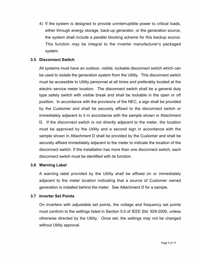
3.5 Disconnect Switch
All systems must have an outdoor, visible, lockable disconnect switch which can
be used to isolate the generation system from the Utility. This disconnect switch
must be accessible to Utility personnel at all times and preferably located at the
electric service meter location. The disconnect switch shall be a general dutytype safety switch with visible break and shall be lockable in the open or offposition. In accordance with the provisions of the NEC, a sign shall be provided
by the Customer and shall be securely affixed to the disconnect switch or
immediately adjacent to it in accordance with the sample shown in Attachment
D. If the disconnect switch is not directly adjacent to the meter, the location
must be approved by the Utility and a second sign in accordance with the
sample shown in Attachment D shall be provided by the Customer and shall be
securely affixed immediately adjacent to the meter to indicate the location of the
disconnect switch. If the installation has more than one disconnect switch, each
disconnect switch must be identified with its function.
3.6 Warning Label
A warning label provided by the Utility shall be affixed on or immediately
adjacent to the meter location indicating that a source of Customer owned
generation is installed behind the meter. See Attachment D for a sample.
3.7 Inverter Set Points
On inverters with adjustable set points, the voltage and frequency set points
must conform to the settings listed in Section 5.0 of IEEE Std. 929-2000, unless
otherwise directed by the Utility. Once set, the settings may not be changed
without Utility approval.

Page 6 of 17
3.8 Interconnection Study
In some cases, depending on system size and the Customer’s location on the
Utility’s distribution system, a detailed interconnection study including harmonics
may be needed. The cost of the study will be the responsibility of the Customer
in accordance with the provisions outlined in Attachment C.
The study results may require that the Customer install additional protection
equipment over that normally provided, or that modifications are necessary on
the Utility system. The Customer will be notified of these additional
requirements, all of which would be at the Customer’s expense, to determine if
the Customer desires to proceed with the installation.
An interconnection study may be required:
1) For radial feeders where the application will result in aggregate generation of
more that 50 kW on a single-phase feeder or more that 150 kW on a three-
phase feeder.
2) For any system installed on the Utility’s looped secondary network where the
system will result in aggregate generation:
(a) greater than 100 kW or
(b) exceeding 50 percent of the minimum load on the network bus to which
the system is connected
Such a system may not be permitted to be connected to a network system or
additional protective devices may be required to ensure power does not flow
into the network system.
3.9 Characteristics of the Customer Interconnection
The voltage and phase configuration of the Customer’s generating system must
match the Utility service voltage and phase configuration at the Interconnection
Point.
4.0 Interconnection Application Process
The application process is detailed below. The application process is also illustrated
in the flowchart on Attachment B.

Page 7 of 17
4.1 The Customer contacts the Utility and requests an “Interconnection
Application/Agreement for Net Metering Facilities for Inverter Based Wind &
Photovoltaic Systems 100 kW or Smaller” (Application) along with these Uniform
Technical and Procedural Interconnection Requirements. The forms are also
available on the Internet at the New Jersey Clean Energy Website at
www.njcep.com.
4.2 The Customer submits the following to the Utility at the address shown in
Attachment E:
1) Page one of the Interconnection Application (Sections A, B & C)
2) The Application Fee of $100.00, in the form of a check made payable to the
appropriate Utility.
3) A One-Line Diagram of the proposed installation.
4) A Plot Plan showing, at a minimum, the location of the main breaker,
metering location, location of the disconnect switch and the inverter/controller
for the Wind or PV System.
5) Inverter documentation necessary to verify conformity with IEEE Std. 929-
2000 and UL 1741.
6) Proposed set points on all of the protective functions associated with the
system protection, if the proposed inverter has adjustable set points.
4.3 The Utility reviews the Interconnection Application/Agreement for Net Metering
Systems and any accompanying documents.
1) Utility response to Interconnection Application/ Agreement will be provided
within 30 days of submission, and will either notify the Customer that they
should proceed with the installation as proposed or notify the Customer of
any deficiencies in the Application.
2) In the event that there is a deficiency, the Interconnection Application/
Agreement will not be accepted. Once the deficiency is corrected and

Page 8 of 17
satisfactory documentation or notification has been provided to the Utility, a
response will be provided within 30 days of submittal.
3) The Utility also determines whether an interconnection study is needed as
outlined in Paragraph 3.8.
In those cases where an interconnection study is deemed to be necessary,
the costs for the study shall be assessed to the Customer according to the
Standardized Costs for Electric Distribution Company Interconnection
Studies for Net Metering-qualified Systems (see Attachment C). The Utility
will advise the Customer of the study costs and request Customer
authorization before proceeding.
Once the interconnection study has been completed the Customer will be
notified of the results, including any specific protection requirements over that
normally provided, or of any modifications necessary to the Utility system.
The Utility will advise the Customer of the costs associated with any
identified Utility system modifications and request Customer authorization
before proceeding.
4.4 The Customer then proceeds to install the clean energy system and have the
system inspected by the local code official.
4.5 The Customer completes page two of the Application, which contains the electric
code inspection signoff (Section E) and Customer acknowledgement (Section
F), after the system has been installed and the system has been inspected and
approved by the electrical code official. The application is then resubmitted to
the Utility.
Please be advised, if the Customer does not follow the Interconnection
Application Process and installs the system before submitting the Application
(Sections A through F submitted in one step), there may be additional costs
associated with the interconnection not yet identified. The Customer shall
assume the risk of any additional costs identified by the Utility in order to
implement the interconnection.

Page 9 of 17
4.6 The Utility reviews the Interconnection Application/Agreement for Net Metering
Systems and any accompanying documents following the same steps described
in Paragraphs 4.4 1) and 4.4 2) above and will provide a response within 30
days of submission. The response will indicate a “yes” (proceed) or “no,
because…”. Any response other than a simple “yes” will be accompanied by a
project specific explanation of the reason for the denial, including what additional
information is needed and/or what modifications may be required before
acceptance can be granted. A site inspection may be performed by the Utility.
4.7 When the interconnection review is completed satisfactorily, the Utility completes
Section G of the Interconnection Application/Agreement form and the Customer
will be notified that they may commence parallel operation of the Wind or PV
System. The Utility will send a copy of the accepted Interconnection
Application/Agreement form to the Customer.
The Utility may need to replace the watt-hour meter at the Customer’s location
so as to properly measure the net energy consumed by the Customer or the net
energy delivered by the Customer’s electric generation facility for the monthly
billing period. The Utility shall furnish, maintain, and own all metering equipment
needed for measurement of the service provided.

Page 10 of 17
Attachment A – Application
JERSEY CENTRAL POWER & LIGHTINTERCONNECTION APPLICATION/AGREEMENT
FOR NET METERING FACILITIES FOR INVERTER BASED WIND AND PHOTOVOLTAIC SYSTEMS 100 kW OR SMALLER
A. Applicant Information
Name:
Mailing Address:
City: State: Zip Code:
Street Address (if different from above):
City: State: Zip Code:
Daytime Phone: Fax: Email:
Jersey Central Power & Light Account No. (from Utility Bill):
Electric Energy Third Party Supplier:
Electric Energy Third Party Supplier Account No.:
B. System Information
Inverter Manufacturer Name Plate AC Power Rating: kW
System Type: q Wind q PV System Location:
Inverter Manufacturer:
Inverter Model No: Inverter Serial No:
Inverter Location: q Indoor q Outdoor q Self Contained Location:
Outdoor Manual AC Disconnect Switch - Location:
C. Installation Contractor Information/Hardware and Installation Compliance
Installation Contractor (Company Name)
Contractor's License No.: Proposed Installation Date:
Mailing Address:
City: State: Zip Code:
Daytime Phone: Fax: Email: The proposed System hardware and installation shall be in compliance with the New Jersey Uniform Technical andProcedural Interconnection Requirements for Net Metering Facilities for Inverter Based Wind and Photovoltaic Systems of100 kW or Smaller, with Underwriters Laboratories (UL) 1741, Standard for Static Inverters and Charge Controllers forUse in Photovoltaic Systems. System shall be installed in compliance with IEEE Standard 929-2000, RecommendedPractice for Utility Interface of Photovoltaic Systems. All System types shall be installed in compliance with applicablerequirements of local electrical codes, JCP&L and the National Electrical Code® (NEC) and shall use a non-islandinginverter as defined under IEEE Standard 929-2000.
If solar electric, the proposed System shall also be in compliance with UL 1703, Standard for Safety: Flat-PlatePhotovoltaic Modules and Panels; and IEEE 1262-1995, IEEE Recommended Practice for Qualification of Photovoltaic(PV) Modules.
The System shall have an outdoor lockable, visible disconnect switch, accessible at all times to JCP&L personnel. If the System is designed to provide uninterruptible power to critical loads, either through energy storage, back-upgenerator, or the generation source, the System shall include a parallel blocking scheme for this backup source.This function may be integral to the inverter manufacturer’s packaged system.
Signed (Contractor): Date:
Name (Print):

Page 11 of 17
JERSEY CENTRAL POWER & LIGHTINTERCONNECTION APPLICATION/AGREEMENT
FOR NET METERING FACILITIES FOR INVERTER BASED WIND AND PHOTOVOLTAIC SYSTEMS 100 kW OR SMALLER (Continued)
D. Additional Terms and Conditionsa) Operation/DisconnectionIf it appears to JCP&L, at any time, in the reasonable exercise of its judgment, that operation of the System is adversely affecting or may adversely affect JCP&L’s electrical system, JCP&L may immediately take any and all steps it reasonablybelieves necessary to mitigate or cure the conditions including, without limitation, disconnecting the System from JCP&L’selectrical system. Applicant/Customer shall at all times permit JCP&L’s employees and inspectors reasonable accessto inspect, test, or examine the System or metering equipment after notice by JCP&L. Applicant/Customer shall beliable for the costs and expenses incurred by JCP&L related to disconnection and reconnection of the System by JCP&Lwhen disconnection is permitted under this paragraph D.
b) Liability/IndemnityApplicant/Customer hereby covenants and agrees to assume all risk of and liability for personal injuries (including death)and damage to property arising out of or caused by the operation of the System. Applicant/Customer hereby covenantsand agrees to indemnify, protect, defend and save harmless JCP&L, its affiliates, officers, directors, employees andagents from and against any and all claims and demands for damages to property and injury or death to personswhich may arise out of, or be related to, or caused by, the operation of the System or its interconnection to the JCP&Lelectrical system, except if caused solely by the gross negligence or willful misconduct of JCP&L as determined by acourt of law.
E. Electrical Code Inspection
The System referenced above satisfies applicable electrical code requirements.
Inspector Name (Print):
Signed (Inspector): (In lieu of the signature of the inspector, a copy of the final inspection certificate may be attached).
Date: Municipality:
F. Customer Acknowledgment
The System has been installed to my satisfaction and I have been given System warranty information, and an operationmanual. Also, I have been informed as to whether my Wind or PV System is eligible for net metering, and been providedwith a copy of JCP&L net metering tariff and interconnection requirements. I have also been instructed in theoperation of the System by the manufacturer and/or the installer of the System.
I agree to abide by the terms of this Application /Agreement and I agree to operate and maintain the System inaccordance with manufacturer’s recommended practices as well as the New Jersey Single, Uniform InterconnectionRequirements. Further, I agree to notify JCP&L 30 days prior to modification or replacement of the System’scomponents or design. Any such modification or replacement shall require submission of a new Application to JCP&L.
I agree not to operate the System in parallel with JCP&L until this Application/Agreement is accepted by JCP&L.
I also agree to provide and install all warning labels as required by JCP&L on or near the Utility Safety Disconnectand/or at my service meter location as described in Sections 3.5 and 3.6 of the New Jersey Uniform InterconnectionRequirements.
Signed (Customer):
Date:
G. Utility Application Acceptance
JCP&L does not, by acceptance of this Application/Agreement, assume any responsibility or liability for damage toproperty or physical injury to persons. Further, this Application/Agreement does not constitute a dedication of theCustomer's System to JCP&L electrical system equipment or facilities.
This Application is accepted by JCP&L on this day of , 200
JCP&L Representative Name (Print):
Signed (JCP&L Representative):
Date:

Page 12 of 17

Page 13 of 17
Attachment C – Standardized Costs
Standardized Costs for Electric Distribution Company InterconnectionStudies for Net Metering-qualified Systems
The following are “standardized” study costs for Customers seeking to interconnect netmetering qualified systems to an EDC’s system, when such systems (individually or inaggregate) meet the criteria specified below. These charges would be in addition to the$100 application fee.
1) For requests to interconnect (i) single phase systems on single phase branches wherethe total aggregate generation is greater than 50 kW but less than or equal to 100 kW;or (ii) single phase and 3 phase systems on 3 phase feeders where the total aggregategeneration is greater than 150 kW but less than or equal to 300 kW, the study cost maybe up to, but not exceed, the cost of 3 man-days of study labor at the current EDCloaded labor rate. These charges will be based on actual time incurred up to themaximum cost.
2) Requests to interconnect any generation up to 100 kW for network service installationsmay incur a maximum study cost based on 5 man-days of study labor at the currentEDC loaded labor rate. These charges will be based on actual time incurred up to themaximum cost. (Note: depending on the proposed size of the unit and the dataavailable for the network, this cost to the Customer may be significantly less than thismaximum amount).
Study costs for proposed installations that fall outside of the “standards” will be estimatedfor the facility owner before any work is performed and billed at the respective EDC’sloaded labor rate.
In all cases Customers/contractors have a right to receive a bill with a detailed explanationof the charge.

Page 14 of 17

Page 15 of 17

Page 16 of 17

Page 17 of 17
Attachment E – Utility Contact List
Atlantic City Electric Company d/b/a Conectiv Power Delivery
New Jersey Clean Energy Program 79NC82Conectiv Power DeliveryP.O. Box 9239Newark, DE 19714-9239866-734-2442
Jersey Central Power & Light a FirstEnergy Company
Jersey Central Power & Light300 Madison AvenueP.O. Box 1911Morristown, NJ 07962-1911Attn: New Jersey Clean Energy Program800-823-6462
Public Service Electric & Gas Company
Public Service Electric & Gas Companyc/o Customer Order Fulfillment24 Brown AvenueSpringfield, NJ 07081973-912-3208
Rockland Electric Company
Rockland Electric Company390 West Route 59Spring Valley, NY 10977Attn: Energy Management AdministratorEnergy Services800-231-0427