Jarno Lukasz CL
10
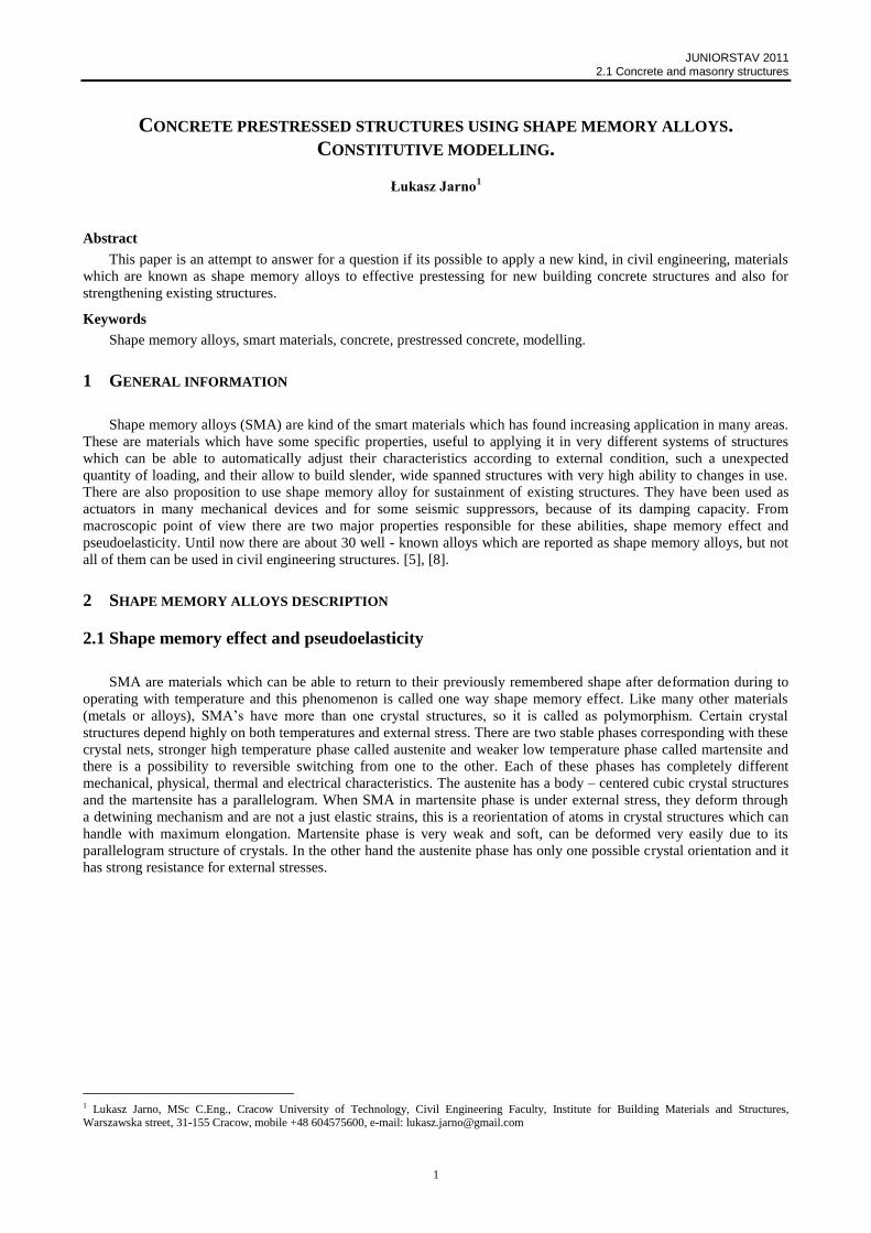
JUNIORSTAV 2011 2.1 Concrete and masonry structures 1 CONCRETE PRESTRESSED STRUCTURES USING SHAPE MEMORY ALLOYS. CONSTITUTIVE MODELLING. Łukasz Jarno 1 Abstract This paper is an attempt to answer for a question if its possible to apply a new kind, in civil engineering, materials which are known as shape memory alloys to effective prestessing for new building concrete structures and also for strengthening existing structures. Keywords Shape memory alloys, smart materials, concrete, prestressed concrete, modelling. 1 GENERAL INFORMATION Shape memory alloys (SMA) are kind of the smart materials which has found increasing application in many areas. These are materials which have some specific properties, useful to applying it in very different systems of structures which can be able to automatically adjust their characteristics according to external condition, such a unexpected quantity of loading, and their allow to build slender, wide spanned structures with very high ability to changes in use. There are also proposition to use shape memory alloy for sustainment of existing structures. They have been used as actuators in many mechanical devices and for some seismic suppressors, because of its damping capacity. From macroscopic point of view there are two major properties responsible for these abilities, shape memory effect and pseudoelasticity. Until now there are about 30 well - known alloys which are reported as shape memory alloys, but not all of them can be used in civil engineering structures. [5], [8]. 2 SHAPE MEMORY ALLOYS DESCRIPTION 2.1 Shape memory effect and pseudoelasticity SMA are materials which can be able to return to their previously remembered shape after deformation during to operating with temperature and this phenomenon is called one way shape memory effect. Like many other materials (metals or alloys), SMA’s have more than one crystal structures, so it is called as polymorphism. Certain crystal structures depend highly on both temperatures and external stress. There are two stable phases corresponding with these crystal nets, stronger high temperature phase called austenite and weaker low temperature phase called martensite and there is a possibility to reversible switching from one to the other. Each of these phases has completely different mechanical, physical, thermal and electrical characteristics. The austenite has a body – centered cubic crystal structures and the martensite has a parallelogram. When SMA in martensite phase is under external stress, they deform through a detwining mechanism and are not a just elastic strains, this is a reorientation of atoms in crystal structures which can handle with maximum elongation. Martensite phase is very weak and soft, can be deformed very easily due to its parallelogram structure of crystals. In the other hand the austenite phase has only one possible crystal orientation and it has strong resistance for external stresses. 1 Lukasz Jarno, MSc C.Eng., Cracow University of Technology, Civil Engineering Faculty, Institute for Building Materials and Structures, Warszawska street, 31-155 Cracow, mobile +48 604575600, e-mail: [email protected]
Transcript of Jarno Lukasz CL
JUNIORSTAV 2011 2.1 Concrete and masonry structures
1
CONCRETE PRESTRESSED STRUCTURES USING SHAPE MEMORY ALLOYS.
CONSTITUTIVE MODELLING.
Łukasz Jarno1
Abstract
This paper is an attempt to answer for a question if its possible to apply a new kind, in civil engineering, materials
which are known as shape memory alloys to effective prestessing for new building concrete structures and also for
strengthening existing structures.
Keywords
Shape memory alloys, smart materials, concrete, prestressed concrete, modelling.
1 GENERAL INFORMATION
Shape memory alloys (SMA) are kind of the smart materials which has found increasing application in many areas.
These are materials which have some specific properties, useful to applying it in very different systems of structures
which can be able to automatically adjust their characteristics according to external condition, such a unexpected
quantity of loading, and their allow to build slender, wide spanned structures with very high ability to changes in use.
There are also proposition to use shape memory alloy for sustainment of existing structures. They have been used as
actuators in many mechanical devices and for some seismic suppressors, because of its damping capacity. From
macroscopic point of view there are two major properties responsible for these abilities, shape memory effect and
pseudoelasticity. Until now there are about 30 well - known alloys which are reported as shape memory alloys, but not
all of them can be used in civil engineering structures. [5], [8].
2 SHAPE MEMORY ALLOYS DESCRIPTION
2.1 Shape memory effect and pseudoelasticity
SMA are materials which can be able to return to their previously remembered shape after deformation during to
operating with temperature and this phenomenon is called one way shape memory effect. Like many other materials
(metals or alloys), SMA’s have more than one crystal structures, so it is called as polymorphism. Certain crystal
structures depend highly on both temperatures and external stress. There are two stable phases corresponding with these
crystal nets, stronger high temperature phase called austenite and weaker low temperature phase called martensite and
there is a possibility to reversible switching from one to the other. Each of these phases has completely different
mechanical, physical, thermal and electrical characteristics. The austenite has a body – centered cubic crystal structures
and the martensite has a parallelogram. When SMA in martensite phase is under external stress, they deform through
a detwining mechanism and are not a just elastic strains, this is a reorientation of atoms in crystal structures which can
handle with maximum elongation. Martensite phase is very weak and soft, can be deformed very easily due to its
parallelogram structure of crystals. In the other hand the austenite phase has only one possible crystal orientation and it
has strong resistance for external stresses.
1 Lukasz Jarno, MSc C.Eng., Cracow University of Technology, Civil Engineering Faculty, Institute for Building Materials and Structures, Warszawska street, 31-155 Cracow, mobile +48 604575600, e-mail: [email protected]
JUNIORSTAV 2011 2.1 Concrete and masonry structures
2
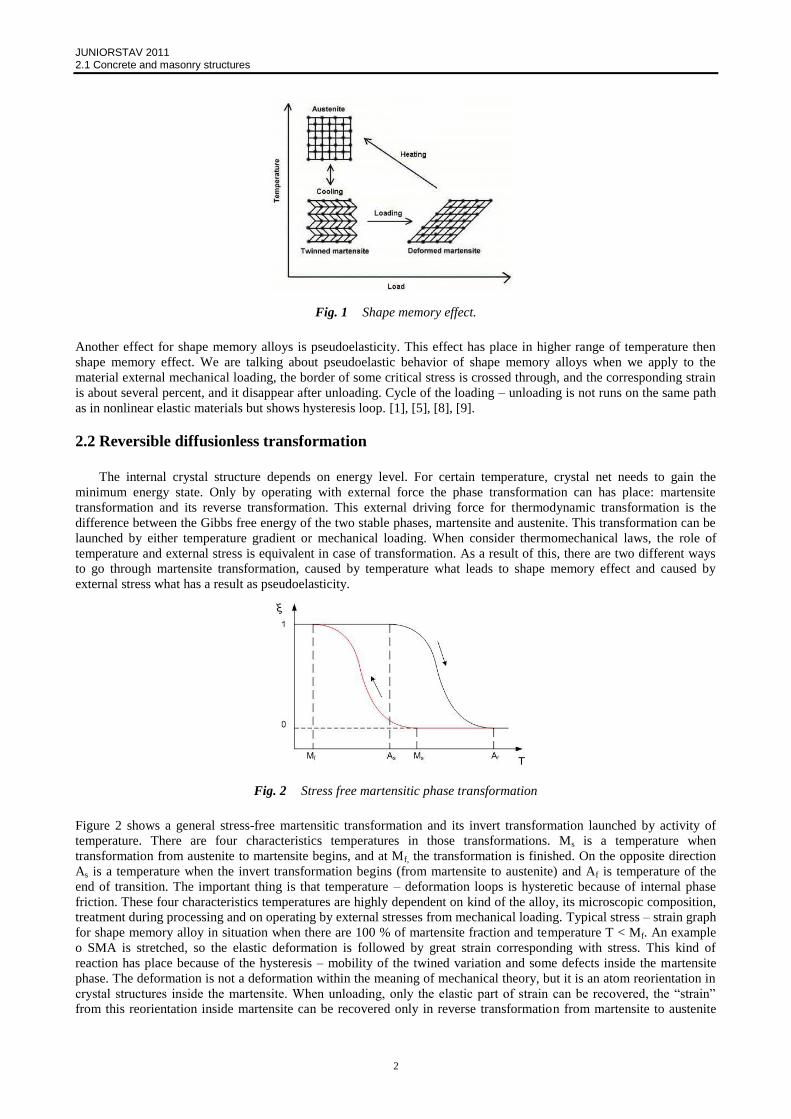
Fig. 1 Shape memory effect.
Another effect for shape memory alloys is pseudoelasticity. This effect has place in higher range of temperature then
shape memory effect. We are talking about pseudoelastic behavior of shape memory alloys when we apply to the
material external mechanical loading, the border of some critical stress is crossed through, and the corresponding strain
is about several percent, and it disappear after unloading. Cycle of the loading – unloading is not runs on the same path
as in nonlinear elastic materials but shows hysteresis loop. [1], [5], [8], [9].
2.2 Reversible diffusionless transformation
The internal crystal structure depends on energy level. For certain temperature, crystal net needs to gain the
minimum energy state. Only by operating with external force the phase transformation can has place: martensite
transformation and its reverse transformation. This external driving force for thermodynamic transformation is the
difference between the Gibbs free energy of the two stable phases, martensite and austenite. This transformation can be
launched by either temperature gradient or mechanical loading. When consider thermomechanical laws, the role of
temperature and external stress is equivalent in case of transformation. As a result of this, there are two different ways
to go through martensite transformation, caused by temperature what leads to shape memory effect and caused by
external stress what has a result as pseudoelasticity.
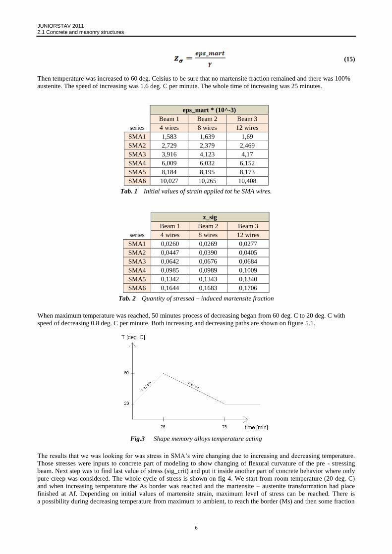
Fig. 2 Stress free martensitic phase transformation
Figure 2 shows a general stress-free martensitic transformation and its invert transformation launched by activity of
temperature. There are four characteristics temperatures in those transformations. Ms is a temperature when
transformation from austenite to martensite begins, and at Mf, the transformation is finished. On the opposite direction
As is a temperature when the invert transformation begins (from martensite to austenite) and Af is temperature of the
end of transition. The important thing is that temperature – deformation loops is hysteretic because of internal phase
friction. These four characteristics temperatures are highly dependent on kind of the alloy, its microscopic composition,
treatment during processing and on operating by external stresses from mechanical loading. Typical stress – strain graph
for shape memory alloy in situation when there are 100 % of martensite fraction and temperature T < Mf. An example
o SMA is stretched, so the elastic deformation is followed by great strain corresponding with stress. This kind of
reaction has place because of the hysteresis – mobility of the twined variation and some defects inside the martensite
phase. The deformation is not a deformation within the meaning of mechanical theory, but it is an atom reorientation in
crystal structures inside the martensite. When unloading, only the elastic part of strain can be recovered, the “strain”
from this reorientation inside martensite can be recovered only in reverse transformation from martensite to austenite

JUNIORSTAV 2011 2.1 Concrete and masonry structures
3
during to heating. If the deformation is too high for the martensite phase capacity (in the meaning of reorientation
mechanism) the permanent plastic deformation takes place. When designing structure it is necessary to remember that
applied stress should not exceed the maximum value corresponding with plastic deformation. [9].
2.3 Other kinds of shape memory alloys
There are also some other kinds of shape memory alloys. Fe-Mn-Si-X alloys is the represent of so called iron
– based shape memory alloys, which are also refers as shape memory steels. The main advantage of these kinds of
alloys is the 60 – 65 % ratio of iron fraction and this is the reason of low cost compares to the Ni – Ti alloys with
remaining high strength and a high Young’s modulus. Nowadays it is not possible to have two – way memory effect in
these kind of iron – based alloys. Corrosion resistance in outdoor environment is not good until addition of about 10%
chromium and nickel, and then the resistance is comparative with stainless steel. There are also other non iron – based
shape memory alloys founded. [5].
3 CONSTITUTIVE MODEL FOR CONCRETE SECTION
3.1 Boltzmann principle for viscoelastic behavior of concrete under continuous loading.
The rules of viscoelastic theory describe well behavior of concrete under long – term loading. However, classical
theory works only with constant loading (applied stress or strain), it was necessary to find a solution in case of
continuous and changeable process of loading. Based on fundamental laws of viscoelastisity is difficult to find this
solution, because of number of variables of the loading history. In case of this finite time period problem, a new
incremental form of constitutive law for material was built. Theory based on Boltzmann principle and linearity, propose
to divide finite period of time on to infinitely small parts, and write is as integral form of superposition principle.
(1)
With as a characteristic function representing material properties. There is more general form of this equation
with including value of the age at loading time t0 :
(2)
Those “action” and “response” express each of them either local strain or local stress, and it is depend on
formulation of equation. A characteristic function in a kernel of integral describes relation between stress and strain and
can be used either as a creep function in creep equation or as relaxation function in relaxation equation.
Creep equation:
(3)
Relaxation equation:
(4)
There are also another formulation (just mathematical rearrangement) of these equations and are called as Volterra
equations but for a purpose of this project are useless so will be ignored. [DES-99], [GWO-99].
Solution of Boltzmann equation for a finite time period is considered:
(5)
where:
is stress corresponding to free strain (thermal, shrinkage).

JUNIORSTAV 2011 2.1 Concrete and masonry structures
4
Fictitious value of elasticity modulus of material:
(6)
And history term:
(7)
Formula (5) shows a linear relation between increase of local strain and stress over a finite time period in uni – axial
state of stress. [2], [4].
4 CONSTITUTIVE MODEL FOR SHAPE MEMORY ALLOYS
4.1 General macroscopic description of the thermo – mechanical behavior of SMA (Lexcellent
model)
Basic assumptions:
Total martensite fraction z was split into two parts:
zT - obtained under pure thermal action, which was self-accommodating, only reorientation of crystals not macroscopic
strain.
zσ – obtained by an external mechanical stress, corresponding to macroscopic strain.
Total strain was divided into two parts, elastic (e) and transformation (tr) strain:
(8)
Form of the Helmholtz free energy was chosen like:
(9)
is the free energy of phase:
1 – parent phase (austenite)
2 – self-accommodating martensite
3 – oriented marteniste
Expression of this energy is:
(10)
Where and are the specific energy and entropy of the α phase.
The constitutive laws resulting from this model are for the forward phase transformation (austenite to martensite):
(11)
(12)
For reverse transformation (martensite to austenite):
(13)

JUNIORSTAV 2011 2.1 Concrete and masonry structures
5
(14)
There are thirteen materials parameters different kinds of alloys determine by some anisothermal and mechanical tests.
5 INTRODUCING OF MODELED OBJECT
The purpose of this thesis is to try preparing a mathematical model for a pre – stressed plain concrete beam
introduced below, using Shape Memory Alloys tendons. The model is build using different models for these two
materials, and connecting them together. For behavior of Shape Memory Alloy wire acting as a tendon in pre – stressed
concrete structure, the Thermo – Mechanical model based on Helmholtz free energy is used. For concrete behavior
under this pre – stressing, model was build in to steps, the first is pure elastic model based on a beam theory, and then
visco – elastic model based on Boltzmann equation was developed.
5.1 General information. Geometry and material properties
The first step of preparation was to calculate the dimensions of three beams. Then to specify the dimensions and
numbers of tendons with Shape Memory Alloys. The best settings were determined by simulations. All data concerning
the wire of SMA’s are obtained from preliminary tests. Each of beams were pre - stressed by 4, 8, and 12 wires.
Geometry and material characteristics (figure 3) in pre-dimensioning procedure were:
- Preliminary dimensions of beam is 48 x 60 x 520 mm, distance between supports l0 = 450mm.
- The class of concrete used to build – up the beam was C20/25, which corresponds to an average strength
and modulus of elasticity 19.9 GPa.
- The wire of SMA’s has a diameter equal 1 mm, and their yield strength was . The modulus
of elasticity for martensitic phase was , and for austenite phase it was
.
- The SMA’s wires were placed in 4 mm from underside surface of the concrete beam.
- Special anchorage was developed because of very small diameter of SMA’s wires, and not allowing them to
slip.
Fig.3 Geometry and cross-section of beam
5.2 Shape memory alloys behavior
The first step was to find a model for Shape memory alloys behavior. The one chosen was thermo – mechanical
model developed by S. Leclercq and C. Lexcellent and programmed by Hanh Tran. This is a termo – dynamic
constitutive model, basing on thermo – dynamic laws. The model describes changes of Helmholtz free energy to
determine participation of each phase during transformation. Basic assumptions and equations for this model are
explained in chapter 4.1. In our case it was not necessary to programming the whole cycle of transformation. The SMA
model was divided onto two parts. First part was build to simulate increase of temperature, producing austenite fraction
and second part for decrease of temperature. Input data for model itself is initial strain which was applied to wires in
martensite phase at ambient temperature. Type of alloy used allows to keep either martensite or austenite phase at room
temperature. It was 49.2 % Titanium and 50.8% Nickel alloy.
Programming cycle is started at room temperature (20 deg. C) with 100 % martensite wires anchored and stretched
with certain strains (eps_mart) which are presented in table 1. Knowing these values of initial strains and uniaxial
pseudoelastic strain equals 0.061 fraction of stress induced martensite was calculated as (values are shown in table 2)
JUNIORSTAV 2011 2.1 Concrete and masonry structures
6
(15)
Then temperature was increased to 60 deg. Celsius to be sure that no martensite fraction remained and there was 100%
austenite. The speed of increasing was 1.6 deg. C per minute. The whole time of increasing was 25 minutes.
eps_mart * (10^-3)
Beam 1 Beam 2 Beam 3
series 4 wires 8 wires 12 wires
SMA1 1,583 1,639 1,69
SMA2 2,729 2,379 2,469
SMA3 3,916 4,123 4,17
SMA4 6,009 6,032 6,152
SMA5 8,184 8,195 8,173
SMA6 10,027 10,265 10,408
Tab. 1 Initial values of strain applied tot he SMA wires.
z_sig
Beam 1 Beam 2 Beam 3
series 4 wires 8 wires 12 wires
SMA1 0,0260 0,0269 0,0277
SMA2 0,0447 0,0390 0,0405
SMA3 0,0642 0,0676 0,0684
SMA4 0,0985 0,0989 0,1009
SMA5 0,1342 0,1343 0,1340
SMA6 0,1644 0,1683 0,1706
Tab. 2 Quantity of stressed – induced martensite fraction
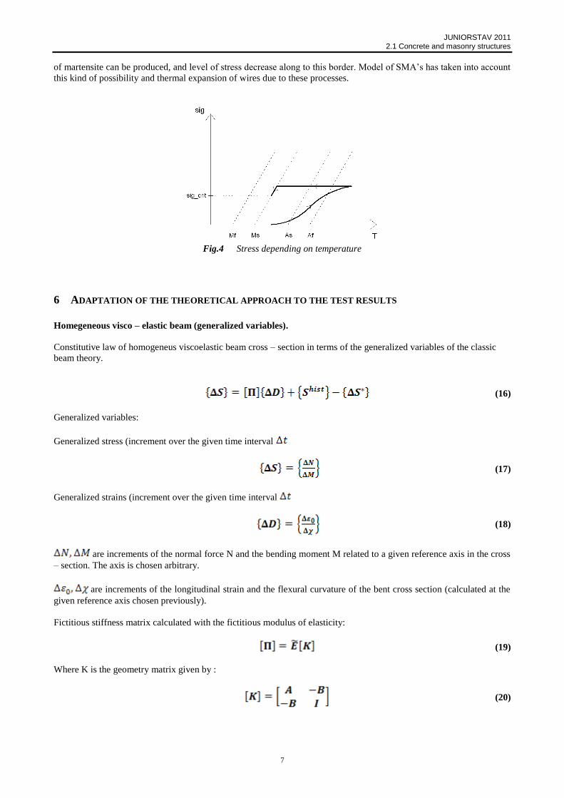
When maximum temperature was reached, 50 minutes process of decreasing began from 60 deg. C to 20 deg. C with
speed of decreasing 0.8 deg. C per minute. Both increasing and decreasing paths are shown on figure 5.1.
Fig.3 Shape memory alloys temperature acting
The results that we was looking for was stress in SMA’s wire changing due to increasing and decreasing temperature.
Those stresses were inputs to concrete part of modeling to show changing of flexural curvature of the pre - stressing
beam. Next step was to find last value of stress (sig_crit) and put it inside another part of concrete behavior where only
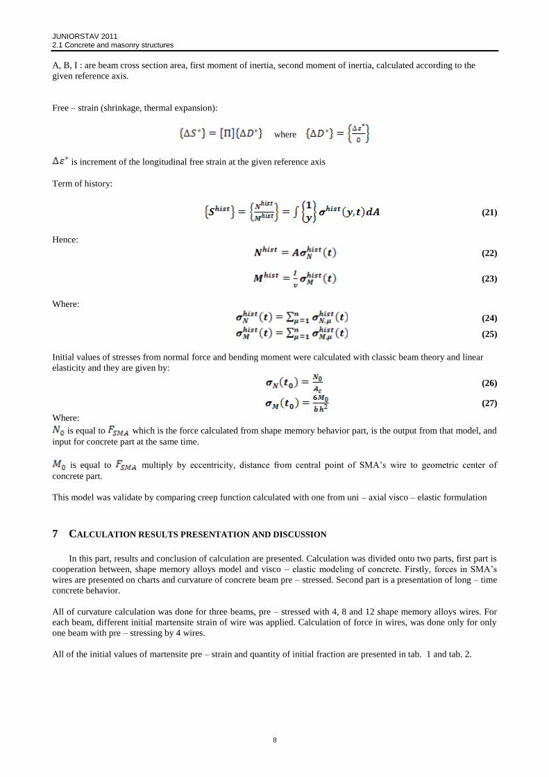
pure creep was considered. The whole cycle of stress is shown on fig 4. We start from room temperature (20 deg. C)
and when increasing temperature the As border was reached and the martensite – austenite transformation had place
finished at Af. Depending on initial values of martensite strain, maximum level of stress can be reached. There is
a possibility during decreasing temperature from maximum to ambient, to reach the border (Ms) and then some fraction
JUNIORSTAV 2011 2.1 Concrete and masonry structures
7
of martensite can be produced, and level of stress decrease along to this border. Model of SMA’s has taken into account
this kind of possibility and thermal expansion of wires due to these processes.
Fig.4 Stress depending on temperature
6 ADAPTATION OF THE THEORETICAL APPROACH TO THE TEST RESULTS
Homegeneous visco – elastic beam (generalized variables).
Constitutive law of homogeneus viscoelastic beam cross – section in terms of the generalized variables of the classic
beam theory.
(16)
Generalized variables:
Generalized stress (increment over the given time interval
(17)
Generalized strains (increment over the given time interval
(18)
are increments of the normal force N and the bending moment M related to a given reference axis in the cross
– section. The axis is chosen arbitrary.
are increments of the longitudinal strain and the flexural curvature of the bent cross section (calculated at the
given reference axis chosen previously).
Fictitious stiffness matrix calculated with the fictitious modulus of elasticity:
(19)
Where K is the geometry matrix given by :
(20)
JUNIORSTAV 2011 2.1 Concrete and masonry structures
8
A, B, I : are beam cross section area, first moment of inertia, second moment of inertia, calculated according to the
given reference axis.
Free – strain (shrinkage, thermal expansion):
where
is increment of the longitudinal free strain at the given reference axis
Term of history:
(21)
Hence:
(22)
(23)
Where:
(24)
(25)
Initial values of stresses from normal force and bending moment were calculated with classic beam theory and linear
elasticity and they are given by:
(26)
(27)
Where:
is equal to which is the force calculated from shape memory behavior part, is the output from that model, and
input for concrete part at the same time.
is equal to multiply by eccentricity, distance from central point of SMA’s wire to geometric center of
concrete part.
This model was validate by comparing creep function calculated with one from uni – axial visco – elastic formulation
7 CALCULATION RESULTS PRESENTATION AND DISCUSSION
In this part, results and conclusion of calculation are presented. Calculation was divided onto two parts, first part is
cooperation between, shape memory alloys model and visco – elastic modeling of concrete. Firstly, forces in SMA’s
wires are presented on charts and curvature of concrete beam pre – stressed. Second part is a presentation of long – time
concrete behavior.
All of curvature calculation was done for three beams, pre – stressed with 4, 8 and 12 shape memory alloys wires. For
each beam, different initial martensite strain of wire was applied. Calculation of force in wires, was done only for only
one beam with pre – stressing by 4 wires.
All of the initial values of martensite pre – strain and quantity of initial fraction are presented in tab. 1 and tab. 2.

JUNIORSTAV 2011 2.1 Concrete and masonry structures
9
Fig.5 Forces in Shape memory alloys wires
Figure 5 presents changes in forces, during increasing temperature from room (20 deg.C) to maximum temperature (60
deg.C), and then decreasing to room temperature again. Each force, starting with Force 1, correspond to SMA series
with specific initial martensite strain. First increasing part of diagram is due to martensite to austenite transformation
which is done at the maximum point. Then, next is a decreasing part, correspond with thermal expansion due to
increasing temperature from austenite transformation finish temperature to the maximum. This maximum was chosen as
60 deg. C to be sure that all transformation was done. Next part is decreasing temperature and increasing force because
of thermal contraction of the wires. As we can see, on the diagram, when consider Force 4, which corresponding to
eps_mart equal about 6 promiles, the “new” part of diagram is shown about 26 deg.C the force is decreasing to a value
of 780,67 N. Afterwards, forces 5 and 6 are below force 4 but ending about the same value, 779,28 N and 740,95 N.
The decreasing slop at the and of force 4 is because reaching a border for martensite start transformation and some of
martensite fraction was produced in our case this phenomena is consider as instant pre – stressing loss, which has to be
taking into account during calculation and designing process. It was unknown why force 5 and 6 are lower than force 4.
It is explained using figure 6.
Fig.6 Forces in SMA’s wires with maximum temperature 100 deg.C
As we can see on figure 6, maximum temperature was change to 100 deg. C. Then forces 4, 5 and 6 at the end point
have almost the same value. It is causing by some production of martensite which has result of decreasing slope at the
end. When compare Fig. 5 and Fig 6 we can see that forces 5 and 6 now are above force 4. This is a proof that
previously with maximum temperature equals to 60 deg.C in case of martensite pre – strain about 6 promiles and above
transformation wasn’t completed. Temperature didn’t crossed a finish martensite to austenite finish border.
Up to SMA 3 research serie, results from experiments and from the model are comparable, especially for 4 wires case.
For SMA 3 and next series results are good for 4 wires, but for 8 and 12 are overestimated. Curvature didn’t increasing
during increasing of martensite pre – strain, the are still the same two reasons of that behavior, production of martensite
because of crossing the border of martensite transformation start and not completed austenite transformation.

JUNIORSTAV 2011 2.1 Concrete and masonry structures
10
Literature
[1] Z. Deng, Q. Li, H. Sun - Behavior of concrete beam with embedded shape memory alloy wires. Engineering
Structures, October 2006, 28(12), 1691-1697
[2] J.-F. Destrebecq, P. Gwoździewicz, B. Jurkiewicz – Time analysis of prestressed concrete members subjected
to axial plus shear loads. Wroclaw, Poland 1999.
[3] B. Gabry, C. Lexcellent, V.H. No, S. Miyazaki – Thermodynamic modeling of the recovery strains of sputter-
deposited shape memory alloys Ti – Ni and Ti – Ni – Cut thin films. Thin Solid Films, May 2000.
[4] P. Gwoździewicz – Time analysis of prestressed concrete structures with accounting for Bendig and shear
effects. Clermont – Ferrand 1999.
[5] L. Janke, C. Czaderski, M. Motavalli, J. Ruth - Applications of shape memory alloys in civil engineering
structures: Overviews, limits and new ideas. Materials and Structures, June 2005, 38(5), 578-592
[6] B. Jurkiewicz, J-F. Destrebecq, A. Vergne – Incremental analysis of time – dependent effects in composite
structures. Computers & Structures 73 (1999).
[7] C. Lexcellent, S. Leclercq – A general macroscopic description of the thermomechanical behavior of shape
memory alloys. November 1995
[8] G. Song, N. Ma, H.N. Li - Applications of shape memory alloys in civil structures. Engineering Structures,
July 2006, 28(9), 1266-1274
[9] A. Ziółkowski – Pseudosprężystość stopów z pamięcią kształtu. Badania doświadczalne i opis teoretyczny.
Prace IPPT. Czerwiec 2006.
Reviewer
Piotr Gwoździewicz, PhD. C. Eng., Cracow University of Technology, Civil Engineering Faculty, Institute for
Building, Materials and Structures, Warszawska street 24, 31-155 Cracow.