CL 50 Solutions Guide for Decentralized PV Systems - Schneider ...
88
CL 30 Inverters Solutions Guide for Decentralized PV Systems (IEC Version) 990-6395 September 2020 http://solar.schneider-electric.com/
-
Upload
khangminh22 -
Category
Documents
-
view
2 -
download
0
Transcript of CL 50 Solutions Guide for Decentralized PV Systems - Schneider ...

CL 30 InvertersSolutions Guide for Decentralized PV Systems(IEC Version)990-6395
September 2020
http://solar.schneider-electric.com/

Copyright © 2020 Schneider Electric. All Rights Reserved.
PSSE is a trademark or registered trademark of Siemens Product Lifecycle Management Software Inc. or its subsidiaries inthe United States and in other countries. PVsyst is used under license from PVsyst SA. All other trademarks are owned bySchneider Electric Industries SAS or its affiliated companies.
Exclusion for Documentation
UNLESSSPECIFICALLYAGREED TO INWRITING, SELLER
(A) MAKESNOWARRANTYASTOTHEACCURACY, SUFFICIENCYOR SUITABILITYOF ANYTECHNICALOROTHER INFORMATION
PROVIDED IN ITSMANUALSOROTHER DOCUMENTATION;
(B) ASSUMESNORESPONSIBILITYOR LIABILITYFOR LOSSES, DAMAGES, COSTSOR EXPENSES,WHETHER SPECIAL, DIRECT,
INDIRECT, CONSEQUENTIALOR INCIDENTAL,WHICHMIGHT ARISEOUT OF THEUSEOF SUCH INFORMATION. THEUSEOF ANYSUCH
INFORMATIONWILL BEENTIRELYAT THEUSER’SRISK; AND
(C) REMINDSYOU THAT IF THISMANUAL IS IN ANYLANGUAGEOTHER THAN ENGLISH, ALTHOUGH STEPSHAVEBEEN TAKEN TO
MAINTAIN THEACCURACYOF THETRANSLATION, THEACCURACYCANNOT BEGUARANTEED. APPROVED CONTENT ISCONTAINED
WITH THEENGLISH LANGUAGEVERSIONWHICH ISPOSTED AT http://solar.schneider-electric.com/.
Document Number: 990-6395 Date: September 2020
Contact Information
For country-specific details, please contact your local Schneider Electric Sales Representative or visit the SchneiderElectric Solar Business website at: http://solar.schneider-electric.com/
Information About Your System
As soon as you open your product, record the following information and be sure to keep your proof of purchase.
Serial Number ____________________________
Product Number ____________________________
Purchased From ____________________________
Purchase Date ____________________________

About
PurposeThe purpose of this solutions guide is to provide explanations for designing a de-centralizedPV system using CL 30 PV inverters and Balance of System (BOS) components offered bySchneider Electric. It describes the interfaces required to implement this architecture andrules to design the solution.
ScopeThis solutions guide provides technical information and design recommendations. Itexplains the design requirements of each system component and provides detailedexplanations about how to select these components.
The information provided in this guide does not modify, replace, or waive any instruction orrecommendations described in theCL 30 QuickStart Guide (document number 990-91393)orCL 30Owner's Guide (document number 990-91392), including warranties of SchneiderElectric products. Always consult the product-specific installation or owner’s guides of anySchneider Electric product when installing and using that product in decentralized PVsystem design using CL 30 inverters.
DANGERHAZARD OF ELECTRIC SHOCK, EXPLOSION, ARC FLASH, AND FIRE
This document is in addition to, and incorporates by reference, the relevant product manualsfor CL 30 PV inverters. Before reviewing this document, you must read the relevant productmanuals. Unless specified, information on safety, specifications, installation and operation isas shown in the primary documentation received with the product. Ensure you are familiar withthat information before proceeding.
Failure to follow these instructions will result in death or serious injury.
For help with designing a PV power plant, contact your Schneider Electric SalesRepresentative or visit the Schneider Electric website for more information atwww.solar.schneider-electric.com.


AudienceThis guide is intended for system integrators or engineers who plan to design a de-centralized PV system using Schneider Electric CL 30 inverters and other SchneiderElectric offered equipment.
Information in this solutions guide is intended for qualified personnel. Qualified personnelhave training, knowledge, and experience in:
n Analyzing application needs and designing PV de-centralized systems with transformer-less string inverters.
n Installing electrical equipment and PV power systems (up to 1000 V).
n Applying all applicable (local and international) installation codes.
n Analyzing and reducing the hazards involved in performing electrical work.
n Selecting and using Personal Protective Equipment (PPE).
Abbreviations and AcronymsAC Alternating current
ACB Air circuit breaker
BOS Balance of systems
DC Direct current
LV Low voltage
LVRT Low voltage ride through
MCB Miniature circuit breaker
MCCB Molded case circuit breaker
MET Meteorological file type
MPP Maximum power point
MPPT Maximum power point trackers
MV Medium voltage
PCC Point of common coupling
POC Point of connection
PV Photovoltaic (solar)
RCD Residual current device
RCMU Residual current monitoring unit
ROI Return on investment
SCADA Supervisory control and data acquisition
SPD Surge protection device
STC Standard test conditions
TMY Typical meteorological year

Related InformationFindmore information about Schneider Electric, as well as its products and services at:www.schneider-electric.com.
For specific information about Schneider Electric Solar products, visit:http://solar.schneider-electric.com/

Safety InformationImportant Information
Read these instructions carefully and look at the equipment to become familiar with thedevice before trying to install, operate, service or maintain it. The following specialmessages may appear throughout this documentation or on the equipment to warn ofpotential hazards or to call attention to information that clarifies or simplifies a procedure.
The addition of either symbol to a “Danger” or “Warning” safety labelindicates that an electrical hazard exists which will result in personalinjury if the instructions are not followed.
This is the safety alert symbol. It is used to alert you to potential personalinjury hazards. Obey all safety messages that follow this symbol to avoidpossible injury or death.
DANGERDANGER indicates a hazardous situation which, if not avoided,will result in death or seriousinjury.
WARNINGWARNING indicates a hazardous situation which, if not avoided, could result in death orserious injury.
CAUTIONCAUTION indicates a hazardous situation which, if not avoided, could result inminor ormoderate injury.
NOTICENOTICE is used to address practices not related to physical injury.
Please NoteElectrical equipment should be installed, operated, serviced, andmaintained only byqualified personnel. No responsibility is assumed by Schneider Electric for anyconsequences arising out of the use of this material.
A qualified person is one who has skills and knowledge related to the construction,installation, and operation of electrical equipment and has received safety training torecognize and avoid the hazards involved. For more information, seeAudience.
990-6395 7
CL 30 Solutions Guide for Decentralized PV Systems
Product Safety InformationDANGER
HAZARD OF ELECTRIC SHOCK, EXPLOSION, ARC FLASH, AND FIRE
This document is in addition to, and incorporates by reference, the relevant product manualsfor CL 30 PV inverters. Before reviewing this document, you must read the relevant productmanuals. Unless specified, information on safety, specifications, installation and operation isas shown in the primary documentation received with the product. Ensure you are familiar withthat information before proceeding.
Failure to follow these instructions will result in death or serious injury.
DANGERHAZARD OF ELECTRIC SHOCK AND FIRE
Installation, including wiring, must be done by qualified personnel to ensure compliance withall applicable installation and electrical codes, including relevant local, regional, and nationalregulations. Installation instructions are not covered in this Solution Guide, but are included inthe relevant product manuals for the CL 30 inverter. Those instructions are provided for use byqualified installers only.
Failure to follow these instructions will result in death or serious injury.
990-6395 8
CL 30 Solutions Guide for Decentralized PV Systems

ContentsAbout 3
Purpose 3
Scope 3
Audience 5Abbreviations and Acronyms 5
Related Information 6
Safety Information 7Product Safety Information 8Introduction 15
Advantages of a Decentralized PV Architecture 16
Why Decentralize PV Solutions? 16
About CL 30 PV Inverters 18
Key Specifications of the CL 30 Inverter 19
Decentralized Systems 21PV SystemModeling 22
PV Site 22
PV System 22
Losses 23
PV System Design Using CL 30 Inverters 23
Building Blocks of a Decentralized PV System 23
Inverter Positioning and Location 25
Option 1 – Inverters installed next to PV modules with first level ACCombiners 25
Option 2 – Inverters installed next to AC combiner groups 26
Option 3 – Inverters installed next to PV modules without first-level ACcombiners 27
Option 4 – Inverters installed next to LV/MV transformer 28
System Design 31DC System Design 32
String and Array Sizing Rules 32
UseCase Example 33
Optimum DC-AC ratio 36
Recommended Basic Rules for String Formation 36
AC System Design 38
Circuit Breaker Coordination 39
AC System Component Design 41
AC Switch Box (optional) 41
CL 30 Solutions Guide for Decentralized PV Systems
990-6395 9
AC Cable Sizing 42
AC Combiner Box 43
AC Re-combiner Box 53
Important Aspects of a Decentralized System Design 63
Selection of Residual Current Monitoring Device (RCD) 63
Selection of a Surge Protection Device 64
Earthing/Grounding System Design 70
Transformer Selection 74
Monitoring System Design 75
Grid Connection 76
Role of Circuit Impedance in Parallel Operation of Multiple CL 30 PV Inverters 77
Layout Optimization 78Layout Design Rules 79
Frequently Asked Questions 80FAQ 81
Planning and Installation FAQ 81
Downloading Files FAQ 82
Wiring and Cabling FAQ 83
Transformer FAQ 84
Specification FAQ 84
De-rating FAQ 86
CL 30 Solutions Guide for Decentralized PV Systems
10 990-6395

FiguresFigure 1 CL 30 PV inverter 18
Figure 2 CL 30 block diagram 19
Figure 3 Option 1: Standard block diagram 26
Figure 4 Option 2: Standard block diagram 27
Figure 5 Option 3: Standard block diagram 28
Figure 6 Option 4: Standard block diagram 29
Figure 7 Summary information 39
Figure 8 Optional AC switch box diagram 41
Figure 9 Example circuit with 100m cable 45
Figure 10 Example circuit with 250m cable 46
Figure 11 Recommended block architecture with five input AC Combiners 52
Figure 12 Breaker selection with 1000 kVA transformer 57
Figure 13 Breaker selection with 800 kVA transformer 57
Figure 14 Additional SPD requirements 66
Figure 15 Installation of SPDs 67
Figure 16 Coordination of SPDs with disconnection devices 68
Figure 17 TN-S Earthing System, 3-Phase + Neutral 69
Figure 18 TN-C Earthing System, 3-Phase 70
Figure 19 MEN Earthing System, 3-Phase 70
Figure 20 Reverse current 72
Figure 21 Earthing circuit connections 73
Figure 22 Parallel connection of multiple inverters to transformer winding 74
Figure 23 Modbus RS485 76
Figure 24 Installation space between inverters 82
Figure 25 Power derating due to temperature 86
CL 30 Solutions Guide for Decentralized PV Systems
990-6395 11


TablesTable 1 Example of highest string sizing ratios 35
Table 2 CL 30 inverter suggested DC oversizing range 36
Table 3 Discrimination data (IEC 60947-2) 40
Table 4 Components needed for AC switch box configuration 42
Table 5 AC cable length and size 43
Table 6 Voltage factor c 48
Table 7 NG125N specifications 50
Table 8 Interpact INS320 specifications 51
Table 9 Voltage factor c 54
Table 10 Compact NSX specifications 58
Table 11 Masterpact NWH1 specifications 59
Table 12 SPD specifications 65
Table 13 Power loss values for transformer ratings and impedance 75
CL 30 Solutions Guide for Decentralized PV Systems
990-6395 13


Introduction
Introduction CL 30 Solutions Guide for Decentralized PV Systems
1
Advantages of a Decentralized PV Architecture 16
Why Decentralize PV Solutions? 16
About CL 30 PV Inverters 18
Key Specifications of the CL 30 Inverter 19
What's in This Chapter?

Advantages of a Decentralized PV ArchitectureDecentralized PV systems are designed by installing small power inverters throughout aPV field area, in the vicinity of PV modules, to allow for connection of the strings assimply as possible.
Advantages of a decentralized PV architecture include:
n Easy adaptation of the solution to roof or plant specificities
n Easy installation of the inverters on roof or plant
n Easy electrical protection
n Easy connection to the grid
n Easy monitoring
n Easy systemmaintenance
n Greater energy production
Why Decentralize PV Solutions?The advantages of decentralized system design are:
1. Lower cost and ease of installation:
a. Smaller units are lighter weight and easier to handle.
b. Inverters can bemounted directly on or underneath the photovoltaic (PV)mounting structures.
c. Smaller units are easy and inexpensive to ship and can be installed by twopeople without heavy and expensive cranes.
d. No concretemounting pad required; unit mounted directly to a wall, pole or PVframe racking.
e. Cost effective: No need to use a DC Combiner or separate DC disconnect(except when required by local installation codes).
2. Easy to service and increased energy harvest:
a. If the inverter detects a failure event, only part of the field is affected versus alarge portion of the field when a large inverter is used, whichmeans minimaldown time and greater return on investment (ROI).
b. Multiple MPPTs allow greater installation flexibility and increased PV harvest.
c. High efficiency for greater harvest.
3. Easy electrical protection:
a. DC circuit length reduced up to the racking with short runs to inverters locatednext to PV panel strings.
b. Lower DC cable losses.
c. AC circuit is expanded, allowing for additional AC equipment, which istypically less expensive than DC equipment and available quickly and easily.
CL 30 Solutions Guide for Decentralized PV Systems Introduction
16 990-6395

4. Easy adaptation to roof specificities:
a. Ability to support different roof plan orientations.
b. Heterogeneous layout of the strings is facilitated (unbalanced arrays).
c. Obstacles on roofs and shadows or shading have less production impact.
5. Easy connection to the grid:
a. CL 30 offers connectivity to both STAR and DELTA type windings.
b. Multiple inverters could be paralleled to a single transformer for bigger powerblocks.
6. Easy monitoring and Configuration:
a. ModBus RS485 daisy chain capability.
b. Monitoring ready with Conext Gateway .
c. Easy configuration and firmware upgrade tools, such as the Insight MobileApp.
Introduction CL 30 Solutions Guide for Decentralized PV Systems
990-6395 17
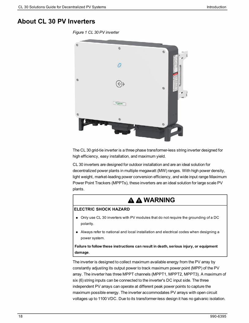
About CL 30 PV InvertersFigure 1 CL 30 PV inverter
The CL 30 grid-tie inverter is a three phase transformer-less string inverter designed forhigh efficiency, easy installation, andmaximum yield.
CL 30 inverters are designed for outdoor installation and are an ideal solution fordecentralized power plants in multiple megawatt (MW) ranges. With high power density,light weight, market-leading power conversion efficiency, and wide input rangeMaximumPower Point Trackers (MPPTs), these inverters are an ideal solution for large scale PVplants.
WARNINGELECTRIC SHOCK HAZARD
n Only use CL 30 inverters with PV modules that do not require the grounding of a DCpolarity.
n Always refer to national and local installation and electrical codes when designing apower system.
Failure to follow these instructions can result in death, serious injury, or equipmentdamage.
The inverter is designed to collect maximum available energy from the PV array byconstantly adjusting its output power to track maximum power point (MPP) of the PVarray. The inverter has threeMPPT channels (MPPT1, MPPT2, MPPT3). A maximum ofsix (6) string inputs can be connected to the inverter's DC input side. The threeindependent PV arrays can operate at different peak power points to capture themaximum possible energy. The inverter accommodates PV arrays with open circuitvoltages up to 1100 VDC. Due to its transformer-less design it has no galvanic isolation.
CL 30 Solutions Guide for Decentralized PV Systems Introduction
18 990-6395

Figure 2 CL 30 block diagram
Key Specifications of the CL 30 Invertern CL 30 inverter: 29.9 kVA, 29.9 kW (1000 VDC systems)
n PV compatibility: Designed to work with 1100 V floating PV systems
n AC wiring output: 400 V, three-phase STAR or DELTA typ
n OperatingMPPT voltage: 200 V–1000 V
n Full PowerMPPT voltage: 550 V–850 V
n Over-panelling: supports high DC/AC over-panelling ratio (up to 1.5)
n Energy harvest (MPPT) efficiency: >99%
n Maximum power conversion efficiency: ~98.6%
n Power factor adjustment range: 0.8 capacitive to 0.8 inductive
n AC output current distortion: Low — (THD < 3%)@ nominal power
n Protection class: IP66 (electronics) protection class for installation in outdoorenvironments
n Operating temperature range: -30 to 60° C
n Inputs: six (6) string inputs with MC4 type connectors
n Modbus RS485 Loop-in Loop-out
n Firmware upgrade tools, such as the Insight Mobile App
Introduction CL 30 Solutions Guide for Decentralized PV Systems
990-6395 19

n Integrated DC switch
n Built-in stringmonitoring
n Type 2 AC and Type 2 DC Surge Protection (SPD)
n Six (6) DC string inputs with MC4 type connectors (mating part supplied with inverter)
CL 30 Solutions Guide for Decentralized PV Systems Introduction
20 990-6395

Decentralized Systems
Decentralized Systems CL 30 Solutions Guide for Decentralized PV Systems
2
PV System Modeling 22
PV Site 22
PV System 22
Losses 23
PV System Design Using CL 30 Inverters 23
Building Blocks of a Decentralized PV System 23
Inverter Positioning and Location 25
Option 1 – Inverters installed next to PV modules with first level AC Combiners 25
Option 2 – Inverters installed next to AC combiner groups 26
Option 3 – Inverters installed next to PV modules without first-level AC combiners 27
Option 4 – Inverters installed next to LV/MV transformer 28
What's in This Chapter?

PV System ModelingImportant aspects of PV systemmodeling are:
n Site
n Type of system
n Losses
PV SiteIt is very important to interpret site conditions carefully andmodel the exact conditions inPV system design software. These conditions include, but are not limited to:
n shadow from surroundings
n ground slope
n layout boundary conditions
n rain water catchment areas
n PV module string arrangements
n shape of the layout
n obstacles (such as power lines, gas pipelines, rivers, and archaeological conditions)
Once all possible factors affecting the PV system design are listed and assessed,capacity of the selected PV installation site can be determined for further processing.Government agency permits and statutory clearances also depend on these factors. Thecost of the land and overall PV system varies with respect to these conditions.
PV SystemPV system installation can be grid tied, stand alone, or hybrid. It could be installed on aroof, car park, or facade, or it could be groundmounted. It may or may not have a trackingoption installed.
Modeling of the system has to be planned using themost suitable option andmustconsider themain purpose of the installation.
Quantum and usage of generated electricity is a very important factor when deciding onthe type of system. A good system design has high efficiency, flexibility, and amodularapproach for faster and quicker installations. Large scale PV power plant design needs tocarefully consider the response of the PV plant power output against dynamic conditionsof the grid. Faster power curtailment or fault ride through capability of the inverter isimportant.
Selection of major components like PV modules, inverters, andmounting structurescomprises most of the systemmodeling and design. These three components also affectthe cost, output, and efficiency of the system.
A block of 897 kW (30 x 29.9) for groundmount solutions and 239.2 kW (8 x 29.9) forrooftop solutions can be configured and thenmultiplied several times to achieve therequired capacity. A standard block is designed once for all respective components andrepeated several times in the installation. This reduces the effort and time to design the
CL 30 Solutions Guide for Decentralized PV Systems Decentralized Systems
22 990-6395
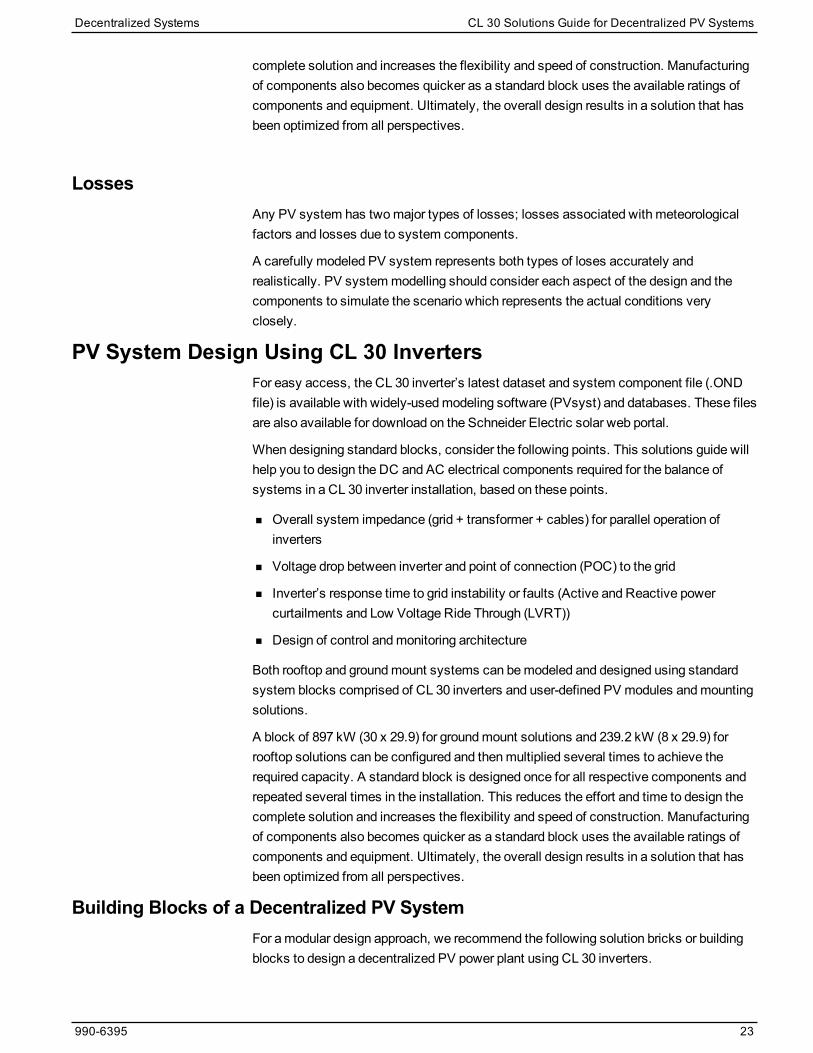
complete solution and increases the flexibility and speed of construction. Manufacturingof components also becomes quicker as a standard block uses the available ratings ofcomponents and equipment. Ultimately, the overall design results in a solution that hasbeen optimized from all perspectives.
LossesAny PV system has twomajor types of losses; losses associated with meteorologicalfactors and losses due to system components.
A carefully modeled PV system represents both types of loses accurately andrealistically. PV systemmodelling should consider each aspect of the design and thecomponents to simulate the scenario which represents the actual conditions veryclosely.
PV System Design Using CL 30 InvertersFor easy access, the CL 30 inverter’s latest dataset and system component file (.ONDfile) is available with widely-usedmodeling software (PVsyst) and databases. These filesare also available for download on the Schneider Electric solar web portal.
When designing standard blocks, consider the following points. This solutions guide willhelp you to design the DC and AC electrical components required for the balance ofsystems in a CL 30 inverter installation, based on these points.
n Overall system impedance (grid + transformer + cables) for parallel operation ofinverters
n Voltage drop between inverter and point of connection (POC) to the grid
n Inverter’s response time to grid instability or faults (Active and Reactive powercurtailments and Low Voltage Ride Through (LVRT))
n Design of control andmonitoring architecture
Both rooftop and groundmount systems can bemodeled and designed using standardsystem blocks comprised of CL 30 inverters and user-defined PV modules andmountingsolutions.
A block of 897 kW (30 x 29.9) for groundmount solutions and 239.2 kW (8 x 29.9) forrooftop solutions can be configured and thenmultiplied several times to achieve therequired capacity. A standard block is designed once for all respective components andrepeated several times in the installation. This reduces the effort and time to design thecomplete solution and increases the flexibility and speed of construction. Manufacturingof components also becomes quicker as a standard block uses the available ratings ofcomponents and equipment. Ultimately, the overall design results in a solution that hasbeen optimized from all perspectives.
Building Blocks of a Decentralized PV SystemFor amodular design approach, we recommend the following solution bricks or buildingblocks to design a decentralized PV power plant using CL 30 inverters.
Decentralized Systems CL 30 Solutions Guide for Decentralized PV Systems
990-6395 23

Brick Description Supplier Model
Inverters CL 30 Schneider Electric PVSCL30E
AC switch box (optional)
AC circuit breaker / switch Schneider Electric INS63Switch Disconnect
Surge protection device Schneider Electric iPRD40 series
Terminal blocks Schneider Electric Linergy-NSYTRV
Enclosure Third-party ---
AC combiner box (5inputs)
AC circuit breaker (MCB) Schneider ElectriciC60, iC120, NG125N-63A,Curve C ,4P(25kA)CB
Terminal blocks Schneider Electric Linergy-NSYTRV
Main bus bar Third-party Copper, 400V, 25kA
AC disconnect switch Schneider Electric INS320-320A type switch-disconnect.4P
Grounding terminal and bus Third-party ---
Surge protection device Schneider Electric At Main Bus - iPRD40r
Enclosure Either ---
AC re-combiner box (6inputs)
AC circuit breaker (MCCB) Schneider Electric
Compact NSX400N- 320A with Micrologic1.3, 3P
Terminal blocks Schneider ElectricLinergy-NSYTRV
Main bus bar Third-party Copper, 400V, 70kA
AC air circuit breaker Schneider Electric NW20H1 - ACB
Grounding terminal and bus Third-party ---
Surge protection device(optional)
Schneider ElectriciPRD 40r
EnclosureSchneider Electricor third-party
---
TransformerLV-MV Dyn11 oil cooled / drytype transformer
Schneider Electric1000kVA, oil immersed or dry type, Z < 6%,20000V/400V, Dyn11
MV ring main systemMV RM6 or Flusarc typeswitchgear units
Schneider Electric RM6 NE-IDI or Flusarc CB-C, 24kV, 16kA
DC solar PV cables DC UV protected cables Third-party ---
AC cables AC LV and MV cables Third-party ---
Communication andmonitoring system
Monitoring and control Schneider ElectricSchneider Electric options, such as ConextGateway .
Earthing systemBonding cableClamps and Connectors
Third-party ---
CL 30 Solutions Guide for Decentralized PV Systems Decentralized Systems
24 990-6395

Inverter Positioning and Location
DANGERHAZARD OF ELECTRIC SHOCK AND FIRE
Installation, including wiring, must be done by qualified personnel to ensure compliancewith all applicable installation and electrical codes, including relevant local, regional, andnational regulations. Installation instructions are not covered in this Solutions Guide, but areincluded in the relevant product manuals for the CL 30 inverter. Those instructions areprovided for use by qualified installers only.
Failure to follow these instructions will result in death or serious injury.
PV system design and efficiency with CL 30 PV inverters aremost effected by thelocation of inverter in the complete solution. Balance of system components and inverterwiring box models are variable depending on the location of the inverters and the length ofpower cables connecting them with AC combiners and re-combiners.
Four types of standard design blocks fit almost all types of installations. Each option hasadvantages and disadvantages with respect to other installations, but for each instancelisted below, the respective option serves the purpose inmost efficient manner.
Option 1
Inverters located on the PV field, electrically grouped in an AC combiner box on the field– Inverters mounted on the PV panel structures and intermediate AC paralleling
Option 2
Inverters grouped on the PV field by clusters “electrically” grouped in an AC combiner boxon the field – Inverters mounted on dedicated structures connected to intermediate ACcombiners
Option 3
Inverters spread on the field – Inverters mounted on PV panel structures and ACparalleling in MV stations
Option 4
DC distribution – Inverters close to an LV/MV substation on a dedicated structure andAC paralleling in an LV/MV substation
Option 1 – Inverters installed next to PV modules with first level AC CombinersInverters located on the PV field, electrically grouped in an AC combiner box on the field– Inverters mounted on the PV panel structures and intermediate AC paralleling.
Decentralized Systems CL 30 Solutions Guide for Decentralized PV Systems
990-6395 25
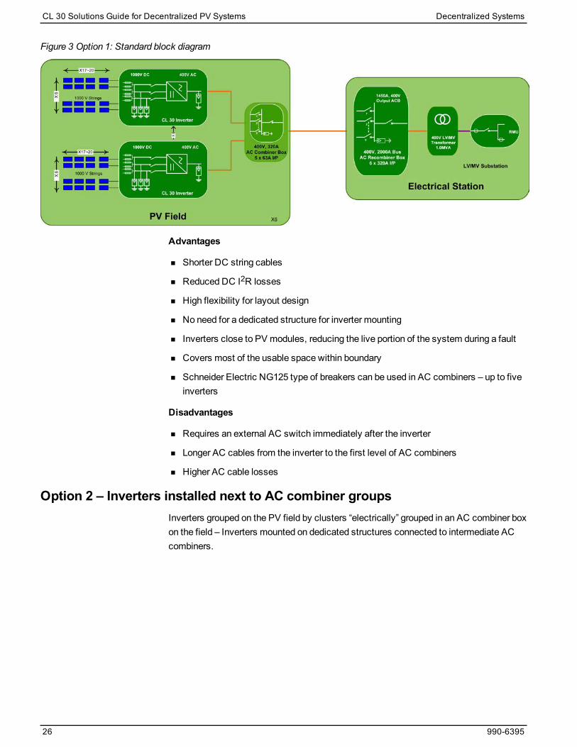
Figure 3 Option 1: Standard block diagram
Advantages
n Shorter DC string cables
n Reduced DC I2R losses
n High flexibility for layout design
n No need for a dedicated structure for inverter mounting
n Inverters close to PV modules, reducing the live portion of the system during a fault
n Covers most of the usable space within boundary
n Schneider Electric NG125 type of breakers can be used in AC combiners – up to fiveinverters
Disadvantages
n Requires an external AC switch immediately after the inverter
n Longer AC cables from the inverter to the first level of AC combiners
n Higher AC cable losses
Option 2 – Inverters installed next to AC combiner groupsInverters grouped on the PV field by clusters “electrically” grouped in an AC combiner boxon the field – Inverters mounted on dedicated structures connected to intermediate ACcombiners.
CL 30 Solutions Guide for Decentralized PV Systems Decentralized Systems
26 990-6395
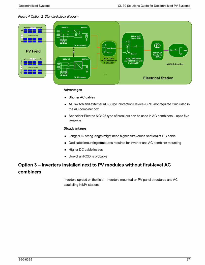
Figure 4 Option 2: Standard block diagram
Advantages
n Shorter AC cables
n AC switch and external AC Surge Protection Device (SPD) not required if included inthe AC combiner box
n Schneider Electric NG125 type of breakers can be used in AC combiners – up to fiveinverters
Disadvantages
n Longer DC string lengthmight need higher size (cross section) of DC cable
n Dedicatedmounting structures required for inverter and AC combiner mounting
n Higher DC cable losses
n Use of an RCD is probable
Option 3 – Inverters installed next to PV modules without first-level ACcombiners
Inverters spread on the field – Inverters mounted on PV panel structures and ACparalleling in MV stations.
Decentralized Systems CL 30 Solutions Guide for Decentralized PV Systems
990-6395 27

Figure 5 Option 3: Standard block diagram
Advantages
n Shorter DC string cables
n Reduced DC I2R losses
n High flexibility for layout design
n No need for a dedicated structure for inverter mounting
n Inverters close to PV modules, reducing the live portion of the system during a fault
n Covers most of the usable space within boundary
n First level AC combiners eliminated resulting in cost savings
Disadvantages
n Requires an external AC switch immediately after the inverter
n Longer AC cables from inverter to AC combiners
n High AC cable losses
n Increased size of AC cable will require higher size of terminal blocks in external ACcombiner boxes
n Use of an RCD is probable
Option 4 – Inverters installed next to LV/MV transformerDC distribution – Inverters close to an LV/MV substation on a dedicated structure andAC paralleling in an LV/MV substation.
CL 30 Solutions Guide for Decentralized PV Systems Decentralized Systems
28 990-6395

Figure 6 Option 4: Standard block diagram
Advantages
n Shorter AC cables
n High flexibility for layout design
n AC switch and AC SPD not required if included in AC combiner box
n Easy access to inverters for service andmaintenance
n RCD not required
Disadvantages
n Longer DC string cables might require higher size of DC cable
n External DC switch box with SPD required to protect long DC strings
n Combining DC strings might lose the benefit of separateMPPT
n Dedicated structures required for inverter and AC combiner mounting at MV station
n Higher DC cable losses
Decentralized Systems CL 30 Solutions Guide for Decentralized PV Systems
990-6395 29


System Design
System Design CL 30 Solutions Guide for Decentralized PV Systems
3
DC System Design 32
String and Array Sizing Rules 32
UseCase Example 33
Optimum DC-AC ratio 36
Recommended Basic Rules for String Formation 36
AC System Design 38
Circuit Breaker Coordination 39
AC System Component Design 41
AC Switch Box (optional) 41
AC Cable Sizing 42
AC Combiner Box 43
AC Re-combiner Box 53
Important Aspects of a Decentralized System Design 63
Selection of Residual Current Monitoring Device (RCD) 63
Selection of a Surge Protection Device 64
Earthing/Grounding System Design 70
Transformer Selection 74
Monitoring System Design 75
Grid Connection 76
Role of Circuit Impedance in Parallel Operation of Multiple CL 30 PV Inverters 77
What's in This Chapter?

DC System Design
DANGERHAZARD OF ELECTRIC SHOCK AND FIRE
Installation, including wiring, must be done by qualified personnel to ensure compliancewith all applicable installation and electrical codes, including relevant local, regional, andnational regulations. Installation instructions are not covered in this Solutions Guide, but areincluded in the relevant product manuals for the CL 30 inverter. Those instructions areprovided for use by qualified installers only.
Failure to follow these instructions will result in death or serious injury.
DC system design is comprised of:
n module and inverter technology assessment
n string sizing
n arrangement and interconnection of strings
n string cable sizing and lengthmanagement
n DC combiner box sizing, if required
n string / array cable sizing
n routing up to the inverter’s terminal
Out of the listed tasks, string sizing is themost important one as many other decisionsdepend on it, such as type and size of modulemounting tables, interconnectionarrangements, and cable routing.
String and Array Sizing RulesTo calculate string size:
1. Gather the following technical information:
a. From the PV modules, find the following data:
l Model of PV module to include
l Maximum open circuit voltage Voc
l Maximum array short circuit current Isc
l Maximum power point voltage Vmpp and current Impp
l Temperature coefficients for Power, Voltage, and Current
b. From the inverter, find the following data:
l Full powerMPPT voltage range (550 V–850 V)
l Operating voltage range (200 V–1000 V)
l Maximum open circuit input voltage (1100 V)
l Absolute Maximum short circuit current (120 A / 20 A per string)
CL 30 Solutions Guide for Decentralized PV Systems System Design
32 990-6395
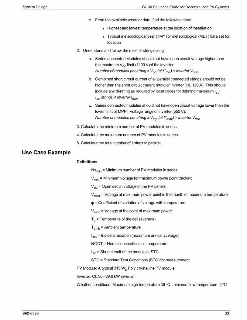
c. From the available weather data, find the following data:
l Highest and lowest temperature at the location of installation.
l Typical meteorological year (TMY) or meteorological (MET) data set forlocation
2. Understand and follow the rules of string sizing:
a. Series connectedModules should not have open circuit voltage higher thanthemaximum Voc limit (1100 V)of the inverter. Number of modules per string x Voc (at t°min) < inverter Vmax
b. Combined short circuit current of all parallel connected strings should not behigher than the short circuit current rating of inverter (i.e. 120 A). This shouldinclude any derating as required by local codes for definingmaximum Isc.Isc strings < inverter Imax
c. Series connectedmodules should not have open circuit voltage lower than thelower limit of MPPT voltage range of inverter (550 V).Number of modules per string x Vmp (at t°max) > inverter Vmin
3. Calculate theminimum number of PV modules in series.
4. Calculate themaximum number of PV modules in series.
5. Calculate the total number of strings in parallel.
Use Case ExampleDefinitions
Nsmin = Minimum number of PV modules in series
Vmin = Minimum voltage for maximum power point tracking
Voc = Open circuit voltage of the PV panels
Vminr = Voltage at maximum power point in themonth of maximum temperature
φ = Coefficient of variation of voltage with temperature
Vmpp = Voltage at the point of maximum power
Tc = Temperaure of the cell (average)
Tamb = Ambient temperature
Iinc = Incident radiation (maximum annual average)
NOCT = Nominal operation call temperature
Isc = Short circuit of themodule at STC
STC = Standard Test Conditions (STC) for measurement
PV Module: A typical 315Wp Poly crystalline PV module
Inverter: CL 30 - 29.9 kW inverter
Weather conditions: Maximum high temperature 36 ºC, minimum low temperature -5 ºC
System Design CL 30 Solutions Guide for Decentralized PV Systems
990-6395 33

Δ Voc/T (φ) Vmpp Vmpp (70 ºC) Voc
315Wp Poly-crystalline, 6 inch PV Module -0.31 36.6 31.49 45.1
Vmpp Min (full power) Voc Isc
CL 30 inverter 550 VDC 1100 VDC 20 ADC/string
STC conditions define the irradiation conditions and temperature of the solar cell, widelyused to characterize the cells, PV modules and solar generators and defined as follows:
n Irradiance : 1,000W/m2
n Spectral distribution : Air Mass 1.5 G
n Cell temperature : 25 º C
NOCT conditions define the irradiation conditions and temperature of the solar cell,widely used to characterize the cells, PV Modules and solar generators and defined asfollows:
n Irradiance : 800W/m2
n Spectral distribution : Air Mass 1.5 G
n Cell temperature : 20 º C
n Wind speed : 1m/s
Minimum number of PV modules
CL 30 has a start up voltage of 250 V and an operatingMPPT window from 550 V to 850V. Theminimum number of modules per PV string is important to ensure that 550 Vremains the output voltage and the inverter gets early start up as often as possible.
The following calculations assume a high temperature of 36 ºC.
To determine the temperature of the cell in any situation, the following formula can beused.
Tc = Tamb + (Iinc (w/m2) * (NOCT–20) / 800)
Tc = 36 ºC + ((1000) * (47 – 20) / 800)) = 70 ºC
To determine the temperature of the cell at STC, we use:
T = Tc - Tstc
T = 70 ºC - 25 ºC = 45 ºC
To calculate the Vmpp of themodule at themaximum temperature 70 ºC
Vmpp= Vmpp (25 ºC) – (T x Vmpp (25 ºC) x Ø / Irradiance STC))
Vmpp= 36.60 V – (45 x (36.60 V x 0.31% / 1000)) = 31.49 V@ 70 ºC
With this data we can calculate theminimum number of PV modules to be connected inseries, to maintain full nameplate power
Ns min = (Vmin / Vmppmin)
Ns min = (550 / 31.49) = 17.46
CL 30 Solutions Guide for Decentralized PV Systems System Design
34 990-6395

Rounding it down, the answer is 17. This is theminimum amount of PV modules to beplaced in series with each string to help ensure that the inverter functions at 1000W/m2
and 36 °C ambient temperature.
Maximum number of PV Modules
Themaximum number of PV modules in a string for the CL 30 inverter is a ratio of thehighest system voltage to themaximum open circuit voltage at the lowest temperature.
The following calculations assume a low temperature of -25 ºC.
For a list of definitions of terms used in the calculations, seeDefinitions on page 33.
To calculate the temperature needed for Voc at - 5ºC:
T = Tamb - Tstc
T = - 5ºC - 25 ºC = - 30 ºC
To calculate the Voc(of themodule at minimum temperature - 5ºC.
Voc (- 5ºC)= Voc (-25 ºC) – (T x Voc (-25 ºC) x Ø ))
Voc (- 5ºC)= 45.1 V – (- 30 x (45.1 V x 0.31% / 100)) = 49.29 V@ - 5ºC
With this data we can calculate themaximum number of PV Modules to be connected inseries, to maintain full nameplate power.
Ns max = (Vmax / Vmax)r
Ns min = (1000 / 49.29 V) =20.28
Rounding it down, the answer will be 20. This is themaximum amount of PV modules tobe placed in series with each string to ensure the functioning of the inverter at 1000W/m2
and -- 5ºC ambient temperature.
Number of strings in parallel
Themaximum number of strings installed in parallel and connected to CL 30 inverters,will be calculated.
Limitation: Inverter can connect with up to 6 strings
Number of Strings = Isc Inverter max / (Isc)
Max. # of parallel strings = 120 A/ 9.08 A = 13.2 strings
Rounding it down, the answer will be 13 strings.
Since we have physical connection limit of 6, we can use themaximum number ofstrings.
PV module type and rating Mono Crystalline 275 W Poly Crystalline 315 W
PV module series number 23 20
# of parallel strings 6 6
Total DC power 37950 W 37800 W
Inverter rated power 29900 W 29900 W
DC/AC ratio limit 1.26 1.26
Table 1 Example of highest string sizing ratios
System Design CL 30 Solutions Guide for Decentralized PV Systems
990-6395 35

Optimum DC-AC ratioDC Ratio is based on STC conditions, but does not take into account the specificconfiguration of the project. The performance is a function of location and racking style. Ahighly optimized system, such as a 2-Axis tracker, will have amuch higher performanceadvantage compared to a 5-degree fix tilt, for example. Likewise, a strong solar irradianceregion will have amuch higher energy potential than a weaker region. The amount ofclipping losses will be based on the amount of relevant energy available vs. the inverternameplate. As clipping exceeds 3%, theremay be diminishing value to higher levels ofDC Ratio.
Shallow Fix tilt (roof mount applications) 1.30 – 1.40
Steep Fix tilt (ground mount applications) 1.25 – 1.35
1-Axis Tracked (ground mount applications) 1.20 – 1.30
2-Axis Tracked (ground mount applications) 1.10 – 1.20
Table 2 CL 30 inverter suggested DC oversizing range
Schneider Electric recommends amaximum oversizing limit of 1.5. Higher DC ratios willrequire review by a Schneider Electric applications engineer.
Note: The CL 30 inverter is a fuse-less design. The PV input of the inverter would needexternal in-line fuse protection if it is required by country compliance standards.Designers and installers must consider this in preliminary design.
An inline fuse connector from third party sources can be used for CL 30 inverters, asshown in the Figure.
Recommended Basic Rules for String Formationn Select an EVEN number for modules in a string to have simpler string
interconnectivity over mounting structures.
n Try tomaximizemodules per string within Voc and Vmpp limits of the inverter.
n The string formation should be designed in a way that cablemanagement at the backof modules could be followed according to electrical installation rules using theshortest string cable length andminimum bends.
n Support the connectors and avoid a sharp bend from the PV module cable box.
CL 30 Solutions Guide for Decentralized PV Systems System Design
36 990-6395

NOTICEHAZARD OF WIRING DAMAGE
Do not route cables such that they make a sharp bend as this can damage the wire'sintegrity.
Failure to follow these instructions can result in equipment damage.
n If possible, keep the PV module strings connected and formed in horizontal lines toavoid row shadow impact on all strings in each wing of racks or trackers.
n Follow the instructions of the PV modulemanufacturer to select portrait or landscapeposition of modules.
n Do not combine separate ratings of PV modules in one string.
n The CL 30 inverter is a transformer-less inverter, so none of the PV inputs can beused with grounded arrays. This inverter is designed only for use withfloating/ungrounded arrays.
WARNINGHAZARD OF ELECTRIC SHOCK, EXPLOSION, ARC FLASH, AND FIRE
The CL 30 inverter must be only used with floating/ungrounded arrays.
Failure to follow these instructions can result in death, serious injury, or equipmentdamage.
Thin-Film modules designed to operate with floating arrays could be connected withthe CL 30 inverter.
System Design CL 30 Solutions Guide for Decentralized PV Systems
990-6395 37

AC System Design
DANGERHAZARD OF ELECTRIC SHOCK AND FIRE
Installation, including wiring, must be done by qualified personnel to ensure compliance withall applicable installation and electrical codes, including relevant local, regional, and nationalregulations. Installation instructions are not covered in this Solutions Guide, but are included inthe relevant product manuals for the CL 30 inverter. Those instructions are provided for use byqualified installers only.
Failure to follow these instructions will result in death or serious injury.
The AC system of a PV plant consists of an AC switch box (optional), AC combiner box,AC re-combiner box, AC cables, trenches, LV-MV transformer, ringmain units at MVstations in the PV field, MV cable circuit, andMV station at the grid box.
AC low voltage circuits with high amounts of power need extreme care to achieve reliability,safety, and the highest level of system availability. Selection of circuit breakers (MCB andMCCBs), disconnect switches, protection devices and cables is key to achieving all threeobjectives.
Safety and availability of energy are the designer’s prime requirements. Coordination ofprotection devices ensures these needs aremet at optimized cost.
Implementation of these protection devices must allow for:
n statutory aspects, particularly relating to the safety of people
n technical and economic requirements
The chosen switchgear must:
n withstand and eliminate faults at optimized cost with respect to the necessaryperformance
n limit a fault's effect to the smallest part of the installation in order to ensure continuity ofsupply.
Achievement of these objectives requires coordination of protection device performance,necessary for:
n managing safety and increasing durability of the installation by limiting stresses
n managing availability by eliminating the fault by means of the circuit breaker immediatelyupstream.
The circuit breaker coordinationmeans are:
n Cascading
n Discrimination
If the insulation fault is specifically dealt with by earth leakage protection devices,discrimination of the residual current devices (RCDs)must also be guaranteed.
990-6395 38
CL 30 Solutions Guide for Decentralized PV Systems

Circuit Breaker CoordinationThe term "coordination" concerns the behavior of two devices placed in series in electricalpower distribution in the presence of a short circuit.
Cascading or back-up protection
This consists of installing an upstream circuit breaker D1 to help a downstream circuitbreaker D2 to break short-circuit currents greater than its ultimate breaking capacity lcu D2.This value is marked lcu D2+D1.
Standard IEC 60947-2 recognizes cascading between two circuit breakers. For criticalpoints, where tripping curves overlap, cascadingmust be verified by tests.
Discrimination
This consists of providing coordination between the operating characteristics of circuitbreakers placed in series so that, should a downstream fault occur, only the circuit breakerplaced immediately upstream of the fault will trip.
Standard IEC 60947-2 defines a current value (ls) known as the discrimination limit suchthat if the fault current is less than the Is value, only the downstream circuit breaker D2trips; if the fault current is greater than the Is value, both circuit breakers D1 and D2 trip. SeeTable 3 for more information. Just as for cascading, discriminationmust be verified by testsfor critical points.
Figure 7 Summary information
990-6395 39
CL 30 Solutions Guide for Decentralized PV Systems

Table 3 Discrimination data (IEC 60947-2)
Note:Discrimination and cascading can only be guaranteed by the circuit breakermanufacturer.
Installation standard IEC 60364 governs electrical installations of buildings. Nationalstandards, based on this IEC standard, recommend good coordination between theprotection switchgear. They acknowledge the principles of cascading and discrimination ofcircuit breakers based on product standard IEC 60947-2.
For more details on Limitation, Cascading and Discrimination of circuit breakers refer toSchneider Electric’s Low Voltage Expert Guide No.5 – “Coordination of LV protectiondevices”.
990-6395 40
CL 30 Solutions Guide for Decentralized PV Systems

AC System Component DesignThere aremany components that may be used, depending on the configuration.
AC Switch Box (optional)An AC switch box should be installed on the CL 30 inverter AC terminals, depending on thedistance from the first AC combiner. Table 4 lists the component part numbers for an ACswitch box.
Figure 8 Optional AC switch box diagram
FunctionThe INS63/ INS80/ NG125N/ Acti 9 iC60 disconnects the inverter from the AC Combiner.
The IQuick PRD40r helps protect the inverter against voltage surges coming from AC lines.
Typical Use
1. The AC switch box is optional, but is necessary when:
l The distance or an obstacle between the inverter and the AC combiner boxprevents the safe disconnection of the inverters at the AC combiner box level
2. The AC switch box is located near the inverter and usually needs to be installed in anoutdoor enclosure.
3. The AC switch box is used when there are long distances between the inverter and theAC combiner box.
4. You can increase the cross-section of the cables to reduce AC losses, for example:
l If the cross-section area of the output cable is higher than 35mm2 (maximumcross-section of the cables at the AC terminal of the inverter), an AC switch boxcould be helpful to host higher-sized cable between the AC Combiner and theinverter.
Advantages of the Offer
1. There are two possible configurations of the AC box:
l with surge protection
l without surge protection
990-6395 41
CL 30 Solutions Guide for Decentralized PV Systems

2. You can increase the cross-section of the cables to reduce AC losses - output cableterminals up to 70mm2. Up to 35mm2 can be directly connected to the upstreambreaker (NG125). Larger cable sizes would need separate terminal blocks in the ACcombiner and in the AC switch box, if required, due to high voltage drop.
3. Range for 29.9 kW (29.9 kVA).
4. There are twomodels:
l ACSB01with switch-disconnect only
l ACSB02with switch-disconnect and surge voltage protection
Components Model Reference No.
AC switch INS63, 4P 28902
Surge protection device I Quick PRD40r A9L16294
Enclosure
Thalassa PLS modular 12 forACSB01Thalassa PLS modular 24 forACSB02
NSYPLS1827PLS12NSYPLS2227DLS24
Table 4 Components needed for AC switch box configuration
AC Cable SizingThe output terminal block of CL 30 inverters can host up to 35mm2 copper or aluminumcable. Recommended cable types are four core for L1, L2, L3 and N and five core foradditional PE connections.
AC cable sizing calculations must consider ampacity, voltage drop, short circuit calculation,and thermal de-rating of AC cables.
Total power loss due to AC cables must be designed to be <1%. To achieve this level, it isimportant to select a suitable cable size with the required ampacity, short circuit rating,voltage grade, and with low voltage drop.
Formulae commonly used to calculate voltage drop in a given circuit per kilometer of length.
Where:
X = inductive reactance of a conductor in Ω / km
Ø = phase angle between voltage and current in the circuit
IB = full load current in amps
L = length of the cable in km
R = resistance of the cable conductor in Ω / km
990-6395 42
CL 30 Solutions Guide for Decentralized PV Systems

X = inductive reactance of a conductor in Ω / km
Un = phase-to-phase voltage
Vd = voltage drop
Vn = phase-to-neutral voltage
AC cable sizes between CL 30 inverters and AC combiner boxes will mostly depend on thedistance between them. Themaximum output current of the CL 30 inverter is 48.15 A andconsidering the de-rating factors due to cable layingmethodology and thermal derating dueto conduits, 35mm2 4 core AL cables are suitable in most instances.
The following table provides recommendedmaximum cable lengths from inverter to ACdistribution box. We recommend that the installer or system designer performs a detailedcable sizing calculation for each inverter in order to calculate the power loss associated withsuggested cables sizes.
AC Cable Length AC Cable Size (mm2)A
1–50 m 35
50–100 m 55
>100 m 70 or higher
Table 5 AC cable length and size
It is essential to calculate and consider the correct fault level on each combiner bus level inorder to select the right size of cable, MCB, MCCB, RCD, surge protection and disconnectdevices.
Use the following methodology to calculate cable sizing:
If the AC cable length exceeds 10m (32.8 ft), the use of an AC switch box closer to theinverter is recommended. This switchbox can be used to connect an AC output cable higherthan 35mm2, if required, to avoid voltage drop.
It is very important to consider both resistive and reactive components of voltage drop whencalculating cable sizing. The reactive component of cable impedance plays an essential rolein the parallel operation of inverters. The target should be to reduce the reactive impedanceas much as possible to increase the number of parallel connected inverters at the LVwinding of the transformer (considering intermediate AC distribution boxes).
AC Combiner BoxAn AC combiner box is the first level of combiners, commonly located in the PV field in largeutility scale projects. AC combiner boxes house the first level protection for inverters on theAC side .
Function
n Combines AC currents coming from several inverters
n Isolates the combiner box from the AC line
n Output - circuit breaker
n Circuit breaker (according to prospective current)
990-6395 43
CL 30 Solutions Guide for Decentralized PV Systems

n Protects inverters against voltage surges from the AC line
n iPRD range for surge protection
Typical use
n The AC combiner box is located near the inverters.
n Use an AC combiner box when there is a long distance between the AC combiner boxand the AC distribution box.
n The AC combiner box requires high cross-section terminals for output cabling.
Depending on the number of inverters being combined at the AC combiner’s busbar, theincoming lines can be protected usingMCBs orMCCBs. Selection of this componentdepends on the rated circuit current, expected fault current, fault clearing time, and remoteoperation requirements. Length of the cable connected between the AC combiner outputand the AC re-combiner input plays an important role as a longer cable length reduces theamount of fault current to break. See the following example circuit.
990-6395 44
CL 30 Solutions Guide for Decentralized PV Systems

Figure 9 Example circuit with 100m cable
The example circuit in Figure 9 has 100m length from the AC combiner to the AC re-combiner. The resulting fault level at the AC combiner bus bar is 13.32 kA and the choice ofbreaker is NG125N MCCB (25 kA).
990-6395 45
CL 30 Solutions Guide for Decentralized PV Systems

Figure 10 Example circuit with 250m cable
The example circuit in Figure 10 has a 250m length from the AC combiner to the AC re-combiner, and the fault current is reduced to 7.11 kA, allowing the selection of C120H MCBwith 15 kA fault level.
Methodology to calculate the fault level at AC combiner bus bar
Example:
n The combiner box is connected to a re-combiner box via a 250m, 185mm2 sizealuminum cable
n The re-combiner box connects to a 1000 kVA 20 kV/400 V, 6% transformer
Fault level at the AC combiner bus bar = Voltage x Voltage correction factor C/ Faultimpedance
= 400 * 1.05/ ( Zgrid + ZTR-LV + Zcable)*√3
990-6395 46
CL 30 Solutions Guide for Decentralized PV Systems

= 400 * 1.05 / (Rgrid+RTR-LV+ Rcable)2+( Xgrid+XTR-LV+Xcable)2 1/2*√3
Grid LV Impedance:
Considering theMV connection at 20 kV andGrid short circuit power of 500MVA, wewilluse following values to calculate Grid impedance at the LV side of the transformer.
MV voltage: 20 kV
Short circuit power from grid: 500MVA
Transformer LV voltage: 400 V
Size of transformer: 1000 KVA
First, calculate MV impedance:
ZMV–GRID = c x V2/SCC =1.1 x 200002/(500 x 106) =0.88 Ω
In the case of high-voltage feeders with nominal voltages above 35 kV fed by overheadlines, the equivalent impedance ZQ may inmany cases be considered as a reactance, i.e.ZQ=0 + jXQ. In other cases, if no accurate value is knows for the resistance RQ of networkfeeders, onemay substitute RQ=0.1 XQ where XQ=0.995 ZQ.
XMV-GRID = .995 x 0.88=0.08788Ω
RMV-GRID = Sqrt(ZMV–GRID2- XMV-GRID2)=0.08756Ω
Then, calculate Grid LV impedance from GridMV values:
XLV–GRID= XMV–GRID(VLV2/VMV2) = 3.5024 x 10⁻⁴Ω;
RLV–GRID= RMV–GRID(VLV2/VMV2) = 3. 5136 x 10-5Ω;
We calculate the transformer LV Impedance for a 1000 KVA, 20 kV / 400 V transformer withthe following details:
n Voltage factor c=1.05
n Short circuit impedance= 6%
n Load loss of 10500W (copper losses),
Before calculating the transformer LV impedance, it is important to know the
following definitions:
Cmax = voltage factor for calculating themaximum short circuit current
IrT = rated current of the transformer on the low or high voltage side
KT = impedance correction factor
A network transformer connects two or more networks at different voltages. Fortwo winding transformers this impedance correction factor should be used whencalculating the short circuit impedance.
PkrT = total loss in the transformer windings at the rated current
SrT = rated apparent power of the transformer
Ukr = short circuit voltage at the rated current
UrT = rated voltage of the transformer on the low or high voltage side
990-6395 47
CL 30 Solutions Guide for Decentralized PV Systems

xt= relative reactance of transformer
XTR-LV = LV winding reactance of the transformer
ZT = transformer LV impedance
Before calculating the transformer LV impedance, calculate Kt and XT using Cmax.
Voltage factor c for the calculation of:
Nominal voltage (Un)maximum short-circuit
currents cmax1
minimum short-circuitcurrents cmin
Low voltage100 V to 1000 V(IEC 60038)
1.052
1.1030.95
Medium voltage>1 kV to 35 kV(IEC 60038)
1.10 0.95
High voltage4
>35 kV(IEC 60038)
1.10 1.00
Table 6 Voltage factor c
Impedance Correction Factor:
Transformer LV impedance ZTR-LV
= KT x 400 x 400 x 0.06/1000 x 1000
= 0.009248Ohms
Where, KT = 0.96328045
RTR-LV
= KT x Losses kW / 3 x (Rated Current)2
= KT x 10500 / 3 x (1000 x 1000/(sqrt (3) x 400))2
= 0.001618Ohms
1 CmaxUn should not exceed the highest voltage Um for equipment of power systems2For low voltage systems with a tolerance of +6%, for example systems renamed from 380 V to
400 V3For low voltage systems with a tolerance of +10%4 If no nominal voltage is defined cmaxUn = Um or cminUn = 0.90 x Um should be applied
990-6395 48
CL 30 Solutions Guide for Decentralized PV Systems

Note: Rated current = Number of inverters x Per inverter output current
XTR-LV = KT x Sqrt( Z2-R2) = 0.009105Ohms
Cable Impedance :
Zcable = Sqrt (Rcable2 + Xcable2)
185 mm2 Cable
R (Ohms/km) 0.2091
X (Ohms/km) 0.08267
Length 250
Runs 2
Type ALU
Rcable = Resistance@ 90°C x length / (runs x 1000 )=.02613Ohms
Xcable = Reactance x length/(runs x 1000) = 0.01033Ohms
Fault level at AC combiner bus bar
= Voltage x Voltage correction factor C/ Fault impedance
= 400 x 1.05 / (RLVgrid+RTR-LV+ Rcable)2+( XLVgrid+XTR-LV +Xcable)2 1/2 x √3
= 400 x 1.05 / 0.027792 + 0.019792 1/2 x √3
= 7.11 kA
Selected circuit breaker for AC combiner inputs:
For this scenario, the following is the recommended circuit breakers with calculated faultcurrent.
The example above results in around 7.11 kA. Generally, we see the fault level on ACCombiner buses within the range of 10 to 20 kA. For this application, we recommend usingbreakers in the NG125N category or higher to help ensure aminimum of 25 kA fault currentrating at the AC combiner level.
990-6395 49
CL 30 Solutions Guide for Decentralized PV Systems
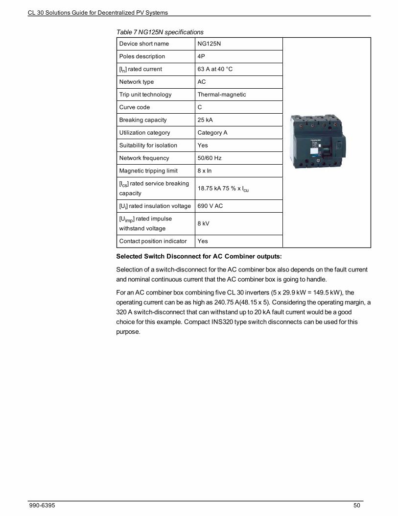
Device short name NG125N
Poles description 4P
[In] rated current 63 A at 40 °C
Network type AC
Trip unit technology Thermal-magnetic
Curve code C
Breaking capacity 25 kA
Utilization category Category A
Suitability for isolation Yes
Network frequency 50/60 Hz
Magnetic tripping limit 8 x In
[Ics] rated service breakingcapacity
18.75 kA 75 % x Icu
[Ui] rated insulation voltage 690 V AC
[Uimp] rated impulsewithstand voltage
8 kV
Contact position indicator Yes
Table 7 NG125N specifications
Selected Switch Disconnect for AC Combiner outputs:
Selection of a switch-disconnect for the AC combiner box also depends on the fault currentand nominal continuous current that the AC combiner box is going to handle.
For an AC combiner box combining five CL 30 inverters (5 x 29.9 kW = 149.5 kW), theoperating current can be as high as 240.75 A(48.15 x 5). Considering the operatingmargin, a320 A switch-disconnect that can withstand up to 20 kA fault current would be a goodchoice for this example. Compact INS320 type switch disconnects can be used for thispurpose.
990-6395 50
CL 30 Solutions Guide for Decentralized PV Systems

Device short name Interpact INS320
Poles description 4P
Network type AC
Network frequency 50/60 Hz
[Ie] rated operational current 320 A
[Ui] rated insulation voltage 750 V AC
[Uimp] rated impulsewithstand voltage
8 kV
[Icm] rated short-circuitmaking capacity
50 kA
[Ue] rated operationalvoltage
690 V AC
Suitability for isolation Yes
Contact position indicator Yes
Table 8 Interpact INS320 specifications
990-6395 51
CL 30 Solutions Guide for Decentralized PV Systems

Figure 11 Recommended block architecture with five input AC Combiners
990-6395 52
CL 30 Solutions Guide for Decentralized PV Systems

AC Re-combiner BoxAn AC re-combiner box re-combines all AC combiner box inputs at one bus bar. Theaccumulated power flows to the transformer LV winding and gets transferred to theMVnetwork.
The AC re-combiner box is usually located at an LV-MV station inside the kiosk or outsideon a concrete pad. All inputs from AC combiners in the PV field are connected to themoldedcase type circuit breakers. The outputs to the LV transformer winding from the AC re-combiner box can be connected to either anMCCB or an air circuit breaker (ACB)depending on the space requirements.
Selection of theMCCB and ACB should follow similar rules as described for AC combiners.It is worth noting that discrimination and cascading of circuit breakers help to design amoreaccurate protection philosophy, as well as to save on capital costs due to the reduced faultlevel capacity of components.
The fault level at the transformer’s LV terminal will bemostly the same as the fault level onthe AC re-combiner’s bus bar due to the short distance between the transformer and the re-combiner panel.
Grid MV and LV Impedance ValuesConsidering theMV connection at 20 kV and grid short circuit power of 500MVA, thefollowing values can be used to calculate grid impedance at the LV side of the transformer.
n MV voltage: 20 kV
n Short circuit power from grid: 500MVA
n Transformer LV voltage: 400 V
n Voltage factor c for MV grid: 1.1
n Size of transformer: 1000 KVA
First calculate MV impedance:
ZMV-grid = (RMV-grid2+ XMV-grid2)1/2
ZMV-grid = c x Grid voltage/Grid current
= 1.1 x 200002/ (500x 106)
= 0.88 Ohms
XMV-grid = 0.995 * ZMV-grid = 0.995 x 0.88
= 0.8756
RMV-grid = ( ZMV-grid2- XMV-grid2)1/2 = 0.08788993Ohms
Then, calculate grid LV impedance from grid MV values:
XLV-grid = XMV-grid x (LV Voltage2 / MV Voltage2)
= 0.8756 (4002/200002)
= 0.0003502Ohms
RLV-grid = RMV-grid x (LV Voltage2 / MV Voltage2)
990-6395 53
CL 30 Solutions Guide for Decentralized PV Systems

= 0.08788993 (4002/200002)
= 3.5156 x 10⁻⁵Ohms
Transformer Impedance ValuesWe calculate the transformer impedance for a 1000 KVA, 20 kV / 400 V transformer with thefollowing details:
n Voltage factor c=1.05
n Short circuit impedance= 6%
n Load loss of 10500W (copper losses),
Before we calculate the transformer impedance, it is important to know the
following definitions:
Cmax = voltage factor for calculating themaximum short circuit current
IrT = rated current of the transformer on the low or high voltage side
KT = impedance correction factor
A network transformer connects two or more networks at different voltages. Fortwo winding transformers this impedance correction factor should be used whencalculating the short circuit impedance.
PkrT = total loss in the transformer windings at the rated current
SrT = rated apparent power of the transformer
Ukr = short circuit voltage at the rated current
UrT = rated voltage of the transformer on the low or high voltage side
xt= relative reactance of transformer
XTR-LV = LV winding reactance of the transformer
ZT = transformer LV impedance
Before we calculate the transformer LV impedance, we will calculate Kt and XT using Cmax.
Voltage factor c for the calculation of:
Nominal voltage (Un)maximum short-circuit
currents cmax5
minimum short-circuitcurrents cmin
Low voltage100 V to 1000 V(IEC 60038)
1.056
1.1070.95
Table 9 Voltage factor c
5 CmaxUn should not exceed the highest voltage Um for equipment of power systems6For low voltage systems with a tolerance of +6%, for example systems renamed from 380 V to
400 V7For low voltage systems with a tolerance of +10%
990-6395 54
CL 30 Solutions Guide for Decentralized PV Systems

Voltage factor c for the calculation of:
Nominal voltage (Un)maximum short-circuit
currents cmax5
minimum short-circuitcurrents cmin
Medium voltage>1 kV to 35 kV(IEC 60038)
1.10 1.00
High voltage8
>35 kV(IEC 60038)
1.10 1.00
5 CmaxUn should not exceed the highest voltage Um for equipment of power systems8 If no nominal voltage is defined cmaxUn = Um or cminUn = 0.90 x Um should be applied
990-6395 55
CL 30 Solutions Guide for Decentralized PV Systems

Impedance Correction Factor:
Transformer LV impedance ZTR-LV
= KT x 400 x 400 x 0.06/1000x 1000
= .00924749Ohms
Where, KT = 0.96328045
RTR-LV= KT x Losses kW / 3 x (Rated Current)2
= KT x 13000 / 3 x (1000 x 1000/400/1.732)2
= 0.001618Ohms
XTR-LV = KT x Sqrt( Z2-R2) = 0.008243Ohms
Fault level at AC re-combiner bus bar
= Voltage x Voltage correction factor C/ Fault impedance
= 400 x 1.05 / (Zgrid+ZTR-LV x √3 x 1000
= 400 x 1.05 / (RLVgrid+RTR-LV)2 + (XLVgrid+XTR-LV)21/2 x √3 x 1000
= 400 x 1.05 / 0.0016532 + 0.00945572821/2 x √3 x 1000
= 25.26 kA
If a 29.9 kVA rating is used, for a 1.0MVA standard block, with 30 CL 30 inverters, six ACCombiner boxes combining five inverters each and each AC Combiner with five inverters,the AC re-combiner box will have six inputs, each with 240.75 A maximum current andrespective fault level.
The length of cables between AC re-combiner and transformer (being very short) does notmakemuch difference to the selection of the circuit breaker’s fault level. Transformerimpedance and grid short-circuit fault level makes a small difference but is not significant.Themajor difference comes from the size of the transformer and LV voltage level.Designers should consider this when designing the system.
Figure 12 and Figure 13 provide examples for understanding the dependency of circuitbreaker selection on the bus bar fault level, as well as the dependency of the bus bar faultlevel in the selection of components.
990-6395 56
CL 30 Solutions Guide for Decentralized PV Systems

Figure 12 Breaker selection with 1000 kVA transformer
Whenwe replace the 1000 kVA transformer with a 800 KVA transformer, the fault leveldecreases significantly on the AC re-combiner’s bus bar and NSX400N type breakersbecome eligible to be used for inputs.
Figure 13 Breaker selection with 800 kVA transformer
990-6395 57
CL 30 Solutions Guide for Decentralized PV Systems

Recommended Circuit Breaker for AC Re-combiner Incoming:
We recommend using Compact NSX400N type Breakers for AC re-combiner input to haveup to 50 kA fault current capacity.
Device short name Compact NSX
Device short name Compact NSX400N
Poles description 3P
Network frequency 50/60 Hz
[In] rated current Up to 400 A (40 °C )
[Ui] rated insulation voltage 800 V AC 50/60 Hz
[Uimp] rated impulsewithstand voltage
8 kV
[Ue] rated operationalvoltage
690 V AC 50/60 Hz
Breaking capacity 50 kA Icu at 380/415 V AC
Table 10 Compact NSX specifications
Selected circuit breaker for AC Re-combiner output:
output current of AC re-combiner
= Block kVA size x 1000 /sqrt 3 x Voltage
= 1000 x 1000 / 1.732 x 400
= 1444 A
Expected Fault level ~ 35 kA
With the above specification, the recommended circuit breaker is Masterpact NW20H1 –2000A – 3 pole (fixed or removable) – with Micrologic trip unit.
990-6395 58
CL 30 Solutions Guide for Decentralized PV Systems

Device short name Masterpact NW20
Poles description AC
Network type 50/60 Hz
Suitability for isolation Yes
Utilization category Category B
Network frequency 50/60 Hz
Control type Pushbutton
Mounting mode Fixed
[In] rated current 2000 A (40 °C )
[Ui] rated insulationvoltage
1000 V AC
[Uimp] rated impulsewithstand voltage
12 kV
[Icm] rated short-circuitmaking capacity
143 kA
[Ue] rated operationalvoltage
690 V AC
Circuit breaker CTrating
2000 A
Breaking capacity 65 kA
Table 11 Masterpact NWH1 specifications
Circuit Breaker Protection - Discrimination Table for SelectionTo achieve the correct level of discrimination and cascading between selected circuitbreakers, use the following tables. If the installed circuit breakers have differentcombinations, check the “Complementary Technical Information”: Low voltage cataloguefor more discrimination tables.
990-6395 59
CL 30 Solutions Guide for Decentralized PV Systems

990-6395 60
CL 30 Solutions Guide for Decentralized PV Systems

990-6395 61
CL 30 Solutions Guide for Decentralized PV Systems

990-6395 62
CL 30 Solutions Guide for Decentralized PV Systems
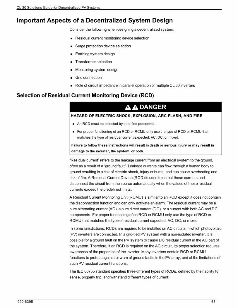
Important Aspects of a Decentralized System DesignConsider the following when designing a decentralized system:
n Residual current monitoring device selection
n Surge protection device selection
n Earthing system design
n Transformer selection
n Monitoring system design
n Grid connection
n Role of circuit impedance in parallel operation of multiple CL 30 inverters
Selection of Residual Current Monitoring Device (RCD)
DANGERHAZARD OF ELECTRIC SHOCK, EXPLOSION, ARC FLASH, AND FIRE
n An RCD must be selected by qualified personnel.
n For proper functioning of an RCD or RCMU only use the type of RCD or RCMU thatmatches the type of residual current expected: AC, DC, or mixed.
Failure to follow these instructions will result in death or serious injury or may result indamage to the inverter, the system, or both.
“Residual current” refers to the leakage current from an electrical system to the ground,often as a result of a “ground fault”. Leakage currents can flow through a human body toground resulting in a risk of electric shock, injury or burns, and can cause overheating andrisk of fire. A Residual Current Device (RCD) is used to detect these currents anddisconnect the circuit from the source automatically when the values of these residualcurrents exceed the predefined limits.
A Residual Current Monitoring Unit (RCMU) is similar to an RCD except it does not containthe disconnection function and can only activate an alarm. The residual current may be apure alternating current (AC), a pure direct current (DC), or a current with both AC and DCcomponents. For proper functioning of an RCD or RCMU only use the type of RCD orRCMU that matches the type of residual current expected: AC, DC, or mixed.
In some jurisdictions, RCDs are required to be installed on AC circuits in which photovoltaic(PV) inverters are connected. In a grid-tied PV system with a non-isolated inverter, it ispossible for a ground fault on the PV system to cause DC residual current in the AC part ofthe system. Therefore, if an RCD is required on the AC circuit, its proper selection requiresawareness of the properties of the inverter. Many inverters contain RCD or RCMUfunctions to protect against or warn of ground faults in the PV array, and of the limitations ofsuch PV residual current functions.
The IEC 60755 standard specifies three different types of RCDs, defined by their ability tosense, properly trip, and withstand different types of current:
990-6395 63
CL 30 Solutions Guide for Decentralized PV Systems

n Type AC - sensitive to residual sinusoidal alternating current (AC).
n Type A - sensitive to residual sinusoidal alternating current (AC) or pulsed direct current(DC).
n Type B - sensitive to residual AC, pulsed DC, or smooth DC currents.
Only Type B RCDs are able to withstand and properly function in the presence of a DCresidual current component exceeding 6mA. These different types of RCDs aremarkedwith specific symbols, as defined in IEC 60755.
The white paper (available at https://solar.schneider-electric.com/), “Guidance on ProperResidual Current Device Selection for Solar Inverters” by K. Ajith Kumar and Jim Eichner,provides more guidance on the requirements and selection of RCDs.
The CL 30 inverter has a built-in RCMU. This continuous RCD is set at 300mA (or higherfor larger systems) and a sudden change detector with limits as listed in the following table(based on DIN/VDE 0126-1-1, EN/IEC 62109-2, and other standards):
Residual current suddenchange
Maximum time to inverter disconnection from themain
30 mA 300 ms
60 mA 150 ms
150 mA 40 ms
Selection of a Surge Protection Device
DANGERHAZARD OF ELECTRIC SHOCK AND FIRE
Installation, including wiring, must be done by qualified personnel to ensure compliance withall applicable installation and electrical codes, including relevant local, regional, and nationalregulations. Installation instructions are not covered in this Solutions Guide, but are included inthe relevant product manuals for the CL 30 inverter. Those instructions are provided for use byqualified installers only.
Failure to follow these instructions will result in death or serious injury.
Surge arrestors help to protect the electrical wiring, components, and system from lightningsurges. The role of a surge arrester is to drive the lightning current to the earth in very shorttime (<350microseconds). However, surge arrestors are not intended to be exposed topermanent over voltages. Extended exposuremay create a short circuit andmay damagethe switch board.
Consider the following when selecting surge protection:
n The protection level of the SPD must be lower than the impulse withstand voltage levelof the equipment protected by the SPD.
n For a TNC earthing scheme, 3P SPDs should be used.
n For a TNS earthing scheme, 3P+N SPDs should be used.
990-6395 64
CL 30 Solutions Guide for Decentralized PV Systems

n If the PV system is installed in the vicinity (within 50m) of a lightning protection rod orlightning termination, a Type 1 SPD will be required to help safeguard the inverter fromlightning discharge currents because it is used to conduct the direct lightning current,propagating from the earth conductor to the network conductors.
n Geographical conditions cause the specific level of lightning flash density. Based on thelevel of lightning flash density and commercial value of the equipment protected, thelevel of surge protection and the fault level (kA) of the SPD must be decided.
n After choosing the surge protection device for the installation, the appropriatedisconnection circuit breaker must be chosen. Its breaking capacity must be compatiblewith the installation’s breaking capacity and each live conductor must be protected, forexample, 3P+N SPD must be combined with a 4P MCCB orMCB.
Use of SPDs on DC CircuitsiPRD PV-DC type surge protection devices should be installed in a switchboard eitherinside the building or in a weatherproofed location outside. Removable iPRD PV-DC surgearresters allow damaged cartridges to be replaced quickly.
The surge arrester base can be turned over to allow the phase/neutral/earth cables to enterthrough either the top or the bottom. These cables offer remote reporting of the “cartridgemust be changed” message.
Table 12 SPD specifications
Depending on the distance between the "generator" part and the "conversion" part, it may benecessary to install two or more surge arresters to help ensure protection of each of the twoparts.
Calculation for DC Surge Protection
To help protect the inverter, you need to have protection level of:
Up (surge arrester) < 0,8 Uw (inverter)
If the distance between the PV module and the inverter is greater than 10m a second surgeprotection should be installed closed to the PV module, except if:
Up < 0,5Uw (module), where U is the impulse withstand.
990-6395 65
CL 30 Solutions Guide for Decentralized PV Systems

The CL 30 is category III:
impulse withstand Uw = 6 kV
The 1000 V modules are usually category A:
impulse withstand is Uw= 8 kV
iPRD40r 1000 V DC surge arrestor:
Up = 3.9 kV
So 3.9 < 0.8 x 6 = 4.8 kV: protection of the inverter is good
And 3.9 < 0.5 x 8 = 4 kV: no need of additional surge arrestor to protect themodules.
The following diagram indicates the additional SPD requirement considering that theimpulse withstand voltage of the PV module is less than the Up of the SPD inside the CL 30inverter.
Figure 14 Additional SPD requirements
The following is a use case example to understand the installation of SPDs.
990-6395 66
CL 30 Solutions Guide for Decentralized PV Systems

Figure 15 Installation of SPDs
If there is a scenario where the PV architecture is without an earthed polarity on the DC sideand with either a PV inverter or galvanic isolation, the following things are required:
n Protection for each string of photovoltaic modules with a C60PV-DC installed in thejunction box near the PV modules
990-6395 67
CL 30 Solutions Guide for Decentralized PV Systems
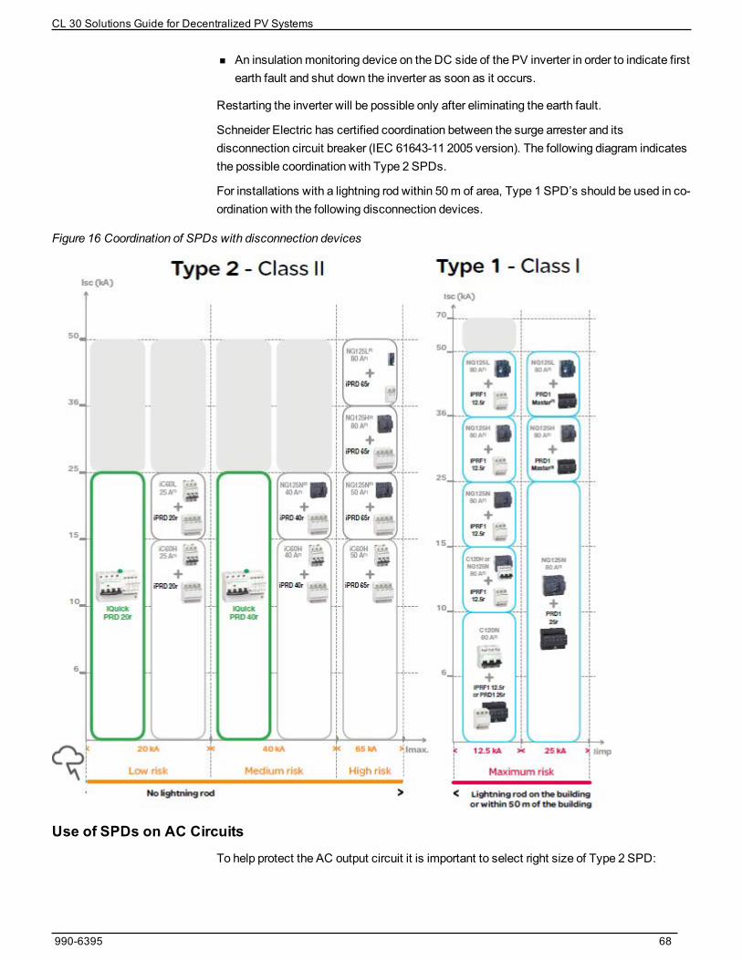
n An insulationmonitoring device on the DC side of the PV inverter in order to indicate firstearth fault and shut down the inverter as soon as it occurs.
Restarting the inverter will be possible only after eliminating the earth fault.
Schneider Electric has certified coordination between the surge arrester and itsdisconnection circuit breaker (IEC 61643-11 2005 version). The following diagram indicatesthe possible coordination with Type 2 SPDs.
For installations with a lightning rod within 50m of area, Type 1 SPD’s should be used in co-ordination with the following disconnection devices.
Figure 16 Coordination of SPDs with disconnection devices
Use of SPDs on AC CircuitsTo help protect the AC output circuit it is important to select right size of Type 2 SPD:
990-6395 68
CL 30 Solutions Guide for Decentralized PV Systems

n This AC SPD provides Type 2 protection to the inverter from AC system surges from thegrid. For the protection of the AC low voltage systems, we recommend selecting thetype of SPD based on the country code and the area lightning protection requirements.
n We recommend using suitable circuit disconnectingmeans with an SPD device outsidethe inverter wiring box.
n The Type 2 PCB-mounted surge protection provided inside the CL 30 wiring box is notmeant to protect AC LV grid components.
n Formore effective surge protection, shorten the length of the cables. Lightning is aphenomenon that generates high frequency voltage. 1m length of cable crossed by alightning current generates an approximate overvoltage of 1000 V.
n Consider intermediate earthing terminals inside the switch boards to shorten the cablelengths. IEC 60364-5-534mandates to restrict the overall length of the cables(connected to the SPD and terminating to ground) up to 50 cm.
In 3-phase AC LV systems, surge protection also depends on the type of earthing systemthat is followed for the wiring of 3 phases and neutral. Figure 17, Figure 18, and Figure 19show examples that illustrate the connection of the SPDs in AC LV circuits.
Figure 17 TN-S Earthing System, 3-Phase + Neutral
990-6395 69
CL 30 Solutions Guide for Decentralized PV Systems

Figure 18 TN-C Earthing System, 3-Phase
Figure 19 MEN Earthing System, 3-Phase
Earthing/Grounding System DesignThe described different earthing schemes (often referred to as the type of power system orsystem earthing arrangements) characterize themethod of earthing the following:
n the installation downstream of the secondary winding of aMV/LV transformer
n the exposed conductive-parts of the LV installation supplied from the transformer
Themethods chosen govern themeasures necessary to help protect against indirect-contact hazards.
The earthing system is comprised of three sets of options, decided by the designer of anelectrical distribution system or installation:
n The type of connection of the electrical system (which is generally of the neutralconductor) and of the exposed parts to earth electrode(s)
n A separate protective conductor, or protective conductor plus neutral conductor togetheras a single conductor
990-6395 70
CL 30 Solutions Guide for Decentralized PV Systems

n The use of earth fault protection for overcurrent protective switchgear which clears onlyrelatively high fault currents or the use of additional relays able to detect and clear smallinsulation fault currents to earth
In practice, these options have been grouped and standardized, as explained below.
Each of these options provides standardized earthing systems with advantages anddrawbacks:
n Connection of the exposed conductive parts of the equipment and of the neutralconductor to the PE conductor results in equi-potentiality and lower over voltages, but itincreases earth fault currents.
n A separate protective conductor is costly even if it has a small cross sectional area, butit is much less likely to be polluted by voltage drops and harmonics, etc. than a neutralconductor is. Leakage currents are also avoided in extraneous conductive parts.
n Installation of residual current protective relays or insulationmonitoring devices aremuchmore sensitive and, in many circumstances, are able to clear faults before heavydamage occurs (motors, fires, electrocution). The protection offered is also independentwith respect to changes in an existing installation.
Earthing for PV Systems
DANGERHAZARD OF ELECTRIC SHOCK, EXPLOSION, ARC FLASH, AND FIRE
n Ground faults must be identified by insulation monitoring or overcurrent protection devicesand cleared by qualified personnel without delay.
n Under no situation should a double ground fault be allowed to occur.
n Ensure correct insulation and earthing practices are followed.
Failure to follow these instructions will result in death or serious injury.
PV systems are either insulated from the earth or one pole is earthed through an overcurrentprotection. In both set-ups, therefore, there can be a ground fault in which current leaks tothe ground. If this fault is not cleared, it may spread to the healthy pole and give rise to ahazardous situation where fire could break out. Even though double insulationmakes suchan eventuality unlikely, it deserves full attention.
990-6395 71
CL 30 Solutions Guide for Decentralized PV Systems

Figure 20 Reverse current
Selected insulationmonitoring devices or overcurrent protection in earthed systems mustdetect the first fault and staff must address the first fault and clear it without delay.
For the following two reasons, the double fault situationmust be avoided:
n The fault level could be low (for example, two insulation faults or a low short circuitcapability of the generator in weak sunlight) and below the tripping value of theovercurrent protection (circuit breaker or fuses). However, a DC arc fault does not spenditself, even when the current is low. It could be a serious hazard, particularly for PVmodules on buildings.
n Circuit breakers and switches used in PV systems are designed to break the ratedcurrent or fault current with all poles at open-circuit maximum voltage (UOC MAX). Tobreak the current when UOC MAX is equal to 1100 V, for instance, four poles in series(two poles in series for each polarity) are required. In double ground fault situations, thecircuit breaker or switches must break the current at full voltage with only two poles inseries. Such switchgear is not designed for that purpose and could sustain irreparabledamage if used to break the current in a double-ground fault situation.
The ideal solution is to prevent double ground faults from arising. Insulationmonitoringdevices or overcurrent protection in grounded systems detects the first fault. However,although the insulation fault monitoring system usually stops the inverter, the fault is stillpresent. Qualified personnel must locate and clear it without delay. In large generators withsub arrays protected by circuit breakers, it is highly advisable to disconnect each arraywhen that first fault has been detected but not cleared within the first few hours.
Figure 21 shows an example of earthing circuit connections for a de-centralize PV design.
990-6395 72
CL 30 Solutions Guide for Decentralized PV Systems

Figure 21 Earthing circuit connections
Country and area installation codes for earthing PV systems must be followed when sizingthe earthing conductor. Selection of system components like SPDs, MCCB andMCB,disconnect switches, panel enclosures, and cables should be in accordance with the type of
990-6395 73
CL 30 Solutions Guide for Decentralized PV Systems

earthing system followed by the utility and required by the type of installed transformer.Typical practices followed by local area safety council and fire-fighting departments shouldbe taken into consideration when designing the PV system earthing scheme.
Transformer SelectionTransformers for PV applications are designed with respect to the size of the AC block. Werecommendmultiples of a 1000 kVA block for largeMW scale plants. Smaller residential orcommercial plants, which need to connect to utility POC at medium voltage levels, can beranged anywhere between 29.9 kW to 897 kW.
WARNINGHAZARD OF ELECTRIC SHOCK, EXPLOSION, ARC FLASH, AND FIRE
Connect the AC output of the CL 30 inverter to a suitably rated isolation transformer that isappropriate for the overall system design and that meets the technical requirements describedin this document.
Failure to follow these instructions can result in death, serious injury, or equipmentdamage.
Follow these guidelines when selecting a transformer:
n A shield winding is recommended as a dU/dt filter between the low voltage and highvoltage windings.
n LV-MV impedance Z (%) for the transformermust be nominally 6%. In case of multipleLV windings, Z (%) refers to a simultaneous short circuit on all LV terminals.
n Configuration of theMV transformer should take into account the local grid frequencyand shouldmeet local and regional standards.
n Dyn11 or Dyn1 type transformers should be connected with CL 30 inverters. The LVvoltage of the transformer shouldmatch the inverter’s AC output voltage andMV voltageshouldmatch the grid connection voltage. CL 30 inverters can also connect to Deltatype networks. Choose the transformer based on utility network requirements.
n Formultiple inverters connected on one transformer secondary winding, the low voltage(inverter-side) windings of theMV transformer can only be configured as floatingWye(Dyn11). If theMV side of the system is groundedWye, use of a floatingWye on theinverter sidemay not be allowed by the local utility. Make sure you understand yoursystem configuration and the utility’s rules before installation.
Figure 22 Parallel connection of multiple inverters to transformer winding
990-6395 74
CL 30 Solutions Guide for Decentralized PV Systems

Table 13 lists the generalized power loss values for transformer ratings and impedance,based on standard transformer sizes, according to EU regulation 548/2014 – Ecodesign.
Table 13 Power loss values for transformer ratings and impedance
Formulti-MW PV systems, we recommend paralleling amaximum of 30 CL 30 inverters toeach LV winding of transformer with lower impedance and a slightly oversized (up to 10%)transformer would support smooth parallel operation of inverters. We recommend usingstandard transformer sizes readily available on themarket to avoid longmanufacturing timeand higher market prices.
Schneider Electric offers Minera PV type high-efficiency oil-immersed transformer forphotovoltaic systems up to 1250 kVA and 36 kV, 50/60 Hz.
Monitoring System DesignCL 30 inverters offer options to connect over Modbus RS485. Two ports (RJ45) for eachModbus RTU are provided. A data-logger, such as Conext Gateway , could be configured toconnect with the inverter and use the data logged by the inverter to display over themonitoring portal. CL 30 inverters offer standard Sunspec Modbus protocol for connectivitywith Conext Gateway .
990-6395 75
CL 30 Solutions Guide for Decentralized PV Systems
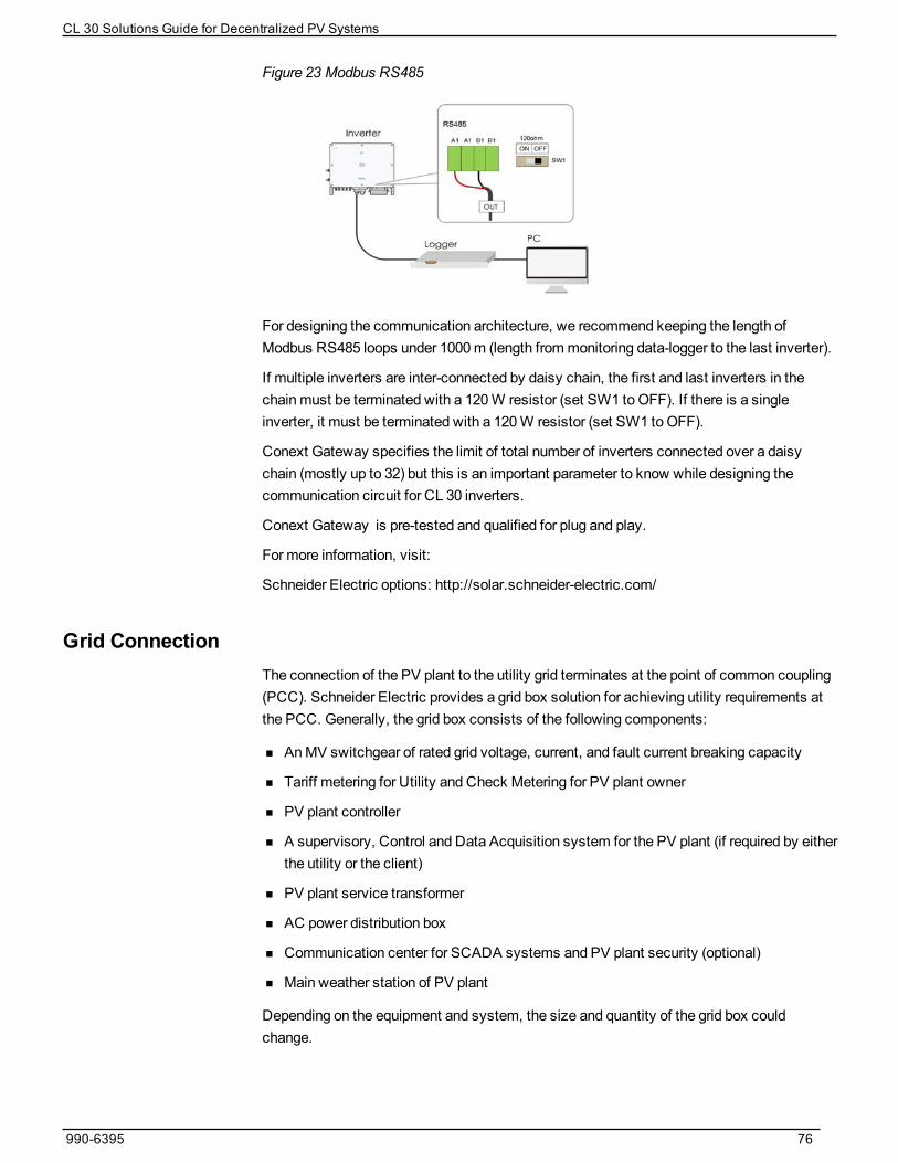
Figure 23 Modbus RS485
For designing the communication architecture, we recommend keeping the length ofModbus RS485 loops under 1000m (length frommonitoring data-logger to the last inverter).
If multiple inverters are inter-connected by daisy chain, the first and last inverters in thechainmust be terminated with a 120W resistor (set SW1 to OFF). If there is a singleinverter, it must be terminated with a 120W resistor (set SW1 to OFF).
Conext Gateway specifies the limit of total number of inverters connected over a daisychain (mostly up to 32) but this is an important parameter to know while designing thecommunication circuit for CL 30 inverters.
Conext Gateway is pre-tested and qualified for plug and play.
For more information, visit:
Schneider Electric options: http://solar.schneider-electric.com/
Grid ConnectionThe connection of the PV plant to the utility grid terminates at the point of common coupling(PCC). Schneider Electric provides a grid box solution for achieving utility requirements atthe PCC. Generally, the grid box consists of the following components:
n AnMV switchgear of rated grid voltage, current, and fault current breaking capacity
n Tariff metering for Utility and Check Metering for PV plant owner
n PV plant controller
n A supervisory, Control and Data Acquisition system for the PV plant (if required by eitherthe utility or the client)
n PV plant service transformer
n AC power distribution box
n Communication center for SCADA systems and PV plant security (optional)
n Main weather station of PV plant
Depending on the equipment and system, the size and quantity of the grid box couldchange.
990-6395 76
CL 30 Solutions Guide for Decentralized PV Systems

Along with basic monitoring capability, Schneider Electric offers advanced, state-of- the-artPV plant SCADA systems with the Conext control monitoring platform, as requested byclient.
Contact Schneider Electric for further information about configuring SCADA systems, PVplant communication, and grid controller offers.
Role of Circuit Impedance in Parallel Operation of Multiple CL 30 PV InvertersThe following recommendations are intended to help with the continuous parallel operationof CL 30 inverters:
n Restrict the AC cable impedance up to 1% of power loss.
n Restrict the Transformer impedance (between LV and HV winding) up to 6%.
n If a three winding transformer is used (HV-LV-LV) including above point, alsomaintainthe short circuit impedance of minimum or greater than 9% between each LV winding.
n Oversize (by 10%) the transformer kVA capacity with respect to installed inverter kWcapacity.
n The AC cable sizing calculation should also consider the reactive impedance of cablesand not just resistive. Grid impedance is an important parameter for this consideration.
n Calculate the grid impedance at PCC before designing the overall PV plant circuit.
990-6395 77
CL 30 Solutions Guide for Decentralized PV Systems

Layout Optimization
Layout Optimization CL 30 Solutions Guide for Decentralized PV Systems
4
Layout Design Rules 79
What's in This Chapter?

Layout Design Rules
DANGERHAZARD OF ELECTRIC SHOCK AND FIRE
Installation, including wiring, must be done by qualified personnel to ensure compliancewith all applicable installation and electrical codes, including relevant local, regional, andnational regulations. Installation instructions are not covered in this Solution Guide, but areincluded in the relevant product manuals for the CL 30 inverter. Those instructions areprovided for use by qualified installers only.
Failure to follow these instructions will result in death or serious injury.
The following layout design recommendations can be used to design standard blocksusing CL 30 inverters:
n Selection of the structural design should be based on the string length and the numberof strings connected to each inverter.
n Arrangement of modules on the PV racking should be decided in-line with the lengthof string to reduce the DC string cable route length. In case of single axis trackers,this requirement becomes more stringent from both inverter and tracker’sperspective.
n Location of the inverter should be decided prior to defining the block size.
n Connection of the strings to the inverter and use of a DC array combiner will bedependent on the location of the PV inverter.
n Location of the AC array combiner box and LV-MV station should be selected in linewith the block size, to divide blocks and reduce the cable length from teh ACcombiners to the LV-MV station.
n In most cases, the standard defined block should be duplicatedmultiple times to helpavoid wiringmistakes and shorten the installation time.
CL 30 Solutions Guide for Decentralized PV Systems Layout Optimization
79 990-6395

Frequently Asked Questions
Frequently Asked Questions CL 30 Solutions Guide for Decentralized PV Systems
5
FAQ 81
Planning and Installation FAQ 81
Downloading Files FAQ 82
Wiring and Cabling FAQ 83
Transformer FAQ 84
Specification FAQ 84
De-rating FAQ 86
What's in This Chapter?
FAQ
DANGERHAZARD OF ELECTRIC SHOCK AND FIRE
Installation, including wiring, must be done by qualified personnel to ensure compliancewith all applicable installation and electrical codes, including relevant local, regional, andnational regulations. Installation instructions are not covered in this Solutions Guide, but areincluded in the relevant product manuals for the CL 30 inverter. Those instructions areprovided for use by qualified installers only.
Failure to follow these instructions will result in death or serious injury.
Planning and Installation FAQDo I need to contact Schneider Electric at the time of designing a PV systemconfiguration for proposal?
Schneider Electric does not provide any proposal for designing a PV system. HoweverSchneider Electric has .OND files of CL 30 inverters which can be used with PV Syst forDesigning a PV system.
What type of support can I have from Schneider Electric for designingconfiguration of my PV system?
Schneider Electric provides reference documentation for designing the system, forexample, a solutions guide, owner’s guide, trainingmaterial etc. Contact us for anyadditional information or services.
Do I need assistance from Schneider Electric for the first installation of CL 30inverters?
No. For first installation, follow Schneider Electric’s CL 30Owner's Guide (documentnumber 990-91392). Identify any possible hazardous conditions, use a certified installer,and follow recommended installation practices. In case of any difficulties, you cancontact Schneider Electric for assistance.
Which parameters I do have to confirm and use to order CL 30 inverters?
Unlike centralized inverters, CL 30 PV inverters are simple to configure and install. Sinceit is simple, there is not any technical information sheet to fill in in order to buy theseinverters. Schneider Electric’s sales representatives can help you to buy the right type ofinverter and associated wiring box. This solutions guide can be used to select the rightwiring box.
Can I install the CL 30 inverter in an outdoor location?
The CL 30 inverter is rated for outdoor use. It can be installed as described in theCL 30QuickStart Guide (document number 990-91393). In any installation, keep the inverterLCD screen protected from direct exposure to sun.
CL 30 Solutions Guide for Decentralized PV Systems Frequently Asked Questions
81 990-6395

How much space do I need to install CL 30 inverters side by side?
Figure 24 Installation space between inverters
What type of monitoring system can I use with CL 30 inverters?
Schneider Electric CL 30 inverters are compatible with Conext Gateway monitoringsolutions. Contact your Schneider Electric sales representative to plan this in advance.
Can I remotely reset (on or off) the inverter over Modbus?
Yes.
Downloading Files FAQWhat is the Schneider Electric customer care contact information for technicalsupport?
You can find customer care contact details in your respective region at:http://solar.schneider-electric.com/tech-support/
Where can I find an Installation manual for CL 30 inverters?
You can find the Installationmanual for CL 30 inverters underDownloads at:
https://solar.schneider-electric.com/product/conext-cl30-string-inverter-iec/
Where can I find the test certificates for CL 30 inverter?
You can find CL 30 inverter certifications at:https://solar.schneider-electric.com/product/conext-cl30-string-inverter-iec/
What type of warranty does Schneider Electric offer for CL 30 inverters?
Warranty terms for CL 30 inverters depends on the region of installation. You can find theinformation about standard warranty at:https://solar.schneider-electric.com/product/conext-cl30-string-inverter-iec/
Frequently Asked Questions CL 30 Solutions Guide for Decentralized PV Systems
990-6395 82
How can I update the firmware version of CL 30 inverters?
CL 30 inverter firmware is available at:https://solar.schneider-electric.com/product/conext-cl30-string-inverter-iec/
You can download the latest firmware and upload it using the Insight Mobile App on yourMobile phone. Each time a CL 30 inverter is being installed, the installer should check forrevisions and use the latest firmware version available on this website.
Where can I find the CL 30 OND file for PVsyst simulation?
You can find OND files for PVsyst simulation at:https://solar.schneider-electric.com/product/conext-cl30-string-inverter-iec/
Is there any tool from Schneider Electric to help me size the strings for myinstallation?
No. Schneider Electric Clients can obtain help from Sales Application engineers to sizecorrect strings or use a third party software like PVsyst.
Wiring and Cabling FAQWhich other system components Schneider Electric can offer?
Follow the chart provided inPV SystemModeling on page 22 to check the offers fromSchneider Electric.
What type of wiring schemes can CL 30 inverters be connected to?
CL 30 inverters can be connected to TN-C, TN-C-S, TN-S, TT,and IT wiring schemes.
Can I install third party components inside the wiring box?
No. Components installed inside the wiring box are tested in the factory before dispatchand hold warranty for the product. If any external component is installed inside the wiringbox, that may void warranty.
What is the solution if my AC cable size is higher than the terminal size of theCL 30 inverter?
An external AC terminal box has to be used in certain situations. This box will have inputfrom the inverter with themaximum cable size the inverter terminal can fit (35mm2). Theoutput terminal of this AC box can have higher sized cables as required by design.
Is it possible to have a different wiring box for CL 30 inverters?
CL 30 inverters are offered with only one type of wiring box (built-in, not separate).Details of components are as described in the datasheet.
Is it mandatory to use an AC circuit breaker at the output of CL 30 wiring box?
We recommend that you use the circuit breaker to support the AC surge protectiondevice.
What is the brief specification of DC and AC Surge protection devices providedin the wiring box of the CL 30 inverters?
CL 30wiring boxes are equipped with Type 2 DC and AC surge protection devices.
CL 30 Solutions Guide for Decentralized PV Systems Frequently Asked Questions
83 990-6395

What type and size of cable could be connected to the output of CL 30 inverters?
Terminals: L1 ,L2, L3, N and PETerminal type: ScrewMin/max cable copper: 5 wires with N 16-35mm2
Cable outer diameter: 20-50mm
Transformer FAQWhat type of transformer can I connect to CL 30 inverters?
See Important Aspects of a Decentralized System Design on page 63.
Dyn11 or Dyn1 type transformers should be connected with CL 30 inverters. The LVvoltage of the transformer shouldmatch the inverter’s AC output voltage andMV voltageshouldmatch the grid connection voltage. CL 30 inverters can also connect to Delta typenetworks. Choose the transformer based on utility network requirements.
How does the choice of transformer affect the inverter's operating capability?
The inverter’s operational capability depends on the transformer in two ways:
1. Parallel operation of inverter: The inverter’s parallel operation is a function of shortcircuit impedance (Z%); the transformer is a circuit component with a very largeimpedance which equates to a large proportion of the overall circuit impedance. Werecommend keeping the impedance of the transformer as low as possible.
2. CL 30 inverter supports TN-C, TN-C-S,TN-S, TT, and IT wiring schemes. When thetransformer is selected, it is important to match:
a. utility side winding requirement with the point of connection
b. low voltage side winding requirement with the inverter’s operationalcompatibility
Do I need to oversize my transformer when I connect to multiple CL 30 inverters?
We recommend equal or oversized transformers for CL 30 inverters, especially whenthere is a large number of CL 30 inverters connected in parallel to one transformer lowvoltage winding. We recommend you oversize the transformer by 10%, however this isnot mandatory.
Specification FAQIs the power measurement inside CL 30 inverters good enough for tariffmetering?
Powermeasurement inside CL 30 inverters takes place with built-in sensors. The powerreading is calculated based on voltage and current sensors measurement within theinverter, each with 1% accuracy. Generally, tariff metering has stringent requirements foraccuracy and other compliances related to utility. Youmust discuss this requirement indetail with your utility company.
What is the maximum oversizing I can achieve for CL 30 inverters?
Maximum oversizing for CL 30 inverter could be up to 50% (1.5 DC-AC ratio). If morethan 50% oversizing is required, please contact your local Sales application engineer for
Frequently Asked Questions CL 30 Solutions Guide for Decentralized PV Systems
990-6395 84

technical assessment in string sizing. In any scenario, the limits of short circuit currentfor the inverter should not be violated. For more details, read the string sizing applicationnote available on our website.
What is the power factor limit CL 30 inverters are capable of operating within?
CL 30 can operate within 0.8 leading to 0.8 lagging power factor limit.
Does the CL 30 inverter support LVRT, HVRT requirement?
Yes. LVRT, HVRT requirement is specified in the respective PV grid code of the country.CL 30 inverter firmware is programmed to follow the LVRT, HVRT requirement (curve)during certification for each country. Contact us to learn the list of countries CL 30inverters are certified for.
Is there anti-islanding protection provided in CL 30 inverters?
Yes. CL 30 inverters are equipped with anti-islanding protection.
What is the output operating voltage range (capability and limits) and responseto network voltage sags?
The CL 30 inverter will deliver full power at unity power factor with +30% and -5% gridvoltage variation.
What is the latency to set the output of the inverter to 0% from 100%?
Latency is 2 seconds (maximum); typically 1 second.
What is the latency to set the output of the inverter to 100% from 0%?
Latency is 2 seconds (maximum); typically 1 second.
Can I control the output of the inverter in 1% steps? What is the time resolution?
1% steps is possible and latency is 2 seconds (maximum); typically 1 second.
How long does it take for a firmware upgrade over Ethernet for a single inverter?
Approximately 10 to 15minutes.
What is the value of the CL 30 inverter’s impedance?
Calculation of the impedance at 175 Hz (R and X)R + jX = 0.006 – j58.299Resistance = 0.006 ohmReactance = -58.299j
What is the switching frequency for CL 30 inverters?
Boost converter = 16 kHzInverter=16 kHz
Does the CL 30 inverter store any data? How much data and what is stored?
Preservationmachine operation and fault information:
1. Operation information (fiveminutes per day over the last 30 days).
2. Recent fault information recording (last 400 entries).
3. Recently recorded event information recording (last 400entries).
CL 30 Solutions Guide for Decentralized PV Systems Frequently Asked Questions
85 990-6395

4. Monthly and annual energy production
a. power curve (7 days)
b. generating capacity (approximately 365 days)
c. monthly energy output (180months)
d. generating capacity (30 years)
De-rating FAQWhen does the temperature de-rating begin for CL 30 inverters? How much doesit de-rate?
Figure 25 Power derating due to temperature
What is the CL 30 inverter’s de-rating with respect to AC output voltage?
When AC voltage increases, it will not result in derating, just power limitation. This isbecause at the same power, current decreases. Power decreases only when AC voltagedecreases, because after current reaches ratedmaximum current, it can not beincreased. At the same time, if the power decrease is due to a grid voltage decrease, theinverter won't display "derating". The output power values at Vdc 550 V are:
Vmin = 180 V: S=14.95 kVAVnom = 220 V: 29.9 kVA@ 40 °CVmax = 305 V: 29.9 kVA@ 40 °C
Frequently Asked Questions CL 30 Solutions Guide for Decentralized PV Systems
990-6395 86

Can you explain a detailed DC voltage vs. power curve for operating, de-ratingand off conditions with respect to specific voltage or range of voltages?
MPPT voltage range: 200 ~ 1000 V
Full MPPT voltage range: 550 ~ 850 V
Maximum voltage: 1000 V
Starting voltage: 250 V
See the diagram below for more details.
CL 30 Solutions Guide for Decentralized PV Systems Frequently Asked Questions
87 990-6395

Schneider Electric
Asstandards, specifications, and designs change from time to time,
please ask for confirmation of the information given in this publication.
For other country details please contact your localSchneider Electric
SalesRepresentative or visit the Schneider ElectricSolar Business
website at: http://solar.schneider-electric.com/
© 2020 Schneider Electric. All RightsReserved.
990-6395 Printed in: