
Lexium 62 ILM - Schneider Electric
173
EIO0000003760.00 Hardware Guide (Original Instructions) Lexium 62 ILM 11/2018
-
Upload
khangminh22 -
Category
Documents
-
view
0 -
download
0
Transcript of Lexium 62 ILM - Schneider Electric

EIO0000003760
.00
Hardware Guide(Original Instructions)
Lexium 62 ILM11/2018

The information provided in this documentation contains general descriptions and/ortechnical characteristics of the performance of the products contained herein. Thisdocumentation is not intended as a substitute for and is not to be used for determiningsuitability or reliability of these products for specific user applications. It is the duty ofany such user or integrator to perform the appropriate and complete risk analysis,evaluation and testing of the products with respect to the relevant specific applicationor use thereof. Neither Schneider Electric nor any of its affiliates or subsidiaries shallbe responsible or liable for misuse of the information contained herein. If you have anysuggestions for improvements or amendments or have found errors in this publication,please notify us.
No part of this document may be reproduced in any form or by any means, electronicor mechanical, including photocopying, without express written permission of Schneid‐er Electric.
All pertinent state, regional, and local safety regulations must be observed when in‐stalling and using this product. For reasons of safety and to help ensure compliancewith documented system data, only the manufacturer should perform repairs to com‐ponents.
When devices are used for applications with technical safety requirements, the rele‐vant instructions must be followed.
Failure to use Schneider Electric software or approved software with our hardwareproducts may result in injury, harm, or improper operating results.
Failure to observe this information can result in injury or equipment damage.
© 2016 Schneider Electric. All rights reserved.
Imprint
2 EIO0000003760 11/2018
Contents
1 Safety Information 7
2 About this manual 9
2.1 Introduction ............................................................................................................... 9
3 Product Related Information 11
3.1 Residual Risks ........................................................................................................ 113.1.1 Electrical parts ........................................................................................................ 113.1.2 Assembly and handling .......................................................................................... 123.1.3 Hot surfaces ........................................................................................................... 133.1.4 Magnetic and electromagnetic fields ...................................................................... 133.1.5 Hazardous movements .......................................................................................... 143.1.6 PELV circuits .......................................................................................................... 153.2 Proper use .............................................................................................................. 163.3 Qualification of Personnel ...................................................................................... 17
4 System overview 18
4.1 Logic Motion Controller .......................................................................................... 184.2 Lexium 62 drive system .......................................................................................... 194.2.1 Lexium 62 Distribution Box ..................................................................................... 194.2.2 Lexium 62 ILM ........................................................................................................ 204.2.3 ILM62DC•000 Daisy Chain Connector Box ............................................................ 214.3 Type code ............................................................................................................... 224.3.1 Lexium 62 connection module ................................................................................ 224.3.2 Lexium 62 distribution box ...................................................................................... 224.3.3 Lexium 62 ILM ........................................................................................................ 234.3.4 Lexium 62 ILM Daisy Chain Connector Box ........................................................... 244.3.5 Lexium 62 ILM Accessories ................................................................................... 254.4 Nameplate descriptions .......................................................................................... 27
5 Indicators and control elements 29
5.1 Displays at the Lexium 62 connection module ....................................................... 295.1.1 DC bus LED ........................................................................................................... 305.1.2 24Vdc LED ............................................................................................................. 305.2 Displays at the Lexium 62 distribution box ............................................................. 305.2.1 Hybrid connection LED ........................................................................................... 315.2.2 DC bus LED ........................................................................................................... 31
Contents
EIO0000003760 11/2018 3

5.3 Displays at the Lexium 62 ILM ............................................................................... 325.3.1 State LED ............................................................................................................... 335.3.2 Port LED ................................................................................................................. 335.3.3 S3 (Sercos III) LED ................................................................................................ 34
6 Planning 35
6.1 Electromagnetic Compatibility, EMC ...................................................................... 356.2 Control cabinet planning ......................................................................................... 386.2.1 Degree of protection (IP) ........................................................................................ 386.2.2 Mechanical and climatic environmental conditions in the control cabinet .............. 386.2.3 Using Cooling Units ................................................................................................ 396.3 Information about wiring ......................................................................................... 406.3.1 Cable characteristics .............................................................................................. 416.3.2 ESD protection measures ...................................................................................... 426.3.3 Conditions for UL / CSA compliant use .................................................................. 426.3.4 Fusing the mains connection .................................................................................. 436.3.5 Mains contactor ...................................................................................................... 436.3.6 Mains filter .............................................................................................................. 436.3.7 Mains line reactor (choke) ...................................................................................... 436.3.8 Wiring with Lexium 62 DC Link Terminal ............................................................... 436.3.9 Leakage current ..................................................................................................... 446.3.10 Residual current operated protective device .......................................................... 446.4 Functional safety .................................................................................................... 456.4.1 Process minimizing risks associated with the machine .......................................... 456.4.2 Designated safety function ..................................................................................... 476.4.3 Setup, installation, and maintenance ..................................................................... 546.4.4 Application proposals for hardware-based safety functions ................................... 586.4.5 Application proposals for software-based safety functions .................................... 616.4.6 Commissioning ....................................................................................................... 616.4.7 Best Practices ........................................................................................................ 626.4.8 Maintenance ........................................................................................................... 636.4.9 Physical environment ............................................................................................. 646.4.10 Safety standards .................................................................................................... 656.5 Special Conditions .................................................................................................. 676.5.1 Low air pressure ..................................................................................................... 67
7 Installation and maintenance 69
7.1 Commissioning ....................................................................................................... 707.1.1 Preparing commissioning ....................................................................................... 717.1.2 Grinding the holding brake ..................................................................................... 727.1.3 Preparing the control cabinet ................................................................................. 727.1.4 Mechanical mounting ............................................................................................. 757.1.5 Wiring Power Supply Module LXM62P and Lexium 62 connection module ........... 777.1.6 Wiring the Lexium 62 connection module in linear or tree topologies .................... 797.1.7 Wiring from the Lexium 62 connection module in a daisy chain topology .............. 847.2 Maintenance, repair, cleaning ................................................................................ 887.2.1 Fuse replacement Lexium 62 connection module .................................................. 897.2.2 Machine repair ........................................................................................................ 937.2.3 Cleaning ................................................................................................................. 94
Contents
4 EIO0000003760 11/2018

7.3 Replacement equipment inventory ........................................................................ 957.4 Replacing Lexium 62 components and cables ....................................................... 967.4.1 Replacement of the Lexium 62 connection module ............................................... 997.4.2 Replacement of the Lexium 62 distribution box ................................................... 1017.4.3 Replacement of the Lexium 62 ILM ...................................................................... 104
8 Technical data 107
8.1 Definition of technical data ................................................................................... 1078.2 Ambient conditions ............................................................................................... 1088.3 Standards and regulations ................................................................................... 1128.4 Motor options ........................................................................................................ 1138.5 Mechanical and electrical data ............................................................................. 1138.5.1 Lexium 62 connection module .............................................................................. 1138.5.2 Lexium 62 distribution box .................................................................................... 1148.5.3 Daisy Chain Connector Box ................................................................................. 1158.5.4 Lexium 62 ILM ...................................................................................................... 1168.5.5 ILM070 Servo Motor ............................................................................................. 1178.5.6 ILM100 Servo Motor ............................................................................................. 1188.5.7 ILM140 Servo Motor ............................................................................................. 1198.5.8 Encoder ................................................................................................................ 1208.5.9 Motor shaft and bearings ...................................................................................... 1218.5.10 Holding brake ....................................................................................................... 1238.6 Mounting arrangement and degree of protection ................................................. 1258.7 Torque/speed characteristic curves ..................................................................... 1258.8 Electrical connections ........................................................................................... 1318.8.1 Lexium 62 connection module .............................................................................. 1318.8.2 Lexium 62 distribution box .................................................................................... 1358.8.3 Lexium 62 ILM ...................................................................................................... 1378.8.4 ILM62DC•000 Daisy Chain Connector Box .......................................................... 1388.9 Dimensions ........................................................................................................... 1408.9.1 Lexium 62 connection module .............................................................................. 1408.9.2 Lexium 62 distribution box .................................................................................... 1418.9.3 ILM62DC•000 Daisy Chain Connector Box .......................................................... 1428.9.4 Lexium 62 ILM ...................................................................................................... 145
9 Optional module ILM62-DIO8 150
9.1 Technical data ...................................................................................................... 1519.2 Installation ............................................................................................................ 1529.3 Electrical connections ........................................................................................... 1549.4 Dimensions ........................................................................................................... 1569.5 Wiring ................................................................................................................... 157
10 Safety option module for Lexium 62 ILM 158
Contents
EIO0000003760 11/2018 5
10.1 Technical data ...................................................................................................... 15910.2 Installation ............................................................................................................ 16010.3 Dimensions ........................................................................................................... 162
11 Hybrid connector ILM62-HCN2 163
11.1 Technical data ...................................................................................................... 16411.1.1 Ambient conditions ............................................................................................... 16411.1.2 Mechanical and electrical data ............................................................................. 16511.2 Installation ............................................................................................................ 16511.3 Electrical connections ........................................................................................... 16711.4 Dimensions ........................................................................................................... 168
12 Appendix 169
12.1 Contact addresses ............................................................................................... 16912.2 Product training courses ....................................................................................... 16912.3 Disposal ................................................................................................................ 16912.4 Units and conversion tables ................................................................................. 17012.4.1 Length .................................................................................................................. 17012.4.2 Mass ..................................................................................................................... 17012.4.3 Force .................................................................................................................... 17012.4.4 Power ................................................................................................................... 17012.4.5 Rotation ................................................................................................................ 17012.4.6 Torque .................................................................................................................. 17112.4.7 Moment of inertia .................................................................................................. 17112.4.8 Temperature ......................................................................................................... 17112.4.9 Conductor cross-section ....................................................................................... 171
Contents
6 EIO0000003760 11/2018
1 Safety InformationImportant Information
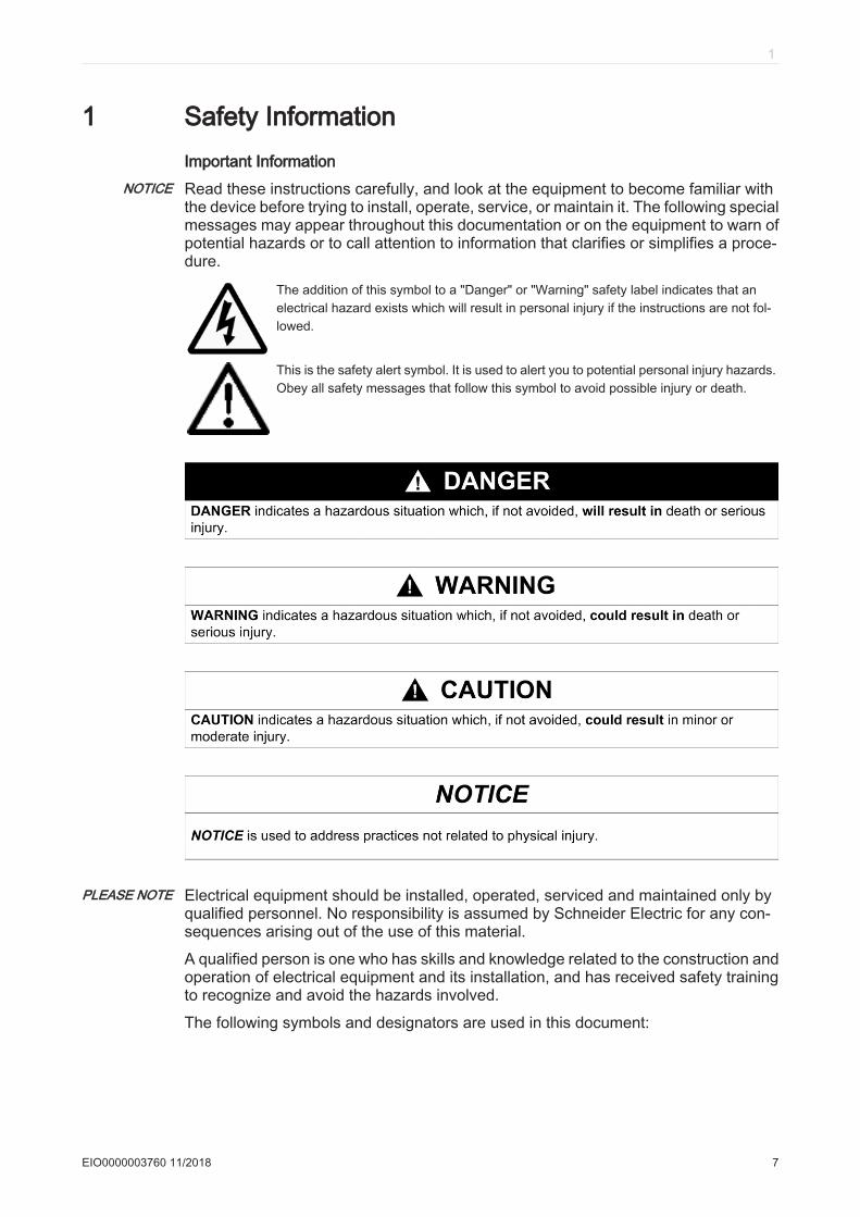
NOTICE Read these instructions carefully, and look at the equipment to become familiar withthe device before trying to install, operate, service, or maintain it. The following specialmessages may appear throughout this documentation or on the equipment to warn ofpotential hazards or to call attention to information that clarifies or simplifies a proce‐dure.
The addition of this symbol to a "Danger" or "Warning" safety label indicates that anelectrical hazard exists which will result in personal injury if the instructions are not fol‐lowed.
This is the safety alert symbol. It is used to alert you to potential personal injury hazards.Obey all safety messages that follow this symbol to avoid possible injury or death.
PLEASE NOTE Electrical equipment should be installed, operated, serviced and maintained only byqualified personnel. No responsibility is assumed by Schneider Electric for any con‐sequences arising out of the use of this material.
A qualified person is one who has skills and knowledge related to the construction andoperation of electrical equipment and its installation, and has received safety trainingto recognize and avoid the hazards involved.
The following symbols and designators are used in this document:
1
EIO0000003760 11/2018 7
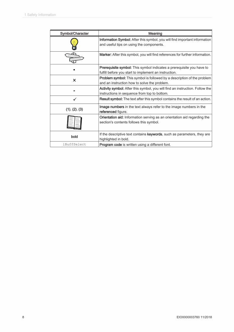
Symbol/Character Meaning
Information Symbol: After this symbol, you will find important informationand useful tips on using the components.
Marker: After this symbol, you will find references for further information.
Prerequisite symbol: This symbol indicates a prerequisite you have tofulfill before you start to implement an instruction.Problem symbol: This symbol is followed by a description of the problemand an instruction how to solve the problem.
►Activity symbol: After this symbol, you will find an instruction. Follow theinstructions in sequence from top to bottom.
ü Result symbol: The text after this symbol contains the result of an action.
(1), (2), (3)Image numbers in the text always refer to the image numbers in thereferenced figure.Orientation aid: Information serving as an orientation aid regarding thesection's contents follows this symbol.
boldIf the descriptive text contains keywords, such as parameters, they arehighlighted in bold.
lBuffSelect Program code is written using a different font.
1 Safety Information
8 EIO0000003760 11/2018
2 About this manual
2.1 Introduction
Read and understand the material contained in this manual before you work on Lexium62 ILM for the first time. Take particular note of the safety information (see 3 ProductRelated Information). As described in section 3.3, only those persons who meetthe "Qualification of Personnel (see 3.3 Qualification of Personnel)" are allowed towork with the Lexium 62 components.
A copy of this manual must be available for personnel who work with the Lexium 62ILM.
This manual is to help you use the capabilities of the Lexium 62 ILM safely and prop‐erly.
Follow the instructions within this manual to help:
• reduce risks• reduce repair costs and downtime of the Lexium 62 components• increase the service life of the Lexium 62 components,• increase reliability of the Lexium 62 components.
Terminology Derived from Standards
The technical terms, terminology, symbols and the corresponding descriptions in thismanual, or that appear in or on the products themselves, are generally derived fromthe terms or definitions of international standards.
In the area of functional safety systems, drives and general automation, this may in‐clude, but is not limited to, terms such as safety, safety function, safe state, fault, faultreset, malfunction, failure, error, error message, dangerous, etc.
Among others, these standards include:
EN 61131-2:2007 Programmable controllers, part 2: Equipment requirements and tests.ISO 13849-1:2008 Safety of machinery: Safety-related parts of control systems. General principles for
design.EN 61496-1:2013 Safety of machinery: Electro-sensitive protective equipment. Part 1: General re‐
quirements and tests.ISO 12100:2010 Safety of machinery - General principles for design - Risk assessment and risk
reductionIEC/EN60204-1:2006
Safety of machinery - Electrical equipment of machines - Part 1: General require‐ments
EN 1088:2008 ISO 14119:2013
Safety of machinery - Interlocking devices associated with guards - Principles fordesign and selection
ISO 13850:2006 Safety of machinery - Emergency stop - Principles for designIEC/EN62061:2005
Safety of machinery - Functional safety of safety-related electrical, electronic, andelectronic programmable control systems
IEC 61508-1:2010 Functional safety of electrical/electronic/programmable electronic safety-relatedsystems: General requirements.
IEC 61508-2:2010 Functional safety of electrical/electronic/programmable electronic safety-relatedsystems: Requirements for electrical/electronic/programmable electronic safety-related systems.
IEC 61508-3:2010 Functional safety of electrical/electronic/programmable electronic safety-relatedsystems: Software requirements.
2.1 Introduction
EIO0000003760 11/2018 9
IEC 61784-3:2008 Digital data communication for measurement and control: Functional safety fieldbuses.
2006/42/EC Machinery Directive2014/30/EU Electromagnetic Compatibility Directive2014/35/EU Low Voltage Directive
In addition, terms used in the present document may tangentially be used as they arederived from other standards such as:
IEC 60034 series Rotating electrical machinesIEC 61800 series Adjustable speed electrical power drive systemsIEC 61158 series Digital data communications for measurement and control – Fieldbus for use in
industrial control systems
Finally, the term zone of operation may be used in conjunction with the description ofspecific hazards, and is defined as it is for a hazard zone or danger zone in the Ma‐chinery Directive (2006/42/EC) and ISO 12100:2010.
NOTE: The aforementioned standards may or may not apply to the specific productscited in the present documentation. For more information concerning the individualstandards applicable to the products described herein, see the characteristics tablesfor those product references.
2 About this manual
10 EIO0000003760 11/2018
3 Product Related Information
This section contains important safety information regarding working with the Lexium62 component. The Lexium 62 ILM, as part of the Lexium 62 Drive System, conformsto recognized technical safety regulations.
3.1 Residual Risks
Hazards arising from the Lexium 62 components have been reduced. However, re‐sidual risks remain since the Lexium 62 components work with electrical voltage andelectrical currents while controlling the motors that produce machine movements.
If activities involve residual risks, a safety message is made at the appropriate points.This includes potential hazard(s) that may arise, their possible consequences, anddescribes preventive measures to avoid the hazard(s).
3.1.1 Electrical parts
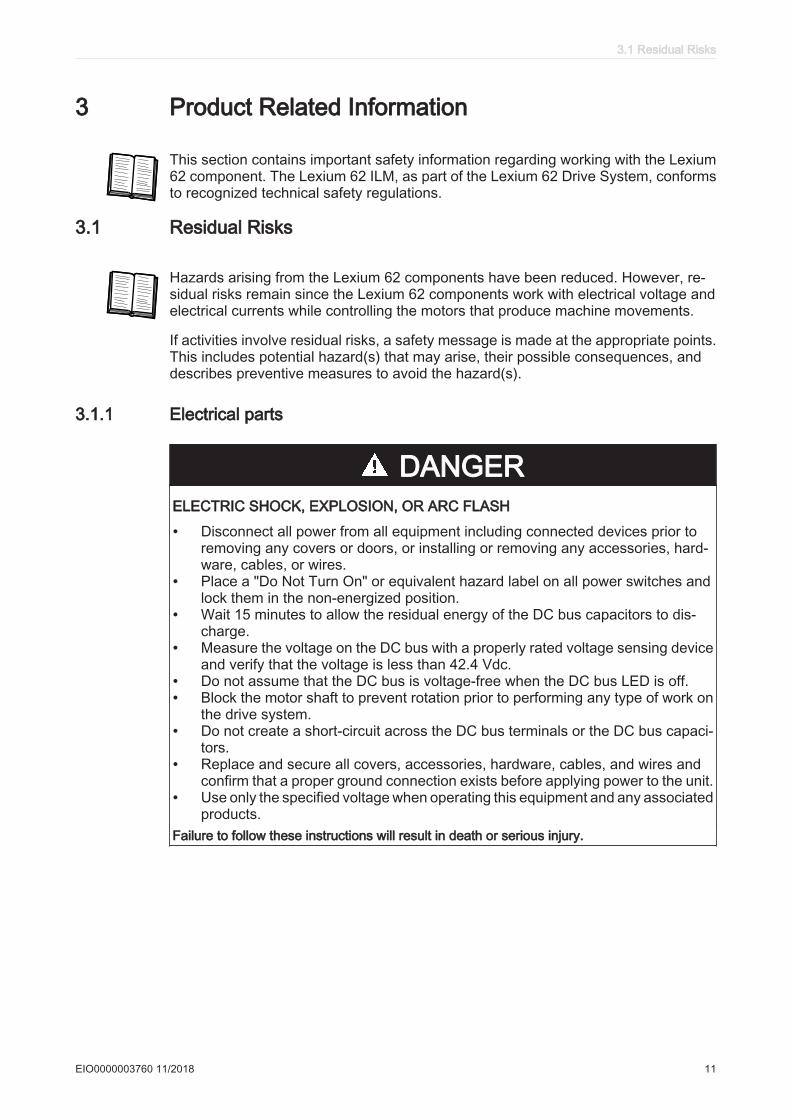
DANGERELECTRIC SHOCK, EXPLOSION, OR ARC FLASH
• Disconnect all power from all equipment including connected devices prior toremoving any covers or doors, or installing or removing any accessories, hard‐ware, cables, or wires.
• Place a "Do Not Turn On" or equivalent hazard label on all power switches andlock them in the non-energized position.
• Wait 15 minutes to allow the residual energy of the DC bus capacitors to dis‐charge.
• Measure the voltage on the DC bus with a properly rated voltage sensing deviceand verify that the voltage is less than 42.4 Vdc.
• Do not assume that the DC bus is voltage-free when the DC bus LED is off.• Block the motor shaft to prevent rotation prior to performing any type of work on
the drive system.• Do not create a short-circuit across the DC bus terminals or the DC bus capaci‐
tors.• Replace and secure all covers, accessories, hardware, cables, and wires and
confirm that a proper ground connection exists before applying power to the unit.• Use only the specified voltage when operating this equipment and any associated
products.Failure to follow these instructions will result in death or serious injury.
3.1 Residual Risks
EIO0000003760 11/2018 11
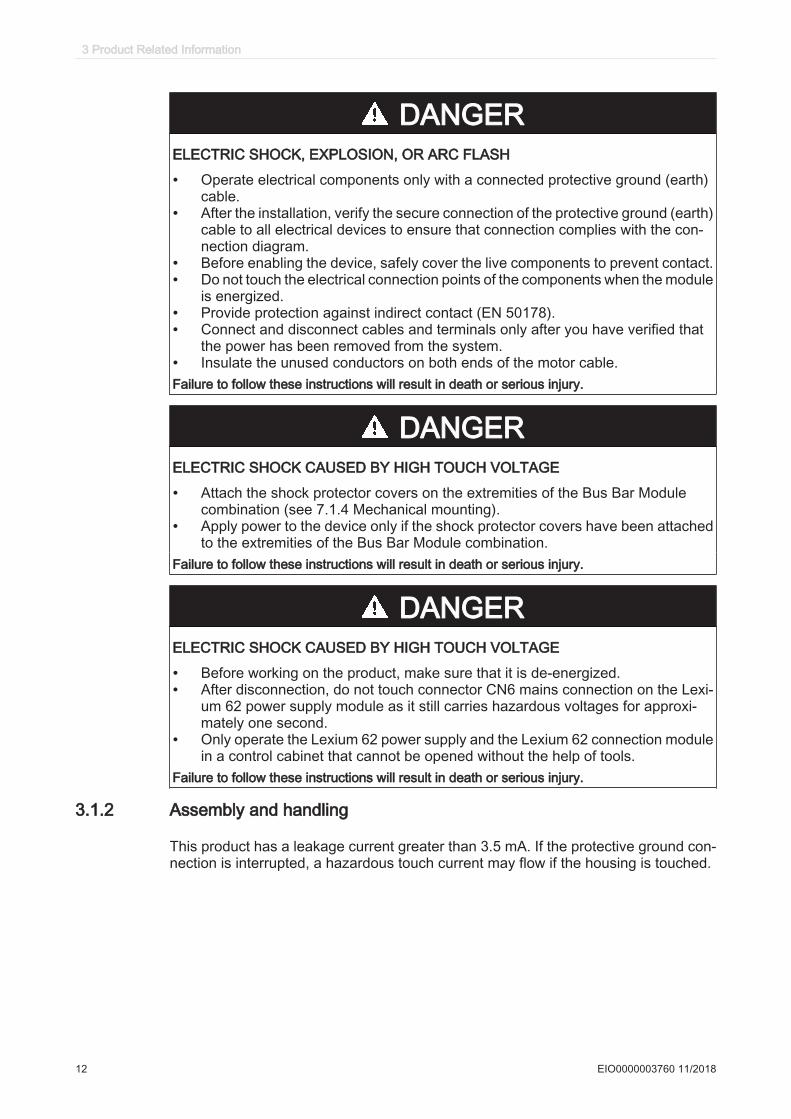
DANGERELECTRIC SHOCK, EXPLOSION, OR ARC FLASH
• Operate electrical components only with a connected protective ground (earth)cable.
• After the installation, verify the secure connection of the protective ground (earth)cable to all electrical devices to ensure that connection complies with the con‐nection diagram.
• Before enabling the device, safely cover the live components to prevent contact.• Do not touch the electrical connection points of the components when the module
is energized.• Provide protection against indirect contact (EN 50178).• Connect and disconnect cables and terminals only after you have verified that
the power has been removed from the system.• Insulate the unused conductors on both ends of the motor cable.Failure to follow these instructions will result in death or serious injury.
DANGERELECTRIC SHOCK CAUSED BY HIGH TOUCH VOLTAGE
• Attach the shock protector covers on the extremities of the Bus Bar Modulecombination (see 7.1.4 Mechanical mounting).
• Apply power to the device only if the shock protector covers have been attachedto the extremities of the Bus Bar Module combination.
Failure to follow these instructions will result in death or serious injury.
DANGERELECTRIC SHOCK CAUSED BY HIGH TOUCH VOLTAGE
• Before working on the product, make sure that it is de-energized.• After disconnection, do not touch connector CN6 mains connection on the Lexi‐
um 62 power supply module as it still carries hazardous voltages for approxi‐mately one second.
• Only operate the Lexium 62 power supply and the Lexium 62 connection modulein a control cabinet that cannot be opened without the help of tools.
Failure to follow these instructions will result in death or serious injury.
3.1.2 Assembly and handling
This product has a leakage current greater than 3.5 mA. If the protective ground con‐nection is interrupted, a hazardous touch current may flow if the housing is touched.
3 Product Related Information
12 EIO0000003760 11/2018
DANGERINSUFFICIENT GROUNDING
• Use a protective ground conductor with at least 10 mm2 (AWG 6) or two protectiveground conductors with the same or larger cross section of the conductors sup‐plying the power terminals.
• Verify compliance with all local and national electrical code requirements as wellas all other applicable regulations with respect to grounding of all equipment.
Failure to follow these instructions will result in death or serious injury.
WARNINGCRUSHING, SHEARING, CUTTING AND HITTING DURING HANDLING
• Observe the general construction and safety regulations for handling and as‐sembly.
• Use appropriate mounting and transport equipment and use appropriate tools.• Prevent clamping and crushing by taking appropriate precautions.• Cover edges and angles to protect against cutting damage.• Wear appropriate protective clothing (for example, protective goggles, protective
boots, protective gloves).Failure to follow these instructions can result in death, serious injury, or equipment damage.
3.1.3 Hot surfaces
The metal surfaces of the product may exceed 85 °C (185 °F) during operation.
WARNINGHOT SURFACES
• Avoid unprotected contact with hot surfaces.• Do not allow flammable or heat-sensitive parts in the immediate vicinity of hot
surfaces.• Verify that the heat dissipation is sufficient by performing a test run under maxi‐
mum load conditions.Failure to follow these instructions can result in death, serious injury, or equipment damage.
3.1.4 Magnetic and electromagnetic fields
Conductors and motors can generate strong local electrical and magnetic fields. Thiscan cause interference in sensitive devices.
3.1 Residual Risks
EIO0000003760 11/2018 13
WARNINGELECTROMAGNETIC FIELDS
• Keep persons with electronic medical implants, such as pacemakers, away fromthe motor and the conductors.
• Do not place electromagnetically sensitive devices in the vicinity of the motor orof the conductors.
Failure to follow these instructions can result in death, serious injury, or equipment damage.
3.1.5 Hazardous movements
There can be different sources of hazardous movements:
• No, or incorrect, homing of the drive• Wiring or cabling errors• Errors in the application program• Component errors• Error in the measured value and signal transmitter
Provide for personal safety by primary equipment monitoring or measures. Do not relyonly on the internal monitoring of the drive components. Adapt the monitoring or otherarrangements and measures to the specific conditions of the installation in accordancewith a risk and error analysis.
DANGERUNAVAILABLE OR INADEQUATE PROTECTION DEVICE(S)
• Prevent entry to a zone of operation with, for example, protective fencing, meshguards, protective coverings, or light barriers.
• Dimension the protective devices properly and do not remove them.• Do not make any modifications that can degrade, incapacitate, or in any way
invalidate protection devices.• Before accessing the drives or entering the zone of operation, bring the drives
and the motors they control to a stop.• Protect existing workstations and operating terminals against unauthorized op‐
eration.• Position EMERGENCY STOP switches so that they are easily accessible and
can be reached quickly.• Validate the functionality of EMERGENCY STOP equipment before start-up and
during maintenance periods.• Prevent unintentional start-up by disconnecting the power connection of the drive
using the EMERGENCY STOP circuit or using an appropriate lock-out tag-outsequence.
• Validate the system and installation before the initial start-up.• Avoid operating high-frequency, remote control, and radio devices close to the
system electronics and their feed lines, and perform, if necessary, an EMC vali‐dation of the system.
Failure to follow these instructions will result in death or serious injury.
Drive systems may perform unanticipated movements because of incorrect wiring,incorrect settings, incorrect data or other errors.
3 Product Related Information
14 EIO0000003760 11/2018
WARNINGUNINTENDED MOVEMENT OR MACHINE OPERATION
• Carefully install the wiring in accordance with the EMC requirements.• Do not operate the product with unknown settings and data.• Perform comprehensive commissioning tests that include verification of config‐
uration settings and data that determine position and movement.Failure to follow these instructions can result in death, serious injury, or equipment damage.
3.1.6 PELV circuits
All signal and control voltages must be designed as PELV circuits. In particular, thisimplies protective measures against direct and indirect contact with hazardous voltageby:
• Ensuring that the voltage with respect to PE remains below 30 Vdc.• An implemented separation in the system/machine of the low and high voltage side.
Connect GND / 0 V to PE (Protective Earth/ground) at least at one point in the controlcabinet.
Separate high and low voltage wiring and respect the standard IEC 61800-5-1, Ad‐justable speed electrical power drive systems - safety requirements.
DANGERELECTRIC SHOCK BY INADEQUATE PROTECTIVE SEPARATION
Only connect devices, electrical components, or lines to the signal voltage connectorsof these products that feature a sufficient, protective separation from the connectedcircuits in accordance with the standards (IEC 61800-5-1: Adjustable speed electricalpower drive systems - safety requirements).Failure to follow these instructions will result in death or serious injury.
3.1 Residual Risks
EIO0000003760 11/2018 15
3.2 Proper use
The Lexium 62 Power Supply and the Lexium 62 Connection Module must only beinstalled in an electrical equipment enclosure (for example, in a control cabinet). Theelectrical equipment enclosure must be lockable by using a key or tool. The Lexium62 ILM and the Lexium 62 Distribution Box are intended for installation in a machine.
Provide forprotectivemeasures
Before installing the device, provide for appropriate protective devices in compliancewith local and national standards. Do not commission components without appropriateprotective devices. After installation, commissioning, or repair, test the protective de‐vices used.
Perform a risk evaluation concerning the specific use before operating the product andtake appropriate security measures.
WARNINGUNINTENDED EQUIPMENT OPERATION
Ensure that a risk assessment is conducted and respected according toEN/ISO 12100 during the design of your machine.Failure to follow these instructions can result in death, serious injury, or equipment damage.
If circumstances occur that affect the safety or cause changes to the operating be‐havior of the Lexium 62 component, then immediately shut down the Lexium 62 com‐ponent and contact Schneider Electric.
Use original-equipment
only
Use only the accessories and mounting parts specified in the documentation and nothird-party devices or components that have not been expressly approved by Schneid‐er Electric. With the exception of replaceable, internal fuses in some Lexium 62 com‐ponents, there are no user-serviceable parts in the Lexium 62 component system. Donot attempt to modify the Lexium 62 component in any way. Refer to Schneider Electricfor all repairs and replacements.
WARNINGUNINTENDED EQUIPMENT OPERATION
• Only use software and hardware components approved by Schneider Electric foruse with this equipment.
• Do not attempt to service this equipment outside of authorized Schneider Electricservice centers.
• Update your application program every time you change the physical hardwareconfiguration.
Failure to follow these instructions can result in death, serious injury, or equipment damage.
The components must not be used in the following environments:Incompatible
environments• In hazardous (explosive) atmospheres• In mobile, movable or floating systems• In life support systems• In domestic appliances• underground
This equipment has been designed to operate outside of any hazardous location. Onlyinstall this equipment in zones known to be free of a hazardous atmosphere.
3 Product Related Information
16 EIO0000003760 11/2018
DANGERPOTENTIAL FOR EXPLOSION
Install and use this equipment in non-hazardous locations only.Failure to follow these instructions will result in death or serious injury.
3.3 Qualification of Personnel
Target audi‐ence
for this manual
Electrical equipment must be installed, operated, serviced, and maintained only byqualified personnel. No responsibility is assumed by Schneider Electric for any con‐sequences arising out of the use of this material.
Qualified per‐son
A qualified person is one who has skills and knowledge related to the construction andoperation of electrical equipment and the installation, and has received safety trainingto recognize and avoid the hazards involved.
The qualified personnel must be able to detect possible hazards that may arise fromparameterization, changing parameter values and generally from mechanical, electri‐cal, or electronic equipment. The qualified personnel must be familiar with the stand‐ards, provisions, and regulations for the prevention of industrial accidents, which theymust observe when working on the drive system.
Designatedsafety func‐
tions
Qualified personnel that work with designated safety functions must be trained ac‐cording to the complexity of the machines and the requirements of the EN ISO13849-1:2008. The training has to include the production process and the relationbetween the designated safety function and the machine.
Qualification guidelines are available in the following publication: Safety, Competencyand Commitment: Competency Guidelines for Safety-Related System Practitioners.IEEE Publications, ISBN 0 85296 787 X, 1999.
3.3 Qualification of Personnel
EIO0000003760 11/2018 17
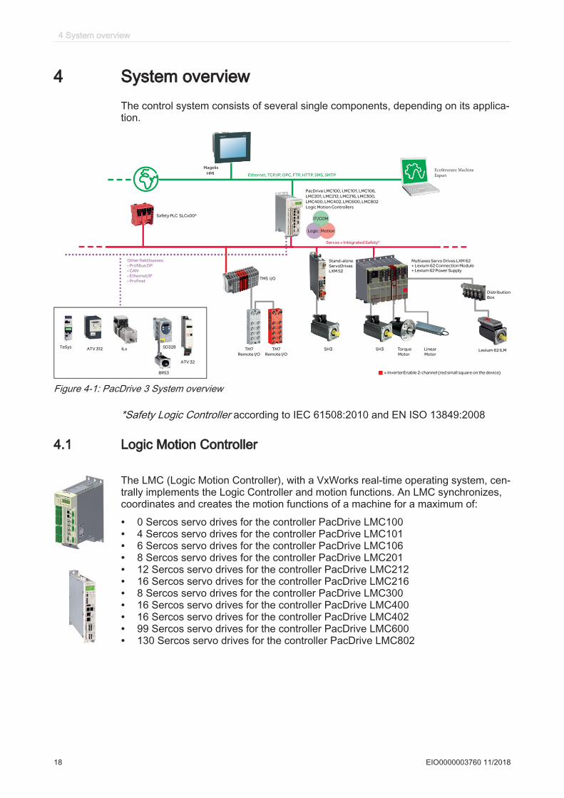
4 System overviewThe control system consists of several single components, depending on its applica‐tion.
Ethernet, TCP/IP, OPC, FTP, HTTP, SMS, SMTP
Sercos + Integrated Safety*
Magelis
HMI
PacDrive LMC100, LMC101, LMC106,
LMC201, LMC212, LMC216, LMC300,
LMC400, LMC402, LMC600, LMC802
Logic Motion Controllers
EcoStruxure Machine Expert
IT/COM
Logic Motion
TM7
Remote I/O
TM7
Remote I/O
TM5 I/O
Multiaxes Servo Drives LXM 62
+ Lexium 62 Power Supply
Stand-alone
ServoDrives
LXM 52
Distribution
Box
Lexium 62 ILMSH3 euqroT H3S
Motor
Linear
Motor
Other field busses:
• Profibus DP
• CAN
• Ethernet/IP
• Profinet
Safety PLC SLCx00*
ILx SD328
BRS3
TeSys ATV 312
ATV 32
= InverterEnable 2-channel (red small square on the device)
+ Lexium 62 Connection Module
Figure 4-1: PacDrive 3 System overview
*Safety Logic Controller according to IEC 61508:2010 and EN ISO 13849:2008
4.1 Logic Motion Controller
The LMC (Logic Motion Controller), with a VxWorks real-time operating system, cen‐trally implements the Logic Controller and motion functions. An LMC synchronizes,coordinates and creates the motion functions of a machine for a maximum of:
• 0 Sercos servo drives for the controller PacDrive LMC100• 4 Sercos servo drives for the controller PacDrive LMC101• 6 Sercos servo drives for the controller PacDrive LMC106• 8 Sercos servo drives for the controller PacDrive LMC201• 12 Sercos servo drives for the controller PacDrive LMC212• 16 Sercos servo drives for the controller PacDrive LMC216• 8 Sercos servo drives for the controller PacDrive LMC300• 16 Sercos servo drives for the controller PacDrive LMC400• 16 Sercos servo drives for the controller PacDrive LMC402• 99 Sercos servo drives for the controller PacDrive LMC600• 130 Sercos servo drives for the controller PacDrive LMC802
4 System overview
18 EIO0000003760 11/2018
4.2 Lexium 62 drive system
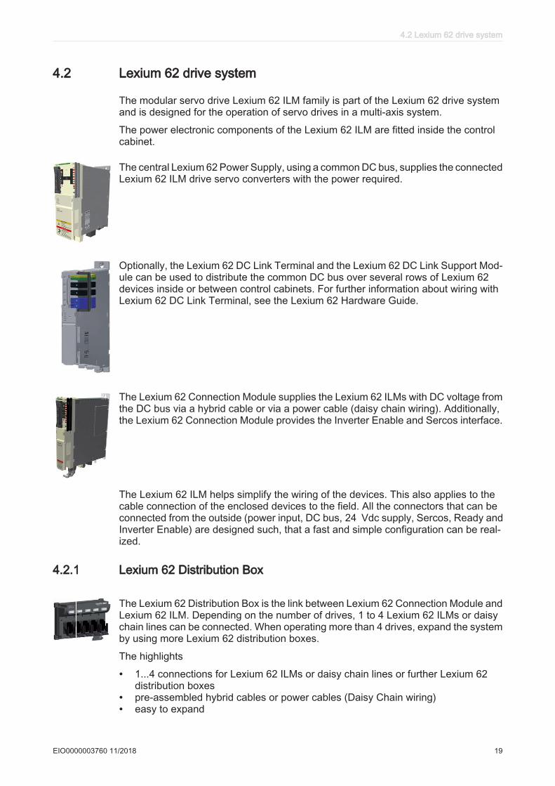
The modular servo drive Lexium 62 ILM family is part of the Lexium 62 drive systemand is designed for the operation of servo drives in a multi-axis system.
The power electronic components of the Lexium 62 ILM are fitted inside the controlcabinet.
The central Lexium 62 Power Supply, using a common DC bus, supplies the connectedLexium 62 ILM drive servo converters with the power required.
Optionally, the Lexium 62 DC Link Terminal and the Lexium 62 DC Link Support Mod‐ule can be used to distribute the common DC bus over several rows of Lexium 62devices inside or between control cabinets. For further information about wiring withLexium 62 DC Link Terminal, see the Lexium 62 Hardware Guide.
The Lexium 62 Connection Module supplies the Lexium 62 ILMs with DC voltage fromthe DC bus via a hybrid cable or via a power cable (daisy chain wiring). Additionally,the Lexium 62 Connection Module provides the Inverter Enable and Sercos interface.
The Lexium 62 ILM helps simplify the wiring of the devices. This also applies to thecable connection of the enclosed devices to the field. All the connectors that can beconnected from the outside (power input, DC bus, 24 Vdc supply, Sercos, Ready andInverter Enable) are designed such, that a fast and simple configuration can be real‐ized.
4.2.1 Lexium 62 Distribution Box
The Lexium 62 Distribution Box is the link between Lexium 62 Connection Module andLexium 62 ILM. Depending on the number of drives, 1 to 4 Lexium 62 ILMs or daisychain lines can be connected. When operating more than 4 drives, expand the systemby using more Lexium 62 distribution boxes.
The highlights
• 1...4 connections for Lexium 62 ILMs or daisy chain lines or further Lexium 62distribution boxes
• pre-assembled hybrid cables or power cables (Daisy Chain wiring)• easy to expand
4.2 Lexium 62 drive system
EIO0000003760 11/2018 19
4.2.2 Lexium 62 ILM
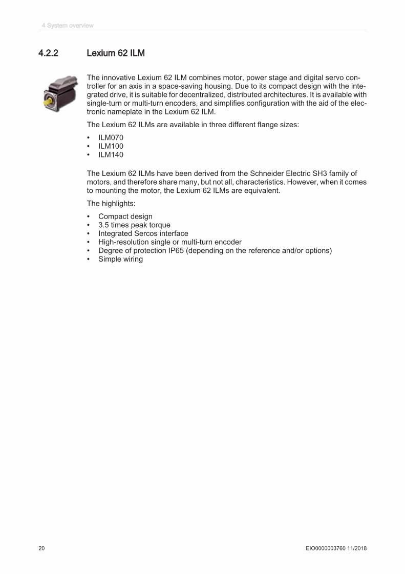
The innovative Lexium 62 ILM combines motor, power stage and digital servo con‐troller for an axis in a space-saving housing. Due to its compact design with the inte‐grated drive, it is suitable for decentralized, distributed architectures. It is available withsingle-turn or multi-turn encoders, and simplifies configuration with the aid of the elec‐tronic nameplate in the Lexium 62 ILM.
The Lexium 62 ILMs are available in three different flange sizes:
• ILM070• ILM100• ILM140
The Lexium 62 ILMs have been derived from the Schneider Electric SH3 family ofmotors, and therefore share many, but not all, characteristics. However, when it comesto mounting the motor, the Lexium 62 ILMs are equivalent.
The highlights:
• Compact design• 3.5 times peak torque• Integrated Sercos interface• High-resolution single or multi-turn encoder• Degree of protection IP65 (depending on the reference and/or options)• Simple wiring
4 System overview
20 EIO0000003760 11/2018
4.2.3 ILM62DC•000 Daisy Chain Connector Box
TM
ILM62DCA000
TM
ILM62DCC000
1
ILM62DCB000
111111111111111111111111111111111111111
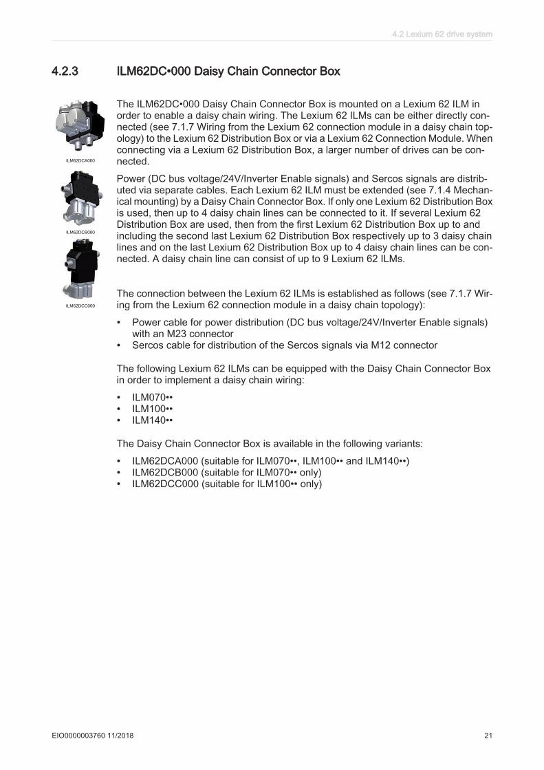
The ILM62DC•000 Daisy Chain Connector Box is mounted on a Lexium 62 ILM inorder to enable a daisy chain wiring. The Lexium 62 ILMs can be either directly con‐nected (see 7.1.7 Wiring from the Lexium 62 connection module in a daisy chain top‐ology) to the Lexium 62 Distribution Box or via a Lexium 62 Connection Module. Whenconnecting via a Lexium 62 Distribution Box, a larger number of drives can be con‐nected.
Power (DC bus voltage/24V/Inverter Enable signals) and Sercos signals are distrib‐uted via separate cables. Each Lexium 62 ILM must be extended (see 7.1.4 Mechan‐ical mounting) by a Daisy Chain Connector Box. If only one Lexium 62 Distribution Boxis used, then up to 4 daisy chain lines can be connected to it. If several Lexium 62Distribution Box are used, then from the first Lexium 62 Distribution Box up to andincluding the second last Lexium 62 Distribution Box respectively up to 3 daisy chainlines and on the last Lexium 62 Distribution Box up to 4 daisy chain lines can be con‐nected. A daisy chain line can consist of up to 9 Lexium 62 ILMs.
The connection between the Lexium 62 ILMs is established as follows (see 7.1.7 Wir‐ing from the Lexium 62 connection module in a daisy chain topology):
• Power cable for power distribution (DC bus voltage/24V/Inverter Enable signals)with an M23 connector
• Sercos cable for distribution of the Sercos signals via M12 connector
The following Lexium 62 ILMs can be equipped with the Daisy Chain Connector Boxin order to implement a daisy chain wiring:
• ILM070••• ILM100••• ILM140••
The Daisy Chain Connector Box is available in the following variants:
• ILM62DCA000 (suitable for ILM070••, ILM100•• and ILM140••)• ILM62DCB000 (suitable for ILM070•• only)• ILM62DCC000 (suitable for ILM100•• only)
4.2 Lexium 62 drive system
EIO0000003760 11/2018 21
4.3 Type code
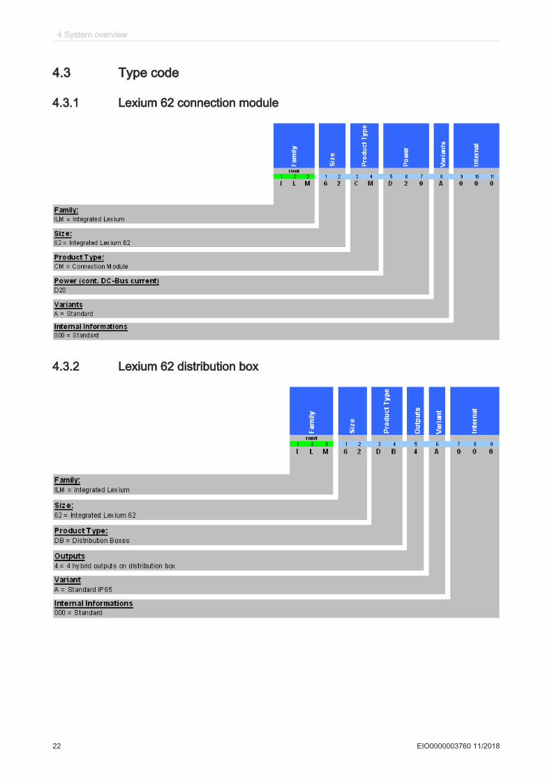
4.3.1 Lexium 62 connection module
4.3.2 Lexium 62 distribution box
4 System overview
22 EIO0000003760 11/2018
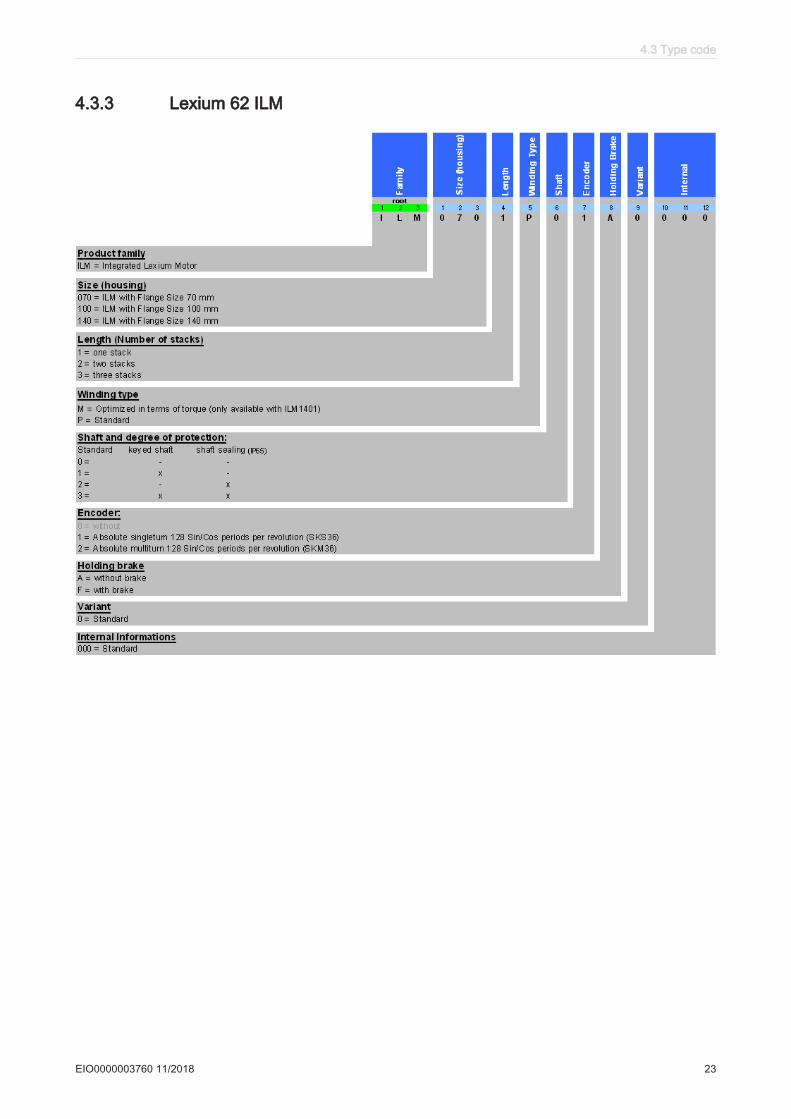
4.3.3 Lexium 62 ILM
4.3 Type code
EIO0000003760 11/2018 23
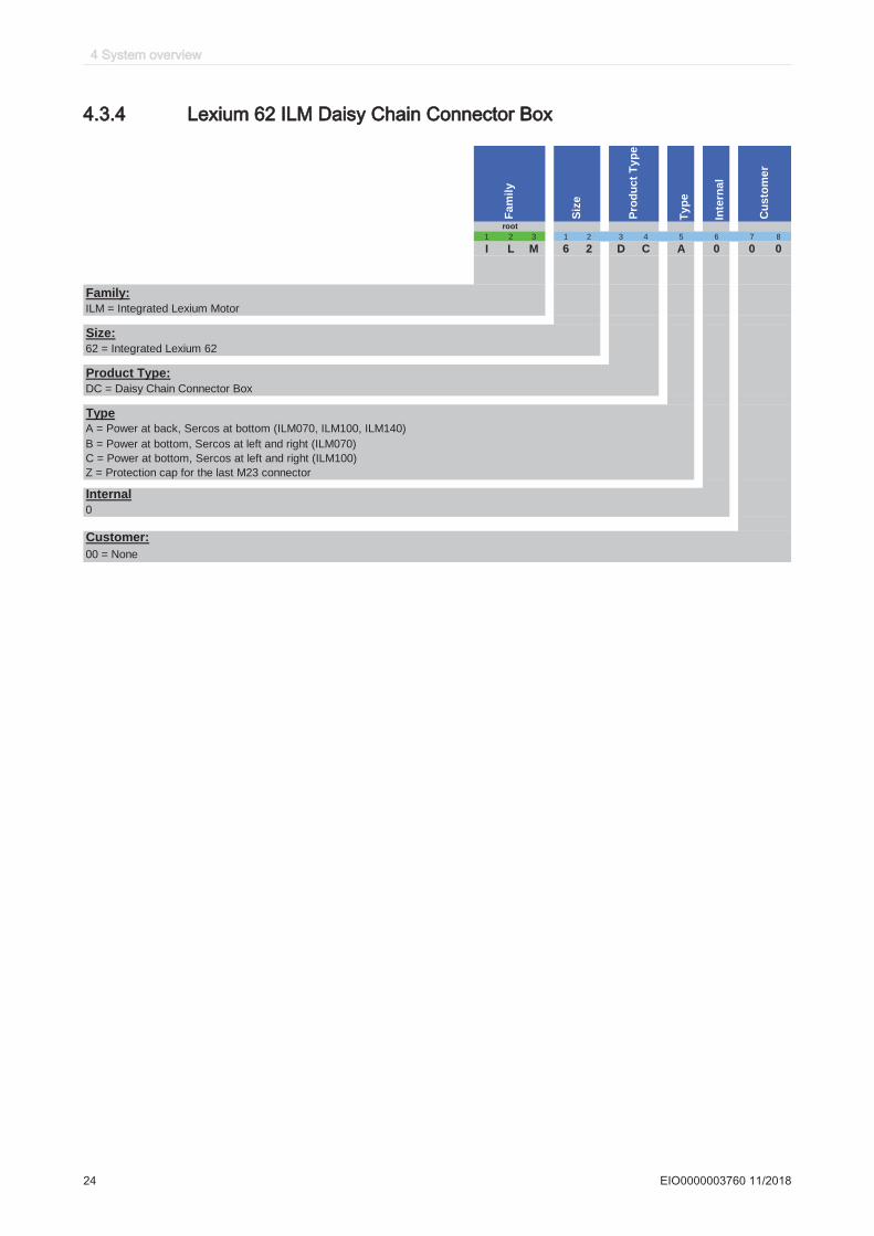
4.3.4 Lexium 62 ILM Daisy Chain Connector Box
Ty
pe
Inte
rna
l
1 2 3 1 2 3 4 5 6 7 8
I L M 6 2 D C A 0 0 0
Family:
ILM = Integrated Lexium Motor
Size:
62 = Integrated Lexium 62
Product Type:
DC = Daisy Chain Connector Box
Type
A = Power at back, Sercos at bottom (ILM070, ILM100, ILM140)
B = Power at bottom, Sercos at left and right (ILM070)
C = Power at bottom, Sercos at left and right (ILM100)
Z = Protection cap for the last M23 connector
Internal
0
Customer:
00 = None
Fa
mil
y
Siz
e
Pro
du
ct
Ty
pe
Cu
sto
me
r
root
4 System overview
24 EIO0000003760 11/2018
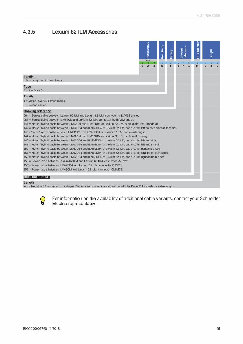
4.3.5 Lexium 62 ILM Accessories
Re
s.
Bo
dy
Fam
ily
Fix
sep
ara
tor
1 2 3 1 2 3 4 5 6 7 8 9
V W 3 E 1 1 4 1 R 0 5 0
Family:
ILM = Integrated Lexium Motor
Type
E = PacDrive 3
Family
1 = Motor / hybrid / power cables
3 = Sercos cables
Drawing reference
064 = Sercos cable between Lexium 62 ILM and Lexium 62 ILM, connector M12/M12 angled
065 = Sercos cable between ILM62CM and Lexium 62 ILM, connector RJ45/M12 angled
141 = Motor / hybrid cable between ILM62CM and ILM62DB4 or Lexium 62 ILM, cable outlet left (Standard)
142 = Motor / hybrid cable between ILM62DB4 and ILM62DB4 or Lexium 62 ILM, cable outlet left on both sides (Standard)
146= Motor / hybrid cable between ILM62CM and ILM62DB4 or Lexium 62 ILM, cable outlet right
147 = Motor / hybrid cable between ILM62CM and ILM62DB4 or Lexium 62 ILM, cable outlet straight
148 = Motor / hybrid cable between ILM62DB4 and ILM62DB4 or Lexium 62 ILM, cable outlet left and right
149 = Motor / hybrid cable between ILM62DB4 and ILM62DB4 or Lexium 62 ILM, cable outlet left and straight
150 = Motor / hybrid cable between ILM62DB4 and ILM62DB4 or Lexium 62 ILM, cable outlet right and straight
151 = Motor / hybrid cable between ILM62DB4 and ILM62DB4 or Lexium 62 ILM, cable outlet straight on both sides
152 = Motor / hybrid cable between ILM62DB4 and ILM62DB4 or Lexium 62 ILM, cable outlet right on both sides
155 = Power cable between Lexium 62 ILM and Lexium 62 ILM, connector M23/M23
156 = Power cable between ILM62DB4 and Lexium 62 ILM, connector D1/M23
157 = Power cable between ILM62CM and Lexium 62 ILM, connector CM/M23
Fixed separator R
Length
xxx = lenght in 0.1 m - refer to catalogue "Motion centric machine automation with PacDrive 3" for available cable lengths
root
Accesso
ries
Len
gth
Dra
win
g
refe
ren
ce
For information on the availability of additional cable variants, contact your SchneiderElectric representative.
4.3 Type code
EIO0000003760 11/2018 25
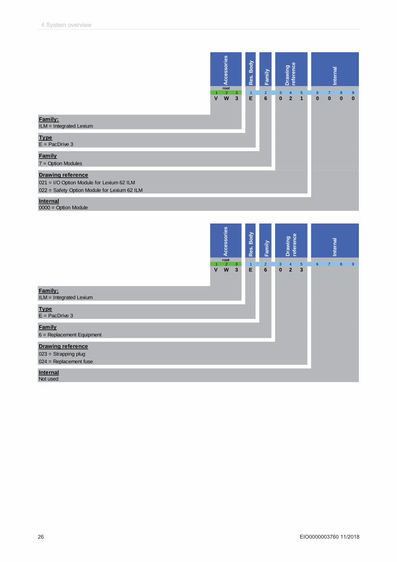
Accesso
ries
Res.
Bo
dy
Fam
ily
Inte
rnal
1 2 3 1 2 3 4 5 6 7 8 9
V W 3 E 6 0 2 1 0 0 0 0
Family:
ILM = Integrated Lexium
Type
E = PacDrive 3
Family
7 = Option Modules
Drawing reference
021 = I/O Option Module for Lexium 62 ILM
022 = Safety Option Module for Lexium 62 ILM
Internal0000 = Option Module
root
Dra
win
g
refe
ren
ce
Res.
Bo
dy
Fam
ily
1 2 3 1 2 3 4 5 6 7 8 9
V W 3 E 6 0 2 3
Family:
ILM = Integrated Lexium
Type
E = PacDrive 3
Family
6 = Replacement Equipment
Drawing reference
023 = Strapping plug
024 = Replacement fuse
InternalNot used
Accesso
ries
Dra
win
g
refe
ren
ce
Inte
rnal
root
4 System overview
26 EIO0000003760 11/2018
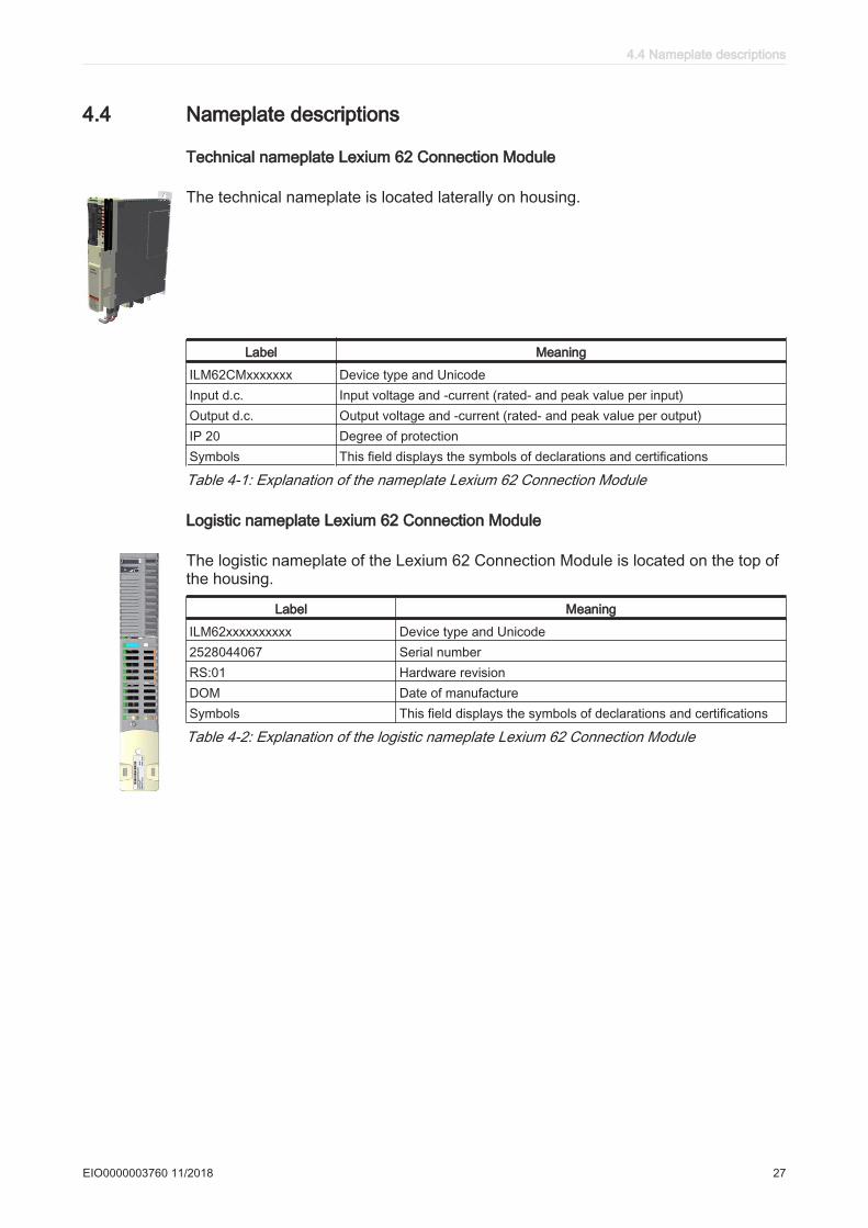
4.4 Nameplate descriptions
Technical nameplate Lexium 62 Connection Module
The technical nameplate is located laterally on housing.
Label Meaning
ILM62CMxxxxxxx Device type and UnicodeInput d.c. Input voltage and -current (rated- and peak value per input)Output d.c. Output voltage and -current (rated- and peak value per output)IP 20 Degree of protectionSymbols This field displays the symbols of declarations and certifications
Table 4-1: Explanation of the nameplate Lexium 62 Connection Module
Logistic nameplate Lexium 62 Connection Module
The logistic nameplate of the Lexium 62 Connection Module is located on the top ofthe housing.
Label Meaning
ILM62xxxxxxxxxx Device type and Unicode2528044067 Serial numberRS:01 Hardware revisionDOM Date of manufactureSymbols This field displays the symbols of declarations and certifications
Table 4-2: Explanation of the logistic nameplate Lexium 62 Connection Module
4.4 Nameplate descriptions
EIO0000003760 11/2018 27
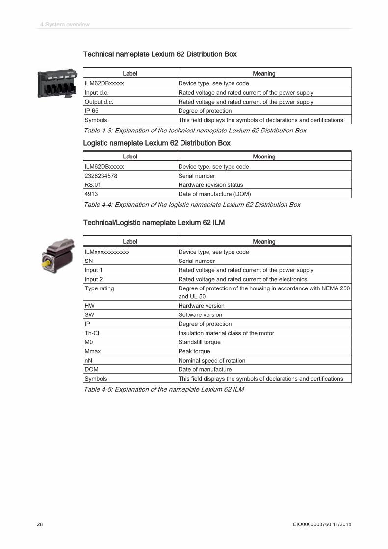
Technical nameplate Lexium 62 Distribution Box
Label Meaning
ILM62DBxxxxx Device type, see type codeInput d.c. Rated voltage and rated current of the power supplyOutput d.c. Rated voltage and rated current of the power supplyIP 65 Degree of protectionSymbols This field displays the symbols of declarations and certifications
Table 4-3: Explanation of the technical nameplate Lexium 62 Distribution Box
Logistic nameplate Lexium 62 Distribution Box
Label Meaning
ILM62DBxxxxx Device type, see type code2328234578 Serial numberRS:01 Hardware revision status4913 Date of manufacture (DOM)
Table 4-4: Explanation of the logistic nameplate Lexium 62 Distribution Box
Technical/Logistic nameplate Lexium 62 ILM
Label Meaning
ILMxxxxxxxxxxxx Device type, see type codeSN Serial numberInput 1 Rated voltage and rated current of the power supplyInput 2 Rated voltage and rated current of the electronicsType rating Degree of protection of the housing in accordance with NEMA 250
and UL 50HW Hardware versionSW Software versionIP Degree of protectionTh-Cl Insulation material class of the motorM0 Standstill torqueMmax Peak torquenN Nominal speed of rotationDOM Date of manufactureSymbols This field displays the symbols of declarations and certifications
Table 4-5: Explanation of the nameplate Lexium 62 ILM
4 System overview
28 EIO0000003760 11/2018
5 Indicators and control elements
5.1 Displays at the Lexium 62 connection module
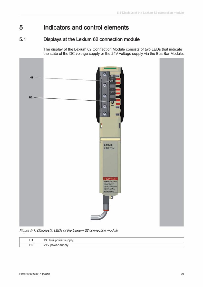
The display of the Lexium 62 Connection Module consists of two LEDs that indicatethe state of the DC voltage supply or the 24V voltage supply via the Bus Bar Module.
TM
H1
H2
Figure 5-1: Diagnostic LEDs of the Lexium 62 connection module
H1 DC bus power supplyH2 24V power supply
5.1 Displays at the Lexium 62 connection module
EIO0000003760 11/2018 29
5.1.1 DC bus LED
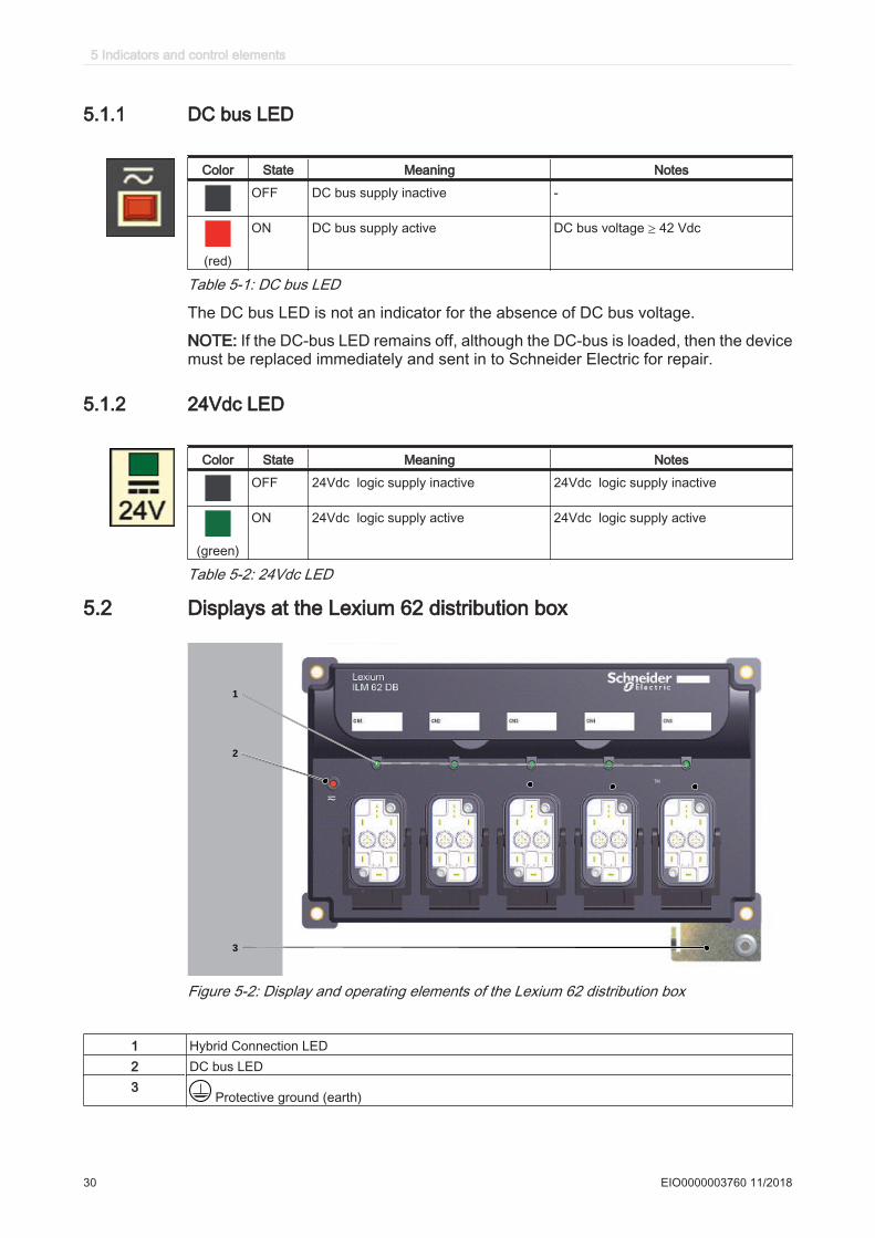
Color State Meaning Notes
OFF DC bus supply inactive -
(red)
ON DC bus supply active DC bus voltage ≥ 42 Vdc
Table 5-1: DC bus LED
The DC bus LED is not an indicator for the absence of DC bus voltage.
NOTE: If the DC-bus LED remains off, although the DC-bus is loaded, then the devicemust be replaced immediately and sent in to Schneider Electric for repair.
5.1.2 24Vdc LED
Color State Meaning Notes
OFF 24Vdc logic supply inactive 24Vdc logic supply inactive
(green)
ON 24Vdc logic supply active 24Vdc logic supply active
Table 5-2: 24Vdc LED
5.2 Displays at the Lexium 62 distribution box
TM
1
3
2
Figure 5-2: Display and operating elements of the Lexium 62 distribution box
1 Hybrid Connection LED2 DC bus LED3
Protective ground (earth)
5 Indicators and control elements
30 EIO0000003760 11/2018

5.2.1 Hybrid connection LED
Color State Meaning Notes
OFF Hybrid connection not connected
ON Hybrid plug connector connected Applies for hybrid cable or power cable (daisychain wiring).
Table 5-3: Hybrid connection LED
5.2.2 DC bus LED
The LED indicates the status of the DC bus voltage.
Color State Meaning Notes
OFF DC bus supply inactive -
(red)
ON DC bus supply active DC bus voltage ≥ 42 Vdc
Table 5-4: DC bus LED
The DC bus LED is not an indicator for the absence of DC bus voltage.
NOTE: If the DC-bus LED remains off, although the DC-bus is loaded, then the devicemust be replaced immediately and sent in to Schneider Electric for repair.
5.2 Displays at the Lexium 62 distribution box
EIO0000003760 11/2018 31
5.3 Displays at the Lexium 62 ILM
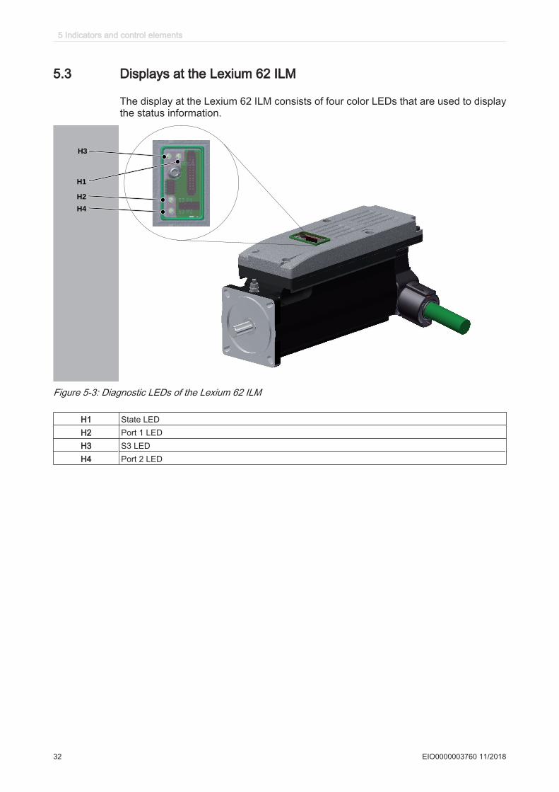
The display at the Lexium 62 ILM consists of four color LEDs that are used to displaythe status information.
H3
H2
H1
H4
Figure 5-3: Diagnostic LEDs of the Lexium 62 ILM
H1 State LEDH2 Port 1 LEDH3 S3 LEDH4 Port 2 LED
5 Indicators and control elements
32 EIO0000003760 11/2018
5.3.1 State LED
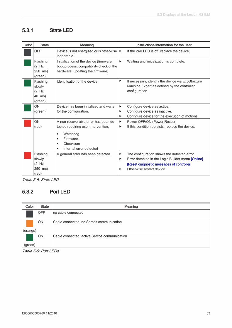
Color State Meaning Instructions/information for the user
OFF Device is not energized or is otherwiseinoperable.
▶ If the 24V LED is off, replace the device.
Flashing(2 Hz,250 ms)(green)
Initialization of the device (firmwareboot process, compatibility check of thehardware, updating the firmware)
▶ Waiting until initialization is complete.
Flashingslowly(2 Hz,40 ms)(green)
Identification of the device ▶ If necessary, identify the device via EcoStruxureMachine Expert as defined by the controllerconfiguration.
ON(green)
Device has been initialized and waitsfor the configuration.
▶ Configure device as active.▶ Configure device as inactive.▶ Configure device for the execution of motions.
ON(red)
A non-recoverable error has been de‐tected requiring user intervention:
• Watchdog• Firmware• Checksum• Internal error detected
▶ Power OFF/ON (Power Reset)▶ If this condition persists, replace the device.
Flashingslowly(2 Hz,250 ms)(red)
A general error has been detected. ▶ The configuration shows the detected error▶ Error detected in the Logic Builder menu [Online] -
[Reset diagnostic messages of controller].▶ Otherwise restart device.
Table 5-5: State LED
5.3.2 Port LED
Color State Meaning
OFF no cable connected
(orange)
ON Cable connected, no Sercos communication
(green)
ON Cable connected, active Sercos communication
Table 5-6: Port LEDs
5.3 Displays at the Lexium 62 ILM
EIO0000003760 11/2018 33
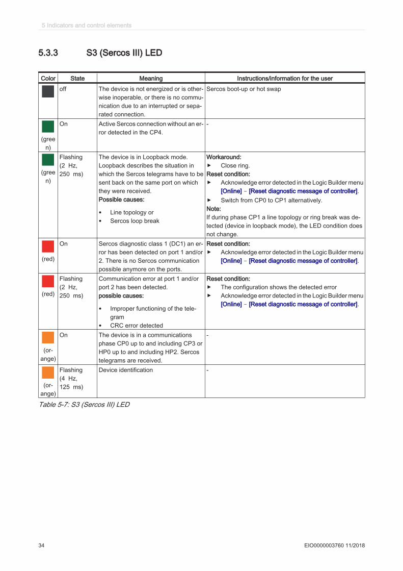
5.3.3 S3 (Sercos III) LED
Color State Meaning Instructions/information for the user
off The device is not energized or is other‐wise inoperable, or there is no commu‐nication due to an interrupted or sepa‐rated connection.
Sercos boot-up or hot swap
(green)
On Active Sercos connection without an er‐ror detected in the CP4.
-
(green)
Flashing(2 Hz,250 ms)
The device is in Loopback mode.Loopback describes the situation inwhich the Sercos telegrams have to besent back on the same port on whichthey were received.Possible causes:
• Line topology or• Sercos loop break
Workaround:▶ Close ring.Reset condition:▶ Acknowledge error detected in the Logic Builder menu
[Online] - [Reset diagnostic message of controller].▶ Switch from CP0 to CP1 alternatively.Note:If during phase CP1 a line topology or ring break was de‐tected (device in loopback mode), the LED condition doesnot change.
(red)
On Sercos diagnostic class 1 (DC1) an er‐ror has been detected on port 1 and/or2. There is no Sercos communicationpossible anymore on the ports.
Reset condition:▶ Acknowledge error detected in the Logic Builder menu
[Online] - [Reset diagnostic message of controller].
(red)
Flashing(2 Hz,250 ms)
Communication error at port 1 and/orport 2 has been detected.possible causes:
• Improper functioning of the tele‐gram
• CRC error detected
Reset condition:▶ The configuration shows the detected error▶ Acknowledge error detected in the Logic Builder menu
[Online] - [Reset diagnostic message of controller].
(or‐ange)
On The device is in a communicationsphase CP0 up to and including CP3 orHP0 up to and including HP2. Sercostelegrams are received.
-
(or‐ange)
Flashing(4 Hz,125 ms)
Device identification -
Table 5-7: S3 (Sercos III) LED
5 Indicators and control elements
34 EIO0000003760 11/2018
6 Planning
6.1 Electromagnetic Compatibility, EMC
This product meets the EMC requirements in accordance with the standard IEC61800-3:2004, provided that the EMC measures described in this manual are compliedwith during installation.
WARNINGELECTROMAGNETIC DISTURBANCES OF SIGNALS AND DEVICES
Use proper EMC shielding techniques to help prevent unintended device operationin accordance with the standard IEC 61800-3:2004.Failure to follow these instructions can result in death, serious injury, or equipment damage.
These types of devices are not intended to be used on a low-voltage public networkwhich supplies domestic premises. Radio frequency interference is expected if usedin such a network.
WARNINGRADIO INTERFERENCE
Do not use these products in domestic electrical networks.Failure to follow these instructions can result in death, serious injury, or equipment damage.
The values are based on the following reference applications:
Reference application for wiring in line structure and/or tree structure
• 1 x Lexium 62 Power Supply (LXM62PD84A11000) with mains line reactor (choke)• 1 x Lexium 62 Connection Module• 3 x Lexium 62 Distribution Box• 3 x ILM070, 4 x ILM100, 3 x ILM140• Hybrid cable 1 x 8 m (26.25 ft) between Lexium 62 Connection Module and first
Lexium 62 Distribution Box• Hybrid cable 2 x 1 m (3.28 ft) between Lexium 62 Distribution Box and Lexium 62
Distribution Box• Hybrid cables 3 x 1 m (3.28 ft), 4 x 1,5 m (4.92 ft), 3 x 2 m (6.56 ft) between Lexium
62 Distribution Box and Lexium 62 ILM
Reference application for wiring in Daisy Chain structure
• 1 x Lexium 62 Power Supply (LXM62PD84A11000) with mains line reactor (choke)• 1 x Lexium 62 Connection Module• 3 x ILM070, 3 x ILM100• Power cable 1 x 10 m (32.8 ft) between Lexium 62 Connection Module and first
Lexium 62 ILM• Power cable 5 x 0,7 m (2.3 ft) between the Lexium 62 ILMs (from the first to the
sixth Lexium 62 ILM)
For further information on this (see 8.5 Mechanical and electrical data).
6.1 Electromagnetic Compatibility, EMC
EIO0000003760 11/2018 35
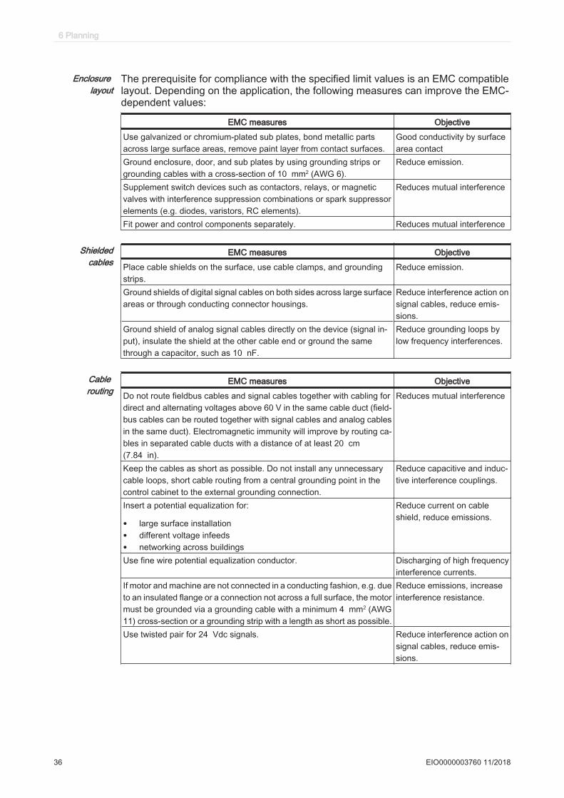
Enclosure layout
The prerequisite for compliance with the specified limit values is an EMC compatiblelayout. Depending on the application, the following measures can improve the EMC-dependent values:
EMC measures Objective
Use galvanized or chromium-plated sub plates, bond metallic partsacross large surface areas, remove paint layer from contact surfaces.
Good conductivity by surfacearea contact
Ground enclosure, door, and sub plates by using grounding strips orgrounding cables with a cross-section of 10 mm2 (AWG 6).
Reduce emission.
Supplement switch devices such as contactors, relays, or magneticvalves with interference suppression combinations or spark suppressorelements (e.g. diodes, varistors, RC elements).
Reduces mutual interference
Fit power and control components separately. Reduces mutual interference
Shieldedcables
EMC measures Objective
Place cable shields on the surface, use cable clamps, and groundingstrips.
Reduce emission.
Ground shields of digital signal cables on both sides across large surfaceareas or through conducting connector housings.
Reduce interference action onsignal cables, reduce emis‐sions.
Ground shield of analog signal cables directly on the device (signal in‐put), insulate the shield at the other cable end or ground the samethrough a capacitor, such as 10 nF.
Reduce grounding loops bylow frequency interferences.
Cable routing
EMC measures Objective
Do not route fieldbus cables and signal cables together with cabling fordirect and alternating voltages above 60 V in the same cable duct (field‐bus cables can be routed together with signal cables and analog cablesin the same duct). Electromagnetic immunity will improve by routing ca‐bles in separated cable ducts with a distance of at least 20 cm(7.84 in).
Reduces mutual interference
Keep the cables as short as possible. Do not install any unnecessarycable loops, short cable routing from a central grounding point in thecontrol cabinet to the external grounding connection.
Reduce capacitive and induc‐tive interference couplings.
Insert a potential equalization for:
• large surface installation• different voltage infeeds• networking across buildings
Reduce current on cableshield, reduce emissions.
Use fine wire potential equalization conductor. Discharging of high frequencyinterference currents.
If motor and machine are not connected in a conducting fashion, e.g. dueto an insulated flange or a connection not across a full surface, the motormust be grounded via a grounding cable with a minimum 4 mm2 (AWG11) cross-section or a grounding strip with a length as short as possible.
Reduce emissions, increaseinterference resistance.
Use twisted pair for 24 Vdc signals. Reduce interference action onsignal cables, reduce emis‐sions.
6 Planning
36 EIO0000003760 11/2018

Voltage supply
EMC measures Objective
Operate product on mains with a grounded neutral. Enable the effect of the inte‐grated mains filter.
Protection circuit if there is a risk of overvoltage. Reduce risk of damage due toovervoltages.
Motor and encoder cables
From an EMC perspective, motor supply cables and encoder cables are particularlyimportant. Only use pre-configured cables, or cables with the prescribed properties,and comply with the following EMC measures.
EMC measures Objective
Do not install switching elements in motor cables or encoder cables. Reduces interference.Route motor cable with a distance of at least 20 cm (7.84in.) to the signalcables or insert shield plates between the motor supply cable and thesignal cable.
Reduces mutual interference
For cabling that approaches the maximum cable distance specification(75 m / 246 ft), use potential equalization cables.
Reduce current on cableshield.
Route motor supply cables and encoder cables without any separationpoint. 1)
Reduces emission.
1) If a cable must be cut through for installation purposes, the cables must be connected at the point ofseparation by using screen connections and metal housing.
Additionalmeasures forimproving the
EMC
Depending on the respective application, the following measures may lead to an EMCcompatible layout:
EMC measures Objective
Upstream connection of mains line reactors (chokes) Reduction of the harmonicnetwork oscillations, exten‐sion of the service life of theproduct.
Upstream connection of external mains filters Improvement of the EMC limitvalues.
Special EMC-appropriate layout, e.g. within an enclosed control cabinetcomplete with 15 dB attenuation of the interferences emitted
Improvement of the EMC limitvalues.
6.1 Electromagnetic Compatibility, EMC
EIO0000003760 11/2018 37

6.2 Control cabinet planning
6.2.1 Degree of protection (IP)▶ Install components such that a degree of protection corresponding to the actual
operational environment is set up.
For more information on the degree of protection of the component (see 8.2 Ambientconditions).
The following ambient conditions may damage the components:
• Oil• Moisture• Electromagnetic interference• Ambient temperature• Metal dust deposits
WARNINGUNINTENDED EQUIPEMENT OPERATION
• Observe and conform to ambient temperatures, storage temperatures and trans‐port temperatures of the individual components as specified in the operatingmanuals of the components.
• Prevent the formation of moisture during the operation, storage and transport ofindividual components.
• Conform to the vibration and shock requirements specified in the operating man‐uals for the components when operating, storing and transporting system com‐ponents.
Failure to follow these instructions can result in death, serious injury, or equipment damage
6.2.2 Mechanical and climatic environmental conditions in the control cabinet▶ Observe the climatic and mechanical ambient conditions.
For more information on the general climatic and mechanical environmental con‐ditions according to IEC/EN 60721 (see 8.2 Ambient conditions).
▶ Check the technical data of the device as to whether the permitted deviations (e.g.higher shock load or higher temperature) are specified.
6 Planning
38 EIO0000003760 11/2018
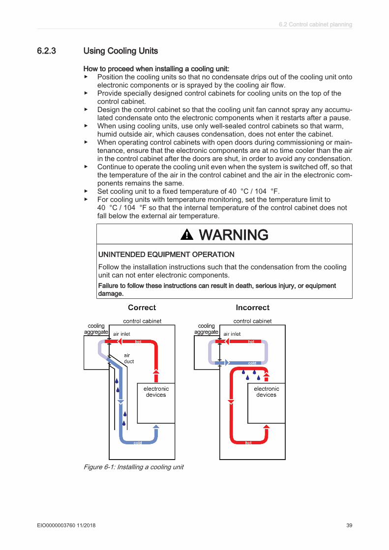
6.2.3 Using Cooling Units
How to proceed when installing a cooling unit:▶ Position the cooling units so that no condensate drips out of the cooling unit onto
electronic components or is sprayed by the cooling air flow.▶ Provide specially designed control cabinets for cooling units on the top of the
control cabinet.▶ Design the control cabinet so that the cooling unit fan cannot spray any accumu‐
lated condensate onto the electronic components when it restarts after a pause.▶ When using cooling units, use only well-sealed control cabinets so that warm,
humid outside air, which causes condensation, does not enter the cabinet.▶ When operating control cabinets with open doors during commissioning or main‐
tenance, ensure that the electronic components are at no time cooler than the airin the control cabinet after the doors are shut, in order to avoid any condensation.
▶ Continue to operate the cooling unit even when the system is switched off, so thatthe temperature of the air in the control cabinet and the air in the electronic com‐ponents remains the same.
▶ Set cooling unit to a fixed temperature of 40 °C / 104 °F.▶ For cooling units with temperature monitoring, set the temperature limit to
40 °C / 104 °F so that the internal temperature of the control cabinet does notfall below the external air temperature.
WARNINGUNINTENDED EQUIPMENT OPERATION
Follow the installation instructions such that the condensation from the coolingunit can not enter electronic components.Failure to follow these instructions can result in death, serious injury, or equipmentdamage.
Figure 6-1: Installing a cooling unit
6.2 Control cabinet planning
EIO0000003760 11/2018 39
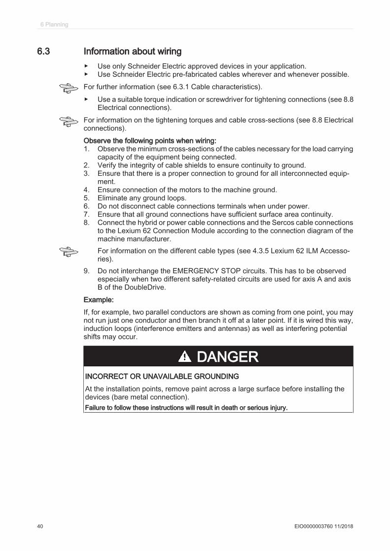
6.3 Information about wiring▶ Use only Schneider Electric approved devices in your application.▶ Use Schneider Electric pre-fabricated cables wherever and whenever possible.
For further information (see 6.3.1 Cable characteristics).
▶ Use a suitable torque indication or screwdriver for tightening connections (see 8.8Electrical connections).
For information on the tightening torques and cable cross-sections (see 8.8 Electricalconnections).
Observe the following points when wiring:1. Observe the minimum cross-sections of the cables necessary for the load carrying
capacity of the equipment being connected.2. Verify the integrity of cable shields to ensure continuity to ground.3. Ensure that there is a proper connection to ground for all interconnected equip‐
ment.4. Ensure connection of the motors to the machine ground.5. Eliminate any ground loops.6. Do not disconnect cable connections terminals when under power.7. Ensure that all ground connections have sufficient surface area continuity.8. Connect the hybrid or power cable connections and the Sercos cable connections
to the Lexium 62 Connection Module according to the connection diagram of themachine manufacturer.For information on the different cable types (see 4.3.5 Lexium 62 ILM Accesso‐ries).
9. Do not interchange the EMERGENCY STOP circuits. This has to be observedespecially when two different safety-related circuits are used for axis A and axisB of the DoubleDrive.
Example:
If, for example, two parallel conductors are shown as coming from one point, you maynot run just one conductor and then branch it off at a later point. If it is wired this way,induction loops (interference emitters and antennas) as well as interfering potentialshifts may occur.
DANGERINCORRECT OR UNAVAILABLE GROUNDING
At the installation points, remove paint across a large surface before installing thedevices (bare metal connection).Failure to follow these instructions will result in death or serious injury.
6 Planning
40 EIO0000003760 11/2018
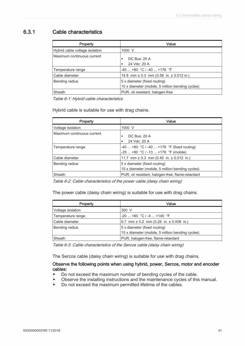
6.3.1 Cable characteristics
Property Value
Hybrid cable voltage isolation 1000 VMaximum continuous current • DC Bus: 20 A
• 24 Vdc: 20 ATemperature range -40 ... +80 °C / -40 ... +176 °FCable diameter 14.8 mm ± 0.3 mm (0.58 in. ± 0.012 in.)Bending radius 5 x diameter (fixed routing)
10 x diameter (mobile, 5 million bending cycles)Sheath PUR, oil resistant, halogen-free
Table 6-1: Hybrid cable characteristics
Hybrid cable is suitable for use with drag chains.
Property Value
Voltage isolation 1000 VMaximum continuous current • DC Bus: 20 A
• 24 Vdc: 20 ATemperature range -40 ... +80 °C / -40 ... +176 °F (fixed routing)
-25 ... +80 °C / -13 ... +176 °F (mobile)Cable diameter 11.7 mm ± 0.3 mm (0.45 in. ± 0.012 in.)Bending radius 5 x diameter (fixed routing)
10 x diameter (mobile, 5 million bending cycles)Sheath PUR, oil resistant, halogen-free, flame-retardant
Table 6-2: Cable characteristics of the power cable (daisy chain wiring)
The power cable (daisy chain wiring) is suitable for use with drag chains.
Property Value
Voltage isolation 300 V Temperature range -20 ... +60 °C / -4 ... +140 °FCable diameter 6.7 mm ± 0.2 mm (0.26 in. ± 0.008 in.)Bending radius 5 x diameter (fixed routing)
10 x diameter (mobile, 5 million bending cycles)Sheath PUR, halogen-free, flame-retardant
Table 6-3: Cable characteristics of the Sercos cable (daisy chain wiring)
The Sercos cable (daisy chain wiring) is suitable for use with drag chains.
Observe the following points when using hybrid, power, Sercos, motor and encodercables:▶ Do not exceed the maximum number of bending cycles of the cable.▶ Observe the installing instructions and the maintenance cycles of this manual.▶ Do not exceed the maximum permitted lifetime of the cables.
6.3 Information about wiring
EIO0000003760 11/2018 41

6.3.2 ESD protection measures
▶ Observe the following instructions to help avoid damages due to electrostatic dis‐charge:
NOTICEELECTROSTATIC DISCHARGE
• Do not touch any of the electrical connections or components.• Prevent electrostatic charges, for example, by wearing appropriate clothing.• If you must touch circuit boards, do so only on the edges.• Move the circuit boards as little as possible.• Remove existing static charge by touching a grounded, metallic surface.Failure to follow these instructions can result in equipment damage.
6.3.3 Conditions for UL / CSA compliant use
General
If you use the Lexium 62 ILM family in accordance with UL or CSA standards, youmust additionally meet, aside from the installation requirements stated in the presentdocument, the following conditions:▶ Use devices only in combination with a Lexium 62 Power Supply on a solidly
grounded wye source only (480Y/277 V).▶ To protect the Lexium 62 Power Supply, use a class J fuse according to UL 248
with a maximum fuse rating of 60 A / 600 Vac.▶ According to UL 508C rules, direct measurement of motor over temperature is
required. This is already internally realized by the Lexium 62 ILM.▶ Install the Lexium 62 Connection Module only in a Pollution Degree 2 environment.▶ For use in NFPA 79 applications only.
Only connect the Lexium 62 ILM family to a mains supply with a maximum short circuitcurrent (SCCR) of 22 kA or worst case SCCR of connected Lexium 62 Drive System.Alternatively, take appropriate measures according to UL 508A SB4 in the supply(feeder) circuit of the control cabinet to limit the short circuit current to a value at orbelow 22 kA or the worst case of the Lexium 62 Drive System.
According to CSA 22.2 No. 14 only a short circuit current rating of 5 kA is permissible.
For further information about conformal use of the Lexium 62 Drive System, see Lex‐ium 62 Hardware Guide.
Notes on Wiring
For wiring of the Lexium 62 Connection Module only use at least 60 °C (140 °F) /75 °C (167 °F) copper conductor. Consider the applicable cross section of the terminalblocks according to following table:
Connection Torque [Nm]/[lbf in] Connection cross section [mm²]/[AWG]
CN1 2.5 / 22 N/ACN6 N/A 0.2 ... 1.5 / 24 ... 16CN7 N/A 0.2 ... 6 / 24 ... 8CN8 N/A 0.2 ... 6 / 24 ... 8
6 Planning
42 EIO0000003760 11/2018

▶ Verify whether the screws of the wiring bus (CN1) have been tightened with2.5 Nm (22 lbf in).
▶ Use only hybrid / power cable approved by Schneider Electric and comply withthe requirements of NFPA 79.
NOTE: The opening of the branch-circuit protective device (fuses in the case of ULconformance, or any circuit breaker) may be an indication that an abnormal conditionhas been interrupted. To reduce the risk of fire or electric shock, current-carrying partsand other components of the controller should be examined and replaced if damaged.If burnout of the current element of an overload relay occurs, the complete overloadrelay must be replaced.
6.3.4 Fusing the mains connection
For further information on the fusing of the mains connection, see the Lexium 62Hardware Guide.
6.3.5 Mains contactor
For further information on the use of a mains contactor, see the Lexium 62 HardwareGuide.
6.3.6 Mains filter
The products described in the present document meet the EMC requirements in ac‐cordance with the standard IEC/EN 61800-3, provided that the EMC measures de‐scribed in this manual are complied with during the installation. The values are basedon the reference application (see 6.1 Electromagnetic Compatibility, EMC) specifiedin the manual.
The connected cable length and the number of connected motors has no significantinfluence on the grid-bound emitted interference. Thus, no external mains filter is re‐quired when only the Lexium 62 ILM related components are used.
In the case of a mixed system using the Lexium 62 cabinet drives combined with theLexium 62 ILM components, the selection of the external mains filter depends on thedevices installed in the control cabinet and the motor supply cables (also see Lexium62 Hardware Guide). The hybrid cable or power cable (with daisy chain wiring) of theLexium 62 ILM Family is not considered as motor supply cables.
For additional information on mains filtering, contact your Schneider Electric repre‐sentative.
6.3.7 Mains line reactor (choke)
For further information on the use of mains line reactor (choke), see the Lexium 62Hardware Guide.
6.3.8 Wiring with Lexium 62 DC Link Terminal
For further information about wiring with Lexium 62 DC Link Terminal and cable se‐lection guidelines for wiring with Lexium 62 DC Link Terminal, see the Lexium 62Hardware Guide.
6.3 Information about wiring
EIO0000003760 11/2018 43

6.3.9 Leakage current
Application per Lexium 62 ConnectionModule
per Lexium 62 DistributionBox
typical (400 V, 50 Hz) < 9 mA < 18 mA
Table 6-4: Leakage currents per device
If the leakage current is too high for the respective application, use an isolating trans‐former on the mains supply.
For specifications on the leakage current of the Lexium 62 Power Supply, see theLexium 62 Hardware Guide.
6.3.10 Residual current operated protective device
This product has a leakage current greater than 3.5 mA. If the protective ground con‐nection is interrupted, a hazardous touch current may flow if the housing is touched.
DANGERINSUFFICIENT GROUNDING
• Use a protective ground conductor with at least 10 mm2 (AWG 6) or two protectiveground conductors with the same or larger cross section of the conductors sup‐plying the power terminals.
• Verify compliance with all local and national electrical code requirements as wellas all other applicable regulations with respect to grounding of all equipment.
Failure to follow these instructions will result in death or serious injury.
For further information on residual current protective devices, see the Lexium 62Hardware Guide.
6 Planning
44 EIO0000003760 11/2018
6.4 Functional safety
6.4.1 Process minimizing risks associated with the machine
The goal of designing machines safely is to protect people. The risk associated withmachines with electrically controlled drives comes chiefly from moving machine partsand electricity itself.
Only you, the user, machine builder or system integrator can be aware of all the con‐ditions and factors realized in the design of your application for the machine. Therefore,only you can determine the automation equipment and the related safeties and inter‐locks which can be properly used, and validate such usage.
WARNINGNON-CONFORMANCE TO SAFETY FUNCTION REQUIREMENTS
• Specify the requirements and/or measures to be implemented in the risk analysisyou perform.
• Verify that your safety-related application complies to applicable safety regula‐tions and standards.
• Make certain that appropriate procedures and measures (according to applicablesector standards) have been established to help avoid hazardous situationswhen operating the machine.
• Use appropriate safety interlocks where personnel and/or equipment hazardsexist.
• Validate the overall safety-related function and thoroughly test the application.Failure to follow these instructions can result in death, serious injury, or equipment damage.
Hazard and risk analysis
Based on the system configuration and utilization, a hazard and risk analysis can becarried out for the system (for example, according to EN ISO 12100 or EN ISO13849-1). The results of this analysis must be considered when using the safety func‐tion. The circuit resulting from this analysis may deviate from the application examples.For example, additional safety components may be required. In principle, the resultsfrom the hazard and risk analysis have priority.
The EN ISO 13849-1 Safety of machinery - Safety-related parts of control systems -Part 1: General principles for design describes an iterative process for the selectionand design of safetyrelated parts of controllers to reduce the risk to the machine to areasonable degree:
To perform risk assessment and risk minimization according to EN ISO 12100, pro‐ceed as follows:1. Defining the boundary of the machine.2. Identifying risks associated with the machine.3. Assessing risks.4. Evaluating risks.5. Minimizing risks by:
- intrinsically safe design- protective devices- user information (see EN ISO 12100)
6. Designing safety-related controller parts (SRP/CS, Safety-Related Parts of theControl System) in an interactive process.
6.4 Functional safety
EIO0000003760 11/2018 45

To design the safety-related controller parts in an interactive process, proceed as fol‐lows:1. Identify necessary safety functions that are executed via SRP/CS (Safety-Related
Parts of the Control System).2. Determine required properties for each safety function.3. Determine the required performance level PLr.4. Identify safety-related parts executing the safety function.5. Determine the performance level PL of the afore-mentioned safety-related parts.6. Verify the performance level PL for the safety function (PL ≥ PLr).7. Verify if all requirements have been met (validation).
Additional information is available on www.schneider-electric.com.
6 Planning
46 EIO0000003760 11/2018
6.4.2 Designated safety function
Functional Description
With the Inverter Enable function (IE), you can bring drives to a defined safe stop. ThisInverter Enable function relates to the components
• Lexium 62 Connection Module• Lexium 62 Distribution Box• Lexium 62 ILM
In the sense of the relevant standards, the requirements of the stop category 0 (Safe Torque Off, STO) and stop category 1 (Safe Stop 1, SS1) can be met. Both categories lead to a torque-free motor while SS1 takes this state after a predefined time. As a result of the hazard and risk analysis, it may be necessary to choose an additional brake as a safety-related option (e.g., for hanging loads).
With the optionally available Safety Option Module for Lexium 62 ILM for Lexium 62 ILM it is also possible to realize the extended safety functions such as Safely Limited Speed (SLS) in connection with the Safety Logic Controller SLC100/200 FS and the associated software EcoStruxure Machine Expert - Safety.
WARNINGUNINTENDED EQUIPMENT OPERATION
• Make certain that no hazards can arise for persons or material during the coastdown period of the axis/machine.
• Do not enter the zone of operation during the coast down period.• Ensure that no other persons can access the zone of operation during the coast
down period.• Use appropriate safety interlocks where personnel and/or equipment hazards
exist.Failure to follow these instructions can result in death, serious injury, or equipment damage.
6.4 Functional safety
EIO0000003760 11/2018 47
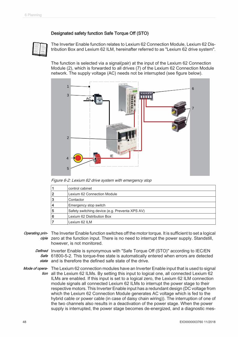
Designated safety function Safe Torque Off (STO)
The Inverter Enable function relates to Lexium 62 Connection Module, Lexium 62 Dis‐tribution Box and Lexium 62 ILM, hereinafter referred to as "Lexium 62 drive system".
The function is selected via a signal(pair) at the input of the Lexium 62 ConnectionModule (2), which is forwarded to all drives (7) of the Lexium 62 Connection Modulenetwork. The supply voltage (AC) needs not be interrupted (see figure below).
1
2
4
5
6
7
IE
3
AC
Figure 6-2: Lexium 62 drive system with emergency stop
1 control cabinet2 Lexium 62 Connection Module3 Contactor4 Emergency stop switch5 Safety switching device (e.g. Preventa XPS AV)6 Lexium 62 Distribution Box7 Lexium 62 ILM
Operating prin‐ciple
The Inverter Enable function switches off the motor torque. It is sufficient to set a logicalzero at the function input. There is no need to interrupt the power supply. Standstill,however, is not monitored.
DefinedSafestate
Inverter Enable is synonymous with "Safe Torque Off (STO)" according to IEC/EN61800-5-2. This torque-free state is automatically entered when errors are detectedand is therefore the defined safe state of the drive.
Mode of opera‐tion
The Lexium 62 connection modules have an Inverter Enable input that is used to signalall the Lexium 62 ILMs. By setting this input to logical one, all connected Lexium 62ILMs are enabled. If this input is set to a logical zero, the Lexium 62 ILM connectionmodule signals all connected Lexium 62 ILMs to interrupt the power stage to theirrespective motors. This Inverter Enable input has a redundant design (DC voltage fromwhich the Lexium 62 Connection Module generates AC voltage which is fed to thehybrid cable or power cable (in case of daisy chain wiring)). The interruption of one ofthe two channels also results in a deactivation of the power stage. When the powersupply is interrupted, the power stage becomes de-energized, and a diagnostic mes‐
6 Planning
48 EIO0000003760 11/2018
sage is generated and made available to the LMC. The motor can no longer generatetorque.
You can use the Inverter Enable function to implement the control function "Stoppingin case of emergency" (IEC/EN 60204-1) for stop categories 0 and 1. Use an appro‐priate external safety circuit to prevent the unintended restart of the drive after removalof the power stage, as required in the machine directive.
Stopcategory 0
In stop category 0 (Safe Torque Off), the drive coasts to a stop (provided there are noexternal forces operating to the contrary). The STO safety-related function is intendedto help prevent an unintended start-up, not stop a motor, and therefore correspondsto an unassisted stop in accordance with IEC 60204-1.
In circumstances where external influences are present, the coast down time dependson physical properties of the components used (such as weight, torque, friction, etc.),and additional measures such as mechanical brakes may be necessary to help preventany hazard from materializing. That is to say, if this means a hazard to your personnelor equipment, you must take appropriate measures (refer to hazard and risk analy‐sis)
WARNINGUNINTENDED EQUIPMENT OPERATION
• Make certain that no hazards can arise for persons or material during the coastdown period of the axis/machine.
• Do not enter the zone of operation during the coast down period.• Ensure that no other persons can access the zone of operation during the coast
down period.• Use appropriate safety interlocks where personnel and/or equipment hazards
exist.Failure to follow these instructions can result in death, serious injury, or equipment damage.
Stopcategory 1
For stops of category 1 (Safe Stop 1, SS1) you can request a controlled stop via thePacDrive LMC. The controlled stop by the PacDrive LMC is not safety-relevant, normonitored, and does not perform as defined in the case of a power outage or if an erroris detected. The final switch off in the defined safe state is accomplished by switchingoff the "Inverter Enable" input. This has to be implemented by means of an externalsafety-related switching device with safety-related delay (see application proposal).
Independent of the safety function, the detectable errors not affecting the safety func‐tion are recognized by the controller, thus avoiding the drive from starting by switchingoff the mains contactor. Contactor K2 prevents the mains contactor from being switch‐ed on.
Executemuting
To execute muting proceed as follows:▶ To execute muting, determine the muting reaction time for switching off, that is,
without the Inverter Enable function, within the application.
Should a response time be required because of the risk assessment of the ma‐chine, the total response time of the machine has to be taken into account. Thatis to say, the components related to the safety functions from the sensor to thedrive shaft or the driven mechanics have to be considered. The determined re‐action time must correspond to the results of the hazard and risk analysis.
6.4 Functional safety
EIO0000003760 11/2018 49
WARNINGUNINTENDED EQUIPMENT OPERATION
• Verify that the maximum response time corresponds to your risk analysis.• Be sure that your risk analysis includes an evaluation for the maximum response
time.• Validate the overall function with regard to the maximum response time and
thoroughly test the application.Failure to follow these instructions can result in death, serious injury, or equipment damage.
Proceed as follows to deactivate the Inverter Enable function:▶ You can deactivate the Inverter Enable function by using the optional module
DIS1. (see 6.4.3.1 Perform muting with the optional module DIS1)The defined safe state can only be achieved if the power is removed from thepower supply (see 6.4.3 Setup, installation, and maintenance).
▶ In order to use the DIS1 optional module, you must define the configuration withthe parameter InverterEnableConfig of the Lexium 62 ILM in the motioncontroller configuration.
If the software configuration does not match the physical configuration of the Lexium62 ILM, then the diagnostic message 8978 "InverterEnableConfig invalid" with "Ext.diagnostic = x(HW)!=y(Cfg)" is presented. The drive is disabled as long as the config‐uration is incorrect. The error can only be acknowledged if the set InverterEna-bleConfig corresponds to the physical configuration. The deactivation of the InverterEnable function can be used to divide the drives on a Lexium 62 Connection Modulein two groups if it is technically not possible to use two Lexium 62 Connection Modulefor the two groups in the existing machine.
The axes without Inverter Enable function become torque-free via the mains contactorand come to a stop.
If only some of the drives attached to a Lexium 62 Connection Module (1) are to beput in the defined safe state, this can be achieved by the configuration of the drives.This can be of interest, for example, for maintenance procedures (6). If an optionalmodule DIS1 (9) is set, then the Inverter Enable signal will be ignored. To implementthe emergency stop, the supply voltage on the Lexium 62 power supply must be in‐terrupted; see illustration below.
6 Planning
50 EIO0000003760 11/2018
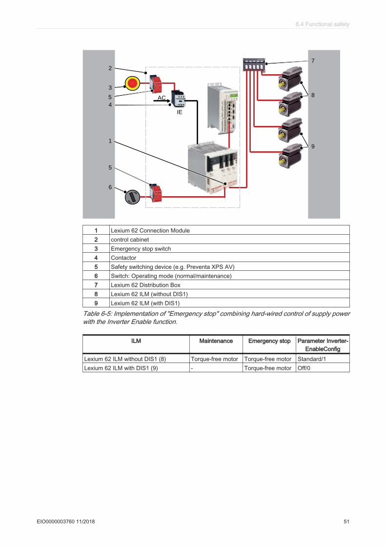
5
2
3
6
7
85
9
IE
4
AC
1
1 Lexium 62 Connection Module2 control cabinet3 Emergency stop switch4 Contactor5 Safety switching device (e.g. Preventa XPS AV)6 Switch: Operating mode (normal/maintenance)7 Lexium 62 Distribution Box8 Lexium 62 ILM (without DIS1)9 Lexium 62 ILM (with DIS1)
Table 6-5: Implementation of "Emergency stop" combining hard-wired control of supply powerwith the Inverter Enable function.
ILM Maintenance Emergency stop Parameter Inverter‐EnableConfig
Lexium 62 ILM without DIS1 (8) Torque-free motor Torque-free motor Standard/1Lexium 62 ILM with DIS1 (9) - Torque-free motor Off/0
6.4 Functional safety
EIO0000003760 11/2018 51
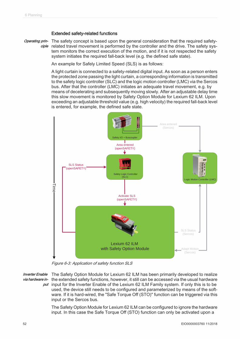
Extended safety-related functionsOperating prin‐
cipleThe safety concept is based upon the general consideration that the required safety-related travel movement is performed by the controller and the drive. The safety sys‐tem monitors the correct execution of the motion, and if it is not respected the safetysystem initiates the required fall-back level (e.g. the defined safe state).
An example for Safely Limited Speed (SLS) is as follows:
A light curtain is connected to a safety-related digital input. As soon as a person entersthe protected zone passing the light curtain, a corresponding information is transmittedto the safety logic controller (SLC) and the logic motion controller (LMC) via the Sercosbus. After that the controller (LMC) initiates an adequate travel movement, e.g. bymeans of decelerating and subsequently moving slowly. After an adjustable delay timethis slow movement is monitored by Safety Option Module for Lexium 62 ILM. Uponexceeding an adjustable threshold value (e.g. high velocity) the required fall-back levelis entered, for example, the defined safe state.
Safety I/O + Buscoupler
Logic Motion Controller (LMC)
Safety Logic Controller
(SLC)
Activate SLS
(openSAFETY)
SLS Status
(openSAFETY)
SLS Status
(Sercos)
Area entered
(openSAFETY)
Area entered
(Sercos)
Tim
e
Adapt Motion
(Sercos)
Lexium 62 ILM
with Safety Option Module
Figure 6-3: Application of safety function SLS
Inverter Enable via hardware in‐
put
The Safety Option Module for Lexium 62 ILM has been primarily developed to realizethe extended safety functions, however, it still can be accessed via the usual hardwareinput for the Inverter Enable of the Lexium 62 ILM Family system. If only this is to beused, the device still needs to be configured and parameterized by means of the soft‐ware. If it is hard-wired, the "Safe Torque Off (STO)" function can be triggered via thisinput or the Sercos bus.
The Safety Option Module for Lexium 62 ILM can be configured to ignore the hardwareinput. In this case the Safe Torque Off (STO) function can only be activated upon a
6 Planning
52 EIO0000003760 11/2018
request over the Sercos bus. Otherwise if the hardware input is not ignored then bothrequests (hardware input and Sercos bus) are verified and the Safe Torque Off (STO)function is triggered if one or both requests are active. The default configuration is notto ignore the hardware input.
Defined safestate
The defined safe state of the device is characterized by the following features:
• The drive is torque-free, which is equivalent to “Safe Torque Off (STO)” accordingto IEC 61800-5-2.
• There is no safety-related communication from the drive via the Sercos bus.
This state is automatically entered when errors are detected.
Validity of the safety case
The safety case for the designated safety function of the Lexium 62 ILM is identified and defined by the standards listed in chapter "Safety standards" (see 6.4.10 Safety standards). The safety case for the designated safety function of the Lexium 62 drive system applies to the following hardware codes, which can be found examining the appropriate software object in EcoStruxure Machine Expert (see EcoStruxure Machine Expert, Programming Guide):
Unicode Hardware code:
ILM 070/xx xxxxxxxxx1xx, xxxxxxxxx2xxILM 100/xx xxxxxxxxx1xx, xxxxxxxxx2xxILM140/xx xxxxxxxxx1xx, xxxxxxxxx2xxDIS1 1ILM62CM xxxxxx1xx, xxxxxx2xxILM62DB xxxxxx1xx
Device Hardware codes
VW3E702200000 011A1110
For questions on this, contact your Schneider Electric representative.
Interface and control
The Inverter Enable function is operated via the switching thresholds of the InverterEnable-input (IE_p1/IE_p2 at Pin1/Pin2, IE_n1/IE_n2 at Pin3/Pin4) of the Lexium 62connection module.
• Maximum downtime: 500µs at UIE > 20V with dynamic control• Maximum test pulse ratio: 1Hz• STO active: -3V ≤ UIE ≤ 5V• Power stage active: 18V ≤ UIE ≤ 30V
Technical data and information on the electrical connections of the Lexium 62 ILMsystem or the Lexium 62 connection module can be found under Technical data (see8 Technical data).
The Inverter Enable function is operated via the switching thresholds of the InverterEnable-input of the Lexium 62 connection module.
Technical data and information on the electrical connections of the Lexium 62 con‐nection module can be found in the Lexium 62 ILM Hardware Guide.
6.4 Functional safety
EIO0000003760 11/2018 53

6.4.3 Setup, installation, and maintenance
Prevent possible unintended operation and avoid overvoltage
The following measures avoid overvoltages and help prevent possible unintendedequipment operation through conductive pollution or parts falling into the device:
DANGERELECTRIC SHOCK, EXPLOSION, OR ARC FLASH
• Install Lexium 62 Connection Module in a control cabinet or housing with aminimum IP54 rating.
• Comply with the clearances and creepage distances according to EN 50178.• Lexium 62 drive system must only be operated with 24 Vdc power supplies
certified according to IEC/EN 60950 or EN 50178.Failure to follow these instructions will result in death or serious injury.
These power supply units do not deliver an overvoltage over 120 Vdc for morethan 120ms or no permanent overvoltage over 60 Vdc.
▶ Only operate the drive system with approved, specified cables, accessories andreplacement equipment by Schneider Electric.
DANGERELECTRIC SHOCK OR ARC FLASH
Do not use non-Schneider Electric approved cables, accessories or any type of re‐placement equipment.Failure to follow these instructions will result in death or serious injury.
Avoid unintentional restart
The unintentional restart of the equipment must be avoided by appropriate means,depending on your particular application.
DANGERUNINTENTIONAL RESTART OF THE MOTOR
• Ensure that a restart of the motor is not possible after a return of power or thetripping of a functional safety device unless preceded by a deliberate enable sig‐nal from the system.
• Ensure that the enable signal meets the specified safety criteria (see 6.4.4 Ap‐plication proposals for hardware-based safety functions).
Failure to follow these instructions will result in death or serious injury.
6 Planning
54 EIO0000003760 11/2018
Encoder connection when using extended safety-related functions
Safety Option Module for Lexium 62 ILM enables the use of extended, position-de‐pendent and/or velocity-dependent safety functions.
To avoid that the system is in a continuous defined safe state, proceed as follows:▶ Observe the specified maximum configuration (number of devices, network struc‐
ture and cable length), or else a power drop of the Inverter Enable signal will occurover the cable length and therefore the system will be in the defined safe statecontinuously.
▶ Connect per Lexium 62 Connection Module a maximum of 45 Lexium 62 ILMs.For further information on the dimensions of the maximum system extension forwiring in line structure or tree structure (see 7.1.6 Wiring the Lexium 62 connectionmodule in linear or tree topologies) or daisy chain structure (see 7.1.7 Wiring fromthe Lexium 62 connection module in a daisy chain topology):
6.4 Functional safety
EIO0000003760 11/2018 55
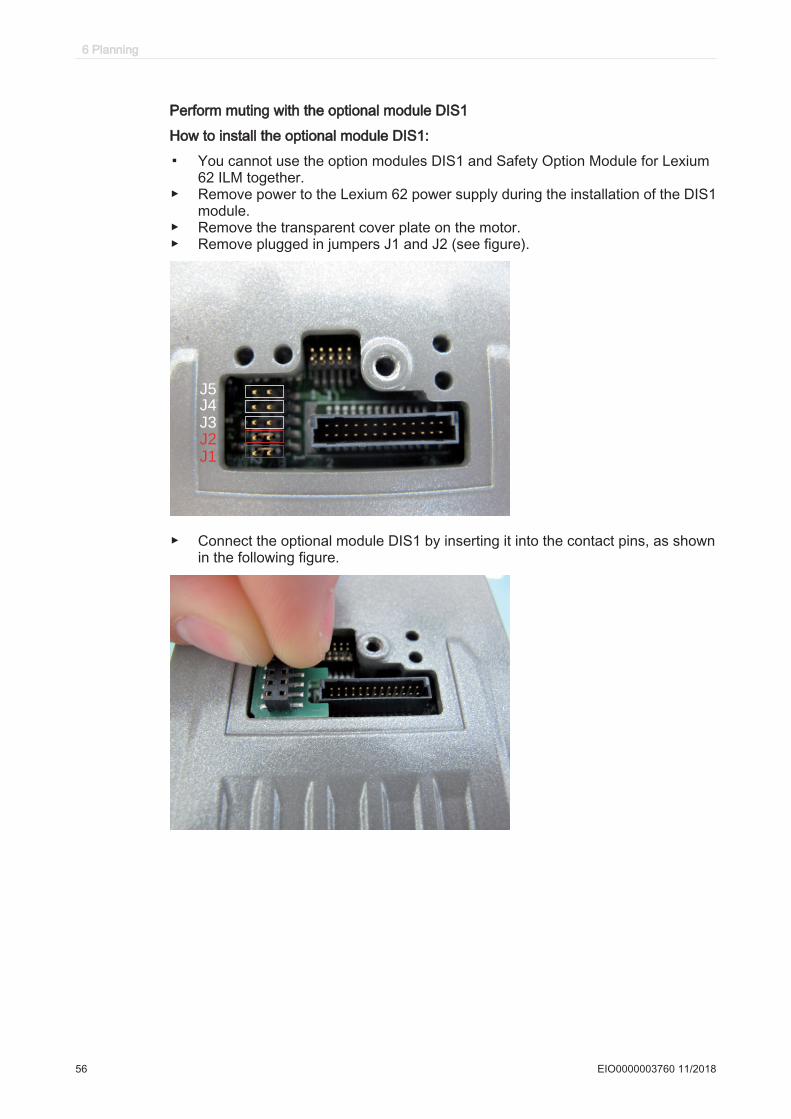
Perform muting with the optional module DIS1
How to install the optional module DIS1:
▪ You cannot use the option modules DIS1 and Safety Option Module for Lexium62 ILM together.
▶ Remove power to the Lexium 62 power supply during the installation of the DIS1module.
▶ Remove the transparent cover plate on the motor.▶ Remove plugged in jumpers J1 and J2 (see figure).
J1
J2
J3
J4
J5
▶ Connect the optional module DIS1 by inserting it into the contact pins, as shownin the following figure.
6 Planning
56 EIO0000003760 11/2018

▶ Replace the transparent cover plate on the motor and secure it.
How to disassemble the optional module DIS1:▶ Remove power to the Lexium 62 power supply during the installation of the DIS1
module.▶ Remove the transparent cover plate on the motor.▶ Remove the optional module DIS1.▶ Re-connect the jumpers J1 and J2 (see figure).
J1
J2
J3
J4
J5
▶ Replace the transparent cover plate on the motor and secure it.
6.4 Functional safety
EIO0000003760 11/2018 57
6.4.4 Application proposals for hardware-based safety functions
To implement the safe stop of category 1 (SS1):
• Refer to the schematic EL-1122-05-xx: Inverter Enable circuit Lexium 62 Connec‐tion Module/Lexium 62 ILM using the PacDrive LMC Pro / PacDrive LMC Pro2 withsafety switch device for an emergency stop circuit
Notes on application proposalsGeneral • All application proposals provide for a protected Inverter Enable-wiring (control
cabinet IP54) from the safety-related switch device to the Lexium 62 ConnectionModule, as wiring issues need to be ruled out.
• Protection against automatic restart must be provided by the external safety-relat‐ed switch device.
Notes onEL-1122-05-xx
The mains contactor in this circuit suggestion is not necessary for functional safetypurposes. It is, however, used in the application proposal for the device protection ofthe Lexium 62 Power Supply or the components connected to it.
6 Planning
58 EIO0000003760 11/2018

A B C D E F
A B C D FE
65
43
21
87
09
54
32
10
69
87
Bl.
= +
von
Blatt
Vert.
DatumName
Z.Art.
Erst.
Gepr.
Freig.
Änderung
SE
APP
WR
L1
L2
L3
PE
N
+24V
0V WD &rdy
+24V
0V
InverterEnable Application
Z.Art.
2
1
4
3
6
5-Q1
-F2
+-
24V
230V
1 24
12
-G
LMC
CN1
CN124V0V
WD1
WD2
LMC WD
-A1
-F3
-L1
2 1
4 3
6 5-K1
1
Hybrid Cable
SafeStop 1 (SS1)withE-Stop
22.07.11
I >I >I >
1
3
5
2
4
6
-Q2
2
EL-1122-05-01
for PacDrive 3 ILM62
PE bar
PE
Cabinet PE
to ILM62DB
28.07.11
28.07.11
Not part of functional safety
CN1
CN4
CN5
CN6
PE
DC-
DC+
24V
0V
L1L2L3
rdy1
rdy2
PE
24V0V
PE
LXM62P
-A2
CN1
CN8
CN7CN6
PE
DC-
DC+
24V
0V
DC+PEDC-
IE_p1
IE_p2
IE_sigIE_ref
IE_n1
IE_n2
0V_int1
0V_int2
24V_out0V_out
ILM62CM
-A3
Machine frame
Figure 6-4: EL-1122-05-xx Sheet 1
6.4 Functional safety
EIO0000003760 11/2018 59
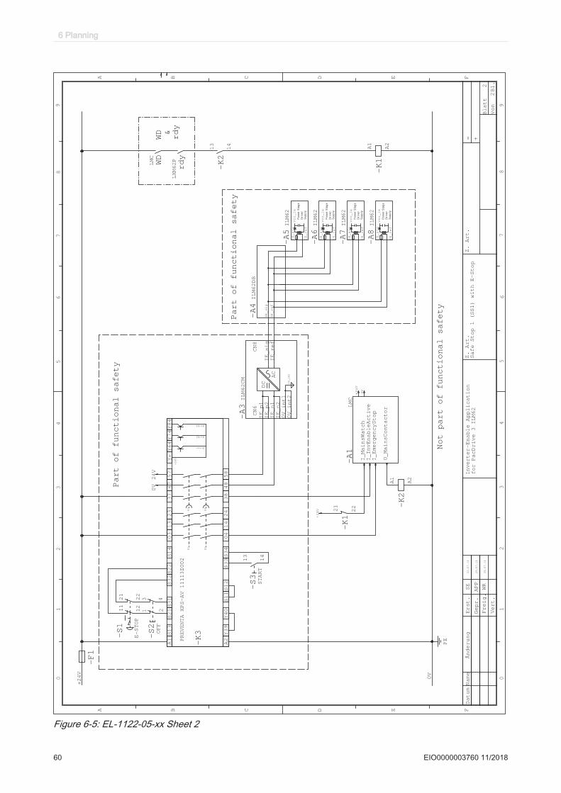
A B C D E F
A B C D F
Bl.
= +
E
von
Blatt
65
43
21
87
09
54
32
10
69
87
Vert.
DatumName
Z.Art.
Z.Art.
Erst.
Gepr.
Freig.
Änderung
SE
WR
WD &
rdy
+24V
0V
+24V
Not part of functional safety
-F1
OFF
1 2
3 4
-S2
E-STOP
11
12
21
22
-S1
START
13
14
-S3
PE
I_MainsWatch
I_InvEnableActive
I_EmergencyStop
O_MainsContactor
LMC
-A1
0V
+24V
A1S13
S14
03
13
23
37
47
57
Y+Y64Y74
85
84
83
42
41
40
93Y
2A
Y84
S21S31
S22
S32
S34
S11S12
S33
Y40
Error
K1/K2
K3/K4
K4
K3
K1
K2
+24V
PREVENTAXPS-AV 11113Z002
-K3
2
22.07.11
APP
Safe Stop 1 (SS1) with E-Stop
Inverter-Enable Application
A1
A2
-K2
13
14
-K2
A1
A2
-K1
21
22
-K1
LMC
WD
0V
24V
Part of functional safety
vcc_ie
Po
we
r S
tag
e
Dri
ve
r
Su
pp
ly
IE_sig
IE_ref
ILM62
-A5
vcc_ie
Po
we
r S
tag
e
Dri
ve
r
Su
pp
ly
IE_sig
IE_ref
ILM62
-A6
vcc_ie
Po
we
r S
tag
e
Dri
ve
r
Su
pp
ly
IE_sig
IE_ref
ILM62
-A7
2
for PacDrive 3 ILM62
Part of functional safety
28.07.11
28.07.11
vcc_ie
Po
we
r S
tag
e
Dri
ve
r
Su
pp
ly
IE_sig
IE_ref
ILM62
-A8
CN6
CN8
DC
AC
0V_INT
IE_n1
IE_p2
IE_n2
0V_int1
0V_int2
IE_sig
IE_ref
IE_p1
ILM62CM
-A3
LXM62P
rdy
IE_ref
IE_sig
ILM62DB
-A4
Figure 6-5: EL-1122-05-xx Sheet 2
6 Planning
60 EIO0000003760 11/2018
6.4.5 Application proposals for software-based safety functions
Proceed as follows to use the Inverter Enable via hardware or extended safety func‐tions by means of Safety Option Module for Lexium 62 ILM:▶ Perform the assembly for Safety Option Module for Lexium 62 ILM.▶ Configure the safety-related network.▶ Adjust the parameters, in particular the prioritization of Inverter Enable via
hard‐ware and STO via the bus.▶ Program the EcoStruxure Machine Expert - Safety application.
6.4.6
Note: Observe the information on the parameters and the EcoStruxure Machine Expert - Safety software in the EcoStruxure Machine Expert online help.
Further information on the parameters and the EcoStruxure Machine Expert - Safety Software can be found in the EcoStruxure Machine Expert online help.
Commissioning▶ Carry out a functional test of the STO function for all drives that need the safety
function.▶ Especially verify the correct application of the axes without Inverter Enable func‐
tion.▶ Complete installation in accordance with the EMC regulations and further speci‐
fications in the device operating manuals.▶ Afterwards commission the drive systems.
When using the extended safety functions, the Safety Option Module for Lexium 62 ILM must be configured, parameterized and programmed according to the EcoStruxure Machine Expert online help as well as EcoStruxure Machine Expert - Safety online help.
6.4 Functional safety
EIO0000003760 11/2018 61

6.4.7 Best Practices
At machine start-up, the connected drives are usually hidden from sight of the machineoperator and cannot be monitored directly.
WARNINGUNSUPERVISED MACHINE START-UP
Only start the machine if there are no persons within the zone of operation of movingmachine components.Failure to follow these instructions can result in death, serious injury, or equipment damage.
Verifyconnections
▶ Verify all terminals, connectors and other connections on all system componentsfor correct and firm fit.
▶ Only use robust connectors and secure fixings.▶ Verify the protective ground (earth) 24Vdc PELV supply.▶ Verify the wiring of the safety function to the axes to avoid an interchange of the
ie_sig and IE_ref inputs as well as the 24V supply.▶ Use coded connectors (see 6.3 Information about wiring) and perform a commis‐
sioning test (see 7.1 Commissioning).
DANGERELECTRIC SHOCK BY INADEQUATE PROTECTIVE SEPARATION
Only connect devices, electrical components, or lines to the signal voltage connectorsof these products that feature a sufficient, protective separation from the connectedcircuits in accordance with the standards (IEC 61800-5-1: Adjustable speed electricalpower drive systems - safety requirements).Failure to follow these instructions will result in death or serious injury.
▶ Use only suitable transport packaging to forward or return individual devices.External
forcesThe defined safe state of the motor is the torque-free output shaft. If external forcesact upon the output shaft, it will not necessarily maintain its position. In any case, themotor will coast to an unassisted stop. This coast down time depends on physicalproperties of the components used (such as weight, torque, friction, etc.), and addi‐tional measures such as mechanical brakes may be necessary to help prevent anyhazard from materializing. If the torque-free defined safe state is inappropriate for yourapplication where external forces may move the output shaft as determined by yourrisk assessment, implement other external safety-related measures.
WARNINGUNINTENDED EQUIPMENT OPERATION
• Make certain that no hazards can arise for persons or material during the coastdown period of the axis/machine.
• Do not enter the zone of operation during the coast down period.• Ensure that no other persons can access the zone of operation during the coast
down period.• Use appropriate safety interlocks where personnel and/or equipment hazards
exist.Failure to follow these instructions can result in death, serious injury, or equipment damage.
6 Planning
62 EIO0000003760 11/2018

Hanging andpullingloads
▶ If the suspension of hanging / pulling loads is a safety objective for the machine,then you can only achieve this objective by using an appropriate external brakeas a safety-related measure.
WARNINGUNINTENDED AXIS MOVEMENT
• Do not use the internal holding brake as a safety-related measure.• Only use certified external brakes as safety-related measures.Failure to follow these instructions can result in death, serious injury, or equipmentdamage.
6.4.8
The device does not provide its own safety-related output to connect an external safety brake to use as a safety-related measure.
Maintenance
The safety function has been designed for a defined lifetime that does not require specific maintenance or verification. After this lifetime a statement about the safety function cannot be made due to the aging of the component. If you want to ensure the functional safety after this period, you need to replace the device that includes the safety function.
Subject the product to a complete function test after replacement.
The following applies for Safety Option Module for Lexium 62 ILM :
In addition to the LED state (see 5.3.1 State LED), data of the Safety Logger is also available in the EcoStruxure Machine Expert Logic Builder. These are provided for information only and must not be used for safety-related diagnostics.
See the "Installation and Maintenance" of this operating instruction chapter for infor‐mation about initial start-up and maintenance.
6.4 Functional safety
EIO0000003760 11/2018 63
6.4.9 Physical environment
The system is not protected against physical or chemical sources of damage by anydesign features, such as:
• toxic,• explosive,• corrosive,• highly reactive, or• inflammable types.
This equipment has been designed to operate outside of any hazardous location. Onlyinstall this equipment in zones known to be free of a hazardous atmosphere.
DANGERPOTENTIAL FOR EXPLOSION
Install and use this equipment in non-hazardous locations only.Failure to follow these instructions will result in death or serious injury.
WARNINGUNINTENDED EQUIPMENT OPERATION
• Observe and conform to the ambient, storage and transport temperatures of theindividual components indicated in the operating manuals of the components.
• Prevent the formation of moisture during the operation, storage and transport ofindividual components.
• Conform to the vibration and shock requirements specified in the operating man‐uals for the components when operating, storing and transporting system com‐ponents.
Failure to follow these instructions can result in death, serious injury, or equipment damage.
The Lexium 62 Power Supply and the Lexium 62 Connection Module must only beinstalled in an electrical equipment enclosure (for example, in a control cabinet). Theelectrical equipment enclosure must be lockable by using a key or tool. The Lexium62 ILM and the Lexium 62 Distribution Box are intended for installation in a machine.
6 Planning
64 EIO0000003760 11/2018
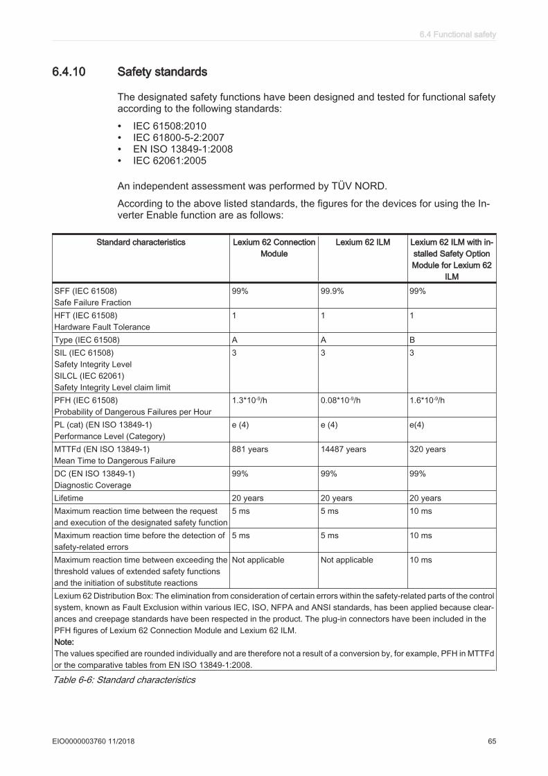
6.4.10 Safety standards
The designated safety functions have been designed and tested for functional safetyaccording to the following standards:
• IEC 61508:2010• IEC 61800-5-2:2007• EN ISO 13849-1:2008• IEC 62061:2005
An independent assessment was performed by TÜV NORD.
According to the above listed standards, the figures for the devices for using the In‐verter Enable function are as follows:
Standard characteristics Lexium 62 ConnectionModule
Lexium 62 ILM Lexium 62 ILM with in‐stalled Safety OptionModule for Lexium 62
ILM
SFF (IEC 61508)Safe Failure Fraction
99% 99.9% 99%
HFT (IEC 61508)Hardware Fault Tolerance
1 1 1
Type (IEC 61508) A A BSIL (IEC 61508) Safety Integrity LevelSILCL (IEC 62061)Safety Integrity Level claim limit
3 3 3
PFH (IEC 61508) Probability of Dangerous Failures per Hour
1.3*10-9/h 0.08*10-9/h 1.6*10-9/h
PL (cat) (EN ISO 13849-1) Performance Level (Category)
e (4) e (4) e(4)
MTTFd (EN ISO 13849-1) Mean Time to Dangerous Failure
881 years 14487 years 320 years
DC (EN ISO 13849-1) Diagnostic Coverage
99% 99% 99%
Lifetime 20 years 20 years 20 yearsMaximum reaction time between the requestand execution of the designated safety function
5 ms 5 ms 10 ms
Maximum reaction time before the detection ofsafety-related errors
5 ms 5 ms 10 ms
Maximum reaction time between exceeding thethreshold values of extended safety functionsand the initiation of substitute reactions
Not applicable Not applicable 10 ms
Lexium 62 Distribution Box: The elimination from consideration of certain errors within the safety-related parts of the controlsystem, known as Fault Exclusion within various IEC, ISO, NFPA and ANSI standards, has been applied because clear‐ances and creepage standards have been respected in the product. The plug-in connectors have been included in thePFH figures of Lexium 62 Connection Module and Lexium 62 ILM.Note:The values specified are rounded individually and are therefore not a result of a conversion by, for example, PFH in MTTFdor the comparative tables from EN ISO 13849-1:2008.
Table 6-6: Standard characteristics
6.4 Functional safety
EIO0000003760 11/2018 65

Standard characteristics Safety Option Module for Lexium 62 ILM
MTTFd (EN ISO 13849-1) Mean Time to Dangerous Failure [years]
Use of Safely Limited Speed (SLS) etc. -... with Sick Stegmann encoder SKM36 250... with Sick Stegmann encoder SKS36 250
Table 6-7: Standard characteristics - Safety Option Module for Lexium 62 ILM
6 Planning
66 EIO0000003760 11/2018
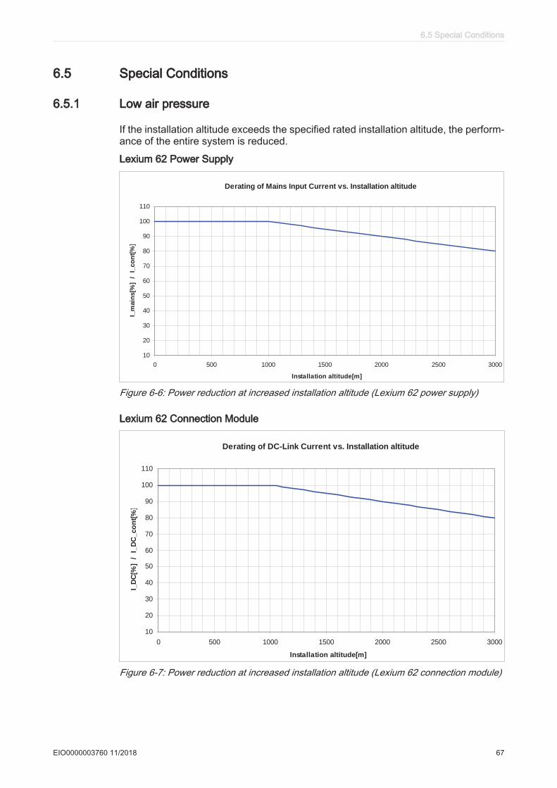
6.5 Special Conditions
6.5.1 Low air pressure
If the installation altitude exceeds the specified rated installation altitude, the perform‐ance of the entire system is reduced.
Lexium 62 Power Supply
Derating of Mains Input Current vs. Installation altitude
10
20
30
40
50
60
70
80
90
100
110
0 500 1000 1500 2000 2500 3000
Installation altitude[m]
I_m
ain
s[%
] /
I_
co
nt[
%]
Figure 6-6: Power reduction at increased installation altitude (Lexium 62 power supply)
Lexium 62 Connection Module
Derating of DC-Link Current vs. Installation altitude
10
20
30
40
50
60
70
80
90
100
110
0 500 1000 1500 2000 2500 3000
Installation altitude[m]
I_D
C[%
] /
I_D
C_co
nt[
%]
Figure 6-7: Power reduction at increased installation altitude (Lexium 62 connection module)
6.5 Special Conditions
EIO0000003760 11/2018 67

Lexium 62 ILM
Derating of Phase Output Current vs. Installation altitude
10
20
30
40
50
60
70
80
90
100
110
0 500 1000 1500 2000 2500 3000
Installation altitude[m]
I_p
h_o
ut
/
I_p
h_o
ut_
co
nt
[%]
Figure 6-8: Power reduction at increased installation height (Lexium 62 ILM at 8 kHz clockfrequency of power stage)
Multiply the values with the nominal current at 40°C / 104°F in order to calculate themaximum current value, depending on the required installation altitude.
6 Planning
68 EIO0000003760 11/2018
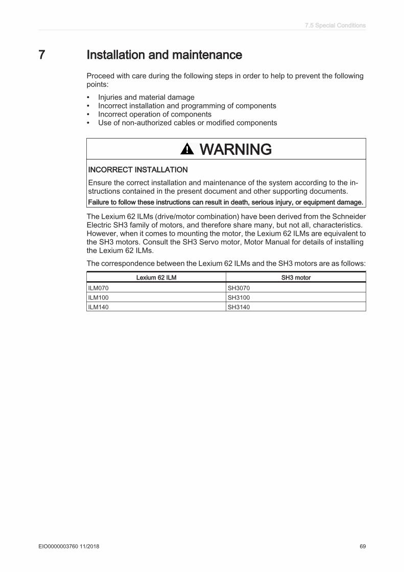
7 Installation and maintenanceProceed with care during the following steps in order to help to prevent the followingpoints:
• Injuries and material damage• Incorrect installation and programming of components• Incorrect operation of components• Use of non-authorized cables or modified components
WARNINGINCORRECT INSTALLATION
Ensure the correct installation and maintenance of the system according to the in‐structions contained in the present document and other supporting documents.Failure to follow these instructions can result in death, serious injury, or equipment damage.
The Lexium 62 ILMs (drive/motor combination) have been derived from the SchneiderElectric SH3 family of motors, and therefore share many, but not all, characteristics.However, when it comes to mounting the motor, the Lexium 62 ILMs are equivalent tothe SH3 motors. Consult the SH3 Servo motor, Motor Manual for details of installingthe Lexium 62 ILMs.
The correspondence between the Lexium 62 ILMs and the SH3 motors are as follows:
Lexium 62 ILM SH3 motor
ILM070 SH3070ILM100 SH3100ILM140 SH3140
7.5 Special Conditions
EIO0000003760 11/2018 69
7.1 Commissioning
DANGERELECTRIC SHOCK, EXPLOSION, OR ARC FLASH
• Disconnect all power from all equipment including connected devices prior toremoving any covers or doors, or installing or removing any accessories, hard‐ware, cables, or wires.
• Place a "Do Not Turn On" or equivalent hazard label on all power switches andlock them in the non-energized position.
• Wait 15 minutes to allow the residual energy of the DC bus capacitors to dis‐charge.
• Measure the voltage on the DC bus with a properly rated voltage sensing deviceand verify that the voltage is less than 42.4 Vdc.
• Do not assume that the DC bus is voltage-free when the DC bus LED is off.• Block the motor shaft to prevent rotation prior to performing any type of work on
the drive system.• Do not create a short-circuit across the DC bus terminals or the DC bus capaci‐
tors.• Replace and secure all covers, accessories, hardware, cables, and wires and
confirm that a proper ground connection exists before applying power to the unit.• Use only the specified voltage when operating this equipment and any associated
products.Failure to follow these instructions will result in death or serious injury.
DANGERELECTRIC SHOCK, EXPLOSION, OR ARC FLASH
• Operate electrical components only with a connected protective ground (earth)cable.
• After the installation, verify the secure connection of the protective ground (earth)cable to all electrical devices to ensure that connection complies with the con‐nection diagram.
• Before enabling the device, safely cover the live components to prevent contact.• Do not touch the electrical connection points of the components when the module
is energized.• Provide protection against indirect contact (EN 50178).• Connect and disconnect cables and terminals only after you have verified that
the power has been removed from the system.• Insulate the unused conductors on both ends of the motor cable.Failure to follow these instructions will result in death or serious injury.
ESD protection ▶ Observe the following instructions to help avoid damages due to electrostatic dis‐charge:
7 Installation and maintenance
70 EIO0000003760 11/2018
NOTICEELECTROSTATIC DISCHARGE
• Do not touch any of the electrical connections or components.• Prevent electrostatic charges, for example, by wearing appropriate clothing.• If you must touch circuit boards, do so only on the edges.• Move the circuit boards as little as possible.• Remove existing static charge by touching a grounded, metallic surface.Failure to follow these instructions can result in equipment damage.
7.1.1 Preparing commissioning
Unpacking How to unpack the device:▶ Remove packaging.▶ Dispose of the packaging material in accordance with the relevant local regula‐
tions.Verifying How to verify the device:
▶ Verify that the delivery is complete on the basis of the delivery slip.▶ Closely inspect the device for any signs of damage.
WARNINGUNINTENTED EQUIPMENT OPERATION
• Do not mount or commission damaged drive systems.• Do not modify the drive systems.• Send back inoperative devices.Failure to follow these instructions can result in death, serious injury, or equipment damage.▶ Verify the data with the help of the nameplates.▶ Observe requirements for the installation location.▶ Observe requirements for the degree of protection and the EMC rules.▶ In addition to the following instructions, also note the information in the chapter
"Planning".▶ Then install Lexium 62 ILM component.
7.1 Commissioning
EIO0000003760 11/2018 71
7.1.2 Grinding the holding brake
Regrind the holding brake if a motor was stored for over 2 years before mounting.
How to disassemble the motor:▶ Observe the general (see 7.4 Replacing Lexium 62 components and cables) and
special (see 7.4.3 Replacement of the Lexium 62 ILM) measures for device re‐placement.
▶ Put main switch in "OFF" position to free system of voltage.▶ Prevent main switch from being switched back on.▶ Disconnect all connection cables on the motor.▶ Loosen the screw connections on the motor.
The motor is removed from the machine and disconnected from all electrical sup‐ply lines.
How to regrind the holding brake:
▪ The motor must not be installed in machine and the holding brake must be en‐gaged.
WARNINGUNINTENDED AXIS MOVEMENTS
Grind holding brake only when the removed motor is disconnected from all elec‐trical supply lines.Failure to follow these instructions can result in death, serious injury, or equipmentdamage.
▶ Verify the holding torque of the holding brake using a torque wrench.▶ Compare the value to the specified holding torque of the holding brake upon de‐
livery (see 8.5.10 Holding brake).▶ If the holding torque of the holding brake considerably differs from the specified
values, manually rotate the motor shaft by 25 rotations in both directions.▶ Repeat the process.
Contact your Schneider Electric representative if you cannot restore the originalholding torque after repeating the process 3 times.
7.1.3 Preparing the control cabinet
DANGERINCORRECT OR UNAVAILABLE GROUNDING
At the installation points, remove paint across a large surface before installing thedevices (bare metal connection).Failure to follow these instructions will result in death or serious injury.▶ If necessary to maintain and respect the maximum ambient operating tempera‐
ture, install additional fan in the control cabinet.▶ Do not block the fan air inlet of the product.▶ Drill mounting holes in the control cabinet in the 45 mm / (1.77 in) (± 0.2 mm /
± 0.01 in) mounting-grid pattern .▶ Observe tolerances as well as distances to the cable channels and adjacent Lex‐
ium 62 cabinet drives or other heat producing equipment.
7 Installation and maintenance
72 EIO0000003760 11/2018
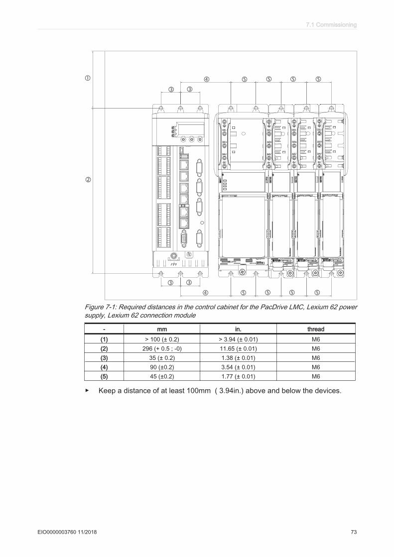
�
�
� �
� � � � �
� �
� � � � �
Figure 7-1: Required distances in the control cabinet for the PacDrive LMC, Lexium 62 powersupply, Lexium 62 connection module
- mm in. thread
(1) > 100 (± 0.2) > 3.94 (± 0.01) M6(2) 296 (+ 0.5 ; -0) 11.65 (± 0.01) M6(3) 35 (± 0.2) 1.38 (± 0.01) M6(4) 90 (±0.2) 3.54 (± 0.01) M6(5) 45 (±0.2) 1.77 (± 0.01) M6
▶ Keep a distance of at least 100mm ( 3.94in.) above and below the devices.
7.1 Commissioning
EIO0000003760 11/2018 73
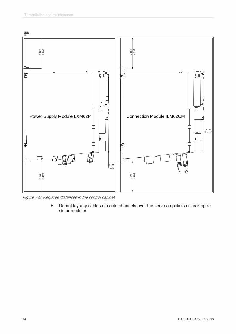
> 1
00
mm
in.
> 3
.94
> 1
00
> 3
.94
> 1
00
> 3
.94
> 1
00
> 3
.94
> 10
> 0.39
> 10
> 0.39
Power Supply Module LXM62P Connection Module ILM62CM
Figure 7-2: Required distances in the control cabinet
▶ Do not lay any cables or cable channels over the servo amplifiers or braking re‐sistor modules.
7 Installation and maintenance
74 EIO0000003760 11/2018
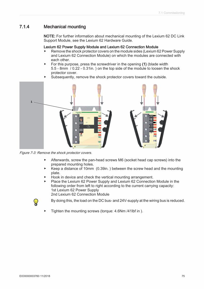
7.1.4 Mechanical mounting
NOTE: For further information about mechanical mounting of the Lexium 62 DC LinkSupport Module, see the Lexium 62 Hardware Guide.
Lexium 62 Power Supply Module and Lexium 62 Connection Module▶ Remove the shock protector covers on the module sides (Lexium 62 Power Supply
and Lexium 62 Connection Module) on which the modules are connected witheach other.
▶ For this purpose, press the screwdriver in the opening (1) (blade width5.5 - 8mm / 0.22 - 0.31in. ) on the top side of the module to loosen the shockprotector cover.
▶ Subsequently, remove the shock protector covers toward the outside.
1
Figure 7-3: Remove the shock protector covers.
▶ Afterwards, screw the pan-head screws M6 (socket head cap screws) into theprepared mounting holes.
▶ Keep a distance of 10mm (0.39in. ) between the screw head and the mountingplate.
▶ Hook in device and check the vertical mounting arrangement.▶ Place the Lexium 62 Power Supply and Lexium 62 Connection Module in the
following order from left to right according to the current carrying capacity:1st Lexium 62 Power Supply2nd Lexium 62 Connection ModuleBy doing this, the load on the DC bus- and 24V-supply at the wiring bus is reduced.
▶ Tighten the mounting screws (torque: 4.6Nm /41lbf in ).
7.1 Commissioning
EIO0000003760 11/2018 75
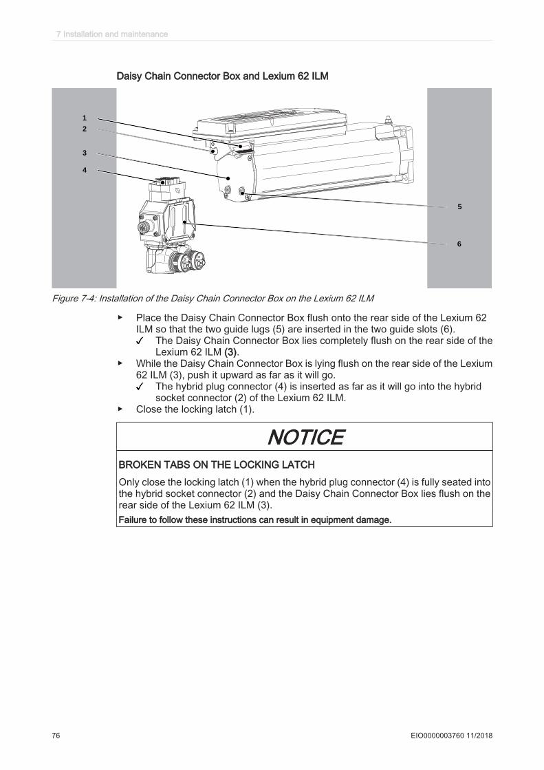
Daisy Chain Connector Box and Lexium 62 ILM
1
2
3
4
6
5
Figure 7-4: Installation of the Daisy Chain Connector Box on the Lexium 62 ILM
▶ Place the Daisy Chain Connector Box flush onto the rear side of the Lexium 62ILM so that the two guide lugs (5) are inserted in the two guide slots (6).
The Daisy Chain Connector Box lies completely flush on the rear side of theLexium 62 ILM (3).
▶ While the Daisy Chain Connector Box is lying flush on the rear side of the Lexium62 ILM (3), push it upward as far as it will go.
The hybrid plug connector (4) is inserted as far as it will go into the hybridsocket connector (2) of the Lexium 62 ILM.
▶ Close the locking latch (1).
NOTICEBROKEN TABS ON THE LOCKING LATCH
Only close the locking latch (1) when the hybrid plug connector (4) is fully seated intothe hybrid socket connector (2) and the Daisy Chain Connector Box lies flush on therear side of the Lexium 62 ILM (3).Failure to follow these instructions can result in equipment damage.
7 Installation and maintenance
76 EIO0000003760 11/2018
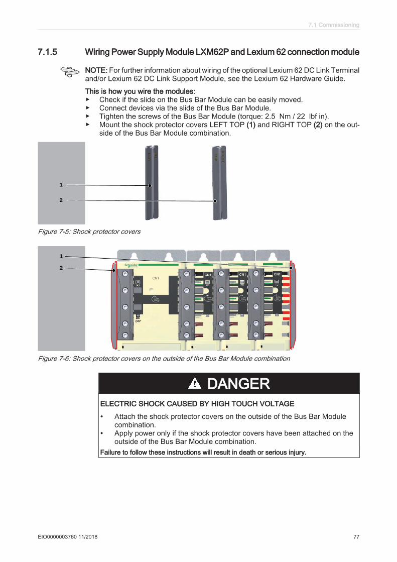
7.1.5 Wiring Power Supply Module LXM62P and Lexium 62 connection module
NOTE: For further information about wiring of the optional Lexium 62 DC Link Terminaland/or Lexium 62 DC Link Support Module, see the Lexium 62 Hardware Guide.
This is how you wire the modules:▶ Check if the slide on the Bus Bar Module can be easily moved.▶ Connect devices via the slide of the Bus Bar Module.▶ Tighten the screws of the Bus Bar Module (torque: 2.5 Nm / 22 lbf in).▶ Mount the shock protector covers LEFT TOP (1) and RIGHT TOP (2) on the out‐
side of the Bus Bar Module combination.
1
2
Figure 7-5: Shock protector covers
1
2
Figure 7-6: Shock protector covers on the outside of the Bus Bar Module combination
DANGERELECTRIC SHOCK CAUSED BY HIGH TOUCH VOLTAGE
• Attach the shock protector covers on the outside of the Bus Bar Modulecombination.
• Apply power only if the shock protector covers have been attached on theoutside of the Bus Bar Module combination.
Failure to follow these instructions will result in death or serious injury.
7.1 Commissioning
EIO0000003760 11/2018 77

▶ Connect the additional protective ground (earth) conductor with the ring cable lugand the M5 screw to the heat sink of the Lexium 62 Power Supply (tighteningtorque: 3.5 Nm / 31 lbf in).
▶ Connect the protective ground (earth) conductor with the following equipment inthe order presented: lock washer, ring cable lug, lock washer, washer and screw.
▶ Verify that terminals are secure and and that the necessary cable sizes are correct(cross section/gauge).
▶ Verify that the shielding is properly grounded. Eliminate short circuits and inter‐ruptions.
▶ Do not choose a connection cross-section of the ground cable that is smaller thanthe cross-section of the main connection.
This product has a leakage current greater than 3.5 mA. If the protective ground con‐nection is interrupted, a hazardous touch current may flow if the housing is touched.
DANGERINSUFFICIENT GROUNDING
• Use a protective ground conductor with at least 10 mm2 (AWG 6) or two protectiveground conductors with the same or larger cross section of the conductors sup‐plying the power terminals.
• Verify compliance with all local and national electrical code requirements as wellas all other applicable regulations with respect to grounding of all equipment.
Failure to follow these instructions will result in death or serious injury.
7 Installation and maintenance
78 EIO0000003760 11/2018
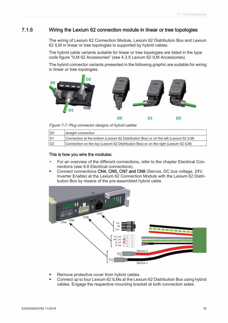
7.1.6 Wiring the Lexium 62 connection module in linear or tree topologies
The wiring of Lexium 62 Connection Module, Lexium 62 Distribution Box and Lexium62 ILM in linear or tree topologies is supported by hybrid cables.
The hybrid cable variants suitable for linear or tree topologies are listed in the typecode figure "ILM 62 Accessories" (see 4.3.5 Lexium 62 ILM Accessories).
The hybrid connector variants presented in the following graphic are suitable for wiringin linear or tree topologies.
D1 D2D0
D1
D2D0
Figure 7-7: Plug connector designs of hybrid cables
D0 straight connectionD1 Connection at the bottom (Lexium 62 Distribution Box) or on the left (Lexium 62 ILM)D2 Connection on the top (Lexium 62 Distribution Box) or on the right (Lexium 62 ILM)
This is how you wire the modules:
▪ For an overview of the different connections, refer to the chapter Electrical Con‐nections (see 8.8 Electrical connections).
▶ Connect connections CN4, CN5, CN7 and CN8 (Sercos, DC bus voltage, 24V,Inverter Enable) at the Lexium 62 Connection Module with the Lexium 62 Distri‐bution Box by means of the pre-assembled hybrid cable.
Sercos 2
CN4CN5
CN8
CN7
Sercos 1
0V_out
24V_out
IE_ref
IE_sig
DC-
DC+
PE
▶ Remove protective cover from hybrid cables.▶ Connect up to four Lexium 62 ILMs at the Lexium 62 Distribution Box using hybrid
cables. Engage the respective mounting bracket at both connection sides.
7.1 Commissioning
EIO0000003760 11/2018 79

▶ Provide unused hybrid connection sockets with strapping plugs.The strapping plugs are not included in the scope of delivery of Lexium 62 ILMand must be ordered separately (order number: VW3E6023).Strapping plugs close the Sercos loop, while ensuring the integrity of the IP65degree of protection.
WARNINGLOSS OF IP65 RATING
Use strapping plugs VW3E6023 in unused hybrid connection sockets.Failure to follow these instructions can result in death, serious injury, or equipment damage.
The following table is an example of the topological addressing of the ILMs, dependingon the Sercos connection and assuming the Lexium 62 Connection Module is con‐nected to connector CN1 with a hybrid cable.
Sercos lines within the Hybridcable
Connection Lexium 62 Con‐nection Module
Topological address of the Lexium 62ILMs connected to the Lexium 62 Distri‐
bution Box
CN2 CN3 CN4 CN5
Sercos 1 (black)Sercos 2 (red)
CN4CN5
4 3 2 1
Sercos 1 (black)Sercos 2 (red)
CN5CN4
1 2 3 4
Table 7-1: The topological address for CN2, CN3, CN4 and CN5 (Lexium 62 Distribution Box) depends of the assignment of Sercos 1/Sercos 2 to CN4/CN5 (Lexium 62 Connection Module)
Depending on the selected identification (address) mode in the EcoStruxure Machine Expert Logic Builder, an interchanged connection of the Sercos 1/Sercos 2 connectors can lead to unintended machine operation.
7 Installation and maintenance
80 EIO0000003760 11/2018

WARNINGUNINTENDED MACHINE OPERATION
Ensure that the Sercos cables are connected to the Sercos connections CN4/CN5 ofthe Lexium 62 Connection Module according to the requirements of the application,its configuration and applicable standards.Failure to follow these instructions can result in death, serious injury, or equipment damage.
The following boundary conditions must be observed for the system layout:
• Maximum cable length of 20 m (65.2 ft) from Lexium 62 Connection Module toLexium 62 Distribution Box.
• Maximum cable length of 10 m (32.8 ft) from Lexium 62 Distribution Box to anotherLexium 62 Distribution Box.
• Maximum cable length of 10 m (32.8 ft) from Lexium 62 Distribution Box to Lexium62 ILM.
• Sum of all cable lengths maximum 200 m (656 ft).• Maximum distance of 50 m (164 ft) between 2 active Sercos slaves. In the example
below, the critical measure is the return from the last Sercos slave (Lexium 62 ILM)to the Lexium 62 Power Supply via the connection module.
• Lexium 62 Connection Module and Lexium 62 Distribution Box are not active Ser‐cos slaves. Both the Lexium 62 Connection Module and the Lexium 62 DistributionBox are passive, pass-through devices.
Contact your Schneider Electric representative in order to create a detailed systemlayout for the respective available topology.
The following two examples illustrate the longest path between 2 active Sercos slavesfor which a maximum length of 50 m (164 ft) is permissible. This critical distance ismarked in blue.
In the following example of a linear topology, the longest path is between the Lexium62 Power Supply and the last Lexium 62 ILM.
20 m (65.6 ft)
10 m
(32.8 ft)
10 m (32.8 ft)
10 m
(32.8 ft)
Total length in
this example:
40 m (131.2 ft)
Figure 7-8: An example of maximum pathway for linear topology
The next example is of a tree topology where the longest path is between two Lexium62 ILMs and not between the Lexium 62 Power Supply and the last Lexium 62 ILM.
7.1 Commissioning
EIO0000003760 11/2018 81
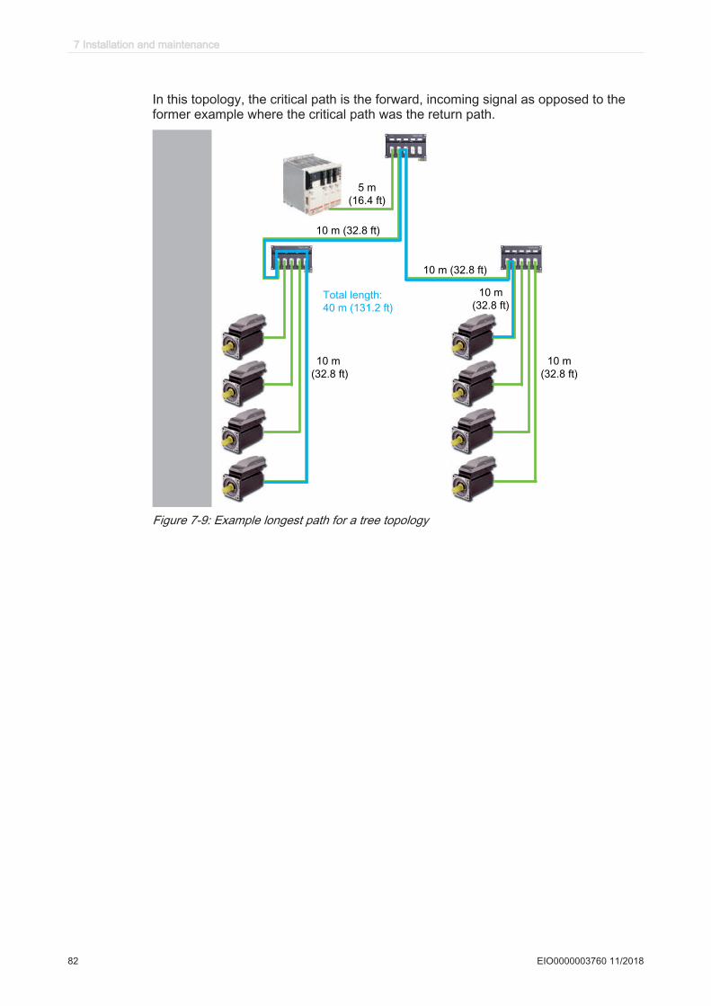
In this topology, the critical path is the forward, incoming signal as opposed to theformer example where the critical path was the return path.
Figure 7-9: Example longest path for a tree topology
7 Installation and maintenance
82 EIO0000003760 11/2018
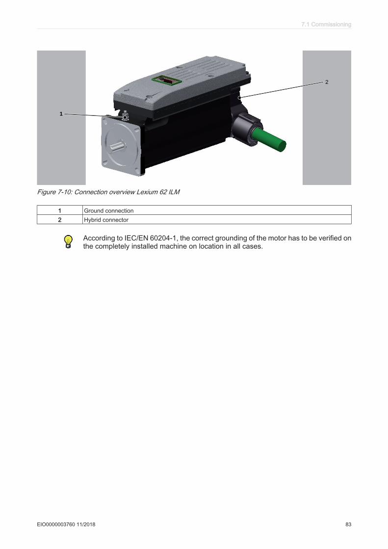
TM
1
2
Figure 7-10: Connection overview Lexium 62 ILM
1 Ground connection2 Hybrid connector
According to IEC/EN 60204-1, the correct grounding of the motor has to be verified onthe completely installed machine on location in all cases.
7.1 Commissioning
EIO0000003760 11/2018 83
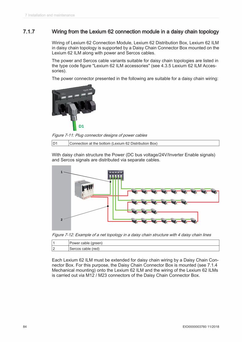
7.1.7 Wiring from the Lexium 62 connection module in a daisy chain topology
Wiring of Lexium 62 Connection Module, Lexium 62 Distribution Box, Lexium 62 ILMin daisy chain topology is supported by a Daisy Chain Connector Box mounted on theLexium 62 ILM along with power and Sercos cables.
The power and Sercos cable variants suitable for daisy chain topologies are listed inthe type code figure "Lexium 62 ILM accessories" (see 4.3.5 Lexium 62 ILM Acces‐sories).
The power connector presented in the following are suitable for a daisy chain wiring:
D1
Figure 7-11: Plug connector designs of power cables
D1 Connection at the bottom (Lexium 62 Distribution Box)
With daisy chain structure the Power (DC bus voltage/24V/Inverter Enable signals)and Sercos signals are distributed via separate cables.
1
2
Figure 7-12: Example of a net topology in a daisy chain structure with 4 daisy chain lines
1 Power cable (green)2 Sercos cable (red)
Each Lexium 62 ILM must be extended for daisy chain wiring by a Daisy Chain Con‐nector Box. For this purpose, the Daisy Chain Connector Box is mounted (see 7.1.4Mechanical mounting) onto the Lexium 62 ILM and the wiring of the Lexium 62 ILMsis carried out via M12 / M23 connectors of the Daisy Chain Connector Box.
7 Installation and maintenance
84 EIO0000003760 11/2018
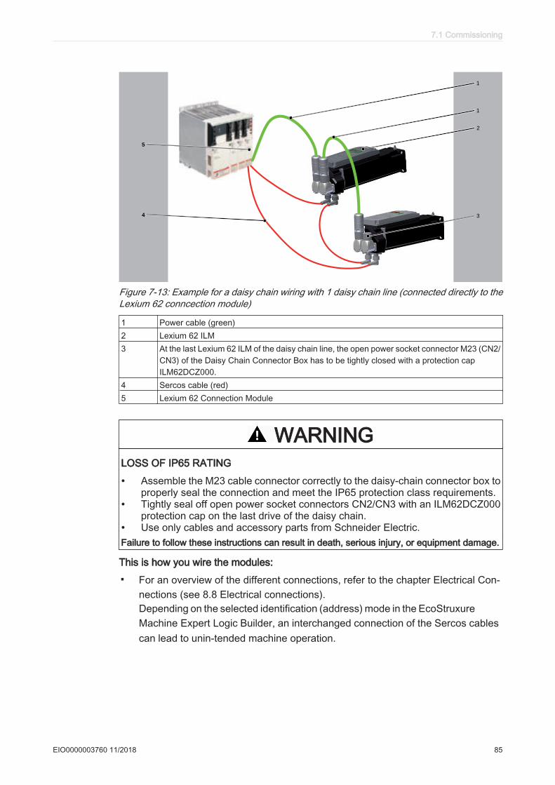
5
4
TM
2
3
1
1
Figure 7-13: Example for a daisy chain wiring with 1 daisy chain line (connected directly to theLexium 62 conncection module)
1 Power cable (green)2 Lexium 62 ILM3 At the last Lexium 62 ILM of the daisy chain line, the open power socket connector M23 (CN2/
CN3) of the Daisy Chain Connector Box has to be tightly closed with a protection capILM62DCZ000.
4 Sercos cable (red)5 Lexium 62 Connection Module
WARNINGLOSS OF IP65 RATING
• Assemble the M23 cable connector correctly to the daisy-chain connector box toproperly seal the connection and meet the IP65 protection class requirements.
• Tightly seal off open power socket connectors CN2/CN3 with an ILM62DCZ000protection cap on the last drive of the daisy chain.
• Use only cables and accessory parts from Schneider Electric.Failure to follow these instructions can result in death, serious injury, or equipment damage.
This is how you wire the modules:
▪ For an overview of the different connections, refer to the chapter Electrical Con‐nections (see 8.8 Electrical connections).Depending on the selected identification (address) mode in the EcoStruxureMachine Expert Logic Builder, an interchanged connection of the Sercos cablescan lead to unin‐tended machine operation.
7.1 Commissioning
EIO0000003760 11/2018 85
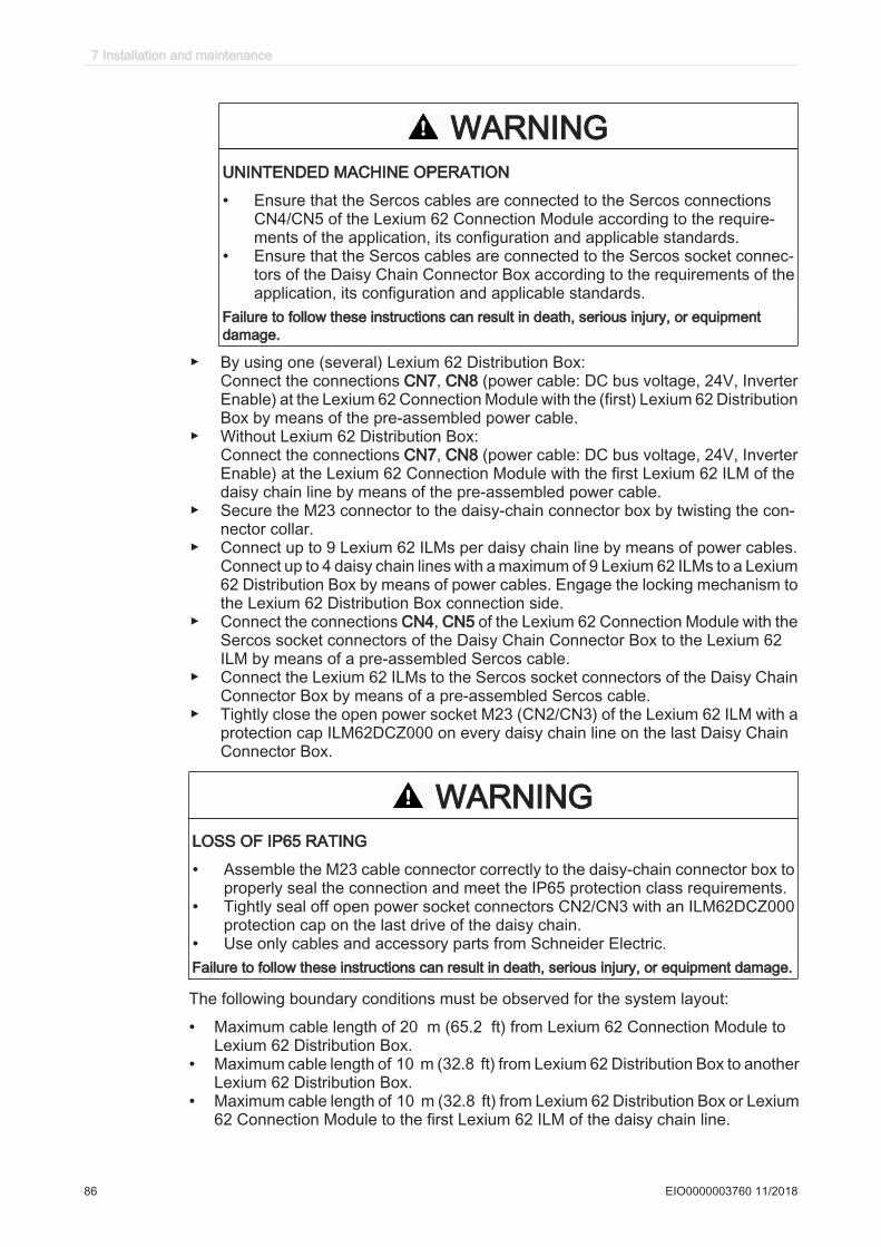
WARNINGUNINTENDED MACHINE OPERATION
• Ensure that the Sercos cables are connected to the Sercos connectionsCN4/CN5 of the Lexium 62 Connection Module according to the require‐ments of the application, its configuration and applicable standards.
• Ensure that the Sercos cables are connected to the Sercos socket connec‐tors of the Daisy Chain Connector Box according to the requirements of theapplication, its configuration and applicable standards.
Failure to follow these instructions can result in death, serious injury, or equipmentdamage.
▶ By using one (several) Lexium 62 Distribution Box:Connect the connections CN7, CN8 (power cable: DC bus voltage, 24V, InverterEnable) at the Lexium 62 Connection Module with the (first) Lexium 62 DistributionBox by means of the pre-assembled power cable.
▶ Without Lexium 62 Distribution Box:Connect the connections CN7, CN8 (power cable: DC bus voltage, 24V, InverterEnable) at the Lexium 62 Connection Module with the first Lexium 62 ILM of thedaisy chain line by means of the pre-assembled power cable.
▶ Secure the M23 connector to the daisy-chain connector box by twisting the con‐nector collar.
▶ Connect up to 9 Lexium 62 ILMs per daisy chain line by means of power cables.Connect up to 4 daisy chain lines with a maximum of 9 Lexium 62 ILMs to a Lexium62 Distribution Box by means of power cables. Engage the locking mechanism tothe Lexium 62 Distribution Box connection side.
▶ Connect the connections CN4, CN5 of the Lexium 62 Connection Module with theSercos socket connectors of the Daisy Chain Connector Box to the Lexium 62ILM by means of a pre-assembled Sercos cable.
▶ Connect the Lexium 62 ILMs to the Sercos socket connectors of the Daisy ChainConnector Box by means of a pre-assembled Sercos cable.
▶ Tightly close the open power socket M23 (CN2/CN3) of the Lexium 62 ILM with aprotection cap ILM62DCZ000 on every daisy chain line on the last Daisy ChainConnector Box.
WARNINGLOSS OF IP65 RATING
• Assemble the M23 cable connector correctly to the daisy-chain connector box toproperly seal the connection and meet the IP65 protection class requirements.
• Tightly seal off open power socket connectors CN2/CN3 with an ILM62DCZ000protection cap on the last drive of the daisy chain.
• Use only cables and accessory parts from Schneider Electric.Failure to follow these instructions can result in death, serious injury, or equipment damage.
The following boundary conditions must be observed for the system layout:
• Maximum cable length of 20 m (65.2 ft) from Lexium 62 Connection Module toLexium 62 Distribution Box.
• Maximum cable length of 10 m (32.8 ft) from Lexium 62 Distribution Box to anotherLexium 62 Distribution Box.
• Maximum cable length of 10 m (32.8 ft) from Lexium 62 Distribution Box or Lexium62 Connection Module to the first Lexium 62 ILM of the daisy chain line.
7 Installation and maintenance
86 EIO0000003760 11/2018

• A maximum of 9 Lexium 62 ILMs can be connected per daisy chain line and amaximum cable length of 10 m (32.8 ft) between the first and the last Lexium 62ILM of the daisy chain line.
• Sum of all cable lengths maximum 200 m (656 ft).• Maximum distance of 50 m (164 ft) between 2 active Sercos slaves.• Lexium 62 Connection Module and Lexium 62 Distribution Box are not active Ser‐
cos slaves. Both the Lexium 62 Connection Module and the Lexium 62 DistributionBox are passive, pass-through devices.
Contact your Schneider Electric representative in order to create a detailed systemlayout for the respective available topology.
NOTICEINCORRECT VOLTAGE / CURRENT
Only use topologies approved by Schneider Electric.Failure to follow these instructions can result in equipment damage.
According to IEC/EN 60204-1, the correct grounding of the motor has to be verified onthe completely installed machine on location in all cases.
7.1 Commissioning
EIO0000003760 11/2018 87
7.2 Maintenance, repair, cleaning▶ Observe the following instructions before carrying out maintenance on Lexium 62
drive system:
DANGERELECTRIC SHOCK, EXPLOSION, OR ARC FLASH
• Disconnect all power from all equipment including connected devices prior toremoving any covers or doors, or installing or removing any accessories, hard‐ware, cables, or wires.
• Place a "Do Not Turn On" or equivalent hazard label on all power switches andlock them in the non-energized position.
• Wait 15 minutes to allow the residual energy of the DC bus capacitors to dis‐charge.
• Measure the voltage on the DC bus with a properly rated voltage sensing deviceand verify that the voltage is less than 42.4 Vdc.
• Do not assume that the DC bus is voltage-free when the DC bus LED is off.• Block the motor shaft to prevent rotation prior to performing any type of work on
the drive system.• Do not create a short-circuit across the DC bus terminals or the DC bus capaci‐
tors.• Replace and secure all covers, accessories, hardware, cables, and wires and
confirm that a proper ground connection exists before applying power to the unit.• Use only the specified voltage when operating this equipment and any associated
products.Failure to follow these instructions will result in death or serious injury.
How to de-energize the system:▶ Set main switch to "OFF Position", or otherwise disconnect all power to the sys‐
tem.▶ Prevent main switch from being switched back on.▶ Wait 15 minutes after removing power (switching off) to allow the DC bus capac‐
itors to discharge.▶ After the DC-BUS LED has turned off on all components located in the axis group,
measure whether any residual voltage is present on the DC bus.▶ Verify DC+ to PE (Protective Earth/ground) and DC- to PE with an appropriate
measuring instrument to make sure it is de-energized before working on the de‐vice.
DANGERELECTRIC SHOCK, EXPLOSION, OR ARC FLASH
Verify with a correctly calibrated measuring instrument that the DC bus is de-ener‐gized (less than 42.4 Vdc) before replacing, maintaining or cleaning machine com‐ponents.Failure to follow these instructions will result in death or serious injury.
7 Installation and maintenance
88 EIO0000003760 11/2018
7.2.1 Fuse replacement Lexium 62 connection module
If there is a loss of power from the Lexium 62 Connection Module while there is powerat the power supply, you may need to replace the internal fuses. The Lexium 62 DriveSystem indicates such a condition by the following:
• DC bus LED at the Lexium 62 Power Supply flashes.• DC bus LED at the Lexium 62 Connection Module is off.
Note: Before attempting to replace the fuses, determine the source of over-current orshort circuit and remedy the issue.
The Lexium 62 Connection Module needs to be disconnected and removed to replacethe internal fuses.
DANGERELECTRIC SHOCK CAUSED BY HIGH TOUCH VOLTAGE
• Before working on the product, make sure that it is de-energized.• After disconnection, do not touch connector CN6 mains connection on the Lexi‐
um 62 Power Supply module as it still carries hazardous voltages for approxi‐mately one second.
• Only operate the Lexium 62 Power Supply and the Lexium 62 Connection Modulein a control cabinet that cannot be opened without the help of tools.
Failure to follow these instructions will result in death or serious injury.▶ Dismount (see 7.4 Replacing Lexium 62 components and cables) Lexium 62
Connection Module.▶ Open maintenance flap.
7.2 Maintenance, repair, cleaning
EIO0000003760 11/2018 89
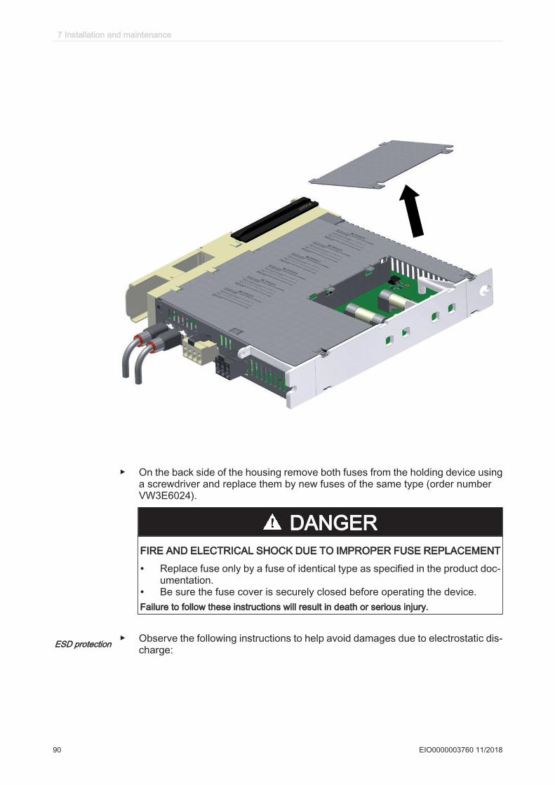
▶ On the back side of the housing remove both fuses from the holding device usinga screwdriver and replace them by new fuses of the same type (order numberVW3E6024).
DANGERFIRE AND ELECTRICAL SHOCK DUE TO IMPROPER FUSE REPLACEMENT
• Replace fuse only by a fuse of identical type as specified in the product doc‐umentation.
• Be sure the fuse cover is securely closed before operating the device.Failure to follow these instructions will result in death or serious injury.
ESD protection ▶ Observe the following instructions to help avoid damages due to electrostatic dis‐charge:
7 Installation and maintenance
90 EIO0000003760 11/2018
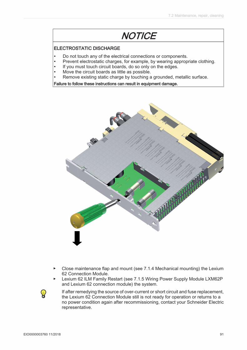
NOTICEELECTROSTATIC DISCHARGE
• Do not touch any of the electrical connections or components.• Prevent electrostatic charges, for example, by wearing appropriate clothing.• If you must touch circuit boards, do so only on the edges.• Move the circuit boards as little as possible.• Remove existing static charge by touching a grounded, metallic surface.Failure to follow these instructions can result in equipment damage.
▶ Close maintenance flap and mount (see 7.1.4 Mechanical mounting) the Lexium62 Connection Module.
▶ Lexium 62 ILM Family Restart (see 7.1.5 Wiring Power Supply Module LXM62Pand Lexium 62 connection module) the system.If after remedying the source of over-current or short circuit and fuse replacement,the Lexium 62 Connection Module still is not ready for operation or returns to ano power condition again after recommissioning, contact your Schneider Electricrepresentative.
7.2 Maintenance, repair, cleaning
EIO0000003760 11/2018 91
There are no other user-serviceable parts within the Lexium 62 components. Eitherreplace the entire device or contact the Schneider Electric Customer Service (for con‐tact addresses, refer to the Appendix (see 12.1 Contact addresses)).
WARNINGUNINTENDED EQUIPMENT OPERATION
• Only use software and hardware components approved by Schneider Electric foruse with this equipment.
• Do not attempt to service this equipment outside of authorized Schneider Electricservice centers.
• Update your application program every time you change the physical hardwareconfiguration.
Failure to follow these instructions can result in death, serious injury, or equipment damage.
7 Installation and maintenance
92 EIO0000003760 11/2018

7.2.2 Machine repair
With exception of internal fuses in the Lexium 62 connection modules (see 7.2.1 Fusereplacement Lexium 62 connection module), there are no other user-serviceable partswithin the Lexium 62 components. Either replace the entire device or contact theSchneider Electric Customer Service (for contact addresses, refer to the Appendix(see 12.1 Contact addresses)).
WARNINGUNINTENDED EQUIPMENT OPERATION
• Only use software and hardware components approved by Schneider Electric foruse with this equipment.
• Do not attempt to service this equipment outside of authorized Schneider Electricservice centers.
• Update your application program every time you change the physical hardwareconfiguration.
Failure to follow these instructions can result in death, serious injury, or equipment damage.
▶ Observe the following instructions to help avoid damages due to electrostatic dis‐charge:
NOTICEELECTROSTATIC DISCHARGE
• Do not touch any of the electrical connections or components.• Prevent electrostatic charges, for example, by wearing appropriate clothing.• If you must touch circuit boards, do so only on the edges.• Move the circuit boards as little as possible.• Remove existing static charge by touching a grounded, metallic surface.Failure to follow these instructions can result in equipment damage.
7.2 Maintenance, repair, cleaning
EIO0000003760 11/2018 93
7.2.3 Cleaning
If you find it necessary to clean the Lexium 62 ILM motors/drives, care must be takenwith cleaning products as some active agents may have deleterious effects on plasticsand stainless steel welds.
NOTICECORROSION CAUSED BY CLEANING AGENTS
• Before using a cleaning agent, carry out a compatibility test in relation to thecleaning agent and the component affected.
• Do not use alkaline detergent.• Do not use any chlorid-containing cleaning agents.• Do not use any sulphuric acid containing detergent.Failure to follow these instructions can result in equipment damage.
For more information on the material properties of your components (see 8.5 Me‐chanical and electrical data).
The standard cooling method of the motor is by natural convection. Therefore, keepthe motor surfaces free from dirt.
7 Installation and maintenance
94 EIO0000003760 11/2018
7.3 Replacement equipment inventory
Keep a stock of the most important components to make certain your machine is func‐tioning and ready for operation.
Replace devices with the same hardware configuration to help ensure compatibility.
Indicate the following information on the replacement equipment order:
Item name: for example, ILM0701P01A0000Hardware code: for example, RS02Software (firmware) version: for example, SW: 0.24.21
This information can be found on the logistic nameplate (see 4.4 Nameplate descrip‐tions).
NOTICEINCREASED PULSE ENERGY ABSORPTION CAPACITY OF THE LEXIUM 62POWER SUPPLY MODULE
Only replace Lexium 62 Power Supply module with the same or greater version.Failure to follow these instructions can result in equipment damage.
For more information concerning the replacement of components, refer to chapterReplacing Lexium 62 components and cables (see 7.4 Replacing Lexium 62 compo‐nents and cables).
7.3 Replacement equipment inventory
EIO0000003760 11/2018 95
7.4 Replacing Lexium 62 components and cables
DANGERELECTRIC SHOCK, EXPLOSION, OR ARC FLASH
• Disconnect all power from all equipment including connected devices prior toremoving any covers or doors, or installing or removing any accessories, hard‐ware, cables, or wires.
• Place a "Do Not Turn On" or equivalent hazard label on all power switches andlock them in the non-energized position.
• Wait 15 minutes to allow the residual energy of the DC bus capacitors to dis‐charge.
• Measure the voltage on the DC bus with a properly rated voltage sensing deviceand verify that the voltage is less than 42.4 Vdc.
• Do not assume that the DC bus is voltage-free when the DC bus LED is off.• Block the motor shaft to prevent rotation prior to performing any type of work on
the drive system.• Do not create a short-circuit across the DC bus terminals or the DC bus capaci‐
tors.• Replace and secure all covers, accessories, hardware, cables, and wires and
confirm that a proper ground connection exists before applying power to the unit.• Use only the specified voltage when operating this equipment and any associated
products.Failure to follow these instructions will result in death or serious injury.
DANGERELECTRIC SHOCK, EXPLOSION, OR ARC FLASH
• Operate electrical components only with a connected protective ground (earth)cable.
• After the installation, verify the secure connection of the protective ground (earth)cable to all electrical devices to ensure that connection complies with the con‐nection diagram.
• Before enabling the device, safely cover the live components to prevent contact.• Do not touch the electrical connection points of the components when the module
is energized.• Provide protection against indirect contact (EN 50178).• Connect and disconnect cables and terminals only after you have verified that
the power has been removed from the system.• Insulate the unused conductors on both ends of the motor cable.Failure to follow these instructions will result in death or serious injury.
With exception of internal fuses in the Lexium 62 connection modules (see 7.2.1 Fusereplacement Lexium 62 connection module), there are no other user-serviceable partswithin the Lexium 62 components. Either replace the entire device or contact theSchneider Electric Customer Service (for contact addresses, refer to the Appendix(see 12.1 Contact addresses)).
7 Installation and maintenance
96 EIO0000003760 11/2018
WARNINGUNINTENDED EQUIPMENT OPERATION
• Only use software and hardware components approved by Schneider Electric foruse with this equipment.
• Do not attempt to service this equipment outside of authorized Schneider Electricservice centers.
• Update your application program every time you change the physical hardwareconfiguration.
Failure to follow these instructions can result in death, serious injury, or equipment damage.
WARNINGIMPROPER REPLACEMENT OR OPENING OF THE COMPONENT HOUSING
• Do not open the housing of the components for commissioning, replacement orany other reason whatsoever unless otherwise instructed in the specific productdocumentation of the component.
• Observe and respect the instructions and specifications in the product documen‐tation and that of the machine manufacturer when replacing the device.
• Replace inoperable components as a whole.Failure to follow these instructions can result in death, serious injury, or equipment damage.
To replace components and cables, read thoroughly the instructions contained in thebeginning of the present chapter, Installation and Maintenance.
7.4 Replacing Lexium 62 components and cables
EIO0000003760 11/2018 97
ESD protection ▶ Observe the following instructions to help avoid damages due to electrostatic dis‐charge:
NOTICEELECTROSTATIC DISCHARGE
• Do not touch any of the electrical connections or components.• Prevent electrostatic charges, for example, by wearing appropriate clothing.• If you must touch circuit boards, do so only on the edges.• Move the circuit boards as little as possible.• Remove existing static charge by touching a grounded, metallic surface.Failure to follow these instructions can result in equipment damage.
How to de-energize the system:▶ Set main switch to "OFF Position", or otherwise disconnect all power to the sys‐
tem.▶ Prevent main switch from being switched back on.▶ Wait 15 minutes after removing power (switching off) to allow the DC bus capac‐
itors to discharge.▶ After the DC-BUS LED has turned off on all components located in the axis group,
measure whether any residual voltage is present on the DC bus.▶ Verify DC+ to PE (Protective Earth/ground) and DC- to PE with an appropriate
measuring instrument to make sure it is de-energized before working on the de‐vice.
DANGERELECTRIC SHOCK, EXPLOSION, OR ARC FLASH
Verify with a correctly calibrated measuring instrument that the DC bus is de-ener‐gized (less than 42.4 Vdc) before replacing, maintaining or cleaning machine com‐ponents.Failure to follow these instructions will result in death or serious injury.
For more information on the DC bus LED (see 5.1.1 DC bus LED).
DANGERINOPERABLE SAFETY FUNCTION
Test the proper functioning of the safety functions after every device replacement andevery change of the wiring.Failure to follow these instructions will result in death or serious injury.
7 Installation and maintenance
98 EIO0000003760 11/2018
7.4.1 Replacement of the Lexium 62 connection module
NOTE: For further information about disassembling/assembling of a optional Lexium62 DC Link Terminal and/or Lexium 62 DC Link Support Module , see the Lexium 62Hardware Guide.
Before beginning the replacement of specific components, read thoroughly the sectionReplacing Lexium 62 components and cables (see 7.4 Replacing Lexium 62 compo‐nents and cables) for important safety information and general instructions.
How to replace the Lexium 62 Connection Module:▶ Disconnect all connection cables on the Lexium 62 Connection Module.
NOTE: Be sure that the cables clearly indicate their connections before discon‐necting.
▶ Loosen the screw connections on the wiring bus (CN1) of the component that isto be replaced.
▶ If present, loosen the screw connections of the adjacent component to the rightof the component that is to be replaced.
▶ Push both slides (CN1) to the center of the device.▶ Loosen the screw connections of the device mounting brackets on the top and
bottom side.
CAUTIONFALLING HEAVY EQUIPMENT
Do not fully remove the screw connections of the device mounting brackets andprevent the device from falling out and down.Failure to follow these instructions can result in injury or equipment damage.
▶ Remove the Lexium 62 Connection Module and replace the complete unit.▶ Install the new Lexium 62 Connection Module and tighten the screw connections
on the top and bottom side.NOTE: If the component you removed had the shock protection cover in place,you must re-install it on the replacement unit.
DANGERELECTRIC SHOCK CAUSED BY HIGH TOUCH VOLTAGE
• Attach the shock protector covers on the outside of the Bus Bar Modulecombination.
• Apply power to the device only if the shock protector covers have been at‐tached on the outside of the Bus Bar Module combination.
Failure to follow these instructions will result in death or serious injury.
▶ Re-connect the cables disconnected according to their assignments.
7.4 Replacing Lexium 62 components and cables
EIO0000003760 11/2018 99

DANGERINCORRECT ASSIGNMENT OF CABLES
• Verify that the assignment of the cables conforms to their previous connectorassignments.
• If you have any doubt as to the cable assignments, contact the manufacturerof the machine or your Schneider Electric Service Center before placing themachine into service.
Failure to follow these instructions will result in death or serious injury.
Depending on the selected identification mode in the EcoStruxure Machine Expert Logic Builder, an interchanged connection of the connection Sercos 1/Sercos 2 or the Sercos cables can lead to unintended operation of the machine.
WARNINGUNINTENDED MACHINE OPERATION
Ensure that the Sercos cables are connected to the Sercos connections CN4/CN5 ofthe Lexium 62 Connection Module according to the requirements of the application,its configuration and applicable standards.Failure to follow these instructions can result in death, serious injury, or equipment damage.▶ After replacing a Lexium 62 Connection Module, proceed as by the first commis‐
sioning.For further information on this (see 7.1 Commissioning).
7 Installation and maintenance
100 EIO0000003760 11/2018

7.4.2 Replacement of the Lexium 62 distribution box
Before beginning the replacement of specific components, read thoroughly the sectionReplacing Lexium 62 components and cables (see 7.4 Replacing Lexium 62 compo‐nents and cables) for important safety information and general instructions.
How to replace the Lexium 62 Distribution Box:
ESD protection ▶ Observe the following instructions to help avoid damages due to electrostatic dis‐charge:
NOTICEELECTROSTATIC DISCHARGE
• Do not touch any of the electrical connections or components.• Prevent electrostatic charges, for example, by wearing appropriate clothing.• If you must touch circuit boards, do so only on the edges.• Move the circuit boards as little as possible.• Remove existing static charge by touching a grounded, metallic surface.Failure to follow these instructions can result in equipment damage.
TM
CN5
CN4
CN3
CN2
CN1
▶ After opening the connector locking mechanism of the Lexium 62 Distribution Box,disconnect the hybrid or power cable connector (cable connection from the Lexium62 Connection Module).NOTE: Be sure that the cables clearly indicate their connections before discon‐necting.
▶ Disconnect the hybrid or power cable connectors of all connected motors.▶ Likewise, remove any strapping plugs that may be connected in the same manner,
and retain them to replace on the new distribution module.▶ Dismount protective ground (earth) cable from the lower-right-corner metal brack‐
et connection of the Lexium 62 Distribution Box.▶ Replace Lexium 62 Distribution Box as a whole.▶ Attach connectors of the hybrid or power cable connectors of all motors to be
connected.▶ In addition, replace any strapping plugs to their respective connections.
7.4 Replacing Lexium 62 components and cables
EIO0000003760 11/2018 101
▶ Secure the connectors by means of the connector locking mechanism of the Lex‐ium 62 Distribution Box.
▶ Attach the hybrid or power cable connector (from the Lexium 62 Connection Mod‐ule) and secure it by means of the connector locking mechanism.
▶ Mount ground (earth) cable to the lower-right-corner metal bracket connection ofthe Lexium 62 Distribution Box.
Removing the Lexium 62 Connection Module hybrid or power cables
Disconnect the pre-assembled hybrid or power cable connector for the connectionbetween Lexium 62 Connection Module and Lexium 62 Distribution Box as follows:▶ Open the connector locking mechanism of the Lexium 62 Distribution Box.▶ Detach the hybrid or power cable connector to its connection at the Lexium 62
Distribution Box.▶ Disconnect the cables at connectors CN4-5 (in the case of the hybrid cable), CN6,
CN7 and CN8 at the Lexium 62 Connection Module.
Removing the Lexium 62 ILM hybrid or power cables
Disconnect the pre-assembled hybrid or power cable connector for the connectionbetween Lexium ILM 62 and Lexium 62 Distribution Box as follows:▶ Detach hybrid or power cable connector to the Lexium 62 ILM
- In the case of the hybrid cable, open the connector locking mechanism and dis‐connect the hybrid cable connector.- In the case of the power cable connector, loosen the retaining sleeve of the M23connector and unbuckle the connector from the daisy-chain connector box.
▶ Open the connector locking mechanism and detach the hybrid or power cableconnector from its connection at the Lexium 62 Distribution Box.
Installing the Lexium 62 Connection Module hybrid or power cables
Connect the pre-assembled hybrid or power cable connector for the connection be‐tween Lexium 62 Connection Module and Lexium 62 Distribution Box as follows:▶ Remove protective cover on the hybrid or power cables connector(s).▶ Attach the hybrid or power cable connector to its connection at the Lexium 62
Distribution Box.▶ Secure the connector by means of the connector locking mechanism of the Lexium
62 Distribution Box.▶ Perform connections CN4-5 (in the case of the hybrid cable), CN6, CN7 and CN8
at the Lexium 62 Connection Module according to the connection overview (see8.8.1 Lexium 62 connection module).
Depending on the selected identification (address) mode in the EcoStruxure Machine Expert Logic Builder, an interchanged connection of the Sercos 1/Sercos 2 connectors can lead to unintended machine operation.
WARNINGUNINTENDED MACHINE OPERATION
Ensure that the Sercos cables are connected to the Sercos connections CN4/CN5 ofthe Lexium 62 Connection Module according to the requirements of the application,its configuration and applicable standards.Failure to follow these instructions can result in death, serious injury, or equipment damage.
Installing the Lexium 62 ILM hybrid or power cables
Connect the pre-assembled hybrid or power cable connector for the connection be‐tween Lexium ILM 62 and Lexium 62 distribution box as follows:▶ Remove protective cover on the hybrid or power cables connector(s).
7 Installation and maintenance
102 EIO0000003760 11/2018
▶ Attach hybrid or power cable connector to the Lexium 62 ILM.- In the case of the hybrid cable, connect it directly to the Lexium 62 ILM integrateddrive and secure it by means of the connector locking mechanism.- In the case of the power cable connector, connect the cable to the daisy chainconnector box mounted on the Lexium 62 ILM via the M23 connector. Be sure tolock the M23 connector by twisting the connection sleeve to ensure a proper IP65rated seal.
▶ Attach the hybrid or power cable connector to its connection at the Lexium 62Distribution Box and secure it by means of the connector locking mechanism ofthe Lexium distribution box.
WARNINGLOSS OF IP65 RATING
• Assemble the M23 cable connector correctly to the daisy-chain connector box toproperly seal the connection and meet the IP65 protection class requirements.
• Tightly seal off open power socket connectors CN2/CN3 with an ILM62DCZ000protection cap on the last drive of the daisy chain.
• Use only cables and accessory parts from Schneider Electric.Failure to follow these instructions can result in death, serious injury, or equipment damage.
7.4 Replacing Lexium 62 components and cables
EIO0000003760 11/2018 103

7.4.3 Replacement of the Lexium 62 ILM
Before beginning the replacement of specific components, read thoroughly the sectionReplacing Lexium 62 components and cables (see 7.4 Replacing Lexium 62 compo‐nents and cables) for important safety information and general instructions.
How to replace the Lexium 62 ILM:
The Lexium 62 ILM is very heavy relative to its size. While replacing the component,its great mass can cause injuries and/or damage.
WARNINGHEAVY, FALLING COMPONENTS
• Use a a suitable crane or other suitable lifting gear for mounting the componentif this is required by the weight of the component.
• Use the necessary personal protective equipment (for example, protective shoes,protective glasses and protective gloves).
• Mount the component so that it cannot come loose (use of securing screws withappropriate tightening torque), especially in cases of fast acceleration or contin‐uous vibration.
Failure to follow these instructions can result in death, serious injury, or equipment damage.
Pay attention to the ESD protection measures, to avoid damages caused by electro‐static discharge.
CAUTIONELECTROSTATIC DISCHARGE
• Use the original or similar packaging to send back components.• Components must be packaged in ESD packaging/film.Failure to follow these instructions can result in injury or equipment damage.
The Lexium 62 ILM is composed of an integrated drive/motor combination, and isconsidered as one, inseparable component. When replacing the Lexium 62 ILM, theentire drive/motor combination must be replaced.
NOTICEIMPROPER REPLACEMENT OR OPENING OF THE COMPONENTS
• Do not open the components to put it into operation or replace it.• In addition to the information and instructions found in this present document,
you must observe the information and instructions of the original machine builder.Failure to follow these instructions can result in equipment damage.▶ Disconnect all connection cables on the Lexium 62 ILM.
NOTE: Be sure that the cables clearly indicate their connections before discon‐necting.
The replacement of the Lexium 62 ILM may have an impact on positioning or otherparameters relative to the machine application. For example, the application may em‐ploy techniques, such as indirect distance measuring, that may be lost as a result ofthe component replacement, and may therefore need to be re-calibrated.
7 Installation and maintenance
104 EIO0000003760 11/2018
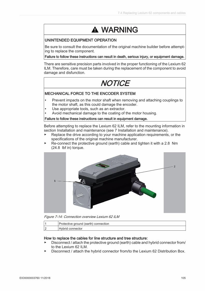
WARNINGUNINTENDED EQUIPMENT OPERATION
Be sure to consult the documentation of the original machine builder before attempt‐ing to replace the component.Failure to follow these instructions can result in death, serious injury, or equipment damage.
There are sensitive precision parts involved in the proper functioning of the Lexium 62ILM. Therefore, care must be taken during the replacement of the component to avoiddamage and disfunction.
NOTICEMECHANICAL FORCE TO THE ENCODER SYSTEM
• Prevent impacts on the motor shaft when removing and attaching couplings tothe motor shaft, as this could damage the encoder.
• Use appropriate tools, such as an extractor.• Avoid mechanical damage to the coating of the motor housing.Failure to follow these instructions can result in equipment damage.
Before attempting to replace the Lexium 62 ILM, refer to the mounting information insection Installation and maintenance (see 7 Installation and maintenance).▶ Replace the drive according to your machine application requirements, or the
specifications of the original machine manufacturer.▶ Re-connect the protective ground (earth) cable and tighten it with a 2.8 Nm
(24.8 lbf in) torque.
TM
1
2
Figure 7-14: Connection overview Lexium 62 ILM
1 Protective ground (earth) connection2 Hybrid connector
How to replace the cables for line structure and tree structure:▶ Disconnect / attach the protective ground (earth) cable and hybrid connector from/
to the Lexium 62 ILM.▶ Disconnect / attach the hybrid connector from/to the Lexium 62 Distribution Box.
7.4 Replacing Lexium 62 components and cables
EIO0000003760 11/2018 105
How to replace the cables for daisy chain structure:▶ Disconnect / attach the protective ground (earth) cable from/to Lexium 62 ILM and
disconnect / attach power cable as well as Sercos cables from/to the Daisy ChainConnector Box which is installed on the Lexium 62 ILM.
▶ Disconnect / attach the power cable from/to Lexium 62 Distribution Box.
7 Installation and maintenance
106 EIO0000003760 11/2018
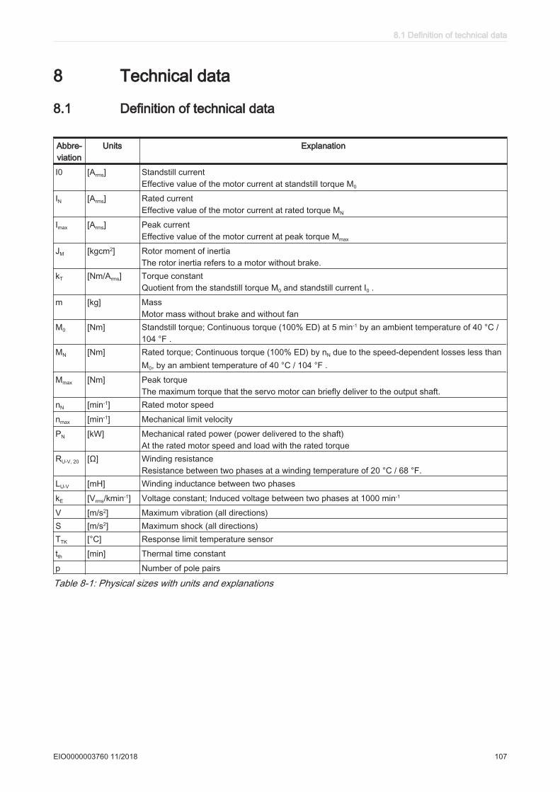
8 Technical data
8.1 Definition of technical data
Abbre‐viation
Units Explanation
I0 [Arms] Standstill current Effective value of the motor current at standstill torque M0
IN [Arms] Rated current Effective value of the motor current at rated torque MN
Imax [Arms] Peak currentEffective value of the motor current at peak torque Mmax
JM [kgcm2] Rotor moment of inertia The rotor inertia refers to a motor without brake.
kT [Nm/Arms] Torque constant Quotient from the standstill torque M0 and standstill current I0 .
m [kg] Mass Motor mass without brake and without fan
M0 [Nm] Standstill torque; Continuous torque (100% ED) at 5 min-1 by an ambient temperature of 40 °C /104 °F .
MN [Nm] Rated torque; Continuous torque (100% ED) by nN due to the speed-dependent losses less thanM0, by an ambient temperature of 40 °C / 104 °F .
Mmax [Nm] Peak torque The maximum torque that the servo motor can briefly deliver to the output shaft.
nN [min-1] Rated motor speed
nmax [min-1] Mechanical limit velocity
PN [kW] Mechanical rated power (power delivered to the shaft) At the rated motor speed and load with the rated torque
RU-V, 20 [Ω] Winding resistanceResistance between two phases at a winding temperature of 20 °C / 68 °F.
LU-V [mH] Winding inductance between two phases
kE [Vrms/kmin-1] Voltage constant; Induced voltage between two phases at 1000 min-1
V [m/s2] Maximum vibration (all directions)S [m/s2] Maximum shock (all directions)TTK [°C] Response limit temperature sensor
tth [min] Thermal time constant
p Number of pole pairs
Table 8-1: Physical sizes with units and explanations
8.1 Definition of technical data
EIO0000003760 11/2018 107
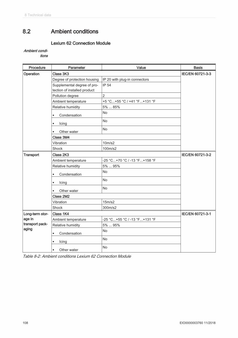
8.2 Ambient conditions
Lexium 62 Connection ModuleAmbient condi‐
tions
Procedure Parameter Value Basis
Operation Class 3K3 IEC/EN 60721-3-3Degree of protection housing IP 20 with plug-in connectorsSupplemental degree of pro‐tection of installed product
IP 54
Pollution degree 2Ambient temperature +5 °C...+55 °C / +41 °F...+131 °FRelative humidity 5% ... 85%
• CondensationNo
• IcingNo
• Other waterNo
Class 3M4Vibration 10m/s2 Shock 100m/s2
Transport Class 2K3 IEC/EN 60721-3-2Ambient temperature -25 °C...+70 °C / -13 °F...+158 °FRelative humidity 5% ... 95%
• CondensationNo
• IcingNo
• Other waterNo
Class 2M2Vibration 15m/s2 Shock 300m/s2
Long-term stor‐age intransport pack‐aging
Class 1K4 IEC/EN 60721-3-1Ambient temperature -25 °C...+55 °C / -13 °F...+131 °FRelative humidity 5% ... 95%
• CondensationNo
• IcingNo
• Other waterNo
Table 8-2: Ambient conditions Lexium 62 Connection Module
8 Technical data
108 EIO0000003760 11/2018

Installation alti‐tude
The installation altitude is defined as height above sea level.
Installation altitude without power reduction <1000m (<3281ft. )Installation altitude while complying with all of the followingconditions:
• 55°C (131°F ) maximum ambient temperature• Reduction of the continuous power by 1% per 100 m
(328 ft. ) above 1000 m (3281 ft. )
1000 ... 2000m (3281 ... 6562ft. )
Installation altitude above sea level when complying with all ofthe following conditions:
• 40°C (104°F ) maximum ambient temperature• Reduction of the continuous power by 1% per 100 m
(328 ft. ) above 1000 m (3281 ft. )• Overvoltages of the supplying grid limited to an overvolt‐
age category III according to IEC 60664-1/IEC61800-5-1
2000 ... 3000m (6562 ... 9843ft. )
Installation lo‐cation and con‐
nection
For operation, the Lexium 62 Power Supply and the Lexium 62 Connection Modulemust be mounted in a closed control cabinet. The devices must only be operated withfixed connections.
Pollution de‐gree and de‐
gree of protec‐tion
Pollution degree according toIEC61800-5-1
2
Degree of protection according toIEC61800-5-1
IP 20 (control cabinet), IP65 (field devi‐ces)
Degree of pro‐tection when
using the safetyfunction
Ensure that no conductive pollution can deposit in the product (pollution degree 2).Conductive pollutions can cause the safety function to be ineffective.
8.2 Ambient conditions
EIO0000003760 11/2018 109
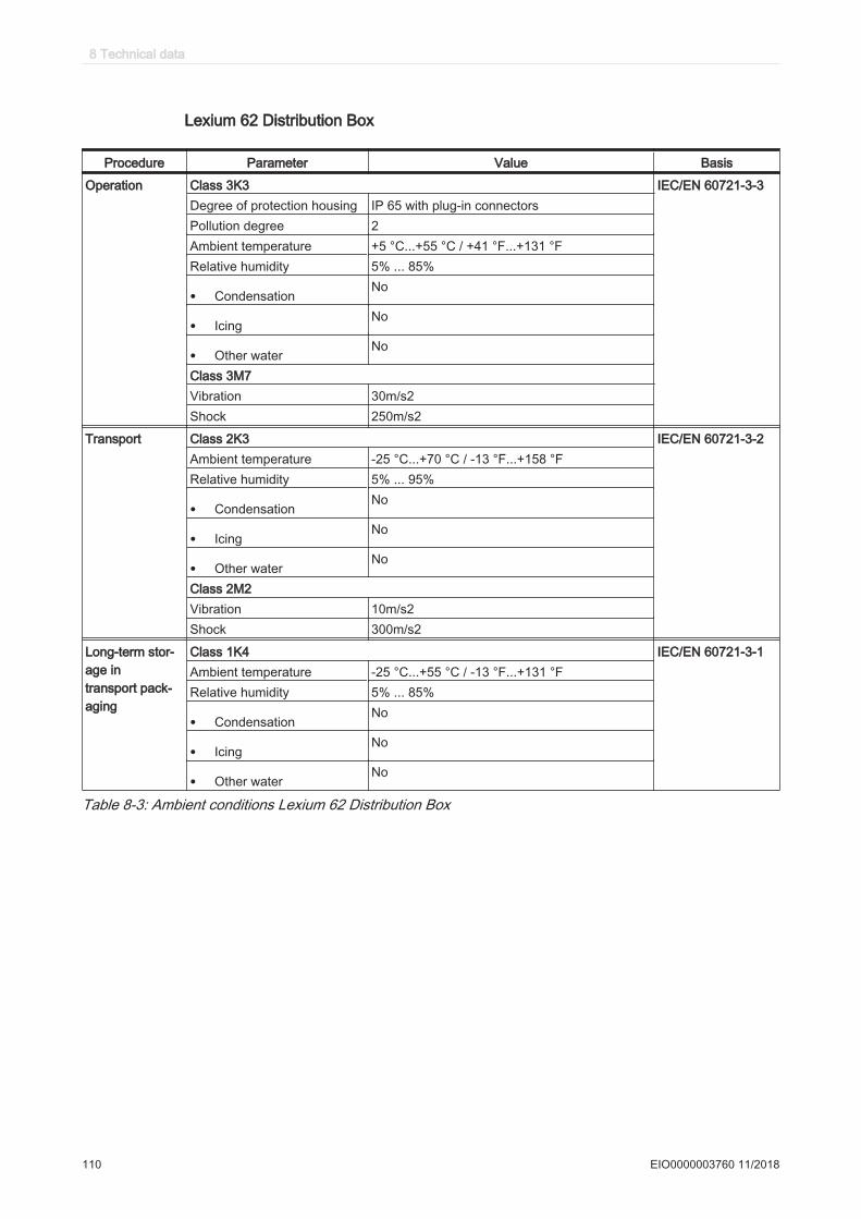
Lexium 62 Distribution Box
Procedure Parameter Value Basis
Operation Class 3K3 IEC/EN 60721-3-3Degree of protection housing IP 65 with plug-in connectorsPollution degree 2Ambient temperature +5 °C...+55 °C / +41 °F...+131 °FRelative humidity 5% ... 85%
• CondensationNo
• IcingNo
• Other waterNo
Class 3M7Vibration 30m/s2 Shock 250m/s2
Transport Class 2K3 IEC/EN 60721-3-2Ambient temperature -25 °C...+70 °C / -13 °F...+158 °FRelative humidity 5% ... 95%
• CondensationNo
• IcingNo
• Other waterNo
Class 2M2Vibration 10m/s2 Shock 300m/s2
Long-term stor‐age intransport pack‐aging
Class 1K4 IEC/EN 60721-3-1Ambient temperature -25 °C...+55 °C / -13 °F...+131 °FRelative humidity 5% ... 85%
• CondensationNo
• IcingNo
• Other waterNo
Table 8-3: Ambient conditions Lexium 62 Distribution Box
8 Technical data
110 EIO0000003760 11/2018
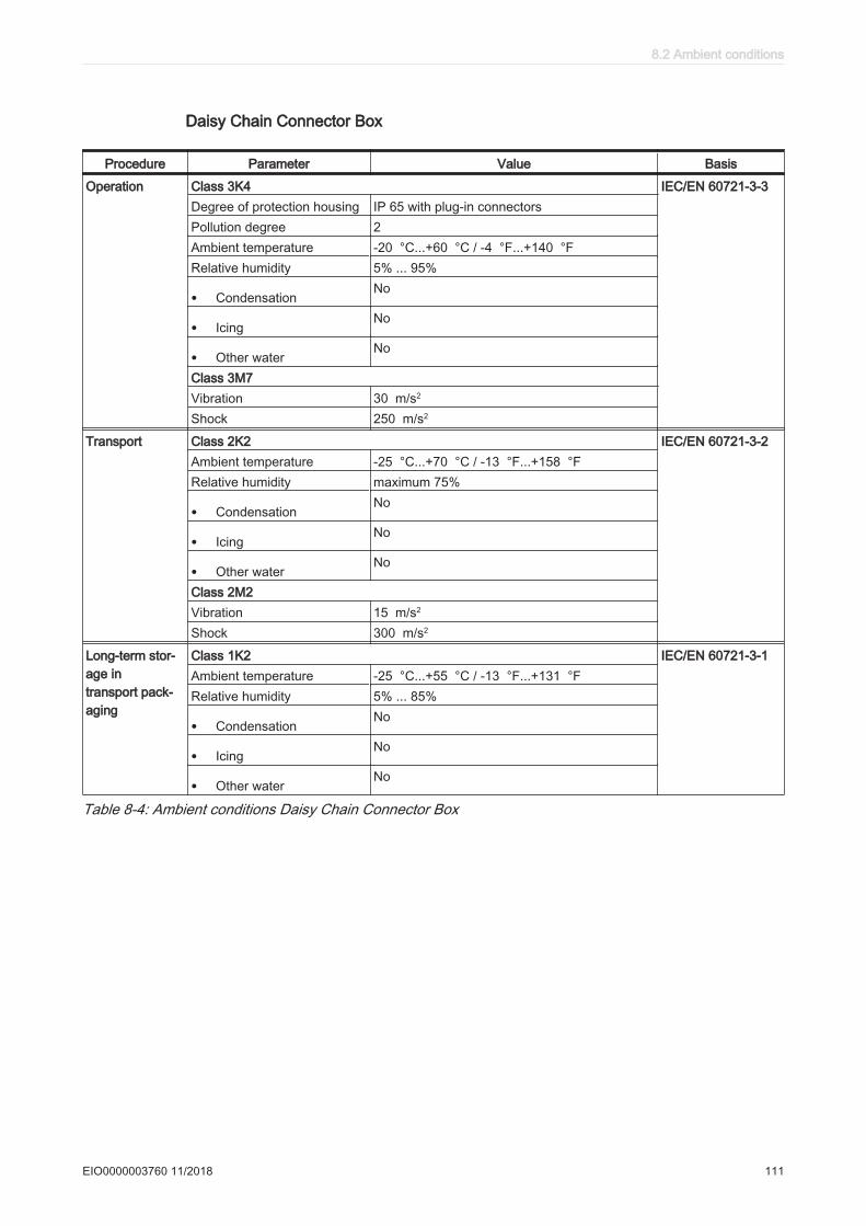
Daisy Chain Connector Box
Procedure Parameter Value Basis
Operation Class 3K4 IEC/EN 60721-3-3Degree of protection housing IP 65 with plug-in connectorsPollution degree 2Ambient temperature -20 °C...+60 °C / -4 °F...+140 °FRelative humidity 5% ... 95%
• CondensationNo
• IcingNo
• Other waterNo
Class 3M7Vibration 30 m/s2
Shock 250 m/s2
Transport Class 2K2 IEC/EN 60721-3-2Ambient temperature -25 °C...+70 °C / -13 °F...+158 °FRelative humidity maximum 75%
• CondensationNo
• IcingNo
• Other waterNo
Class 2M2Vibration 15 m/s2
Shock 300 m/s2
Long-term stor‐age intransport pack‐aging
Class 1K2 IEC/EN 60721-3-1Ambient temperature -25 °C...+55 °C / -13 °F...+131 °FRelative humidity 5% ... 85%
• CondensationNo
• IcingNo
• Other waterNo
Table 8-4: Ambient conditions Daisy Chain Connector Box
8.2 Ambient conditions
EIO0000003760 11/2018 111

Lexium 62 ILM
Procedure Parameter Value Basis
Operation Class 3K3 IEC/EN 60721-3-3Degree of protection housing IP 65 with plugged-in connectorsAmbient temperature +5 °C...+40 °C / +41 °F...+104 °FRelative humidity 5% ... 85%Class 3M7Vibration 30 m/s2 (all directions in space)Shock 250 m/s2
Transport Class 2K3 IEC/EN 60721-3-2Ambient temperature -25 °C...+70 °C / -13 °F...+158 °FRelative humidity 5% ... 95%
• CondensationNo
• IcingNo
• Other waterNo
Class 2M1Vibration 15 m/s2
Shock 100 m/s2
Long-term stor‐age intransport pack‐aging
Class 1K4 IEC/EN 60721-3-1Ambient temperature -25 °C...+55 °C / -13 °F...+131 °FRelative humidity 10% ... 100%
• CondensationNo
• IcingNo
• Other waterNo
Table 8-5: Ambient conditions for Lexium 62 ILM
8.3 Standards and regulations
CE Low Voltage Directive 2014/35/EU
• EN 61800-5-1:2007EMC Directive 2014/30/EU
• EN 61800-3:2004UL UL 508C Power Conversion EquipmentCSA Industrial Control Equipment
• CSA-C22.2 No. 14
Table 8-6: Declarations and certifications
Functional safety EN ISO 13849-1, PL eIEC/EN 62061, SIL 3IEC/EN 61508, SIL 3
Table 8-7: Standards and regulations - Functional safety
8 Technical data
112 EIO0000003760 11/2018
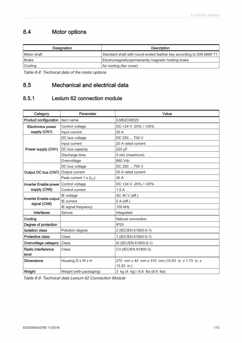
8.4 Motor options
Designation Description
Motor shaft Standard shaft with round-ended feather key according to DIN 6885 T1Brake Electromagnetic/permanently magnetic holding brakeCooling Air cooling (fan cover)
Table 8-8: Technical data of the motor options
8.5 Mechanical and electrical data
8.5.1 Lexium 62 connection module
Category Parameter Value
Product configuration Item name ILM62CMD20
Electronics powersupply (CN1)
Control voltage DC +24 V -20% / +25%Input current 20 A
Power supply (CN1)
DC bus voltage DC 250 ... 700 VInput current 20 A rated currentDC bus capacity 220 µFDischarge time 5 min (maximum)Overvoltage 860 Vdc
Output DC bus (CN7)DC bus voltage DC 250 ... 700 VOutput current 20 A rated currentPeak current 1 s (ISC) 40 A
Inverter Enable powersupply (CN6)
Control voltage DC +24 V -20% / +25%Control current 1.5 A
Inverter Enable outputsignal (CN8)
IE voltage AC 40 V (eff.)IE current 2 A (eff.)IE signal frequency 100 kHz
Interfaces Sercos integrated
Cooling Natural convectionDegree of protection IP20Isolation class Pollution degree 2 (IEC/EN 61800-5-1)
Protective class Class 1 (IEC/EN 61800-5-1)
Overvoltage category Class III (IEC/EN 61800-5-1)
Radio interferencelevel
Class C3 (IEC/EN 61800-3)
Dimensions Housing D x W x H 270 mm x 44 mm x 310 mm (10.63 in. x 1.73 in. x12.20 in.)
Weight Weight (with packaging) 3 kg (4 kg) / 6.6 lbs (8.8 lbs)
Table 8-9: Technical data Lexium 62 Connection Module
8.4 Motor options
EIO0000003760 11/2018 113

8.5.2 Lexium 62 distribution box
Category Parameter Value
Product configuration Item name Lexium 62 Distribution Box
DC power supply(CN1 - CN5)
DC bus voltage DC 250 V ... 700 VRated current 20 ADC capacity 100 µF
Electronics powersupply(CN1 - CN5)
Control voltage / -current DC 24 V (-20%..+25%) / maximum 20 AControl voltage capacity 1000 µF
Inverter Enable(CN1 - CN5)
IE voltage AC 40 V (eff.)IE current 2 A (eff.)IE signal frequency 100 kHz
Ethernet Sercos(CN1 - CN5)
Data rate 100 Mbit/s
Cooling Natural convection
Degree of protection IP 65
Isolation class Pollution degree 2 (IEC/EN 61800-5-1:2007)
Protective class Class 1 (IEC/EN 61800-5-1)
Overvoltage category Class III (IEC/EN 61800-5-1:2007), T2 (DIN VDE 0110)
Radio interferencelevel
Class C3 (IEC/EN 61800-3)
Material Polycarbonate [Lexan 940A]
Dimensions Housing D x W x H 151.4 mm x 230 mm x 94 mm (5.96 in. x 9.05 in. x 3.70 in.)
Weight 0.85 kg (1.8 lbs)
Table 8-10: Technical data Lexium 62 Distribution Box
8 Technical data
114 EIO0000003760 11/2018
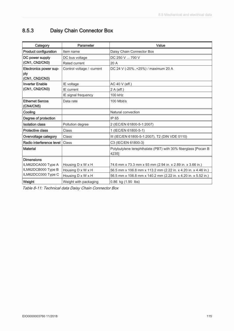
8.5.3 Daisy Chain Connector Box
Category Parameter Value
Product configuration Item name Daisy Chain Connector Box
DC power supply(CN1, CN2/CN3)
DC bus voltage DC 250 V ... 700 VRated current 20 A
Electronics power sup‐ply(CN1, CN2/CN3)
Control voltage / -current DC 24 V (-20%..+25%) / maximum 20 A
Inverter Enable(CN1, CN2/CN3)
IE voltage AC 40 V (eff.)IE current 2 A (eff.)IE signal frequency 100 kHz
Ethernet Sercos(CN4/CN5)
Data rate 100 Mbit/s
Cooling Natural convection
Degree of protection IP 65
Isolation class Pollution degree 2 (IEC/EN 61800-5-1:2007)
Protective class Class 1 (IEC/EN 61800-5-1)
Overvoltage category Class III (IEC/EN 61800-5-1:2007), T2 (DIN VDE 0110)
Radio interference level Class C3 (IEC/EN 61800-3)
Material Polybutylene terephthalate (PBT) with 30% fiberglass [Pocan B4235]
DimensionsILM62DCA000 Type AILM62DCB000 Type BILM62DCC000 Type C
Housing D x W x H 74.6 mm x 73.3 mm x 93 mm (2.94 in. x 2.89 in. x 3.66 in.)Housing D x W x H 56.5 mm x 106.8 mm x 113.2 mm (2.22 in. x 4.20 in. x 4.46 in.)Housing D x W x H 56.5 mm x 106.8 mm x 140.2 mm (2.22 in. x 4.20 in. x 5.52 in.)
Weight Weight with packaging 0.86 kg (1.90 lbs)
Table 8-11: Technical data Daisy Chain Connector Box
8.5 Mechanical and electrical data
EIO0000003760 11/2018 115
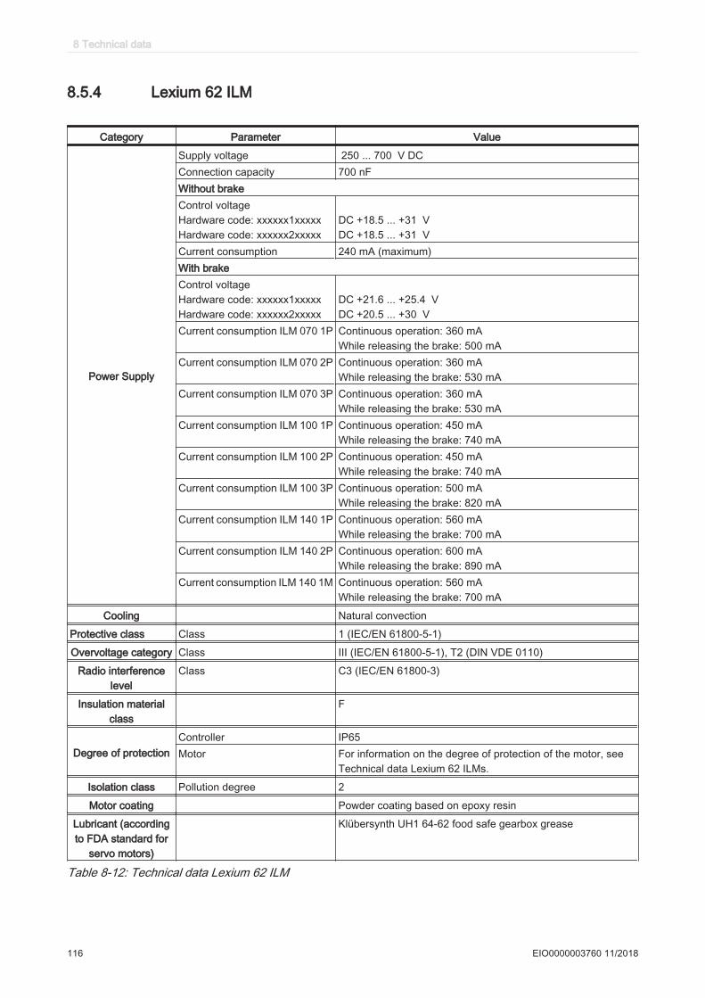
8.5.4 Lexium 62 ILM
Category Parameter Value
Power Supply
Supply voltage 250 ... 700 V DC Connection capacity 700 nFWithout brakeControl voltageHardware code: xxxxxx1xxxxxHardware code: xxxxxx2xxxxx
DC +18.5 ... +31 VDC +18.5 ... +31 V
Current consumption 240 mA (maximum)With brakeControl voltageHardware code: xxxxxx1xxxxxHardware code: xxxxxx2xxxxx
DC +21.6 ... +25.4 VDC +20.5 ... +30 V
Current consumption ILM 070 1P Continuous operation: 360 mAWhile releasing the brake: 500 mA
Current consumption ILM 070 2P Continuous operation: 360 mAWhile releasing the brake: 530 mA
Current consumption ILM 070 3P Continuous operation: 360 mAWhile releasing the brake: 530 mA
Current consumption ILM 100 1P Continuous operation: 450 mAWhile releasing the brake: 740 mA
Current consumption ILM 100 2P Continuous operation: 450 mAWhile releasing the brake: 740 mA
Current consumption ILM 100 3P Continuous operation: 500 mAWhile releasing the brake: 820 mA
Current consumption ILM 140 1P Continuous operation: 560 mAWhile releasing the brake: 700 mA
Current consumption ILM 140 2P Continuous operation: 600 mAWhile releasing the brake: 890 mA
Current consumption ILM 140 1M Continuous operation: 560 mAWhile releasing the brake: 700 mA
Cooling Natural convection
Protective class Class 1 (IEC/EN 61800-5-1)
Overvoltage category Class III (IEC/EN 61800-5-1), T2 (DIN VDE 0110)
Radio interferencelevel
Class C3 (IEC/EN 61800-3)
Insulation materialclass
F
Degree of protectionController IP65Motor For information on the degree of protection of the motor, see
Technical data Lexium 62 ILMs.
Isolation class Pollution degree 2
Motor coating Powder coating based on epoxy resin
Lubricant (accordingto FDA standard for
servo motors)
Klübersynth UH1 64-62 food safe gearbox grease
Table 8-12: Technical data Lexium 62 ILM
8 Technical data
116 EIO0000003760 11/2018
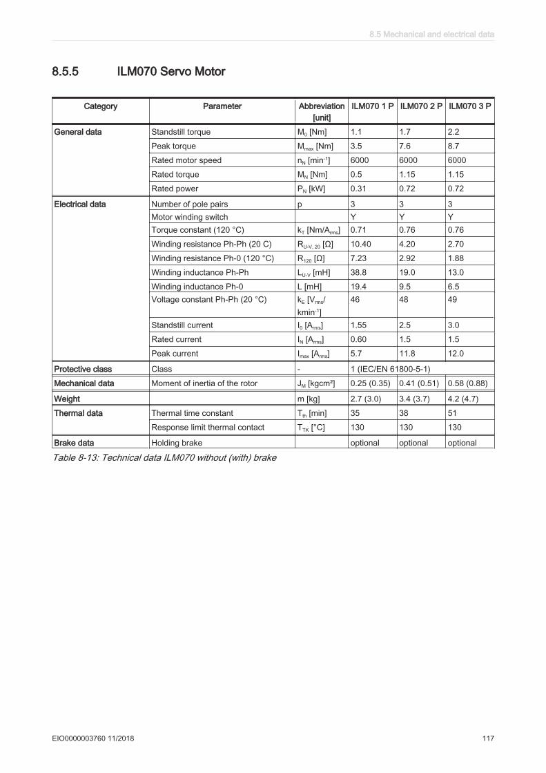
8.5.5 ILM070 Servo Motor
Category Parameter Abbreviation[unit]
ILM070 1 P ILM070 2 P ILM070 3 P
General data Standstill torque M0 [Nm] 1.1 1.7 2.2
Peak torque Mmax [Nm] 3.5 7.6 8.7
Rated motor speed nN [min-1] 6000 6000 6000
Rated torque MN [Nm] 0.5 1.15 1.15
Rated power PN [kW] 0.31 0.72 0.72
Electrical data Number of pole pairs p 3 3 3Motor winding switch Y Y YTorque constant (120 °C) kT [Nm/Arms] 0.71 0.76 0.76
Winding resistance Ph-Ph (20 C) RU-V, 20 [Ω] 10.40 4.20 2.70
Winding resistance Ph-0 (120 °C) R120 [Ω] 7.23 2.92 1.88
Winding inductance Ph-Ph LU-V [mH] 38.8 19.0 13.0
Winding inductance Ph-0 L [mH] 19.4 9.5 6.5Voltage constant Ph-Ph (20 °C) kE [Vrms/
kmin-1]46 48 49
Standstill current I0 [Arms] 1.55 2.5 3.0
Rated current IN [Arms] 0.60 1.5 1.5
Peak current Imax [Arms] 5.7 11.8 12.0
Protective class Class - 1 (IEC/EN 61800-5-1)
Mechanical data Moment of inertia of the rotor JM [kgcm²] 0.25 (0.35) 0.41 (0.51) 0.58 (0.88)
Weight m [kg] 2.7 (3.0) 3.4 (3.7) 4.2 (4.7)
Thermal data Thermal time constant Tth [min] 35 38 51
Response limit thermal contact TTK [°C] 130 130 130
Brake data Holding brake optional optional optional
Table 8-13: Technical data ILM070 without (with) brake
8.5 Mechanical and electrical data
EIO0000003760 11/2018 117
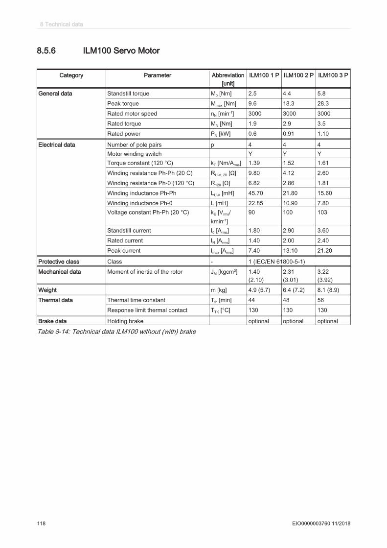
8.5.6 ILM100 Servo Motor
Category Parameter Abbreviation[unit]
ILM100 1 P ILM100 2 P ILM100 3 P
General data Standstill torque M0 [Nm] 2.5 4.4 5.8
Peak torque Mmax [Nm] 9.6 18.3 28.3
Rated motor speed nN [min-1] 3000 3000 3000
Rated torque MN [Nm] 1.9 2.9 3.5
Rated power PN [kW] 0.6 0.91 1.10
Electrical data Number of pole pairs p 4 4 4Motor winding switch Y Y YTorque constant (120 °C) kT [Nm/Arms] 1.39 1.52 1.61
Winding resistance Ph-Ph (20 C) RU-V, 20 [Ω] 9.80 4.12 2.60
Winding resistance Ph-0 (120 °C) R120 [Ω] 6.82 2.86 1.81
Winding inductance Ph-Ph LU-V [mH] 45.70 21.80 15.60
Winding inductance Ph-0 L [mH] 22.85 10.90 7.80Voltage constant Ph-Ph (20 °C) kE [Vrms/
kmin-1]90 100 103
Standstill current I0 [Arms] 1.80 2.90 3.60
Rated current IN [Arms] 1.40 2.00 2.40
Peak current Imax [Arms] 7.40 13.10 21.20
Protective class Class - 1 (IEC/EN 61800-5-1)
Mechanical data Moment of inertia of the rotor JM [kgcm²] 1.40(2.10)
2.31(3.01)
3.22 (3.92)
Weight m [kg] 4.9 (5.7) 6.4 (7.2) 8.1 (8.9)
Thermal data Thermal time constant Tth [min] 44 48 56
Response limit thermal contact TTK [°C] 130 130 130
Brake data Holding brake optional optional optional
Table 8-14: Technical data ILM100 without (with) brake
8 Technical data
118 EIO0000003760 11/2018

8.5.7 ILM140 Servo Motor
Category Parameter Abbreviation[unit]
ILM140 1 P ILM140 1 M ILM140 2 P
General data Standstill torque M0 [Nm] 7.5 8.5 12.5
Peak torque Mmax [Nm] 27.0 27.0 55.0
Rated motor speed nN [min-1] 3000 1500 2000
Rated torque MN [Nm] 4.6 8.3 9.1
Rated power PN [kW] 1.45 1.30 1.91
Electrical data Number of pole pairs p 5 5 5Motor winding switch Y Y YTorque constant (120 °C) kT [Nm/Arms] 1.60 2.65 2.60
Winding resistance Ph-Ph (20 C) RU-V, 20 [Ω] 1.81 4.58 1.90
Winding resistance Ph-0 (120 °C) R120 [Ω] 1.26 3.18 1.32
Winding inductance Ph-Ph LU-V [mH] 19.10 50.0 22.0
Winding inductance Ph-0 L [mH] 9.55 25.0 11.0Voltage constant Ph-Ph (20 °C) kE [Vrms/
kmin-1]108 175 173
Standstill current I0 [Arms] 4.70 3.20 4.8
Rated current IN [Arms] 2.90 3.15 3.7
Peak current Imax [Arms] 18.8 14.6 24.0
Protective class Class - 1 (IEC/EN 61800-5-1)
Mechanical data Moment of inertia of the rotor JM [kgcm²] 7.41 7.41 12.68
Weight (with brake) m [kg] 12.5 (13.8) 12.5 (13.8) 17.2 (18.5)
Thermal data Thermal time constant Tth [min] 64 64 74
Response limit thermal contact TTK [°C] 130 130 130
Brake data Holding brake optional optional optional
Table 8-15: Technical data ILM140 without (with) brake
8.5 Mechanical and electrical data
EIO0000003760 11/2018 119

8.5.8 Encoder
SinCos® (SKS36) Singleturn
Parameter Value Units
Number of revolutions 1Number of sine/cosine periods 128 Per revolutionAbsolute measuring range 1 RevolutionError limits of the digital absolute value +/-5.3 Angular minutesError limits when evaluating the 128 signals (integral non-linearity)
+/-1.3 Angular minutes
Signal shape Sinusoidal
Table 8-16: Technical data of the SinCos encoder (SKS-36)
SinCos® (SKM36) Multiturn
Parameter Value Units
Number of revolutions 4096Number of sine/cosine periods 128 Per revolutionAbsolute measuring range 1 RevolutionError limits of the digital absolute value +/-5.3 Angular minutesError limits when evaluating the 128 signals (integral non-linearity)
+/-1.3 Angular minutes
Signal shape Sinusoidal
Table 8-17: Technical data of the SinCos® encoder (SKM-36)
8 Technical data
120 EIO0000003760 11/2018
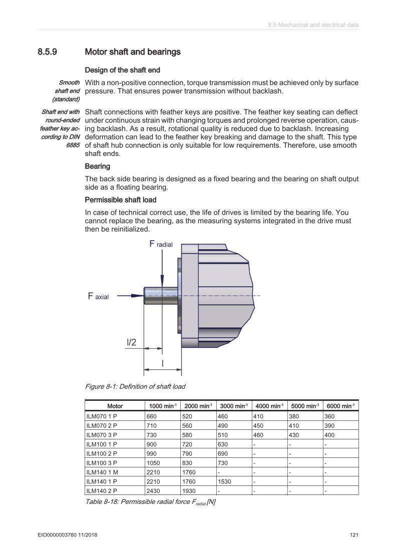
8.5.9 Motor shaft and bearings
Design of the shaft endSmooth
shaft end(standard)
With a non-positive connection, torque transmission must be achieved only by surfacepressure. That ensures power transmission without backlash.
Shaft end withround-ended
feather key ac‐cording to DIN
6885
Shaft connections with feather keys are positive. The feather key seating can deflectunder continuous strain with changing torques and prolonged reverse operation, caus‐ing backlash. As a result, rotational quality is reduced due to backlash. Increasingdeformation can lead to the feather key breaking and damage to the shaft. This typeof shaft hub connection is only suitable for low requirements. Therefore, use smoothshaft ends.
Bearing
The back side bearing is designed as a fixed bearing and the bearing on shaft outputside as a floating bearing.
Permissible shaft load
In case of technical correct use, the life of drives is limited by the bearing life. Youcannot replace the bearing, as the measuring systems integrated in the drive mustthen be reinitialized.
Figure 8-1: Definition of shaft load
Motor 1000 min-1 2000 min-1 3000 min-1 4000 min-1 5000 min-1 6000 min-1
ILM070 1 P 660 520 460 410 380 360ILM070 2 P 710 560 490 450 410 390ILM070 3 P 730 580 510 460 430 400ILM100 1 P 900 720 630 - - -ILM100 2 P 990 790 690 - - -ILM100 3 P 1050 830 730 - - -ILM140 1 M 2210 1760 - - - -ILM140 1 P 2210 1760 1530 - - -ILM140 2 P 2430 1930 - - - -
Table 8-18: Permissible radial force Fradial [N]
8.5 Mechanical and electrical data
EIO0000003760 11/2018 121
Basis for calculation:The permissible axial force Faxial [N] is calculated according to:
Faxial = 0.2 x Fradial
• Nominal bearing life L10h = 20,000 h for a shaft without feather key nut (for operatinghours at a 10% failure probability)
• Ambient temperature = 40 °C / 104 °F (approx. 100 °C / 212 °F storage tempera‐ture)
• Peak torque = 10 % ED• Nominal torque = 100 % ED
8 Technical data
122 EIO0000003760 11/2018
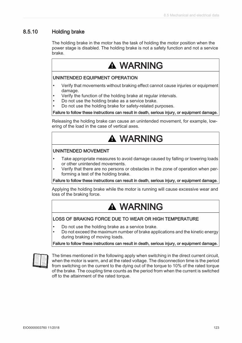
8.5.10 Holding brake
The holding brake in the motor has the task of holding the motor position when thepower stage is disabled. The holding brake is not a safety function and not a servicebrake.
WARNINGUNINTENDED EQUIPMENT OPERATION
• Verify that movements without braking effect cannot cause injuries or equipmentdamage.
• Verify the function of the holding brake at regular intervals.• Do not use the holding brake as a service brake.• Do not use the holding brake for safety-related purposes.Failure to follow these instructions can result in death, serious injury, or equipment damage.
Releasing the holding brake can cause an unintended movement, for example, low‐ering of the load in the case of vertical axes.
WARNINGUNINTENDED MOVEMENT
• Take appropriate measures to avoid damage caused by falling or lowering loadsor other unintended movements.
• Verify that there are no persons or obstacles in the zone of operation when per‐forming a test of the holding brake.
Failure to follow these instructions can result in death, serious injury, or equipment damage.
Applying the holding brake while the motor is running will cause excessive wear andloss of the braking force.
WARNINGLOSS OF BRAKING FORCE DUE TO WEAR OR HIGH TEMPERATURE
• Do not use the holding brake as a service brake.• Do not exceed the maximum number of brake applications and the kinetic energy
during braking of moving loads.Failure to follow these instructions can result in death, serious injury, or equipment damage.
The times mentioned in the following apply when switching in the direct current circuit,when the motor is warm, and at the rated voltage. The disconnection time is the periodfrom switching on the current to the dying out of the torque to 10% of the rated torqueof the brake. The coupling time counts as the period from when the current is switchedoff to the attainment of the rated torque.
8.5 Mechanical and electrical data
EIO0000003760 11/2018 123

The holding brake is designed differently for each series:
Technical data of the holding brake of the ILM070
Parameter ILM070 1 P ILM070 2 P ILM070 3 P Unit
Static holding torque at 120 °C 3.0 3.0 3.0 [Nm]Coupling time 10 10 10 [ms]Disconnection time 80 80 80 [ms]Mass 0.28 0.28 0.28 [kg]Moment of inertia 0.11 0.11 0.11 [kgcm2]
Table 8-19: Technical data of the holding brake of the ILM070
Technical data of the holding brake of the ILM100
Parameter ILM100 1 P ILM100 2 P ILM100 3 P Unit
Static holding torque at 120 °C 5.5 5.5 9.0 [Nm]Coupling time 30 30 25 [ms]Disconnection time 70 70 90 [ms]Mass 0.46 0.46 0.65 [kg]Moment of inertia 0.49 0.49 0.78 [kgcm2]
Table 8-20: Technical data of the holding brake of the ILM100
Technical data of the holding brake of the ILM140
Parameter ILM140 1 P ILM140 1 M ILM140 2 P Unit
Static holding torque at 120 °C 18.0 18.0 23.0 [Nm]Coupling time 50 50 40 [ms]Disconnection time 100 100 100 [ms]Mass 1.06 1.06 1.29 [kg]Moment of inertia 1.5 1.5 2.55 [kgcm2]
Table 8-21: Technical data of the holding brake of the ILM140
8 Technical data
124 EIO0000003760 11/2018
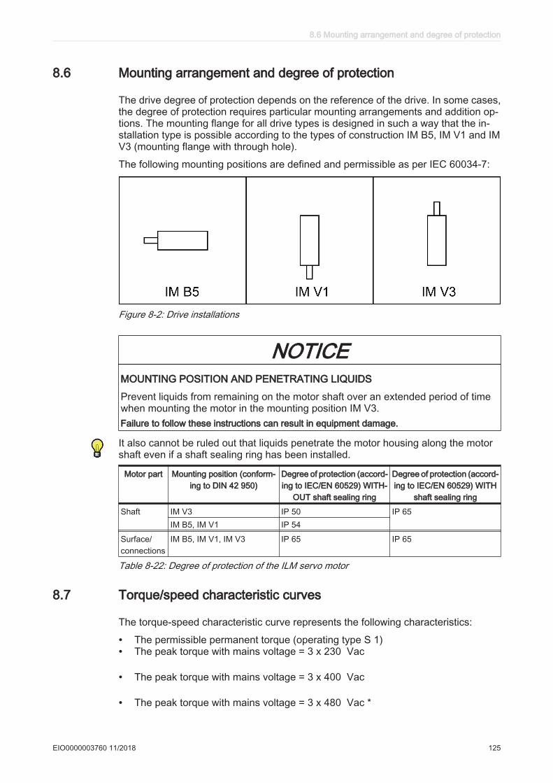
8.6 Mounting arrangement and degree of protection
The drive degree of protection depends on the reference of the drive. In some cases,the degree of protection requires particular mounting arrangements and addition op‐tions. The mounting flange for all drive types is designed in such a way that the in‐stallation type is possible according to the types of construction IM B5, IM V1 and IMV3 (mounting flange with through hole).
The following mounting positions are defined and permissible as per IEC 60034-7:
Figure 8-2: Drive installations
NOTICEMOUNTING POSITION AND PENETRATING LIQUIDS
Prevent liquids from remaining on the motor shaft over an extended period of timewhen mounting the motor in the mounting position IM V3.Failure to follow these instructions can result in equipment damage.
It also cannot be ruled out that liquids penetrate the motor housing along the motorshaft even if a shaft sealing ring has been installed.
Motor part Mounting position (conform‐ing to DIN 42 950)
Degree of protection (accord‐ing to IEC/EN 60529) WITH‐
OUT shaft sealing ring
Degree of protection (accord‐ing to IEC/EN 60529) WITH
shaft sealing ring
Shaft IM V3 IP 50 IP 65IM B5, IM V1 IP 54
Surface/connections
IM B5, IM V1, IM V3 IP 65 IP 65
Table 8-22: Degree of protection of the ILM servo motor
8.7 Torque/speed characteristic curves
The torque-speed characteristic curve represents the following characteristics:
• The permissible permanent torque (operating type S 1)• The peak torque with mains voltage = 3 x 230 Vac
• The peak torque with mains voltage = 3 x 400 Vac
• The peak torque with mains voltage = 3 x 480 Vac *
8.6 Mounting arrangement and degree of protection
EIO0000003760 11/2018 125

(* for ILM140•• only)
Md
Mmax 230V 3AC Mmax 400V 3AC Mmax 480V 3AC*
0,0
10,0
20,0
30,0
40,0
50,0
60,0
0 250 500 750 1000 1250 1500 1750 2000
n [min-1]
M [
Nm
]
Figure 8-3: Example of a torque-speed characteristic curve (* for ILM140•• only)
The characteristic curves refer to an ambient temperature of 40 °C / 104 °F and amaximum winding temperature of 120 °C / 248 °F.
Figure 8-4: Torque-speed characteristic curve ILM 070 1 P
8 Technical data
126 EIO0000003760 11/2018
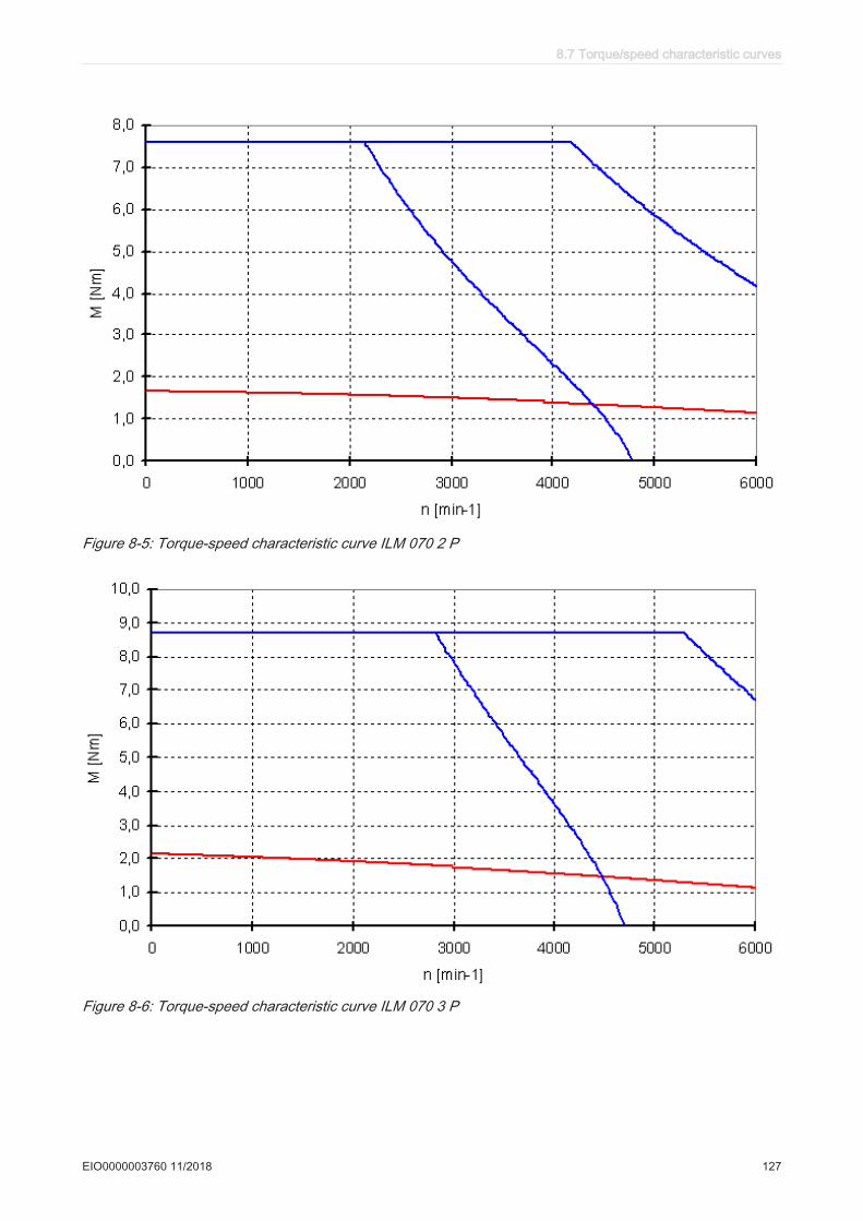
Figure 8-5: Torque-speed characteristic curve ILM 070 2 P
Figure 8-6: Torque-speed characteristic curve ILM 070 3 P
8.7 Torque/speed characteristic curves
EIO0000003760 11/2018 127

Figure 8-7: Torque-speed characteristic curve ILM 100 1 P
Figure 8-8: Torque-speed characteristic curve ILM 100 2 P
8 Technical data
128 EIO0000003760 11/2018
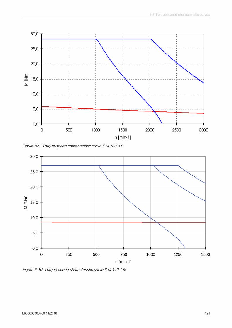
Figure 8-9: Torque-speed characteristic curve ILM 100 3 P
0,0
5,0
10,0
15,0
20,0
25,0
30,0
0 250 500 750 1000 1250 1500
n [min-1]
M [
Nm
]
Figure 8-10: Torque-speed characteristic curve ILM 140 1 M
8.7 Torque/speed characteristic curves
EIO0000003760 11/2018 129

0,0
5,0
10,0
15,0
20,0
25,0
30,0
0 500 1000 1500 2000 2500 3000
n [min-1]
M [
Nm
]
Figure 8-11: Torque-speed characteristic curve ILM 140 1 P
0,0
10,0
20,0
30,0
40,0
50,0
60,0
0 250 500 750 1000 1250 1500 1750 2000
n [min-1]
M [
Nm
]
Figure 8-12: Torque-speed characteristic curve ILM 140 2 P
8 Technical data
130 EIO0000003760 11/2018
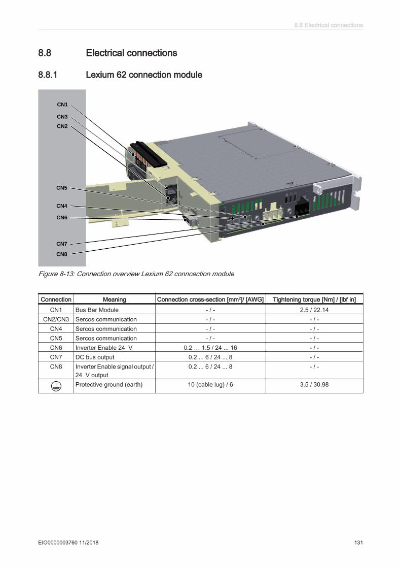
8.8 Electrical connections
8.8.1 Lexium 62 connection module
TM
CN3
CN2
CN1
CN4
CN6
CN5
CN7
CN8
Figure 8-13: Connection overview Lexium 62 conncection module
Connection Meaning Connection cross-section [mm2]/ [AWG] Tightening torque [Nm] / [lbf in]
CN1 Bus Bar Module - / - 2.5 / 22.14CN2/CN3 Sercos communication - / - - / -
CN4 Sercos communication - / - - / -CN5 Sercos communication - / - - / -CN6 Inverter Enable 24 V 0.2 … 1.5 / 24 ... 16 - / -CN7 DC bus output 0.2 ... 6 / 24 ... 8 - / -CN8 Inverter Enable signal output /
24 V output0.2 ... 6 / 24 ... 8 - / -
Protective ground (earth) 10 (cable lug) / 6 3.5 / 30.98
8.8 Electrical connections
EIO0000003760 11/2018 131
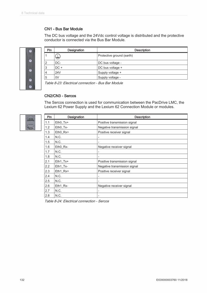
CN1 - Bus Bar Module
The DC bus voltage and the 24Vdc control voltage is distributed and the protectiveconductor is connected via the Bus Bar Module.
Pin Designation Description
1 Protective ground (earth)
2 DC- DC bus voltage -3 DC + DC bus voltage +4 24V Supply voltage +5 0V Supply voltage -
Table 8-23: Electrical connection - Bus Bar Module
CN2/CN3 - Sercos
The Sercos connection is used for communication between the PacDrive LMC, theLexium 62 Power Supply and the Lexium 62 Connection Module or modules.
Pin Designation Description
1.1 Eth0_Tx+ Positive transmission signal1.2 Eth0_Tx- Negative transmission signal1.3 Eth0_Rx+ Positive receiver signal1.4 N.C. -1.5 N.C. -1.6 Eth0_Rx- Negative receiver signal1.7 N.C. -1.8 N.C. -2.1 Eth1_Tx+ Positive transmission signal2.2 Eth1_Tx- Negative transmission signal2.3 Eth1_Rx+ Positive receiver signal2.4 N.C. -2.5 N.C. -2.6 Eth1_Rx- Negative receiver signal2.7 N.C. -2.8 N.C. -
Table 8-24: Electrical connection - Sercos
8 Technical data
132 EIO0000003760 11/2018
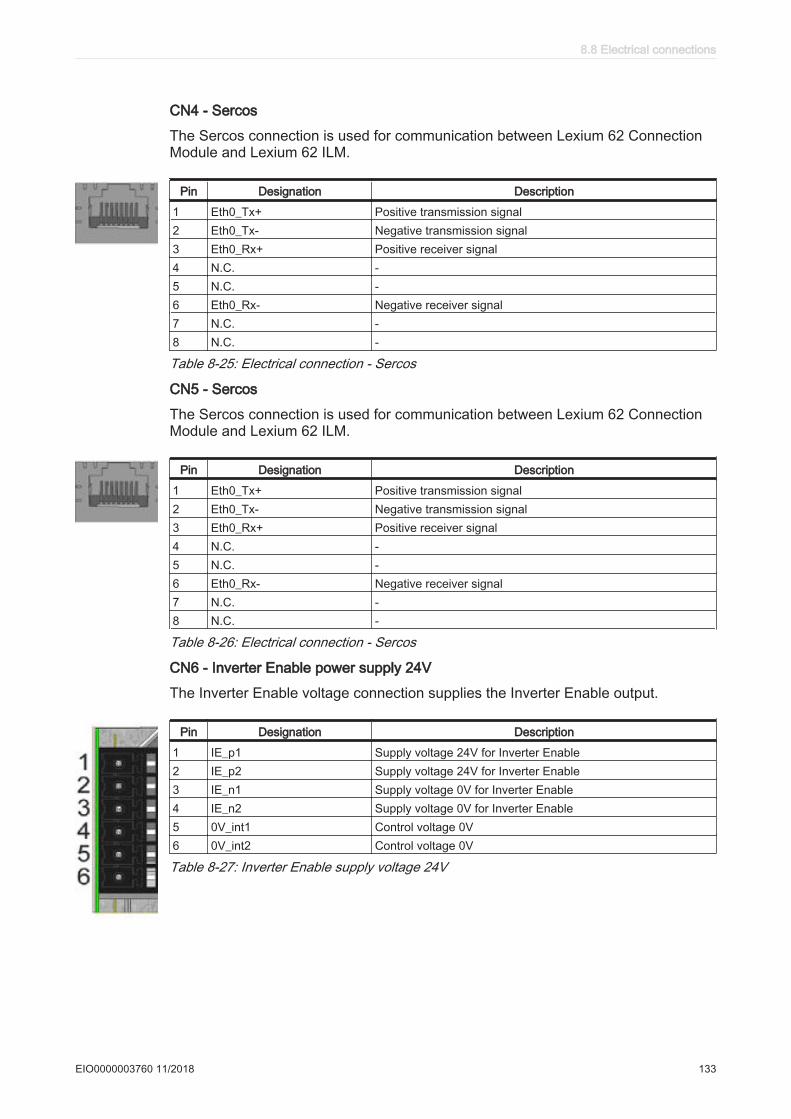
CN4 - Sercos
The Sercos connection is used for communication between Lexium 62 ConnectionModule and Lexium 62 ILM.
Pin Designation Description
1 Eth0_Tx+ Positive transmission signal2 Eth0_Tx- Negative transmission signal3 Eth0_Rx+ Positive receiver signal4 N.C. -5 N.C. -6 Eth0_Rx- Negative receiver signal7 N.C. -8 N.C. -
Table 8-25: Electrical connection - Sercos
CN5 - Sercos
The Sercos connection is used for communication between Lexium 62 ConnectionModule and Lexium 62 ILM.
Pin Designation Description
1 Eth0_Tx+ Positive transmission signal2 Eth0_Tx- Negative transmission signal3 Eth0_Rx+ Positive receiver signal4 N.C. -5 N.C. -6 Eth0_Rx- Negative receiver signal7 N.C. -8 N.C. -
Table 8-26: Electrical connection - Sercos
CN6 - Inverter Enable power supply 24V
The Inverter Enable voltage connection supplies the Inverter Enable output.
Pin Designation Description
1 IE_p1 Supply voltage 24V for Inverter Enable2 IE_p2 Supply voltage 24V for Inverter Enable3 IE_n1 Supply voltage 0V for Inverter Enable4 IE_n2 Supply voltage 0V for Inverter Enable5 0V_int1 Control voltage 0V6 0V_int2 Control voltage 0V
Table 8-27: Inverter Enable supply voltage 24V
8.8 Electrical connections
EIO0000003760 11/2018 133
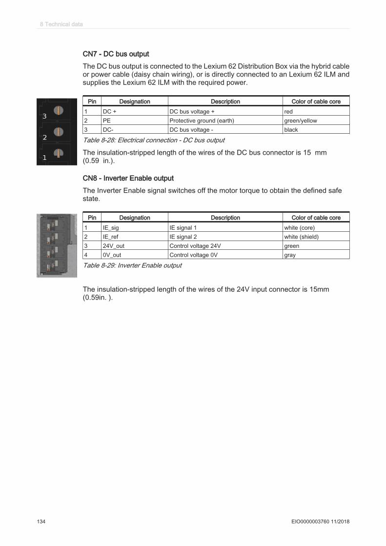
CN7 - DC bus output
The DC bus output is connected to the Lexium 62 Distribution Box via the hybrid cableor power cable (daisy chain wiring), or is directly connected to an Lexium 62 ILM andsupplies the Lexium 62 ILM with the required power.
Pin Designation Description Color of cable core
1 DC + DC bus voltage + red2 PE Protective ground (earth) green/yellow3 DC- DC bus voltage - black
Table 8-28: Electrical connection - DC bus output
The insulation-stripped length of the wires of the DC bus connector is 15 mm(0.59 in.).
CN8 - Inverter Enable output
The Inverter Enable signal switches off the motor torque to obtain the defined safestate.
Pin Designation Description Color of cable core
1 IE_sig IE signal 1 white (core)2 IE_ref IE signal 2 white (shield)3 24V_out Control voltage 24V green4 0V_out Control voltage 0V gray
Table 8-29: Inverter Enable output
The insulation-stripped length of the wires of the 24V input connector is 15mm (0.59in. ).
8 Technical data
134 EIO0000003760 11/2018
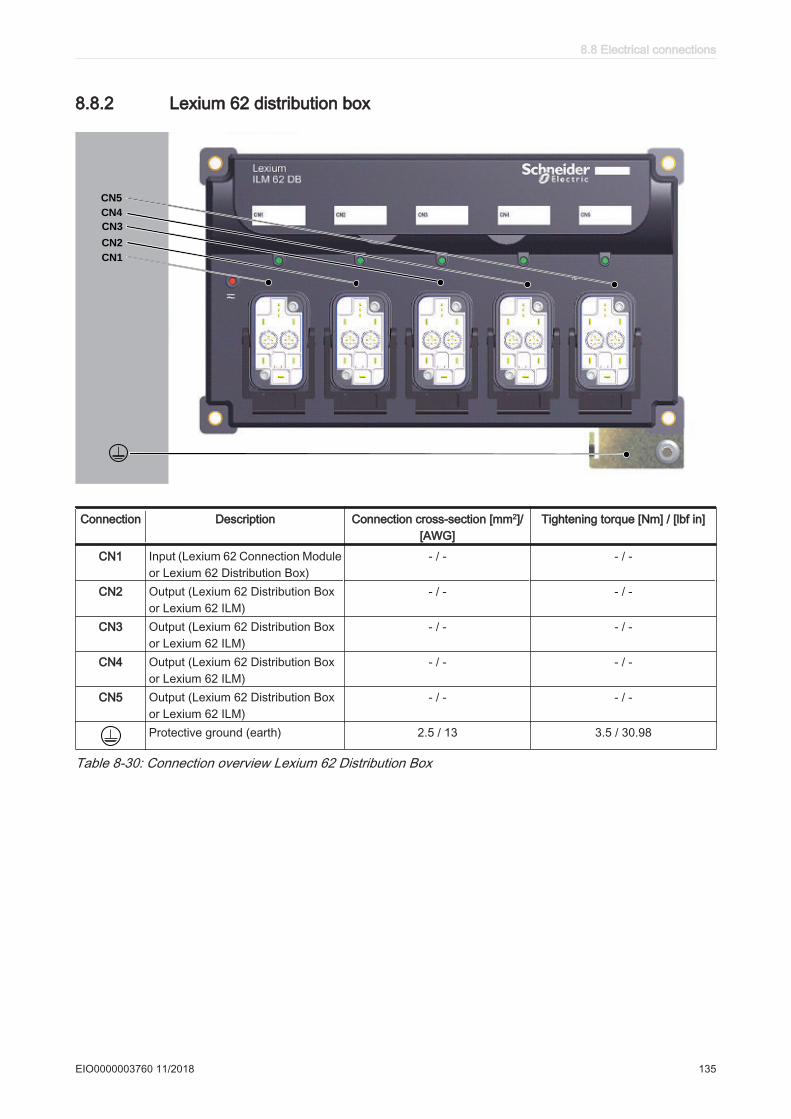
8.8.2 Lexium 62 distribution box
TM
CN5
CN4
CN3
CN2
CN1
Connection Description Connection cross-section [mm2]/[AWG]
Tightening torque [Nm] / [lbf in]
CN1 Input (Lexium 62 Connection Moduleor Lexium 62 Distribution Box)
- / - - / -
CN2 Output (Lexium 62 Distribution Boxor Lexium 62 ILM)
- / - - / -
CN3 Output (Lexium 62 Distribution Boxor Lexium 62 ILM)
- / - - / -
CN4 Output (Lexium 62 Distribution Boxor Lexium 62 ILM)
- / - - / -
CN5 Output (Lexium 62 Distribution Boxor Lexium 62 ILM)
- / - - / -
Protective ground (earth) 2.5 / 13 3.5 / 30.98
Table 8-30: Connection overview Lexium 62 Distribution Box
8.8 Electrical connections
EIO0000003760 11/2018 135
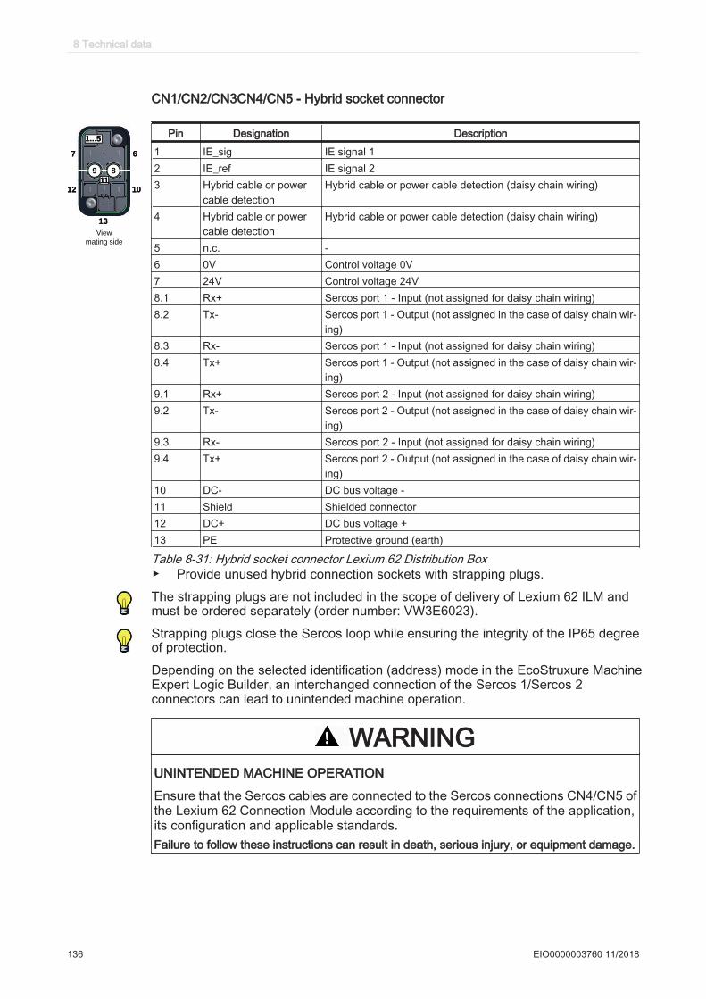
CN1/CN2/CN3CN4/CN5 - Hybrid socket connector
9
77 66
1212 1010
1313
8
1...51...5
1111
View
mating side
Pin Designation Description
1 IE_sig IE signal 12 IE_ref IE signal 23 Hybrid cable or power
cable detectionHybrid cable or power cable detection (daisy chain wiring)
4 Hybrid cable or powercable detection
Hybrid cable or power cable detection (daisy chain wiring)
5 n.c. -6 0V Control voltage 0V7 24V Control voltage 24V8.1 Rx+ Sercos port 1 - Input (not assigned for daisy chain wiring)8.2 Tx- Sercos port 1 - Output (not assigned in the case of daisy chain wir‐
ing)8.3 Rx- Sercos port 1 - Input (not assigned for daisy chain wiring)8.4 Tx+ Sercos port 1 - Output (not assigned in the case of daisy chain wir‐
ing)9.1 Rx+ Sercos port 2 - Input (not assigned for daisy chain wiring)9.2 Tx- Sercos port 2 - Output (not assigned in the case of daisy chain wir‐
ing)9.3 Rx- Sercos port 2 - Input (not assigned for daisy chain wiring)9.4 Tx+ Sercos port 2 - Output (not assigned in the case of daisy chain wir‐
ing)10 DC- DC bus voltage -11 Shield Shielded connector12 DC+ DC bus voltage +13 PE Protective ground (earth)
Table 8-31: Hybrid socket connector Lexium 62 Distribution Box▶ Provide unused hybrid connection sockets with strapping plugs.
The strapping plugs are not included in the scope of delivery of Lexium 62 ILM and must be ordered separately (order number: VW3E6023).
Strapping plugs close the Sercos loop while ensuring the integrity of the IP65 degree of protection.
Depending on the selected identification (address) mode in the EcoStruxure Machine Expert Logic Builder, an interchanged connection of the Sercos 1/Sercos 2 connectors can lead to unintended machine operation.
WARNINGUNINTENDED MACHINE OPERATION
Ensure that the Sercos cables are connected to the Sercos connections CN4/CN5 ofthe Lexium 62 Connection Module according to the requirements of the application,its configuration and applicable standards.Failure to follow these instructions can result in death, serious injury, or equipment damage.
8 Technical data
136 EIO0000003760 11/2018
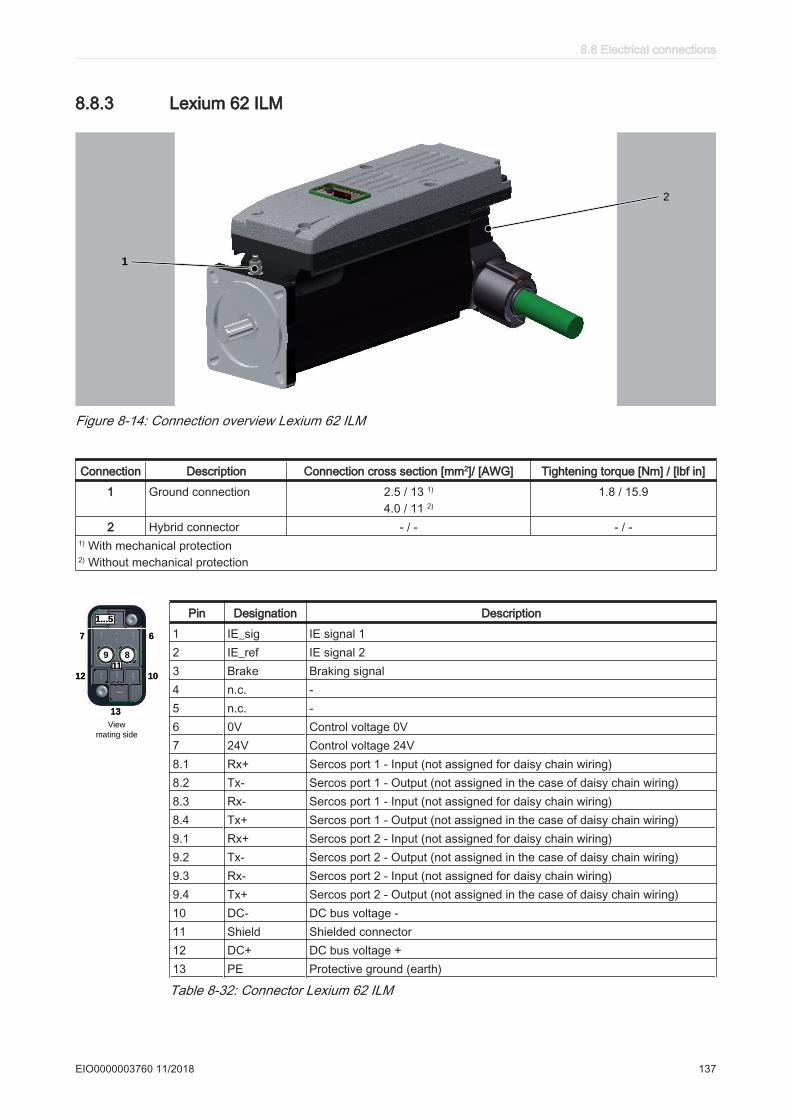
8.8.3 Lexium 62 ILM
TM
1
2
Figure 8-14: Connection overview Lexium 62 ILM
Connection Description Connection cross section [mm2]/ [AWG] Tightening torque [Nm] / [lbf in]
1 Ground connection 2.5 / 13 1)
4.0 / 11 2)
1.8 / 15.9
2 Hybrid connector - / - - / -1) With mechanical protection2) Without mechanical protection
9
77 66
1212 1010
1313
8
1...51...5
1111
View
mating side
Pin Designation Description
1 IE_sig IE signal 12 IE_ref IE signal 23 Brake Braking signal4 n.c. -5 n.c. -6 0V Control voltage 0V7 24V Control voltage 24V8.1 Rx+ Sercos port 1 - Input (not assigned for daisy chain wiring)8.2 Tx- Sercos port 1 - Output (not assigned in the case of daisy chain wiring)8.3 Rx- Sercos port 1 - Input (not assigned for daisy chain wiring)8.4 Tx+ Sercos port 1 - Output (not assigned in the case of daisy chain wiring)9.1 Rx+ Sercos port 2 - Input (not assigned for daisy chain wiring)9.2 Tx- Sercos port 2 - Output (not assigned in the case of daisy chain wiring)9.3 Rx- Sercos port 2 - Input (not assigned for daisy chain wiring)9.4 Tx+ Sercos port 2 - Output (not assigned in the case of daisy chain wiring)10 DC- DC bus voltage -11 Shield Shielded connector12 DC+ DC bus voltage +13 PE Protective ground (earth)
Table 8-32: Connector Lexium 62 ILM
8.8 Electrical connections
EIO0000003760 11/2018 137
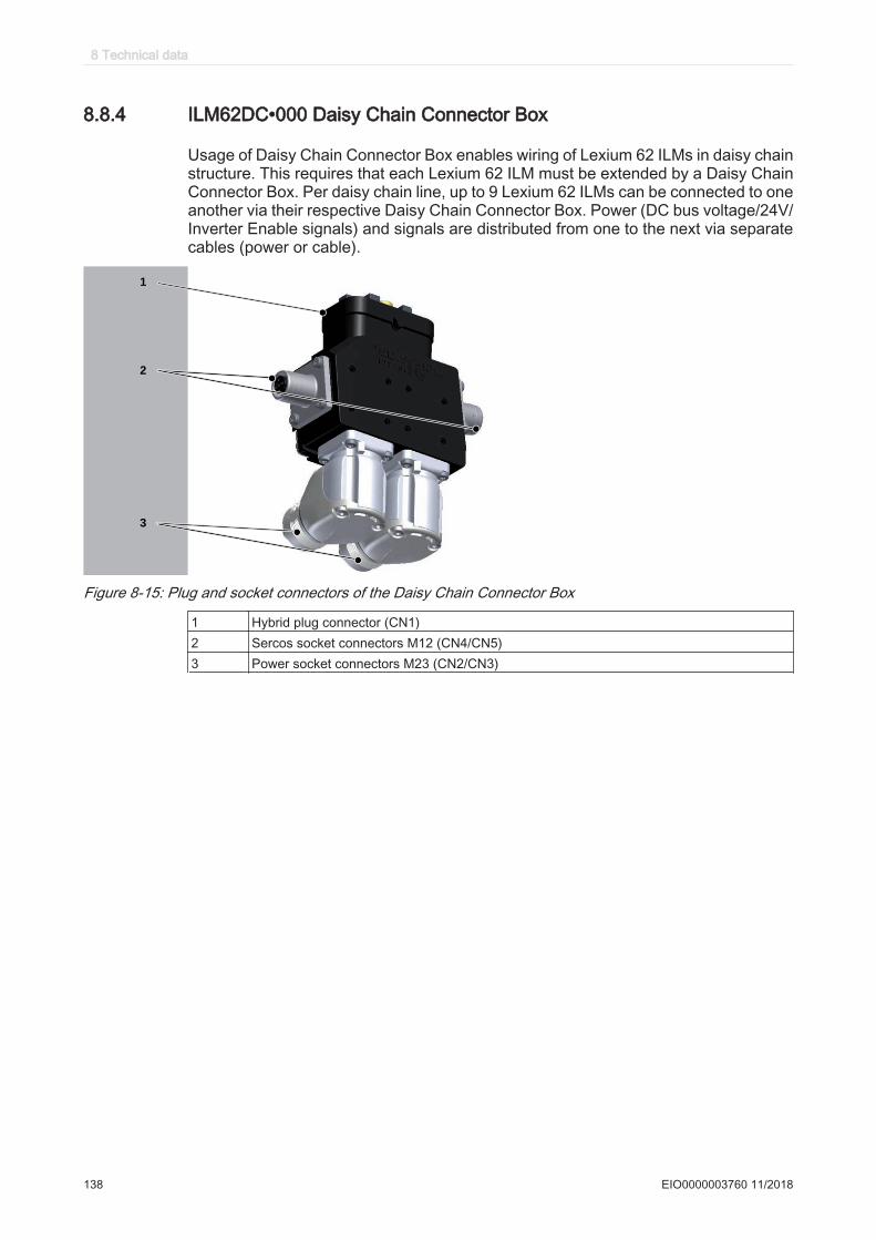
8.8.4 ILM62DC•000 Daisy Chain Connector Box
Usage of Daisy Chain Connector Box enables wiring of Lexium 62 ILMs in daisy chainstructure. This requires that each Lexium 62 ILM must be extended by a Daisy ChainConnector Box. Per daisy chain line, up to 9 Lexium 62 ILMs can be connected to oneanother via their respective Daisy Chain Connector Box. Power (DC bus voltage/24V/Inverter Enable signals) and signals are distributed from one to the next via separatecables (power or cable).
TM
1
2
3
Figure 8-15: Plug and socket connectors of the Daisy Chain Connector Box
1 Hybrid plug connector (CN1)2 Sercos socket connectors M12 (CN4/CN5)3 Power socket connectors M23 (CN2/CN3)
8 Technical data
138 EIO0000003760 11/2018
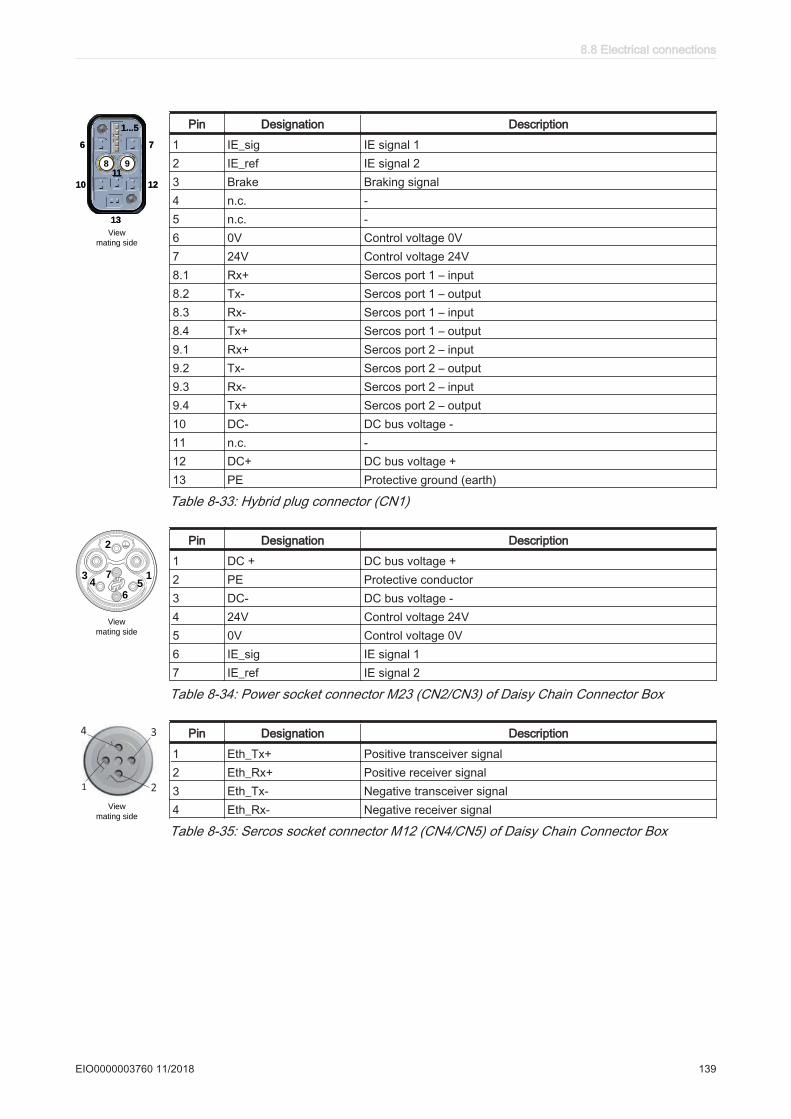
8
66 77
1010 1212
1313
1111
1...51...5
9
View
mating side
Pin Designation Description
1 IE_sig IE signal 12 IE_ref IE signal 23 Brake Braking signal4 n.c. -5 n.c. -6 0V Control voltage 0V7 24V Control voltage 24V8.1 Rx+ Sercos port 1 – input8.2 Tx- Sercos port 1 – output8.3 Rx- Sercos port 1 – input8.4 Tx+ Sercos port 1 – output9.1 Rx+ Sercos port 2 – input9.2 Tx- Sercos port 2 – output9.3 Rx- Sercos port 2 – input9.4 Tx+ Sercos port 2 – output10 DC- DC bus voltage -11 n.c. -12 DC+ DC bus voltage +13 PE Protective ground (earth)
Table 8-33: Hybrid plug connector (CN1)
2
134 5
6
7
View
mating side
Pin Designation Description
1 DC + DC bus voltage +2 PE Protective conductor3 DC- DC bus voltage -4 24V Control voltage 24V5 0V Control voltage 0V6 IE_sig IE signal 17 IE_ref IE signal 2
Table 8-34: Power socket connector M23 (CN2/CN3) of Daisy Chain Connector Box
2
34
1
View
mating side
Pin Designation Description
1 Eth_Tx+ Positive transceiver signal2 Eth_Rx+ Positive receiver signal3 Eth_Tx- Negative transceiver signal4 Eth_Rx- Negative receiver signal
Table 8-35: Sercos socket connector M12 (CN4/CN5) of Daisy Chain Connector Box
8.8 Electrical connections
EIO0000003760 11/2018 139

8.9 Dimensions
8.9.1 Lexium 62 connection module
270
(7,5)
(7,5)
44
44,5
1.73
10.63
31012.20
mmin.
1.75
(0.30)
(0.30)
Figure 8-16: Dimensions Lexium 62 conncection module
8 Technical data
140 EIO0000003760 11/2018

For mounting holes diameters and required distances in the control cabinet, refer tothe chapter Preparing the control cabinet (see 7.1.3 Preparing the control cabinet).
8.9.2 Lexium 62 distribution box
2309.05
93.33.67
56.112.21
26.11.03
67.82.67
12
04
.72
11
2.1
4.4
1
15
1.4
5.9
6
mmin.
2158.46
Ø 5
.3
0.21
Figure 8-17: Dimensions Lexium 62 distribution box
8.9 Dimensions
EIO0000003760 11/2018 141

8.9.3 ILM62DC•000 Daisy Chain Connector Box
93
7
2.94
4.6
4
1.69
3
7 2.94
4.6
3
1.22
1
77.9
4.8
( (0.19))
35.2
( (1.39))
3
1.39
5.272.893.3
43.1(
(1.70)
)
83.66
3.07
3.46
7.8
3
1.22
1
4
1.90
mmin.
8.3
2 0.10
.6
Figure 8-18: Dimensions of the Daisy Chain Connector Box Type A
8 Technical data
142 EIO0000003760 11/2018
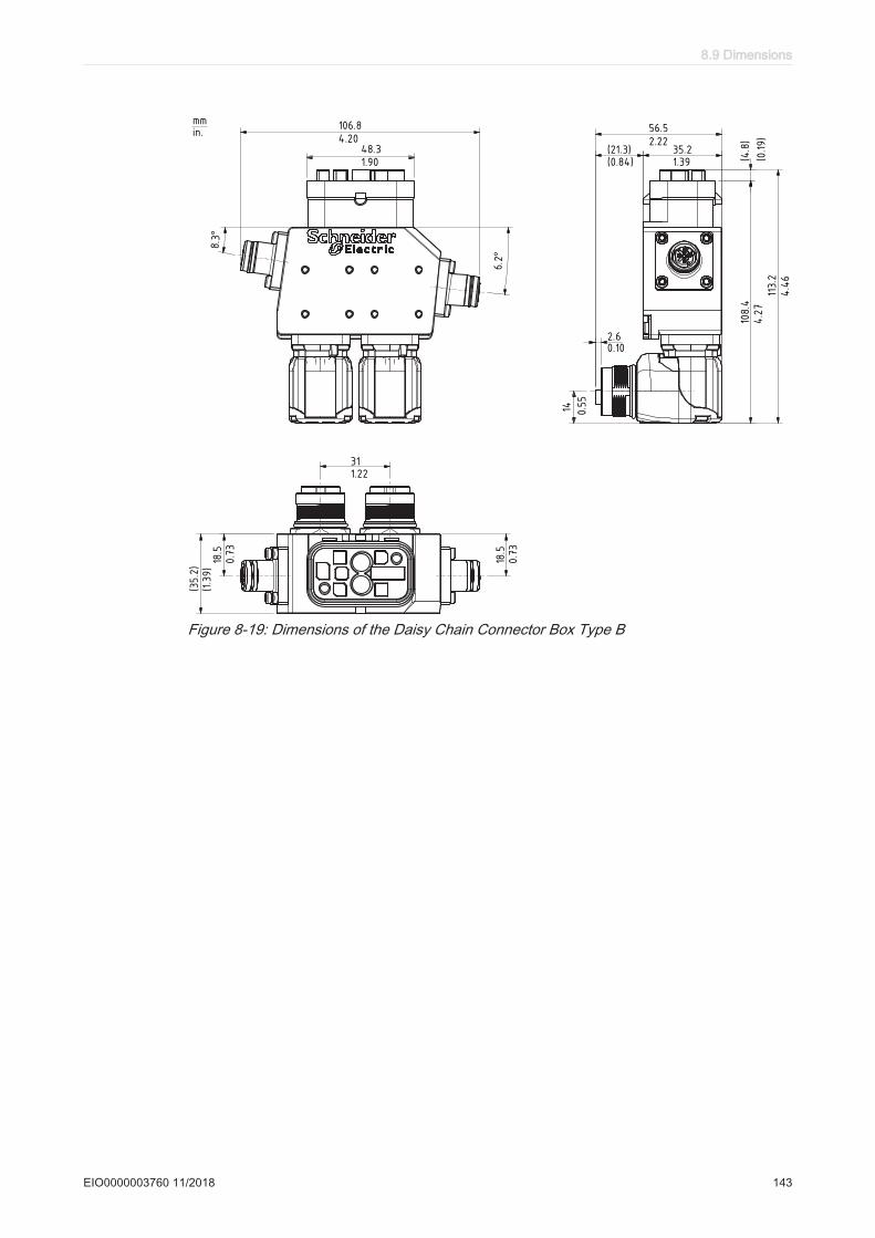
1
4.20
06.8 5
2.22
6.5
35.221.3(1.39(0.84)
)
20.10.6
113.2
1
4.46
4.27
08.4
41.908.3
31.221
1 0.73
8.5
18.5
1 0.55
4
35.2
(
0.73
(1.39))
4.8
( (0.19))
6.2°
8. 3°
mmin.
Figure 8-19: Dimensions of the Daisy Chain Connector Box Type B
8.9 Dimensions
EIO0000003760 11/2018 143
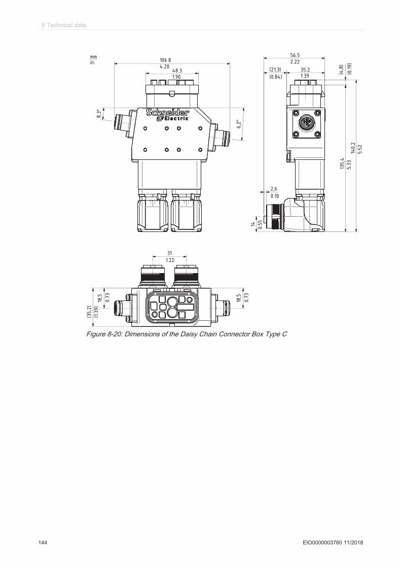
35,2
()
1 5.52
40,2
31
1 5.33
35,4
21,3( )
2,6
4,8
()
14
18,5
18,5
6,2°
8,3°
mmin. 1
4.20
06 .8
41.908.3
5
2.22
6.5
35.21.39(0.84)
(0.19)
0.10
0.55
1.22
0.73
0.73
(1.39)
Figure 8-20: Dimensions of the Daisy Chain Connector Box Type C
8 Technical data
144 EIO0000003760 11/2018

8.9.4 Lexium 62 ILM
Dimensions ILM070
with Option-module
without Option-module
1897.44
TK Ø 75TK Ø 2.95 TK Ø 82
TK Ø 3.23
8.50.34
682.68
702.76
2.50.1
44.51.75
25
0.9
8
127
4.9
9
69
2.7
2
34
1.3
873
2.8
7
107
4.2
1
35
1.3
8
mmin.
Ø 6
0 j6 [
]-0
.01
-0.0
1
Ø 2
.36 j6 [
]-0
.00
04
-0.0
00
4
20-35 mm, see connector0.79-1.38 in., see connector
Figure 8-21: Dimensions ILM070 motor
Note that the ILM series 070 uses different shaft diameters. The shaft diameter for theILM070 3 P is 14 mm/0.55 in.
Dimensions table
Dimensions ILM070 1 P [mm] / [in] ILM070 2 P [mm] / [in] ILM070 3 P [mm] / [in]
A (with brake) 175 (182) / 6.89 (7.17) 189 (215) / 7.44 (8.46) 222 (256) / 8.74 (10.08)B 23 / 0.91 23 / 0.91 30 / 1.18C 11 k6 / 0.43 k6 11 k6 / 0.43 k6 14 k6 / 0.55 k6K (with brake) 212 (219) / 8.35 (8.62) 226 (252) / 8.90 (9.92) 259 (293) / 10.20 (11.54)L (with brake) 25 (31) / 0.98 (1.22) 38 (64) / 1.50 (2.52) 71 (105) / 2.80 (4.13)
Table 8-36: Dimensions of the ILM070
8.9 Dimensions
EIO0000003760 11/2018 145

Dimensions ILM100without Option-module
with Option-module
mmin.
90.35
Ø 9
5 j6
[]
-0.0
13
-0.0
09
Ø 3
.74
j6
[]
0.0
005
0.0
004
99
3.8
9
3.50.14
44.51.75
1897.44
50
1.9
7
34
1.3
41
03
4.0
6
13
75
.39
25
0.9
81
57
6.1
8
TK Ø 115TK Ø 4.53
983.86
702.76
20-35 mm, see connector
0.79-1.38 in., see connector
Figure 8-22: Dimensions ILM100 motor
Dimensions table
Dimensions ILM100 1 P [mm] / [in] ILM100 2 P [mm] / [in] ILM100 3 P [mm] / [in]
A (with brake) 178 (207) / 7.01 (8.15) 212 (243) / 8.35 (9.57) 248 (279) / 9.76 (10.98)B 40 / 1.57 40 / 1.57 40 / 1.57C 19 k6 / 0.75 k6 19 k6 / 0.75 k6 19 k6 / 0.75 k6K (with brake) 215 (243) / 8.46 (9.57) 249 (280) / 9.80 (11.02) 285 (315) / 11.22 (12.40)L (with brake) 27 (55) / 1.06 (2.17) 61 (92) / 2.40 (3.62) 97 (127) / 3.82 (5)
Table 8-37: Dimensions of the ILM100
8 Technical data
146 EIO0000003760 11/2018

Dimensions ILM140without Option-module
with Option-module
mmin.
1897.44
120.47
3.50.14
70
2.7
6
34
1.3
41
47
.55
.80
18
17
.13
TK Ø 165TK Ø 6.50
1375.39
25
0.9
8
20
17
.91
702.76
44.51.75
20-35 mm, see connector
0.79-1.38 in., see connector
13
8.5
5.4
6
Ø 1
30
j6
[]
+0.0
14
-0.0
11
Ø 5
.12
j6
[]
+0
.00
06
-0.0
00
4
Figure 8-23: Dimensions ILM140 motor
Dimensions table
Dimensions ILM140 1 P [mm] / [in] ILM140 1 M [mm] / [in] ILM140 2 P [mm] / [in]
A (with brake) 218 (256) / 8.58 (10.08) 218 (256) / 8.58 (10.08) 273 (311) / 10.75 (12.24)B 50 /1.97 50 /1.97 50 /1.97C 24 k6 / 0.94 k6 24 k6 / 0.94 k6 24 k6 / 0.94 k6K (with brake) 254 (292) / 10 (11.50) 254 (292) / 10 (11.50) 309 (347) / 12.17 (13.66)L (with brake) 67 (105) / 2.64 (4.13) 67 (105) / 2.64 (4.13) 122 (160) / 4.80 (6.30)
Table 8-38: Dimensions of the ILM140
8.9 Dimensions
EIO0000003760 11/2018 147
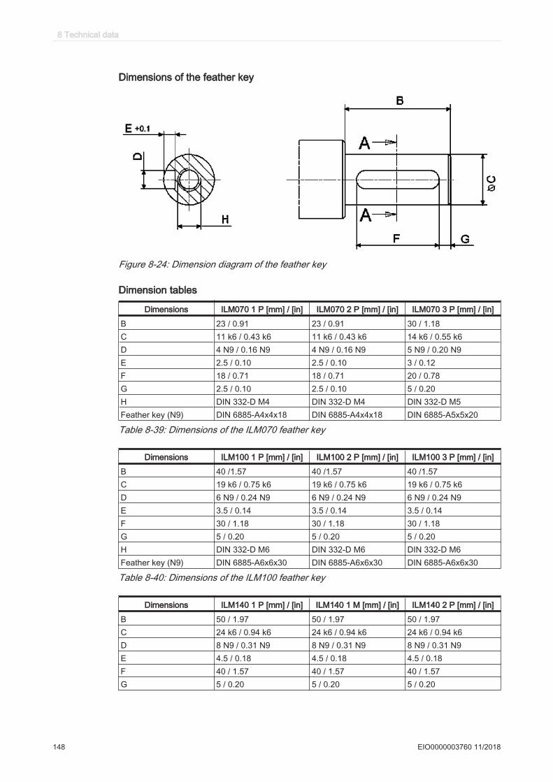
Dimensions of the feather key
Figure 8-24: Dimension diagram of the feather key
Dimension tables
Dimensions ILM070 1 P [mm] / [in] ILM070 2 P [mm] / [in] ILM070 3 P [mm] / [in]
B 23 / 0.91 23 / 0.91 30 / 1.18C 11 k6 / 0.43 k6 11 k6 / 0.43 k6 14 k6 / 0.55 k6D 4 N9 / 0.16 N9 4 N9 / 0.16 N9 5 N9 / 0.20 N9E 2.5 / 0.10 2.5 / 0.10 3 / 0.12F 18 / 0.71 18 / 0.71 20 / 0.78G 2.5 / 0.10 2.5 / 0.10 5 / 0.20H DIN 332-D M4 DIN 332-D M4 DIN 332-D M5Feather key (N9) DIN 6885-A4x4x18 DIN 6885-A4x4x18 DIN 6885-A5x5x20
Table 8-39: Dimensions of the ILM070 feather key
Dimensions ILM100 1 P [mm] / [in] ILM100 2 P [mm] / [in] ILM100 3 P [mm] / [in]
B 40 /1.57 40 /1.57 40 /1.57C 19 k6 / 0.75 k6 19 k6 / 0.75 k6 19 k6 / 0.75 k6D 6 N9 / 0.24 N9 6 N9 / 0.24 N9 6 N9 / 0.24 N9E 3.5 / 0.14 3.5 / 0.14 3.5 / 0.14F 30 / 1.18 30 / 1.18 30 / 1.18G 5 / 0.20 5 / 0.20 5 / 0.20H DIN 332-D M6 DIN 332-D M6 DIN 332-D M6Feather key (N9) DIN 6885-A6x6x30 DIN 6885-A6x6x30 DIN 6885-A6x6x30
Table 8-40: Dimensions of the ILM100 feather key
Dimensions ILM140 1 P [mm] / [in] ILM140 1 M [mm] / [in] ILM140 2 P [mm] / [in]
B 50 / 1.97 50 / 1.97 50 / 1.97C 24 k6 / 0.94 k6 24 k6 / 0.94 k6 24 k6 / 0.94 k6D 8 N9 / 0.31 N9 8 N9 / 0.31 N9 8 N9 / 0.31 N9E 4.5 / 0.18 4.5 / 0.18 4.5 / 0.18F 40 / 1.57 40 / 1.57 40 / 1.57G 5 / 0.20 5 / 0.20 5 / 0.20
8 Technical data
148 EIO0000003760 11/2018

Dimensions ILM140 1 P [mm] / [in] ILM140 1 M [mm] / [in] ILM140 2 P [mm] / [in]
H DIN 332-D M8 DIN 332-D M8 DIN 332-D M8Feather key (N9) DIN 6885-A8x7x40 DIN 6885-A8x7x40 DIN 6885-A8x7x40
Table 8-41: Dimensions of the ILM140 feather key
8.9 Dimensions
EIO0000003760 11/2018 149
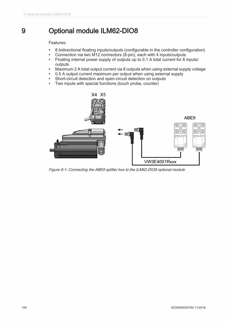
9 Optional module ILM62-DIO8Features:
• 8 bidirectional floating inputs/outputs (configurable in the controller configuration)• Connection via two M12 connectors (8-pin), each with 4 inputs/outputs• Floating internal power supply of outputs up to 0.1 A total current for 8 inputs/
outputs• Maximum 2 A total output current via 8 outputs when using external supply voltage• 0.5 A output current maximum per output when using external supply• Short-circuit detection and open-circuit detection on outputs• Two inputs with special functions (touch probe, counter)
Figure 9-1: Connecting the ABE9 splitter box to the ILM62-DIO8 optional module
9 Optional module ILM62-DIO8
150 EIO0000003760 11/2018
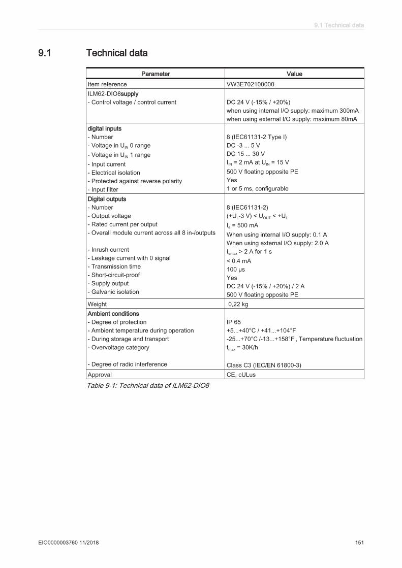
9.1 Technical data
Parameter Value
Item reference VW3E702100000ILM62-DIO8supply- Control voltage / control current DC 24 V (-15% / +20%)
when using internal I/O supply: maximum 300mA when using external I/O supply: maximum 80mA
digital inputs - Number- Voltage in UIN 0 range- Voltage in UIN 1 range- Input current- Electrical isolation- Protected against reverse polarity- Input filter
8 (IEC61131-2 Type I)DC -3 ... 5 VDC 15 ... 30 VIIN = 2 mA at UIN = 15 V500 V floating opposite PEYes 1 or 5 ms, configurable
Digital outputs - Number- Output voltage- Rated current per output- Overall module current across all 8 in-/outputs
- Inrush current- Leakage current with 0 signal- Transmission time- Short-circuit-proof- Supply output- Galvanic isolation
8 (IEC61131-2) (+UL-3 V) < UOUT < +UL
Ie = 500 mAWhen using internal I/O supply: 0.1 A When using external I/O supply: 2.0 A Iemax > 2 A for 1 s< 0.4 mA100 µsYesDC 24 V (-15% / +20%) / 2 A500 V floating opposite PE
Weight 0,22 kg Ambient conditions - Degree of protection- Ambient temperature during operation- During storage and transport- Overvoltage category
- Degree of radio interference
IP 65+5...+40°C / +41...+104°F-25...+70°C /-13...+158°F , Temperature fluctuationtmax = 30K/h
Class C3 (IEC/EN 61800-3)Approval CE, cULus
Table 9-1: Technical data of ILM62-DIO8
9.1 Technical data
EIO0000003760 11/2018 151
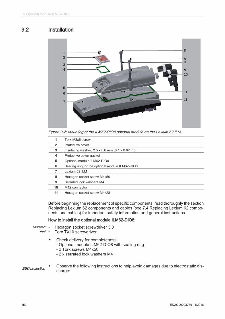
9.2 Installation
9
1
2
3
4
5
6
7
9
8
10
11
11
8
Figure 9-2: Mounting of the ILM62-DIO8 optional module on the Lexium 62 ILM
1 Torx M3x6 screw2 Protective cover3 Insulating washer, 2.5 x 0.6 mm (0.1 x 0.02 in.)4 Protective cover gasket5 Optional module ILM62-DIO86 Sealing ring for the optional module ILM62-DIO87 Lexium 62 ILM8 Hexagon socket screw M4x509 Serrated lock washers M4
10 M12 connector11 Hexagon socket screw M4x28
Before beginning the replacement of specific components, read thoroughly the sectionReplacing Lexium 62 components and cables (see 7.4 Replacing Lexium 62 compo‐nents and cables) for important safety information and general instructions.
How to install the optional module ILM62-DIO8:required
tool• Hexagon socket screwdriver 3.0• Torx TX10 screwdriver
▶ Check delivery for completeness:- Optional module ILM62-DIO8 with sealing ring- 2 Torx screws M4x50- 2 x serrated lock washers M4
ESD protection ▶ Observe the following instructions to help avoid damages due to electrostatic dis‐charge:
9 Optional module ILM62-DIO8
152 EIO0000003760 11/2018
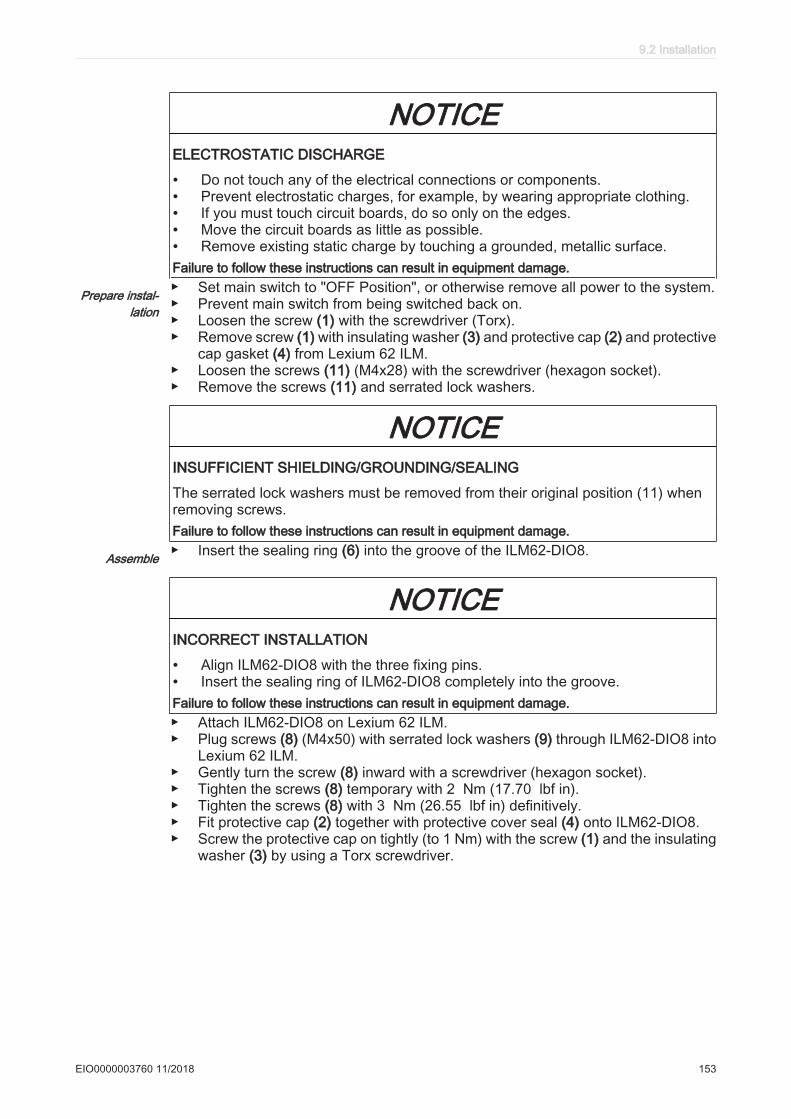
NOTICEELECTROSTATIC DISCHARGE
• Do not touch any of the electrical connections or components.• Prevent electrostatic charges, for example, by wearing appropriate clothing.• If you must touch circuit boards, do so only on the edges.• Move the circuit boards as little as possible.• Remove existing static charge by touching a grounded, metallic surface.Failure to follow these instructions can result in equipment damage.
Prepare instal‐lation
▶ Set main switch to "OFF Position", or otherwise remove all power to the system.▶ Prevent main switch from being switched back on.▶ Loosen the screw (1) with the screwdriver (Torx).▶ Remove screw (1) with insulating washer (3) and protective cap (2) and protective
cap gasket (4) from Lexium 62 ILM.▶ Loosen the screws (11) (M4x28) with the screwdriver (hexagon socket).▶ Remove the screws (11) and serrated lock washers.
NOTICEINSUFFICIENT SHIELDING/GROUNDING/SEALING
The serrated lock washers must be removed from their original position (11) whenremoving screws.Failure to follow these instructions can result in equipment damage.
Assemble ▶ Insert the sealing ring (6) into the groove of the ILM62-DIO8.
NOTICEINCORRECT INSTALLATION
• Align ILM62-DIO8 with the three fixing pins.• Insert the sealing ring of ILM62-DIO8 completely into the groove.Failure to follow these instructions can result in equipment damage.▶ Attach ILM62-DIO8 on Lexium 62 ILM.▶ Plug screws (8) (M4x50) with serrated lock washers (9) through ILM62-DIO8 into
Lexium 62 ILM.▶ Gently turn the screw (8) inward with a screwdriver (hexagon socket).▶ Tighten the screws (8) temporary with 2 Nm (17.70 lbf in).▶ Tighten the screws (8) with 3 Nm (26.55 lbf in) definitively.▶ Fit protective cap (2) together with protective cover seal (4) onto ILM62-DIO8.▶ Screw the protective cap on tightly (to 1 Nm) with the screw (1) and the insulating
washer (3) by using a Torx screwdriver.
9.2 Installation
EIO0000003760 11/2018 153
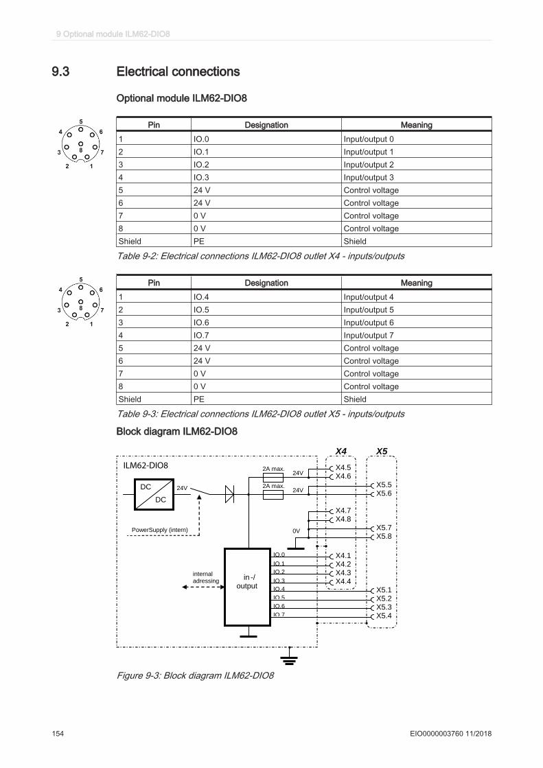
9.3 Electrical connections
Optional module ILM62-DIO8
Pin Designation Meaning
1 IO.0 Input/output 02 IO.1 Input/output 13 IO.2 Input/output 24 IO.3 Input/output 35 24 V Control voltage6 24 V Control voltage7 0 V Control voltage8 0 V Control voltageShield PE Shield
Table 9-2: Electrical connections ILM62-DIO8 outlet X4 - inputs/outputs
Pin Designation Meaning
1 IO.4 Input/output 42 IO.5 Input/output 53 IO.6 Input/output 64 IO.7 Input/output 75 24 V Control voltage6 24 V Control voltage7 0 V Control voltage8 0 V Control voltageShield PE Shield
Table 9-3: Electrical connections ILM62-DIO8 outlet X5 - inputs/outputs
Block diagram ILM62-DIO8
in -/ output
DC
DC
PowerSupply (intern)
24V
internal adressing
X4.5 X4.6
X5.5 X5.6
X4.7 X4.8
X5.7 X5.8
X4.1 X4.2 X4.3 X4.4
X5.1 X5.2 X5.3 X5.4
2A max. 24V
24V
0V
IO.0
IO.1
IO.2
IO.3
IO.4
IO.5
IO.6
IO.7
2A max.
X4 X5
ILM62-DIO8
Figure 9-3: Block diagram ILM62-DIO8
9 Optional module ILM62-DIO8
154 EIO0000003760 11/2018
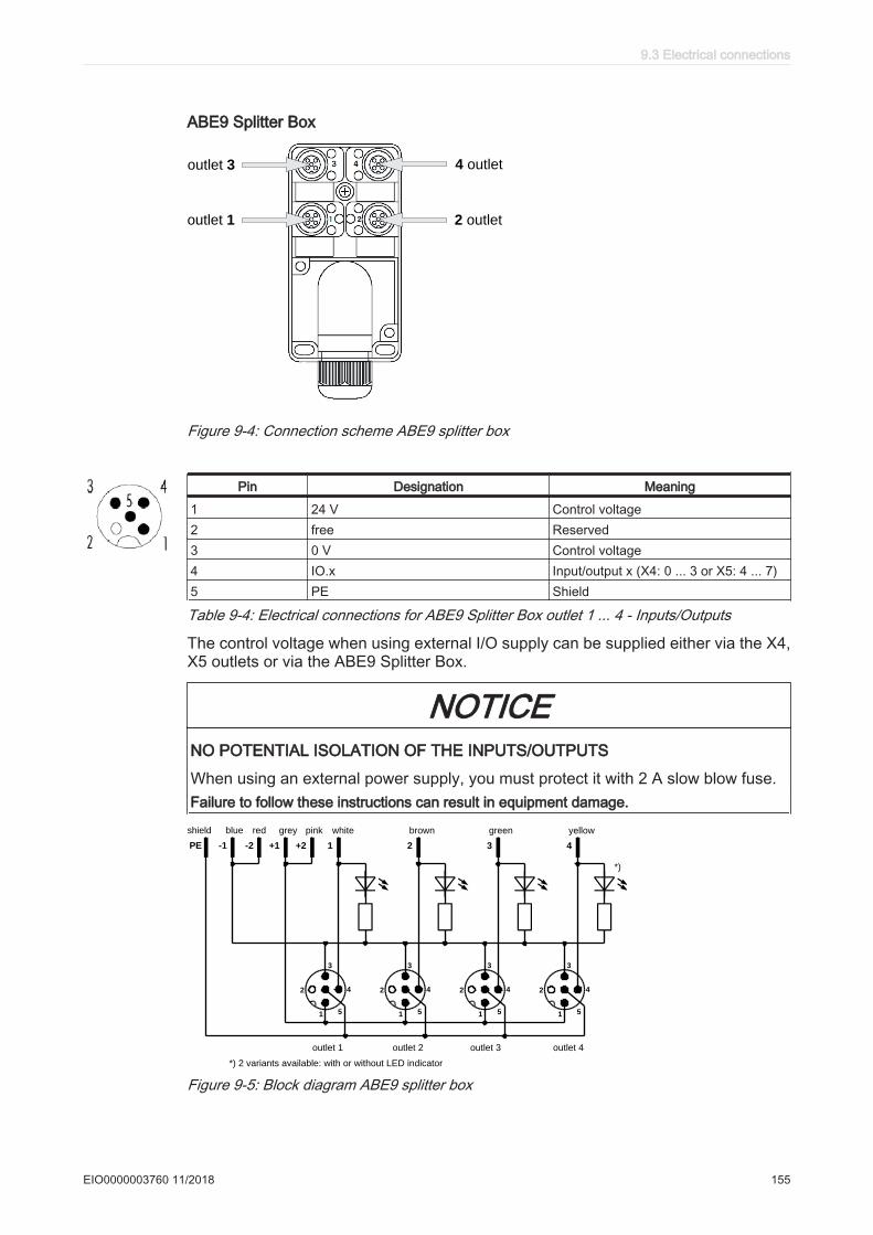
ABE9 Splitter Box
outlet 3 4 outlet
outlet 1 2 outlet
Figure 9-4: Connection scheme ABE9 splitter box
Pin Designation Meaning
1 24 V Control voltage2 free Reserved3 0 V Control voltage4 IO.x Input/output x (X4: 0 ... 3 or X5: 4 ... 7)5 PE Shield
Table 9-4: Electrical connections for ABE9 Splitter Box outlet 1 ... 4 - Inputs/Outputs
The control voltage when using external I/O supply can be supplied either via the X4,X5 outlets or via the ABE9 Splitter Box.
NOTICENO POTENTIAL ISOLATION OF THE INPUTS/OUTPUTS
When using an external power supply, you must protect it with 2 A slow blow fuse.Failure to follow these instructions can result in equipment damage.
1
2
3
4
5 1
2
3
4
5 1
2
3
4
5 1
2
3
4
5
PE -1 -2 +1 +2 1 2 3 4
shield blue red grey pink white brown green yellow
outlet 1 outlet 2 outlet 3 outlet 4
*)
*) 2 variants available: with or without LED indicator
Figure 9-5: Block diagram ABE9 splitter box
9.3 Electrical connections
EIO0000003760 11/2018 155

9.4 Dimensions
mm
in.
36
1.42
59.1
2.33
136.5
5.37
10
0.39
25
0.98
69
2.72
65.3
2.57
(31.3)
(1.23)
Figure 9-6: Dimensions ILM62-DIO8
33
mmin.
50
1.97
5
0.19
73
2.87
LLØ 4.5x3 (2x)
LLØ 0.18x0.12 (2x)
Ø 4.5Ø 0.18
Counterbore Ø 8
Ø 0.31
99
3.90
app. 24
0.95
29
1.1
4
39
1.5
4
33
1.3
0
17
0.6
2
42
1.6
5
Figure 9-7: Dimensions of the ABE9 splitter box
9 Optional module ILM62-DIO8
156 EIO0000003760 11/2018

9.5 Wiring
-1
+1
1
3
PE
4
2
+2
-2
blue
gray
white
green
Shield
yellow
brown
pink
red
KA99051 - xxx
Figure 9-8: Cable configuration VW3E4001Rxxx for connection of ABE9 splitter box
24 V DC
M12-5 pin
M12-8 pin
Figure 9-9: 2-4 inputs/ outputs with external supply
M12-5 pinM12-8 pin
24 V DC
Figure 9-10: 5-7 inputs/ outputs with external supply
9.5 Wiring
EIO0000003760 11/2018 157
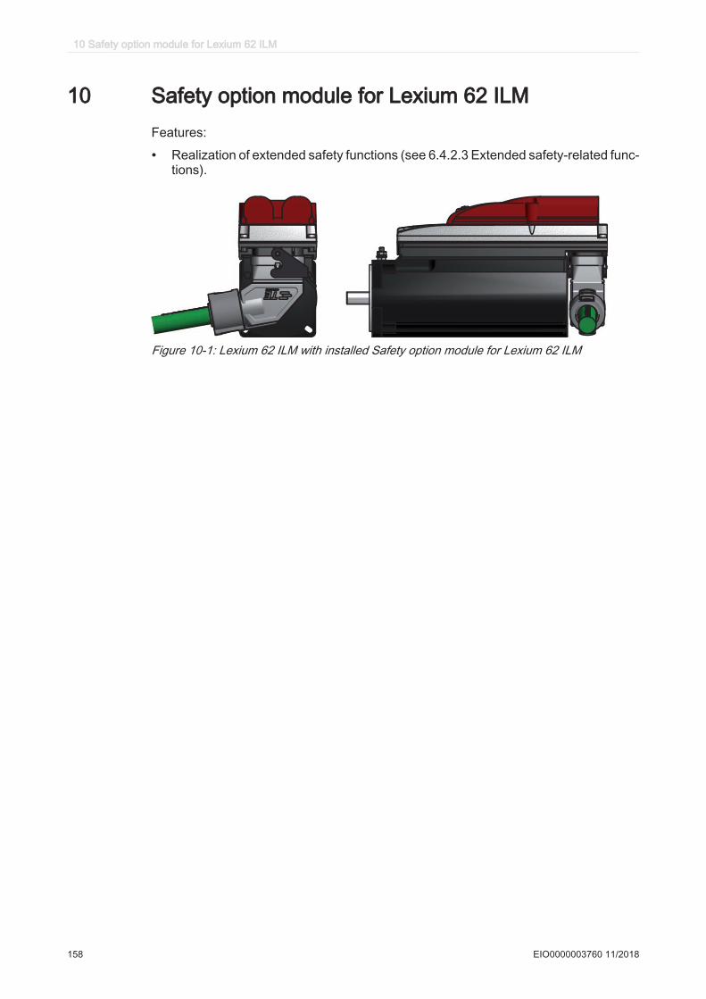
10 Safety option module for Lexium 62 ILMFeatures:
• Realization of extended safety functions (see 6.4.2.3 Extended safety-related func‐tions).
Figure 10-1: Lexium 62 ILM with installed Safety option module for Lexium 62 ILM
10 Safety option module for Lexium 62 ILM
158 EIO0000003760 11/2018
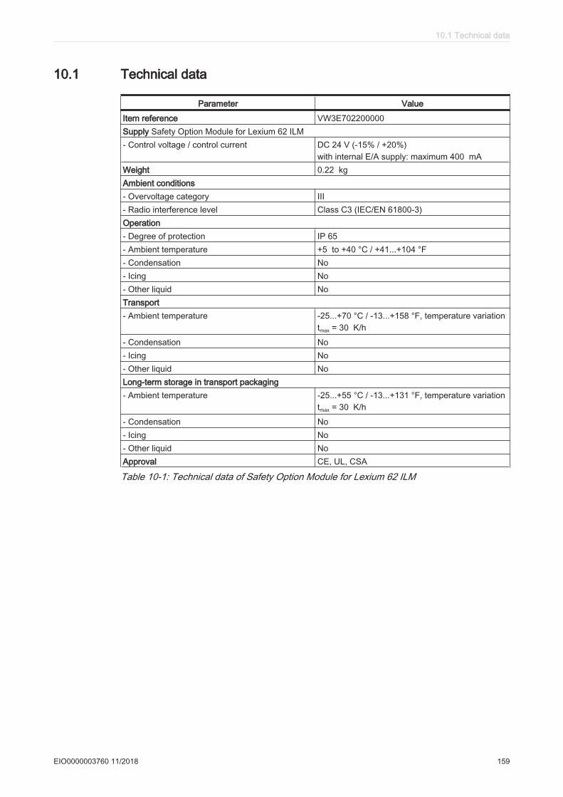
10.1 Technical data
Parameter Value
Item reference VW3E702200000Supply Safety Option Module for Lexium 62 ILM- Control voltage / control current DC 24 V (-15% / +20%)
with internal E/A supply: maximum 400 mAWeight 0.22 kgAmbient conditions- Overvoltage category III- Radio interference level Class C3 (IEC/EN 61800-3)Operation- Degree of protection IP 65- Ambient temperature +5 to +40 °C / +41...+104 °F- Condensation No- Icing No- Other liquid NoTransport- Ambient temperature -25...+70 °C / -13...+158 °F, temperature variation
tmax = 30 K/h
- Condensation No- Icing No- Other liquid NoLong-term storage in transport packaging- Ambient temperature -25...+55 °C / -13...+131 °F, temperature variation
tmax = 30 K/h
- Condensation No- Icing No- Other liquid NoApproval CE, UL, CSA
Table 10-1: Technical data of Safety Option Module for Lexium 62 ILM
10.1 Technical data
EIO0000003760 11/2018 159
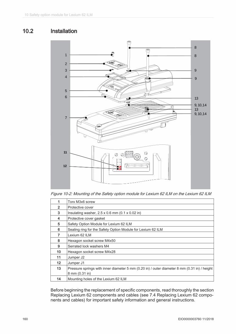
10.2 Installation
9
1
2
3
4
5
6
7
9
8
13
8
13
9, 10,14
9, 10,14
11
12
Figure 10-2: Mounting of the Safety option module for Lexium 62 ILM on the Lexium 62 ILM
1 Torx M3x6 screw2 Protective cover3 Insulating washer, 2.5 x 0.6 mm (0.1 x 0.02 in)4 Protective cover gasket5 Safety Option Module for Lexium 62 ILM6 Sealing ring for the Safety Option Module for Lexium 62 ILM7 Lexium 62 ILM8 Hexagon socket screw M4x509 Serrated lock washers M4
10 Hexagon socket screw M4x2811 Jumper J212 Jumper J113 Pressure springs with inner diameter 5 mm (0.20 in) / outer diameter 8 mm (0.31 in) / height
8 mm (0.31 in)14 Mounting holes of the Lexium 62 ILM
Before beginning the replacement of specific components, read thoroughly the sectionReplacing Lexium 62 components and cables (see 7.4 Replacing Lexium 62 compo‐nents and cables) for important safety information and general instructions.
10 Safety option module for Lexium 62 ILM
160 EIO0000003760 11/2018
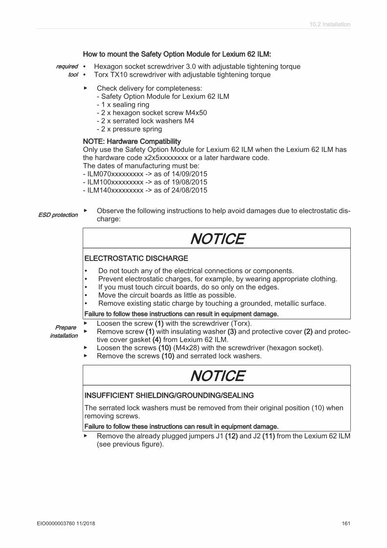
How to mount the Safety Option Module for Lexium 62 ILM:required
tool• Hexagon socket screwdriver 3.0 with adjustable tightening torque• Torx TX10 screwdriver with adjustable tightening torque
▶ Check delivery for completeness:- Safety Option Module for Lexium 62 ILM- 1 x sealing ring- 2 x hexagon socket screw M4x50- 2 x serrated lock washers M4- 2 x pressure spring
NOTE: Hardware CompatibilityOnly use the Safety Option Module for Lexium 62 ILM when the Lexium 62 ILM hasthe hardware code x2x5xxxxxxxx or a later hardware code.The dates of manufacturing must be:- ILM070xxxxxxxxx -> as of 14/09/2015- ILM100xxxxxxxxx -> as of 19/08/2015- ILM140xxxxxxxxx -> as of 24/08/2015
ESD protection ▶ Observe the following instructions to help avoid damages due to electrostatic dis‐charge:
NOTICEELECTROSTATIC DISCHARGE
• Do not touch any of the electrical connections or components.• Prevent electrostatic charges, for example, by wearing appropriate clothing.• If you must touch circuit boards, do so only on the edges.• Move the circuit boards as little as possible.• Remove existing static charge by touching a grounded, metallic surface.Failure to follow these instructions can result in equipment damage.
Prepare installation
▶ Loosen the screw (1) with the screwdriver (Torx).▶ Remove screw (1) with insulating washer (3) and protective cover (2) and protec‐
tive cover gasket (4) from Lexium 62 ILM.▶ Loosen the screws (10) (M4x28) with the screwdriver (hexagon socket).▶ Remove the screws (10) and serrated lock washers.
NOTICEINSUFFICIENT SHIELDING/GROUNDING/SEALING
The serrated lock washers must be removed from their original position (10) whenremoving screws.Failure to follow these instructions can result in equipment damage.▶ Remove the already plugged jumpers J1 (12) and J2 (11) from the Lexium 62 ILM
(see previous figure).
10.2 Installation
EIO0000003760 11/2018 161
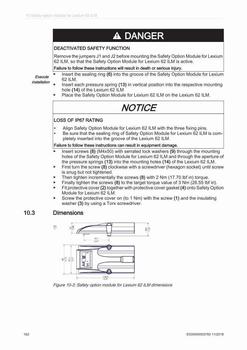
DANGERDEACTIVATED SAFETY FUNCTION
Remove the jumpers J1 and J2 before mounting the Safety Option Module for Lexium62 ILM, so that the Safety Option Module for Lexium 62 ILM is active.Failure to follow these instructions will result in death or serious injury.
Execute installation
▶ Insert the sealing ring (6) into the groove of the Safety Option Module for Lexium62 ILM.
▶ Insert each pressure spring (13) in vertical position into the respective mountinghole (14) of the Lexium 62 ILM
▶ Place the Safety Option Module for Lexium 62 ILM on the Lexium 62 ILM.
NOTICELOSS OF IP67 RATING
• Align Safety Option Module for Lexium 62 ILM with the three fixing pins.• Be sure that the sealing ring of Safety Option Module for Lexium 62 ILM is com‐
pletely inserted into the groove of the Lexium 62 ILM.Failure to follow these instructions can result in equipment damage.▶ Insert screws (8) (M4x50) with serrated lock washers (9) through the mounting
holes of the Safety Option Module for Lexium 62 ILM and through the aperture ofthe pressure springs (13) into the mounting holes (14) of the Lexium 62 ILM.
▶ First turn the screw (8) clockwise with a screwdriver (hexagon socket) until screwis snug but not tightened.
▶ Then tighten incrementally the screws (8) with 2 Nm (17.70 lbf in) torque.▶ Finally tighten the screws (8) to the target torque value of 3 Nm (26.55 lbf in).▶ Fit protective cover (2) together with protective cover gasket (4) onto Safety Option
Module for Lexium 62 ILM.▶ Screw the protective cover on (to 1 Nm) with the screw (1) and the insulating
washer (3) by using a Torx screwdriver.
10.3 Dimensions
Figure 10-3: Safety option module for Lexium 62 ILM dimensions
10 Safety option module for Lexium 62 ILM
162 EIO0000003760 11/2018
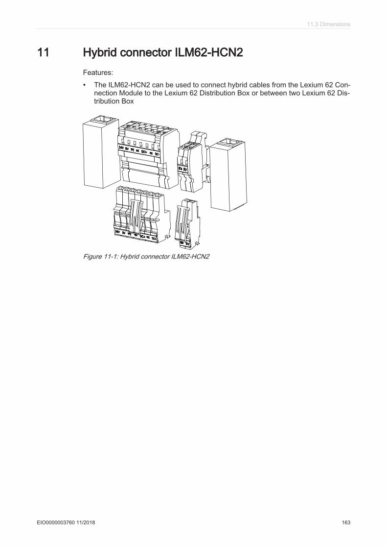
11 Hybrid connector ILM62-HCN2Features:
• The ILM62-HCN2 can be used to connect hybrid cables from the Lexium 62 Con‐nection Module to the Lexium 62 Distribution Box or between two Lexium 62 Dis‐tribution Box
Figure 11-1: Hybrid connector ILM62-HCN2
11.3 Dimensions
EIO0000003760 11/2018 163
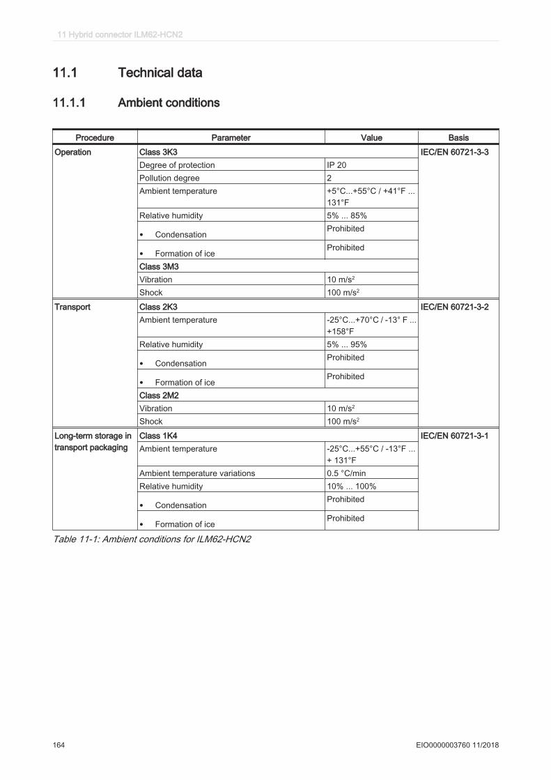
11.1 Technical data
11.1.1 Ambient conditions
Procedure Parameter Value Basis
Operation Class 3K3 IEC/EN 60721-3-3Degree of protection IP 20Pollution degree 2Ambient temperature +5°C...+55°C / +41°F ...
131°FRelative humidity 5% ... 85%
• CondensationProhibited
• Formation of iceProhibited
Class 3M3Vibration 10 m/s2
Shock 100 m/s2
Transport Class 2K3 IEC/EN 60721-3-2Ambient temperature -25°C...+70°C / -13° F ...
+158°FRelative humidity 5% ... 95%
• CondensationProhibited
• Formation of iceProhibited
Class 2M2Vibration 10 m/s2
Shock 100 m/s2
Long-term storage intransport packaging
Class 1K4 IEC/EN 60721-3-1Ambient temperature -25°C...+55°C / -13°F ...
+ 131°FAmbient temperature variations 0.5 °C/minRelative humidity 10% ... 100%
• CondensationProhibited
• Formation of iceProhibited
Table 11-1: Ambient conditions for ILM62-HCN2
11 Hybrid connector ILM62-HCN2
164 EIO0000003760 11/2018
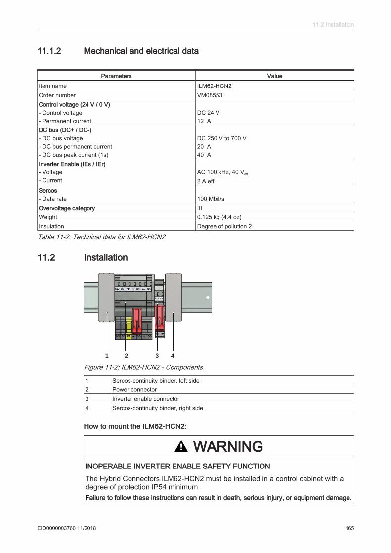
11.1.2 Mechanical and electrical data
Parameters Value
Item name ILM62-HCN2Order number VM08553Control voltage (24 V / 0 V) - Control voltage- Permanent current
DC 24 V12 A
DC bus (DC+ / DC-) - DC bus voltage- DC bus permanent current- DC bus peak current (1s)
DC 250 V to 700 V20 A40 A
Inverter Enable (IEs / IEr) - Voltage- Current
AC 100 kHz, 40 Veff
2 A effSercos- Data rate 100 Mbit/sOvervoltage category IIIWeight 0.125 kg (4.4 oz)Insulation Degree of pollution 2
Table 11-2: Technical data for ILM62-HCN2
11.2 Installation
2 3 41
Figure 11-2: ILM62-HCN2 - Components
1 Sercos-continuity binder, left side2 Power connector3 Inverter enable connector4 Sercos-continuity binder, right side
How to mount the ILM62-HCN2:
WARNINGINOPERABLE INVERTER ENABLE SAFETY FUNCTION
The Hybrid Connectors ILM62-HCN2 must be installed in a control cabinet with adegree of protection IP54 minimum.Failure to follow these instructions can result in death, serious injury, or equipment damage.
11.2 Installation
EIO0000003760 11/2018 165
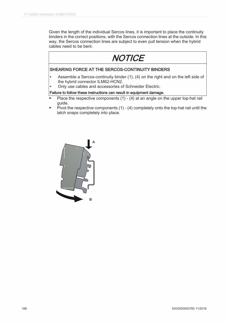
Given the length of the individual Sercos lines, it is important to place the continuitybinders in the correct positions, with the Sercos connection lines at the outside. In thisway, the Sercos connection lines are subject to even pull tension when the hybridcables need to be bent.
NOTICESHEARING FORCE AT THE SERCOS-CONTINUITY BINDERS
• Assemble a Sercos-continuity binder (1), (4) on the right and on the left side ofthe hybrid connector ILM62-HCN2.
• Only use cables and accessories of Schneider Electric.Failure to follow these instructions can result in equipment damage.▶ Place the respective components (1) - (4) at an angle on the upper top-hat rail
guide.▶ Pivot the respective components (1) - (4) completely onto the top-hat rail until the
latch snaps completely into place.
A
B
11 Hybrid connector ILM62-HCN2
166 EIO0000003760 11/2018
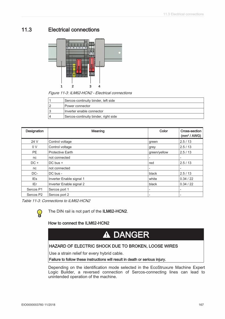
11.3 Electrical connections
2 3 41
Figure 11-3: ILM62-HCN2 - Electrical connections
1 Sercos-continuity binder, left side2 Power connector3 Inverter enable connector4 Sercos-continuity binder, right side
Designation Meaning Color Cross-section(mm2 / AWG)
24 V Control voltage green 2.5 / 130 V Control voltage grey 2.5 / 13PE Protective Earth green/yellow 2.5 / 13nc not connected - -
DC + DC bus + red 2.5 / 13nc not connected - -
DC- DC bus - black 2.5 / 13IEs Inverter Enable signal 1 white 0.34 / 22IEr Inverter Enable signal 2 black 0.34 / 22
Sercos P1 Sercos port 1 - -Sercos P2 Sercos port 2 - -
Table 11-3: Connections to ILM62-HCN2
The DIN rail is not part of the ILM62-HCN2.
How to connect the ILM62-HCN2
DANGERHAZARD OF ELECTRIC SHOCK DUE TO BROKEN, LOOSE WIRES
Use a strain relief for every hybrid cable.Failure to follow these instructions will result in death or serious injury.
Depending on the identification mode selected in the EcoStruxure Machine Expert Logic Builder, a reversed connection of Sercos-connecting lines can lead to unintended operation of the machine.
11.3 Electrical connections
EIO0000003760 11/2018 167
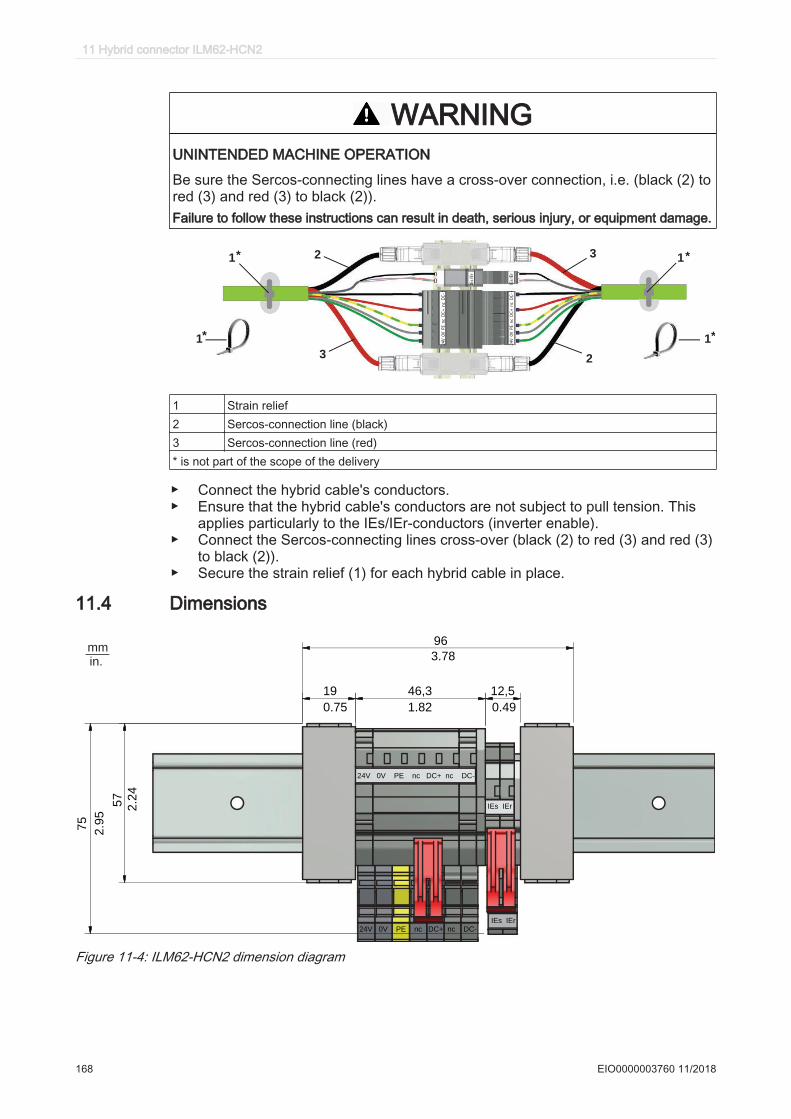
WARNINGUNINTENDED MACHINE OPERATION
Be sure the Sercos-connecting lines have a cross-over connection, i.e. (black (2) tored (3) and red (3) to black (2)).Failure to follow these instructions can result in death, serious injury, or equipment damage.
24
V
0V
P
E
nc
D
C+
n
c
DC
-
24
V
0V
P
E
nc
D
C+
n
c
DC
-
IEs
IEr
IEs
IEr
1*
* *
*1
3
2
2
3
1 1
1 Strain relief2 Sercos-connection line (black)3 Sercos-connection line (red)* is not part of the scope of the delivery
▶ Connect the hybrid cable's conductors.▶ Ensure that the hybrid cable's conductors are not subject to pull tension. This
applies particularly to the IEs/IEr-conductors (inverter enable).▶ Connect the Sercos-connecting lines cross-over (black (2) to red (3) and red (3)
to black (2)).▶ Secure the strain relief (1) for each hybrid cable in place.
11.4 Dimensions
96
3.78
75
2.9
5
57
2.2
4
19
0.75
46,3
1.82
12,5
0.49
IEs IEr
IEs IEr
24V 0V PE nc DC+ nc DC-
24V 0V PE nc DC+ nc DC-
mm
in.
Figure 11-4: ILM62-HCN2 dimension diagram
11 Hybrid connector ILM62-HCN2
168 EIO0000003760 11/2018
12 Appendix
12.1 Contact addresses
Schneider Electric Automation GmbH
Schneiderplatz 197828 Marktheidenfeld, GermanyPhone: +49 (0) 9391 / 606 - 0Fax: +49 (0) 9391 / 606 - 4000Email: [email protected]: www.schneider-electric.com
Machine Solution Service
Schneiderplatz 1D- 97828 Marktheidenfeld, GermanyPhone: +49 (0) 9391 / 606 - 3265Fax: +49 (0) 9391 / 606 - 3340Email: [email protected]: www.schneider-electric.com
See the homepage for additional contact addresses:www.schneider-electric.com
12.2 Product training courses
Schneider Electric offers a number of product training courses on robotics and thevarious components used in the system.
Contact your Schneider Electric representative for more information.
12.3 Disposal
The components consist of different materials, which can be re-used and must bedisposed of separately. The packaging cannot be returned to the manufacturer.
▶ Dispose of the packaging in accordance with the relevant national regulations.▶ Dispose of the packaging at the disposal sites provided for this purpose.▶ Dispose of Lexium 62 components in accordance with the applicable national
regulations.
12.1 Contact addresses
EIO0000003760 11/2018 169
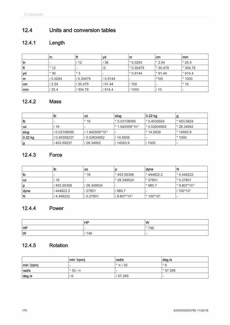
12.4 Units and conversion tables
12.4.1 Length
in ft yd m cm mmin - / 12 / 36 * 0.0254 * 2.54 * 25.4ft * 12 - /3 * 0.30479 * 30.479 * 304.79yd * 36 * 3 - * 0.9144 * 91.44 * 914.4m / 0.0254 / 0.30479 / 0.9144 - *100 * 1000cm / 2.54 / 30.479 / 91.44 / 100 - * 10mm / 25.4 / 304.79 / 914.4 / 1000 / 10 -
12.4.2 Mass
lb oz slug 0.22 kg glb - * 16 * 0.03108095 * 0.4535924 * 453.5924oz / 16 - * 1.942559*10-3 * 0.02834952 * 28.34952slug / 0.03108095 / 1.942559*10-3 - * 14.5939 * 14593.90.22 kg / 0.45359237 / 0.02834952 / 14.5939 - * 1000g / 453.59237 / 28.34952 / 14593.9 / 1000 -
12.4.3 Force
lb oz p dyne Nlb - * 16 * 453.55358 * 444822.2 * 4.448222oz / 16 - * 28.349524 * 27801 * 0.27801p / 453.55358 / 28.349524 - * 980.7 * 9.807*10-3
dyne / 444822.2 / 27801 / 980.7 - / 100*103
N / 4.448222 / 0.27801 / 9.807*10-3 * 100*103 -
12.4.4 Power
HP WHP - * 746W / 746 -
12.4.5 Rotation
min-1(rpm) rad/s deg./smin-1(rpm) - * π / 30 * 6rad/s * 30 / π - * 57.295deg./s / 6 / 57.295 -
12 Appendix
170 EIO0000003760 11/2018
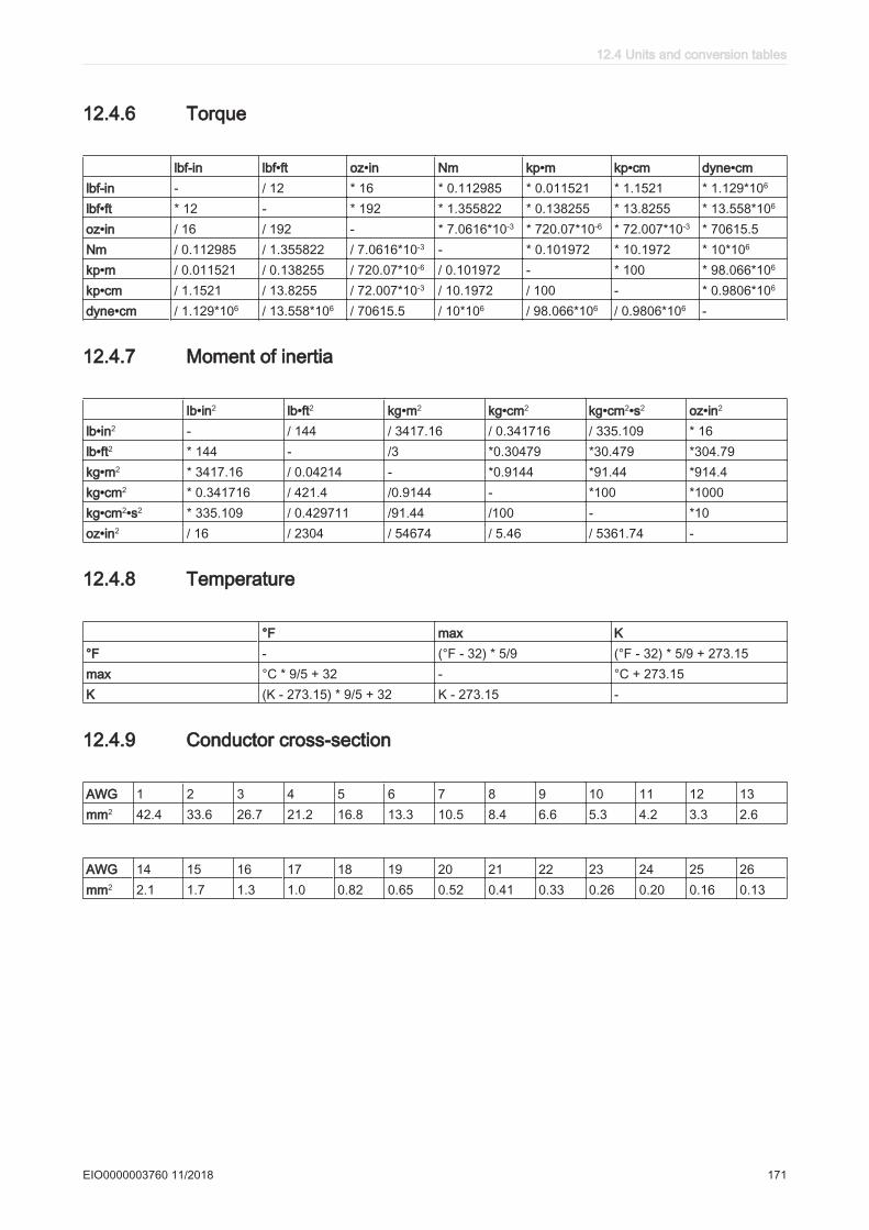
12.4.6 Torque
lbf-in lbf•ft oz•in Nm kp•m kp•cm dyne•cmlbf-in - / 12 * 16 * 0.112985 * 0.011521 * 1.1521 * 1.129*106
lbf•ft * 12 - * 192 * 1.355822 * 0.138255 * 13.8255 * 13.558*106
oz•in / 16 / 192 - * 7.0616*10-3 * 720.07*10-6 * 72.007*10-3 * 70615.5Nm / 0.112985 / 1.355822 / 7.0616*10-3 - * 0.101972 * 10.1972 * 10*106
kp•m / 0.011521 / 0.138255 / 720.07*10-6 / 0.101972 - * 100 * 98.066*106
kp•cm / 1.1521 / 13.8255 / 72.007*10-3 / 10.1972 / 100 - * 0.9806*106
dyne•cm / 1.129*106 / 13.558*106 / 70615.5 / 10*106 / 98.066*106 / 0.9806*106 -
12.4.7 Moment of inertia
lb•in2 lb•ft2 kg•m2 kg•cm2 kg•cm2•s2 oz•in2
lb•in2 - / 144 / 3417.16 / 0.341716 / 335.109 * 16lb•ft2 * 144 - /3 *0.30479 *30.479 *304.79kg•m2 * 3417.16 / 0.04214 - *0.9144 *91.44 *914.4kg•cm2 * 0.341716 / 421.4 /0.9144 - *100 *1000kg•cm2•s2 * 335.109 / 0.429711 /91.44 /100 - *10oz•in2 / 16 / 2304 / 54674 / 5.46 / 5361.74 -
12.4.8 Temperature
°F max K°F - (°F - 32) * 5/9 (°F - 32) * 5/9 + 273.15max °C * 9/5 + 32 - °C + 273.15K (K - 273.15) * 9/5 + 32 K - 273.15 -
12.4.9 Conductor cross-section
AWG 1 2 3 4 5 6 7 8 9 10 11 12 13mm2 42.4 33.6 26.7 21.2 16.8 13.3 10.5 8.4 6.6 5.3 4.2 3.3 2.6
AWG 14 15 16 17 18 19 20 21 22 23 24 25 26mm2 2.1 1.7 1.3 1.0 0.82 0.65 0.52 0.41 0.33 0.26 0.20 0.16 0.13
12.4 Units and conversion tables
EIO0000003760 11/2018 171
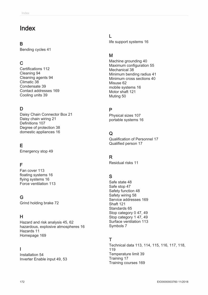
Index
BBending cycles 41
CCertifications 112Cleaning 94Cleaning agents 94Climatic 38Condensate 39Contact addresses 169Cooling units 39
DDaisy Chain Connector Box 21Daisy chain wiring 21Definitions 107Degree of protection 38domestic appliances 16
EEmergency stop 49
FFan cover 113floating systems 16flying systems 16Force ventilation 113
GGrind holding brake 72
HHazard and risk analysis 45, 62hazardous, explosive atmospheres 16Hazards 11Homepage 169
IInstallation 54Inverter Enable input 49, 53
Llife support systems 16
MMachine grounding 40Maximum configuration 55Mechanical 38Minimum bending radius 41Minimum cross sections 40Misuse 62mobile systems 16Motor shaft 121Muting 50
PPhysical sizes 107portable systems 16
QQualification of Personnel 17Qualified person 17
RResidual risks 11
SSafe state 48Safe stop 47Safety function 48Safety wiring 58Service addresses 169Shaft 121Standards 65Stop category 0 47, 49Stop category 1 47, 49Surface ventilation 113Symbols 7
TTechnical data 113, 114, 115, 116, 117, 118,119Temperature limit 39Training 17Training courses 169
Index
172 EIO0000003760 11/2018
Uunderground 16
WWiring 40
Index
EIO0000003760 11/2018 173