JA-62GSM - communicator for GSM - Jablotron
11
The JA-62GSM communicator for GSM The JA-62GSM communicator for GSM 1 / 11 MLD52904 The communicator is a component of the Jablotron JA-63K(R) Profi system. It has been designed for communication via a GSM network. It is installed directly within the control panel housing and it allows the following: − event reporting by SMS (for up to 8 telephone numbers) − event reporting by phone call with voice message warnings (it is possible to record up to 7 messages for various events) − remote control and programming by phone (by calling and using the voice navigation or by SMS instructions) − remote control of the system (or appliances in the house) − data transmission to an Alarm Receiving Centre (ARC) - up to 2 ARCs − remote programming of the ARC by internet application − It is not possible to register the communicator on www.gsmlink.cz The GSM communicator should be installed by a trained technician with a valid certificate issued by an authorised distributor. 1. Installation in the control panel If you purchased the communicator module separately, it should first be installed in the JA-63 Profi control panel as follows: a) The control panel power must be switched off (both mains and battery) b) Fit the communicator inside the control panel housing using screws and connect its cable to the main board. c) Attach the adhesive GSM antenna inside the control panel’s plastic housing (it can be glued in a suitable place) and connect the antenna to the communicator. Warning: never switch the control panel power on if the GSM antenna is not connected to the GSM module as this will cause serious damage!!! Fig. 1 Communicator description: Description: 1. Red LED signalling connection to a GSM network; 2. Green LED signalling normal operating mode; 3. Control panel connector; 4. GSM antenna connector; 5. SIM card 2. Initial powering up of the communicator The communicator is installed in the control panel and its GSM antenna is connected, then: 1. Have a suitable SIM card ready . It should be activated (see if it works in a mobile phone first). The SIM card should have the following services actived: SMS, data (GPRS), voice and CLIP (caller identification). If it requires a PIN code when switching the phone on, then disable the PIN code request upon the first use of the phone); e.g. Nokia: Menu / Settings / Security settings / PIN code request / Off, if the SIM card requires the PIN code enter it, see 6.17. The communicator can work with a prepaid card, but we recommend using a tariff card for more reliable functioning. 2. Insert the SIM card into the communicator (to open the card holder push its frame up a little). 3. Switch on the control panel power (both mains and battery). The communicator’s red LED should be lit = registering to the GSM network; it should go off within a minute = registration successful. 4. If the red LED starts flashing after a while, switch off the control panel power, put the SIM card into a mobile phone and check that it registers to the network in the place where the control panel is installed without any PIN code requests. 5. Close the control panel cover, the alarm system should be in Service mode - if it is not, enter F0 Service code (Factory default setting: 6060) with the alarm system unset (disarmed). 6. Key in 99101 - to set the texts and voice messages of the communicator to the English language. 7. Enter 888 to measure the GSM signal strength (a number in the range from 0 to 9 should be displayed). It should be at least 3 to ensure reliable functioning. If the signal is weak, change the location of the control panel or try a SIM card from another GSM provider (it is not recommended to use either a high-gain or directional GSM antenna – see 6.2 GSM signal strength measuring). 8. If the GSM signal strength is sufficient, test the communicator functions (system control via a mobile phone, etc), see the instructions below. Warning: If installed at a location near a national border where the signal strength fluctuates, roaming to a foreign network is highly likely. We therefore recommend blocking the roaming feature in the SIM card to avoid unnecessarily high communication fees (contact your GSM provider for details). 3. User functions of the communicator The following text describes all communicator features. The installer should show the end user how to operate the functions used in the particular installation. 3.1. Event reporting to the user’s phone The communicator reports events in the Profi system by sending a text SMS and / or calling and transmitting a voice message. Reporting can be set to up to 8 telephone numbers. The most frequently used report variants are preset but they can be customized. Notes: − If used, transmissions to the Alarm Receiving Centre have absolute transmission priority (see 7.4). − Calling is usually used to draw the user’s attention to a detailed report sent in an SMS. If reporting by SMS is enabled, the communicator first sends all SMS messages before it starts dialling the set numbers. − Message playing can be terminated by pressing # on the telephone keypad. The keypad then switches into keypad simulation mode and the messages are not further transmitted to other numbers. 3.2. Temporarily authorizing a phone as a system keypad It is possible to operate the system remotely by temporarily authorizing a phone keypad as follows: a) dial the communicator’s SIM card number b) after 15 seconds of ringing, the system will answer and ask for a code. c) enter a valid control panel access code on the telephone keypad – the code assigned to the telephone (see chapter 6.6), or use a service code for remote access (default 0000) d) once the code has been entered, the system tells you the current status and turns on the Keypad simulation mode e) connection is terminated by hanging up the call, if nothing is entered within a minute, the phone call will end automatically anyway f) the maximum allowed phone call length is 30 minutes Notes: − a land line phone can also be used to control the system remotely in the same way, a condition is that the phone must use tone dialling (DTMF) − do not enter sequences on the phone too fast, each key signal needs a certain time to be sent (it depends on the particular phone and the quality of the GSM connection − Service code for remote access default is set to 0000 3.3. SMS instructions to control the system remotely All incoming SMSes are checked by the communicator and if there are any instructions to the system, they will be performed. Each instruction message must have the following format: Instruction_code (i.e. valid code space instruction) SET 1234 Valid code = any valid code in the system (e.g. 1234), saved in the control panel. The factory-default instruction texts (editable – see TXT command). Command Function Note SET setting (arming) setting or unsetting (the same way as if the used code is entered on the system keypad), If the system is already in the desired mode, it will not change UNSET unsetting (disarming) STATUS reports system status including GSM signal strength, GPRS connection and ARC communication (shown as MS1, MS2 and MS3) MEMORY reports latest events this concerns the last 3 events from the control panel memory PGON turns on PG the PG output has to be programmed for the function PHONE (enter sequnce 238/248) PGOFF turns off PG CREDIT SIM card credit inquiry it has to be initialized before it can be used – see 6.17 DINFO SMS info about device version SMS on assembly info: firmware, hardware and versions + reg. key Tab. 1 SMS commands
-
Upload
khangminh22 -
Category
Documents
-
view
0 -
download
0
Transcript of JA-62GSM - communicator for GSM - Jablotron
The JA-62GSM communicator for GSM
The JA-62GSM communicator for GSM 1 / 11 MLD52904
The communicator is a component of the Jablotron JA-63K(R) Profi system. It has been designed for communication via a GSM network. It is installed directly within the control panel housing and it allows the following: − event reporting by SMS (for up to 8 telephone numbers) − event reporting by phone call with voice message warnings (it is possible
to record up to 7 messages for various events) − remote control and programming by phone (by calling and using the
voice navigation or by SMS instructions) − remote control of the system (or appliances in the house) − data transmission to an Alarm Receiving Centre (ARC) - up to 2 ARCs − remote programming of the ARC by internet application − It is not possible to register the communicator on www.gsmlink.cz
The GSM communicator should be installed by a trained technician with a valid certificate issued by an authorised distributor.
1. Installation in the control panel If you purchased the communicator module separately, it should first be
installed in the JA-63 Profi control panel as follows: a) The control panel power must be switched off (both mains and
battery) b) Fit the communicator inside the control panel housing using screws and
connect its cable to the main board. c) Attach the adhesive GSM antenna inside the control panel’s plastic
housing (it can be glued in a suitable place) and connect the antenna to the communicator. Warning: never switch the control panel power on if the GSM antenna is not connected to the GSM module as this will cause serious damage!!!
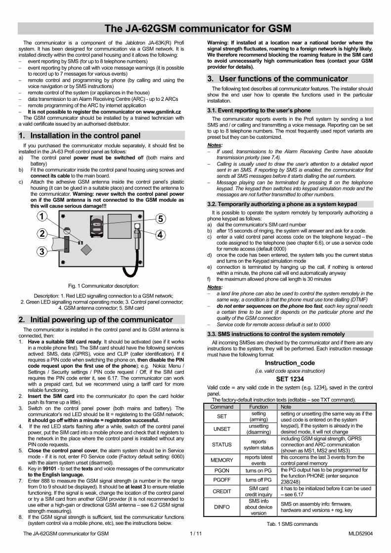
Fig. 1 Communicator description:
Description: 1. Red LED signalling connection to a GSM network; 2. Green LED signalling normal operating mode; 3. Control panel connector;
4. GSM antenna connector; 5. SIM card
2. Initial powering up of the communicator The communicator is installed in the control panel and its GSM antenna is
connected, then: 1. Have a suitable SIM card ready. It should be activated (see if it works
in a mobile phone first). The SIM card should have the following services actived: SMS, data (GPRS), voice and CLIP (caller identification). If it requires a PIN code when switching the phone on, then disable the PIN code request upon the first use of the phone); e.g. Nokia: Menu / Settings / Security settings / PIN code request / Off, if the SIM card requires the PIN code enter it, see 6.17. The communicator can work with a prepaid card, but we recommend using a tariff card for more reliable functioning.
2. Insert the SIM card into the communicator (to open the card holder push its frame up a little).
3. Switch on the control panel power (both mains and battery). The communicator’s red LED should be lit = registering to the GSM network; it should go off within a minute = registration successful.
4. If the red LED starts flashing after a while, switch off the control panel power, put the SIM card into a mobile phone and check that it registers to the network in the place where the control panel is installed without any PIN code requests.
5. Close the control panel cover, the alarm system should be in Service mode - if it is not, enter F0 Service code (Factory default setting: 6060) with the alarm system unset (disarmed).
6. Key in 99101 - to set the texts and voice messages of the communicator to the English language.
7. Enter 888 to measure the GSM signal strength (a number in the range from 0 to 9 should be displayed). It should be at least 3 to ensure reliable functioning. If the signal is weak, change the location of the control panel or try a SIM card from another GSM provider (it is not recommended to use either a high-gain or directional GSM antenna – see 6.2 GSM signal strength measuring).
8. If the GSM signal strength is sufficient, test the communicator functions (system control via a mobile phone, etc), see the instructions below.
Warning: If installed at a location near a national border where the signal strength fluctuates, roaming to a foreign network is highly likely. We therefore recommend blocking the roaming feature in the SIM card to avoid unnecessarily high communication fees (contact your GSM provider for details).
3. User functions of the communicator The following text describes all communicator features. The installer should
show the end user how to operate the functions used in the particular installation.
3.1. Event reporting to the user’s phone The communicator reports events in the Profi system by sending a text
SMS and / or calling and transmitting a voice message. Reporting can be set to up to 8 telephone numbers. The most frequently used report variants are preset but they can be customized. Notes: − If used, transmissions to the Alarm Receiving Centre have absolute
transmission priority (see 7.4). − Calling is usually used to draw the user’s attention to a detailed report
sent in an SMS. If reporting by SMS is enabled, the communicator first sends all SMS messages before it starts dialling the set numbers.
− Message playing can be terminated by pressing # on the telephone keypad. The keypad then switches into keypad simulation mode and the messages are not further transmitted to other numbers.
3.2. Temporarily authorizing a phone as a system keypad It is possible to operate the system remotely by temporarily authorizing a
phone keypad as follows: a) dial the communicator’s SIM card number b) after 15 seconds of ringing, the system will answer and ask for a code. c) enter a valid control panel access code on the telephone keypad – the
code assigned to the telephone (see chapter 6.6), or use a service code for remote access (default 0000)
d) once the code has been entered, the system tells you the current status and turns on the Keypad simulation mode
e) connection is terminated by hanging up the call, if nothing is entered within a minute, the phone call will end automatically anyway
f) the maximum allowed phone call length is 30 minutes Notes: − a land line phone can also be used to control the system remotely in the
same way, a condition is that the phone must use tone dialling (DTMF) − do not enter sequences on the phone too fast, each key signal needs
a certain time to be sent (it depends on the particular phone and the quality of the GSM connection
− Service code for remote access default is set to 0000
3.3. SMS instructions to control the system remotely All incoming SMSes are checked by the communicator and if there are any
instructions to the system, they will be performed. Each instruction message must have the following format:
Instruction_code (i.e. valid code space instruction)
SET 1234 Valid code = any valid code in the system (e.g. 1234), saved in the control panel.
The factory-default instruction texts (editable – see TXT command). Command Function Note
SET setting (arming)
setting or unsetting (the same way as if the used code is entered on the system keypad), If the system is already in the desired mode, it will not change UNSET unsetting
(disarming)
STATUS reports system status
including GSM signal strength, GPRS connection and ARC communication (shown as MS1, MS2 and MS3)
MEMORY reports latest events
this concerns the last 3 events from the control panel memory
PGON turns on PG the PG output has to be programmed for the function PHONE (enter sequnce 238/248) PGOFF turns off PG
CREDIT SIM card credit inquiry
it has to be initialized before it can be used – see 6.17
DINFO SMS info
about device version
SMS on assembly info: firmware, hardware and versions + reg. key
Tab. 1 SMS commands
The JA-62GSM communicator for GSM
The JA-62GSM communicator for GSM 2 / 11 MLD52904
Example by sending: “SET code” (SET space valid code) the system will set (if it is already set it will not change its status) Notes: − the access code is always required for the commands SET and UNSET − the system will confirm performance of the SMS instruction by an
SMS reply, if this function is enabled − the SMS instruction texts are not case-sensitive and only ASCII
characters are allowed − the SMS instruction texts can contain multiple instructions separated with
a comma − if you are sending an instruction and you are not sure whether any other
text will be automatically added to the SMS on the way (for example, when using an SMS internet gate) type the instruction as: %instruction code %%
− the valid code can also be entered automatically, see 6.6.
4. User communicator programming User setting of the communicator is performed by entering sequences from
the Profi system keypad. Selected parameters can also be controlled or set by SMS instructions.
Setting on the system keypad is possible only in the case that the control panel is in maintenance mode (if it is not, enter F0 master code when system is unset – Factory default setting 1234). Modification of values set in the communicator is performed by entering programmable sequences (see Tab. 7).
Press the # button to exit Maintenance mode or to cancel code entering when you enter a wrong number.
If setting of telephone numbers in Maintenance mode is enabled in the control panel settings (sequence 251 of the Profi control panel), then it is possible to set the following communicator parameters in Maintenance mode by keying in the below mentioned sequences beginning with 8: − Set telephone numbers M1 to M8 − Select events which should be reported by an SMS message and calling − Measure GSM signal strength − Limit the number of sent SMSes − Record voice messages
4.1. Setting of telephone numbers for reporting The communicator reports events in the Profi system by sending a text
SMS and / or calling and transmitting a voice message. Reporting can be programmed for to up to 8 telephone numbers.
The most frequently desired reports are already assigned to the telephone number memories by factory-default, so you only need to program tel. numbers to the particular memories:
Overview of reports assigned to tel. numbers (this can be modified see 6.4)
M Reports 1 Alarms by SMS and phone call, faults by SMS
2 Alarms by SMS and phone call 3 Alarms by SMS and phone call 4 Alarms by SMS 5 Alarms by SMS and phone call 6 Alarms by SMS and phone call 7 Alarms by SMS 8 Technical faults by SMS (for a service technician)
tab. 2 Reports assigned to telephone number memories M1to M8
To program phone numbers to the M memories, enter the following sequence while in Maintenance / Service mode:
81 M xxx...x F0 where: M is memory number 1 to 8 xxx...x is a telephone number (max. 20 digits)
To erase a number from memory M enter: 81 M F0
Example: entering 81 5 710 123 456 F0 will store the number 710123456 in memory M5 (alarms will be reported by SMSes + phone calls with a voice message). Notes: − In a split system, when you change a detector’s section, adjust the
reaction of the detector etc, you have to enter enrollment mode for 1 s and leave it before you leave service mode. This way the changes are saved in the communicator.
− Entering F9 before the first digit will insert a “+” for the international formatting of phone numbers.
− SMS report text consists of the installation name, event type, name of the event source, date and time. For example: “Report from your alarm: setting 47: device Time 11:27 01.08 ”.
− If other events or texts should be reported to a particular number, change the communicator settings (see 6.4, 6.7 and tab. 5 the list of events which can be reported to your phone and their factory default settings).
5. Voice menu for control via a telephone The communicator is equipped with voice navigation for remote control of
the basic system functions (remote access via a telephone must be enabled). The menu has factory default voice reports in multiple languages – the desired languages is selected by entering the 991 xx sequence (see 6.1). The voice navigation is as follows:
− After 15 seconds of ringing the communicator will answer the call and
require entering the valid code. − After entering a valid code for remote access the system reports its
current status (always 1x) and opens the keypad simulation mode and allows entering the controlling / programming sequences.
− When you enter a valid access code, the system is set / unset and confirms the system status. For an incorrect entry the system generates a series of beeping sounds.
− When you enter programming sequences, a correct entry is confirmed by one beep, an incorrect entry is rejected and indicated by a series of beeps.
− When the system is in the service / maintenance mode, code verification is performed and if the code is valid, you will hear: “Service mode, keypad simulation“.
− By entering the sequence 892, you enter the voice message recording mode.
6. Installation programming The most convenient and complete programming is best done by a PC
running Comlink software and higher connected locally at the installation or remotely via the Internet.
The communicator can also be programmed by keying in sequences from the system keypad or via SMS programming instructions.
Programming by the system keypad is possible only if the control panel is in Service mode, if it is not, key in *0 Service code (factory default setting: 6060) with the alarm system unset (disarmed) The setting is performed by keying in programming sequences, (see Tab. 7 communicator programming sequences). Press the # button to exit service mode or to cancel code entering when you key in a wrong number.
6.1. Communicator language setting The language of the texts and voice menu used by the communicator can
be set by the instruction:
991 xx where: xx is a number defining the language – see the following
list:
01 EN English 08 IT Italian
02 CZ Czech 09 PT Portuguese
04 NL Dutch 10 FI Finnish
05 DE German 12 SV Swedish
06 PL Polish 14 HU Hungarian
07 DA Danish 15 RU Russian
Example: Keying in 99101 will set English. Notes: − entering 00 will reset the texts and voice messages to the factory default
values in the currently set language. − set the language before editing the text in the system (a change of
language will change the text to the factory default setting) − The set language will not change when a reset is performed Factory default setting: 99101 = English
6.2. GSM signal strength measuring A good quality GSM signal is necessary for the reliable functioning of the
communicator. Enter the 888 to start GSM signal strength measuring. The keypad then displays the signal strength in the range 0 to 9 and the measuring is repeated every second – new data is indicated by a beep. This
The JA-62GSM communicator for GSM
The JA-62GSM communicator for GSM 3 / 11 MLD52904
mode allows users to find a suitable location for the communicator antenna. Press the # key to exit the measuring.
The signal should be at least 3. In places with a weak signal we recommend trying another GSM provider’s SIM card.
Warning: it is not recommended to use a directional GSM antenna
with the communicator (the module would thus communicate with a single cellular base station only). The communicator normally communicates with at least three cellular base stations (the connection is thus more stable). It is not even recommended to use a high-gain antenna – if the signal is transmitted over a distance exceeding 30km, it does not ensure standard GSM function due to time lapses in the transmission.
6.3. Setting of telephone numbers and events The factory-default list of reported events and their assignment to
telephone numbers M1 to M8 (tab. 1) can be modified. The complete list of reportable events is shown in Tab 6.
It is possible to select whether the event should be reported by an SMS or by a phone call, or in both ways.
Each event has pre-programmed factory-default SMS text (it can be modified – see 6.7).
6.4. SMS report setting To set events to being reported by SMS, enter:
82 M uu x where: M is phone number memory 1 to 8
uu event code 01 to 40 (see tab. 5) x 0 = no SMS report, 1 = SMS report
Example: If 82 8 03 1 is programmed and a fire alarm is triggered (event 03 in the table), it will be reported by SMS to the phone number stored in memory M8.
6.5. Voice message setting To set events to being reported by voice messages, enter:
83 M uu x where: M is phone number memory 1 to 8 uu event code 01 to 40 (see tab. 5) x 0 = no phone call, 1 = call
Example: if 83 1 03 1 is programmed and a fire alarm is triggered (event 03 in the table), the communicator will phone the first number stored in the memory and it will keep repeating: Your system is reporting a fire alarm. Notes: − Calling is usually used to draw the user’s attention to a detailed report
sent in an SMS. If reporting by SMS is enabled, the communicator first sends all SMS messages before it starts dialling.
− If used, transmissions to the Alarm Receiving Centre have absolute transmission priority (see 7.4).
− The message playing can be terminated by pressing # on the telephone keypad. The keypad then switches into keypad simulation mode and the messages are not further transmitted to other numbers.
6.6. Access code assignment to programmed telephone numbers
This parameter serves for identification of the user during a voice call. To do so, enter:
84 M xxxx where: M is phone number memory 0 to 8 xxxx Valid code UC / MC / SC
Notes: − Entered codes don t́ have to match the user code defined in the control
panel − Position 0 = service code for remote access,
Factory default setting: No code, 0000 – service code for remote acc
6.7. SMS and instruction text editing The communicator contains various factory default text strings which are
used to create SMS reports and also SMS instruction texts. The language of the text can be set – see 6.1. These text strings can be edited locally by ComLink software or remotely by sending the following SMS instruction:
code_TXT_n,text,n,text,......n,text where: Code is a valid service code for remote access (default 0000)
_ space TXT is an instruction to edit texts N text number (0 to 611, see tab. 6) , comma (or full stop) text the new text (max. 30 characters) which will replace the
former text. It is invalid to enter a comma or a full stop inside the text string, but a space is valid within the text string (spaces outside the text string are ignored).
Notes: − A single SMS TXT instruction can modify multiple texts (limited only by
the maximum length of a single SMS) − the communicator is not case-sensitive and it is recommended to use
only English ASCII characters (some networks do not support non-English national characters)
− the communicator creates SMS reports with 5 parts (installation name, event description, source number (code 01 to 14 or device 01 to 16), source name and time. The maximum possible length of an ASCII SMS is 160 characters (only 70 characters for national characters) If this length is exceeded, the report is sent as multiple SMSes.
− The communicator automatically fills in spaces, delimiters and time. Examples:
if the factory default service code is 0000 then the SMS instruction: 0000 TXT 33,key fob Bob,34,Key fob Jane changes the description
(name) of the key fobs enrolled to addresses 33 and 34. 0000 TXT 609,heating on,610,heating off edits the text of the two
instructions used to command the heating to be switched on and off by the PGX/Y output (the PG output must be programmed to have an PHONE function).
6.8. Voice message recording Recording a message is done by phone with the system in service mode.
Dial the system SIM card number. When the system answers, enter your access code, then press 9 (keypad simulation) and enter *0 service code or *0 Master code (unless you are in service / maintenance mode) and then sequence 892. The communicator will report that you are in voice message recording mode. You will hear regular beeping from the receiver; the communicator is waiting for a key to be pressed:
0 – replay all messages 1 – Record message no. 1 (intruder alarm) 2 – Record message no. 2 (fire alarm) 3 – Record message no. 3 (tamper alarm) 4 – Record message no.4 (panic alarm) 5 – Record message no. 5 (fault alarm) 6 – Record message no.6 (alarm report) – installation identification 7 – Record message no.7 (other event) 8 – delete all user recordings = reset to factory default recordings When you press a key from 1 to 7, you will hear another beep and you can
start speaking. The end of recording is signalled with a beep and the message is replayed. The communicator then returns to the main menu (regular beeping) and it is possible to record further messages. The length of message no.6 should not exceed 5 s, other messages should be 3 s long. Press # to stop the voice recording menu and return to service / maintenance mode.
Message no.7 is played upon each event which you set for a voice message and which is not an alarm. The factory default message is: Other event. i.e. is usually used to inform about sending an SMS. However, it can also be used specifically for a particular event (e.g. it may be used to report PG output control, etc. – it depends on the 83 M uu x settings see 6.5) Notes: − Listening to the message can be terminated by pressing the * key. − To exit the message recording mode, just end the call. − The messages are recorded in a memory which is not erased when the
system power supply is shut down. − For events like setting / unsetting, the voice messages “Armed system”
, “Disarmed system” or “Partially armed” are reported; these messages cannot be changed.
6.9. Quick enabling / disabling of reporting to phones Event reports to your phone can be enabled / disabled as follows:
901 0 all SMS and call reports disabled 901 1 all SMS and call reports enabled 901 2 all reports enabled except reports of setting and unsetting by
users 1 to 4 (i.e. their codes and key fobs). Master code control is not reported either. This allows setting and unsetting done by report recipients (owners, bosses, etc.) not to be reported.
Factory default setting: 9011 all reports enabled
The JA-62GSM communicator for GSM
The JA-62GSM communicator for GSM 4 / 11 MLD52904
6.10. Forwarding of incoming SMS messages The communicator enables the automatic forwarding of incoming SMS
messages which contain no valid instructions to the system:
801 0 messages are not forwarded, but the communicator saves the last 10 received messages to the SIM card
801 1 messages are forwarded to the first programmed tel. number in memories M1 to M8 (e.g. if numbers are only programmed in M5 and M6, then messages will be forwarded to M5). The tel. number from which the SMS was received will be shown at the beginning of the forwarded text.
Factory default setting: messages are forwarded Notes: − In order to protect the user against runaway (donation SMSes etc.), the
forwarding is limited to the first 50 SMS messages. The counter can be erased automatically each midnight, by processing any SMS instruction or by exiting Service / Maintenance mode.
6.11. SMS instruction confirmation If the communicator receives a valid SMS instruction, a confirmation SMS
will be sent a s a reply. This confirmation can be disabled as follows:
904 0 disabled 904 1 enabled Factory default setting: enabled
6.12. Reaction to incoming calls This sequence can be used to set the communicator’s reaction to incoming
phone calls:
905 0 the communicator ignores incoming calls 905 1 the communicator will answer after ringing for 15s Factory default setting: answer after ringing for 15s
6.13. GSM signal dropout indication This feature enables the monitoring of GSM network signal availability. If
enabled and if there is a GSM signal dropout longer than 15 minutes, the control panel announces “External communication fault”.
906 0 signal availability monitoring disabled 906 1 signal availability monitoring enabled Factory default setting: disabled
6.14. Phone receiver loudness To set the loudness of the receiver of the phone which is used to call the
communicator key in:
909 x where x is a number from 1 to 9 (max.) Factory default setting: 9 (max.)
6.15. Number to be called to maintain SIM card validity If a prepaid SIM card is used and a lack of outgoing phone calls for a
certain period cancels the validity of the SIM card, then this function offers the following: if there have been no outgoing phone calls within the last 90 days, then the communicator automatically calls the number programmed by this sequence. The communicator waits until the call is answered and then automatically hangs up after 10 sec.
910 xx...x F0 where: xx...x is the telephone number Notes: − To erase this number enter 910 F0 − It is recommended to call cheap public services (e.g. weather forecasts
etc.) but not toll-free numbers. Factory default setting: Erased
6.16. Restriction of the number of sent SMSes The parameter limits the amount of sent SMSes to 100 per 24 hours. 50
may be alarm SMSes and 50 may be for other events. This is to prevent enormously high telephone fees. 803 0 restriction disabled 803 1 restriction enabled Factory default setting: enabled There is also a limiter to 500 SMSes per 24 hours – it can not be disabled.
6.17. Prepaid SIM card credit interrogation The communicator is capable of checking the credit balance of its SIM card
upon request (by the “CREDIT” SMS instruction) or this activity can be requested automatically (with a preset cycle) and if it finds out that the remaining credit is lower than the preset value, an information SMS is sent. The function is set by sending the following SMS instruction:
code_CREDIT_uu..u_xx_yyy_zz where: Code is a valid access or service code for remote access
(e.g. 0000), a change of parameters is possible only with a service code (other codes allow “0000 CREDIT“ SMS credit interrogation)
_ space uu..u instruction recognized by the GSM network to check
the balance xx automatic checking period in days, yyy minimum acceptable credit balance zz the textual position in which the number showing the
balance starts in the reply message from the GSM provider.
Notes: − If the reported credit balance is lower than the set limit (yyy), text no. 545
will be sent to phone numbers M1 and M8 which have the “Low credit balance” (event no. 28) event sending enabled
− If only uu..u follows the CREDIT instruction (no xx yyy zz) then periodic balance checking will not be performed, but the balance will be checked immediately
− If there is further data following the CREDIT instruction, the communicator will memorize them and automatically put them in the message when the CREDIT instruction is used again (i.e. the Credit instruction must contain at least the uu..u part upon the first sending) and the user just needs to send: code CREDIT
Example: sending the SMS instruction “code CREDIT ∗101# 7 50 1” causes the credit balance to be checked every 7th day after the SMS has been sent and if the balance (starting with the first character in the message from the GSM provider) is lower than 50 currency units it will be reported. Warning: the use of prepaid SIM cards in the communicator can negatively influence the reliability of the device. Some GSM providers block cards not only when there is no credit but also when they are not topped up frequently enough. This means that even if there is enough credit balance on the card, the communication can still be blocked. We therefore strongly advise the use of tariff SIM cards !!!
6.18. Remote programming by SMS instructions The communicator enables remote programming of the system by the
following SMS instruction:
code_PRG_seq_seq, another instruction where: Code valid access or service system code (e.g. 0000) _ space
seq programming sequence usually set via the keypad Notes: − Only characters which can be keyed in from the system keypad
(0 to 9, * and #) can be used in the sequences. − When a valid instruction is received, the communicator performs the
sequence by simulating pressing the keys on the keypad. A comma in the SMS is taken as a pause in the sequence entering.
− If you want to remotely reprogram the system it must first be unset and then switched to programming mode.
− The number of sequences in one SMS is limited by the maximum size of an SMS in the GSM network.
Example: by sending SMS 0000_PRG_F06060_201_#, SET 4321 the exit delay will be set to 10s and set system by the code 4321.
6.19. Registration code The code is stated on the label on the communicator panel but it can also
be sent to the mobile phone by SMS (see table 1, 3.3) DINFO command. To request a registration code, enter:
911 xx...x F0 where: xx...x is the number of the phone where the code should be
sent Notes: − The time needed for delivery of the code depends on the current GSM
network speed − Each communicator has a unique registration code in the following
format: xxxxx-xxxxx-xxxx
The JA-62GSM communicator for GSM
The JA-62GSM communicator for GSM 5 / 11 MLD52904
6.20. Restarting GSM communication After 893 has been entered, the communicator disconnects from the GSM
network and then re-registers itself. This re-registration does not change any settings in the communicator. It should be used after GSM network faults or data collisions and in some networks it also has to be used after a blocked SIM card has been unblocked by the GSM provider. It is also possible (if the SIM card can still receive) to trigger GSM network re-registration by sending the SMS instruction.
6.21. Communicator reset Entering 998080 returns the communicator to its factory default settings.
Telephone numbers will be erased together with all untransmitted reports but the text settings in the communicator will not be changed.
6.22. SIM card’s PIN code It is recommended to use a SIM card with disabled PIN protection in the
communicator. If you still want to use a card with PIN protection, enter the PIN by entering the following sequence (it must be entered after the control panel has been powered up):
920 PIN F0 Example: If the SIM card PIN code is 1234, enter 920 1234 F0 Notes: − If the communicator does not register to the GSM network within 1
minute of the PIN being entered (this problem is shown by the red LED flashing), then you either entered a wrong PIN or the GSM signal is too weak. In such a case:
− enter 920 F0 while in control panel service mode (erases the PIN entered in the communicator)
− disconnect the control panel power (mains and battery) − take out the SIM card, insert it into a mobile phone and check whether
the PIN is correct. Check whether the signal strength at the location of the control panel is sufficient
− if you know the right PIN code and the GSM signal is strong enough, put the SIM card back into the communicator, turn on the control panel power and then enter the correct PIN code (920 PIN F0) and wait until the communicator registers to the GSM network (its red LED should turn off within a minute)
− The communicator memorizes the set PIN and it will use it automatically whenever it registers to the GSM network again.
− If you are replacing the SIM card in the communicator with another one and the former one used a PIN code, first switch the control panel to service mode and enter 920 F0 to erase the former PIN code. The SIM card can then be changed.
Warning: The PIN code cannot be changed if the ARC settings are locked Factory default setting: The PIN code is erased
6.23. GPRS parameter setting GPRS data communication (wireless Internet via a GSM network) is used
for communication between the system and the ARC. To use GPRS data communication it must first be enabled (activated) in the SIM card (contact your GSM provider for details). Depending on the SIM card used, the GPRS parameters (APN and possibly the login and password if the SIM card requires them) must be programmed by sending the following SMS instruction to the communicator.
code_GPRS_x..x_y..y_z..z where: Code valid service system code (e.g. 0000)
_ space x..x SIM card APN y..y username (do not enter if not required) z..z password (do not enter if not required)
Examples:
For a T-mobile Czechia card enter: code GPRS internet.t-mobile.cz Warning: The GPRS parameters cannot be changed if the ARC settings
are locked Factory default setting: APN = internet
7. Communication to the ARC
7.1. ARC phone numbers Events can be reported to up to 2 ARCs (which can be independent or
ARC2 can work as ARC1’s backup). Each ARC can have its main and backup phone numbers (or IP addresses) programmed with:
Main: 01 p xx....xF0
Backup: 02 p xx....xF0 where: p 1=ARC1, 2=ARC2 xxx...x tel. number (max.20 digits) or IP address and port –
entry format Example: 01 2 F8 192 168 001 123 08080 F0
where: F8 (auto-converts to #) signifies an IP address which must have
12 digits and must be followed by the 5 digits of the port number (no separators).
To erase a tel. number / IP address enter 01pF0 or 02pF0. If numbers / IP addresses are erased there will be no reporting to that particular ARC. Notes: − the communicator first tries to send data to the main number / address, if
it is not successful it tries the backup number / address. Factory default setting: all tel. Numbers / IP addresses erased
7.2. Installation (alarm system) ID for ARC use The installation’s ID number which is sent to an ARC with every report can
be programmed with:
03 p zz..z F0 where: p 1=ARC1, 2=ARC2 zz..z installation ID number, max. 8 characters (0 to 9 and
F1=A to F6=F) Factory default setting: for all ARCs = 0000
7.3. Selecting the ARC communication protocol To select the required communication protocol enter:
04 p x where: p 1 = ARC1, 2 = ARC2 x 0..2 = ARC type 0 = Contact ID, 1 = Jablotron GPRS, 2 = Jablotron
SMS Notes: − Jablotron IP is the fastest of the above-mentioned protocols and it is the
only one which allows very frequent checking of communication reliability with the ARC (e.g. every 5 minutes).
− Contact ID protocol can be directed to ARCs linked by standard telephone lines (if they support Contact ID).
− If your ARC does not allow Jablotron SMS or Jablotron GPRS protocols, please contact a Jablotron distributor for details on how to upgrade your ARC
Factory default setting: ARC1 – Jablotron GPRS, ARC2 – Jablotron SMS
7.4. Selection of events to report to ARCs This sequence allows you to select which events are reported to the ARC:
05 p uu x where: p 1 = ARC1, 2 = ARC2 uu Event numer 00 to 93 x 0 = no report, 1 = report
Factory default setting: See the table below
Event CID CODE Factory default settings
uu CL
Alarm after powering up the system 1140 reported 00 1
Instant zone alarm 1130/3130 reported 01 2 Delayed zone alarm 1134/3134 reported 02 3 Fire zone alarm 1110/3110 reported 03 4 Panic alarm 1120/3120 reported 04 5 Tampering alarm 1144/3144 reported 05 6 Wrong codes entered 1461/3461 reported 06 7 Fault 1330/3330 reported 07 8 Setting 3401 reported 08 9 Unsetting 1401 reported 09 10 Completely set without code 3408 reported 12 11
The JA-62GSM communicator for GSM
The JA-62GSM communicator for GSM 6 / 11 MLD52904
Event CID CODE Factory default settings
uu CL
Partial setting 3402 reported 13 12 Lost communication w. device 1350/3350 reported 14 13 Power fault of control panel 1301 reported 15 14 Control panel power OK 3301 reported 16 15 Low battery in the device 1384/3384 reported 17 16 Communicator fault 1330 not reported 18 17 Communicator is working 3330 not reported 19 18 Back up battery fault 1302 reported 20 19 Back up battery OK 3302 reported 21 20 Receiver jamming detected 1355 reported 24 21 Setting (Two section system) 3402 reported 30 22 Unsetting (Two section system) 1402 reported 31 23 Setting zone A 3402 reported 30 24 Setting zone B 3402 reported 31 25 Unsetting zone A 1402 reported 28 26 Unsetting zone B 1402 reported 29 27 Low SIM card credit * not reported 50 28 Control panel powering up 3301 not reported 64 29 Service/maintenance mode entered 1306 reported 65 30
Service/maintenance mode exit 3306 reported 66 31 Alarm end * not reported 67 32 Alarm cancelled by user 1406 reported 78 33 All tampers contacts OK 3137 reported 80 34 No fault in system 3300 not reported 81 35 All device power OK * not reported 82 36 Master code changed * not reported 86 37 AC fault longer then 30 minutes 1301 reported 89 38 PG output ON 1661 not reported 92 39 PG output OFF 3661 not reported 93 40
tab. 3 ARC event table
Source Name 701 Control panel 731 Communicator 741 Keypad 001 - 016 Wired inputs 017 – 032 Wireless detectors 033 - 040 Remote controls 041 Wireless siren 042 Sub panel 500 Master code 599 Service code 501 - 514 Code 1 – code 14
tab. 4 Source number table
The report to the ARC consists of: − Premises number, event code, section, source number. − Section: 01 is set for all reports − Split system for setting and unsetting: 02 = A, 03 = B − Unsplit system for Partial setting (Home bypassed) : 03 − Unsplit system for Set always (Normal arming): 02 Notes: − Events to ARC are reported with the identification of the section
7.5. ARC communication checking – periodic or fixed This sequence is used to define whether the regular transmission takes
place at a given time according to 07 p hhmm, or periodically according to 07 p hhmm settings.
06 p x where: p 1=ARC1, 2=ARC2 x 0 = with a period according to 07 p hhmm
1 = at the set time according to 07 p hhmm Factory default setting: With a period after the last report
7.6. ARC communication checking period This sequence programs how often the communication check is
performed:
07 p hhmm where: p 1 = ARC1, 2 = ARC2 hh hours mm minutes Notes: − Checking reports are not sent in service mode. − Jablotron GPRS protocol allows very frequent checking of ARC
communication (even every 5 minutes in practice). − When 00:00 is set, a communication check is not performed. Factory default setting: 23:59 (hours:mins)
7.7. Enable ARC reporting (ARC2 backs up ARC1) This sequence allows reporting to ARCs to be switched on/off and also
enables ARC2 to backup ARC1:
08 p x where: p 1 = ARC1, 2 = ARC2 x 0 = off, 1 = on, 2 = ARC2 backs up ARC1 (2 can only
be entered for ARC2) Note: if ARC2 backs up ARC1 then it will only receive reports if it is not possible to deliver them to ARC1. Each event is first reported to ARC1 (both main and backup number / URL address) and if the transmission fails, the event is reported to ARC2. A report containing “Communication fault to ARC1” is then sent to ARC2 together with the first report to ARC2 Factory default setting: Transmissions to both ARCs are off
7.8. Recording ARC reporting in the control panel memory This sequence enables the recording of every report successfully
communicated to ARCs in the control panel’s internal memory:
001 0 disabled 001 1 enabled
Note: it is recommended not to record reports sent to ARCs via reliable protocols (IP CID and SMS CID) but to enable the indication of ARC communication faults (see 7.9). This saves a significant amount of control panel memory. The system initially assumes that every report is successfully delivered to ARCs, but if a report is not successfully delivered within 110 seconds of transmission, then a communication fault will be indicated and recorded. Factory default setting: disabled
7.9. Indicate an unsuccessful ARC communication fault Enables the indication and recording of a communication fault if a report is
not successfully delivered to an ARC within 110 seconds of its transmission:
002 0 communication faults not indicated 002 1 communication faults indicated Notes: − The communicator continues trying to send information to an ARC even
after a communication fault has been indicated (after the data has been delivered, communication fault indication stops)
− for communication-checking reports the delivery time limit (confirmation from the ARC) is 300 minutes. But if any other report is sent to the ARC it must be confirmed within 110 seconds (otherwise a communication fault will be indicated).
Factory default setting: communication faults not indicated
7.10. Locking the ARC settings All settings which affect reporting to ARCs can be locked by a digital code.
To do so, enter:
091 xx..xF0 where: xx..x is your code (4 to 8 digits) Notes: − Exiting service mode after the locking code has been entered will lock all
the settings affecting ARC communication (see the sequence list in section 12).
− If ARC programming is locked, then it can be temporally enabled in service mode by entering 092 xx..x F0 where xx..x is the locking code. It will then relock on exiting service mode.
The JA-62GSM communicator for GSM
The JA-62GSM communicator for GSM 7 / 11 MLD52904
− The ARC settings can be permanently unlocked by entering 091 F0 (the code can be erased only if ARC setting is unlocked)
Factory default setting: ARC settings unlocked
7.11. Repeated ARC communication The communicator tries to send the report to the main telephone number. If
this fails, it tries the backup number and in the case of failure, the communicator repeats the attempt with a delay which is set by the following sequence:
0001 p mmss where: p 1 = ARC1, 2 = ARC2 mmss time in minutes, seconds Notes: − Comlink SW allows you to set the time scale with 5 minute steps − When you enter a delay of 31 min for example, the communicator
rounds it to 30 min. − Seconds entry is required, but it will always be rounded to 00 regardless
of what you enter Factory default setting: without delay (0000)
7.12. Number of repeated attempts Defines how many times in a row the communicator will try to transmit
information to the ARC after an unsuccessful attempt. It is possible to set up to 9 repeated attempts. They are set by the following sequence:
0002 p n where: p 1=ARC1, 2=ARC2 n 1 to 9 attempts Note: Comlink SW allows you to enter data from 0 to 15, via the keypad you can only enter the range 0 – 9. Factory default setting: 2 attempts
8. Further guidance on the communicator
8.1. How the communicator sends reports 1. If there is a need to report an event (e.g. an alarm) then the
communicator sends data to ARC1 (the communicator tries the main phone number / IP address / URL. If unsuccessful then it tries the backup number / IP address / URL and if still unsuccessful, it repeats the action).
2. Then it sends data to ARC2 in the same way if programmed as an independent ARC. If ARC2 is programmed as the backup to ARC,1 then the data will only be sent to it if transfer to ARC1 has been unsuccessful.
3. Then the unit sends SMS reports (1st tel. number, 2nd tel. Number,..) 4. Then the unit transmits a voice message to each telephone number with
this setting. Each programmed number is called only once regardless of whether the call has been answered or not. Pressing the # key cancels calling other numbers and the system enters keypad simulation mode in which it is possible to fully control the system.
If all previous attempts to send data to ARCs have been unsuccessful, the next attempts occur after the programmed repeat period (see 7.6).
If an alarm is cancelled by a user while it is being reported, any
unsent SMSes and unperformed call reports are cancelled, but the ARC still gets a complete set of reports about events in the system.
8.2. The communicator’s LED The red LED on the communicator board indicates as follows: − It is lit for a period during registration to a GSM network − when sending an SMS message, the LED is lit for 1 second − the LED flashes rapidly during the detection of an incoming call − It is lit permanently during remote access from a telephone − A permanently lit LED could indicate that the communicator is not
registered to a GSM network The green LED on the communicator board indicates as follows: − Flashes for 2 seconds when the communicator is connected to the
control panel
8.3. Notes on entering service mode If the system is switched to service mode:
1. The communicator completes the current transmission to the ARC. 2. The current phone call reporting is terminated. 3. Unfinished SMSes and call reports are erased (they are not transmitted
after the service mode has been exited).
4. Unsent ARC reports are only erased if ARC tel. numbers / IP addresses / URLs or the ARC communication format or the installation ID are changed.
5. Fault restoration reports are sent to the ARC even in service mode. 6. Changes to communicator settings do not take effect until service mode
has been exited.
9. Technical specifications Power 12V DC (from the control panel) Stand-by consumption (mean value) about 35 mA (depends on the GSM signal strength) GSM band QUAD-BAND, 850/900/1800/1900MHz Complies in configuration CIE Profi system with EN 50131-1, EN 50136-2-1 as follows: ATS 4, ATS 5 if CID protocol is used and the repeating period is set to zero (Sequence 06p0) Operating environment – indoor general (-10 °C to 40 °C) Class II Security Grade 2 Safety EN 60950-1 EMC ETSI EN 301489-1, ETSI EN 301489-7, EN 55022, EN 50130-4 Radio transmissions ETSI EN 301419-1 and EN 301511 CLIP protocol (caller ID + SMS) ETSI EN 300 089 Can be operated according to GSM Regulations
JABLOTRON ALARMS a.s. hereby declares that the JA-62GSM is in a compliance with the relevant Union harmonisation legislation: Directives No: 2014/53/EU, 2014/35/EU, 2014/30/EU, 2011/65/EU. The original of the conformity assessment can be found at www.jablotron.com - Section Downloads.
Note: Although this product does not contain any harmful
materials we suggest you return the product to the dealer or directly to the producer after use.
The JA-62GSM communicator for GSM 8 / 11 MLD52904
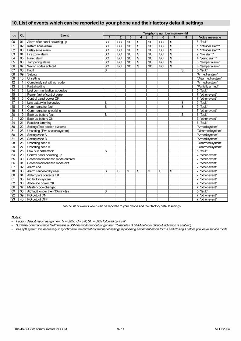
10. List of events which can be reported to your phone and their factory default settings
uu CL Event Telephone number memory - M 1 2 3 4 5 6 7 8 Voice message
00 01 Alarm after panel powering up SC SC SC S SC SC S 5: “fault“ 01 02 Instant zone alarm SC SC SC S SC SC S 1: “intruder alarm“ 02 03 Delay zone alarm SC SC SC S SC SC S 1: “intruder alarm“ 03 04 Fire zone alarm SC SC SC S SC SC S 2: “fire alarm“ 04 05 Panic alarm SC SC SC S SC SC S 4: “panic alarm“ 05 06 Tampering alarm SC SC SC S SC SC S 3: “tamper alarm” 06 07 Wrong codes entered SC SC SC S SC SC S 3: “tamper alarm” 07 08 Fault S S 5: “fault“ 08 09 Setting ”Armed system“ 09 10 Unsetting ”Disarmed system“ 12 11 Completely set without code ”Armed system“ 13 12 Partial setting ”Partially armed“ 14 13 Lost communication w. device 5: “fault“ 15 14 Power fault of control panel 7: “other event“ 16 15 Control panel power OK 7: “other event“ 17 16 Low battery in the device S S 5: “fault“ 18 17 Communicator fault S S 5: “fault“ 19 18 Communicator is working 7: “other event“ 20 19 Back up battery fault S S 5: “fault“ 21 20 Back up battery OK 7: “other event“ 24 21 Receiver jamming 5: “fault“ 30 22 Setting (Two section system) ”Armed system“ 31 23 Unsetting (Two section system) ”Disarmed system“ 30 24 Setting zone A ”Armed system“ 31 25 Setting zone B ”Armed system“ 28 26 Unsetting zone A ”Disarmed system“ 29 27 Unsetting zone B ”Disarmed system“ 50 28 Low SIM card credit S 5: “fault“ 64 29 Control panel powering up 7: “other event“ 65 30 Service/maintenance mode entered 7: “other event“ 66 31 Service/maintenance mode exit 7: “other event“ 67 32 Alarm end 7: “other event“ 78 33 Alarm cancelled by user S S S S S S S 7: “other event“ 80 34 All tampers contacts OK 7: “other event“ 81 35 No fault in system 7: “other event“ 82 36 All device power OK 7: “other event“ 86 37 Master code changed 7: “other event“ 89 38 AC fault longer then 30 minutes S 5: “fault“ 92 39 PG output ON 7: “other event“ 93 40 PG output OFF 7: “other event“
tab. 5 List of events which can be reported to your phone and their factory default settings
Notes: − Factory default report assignment: S = SMS, C = call, SC = SMS followed by a call − “External communication fault“ means a GSM network dropout longer than 15 minutes (if GSM network dropout indication is enabled) − In a split system it is necessary to synchronize the current control panel settings by opening enrollment mode for 1 s and closing it before you leave service mode
The JA-62GSM communicator for GSM 9 / 11 MLD52904
•
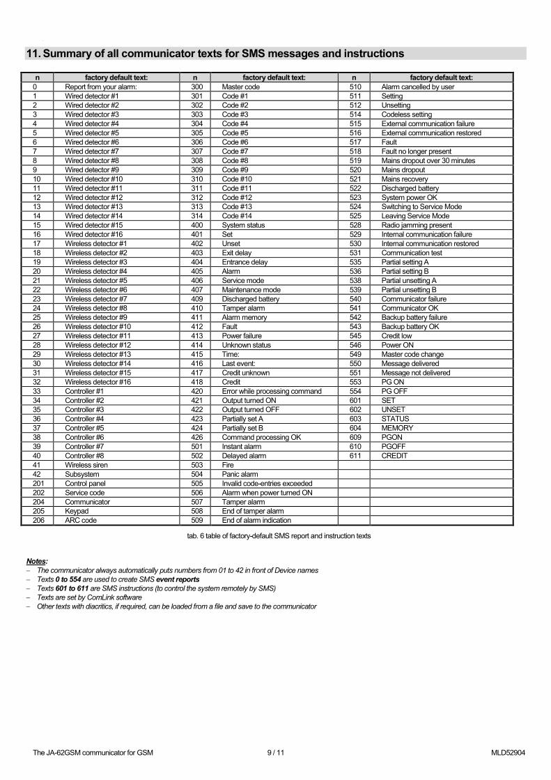
11. Summary of all communicator texts for SMS messages and instructions n factory default text: n factory default text: n factory default text:
0 Report from your alarm: 300 Master code 510 Alarm cancelled by user 1 Wired detector #1 301 Code #1 511 Setting 2 Wired detector #2 302 Code #2 512 Unsetting 3 Wired detector #3 303 Code #3 514 Codeless setting 4 Wired detector #4 304 Code #4 515 External communication failure 5 Wired detector #5 305 Code #5 516 External communication restored 6 Wired detector #6 306 Code #6 517 Fault 7 Wired detector #7 307 Code #7 518 Fault no longer present 8 Wired detector #8 308 Code #8 519 Mains dropout over 30 minutes 9 Wired detector #9 309 Code #9 520 Mains dropout 10 Wired detector #10 310 Code #10 521 Mains recovery 11 Wired detector #11 311 Code #11 522 Discharged battery 12 Wired detector #12 312 Code #12 523 System power OK 13 Wired detector #13 313 Code #13 524 Switching to Service Mode 14 Wired detector #14 314 Code #14 525 Leaving Service Mode 15 Wired detector #15 400 System status 528 Radio jamming present 16 Wired detector #16 401 Set 529 Internal communication failure 17 Wireless detector #1 402 Unset 530 Internal communication restored 18 Wireless detector #2 403 Exit delay 531 Communication test 19 Wireless detector #3 404 Entrance delay 535 Partial setting A 20 Wireless detector #4 405 Alarm 536 Partial setting B 21 Wireless detector #5 406 Service mode 538 Partial unsetting A 22 Wireless detector #6 407 Maintenance mode 539 Partial unsetting B 23 Wireless detector #7 409 Discharged battery 540 Communicator failure 24 Wireless detector #8 410 Tamper alarm 541 Communicator OK 25 Wireless detector #9 411 Alarm memory 542 Backup battery failure 26 Wireless detector #10 412 Fault 543 Backup battery OK 27 Wireless detector #11 413 Power failure 545 Credit low 28 Wireless detector #12 414 Unknown status 546 Power ON 29 Wireless detector #13 415 Time: 549 Master code change 30 Wireless detector #14 416 Last event: 550 Message delivered 31 Wireless detector #15 417 Credit unknown 551 Message not delivered 32 Wireless detector #16 418 Credit 553 PG ON 33 Controller #1 420 Error while processing command 554 PG OFF 34 Controller #2 421 Output turned ON 601 SET 35 Controller #3 422 Output turned OFF 602 UNSET 36 Controller #4 423 Partially set A 603 STATUS 37 Controller #5 424 Partially set B 604 MEMORY 38 Controller #6 426 Command processing OK 609 PGON 39 Controller #7 501 Instant alarm 610 PGOFF 40 Controller #8 502 Delayed alarm 611 CREDIT 41 Wireless siren 503 Fire 42 Subsystem 504 Panic alarm 201 Control panel 505 Invalid code-entries exceeded 202 Service code 506 Alarm when power turned ON 204 Communicator 507 Tamper alarm 205 Keypad 508 End of tamper alarm 206 ARC code 509 End of alarm indication
tab. 6 table of factory-default SMS report and instruction texts
Notes: − The communicator always automatically puts numbers from 01 to 42 in front of Device names − Texts 0 to 554 are used to create SMS event reports − Texts 601 to 611 are SMS instructions (to control the system remotely by SMS) − Texts are set by ComLink software − Other texts with diacritics, if required, can be loaded from a file and save to the communicator
The JA-62GSM communicator for GSM 10 / 11 MLD52904
•
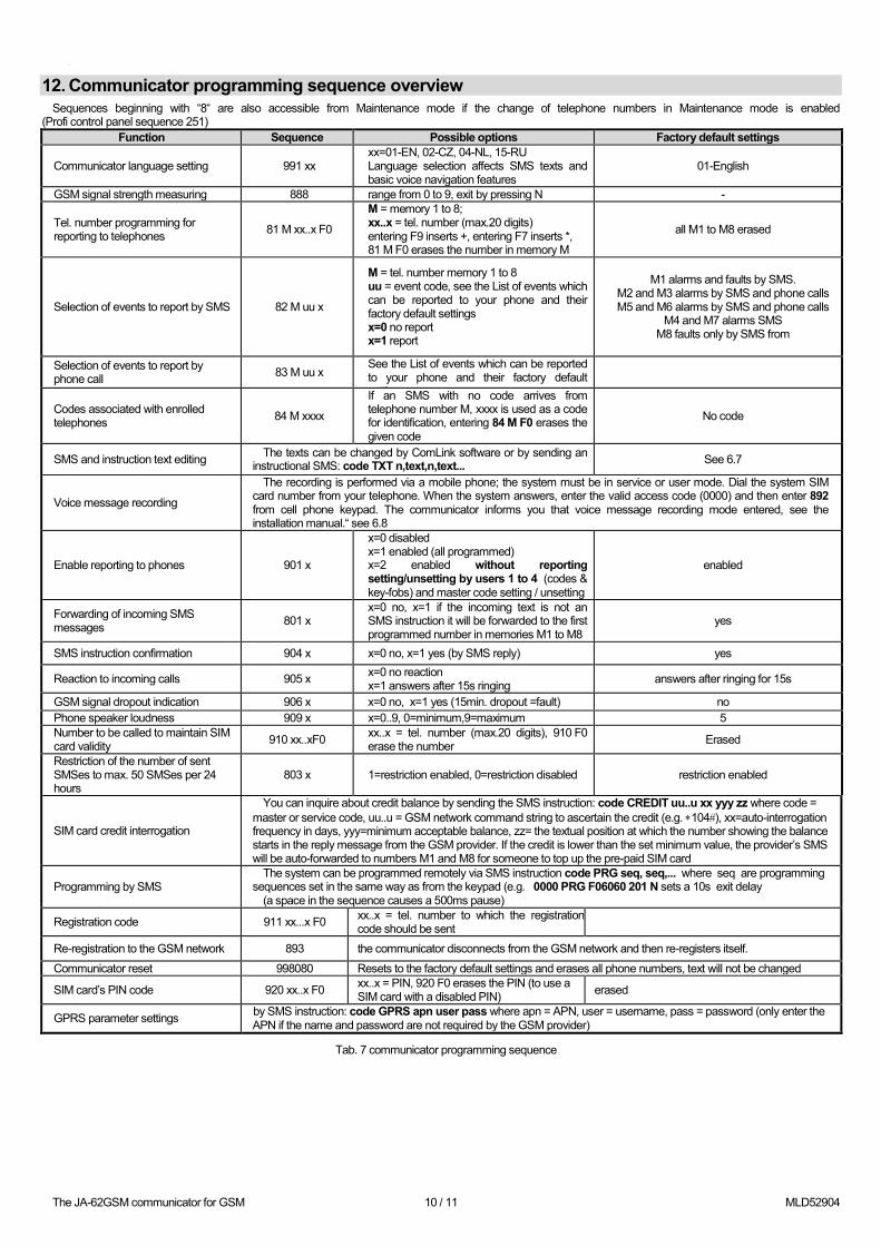
12. Communicator programming sequence overview Sequences beginning with “8“ are also accessible from Maintenance mode if the change of telephone numbers in Maintenance mode is enabled
(Profi control panel sequence 251) Function Sequence Possible options Factory default settings
Communicator language setting 991 xx xx=01-EN, 02-CZ, 04-NL, 15-RU Language selection affects SMS texts and basic voice navigation features
01-English
GSM signal strength measuring 888 range from 0 to 9, exit by pressing N -
Tel. number programming for reporting to telephones 81 M xx..x F0
M = memory 1 to 8; xx..x = tel. number (max.20 digits) entering F9 inserts +, entering F7 inserts *, 81 M F0 erases the number in memory M
all M1 to M8 erased
Selection of events to report by SMS 82 M uu x
M = tel. number memory 1 to 8 uu = event code, see the List of events which can be reported to your phone and their factory default settings x=0 no report x=1 report
M1 alarms and faults by SMS. M2 and M3 alarms by SMS and phone calls M5 and M6 alarms by SMS and phone calls
M4 and M7 alarms SMS M8 faults only by SMS from
Selection of events to report by phone call 83 M uu x
See the List of events which can be reported to your phone and their factory default
tti
Codes associated with enrolled telephones 84 M xxxx
If an SMS with no code arrives from telephone number M, xxxx is used as a code for identification, entering 84 M F0 erases the given code
No code
SMS and instruction text editing The texts can be changed by ComLink software or by sending an instructional SMS: code TXT n,text,n,text... See 6.7
Voice message recording
The recording is performed via a mobile phone; the system must be in service or user mode. Dial the system SIM card number from your telephone. When the system answers, enter the valid access code (0000) and then enter 892 from cell phone keypad. The communicator informs you that voice message recording mode entered, see the installation manual.“ see 6.8
Enable reporting to phones 901 x
x=0 disabled x=1 enabled (all programmed) x=2 enabled without reporting setting/unsetting by users 1 to 4 (codes & key-fobs) and master code setting / unsetting
enabled
Forwarding of incoming SMS messages 801 x
x=0 no, x=1 if the incoming text is not an SMS instruction it will be forwarded to the first programmed number in memories M1 to M8
yes
SMS instruction confirmation 904 x x=0 no, x=1 yes (by SMS reply) yes
Reaction to incoming calls 905 x x=0 no reaction x=1 answers after 15s ringing answers after ringing for 15s
GSM signal dropout indication 906 x x=0 no, x=1 yes (15min. dropout =fault) no Phone speaker loudness 909 x x=0..9, 0=minimum,9=maximum 5 Number to be called to maintain SIM card validity 910 xx..xF0 xx..x = tel. number (max.20 digits), 910 F0
erase the number Erased
Restriction of the number of sent SMSes to max. 50 SMSes per 24 hours
803 x 1=restriction enabled, 0=restriction disabled restriction enabled
SIM card credit interrogation
You can inquire about credit balance by sending the SMS instruction: code CREDIT uu..u xx yyy zz where code = master or service code, uu..u = GSM network command string to ascertain the credit (e.g. ∗104#), xx=auto-interrogation frequency in days, yyy=minimum acceptable balance, zz= the textual position at which the number showing the balance starts in the reply message from the GSM provider. If the credit is lower than the set minimum value, the provider’s SMS will be auto-forwarded to numbers M1 and M8 for someone to top up the pre-paid SIM card
Programming by SMS The system can be programmed remotely via SMS instruction code PRG seq, seq,... where seq are programming
sequences set in the same way as from the keypad (e.g. 0000 PRG F06060 201 N sets a 10s exit delay (a space in the sequence causes a 500ms pause)
Registration code 911 xx...x F0 xx..x = tel. number to which the registration code should be sent
Re-registration to the GSM network 893 the communicator disconnects from the GSM network and then re-registers itself.
Communicator reset 998080 Resets to the factory default settings and erases all phone numbers, text will not be changed
SIM card’s PIN code 920 xx..x F0 xx..x = PIN, 920 F0 erases the PIN (to use a SIM card with a disabled PIN) erased
GPRS parameter settings by SMS instruction: code GPRS apn user pass where apn = APN, user = username, pass = password (only enter the APN if the name and password are not required by the GSM provider)
Tab. 7 communicator programming sequence
The JA-62GSM communicator for GSM 11 / 11 MLD52904
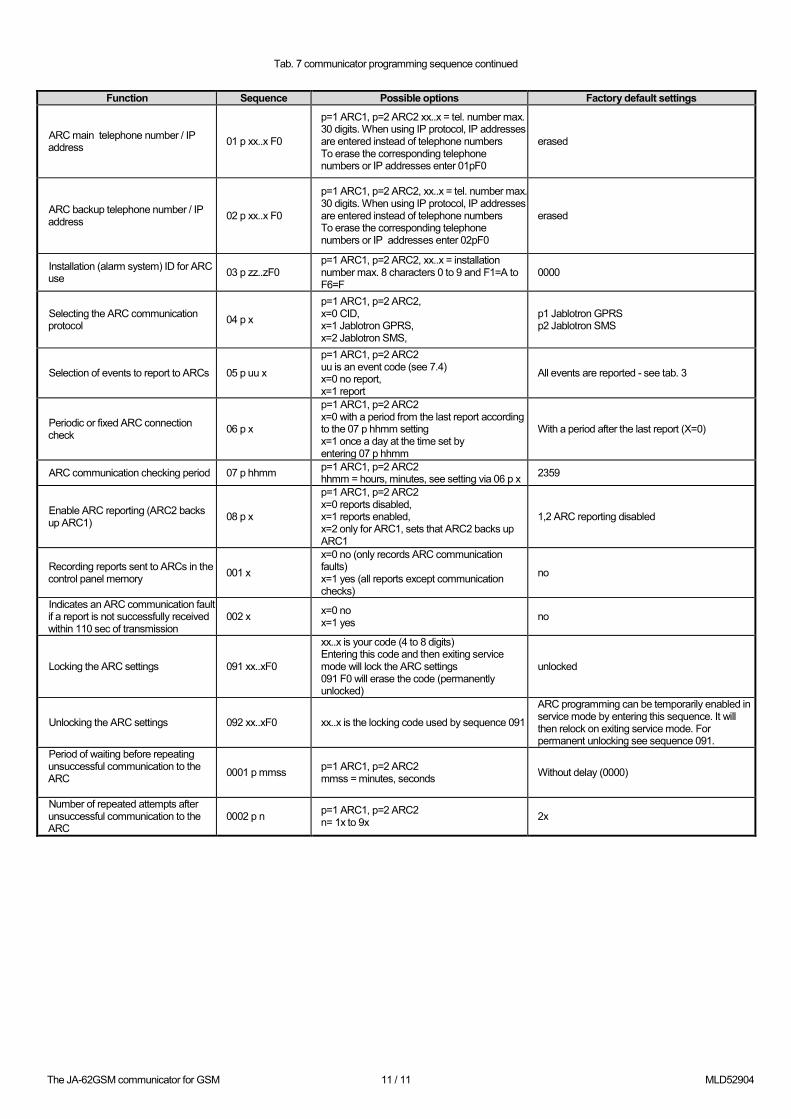
Tab. 7 communicator programming sequence continued
Function Sequence Possible options Factory default settings
ARC main telephone number / IP address 01 p xx..x F0
p=1 ARC1, p=2 ARC2 xx..x = tel. number max. 30 digits. When using IP protocol, IP addresses are entered instead of telephone numbers To erase the corresponding telephone numbers or IP addresses enter 01pF0
erased
ARC backup telephone number / IP address 02 p xx..x F0
p=1 ARC1, p=2 ARC2, xx..x = tel. number max. 30 digits. When using IP protocol, IP addresses are entered instead of telephone numbers To erase the corresponding telephone numbers or IP addresses enter 02pF0
erased
Installation (alarm system) ID for ARC use 03 p zz..zF0
p=1 ARC1, p=2 ARC2, xx..x = installation number max. 8 characters 0 to 9 and F1=A to F6=F
0000
Selecting the ARC communication protocol 04 p x
p=1 ARC1, p=2 ARC2, x=0 CID, x=1 Jablotron GPRS, x=2 Jablotron SMS,
p1 Jablotron GPRS p2 Jablotron SMS
Selection of events to report to ARCs 05 p uu x
p=1 ARC1, p=2 ARC2 uu is an event code (see 7.4) x=0 no report, x=1 report
All events are reported - see tab. 3
Periodic or fixed ARC connection check 06 p x
p=1 ARC1, p=2 ARC2 x=0 with a period from the last report according to the 07 p hhmm setting x=1 once a day at the time set by entering 07 p hhmm
With a period after the last report (X=0)
ARC communication checking period 07 p hhmm p=1 ARC1, p=2 ARC2 hhmm = hours, minutes, see setting via 06 p x 2359
Enable ARC reporting (ARC2 backs up ARC1) 08 p x
p=1 ARC1, p=2 ARC2 x=0 reports disabled, x=1 reports enabled, x=2 only for ARC1, sets that ARC2 backs up ARC1
1,2 ARC reporting disabled
Recording reports sent to ARCs in the control panel memory 001 x
x=0 no (only records ARC communication faults) x=1 yes (all reports except communication checks)
no
Indicates an ARC communication fault if a report is not successfully received within 110 sec of transmission
002 x x=0 no x=1 yes no
Locking the ARC settings 091 xx..xF0
xx..x is your code (4 to 8 digits) Entering this code and then exiting service mode will lock the ARC settings 091 F0 will erase the code (permanently unlocked)
unlocked
Unlocking the ARC settings 092 xx..xF0 xx..x is the locking code used by sequence 091
ARC programming can be temporarily enabled in service mode by entering this sequence. It will then relock on exiting service mode. For permanent unlocking see sequence 091.
Period of waiting before repeating unsuccessful communication to the ARC
0001 p mmss p=1 ARC1, p=2 ARC2 mmss = minutes, seconds Without delay (0000)
Number of repeated attempts after unsuccessful communication to the ARC
0002 p n p=1 ARC1, p=2 ARC2 n= 1x to 9x 2x