GSM based irrigation system
61
GSM based irrigation system
-
Upload
independent -
Category
Documents
-
view
2 -
download
0
Transcript of GSM based irrigation system

GSM based irrigation system

Abstract— Irrigation is the process of artificiallysupplying water to land where crops are cultivated.Traditionally hand pumps, canal water and rainfall werea major source of water supply for irrigation. Thismethod has led to severe drawbacks like underirrigation, over-irrigation which in turn causesleaching and loss of nutrient content of soil. Changingenvironmental conditions and shortage of water have ledto the need for a system which efficiently managesirrigation of fields. Automated irrigation system is amachine based system, which automates the irrigation ofland by combining various software and hardwareapproaches together for field irrigation.This paper deals with a detailed survey of various GSM
based automated farm irrigation systems. GSM serves asan important part since it is responsible forcontrolling the irrigation facility and sends them toreceiver through coded signal. Our study isconcentrated on comparison of various GSM approaches.
I. INTRODUCTIONIrrigation is a scientific process of artificially
supplying water to the land or soil that is beingcultivated. Traditionally in dry regions having no orlittle rainfall water had to be supplied to the fieldseither through canals or hand pumps, tube wells. Butthis method had severe problems such as increase inworkload of farm labor and often it lead to problemsuch as over-irrigation or under-irrigation, andleaching of soil. Further there were issues likeweeding, lesser yield of crop as an effect of abovementioned problems.Hence there was a need for a way to test the soil
condition before supplying water to the fields. Thismechanism would reduce the workload of the farmer andhelp maintain proper soil conditions for improved andbetter crop production. Hence with the advance oftechnology it was possible to design systems thateliminated the direct involvement of the farmer withrespect to irrigation of their fields.
These systems automated the entire irrigation system bycontrolling the motors that irrigated the fields.A GSM based farm irrigation system has two major
technologies behind it, primary being the “GSM” andsecondary one is the controller or processor. GSM(Global System for Mobile Communication) is a standardset used to describe protocols for digital cellularnetworks. This GSM facility serves as an important partfor controlling the irrigation on field and sending theresults to the farmer using coded signals to a mobiledevice which indirectly controls the entire farmirrigation system. The processor or the controllerworks as a central core for functioning of theautomated process after it has been initiated by theGSM based device and finally presents the output to thedevice.This paper contains five detailed comparative study of
GSM based farm irrigation approaches. Now a day, aBluetooth module is also interfaced with theprocessor/controller for simplifying the mobile devicecomplications. It gives a detailed study of theadvantages and disadvantages of the varioustechnologies proposed by the systems in the papersunder study.The system continuously monitors the soil moisture,
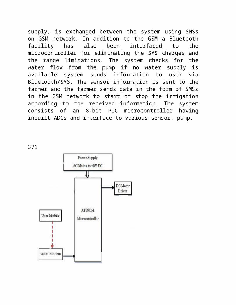
water level of the well, temperature, humidity, dewpoint, weather conditions and provides the detailsabout the field to user though SMS. The systemconsists of a centralized unit having a subscribernumber which forms a link between user and deviceand acts as a primary node for sending and receivingthe data though SMSs by the user. The centralizedunit communicates with the system through SMSs whichwill be received by GS with the help of SIM card;
the GSM sends this data to ARM7, after processing itdisplays it on the LCD. The activation command isgiven to start the motor and indirectly activate thetransistorized relay circuit to constantly monitorthe environmental factors and once the requiredlevel is reached the motor is turned off and themessage is sent to the farmer.B] Real time automation of Indian Agricultural
System [2] deals with ARM7 and GSM combined togetherfor programming and developing the automated system.It is very much similar to the system presented inReal-time automization of Agricultural Environmentfor Social Modernization of Indian AgriculturalSystem [1]. In the system, soil moisture is measuredusing dielectric constant of soil and is informed tothe centralized unit which sends a message to thedevice which waits for a certain amount of defaulttime for user response if no response is received itcontinuously monitors the field and keeps on sendingthe parameters to the centralized unit where it isstored in the EEPROM of ARM. Additionally, tomonitor the plant or leaf’s health, a leaf wetnesssensor has been used allowing us to forecast diseaseand to protect plan canopy. It uses ARM7TDMI, 16kbRAM, flash memory, In-system programming with timersand serial interfaces and modems for creating thereal time applications.C] Innovative GSM Bluetooth Based Remote Controlled
Embedded System for Irrigation [3] proposes a systemwhere GSM/Bluetooth based remote controlled embeddedsystem is used for irrigation. The system sets theirrigation time depending on the environmentalfactors and can automatically irrigate the field[3]. Information, regarding the status of power
supply, is exchanged between the system using SMSson GSM network. In addition to the GSM a Bluetoothfacility has also been interfaced to themicrocontroller for eliminating the SMS charges andthe range limitations. The system checks for thewater flow from the pump if no water supply isavailable system sends information to user viaBluetooth/SMS. The sensor information is sent to thefarmer and the farmer sends data in the form of SMSsin the GSM network to start of stop the irrigationaccording to the received information. The systemconsists of an 8-bit PIC microcontroller havinginbuilt ADCs and interface to various sensor, pump.
371
D] Integration of Wireless Technologies forSustainable Agriculture [4] proposes the system thateliminates the use of wired technology and improves theold method of collecting data and allows the farmer tocontrol their sprinklers remotely. It utilizes wirelesssensor networks to collect real time status ofagricultural field and uses mobile phone to control thewatering of the field using sprinkler.The wireless sensor nodes collect information
regarding water level conditions and send the data tothe central sink node which processes the informationand sends it to the user’s mobile phone and heaccordingly controls the watering of the field usingsprinkler controller. The nodes contain a sensor, radiotransceivers, battery and interfacing circuit [4]. Thesystem proposes the use of sprinklers having two majorfeatures, pulsing (water application depth can becontrolled by a series of on-off cycles)[4] and nozzleorifice control (mechanically activated pin to alterthe area which adjusts the sprinkler flow rate)[4],controlled by the sprinkler controller which in turnhas a GSM modem and a microcontroller. It uses a missedcall instruction format wherein each number of missedcalls is associated with a certain number ofinstructions to be performed, which is calculated bythe microcontroller.
E] Design of Ultra Low Cost Cell Phone Based EmbeddedSystem for Irrigation [5] uses AVR ATMega32microcontroller and includes protection against singlephasing, over current, over voltage, dry running andprobable bearing faults; and alerts the user throughmissed calls/buzzers on completion of tasks. RTC DS1307
and DS18S20 are used for time and temperaturemeasurement [5]. The system offers attractive featureslike automated control based on parameters specifiedthough keyboard, SMS, number of missed calls inspecified duration from user mobile though serial cableand based on the commands received and the presentsensor conditions microcontroller system sends signalto the switch on-off the motor though starter usingrelay. Interfacing is done using RS232, AT commands isused. The SMS is a store and forward [5] way oftransmitting messages.
III. ADVANTAGES AND DISADVANTAGES
The system described in [1] uses ARM7, low powerconsuming processor which is very important. GSMtechnology’s ready availability, simplicity, lesssignal deterioration makes it better for sendingcontrol signals and For critical applicationsrequiring real-time monitoring the field conditioncan be transmitted using radio link [1].The drawback of this system was that GSM has a
fixed maximum cell site range of 35km [1] which isimposed by technical limitations. Secondly, thefarmer needs to be familiar with the entire complexAT commands, and finally soil parameters regardingfertilizers and plant diseases are not incorporatedin the system.The system described in [2] also is a low power
consumer with simple and efficient GSM facilities.
It measures all possible soil environmental factorsincluding the health of the plant and detects amountof water or ice on the leaf’s surface also [2]. Thedrawbacks of the system are firstly farmer has tosuffer SMS costs due to the GSM facility, and badrange of the GSM provider may also act as a limitingfactor to the system.The system described in [3] has incorporated
Bluetooth for remote monitoring which reduces theproblem of range with GSM network and saves SMS costfor the farmer. The smoke sensors used to sendemergency information to user incase of fire infield or burning of motor [3]. The design is lowpower, low cost, small size, robust and highlyversatile. It has the same problems as the systemsabove, that range of GSM and Bluetooth is notdependable and user needs to familiarize himselfwith too many complex AT commands.The system described in [4] uses sprinkler
irrigation rather than traditional motors whichincreases the area of water supply. Also, lowinfiltrated soil can be tackled using this systemand since it is a wireless system it has increasedmobility, portability and suitability in adverseconditions. Also it is low cost and user does nothave to memorize complex instructions due to simplemissed call format. But due to this, it also suffersfrom problem of limited instructions, and farmer hasto remember the number of missed calls for eachinstruction and it may not be possible to reach thenumber of missed calls in that time delay.
The system described in [5] provide optimum waterdistribution in fields based on manual settings,

number of missed calls in specified time duration,SMS from cell phones. It ensures protection of motoragainst overloads and overheating and facesimbalances and also provides automated restarting[5]. It uses buzzers, missed calls for alertpurpose. It’s an ultra low cost due to usage ofobsolete cell phone models [5]. It has a dedicatedvoice based call approach for spoken commands tohelp the illiterate farmers [5]. The only drawbackit has is that it uses the same network operator forcontrol system and user cell phones to ensuregreater probability of successful connection; and itrequires extra storage memory for adding othersensors.372

IV. CONCLUSION
There is an urgent need for a system that makes theagricultural process easier and burden free from thefarmer’s side. With the recent advancement oftechnology it has become necessary to increase theannual crop production output of our country India, anentirely agro-centric economy. The ability to conservethe natural resources as well as giving a splendidboost to the production of the crops is one of the mainaims of incorporating such technology into theagricultural domain of the country. To save farmer’seffort, water and time has been the most importantconsideration. Hence systems need to be designed toprovide this ability efficiently using wireless sensornetworking, sprinkler irrigation, GSM, SMS technology,Bluetooth technology and readily available mobile phonedevices is a certain help to the farmers to get betteryield on a large scale and thereby increasing theagricultural wealth and the economic growth of ourcountry.
In this paper we presented a summarized approach ofvarious different types irrigation systems based on GSMapproach. The project is carried out using ARM7TDMIcore with the help of GSM technologies to ensure afaithful irrigation of the farm field. These systemswere all remotely controlled systems which proposed alow cost information exchange via SMS and GSM network.The soil moisture, humidity and various otherenvironmental factors influencing growth of crops areperiodically sensed using high quality accurate sensorand those values are passed on to theprocessor/controller to calculate required amount ofwater and fertilizers and various other inputs during
irrigation and accordingly supplied to the farm. Thefunctionality of GSM increases the efficiency of theautomated irrigation system by giving it a more userfriendly interface using SMS (Short Message Service)coupled with missed called services and incorporationof Bluetooth for further controlling the system fromthe farmer’s side.
The result of the survey conducted has lead to a verypositive approach on the impact of GSM technology infarm irrigation methods and techniques. The approachesstudied had various pros and cons in the time requiredfor operations or complexity or feasibility and userinteractions. With technology advancing everyday newtechniques have been implemented for further minimizingthe irrigation process like using prebuilt mobile phoneor standalone application software for conduction theirrigation process.
MICROCONTROLLER:-
This amplified signal is then given to the controller. A
microcontroller (also microcomputer, MCU or µC) is a small
computer on a single integrated circuit consisting internally of
a relatively simple CPU, clock, timers, I/O ports, and memory.
Program memory in the form of NOR flash or OTP ROM is also often
included on chip, as well as a typically small amount of RAM.
Microcontrollers are designed for small or dedicated
applications.

The AT89S51 is a low-power, high-performance CMOS 8-bit
microcontroller with 4K bytes of In-System Programmable Flash
memory. The device is manufactured using Atmel’s high-density
nonvolatile memory technology and is compatible with the
industry-standard 80C51 instruction set and pin out. The on-chip
Flash allows the program memory to be reprogrammed in-system or
by a conventional nonvolatile memory programmer. By combining a
versatile 8-bit CPU with In-System Programmable Flash on a
monolithic chip, the Atmel AT89S51 is a powerful microcontroller
which provides a highly-flexible and cost-effective solution to
many embedded control applications. The AT89S51 provides the
following standard features: 4K bytes of Flash, 128 bytes of RAM,
32 I/O lines, Watchdog timer, two data pointers, two 16-bit
timer/counters, a Five vector two-level interrupt architecture, a
full duplex serial port, on-chip oscillator, and clock circuitry.
In addition, the AT89S51 is designed with static logic for
operation down to zero frequency and supports two software
selectable power saving modes. The Idle Mode stops the CPU while
allowing the RAM, timer/counters, serial port, and interrupt
system to continue functioning. The Power-down mode saves the RAM
contents but freezes the oscillator, disabling all other chip
functions until the next external interrupt or hardware reset.
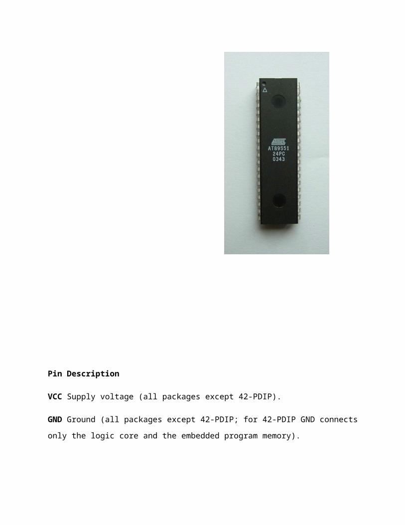
Pin Description
VCC Supply voltage (all packages except 42-PDIP).
GND Ground (all packages except 42-PDIP; for 42-PDIP GND connects
only the logic core and the embedded program memory).
VDD Supply voltage for the 42-PDIP which connects only the logic
core and the embedded program memory.
PWRVDD Supply voltage for the 42-PDIP which connects only the I/O
Pad Drivers. The application board must connect both VDD and
PWRVDD to the board supply voltage.
PWRGND Ground for the 42-PDIP which connects only the I/O Pad
Drivers. PWRGND and GND are weakly connected through the common
silicon substrate, but not through any metal link. The
application board MUST connect both GND and PWRGND to the board
ground.
Port 0 Port 0 is an 8-bit open drain bi-directional I/O port. As
an output port, each pin can sink eight TTL inputs. When 1s are
written to port 0 pins, the pins can be used as high-impedance
inputs.
Port 0 can also be configured to be the multiplexed low-order
address/data bus during
accesses to external program and data memory. In this mode, P0
has internal pull-ups.
Port 0 also receives the code bytes during Flash programming and
outputs the code bytes
during program verification. External pull-ups are required
during program verification.
Port 1 Port 1 is an 8-bit bi-directional I/O port with internal
pull-ups. The Port 1 output buffers can sink/source four TTL
inputs. When 1s are written to Port 1 pins, they are pulled high
by the internal pull-ups and can be used as inputs. As inputs,
Port 1 pins that are externally being pulled low will source
current (IIL) because of the internal pull-ups.
Port 1 also receives the low-order address bytes during Flash
programming and verification.
Port 2 Port 2 is an 8-bit bi-directional I/O port with internal
pull-ups. The Port 2 output buffers can sink/source four TTL
inputs. When 1s are written to Port 2 pins, they are pulled high
by the internal pull-ups and can be used as inputs. As inputs,
Port 2 pins that are externally being pulled low will source
current (IIL) because of the internal pull-ups.
Port 2 emits the high-order address byte during fetches from
external program memory and during accesses to external data
memory that uses 16-bit addresses (MOVX @ DPTR). In this
application, Port 2 uses strong internal pull-ups when emitting
1s. During accesses to external data memory that use 8-bit
addresses (MOVX @ RI), Port 2 emits the contents of the P2
Special
Function Register.

Port 2 also receives the high-order address bits and some control
signals during Flash programming and verification.
Port 3 Port 3 is an 8-bit bi-directional I/O port with internal
pull-ups. The Port 3 output buffers can sink/source four TTL
inputs. When 1s are written to Port 3 pins, they are pulled high
by the internal pull-ups and can be used as inputs. As inputs,
Port 3 pins that are externally being pulled low will source
current (IIL) because of the pull-ups.
Port 3 receives some control signals for Flash programming and
verification.
Port 3 also serves the functions of various special features of
the AT89S51, as shown in the following table.
RST Reset input. A high on this pin for two machine cycles while
the oscillator is running resets the device. This pin drives High
for 98 oscillator periods after the Watchdog times out. The
DISRTO bit in SFR AUXR (address 8EH) can be used to disable this
feature. In the default state of bit DISRTO, the RESET HIGH out
feature is enabled.
ALE/PROG Address Latch Enable (ALE) is an output pulse for
latching the low byte of the address during accesses to external
memory. This pin is also the program pulse input (PROG) during
Flash programming.
In normal operation, ALE is emitted at a constant rate of 1/6 the
oscillator frequency and may be used for external timing or
clocking purposes. Note, however, that one ALE pulse is skipped
during each access to external data memory.
If desired, ALE operation can be disabled by setting bit 0 of SFR
location 8EH. With the bit set, ALE is active only during a MOVX
or MOVC instruction. Otherwise, the pin is weakly pulled high.
Setting the ALE-disable bit has no effect if the microcontroller
is in external execution mode.
PSEN Program Store Enable (PSEN) is the read strobe to external
program memory.
When the AT89S51 is executing code from external program memory,
PSEN is activated twice each machine cycle, except that two PSEN
activations are skipped during each access to external data
memory.
EA/VPP External Access Enable. EA must be strapped to GND in
order to enable the device to fetch code from external program
memory locations starting at 0000H up to FFFFH. Note, however,
that if lock bit 1 is programmed, EA will be internally latched
on reset.
EA should be strapped to VCC for internal program executions.
This pin also receives the 12-volt programming enable voltage
(VPP) during Flash programming.

XTAL1 Input to the inverting oscillator amplifier and input to
the internal clock operating circuit.
XTAL2 Output from the inverting oscillator amplifier
TRANSFORMATION:-
As already discussed the supply which we get is 220V A.C. supply.
In order to decrease the magnitude of the voltage we make use of
step down transformer. This transformer has more windings in the
primary coil than in the secondary coil. So the voltage output at
the secondary is an A.C. supply with magnitude less than 220V as
shown below:
RECTIFICATION:-
As all the electronic circuits work on DC therefore this low
voltage A.C. cannot be directly fed to our circuit. Thus a
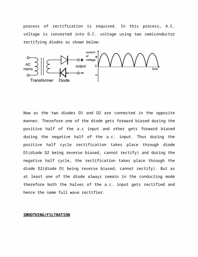
process of rectification is required. In this process, A.C.
voltage is converted into D.C. voltage using two semiconductor
rectifying diodes as shown below:
Now as the two diodes D1 and D2 are connected in the opposite
manner. Therefore one of the diode gets forward biased during the
positive half of the a.c input and other gets forward biased
during the negative half of the a.c. input. Thus during the
positive half cycle rectification takes place through diode
D1(diode D2 being reverse biased, cannot rectify) and during the
negative half cycle, the rectification takes place through the
diode D2(diode D1 being reverse biased, cannot rectify). But as
at least one of the diode always remain in the conducting mode
therefore both the halves of the a.c. input gets rectified and
hence the name full wave rectifier.
SMOOTHING/FILTRATION
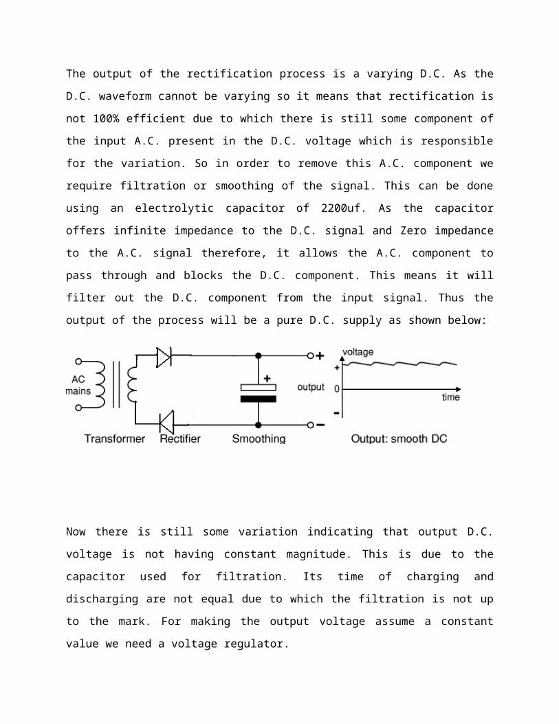
The output of the rectification process is a varying D.C. As the
D.C. waveform cannot be varying so it means that rectification is
not 100% efficient due to which there is still some component of
the input A.C. present in the D.C. voltage which is responsible
for the variation. So in order to remove this A.C. component we
require filtration or smoothing of the signal. This can be done
using an electrolytic capacitor of 2200uf. As the capacitor
offers infinite impedance to the D.C. signal and Zero impedance
to the A.C. signal therefore, it allows the A.C. component to
pass through and blocks the D.C. component. This means it will
filter out the D.C. component from the input signal. Thus the
output of the process will be a pure D.C. supply as shown below:
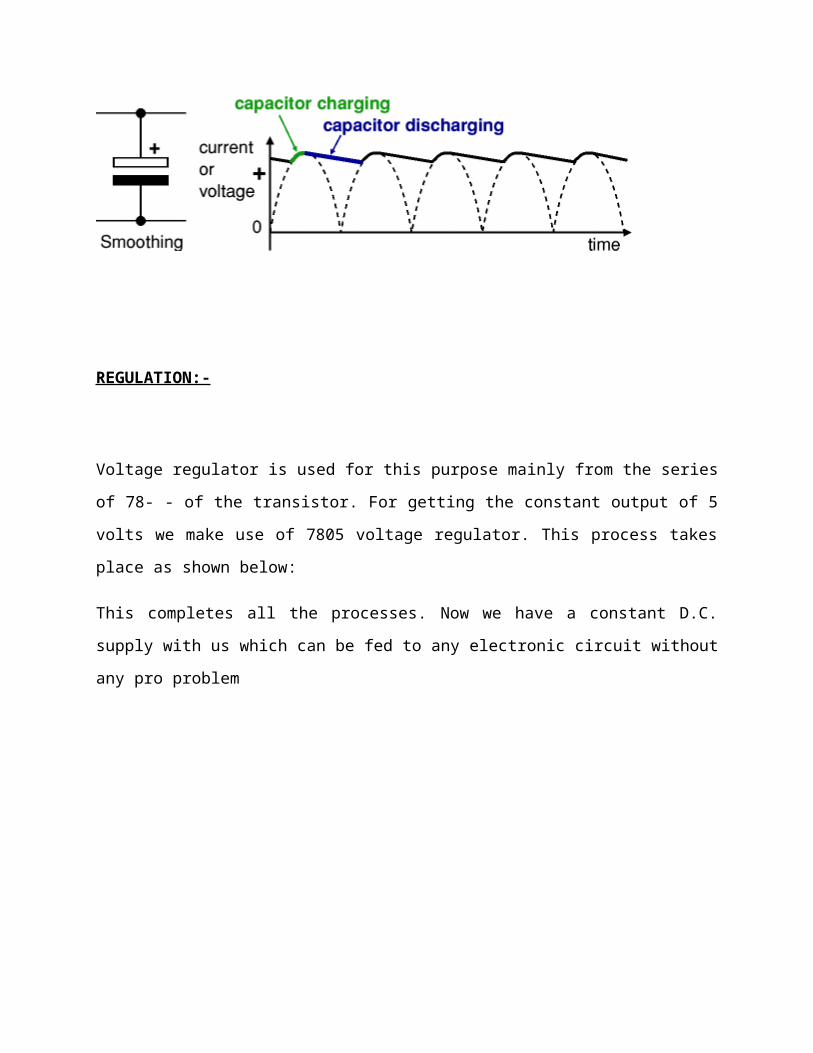
Now there is still some variation indicating that output D.C.
voltage is not having constant magnitude. This is due to the
capacitor used for filtration. Its time of charging and
discharging are not equal due to which the filtration is not up
to the mark. For making the output voltage assume a constant
value we need a voltage regulator.
REGULATION:-
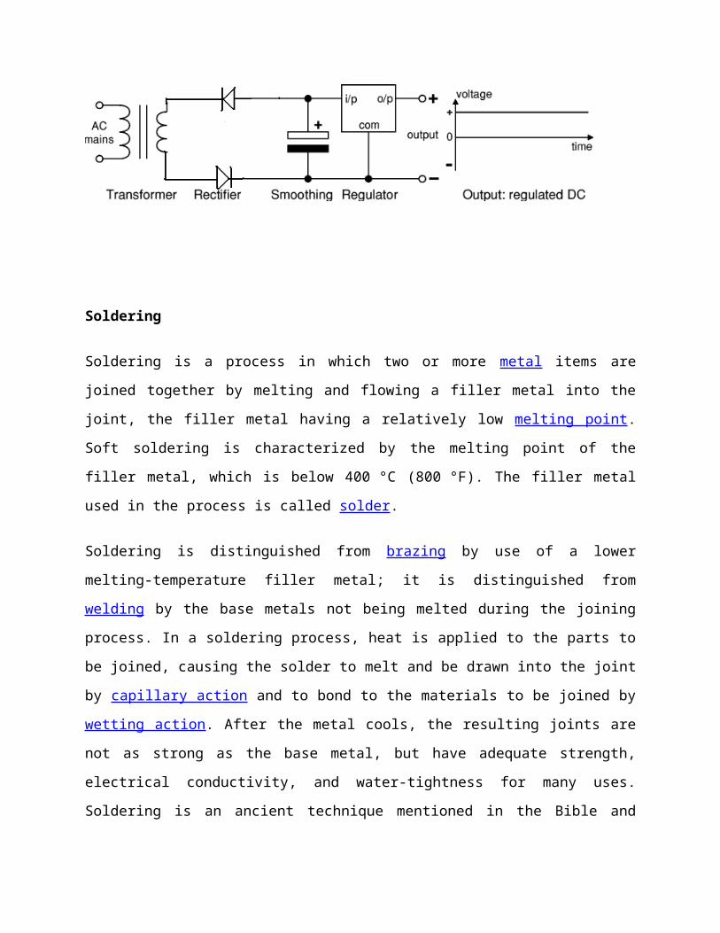
Voltage regulator is used for this purpose mainly from the series
of 78- - of the transistor. For getting the constant output of 5
volts we make use of 7805 voltage regulator. This process takes
place as shown below:
This completes all the processes. Now we have a constant D.C.
supply with us which can be fed to any electronic circuit without
any pro problem
Soldering
Soldering is a process in which two or more metal items are
joined together by melting and flowing a filler metal into the
joint, the filler metal having a relatively low melting point.
Soft soldering is characterized by the melting point of the
filler metal, which is below 400 °C (800 °F). The filler metal
used in the process is called solder.
Soldering is distinguished from brazing by use of a lower
melting-temperature filler metal; it is distinguished from
welding by the base metals not being melted during the joining
process. In a soldering process, heat is applied to the parts to
be joined, causing the solder to melt and be drawn into the joint
by capillary action and to bond to the materials to be joined by
wetting action. After the metal cools, the resulting joints are
not as strong as the base metal, but have adequate strength,
electrical conductivity, and water-tightness for many uses.
Soldering is an ancient technique mentioned in the Bible and
there is evidence that it was employed up to 5000 years ago in
Mesopotamia.
Soldering Tools
The only tools that are essential to solder are a soldering iron
and some solder. There are, however, lots of soldering
accessories available (see soldering accessories for more
information).
Different soldering jobs will need different tools, and different
temperatures too. For circuit board work you will need a finer
tip, a lower temperature and finer grade solder. You may also
want to use a magnifying glass. Audio connectors such as XLR's
will require a larger tip, higher temperature and thicker solder.
Clamps and holders are also handy when soldering audio cables.
Soldering Irons
There are several things to consider when
choosing a soldering iron.
Wattage
adjustable or fixed temperature
power source (electric or gas)
portable or bench use
I do not recommend soldering guns, as these have no temperature
control and can get too hot. This can result in damage to circuit
boards, melt cable insulation, and even damage connectors
What is a transformer, and why should I care?
A "transformer" changes one voltage to another. This attribute is
useful in many ways.
A transformer doesn't change power levels. If you put 100 Watts
into a transformer, 100 Watts come out the other end. [Actually,
there are minor losses in the transformer because nothing in the
real world is 100% perfect. But transformers come pretty darn
close; perhaps 95% efficient.]
A transformer is made from two coils of wire close to each other
(sometimes wrapped around an iron or ferrite "core"). Power is
fed into one coil (the "primary"), which creates a magnetic
field. The magnetic field causes current to flow in the other
coil (the "secondary"). Note that this doesn't work for direct
current (DC): the incoming voltage needs to change over time -
alternating current (AC) or pulsed DC.

Iron core
The number of times the wires are wrapped around the core
("turns") is very important and determines how the transformer
changes the voltage.
If the primary has fewer turns than the secondary, you have
a step-up transformer that increases the voltage.
If the primary has more turns than the secondary, you have a
step-down transformer that reduces the voltage.
If the primary has the same number of turns as the
secondary, the outgoing voltage will be the same as what
comes in. This is the case for an isolation transformer.
In certain exceptional cases, one large coil of wire can
serve as both primary and secondary. This is the case with
variable auto-transformers and xenon strobe trigger
transformers.
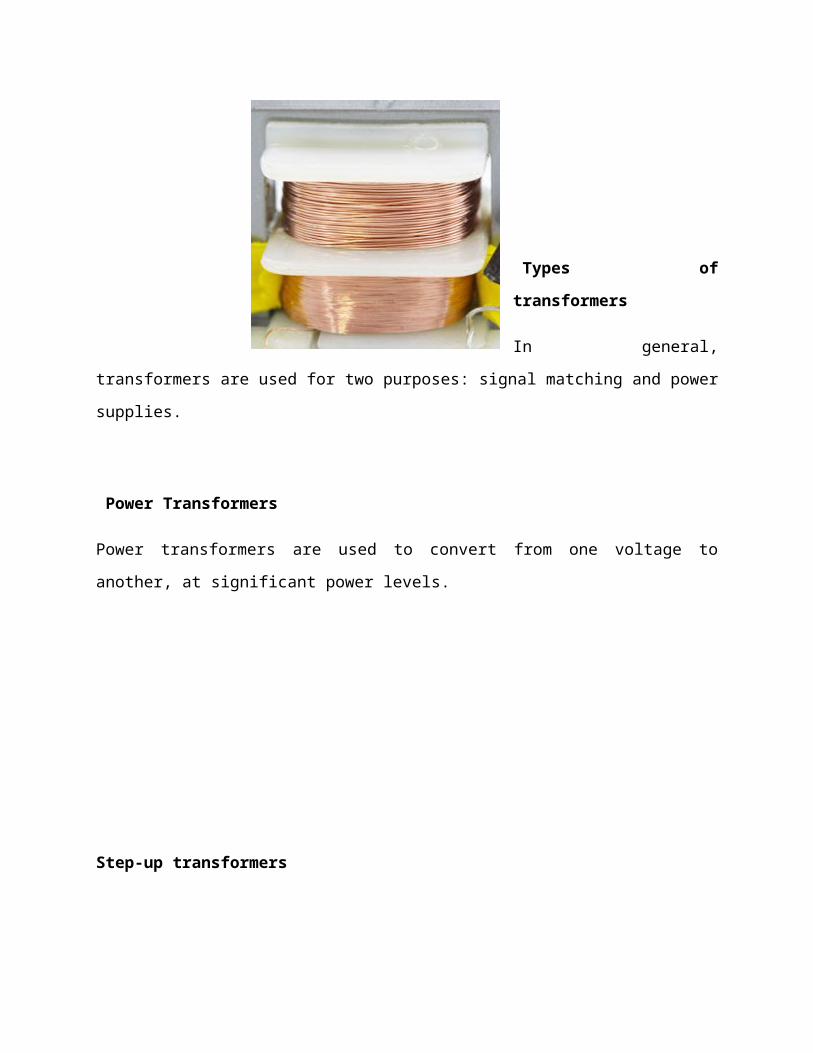
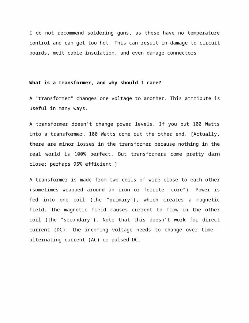
Types of
transformers
In general,
transformers are used for two purposes: signal matching and power
supplies.
Power Transformers
Power transformers are used to convert from one voltage to
another, at significant power levels.
Step-up transformers
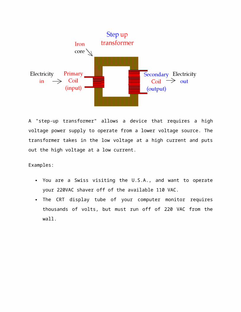
A "step-up transformer" allows a device that requires a high
voltage power supply to operate from a lower voltage source. The
transformer takes in the low voltage at a high current and puts
out the high voltage at a low current.
Examples:
You are a Swiss visiting the U.S.A., and want to operate
your 220VAC shaver off of the available 110 VAC.
The CRT display tube of your computer monitor requires
thousands of volts, but must run off of 220 VAC from the
wall.
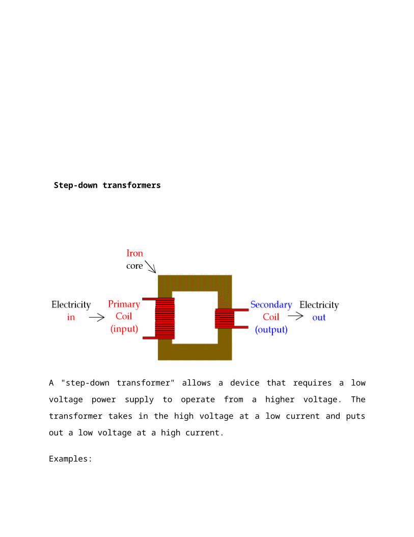
Step-down transformers
A "step-down transformer" allows a device that requires a low
voltage power supply to operate from a higher voltage. The
transformer takes in the high voltage at a low current and puts
out a low voltage at a high current.
Examples:
Your Mailbu-brand landscape lights run on 12VAC, but you
plug them into the 220 VAC line.
Your doorbell doesn't need batteries. It runs on 220 VAC,
converted to 12VAC.
In many cases, step-down transformers take the form of wall
warts.

Isolation transformers
An "isolation transformer" does not raise or lower a voltage;
whatever voltage comes in is what goes out. An isolation
transformer prevents current from flowing directly from one side
to the other. This usually serves as a safety device to prevent
electrocution.
Variable auto-transformers
A "variable auto-transformer" (variac) can act like a step-up
transformer or step-down transformer. It has a big knob on top
that allows you to dial in whatever output voltage you want.
This page from the All Electronics catalog (#103, Winter 2003)
shows some variacs.
WARNING: A variable auto-transformer does not provide isolation
from line current. For that you need an isolation transformer.
Inverters
An "inverter" takes a DC power source and boosts it up to a
higher voltage. The most common type of inverter takes power from
an automobile and cranks out 220 VAC to run appliances and power
tools. Inverters are also used to operate fluorescent lamps from
battery power.
Technically, an inverter isn't a transformer; it contains a
transformer (and lots of other stuff).
Signal Transformers
"Signal transformers" also take one thing in and transform it to
another thing out. But in this case, the power levels are low,
and the transformed thing carries some type of information
signal.
In most cases, these transformers are thought of as impedance
matching.
COMPONENTS
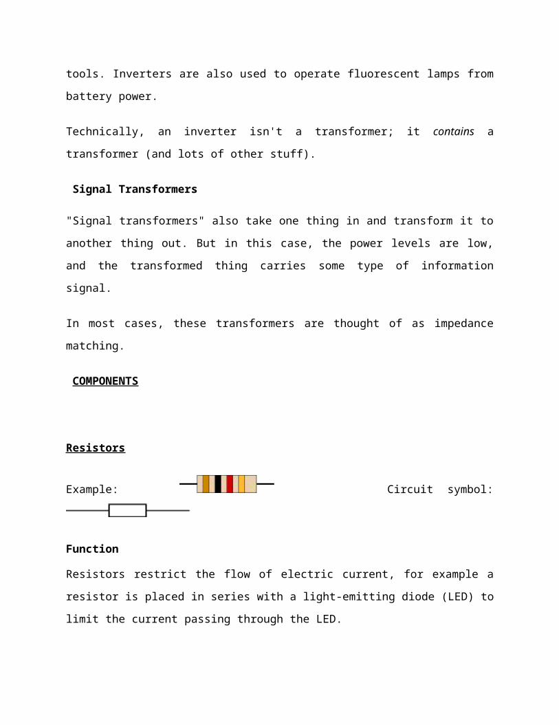
Resistors
Example: Circuit symbol:
Function
Resistors restrict the flow of electric current, for example a
resistor is placed in series with a light-emitting diode (LED) to
limit the current passing through the LED.

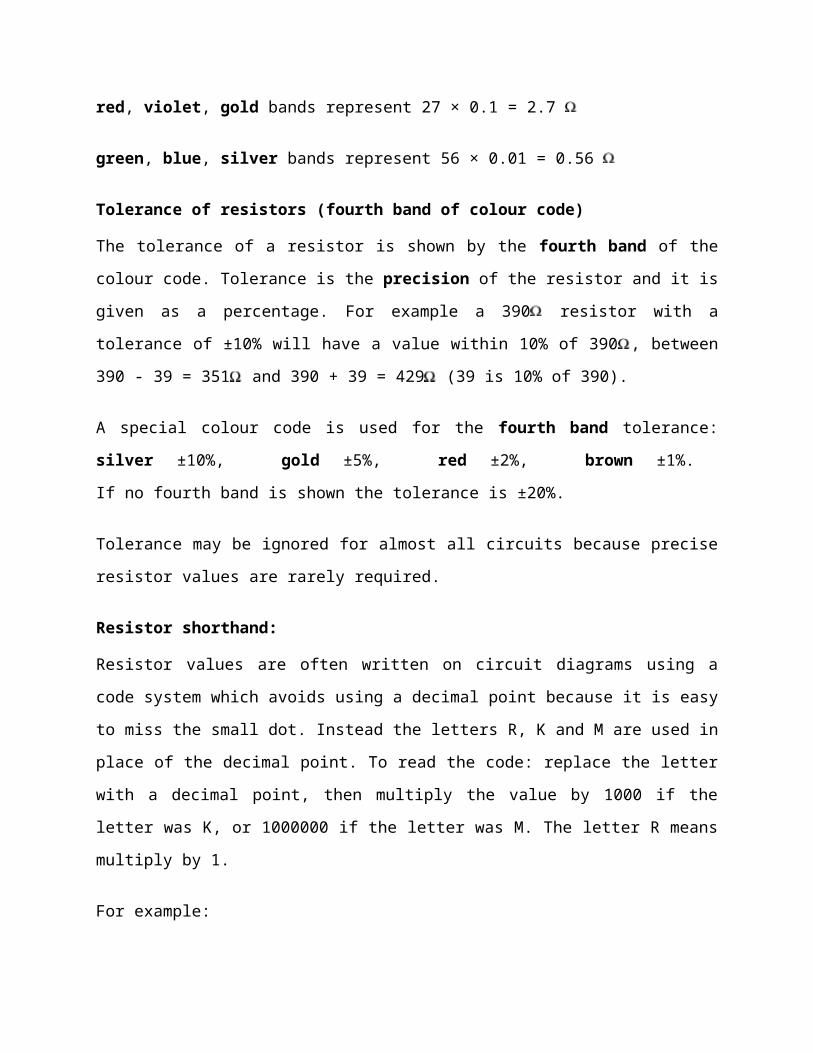
Connecting and soldering
Resistors may be connected either way round. They are not damaged
by heat when soldering.
Resistor values - the resistor colour code
Resistance is measured in ohms, the symbol for ohm is an omega
.
1 is quite small so resistor values are often given in k and M
.
1 k = 1000 1 M = 1000000 .
Resistor values are normally shown using
coloured bands.
Each colour
represents a number
as shown in the table.
Most resistors have 4 bands:
The first band gives the first digit.
The second band gives the second digit.
The Resistor
Colour Code
Colour Number
Black 0
Brown 1
Red 2
Orange 3
Yellow 4
Green 5
Blue 6
Violet 7
Grey 8
White 9
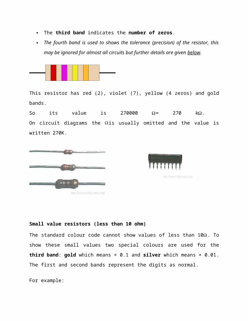
The third band indicates the number of zeros.
The fourth band is used to shows the tolerance (precision) of the resistor, this
may be ignored for almost all circuits but further details are given below.
This resistor has red (2), violet (7), yellow (4 zeros) and gold
bands.
So its value is 270000 = 270 k .
On circuit diagrams the is usually omitted and the value is
written 270K.
Small value resistors (less than 10 ohm)
The standard colour code cannot show values of less than 10 . To
show these small values two special colours are used for the
third band: gold which means × 0.1 and silver which means × 0.01.
The first and second bands represent the digits as normal.
For example:
red, violet, gold bands represent 27 × 0.1 = 2.7
green, blue, silver bands represent 56 × 0.01 = 0.56
Tolerance of resistors (fourth band of colour code)
The tolerance of a resistor is shown by the fourth band of the
colour code. Tolerance is the precision of the resistor and it is
given as a percentage. For example a 390 resistor with a
tolerance of ±10% will have a value within 10% of 390 , between
390 - 39 = 351 and 390 + 39 = 429 (39 is 10% of 390).
A special colour code is used for the fourth band tolerance:
silver ±10%, gold ±5%, red ±2%, brown ±1%.
If no fourth band is shown the tolerance is ±20%.
Tolerance may be ignored for almost all circuits because precise
resistor values are rarely required.
Resistor shorthand:
Resistor values are often written on circuit diagrams using a
code system which avoids using a decimal point because it is easy
to miss the small dot. Instead the letters R, K and M are used in
place of the decimal point. To read the code: replace the letter
with a decimal point, then multiply the value by 1000 if the
letter was K, or 1000000 if the letter was M. The letter R means
multiply by 1.
For example:
560R means 560
2K7 means 2.7 k = 2700
39K means 39 k
1M0 means 1.0 M = 1000 k
Capacitors
The capacitor's function is to store electricity, or
electrical energy.
The capacitor also functions as a filter, passing alternating
current (AC), and blocking direct current (DC).
This symbol is used to indicate a capacitor in a circuit
diagram.
The capacitor is constructed with two electrode plates facing
eachother, but separated by an insulator.
When DC voltage is applied to the capacitor, an electric charge is
stored on each electrode. While the capacitor is charging up,
current flows. The current will stop flowing when the
capacitor has fully charged.
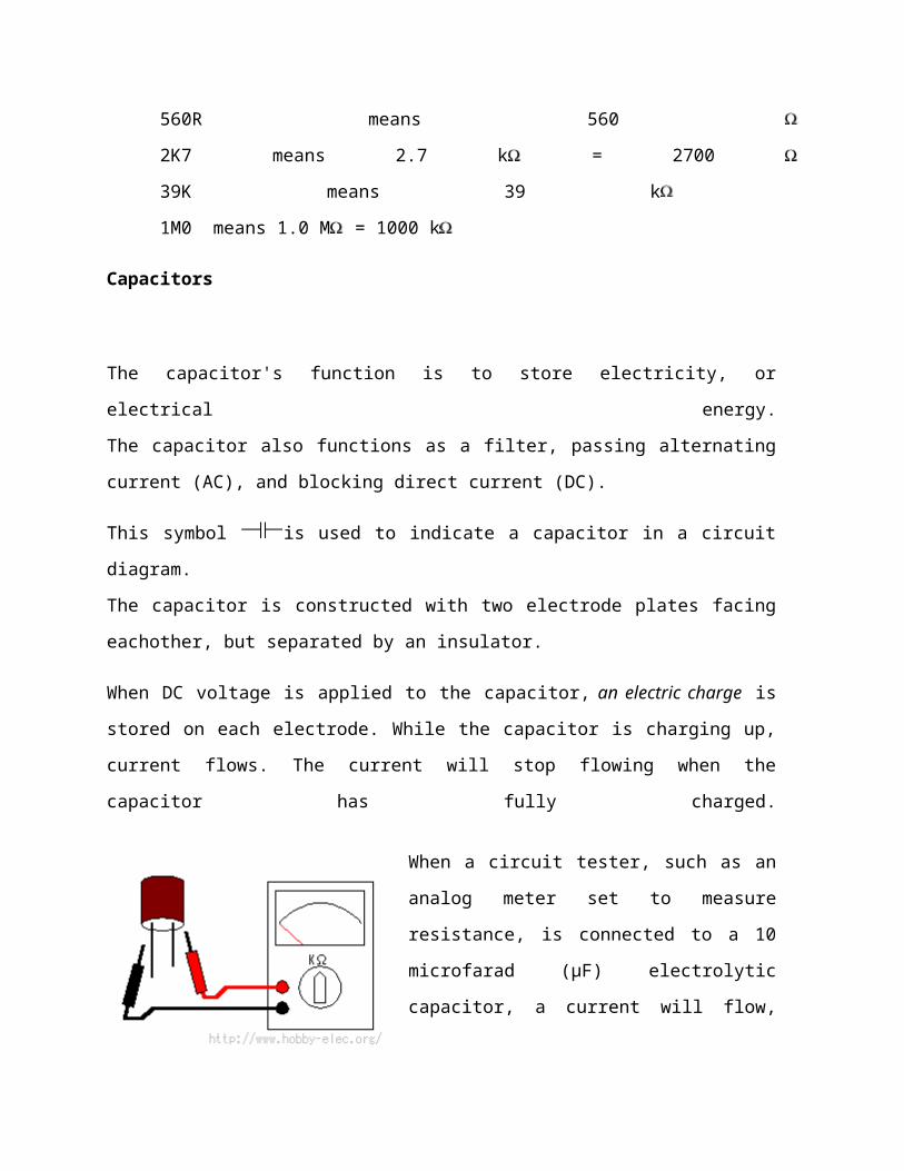
When a circuit tester, such as an
analog meter set to measure
resistance, is connected to a 10
microfarad (µF) electrolytic
capacitor, a current will flow,

but only for a moment. You can confirm that the meter's needle
moves off of zero, but returns to zero right away.
When you connect the meter's probes to the capacitor in
reverse, you will note that current once again flows for a
moment. Once again, when the capacitor has fully charged, the
current stops flowing. So the capacitor can be used as a
filter that blocks DC current. (A "DC cut" filter.)
However, in the case of alternating current, the current will
be allowed to pass. Alternating current is similar to
repeatedly switching the test meter's probes back and forth on
the capacitor. Current flows every time the probes are
switched.
The value of a capacitor (the capacitance), is designated in
units called the Farad(F).
The capacitance of a capacitor is generally very small, so
units such as the microfarad ( 10-6F ), nanofarad ( 10-9F ), and
picofarad (10-12F ) are used.
Recently, an new capacitor with very high capacitance has been
developed. The Electric Double Layer capacitor has capacitance
designated in Farad units. These are known as "Super
Capacitors."
Sometimes, a three-digit code is used to indicate the value of
a capacitor. There are two ways in which the capacitance can
be written. One uses letters and numbers, the other uses only
numbers. In either case, there are only three characters used.
[10n] and [103] denote the same value of capacitance. The
method used differs depending on the capacitor supplier. In
the case that the value is displayed with the three-digit
code, the 1st and 2nd digits from the left show the 1st figure
and the 2nd figure, and the 3rd digit is a multiplier which
determines how many zeros are to be added to the capacitance.
Picofarad ( pF ) units are written this way.
For example, when the code is [103], it indicates 10 x 103, or
10,000pF = 10 nanofarad( nF ) = 0.01 microfarad( µF ).
If the code happened to be [224], it would be 22 x 104 = or
220,000pF = 220nF = 0.22µF.
Values under 100pF are displayed with 2 digits only. eg, 47
would be 47pF.
The capacitor has an insulator( the dielectric ) between 2
sheets of electrodes. Different kinds of capacitors use
different materials for the dielectric.
Breakdown voltage
When using a capacitor, you must pay attention to the maximum
voltage which can be used. This is the "breakdown voltage."
The breakdown voltage depends on the kind of capacitor being
used. You must be especially careful with electrolytic
capacitors because the breakdown voltage is comparatively low.
The breakdown voltage of electrolytic capacitors is displayed
as Working Voltage.
The breakdown voltage is the voltage that when exceeded will
cause the dielectric (insulator) inside the capacitor to break
down and conduct. When this happens, the failure can be
catastrophic.
Electrolytic Capacitors (Electrochemical type capacitors)
Aluminum is used for the electrodes by using a thin
oxidization membrane.
Large values of capacitance can be obtained in comparison with
the size of the capacitor, because the dielectric used is very
thin.
The most important characteristic of electrolytic capacitors
is that they have polarity. They have a positive and a
negative electrode [Polarised]. This means that it is very
important which way round they are connected. If the capacitor
is subjected to voltage exceeding its working voltage, or if
it is connected with incorrect polarity, it may burst. It is
extremely dangerous, because it can quite literally explode.
Make absolutely no mistakes.
Generally, in the circuit diagram, the positive side is
indicated by a "+" (plus) symbol.
Electrolytic capacitors range in value from about 1µF to
thousands of µF. Mainly this type of capacitor is used as a
ripple filter in a power supply circuit, or as a filter to
bypass low frequency signals, etc. Because this type of
capacitor is comparatively similar to the nature of a coil in
construction, it isn't possible to use for high-frequency
circuits. (It is said that the frequency characteristic is
bad.)
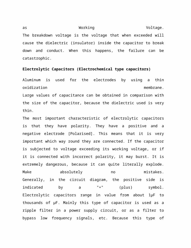
The photograph on the left is an example of the different
values of electrolytic capacitors in which the capacitance and
voltage differ.
From the left to right:
1µF (50V) [diameter 5 mm, high 12 mm]
47µF (16V) [diameter 6 mm, high 5 mm] 100µF (25V) [diameter 5
mm, high 11 mm] 220µF (25V) [diameter 8 mm, high 12 mm] 1000µF
(50V) [diameter 18 mm, high 40 mm]
The size of the capacitor sometimes depends on the
manufacturer. So the
sizes shown here on this page are just examples.
In the photograph to
the right, the mark
indicating the
negative lead of the
component can be
seen. You need to pay
attention to the
polarity indication
so as not to make a
mistake when you
assemble the circuit.
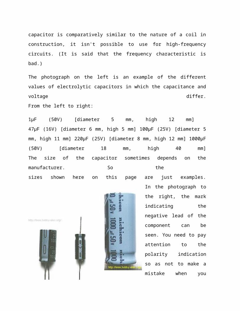
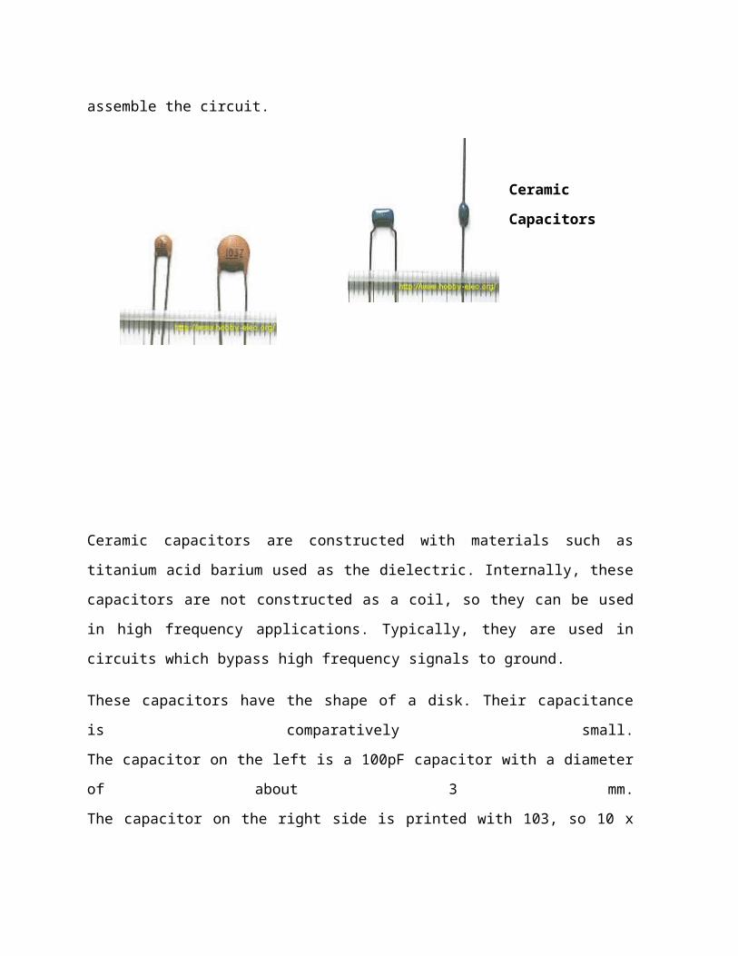
Ceramic
Capacitors
Ceramic capacitors are constructed with materials such as
titanium acid barium used as the dielectric. Internally, these
capacitors are not constructed as a coil, so they can be used
in high frequency applications. Typically, they are used in
circuits which bypass high frequency signals to ground.
These capacitors have the shape of a disk. Their capacitance
is comparatively small.
The capacitor on the left is a 100pF capacitor with a diameter
of about 3 mm.
The capacitor on the right side is printed with 103, so 10 x
103pF becomes 0.01 µF. The diameter of the disk is about 6 mm.
Ceramic capacitors have no polarity.
Ceramic capacitors should not be used for analog circuits,
because they can distort the signal.
Multilayer Ceramic Capacitors
The multilayer ceramic capacitor has a many-layered
dielectric. These capacitors are small in size, and have good
temperature and frequency characteristics.
Square wave signals used in digital circuits can have a
comparatively high frequency component included.
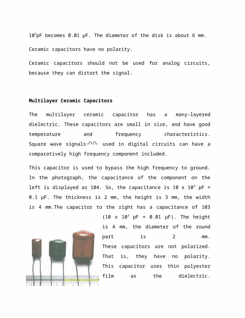
This capacitor is used to bypass the high frequency to ground.
In the photograph, the capacitance of the component on the
left is displayed as 104. So, the capacitance is 10 x 104 pF =
0.1 µF. The thickness is 2 mm, the height is 3 mm, the width
is 4 mm.The capacitor to the right has a capacitance of 103
(10 x 103 pF = 0.01 µF). The height
is 4 mm, the diameter of the round
part is 2 mm.
These capacitors are not polarized.
That is, they have no polarity.
This capacitor uses thin polyester
film as the dielectric.
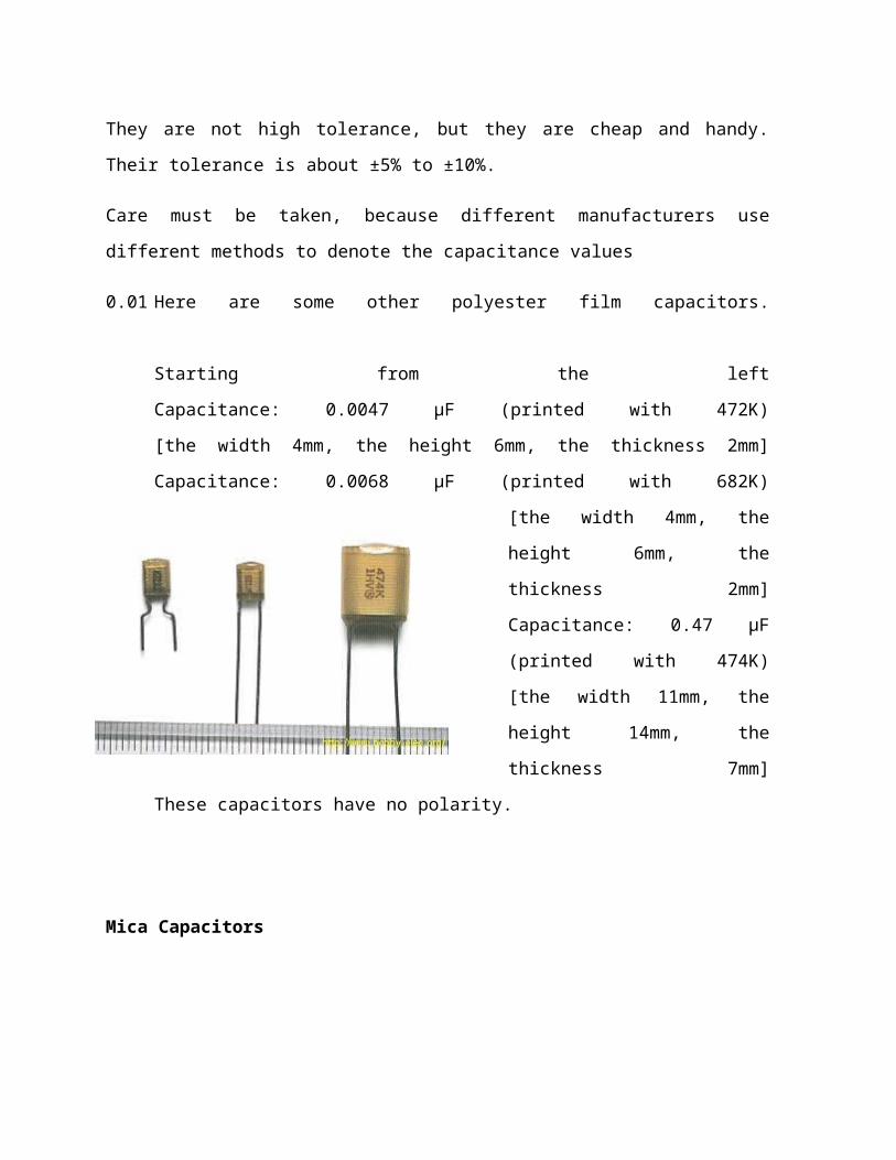
They are not high tolerance, but they are cheap and handy.
Their tolerance is about ±5% to ±10%.
Care must be taken, because different manufacturers use
different methods to denote the capacitance values
0.01 Here are some other polyester film capacitors.
Starting from the left
Capacitance: 0.0047 µF (printed with 472K)
[the width 4mm, the height 6mm, the thickness 2mm]
Capacitance: 0.0068 µF (printed with 682K)
[the width 4mm, the
height 6mm, the
thickness 2mm]
Capacitance: 0.47 µF
(printed with 474K)
[the width 11mm, the
height 14mm, the
thickness 7mm]
These capacitors have no polarity.
Mica Capacitors
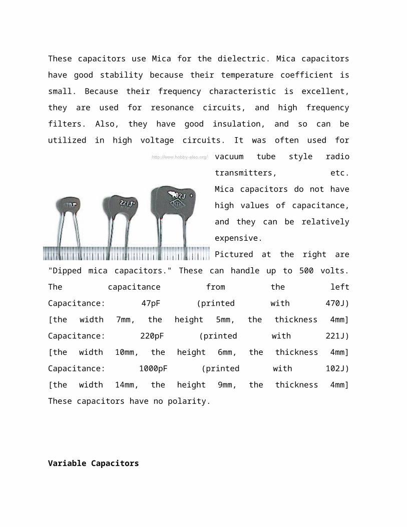
These capacitors use Mica for the dielectric. Mica capacitors
have good stability because their temperature coefficient is
small. Because their frequency characteristic is excellent,
they are used for resonance circuits, and high frequency
filters. Also, they have good insulation, and so can be
utilized in high voltage circuits. It was often used for
vacuum tube style radio
transmitters, etc.
Mica capacitors do not have
high values of capacitance,
and they can be relatively
expensive.
Pictured at the right are
"Dipped mica capacitors." These can handle up to 500 volts.
The capacitance from the left
Capacitance: 47pF (printed with 470J)
[the width 7mm, the height 5mm, the thickness 4mm]
Capacitance: 220pF (printed with 221J)
[the width 10mm, the height 6mm, the thickness 4mm]
Capacitance: 1000pF (printed with 102J)
[the width 14mm, the height 9mm, the thickness 4mm]
These capacitors have no polarity.
Variable Capacitors
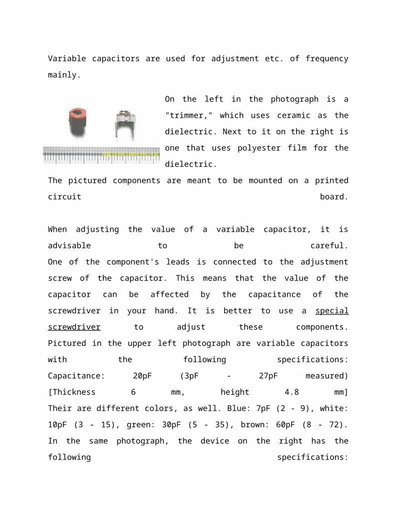
Variable capacitors are used for adjustment etc. of frequency
mainly.
On the left in the photograph is a
"trimmer," which uses ceramic as the
dielectric. Next to it on the right is
one that uses polyester film for the
dielectric.
The pictured components are meant to be mounted on a printed
circuit board.
When adjusting the value of a variable capacitor, it is
advisable to be careful.
One of the component's leads is connected to the adjustment
screw of the capacitor. This means that the value of the
capacitor can be affected by the capacitance of the
screwdriver in your hand. It is better to use a special
screwdriver to adjust these components.
Pictured in the upper left photograph are variable capacitors
with the following specifications:
Capacitance: 20pF (3pF - 27pF measured)
[Thickness 6 mm, height 4.8 mm]
Their are different colors, as well. Blue: 7pF (2 - 9), white:
10pF (3 - 15), green: 30pF (5 - 35), brown: 60pF (8 - 72).
In the same photograph, the device on the right has the
following specifications:

Capacitance: 30pF (5pF - 40pF measured)
[The width (long) 6.8 mm, width (short) 4.9 mm, and the height
5 mm]
The components in the photograph on the right are used for
radio tuners, etc. They are called "Varicons" but this may be
only in Japan.
The variable capacitor on the left in the photograph, uses air
as the dielectric. It combines three independent capacitors.
For each one, the capacitance changed 2pF - 18pF. When the
adjustment axis is turned, the capacitance of all 3 capacitors
change simultaneously.
Physically, the device has a depth of 29 mm, and 17 mm width
and height. (Not including the adjustment rod.)
There are various kinds of variable capacitor, chosen in
accordance with the purpose for which they are needed. The
pictured components are very small.
To the right in the photograph is a variable capacitor using
polyester film as the dielectric.
Two independent capacitors are
combined.
The capacitance of one side
changes 12pF - 150pF, while the
other side changes from 11pF -
70pF.
Physically, it has a depth of 11mm, and 20mm width and height.
(Not including the adjustment rod.)
The pictured device also has a small trimmer built in to each
capacitor to allow for precise adjustment up to 15pF.
What is a Rectifier?
A rectifier changes alternating current into direct current. This
process is called rectification. The three main types of
rectifier are the half-wave, full-wave, and bridge. A rectifier
is the opposite of an inverter, which changes direct current into
alternating current.
Half-Wave Rectifier
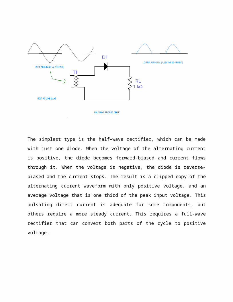
The simplest type is the half-wave rectifier, which can be made
with just one diode. When the voltage of the alternating current
is positive, the diode becomes forward-biased and current flows
through it. When the voltage is negative, the diode is reverse-
biased and the current stops. The result is a clipped copy of the
alternating current waveform with only positive voltage, and an
average voltage that is one third of the peak input voltage. This
pulsating direct current is adequate for some components, but
others require a more steady current. This requires a full-wave
rectifier that can convert both parts of the cycle to positive
voltage.
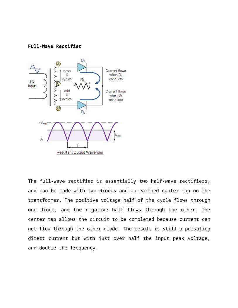
Full-Wave Rectifier
The full-wave rectifier is essentially two half-wave rectifiers,
and can be made with two diodes and an earthed center tap on the
transformer. The positive voltage half of the cycle flows through
one diode, and the negative half flows through the other. The
center tap allows the circuit to be completed because current can
not flow through the other diode. The result is still a pulsating
direct current but with just over half the input peak voltage,
and double the frequency.
D.C. MOTOR
In any electric motor, operation is based on simple
electromagnetism. A current-carrying conductor generates a
magnetic field; when this is then placed in an external magnetic
field, it will experience a force proportional to the current in
the conductor, and to the strength of the external magnetic
field. As you are well aware of from playing with magnets as a
kid, opposite (North and South) polarities attract, while like
polarities (North and North, South and South) repel. The internal
configuration of a DC motor is designed to harness the magnetic
interaction between a current-carrying conductor and an external
magnetic field to generate rotational motion.
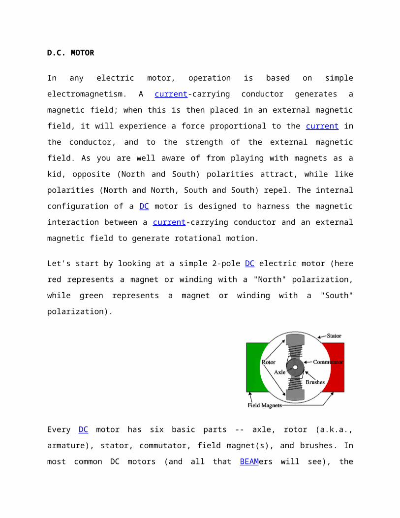
Let's start by looking at a simple 2-pole DC electric motor (here
red represents a magnet or winding with a "North" polarization,
while green represents a magnet or winding with a "South"
polarization).
Every DC motor has six basic parts -- axle, rotor (a.k.a.,
armature), stator, commutator, field magnet(s), and brushes. In
most common DC motors (and all that BEAMers will see), the
external magnetic field is produced by high-strength permanent
magnets1. The stator is the stationary part of the motor -- this
includes the motor casing, as well as two or more permanent
magnet pole pieces. The rotor (together with the axle and
attached commutator) rotate with respect to the stator. The rotor
consists of windings (generally on a core), the windings being
electrically connected to the commutator. The above diagram shows
a common motor layout -- with the rotor inside the stator (field)
magnets.
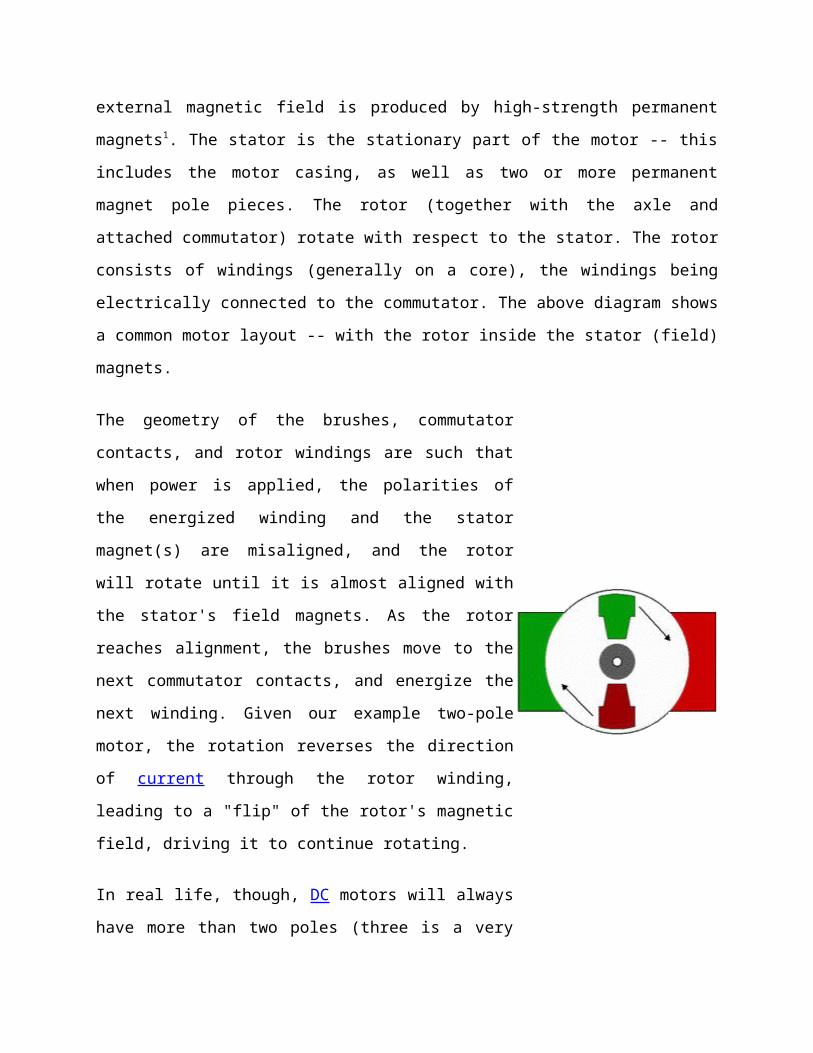
The geometry of the brushes, commutator
contacts, and rotor windings are such that
when power is applied, the polarities of
the energized winding and the stator
magnet(s) are misaligned, and the rotor
will rotate until it is almost aligned with
the stator's field magnets. As the rotor
reaches alignment, the brushes move to the
next commutator contacts, and energize the
next winding. Given our example two-pole
motor, the rotation reverses the direction
of current through the rotor winding,
leading to a "flip" of the rotor's magnetic
field, driving it to continue rotating.
In real life, though, DC motors will always
have more than two poles (three is a very
common number). In particular, this avoids
"dead spots" in the commutator. You can
imagine how with our example two-pole
motor, if the rotor is exactly at the
middle of its rotation (perfectly aligned
with the field magnets), it will get
"stuck" there. Meanwhile, with a two-pole
motor, there is a moment where the
commutator shorts out the power supply
(i.e., both brushes touch both commutator
contacts simultaneously). This would be bad
for the power supply, waste energy, and
damage motor components as well. Yet
another disadvantage of such a simple motor
is that it would exhibit a high amount of
torque "ripple" (the amount of torque it
could produce is cyclic with the position
of the rotor).
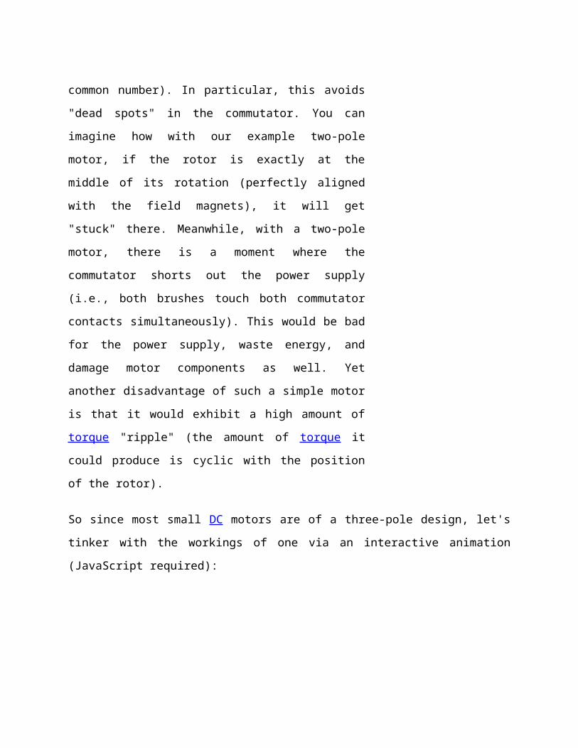
So since most small DC motors are of a three-pole design, let's
tinker with the workings of one via an interactive animation
(JavaScript required):
You'll notice a few things from this -- namely, one pole is fully
energized at a time (but two others are "partially" energized).
As each brush transitions from one commutator contact to the
next, one coil's field will rapidly collapse, as the next coil's
field will rapidly charge up (this occurs within a few
microsecond). We'll see more about the effects of this later, but
in the meantime you can see that this is a direct result of the
coil windings' series wiring:
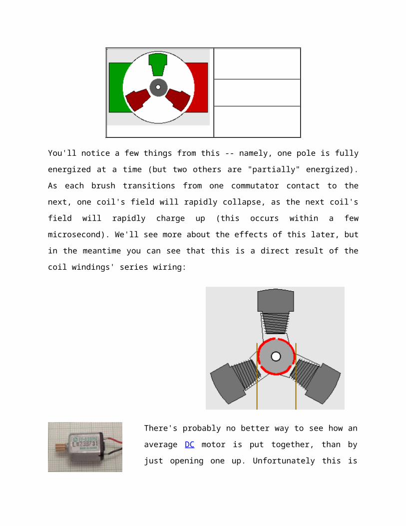
There's probably no better way to see how an
average DC motor is put together, than by
just opening one up. Unfortunately this is

tedious work, as well as requiring the
destruction of a perfectly good motor.
Luckily for you, I've gone ahead and done
this in your stead. The guts of a
disassembled Mabuchi FF-030-PN motor (the
same model that Solarbotics sells) are
available for you to see here (on 10 lines /
cm graph paper). This is a basic 3-pole DC
motor, with 2 brushes and three commutator
contacts.
The use of an iron core armature (as in the Mabuchi, above) is
quite common, and has a number of advantages2. First off, the
iron core provides a strong, rigid support for the windings -- a
particularly important consideration for high-torque motors. The
core also conducts heat away from the rotor windings, allowing
the motor to be driven harder than might otherwise be the case.
Iron core construction is also relatively inexpensive compared
with other construction types.
But iron core construction also has several disadvantages. The
iron armature has a relatively high inertia which limits motor
acceleration. This construction also results in high winding
inductances which limit brush and commutator life.
In small motors, an alternative design is often used which
features a 'coreless' armature winding. This design depends upon
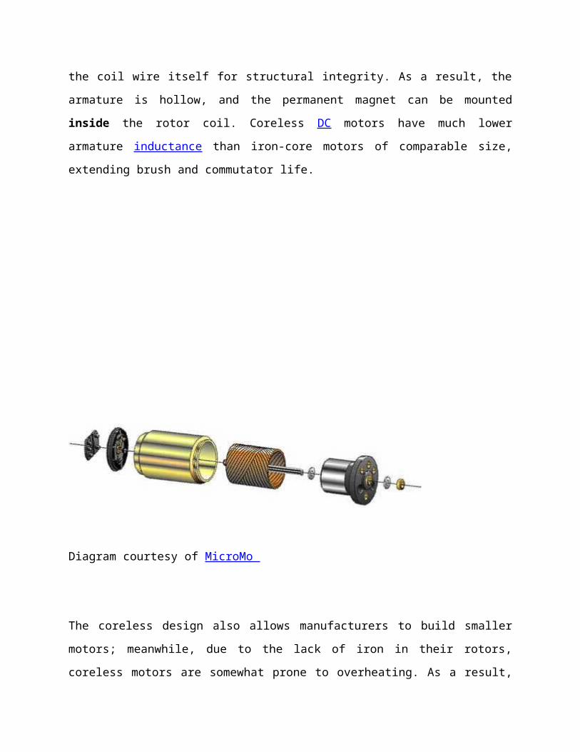
the coil wire itself for structural integrity. As a result, the
armature is hollow, and the permanent magnet can be mounted
inside the rotor coil. Coreless DC motors have much lower
armature inductance than iron-core motors of comparable size,
extending brush and commutator life.
Diagram courtesy of MicroMo
The coreless design also allows manufacturers to build smaller
motors; meanwhile, due to the lack of iron in their rotors,
coreless motors are somewhat prone to overheating. As a result,
this design is generally used just in small, low-power motors.
BEAMers will most often see coreless DC motors in the form of
pager motors.
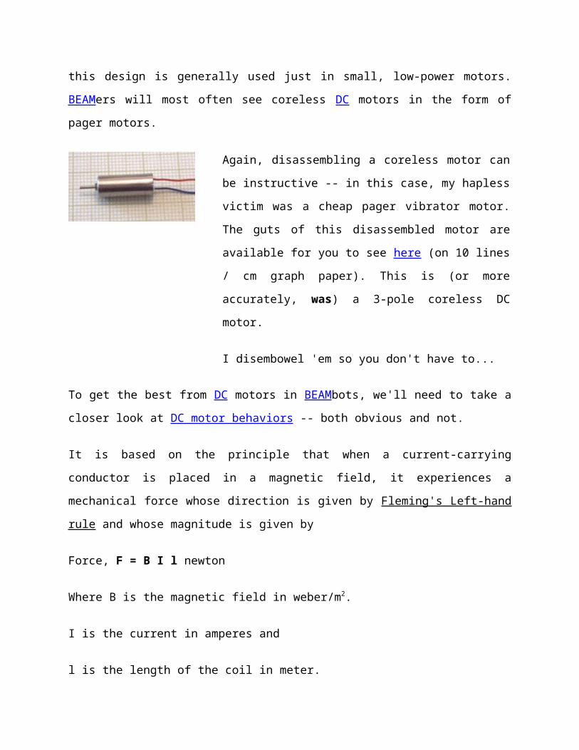
Again, disassembling a coreless motor can
be instructive -- in this case, my hapless
victim was a cheap pager vibrator motor.
The guts of this disassembled motor are
available for you to see here (on 10 lines
/ cm graph paper). This is (or more
accurately, was) a 3-pole coreless DC
motor.
I disembowel 'em so you don't have to...
To get the best from DC motors in BEAMbots, we'll need to take a
closer look at DC motor behaviors -- both obvious and not.
It is based on the principle that when a current-carrying
conductor is placed in a magnetic field, it experiences a
mechanical force whose direction is given by Fleming's Left-hand
rule and whose magnitude is given by
Force, F = B I l newton
Where B is the magnetic field in weber/m2.
I is the current in amperes and
l is the length of the coil in meter.
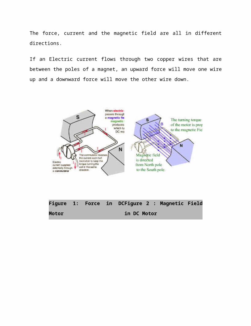
The force, current and the magnetic field are all in different
directions.
If an Electric current flows through two copper wires that are
between the poles of a magnet, an upward force will move one wire
up and a downward force will move the other wire down.
Figure 1: Force in DC
Motor
Figure 2 : Magnetic Field
in DC Motor

Figure 3 : Torque in DC
Motor
Figure 4 : Current Flow in
DC Motor
The loop can be made to spin by fixing a half circle of copper
which is known as commutator, to each end of the loop. Current is
passed into and out of the loop by brushes that press onto the
strips. The brushes do not go round so the wire do not get
twisted. This arrangement also makes sure that the current always
passes down on the right and back on the left so that the
rotation continues. This is how a simple Electric motor is made.
References

www.datasheetarchive.com
www.google.com
www.wikipedia.com
www.answers.com