J Series 2.0, 2.4, and 3.0kW - QED Productions
94
J Series 2.0, 2.4, and 3.0kW Service Manual 020-100739-01
-
Upload
khangminh22 -
Category
Documents
-
view
0 -
download
0
Transcript of J Series 2.0, 2.4, and 3.0kW - QED Productions
J Series2.0, 2.4, and 3.0kW
S e r v i c e M a n u a l
020-100739-01

J Series2.0, 2.4, and 3.0kW
S e r v i c e M a n u a l
020-100739-01
NOTICES
COPYRIGHT AND TRADEMARKS
© 2011 Christie Digital Systems USA, Inc. - All rights reserved.
All brand names and product names are trademarks, registered trademarks or trade names of their respective holders.
REGULATORY
The product has been tested and found to comply with the limits for a Class A digital device, pursuant to Part 15 of the FCC Rules. These limits are designed to provide reasonable protection against harmful interference when the product is operated in a commercial environment. The product generates, uses, and can radiate radio frequency energy and, if not installed and used in accordance with the instruction manual, may cause harmful interference to radio communications. Operation of the product in a residential area is likely to cause harmful interference in which case the user will be required to correct the interference at the users own expense.
This Class A digital apparatus complies with Canadian ICES-003.Cet appareil numérique de la classe A est conforme à la norme NMB-003 du Canada.
(A ) , .
GENERAL
Every effort has been made to ensure accuracy, however in some cases changes in the products or availability could occur which may not be reflected in this document. Christie reserves the right to make changes to specifications at any time without notice. Performance specifications are typical, but may vary depending on conditions beyond Christie's control such as maintenance of the product in proper working conditions. Performance specifications are based on information available at the time of printing. Christie makes no warranty of any kind with regard to this material, including, but not limited to, implied warranties of fitness for a particular purpose. Christie will not be liable for errors contained herein or for incidental or consequential damages in connection with the performance or use of this material.
The product is designed and manufactured with high-quality materials and components that can be recycled and reused. This symbol means that electrical and electronic equipment, at their end-of-life, should be disposed of separately from regular waste. Please dispose of the product appropriately and according to local regulations. In the European Union, there are separate collection systems for used
electrical and electronic products. Please help us to conserve the environment we live in!
Canadian manufacturing facility is ISO 9001 and 14001 certified.
GENERAL WARRANTY STATEMENTS
For complete information about Christie limited warranty, please contact your Christie dealer. In addition to the other limitations that may be specified in Christie limited warranty, the warranty does not cover:
a. Damage occurring during shipment, in either direction.b. Projector lamps (See Christie separate lamp program policy).c. Damage caused by use of a projector lamp beyond the recommended lamp life, or use of a lamp supplied by a supplier other than Christie.d. Problems caused by combination of the product with non-Christie equipment, such as distribution systems, cameras, video tape recorders,
etc., or use of the product with any non-Christie interface device.e. Damage caused by misuse, improper power source, accident, fire, flood, lightening, earthquake or other natural disaster.f. Damage caused by improper installation/alignment, or by product modification, if by other than a Christie authorized repair service
provider.g. For LCD projectors, the warranty period specified applies only where the LCD projector is in “normal use.” “Normal use” means the LCD
projector is not used more than 8 hours a day, 5 days a week. For any LCD projector where “normal use” is exceeded, warranty coverage under this warranty terminates after 6000 hours of operation.
h. Failure due to normal wear and tear.
PREVENTATIVE MAINTENANCE
Preventative maintenance is an important part of the continued and proper operation of your product. Please see the Maintenance section for specific maintenance items as they relate to your product. Failure to perform maintenance as required, and in accordance with the maintenance
schedule specified by Christie, will void the warranty.
Table of Contents
1: Introduction
1.1 Safety Warnings and Guidelines .................................................................................................1-11.1.1 Repair Cautions....................................................................................................................1-11.1.2 General Precautions .............................................................................................................1-21.1.3 AC /Power Precautions........................................................................................................1-31.1.4 Lamp Precautions ................................................................................................................1-3
2: Projector Maintenance
2.0.1 Cleaning Projector Components ..........................................................................................2-12.0.2 Inspect Ventilation...............................................................................................................2-12.0.3 Inspect Power Supplies and Power Cords ...........................................................................2-22.0.4 Replace the Filter .................................................................................................................2-22.0.5 Inspect and Clean Optics .....................................................................................................2-22.0.6 Clean the Lens .....................................................................................................................2-3
3: Troubleshooting
3.0.1 Contact Technical Support...................................................................................................3-13.1 Temperature Sensor Locations ....................................................................................................3-13.2 Projector LED Status Indicators ..................................................................................................3-23.3 Retrieve Projector Error Messages ..............................................................................................3-2
3.3.1 How To Obtain an Error Log...............................................................................................3-23.3.2 Problems to Save an Error Log............................................................................................3-23.3.3 Submit an Error Log for Analysis........................................................................................3-43.3.4 LCD Error Messages ...........................................................................................................3-4
4: Parts and Module Replacement
4.1 Ordering Parts..............................................................................................................................4-14.1.1 Projector Exploded View.....................................................................................................4-24.1.2 Optical Engine Exploded View ...........................................................................................4-34.1.3 Projector Keypad Exploded View .......................................................................................4-3
4.2 Available Replacement Parts and Modules .................................................................................4-44.3 Servicing Guidelines....................................................................................................................4-64.4 Tools Required ............................................................................................................................4-64.5 Remove and Replacement of Parts ..............................................................................................4-7
4.5.1 Remove and Replace the Liquid Cooling Module...............................................................4-74.5.2 Remove and Replace AC Lamp Blower Fan.......................................................................4-84.5.3 Remove and Replace Anode Fan (2.0 & 2.4kW Only) .......................................................4-104.5.4 Remove and Replace the Integrator Blower Fan .................................................................4-104.5.5 Remove and Replace the Card Cage Cooling Fan...............................................................4-114.5.6 Remove and Replace the Prism Fan ....................................................................................4-124.5.7 Remove and Replace the Red Channel Cooling Fan...........................................................4-134.5.8 Remove and Replace the Lamp Ballast ...............................................................................4-134.5.9 Remove and Replace the Low Voltage Power Supply (LVPS)...........................................4-154.5.10 Remove and Replace the AC Line Filter ...........................................................................4-164.5.11 Remove and Replace the AC Power Switch (2.0kW & 2.4kW) ......................................4-17
J Series 2.0, 2.4, and 3.0kW Service Manual i020-100739-01 Rev. 1 (01-2012)
Table of Contents
4.5.12 Remove and Replace the AC Power Switch (3.0kW) ...................................................... 4-184.5.13 Remove and Replace the AC Voltmeter ........................................................................... 4-194.5.14 Remove and Replace the Igniter ....................................................................................... 4-194.5.15 Remove and Replace the Lamp ........................................................................................ 4-204.5.16 Remove and Replace the Lamp Memory Module ............................................................ 4-234.5.17 Remove and Replace the Air Filter................................................................................... 4-244.5.18 Remove and Replace the Light Engine............................................................................. 4-244.5.19 Remove and Replace the Feet ........................................................................................... 4-254.5.20 Remove and Replace the Front IR Sensor ........................................................................ 4-264.5.21 Remove and Replace the Rear IR Sensor ......................................................................... 4-274.5.22 Remove and Replace the Lens Mount .............................................................................. 4-274.5.23 Remove and Replace the Thermal Sensor / Keypad Harness Assembly .......................... 4-304.5.24 Remove and Replace the Temp 2 Exhaust PC Board ....................................................... 4-304.5.25 Remove and Replace the Integrator Rod Assembly ........................................................ 4-314.5.26 Remove and Replace the Fold Mirror .............................................................................. 4-314.5.27 Remove and Replace the Shutter Assembly .................................................................... 4-334.5.28 Remove and Replace the Cold Mirror Assembly ............................................................ 4-334.5.29 Remove and Replace the Contrast Aperture Assembly ................................................... 4-354.5.30 Remove and Replace the LiteLOC Assembly .................................................................. 4-354.5.31 Remove and Replace the Optical Glass Window ............................................................. 4-364.5.32 Remove and Replace the Panel Driver ............................................................................. 4-394.5.33 Remove and Replace the Projector Keypad...................................................................... 4-404.5.34 Remove and Replace the Convenience Light Board ........................................................ 4-404.5.35 Remove and Replace the AC Relay Module .................................................................... 4-414.5.36 Remove and Replace the LCD Display ............................................................................ 4-424.5.37 Remove and Replace the Passive Backplane Module ...................................................... 4-424.5.38 Remove and Replace the Processor Board ....................................................................... 4-434.5.39 Remove and Replace the Input Module ............................................................................ 4-444.5.40 Remove the Lens............................................................................................................... 4-444.5.41 Install the Lens .................................................................................................................. 4-454.5.42 Remove and Replace the Lamp Door Interlock Switch.................................................... 4-454.5.43 Remove and Replace the Card Cage................................................................................. 4-46
4.6 Boresight Alignment................................................................................................................... 4-474.7 Fold Mirror Adjustment.............................................................................................................. 4-484.8 Integrator Assembly Adjustment ................................................................................................ 4-48
5: Interconnections
5.1 Interconnect Drawing.................................................................................................................. 5-1
6: Specifications
6.1 Image Performance ..................................................................................................................... 6-16.1.1 Pixel Format ....................................................................................................................... 6-16.1.2 Nominal Brightness............................................................................................................. 6-16.1.3 Contrast ............................................................................................................................... 6-16.1.4 Luminance Uniformity........................................................................................................ 6-1
ii J Series 2.0, 2.4, and 3.0kW Service Manual020-100739-01 Rev. 1 (01-2012)
Table of Contents
6.1.5 Gamma.................................................................................................................................6-16.1.6 Grayscale/Color Resolution.................................................................................................6-26.1.7 Color Temperature ...............................................................................................................6-26.1.8 Convergence ........................................................................................................................6-26.1.9 Blemishes.............................................................................................................................6-36.1.10 Pixel Defects ......................................................................................................................6-3
6.2 Feature Set ...................................................................................................................................6-36.2.1 Airflow ................................................................................................................................6-36.2.2 Air Filters (Optional) ...........................................................................................................6-36.2.3 Dust Sealing.........................................................................................................................6-36.2.4 ILS (Intelligent Lens System)..............................................................................................6-36.2.5 Projection Lens Compatibility .............................................................................................6-46.2.6 Automatic Fans ....................................................................................................................6-46.2.7 Constant Lamp Output Management ...................................................................................6-46.2.8 Shutter .................................................................................................................................6-56.2.9 Lamps...................................................................................................................................6-56.2.10 Status LED.........................................................................................................................6-56.2.11 Electronics/SW .................................................................................................................6-5
6.3 Image Processor Performance .....................................................................................................6-66.4 Input (Source Signal) Compatibility ...........................................................................................6-6
6.4.1 Analog (Only) Input.............................................................................................................6-66.4.2 Twin HDMI Input ................................................................................................................6-66.4.3 Dual Link DVI Input............................................................................................................6-76.4.4 Video Decoder Input............................................................................................................6-76.4.5 Dual 3G/HD/SD - SDI Input ...............................................................................................6-7
6.5 Control Signal Compatibility ......................................................................................................6-76.5.1 Projector Control..................................................................................................................6-76.5.2 Control Receiver ..................................................................................................................6-76.5.3 RS-232 .................................................................................................................................6-86.5.4 RS-422 .................................................................................................................................6-86.5.5 Ethernet ................................................................................................................................6-86.5.6 USB 2.0 Device Port ...........................................................................................................6-86.5.7 GPIO ....................................................................................................................................6-86.5.8 DMX512 Interface...............................................................................................................6-86.5.9 Built-In Keypad and Display ...............................................................................................6-86.5.10 Convenience Light .............................................................................................................6-8
6.6 Power Requirements....................................................................................................................6-96.6.1 Lamp Specification ..............................................................................................................6-9
6.7 Physical Specifications ................................................................................................................6-96.7.1 Size.......................................................................................................................................6-96.7.2 Adjustment...........................................................................................................................6-106.7.3 Weight..................................................................................................................................6-10
6.8 Reliability and Serviceability ......................................................................................................6-106.8.1 Reliability.............................................................................................................................6-106.8.2 Serviceability .......................................................................................................................6-10
6.9 Environment ................................................................................................................................6-10
J Series 2.0, 2.4, and 3.0kW Service Manual iii020-100739-01 Rev. 1 (01-2012)
Table of Contents
6.9.1 Temperature/Humidity/Altitude.......................................................................................... 6-106.10 Accessories and Service Components ...................................................................................... 6-116.11 Regulatory................................................................................................................................. 6-11
6.11.1 Safety ................................................................................................................................ 6-116.11.2 Electro-Magnetic Compatibility ....................................................................................... 6-126.11.3 Environmental ................................................................................................................... 6-126.11.4 Marking............................................................................................................................. 6-12
A: Appendix Projector Menus
A.1 J Series Menu Tree..................................................................................................................... A-1
iv J Series 2.0, 2.4, and 3.0kW Service Manual020-100739-01 Rev. 1 (01-2012)
1 IntroductionThis manual provides information and procedures for servicing the J Series 2.0, 2.4, and 3.0kW projectors. This manual assumes a familiarity with J Series functionality.Only accredited Christie technicians who are knowledgeable about the hazards associated with high-voltage, ultraviolet exposure, and the high temperatures generated by the projector lamp are authorized to assemble, install, and service projectors.
1.1 Safety Warnings and Guidelines
Always power down and disconnect power sources prior to servicing.
High voltages may be exposed! Always unplug the projector prior to disassembly.
Christie accredited service technicians required! All module replacement procedures must be performed by qualified service technicians.
Non-insulated dangerous voltages may be exposed! Always disconnect from AC prior to disassembly.
Observe all electrostatic precautions! Use a grounded wrist strap when handling electronic assemblies.
Allow lamp and projector to cool down! Once you have turned off the projector, allow the cooling fans to automatically turn off before disconnecting from AC and opening the projector. This takes approximately 15 minutes.
1.1.1 Repair Cautions
Ensure the projector is disconnected from AC power before you start testing, removing, or installing modules.
Do not operate the projector with any internal parts removed. If for testing purposes, you must operate the projector without the lid and/or lamp door, ensure to wear UV glasses and stand well back from the projector at all times.
WARNING
WARNING
WARNING
WARNING
WARNING
WARNING
WARNING
WARNING
J Series 2.0, 2.4, and 3.0kW Service Manual 1-1020-100739-01 Rev. 1 (01-2012)
Section 1: Introduction
1.1.2 General Precautions
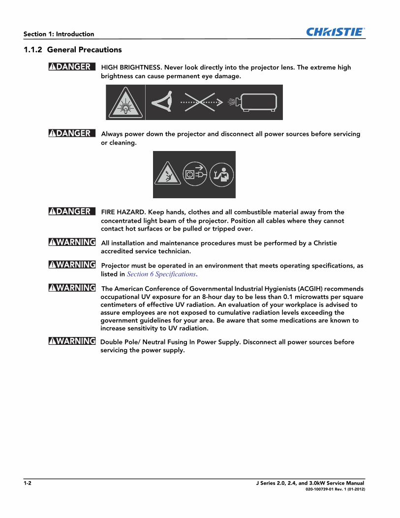
HIGH BRIGHTNESS. Never look directly into the projector lens. The extreme high brightness can cause permanent eye damage.
Always power down the projector and disconnect all power sources before servicing or cleaning.
FIRE HAZARD. Keep hands, clothes and all combustible material away from the concentrated light beam of the projector. Position all cables where they cannot contact hot surfaces or be pulled or tripped over.
All installation and maintenance procedures must be performed by a Christie accredited service technician.
Projector must be operated in an environment that meets operating specifications, as listed in Section 6 Specifications.
The American Conference of Governmental Industrial Hygienists (ACGIH) recommends occupational UV exposure for an 8-hour day to be less than 0.1 microwatts per square centimeters of effective UV radiation. An evaluation of your workplace is advised to assure employees are not exposed to cumulative radiation levels exceeding the government guidelines for your area. Be aware that some medications are known to increase sensitivity to UV radiation.
Double Pole/ Neutral Fusing In Power Supply. Disconnect all power sources before servicing the power supply.
DANGER
DANGER
DANGER
WARNING
WARNING
WARNING
WARNING
1-2 J Series 2.0, 2.4, and 3.0kW Service Manual020-100739-01 Rev. 1 (01-2012)
Section 1: Introduction
1.1.3 AC /Power Precautions
Use only the AC power cord supplied. Do not attempt operation if the AC supply and cord are not within the specified voltage and power range. Refer to the license label on the back of the projector or Section 6 Specifications for rated voltage and power.
The projector is equipped with a 3-wire plug with a grounding pin. This is a safety feature. If you are unable to insert the plug into the outlet, contact an electrician to have the outlet replaced. NEVER defeat the safety purpose of the grounding-type plug.
Do not allow anything to rest on the power cord. Locate the power cord where persons walking on it or objects rolling over it cannot damage the cord.
1.1.4 Lamp Precautions
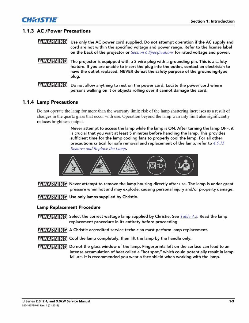
Do not operate the lamp for more than the warranty limit; risk of the lamp shattering increases as a result of changes in the quartz glass that occur with use. Operation beyond the lamp warranty limit also significantly reduces brightness output. Never attempt to access the lamp while the lamp is ON. After turning the lamp OFF, it
is crucial that you wait at least 5 minutes before handling the lamp. This provides sufficient time for the lamp cooling fans to properly cool the lamp. For all other precautions critical for safe removal and replacement of the lamp, refer to 4.5.15 Remove and Replace the Lamp.
Never attempt to remove the lamp housing directly after use. The lamp is under great pressure when hot and may explode, causing personal injury and/or property damage.
Use only lamps supplied by Christie.
Lamp Replacement Procedure
Select the correct wattage lamp supplied by Christie. See Table 4.2. Read the lamp replacement procedure in its entirety before proceeding.
A Christie accredited service technician must perform lamp replacement.
Cool the lamp completely, then lift the lamp by the handle only.
Do not the glass window of the lamp. Fingerprints left on the surface can lead to an intense accumulation of heat called a “hot spot,” which could potentially result in lamp failure. It is recommended you wear a face shield when working with the lamp.
WARNING
WARNING
WARNING
WARNING
WARNING
WARNING
WARNING
WARNING
WARNING
J Series 2.0, 2.4, and 3.0kW Service Manual 1-3020-100739-01 Rev. 1 (01-2012)

2 Projector MaintenanceRead this section in its entirety and understand all warnings and precautions before performing projector maintenance.
2.0.1 Cleaning Projector Components
2.0.2 Inspect Ventilation
Vents and louvers in the projector covers provide ventilation, both for intake and exhaust. Inspect the projector regularly to ensure these openings are not blocked or covered. Verify the projector is not installed near a radiator, heat register, or within an enclosure. To ensure adequate airflow around the projector, keep a minimum clearance on the left, right, and rear sides of the projector.
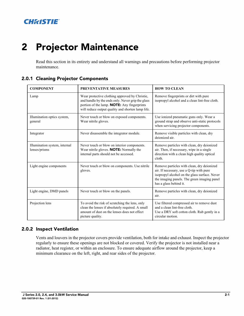
COMPONENT PREVENTATIVE MEASURES HOW TO CLEAN
Lamp Wear protective clothing approved by Christie, and handle by the ends only. Never grip the glass portion of the lamp. NOTE: Any fingerprints will reduce output quality and shorten lamp life.
Remove fingerprints or dirt with pure isopropyl alcohol and a clean lint-free cloth.
Illumination optics system, general
Never touch or blow on exposed components. Wear nitrile gloves.
Use ionized pneumatic guns only. Wear a ground strap and observe anti-static protocols when servicing projector components.
Integrator Never disassemble the integrator module. Remove visible particles with clean, dry deionized air.
Illumination system, internal lenses/prisms
Never touch or blow on interior components. Wear nitrile gloves. NOTE: Normally the internal parts should not be accessed.
Remove particles with clean, dry deionized air. Then, if necessary, wipe in a single direction with a clean high quality optical cloth.
Light engine components Never touch or blow on components. Use nitrile gloves.
Remove particles with clean, dry deionized air. If necessary, use a Q-tip with pure isopropyl alcohol on the glass surface. Never the imaging panels. The green imaging panel has a glass behind it.
Light engine, DMD panels Never touch or blow on the panels. Remove particles with clean, dry deionized air.
Projection lens To avoid the risk of scratching the lens, only clean the lenses if absolutely required. A small amount of dust on the lenses does not effect picture quality.
Use filtered compressed air to remove dust and a clean lint-free cloth. Use a DRY soft cotton cloth. Rub gently in a circular motion.
J Series 2.0, 2.4, and 3.0kW Service Manual 2-1020-100739-01 Rev. 1 (01-2012)
Section 2: Service Guidelines
2.0.3 Inspect Power Supplies and Power Cords
Do not operate the projector if the AC supply is not within the specified voltage and power range.
An appropriate rated power cord for the country of use is provided with each projector. Ensure that you are using a power cord, power plug, and socket that is rated for your location.
You should never open or repair a failed power supply. If a power supply fails, contact Christie support and request a replacement.The use of accessories that are not approved by Christie can result in fire, shock, or personal injury.
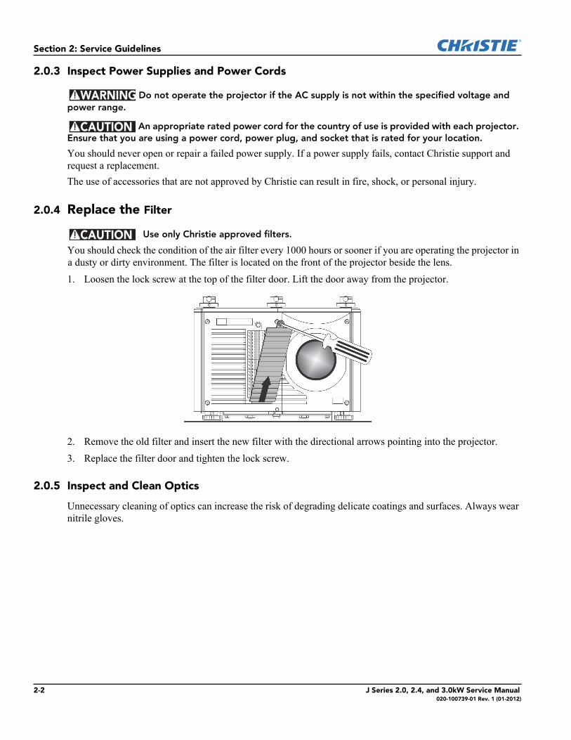
2.0.4 Replace the Filter
Use only Christie approved filters.
You should check the condition of the air filter every 1000 hours or sooner if you are operating the projector in a dusty or dirty environment. The filter is located on the front of the projector beside the lens. 1. Loosen the lock screw at the top of the filter door. Lift the door away from the projector.
2. Remove the old filter and insert the new filter with the directional arrows pointing into the projector.3. Replace the filter door and tighten the lock screw.
2.0.5 Inspect and Clean Optics
Unnecessary cleaning of optics can increase the risk of degrading delicate coatings and surfaces. Always wear nitrile gloves.
WARNING
CAUTION
CAUTION
2-2 J Series 2.0, 2.4, and 3.0kW Service Manual020-100739-01 Rev. 1 (01-2012)
Section 2: Service Guidelines
2.0.6 Clean the Lens
A small amount of dust or dirt on the lens has minimal effect on image quality. To avoid the risk of scratching the lens, clean only if absolutely necessary. Remove Dust:1. Brush most of the dust off with a camel hair brush or use a dust-free blower.2. Fold a microfibre cloth and wipe the remaining dust particles off the lens with the smooth portion of the
cloth that has no folds or creases. Do not apply pressure with your fingers. Instead, use the tension in the folded cloth to remove the dust.
3. If significant dust remains on the lens surface, dampen a clean microfiber cloth with lens cleaning solution and wipe gently until clean.
Remove Fingerprints, Smudges, or Oil:1. Brush most of the dust off with a camel hair brush or use a dust-free blower.2. Wrap a lens tissue around a swab and soak it in lens cleaning solution. The tissue should be damp but not
dripping.3. Gently wipe the surface using a figure eight motion. Repeat until the blemish is removed.
J Series 2.0, 2.4, and 3.0kW Service Manual 2-3020-100739-01 Rev. 1 (01-2012)

3 TroubleshootingThis section provides information and procedures for resolving common projector issues. If you cannot resolve a projector issue, contact Christie technical support.Before you suspect a performance problem:1. Ensure the projector is plugged in.2. Ensure the power switch is in the ON position.3. Ensure the correct voltage is available for your model projector.4. Check the status display window for error codes. 5. Verify that external devices connected to the projector are operating correctly.6. Check source reliability. Switch sources if possible.7. Ensure cables are connected and not damaged.
3.0.1 Contact Technical Support
You can contact Christie technical support by telephone or by email:Telephone: 1-800-221-8025Email: [email protected] (email support is only available in North America)
3.1 Temperature Sensor Locations
Table 3.1 - Temperature Sensor Interface
ID Interface Location
2 Projector exhaust temperature
3 I2C Projector air intake temperature
9 Single Wire Located on the main panel driver and monitors the panel driver board temperature
10 Single Wire Located on the image processor board
13 Single Wire Located on slot 1 option card and monitors option card temperature
14 Single Wire Located on slot 2 option card and monitors option card temperature
15 Single Wire Located on slot 3 option card and monitors option card temperature
16 Single Wire Located on slot 4 option card and monitors option card temperature
J Series 2.0, 2.4, and 3.0kW Service Manual 3-1020-100739-01 Rev. 1 (01-2012)
Section 3: Troubleshooting
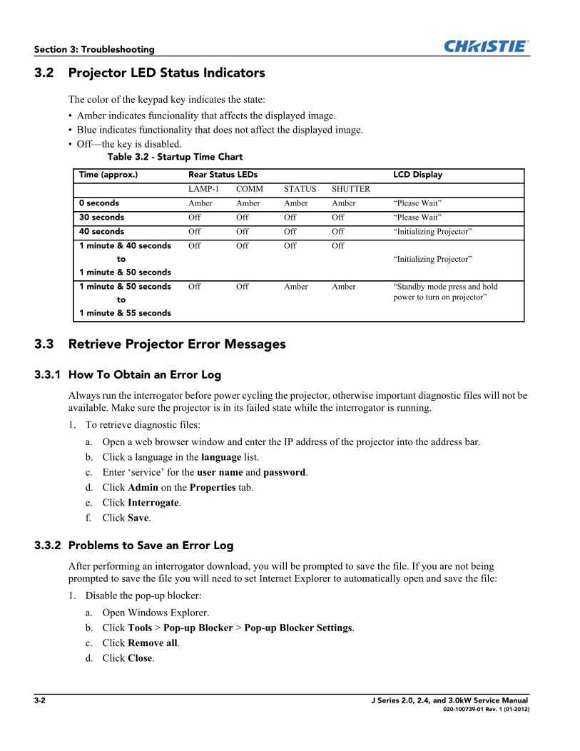
3.2 Projector LED Status Indicators
The color of the keypad key indicates the state:• Amber indicates funcionality that affects the displayed image.• Blue indicates functionality that does not affect the displayed image.• Off—the key is disabled.
3.3 Retrieve Projector Error Messages
3.3.1 How To Obtain an Error Log
Always run the interrogator before power cycling the projector, otherwise important diagnostic files will not be available. Make sure the projector is in its failed state while the interrogator is running. 1. To retrieve diagnostic files:
a. Open a web browser window and enter the IP address of the projector into the address bar.b. Click a language in the language list.c. Enter ‘service’ for the user name and password.d. Click Admin on the Properties tab.e. Click Interrogate.f. Click Save.
3.3.2 Problems to Save an Error Log
After performing an interrogator download, you will be prompted to save the file. If you are not being prompted to save the file you will need to set Internet Explorer to automatically open and save the file: 1. Disable the pop-up blocker:
a. Open Windows Explorer.b. Click Tools > Pop-up Blocker > Pop-up Blocker Settings.c. Click Remove all.d. Click Close.
Table 3.2 - Startup Time Chart
Time (approx.) Rear Status LEDs LCD Display
LAMP-1 COMM STATUS SHUTTER
0 seconds Amber Amber Amber Amber “Please Wait”
30 seconds Off Off Off Off “Please Wait”
40 seconds Off Off Off Off “Initializing Projector”
1 minute & 40 seconds
to
1 minute & 50 seconds
Off Off Off Off“Initializing Projector”
1 minute & 50 seconds
to
1 minute & 55 seconds
Off Off Amber Amber “Standby mode press and hold power to turn on projector”
3-2 J Series 2.0, 2.4, and 3.0kW Service Manual 020-100739-01 Rev. 1 (01-2012)
Section 3: Troubleshooting
2. Enable File Download Promptinga. Open Windows Explorer.a. Click Tools > Internet Options.b. Click Security on the Properties tab.c. Click Internet in the Select a zone to view or change security settings list.d. Click Custom Level.e. Select Downloads > Automatic prompting for file downloads > File download > Enablef. Click OK.g. Click Local intranet in the Select a zone to view or change security settings list.h. Click Custom Level.i. Select Downloads > Automatic prompting for file downloads > File download > Enablej. Click OK.
J Series 2.0, 2.4, and 3.0kW Service Manual 3-3020-100739-01 Rev. 1 (01-2012)
Section 3: Troubleshooting
3.3.3 Submit an Error Log for Analysis
The interrogator log is saved as an encrypted file and is required to be sent to the Christie Service Department for analysis. NOTE: Please allow for a 24 hour response time.1. To submit an error log:
a. Attach the log file to your email.b. Add the following:
• Your name• Company name• Telephone number• Email address• A detailed description of the error• A Photo of the error (optional)
c. Email to: [email protected]
3.3.4 LCD Error Messages
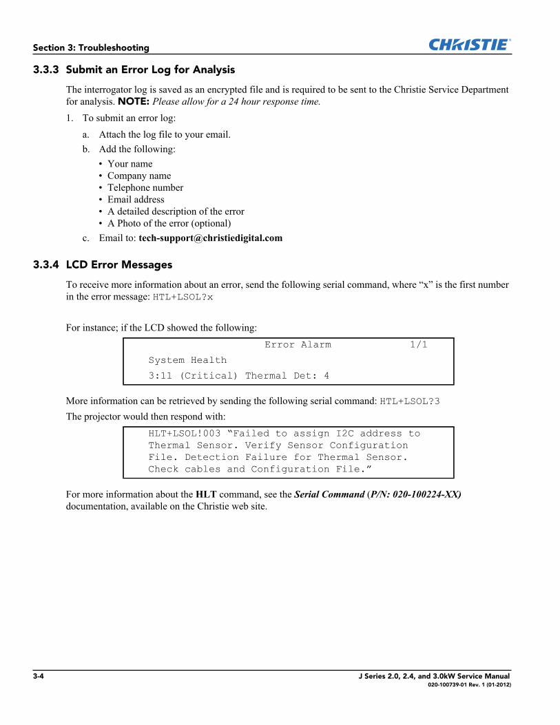
To receive more information about an error, send the following serial command, where “x” is the first number in the error message: HTL+LSOL?x
For instance; if the LCD showed the following:
More information can be retrieved by sending the following serial command: HTL+LSOL?3The projector would then respond with:
For more information about the HLT command, see the Serial Command (P/N: 020-100224-XX) documentation, available on the Christie web site.
Error Alarm 1/1System Health
3:11 (Critical) Thermal Det: 4
HLT+LSOL!003 “Failed to assign I2C address to Thermal Sensor. Verify Sensor Configuration File. Detection Failure for Thermal Sensor. Check cables and Configuration File.”
3-4 J Series 2.0, 2.4, and 3.0kW Service Manual 020-100739-01 Rev. 1 (01-2012)
4 Parts and Module Replacement
4.1 Ordering Parts
When ordering replacement parts provide the following information found on the product license label:• Christie part number for each item• Projector model • Projector serial number • Manufacture date
Table 4.1 Technical Support Contact Information
AMERICAS
CanadaToll Free: 1-800-221-8025Tel: 519-744-8005Fax: 519-749-2776
USAToll Free: 1-800-221-8025Tel: 519-744-8005Fax: 519-749-3302
ChileToll Free: 1-800-221-8025Tel: 519-744-8005Fax: 519-749-3302
EUROPE, MIDDLE EAST AND AFRICA
United KingdomSupport/Service Centre Tel: +44 (0) 118 977 8111Fax: +44 (0) 118 977 8112
ItalyeHome Italia ServiceTel: +39 (0) 2 9902 1161Fax: +39 (0) 2 9902 2641
Middle East & AfricaSupport/Service CentreTel: +44 (0) 118 977 8111Fax: +44 (0) 118 977 8112
GermanySupportTel: +49 (0) 1749 9834 95Fax: +49 (0) 2161 6645 46
Service CentreTel: +49 (0) 2161 56620 22Fax: +49 (0) 2161 6645 46Spain
Marcus FernandezChristie Spain c/o EsherTel: +34 91 633 9990Fax: +34 91 633 9991Mobile: +34 667 447 707
Eastern EuropeSupport/Service CentreTel: +44 (0) 118 977 8111Fax: +44 (0) 118 977 8112
FranceSupportTel: +33 (0) 1 47 48 28 06Fax: +33 (0) 1 47 48 26 06
Service CentreTel: +33 (0) 1 47 48 28 88Fax: +33 (0) 1 47 48 26 06
Hungary & RussiaSupport/Service CentreTel: +44 (0) 118 977 8111Fax: +44 (0) 118 977 8112
ASIA-PACIFIC
SingaporeTel: +65 877 8737Fax: +65 877 8747
Japan - TokyoTel: +81 3 3599 7481Fax: +81 3 3599 7482
China - BeijingTel: +86 21 6278 7708Fax: +86 21 6278 7707
South KoreaTel: +82 2 702 1601Fax: +82 2 702 1602
China - ShanghaiTel: +86 21 6278 7708Fax: +86 21 6278 7707
J Series 2.0, 2.4, and 3.0kW Service Manual 4-1020-100739-01 Rev. 1 (01-2012)
Section 4: Parts and Module Replacement
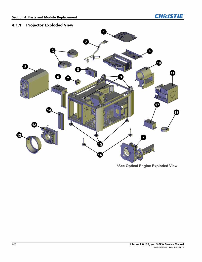
4.1.1 Projector Exploded View
4-2 J Series 2.0, 2.4, and 3.0kW Service Manual020-100739-01 Rev. 1 (01-2012)
Section 4: Parts and Module Replacement
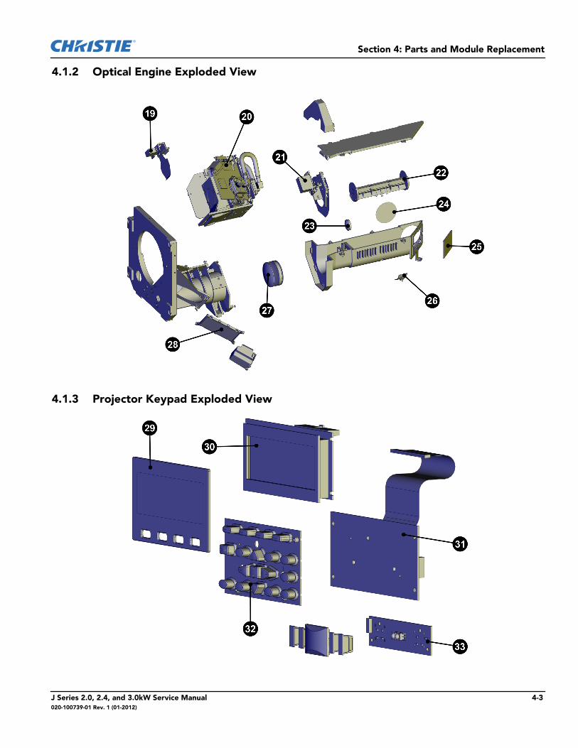
4.1.2 Optical Engine Exploded View
4.1.3 Projector Keypad Exploded View
J Series 2.0, 2.4, and 3.0kW Service Manual 4-3020-100739-01 Rev. 1 (01-2012)
Section 4: Parts and Module Replacement
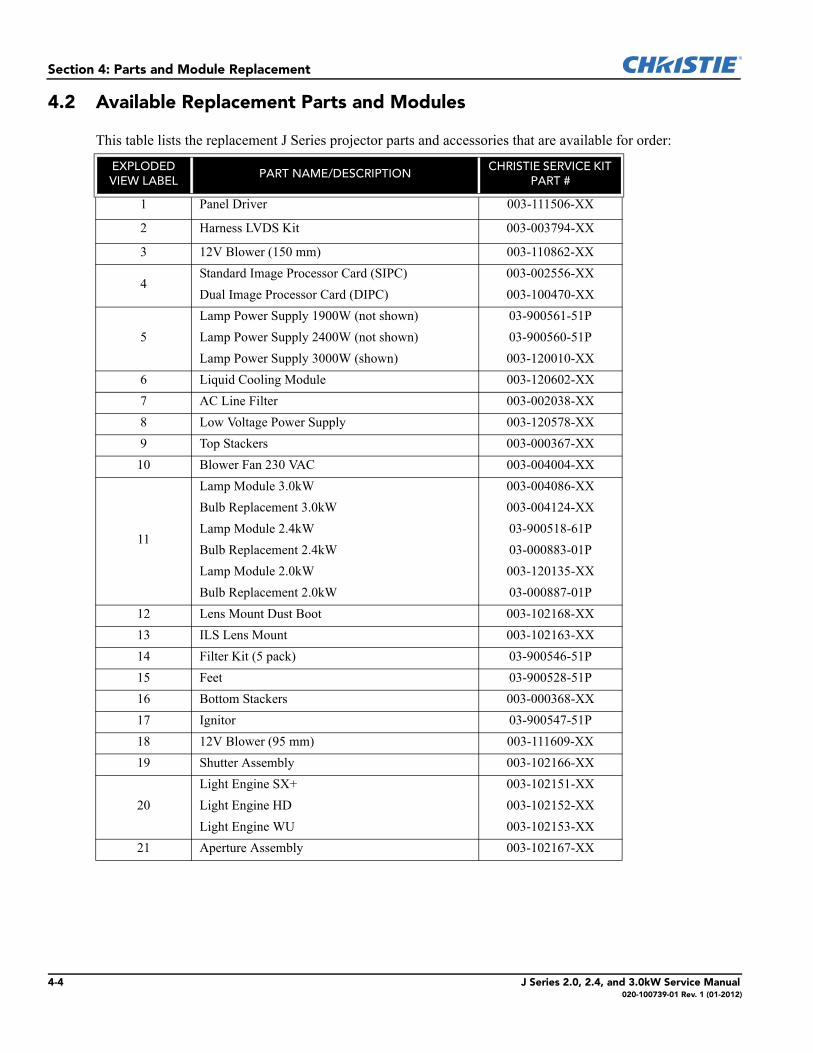
4.2 Available Replacement Parts and Modules
This table lists the replacement J Series projector parts and accessories that are available for order:
EXPLODED VIEW LABEL
PART NAME/DESCRIPTIONCHRISTIE SERVICE KIT
PART #
1 Panel Driver 003-111506-XX
2 Harness LVDS Kit 003-003794-XX
3 12V Blower (150 mm) 003-110862-XX
4Standard Image Processor Card (SIPC) 003-002556-XXDual Image Processor Card (DIPC) 003-100470-XX
5Lamp Power Supply 1900W (not shown) 03-900561-51PLamp Power Supply 2400W (not shown) 03-900560-51PLamp Power Supply 3000W (shown) 003-120010-XX
6 Liquid Cooling Module 003-120602-XX7 AC Line Filter 003-002038-XX8 Low Voltage Power Supply 003-120578-XX9 Top Stackers 003-000367-XX10 Blower Fan 230 VAC 003-004004-XX
11
Lamp Module 3.0kW 003-004086-XXBulb Replacement 3.0kW 003-004124-XXLamp Module 2.4kW 03-900518-61PBulb Replacement 2.4kW 03-000883-01PLamp Module 2.0kW 003-120135-XXBulb Replacement 2.0kW 03-000887-01P
12 Lens Mount Dust Boot 003-102168-XX13 ILS Lens Mount 003-102163-XX14 Filter Kit (5 pack) 03-900546-51P15 Feet 03-900528-51P16 Bottom Stackers 003-000368-XX17 Ignitor 03-900547-51P18 12V Blower (95 mm) 003-111609-XX19 Shutter Assembly 003-102166-XX
20Light Engine SX+ 003-102151-XXLight Engine HD 003-102152-XXLight Engine WU 003-102153-XX
21 Aperture Assembly 003-102167-XX
4-4 J Series 2.0, 2.4, and 3.0kW Service Manual020-100739-01 Rev. 1 (01-2012)
Section 4: Parts and Module Replacement
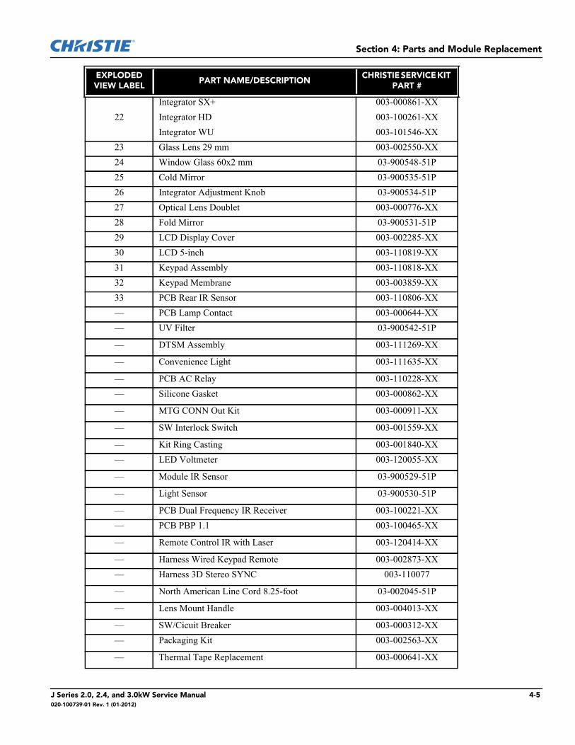
EXPLODED VIEW LABEL
PART NAME/DESCRIPTIONCHRISTIE SERVICE KIT
PART #
22Integrator SX+ 003-000861-XXIntegrator HD 003-100261-XXIntegrator WU 003-101546-XX
23 Glass Lens 29 mm 003-002550-XX24 Window Glass 60x2 mm 03-900548-51P25 Cold Mirror 03-900535-51P26 Integrator Adjustment Knob 03-900534-51P27 Optical Lens Doublet 003-000776-XX28 Fold Mirror 03-900531-51P29 LCD Display Cover 003-002285-XX30 LCD 5-inch 003-110819-XX31 Keypad Assembly 003-110818-XX32 Keypad Membrane 003-003859-XX33 PCB Rear IR Sensor 003-110806-XX— PCB Lamp Contact 003-000644-XX— UV Filter 03-900542-51P
— DTSM Assembly 003-111269-XX
— Convenience Light 003-111635-XX
— PCB AC Relay 003-110228-XX— Silicone Gasket 003-000862-XX
— MTG CONN Out Kit 003-000911-XX
— SW Interlock Switch 003-001559-XX
— Kit Ring Casting 003-001840-XX— LED Voltmeter 003-120055-XX
— Module IR Sensor 03-900529-51P
— Light Sensor 03-900530-51P
— PCB Dual Frequency IR Receiver 003-100221-XX— PCB PBP 1.1 003-100465-XX
— Remote Control IR with Laser 003-120414-XX
— Harness Wired Keypad Remote 003-002873-XX— Harness 3D Stereo SYNC 003-110077
— North American Line Cord 8.25-foot 03-002045-51P
— Lens Mount Handle 003-004013-XX
— SW/Cicuit Breaker 003-000312-XX— Packaging Kit 003-002563-XX
— Thermal Tape Replacement 003-000641-XX
J Series 2.0, 2.4, and 3.0kW Service Manual 4-5020-100739-01 Rev. 1 (01-2012)
Section 4: Parts and Module Replacement
4.3 Servicing Guidelines
• Follow all service safety warnings and guidelines. See Introduction.• Always read and understand all instructions before starting the procedure.• Always power down and disconnect power sources prior to removal.• See Interconnections when re-connecting harnesses.• When reinstalling a module, follow “removal” instructions in reverse unless otherwise indicated.
4.4 Tools Required
• Long magnetic-tip Phillips™ screwdrivers - #1, #2• Slotted screwdriver• Stubby, right angle, universal joint screwdrivers• Metric Allen Key Set: 2.5 mm, 3 mm, 5 mm, 6 mm• Metric Hex Driver Set: 2.5 mm, 3 mm, 5 mm, 6 mm• Metric Socket Driver Set• Wrench: 10 mm, 13 mm• 6 inch adjustable wrench• Magnetizer• Electrostatic protective strap and pad• Disposable Nitril gloves
EXPLODED VIEW LABEL
PART NAME/DESCRIPTIONCHRISTIE SERVICE KIT
PART #
— Shipping Lens Plug 03-900565-51P
— Thermal Pad Replacement 03-900569-51P— Heat Deflector 003-000851-XX
— Skin Fastener Kit 03-900579-51P
— Lens Support Kit 003-100830-XX
— Convergence Tool kit 003-000078-XX— Cover Lens Set 0.73SX+/0.67HD 003-002837-XX
— Cover Lens Set 003-002838-XX
— Cover Lens Set 1.25SX+/1.1HD 003-002841-XX— Lens Connector Kit 003-003351-XX
4-6 J Series 2.0, 2.4, and 3.0kW Service Manual020-100739-01 Rev. 1 (01-2012)
Section 4: Parts and Module Replacement
4.5 Remove and Replacement of Parts
4.5.1 Remove and Replace the Liquid Cooling Module
1. Power down the projector:a. Turn the projector off and allow the projector to cool for a minimum of 5 minutes.b. Disconnect the AC power cord from the rear of the projector.
2. If installed, remove the 3 stacking mounts from the top cover:a. Remove and set aside the safety pin.b. Remove the screw.c. Remove the mount, the screw, and the spring and set them aside.d. Repeat steps a to c for the remaining mounts.
3. Remove the 8 screws holding the top cover and then remove the top cover and set it aside.4. Remove the removable cross member on the frame:
a. Remove the 2 hex head screws.b. Lift and remove the bracket and set it aside.
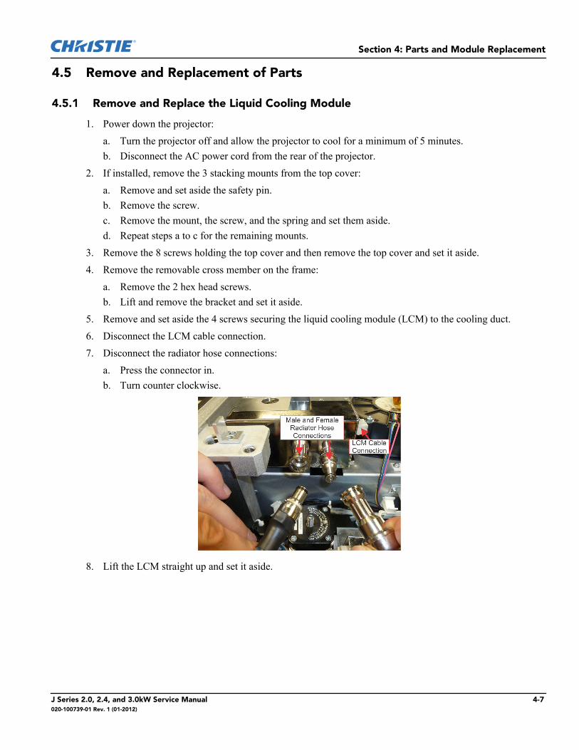
5. Remove and set aside the 4 screws securing the liquid cooling module (LCM) to the cooling duct.6. Disconnect the LCM cable connection.7. Disconnect the radiator hose connections:
a. Press the connector in.b. Turn counter clockwise.
8. Lift the LCM straight up and set it aside.
J Series 2.0, 2.4, and 3.0kW Service Manual 4-7020-100739-01 Rev. 1 (01-2012)
Section 4: Parts and Module Replacement
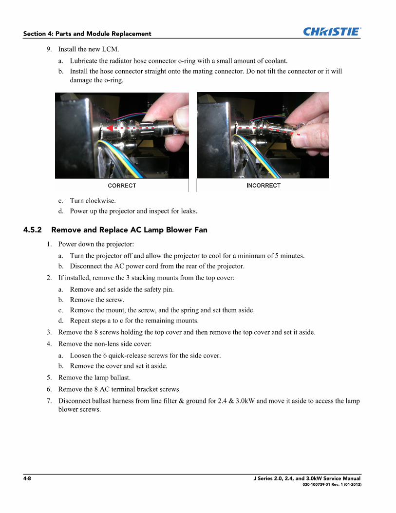
9. Install the new LCM.a. Lubricate the radiator hose connector o-ring with a small amount of coolant.b. Install the hose connector straight onto the mating connector. Do not tilt the connector or it will
damage the o-ring.
c. Turn clockwise.d. Power up the projector and inspect for leaks.
4.5.2 Remove and Replace AC Lamp Blower Fan
1. Power down the projector:a. Turn the projector off and allow the projector to cool for a minimum of 5 minutes.b. Disconnect the AC power cord from the rear of the projector.
2. If installed, remove the 3 stacking mounts from the top cover:a. Remove and set aside the safety pin.b. Remove the screw.c. Remove the mount, the screw, and the spring and set them aside.d. Repeat steps a to c for the remaining mounts.
3. Remove the 8 screws holding the top cover and then remove the top cover and set it aside.4. Remove the non-lens side cover:
a. Loosen the 6 quick-release screws for the side cover.b. Remove the cover and set it aside.
5. Remove the lamp ballast.6. Remove the 8 AC terminal bracket screws.7. Disconnect ballast harness from line filter & ground for 2.4 & 3.0kW and move it aside to access the lamp
blower screws.
4-8 J Series 2.0, 2.4, and 3.0kW Service Manual020-100739-01 Rev. 1 (01-2012)
Section 4: Parts and Module Replacement
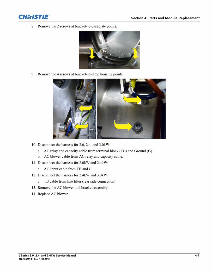
8. Remove the 2 screws at bracket-to-baseplate points.
9. Remove the 4 screws at bracket-to-lamp housing points.
10. Disconnect the harness for 2.0, 2.4, and 3.0kW:a. AC relay and capacity cable from terminal block (TB) and Ground (G).b. AC blower cable from AC relay and capacity cable.
11. Disconnect the harness for 2.0kW and 2.4kW:a. AC Input cable from TB and G.
12. Disconnect the harness for 2.4kW and 3.0kW:a. TB cable from line filter (rear side connection).
13. Remove the AC blower and bracket assembly.14. Replace AC blower.
J Series 2.0, 2.4, and 3.0kW Service Manual 4-9020-100739-01 Rev. 1 (01-2012)

Section 4: Parts and Module Replacement
4.5.3 Remove and Replace Anode Fan (2.0 & 2.4kW Only)
1. Power down the projector:a. Turn the projector off and allow the projector to cool for a minimum of 5 minutes.b. Disconnect the AC power cord from the rear of the projector.
2. If installed, remove the 3 stacking mounts from the top cover:a. Remove and set aside the safety pin.b. Remove the screw.c. Remove the mount, the screw, and the spring and set them aside.d. Repeat steps a to c for the remaining mounts.
3. Disconnect fan harness and release it from its wire dressing clips. 4. Remove the 2 screws securing the fan.
5. Remove the fan assembly.6. Install the anode fan.
4.5.4 Remove and Replace the Integrator Blower Fan
1. Power down the projector:a. Turn the projector off and allow the projector to cool for a minimum of 5 minutes.b. Disconnect the AC power cord from the rear of the projector.
2. If installed, remove the 3 stacking mounts from the top cover:a. Remove and set aside the safety pin.b. Remove the screw.c. Remove the mount, the screw, and the spring and set them aside.d. Repeat steps a to c for the remaining mounts.
3. Remove the 8 screws holding the top cover and then remove the top cover and set it aside.
4-10 J Series 2.0, 2.4, and 3.0kW Service Manual020-100739-01 Rev. 1 (01-2012)
Section 4: Parts and Module Replacement
4. Remove the lens side cover:a. Loosen the 6 quick-release screws for the side cover.b. Remove the cover and set it aside.
5. Remove the lens side small cover that sits behind the handle:a. Loosen the 3 quick-release screws for the cover.b. Remove the cover and set it aside.
6. Disconnect the fan harness and release it from its wire dressing clips.7. Remove the 2 screws securing the fan.
8. Remove the fan assembly.9. Install the integrator blower fan.
4.5.5 Remove and Replace the Card Cage Cooling Fan
1. Power down the projector:a. Turn the projector off and allow the projector to cool for a minimum of 5 minutes.b. Disconnect the AC power cord from the rear of the projector.
2. If installed, remove the 3 stacking mounts from the top cover:a. Remove and set aside the safety pin.b. Remove the screw.c. Remove the mount, the screw, and the spring and set them aside.d. Repeat steps a to c for the remaining mounts.
3. Remove the 8 screws holding the top cover and then remove the top cover and set it aside.4. Remove the 2 screws holding the removable cross member on the frame and set it aside.5. Remove the 3 screws securing the air duct.6. Disconnect the fan harness and release it from its wire dressing clips.
J Series 2.0, 2.4, and 3.0kW Service Manual 4-11020-100739-01 Rev. 1 (01-2012)
Section 4: Parts and Module Replacement
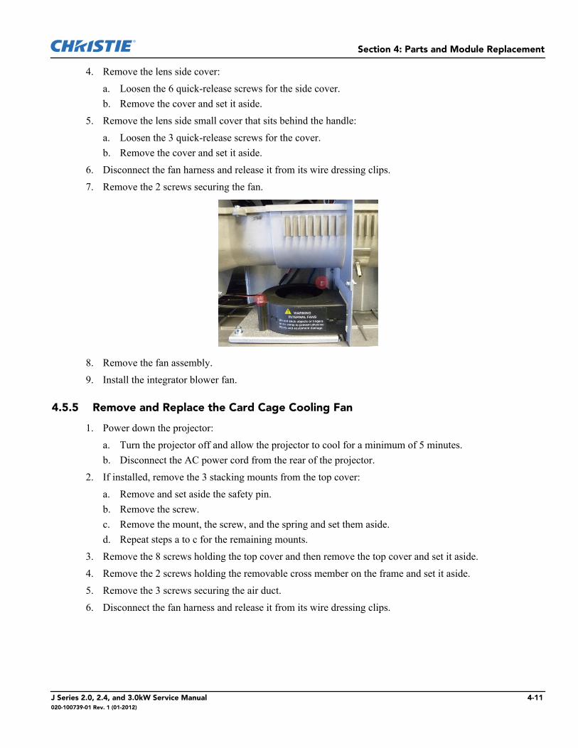
7. Remove the 2 screws and washers securing the fan.
8. Remove the fan assembly.9. Install the card cage cooling fan.
4.5.6 Remove and Replace the Prism Fan
1. Power down the projector:a. Turn the projector off and allow the projector to cool for a minimum of 5 minutes.b. Disconnect the AC power cord from the rear of the projector.
2. If installed, remove the 3 stacking mounts from the top cover:a. Remove and set aside the safety pin.b. Remove the screw.c. Remove the mount, the screw, and the spring and set them aside.d. Repeat steps a to c for the remaining mounts.
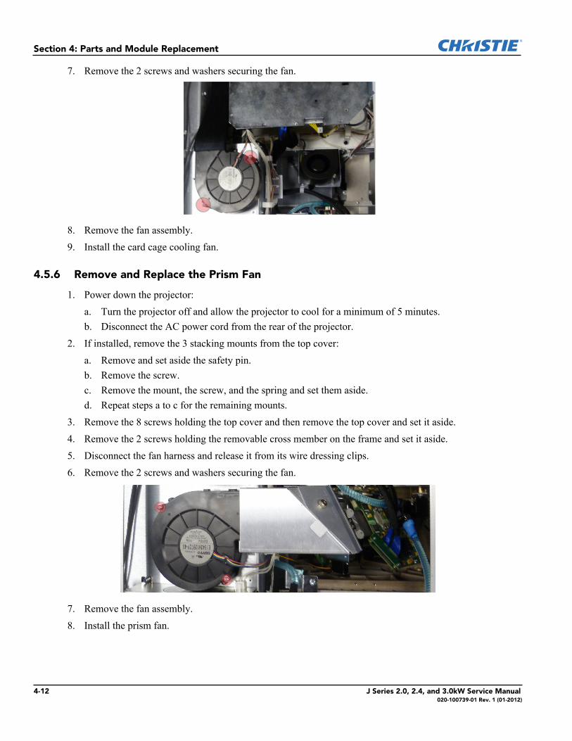
3. Remove the 8 screws holding the top cover and then remove the top cover and set it aside.4. Remove the 2 screws holding the removable cross member on the frame and set it aside.5. Disconnect the fan harness and release it from its wire dressing clips.6. Remove the 2 screws and washers securing the fan.
7. Remove the fan assembly.8. Install the prism fan.
4-12 J Series 2.0, 2.4, and 3.0kW Service Manual020-100739-01 Rev. 1 (01-2012)
Section 4: Parts and Module Replacement
4.5.7 Remove and Replace the Red Channel Cooling Fan
1. Power down the projector:a. Turn the projector off and allow the projector to cool for a minimum of 5 minutes.b. Disconnect the AC power cord from the rear of the projector.
2. Remove the 8 screws holding the top cover and then remove the top cover and set it aside.3. Remove the side covers:
a. Loosen the 6 quick-release screws for each side cover.b. Remove each cover and set it aside.
4. Remove the 4 screws securing the light engine blower duct.5. Disconnect fan harness.6. Remove the light engine. See Remove and Replace the Light Engine.7. Remove the 3 fan bracket screws.8. Using the handle on the bracket, carefully remove the fan and the bracket.9. Remove the 2 screws from the fan and bracket.10. Install the fan and bracket.
4.5.8 Remove and Replace the Lamp Ballast
Always power down the projector and disconnect all power sources before servicing.
1. Power down the projector:a. Turn the projector off and allow the projector to cool for a minimum of 5 minutes.b. Disconnect the AC power cord from the rear of the projector.
2. Remove the non-lens side cover:a. Loosen the 6 quick-release screws.b. Remove the cover and set it aside.
3. Remove the non-lens side small cover that sits behind the handle:a. Loosen the 3 quick-release screws for the cover.b. Remove the cover and set it aside.
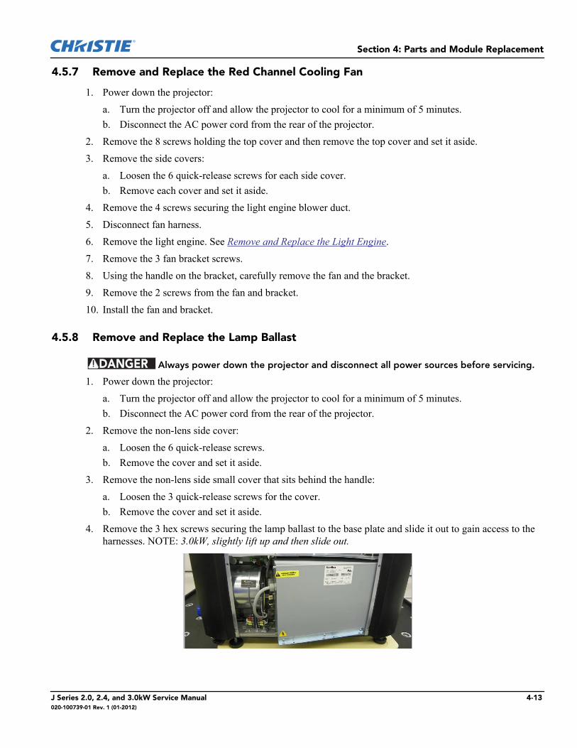
4. Remove the 3 hex screws securing the lamp ballast to the base plate and slide it out to gain access to the harnesses. NOTE: 3.0kW, slightly lift up and then slide out.
DANGER
J Series 2.0, 2.4, and 3.0kW Service Manual 4-13020-100739-01 Rev. 1 (01-2012)
Section 4: Parts and Module Replacement
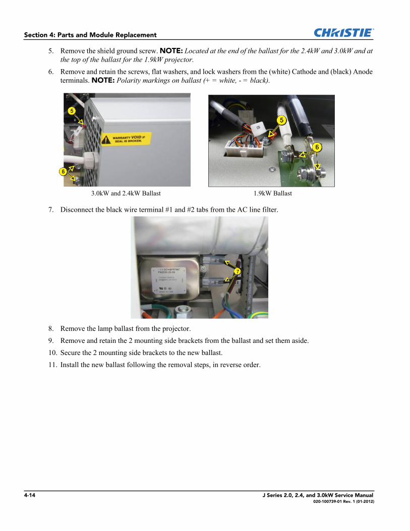
5. Remove the shield ground screw. NOTE: Located at the end of the ballast for the 2.4kW and 3.0kW and at the top of the ballast for the 1.9kW projector.
6. Remove and retain the screws, flat washers, and lock washers from the (white) Cathode and (black) Anode terminals. NOTE: Polarity markings on ballast (+ = white, - = black).
7. Disconnect the black wire terminal #1 and #2 tabs from the AC line filter.
8. Remove the lamp ballast from the projector.9. Remove and retain the 2 mounting side brackets from the ballast and set them aside.10. Secure the 2 mounting side brackets to the new ballast.11. Install the new ballast following the removal steps, in reverse order.
3.0kW and 2.4kW Ballast 1.9kW Ballast
4-14 J Series 2.0, 2.4, and 3.0kW Service Manual020-100739-01 Rev. 1 (01-2012)
Section 4: Parts and Module Replacement
4.5.9 Remove and Replace the Low Voltage Power Supply (LVPS)
1. Power down the projector:a. Turn the projector off and allow the projector to cool for a minimum of 5 minutes.b. Disconnect the AC power cord from the rear of the projector.
2. If installed, remove the 3 stacking mounts from the top cover:a. Remove and set aside the safety pin.b. Remove the screw.c. Remove the mount, the screw, and the spring and set them aside.d. Repeat steps a to c for the remaining mounts.
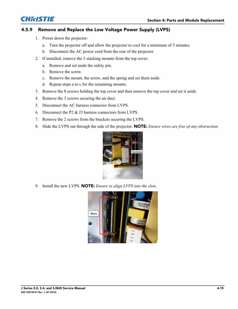
3. Remove the 8 screws holding the top cover and then remove the top cover and set it aside.4. Remove the 3 screws securing the air duct.5. Disconnect the AC harness connector from LVPS.6. Disconnect the P2 & J3 harness connectors from LVPS. 7. Remove the 2 screws from the brackets securing the LVPS.8. Slide the LVPS out through the side of the projector. NOTE: Ensure wires are free of any obstruction.
9. Install the new LVPS. NOTE: Ensure to align LVPS into the slots.
J Series 2.0, 2.4, and 3.0kW Service Manual 4-15020-100739-01 Rev. 1 (01-2012)
Section 4: Parts and Module Replacement
4.5.10 Remove and Replace the AC Line Filter
1. Power down the projector:a. Turn the projector off and allow the projector to cool for a minimum of 5 minutes.b. Disconnect the AC power cord from the rear of the projector.
2. For the 3.0kW:a. Remove the locking pin from the bracket surrounding the AC receptacle at the AC inlet.b. Remove the 2 screws from the AC inlet bracket.
3. For 2.0kW and 2.4kW:a. Remove the power cord retaining clip.
4. For 3.0kW, disconnect the two inlet connectors and the 2 outlet connectors from the AC line filter5. Remove the rear cover:
a. Loosen the 8 quick-release screws on the rear cover.b. Move the cover away from the rear of the projector to access the keypad PCB.c. Disconnect the projector keypad harness connector P65.d. Remove the rear cover and set it aside.
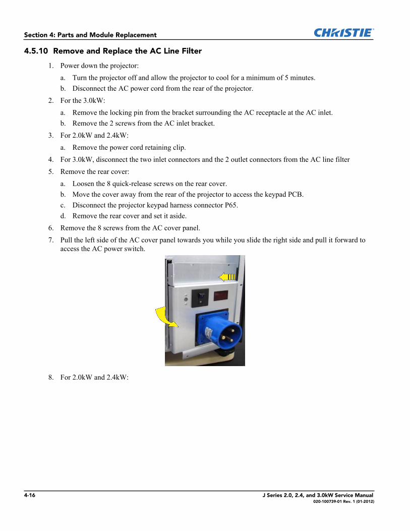
6. Remove the 8 screws from the AC cover panel.7. Pull the left side of the AC cover panel towards you while you slide the right side and pull it forward to
access the AC power switch.
8. For 2.0kW and 2.4kW:
4-16 J Series 2.0, 2.4, and 3.0kW Service Manual020-100739-01 Rev. 1 (01-2012)
Section 4: Parts and Module Replacement
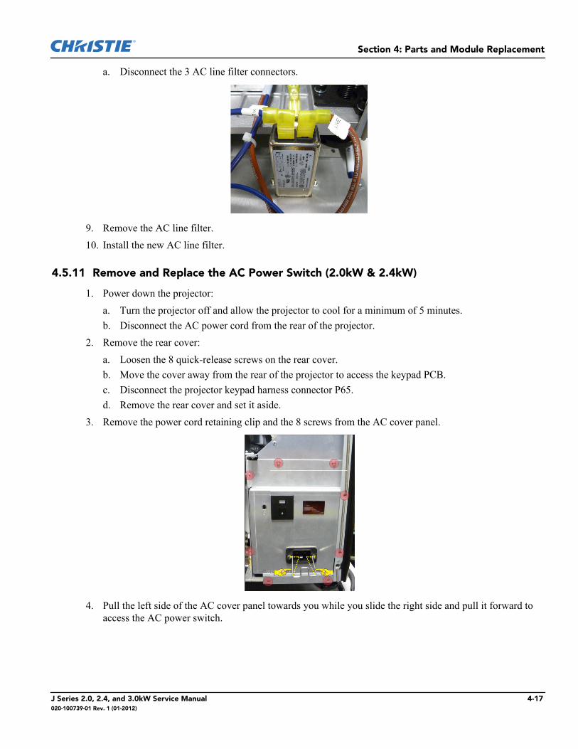
a. Disconnect the 3 AC line filter connectors.
9. Remove the AC line filter.10. Install the new AC line filter.
4.5.11 Remove and Replace the AC Power Switch (2.0kW & 2.4kW)
1. Power down the projector:a. Turn the projector off and allow the projector to cool for a minimum of 5 minutes.b. Disconnect the AC power cord from the rear of the projector.
2. Remove the rear cover:a. Loosen the 8 quick-release screws on the rear cover.b. Move the cover away from the rear of the projector to access the keypad PCB.c. Disconnect the projector keypad harness connector P65.d. Remove the rear cover and set it aside.
3. Remove the power cord retaining clip and the 8 screws from the AC cover panel.
4. Pull the left side of the AC cover panel towards you while you slide the right side and pull it forward to access the AC power switch.
J Series 2.0, 2.4, and 3.0kW Service Manual 4-17020-100739-01 Rev. 1 (01-2012)
Section 4: Parts and Module Replacement
5. Disconnect the 4 AC switch connectors.
6. Unlock and remove the AC power switch.7. Install the new AC power switch.
4.5.12 Remove and Replace the AC Power Switch (3.0kW)
1. Power down the projector:a. Turn the projector off and allow the projector to cool for a minimum of 5 minutes.b. Disconnect the AC power cord from the rear of the projector.
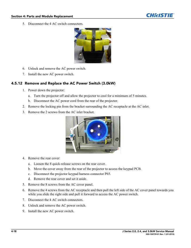
2. Remove the locking pin from the bracket surrounding the AC receptacle at the AC inlet.3. Remove the 2 screws from the AC inlet bracket.
4. Remove the rear cover:a. Loosen the 8 quick-release screws on the rear cover.b. Move the cover away from the rear of the projector to access the keypad PCB.c. Disconnect the projector keypad harness connector P65.d. Remove the rear cover and set it aside.
5. Remove the 8 screws from the AC cover panel.6. Remove the 4 screws from the AC receptacle and then pull the left side of the AC cover panel towards you
while you slide the right side and pull it forward to access the AC power switch.7. Disconnect the 4 AC switch connectors.8. Unlock and remove the AC power switch.9. Install the new AC power switch.
4-18 J Series 2.0, 2.4, and 3.0kW Service Manual020-100739-01 Rev. 1 (01-2012)

Section 4: Parts and Module Replacement
4.5.13 Remove and Replace the AC Voltmeter
1. Power down the projector:a. Turn the projector off and allow the projector to cool for a minimum of 5 minutes.b. Disconnect the AC power cord from the rear of the projector.
2. For the 3.0kW:a. Remove the locking pin from the bracket surrounding the AC receptacle at the AC inlet.b. Remove the 2 screws from the AC inlet bracket.c. Remove the 4 screws from the AC inlet.
3. For 2.0kW and 2.4kW:a. Remove the power cord retaining clip.
4. Remove the rear cover:a. Loosen the 8 quick-release screws on the rear cover.b. Move the cover away from the rear of the projector to access the keypad PCB.c. Disconnect the projector keypad harness connector P65.d. Remove the rear cover and set it aside.
5. Remove the 8 screws from the AC cover panel and pull it out. 6. Remove the 2 screws securing the filter capacitor and AC connection.7. Remove the AC voltmeter.8. Install the new AC voltmeter and tighten the 2 screws. NOTE: Tighten the two screws to 4 inch-lb.
4.5.14 Remove and Replace the Igniter
1. Power down the projector:a. Turn the projector off and allow the projector to cool for a minimum of 5 minutes.b. Disconnect the AC power cord from the rear of the projector.
2. Remove the lamp ballast. See Remove and Replace the Lamp Ballast or Remove and Replace the Temp 2 Exhaust PC Board. Do not remove the mounting brackets.
3. Remove the screw and lock washer from the anode connection.4. Remove the screw and lock washer from the cathode connection.
J Series 2.0, 2.4, and 3.0kW Service Manual 4-19020-100739-01 Rev. 1 (01-2012)
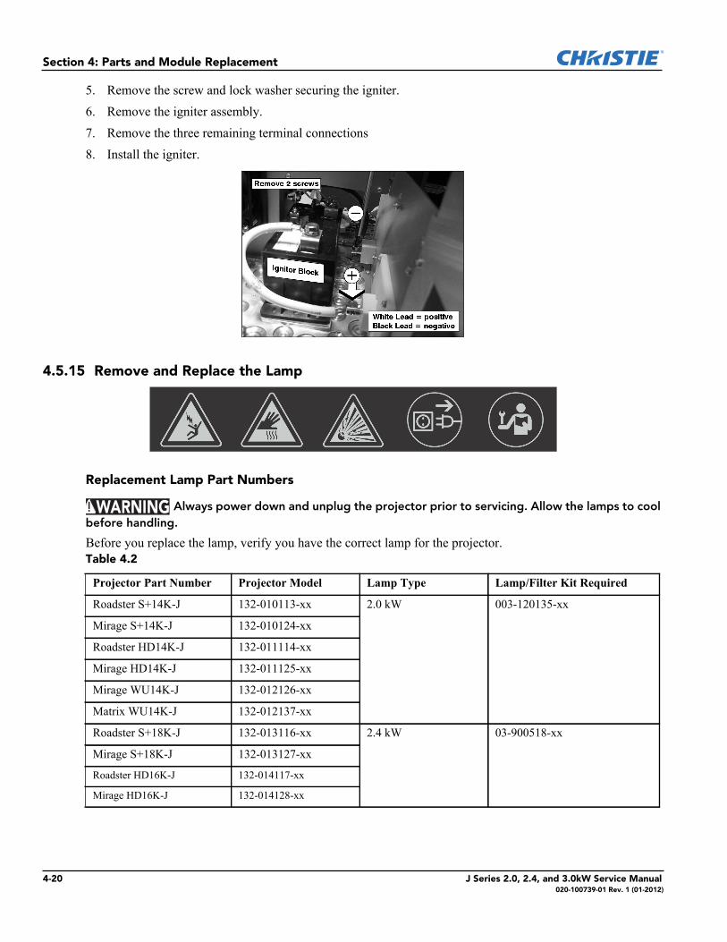
Section 4: Parts and Module Replacement
5. Remove the screw and lock washer securing the igniter.6. Remove the igniter assembly.7. Remove the three remaining terminal connections8. Install the igniter.
4.5.15 Remove and Replace the Lamp
Replacement Lamp Part Numbers
Always power down and unplug the projector prior to servicing. Allow the lamps to cool before handling.
Before you replace the lamp, verify you have the correct lamp for the projector.Table 4.2
Projector Part Number Projector Model Lamp Type Lamp/Filter Kit Required
Roadster S+14K-J 132-010113-xx 2.0 kW 003-120135-xx
Mirage S+14K-J 132-010124-xx
Roadster HD14K-J 132-011114-xx
Mirage HD14K-J 132-011125-xx
Mirage WU14K-J 132-012126-xx
Matrix WU14K-J 132-012137-xx
Roadster S+18K-J 132-013116-xx 2.4 kW 03-900518-xx
Mirage S+18K-J 132-013127-xx
Roadster HD16K-J 132-014117-xx
Mirage HD16K-J 132-014128-xx
WARNING
4-20 J Series 2.0, 2.4, and 3.0kW Service Manual020-100739-01 Rev. 1 (01-2012)
Section 4: Parts and Module Replacement
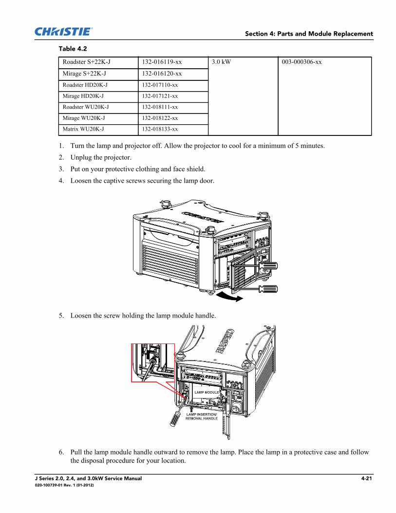
1. Turn the lamp and projector off. Allow the projector to cool for a minimum of 5 minutes.2. Unplug the projector.3. Put on your protective clothing and face shield.4. Loosen the captive screws securing the lamp door.
5. Loosen the screw holding the lamp module handle.
6. Pull the lamp module handle outward to remove the lamp. Place the lamp in a protective case and follow the disposal procedure for your location.
Roadster S+22K-J 132-016119-xx 3.0 kW 003-000306-xx
Mirage S+22K-J 132-016120-xx
Roadster HD20K-J 132-017110-xx
Mirage HD20K-J 132-017121-xx
Roadster WU20K-J 132-018111-xx
Mirage WU20K-J 132-018122-xx
Matrix WU20K-J 132-018133-xx
Table 4.2
J Series 2.0, 2.4, and 3.0kW Service Manual 4-21020-100739-01 Rev. 1 (01-2012)
Section 4: Parts and Module Replacement
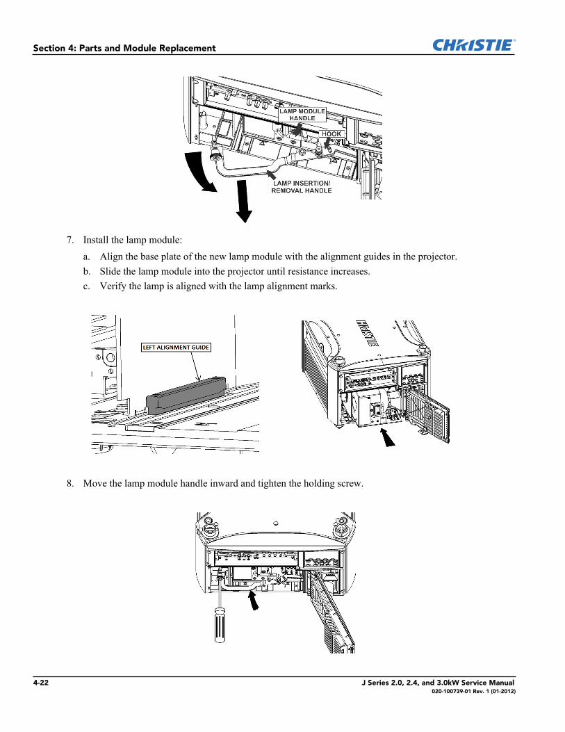
7. Install the lamp module:a. Align the base plate of the new lamp module with the alignment guides in the projector.b. Slide the lamp module into the projector until resistance increases.c. Verify the lamp is aligned with the lamp alignment marks.
8. Move the lamp module handle inward and tighten the holding screw.
4-22 J Series 2.0, 2.4, and 3.0kW Service Manual020-100739-01 Rev. 1 (01-2012)
Section 4: Parts and Module Replacement
9. Close the lamp door and tighten the captive screws.10. Record the lamp serial number:
a. Click Menu > Advanced Setup > Lamp History.b. Click Add Lamp.c. Complete the fields in the Add Lamp dialog.d. Click Save.
4.5.16 Remove and Replace the Lamp Memory Module
1. Power down the projector:a. Turn the projector off and allow the projector to cool for a minimum of 5 minutes.b. Disconnect the AC power cord from the rear of the projector.
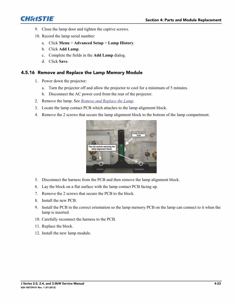
2. Remove the lamp. See Remove and Replace the Lamp.3. Locate the lamp contact PCB which attaches to the lamp alignment block.4. Remove the 2 screws that secure the lamp alignment block to the bottom of the lamp compartment.
5. Disconnect the harness from the PCB and then remove the lamp alignment block.6. Lay the block on a flat surface with the lamp contact PCB facing up. 7. Remove the 2 screws that secure the PCB to the block. 8. Install the new PCB.9. Install the PCB in the correct orientation so the lamp memory PCB on the lamp can connect to it when the
lamp is inserted.10. Carefully reconnect the harness to the PCB.11. Replace the block.12. Install the new lamp module.
J Series 2.0, 2.4, and 3.0kW Service Manual 4-23020-100739-01 Rev. 1 (01-2012)
Section 4: Parts and Module Replacement
4.5.17 Remove and Replace the Air Filter
1. Power down the projector:a. Turn the projector off and allow the projector to cool for a minimum of 5 minutes.b. Disconnect the AC power cord from the rear of the projector.
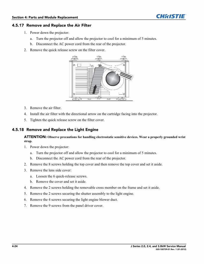
2. Remove the quick release screw on the filter cover.
3. Remove the air filter. 4. Install the air filter with the directional arrow on the cartridge facing into the projector.5. Tighten the quick release screw on the filter cover.
4.5.18 Remove and Replace the Light Engine
ATTENTION: Observe precautions for handling electrostatic sensitive devices. Wear a properly grounded wrist strap.
1. Power down the projector:a. Turn the projector off and allow the projector to cool for a minimum of 5 minutes.b. Disconnect the AC power cord from the rear of the projector.
2. Remove the 8 screws holding the top cover and then remove the top cover and set it aside.3. Remove the lens side cover:
a. Loosen the 6 quick-release screws.b. Remove the cover and set it aside.
4. Remove the 2 screws holding the removable cross member on the frame and set it aside.5. Remove the 2 screws securing the shutter assembly to the light engine. 6. Remove the 4 screws securing the light engine blower duct.7. Remove the 9 screws from the panel driver cover.
4-24 J Series 2.0, 2.4, and 3.0kW Service Manual020-100739-01 Rev. 1 (01-2012)
Section 4: Parts and Module Replacement
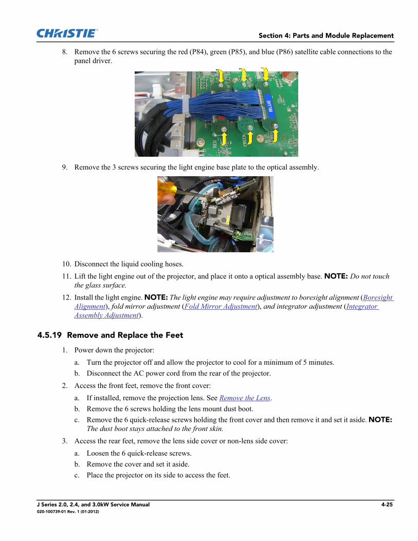
8. Remove the 6 screws securing the red (P84), green (P85), and blue (P86) satellite cable connections to the panel driver.
9. Remove the 3 screws securing the light engine base plate to the optical assembly.
10. Disconnect the liquid cooling hoses.11. Lift the light engine out of the projector, and place it onto a optical assembly base. NOTE: Do not touch
the glass surface.12. Install the light engine. NOTE: The light engine may require adjustment to boresight alignment (Boresight
Alignment), fold mirror adjustment (Fold Mirror Adjustment), and integrator adjustment (Integrator Assembly Adjustment).
4.5.19 Remove and Replace the Feet
1. Power down the projector:a. Turn the projector off and allow the projector to cool for a minimum of 5 minutes.b. Disconnect the AC power cord from the rear of the projector.
2. Access the front feet, remove the front cover:a. If installed, remove the projection lens. See Remove the Lens.b. Remove the 6 screws holding the lens mount dust boot.c. Remove the 6 quick-release screws holding the front cover and then remove it and set it aside. NOTE:
The dust boot stays attached to the front skin.3. Access the rear feet, remove the lens side cover or non-lens side cover:
a. Loosen the 6 quick-release screws.b. Remove the cover and set it aside.c. Place the projector on its side to access the feet.
J Series 2.0, 2.4, and 3.0kW Service Manual 4-25020-100739-01 Rev. 1 (01-2012)

Section 4: Parts and Module Replacement
4. Remove the retention clip from the top of the foot. 5. Unscrew the foot and remove it from the projector. 6. Insert the threaded end of the replacement foot in the mounting hole and turn until tight.
7. Replace retention clip.
4.5.20 Remove and Replace the Front IR Sensor
1. Power down the projector:a. Turn the projector off and allow the projector to cool for a minimum of 5 minutes.b. Disconnect the AC power cord from the rear of the projector.
2. Remove the front cover:a. Remove the 6 quick-release screws holding the front skin and then remove it and set it aside.
3. Disconnect the sensor connector.4. Remove the 2 screws.
5. Remove the sensor6. Install the front infrared sensor.
4-26 J Series 2.0, 2.4, and 3.0kW Service Manual020-100739-01 Rev. 1 (01-2012)
Section 4: Parts and Module Replacement
4.5.21 Remove and Replace the Rear IR Sensor
1. Power down the projector:a. Turn the projector off and allow the projector to cool for a minimum of 5 minutes.b. Disconnect the AC power cord from the rear of the projector.
2. Remove the rear cover:a. Loosen the 8 quick-release screws on the rear cover.b. Move the cover away from the rear of the projector to access the keypad PCB.c. Disconnect the projector keypad harness connector P65.d. Remove the rear cover and set it aside.
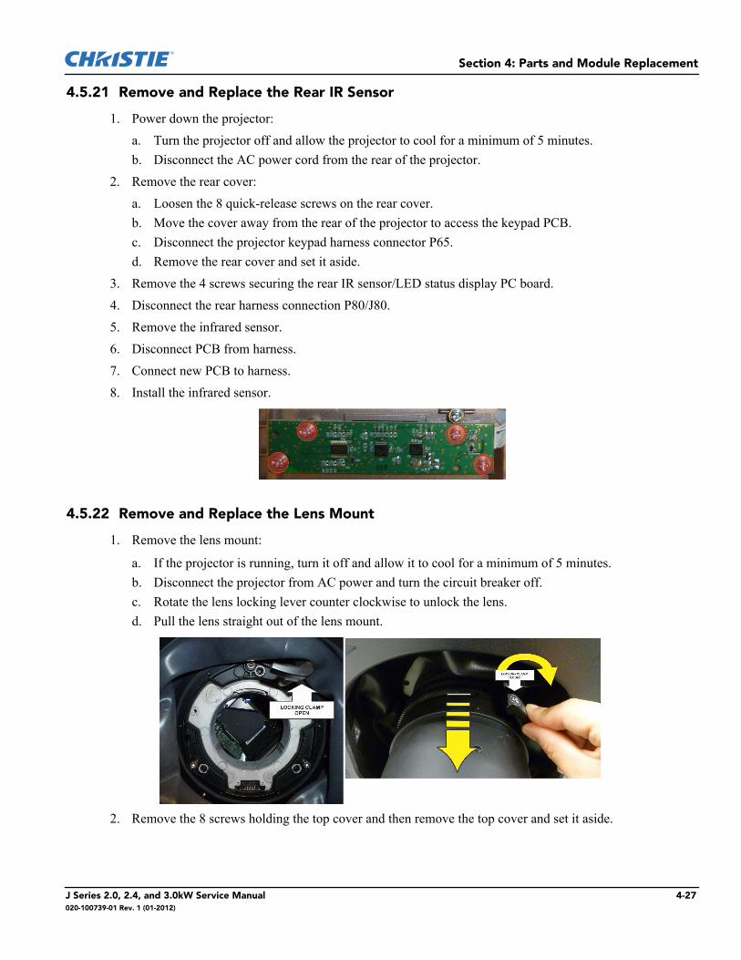
3. Remove the 4 screws securing the rear IR sensor/LED status display PC board. 4. Disconnect the rear harness connection P80/J80.5. Remove the infrared sensor. 6. Disconnect PCB from harness.7. Connect new PCB to harness.8. Install the infrared sensor.
4.5.22 Remove and Replace the Lens Mount
1. Remove the lens mount:
a. If the projector is running, turn it off and allow it to cool for a minimum of 5 minutes.b. Disconnect the projector from AC power and turn the circuit breaker off.c. Rotate the lens locking lever counter clockwise to unlock the lens. d. Pull the lens straight out of the lens mount.
2. Remove the 8 screws holding the top cover and then remove the top cover and set it aside.
J Series 2.0, 2.4, and 3.0kW Service Manual 4-27020-100739-01 Rev. 1 (01-2012)
Section 4: Parts and Module Replacement
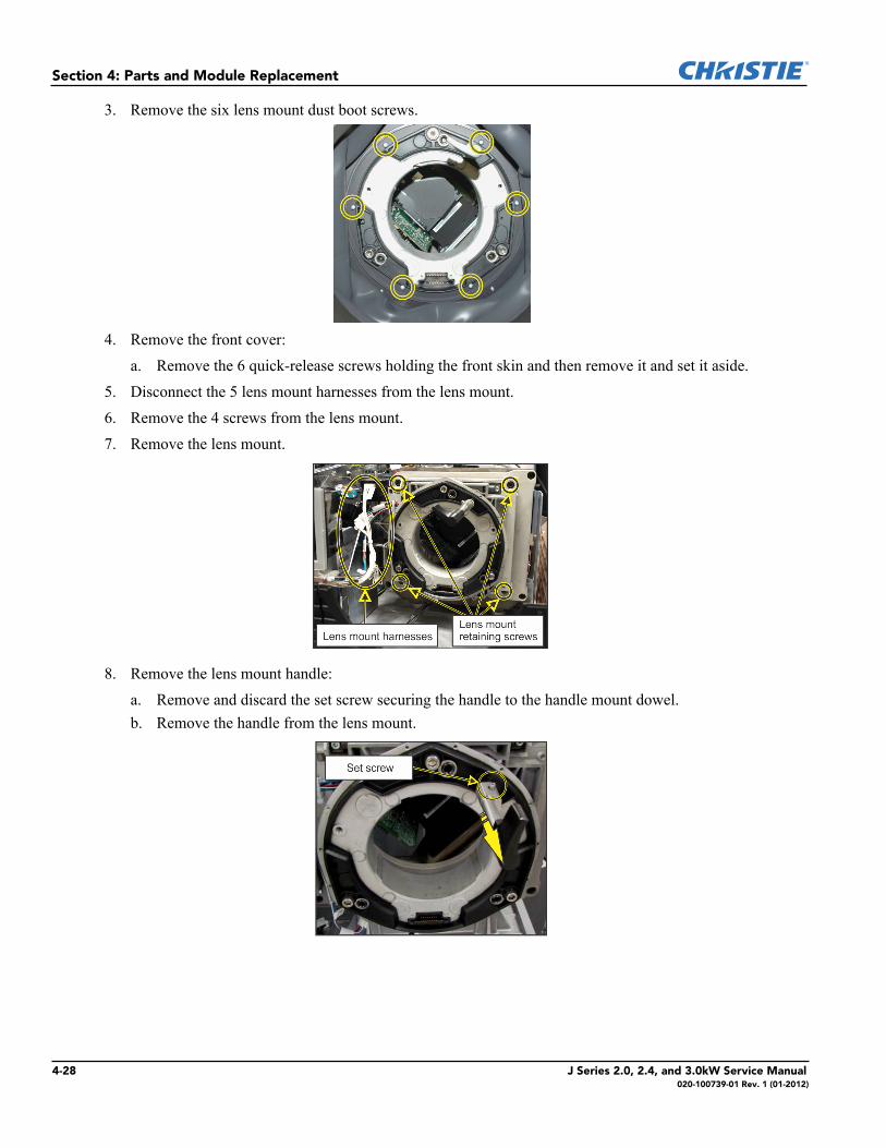
3. Remove the six lens mount dust boot screws.
4. Remove the front cover:a. Remove the 6 quick-release screws holding the front skin and then remove it and set it aside.
5. Disconnect the 5 lens mount harnesses from the lens mount. 6. Remove the 4 screws from the lens mount. 7. Remove the lens mount.
8. Remove the lens mount handle:a. Remove and discard the set screw securing the handle to the handle mount dowel. b. Remove the handle from the lens mount.
4-28 J Series 2.0, 2.4, and 3.0kW Service Manual020-100739-01 Rev. 1 (01-2012)
Section 4: Parts and Module Replacement
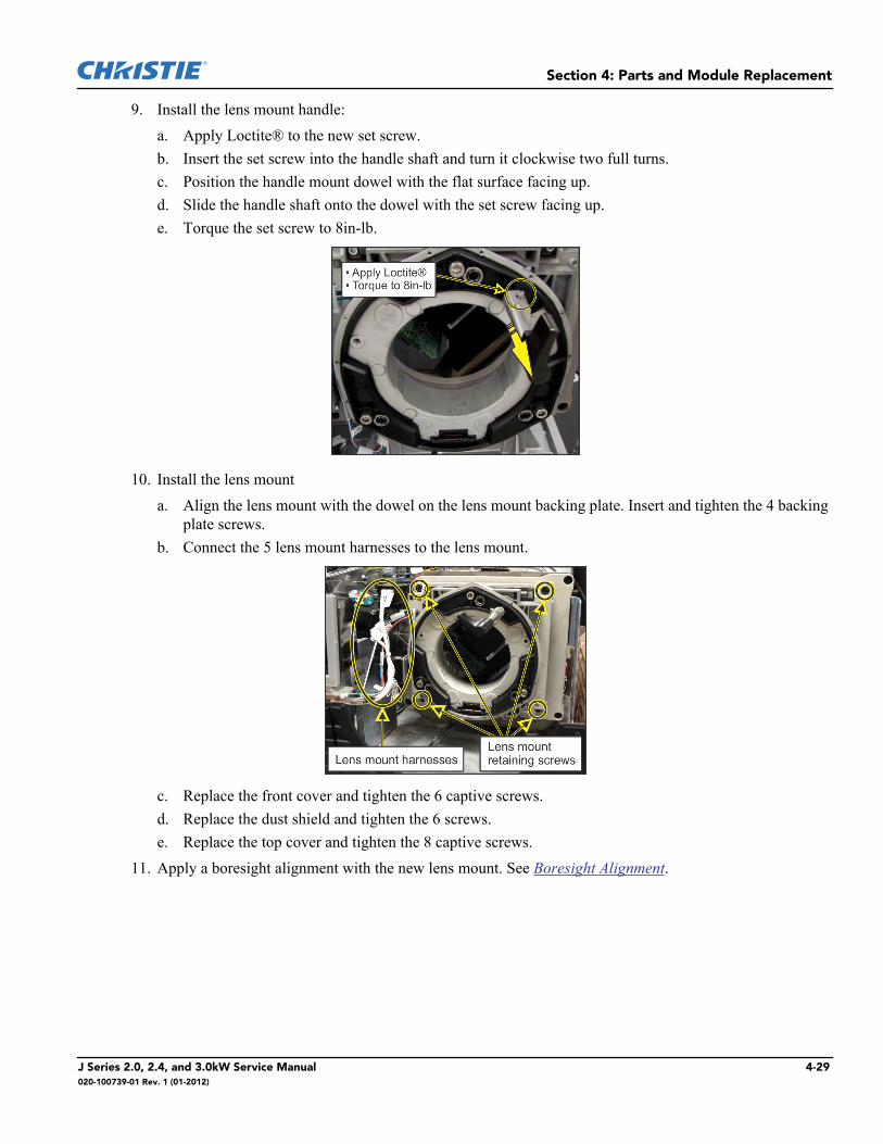
9. Install the lens mount handle:a. Apply Loctite® to the new set screw.b. Insert the set screw into the handle shaft and turn it clockwise two full turns.c. Position the handle mount dowel with the flat surface facing up. d. Slide the handle shaft onto the dowel with the set screw facing up.e. Torque the set screw to 8in-lb.
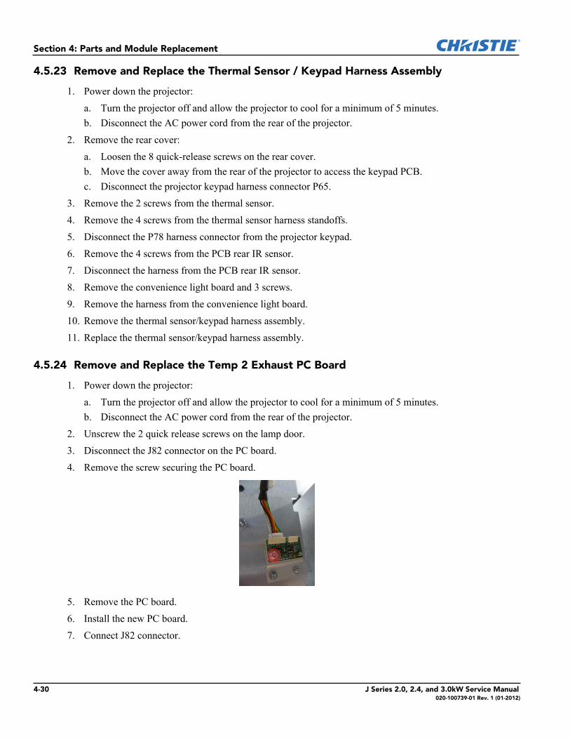
10. Install the lens mounta. Align the lens mount with the dowel on the lens mount backing plate. Insert and tighten the 4 backing
plate screws.b. Connect the 5 lens mount harnesses to the lens mount.
c. Replace the front cover and tighten the 6 captive screws.d. Replace the dust shield and tighten the 6 screws.e. Replace the top cover and tighten the 8 captive screws.
11. Apply a boresight alignment with the new lens mount. See Boresight Alignment.
J Series 2.0, 2.4, and 3.0kW Service Manual 4-29020-100739-01 Rev. 1 (01-2012)
Section 4: Parts and Module Replacement
4.5.23 Remove and Replace the Thermal Sensor / Keypad Harness Assembly
1. Power down the projector:a. Turn the projector off and allow the projector to cool for a minimum of 5 minutes.b. Disconnect the AC power cord from the rear of the projector.
2. Remove the rear cover:a. Loosen the 8 quick-release screws on the rear cover.b. Move the cover away from the rear of the projector to access the keypad PCB.c. Disconnect the projector keypad harness connector P65.
3. Remove the 2 screws from the thermal sensor. 4. Remove the 4 screws from the thermal sensor harness standoffs.5. Disconnect the P78 harness connector from the projector keypad.6. Remove the 4 screws from the PCB rear IR sensor.7. Disconnect the harness from the PCB rear IR sensor.8. Remove the convenience light board and 3 screws.9. Remove the harness from the convenience light board.10. Remove the thermal sensor/keypad harness assembly.11. Replace the thermal sensor/keypad harness assembly.
4.5.24 Remove and Replace the Temp 2 Exhaust PC Board
1. Power down the projector:a. Turn the projector off and allow the projector to cool for a minimum of 5 minutes.b. Disconnect the AC power cord from the rear of the projector.
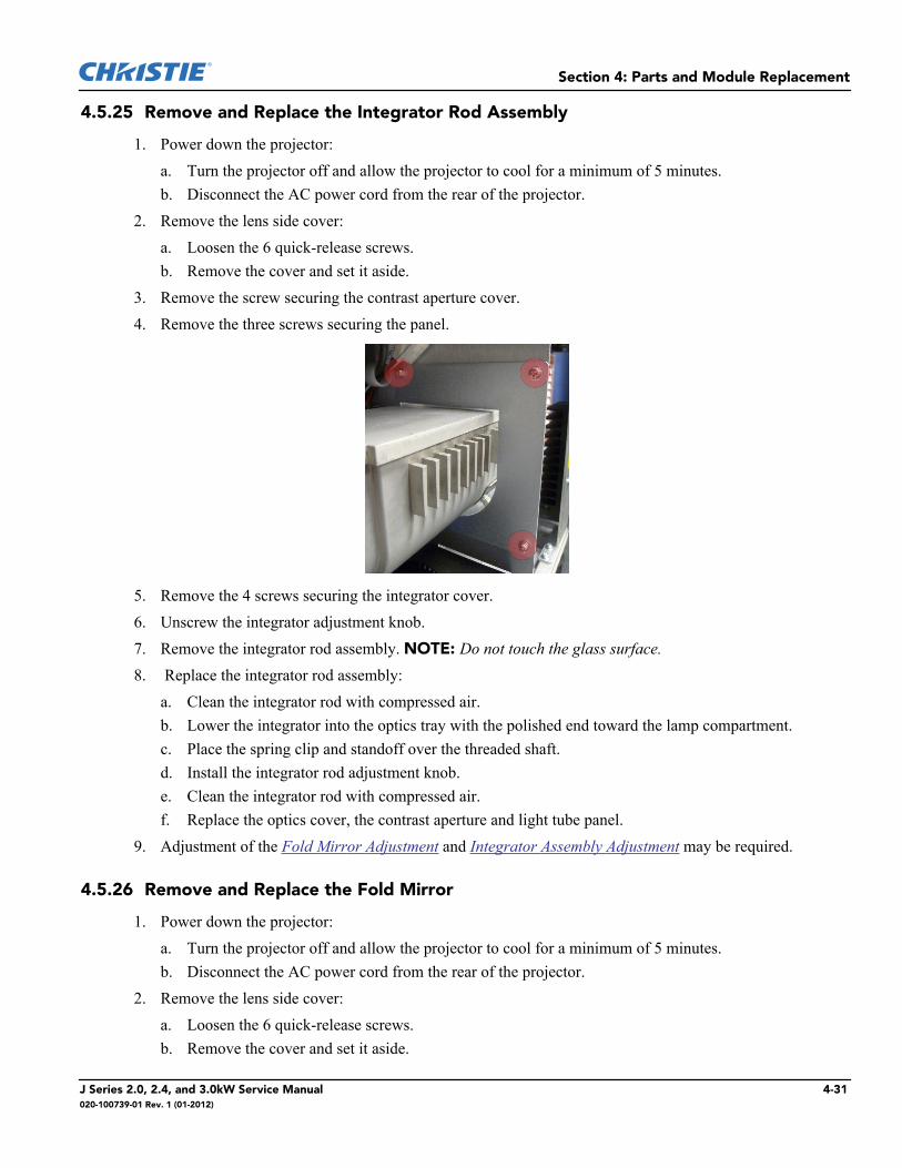
2. Unscrew the 2 quick release screws on the lamp door.3. Disconnect the J82 connector on the PC board.4. Remove the screw securing the PC board.
5. Remove the PC board.6. Install the new PC board.7. Connect J82 connector.
4-30 J Series 2.0, 2.4, and 3.0kW Service Manual020-100739-01 Rev. 1 (01-2012)
Section 4: Parts and Module Replacement
4.5.25 Remove and Replace the Integrator Rod Assembly
1. Power down the projector:a. Turn the projector off and allow the projector to cool for a minimum of 5 minutes.b. Disconnect the AC power cord from the rear of the projector.
2. Remove the lens side cover:a. Loosen the 6 quick-release screws.b. Remove the cover and set it aside.
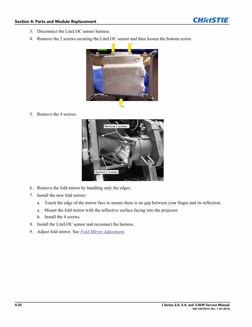
3. Remove the screw securing the contrast aperture cover.4. Remove the three screws securing the panel.
5. Remove the 4 screws securing the integrator cover.6. Unscrew the integrator adjustment knob.7. Remove the integrator rod assembly. NOTE: Do not touch the glass surface.8. Replace the integrator rod assembly:
a. Clean the integrator rod with compressed air.b. Lower the integrator into the optics tray with the polished end toward the lamp compartment.c. Place the spring clip and standoff over the threaded shaft.d. Install the integrator rod adjustment knob.e. Clean the integrator rod with compressed air.f. Replace the optics cover, the contrast aperture and light tube panel.
9. Adjustment of the Fold Mirror Adjustment and Integrator Assembly Adjustment may be required.
4.5.26 Remove and Replace the Fold Mirror
1. Power down the projector:a. Turn the projector off and allow the projector to cool for a minimum of 5 minutes.b. Disconnect the AC power cord from the rear of the projector.
2. Remove the lens side cover:a. Loosen the 6 quick-release screws.b. Remove the cover and set it aside.
J Series 2.0, 2.4, and 3.0kW Service Manual 4-31020-100739-01 Rev. 1 (01-2012)
Section 4: Parts and Module Replacement
3. Disconnect the LiteLOC sensor harness.4. Remove the 2 screws securing the LiteLOC sensor and then loosen the bottom screw.
5. Remove the 4 screws.
6. Remove the fold mirror by handling only the edges.7. Install the new fold mirror:
a. Touch the edge of the mirror face to ensure there is no gap between your finger and its reflection.a. Mount the fold mirror with the reflective surface facing into the projector. b. Install the 4 screws.
8. Install the LiteLOC sensor and reconnect the harness.9. Adjust fold mirror. See Fold Mirror Adjustment.
4-32 J Series 2.0, 2.4, and 3.0kW Service Manual020-100739-01 Rev. 1 (01-2012)

Section 4: Parts and Module Replacement
4.5.27 Remove and Replace the Shutter Assembly
1. Power down the projector:a. Turn the projector off and allow the projector to cool for a minimum of 5 minutes.b. Disconnect the AC power cord from the rear of the projector.
2. Remove the 8 screws holding the top cover and then remove the top cover and set it aside.3. Remove the lens side cover:
a. Loosen the 6 quick-release screws for the side cover.b. Remove the cover and set it aside.
4. Remove the removable cross member on the frame:a. Remove the 2 hex head screws.b. Lift and remove the bracket and set it aside.
5. Remove the 9 screws from the panel driver cover.6. Disconnect the P17 cable connector from the panel driver and then release it from the 4 cable clamps.7. Remove the 4 screws from the light engine duct.8. Remove the shutter harness, harness from cable clips.9. Remove the 2 screws securing the shutter assembly to the light engine.
10. Remove the shutter assembly.11. Reinstall the shutter harness in the cable clips.
4.5.28 Remove and Replace the Cold Mirror Assembly
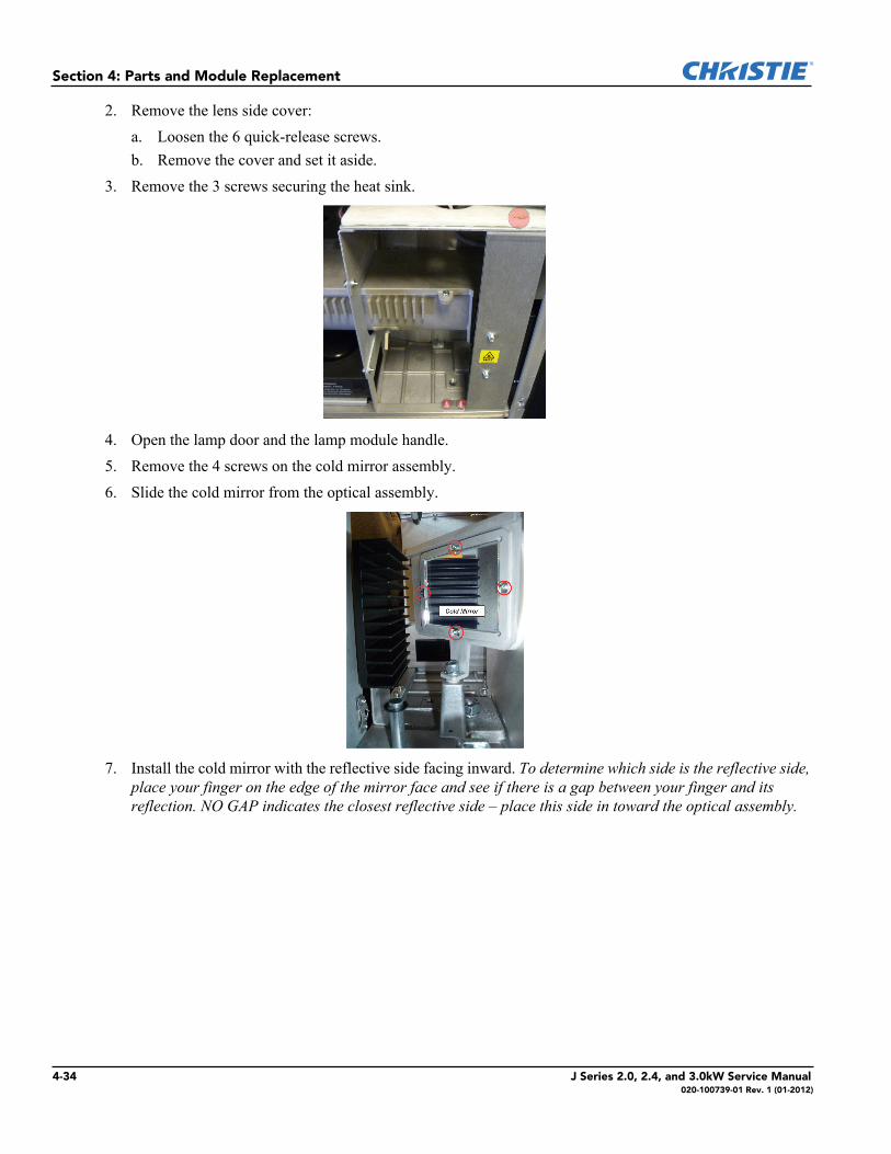
IMPORTANT! Wear nitrile gloves when handling the cold mirror and handle by its edges only -reflective surface facing into the projector.
1. Power down the projector:a. Turn the projector off and allow the projector to cool for a minimum of 5 minutes.b. Disconnect the AC power cord from the rear of the projector.
J Series 2.0, 2.4, and 3.0kW Service Manual 4-33020-100739-01 Rev. 1 (01-2012)
Section 4: Parts and Module Replacement
2. Remove the lens side cover:a. Loosen the 6 quick-release screws.b. Remove the cover and set it aside.
3. Remove the 3 screws securing the heat sink.
4. Open the lamp door and the lamp module handle.5. Remove the 4 screws on the cold mirror assembly.6. Slide the cold mirror from the optical assembly.
7. Install the cold mirror with the reflective side facing inward. To determine which side is the reflective side, place your finger on the edge of the mirror face and see if there is a gap between your finger and its reflection. NO GAP indicates the closest reflective side – place this side in toward the optical assembly.
4-34 J Series 2.0, 2.4, and 3.0kW Service Manual020-100739-01 Rev. 1 (01-2012)
Section 4: Parts and Module Replacement
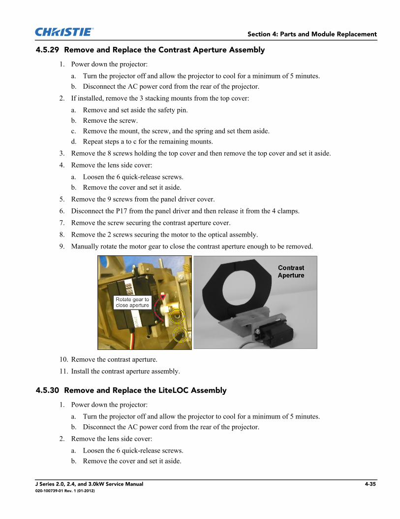
4.5.29 Remove and Replace the Contrast Aperture Assembly
1. Power down the projector:a. Turn the projector off and allow the projector to cool for a minimum of 5 minutes.b. Disconnect the AC power cord from the rear of the projector.
2. If installed, remove the 3 stacking mounts from the top cover:a. Remove and set aside the safety pin.b. Remove the screw.c. Remove the mount, the screw, and the spring and set them aside.d. Repeat steps a to c for the remaining mounts.
3. Remove the 8 screws holding the top cover and then remove the top cover and set it aside.4. Remove the lens side cover:
a. Loosen the 6 quick-release screws.b. Remove the cover and set it aside.
5. Remove the 9 screws from the panel driver cover.6. Disconnect the P17 from the panel driver and then release it from the 4 clamps.7. Remove the screw securing the contrast aperture cover.8. Remove the 2 screws securing the motor to the optical assembly.9. Manually rotate the motor gear to close the contrast aperture enough to be removed.
10. Remove the contrast aperture.11. Install the contrast aperture assembly.
4.5.30 Remove and Replace the LiteLOC Assembly
1. Power down the projector:a. Turn the projector off and allow the projector to cool for a minimum of 5 minutes.b. Disconnect the AC power cord from the rear of the projector.
2. Remove the lens side cover:a. Loosen the 6 quick-release screws.b. Remove the cover and set it aside.
J Series 2.0, 2.4, and 3.0kW Service Manual 4-35020-100739-01 Rev. 1 (01-2012)
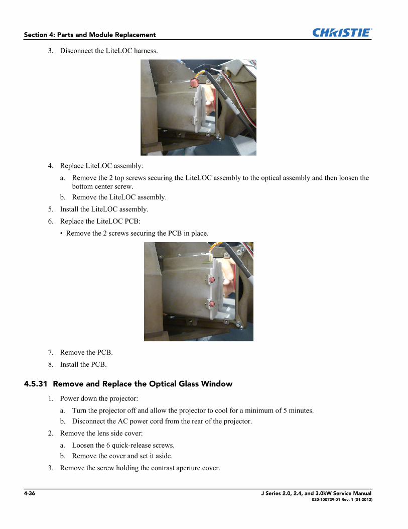
Section 4: Parts and Module Replacement
3. Disconnect the LiteLOC harness.
4. Replace LiteLOC assembly:a. Remove the 2 top screws securing the LiteLOC assembly to the optical assembly and then loosen the
bottom center screw.b. Remove the LiteLOC assembly.
5. Install the LiteLOC assembly.6. Replace the LiteLOC PCB:
• Remove the 2 screws securing the PCB in place.
7. Remove the PCB.8. Install the PCB.
4.5.31 Remove and Replace the Optical Glass Window
1. Power down the projector:a. Turn the projector off and allow the projector to cool for a minimum of 5 minutes.b. Disconnect the AC power cord from the rear of the projector.
2. Remove the lens side cover:a. Loosen the 6 quick-release screws.b. Remove the cover and set it aside.
3. Remove the screw holding the contrast aperture cover.
4-36 J Series 2.0, 2.4, and 3.0kW Service Manual020-100739-01 Rev. 1 (01-2012)
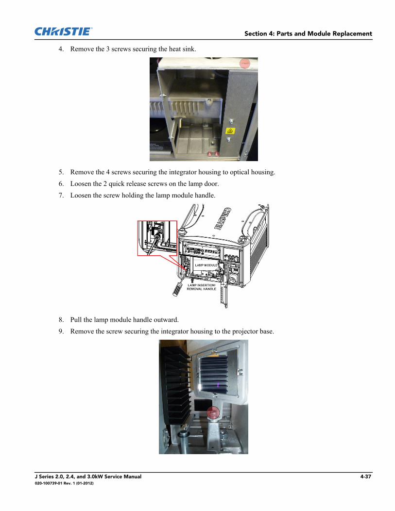
Section 4: Parts and Module Replacement
4. Remove the 3 screws securing the heat sink.
5. Remove the 4 screws securing the integrator housing to optical housing. 6. Loosen the 2 quick release screws on the lamp door. 7. Loosen the screw holding the lamp module handle.
8. Pull the lamp module handle outward.9. Remove the screw securing the integrator housing to the projector base.
J Series 2.0, 2.4, and 3.0kW Service Manual 4-37020-100739-01 Rev. 1 (01-2012)
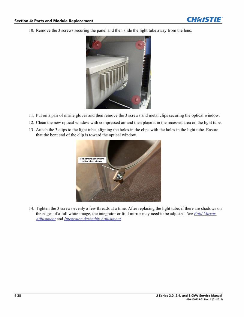
Section 4: Parts and Module Replacement
10. Remove the 3 screws securing the panel and then slide the light tube away from the lens.
11. Put on a pair of nitrile gloves and then remove the 3 screws and metal clips securing the optical window.12. Clean the new optical window with compressed air and then place it in the recessed area on the light tube. 13. Attach the 3 clips to the light tube, aligning the holes in the clips with the holes in the light tube. Ensure
that the bent end of the clip is toward the optical window.
14. Tighten the 3 screws evenly a few threads at a time. After replacing the light tube, if there are shadows on the edges of a full white image, the integrator or fold mirror may need to be adjusted. See Fold Mirror Adjustment and Integrator Assembly Adjustment.
4-38 J Series 2.0, 2.4, and 3.0kW Service Manual020-100739-01 Rev. 1 (01-2012)
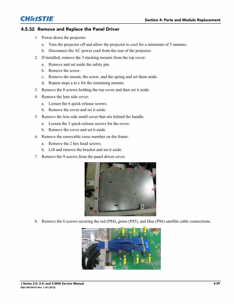
Section 4: Parts and Module Replacement
4.5.32 Remove and Replace the Panel Driver
1. Power down the projector:a. Turn the projector off and allow the projector to cool for a minimum of 5 minutes.b. Disconnect the AC power cord from the rear of the projector.
2. If installed, remove the 3 stacking mounts from the top cover:a. Remove and set aside the safety pin.b. Remove the screw.c. Remove the mount, the screw, and the spring and set them aside.d. Repeat steps a to c for the remaining mounts.
3. Remove the 8 screws holding the top cover and then set it aside.4. Remove the lens side cover:
a. Loosen the 6 quick-release screws.b. Remove the cover and set it aside.
5. Remove the lens side small cover that sits behind the handle:a. Loosen the 3 quick-release screws for the cover.b. Remove the cover and set it aside.
6. Remove the removable cross member on the frame:a. Remove the 2 hex head screws.b. Lift and remove the bracket and set it aside.
7. Remove the 9 screws from the panel driver cover.
8. Remove the 6 screws securing the red (P84), green (P85), and blue (P86) satellite cable connections.
J Series 2.0, 2.4, and 3.0kW Service Manual 4-39020-100739-01 Rev. 1 (01-2012)
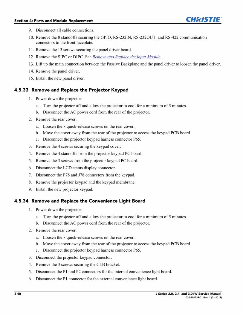
Section 4: Parts and Module Replacement
9. Disconnect all cable connections. 10. Remove the 8 standoffs securing the GPIO, RS-232IN, RS-232OUT, and RS-422 communication
connectors to the front faceplate.11. Remove the 13 screws securing the panel driver board.12. Remove the SIPC or DIPC. See Remove and Replace the Input Module.13. Lift up the main connection between the Passive Backplane and the panel driver to loosen the panel driver. 14. Remove the panel driver.15. Install the new panel driver.
4.5.33 Remove and Replace the Projector Keypad
1. Power down the projector:a. Turn the projector off and allow the projector to cool for a minimum of 5 minutes.b. Disconnect the AC power cord from the rear of the projector.
2. Remove the rear cover:a. Loosen the 8 quick-release screws on the rear cover.b. Move the cover away from the rear of the projector to access the keypad PCB board.c. Disconnect the projector keypad harness connector P65.
3. Remove the 4 screws securing the keypad cover.4. Remove the 4 standoffs from the projector keypad PC board.5. Remove the 3 screws from the projector keypad PC board.6. Disconnect the LCD status display connector.7. Disconnect the P78 and J78 connectors from the keypad.8. Remove the projector keypad and the keypad membrane.9. Install the new projector keypad.
4.5.34 Remove and Replace the Convenience Light Board
1. Power down the projector:a. Turn the projector off and allow the projector to cool for a minimum of 5 minutes.b. Disconnect the AC power cord from the rear of the projector.
2. Remove the rear cover:a. Loosen the 8 quick-release screws on the rear cover.b. Move the cover away from the rear of the projector to access the keypad PCB board.c. Disconnect the projector keypad harness connector P65.
3. Disconnect the projector keypad connector.4. Remove the 3 screws securing the CLB bracket.5. Disconnect the P1 and P2 connectors for the internal convenience light board.6. Disconnect the P1 connector for the external convenience light board.
4-40 J Series 2.0, 2.4, and 3.0kW Service Manual020-100739-01 Rev. 1 (01-2012)
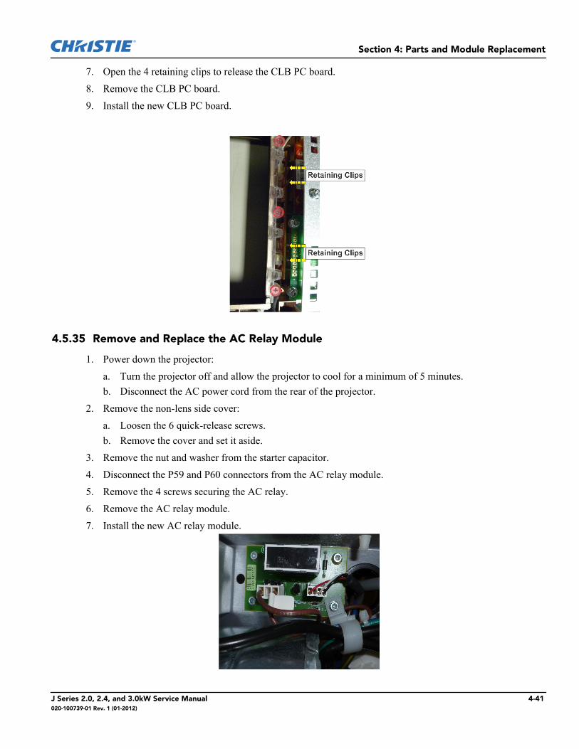
Section 4: Parts and Module Replacement
7. Open the 4 retaining clips to release the CLB PC board.8. Remove the CLB PC board.9. Install the new CLB PC board.
4.5.35 Remove and Replace the AC Relay Module
1. Power down the projector:a. Turn the projector off and allow the projector to cool for a minimum of 5 minutes.b. Disconnect the AC power cord from the rear of the projector.
2. Remove the non-lens side cover:a. Loosen the 6 quick-release screws.b. Remove the cover and set it aside.
3. Remove the nut and washer from the starter capacitor.4. Disconnect the P59 and P60 connectors from the AC relay module.5. Remove the 4 screws securing the AC relay.6. Remove the AC relay module.7. Install the new AC relay module.
J Series 2.0, 2.4, and 3.0kW Service Manual 4-41020-100739-01 Rev. 1 (01-2012)
Section 4: Parts and Module Replacement
4.5.36 Remove and Replace the LCD Display
1. Power down the projector:a. Turn the projector off and allow the projector to cool for a minimum of 5 minutes.b. Disconnect the AC power cord from the rear of the projector.
2. Remove the rear cover:a. Loosen the 8 quick-release screws on the rear cover.b. Move the cover away from the rear of the projector to access the keypad PCB board.c. Disconnect the projector keypad harness connector P65.
3. Disconnect the projector keypad connector.4. Remove the 4 screws securing the keypad cover.5. Remove the 4 screws from the LCD display.6. Disconnect the LCD display connector.7. Remove the LCD status display.8. Install the new LCD status display.
4.5.37 Remove and Replace the Passive Backplane Module
1. Power down the projector:a. Turn the projector off and allow the projector to cool for a minimum of 5 minutes.b. Disconnect the AC power cord from the rear of the projector.
2. Remove the CPU High Definition Panel Driver. See Remove and Replace the Panel Driver.3. Remove SIPC or DIPC. See Remove and Replace the Input Module.4. Remove the 8 standoffs securing the GPIO, RS-232IN, RS-232OUT, RS-422 communication connectors
to the front faceplate.5. Remove the 13 screws securing the panel driver.6. Lift up the main connection between the passive backplane and the panel driver.
7. Remove the panel driver board.8. Lift and remove the two side input guides.
4-42 J Series 2.0, 2.4, and 3.0kW Service Manual020-100739-01 Rev. 1 (01-2012)
Section 4: Parts and Module Replacement
9. Remove the 4 front face plate screws.10. Remove the 3 screws securing the plate underneath the front face plate.11. Remove the 4 screws securing the middle input guide and then remove it.
12. Remove the 9 screws securing the passive backplane to the card cage frame.
13. Remove the PC board.14. Install the passive backplane module following the removal steps, in reverse order.
4.5.38 Remove and Replace the Processor Board
1. Power down the projector:a. Turn the projector off and allow the projector to cool for a minimum of 5 minutes.b. Disconnect the AC power cord from the rear of the projector.
2. Unscrew the 2 captive screws.
3. Pull the clips to release the processor board.4. Slide the processor board out.5. Replace the processor board.6. Install the new processor board.
J Series 2.0, 2.4, and 3.0kW Service Manual 4-43020-100739-01 Rev. 1 (01-2012)
Section 4: Parts and Module Replacement
4.5.39 Remove and Replace the Input Module
1. Unscrew the 2 captive screws.2. Slide the input module out.3. Install the new input module.
4.5.40 Remove the Lens
1. Remove and set aside the red security screws on lens plate models (if used).
2. Rotate the lens clamp to the OPEN position.
3. Pull the lens straight out.
4-44 J Series 2.0, 2.4, and 3.0kW Service Manual020-100739-01 Rev. 1 (01-2012)
Section 4: Parts and Module Replacement
4.5.41 Install the Lens
1. Remove the rear lens cap from the lens.2. Rotate the lens locking clamp to the OPEN position.3. Install the lens straight into the lens mount opening all the way back, without turning. Make sure the lens
connector lines up with the connector on the projector.
4. Hold the lens flat against the lens mount and then rotate the lens clamp clockwise to lock the lens in position.
5. Tighten the red security screws provided with the lens mount, or hand tighten the lens retaining screws attached to the lens.
You must install the lens red security screws or the lens retaining screws if the projectoris installed in an elevated position.
6. Remove the front lens cap.
4.5.42 Remove and Replace the Lamp Door Interlock Switch
1. Power down the projector:a. Turn the projector off and allow the projector to cool for a minimum of 5 minutes.b. Disconnect the AC power cord from the rear of the projector.
1. Loosen the 2 quick release screws on the lamp door.2. Disconnect the 2 lamp interlock switch connectors.3. Remove the 2 screws securing switch and bracket holder.
WARNING
J Series 2.0, 2.4, and 3.0kW Service Manual 4-45020-100739-01 Rev. 1 (01-2012)
Section 4: Parts and Module Replacement
4. Remove the lamp interlock switch.5. Install the new lamp interlock switch.
4.5.43 Remove and Replace the Card Cage
Observe all ESD precautions when handling any of the PCBs in the projector.
1. Power down the projector:a. Turn the projector off and allow the projector to cool for a minimum of 5 minutes.b. Disconnect the AC power cord from the rear of the projector.
2. Remove the 8 screws holding the top cover and then remove the top cover and set it aside.3. Remove the lens side cover:
a. Loosen the 6 quick-release screws.b. Remove the cover and set it aside.
4. Remove the lens side small cover that sits behind the handle:a. Loosen the 3 quick-release screws for the cover.b. Remove the cover and set it aside.
5. Remove the removable cross member on the frame:a. Remove the 2 hex head screws.b. Lift and remove the bracket and set it aside.
6. Remove the 9 screws from the panel driver cover.7. Remove the 6 screws securing the red (P84), green (P85), and blue (P86) connectors and then disconnect
the remaining cable connectors.8. Disconnect all connectors from card cage and remove the wires and cables from the card cage enclosure.9. Remove the rear skin:
a. Loosen the 8 quick-release screws on the rear cover.b. Move the cover away from the rear of the projector to access the keypad PCB.c. Disconnect the projector keypad harness connector P65.
10. Remove the 4 screws securing the front faceplate.11. Remove the 3 screws securing the side of the air duct.12. Remove air duct.13. Remove the 3 screws securing the card cage assembly to the base of the projector.14. Remove the low voltage power supply.15. Slide the card cage out.16. Install the new card cage.
CAUTION
4-46 J Series 2.0, 2.4, and 3.0kW Service Manual020-100739-01 Rev. 1 (01-2012)
Section 4: Parts and Module Replacement
4.6 Boresight Alignment
1. Display the Boresight Test Pattern:a. Press Test on the projector keypad.b. Press the Up key until Boresight displays.c. Press Enter.
2. Focus the image on cross-hair pattern I. Evaluate the focus on cross-hair image II and III. If all 3 images are in focus, no further action is required. If boresight is required:a. Loosen the 3 locking setscrews on the lens mount.
b. Adjust the cap screw until pattern I is in focus with minimal flare.c. Adjust the cap screw until pattern II is in focus with minimal flare.d. Adjust the cap screw until pattern III is in focus with minimal flare.
3. Repeat step b, c, d until 3 patterns are equally focused. If the boresight is acceptable proceed to step 5. If the boresight is not correct, proceed to step 4.
4. Turn the setscrews until they are flush with the front face of the lens mount plate and in contact with the inner lens mount plate.
J Series 2.0, 2.4, and 3.0kW Service Manual 4-47020-100739-01 Rev. 1 (01-2012)
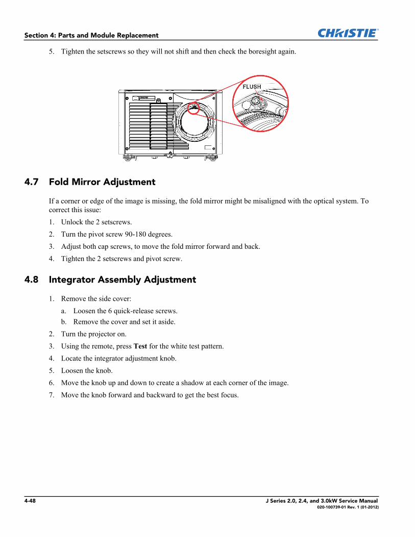
Section 4: Parts and Module Replacement
5. Tighten the setscrews so they will not shift and then check the boresight again.
4.7 Fold Mirror Adjustment
If a corner or edge of the image is missing, the fold mirror might be misaligned with the optical system. To correct this issue:1. Unlock the 2 setscrews.2. Turn the pivot screw 90-180 degrees.3. Adjust both cap screws, to move the fold mirror forward and back.4. Tighten the 2 setscrews and pivot screw.
4.8 Integrator Assembly Adjustment
1. Remove the side cover:a. Loosen the 6 quick-release screws.b. Remove the cover and set it aside.
2. Turn the projector on. 3. Using the remote, press Test for the white test pattern. 4. Locate the integrator adjustment knob.5. Loosen the knob.6. Move the knob up and down to create a shadow at each corner of the image.7. Move the knob forward and backward to get the best focus.
4-48 J Series 2.0, 2.4, and 3.0kW Service Manual020-100739-01 Rev. 1 (01-2012)
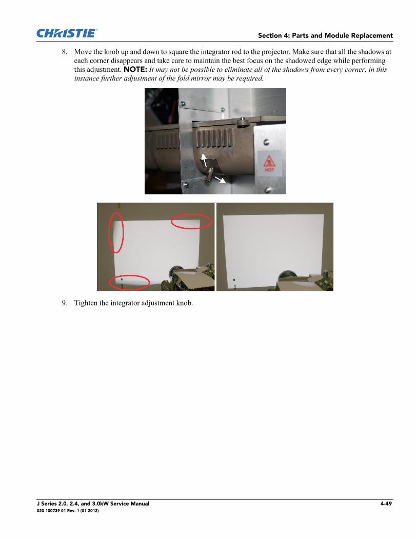
Section 4: Parts and Module Replacement
8. Move the knob up and down to square the integrator rod to the projector. Make sure that all the shadows at each corner disappears and take care to maintain the best focus on the shadowed edge while performing this adjustment. NOTE: It may not be possible to eliminate all of the shadows from every corner, in this instance further adjustment of the fold mirror may be required.
9. Tighten the integrator adjustment knob.
J Series 2.0, 2.4, and 3.0kW Service Manual 4-49020-100739-01 Rev. 1 (01-2012)

5 Interconnections
This diagram illustrates the electrical connections between internal electronic components.NOTE: Part numbers are subject to change.
J Series 2.0, 2.4, and 3.0kW Service Manual 5-1020-100739-01 Rev. 1 (01-2012)

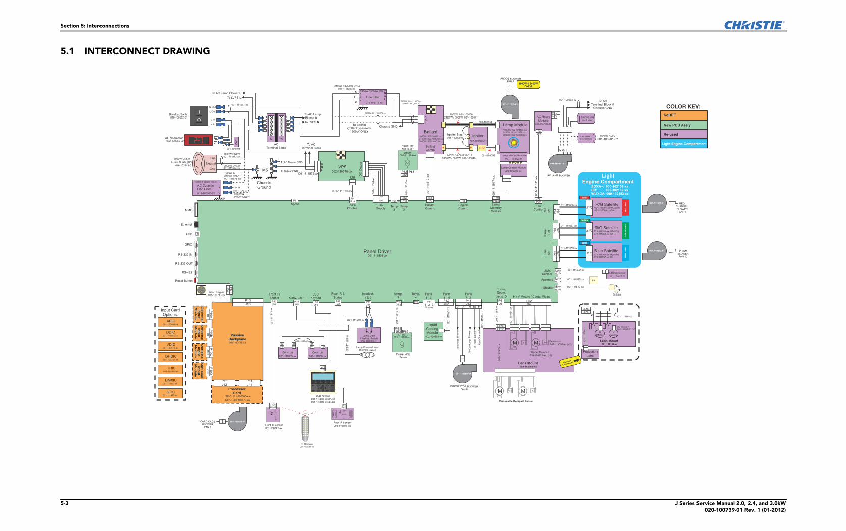
Section 5: Interconnections
5-3 J Series Service Manual 2.0, 2.4, and 3.0kW020-100739-01 Rev. 1 (01-2012)
5.1 INTERCONNECT DRAWING
Breaker/Switch016-100582-01
AC Voltmeter002-100055-02
3000W ONLY!
IEC309 Coupler016-103843-01
3000W ONLY!001-111573-xx
001-111574-xx
001-100108
1900W &2400W ONLY!001-111575-xx
001-111576-xx
1900W &2400W ONLY!
ChassisGround
To AC Blower GND
To Ballast GND001-111572-xx
To ACTerminal Block
001-111577-xx
To AC LampBlower N
To LVPS N
001-111578-xx2400W / 3000W ONLY
Chassis GND
To ACTerminal Block &
Chassis GND
2400W: 001-111679-xx3000W: n/a (built in)
1900W: 001-1000582400W / 3000W: 001-100041
001-100054
Igniter Bias001-100029-02
1900W: 34-001939-01P2400W / 3000W: 001-100040
001-100056
ACTerminal Block
L1900W ONLY
001-100201-02
001-1
11511-x
x
001-1
11512-x
x
001-1
11517-x
x
001-1
11504-x
x
001-111519-xx
BallastComm.
Interlock1 & 2
+
_ _
+
Line
Gnd
1900W & 2400W ONLY!
016-100005-02
AC Coupler/Line Filter
Line Filter
2400W / 3000W ONLY
016-104176-xx
Ballast1900W: 002-100101-xx2400W: 002-100098-xx3000W: 002-100010-xx
BallastComm.
AC RelayModule
001-100228-01
Startup Cap(included)
Fan SpeedReduction Cap
002-100100-01
Igniter
Lamp Module1900W: 002-100135-xx2400W: 002-120592-xx3000W: 002-120593-xx
+HV
Lamp Memory Module
Lamp Contact Module
001-100362-xx
001-100363-xx
L N
NGL
LVPS002-120578-xx
DC
Ou
tpu
t
Ctrl
N G L
BallastComm.
LampMemoryModule
FanControl
DCSupply
LVPSControl
Spare
001-111506-xxPanel Driver
Front IRSensor Conv. Lts 1
LCDKeypad
Rear IR &Status
Interlock1 & 2
Fans1 - 3
Fans4 - 6
001-1
11553-x
x
LiquidCoolingModule
002-120602-xx
Lamp CompartmentThermal Switch
001-111559-xx
001-1
11560-x
x
001-111646-xx
Conv. Lts
001-111635-xx
Conv. Lts
001-111635-xx
001-1
11543-x
x
3000W ONLY!
L Out
N Out
N In
L In
CA
P
001-100063-02
P55
P120P73 P72
Neutral
L
N
G
P48
M5
N
LG
N
LG
N
LG
1900W: 001-100379-xx
To Ballast(Filter Bypassed)
1900W ONLY
MMC
Ethernet
GPIO
RS-232 IN
RS-232 OUT
Reset Button
RS-422
USB
KoRETM
Re-used
Light Engine Compartment
New PCB Ass’y
COLOR KEY:
011-111658-xx
011-111657-xx
011-111659-xx
Blue Satellite001-111365-xx (HD/WU)001-111367-xx (SX+)
LightEngine Compartment
SGXA+: 000-102151-xxHD: 000-102152-xxWUXGA: 000-102153-xx
Blu
eS
at.
Gre
en
Sat.
Red
Sat.
P85
P86
GREEN
BLUE
RED
RE
D D
MD
GR
EE
N D
MD
R/G Satellite001-111366-xx (HD/WU)001-111368-xx (SX+)
R/G Satellite001-111366-xx (HD/WU)001-111368-xx (SX+)
BLU
E D
MD
001-111592-xx
001-111537-xx
001-111540-xx
LiteLOC Sensor
001-100229-xx
Shutter
Aperture
LightSensor P
47
P17
P16
Shutter
Iris
000-102163-xx
Lens Mount
Sensors =
Stepper Motors =016-104121-xx (x2)
00
1-1
11555-x
x001-1
11589-x
x
001-1
11554-x
x
Focus,Zoom,
Lens ID H / V Motors / Center Flags
P62P61
Removable Compact Len(s)
M M
M M
P62P61
To
An
od
eB
low
er
To
Card
cage
Blo
wer
To
Prism
Blo
wer
Re
dC
ha
nn
el
Fans7-11P43
001-1
11550-x
x
7 9 10 11
P42
Op
tion
al
Inp
ut
Mo
du
le
Op
tion
al
Inp
ut
Mo
du
le
Op
tion
al
Inp
ut
Mo
du
le
Op
tion
al
Inp
ut
Mo
du
le
ABIC001-100466-xx
DDIC001-100752-xx
VDIC001-100475-xx
DHDIC001-100751-xx
THIC001-100467-xx
DMXIC001-111153-xx
3GIC001-111475-xx
Input CardOptions:
P13
P59
LCD Keypad
001-110818-xx (PCB)
001-110819-xx (LCD)
Wired Keypad001-100717-xx
Front IR Sensor
001-100221-xx
PassiveBackplane001-100465-xx
ProcessorCard
SIPC: 001-100686-xx
DIPC: 001-100470-xx
STA
TU
S
CO
MM
LA
MP
SH
UT
TE
R
Rear IR Sensor
001-110806-xx
P65P15 P41P50
000-102587-xx
IR Remote
P11
001-111588-xx
DC Motors =001-100249-01 (x2)
001-102164-xx
Lens Mount
ProjectionLens
001-1
11556-x
x
Alternate
Lens Mount
P14P6 P26
ANODE BLOWERFAN 7
J14J26
J72J73 J120
J85
J8
6J4
7J1
7J1
6
J62J61J42J48J65J15J50J13
J59
8
P84
J84
P60
P1
J1
P1
J1
P1
J1
INTEGRATOR BLOWERFAN 8
001-111609-01
001-111609-01
P108J108
P80J80
P78J78
P2
J2P1J1
P1J1
P2
LENS
LENS
LENS
LENS
J43
J60
P59J59
AC LAMP BLOWER
001-100431-01
001-110862-01CARD CAGEBLOWER
FAN 9
REDCHANNELBLOWERFAN 11
001-111609-01
001-110862-01 PRISMBLOWERFAN 10
To LVPS L
To AC Lamp Blower L
1900W & 2400WONLY!
1900W & 2400WONLY!
EngineComm.
P8
1 2 3Spares
Lamp DoorInterlock Switch016-100966-01
Temp.1
Temp.4
001-1
11549-x
x
P52J52
Intake TempSensor
001-111558-xx (x2)
DTSM001-111269-xx
P82J82 P83
P53
Temp2
J53
EXHAUSTAIR TEMP
001-1
11518-x
x
DTSM001-111269-xx
P82J82
P83
Temp3
P54
J11
P10A
J10
P10B
J10
P10C
J10
P10D
J10
P12
J12
P11
J11
VMotor
HMotor

6 SpecificationsThis section provides detailed J Series specifications
6.1 Image Performance
6.1.1 Pixel Format
6.1.2 Nominal Brightness
6.1.3 Contrast
6.1.4 Luminance Uniformity
6.1.5 Gamma
1080p (H x V square pixels) 1920 x 1080SXGA+ (H x V square pixels) 1400 x 1050WUXGA (H Save square pixels) 1920 x 1200
Projector Base Model Lamp Power Brightness (ANSI) (Center)
3000W 1080p 3000W 18,000 20,0002400W 1080p 2400W 14,000 15,4001900W 1080p 1900W 12,000 13,200
3000W SXGA+ 3000W 20,000 22,0002400W SXGA+ 2400W 16,000 17,6001900W SXGA+ 1900W 12,500 13,750
3000W WUXGA 3000W 18,000 20,0002400W WUXGA 2400W 14,000 12,4001900W WUXGA 1900W 12,000 13,200
ANSI: 16 pt. checker pattern on black screen 650:1 typical
Full field: 9 pt. average ON/OFF with background light subtraction
1500: 1 typical
90% Brightness Uniformity SXGA+80% Brightness Uniformity 1080p, WUXGA
Default Gamma (all points from 10 to 90 IRE)
2.2 + linear segment
Adjustable Gamma range 1.0 to 3.0
J Series 2.0, 2.4, and 3.0kW Service Manual 6-1020-100739-01 Rev. 1 (01-2012)
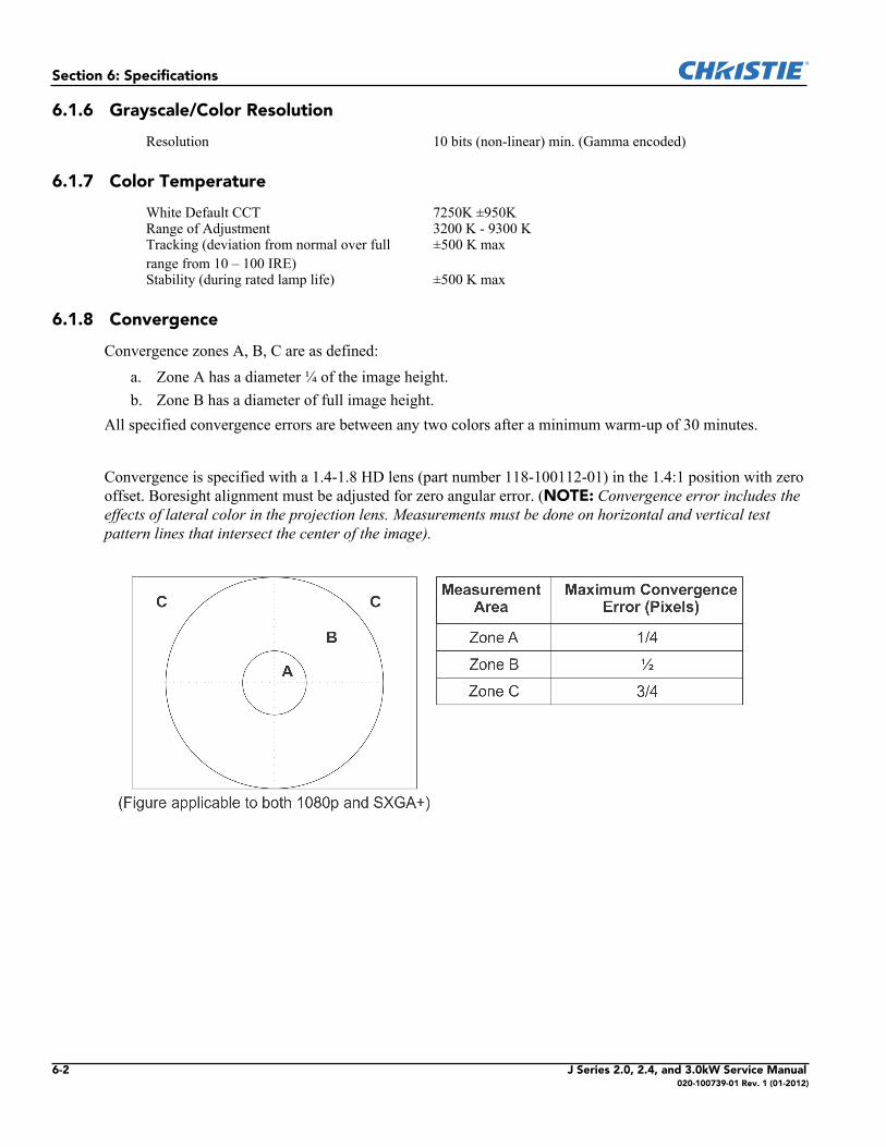
Section 6: Specifications
6.1.6 Grayscale/Color Resolution
6.1.7 Color Temperature
6.1.8 Convergence
Convergence zones A, B, C are as defined: a. Zone A has a diameter ¼ of the image height. b. Zone B has a diameter of full image height.
All specified convergence errors are between any two colors after a minimum warm-up of 30 minutes.
Convergence is specified with a 1.4-1.8 HD lens (part number 118-100112-01) in the 1.4:1 position with zero offset. Boresight alignment must be adjusted for zero angular error. (NOTE: Convergence error includes the effects of lateral color in the projection lens. Measurements must be done on horizontal and vertical test pattern lines that intersect the center of the image).
Resolution 10 bits (non-linear) min. (Gamma encoded)
White Default CCT 7250K ±950KRange of Adjustment 3200 K - 9300 KTracking (deviation from normal over full range from 10 – 100 IRE)
±500 K max
Stability (during rated lamp life) ±500 K max
6-2 J Series 2.0, 2.4, and 3.0kW Service Manual020-100739-01 Rev. 1 (01-2012)
Section 6: Specifications
6.1.9 Blemishes
6.1.10 Pixel Defects
6.2 Feature Set
6.2.1 Airflow
6.2.2 Air Filters (Optional)
6.2.3 Dust Sealing
6.2.4 ILS (Intelligent Lens System)
Red screen No blemishesGreen screen No blemishesBlue screen No blemishesWhite screen No blemishesBlack screen No blemishes
Red 0 bright, up to 1 darkGreen 0 bright, 0 darkBlue 0 bright, up to 2 dark non-adjacent
Air intakes Front of projectorAir exhaust Hot lamp exhaust: rear of projector
Filter media types Dust filterFog filter
Filter access Service-interchangeable via access panel
Dust sealed DMDs Gasket sealed
Motorized lenses and lens mount with position encoding
Zoom, focus, horizontal and vertical offsets
Accuracy ±2 pixelManual control 1/3 pixel fine movement control per button press on
any applicable User Interface (e.g., remote).Calibration User Configurable Calibration Modes
Automatic calibration on lens change detectionAutomatic calibration on power-upManual calibration
Calibration time < 10 seconds when requiredBore sight 3-point +- 4 degrees adjustment and lockable
without removing coversTravel time stop to stopZoom and Focus 10 seconds nominal (depends on lens type)Offsets 5 seconds (nominal (depends on lens type)Manual Lens Movement Manual over-ride permissible for zoom and focus
J Series 2.0, 2.4, and 3.0kW Service Manual 6-3020-100739-01 Rev. 1 (01-2012)
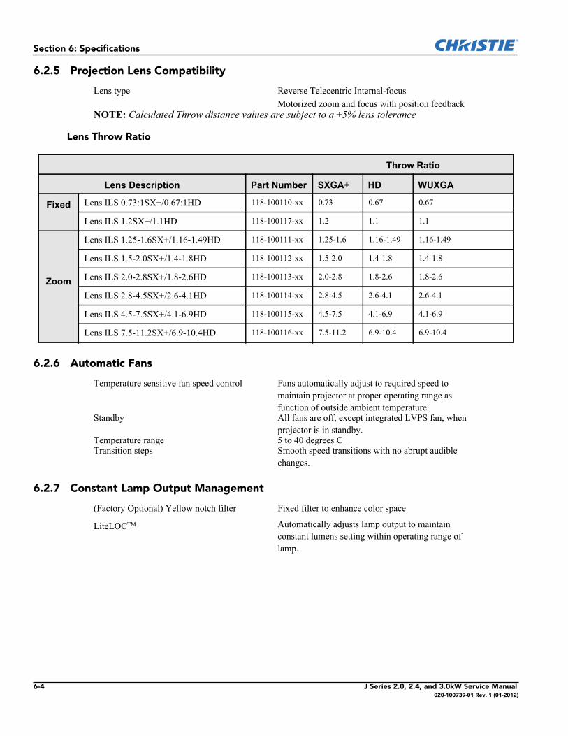
Section 6: Specifications
6.2.5 Projection Lens Compatibility
Lens Throw Ratio
6.2.6 Automatic Fans
6.2.7 Constant Lamp Output Management
Lens type Reverse Telecentric Internal-focusMotorized zoom and focus with position feedback
NOTE: Calculated Throw distance values are subject to a ±5% lens tolerance
Throw Ratio
Lens Description Part Number SXGA+ HD WUXGA
Fixed Lens ILS 0.73:1SX+/0.67:1HD 118-100110-xx 0.73 0.67 0.67
Lens ILS 1.2SX+/1.1HD 118-100117-xx 1.2 1.1 1.1
Zoom
Lens ILS 1.25-1.6SX+/1.16-1.49HD 118-100111-xx 1.25-1.6 1.16-1.49 1.16-1.49
Lens ILS 1.5-2.0SX+/1.4-1.8HD 118-100112-xx 1.5-2.0 1.4-1.8 1.4-1.8
Lens ILS 2.0-2.8SX+/1.8-2.6HD 118-100113-xx 2.0-2.8 1.8-2.6 1.8-2.6
Lens ILS 2.8-4.5SX+/2.6-4.1HD 118-100114-xx 2.8-4.5 2.6-4.1 2.6-4.1
Lens ILS 4.5-7.5SX+/4.1-6.9HD 118-100115-xx 4.5-7.5 4.1-6.9 4.1-6.9
Lens ILS 7.5-11.2SX+/6.9-10.4HD 118-100116-xx 7.5-11.2 6.9-10.4 6.9-10.4
Temperature sensitive fan speed control Fans automatically adjust to required speed to maintain projector at proper operating range as function of outside ambient temperature.
Standby All fans are off, except integrated LVPS fan, when projector is in standby.
Temperature range 5 to 40 degrees CTransition steps Smooth speed transitions with no abrupt audible
changes.
(Factory Optional) Yellow notch filter Fixed filter to enhance color space
LiteLOC Automatically adjusts lamp output to maintain constant lumens setting within operating range of lamp.
6-4 J Series 2.0, 2.4, and 3.0kW Service Manual020-100739-01 Rev. 1 (01-2012)
Section 6: Specifications
6.2.8 Shutter
6.2.9 Lamps
6.2.10 Status LED
6.2.11 Electronics/SW
Open Light transmitted to projection lensClosed All light blocked - no light on screen
Ushio Xenon bubble lamp system Lamps are accessed from the rear of the projector
Status LEDs #LED STATES
Lamp 1 Off – Lamp offYellow – Lamp time has expired and lamp should be replacedGreen – Lamp is on and operating correctlyFlashing red – Lamp has malfunctionedFlashing yellow – Lamp door is open
Comm 2 Flashing red – Error has occurred. Details are displayed on the status display
Status 3 Off – AC power is offYellow – AC is present but projector is in standbyGreen – Power is powered up and operating normallyFlashing red – Error has occurred. Details are displayed on the status display
Shutter 4 Green – Shutter is openYellow – Shutter is closed
FEATURE COMMENTSImage Device Supports 3 chip DMD operationVideo Format Re-Sizing All video formats can be resized to fill screen either horizontally or
vertically while maintaining aspect ratioPicture in Picture SupportedBuilt-in 2D keystone and geometry correction SupportedAuto-scaling SupportedAuto-de interlacing SupportedEdge blending SupportedWarping SupportedTiling (max array size) 3x3 Standard Image Processor & 2x2 Dual Image ProcessorBlanking and Image positioning SupportedBrightness, contrast, color, and uniformity User settable controlImage orientation Can display image front/rear screen, normal/inverted (ceiling)Electronics HW access Mounted at the back of the projectorNumber of option cards 6 user inter-changeable – hot swappableNumber of processor cards 2 user inter-changeableNumber of option slots 4, option cards; 1, processor cardArbitrary Gamma User definable gamma curves
J Series 2.0, 2.4, and 3.0kW Service Manual 6-5020-100739-01 Rev. 1 (01-2012)
Section 6: Specifications
6.3 Image Processor Performance
6.4 Input (Source Signal) Compatibility
6.4.1 Analog (Only) Input
6.4.2 Twin HDMI Input
Min input pixel rate 13 Mpix/sMax input pixel rate 165 Mpix/s Standard Mode
330 Mpix/s High Bandwidth modeStandard Image ProcessorDual Image Processor
Max input resolution 2048x1536 (QXGA)Min input resolution 640x400Max input frame rate with Dual Image Processor Card
120Hz at 2048x108092Hz at 2048x1536*
Dual Image Processor (DIPC) required* QXGA with sources that can output minimum blanking
Max input frame rate with Standard Image Processor Card
50Hz at 2048x1536 (QXGA) *With sources that can output minimum blanking, otherwise lower vertical rates
Processing 10 bit throughout * * Except Dual-DVI input in dual-link mode (dual 8 bit input paths into 10 bit processing)
Source switching time Switch time 1 second
Switch time 3 seconds
Low bandwidth signals
3D signals
Connectors 5 female BNC, 75 OhmR/PrG/YB/PbH/CV
Color spaces/signal types RGBYPbPr
A/D conversion 10 bits
Connectors 2 independent HDMI inputs type A2 loop-out HDMI connectors type A
Color spaces/signal types RGBYCbCr (4:2:2)YCbCr (4:4:4)HDCP supportHDMI 1.3 supported (not including audio) except: 12 bit color dithered to 10 bits; 16 bit color not supportedHDMI 1.4a (Mirage Models)
6-6 J Series 2.0, 2.4, and 3.0kW Service Manual020-100739-01 Rev. 1 (01-2012)
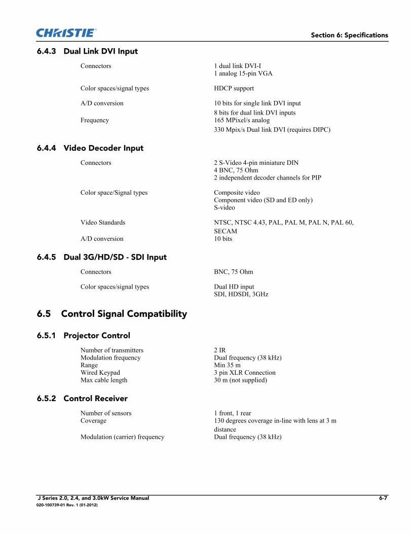
Section 6: Specifications
6.4.3 Dual Link DVI Input
6.4.4 Video Decoder Input
6.4.5 Dual 3G/HD/SD - SDI Input
6.5 Control Signal Compatibility
6.5.1 Projector Control
6.5.2 Control Receiver
Connectors 1 dual link DVI-I1 analog 15-pin VGA
Color spaces/signal types HDCP support
A/D conversion 10 bits for single link DVI input8 bits for dual link DVI inputs
Frequency 165 MPixel/s analog330 Mpix/s Dual link DVI (requires DIPC)
Connectors 2 S-Video 4-pin miniature DIN4 BNC, 75 Ohm 2 independent decoder channels for PIP
Color space/Signal types Composite videoComponent video (SD and ED only)S-video
Video Standards NTSC, NTSC 4.43, PAL, PAL M, PAL N, PAL 60, SECAM
A/D conversion 10 bits
Connectors BNC, 75 Ohm
Color spaces/signal types Dual HD inputSDI, HDSDI, 3GHz
Number of transmitters 2 IR Modulation frequency Dual frequency (38 kHz)Range Min 35 mWired Keypad 3 pin XLR ConnectionMax cable length 30 m (not supplied)
Number of sensors 1 front, 1 rear Coverage 130 degrees coverage in-line with lens at 3 m
distanceModulation (carrier) frequency Dual frequency (38 kHz)
J Series 2.0, 2.4, and 3.0kW Service Manual 6-7020-100739-01 Rev. 1 (01-2012)
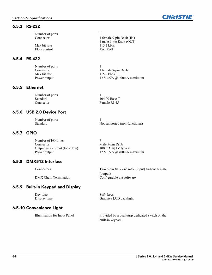
Section 6: Specifications
6.5.3 RS-232
6.5.4 RS-422
6.5.5 Ethernet
6.5.6 USB 2.0 Device Port
6.5.7 GPIO
6.5.8 DMX512 Interface
6.5.9 Built-In Keypad and Display
6.5.10 Convenience Light
Number of ports 2Connector 1 female 9-pin Dsub (IN)
1 male 9-pin Dsub (OUT)Max bit rate 115.2 kbpsFlow control Xon/Xoff
Number of ports 1Connector 1 female 9-pin DsubMax bit rate 115.2 kbpsPower output 12 V ±5% @ 400mA maximum
Number of ports 1Standard 10/100 Base-TConnector Female RJ-45
Number of ports 1Standard Not supported (non-functional)
Number of I/O Lines 7Connector Male 9-pin DsubOutput sink current (logic low) 100 mA @ 1V typicalPower output 12 V ±5% @ 400mA maximum
Connectors Two 5-pin XLR one male (input) and one female (output)
DMX Chain Termination Configurable via software
Key type Soft- keysDisplay type Graphics LCD backlight
Illumination for Input Panel Provided by a dual-strip dedicated switch on the built-in keypad.
6-8 J Series 2.0, 2.4, and 3.0kW Service Manual020-100739-01 Rev. 1 (01-2012)
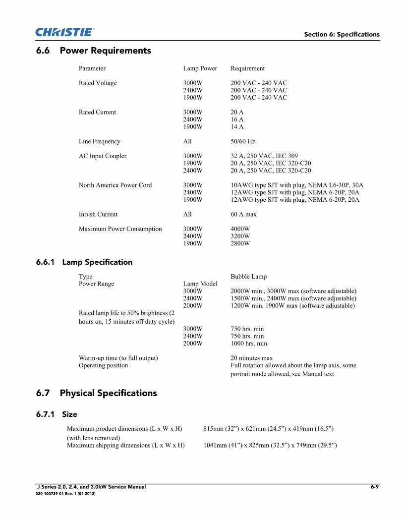
Section 6: Specifications
6.6 Power Requirements
6.6.1 Lamp Specification
6.7 Physical Specifications
6.7.1 Size
Parameter Lamp Power Requirement
Rated Voltage 3000W 200 VAC - 240 VAC2400W 200 VAC - 240 VAC1900W 200 VAC - 240 VAC
Rated Current 3000W 20 A2400W 16 A1900W 14 A
Line Frequency All 50/60 Hz
AC Input Coupler 3000W 32 A, 250 VAC, IEC 3091900W 20 A, 250 VAC, IEC 320-C202400W 20 A, 250 VAC, IEC 320-C20
North America Power Cord 3000W 10AWG type SJT with plug, NEMA L6-30P, 30A2400W 12AWG type SJT with plug, NEMA 6-20P, 20A1900W 12AWG type SJT with plug, NEMA 6-20P, 20A
Inrush Current All 60 A max
Maximum Power Consumption 3000W 4000W2400W 3200W1900W 2800W
Type Bubble LampPower Range Lamp Model
3000W 2000W min., 3000W max (software adjustable)2400W 1500W min., 2400W max (software adjustable)2000W 1200W min, 1900W max (software adjustable)
Rated lamp life to 50% brightness (2 hours on, 15 minutes off duty cycle)
3000W 750 hrs. min2400W 750 hrs. min2000W 1000 hrs. min
Warm-up time (to full output) 20 minutes maxOperating position Full rotation allowed about the lamp axis, some
portrait mode allowed, see Manual text
Maximum product dimensions (L x W x H)(with lens removed)
815mm (32”) x 621mm (24.5”) x 419mm (16.5”)
Maximum shipping dimensions (L x W x H) 1041mm (41”) x 825mm (32.5”) x 749mm (29.5”)
J Series 2.0, 2.4, and 3.0kW Service Manual 6-9020-100739-01 Rev. 1 (01-2012)
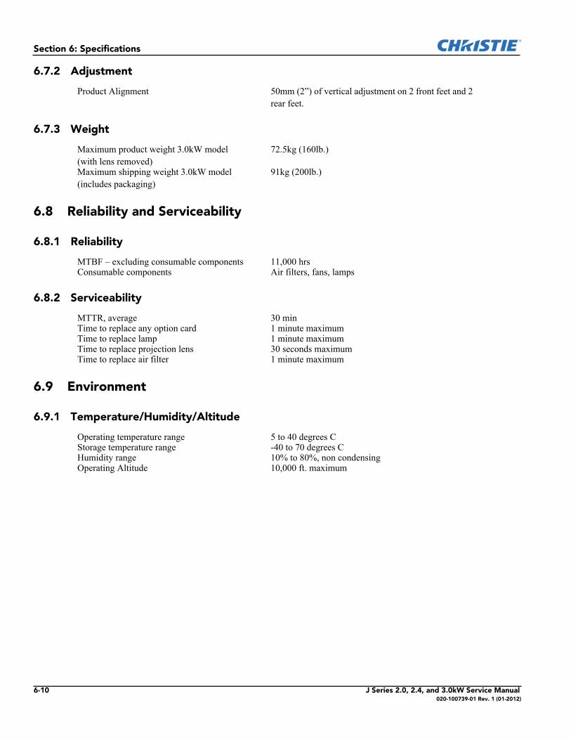
Section 6: Specifications
6.7.2 Adjustment
6.7.3 Weight
6.8 Reliability and Serviceability
6.8.1 Reliability
6.8.2 Serviceability
6.9 Environment
6.9.1 Temperature/Humidity/Altitude
Product Alignment 50mm (2”) of vertical adjustment on 2 front feet and 2 rear feet.
Maximum product weight 3.0kW model (with lens removed)
72.5kg (160lb.)
Maximum shipping weight 3.0kW model (includes packaging)
91kg (200lb.)
MTBF – excluding consumable components 11,000 hrsConsumable components Air filters, fans, lamps
MTTR, average 30 minTime to replace any option card 1 minute maximumTime to replace lamp 1 minute maximumTime to replace projection lens 30 seconds maximumTime to replace air filter 1 minute maximum
Operating temperature range 5 to 40 degrees C Storage temperature range -40 to 70 degrees CHumidity range 10% to 80%, non condensingOperating Altitude 10,000 ft. maximum
6-10 J Series 2.0, 2.4, and 3.0kW Service Manual020-100739-01 Rev. 1 (01-2012)
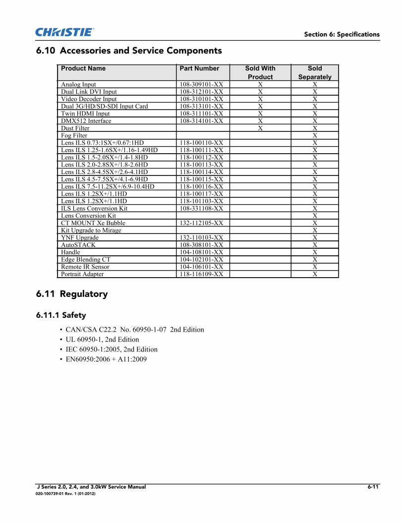
Section 6: Specifications
6.10 Accessories and Service Components
6.11 Regulatory
6.11.1 Safety
• CAN/CSA C22.2 No. 60950-1-07 2nd Edition • UL 60950-1, 2nd Edition • IEC 60950-1:2005, 2nd Edition• EN60950:2006 + A11:2009
Product Name Part Number Sold With Product
Sold Separately
Analog Input 108-309101-XX X XDual Link DVI Input 108-312101-XX X XVideo Decoder Input 108-310101-XX X XDual 3G/HD/SD-SDI Input Card 108-313101-XX X XTwin HDMI Input 108-311101-XX X XDMX512 Interface 108-314101-XX X XDust Filter X XFog Filter XLens ILS 0.73:1SX+/0.67:1HD 118-100110-XX XLens ILS 1.25-1.6SX+/1.16-1.49HD 118-100111-XX XLens ILS 1.5-2.0SX+/1.4-1.8HD 118-100112-XX XLens ILS 2.0-2.8SX+/1.8-2.6HD 118-100113-XX XLens ILS 2.8-4.5SX+/2.6-4.1HD 118-100114-XX XLens ILS 4.5-7.5SX+/4.1-6.9HD 118-100115-XX XLens ILS 7.5-11.2SX+/6.9-10.4HD 118-100116-XX XLens ILS 1.2SX+/1.1HD 118-100117-XX XLens ILS 1.2SX+/1.1HD 118-101103-XX XILS Lens Conversion Kit 108-331108-XX XLens Conversion Kit XCT MOUNT Xe Bubble 132-112105-XX XKit Upgrade to Mirage XYNF Upgrade 132-110103-XX XAutoSTACK 108-308101-XX XHandle 104-108101-XX XEdge Blending CT 104-102101-XX XRemote IR Sensor 104-106101-XX XPortrait Adapter 118-116109-XX X
J Series 2.0, 2.4, and 3.0kW Service Manual 6-11020-100739-01 Rev. 1 (01-2012)
Section 6: Specifications
6.11.2 Electro-Magnetic Compatibility
Emissions
• FCC CFR47, Part 15, Subpart B, Class A - Unintentional Radiators• CISPR 22: 2008-09/EN55022: 2006 + A1:2007 Class A - Information Technology Equipment
Immunity
• CISPR 24: 1997 +A1:2001+A2:2002/ EN55024: 1998 +A1:2001 +A2:2003 EMC Requirements - Infor-mation Technology Equipment
6.11.3 Environmental
The product must conform to:• EU Directive (2002/95/EC) on the restriction of the use of certain hazardous substances (RoHS) in electrical
and electronic equipment and the applicable official amendment(s).• EU Regulation (EC) No. 1907/2006 on the registration, evaluation, authorization and restriction of chemicals
(REACH) and the applicable official amendments.• EU Directive (2002/96/EC) on waste and electrical and electronic equipment (WEEE) and the applicable
official amendment(s).• China Ministry of Information Industry Order No.39 (02/2006) on the control of pollution caused by elec-
tronic information products, the hazardous substances concentration limits (SJ/T11363-2006), and the appli-cable product marking requirement (SJ/T11364-2006).
6.11.4 Marking
This product shall conform to all relevant Canadian, US, and European directives, standards, safety, health and environmental concerns and bears the following markings at product launch:• UL• CE• RoHS• WEEE• Future International Certifications to include: CCC, KC, PSE, c-tick, Gost-R, South Africa• International packaging recycling mark requirements:• EU Directive (94/62/EC) on packaging and packaging waste;• China packaging recycling mark standard (GB18455-2001);• Korea extended producer responsibility (EPR) separate discharge mark system under the act on the promo-
tion of resource saving and recycling (2003);• United States society of the plastics industry (SPI) resin identification code (1988);• ISO standards on marking of plastics (11469:2000, 1043-1:2001, 1043-2:2000, 1043-3:1996, and 1043-
4:1998).
6-12 J Series 2.0, 2.4, and 3.0kW Service Manual020-100739-01 Rev. 1 (01-2012)
A Appendix Projector Menus
A.1 J Series Menu Tree
J Series 2.0, 2.4, and 3.0kW Service Manual A-1020-100739-01 Rev. 1 (01-2012)

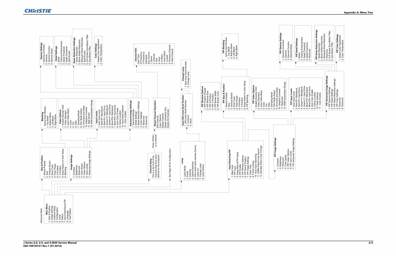
Appendix A: Menu Tree
J Series 2.0, 2.4, and 3.0kW Service Manual A-3020-100739-01 Rev.1 (01-2012)
MainMenu
1.Size&Position
2.ImageSettings
3,ChannelSetup
4.Configuration
5.Lamp
6.Status
7.InputSwitching&PIP
8.Language
9.TestPattern
Size&Position
1.ResizePresets
2.Size
3.VerticalStretch
4.PixelTrack
5.PixelPhase
6.H-Position
7.V-Position
8.KeepAspectonAutoSetup
9.Blanking
Blanking
ActiveInputWindow
1.TopBlank
2.BottomBlank
3.LeftBlank
4.RightBlank
ChannelSetup
Thisisalistofallofthe
channelsthathavebeen
definedforthisprojector.
ChannelEdit:
CardType
H-Frequency
V-Frequency
Interlaced
SyncSource
1.Name
2.Channel
3.Slot
4.Input
5.InMenu
6.AutoSelect
7.Locked
8.PreviousChannel
9.NextChannel
SelectChannelOperation
EditChannel
CopyChannel
DeleteChannel
DeleteUnlockedOnly
DeleteAllChannels
Press<Enter>
onachannel
AdvancedMain
SeePageA4
forConfiguration
ImageSettings
1.Contrast
2.Brightness
3.Reserved
4.ColorSpace
5.VideoOptions
6.InputLevels
7.AdvancedImageSettings
VideoOptions
1.EnableDecoderAGC
2.VideoStandard
3.InputVideoBlack
4.Color
5.Tint
6.Filter
7.SamplingMode
8.FilmModeDetect
9.Chroma/LumaDelay
10.AdaptiveContrast
11.SplitScreen
12.RGBQuantizationRange
InputLevels
1.AutoInputLevel
2.Red<Pr>Blacklevel
3.Red<Pr>InputDrive
4.Green<Y>Blacklevel
5.Green<Y>InputDrive
6.Blue<Pb>Blacklevel
7.Blue<Pb>InputDrive
8.AutoColorEnable
9.ClampLocation
10.InputPeakDetector
11.ColorEnable
AdvancedImageSettings
1.GammaSettings
2.DetailSettings
3.NoiseReductionSettings
4.ColorSettings
5.Reserved
6.Reserved
GammaSettings
1.GammaCorrection
2.Gamma
3.GammaFunction
4.GammaSlope
DetailSettings
1.Detail
2.TextureEnhancement
3.DetailThreshold
4.DetailOvershoot
5.SplitScreen
NoiseReductionSettings
1.NoiseReduction
2.BlockArtifactReduction
3.MosquitoNoiseReduction
4.SplitScreen
5.FullScreenEye-MotionFilter
6.Eye-MotionFilter
ColorSettings
1.SelectColorAdjustment
2.ColorTemperature
Lamp
1.LampMode
2.Power
3.Intensity
4.OpticalAperture
5.Warnwhenlampreaches(hours)
6.Lamps/n
7.ChangeLamp
8.LampHistory
InputOldLampSerialNum
ber
1.OldLampSerialNumber
2.Continue
3.Abort
ChangeLamp
1.New
lampSerialNumber
2.ChangeLamp
PIPBlanking
ActiveInputWindow
1.TopBlank
2.BottomBlank
3.LeftBlank
4.RightBlank
PIPImageSettings
1.Contrast
2.Brightness
3.Reserved
4.ColorSpace
5.PIPVideoOptions
6.PIPInputLevels
7.PIPAdvancedImageSettings
PIPVideoOptions
1.EnableDecoderAGC
2.VideoStandard
3.InputVideoBlack
4.Color
5.Tint
6.Filter
7.SamplingMode
8.FilmModeDetect
9.Chroma/LumaDelay
10.AdaptiveContrast
11.Reserved
12.RGBQuantizationRange
PIPAdvancedImageSettings
1.PIPGammaSettings
2.PIPDetailSettings
3.PIPNoiseReductionSettings
4.PIPColorSettings
5.Reserved
6.Reserved
PIPGammaSettings
1.GammaCorrection
2.Gamma
3.GammaFunction
4.GammaSlope
PIPDetailSettings
1.Detail
2.TextureEnhancement
3.DetailThreshold
4.DetailOvershoot
5.Reserved
PIPNoiseReductionSettings
1.NoiseReduction
2.BlockArtifactReduction
3.MosquitoNoiseReduction
4.Reserved
5.FullScreenEye-MotionFilter
6.Eye-MotionFilter
PIPColorSettings
1.SelectColorAdjustment
2.ColorTemperature
PIPInputLevels
1.AutoInputLevel
2.Red<Pr>Blacklevel
3.Red<Pr>InputDrive
4.Green<Y>Blacklevel
5.Green<Y>InputDrive
6.Blue<Pb>Blacklevel
7.Blue<Pb>InputDrive
8.AutoColorEnable
9.ClampLocation
10.PeakDetector
11.ColorEnable
InputSwitchingPIP
1.MainInput
2.PIPInput
3.SwapMain&PIPinputs
4.PIPEnable
5.PIPWindowOptions
6.PIPSize&Position
7.PIPImageSettings
8.FadeTime
9.FrameLocking
10.AutoInputSearching
11.HDMIOutputLoopSource
12.StandbyActiveLoop-Through
PIPWindowOptions
1.PIPPositionPresets
2.PIPWindowSize
3.PIPH-Position
4.PIPV-Position
5.PIPBorderWidth
6.PIPBorderColor
PIPSize&Position
1.ResizePresets
2.Size
3.VerticalStretch
4.PixelTrack
5.PixelPhase
6.H-Position
7.V-Position
8.KeepAspectonAutoSetup
9.PIPBlanking
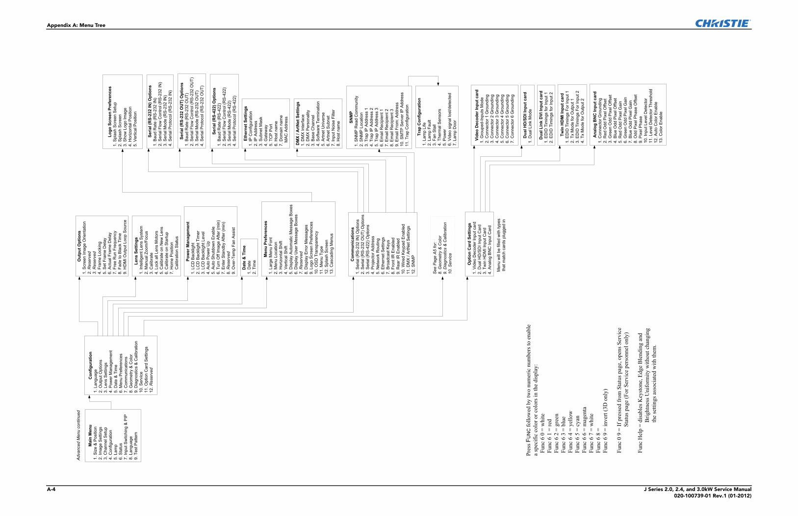
Appendix A: Menu Tree
A-4 J Series 2.0, 2.4, and 3.0kW Service Manual020-100739-01 Rev.1 (01-2012)
Configuration
1.Language
2.OutputOptions
3.LensSettings
4.PowerManagement
5.Date&Time
6.MenuPreferences
7.Communications
8.Geometry&Color
9.Diagnostics&Calibration
10.Service
11.OptionCardSettings
12.Reserved
MenuPreferences
1.LargeMenuFont
2.MenuLocation
3.HorizontalShift
4.VerticalShift
5.DisplayAutomaticMessageBoxes
6.DisplayUserMessageBoxes
7.Reserved
8.DisplayErrorMessages
9.LogoScreenPreferences
10.OSDTransparency
11.MenuType
12.SplashScreen
13.CascadingMenus
Date&Time
1.Date
2.TimeOutputOptions
1.ScreenImageOrientation
2.Reserved
3.Reserved
4.FrameLocking
5.SetFrameDelay
6.ActualFrameDelay
7.FreeRunFrequency
8.FadetoBlackTime
9.HDMIOutputLoopSource
PowerManagement
1.LCDBacklight
2.LCDBacklightTimer
3.LCDBacklightLevel
4.AutoPowerUp
5.AutoShutdownEnable
6.TurnOffImageAfter(min)
7.EnterStandbyAfter(min)
8.Reserved
9.Over-TempFanAssist
LensSettings
1.IntelligentLensSystem
2.ManualZoom/Focus
3.Calibrate
4.LockallLensMotors
5.CalibrateonNew
Lens
6.CalibrateonStartup
7.HomePosition
CalibrationStatus
Com
munications
1.Serial(RS-232IN)Options
2.Serial(RS-232OUT)Options
3.Serial(RS-422)Options
4.ProjectorAddress
5.NetworkRouting
6.EthernetSettings
7.BroadcastKeys
8.FrontIREnabled
9.RearIREnabled
10.WiredKeypadEnabled
11.DMX/ArtNetSettings
12.SNMP
EthernetSettings
1.IPConfiguration
2.IPAddress
3.SubnetMask
4.Gateway
5.TCPPort
6.Hostname
7.Domainname
MACAddress
Serial(RS-232IN)Options
1.BaudRate(RS-232IN)
2.SerialFlowControl(RS-232IN)
3.SerialMode(RS-232IN)
4.SerialProtocol(RS-232IN)
Serial(RS-232OUT)Options
1.BaudRate(RS-232OUT)
2.SerialFlowControl(RS-232OUT)
3.SerialMode(RS-232OUT)
4.SerialProtocol(RS-232OUT)
Serial(RS-422)Options
1.BaudRate(RS-422)
2.SerialFlowControl(RS-422)
3.SerialMode(RS-422)
4.SerialProtocol(RS-422)
AdvancedMenucontinued
OptionCardSettings
1.VideoDecoderInputcard
2.DualHD/SDIInputCard
3.TwinHDMIInputCard
4.AnalogBNCInputCard
VideoDecoderInputcard
1.Grouped-InputsMode
2.Connector1Grounding
3.Connector2Grounding
4.Connector3Grounding
5.Connector4Grounding
6.Connector5Grounding
7.Connector6Grounding
DualHD/SDIInputcard
1.DualLinkMode
TwinHDMIInputcard
1.EDIDTimingsForInput1
2.TxModeforOutput1
3.EDIDTimingsForInput2
4.TxModeforOutput2
Menuwillbefilledwithtypes
thatmatchcardspluggedin
AnalogBNCInputcard
1.ConnectorGrounding
2.RedOddPixelOffset
3.GreenOddPixelOffset
4.BlueOddPixelOffset
5.RedOddPixelGain
6.GreenOddPixelGain
7.BlueOddPixelGain
8.OddPixelPhaseOffset
9.PixelPhase
10.InputLevelDetector
11.LevelDetectorThreshold
12.AutoColorEnable
13.ColorEnable
SeePageA5for:
8.Geometry&Color
9.Diagnostics&Calibration
10.Service
DualLinkDVIInputcard
1.EDIDTimingsforInput1
2.EDIDTimingsforInput2
DMX/ArtNetSettings
1.DMXInterface
2.DMXPersonality
3.BaseChannel
4.SoftwareTermination
5.ArtnetUniverse
6.ArtnetSubnet
7.InputNoiseFilter
8.Hostname
MainMenu
1.Size&Position
2.ImageSettings
3,ChannelSetup
4.Configuration
5.Lamp
6.Status
7.InputSwitching&PIP
8.Language
9.TestPattern
PressF
UNCfollowedbytwonumericnumberstoenable
aspecificcolororcolorsinthedisplay:
Func60=white
Func61=red
Func62=green
Func63=blue
Func64=yellow
Func65=cyan
Func66=magenta
Func67=white
Func68=
Func69=invert(3Donly)
Func09=IfpressedfromStatuspage,opensService
Statuspage(ForServicepersonnelonly)
FuncHelp=disablesKeystone,EdgeBlendingand
BrightnessUniformitywithoutchanging
thesettingsassociatedwiththem.
LogoScreenPreferences
1.SplashScreenSetup
2.SplashScreen
3.ShowLogoImage
4.HorizontalPosition
5.VerticalPosition
SNMP
1.SNMPReadCommunity
2.SNMPLocation
3.TrapIPAddress1
4.TrapIPAddress2
5.TrapIPAddress3
6.EmailRecipient1
7.EmailRecipient2
8.EmailRecipient3
9.EmailFrom:Address
10.SMTP
ServerIPAddress
11.TrapConfiguration
TrapConfiguration
1.LampLife
2.LampFault
3.FanStall
4.ThermalSensors
5.Power
6.Videosignallost/detected
7.LampDoor
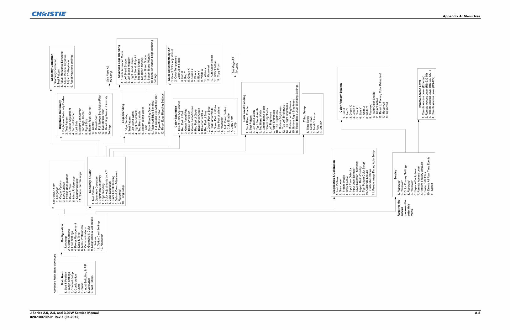
Appendix A: Menu Tree
J Series 2.0, 2.4, and 3.0kW Service Manual A-5020-100739-01 Rev.1 (01-2012)
Configuration
1.Language
2.OutputOptions
3.LensSettings
4.PowerManagement
5.Date&Time
6.MenuPreferences
7.Communications
8.Geometry&Color
9.Diagnostics&Calibration
10.Service
11.OptionCardSettings
12.Reserved
AdvancedMainMenucontinued
ColorAdjustmentsbyX,Y
1.SelectColorAdjustment
2.ColorTemperature
ValidColorSpace
3.RedX
4.RedY
5.GreenX
6.GreenY
7.BlueX
8.BlueY
9.WhiteX
10.WhiteY
11.Reserved
12.AutoColorEnable
13.ColorEnable
14.CopyFrom
ColorSaturation
1.SelectColorAdjustment
2.RedPartofRed
3.GreenPartofRed
4.BluePartofRed
5.GreenPartofGreen
6.RedPartofGreen
7.BluePartofGreen
8.BluePartofBlue
9.RedPartofBlue
10.GreenPartofBlue
11.RedPartofWhite
12.GreenPartofWhite
13.BluePartofWhite
14.Reserved
15.AutoColorEnable
16.ColorEnable
17.CopyFrom
18.Lamp
Geometry&Color
1.TestPattern
2.GeometryCorrection
3.BrightnessUniformity
4.EdgeBlending
5.ColorAdjustmentsbyX,Y
6.ColorSaturation
7.BlackLevelBlending
8.DefaultColorAdjustment
9.Reserved
10.TilingSetup
SeePageA3
forLamp
BrightnessUniformity
1.BrightnessUniformityEnable
2.TestPattern
3.CoarseAdjustment
4.TopLeftCorner
5.LeftSide
6.BottomLeftCorner
7.TopRightCorner
8.RightSide
9.BottomRightCorner
10.Center
11.OverallGain
12.FullScreenEye-MotionFilter
13.Eye-MotionFilter
14.ResetBrightnessUniformity
Settings
EdgeBlending
1.EdgeBlending
2.TestPattern
3.LeftBlendWidth
4.RightBlendWidth
5.TopBlendWidth
6.BottomBlendWidth
7.Lamp
8.ShowBlendingOverlap
9.AdvancedEdgeBlending
10.FullScreenEye-MotionFilter
11.Eye-MotionFilter
12.ResetEdgeBlendingSettings
SeePageA3
forLamp
BlackLevelBlending
1.BlackBlendEnable
2.TestPattern
3.LeftBlendWidth
4.RightBlendWidth
5.TopBlendWidth
6.BottomBlendWidth
7.CenterBrightness
8.LeftBrightness
9.RightBrightness
10.TopBrightness
11.BottomBrightness
12.TopLeftBrightness
13.TopRightBrightness
14.BottomLeftBrightness
15.BottomRightBrightness
16.ResetBlackLevelBlendingSettings
AdvancedEdgeBlending
1.EnableAdvancedCurve
2.LeftBlendShape
3.LeftBlendMidpoint
4.RightBlendShape
5.RightBlendMidpoint
6.TopBlendShape
7.TopBlendMidpoint
8.BottomBlendShape
9.BottomBlendMidpoint
10.ResetAdvancedEdgeBlending
Settings
SeePageA4for:
1.Language
2.OutputOptions
3.LensSettings
4.PowerManagement
5.Date&Time
6.MenuPreferences
7.Communications
11.OptionCardSettings
GeometryCorrection
1.GeometryCorrection
2.TestPattern
3.AdjustHorizontalKeystone
4.AdjustVerticalKeystone
5.Adjust2DKeystone
6.ResetKeystonesettings
TilingSetup
1.TilingSetup
2.TotalRows
3.TotalColumns
4.Row
5.Column
Diagnostics&Calibration
1.TestPattern
2.GreyLevel
3.FreezeImage
4.ColorEnable
5.InputPeakDetector
6.InputLevelDetector
7.LevelDetectorThreshold
8.AspectRatioOverlay
9.TestPatternColorSwap
10.CalibrateLiteLoc
CalibrationStatus
11.FreezeImageDuringAutoSetup
Service
1.Reserved
2.Reserved
3.ColorPrimarySettings
4.Reserved
5.Reserved
6.ReplaceBackplane
7.RemoteAccessLevel
8.RestoreFactoryDefaults
9.EraseDataFiles
10.DeleteAllRealTimeEvents
11.Status
Requiresthe
service
passwordto
enterthis
menu
ColorPrimarySettings
1.RedX
2.RedY
3.GreenX
4.GreenY
5.BlueX
6.BlueY
7.WhiteX
8.WhiteY
9.Reserved
10.AutoColorEnable
11.ColorEnable
12.ResettoFactoryColorPrimaries?
13.Reserved
14.Reserved
RemoteAccessLevel
1.RemoteAccessLevel(Ethernet)
2.RemoteAccessLevel(RS-232IN)
3.RemoteAccessLevel(RS-232OUT)
4.RemoteAccessLevel(RS-422)
MainMenu
1.Size&Position
2.ImageSettings
3,ChannelSetup
4.Configuration
5.Lamp
6.Status
7.InputSwitching&PIP
8.Language
9.TestPattern


Japanph: 81-3-3599-7481
South Koreaph: +82 2 702 1601
For the most current technical documentation, please visit www.christiedigital.com
USA – Cypressph: 714-236-8610
Canada – Kitchenerph: 519-744-8005
United Kingdomph: +44 118 977 8000
Franceph: +33 (0) 1 41 21 00 36
Germanyph: +49 2161 664540
Eastern Europeph: +36 (0) 1 47 48 100
Middle Eastph: +971 (0) 4 299 7575
Spainph: + 34 91 633 9990
Singaporeph: +65 6877-8737
Beijingph: +86 10 6561 0240
Shanghaiph: +86 21 6278 7708
Corporate offi ces Worldwide offi ces