Italian Spring Accelerometer (ISA): A fundamental support to BepiColombo Radio Science Experiments
9
Italian Spring Accelerometer (ISA): A fundamental support to BepiColombo Radio Science Experiments V. Iafolla , E. Fiorenza, C. Lefevre, A. Morbidini, S. Nozzoli, R. Peron, M. Persichini, A. Reale, F. Santoli Istituto di Fisica dello Spazio Interplanetario - Istituto Nazionale di Astrofisica, Via del Fosso del Cavaliere, 00133 Roma, Italia article info Article history: Received 29 April 2008 Received in revised form 23 February 2009 Accepted 6 April 2009 Available online 22 April 2009 Keywords: Solar system Mercury Accelerometers Non-gravitational perturbations Gravimetry General relativity abstract The Radio Science Experiments of the BepiColombo mission will enable substantial improvement of the knowledge of Mercury’s orbit and rotation, and the relativistic dynamics in the solar system. A fundamental support to the spacecraft tracking data will be given by the Italian Spring Accelerometer (ISA). This is a three-axis accelerometer devoted to the measurement of the non-gravitational perturbations acting on the Mercury Planetary Orbiter (MPO), whose knowledge is important in order to fully exploit the quality of the tracking data. The intrinsic noise level of the instrument that will be onboard MPO, 10 9 m=s 2 = ffiffiffiffiffiffi Hz p in the 3 10 5 to 10 1 Hz frequency range, guarantees the fulfilment of the RSE requirements. The main scientific and technological features of the instrument are discussed, together with its current error budget, experimental activities and foreseen calibration strategies. & 2009 Elsevier Ltd. All rights reserved. 1. Introduction—scientific objectives Among the main scientific objectives of the BepiColombo mission to planet Mercury, an important set is formed by the so- called Radio Science Experiments (RSE). These aim to perform precise measurements of gravitational field of Mercury; rotation of Mercury; general relativistic effects, in particular Mercury perihelion precession by state-of-the-art radiometric tracking of Mercury Planetary Orbiter (MPO) spacecraft. The overall procedure is fairly complex and is fully described in Iess (2009) (see also Milani et al., 2001, 2002). From the point of view of orbit determination, the tracking data—which in our case are range and range-rate—need to be fitted with a dynamical model as complete as possible and a model for the measurement types. In particular the dynamical model is based on general relativity (at the relevant post- Newtonian level) for the motion of bodies in the solar system and on a spherical harmonics expansion of the Hermean gravitational field, in order to determine accurately the MPO motion around Mercury. The models will depend in general on a set of parameters which will be adjusted in the orbit determina- tion procedure; among them, the quantities of interest, like the PPN parameters and the spherical harmonics coefficients C lm and S lm of Mercury gravity field. A distinctive feature of BepiColombo with respect to other deep- space missions is its relative proximity to the Sun. This has two fundamental consequences. Firstly, general relativistic effects are enhanced (motion near a massive body): this is the main reason to perform such an experiment. Secondly, the harsh environment the spacecraft will move in: non-gravitational effects due to surface forces, mainly the solar radiation pressure, perturb the motion of the spacecraft and mix with the gravitational effects. These forces are very difficult to model, since they depend in a complex way on incoming radiation and spacecraft surface optical properties and spacecraft attitude (Lucchesi and Iafolla, 2006). Analytical models do indeed exist, but they are effective only in particular cases, the simplest of which is a spherically symmetric spacecraft (for a general review of this issue see Milani et al., 1987). This is a serious problem, since it limits the accuracy with which the relativistic and geophysical parameters could be recovered. In order to overcome it, an accelerometer onboard the MPO—the Italian Spring Acceler- ometer (ISA)—will directly measure the non-gravitational perturba- tions so as to precisely take them into account in the orbit determination procedure and make the MPO an a posteriori drag- free satellite. The use of high-performance accelerometers instead of analytical or numerical models, in order to improve the quality of orbit determination and especially of related parameter ARTICLE IN PRESS Contents lists available at ScienceDirect journal homepage: www.elsevier.com/locate/pss Planetary and Space Science 0032-0633/$ - see front matter & 2009 Elsevier Ltd. All rights reserved. doi:10.1016/j.pss.2009.04.005 Corresponding author. Tel.: +39 064 45488391. E-mail address: [email protected] (V. Iafolla). Planetary and Space Science 58 (2010) 300–308
Transcript of Italian Spring Accelerometer (ISA): A fundamental support to BepiColombo Radio Science Experiments
ARTICLE IN PRESS
Planetary and Space Science 58 (2010) 300–308
Contents lists available at ScienceDirect
Planetary and Space Science
0032-06
doi:10.1
� Corr
E-m
journal homepage: www.elsevier.com/locate/pss
Italian Spring Accelerometer (ISA): A fundamental support to BepiColomboRadio Science Experiments
V. Iafolla �, E. Fiorenza, C. Lefevre, A. Morbidini, S. Nozzoli, R. Peron, M. Persichini, A. Reale, F. Santoli
Istituto di Fisica dello Spazio Interplanetario - Istituto Nazionale di Astrofisica, Via del Fosso del Cavaliere, 00133 Roma, Italia
a r t i c l e i n f o
Article history:
Received 29 April 2008
Received in revised form
23 February 2009
Accepted 6 April 2009Available online 22 April 2009
Keywords:
Solar system
Mercury
Accelerometers
Non-gravitational perturbations
Gravimetry
General relativity
33/$ - see front matter & 2009 Elsevier Ltd. A
016/j.pss.2009.04.005
esponding author. Tel.: +39 064 4548 8391.
ail address: [email protected] (V
a b s t r a c t
The Radio Science Experiments of the BepiColombo mission will enable substantial improvement of the
knowledge of Mercury’s orbit and rotation, and the relativistic dynamics in the solar system. A
fundamental support to the spacecraft tracking data will be given by the Italian Spring Accelerometer
(ISA). This is a three-axis accelerometer devoted to the measurement of the non-gravitational
perturbations acting on the Mercury Planetary Orbiter (MPO), whose knowledge is important in order to
fully exploit the quality of the tracking data. The intrinsic noise level of the instrument that will be
onboard MPO, 10�9 m=s2=ffiffiffiffiffiffiffi
Hzp
in the 3� 10�5 to 10�1 Hz frequency range, guarantees the fulfilment of
the RSE requirements. The main scientific and technological features of the instrument are discussed,
together with its current error budget, experimental activities and foreseen calibration strategies.
& 2009 Elsevier Ltd. All rights reserved.
1. Introduction—scientific objectives
Among the main scientific objectives of the BepiColombomission to planet Mercury, an important set is formed by the so-called Radio Science Experiments (RSE). These aim to performprecise measurements of
�
gravitational field of Mercury; � rotation of Mercury; � general relativistic effects, in particular Mercury perihelionprecession
by state-of-the-art radiometric tracking of Mercury PlanetaryOrbiter (MPO) spacecraft. The overall procedure is fairly complexand is fully described in Iess (2009) (see also Milani et al., 2001,2002). From the point of view of orbit determination, the trackingdata—which in our case are range and range-rate—need to befitted with a dynamical model as complete as possible and amodel for the measurement types. In particular the dynamicalmodel is based on general relativity (at the relevant post-Newtonian level) for the motion of bodies in the solar systemand on a spherical harmonics expansion of the Hermeangravitational field, in order to determine accurately the MPOmotion around Mercury. The models will depend in general on a
ll rights reserved.
. Iafolla).
set of parameters which will be adjusted in the orbit determina-tion procedure; among them, the quantities of interest, like thePPN parameters and the spherical harmonics coefficients Clm andSlm of Mercury gravity field.
A distinctive feature of BepiColombo with respect to other deep-space missions is its relative proximity to the Sun. This has twofundamental consequences. Firstly, general relativistic effects areenhanced (motion near a massive body): this is the main reason toperform such an experiment. Secondly, the harsh environment thespacecraft will move in: non-gravitational effects due to surfaceforces, mainly the solar radiation pressure, perturb the motion ofthe spacecraft and mix with the gravitational effects. These forcesare very difficult to model, since they depend in a complex way onincoming radiation and spacecraft surface optical properties andspacecraft attitude (Lucchesi and Iafolla, 2006). Analytical modelsdo indeed exist, but they are effective only in particular cases, thesimplest of which is a spherically symmetric spacecraft (for ageneral review of this issue see Milani et al., 1987). This is a seriousproblem, since it limits the accuracy with which the relativistic andgeophysical parameters could be recovered. In order to overcome it,an accelerometer onboard the MPO—the Italian Spring Acceler-
ometer (ISA)—will directly measure the non-gravitational perturba-tions so as to precisely take them into account in the orbitdetermination procedure and make the MPO an a posteriori drag-free satellite.
The use of high-performance accelerometers instead ofanalytical or numerical models, in order to improve the qualityof orbit determination and especially of related parameter
ARTICLE IN PRESS
10-5 10-4 10-3 10-2 10-1 100 10110−14
10−12
10−10
10−8
10−6
10−4
10−2
Frequency (Hz)
Spec
tral
den
sity
(m/s
2 /√H
z)
Tracking noiseThermal noiseIntrinsic noiseTotal noiseSensitivity requirement
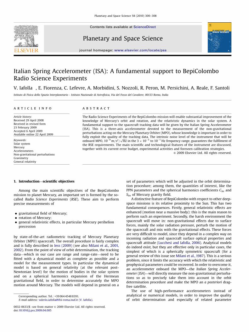
Fig. 1. Noise contributions from the accelerometer and the tracking system as used in the simulations that have been performed to prove the reliability of the RSE. The total
noise level is mainly due to the thermal effects on the accelerometer at low frequencies and to the tracking noise at high frequencies. The light blue bar represents the ISA
bandwidth. (For interpretation of the references to colour in this figure legend, the reader is referred to the web version of this article.)
Table 1RSE related features and performances.
Parameter Value
Measurement frequency range 3� 10�5 to 10�1 Hz
Maximum expected signal 3� 10�6 m=s2
Measurement total noise 10�8 m=s2=ffiffiffiffiffiffi
Hzp
Instrument intrinsic noise 10�9 m=s2=ffiffiffiffiffiffi
Hzp
Required measurement accuracy 10�8 m=s2
Read-out interval 1 s
V. Iafolla et al. / Planetary and Space Science 58 (2010) 300–308 301
determination, has been given increasing attention in recentyears. Indeed, the performance of the tracking systems has beensteadily improving, whereas this cannot be said about modeliza-tion. From near-Earth geodetic missions like the LAGEOS satellitesto deep-space probes exploring the outer solar system, cases canbe found where physical processes of non-gravitational origincould at least in principle play an important role (think to the so-called Pioneer anomaly, see Anderson et al., 1998, 2002).Examples of the accelerometers effectiveness are given by theCHAMP and GRACE geodetic missions, where the precise GPSposition measurements are combined with accelerometric mea-surements (see van den Ijssel and Visser, 2007). The use ofacceleration data improves the geophysical parameters estimationand is far better than the use of empirical acceleration terms inthe modelization; these empirical accelerations could in factimprove the quality of the fit (post-fit RMS reduction), but at thecost of a predictivity lack (no or small correlation with physicallyrelevant parameters).
The accelerometer characteristics requirements follow fromthe RSE requirements (see also Iafolla and Nozzoli, 2001). Asdiscussed in van Casteren et al. (2009), the MPO spacecraft will bethree-axis stabilized, Nadir pointing, characterized by a 400�1500 km polar orbit around Mercury. This orbit configuration issuitable for the recovery, with a signal-to-noise ratio larger than10, of Mercury’s gravity field up to degree l ¼ 25, corresponding toa spatial resolution of about 300 km (Milani et al., 2001, 2002;Iess, 2009). In order to reach the goals of the RSE, the orbit mustbe known with an accuracy of at least 1 m in the along-trackdirection over one orbital revolution of the MPO around Mercury,i.e., over 8355 s. This corresponds to an along-track accelerationaccuracy of about 10�8 m=s2. Therefore, this number has beenconsidered equivalent to the acceleration measurement error overthe typical arc length during one observation session from Earth’sground antenna(s).
However, it is not necessary to retain a spectral density of10�8 m=s2=
ffiffiffiffiffiffiffi
Hzp
through all the accelerometer’s bandwidth.
Indeed, as shown in Fig. 1, which describes the noisecontributions due to the accelerometer and to the trackingsystem, at low frequency the noise is dominated by the thermaldisturbing effects at the interface between spacecraft andaccelerometer while at higher frequencies the noise isdominated by the tracking errors. The red line represents ISAintrinsic noise; the green line represents the filtered thermal noiseeffects due to a possible white noise at a level of 4 �C=
ffiffiffiffiffiffiffi
Hzp
, whichmay be present at the mechanical interface between thespacecraft structure and ISA; the blue line represents theequivalent acceleration associated with the Doppler noise;finally, the black line represents the total noise (quadratic sumof the previous noise sources). The various noise sources—ISAintrinsic noise, thermal noise, tracking noise—constrain the ISAsensitivity requirement. This requirement has been used in theerror budget analysis described in Section 4 (sensitivityrequirement, diamond line). The need to fully exploit theaccelerometer performances only in a narrower bandwidth,between 10�4 and 10�3 Hz, is clear. We stress that these resultshave been obtained in the case of a passive thermal control.Currently, an active thermal control is foreseen as baseline; thethermal effects will be further attenuated by a factor 700. In Table1 the main RSE-derived requirements are summarized.
ARTICLE IN PRESS
−2000 0 2000 4000 6000 8000 10000 120001361
1362
1363
1364
1365
1366
1367
1368
1369
Time (d, epoch 0 Jan 1980)
Irrad
ianc
e (W
/m2 )
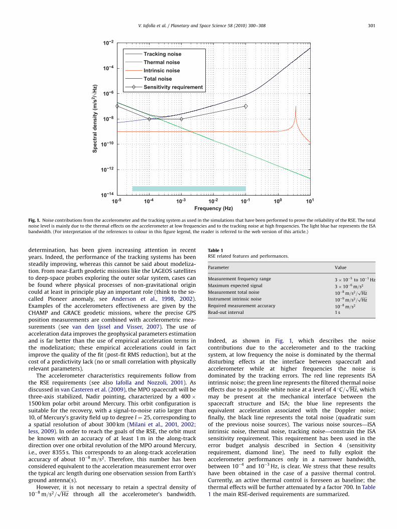
Fig. 2. Composite Total Solar Irradiance (TSI) at 1 AU. The data, over which this time series is built, are based on a number of records, merged to construct this composite.
V. Iafolla et al. / Planetary and Space Science 58 (2010) 300–308302
Concerning the non-gravitational perturbations acting on thespacecraft, the near-Mercury environment the MPO will move inis particularly harsh. Due to the relative proximity to the Sun, theradiation and particle fluxes are very strong. In Fig. 2 the solarirradiance—Composite Total Solar Irradiance (TSI)—as measuredby several space missions1 is shown (Frohlich, 2000). The solarcycle of about 11 years, with several small-scale fluctuations, isclearly visible. The radiation exerts a push on the spacecraft bodyin a way that depends on the optical properties of its surfaces.
One can identify at least three different types of perturbationsdue to electromagnetic radiation impinging on the spacecraftsurfaces:
�
com
visible radiation coming directly from the Sun (direct solar
radiation pressure);
� visible radiation from the Sun being reflected by the Mercurysurface (albedo radiation pressure);
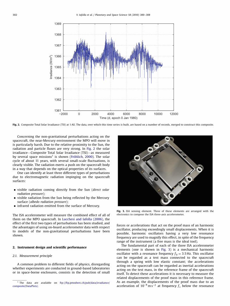
�Fig. 3. ISA sensing element. Three of these elements are arranged with the
electronics to compose the ISA three-axis accelerometer.
infrared radiation emitted from the surface of Mercury.
The ISA accelerometer will measure the combined effect of all ofthem on the MPO spacecraft. In Lucchesi and Iafolla (2006), theeffect of the first two types of perturbations has been studied, andthe advantages of using on-board accelerometer data with respectto models of the non-gravitational perturbations have beenshown.
2. Instrument design and scientific performance
2.1. Measurement principle
A common problem to different fields of physics, disregardingwhether experiments are conducted in ground-based laboratoriesor in space-borne enclosures, consists in the detection of small
1 The data are available on ftp://ftp.pmodwrc.ch/pub/data/irradiance/
posite/DataPlots/.
forces or accelerations that act on the proof mass of an harmonicoscillator, producing exceedingly small displacements. When it ispossible, harmonic oscillators having a very low resonancefrequency are used to magnify this effect, in spite of the frequencyrange of the instrument (a free mass is the ideal tool).
The fundamental part of each of the three ISA accelerometerelements (one is shown in Fig. 3) is a mechanical harmonicoscillator with a resonance frequency f 0 ¼ 3:5 Hz. This oscillatorcan be regarded as a test mass connected to the spacecraftthrough a spring with low elastic constant; the accelerationsacting on the spacecraft can be regarded as inertial accelerationsacting on the test mass, in the reference frame of the spacecraftitself. To detect these accelerations it is necessary to measure therelated displacements of the proof mass in this reference frame.As an example, the displacements of the proof mass due to anacceleration of 10�8 m s�2 at frequency f s below the resonance
ARTICLE IN PRESS
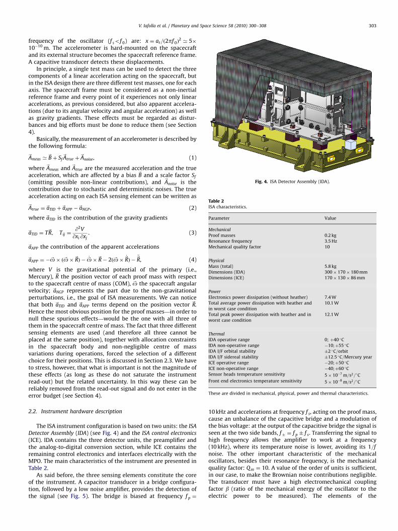
Fig. 4. ISA Detector Assembly (IDA).
Table 2ISA characteristics.
Parameter Value
Mechanical
Proof masses 0.2 kg
Resonance frequency 3.5 Hz
Mechanical quality factor 10
Physical
Mass (total) 5.8 kg
Dimensions (IDA) 300� 170� 180 mm
Dimensions (ICE) 170� 130� 86 mm
Power
Electronics power dissipation (without heather) 7.4 W
Total average power dissipation with heather and
in worst case condition
10.1 W
Total peak power dissipation with heather and in
worst case condition
12.1 W
Thermal
IDA operative range 0; þ40 �C
IDA non-operative range �10;þ55 �C
IDA I/F orbital stability �2 �C=orbit
IDA I/F sidereal stability �12:5 �C=Mercury year
ICE operative range �20;þ50 �C
ICE non-operative range �40;þ60 �C
Sensor heads temperature sensitivity 5� 10�7 m=s2=�C
Front end electronics temperature sensitivity 5� 10�8 m=s2=�C
These are divided in mechanical, physical, power and thermal characteristics.
V. Iafolla et al. / Planetary and Space Science 58 (2010) 300–308 303
frequency of the oscillator (f sof 0) are: x ¼ as=ð2pf 0Þ2’ 5�
10�10 m. The accelerometer is hard-mounted on the spacecraftand its external structure becomes the spacecraft reference frame.A capacitive transducer detects these displacements.
In principle, a single test mass can be used to detect the threecomponents of a linear acceleration acting on the spacecraft, butin the ISA design there are three different test masses, one for eachaxis. The spacecraft frame must be considered as a non-inertialreference frame and every point of it experiences not only linearaccelerations, as previous considered, but also apparent accelera-tions (due to its angular velocity and angular acceleration) as wellas gravity gradients. These effects must be regarded as distur-bances and big efforts must be done to reduce them (see Section4).
Basically, the measurement of an accelerometer is described bythe following formula:
~Ameas ’~Bþ Sf
~Atrue þ~Anoise, (1)
where ~Ameas and ~Atrue are the measured acceleration and the trueacceleration, which are affected by a bias ~B and a scale factor Sf
(omitting possible non-linear contributions), and ~Anoise is thecontribution due to stochastic and deterministic noises. The trueacceleration acting on each ISA sensing element can be written as
~Atrue ¼ ~aTID þ~aAPP �~aNGP , (2)
where ~aTID is the contribution of the gravity gradients
~aTID ¼ T~R; Tij ¼@2V
@xi @xj. (3)
~aAPP the contribution of the apparent accelerations
~aAPP ¼ �~o� ð~o�~RÞ � _~o�~R� 2ð~o� _~RÞ �€~R, (4)
where V is the gravitational potential of the primary (i.e.,Mercury), ~R the position vector of each proof mass with respectto the spacecraft centre of mass (COM), ~o the spacecraft angularvelocity; ~aNGP represents the part due to the non-gravitationalperturbations, i.e., the goal of ISA measurements. We can noticethat both ~aTID and ~aAPP terms depend on the position vector ~R.Hence the most obvious position for the proof masses—in order tonull these spurious effects—would be the one with all three ofthem in the spacecraft centre of mass. The fact that three differentsensing elements are used (and therefore all three cannot beplaced at the same position), together with allocation constraintsin the spacecraft body and non-negligible centre of massvariations during operations, forced the selection of a differentchoice for their positions. This is discussed in Section 2.3. We haveto stress, however, that what is important is not the magnitude ofthese effects (as long as these do not saturate the instrumentread-out) but the related uncertainty. In this way these can bereliably removed from the read-out signal and do not enter in theerror budget (see Section 4).
2.2. Instrument hardware description
The ISA instrument configuration is based on two units: the ISA
Detector Assembly (IDA) (see Fig. 4) and the ISA control electronics
(ICE). IDA contains the three detector units, the preamplifier andthe analog-to-digital conversion section, while ICE contains theremaining control electronics and interfaces electrically with theMPO. The main characteristics of the instrument are presented inTable 2.
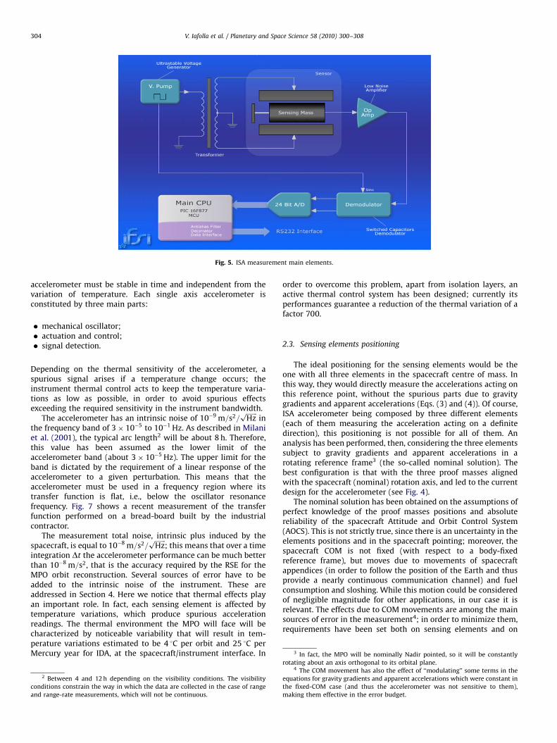
As said before, the three sensing elements constitute the coreof the instrument. A capacitor transducer in a bridge configura-tion, followed by a low noise amplifier, provides the detection ofthe signal (see Fig. 5). The bridge is biased at frequency f p ¼
10 kHz and accelerations at frequency f s, acting on the proof mass,cause an unbalance of the capacitive bridge and a modulation ofthe bias voltage: at the output of the capacitive bridge the signal isseen at the two side bands, f� ¼ f p � f s. Transferring the signal tohigh frequency allows the amplifier to work at a frequency(10 kHz), where its temperature noise is lower, avoiding its 1=f
noise. The other important characteristic of the mechanicaloscillators, besides their resonance frequency, is the mechanicalquality factor: Qm ¼ 10. A value of the order of units is sufficient,in our case, to make the Brownian noise contributions negligible.The transducer must have a high electromechanical couplingfactor b (ratio of the mechanical energy of the oscillator to theelectric power to be measured). The elements of the
ARTICLE IN PRESS
Fig. 5. ISA measurement main elements.
V. Iafolla et al. / Planetary and Space Science 58 (2010) 300–308304
accelerometer must be stable in time and independent from thevariation of temperature. Each single axis accelerometer isconstituted by three main parts:
�
con
and
mechanical oscillator;
� actuation and control; � signal detection.3 In fact, the MPO will be nominally Nadir pointed, so it will be constantly
Depending on the thermal sensitivity of the accelerometer, aspurious signal arises if a temperature change occurs; theinstrument thermal control acts to keep the temperature varia-tions as low as possible, in order to avoid spurious effectsexceeding the required sensitivity in the instrument bandwidth.
The accelerometer has an intrinsic noise of 10�9 m=s2=ffiffiffiffiffiffiffi
Hzp
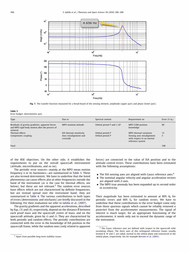
inthe frequency band of 3� 10�5 to 10�1 Hz. As described in Milaniet al. (2001), the typical arc length2 will be about 8 h. Therefore,this value has been assumed as the lower limit of theaccelerometer band (about 3� 10�5 Hz). The upper limit for theband is dictated by the requirement of a linear response of theaccelerometer to a given perturbation. This means that theaccelerometer must be used in a frequency region where itstransfer function is flat, i.e., below the oscillator resonancefrequency. Fig. 7 shows a recent measurement of the transferfunction performed on a bread-board built by the industrialcontractor.
The measurement total noise, intrinsic plus induced by thespacecraft, is equal to 10�8 m=s2=
ffiffiffiffiffiffiffi
Hzp
; this means that over a timeintegration Dt the accelerometer performance can be much betterthan 10�8 m=s2, that is the accuracy required by the RSE for theMPO orbit reconstruction. Several sources of error have to beadded to the intrinsic noise of the instrument. These areaddressed in Section 4. Here we notice that thermal effects playan important role. In fact, each sensing element is affected bytemperature variations, which produce spurious accelerationreadings. The thermal environment the MPO will face will becharacterized by noticeable variability that will result in tem-perature variations estimated to be 4 1C per orbit and 25 1C perMercury year for IDA, at the spacecraft/instrument interface. In
2 Between 4 and 12 h depending on the visibility conditions. The visibility
ditions constrain the way in which the data are collected in the case of range
range-rate measurements, which will not be continuous.
order to overcome this problem, apart from isolation layers, anactive thermal control system has been designed; currently itsperformances guarantee a reduction of the thermal variation of afactor 700.
2.3. Sensing elements positioning
The ideal positioning for the sensing elements would be theone with all three elements in the spacecraft centre of mass. Inthis way, they would directly measure the accelerations acting onthis reference point, without the spurious parts due to gravitygradients and apparent accelerations (Eqs. (3) and (4)). Of course,ISA accelerometer being composed by three different elements(each of them measuring the acceleration acting on a definitedirection), this positioning is not possible for all of them. Ananalysis has been performed, then, considering the three elementssubject to gravity gradients and apparent accelerations in arotating reference frame3 (the so-called nominal solution). Thebest configuration is that with the three proof masses alignedwith the spacecraft (nominal) rotation axis, and led to the currentdesign for the accelerometer (see Fig. 4).
The nominal solution has been obtained on the assumptions ofperfect knowledge of the proof masses positions and absolutereliability of the spacecraft Attitude and Orbit Control System(AOCS). This is not strictly true, since there is an uncertainty in theelements positions and in the spacecraft pointing; moreover, thespacecraft COM is not fixed (with respect to a body-fixedreference frame), but moves due to movements of spacecraftappendices (in order to follow the position of the Earth and thusprovide a nearly continuous communication channel) and fuelconsumption and sloshing. While this motion could be consideredof negligible magnitude for other applications, in our case it isrelevant. The effects due to COM movements are among the mainsources of error in the measurement4; in order to minimize them,requirements have been set both on sensing elements and on
rotating about an axis orthogonal to its orbital plane.4 The COM movement has also the effect of ‘‘modulating’’ some terms in the
equations for gravity gradients and apparent accelerations which were constant in
the fixed-COM case (and thus the accelerometer was not sensitive to them),
making them effective in the error budget.
ARTICLE IN PRESS
V. Iafolla et al. / Planetary and Space Science 58 (2010) 300–308 305
COM position knowledge. It has to be noticed that this scenariohas been simplified by the new concept of radio sciencemeasurement recently introduced. For a discussion of these issueswe refer to Section 4.
3. Current experimental activities
The development of the instrument relies on a strongensemble of laboratory experimental activities. These are aimedat testing the various technological solutions on prototypes,measuring the various features (see Table 2), testing selectedeffects, doing performance checks on bread-boards built by theindustrial contractor. The main tasks—described in the follo-wing—concern tests on thermal control system and measure-ments of the intrinsic noise level of the instrument (usingcommon-mode-rejection); activities are also devoted to thedevelopment of the read-out electronics and finally an importantrole is performed by tests on bread-boards built by the industrialcontractor.
3.1. Rejection tests
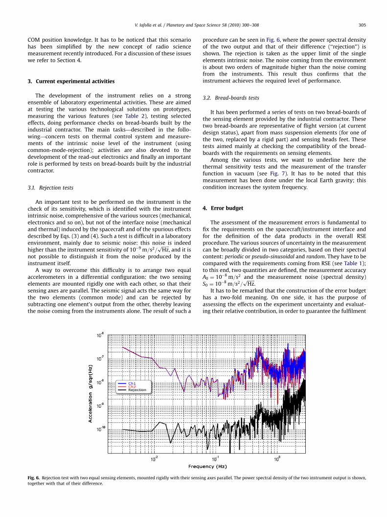
An important test to be performed on the instrument is thecheck of its sensitivity, which is identified with the instrumentintrinsic noise, comprehensive of the various sources (mechanical,electronics and so on), but not of the interface noise (mechanicaland thermal) induced by the spacecraft and of the spurious effectsdescribed by Eqs. (3) and (4). Such a test is difficult in a laboratoryenvironment, mainly due to seismic noise: this noise is indeedhigher than the instrument sensitivity of 10�9 m=s2=
ffiffiffiffiffiffiffi
Hzp
, and it isnot possible to distinguish it from the noise produced by theinstrument itself.
A way to overcome this difficulty is to arrange two equalaccelerometers in a differential configuration: the two sensingelements are mounted rigidly one with each other, so that theirsensing axes are parallel. The seismic signal acts the same way forthe two elements (common mode) and can be rejected bysubtracting one element’s output from the other, thereby leavingthe noise coming from the instruments alone. The result of such a
Fig. 6. Rejection test with two equal sensing elements, mounted rigidly with their sensin
together with that of their difference.
procedure can be seen in Fig. 6, where the power spectral densityof the two output and that of their difference (‘‘rejection’’) isshown. The rejection is taken as the upper limit of the singleelements intrinsic noise. The noise coming from the environmentis about two orders of magnitude higher than the noise comingfrom the instruments. This result thus confirms that theinstrument achieves the required level of performance.
3.2. Bread-boards tests
It has been performed a series of tests on two bread-boards ofthe sensing element provided by the industrial contractor. Thesetwo bread-boards are representative of flight version (at currentdesign status), apart from mass suspension elements (for one ofthe two, replaced by a rigid part) and sensing heads feet. Thesetests aimed mainly at checking the compatibility of the bread-boards with the requirements on sensing elements.
Among the various tests, we want to underline here thethermal sensitivity tests and the measurement of the transferfunction in vacuum (see Fig. 7). It has to be noted that thismeasurement has been done under the local Earth gravity; thiscondition increases the system frequency.
4. Error budget
The assessment of the measurement errors is fundamental tofix the requirements on the spacecraft/instrument interface andfor the definition of the data products in the overall RSEprocedure. The various sources of uncertainty in the measurementcan be broadly divided in two categories, based on their spectralcontent: periodic or pseudo-sinusoidal and random. They have to becompared with the requirements coming from RSE (see Table 1);to this end, two quantities are defined, the measurement accuracyA0 ¼ 10�8 m=s2 and the measurement noise (spectral density)S0 ¼ 10�8 m=s2=
ffiffiffiffiffiffiffi
Hzp
.It has to be remarked that the construction of the error budget
has a two-fold meaning. On one side, it has the purpose ofassessing the effects on the experiment uncertainty and evaluat-ing their relative contribution, in order to guarantee the fulfilment
g axes parallel. The power spectral density of the two instrument output is shown,
ARTICLE IN PRESS
Fig. 7. The transfer function measured for a bread-board of the sensing element, amplitude (upper part) and phase (lower part).
Table 3Error budget: deterministic part.
Type Due to Spectral content Requirement on Error (% A0)
Residuals of gravity gradients, apparent forces
and MPO rigid body motion after the process of
removal
MPO nominal attitude Orbital period P and 1=2P MPO COM position
knowledge
80
Thermal effects ISA thermal sensitivity Orbital period P MPO thermal variations 15
Components coupling Axes misalignment and
crosstalk
Orbital period P Sensing axes misalignment
with respect to an inertial
reference system
5
Total 100
6
V. Iafolla et al. / Planetary and Space Science 58 (2010) 300–308306
of the RSE objectives. On the other side, it establishes therequirements to put on the overall spacecraft environment(attitude, microvibrations, and so on).
The periodic error sources—mainly at the MPO mean motionfrequency n or its harmonics—are summarized in Table 3. Theseare also termed deterministic. We have to underline that the listedphenomena can cause effects also at other frequencies outside theband of the instrument (as is the case for thermal effects, seebelow), but these are not relevant.5 The random error sourceshave effects which are not characterized by definite frequencies,but are instead spread over the instrument band; they aresummarized in Table 4. The various contributions to both typesof errors (deterministic and stochastic) are briefly discussed in thefollowing. For their evaluation we refer to Iafolla et al. (2007).
The gravity gradients and the apparent accelerations, describedby Eqs. (3) and (4), respectively, depend on the distance~R betweeneach proof mass and the spacecraft centre of mass, and on thespacecraft attitude, given by ~o and _~o. They are characterized byboth periodic and random effects. The periodic contributions areconnected with the error in the knowledge of ISA position in thespacecraft frame, while the random ones (only related to apparent
5 Apart from possible long-term stability issues.
forces) are connected to the value of ISA position and to theattitude control errors. These contributions have been estimatedwith the following assumptions:
�
osc
term
orb
The ISA sensing axes are aligned with Gauss reference axes.6
�
The nominal angular velocity and angular acceleration vectorsare aligned with Z-axis. � The MPO true anomaly has been expanded up to second orderin eccentricity.
Their magnitude has been estimated to amount at 80% A0 forperiodic errors and 60% S0 for random errors. We have tounderline that these contributions to the error budget come onlyfrom those spurious signals which cannot be reliably removed a
posteriori from the accelerometer measurements. The signal ofinterest is much larger; for an appropriate functioning of theaccelerometer, it needs only not to exceed the dynamic range ofthe instrument.
The Gauss reference axes are defined with respect to the spacecraft orbit
ulating ellipse. The three axes of this orthogonal reference frame, usually
ed R, W and T , are radial, normal to the orbital plane and transversal in the
ital plane, respectively. See for example Bertotti et al. (2003).
ARTICLE IN PRESS
Table 4Error budget: random part.
Type Due to Spectral content Requirement on Error (% S0)
Apparent forces Error in MPO attitude knowledge Random MPO AOCS performance and MPO
COM position
60
Thermal effects ISA thermal sensitivity Random MPO thermal noise 30
MPO structural vibrations Reaction wheels, MPO
mechanisms, etc.
Random 10
MPO rigid body motion removal
residual
COM displacement due to the HGA
movements, fuel consumption, etc.
Random MPO COM displacements
knowledge
70
Components coupling Axes misalignment and crosstalk Random Random component of
misalignment angle
10
ISA intrinsic noise Random 10
Total (not correlated noise) o100
V. Iafolla et al. / Planetary and Space Science 58 (2010) 300–308 307
Thermal variations at the spacecraft/instrument interface willcause a spurious signal on the accelerometer output. The mostsensitive part of the instrument (sensing head mechanics) has athermal sensitivity of 5� 10�7 m=s2=�C. This means that atemperature variation of 1 1C gives a spurious acceleration signalequal to 5� 10�7 m=s2. Taking into account the maximumforeseen temperature variation inside the instrument bandwidth(2 1C peak, at the MPO orbital period around Mercury) and theattenuation factor of 700, a value of 15% A0 is obtained. A similarcalculation for the random part, with a thermal noise of 4 �C=
ffiffiffiffiffiffiffi
Hzp
,gives a value of 30% S0.
The accelerometer is also subject to inertial accelerationsrelated to the linear (rigid body) motion of the MPO (due tochange in its configuration and then to its COM displacement). Itis considered to perform their removal during data analysis: thenthe error considered in the error budget is related to the removalresidual. The assigned share is of 70% S0.
In Tables 3 and 4 ‘‘component coupling’’ indicates the error inISA measurements caused by the following four different effects:
(1)
Misalignments of sensing axes with respect to the inertialreference frame with periodicity at orbital period (as thoserelated to thermoelastic distortions).(2)
Misalignments of sensing axes with respect to the inertialreference frame having a random noise behaviour (as thoserelated to structural vibrations).(3)
Internal crosstalk of sensing elements causing an effect withthe same frequency content of input signal, as that related tomechanical tolerances.(4)
Internal crosstalk of sensing elements having a random noisebehaviour, as that related to out of band noise.These effects cause essentially a mixing of the sought—for signalcomponents, which must be avoided. Finally, the contribution ofthe instrument intrinsic noise must be considered in the errorbudget. This noise, coming from the internal parts of theaccelerometer (mechanical elements, electronics) is random andhas been fixed to 10% S0. This value is consistent withexperimental measurements of ISA noise level done in adifferential configuration (see Section 3.1).
The error budget as shown here is fundamentally based on a‘‘standard’’ concept of radio science procedure, in which thespacecraft equation of motion is referred to its COM, and thevarious measurements involved in the procedure (range andrange-rate, acceleration) are to be corrected accordingly. Thisreferencing (as seen in Section 2.3 for accelerometric data)introduces an error in the data ‘‘pre-processing’’ and a consequentbias in the parameter estimation procedure, and ultimately
implies very strict requirements on the spacecraft/instrumentinterface.
In order to overcome these problems, a new concept of radioscience procedure has been recently introduced, in which theequation of motion is referred to the accelerometer position (moreprecisely, to the reference point of the accelerometer itself). In thisnew procedure, the proof mass whose motion is tracked is—atleast ideally—one of the three proof masses of the accelerometer.Using the new concept the requirements coming from the above-presented error budget are much less demanding and easy tomatch.
5. Calibration
For ‘‘calibration’’ we mean a series of measurements thatdefine all the instrument characteristics, in all the phases andoperative conditions. This implies a complete set of tests andprocedures.
The main tests to perform for the ISA characterization are:
�
transfer function; � transducer factor; � linearity of response; � intrinsic noise; � thermal stability.These are planned on ground and some of them will be repeatedin the various phases of the mission, to verify that the instrumentworks properly, with the declared performance.
Calibrations in the strict meaning, i.e., calibrations of the
transducer factor (relating the output of the capacitive bridge tothe measured acceleration), are planned throughout the entiremission. The transducer factor measurement is strictly related tothe quality of the final data product, and various strategies havebeen studied to perform its measure. The baseline is to use the ISAactuators to give each proof mass a known (electric) acceleration,and then obtain the transducer factor. Another (backup) possibi-lity is to perform some MPO manoeuvres at selected times and bya precise knowledge of the spacecraft attitude (given by the AOCS)calculate the corresponding acceleration on each sensing elementand then again the transducer factor. A further opportunity will beavailable during the Superior Conjunction Experiment (SCE)during cruise (see Iess, 2009). In that phase of the mission theMercury Composite Spacecraft (MCS) will travel in a relativelystable dynamical environment (far from the Sun and withconstant attitude) in such a way that the non-gravitationalperturbations acting on the MCS will be nearly constant; high-
ARTICLE IN PRESS
V. Iafolla et al. / Planetary and Space Science 58 (2010) 300–308308
precision tracking will also be performed. The comparison ofaccelerometer with tracking data will enable at least in principle acalibration of the accelerometer.
6. Conclusions
The BepiColombo mission will give the scientific communityan opportunity for studying in detail the planet Mercury and itsenvironment; in particular, the important scientific objectives ofthe RSE will be achievable using a dedicated set of instrumenta-tion. The standard procedure of precise orbit determination andparameter estimation (in order to recover the geophysical andPPN parameters) will be augmented and enriched by an on-boardaccelerometer, ISA, for the direct measurement of the non-gravitational accelerations acting on the spacecraft, which—inthe case of BepiColombo MPO—are particularly strong anddifficult to model precisely. The instrument itself comes from along research activity in fundamental physics and geophysics; itshigh sensitivity and low intrinsic noise make possible to ‘‘filterout’’ the strong ‘‘noise’’ of non-gravitational perturbations. WithBepiColombo it will be the first time an accelerometer will fly on adeep-space mission, opening a new field of possibilities forfundamental physics studies.
Acknowledgements
The authors wish to thank Roberto Formaro (ISA ProgramManager, Agenzia Spaziale Italiana), Thales Alenia Space and thetwo referees.
References
Anderson, J.D., Laing, P.A., Lau, E.L., Liu, A.S., Nieto, M.M., Turyshev, S.G., 1998.Indication, from Pioneer 10/11, Galileo, and Ulysses data, of an apparentanomalous, weak, long-range acceleration. Phys. Rev. Lett. 81, 2858–2861.
Anderson, J.D., Laing, P.A., Lau, E.L., Liu, A.S., Nieto, M.M., Turyshev, S.G., 2002.Study of the anomalous acceleration of Pioneer 10 and 11. Phys. Rev. D 65 (8),082004.
Bertotti, B., Farinella, P., Vokrouhlicky, D., Physics of the solar system—dynamicsand evolution, space physics, and spacetime structure. Astrophysics and SpaceScience Library, vol. 293. Kluwer Academic Publishers, Dordrecht.
Frohlich, C., 2000. Observations of irradiance variations. Space Sci. Rev. 94, 15–24.Iafolla, V., Lucchesi, D.M., Nozzoli, S., Santoli, F., 2007. ISA accelerometer onboard
the mercury planetary orbiter: error budget. Celestial Mech. Dyn. Astr. 97,165–187.
Iafolla, V., Nozzoli, S., 2001. Italian spring accelerometer (ISA) a high sensitiveaccelerometer for ‘‘BepiColombo’’ ESA CORNERSTONE. Planet. Space Sci. 49,1609–1617.
Iess, L.e.a., 2009. MORE: geodesy, geophysics and relativity with BepiColombo, inpreparation.
Lucchesi, D.M., Iafolla, V., 2006. The non-gravitational perturbations impact on theBepiColombo radio science experiment and the key role of the ISAaccelerometer: direct solar radiation and albedo effects. Celestial Mech. Dyn.Astr. 96, 99–127.
Milani, A., Nobili, A.M., Farinella, P., 1987. Non-gravitational Perturbations andSatellite Geodesy. Adam Hilger, Bristol.
Milani, A., Rossi, A., Vokrouhlicky, D., Villani, D., Bonanno, C., 2001. Gravity fieldand rotation state of mercury from the BepiColombo radio science experi-ments. Planet. Space Sci. 49, 1579–1596.
Milani, A., Vokrouhlicky, D., Villani, D., Bonanno, C., Rossi, A., 2002. Testing generalrelativity with the BepiColombo radio science experiment. Phys. Rev. D 66 (8),082001.
van Casteren, J., Novara, M., Best, R., Hayakawa, H., Ferri, P., 2009. The BepiColombomission, Planet. Space Sci., submitted for publication.
van den Ijssel, J., Visser, P., 2007. Performance of GPS-based accelerometry: CHAMPand GRACE. Adv. Space Res. 39, 1597–1603.