ISSN 1816-353X (Print) Vol. 21, No. 3 (May 2019) ISSN 1816 ...
182
ISSN 1816-353X (Print) Vol. 21, No. 3 (May 2019) ISSN 1816-3548 (Online)
-
Upload
khangminh22 -
Category
Documents
-
view
0 -
download
0
Transcript of ISSN 1816-353X (Print) Vol. 21, No. 3 (May 2019) ISSN 1816 ...

ISSN 1816-353X (Print) Vol. 21, No. 3 (May 2019)
ISSN 1816-3548 (Online)

Editor-in-Chief
Prof. Min-Shiang Hwang Department of Computer Science & Information Engineering, Asia University, Taiwan
Co-Editor-in-Chief:
Prof. Chin-Chen Chang (IEEE Fellow) Department of Information Engineering and Computer Science, Feng Chia University, Taiwan
Publishing Editors
Shu-Fen Chiou, Chia-Chun Wu, Cheng-Yi Yang
Board of Editors
Ajith Abraham
School of Computer Science and Engineering, Chung-Ang University (Korea)
Wael Adi
Institute for Computer and Communication Network Engineering, Technical University of Braunschweig (Germany)
Sheikh Iqbal Ahamed
Department of Math., Stat. and Computer Sc. Marquette University, Milwaukee (USA)
Vijay Atluri
MSIS Department Research Director, CIMIC Rutgers University (USA)
Mauro Barni
Dipartimento di Ingegneria dell’Informazione, Università di Siena (Italy)
Andrew Blyth
Information Security Research Group, School of Computing, University of Glamorgan (UK)
Soon Ae Chun
College of Staten Island, City University of New York, Staten Island, NY (USA)
Stefanos Gritzalis
University of the Aegean (Greece)
Lakhmi Jain
School of Electrical and Information Engineering, University of South Australia (Australia)
James B D Joshi
Dept. of Information Science and Telecommunications, University of Pittsburgh (USA)
Ç etin Kaya Koç
School of EECS, Oregon State University (USA)
Shahram Latifi
Department of Electrical and Computer Engineering, University of Nevada, Las Vegas (USA)
Cheng-Chi Lee
Department of Library and Information Science, Fu Jen Catholic University (Taiwan)
Chun-Ta Li
Department of Information Management, Tainan University of Technology (Taiwan)
Iuon-Chang Lin
Department of Management of Information Systems, National Chung Hsing University (Taiwan)
John C.S. Lui
Department of Computer Science & Engineering, Chinese University of Hong Kong (Hong Kong)
Kia Makki
Telecommunications and Information Technology Institute, College of Engineering, Florida International University (USA)
Gregorio Martinez
University of Murcia (UMU) (Spain)
Sabah M.A. Mohammed
Department of Computer Science, Lakehead University (Canada)
Lakshmi Narasimhan
School of Electrical Engineering and Computer Science, University of Newcastle (Australia)
Khaled E. A. Negm
Etisalat University College (United Arab Emirates)
Joon S. Park
School of Information Studies, Syracuse University (USA)
Antonio Pescapè
University of Napoli "Federico II" (Italy)
Zuhua Shao
Department of Computer and Electronic Engineering, Zhejiang University of Science and Technology (China)
Mukesh Singhal
Department of Computer Science, University of Kentucky (USA)
Nicolas Sklavos
Informatics & MM Department, Technological Educational Institute of Patras, Hellas (Greece)
Tony Thomas
School of Computer Engineering, Nanyang Technological University (Singapore)
Mohsen Toorani
Department of Informatics, University of Bergen (Norway)
Shuozhong Wang
School of Communication and Information Engineering, Shanghai University (China)
Zhi-Hui Wang
School of Software, Dalian University of Technology (China)
Chuan-Kun Wu
Chinese Academy of Sciences (P.R. China) and Department of Computer Science, National Australian University (Australia)
Chou-Chen Yang
Department of Management of Information Systems, National Chung Hsing University (Taiwan)
Sherali Zeadally
Department of Computer Science and Information Technology, University of the District of Columbia, USA
Jianping Zeng
School of Computer Science, Fudan University (China)
Justin Zhan
School of Information Technology & Engineering, University of Ottawa (Canada)
Mingwu Zhang
College of Information, South China Agric University (China)
Yan Zhang
Wireless Communications Laboratory, NICT (Singapore)
INTERNATIONAL JOURNAL OF NETWORK SECURITY
PUBLISHING OFFICE
Min-Shiang Hwang
Department of Computer Science & Information Engineering, Asia
University, Taichung 41354, Taiwan, R.O.C.
Email: [email protected]
International Journal of Network Security is published both in traditional
paper form (ISSN 1816-353X) and in Internet (ISSN 1816-3548) at
http://ijns.jalaxy.com.tw
PUBLISHER: Candy C. H. Lin
© Jalaxy Technology Co., Ltd., Taiwan 2005
23-75, P.O. Box, Taichung, Taiwan 40199, R.O.C.
International Journal of Network Security
Vol. 21, No. 3 (May 1, 2019)
1. ISCP: An Improved Blockchain Consensus Protocol
Zhong-Cheng Li, Jian-Hua Huang, Da-Qi Gao, Ya-Hui Jiang and Li Fan
359-367
2. OCFSII: A New Feature Selection Based on Orthogonal Centroid both Inter-class and
Intra-class for Vulnerability Classification
Jialiang Song, Jihong Han, Xirui Zhang, Lulu Shao, and Yang Wang 368-377
3. Additively LWE Based Homomorphic Encryption for Compact Devices with
Enhanced Security
Ratnakumari Challa and Vijayakumari Gunta 378-383
4. An Improved Ternary Montgomery Ladder Algorithm on Elliptic Curves over GF(3m)
Shuang-Gen Liu, Rong-Rong Wang, Yun-Qi Li, and Can-Liang Zhai 384-391
5. A Fast Recovery Method for Single Disk Failure Based on EVENODD
Feng Xiao, Di Fan, and Dan Tang
392-401
6. A Pseudo Random Bit Generator Based on a Modified Chaotic Map
Chokri Nouar and Zine El Abidine Guennoun
402-408
7. Group-Wise Classification Approach to Improve Android Malicious Apps Detection
Accuracy
Ashu Sharma and Sanjay Kumar Sahay
409-417
8. Multipath Key Exchange Scheme Based on the Diffie-Hellman Protocol and the
Shamir Threshold
Daouda Ahmat, Marayi Choroma, Tégawendé F. Bissyandé
418-427
9. Efficient Access Control Scheme with Certificateless Signcryption for Wireless Body
Area Networks
Gaimei Gao, Xinguang Peng, and Lizhong Jin
428-437
10. A Global Intrusion Detection System using PcapSockS Sniffer and Multilayer
Perceptron Classifier
Azidine Guezzaz, Ahmed Asimi, Younes Asimi, Zakariae Tbatous and Yassine Sadqi
438-450
11. Privacy-preserving TPA Auditing Scheme Based on Skip List for Cloud Storage
Haichun Zhao, Xuanxia Yao, and Xuefeng Zheng
451-461
12. Authentication Techniques in the Internet of Things Environment: A Survey
Sunghyuck Hong
462-470
13. Virus Propagation Behavior Simulation Based on Node Movement Model of Wireless
Multi-hop Network
Weimin Kang and Simiao Wang
471-476
14. A Cloud Computing Oriented Neural Network for Resource Demands and
Management Scheduling
Gaoxiang Lou and Zongyan Cai
477-482

15. Trust in Ad Hoc Networks: A New Model Based on Clustering Algorithm
Ali Mansouri and Mohamed Salim Bouhlel
483-493
16. Two Number-guessing Problems Plus Applications in Cryptography
Xingbo Wang
494-500
17. General Model for Secure Electronic Cash Scheme
Dany Eka Saputra, Sarwono Sutikno, and Suhono Harso Supangkat
501-510
18. Secure Traffic Efficiency Control Protocol for Downtown Vehicular Networks
Maram Bani Younes
511-521
19. A New Erasure Code Decoding Algorithm
Di Fan, Feng Xiao, and Dan Tang
522-529
20. Computer Real-Time Location Forensics Method for Network Intrusion Crimes Yingsu Qi
530-535

International Journal of Network Security, Vol.21, No.3, PP.359-367, May 2019 (DOI: 10.6633/IJNS.201905 21(3).01) 359
ISCP: An Improved Blockchain ConsensusProtocol
Zhong-Cheng Li, Jian-Hua Huang, Da-Qi Gao, Ya-Hui Jiang and Li Fan(Corresponding author: Jian-Hua Huang)
School of Information Science and Engineering, East China University of Science and Technology
No. 130, Meilong Road, Xuhui District, ShangHai, China
(Email: [email protected])
(Received Dec. 21, 2017; Revised and Accepted June 15, 2018; First Online Dec. 10, 2018)
Abstract
SCP is a recent effort that focuses on improving the scal-ability of blockchains by combining PoW and BFT. How-ever, there exist security problems and performance lim-itation in SCP. In this paper, an improved blockchainconsensus protocol ISCP with higher security and betterefficiency is presented. We adopt a decentralized multi-partition consensus model to address the security problemin SCP while keeping the computational-scalable featureof the protocol. We also propose a novel intra-committeeconsensus algorithm which is more efficient than BFT inintra-committee consensus. We analyze and prove thatISCP has higher security and better efficiency than SCP.Experimental results show that the novel intra-committeeconsensus protocol can significantly reduce consensus de-lay and greatly increase throughput of the network.
Keywords: Blockchain; Consensus Protocol; Security;Throughput
1 Introduction
Blockchains that can provide trusted, auditable comput-ing in a decentralized network of peers are the underlyingtechnology of cryptocurrency platforms represented byBitcoin [7]. They also show broad application prospectsin fields such as finance, logistics, healthcare [8], and e-commerce [15]. A blockchain is a kind of state machinebased on peer-to-peer networks. Ideally, the state of everypeer should keep consistent. A Proof-of-Work(PoW) [9]consensus protocol based on CPU power is utilized in theBitcoin network to achieve consistency among peers byselecting one of participants called miners to issue a pro-posal that everyone adopts. The miners collect transac-tions and compete to solve cryptographic puzzles. Thisprocess is also known as mining [13]. The PoW con-sensus can ensure communication efficiency and securityof blockchains. However, there are some limitations tothe consensus mechanism, such as consuming too muchcomputing power and spending too long time in each
epoch. The Bitcoin blockchain grows steadily at a rateof one block every 10 minutes, with size of 1MB perblock [12]. The fixed growth speed and block size leadto poor throughput of only 7 transactions per second(Tx/s). Worse still, it will bring about more forks in theblockchain if we simply increase the block size and speedup the generation of blocks, which is likely to result indouble-spending [4, 10].
To address the security problem of PoW mechanismunder high-speed generating of blocks, Ethereum [2]adopts GHOST (Greedy Heaviest-Observed Sub-Tree)protocol which uses a new policy for selecting the mainchain in the block tree to relieve the conflict between secu-rity and performance. However, the performance of theperformance of GHOST-PoW has not been sufficientlytested. Eyal et al. propose the Bitcoin-NG [6] protocolto increase the throughput of blockchains via a primarynode appending micro-blocks to the blockchain withoutproof of work. However, the election of the primary nodeis based on PoW mechanism which may lead to forks,and the eventual consistency cannot be ensured throughthis way. Traditional BFT consensus protocols have goodperformance in throughput, but they require the identi-ties of nodes to be fixed. Furthermore, the communica-tion complexity of BFT will increase dramatically withthe increase of participants, so it only works on networkswith fewer nodes. Tendermint [1] with low communica-tion overhead is a variant of BFT protocols. It offersbetter node scalability and security than BFTs.
In recent years, hybrid PoW/BFT consensus proto-cols become the promising solution for high performanceblockchains. SCP [14] is a computationally scalableByzantine consensus protocol for blockchains. It uti-lizes a PoW-based identity management mechanism toprevent Sybil attacks [5] and divide nodes into differentcommittees. Moreover, committees generating blocks inparallel through the BFT protocol enables the networkthroughput to scale approximately linearly with comput-ing power. However, the node scalability of the BFT pro-tocol is poor, and communication complexity increases

International Journal of Network Security, Vol.21, No.3, PP.359-367, May 2019 (DOI: 10.6633/IJNS.201905 21(3).01) 360
dramatically with the increase of nodes within commit-tees, which will lead to long consensus delay. Besides, afinal committee is designated to combine the blocks ofsub-committees into an ordered blockchain data struc-ture, which may cause the security problem. There existinherent contradictions between communication complex-ity and security of the final committee. It is difficult toensure the security of the protocol while keeping its ef-ficiency. This paper presents an improved SCP protocol(ISCP). We design a decentralized multi-partition con-sensus model without the final committee to address thesecurity problem in SCP and reduce the communicationcomplexity of the protocol. We further propose a moreefficient intra-committee consensus mechanism that sim-plifies the consensus process and reduces the consensusdelay.
The remainder of this paper is organized as follows. InSection 2, we overview some novel blockchain consensusmechanisms that scale PoW and BFT protocols. Sec-tion 3 analyses security and efficiency problem of SCP.Section 4 introduces our improved consensus protocol indetail. In Section 5 and Section 6, we analyze the se-curity and efficiency of ISCP thoroughly. Experimentalresults are presented in Section 7. The contributions ofthis paper are concluded in Section 8.
2 Related Work
PoW blockchains are not suitable for modern cryptocur-rency platforms due to their poor performance. There-fore, many approaches have been proposed to solve theproblem. The GHOST protocol used in Ethereum the-oretically supports higher throughput than Bitcoin. Itadopts a new policy that weights the subtrees rooted inblocks rather than the longest chain rooted in given blockscalled the longest chain rule in Bitcoin. The new policyrelieves the conflict between performance and security, soit supports higher throughput. However, the performanceof GHOST has not been verified yet because the currentthroughput of Ethereum is only about 0.2 Tx/s on aver-age. Eyal et al. proposed Bitcoin-NG that increases net-work throughput and reduces consensus delay. In Bitcoin-NG, a primary node elected by means of PoW appendsmultiple micro-blocks that consist of transactions to theblockchain without PoW mining. However, forks will ap-pear during the election of the primary node inevitablyand the eventual consistency cannot be guaranteed, whichmay lead to security problems.
Traditional BFT protocols, which support highthroughput, are only applicable in networks with fewnodes because they are bandwidth-limited. Classical BFTprotocols would run in O(n2) or O(n3) communicationcomplexity. With increase of nodes, the consensus delaywill eventually become unacceptable. In addition, theycannot tolerate the fluidity of participants. As a result,Byzantine agreement protocols cannot be directly used inblockchain consensus. As a variant of BFT, the Tender-
mint protocol has higher security, better flexibility thantraditional BFTs because participants are forced to locktheir coins in a bond deposit during the consensus processand a block is added to the blockchain only if it has beensigned by more than 2/3 validators. HoneyBadger [11] isa randomized BFT protocol which supports more nodesthan classical BFT protocols and ensures good practicalperformance. Liu et al. [3] argue that the attack modelassumed by the BFT systems rarely appears in reality andpropose the XFT protocol which reduces the communica-tion complexity and tolerates up to n/2 byzantine nodessimultaneously.
The lightning network proposed by Poon et al. [16] in-creases the transaction throughput through a dedicatedfast channel. Through the scalable micro-payment chan-nel network, parties can make high-frequency and bidirec-tional micro-payment with extremely low delay. However,the security of the lightning network is difficult to guaran-tee and it essentially belongs to offline blockchain technol-ogy. Micro-payment channels [17] increase the through-put of blockchains, but it is also offline blockchain tech-nology and its security is difficult to guarantee.
Hybrid consensus refers to a new kind of consensusmechanism which combines PoW and BFT. SCP is a hy-brid consensus protocol using PoW for identity manage-ment and BFT for consensus. Generating blocks in par-allel enables the throughput of blockchains to scale ap-proximately linearly with the number of participants inSCP.
3 SCP and Its Two-layerBlockchain
SCP utilizes proof-of-work to randomly place nodes intodifferent committees, and these committees propose sub-blocks in parallel, thus improving the throughput of theblockchain network. The problem here is how to combinethe outputs of committees into an ordered data structurewhich will be added to the blockchain. In SCP, a finalcommittee is designated to combine these sub-blocks likethe centralized institution. Furthermore, SCP has provedthe following lemmas:
Lemma 1. In every epoch with good randomness, foreach committee, at least c/2+1 committee members will behonest with probability at least 1 − e−27c160. Moreover,the probability of generating c/2 + 1 malicious identitiesby the end of the epoch is also exponentially small.
Lemma 2. In every epoch with good randomness, thehonest members agree on a unique value with at least c/2+1 signatures, with probability at least 1− e−27c160.
Lemma 3. In every epoch with good randomness, hon-est members of the final committee will broadcast a com-bined value (from values from other committees) whichhas at least c/2 + 1 signatures, with probability at least1− e−27c160.

International Journal of Network Security, Vol.21, No.3, PP.359-367, May 2019 (DOI: 10.6633/IJNS.201905 21(3).01) 361
Where c is the size of each committee, 2s is the numberof committees. Lemma 3 ensures security and correctnessof the final committee as long as c is large enough. How-ever, the parameter c has significant influence on efficiencyof SCP because the total number of message transmissionsis O(nc + c3) in each epoch where n is the total numberof nodes in an epoch. As shown in Figure 1, assumingn is 10,000 (10,510 nodes in Bitcoin and 15,147 nodes inEthereum until May 2018), the number of message trans-missions will reach 390,000 when the size of committeeis 35. Moreover, according to Lemma 3, probability thatthe final committee behaves correctly will decrease dra-matically when the size of final committee is below 50,which is shown in Figure 2. Therefore, the correctnessof final committee cannot be ensured with overwhelmingprobability while keeping the efficiency of the protocol.
Figure 1: Message transmissions grow polynomial withthe size of committee
Figure 2: Probability that the final committee behavescorrectly decreases dramatically when the size of finalcommittee is below 50
4 ISCP
To address the security and efficiency problems of SCP,we propose ISCP, an improved blockchain protocol. Wedesign a decentralized multi-partition consensus modelwhich consists of only single layer without the final com-mittee. We further propose an inter-committee consensusprotocol to ensure all the honest nodes reach an agree-ment securely and efficiently on the final block which isthen added to the blockchain. To further improve the ef-ficiency of ISCP, we also adopt a novel intra-committeeconsensus algorithm which only requires linear communi-cation complexity.
4.1 Decentralized Multi-partition Con-sensus Model
As shown in Figure 3, we propose a decentralized multi-partition consensus model. The operation of ISCP is di-vided into epochs. In each epoch, ISCP splits networkparticipants into several sub-committees to generate sub-blocks in parallel. Similar with SCP, nodes in ISCP arerandom assigned into different committees according tothe PoW computation result. The last r bits of the PoWresult is used to specify which committee a node belongsto, i.e., each committee is identified by its r-bit commit-tee id. Unlike SCP, a final committee is not required tointegrate sub-blocks in our decentralized multi-partitionconsensus model. The committees in our protocol areresponsible for not only generating sub-blocks but alsocombining all the correct sub-blocks into a final consen-sus block.
The consensus process of each epoch is divided intotwo steps. In the first step, committees run our intra-committee consensus protocol to process separate sets oftransactions and generate sub-blocks in parallel. Once asub-block is verified and signed by at least c/2 + 1 mem-bers of a committee, the sub-block will be broadcast to allthe sub-committees instead of sending to the final com-mittee. In the second step, each committee runs an inter-committee consensus protocol to reach an agreement onthe final consensus block that includes all the correct sub-blocks. The final consensus block will be added to theblockchain. At the same time, a random string is revealedto each node to start a new epoch.
4.2 Intra-committee Consensus
4.2.1 Algorithm
The PoW consensus algorithm is designed for Bitcoin net-works with a large number of nodes and high mobility, butit is criticized for its heavy computational resource con-sumption and unstable consensus period. SCP adopts theBFT protocol for consensus in committees. The BFTsprotocol, which are bandwith-limited, are not suitablefor intra-committee consensus in our system because thenumber of nodes may exceed 200 (e.g. 300) in a sin-gle committee. In this paper, we propose a novel intra-

International Journal of Network Security, Vol.21, No.3, PP.359-367, May 2019 (DOI: 10.6633/IJNS.201905 21(3).01) 362
Figure 3: Decentralized multi-partition consensus model
committee consensus algorithm to achieve better consen-sus performance. We adopt a “retry-on-failure” mech-anism to achieve consensus and reduce communicationcomplexity in each committee. The interaction processof the novel intra-committee consensus protocol includesfive operation steps. These steps are described as follows:
In Step 1, the leader node in each committee broad-casts the prepare message 〈PreBlockHash, BlockHash,Blockpre, random, Signature, CommitteeId〉 within thecommittee. Where Blockpre contains all the correct trans-actions received by the committee, random is a randomvalue chosen by the leader node as the seed for generatingepochRandomness which will be used in next epoch, andCommitteeId is the identity of the committee;
In Step 2, nodes in the committee verify the cor-rectness of data in Blockpre, and send a prevotemessage 〈BlockHash, IP, PK, nonce, Signature〉 to theleader node if the verification succeeds. If a node detectserrors in Blockpre, the node will ask other nodes in thecommittee to re-elect the leader node.
In Step 3, when the leader node in a parti-tion collects c/2 + 1 of the prevote messages thefor the Blockpre, it broadcasts a submit message〈Block,BlockHash, T imestamp, random,PK, Signatures, CommitteeId〉 to the nodes in the committee.
In Step 4, the nodes in the committee verify whetherthe Signatures in the submit message contains at leastc/2 + 1 valid signatures or not. If the verification fails,another leader node will be randomly elected to restartthe consensus process. In this paper, a new concept calledcomputation power distance between nodes is introducedto help to randomly elect a new leader node when thecurrent leader node is compromised. We will introduce itlater in Section 4.2.2. If the verification succeed, nodesin the committee will broadcast the submit message toother committees.
4.2.2 Computation Distance
When the leader node in a committee is compromised,honest nodes will randomly select a new leader node whichhas the minimal computation distance with the previousleader node to continue the consensus process. In ISCP,
we introduce a new concept called computation distanceto ensure the randomness of selection. The computationpower distance is defined as follows:
Dist(node1, node2) = Hashnode1 XOR Hashnode2 . (1)
Where Dist(node1, node2) is the computation powerdistance between node1 and node2, Hashnode1 andHashnode2 are the suitable fixed-length hash strings cal-culated by node1 and node2 in the previous PoW phase.XOR stands for the logical operation whose output is trueonly when inputs differ. We can easily prove the random-ness of the selection because the hash string is randomlygenerated.
4.2.3 Normal-case Operation
When the leader node in a partition is a non-maliciousnode, the timing diagram of the protocol is illustrated asFigure 4.
Figure 4: Normal case timing diagram of intra-committeeconsensus
After joining a committee, leader nodes and ordinarynodes start to collect transactions submitted by users inthe blockchain network. In our system, all nodes in a com-mittee can receive transactions and all the received trans-actions will be broadcasted within the partition. Thisprocess ensures that the committee can continue to pro-cess transactions even if the leader node is compromised.When the received data reaches a certain number of bytes(such as 1 MB) or the waiting time expires (for example 5minutes), the committee generates and broadcasts a sub-block following the protocol described above.
4.3 Inter-committee Consensus
After broadcasting sub-blocks, all committees have toachieve consensus on the final block through running the

International Journal of Network Security, Vol.21, No.3, PP.359-367, May 2019 (DOI: 10.6633/IJNS.201905 21(3).01) 363
inter-committee consensus protocol. Our goal is to en-sure security with overwhelming probability and achieveO(n) communication complexity which is independent ofthe size of a committee. An inter-committee consensusprotocol is introduced to integrate sub-blocks into a finalconsensus block. The protocol consists of the followingsteps:
In Step 1, after receiving a submit message with sub-block, an honest node checks whether the sub-block con-tains at least c/2 + 1 correct signatures or not. If theverification fails, the honest node will discard this mes-sage and stop to propagate to other nodes. If the verifi-cation succeeds, the honest node will save the sub-blockand sends the submit message to its neighboring nodes.
In Step 2, once a node has received sub-blocks from allthe committee, it begins to take the ordered set union ofall transactions in sub-blocks into a final consensus blockwhere sub-blocks are arranged by the order of committeeid. If there exist conflicts between sub-blocks, the trans-action in the sub-block behind will be deleted from thefinal consensus block.
In Step 3, a node which has generated the final blockbecomes a leader node in its committee and the committeerun the intra-committee consensus protocol to reach anagreement on the final consensus block.
In Step 4, each committee broadcast its confirmmessages 〈PreBlockHash, BlockHash, Timestamp,CommitteeId, epochRandomness, nodesList〉 to othercommittees, where BlockHash is the cryptographic di-gest of the final consensus block and epochRandomnesscalculated from seeds in all the sub-blocks is the randomvalue for next epoch of consensus process. nodeList is alist of 20 to 30 members in a committee from where othernodes can download the final consensus block.
In Step 5, once a node has received at least c/2 + 1valid confirm message with the same PreBlockHashand BlockHash, it adds the final consensus block to theblockchain locally and begins the next epoch.
5 Security Analysis
In ISCP, we consider the same threat model and secu-rity assumptions as SCP. Malicious nodes may behavearbitrarily and the portion of byzantine adversaries is nomore than 1/3. In addition, honest nodes in the networktopology are connected and the communication channelis synchronous.
5.1 Intra-committee Consensus Security
As mentioned above, nodes are randomly assigned intodifferent committees, the number of compromised nodesis at most 1/3 at a high probability. We utilize a “retry onfailur” method to elect an honest leader node to proposea correct sub-block and reach consensus within a com-mittee. We also adopt a new concept called computationdistance to ensure randomness of the election. In each
time of election, The probability that the elected leadernode behaves arbitrarily is no more than 1/3. In the firstx times of elections, the probability P that all the leadernodes are compromised satisfies the following constraint:
P = 3−x. (2)
As shown in Figure 5, with the increase of electiontimes, the probability that all the previous leader nodesare malicious decreases dramatically and honest nodesin a committee will reach an agreement once an honestleader node turns up. A Malicious leader node may broad-cast a sub-block without enough signatures, but honestnodes will refuse to accept it and stop to propagate toother nodes.
Figure 5: Probability that elected leader nodes are allmalicious decreases quickly with times of election
5.2 Inter-committee Consensus Security
During propagation phase of sub-blocks, a malicious ad-versary may forge sub-blocks to confuse other honestnodes in the network because honest nodes do not knowthe identities of the nodes in other committees. Thesecounterfeit sub-blocks consist of correct transaction databut are different from the origin ones, i.e., part of trans-actions are deleted. We will prove that it is extremelyhard for malicious adversaries to launch such an attack.
As mentioned above, Provotes in the submit messagemust contain at least c/2+1 valid prevote messages. Theprevote message contains IP , PK, Signature and nonceof a specific node. Honest nodes can check the valida-tion of an identity by comparing the difficulty and hashstring which is calculated from IP , PK and nonce inprevote message. A malicious adversary wants to forgea sub-block, he must create enough identities to provideenough valid signatures. Moreover, these identities mustbelong to the same committee which is identified by an

International Journal of Network Security, Vol.21, No.3, PP.359-367, May 2019 (DOI: 10.6633/IJNS.201905 21(3).01) 364
r-bit committee id. The malicious adversary has to searchfor valid nonce that makes the calculated hash string have(50+r) same bits with the original. If T is the expectedtime for all the users, collectively, to find one proof-of-work, then the adversary has to take a time Tbyz to finda satisfied nonce value. The Tbyz satisfies the followingconstraint:
Tbyz = 2s · T. (3)
Assuming T10 minutes, 2s is 32, Tbyz will be 5.3 hourswhich are far more than the time an epoch takes. There-fore, It is nearly impossible for the adversary to launchsuch an attack.
6 Efficiency Analysis
6.1 Intra-committee Consensus Effi-ciency
In SCP, a committee runs classical consensus protocolsuch as PBFT to propose sub-block. The number ofnodes is c in a committee, the operation of PBFT proto-col in normal case is shown in Figure 6. Four phases areneeded in each consensus epoch, including pre-preparephase, prepare phase, commit phase and reply phase.During the last reply phase, nodes in a committee sub-mit a sub-block to the upper layer (the final committee).The messages required for a consensus process is the sumof messages in four phases, Msgsum = 2c2 − c, and thetime complexity is O(c2).
Figure 6: Normal case operation of the PBFT protocol
The operation of our intra-committee consensus pro-tocol in normal case is showed in Figure 7. Four phasesare required to complete a consensus, including preparephase in which the leader node broadcasts Blockpre toother nodes in the partition for verification, prevote phaseduring which vote messages towards Blockpre from othernodes will be sent to the leader node, submit phase inwhich the leader node broadcast a block with enough sig-natures to the other nodes in the committee, broadcastphase in which the committee members broadcast the
submit message to other committees. The number of mes-sages required for a consensus is Msgsum = N + c + c +c− 3 = 3c− 3 + N , and the time complexity is O(c).
Figure 7: Normal case operation of the intra-committeeconsensus protocol
PBFT can achieve the state synchronization amonghonest nodes even if a few nodes are compromised. How-ever, consistency among nodes within a committee isachieved through a voting process in our system. Com-pared with BFTs, we cancel the mutual communicationamong the nodes in our intra-committee consensus proto-col. Even if the leader node is compromised, other nodescan detect the compromise in time and continue to com-plete the consensus. From the analysis above, it can beconcluded that the intra-committee consensus protocol inISCP greatly reduces the computation complexity of theprotocol compared with the BFTs protocol.
6.2 Inter-committee Consensus Effi-ciency
In SCP, the number of messages transmitted in the finalconsensus phase and broadcast phase is Msgsum = N+c3.The final committee has to run the PBFT protocol when-ever a sub-block is proposed by a node in committees,which causes very high communication complexity. Incontrast, each committee only broadcasts a sub-block tothe network in ISCP, which makes the communicationcomplexity independent of the size of committee. Thetotal number of messages transmitted during the inter-committee consensus phase is (3 + 2s) ·N which consistsof an intra-committee consensus process and a broadcastof the final block.
7 Experimental Evaluation
Experiments are conducted to test and compare the con-sensus delay and throughput of ISCP and SCP in theintra-committee.

International Journal of Network Security, Vol.21, No.3, PP.359-367, May 2019 (DOI: 10.6633/IJNS.201905 21(3).01) 365
7.1 Experiment Setup
In the experiments, Docker, an advanced container virtu-alization technology, is used to simulate network nodeswith version of Docker Community Edition 17.09.0-ce-win33 (13620). The codes are based on Python 3. Thecommunication between nodes is based on the UDP pro-tocol. An official Docker image with python version 3.5.4-jessie is the running environment of the codes. The host’smemory is 8GB and its operating system is Windows 10Professional Version 14393.1770. 2048MB memory is al-located to Docker for use.
7.2 Consensus Delay Test
Consensus delay experiments test the time required forSCP and ISCP to complete a consensus in one commit-tee. SCP uses the PBFT protocol to reach a consensus,while ISCP uses the intra-committee consensus protocolreach a consensus. By continuously increasing the num-ber of nodes in the committee, we obtain a delay trend forconsensus in a partition, as showed in Figure 8. Each datais the average of 20 test results under the same conditions.
Figure 8: Consensus delay evaluation
In a committee, the consensus delay of SCP approxi-mately grows quadratically with the increase of numberof nodes, but the consensus delay of ISCP increases lin-early at the same conditions. The reason is that thereis many unnecessary communication between nodes inthe PBFT protocol used by SCP when the leader nodeis honest with high probability. Massive message trans-mission between nodes greatly increases the consensus de-lay, especially in the internet environment where theremay be non-negligible delay during message delivery. Theintra-committee consensus protocol in our single-layerblockchain is used for electing a consensus sub-block byvoting within a committee. As a result, messages ex-changed between nodes are greatly reduced. Experimen-tal results show that our intra-committee consensus pro-
tocol can greatly reduce the time it takes to reach con-sensus in a committee, which enables the committee pro-cess network requests more quickly and provide betterservices.
7.3 Throughput Test
This test compares the processing performance of SCPand ISCP in a committee. SCP uses the PBFT protocolto reach a consensus, while ISCP uses the intra-committeeconsensus protocol to reach a consensus. A certain num-ber of requests (200 in the test) are send to the committeewith sending rate increased constantly. When the sendingrate is increased to a certain extent, requests cannot befully processed in the committee and some messages arelost. We think this is a failure. In the experiment, thefailure rate of processing requests of the two protocols iscompared at different request sending rate.
Figure 9: Throughput evaluation
As shown in Figure 9, the failure of the PBFT proto-col occurs when requests are processed at a sending rateof 185 requests per second. However, the failure of ISCPoccurs at 333 requests per second. At a high level, whennew requests arrive at the partition, a queue of requestswith limited length is allocated to cache the requests ineach member of the partition. If the partition cannot pro-cess and remove the requests from the queue in time, thenewly arrived requests will be discarded. That is, requestprocessing begins to fail. When a committee in ISCP runsthe intra-committee consensus protocol, the delay of con-sensus process is low and requests are processed quickly.Because the delay of the consensus process of PBFT inSCP are longer than the intra-committee consensus pro-tocol in ISCP, slow request processing rate leads to lowthroughput. The experimental results show that the com-mittee in ISCP can handle requests with higher sendingrate when using our intra-committee consensus protocol.The throughput of the ISCP in committees is higher thanthat of the SCP committees.

International Journal of Network Security, Vol.21, No.3, PP.359-367, May 2019 (DOI: 10.6633/IJNS.201905 21(3).01) 366
8 Conclusion
BFT used in SCP can result in higher latency and com-munication complexity in the intra-committee consensusprocess. In addition, existence of the centralized finalcommittee also leads to the increase of communicationcomplexity and the security of final committee is hard toguarantee, which threatens the system security. This pa-per introduced ISCP, an improved blockchain consensusprotocol to address these problems. We design a decen-tralized multi-partition consensus model without the finalcommittee and an inter-committee consensus protocol toenable honest nodes to reach an agreement on the finalconsensus block with high efficiency. We further proposean intra-committee consensus protocol for committee con-sensus which is more efficient than the BFTs protocol inSCP. The consensus mechanism of ISCP enhanced theperformance and security of blockchains. Experimentalresults showed that the consensus delay of the commit-tees in ISCP is much lower than that of the commit-tees in SCP, especially as the number of nodes increases.The intra-committee consensus protocol of ISCP supportshigher processing rates of transactions than PBFT underthe same conditions.
Acknowledgments
This work was supported in part by the National NaturalScience Foundation of China under Grant 61472139 and aresearch Grant made to East China University of Scienceand Technology by Shanghai Education Commission. Theauthors are also grateful to the anonymous referees fortheir insightful and valuable comments and suggestions.
References
[1] S. Bano, A. Sonnino, M. Al-Bassam, et al. “Consensusin the age of blockchains,” Cryptography and Security,2017. (https://arxiv.org/abs/1711.03936)
[2] M. Bartoletti, S. Carta, T. Cimoli, R. Saia, “Dissect-ing ponzi schemes on ethereum: Identification, anal-ysis, and impact,” Cryptography and Security, 2017.(https://arxiv.org/abs/1703.03779)
[3] T. Crain, V. Gramoli, M. Larrea, and M. Ray-nal, DBFT: Efficient Byzantine Consensus with aWeak Coordinator and its Application to Consor-tium Blockchains, Technical Report 1702.03068, 2017.(https://arxiv.org/abs/1702.03068v3)
[4] A. Dmitrienko, D. Noack, M. Yung, “Secure wallet-assisted offline bitcoin payments with double-spenderrevocation,” ACM, pp.520-531, 2017.
[5] X. Feng, C. Y. Li, D. X. Chen, et al. “A method for de-fensing against multi-source Sybil attacks in VANET,”Peer-to-Peer Networking and Applications, vol. 10, no.2, pp. 305-314, 2017.
[6] A. E. Gencer, S. Basu, I. Eyal, et al. “Decentraliza-tion in bitcoin and ethereum networks,” Cryptography
and Security, 2018. (https://arxiv.org/abs/1801.03998)
[7] A. Judmayer, N. Stifter, K. Krombholz, et al. “Blocksand chains: Introduction to bitcoin, cryptocurrencies,and their consensus mechanisms,” Synthesis Lectureson Information Security Privacy & Trust, vol. 9, no. 1,pp. 1-123, 2017.
[8] T. T. Kuo, L. Ohnomachado, “ModelChain: Decen-tralized privacy-preserving healthcare predictive mod-eling framework on private blockchain networks,” Com-puters and Society, 2018. (https://arxiv.org/abs/1802.01746)
[9] J. Li, T. Wolf, “A one-way proof-of-work protocol toprotect controllers in software-defined networks,” Sym-posium on Architectures for Networking & Communi-cations Systems, pp. 123-124, 2016.
[10] I. C. Lin, T. C. Liao, “A survey of blockchain se-curity issues and challenges,” International Journal ofNetwork Security, vol. 19, no. 5, pp. 653-659, 2017.
[11] A. Miller, Y. Xia, K. Croman, E. Shi, and D.Song, “The honey badger of BFT protocols,” in Cryp-tology ePrint Archive, 2016. (https://eprint.iacr.org/2016/199.pdf)
[12] M. Nofer, P. Gomber, O. Hinz, D. Schiereck,“Blockchain,” Business & Information Systems Engi-neering, vol. 59, no. 3, pp. 183-187, 2017.
[13] R. Pass, E. Shi, “Fruitchains: A fair blockchain,”Proceedings of the ACM Symposium on Principles ofDistributed Computing, pp.315-324, 2017.
[14] R. Pass, E. Shi, “Hybrid consensus: Efficient con-sensus in the permissionless model,” LIPIcs-Leibniz In-ternational Proceedings in Informatics, 2017. (https://eprint.iacr.org/2016/917.pdf)
[15] A. Pazaitis, P. D. Filippi, V. Kostakis, “Blockchainand value systems in the sharing economy: The illustra-tive case of backfeed,” Social Science Electronic Pub-lishing, vol. 125, pp. 105-115, 2017.
[16] J. Poon, T. Dryja, “The bitcoin lightning net-work,” Draft, 2015. (http://lightning.network/lightning-network.pdf)
[17] E. Rohrer, J. F. Laß, F. Tschorsch, “Towards a con-current and distributed route selection for paymentchannel networks,” Networking and Internet Architec-ture, 2017. (https://arxiv.org/abs/1708.02419)
Biography
Zhong-Cheng Li had received the B.Eng degree incomputer science and technology from East ChinaUniversity of Science and Technology, Shanghai, China.He is currently pursuing the M.Sc. degree in computerscience and technology from East China University ofScience and Technology, Shanghai, China. His currentresearch interests include blockchain technology anddistributed network security.
Jian-Hua Huang had received the B.S. and M.S.degrees from East China University of Science and

International Journal of Network Security, Vol.21, No.3, PP.359-367, May 2019 (DOI: 10.6633/IJNS.201905 21(3).01) 367
Technology, Shanghai,China, and the Ph.D. degree incontrol theory and control engineering from East ChinaUniversity of Science and Technology, Shanghai,China.He has served as Associate Professor of Computer Scienceand Engineering at East China University of Science andTechnology since 1998. His current research interestsinclude computer networks, wireless sensor networks,information security, data mining, cloud computing, opti-mization and modeling. Dr. Huang has been a member ofvarious network committees including Specialist Group ofShanghai Education and Research Network and NetworkSpecialized Committee of Shanghai Higher Educa-tion Association. He is also the director of DevelopmentCenter of Shanghai Education Network IPv6 Laboratory.
Da-Qi Gao had received the PhD degree in IndustrialAutomation from Zhejiang University, China, in 1996.Currently, he is a Full Professor in the Department ofComputer Science at East China University of Science
and Technology. He has authored or coauthored morethan 100 papers. His research interests include MachineLearning, Pattern Recognition, Neural Networks and Ar-tificial Olfactory.
Ya-Hui Jiang had received the B.Eng degree in infor-mation security from Jiangsu University, Jiangsu, China.She is currently pursuing the M.Sc. degree in computerscience and technology from East China University of Sci-ence and Technology, Shanghai, China. Her current re-search interests include blockchain technology and securemultiparty computation.
Li Fan had received the B.Eng degree in information se-curity from Qingdao University, Shandong, China. She iscurrently pursuing the M.Sc. degree in computer scienceand technology from East China University of Science andTechnology, Shanghai, China. Her current research inter-ests include blockchain technology and distributed net-work security.

International Journal of Network Security, Vol.21, No.3, PP.368-377, May 2019 (DOI: 10.6633/IJNS.201905 21(3).02) 368
OCFSII: A New Feature Selection Based onOrthogonal Centroid Both Inter-class andIntra-class for Vulnerability Classification
Jialiang Song1, Jihong Han1, Xirui Zhang1, Lulu Shao1, and Yang Wang2
(Corresponding author: Jialiang Song)
Zhengzhou Information Science and Technology Institute1
Zhengzhou 450001, P.R. China
Xi’an Surveying and Mapping Technological Center2
(Email: [email protected], [email protected])
(Received Sept. 20, 2017; Revised and Accepted Mar. 27, 2018; First Online Dec. 10, 2018)
Abstract
With the rapid development of information technology,vulnerability has become a major threat to network secu-rity management. Vulnerability classification plays a vitalrole in the whole process of vulnerability management. Itis the key point to select proper features to represent cat-egories. Due to the low efficiency and accuracy of somecommon feature selection algorithms, in this paper, weproposed a new method called OCFSII, which measuresthe importance of the feature terms both in inter-classand intra-class based on orthogonal centroid. We eval-uated the method on the vulnerability database, usingtwo classifiers, namely, KNN and SVM. The experimentalresults show that the proposed method OCFSII outper-forms Information Gain (IG), Document Frequency (DF),Orthogonal Centroid (OC), and is comparable with Im-proved Gini index (IGI) when KNN used while OCFSIIis superior to the four algorithms. In addition, OCFSII ismore advanced than OC.
Keywords: Classifier; Feature Selection; Information Se-curity; OCFSII; Vulnerability Classification
1 Introduction
Nowadays, with the development of network technology,people can get information in different channels. To meetthe demands of various users, the relevant products, suchas different operation systems and application software,are developed, which greatly promotes transmission andsharing of information. However, because of the defectsof operation and application software on design or on owndisadvantage of programming languages, these productshave various disadvantages on design and realization. Interms of information security, the most significant defectis inevitable security vulnerabilities [12]. With the im-provement of information society, the coverage rate of In-
ternet devices is improving while the number of securityvulnerabilities increases in exponential type. Therefore, itis significant to manage the numerous vulnerabilities [10].
As an important link of vulnerability management,the key point in vulnerability classification is to describeand distinguish different vulnerabilities accurately. Ac-curate classification of security vulnerability is the basisto continue to analyze and manage vulnerability. It canalso greatly help vulnerability researcher know profoundlygeneration cause and attack influence of the same kind ofvulnerability, and it provides key reference information forsecurity administrator to assess severity of vulnerabilitycorrectly. Detailed data about vulnerability is indispens-able core data for computer security tool and vulnerabilityclassification, while these data are based on text informa-tion.
It is the key for vulnerability classification to establishrelationship between feature and category and moreover,it is the key point for research of this paper about howto select proper vulnerability features to represent vul-nerability category. Whether vulnerability features areproper or not will greatly influence the accuracy of vul-nerability classification. In recent years, research popu-larity for text features selection still increases. Venter etal. [13] have put forward a kind of automatic classificationscheme based on Self Organization Maps (SOM), which isa kind of data cluster algorithm. The main contributionof this method lies in a type of experimental vulnerabil-ity classification model, which does not need to define thevulnerability category manually in advance. It can collectvulnerability samples with similar features into differentcategories automatically by SOM algorithm. But, thismethod has low accuracy and efficiency. Mingoti et al. [9]has improved vulnerability classification model based onSOM cluster algorithm in [13] using N-Gram replacementword, which has advanced accuracy of cluster. Wang etal. [14] has proposed a kind of automatic classification

International Journal of Network Security, Vol.21, No.3, PP.368-377, May 2019 (DOI: 10.6633/IJNS.201905 21(3).02) 369
model for vulnerability based on Bayesian network, whichtrains Bayesian network by vulnerability information ob-tained from NVD database and then divides vulnerabilityinto categories defined by CWEs. Chen et al. [2] have pre-sented a kind of automatic classification model based onSVM, which trains the SVM classifier with vulnerabil-ity information obtained from the CVE list and dividesvulnerability automatically into predefined vulnerabilityfeatures categories. Zhang et al. [17] have put forward theresearch on vulnerability classification method based onfuzzy entropy features selection algorithm. This methodcan classifies different vulnerabilities combining the ad-vantages of fuzzy entropy theory and SVM classificationmethod and give the evidence for vulnerability featuresselection to calculate fuzzy entropy. In addition, manyscholars have put forward various feature selection al-gorithms to select more reasonable vulnerability featuresand improve accuracy and learning ability of vulnerabilityclassification.
However, these methods have some disadvantages.Here are the following points to be improved:
1) Factors for assessing these algorithms are too sim-ple and the situation that distinguishes categories viafeatures is usually considered from one perspective.For example, in [16], document frequency only mea-sures the significance of a feature term in the intra-class while in [1, 15], orthogonal centroid feature se-lection algorithm and DIA association only calculatethe score of a feature in the inter-class. Namely, thesealgorithms do not take into account importance offeatures both in the inter-class and intra-class.
2) During the results and analysis of these algorithms,experiments are carried out only by utilizing onesame kind of classifier. And the influence in differenttypes of classifiers on accuracy of vulnerability fea-tures is not compared. For example, in [4], only naıveBayes is taken as an experiment tool of vulnerabilityclassification while in [5,6], only SVM is taken as anexperiment tool of vulnerability classification.
3) These algorithms need to obtain vulnerability textresource from vulnerability database, while differentvulnerability database has different text factors.
It is necessary to formulate the unified vulnerability textfactors to enhance the applicability
To solve the above problems, this paper compares fac-tors in different vulnerability databases, and proposes thestandard vulnerability text factors. Moreover, we put for-ward a new features selection algorithm, called Orthogo-nal Centroid Features Selection algorithm both in Inter-class and Intra-class (OCFSII). To confirm this method,we use two classifiers including SVM and KNN in vul-nerability data, and compare it with four feature selec-tion algorithms including in Information Gain, ImprovedGini index, Document Frequency and Orthogonal Cen-troid. The experiment results show that the proposed
method OCFSII outperforms IG, DF OC, and is compa-rable with IGI when KNN used while OCFSII is superiorto IG, DF, OC and IGI when SVM used.
The main contributions of our paper are as follows.
1) This paper gives the standard and unified vulnerabil-ity text factors from different vulnerability database.
2) The proposed method measures the significance of afeature term both in inter-class and intra-class.
The remainder of the paper is organized as follows. InSection 2, vulnerability classification principle, feature se-lection and feature term -classification matrix are brieflyreviewed. After that, the proposed method algorithm ispresented in Section 3. Experimental setup and Resultsare included in Section 4 and Section 5 respectively. Fi-nally, the concluding remarks are drawn in Section 6.
2 Related Work
2.1 Vulnerability Classification Principle
Since vulnerabilities from regular vulnerability databasesand open vulnerability resource mainly are presented intext form, this paper classifies vulnerabilities via refer-ring to relevant technologies of text classification. Textclassification is a process that divides the given text toone or more predefined text categories according to con-tents [7]. Similarly, Vulnerability classification is a processthat classifies the unknown vulnerabilities into predefinedvulnerability categories. From the mathematical perspec-tive, vulnerability classification is a special mapping pro-cess actually.
This paper gives formalized description for vulner-ability classification: Giving a vulnerability text setD =
d1, d2, · · · , d|D|
and a vulnerability category set
C =c1, c2, · · · , c|C|
, where, |D| and |C| represent the
number of vulnerability text and vulnerability categories.There is an unknown ideal mapping Φ between vulnera-bility text set and vulnerability category set:
Φ : D → C. (1)
The purpose of classification learning is to find a map-ping model ϕ that is the most similar to ideal mapping Φand based on the given assessment function f , the aim oflearning is to make Φ and ϕ fulfilling the following formula
Min
|D|∑i=1
f(Φ(di)− ϕ(di))
(2)
Generally, the process of vulnerability classification isshown as Figure 1, which includes learning stage and clas-sification stage. Learning stage consists of training pro-cess and test process. In order to find the proper parame-ters for classifying, the feedback mechanism is introduced,which could improve the training results. Classificationstage classifies unmarked vulnerabilities by utilizing clas-sifiers ultimately generated in learning stage and vulner-ability classification results are output.

International Journal of Network Security, Vol.21, No.3, PP.368-377, May 2019 (DOI: 10.6633/IJNS.201905 21(3).02) 370
Training Set
Classifier
Test set
Text preprocess
Output
Learning Stage
Classification Stage
Textpreprocess
Featureselection
Textrepresentation
Text preprocess
PerformanceEvaluation
New test set
Figure 1: Vulnerability classification process
2.2 Feature Selection
Feature selection is a method which we use proper eval-uation criteria to select the optimal features subset fromthe original feature set. The aim is to select the smallestfeatures subset according to some criteria, so that sometasks, such as classification and regression, achieve betterresults. Through feature selection, some irrelevant andredundant features are removed, so the simplified datasets often get more accurate models and are easier to un-derstand. In this paper, we give a general framework offeature selection, as shown in Figure 2.
A feature selection algorithm is mainly composed offour parts: generation strategy, evaluation criteria, stopcondition and conclusion. The generation strategy refersto generate some feature subsets from the original featureset, while the evaluation criteria means to evaluate the ra-tionality and relevance of feature subsets. Moreover, thestop condition is to determine whether the feature subsetsin accordance with initial requirements while conclusionmeans the validity of feature subsets.
We give the presentation of some popular feature se-lections including Information Gain, Improved Gini index,Document Frequency and Orthogonal Centroid.
1) Information gain: Information gain is a widely usedalgorithm in the field of machine learning. The In-formation Gain of a given feature tk with respect tothe class ci is the reduction in uncertainty about thevalue of ci when the value of tk is known. The largerInformation Gain of a feature is, the more useful the
Original feature space
Generation strategyGeneration strategy
Evaluation criteriaEvaluation criteria
Stop conditionStop condition
conclusionconclusion
YES
NO
Figure 2: Framework of feature selection
feature is for classification. Information Gain of afeature tk toward a classification ci can be defined as
International Journal of Network Security, Vol.21, No.3, PP.368-377, May 2019 (DOI: 10.6633/IJNS.201905 21(3).02) 371
follows:
IG(tk, ci) =∑c
∑t
P (t, c)logP (t, c)
P (t)P (c)(3)
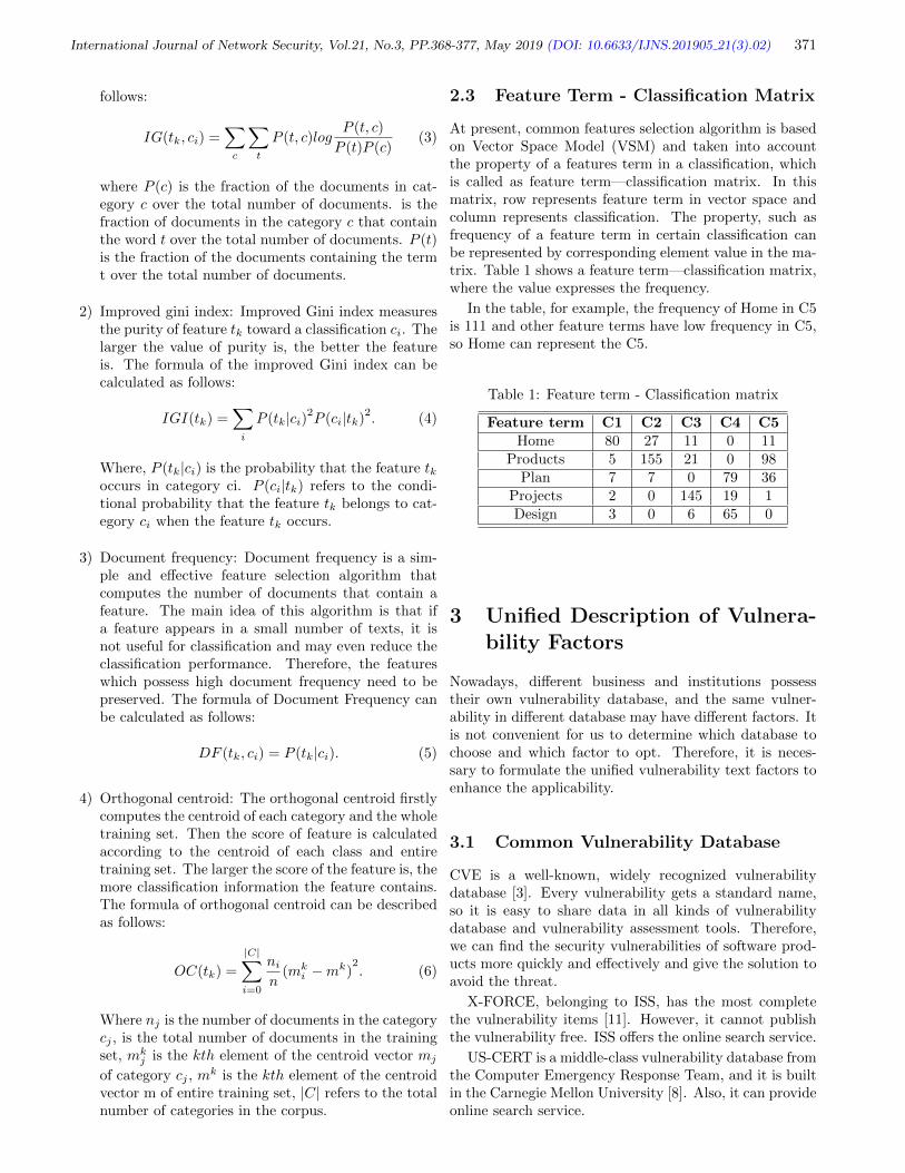
where P (c) is the fraction of the documents in cat-egory c over the total number of documents. is thefraction of documents in the category c that containthe word t over the total number of documents. P (t)is the fraction of the documents containing the termt over the total number of documents.
2) Improved gini index: Improved Gini index measuresthe purity of feature tk toward a classification ci. Thelarger the value of purity is, the better the featureis. The formula of the improved Gini index can becalculated as follows:
IGI(tk) =∑i
P (tk|ci)2P (ci|tk)2. (4)
Where, P (tk|ci) is the probability that the feature tkoccurs in category ci. P (ci|tk) refers to the condi-tional probability that the feature tk belongs to cat-egory ci when the feature tk occurs.
3) Document frequency: Document frequency is a sim-ple and effective feature selection algorithm thatcomputes the number of documents that contain afeature. The main idea of this algorithm is that ifa feature appears in a small number of texts, it isnot useful for classification and may even reduce theclassification performance. Therefore, the featureswhich possess high document frequency need to bepreserved. The formula of Document Frequency canbe calculated as follows:
DF (tk, ci) = P (tk|ci). (5)
4) Orthogonal centroid: The orthogonal centroid firstlycomputes the centroid of each category and the wholetraining set. Then the score of feature is calculatedaccording to the centroid of each class and entiretraining set. The larger the score of the feature is, themore classification information the feature contains.The formula of orthogonal centroid can be describedas follows:
OC(tk) =
|C|∑i=0
ni
n(mk
i −mk)2. (6)
Where nj is the number of documents in the categorycj , is the total number of documents in the trainingset, mk
j is the kth element of the centroid vector mj
of category cj , mk is the kth element of the centroid
vector m of entire training set, |C| refers to the totalnumber of categories in the corpus.
2.3 Feature Term - Classification Matrix
At present, common features selection algorithm is basedon Vector Space Model (VSM) and taken into accountthe property of a features term in a classification, whichis called as feature term—classification matrix. In thismatrix, row represents feature term in vector space andcolumn represents classification. The property, such asfrequency of a feature term in certain classification canbe represented by corresponding element value in the ma-trix. Table 1 shows a feature term—classification matrix,where the value expresses the frequency.
In the table, for example, the frequency of Home in C5is 111 and other feature terms have low frequency in C5,so Home can represent the C5.
Table 1: Feature term - Classification matrix
Feature term C1 C2 C3 C4 C5Home 80 27 11 0 11
Products 5 155 21 0 98Plan 7 7 0 79 36
Projects 2 0 145 19 1Design 3 0 6 65 0
3 Unified Description of Vulnera-bility Factors
Nowadays, different business and institutions possesstheir own vulnerability database, and the same vulner-ability in different database may have different factors. Itis not convenient for us to determine which database tochoose and which factor to opt. Therefore, it is neces-sary to formulate the unified vulnerability text factors toenhance the applicability.
3.1 Common Vulnerability Database
CVE is a well-known, widely recognized vulnerabilitydatabase [3]. Every vulnerability gets a standard name,so it is easy to share data in all kinds of vulnerabilitydatabase and vulnerability assessment tools. Therefore,we can find the security vulnerabilities of software prod-ucts more quickly and effectively and give the solution toavoid the threat.
X-FORCE, belonging to ISS, has the most completethe vulnerability items [11]. However, it cannot publishthe vulnerability free. ISS offers the online search service.
US-CERT is a middle-class vulnerability database fromthe Computer Emergency Response Team, and it is builtin the Carnegie Mellon University [8]. Also, it can provideonline search service.

International Journal of Network Security, Vol.21, No.3, PP.368-377, May 2019 (DOI: 10.6633/IJNS.201905 21(3).02) 372
3.2 Select Unified Factor
The selection of the vulnerability unified factor is thefoundation of vulnerability Classification. According tosome factors from different database, three institutionsselecting the factors for vulnerability classification areshown in Table 2.
Therefore, we select four factors for the unified stan-dards, where the number of the factors selected is threetimes. It shows that these factors are recognized as therepresentative attributes in the world. Actually, the fac-tor Date Public is just the time and it has no use for usto vulnerability classification.
Ultimately, we use three factors, CVE name, severityrank and description to express vulnerability. We give anexample in Table 3.
4 Algorithm Design
4.1 Algorithm Idea
Orthogonal Centroid Algorithm firstly calculates the cen-troid of all features in each class and the training set andthen calculates the score. We can find that orthogonalcentroid algorithm focuses on inter-class, namely calcu-lating the most important feature term compared withother feature terms in one classification. Document fre-quency is a simple and effective feature selection algo-rithm. However, Document Frequency method only mea-sures the significance of a feature term in the intra-class.Thus the Document Frequency method concentrates onthe column of the feature term-classification matrix whileOrthogonal Centroid Algorithm focuses on the row.
Both Document Frequency method and OrthogonalCentroid Algorithm just focus on one respect of the ma-trix. Therefore, this paper puts forward a kind of newfeature selection algorithm, Orthogonal Centroid FeaturesSelection algorithm both in Inter-class and Intra-class(OCFSII), which can make up deficiency of OrthogonalCentroid Algorithm and Document Frequency methodand measure comprehensively the importance of a featureterm to classification.
4.2 Algorithm Flow
As is shown in Figure 3, we give the flow chart of OCF-SII algorithm, which mainly includes two parts, includingthe construction of feature term-classification matrix andselection of text feature. Text feature selection needs tocalculate the centroid of training set. Moreover, we cal-culate the offset of feature terms both in inter-class andintra-class respectively. Finally, we can obtain the totaloffset of feature terms and then make a rank for those.
Here, feature term-classification matrix is VT×C , whichconsists of T features and Cclasses, matrix element vij rep-resents the frequency of the ith feature in the jth class, thevector D = d1, d2 · · · di, 1 ≤ i ≤ C, where di represents
text number of the ith class. There are some calculationformulas as following:
1) Feature term centroid in training set M =m1,m2, · · ·mi
mi =
C∑j=1
vij/
C∑j=1
dj (7)
Where mirepresents the ith feature term centroid;
2) Feature term centroid in inter-class Mj =m1
j ,m2j · · ·mi
j
mij =
vijdj
(8)
Where, mij represents the centroid of the ith feature
term in the jth class;
3) Feature term centroid in intra-class
m =
C∑j=1
vij
C(9)
4.3 Algorithm Description
Algorithm 1 OCFSII algorithm
1: Input feature term - classification matrix VT×C andmatrix element vijrepresents frequency of the ith fea-ture in the jth class; text number vector of classvulnerabilityD = d1, d2 · · · di , 1 ≤ i ≤ C; featurenumberK
2: Output feature subset VS
3: mi = F1(vij , di) // calculate feature term centroid intraining set
4: mij =
vijdj
// calculate feature term centroid in inter-
class5: m = F2(Vij , C) // calculate feature term centroid in
intra-class6: for i = 1 to T7: for j = 1 to C8: aij = vij−m // calculate offset in intra-class9: bij = mi
j − mi // calculate offset in inter-class
10: end for11: OCFSIIij = aij ∗ bij12: end for13: VS = OCFSIITOPK
Moreover, the function F1 and F2 are defined as fol-lows:
OCFSII algorithm measures the importance of featuresboth in inter-class and intra-class. And it is so simple toimplement. The time complexity is O(T*C) - namely theproduct of the number of rows and columns in FeatureTerm-classification Matrix.

International Journal of Network Security, Vol.21, No.3, PP.368-377, May 2019 (DOI: 10.6633/IJNS.201905 21(3).02) 373
Table 2: Institution selecting the factors for vulnerability classification
ID Factor CVE X-FORCE US-CERT Times1 CVE name X X X 32 Data public X X X 33 Date-up Ö Ö X 14 Severity rank X X X 35 Credit Ö Ö X 16 Solution Ö Ö X 17 Description X X X 3
Table 3: CVE-2015-1611 information
CVE name description Severity rank
CVE-2015-1611OpenFlow plugin for Daylight before Helium SR3 allows
remote attackers to spoof the SDN topology and affect theflow of data, related to fake LLDP injection.
Middle(CVSS score: 5.0)
Feature terms
Calculate the centroid of
training set and every
classification
Calculate the centroid of
training set and every
classification
Feature term-
classification matrix
Feature term-
classification matrix
Intra-class: calculate the
offset between a feature term
and a centroid of the class
Intra-class: calculate the
offset between a feature term
and a centroid of the class
Calculate the total
offset of feature terms
Calculate the total
offset of feature terms
Vulnerability Features
Inter-class: calculate the
offset between a feature term
and another one
Inter-class: calculate the
offset between a feature term
and another one
Rank the feature
terms
Rank the feature
terms
Figure 3: Flow chart of OCFSII algorithm
5 Experiment Setup
5.1 Experimental Classifier
In this section, K-Nearest Neighbor (KNN) and SupportVector Machine (SVM) are described briefly. Both ofthem are supervised learning method.
1) KNN classifier: KNN classification is a kind of learn-ing algorithm based on sample, which is considered
as an inert method. This algorithm shows wonderfulperformance in many applications. The key point ofthis method is to find a proper similarity measureto determine the degree of similarity between sampleand training set. Therefore, we can get the nearesttraining set from the unmarked samples.
2) SVM classifier: SVM is a kind of machine learningalgorithm, which is widely used in machine learning.

International Journal of Network Security, Vol.21, No.3, PP.368-377, May 2019 (DOI: 10.6633/IJNS.201905 21(3).02) 374
Algorithm 2 F1(vij , di)
1: vij = 0; dj = 02: for i = 1 to T3: for j = 1 to C4: vij = vij + 15: dj = dj + 16: mi =
vijdij
7: end for8: end for9: return (vij , dj)
Algorithm 3 F2(vij)
1: vij = 02: for i = 1 to T3: for j = 1 to C4: vij = vij + 15: m =
vijC
6: end for7: end for8: return (vij)
Moreover, SVM is a high efficient classifier in classi-fication. In our study, we choose liner kernel SVM.
5.2 Experimental Data
The purpose of this experiment is to select the feature ofvulnerability, so as to verify the accuracy and efficiencyof the vulnerability classification. In addition, we do notgive a profound study on the selection of the categories.The vulnerabilities are divided into the most common sixcategories, authentication, buffer errors, cross-site script-ing, code injection, information leak and input validationrespectively. The sample set of vulnerabilities is shown inTable 4.
We select 3500 vulnerabilities from Security ContentAutomation Protocol (SCAP), from which 3000 vulnera-bilities belong to training sample and 500 vulnerabilitiesbelong to test training. As is seen from the Table 4, 3000samples will train the classifier alter the feature selectionand, the 500 samples are utilized to test the accuracy ofOSFCII.
5.3 Experimental Steps
In this section, we give the concrete the steps of vulnera-bility classification experiment.
1) Obtain the original vulnerability features via prepro-cessing the vulnerabilities text from the database;
2) Construct the feature term- class matrix;
3) Get the feature terms of each category by utilizingthe proposed feature selection OCFSII;
4) Use VSM to quantify the vulnerability feature terms;
5) Utilize one-to-many method to structure the vulner-ability classifier;
6) Calculate the F1 and accuracy and give the experi-ment results.
5.4 Performance Measures
In our experiment, we utilize the F1 and Accuracy to mea-sure the performance of the vulnerability classification.
1) Precision and micro-precision: Precision is the ra-tio of the number of vulnerability texts which arecorrectly classified as the positive class to the totalnumber of those which are classified as the positiveclass. The formula of the precision for class ci is de-fined as:
Pi =TPi
TPi + FPi(10)
Where TPi is the number of vulnerability texts whichare correctly classified as class ciand FPi means thenumber of vulnerability texts which are misclassifiedas class.
Similarly, in order to evaluate the performance aver-age across the classes and micro-precision is used inthis paper. The formula of the micro-precision canbe calculated:
Pmicro =TP
TP + FP=
|C|∑i=1
TPi
|C|∑i=1
(TPi + FPi)
(11)
Where |C| is the number of the classes.
2) Recall and micro-recall: Recall is the ratio of thenumber of vulnerability texts which are correctlyclassified as the positive class to the total number ofthose which are actually belong to the positive class.The formula of the precision for class ci is defined as:
Ri =TPi
TPi + FNi(12)
Where FNi means the number of vulnerability textsbelonging to class ci are misclassified to other classes.
Similarly, in order to evaluate the performance aver-age across the classes and micro-precision is used inthis paper. The formula of the micro-precision canbe calculated:
Rmicro =TP
TP + FN=
|C|∑i=1
TPi
|C|∑i=1
(TPi + FNi)
(13)
3) F1 and accuracy: When we obtain the micro-precision and micro-recall, the formula of the F1 andAccuracy can be calculated:
F1 =2PmicroRmicro
Pmicro + Rmicro(14)

International Journal of Network Security, Vol.21, No.3, PP.368-377, May 2019 (DOI: 10.6633/IJNS.201905 21(3).02) 375
Table 4: Experimental vulnerability sample
CategoryNumber
Training sample Testing sample The totalauthentication 221 30 251buffer errors 303 80 383
cross-site scripting 945 200 1145code injection 830 110 940
information leak 250 30 280input validation 451 50 501
Accuracy =TP + TN
TP + TN + FP + FN(15)
Where TN means the number of vulnerability textswhich are correctly classified to other classes exclud-ing the positive class.
6 Results
6.1 Experimental Results when KNNClassifier
Table 5 shows the F1 measure results when KNN classifieris used. In this chart, we can see that OCFSII actuallyhas the best performance when the number of featuresis 300, 500, 1300 and 1500. Moreover, the IGI has thesimilar performance compared with OCFSII but the lat-ter is superior to the former. All of the algorithms havethe positive correlation when the number of the featuresbetween 300 and 1300 and from 1300 on, the F1 measurebegins to decrease. Therefore, the number of the featuresis 1300 for the database and the experiments can get theexcellent results.
Similarity, Figure 4 shows the accuracy measure resultswhen KNN classifier is used. In this graph, OCFSII andIGI have the better results compared with other methods.And all the curves rise from 300 to 1300 and decline later.It proves that when the number of features is 1300, andwe can get the good results. OCFSII has the greatlyimproved when we consider the importance of featuresboth in inter-class and intra-class compared with OC.
6.2 Experimental Results when SVMClassifier
Table 6 shows the F1 measure results when SVM classifieris used. In this chart, it can be seen that F1 measure re-sults when utilized OCFSII outperforms any other meth-ods. Although IGI has the similar performance comparedwith OCFSII, the latter precedes the former a little. Sim-ilarly, all of the algorithms have the positive correlationwhen the number of the features between 300 and 1300and from 1300 on, the F1 measure begins to decrease.So, we can select 1300 features for the database approxi-mately to obtain the good results. Compared with KNN
10
300
Acc
ura
cy(%
)
50
60
90
500 700 900 1100
20
30
40
70
80
1300
The number of features
1500
OCFSIIIGIDFOCIG
Figure 4: Accuracy measure curve using KNN classifier(%)
classifier used in the experiment, SVM classifier performsbetter when we use the same methods.
Similarity, Figure 5 shows the accuracy measure re-sults when SVM classifier is used. In this graph, OCF-SII has the better results compared with other methods.All of the curves ascend gradually with the increasing ofthe number of features, and they reach the highest pointwhen the number is 1300. It tells us that we can getthe excellent performance when we select 1300 featuresapproximately. Obviously, OCFSII has the greatly im-proved compared with OC because both inter-class andintra-class are taken into consideration. Compared withKNN classifier used in the experiment, SVM classifier out-performs when we use the same methods.
7 Conclusion
In order to protect the information and network from thenumerous numbers of the vulnerabilities, it is significantto manage the vulnerabilities. Classification, as a key linkof vulnerability management, plays a major role in thiswhole process. Due to some feature selection method justconsider the importance of the feature term from one as-pect, we proposed a new feature selection algorithm called

International Journal of Network Security, Vol.21, No.3, PP.368-377, May 2019 (DOI: 10.6633/IJNS.201905 21(3).02) 376
Table 5: F1 measure results using KNN classifier (%)
The number of feature 300 500 700 900 1100 1300 1500OCFSII 69.22 72.54 74.65 76.70 77.76 78.55 77.21
IG 47.88 49.43 52.12 55.23 57.12 58.21 57.33DF 50.32 52.88 54.76 57.45 59.23 60.52 59.21IGI 68.54 71.21 74.87 76.92 77. 99 78.32 77.10OC 49.83 51.43 53.43 56.32 58.22 59.43 58.45
Table 6: F1 measure results using SVM classifier (%)
The number of feature 300 500 700 900 1100 1300 1500OCFSII 71.54 73.85 75.81 78.60 79.76 80.21 79.21
IG 50.39 51.66 53.94 56.43 57.99 58.32 57.10DF 52.47 54.18 56.85 58.21 60.23 61.76 60.53IGI 70.35 72.31 75.32 78.10 78.54 79.21 78.29OC 51.43 53.57 55.22 57.47 59.22 60.25 59.64
10
300
Acc
ura
cy(%
)
50
60
90
500 700 900 1100
20
30
40
70
80
1300
The number of features
1500
OCFSIIIGIDFOCIG
Figure 5: Accuracy measure curve using SVM classifier(%)
OCFSII, considering the importance of the feature termboth in inter-class and intra-class. To confirm the valid-ity of this method, we use two classifiers including SVMand KNN in our experiment, and compare it with fourfeature selection algorithms including Information Gain,IGI, Document Frequency and Orthogonal Centroid. Theexperiment results show that the proposed method OCF-SII outperforms IG, DF OC, and is comparable with IGIwhen KNN used while OCFSII is superior to IG, DF,OC and IGI when SVM used. As part of our future re-search, we plan to design the better method to improvethe accuracy and efficiency to enhance the understandingof vulnerability essence. [8]
References
[1] B. Bigi, “Using kullback-leibler distance for text cat-egorization,” Lecture Notes in Computer Science,vol. 2633, pp. 305–319, 2016.
[2] Z. Chen, Y. Zhang, and Z. Chen, “A categorizationframework for common computer vulnerabilities andexposures,” The Computer Journal, vol 53, no. 5, pp.551-580, 2010.
[3] S. Christey and R. A. Martin, “Vulnerabilitytype distributions in CVE,” The MITRE Corpo-ration, 2007. (http://cwe.mitre.org/documents/vuln-trends/index.html)
[4] A. K. Gupta and N. Sardana, “Naive bayes ap-proach for predicting missing links in ego networks,”in IEEE International Symposium on Nanoelectronicand Information Systems, pp. 161–165, 2017.
[5] K. M. A. Hasan, M. S. Sabuj, and Z. Afrin, “Opin-ion mining using naive bayes,” in IEEE InternationalWie Conference on Electrical and Computer Engi-neering, pp. 511–514, 2016.
[6] H. J. Kim, J. Kim, and J. Kim, “Semantic text classi-fication with tensor space model-based naive bayes,”in IEEE International Conference on Systems, Man,and Cybernetics, pp. 004206–004210, 2017.
[7] H. Lodhi, C. Saunders, J. Shawe-Taylor, N. Cris-tianini, and C. Watkins, “Text classification usingstring kernels,” Journal of Machine Learning Re-search, vol. 2, no. 3, pp. 419–444, 2002.
[8] P. Minarik and T. Dymacek, “Netflow data visualiza-tion based on graphs,” in Proceedings of Visualiza-tion for Computer Security, International Workshop,pp. 144–151, 2008.
[9] S. A. Mingoti and J. O. Lima, “Comparing som neu-ral network with fuzzy -means, -means and tradi-tional hierarchical clustering algorithms,” European

International Journal of Network Security, Vol.21, No.3, PP.368-377, May 2019 (DOI: 10.6633/IJNS.201905 21(3).02) 377
Journal of Operational Research, vol. 174, no. 3,pp. 1742–1759, 2006.
[10] E. U. Opara, O. A. Soluade, “Straddling the nextcyber frontier: The empirical analysis on networksecurity, exploits, and vulnerabilities,” InternationalJournal of Electronics and Information Engineering,vol. 3, no. 1, pp. 10–18, 2015.
[11] F. H. Schmitz, “Reduction of blade-vortex interac-tion (BVI) noise through x-force control,” Journalof the American Helicopter Society, vol. 43, no. 1,pp. 14–24(11), 1995.
[12] J. Song, J. Han, D. Zhang, L. Yuan, and L.Shao, “Evaluation of security vulnerability severitybased on cmahp,” in IEEE International Conferenceon Computer and Communications, pp. 1056–1060,2017.
[13] H. S. Venter, J. H. P. Eloff, and Y. L. Li, “Standardis-ing vulnerability categories,” Computers & Security,vol. 27, no. 3-4, pp. 71–83, 2008.
[14] J. A. Wang and M. Guo, “Vulnerability categoriza-tion using bayesian networks,” in Proceedings of theSixth Annual Workshop on Cyber Security and Infor-mation Intelligence Research (CSIIRW’10), pp. 1–4,2010.
[15] J. Yan, N. Liu, B. Zhang, S. Yan, Z. Chen, Q. Cheng,W. Fan, and W. Y. Ma, “Ocfs: Optimal orthogonalcentroid feature selection for text categorization,” inInternational ACM SIGIR Conference on Researchand Development in Information Retrieval, pp. 122–129, 2005.
[16] Y. Yang and J. O. Pedersen, “A comparative studyon feature selection in text categorization,” in Four-teenth International Conference on Machine Learn-ing, pp. 412–420, 1997.
[17] P. Zhang and X. Y. Xie, “Research on vulnerabilityclassification based on svm with fuzzy entropy fea-ture selection algorithm (in Chinese),” ApplicationResearch of Computers, vol. 32, no. 4, pp. 1145-1148,2015.
Biography
Jialiang Song received the B.S. degree in electronic sci-ence and technology from Zhengzhou information scienceand technology institute, Henan, China, in 2015. Heis pursuing the M.S. degree in information security atZhengzhou information science and technology institute.His research interests include vulnerability managementand information security.
Jihong Han received the B.S., M.S. and Ph.D degrees ininformation security from Zhengzhou information scienceand technology institute, Henan, China, in 1983, 1990,and 2008, respectively. She is now a professor at the De-partment of Information Security, Zhengzhou informationscience and technology institute. Her research interestsinclude information hiding, watermarking and softwarereliability. She has published 60 research articles and 3books in these areas.
Xirui Zhang received the B.S. degree in managementfrom Zhengzhou information science and technology in-stitute, Henan, China, in 2016. He is pursuing the M.S.degree in information security at Zhengzhou informationscience and technology institute. His research interestsinclude information security and data mining.
Lulu Shao received the B.S., M.S in information secu-rity from Chongqing communications college, Chongqing,China, in 2004 and 2011. She is pursuing the Ph.D degreein information security at Zhengzhou information scienceand technology institute. Her research interests includewireless communication security.
Yang Wang received the B.S. degree in computer scienceand technology from Henan University, China, in 2014.He is pursuing the M.S. degree in computer science andtechnology at Zhengzhou information science and tech-nology institute. His research interests include softwarereverse analysis and network security.

International Journal of Network Security, Vol.21, No.3, PP.378-383, May 2019 (DOI: 10.6633/IJNS.201905 21(3).03) 378
Additively LWE Based Homomorphic Encryptionfor Compact Devices with Enhanced Security
Ratnakumari Challa1 and Gunta Vijaya Kumari2
(Corresponding author: Ratnakumari Challa)
Department of Computer Science, Engineering, Rajiv Gandhi University of Knowledge Technologies1
IIIT-AP, RKValley, Kadapa Dist, Andhra Pradesh, India
Department of Computer Science, Engineering, Jawaharlal Nehru Technological University, Hyderabad2
Kukatpally, Hyderabad, Telangana, India
(Email: [email protected])
(Received Nov. 03, 2017; Revised and Accepted July 7, 2018; First Online Dec. 10, 2018)
Abstract
LWE based homomorphic encryption scheme has beenproven as secured technique and consequently widely im-plemented since the last decade. However, the scheme isnot considered to be practical because of its larger size ofpublic keys and ciphertexts. In this paper, LWE basedadditively homomorphic encryption technique is furthermodified to enhance the performance in minimizing thespace required for public keys and ciphertext withoutcompromising the security of the scheme. This makesthe scheme suitable for implementation in low space de-vices. The practical implementation of the scheme is ex-plored and its performance analysis has been presentedhere. The scheme is also compared with the standardLWE.
Keywords: Compact Devices; Learning with Errors;Prime Factoring; Pseudorandom Generator
1 Introduction
A Fully Homomorphic Encryption (FHE) is treated astheholy grail of cryptography, because, it allows arbi-trary processing of data in encrypted mode [8, 13]. Anencryption scheme is called homomorphic if, given twociphertexts say c1 = Ek(m1) and c2 = Ek(m2) wherem1,m2 are plaintexts and k is the key, one can com-pute c = c1oc2 = Ek(m1om2) for some operation o suchthat Dk(c) = m1om2 [11]. This idea of homomorphicencryption was initially proposed by Rivert, et al [19]in 1978. If o corresponds to a single operation of ei-ther addition or multiplication only, the scheme is saidto be partially homomorphic. Several partially homo-morphic encryption schemes were proposed and success-fully used in applications such as electronic voting, pri-vate information retrieval, multiparty computation, obliv-ious polynomial evaluation and so on [11, 15]. However,
to perform arbitrary computations over the encrypteddata so that the scheme is suitable for any applicationin general, it must support both addition and multipli-cation operations over the ciphertexts without any limitsin case of which it is called as fully homomorphic encryp-tion (FHE) [8]. Solving a three-decade old long lastingcryptographic problem of designing an FHE scheme wasa dream of cryptographers, which was first theoreticallysolved in a pioneering work by Craig Gentry in 2009 us-ing an innovative construction method [8] Gentry’s FHEis based on the algebraic lattice theory and consists ageneral blueprint that can be used for the constructionof FHE schemes. However, the scheme was practicallyinfeasible due to high computational complexities under-lying the blueprint, specifically, the bootstrapping or ci-phertext refreshing process. In a quest for devising apractical FHE scheme, several variants of the Gentry’sscheme were explored [20–22]. Many new schemes basedon different security assumptions and hard algebraic andnumber theoretic problems such as Approximate GreatestCommon Divisors (AGCD) [22], Chinese Remainder The-orem (CRT) [5], identity based [13] and attribute basedschemes [10] were proposed. Though all these works haveshown progressive improvements one over the other, noneof them could be a candidate for practical deployment.Therefore, devising an FHE scheme with practical timecomplexities is still an open problem.
The Learning with errors (LWE) based cryptographicscheme was first proposed and implemented by Regev [18]in 2009. LWE problem has been considered well suitedfor new research on public key cryptography. LWE basedcryptosystem is proven as simple and fast for implemen-tation. Moreover, the security of the LWE problems isproven to be hard [17] since it is related to the well-known“learning parity with noise” problem.
Several variants of LWE based Homomorphic encryp-tion schemes such as FHE using standard LWE [2, 3],RLWE (Ring LWE) [2, 14], and other variants [1, 4, 9]

International Journal of Network Security, Vol.21, No.3, PP.378-383, May 2019 (DOI: 10.6633/IJNS.201905 21(3).03) 379
have been proposed. The theoretical implementation ofthe schemes has been considered to preserve privacy incloud computing while practical implementation of LWEbased homomorphic encryption is considered to be com-plex due to its larger public keys and ciphertexts. Thespace constraint also limits the implementation of theseschemes on compact devices. However, there were sometechniques [6, 7, 12, 16] proposed elsewhere to reduce thesize of public keys and ciphertexts which are suitable forthe implementation in low speed and low storage devices.The aim of this work is to propose the possible imple-mentation of the LWE based cryptosystem suited for thedevices with low storage capacity.
Contributions. The major contribution of this paperis to reduce the size of the public keys and cipher-texts. The scheme is theoretically presented withtime complexities for the Encryption, Decryption,Key Generation and Additions functions in the pre-vious work [16]. In this work, the extended version ofthe encryption is presented to further minimize thepublic key space without compromising the security.
2 Preliminaries
2.1 Notations
In this section, basic concepts related to LWE notationsare presented for quick appreciation of the proposed work.An integer is denoted as small case letter in single quo-tations (e.g., ′n′). The bold upper case letters (e.g., V ))are used to denote vectors. The symbols ′+′ and ′.′ areused for the addition and multiplication operations re-spectively. The symbol < V 1,V 2 > denotes the integerwhich resulted as the sum of individual products of ele-ments of the vectors V 1 and V 2.
2.2 LWE Based Homomorphic Encryp-tion
Standard LWE based homomorphic encryption scheme [3]is constructed based on two major parameters: ′n′ (di-mension) and ′q′ (modulus). First Secret vector S of′n′ integers is chosen and then set of public keys (Ai, b),denoted as PK = PK1, PK2..., is computed usingkey generation function, where Ai is an arbitrary vec-tor of ′n′ integers, and ′b′ is an integer computed as< Ai,S > +2.ei; where ′e′i is small randomly chosenerror. Now, for every jth public key generation, therandom arbitrary vector Aj is chosen, and jth publickey, PKj , computed from the secret key S as follows:PKj = (Aj , bj) = (Aj , < Aj ,S > +2.ej).
Given the plaintext message bit mi, encryption al-gorithm computes the ciphertext C i = (Ai, vi) usingany random jth public key PKj= (Aj , bj ) where vi =bj +mi (mod q) = (< Aj ,S > +2.ej +mi (mod q)) andAi= Aj .
Decryption takes ciphertext C i = (Ai, vi) and com-putes the plaintext message bit ′mi’ using the secret keyS . The decryption process is given as follows:
mi = (vi− < Ai,S >)mod2,
Decryption eliminates two masks and leaves the messagebit as output.
3 Scheme with Shorter PublicKeys and Ciphertexts
In this section, we formally present the LWE basedadditively homomorphic encryption scheme with shorterpublic keys and ciphertexts. Seed based technique isproposed to minimize the each public key as well asciphertext from (n + 1).log2(q) bits down to 2.log2(q)bits [7, 16]. A pseudo random number generator withinitialized seed value (seedj) is used to generate thevectorAj of ‘n′ elements which in turn generates the jth
public key PKj = (Aj , bj).
Instead of publishing the public keyPKj = (Aj , bj) ofsize n + 1, the public key vector is shortened to two inte-gers and published as (seedj , bj). LWE based encryptionwith shortened public keys with the support of homomor-phic encryption [16] is formally presented as follows:
KeyGen function. It takes initial parameters, modulus′q′ and dimension ′n′ as inputs, then it chooses thesecret key vector S of ′n′ integers and generates setof public keys PK(= PK1, PK2, . . . ..). Any ith el-ement of PK, using parameters ′n′,′ q′ and the secretkey vector S , is computed as follows:
1) Choose a prime value ′p′i as a seed value andpass it to the pseudo random number generatorfor generating ′n′ integers of vector Ai.
2) Compute the public key PKi = (Ai, bi) as(Ai, < Ai,S > +2ei) where ′e′i is a small ran-dom error.
3) Publish the public key PKi = (pi, bi) instead of(Ai, bi).
Encryption function. For encrypting any ith plain textmessage bit mi (0 or 1)
1) Choose any kth public key PKk : (pk, bk)
2) Compute ciphertext Ci using public key PKk
as follows:
Ci = (pi, vi) = (pk, bk + mj).
Homomorphic addition function. Given any two ci-phertexts Cx= (px, vx) and Cy= (py, vy), computethe new sum cipher Cz as follows:
Cz= (pz, vz),
where pz = px.py and vz = vx + vy.

International Journal of Network Security, Vol.21, No.3, PP.378-383, May 2019 (DOI: 10.6633/IJNS.201905 21(3).03) 380
Figure 1: Proposed LWE based additively homomorphicencryption process
Decryption function. For any given ciphertext Cj=(pj , vj) decryption function computes the plaintextmessage bit mj using the secret key S . The processis given as follows:
1) Compute set of prime factors p1, p2, p3 and soon from pj using prime factoring technique.
2) Generate vector Ai of size ′n′ using pseudo ran-dom number generator function from the seedvalue ′p′i for all prime factors computed from′p′j .
3) Compute sum vector A from all vectors A1,A2, A3,... as follows:
A =∑i
Ai
4) Compute message mj from ciphertext using thefollowing relation,
mj = (vj− < A,S >) mod 2where S is the secret key vector.
The whole process of key generation, encryption, anddecryption and addition operation is illustrated asshown in the Figure 1.
4 An Extended Encryption
The key generation function is used to generate a set of ′x′
public keys and these keys are stored in the public store.
In the encryption process, a public key, PKk = (pk, bk)is chosen randomly from the public key store to encryptthe plain text message bit mi and to compute the cipher-text Ci= (pi, vi) as described under Encryption Functionin Section 3. The ciphertext thus computed is stored inpublicly accessed ciphertext store. Also, the second com-ponent ′v′i of the ciphertext is computed by adding themessage bit (0 or 1) to the second component ′b′k of thepublic key, PKk. If the message is 0, then vi = bk and ifthe message is 1, then vi = bk + 1. This makes very littledifference to the component ′v′i of the ciphertext. Sincethe public key store and the ciphertext store are publiclyaccessible, an adversary can choose any ciphertext fromthe ciphertext store and search for its corresponding pub-lic key (used for its encryption) in the public key set. Ifthe size of public key set is small, then it becomes easy foran adversary to search for its corresponding public key,hence, to compute the message bit. Therefore, big size ofthe public key set ensures that the scheme is secure. How-ever, the huge size may affect the suitability of scheme inimplementing over compact devices.
Modification in the encryption function, proposed ear-lier [16], helps to reduce the number of keys down to smallnumber and to make the scheme suitable for compact de-vices without compromising the security. The proposedextended version of the scheme utilizes the modified en-cryption function.
Modified encryption function. For encrypting anyith message bit mi (0 or 1)
1) Choose any kth public key PKk : (pk, bk)
2) Compute ciphertext Ci
Ci = (pi, vi) = (pk, bk + mi + 2.ei)where ′e′i is randomly chosen error.
Now, the newly added error term ‘e′i in the encryp-tion seems to make the scheme significantly more se-cure; further, the public key set can be minimized tofit for the low storage devices.
Security of the scheme.
• The security of the scheme is totally dependenton modulus ′q′, dimension ′n′ and the secretvector S. Hence, its hardness is equivalent tothat of the LWE problem.
• It is important to consider the privacy of the op-erations on the ciphertext as it is important forhomomorphic encryption scheme. The size ofthe ciphertext is reduced to two and it maintainsthe privacy even after performing the many ad-dition operations on it.
5 Results and Discussion
In the proposed scheme, the total size required for storing′x′ public keys or ciphertexts is minimized to [2x. log2(q)],

International Journal of Network Security, Vol.21, No.3, PP.378-383, May 2019 (DOI: 10.6633/IJNS.201905 21(3).03) 381
whereas the size required in standard LWE schemes is[x.(n + 1). log 2(q)]. The comparison of the storage (inbits) required for publishing 1024 public keys in standardLWE scheme and the proposed scheme is given in Table 1.For the parameter n = 10 and for an integer ′q′ with10 bits the maximum storage required for 1024 publickeys in the proposed scheme is 24477 bits, whereas forthe standard LWE scheme, the storage required is 112624bits. A key implication of this minimization is that thesize of the public keys or ciphertexts becomes independentof the security parameter ′n′.
In the practical implementation of the proposed LWEbased additively homomorphic encryption scheme, it isobserved that the execution time for the encryption op-eration is in the same range as that of the previouslyproposed work [16]. The comparison of the time com-plexities of standard LWE scheme [3] and the proposedversion of the LWE scheme for different values of ′n′ and′q′ are given in Figure 2. It is observed that the execu-tion time for the homomorphic encryption functions ofthe proposed LWE are comparable to the standard LWE.The execution time for the Key Generation, Encryptionand Decryption operations are in the same range too asthat of the standard LWE. However, the execution timefor the addition operation is significantly low in the pro-posed LWE which becomes more prominent at higher ′n′
and ′q′ values. At n = 100000 and ′q′ to be a 50 bitnumber, the execution time for the addition operation instandard LWE is 2.1×10⁸ whereas for the proposed LWE,it is 4× 10³.
6 Conclusions
An efficient LWE based additively Homomorphic Encryp-tion has been proposed and explored with practical im-plementation. The prime number used as the seed valuefor the pseudo random generator helps shorten the publickeys and ciphertexts. The proposed enhanced encryptionfunction provides the enhanced security and further mini-mization of public key space large extent. In the practicalimplementation of the scheme, the execution time com-plexities for every function are reasonably small even forhigher values of the security parameters. This makes thescheme suitable to implement over compact devices.
Acknowledgments
The authors gratefully acknowledge the anonymous re-viewers for their valuable comments.
References
[1] S. Agrawal, D. M. Freeman, and V. Vaikuntanathan,“Functional encryption for inner product predicatesfrom learning with errors,” in Proceedings of The17th International Conference on the Theory and
Application of Cryptology and Information Security(ASIACRYPT’11), pp. 21–40, Dec. 2011.
[2] Z. Brakerski, C. Gentry, and V. Vaikuntanathan,“(leveled) fully homomorphic encryption withoutbootstrapping,” in Proceedings of The 3rd Innova-tions in Theoretical Computer Science Conference(ITCS’12), pp. 309–325, Jan. 2012.
[3] Z. Brakerski and V. Vaikuntanathan, “Efficient fullyhomomorphic encryption from (standard) LWE,” inProceedings of The IEEE 52nd Annual Symposiumon Foundations of Computer Science (FOCS’11),2011. DOI: 10.1109/FOCS.2011.12
[4] Z. Brakerski and V. Vaikuntanathan, “Fully homo-morphic encryption from ring-lwe and security forkey dependent messages,” in Proceedings of The31st Annual Conference on Advances in Cryptology(CRYPTO’11), pp. 505–524, Aug. 2011.
[5] J. H. Cheon, J. S. Coron, J. Kim, M. S. Lee, T. Le-point, and M. Tibouchi, “A batch fully homomor-phic encryption over the integers,” in Proceedingsof The Advances in Cryptology (EUROCRYPT’17),pp. 315–335, 2013.
[6] D. H. Duong, M. P. Kumar, and M. Yasuda, “Ef-ficient secure matrix multiplication over lwe-basedhomomorphic encryption,” Tatra Mountain Mathe-matical publication, vol. 67, pp. 69–83, 2016.
[7] S. D. Galbraith, Space-efficient Variants of Cryp-tosystems based on Learning with Errors, 2013.(https://www.math.auckland.ac.nz/~sgal018/compact-LWE.pdf)
[8] C. Gentry, “A fully homomorphic encryptionscheme,” ACM Digital Library, 2009. ISBN: 978-1-109-44450-6
[9] C. Gentry, S. Halevi, and V. Vaikuntanathan, “Asimple bgn-type cryptosystem from LWE,” in Pro-ceedings of The EUROCRYPT, pp. 506–522, 2010.
[10] C. Gentry, A. Sahai, and B. Waters, “Ho-momorphic encryption from learning with er-rors: Conceptually-simpler, asymptotically-faster,attribute-based,” in Proceedings of TheAdvances inCryptology (CRYPTO’13), pp. 75–92, 2013.
[11] I. Jabbar and S. N. Alsaad, “Design and implemen-tation of secure remote e-voting system using homo-morphic encryption,” International Journal of Net-work Security, vol. 19, no. 5, pp. 694–703, 2017.
[12] R. Lindner and C. Peiker, “Better key sizes (and at-tacks) for lwe-based encryption,” in Proceedings ofThe Cryptographers Track at the RSA (CT RSA’11),pp. 319–339, 2011.
[13] L. Liu and J. YeA, “Homomorphic universal re-encryptor for identity-based encryption,” Interna-tional Journal of Network Security, vol. 19, no. 1,pp. 11–19, 2017.
[14] V. Lyubashevsky, C. Peikertand, and O. Regev, “Onideal lattices and learning with errors over rings,” inProceedings of The EUROCRYPT, pp. 1–23, 2010.
[15] D. Rappe, “Homomorphic cryptosystems andtheir applications,” ResearchGate, 2004. DOI:10.17877/DE290R-15728

International Journal of Network Security, Vol.21, No.3, PP.378-383, May 2019 (DOI: 10.6633/IJNS.201905 21(3).03) 382
Table 1: Storage required for 1024 public keys at different security levels
Parametres Storage space in bitsSecurity Level n q is an integer of Standard LWE scheme Proposed scheme
Toy 10 10 bits 112624 24477Small 100 20 bits 2068323 40957Medium 1000 30 bits 30748377 61436Large 10000 40 bits 409609747 81914Very Large 100000 50 bits 5121138606 102422
Figure 2: Practical performance of key generation, encryption, decryption and addition functions of the schemes(standard and proposed) at different security levels

International Journal of Network Security, Vol.21, No.3, PP.378-383, May 2019 (DOI: 10.6633/IJNS.201905 21(3).03) 383
[16] C. Ratnakumari and G. VijayaKumari, “An efficientLWE-based additively homomorphic encryption withshorter public keys,” in Proceedings of The Progressin Intelligent Computing Techniques: Theory, Prac-tice, and Applications (ICACNI’16), pp. 171–177,2018.
[17] O. Regev, “On lattices, learning with errors, ran-dom linear codes, and cryptography,” Journal of theACM, vol. 56, no. 6, 2009.
[18] O. Regev, “The learning with errors problem (invitedsurvey),” in Proceedings of The IEEE 25th AnnualConference on Computational Complexity (CCC’10),pp. 191–204, June 2010.
[19] R. Rivest, L. Adleman, and L.M. Dertouzos, “Ondata banks and privacy homomorphisms,” AcademicPress, Massachusetts Institute of Technology, Cam-bridge, Massachusetts, vol. 56, no. 6, pp. 169–180,1978.
[20] N.P. Smart and F. Vercauteren, “A fully homomor-phic encryption with relatively small key and cipher-text sizes,” in Proceedings of The Public Key Cryp-tography (PKC’10), pp. 420–443, 2010.
[21] D. Stehle and R. Steinfeld, “Faster fully homomor-phic encryption,” in Proceedings of The Advances inCryptology (ASIACRYPT’10), pp. 377–394, 2010.
[22] M. VanDijk, C. Gentry, S. Halevi, and V. Vaikun-tanathan, “A fully homomorphic encryption over theintegers,” in Proceedings of The Advances in Cryp-tology (EUROCRYPT’10), pp. 24–43, 2010.
Biography
RatnaKumari Challa biography. She has received herM.Tech degree in Computer Science from University ofHyderabad, India in 2009. She is an Assistant Professorin Department of Computer Science and Engineering,RGUKT, IIIT-AP, Andhra Pradesh, India. She iscurrently pursuing Ph.D in JNTUH, Hyderabad, India.Her research interests include Security, Cloud Computingand Image processing.
VijayaKumari Gunta biography.She has received herPh.D degree from University of Hyderabad, India in2002 . She is a professor in Department of ComputerScience and Engineering, JNTUH, Hyderabad. India.Her research interests include Algorithms, Security andCloud Computing.

International Journal of Network Security, Vol.21, No.3, PP.384-391, May 2019 (DOI: 10.6633/IJNS.201905 21(3).04) 384
An Improved Ternary Montgomery LadderAlgorithm on Elliptic Curves over GF(3m)
Shuang-Gen Liu, Rong-Rong Wang, Yun-Qi Li, and Can-Liang Zhai(Corresponding author: Shuang-Gen Liu)
School of Communication and Information Engineering, Xi’an University of Posts and Telecommunications
Xi’an 710121, China
(Email: [email protected])
(Received Jan. 15, 2018; Revised and Accepted Apr. 21, 2018; First Online Jan. 11, 2019)
Abstract
In this paper, we propose a new scalar multiplication algo-rithm on elliptic curves over GF(3m). It combines originalMontgomery ladder algorithm and the ternary representa-tion of the scalar, which makes full use of cubing. In addi-tion, in order to improve performance, we have presentednew composite operation formulas which are 2P1+P2 and3P1, and applied them to the improved scalar multiplica-tion algorithm. Based on the original Montgomery lad-der algorithm, it can resist Simple Power Attack (SPA).In the experimental analysis, we set the ratio of inversionand multiplication to a dynamic value. Results show thatwith respect to previous algorithm, the average efficiencyof proposed scalar multiplication algorithm is increasedby 7.8 % to 11.3 % in affine coordinate, and 4.0 % to17.9 % in projective coordinate.
Keywords: Characteristic Three; Composite Formulas;Elliptic Curve Cryptography; Montgomery Ladder Algo-rithm; Scalar Multiplication
1 Introduction
Elliptic Curve Cryptography (ECC) was introduced inde-pendently by Koblitz [9] and Victor Miller [16] in around1985. Its key size is smaller than RSA with the equiva-lent security, for example, elliptic curve with the key of160 bits is competitive with RSA with the key of 1024bits. This can be especially an advantage for applica-tions where resources are limited, such as smart cards,embedded devices and mobile phones. Its safety is basedon the difficulty of elliptic curve discrete logarithm prob-lem (ECDLP). ECC is used for encryption, decryption,digital signature and verification [5, 7, 8, 18, 22, 28]. Thefactors that affect the execution rate of ECC algorithmare generally as follows: The choice of coordinates, scalarmultiplication, the selection of elliptic curves. One of thedecisive factors is the calculated rate of scalar multiplica-tion. Scalar multiplication, defined as [k ]P=P+P+. . .+P,
where k is an integer and P is an elliptic curve point, isa major and time-consuming operation in ECC. Scalarmultiplication operations can be divided into two layers:the top layer and the bottom layer. Among them, the toplayer operation is basic point operation on elliptic curve,such as point addition and point doubling, and the bot-tom layer operation is underlying field operation, such asinverse, multiplication, squaring, and so on.
In recent years, GF(2m)-ECC and GF(p)-ECC havebeen well studied. There are a lot of methods to improvethe elliptic curve scalar multiplication, such as double-and-add [11], non-adjacent form (NAF) [20] and so on,while GF(3m)-ECC have been less studied due to theirefficiency factors. So the research of fast and securityscalar multiplication on the elliptic curve over GF(3m)has become one of the hot research topics. GF(3m)-ECC,as a special type of GF(pm)-ECC, has some properties offast computation similar to GF(2m)-ECC, but it has ownspecial properties and is suitable as a carrier of securepassword algorithm [12,19,24,26].
In 1987, Montgomery [17] proposed a fast algorithmfor calculating the elliptic curve scalar multiplication kPthat resists Simple Power Attack(SPA) attacks. SPA isa type of side channel attack proposed by literature [10].The basic idea is: Integer k is expanded into binary form,which is computed cyclically from left to right. And thereare one point doubling and one point addition operationsin each cycle. Because of the same computational patternand cost in every loop iteration, this algorithm preventsSPA. However, the original Montgomery ladder algorithmhas the demerit of slow performance. In this paper, ascalar k is represented as ternary form instead of binaryform. The length of the ternary expression is shorterthan binary expression. Based on Montgomery’s idea,a new algorithm was proposed by Lopez and Dahab [15]in 1999, and it was used for calculating the elliptic curvescalar multiplication over GF(2m). By using a new setof point addition and point doubling calculation formu-las, every iteration requires only the x-coordinate of thepoint to be calculated, and the y-coordinate is restored

International Journal of Network Security, Vol.21, No.3, PP.384-391, May 2019 (DOI: 10.6633/IJNS.201905 21(3).04) 385
at the end of the algorithm. Smart and Westwood [27]first pointed out that ordinary elliptic curves over finitefields of characteristic three is an alternative for imple-menting elliptic curve cryptosystems, and it is at most50% slower than the equivalent system over finite fields ofcharacteristic two. After that, these elliptic curves wereextensively studied by many papers [3, 4, 12, 27]. The lit-erature [29] proposed point addition and point doublingcalculation formulas that omit the calculation of the Y-coordinate, and remove the inverse operation, thereby im-proving the Montgomery algorithm over GF(3m). The lit-erature [3] improved further point addition, doubling andtripling operation over GF(3m). In 2013, Gu et al. [4]gave the reason why the Montgomery ladder algorithmperforms worse over ternary fields than binary fields. In2015, Zhou et al. [25] deduced a formula of calculating3k P directly under the affine coordinates. Yu et al. [30]optimized Projective Montgomery Algorithm over the fi-nite field with characteristic of 3 by using co-Z tricks, andthe Y coordinate is not calculated in the middle of theloop. Robert and Negre [1] first presented thirding pointformula together with our third-and-add and parallel ap-proaches for scalar multiplication.
Our contributions in this paper are divided three levels:
• We review researches about scalar multiplication overGF(2m), GF(p) and GF(3m) in recent years, and re-lated theory about ECC.
• Different from original Montgomery ladder algo-rithm, an improved ternary Montgomery ladder al-gorithm over GF(3m) is proposed. Furthermore, inorder to increase the speed of scalar multiplication,we develop composite operation formulas in the un-derlying field.
• The proposed algorithm can be applied in ellipticcurve cryptography. This algorithm has many ad-vantages over the existing ones, and it has betterperformance and higher security naturally.
The remainder of this paper is organized as follows. Thenext section reviews the necessary background for arith-metic on elliptic curves over GF(3m), ordinary ternaryform of k, and related scalar multiplication. In Section 3,we present the improved ternary Montgomery ladder al-gorithm. Additionally, we derive composite operation for-mulas which are 2P1 + P2 and 3P1. In Section 4, we givesome comparison with other algorithms under differentcoordinate system. Finally, in Section 5, we draw someconcluding remarks.
2 Background
2.1 Elliptic Curve Cryptography
An elliptic curve E over a finite field K is defined by theequation
y2 + a1xy + a3y = x3 + a2x2 + a4x+ a6. (1)
where a1, a2, a3, a4, a6 ∈ K, and∆ 6= 0, the ∆ is discrimi-nant of E.
When the characteristic of K is equal to 3, we use thenon-supersingular form of an elliptic curve given for a 6= 0by
y2 = x3 + ax2 + b. (2)
where a, b ∈ K, and ∆ = −a3b 6= 0.P1 = (x1, y1) 6= O and P2 = (x2, y2) 6= O is two differ-
ent points on the elliptic curve, then the sum of them isP3 = (x3, y3) computed by
x3 = λ2 − x1 − x2 − a, y3 = λ(x1 − x3)− y1, (3)
where λ =y2 − y1x2 − x1
.
The doubling of the point P1 = (x1, y1) 6= O is thepoint P3 = (x3, y3) given by
x3 = λ2 + x1 − a, y3 = λ(x1 − x3)− y1, (4)
where λ =ax1y1
.
Both doubling and addition formulae require 1I+2M+1S, where I,M, S is the cost of a field inverse, multipli-cation and squaring, respectively.
2.2 Elliptic Curve over Fields of Charac-teristic Three
For elliptic curves over fields of characteristic three, weknow some basic facts [27]: polynomial g(z), as an elementin the field F3m = F3[z]/M(z), the cubing rule can beshown as follows:
g(z)3 = g(z3) (mod M(z)).
The square uses the same algorithm as multiplication,so it is regarded as equivalent to multiplication. Multiply-ing and squaring field elements are similar in complexityand are not too expensive, but more costly than cubing.The computing speed of cubing is at least ten times fasterthan that of multiplication or squaring. Since the charac-teristic of the elliptic curve is 3, so we can simplify cubiccomputation with Frobenius self-homomorphism [6], andcomputational overhead of cubic can be negligible, com-pared to other operations. Addition and subtraction canbe ignored as well [2]. Although, the cubing in ternaryfields can be implemented by previous efficient methods,the original Montgomery ladder algorithm do not makefull use of cubing [4]. In Section 3, we propose an im-proved ternary Montgomery ladder algorithm. Here, theternary expression is useful to reduce the length of thescalar representation.
A curve of the form y2 = x3 + ax2 + b is used in thispaper, and it has a point of order three and the order ofthe group is divisible by three. It needs to meet some re-quirements, for example, there is group order 3×p, wherep is a prime, and it can be performed in the subgroup ofsize p.

International Journal of Network Security, Vol.21, No.3, PP.384-391, May 2019 (DOI: 10.6633/IJNS.201905 21(3).04) 386
2.3 Ordinary Ternary Form
According to the traditional division algorithm,An arbitrary positive integer k is expressed ask=(kn−1, · · · , k1, k0)3, where kn−1=1 or 2, andki ∈ 0, 1, 2, i = 0, 1, · · · , n− 2.
Algorithm 1 Ordinary Ternary Form
1: Input: A positive integer k2: Output: k=(kn−1, · · · , k1, k0)3, with kn−1=1 or 2
and ki ∈ 0, 1, 2.3: i← 04: while k > 0 do5: if k mod 3 = 2 then6: ki ← 27: k = bk/3c8: end if9: if k mod 3 = 1 then
10: ki ← 111: k = bk/3c12: end if13: if k mod 3 = 0 then14: ki ← 015: k = k/316: end if17: i← i+ 118: end while19: Output k.20: End
Algorithm 1 correctness:
1) The result of k mod 3 in this algorithm is only 2, 1and 0, and the ratio of 2, 1, and 0 is 1/3 [13], onaverage.
2) A branch is always performed in the loop, so k willcertainly continue to decrease after k ← k/3, theprogram ends the loop when the final result of k is0. Therefore,any positive integer k will certainly beturned into an ordinary ternary string, after the cir-cular execution of Algorithm 1.
Example 1. A positive integer k = 520i← 0k0 ← 1, k = 173, i← 1k1 ← 2, k = 57, i← 2k2 ← 0, k = 19, i← 3k3 ← 1, k = 6, i← 4k4 ← 0, k = 2, i← 5k5 ← 2, k = 0, i← 6Output k = 2, 0, 1, 0, 2, 1
2.4 Scalar Multiplication
2.4.1 Ordinary Ternary Form Scalar Multiplica-tion
Ordinary ternary form scalar multiplication is expressedas left-to-right form, and Algorithm 2 describes corre-sponding elliptic curve scalar multiplication.
kP =
n−1∑i=0
ki3iP = 3(· · · 3(3kn−1P + kn−2P ) + · · · ) + k0P.
Algorithm 2 Ordinary ternary form scalar multiplica-tion algorithm
1: Input: P = (x, y) ∈ E(GF (2m)), and k =(kn−1, kn−2, · · · , k1, k0)3
2: Output: Q = kP ∈ E(GF (2m)).3: R0 ← O4: for i = n− 1, · · · , 0 do5: R0 = 3R0
6: R1 = R0 + P7: R2 = R0 + 2P8: R0 = Rki
9: end for10: Return Q = R0
11: End
The algorithm requires (n)-time triple, (n)-time doubleand 2(n)-time addition. Each loop performs the samepoint operation whatever the key bit is, so attacker cannot guess the value of scalar k from power trace of pointmultiplication, i.e., Algorithm 2 can resist SPA.
2.4.2 A Left-to-Right Montgomery Ladder
The well-known Montgomery ladder for speeding up thescalar multiplication, which was initially proposed andutilized for Montgomery form elliptic curves [17], can beadapted to Weierstrass form curves. Algorithm 3 de-scribes the classical left-to-right Montgomery ladder ap-proach for point multiplication [21].
The algorithm requires (n-1)-time double and (n-1)-time addition. Each loop performs one point doubling andone point addition operations, so this algorithm preventsSPA. Furthermore, given a base point P, and there is nochange in the difference between the input points R0 andR1, i.e., R1−R0 = P . This algorithm can also be appliedto elliptic curve over GF(3m) [30].
3 Proposed Algorithm
In this part, we propose a new efficient scalar multipli-cation algorithm based on the Montgomery ladder algo-rithm. The scalar k is represented as a ternary form,and the new algorithm is extended to elliptic curves overGF(3m).

International Journal of Network Security, Vol.21, No.3, PP.384-391, May 2019 (DOI: 10.6633/IJNS.201905 21(3).04) 387
Algorithm 3 Left-To-Right Montgomery Ladder Algo-rithm1: Input: P = (x, y) ∈ E(GF (2m)), and k =
(1, kn−2, · · · , k1, k0)22: Output: Q = kP ∈ E(GF (2m)).3: R0 = P ; R1 = 2P4: for i = n− 2, · · · , 0 do5: if ki = 1 then6: R0 = R0 +R1; R1 = 2R1
7: end if8: if ki = 0 then9: R1 = R0 +R1; R0 = 2R0
10: end if11: end for12: Return Q = R0
13: End
3.1 The Improved Ternary MontgomeryLadder Algorithm
Given a positive integer k, and it is expressed as ternaryform k = 3n−1kn−1 + · · ·+ 3k1 + k0, where kn−1=1 or 2.
Definition 1. The value of scalar multiplication is stored
in R0. We define R(i)0 = (
∑ij=1 kn−j3
i−j)P as the valueof R0 at the end of the ( i-1)-round loop in the algorithm,
where 1 ≤ i ≤ n, j ≤ i and R(i)0 is a point on the elliptic
curve. Especially, for i = 1, R(1)0 = (
∑1j=1 kn−130)P =
kn−1P is an initial value in the algorithm.
Similarly, R(i)1 is defined as R
(i)1 = (
∑ij=1 kn−j3
i−j)P ,
and it also holds R(i)1 = R
(i)0 +P . Then, R
(i+1)0 and R
(i+1)1
are computed by using R(i)0 and R
(i)1 , and they depend on
the value of kn−i−1, as follows:
if kn−i−1 = 0, R(i+1)0 = 3R
(i)0 ,
R(i+1)1 = 2R
(i)0 +R
(i)1
if kn−i−1 = 1, R(i+1)0 = 2R
(i)0 +R
(i)1 ,
R(i+1)1 = 2R
(i)1 +R
(i)0
if kn−i−1 = 2, R(i+1)0 = 2R
(i)1 +R
(i)0 ,
R(i+1)1 = 3R
(i)1
(5)
Therefore, in the calculation of R(i+1)0 and R
(i+1)1 , two
composite operations 2P1 + P2 and 3P1 are involved,
where P1 and P2 are R(i)0 or R
(i)1 . R
(i)1 − R
(i)0 = P is
still valid. Algorithm 4 describes the improved ternaryMontgomery ladder algorithm over finite fields of charac-teristic three, and in the following, the algorithm is veri-fied by giving an example.
Notice that at each iteration of Algorithm 4, the vari-able R0 is updated as
R0 =
3R0, if ki = 02R0 +R1, if ki = 12R1 +R0, if ki = 2
(6)
Algorithm 4 The Improved Ternary Montgomery Lad-der Algorithm over GF(3m)
1: Input: P = (x, y) ∈ E(GF (3m)), and k =(kn−1, kn−2, · · · , k1, k0)3, where kn−1 = 1 or 2
2: Output: Q = kP ∈ E(GF (3m)).3: R0 = kn−1P , R1 = (kn−1 + 1)P4: for i = n− 2, · · · , 0 do5: if ki = 0 then6: R2 = 3R0, R1 = 2R0 +R1
7: end if8: if ki = 1 then9: R2 = 2R0 +R1, R1 = 2R1 +R0
10: end if11: if ki = 2 then12: R2 = 2R1 +R0, R1 = 3R1
13: end if14: R0 = R2
15: end for16: Return Q = R0
17: End
Example 2. k = 520, k =2,0,1,0,2,1R0 = 2P,R1 = 3Pk = 0, R0 = 3R0 = 6P,R1 = 2R0 +R1 = 7Pk = 1, R0 = 2R0 +R1 = 19P,R1 = 2R1 + 2R0 = 20Pk = 0, R0 = 3R0 = 57P,R1 = 2R0 +R1 = 58Pk = 2, R0 = 2R1 +R0 = 173P,R1 = 3R1 = 174Pk = 1, R0 = 2R0 +R1 = 520P,R1 = 2R1 + 2R0 = 521POutput Q = 520P
and the variable R1 is updated as
R1 =
2R0 +R1, if ki = 02R1 +R0, if ki = 13R1, if ki = 2
(7)
The new proposed algorithm preserves the advantagesof the original Montgomery ladder algorithm, the differ-ence between input point R0 and R1 is not changed, i.e.,R1 −R0 = P .
3.2 Composite Operation
Computing 2P1+P2. Let O is the identity element on theelliptic curve, which is considered as a point at infinity.
Now given two points P1 = (x1, y1) and P2 =(x2, y2) in E\O with x1 6= x2, their sum is the pointR = P1+P2 = (x3, y3) and is given by using Equation (3)
x3 = µ21 − a− x1 − x2, y3 = µ1(x1 − x3)− y1, (8)
where µ1 =y2 − y1x2 − x1
.
R is added to P1 to get point S = 2P1 + P2 = (x4, y4),and coordinates of S is given by
x4 = µ22 − a− x1 − x3, y4 = (x1 − x4)µ2 − y1, (9)

International Journal of Network Security, Vol.21, No.3, PP.384-391, May 2019 (DOI: 10.6633/IJNS.201905 21(3).04) 388
where µ2 =y3 − y1x3 − x1
.
The calculation of y3 can be omitted by deform µ2 as
µ2 = −µ1 −2y1
x3 − x1= − y1
x1 − x3− µ1.
x4 can be also computed as
x4 = µ22 − a− x1 − x3 = (µ2 − µ1)(µ2 + µ1) + x2.
In addition, letting h := (x2 − x1)2(2x1 + x2) − (y2 −y1)2 + a(x2−x1)2,it follows that h = (x2−x1)2(x1−x3).Defining H := h(x2 − x1) and I := H−1,we get
1
x2 − x1= hI and
1
x1 − x3= (x2 − x1)3I.
Therefore, there is no x3 is used when computing2P1 + P2. In Algorithm 5, the computation of h,H, I, µ1
and µ2 requires 1 inversion, 2 squarings, 1 cubing and 8multiplications. Similarly, Algorithm 6 is point triplingalgorithm.
Algorithm 5 Double-and-Add Algorithm for EllipticCurve over GF(3m)
1: Input: P1 = (x1, y1) 6= O, and P2 = (x2, y2) 6= O2: Output: S = 2P1 + P2.3: if x1 = x2 then4: if y1 = y2 then5: return 3P1
6: end if7: if y1 6= y2 then8: return P1
9: end if10: X ← (x2 − x1)2;Y ← (y2 − y1)2
11: h← X(2x1 + x2)− Y + aX12: if h=0 then13: return O14: end if15: H ← h(x2 − x1); I ← H−1
16: µ1 ← hI(y2 − y1)17: µ2 ← −y1X(x2 − x1)I − µ1
18: x4 ← (µ2 − µ1)(µ2 + µ1) + x219: y4 ← (x1 − x4)µ2 − y120: end if21: Return (x4, y4)22: End
4 Analysis of Algorithm
In this part, we first analyze the security of the new al-gorithm. Then, in order to make the efficiency analysismore accurate, we compare the new algorithm with pre-vious algorithms over GF(3m) in different coordinate sys-tems. And some practical results are listed in the tablebelow.
Algorithm 6 Tripling Algorithm for Elliptic Curve overGF(3m)
1: Input: P1 = (x1, y1) 6= O2: Output: S = 3P1.3: if y1 = 0 then4: return P1
5: end if6: A← ax1;B ← x31 + b7: C0 ← 1;C1 ← a(x31 + b) = aB8: D ← y319: E ← B3 − bA3C2
0
10: F ← D3 − aDC21
11: x3 ← EC2
1
12: y3 ← FC3
1
13: Return (x3, y3)14: End
4.1 Security Analysis
The basic idea of power analysis attack is to obtain itskey by analyzing the energy consumption during the op-eration of the cryptographic device. Power analysis at-tacks include Simple Power Analysis (SPA) and Differen-tial Power Analysis (DPA). SPA [10,14,23] is a techniquethat can directly analyze the power consumption infor-mation, which is collected during the execution of theencryption algorithm. It can retrieve its key through asingle leakage trace.
In this paper, the security is analyzed by taking I/M =8.75, C/M = 1.37, S/M = 1 [27,29] for the cost of inverse,cubing and squaring operation. For GF(3m), the cost ofcomputing 2P1 + P2 is 1I + 2S + C + 8M ≈ 1I + 11M .And the cost of computing 3P1 is 1I + 2S + 6C + 3M ≈1I + 11M . Because energy consumption of each iterationis the same roughly whether ki = 0, 1, or 2, so side chan-nel profile of 2P1 + P2 and 3P1 can not be distinguished.Our algorithm is based on the original Montgomery lad-der algorithm, so the this algorithm is able to resist SPAattacks. Furthermore, this algorithm can resist the DPAby randomizing the scalar.
4.2 Efficiency Analysis
Before we analyze the efficiency, we define β as a dynamicratio of inverse and multiplication [13]:
I
M= β. (10)
In Algorithm 4, there are operation included triplingand double-and-add or two double-and-add at each loop,which depends on the value of the scalar k. The cost oftripling and double-and-add is 2I + 4S + 7C + 11M , thecost of two double-and-double is 2I + 4S + 2C + 16M , sothe average cost of each iteration, which is tripling anddouble-and-add or two double-and-add, is 2I + 38
3 M +163 C + 4S.
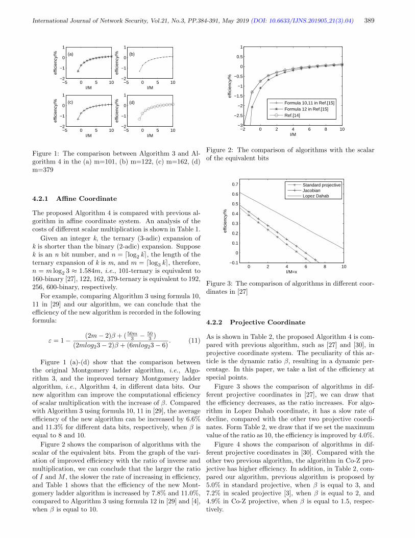
International Journal of Network Security, Vol.21, No.3, PP.384-391, May 2019 (DOI: 10.6633/IJNS.201905 21(3).04) 389
−5 0 5 10−2
−1
0
1
(a)
I/M
effic
ienc
y/%
−5 0 5 10−2
−1
0
1
(b)
I/M
effic
ienc
y/%
−5 0 5 10−2
−1
0
1
(c)
I/M
effic
ienc
y/%
−5 0 5 10−2
−1
0
1
(d)
I/M
effic
ienc
y/%
Figure 1: The comparison between Algorithm 3 and Al-gorithm 4 in the (a) m=101, (b) m=122, (c) m=162, (d)m=379
4.2.1 Affine Coordinate
The proposed Algorithm 4 is compared with previous al-gorithm in affine coordinate system. An analysis of thecosts of different scalar multiplication is shown in Table 1.
Given an integer k, the ternary (3-adic) expansion ofk is shorter than the binary (2-adic) expansion. Supposek is an n bit number, and n = dlog2 ke, the length of theternary expansion of k is m, and m = dlog3 ke, therefore,n = m log2 3 ≈ 1.584m, i.e., 101-ternary is equivalent to160-binary [27], 122, 162, 379-ternary is equivalent to 192,256, 600-binary, respectively.
For example, comparing Algorithm 3 using formula 10,11 in [29] and our algorithm, we can conclude that theefficiency of the new algorithm is recorded in the followingformula:
ε = 1−(2m− 2)β + ( 50m
3 −503 )
(2mlog23− 2)β + (6mlog23− 6). (11)
Figure 1 (a)-(d) show that the comparison betweenthe original Montgomery ladder algorithm, i.e., Algo-rithm 3, and the improved ternary Montgomery ladderalgorithm, i.e., Algorithm 4, in different data bits. Ournew algorithm can improve the computational efficiencyof scalar multiplication with the increase of β. Comparedwith Algorithm 3 using formula 10, 11 in [29], the averageefficiency of the new algorithm can be increased by 6.6%and 11.3% for different data bits, respectively, when β isequal to 8 and 10.
Figure 2 shows the comparison of algorithms with thescalar of the equivalent bits. From the graph of the vari-ation of improved efficiency with the ratio of inverse andmultiplication, we can conclude that the larger the ratioof I and M , the slower the rate of increasing in efficiency,and Table 1 shows that the efficiency of the new Mont-gomery ladder algorithm is increased by 7.8% and 11.0%,compared to Algorithm 3 using formula 12 in [29] and [4],when β is equal to 10.
−2 0 2 4 6 8 10−3
−2.5
−2
−1.5
−1
−0.5
0
0.5
1
I/M
effic
ienc
y/%
Formula 10,11 in Ref.[15]Formula 12 in Ref.[15]Ref.[14]
Figure 2: The comparison of algorithms with the scalarof the equivalent bits
0 2 4 6 8 10−0.1
0
0.1
0.2
0.3
0.4
0.5
0.6
0.7
I/M=x
effic
ienc
y/%
Standard projectiveJacobianLopez Dahab
Figure 3: The comparison of algorithms in different coor-dinates in [27]
4.2.2 Projective Coordinate
As is shown in Table 2, the proposed Algorithm 4 is com-pared with previous algorithm, such as [27] and [30], inprojective coordinate system. The peculiarity of this ar-ticle is the dynamic ratio β, resulting in a dynamic per-centage. In this paper, we take a list of the efficiency atspecial points.
Figure 3 shows the comparison of algorithms in dif-ferent projective coordinates in [27], we can draw thatthe efficiency decreases, as the ratio increases. For algo-rithm in Lopez Dahab coordinate, it has a slow rate ofdecline, compared with the other two projective coordi-nates. Form Table 2, we draw that if we set the maximumvalue of the ratio as 10, the efficiency is improved by 4.0%.
Figure 4 shows the comparison of algorithms in dif-ferent projective coordinates in [30]. Compared with theother two previous algorithm, the algorithm in Co-Z pro-jective has higher efficiency. In addition, in Table 2, com-pared our algorithm, previous algorithm is proposed by5.0% in standard projective, when β is equal to 3, and7.2% in scaled projective [3], when β is equal to 2, and4.9% in Co-Z projective, when β is equal to 1.5, respec-tively.

International Journal of Network Security, Vol.21, No.3, PP.384-391, May 2019 (DOI: 10.6633/IJNS.201905 21(3).04) 390
Table 1: Timing costs of different algorithm in affine coordinate system
Algorithm Total costs(n = dlog2 ke,m = dlog3 ke) Total costs(#I + #M)Formula 10,11 in [29] 2(n− 1)I + 4(n− 1)M + 2(n− 1)S (2n− 2)I + (6n− 6)M
Formula 12 in [29] 2(n− 1)I + 3(n− 1)M + 2(n− 1)C + 2(n− 1)S (2n− 2)I + (5n− 5)M[4] (2n− 3)I + (3n− 5)M + (3n− 5)S (2n− 3)I + (6n− 10)M
Ours 2(m− 1)I + 383 (m− 1)M + 16
3 (m− 1)C + 4(m− 1)S (2m− 2)I + 503 (m− 1)M
Table 2: Timing costs of different algorithm in projective coordinate system
Algorithm Coordinate Each iteration’s costs Total costs(#M) IM = β ε
Ref. [27](binary)
Standard projective 15M + 2S + 4C 17M 4 8.8%Jacobian 13M + 5S + 5C 18M 5 6.9%
Lopez Dahab 17M + 7S + 2C 24M8 17.9%10 4.0%
Ref. [30](binary)
Standard projective 13M + 2S + 2C 15M 3 5.0%Scaled projective [3] 14M + 3C 14M 2 7.2%
Co-Z projective 10M + 3S + C 13M 1.5 4.9%
Ours(ternary) Affine 2I + 38M3 + 16C
3 + 4S 2I + 50M3
HHHHH
HHHHH
−1 0 1 2 3 4
0
0.1
0.2
0.3
0.4
0.5
I/M=x
effic
ienc
y/%
Standard projectiveScaled projectiveCo−Z projective
Figure 4: The comparison of algorithms in different coor-dinates in [30]
In the actual experimental environment, I/M is differ-ent and relatively large. Table 2 shows that the efficiencyof new algorithm varies from 4% to 17.9%, compared withprevious algorithm in projective coordinate system.
5 Conclusions
In this paper, we proposed an improved Montgomery lad-der algorithm over GF(3m), and the scalar was expressedin ternary form. In addition, we derived composite op-eration formulas 2P1 + P2 and 3P1 with a lower compu-tational cost. Based on the original Montgomery ladderalgorithm, it is able to resist SPA. In analyzing efficiency,the difference with the past is that the ratio of I to M ,which is set to a dynamic value. Correspondingly, in-creased efficiency is also dynamic, ranging from 7.8% to11.3% in affine coordinate, and from 4% to 17.9% in pro-
jective coordinate. Further work may include designing anew scalar multiplication algorithm over GF(3m), and itmakes cubing operation faster.
References
[1] N. Christophe and J. M. Robert, “New parallel ap-proaches for scalar multiplication in elliptic curveover fields of small characteristic,” IEEE Transac-tions on Computers, vol. 64, no. 10, pp. 2875–2890,2015.
[2] M. Ciet, M. Joye, K. Lauter, and P. L. Montgomery,“Trading inversions for multiplications in ellipticcurve cryptography,” Designs, Codes and Cryptog-raphy, vol. 39, no. 2, pp. 189–206, 2006.
[3] R. R. Farashahi, H. F. Wu, and C. A. Zhao, “Efficientarithmetic on elliptic curves over fields of character-istic three,” in International Conference on SelectedAreas in Cryptography, pp. 135–148, Aug. 2012.
[4] H. H. Gu, W. L. Xie, and Ray C. C. Cheung,“Analysis the montgomery ladder algorithm for el-liptic curves over ternary fields,” in InternationalConference on Information and Network Security(ICINS’13), pp. 1–5, Nov. 2013.
[5] L. D. Han, Q. Xie, and W. H. Liu, “An improvedbiometric based authentication scheme with useranonymity using elliptic curve cryptosystem,” Inter-national Journal of Network Security, vol. 19, no. 3,pp. 469–478, 2017.
[6] D. Hankerson, A. Menezes, and S. Van-stone, Guide to Elliptic Curve Cryptogra-phy, Springer-Verlag New York, 2004. (http://citeseerx.ist.psu.edu/viewdoc/download?
doi=10.1.1.394.3037&rep=rep1&type=pdf)

International Journal of Network Security, Vol.21, No.3, PP.384-391, May 2019 (DOI: 10.6633/IJNS.201905 21(3).04) 391
[7] G. F. Hou and Z. J. Wang, “A robust and efficient re-mote authentication scheme from elliptic curve cryp-tosystem,” International Journal of Network Secu-rity, vol. 19, no. 6, pp. 904–911, 2017.
[8] C. Kakali, D. Asok, and Daya Gupta, “Mutual au-thentication protocol using hyperelliptic curve cryp-tosystem in constrained devices,” International Jour-nal of Network Security, vol. 15, no. 1, pp. 9–15,2013.
[9] N. Koblitz, “Elliptic curve cryptosystems,” Mathe-matics of Computation, vol. 48, no. 177, pp. 203–209,1987.
[10] P. Kocher, J. Jaffe, and B. Jun, “Differentialpower analysis,” Lecture Notes in Computing ScienceSpringer-Verlag, vol. 1666, pp. 388–397, 1999.
[11] K. Koyama and Y. Tsureoka, “Speeding up el-liptic curve cryptosystems by using a signed bi-nary windows method,” Advances in Cryptology(CRYPTO’92), pp. 345–357, 1992.
[12] H. K. Kwang, I. K. So, and S. C. Ju, NewFast Algorithms for Arithmetic on Elliptic CurvesOver Finite Fields of Characteristic Three, May2007. (http://citeseerx.ist.psu.edu/viewdoc/summary?doi=10.1.1.81.1113)
[13] L. Li, “Research on the ternary algorithm in the el-liptic curve operations,” Journal of Network SafetyTechnology and Application (in Chinese), no. 11,pp. 94–96, 2015.
[14] S. G. Liu, H. T. Yao, and X. A. Wang, “Spa re-sistant scalar multiplication based on addition andtripling indistinguishable on elliptic curve cryptosys-tem,” in 10th International Conference on P2P, Par-allel, Grid, Cloud and Internet Computing (3PG-CIC’15), pp. 785–790, Nov. 2015.
[15] J. Lopez and R. Dahab, “Fast multiplicationon elliptic curves over gf(2m) without precom-putation,” in First International Workshop onCryptographic Hardware and Embedded Systems(CHES’99), pp. 316–327, Aug. 1999.
[16] V. S. Miller, “Use of elliptic curves in cryptography,”Lecture Notes in Computer Science Springer-Verlag,vol. 218, no. 1, pp. 417–426, 1986.
[17] P. L. Montgomery, “Speeding the pollard and ellip-tic curve methods of factorization,” Mathematics ofComputation, vol. 48, no. 177, pp. 243–264, 1987.
[18] J. Moon, D. Lee, and J. Jung, “Improvement of effi-cient and secure smart card based password authen-tication scheme,” International Journal of NetworkSecurity, vol. 19, no. 6, pp. 1053–1061, 2017.
[19] C. Negre, “Scalar multiplication on elliptic curvesdefined over fields of small odd characteristic,” inProceedings of the 6th International Conference onCryptology (INDOCRYPT’05), pp. 389–402, Dec.2005.
[20] K. Okeya and T. Takagi, “The width-w naf methodprovides small memory and fast elliptic saclar mul-tiplications secure against side channel attacks,”Rsa Conference on the Cryptographers, pp. 328–343,2003.
[21] T. Oliveira, J. Lopez, and R. H. Francisco, “Themontgomery ladder on binary elliptic curves,” Jour-nal of Cryptographic Engineering, no. 5, pp. 1–18,2017.
[22] Q. Qian, Y. L. Jia, and R. Zhang, “A lightweightrfid security protocol based on elliptic curve cryptog-raphy,” International Journal of Network Security,vol. 18, no. 2, pp. 354–361, 2016.
[23] Reddy and E. Kesavulu, “Elliptic curve cryptosys-tems and side-channel attacks,” International Jour-nal of Network Security, vol. 12, no. 3, pp. 151–158,2011.
[24] T. Satoh, “The canonical lift of an ordinary ellipticcurve over a finite field and its point counting,” Jour-nal of the Ramanujan Mathematical Society, vol. 15,no. 4, pp. 247–270, 2000.
[25] S. F. Shen and M. Zhou, “Research on fast algo-rithms for scalar multiplication of elliptic curve cryp-tography over gf(3n),” Advances in Applied Mathe-matics (in Chinese), vol. 4, no. 4, pp. 390–399, 2015.
[26] C. S. Sin, Regular Ternary Algorithm for Scalar Mul-tiplication on Elliptic Curves Over Finite Fields ofCharacteristic Three, July 2012. (https://eprint.iacr.org/2012/390.pdf)
[27] N. P. Smart and E. J. Westwood, “Point multi-plication on ordinary elliptic curves over fields ofcharacteristic three,” Applicable Algebra in Engineer-ing, Communication and Computing, vol. 13, no. 6,pp. 485–497, 2003.
[28] S. F. Tzeng, M. S. Hwang, “Digital signature withmessage recovery and its variants based on ellipticcurve discrete logarithm problem”, Computer Stan-dards & Interfaces, vol. 26, no. 2, pp. 61–71, Mar.2004.
[29] H. Wang, B. Li, and W. Yu, “Montgomery algorithmon elliptic curves over finite fields of character three,”Journal on Communications (in Chinese), vol. 29,no. 10, pp. 25–29, 2008.
[30] W. Yu, B. LI, K. P. Wang, W. X. Li, and S. Tian,“Co-z montgomery algorithm on elliptic curves overfinite fields of characteristic three,” Chinese Journalof Computers (in Chinese), vol. 40, no. 5, pp. 1121–1133, 2017.
Biography
Shuang-Gen Liu is PhD, associate professor. His re-search interests are information security and cryptology.
Rong-Rong Wang is a graduate student of Xi’an Uni-versity of posts and telecommunications. She is mainlyengaged in the research of elliptic curve cryptosystem.
Yun-Qi Li is a undergraduate student in informationsecurity in Xi’an University of posts and telecommunica-tions. Her research interest is cryptography.
Can-Liang Zhai is a undergraduate student in informa-tion security in Xi’an University of posts and telecommu-nications. His research interest is cryptography.

International Journal of Network Security, Vol.21, No.3, PP.392-401, May 2019 (DOI: 10.6633/IJNS.201905 21(3).05) 392
A Fast Recovery Method for Single Disk FailureBased on EVENODD
Feng Xiao, Di Fan, and Dan Tang(Corresponding author: Dan Tang)
School of Software Engineering, Chengdu University of Information Technology
No. 24, Xue-Fu Road, Chengdu 610225, China
(Email: [email protected])
(Received Nov. 23, 2017; Revised and Accepted Apr. 28, 2018; First Online Jan. 12, 2019)
Abstract
In an array storage system based on EVENODD, the tra-ditional single disk failure recovery requires reading allthe remaining data. Even if the hybrid recovery methodis used, the theoretical limit of the data reading cost canbe reduced by only 25%.To further reduce the read over-head for single disk failure recovery, improve the reliabil-ity of storage system, this paper proposes an improvedmethod for EVENODD single disk failure recovery. Thismethod is to reduce the amount of data that needed toread during recovery by adding a local redundant.The ex-perimental results show that the improved method hassignificantly improved the recovery time comparing withthe EVENODD.
Keywords: EVENODD; Reading Overhead; Single DiskFailure
1 Introduction
In recent years, with the rapid development of societyand technology, the amount of data in the world is in-creasing at an explosive rate. As a result, the scale ofstorage systems is also growing accordingly. As the scaleincreases, the stability of the storage system is also fac-ing many great challenges. The main reason is that whilethe number of disks is increasing, the probability of dataloss caused by disk failures is also increasing. In order toprotect the data, it is necessary to recover the data evenafter the disk failed. Therefore, the time of data recoveryand the amount of the data that needed to be read duringthe recovery process become the key to the stability of thesystem.
Array codes is a kind of erasure code which is widelyapplied. Its advantage is the calculation is XOR so theencoding and decoding speed are pretty fast. The typicalarray codes include EVENODD [5], RDP [3], STAR [7],RTP [4] and so on. STAR and RTP are expanded byEVENODD and RDP respectively. However, there arestill many problems to be solved. Aiming at the prob-
lem of update efficiency, Chen put forward the InverseCode [2] by constructing low density matrix. Aiming atthe problem of data storage reliability and expansibility,Teng proposed the Random Array Code [10]. In orderto accelerate the speed of data recovery, Sun proposed anew coding theory named ESRC [9], which is based onlocal check and global check. In order to solve the prob-lem that the MDS array codes have a length limitation,Huang proposed a new code named Symmetric code [6].
EVENODD code is one of the most commonly usedarray codes in storage systems which can tolerate twoerrors. Its principle is to ensure the integrity of the databy adding two redundant disks. EVENODD can recoverthe original data correctly after any two of the disks failed.
For EVENODD coding, the advantages are that thestructure is simple, and the encoding and decoding pro-cess are based on XOR operation, so the speed is veryfast. However, one of the major defect is that the sin-gle disk failure recovery requires too much data to read.All the remaining raw data is need to be read. Consid-ering that the recovery is based on a single check disk, ifa local check disk is computed only by some of the datadisks, then when the data disk fails, only part of the datadisks that generate the local check disk can be recovered.Therefore, a fast recovery method for single disk failurebased on EVENODD is proposed.
2 Introduction of EVENODD
2.1 Encoding Process
The encoding process of EVENODD is based on an orig-inal data array, and the size of the original data array is(p − 1) ∗ p, p is a prime number. The data block in thearray is assumed to be ai,j , where i and j represent rowand column coordinates of elements. The coding formulasare shown in Equations (1),(2)and (3):
ai,p =
p−1⊕j=0
ai,j (1)

International Journal of Network Security, Vol.21, No.3, PP.392-401, May 2019 (DOI: 10.6633/IJNS.201905 21(3).05) 393
S =
p−1⊕j=1
ap−1−j,j (2)
ai,p+1 = S ⊕( p−1⊕
j=0
a<i−j>p,j
). (3)
The final coding process is shown in Figure 1.
Figure 1: Horizontal redundancy and diagonal redun-dancy calculation process
Finally, an array of (p−1)∗(p+2) with two redundantcolumns is obtained.
2.2 Single Disk Failure Recovery
The traditional single disk failure recovery method canbe divided into two categories according to the positionof the failed disk: data disk failure and redundant diskfailure.
The method of recovering from data disk failure is todetermine the location of the failed disk first, and thenread out all the other data blocks in data disks and hor-izontal redundant disk, and finally run XOR operationthrough these data, get the lost data disk. The data re-quired to be read during recovery is shown in Figure 2, the”X” indicates that the data block is lost and ”O” meansthe data block need to be read.
Figure 2: Data to be read from single disk failure recovery
The recovery of the redundant disk failure is exactlythe same as the coding process, that is, when the hori-zontal or diagonal redundant disk fails, it can be rebuiltby using encoding algorithm.
Therefore, for the method of traditional single disk fail-ure recovery, whether the data disk failed or redundantdisk failed, the number of data disks required is p.
2.3 Single Disk Failure Hybrid RecoveryAlgorithm
In order to reduce the recovery read overhead of singledisk failure, literature [1] proposes that, for EVENODDwhen a data disk fails, the horizontal redundancy and di-agonal redundancy can be used simultaneously to recover.Because there are some repeated data blocks needed inusing different methods to recover, so the recovery readoverhead can be reduced by caching these blocks. The-oretical deduction is also carried out in this paper, andit is found that the best recovery method is to recoverhalf of the data using horizontal redundancy, and recoverthe other half data using diagonal redundancy. And thelower bound of the theoretical recovery read overhead is3/4 of the total data, which means it can save 25% ofthe recovery read overhead. Similarly, a hybrid recoveryalgorithm for RDP single disk failure is proposed in theliterature [11]. The lower bound of the read overhead isalso 3/4 of the total data.
As it’s shown in Figure 3, when the Disk0 fails, thefirst two data blocks are recovered by horizontal redun-dant columns, and the latter two data blocks are recov-ered by diagonal redundancy. Among them the circle in-dicates that the data blocks used by horizontal redundantcolumns while square means the data blocks used by diag-onal redundant columns, and the data blocks which haveboth symbols mean they are repeated.
Figure 3: Using hybrid algorithm to recover single diskfailure
3 Local Repair Method of EVEN-ODD
In order to reduce the recovery read overhead of EVEN-ODD code in the single disk failure further, this paperhas modified this code. The transformation method iscalled EVENODD local repair method. And the ex-panded EVENODD is called LREVENODD (Local Re-pairable EVENODD).

International Journal of Network Security, Vol.21, No.3, PP.392-401, May 2019 (DOI: 10.6633/IJNS.201905 21(3).05) 394
3.1 Encoding Process
Local repairable EVENODD code is an extension ofEVENODD. A redundant column x is added on the basisof the original EVENODD with two redundant columns.Redundant column x is obtained by horizontal XOR com-putation of the previous p−1
2 data columns. The compu-tation formula is Equation (4):
ai,p+2 =
p−12⊕
j=0
ai,j (4)
Encoding process of Local repairable EVENODD codeis shown in Figure 4. The same shape of white blocksgenerate the corresponding black check blocks:
Figure 4: Encoding process of LREVENODD
3.2 Encoding Overhead
For the EVENODD local repair method, encoding pro-cess only adds a step in the traditional process of EVEN-ODD encoding. In the calculation of horizontal redun-dant columns, after XORing the first half of the data, theXOR result as local redundant column and save to diskX. Although this step increases the storage overhead andthe encoding time, it does not increase the computationalcomplexity. Moreover, with the increase of prime number,the proportion of increased overhead to the overall cod-ing overhead will continue to decline. Because the valuep in the real environment represents the number of disksin the storage cluster, it is generally larger, so the over-head caused by the increased local redundant column x isrelatively smaller.
3.3 Correctness Proof
Based on the definition in the upper section, the formerp+ 2 column of the Local Repairable EVENODD code isthe EVENODD code, so the nature of the former p + 2column is no longer discussed at next, and only the impactof the new local redundant column x loss is discussed
3.3.1 Only the X Column is Missing
If only the X column is missing, it means that all the datain the front p+ 2 columns is in good condition, and the Xcolumn can be generated by encoding Equation (4). Atthis point, the data integrity can be guaranteed.
3.3.2 X and Another Column Y Missing
First, suppose that another missing column is a data col-umn, then the horizontal redundant column is intact. Sothe data column can be recovered by XOR of all the re-maining data columns and the horizontal redundant col-umn. The computation formula is Equation (5):
ai,y =
p⊕j=0
ai,j (5)
When all the data columns have been rebuilt, the sit-uation is consistent with the loss of the X column, andthen the X column can be generated again by encoding.
If another missing column is a redundant column,which means all data columns are in good condition. So atfirst, the missing horizontal redundant column or diago-nal redundant column can be regenerated by EVENODDencoding. If the horizontal redundancy column is lost, thecoding formula of recovery is Equation (1). If the miss-ing redundant column is diagonal redundant column, thecoding formula of recovery is shown in Equation (2) andEquation (3).
After restoring the horizontal redundant column or di-agonal redundant column, only the X column still needsto be recovered. So the X column can be restored byEquation (4).
Through the analysis above, it can be concluded thatafter adding a local redundant column x, the new arraycode can still recover any two errors.
3.4 Relative Properties
3.4.1 MDS Property
It can be found that although the extended EVENODDcode adds a redundancy, but it can only tolerate any twoerrors (in some cases it can tolerate three errors) and losethe MDS property. The reason is that the local fault tol-erance is in conflict with MDS property. For example, RScodes remove the lost blocks and decode them with therest of the global blocks, so the locality is poor, but thereis good code distance, and has the best fault tolerance.EVENODD and all the MDS codes are like this. Theliterature [8] pointed out that if adds some local redun-dant columns, it means that there exists errors(missingcolumns is not related to these columns) that the local re-dundant columns can not be solved. Thus it can be seenthat the local fault tolerance and minimum code distanceare conflicted, which means it is inevitable to improve thelocal tolerance while sacrificing MDS property.
Furthermore, it is proved that the Local RepairableCodes with additional local redundant columns can beinfinitely approximated to MDS codes. Then, for a MDScode with only one redundant column, it can be provedthat, when the value p is increased, the LREVENODDcode can also be close to the MDS codes.

International Journal of Network Security, Vol.21, No.3, PP.392-401, May 2019 (DOI: 10.6633/IJNS.201905 21(3).05) 395
3.4.2 The Relationship Between New Redun-dancy and Overhead Reduction
By discussing MDS property, it can be concluded thatincreasing local redundant columns and ensuring MDSproperty are conflicted. The paper [12] pointed out thatappropriate data redundancy can improve system per-formance. Therefore, it is necessary to explore the re-lationship between redundant columns number and re-duced overhead to determine how much local redundancyis added to achieve optimal.
In order not to increase the complexity of the encodingprocess, the redundant columns are selected by sharingthe original data columns. The number of local redundantcolumns is n, and the percentage of saved overhead is cp,then the ratio of new redundancy and overhead is l = cp
n .Assuming that the additional local redundancy columnsare 1, 2, 3, 4 and 5, the obtained results are shown inTable 1:
Table 1: Relationship between new redundancy and over-head reduction
symbol valuecp 50% 67% 75% 80% 83%n 1 2 3 4 5l 50% 33% 25% 20% 17%
It can be seen from the table that with the increase ofthe number of local redundant columns, the saved readoverhead is also increasing, but the reduction of the over-head caused by the new redundancy is decreasing, thatis, the efficiency is decreasing. And adding redundantcolumns will bring more storage overhead, and will alsoinfluence the efficiency of encoding and decoding. So thechoice of adding only a local redundant column can signif-icantly reduce the single disk failure recovery read over-head and does not increase the excessive storage overheadand lead to system performance degradation.
4 Decoding Process
4.1 Single Disk Failure
For traditional EVENODD coding, the recovery of singledisk failure (non redundant columns) is done by readingthe remaining data columns and the horizontal redundantcolumns to xor. For the EVENODD local repair method,there are two situations to repair a single disk failure.
First, suppose the data column fails, then it can bedivided into two cases, one is the missing data columnis in the first half, and the other is in the second half.If the missing column is in the first p−1
2 columns, it isnecessary to read the first half part of the remaining datacolumn and the new local redundant column x for XORrestoration. The data block needed to recover is shown
in Figure 5, the ”X” indicates that the data block is lost,”O” means the data blocks which are required in recover.
Figure 5: Data need to read when missing column is infirst part
If the missing column is in the posterior p+12 columns,
the local redundancy column X and the horizontal redun-dant column p can be read first, then XOR them, andthe result is the XOR of the data column in the secondhalf. Then read the data columns in the second half, andXOR with the previous result, to get the missing datacolumn. The data blocks needed for recovery are shownin Figure 6.
Figure 6: Data need to read when missing column is insecond part
It can be concluded that the amount of data needed torecover from single disk failure is p−1
2 and p+12 respectively
in two cases. When p is increasing, the reduced readoverhead tends to approach 50%.
If the local redundant column fails, it is necessary toread the first p−1
2 data columns for restoration, which iscompletely equivalent to the encoding process. This sit-uation does not exist in the EVENODD codes, and therecovery read overhead remains p−1
2 . When p is increas-ing, the proportion of local redundant column fails to allsingle disk failures will continue to decrease.
In case of horizontal redundant column fails, only theposteriors p+1
2 data columns and the local redundant col-
umn are needed to recover. Read overhead is only p+12 +1.
When p is increasing, it can reduce the data reading over-head approaching to 50%. The data blocks required forthe recovery of horizontal redundant column failure areshown in Figure 7.
For the case of diagonal redundant column fails, theEVENODD local repair method is consistent with the tra-ditional EVENODD recovery algorithm, that is, read all

International Journal of Network Security, Vol.21, No.3, PP.392-401, May 2019 (DOI: 10.6633/IJNS.201905 21(3).05) 396
Figure 7: Data need to read when horizontal redundantcolumn is missing
data columns to encode and get the redundant columns,and the read overhead is p. Similarly, the ratio of this fail-ure to all single disk failures will continue to decrease as pcontinues to increase. Therefore, for single disk failure re-covery, assuming that the probability of each disk failureis consistent, the average overhead of the LREVENODDsingle disk failure recovery is shown in Equation (6):
c =p−12 ∗ p−1
2 + p+12 ∗ p+3
2 + p+32 + p+ p−1
2
p+ 3(6)
According to the analysis above, it can be concludedthat the single disk failure recovery overhead of LREVEN-ODD approach nearly p
2 , and Figure 8 is a theoreticalcomparison between the EVENODD and the LREVEN-ODD single disk failure recovery overhead when p takesdifferent values.
Figure 8: Comparison of single disk failure recovery read-ing overhead
Compared with the traditional EVENODD recoveryalgorithm, the proposed method saves 50% of the dataread overhead in the single disk failure recovery, whilethe recovery of redundant columns is almost consistentwith the traditional EVENODD read overhead. Becausethe number of data columns in practical applications ismuch larger than the number of redundant columns, itcan be concluded that the method reduces the data readoverhead by nearly 50% for single disk failure recovery.
4.2 Double Disk Failures Recovery
4.2.1 Two Data Column Missing
Like traditional recovery methods, recovery is done byreading the remaining data and using horizontal redun-dancy and diagonal redundancy when two data columnsfailed in LREVENODD. Data read overhead is shown asEquation (7):
cp = p− 2 + 2 = p. (7)
4.2.2 One Data Column and Local RedundantColumn Missing
First, by reading the remaining data columns and hor-izontal redundant column to recover the lost data col-umn, and cache the xor result of the previous p−1
2 datacolumns(don’t xor the missing column, but xor it withthe cache result when restored it ), the final xor result isthe missing local redundant column.
As shown in Figure 9, when the second data columnand the local redundant column are lost, the remainingintact data columns and horizontal redundant columnsare first read to recover the lost second data column. Atthe same time, the XOR results are saved in the process.After calculating the second column data, xor the resultwith the second data column, and the local redundantcolumn is obtained.
Figure 9: Data need to read when local redundant columnand one data column are missing
As shown in Figure 9, the read overhead of recovery inthis case is still p columns.
4.2.3 One Data Column and Horizontal or Diag-onal Redundant Column Missing
The recovery method in this situation is consistent withthe traditional EVENODD recovery method. The readingoverhead is p.
4.2.4 Two Redundant Columns Missing
The recovery method in this situation is consistent withthe encoding process. So obviously, the reading overheadis p.
In summary, the EVENODD local repair method cangreatly reduce the read overhead and improve the per-formance when the single data disk fails. For other cases,

International Journal of Network Security, Vol.21, No.3, PP.392-401, May 2019 (DOI: 10.6633/IJNS.201905 21(3).05) 397
the EVENODD local repair method does not produce toomuch overhead, and is basically consistent with the tra-ditional EVENODD.
4.3 Triple Disk Failures Recovery
Although the extended EVENODD loses its MDS prop-erty, it can still be successfully restored for most of thethree disk failures. Then analysis in which case the threedisk failure can be restored when p = 7.
The three redundant columns in the extended EVEN-ODD can be represented by the following equations:
ai,p =
p−1⊕j=0
ai,j (i = 0, 1, ..., p− 2)
aj,p+1 = S ⊕( p−1⊕
j=0
a<i−j>p,j
)(i = 0, 1, ..., p− 2)
ai,p+2 =
p−12⊕
j=0
ai,j (i = 0, 1, ..., p− 2).
Meanwhile, assume the probability of each disk failureis γ.
4.3.1 Three Data Disks Missing
When three disks are lost and the three disks are all datadisks, the probability is shown as Equation (8).
λ = C3p ∗ γ3 (8)
When the lost disks are all data disks, for the horizontalredundant disk, each of the equations contains 3 unknownquantities. For diagonal redundant disk, each equationcontains at least 2 unknown quantities. The problem thenturns into whether the situation can be translated intotwo disks lost, i.e. whether a disk exists in the three lostdisks can be recovered by the local redundant disk. Wediscuss the situation according to the position distributionof the three data disks:
First, the three column data disks are in the front p−12
disks or back p+12 disks, the probability of such a situation
is shown as Equation (9).
λ = C3p−12
∗ γ3 + C3p+12
∗ γ3 (9)
First, suppose that three disks are in the previous p−12
disks, as shown in Figure 10. Assuming each column rep-resents a data disk, for a local redundant disk, each of itsequations contains 3 unknown quantities and is not solv-able. And if three disks are in posteriors p+1
2 disks is alsosimilar, because the disks in the back are not a linear re-lationship with the local redundant disk, it is impossibleto recover the local redundant disk. And only throughthe other two redundant disks to restore has too manyunknown disks, so this situation is not solvable.
Figure 10: Can not recover from missing three data disksin same part
Assuming there is a disk in the three data disks not inthe same half with the other two disks, the probability ofthis kind of case is shown as Equation (10).
λ = C1p−12
∗ C2p+12
∗ γ3 + C2p−12
∗ C1p+12
∗ γ3 (10)
First, suppose that there is a lost disk in the previousp−12 disks and the other two lost disks are in the second
half, then there is only one unknown quantity in eachequation that constitutes a local redundant disk. So it canbe solved. When the first lost disk is restored, the problemis transformed into an ordinary double disk failure, so thesituation is solvable.
If there are two disks lost in the previous p−12 disks
and one in the second half. Then the equations of thehorizontal redundant disk and the equations that consti-tute the local redundant disk can be subtracted, and a setof equations about the latter p+1
2 disks can be obtained,shown as Equation (11).
ai,p − ai,p+2 =
p−1⊕j= p−1
2
ai,j (11)
In these equations, each has only one unknown quan-tity and can be solved. When the missing data is restored,the problem is transformed into an ordinary double diskfailure again. So the situation is also solvable.
4.3.2 Two Data Disks and One Redundant DiskMissing
When there are three disks lost, two of them are datadisks, and the other one is redundant disk, and the prob-ability of this case is shown as Equation (12).
λ = C2p ∗ C1
3 ∗ γ3 (12)
This situation can be divided into several types accord-ing to the redundant disk type, in which the probabilityof each case is shown as Equation (13).
λ = C2p ∗ γ3 (13)
First, if the lost disk is a local redundant disk, it isequivalent to the normal EVENODD double disk failure

International Journal of Network Security, Vol.21, No.3, PP.392-401, May 2019 (DOI: 10.6633/IJNS.201905 21(3).05) 398
recovery. After the completion of the restoration, the localredundant disk can be restored by encoding.
If the lost disk is horizontal redundant disk, then itcan be classified according to the distribution of the datadisks.
When the two disks are in the first half, the propertyof EVENODD shows that there is always only one un-known ai,j in the equations of the diagonal redundantdisk. Through diagonal redundancy can calculate this un-known quantity ai,j . And then there is only the unknownquantity ai,k in the same row, and it can be calculatedthrough the local redundancy. And after ai,k is calcu-lated, there is only one unknown quantity on the line andit located which slope is 1. And by repeating these steps,it can solve all the unknowns.
If the two disks are in the second half, because the localredundancy is independent of the latter p+1
2 disks, theycan only be solved by diagonal redundancy. The previ-ous discussion shows that although the diagonal redun-dancy can solve an unknown quantity ai,j , but the otherunknown quantity in the same line depends on other re-dundancy to solute. While there is no other redundantexistence at the same time, so it can not be solved. Theprobability of this case is shown as Equation (14).
λ = C2p+12
∗ γ3 (14)
Assuming there is a data disks in the previous p−12 disks
while the other is in the second part, the probability ofsuch a situation is shown as Equation (15).
λ = C1p−12
∗ C1p+12
∗ γ3 (15)
There is only one unknown quantity existed in eachequation that constitutes a local redundant disk. So itcan be solved. When the first lost disk is restored, thereis still one data disk and horizontal redundant disk aremissing, which can be restored by the traditional RDPdouble disk recovery method. So this situation is solvable.
If the lost disk is redundant disk, then it can be clas-sified according to the distribution of the data disk.
Assuming the two disks are both in the previous p−12
disks or in the second half, the probability of this hap-pening is shown as Equation (16).
λ =(C2
p−12
+ C2p+12
)∗ γ3 (16)
When the two lost data disks are in the first half, eventhough there are two redundant disks, the two redundantdisks are linearly related, so the two missing disks can notbe restored. And when the two disks are in the secondhalf, there is only horizontal disk related to the lost disk,so it can not be recovered either.
If one of the two disks is in the first half and the otherin the second half, they can be restored. Because the lostdisk in the first half can be restored by the local redun-dant disk, the remaining lost data disk can be restoredby the horizontal redundant disk. Finally, the diagonalredundant column is restored by the encoding algorithm.
4.3.3 One Data Disk and Two Redundant DisksMissing
Assuming there are three disks lost, one is a data disk,and the other two are redundant disks, the probability ofthis case is shown as Equation (17).
λ = C1p ∗ C2
3 ∗ γ3 (17)
In consideration of that only one data disk is lost, ifthe intact redundant disk is a horizontal redundant diskor a diagonal redundant disk, the data disk can be re-stored, and then the lost redundant disks can be restoredby encoding.
Assuming the remaining redundant disk is local redun-dant disk, the probability of such a situation is shown asEquation (18).
λ = C1p ∗ γ3 (18)
This situation needs to be classified according to thelocation of the data disk.
If the lost data disk is in the front half, the data diskcan be recovered through a local redundant disk, and thenother redundant disks are restored by encoding.
And assuming the missing data disk is in the secondhalf, the probability of such a situation is shown as Equa-tion (19).
λ = C1p+12
∗ γ3 (19)
Because the local redundant disk is linear independentof the latter part, and it is impossible to recover the lostdata disk only by diagonal redundancy, so the situationis not solvable.
4.3.4 Three Redundant Disks Missing
If the lost three disks are redundant disks, they can berestored directly by encoding again.
From the above discussion, we can get the sum of theprobability of the non-solvable cases, which are shown asEquation (20).
λ =(C3
p−12
+ C3p+12
+ C2p+12
+
(C2p−12
+ C2p+12
) + C1p+12
)∗ γ3 (20)
And the probability of three disk failures is shown asEquation (21).
λ = C3p+3 ∗ γ3 (21)
Therefore, the proportion of non-recoverable cases ofall three disk failures is shown as the following equation:
Ω =
(C3
p−12
+ C3p+12
+ C2p+12
+ (C2p−12
+ C2p+12
) + C1p+12
)C3
p+3
From the above equation, it can be concluded thatwhen the p tends to infinity, the probability of unable to

International Journal of Network Security, Vol.21, No.3, PP.392-401, May 2019 (DOI: 10.6633/IJNS.201905 21(3).05) 399
recover in the three disk failure is Ω = 14 , that is to say,
for the LREVENODD, 75% of the three disk failures canbe recovered. And because in practice, the probability ofthree disk failures is much lower than the single disk fail-ure, so the EVENODD extended by using the local repairalgorithm is closer to MDS codes.
5 Performance Test
This section tests and compares the performance ofthe single disk failure recovery between EVENODD andLREVENODD. The machine parameters in the experi-mental environment cluster are: CPU Intel Core i7-3632,memory 8GB, disk 500GB, test file size 10M.
5.1 Encoding Test
Figure 11 gives the coding time of EVENODD andLREVENODD when the prime takes different values.
Figure 11: Coding time comparison
5.2 Single Disk Failure Recovery Test
Figure 12 gives a single disk failure recovery time when pis determined and block size is different. And Figure 13gives a single disk failure recovery time when p takes dif-ferent values.
Through the test results, it can be found that whenthe p increases and the block file size increases, the recov-ery overhead of single disk failure decreases. When p=17and block file size is 5000Bytes, the overhead is reducedby 44%. And Figure 14 gives a comparison of the fileblock used in single disk failure recovery process betweenEVENODD and LREVENODD.
As shown in Figure 14, it can be found that when thenumber of file blocks increases, the number of data blocksrequired for single disk failure recovery in LREVENODDis closer to 50% of the number in EVENODD.
Figure 12: Single disk failure recover time in determing p
Figure 13: Single disk failure recover time in determingblock file size
Figure 14: Single disk failure recovery reading overhead

International Journal of Network Security, Vol.21, No.3, PP.392-401, May 2019 (DOI: 10.6633/IJNS.201905 21(3).05) 400
5.3 Double Disk Failure Recovery Test
Figure 15 shows the recover time in double disk failurewhen the prime number p is different while block size isdetermined.
Figure 15: Double disk failures recover time
5.4 Triple Disk Failure Recovery Test
Figure 16 shows the unrecoverable times when 10000triple disk failures occured with different prime number.
Figure 16: Times of unrecoverable triple disk failure
By Figure 16 knowable, when p increases, the numberof non recoverable times is gradually approaching 2500times, which is 25% of the total number of triple diskfailure. Figure 17 shows the average recovery time of thetriple disk failure when the file size is large and the primenumber p takes different values.
6 Conclusions
Aiming at the problem that the read overhead of singledisk failure recovery in EVENODD is too large, this pa-per proposes a method to reform it. Combining LRC with
Figure 17: Decoding time in triple disk failure
RS codes, local repair method is used to improve EVEN-ODD codes. The local repair method reduces the readoverhead of single disk failure recovery by adding a newredundant column. The experimental results showed thatthe improved EVENODD code with local repair methodcan effectively reduce the read overhead of single disk fail-ure recovery and improve the system performance. Infact, this method is not only applicable to EVENODD,but also can be used for RDP, STAR and RTP codes andmany other slope codes, and the relevant proof and testneed to be further completed.
Acknowledgments
This study was supported by the National Natural Sci-ence Fund of China 61501064 and Science and technologyprogram of Sichuan 2018GZ0099. The authors gratefullyacknowledge the anonymous reviewers for their valuablecomments and teacher’s hard cultivation.
References
[1] Q. Chang, Y. Xu, L. Xiang, and Y. Pan, ”A hybridrecovery algorithm for single disk failure in evenodd(in chinese),” Computer Applications and Software,vol. 28, no. 6, pp. 15–18, 2011.
[2] L. Chen, D. Yuan, P. Teng, and X. Wang, ”Inversecode: A low density mds horizontal array code thatcan accommodate 3 errors (in chinese),” Journalof Sichuan University (Engineering Science Edition),no. 5, pp. 135–142, 2017.
[3] P. Corbett, B. English, A. Goel, T. Grcanac, S.Kleiman, J. Leong, and S. Sankar, ”Row-diagonalparity for double disk failure correction,” in UsenixConference on File and Storage Technologies, pp. 1–1, 2004.
[4] A. Goel and P. Corbett, ”Raid triple parity,” AcmSigops Operating Systems Review, vol. 46, no. 3, pp.41–49, 2012.

International Journal of Network Security, Vol.21, No.3, PP.392-401, May 2019 (DOI: 10.6633/IJNS.201905 21(3).05) 401
[5] R. Hu, G. Liu, and J. Jiang, ”An efficient cod-ing scheme for tolerating double disk failures,” inIEEE International Conference on High Perfor-mance Computing and Communications, pp. 707–712, 2010.
[6] Z. Huang, Research on MDS Array Code in Fault-Tolerant Storage System, PhD thesis, Huazhong Uni-versity of Science and Technolog, 2016.
[7] C. Huang and L. Xu, ”Star: An efficient codingscheme for correcting triple storage node failures,” inConference on Usenix Conference on File and Stor-age Technologies, pp. 15–15, 2005.
[8] M. Sathiamoorthy, M. Asteris, D. Papailiopou-los, A. G. Dimakis, R. Vadali, S. Chen, and D.Borthakur, ”Xoring elephants: Novel erasure codesfor big data,” Proceedings of the Vldb Endowment,vol. 6, no. 5, pp. 325–336, 2013.
[9] D. Sun, Research on Verification Update and RepairOptimization Technology for Fault-Tolerant StorageSystem, PhD thesis, University of Science and Tech-nology of China, 2017.
[10] P. Teng, J. Zhang, L. Chen, and X. Wang, ”Randomarray code: A raid storage disaster recovery methodwith high disaster tolerance and scalability,” Journalof Sichuan University (Engineering Science Edition),vol. 49, no. 3, pp. 110–116, 2017.
[11] L. Xiang, Y. Xu, J. C. S. Lui, and Q. Chang, ”Opti-mal recovery of single disk failure in rdp code storagesystems,” Acm Sigmetrics Performance EvaluationReview, vol. 38, no. 1, pp. 119–130, 2010.
[12] L. Xu and J. Bruck, ”Highly available distributedstorage systems,” A Caltech Library Service, vol.249, pp. 307–330, 1999.
Biography
Feng Xiao, master candidate. He is currently an Mas-ter student in Chengdu University of Information Tech-nology, Chengdu, China. His research interests includecoding theory and database theory.
Di Fan, master candidate. She is currently an Masterstudent in Chengdu University of Information Technol-ogy, Chengdu, China. Her research interests include cod-ing theory and information security.
Dan Tang received his Ph.D. degree from Graduate Uni-versity of Chinese Academy of Sciences (CAS), Beijing,China in 2010. He is currently an associate professor withChengdu University of Information Technology, Chengdu,China. His research interests include coding theory andsecret sharing scheme.

International Journal of Network Security, Vol.21, No.3, PP.402-408, May 2019 (DOI: 10.6633/IJNS.201905 21(3).06) 402
A Pseudo Random Bit Generator Based on aModified Chaotic Map
Chokri Nouar and Zine El Abidine Guennoun(Corresponding author: Chokri Nouar)
Department of Mathematics, Mohamed V University in Rabat
No. 4, Avenue Ibn Battouta B. P. 1014 RP, Rabat, Morocco
(Email: corresponding [email protected])
(Received Dec. 11, 2017; Revised and Accepted Apr. 8, 2018; First Online Jan. 14, 2019)
Abstract
This paper presents a new pseudo random bit generatorbased on a modified Gingerbreadman chaotic system, Thenew model has been well studied to avoid fixed and peri-odic points. We have verified that the system’s Lyapunovexponent is positive, which means the system is a chaoticone. The randomness of the bits generated by the pro-posed generator is successfully tested by the NIST. Wenotice that during the execution of the algorithm, thepassword changes automatically after a number of itera-tions.
Keywords: Chaotic Systems; Gingerbreadman Map; Lya-punov Exponent; NIST; Pseudo-random Bit Generator
1 Introduction
In the mathematical theory, introduced by Devaneyin 1988, the Gingerbreadman map is a simple two-dimensional chaotic map. Several studies, which were de-voted to the Gingerbreadman map, show the existence offixed and periodic points [4]. This property is undesirableby cryptography.
The idea of designing a pseudo-random bit generatorby making use of chaotic first order nonlinear differen-tial equation was proposed by Oishi and Inoue [9] in1982. After their paper, several pseudo-random bit gen-erators were suggested. Notice that the algorithms basedon chaos showed a good performance for data encryptionsuch as images, videos or audio data [8].
The aim of this paper is to propose a new pseudo-random bit generator based on a chaotic system. We will,firstly, try to eliminate the fixed and periodic points byadding a perturbation function. Then we will verify thatthe modified Gingerbreadman map is a chaotic systemthat includes appropriate features such as high sensitiv-ity to initial conditions, unpredictability, mixing propertyand high complexity. This will allow the system to inte-grate into various cryptographic applications.
The rest of this paper is structured as follows: the first
section presents how the chaotic system affects the pro-duced sequences. In the second section, basic definitionsof Lyapunov exponent and The Gingerbreadman map willbe recalled. In the third section, we will test the modi-fied Gingerbreadman chaotic system. In section four, wepresent a detailed description of our generator. Beforeconcluding, the statistical analysis and validation of thebits sequences generated by our generator are given insection five.
2 Chaotic System
A chaotic system is a non-linear deterministic dynamicalsystem, which exhibits pseudo-random behaviour. Theoutput values of a chaotic system vary depending on spe-cific parameters and initial conditions. Different param-eter values yield different periods of oscillations at theoutput of the system.
Chaotic sequences produced by a chaotic system arepseudo-random ones, their structures are very complexand difficult to analyse and to predict. These sequencesappear totally random to an external observer, in spiteof their deterministic generation, as they are sensitivelydependent on initial conditions. In other words, chaoticsystems can improve the security of encryption systems.
In mathematics, ”Lyapunov exponent” is a quantitythat measures the speed at which those small differencesare amplified; it actually measures the degree of sensi-tivity of chaotic systems. Those that have a chaotic be-haviour are defined as a chaotic map [10].
The two following sections present a brief descriptionof the Lyapunov exponent and the chaotic map (Ginger-BreadMan) used in this paper.
2.1 Lyapunov Exponent
In chaotic systems, the distance between two initiallyclose trajectories tends to increase at an exponential speedand then stabilizes when the distance reaches a limitvalue.

International Journal of Network Security, Vol.21, No.3, PP.402-408, May 2019 (DOI: 10.6633/IJNS.201905 21(3).06) 403
The Lyapunov exponent is an approximate quantitythat measures the exponential divergence of initially closetrajectories, it also estimates the amount of chaos in anysystem.
Definition 1. The Lyapunov exponent L computed usingthe derivative method is defined by
L = 1/n(ln | f ′(x1) | +ln | f ′(x2) | + · · ·+ ln | f ′(xn) |)
where f ′ represents differentiation with respect to x andx1, x2...xn are successive iterates. The Lyapunov expo-nent may be computed for a sample of points near theattractor to obtain an average Lyapunov exponent. [6]
Theorem 1. If at least one of the average Lyapunov ex-ponents is positive, then the system is chaotic; if the av-erage Lyapunov exponent is negative, then the orbit is pe-riodic. However when the average Lyapunov exponent iszero, a bifurcation occurs [7].
2.2 The Gingerbreadman Map
In dynamical systems theory, the System (1) is called ”theGingerbreadman map.” It was investigated by Devaney in1984 as a simple module of a chaotic two-dimensional mappresented by the following transformation:
xn+1 = 1− yn+ | xn |yn+1 = xn
(1)
The Gingerbreadman map is a piecewise linear appli-cation, which has been shown to be chaotic in certainregions and stable in others. Figures 1 and 2 displays thefirst iterations of (−0, 2; 0, 2).
Figure 1: 10000 iterates Figure 2: 20000 iterates
Despite its good property, algorithms [3] proved thatthe Gingerbreadman map has fixed and periodic pointsin the hexagonal as shown in Figure 3.
3 A Proposed Chaotic System
3.1 Description of the Proposed System
In order to avoid these fixed and periodic points, we addthe perturbation function f(yn) = r × sin(yn) to the sec-ond equation in the Gingerbreadman system, where r isa non-arbitrarily chosen real parameter. Therefore, the
Figure 3: Periodic and fixed points of Gingerbreadmanmap
new model of Gingerbreadman map (NMGM) is given bythe following system
H =
xn+1 = 1− yn+ | xn |yn+1 = xn + r × sin(yn)
(2)
The aforementioned perturbation function is simple andperiodic function to ensure that the dynamical systemremains non-linear and deterministic; that is, it does nottend to infinity. It should be noted that it is possible toreplace the sin(yn) with cos(yn) as shown in the Figures 4and 5.
Figure 4: Gingerbread-man with cos(y) and r =3.8
Figure 5: Gingerbread-man with sin(y) and r =3.8
In the next section, we determine the intervals of theparameter r for which the system remains chaotic, byusing the Lyapunov exponent.
3.2 Chaotic Tests of the Proposed Sys-tem
The Lyapunov exponent of the proposed system variesdepending on the parameter r.
The Figure 6 gives the curve of the Lyapunov exponentin function of the parameter r. One can remark that theLyapunov exponent of the new model of Gingerbreadman

International Journal of Network Security, Vol.21, No.3, PP.402-408, May 2019 (DOI: 10.6633/IJNS.201905 21(3).06) 404
map (NMGM) is positive when r > 2 for x0 = 0 andy0 = 0, which implies that the proposed system is chaotic.
Figure 6: The Lyapunov exponent of the proposed system
Another simple method used to determine whether ornot a system is chaotic, is to use the sensitivity to initialconditions. Figures 7, 8, 9 and 10 show how the attrac-tors of the NMGM are affected by small differences in theinitial conditions.
Figure 7: NMGM withr = 3.8, y0 = 0 and x0 =0.1
Figure 8: NMGM withr = 3.8, y0 = 0 and x0 =0.1 + 0.1× 10⁻⁶
Figure 9: NMGM withr = 3.8, y0 = 0 and x0 =0.1 + 0.1× 10⁻⁹
Figure 10: NMGM withr = 3.8, y0 = 0 and x0 =0.1 + 0.1× 10⁻¹²
3.3 Comparison of the Bifurcation andLyapunov Exponent
In this section, the comparison between our system andGingerbreadman map is presented. Figures 1 and 2 showsthe bifurcation diagrams of Gingerbreadman map. It isapparent from comparison of Figures 7, 8, 9 and 10, thebifurcation of our system is well distributed.
Figures 11, 12, 13 and 14 shows the Lyapunov expo-nent of NMGM is more than 0.6 where the Lyapunovexponent of Gingerbreadman map is less than 0.15. Sowe can concluded that, the NMGM is more chaotic.
Figure 11: Gingerbread-man map y0
Figure 12: Gingerbread-man map x0
Figure 13: NMGM with y0Figure 14: NMGM withx0
4 Designing a PRBG Based onthe NMGM
Our pseudo-random bit generator based on the new modelof Gingerbreadman map (PRBG-NMGM) is a determin-istic generator initialized by a password Pw of any size,whose output is a cryptographically secure binary se-quence.
The initial conditions of our system (NMGM) x0, y0and r0 are calculated from the password Pw by a methodbased on a pointer that is positioned on a bit of the Pw.The pointer moves from a position to another accordingto a linear congruential throughout the ASCII represen-tation of the Pw [2].
After a predetermined number of iterations performedfor the three initial conditions x0, y0 and r0, we startgenerating the numbers needed to construct the final se-quence S = S1...Sn with Si = Xi ⊕ Yi, where Xi and Yiare two 32-bit numbers generated in the ith step.
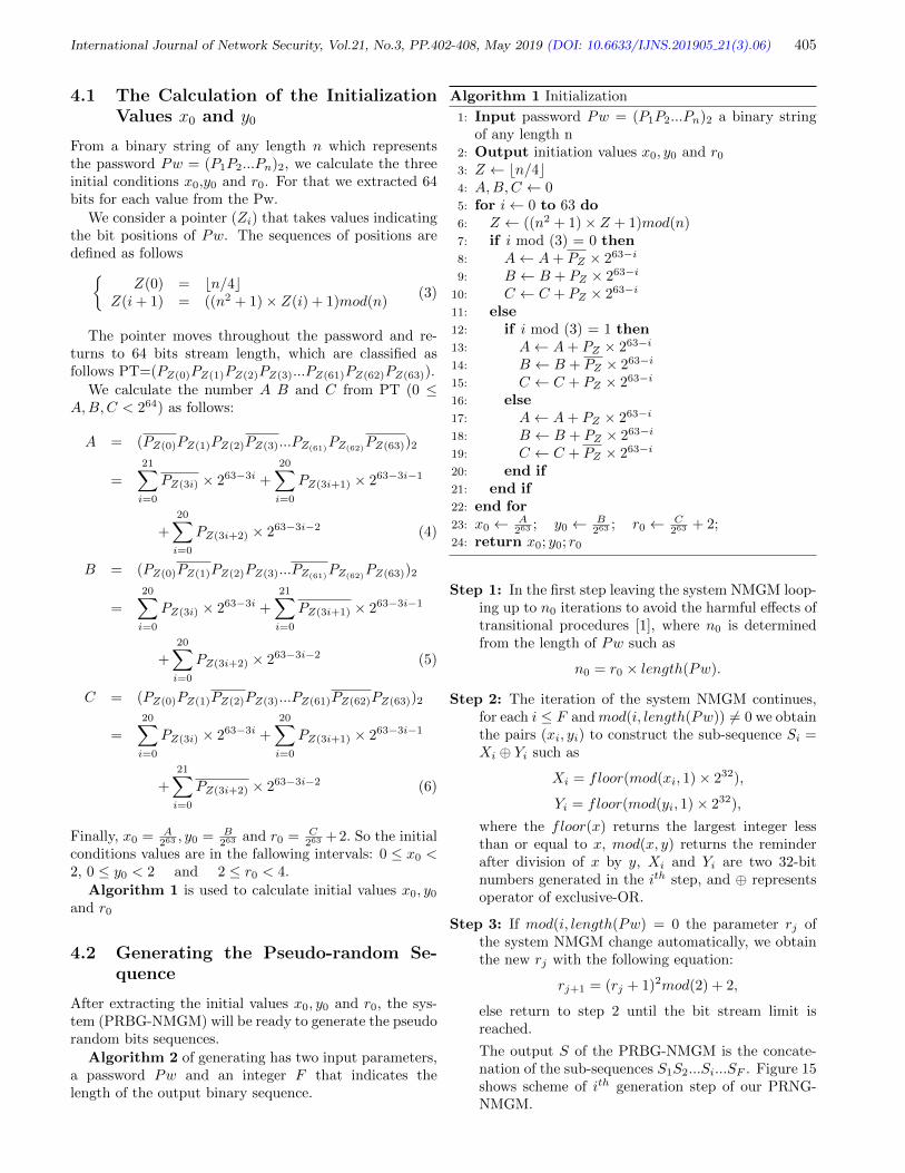
International Journal of Network Security, Vol.21, No.3, PP.402-408, May 2019 (DOI: 10.6633/IJNS.201905 21(3).06) 405
4.1 The Calculation of the InitializationValues x0 and y0
From a binary string of any length n which representsthe password Pw = (P1P2...Pn)2, we calculate the threeinitial conditions x0,y0 and r0. For that we extracted 64bits for each value from the Pw.
We consider a pointer (Zi) that takes values indicatingthe bit positions of Pw. The sequences of positions aredefined as follows
Z(0) = bn/4cZ(i+ 1) = ((n2 + 1)× Z(i) + 1)mod(n)
(3)
The pointer moves throughout the password and re-turns to 64 bits stream length, which are classified asfollows PT=(PZ(0)PZ(1)PZ(2)PZ(3)...PZ(61)PZ(62)PZ(63)).
We calculate the number A B and C from PT (0 ≤A,B,C < 264) as follows:
A = (PZ(0)PZ(1)PZ(2)PZ(3)...PZ(61)PZ(62)
PZ(63))2
=
21∑i=0
PZ(3i) × 263−3i +
20∑i=0
PZ(3i+1) × 263−3i−1
+
20∑i=0
PZ(3i+2) × 263−3i−2 (4)
B = (PZ(0)PZ(1)PZ(2)PZ(3)...PZ(61)PZ(62)
PZ(63))2
=
20∑i=0
PZ(3i) × 263−3i +
21∑i=0
PZ(3i+1) × 263−3i−1
+
20∑i=0
PZ(3i+2) × 263−3i−2 (5)
C = (PZ(0)PZ(1)PZ(2)PZ(3)...PZ(61)PZ(62)PZ(63))2
=
20∑i=0
PZ(3i) × 263−3i +
20∑i=0
PZ(3i+1) × 263−3i−1
+
21∑i=0
PZ(3i+2) × 263−3i−2 (6)
Finally, x0 = A263 , y0 = B
263 and r0 = C263 +2. So the initial
conditions values are in the fallowing intervals: 0 ≤ x0 <2, 0 ≤ y0 < 2 and 2 ≤ r0 < 4.
Algorithm 1 is used to calculate initial values x0, y0and r0
4.2 Generating the Pseudo-random Se-quence
After extracting the initial values x0, y0 and r0, the sys-tem (PRBG-NMGM) will be ready to generate the pseudorandom bits sequences.
Algorithm 2 of generating has two input parameters,a password Pw and an integer F that indicates thelength of the output binary sequence.
Algorithm 1 Initialization
1: Input password Pw = (P1P2...Pn)2 a binary stringof any length n
2: Output initiation values x0, y0 and r03: Z ← bn/4c4: A,B,C ← 05: for i← 0 to 63 do6: Z ← ((n2 + 1)× Z + 1)mod(n)7: if i mod (3) = 0 then8: A← A+ PZ × 263−i
9: B ← B + PZ × 263−i
10: C ← C + PZ × 263−i
11: else12: if i mod (3) = 1 then13: A← A+ PZ × 263−i
14: B ← B + PZ × 263−i
15: C ← C + PZ × 263−i
16: else17: A← A+ PZ × 263−i
18: B ← B + PZ × 263−i
19: C ← C + PZ × 263−i
20: end if21: end if22: end for23: x0 ← A
263 ; y0 ← B263 ; r0 ← C
263 + 2;24: return x0; y0; r0
Step 1: In the first step leaving the system NMGM loop-ing up to n0 iterations to avoid the harmful effects oftransitional procedures [1], where n0 is determinedfrom the length of Pw such as
n0 = r0 × length(Pw).
Step 2: The iteration of the system NMGM continues,for each i ≤ F andmod(i, length(Pw)) 6= 0 we obtainthe pairs (xi, yi) to construct the sub-sequence Si =Xi ⊕ Yi such as
Xi = floor(mod(xi, 1)× 232),
Yi = floor(mod(yi, 1)× 232),
where the floor(x) returns the largest integer lessthan or equal to x, mod(x, y) returns the reminderafter division of x by y, Xi and Yi are two 32-bitnumbers generated in the ith step, and ⊕ representsoperator of exclusive-OR.
Step 3: If mod(i, length(Pw) = 0 the parameter rj ofthe system NMGM change automatically, we obtainthe new rj with the following equation:
rj+1 = (rj + 1)2mod(2) + 2,
else return to step 2 until the bit stream limit isreached.
The output S of the PRBG-NMGM is the concate-nation of the sub-sequences S1S2...Si...SF . Figure 15shows scheme of ith generation step of our PRNG-NMGM.

International Journal of Network Security, Vol.21, No.3, PP.402-408, May 2019 (DOI: 10.6633/IJNS.201905 21(3).06) 406
Algorithm 2 Generation
1: Input password Pw = (P1P2...Pn)2 and F the lengthof the requested binary sequence
2: Output S the random binary sequence3: x, y, r ← Initialize(Pw)4: M ← r × length(Pw)5: S ← 06: i, j, k ← 07: while j ≤ F do8: if i ≤M then9: (xi+1, yi+1, r)← H(xi, yi, r)
10: i← i+ 111: else12: if i%n 6= 0 then13: (xi+1, yi+1, r)← H(xi, yi, r)14: X ← b(xi+1mod(1)× 232c15: Y ← b(yi+1mod(1)× 232c16: R = X
⊕Y
17: S ← S ‖ R18: i← i+ 119: j ← j + 120: else21: r ← (r + 1)2mod(2) + 222: i← i+ 123: end if24: end if25: end while26: return S
5 Security Analysis
Security analysis is a tool for evaluating the performanceof our proposal PRBG-NMGM. In this section we exam-ine the key space size, the sensitivity to the initial condi-tions and the randomness level of the generated sequences.
5.1 Key Space
Among the most important criteria of a cryptosystem isthe size of key space. A space large enough security keysmake exhaustive attacks infeasible. Our PRBG-NMGMinitialized by a key of any size as already mentioned.
On the other hand a key space of size larger than 2128
is computationally secured against exhaustive attacks [5],therefore, the key size N must be greater than 128.
The calculation of the three initial values x0, y0 and r0needs exactly 192 bits, which are extracted via a pointerthat traverses the binary string, so the space of initialvalues is 2192. This leads us to say that the size of thekey space is large enough to be attacked exhaustively.
5.2 Key Sensitivity
The key sensitivity implies that the small change in thesecret key should produce a big change in the pseudo-random sequences, this property is essential to make ahighly secured PRBG against statistical and differential
Figure 15: Scheme of ith generation step of our PRNG
attacks. This property is also basic for the PRGB not tobe broken even if there is a small difference between thekeys. The proposed generator is based on a chaotic mapof the positive Lyapunov exponent meaning that is verysensitive to the initial conditions.
In order to examine the security of our generator, wehave performed the key sensitivity test; we place severalkeys ki in the input of the generator with a bit of differencebetween them, then we calculate the hamming distancebetween two pseudo-random sequences Si of the size Ngenerated by each key.
The calculation of the hamming distance betweentwo binary sequences is the number DH(Si, Sj) =carde/xe 6= ye with Si = x1x2...xN and Sj = y1y2...yN .In general, this distance is given by:
DH(Si, Sj) =
N∑k=1
(xk⊕
yk).
The fact that a generator is very sensitive to the keymakes the hamming distance vary in the neighbourhoodof N/2, resulting the DH(Si, Sj)/N being about 0.50 foreach pair of sequences produced.
In the next test we will generate a set of pseudo-randomsequences Si from the keys ki0≤i≤55.
We consider k0 = ”ABIDINE” whose binary repre-sentation in ASCII code is k0 = (01000001 0100001001001001 01000100 01001001 01001110 01000101)2.The other 55 keys ki1≤i≤55 are derived from the k0,

International Journal of Network Security, Vol.21, No.3, PP.402-408, May 2019 (DOI: 10.6633/IJNS.201905 21(3).06) 407
modifying the ith bit among the 56 bits of the k0 to findki.
The result of the Hamming distance between the se-quences is given in Figure 16.
Figure 16: The Hamming distance between the sequences
It is clear that the proportions of difference between thesequences are about 50%, which implies that the proposedgenerator is purely sensitive to the initial conditions.
This sensitivity is due to the chaotic system that con-structs the generator, meaning that the generated se-quences are chaotic and unpredictable. It is also due tothe initialization values of the PRBG-NMGM that are de-rived from a password, using a method based on a LinearCongruential Generators.
Indeed, a change of one bit between two keys leads toa totally different initialization values as well as differentgenerated sequences.
5.3 Randomness Level
We used the NIST tests and DIEHARD tests in orderto measure the level of randomness of the bits sequencesgenerated by PRBG-NMGM .
The NIST tests suite consists of 15 tests developed toquantify and to evaluate the degree of randomness of thebinary sequences produced by the cryptographic genera-tors.
These tests are: frequency (monobit), block-frequency,cumulative sums, runs, longest run of ones, rank, FastFourier Transform (spectral), non-overlapping templates,overlapping templates, Maurers Universal Statistical, ap-proximate entropy, random excursions, random-excursionvariant, serial, and linear complexity.
For each statistical test, a Pvalue is calculated from thebit sequence. This Pvalue is compared to a predefinedthreshold α = 0.01, which is also called significance level.
If Pvalue is greater than 0.01, then the sequence is con-sidered to be random, and it proceeds the statistical testsuccessfully. Otherwise, the sequence does not appearrandom.
To apply the NIST tests on our generator we generated1000 sequences, the size of each sequence is 106 bit from a
different key. The table 1 bellow presents the test resultsin the sequences.
Table 1: NIST statistical test suite results for 1000 se-quences of size 106 bit each generated by the our genera-tor
NIST statistical test Pvalue Pass rateFrequency 0,800005 989/1000
Block-Frequency 0,100709 990/1000Cumulative Sums 0,233162 989/1000
Runs 0,350485 994/1000Longest Run 0,719747 989/1000
Rank 0,402962 995/1000FFT 0.345650 987/1000
Non-Overlapping 0,509841 990/1000Overlapping 0.709558 987/1000
Universal 0.390721 990/1000Approximate Entropy 0.846338 986/1000Random Excursions 0,338148 620/628
Random Excursions Variant 0,592461 623/628Serial 0,490572 990/1000
Linear Complexity 0.805569 987/1000
The minimum pass rate for each statistical test withthe exception of the random excursion (variant) test is ap-proximately 980 for a sample size 1000 binary sequences.
The minimum pass rate for the random excursion (vari-ant) test is approximately 613 for a sample size 627 binarysequences.
The DIEHARD tests consists of a set of sta-tistical tests for measuring the quality of random-ness, developed by George Marsaglia, these testsare: birthday spacings, overlapping 5-permutations, bi-nary rank (31 x 31), binary rank (32 x 32), bi-nary rank (6 x 8), bitstream, Overlapping-Pairs-Sparse-Occupancy, Overlapping-Quadruples-Sparse-Occupancy,DNA, stream count- the-ones, byte-count-the-ones, 3Dspheres, squeeze, overlapping sums, runs up, runs down,craps.
For the DIEHARD tests, we generated 1000 sequencesof one million bits each, by the proposed pseudo-randombit generators. The results are given in Table 2.
We can see from Table 1 that the NIST tests suite ispassed successfully. The pvalue of all tests is greater thanthe minimum rate (0.01).
Table 2 shows the DIEHARD Pvalues are in acceptablerange of (0, 1), and all tests are passed successfully.
Based on these results, the NMGM based random gen-erator is suitable for cryptographic applications.
6 Conclusion
In this paper, a novel pseudo-random bits generator basedon modified chaotic map was presented.

International Journal of Network Security, Vol.21, No.3, PP.402-408, May 2019 (DOI: 10.6633/IJNS.201905 21(3).06) 408
Table 2: DIEHARD statistical test suite results for 1000sequences of size 106 bit each generated by the our gen-erator
DIEHARD test name Pvalue AssessmentBirthday 0.92580677 passed
Overlapping 5-permutation 0.22867882 passedBinary rank (32 x 32) 0.82601210 passedBinary rank (6 x 8) 0.59379048 passed
Bitstream 0.90091209 passedOPSO 0.09739253 passedOQSO 0.54519450 passedDNA 0.17853645 passed
Stream count-the-ones 0.50254509 passedByte count-the-ones 0.39753149 passed
Parking lot 0.91507220 passedMinimum distance 0.91222820 passed
3D spheres 0.41362890 passedSqueeze 0.63363326 passedRuns up 0.09807447 passed
Runs down 0.49918763 passedCraps 0.61161595 passed
The new model has been selected after a rigorous anal-ysis that showed high dimensional chaotic which generatemore complex and unpredictable chaotic sequences.
The results of statistical analyses like randomness, keyspace and key sensitivity indicate high security and suit-ability of the proposed generator for practical encryption.
In future works, we will apply our proposal PRBG-NMGM especially in audio and image encryption and inother cryptographic applications
References
[1] S. Borislav and K. Krasimir, “Novel secure pseudo-random number generation scheme based on twotinkerbell maps,” Advanced Studies in TheoreticalPhysics, vol. 9, no. 9, pp. 411–421, 2015.
[2] K. Charif, A. Drissi, and Z. E. A. Guennoun, “Apseudo random number generator based on chaoticbilliards,” International Journal of Network Security,vol. 19, pp. 479–486, May 2017.
[3] G. Feiab, F. Feng-xiaa, D. Yan-fanga, Q. Yi-boa, andI. Balasingham, “A novel non-lyapunov approachthrough artificial bee colony algorithm for detectingunstable periodic orbits with high orders,” Expert
Systems with Applications, vol. 39, pp. 12389–12397,Nov. 2012.
[4] F. Gao, H. Gao, Z. Li, H. Tong, and J. J. Lee, “De-tecting unstable periodic orbits of nonlinear map-pings by a novel quantum-behaved particle swarmoptimization non-lyapunov way,” Chaos, Solitonsand Fractals, vol. 42, pp. 2450–2463, Nov. 2009.
[5] E. Hato and D. Shihab, “Lorenz and rossler chaoticsystem for speech signal encryption,” InternationalJournal of Computer Applications, vol. 128, pp. 25–33, Oct. 2015.
[6] M. B. Jacques, C. Jean-Francois, and G. Christophe,“Quality analysis of a chaotic proven keyed hashfunction,” International Journal On Advances in In-ternet Technology, Aug. 2016. (https://arxiv.org/abs/1608.05928)
[7] S. Lynch, Dynamical Systems with ApplicationsUsing MATLAB, Boston, USA: Birkhuser,2014. (https://www.springer.com/us/book/9783319068190)
[8] A. Musheer, A. Bashir, and F. Omar, “Chaos basedmixed keystream generation for voice data encryp-tion,” International Journal on Cryptography and In-formation Security, vol. 2, no. 1, pp. 36–45, 2014.
[9] S. Oishi and H. Inoue, “Pseudo-random number gen-erators and chaos,” IEICE Transactions, vol. E65,pp. 534–541, September 1982.
[10] R. Swati and T. Sanjeev, “Security analysis of multi-media data encryption technique using piecewise lin-ear chaotic maps,” International Journal on Recentand Innovation Trends in Computing and Commu-nication, vol. 1, pp. 458–461, May 2013.
Biography
Chokri NOUAR He is received his Master’s degree inmathematics and statistics, option cryptography and in-formation security from Mohammed-V University in Ra-bat, Morocco. He is actually a PhD student in the Lab-oratory of Mathematics, statistic and applications. Hismajor research interests include information security andcryptography.
Zine El Abidine GUENNOUN He is a full professorof Department of Mathematics at the Faculty of Science,Mohamed V University in Rabat, Morocco. He receivedhis Ph.D. (1989). His research interests include non linearanalysis, fixed point theory, differential equation, financialmathematics and cryptography.

International Journal of Network Security, Vol.21, No.3, PP.409-417, May 2019 (DOI: 10.6633/IJNS.201905 21(3).07) 409
Group-Wise Classification Approach to ImproveAndroid Malicious Apps Detection Accuracy
Ashu Sharma and Sanjay Kumar Sahay(Corresponding author: Sanjay K. Sahay)
Birla Institute of Technology and Science, Pilani, Department of Computer Science and Information Systems
Goa Campus, NH-17B, By Pass Road, Zuarinagar-403726, Goa, India
(Email: [email protected])
(Received Dec. 21, 2017; Revised and Accepted Mar. 7, 2018; First Online Jan. 14, 2019)
Abstract
In the fast-growing smart devices, Android is the mostpopular OS, and due to its attractive features, mobility,ease of use, these devices hold sensitive information suchas personal data, browsing history, shopping history, fi-nancial details, etc. Therefore, any security gap in thesedevices means that the information stored or accessingthe smart devices are at high risk of being breached bythe malware. These malware are continuously growingand are also used for military espionage, disrupting theindustry, power grids, etc. To detect these malware, tra-ditional signature matching techniques are widely used.However, such strategies are not capable to detect theadvanced Android malicious apps because malware de-veloper uses several obfuscation techniques. Hence, re-searchers are continuously addressing the security issuesin the Android based smart devices. Therefore, in thispaper using Drebin benchmark malware dataset we ex-perimentally demonstrate how to improve the detectionaccuracy by analyzing the apps after grouping the col-lected data based on the permissions and achieved 97.15%overall average accuracy. Our results outperform the ac-curacy obtained without grouping data (79.27%, 2017),Arp, et al. (94%, 2014), Annamalai et al. (84.29%, 2016),Bahman Rashidi et al. (82%, 2017)) and Ali Feizollah, etal. (95.5%, 2017). The analysis also shows that amongthe groups, Microphone group detection accuracy is leastwhile Calendar group apps are detected with the highestaccuracy, and for the best performance, one shall take 80-100 features.
Keywords: Android Malicious Apps; Dangerous Permis-sions; Machine Learning; Static Malware Analysis
1 Introduction
The attractive features and mobility of smart devices havedrastically changed the today’s environment. Many func-tionalities of these devices are similar to the traditionalinformation technology system, which can also access en-
terprises applications and data, enabling employees to dotheir work remotely. Hence the security risks are not onlylimited to Bring Your Own Smart Device (BYOSD) sce-narios but also for the devices which are adopted on anad hoc basis. Therefore, any security gap in these devicesmeans that the information stored or accessing smart de-vices are at high risk of being breached. The recent at-tack shows that the security features in these devices arenot as par to completely stop the adversary [23]. Hencesmart devices are becoming an attractive target for theonline criminal, and they are investing more and more forthe sophisticated attacks viz. ransomware or to steal thevaluable personal data from the user device.
In the smart devices, Android is the most popular oper-ating systems and are connected through the internet ac-cessing billions of online websites (an estimate shows that5 out of 6 mobile phones are working on Android OS [25]).Its popularity is basically due to its open source, exponen-tial increase in the Android supported apps, third-partydistribution, free rich SDK and the very much suited Javalanguage. In this growing Android apps market, it isvery hard to know which apps are malicious. As perStatista [24], there are approximately two million appsat the Play Store of Google and also many third-partyapps available for the Android users. Hence potential ofthe malicious apps or malware entering these systems isnow at never seen before levels, not only to the normalusers but also for military espionage, disrupting the indus-try, power grids (e.g., Duqu, StuxNet), etc. [21]. In this,Quick Heal Threat Research Labs in the 3rd quarter of2015 reported that they had received ∼ 4.2×10⁵ malwareper day for the Android and Windows platforms [15].
To detect the malware, traditional approaches arebased on the signature matching, which is efficient from atime perspective but not relevant for the detection of ad-vanced malicious apps and continuously growing zero-daymalware attack [9]. Also, to evade the signature-basedtechniques, malware developer uses several obfuscationtechniques. However, to detect the Android maliciousapps, time to time, a number of static and dynamic meth-

International Journal of Network Security, Vol.21, No.3, PP.409-417, May 2019 (DOI: 10.6633/IJNS.201905 21(3).07) 410
ods have been proposed [2,5,11,16]. But, it appears thatthe proposed methods are not good enough to effectivelydetect the advanced malware [21] in the fast-growing in-ternet and Android based smart devices usage into ourdaily life. Hence researchers are continuously addressingthe security issues in the Android based smart devices.Therefore, in this paper, for the effective detection of An-droid malicious apps with high accuracy, we classified theapps after grouping the collected data based on permis-sions. The remaining paper is organized as follows. Innext Section, we discuss the related work. Section 3 de-scribes how the collected Android apps are grouped, Sec-tion 4 explains the feature selection approach, while Sec-tion 5 describes our approach for the effective detectionof Android malicious apps and the obtained experimentalresults. Finally, Section 6 contains the conclusion.
2 Related Work
In both the two main methods (static and dynamic) usedfor the classification of malicious apps, selected classi-fiers are trained with a known dataset to differentiatethe benign and malicious apps. In this, Arpil et al.achieved 94% detection accuracy by generating a jointvector space using AndroidManifest.xml file and the dis-assembled code [2]. Seo, et al. also used the same staticfeatures viz. permissions, dangerous APIs, and keywordsassociated with malicious behaviors to detect potentialmalicious apps [19].
Based on a set of characteristics derived from binaryand metadata Gonzalez, et al. proposed a method Droid-Kin, which can detect the similarity among the apps un-der various levels of obfuscation [6]. Quentin et al., usesop-code sequences to detect the malicious apps. However,their approaches are not suitable to detect the malwarewhich are completely different [8].
In 2015, Smita Naval, et al. proposed an approachby quantifying the information-rich call sequences to de-tect the malicious binaries and claimed that the model isless vulnerable to call-injection attacks [12]. In 2016, Jae-wook jang, et al. proposed Andro-Dumpsys, a hybrid mal-ware detection approach based on the similarity betweenthe malware creator-centric and malware-centric infor-mation. Their experimental analysis shows that Andro-Dumpsys can classify the malware families with good TruePositive (TP ) and True Negative (TN), and are also capa-ble of identifying zero-day threats [7]. Luca Caviglione, etal. obtained 95.42% accuracy using neural networks anddecision trees [12].
Sanjeev Das, et al. proposed GuardOl (a hardware-enhanced architecture), a combined approach using pro-cessor and field programmable gate array for online mal-ware detection. Their approach detects 46% of malwarefor the first 30% of execution, while 97% on complete ex-ecution [4]. Saracino, et al., proposed a host-based mal-ware detection system called MADAM which simultane-ously analyzes and correlates the features at four levels
to detect the malware [18]. Gerardo Canfora, et al. ana-lyzed two methods to detect Android malware, first wasbased on Hidden Markov Model, while the 2nd one ex-ploits structural entropy and found that the structural en-tropy can identify the malware family more correctly [3].
Annamalai et al. proposed DroidOl for the effectiveonline detection of malware using passive-aggressive clas-sifier and achieved an accuracy of 81.29% [11].
Recently in 2017, Feizollah, et al. evaluated the effec-tiveness of Android Intents (explicit and implicit) as a dis-tinguishing feature for identifying malicious applications.They conducted experiments using a dataset containing7406 applications comprising 1846 clean and 5560 infectedapplications. They achieved the detection rate of 91% us-ing Android Intent and 83% using Android permission.With the combination of both the features, they haveachieved 95.5% detection rate [5]. Nikola et al. estimatedF-measure (does not take account of correctly classifiedbenign apps) of 95.1% and 89% by classifying the appsbased on source code and permission respectively [10].
Rashidi et al. experimented with the Drebin bench-mark malware dataset and shown that their model canaccurately assess the risk levels of malicious applicationsand provide adaptive risk assessment based on user in-put and can find malware with the maximum accuracy of82% [16].
3 Grouping of Android Apps
In Android, apps run as a separate process with uniqueuser/group ID and operate in an application sandboxso that apps execution can be kept in isolation fromother apps and the system. Hence, to access the userdata/resources from the system, apps need additionalcapabilities that are not provided by the basic sand-box. To access data/resources which are outside of thesandbox, the apps have to explicitly request the neededpermission. Depending on the sensitivity of data/area,requested permission may be granted automatically bythe system or ask the user to approve or reject therequest. In Android, these permissions can be found inManifest.permission file e.g. to use the call service in anAndroid app, it should specify:
< manifestxmlns :
Android = “http : //schemas.Android.com/apk/res/Android”
package = ”com.Android.app.callApp” >
< uses− permissionAndroid :
name = “android.permission.CALL PHONE”/ >
...
< /manifest >
In total there are 235 permissions out of which 163 arehardware accessible and remaining are for user informa-tion access [13]. In terms of security, all these permissionscan be put into two categories i.e. normal and dangerouspermissions [1]. Therefore it will be important to study
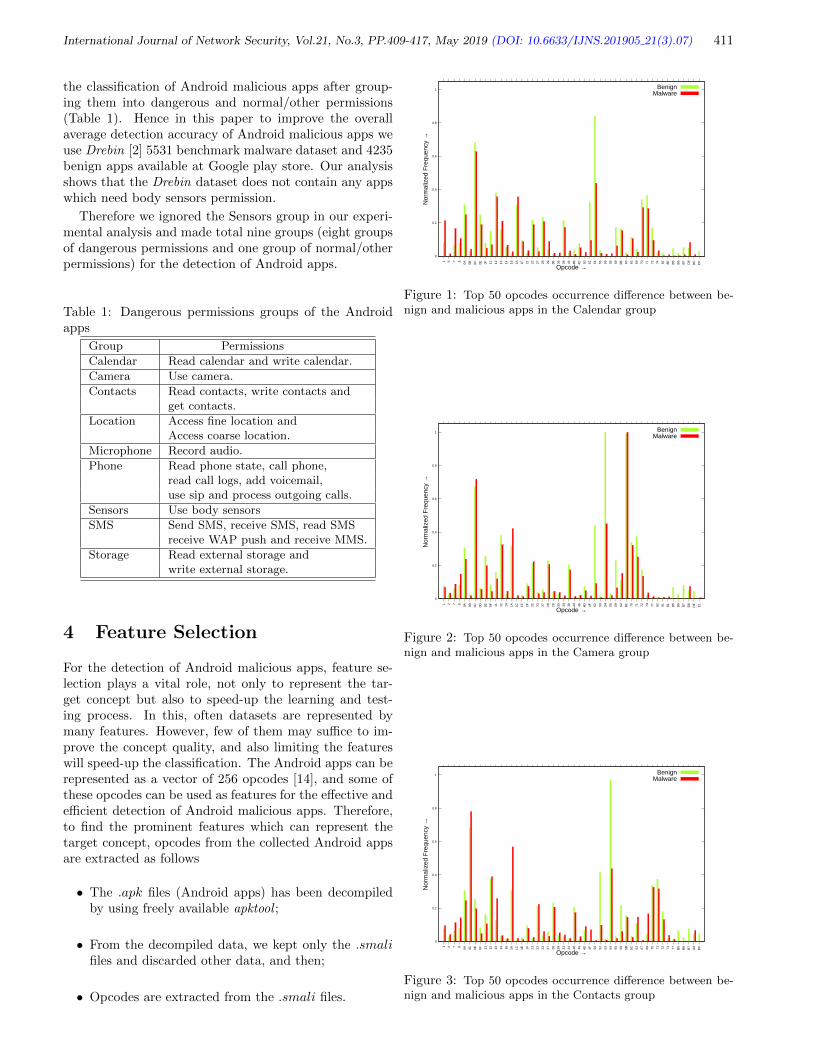
International Journal of Network Security, Vol.21, No.3, PP.409-417, May 2019 (DOI: 10.6633/IJNS.201905 21(3).07) 411
the classification of Android malicious apps after group-ing them into dangerous and normal/other permissions(Table 1). Hence in this paper to improve the overallaverage detection accuracy of Android malicious apps weuse Drebin [2] 5531 benchmark malware dataset and 4235benign apps available at Google play store. Our analysisshows that the Drebin dataset does not contain any appswhich need body sensors permission.
Therefore we ignored the Sensors group in our experi-mental analysis and made total nine groups (eight groupsof dangerous permissions and one group of normal/otherpermissions) for the detection of Android apps.
Table 1: Dangerous permissions groups of the Androidapps
Group Permissions
Calendar Read calendar and write calendar.
Camera Use camera.
Contacts Read contacts, write contacts andget contacts.
Location Access fine location andAccess coarse location.
Microphone Record audio.
Phone Read phone state, call phone,read call logs, add voicemail,use sip and process outgoing calls.
Sensors Use body sensors
SMS Send SMS, receive SMS, read SMSreceive WAP push and receive MMS.
Storage Read external storage andwrite external storage.
4 Feature Selection
For the detection of Android malicious apps, feature se-lection plays a vital role, not only to represent the tar-get concept but also to speed-up the learning and test-ing process. In this, often datasets are represented bymany features. However, few of them may suffice to im-prove the concept quality, and also limiting the featureswill speed-up the classification. The Android apps can berepresented as a vector of 256 opcodes [14], and some ofthese opcodes can be used as features for the effective andefficient detection of Android malicious apps. Therefore,to find the prominent features which can represent thetarget concept, opcodes from the collected Android appsare extracted as follows
• The .apk files (Android apps) has been decompiledby using freely available apktool ;
• From the decompiled data, we kept only the .smalifiles and discarded other data, and then;
• Opcodes are extracted from the .smali files.
0
0.2
0.4
0.6
0.8
1
1 5 7 8
0A 0B 0C 0E 0F 11 12 13 14 16 1A 1F 21 22 27 28 29 2B 36 38 46 4B 4D 50 52 54 55 56 58 59 5B 60 62 69 70 71 72 74 82 8E B5
B6
B7
D8
DC
DF
Nor
mal
ized
Fre
quen
cy →
Opcode →
BenignMalware
Figure 1: Top 50 opcodes occurrence difference between be-nign and malicious apps in the Calendar group
0
0.2
0.4
0.6
0.8
1
1 2 7 8
0A 0B 0C 0D 0E 0F 11 12 14 1A 1C 1E 1F 22 23 27 28 29 33 34 38 44 46 4D 4F 52 53 54 55 59 62 6E 70 71 72 74 77 82 91 B1
B5
B6
B7
D8
DF
E1
Nor
mal
ized
Fre
quen
cy →
Opcode →
BenignMalware
Figure 2: Top 50 opcodes occurrence difference between be-nign and malicious apps in the Camera group
0
0.2
0.4
0.6
0.8
1
1 2 7 8
0A 0C 0E 0F 11 12 13 14 16 1A 1C 1E 1F 21 22 23 27 28 29 33 34 38 46 4D 4F 50 52 53 54 55 59 5B 5C 62 67 69 70 71 72 74 77 B5
B6
B7
D8
DF
Nor
mal
ized
Fre
quen
cy →
Opcode →
BenignMalware
Figure 3: Top 50 opcodes occurrence difference between be-nign and malicious apps in the Contacts group

International Journal of Network Security, Vol.21, No.3, PP.409-417, May 2019 (DOI: 10.6633/IJNS.201905 21(3).07) 412
0
0.2
0.4
0.6
0.8
1
1 2 7 8
0A 0C 0D 0E 0F 11 13 15 1A 1C 1E 1F 21 22 23 27 28 29 33 34 39 44 46 4B 4D 4F 50 52 54 55 59 5B 62 6E 70 71 72 74 76 77 B5
B6
B7
D8
DF
E1
Nor
mal
ized
Fre
quen
cy →
Opcode →
BenignMalware
Figure 4: Top 50 opcodes occurrence difference between be-nign and malicious apps in the Location group
0
0.2
0.4
0.6
0.8
1
1 2 7 8
0A 0B 0C 0D 0E 0F 11 12 13 14 1A 1F 21 22 23 27 28 29 33 34 35 36 38 39 46 48 49 4D 4F 52 53 54 55 59 62 71 72 74 76 B0
B1
B5
B6
B7
D8
DF
Nor
mal
ized
Fre
quen
cy →
Opcode →
BenignMalware
Figure 5: Top 50 opcodes occurrence difference between be-nign and malicious apps in the Microphone group
0
0.2
0.4
0.6
0.8
1
1 2 7 8
0A 0C 0D 0E 11 12 13 14 1A 1F 20 21 22 23 27 28 29 32 33 35 37 38 39 3A 3B 46 4D 52 54 59 5B 62 69 6E 6F 70 71 72 74 77 91 B5
B6
B7
D8
DF
Nor
mal
ized
Fre
quen
cy →
Opcode →
BenignMalware
Figure 6: Top 50 opcodes occurrence difference between be-nign and malicious apps in the Other group
We studied the occurrence of opcodes in benign andmalicious apps separately in each formed group, and com-puted the opcode occurrences difference between them.We observe that the opcode occurrence between mali-cious and benign apps among the formed group differ sig-nificantly (group-wise top 50 opcodes whose occurrencesignificantly differ are shown in Figures 1 - 9 for the Cal-endar, Camera, Contacts, Location, Microphone, Others,
Phone, SMS, and Storage group respectively). Also, wefind that the opcode occurrence in any group differs sig-nificantly when compared with the opcode occurrence ob-tained without forming the groups [22].
0
0.2
0.4
0.6
0.8
1
1 2 7 8
0A 0C 0E 0F 11 12 13 14 15 1A 1C 1E 1F 21 22 23 27 29 33 34 39 44 46 4B 4D 4F 52 54 55 59 5B 62 69 6E 70 71 72 74 76 77 B1
B5
B6
B7
D8
DF
Nor
mal
ized
Fre
quen
cy →
Opcode →
BenignMalware
Figure 7: Top 50 opcodes occurrence difference between be-nign and malicious apps in the Phone group
0
0.2
0.4
0.6
0.8
1
1 2 7 8
0A 0C 0D 0E 0F 11 12 13 14 16 1A 1E 1F 20 22 23 27 28 29 33 34 38 46 48 4D 4F 52 53 54 55 59 5B 62 67 69 70 71 72 74 77 B1
B5
B6
B7
D8
DF
Nor
mal
ized
Fre
quen
cy →
Opcode →
BenignMalware
Figure 8: Top 50 opcodes occurrence difference between be-nign and malicious apps in the SMS group
0
0.2
0.4
0.6
0.8
1
1 2 7 8 10 12 13 14 15 17 18 19 20 21 26 28 30 31 33 34 35 39 41 51 52 57 68 70 75 77 79 82 84 85 89 91 98 103
105
110
112
113
114
116
119
181
182
183
216
223
Nor
mal
ized
Fre
quen
cy →
Opcode →
BenignMalware
Figure 9: Top 50 opcodes occurrence difference between be-nign and malicious apps in the Storage group
Hence, the final features are selected after ordering theopcodes by their occurrence difference in each group (Al-

International Journal of Network Security, Vol.21, No.3, PP.409-417, May 2019 (DOI: 10.6633/IJNS.201905 21(3).07) 413
Table 2: Number of benign and Android malicious apps used for training and testing the classifiers
Groups Train Train Test Test Total No.malware benign malware benign of apps
Calendar 59 57 14 14 144
Camera 179 423 44 106 752
Contacts 1073 356 268 89 1786
Location 1538 68 383 18 2007
Microphone 95 218 23 55 391
Others 110 891 27 223 1251
Phone 3981 1453 986 373 6793
SMS 2712 239 677 60 3688
Storage 2923 837 730 210 4700
gorithm 1) and used it for the detection of Android mali-cious apps.
Algorithm 1 : Feature Selection
INPUT: Pre-processed dataNB: No. of benign apps, NM: No. of malicious apps,n: Total number of features required.OUTPUT: List of features
BEGINfor all benign and malicious apps do
Find the sum of frequencies fi of each opcode Op andnormalize it.
FB(Opj) = (∑
fi(Opj))/NB
FM (Opj) = (∑
fi(Opj))/NM
end forfor all opcode Opj do
D(Opj) = |FB(Opj)− FM (Opj)|end forreturn n number of prominent opcodes as features withhigh D(Op).
5 Classification of Malicious Apps
Ashu et al. [22] without grouping the data nor talking theapps permission investigated the top five classifiers viz.FT, RF, LMT, NBT and J48 for the classification of appsand reported that the FT is the best classifier and can de-tect the malicious apps with 79.27% accuracy [22]. Henceto improve the detection accuracy in this paper, first wegrouped the apps based on the permissions and then clas-sify the malicious apps using prominent opcode as thefeatures (Figure 10). For the classification, the detail dis-tribution (No. of training and testing malicious/benignapps, No. of apps in the group used for the classifica-tion) of the total collected dataset is given in Table 2.For the group-wise classification, we have used WaikatoEnvironment for Knowledge Analysis (WEKA).
Figure 10: Flow chart for the detection of Android maliciousapps by grouping the data
On the basis of studies [17, 20], we selected the sameclassifier (FT, RF, LMT, NBT, and J48) for the clas-sification, but prominent features, training, and testingdata are taken from the formed group only (Table 2). Tomeasure the goodness of trained models, we evaluate thedetection accuracy given by the equation
Accuracy(%) =True Positive + True Negative
Total No. of Android Apps× 100.
Where True Positive/Negative is the Android mali-cious/benign apps correctly classified [22].
The performance of the classifier has been investigatedfor each group by taking randomly 20% of the collecteddata (other than the training) with 20 - 200 best fea-tures incrementing 20 features at each step and the resultobtained are shown in Figures 11 - 19 for the Calendar,Camera, Contacts, Location, Microphone, Others, Phone,SMS, and Storage group respectively.

International Journal of Network Security, Vol.21, No.3, PP.409-417, May 2019 (DOI: 10.6633/IJNS.201905 21(3).07) 414
50
60
70
80
90
100
20 40 60 80 100 120 140 160 180 200
Acc
urac
y →
Features →
J48RandomForest
NBTFT
LMT
Figure 11: Detection accuracy obtained by the selected fiveclassifiers for the Calendar group
50
60
70
80
90
100
20 40 60 80 100 120 140 160 180 200
Acc
urac
y →
Features →
J48RandomForest
NBTFT
LMT
Figure 12: Detection accuracy obtained by the selected fiveclassifiers for the Camera group
50
60
70
80
90
100
20 40 60 80 100 120 140 160 180 200
Acc
urac
y →
Features →
J48RandomForest
NBTFT
LMT
Figure 13: Detection accuracy obtained by the selected fiveclassifiers for the Contacts group
50
60
70
80
90
100
20 40 60 80 100 120 140 160 180 200
Acc
urac
y →
Features →
J48RandomForest
NBTFT
LMT
Figure 14: Detection accuracy obtained by the selected fiveclassifiers for the Location group
50
60
70
80
90
100
20 40 60 80 100 120 140 160 180 200
Acc
urac
y →
Features →
J48RandomForest
NBTFT
LMT
Figure 15: Detection accuracy obtained by the selected fiveclassifiers for the Microphone group
50
60
70
80
90
100
20 40 60 80 100 120 140 160 180 200
Acc
urac
y →
Features →
J48RandomForest
NBTFT
LMT
Figure 16: Detection accuracy obtained by the selected fiveclassifiers for the Others group

International Journal of Network Security, Vol.21, No.3, PP.409-417, May 2019 (DOI: 10.6633/IJNS.201905 21(3).07) 415
50
60
70
80
90
100
20 40 60 80 100 120 140 160 180 200
Acc
urac
y →
Features →
J48RandomForest
NBTFT
LMT
Figure 17: Detection accuracy obtained by the selected fiveclassifiers for the Phone group
50
60
70
80
90
100
20 40 60 80 100 120 140 160 180 200
Acc
urac
y →
Features →
J48RandomForest
NBTFT
LMT
Figure 18: Detection accuracy obtained by the selected fiveclassifiers for the SMS group
50
60
70
80
90
100
20 40 60 80 100 120 140 160 180 200
Acc
urac
y →
Features →
J48RandomForest
NBTFT
LMT
Figure 19: Detection accuracy obtained by the selected fiveclassifiers for the Storage group
Table 3: Average accuracy obtained by the five classifiers
No. of J48 RF NBT FT LMTFeatures
20 93.69 95.01 90.37 93.32 94.28
40 95.28 96.26 92.26 93.78 93.45
60 95.51 96.10 94.24 94.01 94.31
80 94.83 96.32 94.44 95.38 95.46
100 95.15 96.24 94.41 95.43 85.47
120 94.48 95.96 92.96 94.57 94.23
140 95.12 96.08 93.68 93.53 94.76
160 95.39 95.16 94.97 95.16 94.29
180 94.94 95.73 93.93 95.18 94.56
200 94.71 95.78 93.24 94.98 94.71
Maximum 95.51 96.32 94.97 95.43 95.47
Minimum 93.69 95.01 90.37 93.32 93.45
The average accuracy obtained by the selected classifierare shown in Table 3. Here, the average accuracy meansthe sum of accuracy obtained by the classifier in the indi-vidual group with a fixed number of features divided bythe total number of groups.
The analysis shows that RF average detection accu-racy is best among the five classifiers and fluctuates leastwith the number of features, whereas NBT performanceis worst and fluctuate maximum with the number of fea-tures.
However, the maximum average accuracy obtainedby the selected five classifiers does not fluctuate much(94.97% - 96.32%) but minimum average accuracy fluctu-ation is high (90.37% - 95.01%), and for the best perfor-mance one shall take top 80 - 100 features, for the trainingand testing. The best accuracy obtained by the classifierin all the groups are given in Table 4.
We find that the detection accuracy is maximum in theCalendar group and minimum in the Microphone groupobtained by FT and RF classifier respectively. The over-all average maximum accuracy comes to 97.15%, which isvery much better than then the obtained accuracy with-out grouping and taking permissions into account [22] andArp, et al. (94%, 2014), Annamalai et al. (84.29%, 2016),Bahman Rashidi et al. (82%, 2017), Ali Feizollah, et al.(95.5%, 2017) (Figure 20).
In terms of TP i.e. detection rate of malicious apps,the Calendar group are best classified by RF and SMSgroup are least by FT, while in terms of TN i.e. benigndetection rate, Calendar, and SMS group are best classi-fied with RF and FT classifier respectively, while Othersgroup containing normal permissions is best classified bythe LMT classifier. The group-wise results of TP and TNobtained by the classifiers which give the best accuracyare shown in Table 4.

International Journal of Network Security, Vol.21, No.3, PP.409-417, May 2019 (DOI: 10.6633/IJNS.201905 21(3).07) 416
75
80
85
90
95
100
Bahman Rashidi, et. al. 2017 Annamalai, et. al. 2016 Arp, et. al. 2014 Ali Feizollah, et. al. 2017 Our Approach
Accura
cy →
Figure 20: Comparisons of accuracy achieved by us with fourother authors
Table 4: Group-wise maximum accuracy, TP and TN ob-tained by the classifiers
Groups Best Accu- Features TN TPClassifier racy Required
Calendar RF 100.00 20 1.00 1.00
Camera FT 96.67 40 0.93 0.98
Contacts RF 96.08 120 0.99 0.89
Location FT 99.25 60 0.99 0.94
Microphone FT 93.59 120 0.87 0.96
Others LMT 96.80 160 0.85 0.98
Phone RF 96.54 60 0.98 0.92
SMS FT 98.51 100 1.00 0.80
Storage LMT 96.91 140 0.99 0.88
6 Conclusion
For the smart devices users, millions of Android apps areavailable at Google Play store and by the third party.Some of these available apps may be malicious. To de-fend the threat/attack from these malicious apps, a timelycounter-measures has to be developed. Therefore, inthis paper using Drebin benchmark malware dataset wegroup-wise analyzed the collected data based on permis-sions and experimentally demonstrated how to improvethe detection accuracy of Android malicious apps andachieved 97.15% average accuracy. The obtained resultsoutperformed the accuracy achieved by without group-ing the data (79.27%, 2016), Arp, et al. (94%, 2014),Annamalai et al. (84.29%, 2016), Bahman Rashidi etal. (82%, 2017)) and Ali Feizollah, et al. (95.5%, 2017).The outperformance of our approach with the comparedauthor results is basically due to the use of logic of theapps resides in the .smalli file and developing nine dif-ferent models for the classification. Among the groups,the Microphone group detection accuracy is least while
Calendar group apps are detected with maximum accu-racy and for the best performance, one shall take top 80- 100 features. In term of TP i.e. detection rate of mali-cious apps, Calendar group is best classified by RF, andSMS group is least by FT, while in terms TN i.e. be-nign detection rate, Calendar, and SMS group are bestclassified by RF and FT classifier respectively, while Oth-ers group containing normal permissions is best classifiedby the LMT classifier. It appears that group-wise de-tection of Android malicious apps will be efficient thanwithout grouping the data. Hence, for the efficient clas-sification of apps, in-depth study is required to optimizethe feature selection, identifying the best-suited classifierfor the group-by-group analysis. In this direction, workis in progress and will be reported elsewhere.
Acknowledgements
Mr. Ashu Sharma is thankful to BITS, Pilani, K.K.Birla Goa Campus for the Ph.D. scholarship No.Ph603226/July 2012/01. We are also thankful to Tech-nische Universitat Braunschweig for providing the Drebindataset for research on Android malware.
References
[1] Android-developers, Normal and Dangerous Permis-sions requesting permissions, Technical Report, An-droid Labs, 2017.
[2] D. Arp, M. Spreitzenbarth, M. Hubner, H. Gascon,and K. Rieck, “Drebin: Effective and explainable de-tection of android malware in your pocket,” in NDSS,pp. 1–15, 2014.
[3] G. Canfora, F. Mercaldo, and C. A. Visaggio, “AnHMM and structural entropy based detector for an-droid malware: An empirical study,” Computers &Security, vol. 61, pp. 1–18, 2016.
[4] S. Das, Y. Liu, W. Zhang, and M. Chandramo-han, “Semantics-based online malware detection:Towards efficient real-time protection against mal-ware,” IEEE Transactions on Information Forensicsand Security, vol. 11, no. 2, pp. 289–302, 2016.
[5] A. Feizollah, N. B. Anuar, R. Salleh, S. T. Guillermo,and S. Furnell, “Androdialysis: Analysis of androidintent effectiveness in malware detection,” Comput-ers & Security, vol. 65, pp. 121–134, 2017.
[6] H. Gonzalez, N. Stakhanova, and A. A. Ghorbani,“Droidkin: Lightweight detection of android appssimilarity,” in International Conference on Securityand Privacy in Communication Systems, pp. 436–453, 2014.
[7] J. Jang, H. Kang, J. Woo, A. Mohaisen, and H. K.Kim, “Andro-dumpsys: Anti-malware system basedon the similarity of malware creator and malwarecentric information,” computers & security, vol. 58,pp. 125–138, 2016.

International Journal of Network Security, Vol.21, No.3, PP.409-417, May 2019 (DOI: 10.6633/IJNS.201905 21(3).07) 417
[8] Q. Jerome, K. Allix, R. State, and T. Engel, “Usingopcode-sequences to detect malicious android appli-cations,” in 2014 IEEE International Conference onCommunications (ICC’14), pp. 914–919, 2014.
[9] McAfee, Mcafee Labs Threats Re-port, Dec. 2016. (https://www.mcafee.com/enterprise/en-us/assets/reports/
rp-quarterly-threats-dec-2016.pdf)[10] N. Milosevic, A. Dehghantanha, and K. K. R. Choo,
“Machine learning aided android malware classifica-tion,” Computers & Electrical Engineering, 2017.
[11] A. Narayanan, L. Yang, L. Chen, and L. Jinliang,“Adaptive and scalable android malware detectionthrough online learning,” in International Joint Con-ference on Neural Networks (IJCNN’16), pp. 2484–2491, 2016.
[12] S. Naval, V. Laxmi, M. Rajarajan, M. S. Gaur, andM. Conti, “Employing program semantics for mal-ware detection,” IEEE Transactions on InformationForensics and Security, vol. 10, no. 12, pp. 2591–2604, 2015.
[13] K. Olmstead and M. Atkinson, Apps Permissions inthe Google Play Store, Pew Research Center, 2015.(http://www.pewinternet.org/2015/11/10/apps-permissions-in-the-google-play-store/)
[14] G. Paller, Dalvik Opcodes, Android labs,2017. (http://pallergabor.uw.hu/androidblog/dalvik_opcodes.html)
[15] QuickHeal, Threat Report 3rd Quarter, TechnicalReport, Quick Heal, 2015.
[16] B. Rashidi, C. Fung, and E. Bertino, “Android re-source usage risk assessment using hidden markovmodel and online learning,” Computers & Security,vol. 65, pp. 90–107, 2017.
[17] S. K. Sahay and A. Sharma, “Grouping the executa-bles to detect malwares with high accuracy,” Proce-dia Computer Science, vol. 78, pp. 667–674, 2016.
[18] A. Saracino, D. Sgandurra, G. Dini, and F. Mar-tinelli, “Madam: Effective and efficient behavior-based android malware detection and prevention,”IEEE Transactions on Dependable and Secure Com-puting, vol. 99, pp. 1–14, 2016.
[19] S. H. Seo, A. Gupta, A. M. Sallam, E. Bertino, andK. Yim, “Detecting mobile malware threats to home-land security through static analysis,” Journal ofNetwork and Computer Applications, vol. 38, pp. 43–53, 2014.
[20] A. Sharma, S. K. Sahay, and A. Kumar, “Im-proving the detection accuracy of unknown mal-ware by partitioning the executables in groups,” inAdvanced Computing and Communication Technolo-gies, pp. 421–431, 2016.
[21] A. Sharma and S. K. Sahay, “Evolution and detec-tion of polymorphic and metamorphic malwares: A
survey,” International Journal of Computer Applica-tions, vol. 90, pp. 7–11, Mar. 2014.
[22] A. Sharma and S. K. Sahay, “An investigation of theclassifiers to detect android malicious apps,” in In-formation and Communication Technology, pp. 207–217, 2017.
[23] A. Shaun, A. Tareq, C. Peter, C. Mayee, and D. Jon,Internet Security Threat Report 2017, Symentec,2017. (https://www.symantec.com/content/dam/symantec/docs/reports/istr-22-2017-en.pdf)
[24] Statista, Number of Available Applications in theGoogle Play Store from December 2009 to February2016, Technical Report, Statista, Aug. 2016.
[25] Symentec, Internet Security Threat Report2016, Symantec Corporation, 2016. (http://or.himsschapter.org/sites/himsschapter/
files/ChapterContent/or/FinnD_ORHIMSS_
Spring16_Conf.pdf)
Biography
Mr. Ashu Sharma was born in Jhansi, Uttar Pradesh,India. He received his Bachelor’s degree in ComputerScience and Engineering from Uttar Pradesh TechnicalUniversity and Master’s degree in Information Securityfrom Atal Bihari Vajpayee Indian Institute of InformationTechnology and Management, Gwalior. In 2012 he joinedthe Department of Computer Science and InformationSystems, BITS, Pilani, K.K. Birla Goa Campus, India asa full-time research scholar for the Ph.D. degree underthe supervision of Dr. Sanjay K. Sahay. He has publishedseveral papers in reputed journals and conferences.
Dr. Sanjay Kumar Sahay is working as an AssoicateProfessor in the Department of Computer Science andInformation Systems, BITS, Pilani, K.K. Birla GoaCampus. He is also a Visiting Associate of IUCAA,Pune. His research interests are Information Security,Data Science, and Gravitational Waves. He basicallyteaches Network Security, Cryptography, ComputerNetworks, and Data Mining courses. Before joiningBITS, Pilani, and after submitting his Ph.D. thesis on“Studies in Gravitational Wave Data Analysis” during2002-2003, he continued his work on Data Analysis ofGravitational Waves as a Project Scientist at IUCAA,Pune, India. In 2003-2005 at Raman Research Institute,Bangalore, India he worked as Project Associate onthe multi-wavelength astronomy project (ASTROSAT),where he worked on the data pipeline of Scanning SkyMonitor. In 2005 he worked as Post Doctoral Fellow atTel Aviv University.

International Journal of Network Security, Vol.21, No.3, PP.418-427, May 2019 (DOI: 10.6633/IJNS.201905 21(3).08) 418
Multipath Key Exchange Scheme Basedon the Diffie-Hellman Protocol and the
Shamir ThresholdDaouda Ahmat1, Marayi Choroma2, and Tegawende F. Bissyande3,4
(Corresponding author: Daouda Ahmat - [email protected])
Virtual University of Chad1
B.P: 5711, General Daoud Soumaine Road, N’Djamena, Chad
University of N’Djamena2
B.P: 1117, Mobutu Street, N’Djamena, Chad
University of Luxembourg, SnT3
2, avenue de l’Universite L-4365 Esch-sur-Alzette, Luxembourg
University Ouaga I Pr Joseph Ki-Zerbo4
B.P: 7021, Ouagadougou, Burkina Faso
(Email: [email protected] / [email protected] / [email protected],4)
(Received Dec. 18, 2017; Revised and Accepted June 18, 2018; First Online Jan. 13, 2019)
Abstract
In the Internet, as well as in any open autonomousdistributed systems, threats to secure communicationsare pervasive. We contribute towards adressing them byproposing, in this paper, a new multipath key exchangeapproach, which does not rely on any centrally trustedcoordinator. This approach is thus suitable for use indistributed systems such as widespread P2P networks orbooming wireless mesh networks (e.g., for the Internet-of-Things). We design a new algorithm based uponan extension of both the Diffie-Hellman protocol andthe Shamir threshold scheme. In order to overcomeman-in-the-middle attacks inherent to the Diffie-Hellmankey exchange model, our proposed approach guaranteessecure key exchange by exploring disjoint transmissionpaths and the Shamir threshold scheme. The public keyis used as the root of a polynomial of degree k− 1, and npoints of this polynomial are generated and transmittedfrom source to destination, each point through a disjointpath. Upon reception of at least k points among n,the receiver is able to reconstruct the complete key. Inaddition, this paper demonstrates how the disjoint pathsconstructions and the routing algorithms are designed towork regardless of the network topology.
Keywords: Diffie-Hellman; Key Exchange; MultipathRouting; P2P Networks; Shamir Secret Sharing
1 Introduction
A growing number of security attacks on distributed sys-tems such as the Internet and P2P networks for theInternet-of-things (IoT), have led to an increasing interestin the research community. In this regard, many solutionshave been proposed to secure traffic across networks byusing a security infrastructure based on a central author-ity through which s cryptographic keys are dispatched.However, centralized key exchange systems are not suit-able for autonomous distributed systems such as peer-to-peer networks. Infrastructure-less key exchange tech-niques, which are not tied to a central node for key nego-tiation, and which can be usable over insecure networksare thus necessary in the context of such systems.
The end-to-end key exchange scheme proposed by theDiffie-Hellman protocol [11] enables a key exchange be-tween two remote correspondents. However, due to itsvulnerability to interception attacks, the Diffie-Hellmanprotocol cannot be leveraged as-is. Our approach, inthis paper, aims at overcoming this issue by combiningthe Diffie-Hellman protocol with both multipath routingand the Shamir’s threshold scheme [32]. Concretely, theShamir’s secret sharing enables us to divide a key K inton subkeys in such a way that K is reconstructable fromany k subkeys. A security property in this scheme is thatany subset of up to k−1 subkeys cannot leak informationabout K.
The contributions of the paper are exposed in the re-

International Journal of Network Security, Vol.21, No.3, PP.418-427, May 2019 (DOI: 10.6633/IJNS.201905 21(3).08) 419
mainder of the paper, which is structure as follows:
• We first discuss the scope and features provided byliterature work, then we enumerate the limitations ofour own previous work towards implementing securenetwork exchanges (cf. Section 2).
• We then present background information related toprevious work (cf. Section 3), before providing de-tailed descriptions on the design of our key exchangescheme (cf. Section 4), including the implementa-tion of several multipath routing approaches (cf. Sec-tion 5).
• Finally, we analyse the security advantages of ourapproach (cf. Section 6) and discuss experimentalresults —based on network simulations— that as-sess the efficiency of the proposed approach (cf. Sec-tion 7).
2 Related Work
A number of research works have presented various se-curity infrastructures over fully decentralized or ad hocnetworks [5,10,13,23,35,41]. Although they are designedto be suitable in such environments, the proposed ap-proaches come with different caveats. In this section, wedescribe some models from the literature and highlightthe potential benefits of our approach.
Srivasta and Liu have relied on the Diffie-Hellman algo-rithm to deliver a solution that prevents threats in DHTnetworks [34]. Wang et al. have built a distributed PKIon top of the Chord structured overlay network [2]. Theyhave used threshold cryptography to distribute the func-tionality of the PKI across the nodes of the DHT network.This Chord-PKI provides traditional PKI features such ascertification, revocation, storage and retrieval.
The literature now includes a number of approaches [8,9,12,15,17,22,24,26–30,40] that extend the Diffie-Hellmankey exchange algorithm. Nevertheless, there are scarceworks which address end-to-end key exchange problembased on both distributed systems such as peer-to-peernetworks by leveraging the Diffie-Hellman protocol andproposing multipath subkeys routing and multi-secretmechanisms. Takano et al. [35] have investigated this av-enue over a decade ago. This approach is based on ringtopology and does not provide explanation about its keysplitting technique.
Jiejun et al. propose to distribute certification author-ity functions through a threshold secret sharing mecha-nism [21]. In this system, the private key is computed byk neighbor nodes and the public key is derived from nodeidentity.
Many threshold schemes have been directly derivedfrom traditional Shamir threshold [32] to address multi-secret sharing mechanisms. Among them we can quicklycite Brian King [20], Appala et al. [36], Harsha et al. [19],Rao et al. [39], Yang et al. [42], Guo et al. [18], Ting-Yi Chang et al. [38], Ting-Yi Chang [7] and Chang et
al. [6]. We will focus our study on the mainstream proto-col known under name of the Shamir threshold [32].
Fathimal et al. [16] recently proposed an extension ofShamir’s method that enables to retrieve a key from psubkeys, where p ≤ k − 1. p is a threshold number ofequally-weighted from each compartment.
Threshold cryptography is also used in identity-basedkey management [10]. The main idea for identity-basedcryptography is to define public keys derived from theidentities of communicating nodes [33]. Unfortunately,node identity updates lead to frequent key changes.
Myrmic [41] is a DHT-based system that proposes asecure and robust routing protocol. Designed to be ro-bust against adversarial interference, Myrmic introducesthe concept of Neighborhood Authority in order to handlecertificates in a small set of nodes.
Takano et al. have designed a Multipath Key Ex-change [35] similar to that proposed in our work. Theirtechnique however was designed to fit the Symphony andChord P2P systems that are both based upon a ring topol-ogy. Their proposed approach, based on probabilisticclockwise/anticlockwise routing, is thus sensitive to co-ordinated MITM attacks by two attackers.
Jaydip Sen proposes a multipath certification protocolfor MANETs that proceeds by broadcasting in order todiscover the route between both source and destinationnodes [31]. The key exchange protocol is based on thisrouting approach to retrieve the public keys of the nodes.However, broadcasting techniques have proven to not berelevant for large scale networks such as fully decentral-ized P2P systems.
El Hajj Shehadeh et al. investigate secret key genera-tion from wireless multipath channels [13]. The proposedprotocol is based mainly on both the physical character-istics of the wireless channel and a key pre-distributionscheme. This solution is implemented within the physicallayer and does not scale to large networks.
3 Background
In previous work [1], we have proposed a key exchangescheme based on an extension of the Diffie-Hellman proto-col. Our approach enabled sharing a secret by using mul-tiple disjoint paths in a P2P system called CLOAK [4,37].The scheme was mainly devised to overcome the vul-nerability of the Diffie-Hellman protocol to Man-In-The-Middle (MITM) attacks.
In this scheme, we would split the public key into sev-eral subkeys that would then be sent over several disjointpaths to the destination. The destination needed to re-cover all subkeys in order to get the public key of thesender. A major issue with this approach was that theinterception of most (i.e., not even all) of the subkeys byan attacker, allows him to make a brute force attack onthe missing subkey(s) which are smaller than the originalkey. Indeed, if the subkeys set is SK = 0, 1∗, where|SK | = ρ , interception of α key components among n by

International Journal of Network Security, Vol.21, No.3, PP.418-427, May 2019 (DOI: 10.6633/IJNS.201905 21(3).08) 420
an attacker, with α ≤ n, reduces the difficulty to carry out
a brute force attack toρ−α ρnn , that is ρn−αn2 . In addition,
in our previous work, the proposed multipath routing al-gorithm for the subkeys was exclusively suitable to ourCLOAK P2P system [37], making its exploitation chal-lenging in other systems.
In this work, we try to address the issues and limita-tions of this prior work by integrating the Shamir’s sharedsecret scheme in our previous solution.
4 Scheme Design
In this section, we describe our key exchange scheme andits corollary properties which are suitable to distributednetworks, i.e., networks that lack any trusted central co-ordination point.
4.1 Diffie-Hellman Vulnerability
Figure 1: Man-in-the-middle attack
The Diffie-Hellman protocol is an algorithm initiatedby two distant correspondents that cooperate to remotelyaccomplish key exchange tasks. As shown in Figure 1,one fundamental problem of the Diffie-Hellman protocolis its vulnerability to interception attacks, known as Man-In-The-Middle (MITM) attacks. This figure displays ascenario where an attacker, Oscar, eavesdrops the chan-nel used by both Alice and Bob to exchange cryptographicdata. ¶ and ¸ flows represent intercepted data by the at-tacker Oscar, data transmitted respectively by Alice andBob. · and ¹ show corrupted flows produced by Oscarand then respectively transmitted to Bob and Alice. Thus,Oscar can perpetrate attacks: it can eavesdrop, replay ormodify data exchanged between Alice and?Bob. Specifi-cally to the Diffie-Hellman protocol, Oscar can interceptthe public key sent by Alice and send its own public keyto Bob and can do the same in the other direction withanother public key generated to replace the public keysent by Bob.
4.2 Protocol Overview
Based upon multipath routing, our approach aims at re-ducing the Diffie-Hellman vulnerability by combining thetwo cryptographic algorithms mentioned earlier. Hence,key K = gs mod (p) must be splitted into n subkeyssk0 , . . . , skn−1
and then each subkey ski will be subse-quently sent through a disjoint path. Shamir’s thresh-old algorithm is applied in both splitting and reconstruc-tion of key K. In addition, various routing techniques areproposed in order to route subkeys over network throughdisjoint paths.
4.3 Key Management
Our key exchange approach is based upon both the Diffie-Hellman protocol and Shamir’s threshold. We now de-scribe the mechanisms behind our key exchange scheme.
4.3.1 Key Splitting
In order to forge subkeys, each correspondent firstly cre-ates a secret key SK = s and generates a polynom f l(X),where f l(0) = gs(mod p), as shown in Algorithm 1.Then, for each xi 0≤i≤n , with xi 6= 0, f l(xi) is com-
puted. Finally, all interpolation points (xi, fl(xi)), ex-
cept (0, f l(0)), are stocked in subKeysList. Algorithm2, which depends on Algorithm 1, provides more detailsabout the key splitting scheme.
Algorithm 1: Creation of polynom of degree k
createPolynom(k, gS(mod p)) return Polynom;begin
a0 ← gS(mod p);
f l(0)← a0;i← 1;while i ≤ k − 1 do
ai ← getRandomCoefficient();if i = k − 1 and ai = 0 then
continue;
li(X)← aiXi;
i← i+ 1;
f l(X)←k−1∑i=1
li(X) + f l(0);
return f l(X);
4.3.2 Key Reconstitution
On receiving of (xi, fl(xi))0≤i≤n, correspondent node ap-
plies Algorithm 3 in order to rebuild key K = gs( mod p)from received subkeys sk0 , . . . , skp−1 , that are equiva-lent to (xi, f
l(xi))0≤i≤p, where p ≥ k(= degree of f l).Indeed, receiver computes sk0 sk1 · · · skp−1
=gs(mod p) = F l(0), such that:

International Journal of Network Security, Vol.21, No.3, PP.418-427, May 2019 (DOI: 10.6633/IJNS.201905 21(3).08) 421
Algorithm 2: Subkeys generation
Input: k, n, gS(mod p)f l(X)← createPolynom
(k, gS(mod p)
);
subKeysList←⊥;begin
i← 1;while i ≤ n do
xi ← getRandomValue();
f(xi)←(xi, f
l(xi));
storeInSubKeysList(f(xi), subKeysList[i]
);
i← i+ 1;
F l(X) =
p∑j=0
yj lj(X) (1)
where yi = f l(xi) and
lj(X) =
p∏i=0,i6=j
X − xixj − xi
(2)
Algorithm 3: Reconstitution of key from receivedsubkeys
Input: k, (xi, yi)0≤i≤nOutput: Keybegin
if |(xi, yi)0≤i≤n| < k thenreturn ⊥;
elseforeach i ∈ J0, nK do
li(X)←n∏
j=0,j 6=i
X−xjxi−xj ;
j ← 0;fl(X)← 0;while j ≤ n do
fl(X)← yj × lj(X) + fl(X);j ← j + 1;
return fl(0);
4.4 Key Exchange Protocol
Algorithm 4 summarizes the process of our key exchangeapproach: the Diffie-Hellman protocol is relied uponfirstly to generate a key of shape K = gs(mod p); thenShamir’s threshold is leveraged to split the key into sev-eral subkeys or to rebuild the key from its componentsubkeys sk0 , sk1 , · · · , skn . Precisely, equations 1 and 2 de-scribe Lagrange Interpolation used in order to rebuild keyK original.
Algorithm 4: Multipath key exchange protocol
public data:p : a prime numberg : a generator
private data:sa : secret key of Alicesb : secrete key of Bob
1) Alice creates sa and she then computes her partial key Keya= gsa mod (p) ;
2) Alice generates a polynom f la of degree k, such as f l
a(0) =Keya, and she then computes n interpolation points of thepolynom: fa0 , ..., fan−1 (where n ≥ k);
3) Alice sends n subkeys fai , except (0, f l(0)) point, to Bobvia disjoint paths;
4) Bob determines Lb(X) according to fai , received fromAlice, and subsequently computes Lb(0) which gives
gsa mod (p), if |fai | ≥ k;
5) Bob creates sb and he then generates his partial Keyb =gsb mod (p) ;
6) Bob forges a polynom f lb, such as f l
b(0) = Keyb, and he thendetermines n interpolation points of the polynomfb0 , ..., fbp−1
(where p ≥ k);
7) Bob sends n subkeys fbi , except (0, f l(0)) point, to Alicethrough disjoint paths;
8) Alice generates La(X) from fbi received from Bob and she
then computes La(0) which gives gsb mod (p), if |fbi | ≥ k;
9) Alice computes Key =Keya × L(0) = gsa mod (p)× gsb mod (p) = gsasb mod (p) ;
10) Bob computes Key =Keyb × L(0) = gsb mod (b)× gsa mod (p) = gsbsa mod (p) ;
5 Multipath Routing Policy
In this section, we provide technical details about multi-path routing algorithms and then point out their perfor-mance differences.
5.1 Deterministic Routing: Pre-routingand Then Routing
Deterministic routing: Enables to route subkeys throughdisjoint and predetermined paths, as described in Al-gorithm 5. In other words, each subkey is sent via adisjoint path whose constituting hops are all deter-mined in advance. Deterministic routing is howevernot suitable for dynamic environments where topolo-gies change constantly.
5.2 Non-deterministic Routing: BothMarking and Routing
Non-deterministic routing: Detailed in Algorithm 6, en-ables to route each subkey through a disjoint path,but unlike deterministic routing, determines on thefly the hops that form each disjoint path.

International Journal of Network Security, Vol.21, No.3, PP.418-427, May 2019 (DOI: 10.6633/IJNS.201905 21(3).08) 422
Algorithm 5: Deterministic routing
Input: G = (V,E), (s, t),SubKeysListV ← ∅;begin
k ← |SubKeysList|;j ← k − 1;V ← V ∪ s, t;while j ≥ 0 do
node← s;while node 6= t do
dmin ← distance(node, t);foreachneighbor ∈ neighborsListOf(node)dod← distance(neighbor, t);if neighbor /∈ V and d < dmin then
dmin ← d;node← neighbor;
V ← V ∪ node;Pj ← Pj ∪ node;
j ← j − 1;
while k > 0 doe← SubKeysList[k];sendViaPath(e,Pk);k ← k − 1;
5.3 Technical Comparison BetweenRouting Algorithms
Table 1 presents a technical comparison of both perfor-mance metrics and features provided by various multipathrouting algorithms.
6 Security Analysis
In a multipath key exchange scheme, a malicious nodethat wishes to compromise a key being exchanged must beable to collect each of all key components routed over thenetwork. Formally, when paths P0, ...,Pk−1 are used tosend several distinct subkeys from source S to destinationD, the only malicious nodes that could compromise thekey should be located at the intersection of all paths. Inother words, all the malicious nodes belong to a set M =k⋂i=0
Pi which represents the set of intersection points of
all paths Pi. S and D are obviously ignored in this set.
Thus, whenk⋂i=0
Pi = ∅ (bigon criterion is respected [14,
Lemma 2.5]), then all paths are disjoint and any MITMattack attempt cannot succeed. In such a desirable case,there exists a k-connected subgrah between S and D in
the network topology. When |k⋂i=0
Pi| ≥ 1, there exists
a real risk that MITM attacks could be committed on
Algorithm 6: Non-deterministic routing
Input: G = (V,E), (s, t),SubKeysListV ← ∅;beginV ← V ∪ s, t;foreach e ∈ SubKeysList do
node← s;while node 6= t do
dmin ← (node, t);foreachneighbor ∈ neighborListOf(node) dod← distance(neighbor, t);if neighbor /∈ V and d < dmin then
dmin ← d;node← neighbor;
V ← V ∪ node;forward(e, node);
exchange transmitted between S and D. That means thatthere exists at least one articulation point. Algorithm 7enables to detect articulation points within network.
Consequently, the probability to have a MITM attack
is estimated by σ =|k⋂i=0Pi|
|k⋃i=0Pi|
(where each path Pi is con-
stituted of a set of consecutive hops from source S to des-tination D). When all used paths are pairwise disjoint,the probability of isolated MITM attack (no coordinated
MITM attack) is then: σ = 0 (i.e |k⋂i=0
Pi| = 0).
The number of distinct paths is also dependant on thesource node’s degree. Thus, for a given q-regular tree, if qis a large number, then there is a probability to have sev-eral disjoint transmission channels. Nonetheless, despitethe robustness of our multipath negotiation approach, co-operative (i.e., coordinated) MITM attacks, where severalnodes maliciously cooperate to compromise a key, are pos-sible. However, it is very hard, and excessively costly tolaunch such an attack in a real environment, especiallyin distributed systems where network topology changesdynamically. In addition, the key exchange scheme issuitable for P2P networks and designed regardless of aspecific network architecture.
In order to improve performance, re-authentication fea-ture is introduced. However, the challenge message usedin this phase could be replayed. Furthermore, when a ma-licious node caches a challenge message, it can then cre-ate its copies and send them successively to target node.Thus, target node tries to resolves each challenge requestbecause it does not know which packet is more fresh thanthe other. Consequently, it will be rapidly saturated withrequests from malicious nodes. Therefore, this causes aDenial-of-Service (DoS) attack.
In order to avoid such an attack from malicious nodes,
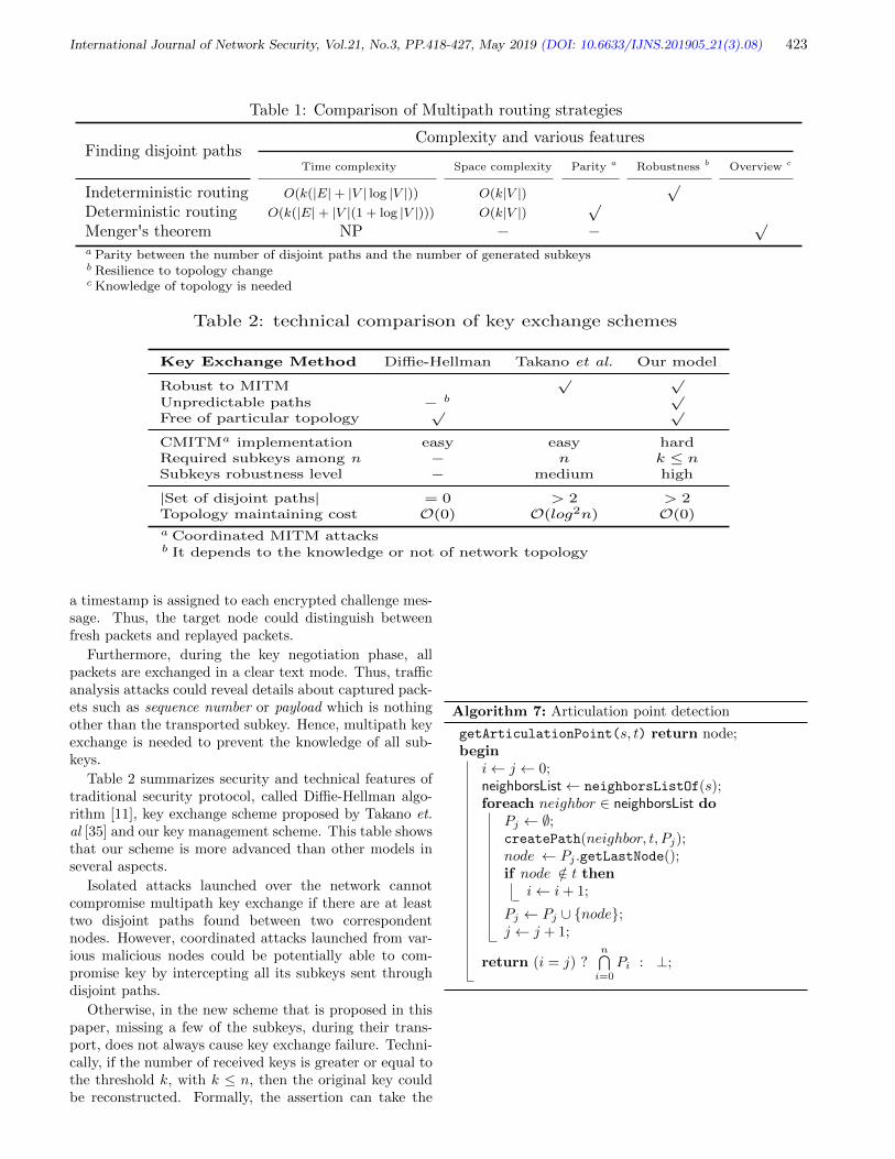
International Journal of Network Security, Vol.21, No.3, PP.418-427, May 2019 (DOI: 10.6633/IJNS.201905 21(3).08) 423
Table 1: Comparison of Multipath routing strategies
Finding disjoint pathsComplexity and various features
Time complexity Space complexity Parity a Robustness b Overview c
Indeterministic routing O(k(|E|+ |V | log |V |)) O(k|V |)√
Deterministic routing O(k(|E|+ |V |(1 + log |V |))) O(k|V |)√
Menger's theorem NP − − √a Parity between the number of disjoint paths and the number of generated subkeysb Resilience to topology changec Knowledge of topology is needed
Table 2: technical comparison of key exchange schemes
Key Exchange Method Diffie-Hellman Takano et al. Our model
Robust to MITM√ √
Unpredictable paths − b √Free of particular topology
√ √
CMITMa implementation easy easy hardRequired subkeys among n − n k ≤ nSubkeys robustness level − medium high
|Set of disjoint paths| = 0 > 2 > 2Topology maintaining cost O(0) O(log2n) O(0)
a Coordinated MITM attacksb It depends to the knowledge or not of network topology
a timestamp is assigned to each encrypted challenge mes-sage. Thus, the target node could distinguish betweenfresh packets and replayed packets.
Furthermore, during the key negotiation phase, allpackets are exchanged in a clear text mode. Thus, trafficanalysis attacks could reveal details about captured pack-ets such as sequence number or payload which is nothingother than the transported subkey. Hence, multipath keyexchange is needed to prevent the knowledge of all sub-keys.
Table 2 summarizes security and technical features oftraditional security protocol, called Diffie-Hellman algo-rithm [11], key exchange scheme proposed by Takano et.al [35] and our key management scheme. This table showsthat our scheme is more advanced than other models inseveral aspects.
Isolated attacks launched over the network cannotcompromise multipath key exchange if there are at leasttwo disjoint paths found between two correspondentnodes. However, coordinated attacks launched from var-ious malicious nodes could be potentially able to com-promise key by intercepting all its subkeys sent throughdisjoint paths.
Otherwise, in the new scheme that is proposed in thispaper, missing a few of the subkeys, during their trans-port, does not always cause key exchange failure. Techni-cally, if the number of received keys is greater or equal tothe threshold k, with k ≤ n, then the original key couldbe reconstructed. Formally, the assertion can take the
Algorithm 7: Articulation point detection
getArticulationPoint(s, t) return node;begin
i← j ← 0;neighborsList← neighborsListOf(s);foreach neighbor ∈ neighborsList do
Pj ← ∅;createPath(neighbor, t, Pj);node ← Pj .getLastNode();if node /∈ t then
i← i+ 1;
Pj ← Pj ∪ node;j ← j + 1;
return (i = j) ?n⋂i=0
Pi : ⊥;

International Journal of Network Security, Vol.21, No.3, PP.418-427, May 2019 (DOI: 10.6633/IJNS.201905 21(3).08) 424
form of the following theorem.
Theorem 1. In Shamir’s (k, n)−threshold scheme, anysubset of up to q = k − 1 subkeys, where k ≤ n, does notleak any information on the shared secret K.
Proof. To retrieve key K from (xi, yi) which are employedin Equation (1), let’s proceed as follow:
K = F l(0) =
p∑j=0
yj
p∏i=0,i6=j
−xixj − xi
(3)
where k ≤ p ≤ n.
Given |(xi, yi)|1≤i≤q, with q < k ⇒ q < p. Let’s sup-pose that p = k, that means that Equation (3) becomesin developped form:
K =
q∑j=0
yj
q∏i=0i6=j
−xixj − xi
+
k∑j=q+1
yj
k∏i=q+1i 6=j
−xixj − xi
(4)
In Equation (4) let’s put:
q∑j=0
yj
q∏i=0i 6=j
−xixj − xi
= K0 (5)
and
k∑j=q+1
yj
k∏i=q+1i 6=j
−xixj − xi
= K1 (6)
Therefore Equation (4) becomes:
K = K0 +K1 (7)
The value of K1 is indeterminate because points(xi, yi)q+1≤i≤k are unknown. That implies K indetermi-nate.
The public key cryptography gski can be publishedand used in order to verify authenticity of each subkeyski . However, public key mechanism requires the use ofa traditional centralized public key infrastructure that isincongruous to distributed systems such as peer-to-peernetworks.
7 Protocol Assessment
We rely on the Erdos-Renyi and the Magoni-Pansiot [25]models to build a synthesized graph that represents a ran-dom topology. To assess our approach, we use the nemsimulator1.
1http://www.labri.fr/perso/magoni/nem/
0 20 40 60 80 100% key exchange success
1
2
4
8
16
32
64
% c
oord
inat
ed a
ttack
ers
2 paths4 paths6 paths8 paths10 paths
Figure 2: Average number for 10 assessment rounds of keyexchange success with respect to both various numbersof disjoint paths found and percentages of coordinatedattackers existing over the network
We have carried out the experiments through simula-tions. We succinctly present the steps that are carriedout for the experiments:
• Definition of the network: A P2P network is firstcreated. In this step, we set the type of the topology(real map, synthesized topology such as Erdos-Renyi,Internet-like, etc.) and the size of this network.
• Selection of the set of compromised nodes: In thesecond step, we select a subset of X% nodes whichwill act as attackers. These nodes are supposed tocoordinate their actions.
• Identification of source and destination nodes: Wethen select, among the non-compromised nodes, apair of source and destination nodes for the data ex-change.
• Data packet transfer: We launch the transmission bytransferring a data packet through the shortest pathtowards the destination node. All intermediate nodeswill be marked and may not be used for anotherpacket between the same pair of source/destinationnodes.
• Check for attacks: At the end of the packet transfer,we check whether the packet was intercepted by anattacker.
• Use of alternative paths: At this time, we start overfrom step 4, using the same source node but a differ-ent path to reach the same destination.
• Confirmation of the validity of the generated key: Wecheck whether the packet was potentially interceptedon all disjoint paths. If this is the case, then this

International Journal of Network Security, Vol.21, No.3, PP.418-427, May 2019 (DOI: 10.6633/IJNS.201905 21(3).08) 425
attempt to generate a key is a failure. It is a successotherwise.
• Change of source/destination nodes: We repeat theexperiments starting from step 3 with a new pair ofsource and destination nodes.
• Change of compromised nodes set: We repeat the ex-periments starting from step 2 with a new subset ofcompromised nodes. Basically, we change the per-centage of attackers.
• Change of network settings: We start over the ex-periments from step 1 with a new network topologyand/or a new size value for the network.
Assessment results are depicted in Figure 2. On theone hand, and despite coordinated attacks, the resultsshow that the higher the number of the disjoint paths,the greater the success rate. On the other hand, the as-sessment results show also that the higher the rate of at-tackers within the network, the less the success rate.
8 Conclusion
Currently, security threats in large scale autonomous P2Psystems are increasingly present. Given that traditionalsecurity protocols fail to be applied in these systemsfree of central coordination points, we have proposed inthis paper a new key exchange algorithm suitable to dis-tributed systems.
It is not only about designing an interesting approach,it is also about a robust scheme. Indeed, the robustnessgoal is fulfilled by using multipath key exchange techniquethat extends both Diffie-Hellman protocol and Shamir’sthreshold in order to meet security expectations. In addi-tion, based on disjoint paths and defined in order to routeseparately subkeys through the network, multipath rout-ing methods are quite similar to Menger’s theorem [3]. Fi-nally, experiments show that our multipath key exchangescheme is robust to isolated MITM attacks and reducessubstantially vulnerabilities to distributed MITM attacksas the number of disjoint paths increases.
References
[1] D. Ahmat, D. Magoni, and T. Bissyande, “End-to-end key exchange through disjoint paths in P2P net-works,” in European Alliance for Innovation, En-dorsed Transaction on Security and Safety, pp. 1–15,vol. 2-3, Jan. 2015.
[2] A. Avramidis, P. Kotzanikolaou, C. Douligeris, andM. Burmester, “Chord-pki: A distributed trust in-frastructure based on p2p networks,” Computer Net-works, vol. 56, pp. 378–398, Jan. 2012.
[3] T. Bohme, F. Goring, and J. Harant, “Menger’stheorem,” Journal of Graph Theory, vol. 37, no. 1,pp. 35–36, 2001.
[4] C. Cassagnes, T. Tiendrebeogo, D. Bromberg, andD. Magoni, “Overlay addressing and routing systembased on hyperbolic geometry,” in Proceedings of the16th IEEE Symposium on Computers and Commu-nications, pp. 294–301, 2011.
[5] M. Castro, P. Druschel, A. Ganesh, A. Rowstron,and D. S. Wallach, “Secure routing for structuredpeer-to-peer overlay networks,” SIGOPS OperatingSystems Review, vol. 36, pp. 299–314, Dec. 2002.
[6] T. Y. Chang, M. S. Hwang, and W. P. Yang, “Animproved multi-stage secret sharing scheme based onthe factorization problem,” Information Technologyand Control, vol. 40, no. 3, pp. 246–251, 2011.
[7] T. Y. Chang, M. S. Hwang, and W. P. Yang, “Animprovement on the lin-wu (t,n) threshold verifiablemulti-secret sharing scheme,” Applied Mathematicsand Computation, vol. 163, no. 1, pp. 169–178, Apr.2005.
[8] R. Chaubey and V. R. R. Manthena, Decryption ofSecure Sockets Layer Sessions Having Enabled Per-fect Forward Secrecy Using a Diffie-Hellman Key Ex-change, Feb. 13, 2018. US Patent 9,893,883.
[9] S. F. Chiou, M. S. Hwang, and S. K. Chong, “A sim-ple and secure key agreement protocol to integratea key distribution procedure into the dss,” Interna-tional Journal of Advancements in Computing Tech-nology, vol. 4, no. 19, pp. 529–535, Octo. 2012.
[10] H. Deng, A. Mukherjee, and D. P. Agrawal, “Thresh-old and identity-based key management and authen-tication for wireless ad hoc networks,” in Proceed-ings of the International Conference on Informa-tion Technology: Coding and Computing (ITCC’04),pp. 107, 2004.
[11] W. Diffie and M. E. Hellman, “New directions incryptography,” IEEE Transactions on InformationTheory, vol. 22, no. 6, pp. 644–654, 1976.
[12] N. Dottling and S. Garg, “Identity-based encryp-tion from the diffie-hellman assumption,” in AnnualInternational Cryptology Conference, pp. 537–569,2017.
[13] Y. E. H. Shehadeh, O. Alfandi, and D. Hogrefe, “To-wards robust key extraction from multipath wire-less channels,” Journal of Communications and Net-works, vol. 14, no. 4, pp. 385–395, 2012.
[14] D. B. A. Epstein, “Curves on 2-manifolds and iso-topies,” in Acta Math, pp. 15–16, 1966.
[15] A. Escala, G. Herold, E. Kiltz, C. Rafols, and JorgeVillar, “An algebraic framework for diffie–hellmanassumptions,” Journal of Cryptology, vol. 30, no. 1,pp. 242–288, 2017.
[16] P. M. Fathimal and P. A. J. Rani, “Threshold se-cret sharing scheme for compartmented access struc-tures,” International Journal of Information Securityand Privacy, vol. 10, no. 3, p. 9, 2016.
[17] C. E. Gero, J. N. Shapiro, and D. J. Burd, Provid-ing Forward Secrecy in a Terminating ssl/tls Con-nection Proxy Using Ephemeral Diffie-Hellman KeyExchange, Dec. 27 2016. US Patent 9,531,685.

International Journal of Network Security, Vol.21, No.3, PP.418-427, May 2019 (DOI: 10.6633/IJNS.201905 21(3).08) 426
[18] C. Guo and C. C. Chan, “A novel thresholdconference-key agreement protocol based on general-ized chinese remainder theorem,” International Jour-nal of Network Security, vol. 17, no. 2, pp. 165–173,Mar. 2015.
[19] P. Harsha, P. Chanakya, and V. C. Venkaiah, “Areusable multipartite secret sharing scheme based onsuperincreasing sequence,” International Journal ofNetwork Security, vol. 20, no. 3, pp. 527–535, May2018.
[20] B. King, “A dynamic threshold decryption schemeusing bilinear pairings,” International Journal ofNetwork Security, vol. 17, no. 6, pp. 771–778, Nov.2015.
[21] J. Kong, Z. Petros, H. Luo, S. Lu, and L. Zhang,“Providing robust and ubiquitous security supportfor mobile ad-hoc networks,” in Ninth InternationalConference on Network Protocols, pp. 251–260, 2001.
[22] B. Koziel, A. Jalali, R. Azarderakhsh, D. Jao, andM. Mozaffari-Kermani, “Neon-sidh: Efficient imple-mentation of supersingular isogeny diffie-hellman keyexchange protocol on arm,” in International Confer-ence on Cryptology and Network Security, pp. 88–103, 2016.
[23] H. Kwon, S. Koh, J. Nah, and J. Jang, “The se-cure routing mechanism for dht-based overlay net-work,” in 10th International Conference on AdvancedCommunication Technology (ICACT’08), vol. 2,pp. 1300–1303, 2008.
[24] J. Liu and J. Li, “A better improvement on the in-tegrated diffie-hellman-dsa key agreement protocol,”International Journal of Network Security, vol. 11,no. 2, pp. 114–117, Sep. 2010.
[25] D. Magoni and J. J. Pansiot, “Internet topologymodeler based on map sampling,” in Proceedings ofthe 7th IEEE Symposium on Computers and Com-munications, pp. 1021–1027, 2002.
[26] T. Mefenza and D. Vergnaud, “Polynomial interpo-lation of the generalized diffie–hellman and naor–reingold functions,” Designs, Codes and Cryptogra-phy, pp. 1–11, 2018.
[27] H. T. Pan, J. R. Sun, and M. S. Hwang, “Crypt-analysis of biswas’s multi-party keys scheme basedon the diffie-hellman technique,” International Con-ference on Advances in Mechanical Engineering andIndustrial Informatics, Jan. 2015.
[28] H. K. Pathak and M. Sanghi, “Simple three party keyexchange protocols via twin diffie-hellman problem,”International Journal of Network Security, vol. 15,no. 4, pp. 256–264, July 2013.
[29] Q. Peng and Y. Tian, “A publicly verifiable secretsharing scheme based on multilinear diffie-hellmanassumption,” International Journal of Network Se-curity, vol. 18, no. 6, pp. 1192–1200, Nov. 2016.
[30] C. Rajarama, J. N. Sugatoor, and T. Y. Swamy,“Diffie-hellman type key exchange, elgamal like en-cryption/decryption and proxy re-encryption usingcirculant matrices,” International Journal of Net-work Security, vol. 20, 2018.
[31] J. Sen, “A multi-path certification protocol for mo-bile ad hoc networks,” in The 4th International Con-ference on Computers and Devices for Communica-tion, pp. 1–4, 2009.
[32] A. Shamir, “How to share a secret,” Communicationsof the ACM, vol. 22, pp. 612–613, Nov. 1979.
[33] A. Shamir, “Identity-based cryptosystems and sig-nature schemes,” in Proceedings of Crypto 84 on Ad-vances in Cryptology, pp. 47–53, 1984.
[34] M. Srivatsa and L. Liu, “Vulnerabilities and securitythreats in structured overlay networks: a quantita-tive analysis,” in The 20th Annual Computer Secu-rity Applications Conference, pp. 252–261, 2004.
[35] Y. Takano, N. Isozaki, and Y. Shinoda, “Multipathkey exchange on p2p networks,” in The First Inter-national Conference on Availability, Reliability andSecurity, pp. 8, 2006.
[36] A. N. Tentu, V. K. Prasad, and V. C. Venkaiah, “Se-cret sharing schemes for multipartite access struc-tures,” International Journal of Applied EngineeringResearch, vol. 11, no. 7, pp. 5244–5249, 2016.
[37] T. Tiendrebeogo, D. Ahmat, D. Magoni, and O Sie,“Virtual connections in p2p overlays with dht-basedname to address resolution,” International Journalon Advances in Internet Technology, vol. 5, no. 1,pp. 11–25, 2012.
[38] M. S. Hwang, T. Y. Chang and W. P. Yang, “Animproved multi-stage secret sharing scheme based onthe factorization problem,” Information Technologyand Control, vol. 40, no. 3, pp. 246 – 251, 2010.
[39] R. Y. V. Subba and C. Bhagvati, “Crt based thresh-old multi secret sharing scheme,” International Jour-nal of Network Security, vol. 16, no. 4, pp. 249–255,July 2014.
[40] L. Valenta, D. Adrian, A. Sanso, S. Cohney, J. Fried,M. Hastings, J. A. Halderman, and N. Heninger,“Measuring small subgroup attacks against diffie-hellman (eprint),” in Proceedings of 39th IEEE Sym-posium on Security and Privacy (Oakland’18), 2018.(https://eprint.iacr.org/2016/995.pdf)
[41] P. Wang, I. Osipkov, and Y. Kim, Myrmic: Secureand Robust DHT Routing, 2007. (https://www.dtc.umn.edu/publications/reports/2006_20.pdf)
[42] C. C. Yang, T. Y. Chang, and M. S. Hwang, “A (t,n)multi-secret sharing scheme,” Applied Mathematicsand Computation, vol. 151, no. 2, pp. 483–490, Apr.2004.
Biography
Dr. Daouda Ahmat completed his Computer Sci-ence PhD studies in 2014 at the University of Bordeaux,France. He also graduated (MSc) from the same Univer-sity in 2011 after having obtained a Bachelor degree fromthe University of NDjamena, Chad. He is currently theVice-Rector of Virtual University of Chad. His researchinterests include Network Security, Mobile VPN, Key Ex-change in Distributed Systems, Peer-to-Peer Networks,

International Journal of Network Security, Vol.21, No.3, PP.418-427, May 2019 (DOI: 10.6633/IJNS.201905 21(3).08) 427
Anonymous Systems, Blockchain and ICT for Develop-ment.
Mr. Marayi Choroma is an Industrial and ComputerEngineer. He obtained a University Diploma of Researchin Digital Education from the University of Lille 1, Francein 2015. He is currently interested in the design andimplementation of digital instruments for learning andteaching, including the integration of MOOCs into higher
education programs in Chad.
Dr. Tegawende F. Bissyande is a research scientist atthe Interdisciplinary Centre for Security, Reliability andTrust of the University of Luxembourg. He received hisPhD degree in Computer Sciences from the University ofBordeaux in 2013. His main research interests are in soft-ware engineering, notably debugging software to repairbugs, patch vulnerabilities and identify security threatssuch as malware.

International Journal of Network Security, Vol.21, No.3, PP.428-437, May 2019 (DOI: 10.6633/IJNS.201905 21(3).09) 428
Efficient Access Control Scheme withCertificateless Signcryption for Wireless Body
Area Networks
GaiMei Gao1,2, XinGuang Peng1, and LiZhong Jin3
(Corresponding author: XinGuang Peng)
College of Information and Computer, Taiyuan University of Technology1
No.79, West Yingze Street, Taiyuan, Shanxi, China
Department of Computer Science and Technology, Taiyuan University of Science and Technology2
Applied Science College, Taiyuan University of Science and Technology3
No.66, Waliu Road, Wanbailin District, Taiyuan, Shanxi, China
(Email: [email protected])
(Received Jan. 9, 2018; Revised and Accepted May 5, 2018; First Online Jan. 13, 2019)
Abstract
Wireless body area networks (WBANs) can collect pa-tients’ vital data of body parameters and environmentparameters via small wearable or implantable sensors. Toensure the security of the vital data, an efficient accesscontrol scheme with certificateless signcryption(CLSC) isdesigned. The correctness of the scheme is proved bymathematical calculation. It also proves that the schemeoffers confidentiality and unforgeability in the random or-acle model on the basis of the hardness of the Computa-tional Diffie-Hellman (CDH) problem and Discrete Log-arithm (DL) problem respectively. Compared with theexisting three access control schemes utilizing signcryp-tion, the scheme can satisfy more security properties andhas the shortest computational time and the least energyconsumption for the controller.
Keywords: Access Control; Certificateless; Signcryp-tion;Wireless Body Area Networks
1 Introduction
Wireless body area networks (WBANs) can acquire hu-man body’s vital signals through a network which con-sists of intelligent and low-power micro- and nano-sensorsand actuators. These sensors for collecting timely datacan be placed on the body or implanted in the humanbody (or even in the blood stream). In addition to savinglives, WBANs is prevalent in reducing health care costsby removing the costly in-hospital monitoring of patients.In IEEE 802.15.6 [13], WBANs applications are classifiedinto two types: medical and non-medical applications. Inthe study, we focus on the technological requirements ofmedical WBANs.
Security and privacy are two important considerationsin WBANs. Since the patient-related data in the WBANsplays a critical role in medical diagnosis and treatment,it is necessary to ensure the security of these data insuch a way that only authorized users can access thesedata [4, 18, 19]. Another aspect which should be consid-ered in WBANs is the limitation of the controller’s re-sources, especially storage space and computational ca-pability. In order to protect the data privacy and reducethe energy consumption of computation and communica-tion, lightweight access control schemes are needed. Thecertificateless public key cryptography (CL-PKC) [5] doesnot require the use of the certificate which brings the bur-den of certificate management, and CL-PKC avoids thekey escrow problem because the user’s private key is notgenerated by himself but by the user and the key gener-ation center (KGC). Signcryption [3], as a cryptographictechnique, can provide both the functions of public key en-cryption and digital signature in a logical single step at asignificantly lower cost compared to traditional signature-then-encryption methods. A signcryption scheme canachieve confidentiality, authentication, integrity, and non-repudiation simultaneously at a lower cost. Therefore,we design an efficient access control with certificatelesssigncryption (CLSC) to protect data privacy of WBANswhile reducing the computational overhead and storageoverhead of resource-constrained controller. Many cer-tificateless cryptosystems [1, 9, 10], such as certificatelessencryption schemes, certificateless signcryption schemes,and certificateless access control schemes were proposed.
Access control is an important part of defense for thesecurity of network systems, which protects data secu-rity and user privacy through only authorized users canaccess the WBANs. Some important progresses havebeen made in the access control for the WBANs. In

International Journal of Network Security, Vol.21, No.3, PP.428-437, May 2019 (DOI: 10.6633/IJNS.201905 21(3).09) 429
2011, Cagalaban and Kim [2] proposed a novel efficientaccess control scheme for the WBANs based on identity-based signcryption (IBSC) [12] (hereafter called CK). Thesigncryption method adopted in the CK scheme can si-multaneously authenticate the users and protect the re-quest messages. The scheme effectively solves the prob-lem of a single point of failure in the traditional public-keyinfrastructure-supported system (PKI) by providing keygeneration and key management services without any as-sumption of pre-fixed trust relationship between networkdevices. However, CK has the key escrow problem sinceit is based on the IBSC. In 2016, Li and Hong [8] demon-strated an efficient certificateless access control scheme forthe WBANs by using certificateless signcryption (CLSC)with public verifiability and ciphertext authenticity (here-after called LH). The scheme can solve the key escrowproblem and avoid the use of public key certificates. Thecontroller could verify the validity of a ciphertext beforedecryption. Then Li et al. [7] proposed a novel certificate-less signcryption scheme and designed a cost-effective andanonymous access control scheme for the WBANs withthe novel signcryption (hereafter called LHJ). They re-ported that the proposed access control scheme achievedvarious securities and had the least computational costand total energy consumption of the controller. However,the above two schemes may not be good choices sincethey require some costly bilinear pairing operations. Thecomputational cost of a bilinear pairing operation is ap-proximately twenty times higher than that of scale multi-plication [6]. These costly operations are a heavy burdenfor resource-limited sensor nodes.
In this paper, we proposed an efficient access controlscheme with certificateless signcryption for WBANs. Themain contributions are:
1) A CLSC scheme without using bilinear pairing op-eration is proposed, and an efficient access controlscheme for WBANs is constructed. The use of CL-PKC eliminates the burden of certificate manage-ment and solves the key escrow problem.
2) The correctness of the CLSC scheme is verified fromthe aspects of the partial key, the ciphertext and thesignature.
3) It is formally proved that the scheme is semanticallysecure against indistinguishability-certificatelesssigncryption-adaptive chosen ciphertext attacks(IND-CLSC-CCA2) based on the hardness of theComputational Diffie-Hellman (CDH) problem andexistential unforgeability-certificateless signcryption-chosen message attack (EUF-CLSC-CMA) basedon the hardness of the Discrete Logarithm (DL)problem.
4) The security attributes of the scheme are analyzed.
5) Compared with three other access control schemesutilizing signcryption, the scheme is characterized by
the lowest computational cost and energy consump-tion for the controller.
2 Preliminary
In this section, we present some mathematical assump-tions, the security model and the network model.
2.1 Computational Assumptions
Definition 1. Computational Diffie-Hellman (CDH).Given a 3-tuple (p, aP, bP ) for two unknown elementsa, b ∈ Z∗q , here G is a group with prime order q and Pis a generator of G, the CDH problem is to compute thevalue abP from aP and bP . The advantage of any prob-abilistic polynomial time algorithm A in solving the CDHproblem in G is defined as AdvCDH
A = Pr[A(p, aP, bP ) =abP |a, b ∈ Z∗q ]. The CDH assumption is that the advan-
tage AdvCDHA is negligibly small for any probabilistic poly-
nomial time algorithm A.
Definition 2. Discrete Logarithm (DL). Given a 2-tuple(P, µP ) for an unknown element µ ∈ Z∗q , here G is agroup with prime order q and P is a generator of G, theDL problem is to find the value µ. The advantage of anyprobabilistic polynomial time algorithm A in solving theDL problem in Z∗q is defined as AdvDL
A = Pr[A(P, µP ) =µ|µ ∈ Z∗q ]. The DL assumption is that the advantage
AdvDLA is negligibly small for any probabilistic polynomial
time algorithm A.
2.2 Security Model
All CLSC schemes may be subjected to two types of at-tacks [20]: Type-I adversary A1 and Type-II adversaryA2.
Type-I adversary: The adversary A1 is not accessiblethe master key, but he can replace public keys athis will. Therefore, the adversary A1 is also calledmalicious user.
Type-II adversary: The adversary A2 is accessible tothe master key, but he cannot replace user’s publickeys. It represents a malicious KGC who generatespartial private key of users.
Definition 3. Confidentiality. A certificatelesssigncryption scheme is semantically secure againstindistinguishability-certificateless signcryption-adaptivechosen ciphertext attacks (IND-CLSC-CCA2) if there isnot a probabilistic polynomial time adversary Ai(i=1,2)
that has the non-negligible advantage in winning thegame [20].
Definition 4. Unforgeability. A certificateless sign-cryption scheme is semantically secure against existen-tial unforgeability-certificateless signcryption-chosen mes-sage attack (EUF-CLSC-CMA) if there is not a proba-bilistic polynomial time adversary Ai(i=1,2) with the non-negligible advantage in winning the game [20].

International Journal of Network Security, Vol.21, No.3, PP.428-437, May 2019 (DOI: 10.6633/IJNS.201905 21(3).09) 430
2.3 Network Model
The IEEE 802.15.6 working group has considered WBANsto operate in a one-hop or two-hop star topology. Thenode being placed on a location like the waist is the cen-ter of the star topology and controls the communicationin WBANs [13]. Here we consider the one-hop star topol-ogy and all nodes in the WBANs are directly connectedto the controller which all nodes talk. The WBANs con-tains some sensor nodes and a controller. Sensor nodesin, on or around the body collect vital signals of the pa-tient and regularly transfer them to the correspondingcontroller. The controller aggregates information fromthe sensor nodes and communicates with the Internet.Figure 1 shows the overview of the network model of ourWBANs applications. The framework is mainly composedof three entities: a Server Provider (SP), the WBANs ofa patient, and a user (e.g. a physician, a researcher oran emergency). The SP deploys the WBANs and is re-sponsible for the registration both of users and patients.The SP plays the role of KGC in the CLCS scheme andproduces the partial key for any entity which registers atthe SP. We suppose that the SP is honest. However, inpractices, we do not need to fully trust the SP since itonly knows the partial private key of the entity.
Figure 1: Network model of our WBANs applications
Here’s a practical example. We assume that a patientBob is hospitalized and the SP has deployed the WBANsof Bob. Bob’s private key has generated when he regis-tered at the SP. Sensor nodes in WBANs collect Bob’sprofile and medical records and transfer them to the con-troller. Doctor Alice has registered at the SP, and the SPhas allocated expire data for Alice. When Alice needs toaccess the data of Bob, she first sends an access requestmessage to Bob. Then Bob checks whether the Alice hasthe access privilege to his medical data. If Alice is autho-rized, Alice communicates with Bob to get the vital signdata in order to provide the better medical care service.Otherwise, Bob refuses the access request.
3 Construction of the Access Con-trol Scheme
In this section, we first propose a CLSC scheme withoutusing bilinear pairing operation. Then we construct anefficient access control scheme with the proposed CLSCscheme.
3.1 The Proposed CLSC Scheme
The CLSC scheme Π = (Setup, PartialKeyGen, KeyGen,Sign, UnSign) consists of five algorithms.
Setup: Given a security parameter k, the SP choosescyclic group G of a large prime order q, a gen-erator P of G, and three security hash functionsH1 : 0, 1∗ × G → Z∗q , H2 : 0, 1∗ → Z∗q and
H3 : Z∗q → 0, 1l0+|Z∗q |. Here l0 is the number of
bits of a message to be sent, and |Z∗q | is the num-ber of bits of the element in Z∗q . Then the SP se-lects the system’s master key z ∈ Z∗q at randomand computes the corresponding public key y = zP .Finally, the SP distributes the system parametersparams = (G, q, P, y,H1, H2, H3) and keeps the mas-ter key z secretly.
Partial Key Generation (PartialKeyGen): Whenentities want to register his/her identity IDi to theSP, he/she first sends IDi to the SP. Then the SPselects random number ri ∈ Z∗q , computes Ri = riPand di = ri + zH1(IDi, Ri). Finally, the SP setsdi as the entity’s partial private key and Ri as theentity’s partial public key, and transfers (di, Ri) tothe entity over a confidential and authentic channel.
Key Generation (KeyGen): When the entity receiv-ing the partial key generated by SP, he/she needsto choose another part of key and generate his/herfull key. The entity selects secret value xi ∈ Z∗qat random and computes Xi = xiP . Then the en-tity sets SKi = (di, xi) as his/her private key andPKi = (Ri, Xi) as his/her public key.
Here, we assume that the access request is sent bydoctor Alice whose identity is IDA, and the receiveris patient Bob whose identity is IDB in our CLSCscheme. Alice’s public key is PKA = (RA, XA)and private key is SKA = (dA, xA). Bob’s pub-lic key is PKB = (RB , XB) and private key isSKB = (dB , xB). Alice and Bob can verify the cor-rectness of the partial private key and partial publickey with the equation rAP + H1(IDA, RA)y = dAPand rBP +H1(IDB , RB)y = dBP respectively.
Signcryption (Sign): With the system parameters , ac-cess plaintext message m, Alice’s identity IDA andprivate key SKA = (dA, xA), Bob’s identity IDB andpublic key PKB = (RB , XB), Alice runs followingsteps to generate the ciphertext δ = (s, C, T ).

International Journal of Network Security, Vol.21, No.3, PP.428-437, May 2019 (DOI: 10.6633/IJNS.201905 21(3).09) 431
1) Selects a random β ∈ Z∗q and computes T = βP .
2) Computes h1 = H1(IDB , RB).
3) Computes VA = β(XB +RB + h1y).
4) Computes h = H2(m||T ||IDA||IDB ||XA||XB).
5) Computes s = (xA + β)/(h+ dA + xA).
6) Computes C = H3(VA)⊕ (m||s).
7) Outputs a ciphertext δ = (s, C, T ).
UnSigncryption (UnSign): Taking a ciphertext δ,Bob’s identity IDB and private key SKB = (dB , xB),Alice’s identity IDA and public key PKA =(RA, XA) as inputs, Bob execute following steps tocomplete the verification of signcryption.
1) Computes VB = (xB + dB)T .
2) Recover the message m||s = H3(VB) ⊕ C, andcomplete decryption.
3) Computes h = H2(m||T ||IDA||IDB ||XA||XB).
4) Computes h′1 = H1(IDA, RA).
5) If s(XA+RA+h′1 ·y+h ·P ) = XA+T holds, themessage m is valid and Alice communicates withBob using the session key H3(VA) or H3(VB).Otherwise return ⊥ .
3.2 Our Access Control Scheme
In this section, with the proposed CLSC scheme, we de-sign an efficient access control scheme with certificate-less signcryption for the WBANs. The scheme has fourphases: the initialization phase, the registration phase,the authentication and authorization phase, and the re-vocation phase. We define ED as an expiration date. Theaccess control scheme is summarized in Figure 2.
Figure 2: Certificateless access control scheme
3.2.1 Initialization Phase
In this phase, the SP runs Setup algorithm to deploythe WBANs and generate the system parameters. Thepatient Bob with identity IDB gets his/her public keyPKB = (XB , RB) and private key SKB = (xB , dB). Inparticular, Bob’s communications with Internet are alldone by the controller of the WBANs, so Bob also refersto the controller of the WBANs. The SP may run Setupalgorithm and PartialKeyGen algorithm.
3.2.2 Registration Phase
Only when the doctor Alice is a registered user of theSP can she access the data of patient Bob. Alice sub-mits his identity IDA to the SP and then the SP checkswhether the identity is valid. If not, the SP rejects theregistration request. Otherwise, the SP sets an expi-ration date ED and runs PartialKeyGen algorithm toproduce a partial private key (dA, RA). After receiv-ing (dA, RA), Alice runs KeyGen algorithm to get thefull private key SKA = (dA, xA) and the full public keyPKA = (RA, XA).
3.2.3 Authentication and Authorization Phase
When the doctor Alice with the identity IDA wants toaccess the monitoring data of the WBANs, Alice firstlyproduces a request message m and runs Sign algorithm togenerate a ciphertext δ = (s, C, T ). To resist the replayattack, we may concatenate the request message and atimestamp to form a new signcrypted message. Then Al-ice sends the requirement message δ||IDA||PKA||T1 toBob, wherein T1 is the current timestamp. When obtain-ing the access request from Alice, Bob checks T2 − T1 <∆T whether holds, wherein T2 is the current timestamp.If it does not hold, Bob terminates the session. Otherwise,Bob runs Unsign algorithm to complete unsigncryption.When the return value of Unsign algorithm is ⊥, Bob re-jects the request. Otherwise, the request is valid and Alicecommunicates with Bob using the session key H3(VA) orH3(VB). This session key has been established betweenBob and Alice.
3.2.4 Revocation
The access privilege is automatically revoked by the ex-pired date ED. For example, if the expired date ED is“2017-12-31”, the user only can access the WBANs be-fore December 31, 2017. That is to say, the SP will revokeAlice’s partial private key and partial public key, whichmade Alice automatically illegal after December 31, 2017.For some reasons we need to revoke the Alice’s accessprivilege before the expired date, the SP will submit theAlice’s identity to Bob, which keeps a list of revoked iden-tities for identifying the validity of users. Bob will add arecord to his revocation list and this makes Alice an illegaluser.

International Journal of Network Security, Vol.21, No.3, PP.428-437, May 2019 (DOI: 10.6633/IJNS.201905 21(3).09) 432
4 Performance Analysis
In this section, we will analysis the access control scheme.First is the validation of mathematical correctness. Thenwe demonstrate the scheme is provably secure based onCDH problem and DL problem. Third is the analysisof security property. Finally is the efficiency comparisonwith three other schemes.
4.1 Correctness of the Proposed CLSCScheme
4.1.1 Correctness of the Partial Key
Both of Alice and Bob can verify the correctness of thepartial key (di, Ri) which SP assigned to him/her by fol-lowing equal.
Ri +H1(IDi, Ri)y
= riP + zPH1(IDi, Ri)
= (ri + zH1(IDi, Ri))P
= diP.
4.1.2 Correctness of the Ciphertext
The verification of the ciphertext in the UnSign algorithmis obtained from the following:
VB = (XB + dB)T
= (xB + rB + zH1(IDB , RB))βP
= β(XB +RB + yH1(IDB , RB))
= VA.
We will then obtain the following:
m||s = H3(VB)⊕ C= H3(VA)⊕H3(VA)⊕ (m||s)= m||s.
4.1.3 Correctness of the Signature
The verification operation of the signature in the UnSignalgorithm can be completed by following equation.
s(XA +RA + h′1y + hP )
=xA + β
h+ dA + xA(xAP + rAP + zH1(IDA, RA)P + hP )
=xA + β
h+ dA + xA(xA + dA + h)P
= (xA + β)P
= xAP + βP
= XA + T.
4.2 Proof of Security
Based on the CDH problem and DL problem in the ran-dom oracle model, we prove that the CLSC scheme satis-fies confidentiality in the following Theorem 1 and Theo-rem 2, and unforgeability in the following Theorem 3.
Theorem 1. (Type-I Confidentiality): In the randomoracle model, if there is an adversary A1 who can winthe IND-CLSC-CCA2 game with non-negligible advan-tage ε, there will be an algorithm F which can solve theCDH problem with an advantage AdvIND−CLSC−CCA2
A1≥
εq21q3
(1− 1qs+1 )qs 1
qs+1 . Here, the adversary A1 performs at
most qi hash queries to random oracles Hi(i=1,2,3) and qssigncryption queries.
Proof. Supposing that there is an adversary A1 whocan break our CLCS scheme. We want to build an al-gorithm F that use A1 to solve CDH problem. Thealgorithm F receives an instance (P, aP, bP ) of CDHproblem to compute abP . F respectively maintains thelists L1, L2, L3, LD, LSK , LPK , LS , LU to track the ora-cle model H1, H2, H3, partial key generation, private keygeneration, public key generation, signcryption, and un-signcryption. Moreover, F sets the list Lrec to record theparameters of the challenge identity. Each list is emptyat the beginning.
Setup: Input security parameter k. F executes Setupalgorithm and sends the generated parametersparams = (G, q, P, y,H1, H2, H3) to A1. F can alsosimulate the partial key generation, key generation,public key query, public key replacement, signcryp-tion, and un-signcryption oracle to provide responsesto A1’s queries.
Find Stage: A1 can adaptively make a polynomialbounded number of the following queries.
1) H1 queries: When F receives the queryH1(ID,R) from A1, if (ID,R, h1, c) exists inthe list L1, F returns h1 to A1. Otherwise, Fselects random c ∈ 0, 1, here Pr[c = 1] =δ = 1/(qs + 1) [21]. When c = 0, F randomlychooses h1 ∈ Z∗q , returns it to A1, and inserts(ID,R, h1, c) into the list L1. When c = 1, Flets h1 = k and returns k to A1.
2) H2 queries: When F receives the queryH2(m,T, IDA, IDB , XA, XB) from A1, if(m,T, IDA, IDB , XA, XB , h2) exists in the listL2, F returns h2 to A1. Otherwise, F randomlyselects h2 ∈ Z∗q , and returns it to A1. Then Finserts (m,T, IDA, IDB , XA, XB , h2) into thelist L2.
3) H3 queries: When F receives the query H3(T )from A1, if (T, h3) exists in the list L3, F returnsh3 to A1. Otherwise, F randomly picks h3 ∈ Z∗q ,and returns it to A1. Then F inserts (T, h3) tothe list L3.
4) Partial Key queries: A1 submits a request(ID, d,R). F checks whether the (ID, d,R) al-ready exists in the list LD. If it exists, F re-turns (d,R) to A1, otherwise, since F does notknow the master secret key, F randomly selectsr, z ∈ Z∗q , and computes the entity’s partial

International Journal of Network Security, Vol.21, No.3, PP.428-437, May 2019 (DOI: 10.6633/IJNS.201905 21(3).09) 433
private key as d = r + zH1(ID,R). F inserts(ID, d,R) into the list LD and returns (d,R) toA1.
5) Private Key queries: A1 submits a request(ID, d, x). F checks whether the (ID, d, x) al-ready exists in the list LSK . If it exists, F re-turns (d, x) to A1. Otherwise, F obtains d bypartial key queries, then randomly picks x ∈ Z∗q ,inserts (ID, d, x) into the list LSK , and finallyreturns (d, x) to A1.
6) Public Key queries: A1 submits a request(ID,R,X). F responds as follows:
• If (ID,R,X) already exists in the list LPK ,F returns (R,X) to A1.
• Otherwise, F checks the list Ld and LSK . Ifthere is the record of the entity with ID, Fcan obtain (R, x), then compute X = xP ,insert (ID,R,X) into LPK , and returns(R,X) to A1 as a response. If there isno record of ID in the list Ld and LSK ,F checks the list L1. If c = 1, F ran-domly picks r, x ∈ Z∗q , computes R = rP ,X = xP , inserts (ID,R,X) into LPK , andreturns (R,X) to A1. At the same time,F inserts (ID, r, x, c) into Lrec. If c = 0,F runs private key queries, obtains (R,X),inserts (ID,R,X) into LPK , and returns(R,X) to A1.
7) Replace Public Key queries: A1 supplies iden-tity ID and a new public key (R′, X ′). F re-places the current public key (R,X) by the newkey (R′, X ′).
8) Signcryption queries: A1 supplies two identities(IDA, IDB) and a message m. F checks the(IDA, RA) in the list L1 and responds as follows:
a. If c = 0, F gets (IDA, dA, xA), (IDB , RB ,XB) respectively from the list LSK , LPK
according to IDA, IDB , runs the Sign algo-rithm to complete signcryption, and returnsciphertext δ = (s, C, T ) to A1.
b. If c = 1, F fails and aborts.
9) Un-Signcryption queries: A1 supplies twoidentities (IDA, IDB) and a ciphertext δ =(s, C, T ). F checks the (IDB , RB) in the listL1 and responds as follows:
a. If c = 0, F gets (IDA, RA, XA),(IDB , dB , xB) respectively from the listLPK , LSK according to IDA, IDB , runsthe UnSign algorithm to complete un-signcryption, and returns the message m toA1.
b. If c = 1, F traverses down (VB , h3) of thelist L3, then computes m||s = H3(VB) ⊕C and completes the un-signcryption.F selects h′1 from (IDA, RA, h
′1, c) in
the list L1, selects RA, XA from(IDA, RA, XA) in the list LPK , selects h2from (T, IDA, IDB , XA, XB ,m, h2) in thelist L2, where h = h2, then F verifieswhether the equation s(XA + RA + h′1y +hP ) = XA + T is valid. If the equationholds, then F outputs m, otherwise F startsfrom the next record of the list L3 and redoStep b. If all the items in the list L3 havenot been returned, then F outputs ⊥, whichmeans un-signcryption fails.
Challenge Stage: A1 can adaptively make two differ-ent messages m0, m1 with the same length andtwo challenge identities IDA, IDB . F firstly checks(IDB , RB) in the list L1. If c = 0, F stops. Oth-erwise, F makes a Public Key queries to ensurethat (xB , rB) already exist in the list Lrec. Thenthe algorithm F selects s∗, c∗ ∈ Z∗q at random andsets T ∗ = βP . F sends the challenge ciphertextδ∗ = (s∗, c∗, T ∗) to A1.
Guess Stage: A1 can make a polynomial bounded num-ber of queries like that in the Find stage. Finally, Foutputs her guess c′. If c′ = c, A1 can make a queryin H3 with V ′ = β(XB + RB + h1y). In this case,the candidate answer of the CDH problem is storedin the list L3. F ignores the guessed value of A1,selects V ′ from the list L3 at random, and outputs(V ′ − (xB + rB)T ∗)/k = zβP as the answer to CDHproblem, where xB , rB , T ∗, V ′ are known to the al-gorithm F. Otherwise, the algorithm F does not solvethe CDH problem.
The algorithm F simulates the real attack situationfor A1. If F is not terminated in the process of simu-lation and can breach the confidentiality in this paperwith non-negligible probability ε, F outputs the validanswer of the CDH problem.
Now, we evaluate the probability of success. The prob-ability that A1 runs partial private key queries or privatekey queries for IDB is at least 1/q21 . The probabilitythat F successfully selects V ′ from the list L3 as a can-didate answer for the CDH problem is 1/q3. The non-termination probability is (1− δ)qs in the find stage. Thenon-termination probability is δ in the challenge stage.Therefore, the probability that F does not abort duringthe simulation is at least ε
q21q3(1− 1
qs+1 )qs 1qs+1 .
To sum up, if the algorithm F does not abort in thesimulation process and A1 can break the confidentialityof our signcryption scheme with the non-negligible ad-vantage ε, F can output the valid solution of CDH prob-lem with the advantage AdvIND−CLSC−CCA2
A1≥ ε
q21q3(1−
1qs+1 )qs 1
qs+1 .
Theorem 2. (Type-II Confidentiality): In the randomoracle model, if there is an adversary A2 who can win theIND-CLSC-CCA2 game with a non-negligible advantage

International Journal of Network Security, Vol.21, No.3, PP.428-437, May 2019 (DOI: 10.6633/IJNS.201905 21(3).09) 434
ε, there will be an algorithm F that solves the CDH prob-lem with an advantage AdvIND−CLSC−CCA2
A2≥ ε
q21q3(1 −
1qs+1 )qs 1
qs+1 . Here, the adversary A2 performs at mostqi hash queries to random oracles Hi(i=1,2,3) and qs sign-cryption queries.
Proof. The proof idea is similar to Theorem 1 except thefollowing aspects.
1) The adversary A2 knows the system master key z.
2) In the Public Key queries, we set R = zP other thanR = rP , and we insert (ID,−, x, c) into Lrec otherthan (ID, r, x, c).
3) In the guess stage, F outputs V ′−(xB+kz)T ∗ = zβPas the answer to CDH problem.
Theorem 3. (Unforgeability): In the random oraclemodel, if there is an adversary Ai(i=1,2) who can winthe EUF-CLSC-CMA game with non-negligible advantageε, there will be an algorithm F that solves the DL prob-lem with an advantage AdvEUF−CLSC−CMA
Ai(i=1,2) ≥ ε9q21
(1 −1
qs+1 )qs . Here, the adversary Ai(i=1,2) performs at mostq1 hash queries to random oracles Hi(i=1,2,3) and qs sign-cryption queries.
Proof. Supposing that there is an adversary Ai(i=1,2) whocan break our CLCS scheme. We want to build an algo-rithm F which uses Ai(i=1,2) to solve DL problem. Thealgorithm F receives an instance (P, µP ) of the DL prob-lem and his goal is to compute µ.
Setup: The algorithm F set y = µp for the adversary A1.The other settings are the same as those in Theorem1 for A1. The algorithm F set y = zp for the adver-sary A2. The other settings are the same as those inTheorem 2 for A2.
Queries: The adversary A1 can adaptively make a poly-nomial bounded number of queries like those in Theo-rem 1, whereas the adversary A2 can adaptively makethe queries like those in Theorem 2.
Forgery: After a polynomial bounded number of queries,Ai(i=1,2) outputs a faked ciphertext δ∗ = (s∗, c∗, T ∗)on message m∗ with IDA as the sender and IDB asthe receiver.
The algorithm F first checks the list L1. If c = 0, Faborts. Otherwise, F can get the private key of IDB ,compute V ∗B = (xB + dB)T ∗ and get h∗3 by H3 querieswith V ∗B . F recovers m∗, s∗ by h∗3 and verifies the δ∗.If the Ai(i=1,2) has successfully forged a user, F canget two legal signatures (m∗, IDA, IDB , T
∗, h, s1) and(m∗, IDA, IDB , T
∗, h′, s1) with the Splitting Lemma [15],where h 6= h′. Thus, we get T ∗ = βP = (s1(h +dA + xA) − xA)P = (s2(h′ + dA + xA) − xA)P ands1(h+ dA + xA)) = s2(h′ + dA + xA)).
For Type-I attack A1, it is s1(h + rA + µk + xA) =s2(h′ + rA + µk + xA), where k = h1 = H1(IDA, RA).Only µ is unknown in this formula, so µ can be computed.
For Type-II attack A1, it is s1(h + rA + zk + xA) =s2(h′ + rA + zk + xA), where k = h1 = H1(IDA, RA).Only rA is unknown in this formula, so rA can be solved.We have set R = rAP = µP in the Public Key queries,so µ can be computed.
Now, we evaluate the probability of success. The prob-ability that A1 runs partial private key queries or privatekey queries for IDA is at least 1/q21 . The non-terminationprobability is (1−δ)qs in the find stage. The probability offailure is less than 1/9 when two or more effective cipher-texts are produced with the oracle replay technique [15].Therefore, the probability that F can solve the DL prob-lem is at least 1
9q21. Thus, the probability that F success-
fully forges a user is at least ε9q21
(1− 1qs+1 )qs .
4.3 Analysis of Security Properties
In the authentication and authorization phase, the ses-sion key is only known by the patient Bob and the doc-tor Alice, the scheme can achieve the confidentiality forfuture communication between them. In addition, thescheme uses the proposed CLSC scheme that is proved tohave confidentiality in theorem1 and theorem2 and un-forgeability in theorem 3, so the access control achievesconfidentiality property and unforgeability property. Thenon-repudiation of the access request is guaranteed by in-troducing the timestamp. Owing to the characteristics ofthe CL-PKC, the access control can solve key escrow prob-lem and avoid the use of public key certificates. When wedesign the CLSC scheme, we don’t use bilinear pair opera-tions, so our scheme avoids the bilinear pairing operation.Table 1 is the security properties comparing of the fourschemes.
4.4 Efficiency Comparisons
In this section, we analyze the performance of our ac-cess control scheme in regard to energy consumption andcommunication overhead. Firstly, we compare the schemewith other three schemes of CK [2], LH [8] and LHJ [7]in computation efficiency and communication efficiency.The computation efficiency is determined by the computa-tional cost of algorithm and the communication efficiencyis determined by the length of ciphertext and public key.The symbol P denotes pairing operation, the symbol Edenotes an exponentiation operation, the symbol M de-notes a point multiplication operation. Let |∗| denote thelength of element ∗. For example, |G| denotes the lengthof element in group G and |m| denotes the length of mes-sage space. As can be seen from Table 2, our scheme hasthe lower computational cost than the other three schemesfor both Alice and Bob. Here, we neglect the cost of otheroperations because they are much smaller than the abovethree operations.

International Journal of Network Security, Vol.21, No.3, PP.428-437, May 2019 (DOI: 10.6633/IJNS.201905 21(3).09) 435
Table 1: Comparisons of security properties
CK [2] LH [8] LHJ [7] Our schemeConfidentiality
√ √ √ √
Unforgeability√ √ √ √
Authentication√ √ √ √
Non-repudiation√ √ √ √
No certificate√ √ √ √
No key escrow ×√ √ √
Without bilinear pairing × × ×√
Abbreviations:√
: Scheme prevents this attack or satisfies the attribute,×: Scheme fails to prevent the attack or does not satisfy the attribute.
Table 2: Performance evaluation of the four schemes
Schemes Computational Cost (Alice) Computational Cost (Bob) Communication Cost (Bob)CK [2] 1P+3M 3P+M 2|G1|+ |ID|+ |m|LH [8] 2E 1P+1M+1E |G1|+ |G2|+ 3|Z∗p |+ |ID|+ |m|LHJ [7] 1E+4M 2P+2M+1E 3|G1|+ |ID|+ |m|
Ours 3M 4M 5|Z∗q |+ |ID|+ |m|
Quantitative evaluation results for the four schemesare described below. Here, we only consider Bob’s over-head, because his controller’s resource is limited. Weadopt the result in [14, 17] on the MICA2 mote whichis equipped with an ATmega128 8-bit processor lockedat 7.3728 MHz, 128KB ROM, and 4KB RAM. A pair-ing operation costs 1.9 s and an exponentiation operationcosts 0.9 s by using a supersingular curve y2 + y = x3 +xwith an embedding degree of 4 and implementing an ηTpairing: E(F2271)×E(F2271)→ F24271 , which is also equiv-alent to the 80-bit security level. According to the pre-vious results [8], a point multiplication over the super-singular curve costs 0.81 s. Therefore, the computationaltime on the controller of CK [2], LH [8], LHJ [7], andour scheme are respectively 3 × 1.9 + 1 × 0.81 = 6.51 s,1×1.9+1×0.81+1×0.9 = 3.61 s, 2×1.9+2×0.81+1×0.9 =6.32 s and 4 × 0.81 = 3.24 s. We also suppose that thepower level of MICA2 is 3.0 V. The current draw in ac-tive mode is 8.0 mA and the current draw in receivingmode is 10 mA [15]. For energy consumption, accordingto the evaluation method [11,16], a pairing operation con-sumes 3.0 × 8.0 × 1.9 = 45.6 mJ, a point multiplicationoperation consumes 3.0×8.0×0.81 = 19.44 mJ, an expo-nentiation operation in G2 consumes 3.0×8.0×0.9 = 21.6mJ. Therefore, the computational energy consumption onthe controller of CK [2], LH [8], LHJ [7] and our schemeare 3×45.6+1×19.44 = 156.24 mJ, 1×45.6+1×19.44+1×21.6 = 86.64 mJ, 2×45.6+2×19.44+1×21.6 = 151.68mJ and 4× 19.44 = 77.76 mJ respectively.
Figure 3 and Figure 4 respectively describe the compu-tational time and energy consumption of the controller.It is clear that our scheme has the shortest computa-
tional time and least energy consumption among the fourschemes.
Figure 3: The computational time of the controller
For the communication cost, we suppose that |m| =160 bits and |ID| = 80 bits. CK [2], LH [8], LHJ [7]schemes use a curve over the binary field F2271 with theG1 of 252-bit prime order. As in [12, 17], the size of anelement in group G2 is 542 bits and can be compressed to34 bytes. The size of an element in group G2 is 1084 bitsand can be compressed to 136 bytes. The size of an ele-ment of Z∗q is 32 bytes. In CK [2], LH [8], LHJ [7] and ourscheme, the controller needs to receive 2|G1|+ |ID|+ |m|bits=2 × 34 + 10 + 20 = 98 bytes, |G1| + |G2| + 3|Z∗p | +|ID|+ |m| bits=34 + 136 + 3× 32 + 10 + 20 = 296 bytes,3|G1| + |ID| + |m| bits=3 × 34 + 10 + 20 = 132 bytes,and 5|Z∗q | + |ID| + |m| bits=5 × 32 + 10 + 20 = 190bytes respectively. From [12, 17], we know the controller

International Journal of Network Security, Vol.21, No.3, PP.428-437, May 2019 (DOI: 10.6633/IJNS.201905 21(3).09) 436
Table 3: Energy consumption of the four schemes
Computational energy Communication energy Total energySchemes consumption (mJ) consumption (mJ) consumption (mJ)CK [2] 156.24 1.86 158.1LH [8] 86.64 5.62 92.26LHJ [7] 151.68 2.51 154.19
Ours 77.76 3.61 81.37
Figure 4: The energy consumption of the controller
takes 3 × 10 × 8/12400 = 0.019 mJ to receive one-bytemessage. Therefore, in CK [2], LH [8], LHJ [7] and ourscheme, communication energy consumption values of thecontroller are 0.019×98 = 1.86 mJ, 0.019×296 = 5.62 mJ,0.019×132 = 2.51 mJ, and 0.019×190 = 3.61 mJ respec-tively. The total energy consumption of CK [2], LH [8],LHJ [7] and our schemes are 156.24 + 1.86 = 158.1 mJ,86.64 + 5.62 = 92.26 mJ, 151.68 + 2.51 = 154.19 mJ, and77.76 + 3.61 = 81.37 mJ respectively. Table 3 providesenergy consumption of four schemes. Although the com-munication cost of our scheme is more than that of CK [2]and LHJ [7], the total energy consumption of our schemeis less than that of other three schemes. The controller’senergy consumption of computation and communicationin our scheme is almost half of that in CK [2] and LHJ [7].
5 Conclusions
In this paper, we proposed a new CLSC scheme with-out using bilinear pairing operation and constructed anefficient access control scheme using the proposed CLSCscheme for the WBANs. We verified the mathematicalcorrectness of the CLSC scheme from the aspect of thepartial key, the ciphertext and the signature. Then weproved that the proposed scheme offered confidentialityand unforgeability in the random oracle model on thebasis of the hardness of the CDH problem and the DLproblem respectively. Moreover, we have analyzed the
security property and concluded that our scheme satisfymore security property than three others schemes. As faras performance analysis is concerned, our access controlscheme had the shortest computational time and the leastenergy consumption compared with the existing three ac-cess control schemes utilizing signcryption.
Acknowledgements
This work is supported by the Key Research and De-velopment Program of Shanxi Province under GrantNo.201703D121042-1.
References
[1] S. K. Balakrishnan and V. P. Jagathy Raj, “Practicalimplementation of a secure email system using cer-tificateless cryptography and domain name system”,International Journal of Network Security, vol. 18,no. 1, pp. 99-107, 2016.
[2] G. Cagalaban and S. Kim, “Towards a secure patientinformation access control in ubiquitous healthcaresystems using identity-based signcryption”, in Pro-ceedings of 13th International Conference on Adv.Commun. Technol. (ICACT’11), pp. 863-867, 2011.
[3] L. Cheng and Q. Wen, “An improved certificatelesssigncryption in the standard model”, InternationalJournal of Network Security, vol. 17, no. 5, pp. 597-606, 2015.
[4] G.Gao, X. Peng, Y. Tian and Z. Qin, “A chaoticmaps-based authentication scheme for wireless bodyarea networks”, International Journal of DistributedSensor Networks, vol. 12, no. 7, pp. 2174720-2174720,2016.
[5] M. Hassouna, B. Barry, and E. Bashier, “A new level3 trust hierarchal certificateless public key cryptog-raphy scheme in the random oracle model”, Interna-tional Journal of Network Security, vol. 19, no. 4, pp.551-558, 2017.
[6] D. He, J. Chen, and J. Hu, “An ID-based proxy sig-nature schemes without bilinear pairings”, Annals ofTelecommunications, vol. 66, no. 11-12, pp. 657-662,2011.
[7] F. Li, Y. Han, and C. Jin, “Cost-effective and anony-mous access control for wireless body area networks”,

International Journal of Network Security, Vol.21, No.3, PP.428-437, May 2019 (DOI: 10.6633/IJNS.201905 21(3).09) 437
IEEE Systems Journal, vol.12, no. 1, pp. 747-758,2018.
[8] F. Li and J. Hong, “Efficient certificateless accesscontrol for wireless body area networks”, IEEE Sen-sors Journal, vol. 16, no. 13, pp. 5389-5396, 2016.
[9] F. Li, J. Hong, and A. A. Omala, “Efficient cer-tificateless access control for industrial Internet ofthings”, Future Generation Computer Systems, vol.76, pp.285-292, 2017.
[10] M. Luo, Y. Wan, and D. Huang, “Certificatelesshybrid signcryption scheme with known session-specific temporary information security”, Interna-tional Journal of Network Security, vol. 19, no. 6,pp. 966-972, 2017.
[11] C. Ma, K. Xue, and P. Hong, “Distributed accesscontrol with adaptive privacy preserving property forwireless sensor networks”, Security and Communica-tion Networks, vol. 7, no. 4, pp. 759-773, 2014.
[12] M. Mandal, G. Sharma, and A. K. Verma, “Acomputational review of identity-based signcryptionschemes”, International Journal of Network Security,vol. 18, no. 5, pp. 969-977, 2016.
[13] S. Movassaghi, M. Abolhasan, J. Lipman, D. Smith,and A. Jamalipour, “Wireless body area networks: asurvey”, IEEE Communication Surveys & Trtorials,vol. 16, no. 3, pp. 1658-1686, 2014.
[14] L. B. Oliveira, D. F. Aranha, et al., “TinyPBC: Pair-ings for authenticated identity-based non-interactivekey distribution in sensor networks”, ComputerCommunications, vol. 34, no. 3, pp. 485-493, 2011.
[15] Z. Shao, Y. Gao, “A provably secure signaturescheme based on factoring and discrete logarithms”,Applied Mathematics & Information Sciences, vol. 8,no. 4, pp. 1553-1558, 2014.
[16] K. A. Shim, “S2DRP: Secure implementations of dis-tributed reprogramming protocol for wireless sensornetworks”, Ad Hoc Networks, vol. 19, pp. 1-8, 2014.
[17] K. A. Shim, Y. R. Lee, and C. M. Park, “EIBAS:An efficient identity-based broadcast authenticationscheme in wireless sensor networks”, Ad Hoc Net-work, vol. 11, no. 1, pp. 182-189, 2013.
[18] Y. Tian, Y. Peng, X. Peng, and H. Li, “An attribute-based encryption scheme with revocation for fine-
grained access control in wireless body area net-works”, International Journal of Distributed SensorNetworks, vol. 10, pp. 713541-173541, 2014.
[19] Y. Tian, Y. Peng, G. Gao, and X. Peng, “Role-based access control for body srea networks usingattribute-based encryption in cloud storage”, Inter-national Journal of Network Security, vol. 17, no. 5,pp. 597-606, 2015.
[20] C. Zhou, G. Gao, and Z. Cui, “Certificateless sign-cryption in the standard model”, Wireless PersonalCommunications, vol.92, no. 2, pp. 495-513, 2017.
[21] Y. Zhou, B. Yang, and W. Zhang, “Provably Secureand Efficient Certificateless Generalized SigncryptionScheme”, Chinese Journal of Computers, vol. 39, no.3, pp. 543-551, 2016.
Biography
Gaimei Gao received the M.E from Taiyuan Universityof Science and technology, China, in 2007. She is cur-rently a ph.D.student in Taiyuan university of technologyand a lecture in Taiyuan University of Science and Tech-nology. Her current research interests are in the area ofwireless body area networks and information security.
Xinguang Peng received the D.E from Beijing Insti-tute of technology, China in 2004. He is now a professorand doctoral supervisor in college of computer science andtechnology, Taiyuan University of Technology, Taiyuan,China. His research interests include information secu-rity and trusted computing.
Lizhong Jin received the M.E in Computer Science andTechnology in 2005 from Taiyuan University of Technol-ogy, China. He is currently a Ph.D. student at TaiyuanUniversity of Technology. His research interests includePattern Recognition, data mining and Big Data Analysisand Application.

International Journal of Network Security, Vol.21, No.3, PP.438-450, May 2019 (DOI: 10.6633/IJNS.201905 21(3).10) 438
A Global Intrusion Detection System usingPcapSockS Sniffer and Multilayer Perceptron
Classifier
Azidine Guezzaz1, Ahmed Asimi2, Younes Asimi2,3, Zakariae Tbatous2 and Yassine Sadqi4
(Corresponding author: Ahmed Asimi)
M2SC Team, Technology High School Essaouira, Cadi Ayyad University Marrakech1
Km9, Road Agadir, Essaouira Aljadida BP.383, Morocco
LaB SiV Laboratory, SCCAM Team, Faculty of Sciences, IbnZohr University2
Agadir, Morocco
Technology High School Guelmim ,IbnZohr University3
Agadir, Morocco
Km9, Road Agadir, Essaouira Aljadida BP.383, Morocco
Polydisciplinairy Faculty, Sultan Moulay Slimane University4
Beni Mellal, Morocco
(Email: [email protected])
(Received Aug. 1, 2017; Revised and Accepted Apr. 12, 2018; First Online Feb. 10, 2019)
Abstract
The evolution of networks requires a high monitoring oftheir resources and a reliable security of exchanges to ob-tain a faithful communication between their systems. Theautomatic detection of intrusions has become an activediscipline due to the increased needs of computer secu-rity and large malicious traffic with attacks that can in-fect systems. Intrusion detection and prevention systemsare the recent technologies used to monitor data activ-ities. Thus, their assessment is very useful. The maingoal of this paper is to analyze some sniffers tools andto assess the performances of certain intrusion detectionand prevention systems. The analysis measures assessthe authenticity, availability, integrity and confidentialitybut also certain parameters related to security, such as:Detection type, filtering detection method, real time re-action, updating, alerting, logging. A novel detection ap-proach is designed to perform the monitoring of networks.It is based on PcapSockS sniffer that collects data and onmultilayer perceptron to analyze and make the appropri-ate decisions. This approach makes a reliable detectionby minimization number of false positives and eliminationof false negatives.
Keywords: Classification; Intrusion Detection; Perfor-mances; Security; Sniffing
1 Introduction and Notations
As long as the intrusions detection makes a network safer,prevention aims to make appropriate decisions by reactingin real time. The IDPSs (Intrusion Detection and preven-tion Systems) are designed for networks security needs.The sniffers tools are used to capture the circulated pack-ets within network interfaces; they decode certain pack-ets of a specific interest. The IDPS are used to controlexchanged events through networks, to inform the exis-tence of an intrusion, and then to take a concise actionand bring systems into a safe state. The current IDPSare oriented towards automatic responses to intrusions inreal time with alerts. They can be classified according tothe type of detection approach, level of monitoring, fre-quency of use or nature of reaction. False positives aregenerated when a detection system identifies normal ac-tivity as an intrusion, while false negatives correspond toundetected intrusions, so no alert is generated. It is im-possible to find a standard detection tool that can over-come all limitations. The second section presents a stateof art on intrusion detection, sniffing and multilayer per-ceptron. The performances analysis is cited in the thirdpart, based on security objectives and on parameters re-lated to security. For the fourth section, the proposedsolutions are described. The article is accomplished by aconclusion and the future works. In this paper, we usethe following notations (Table 1):

International Journal of Network Security, Vol.21, No.3, PP.438-450, May 2019 (DOI: 10.6633/IJNS.201905 21(3).10) 439
Table 1: Notations
f : Sigmoid Function.(Xi)i=1..n : The presented inputs.Xi = (xi,j)j=1..m : The presented occurrences to input Xi.W (0) = (wi,0)i=1..n : The initialized weights.Wi = (wi,j)j=1..m : The associated weights to input Xi.w0,i : Initialized Bias to 1 and associated to input Xi.ai : Weighted sum associated to input Xi.y(ai) = f(ai) : Calculated output associated to input Xi.εi : Calculated error associated to an entry Xi.
W opi = (w
(op)i,j )j=1..m : Optimal system solution (Training Algorithm) for Xi.
W op0,i : Optimal System Bias (Training Algorithm) for Xi.
a(op)i : Optimal weighted sum associated to an input Xi.
a(max)i : Maximum weighted sum associated to an input Xi.
Wmax = (w(max)j )j=1..m : Maximum weights.
w(max)0 : Maximum bias.
d = +1 : Normal Output.d = −1 : Anormal Output.
2 State of Art
This section gives a state of art of IDPS, the sniffing tech-niques and multilayer perceptron.
2.1 Intrusion Detection and Prevention
Intrusion detection is a set of techniques used to detectundesirable activities. An intrusion attempts to violateone of security objectives [2, 11]. An IDPS can be soft-ware or hardware which can detect malicious events thatattempt to infect a security policy. IPS (Intrusion Pre-vention Systems) are considered as second generation de-tection systems, designed to make necessary decisions tostop the detected intrusions accurately. There are twofundamental detection methods [2, 7, 11,12,17,18,24]:
• Scenario approach that identifies an intrusion usinga configuration known for malicious activity.
• Behavioral approach that attempts to identify mali-cious based on a deviation from normal activity. Itis proposed by J. P. Anderson (1980) and extendedby D. E. Denning (1987).
An IDPS can control and detect accurately the abnormalactivities by blocking them quickly. It is characterized byfollowing properties:
• Real time takes into account time constraints anddelays related to the results.
• Response time which determines the duration be-tween activation and time of the results.
• Blocking is used to interrupt the passage of suspiciousactivities.
• Alert is a message generated after detection to informthe manager about the existence of an intrusion.
The IDPS architecture is composed by [10,12,15,16,24,28](Figure 1):
Figure 1: Classical architecture of IDPS
• Data sources contain the data that reflects what ishappening on the hosts and the traffic of packets thatis intercepted by a network monitor.
• Activities are collected within data sources andstored in database.
• Sensor observes the system activities through datasources and provides a sequence of events that informevolution of the system state.
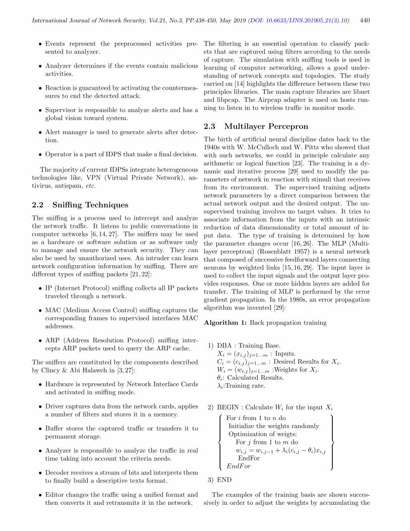
International Journal of Network Security, Vol.21, No.3, PP.438-450, May 2019 (DOI: 10.6633/IJNS.201905 21(3).10) 440
• Events represent the preprocessed activities pre-sented to analyzer.
• Analyzer determines if the events contain maliciousactivities.
• Reaction is guaranteed by activating the countermea-sures to end the detected attack.
• Supervisor is responsible to analyze alerts and has aglobal vision toward system.
• Alert manager is used to generate alerts after detec-tion.
• Operator is a part of IDPS that make a final decision.
The majority of current IDPSs integrate heterogeneoustechnologies like, VPN (Virtual Private Network), an-tivirus, antispam, etc.
2.2 Sniffing Techniques
The sniffing is a process used to intercept and analyzethe network traffic. It listens to public conversations incomputer networks [6, 14, 27]. The sniffers may be usedas a hardware or software solution or as software onlyto manage and ensure the network security. They canalso be used by unauthorized uses. An intruder can learnnetwork configuration information by sniffing. There aredifferent types of sniffing packets [21,22]:
• IP (Internet Protocol) sniffing collects all IP packetstraveled through a network.
• MAC (Medium Access Control) sniffing captures thecorresponding frames to supervised interfaces MACaddresses.
• ARP (Address Resolution Protocol) sniffing inter-cepts ARP packets used to query the ARP cache.
The sniffers are constituted by the components describedby Clincy & Abi Halaweh in [3, 27]:
• Hardware is represented by Network Interface Cardsand activated in sniffing mode.
• Driver captures data from the network cards, appliesa number of filters and stores it in a memory.
• Buffer stores the captured traffic or transfers it topermanent storage.
• Analyzer is responsible to analyze the traffic in realtime taking into account the criteria needs.
• Decoder receives a stream of bits and interprets themto finally build a descriptive texts format.
• Editor changes the traffic using a unified format andthen converts it and retransmits it in the network.
The filtering is an essential operation to classify pack-ets that are captured using filters according to the needsof capture. The simulation with sniffing tools is used inlearning of computer networking, allows a good under-standing of network concepts and topologies. The studycarried on [14] highlights the difference between these twoprinciples libraries. The main capture libraries are libnetand libpcap. The Airpcap adapter is used on hosts run-ning to listen in to wireless traffic in monitor mode.
2.3 Multilayer Percepron
The birth of artificial neural discipline dates back to the1940s with W. McCulloch and W. Pitts who showed thatwith such networks, we could in principle calculate anyarithmetic or logical function [23]. The training is a dy-namic and iterative process [29] used to modify the pa-rameters of network in reaction with stimuli that receivesfrom its environment. The supervised training adjustsnetwork parameters by a direct comparison between theactual network output and the desired output. The un-supervised training involves no target values. It tries toassociate information from the inputs with an intrinsicreduction of data dimensionality or total amount of in-put data. The type of training is determined by howthe parameter changes occur [16, 26]. The MLP (Multi-layer perceptron) (Rosenblatt 1957) is a neural networkthat composed of successive feedforward layers connectingneurons by weighted links [15, 16, 29]. The input layer isused to collect the input signals and the output layer pro-vides responses. One or more hidden layers are added fortransfer. The training of MLP is performed by the errorgradient propagation. In the 1980s, an error propagationalgorithm was invented [29]:
Algorithm 1: Back propagation training
1) DBA : Training Base.Xi = (xi,j)j=1...m : Inputs.Ci = (ci,j)j=1...m : Desired Results for Xi.Wi = (wi,j)j=1...m :Weights for Xi.θi: Calculated Results.λi:Training rate.
2) BEGIN : Calculate Wi for the input Xi
For i from 1 to n doInitialize the weights randomlyOptimization of weigts:
For j from 1 to m dowi,j = wi,j−1 + λi(ci,j − θi)xi,jEndFor
EndFor
3) END
The examples of the training basis are shown succes-sively in order to adjust the weights by accumulating the
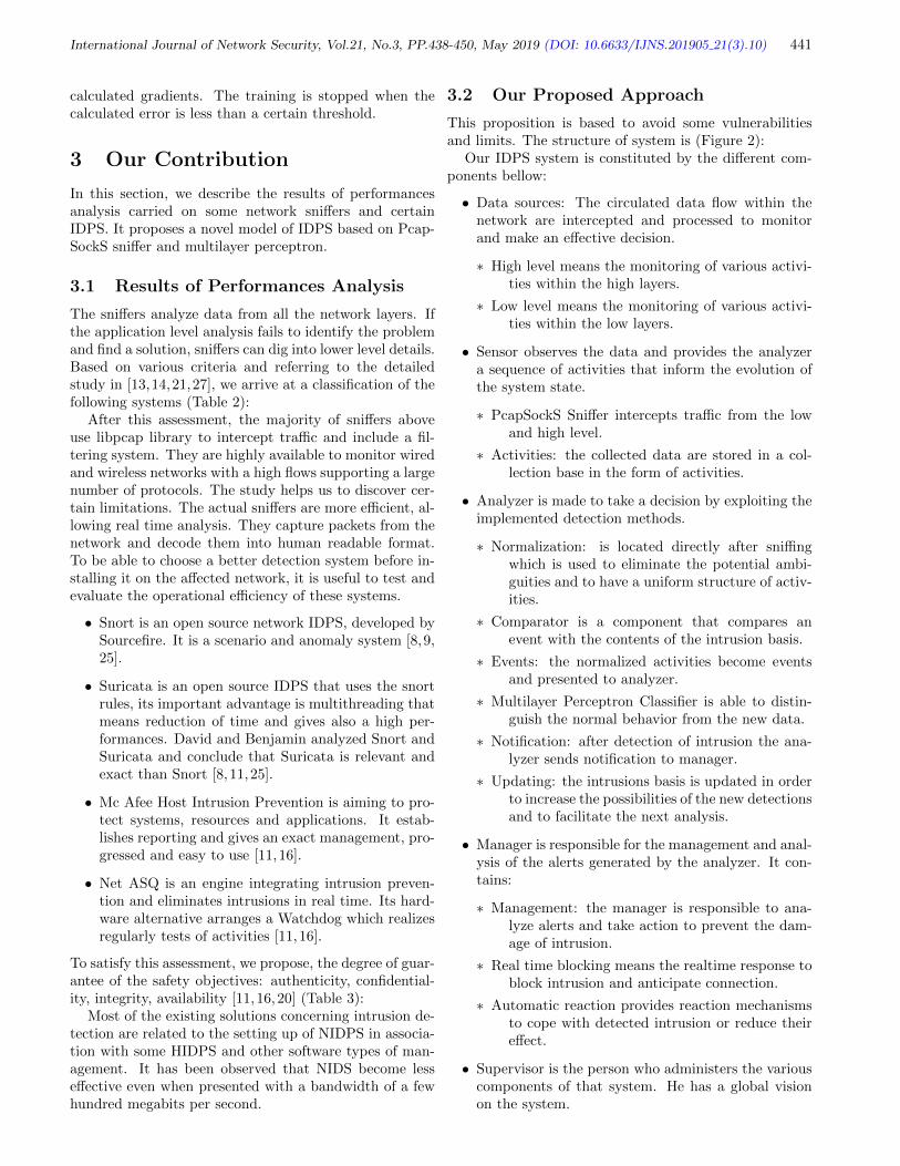
International Journal of Network Security, Vol.21, No.3, PP.438-450, May 2019 (DOI: 10.6633/IJNS.201905 21(3).10) 441
calculated gradients. The training is stopped when thecalculated error is less than a certain threshold.
3 Our Contribution
In this section, we describe the results of performancesanalysis carried on some network sniffers and certainIDPS. It proposes a novel model of IDPS based on Pcap-SockS sniffer and multilayer perceptron.
3.1 Results of Performances Analysis
The sniffers analyze data from all the network layers. Ifthe application level analysis fails to identify the problemand find a solution, sniffers can dig into lower level details.Based on various criteria and referring to the detailedstudy in [13,14,21,27], we arrive at a classification of thefollowing systems (Table 2):
After this assessment, the majority of sniffers aboveuse libpcap library to intercept traffic and include a fil-tering system. They are highly available to monitor wiredand wireless networks with a high flows supporting a largenumber of protocols. The study helps us to discover cer-tain limitations. The actual sniffers are more efficient, al-lowing real time analysis. They capture packets from thenetwork and decode them into human readable format.To be able to choose a better detection system before in-stalling it on the affected network, it is useful to test andevaluate the operational efficiency of these systems.
• Snort is an open source network IDPS, developed bySourcefire. It is a scenario and anomaly system [8,9,25].
• Suricata is an open source IDPS that uses the snortrules, its important advantage is multithreading thatmeans reduction of time and gives also a high per-formances. David and Benjamin analyzed Snort andSuricata and conclude that Suricata is relevant andexact than Snort [8, 11,25].
• Mc Afee Host Intrusion Prevention is aiming to pro-tect systems, resources and applications. It estab-lishes reporting and gives an exact management, pro-gressed and easy to use [11,16].
• Net ASQ is an engine integrating intrusion preven-tion and eliminates intrusions in real time. Its hard-ware alternative arranges a Watchdog which realizesregularly tests of activities [11,16].
To satisfy this assessment, we propose, the degree of guar-antee of the safety objectives: authenticity, confidential-ity, integrity, availability [11,16,20] (Table 3):
Most of the existing solutions concerning intrusion de-tection are related to the setting up of NIDPS in associa-tion with some HIDPS and other software types of man-agement. It has been observed that NIDS become lesseffective even when presented with a bandwidth of a fewhundred megabits per second.
3.2 Our Proposed Approach
This proposition is based to avoid some vulnerabilitiesand limits. The structure of system is (Figure 2):
Our IDPS system is constituted by the different com-ponents bellow:
• Data sources: The circulated data flow within thenetwork are intercepted and processed to monitorand make an effective decision.
∗ High level means the monitoring of various activi-ties within the high layers.
∗ Low level means the monitoring of various activi-ties within the low layers.
• Sensor observes the data and provides the analyzera sequence of activities that inform the evolution ofthe system state.
∗ PcapSockS Sniffer intercepts traffic from the lowand high level.
∗ Activities: the collected data are stored in a col-lection base in the form of activities.
• Analyzer is made to take a decision by exploiting theimplemented detection methods.
∗ Normalization: is located directly after sniffingwhich is used to eliminate the potential ambi-guities and to have a uniform structure of activ-ities.
∗ Comparator is a component that compares anevent with the contents of the intrusion basis.
∗ Events: the normalized activities become eventsand presented to analyzer.
∗ Multilayer Perceptron Classifier is able to distin-guish the normal behavior from the new data.
∗ Notification: after detection of intrusion the ana-lyzer sends notification to manager.
∗ Updating: the intrusions basis is updated in orderto increase the possibilities of the new detectionsand to facilitate the next analysis.
• Manager is responsible for the management and anal-ysis of the alerts generated by the analyzer. It con-tains:
∗ Management: the manager is responsible to ana-lyze alerts and take action to prevent the dam-age of intrusion.
∗ Real time blocking means the realtime response toblock intrusion and anticipate connection.
∗ Automatic reaction provides reaction mechanismsto cope with detected intrusion or reduce theireffect.
• Supervisor is the person who administers the variouscomponents of that system. He has a global visionon the system.

International Journal of Network Security, Vol.21, No.3, PP.438-450, May 2019 (DOI: 10.6633/IJNS.201905 21(3).10) 442
Tab
le2:
Per
form
an
ces
ass
essm
ent
of
som
en
etw
ork
sniff
ers
Netw
ork
sniff
ers
S/H
Lib
rary
Fil
terin
gF
low
Avail
abil
ity
Ale
rt
Real
tim
eT
cp
dum
pS
Lib
pcap
(Win
pcap)
++
Flo
wof
Eth
ern
et
netw
ork
sV
ery
econom
ical
inst
allati
on
file
size:
484
KB
--
--
Wir
esh
ark
SL
ibp
cap
(Win
pcap)
++
Flo
wof
Eth
ern
et
and
wir
ele
ssnetw
ork
s.81
MB
aft
er
inst
allati
on.
--
++
PA
CK
ET
YZ
ER
SL
ibp
cap
(Win
pcap)
++
Flo
wof
Eth
ern
et,
FD
DI,
PP
P,
Token
-supp
ort
s483
pro
tocols
.-
-+
+R
ing
and
wir
ele
ssnetw
ork
s.-D
ecodes
and
edit
spack
ets
.V
ery
hig
h(p
rovid
es
valu
able
info
rmati
on
ab
out
Netfl
ow
CIS
CO
SL
ibp
cap
++
Hig
hflow
netw
ork
s(G
igabit
).use
rs,
netw
ork
applicati
ons,
peak
hours
).+
++
+H
-2G
HD
ual
pro
cess
or.
-2G
OM
em
ory
.F
low
wir
ed
and
wir
ele
ssnetw
ork
s-N
oT
ole
rant
wit
hth
eatt
ack
s:A
RP
,T
CP
Cola
soft
Capsa
SL
ibp
cap
++
over
802.1
1a,
802.2
2b,
802.1
1g
port
scannin
g,
++
++
and
802.1
1n
-Sig
nals
DO
Satt
ack
s-6
53
MB
on
aft
er
win
dow
s7
inst
allati
on.
-Fre
evers
ion
isavailable
wit
hlim
ited
featu
res.
-Inte
gra
tes
SN
MP
,P
ack
et
(Sniffi
ng
and
Net
flow
).-m
onit
ors
24/7
netw
ork
.P
RT
GN
etw
ork
SL
ibp
cap
++
Hig
hflow
-In
clu
des
over
200
typ
es
of
senso
rs.
++
++
Monit
or
H-L
ess
than
30
pro
tocols
(Fre
e).
-M
ore
than
30
pro
tocols
(Com
)K
ism
itS
Lib
pcap
++
Flo
ws
of
wir
ele
ssnetw
ork
s802.1
1n,
Hig
h(s
upp
ort
sany
wir
ele
sscard
rfm
on)
++
++
802.2
2b
802.1
1g
and
802.1
1a
Scapy
SL
ibp
cap
and
Lib
net
++
Inje
cte
sth
e802
fram
es
-G
enera
tes
and
receiv
es
quic
kand
accura
tetr
affi
c.
++
++
-D
ecodes
pack
ets
of
anum
ber
of
pro
tocols
.E
thern
et,
Gig
abit
,10
Gig
abit
,-c
aptu
res
on
mult
iple
netw
ork
ssi
mult
aneousl
y.
Om
niP
eek
SL
ibp
cap
++
208.1
1a
/b
/g
/n
/ac
wir
ele
ss,
-Severa
lhundre
dpro
tocols
++
++
HV
oIP
,V
ideo,
MP
LS
and
VL
AN
-W
PA
,W
PA
2and
PSK
Decodin
g.
ET
HE
RA
PS
Lib
pcap
++
Flo
ws
of
Eth
ern
et,
FD
DI,
Token
Rin
g,
-Is
only
available
for
GN
U/
Lin
ux
syst
em
s.-
-+
+IS
DN
.Soft
Perf
ect
-Analy
zes
of
fragm
ente
dfloors
.N
etw
ork
Pro
tocol
SL
ibp
cap
++
Flo
ws
of
Eth
ern
et
netw
ork
s-D
efr
agm
ents
and
reass
em
ble
sth
epack
ets
.-
-+
+A
naly
zer
-Siz
eof
the
inst
allati
on
file
4.8
7M
b.
-W
irele
ssnetw
ork
s802.1
1.
-Identi
ficati
on
the
coord
inate
daccess
poin
ts.
Air
odum
pS
Lib
pcap
++
-Supp
ort
s4.2
GH
zch
annels
-Wri
tes
the
severa
lfile
sconta
inin
gdeta
ils
--
++
of
all
seen
access
poin
tsand
clients
.
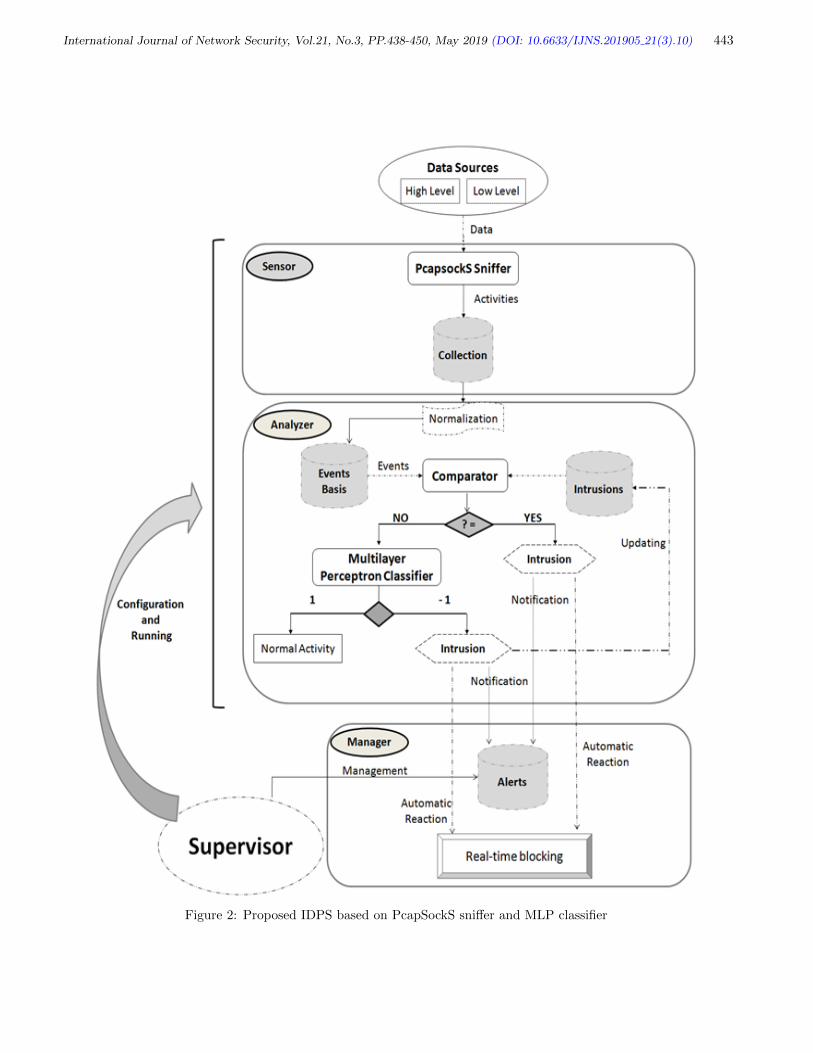
International Journal of Network Security, Vol.21, No.3, PP.438-450, May 2019 (DOI: 10.6633/IJNS.201905 21(3).10) 443
Figure 2: Proposed IDPS based on PcapSockS sniffer and MLP classifier

International Journal of Network Security, Vol.21, No.3, PP.438-450, May 2019 (DOI: 10.6633/IJNS.201905 21(3).10) 444
Tab
le3:
Ass
essm
ent
base
don
secu
rity
ob
ject
ives
Snort
NetA
SQ
Suric
ata
Win
pooch
MC
Afe
eB
ro
Net
Screen
Cis
co
Net
Intercept
Intrusio
nR
anger
Auth
enti
cit
yH
igh
Pro
tocole
IPSE
C,
Hig
hM
AC
alg
ori
thm
Hig
hH
igh
Mediu
mA
CL
Lis
tsC
ert
ificats
X.5
09,
PK
Iin
frast
ructu
res,
SSL
Confidenti
ality
Tow
Fis
hD
ES,
3D
ES,
AE
S,
Cry
pto
gra
fic
functi
ons
——
—–
Inclu
de
SSH
functi
ons
RC
4A
lgori
thm
——
Alg
ori
thm
Blo
wF
ish.
of
TL
Spro
tocol
Inte
git
y5M
B/s,
10M
B/s,
Hig
hsp
eed
MD
5,
Hush
functi
ons
of
Inclu
des
scan
of
—–
hig
h-l
evel
sem
anti
c5M
B/s,
100M
B/s,
Hig
h4G
B/s
SH
A1,
SH
A2
TL
Spro
tocol
Cla
mW
inantu
vir
us
analy
sis/
dete
ct
ala
rge
1G
B/s/
reliabilit
ynum
ber
of
pro
tocols
Availabilit
yC
onti
nuous
Conti
nuous
Conti
nuous
Hig
hC
onti
nuous
Conti
nuous
Conti
nuous
Conti
nuous
frequency
frequency
frequency
frequency
frequency
frequency
frequency
The use and management of databases is very importantin this approach; we opted for using of four databases:
• Collection basis is composed by activities that inter-cepted within networks by PcapsockS sniffer.
• Events basis is constituted by the normalized activi-ties.
• Intrusions basis includes all known attacks by usinga certain format. There is no standard for the codingof attacks. It is updated after detection.
• Alerts basis contains different alerts generated afterdetection by our IDPS.
Our IDPS performs the first monitoring based on signa-ture detection. Thus, it needs signatures basis that willsatisfy this type of detection. Therefore, we have to con-ceive intrusions basis which characterize the anomalies ofthe monitored network (Figure 3).
Figure 3: Conception of intrusions basis
The monitoring is done in a hybrid and complete wayby controlling all levels of data sources. For this, we usethe most famous sniffing tools more used currently to meetour needs. For example, we use Scapy [13,14,16] for highlevel sniffing and Wireshark [3,14,21] for the lower layers.The collected activities are recorded in a collection basis.In this case, the sniffing type takes place during so calledabnormal operation of the network to collect abnormalactivities characterizing the anomalies of the monitorednetwork. The intrusions are used by detection systems.They are stored and integrated into their database at eachinfection. The detection is carried out by comparing theevent collected the contents of the intrusion database. Toimplement the new approach, various phases are used:

International Journal of Network Security, Vol.21, No.3, PP.438-450, May 2019 (DOI: 10.6633/IJNS.201905 21(3).10) 445
3.2.1 Collection and Filtering Phase
The proposed design in [1] focuses on the combination ofcurrent performances of high sniffers and minimization ofvarious limitations. It is a distributed model consisted bytwo main components:
• The kernel is composed by two processors to captureand filter the traffic.
• The operator decodes and normalizes the electedtraffic.
These components are described in the figure below (Fig-ure 4):
This traffic is composed of a set of bits and frames, it’ssaved in a temporary basis to apply the BPF (BerkeleyPacket Filter) and then meet adequate collection condi-tions. Libpcap provides the possibility to introduce thefilters to filter traffic: PBF, SWIF. It applies the filters ontraffic in the basis in order to choose the elected packets.This latter is redirected to the operator space. The decod-ing processor normalizes and stores the chosen traffic inthe collection Database. In the high level, we use the sock-ets mechanism to ensure a reliable collection. The TCP(Transmission Control Protocol) and UDP (User Data-gram Protocol) sockets are implemented for this purpose.Raw sockets are used to reinforce the interception to thelow level with libpcap. The collected traffic is saved ina temporary basis to apply the filter LSF and redirecteddirectly to Collection Database. Our sniffer collects datain three modes:
• Connection oriented mode requires a prior connec-tion establishment between communicating entities.
• Connectionless mode cannot guarantee a reliable con-nection, insertion errors, wrong delivery, duplication,or non sequencing delivery packets.
• Raw mode can provide both services in connectionoriented and connectionless mode.
The filtering provides a considerable gain; it avoids thecongestion and the saturation of memory. The filtering isa very useful to meet the various network services usingmainly in intrusion detection. The treatments are in realtime. Take into account the time constraints which are asimportant as the accuracy of the results for this systemsynchronizes multiple tasks that take place and the possi-bility of including several shorter threads in a single pro-cess. To show the performances provided by PcapSockSSniffer, it is very useful to compare it with other snifferswhich have demonstrated their reliability (Table 4):
The new model combines libpcap and sockets functionsto capture the packets, filters traffic taking into accountthe capture needs. All treatments are in real-time andEncryption of transactions between the sniffer and Col-lection database.
3.2.2 Preprocessing and Normalization Phase
The preprocessing phase is the most labor intensive, duein particular to the lack of structuring and the largeamount of noise existing in the raw data used. It consistsin structuring the activities in order to prepare them for afuture analysis. The significant formatting is required be-fore analyzing and classifying traffic. The normalizationis carried out also to establish a pattern of activities fa-cilitating the distinction between the activities and allow-ing an extraction of useful fields if necessary. The eventsare stored in a database table which contains columns tospecify the fields and contains the occurrences with stringtype. A hash function is applied to compute the signa-tures of the content. We realize a particular coding forthe enumeration of the occurrences and adapt them tothe entries of the model which accept in principle onlyinteger, real or Boolean entries. The hashing and codingtechniques guarantee also a certain rapidity and integrity.The input layer receives successively the preprocessed oc-currences. An occurrence is subdivided into a set of fields.Each field is received by a neuron representing a simple re-ceptor that does not perform any treatment. A weightedsum is calculated on the input values. A transfer functionis applied to the calculated sum. The sigmoıde functionis implemented in the hidden layer.
3.2.3 Classification Phase
We propose a rigorous algorithm for training and recog-nition. Thus, we use the multilayer perceptron. The pro-posed classifier is [15,16,19] (Figure 5).
Each layer has neurons directly linked to the neurons ofthe next layer. We find ourselves faced with an optimiza-tion model containing changeable variables that describethe problem, together with constraints representing limitson these variables. We define a cost function to minimizeis:
ai =
m∑j=1
wi,jxi,j + w0,i for i = 1, · · · , n.
The inputs preprocessing are used to remove redundantand irrelevant information in order to achieve a small andoptimal network structure.
Algorithm 2: Training algorithmInitialize weights W (0) = (wi,0)i=1...n such as wi,0 6 10−3
for i = 1 . . . n and w0,i = 1.For i from 1 to n do
1) Present the iutputs Xi = (xi,j)j=1...m.
2) Calculate W(op)i and εi :
εi = minai
(1− y(ai))

International Journal of Network Security, Vol.21, No.3, PP.438-450, May 2019 (DOI: 10.6633/IJNS.201905 21(3).10) 446
Figure 4: The pcapSockS sniffer
Table 4: Comparison between pcapSockS sniffer, scapy and wireshark
Sniffer Platforms Low capture High capture Low filtering High Networkfiltering
Scapy -Win -Libpcap -Libnet -PBFfilter -No -Wired-Linux -Python Functions -Wireless
-Mac OSWireshark -Win -Libpcap -No -PBF Filter -No -Wired
-Linux -WirelessPcap.Sock -Win -Libpcap - Sock−Stream -PBF Filter -LSF Filter -Wired
Sniffer -Linux -Raw Sockets -Sock−Dgram
Figure 5: Multilayer perceptron classifier

International Journal of Network Security, Vol.21, No.3, PP.438-450, May 2019 (DOI: 10.6633/IJNS.201905 21(3).10) 447
ai =
m∑j=1
wi,jxi,j + w0,i;
y(ai) = f(ai);w0,i = w0,i + [1− y(ai)];For j from 1 to m do
wi,j = wi,j−1 + [1− y(ai)]xi,j ;EndFor
3) EndFor
In the following, we denote with:
W(max)
= (w(max)j )j=1...m with w
(max)j =
maxw(op)i,j , i = 1 . . . n and w
(max)0 = maxw(op)
0,i , i =
1 . . . n, a(max)i =
m∑j=1
w(max)i,j xi,j + w
(max)0,i a
(op)i =
m∑j=1
w(op)i,j xi,j + w
(op)0,i and S = (Xn
i=1 = (xi,j)j=1...m,
W(op)i = (w
(op)i,j )j=1...m, w
(op)0,i , εi), i = 1 . . . n the
obtained results during the training phase.
Proposition 3.1. With the above assumptions, we thenhave for all i ∈ 1, . . . , n
1) a(max)i ≥ a(op)
i .
2) 0 < 1− y(a(max)i ) ≤ εi.
Proof.
1) As wmaxj = maxw(op)
i,j , i = 1 . . . n ≥ w(op)i,j and
xi,j ≥ 0 for all i = 1 . . . n, then a(max)i > a
(op)i for
all i ∈ 1, . . . , n.
2) We have 1 − y(a(op)i ) = εi for each i ∈ 1, . . . , n
, y(a(op)i ) = f(a
(op)i ). Therefore 0 6 f(a
(op)i ) 6
f(a(max)i ) < 1 for each i ∈ 1, . . . , n because f is
an increasing function.
Thereafter εi = 1 − y(a(op)i ) = 1 − f(a
(op)i ) > 1 −
f(a(max)i ) = 1− y(a
(max)i ) > 0
which shows (2).
This phase consists of validating the model: We use forthis the optimized weights which are obtained during thetraining phase.
Definition 3.1. Let K = (kj)j=1...m be an input occur-
rence and a =
m∑j=1
w(max)j kj + w
(max)0 .
1) K is a normal occurrence if there exits i ∈ 1, . . . , nsuch that 1− y(a) 6 εi.
2) K is an intrusion occurrence if for all i ∈ 1, . . . , nwe get 1− y(a) > εi.
Proposition 3.2. Let K = (kj)j=1...m be an input oc-
currence, a =
m∑j=1
w(max)j kj + w
(max)0 and ε = εi, i =
1, . . . , n.The following conditions are equivalent:
1) K is an intrusion.
2) 1− y(a) > ε.
The proof of this proposition relies on Definition 3.1.
Corollary 3.1. : Let K = (kj)j=1...m be an input occur-
rence, a =
m∑j=1
w(max)j kj + w
(max)0 and ε = maxεi, i =
1, . . . , n. The following conditions are equivalent:
1) K is a normal information.
2) 1− y(a) ≤ ε.
The proof of this corollary relies on Definition 3.1 andProposition 3.2.
Algorithm 5: Recognition algorithm
1) New input X = (x(j))j=1...m, final output d, activa-tion state a, calculated result y(a).
2) Computing of output
a =
m∑j=1
w(max)j x(j) + w
(max)0 ;
y(a) = f(a);
3) Classification of activitiesif (1− y(a) 6 ε) thend = 1 //Normal activityelsed = −1 //Intrusion
Endif
The sigmoid is introduced into the two proposed algo-
rithms for training and recognition. It presents certainconstraints during its implementation which leads us tomake an evaluation of the sigmoid on platforms more usedin practice. In this case, we determine the random valuesof the weights in wi 6 10−3 to ensure the possible resultsand avoid the falsified outputs. This modeling leads usto develop an optimal and restricted database containingthe occurrences (Table 5):
Table 5: Database structure
W (max) = (w(max)j )mj=0 ε

International Journal of Network Security, Vol.21, No.3, PP.438-450, May 2019 (DOI: 10.6633/IJNS.201905 21(3).10) 448
3.3 Evaluation Study of Proposed Ap-proach
To accomplish such evaluation, a set of measures areavailable: precision, number of false positives and falsenegatives. We take into account the parameters citedin [5,11,14,16,20] such as data sources, intrusion response,frequency of use, real time analysis, intrusion blockingmethod, real time alert, logging, filtering methods, com-patible operating systems (Table 6).
The proposed classifier defines a supervised method us-ing a three layer perceptron and represents a perceptualanalysis layer which can be integrated into our new de-tection system to monitor traffic and make control of thedata flow more reliable. With a series of experimentalstudies on a set of intrusion detection and prevention sys-tems much responded actually. We demonstrated thatour new proposal model is more efficient, especially atthe level, of data collection, pretreatment of the activitiesand their classification.
4 Conclusion
An IDPS tries to detect malicious activities and attacks.It attempts to control computers by monitoring traffic.Many methods have been employed. In this paper, weperform performances evaluation of a list of sniffing andintrusion detection tools and we deduct in the end thatthose tools suffer much vulnerabilities. So, we propose anoptimal approach of intrusion detection based on multi-layer perceptron technique aiming to improve the accu-racy of detection. The modeled system aims to protectnetworks from attacks on service integrity, authenticationand confidentiality. The preprocessing is performed totransform data evens into a new representation beforebeing presented to a neural network inputs. With im-plementations carried on different parts, we demonstratethat our system gives the solutions more reliable and rel-evant to improve the o the network security. Our nextwork will focus and discuss in detail the various steps ofimplementation and validation of this global system de-scribing the proposed solutions.
References
[1] Amrita, K. Ravulakollu, “A hybrid intrusion detec-tion system: Integrating hybrid feature selection ap-proach with heterogeneous ensemble of intelligentclassifiers,” International Journal of Network Secu-rity (IJNS’18), vol. 20, no. 1, pp. 41-55, 2018.
[2] V. Alanou, Detection D’intrusion Dans Un SystemeInformatique : Methodes Et Outils, 1996. (http://www.secdev.org/idsbiblio/lme96methodes.pdf)
[3] Asrodia, et al., ”Analysis of various packet sniffingtools for network monitoring and analysis,” Inter-national Journal of Electrical, Electronics and Com-puter Engineering, vol. 1, no. 1, pp. 55-58, 2012.
Tab
le6:
Ass
essm
ents
base
don
pro
pose
dp
ara
met
ers
Snort
NetA
SQ
Suric
ata
MC
Afe
eB
ro
Cis
co
Net
Our
Prop
osed
Intercept
Ranger
IDP
SR
ealt
imA
naly
sis
Yes
Yes
Yes
Yes
Yes
Yes
Yes
Typ
eN
ips/
Hip
sN
ips/
Hip
sN
ips
Nip
sN
ips
Nip
sN
idps/
Hid
ps
Dete
cti
on
Sig
natu
reSig
natu
re/
Sig
natu
re/
Sig
natu
re/
Sig
natu
re/
Sig
natu
reSig
natu
re/
typ
eB
ehavio
ral
Behavio
ral
Behavio
ral
Behavio
ral
Behavio
ral
Blo
ckin
gY
es
Yes
Yes
Yes
Yes
Yes
Yes
Reacti
on
Acti
ve
Acti
ve
Acti
ve
Acti
ve
Pass
ive
Acti
ve
Acti
ve
Real
tim
eA
lert
sY
es
Yes
Yes
Yes/
Em
ail,
SN
MP
Yes
Yes
Yes
Loggin
gY
es
Yes
Yes
Yes/
MS
SQ
LServ
er
Yes
Yes
Yes
Filte
ring
Dete
rmin
ed
Filte
ring
and
Yes
Yes
Yes
Yes
Yes
by
Adm
inflow
conto
lU
pdati
ng
Manual
Auto
mati
cM
anual
—–
Auto
mati
cA
uto
mati
cA
uto
mati
c/
Manual
Op
era
ting
Lin
ux/
Lin
ux/
OS
Com
mun
Win
dow
s/L
inux/
Fre
eO
SC
om
mun
Lin
ux/
Syst
em
sW
indow
sW
indow
sSola
ris
BSD
/M
AC
OS
Win
dow
sM
odula
rity
of
No
No
No
No
No
No
Yes
com
ponents
Data
collecti
on
Mediu
mM
ediu
mM
ediu
mM
ediu
mM
ediu
mM
ediu
mH
igh
Cla
ssifi
cati
on
Mediu
mM
ediu
mM
ediu
mM
ediu
mM
ediu
mM
ediu
mH
igh
of
atv
itie
s

International Journal of Network Security, Vol.21, No.3, PP.438-450, May 2019 (DOI: 10.6633/IJNS.201905 21(3).10) 449
[4] J. Balasubramaniyan, J. O. Garcia-Fernandez, D.Isacoff, E. Spafford, D. Zamboni, “An archi-tecture for intrusion detection using autonomousagents,” COAST Laboratory Purdue University WestLafayette, 1998. ISBN: 0-8186-8789-4.
[5] M. Boujnouni and M. Jedra, “New intrusion detec-tion system based on support vector domain descrip-tion with information gain metric,” InternationalJournal of Network Security (IJNS’18), vol. 20, no.1, pp. 25-34.
[6] L. Chappell, ”Wirehark 101 essential skills fornetwork analysis,” Protocol Analysis Institute, Inc,2013. (https://www.wiresharkbook.com/101v2_samplepages/Wireshark978-1893939752-toc.
pdf)[7] A. Chaudhary, V. N. Tiwari, and A. Kumar, “A New
intrusion detection system based on soft comput-ing techniques using neuro-fuzzy classifier for packetdropping attack in MANETs,” International Journalof Network Security, vol. 18, no. 3, pp. 514-522, 2017.
[8] D. J. Day, B. Burns, “A performance analysisof snort and suricata network intrusion detectionand prevention engines,” in The Fifth Inter-national Conference on Digital Society, 2011.(https://www.researchgate.net/publication/241701294_A_Performance_Analysis_of_Snort_
and_Suricata_Network_Intrusion_Detection_
and_Prevention_Engines)[9] O. Eldow, P. Chauhan, P. Lalwani, M. Potdar,
“Computer network security ids tools and techniques(snort/suricata),” International Journal of Scientificand Research Publications, vol. 6, no. 1, pp. 593,2016.
[10] Y. Farhaoui, A. Asimi, “Creating a complete modelof an intrusion detection system effective on theLAN,” International Journal of Advanced ComputerScience and Applications (IJACSA’12), vol. 3, no. 5,2012.
[11] Y. Farhaoui and A. Asimi, “Performance method ofassessment of the intrusion detection and preventionsystems,” International Journal of Engineering Sci-ence and Technology (IJEST’11), vol. 3, 2011. ISSN:0975-5462.
[12] Y. Farhaoui, “Design and implementation of an in-trusion prevention system,” International Journal ofNetwork Security, vol. 19, no. 5, pp. 675-683, 2017.
[13] C. Gandhi, G. Suri, R. P. Golyan, P. Saxena, B. K.Saxena, ”Packet sniffer – A comparative study,” In-ternational Journal of Computer Networks and Com-munications Security, vol. 2, no. 5, pp. 179–187,2014.
[14] A. Guezzaz, et al., “A new hybrid network sniffermodel based on Pcap language and sockets (Pcap-SockS),” International Journal of Advanced Com-puter Science and Applications (IJACSA’16), vol. 7,no. 2, 2016.
[15] A. Guezzaz, et al., “A novel scheme of an intru-sion system using multilayer perceptron,” The Sec-
ond International Day on Computer Science & Ap-plied Mathematics in Saculty of Sciences and Tech-niques (ICSAM’17), vol. 9, no. 4, 2017.
[16] A. Guezzaz, et al., “A hybrid NIPS based on pcap-SockS sniffer and neural MLP,” in International Con-ference on Information Technology and Communica-tion Systems in National School of Applied Sciences(ITCS’17), pp. 253-266, 2017.
[17] A. Guezzaz, et al., “A lightweight neural classifierfor behavioral detection,” in International Confer-ence on Information Technology and Communica-tion Systems in Faculty of Sciences and Techniques(IWAM’17), vol. 2, no. 2, pp. 57-66, 2017.
[18] A. Gupta, M. Kumar, A. Rangra, V. K. Tiwari,P. Saxena, ”Network intrusion detection types andanalysis of their tools,” Department of Computer Sci-ence and Information Technology, Jaypee Universityof Information Technology, vol. 2, no. 1, pp. 63-69,2012.
[19] A. Guezzaz, et al., “A lightweight neural classifierfor intrusion detection,” General Letters in Mathe-matics, vol. 2, pp.57-66, 2017.
[20] A. Guezzaz, et al., “A hybrid NIPS based on Pcap-SockS sniffer and neural MLP,” International Con-ference on Information Technology and Communica-tion Systems (ITCS’17), pp. 253-266, 2017.
[21] A. Halaweh,“A taxonomy of free network snifers forteaching and research,” Journal of Computing Sci-ences in Colleges, vol. 21, no. 1, pp. 64-75, 2005.
[22] B. Ma, “Using packet sniffing to teach networkingconcepts,” Journal of Computing Sciences in Col-leges, vol. 30, no. 6, pp. 67-74, 2015.
[23] N. Malik, “Artificial neural networks and theirapplications,” National Conference on Un-earthing Technological Developments & theirTransfer for Serving Masses GLA ITM, 2005.(https://www.researchgate.net/publication/1958135_Artificial_Neural_Networks_and_
their_Applications)
[24] L. Moulad, H. Belhadaoui, M. Rifi, “Implementationof a hierarchical hybrid intrusion detection mech-anism in wireless sensors network”, InternationalJournal of Advanced Computer Science and Appli-cations (IJACSA’17), vol. 8, no. 10, 2017.
[25] M. Ridho, F. Yasin, M. Eng, “Analysis and eval-uation snort, bro, and suricata as intrusion detec-tion system based on linux server,” Department ofInformatics, Faculty of Communications and Infor-matics Universitas Muhammadiyah Surakarta, 2014.(http://etd.eprints.ums.ac.id/31281/)
[26] M. Rochaa, et al., “Evolution of neural networks forclassification and regression,” Neurocomputing, vol.70, no. 16-18, pp. 2809-2816, 2007.
[27] Rupam, A. Verma, A. Singh, ”An approach to detectpackets using packet sniffing,” International Journalof Computer Science & Engineering Survey (IJC-SES’13), vol. 4, no. 3, 2013.

International Journal of Network Security, Vol.21, No.3, PP.438-450, May 2019 (DOI: 10.6633/IJNS.201905 21(3).10) 450
[28] B. Santos, T. Chandra, M. Ratnakar, S. Baba, N.Sudhakar, “Intrusion detection system types and pre-vention,” International Journal of Computer Scienceand Information Technologies, vol. 4, no. 1, 2013.
[29] Schiffmann, et al., Optimization of the Backprop-agation Algorithm for Training Multilayer Per-ceptrons, 1994. (http://www.cs.bham.ac.uk/~pxt/NC/schiffmann.bp.pdf)
Biography
Guezzaz Azidine received his Ph.D in design and val-idation of an intrusion detection and prevention systembased on neural network for cloud computing. His re-search interest is Intrusion Detection and Prevention andComputer and Network Security and Cryptography. Heis an assistant professor at the Technology High SchoolEssaouira Cadi Ayyad University Marrakech, Morocco.
ASIMI Ahmed received his PhD degree in Number the-ory from the University Mohammed V – Agdal in 2001.He is reviewer at the International Journal of NetworkSecurity (IJNS). His research interest includes Numbertheory, Code theory, and Computer Cryptology and Se-
curity. He is a full professor at the Faculty of Science atAgadir Morocco since 2008.
Younes Asimi received his Ph.D. in Strong Zero-Knowledge Authentication Based on virtual passwordsper session and the Session Keys in 2015. His research in-terests include Authentication Protocols, Computer andNetwork Security and Cryptography. He is an assistantprofessor at the Technology High School Guelmim, Ibn-Zohr University Agadir, Morocco.
Tbatou Zakariae received his Ph.D degree in. He is cur-rently Ph.D student in Authentication Protocols Kerberosfor distributed systems. His research interests include Au-thentication Protocols, distributed systems, cloud com-puting, Computer and Network Security and Cryptogra-phy.
SADQI Yassine received his Ph.D degree in the field ofComputer Science and Distributed Systems at Ibn Zo-her University in 2012. His research interest is WebApplications Security, Computer Security and Cryptog-raphy. He is an assistant professor at PolydisciplinairyFaculty,Sultan Moulay Slimane University, Beni Mellal,Morocco.

International Journal of Network Security, Vol.21, No.3, PP.451-461, May 2019 (DOI: 10.6633/IJNS.201905 21(3).11) 451
Privacy-preserving TPA Auditing Scheme Basedon Skip List for Cloud Storage
Haichun Zhao1,2, Xuanxia Yao1, and Xuefeng Zheng1
(Corresponding author: Xuanxia Yao)
School of Computer and Communication Engineering, University of Science and Technology Beijing1,
Beijing, China
School of Computer Science and Technology, Inner Mongolia University for Nationalities2,
Tongliao, China
(Email: [email protected])
(Received Jan. 3, 2018; Revised and Accepted June 15, 2018; First Online Jan. 25, 2019)
Abstract
Recently, researchers have proposed several privacy-preserving public auditing schemes to remotely check theintegrity of outsourced data based on homomorphic au-thenticators, random block sampling and random mask-ing techniques. However, almost all these schemes requireusers to maintain tables related to the block index. Thesetables are difficult to maintain, especially when the out-sourced data is frequently updated. In this paper, we pro-pose a privacy-preserving public auditing scheme with thesupport of dynamics using rank-based authenticated skiplist for the integrity of the data in cloud storage, of whichusers do not need to maintain the relevant table. Andwe give a formal security proof for data integrity guar-antee and analysis for privacy-preserving property of theaudit protocol. The performance analysis demonstratesthat our scheme is highly efficient.
Keywords: Audit Protocol; Cloud Storage; Privacy-preserving; Public Auditing; Rank-based AuthenticatedSkip List
1 Introduction
Cloud computing has many advantages; this has led to anincreasing number of individuals and companies choos-ing to store their data and conduct their business us-ing cloud-based services [22]. Unlike traditional systems,users lose their physical control over their data. Althoughthe cloud infrastructure is significantly more reliable thanpersonal computing devices, data security/privacy is stillone of the core considerations for users when adopt-ing cloud services because of the internal and externalthreats associated with cloud services [1, 35, 38]. There-fore, researchers have proposed various security modelsand schemes to overcome the issue of data integrity au-diting [3, 12–15,18,20,27,29–31,33,34,36,37].
The public auditable schemes allow external parties,in addition to the user, to audit the integrity of out-sourced data; however, this could potentially leak theuser’s data to auditors. Hence, researchers have proposedprivacy-preserving public auditing schemes to avoid au-ditors learning user’s data in the auditing phase. Theconstruction of the signatures in some of these schemes in-volve the block index information i, such as H (name ‖ i)or H (Bi ‖ Vi ‖ Ri) [30, 36, 37]. Users need to maintaina table in the local storage for each file, such as map-version Table [5] or index-hash table [36,37]. The table isalso sent to the third-party auditor (TPA) before the datais audited. If the table is corrupted, effective audits or dy-namic operations cannot be conducted on the outsourceddata. In addition, if a large file is stored in cloud stor-age server (CSS) and undergoes frequent insert and deleteoperations, the block index will continue to increase andbecome very large. This is because the block index cannotbe reused. Consequently, it becomes increasingly difficultfor users to maintain the table. To address the problem,the index i is removed, and H (mi) is used in construct-ing the signature for block mi to prevent replay attackon the same hash values. To support privacy-preservingTPA auditing, (H (mi))
α/β is used in the signature con-struction and assigned to the data item value for the leafnode of the skip list [9].
In this paper, a secure public auditing algorithm isproposed with the support of dynamics using a rank-basedauthenticated skip list [9] for the outsourced data. Thecontributions of this paper can be summarized as follows:
1) A privacy-preserving public auditing scheme whichfully supports dynamics by employing rank-based au-thenticated skip list is proposed. (H (mi))
α/β is usedas the data item of the bottom node of the skip listto realize privacy-preserving.
2) Based on the cryptography reduction theory [16, 21]and CPoR’s model [27] a formal security proof

International Journal of Network Security, Vol.21, No.3, PP.451-461, May 2019 (DOI: 10.6633/IJNS.201905 21(3).11) 452
is given for the integrity guarantee of outsourceddata and privacy-preserving property of the auditingphase for the scheme.
The remainder of the paper is organized as follows. Sec-tion 2 contains the related work. Section 3 introducesthe system model and our design goals. In Section 4, weelaborate our proposed scheme. Section 5 analyzes thesecurity and performance of our scheme. The conclusionis given in Section 6.
2 Related Work
Ateniese et al. proposed the provable data possession(PDP) model, which can be used for remotely checkingdata integrity [2, 3]. This model can generate probabilis-tic proofs of possession by randomly sampling data blocksfrom the server, in which the tags of the sampled blockscan be aggregated into a single value using homomor-phic verifiable tags(HVTs). It is believed to be the firstscheme to provide blockless verification and public verifi-ability at the same time. Erway et al. proposed dynamicPDP (DPDP), which applies the structure of rank-basedauthenticated skip list to ensures the integrity of the tagsusing the skip list structure and the integrity of the blocksby their tags. This scheme effectively supports provablesecure updates to the remotely stored data [9]. Juelsand Kaliski presented the proof of retrievability (PoR)model. This model ensures both the possession and theretrievability of outsourced data by using spot-checkingand error-correcting codes. However, the number of au-dit challenges a user can perform is predetermined andpublic auditability is not supported in [15].
Shacham et al. designed a compact version of PoR(CPoR) [27] and proved the security of their schemeagainst arbitrary adversaries in the Juel-Kaliski model.The construction of the publicly verifiable CPoR schemeis based on Boneh-Lynn-Shacham (BLS) signatures [8].Wang et al. proposed a public auditing scheme that sup-ports dynamic data operations in [31]. The authenticationinformation of the scheme is managed using the Merklehash tree (MHT) [23], in which the leaf nodes are thevalues of H (mi)(mi is the i-th block of the file). To pre-vent TPA extracting data content from the collected in-formation, they designed a privacy-preserving public au-diting scheme using a random mask technique to blindthe response information in the follow-up work [30]. Butits description for the dynamics is ambiguous. Zhu etal. proposed another privacy-preserving public auditingscheme which supported dynamic data updates employingan index-hash table [36]. However, in these two privacy-preserving schemes, block index related information is in-volved in the signature construction. Users are requiredto maintain a relevant table. To guarantee the integrityof the multiple replicas in cloud, Curtmola et al. pro-posed the replication-based remote data auditing scheme,called Multiple-Replica PDP (MR-PDP), which extendsthe (single-copy) PDP scheme for overcoming the collu-
sion attack in a multi-server environment. However, MR-PDP only supports private verification [7].
Barsoum et al. proposed two multi-copy DPDP pub-lic auditing schemes, supporting data dynamics based onthe MHT and map-version table, respectively. Differentcopies are generated through encrypting the concatena-tion of the copy number and file blocks [5]. In the latter,the map-version table must be stored in the local stor-age of the user and is managed by the user during thevarious update operations performed on the file. In [34],Yang et al. propose a public auditing scheme for sharedcloud data in which a group manager is introduced to helpmembers generate authenticators to protect the identityprivacy. This method uses two lists to record the mem-bers who performed the most-recent modification on eachblock to achieve the identity traceability. This schemealso achieves data privacy during authenticator genera-tion by employing a blind signature technique. To over-come the issue of resource-constrained users dealing withheavy burdens, Shen et al. proposed a cloud storage au-diting scheme for group users by introducing a third partymedium (TPM) to perform time-consuming operations onbehalf of users [29]. Utilizing proxy re-signatures andhomomorphic linear authenticators, Li et al. propose aprivacy-preserving cloud data audit scheme that can sup-port key-updating and authenticator-evolving [18].
Researchers have proposed a number of cloud storageauditing schemes in the recent past. All these schemes pri-marily focus on several different aspects of cloud storageauditing. However, almost none of these schemes addressthe issue that users need to maintain a block index relatedtable in the local storage for the privacy-preserving publicauditing schemes. Users should be “stateless” and mustnot be required to store and update the table betweendifferent dynamic operations, since such table is difficultto maintain.
3 Problem Statements
3.1 System Model
The auditing system for cloud storage involves cloudusers, CSS and TPA as shown in Figure 1. The clouduser is the data owner, who has large amount of data to bestored in the CSS. The users can access and dynamicallyupdate their data in the CSS by interacting with the CSS.The CSS, which is managed by the cloud service provider(CSP), has significant storage space and massive amountof computational resources. The users’ data is stored inthe cloud storage and is managed and maintained by theCSP. The TPA has expertise and capabilities that usersdo not have and can audit the users’ outsourced data inthe CSS on behalf of users at the users’ request.
To ensure the integrity and correctness of the users’outsourced data, users need to make periodic checks. Tosave computation resources and network bandwidth, userscan delegate the TPA to perform the periodic data in-tegrity verification. However, users do not want informa-

International Journal of Network Security, Vol.21, No.3, PP.451-461, May 2019 (DOI: 10.6633/IJNS.201905 21(3).11) 453
Data Flow
Third Party
Auditor (TPA)
Cloud Users
Security Message Flow
Cloud Storage
Server (CSS)
AuditingChallenge
Message
AuditingProof
Message
AuditingDelegation
AuditingReport
Figure 1: The cloud storage architecture includes theCSS, the cloud users and the TPA
tion from their data to be learned by the TPA during theauditing process.
In this model, it is assumed that the cloud server doesnot have the incentive to reveal their hosted data to anyexternal entity. It is also assumed that the TPA has noincentive to collude with either the CSP or the user dur-ing the auditing process. However, it is interested in theusers’ data.
3.2 Design Goals
In the aforementioned model, a scheme is proposed inwhich the design goals can be summarized as follows [19]:
1) Public auditability: To allow any authorized TPA toverify the integrity of the cloud data without retriev-ing a copy of the whole data;
2) Storage correctness: To ensure that there no CSPexists that can pass the audit of the TPA withoutstoring cloud users’ data intact;
3) Privacy preserving: To ensure that it is infeasible forthe TPA to recover the user’s data from the informa-tion collected during the auditing phase;
4) High performance: The TPA can perform data audit-ing with minimum communication and computationoverhead;
5) Dynamic data: To allow the data owners to modify,insert and delete data blocks in the cloud storagewhen they want to update their data at any time;
6) Batch auditing: The TPA can audit the data of dif-ferent users at the same time.
4 The Proposed Construction
4.1 Preliminaries
Relevant functions. A pseudo-random function (PRF) fand a pseudo-random permutation (PRP) π are used with
Figure 2: Example of a rank-based skip list
the following parameters [3]:
fk : 0, 1log2n ×K → 0, 1l;πk : 0, 1log2n ×K → 0, 1log2n.
Bilinear maps. Suppose a group G is a Gap Diffie-Hellman (GDH) group with prime order p. GT is anothermultiplicative cyclic group with prime order p. Then, thebilinear map is a map e : G ×G → GT with the followingproperties [8]:
1) Bilinearity – ∀u, v ∈ G , a, b ∈ Zp , e(ua , vb) = e(u, v)ab ;
2) Non-degeneracy – e(g , g) 6= 1 , where g is a generatorof G;
3) Computability – e should be efficiently computable.
The following scheme description uses the symmetric bi-linear map for the purpose of simplicity. The asymmetricbilinear map is in the form of e : G1 ×G2 → GT .
Rank-Based Skip List [9,11,24]. The main informationrelated to i-th node v on level 0 (bottom-level) includes:the level of i-th node l(v), the rank of i-th node r(v),the data item of i-th node T (mi) and the label of i-thnode f (v); that on non-bottom level includes: the level ofthe node l(v), the rank of the node r(v), the label of thenode f (v); In addition to these, each node contains someinformation related to the structure of the skip list, suchas, right and down pointers.
The rank value of a node indicates the number of thereachable bottom nodes (or leaf nodes) departing from thenode. The rank of a Null node equals 0. The location ofeach bottom node can be calculated from the rank valuesof the relevant nodes.
The label value of a node on bottom-level is
f (v) = h2 (l(v) ‖ r(v) ‖ T (mi) ‖ f (right(v)))
and that on non-bottom level is
f (v) = h2 (l(v) ‖ r(v) ‖ f (down(v)) ‖ f (right(v)))
where the symbol “||” denotes concatenation, f (down(v))and f (right(v)) are the label of the down and right node

International Journal of Network Security, Vol.21, No.3, PP.451-461, May 2019 (DOI: 10.6633/IJNS.201905 21(3).11) 454
of v, respectively. The label value of a Null node is 0. Thefunction h2 (·) is a collision-resistant cryptographic hashfunction. Users hold the label f (s) of the top leftmostnode (or start node) of the skip list. The f (s) is called thebasis (or root). It is equivalent to the user’s verificationmetadata.
To obtain the proof information of some block i, theskip list needs traversing from the start node vk to thenode v1 associated with block i through the rank of thenodes. The reverse path v1 , · · · , vk is called verificationpath of the block i, as shown in Figure 2. The infor-mation of the nodes x0 , y0 − y3 and v1 − v2 is used asauxiliary authentication information (AAI) for calculat-ing each rank and label value from v1 to vk on the verifi-cation path.
The proof of a block is composed of a sequence oftuples made of the relevant information of each nodeon the verification path. That is, the proof for block iwith data T (mi) is a sequence Πi = (A(v1 ), · · · ,A(vk ))where A(vj ) = (l(vj ), q(vj ), d(vj ), g(vj )), 1 ≤ j ≤ k , fromwhich we can get the AAI. The l(vj ) is the level ofthe node and Boolean d(vj ) indicates whether vj−1is to the right or below vj . The value of g(vj ) isused to calculate the label of the corresponding nodealong the verification path. For the non-bottom levelnodes, if d(vj ) = rgt , then g(vj ) = f (dwn(vj )), else ifd(vj ) = dwn, then g(vj ) = f (rgt(vj )). For bottom-levelnodes vj (j > 1 ) on the verification path, the value ofg(vj ) is the data item of the node. The value of g(v1 )is the label of the right node of v1 . For nodes atthe bottom-level, q(v1 ) is the sum of the rank of theright node of v1 and 1, this 1 means that the nodev1 itself is also a reachable node on the bottom-level.The value of q(vj ) of each node on the left side of thenode v1 at bottom-level is 1. For non-bottom levelnodes, if the node vj−1 is the right (or down) node ofvj , then q(vj ) = r(dwn(vj )) (or q(vj ) = r(rgt(vj ))).
4.2 The Privacy-preserving Scheme
The notions proposed in [3, 15, 27, 28, 30, 31, 36] were fol-lowed in this study. The proposed scheme is based onCPoR’s model [27] and the relevant method in [25].
The scheme consists of two algorithmsKeyGen(1 k ),St(sk ,F ) and an interactive audit pro-tocol Audit(CSP ,TPA).
Let S = (p,G ,GT , e) be a bilinear map group sys-tem with randomly selected generators g , h ∈R G , whereG ,GT are two groups of large prime order p. H (·) is asecure map-to-point hash function: 0 , 1∗ → G , whichmaps strings uniformly to G. Another hash functionh1 (·) : GT → Zp maps the group element of GT uniformlyto Zp .
KeyGen(1k) : This randomized algorithm generates thepublic and secret parameters. The cloud user choosesa random signing key pair (spk,ssk) and two randomα, β ∈R Zp . The secret parameter is sk= (α, β, ssk)
and the public parameter is pk=(g,h,X,Y) , whereX = hα,Y = hβ ∈ G .
St(sk, F ) : The data file F is split into n × s sectorsF = mijn×s ,mi = mij1≤j≤s ,mij ∈ Zp . Thecloud user chooses s random τ1 , · · · , τs ∈ Zp
as the secret of the file and computesuj = gτj ∈ G , 1 ≤ j ≤ s and authenticatorσi ← (H(mi))
α · (∏
sj=1u
mij
j )β = ((H(mi))α/β
·g∑ s
j=1τj ·mij )β(1)
for each block i. The cloud user constructsa rank-based authenticated skip list of whichthe data item of the i-th bottom node is(H (mi))
α/β , 1 ≤ i ≤ n. Let Φ = (σ1 , · · · , σn) andt0 be “fn ‖ n ‖ u1 ‖ · · · ‖ us ‖ Mc”, fn is chosen bythe user uniformly at random from Zp as the iden-tifier of file F , Mc is the root of the skip list. Thecloud user computes t = t0 ‖ SSigssk (t0 ) as the filetag for F under the private key ssk. The user thensends F ,Φ, t and the skip list to the cloud serverand deletes F ,Φ and the skip list from his localstorage. Then the user holds t as the metadata.
Audit(CSP, TPA) : This is a 3–move protocol betweenTPA and CSP as the following:
• Commitment(CSP → TPA): The CSP choosess random λj ∈R Zp , (1 ≤ j ≤ s), then computes
Tj = uλj
j , (1 ≤ j ≤ s) and sends its commitment,Tjj∈[1 ,s], to TPA.
• Challenge(TPA→ CSP): The authorized TPA firstretrieves the file tag t. The TPA checks the valid-ity of t via spk, and quits by outputting reject if theverification fails. Otherwise, the TPA recovers thevalues in t0 . Then TPA generates a set of challengeinformation Chal = c, k1 , k2 [3], in which c is thenumber of the data blocks to be audited and k1 , k2are randomly chosen keys for the pseudo-random per-mutation πk and pseudo-random function fk , respec-tively. The πk and fk are used to generate c in-dices sj (1 ≤ j ≤ c, 1 ≤ sj ≤ n) and c relevant coef-ficients vi(i ∈ sj |1 ≤ j ≤ c, vi ∈R Zp) of the chal-lenged data blocks. Let I denotes the set of c randomindices sj . Let Q be the set (i , vi)i∈I of the indexand coefficient pairs. Then TPA sends Chal to theprover CSP.
• Response(TPA← CSP): Upon receiving the chal-lenge Chal, CSP chooses a random r ∈R Zp and cal-culates
ψ = e(gr , h), γ = h1 (ψ), sj = πk1 (j ),
and
vi = fk2 (j ),
where
1 ≤ j ≤ c, i ∈ sj |1 ≤ sj ≤ n, vi ∈ Zp .

International Journal of Network Security, Vol.21, No.3, PP.451-461, May 2019 (DOI: 10.6633/IJNS.201905 21(3).11) 455
Then the CSP computesσ ←
∏(i,vi)∈Q σ
γ·vii · gr
µj ← λ−1j · (γ ·
∑(i,vi)∈Q vi ·mij + 1)
(2)
and sends the response θ = (σ, µjj∈[1 ,s], ψ), theset Πii∈I of the proof for every block i and(H (mi))
α/β)i∈I to the TPA.
Verification: TPA calculates the root Rt from
(H (mi))α/β ,Πii∈I and checks Rt
?= Mc . If it is not
true, TPA outputs reject, otherwise TPA can check
e(σ, h)?= ψ · e(
∏(i,vi)∈Q
((H(mi))α/β)vi·γ
·∏
sj=1T
µj
j · u−1j , Y )
(3)
If it holds, TPA outputs accept, otherwise reject.
4.3 Support for Dynamic Data Operation
Merkle hash tree can perfectly work for the static case andalso do well when the elements are inserted in a randomorder for the dynamic case. When it undergoes a sequenceof inserting operations in a certain order, the structure ofthe binary tree may degenerate and the performance maybecome poor. In this case, the binary tree will need rebal-ancing continuously with the operations [4,17]. While theskip lists are balanced probabilistically, in dealing with avariety of dynamic operations, the performance of the skiplist is relatively stable [26]. So, we choose the rank-basedauthenticated skip list [9] as the authenticated search datastructure of the dynamic case [10]. Through this struc-ture, various dynamic operations can be efficiently per-formed, the order of data blocks in the file can be guaran-teed not to be changed, the integrity of (H (mi))
α/β canbe ensured and then the integrity of the signatures andthe data blocks can be ensured.
Now we describe the dynamic data operations. Ourscheme can fully handle block-level dynamic operationsincluding modification (′M ′), insertion (′I ′) and dele-tion (′D ′) for the outsourced data. Each operation af-fects only nodes along a verification path in the skiplist. We assume that the file F, the signatures of datablocks Φ and the corresponding skip list with the ele-ments (H (mi))
ρ(1 ≤ i ≤ n, ρ = α/β) have been stored inthe cloud server. The user keeps the root as verificationmetadata, which is the label of the start node of the skiplist.
Data modification: We assume that the user wants tomodify the i-th data block mi to m
′
i . Firstly, the usersends a query “Prepareupdate = (i)” to the server toget the message which includes H (mi) and the proofΠi of block i. After receiving these information,the user computes (H (mi))
ρ and generates root S.
Then the user checks Mc?= S . If it is not true,
output reject, otherwise the user computes the new
block signature σi ← ((H (m′
i ))α/β ·
∏sj=1 u
m′ij
j )β .Then, he constructs an update request message“Update = (′M ′, i ,m
′
i , σ′
i ,H (m′
i )ρ)” and sends it to
the server. Upon receiving the request, the serverruns PerformUpdate(F ,Φ,Update). Through theprocedure the server completes the following tasks:
1) Replaces mi and σi with m′
i and σ′
i , respec-tively;
2) Replaces (H (mi))ρ with (H (m
′
i ))ρ of the leaf
node i, then updates the labels of the affectednodes and generates the new root M
′
c .
Finally the server returns M′
c to the user. Then theuser generates the new root S
′using Πi , (H (m
′
i ))ρ
and compares it with M′
c to check whether the serverhas performed the modification operation as requiredor not. If it is not true, output reject, otherwise out-put accept. Then, the user replaces Mc with M
′
c asthe new root metadata and deletes Update and m
′
i
from its local storage.
Data insertion: Data insertion means inserting a newblock after some specified position in the file F.Suppose the user wants to insert a block m
′
i+1 af-ter the i–th block mi . Firstly, the user sends aquery “Prepareupdate = (i)” to the server, then theserver returns H (mi) and the proof Πi of blocki. Next, the user computes (H (mi))
ρ and gener-ates root S using Πi ,H (mi)
ρ. Then the user
checks Mc?= S . If it is not true, output re-
ject, otherwise the user computes the new block
signature σ′
i+1 = ((H (m′
i+1 ))α/β∏s
j=1 um′i+1,j
j )β anddetermines the height of the tower of theskip list associated with the new block. Fi-nally he constructs an update request message“Update = (′I ′, l , i ,m
′
i+1 , σ′,H (m
′
i+1 )ρ)” and sendsit to the server, where ‘l’ denotes the height of thetower related to the new node. Upon receiving the re-quest, the server runs PerformUpdate(F ,Φ,Update).The server completes the following tasks:
1) The server stores data block m′
i+1 and its sig-
nature σ′
i+1 ;
2) The server adds a leaf node after the position iof which the data item is (H (m
′
i+1 ))ρ accordingto the height l, then updates the labels, levelsand ranks of the affected nodes and generatesthe new root M
′
c based on the updated skip list.
The server sends to the user M′
c in re-sponse. Then the user generates the new rootS′
using Πi , (H (m′
i+1 ))ρ and compares it with
M′
c to check whether the server has performedthe insertion operation as required or not. If it isnot true, output reject, otherwise output accept.Then, the user replaces Mc with M
′
c as the new root

International Journal of Network Security, Vol.21, No.3, PP.451-461, May 2019 (DOI: 10.6633/IJNS.201905 21(3).11) 456
metadata and deletes Update and m′
i+1 from its localstorage.
Data deletion: Data deletion refers to deleting a specifieddata block from the file. The corresponding elementin the skip list will be deleted at the same time. Datadeletion is the opposite operation of data insertion.However, the parameters specified by the user don’tinclude the tower height. The details of the operationprocedure are similar to that of data modificationand insertion, so we omit them here.
4.4 Support for Batch Auditing
When the TPA simultaneously copes with different au-diting delegations from different D users on different Dfiles respectively, we can extend our scheme to implementbatch auditing tasks. If the i in the Q is within the rangeof the number of blocks of the file, the auditing for the filecan be added into the batch auditing. The batch audit-ing scheme can reduce the number of relatively expensivepairing operations from 2D to D+1.
The k th user randomly chooses parame-ters uk ,j ∈R G , 1 ≤ k ≤ D , 1 ≤ j ≤ s. His/hersecret key and corresponding public keyare denoted as skk = (αk , βk , sskk ) andpkk = (Xk ,Yk , spkk ). The user’s outsourced fileis Fk = mk ,i,j, (1 ≤ k ≤ D , 1 ≤ i ≤ n, 1 ≤ j ≤ s),the file name is fnk and the tag of the file istk = tk ,0 ‖ SSigsskk (tk ,0 ). The signature of the block i isσk ,i = ((H (mk ,i))
αk/βk ·∏s
j=1 umk,i,j
k ,j )βk . The root of thecorresponding skip list is Mk ,c .
The CSP chooses λk ,j ∈R Zp , then computes
Tk ,j = uλk,j
k ,j as the commitments for each user. TheTPA chooses the challenge Chal = c, k1 , k2 andsends Chal to CSP. After receiving Chal, the CSPgets Q = (i , vi)i∈I , chooses randomly rk ∈R Zp andcalculates ψk = e(grk , h), γk = h1 (ψk ) and
σk ←∏
(i,vi)∈Q σγk·vik,i · grk
µk,j ← λ−1k,j · (γk ·
∑(i,vi)∈Q vi ·mk,i,j + 1)
(4)
The CSP sends θk = (σk1≤k≤D , µk ,j1≤k≤D,1≤j≤s, ψk1≤k≤D), the set Πk ,i1≤k≤D,i∈I of the proof forblock mk ,i and (H (mk ,i))
αk/βk 1≤k≤D,i∈I to the TPA.After receiving the response from the
CSP, the TPA calculates the root Rk ,t from
(H (mk ,i))αk/βk ,Πk ,i1≤k≤D,i∈I and checks Rk ,t
?= Mk ,c
for every file. If it is not true, TPA outputs reject,otherwise TPA can check
e(∏D
k=1σk, h)
?=
∏D
k=1(ψk·
e(∏
(i,vi)∈Q((H(mk,i))
αk/βk)vi·γk ·∏
sj=1T
µk,j
k,j · u−1k,j , Yk))
(5)
If it holds, TPA outputs accept, otherwise reject.
5 Evaluation
5.1 Security Evaluation
Completeness property: For each random challenge Qand its corresponding correct responses, the com-pleteness of the protocol can be elaborated as follows:
e(σ, h)?=
ψ · e(∏
(i,vi)∈Q((H(mi))
α/β)vi·γ ·∏s
j=1Tµj
j · u−1j , Y )
The right side
= e(∏
(i,vi)∈Q(H(mi))
(α/β)·vi·γ
·∏s
j=1uγ·
∑(i,vi)∈Q
vi·mij+1
j · u−1j , Y ) · ψ
= e(∏
(i,vi)∈Q(H(mi))
(α/β)·vi·γ
·∏s
j=1uγ·
∑(i,vi)∈Q
vi·mij
j , Y ) · ψ
= e(∏
(i,vi)∈Q(H(mi))
(α/β)·vi·γ
·∏
(i,vi)∈Q(∏s
j=1umij
j )vi·γ , Y ) · ψ
= e(∏
(i,vi)∈Q((H(mi))
α/β ·∏s
j=1umij
j )vi·γ·β · gr, h)
= The left side of the equation
So the equation means that the protocol is valid forthe correct responses.
Soundness property: The soundness property meansthat a false response will not be accepted as the cor-rect. In this context, it means that the CSS cannotgenerate a valid response to the TPA’s challenge ifthe outsourced data is not stored well.
Theorem 1. If the CSS passes the verification of theAudit protocol, it must indeed store the specified dataintact.
Following from the proof of CPoR [ [27], Theo-rem 4.2], we give a proof of Theorem 1 in the randomoracle model.
Proof. To prevent the TPA from extracting the valueof σi from
∏(i,vi )∈Q σvi ·γ
i , we blind it with gr ateach instance. To prove that the cloud server can-not falsify σ, µj1≤j≤s , we assume that the responseinformation contains gr instead of ψ and also con-tains λj , (1 ≤ j ≤ s), corresponding to the commit-ment.
There are a challenger and an adversary , and thelatter is a malicious CSP. The challenger constructs asimulator S that will simulate the entire environmentof the scheme for the adversary A. For any file F onwhich it previously made St query, the adversary A

International Journal of Network Security, Vol.21, No.3, PP.451-461, May 2019 (DOI: 10.6633/IJNS.201905 21(3).11) 457
can perform the Audit protocol with the challenger.In these executions of the protocol, the simulator Splays the part of the verifier and the adversary Aplays the part of the prover: S (pk , sk , t) A.
For some file F, if the adversary A can successfullyforge the aggregate signature σ
′with a non-negligible
probability resulting in σ′ 6=
∏(i,vi )∈Q σvi ·γ
i · gr andsuccessfully pass the verification, the simulator canmake use of the adversary to solve the ComputationalDiffie-Hellman problem.
The simulator is given as input valuesh,X = hα,Y = hβ , and its goal is to outputhα·β .
Let H : 0 , 1∗ → G be a hash function which willbe modeled as a random oracle. The simulator pro-grams the random oracle H. When answering queries
from the adversary, it chooses a random ϕR←− Zp and
respond with hϕ ∈ G . When answering the queriesof the form H (mi), the simulator programs it in aspecial way described below.
For each j , 1 ≤ j ≤ s, the simulator chooses random
values ηj , θjR←− Zp and sets uj ← X ηj · hθj .
For each i , 1 ≤ i ≤ n, the simulator chooses a ran-
dom value riR←− Zp , and programs the random oracle
at i asH (mi) = hri/Y
∑sj=1 ηj ·mij .
Now the simulator computes:
σi = (H(mi))α · (
∏s
j=1umij
j )β
= (hri/(Y∑s
j=1 ηj ·mij ))α · (∏s
j=1(Xηj · hθj )mij )β
= (hri/(Y∑s
j=1 ηj ·mij ))α
·(X∑s
j=1 ηj ·mij · h∑s
j=1 θj ·mij )β
= hα·ri · hβ·∑s
j=1 θj ·mij
= Xri · Y∑s
j=1 θj ·mij (6)
The challenger keeps a list of its responses to Stqueries made by the adversary. Now the challengerobserves each instance of the Audit protocol withthe adversary A. If in any of these instances theadversary is successful (i.e., the verification equa-tion holds), but the adversary’s aggregate signatureσ′ 6=
∏(i,vi )∈Q σvi ·γ
i · gr , the challenger declares fail-ure and aborts.
Suppose Q = (i , vi)i∈I is the query that causes thechallenger to abort, and the adversary’s response tothat query is µ
′
1 , · · · , µ′
s together with σ′. Let the
expected response be µ1 , · · · , µs and σ. By the cor-rectness of the scheme, the expected response satis-fies the verification equation, i.e., that
e(σ, h)/ψ
=e(∏
(i,vi)∈Q((H(mi))
α/β)vi·γ ·∏
sj=1T
µj
j · u−1j , Y )
(7)
Because the challenger aborts, we know that σ 6= σ′
and that σ′
passes the verication equation, i.e. that
e(σ′, h)/ψ
=e(∏
(i,vi)∈Q((H(mi))
α/β)vi·γ ·∏
sj=1T
µ′j
j · u−1j , Y )
(8)
Observe that if µ′
j = µj for each j, we can get σ′
= σ,which contradicts our assumption above. Therefore,
if we define ∆µjdef= µ
′
j − µj for 1 ≤ j ≤ s, it must bethe case that at least one of ∆µj is nonzero. Letσ∗ =
∏(i,vi )∈Q σvi
i and µ∗j =∑
(i,vi )∈Q vi ·mij . So,
dividing the Equation (8) by the Equation (7) , weobtain
e((σ∗′)γ/(σ∗)γ , h)
=e(∏s
j=1uγ·∆µ∗jj , Y )
=e(∏s
j=1(Xηj · hθj )γ·∆µ
∗j , Y )
=e(∏s
j=1Xγ·ηj ·∆µ∗j , Y ) · e(
∏s
j=1hγ·θj ·∆µ
∗j , Y )
=e(X(∑s
j=1 ηj ·∆µ∗j )·γ , Y ) · e(h(
∑sj=1 θj ·∆µ
∗j )·γ , Y )
(9)
e((σ∗′)γ · ((σ∗)γ)−1 · Y −γ·(
∑sj=1 θj ·∆µ
∗j ), h)
=e((Xγ·(∑s
j=1 ηj ·∆µ∗j ))β , h)
(10)
So, if∑s
j=1 ηj ·∆µ∗j 6= 0 , we see that we have foundthe solution to the computational Diffie-Hellmanproblem:
hα·β = ((σ∗′)γ ·(σ∗γ)−1·Y −γ·(
∑sj=1 θj ·∆µ
∗j ))1/(γ·
∑sj=1 ηj ·∆µ
∗j )
Except the case that∑s
j=1 ηj ·∆µ∗j is equal to zero.However, we have already realized that not all of∆µ∗j can be zero, and the values of ηj are in-formation that is theoretically hidden from the ad-versary, so
∑sj=1 ηj ·∆µj = 0 is only with the prob-
ability 1/p, which is negligible.
As demonstrated before, we know σ′
= σ. Equatingthe verifications gives us
e(σ, h) = e(σ′, h),
from which using µ and µ′
we get that
e(∏s
j=1uγ·µj
∗
j ), Y ) = e(∏s
j=1uγ·µ∗j
′
j , Y )
s∏j=1
uγ·∆µj
∗
j = 1
∏s
j=1(Xηj · hθj )γ·∆µj
∗= 1
X∑s
j=1 γ·ηj ·∆µj∗· h
∑sj=1 γ·θj ·∆µj
∗= 1
X∑s
j=1 γ·ηj ·∆µj∗
= h−∑s
j=1 γ·θj ·∆µj∗

International Journal of Network Security, Vol.21, No.3, PP.451-461, May 2019 (DOI: 10.6633/IJNS.201905 21(3).11) 458
So we find the solution to the discrete logarithmproblem,
α = −(∑s
j=1γ · θj ·∆µ∗j )/(
∑s
j=1γ · ηj ·∆µ∗j ),
except the case that∑s
j=1 ηj ·∆µ∗j is equal to zero.While not all of ∆µ∗j can be zero, and the val-ues of ηj are information that is theoretically hid-den from the adversary, so
∑sj=1 ηj ·∆µ∗j = 0 is only
with probability 1/p, which is negligible. This com-pletes the proof of the Theorem 1.
Privacy-Preserving Property: The privacy-preservingproperty means that TPA cannot extract users’ datafrom the information gleaned during the auditingphase.
Theorem 2. The TPA cannot extract users’ datafrom the CSP’s response θ and (H (mi))
α/βi∈I .
Proof. The mi , α and β are all hidden from theTPA, so H (mi) cannot be determined from(H (mi))
α/β . Although e(H (mi), X ) is equalto e((H (mi))
α/β , Y ), H (mi) cannot be calculatedfrom it either. Because the isomorphism fQ : G →GT by fQ(P ) = e(P,Q) is believed to be one-wayfunction [6], when given fQ(P), it is infeasible to findits inverse. In addition, X can be removed from thepk in a concrete implementation. Therefore, it is hardto recover mi from (H (mi))
α/β . Similarly, it is hardto extract σi from σ.
Every λj is randomly chosen by CSP, the λ−1j isthe inverse element of it. Both of them are hid-den from TPA. The
∑i,vi∈Q vimij is blinded with
λ−1j , so µj is uniformly distributed in Zp for everyresponse. Although TPA can obtain enough linearcombinations of the data block mi and its coefficientvi , he must firstly obtain λ−1j if he wants to get µ∗j .
The λj can be calculated from Tj = uλj
j , (1 ≤ j ≤ s).But this means to solve the discrete logarithm prob-lem (DLP). Due to the hardness assumption of DLP,TPA cannot get λj . So it is hard to obtain users’data from µj , (1 ≤ j ≤ s). This completes the proofof the Theorem 2.
5.2 Performance Analysis
In order to elaborate the computation overhead of eachentity, we specify some notations for the basic computa-tional operations in the Table 1 [32].
We compared the two typical privacy-preserving dataauditing schemes with that of ours in Table 2 for the com-putational cost of the user, CSP, and TPA, respectively.Here, n, s, and c are the number of data blocks, numberof sectors and number of sampled data blocks, respec-tively. For the storage and communication overhead ofour scheme, we present the following complexity analysis:
Table 1: Notations of relevant operations
Notation MeaningMultxG x multiplications in group GMultxZp
x multiplications in group Zp
HashxZp
x hash values into group Zp
HashxG x hash values into group G
HashxDg
x times hash function h2 (·), generating
message digestAddx
Zpx additions in group Zp
ExpxG x exponentiations g t , for g ∈ G , t ∈ Zp
ExpxGT
x exponentiations g t , for g ∈ GT , t ∈ Zp
PairxGT
x pairings e(u, v),where u, v ∈ G , e(u, v) ∈ GT
PRP xS x pseudo–random permutationsin S = 0, 1log2 n
PRF xZp
x pseudo–random functions in Zp
1) The user storage complexity is O(1) and the serverstorage complexity is O(n).
2) The communication complexity of the challengephase is O(1) and that of the response phase isO(log n).
We compared the complexities of the storage and com-munication of the audit protocol of our scheme with thatof two other privacy-preserving schemes in Table 3. Thecommunication complexity in the phase of auditing isO(log n) in our scheme; however, we could save the main-tenance of a table with O(n) complexity of storage spaceon the user side.
Figure 3: Comparison of computing time for CSP underdifferent s and c
Based on the Pairing-Based Cryptography (PBC) li-brary version 0.5.14, we implement our experiment usingC language on an Ubuntu Linux system with an Intel Corei7-4790 CPU running at 3.60GHz with 8GB of RAM anda 7,200 RPM Seagate 1 TB drive. The elliptic curve wechoose in the experiment is an MNT curve, with base fieldsize of 159 bits and the embedding degree 6. The length

International Journal of Network Security, Vol.21, No.3, PP.451-461, May 2019 (DOI: 10.6633/IJNS.201905 21(3).11) 459
Table 2: Comparison of computation overhead of different privacy-preserving schemes
The Computation overheadScheme User Server Verifier
[30] Expn·(s+2)G + Mult
(n·s)G +
HashnG
PairsGT+ ExpsGT
+ ExpcG +
Multc−1G + Mult
(c+1)·sZp
+
Addc·sZp+Hash1
Zp
Pair2GT
+ Exps+c+2G +
Multc+s−1G + MultsGT
+HashcG +Hash1
Zp
[37] Exp2n+2+sG + MultnG +
Multn·(s+1)Zp
+ Addn·(s−1)Zp
+HashnG
Pair1GT
+ Expc+s+2G +
Multc+s−2G + Mult
(c+1)·sZp
+Addc·sZp
Pair3GT
+ Expc+sG +
Multc+s−2G + Mult2GT
+HashcG
Our scheme Exp3·n+2G + MultnG +
Multn·sZp+Add
n·(s−1)Zp
+HashnG
Pair1GT
+ Expc+s+2G +
MultcG +Multc+2Zp
+AddcZp+
Hash1Zp
+ PRP cS + PRF cZp
Pair2GT
+ Expc+s+2G +
Multc+sG + Hashc·(logn−1)Dg +
PRP cS + PRF cZp
Figure 4: Comparison of computing time for TPA underdifferent s and c
of p is 160 bits. Our test data is a randomly generated100-MB file. All experimental results represent the meanof 30 trials.
Table 4 presents the experiment result of performancecomparison between our scheme and that of [30] underdifferent s and c. It shows that our scheme outperformsthe other scheme except for the computing time of CSPin the case of s = 1 . However, as the value of s increases,the CSP computing time of [30] will increase significantlybecause it needs to calculate s pairings during the audit-ing process. The communication overhead that the CSPsends to the TPA also increases significantly because thelength of an element in group GT is 120 bytes. Figure 3and Figure 4 show computing time for CSP and TPA ofour scheme under different s and c. With increase in s andc, the image curves change relatively smoothly and thedistance between the curves is relatively uniform. Thisshows that our scheme is stable and there are no specialexpensive calculations related to s and c.
Table 3: Storage complexity and communication com-plexity of different privacy-preserving schemes
SchemeUser storagecomplexity
Communicationcomplexity
of Audit protocol[30] O(n) O(1 )[37] O(n) O(1 )
Our scheme O(1 ) O(log n)
6 Conclusions
In this paper, we proposed a privacy-preserving publicauditing scheme with supporting dynamics. The schemeuses the rank-based authenticated skip list as the au-thenticated search data structure. The formal proofdemonstrates that our scheme is secure and has privacy-preserving property in the auditing phase, and perfor-mance analysis shows that our scheme is highly efficient.
Acknowledgments
This work is supported by the grants from National Nat-ural Science Foundation of China (No. 61872038). Theauthors gratefully acknowledge the anonymous reviewersfor their valuable comments.
References
[1] Cloud Security Alliance, Top Threats to Cloud Com-puting, 2010. (https://cloudsecurityalliance.org/topthreats/csathreats.v1.0.pdf)
[2] G. Ateniese, R. Burns, R. Curtmola, J. Herring, O.Khan, L. Kissner, Z. Peterson, and D. Song, “Re-mote data checking using provable data possession,”Acm Transactions on Information & System Security,vol. 14, no. 1, p. 12, 2011.

International Journal of Network Security, Vol.21, No.3, PP.451-461, May 2019 (DOI: 10.6633/IJNS.201905 21(3).11) 460
Table 4: Comparison of computing time for CSP and TPA under different s and c
s=1 Our scheme [30]Number of sampled blocks c 300 460 500 300 460 500CSP computing time (ms) 142.28 217.10 233.69 142.37 203.78 227.81TPA computing time (ms) 143.37 218.66 238.30 147.02 227.75 257.98
s=10 Our scheme [30]Number of sampled blocks c 300 460 500 300 460 500CSP computing time (ms) 153.50 227.66 244.85 168.68 245.38 258.29TPA computing time (ms) 148.97 225.62 241.31 151.89 226.96 255.81
[3] G. Ateniese, R. Burns, R. Curtmola, J. Herring,L. Kissner, Z. Peterson, and D. Song, “Provabledata possession at untrusted stores,” in ACM Con-ference on Computer and Communications Security,pp. 598–609, 2007.
[4] J. L. Baer and B. Schwab, “A comparison of tree-balancing algorithms,” Communications of the Acm,vol. 20, no. 5, pp. 322–330, 1977.
[5] A. F. Barsoum and M. A. Hasan, “On verifying dy-namic multiple data copies over cloud servers,” IacrCryptology Eprint Archive, vol. 2011, 2011.
[6] D. Boneh and M. K. Franklin, “Identity based en-cryption from the weil pairing,” Crypto, vol. 32,no. 3, pp. 213–229, 2001.
[7] R. Curtmola, O. Khan, R. Burns, and G. Ate-niese, “Mr-pdp: Multiple-replica provable data pos-session,” in The International Conference on Dis-tributed Computing Systems, pp. 411–420, 2008.
[8] B. Dan, B. Lynn, and H. Shacham, “Short signaturesfrom the weil pairing,” Journal of Cryptology, vol. 17,no. 4, pp. 297–319, 2004.
[9] C. C. Erway, C. Papamanthou, and R. Tamassia,“Dynamic provable data possession,” ACM Trans-actions on Information and System Security (TIS-SEC’15), vol. 17, no. 4, p. 15, 2015.
[10] M. Etemad and A. Kupcu, “Transparent, dis-tributed, and replicated dynamic provable data pos-session,” in International Conference on AppliedCryptography and Network Security, pp. 1–18, 2013.
[11] M. T. Goodrich, R. Tamassia, and A. Schwerin,“Implementation of an authenticated dictionary withskip lists and commutative hashing,” in DARPA In-formation Survivability Conference & Exposition II,pp. 68–82 vol.2, 2001.
[12] W. Hsien, C. Yang and M. S. Hwang, “A survey ofpublic auditing for secure data storage in cloud com-puting,” International Journal of Network Security,vol. 18, no. 1, pp. 133-142, 2016.
[13] M. S. Hwang, C. C. Lee, T. H. Sun, “Data errorlocations reported by public auditing in cloud storageservice,” Automated Software Engineering, vol. 21,no. 3, pp. 373–390, Sep. 2014.
[14] M. S. Hwang, T. H. Sun, C. C. Lee, “Achievingdynamic data guarantee and data confidentiality ofpublic auditing in cloud storage service,” Journal of
Circuits, Systems, and Computers, vol. 26, no. 5,2017.
[15] A. Juels and B. S. Kaliski, “Pors: Proofs of retriev-ability for large files,” in ACM Conference on Com-puter and Communications Security, pp. 584–597,2007.
[16] J. Katz and Y. Lindel, Introduction to ModernCryptography: Principles and Protocols (1 edition),British: Chapman and Hall/CRC, 2007.
[17] D. E. Knuth, The Art of Computer Programming,Volume3: Sorting and Searching (2nd Edition), TheUS: Addison-Wesley Professional, 1998.
[18] Y. Li, Y. Yu, B. Yang, G. Min, and H. Wu, “Privacypreserving cloud data auditing with efficient key up-date,” Future Generation Computer Systems, vol. 78,2016.
[19] C. W. Liu, W. F. Hsien, C. C. Yang, and M. S.Hwang, “A survey of public auditing for shared datastorage with user revocation in cloud computing,”International Journal of Network Security, vol. 18,no. 4, pp. 650–666, 2016.
[20] C. Liu, J. Chen, L. T. Yang, X. Zhang, C. Yang, R.Ranjan, and R. Kotagiri, “Authorized public audit-ing of dynamic big data storage on cloud with effi-cient verifiable fine-grained updates,” IEEE Trans-actions on Parallel & Distributed Systems, vol. 25,no. 9, pp. 2234–2244, 2014.
[21] W. Mao, Modern Cryptography: Theory and Prac-tice, The US: Prentice Hall PTR, 2003.
[22] T. Mell and P. Grance, “Draft nist working definitionof cloud computing,” Referenced on, vol. 53, no. 6,pp. 50–50, 2009.
[23] R. C. Merkle, “A digital signature based on a con-ventional encryption function,” in Th Conference onAdvances in Cryptology, pp. 369–378, 1987.
[24] C. Papamanthou and R. Tamassia, “Time and spaceefficient algorithms for two-party authenticated datastructures,” Information and Communications Secu-rity, pp. 1-15, 2007.
[25] D. Pointcheval and J. Stern, “Provably secureblind signature schemes,” Proceedings of Asiacrypt,vol. 1163, pp. 252–265, 1996.
[26] W. Pugh, “Skip lists : A probabilistic alternativeto balanced tress,” Communications of the Acm,vol. 33, no. 6, pp. 668–676, 1990.

International Journal of Network Security, Vol.21, No.3, PP.451-461, May 2019 (DOI: 10.6633/IJNS.201905 21(3).11) 461
[27] H. Shacham and B. Waters, “Compact proofs of re-trievability,” in International Conference on the The-ory and Application of Cryptology and InformationSecurity, pp. 90–107, 2008.
[28] M. A. Shah, M. Baker, J. C. Mogul, and R.Swaminathan, “Auditing to keep online stor-age services honest,” in Hotos’07: Workshop onHot Topics in Operating Systems, 2007. (https://www.usenix.org/legacy/event/hotos07/tech/
full_papers/shah/shah_html/hotos11web.html)[29] W. Shen, J. Yu, H. Xia, H. Zhang, X. Lu, and
R. Hao, “Light-weight and privacy-preserving securecloud auditing scheme for group users via the thirdparty medium,” Journal of Network & Computer Ap-plications, vol. 82, pp. 56–64, 2017.
[30] C. Wang, S. S. M. Chow, Q. Wang, K. Ren, and W.Lou, “Privacy-preserving public auditing for securecloud storage,” IEEE Transactions on Computers,vol. 62, no. 2, pp. 362–375, 2013.
[31] Q. Wang, C. Wang, K. Ren, W. Lou, and J. Li,“Enabling public auditability and data dynamics forstorage security in cloud computing,” IEEE Trans-actions on Parallel & Distributed Systems, vol. 22,no. 5, pp. 847–859, 2011.
[32] S. G. Worku, C. Xu, J. Zhao, and X. He, “Secure andefficient privacy-preserving public auditing schemefor cloud storage,” Computers & Electrical Engineer-ing, vol. 40, no. 5, pp. 1703–1713, 2014.
[33] C. Xu, Y. Zhang, Y. Yu, X. Zhang, and J. Wen,“An efficient provable secure public auditing schemefor cloud storage,” Ksii Transactions on Internet &
Information Systems, vol. 8, no. 11, pp. 4226–4241,2014.
[34] G. Yang, J. Yu, W. Shen, Q. Su, Z. Fu, and R. Hao,“Enabling public auditing for shared data in cloudstorage supporting identity privacy and traceabil-ity,” Journal of Systems & Software, vol. 113, no. C,pp. 130–139, 2016.
[35] J. Yao, S. Chen, S. Nepal, D. Levy, and J. Zic,“Truststore: Making amazon s3 trustworthy withservices composition.,” in Ieee/acm InternationalConference on Cluster, Cloud and Grid Computing,pp. 600–605, 2010.
[36] Y. Zhu, G. J. Ahn, H. Hu, S. S. Yau, H. G. An,and S. Chen, “Dynamic audit services for outsourcedstorages in clouds,” IEEE Transactions on ServicesComputing, vol. 6, no. 2, pp. 227–238, 2013.
[37] Y. Zhu, H. Hu, G. J. Ahn, and S. S. Yau, “Effi-cient audit service outsourcing for data integrity inclouds,” Journal of Systems & Software, vol. 85, no. 5,pp. 1083–1095, 2012.
[38] D. Zissis and D. Lekkas, “Addressing cloud com-puting security issues,” Future Generation ComputerSystems, vol. 28, no. 3, pp. 583–592, 2012.
Biography
Haichun Zhao received his Bachelor’s and Master’s de-grees in Computer Science and Technology from Schoolof Computer Science at Inner Mongolia Normal Univer-sity, P. R. China. He is currently a Ph.D. candidate inSchool of Computer and Communication Engineering atUniversity of Science and Technology Beijing. His currentresearch interests are in information security and cloudcomputing.
Xuanxia Yao received her B.S. degree from Jiangsu Uni-versity, M.S. and Ph.D. degree from University of Scienceand Technology Beijing (USTB), China. She is an asso-ciate professor in School of Computer and Communica-tion Engineering, USTB. She is the author of one book,more than 30 articles. Her research interests include net-work and information security, trusted computing, thesecurity issues in internet of things, cloud computing,blockchain and big data as well.
Xuefeng Zheng is Professor and Ph.D. Supervisor inSchool of Computer and Communication Engineering atUniversity of Science and Technology Beijing, P.R. China.His research interests include the security of sensor net,cryptosystem and network security.

International Journal of Network Security, Vol.21, No.3, PP.462-470, May 2019 (DOI: 10.6633/IJNS.201905 21(3).12) 462
Authentication Techniques in the Internet ofThings Environment: A Survey
Sunghyuck HongDivision of Communication and Information, Baekseok University
Chungcheongnam-do, Cheonan-si, Dongnam-gu, Anseo-dong 115, Korea
(Email: [email protected])
(Received Nov. 2, 2017; Revised and Accepted July 7, 2018; First Online Jan. 30, 2019)
Abstract
The Internet of Things (IoT) enables the offering of ser-vices specialized for each client in real time by process-ing and analyzing the sensor information concerned af-ter storing the sensor information collected from numer-ous things on the Internet through wired/wireless com-munications technology. The IoT technology currentlyapplies to various industrial fields including home, med-ical service, transportation, environmentdisaster, man-ufacturing, construction, and energy and has been ac-tively researched. The IoT technology closely combinedwith real life can cause monetary and physical damagesto clients by malicious clients through the seizure andfalsification of information. Unlike computes and mo-bile devices, the IoT technology uses micro devices, andtherefore lightweight cryptographic techniques with lim-ited storing space are needed. In this regard, this reportaims to examine security threatening factors that mayoccur in the IoT environment and service and to guideauthentication techniques by which safe IoT service canbe realized. Through this, this research presents a ref-erence guide that can be used by companies or securityprotocol developers.
Keywords: IoT; Light-Weight Protocol; Secure Authenti-cation; Secure IoT
1 Introduction
1.1 Overview of IoT
IETF, ITUT (MOC), 3GPP (MTC), and ETSI (M2M)defined the security IoT, respectively. Many definitions onthe IoT exist, and the IoT concept defined in the CERT-IoT 2009 seems to be most comprehensive and clear. Ac-cording to it, the IoT is the integrated part of the fu-turistic Internet and can be defined as a dynamic globalnetwork infrastructure equipped with a self-setup func-tion as a mutually compatible communications protocolwith standards. Also, CERT-IoT 2009 defines that theIoT consists of self-identifiers, physical things having dif-ferent characteristics, and virtual things. Upon looking at
the definition, things represent a concept containing bothphysical and virtual things. Here, the examples of virtualthings can be software service, software object, and actoras a main player of an act.
Figure 1 shows the concept of IoT [5]. Things, a maincomponent of the IoT, include not only end-devices in thewired/wireless networks, but humans, vehicles, bridges,various electronic equipment, cultural assets, and physicalthings constituting the natural environment. By expand-ing the concept of machine to machine (M2M), throughwhich intelligent communications can be conducted be-tween person and machine and between machine and ma-chine using mobile communications network, the concepthas evolved into one that can interact with all informationin the real and virtual worlds.
Figure 1: The concept of IoT
1.2 Security-Threatening Factors of IoT
Security threats by component of the IoT are as follows:
• Device layer: This refers to physical threats that in-clude infrastructure paralysis and a threat to life bydevice suspension and malfunction, information fal-sification, leakage by the loss, theft, forgery, or falsi-fication of devices, malicious code transition attackthereat between devices, and difficulties to apply IPsecurity technology to lightweight/low power devices.
• Network layer: This refers to information falsificationand leakage in the linkage communications processbetween heterogeneous things networks, damage dif-fusion due to network and gateway hacking and cross

International Journal of Network Security, Vol.21, No.3, PP.462-470, May 2019 (DOI: 10.6633/IJNS.201905 21(3).12) 463
network devices, and denial of service (DoS) of theIoT by large-scale thingbots.
• Platform service layer: This covers illegal accessand attack to platforms by malicious devices/clients,platform collapse according to encryption key hack-ing after illegal capture, cloud, big data personal in-formation leakage, and privacy infiltration. IoT con-stitutes specific services by combining various tech-nological factors, such as device, network, and ser-vice/platform. Although security technologies tosafely protect each technological factor exist, therecan be security vulnerability without a method tointegrate/link those technological factors.
1.3 Security Technology of IoT
Device security technology needs low power and lowweight technologies. Most IoT devices are operated in alow power mode basically and they are low weight deviceswith low arithmetic operation or storage capacity. There-fore, low power and low weight encryption algorithmsconsidering the performance and required security inten-sity of low power and low weight IoT devices are needed.Also, a function enduring no-suspension and malfunction,along with a physical threat prevention function, is neces-sary. Currently a variety of IoT security technologies arebeing developed worldwide. Low weight cryptographictechniques include PRESENT and KATAN overseas, andLEA and HIGHT domestically. However, the low weightcryptographic techniques developed so far are known tohave vulnerability to hacking including auxiliary channelattack. In Korea, ETRI is developing a hardware securitymodule for smartphones [2].
1.4 Network Security Technology
Currently included in the IoT are IEEE 802.15.4 lowpower communications technology ZigBee as a local areacommunications technology, IEEE 802.11 wireless LANtechnology Wi-Fi whose usage has become universal asit has been used for smartphones, and radio frequencyidentification (RFID) which is an electronic tag technol-ogy adopted for the automatic recognition of things byreplacing existing bar codes. As long distance commu-nications technology, 3G or LTE, which are widely usedwireless mobile communications modes, are included [3].
• ZigBee: ZigBee has two modes: standard securitymode (SSM) for low level security and high securitymode (HSM) for high level security. Because eachZigBee device is operated in the open trust mode, re-liability of the device is assured. Thus, reliability canbe secured if confidentiality and integrity are guaran-teed in the communications process between ZigBeedevices. However, preparation for a separate securitymeasure is demanded since no encryption is made forall communications sections.Discussion, Implication,and Conclusion;
• Wi-Fi: Wi-Fi is a wireless LAN technology based onIEEE802.11 standard and where high performancewireless communications can be performed. Sincecommunications are conducted in a wireless mode inWi-Fi, it is especially vulnerable to security threats.If communications data encryption is not conductedin using Wi-Fi, attacks such as wiretapping, snip-ping, and non-authorized access can occur. As amethod to safely protect data in the wireless section,there is a wired equivalent privacy (WEP) authen-tication protocol presented in the IEEE802.11 stan-dard, and also Wi-Fi protected access (WAP) andWPA 2, which improved WEP’s drawbacks, whichwere proposed in the IEEE802.11i. For security inthe access process in addition to the communica-tions process of wireless section, the use of encryptionalgorithms, such as temporal key integrity protocol(TKIP) and counter mode with CBC-MAC protocol(CCMP), is recommended.
• RFID: RFID is a technology using wireless frequencyfor the automatic recognition of things and it is basedon ISO 18000-7 standard. RFID is a wireless net-work technology recognizing the tag information at-tached to things, regardless of physical and visualcontacts. It can be the technology receiving mostattention recently for the construction of ubiquitoussensor network (USN) environment. Since the pas-sive tag mainly used in the RFID system has lim-ited arithmetic operation capacity and also limita-tion in the power amount to be used, there is a de-merit that high level security technology is difficultto be applied. Being based on wireless communi-cations, RFID is also vulnerable to security threatssuch as information leakage. As the security require-ments in USN, confidentiality and integrity on datacommunications are required, as well as a safe keycontrol and distribution function. In addition, a safeplatform design taking sensor network characteris-tics into account is needed. Recently, various tech-niques [8] have been studied for mutual authentica-tion between nodes for data security transmitted inthe RFID/USN environment.
• 3G/LTE: Although 3G mobile communications net-work was a closed structure mainly providing circuitswitch, technology-based voice service in the earlystage of its introduction, it has gradually evolvedinto a structure expanding data service in additionto voice, based on packet switching technology. Dueto a recent increase in mobile malicious codes, ma-licious and abnormal traffic of infected terminals isflowing into 3G/4G network. Therefore, a varietyof security threats occur. There are many cases inwhich application of the security equipment used inthe existing Internet environment is difficult. Suchsecurity equipment has a limitation in that it is dif-ficult to detect or cope with attacks aiming at theunique physical weaknesses of 3G/4G network.

International Journal of Network Security, Vol.21, No.3, PP.462-470, May 2019 (DOI: 10.6633/IJNS.201905 21(3).12) 464
As examined above, security technologies to block at-tacks, such as infiltration through network or DDoS, arerequired for IoT service. Studies on the IoT gateway, inorder to block infiltration into the IoT network connectedwith different types of devices and thingbot attack preven-tion, are evaluated to be at their infant stage. AlthoughIntel, Freescale, and Eurotech developed the IoT gateway,a security control function for the IoT devices and networkincluding real time monitoring or infiltration blocking isnot applied.
1.5 Platform/Service Security Technol-ogy
The IoT platform/service needs to have an opening struc-ture that can add and develop new services in the mashup type of existing application layer, as well as externalsensors or terminals. The relevant studies are activelycarried out, centering on the IoT Architecture (IoT-A)project. Mutual authentication, communications encryp-tion, and privacy protection functions between devices,clients, and services need to be provided [16].
As shown in Figure 2, automatic authentication andcommunications encryption are needed in the IoT with-out a person’s intervention; specifically, a technology of-fering a new device’s service participation registration andkey distribution functions to be suitable for service typesis necessary. When big data are analyzed by combin-ing various types of sensing information collected in theIoT, a possibility of personal privacy being infiltrated oc-curs. Therefore, a technology to block automatic per-sonal information collection and non-identification tech-nology are needed in order to prevent personal identifica-tion/tracking risk by post-analysis of big data [13].
Figure 2: Security technology of IoT service
Although studies on service registration and key con-
trol are carried out for IoT equipment authentication, atechnology used for user (client) authentication on the ex-isting Internet including PKI is just applied. Even thoughhigh growth-applied service fields such as medical service,cars, and home network grow fast, the applied service se-curity technology development is assessed as insufficient.
2 Recommended Encryption Al-gorithm of Each IoT Compo-nent
2.1 Device
A variety of processor platforms are used for the IoTservice including 8- and 16-bit processors, which arelightweight devices and 32-bit processor with high per-formance in terms of IoT devices. Table 1 shows thecharacteristics of representative processors [6].
To meet confidentiality, integrity, and authentica-tion/authorization, the security requirements in the sevenmajor IoT services (smart home, medical service, traf-fic, environment/disasters, manufacturing, construction,and energy) should be met by operating symmetric keyencryption and open key encryption, which are repre-sentative encryption techniques. Concerning symmetricencryption, HIGHT, SEED, ARIA, and LEA (domesticstandards), as well as AES (international standard), needto be carried out. Because AES symmetric key encryptionoffering 128-bit security in the 8-bit processor, for whichsupport is most scarce, requires 0.02ms on average perexecution, it is expected to be able to adequately performencryption/deciphering in the low specs devices.
2.2 Communications and Network
Various processors are used in the IoT devices, while avariety of communications protocols are used as commu-nications stacks. IoT platforms offer various functions,including data control and user (client) and service au-thentications, so that data sensed from IoT devices canbe used by the IoT service. They also have communi-cations interface for communications like Ethernet. Asfor communications protocols, the IoT platforms supportlightweight protocols such as CoAP used in the IoT de-vices and such protocols as HTTP used in applicationservices. For connection between devices and IoT gate-way, wireless communications are mainly used. ZigBee,Bluetooth, Z-Wave, IEEE802.15.4, LoRA, and Wi-Fi areincluded in the wireless protocols used for the IoT. For theconnection between platforms and IoT gateway, RESTcommunications including HTTP and message queuingprotocols composed of publication/subscription such asMQTT are used. Between service and platform, proto-cols such as RPC and SOAP used by mainly API areused so that service can be created through mash-up bythe IoT application service [7].

International Journal of Network Security, Vol.21, No.3, PP.462-470, May 2019 (DOI: 10.6633/IJNS.201905 21(3).12) 465
Table 1: Comparison of light and high performance IoT devices
Category Atmega128 MSP430 ARM-CoriexData area 8 bits 16 bits 32 bitsWords 16 bits 16 bits 32 bitsStructure Harvard Von Neumann 32 Von NeumannNo. of registers 32 12/16 8/13/16No. of commands 61 27 56Core size 6140GE 4913GE -Application field Arduino, Micaz TelosB Beagle, Odroid
Table 2 shows standard Encryption Algorithms forCommunications/Network.
2.3 Platform
The IoT platform can be an important factor in theIoT environment for data control, client control, and ser-vice control and connection between virtual things andphysical things. As such, security technology special-ized for the platform environment in addition to confi-dentiality, integrity, and availability, which are the topthree security factors in terms of cryptology, should beoffered. AllJoyn is an IoT platform developed mainly byAllSeen alliance, centered on Qualcomm. AllJoyn frame-work consists of Apps and routers. Apps communicatewith routers, and the communications between Apps canbe conducted through only routers. AllJoyn platform cur-rently supports Bluetooth, Wi-Fi, Ethernet, Serial, andPLC communications, and Zigbee and Z-Wave can beused through bridge software. To offer confidentiality, in-tegrity, and availability (CIA) and authentication in theAllJoyn platform environment, TLS’ Pin-code Logon andRSA-based certificate described in RFC5256 are used, andthe three factors conduct initial stage communications us-ing SASL. OneM2M recommends 128-bit AES-CBC andAES-CCM to guarantee confidentiality, and recommendsthe use of HMAC-SHA 256 to assure integrity [9].
3 IoT Authentication Protocol
3.1 ID/Password-based Authentication
This mode serves to store each user’s (client’s) ID andpassword in the server’s DB, and authentication is car-ried out on the basis of the stored knowledge. This tech-nology is mainly used in the server/client authenticationenvironment. To prevent authentication disabling due toexposure to the password list stored on the server, thereare many cases to adopt a mode storing values througha hash function. To assure higher stability, SSID is hid-den, WEP key is used between AP and device, PAP au-thentication mode is adopted, or RFID mode is used. Inthe IoT environment, the ID/Password mode has someproblems such as server control and load, in light of theIoT environment characteristics where many devices are
used without human intervention. Additionally, there isa problem that human intervention should be precondi-tioned in the device correcting and adding process. TheID/Password mode is not suitable as an authenticationtechnique in the IoT environment since it cannot offer arejection prevention function [8].
3.2 MAC Address-based Authentication
This is a mode using media access control (MAC) address,which is the identification address allotted to network in-terface and is mainly used for network access control inthe intranet environment. When a device requests accessto network, a procedure to authenticate by comparing theMAC address registered in the server and the MAC trans-mitted with the message requested from the device is un-dergone. This mode is simpler and more convenient andfaster than the ID/Password-based authentication mode.However, there is a need to define a new MAC addressstyle due to the increase of various devices and the ad-vent of IoT, and thus new standards such as EUI-48 andEUI-64 are defined. MAC address is vulnerable to attacksincluding spoofing due to the absence of separate securityequipment as MAC address can be forged [10].
3.3 Code-based Authentication
As a protocol authenticating a thing based on open keycodes and symmetric codes, this mode is mainly used forwireless Internet security protocol. This mode supportsa variety of standards such as 802.1x/802.11i and WAP.The code protocol-based authentication mode can in-clude such techniques as ID/Password-based authentica-tion, MAC address-based authentication, and certificate-based authentication. By offering various authenticationmodes, clients can select a suitable authentication modeaccording to the use environment, and the rejection pre-vention function is also available according to the adoptedcode protocol. However, the authentication technique canbe connected to vulnerability, if the weakness of code tech-nique is found, because stability is dependent upon codetechnique [12].

International Journal of Network Security, Vol.21, No.3, PP.462-470, May 2019 (DOI: 10.6633/IJNS.201905 21(3).12) 466
Table 2: Standard encryption algorithms for communications/network
Communications/Network Support CodesZigBee (IEEE 802.15.4) AES-128Bluetooth (IEEE 802.15.1) SAFER-SK128, AES-1286LoWPAN (IEEE 802.15.4, RFC 4919) AES-128hline RSA-1024, ECC-160Z-Wave (IEEE 802.11) TDES, AES-128LoRA AES-128CoAP (RFC 7252) AES-128
AES-128ECC-160
MQTT (OASIS MQTT Version 3.1.1) AES-128, AES-256, TDESSHA-1, AHA-256, SHA-384
DDS (DDS Security V1.0) AES-128, AES-256SHA-1, SHA-256RSA-2048
3.4 Certificate-based Authentication
Certificate-based Authentication is a mode to authenti-cate through electronic signature using an open key code.Authentication is carried out on the basis of containingthe information for e-signature on the certificate. In Ko-rea, through the E-Signature Act enacted in 1999, thecertificate issue system and control regulations were de-vised. Under the top level certification agency, Root CA,the issue and authentication of certificates are conductedthrough five authentication (certification) agencies. Inforeign countries, personal devices and cable model deviceauthentication, WiMAX industrial certificates throughVersign’s device authentication service, are offered. In ad-dition, certificate-based authentication technique is usedin VoIP and network monitoring cameras, and the areasare gradually expanded.
The certificate-based authentication technique offershigh stability through powerful authentication technique,and the reject prevention function is also provided. How-ever, device certificate processing software and algorithmsrequire a high level of arithmetic operation processing vol-ume. Therefore, the technique is not suitable to be usedin the low power and low performance IoT devices [13].
3.5 Authentication Using IBE
ID-based authentication is an open key code system usinga user’s (client’s) ID, including email address, name, IPaddress as an open key, and signature, and where authen-tication is provided. Although there are such merits aspre-key distribution independence, small arithmetic op-eration volume, and relatively shorter key length, there isa demerit that ID-based authentication is vulnerable toID sham attack. As a relatively new concept and tech-nique, compared with other authentication techniques,there are various authentication schemes including Hess’sAlgorithm, Lunn’s Algorithm, and Gentry and Silver-
berg’s Algorithm [14].
3.6 Service-based IoT AuthenticationTechniques
The IoT environment-based smart home service systemconsists of home server, home gateway, and smart homedevices. As for smart home devices that can be connectedwith the external Internet through mobile communica-tions network like smartphones, they are limited in a typeconnected to the external Internet through home gate-way [15].
3.7 Requirements of Smart Home ServiceSecurity
Table 3 classifies and defines the requirements of smarthome service security according to the perspectives of con-fidentiality, integrity, and availability 3.
3.8 Smart Home Security Function
Smart home means a house or home to which the IoTsystem monitoring a variety of things and environments,controlling them remotely, or automatically controllingthem is applied. The smart home service rapidly grows inthe fields including smart home appliances control, cool-ing/heating control, energy use, HVAC control, crime pre-vention, and child/baby care. At the CES held in LasVegas in 2015, smart home based on the IoT gained at-traction. Table 4 defines the security function require-ments to be applied to home server, home gateway, andhome devices consisting of the smart home system. Here,smart home device user (client) authentication is ad-dressed. Smart home devices offer useful information andservices to clients through a connection between the ser-vice provider and devices within a home. In this process,

International Journal of Network Security, Vol.21, No.3, PP.462-470, May 2019 (DOI: 10.6633/IJNS.201905 21(3).12) 467
Table 3: Classifies and defines the requirements of smart home service
Category RequirementsConfidentiality Safe control is needed so that key information for encryption and deciphering used for a user’s
(client’s) important data and encryption algorithms, transmitted and received between smarthome devices, cannot be exposed externally. When the data created from a smart home deviceneed to be transmitted externally, they should be transmitted by converting them into a cryp-togram type, not in the form of plain text data. The identifier information, by which smarthome devices can be identified, should be safely managed so that the information cannot beleaked externally, copied, or modified. Safe and powerful passwords should be set up for smarthome devices, and a function to change the set up password cyclically should be provided. Insetting up powerful and complex passwords to a home gateway that connects a smart homedevice with an external communications network, a security function needs to be consolidated.
Integrity To maintain the reliability and safety of smart home devices, unauthorized devices or unautho-rized user (client) access should not be allowed. Safe control is needed so that key informationfor encryption and deciphering used for a user’s (client’s) important data and encryption al-gorithms transmitted and received between smart home devices cannot be exposed externally.Data integrity should be provided when the data created from a smart home device needs tobe transmitted externally. Reliable communications environment needs to be shaped throughmutual authentication between the devices consisting of smart home service.
Availability An external attack detection function that can cope with security threats such as cyber attackand hacking should be created. A security function needs to be offered so that smart homedevice software update can be safely carried out. A device security policy setup functionconsidering various device characteristics and specifications consisting of smart home serviceshould be provided. Smart home devices need to offer a device control system to cope with thetheft, loss, addition, and disposition of smart home devices. Smart home device’s status needsto be continuously managed and unnecessary remote access should be blocked. Upon detectionof abnormal activity of a smart home device, a suitable action should be taken, and the detailsneed to be recorded.
smart home devices can be protected by the security func-tions of home server and home gateway primarily; how-ever, to cope with security attacks to smart home devices,security functions including compliance with the securitygrade of each device, hacking prevention, prevention ofID information duplication, and forgery/falsification pre-vention should be included [16]. A mutual authenticationfunction between smart home devices also needs to beconsidered so that a data collection and exchange func-tion can be safely conducted between devices in the IoTenvironment [17].
• Knowledge-based authentication: Knowledge-basedauthentication is based on what users know, and thepasswords and personal identification numbers thatusers memorize are included. Knowledge-based au-thentication is based on the secret information sharedby a user and the authentication system in advance,and separate devices are not required mostly. There-fore, the cost to build the system is very small,and it is convenient for clients to use, and thus theknowledge-based authentication utilized as a generalauthentication means a lot. However, there is a draw-back in that authentication intensity is weak.
• Possession-based authentication: Possession-basedauthentication is a mode based on what a user pos-sesses. The characteristic of the possession-based au-
thentication is that users need to use the physical de-vice that the user must possess in the medium usedin authentication. Out-of-brand (OOB), OTP token,and open key token authentication are recently useda lot as the authentication means used for possession-based authentication.
• Bio-based authentication: Bio-based authenticationis based on the user him/herself and what the useruses, namely, personal physical characteristics clas-sified biologically according to users. Bio-based au-thentication includes fingerprint, glottis, retina pat-tern, iris pattern, face shape, palm type, and handshape. The examples used by clients are signature,which is called behavioral biometrics, and key in-put pattern perception. Bio-based authenticationtechnique’s security is high, and its convenience isalso high because it always possesses bio means,compared with possession-based authentication tech-nique. However, system management and construc-tion costs become high because of the high costof perception devices to perceive body information.Due to such a reason, bio-based authentication is notwidely used generally.
International Journal of Network Security, Vol.21, No.3, PP.462-470, May 2019 (DOI: 10.6633/IJNS.201905 21(3).12) 468
3.9 Authentication Techniques for Medi-cal Service and Health Care
The convergence of medical service and ICT is the serviceincluding e-health and u-healthcare and has evolved to themode by which medical service can be offered anywhereand anytime through ICT technology in terms of hospi-tal and treatment environment. Smart healthcare risingrecently means a more complex and intelligent level byadding welfare and safety to medical service. As an en-vironment evolves, in which individuals can manage orcontrol exercise amount, meal calories, and sports activityrecords, the service, provider, and user (client) scopes areexpanded [12]. The smart healthcare industry includeshardware such as wearable healthcare devices, and soft-ware including healthcare apps, communications and dataplatforms for healthcare information delivery, and linkedmedical service.
3.10 IoT – Threats to the Security ofSmart Healthcare
• Device hacking: Device hacking refers to the hackingcontrol software that controls hardware, rather thanhardware hacking. The control software controllinghardware is generally called firmware. The scope offirmware may mean the OS and also the boot loaderuploading the OS to the software. Generally, devicehacking means giving the control right of applicationsto a hacker by hacking OS from various firmware.
• Threats to network security: In the smart health-care environment where electronic medical devicesand wired/wireless network are combined, existingTCP/IP-based security threats and sensor securitythreats exist.
• Bio-based authentication: Bio-based authenticationis based on the user him/herself and what the useruses, namely, personal physical characteristics clas-sified biologically according to users. Bio-based au-thentication includes fingerprint, glottis, retina pat-tern, iris pattern, face shape, palm type, and handshape. The examples used by clients are signature,which is called behavioral biometrics, and key in-put pattern perception. Bio-based authenticationtechnique’s security is high, and its convenience isalso high because it always possesses bio means,compared with possession-based authentication tech-nique. However, system management and construc-tion costs become high because of the high costof perception devices to perceive body information.Due to such a reason, bio-based authentication is notwidely used generally.
• Threats to personal information infiltration from ser-vice perspective: Security measures for authentica-tion have not been devised on sharing scope, read-ing/examination restriction, security auditing, and
bio information exposure when a patient’s personalinformation and medical information are shared forpatient relocation or cooperative treatment. In Ko-rea, incidents that not only leak medical informationby hacking, but those that may harm life by captur-ing hospital information system, occurred (August2013). A variety of medical information within do-mestic hospitals was collected by overseas servers,and hackers could manipulate prescriptions randomlyby seizing PCs within the hospitals, in addition tomedical information leakage.
Because the IoT is used as wearable devices a lot, itneeds to be smaller in consideration of design, and thereis a limitation that hardware performance becomes lower.Therefore, negligence can occur to security, while basicfunctions offering can be concentrated. In reality, dam-ages occur gradually due to the IoT device hacking.
3.11 IoT – Information Protection Mea-sures for Smart Healthcare
When communications are conducted with other devicesin the IoT environment, the identification and authen-tication on whether the data are transmitted from theproper devices should be conducted. As for device au-thentication mode, ID/PW, certificate, and SIM are used.As for ID/PW mode, it is the most basic authentica-tion mode, and separate application and protocol are re-quired for ID/PW authentication between the adminis-trator and device, and personal information needs to beshared in advance. Concerning certificate-based mode, aPKI-based device certificate is widely used. It is safe touse RSA (2,048 bits) and hash function SHA-2 (256 bits)or higher. SIM mode is an authentication mode usingUSIM or UICC mounted on the terminals, and studieson the mode are actively conducted as communicationsbetween devices have been made possible through mobilecommunications network recently. Since 2011, standard-ization has been carried out from ETSI and 3GPP start-ing the embedded SIM Project from GSMA. In Korea,various pilot projects are performed through the partici-pation of mobile carriers such as KT and SKT.
In the IoT, measures to apply TLS, DTLS, IPsec, HIP,and PANA that were applied to the Internet environmentto prevent security threats are considered. Specifically,the application of DTLS to a core protocol, CoAP, is set asa basic direction [6]. To apply existing IP-based securityprotocol, lightweight algorithms are needed in considera-tion of a device’s calculation capacity and memory space.As the method to make DTLS protocol lightweight, thereare methods like reducing the number of hand shake mes-sages or simplifying authentication process on the certifi-cate. The initial shaking process is delegated to the own-ers of resource-limited devices to reduce the hand shakingmessage packets. The device owners and each device sharesecret keys safely in advance and form a DTLS sessionwith the server. The device owner encrypts the DTLS ses-

International Journal of Network Security, Vol.21, No.3, PP.462-470, May 2019 (DOI: 10.6633/IJNS.201905 21(3).12) 469
sion information with pre-shared secret key to the device,transmits it, and closes the session. After that, the com-plex initial stage hand shaking process can be conductedon behalf of the device owner by resuming each sessionbetween the device and server. The proposed system,however, has a burden to upload DTLS protocol to thedevice for DTLS session resumption between the deviceand server, and thus compressed IPsec is used throughvarious studies [1, 4, 11].
4 Conclusions
The service markets of the IoT are expanded through con-vergence and compound with various industries. Manystudies on security technology in the seven major IoT in-dustrial fields are carried out: Smart home, medical ser-vice, transportation, environment/disasters, manufactur-ing, construction, and energy. The authentication tech-niques addressed in this report have applied the crypto-graphic techniques supported in the fields concerned, andthey are presumed to be used as baseline data in devel-oping authentication techniques in each field.
Acknowledgments
This work was supported by the National Research Foun-dation of Korea (NRF) grant funded by the Korea gov-ernment (MSIP) (NRF-2017R1A2B1003394).
References
[1] D. Chatzopoulos and P. Hui, “Asynchronous reputa-tion systems in device-to-device ecosystems,” in 2016IEEE 17th International Symposium on A World ofWireless, Mobile and Multimedia Networks (WoW-MoM’16), pp. 1–3, June 2016.
[2] F. Corso, Y. Camargo, and L. Ramirez, “Wire-less sensor system according to the concept of iot-internet of things-,” in 2014 International Confer-ence on Computational Science and ComputationalIntelligence, vol. 1, pp. 52–58, Mar. 2014.
[3] D. M. Dobrea and M. C. Dobrea, “Concepts and de-velopments of an wearable system - an iot approach,”in 2017 International Symposium on Signals, Cir-cuits and Systems (ISSCS’17), pp. 1–4, July 2017.
[4] J. Furtak, Z. Zielinski, and J. Chudzikiewicz, “Secu-rity techniques for the wsn link layer within militaryiot,” in 2016 IEEE 3rd World Forum on Internet ofThings (WF-IoT’16), pp. 233–238, Dec. 2016.
[5] R. Galambos and L. Sujbert, “Active noise controlin the concept of iot,” in Proceedings of the 201516th International Carpathian Control Conference(ICCC’15), pp. 133–137, May 2015.
[6] P. P. Lokulwar and H. R. Deshmukh, “Threat analy-sis and attacks modelling in routing towards iot,” in2017 International Conference on I-SMAC (IoT in
Social, Mobile, Analytics and Cloud) (I-SMAC’17),pp. 721–726, Feb. 2017.
[7] J. Marconot, F. Pebay-Peyroula, and D. Hely, “Iotcomponents lifecycle based security analysis,” in2017 Euromicro Conference on Digital System De-sign (DSD’17), pp. 295–298, Aug. 2017.
[8] S. A. Nauroze, J. G. Hester, B. K. Tehrani, W. Su,J. Bito, R. Bahr, J. Kimionis, and M. M. Tentzeris,“Additively manufactured rf components and mod-ules: Toward empowering the birth of cost-efficientdense and ubiquitous iot implementations,” Proceed-ings of the IEEE, vol. 105, pp. 702–722, Apr. 2017.
[9] J. Ni, K. Zhang, X. Lin, and X. S. Shen, “Secur-ing fog computing for internet of things applications:Challenges and solutions,” IEEE CommunicationsSurveys Tutorials, vol. 20, pp. 601–628, 2018.
[10] S. M. A. Oteafy and H. S. Hassanein, “Resilientiot architectures over dynamic sensor networks withadaptive components,” IEEE Internet of ThingsJournal, vol. 4, pp. 474–483, Apr. 2017.
[11] A. Pfitzmann, B. Pfitzmann, M. Schunter, andM. Waidner, “Trusting mobile user devices and se-curity modules,” Computer, vol. 30, pp. 61–68, Feb.1997.
[12] K. Rostamzadeh, H. Nicanfar, N. Torabi,S. Gopalakrishnan, and V. C. M. Leung, “Acontext-aware trust-based information dissemi-nation framework for vehicular networks,” IEEEInternet of Things Journal, vol. 2, pp. 121–132, Apr.2015.
[13] H. Shuang and Y. Z. Author, “A study of au-tonomous method of iot component,” in The 5th In-ternational Conference on New Trends in Informa-tion Science and Service Science, vol. 2, pp. 294–298,Oct. 2011.
[14] S. N. Swamy, D. Jadhav, and N. Kulkarni, “Securitythreats in the application layer in iot applications,”in 2017 International Conference on I-SMAC (IoT inSocial, Mobile, Analytics and Cloud) (I-SMAC’17),pp. 477–480, Feb. 2017.
[15] A. Syed and R. M. Lourde, “Hardware securitythreats to dsp applications in an iot network,” in2016 IEEE International Symposium on Nanoelec-tronic and Information Systems (iNIS’16), pp. 62–66, Dec. 2016.
[16] P. Urien, “Introducing tls/dtls secure access modulesfor iot frameworks: Concepts and experiments,” in2017 IEEE Symposium on Computers and Commu-nications (ISCC’17), pp. 220–227, July 2017.
[17] T. Yu, X. Wang, and A. Shami, “Recursive principalcomponent analysis-based data outlier detection andsensor data aggregation in iot systems,” IEEE Inter-net of Things Journal, vol. 4, pp. 2207–2216, Dec.2017.

International Journal of Network Security, Vol.21, No.3, PP.462-470, May 2019 (DOI: 10.6633/IJNS.201905 21(3).12) 470
Biography
Sunghyuck Hong Currently, he is an associate pro-fessor in Division of Information and Communicationat Baekseok University, and he is a member of editorialboard in the Journal of Korean Society for InternetInformation (KSII) Transactions on Internet and Infor-mation Systems. His current research interests includeBlockchain, Secure Mobile Networks, Secure Wireless
Sensor Networks, Key Management (Group Key Agree-ment Protocol), Networks Security (Authentication),Information Security, Embedded Networked Systems,Embedded Software, Wireless LAN, Distributed Systems,Computer Networks, Hybrid Wireless Network Architec-ture Design, and Mobility Design/Modeling/Simulation.To God, Gloria In Excelsis Deo.

International Journal of Network Security, Vol.21, No.3, PP.471-476, May 2019 (DOI: 10.6633/IJNS.201905 21(3).13) 471
Virus Propagation Behavior Simulation Based onNode Movement Model of Wireless Multi-hop
Network
Weimin Kang and Simiao Wang(Corresponding author: Simiao Wang)
Changchun Medical College, Changchun, Jilin 130062, China
No. 6177, Jilin Road, Changchun, Jilin 130062, China
(Email: simiaow [email protected])
(Received May 31, 2018; Revised and Accepted Dec. 17, 2018; First Online Jan. 31, 2019)
Abstract
The improvement of communication technology and thepopularity of wireless networks bring us a convenient life,but at the same time they provide a new room for thepropagation of viruses, which challenges the security ofthe Internet. In order to deal with the new kind of viruspropagation in wireless multi-hop networks, this studyused MATLAB simulation software to simulate SI viruspropagation model and random path point model and an-alyze the effects of the time required for virus transmis-sion, the communication radius of nodes and the numberof initial infected nodes on the transmission of SI virus inwireless networks. The result showed that the velocity ofnode movement could affect the velocity of virus transmis-sion which increased first and then decreased with the in-crease of node moving speed; the virus transmission speeddecreased with the increase of the time required for trans-mission, and increased with the increase of the communi-cation radius of nodes and the number of initial infectednodes; when the propagation speed was the fastest, themovement speed of the corresponding node was inverselyproportional to the time required for propagation, directlyproportional to the communication radius, and unrelatedto the number of initial infected nodes.
Keywords: Node Movement Model; Virus TransmissionModel; Wireless Multi-Hop Networks
1 Introduction
After entering the 21st century, information technol-ogy has developed fast, so wireless communication tech-nology gradually replaces wired communication technol-ogy [5] and popularizes, especially, the emergence of smartphones, iPad and laptops, which further promote the ex-istence of wireless networks. In wireless multi-hop net-works [4], people can obtain resources by using mobileterminals as nodes to access the Internet anytime and
anywhere, or as base stations to provide resources. Thenetwork is open, besides users and operators, users andusers can also provide corresponding services, and theycan enter different wireless networks at the least cost; thedistribution of the network makes it possible for the net-work to jump to the rest of the intact nodes normally,even if some of the nodes are missing, to obtain the re-sources on the Internet. However, it is the open and dis-tributed structure of the wireless multi-hop network [20],which poses a severe challenge to network security. Be-cause of the openness, the network virus camouflaged canfreely enter the network, and because of the distributedstructure, the transmission of the virus is more com-plex [2, 8, 11,12,16,19].
In order to guarantee the healthy development of thewireless network, it is necessary to strengthen the defenseof the network virus and to study the transmission be-havior of the network virus [1, 9, 18]. Lu et al. [10] useda random approach to study the evolution and impactof the mobile botnet which was a collection of maliciousnodes caused by mobile malware that could perform co-ordinated attacks. It was discovered that the mobility ofa node might be a trigger for a botnet propagation storm.Increasing network bandwidth was an aid to mobile ser-vices, but at the same time it was possible to increase therisk that the service was being destroyed by the mobilebotnet. Han et al. [6] discussed the definition and charac-teristics of the computer virus, analyzed the virus propa-gation model and the virus control, proved the necessaryand sufficient condition of the non-viral equilibrium pointand the local disease equilibrium point of the model bythe first method and the disc theorem of the Lyapunov,and then calculated the optimal control strategy of thevirus propagation model, which verified the effectivenessof the optimal control.
Sanum et al. [15] proposed a mobile Ad Hoc wire-less network deterministic node mobility model based onchaos, which realized the deterministic process of ran-

International Journal of Network Security, Vol.21, No.3, PP.471-476, May 2019 (DOI: 10.6633/IJNS.201905 21(3).13) 472
domness generation in mobile mode. The simulation re-sults included the moving path of nodes. Comparing therandom speed, direction and average speed of the mo-bile node under certain control parameters, the methodcould simulate the mobile mode of real users in a con-trollable way. In this study, MATLAB simulation soft-ware was used to simulate SI virus transmission modeland random route point model. The impact of the trans-mission time, node communication radius and initial in-fective node number of SI virus on the communication inthe network were analyzed.
2 Node Movement Model
Since the beginning of the 21st century, the communi-cation technology has been rapidly improved, from theinitial wired communication to the wireless communica-tion which has been widely used, the network constructedby the data interaction is becoming larger and larger, butat the same time the spread of the network virus is alsomore and more harmful. A wireless multi-hop networkconsists of multiple nodes, which can be served by a fixedcomputer or a mobile terminal [3, 14]. Nodes and nodesare connected wirelessly, and data are transmitted to eachother through the network. Each wireless node has thefunction of receiving and transmitting at the same time,and the data in the network jump from one node to theother. Unless all nodes in the network are down, the datamust be available to transfer to the target node. Thetopology of wireless multi-hop networks is not only sta-ble but also extensible. The network node of the origi-nal wired communication is limited by the fixed base sta-tion, and the network topology of the node [13] will notchange, which means the law of the network virus in thetransmission process is easy to grasp. However, after thepopularization of the wireless communication, the nodesof the wireless network will move with the mobile termi-nal, and the topology of the network will also change andpresent irregularity in a short period of time. Therefore,when studying the law of transmission of modern networkvirus, the movement of nodes needs to be considered.
As shown in Figure 1, the initial network structurein this paper was like that of a cellular network whensimulating the propagation law of network viruses. Eachintersection point was a network node, and the circle rep-resented the signal coverage range of the node [7]. On thebasis of the initial deployment, the node mobility modelwas added to make the network nodes move within a spec-ified range according to the model rules.
The model of node movement could reflect the law ofnode movement. The definition of the model could bedivided into two types: One was the reproduction of realtrajectory, which was reproduced by collecting the movingdata of real nodes, but the data that need be processedwas too large, which had no extensive practicability; theother was to construct an abstract model, which extractedthe motion rules and built a mathematical model by mov-
Figure 1: Wireless network topology structure
ing data of some real nodes. Random path model (RWP)was one of the most frequently used abstract models inmobile network research. Its principle was Brownian mo-tion. The definition of RWP model [17] was as follows:
1) All nodes were in the rectangular region, and the con-nection between nodes and nodes was like honeycombas shown in Figure 1.
2) The nodes moved to any node in the region.
3) The moving speed of the node was within a certainrange, and the speed was uniform before reaching thetarget node.
At the same time, in order to prevent the nodes fromleaving the experimental area in the process of randommotion, the method of crossing inversion [21] was usedto control the motion range and number of nodes. Thespecific operation was as follows: When any node movesto the boundary of the region, the node was separatedfrom the region from the boundary, and then entered theexperimental area again in the symmetrical direction.
3 Virus Transmission Model
The advance of wireless communication technology notonly facilitates people’s life, but also increases the risk ofnetwork security where the network virus is one of thebiggest. Its propagation law study can help raise the net-work security. The transmission mode of network virusin the network is similar to that of the virus in biology.Therefore, according to the characteristics of the trans-mission of network virus, the transmission model of net-work virus was constructed with reference to the trans-mission model of biological virus [25]. At present, therewere three common models of virus transmission: SI, SISand SIR. This paper focused on the SI model [23].
As shown in Figure 2, in the SI model, a node hadtwo shapes: One was the susceptible node ”S” (similar tothe susceptible population) and the other was the infectednode ”I” (the equivalent of the source of infection) whichrepresented the probability of a node changing from ”S”

International Journal of Network Security, Vol.21, No.3, PP.471-476, May 2019 (DOI: 10.6633/IJNS.201905 21(3).13) 473
to ”I” within a certain time range, and its formula [24]was expressed as:
dS(t) = −βI(t)S(t)dt
dI(t) = βI(t)S(t)dt.
S(t) represents the proportion of susceptible nodes at themoment, and I(t) represents the proportion of nodes in-fected at time. Since the immune mechanism was not setin this model, the infected node would not be re-convertedto the easy-to-sense node, and eventually the nodes in theentire network would become Class I nodes.
Figure 2: SI virus transmission model
Figure 3: The relationship between node mobility speedand the proportion of infected nodes at time t = 48s underdifferent virus transmission time
4 Simulation Analysis
4.1 Experimental Environment
This paper used the MATLAB simulation platform [22]to compile the network virus propagation model and nodemoving model. The experiment was carried out on thelaboratory server. The server was configured as Win-dows7 system, I7 processor, 16G memory.
4.2 Experimental Setup
1) Parameter setting of the effect of virus propagationtime on the speed of propagation.Area of node simulation motion region was Ω =1500 × 1500m2; total number of nodes was N=300;number of initial infected nodes was n=3; node com-munication radius was r = 30m; detection time was
t = 48s. Under the settings of the above parame-ters, the node infection ratio at different node mov-ing speeds was respectively simulated when the virustransmission time ∆T was 1 dt, 2 dt and 3 dt.
2) Parameter setting of influence of node communica-tion radius on propagation speed.Area of node simulation motion region was Ω =1500 × 1500m2; total number of nodes was N=300;number of initial infected nodes was n=3; virus trans-mission time was ∆T = 2dt; detection time wast = 48s . Under the setting of the above parame-ters, the infection ratio of nodes at different movingspeeds was simulated when the communication ra-dius of nodes was 20 m, 30 m and 40 m, respectively.
3) Parameter Settings of the influence of the number ofinitial infection nodes on the propagation speed.Area of node simulation motion region was Ω =1500 × 1500m2; total number of nodes was N=300;node communication radius was r = 30m; virustransmission time was ∆T = 2dt; detection time wast = 48s. Under the settings of the above parameters,when the number of initial infected nodes (n) was 3,6 and 9, respectively, the infection ratio of nodes atdifferent moving speeds was simulated.
4.3 Experiment Results
1) The effect of virus propagation time on the speed ofpropagation.As shown in Figure 3, as a whole, as the time wasrequired to spread the virus increases, the speed ofinfected nodes decreased at the same speed of nodemovement. The reason was that at a certain nodespeed, the communication time between nodes couldbe limited, as the shorter the transmission time was,the greater the probability of successful infectionwithin the communication time and the higher theproportion of infected nodes at would be. Horizon-tal comparison showed that the speed of the infectednodes increased with the moving speed of the nodesunder the transmission time of each virus, which in-creased first and then decreased. The reason wasthat with the increase of the moving speed of thenodes, more frequent contact between infected nodesand uninfected ones leaded to an increase in infectionrate.
The smaller ∆T was, the faster it would be. Whenthe node moved more than a certain value, althoughthe node contacted more frequently, the communica-tion time between the nodes became shorter, there-fore, it was difficult to meet the need of virus trans-mission time, which made that the probability of in-fection and the speed of infection decreased. Thenode moving speed corresponding to the maximumspeed of an infected node was called vmax. When thetime required to spread the virus was 1 dt, vmax was

International Journal of Network Security, Vol.21, No.3, PP.471-476, May 2019 (DOI: 10.6633/IJNS.201905 21(3).13) 474
20 m/s; when the time required was 2 dt, vmax was10 m/s; and when the time required was 1 dt, vmax
was 5 m/s, from which it could be seen that with thetime taking to spread the virus, vmax decreased be-cause the largest communication times between twonodes were determined by the communication radiusand the speed at which the nodes move, so the rela-tionship between the virus spread time and vmax wasvmax ∝ 1
∆T .
2) The influence of node communication radius on prop-agation speed.As shown in Figure 4, as the node communicationradius increased, the infection rate increased at thesame node moving speed. The reason was that theincrease of communication radius prolonged the com-munication time between nodes and the virus hadmore time to complete infection, which leaded to theincrease of infection speed.
Figure 4: The relationship between node mobility speedand the proportion of infected nodes at time t = 48s underdifferent node communication radius
Horizontally, the speed of infected nodes increasedfirst and then decreased with the increase of nodemoving speed under every kind of node communi-cation radius. As mentioned above, the increase ofnode mobility increased the connectivity of nodes.The infection probability increased, the communica-tion time decreased and the infection probability de-creased when the speed was too large. At the sametime, the larger the communication radius were, thefaster the infection speed increased but the slowerit decreased. When the communication radius was20/m, vmax was 6 m/s; when the communication ra-dius was 30/m, vmax was 11m/s; when the communi-cation radius is 40/m, vmax was 18 m/s, and it couldbe found out that with the increase in the radius ofcommunication, vmax increased which was because ofan increase in the radius of the virus, and even if thespeed of movement increased, it could be guaranteedthat the virus would complete the transmission whenthe communication time was sufficient, so that therelationship between the node communication radiusand vmax was vmax ∝ r.
3) The effect of initial infective nodal points on thespeed of transmission.As shown in Figure 5, with the increase of initial in-fected nodes, the infection speed increased with thesame node moving speed. The reason was that theincrease of initial infected nodes increased the fre-quency of contact between infected nodes and suscep-tible nodes, and the probability of successful trans-mission of the virus increased, which leaded to theincrease of infection speed.
Figure 5: The relationship between node mobility speedand the proportion of infected nodes at time t = 48s underdifferent initial number of infected nodes
Transverse comparison showed that with the increaseof node moving speed, the infection node velocityincreased first and then decreased with the numberof initial infected nodes. As the reason was men-tioned above, the more the initial infected nodeswere, the faster the infection velocity increased andthe slower the infection speed decreased. Whetherthe initial number of infected nodes was 3, 6 or 9,the corresponding vmax were all 10 m/s, from whichit could be noticed that vmax remained steady withthe change of initial infected nodes. The reason wasthat the infection probability of nodes was relatedto the network connectivity and the time required tospread the virus. As the network connectivity was aninherent attribute of the network, it was only relatedto the communication radius and the moving speedof the nodes, and whether the nodes were infected ornot would not affect the network connectivity. Thetransmission time was the attribute of the virus itself,and the nodal infection would not affect the virus it-self. In this experiment, the communication radiusand propagation time were fixed, so vmax would haveno change.
5 Conclusion
In this study, SI virus transmission model and RWPmodel were simulated by MATLAB simulation software,and the effects of virus transmission time, node commu-nication radius and initial infective node number on the

International Journal of Network Security, Vol.21, No.3, PP.471-476, May 2019 (DOI: 10.6633/IJNS.201905 21(3).13) 475
transmission of SI virus in wireless network were analyzed.The results showed that:
1) The infection speed of the virus in the network in-creased first and then decreased with the increase ofthe moving speed of the nodes.
2) With the increase of the time required for virus trans-mission, the infection rate of the virus in the networkdecreased.
3) With the increase of the node communication radius,the infection speed of the virus increased, and theinfection speed was the most rapid.
4) With the increase of the initial number of infectednodes, the infection speed of the virus increased,and the corresponding node movement speed did notchange at the fastest speed.
In this paper, the biological virus transmission model isapplied to the transmission of network virus, and theRWP model is used to simulate the movement of people.Compared with the analysis method of real trajectory re-construction, this method requires less computation andhas higher accuracy.
References
[1] D. S. AbdElminaam, “Improving the security ofcloud computing by building new hybrid cryptogra-phy algorithms,” International Journal of Electron-ics and Information Engineering, vol. 8, no. 1, pp.40-48, 2018.
[2] M. H. R. Al-Shaikhly, H. M. El-Bakry, and A. A.Saleh, “Cloud security using Markov chain and ge-netic algorithm,” International Journal of Electron-ics and Information Engineering, vol. 8, no. 2, pp.96-106, 2018.
[3] A. A. Al-khatib, W. A. Hammood, “Mobile malwareand defending systems: Comparison study,” Inter-national Journal of Electronics and Information En-gineering, vol. 6, no. 2, pp. 116–123, 2017.
[4] S. Chawla, M. Manju, S. Singh, “Computational in-telligence techniques for wireless sensor network: Re-view,” International Journal of Computer Applica-tions, vol. 118, no. 14, pp. 23–27, 2015.
[5] H. Chen, X. Wang, “Research on network evolu-tion model based on computer virus transmissionmechanism,” in International Conference on Infor-mative & Cybernetics for Computational Social Sys-tems, IEEE, 2016.
[6] C. Han, L. Li, “Control on the transmission ofcomputer viruses in network,” Automatic Control &Computer Sciences, vol. 51, no. 4, pp. 233–239, 2017.
[7] J. He, K. Ma, Y. Yang, “Research on wireless net-work topology of substation equipment monitoringbased on QoS,” in International Conference on In-telligent Computation Technology and Automation,IEEE, pp. 605–608, 2015.
[8] S. Islam, H. Ali, A. Habib, N. Nobi, M. Alam, and D.Hossain, “Threat minimization by design and deploy-ment of secured networking model,” InternationalJournal of Electronics and Information Engineering,vol. 8, no. 2, pp. 135–144, 2018.
[9] M. Kumar, K. Dutta, I. Chopra, “Impact of worm-hole attack on data aggregation in hieracrchicalWSN,” International Journal of Electronics and In-formation Engineering, vol. 1, no. 2, pp. 70–77, 2014.
[10] Z. Lu, W. Wang, C. Wang, “On the evolution andimpact of mobile botnets in wireless networks,” IEEETransactions on Mobile Computing, vol. 15, no. 9,pp. 2304–2316, 2016.
[11] A. A. Orunsolu, A. S. Sodiya, A. T. Akinwale, B.I. Olajuwon, “An anti-phishing kit scheme for secureweb transactions,” International Journal of Electron-ics and Information Engineering, vol. 6, no. 2, pp.72–86, 2017.
[12] A. A. Orunsolu, A. S. Sodiya, A. T. Akinwale, B.I. Olajuwon, M. A. Alaran, O. O. Bamgboye, andO. A. Afolabi, “An empirical evaluation of securitytips in phishing prevention: A case study of nigerianbanks,” International Journal of Electronics and In-formation Engineering, vol. 6, no. 1, pp. 25-39, 2017.
[13] M. K. Priyan, G. U. Devi, “Energy efficient nodeselection algorithm based on node performance indexand random waypoint mobility model in internet ofvehicles,” Cluster Computing, vol. 4, pp. 1-15, 2017.
[14] A. Rana, D. Sharma, “Mobile ad-hoc clustering us-ing inclusive particle swarm optimization algorithm,”International Journal of Electronics and InformationEngineering, vol. 8, no. 1, pp. 1-8, 2018.
[15] W. Sanum, P. Ketthong, J. Noymanee, “A determin-istic node mobility model for mobile ad hoc wirelessnetwork using signum-based discrete-time chaoticmap,” in Telecommunication Networks & Applica-tions Conference, IEEE, pp. 114–119, 2015.
[16] R. K. Shakya, “Modified SI epidemic model forcombating virus spread in spatially correlated wire-less sensor networks,” eprint arXiv:1801.04744, Jan.2018.
[17] R. T. Silva, R. R. Colletti, C. Pimentel, et al.,“BETA random waypoint mobility model for wire-less network simulation,” Ad Hoc Networks, vol. 48,pp. 93–100, 2016.
[18] J. Singh, “Cyber-attacks in cloud computing: A casestudy,” International Journal of Electronics and In-formation Engineering, vol. 1, no. 2, pp. 78–87, 2014.
[19] A. Tayal, N. Mishra and S. Sharma, “Active mon-itoring & postmortem forensic analysis of networkthreats: A survey,” International Journal of Elec-tronics and Information Engineering, vol. 6, no. 1,pp. 49–59, 2017.
[20] L. Wang, C. Yao, Y. Yang, et al., “Research on adynamic virus propagation model to improve smartcampus security,” IEEE Access, vol. 6, pp. 20663,20671, 2018.

International Journal of Network Security, Vol.21, No.3, PP.471-476, May 2019 (DOI: 10.6633/IJNS.201905 21(3).13) 476
[21] X. Wang, W. Ni, K. Zheng, et al., “Virus propa-gation modeling and convergence analysis in large-scale networks,” IEEE Transactions on InformationForensics & Security, vol. 11, no. 10, pp. 2241–2254,2016.
[22] Y. Xu, J. Ren, “Propagation effect of a virus out-break on a network with limited anti-virus ability,”PlosOne, vol. 11, no. 10, pp. e0164415, 2016.
[23] L. Yang, M. Draief, X. Yang, “Heterogeneous viruspropagation in networks: A theoretical study,” Math-ematical Methods in the Applied Sciences, vol. 40, no.5, 2017.
[24] C. Zhang, H. Huang, “Optimal control strategy fora novel computer virus propagation model on scale-free networks,” Physica A: Statistical Mechanics &Its Applications, vol. 451, pp. 251–265, 2016. Volume451, 1 June 2016, Pages 251-265
[25] J. Zhang, M. Yang, D. Zhang, “The research of viruspropagation and immunization strategy based on therestricted edge weighted BBV network model,” inInternational Symposium on Computational Intelli-gence and Design, IEEE, pp. 204–209, 2016.
Biography
Weimin Kang, born in June 1972, graduated from JilinUniversity with a master’s degree. Her research directionis computer application technology, and she is currentlyworking as an associate professor at Changchun Medi-cal College. She published Computer Basic ExaminationReform in Medical Colleges in 2013, Computer Applica-
tion Fundamentals and Test Analysis in 2014, Opinionson the Development of Health Information Managementin China, and Design of the Expert System for Com-puter Rank Examination Based on J2EE in 2015, Appli-cation of Information Retrieval and Information Statisticsin Hospital Information System in 2016, How to Use theUse of Disease Codes in Medical Records to Unify Med-ical Charges in 2017 and Study on the Practical Teach-ing System of Health Information Management Based onPost Competence in 2019. She held the subject of Com-puter Level Examination Tutoring Teaching Expert Sys-tem Based on Artificial Intelligence Technology in 2014,Application Research of “2+3” High-level Talents Train-ing Program for Health Information Management Majorin 2016 and international disease classification coding andsurgical coding in the application of medical records in2017.
Simiao Wang, born in 1989, graduated from IndianaUniversity with a master’s degree. Her research directionis health information management, and she now worksat Changchun Medical College as an assistant. She par-ticipated in the subject of Application Research of the”2+3” High-level Talents Training Program for HealthInformation Management Major in 2016 and ApplicationResearch of International Classification of Diseases andSurgical Coding in Medical Record Management in 2017.
She published Review of the Application and Review ofDRGs in China and the United States and the Statusand Necessity of Integrating EBM Research Evidence intoEHR in China and the United States in 2017.

International Journal of Network Security, Vol.21, No.3, PP.477-482, May 2019 (DOI: 10.6633/IJNS.201905 21(3).14) 477
A Cloud Computing Oriented Neural Networkfor Resource Demands and Management
Scheduling
Gaoxiang Lou and Zongyan Cai(Corresponding author: Gaoxiang Lou)
School of Construction Machinery, Chang’an University
Xi’an, Shaanxi 710064, China
(Email: [email protected])
(Received May 31, 2018; Revised and Accepted Dec. 17, 2018; First Online Jan. 31, 2019)
Abstract
Cloud computing, a new kind of resource sharing servicesystem, can provide virtual resource services such as in-frastructure and platform for users who access it throughthe Internet. Its service quality is related to resource man-agement and scheduling. In this study, CloudSim3.0 sim-ulation platform was used as a simulation platform forcloud computing resource scheduling to test the perfor-mance of radial base function (RBF) neural network basedon particle swarm optimization (PSO) and RBF neuralnetwork based on Improved Particle Swarm Optimization(IPSO) in cloud resource scheduling and configuration.The results showed that the CPU and memory utilizationrate and processing time of the two algorithms increasedwith the increase of processing tasks. It was found thatcompared to PSO-RBF, IPSO-RBF had higher CPU andmemory utilization rate and shorter processing time andconverged faster and found the best position of particlesafter only 30 iterations with small fluctuation amplitude.In addition, IPSO-RBF had better performance in bal-ancing the load of different kinds of physical resourcescompared to PSO-RBF.
Keywords: Cloud Computing; Particle Swarm Algorithm;Radial Base Function Neural Network; Resource Schedul-ing
1 Introduction
With the development of society, the role of computer invarious fields of society is becoming more and more exten-sive. At the same time, the demand for computing powerin industries that need to use computer power is also in-creasing day by day [6]. Single improvement of computerhardware performance to obtain more computing powernot only has limited computing power improvement, butalso has low cost performance for a single user comparedwith the cost of hardware improvement [9].
The emergence of cloud computing solves the problemof limited performance improvement of a single computer.Relying on the Internet, cloud computing uploaded anddistributed the tasks that users needed to process to the”master station” composed of a large number of servers,and applied the physical resources in the ”master station”to process the tasks of users [1, 3]. Its ”master station”is called the resource pool [15], also known as ”cloud”.Cloud computing combines virtualization, parallel com-puting, distributed computing and other concepts, andhas the following characteristics [5].
Cloud computing has a larger computing scale than asingle user; Cloud computing can complete the interac-tion of information through the Internet and terminals,and the resources it uses are not physical objects [10,13].Resource pools in cloud computing are Shared. Relevantresearches are as follows. Chen et al. [4] proposed anImproved Ant Colony System (IACS) method and con-ducted extensive experiments based on workflows of dif-ferent scales and different cloud resources. Experimentalresults showed that IACS was able to find a better solu-tion with lower cost than basic particle swarm optimiza-tion (PSO) and dynamic target genetic algorithm underdifferent scheduling scales and deadlines. Abdullahi Mo-hammed et al. [11] proposed a symbiotic organisms searchoptimization algorithm (SOS) based on simulated anneal-ing (SA) to improve the convergence speed and quality ofSOS solutions.
CloudSim simulation results showed that SASOS wassuperior to SOS in terms of convergence speed, responsetime, unbalance and MAK. Zhang et al. [18] proposed animproved Centrino Hardware Control (CHC) algorithm,which inherited the advantages of standard genetic algo-rithm (SGA) and CHC algorithm. The experimental re-sults showed that the improved CHC algorithm had betterefficiency and convergence, and the average time and com-pletion time of task scheduling were relatively shorter. Inthis paper, CloudSim3.0 simulation platform was adopted

International Journal of Network Security, Vol.21, No.3, PP.477-482, May 2019 (DOI: 10.6633/IJNS.201905 21(3).14) 478
as the simulation platform for cloud computing resourcescheduling to test the scheduling configuration perfor-mance of RBF neural network based on PSO and RBFneural network based on improved particle swarm opti-mization (IPSO).
2 Cloud Computing ResourceScheduling
The resource scheduling model in cloud computing con-sists of three layers: service request, virtual resource pooland physical resource pool. Cloud computing resourcescheduling was generally divided into two steps. First,the task in the service request was allocated to the vir-tual machine in the virtual resource pool, and then theallocated virtual machine was deployed to the physicalmachine in the physical resource pool, as showed in Fig-ure 1.
Figure 1: Cloud computing resource scheduling
Its mathematical model [2] was: If the task in the ser-vice request was divided into n mutually independent sub-tasks, the set of sub-tasks was M = m1,m2, · · · ,mn,where the i-th sub-task was mi, and a sub-task couldonly run in one virtual node. If there were b virtual nodes(b < n), the set of virtual nodes was V = v1, v2, · · · , vb,where vj is the j-th virtual node. Then the distributioncould be expressed by the matrix A:
A =
a11 a12 · · · a1na21 a22 · · · a2n· · · · · · · · · · · ·ab1 ab2 · · · abn
(1)
Any element in the matrix represents the relationshipbetween the sub-task and the virtual section. When thei-th task run on the JTH node, it was 1, otherwise it was0. For the convenience of later calculation, it was assumedthat a node could only run one task at a time, and a taskcould only run on one node at the same time. Hence thetime spent in completing task M was:
time = max(
n∑i=1
ajitji, (1 ≤ i ≤ n, 1 ≤ j ≤ b). (2)
A good resource scheduling algorithm should have theleast time to complete the task, i.e.,
Cost = min(time). (3)
Equations (1), (2) and (3) were the mathematical modelof cloud computing resource scheduling.
Figure 2: Basic structure of RBF network
3 Radial Basis Function (RBF)Neural Network
Radial basis function neural network [?, 19] has a simplestructure. It converges quickly and could simulate anynonlinear function. Its structure is shown in Figure 2.RBF neural network belongs to feed-forward neural net-work, and its basic structure was divided into three layers,including input layer, hidden layer and output layer. Theactivation function of hidden layer is radial basis function,so each node of hidden layer has a data center ci.
Each data node in the input layer was denoted asx = (x1, x2, · · · , xi, · · · , xn)T . The output data in theoutput layer was denoted as y = (y1, y2, · · · , yi, · · · , yn)T .The mapping between the hidden layer and the outputlayer was a linear mapping, and the weight matrix ofthe mapping between the nodes of the two layers was de-noted as w = (w11, w12, · · · , wij , · · · , whm)T . The map-ping from an input layer to a hidden layer in RBF networkis a nonlinear mapping, and its mapping formula [7] was:
hi = exp(||x− ci||2
2b2i), 1 ≤ i ≤ h, (4)
where hi refers to the output of the i-th node in the hiddenlayer, || · || is the euclidean distance, and bi refers to thewidth of the radial basis function of the node of the i-thhidden layer. The mapping formula between the hiddenlayer and the output layer was:
yj =
h∑i=1
wijhi, 1 ≤ j ≤ m, (5)
where yj is the output data of the j-th node in the out-put layer and wij is the mapping weight between the i-thhidden layer node and the j-th output layer node.

International Journal of Network Security, Vol.21, No.3, PP.477-482, May 2019 (DOI: 10.6633/IJNS.201905 21(3).14) 479
4 RBF Network Based on PSO
PSO [17] is also known as ”flock foraging algorithm” be-cause it is derived from the research on the foraging andmigration behavior of birds. Its principle is to obtain theglobal optimal solution by tracing the current optimal so-lution. PSO is one of the evolutionary algorithms. Similarto other evolutionary algorithms, PSO uses population tofind the solution set in space, and iterates randomly onpopulation initialization and end conditions to get theoptimal solution. In the process of operation, the direc-tion of the optimal solution was determined by the fitnessvalue, and the fitness value was used to judge whether thesolution was good or not. The global optimal solutionwas found by comparing the self-optimal solution withthe currently explored optimal solution.In particle swarmoptimization, individual updates were influenced by his-torical particles rather than random ones. The numberof particles in the particle swarm optimization algorithmwas n. In m-dimensional space, Pi was used as the vector
position of the i-th particle, i.e.,−→Pi = (pi1, pi2, · · · , piM ),
Si as the velocity of the particle−→Vi = (vi1, vi2, · · · , viM ).
Let the current optimal position of the i-th particlebe pbesti, the optimal position of the particle swarm wasgbesti. Then the formula [16] for the velocity change ofthe particle was:
Vi+1 = µVi + a1x1(pbesti − Pi) + a2x2(gbesti − Pi), (6)
where µ refers to the value of the particle affected by iner-tia, a1 and a2 are the learning factor, x1 and x2 are a ran-dom number, they were evenly distributed between 0 and1, a1x1(pbesti−Pi) is cognitive term, and a2x2(gbesti−Pi)refers to social term.
The expression of the position change of the particlewas:
Pi+1 = Pi + Vi. (7)
By repeatedly updating the calculation based on Equa-tions (6) and (7), and analyzing the fitness of particles, theoptimal solution with the largest fitness could be found.This study adopted PSO algorithm to optimize RBF net-work. First, the mapping parameters in the RBF networkwere converted into the dimensional vectors of each parti-cle in the PSO. In other words, mapping parameters suchas data center ci, width coefficient bi, and weight wij inRBF network were taken as dimensions in correspondingparticles. Then, the fitness function in PSO was takenas the mean square error in RBF network, and the opti-mal weight with the minimum mean square error couldbe obtained after PSO operation.
After the mapping parameters in RBF were convertedinto the dimensions of particles in the particle swarm, theoptimal parameters of a set of particles were calculatedaccording to the calculation flow in Figure 3, and thenthe dimensions of the particles were converted into themapping parameters in the RBF network to participatein the scheduling and configuration of cloud resources bythe RBF neural network.
5 RBF Network Based on Im-proved Particle Swarm Opti-mization
Up to now, there are various ways to improve the tradi-tional particle swarm optimization algorithm, but the ul-timate purpose is to make up for the two shortcomings ofthe traditional particle swarm optimization: First, whenthe test object is a complex function, with the increaseof the number of iterations, the algorithm is likely to fallinto a local extreme value, which is difficult to obtain thereal optimal solution. The second is the selection of al-gorithm parameters, among which the inertia factor andlearning factor have the greatest influence on the changeof algorithm capability.
In the traditional PSO algorithm, cognitive coefficienta1 and social coefficient a2 remain unchanged, they arelearning factors; as a result, when the number of itera-tions is small, the influence of individual cognition is large;when the number of iterations is large, the social influenceis large, failing to reflect the aforementioned changes atthe same time, which makes the algorithm obtain the lo-cal optimal solution and induces the phenomenon of ”pre-mature” [14]. In order to solve the above problems, thetraditional particle swarm optimization algorithm was im-proved, and the improved formula [12] was:
Si+1 = µVi + b(1
n)x1(pbesti − Pi) + cn2x2(gbesti − Pi). (8)
By comparing Equations (6) and (8), it was found thatthe improvement made is to change the cognitive termcoefficient a1 into b( 1
n ), so that the individual cognitiveproportion decreased with the increase of the number ofiterations. The social item coefficient a2 changes to cn2,so that the social item proportion of the group increaseswith the number of iterations. Then, when calculating,b took a large value, and c took a small value, makingit conform to the fact that individual cognition was thedominant factor in the initial stage. As the number of iter-ations increases, the proportion of social terms increases,and it started to become the dominant factor.
After the improvement, the algorithm was more consis-tent with the objective law of the optimal solution, andthe practicability was greatly improved. The optimiza-tion steps of the IPSO for RBF network were not muchdifferent from those of PSO for RBF above. Similarly, themapping parameters in RBF were converted into the di-mensions of particles in the particle swarm. Then, the op-timal parameters of the particle swarm were calculated ac-cording to the steps shown in Figure 3, and the differencewas that the formula for updating the particle velocity isreplaced by Equations (6) with (8). Then, the dimensionsof the optimal particle swarm were converted into variousmapping parameters in the RBF network, and participatein the scheduling and configuration of cloud resources bythe RBF neural network.
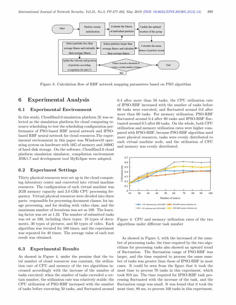
International Journal of Network Security, Vol.21, No.3, PP.477-482, May 2019 (DOI: 10.6633/IJNS.201905 21(3).14) 480
Figure 3: Calculation flow of RBF network mapping parameters based on PSO algorithm
6 Experimental Analysis
6.1 Experimental Environment
In this study, CloudSim3.0 simulation platform [8] was se-lected as the simulation platform for cloud computing re-source scheduling to test the scheduling configuration per-formance of PSO-based RBF neural network and IPSO-based RBF neural network for cloud resources.The exper-imental environment in this paper was Windows10 oper-ating system on hardware with 16G of memory and 1000Gof hard disk storage. On the software, CloudSim3.0 cloudplatform simulation simulator, compilation environmentJDK1.7 and development tool MyEclipse were adopted.
6.2 Experiment Settings
Thirty physical resources were set up in the cloud comput-ing laboratory center and converted into virtual machineresources. The configuration of each virtual machine was2GB memory capacity and 3.0 GHz CPU processing fre-quency. Virtual physical resources were divided into threeparts: responsible for processing document classes, for im-age processing, and for dealing with video class, and themaximum number of iterations was set as 100. The learn-ing factor was set as 1.33. The number of submitted taskswas set as 100, including three types: 10 types of docu-ments, 30 types of pictures, and 60 types of video. Eachalgorithm was iterated for 100 times, and the experimentwas repeated for 40 times. The average value of each testresult was obtained.
6.3 Experimental Results
As showed in Figure 4, under the premise that the to-tal number of cloud resources was constant, the utiliza-tion rate of CPU and memory of the two algorithms in-creased accordingly with the increase of the number oftasks executed; when the number of tasks exceeded a cer-tain number, the utilization rate was relatively stable; theCPU utilization of PSO-RBF increased with the numberof tasks before executing 50 tasks, and fluctuated around
0.4 after more than 50 tasks; the CPU utilization rateof IPSO-RBF increased with the number of tasks before60 tasks were executed, and fluctuated around 0.6 aftermore than 60 tasks. For memory utilization, PSO-RBFfluctuated around 0.4 after 80 tasks and IPSO-RBF fluc-tuated around 0.5 after 60 tasks. On the whole, both CPUutilization and memory utilization rates were higher com-pared with IPSO-RBF, because PSO-RBF algorithm usedmore physical resources, tasks were evenly distributed toeach virtual machine node, and the utilization of CPUand memory was evenly distributed.
Figure 4: CPU and memory utilization rates of the twoalgorithms under different task number
As showed in Figure 5, with the increased of the num-ber of processing tasks, the time required by the two algo-rithms for processing tasks also showed an upward trendof fluctuation. The fluctuation range of PSO-RBF waslarger, and the time required to process the same num-ber of tasks was greater than those of IPSO-RBF in mostcases. It could be seen from the figure that it took themost time to process 70 tasks in this experiment, whichtook 910 ms. The time required for IPSO-RBF task pro-cessing fluctuated with the increase of the task, and thefluctuation range was small. It was found that it took themost time, 80 ms, to process 100 tasks in this experiment.

International Journal of Network Security, Vol.21, No.3, PP.477-482, May 2019 (DOI: 10.6633/IJNS.201905 21(3).14) 481
On the whole, IPSO-RBF was more efficient and took lesstime to process tasks.
Figure 5: Time consumed by the two algorithms in pro-cessing different number of tasks
As showed in Figure 6, with the increase of iterationtimes, the convergence of the two algorithms became sta-ble. In the process of convergence, the particle positionof PSO-RBF increased with the number of iterations andfluctuated greatly. It did not stabilize until 90 iterations.The particle position of IPSO-RBF increased with thenumber of iterations, with a small fluctuation range, andthe position of the optimal solution was found stably af-ter 30 iterations. IPSO-RBF had a fast convergence speedand a better effect of finding the optimal solution.
Figure 6: Convergence effect of the two algorithms
As showed in Figure 7, due to the difference in process-ing capacity between nodes, the number of tasks assignedon different types of physical resource nodes was differ-ent. In the PSO-RBF algorithm, the number of tasksprocessed on the three types of nodes was similar, and thenumber of actual task types was compared. It could befound that the PSO-RBF algorithm basically distributestasks to all nodes on an equal basis without consideringthe difference in processing capability of different typesof tasks between different nodes. However, the number
of tasks on different types of nodes allocated by IPSO-RBF algorithm was obviously different. By comparingthe number of actual types of tasks, it was found that thisalgorithm considers whether the type of tasks was consis-tent with the type of resource nodes in the allocation oftasks, and balanced the load between different nodes.
Figure 7: Load distribution on nodes of different physicalresource types
7 Conclusion
Firstly, this paper briefly introduced the cloud computingresource scheduling model and the construction of RBFneural network. In cloud computing resource scheduling,tasks were allocated to virtual machine according to re-quests, and then virtual machine was allocated with phys-ical resources. Then, the PSO-based RBF neural net-work algorithm and IPSO-based RBF neural network al-gorithm were proposed. Finally, simulation experimentswere carried out on the CloudSim3.0 simulation platformfor the two algorithms. The results showed that the CPUand memory utilization rate and running time of the vir-tual machine increased with the increase of the numberof tasks. Moreover, IPSO-RBF algorithm had a higherutilization rate of virtual machine resources and shorterrunning time than PSO-RBF algorithm. In terms of theconvergence effect, IPSO-RBF algorithm could achievestable convergence faster with only 30 iterations, whilePSO-RBF algorithm needed 90 iterations to achieve sta-ble convergence. IPSO-RBF could balance the load of dif-ferent kinds of physical resources better than PSO-RBF.
References
[1] D. S. AbdElminaam, “Improving the security ofcloud computing by building new hybrid cryptogra-phy algorithms,” International Journal of Electron-ics and Information Engineering, vol. 8, no. 1, pp.40–48, 2018.

International Journal of Network Security, Vol.21, No.3, PP.477-482, May 2019 (DOI: 10.6633/IJNS.201905 21(3).14) 482
[2] A. Alexandridis, E. Chondrodima, H. Sarimveis,“Cooperative learning for radial basis function net-works using particle swarm optimization,” AppliedSoft Computing, vol. 49, pp. 485–497, 2016.
[3] M. H. R. Al-Shaikhly, H. M. El-Bakry, and A. A.Saleh, “Cloud security using Markov chain and ge-netic algorithm,” International Journal of Electron-ics and Information Engineering, vol. 8, no. 2, pp.96–106, 2018.
[4] Z. G. Chen, Z. H. Zhan, H. H. Li, et al., “Deadlineconstrained cloud computing resources schedulingthrough an ant colony system approach,” in Inter-national Conference on Cloud Computing Researchand Innovation, IEEE, pp. 112–119, 2015.
[5] M. C. S. Filho, R. L. Oliveira, C. C. Monteiro, etal., “CloudSim Plus: A cloud computing simulationframework pursuing software engineering principlesfor improved modularity, extensibility and correct-ness,” in Integrated Network and Service Manage-ment, IEEE, pp. 400–406, 2017.
[6] M. B. Gawali, S. K. Shinde, “Task scheduling and re-source allocation in cloud computing using a heuris-tic approach,” Journal of Cloud Computing, vol. 7,no. 1, pp. 4, 2018.
[7] S. Guo, J. Liu, Y. Yang, et al., “Energy-efficient dy-namic computation offloading and cooperative taskscheduling in mobile cloud computing,” IEEE Trans-actions on Mobile Computing, vol. 18, no. 2, pp. pp:319–333, 2018.
[8] H. Han, X. Wu, L. Zhang, et al., “Self-organizingRBF neural network using an adaptive gradientmultiobjective particle swarm optimization,” IEEETransactions on Cybernetics, vol. 49, no. 1, pp. 69–82, 2017.
[9] N. Kumar, N. Chilamkurti, S. Zeadally, et al.,“Achieving quality of service (QoS) using resourceallocation and adaptive scheduling in cloud comput-ing with grid support,” Computer Journal, vol. 57,no. 2, pp. 281–290, 2018.
[10] L. Liu, Z. Cao, C. Mao, “A note on one outsourc-ing scheme for big data access control in cloud,” In-ternational Journal of Electronics and InformationEngineering, vol. 9, no. 1, pp. 29-35, 2018.
[11] A. Mohammed, N. Md Asri, “Hybrid symbiotic or-ganisms search optimization algorithm for schedul-ing of tasks on cloud computing environment,” PLoSOne, vol. 11, no. 6, pp. e0158229, 2016.
[12] A. D. Niros, G. E. Tsekouras, D. Tsolakis, et al., “Hi-erarchical fuzzy clustering in conjunction with par-ticle swarm optimization to efficiently design RBFneural networks,” Journal of Intelligent & RoboticSystems, vol. 78, no. 1, pp. 105–125, 2015.
[13] S. Rezaei, M. Ali Doostari, and M. Bayat, “Alightweight and efficient data sharing scheme forcloud computing,” International Journal of Electron-ics and Information Engineering, vol. 9, no. 2, pp.115-131, 2018.
[14] K. Shanmukhi, P. R. Vundavilli, B. Surekha, “Mod-eling of ECDM micro-drilling process using GA- andPSO-trained radial basis function neural network,”Soft Computing, vol. 19, no. 8, pp. 2193–2202, 2015.
[15] W. Wei, X. Fan, H. Song, et al., “Imperfect infor-mation dynamic stackelberg game based resource al-location using hidden markov for cloud computing,”IEEE Transactions on Services Computing, vol. 11,no. 1, pp. 78–89, 2018.
[16] J. Wu, J. Long, M. Liu, “Evolving RBF neural net-works for rainfall prediction using hybrid particleswarm optimization and genetic algorithm,” Neuro-computing, vol. 148, no. 2, pp. 136–142, 2015.
[17] L. Xu, F. Qian, Y. Li, et al., “Resource allocationbased on quantum particle swarm optimization andRBF neural network for overlay cognitive OFDMSystem,” Neurocomputing, vol. 173, no. 3, pp. 1250–1256, 2016.
[18] L. Zhang, W. Tong, S. Lu, “Task scheduling of cloudcomputing based on Improved CHC algorithm,” inInternational Conference on Audio, Language andImage Processing, IEEE, pp. 574–577, 2015.
[19] W. Zhang, D. Wei, “Prediction for network trafficof radial basis function neural network model basedon improved particle swarm optimization algorithm,”Neural Computing & Applications, vol. 29, no. 1, pp.1–10, 2016.
Biography
Gaoxiang Lou (1989-). Ph.D. candidate fromChang’an University. His research interests in-clude Mixed flow assembly scheduling, Manufactur-ing system integration and automation, etc. Fund-ing institutions: National Natural Science Founda-tion, China(51305042),Construction project of Cen-tral University Educational Reform Special FoundationChina(jgy16049,jgy170501). Recently published papers:Research on the Hybrid Algorithm based on DifferentialEvolution and Genetic Algorithm for Mixed Model As-sembly Scheduling, Improved hybrid immune clonal selec-tion genetic algorithm and its application in hybrid shopscheduling, etc.
Zongyan Cai (1964-). Doctor of Education , Pro-fessor. Worked in Chang’an University. His re-search interests include Manufacturing system integra-tion and automation, Intelligent robot technology, etc.Funding institutions: National Natural Science Foun-dation, China(51705030),Construction project of Cen-tral University Educational Reform Special FoundationChina(jgy16049,jgy170501). Recently published papers:An enhanced bearing fault diagnosis method based onTVF-EMD and a high-order energy operator, An alterna-tive demodulation method using envelope-derivative op-erator for bearing fault diagnosis of the vibrating screen,etc.

International Journal of Network Security, Vol.21, No.3, PP.483-493, May 2019 (DOI: 10.6633/IJNS.201905 21(3).15) 483
Trust in Ad Hoc Networks: A New Model Basedon Clustering Algorithm
Ali Mansouri1 and Mohamed Salim Bouhlel2
(Corresponding author: Ali Mansouri)
Higher Institute of Applied Languages and Computer Sciences of Beja1
Boulevard of the Environment B.P. 340 Beja 9000, Tunisia
Higher Institute of Biotechnology of Sfax (ISBS)2
Soukra Road km 4, B.P. 1175, 3038 Sfax, Tunisia
(Email: [email protected])
(Received Nov. 13, 2017; Revised and Accepted May 5, 2018; First Online Feb. 16, 2019)
Abstract
An Mobile Ad-hoc network (MANET) is formed whengroup of mobile wireless nodes collaborate between themto communicate through wireless links in the absence ofthe fixed infrastructure and any centralized control. Thispaper focuses on the design a self-stabilizing clusteringalgorithm in MANETs. The Topology that we proposeis a partitioning based on trust between members of agroup. It forms a structure able to adapt dynamicallyto changes in the topology. Some cryptographic-basedschemes have been proposed to secure the clustering pro-cess, but they are unable to handle the internal attacks.To defend against insider malicious nodes, trust and repu-tation management systems should be used .Our solutionis based on our efficient trust model and distributed al-gorithm to clustering network.We present our clusteringapproach based on trust for applications in the field ofsecurity.
Keywords: Clustering Algorithm; Maintenance of theTopology; Mobile Ad Hoc; Self-stabilizing; Trust Relation-ships
1 Introduction
A mobile ad hoc network is a collection Mobile entitiesinterconnected by a wireless network forming temporaryindependently of any infrastructure or centralized admin-istration. The nodes in Mobile ad hoc networks join andleave the networks dynamically. At some point of timethere is a possibility of enormous increase in the size ofthe network. Handling nodes in big network may put aburden on network management schemes and may intro-duce delays in the net-work.
Dividing big networks in small groups called clustersmay prove to be a good solution for handling them ina better and efficient manner. As MANET (Mobile Ad
hoc networks) is self organized, the challenge of achievingsecurity is critical. Evolving and managing trust relation-ships among the nodes in the network are important tocarry efficient transmissions Clustering organize the adhoc networks hierarchically and create clusters of ad hocnodes which are geographically adjacent. Each cluster ismanaged by a cluster head (CH) and other nodes may actas cluster gateway or cluster member.
In this article, we present a clustering approach for ef-ficient, scalable and secure clustering of MANETs. Ourproposal consists on forming clusters around the trust-worthy nodes; in other words, the node that has highesttrust value is elected as the cluster head. A threshold oftrustworthy is used to perform system stability.
2 Related Work
In the literature, there are many proposals to constructclusters in mobile ad hoc networks.The first algorithms ofLowest-ID clustering algorithm (LID) proposed by Bakerand Ephremides [5]. Clustering High-Connectivity (HCC)of are based on a particular criterion the selection ofcluster-heads, which is the identifier of a node. This algo-rithm to form clusters in a single jump, where each mem-ber is its direct neighbor cluster-head. In the constructionphase clusters, nodes communicate with their neighborsto have a local knowledge and thus fix the cluster-head.
This phase is repeated periodically for any topologychange. The algorithm cited in [15]is a modified versionof the Lowest-ID algorithm .The authors propose a clus-tering algorithm to reduce the work-Clustering fic control.A node broadcasts a single message containing his clus-tering decision. According to his local knowledge of thetopology, each node decides to become a head-cluster ornot. This decision is communicated to the neighborhood,forcing the neighbors of the new cluster-head who are notyet affiliated a cluster choose it as a cluster-head.

International Journal of Network Security, Vol.21, No.3, PP.483-493, May 2019 (DOI: 10.6633/IJNS.201905 21(3).15) 484
In [6], authors propose energy efficient secure trustbased clustering algorithm for mobile wireless sensor net-work. Their solution creates one hop members to mini-mize the overhead and take into account the trust levelof a node, mobility, remaining energy and its distance toneighbors.
In [18], authors present a preference-based protocol fortrust and head selection for cluster-based MANET per-form the tasks of a certification authority and proactivesecret sharing scheme is used to distribute the private net-work key to the CHs. In this solution, each cluster is firstformed based on the trust values of the neighbor nodes.To create cluster, an ad hoc node evaluates its neighbornodes’ of neighbor nodes; each node chooses one node thathas the highest value as its trust guarantor. Then, thechosen node becomes the CH and the chooser becomes amember of the cluster, a node of the second highest trustvalue is chosen, in this way, a cluster is formed by theCH which has the highest trust value among the clustermembers.
The other trust-based clustering scheme is designedin [1], Authors propose trust based secure on demandrouting protocol (TSDRP) for Manet’s. In this schemeeach node evaluates the trust value of neighbor nodes andrecommends one of neighbors that have the highest trustvalue as its trust guarantor. Then a node becomes a mem-ber of CH node which is one-hop away.
In [16], authors propose a self-stabilizing clustering al-gorithm in mobile ad hoc networks Clustering Algorithmis another trust-based clustering scheme. It evaluates thestability of node through computing the neighbor changeratio and the residual battery power of mobile nodes.To elect CHs by using the voting mechanism, each nodevotes other nodes only if the node is the most trustfulone among its neighbor nodes and the node’s stability isbetter than itself.
In [10], authors propose an efficient secure group com-munication in MANET using fuzzy trust based cluster-ing and hierarchical distributed group key managementwhich includes a trust value defining how much any nodeis trusted by its neighborhood and used the certificate asnode’s identifier. It uses voting mechanism to elect themost trusted node.
In [17],authors give a honey bee algorithm–based effi-cient cluster formation and optimization scheme in mobilead hoc networks. It aims to elect trust worthy stable CHsthat can provide secure communication via cooperativenodes. The authors in [17], authors propose performanceanalysis of TSDRP and AODV routing protocol underblack hole attacks in Manets by varying network size.
The authors in [12], authors present a multi-metric-based algorithm for cluster head selection in multi-hopad hoc network to improve the search performance andscalability of MANETs with trust mechanism. In this so-lution, the trust relationship is formed by evaluating thelevel of trust using Bayesian statistic analysis and clusterscan be formed and maintained with only partial knowl-edge which makes it suitable for distributed autonomous
MANETs.In [11], authors give a model of mobility aware cluster-
ing scheme with bayesian-evidence trust management forpublic key infrastructure in ad hoc networks.
The authors in [14], propose an efficient trust-basedscheme for secure and quality of service routing inMANETs. A composite trust model for secure routingin mobile ad-hoc networks is proposed in [13], and Trustthreshold based public key management in mobile ad hocnetworks proposed in [3]. Also, a preference-based proto-col for trust and head selection for cluster-based MANETis proposed in [18].
3 Global Architecture and Crite-ria of Clustering
This section introduces our topology. We assume firstthat all nodes periodically broadcast a hello message totheir neighbors in a single jump for the information ofthe nodes around them. Our topology is organized clus-tered. Each cluster consists of a cluster-head, a core anda periphery.
• The cluster-head is the node that identifies the clus-ter. He is responsible for the communication betweenclusters. The cluster-head is the root of a undertree built during the clustering process and coversall members the cluster.
• The core is the center of cluster. The cluster-head isone of the members of the core of its cluster. All coremembers are neighbors to the cluster-head.
• The periphery is composed of cluster members thatare not in the core. Figure 1 illustrates the mainfeatures and elements of our topology.
Figure 1: General structure of our topology

International Journal of Network Security, Vol.21, No.3, PP.483-493, May 2019 (DOI: 10.6633/IJNS.201905 21(3).15) 485
We are interested in the clustering area of security. Ouralgorithm uses trust as partitioning criteria.Trust is fun-damental to maintain a certain level of security. This isa important aspect in the design of network.
However, in a dynamic and mobile environment with-out trusted authority centralized, it is not easy to assessconfidence. Many existing solutions propose to calculatethe confidence in MANET based on the information thata node can collect other nodes passively [8].
As these interactions are frequent in the cooperativebehavior of the nodes of a MANET, it will not difficultto quickly establish a first estimate of the level of trustbetween direct neighbors. If ordinary interactions arenot sufficient to evaluate a ratio trust/distrust, the nodescan generate additional traffic to evaluate how much theytrust their neighbors. Thus, to manage its trust, eachnode i maintains tv value of trust (i, j) for any neigh-bor j to node i (and possibly former neighbors and nodesnot adjacent where the node i receives recommendations).This value reflects the degree of trust or distrust node ihas on its neighbor j. Several trust functions were pro-posed in the literature. We use quantification confidenceproposed in [9] and we extend to reflect Account trustedrecommendations developed in [20].
Thus, our confidence values are real numbers between-1 and +1. A number negative represents the degree ofdistrust. -1 indicates a total distrust. A number positiverepresents the degree of confidence. 1 represents absoluteconfidence. When a new or unknown node j between inthe neighborhood of node i, the node i initializes tv(i, j)to a first value init trust (tv(i, j) = init trust).
This initial value is useful for two nodes that have notyet reported together. For example, if they are completelyunknown init trust = −1 else init trust = 1.
Note that two neighboring i and j may have differentinterpretations of their exchanges.Thus, tv(i, j) may bedifferent from tv(j, i). We use the following function tocalculate the value of the confidence node i to node j:
tv(i, j) = tanh
(n1∑k=1
ukwk
)(1)
Where n1 is the number of interactions between the twonodes. wk is the weight of the interaction number k. uk
is 1 if the k is positive interaction and -1 if it is negative.The function tanh is used to project the sum of differentinteractions in the interval [-1, 1].
Several examples of interactions can be used to calcu-late confidence values . All these interactions is based onthe routing information. Here we develop the all interac-tions we use in our clustering algorithm.
Passive Knowledge: A node can obtain important in-formation a neighbor in road construction, for ex-ample. In fact, if a node starts in ”promiscuous”after the transmission of all packets to hear the re-transmission by the destination node, it can get thefollowing information about this neighbor [2]:
• It acts as a black hole if the packet is not for-warded.
• There is a change of attack if the content haschanged.
• It makes an attack if a manufacturing self-produced packet is transmitted.
• It makes an identity theft attack if the IP ad-dresses were falsified.
• It induces delays by delaying the retransmissionof the packet.
Accuracy/packet error: When a node receives a cor-rect packet, can increase the value of trust which heattributes to the one that sent the packet, and othernodes in the path from the source (if the protocolrouting provides information on the nodes that makeup a route from a source to a destination). Similarly,if the received packet is wrong, the receiver can re-duce the value of the confidence he attributes to thesender of the package and the value of the confidencehe attributes to intermediate nodes of the road.
Altruistic Behavior: If an intermediate node on aroute to a destination given, receives a packet forwhich the next hop is not available, it can removethe package and notify the sender. Even So, if thereis a route to the final destination can use this routefrom its cache, send the packet on the new road andnotify the sender the broken link. If the new road isto be correct, it reveals that the sender Error in al-truistic behavior. Therefore, this information can beused to increase trust between the two nodes. Com-pliance / non-compliance with the rules of clustering:a node that does not meet the clustering rules is ob-viously a malicious node. His neighbors may detectthis problem by observing how it sets its clusteringvariables, described later in this chapter in its hellomessages.
Inconsistent Trust: A node that distributes false re-ports trust or lies about his relationship of trust ismalicious. This behavior may be detected by com-paring the ratio of trust receipt and monitoring com-munications of its neighbors.
Communication with malicious nodes: when a noderegularly exchanges messages with a malicious node, itis considered a malicious node. These direct assessmentsof trust can be strengthened by reports distributed trust.The confidence reports allow nodes to share the informa-tion in confidence and disseminate in the network. A sim-ple approach to distribute the relationship of trust is foreach node to broadcast only trusting relationships withits immediate neighbors. A report confidence initiated bynode k lists the values of trust that has the other nodes,namely tv(k, j). When node i receives reports of confi-dence of a certain node j, it uses them to improve theirconfidence value tv(i, j) as follows:

International Journal of Network Security, Vol.21, No.3, PP.483-493, May 2019 (DOI: 10.6633/IJNS.201905 21(3).15) 486
Where n2 is the number of nodes that have sent con-fidence reports node j to node i. If the received one re-port of an un-known node, report trust is not consid-ered. In addition, the use of tv(i, k) as a weight for arelationship of trust initiated by a node k favors directconsiderations confidence. Some malicious nodes can lieabout trust. However, these false reports can be detectedby neighbors.Monitoring Mutual nodes avoids inconsis-tencies trusted reports received.
To use the confidence values calculated by the nodes asa criterion for clustering,we define two confidence thresh-olds Smin and Smax where Smin ≤ Smax, Smax ∈ [0, 1]and Smin ∈ [−1, 0].
• Full Trust (TT): A relationship between two nodesi and j is a relationship full trust ((Relation(i, j) =TT )iftv(i, j) ∈ [Smax, 1]andtv(j, i) ∈ [Smax, 1]).
• Partial Trust (PT): A relationship between two nodesi and j is a relationship partial trust (Relation (i, j)= PT) if and only if:
– Tv(i, j) ∈ [Smax, 1];
– Tv(j, i) ∈ [Smax, 1];
– Tv(i, j) ∈ [Smin, Smax].
• Suspicion (DT): A relationship between two nodesi and j is a relationship distrust ((Relation(i, j) =DT ) if and only if tv(i, j) ∈ [−1, Smin] or tv(j, i) ∈[−1, Smin]).
Note that the three relationships are symmetrical. Forexample, if a node i has a total trust with a node j thenthe node j has a relationship total confidence with nodei. In the following, we develop the different steps of ouralgorithm clustering.
4 Clustering Algorithm Based onTrust
This algorithm uses a distributed heuristic and tries tominimize the explicit information of the formation of clus-ters. Our algorithm is composed of three sub algorithms:1, 2 and 3. In the follows, the authors show the rulesforming algorithm.
Algorithm 1 :RULE0: The excluded members.
Beginif ∨j ∈ Ni.Relation(i, j) = DT thenCHi = null ∧ Parenti = null.
end if
4.1 Description of Rules of the Algorithm
In this section, we present the rules of our clustering al-gorithm.We start by characterizing a legitimate state. Alegitimate state is stable clustering training cluster-heads,
Algorithm 2 :RULE1 & RULE2: Selection and up-dating the cluster-head members
RULE1Beginif ∨j ∈ Ni.Relation(i, j) = DT thenCHi = null ∧ Parenti = null.
end ifRULE2if ∨j ∈ N.i[Relation(i, j) = TT ∧ Compare(TT −edgei, TT−edgej)]∧∨j ∈ N.i[CHj 6= j∧(CHj = null∧Relation(i, j) = TT ) ∧ Compare(TT − edgei, TT −edgej)]) then
CHi = i ∧ Parenti = i ∧Hop− CHi = 0end if
Algorithm 3 :RULE3 & RULE4: Selection and up-date the other cluster nodes.RULE3if ∨k ∈ N.i∃j ∈N.iCompare(Relation(i, j), Relation(i, k)) ∧ CHi 6= ithen
CHi = CHj ∧Parenti = j ∧HopCHi = HopCHj+1
end ifRULE4if CHi 6= CHParenti∨HopCHi 6= HopCHParenti+1
thenCHi = null ∧ Parenti = null ∧HopCHi = null
end if
core members, members of the periphery and membersexcluded. That algorithm consists of five detailed rules ,each node determines the role as hello messages it receivesfrom its neighbors.
In our algorithm, the rules (R0), (R2) and (R4) havepriority over other rules (R1) and (R3). Indeed, an assetthat has a top incorrect value of its variable initializes itsstate null. Then, it executes the rule corresponding tobecome a cluster-head, a core member, a member of theperiphery or excluded member. The clustering algorithmadded to hello messages the following fields:
• TT − edgei: Number of TT relationships a node ihave with its neighbors.
• CHi: The cluster cluster-head is attached node i.CHi is equal to null if node i does not yet belong toa cluster.
• Corei: The kernel member belongs node i. If i is aclusterhead or ring member then Corei is set to i. Ifi is not yet attached to a kernel then Corei is set tonull.
• Hop−CHi: Number of hops from node i to cluster-head.
• Tv(i, j): For each neighbor j, this field represents thevalue of the trust from node i to node j.

International Journal of Network Security, Vol.21, No.3, PP.483-493, May 2019 (DOI: 10.6633/IJNS.201905 21(3).15) 487
Figure 2: The resulting clustering
• Parenti: This field expresses the father of node i inthe cor-responding subtree. Clustering is performedin three fully dynamic and distributed phases:
Phase 1: Election of cluster-head. Each nodewhich has the largest number TT-edge amongits neighbors who do not yet belong to a clusterdeclares as a cluster-head. In case of a tie thenode with the most neighbors is elected. Incase of equal values TT-edge and the equalnumber of neighbors, the node that has thegreater identity is privileged. Once a nodebecomes a cluster-head, he puts his identity inthe scope of its CH hello messages and changesthe value of Hop field - CH to zero.
Phase 2: Core training. All the neighbors whohave relation-ships TT with a cluster-head formthe cluster core. Their hello messages containthe identity of the cluster-head in the CH fieldand the value 1 in the Hop-CH field. A nodecan have relationships with several TT cluster-heads. In this case, the node chooses the cluster-head that has the largest TT-edge.
Phase 3: Formation of the periphery of the core.After the phase 1 and Phase 2, the nodes sur-rounding the core joining the cluster accordingto the two steps following (TT privileged rela-tionship is a relationship that PT is privilegedto DT relationship.
Step 1. Members of the periphery having TT rela-tions. After incorporation cores, if any of thenodes that have not yet ad-hered to a clusterTT and have relations with at least one ring,they join the cluster which they have the great-est confidence value.
Step 2. Members of the periphery having PT rela-tionships. The latter step is to add the nodesthat share relationships with the PT least one
node in the cluster. A node in this categoryfavors cluster with which it has the lowest dis-tance (number of hops) to the cluster-head. Theneighbor with whom he has a relationship PTand the lowest distance clusterhead became hisfather in the sub-tree rooted. The cluster-headis the root of the subtree. This subtree simpli-fies communication between clusters. A nodein the periphery with at least one neighbor be-longing in another cluster is called a gateway.When a node joins a cluster, it updates the CHand CH-Hop fields of hello message.
Clustering obtained is shown in Figure 2.To succeed clustering, despite the presence of malicious
nodes, the honest nodes cooperate closely. They do notcommunicate the message clustering malicious nodes andignore all messages from clustering these nodes. Thus,clustering messages and data dissemination spend onlyby TT relation-ships or relationships PT. However, evenif all malicious nodes were detected, clustering can bedisrupted.
The condition on the number of malicious nodes andtheir dispersion in the network is necessary. In fact, if thenetwork is not sufficiently dense and malicious nodes arescattered so that they prevent honest nodes to participatein clustering, the protocol will fail to achieve a completeclustering. As a result, isolated nodes and clusters canappear disconnected.
4.2 Clustering Example
We explain our clustering algorithm by applying it to theset of nodes described in Figure 3. In this example, weassume that the nodes have already calculated their con-fidence values from their direct neighbors. Each node hasa unique identifier and is denominated by the trust he at-tributes to his neighbors. The confidence thresholds areset at Smin = 0 and Smax = 0.2.

International Journal of Network Security, Vol.21, No.3, PP.483-493, May 2019 (DOI: 10.6633/IJNS.201905 21(3).15) 488
Figure 3: Example of clustering
Figure 3(a) illustrates the different relationships TT,PT and DT in the network according to the values ofSmin and Smax. Figure3(b) show nodes 4 and 13 areclusterheads according to the number of TT relationshipsthey have with their neighbors.
Recall that this information is broadcast in hello mes-sages. Each of the nodes 4 and 13 puts its identity in theCH field and updates the Hop-CH field to 0. Then, nodes1, 7 and 10 (respectively 2, 8 and 9) which share a relationTT with cluster-head 13 (respectively 4) form the core ofit (see Figure 3 (c)) Nodes 1, 7 and 10 (respectively 2, 8and 9) change their fields CH and Hop - CH from theirhello messages to respectively 13 and 1 (respectively 4and 1). The two nodes 14 and 15 have TT relations withnode 2. Thus, they join cluster 4. They are attached tokernel member 2 (see Figure 3(c)).
They update their CH and Hop-CH fields accordingly.In the last step, the nodes 12 and 5 (respectively 3) thatshare a PT relationship with a node belonging to cluster 4(respectively 13), join this cluster and update the CH andHop - CH fields of their hello messages. Oriented edgesin the example illustrate the subtrees built during theclustering process. When a node joins a cluster, it choosesa father in the shortest way to the cluster-head. Nodes6 and 11 do not share any TT or PT relationships withother nodes of the network. So, the clustering algorithmdoes not take into account these nodes in the clusters
obtained.
4.3 Convergence and Accuracy of the Al-gorithm
We show in this section that our algorithm converges toa state legitimate. For example, from any initial state,the algorithm con-verges to a stable state composed ofcluster-heads, core members, member of the peripheryand excluded members. We will assume for this that thenodes are not malicious.
Lemma 1. The node running the rule (R0) does notchange its state only time and remains stable there after.
Proof. A node that only sharing DT relations with itsneighbors will belong to any cluster, and runs the rule(R0). In addition, any of its neighbors will consider it,and it will be ignored. Therefore, it will no longer changestate.
Lemma 2. The node running the rule (R1)stabilizes aftermore (4− 1)2 movements.
Proof. The node that has the maximum number of TTcompared Relations with all its neighbors with which itshares a TT relationship will become a cluster-head. Itdoes not change state thereafter because the decision is

International Journal of Network Security, Vol.21, No.3, PP.483-493, May 2019 (DOI: 10.6633/IJNS.201905 21(3).15) 489
local and has best value (the maximum number of TT re-lations). This comparison depends only the number of re-lationships that TT is previously updated by the messagehello. Against by, in some cases, the rule (R1), the nodeis declared as a cluster-head because it has the maximumnumber of relationships TT compared with all neighborswith whom it shares TT relationship and who are not yetto a cluster. His decision depends only on its neighborswhich are stabilized at the after (∆− 1) move. Hence, acluster-head stabilizes more after (4−1)2 movements.
Lemma 3. The system enters a legitimate state in O(n(4− 1)2).
Proof. The other vertices which are not cluster-headsalways choose the parent with whom they share thestrongest relationship. This Parent exists and is uniquebecause the Com-pare function (x, y) selects a singlevertex. The best relationship is the relationship with acluster-head, which is the root of subtree. According tothe previous lemma, a cluster-head converges to a sta-ble state more after (4− 1)2 movements. The algorithmconverges and a legitimate state O(n(4− 1)2).
5 Maintenance of the Topology
The clustering algorithm is self-stabilizing. It runs contin-uously and readjusts clusters based on trust relationshipsbetween nodes. Relationships confidence evolves overtime depending on the interactions between the nodes.The Mobility can also change the situation of clusters. Infact, when a node acquires new neighbors or loses someof them, because of mobility, several changes can appearin the situation of the node inside Cluster:
1) The number of TT (TT-edge) relationships of thenode can change. For example, if the node is acluster-head, it can no longer be. If the node is amember from the periphery, it can become a mem-ber of the kernel or a cluster-head.
2) The PT or TT relationships that link a node to acluster can break and the node no longer belongs tothe cluster.
3) A node that has only DT relationships with its neigh-bors can acquire PT or TT relationships and thusjoins a cluster.
4) Etc. Phase 1, Phase 2 and Phase 3 of the clusteringalgorithm are re-executed as often as necessary toform new clusters or up-date existing clusters.
5.1 Election of a New Cluster-head
Several situations may involve the election of a newcluster-head. We focus on two of these situations: thefailure of the current cluster-head and the change theTT-edge value of the current cluster-head so that it is no
longer the node with the highest TT- edge value amongits neighbors.
1) Cluster-head failure: If a cluster-head goes down, itswires (that’s to say other members of the same ker-nel) no longer receive his hello messages periodicals.In this case, the kernel members re-initialize the CHfield from their messages hello to null. Upon receiptof these modifications of the message hello, membersof the underlying periphery are also putting the CHfield of their hello messages to null. This launchesthe clustering phases of these nodes and rearrangesthe cluster.
2) Modification of the TT- edge value: A cluster headincluding one of its neighbors has a higher value TT-edge re-initializes the CH field of its messages hello tonull. When receiving updates to the hello messages,the neighbor’s cluster-head that are members of thecluster propagate this re-initialization to all membersof the cluster. This leads to a failure situation of thecluster-head.
5.2 Breaking Trust Relationships
When a node is authenticated as a member of the groupand has at least a TT or PT relationship with a clustermember, he remains a member of the cluster. When theTT or PT relation-ships that link the node to the clusterare broken (because of mobility or change of trust value),the node must to be excluded from the cluster: it is con-sidered a malicious node. At this level, exclusion does nothave a practical impact. In fact, if the node is malicious,it does not will not respect the clustering rules. The nodethen joins another cluster if it has TT or PT relation-ships with other nodes in the network. This modificationmay generate other changes in the constitution of clus-ters. Note here that all stages of clustering are based ontrust and strict respect for Clustering rules for members.Malicious nodes may not respect these rules. In this case,using the confidence values, it is possible to detect the ma-licious nodes. As described earlier in this section, a nodecan detect that a neighbor is not complying with cluster-ing rules by controlling values of its clustering variables(contained in its hello messages).
5.3 Failure of a Core Member or a Mem-ber of the Periphery
When a kernel member or a member of the periphery fails,the other periphery members that depend on it are iso-lated from the cluster. These re-execute Phase 3 cluster-ing to select a new father in the cluster or to join anothercluster.
5.4 Management of New Nodes
When a new member j becomes neighbor of a member i, iassigns the value 1his trust relationship with j(tv(i, j) =

International Journal of Network Security, Vol.21, No.3, PP.483-493, May 2019 (DOI: 10.6633/IJNS.201905 21(3).15) 490
1). This means that a new member he is granted a TTrelationship upon his arrival and, therefore, has access tothe different clustering steps. However, if i and j fail toauthenticate, they attribute to each other a relationshipof mistrust.
6 Evaluation
We simulated our algorithm to evaluate its performanceand compare it with other clustering algorithms perfor-mance. In This section provides an overview of our simu-lation model and results we have obtained. We simulatedour approach within the platform NS2 network simula-tion. Our simulation MANET models a maximum of 100nodes moving randomly in an area of 1000x1000 m2 un-der model Random waypoint Model [4]. Each node isequipped with a radio transceiver capable of transmittingup to 250 m.
We use as 802.11 protocols MAC layer in our exper-iments. We assessed the stability of our system cluster-ing by studying the variation in the number of clusters itgenerates. To see the behavior of this approach and tomeasure the effect that will cause the implementation ofour algorithm in an OLSR network, we performed severalsimulations with variable number of nodes and differentnodes velocity. We used NS2 [7] as a network simulator.
We performed simulations with, and without cluster-ing inter-val and we have recorded the average number ofclusters built (which we note NC) and the average timeduring which a cluster is Maintained.
6.1 Trust Value of Cluster Head Based onthe Number of Nodes
To approve the efficiency of our algorithm, we comparedit with another algorithm in the literature, which is thealgorithm of clustering based on node density. We noticethat the trust values of the clusterhead in our proposalare much more important than in the algorithm based ondensity.
Figure 4: Average trust value of CH = f ( nb of nodes ),V = 10 m/s
In our algorithm the trust of the CH varies between224,07 and 1673,9 while in the algorithm of clustering
based on density it varies between76,076 and 1100, 7 (seeFigure 4).
6.2 Number of Clusters Formed Based onthe Number of Nodes in the Network
Figure 5 shows the evolution of the number of clustersin relation to the number of nodes in the network for amaximum speed of 10 m /s.
Figure 5: Average number of cluster = f (nbr nodes), V= 10m/s
We notice that the numbers of clusters in our proposalare less than in the algorithm based on density, whichshows the stability of our proposal.
6.3 Number of Clusters Formed Based onthe Number of Nodes in the Network
Figure 6 shows the evolution of the number of clustersin relation to the number of nodes in the network for amaximum speed of 10 m /s.
Figure 6: Average number of cluster = f (nbr nodes), V= 10m/s
We notice a great improvement with the use of theclustering interval. The number of clusters varies between246 and 8588 in the case where the clustering interval isnot used, when this number varies between 4.8 and 6.8with the use of clustering interval for a network with 100nodes.
6.4 Trust Value of Cluster Head Based onthe Number of Nodes
Figure 7 shows the evolution of trust value of clustersin relation to the number of nodes in the network for amaximum speed of 10 m /s.

International Journal of Network Security, Vol.21, No.3, PP.483-493, May 2019 (DOI: 10.6633/IJNS.201905 21(3).15) 491
Figure 7: Average trust value of CH = f ( nb of nodes ),V = 10 m/s
We notice a great improvement with the use of theclustering interval. The trust value varies between 88,9and 1112,5 in the case where the clustering interval is notused, when it varies between 224,07 and 1673.9 with theuse of clustering interval for a network with 100 nodes.
6.5 Average Cluster Duration Based onthe Number of Nodes in the Network
Figure 8 shows the behavior of the average time duringwhich a cluster is built based on the number of nodes inthe network.
Figure 8: Average cluster duration = f(nbr nodes) , V =10m/s
We notice a significant improvement brought by theclustering interval. The average duration of clusters variesbetween 0.007 ms and 1.116 ms in the case where theclustering interval is not used, when this number variesbetween 5,39 ms and 13.37 ms with the use of clusteringinterval for a network with 100 nodes.
7 Comparison and Analysis
We compared our clustering algorithm with two existingschemes SGCP [19] (Secure Group Communication Pro-tocol)and LID [5](Lowest IDentifier). LID is one of themost known protocols clustering. LID is usually used asa reference protocol evaluation of clustering algorithmsperformance. We simulated the three protocols in thethree scenarios described above mobility: mobility low,medium, high mobility and mobility. We considered dif-ferent connectivity rate and measured the number of clus-ters realized by each three protocols.
Figure 9: Comparison of the number of clusters of ourprotocol with LID, SGCP
Figure 9 shows that our algorithm gives good results.It has the same number of clusters as LID in a low mobil-ity scenario(see Figure 9(a) ) and has the lowest number ofclusters in medium and high mobility scenarios.(see Fig-ure 9(b),(c) We also studied the variation of the numberof clusters of three protocols over time. For this, we alsoperformed the three protocols under the same conditionsof mobility and connectivity for 50s.
Figure 10 represents our results. It’s clearly shows thatthe variation in the number of clusters is not importantand is stable with LID and our protocol. It is not the casefor SGCP where the number of clusters increases dramat-ically after 20s simulation. This shows that comparedto SGCP and LID, our protocol Clustering is stable: itgenerates a reasonable number of clusters in all mobilityscenarios.

International Journal of Network Security, Vol.21, No.3, PP.483-493, May 2019 (DOI: 10.6633/IJNS.201905 21(3).15) 492
Figure 10: Evolution of the number of clusters
8 Conclusions
Our clustering algorithm is used to manage the networkdynamics, it is based on building a topology to minimizethe mobility of the network, optimize the scalability, facil-itate and secure protocols communication. Our proposalis based on the definition of a model Dynamic and dis-tributed trust for ad hoc mobile networks. Our approachis to divide the network into clusters organized into sub-trees linked and supervised by cluster-heads. By There-fore, the addition or removal of a member only affects thecluster to which it belongs. The security of our protocol isenhanced by its clustering criterion that constantly mon-itors the relationship of trust between nodes and expelsmalicious nodes in the broadcast session.
The clustering algorithm is self-stabilizing. It runs con-tinuously and read just clusters based on trust relation-ships between nodes. Relationships confidence evolvesover time depending on the interactions between thenodes. The Mobility can also change the situation of clus-ters.
To succeed clustering, despite the presence of maliciousnodes, the honest nodes cooperate closely. They do notcommunicate the message clustering malicious nodes andignore all messages from clustering these nodes. Thus,clustering messages and data dissemination spend onlyby TT relation-ships or relationships PT. However, evenif all malicious nodes were detected, clustering can be dis-rupted. The condition on the number of malicious nodesand their dispersion in the network is necessary. As per-spective to this work to make our algorithm more stable,we added the concept of the threshold of trust, whichrepresents the trust value at which each node can act ascluster head.
Our algorithm gives good results. It has the same num-ber of clusters as LID in a low mobility scenario and hasthe lowest number of clusters in medium and high mobil-ity scenarios. This shows that compared to SGCP andLID, our protocol Clustering is stable: it generates a rea-sonable number of clusters in all mobility scenarios. Ac-cording to the results of simulations that we made, wenotice a great improvement and better system stabilitywith the adopted solution.Also, we plan to use the clus-
tering solution to manage cryptographic key in MANETs.
References
[1] A. Akshai, G. Savita, C. Nirbhay, and J. Keyurb-hai, “Trust based secure on demand routing protocol(tsdrp) for manets,” in Fourth International Con-ference on Advanced Computing & CommunicationTechnologies (ACCT’14), pp. 432–438, IEEE, 2014.
[2] P. Asad Amir and M. Chris, “Establishing trust inpure ad-hoc networks,” in Proceedings of the 27thAustralasian Conference on Computer Science, vol.26, pp. 47–54, 2004.
[3] J. H. Cho, I. R. Chen, and K. S. Chan, “Trust thresh-old based public key management in mobile ad hocnetworks,” Ad Hoc Networks, vol. 44, pp. 58–75,2016.
[4] B. Christian, H. Hannes, and C. Xavier, “Stochasticproperties of the random waypoint mobility model,”Wireless Networks, vol. 10, no. 5, pp. 555–567, 2004.
[5] B. Dennis and E. Anthony, “The architectural orga-nization of a mobile radio network via a distributedalgorithm,” IEEE Transactions on communications,vol. 29, no. 11, pp. 1694–1701, 1981.
[6] R. Eid, S. Muhammad, N. Syed Hussnain Abbas,B. Khan, and U. Kamran, “Energy efficient securetrust based clustering algorithm for mobile wirelesssensor network,” Journal of Computer Networks andCommunications, vol. 2017, 2017.
[7] K. Fall, K. Varadhan, The NS Manual, 2003.[8] T. George and B. John, “On trust models and trust
evaluation metrics for ad hoc networks,” IEEE Jour-nal on Selected Areas in Communications, vol. 24,no. 2, pp. 318–328, 2006.
[9] T. George and B. John, “A testbed for comparingtrust computation algorithms,” in Proceedings of the25th Army Science Conference (ASC’06), 2006.
[10] K. Gomathi, B. Parvathavarthini, and C. Sara-vanakumar, “An efficient secure group communi-cation in manet using fuzzy trust based cluster-ing and hierarchical distributed group key manage-ment,” Wireless Personal Communications, vol. 94,no. 4, pp. 2149–2162, 2017.
[11] V. S. Janani and M. S. K. Manikandan, “Mobil-ity aware clustering scheme with bayesian-evidencetrust management for public key infrastructure in adhoc networks,” Wireless Personal Communications,vol. 99, no. 1, pp. 371–401, 2018.
[12] P. Jay, K. Rakesh, K. Sarvesh, and J. P. Saini,“A multi-metric-based algorithm for cluster headselection in multi-hop ad hoc network,” in Next-Generation Networks, pp. 513–524, Springer, 2018.
[13] R. H. Jhaveri, N. M. Patel, and D. C. Jinwala, “Acomposite trust model for secure routing in mobilead-hoc networks,” in Ad Hoc Networks, InTech, 2017.
[14] H. Jingsha, Z. Z. Ali, M. M. Qasim, H. M. Iftikhar,M. S. Pathan, Z. Nafei, “An efficient trust-based

International Journal of Network Security, Vol.21, No.3, PP.483-493, May 2019 (DOI: 10.6633/IJNS.201905 21(3).15) 493
scheme for secure and quality of service routing inmanets,” Future Internet, vol. 10, no. 2, p. 16, 2018.
[15] X. Li, S. Jill, and Y. Shaokai, “Evaluating trust inmobile ad hoc networks,” in The Workshop of Inter-national Conference on Computational Intelligenceand Security, Citeseer, 2005.
[16] A. Mansouri and M. S. Bouhlel, “Self-stabilizingclustering algorithm in mobile ad hoc networks,” inSAI Intelligent Systems Conference (IntelliSys’15),pp. 978–983, IEEE, 2015.
[17] C. Nirbhay, A. Akshai, G. Savita, and J. Keyurb-hai, “Performance analysis of tsdrp and aodv rout-ing protocol under black hole attacks in manets byvarying network size,” in Fifth International Con-ference on Advanced Computing & CommunicationTechnologies (ACCT’15), pp. 320–324, IEEE, 2015.
[18] M. Rajkumar and S. Subramanian, “A preference-based protocol for trust and head selection forcluster-based manet,” Wireless Personal Communi-cations, vol. 86, no. 3, pp. 1611–1627, 2016.
[19] Y. M. Tzeng, C. C. Yang, and D. R. Lin, “A securegroup communication protocol for ad hoc wirelessnetworks,” Advances in Wireless Ad Hoc and Sen-sor Networks, Signals and Communication Technol-ogy Series, Springer, pp. 102–130, 2007.
[20] L. Zhaoyu, J. Anthony, and T. Robert, “A dy-namic trust model for mobile ad hoc networks,”in 10th IEEE International Workshop on FutureTrends of Distributed Computing Systems (FT-DCS’04), pp. 80–85, 2004.
Biography
Ali Mansouri is an assistant professor at Jendouba Uni-versity since 2011; Head of Computer Department atHigher Institute of Applied Languages and Computer Sci-ences in Beja since 2013. Researcher at the SETIT Re-search Laboratory: Research Unit: Science and Technol-ogy of Image and Telecommunications (from the Univer-sity of Sfax), member of PRISMa Laboratory NautibusBuilding (ex 710) Claude Bernard University Lyon 1 Re-search field: Dynamic algorithms for ad hoc networkcommunication, Coloration of graphs. Computer ScienceMaster: INSA DE LYON: The National Institute of Ap-plied Sciences of Lyon in France.Master’s degree in Com-puter Science Management Faculty of Jendouba Tunisia.
Mohamed Salim Bouhlel is a full professor at Sfax Uni-versity, Tunisia. Head of the Research Lab SETIT since2003. President and founder of the Tunisian associationon HMI since 2013. Editor in Chief of the internationalJournals “HMI”, ”MLHC and a dozen of special issues.Chairman of many international conferences research in-terests: Image processing, Telecom and HMI in which hehas obtained more than 20 patents so far. More than 500articles were published in IJ, IC & books.

International Journal of Network Security, Vol.21, No.3, PP.494-500, May 2019 (DOI: 10.6633/IJNS.201905 21(3).16) 494
Two Number-guessing Problems PlusApplications in Cryptography
Xingbo Wang(Corresponding author: Xingbo Wang)
Department of Mechatronic Engineering,Foshan University
Guangdong Engineering Center of Information Security for Intelligent Manufacturing System
[email protected]; [email protected]
(Received Jan. 22, 2018; Revised and Accepted May 7, 2018; First Online Feb. 13, 2019)
Abstract
The article first puts forward two number-guessing prob-lems that is to guess if an odd integer or one of its divisorsis a divisor of another odd integer that is contained in angiven odd sequence consisting in consecutive odd integers,then solves the two problems through an investigation onthe global intrinsic properties of the odd sequence. Sev-eral criteria are proved to determine if a special term iscontained in an odd sequence. Based on the proved cri-teria, algorithms are designed to detect if a interval con-tains a divisor-host that has a common divisor with agiven number and to find out the divisor-host by meansof probabilistic search. The theory and the algorithms arehelpful in cracking a password or some encryption codes.
Keywords: Cryptography; Number Guessing; PasswordCracking; Probabilistic Algorithm
1 Introduction
It is mandatory for a researcher of information securityto guess the key of encrypted information. For exam-ple, it is necessary to simulate a crack on an encryptedsystem by guessing the password to see if the designedpassword is sure to be save enough, as J Lopez and HC Chou introduced in their articles [4] and [2]. In fact,such guessing games have been a primary approach incryptography. In order to increase the probability of asuccessful encryption or decryption, kinds of mathemat-ical methods are applied to the guessing process, as in-troduced and overviewed in articles [5] to [3]. Among thehistorical guessing approaches, the Pollard’s rho methodof factoring integers was a remarkably successful one be-cause it was essentially a probabilistic algorithm calledMonte Carol’s approach, as analyzed in Bach’s article [1].
A recent study comes across a problem that requiresknowing an odd integer N with a nontrivial divisor thatcan divide another odd integer o that is hidden in a verylarge odd interval Iodd, which consists in finite consec-
utive odd integers. For example, suppose N is an oddcomposite integer; according to theorems proved in [7]and [8], one of N ’s divisor p can be found uniquely in anodd integer o lying in a divisor-interval, as the five oddcomposite integers and their respective divisor-intervalslist in Table 1.
Due to a vast number of the odd integers contained inIodd, a one-by-one sequential check is impossible to per-form the detection of o, called a divisor-host, even withthe fastest computer in the world. Hence the intervalIodd is subdivided into finite subintervals to be separatelysearched in parallel computation, as introduced in arti-cle [8]. Since there might be only one divisor-host o con-tained in one of the subdivided subintervals, solutions forthe following two problems are necessary.
(P1). Is there a way to know which subinterval o lies in?
(P2). Is there a simple and fast way to locate o’s positionif the subinterval in which o lies is known?
The problems P1 and P2 are sure the kind of guessing-number problems if their background stated above is ig-nored. Moreover, they can be described in the followingmore general questions Q1 and Q2.
(Q1). Is there a way to know if an odd integer o itself orone of its divisorscan divide one of the odd integersin an odd interval Iodd?
(Q2). If an odd integer o itself or one of its divisors doesdivide one of the odd integers in an odd interval Iodd,is there a simple and fast way to detect the divisor-host that is divisible by o or one of o’s divisors?
This article intends to answer the two questions Q1and Q2 and explores their applications. By analyzing theintrinsic traits of consecutive odd integers that contain aspecial term, the article proves several criteria that candetermine if o or one of o’s divisors is contained in anodd interval or in an arithmetic progression. Based onthe proved criteria, a fast way is developed to detect the

International Journal of Network Security, Vol.21, No.3, PP.494-500, May 2019 (DOI: 10.6633/IJNS.201905 21(3).16) 495
Table 1: Big integers and their divisor-intervals
Composite integer N N ’s Divisor-interval
N1 = 1123877887715932507 [323935746324954482071652928163131137,323935746324954482071652929223262207]
N2 = 1129367102454866881 [325517904753935056870231790741633615,325517904753935056870231791804350463]
N3 = 35249679931198483 [317500890806149478235110120566155,317500890806149478235110308315135]
N4 = 208127655734009353 [14997178124946870357186221307775309,14997178124946870357186221763985407]
N5 = 331432537700013787 [47764462505095678672504375649205487,47764462505095678672504376224907263]
interval that contains o or one of o’s divisors and a prob-abilistic approach is proposed to find out the integer thathas a common divisor with o.
2 Symbols and Notations
In this whole article, an odd interval [a, b], also called anodd sequence, is a set of consecutive odd numbers thattake a as the lower bound and b as the upper bound,for example, [3, 11] = 3, 5, 7, 9, 11. Symbol Σ[a, b] isto express the sum of all terms on the close odd interval[a, b], for example, Σ[3, 11] = 3 + 5 + 7 + 9 + 11 = 35.Symbol ΣS
n is the arithmetic average value on odd interval
S that consists in n odd integers, and symbol ΣSρn = 1
ρ ×ΣSn is called a ρ-enhanced arithmetic average value on S.
Symbol ]a, b[ is to express a set whose elements are eithersmaller than a or bigger than b, and thus x ∈ ]a, b[ isequivalent to x ≤ a or x ≥ b. Symbol a|b means b isdivisible by a and symbol a - b means b is not divisibleby a. Symbol A⇒ B means conclusion B can be derivedfrom condition A; A⇔ B means B holds if and only if Aholds; the term ’if and only if’ is also briefly written bynotation iff, which also means ’the necessary and sufficientcondition.
3 Main Results and Proofs
Theorem 1. Suppose N is a composite odd integer witha divisor p bigger than 1, m and n are positive integerswith 1 ≤ m ≤ n < p; let S = s1, s2, ..., sn be a set thatconsists in n consecutive odd integers in which sm is theunique term such that p|sm and N - sm; then there areat least (n−m)(n−m+ 1) + 1 possible ways to computeGCD(N, sm) if m ≤ n < 2m − 1, and there are at leastm(m − 1) + 1 possible ways to compute GCD(N, sm) ifn ≥ 2m− 1.
Proof. The given conditions immediately yieldGCD(sm, N) = p. Since S consists in n consecu-tive odd integers, when n ≥ 2m− 1 it knows that, thereare m − 1 terms on the left side of sm and there are atleast m − 1 terms on its right side. This time, it yieldsthe following facts.
1) There are 2(m − 1) ways to obtain 2sm by choosingsm−j or sm+j that fits sm−j + sm+j = 2sm with
j = 1, 2, ...,m− 1;
2) There are 2(m − 2) ways to obtain 4sm by choos-ing two consecutive terms, sm−j and sm−j−1, or twoterms, sm+j and sm+j+1, that fit sm−j + sm−j−1 +sm+j+sm+j+1 = 4sm with j = 1, 3, ...,m−2. Consid-ering that arbitrary symmetrically-distributed fourterms, say sm−l, sm−k,sm+l and sm+k, fit sm−l +sm−k + sm+l + sm+k = 4sm, one knows there are atleast 2(m− 2) ways to obtain 4sm.
3) Likewise, there are at least 2(m− k) ways to obtainby choosing k consecutive terms, say sm−j−k, · · · ,sm−j−1, sm−j or sm+j , sm+j+1, · · · , sm+j+k that fitsm−j−k + · · · + sm−j−1 + sm−j + sm+j +sm+j+1 +· · ·+ sm+j+k = 2ksm with j = 1, · · · ,m− k − 1;
4) There is one way to obtain sm, that is, to choose smitself.
Consequently, from 1 to k the minimal ways, denoted byΛk, which can produce multiples of sm are given by
Λk = 2(m− 1) + 2(m− 2) + · · ·+ 2(m− k) + 1
= k(2m− k − 1) + 1.
And when k = m− 1, it yields
Λm−1 = m(m− 1) + 1.
When m ≤ n < 2m− 1, there are m− 1 terms on theleft side of sm while there are merely n−m < m−1 termson its right side. Hence Λn−m is the biggest number forthe case and consequently it yields
Λn−m = 2(n−m) + ...+ 2 + 1
= 2((n−m+ 1)(n−m)
2) + 1
= (n−m)(n−m+ 1) + 1
Corollary 1. Suppose p is an odd prime number, m andn are positive integers with 1 ≤ m < n < p and n =2m − 1; let S = s1, s2, ..., sn be a set consisting in nconsecutive odd integers; then the necessary and sufficientcondition of p|sm is p|ΣS, namely, p|sm ⇔ p|ΣS.

International Journal of Network Security, Vol.21, No.3, PP.494-500, May 2019 (DOI: 10.6633/IJNS.201905 21(3).16) 496
Proof. n = 2m− 1 means sm is the mid-term of S. p|smyields sm = ps for some odd integer s > 1 and sm−j +sm+j = 2sm with j = 1, 2, ...,m− 1. Consequently,
p|sm ⇒ p|ΣS.
Since S consists in n consecutive odd integers, it knows
ΣS = Σ[s1, sm−1] + sm + Σ[sm+1, s2m−1]
= (2m− 1)sm.(1)
Note that the condition that 1 ≤ m < n < p andn = 2m− 1 yields p > 2m− 1; hence p - 2m− 1 becauseof p’s primality and as a result,
p|ΣS ⇒ p|sm.
Corollary 2. Suppose p is an odd prime number, mand n are positive integers with 1 ≤ m < n < p andn = 2m − 1; Let S = s1, s2, ..., sn be an arithmetic in-teger sequence that consists in n consecutive terms; thenthe necessary and sufficient condition of p|sm is p|ΣS,namely, p|sm ⇔ p|ΣS.
Proof. (Omitted)
Theorem 2. Let S be an odd sequence that consists in nconsecutive odd integers and s be an odd integer; then Scontains s iff ns−n(n−1) ≤ ΣS ≤ ns+n(n−1), whereasS does not contain s iff ΣS ∈]ns−n(n+1), ns+n(n+1)[.
Proof. The necessity. When containing s, S is given by
S = s− 2k, ..., s− 2, s, s+ 2, ..., s+ 2l︸ ︷︷ ︸n terms
with l, k ≥ 0 and l + k + 1 = n; consequently it yields
ΣS = ns+ (l − k)n.
Since k+l+1 = n⇒ k+l = n−1⇒l = n− 1− kk = n− 1− l ,
it yields
ΣS =
ns+ n(n− 1)− 2nkns− n(n− 1) + 2nl
(2)
Considering the following two particular cases given by
S = s, s+ 2, ..., s+ 2(n− 1)︸ ︷︷ ︸n terms
⇒ ΣS = ns+ n(n− 1)
and
S = s− 2(n− 1), ..., s− 2, s︸ ︷︷ ︸n terms
⇒ ΣS = ns− n(n− 1),
it yields
ns− n(n− 1) ≤ ΣS ≤ ns+ n(n− 1).
When not containing s, S fits one of the following twocases
1) S = s+ 2k, s+ 2k + 2, ..., s+ 2k + 2(n− 1)︸ ︷︷ ︸n terms
with
k ≥ 1 leads to
ΣS = ns+ n(n− 1) + 2kn (3)
2) S = s− 2l − 2(n− 1), ..., s− 2l − 2, s− 2l︸ ︷︷ ︸n terms
with
l ≥ 1 leads to
ΣS = ns− n(n− 1)− 2ln. (4)
Note that, Case (1) turns to be S =s+ 2, s+ 4, ..., s+ 2n︸ ︷︷ ︸
n terms
⇒ ΣS = ns+n(n+1) when k = 1
and case (2) turns to be S = s− 2n, ..., s− 4, s− 2︸ ︷︷ ︸n terms
⇒
ΣS = ns − n(n + 1) when l = 1; it immediately knowsΣS ∈]ns− n(n+ 1), ns+ n(n+ 1).
Hence the necessity is true. Next is the proof forthe sufficiency. Without loss of generality, let S =s1, s2, ..., sn; then sn = s1 + 2(n − 1) and ΣS = ns1 +n(n−1). The condition ns−n(n−1) ≤ ΣS ≤ ns+n(n−1)yields
ΣS
n− (n− 1) ≤ s ≤ ΣS
n+ (n− 1).
Namely,s1 ≤ s ≤ s1 + 2(n− 1).
Hence it is sure that S contains s.Now consider ΣS ∈]ns−n(n+1), ns+n(n+1)[, namely,
ΣS ≤ ns − n(n + 1) or ΣS ≥ ns + n(n + 1). If ΣS ≤ns− n(n+ 1), it holds
ΣS
n+ (n+ 1) ≤ s.
Substituting ΣS by ns1 + n(n− 1) yields, namely
sn = s1 + 2(n− 1) < s
which says S does not contains s when ΣS ≤ ns−n(n+1).Similarly, ΣS ≥ ns+n(n+1) yields s < sn−2(n−1) =
s1, which indicates S does not contains s.Hence the sufficiency is also true.
Theorem 2 can be alternatively stated as the followingTheorem 3 and Theorem 4.
Theorem 3. Let S be an odd sequence that consists in nconsecutive odd integers and s be an odd integer; then Scontains s iff|ΣSn − s| ≤ n − 1, and S does not contain s
iff |ΣSn − s| ≥ n+ 1.
Theorem 4. Let S be an odd sequence that consists in nconsecutive odd integers and s be an odd integer; then Scontains s iff |ΣSns − 1| ≤ n−1
s , and S does not contain s
iff |ΣSns − 1| ≥ n+1s .
These theorems directly derive out the following corol-laries.

International Journal of Network Security, Vol.21, No.3, PP.494-500, May 2019 (DOI: 10.6633/IJNS.201905 21(3).16) 497
Corollary 3. Let S be an arithmetic integer sequence thatconsists in n terms with common difference d; suppose s isan integer number; if S contains s, then ns− 1
2n(n−1)d ≤ΣS ≤ ns + 1
2n(n − 1)d; if S does not contains s, thenΣS ∈]ns− 1
2n(n+ 1)d, ns+ 12n(n+ 1)d[.
Proof of Corollary 3. (Omitted)
Corollary 4. Let S1 = s1, s2, ..., sn and S2 = sn +2, sn + 4, ..., sn + 2n be two adjacent odd sequences eachof which consists in n terms; then ΣS2 = ΣS1 + 2n2.
Proof. sn = s1 +2(n−1)⇒ ΣS1 = ns1 +n(n−1). ΣS2 =nsn + n(n+ 1) = ns1 + n(n− 1) + 2n2 = ΣS1 + 2n2.
Corollary 5. Suppose S is an odd sequence that consistsin n consecutive odd integers and s = pq is an integerwith p and q being odd integers and 1 < n ≤ p ≤ q; thenS contains s iff |ΣSnp − q| ≤
n−1p , and S does not contain
s iff |ΣSnp − q| ≥n+1p . This indicates ΣS
np is more closer toq if S contains s = pq.
Proof. (Omitted)
Corollary 6. Suppose S is an odd sequence that consistsin n consecutive odd integers and p is an odd integer thatfits 1 < n ≤ p; if there exists an odd integer q that satisfies|q − ΣS
np | ≤n−1p then S contain s = pq.
Proof. |q − ΣSnp | ≤
n−1p ⇒ −n−1
p ≤ q − ΣSnp ≤
n−1p ⇒
ΣSnp −
n−1p ≤ q ≤ ΣS
np + n−1p ⇒ ΣS − n(n − 1) ≤ ns ≤
ΣS + n(n − 1). Since p and q are odd integers, s = pqis an odd integer. By Theorem 2, it knows S contains = pq.
Corollary 5 and Corollary 6 result in the following The-orem 5.
Theorem 5. Suppose S is an odd sequence that consistsin n consecutive odd integers and p is an odd integer thatfit 1 < n ≤ p; then there exists an odd integer q such thatS contains s = pq iff there exists an odd integer q thatsatisfies |q − ΣS
np | ≤n−1p .
Obviously, the computation of q is mandatory to takeinto consideration, as proposed by the following proposi-tion.
Proposition 1. Arbitrary integers p, q and n with 1 <n ≤ p and q ≥ 1, the inequality |q − α
np | ≤n−1p yields
with arbitrary real number α. Consequently, suppose S isan odd sequence consisting in n consecutive odd integersand p is an odd integer that fit 1 < n ≤ p ; if thereexists an odd integer q such that S contains s = pq then⌊
ΣSnp
⌋− 1 ≤ q ≤
⌊ΣSnp
⌋+ 1.
Proof. αnp −
n−1p ≤ q ≤ α
np + n−1p ⇒
⌊αnp −
n−1p
⌋≤ q ≤⌊
αnp + n−1
p
⌋⇒⌊αnp
⌋−⌊n−1p
⌋−1 ≤ q ≤
⌊αnp
⌋+⌊n−1p
⌋+1.
Since 1 < n ≤ p leads to⌊n−1p
⌋= 0, it knows
⌊α
np
⌋− 1 ≤ q ≤
⌊α
np
⌋+ 1
4 Algorithms & Applications
By now, the questions Q1 and Q2 raised in the introduc-tory part has been answered. For example, Theorem 2shows how to know if an odd interval contains a specialodd integer, Theorem 5 shows how to know if a divisorof an odd integer is a divisor of a term in an odd in-terval. Moreover, Theorem 1 indicates that, there is bigprobability to seek a unique term in a large odd interval,This provides a new applicable chance in factorization ofodd composite integers by probabilistic approaches. Ac-cordingly, this section presents a fast way to detect thedivisor-interval that contains the divisor-host and intro-duces a probabilistic approach to search the divisor-host.Examples to solve the problems Q1 and Q2 are also givenin this section.
4.1 Fast Detection of Divisor-interval
Let Iodd be a very large odd interval that contains the divi-sor host Nhost; as is stated, a one-by-one check is difficultto locate Nhost. Instead, a subdivision-based approachcan reach an appreciated effect. The approach first sub-divides Iodd into a proper number of subintervals, thencalculates the arithmetic average value ΣS
n , s-enhanced
arithmetic average value ΣSns or p-enhanced arithmetic av-
erage value ΣSnp on each subinterval. Since n− 1,n−1
s andp−1p are definitely known for a given n, s or p, it is easy
to judge which subinterval contains Nhost. Assuming Lsiis set to be the biggest number of odd integers containedin each subinterval, the following algorithm can find thesubinterval containing Nhost. The process is described asa divisor-interval detecting algorithm (Algorithm 1).
Algorithm 1 Divisor-interval Detecting Algorithm
1: Begin2: Input: Large odd interval Iodd, Lsi, s (or p);3: Step 1. Calculate N , the number of odd integers inIodd;
4: Step 2. Subdivide Iodd into m+1 subintervals, amongwhich m ones are of equal length Lsi and one is oflength R by N = mLsi +R.
5: Step 3. Compare on each subinterval ΣSLsi−s with n−1
or ΣSsLsi− 1 with Lsi−1
s for objective s, (or compute q
with Algorithm 2 and then compare ΣSpLsi
− q withLsi−1p for objective p), where ΣS is the sum on the
respective subinterval.6: Step 4. Choose the host-interval by Theorem 5* (or
Corollary 5 for p).7: End

International Journal of Network Security, Vol.21, No.3, PP.494-500, May 2019 (DOI: 10.6633/IJNS.201905 21(3).16) 498
Remark 1. If the calculated objective is a divisor p, itis mandatory to calculate q first. This can be done as thefollowing subroutine (Algorithm 2) shows.
Algorithm 2 Subroutine: q’s Calculation
1: Begin2: Input: p, Lsi, ΣS;3: Step 1. Calculate ε = Lsi−1
p ;
4: Step 2. Calculate q−1i =
⌊ΣSpLsi
⌋− 1, q0
i =⌊
ΣSpLsi
⌋and
q+1i =
⌊ΣSpLsi
⌋+ 1 on each subinterval;
5: Step 3. Choose q to be an odd one from q−1i , q0
i andq+1i that satisfies |q − ΣS
np | ≤ ε6: End
4.2 Probabilistic Approach To Find OutDivisor-host
Now that a divisor-interval is obtained with Algorithm 1,one can search the divisor-host by the brutal search, whichsearches the objective number one by one in the divisor-interval. It is known that, the efficiency of the brutalsearch depends on the length of the divisor-interval andsometimes a probabilistic search is faster than the bru-tal search. Therefore here introduces a probabilistic ap-proach. According to Theorem 3, the probability to findthe GCD will increase a lot by adding two or more oddintegers in the divisor-interval. Thus, the probabilisticapproach of searching the divisor-host can be deigned asAlgorithm 3 shows.
Algorithm 3 Probabilistic Algorithm
1: Begin2: Input: odd composite integer N and N ’s divisor-
interval Iodd3: Begin loop4: Step 1. Select an integer a ∈ Iodd randomly;
Select another integer b ∈ Iodd randomly;5: Step 2. d1=FindGCD(N , a);d2=FindGCD(N , b);
d3=FindGCD(N , a+ b);6: Step 3. If d1 > 1 then stop loop and return d1;
If d2 > 1 then stop loop and return d2;If d3 > 1 then stop loop and return d3;
7: End loop8: End
Remark 2. Algorithm 3 can also be a algorithm to fac-torize an odd integer. It can be applied only on the divisor-interval. Otherwise, it will fail absolutely.
Applying Algorithm 3, big odd integers list in Ta-ble 1 are very quickly factorized by N1 = 299155897 ×3756830131, N2 = 25869889 × 43655660929, N3 =59138501× 596052983, N4 = 430470917× 483488309 andN5 = 114098219× 2904800273.
4.3 Comments & Examples
One can see that, the purpose of the algorithm 1 is tosubdivide a big interval to find out the host-interval. Thetime complexity of the algorithm is O( N
Lsi) with N being
the number of terms in Iobj and Lsi that is set up in ad-vance and according to the computational capability ofthe computer performing the computation. Algorithm 2is an auxiliary process of Algorithm 1 and its time com-plexity is O(1). Algorithm 3 can be applied followingAlgorithm 1. It needs to point out that, Algorithm 3 hereis merely a framework of the probabilistic approach. Itneeds improving in the way that picks the numbers ran-domly. The related work will be shown in a future paper.
In order for readers to understand the theory and thealgorithms 1 and 2, here presents 2 examples which arealso examples of the problems Q1 and Q2 with their so-lutions.
Example 1. Let S1, S2 and S3 be three sets each of whichconsists in 5 odd consecutive integers; suppose the sum ofall the odd integers in each set is given by 4045, 4095 and4145 respectively, judge which of S1, S2 and S3 containsthe number 825.
Solution. The number 825 is the objective and eachof S1, S2 and S3 is a possible host-interval. n = 5yields n−1 = 4. The arithmetic average values of S1,S2 and S3 are respectively 4045
5 = 809, 40955 = 819
and 41455 = 829. Since |809 − 825| = 16, |819 −
825| = 6 and |829 − 825| = 4, it knows S3 containsthe objective 825 by Theorem 5*.
Example 2. Let S=1133, 1135, 1137, 1139, 1141,1143, 1145, 1147, 1149, 1151, 1153, 1155, 1157,1159, 1161, 1163, 1165, 1167, 1169, 1171; detectif 31 can be divisible one of the terms in S.
Solution. The objective is p = 31 and Iobj = S. N = 20is the number of terms in S. Subdivide S into 4sub-sequences, (and thus Lsi = 5), by
S1 = 1133, 1135, 1137, 1139, 1141,
S2 = 1143, 1145, 1147, 1149, 1151,
S3 = 1153, 1155, 1157, 1159, 1161,
S4 = 1163, 1165, 1167, 1169, 1171.
Let ε = Lsi−1p = 5−1
31 ≈ 0.129 and E = Lsi+1p = 5+1
31 ≈0.1935; by Corollary 4, it needs to determine a q and check| ΣSi
5×31 − q| ≤ ε for i = 1, 2, 3, 4. Note that,
ΣS1 = 5685⇒ ΣS1
5× 31≈ 36.6774
ΣS2 = 5735⇒ ΣS2
5× 31= 37.0000
ΣS3 = 5785⇒ ΣS3
5× 31≈ 37.3226

International Journal of Network Security, Vol.21, No.3, PP.494-500, May 2019 (DOI: 10.6633/IJNS.201905 21(3).16) 499
ΣS4 = 5835⇒ ΣS4
5× 31≈ 37.6452
By Proposition 1, q is 37.0000; then by Corollary 4, itknows that S2 contains a term that is divisible by 31. Infact, 1147=31×37.
As a comparison, subdividing S into 5 sub-sequences,which leads to Lsi = 4, results in
S1 = 1133, 1135, 1137, 1139,
S2 = 1141, 1143, 1145, 1147,
S3 = 1149, 1151, 1153, 1155,
S4 = 1157, 1159, 1161, 1163,
S5 = 1165, 1167, 1169, 1171,
Referring to Corollary 4, let ε = Lsi−1p = 4−1
31 ≈ 0.0968
and E = Lsi+1p = 5+1
31 ≈ 0.1613; then
ΣS1 = 4544⇒ ΣS1
4× 31≈ 36.6452
ΣS2 = 4576⇒ ΣS2
4× 31≈ 36.9032
ΣS3 = 4608⇒ ΣS3
4× 31≈ 37.1613
ΣS4 = 4640⇒ ΣS4
4× 31≈ 37.4194
ΣS5 = 4672⇒ ΣS5
4× 31≈ 37.6774
Obviously, by Proposition 1, q = 36 + 1 = 37 is areasonable choice and this time S2 contains s = 31 × 37because | ΣS2
4×31 − q| ≈ 0.09677 ≤ ε while | ΣS3
4×31 − q| ≈0.1613 ≈ E and | ΣS1
4×31 − q| ≈ 0.3548 > E.
5 Conclusions and Future Work
Finding a hidden objective in a set is meaningful in bothmathematics and engineering. The set of consecutive oddintegers, as a special set in cryptography, hides manyproblems inside. It is worthy of a subtitle study of theset. This paper solves the problem to detect if a num-ber itself or one of its divisors is a divisor of anothernumber that hidden in a set. It is helpful in crackinga password or some encryption codes. The probabilisticapproach raised in this paper is sure a new idea to fac-torize odd integers because its way of finding GCD byadding randomly-picked items is quite different from thepresent Pollard’s rho method that finds GCD by subtract-ing randomly-picked items. However, as stated before,the algorithm presented in this paper needs a further in-vestigation. This is part of our future work. Hope it isconcerned by more colleagues and valuable results comeinto being.
Acknowledgments
The research work is supported by the State KeyLaboratory of Mathematical Engineering and AdvancedComputing under Open Project Program No.2017A01,Department of Guangdong Science and Technologyunder projects 2015A030401105 and 2015A010104011,Foshan Bureau of Science and Technology underprojects 2016AG100311, Projects 2014SFKC30 and2014QTLXXM42 from Guangdong Education Depart-ment. The author sincerely presents thanks to them all.
References
[1] E. Bach, ”Toward a theory of Pollard’s Rhomethod”, Information and Computation, vol. 90, pp.139-155, 1991.
[2] H. C. Chou, H. C. Lee, H. J. Yu, et al., ”Pass-word cracking based on learned patterns from dis-closed passwords”, International Journal of Innova-tive Computing Information & Control, vol. 9, no. 2,pp. 821-839, 2013.
[3] S. Houshmand, S. Aggarwal, R. Flood, ”Next genPCFG password cracking”, IEEE Transactions onInformation Forensics & Security, vol. 10, no. 8, pp.1776-1791, 2017.
[4] J. Lopez, L. F. Cranor, N. Christin, et al., ”Guessagain (and again and again): Measuring pass-word strength by simulating password-cracking al-gorithms”, Security & Privacy, vol. 12, no. 02, pp.523-537, 2012.
[5] S. Marechal, ”Advances in password cracking”, Jour-nal in Computer Virology, no. 4, pp. 73-81, 2008.DOI10.1007/s11416-007-0064-y
[6] V. Vijayan, J. P. Joy, M. S. Suchithra, ”A review onpassword cracking strategies”, International Journalof Computer and Communication Technology, vol. 3,no. 3, pp. 8-15, 2014.
[7] X. Wang, ”Genetic traits of odd numbers with ap-plications in factorization of integers”,Global Journalof Pure and Applied Mathematics, vol. 13, no. 1, pp.318-333, 2017.
[8] X. Wang, ”Strategy for algorithm design in factoringRSA numbers”, IOSR Journal of Computer Engi-neering, vol. 19, no. 3(ver.2), pp. 1-7, 2017.
[9] C. M. Weir, ”Using probabilistic techniques to aidin password cracking attacks”, PhD Dissertations,2010. (http://purl.flvc.org/fsu/fd/FSU_migr_etd-1213)
[10] F. Yu, Y. Huang, ”An overview of study of passowrdcracking”, in International Conference on ComputerScience and Mechanical Automation, pp. 25-29, 2015.
Biography
Dr. & Prof. Xingbo WANG was born in Hubei, China.He got his Master and Doctor degrees at National Univer-sity of Defense Technology of China and had been a staff

International Journal of Network Security, Vol.21, No.3, PP.494-500, May 2019 (DOI: 10.6633/IJNS.201905 21(3).16) 500
in charge of researching and developing CAD/CAM/NCtechnologies in the university. Since 2010, he has beena professor in Foshan University with research interestsin computer application and information security. Heis now the chief of Guangdong engineering center of in-formation security for intelligent manufacturing system.
Prof. WANG was in charge of more than 40 projectsincluding projects from the National Science FoundationCommittee, published 8 books and over 90 papers relatedwith mathematics, computer science and mechatronic en-gineering, and invented 30 more patents in the relatedfields.

International Journal of Network Security, Vol.21, No.3, PP.501-510, May 2019 (DOI: 10.6633/IJNS.201905 21(3).17) 501
General Model for Secure Electronic CashScheme
Dany Eka Saputra1, Sarwono Sutikno2, and Suhono Harso Supangkat2
(Corresponding author: Dany Eka Saputra)
Departement on Informatics, STMIK “AMIKBANDUNG”1
Jl. Jakarta no 28, Kota Bandung, Jawa Barat, Indonesia
School of Electrical Engineering, Institut Teknologi Bandung2
Jl. Ganesha No 10, Kota Bandung, Jawa Barat, Indonesia
(Email: [email protected])
(Received Nov. 01, 2017; Revised and Accepted June 18, 2018; First Online Feb. 24, 2019)
Abstract
The vast variation of electronic cash scheme make it dif-ficult to compare a scheme with another. We proposea general model of electronic cash. The development ofthe model uses logical modeling based on Inenaga et al.model of money system. The model consists of three sub-model: the model of system, the model of process, andthe model of property. The model of system describe thebasic model of electronic cash data, entity, and form. Themodel of process enlist the common process found in elec-tronic cash scheme. The model of property describes thecommon property in electronic cash scheme, including se-curity property. We find that our model can be used as abase of security evaluation and covers wider variation ofelectronic cash scheme than the model in Inenaga et al.
Keywords: Electronic Cash; Mathematic Modeling; Secu-rity Model
1 Introduction
Comparing and choosing electronic cash schemes for animplementation requires great effort. Each scheme needto be reviewed to list its respective properties and choosethe one that suits the implementation. However, two dif-ferent schemes may define a single property differently.This condition may complicate the effort to define the se-curity objectives of electronic cash and may hamper thesecurity of the implementation. For example, Dreier et al.proposed a method to evaluate the security of electroniccash [9]. The works of Chen & Chou [7], and Wang etal. [28] also attempt to evaluate another existing schemes.However, the definition of forgery in [9] differs with thedefinition used in [7] and [28].
An attempt to design new electronic cash scheme facesimilar problem. Different definition of property and be-havior may lead to incorrect design. This condition may
result in insecure scheme. Having standard definition ormodel of electronic cash and its property (including secu-rity property) greatly help the process of designing a newscheme or comparing schemes for implementation.
Modeling a common definition of electronic cash de-mands quite an effort. A model usually represents certainaspect of an object. By observing the object for any pat-tern that represent the object’s properties, we can build amodel of the object. In electronic cash, extracting thosepattern is a challenging task. Due to the numerous schemeof electronic cash, we can find many variation of propertyand its definition. Under this condition, it is difficult toextract a common pattern. For a start, the electronic cashscheme can be divided into two paradigms: centralizedand distributed electronic cash [26]. Both paradigms havedifferent ways to describe and process electronic cash.Cannard-Gouget [2] explain four definition of anonymity,which is differs from the definition of anonymity in mostof electronic cash scheme.
Inenaga et al. propose a model of money system [15].The model describes the general model of money systemthat can be used to model electronic cash. The modelalso describes the transfer model of electronic cash andthe security property of electronic cash. However, themodel only covers off-line electronic scheme. It does notmodel the electronic cash data creation process and doesnot consider the issuer of electronic cash as part of thesystem. The model lacks the generality needed to describeelectronic cash system.
We propose a new General Model of Electronic Cash.We take several concepts from Inenaga et al. and forma new model that covers wider range of electronic cashscheme. The model is build by using logical approach,so it can be used as a tool to design new scheme or tocompare and evaluate existing scheme.
The proposed model only covers the description of cen-tralized electronic cash. By using this paradigm, we referelectronic cash as a digital representative of cash that cre-

International Journal of Network Security, Vol.21, No.3, PP.501-510, May 2019 (DOI: 10.6633/IJNS.201905 21(3).17) 502
ated after exchanging a certain amount of cash to the elec-tronic cash issuer. Distributed electronic cash (or cryp-tocurrency), such as Bitcoin [22], can not be describedby using our model. The hybrid (centralized-distributed)electronic cash scheme ( [8, 14, 20, 27]) also cannot be de-scribed using our model.
The rest of this paper is arranged as follows. Next,we will describe the definition of electronic cash data andsystem. The third part of this paper explains the modelof process in electronic cash. The next part contains theproperty of electronic cash, including security property.We give a case study where we use our model to ana-lyze the security of Chaum’s Untraceable Electronic Cashscheme [6]. We also compare our model with Inenaga etal. model at the end of this paper.
2 Model of Electronic Cash Sys-tem
2.1 Electronic Cash Data
The model starts with the definition of electronic cashdata. The definition acts as the basis of the rest of themodel. The definition of electronic cash data is as follows.
Definition 1. Let m be a medium to store monetaryvalue, v is a non-negative integer represents denomina-tion of monetary value, and u is the owner’s identity of amoney. An electronic cash data e is defined as a functionof m, v, and u, such as:
e = f(m, v, u).
In [15], a medium is mapped to a value and theholder/owner of the electronic cash. The value function(vf) is a function that maps a medium to a value. Theholder function (hf) is a mapping of a medium to a holder.We take this concept from [15] and redefine the functionas follows.
Definition 2. Given a certain medium m and a singledenomination value v, where v ∈ Z∧ v > 0, a value func-tion is defined as a function of m and v, declared as
vfvm = f(m, v).
The value function bonds a medium and a value, en-ables the determination of the value of electronic cash andthe authenticity of monetary value upon evaluation. Theholder function is defined as follows.
Definition 3. For a certain medium m and an owner ofelectronic cash u, a holder function is a mapping functionof a medium to a holder. This notion is declared as:
hfum = f(m,u).
The holder function represents proof of ownership of anelectronic cash data. Any entity can define the ownershipof an electronic cash by using the holder function. By
using Definition 2 and Definition 3, we can redefine thedefinition of electronic cash data (from Definition 1) as
e = f(vfvm, hfu
m). (1)
The rest of the model uses Equation (1) as reference toelectronic cash data. Equation (1) implies that an elec-tronic cash data must, at least, consist of two data: Valuefunction and holder function.
2.2 Electronic Cash System
The sub-model of electronic cash system describes the en-tities, the processes of electronic cash, and the relation-ship between entities and processes. First, we need todefine the entities in electronic cash system. In most ofthe schemes such as in [4] and [6], the schemes involvethree entities. However, there are schemes which involvemore entities (such as [23]) or less [3].
In this model, we model the entities as a set. There arefour entities in the set. The role in electronic cash systemdefines each entity. We describe the model of entity asfollows.
Definition 4. Let E be a set of entity in an electroniccash scheme. The set of E is defined as
E = P,U, I,R,
where:
• P is a single principal that manage and arbitrate theentire system,
• I is an issuer of electronic cash,
• U is a finite set of electronic cash user/holder, whereU = u1, u2, . . . , ui,∀i ∈ Z+,
• R is a finite set of electronic cash merchant/receiver,where R = r1, r2, . . . , rj ,∀i ∈ Z+.
It is possible for a P and I to be implemented as asingle entity. This can be seen in [19]. Although in [18]there seems to exist separate I and P , both original signerand proxy signer can be considered as the same entitywith the responsibility of both I and P .
The processes of electronic cash defines how the systemworks. Each process involves one or more entities. Wedefine the model of process as a set of processes as follows.
Definition 5. Let A be a set of action/process related toelectronic cash system. The membership of A is definedas:
A = SETUP, CREATE, SPEND, DEPOSIT, ARBITRATE,
where:
• SETUP is a process to generate system parameters,including entity’s credential,

International Journal of Network Security, Vol.21, No.3, PP.501-510, May 2019 (DOI: 10.6633/IJNS.201905 21(3).17) 503
P
I
U
R
SPEND
CREATE
SETUP
DEPOSIT
ARBITRATE
Figure 1: The mapping of electronic cash system
• CREATE is a process to generate electronic cash datae,
• SPEND is a process to use an electronic data e in atransaction,
• DEPOSIT is a process to settle electronic cash datausage,
• ARBITRATE is a process to settle a dispute regardingelectronic cash usage.
The processes in Definition 5 represent the general pro-cess of an electronic cash system. It only describes theprocesses directly linked to electronic cash system’s lifecycle [5]. A scheme may implement more process, suchas in [3]. However, these extra process are usually a subprocess of a process in A.
Interaction between entities and process related to elec-tronic cash is a general definition of electronic cash sys-tem. By referring to Definition 4 and Definition 5, wecan redefine the general definition as “a set of entitiesconduction a set of processes to use electronic cash data”.This definition can uses a simple mapping as its model,as shown in Figure 1. The formal definition of electroniccash system can be defined as follows.
Definition 6. An electronic cash system e is a many-to-many mapping from set E to set A over finite amount ofelectronic cash data
e : E → A.
2.3 Electronic Cash Form
The Definition 1 and Equation (1) define the data ofelectronic cash. However, the implementation method ofvalue function determines the form of e-cash. In schemesuch as [16], each e has a single denomination value, thatwill not change throughout its life cycle. Different ap-proach is taken by some scheme, such as [4]. The value ofe can change during its life cycle.
The first case the value function is constant. The valuefunction will not change on a transaction, even when theholder function changed. The form which implements this
method is defined as fix-valued electronic cash. The defi-nition of this form is defined as:
Definition 7. Let va be a constant that represent a de-nomination, where va ∈ Z+, and ma is a single uniquemedium which holds va. A fix-valued electronic cash is asystem of e that satisfy:
vfmama
= f(ma, va) = constant
for any n SPEND operation.
The second case of implementation changes the elec-tronic cash value function but usually retain its holderfunction. This form of electronic cash can be defined asvariable-valued electronic cash. The formal definition isas follows.
Definition 8. For a given medium ma, a variable-valuedelectronic cash is a system of e that satisfy:
vfvma
= vfv1ma
+ vfv2ma
+ . . . + vfvnma
or
vfvma
= f(ma, v(n))
where n is any number of SPEND operation, andv1, v2, . . . , vn ∈ Z+.
3 Model of Electronic Cash Pro-cesses
The sub model of electronic cash processes defines themodels of each process in Definition 5. The model con-tains the algorithm of each process. This algorithm ex-plain how to conduct each process in general terms. Theimplementation of this model may contains more stepsand protocols, depends on the underlying cryptographicscheme or mechanics in the implementation.
3.1 SETUP Process
SETUP is a process to create a set of parameters as a basisof the entire system operation. The process involves P ,I, or u ∈ U to cooperate and create the parameters. Theparameters could be in form of modulus, public-privatekey pair, or other value. The model of this process is asfollows.
Definition 9. For each entity i, where i ∈ E, SETUP
is an algorithm to create a set of variables ai =ai1, ai2, . . . , ain as i’s parameters in system e. Algo-rithm 1 explains this process.
3.2 CREATE Process
CREATE defines the process of electronic cash withdrawal.In many schemes, the process is called withdraw process.This paper uses ’create’ as this process name to emphasisthe process of data creation.

International Journal of Network Security, Vol.21, No.3, PP.501-510, May 2019 (DOI: 10.6633/IJNS.201905 21(3).17) 504
Algorithm 1 SETUP Algorithm
1: Begin2: i contacts P and request for admission in e.3: P calculates ai.4: P sends ai to i.5: i keeps ai.6: End
Definition 10. For each u ∈ U , CREATE is a process torequest an electronic cash data e with value of v from Iby using steps explained in Algorithm 2.
Algorithm 2 CREATE Algorithm
1: Begin2: u choose a medium mu.3: u create a request in form of re = f(au,mu, v) and
send it to I.4: I calculate vfv
mu, hfu
mu, and e = f(vfv
mu, hfu
mu).
5: I send e to u and deduct an amount of v from u’saccount.
6: End
In some scheme, such as [11, 13], CREATE process isnot an independent process. It exist as a part of SETUPprocess. In this scheme, a medium m is a part of useru’s system parameter au. The electronic cash data e canbe used multiple times, with each usage has a value offixed v. With these conditions, this scheme still fulfillDefinition 1 and Definition 10.
3.3 SPEND Process
This part of the model describes the core process of elec-tronic cash system, which is the exchange of e. This pro-cess only involves a user u and a merchant r. The defini-tion of this model is as follows.
Definition 11. For a pair of user u ∈ U and a receiverr ∈ R, SPEND(u, r, e) is an operation to exchange elec-tronic cash data e from u to r by using Algorithm 3.
Algorithm 3 SPEND Algorithm
1: Begin2: u and r agree on a value v.3: u send e = f(vfv
m, hfum) to r.
4: if r verify that f(m, v) = vfvm AND f(m,u) =
hfum AND vfv
m ≥ v then5: r create a receipt rt = f(u, r, e, ar).6: else7: r reject and abort process.8: end if9: End
Some scheme may delegate the verification process inAlgorithm 3 to I. In this scheme, r simply contact Iand send the transaction data (e, u, r, ar) to I (this step
usually found at on-line scheme). Since in the end r stillreceive the result of verification and decide to continue ornot, the process still fulfill Definition 11.
3.4 DEPOSIT Process
An electronic cash data life cycle when it is returned toI. DEPOSIT process explains the steps to terminate anelectronic cash data usage. This process can be consid-ered as a process to change electronic cash to cash, or anopposite process of CREATE. The definition of this processis as follows.
Definition 12. For each e received by a r ∈ R, DEPOSITis an operation between r and I to settle the usage of e byusing Algorithm 4.
Algorithm 4 DEPOSIT Algorithm
1: Begin2: r send I a set of electronic cash data e1, e2, . . . , en,
where n is the number of electronic cash data to besettled.
3: for all e in set do4: if I verify vfv
m = f(v) AND vfvm /∈ Le, where Le is
a list of used e then5: I add v to r account.6: I add en to list Le so that Le ∪ en.7: else8: I reject en.9: end if
10: end for11: End
I may find a data that has been used before or formedwithout proper protocol. After finding such data, I canuse ARBITRATE process to track the responsible user.
3.5 ARBITRATE Process
Some dispute may arise from the usage of electronic cash.A user may forges a data and uses it on a transaction. Amerchant may receives a double spent electronic cash. Adishonest issuer may accuses honest user of doing doublespend. To settle these disputes, we need to prove twothings. First we need to validate the electronic cash data,by proving the value function and holder function. Secondis to determine the adversary identity.
ARBITRATE models the process to determine the valid-ity of e or to identify of an adversary. The model is definedas follows.
Definition 13. For a dispute between any entity i ∈ E →i 6= P over a transaction of e, ARBITRATE is an operationconducted by P to determine the usage of e or to traceany entity involved with e by using Algorithm 5.

International Journal of Network Security, Vol.21, No.3, PP.501-510, May 2019 (DOI: 10.6633/IJNS.201905 21(3).17) 505
Algorithm 5 ARBITRATE Process
1: Begin2: An entity i request an arbitration to P .3: i send data of the disputed transaction (e, rt).4: if P verify f(m, v) = vfv
m AND vfvm /∈ Le then
5: e is valid.6: else7: e is forged or double spent.8: end if9: if P verify rt = f(u, r, e) then
10: The transaction between u and r is valid.11: else12: The transaction is not valid.13: end if14: if The user u ∈ f(m,u) = hfu
m then15: P prove the ownership of u over e.16: else17: u is not the owner of e.18: end if19: End
4 Model of Electronic Cash Prop-erties
We present a list of property model commonly found inelectronic cash scheme. The property can be divided intotwo general categories: functional, and security. It is notmandatory to implement all properties in a scheme. How-ever, two security properties must exist for a scheme tobe functional.
4.1 Functional Property
Functional property model covers all property that canhelp the operation of electronic cash system. This typeof property is not mandatory, a scheme can operates ap-propriately without a functional property. However, somescheme may gains additional benefit by implementing thisproperty. The model of electronic cash functional prop-erty consist of divisibility, peer-to-peer, and transferable.
Divisibility describes the behavior of electronic cashdata value function. A divisible electronic cash data canbe used multiple time by an user without changing itsmedium. The value function of electronic cash with thisproperty can be divided into smaller value. We definedivisibility as follow:
Definition 14. Divisible electronic cash is a system of ewhere for each e, the value function for a certain mediumvfv
m is a sum of arbitrary smaller values vn. Each vn canbe used in any n transaction by the same u ∈ U . Thevalue function of divisible electronic cash must satisfy:
vfvm = vfv1
m + vfv2m + . . . + vfvn
m ,
where
v = v1 + v2 + . . . + vn.
Definition 14 also complies to Definition 8. This meansthat divisible electronic cash has the form of variable-valued electronic cash. It is also means that variable-valued type of e-cash always has the divisible property.
Peer-to-peer is a property that describes the implemen-tation behavior of SPEND process. As we have stated be-fore, the verification of e can be delegated to I. If ascheme can use SPEND without involving any entity be-side r and u, the scheme has the property of peer-to-peer.The complete definition is as follows.
Definition 15. A system e is a peer-to-peer elec-tronic cash system if for any SPEND process thereis an ordered pair with an exact member, such as(U, SPEND), (R, SPEND).
By Definition 11, an user u transfers electronic cash tor without changing its holder function. This electroniccash data cannot be used in another transaction by r andit must be settled by using DEPOSIT process. Transferableproperty alter this behavior, it enables the transfer of elec-tronic cash data ownership by alters its holder function.The receiver can used the electronic cash data in anothertransaction. The definition of this property is as follows.
Definition 16. A system e is having a transferable prop-erty if for all e there can there is a SPEND process betweentwo user, u1, u2 and u1 6= u2, so that the process fulfill:
f(vfvtmt
, hfu2mt
) = f(vfv2m2
, hfv2m2
) + f(vfv1m1
, hfu1m1
),
where t denotes the time after SPEND process,
vt = v2 + v1,
mt = m2 + m1.
Transferable property simplify the entity set E. In asystem with transferable property, it is applies that U =R. There is no need to set up the parameter of differentgroup of entity thus reducing the system complexity. Theexample of scheme with this property can be found in [1].
4.2 Mandatory Security Property
Within any monetary system, forgery poses significantthreat to the entire system. In electronic cash system, auser who able to forge electronic cash data can generateany number of data without the proper process. As aresult, the system cannot be trusted for further operation.Therefore, the property of unforgeability is a must. Wedefine unforgeabiltity as follows.
Definition 17. A system e is said to have unforgeabilityif ∀u, r ∈ E there is no non-negligible advantage to forma valid e without using CREATE process.
Double spending is an action where a user, or a re-ceiver, uses a value function more than once in a differenttransaction (SPEND process). This action is a variationof forgery. However, if in forgery the value function and
International Journal of Network Security, Vol.21, No.3, PP.501-510, May 2019 (DOI: 10.6633/IJNS.201905 21(3).17) 506
holder function is not valid data, in double spend bothvalue is a valid data made by a proper process.
A system of e must have a mechanism to detect doublespent data to prevent (or to search for the perpetrator)double spending. For example, using the list Le fromAlgorithm 4, an entity can determine whether a data hasbeen used before or not. To model this property in moreformal manner, we define the property of double spendingprevention as follows.
Definition 18. A system e is said to have double spend-ing prevention property if ∀u ∈ U there is no non-negligible advantage to execute two or more SPEND pro-cess to any r1, r2 ∈ R with the same e = f(vfv
m, hfum).
Or, ∀r ∈ R there is no non-negligible advantage to ex-ecute two or more DEPOSIT process for a single e =f(vfv
m, hfum),∀u ∈ U .
The advantage described in Definition 17 and Defini-tion 18 not only refers to the probability of success offorgery or double spending. The phrase also refers to thefeasibility of the actions. If a scheme has non-negligibleprobability but infeasible to do the forgery or doublespending, the adversary is considered to have negligibleadvantage to do the action.
4.3 Optional Security Property
The optional security properties are not mandatory, suchas unforgeability and double spending prevention. Theelectronic cash system still secure in the absence of theseproperties. However, the implementation of these proper-ties will add additional layer of security into the scheme.
The first property is anonymity. The works ofCannard-Gouget classify anonymity into 4 different lev-els: weak, strong, full, and perfect anonymity [2]. How-ever, the notion of anonymity of Cannard-Gouget clas-sification merges anonymity with unlinkability. To pre-vent the confusion between the two notions, we modelsanonymity with unlinkability separately. The fulfillmentof Cannard-Gouget classification in this model, dependson the fulfillment of anonymity and unlinkabiltiy in thispaper. In this paper, we define anonymity as follows.
Definition 19. Let rt(e) be a transaction receipt of acertain SPEND process between u ∈ U and r ∈ R. Asystem e has the property of anonymity if for any entityi ∈ E, i 6= u, r, P, there is no non-negligible advantageto determine that u, r ∈ rt(e).
Unlinkability is a property that ensure that no one cantrack the movement of electronic cash data. If an adver-sary can see two distinct transactions, he/she shall notbe able to link the two transaction to a user (even if bothtransaction involve the same user). We define the unlink-ability as follow:
Definition 20. Let e1, e2 be two distinct electronic cashdata owned by u ∈ U , and r1, r2 be the transaction receiptof e1, e2 respectively. A system e has the unlinkability
property if for any entity i ∈ E, i 6= u, P, there is nonon-negligible advantage to determine that:
u ∈ r1(e1) ∩ r2(e2),
where
e1 = f(hfum1
),
e2 = f(hfum2
).
The last security property related to the common as-sumption in electronic cash scheme. Many scheme assumethat entity I is trusted by the entire system. It is assumedthat I will not deliberately conduct any action that dis-advantageous to another honest entity.
The exculpability property disregards this assumptionof I. A scheme that has exculpabilty property (suchas [25]) deploys a mechanism to ensure that I can betrusted. The exculpability property prevent I to accusean honest user of double spending. It also prevent I tocreate e without any request from u. We define exculpa-bility as follows.
Definition 21. A system e have exculpability property iffor any honest user u ∈ U and a non-exist electronic cashdata ex, there is no non-negligible advantage for I to claimthat ex ∈ Le ↔ SPEND(u, r, ex) or that ex = f(hfu
m).
5 Using The Model for SecurityAnalysis
At this section, we will use our model to analyze the se-curity of an existing electronic cash scheme. We use thisactivity to validate our model. We aim to analyze the se-curity of Chaum’s Untraceable Electronic Cash scheme [6]using our model.
As a starting point, we define the electronic cash datae in this scheme (from this point, we will refer Chaum’sscheme as “scheme”), which in form of
C =∏
1≤i≤k/2
f(xi, yi)1/3mod n. (2)
The identity of a user is represented by an account numberu and a counter v. Both values are components of yi =g(ai ⊕ (u||(v + i))). Each C has a fixed denomination ofv. These conditions fulfill Definition 1 and Equation (1)to describe e. It can also be noted that the scheme fulfillDefinition 7, which make it a fix-valued electronic cash.
The electronic cash data in the scheme is made by usingwithdraw protocol between a user and the bank (issuer ofelectronic cash data, hence I). The steps of this processcan be summarized as follows.
From Algorithm 6, we can see that all the variablesneeded to construct C is made by the user. The bankonly verify the ownership of Bi and debit the user ac-count. There is no process that involve the bank secretparameter in the construction of C. With this condition,

International Journal of Network Security, Vol.21, No.3, PP.501-510, May 2019 (DOI: 10.6633/IJNS.201905 21(3).17) 507
Algorithm 6 Withdraw Process of [6]
1: Begin2: The user choose ai, ci, di and ri, where 1 ≤ i ≤ k,
randomly from residue of mod n.3: The user send Bi = r3i .f(xi, yi)mod n, for all i, where
xi = g(ai, ci) and yi = g(ai ⊕ (u||(v + i))) to bank.4: The bank choose R = ij, where 1 ≤ ij ≤ k, 1 ≤ j ≤
k/2.5: for all i ∈ R do6: The user send ai, ri, ci, di to the bank.7: end for8: The bank send the user
∏i/∈R B
1/3i =∏
1≤i≤k/2 B1/3i mod n.
9: The user extract the electronic cash data C =∏1≤i≤k/2 f(xi, yi)
1/3mod n.10: End
the user actually can produce C without using the with-draw protocol with great probability. The user only needsto choose a set of ai, ci, di, and ri and construct C usingstep 9 in Algorithm 6. Therefore, the scheme is not ful-filling Definition 17.
The scheme need to fulfill the second mandatory prop-erty of security, the double spending prevention. Thedouble spending prevention mechanism could be analyzedfrom the scheme’s SPEND and DEPOSIT action. In thescheme, both action are combined into one protocol. Theprotocol is summarized in Algorithm 7.
Algorithm 7 Spend Protocol of [6]
1: Begin2: The user u send C to the receiver r.3: r choose a binary string, z1, z2, . . . , zk/2 and send it
to u.4: for all zi in binary string do5: if zi = 0 then6: u send xi, a1 ⊕ (u||(v + i)) to r.7: else8: u send ai, ci, yi to r.9: end if
10: end for11: if r can verify the correctness of C then12: r accept C.13: else14: r reject C.15: end if16: r send C, the binary string (z1, z2, . . . , zk/2), and all
u’s responses to I.17: if I can verify the transaction then18: I credit r account.19: else20: I reject the transaction.21: end if22: End
Step 16 to 21 in Algorithm 7 can be executed separately
from the rest of steps. These steps represent the DEPOSIT
action in the scheme. The receiver may wait until end ofthe day to execute theses steps for all transaction he/shereceives in the day. This delay may result in a doublespending attempt by the user.
According to Algorithm 7, the receiver cannot checkwhether a data has been used before by the same user.Therefore, it is quite possible for a user to spend a datain a receiver, then uses the same data in another trans-action with another receiver. However, using step 16 to21, I can detect the double spender quite easily and run atracing algorithm to determine the user identity. If a userdouble spend an electronic cash data, then I will, withgreat probability, acquires both ai and ai ⊕ (u||(v + i))components of the same i in the electronic cash data. Byusing XOR operation on both components, I can extract(u||(v + i)) which contains the user’s identity u. In short,it is quite improbable for an u to conduct a double spendwithout being detected and traced by I. Thus, the schemefulfill Definition 18.
From Algorithm 7, we can also see that the SPEND
process involves two entities: the user and the receiver.The receiver validates the electronic cash data withoutthe help of another entity. This condition fulfill the de-scription in Definition 15, which make the scheme has theproperty of peer-to-peer.
6 Comparison with AnotherModel
As we have stated earlier, we build our model based onthe model of Inenaga et al. [15]. We find that the modelin Inenaga et al. only covers a portion of electronic cashsystem. The model can only be used to describe an off-line electronic cash (peer-to-peer) involving only two en-tities. The complete comparison between our model andInenaga et al. model can be seen in Table 1.
The model proposed by Inenaga et al. cannot be usedto model scheme such as find in Kang & Xu [16], evenwhen the scheme uses off-line transaction. The Kang &Xu scheme involve entity such as Bank and Trustee, whichis not described in Inenaga et al. model. The scheme ofKang & Xu is built with property of anonymity as itsgoals, which is not found in the model of Inenaga et al.At best, the model of Inenaga et al. can only models smallpart of Kang & Xu’s scheme.
On the contrary, Bank and Trustee is covered in ourmodel as Issuer and Principal. Our model also provide aproperty model that can explain anonymity. Compared toInenaga et al. model, our model can easily models the en-tire scheme of Kang & Xu. This illustrate our model’s ca-pability to model a wider range of electronic cash schemecompared to Inenaga et al. model.

International Journal of Network Security, Vol.21, No.3, PP.501-510, May 2019 (DOI: 10.6633/IJNS.201905 21(3).17) 508
Table 1: Comparison of models
Model SubModel of System SubModel of Process SubModel of Property
Inenaga et al.Money SystemE-money Type
Money TransferMoney ForgeryForged Money TransferDetectability of Forged Money
ProposedElectronic cash dataElectronic cash systemElectronic cash form
SETUPCREATESPENDDEPOSITARBITRATE
Functional PropertySecurity Property
7 Conclusions
The proposed model has more comprehensive approachcompared to the model in [15]. Figure 2 shows the resumeof our model. We divide the model into 3 sub models:the model of system, the model process, and the model ofproperties. Due to its generality, our model can be usedto describe most of existing electronic cash scheme. How-ever, it cannot be used to describe a specific mechanicsused in specific scheme. For example, the model of SPENDprocess cannot describe the process of updating electroniccash record to the entire system in scheme [25].
Figure 2: The proposed model
The proposed model can be used as a helping tool tobuild new electronic cash scheme. The model can be con-sidered as a skeleton to build more detailed scheme. Anyperson can use the model as a reference on how elec-tronic cash should behave. By using the security prop-erty model, the builder of the scheme can ensure thattheir scheme has the proper security mechanism.
As we have shown in previous example, our model
is suited as a reference to compare or evaluate existingscheme. By using our model, any method of evaluation,such as in [7, 9, 28], can have a clear definition on deter-mining the performance of the evaluated scheme. By hav-ing a clear definition of security objective, we can avoidmistakes because of the difference in security definition.
We also believe that our model can be used to helpthe development of payment scheme on a specific plat-form but not necessarily electronic cash scheme, such asscheme in [10, 12, 17, 24]. Although, the two scheme doesnot explicitely uses electronic cash, it has the same funda-mental principle. The electronic cash and these paymentschemes have more similarity compared to electronic cashand cryptocurrency.
This model does not cover distributed electronic cashor cryptocurrency, such as Bitcoin, due to the differencein underlying mechanism. However, we find that thebasic principle of centralized and distributed electroniccash is the same. For example, both centralized anddistributed electronic cash must have unforgeability anddouble spending prevention property. It is interesting toexpand this model to cover distributed electronic cash
There are many attempt to use centralized electroniccash scheme as a mixing agent to increase the anonymityproperty of distributed electronic cash scheme. Schemesuch as [8, 14, 20, 21, 27], using centralized electroniccash mechanism to create a masking medium to Bitcoin.These schemes has more similarity to centralized elec-tronic scheme while operating under the paradigm of dis-tributed electronic cash. These schemes is suitable as thefirst stepping stone to develop more general model thatcovers distributed electronic cash.
References
[1] O. Blazy, S. Canard, G. Fuchsbauer, A. Gouget,H. Sibert, and J. Traore, “Achieving optimalanonymity in transferable e-cash with a judge,” inInternational Conference on Cryptology in Africa,pp. 206–223, 2011.
[2] S. Canard and A. Gouget, “Anonymity in transfer-able e-cash,” in International Conference on AppliedCryptography and Network Security, pp. 207–223,2008.

International Journal of Network Security, Vol.21, No.3, PP.501-510, May 2019 (DOI: 10.6633/IJNS.201905 21(3).17) 509
[3] S. Canard, A. Gouget, and J. Traore, “Improvementof efficiency in (unconditional) anonymous transfer-able e-cash,” in International Conference on Finan-cial Cryptography and Data Security, pp. 202–214,2008.
[4] S. Canard, D. Pointcheval, O. Sanders, and J. Traore,“Divisible e-cash made practical,” IET InformationSecurity, vol. 10, no. 6, pp. 332–347, 2016.
[5] D. Chaum, “Blind signatures for untraceable pay-ments,” in Advances in cryptology, pp. 199–203,1983.
[6] D. Chaum, A. Fiat, and M. Naor, “Untraceable elec-tronic cash,” in Conference on the Theory and Ap-plication of Cryptography, pp. 319–327, 1988.
[7] Y. Chen and J. S. Chou, “On the privacy of userefficient recoverable off-line e-cash scheme with fastanonymity revoking,” International Journal NetworkSecurity, vol. 17, no. 6, pp. 708–711, 2015.
[8] G. Danezis, C. Fournet, M. Kohlweiss, and B. Parno,“Pinocchio coin: Building zerocoin from a suc-cinct pairing-based proof system,” in Proceedings ofthe First ACM workshop on Language Support forPrivacy-enhancing Technologies, pp. 27–30, 2013.
[9] J. Dreier, A. Kassem, and P. Lafourcade, “Formalanalysis of e-cash protocols,” in 12th InternationalJoint Conference on e-Business and Telecommuni-cations (ICETE’15), vol. 4, pp. 65–75, 2015.
[10] T. H. Feng, M. S. Hwang, and L. W. Syu, “Anauthentication protocol for lightweight NFC mo-bile sensors payment,” Informatica, vol. 27, no. 4,pp. 723–732, 2016.
[11] M. S. Hwang, C. C. Lee, Y. C. Lai, “Traceability onlow-computation partially blind signatures for elec-tronic cash”, IEICE Fundamentals on Electronics,Communications and Computer Sciences, vol. E85-A, no. 5, pp. 1181–1182, May 2002.
[12] M. S. Hwang, I. C. Lin, L. H. Li, “A simple micro-payment scheme”, Journal of Systems and Software,vol. 55, no. 3, pp. 221–229, Jan. 2001.
[13] M. S. Hwang and P. C. Sung, “A study of micro-payment based on one-way hash chain,” Interna-tional Journal Network Security, vol. 2, no. 2, pp. 81–90, 2006.
[14] M. H. Ibrahim, “Securecoin: A robust secure and effi-cient protocol for anonymous bitcoin ecosystem,” In-ternational Journal Network Security, vol. 19, no. 2,pp. 295–312, 2017.
[15] S. Inenaga, K. Oyama, and H. Yasuura, “Towardsmodeling stored-value electronic money systems,”Information and Media Technologies, vol. 6, no. 1,pp. 25–34, 2011.
[16] B. Kang and D. Xu, “Secure electronic cash schemewith anonymity revocation,” Mobile InformationSystems, vol. 2016, 2016.
[17] I. C. Lin, M. S. Hwang, C. C. Chang, “The gen-eral pay-word: A micro-payment scheme based on n-dimension one-way hash chain”, Designs, Codes andCryptography, vol. 36, no. 1, pp. 53–67, July 2005.
[18] J. Liu and Y. Hu, “A new off-line electronic cashscheme for bank delegation,” in 5th InternationalConference on Information Science and Technology(ICIST’15), pp. 186–191, 2015.
[19] J. W. Lo, H. M. Lu, T. H. Sun, and M. S.Hwang,“Improved on date attachable electronic cash,” Ap-plied Mechanics and Materials, vol. 284, pp. 3444–3448, 2013.
[20] I. Miers, C. Garman, M. Green, and A.D. Rubin,“Zerocoin: Anonymous distributed e-cash from bit-coin,” in IEEE Symposium on Security and Privacy(SP’13), pp. 397–411, 2013.
[21] K. Naganuma, M. Yoshino, H. Sato, and T. Suzuki,“Auditable zerocoin,” in IEEE European Sympo-sium on Security and Privacy Workshops (Eu-roS&PW’17), pp. 59–63, 2017.
[22] S. Nakamoto, “Bitcoin: A peer-to-peer electroniccash system,” Bitcoin, 2008. (https://bitcoin.org/en/bitcoin-paper)
[23] H. Oros and C. Popescu, “A secure and efficientoff-line electronic payment system forwireless net-works,” International Journal of Computers Com-munications & Control, vol. 5, no. 4, pp. 551–557,2010.
[24] H. H. Ou, M. H. Hwang, and J. K. Jan, “A provablebilling protocol on the current umts,” Wireless Per-sonal Communications, vol. 55, no. 4, pp. 551–566,2010.
[25] T. Sander and A. Ta-Shma, “Auditable, anonymouselectronic cash,” in Annual International CryptologyConference, pp. 555–572, 1999.
[26] D. E. Saputra and S. H. Supangkat, “A study of elec-tronic cash paradigm,” in International Conferenceon Information Technology Systems and Innovation(ICITSI’14), pp. 273–278, 2014.
[27] E. B. Sasson, A. Chiesa, C. Garman, M. Green,I. Miers, E. Tromer, and M. Virza, “Zerocash: De-centralized anonymous payments from bitcoin,” inIEEE Symposium on Security and Privacy (SP’14),pp. 459–474, 2014.
[28] F. Wang, C. C. Chang, and C. Lin, “Security anal-ysis on secure untraceable off-line electronic cashsystem.,” International Journal Network Security,vol. 18, no. 3, pp. 454–458, 2016.
Biography
Dany Eka Saputra received B.Eng. in Aeronautics andAstronautics from Institut Teknologi Bandung in 2007.He also obtained his M.Eng. in Electrical Engineeringfrom the same university in 2012. Currently, he istaking his Doctoral Study in Electrical Engineering andInformatics from Institut Teknologi Bandung. He also afaculty member of Departement of Informatics at STMIK“AMIKBANDUNG”. His main interest is informationsecurity with specialization in electrical cash security.His other interests include game tecnology and protocol

International Journal of Network Security, Vol.21, No.3, PP.501-510, May 2019 (DOI: 10.6633/IJNS.201905 21(3).17) 510
engineering.
Sarwono Sutikno received B.Eng. in Electronics fromInstitut Teknologi Bandung in 1984. He then receivedhis Dr.Eng. in Integrated System from Tokyo Instituteof Technology in 1994. Currently, he is an AssociateProfessor at Institut Teknologi Bandung. An activemember of ISACA with several certification. His maininterests are information security and cyber security.
Suhono harso Supangkat received his B.Eng. in Elec-trical Engineering from Institut Teknologi Bandung in1986. He received his Dr.Eng. in Information SystemScience from Tokyo University of Electro-communicationin 1998. Currently, he is a Professor at Institut TeknologiBandung. His main interest is smart city system andtechnology. Actively promoting smart city concept andtechnology from 2012.

International Journal of Network Security, Vol.21, No.3, PP.511-521, May 2019 (DOI: 10.6633/IJNS.201905 21(3).18) 511
Secure Traffic Efficiency Control Protocol forDowntown Vehicular Networks
Maram Bani Younes(Corresponding author: Maram Bani Younes)
Computer Science Department, Philadelphia University, Jordan
P. O. Box: 19392 V Amman - Jordan
(Email: [email protected])
(Received Nov. 6, 2017; Revised and Accepted June 18, 2018; First Online Feb. 26, 2019)
Abstract
The intelligent transport system increasingly considersthe traffic efficiency applications over the road networks.This type of application aims mainly at reducing thetraveling time of each vehicle toward its targeted des-tination/destinations and deceasing the fuel consump-tion and the gas emissions there. The Vehicular Ad-HocNetworks (VANETs) technology is one of the main ap-proaches that have been used in these applications. How-ever, the connecting environment of VANETs introducesa good chance for malicious drivers to take advantagesof other cooperative drivers and deceive them to achievetheir own benefits. This paper introduces a Secure TrafficEfficiency control Protocol (STEP). The designed proto-col means to secure the traffic efficiency control applica-tions over the downtown areas. It protects the privacy ofcooperative drivers and minimizes any damage that ma-licious drivers may cause. From the experimental results,the STEP protocol succeeds to detect malicious nodesover the road network. Thus, it enhances the correctnessof the traffic efficiency applications and increases theirfeasibility.
Keywords: Authentication; Integrity; Malicious; STEP;Traffic Efficiency
1 Introduction
Several protocols have been introduced recently aiming toefficiently use the available resources over the downtownroad scenarios [4,12,20,32]. The grid-layout of the moderndowntown areas directs the researchers to develop proto-cols that first evaluate the real-time traffic characteristicsof each road segment separately [34,39]. Then, accordingto the traffic distribution over the downtown area, sev-eral research studies have selected the best path towardany targeted destination in terms of traveling time [38],fuel consumption and gas emission [25, 40] or the con-text of each road segment [33]. Moreover, located trafficlights are significant in term of controlling the traffic effi-
ciency. Several protocols have been introduced aiming tointelligently schedule the phases of each traffic light basedon the traffic distribution over the neighboring road seg-ments [23,36,37].
Several security issues are threaten the traffic efficiencyprotocols over the downtown areas [18]. Indeed, these is-sues have dangerous consequences when attackers exploitthe venerabilities in the traffic efficiency protocols. Mali-cious attackers can be categorized into four main groupsaccording to their targets: Vandal, selfish, intruder, andprankster. Vandal attackers aim to overload the networkwith useless packets, which causes losing important dataand decreasing the functionality of the connecting net-work. Selfish attackers deceive other drivers, in order toachieve their own benefits while falsely direct the traffic.Intruders try to chase and stalk other drivers and theirend destinations. finally, pranksters and criminals maytry to deceive drivers in a certain area aiming to kidnapor hurt them.
In this work, we introduce a secure traffic efficiencycontrol protocol (STEP) for downtowns, using the com-munication technology of VANETs. This protocol aimsmainly to achieve the authenticity and the integrity of thetransmitted data. Thus, it guarantees the correctness ofthe targeted efficiency control factor (i.e., traveling time,traveling speed, fuel consumption, gas emission, etc.)
The remaining of this paper is organized as follows:In Section 2, we investigate some traffic efficiency controlprotocols and other traditional secure protocols that havebeen introduced using the communication technology ofVANETs. We then define the general adversary threats oftraffic efficiency protocols in Section 3. Next, the detailsof the secure traffic efficiency control protocol (STEP) ispresented, in Section 4. After that, we present the experi-mental study which evaluates the efficiency, accuracy, andcorrectness of the STEP protocol compared to other un-secure traffic control protocols in Section 5. Eventually,Section 6 presents the entire conclusion of this work.

International Journal of Network Security, Vol.21, No.3, PP.511-521, May 2019 (DOI: 10.6633/IJNS.201905 21(3).18) 512
2 Related Work
In this section, we investigate the details of some trafficefficiency control protocols that have been developed us-ing VANETs for downtown areas. After that, we exploresome traditional secure protocols that have been designedfor VANETs.
2.1 Traffic Efficiency Control Protocols
Several protocols have been introduced in the literature tocontrol the traffic efficiency over the road network [11,13,20,23,28,33,34,36,38]. These protocols aimed to enhancetraffic fluency of vehicles on the road network. This is bydecreasing the traveling time, the fuel consumption andthe gas emission. It is also by increasing the travelingspeed of each vehicle toward its destination.
The grid-layout of the downtown areas motivates theresearchers in this field to investigate and locate the highlycongested road segments. Then, recommend drivers toavoid these congested road segments during their trips.On the other hand, intelligent scheduling algorithms havebeen introduced for the installed traffic lights on down-town areas. These algorithms aim to decrease the waitingdelay time of each vehicle at the signalized road intersec-tions. Some of these algorithms use the traffic distribu-tion on the neighboring road segments. Others considerthe estimated arrival time of competing traffic flows.
2.1.1 Traffic Congestion Detection
The existed traffic evaluation and congestion detectionprotocols are classified into two main categories: Sensor-based protocols [7, 21, 27] and vehicular-based proto-cols [13,28,34,39].
The sensor based protocols provide real-time and accu-rate congestion level estimation for each investigated roadsegment. However, in these protocols special and expen-sive equipments (e.g., camcorders, inductive loop detec-tors, antennas, radars, etc.) are required all over the areaof interest. It is difficult to install and maintain theseequipments regularly. Moreover, these equipments pro-vide fixed-point or short-section traffic information limi-tations [21]. The basic traffic data is extracted from ve-hicles passing through the detection zone and saved forfarther usage or analysis.
On the other hand, different traffic evaluation protocolshave been introduced using the technology of VANETs.These protocols collect the basic traffic data of surround-ing vehicles in each traveling zone. Traveling vehicles areexpected to be equipped by VANETs-wireless transceiverand Global Positioning System (GPS) devices. Travelingvehicles broadcast their basic data periodically in order toannounce their location, direction and speed during thatperiod of time. Receiver vehicles can compute and/or pre-dict the traffic density [13, 39], traffic speed, or travelingtime [42] of that area, using the gathered traffic data ofthe surrounding vehicles.
In order to expand the boundaries of the investigatedarea, Fukumoto et al. [13] used a blind forwarding mech-anism where each vehicle forwards the received messages.On the other hand, Sankaranarayanan et al. [28] proposeda more efficient mechanism that forwards statistical dataof the traffic situation over the area of interest. In our pre-viously proposed work [34], we have introduced a protocolthat specifically aimed to evaluate the traffic characteris-tics on any road segment in a downtown area. Based onthe length of each road segment, reporting areas are vir-tually configured on that road where vehicles over theseareas are responsible of forwarding the gathered trafficdata. This mechanism aims mainly to deliver the trafficinformation between vehicles that cannot contact directly.
2.1.2 Road Traffic Control and Efficient PathRecommendations
Different protocols have been introduced to select the bestpath (i.e., most efficient) toward each targeted destina-tion. The grid-layout of the downtown area contains dif-ferent paths that lead toward any targeted destination.Several protocols [4, 12, 20, 42] have used a central pro-cessor that gathers the real-time traffic distribution allover the investigated road network. The best or fastestpath toward each targeted destination is obtained by thecentral processor. The best path recommendations aresent back to each traveling vehicle all over the area ofinterest. However, this centralized behavior introduces abottleneck as well as single point of failure problems [30].
On the other hand, several researchers have designeda complete distributed path recommendation and conges-tion avoidance protocols [32, 33]. The best path towardeach targeted destination is obtained and updated in ahop-by-hop fashion. The path is then constructed fromthe location of the targeted destination toward each roadintersection all over the area of interest. Periodic anddynamic communications take its place among installedRSUs at each road intersection, in order to ensure fullawareness of real-time traffic characteristics.
Furthermore, several protocols have been proposed torecommend the best path in terms of fuel consumptionor gas emission [25, 40]. Other studies have consideredthe context of the road network [33] in terms of locatedservices at each road segment. They aim to guarantee acertain level of congestion-free to special road segments(e.g., a congestion-free level is guaranteed for road seg-ments that lead to hospitals in order to allow the emer-gency cases to arrive it fast).
2.1.3 Intelligent Traffic Light Control
In order to design an intelligent scheduling algorithm forlocated traffic lights on downtown road networks, severalmechanisms have been proposed. Some studies have in-troduced a scheduling algorithm for isolated traffic light(i.e., single assumed traffic light) [15,16,24]. These stud-ies have considered the real-time traffic characteristics of

International Journal of Network Security, Vol.21, No.3, PP.511-521, May 2019 (DOI: 10.6633/IJNS.201905 21(3).18) 513
competing flows of traffic at a single road intersection.Traffic volume and the length of vehicles’ queues [31], traf-fic speed and density [36] and estimated arrival times [23]are the main real-time parameters that have been consid-ered to obtain efficient schedules for isolated traffic lights.
Several other studies have considered the coopera-tive communications among located traffic lights overroad networks [22, 37, 41]. These studies have producedscheduling algorithms for each traffic light located on closeroad network or open road networks. It is referred tothe synchronized situation among located traffic lights ongrid-layout road network where all road segments havethe same priority to cross the signalized intersection asclose road network [14]. On the other hand, the scenarioswhere an arterial street (i.e., set of continues road seg-ments) is existed on the road network vehicles over thisstreet have a higher priority to cross any signalized inter-section before conflicted traffic flows is referred to as opennetwork [29].
For the open and close road network scenarios. Besides,considering the traffic characteristics of the competingtraffic flows, the schedule of each traffic light in these sce-narios have considered the estimated arrival platoons ofvehicles from the neighboring road intersections [5,22,41].The number of vehicles, traveling speed and estimated ar-rival time of each platoon are the main characteristics toconsider in these algorithms.
2.2 Secure Protocols for VANETs
The high speed mobility and extended geographical areaof the VANET technology have produced real challengesto secure the introduced applications there. Special mech-anisms have been designed to enhance the secure commu-nications on VANETs. Several studies have been intro-duced to guarantee the authenticity, integrity and confi-dentiality feature for VANET in general [9, 10,17].
Recently, researchers start developing secure serviceprotocols. These protocols provide a certain service andspecifically considering the security requirements of thatservice. To mention a few, secure cooperative collisionwarnings [26], secure position information [3], secure in-formation dissemination [1], and secure service discoveryprotocols [2]. In these studies, first an adversary model isdefined specifically to the investigated application, thenthe security mechanism are developed to handle the de-fined venerabilities, to eliminate threats and to mitigatethe risks there.
In our previous work [35] we have presented a securetraffic evaluation protocol (SCOOL). This protocol re-marks the security threats of the traffic evaluation pro-tocols on the downtown areas and introduces solutionsfor each defined vulnerability there. In this paper, weaim to expand our previous work to investigate the vul-nerabilities of other traffic efficiency applications on thedowntown areas such as: Path recommendations and traf-fic light controlling mechanisms. Then, a complete securetraffic efficiency control protocol for downtown areas is
proposed, we name this protocol by STEP.
3 Adversary Model of The TrafficEfficiency Control Protocols
The traffic efficiency is one of the main categories in thevehicular network applications. Evaluating the real-timetraffic characteristics of the road network. Recommend-ing vehicles to follow the most efficient path toward theirtargeted destinations. Scheduling the located traffic lightsaccording to the real-time traffic distribution on the com-peting traffic flows. Many other applications have beenproposed aiming mainly to increase the traffic fluency andefficiently use the available resources over the road net-work. All of these applications vitally require the traf-fic reports of traveling vehicles. Cooperative communi-cations among traveling vehicles and installed road-sideunits (RSUs) help to gather the real-time traffic charac-teristics of the investigated area of interest. These trafficcharacteristics are processed and analyzed to obtain themost efficient recommendations for drivers, traffic lightsand other road components. In this section, we discussthree main adversaries on traffic efficiency control proto-cols.
1) Integrity: Aims to ensure that data has not beenaltered by unauthorized users. It also prevents acci-dental hold or deletion of data by users. Three mainthreats can be categorized under this adversary:
a. Forgery : Some drivers alter the reported speedor location of their vehicles. Then, the vitalmessage of evaluating the traffic characteris-tics of each area of interest carries wrong data.Moreover, vehicles that forward messages to-ward far areas may also alter and compromisethe forwarded messages or initiate a fake report.This causes to generate inaccurate traffic eval-uation reports for the road network. Then, itreduces the performance and correctness of thecorresponding efficiency control protocol such asefficient path recommendation protocols and in-telligent traffic light scheduling algorithms.
b. Denial of service: In this case, attackers for-bade the communication channel by overloadingit with useless messages. Attackers can use theBotnet system (i.e., set of compromised nodesattack the same target on the computer net-work). Unexpected large number of fake vehi-cles asking for recommendations from the sameRSU prevent other vehicles from sending theirrequested information. Several vehicles broad-cast large number of messages in a short periodof time increases the demand on the communi-cation channels as well. These scenarios neg-atively affect the performance and accuracy oftraffic efficiency application protocols.

International Journal of Network Security, Vol.21, No.3, PP.511-521, May 2019 (DOI: 10.6633/IJNS.201905 21(3).18) 514
c. Black-hole attack : Some attackers and mali-cious vehicles drop all or few selected packetswithout informing the senders. Then, severalpackets are lost over the network and will notbe considered in the traffic evaluation. Basedon the importance and number of the lost pack-ets, this affects the performance of the trafficefficiency control protocols.
2) Impersonation: Is used to gain an access to the ve-hicular network in order to commit fraud or identitytheft.
a. Sybil attacks: In this attack vehicles broadcastseveral messages containing different fake identi-ties and locations over a certain area of interest.Then, fake traffic conditions are reported re-garding that area of interest. This should affectthe traffic efficiency controlling protocols by rec-ommending vehicles to avoid the fake congestedarea or reschedule the located traffic lights toreduce that fake congestion.
b. Masquerading : Some attackers use fake identitythat is related to other vehicles or RSUs. Theseattackers aim at utilizing some facilities andfunctionalities through legitimate access iden-tification. This can be achieved by spoofing theidentity of other nodes or replaying some legalpackets (i.e., man-in-the-middle attack).
c. Non-repudiation: Some vehicles deny sending orreceiving a certain packet over the network. Inthis case, senders can send a damage data with-out being asked to take responsibility of sendingsuch data. Moreover, any vehicle can deny re-ceiving some vital packets that it did not obeyand then it has caused a chaos on the road net-work.
3) Privacy: Deals with the ability a driver has to de-termine what data to be shared with third parties.Moreover, if the driver has to reveal his/her iden-tity when sending a message or it can be sent anony-mously.
a. Traceability : This threat defines the ability oftracing a certain vehicle actions over the net-work. This includes broadcast messages, re-quest services or reporting cases. Tracing theactions of vehicles on the road network helps totrace their locations and identity.
b. Linkability : This refers to the case that anunauthorized entity can link a vehicle identityto its driver/owner. This is introduced for lo-calizing people and tracing their information.
4 The Proposed Secure Traf-fic Efficiency Control Protocol:STEP
This section presents the details of the proposed SecureTraffic Efficiency control Protocol (STEP). As discussedin Section 2 several protocols were proposed to controltraffic efficiency over the road network in the downtownareas. In those protocols, transmitting packets amongtraveling vehicles (V2V) and transmitting packets be-tween vehicles and installed Road-Side-Units (V2I) havebeen used to provide real-time and efficient recommen-dations. Several RSUs are expected to be installed overdowntown areas that can help to strength the communi-cations as a backbone to all real-time protocols. In orderto secure the traffic efficiency control applications over thedowntown areas we propose the STEP protocol.
4.1 Basic Setup of STEP
The STEP protocol provides secure communicationsamong travelling vehicles over downtown areas using thegroup-based cryptography technique. Vehicles transferencrypted messages that only targeted receiver/receiverscan understand, without the need of revealing the identityor the privacy of any vehicle. In traffic efficiency proto-cols, each vehicle is interested to transmit messages to-ward its neighboring vehicles (i.e., same road segment inthe downtown). In this work we define the road segmentover downtown areas as the road between two adjacentroad intersections. Thus, several road segments are con-figured geographically close each other in order to enhancethe management processes there.
Figure 1: Downtown STEP authentication scenario
The installed RSUs over downtown areas are connected

International Journal of Network Security, Vol.21, No.3, PP.511-521, May 2019 (DOI: 10.6633/IJNS.201905 21(3).18) 515
Figure 2: Phases of STEP
to the country vehicles registration authorities. As illus-trated in Figure 1 several groups are configured over there.RSUs are responsible of providing each vehicle with therequired variables to generate its key at the configuredgroup. Several groups are handled by the same RSU overthe road networks, each RSU should be able to prove itsidentity into vehicles aiming to achieve integrity, authen-ticity and privacy of communications.
RSUs provide the certificate authorities of vehiclessince it is directly connected to vehicles registration au-thority. Each RSU provides close vehicles with the re-quired variables to generate the group-key at each con-figured road segment, we assume that each group shouldbe on the same road segment. Each RSU handles severalroad segments (i.e., several groups) over the downtownscenarios. However, the RSU should be able to prove itsidentity in order to guarantee the integrity and authen-ticity of its communications. Each RSU contacts the KeyDistribution Center to obtain public and private key pair,(Pubi, Privi). Moreover, the Certificate Server providesthe RSU with a certificate that contains: RSU’s iden-tity and public key that is encrypted by the CertificateServer’s private key. This certificate has an expirationtime and they are timestamped to prevent replay attacks.Figure 1 illustrates how RSUs contact with Key Distribu-tion Center and Certificate Server over downtown areas.
RSUs generate the required bilinear groups with thefollowing road segment parameters: Let Group1 andGroup2 be two multiplicative cyclic groups of the sameprime order p, gen1 and gen2 are generators of Group1
and Group2 respectively. The computable map withthe Bilinearity and Nondegeneracy properties is repre-sented by the following relation e : Group1 × Group2 →GroupT [19]. ψ is a computable isomorphism fromGroup1 to Group2, with ψ(gen1) = gen2. Then, eachRSU selects two random elements r and r0, where r ∈Group1 and r 6= 1Group1 , r0 ∈ Group2 and r0 6= 1Group2 .That RSU also selects two random numbers ξ1, ξ2 ∈ Z∗
q ,
and sets u, v ∈ Group1 such that uξ1 = vξ2 = r andr1, r2 ∈ Group2 such that r1 = r0
ξ1 , r2 = r0ξ2 . The
RSU randomly selects γ ∈ Z∗q as a private key and sets
w = gen2γ as a system parameter. A secure hash func-
tion, Hash, is randomly chosen for each road segmenttoo.
The system parameters (PR) after these computa-tions are represented by: Group1, Group2, GroupT ,gen1, gen2, p, ψ, e, Hash, w, u, v, r, r0, r1, andr2. The group public key (GPK) is represented by thefollowing parameters: gen1, gen2, w. We assume thatthe Strong Diffie-Hellman (SDH) assumptions hold onGroup1andGroip2 [6] and the linear Diffie-Hellman as-sumption hold on Group1 [8].
Each RSU broadcasts an initialization message, Imessg,the latter message contains that RSU’s ID, public keyand certificate. It also contains the targeted road seg-ment’s ID, the system parameters (PR) and group publickey GPK. In order to guarantee the integrity, each RSUuses its private key to encrypt the road segment’s ID, PRand GPK and adds the encrypted data (Encdata) to theImessg message.

International Journal of Network Security, Vol.21, No.3, PP.511-521, May 2019 (DOI: 10.6633/IJNS.201905 21(3).18) 516
Upon receiving any Imessg, any traveling vehicle, Vi,first uses the Certificate Server public key to verify theidentity and the public key of that RSU. Then, it usesthe RSU’s public key to verify the integrity of the in-tended road segment identity and the generated groupkey. Only if Vi is currently located on the same road seg-ment, it keeps the values of PR and GPK in its database.Consequently, the vehicle, Vi, sends a request message tothe RSU aiming to register to that group, where the re-quested message includes an encrypted value of the realidentity IDi of Vi, using the RSU’s public key. TheRSU generates a private key GSK[i] for each Vi with itsidentity. The GSK[i] is represented by (Ai, xi), wherexi ← H(γ, IDi) ∈ Z∗
q and Ai ← g11/(γ+xi). It stores
(Ai, IDi) in its database, aiming to guarantee conditionalprivacy. Then, the RSU uses the secure hash function toencrypt the secrete key of that vehicle, H(GSK[i], IDi).Finally, it encrypts the hashed value using the RSU’s pri-vate key and sends it back to the vehicle Vi.
Thus, all RSUs and vehicles obtain their public, groupand private keys. Figure 2 illustrates, in details, the se-quential steps of the setup phase in a systematic manner.
4.2 Secure Traffic Data Gathering
Each traveling vehicle Vi uses its group key GSK to en-crypt the advertisement message, ADVi. This messageis periodically broadcasted to announce the basic trafficdata of each vehicle (i.e., ID, location, speed, direction,destination, etc). On the other hand, each vehicle gathersthese ADV messages from its neighboring vehicles at thesame road segment to predict the traffic situation overthat road segment. Vehicles use the group public key,GPK to retrieve the guaranteed basic traffic data of thesender vehicle. In the case any suspicious message is re-ceived it can be simply dropped. Only messages that sat-isfy the security requirements (i.e., retrieve correct dataafter decrypting by GPK) can be used to evaluate thetraffic characteristics on the road network.
The vehicle located in the closest location to the cor-responding RSU, VC , uses the gathered traffic data togenerate the traffic monitoring report of that road seg-ment. This report includes: Traffic speed (i.e., averagespeed of all vehicles), traffic density (i.e., number of vehi-cles per meter square) and the expected traveling time ofthat road segment (based of the road segment length andthe traffic speed there). VC sends the traffic monitoringreport encrypted by its GSK key. The receiver RSU usesthe GPK to verify the identity of the sender vehicle andthe correctness of the received data [8].
4.3 Secure Efficient Path Recommenda-tion
Based on the traffic distribution over the road network,the most efficient path toward any targeted destination isconfigured at each installed RSU. In the case that, vehi-cles contact the located RSUs with its targeted destina-
tions to request the best path toward their destinations.The requested message is encrypted by the GSK in oderto secure the targeted destination of the vehicle and toguarantee the authenticity. The located RSU uses GPKto read the details of the message. Then, it replies withthe best path recommendation message that is encryptedby GPK.
On other cases, when the RSU periodically broadcastsa list of common targeted destinations and the next hoptoward each one. In this scenario, the RSU should adda digital signature to the broadcast message to prove theintegrity and authenticity of the message. Thus, maliciousnodes cannot impersonate RSUs and direct the vehiclesfalsely.
4.4 Secure Traffic Light Controlling
Intelligent traffic lights are located as RSUs at the roadintersections. Each traffic light is provided with wire-less transceiver and simple processor. Traffic lights aimto guarantee safe sharing of the road intersections whereconflicted flows of traffic can pass the road intersection.The schedule of each intelligent traffic light is set basedon the real-time traffic characteristics of the competingflows of traffic. The sequences and the assigned time ofeach phase are set to minimize the queuing delay timeand to increase the throughput of the signalized road in-tersection.
The traffic characteristics of each flow of traffic that aredelivered to the scheduling processor should be encryptedusing GSK of the reported vehicle. The receiver proces-sor (RSU) uses the GPK key to verify the correctness ofthe received data and to verify the identity of the sender.Moreover, the schedule of each traffic light should be en-crypted using the private key of the RSU. The receivervehicles use the public key of the RSU to verify the cor-rectness of the received data. It also checks the identity ofthe RSU in order to check any fake announced schedule.
5 Performance Evaluation
This section investigates the benefits of the proposed pro-tocol in terms of controlling the traffic efficiency over theroad network. This study takes its place in the case thatdifferent malicious nodes are existed and transfer fakedata aiming to deceive drivers. We compare the perfor-mance of the STEP protocol to different traffic controllingprotocols, where different number of malicious vehicleswere detected.
5.1 Accuracy of Data Gathering
Here, we evaluate the accuracy of the gathered traffic dataover the road network. This data is used to control thetraffic efficiently. Malicious vehicles broadcast several ad-vertisement messages with different identities and fakebasic data. We compare the performance of the STEPprotocol to ECODE [34](i.e., one of the traffic evaluation

International Journal of Network Security, Vol.21, No.3, PP.511-521, May 2019 (DOI: 10.6633/IJNS.201905 21(3).18) 517
Figure 3: An example of 4X4 manhattan and three targeted destinations (A, B and C)
0.2
0.4
0.6
0.8
1
1.2
1.4
0.025 0.05 0.075 0.1 0.125
Acc
ura
cy (
%)
Road Density
ECODE
STEP
(a)
0.2
0.4
0.6
0.8
1
1.2
1.4
0 3 6 9 12
Acc
ura
cy (
%)
Number of malicious nodes
ECODE
STEP
(b)
0.2
0.4
0.6
0.8
1
1.2
1.4
2 3 4 5 6
Acc
ura
cy (
%)
Number of messages each malicious node broadcast
ECODE
STEP
(c)
Figure 4: Data gathering accuracy of STEP: (a) Accuracy of STEP compared to ECODE for different traffic densities,(b) Accuracy of STEP compared to ECODE for different number of malicious nodes and (c) Accuracy of STEPcompared to ECODE when each malicious node send different number of advertisement messages
protocols for road networks) in term of the accuracy ofdata gathering. We measure the accuracy of each pro-tocol by comparing the number of detected vehicles tothe number of existed vehicles over each road segment.Table 3 illustrates the simulation parameters of the per-formance comparison.
Table 1: Simulation parameters
Parameter Value
Simulator NS-2, SUMOTransmission range (m) 250
Simulation time (s) 2000Simulation area (m2) 20 X 200Number of Vehicles 20 - 100
Simulation map 2 lane road segmentTraffic speed 1-10 m/s
Mobility model downtown mobilityNumber of malicious nodes 4-12Number of fake messages 2-5
In Figure 4, the comparative results of the data gath-ering accuracy for STEP and ECODE protocols are pre-
sented. First, in Figure 4(a) we assume the existence offive malicious nodes each one broadcast five advertisementmessages. From this figure we can infer that the impor-tance of securing the data gathering protocols is increasedwhen the traffic density is less over the road network. Byincreasing the traffic density while the same number ofmalicious nodes are existed the effect of these nodes isbecoming negligible regarding the traffic evaluation.
Second, we study the effect of increasing the number ofmalicious nodes over the road scenario where the trafficdensity is fixed to 0.075 vehicle/meter2. The results ofcomparison is illustrated in Figure 4(b), several maliciousnodes are simulated where each node broadcast five adver-tisement messages. From Figure 4(b) we can clearly seethat by increasing the number of the malicious nodes theaccuracy of traffic evaluation is decreased without usingthe secure protocol.
Figure 4(c) investigates the effect of the number of ad-vertisement messages that each malicious node send. Themalicious node becomes more disturbing when it broad-casts more fake messages in ECODE. Figure 4(a), Fig-ure 4(b) and Figure 4(c) have shown that the STEP pro-tocol can detect all fake messages broadcast by maliciousnodes. Thus, it is able to produce accurate traffic evalu-ation.

International Journal of Network Security, Vol.21, No.3, PP.511-521, May 2019 (DOI: 10.6633/IJNS.201905 21(3).18) 518
Table 2: Simulation parameters
Parameter Value
Simulator NS-2, SUMOTransmission range (m) 250
Simulation time (s) 2000Simulation area (m2) 1000 X 1000Number of vehicles 200 - 1000
Simulation map Grid-layoutMobility model downtown mobilityTraffic speed 1-10 m/s
Number of malicious RSUs 0-4
5.2 Efficiency of The Configured Path
200
400
600
800
1000
1200
1400
1600
1800
2000
0 1 2 3 4
Tra
vel
ing
Tim
e (S
econd)
Number of malicious RSUs
ICOD
STEP
(a)
1000
1200
1400
1600
1800
2000
0 1 2 3 4
Tra
vel
ing D
ista
nce
(M
eter
)
Number of malicious RSUs
ICOD
STEP
(b)
Figure 5: Efficiency of STEP compared to ICOD: (a)Traveling time of the configured path, (b) Traveling dis-tance of the configured path
In this section we investigate the effects of the exis-tence of some malicious RSUs on the road network interms of configuring the efficient path toward targeteddestinations. We run our experiments in 4X4 Manhattanmodel 16 RSUs are expected to be installed one at eachintersection. We assume that all drivers on this road net-work are targeting one of three destinations, A, B and C,as illustrated in Figure 3. Some road segments are highlycongested while others witness a low traffic density. Ma-
licious RSUs broadcast fake and in-accurate data aboutone of the targeted destinations, drivers will be deceivedto travel more time and extra distance then. Table 2 il-lustrates the simulation parameters for this comparisonexperiment.
We compare the performance of the STEP protocol interms of configuring efficient path to ICOD [38] one ofthe distributed path recommendation protocols. Figure 5illustrates the comparison study between these protocols.In Figure 5(a) we can see that by increasing number ofmalicious RSUs over the road network, the average trav-eling time toward these destinations is increased drasti-cally by ICOD. This is due to recommending the highlycongested road segments on the road network in thesecases. At the same time Figure 5(b), the average travel-ing distance is increased when using ICOD to configurethe efficient paths. However the increased in the trav-eling distance is small compared to the increase in thetraveling time, this can be clearly seen from Figure 5(a)and Figure 5(b). The STEP protocol was able to config-ure malicious RSUs and ignore the recommendation mes-sages they broadcast. Thus, the STEP protocol acquirebetter traveling time and traveling distance regardless ofthe number of existed malicious RSUs.
5.3 Efficiency of The Traffic Light Sched-ule
Table 3: Simulation parameters of ITLC
Parameter Value
Simulator NS-2 , SUMOTransmission range (m) 250
Simulation time (s) 2000
Simulation area (m2) 1000 X 1000Number of traffic lights 1
Number of vehicles 200 - 1000Simulation map 4-leg traffic intersectionMobility model downtown mobility
Number of malicious RSUs 0-4
We measure the efficiency of the traffic light sched-ule by the average waiting delay time of each vehicle atthe traffic light and the throughput of the signalized roadintersection (i.e., number of vehicles passing the intersec-tion per second). Malicious drivers can deceive the trafficlight by broadcasting several advertisement messages toincrease the traffic density of the traffic flow. Moreover,they can announce themselves as emergency vehicles thathave a higher priority to pass the signalized intersectionfirst. This drastically decrease the efficiency performanceof the traffic light schedule. Figure 6 compares the STEPprotocol to ITLC [36] in term of efficiency of the trafficlight schedule. The average waiting delay of each vehicleis illustrated in Figure 6(a). As we can see from this figureby increasing the number of malicious drivers at the sig-nalized intersection, the waiting delay time of each vehicleis increased when using the ITLC protocol. On the otherhand, Figure 6(b) shows that using ITLC protocol to gen-

International Journal of Network Security, Vol.21, No.3, PP.511-521, May 2019 (DOI: 10.6633/IJNS.201905 21(3).18) 519
2
2.5
3
3.5
4
4.5
5
5.5
6
0 1 2 3 4
Wai
tin
g D
elay
Tim
e (S
eco
nd)
Number of malicious RSUs
ITLC
STEP
(a)
0.6
0.8
1
1.2
1.4
1.6
1.8
2
0 1 2 3 4
Thro
ug
hput
(veh
icle
/sec
on
d)
Number of malicious RSUs
ITLC
STEP
(b)
Figure 6: The efficiency of traffic light schedule: (a) Av-erage waiting delay of each vehicle, (b) Throughput of thesignalized intersection
erate the schedule of the traffic light, the throughput ofthe signalized intersection is decreased.
6 Conclusions
In this paper, we have proposed a secure traffic congestioncontrol protocol, STEP. This protocol controls the trafficcongestion problem over the downtown areas in a secureand efficient fashion. It relays on the public cryptographyto authenticate RSUs at road intersections. On the otherhand, at each road segment the group signature is usedto secure the communications between vehicles. Exper-imental results have indicated that the efficiency proto-cols achieves better performance in the case that securecommunications are used. This is due to the behavior ofthe malicious nodes which intend to deceive the efficiencycontrol protocols aiming to serve their benefits.
References
[1] K. Abrougui and A. Boukerche, “An efficient secureservice discovery protocol for intelligent transporta-tion systems,” in IEEE 22nd International Sympo-sium on Personal Indoor and Mobile Radio Commu-nications (PIMRC’11), pp. 756–760, 2011.
[2] K. Abrougui, A. Boukerche, and Y. Wang, “Securegateway localization and communication system forvehicular ad hoc networks,” in IEEE Global Com-munications Conference (GLOBECOM’12), pp. 391–396, 2012.
[3] O. Abumansoor and A. Boukerche, “A secure coop-erative approach for nonline-of-sight location verifi-cation in vanet,” IEEE Transactions on VehicularTechnology, vol. 61, no. 1, pp. 275–285, 2012.
[4] Q. A. Arain, D. Zhongliang, I. Memon, S. Arain,F. K. Shaikh, A. Zubedi, M. A. Unar, A. Ashraf, andR. Shaikh, “Privacy preserving dynamic pseudonym-based multiple mix-zones authentication protocolover road networks,” Wireless Personal Communi-cations, vol. 95, no. 2, pp. 505–521, 2017.
[5] C. T. Barba, M. A. Mateos, P. R. Soto, A. M.Mezher, and M. A. Igartua, “Smart city for vanetsusing warning messages, traffic statistics and intelli-gent traffic lights,” in IEEE Intelligent Vehicles Sym-posium (IV’12), pp. 902–907 , 2012.
[6] N. Baric and B. Pfitzmann, “Collision-free accumu-lators and fail-stop signature schemes without trees,”in International Conference on the Theory and Ap-plications of Cryptographic Techniques, pp. 480–494,1997.
[7] P. Bellavista, F. Caselli, A. Corradi, and L. Foschini,“Cooperative vehicular traffic monitoring in realisticlow penetration scenarios: The colombo experience,”Sensors, vol. 18, no. 3, pp. 822, 2018.
[8] D. Boneh, X. Boyen, and H. Shacham, “Shortgroup signatures,” in Annual International Cryptol-ogy Conference, pp. 41–55, 2004.
[9] W. Chen and Y. Sun, “On the security cost of in-terval multicast,” in International Conference on In-formation and Automation (ICIA’09), pp. 101–105 ,2009.
[10] M. S. Hwang C. Y. Tsai, P. F. Ho, “A secure groupsignature scheme,” International Journal of NetworkSecurity, vol. 20, no. 2, pp. 201–205, 2018.
[11] L. D. Chou, D. C. Li, and H. W. Chao, “Mitigatetraffic congestion with virtual data sink based in-formation dissemination in intelligent transportationsystem,” in Third International Conference on Ubiq-uitous and Future Networks (ICUFN’11), pp. 37–42, 2011.
[12] E. C. Eze, S. J. Zhang, E. J. Liu, and J. C. Eze,“Advances in vehicular ad-hoc networks (VANETs):Challenges and road-map for future development,”International Journal of Automation and Comput-ing, vol. 13, no. 1, pp. 1–18, 2016.
[13] J. Fukumoto, N. Sirokane, Y. Ishikawa, T. Wada, K.Ohtsuki, and H. Okada, “Analytic method for real-time traffic problems by using contents oriented com-munications in vanet,” in 7th International Confer-ence on ITS Telecommunications (ITST’07), pp. 1–6, 2007.
[14] R. L. Gordon, W. Tighe, ITS Siemens, et al., Traf-fic Control Systems Handbook, FHWA-HOP-06-006,2005.

International Journal of Network Security, Vol.21, No.3, PP.511-521, May 2019 (DOI: 10.6633/IJNS.201905 21(3).18) 520
[15] V. Gradinescu, C. Gorgorin, R. Diaconescu, V.Cristea, and L. Iftode, “Adaptive traffic lights usingcar-to-car communication,” in 65th Vehicular Tech-nology Conference (VTC’07), pp. 21–25, 2007.
[16] D. Greenwood, B. Burdiliak, I. Trencansky, H. Arm-bruster, and C. Dannegger, “Greenwave distributedtraffic intersection control,” in Proceedings of The8th International Conference on Autonomous Agentsand Multiagent Systems-Volume 2, pp. 1413–1414,2009.
[17] W. J. Hu, Y. B. Huang, Q. Y. Zhang, “Robust speechperception hashing authentication algorithm basedon spectral subtraction and multi-feature tensor,”International Journal of Network Security, vol. 20,no. 2, pp. 206–216, 2018.
[18] C. T. Li, M. S. Hwang, Y. P. Chu, “A secure andefficient communication scheme with authenticatedkey establishment and privacy preserving for vehic-ular ad hoc networks”, Computer Communications,vol. 31, no. 12, pp. 2803-2814, July 2008.
[19] X. Lin, X. Sun, P. H. Ho, and X. Shen, “Gsis: Asecure and privacy-preserving protocol for vehicularcommunications,” IEEE Transactions on VehicularTechnology, vol. 56, no. 6, pp. 3442–3456, 2007.
[20] H. Menouar, I. Guvenc, K. Akkaya, A. S. Uluagac,A. Kadri, and A. Tuncer, “Uav-enabled intelligenttransportation systems for the smart city: Applica-tions and challenges,” IEEE Communications Mag-azine, vol. 55, no. 3, pp. 22–28, 2017.
[21] K. Nellore and G. P. Hancke, “A survey on urbantraffic management system using wireless sensor net-works,” Sensors, vol. 16, no. 2, pp. 157, 2016.
[22] Z. Ozcelik, C. Tastimur, M. Karakose, and E. Akin,“A vision based traffic light detection and recogni-tion approach for intelligent vehicles,” in Interna-tional Conference on Computer Science and Engi-neering (UBMK’17), pp. 424–429 , 2017.
[23] K. Pandit, D. Ghosal, H. M. Zhang, and C. N.Chuah, “Adaptive traffic signal control with vehicu-lar ad hoc networks,” IEEE Transactions on Vehic-ular Technology, vol. 62, no. 4, pp. 1459–1471, 2013.
[24] K. Pandit, D. Ghosal, H. M. Zhang, and C. N.Chuah, “Adaptive traffic signal control with vehicu-lar ad hoc networks,” IEEE Transactions on Vehic-ular Technology, vol. 62, no. 4, pp. 1459–1471, 2013.
[25] J. Qian and R. Eglese, “Fuel emissions optimiza-tion in vehicle routing problems with time-varyingspeeds,” European Journal of Operational Research,vol. 248, no. 3, pp. 840–848, 2016.
[26] M. Riley, K. Akkaya, and K. Fong, “Group-basedhybrid authentication scheme for cooperative colli-sion warnings in vanets,” Security and Communica-tion Networks, vol. 4, no. 12, pp. 1469–1482, 2011.
[27] M. A. Salman, S. Ozdemir, and F. V. Celebi, “Fuzzylogic based traffic surveillance system using coopera-tive v2x protocols with low penetration rate,” in In-ternational Symposium on Networks, Computers andCommunications (ISNCC’17), pp. 1–6 , 2017.
[28] M. Sankaranarayanan, C. Mala, and S. Mathew,“Congestion rate estimation for vanet infrastructureusing fuzzy logic,” in Proceedings of the InternationalConference on Intelligent Systems, Metaheuristics &Swarm Intelligence, pp. 98–102, 2017.
[29] O. Tomescu, I. M. Moise, A. E. Stanciu, and I. Ba-tros, “Adaptive traffic light control system using adhoc vehicular communications network,” UPB Sci-entific Bulletin, Series D, vol. 74, no. 2, 2012.
[30] K. Upasani, M. Bakshi, V. Pandhare, and B. K. Lad,“Distributed maintenance planning in manufactur-ing industries,” Computers & Industrial Engineering,vol. 108, pp. 1–14, 2017.
[31] C. Vilarinho, J. P. Tavares, and R. J. F. Rossetti,“Intelligent traffic lights: Green time period nego-tiaton,” Transportation Research Procedia, vol. 22,pp. 325–334, 2017.
[32] M. B. Younes, G. R. Alonso, and A. Boukerche, “Adistributed infrastructure-based congestion avoid-ance protocol for vehicular ad hoc networks,” inIEEE Global Communications Conference (GLOBE-COM’12), pp. 73–78 , 2012.
[33] M. B. Younes and A. Boukerche, “A performanceevaluation of a context-aware path recommenda-tion protocol for vehicular ad-hoc networks,” inIEEE Global Communications Conference (GLOBE-COM’13), pp. 516–521 , 2013.
[34] M. B. Younes and A. Boukerche, “A performanceevaluation of an efficient traffic congestion detectionprotocol (ECODE) for intelligent transportation sys-tems,” Ad Hoc Networks, vol. 24, pp. 317–336, 2015.
[35] M. B. Younes and A. Boukerche, “Scool: A se-cure traffic congestion control protocol for vanets,”in IEEE Wireless Communications and NetworkingConference (WCNC’15), pp. 1960–1965 , 2015.
[36] M. B. Younes and A. Boukerche, “Intelligent traf-fic light controlling algorithms using vehicular net-works,” IEEE Transactions on Vehicular Technology,vol. 65, no. 8, pp. 5887–5899, 2016.
[37] M. B. Younes and A. Boukerche, “An efficient dy-namic traffic light scheduling algorithm consideringemergency vehicles for intelligent transportation sys-tems,” Wireless Networks, pp. 1–13, 2017.
[38] M. B. Younes, A. Boukerche, and G. Rom’an-Alonso,“An intelligent path recommendation protocol (icod)for vanets,” Computer Networks, vol. 64, pp. 225–242, 2014.
[39] M. B. Younes, A. Boukerche, and X. Zhou, “An in-telligent vehicular traffic prediction (itp) protocol,”in IEEE 40th Local Computer Networks ConferenceWorkshops (LCN Workshops), pp. 899–904, 2015.
[40] X. Zhang, V. J. Karplus, T. Qi, D. Zhang, and J.He, “Carbon emissions in china: How far can newefforts bend the curve?,” Energy Economics, vol. 54,pp. 388–395, 2016.
[41] J. Zhong and H. Liao, “Research on the applicationsof electronic information technology in intelligent

International Journal of Network Security, Vol.21, No.3, PP.511-521, May 2019 (DOI: 10.6633/IJNS.201905 21(3).18) 521
traffic light signal control,” in Proceedings of Inter-national Conference on Computing,Communicationsand Automation (I3CA’17), 2017.
[42] S. Zhong, X. Xiao, M. Bushell, and H. Sun, “Optimalroad congestion pricing for both traffic efficiency andsafety under demand uncertainty,” Journal of Trans-portation Engineering, Part A: Systems, vol. 143,no. 4, pp. 04017004, 2017.
Biography
Maram Bani Younes received the Ph. D. degreein computer science from the University of Ottawa,
Ottawa, ON, Canada, in 2015. She is currently anAssistant Professor with the Department of ComputerScience, Philadelphia University, Jordan, and a ResearchAssociate with the School of Information Technologyand Engineering, University of Ottawa. Her researchinterests are wireless networks, wireless ad hoc andsensor networks, vehicular networks and traffic efficiencyfor vehicular network.

International Journal of Network Security, Vol.21, No.3, PP.522-529, May 2019 (DOI: 10.6633/IJNS.201905 21(3).19) 522
A New Erasure Code Decoding Algorithm
Di Fan, Feng Xiao, and Dan Tang(Corresponding author: Dan Tang)
SoftwareEngineering College, Chengdu University of Information Technology
No. 24, Xue-Fu Road, Chengdu 610225, China
(Email: [email protected])
(Received Nov. 23, 2017; Revised and Accepted June 18, 2018; First Online Feb. 24, 2019)
Abstract
Erasure code, as a fault-tolerant technology which iswidely used in storage and communication fields. It canreduce the storage space consumption and provide thefault-tolerant capability of the replication backup. There-fore, a simple and efficient erasure coding and decodingalgorithm is also paid much attention. Deenadhayalanhas proposed a matrix methods for lost data reconstruc-tion for erasure code that uses the pseudo-inverse princi-ple to recover a random raw data element and apply toany erasure code, but cannot recover both the data ele-ment and the redundant element at the same time. Afterthe data elements are recovered, the redundant elementscan recovered by encoding, which increases the compu-tational complexity. In response to this situation, thispaper presents an improved decoding algorithm suitablefor any theoretically recoverable cases. The algorithm isan erasure code decoding algorithm based on matrix thatcan reconstruct data elements and redundant elements atthe same time. It also has high practicability and sim-ple,easy algorithm steps, is easy to implement and has awide range of applications. Through the simulation ex-periment it can be concluded that the efficiency is alsohigh.
Keywords: Erasure Codes; Improved Decoding Algorithm;Matrix Decoding; Theory Can be Restored
1 Introduction
With the rapid development of computer technology, in-formation technology has been widely popularized in vari-ous industries and fields. The data were explosively grow-ing, and the demand for the storage system [6, 12, 13] isgetting higher and higher. With the increasing storage de-mand, both the number of storage nodes and the capacityof single node in storage system are increasing exponen-tially, which means that the probability of node failureand the failure of sectors in single node are larger thanbefore, so data fault-tolerant is an indispensable key tech-nology in storage system.
The most widely used fault tolerance technology is
multi copy replication technology, that is, fault-toleranceby replica copy. The other is erasure code technology,through the encoding of fault-tolerance. Erasure codetechnology [7, 10] mainly relies on the erasure code al-gorithm [14] to store the original data after obtaining re-dundant elements, so as to achieve the purpose of faulttolerance. In the storage system, its main idea is to en-code the original data element of the k block to obtainthe m block redundancy element, and when there is am block element failures, the lost element can be recov-ered through the remaining elements by using a certaindecoding algorithm. Compared with multi-rseplica fault-tolerant technology, erasure code fault-tolerant technol-ogy can reduce the storage space significantly while pro-viding the same or even higher data fault tolerance.
In recent years, most of the research on erasure codeis focused on the encoding process [8], and the decodingprocess is rarely involved. The decoding process of theoriginal erasure code is processed by cyclic iteration ormatrix inversion. Each code has different decoding algo-rithm. And the original decoding type is node loss, whenan element or sector is lost in a node, the entire nodeis considered invalid. However, as the amount of datais increasing and the number of hardware is increasing,there are more and more failures of sectors in one node.When the whole node is rebuilt, those sectors that are notneeded to be rebuilt are also rebuilt, thus causing repeti-tion and increasing unnecessary computation. Therefore,the restoration of random elements or sector losses hasalso become an important problem in erasure code de-coding.
In [9], an algorithm for merging and decoding in bi-nary domain (hereinafter referred to as merger decoding)is proposed. This algorithm restores the node error byrebuilding the data block on the fault-tolerant storagesystem and and can be used to restore the loss of the ran-dom element. However, the calculation of this algorithminvolves the calculation of the inverse matrix. Therefore,when the single error is restored, the efficiency will behigher. Once there are many errors, the operation of in-version will greatly affect the speed of operation, thusaffecting the decoding efficiency.

International Journal of Network Security, Vol.21, No.3, PP.522-529, May 2019 (DOI: 10.6633/IJNS.201905 21(3).19) 523
In [3], Deenadhayalan proposed a decoding algorithmfor erasure codes. This algorithm is based on generatormatrix and its pseudo-inverse matrix (hereinafter referredto as matrix decoding), and is generally declared as tworesults for lost data sectors. One is that the algorithm isrecoverable, which is theoretically recoverable, when thealgorithm provides a formula made up of readable datato restore the lost sector, the other is an unrecoverablesector in theory. The matrix decoding algorithm not onlysolves the problem of recovery of random sector loss, butalso abandons the calculation of the inverse matrix tomake it highly efficient. At the same time, it is also auniversal decoding algorithm that is applicable to any ar-ray code and can also be used for non-XOR erasure code,but most suitable for the array code. Therefore, this pa-per describes the array code as an example. However,the matrix decoding algorithm has a disadvantage at thesame time. The loss of redundant elements can only besolved by the encoding algorithm after the data elementsare recovered, but cannot recover the data elements andredundant elements at the same time. In this paper, animproved algorithm which can restore random lost sectorincluding redundant sector is proposed for the problemof matrix decoding. It reduces the complexity of algo-rithm from the algorithm level, and can restore any lossthat can be recovered theoretically, and the efficiency hasbeen improved through experiments.
Here is a description of the organizational structure ofthis paper. The second part introduces some basic theo-ries and principles implicated in the algorithm. The thirdpart presents the example of the original matrix decodingalgorithm and the improved algorithm steps, and givesconcrete examples. The fourth part analyzes the exper-imental data of the algorithm, and compared with theother decoding algorithm by performance. The fifth partgives the summary of this paper.
2 Basic Concepts and Principles
In order to better describe the algorithm and get a clearerunderstanding of the algorithm, this section will introducesome basic concepts and principles involved in the paper.
2.1 Basic Concepts
There is no consistent definition of erasure-tolerant tech-nology to erasing codes in storage systems. In order tofacilitate the description and understanding of this pa-per, based on the literature [3, 4], the relevant conceptscommonly used in this paper are as follows.
• Data (or information): The original piece of datastring used to store the information needed by realusers.
• Parity (or redundant): By using the erasure code al-gorithm, a data string of redundant information ob-tained by calculating the data, the existence of these
redundancies is to ensure the erasure code’s fault-tolerance.
• Element (or symbol): A fundamental unit of data orparity; this is the building block of the erasure code.In the process of erasure code calculation, an elementis usually regarded as a basic unit of computation.
• Stripe: Collection of all information independentlyrelated to the same erasure algorithm. A storagesystem can be regarded as a collection of multiplestripes. The stripe is a set of information that inde-pendently constitutes an erasure code algorithm.
• Strip: A unit of storage consisting of all contingu-ous elements (data, parity or both) from the samedisk and stripe. In coding theory,this is associ-ated with a code symbol. It is sometimes calleda stripe unit.The set of strips in code instanceform a stripe.Typically,the strips are all of the samesize(contain the same number of elements). A col-lection of data belonging to the same stripe on thesame disk. The size of a strip is determined by thenumber of elements contained in the strip.
The symbols and descriptions of some principles aredescribed in Table 1.
Table 1: Symbols
Symbols Size ExplainG R× C Generate matrixH (R− C)×R Check matrixU C ×R Left pseudo-inverseOR C × C Partial unit matrix
di,j —The i element of the
j strip in thedisk array
D C × 1 Raw data
T R× 1After encoding
the element dataH ′ (R− C)×R Redundancy matrix
2.2 Basic Principles and Proofs
The basic principle of the improved algorithm in this pa-per is divided into two parts: the pseudo-inverse matrixU used to recover the data elements and the redundancymatrix H ′ used to recover the redundant elements. Thenwe describe separately and give the proof at the sametime.
2.2.1 Pseudo-Inverse Matrix U
First describe some of the basic theories about linear al-gebra in binary.
Definition 1.

International Journal of Network Security, Vol.21, No.3, PP.522-529, May 2019 (DOI: 10.6633/IJNS.201905 21(3).19) 524
(Left pseudo-inverse): If matrix A is left multiplied bymatrix B to get the unit matrix, then B is called the leftpseudo-inverse matrix of A. When the matrix is full rankand R ≤ C, the left pseudo-inverse matrix must exist.
(Null space): Null space refers to a set of all vectors or-thogonal to each row vector of the matrix. Null Space Baserefers to the largest set of linearly independent vectors innull space.
Suppose that G is a R× C matrix, and R ≤ C.If B isthe null space of G, U is the left pseudo-inverse matrix ofG, X varies over all binary C × (R − C) matrices, thenget Equation (1):
(U + (X ·B)) ·G = OR. (1)
U + (X ·B) runs over all partial pseudo-inverses, X is toadd a null space vector for each column of U . There aretwo important equations in the coding theory, G×D = Tand H × T = 0 respectively. This can be introducedEquation (2):
H ×G×D == 0. (2)
It can be seen from Equation (2) that H is a zero-spacebasis of G, so that the pseudo-inverse matrix of the gen-erated matrix can be found using the check matrix.
Theorem 1. The left pseudo-inverse matrix obtained bythe improved algorithm, in which any theoretically recov-erable data element corresponds to a non-zero row of thepseudo-inverse matrix, and the non-zero positions in thesenon-zero row indicate which data elements and redundantelements whose XOR is a data element. A directly read-able element corresponds to a labeled row in the pseudo-inverse matrix (ie, a row vector containing only one.) Anunrecoverable data element corresponds to an all-zero rowof pseudo-inverse matrix.
Proof. Suppose that T represents the vector containing allthe elements after encoding, T ′ represents the lost codingvector, that is, the lost element corresponding position is0, and obviously get Equation (3)
G′ ×D = T ′ (3)
In Equation (3), the missing element corresponds toall-zero rows in G′. So,here has Equation (4)
U · T ′ = U ·G′ ·D = OR ·D = D′ (4)
Where the 0 element of D′ corresponds to a zero positionon the diagonal of OR, and OR corresponds to all-zerorows in the pseudo-inverse matrix. Non-zero position onthe diagonal of OR corresponds to the non-zero positionin D′, while the non-zero position on the diagonal of OR
corresponding to non-zero row of pseudo-inverse matrixU . Thus can be see each row of the pseudo-inverse ma-trix U corresponds to each of the elements of D′,that is
the data element. In the meantime, since U · T ′ = D′,therefore, each row in the pseudo-inverse matrix U , eachbit corresponds to one element in T , so that each row cor-responds to one data element and each bit corresponds toone element.
2.2.2 Check Matrix H and Redundancy MatrixH ′
Check matrix is a very important concept in coding the-ory.This section describes the concepts of check matri-ces,redundancy matrices and the theory of recovery par-ity elements. In this paper, we referred to the matricestransformed by the improved parity check matrix as re-dundancy matrices.
Check matrix is a matrix used to check whether a code-word is correct. Each column represents an element lo-cation. Each row represents a redundant element and isalso an equation (the result is 0 after XOR for all non-zeropositions in each row). For example, Equation (5) is thecheck matrix of STAR (3,6) code.
H =
1 0 1 0 1 0 1 0 0 0 0 00 1 0 1 0 1 0 1 0 0 0 01 0 0 1 1 1 0 0 1 0 0 00 1 1 1 1 0 0 0 0 1 0 01 0 1 1 0 1 0 0 0 0 1 00 1 1 0 1 1 0 0 0 0 0 1
(5)
Theorem 2. The redundancy matrix obtained by the im-proved algorithm in this paper, whose non-zero rows rep-resent a theoretically recoverable redundant element, theexclusive-OR of elements corresponding to each non-zeroposition in this row is the redundancy element correspond-ing to this row. Each of all-zero row represents a knownreadable redundant element.
Proof. As described above for the check matrix, it can beclearly seen that the result of the exclusive-OR of each rowin the check matrix is 0, so the result of the XOR betweenthe row and the row is also 0, and the XOR transforma-tions between rows and rows does not affect the propertyof the check matrix. Suppose that the redundant elementsof STAR (3, 6) code are (P0, P1|Q0,0, Q1,0|Q0,1, Q1,1),that is, each row represents a redundant element. If thesecond row is added to the first row and placed in thefirst line, the result of XOR for all the non-zero positionelements is still 0. As in Equations (6), (1) and (3) addthe same result to zero.
d0,0 + d0,1 + d0,2 + P0 = 0(1)d0,0 + d0,1 + d0,2 = P0(2)d1,0 + d1,1 + d1,2 + P1 = 0(3)d1,0 + d1,1 + d1,2 = P1(4)
(6)
On this basis, if zero redundant element correspondingto the row, the result of the difference of the remainingelements is equal to the redundant element, so that the

International Journal of Network Security, Vol.21, No.3, PP.522-529, May 2019 (DOI: 10.6633/IJNS.201905 21(3).19) 525
redundant element can be obtained. Use the above checkmatrix formula for example. The Equations (6) (1) and(3) two formula will be combined make P0 into 0, thenget the available Equation (7).
d0,0 + d0,1 + d0,2 + d1,0 + d1,1 + d1,2 + P1 = P0 (7)
From this we can prove that the theory 2 is correct.Withthe above concepts and theories, the next section will de-scribe our improved algorithm process based on these con-tents and give examples.
3 Decoding Algorithm
In Paper [3], a matrix based erasure decoding algorithmmatrix decoding is described. In the literature, specificmethods and steps are given for the reconstruction ofEVENODD array code [11]. For the case of missing el-ements including redundant elements, the matrix decod-ing algorithm first recovers the missing data elements andthen encodes the missing redundant elements. This sec-tion first describes the decoding algorithm of the matrixdecoding algorithm, and gives an example. Next, the im-proved algorithm of the matrix decoding algorithm in thispaper is introduced, and the algorithm steps are describedin detail.
3.1 Matrix Decoding Algorithm
The matrix decoding algorithm is based on the matrixtheory and the pseudo-inverse principle. The core of thealgorithm is to construct the pseudo-inverse matrix of thegenerate matrix. When the pseudo-inverse matrix is con-structed, each column of the pseudo-inverse matrix repre-sents one data element, each non-zero position of a columnrepresents a known-readable element. H in the originalalgorithm is a vertical matrix. So let’s describe the struc-ture of the pseudo-inverse matrix.
1) Construct a square matrix W of size R × R, W =(B|H),the initial B consists of a unit matrix and all-zero rows.Write all missing element positions to auniform list L - lost list.
2) For each lost element in list L,let r indicate the lostelement corresponding to the row of W , then:
• Find any column b in H that has a one in rowr. If none exists,Zero any column in B that hasa one in row r and continue to the next lostelement;
• For each one in row r of W , say in column c,ifc 6= b, sum and replace column b into column c.
• Zero column b in H.
3) Use the resulting B to recover lost data elements.
Example 1. The following uses STAR(3,6) as an exam-ple. The data encoded by the STAR code is arranged asEquation (8)
T =(d0,0,d1,0|d0,1,d1,1|d0,2,d1,2|P0,P1|Q0,0,Q1,0|Q0,1,Q1,1) (8)
Suppose that the lost elements list L = (0, 2, 4, 5, 8, 9),then the data is arranged as T = (0, d1,0|0, d1,1|0, 0|P0,P1|0, 0|Q0,1, Q1,1). From the steps above can get thepseudo-inverse matrix as Equation (9).
U =
0 0 0 0 0 00 1 1 0 1 10 0 0 0 0 01 0 1 1 0 10 0 0 0 0 00 0 0 0 0 01 0 1 0 1 01 0 0 0 1 10 0 0 0 0 00 0 0 0 0 00 0 1 0 1 01 0 1 0 0 0
(9)
Each column in the pseudo-inverse matrix represents aprimitive data element, and each non-zero position repre-sents a known available data element. After the originaldata elements 0, 2, 4, and 5 are obtained therefrom, anencoding algorithm get 8,9 and multiply the original dataelement by the generator matrix, as in Equation (10).
1 0 0 0 0 00 1 0 0 0 00 0 1 0 0 00 0 0 1 0 00 0 0 0 1 00 0 0 0 0 11 0 1 0 1 00 1 0 1 0 11 0 0 1 1 10 1 1 1 1 01 0 1 1 0 10 1 1 0 1 1
d0,0d1,0d0,1d1,1d0,2d1,2
=
d0,0d1,0d0,1d1,1d0,2d1,2P0
P1
Q0,0
Q1,0
Q0,1
Q1,1
(10)
3.2 Improved Decoding Algorithm
This section will describe the improved algorithm pro-posed in this paper, will give the algorithm specific stepsand examples. The algorithm proposed in this paper isbased on the improvement of the matrix decoding algo-rithm. But it can recover all the theoretically recoverablecases at the same time, including recover the original dataelements and redundant data elements at the same time.It can be applied to any array code, and it can be ex-tended to non-binary erasure codes, such as RS codes.
3.2.1 Improved Algorithm Steps
Algorithm steps are as follows:
1) Construct a square matrix A, A =(UH
), U = (Ic|0),
H is check matrix. Is the lost elements list;

International Journal of Network Security, Vol.21, No.3, PP.522-529, May 2019 (DOI: 10.6633/IJNS.201905 21(3).19) 526
2) Judging whether the right half of the check matrixformed is a unit matrix or not, if not, transform ma-trix between rows and rows to make it a identify ma-trix;
3) The transformation of A is equivalent to the inversionprocess;
4) Get the converted A can recover the lost elements, arow represents a data element, in the row a non-zeroposition corresponding to a known data elements.
The following steps for the transformation of the specificsteps:
1) For each data element s in the lost element list L,first determine whether the type of the data elementbelongs to the original data or to the redundant data.If s belongs to original data,then continue; if not,thenskip. Loop through the data block element s in L;
2) Find h in H, its s column is 1. If none exist, the Uin the s column has a line set to zero;
3) After found h, if L does not contain redundant ele-ments, then select the most sparse row f from thefound result h, if the redundant elements are in-cluded, remove the missing redundant elements fromthe found result after select the most sparse row f inh (in order to retain the value of the missing redun-dant element row, the last can be found at the sametime);
4) For one in column s of A in row e, if e is not equalto f , add f(exclusive-or) to e and replace e;
5) Set the row f in H to zero;
6) After traversing the data block elements in L, set theredundant elements in L correspond to the columnsin H to zero.
3.2.2 Examples of Improved Algorithm
In order to better understand and explain the above algo-rithm, the following is illustrated by taking STAR [5](3,6)and RDP [2](3,4) as examples.
Eg1. STAR code: The structure of the STAR code isshown in Table 2.
Table 2: STAR code structure
Expand the disk data, change to D = (d0,0, d1,0|d0,1,d1,1|d0,2, d1,2), then T = (d0,0, d1,0|d0,1, d1,1|d0,2, d1,2|P0,
P1|Q0,0, Q1,0|Q0,1, Q1,1). Construct the square matrix asshown in Equation (11).
A=
(U
H
)=
1 0 0 0 0 0 0 0 0 0 0 00 1 0 0 0 0 0 0 0 0 0 00 0 1 0 0 0 0 0 0 0 0 00 0 0 1 0 0 0 0 0 0 0 00 0 0 0 1 0 0 0 0 0 0 00 0 0 0 0 1 0 0 0 0 0 01 0 1 0 1 0 1 0 0 0 0 00 1 0 1 0 1 0 1 0 0 0 01 0 0 1 1 1 0 0 1 0 0 00 1 1 1 1 0 0 0 0 1 0 01 0 1 1 0 1 0 0 0 0 1 00 1 1 0 1 1 0 0 0 0 0 1
(11)
In order to facilitate the comparison with the originalalgorithm, we assume that the missing element is the sameas the missing element in Section 3.1.Suppose that thelost elements list L = (0, 2, 4, 5, 8, 9). The data in list Lcorrespond to rows s of A.
First determine the check matrix, the right half of it isthe unit matrix, then the following operation.
For column s = 0, find some row in H that has a onein this column,we can find h = (6, 8, 10), but 8 is in list L,so we choose h = 6, because the row 6 is more sparse thanthe row 10, after select, add row 6 to row 0,8,10, then setrow 6 to 0; For row s = 2, we can find h = (8, 9, 11), but8,9 is in list L, so we choose h = 11, after select,add row11 to row 0,2,8,9, then set row 11 to 0; For column s = 4,find some row in H that has a one in column 4, we canfind h = (8, 10), but 8 is in list L,so we choose h = 10,after select, add row 10 to row 2,4,8, then set row 10 to0; For column s = 5, we can choose h = (7, 8, 9), but 8,9is in list L,so we choose h = 7, after choose, add row 7to row 0,4,5,8,9, set row 7 to 0;For row s = 8, 9, because8,9 is in list L, so end the traverse, set the column 8,9 to0.The final result becomes Equation (12):
A =
0 0 0 1 0 0 1 1 0 0 0 10 1 0 0 0 0 0 0 0 0 0 00 1 0 1 0 0 1 0 0 0 1 10 0 0 1 0 0 0 0 0 0 0 00 1 0 0 0 0 1 1 0 0 1 00 1 0 1 0 0 0 1 0 0 0 00 0 0 0 0 0 0 0 0 0 0 00 0 0 0 0 0 0 0 0 0 0 00 0 0 1 0 0 0 1 0 0 1 10 1 0 0 0 0 0 1 0 0 0 10 0 0 0 0 0 0 0 0 0 0 00 0 0 0 0 0 0 0 0 0 0 0
(12)
A row with multiple non-zero positions in A is a theoret-ically solvable element, which results in Equation (13):
d0,0 = d1,1 + P0 + P1 + Q1,1
d0,1 = d1,0 + d1,1 + P0 + Q1,0 + Q1,1
d0,2 = d1,0 + P0 + P1 + Q1,0
d1,2 = d1,0 + d1,1 + P1
Q0,0 = d1,1 + P1 + Q1,0 + Q1,1
Q0,1 = d1,0 + P1 + Q1,1
(13)

International Journal of Network Security, Vol.21, No.3, PP.522-529, May 2019 (DOI: 10.6633/IJNS.201905 21(3).19) 527
Eg2. RDP code: The structure of the RDP code isshown in Table 3.
Table 3: RDP code structure
Expand the disk data, change to D = (d0,0, d1,0|d0,1, d1,1),then T = (d0,0, d1,0|d0,1, d1,1|P0, P1|Q0, Q1). Constructthe square matrix as shown in Equation (14).
A =
(U
H
)=
1 0 0 0 0 0 0 00 1 0 0 0 0 0 00 0 1 0 0 0 0 00 0 0 1 0 0 0 01 0 1 0 1 0 0 00 1 0 1 0 1 0 01 0 0 0 0 1 1 00 1 1 0 0 0 0 1
(14)
Suppose that the lost elements list L = (0, 2, 4, 5). Firstdetermine the check matrix, the right half of it is theunit matrix, it can be clearly seen is not, so after sometransformation between rows, the row 5 added to the row6, we can make the right half of H into a unit matrix, thefinal transformation results is:
A =
1 0 0 0 0 0 0 00 1 0 0 0 0 0 00 0 1 0 0 0 0 00 0 0 1 0 0 0 01 0 1 0 1 0 0 00 1 0 1 0 1 0 01 1 0 1 0 0 1 00 1 1 0 0 0 0 1
(15)
For column s = 0,find some row in H that has a one inthis column, we can find h = (4, 6), but 4 is in list L, sowe choose h = 6, after select,add row 6 to row 0,8,10,thenset row 6 to 0, the result matrix is:
A =
0 1 0 1 0 0 1 00 1 0 0 0 0 0 00 0 1 0 0 0 0 00 0 0 1 0 0 0 00 1 1 1 1 0 1 00 1 0 1 0 1 0 00 0 0 0 0 0 0 00 1 1 0 0 0 0 1
(16)
For column s = 2, find some row in H that has a one inthis column, h = (4, 7), but 4 is in list L, so choose h = 7,add row 7 to row 0,4, set row 7 to 0,the result matrix is :
A =
0 1 0 1 0 0 1 00 1 0 0 0 0 0 00 1 0 0 0 0 0 10 0 0 1 0 0 0 00 0 0 1 0 0 1 10 1 0 1 0 0 0 00 0 0 0 0 0 0 00 0 0 0 0 0 0 0
(17)
A row with multiple non-zero positions in A is a theoret-ically solvable element, which gives the following Equa-tion (18):
d0,0 = d1,0 + d1,1 + Q0
d0,1 = d1,0 + Q1
P0 = d1,1 + Q0 + Q1
P1 = d1,0 + d1,1
(18)
4 Analysis and Discussions
For a code system, the performance of coding system isusually evaluated from the encoding rate and the utiliza-tion ratio of space. For decoding, the decoding rate, re-covery efficiency, and loss type of the decoding algorithmcan be used for evaluation. This section will experimen-tally analyze this algorithm in terms of its applicabilityand decoding rate. The following is encoded and simu-lated data loss in the Python 3 environment supposing afolder represents a disk to emulate the raid.
Array code is a code system constructed only throughXOR operations, and its own decoding algorithm usescyclic iterative decoding. When an element in a strip islost, it is considered the loss of the entire strip or eventhe entire disk. The entire disk is rebuilt upon recovery,and the original decoding of each array code is different.Deenadhaylan proposes an algorithm for restoring ran-dom data elements - matrix decoding, using the pseudo-inverse theory of the generating matrix to reconstruct thedata elements, which is suitable for any erasure code, butcan not restore the redundant elements at the same time.Tang proposed a merger decoding algorithm in paper [9],which reconstructed disk data elements by chunking andinverting the check matrix to recover both data elementsand redundant elements. But this algorithm needs tocompute the inverse matrix, which increases the compu-tational complexity and the efficiency is not high. Theimproved decoding algorithm proposed in this paper isbased on the improvement of the matrix decoding algo-rithm, and can recover any theoretically possible recov-ery, including the simultaneous restoration of data ele-ments and redundant elements. Table 4 compares thethree decoding algorithms and the cyclic iterative decod-ing algorithm for the decoding of the array code in termsof whether it can restore the random elements, whetherit can restore data and redundant data and versatility atthe same time.
It can be seen from Table 4 that the three algorithms ofmatrix decoding, merge decoding and improved decodingalgorithm can recover random elements under the samefault-tolerant capacity. The merge decoding and the im-proved decoding algorithm can also recover the data andredundant elements. Compared with the original decod-ing algorithm only for one array code, the improved de-coding algorithm and the merger decoding algorithm canbe applied to any array code.
The following is the analysis of experimental data. Forthe matrix decoding algorithm, when the pseudo-inverse

International Journal of Network Security, Vol.21, No.3, PP.522-529, May 2019 (DOI: 10.6633/IJNS.201905 21(3).19) 528
Table 4: Properties of algorithm
Decodingalgorithm
Whetherthe
randomelementscan be
recovered
Recoverdata and
redundantelements atthe same
time
Versati-lity
Cycliciterative
False False Bad
Matrixdecoding
True False Good
Mergerdecoding
True True Good
Improveddecoding
True True Good
matrix is taking, it needs to be encoded to obtain the re-dundant elements. Therefore, an extra matrix operationis added to the algorithm complexity of the improved algo-rithm in this paper. Taking EVENODD [1] for example,the matrix decoding algorithm requires 60 more XOR op-erations than the algorithm proposed in this paper, eachadding 60 more operations. Even if the XOR operationis fast, the efficiency will still be affected. This papersimulates the data loss and compares efficiency by decod-ing different file sizes. The final experimental results areshown in Figure 1.
Figure 1: Efficiency comparison
It can be seen from the figure above that the improveddecoding algorithm mentioned in this paper improves thetime-consuming decoding algorithm of the original algo-rithm matrix, and it also improves the efficiency. Thus,the improved algorithm is efficient and simple.
For the two algorithms of merger decoding and im-proved decoding algorithm, we compare their efficiencyby computing time and use EVENODD code to carry outexperiments. Through the cyclic iteration, the mergingdecoding and the improved decoding algorithm, the ex-perimental conditions of the data loss are hypothesizedand the lost data are reconstructed gradually. Finallydraw the experimental results as shown in Figure 2.
It can be seen clearly from the above figure that the
Figure 2: Four algorithm efficiency comparison
cyclic iterative decoding algorithm has the highest effi-ciency. The improved decoding algorithm takes longerthan the cyclic iterative decoding algorithm, but the dif-ference is not much. And because the merger decodingis used in the process of inversion calculation, it will betwice as much as the cyclic iterative decoding algorithm.It can be seen that the efficiency of the improved algo-rithm proposed in this paper is not bad.
Next, take RDP-code as an example to conduct dou-ble fault experiments. Four different algorithms are usedrespectively. Finally, the experimental diagram is shownas follows in Figure 3:
Figure 3: Four algorithm efficiency comparison
It can be seen that the above results are similar tothose of EVENODD-code, so the algorithm proposed inthis paper is more efficient.
5 Summary
In this paper, an improved erasure code decoding algo-rithm based on matrix decoding algorithm is proposed torecover the random sector loss of erasure codes. It is appli-cable to any theory recoverable situation, which includesthe situation that the original algorithm can not be recov-ered, and it continues the good generality of the originalalgorithm. It is found that the efficiency of the algorithmis more efficient than the original one, and the calcula-tion efficiency is higher, which can be widely used in the

International Journal of Network Security, Vol.21, No.3, PP.522-529, May 2019 (DOI: 10.6633/IJNS.201905 21(3).19) 529
random sector loss. This improved algorithm proposed inthis paper is currently running on the binary matrix arraycode for the operation. After that, this algorithm can beextended to non-binary decoding operations, such as RScode.
Acknowledgments
The author thanked Pro.Dan Tang for the affirmation andguidance of the algorithm, the research of this paper cannot be separated from Professor Tang’s continuous en-couragement and correction.This work was supported bythe National Natural Science Foundation of China underGrant No. 61501064 and Science and technology pro-gram of SICHUAN 2018GZ0099.The authors gratefullyacknowledge the anonymous reviewers for their valuablecomments.
References
[1] M. Blaum, J. Brady, J. Bruck, and Jai Menon,“Evenodd: An efficient scheme for tolerating dou-ble disk failures in raid architectures,” IEEE Trans-actions on Computers, vol. 22, vol. 2, pp. 245–254,1994.
[2] P. Corbett, B. English, A. Goel, T. Grcanac, S.Kleiman, J. Leong, and S. Sankar, “Row-diagonalparity for double disk failure correction,” in UsenixConference on File and Storage Technologies, pp. 1,2004.
[3] J. L. Hafner, V. Deenadhayalan, K. K. Rao, andJ. A. Tomlin, “Matrix methods for lost data recon-struction in erasure codes,” in Conference on UsenixConference on File and Storage Technologies, pp. 14,2005.
[4] J. L. Hafner, V. Deenadhayalan, T. Kanungo, and K.K. Rao, “Performance metrics for erasure codes instorage systems,” Chaos An Interdisciplinary Jour-nal of Nonlinear Science, vol. 18, vol. 3, pp. 150–156,2004.
[5] C. Huang and L. Xu, “Star: An efficient codingscheme for correcting triple storage node failures,”IEEE Transactions on Computers, vol. 57, vol. 7,pp. 889–901, 2008.
[6] M. S. Hwang, T. H. Sun, C. C. Lee, “Achievingdynamic data guarantee and data confidentiality ofpublic auditing in cloud storage service,” Journal ofCircuits, Systems, and Computers, vol. 26, no. 5,2017.
[7] E. Mugisha, G. Zhang, M. Zine, E. Abidine, and M.Eugene, “A TPM-based secure multi-cloud storage
architecture grounded on erasure codes,” Interna-tional Journal of Information Security and Privacy,vol. 11, no. 1, pp. 52-64, 2017.
[8] J. Qureshi and A. Malik, “On optimization of wire-less xor erasure codes,” Physical Communication,vol. 27, no. 1, pp. 74–85, 2018.
[9] D. Tang, “Research of methods for lost data recon-struction in erasure codes over binary fields,” Jour-nal of Electronics and Technology, vol. 14, no. 1, pp.43–48, 2010.
[10] P. Teng, L. Chen, D. Yuan, and X. Wang, “Sparserandom erasure code: A large-scale data storage dis-aster recovery method,” Journal of Xi’an JiaotongUniversity, vol. 51, no. 5, pp.48-53, 2017.
[11] P. Teng, J. Zhang, L. Chen, and X. Wang, “Randomarray code: A highly disaster-tolerant and expand-able raid storage disaster recovery method,” Engi-neering Science and Technology, vol. 49, pp. 3, pp.110–116, 2017.
[12] Y. Wang, F. Xu, and X. Pei, “Research on erasure-code fault-tolerance technology in distributed stor-age,” Journal of Computer, vol. 1, pp. 236–255, 2017.
[13] Z. Wang, Y. Lu, G. Sun, “A policy-based de-duplication mechanism for securing cloud storage,”International Journal of Electronics and InformationEngineering, vol. 2, no. 2, pp. 70–79, 2015.
[14] S. Yang and G. Zhang, “A survey of data repairmethods in erasure code storage system,” ComputerScience and Exploration, vol. 11, no. 10, pp. 1531–1544, 2017.
Biography
Di Fan, master candidate. She is currently an Masterstudent in Chengdu University of Information Technol-ogy, Chengdu, China. Her research interests include cod-ing theory and information security.
Feng Xiao, Master candidate. He is currently an Mas-ter student in Chengdu University of Information Tech-nology, Chengdu, China. His research interests includecoding theory and database theory.
Dan Tang received his Ph.D. degree from Graduate Uni-versity of Chinese Academy of Sciences (CAS), Beijing,China in 2010. He is currently an associate professor withChengdu University of Information Technology, Chengdu,China. His research interests include coding theory andsecret sharing scheme.

International Journal of Network Security, Vol.21, No.3, PP.530-535, May 2019 (DOI: 10.6633/IJNS.201905 21(3).20) 530
Computer Real-Time Location Forensics Methodfor Network Intrusion Crimes
Yingsu Qi(Corresponding author: Yingsu Qi)
Beijing Police College, Beijing, China
No. 11, Nanjian Road, Nankou Town, Changping district, Beijing 102202, China
(yingsq [email protected])
(Received May 31, 2018; Revised and Accepted Oct. 13, 2018; First Online Mar. 6, 2019)
Abstract
In recent years, with the development of Internet tech-nology, people’s life has been more convenient with thehelp of the Internet. But it has also given rise to a newform of crime, Internet crimes. Computer forensics is thusborn to deal with new kinds of crimes. In this study,the improved K-means clustering algorithm was adoptedto obtain computer real-time evidence of network intru-sion crimes. The detection performance of the improvedalgorithm for the four types of characteristic data wasanalyzed by MATLAB. Moreover, the detection perfor-mance of traditional clustering algorithm under differ-ent intrusion attack modes was compared. The resultsdemonstrated that the improved algorithm is more suit-able for detecting the first kind of characteristic data; andcompared with the traditional clustering algorithm, underthe three flood attack modes of User Datagram Protocol(UDP), Internet Control Messages Protocol (ICMP) andTransmission Control Protocol (TCP), the improved al-gorithm is better and has faster speed of data processing.In conclusion, the improved K-means clustering algorithmcan be applied to the computer real-time location andforensics of network intrusion crimes.
Keywords: Clustering Algorithm; Computer Forensics;Network Intrusion; Network Security
1 Introduction
With the globalization of information, the Internet hasdeveloped rapidly. Enterprises, governments and individ-uals cooperate with each other on the Internet, whichimproves work efficiency as well as convenience and en-riches people’s spare time life [7]. The Internet has theadvantages of openness and sharing. On the one hand,with these two advantages, the network has a variety ofresources and facilitates people’s life. On the other hand,since these two advantages are not only for the generalpublic, cybercriminals can also take advantage of thesetwo advantages to launch an invasion against enterprises,
governments or individuals through the Internet.
In recent years, the popularity of mobile terminals thatcan be connected to the Internet has also diversified theways of network crimes. Due to the convenience broughtby the network, it brings greater security risks to users [6].Therefore, in order to protect the network security of usersand combat the illegal criminal acts with the help of thenetwork, computer forensics technology emerges at thehistoric moment. Computer forensics technology [11] in-tercepts and analyzes network intrusion data to obtainrelevant criminal evidence. The early computer foren-sics technology is usually used to reverse and analyzethe intrusion scene after the event to obtain relevant ev-idence. However, with the rapid development of networktechnology, the corresponding traces of the perpetratorsare often eliminated after the invasion, making it diffi-cult to obtain effective evidence for the early static foren-sics [10]. Therefore, the real-time dynamic forensics tech-nology that can collect effective evidence in large-scalenetworks is required.
Here are the relevant studies. Sun et al. [12] proposed amodeling method for Evolved Packet Core (EPC) networkintrusion system in order to obtain appropriate defensestrategies. Firstly, the attack behavior in the network isdescribed, and the intrusion attack is introduced into themodel based on time. Finally, UPPAAL is used to verifythe correctness of the proposed model. Compared withother typical attack models, the proposed model is com-prehensive and integrated. Malialis et al. [8] proposeda method combining task decomposition, team rewardsand punishments and forms of rewards and punishments,which is called differential rewards and punishments sys-tem. The system learns quickly. The extensibility of thealgorithm is demonstrated in experiments involving 1000learning agents. Compared with baseline technology andthrottling technology, this method is more effective. Itcan adapt to complex attack rates and dynamics, and itis robust to agent failure.
Hodo proposed the use of Artificial Neural Network(ANN) to deal with malicious attacks in the Internet [3].

International Journal of Network Security, Vol.21, No.3, PP.530-535, May 2019 (DOI: 10.6633/IJNS.201905 21(3).20) 531
The classification of normal mode and threat mode in net-work is studied. The experimental results show that thismethod has 99.4% accuracy and can detect all kinds ofDDoS attacks successfully. In this paper, the improvedk-means clustering algorithm is adopted to obtain com-puter real-time evidence of network intrusion crimes. Thedetection performance of the improved algorithm for thefour types of characteristic data was analyzed by simula-tion on MATLAB. At the same time, the detection perfor-mance of traditional clustering algorithms under differentintrusion attack modes was compared.
2 Computer Forensics Technology
With the rapid development of network technology, peo-ple’s life style has changed dramatically. The emergenceof the Internet not only provides convenience, but alsoprovides a new criminal channel which is different fromthe traditional one. In view of the new network crime, thecomputer forensics technology arises at the historic mo-ment. Computer forensics is also called network forensics.The evidence of network crime provided by it is recognizedby law and can be used as an effective and reliable basisin judgment. The key principle of computer forensics [13]is to use the relevant network data analysis technology tojudge the motive of the crime and to collect the networkcrime data of the suspect specifically, which is taken asthe evidence of legal trial.
Figure 1: Technical process of computer forensics
As shown in Figure 1, the process of computer foren-sics technology is divided into three steps [4]. First, datafor an intrusion is acquired. Then the collected data ispreserved and analyzed. Finally, the evidence and dataobtained from the analysis are extracted for a summaryreport. In the three processes of evidence collection, basedon the continuity principle of effective evidence, it is nec-essary to record the three processes.
In terms of network intrusion data, network intrusionis usually an attack on a server with a large amount ofgarbage data, and the actual purpose of the operation ishidden in it for an invasion purpose. The common net-work attack mode is a flood attack that is simply roughand difficult to defend. The common flood attack modesare User Datagram Protocol (UDP) flood attack, Trans-mission Control Protocol (TCP) flood attack and Inter-net Control Messages Protocol (ICMP) flood attack. The
above flood attacks are all DDoS flood attacks, whichflood the server with a large amount of garbage data,causing the server to run out of resources and go down.The difference between the three DDoS flooding attacksmentioned above lies in the different message data usedfor the attack. UDP message mainly attacks target IPaddress. TCP mainly uses the TCP protocol to suspenda service. Information for requesting confirmation is con-tinuously sent to consume server resource. And accessto other users is blocked . ICMP is a traffic attack thatconsumes resources by sending more than 65,535 bytes ofdata to the server.
In order to ensure the effectiveness of computer foren-sics, the following three principles should be followed [2]:
1) The crime scene is made of a timely blockade to en-sure the preservation of evidence maximization;
2) The collection of evidence network integrity and con-tinuity must be guaranteed. The final evidence sub-mitted shall be the same as the final evidence inves-tigated;
3) In the whole process of evidence collection, theremust be a third party to supervise so to ensure theimpartiality of evidence.
3 Cluster Detection AlgorithmBased on Network Packet Anal-ysis
When the intrusion data is analyzed, the correspondingintrusion detection algorithm should be applied. In thispaper, clustering detection algorithm based on networkpacket is selected. The working principle of clustering al-gorithms is simply to classify the collected data and dis-tinguish normal data from abnormal data. In practicalwork, the collected data are first converted into vectors,and then the vector data are classified by clustering al-gorithms. There are different clustering algorithms fordifferent data types. In this paper, k-means clusteringalgorithm [1] is selected and its principle is as follows:
d(a, b) = dcontinuous(a, b) + ddiscrete(a, b)
a = a1, a2, · · · , ai, ai+1, ai+2, · · · , an (1)
b = b1, b2, · · · , bi, bi+1, bi+2, · · · , bn
where d(a, b) is the distance between eigenvectors a andb; dcontinuous(a, b) is the distance of continuous eigenvec-tors; ddiscrete(a, b) is the distance of discrete eigenvectors,and a1, a2, · · · , ai and bi+1, bi+2, · · · , bn are continuouseigenvectors; ai, ai+1, ai+2, · · · , an and b1, b2, · · · , bi are

International Journal of Network Security, Vol.21, No.3, PP.530-535, May 2019 (DOI: 10.6633/IJNS.201905 21(3).20) 532
discrete eigenvectors. Moreover,
dcontinuous(a, b) =
√√√√ i∑j=1
(aj − bj)2
ddiscrete(a, b) =
n∑j=i+1
d(aj , bj)
d(ai, bi) = 0 if ai = bi
d(ai, bi) = 1 if ai 6= bi. (2)
Then according to the calculated distance between thetwo eigenvectors of a and b, the similarity of the two fea-tures is determined, and the classification is carried outaccordingly.
Figure 2: The process of the improved k-means algorithm
As shown in Figure 2, K represents the number of cat-egories. In the traditional k-means algorithm process,there are no steps in the dotted box. The clustering effectof data depends on whether the choice of K value is rea-sonable. When the detected data is discrete, the defectexposure is more obvious. In this paper, the data of com-puter forensics for network intrusion is discrete. There-fore, in order to improve the accuracy and efficiency offorensics, combined with the theory of hierarchical clus-tering, the traditional algorithm is improved by increasingstandard deviation and cross entropy [9]. The formula ofits increase steps are:
Standard deviation is:
σ =
√d(ai, C)
m(3)
where C is the threshold; M is the number of cate-gories.
Cross entropy is:
DR = − log(1
mn
n∑i=1
m∑j=1
e−||a−b||2
2σ2 ), (4)
where n is the number of another category.
The improved K-means algorithm is shown in Figure 2.First, K value and eigenvector data are input to calcu-late its center point. Then K is divided into the rightnumber of species by the standard deviation. Next, it isaggregated by cross entropy. After completion, the classi-fication is carried out through the k-means algorithm untilthe convergence of K value is stable, and the algorithmis completed.
4 Simulation Test
4.1 Data Preparation
KDD99 data set was used [14]. Data in the data set can bedivided into four categories according to characteristics.The first category is a description of the characteristicsof the server status. The second category is a descriptionof the characteristics of the operations received by theserver. The third category is a description of the char-acteristics of network traffic in the past 2 s. The fourthcategory is a description of the characteristics of networktraffic over the first 100 connections. There are totally40 features. Each data in the data set has 42 dimensions.The first 41 dimension is the characteristic attribute of thedata, and the last one is the decision attribute, which in-dicates whether the data is abnormal and is used to detectthe performance of the algorithm. The data set includ-ing data and normal data of the known network intrusiontype is used to simulate the real network environment.In this paper, 100,000 pieces of data were selected in thedata set, of which 30,000 pieces were normal data, andthe rest were network intrusion data.
4.2 Data Preprocessing
If the weight of eigenvalues in the data is too large, it willaffect the accuracy of the detection algorithm. Therefore,it is necessary to normalize the characteristic data. Theformula [5] is:
x′ =x−Nmn
Nmax −Nmin, (5)
where x is the characteristic data that needs to be nor-malized; Nmin is the minimum value in the characteristicdata; and Nmax is the maximum value in the character-istic data. When the maximum and minimum are equal,the normalized eigenvalue is denoted as 0.
4.3 Experimental Environment
In this study, the algorithm model is written by Matlabsimulation platform, and the experiment is carried outon the laboratory server. The server is configured as:Windows 7 system, I7 processor, 16G memory.

International Journal of Network Security, Vol.21, No.3, PP.530-535, May 2019 (DOI: 10.6633/IJNS.201905 21(3).20) 533
4.4 Experimental Settings
1) The improved k-means algorithm is used to detectthe data set where the initial K value is set as 6;the initial standard deviation is set as 0.6; the split-ting parameter c1 is set as 2.1, and the aggregationparameter c2 is set as 0.4.
2) Packet uploads in the network are simulated as at-tacks. The traditional k-means algorithm and theimproved k-means algorithm are used to detect theintrusion data, and each attack mode is simulated4,000 times.
4.5 Evaluation Criteria
The performance evaluation of intrusion detection algo-rithm is usually represented by three data which are ac-curacy rate BC , false alarm rate EA and failure rate d.For the performance of intrusion detection algorithm, thehigher the accuracy, the better; and the lower the falsealarm rate and failure rate, the better. The calculationformula is as follows:
BC =CP + CN
CP + CN +MP +MN, (6)
EA =MN
CN +MN, (7)
NA =MP
CP +MP, (8)
where CP is the attack data correctly classified; CN isnormal data with correct classification; MN is the nor-mal data with misclassification, and MP is a misclassifiedattack data.
4.6 Experimental Results
4.7 Detection Performance of the Im-proved K-means Algorithm
As shown in Figure 3, the detection accuracy rate of theimproved k-means algorithm for the intrusion of Data I is97%. The false alarm rate is 11.1%, and the missing alarmrate is 5.6%. The detection accuracy rate of the intrusionof Data II is 94%. The false alarm rate is 12.3%, and themissing alarm rate is 6.2%. The detection accuracy rate ofthe intrusion of Data III is 93.1%. The false alarm rate is13.5%, and the missing alarm rate is 7.1%. The detectionaccuracy rate of the intrusion of Data IV is 89%. The falsealarm rate is 13.9%, and the missing alarm rate is 8.2%.It can be intuitively seen from the Figure 3 where theimproved K-means algorithm has the highest detectionaccuracy and the lowest false alarm rate and omissionrate on Data I. Compared with the other three types ofdata, the improved K-means algorithm is more suitablefor detecting the network intrusion attacks of Data I.
Figure 3: Intrusion detection results of the improved K-means algorithm
4.8 Performance Comparison with Tradi-tional K-means Algorithm
As shown in Figure 4, in the UDP simulated flood at-tack mode of Data I, the detection accuracy rate of thetraditional K-means algorithm is 91.4%. The false alarmrate is 9.8%, and the missing alarm rate is 7.8%. The de-tection accuracy rate of the improved k-means algorithmis 93.2%. The false alarm rate is 4.5%, and the missingalarm rate is 3.1%.
Figure 4: Detection performance of the two algorithms inUDP flood attack mode
As shown in Figure 5, in the ICMP simulated floodattack mode of Data I, the detection accuracy rate of thetraditional K-means algorithm is 91.3%. The false alarmrate is 9.6%, and the missing alarm rate is 7.5%. The de-tection accuracy rate of the improved k-means algorithmis 93.5%. False alarm rate is 4.6%, and missing rate is2.9%. It can be seen that the improved clustering algo-rithm has better detection performance for ICMP floodattack mode.
As shown in Figure 6, in the TCP simulated flood at-tack mode of Data I, the detection accuracy rate of thetraditional K-means algorithm is 91.2%. The false alarmrate is 9.9%, and the missing alarm rate is 7.9%. The de-tection accuracy rate of the improved k-means algorithm

International Journal of Network Security, Vol.21, No.3, PP.530-535, May 2019 (DOI: 10.6633/IJNS.201905 21(3).20) 534
Figure 5: Detection performance of the two algorithms inICMP flood attack mode
is 94.1%. The false alarm rate is 4.8%, and the missingalarm rate is 3.3%. It can be seen that the improvedclustering algorithm has better detection performance forTCP flood attack mode.
Figure 6: Detection performance of the two algorithms inTCP flood attack mode
As shown in Table 1, the processing speed of tradi-tional clustering algorithm for UDP flood attack is 331.5piece/s. The processing speed of ICMP flood attack is321.6 piece/s. The processing speed of TCP flood at-tack is 335.4 piece/s. The processing speed of the im-proved clustering algorithm for UDP flood attack is 523.6piece/s. The processing speed of ICMP flood attack is528.4 piece/s. The processing speed of TCP flood at-tack is 531.3 piece/s. It can be seen from the statisticalresults that the improved clustering algorithm is signifi-cantly faster than the traditional clustering algorithm inprocessing the intrusion data. Moreover, according to thecomparison of the amount and time of the evidence ofthe intrusion data obtained by computer forensics in thepast network intrusion crimes, it can be seen that the pro-cessing performance of the improved clustering algorithmfor the intrusion data exceeds the actual performance re-quirements, and the algorithm has been able to be usedfor the real-time forensics of network intrusion crimes.
5 Conclusion
In this study, the improved K-means clustering algorithmwas adopted to obtain computer real-time evidence of net-work intrusion crimes. In addition, the detection per-formance of the improved algorithm for the four typesof characteristic data was simulated and analyzed inMATLAB. Moreover, the detection performance of tra-ditional clustering algorithm under different intrusion at-tack modes was compared. The performance of the im-proved k-means clustering algorithm in detecting the firsttype of feature data is better than the other three. Underthe flood attack modes of UDP, ICMP and TCP, the im-proved k-means clustering algorithm is superior to the tra-ditional clustering algorithm in the detection performanceof intrusion data. The two algorithms were compared inthe processing speed of the intrusion data under the threeintrusion attack modes, and the improved algorithm ob-viously exceeds the traditional clustering algorithm.
References
[1] L. Duan, F. Yu, L. Zhan, “Improved fuzzy c-meansclustering algorithm,” in International Conferenceon Natural Computation, fuzzy Systems and Knowl-edge Discovery, IEEE, pp. 44–46, 2016.
[2] D. Gugelmann, F. Gasser, B. Ager, et al., “Hviz:HTTP(S) traffic aggregation and visualization fornetwork forensics,” Digital Investigation, vol. 12, pp.s1-s11, 2015.
[3] E. Hodo, X. Bellekens, A. Hamilton, et al., “Threatanalysis of IoT networks using artificial neural net-work intrusion detection system,” in InternationalSymposium on networks, IEEE, pp. 6865–6867, 2016.
[4] F. Karpisek, I. Baggili, F. Breitinger, “WhatsAppnetwork forensics: Decrypting and understandingthe WhatsApp call signaling messages,” Digital In-vestigation, vol. 15, pp. 110-118, 2015.
[5] N. Khamphakdee, N. Benjamas, S. Saiyod, “Improv-ing intrusion detection system based on snort rulesfor network probe attacks detection with associationrules technique of data mining,” Journal of ICT Re-search & Applications, vol. 8, no. 3, pp. 234–250,2015.
[6] S. Khan, A. Gani, A. W. Wahab, et al., “Networkforensics: Review, taxonomy, and open challenges,”Journal of Network & Computer Applications, vol.66, pp. 214–235, 2016.
[7] M. Korczynski, A. Hamieh, J. H. Huh, et al., “Hiveoversight for network intrusion early warning us-ing DIAMoND: A bee-inspired method for fullydistributed cyber defense,” IEEE CommunicationsMagazine, vol. 54, no. 46, pp. 60–67, 2016.
[8] K. Malialis, S. Devlin, D. Kudenko, “Distributed re-inforcement learning for adaptive and robust networkintrusion response,” Connection Science, vol. 27, no.3, pp. 19, 2015.

International Journal of Network Security, Vol.21, No.3, PP.530-535, May 2019 (DOI: 10.6633/IJNS.201905 21(3).20) 535
Table 1: Processing speed of the two algorithms in different attack modes
Intrusion attack Number of Total detection Processing speedDetection algorithm mode invasions time/s (piece/s)
UDP flood attack 5216 15.73 331.5Traditional clustering algorithm ICMP flood attack 4215 13.11 321.6
TCP flood attack 4856 14.48 335.4UDP flood attack 5745 10.97 523.6
Improved clustering algorithm ICMP flood attack 4351 8.23 528.4TCP flood attack 4951 9.32 531.3
[9] P. Nayak, A. Devulapalli, “A fuzzy logic-based clus-tering algorithm for WSN to extend the network life-time,” IEEE Sensors Journal, vol. 16, no. 1, pp. 137–144, 2015.
[10] A. Singhal, C. Liu, D. Wijesekara, “POSTER: Alogic based network forensics model for evidenceanalysis,” in ACM Sigsac Conference on Computerand Communications Security, pp. 1677–1677, 2015.
[11] G. Singhchhabra, P. Singh, “Distributed networkforensics framework: A systematic review,” Interna-tional Journal of Computer Applications, vol. 119,no. 19, pp. 31–35, 2015.
[12] Y. Sun, T. Y. Wu, X. Q. Ma, H. C. Chao, “Modelingand verifying the EPC network intrusion system -based on timed automata,” Journal of Pervasive andMobile Computing, vol. 24, pp. S1574119215001145,2015.
[13] M. Vallentin, R. Sommer, R. Sommer, “VAST: Aunified platform for interactive network forensics,”in Usenix Conference on Networked Systems Designand Implementation, pp. 345–362, 2016.
[14] T. Yoshioka, S. Karita, T. Nakatani, “Far-field re-searched and recognition using CNN-within DNN-HMM with convolution in time,” in IEEE Interna-tional Conference on Acoustics, Researched and Sig-nal Processing, pp. 4360–4364, 2015.
Biography
Yingsu Qi, female, born in July 1979, is a master ofengineering and lecturer. Her research interests includecomputer forensics and information security. She haspresided over the project of Beijing Education Commit-tee’s Talent Program and published articles includingComputer Forensics Technology, Thoughts on NetworkQuality Training from the Perspective of Personal Infor-mation Security and Research on Enterprise InformationSharing Platform Based on Real-time Database and XMLand participated in the compilation of a ministerial text-book Handbook of Public Security Information Applica-tion Law.

Guide for Authors International Journal of Network Security
IJNS will be committed to the timely publication of very high-quality, peer-reviewed, original papers that
advance the state-of-the art and applications of network security. Topics will include, but not be limited to,
the following: Biometric Security, Communications and Networks Security, Cryptography, Database
Security, Electronic Commerce Security, Multimedia Security, System Security, etc.
1. Submission Procedure Authors are strongly encouraged to submit their papers electronically by using online manuscript
submission at http://ijns.jalaxy.com.tw/.
2. General
Articles must be written in good English. Submission of an article implies that the work described has not
been published previously, that it is not under consideration for publication elsewhere. It will not be
published elsewhere in the same form, in English or in any other language, without the written consent of the
Publisher.
2.1 Length Limitation:
All papers should be concisely written and be no longer than 30 double-spaced pages (12-point font,
approximately 26 lines/page) including figures.
2.2 Title page
The title page should contain the article title, author(s) names and affiliations, address, an abstract not
exceeding 100 words, and a list of three to five keywords.
2.3 Corresponding author
Clearly indicate who is willing to handle correspondence at all stages of refereeing and publication. Ensure
that telephone and fax numbers (with country and area code) are provided in addition to the e-mail address
and the complete postal address.
2.4 References
References should be listed alphabetically, in the same way as follows:
For a paper in a journal: M. S. Hwang, C. C. Chang, and K. F. Hwang, ``An ElGamal-like cryptosystem for
enciphering large messages,'' IEEE Transactions on Knowledge and Data Engineering, vol. 14, no. 2, pp.
445--446, 2002.
For a book: Dorothy E. R. Denning, Cryptography and Data Security. Massachusetts: Addison-Wesley,
1982.
For a paper in a proceeding: M. S. Hwang, C. C. Lee, and Y. L. Tang, ``Two simple batch verifying multiple
digital signatures,'' in The Third International Conference on Information and Communication Security
(ICICS2001), pp. 13--16, Xian, China, 2001.
In text, references should be indicated by [number].
Subscription Information Individual subscriptions to IJNS are available at the annual rate of US$ 200.00 or NT 7,000 (Taiwan). The
rate is US$1000.00 or NT 30,000 (Taiwan) for institutional subscriptions. Price includes surface postage,
packing and handling charges worldwide. Please make your payment payable to "Jalaxy Technique Co.,
LTD." For detailed information, please refer to http://ijns.jalaxy.com.tw or Email to


![Starbucks Am Sci 2021;17(4):37-47]. ISSN 15451003 (print)](https://static.fdokumen.com/doc/165x107/6334af9f62e2e08d4902bbea/starbucks-am-sci-202117437-47-issn-15451003-print.jpg)