Isolation and characterization of lamellar aggregates of LHCII and LHCII-lipid macro-assemblies with...
359
Edited by Robert Carpentier Photosynthesis Research Protocols Volume 274 METHODS IN MOLECULAR BIOLOGY TM METHODS IN MOLECULAR BIOLOGY TM Edited by Robert Carpentier Photosynthesis Research Protocols
-
Upload
independent -
Category
Documents
-
view
2 -
download
0
Transcript of Isolation and characterization of lamellar aggregates of LHCII and LHCII-lipid macro-assemblies with...

Edited by
Robert Carpentier
PhotosynthesisResearchProtocols
Volume 274
METHODS IN MOLECULAR BIOLOGYTMMETHODS IN MOLECULAR BIOLOGYTM
Edited by
Robert Carpentier
PhotosynthesisResearchProtocols

Photosynthesis Research Protocols

M E T H O D S I N M O L E C U L A R B I O L O G Y™
John M. Walker, SERIES EDITOR
297. Protein Nanotechnology: Protocols,Instrumentation, and Applications, edited by TuanVo-Dinh, 2005
296. Cell Cycle Protocols, edited by Tim Humphrey andGavin Brooks, 2005
295. Immunochemical Protocols, Third Edition, editedby Robert Burns, 2005
294. Cell Migration: Developmental Methods andProtocols, edited by Jun-Lin Guan, 2005
293. Laser Capture Microdissection: Methods andProtocols, edited by Graeme I. Murray andStephanie Curran, 2005
292. DNA Viruses: Methods and Protocols, edited byPaul M. Lieberman, 2005
291. Molecular Toxicology Protocols, edited byPhouthone Keohavong and Stephen G. Grant, 2005
290. Basic Cell Culture, Third Edition, edited byCheryl D. Helgason and Cindy Miller, 2005
289. Epidermal Cells, Methods and Applications,edited by Kursad Turksen, 2004
288. Oligonucleotide Synthesis, Methods and Appli-cations, edited by Piet Herdewijn, 2004
287. Epigenetics Protocols, edited by Trygve O.Tollefsbol, 2004
286. Transgenic Plants: Methods and Protocols,edited by Leandro Peña, 2004
285. Cell Cycle Control and DysregulationProtocols: Cyclins, Cyclin-Dependent Kinases,and Other Factors, edited by Antonio Giordanoand Gaetano Romano, 2004
284. Signal Transduction Protocols, Second Edition,edited by Robert C. Dickson and Michael D.Mendenhall, 2004
283. Bioconjugation Protocols, edited by ChristofM. Niemeyer, 2004
282. Apoptosis Methods and Protocols, edited byHugh J. M. Brady, 2004
281. Checkpoint Controls and Cancer, Volume 2:Activation and Regulation Protocols, edited byAxel H. Schönthal, 2004
280. Checkpoint Controls and Cancer, Volume 1:Reviews and Model Systems, edited by Axel H.Schönthal, 2004
279. Nitric Oxide Protocols, Second Edition, editedby Aviv Hassid, 2004
278. Protein NMR Techniques, Second Edition,edited by A. Kristina Downing, 2004
277. Trinucleotide Repeat Protocols, edited byYoshinori Kohwi, 2004
276. Capillary Electrophoresis of Proteins andPeptides, edited by Mark A. Strege andAvinash L. Lagu, 2004
275. Chemoinformatics, edited by Jürgen Bajorath,2004
274. Photosynthesis Research Protocols, edited byRobert Carpentier, 2004
273. Platelets and Megakaryocytes, Volume 2:Perspectives and Techniques, edited byJonathan M. Gibbins and Martyn P. Mahaut-Smith, 2004
272. Platelets and Megakaryocytes, Volume 1:Functional Assays, edited by Jonathan M.Gibbins and Martyn P. Mahaut-Smith, 2004
271. B Cell Protocols, edited by Hua Gu and KlausRajewsky, 2004
270. Parasite Genomics Protocols, edited by SaraE. Melville, 2004
269. Vaccina Virus and Poxvirology: Methods andProtocols,edited by Stuart N. Isaacs, 2004
268. Public Health Microbiology: Methods andProtocols, edited by John F. T. Spencer andAlicia L. Ragout de Spencer, 2004
267. Recombinant Gene Expression: Reviews andProtocols, Second Edition, edited by PaulinaBalbas and Argelia Johnson, 2004
266. Genomics, Proteomics, and ClinicalBacteriology: Methods and Reviews, edited byNeil Woodford and Alan Johnson, 2004
265. RNA Interference, Editing, andModification: Methods and Protocols, editedby Jonatha M. Gott, 2004
264. Protein Arrays: Methods and Protocols,edited by Eric Fung, 2004
263. Flow Cytometry, Second Edition, edited byTeresa S. Hawley and Robert G. Hawley, 2004
262. Genetic Recombination Protocols, edited byAlan S. Waldman, 2004
261. Protein–Protein Interactions: Methods andApplications, edited by Haian Fu, 2004
260. Mobile Genetic Elements: Protocols andGenomic Applications, edited by Wolfgang J.Miller and Pierre Capy, 2004
259. Receptor Signal Transduction Protocols,Second Edition, edited by Gary B. Willarsand R. A. John Challiss, 2004
258. Gene Expression Profiling: Methods andProtocols, edited by Richard A. Shimkets, 2004
257. mRNA Processing and Metabolism: Methodsand Protocols, edited by Daniel R. Schoenberg,2004
256. Bacterial Artifical Chromosomes, Volume 2:Functional Studies, edited by Shaying Zhaoand Marvin Stodolsky, 2004
255. Bacterial Artifical Chromosomes, Volume 1:Library Construction, Physical Mapping, andSequencing, edited by Shaying Zhao andMarvin Stodolsky, 2004
M E T H O D S I N M O L E C U L A R B I O L O G Y™
PhotosynthesisResearch Protocols
Edited by
Robert CarpentierDépartement de Chimie-Biologie (GREIB),
Université du Québec à Trois-Rivières,Trois-Rivières, Québec, Canada

© 2004 Humana Press Inc.999 Riverview Drive, Suite 208Totowa, New Jersey 07512
humanapress.com
All rights reserved. No part of this book may be reproduced, stored in a retrieval system, or transmitted inany form or by any means, electronic, mechanical, photocopying, microfilming, recording, or otherwisewithout written permission from the Publisher. Methods in Molecular BiologyTM is a trademark of TheHumana Press Inc.
All papers, comments, opinions, conclusions, or recommendations are those of the author(s), and do notnecessarily reflect the views of the publisher.
This publication is printed on acid-free paper. ∞ANSI Z39.48-1984 (American Standards Institute)Permanence of Paper for Printed Library Materials.
Cover illustration: Foreground illustration by David Joly. Background from Fig. 4, Chapter 9, “Purifica-tion and Crystallization of the Cytochrome b6f Complex in Oxygenic Photosynthesis,” by Huamin Zhangand William A. Cramer.
Cover design by Patricia F. Cleary.
For additional copies, pricing for bulk purchases, and/or information about other Humana titles, contactHumana at the above address or at any of the following numbers: Tel.: 973-256-1699; Fax: 973-256-8341;E-mail: [email protected]; or visit our Website: www.humanapress.com
Photocopy Authorization Policy:Authorization to photocopy items for internal or personal use, or the internal or personal use of specificclients, is granted by Humana Press Inc., provided that the base fee of US $25.00 per copy is paid directlyto the Copyright Clearance Center at 222 Rosewood Drive, Danvers, MA 01923. For those organizationsthat have been granted a photocopy license from the CCC, a separate system of payment has been arrangedand is acceptable to Humana Press Inc. The fee code for users of the Transactional Reporting Service is:[1-58829-232-0/04 $25.00 ].
Printed in the United States of America. 10 9 8 7 6 5 4 3 2 1
1-59259-799-8 (e-book)
Library of Congress Cataloging in Publication DataPhotosynthesis research protocols / edited by Robert Carpentier. p. ; cm. -- (Methods in molecular biology, 1064-3745 ; v. 274)Includes bibliographical references and index. ISBN 1-58829-232-0 (alk. paper) 1. Photosynthesis--Laboratory manuals. [DNLM: 1. Photosynthesis. 2. Plant Proteins. ] I. Carpentier,Robert. II. Series: Methods in molecular biology (Clifton, N.J.) ; v.274. QK882.P539 2004 572'.46--dc22
2003023725

v
Preface
Photosynthesis is one of the most important biological phenomena on earth.The conversion of sunlight by photosynthetic organisms supplies most of theenergy required to develop and sustain life on the planet. Photosynthesis is notonly at the heart of plant bioenergetics, it is also fundamental to plant produc-tivity and biomass. Photosynthetic carbon fixation and oxygen evolution di-rectly intervene in many environmental, including the global atmospheric CO2level and global climate. Therefore, it is not surprising that a large effort isdevoted to photosynthesis research.
Several biochemical methods of isolation, treatment, and analysis have beendeveloped to fulfill the needs of photosynthesis research. PhotosynthesisResearch Protocols contains a broad range of general and fundamental meth-ods that are commonly used by plant biochemists, physiologists, and molecu-lar biologists. This book is thus intended as a source of information forscientists working on any of the multiple aspects of photosynthesis, and shouldbe of great interest to a multidisciplinary field of research involving agricul-ture, biochemistry, biotechnology, botany, cell biology, environmental sci-ences, forestry, plant genetics, plant molecular biology, photobiology,photophysics, photoprotection, plant physiology, plant stress, etc.
Each technique is described by an expert, and the methods presented shouldserve as basic protocols for new photosynthesis researchers as well as for ex-perienced ones needing to use a new type of preparation or method. The bookis especially valuable to the beginner in the field of photosynthesis becauseeach technique is described in simple terms, requiring no previous knowledgeof the method. The “Notes” section of each chapter contains some further hintsand tips that are not provided in regular research papers.
I would like to acknowledge and congratulate our series editor John Walkerfor suggesting a book on the methods used in photosynthesis; such a book hadbeen badly missing from our shelves. I also want to thank my wife Johanne forher great help in preparing the final layout and arrangement of the chapters.Finally, I wish to express my deep gratitude to all the contributors for agreeingto participate. Thanks to their considerable effort, Photosynthesis ResearchProtocols should become a valuable reference book in many laboratories.
Robert Carpentier


vii
Contents
Preface ..............................................................................................................vContributors .....................................................................................................xi
1 Fractionation of Thylakoid Membranes Into Grana and StromaThylakoids
Juan Cuello and María José Quiles ....................................................... 12 Isolation of Photosystem I Particles From Spinach
Tetsuo Hiyama .................................................................................... 113 Rapid Isolation and Purification of Photosystem I
Chlorophyll-Binding Protein From Chlamydomonas reinhardtiiVelupillai M. Ramesh and Andrew N. Webber .................................. 19
4 Isolation of Photosystem II-Enriched Membranesand the Oxygen-Evolving Complex Subunit ProteinsFrom Higher Plants
Yasusi Yamamoto, Shinsuke Sakuma, and Jian-Ren Shen .................. 295 Isolation of Functional Photosystem II Core Particles
From the Cyanobacterium Synechocystis sp. PCC 6803Dmitrii V. Vavilin ................................................................................ 37
6 Isolation of Photosystem I Reaction Center PreparationFrom Spinach
Tetsuo Hiyama .................................................................................... 497 Isolation of Photosystem II Reaction Center Complexes
From PlantsMichael Seibert, Inmaculada Yruela, and Rafael Picorel ................... 53
8 Isolation of Photosystem I Reaction Center Subunit PolypeptidesFrom Spinach
Tetsuo Hiyama .................................................................................... 639 Purification and Crystallization of the Cytochrome b6f Complex
in Oxygenic PhotosynthesisHuamin Zhang and William A. Cramer .............................................. 67
10 Purification of Plastocyanin and Cytochrome c6 From Plants,Green Algae, and Cyanobacteria
José A. Navarro, Manuel Hervás, and Miguel A. De la Rosa ............. 79

viii Contents
12 Isolation and Characterization of Lamellar Aggregates of LHCIIand LHCII-Lipid Macro-Assemblies With Light-InducibleStructural Transitions
Ilian Simidjiev, Zsuzsanna Várkonyi, and Gyozo Garab .................. 10513 Separation, Purification, and Characterization of Polypeptide
Composition of Subcomplexes of the Main Light-HarvestingChlorophyll a/b–Protein Complex of Photosystem II
Grzegorz Jackowski .......................................................................... 11514 Isolation of CP43 and CP47 Photosystem II Proximal Antenna
Complexes From PlantsRafael Picorel, Miguel Alfonso, and Michael Seibert ....................... 129
15 The Determination and Quantification of Photosynthetic Pigmentsby Reverse Phase High-Performance Liquid Chromatography,Thin-Layer Chromatography, and Spectrophotometry
Tessa Pocock, Marianna Król, and Norman P. A. Huner ................. 13716 Isolation and Identification of Chloroplast Lipids
Norihiro Sato and Mikio Tsuzuki ...................................................... 14917 DNA Adducts With Chlorophyll and Chlorophyllin
As Antimutagenic Agents: Synthesis, Stability,and Structural Features
Heidar-Ali Tajmir-Riahi, Jean-Francois Neault,and Stavroula Diamantoglou ........................................................ 159
18 Incorporation and Analysis of LHCII in Model SystemsWieslaw I. Gruszecki ........................................................................ 173
19 Photosystem II Reconstitution Into Proteoliposomes:Structure–Function Characterization
Mário Fragata .................................................................................... 18320 Extraction of the Functional Manganese and Calcium
From Photosystem IIJoel Freeman, Garth Hendry, and Tom Wydrzynski ........................ 205
21 Assay of Photoinhibition of Photosystem II and ProteaseActivity
Yasusi Yamamoto, Yoji Nishi, Hitoshi Yamasaki, Suguru Uchida,and Satoshi Ohira ......................................................................... 217
22 Thermoluminescence: A Technique for Probing Photosystem IIPrafullachandra V. Sane.................................................................... 229
11 Preparation of Native and Recombinant Light-HarvestingChlorophyll-a/b Complex
Wolfgang Rühle and Harald Paulsen .................................................. 93
""

Contents ix
23 Detection of Free Radicals and Reactive Oxygen SpeciesÉva Hideg .......................................................................................... 249
24 Stabilization of Photosynthetic MaterialsRégis Rouillon, Pierre Euzet, and Robert Carpentier ....................... 261
25 Determination of Phosphoproteins in Higher Plant ThylakoidsEva-Mari Aro, Anne Rokka, and Alexander V. Vener ....................... 271
26 Identifying Photoprotection Mutants in Arabidopsis thalianaJan Bart Rossel, Abby Cuttriss, and Barry J. Pogson ........................ 287
27 A Simple Method for Chloroplast Transformationin Chlamydomonas reinhardtii
Velupillai M. Ramesh, Scott E. Bingham, and Andrew N. Webber .. 30128 The Construction of Gene Knockouts in the Cyanobacterium
Synechocystis sp. PCC 6803Julian J. Eaton-Rye ............................................................................ 309
29 Gene Inactivation in the Cyanobacterium Synechococcus sp.PCC 7002 and the Green Sulfur Bacterium Chlorobiumtepidum Using In Vitro-Made DNA Constructs and NaturalTransformation
Niels-Ulrik Frigaard, Yumiko Sakuragi, and Donald A. Bryant ........ 325Index ............................................................................................................ 341

Contributors
MIGUEL ALFONSO • Estación Experimental de Aula Dei, ConsejoSuperior de Investigaciones Científicas, Apdo. Zaragoza, Spain
EVA-MARI ARO • Department of Biology, University of Turku, Turku,Finland
SCOTT E. BINGHAM • Department of Plant Biology and Center for the Studyof Early Events in Photosynthesis, Tempe, AZ
DONALD A. BRYANT • Department of Biochemistry and Molecular Biology,The Pennsylvania State University, University Park, PA
ROBERT CARPENTIER • Département de Chimie-Biologie (GREIB), Universitédu Québec à Trois-Rivières, Trois-Rivières, Québec, Canada
WILLIAM A. CRAMER • Department of Biological Sciences, Lilly Hall of LifeSciences, Purdue University, West Lafayette, IN
JUAN CUELLO • Departamento de Biología Vegetal, Facultad de Biología,Universidad de Murcia, Campus de Espinardo, Murcia, Spain
ABBY CUTTRISS • School of Biochemistry and Molecular Biology, TheAustralian National University, Canberra, Australia
MIGUEL A. DE LA ROSA • Instituto de Bioquímica Vegetal y Fotosíntesis,Universidad de Sevilla y Consejo Superior de Investigaciones Científicas,Américo Vespucio s/n, Sevilla, Spain
STAVROULA DIAMANTOGLOU • Département de Chimie-Biologie (GREIB),Université du Québec a Trois-Rivières, Québec, Canada
JULIAN J. EATON-RYE • Biochemistry Department, University of Otago,Dunedin, New Zealand
PIERRE EUZET • Centre de Phytopharmacie, Université de Perpignan,Perpignan, France
MÁRIO FRAGATA • Département de Chimie-Biologie (GREIB), Universitédu Québec a Trois-Rivières, Québec, Canada
JOEL FREEMAN • Photobioenergetics, Research School of BiologicalSciences, The Australian National University, Canberra, Australia
NIELS-ULRIK FRIGAARD • Department of Biochemistry and MolecularBiology, The Pennsylvania State University, University Park, PA
GYOZO GARAB • Institute of Plant Biology, Biological Research Center,Hungarian Academy of Sciences, Szeged, Hungary
WIESLAW I. GRUSZECKI • Department of Biophysics, Institute of Physics,Maria Curie, Sklodowska University, Lublin, Poland
xi
""

GARTH HENDRY • Photobioenergetics, Research School of BiologicalSciences, The Australian National University, Canberra, Australia
MANUEL HERVÁS • Instituto de Bioquímica Vegetal y Fotosíntesis,Universidad de Sevilla y Consejo Superior de Investigaciones Científicas,Américo Vespucio s/n, Sevilla, Spain
ÉVA HIDEG • Institute of Plant Biology, Biological Research Center, Szeged, HungaryTETSUO HIYAMA • Department of Biochemistry and Molecular Biology,
Saitama University, JapanNORMAN P. A. HUNER • Department of Biology, The University of Western
Ontario, London, CanadaGRZEGORZ JACKOWSKI • Adam Mickiewicz University, Department of Plant
Physiology, Poznan, PolandMARIANNA KRÓL • Department of Biology, The University of Western
Ontario, London, CanadaJOSÉ A. NAVARRO • Instituto de Bioquímica Vegetal y Fotosíntesis,
Universidad de Sevilla y Consejo Superior de Investigaciones Científicas,Américo Vespucio s/n, Sevilla, Spain
JEAN-FRANCOIS NEAULT • Département de Chimie-Biologie (GREIB),Université du Québec a Trois-Rivières, Québec, Canada
YOJI NISHI • Graduate School of Natural Science and Technology, OkayamaUniversity, Okayama, Japan
SATOSHI OHIRA • Graduate School of Natural Science and Technology,Okayama University, Okayama, Japan
HARALD PAULSEN • Institut f. Allgemeine Botanik der Johannes-Gutenberg-Universität, Mainz, Germany
RAFAEL PICOREL • Estación Experimental de Aula Dei, Consejo Superior deInvestigaciones Científicas, Apdo. Zaragoza, Spain
TESSA POCOCK • Department of Biology, The University of Western Ontario,London, Canada
BARRY J. POGSON • School of Biochemistry and Molecular Biology, TheAustralian National University, Canberra, Australia
MARÍA JOSÉ QUILES • Departamento de Biología Vegetal, Facultad deBiología, Universidad de Murcia, Campus de Espinardo, Murcia, Spain
VELUPILLAI M. RAMESH • Department of Plant Biology and Center for theStudy of Early Events in Photosynthesis, Arizona State University,Tempe, AZ
ANNE ROKKA • Department of Biology, University of Turku, Turku, FinlandJAN BART ROSSEL • School of Biochemistry and Molecular Biology, The
Australian National University, The Australian National University,Canberra, Australia
xii Contributors

RÉGIS ROUILLON • Centre de Phytopharmacie, Université de Perpignan,Perpignan, France
WOLFGANG RÜHLE • Institut f. Allgemeine Botanik der Johannes-Gutenberg-Universität, Mainz, Germany
SHINSUKE SAKUMA • Graduate School of Natural Science and Technology,Okayama University, Okayama, Japan
YUMIKO SAKURAGI • Department of Biochemistry and Molecular Biology,The Pennsylvania State University, University Park, PA
PRAFULLACHANDRA V. SANE • National Botanical Research Institute, RanaPratap Marg, Lucknow, India
NORIHIRO SATO • School of Life Science, Tokyo University of Pharmacy andLife Science, Horinouchi, Hachioji, Tokyo, Japan
MICHAEL SEIBERT • Basic Sciences Center, National Renewable EnergyLaboratory, Golden, CO
JIAN-REN SHEN • Riken Harima Institute, Sayo-gun, Mikazuki-cho, Hyogo, JapanILIAN SIMIDJIEV • Institute of Plant Biology, Biological Research Center,
Hungarian Academy of Sciences, Szeged, HungaryHEIDAR-ALI TAJMIR-RIAHI • Département de Chimie-Biologie (GREIB),
Université du Québec a Trois-Rivières, Québec, CanadaMIKIO TSUZUKI • School of Life Science, Tokyo University of Pharmacy and
Life Science, Horinouchi, Hachioji, Tokyo, JapanSUGURU UCHIDA • Graduate School of Natural Science and Technology,
Okayama University, Okayama, JapanZSUZSANNA VÁRKONYI • Institute of Plant Biology, Biological Research
Center, Hungarian Academy of Sciences, Szeged, HungaryDMITRII V. VAVILIN • School of Life Sciences, Arizona State University,
Tempe, AZALEXANDER V. VENER • Division of Cell Biology, Linköping University,
Linköping, SwedenANDREW N. WEBBER • Department of Plant Biology, Arizona State
University, Tempe, AZTOM WYDRZYNSKI • Photobioenergetics, Research School of Biological
Sciences, The Australian National University, Canberra, AustraliaYASUSI YAMAMOTO • Graduate School of Natural Science and Technology,
Okayama University, Okayama, JapanHITOSHI YAMASAKI • Graduate School of Natural Science and Technology,
Okayama University, Okayama, JapanINMACULADA YRUELA • Estación Experimental de Aula Dei, Consejo Superior
de Investigaciones Científicas, Apdo, Zaragoza, SpainHUAMIN ZHANG • Department of Biological Sciences, Lilly Hall of Life
Sciences, Purdue University, West Lafayette, IN
Contributors xiii


Grana and Stroma Thylakoids 1
1
From: Methods in Molecular Biology, Vol. 274: Photosynthesis Research ProtocolsEdited by: R. Carpentier © Humana Press Inc., Totowa, NJ
1
Fractionation of Thylakoid MembranesInto Grana and Stroma Thylakoids
Juan Cuello and María José Quiles
SummaryThe chloroplasts contain an extensive system of internal membranes or thylakoids in which
all the light-harvesting and energy-transducing processes of the photosynthesis are located. Thy-
lakoids are differentiated into stacked membrane regions (or grana thylakoids) and nonstacked
membranes (or stroma thylakoids), each with a specialized structure and function. Both kinds
of thylakoids can be separated by detergent-based methods or mechanical fragmentation such
as sonication. We describe the fractionation of thylakoid membranes into grana and stroma thy-
lakoids by treatment with the detergent digitonin and successive ultracentrifugation of the resul-
tant vesicles. After their separation, the thylakoid fractions retain electron transport and enzymatic
activities and are characterized using various parameters. The stroma thylakoids have higher
chlorophyll a/chlorophyll b and protein/total chlorophyll ratios, and greater photosystem I and
NADH dehydrogenase activities than the grana thylakoids. In the conditions used and on a
protein basis of total thylakoids, the yield of stroma thylakoids is 5%, which is considerable
taking into account that the stroma thylakoids are a minor component of total thylakoids.
Key Words: Barley; chloroplast; digitonin fractionation; grana thylakoids; Hordeum vulgare;
stroma thylakoids; thylakoid fractionation.
1. IntroductionIn photosynthetic eukaryotes, photosynthesis occurs in subcellular orga-
nelles known as chloroplasts. These are semiautonomous organelles compris-
ing an envelope formed of two membranes, an aqueous matrix known as stroma,
and an extensive system of internal membranes known as thylakoids. All of
the light-harvesting and energy-transducing functions are located in the thyla-
koids, which form a physically continuous membrane system that encloses an
aqueous compartment, the thylakoid lumen. With few exceptions, thylakoids
are essentially differentiated into stacked membrane regions (grana thylakoids)
2 Cuello and Quiles
and non-stacked membranes or membranes exposed to the stroma (stroma thy-
lakoids) (1). Each of these two kinds of thylakoids has a specialized structure
and function. Cyclic electron transport occurs in the stroma thylakoids, which
account for about 20% of the thylakoid membranes, whereas linear electron
transport occurs in the grana thylakoids (2). A quantitative model of the distribu-
tion of the photosynthetic components in stroma and grana thylakoids, includ-
ing the three membrane domains constituting the grana thylakoids, has been
proposed (3).
The first subfractionations of the thylakoid membranes used detergent-based
methods, such as digitonin and Triton X-100 (4). Other methods relied on mech-
anical fragmentation, such as the passage of thylakoids through a French pres-
sure cell or subjection to sonication (4). More recently, a combination of press
treatment or sonication and partitioning in an aqueous polymer two-phase sys-
tem or countercurrent distribution of vesicles originating from thylakoids has been
exploited to isolate subthylakoid fractions (5,6). When necessary, ultrasonic
disintegration of the thylakoid membranes into the grana and stroma thylakoid
fractions can be used because it prevents possible partial delipidation or the
enzymatic inactivations which occur when detergent-based methods are used.
Digitonin has proven to be the most useful detergent for isolating vesicles of
stroma thylakoids, and low amounts of this detergent appear to be selective,
leaving the grana stacks mainly intact (4). Using the detergent digitonin method
outlined by Leto et al. (7), we describe the fractionation of thylakoid membranes
into grana and stroma thylakoids, both of which after their separation retain
electron transport and enzymatic activities. With this in mind, the Methods sec-
tion will be constituted by two subsections: Isolation of chloroplasts and Frac-
tionation of thylakoid membranes into grana and stroma thylakoids.
2. Materials1. Barley (Hordeum vulgare L.) leaves. Sow 25 g of barley seeds in seedling tray (30
cm � 18 cm � 5 cm) in vermiculite and water regularly with a nutrient medium
(see Note 1). Grow in a plant culture chamber at 24°C under an 18 h photoperiod
of white light (53 µE·m�2·s�1 or 12 W·m�2 photosynthetic active radiation). Seed-
lings can be harvested 8–14 d after sowing (see Note 2). For 36 g of leaves, two
plantations are required, and for chloroplast isolation only the oldest leaf is used.
2. Homogenizer Sorvall Omni-mixer (for leaf samples up to 36 g) or Waring blender
(for samples > 72 g).
3. Extraction buffer (E): 0.35 M sucrose, 25 mM HEPES, 2 mM Na2-EDTA, 2 mM
ascorbic acid, 4 mM dithiothreitol, 10 mM MgCl2 and 1 mM phenylmethylsul-
fonyl fluoride (PMSF), pH 7.6. To make 1 liter, dissolve 119.8 g sucrose, 5.9572 g
HEPES, 0.7444 g Na2-EDTA, 0.3520 g ascorbic acid, 0.6168 g dithiothreitol, 2.0331 g
MgCl2.6H2O and 0.1742 g PMSF in 900 mL distilled water (see Note 3). Adjust the

Grana and Stroma Thylakoids 3
pH to 7.6 with NaOH and bring the volume up to 1 liter with distilled water. Store
frozen in 1/3 liter aliquots until use, a maximum of 10 d after preparation. To thaw
to an icy slush and keep at 0–4°C immediately before using. Discard the remain-
ing thawed buffer if it is not used immediately for further chloroplast isolation.
4. Muslin.
5. Four 250-mL centrifuge bottles, two 50-mL and two 15-mL centrifuge tubes, and
four 38-mL ultracentrifuge tubes.
6. Hypotonic buffer (H): 10 mM tricine, 10 mM NaCl and 10 mM MgCl2, pH 7.8. To
make 500 mL, dissolve 0.8960 g tricine, 0.2922 g NaCl and 1.0166 g MgCl2.6H2O
in 450 mL distilled water. Adjust the pH to 7.8 with NaOH and bring the volume up
to 500 mL with distilled water. Stored at 0–4°C, it remains stable for at least 1 mo.
7. Pure acetone.
8. 80% (v/v) acetone.
9. Buffer H containing 0.1 M sorbitol. To make 250 mL, dissolve 4.5550 g D-sorbitol
in buffer H and bring the volume up to 250 mL. Stored at 0–4°C, it remains stable
for at least 2 wk.
10. 1% (w/v) digitonin solution in buffer H containing 0.1 M sorbitol. To make 50
mL, dissolve at 50–60°C by heating 0.5 g of water-soluble digitonin in 45 mL of
buffer H containing 0.1 M sorbitol and then bring the volume up to 50 mL with
the same buffer. Store at 0–4°C for up to 1 wk (see Note 4).
3. MethodsThe following methods describe the isolation of chloroplasts (see Subhead-
ing 3.1.) and the fractionation of their thylakoid membranes into grana and
stroma thylakoids by treating with the detergent digitonin (see Subheading
3.2.). With the purpose of retaining electron transport and/or enzymatic activi-
ties in the membranous fractions obtained, all the steps of the procedures are
performed at 0–4°C unless stated otherwise. Moreover, it is essential to perform
the protocol quickly to obtain biochemically active fractions. Separate the chloro-
plasts from the homogenate as rapidly as possible.
3.1. Isolation of Chloroplasts
Chloroplasts are isolated from recently detached barley leaves by a modifica-
tion of the method of Ellis (24), as described by Quiles and Cuello (25).
1. Harvest 36 g of leaves and wash with distilled water and then wipe with filter
paper. Cut into 0.5–1.0 cm sections with scissors and place in a 400–500 mL homog-
enization chamber. Add 225 mL of buffer E (preferably as a semi-frozen slurry)
and grind for 10 s with a Sorvall Omni-mixer homogenizer at setting 9 (14,400
rpm, according to supplier) (see Notes 5 and 6).
2. Filter the homogenate immediately through four layers of muslin into a 500-mL
beaker submerged in ice. Gently squeezing the homogenate through the muslin
increases chloroplast yield and saves time.

4 Cuello and Quiles
3. Divide the filtrate into two 250-mL centrifuge bottles and centrifuge at 200g for
5 min.
4. Carefully decant the supernatant in other two centrifuge bottles and centrifuge it
at 2500g for 10 min to precipitate the chloroplasts.
5. Discard the supernatant by careful decantation, hold the bottles upside down and
wipe insides with filter paper. Continuously wash the pellets of crude chloroplasts
to reduce cytoplasmic contamination by resuspending the pellets gently in 40 mL
buffer E (20 mL for every pellet) using a paintbrush until the suspension appears
uniform. Transfer both chloroplast suspensions to one 50-mL centrifuge tube.
6. Centrifuge at 2500g for 10 min.
7. After discarding the supernatant, repeat the chloroplast washing by gently resus-
pending the pellet in 40 mL buffer E using a paintbrush and centrifuge again at
2500g for 10 min. The pellet is constituted by the washed chloroplasts (see Note
7), which are used immediately to isolate grana and stroma thylakoids.
3.2. Fractionation of Thylakoid MembranesInto Grana and Stroma Thylakoids
Thylakoid membranes were fractionated into grana and stroma thylakoids essen-
tially as described by Leto et al. (7).
1. Resuspend the washed chloroplast pellet obtained in step 7 of Subheading 3.1. in
45 mL buffer H (to osmotically break the chloroplasts) with gentle shaking until a
uniform suspension is obtained, and centrifuge at 2500g for 10 min.
2. Discard the supernatant containing the chloroplast stroma and wash the pellet of
total chloroplast membranes. To do this, resuspend the pellet in 45 mL of buffer H
with gentle shaking, and centrifuge again at 2500g for 10 min.
3. Discard the supernatant and resuspend the pellet of washed chloroplast membranes
in 7 mL of buffer H containing 0.1 M sorbitol with gentle shaking until a homogene-
ous suspension is obtained, before measuring the exact final volume of suspension.
4. Determine the chlorophyll concentration of the previous suspension by taking
0.05 mL and mixing with 0.95 mL distilled water plus 4 mL pure acetone in a 15
mL centrifuge tube (make a duplicate mixture to calculate the mean value). Vor-
tex the mixture and then centrifuge for 5 min at 2500g. The absorbances at 646
and 663nm in the supernatant are determined using 80% (v/v) acetone as a blank;
calculate the concentration using the Lichtenthaler and Wellburn formula (8):
Total chlorophyll (mg/L) = 17.32 A646 + 7.18 A663 (see Note 8)
Thus, the chlorophyll concentration (mg/mL) in the suspension of step 3 is obtained
by dividing the value given by this formula by 10. This concentration must be at least
0.8 mg chlorophyll/mL. This whole step must be carried out at room temperature.
5. Bearing in mind the chlorophyll concentration obtained in the suspension of step
3, add buffer H containing 0.1 M sorbitol and 1% digitonin solution to final con-
centrations of 0.4 mg chlorophyll/mL and 0.5% (w/v) digitonin in the suspension
(see Note 9).

Grana and Stroma Thylakoids 5
6. Incubate at 0–4°C for 30 min with gentle and continuous shaking in the dark.
7. Centrifuge the resulting suspension at 1000g for 3 min to remove the undigested
material.
8. Discard the pellet and decant the supernatant containing the thylakoid membranes
solubilized with digitonin into two ultracentrifuge tubes. Ultracentrifuge at 40,000g
for 30 min.
9. Decant the green supernatants containing the stroma thylakoids into one ultracen-
trifuge tube and resuspend the pellets of grana thylakoids in 18 mL (9 mL for
every pellet) of buffer H. Store the suspension of grana thylakoids at �20°C until
use (see Note 10).
10. Ultracentrifuge the supernatant containing the stroma thylakoids at 144,000g for
90 min to precipitate the stroma thylakoids.
11. Discard the supernatant and resuspend the pellet of stroma thylakoids in 1.5 mL
of buffer H. Store at �20°C until use (see Notes 11 and 12).
As previously described (9–12), grana and stroma thylakoids can be charac-
terized by using various parameters, including chlorophyll a/chlorophyll b ratio,
protein/total chlorophyll ratio and photosystem (PS) I and II activities. Table 1
shows the values of these parameters and those of NADH-ferricyanide oxido-
reductase (NADH-FeCNR) activities for the grana and stroma thylakoids obtained
using the described protocol. The chlorophyll a/chlorophyll b ratio is approxi-
mately three times greater in the stroma than in the grana thylakoids, in accor-
dance with the findings of other authors (9–11). As a result of the enrichment
of the ATP synthase complex in the stroma thylakoids (10), the stroma thyla-
koids contain more protein per unit of chlorophyll than the grana thylakoids.
The stroma thylakoid fraction, which lacks PSII activity, is very rich in PSI
activity, as observed by Ford et al. (9). Table 1 shows that the NADH-FeCNR
activity associated to the thylakoid NADH dehydrogenase complex (20,25), is
Table 1Chlorophyll a/Chlorophyll b and Protein/Total Chlorophyll Ratios andNADH-FeCNR and Photosystem Activities of the Grana and Stroma Thylakoids
Thylakoid Grana Stroma
Parameter membranes thylakoids thylakoids
Chl a/b (w/w) 4.2 3.6 10.6
Protein/total Chl (w/w) 5.5 4.8 6.0
NADH-FeCNR (U (mg protein)�1) 0.11 ± 0.01 0.06 ± 0.01 0.41 ± 0.05
PSI (U (mg Chl)�1) 0.43 ± 0.08 0.25 ± 0.06 0.70 ± 0.04
PSII (U (mg Chl)�1) 0.35 ± 0.04 0.49 ± 0.03 0.02 ± 0
The values are means ± SE from three to five independent experiments. Chl, chlorophyll. U,
unit of activity. Data from Quiles et al. (12).

6 Cuello and Quiles
seven times greater in stroma than in grana thylakoids. This reflects the fact
that the chloroplast NADH dehydrogenase complex, which is NADH-specific
(13,14), is preferentially located in stroma thylakoids (12,14). Moreover, both
thylakoid fractions retain NADPH-FeCNR activity, probably owing to the dia-
phorase activity of ferredoxin-NADP oxidoreductase (12).
4. Notes1. Method can be used with any nutrient medium. If Crone medium is used, water
each seedling tray with 2 g KNO3, 1 g CaSO4·2H2O, 1.58 g MgSO4·7H2O, 0.5 g Ca3
(PO4)2 and 0.5 g Fe3 (PO4)2·8H2O in 2 L of tap water and, if necessary, only tap
water. All these salts must be of low purity grade.
2. To prevent the chloroplasts from breaking during centrifugation, the leaves must
be free from starch grains (15). The plants must be grown under a lower light inten-
sity (20 µE·m�2·s�1) during the last photoperiod or in dark during the last 24 h. How-
ever, this last low light or dark treatment may affect the electron transport activity
of the isolated thylakoids because the thylakoid NADH dehydrogenase complex
mediates cyclic electron transport around PSI in light (16,17) and PSI and NADH
dehydrogenase complex activities have been found to increase with light (18,19).
3. The extraction buffer should contain an osmoticum, such as 0.35 M sucrose, to pre-
vent osmotic breakage of the chloroplasts during the extraction process and a prote-
ase inhibitor, such as PMSF, to minimize the hydrolytic effect of the proteases
released from the vacuole during homogenization. Before dissolving the sucrose,
dissolve the rest of the buffer components, especially the PMSF, which is the least
soluble product.
4. Use water-soluble digitonin, which can be supplied by SIGMA. This product is highly
toxic. To handle, wear suitable protective clothing, gloves, and eye/face protec-
tion. Do not breathe the dust.
5. Starting with 72 g or more of leaves, add (number g of leaves � 6.25) mL of buffer
E and homogenize in a Waring blender operating at the lowest speed (15,000 rpm)
with three pulses of 4 s.
6. The chloroplast yield depends on the degree of leaf grinding, and thus on the sharp-
ness of the homogenizer blades. These must be suitably sharpened.
7. Use enzymatic markers and compare the polypeptide profiles of mitochondria
and chloroplast to determine if this chloroplast preparation is essentially free from
other cellular components (20).
8. For a chlorophyll solution in 80% (v/v) acetone, the total chlorophyll concentration
can also be obtained by the classical Arnon formula (21), which gives a higher value
than that obtained by the Lichtenthaler and Wellburn formula by a factor of 1.11 (22).
9. If digitonin begins to precipitate in the 1% (w/v) digitonin solution in buffer H con-
taining 0.1 M sorbitol, redissolve before using by heating at 50–60°C for several
min before cooling again to 0–4°C.
10. The grana thylakoids obtained are a crude fraction. To obtain a highly enriched
grana fraction, and if enzymatic inactivation during the isolation procedure is not
considered very important, continue as described by Leto et al. (7):

Grana and Stroma Thylakoids 7
a. Resuspend the crude grana thylakoid pellet to reach 1.5 mg chlorophyll/mL in
buffer H containing 0.1 M sorbitol and 0.5% (w/v) digitonin, and add Triton X-
100 with vortex mixing to reach a final Triton/chlorophyll ratio of 15/1 (w/w).
b. One min after mixing, dilute the granal suspension with buffer H containing
0.1 M sorbitol and 0.5% digitonin, and centrifuge at 1000g for 3 min to remove
the pellet of undigested material.
c. Centrifuge the supernatant at 40,000g for 30 min to obtain the pellet of grana
thylakoids, which is resuspended in buffer H.
11. Compared with the total thylakoid membranes obtained with the protocol described,
the yield of stroma thylakoids is 3.6 ± 0.3% and 4.9 ± 0.3% (w/w) (means ± SE,
n = 5) based on chlorophyll and protein, respectively (results obtained in our labor-
atory), which is considerable taking into account that, as indicated in the Intro-
duction, the relative content of stroma thylakoids in chloroplasts is low.
12. To prevent possible partial electron transport and/or enzymatic inactivation caused
by digitonin, stroma thylakoids can be obtained by sonication from step 2 of Sub-
heading 3.2. following the method of Ford et al. (9) with modifications, as described
by Quiles et al. (23):
a. Resuspend the pellet of washed chloroplast membranes in a buffer 5 mM potas-
sium phosphate, 130 mM KCl, 0.2 M sorbitol, pH 7.5, at 0.4 mg chlorophyll/mL.
b. Incubate for 45 min at 0–4°C in the dark with occasional stirring.
c. Sonicate the thylakoid suspension in a Dynatech Sonic Dismembrator, Model
300 (ARTEK) at 50% intensity for three pulses of 30 s each with 60 s resting
intervals and continuous cooling.
d. Ultracentrifuge the sonicate at 25,000g for 30 min.
e. Ultracentrifuge the supernatant at 40,000g for 1 h. Resuspend the pellet of
stroma thylakoids obtained in 1.5 mL of buffer 5 mM potassium phosphate,
130 mM KCl, 0.2 M sorbitol, pH 7.5. Store at �20°C until use. The stroma thy-
lakoids isolated through sonication have high chlorophyll a/chlorophyll b and
protein/total chlorophyll ratios and high PSI and NADH-FeCNR activities (23).
However, from total thylakoid membranes of 8-d old barley leaves, the method
yields only 2.1 ± 0.3% and 2.3 ± 0.3% (w/w) (means ± SE, n = 5) based on
chlorophyll and protein, respectively (results obtained in our laboratory), percen-
tages which are lower than those obtained using the digitonin-based method.
AcknowledgmentsThis work was supported by the Spanish DGICYT (Grant No. PB94-1141).
References1. Staehelin, L. A. and van der Staay, G. W. M. (1996) Structure, composition, func-
tional organization and dynamic properties of thylakoid membranes, in Oxygenic
Photosynthesis: The Light Reactions (Ort, D. R. and Yocum, C. F., eds.), Kluwer
Academic Publishers, Dordrecht, The Netherlands, pp. 11–30.
2. Albertsson, P. A. (1995) The structure and function of the chloroplast photosynthe-
tic membrane—a model for the domain organization. Photosynth. Res. 46, 141–149.

8 Cuello and Quiles
3. Albertsson, P. A. (2001) A quantitative model of the domain structure of the pho-
tosynthetic membrane. Trends Plant Sci. 6, 349–354.
4. Andersson, B. and Anderson, J. M. (1985) The chloroplast thylakoid membrane—
isolation, subfractionation and purification of its supramolecular complexes, in
Cell Components (Linskens, H. F. and Jackson, J. F., eds.), Springer-Verlag, Berlin,
pp. 231–258.
5. Albertsson, P. A., Andreasson, E., Stefánsson, H., and Wollenberger, L. (1994)
Fractionation of Thylakoid Membrane. Methods Enzymol. 228, 469–482.
6. Gadjieva, R., Mamedov, F., and Albertsson, P. A. (1999) Fractionation of the
thylakoid membranes from tobacco. A tentative isolation of ‘end membrane’ and
purified ‘stroma lamellae’ membranes. Biochim. Biophys. Acta 1411, 92–100.
7. Leto, K. J., Bell, E., and McIntosh, L. (1985) Nuclear mutation leads to an accel-
erated turnover of chloroplast-encoded 48 kd and 34.5 kd polypeptides in thyla-
koids lacking photosystem II. EMBO J. 4, 1645–1653.
8. Lichtenthaler, H. K. and Wellburn, A. R. (1983) Determinations of total caro-
tenoids and chlorophylls a and b of leaf extracts in different solvents. Biochem.
Soc. Trans. 11, 591–592.
9. Ford, R. C., Chapman, D. J., Barber, J., Pedersen, J. Z., and Cox, R. P. (1982)
Fluorescence polarization and spin-label studies of the fluidity of stromal and granal
chloroplast membranes. Biochim. Biophys. Acta 681, 145–151.
10. Wollenberger, L., Weibull, C., and Albertsson, P. A. (1995) Further characteriza-
tion of the chloroplast grana margins: the non-detergent preparation of granal Photo-
system I cannot reduce ferredoxin in the absence of NADP+ reduction. Biochim.
Biophys. Acta 1230, 10–22.
11. Wilhelmová, N. and Kutík, J. (1995) Influence of exogenously applied 6-benzyl-
aminopurine on the structure of chloroplasts and arrangement of their membranes.
Photosynthetica 31, 559–570.
12. Quiles, M. J., García, A., and Cuello, J. (1999) Localization of the chloroplast
NAD(P)H dehydrogenase complex in stroma thylakoids from barley. Plant Sci.
146, 17–25.
13. Quiles, M. J., Molina, N. C., and Cuello, J. (2002) Isolation of an NADH dehydro-
genase complex not associated to ferredoxin-NADP oxidoreductase from oat stroma
thylakoids. J. Plant Physiol. 159, 457–464.
14. Sazanov, L. A., Burrows, P. A., and Nixon, P. J. (1998) The plastid ndh genes
code for an NADH-specific dehydrogenase: isolation of a complex I analogue
from pea thylakoid membranes. Proc. Natl. Acad. Sci. USA 95, 1319–1324.
15. Ellis, R. J. and Hartley, M. R. (1982) Preparation of higher plant chloroplasts
active in protein and RNA synthesis, in Methods in Chloroplast Molecular Biol-
ogy (Edelman, M., Hallick, R. B., and Chua, R.-H., eds.), Elsevier Biomedical
Press, Amsterdam, pp. 169–188.
16. Shikanai, T. and Endo, T. (2000) Physiological function of a respiratory complex,
NAD(P)H dehydrogenase in chloroplasts: dissection by chloroplast reverse gene-
tics. Plant Biotechnol. 17, 79–86.

Grana and Stroma Thylakoids 9
17. Cuello, J. and Quiles, M. J. (2001) The NAD(P)H dehydrogenase complex of higher
plant chloroplasts, in Recent Research Developments in Plant Physiology 2 (Pandalai,
S. G., ed.), Research Signpost, Trivandrum, India, pp. 139–156.
18. Teicher, H. B. and Scheller, H. V. (1998) The NAD(P)H dehydrogenase in barley
thylakoids is photoactivatable and uses NADPH as well as NADH. Plant Physiol.
117, 525–532.
19. Cuello, J. and Quiles, M. J. (2000) Effects of photoperiod and plant developmen-
tal stage on NADH dehydrogenase and photosystem activities of isolated chloro-
plasts. Biol. Plant. 43, 393–398.
20. Cuello, J., Quiles, M. J., Albacete, M. E., and Sabater, B. (1995) Properties of a
large complex with NADH dehydrogenase activity from barley thylakoids. Plant
Cell Physiol. 36, 265–271.
21. Arnon, D. I. (1949) Copper enzymes in isolated chloroplasts: polyphenoloxidase
in Beta vulgaris. Plant Physiol. 24, 1–15.
22. Cuello, J. (1997) Differential effects of linolenic acid and methyl jasmonate on the
degradation of chlorophylls and carotenoids of senescing barley leaves. Acta Bot.
Neerl. 46, 303–314.
23. Quiles, M. J., García, A., and Cuello J. (2000) Separation by blue-native PAGE and
identification of the whole NAD(P)H dehydrogenase complex from barley stroma
thylakoids. Plant Physiol. Biochem. 38, 225–232.
24. Ellis, R. J. (1977) Protein synthesis by isolated chloroplasts. Biochim. Biophys.
Acta 463, 185–215.
25. Quiles, M. J. and Cuello, J. (1998) Association of ferredoxin-NADP oxidoreduc-
tase with the chloroplastic pyridine nucleotide dehydrogenase complex in barley
leaves. Plant Physiol. 117, 235–244.

10 Cuello and Quiles

Photosystem I Particles From Spinach 11
11
From: Methods in Molecular Biology, Vol. 274: Photosynthesis Research ProtocolsEdited by: R. Carpentier © Humana Press Inc., Totowa, NJ
2
Isolation of Photosystem I Particles From Spinach
Tetsuo Hiyama
SummaryA method to prepare photosystem I (PSI) particles is described. Spinach leaves are used to
prepare broken chloroplasts that are then solubilized by using a detergent (Triton X-100). Solu-
bilized chloroplasts are then applied on an ion-exchange column. Eluted by a linear concentra-
tion gradient of NaCl, fractions enriched in PSI particles are collected and applied on a small
hydroxyapatite column. By eluting with phosphate buffer, a concentrated preparation of PSI
particles is obtained. The particles consist of PsaA, PsaB, PsaC, PsaD, PsaE, and PsaY. Assay
methods that involve SDS-PAGE and P700 determination are also presented.
Key Words: Photosystem I; preparation; reaction center.
1. IntroductionFunctionally, photosystem I (PSI) is defined as “a pigment–protein com-
plex” embedded in thylakoid membranes that can photoreduce ferredoxin by
electrons from photosystem II (PSII) fed through plastocyanin (1). In short, it
may also be called a “light-driven plastocyanin: ferredoxin oxidoreductase”,
although its inherently irreversible nature might not fit well the word “oxido-
reductase” in its enzymological sense. The core of the complex is a heterodimer
of two, 80 kDa polypeptides (PsaA and PsaB). This core binds a P700 (the
photochemical reaction center pigment: a heterodimer of chlorophylls a and
a'), two phylloquinones, an iron-sulfur cluster and a number of light-harvest-
ing chlorophyll a molecules. Thus far, as many as 15 other subunits smaller
than 20 kDa have been proposed to be members of the PSI complex.
Efforts to isolate PSI activity in a form of a complex date back to the 1960s.
Currently, a variety of different preparations have been reported from numer-
ous photosynthetic organisms. Their subunit compositions vary widely even
within the same plant species. Those complexes are categorized into three types:

12 Hiyama
Types I, II, and III (1). One of the most common types of PSI complex, catego-
rized as Type II, consists of PsaA, PsaB, PsaC, PsaD, PsaE, and occasionally a
few other small polypeptides. Core complexes that consist only of large sub-
units (PsaA and PsaB) are Type III. This chapter discusses Type II prepara-
tion; Type III will be discussed in Chapter 6.
2. Materials1. Spinach leaves (see Note 1).
2. Kitchen blender.
3. Cheese cloth on a funnel (for filtration).
4. Chloroplast preparation buffer: 50 mM sodium phosphate buffer, pH 7.0, and
10 mM NaCl.
5. Centrifuge, refrigerated type.
6. Spectrophotometer.
7. Temperature-controlled water bath (45°C and 37°C).
8. Solubilization medium: 50 mM Tris-HCl, pH 8.8, and 3% Triton X-100 (see Note 2).
9. Column chromatography apparatus equipped with a peristaltic pump, a gradient
maker (Note 3), a three-way valve, and a fraction collector (see Note 4).
10. Anion-exchange column (BioRad Econo-Pac HighQ, 5-mL type).
11. Starting buffer: 10 mM Tris-HCl, pH 8.8, 0.2% Triton X-100, and 20% sucrose.
12. Sodium dodecylsulfate polyacrylamide gel electrophoresis (SDS-PAGE) appara-
tus with a gradient former. Less time-consuming mini-size (10 cm � 10 cm) equip-
ment is preferred for quick analysis.
13. Pretreatment medium: 90 mM Tris-HCl, pH 6.8, 10% 2-mercaptoethanol, and 0.6 M
sucrose.
14. Upper and lower electrode buffer: 25 mM Tris-hydroxyaminomethane (Tris), 192
mM glycine, and adjust 0.1% SDS to pH 8.3 at room temperature. Supplement the
upper buffer with 0.1 mL/100 mL of 0.1% ethanol solution of bromophenolblue
(BPB).
15. Stacking gel: 4.87% acrylamide, 0.13% methylene-bis-acrylamide, 0.125 M Tris-
HCl buffer, pH 6.8, and 7.5 M urea.
16. Separating gel: linear gradient of the following monomer solutions (a and b): a,
16% acrylamide, 0.27% methylene-bis-acrylamide, 7.5 M urea and 600 mM Tris-
HCl, pH 8.8; b, 22% acrylamide, 0.37% methylene-bis-acrylamide, 6% sucrose,
7.5 M urea and 600 mM Tris-HCl, pH 8.8.
17. Staining solution: 0.23% Coomasie brilliant blue (CBB) in 50% methanol and 10%
acetic acid.
18. Hydroxyapatite medium: 10 mM Tris-HCl, pH 7.5, and 0.6 mM CaCl2.
19. Hydroxyapatite column (BioRad Econo-Pac CHT-II, 1-mL type).
20. Equilibration buffer: 10 mM Tris-HCl, pH 8.8, 0.3 mM CaCl2, and 0.05% Triton
X-100.
21. Elution buffer: 50 mM sodium phosphate buffer, pH 8.0 and 0.05% Triton X-100.
22. Deep freezer (below �50°C, preferably �80°C).

Photosystem I Particles From Spinach 13
3. Methods
3.1. Preparation
Preparation should be conducted at low temperatures (approx 4°C). The
methods described below outline (1) the preparation of broken chloroplasts,
solubilization, and column chromatographies, (2) assay methods including SDS-
PAGE, optical measurement of chlorophyll concentration, and optional P700
determination.
3.1.1. Preparation of Broken Chloroplasts
1. Spinach leaves, remove ribs and wash in ice water, loosely packing in plastic
bags, and leave overnight in a cold room (see Note 5).
2. Blend leaves (about 100 g wet weight) in a kitchen mixer with 500 mL of chloro-
plast preparation buffer. Thirty seconds is usually adequate.
3. Combine two batches (about 1000 mL from 200 g leaves) and filter through four
layers of cheesecloth.
4. Centrifuge the filtrate 10,000g for 5 min. Resuspend the precipitate in the same
buffer.
5. Adjust the chlorophyll concentration by dilution to 2 mg/mL. For this purpose, a
rough estimation of total chlorophylls is adequate (see Note 6).
3.1.2. Solubilization
1. Mix one volume of the suspension with two volumes of preheated (45°C) solubi-
lization medium at the chlorophyll concentration of 2 mg/mL and incubate for 30
min at 45°C (see Note 7).
2. Chill the suspension (approx 50 mg chlorophylls) in an ice bath and centrifuge at
12,000g for 30 min to remove debris.
3. Collect the supernatant and use in the next step.
3.1.3. Column Chromatography
1. Wash a newly purchased HighQ column with 100 mL of the starting buffer (see
Note 8).
2. Keep the flow rate constant at 1 mL/min throughout the procedure.
3. The supernatant (approx 50 mg chlorophylls) is loaded on the column by inject-
ing it through the three-way valve (see Note 4).
4. Wash the loaded column with 1000 mL of the starting buffer supplemented with
10 mM NaCl, then with 300 mL of the starting medium supplemented with 50 mM
NaCl, and finally with 400 mL of linear gradient NaCl (50–200 mM, see Note 3).
The concentration gradient is formed by filling a mixing chamber of the gradient
apparatus with 200 mL of the starting buffer supplemented with 50 mM NaCl and
the bottom-connected chamber with an equal volume of the same buffer supple-
mented with 200 mM NaCl.

14 Hiyama
5. Subject collected fractions (1 mL each) to SDS-PAGE for PSI assay (see Note 8).
Collect and dilute fractions that show a typical PSI pattern (Fig. 1) with an equal
volume of the hydroxyapatite medium, and then load on an Econo-Pac CHT-II
column equilibrated with the equilibration buffer. To load, inject the combined
fractions through a 50-mL syringe directly fitted on the column.
6. Wash the column with 20 mL of the above medium, then elute with a small volume
(1–2 mL) of the elution buffer to obtain a concentrated preparation.
7. Immediately supplement this final preparation with 20% sucrose for stabilization
and store in a deep freezer for months.
3.2. Assays
3.2.1. SDS-PAGE
For SDS-PAGE, a linear gradient gel supplemented with urea gives a favor-
able result. We routinely use a mini-size slab gel (10 cm wide and 7 cm high
for separating gel and 1.5 cm high for stacking gel on top; 1 mm thick).
Fig. 1. SDS-PAGE of Type II PSI particles from spinach. Electrophoresis was per-
formed as described in the text.

Photosystem I Particles From Spinach 15
1. Mix a sample suspension with an equal volume of a pretreatment medium, and
incubate at 37°C for 20 min before applying on the gel.
2. Prepare the electrophoresis gel using the stacking and separating gel solutions.
3. Perform electrophoresis at room temperature using upper and lower buffers.
4. Apply 70 volt until the BPB front line reaches the stacking gel, then raise the volt-
age to 170 volt.
5. Stop electrophoresis when the BPB front line comes near the end.
6. Stain the gel for 30 min with the staining solution, and then rinse in 7% acetic acid
for destaining.
3.2.2. Optical Measurements
Absorbance is measured by using a spectrophotometer for determination of
chlorophyll concentration (see Note 6). Any type of spectrophotometer can be
used for this purpose.
3.2.3. P700 Determination
This step is optional because the method requires specialized equipment
(see Note 9).
4. Notes1. Spinach (Spinacia oleracea) available at markets comes in a wide variety of cul-
tivated strains. They not only differ from locality to locality but also depend on
seasons. Fortunately for broken chloroplast preparation, most varieties of spinach,
in any season, can be successfully used for this purpose. Preparation yields may
fluctuate somewhat.
2. The pH values of the media and buffers stated in this chapter are all measured and
adjusted at room temperatures.
3. Any type gradient maker can be used. An apparatus routinely used in our labora-
tory consists of a mixing chamber (cylinder) with two spouts at the bottom. One
spout is connected to another chamber of the same size and shape, with a short
silicon rubber tubing pinched by a pinch cock. The mixing chamber is filled with
a medium with a lower salt concentration and the other with a higher concentra-
tion medium. The mixing chamber with a stirring bar on the bottom is placed on a
magnetic stirrer. Before starting the flow, the pinch cock is removed and the stir-
ring is initiated. A device of the similar but smaller type is used for gradient gel
making.
4. Prepacked columns with an assembly based on luer fittings are recommended.
Utilizing a peristaltic pump between the column and a buffer reservoir, flow rate
can be kept constant. A simple three-way valve (a disposable luer fitting type) is
inserted between the pump and the column for sample injection.
5. This overnight cold storage is rather optional; washed leaves can be used immedi-
ately without much trouble.

16 Hiyama
6. A rough molar extinction coefficient (90 mg�1 mL1 cm�1 or 100 mM�1 cm�1) at
665 nm for chlorophyll a in 80% acetone can be used for this calculation. Add 3
mL of the chloroplast suspension to 3 mL of 80% acetone and mix well. Measure
the absorbance at 665 nm (A665). A rough chlorophyll a concentration is calcu-
lated as A665 � 1000/90 (mg/mL). Here, chlorophyll means chlorophyll a, as chlor-
ophyll b content in PSI is low.
7. Heat treatment is quite effective to remove PSII and other heat-labile components.
8. The column can be rejuvenated by washing with the starting buffer supplemented
with 1.0 M NaCl, and used repeatedly several times.
9. The best way to prepare photochemically sound particles is to collect fractions
enriched in the reaction center pigment P700. P700 can be determined in several
ways: light-induced oxidation, chemical oxidation, and determination of chloro-
phyll a'. For the oxidation methods, either light induced or chemically induced, it
is essential to use a spectrophotometer highly sensitive and stable enough to mea-
sure absorbance changes as small as 0.001. Preferably, a photodetector (e.g., pho-
tomultiplier) is set near the cuvet so that scattering interference may be minimal.
Such instruments currently available include a Shimadzu MPS-2400 spectropho-
tometer. I recommend the chemical method, because a custom-made accessory
for either flash or continuous illumination is needed for measurement of light-
induced changes (2,3). The chemical procedure is as follows:
a. Add 10 µL each of 0.1 mM TMPD (N,N,N',N'-tetramethyl-p-phenylenedia-
mine) and 0.1 mM potassium ferricyanide to 3 mL of the reaction buffer (50 mM
Tris-HCl, pH 8.8 supplemented with 0.05% Triton X-100) in a standard cuvet
(1-cm light path), and mix well.
b. Scan and record the absorbance spectrum from 650 nm to 750 nm. It is essen-
tial to store the data in a computer memory.
c. Then, add 10 µL of 2 mM ascorbic acid to the same cuvet using a disposable
tiny-headed coffee spoon, and stir it well without disturbing the cuvet position.
d. Scan again, and subtract the spectrum recorded prior to obtain a difference
spectrum (oxidized-minus-reduced). From the trough size around 700 nm, the
concentration of P700 can be calculated by using a molar extinction coeffi-
cient for P700, 64 mM�1 cm�1 (4).
The 3-D structure analysis of the PSI reaction center (5) determined that the
molecular nature of P700 is a heterodimer of chlorophyll a and chlorophyll
a' (6,7). The determination of chlorophyll a' involves a special extraction proce-
dure followed by a high-performance liquid chromatography (HPLC) analysis,
beyond the scope of this chapter. Refer to Maeda and colleagues for details (8).
References1. Hiyama, T. (1996) Photosystem I: structures and functions, in Handbook of Pho-
tosynthesis (Pessarakli, M. ed.), Marcel Dekker, New York, pp. 195–217.

Photosystem I Particles From Spinach 17
2. Hiyama, T., Ohinata, A., and Kobayashi, S. (1993) Paraquat (methyl viologen): Its
interaction with primary photochemical reactions. Z. Naturforsch. 48c, 374–378.
3. Hiyama, T. (1985) Quantum yield and requirement for the photoreduction of P700.
Physiol. Veg. 23, 605–610.
4. Hiyama, T. and Ke, B. (1972) Difference spectra and extinction coefficients of P
700. Biochim. Biophys. Acta 267, 160–171.
5. Jordan, P., Fromme, P., Witt, H. T., Klukas, O., Saenger, W., and Krauss, N. (2001)
Three-dimensional structure of cyanobacterial photosystem I at 2.5 A resolution.
Nature 411, 909–917.
6. Kobayashi, M., Watanabe, T., Nakazato, M., et al. (1988) Chlorophyll a'/P-700
stoichiometries in higher plants and cyanobacteria determined by HPLC analysis.
Biochim. Biopys. Acta 936, 81–89.
7. Hiyama, T., Watanabe, T., Kobayashi, M., and Nakazato, M. (1987) Interaction
of chlorophyll a' with the 65 kDa subunit protein of photosystem I reaction cen-
ter. FEBS. Lett. 214, 97–100.
8. Maeda, H., Watanabe, T., Kobayashi, S., and Hiyama, T. (1993) Normal-phase
HPLC quantitation of chlorophyll a' and phylloquinone in photosystem I particles.
Photosynthesis Res. 35, 179–184.

18 Hiyama

Isolation and Purification of PSI Chlorophyll-Binding Protein 19
19
From: Methods in Molecular Biology, Vol. 274: Photosynthesis Research ProtocolsEdited by: R. Carpentier © Humana Press Inc., Totowa, NJ
3
Rapid Isolation and Purificationof Photosystem I Chlorophyll-BindingProtein From Chlamydomonas reinhardtii
Velupillai M. Ramesh and Andrew N. Webber
SummaryThe available procedures for isolation and purification of photosystem I (PSI) from Chlamy-
domonas reinhardtii are time consuming and usually require several hours of sucrose gradient
ultracentrifugation steps. This may lead to structural and functional impairment, including release
of pigments and/or dissociation of protein subunits. Moreover, it is difficult to isolate intact
complexes from thylakoids containing mutated PSI that accumulate to lower levels. Hence, iso-
lation of intact PSI core complex depends on the speed of the procedure and the mildness of the
extraction and purification. We have, therefore, modified the procedure for PSI isolation to both
increase the yield of PSI and to reduce contamination by other pigment protein complexes. The
modified procedure involves dodecyl maltoside solubilization of crude-thylakoid membranes
followed by single-step column chromatography using a weak anion-exchanger. PSI eluted from
the column between 13 mM and 15 mM Mg S04. This new rapid purification procedure yielded
pure PSI preparations with a Chl/P700 ratio of approx 90 and showing typical absorption differ-
ence spectra with a maximum bleaching occurring at 696 nm. Femtosecond transient absorption
spectroscopy of purified PSI complex revealed a high degree of similarity in terms of excitation
energy transfer within the PSI core to observations in cyanobacterial PSI.
Key Words: Chlamydomonas reinhardtii; core complex; dodecyl maltoside; green alga; ion
exchange chromatography; membrane protein purification; photosystem IChl/P700.
1. IntroductionPhotosystem I (PSI) is a multi-subunit pigment protein complex embedded in
the thylakoid membrane of cyanobacteria, algae, and plants. It mediates the light-
driven electron transport from plastocyanin or cytochrome C6 to ferredoxin.
Although eukaryotic PSI has many similarities to cyanobacterial PSI, both in
structure and in function, there are also important differences. Eukaryotic PSI

20 Ramesh and Webber
is composed of a core complex and a light-harvesting complex (LHC). The green
unicellular alga Chlamydomonas reinhardtii has emerged as a powerful model
organism for genetic and biochemical/biophysical analysis of photosynthesis
(1). Photosynthetic function is dispensable in this alga and mutants deficient in
photosynthetic activity can be grown in media supplemented with acetate. The
establishment of reliable chloroplast and nuclear transformation methods for
Chlamydomonas reinhardtii has opened the door for an in-depth analysis of the
structure-function relationship of photosynthetic complexes (1). However, the
available procedures for isolation and purification of PSI from this alga are
time consuming and usually require several hours of sucrose gradient ultra cen-
trifugation steps. This may lead to structural and functional impairment, includ-
ing release of pigments and/or dissociation of protein subunits (2). Moreover,
it is difficult to isolate intact complexes from thylakoids containing mutated
PSI that accumulate to lower levels. Hence, isolation of intact PSI core complex
depends on the speed that the procedure is conducted and the mildness of the
extraction and purification. Therefore, we have modified the procedure for PSI
isolation from green alga C. reinhardtii to both increase the yield of PSI and to
reduce contamination by other pigment protein complexes. The modified proc-
edure involves dodecyl maltoside solubilization of crude thylakoid membranes
followed by single-step column chromatography using a weak anion-exchanger.
2. Materials1. Strains: Chlamydomonas reinhardtii strains CC125 and CC2696.
2. Medium : 1� Cox Chlamydomonas medium (CC): 2.5 g Tris-HCl base, 1 mL glacial
acetic acid, 0.5 g NH4NO3, 0.1 g MgSO4.7H2O, 0.02 g CaCl2.2H2O, 0.05 g KH2PO4,
0.1 g KCl, 1 mL Hunter’s trace elements solution.
3. Add yeast extract to the liquid CC medium (1X) at a final concentration of 0.1%
before autoclave.
4. Hutner’s trace element solution: For 1L of trace elements mix, dissolve each com-
pound in the volume of water indicated. Dissolve EDTA in boiling water, and pre-
pare the FeSO4 last to avoid oxidation. EDTA, disodium salt (50 g in 250 mL H2O),
ZnSO4. H2O (22 g in 100 mL H2O), H3BO3 (11.4 g in 200 mL H2O), MnCl2.4H2O
(5.06 g in 50 mL H2O), CoCl2.6H2O (1.61 g in 50 mL H2O), CuSO4.5H2O (1.57 g
in 50 mL H2O), (NH4)6Mo7O24.4H2O (1.1 g in 50 mL H2O), FeSO4.7 H2O (4.99 g
in 50 mL water).
Mix all solutions except EDTA. Bring this mixture to a boil and add EDTA.
The mixture should turn green. When everything is dissolved, cool to 70°C. Keep-
ing the temperature at 70°C, adjust the pH to 6.7 with 80–90 mL hot KOH (20%).
Bring the final solution to 1 L total volume. It should be clear green initially.
Stopper the flask with a cotton plug and let it stand for 1–2 wk, shaking it once a
day. Filter the solution using two layers of Whatman no.1 filter paper. When the
solution turns purple it can be stored in the refrigerator.

Isolation and Purification of PSI Chlorophyll-Binding Protein 21
5. Buffer A (breaking buffer): 50 mm HEPES, pH 7.2, 5 mM MgCl2, 5 mM CaCl2,
20% glycerol (v/v).
6. Buffer B: 50 mm HEPES pH 7.2, 5 mM MgCl2, 12 mM CaCl2, 20% glycerol (v/v).
7. Buffer C: 50 mm HEPES pH 7.2, 5 mM MgCl2, 12 mM CaCl2, 20% glycerol (v/v),
100 mM MgSO4.
8. Buffer D: 50 mm HEPES, pH 7.2, 5 mM MgCl2, 12 mM CaCl2, 0.03% �-D-malto-
side, 5 mM sodium ascorbate, 10 µM phenazine methosulfate.
9. Protease inhibitors:1 mM benzamidine, 1 mM phenyl methyl sulfonyl fluoride (PMSF)
and 1 mM EDTA.
10. French press.
11. Detergent: n-dodecyl-�-D-maltoside (Sigma).
12. Chromatography equipment: Column (26 � 2.7 cm).
13. Peristaltic pump (Model P-3, Pharmacia).
14. DEAE Toyopearl 650 S (weak anion exchanger, Toso Hass, Japan).
15. Gradient mixer GM-1 (Pharmacia).
16. Fraction collector (RediFrac, Pharmacia).
17. Sodium dodecyl sulfate-polyacrylamide gel electrophoresis (SDS-PAGE).
18. 1% SDS sample buffer.
19. Ultra filters: Centricon 100 (Amicon).
3. MethodsThe methods described below outline:
1. The strains and culture conditions.
2. Preparation of thylakoid membrane.
3. Extraction and purification of the PSI core complex by ion exchange column chro-
matography.
4. Analysis and characterization of the PSI core complex proteins (see Note 1).
3.1. Strains and Culture Conditions1. Chlamydomonas reinhardtii strains Wt CC 125 mt+ and Wt CC 2696 were obtained
from the Chlamydomonas culture collection at Duke University. Strain CC 2696
was used to prepare the PSI without contamination by PSII and peripheral Chlb-
containing antenna complex, as CC2696 strain carries the DS521 cab deficiency
mutation and a psbA deletion mutation.
2. Cells were maintained on 1.5% agar plates containing Cox Chlamydomonas medium
(CC).
3. For thylakoid membrane preparation, starter culture was initiated by growing the
cells heterotrophically in 250 mL flasks containing autoclaved 100 mL CC liquid
medium at 25°C under the light intensity of 50 µm photons m�2 s�1 with constant
shaking for 3–4 d according to Harris (3).
4. Then 1–2 mL of starter culture was transferred to 2 L flasks containing sterilized
1000 mL of CC medium and grown for 5 d under the same condition as described
above. Figure 1 indicates schematically the isolation procedure for obtaining the
PSI core complex.

22 Ramesh and Webber
3.2. Preparation of Thylakoid Membrane
1. Cells from 6 L of medium were harvested during exponential growth at a density of
2 � 106 cells/mL by centrifugation at 4°C for 10 min at 6000g in a Sorvall GS-3 rotor.
2. The pellets were suspended in 350 mL of buffer A and centrifuged for 15 min at
9000g in Sorvall GS3 rotor.
3. The resulting pellets were resuspended in 125 mL of same buffer A containing 1 mM
Benzamidine, 1 mM phenyl methyl sulfonyl fluoride (PMSF) and 1 mM EDTA at
2 � 108 cells/mL.
Fig. 1. Flow diagram of the preparation of thylakoid membranes and purification of
PSI core complex from Chlamydomonas reinhardtii.

Isolation and Purification of PSI Chlorophyll-Binding Protein 23
4. Cells were broken in chilled French press at 660 kg/cm2 pressure.
5. Unbroken cells and starch granules were removed from the membrane suspension
by centrifugation for 5 min at 2000g in a Sorvall SS-34 rotor.
6. Crude thylakoid membranes in the supernatant were pelleted by centrifugation at
100,000g for 20 min in a Beckman 50.2 Ti rotor at 4°C.
3.3. Extraction and Purification of the PSI Core Complexby Ion Exchange Column Chromatography (see Note 2)1. The membrane pellets were washed once with buffer A containing 1 mM benzamid-
ine, 1 mM phenyl methyl sulfonyl fluoride (PMSF) and 1 mM EDTA and resus-
pended in the same buffer A at a Chlorophyll (Chl) concentration of 0.8–1 mg/mL.
2. A 10% stock solution of dodecyl maltoside (Sigma) was added drop wise to this
suspension of thylakoid membranes for a final concentration of 0.6% detergent.
3. Extraction proceeded in the dark for 15–20 min on ice with gentle stirring.
4. The suspension was then centrifuged at 125,000g in a Beckman 50.2 Ti rotor for
20 min at 4°C.
5. The supernatant was loaded onto a DEAE Toyopearl 650 S column (2.7 ��26 cm,
a weak anion exchanger, Toso Haas) previously equilibrated with 500 mL of buf-
fer A containing 1 mM benzamidine, 1 mM PMSF and 1 mM EDTA + 0.03% dode-
cyl maltoside (see Note 3).
6. The column was washed successively with 600 mL of buffer A containing 1 mM
benzamidine, 1 mM PMSF and 1 mM EDTA + 0.03% dodecyl maltoside and with
500–600 mL of buffer B containing 1 mM benzamidine, 1 mM PMSF and 1 mM
EDTA + 0.03% dodecyl maltoside and then with 150 mL of 5 mM MgSO4 in buffer
B at a flow rate of 6–7 mL/min using a peristaltic pump (Model P-3, Pharmacia)
(see Note 4).
7. The wash with buffer A, buffer B, and 5 mM MgSO4 in buffer B elutes the free
pigments successively, mainly the carotenoids (see Note 5).
8. Then a 500 mL linear gradient from 5 to 25 mM MgSO4 in buffer B was applied to
the column (see Note 6).
9. Fractions were collected in 3–5 mL each using a fraction collector (RediFrac,
Pharmacia).
10. The eluted fractions were scanned between 400 and 800 nm in a Shimadzu ultra-
violet 160 spectrophotometer.
11. Fractions with Chl absorbance maxima between 675 and 677 nm were pooled and
concentrated to the desired concentration using a Centricon 100 (Amicon) at
3000g in a Sorvall SS-34 rotor at 4°C.
12. Table 1 shows the yield and electron transfer activity of purified PSI by ion exchange
column chromatography.
3.4. Analysis and Characterization of PSI Core Complex Proteins
3.4.1. Chlorophyll Assay1. The chlorophyll concentration in the thylakoid membrane/purified PSI was deter-
mined by adding 20 or 10 µL of respective sample to 80% of acetone.

24 Ramesh and Webber
2. This solution was mixed by inverting three to six times, and centrifuging for 2 min
at room temperature in a microfuge.
3. Chlorophyll concentration in the supernatant was determined by measuring absorp-
tion with a spectrophotometer at 645 and 663 nm using the following equation (4):
Chlorophyll b (µg/mL) = 22.9 � A645) – (4.68 � A663);
chlorophyll a (µg/mL) = 12.7 � A663 ) – (2.69 � A645);
Total chlorophyll = Chl a + Chl b = (20.2 � A645) + (8.02 � A663).
3.4.2. Room Temperature Absorption Spectrum
The room temperature absorption spectrum of purified PSI core complex was
recorded on a spectrophotometer between 400 and 750 nm and is illustrated in
Fig. 2. An absorbance maximum was observed at 677 nm. This is a typical absor-
bance spectrum of a PSI core complex, and is nearly identical to the PSI core
complex from Synechocystis sp. and spinach. The spectra indicate that a large
fraction of the carotenoid, absorbing between 450 and 500 nm, was removed
from this preparation.
3.4.3. Flash-Induced Absorption Spectrum
1. The flash-induced absorption spectra (Fig. 3) were recorded as described by Webber
et al. (5) using a laboratory-built flash spectrophotometer.
2. The measuring light from a 55 W tungsten halogen lamp was passed through a
monochromator with 3 nm bandwith, 1 cm optical cuvet, and a combination of
interference and edge filter in front of the photomultiplier (EMI 9558BQ) that
was coupled to a transient recorder (Tektronix TDS 320). The samples were excited
by saturating Xe flashes of about 15 µs duration filtered by a colored glass (CS96-4
from Corning).
3. Before measurements, the PSI complexes were diluted to approx 10 µM Chl with
buffer D.
Table 1Oxygen Uptake and Chlorophyll YieldDuring Isolation of PSI From Chlamydomonas Reinhardtii
O2 uptake Total Chl Total yield
Material µM O2/mg chl/h mg Chl (%)
Cells 275 60.00 100.0
Thylakoids 255 50.00 83.0
DM extracts 260 39.00 65.0
PSI from column 1280 02.35 03.9

Isolation and Purification of PSI Chlorophyll-Binding Protein 25
4. The time course of the absorbance changes was fitted to an exponential decay
using an algorithm that minimizes the sum of the unweighted least squares.
5. The number of Chl molecules per RC was estimated on the basis of the ratio
absorption of antenna Chls at 675 nm and �A696 owing to oxidation of P700 after
a saturating flash. Assuming a molar extinction coefficient of 60 mM�1 cm�1 for a
Chl a molecules (6) and a differential molar extinction coefficient of 64 mM�1
cm�1 for P700/P700+ (7), we have calculated 85–90 Chls/RC for the purified PSI.
6. A femto second transient absorption spectrum (Fig. 4) of the PSI complex puri-
fied by ion exchange column chromatography shows a high degree of similarity
in terms of excitation energy transfer within the PSI core, to what was observed
previously with cyanobacterial PSI.
3.4.2. SDS-Polyacrylamide Gel Electrophoresis
1. The polypeptide composition of the core complexes was analyzed by denaturing
SDS-polyacrylamide gel electrophoresis (PAGE) in the presence of 6 M urea using
a 10–20% linear gradient ployacrylamide gel as described by Chua (8).
2. The samples were solubilized in 1% SDS sample buffer by incubation for 40 min
at room temperature.
3. The gel was run for 5–6 h at 4°C with a constant voltage of 60 V. The gels were
stained with coomassied Brilliant Blue R-250. For calibration, prestained marker
proteins (Bio-Rad) were used.
Fig. 2. Room temperature absorption spectrum of PSI core complex from CC2696
strain of Chlamydomonas reinhardtii with maximum absorption at 677 nm.

26 Ramesh and Webber
4. Notes1. The present method for the purification of PSI from Chlamydomonas reinhardtii
is aimed to replace the conventional, time consuming, sucrose density gradient in
order to avoid the structural and functional impairment of PSI complex. Isolation
of intact PSI core complex depends upon the speed of the procedure and the mild-
ness of the extraction and purification. The present procedure requires only 12 h
to purify the active PSI.
2. Activity of photosynthetic reaction center protein is maintained by the choice of
pH and the presence of glycerol and of the mild detergent dodecyl maltoside. We
use Hepes buffer with pH 7.2 instead of tricine pH 7.5 (used in earlier methods),
glycerol instead of sucrose or sorbitol (sucrose found to degrade the core proteins)
and mild detergent �-D-maltoside. A 10–15 min treatment of thylakoid membrane
Fig. 3. Flash induced absorbance spectra of P700+. /P700 measured at room tem-
perature. The solid line without symbols (– –) represents the spectrum of the wild type
(wt), and the lines with symbols represent the spectra of the mutated PSI complexes as
indicated in the insets. The samples were excited by saturating flashes about 15 µs in
length from a Xe flash lamb. The spectra are normalized to the same bleached area
between 650 and 720 nm. This new rapid purification procedure yielded pure PSI
preparations with a Chl/P700 ratio of approx 85–95 and showing typical absorption
difference spectra with a maximum bleaching occurring at 696 nm.

Isolation and Purification of PSI Chlorophyll-Binding Protein 27
with dodecyl maltoside extracts 80% Chl and shows no loss in electron transfer
activity.
3. Use of DEAE-Toyopearl 650S anion exchange resin to purify the PSI permits us
to use the low salt concentration to elute the PSI core complex from the column.
MgSO4 is used to elute the PSI from the column since it is most gentle salt to elute
Photosynthetic reaction center proteins (9,10).
4. The utilization of protease inhibitor cocktails prevent the proteolytic cleavage of
photosynthetic complexes during the breakage of cells and further steps in pro-
tein purification. Hence, it is recommended that the protease inhibitors always be
added in all the buffers used for purification until the final step.
5. Changing the MgSO4 for each new purification affects the elution pattern of PSI
from the column. Therefore, it is recommended that the same kind (from same
company) of MgSO4 should always be used.
6. Step gradient 5, 8, 10, 13, 15, 18, and 25 mM MgSO4 in buffer B can also be applied
to elute the PSI from the column. Current mild purification method helped us
to get 85–90 Chls/ RC for the PSI from CC 2696 Chlamydomonas strain. This
number is higher than other PSI preparations from C. reinhardtii CC2696 (40–63
Chls) (11–13).
Fig. 4. Decay associated spectra of global analysis of transient absorption spectra
of the PSI core antenna (purified by ion exchange column chromatography) from Chla-
mydomonas reinhardtii excited at 700 nm indicating typical 23 ps energy trapping by
the reaction center.

28 Ramesh and Webber
AcknowledgmentThis work was supported by USDA no. 2001-35318-11137 to A. N. Webber.
References1. Rochaix, J. D., Fischer, N., and Hippler, M. (2000) Chloroplast site-directed muta-
genesis of photosystem I in Chlamydomonas: electron transfer reactions and light
sensitivity. Biochimie 82, 635–645.
2. Tjus, S. E., Roobol-Boza, M., Palsson, L. O., and Andersson, B. (1995) Rapid
isolation of photosystem I chlorophyll-binding proteins by anion exchange perfu-
sion chromatography. Photosyn. Res. 45, 41–49.
3. Harris, E. H. (1989) Chlamydomonas Source Book, Academic San Deigo, CA.
4. Arnon, D. I. (1949) Copper enzymes in isolated chloroplasts. Polyphenoloxidase
in Beta Vulgaris. Plant Physiol. 24, 1–15.
5. Webber, A. N., Su, H., Bingham, S. E., et al. (1996) Site-directed mutations affect-
ing the spectroscopic characteristics and midpoint potential of the primary donor
in photosystem I. Biochemistry 35, 12857–12863.
6. Thornber, J. P. (1969) Comparison of a chlorophyll a-protein complex isolated
from a blue-green alga with chlorophyll-protein complexes obtained from green
bacteria and higher plants. Biochim. Biophys. Acta 172, 230.
7. Hiyama, T. and Ke, B. (1972) Difference spectra and extinction coefficients of P700.
Biochim. Biophys. Acta 267, 160.
8. Chua, N. H. (1980) Meth. Enzymol. 69, 434–446.
9. Tang, X. S. and Diner, B. A. (1994) Biochemical and spectroscopic characteriza-
tion of a new oxygen-evolving photosystem-II core complex from the cyanobac-
terium synechocystis PCC-6803. Biochemistry 33, 4594–4603.
10. Fromme, P. and Witt, H. T. (1998) Improved crystallization of Photosystem I for
structural analysis. Biochim. Biophys. Acta 1365, 175–184.
11. Owens, T. G., Webb, S. P., Mets, L., Alberte, R. S., and Fleming, G. R. (1989)
Antenna structure and excitation dynamics in photosystem-I. 2. Studies with
mutants of Chlamydomonas-reinhardtii lacking photosystem-II. Biophys. J. 56,
95–106.
12. Hastings, G., Hoshina, S., Webber, A. N., and Blankenship, R. E. (1995) Univer-
sality of energy and electron-transfer processes in photosystem-I. Biochemistry
34, 15,512–15,522.
13. Werst, M., Jia, Y. W., Mets, L., and Fleming, G. R. (1992) Energy-transfer and
trapping in the photosystem-I core antenna—a temperature study. Biophys. J. 61,
868–878.

Isolation of PSII-Enriched Membranes 29
29
From: Methods in Molecular Biology, Vol. 274: Photosynthesis Research ProtocolsEdited by: R. Carpentier © Humana Press Inc., Totowa, NJ
4
Isolation of Photosystem II-EnrichedMembranes and the Oxygen-EvolvingComplex Subunit Proteins From Higher Plants
Yasusi Yamamoto, Shinsuke Sakuma, and Jian-Ren Shen
SummaryMethods for the isolation of highly active oxygen-evolving photosystem (PS)II membranes
from higher plants and the purification of the oxygen-evolving complex (OEC) subunits are
described. Membrane samples used as the material for various in vitro studies of PSII are pre-
pared by solubilization of thylakoid membranes with the non-ionic detergent Triton X-100.
The OEC subunit proteins are dissociated from the PSII-enriched membranes by alkaline treat-
ment or salt treatment, and then purified by ion-exchange chromatography using an automated
high-performance liquid chromatography system.
Key Words: Ion-exchange chromatography; membrane preparation; oxygen evolution; oxygen-
evolving complex; photosystem II; protein purification.
1. IntroductionHighly active oxygen-evolving photosystem (PS)II membranes are the start-
ing material for isolation of various membrane proteins related to the water-
oxidation activity of PSII. Preparation of these membranes was first reported
in the early 1980s (1–3) and promoted the structural and functional analyses of
PSII. Solubilization of thylakoids with non-ionic detergents to obtain PSII-
enriched grana thylakoid membrane particles is the principle technique used
for preparation of membranes. The detergents Triton X-100 and digitonin were
used to separate the grana-stacked from the stroma-exposed regions of the thy-
lakoids. However, Triton X-100 was shown to be superior in yielding highly
active oxygen-evolving PSII particles.
The presence of the oxygen-evolving complex (OEC) subunits in PSII was
first reported from PSII-enriched oxygen-evolving samples (1). The OEC is

30 Yamamoto, Sakuma, and Shen
composed of three extrinsic proteins, namely OEC33, 24, and 18, encoded by
their respective nuclear genes psb O, P and Q, and have apparent relative molec-
ular masses of 33, 24, and 18 kDa on sodium dodecyl sulfate-polyacrylamide
gel electrophoresis (SDS-PAGE). Among these proteins, OEC33 is respon-
sible for the stabilization of catalytic Mn cluster. The exact functions of the
OEC24 and 18 are not known, but it has been suggested that they are involved
in the regulation of the concentration of Ca2+ and Cl� necessary for the func-
tioning of the catalytic Mn cluster. Proteins equivalent to the OEC subunit pro-
teins of higher plants are present in PSII of green algae, and in PSII of cyano-
bacteria and red algae, the two small subunits are replaced by cyt c550 and a 12
kDa protein (4,5). Red algal PSII contains an additional 20 kDa extrinsic pro-
tein (6). The three OEC subunit proteins of higher plants were first isolated by
isoelectric focusing (pIs of the OEC33, 24 and 18 are 5.1, 6.5, and 9.2, respec-
tively) (7). However, these proteins are released from PSII-enriched membranes
relatively easily by urea, salt, or alkaline treatment. Separation of the proteins
is achieved by ion-exchange chromatography. A method to isolate large
amounts of OEC33 was also reported (8). The isolated proteins have been used
for various biochemical and biophysical assays of oxygen-evolving systems
associated with PSII. These proteins served as models for the analyses of pro-
tein transport across the thylakoid membrane during chloroplast biogenesis (9,
10). More recently, cloned OEC subunit proteins overexpressed in E. coli were
crystallized, allowing for structural studies of the proteins by X-ray diffraction
analysis.
2. Materials
2.1. Plant Materials The most widely used materials for isolation of the PSII-enriched mem-
branes from higher plants are spinach and pea leaves. Spinach can be purchased
in local markets. Peas are usually grown in a plant growth chamber at 20°C.
2.2. Buffers for Isolationof Actively Oxygen-Evolving PSII Membranes
Among the several PSII-enriched membranes prepared from higher plants,
the BBY membranes (2) and the membranes prepared by Kuwabara and Murata
(KM membranes) (3) are the most widely used.
2.2.1. BBY Membranes
1. BBY-1: 0.4 M NaCl, 0.2% bovine serum albumin (BSA), 20 mM Tricine, 2 mM
MgCl2. Add distilled water to 500 mL, and adjust pH to 8.0 with NaOH.
2. BBY-2: 0.15 M NaCl, 0.2% BSA, 20 mM Tricine, 5 mM MgCl2. Add distilled
water to 50 mL, and adjust pH to 8.0 with NaOH.

Isolation of PSII-Enriched Membranes 31
3. BBY-3: 0.4 M sucrose, 40 mM Mes, 10 mM NaCl, 5 mM MgCl2. Add distilled
water to 500 mL, and adjust pH to 6.5 with NaOH.
4. BBY-3T (BBY-3 + Triton X-100): 14% (w/v) Triton X-100, add BBY-3 solution
to 20 mL. To dissolve Triton X-100, use a water bath or a hot-plate with a stirrer.
Cool and store the solution at 4°C after preparation.
5. BBY-4: 0.4 M sucrose, 15 mM NaCl, 5 mM MgCl2, 20 mM Mes, 30% (v/v) ethylene
glycol. Add distilled water to 100 mL, and adjust pH to 6.0 with NaOH.
2.2.2. KM Membranes1. K-1: 0.1 M sucrose, 0.2 M NaCl, 50 mM KH2PO4. Add distilled water to 3 L, and
adjust pH to 6.9 with NaOH.
2. K-2: 0.3 M sucrose, 0.1 M NaCl, 50 mM KH2PO4. Add distilled water to 500 mL,
and adjust pH to 6.4 with NaOH.
3. SMN: 0.4 M sucrose, 10 mM NaCl, 40 mM Mes. Add distilled water to 500 mL,
and adjust pH to 6.5 with NaOH.
4. K-3 (the same as BBY-4): 0.4 M sucrose, 15 mM NaCl, 5 mM MgCl2, 20 mM
Mes, 30% (v/v) ethylene glycol. Add distilled water to 100 mL, and adjust pH to
6.0 with NaOH.
5. TX-100: 20% (w/v) Triton X-100. Mix the Triton into solution using a hot water
bath or a hot-plate with a stirrer, and add distilled water to 50 mL. Cool and store
at 4°C after preparation.
2.3. Buffers for Isolation of the OEC Subunit Proteins
2.3.1. Buffers for Isolation of OEC24 and 18
OEC24, 18 are released from PSII membranes by a 1.0 M NaCl-wash, and
then purified by column chromatography.
1. NaCl-1: 0.4 M sucrose, 1.0 M NaCl, 5 mM MgCl2, 20 mM Mes. Add distilled water
to 100 mL, and adjust pH to 6.0 with NaOH.
2. A-1: 30 mM citric acid. Add distilled water to 500 mL, and adjust pH to 4.0 with
NaOH.
3. B-1: 30 mM citric acid, 1.0 M NaCl. Add distilled water to 500 mL, and adjust pH
to 4.0 with NaOH.
2.3.2. Buffers for Isolation of OEC33
OEC33 is released from NaCl-washed PSII membranes (depleted of OEC24
and OEC18) by a Tris-HCl wash and purified by column chromatography.
1. NaCl-2: 0.4 M sucrose, 1.0 M NaCl, 5 mM MgCl2, 20 mM Mes. Add distilled H2O
to 100 mL, and adjust pH to 6.0 with NaOH.
2. Tris-HCl washing: 0.4 M sucrose, 1.0 M Tris-HCl, 5 mM MgCl2. Add distilled
H2O to 100 mL, and adjust pH to 8.5 with HCl.
3. A-2: 30 mM Tris-HCl. Add distilled H2O to 500 mL, and adjust pH to 9.0 with
HCl.

32 Yamamoto, Sakuma, and Shen
4. B-2: 30 mM Tris-HCl, 1.0 M NaCl. Add distilled H2O to 500 mL, and adjust pH to
9.0 with HCl.
2.4. Other Chemicals and Materials Commonly Usedfor Preparation of the Membrane Samples and for Isolation of Proteins1. Cheese cloth (for filtration of the homogenate of spinach leaves).
2. 80% Acetone (for determination of chlorophyll concentration).
4. Liquid nitrogen.
5. Dialysis tubing.
2.5. Instruments1. Blender.
2. High-speed refrigerated centrifuge with angled rotors.
3. Brushes for resuspending membrane precipitates after centrifugation.
4. Cation exchange column Bio-Scale S (BioRad) or a similar column.
5. Anion exchange column Bio-Scale Q (BioRad) or a similar column.
6. Biologic chromatography system (BioRad) or an equivalent FPLC system.
7. Ultrafiltration cell (Millipore) connected with a high pressure nitrogen or helium
gas cylinder (for dialysis and concentration of proteins).
3. Methods
3.1. Isolation of Highly Active Oxygen-Evolving PSII Membranes
3.1.1. BBY Membranes
The following steps are carried out on ice or at 4°C. Light should be avoided
during the preparation if using the samples as materials for photochemical
measurements or for photoinhibition studies. Green safe light is used for the
preparation in the dark.
1. Rinse spinach leaves with tap water.
2. Cool leaves in ice or in a refrigerator.
3. Homogenize 100 g of spinach leaves with 300 mL BBY-1 solution in a pre-cooled
blender.
4. Filter the homogenate with cheesecloth. If foaming occurs, store the homogenate
in a large container in a refrigerator to diminish the foaming created during homog-
enization.
5. Centrifuge the filtrate at 6000g for 10 min.
6. Suspend the precipitate in 80 mL BBY-1 solution and centrifuge at 400g for 30 s.
Brushes are used for resuspending precipitates (see Note 1).
7. Centrifuge the supernatant at 35,000g for 7 min.
8. Suspend the precipitate in 40 mL of BBY-2 solution and centrifuge at 35,000g for
7 min.
9. Suspend the precipitate in 7 mL of BBY-3 solution.

Isolation of PSII-Enriched Membranes 33
10. Measure the volume of the suspension with a precooled graduated cylinder (mL ).
11. Determine the chlorophyll concentration in the suspension (B mg chlorophyll
mL�1) (see Subheading 3.1.3.).
12. Adjust the chlorophyll concentration to 2.5 mg chlorophyll/ mL�1 by adding [(A��
B/2.5) � A] mL BBY-3 solution.
13. Add 1/4 volume of BBY-3T solution slowly to the suspension with a pipet while
stirring. Avoid foaming as much as possible. The final chlorophyll concentration
is 2 mg chlorophyll/mL�1, and the ratio of TX-100 to chlorophyll (w/w) is 14:1.
To change the ratio of TX-100 and chlorophyll, for example, to 20:1, adjust the
concentration of TX-100 in the BBY-3T solution to 20%.
14. Stir slowly for 10 min.
15. Centrifuge the suspension at 35,000g for 15 min.
16. Suspend the precipitate in 40 mL of BBY-3 solution and centrifuge at 3000g for
3 min.
17. Centrifuge the supernatant at 35,000g for 20 min. If the resulting supernatant is
green, suspend the precipitate of step 15 again in the BBY-3 solution and centri-
fuge the suspension at 35,000g for 20 min.
18. Suspend the precipitate in BBY-4 solution.
19. Determine the concentration of chlorophyll.
20. Store the sample in small plastic sample tubes (see Note 2).
21. Freeze the samples in liquid nitrogen, and then store them at �80°C.
3.1.2. KM Membranes
1. Rinse spinach leaves with tap water.
2. Cool the leaves in ice.
3. Put leaves in a blender and homogenize with K-1 solution. Add 250 mL K-1
solution per 100 g leaves.
4. Filter the homogenate through four layers of cheese cloth.
5. Centrifuge the filtrate at 4000g for 5 min.
6. Suspend the precipitate with K-1 solution and centrifuge the suspension at 500g
for 30 s (see Note 1).
7. Centrifuge the supernatant at 4000g for 10 min.
8. Suspend the precipitate with K-2 solution.
9. Measure the volume of the suspension with a precooled graduated cylinder (mL).
10. Determine the chlorophyll concentration (B mg chlorophyll/mL�1) (Subheading
3.1.3.).
11. Adjust the chlorophyll concentration to 2.5 mg chlorophyll/mL�1 by adding [(A��
B/2.5) � A]mL K-2 solution.
12. Add 20% TX-100 solution to the suspension with stirring.
13. Centrifuge at 35,000g for 15 min.
14. Suspend the precipitate with SMN and centrifuge at 1500g for 2 min. This step
may be omitted.
15. If step 14 is conducted, centrifuge the suspension again at 35,000g for 15 min.

34 Yamamoto, Sakuma, and Shen
16. Suspend the precipitate with K-3 solution.
17. Determine the chlorophyll concentration.
18. Transfer the samples to sample tubes (see Note 2).
19. Freeze the samples quickly in liquid nitrogen and store at �80°C.
3.1.3. Determination of Chlorophyll Concentration
1. Transfer 5 µL or 10 µL samples with a glass microsyringe to test tubes.
2. Add 2.5 mL 80% acetone and mix with a vortex mixer.
3. Centrifuge at 1300g for 3 to 5 min.
4. Measure absorption at 645 nm, 663 nm, and 720 nm. Calculate chlorophyll con-
centration using the following formulas and the reported chlorophyll absorption
coefficients (11):
Total chlorophyll (µg/mL) = (8.05���A663 + 20.29���A645)/(X�dilution)
Chlorophyll a (µg/mL) = (12.7���A663 � 2.59���A645)/(X dilution)
Chlorophyll b (µg/mL) = (22.9���A645 � 4.67���A663)/(X dilution)
To obtain A663 and A645, the absorbance equal to A720 should be subtracted from
each absorbance to compensate for background absorbance. The X dilution value,
for example, is 1/500 when 5 µL sample is used.
3.2. Isolation of the OEC Subunit Proteins
3.2.1. Isolation of OEC24 and OEC18
OEC24 and OEC18 are released from PSII membranes by 1.0 M NaCl-wash-
ing, and then purified by column chromatography.
1. Thaw PSII membranes, and then suspend them with NaCl-1 buffer to a chloro-
phyll concentration of 1.0 mg/mL.
2. Incubate for 30 min on ice in the dark.
3. Centrifuge the PSII membranes at 35,000g for 15 min.
4. Collect the supernatant containing OEC24 and OEC18 proteins. The supernatant
should be colorless; if not, centrifuge it at 200,000g for 60 min, and then collect
the supernatant again. Store the supernatant at �80°C if not used immediately.
5. Immediately before loading to a column, dilute the NaCl-washed supernatant six-
fold with A-1 buffer to ensure that the NaCl concentration in the supernatant is low
enough for the OEC24 and OEC18 proteins to bind to the column (see Note 3).
6. Load the NaCl-washed supernatant onto a Bio-Scale S cation-exchange column
(BioRad) equilibrated with A-1 buffer.
7. Elute OEC24 and OEC18 with a linear NaCl gradient from 350 mM to 650 mM
using buffers A-1 and B-1. Under this elution condition, OEC24 elutes first and
then OEC18 follows (see Note 4).
8. If necessary, elute OEC24 and OEC18 as they are concentrated by ultrafiltration.
The proteins are dialyzed against an appropriate buffer. Store the purified OEC24
and OEC18 at �80°C.

Isolation of PSII-Enriched Membranes 35
3.2.2. Isolation of OEC33
OEC33 is released by Tris-HCl washing of PSII membranes depleted of OEC24
and OEC18 by NaCl-washing, and then purified by column chromatography.
1. Thaw PSII membranes, and suspend them with NaCl-2 buffer to a chlorophyll
concentration of 1.0 mg/mL to release OEC24 and OEC18.
2. Incubate for 30 min on ice in the dark.
3. Centrifuge the PSII membranes at 35,000g for 15 min.
4. Suspend PSII membrane pellet with Tris-HCl washing buffer to a chlorophyll con-
centration of 1.0 mg/mL; incubate for 30 min on ice in the dark.
5. Collect the supernatant, which contains OEC33, by centrifugation. The superna-
tant should be colorless; if not, centrifuge at 200,000g for 60 min, and collect the
supernatant. The supernatant is stored at �80°C if not used immediately for puri-
fication by column chromatography.
6. The Tris-HCl washing supernatant is dialyzed against a large volume of A-2 buffer
for three h; longer dialysis should be avoided to prevent proteolysis of OEC33.
7. Load the Tris-HCl washed supernatant onto a Bio-Scale Q anion-exchange column
(BioRad) that has been equilibrated with A-2 buffer.
8. Elute OEC33 with a linear NaCl gradient from 100 mM to 600 mM using buffers
A-2 and B-2. Under this elution condition, OEC33 may appear in two major frac-
tions; collect both fractions for future use.
9. If necessary, concentrate eluted OEC33 by ultrafiltration. The protein is dialyzed
against an appropriate buffer. Store the purified OEC33 at �80° before use.
4. Notes1. Brushes for watercolor are good for suspending precipitates.
2. If necessary, black sample tubes should be used to avoid light.
3. It is important to keep the NaCl concentration in the supernatant to 1.0 M prior to
column chromatography, because a high NaCl concentration protects OEC24 and
OEC18 from digestion by proteases that may be released from PSII membranes
by the NaCl-wash.
4. A small amount of OEC24 may be found in the OEC18 fraction; if this is the case,
re-run the OEC18 fraction on the column. This separates the residual OEC24 from
OEC18.
AcknowledgmentsWe thank Dr. Larry Morand of the University of California, Davis, for criti-
cally reading the manuscript. Thanks are also due to Ms. Noriko Morita for her
assistance in preparing the manuscript.
References1. Yamamoto, Y., Doi, M., Tamura, N., and Nishimura, M. (1981) Release of poly-
peptides from highly active O2-evolving photosystem-2 preparation by Tris treat-
ment. FEBS Lett. 133, 265–268.

36 Yamamoto, Sakuma, and Shen
2. Berthold, D. A., Babcock, G. T., and Yocum, C. F. (1981) A highly resolved,
oxygen-evolving photosystem II preparation from spinach thylakoid membranes.
FEBS Lett. 134, 231–234.
3. Kuwabara, T. and Murata, N. (1982) Inactivation of photosynthetic oxygen evo-
lution and concomitant release of three polypeptides in the photosystem II par-
ticles of spinach chloroplasts. Plant Cell Physiol. 23, 533–539.
4. Shen, J.-R., Ikeuchi, M., and Inoue, Y. (1992) Stoichiometric association of extrin-
sic cytochrome c 550 and 12 kDa protein with a highly purified oxygen-evolv-
ing photosystem II core complex from Synechococcus vulcanus. FEBS Lett. 301,
145–149.
5. Enami, I., Murayama, H., Ohta, H., Kamo, M., Nakazato, K., and Shen, J.-R.
(1995) Isolation and characterization of a Photosystem II complex from the red
alga Cyanidium caldarium: association of cytochrome c-550 and a 12 kDa protein
with the complex. Biochim. Biophys. Acta 1232, 208–216.
6. Enami, I., Kikuchi, S., Fukuda, T., Ohta, H., and Shen, J.-R. (1998b) Binding and
functional properties of four extrinsic proteins of photosystem II from a red alga,
Cyanidium caldarium, as studied by release-reconstitution experiments. Biochem-
istry 9, 2787–2793.
7. Yamamoto, Y., Shimada, S., and Nishimura, M. (1983) Purification and molecu-
lar properties of 3 polypeptides released from a highly active O2-evolving photo-
system-II preparation by Tris-treatment. FEBS Lett. 151, 49–53.
8. Yamamoto, Y., Hermodson, M. A., and Krogmann, D. W. (1986) Improved puri-
fication and N-terminal sequence of the 33-kDa protein in spinach PSII. FEBS
Lett. 195, 155–158.
9. Cline, K., Henry, R., Li, C., and Yuan, J. (1993) Multiple pathways for protein
transport into or across the thylakoid membrane. EMBO J. 12, 4105–4114.
10. Hashimoto, A., Ettinger, W., Yamamoto, Y., and Theg, S. M. (1997) Assembly of
newly imported oxygen-evolving complex subunits in isolated chloroplasts: sites
of assembly and mechanism of binding. Plant Cell 9, 441–452.
11. Mackinney, G. (1941) Absorption of light by chlorophyll solutions. J. Biol. Chem.
140, 315–322.

Isolation of Functional PSII Core Particles 37
37
From: Methods in Molecular Biology, Vol. 274: Photosynthesis Research ProtocolsEdited by: R. Carpentier © Humana Press Inc., Totowa, NJ
5
Isolation of Functional Photosystem II Core ParticlesFrom the Cyanobacterium Synechocystis sp. PCC 6803
Dmitrii V. Vavilin
SummaryThis chapter contains the description of several methods used for the isolation of functional
photosystem (PS)II core particles from wild-type (wt), PSI-less, and CP47 histidine-tagged
cells of the cyanobacterium Synechocystis sp. PCC 6803. These protocols discuss the cultivation
of PSI-containing and PSI-less cells, isolation of thylakoid membranes, purification of PSII core
particles using a weak cation exchange or metal affinity column chromatography, and characteri-
zation of the final preparation. The described isolation procedures, which normally yield PSII
particles highly active in oxygen evolution, can be easily adapted for obtaining preparations from
different types of Synechocystis mutants with modified PSII.
Key Words: Anion-exchange chromatography; isolation protocol; metal affinity chromatography;
oxygen evolution; photosystem (PS)II; Synechocystis 6803.
1. IntroductionPhotosystem (PS)II is a multi-subunit pigment–protein complex that uses
the energy of light to mediate electron transfer from water to plastoquinone in
thylakoid membranes of plants, algae, and cyanobacteria (1,2). PSII is com-
posed of more than 25 protein subunits, which include the reaction center pro-
teins D1 and D2, the pigment-binding proteins CP43 and CP47, the � and �
subunits of cytochrome b559, and several Mn-stabilizing proteins of the oxygen-
evolving complex (OEC). These proteins together with other polypeptides of
unknown function constitute the “core” of PSII.
The unicellular photosynthetic cyanobacterium Synechocystis sp. strain PCC
6803 serves as an important model organism to study PSII structure and func-
tion (3,4). Synechocystis sp. PCC 6803 has a number of advantages over other
eucaryotic and prokaryotic photosynthetic organisms. This particular strain is

38 Vavilin
naturally transformable with high efficiency and can integrate foreign DNA into
its genome by double homologous recombination, thus enabling facile intro-
duction of mutations into the genes encoding the PSII subunits. Moreover,
Synechocystis sp. PCC 6803 can grow photoheterotrophically, in the absence
of PSII or/and of photosystem I (PSI) activities, allowing for the construction
and study of PSII mutants that normally have lethal phenotype.
During the last decade, a number of protocols have been developed to iso-
late functional PSII complexes from Synechocystis (5–10). Because the PSI
complex is at least five times more abundant in cyanobacterial thylakoids than
PSII, it has been a challenge to separate PSII from PSI while preserving the
oxygen evolution activity of the former complex. Tang and Diner (5) were the
first to obtain a PSII preparation that was highly active in oxygen evolution
and contained less than 4% of contaminating PSI. The procedure took at least
12 h from cell harvesting to completion and included a purification step on a
weak anion-exchange column. A few years later, Bricker and colleagues (6)
described an isolation of highly active PSII particles using a histidine-tagged
mutant of CP47. Introduction of six histidines at the N-terminus of CP47 of
Synechocystis had no significant effect on PSII function and allowed for the
completion of the isolation procedure in less than 7 h using metal-affinity chroma-
tography. The final preparation was highly depleted from many contaminating
proteins, including PSI reaction center proteins (6). Isolation of PSII particles
completely free from contaminating PSI was accomplished by using PSI-less
cells (11) as a starting material, with minor adjustments of the purification pro-
tocol reported by Tang and Diner (7). The column chromatography protocols
for the isolation of PSII particles from wt, his-tagged, and PSI-less strains of
Synechocystis sp. PCC 6803 are described in Subheading 3 (see Note 1).
2. Materials1. Bead beater.
2. Glass beads, 0.1 mm in diameter.
3. Equipment for column chromatography, including a pump and a fraction collector.
4. Chromatography column packed with DEAE-Toyopearl 650S (Toso Haas) weak
cation exchanger or with BD TALON (Clontech) Co2+ affinity resin.
5. BG-11 growth media for Synechocystis:
Make stock solutions of: 3.05 g K2HPO4 per 100 mL H2O; 2 g Na2CO3 per 100 mL
H2O; 0.6 g ferric ammonium citrate per 100 mL H2O; trace minerals (2.86 g H3BO3,
1.81 g MnCl2·4H2O, 0.22 g ZnSO4·7H2O, 0.39 g Na2MoO4·2H2O, 0.079 g
CuSO4·5H2O, 0.049 Co(NO3)2·6H2O per 1 L H2O); 0.25 M EDTA (pH 8.0, adjusted
with NaOH) and BG-11 without iron, phosphate and carbonate (150 g NaNO3, 7.5 g
MgSO4·7H2O, 3.6 g CaCl2·2H2O, 0.6 g citric acid, 1.12 mL of NaEDTA from stock,
and 100 mL of trace minerals from the stock solution per 1 L H2O). Also make

Isolation of Functional PSII Core Particles 39
200 mL of 1 M TES-NaOH buffer (pH 8.2) and 100 mL of 1 M filter-sterilized glu-
cose solution, if required.
Per 1 liter of water take from stock 10 mL of BG-11 (without iron, phosphate,
and carbonate), 1 mL of K2HPO4, 1 mL of Na2CO3, 1 mL of ferric ammonium
citrate, and 10 mL of TES-buffer (required for growing the PSI-less strain). Ster-
ilize the media by autoclaving on the same day. Sterile glucose (5 mM final con-
centration) can be added to the autoclaved media before starting the Synechocystis
culture. The autoclaved BG-11 medium and sterile stock of glucose can be stored
at room temperature for several months (the brownish pellet of iron salts formed
in the media after autoclaving does not affect cell growth). Other stock solutions
should be stored at 4°C.
6. Buffer A (thylakoid buffer): 50 mM MES-NaOH (pH 6.0), 10 mM MgCl2, 5 mM
CaCl2, 25% glycerol. Store at 4°C.
7. Protease inhibitors: aminocaproic acid (dissolves in water), benzamidine hydro-
chloride (make 100 mM stock solution in ethanol, isopropanol, or dimethyl sulfox-
ide), and phenylmethanesulfonyl fluoride (because of a short lifetime in aqueous
media, make 100 mM stock solution in dimethyl sulfoxide and dissolve into the
buffer immediately before use). Phenylmethane-sulfonyl fluoride is toxic by inha-
lation, contact with skin, and if swallowed. It can be replaced with less toxic and
more stable 4-(2-aminoethyl)benzenesulfonyl fluoride hydrochloride (AEBSF).
8. Buffer B (thylakoid buffer with protease inhibitors): same as buffer A + protease
inhibitors (1 mM of each) + 50 µg/mL DNase I (from bovine pancreas, type IV,
Sigma). Prepare immediately before use.
9. Buffer C: same as buffer A, but containing 10 mM CaCl2. Store at 4°C.
10. Detergent: 10% (w/v) stock solution of dodecyl �-D-maltoside in water. Can be
stored at room temperature for at least several days.
11. Elution buffers.
Buffer D1: same as buffer C, but containing 20 mM MgSO4 + 0.03% w/v dodecyl
�-D-maltoside.
Buffer D2: same as buffer C + 0.03% w/v dodecyl �-D-maltoside.
Buffer D3: same as buffer A + 0.04% w/v dodecyl �-D-maltoside.
Buffer D4: same as buffer A + 0.04% w/v dodecyl �-D-maltoside + 50 mM histidine.
12. Buffer E: 50 mM MES-NaOH,pH 6.5, 10 mM NaCl, 5 mM MgCl2, and 20 mM
CaCl2.
13. Buffer F: 40 mM HEPES-NaOH, pH 7.5, 10 mM NaCl, 5 mM MgCl2, 20 mM CaCl2,
and 0.03% (w/v) dodecyl �-D-maltoside.
3. MethodsPreparation of PSII core particles involves
1. Cultivation of a sufficient amount of cyanobacterial cells,
2. Isolation of thylakoid membranes,
3. Solubilization of thylakoid proteins and purification of PSII by column chroma-
tography,

40 Vavilin
4. Concentration and storage of the purified material, and
5. Analysis of the quality of the obtained PSII particles.
3.1. Cell Growing
Synechocystis cells are typically grown at 28–30°C in liquid BG-11 medium
(12), which should be supplemented with 5 mM glucose and 10 mM TES-
NaOH buffer, pH 8.2, for the cultivation of the PSI-less mutant (see Note 2). A
small amount of material (�0.5 L) can be grown in sterile flasks on a shaker.
Larger volumes require continuous pumping of filter-sterilized air through the
culture. Wt (PSI-containing) cells are generally grown at a light intensity of 50
to 100 µmol photons/m2s. The light intensity for growing PSI-less mutants
should not exceed 5 µmol photons/m2s. The doubling time of wt cells typically
varies from 9 to 13 h, whereas PSI-less mutants generally double every 20–24 h.
Cells are harvested at their late logarithmic growth phase at OD730 approx
0.8–1.0 (see Notes 3 and 4). The protocols presented below are based on a 20-
L volume of cyanobacterial culture. A 20-L carboy typically yields 17–67 nmol
of PSII particles containing 0.6–2.4 mg of chlorophyll.
3.2. Isolation of Thylakoid Membranes
This subsection outlines procedures for cell disruption and isolation of thy-
lakoid membranes. All steps should be performed at 4°C at low light or in dark-
ness (see Notes 5 and 6).
1. Wash harvested cells by suspending them in 100 mL of buffer A. Pellet cells by
centrifugation for 5 min at 6000g.
2. Suspend the pellet in 50 to 100 mL of buffer B (see Notes 7–9). Load the cell sus-
pension into a pre-chilled bead beater chamber filled with 0.1 mm glass beads to
give a 1:2 to 1:1 (v/v) ratio of glass beads to the cell suspension.
3. Break cells with up to 15 break cycles, where each cycle consists of 15 s of homog-
enization followed by 2–4 min of cooling. After breakage, separate cell homoge-
nate from the beads by decantation; wash the beads several times with buffer B to
recover additional homogenate. The final volume of cell homogenate should be
approx 200 mL.
4. When isolating his-tagged PSII particles go directly to Subsection 3.3. Otherwise,
continue from step 5 of this subsection.
5. Remove unbroken cells and glass beads remaining in the suspension by centrifu-
gation (5 min, 1000g).
6. Carefully aspirate or decant the supernatant into clean ultracentrifuge tubes (avoid
taking the loose pellet). Pellet thylakoids by centrifugation for 20 min at 120,000g
(see Note 10).
7. Suspend the thylakoids in 200 mL of buffer C and re-pellet by centrifugating for
20 min at 120,000g (see Note 10) to wash the material from remaining phycobilins
and other soluble proteins. Discard the supernatant.

Isolation of Functional PSII Core Particles 41
3.3. Solubilization of Thylakoids and Column Chromatography
The Subheadings 3.3.1., 3.3.2., and 3.3.3. contain procedures for solubili-
zation and chromatography purification of PSII from wt (PSI-containing), PSI-
less and his-tagged cells, respectively.
3.3.1. PSI-Containing Cells
1. Pre-equilibrate a weak anion exchange column (5.5 � 17 cm) containing DEAE-
Toyopearl 650S resin (Toso Haas) with 500 mL of buffer D1.
2. Thoroughly suspend thylakoids in buffer C first with a paintbrush and then using
a Potter-Elvehjem tissue grinder to a final chlorophyll concentration of 1 mg/mL
(see Note 11).
3. Add dropwise a 10% stock solution of dodecyl �-D-maltoside to the thylakoid sus-
pension to give a final detergent concentration of 1%. Proceed with the extraction
for 10 min at 4°C with gentle stirring.
4. Pellet unsolubilized material by centrifugation (20 min, 40,000g).
5. Apply the supernatant containing the solubilized material onto the column at a
flow rate of 3–4 mL/min.
6. Wash the column with 500–1000 mL of the equilibration buffer D1 at a flow rate of
up to 10 mL/min under continuous monitoring of the absorption spectrum of the
eluant. The wash with buffer D1 elutes in the following order; free chlorophyll and
carotenoids (fractions having green and orange colors), cytochromes (fractions with
a pink color characterized by an absorbance peak around 400 nm), residual phyco-
biliproteins (greenish-yellow color with a wide absorption peak around 620 nm),
and monomeric PSI complexes (fractions with an intensive green color characterized
by an absorption maximum around 679 nm). PSII, which is characterized by a red
absorption maximum at about 673.5 nm, is eluted right after the monomeric PSI.
7. After the red absorption maximum of the eluant decreased from approx 679 nm to
below 674.5 nm, apply a 500-mL linear gradient of 20–30 mM MgSO4 in buffer
D1. Continue to wash the column with buffer D1 containing 30 mM MgSO4 until
the red absorption maximum of the eluant does not shift above 675 nm resulting
from the beginning of elution of PSI aggregates, characterized by an absorption
peak around 679 nm.
8. Spool fractions containing PSII with the absorbance maxima ranging from 673.5
to 674.0 nm.
3.3.2. PSI-Less Cells
1. Pre-equilibrate a weak anion-exchange column (2.5 � 15 cm) containing DEAE-
Toyopearl 650S resin (Toso Haas) with 200 mL of buffer D2.
2. Thoroughly resuspend thylakoids in buffer B first with a paintbrush, and then using
a Potter-Elvehjem tissue grinder to a final chlorophyll concentration of 0.1 mg/mL
(see Note 12).
3. Add dropwise a 10% stock solution of dodecyl �-D-maltoside to the thylakoid sus-
pension to give a final detergent concentration of 0.4%. Proceed with the extraction

42 Vavilin
for 30 min at 0°C with gentle stirring. Pellet unsolubilized material by centrifuga-
tion (20 min at 40,000g).
4. Apply the supernatant containing the solubilized material onto the column at a
flow rate of 2.5–3.0 mL/min.
5. Wash the column with 100 mL of the equilibration buffer D2 at a flow rate of 6–7
mL/min. This wash elutes free chlorophyll and carotenoids.
6. Apply a 500-mL linear gradient of 0–50 mM MgSO4 in buffer D2 and then con-
tinue to wash the column with buffer D2, containing 50 mM MgSO4. Collect frac-
tions during and after the salt gradient.
7. Pool PSII fractions eluted at the end of the MgSO4 gradient and during the wash
with 50 mM MgSO4 that satisfy the following criteria:
a. The position of the peak of the Qy absorption band is in the range from 672.5
to 674.0 nm;
b. The ratio of �-carotene absorption at approx 490 nm to chlorophyll a absorp-
tion at approx 673 nm is below 0.55; and
c. No well-resolved absorption peak is observed at 420 nm (these fractions ap-
pear at the end of the PSII elution).
3.3.3. His-Tagged PSII
1. Pre-equilibrate Co2+ affinity column (2.5 � 10 cm) containing 25 mL of the resin
(BD TALON, Clontech) with 75 mL of buffer D3.
2. Utilizing continuous gentle stirring, bring cell homogenate to a concentration of
1% dodecyl maltoside by dropwise addition of a 10% stock of the detergent. With-
out an additional incubation period, pellet unsolubilized material, unbroken cells,
and residual glass beads by centrifugation (20 min at 40,000g).
3. Apply the supernatant containing the solubilized material onto the column at a
flow rate of 2–3 mL/min.
4. Wash the column with 75 mL of buffer D3 at a flow rate of 4–5 mL/min.
5. Elute PSII particles from the column with buffer D4 and collect fractions. Pool
the fractions with an intense green color.
3.4. Concentration and Storage of PSII Particles
PSII particles can be concentrated by using centrifugal concentrators equipped
with a 30 or 50 kDa MWCO filter (e.g., Vivaspin-20, Vivascience). This approach
is time consuming although it allows for the additional purification of the sam-
ple from low-molecular-weight contaminating proteins. Alternatively, PSII can
be precipitated with polyethylenglycol (PEG), as described below.
1. Mix the eluted PSII particles with an equal volume of 25% PEG-8000 in buffer C
containing 0.03% w/v dodecyl �-D-maltoside and incubate the mixture for 30 min
on ice.
2. Harvest PSII by centrifugation (30 min, 40,000g).
3. Discard the supernatant and resuspend the pellet in a small volume (approx 2 mL)
of buffer C containing 0.03% w/v dodecyl �-D-maltoside.

Isolation of Functional PSII Core Particles 43
4. Put small aliquots in 0.6 mL microcentrifuge tubes, freeze in liquid nitrogen, and
store in darkness at �80°C.
3.5. Quality Analysis
The quality of the purified PSII core particles can be assayed by measuring
the functional activity (oxygen evolution), pigment composition, and contami-
nation with PSI.
3.5.1. Oxygen Evolution
Oxygen evolution rates are measured using a Clark-type oxygen electrode
under continuous illumination of samples at 25°C. PSII core complexes are
suspended in buffer E to chlorophyll concentration of 2 to 10 µg/mL. Potassium
ferricyanide (1 mM) and 2, 6-dichloro-p-benzoquinone (0.3 mM) are added to
the suspension as electron acceptors. Upon illumination with a saturating light
(1000 µmol photons/m2s), fully active PSII particles evolve oxygen at a rate of
about 2500 µmol O2/mg chlorophyll·h.
3.5.2. Absorbance Spectra
A typical absorbance spectrum of purified PSII particles is shown in Fig. 1.
The spectrum is characterized by large chlorophyll a absorption peaks at
approx 436 and 673–674 nm. Absorption of pheophytin a is generally observed
as a small peak or shoulder near 545 nm. The absorption around 460–500 nm
is attributed to carotenoids (mostly �-carotene); the absorption ratio A490/A674
Fig. 1. Typical absorption spectra of isolated photosystem (PS)I (dashed line) and
PSII (solid line) particles.
44 Vavilin
varies from 0.35 to 0.45, but may be larger if cells that were used to isolate
PSII particles contained significant amount of carotenoids. The absorption ratio
A625/A674 approx 0.22 indicates that the preparation is essentially free of con-
taminating phycobiliproteins, which are characterized by a broad absorption
band peaking at 620–623 nm.
3.5.3. HPLC Analysis
Pigments are extracted at 4°C by adding 9 volumes of cold HPLC grade
acetone to 1 volume of PSII preparation (e.g., 90 µL of acetone to 10 µL of the
sample). The mixture is shaken vigorously for 30 s and then centrifuged in a
microcentrifuge (3 min at a maximum speed) to precipitate proteins. To avoid
pheophetinization of chlorophyll, the extract is immediately injected in a chro-
matograph for analysis on a reverse phase C-18 HPLC column (e.g., Spherisorb
S5ODS1; 250 � 4.6 mm). The column is eluted at a flow rate of 1 mL/min with
an isocratic mobile phase consisting of methanol and ethyl acetate (68:32, v:v).
The pigments are detected at 663 nm (chlorophyll a and pheophytin a), 450
nm (�-carotene), and 254 nm (plastoquinone-9). Extinction coefficients for
chlorophyll a, pheophytin a, and �-carotene dissolved in the methanol/ethyl
acetate mix (68:32, v:v) are 86.9 mM�1 cm�1 at 663 nm, 49.3 mM�1 cm�1 at 663
nm, and 135.0 mM �1 cm�1 at 450 nm, respectively (13). The extinction coeffi-
cient of plastoquinone-9 dissolved in absolute ethanol is 17.9 mM�1 cm�1 at 254
nm (14). A typical PSII preparation contains 33–40 chlorophyll a molecules, 10
�-carotenes, and approx 2 plastoquinones per two pheophytins.
3.5.4. Contamination With PSI
Contamination of the preparation with PSI can be assessed by measuring
ascorbate-reduced minus ferricyanide-oxidized absorption difference spectrum
using a double-beam spectrophotometer. PSII particles are suspended in buffer
F to OD674 approx 1 and then placed in two different cuvets. P700 is oxidized
in the first cuvet by adding ferricyanide (20 µM). A few granules of solid sodium
ascorbate and phenazine methosulfate (20 nM) are added to the second cuvet
and the difference absorption spectrum is recorded a few minutes later. The
upper value for the concentration of P700 can be calculated using the differen-
tial absorption coefficient �A705–750 = 64 mM �1 cm�1 (15) and the percentage
of chlorophyll molecules from contaminating PSI can be estimated consider-
ing that each PSI complex can contain 96 chlorophylls (16).
4. Notes1. PSII core particles can also be purified by gradient centrifugation in sucrose, or
gradient centrifugation can be used as an additional purification step in combina-
tion with column chromatography (8–10). One of the major disadvantages of this

Isolation of Functional PSII Core Particles 45
approach is that it cannot be scaled up to isolate large quantities of the material
often required for spectroscopic studies. There were no reports indicating that prep-
arations obtained by sucrose density centrifugation retain significant oxygen evo-
lution activity.
2. To accelerate cell growth, glucose (5 mM final concentration) is often added to wt
Synechocystis cultures as well.
3. The suspension of wt Synechocystis cells with OD730 = 1 (measured in a 1-cm cuvet
using a Shimadzu UV-150 spectrophotometer) contains 4–5 µg chlorophyll/mL
(0.8–1.0 µg chlorophyll/mL for PSI-less cells). Growing cultures to higher optical
density may result in less efficient cell breakage.
4. Cyanobacterial cells can be harvested by 5-min centrifugation at 3000g using a
conventional centrifuge. Considering the large volume of starting material, it is
desirable to use rotors accommodating large-volume buckets that allow concentra-
tion of 4 to 6 L of cell suspension in one run. In this case, the harvesting of 20-L
culture can be completed in 1.5–2.0 h. Another option is to use a continuous flow
rotor /centrifuge, or a special filtration apparatus for bacterial cells (e.g., Pellicon
tangential ultrafiltration device equipped with 0.4 µm filter, Millipore).
5. Because PSII complexes are easily and irreversibly damaged by illumination, ex-
posure of the material to light should be reduced to a minimum. It is best to per-
form the isolation in a cold room under a dim green light or in darkness, whenever
possible.
6. Freezing of cells or isolated thylakoids in liquid nitrogen for their subsequent stor-
age at low temperature in between the isolation steps results in partial loss of oxy-
gen-evolving activity of the final preparation (5). Therefore, only the fresh material
should be used for the isolation of PSII. If the isolation procedure cannot be com-
pleted in 1 d, minimal loss of oxygen evolution occurs if solubilized PSII particles
are left overnight on the DEAE column (the column with PSII should be prelimina-
rily washed with 0.03–0.04% dodecyl maltoside dissolved in the corresponding
washing buffer and then stored in complete darkness at 4°C).
7. The pelleted material (cells, thylakoids, or purified PSII particles) is easily sus-
pended with a small paintbrush soaked in ice-cold wash buffer.
8. The optimal pH for the isolation of oxygen evolving PSII particles is about 6.0–
6.4. Higher pH (7.2–7.4) cause partial loss of oxygen evolution. However, the
chlorophyll to pheophytin ratio of the final preparation tends to be higher, if the
isolation is performed at slightly basic pH.
9. The volume of cell suspension and the amount of added glass beads depend on the
type of available bead beater chamber. Biospec Products (Bartlesville, OK) offers
several models of bead beaters suitable for different volumes of cell suspension.
Variations in the concentration of cell suspension and the amount of glass beads
within certain limits do not affect the efficiency of cell breakage.
10. Because most of thylakoids can be pelleted by 30 min centrifugation at a lower
centrifugal force (approx 40,000g), the isolation protocol can be adapted to use
an ordinary centrifuge (e.g., Sorvall RC-5 centrifuge equipped with SS-34 rotor)
rather than an ultracentrifuge.

46 Vavilin
11. Chlorophyll concentration is determined by pigment extraction with acetone or
methanol (100% methanol is good for chlorophyll extraction from unbroken cells).
Proteins are precipitated from the extract by 3-min centrifugation in a bench micro-
centrifuge at maximum speed. The specific extinction coefficients for chlorophyll
dissolved in 100% methanol (�max = 665.2 nm) and in 80% acetone (�max =
663.6 nm) are 80.0 mL·mg�1 cm�1 and 86.0 mL·mg�1 cm�1, respectively (17).
12. PSI-less cells have nearly fivefold reduced chlorophyll content as compared to wt
Synechocystis. Therefore, initial solubilization of thylakoid membranes in dodecyl
maltoside is performed at a lower chlorophyll concentration. The best results were
obtained when final concentration of the detergent was reduced to 0.4%, but the
solubilization continued for a longer time (30 min) comparing to wt cells.
AcknowledgmentsThe author would like to thank Dr. Ilya R. Vassiliev for the absorption spec-
trum of isolated PSI complex. The work is supported by a grant from the Depart-
ment of Energy DE-FG03-95ER20180 (to W. Vermaas).
References1. Rhee, K. H. (2001) Photosystem II: the solid structural era. Annu. Rev. Biophys.
Biomol. Struct. 30, 307–328.
2. Diner, B. A. and Rappaport, F. (2002) Structure, dynamics, and energetics of the
primary photochemistry of photosystem II of oxygenic photosynthesis. Annu. Rev.
Plant Biol. 53, 551–580.
3. Vermaas, W. F. J. (1998) Gene modifications and mutation mapping to study the
function of photosystem II. Method. Enzymol. 297, 293–310.
4. Vermaas, W. (1996) Molecular genetics of the cyanobacterium Synechocystis sp.
PCC 6803: principles and possible biotechnology applications. J. Appl. Phycol. 8,
263–273.
5. Tang, X. S. and Diner, B. A. (1994) Biochemical and spectroscopic characteriza-
tion of a new oxygen-evolving photosystem II core complex from the cyanobac-
terium Synechocystis PCC 6803. Biochemistry 33, 4594–4603.
6. Bricker, T. M., Morvant, J., Masri, N., Sutton, H. M., and Frankel, L. K. (1998)
Isolation of a highly active Photosystem II preparation from Synechocystis 6803
using a histidine-tagged mutant of CP 47. Biochim. Biophys. Acta 1409, 50–57.
7. Vavilin, D., Xu, H., Lin, S., and Vermaas, W. (2003) Energy and electron transfer in
photosystem II of a chlorophyll b-containing Synechocystis sp. PCC 6803 mutant.
Biochemistry 42, 1731–1746.
8. Szabo, I., Rigoni, F., Bianchetti, M., et al. (2001) Isolation and characterization of
photosystem II subcomplexes from cyanobacteria lacking photosystem I. Eur. J.
Biochem. 268, 5129–5134.
9. Rögner, M., Nixon, P. J., and Diner, B. A. (1990) Purification and characterization
of photosystem I and photosystem II core complexes from wt and phycocyanin-
deficient strains of the cyanobacterium Synechocystis PCC 6803. J. Biol. Chem.
265, 6189–6196.
Isolation of Functional PSII Core Particles 47
10. Xu, H., Vavilin, D., and Vermaas, W. (2001) Chlorophyll b can serve as the major
pigment in functional photosystem II complexes of cyanobacteria. Proc. Natl. Acad.
Sci. USA 98, 14,168–14,173.
11. Shen, G.-Z., Boussiba, S., and Vermaas, W. F. J. (1993) Synechocystis sp. PCC
6803 strains lacking photosystem I and phycobilisome function. Plant Cell 5,
1853–1863.
12. Rippka, R., Deruelles, J., Waterbury, J. B., Herdmann, M., and Stanier, R. Y.
(1979) Generic assignments, strain histories and properties of pure cultures of cyan-
obacteria. J. Gen. Microbiol. 111, 1–61.
13. Giorgi, L. B., Nixon, P. J., Merry, S. A. P., et al. (1996) Comparison of primary
charge separation in the photosystem II reaction center complex isolated from wt
and D1-130 mutants of the cyanobacterium Synechocystis PCC 6803. J. Biol.
Chem. 271, 2093–2101.
14. Kzuk, J., Strzclka, K., and Leblanc, R. M. (1992) Monolayer study of plasto-
quinones �-tocopherol quinone, their hydroquinone forms and their interaction
with monogalactosyldiacylglycerol change-transfer complexes in a mixed mono-
layer. Biochim. Biophys. Acta 1112, 19–26.
15. Hiyama, T. and Ke, B. (1972) Difference spectra and extinction coefficients of
P700. Biochim. Biophys Acta 267, 160–171.
16. Jordan, P., Fromme, P., Witt, H. T., Klukas, O., Saenger, W., and Krauss, N.
(2001) Three-dimensional structure of cyanobacterial photosystem I at 2.5 A reso-
lution. Nature 411, 909–917.
17. Porra, R. J. (2002) The chequered history of the development and use of simulta-
neous equations for the accurate determination of chlorophylls a and b. Photo-
synth. Res. 73, 149–156.

48 Vavilin

PSI Reaction Center Preparation From Spinach 49
49
From: Methods in Molecular Biology, Vol. 274: Photosynthesis Research ProtocolsEdited by: R. Carpentier © Humana Press Inc., Totowa, NJ
6
Isolation of Photosystem IReaction Center Preparation From Spinach
Tetsuo Hiyama
SummaryThis chapter deals with the preparation of photochemically active reaction center particles
(Type III) that basically contain only two subunits, PsaA and PsaB. The preparation is obtained
by further treating the Type II preparation described in the preceding chapter with a chaotropic
agent, sodium iodide, followed by ultrafiltration.
Key Words: Photosystem (PS)I; reaction center preparation.
1. IntroductionThis chapter deals with the preparation of the Type III reaction center par-
ticles as described in Chapter 2. The Type III contains two subunits, PsaA and
PsaB (Note 1). The preparation is obtained by further treating the Type II prep-
aration with either a chaotropic agent, sodium iodide (NaI) or a strong deter-
gent (lithium dodecyl sulfate) followed either by a gel-permeation chromatography
or by ultrafiltration (1). Described here is an NaI-ultrafiltration method that has
been employed successfully in my laboratory for years (Note 2).
2. Materials1. Type II preparation described in Chapter 2.
2. NaI medium: 2 M NaI, 0.1% Triton X-100 and 10 mM Tris-HCl, pH 8.8 (see Note 3).
3. Dilution medium: 0.1% Triton X-100 and 10 mM Tris-HCl, pH 8.8.
4. Purified nitrogen gas (99.9998% or better).
5. Ultrafiltration apparatus with a stirring device (Ultrafiltering Unit, Advantec, Tokyo;
Stir Cell, Model 8200, Millipore) and pressurized gas and ultrafilter disc (UK-50,
Advantec, Tokyo; Biomax PBQK Ultrafiltration Discs or Ultracel PLTK Ultrafil-
tration Discs, Millipore).

50 Hiyama
6. Nitrogen gas (regular grade) tank with a regulator and fittings for the above apparatus.
7. Sodium dodecyl sulfatepolyacrylamide gel electrophoresis (SDS-PAGE) appara-
tus with a gradient gel maker as described in Chapter 2.
3. MethodsThe starting material is the Type II preparation described in Chapter 2. It is
important to perform the experiments in a cold room and keep it anaerobic to
keep photochemical activities intact.
3.1. Preparation
1. Deoxygenate the NaI and dilution media by flushing with purified nitrogen gas
and chill prior to use (see Note 4).
2. Suspend the Type II preparation in the NaI medium (100 mL, final protein concen-
tration, 0.1 mg/mL) and place in a nitrogen-filled ultrafiltration apparatus fitted
with the ultrafilter disc.
3. Apply pressurized nitrogen gas (2.5 kg/cm2) immediately with stirring.
4. Set the filtrate aside for subunit preparations described in the following chapter.
5. Dilute the concentrate left on the filter (approx 10 mL) with 100 mL of the dilu-
tion medium, and filtrate again.
6. Repeat this procedure three times.
7. Supplement the final concentrate with 20% sucrose immediately and keep at �80°C
for storage.
3.2. Assays
3.2.1. SDS-PAGE
Perform as described in a previous chapter. A typical SDS-PAGE pattern is
shown in Fig. 1.
3.2.2. P700 Determination
This method is optional because it requires specialized equipment (see Note
6 of Chapter 2 and ref. 1). It should be noted that the photochemical activity is
less stable in this type of preparation than Type II; chemical difference spec-
trum is all but impossible. Flash-induced absorbance changes can be measured
by using a custom-made high-speed flash spectrophotometer (1).
4. Notes1. Recently, another small subunit protein, PsaY/PsbW, was reported to be present
ubiquitously in Type III (2).
2. NaI-method has been used reproducibly in our laboratory for years for obtaining
photochemically active preparations. Other methods are described in ref. 2 in detail.
A photochemically inactive (but useful for in vitro reconstruction of P700 by sup-

PSI Reaction Center Preparation From Spinach 51
plementing chlorophyll a epimer (a') was prepared by using a strong detergent
(lithium dodecyl sulfate) followed by gel-permeation chromatography at room
temperature (3).
3. The pH values of the media and buffers described are all measured and adjusted at
room temperatures.
4. Deoxygenation is not necessary for a photochemically inactive preparation.
References1. Hiyama, T., Ohinata, A., and Kobayashi, S. (1993) Paraquat (methyl viologen): its
interaction with primary photochemical reactions. Z. Naturforsch. 48c, 374–378.
2. Hiyama, T., Yumoto, K., Satoh, A., et al. (2000) Chromatographic separation of a
small subunit (PsbW/PsaY) and its assignment to Photosystem I reaction center.
Biochim. Biophys. Acta 1459, 117–124.
3. Hiyama, T., Watanabe, T., Kobayashi, M., and Nakazato, M. (1987) Interaction
of chlorophyll a' with the 65 kDa subunit protein of photosystem I reaction center.
FEBS Lett. 214, 97–100.
Fig. 1. SDS-PAGE of photosystem I reaction center preparation (Type III) from
spinach. Electrophoresis was performed as described in the text.

52 Hiyama

Isolation of PSII Reaction Center Complexes From Plants 53
53
From: Methods in Molecular Biology, Vol. 274: Photosynthesis Research ProtocolsEdited by: R. Carpentier © Humana Press Inc., Totowa, NJ
7
Isolation of Photosystem IIReaction Center Complexes From Plants
Michael Seibert, Inmaculada Yruela, and Rafael Picorel
SummaryMethods to isolate and purify 6- and 5-chlorophyll (Chl) D1/D2/Cyt b559 photosystem (PS)
II reaction center complexes from plants are presented, and the advantages and disadvantagesof each procedure are discussed. One of the simpler 6-Chl procedures and a procedure forisolating 5-Chl complexes are described in detail. Furthermore, a rapid procedure that pro-duces relatively large amounts of less pure 6-Chl material is also described. Criteria to assessthe purity of photosystem II (PSII) reaction center preparations are presented, and problemsassociated with each of the isolation procedures are discussed.
Key Words: Intrinsic protein; isolation; pigment–protein complex; photosystem II; reaction center.
1. IntroductionThe reaction center (RC) complex of photosystem II (PSII) was first iso-
lated by Nanba and Satoh (1) 19 yr after the bacterial reaction center was puri-fied. Both are integral membrane protein complexes, and the latter was thefirst such complex for which an X-ray crystal structure was obtained (2). Theisolation of the PSII RC, containing the D1 and D2 polypeptides and Cyt b559,started a long series of events that have led to many advances in understand-ing functional aspects of PSII and its structure at the molecular level (3,4).Although the PSII RC complex itself has not been crystallized so that a de-tailed crystal structure could be obtained, X-ray crystal structures of PSII corecomplexes that contain the RC have been obtained (5–6). Nevertheless, this chap-ter will illustrate some common procedures used to isolate the PSII RC fromplants and the pitfalls that researchers might face in the process. The proceduresdescribed have been optimized for spinach, pea, and sugar beet.

54 Seibert, Yruela, and Picorel
2. Materials1. Plant leaves such as from spinach (see Note 1), pea, and sugar beet, but modifica-
tions of the procedures have worked with wheat and Spirodella.2. Warring blender and cheesecloth.3. Cold room or cold box.4. Preparative centrifuge, centrifuge rotors capable of generating forces of up to
33,000g, and centrifuge tubes (see Note 2).5. Spectrophotometer for determining chlorophyll concentrations and absorption
spectra.6. Detergent (Triton X-100 and n-dodecyl-�-D-maltoside [�-DM]), buffers, sucrose,
and common salts.7. Anion-exchange resin, TSK-GEL Toyopearl DEAE 650(S) (see Note 3).8. Chromatographic columns (2.5���9 cm, 1.6���10 cm, and 1���10 cm).9. Pumps and fraction collector or FPLC.
10. Linear gradient maker.11. Dialysis tubing.12. Centricon or Centriprep centrifugal concentrator tubes.13. Buffer K-1: 50 mM Na/K phosphate (pH 7.4), 100 mM sucrose, and 200 mM NaCl.14. Buffer K-2: 50 mM Na/K phosphate (pH 6.9), 300 mM sucrose, and 50 mM NaCl.15. Buffer K-3: 40 mM Na/K phosphate (pH 6.9).16. Buffer K-4: 20 mM Mes-NaOH (pH 6.5), 400 mM sucrose, 15 mM NaCl, and 5 mM
MgCl2.17. Buffer A: 50 mM Tris-HCl (pH 7.2) and 30 mM NaCl.18. Buffer B: 50 mM Tris-HCl (pH 7.2), 30 mM NaCl, and 0.05% (w/v) Triton X-100.19. Buffer C: 50 mM Tris-HCl (pH 7.2) and 0.05% (w/v) �-DM.20. Buffer D: 50 mM MES (pH 6.5) and 30 mM NaCl.21. Buffer E: 50 mM MES (pH 6.5), 30 mM NaCl, and 1% (w/v) Triton X-100.22. Buffer F: 50 mM MES (pH 6.5) and 0.05% (w/v) Triton X-100.23. Buffer G: 50 mM MES (pH 6.5) and 0.05% (w/v) �-DM.24. Buffer H: 50 mM Na2HPO4 (pH 6.5), 50 mM NaCl, 0.2% (w/v) Triton X-100 and
0.06% (w/v) �-DM.25. Buffer I: 50 mM MES (pH 6.5), 5 mM imidazol, and 0.1% (w/v) �-DM.
3. MethodsThe methods outlined below describe how to:
1. Isolate PSII membrane fragments, required for isolating and purifying PSII RCmaterial,
2. Isolate standard 6-chlorophyll (Chl) per center (2 pheophytins) PSII RC prepara-tions using anionic-exchange chromatography,
3. Isolate 5-Chl per RC preparations using immobilized metal affinity chromatogra-phy (IMAC), and
4. Determine the purity of the preparations.

Isolation of PSII Reaction Center Complexes From Plants 55
In addition to step 2 above, a procedure will also be described to rapidlyisolate large amounts of 6-Chl-type preparations when the purity of the RCs isnot a major issue.
3.1. Isolation of PSII RC Complexes
Isolated PSII-enriched membrane fragments are the starting material for thefurther isolation and purification of PSII RC material. In 1981 and 1982, threegroups reported the use of different detergent-solubilization procedures to iso-late active PSII membranes (i.e., membranes that still exhibited water-splittingfunction) from broken thylakoid preparations (7–9). Dunahay et al. (10) reporteda detailed comparison of the purity of the different types of PSII membranefragments. It is important for the purpose of RC-isolation protocols that the PSIImembranes are not contaminated with photosystem I (PSI) because PSI com-plexes, if present may elute with the PSII RC complex. See Chapter 4 for moreinformation about the preparation of PSII membrane fragments. The followingprotocol is used in our laboratories, and it is a slight modification of the so-calledKM procedure (8,10). However, the BBY procedure (7,10) can also be used.
3.1.1. Procedure for Isolating PSII Membrane Fragments1. The following steps should be performed at 4°C in dim room light (steps 2 and 3)
and in the dark (steps 4–11). The buffers referred to in this section are describedin Table 1.
2. In a Warring blender, grind 1 Kg of de-ribbed spinach in ice-cold K-1 buffer (1:2w/v). Repeat four to five times for 10 s each time with about 30 s in between eachgrind until the green suspension does not contain leave debris larger than a fewmm. Filter the suspension through 16 layers of cheesecloth.
3. Centrifuge the filtrate at 500g (e.g., 2000 rpm in a Beckman JLA-10.500 rotor)for 1 min to remove any cell debris that passes through the cheesecloth.
4. Pour the supernatant into appropriate sized centrifuge tubes and pellet at 12,300g
(e.g., 10,000 rpm in a Beckman JLA-10.500 rotor) for 25 min.5. Discard the supernatant (it contains free Chl, cell cytoplasmic material, proteases,
etc.), resuspend the pellet in a smaller volume fresh K-1 buffer, pour into centri-fuge tubes, and pellet at 12,300g (e.g., 10,000 rpm in a Beckman JLA-10.500 rotor)for 25 min.
6. Resuspend the pellet in K-2 buffer with a homogenizer and run a Chl analysis.Adjust the suspension to between 3 and 4 mg Chl/mL. The Chl a/b ratio should bearound 3.0 if the procedure is successful at this point.
7. Add 20% (w/v) Triton X-100 to the suspension with gentle stirring to a final ratioof 25:1 (w/w) Triton/Chl (see Note 1). Incubate with gentle stirring for 7 min inthe cold. The suspension should turn a deeper shade of green.
8. Pour the suspension into clean centrifuge tubes and pellet at 32,900g (e.g., 20,000rpm in a Beckman JA-25.50 rotor) for 15 min.

56 Seibert, Yruela, and Picorel
9. Discard the supernatant, resuspend the pellet in K-3 buffer with a homogenizer, andpellet at 737g (e.g., 3000 rpm in a Beckman JA-25.50 rotor) for 1.5 min to removestarch.
10. Pour the supernatant into clean centrifuge tube and pellet at 32,900g (e.g., 20,000rpm in a Beckman JA-25.50 rotor) for 15 min.
11. Resuspend the pellet in K-4 and run a Chl analysis. A Chl a/b ratio of 1.8–2.2indicates a successful preparation at this point. The membranes can be storedunder liquid N2 for up to 1 yr.
3.1.2. Procedures for Isolating and Purifying 6-Chl PSII RC Complex
This procedure is based on the original by Nanba and Satoh (1), which pro-duced highly labile material (11,12). Stabilization of the material was accom-plished by exchanging the non-ionic detergent �-DM (or lauryl maltoside) forthe non-ionic detergent Triton X-100 (11,13). However, even after purifica-tion and stabilization, if the material is to be left unfrozen in room light formore than a short period of time, the researcher should work at 4°C with anoxygen-scrubbing system added to the material (13).
3.1.2.1. STANDARD PROCEDURE FOR PREPARING HIGHLY PURIFIED RCS
(0.05% TRITON X-100)
This protocol produces a highly purified PSII RC preparation, but may takeseveral days to complete (around 72 h with the starting material suggestedbelow; see Note 4), depending on how much material is to be isolated.
1. The following steps should be performed at 4°C in the dark.2. Unfreeze 62 mg Chl of PSII-enriched membranes and pellet at 32,900g (e.g.,
20,000 rpm in a Beckman JA-25.50 rotor) for 15 min.3. Resuspend the pellet in 48 mL (final volume) of buffer A.4. Add 12 mL 20% (w/v) Triton X-100 (60 mL total final volume at 1 mg Chl/mL and
4% w/v Triton) slowly with gentle stirring and incubate for 1 h also with gentlestirring.
5. Centrifuge at 32,900g for 1 h and keep the supernatant.6. Load the supernatant onto a pre-packed (at 4°C) TSK-GEL Toyopearl DEAE
650(S) anion exchange column (1.6���10 cm) pre-equilibrated with buffer B.7. Wash the column overnight with the same buffer at a flow rate of 2.5 mL/min
until the eluate exhibits a 417:435 nm peak ratio of about 1.16 (this ratio is approxi-mately the ratio of the final RCs as purified). This ratio is a better measure of finalpurity than the absorbance of the eluate at 670 nm, which depends on the columnflow rate. The wash step takes about 30 h. Higher amounts of starting materialwill take longer periods of time to wash.
8. Exchange �-DM for Triton X-100 by washing the column with the same bufferexcept with 0.1% (w/v) �-DM substituted for the Triton. Continue to wash until

Isolation of PSII Reaction Center Complexes From Plants 57
the absorption band at 280 nm (residual Triton) has an absorbance lower than 0.1(1-cm path).
9. Apply 140 mL of a 30–200 mM NaCl linear gradient (in the same buffer anddetergent) at a flow rate of 1 mL/min. Collect 3 mL fractions of the eluate andsave. The green band containing the RC complex elutes at 90–120 mM salt. Notethat two peaks may come off the column, but the second is much smaller than thefirst. If so use the peak that comes off first because it is purer (see Note 5).
10. Take the absorption spectrum of each fraction, combine those with a red-peakmaxima at 675 nm or higher, and desalt by dialyzing against buffer C for 1 h withone buffer exchange. Desalting is required if the samples are to be used for low-temperature spectroscopy, since high salt will interfere with the formation of aclear glass.
11. If desired, the material can be concentrated using Centriprep YM-50 centrifugalfilter devices (50,000 MW cut-off; Amicon Bioseparations, Bedford, MA) or Cen-tricon-50 (50,000 MW cut-off, Amicon, Beverely, MA) concentrators, if smallvolumes are to be concentrated. When the desired concentration is achieved, freezethe sample in liquid N2 and store under liquid N2. The samples can also be storedat �80°C in a freezer if they are to be used within a short period of time or on dryice if they are to be shipped.
3.1.2.2. MODIFIED PROCEDURE FOR FASTER PREPARATION
OF RCS WITH HIGH YIELD BUT LOWER PURITY (1% TRITON X-100)
This procedure can be used if large amounts of material are needed, and con-tamination from nonpigmented proteins is not a significant issue. The advan-tage of this protocol is that the isolation procedure takes less time (steps 2–12
in Subheading 3.1.2.2. take 20 h with the suggested starting material) (see
Note 6).
1. The following steps should be performed at 4°C in the dark.2. Unfreeze 62 mg Chl of PSII-enriched membranes.3. Centrifuge the suspension at 32,900g (e.g., 20,000 rpm in a Beckman JA-25.50
rotor) for 15 min. Resuspend the pellet in buffer D (see Note 7) to a final volume of48 mL.
4. Add 12 mL 20% (w/v) Triton X-100 (60 mL total final volume at 1 mg Chl/mL and4% w/v Triton) slowly with gentle stirring and incubate for 2 h also with gentlestirring.
5. Pellet at 32,900g for 1 h.6. Load the supernatant onto a pre-packed TSK-GEL Fractogel DEAE 650(S) column
(2.5���9 cm) that had been pre-equilibrated with buffer E.7. Wash the column with the same buffer for 2 h at a flow rate of 2 mL/min, and then
apply 170 mL of a 60–400 mM NaCl linear gradient in the same buffer but with0.05% (w/v) Triton X-100 at a flow rate of 1 mL/min.
8. Pool the 3 mL fractions with a distinct Qx Pheo band observed at around 543 nm.

58 Seibert, Yruela, and Picorel
9. Dilute the pooled eluate eightfold with buffer F, and then load it onto a smallerTSK-GEL Fractogel DEAE 650(S) column (1.6���2.5 cm) pre-equilibrated withbuffer E (see Note 8).
10. Wash the column overnight with the same buffer at a flow rate of 1 mL/min.11. When the eluate shows a 417:435 nm peak ratio of about 1.16 (the wash step takes
about 14 h), exchange �-DM for Triton X-100 by further washing with 45 mL ofthe same buffer, but with 0.1% (w/v) �-DM substituted for the Triton.
12. Elute the RC complex with 140 mL of a 60–350 mM NaCl linear gradient in thesame buffer with 0.1% �-DM at a flow rate of 1 mL/min (the green band elutes atabout 170 mM salt).
13. Take the spectra of each 3 mL fraction, combine those with a red-peak maximumat 675 nm or higher and desalt by dialyzing against buffer G for 1 h with one buf-fer exchange (see Note 9).
14. If desired, the material can be concentrated using Centriprep YM-50 centrifugalfilter devices (50,000 MW cut-off; Amicon Bioseparations, Bedford, MA). Whenthe desired concentration is achieved, freeze the sample in liquid N2 and store underliquid N2. The samples can also be stored at �80°C in a freezer if they are to beused immediately or on dry ice if they are to be shipped.
3.1.3. Procedure for Isolating and Purifying 5-Chl PSII RC Complex
This procedure was developed by Vacha et al. (14). This preparation isdirectly eluted with �-DM, but may be less stable than the 6-Chl preparationsbecause one of the proximal Chls is missing. Note that an oxygen-scrubbingsystem can be added to this preparation to improve stability. The entire isolationprocedure takes 30 h with the amount of starting material suggested below.
1. The following steps should be performed at 4°C in the dark.2. Unfreeze 31 mg Chl of PSII-enriched membranes and treat with 2 M CaCl2 for 10
min with gentle stirring.3. Centrifuge the suspension at 32,900g (e.g., 20,000 rpm in a Beckman JA-25.50
rotor) for 15 min and resuspend the pellet in 50 mM MES (pH 6.5) at a Chl concen-tration of 2 mg Chl/mL.
4. Solubilize by adding 1 vol. of 30% (w/v) Triton X-100 to 3 vol. of treated mem-branes, and incubate for 2 h with gentle stirring.
5. Centrifuge at 40,000g (e.g., 22,000 rpm in a Beckman JA-25.50 rotor) for 30 minto remove any non-solubilized material.
6. Load the supernatant onto a Cu (II) affinity column (1���10 cm) at a flow rate of4 mL/min. The column material is prepared by washing Fast-Flow ChelatingSepharose (cat. no. 17-0575-01; Amersham [Pharmacia], Uppsala, Sweden) withdistilled water, and then degassing the material under vacuum to remove O2
bubbles that could interfere with the chromatography. At this point the material ispacked into the 1���10 cm column. The column is prepared at room temperature,washed extensively with distilled water and then with 10 mL of 0.1 M CuSO4.

Isolation of PSII Reaction Center Complexes From Plants 59
The excess Cu is removed by washing the column with 100 mL of distilled water,and finally the column is equilibrated with 50 mL of buffer H at 4°C. The use ofboth detergents seems to improve the stability of the preparation.
7. Wash the loaded column at a flow rate of 2.5 mL/min with buffer H until the417:435 nm peak ratio of the eluate is about 1.16.
8. Elute the column with buffer I at a flow rate of 1 mL/min, and collect 3.0 mLfractions.
9. Take the absorption spectra of each fraction and pool those with a red-peak maxi-mum at 677 nm or higher.
10. If desired, the material can be concentrated using Centriprep YM-50 centrifugalfilter devices (50,000 MW cut-off; Amicon Bioseparations, Bedford, MA) or Cen-tricon-50 (50,000 MW cut-off, Amicon, Beverely, MA) concentrators, if smallvolumes are to be concentrated. When the desired concentration is achieved, freezethe sample in liquid N2 and store under liquid N2. The samples can also be storedat �80°C in a freezer if they are to be used within a short period of time or on dryice if they are to be shipped.
3.2 Purity of the Preparations
3.2.1. UV-VIS Absorption Spectra
Room-temperature absorption spectra of 6-Chl RCs, obtained using eitherlow (0.05% w/v) or high (1% w/v) Triton X-100 concentration in the column-washing buffers, exhibit a red-band maximum at 675.0–675.5 nm resultingfrom the Qy transition of Chl and Pheo, a 435 nm band resulting from Chl, anda 417 nm band mainly resulting from Pheo (but also to the Soret bands of Chland Cyt b559). The distinct band at 543 nm corresponds to the Pheo Qx transi-tion, and the bands between 450 and 525 nm to �-carotene. The spectrum of a5-Chl RC preparation is very similar to that of the 6-Chl RC material with theexception that the red-band peak is at 677 nm, and the absorption at around670 nm is smaller by comparison.
3.2.2. Pigment Quantitation
Determination of the Chl a, Pheo a, and �-carotene contents in all threePSII RC preparations can be done by spectral analysis of the pigments extractedin 80% (v/v) acetone following the method described in (15). The pigments(see Note 10) are extracted at room temperature under dim light, sonicated for1 min, and centrifuged for 3 min in a microfuge to remove insoluble material.Complete pigment extraction is assured by repeating the extraction proceduretwice and checking that no pigments (except Cyt b559) remain in the pellet.Note that the extract needs to have an optical density of between 0.3 and 0.6absorption units in the Qy absorption region, to accurately calculate the pigment

60 Seibert, Yruela, and Picorel
concentrations below, from absorption values found in the lower absorptionregions. The following equations are used to determine the pigment concentra-tions where c and A are given in µM and cm�1, respectively.
cChl = 11.577 A663 � 76.994 A535–551 + 0.624 A480
cPheo = 0.020 A663 + 132.505 A535–551 � 1.150 A480
cCar = � 0.146 A663 � 4.054 A535–551 + 8.311 A480
3.2.3. Polypeptide Content Determination by SDS-PAGE
Coomassie Brilliant Blue staining of a gel (SDS-PAGE containing 12.5%acrylamide) demonstrates that all three types of RCs contain the same polypep-tides. The heaviest staining bands are at around 33 and 30 kDa, which corre-spond to D2 and D1, respectively, depending on the presence of urea in the gel.A weakly staining band at 55–60 kDa corresponds to a cross-linked D1-D2heterodimer, and the low molecular weight band (9.5 kDa) corresponds to the�-subunit of the Cyt b559.
4. Notes1. If market spinach is used, we have found that material purchased in Denver between
the months of April and October produce adequate RC material. If spinach is pur-chased during the winter months, it can be difficult to (a) get membranes unlessthe Triton/Chl ratio is lowered or (b) separate RC and antenna complexes duringRC isolation.
2. The centrifugation times may vary with conditions. The times given are the long-est times that we have found necessary.
3. TSK-GEL Toyopearl DEAE 650(S) can be stored at room temperature or at 4°C;however, it should not be frozen. The user is cautioned that the material is an eyeand skin irritant, and is extremely flammable if dried. Refer to the instructions forpreparing the resin prior to packing a column and for regenerating the materialafter use.
4. Increasing the column flow rate somewhat can shorten the time-consuming, col-umn-washing steps (although more buffer will be used), if precautions are takento ensure that everything on-line (column, resin, fraction collector, tubing, andpumps, for example) has the capability to maintain the higher flow rate. Note thatthe viscosity of a solution containing detergent is dependent on the temperature,and thus, at 4°C the viscosity is much higher than that at room temperature whereall the chromatography tools and method specifications are normally checked.
5. Higher levels of the D1-D2 heterodimer band at 55–60 kDa in the SDS-PAGE indi-cate a damaged RC preparation. The ideal situation is a nondetectable level of theheterodimer.
6. The RC preparations obtained with high Triton X-100 concentration (1% w/v) tendto have less �-carotene content.

Isolation of PSII Reaction Center Complexes From Plants 61
7. The use of buffers at pH 6.5 (compared to higher pHs) results in a more transparent(less turbid) final preparation of RC.
8. When Taurine at a concentration of 1.5% (w/v) is added to the column-washingbuffers, the RC-6 Chl preparation obtained with high Triton X-100 concentration(1% w/v) has less nonpigmented protein contaminant, but the yield of the isolatedmaterial is lower.
9. The 6-Chl RC preparation obtained with high Triton X-100 concentration (1% w/v)in the column-washing buffer can be further purified, if necessary, using a sucrosedensity gradient. To make the gradient, a solution of 50 mM MES, pH 6.5, 500mM sucrose, and 0.1% (w/v) �-DM is placed in 10 mL centrifuge tubes. Tubes con-taining this solution are frozen at �20°C and allowed to slowly thaw at 4°C. Thisprocedure will form a sucrose gradient. The tubes are then loaded with contami-nated RC material, placed in a swinging bucket rotor (e.g., a Bechman Ti SW41rotor), and centrifuged overnight at 35,000 rpm at 4°C. A major green band appearsat the middle of the gradient, and this is the pure RC material. We emphasize thatthe contaminating material is nonpigmented since the pigment content of thepreparation is 6 Chls/2 Pheos before and after the sucrose density step. Any greenpigmentation in the pellet appears to be aggregated RC.
10. Recent studies (16,17) reveal differences in the spectroscopy of the pigments asso-ciated with P680 in PSII core vs PSII RC preparations resulting perhaps from struc-tural changes in the reaction center accompanied by the loss of QA. This observationprovides new opportunities for the use of the preparations described in this paperfor characterizing the effects of structure on the spectroscopy of the reaction centerpigments.
AcknowledgmentsThe authors would like to thank all of their current and past collaborators
for helping us make good use of the preparations described in this article.This work was supported by the Division of Energy Biosciences, Office ofScience, US Department of Energy (MS) and by the MCYT (Grant PB98-1632and BMC2002-00031, RP).
References1. Nanba, O. and Satoh, K. (1987) Isolation of a photosystem II reaction center con-
sisting of D1 and D2 polypeptides and cytochrome b-559. Proc. Natl. Acad. Sci.
USA 84, 109–112.2. Deisenhofer, J., Epp, O., Miki, K., Huber, R., and Michel, H. (1985) Structure of
the protein subunits in the photosynthetic reaction center of Rhodopseudomonas
viridis at 3 Å resolution. Nature 318, 618–624.3. Dekker, J. P. and Van Grondelle, R. (2000) Primary charge separation in photo-
system II. Photosynth. Res. 63, 195–208.
4. Diner, B. A. and Rappaport, F. (2002) Structure, dynamics, and energetics of theprimary photochemistry of photosystem II of oxygenic photosynthesis. Ann. Rev.
Plant Biol. 53, 551–580.

62 Seibert, Yruela, and Picorel
5. Zouni, A., Witt, H. T., Kern, J., Fromme, P., Krauss, N., and Orth, P. (2001)Crystal structure of photosystem II from Synechococcus elongatus at 3.8 Å reso-lution. Nature 409, 739–743.
6. Kamiya, N. and Shen, J.-R. (2003) Crystal structure of oxygen-evolving photo-system II from Thermosynechococcus vulcanus at 3.7 Å resolution. Proc. Natl.
Acad. Sci. USA 100, 98–1003.7. Berthold, D. A., Babcock, G. T., and Yocum, C. F. (1981) A highly resolved,
oxygen-evolving photosystem II preparation from spinach thylakoid membranes.FEBS Lett. 134, 231–234.
8. Kuwabara, T. and Murata, N. (1982) Inactivation of photosynthetic oxygen evo-lution and concomitant release of three polypeptides in the photosystem II par-ticles of spinach chloroplasts. Plant Cell Physiol. 23, 533–539.
9. Yamamoto, Y., Doi, M., Tamura, N., and Nishimura, M. (1981) Release of poly-peptides from highly active O2-evolving photosystem 2 preparation by Tris treat-ment. FEBS Lett. 133, 265–268.
10. Dunahay, T. G., Staehelin, L. A., Seibert, M., Ogilvie, P. D., and Berg, S. P. (1984)Structural, biochemical and biophysical characterization of four oxygen-evolvingphotosystem II preparations from spinach. Biochim. Biophys. Acta 764, 179–193.
11. Seibert, M., Picorel, R., Rubin, A. B., and Connolly, J. S. (1988) Spectral, photo-physical, and stability properties of isolated photosystem II reaction center. Plant
Physiol. 87, 303–306.12. Chapman, D. J., Gounaris, D., and Barber, J. (1988) Electron-transport properties
of the isolated D1-D2-cytochrome b559 photosystem II reaction center. Biochim.
Biophys. Acta 933, 423–431.13. McTavish, H., Picorel, R., and Seibert, M. (1989) Stabilization of isolated PSII
reaction center complex in the dark and in the light using polyethylene glycol andan oxygen-scrubbing system. Plant Physiol. 89, 452–456.
14. Vacha, F., Joseph, D. M., Durrant, J. R., et al. (1995) Photochemistry and spec-troscopy of a five-chlorophyll reaction center of photosystem II isolated by usinga Cu affinity column. Proc. Natl. Acad. Sci. USA 92, 2929–2933.
15. Eijckelhoff, C. and Dekker, J. P. (1997) A routine method to determine the chlo-rophyll a, pheophytin a, and �-catotene contents of isolated photosystem II reac-tion center complexes. Photosynth. Res. 52, 69–73.
16. Hillmann, B., Brettel, K., van Mieghem, F. J. E., et al. (1995) Charge recombina-tion in Photosystem II. 2. Transient absorbance difference spectra and their tem-perature dependence. Biochemistry 34, 4814–4827.
17. Smith, P. J., Peterson, S., Masters, V. M., et al. (2002) Magneto-optical measure-ments of the pigments in fully active photosystem II core complexes from plants.Biochemistry 41, 1981–1989.

Isolation of PSI RC Subunit Polypeptides 63
63
From: Methods in Molecular Biology, Vol. 274: Photosynthesis Research ProtocolsEdited by: R. Carpentier © Humana Press Inc., Totowa, NJ
8
Isolation of Photosystem I Reaction CenterSubunit Polypeptides From Spinach
Tetsuo Hiyama
SummaryMethods to prepare photosystem (PS)I reaction center (RC) subunit polypeptides are
described. For PsaC, PsaD, PsaE, and PsaY, the filtrate resulting from the ultrafiltration in
Chapter 6 is used for preparative sodium dodecyl sulfate-polyacrylamide gel electrophoresis
(SDS-PAGE). PsaA and PsaB, Type II PSI particles, prepared as described in the preceding
chapter, are treated with sodium dodecyl sulfate, then applied on preparative SDS-PAGE. After
electrophoresis, each band is cut out and electroeluted. A simple method to prepare PsaC is also
presented.
Key Words: Photosystem (PS) I; preparation; reaction center (RC); subunits.
1. IntroductionMethods to prepare certain photosystem (PS)I reaction center subunit poly-
peptides are described. For PsaC, PsaD, PsaE, and PsaY, the filtrate resulting
from the ultrafiltration in Chapter 6 is used for preparative sodium dodecyl sul-
fate-polyacrylamide gel electrophoresis (SDS-PAGE). For PsaA and PsaB,
Type II PSI particles, prepared as described in Chapter 2, are treated with SDS,
then applied on preparative SDS-PAGE. After electrophoresis, each band is
cut out and electroeluted.
2. Materials1. Type II preparation described in Chapter 2.
2. The filtrate containing the small subunit described in Chapter 6.
3. Equipment for concentrating protein (see Note 1).
4. SDS-PAGE apparatus with a gradient gel maker (see Note 2).
5. An electroelution apparatus for acrylamide gel (see Note 3).
6. Elution buffer: 7.5 M urea, 0.1% SDS and 400 mM Tris-HCl, pH 8.8.

64 Hiyama
7. Stacking gel: 4.87% acrylamide, 0.13% methylene-bis-acrylamide, 0.125 M Tris-
HCl buffer, pH 6.8, 7.5 M urea and 0.1% SDS.
8. Separating gel: 10% acrylamide, 0.13% methylene-bis-acrylamide, 7.5 M urea,
0.1% SDS and 400 mM Tris-HCl, pH 8.8.
3. Methods
3.1. PsaC, PsaD, PsaE, and PsaY
The starting material is the first filtrate obtained in the ultrafiltration step
described in Chapter 6.
3.1.1. Electrophoresis and KCl Staining
1. Preparative SDS-PAGE is performed as described in Chapter 2, except for the
larger sized gel (see Note 2).
2. Prior to applying to the sample well, the filtrate must be concentrated as the amount
applicable to one lane is limited to approx 10 µL (see Note 3). Use as many lanes
as available.
3. After electrophoresis, the removed gel slab is immersed in 2 M KCl filled in a
shallow dish.
4. After a few minutes, the gel turns translucent except for protein bands, which
remain transparent. Cut out protein bands by using a disposable surgical knife.
3.1.2. Electroelution of the Bands
The gel pieces of the protein bands are placed in an electroeluter filled with the
elution buffer. The elution is performed according to manufacturer’s instruction.
3.2. PsaA and PsaB
1. The starting material is either Type II or Type III preparation.
2. SDS-PAGE is performed as described above except for the gel system. Use the
specific stacking and separating gel solutions mentioned in material section, Sub-
heading 2., items 7 and 8, and a prolonged running time.
3. Prior to injection, the filtrate must be concentrated.
4. It is important to continue electrophoresis after BPB front line passes through the
end of the gel, and continue running for several hours (see Note 4).
5. After electrophoresis, the gel slab is KCl-stained, and the bands are cut out and
electroeluted as stated above.
6. A typical separation pattern is shown in Fig 1.
3.2.1. Characterizations
These subunit proteins are tentatively identified from relative mobilities on
SDS-PAGE. Positive identification requires either N-terminal sequencing or
mass spectroscopy (see Note 4).

Isolation of PSI RC Subunit Polypeptides 65
4. Notes1. Numerous devices have been on the market. A Centricon (Millipore) is an example
of such device.
2. For preparation, a large gel size (higher than 15-cm) is recommended. Although a
thicker gel up to 2 mm can be used to get better yield, a thinner gel usually gives
better resolution.
3. Numerous types of equipment have been on the market. A Centrilutor Micro-
Electroeluter (Millipore), has been used in our laboratory for some years.
4. Some of the subunit proteins, such as PsaA, PsaB, and PsaL, cannot be sequenced
as a result of amino-terminal blocking. Matrix-assisted laser desorption induced
time-of-flight mass spectroscopy (MALDI-TOF-MS) can be applied to protease-
treated samples.
5. A simplified yet effective preparation for PsaC: The filtrate is passed through a
BioRad Econo-Pac CHT-II (1-mL type) that has been equilibrated with a urea
medium (7.5 M urea, 10 mM Tris-HCl, pH 7.8, 0.1% Triton X-100 and 0.1% 2-mer-
captoethanol) and washed once with 10 mL of the medium. Passed-through and
washed-out fractions are combined and concentrated by ultrafiltration. A purified
preparation of PsaC can be obtained this way (1).
6. For other subunit proteins, less purified PSI preparations, such as digitonin-parti-
cles (2), are needed. SDS-PAGE followed by electroelution described above may
be utilized for this purpose.
Fig. 1. A special SDS-PAGE of photosystem I particles to achieve PsaA/PsaB sepa-
ration. Electrophoresis was performed as described in the text.

66 Hiyama
References1. Hiyama, T., Yumoto, K., Satoh, A., et al. (2000) Chromatographic separation of a
small subunit (PsbW/PsaY) and its assignment to Photosystem I RC. Biochim.
Biophys. Acta 1459, 117–124.
2. Anderson, J. M. and Boardman, N. K. (1966) Fractionation of the photochemical
systems of photosynthesis I. Chlorophyll contents and photochemical activities of
particles isolated from spinach chloroplasts. Biochim. Biophys. Acta 112, 403–421.

Cytochrome b6f Complex 67
67
From: Methods in Molecular Biology, Vol. 274: Photosynthesis Research ProtocolsEdited by: R. Carpentier © Humana Press Inc., Totowa, NJ
9
Purification and Crystallization of the Cytochrome b6fComplex in Oxygenic Photosynthesis
Huamin Zhang and William A. Cramer
SummaryThe cytochrome b6 f complex from the thermophilic cyanobacterium Mastigocladus lamino-
sus and spinach chloroplasts has been purified as a dimeric species. It was found by electrosprayionization mass spectroscopy to contain eight and nine subunits, respectively, and dimericmasses of 217,070 and 286,454 Da. The subunits common to the complex from both sourcesare petA (cytochrome f ), B (cytochrome b6), C (Rieske iron-sulfur protein), D (subunit IV), andsmall 3.2–4.2 kDa polypeptides petG,L,M, and N. The ninth polypeptide, the 35 kDa petH poly-peptide in the spinach complex, was identified as ferredoxin NADP reductase (FNR), whichbinds to the complex tightly at a stoichiometry of approx 0.9 (cyt f )�1. The spinach complexcontains diaphorase activity diagnostic of FNR, and is active in facilitating ferredoxin-depen-dent electron transfer from NADPH to the cytochrome b6 f complex. The purified cytochromeb6 f complex contains stoichiometrically bound chlorophyll a and �-carotene at a ratio of one percytochrome f, and bound lipid, in which MGDG and PG are the most abundant species. Thedelipidated highly purified complexes are active immediately after preparation and for approx1 wk if left on ice, transferring 300–350 electrons/cyt f/s. Both complexes are subject to prote-olysis and associated loss of activity if left for extended periods (>1 wk) at room temperature.Addition of pure synthetic lipid to the delipidated M. laminosus complex (the “lipid augmenta-tion” technique) allows rapid and ready formation of large (>0.2 mm) crystals suitable for x-raydiffraction analysis and structure determination, which diffract with good statistics to 3.0 Å.
Key Words: Cytochrome (cyt); dimethyl sulfoxide (DMSO); ethylenedinitrilo tetraacetic acid(EDTA); ferredoxin:NADP+ oxidoreductase (FNR); monogalactosyl-diacylglycerol (MGDG);phosphatidylglycerol (PG); plastoquinone bound on electrochemically negative side of b6 f com-plex (Qn); n-undecyl-�-D-maltoside (UDM).
1. IntroductionThe hetero-oligomeric cytochrome b6 f complex (plastoquinol:plastocyanin/
cytochrome c6 oxidoreductase) functions in oxygenic photosynthesis to mediateelectron transfer from photosystem (PS)II to PSI in the linear electron transfer

68 Zhang and Cramer
pathway (1–3), or around PSI in a cyclic pathway (4), generating an electro-chemical proton gradient across the membrane that is used for the synthesis ofadenosine 5'-triphosphate. The b6 f complex is an integral membrane proteincomplex composed of eight or nine polypeptide subunits (4,5), and is an obligatedimer (6,7). The complex contains three traditional hemes per monomer (twolinked to the cytochrome b polypeptide (8), and one covalently attached to cyto-chrome f), one novel covalently bound heme, “heme X” in cytochrome b6 (8a),
and two non-heme Fe in the prosthetic group of the Rieske iron-sulfur protein(ISP). The b6 f complex also mediates transmembrane activation of the stromal-side light-harvesting complex protein kinase (9).
The complex is phylogenetically analogous to the cytochrome bc1 complexof mitochondria and photosynthetic bacteria, for which crystal structures havebeen obtained from bovine (10–13), avian (11), yeast (14,15), and bacterial(16) sources. In cyanobacteria, the b6 f complex is shared by both photosyn-thetic and respiratory electron transfer chains because of the absence of thecytochrome bc1 complex (1). The 24-kDa cytochrome b6 subunit, which hasfour transmembrane �-helices and contains two b-type hemes, together with the17-kDa subunit IV, which has three transmembrane �-helices, are functionallyand structurally analogous to the N-terminal and C-terminal helices of the cyto-chrome b in the bc1 complex (8). The 19-kDa Rieske ISP, which has an N-termi-nal single transmembrane �-helix domain and a C-terminal 140 residue solubleextrinsic domain including a linker region connecting these two domains, isstructurally and functionally related to the ISP subunit in the bc1 complex (17,18). The 31-kDa c-type cytochrome f subunit is functionally but not structur-ally related to cytochrome c1 in the bc1 complex (17,19). Among the c-typecytochromes, the �-strand secondary structure and distal heme ligation by theN-terminal �-amino terminus of cytochrome f are unique structural signaturesthat are conserved from the cyanobacteria (20) through the green algae (21,22)
to plants (17,19).It is of significant interest to compare the high resolution structure of the b6 f
complex with that of bc1. Among the questions that could be answered by theexistence of a high-resolution structure for b6 f are:
1. Does the unique structure of the cytochrome f soluble domain imply a unique struc-ture-function relation?
2. Does the insensitivity of the hinge region of the Rieske protein to mutational per-turbation (23) imply a different set of conformations compared to that in the bc1
complex (10–13)?3. What is the conformation of the quinone bound on electrochemically negative
side of b6 f complex (Qn) site that precludes the action of Qn-type quinone analoginhibitors such as antimycin A that are active toward the bc1 complex?

Cytochrome b6f Complex 69
4. What is the function of the chlorophyll a (6,24,25) and �-carotene (26) that areunique to b6 f compared to bc1 complexes?
2. Materials1. Sources of the complex: Spinach and the thermophilic cyanobacterium, Mastig-
ocladus laminosus. Spinach was purchased from the market. Fresh leaves werewashed and stored at 4°C. The thermophilic cyanobacterium M. laminosus wasgrown in 10 L carboys at 55°C to late logarithmic phase, and harvested, 4 carboysat a time, utilizing a Millipore Pellicon™ filtration system.
2. Cell breakage solution for M. laminosus cells: 25 mM Hepes/KOH, pH 7.5, 0.4 Msucrose, 10 mM MgCl2, 10 mM CaCl2.
3. Homogenizing solution for spinach leaves (TNS): 50 mM Tris-HCl, pH 7.5, 0.1 MNaCl, 0.2 M sucrose.
4. Propyl-agarose (Sigma).5. Solid n-undecyl-�-D-maltoside. Stored at �20°C.6. Solid n-octyl-�-D-glucoside (Anatrace). Stored at �20°C.7. Buffer 1: 10 mM Tricine/NaOH, pH 8.0, 2 M NaBr, 0.3 M sucrose.8. 20 mM Tricine/NaOH, pH 8.0.9. TMKNE buffer: 30 mM Tris-HCl, pH 7.5, 5 mM MgCl2, 5 mM KCl, 50 mM NaCl,
1mM EDTA.10. Buffer 2: 50 mM Tris-HCl, pH 7.5, 50 mM NaCl, 1 mM EDTA, 0.05% UDM.11. Buffer 3: 50 mM Tris-HCl, pH 7.5, 50 mM NaCl, 1 mM EDTA. 0.05% UDM, 20%
DMSO.12. Buffer 5: 30 mM Tris-HCl, pH 7.5, 50 mM NaCl, 0.05% UDM.13. Buffer 7: 100 mM Tris-HCl, pH 7.5, 100 mM MgCl2 and 30% PEG 400.14. 8% (w/v) sucrose in TMKNE, 0.05% n-undecyl-�-D-maltoside.15. 40% (w/v) sucrose in TMKNE, 0.05% n-undecyl-�-D-maltoside.16. Sample buffer for SDS-PAGE: 50 mM Tris-HCl, pH 8.6, 8 M urea, 4% SDS, 10%
glycerol, and 4% mercaptoethanol.
3. Methods
3.1. Thylakoid Membrane Preparation
3.1.1. Spinach1. Homogenize one bushel of leaves in a Waring 4-L blender for 2 min in 1.5 liters
TNS.2. Filter the slurry through a wire sieve and then through four layers of cheesecloth.3. Centrifuge the eluate at 13,000g in a Sorvall GSA rotor for15 min.4. Suspend the sediment in 1.2 L of 0.15 M NaCl solution, homogenize, and sedi-
ment at 13,000g for 15 min.5. The pellet was resuspended in 1.2 L of buffer 1.6. The suspension was stirred on ice for 20 min, an equal volume of cold water
added, and then centrifuged at 13,000 g for 15 min.

70 Zhang and Cramer
7. This step was repeated, and thylakoid membranes then washed with 1.2 L of 0.15 MNaCl.
3.1.2. M. Laminosus
1. Harvest 40 g (wet weight) M. laminosus cells from 40 L culture, broken by shear-ing twice in a French press at 20,000 psi in 200 mL of cell breakage solution.
2. Sediment broken cell fragments by centrifugation at 250,000g in a Ti70 (Beck-man) rotor for 45 min.
3. Resuspend thylakoid membranes and centrifuge in the following solution: 200 mLof 20 mM Tricine/NaOH, pH 8.0; 100 mL of buffer 1.
4. Stir the suspension on ice for 20 min.5. Add an equal volume of cold water and centrifuge again at 300,000g for 45 min.6. Repeat this step once.7. Resuspend the pellet in 200 mL TMKNE buffer, and centrifuge at 300,000g for
45 min.
3.2. Purification of the Cytochrome b6f Complex
3.2.1. Selective Solubilization of the Complex
1. Resuspend thylakoid membranes in TMKNE buffer to obtain a chlorophyll con-centration of 2 mg/mL.
2. Slowly add an equal volume of TMKNE containing 60 mM OG, 0.1% cholate tothe stirred membrane suspension.
3. Stir the mixture at room temperature for 15 min and centrifuge at 300,000g for45 min.
4. Collect the supernatant, add solid ammonium sulfate to 35% saturation, stir atroom temperature for 15 min, and then centrifuge at 300,000g for 30 min.
5. Collect the supernatant for further purification.
3.2.2. Propyl-Agarose Chromatography
1. Pack the propyl-agarose resin (Sigma) into a 2���15 cm column, wash sequenti-ally with distilled water, TMKNE buffer, and equilibrate with 10 column volumesof TMKNE containing 35% (w/v) saturated ammonium sulfate, and 0.05% UDM.
2. Load the sample on the column by gravity.3. Wash the column thoroughly with equilibration buffer until the eluant is colorless.4. Elute the cytochrome b6 f complex with TMKNE containing 20% (w/v) saturated
ammonium sulfate, 0.05% UDM. The earlier fractions were greenish, and thoseeluting later greenish-blue.
5. The cytochrome f concentration was determined by the difference spectrum of ascor-bate minus ferricyanide, using an extinction coefficient of 30 mM�1 cm�1 at 554 nmrelative to a baseline drawn between the spectral troughs at 538 and 568 nm (27).
6. Fractions with a cytochrome f concentration greater than 1 µM were pooled, andconcentrated with a Centriprep 10 (Millipore) (see Note 4).

Cytochrome b6f Complex 71
3.2.3. Sucrose Gradient Ultra-Centrifugation
1. Prepare a continuous sucrose gradient of 8–40% in TMKNE, 0.05% UDM.2. Load the concentrated sample from the propyl-agarose column to the top of the
gradient at a ratio of approx 1:10 (v/v).3. Perform centrifugation at 160,000g in an SW-41 rotor for 16 h.4. Collect the brown band in the middle of the gradient.5. A second sucrose gradient is needed if the bands are not well separated in the first
run.6. After purification, store the cytochrome b6 f complex on ice in buffer 2.7. Add synthetic dioleolyl-phosphatidylcholine (Avanti) to the complex at a final con-
centration of 0.1% (w/v) by diluting a 20% (w/v) stock solution stored in buffer 3.
3.3. SDS-PAGE
1. The sample was solubilized in the sample buffer, and then heated at 90°C for2 min. The 15% SDS-gel was prepared according to the Laemmli system (28).
2. The purified cytochrome complexes from spinach chloroplasts and M. laminosus
show different patterns on SDS-PAGE. The four large subunits were well sepa-rated in the M. laminosus complex (Fig. 1, lane 1). However, in the spinach com-plex, cyt b6 and the Rieske ISP co-migrated into one thick band (Fig. 1, lane 2).An extra-high-molecular-weight band was detected in the spinach complex, whichwas characterized as a bound FNR (4).
Fig. 1. SDS-PAGE of the cytochrome b6 f complexes from M. laminosus (lane 1)and spinach chloroplasts (lane 2). The four large (>17 kDa) subunits are labeled.

72 Zhang and Cramer
3.4. Visible Difference Absorbance Spectra
1. The cytochrome content was determined from the difference spectra of the cyto-chrome complex.
2. The complex was diluted in 4 to 0.1 mg/mL buffer.3. Visible spectra were measured on a Cary 3 UV-visible spectrophotometer with a
measuring beam half-band width of 2.0 nm.4. The absorbance spectrum of the complex was measured as a difference spectra
(ascorbate minus buffer; Fig. 2, outset panel).5. Cytochrome f and b6 spectra were measured, respectively, as difference spectra,
ascorbate minus ferricyanide and dithionite minus ascorbate (Fig. 2, inset panel).
3.5. Electron Transfer Activity
1. Electron transfer activity was measured according to the method of Black et al.(29). The assay mixture contained 5 µM plastocyanin, 5 nM cytochrome complexin buffer 4.
2. Reduction of plastocyanin was initiated by addition of 25 µM decyl-plastoquinol,and monitored by the absorbance change at 600 nm relative to that at 500 nm.
3. The electron transfer activity of the isolated cytochrome complex from M. lamino-
sus is typically 200–300 electrons/cyt f/s.
Fig. 2. Absolute visible absorbance spectra of the cytochrome b6 f complex fromspinach chloroplasts (solid line) and M. laminosus (dashed line). The complexes(equivalent to 1 µM cyt f ) were reduced with Na-ascorbate. Peak 1, Soret bands; 2,FNR; 3, FNR and carotenoid; 4, cytochrome f �-band; 5, chlorophyll a Qy band. Insetpanel shows the spectra of cyt f and cyt b6, respectively as ascorbate minus ferricya-nide and dithionite minus ascorbate difference spectra.

Cytochrome b6f Complex 73
4. In the presence of 2 µM stigmatellin, the activity was inhibited approx 60%, whereasinhibition by 2 µM tridecyl-stigmatellin or 2 µM DBMIB is >90% (Fig. 3).
3.6. Mass Spectrometry
The subunit composition of the cytochrome complex was analyzed by massspectrometry (5). The active dimeric forms of the cytochrome complex fromthe cyanobacterium, Mastigocladus laminosus, and spinach chloroplasts con-tain eight and nine subunits, respectively, which are petA (cytochrome f ), petB(cytochrome b), petC (Rieske ISP), petD (subunit IV), and the small 3.2–4.2kDa polypeptides petG, L, M, and N, as listed in Table 1. The ninth subunit inthe spinach complex was identified as ferredoxin:NADP+ reductase (FNR).
3.7. Lipid Analysis
Total lipids were extracted from the isolated complex according to the pro-cedure described by Sato and Murata (30).
1. Thin-layer chromatography was performed on a precoated 20 � 20 cm silica gelplate (Merck).
2. 50 µL of extracted lipid solution was applied to the plate.
Fig. 3. Electron transfer activity and inhibitor effects. The electron transfer activityof the isolated cytochrome complex from M. laminosus is typically 200–300 electrons/cyt f/s. In the presence of 2 µM stigmatellin, the activity was inhibited approx 60%.Whereas inhibition by 2 µM tridecyl-stigmatellin or 2 µM DBMIB is >90%.
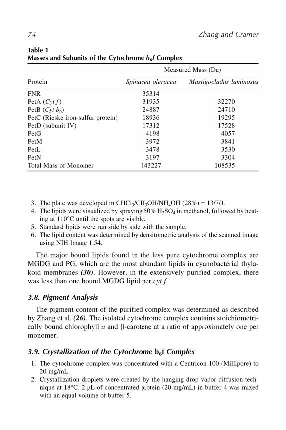
74 Zhang and Cramer
3. The plate was developed in CHCl3/CH3OH/NH4OH (28%) = 13/7/1.4. The lipids were visualized by spraying 50% H2SO4 in methanol, followed by heat-
ing at 110°C until the spots are visible.5. Standard lipids were run side by side with the sample.6. The lipid content was determined by densitometric analysis of the scanned image
using NIH Image 1.54.
The major bound lipids found in the less pure cytochrome complex areMGDG and PG, which are the most abundant lipids in cyanobacterial thyla-koid membranes (30). However, in the extensively purified complex, therewas less than one bound MGDG lipid per cyt f.
3.8. Pigment Analysis
The pigment content of the purified complex was determined as describedby Zhang et al. (26). The isolated cytochrome complex contains stoichiometri-cally bound chlorophyll a and �-carotene at a ratio of approximately one permonomer.
3.9. Crystallization of the Cytochrome b6f Complex
1. The cytochrome complex was concentrated with a Centricon 100 (Millipore) to20 mg/mL.
2. Crystallization droplets were created by the hanging drop vapor diffusion tech-nique at 18°C. 2 µL of concentrated protein (20 mg/mL) in buffer 4 was mixedwith an equal volume of buffer 5.
Table 1Masses and Subunits of the Cytochrome b6f Complex
Measured Mass (Da)
Protein Spinacea oleracea Mastigocladus laminosus
FNR 35314PetA (Cyt f ) 31935 32270PetB (Cyt b6) 24887 24710PetC (Rieske iron-sulfur protein) 18936 19295PetD (subunit IV) 17312 17528PetG 4198 4057PetM 3972 3841PetL 3478 3530PetN 3197 3304Total Mass of Monomer 143227 108535

Cytochrome b6f Complex 75
3. Hexagonal crystals with space group P61 grew overnight to 0.3���0.15���0.1 mm,and reached a size of 0.5���0.25���0.2 mm after 3–4 d (Fig. 4).
4. For data collection, crystals were frozen in 28% PEG 400 with 5% 2, 3-butanediol.
4. Notes1. All of the stock solutions should be stored at 4°C in the presence of protease
inhibitors: 0.25 mM PMSF, 2 mM benzamidine, 2 mM �-amino-caproic acid.2. In the present chapter we have described the methods for purification of the cyto-
chrome b6 f complex from spinach chloroplasts and a thermophilic cyanobacterium.For purification of the complex from the green alga, Chlamydomonas reinhardtii,consult Pierre et al. (7).
3. The purified cytochrome complex is subject to proteolysis. Even in the presenceof protease inhibitors, the Rieske ISP, cytochrome b6 and subunit IV could bepartially proteolysed if left at room temperature for a week or so. After 2 wk atroom temperature, these three subunits were completely cleaved (Fig. 5). Thecomplex is stable on ice over several weeks, and it can be frozen in liquid nitrogenand stored at �80°C for a longer period of time without significant loss of activity.
4. After elution, the propyl-agarose column was still blue because of bound phyco-bilin proteins. The column can be regenerated by washing with one volume ofdistilled water, followed by seven sequential washes with one volume of 25, 50,and 95% ethanol, two volumes of n-butanol, and one volume of 95, 50, and 25%ethanol. The clean resin is washed and kept in distilled water.
Fig. 4. Crystals of the cytochrome b6 f complex from M. laminosus. The reddishbrown hexagonal crystals (0.5���0.25���0.2 mm) with space group P61 diffracted to 3.0Šwith good statistics (31).

76 Zhang and Cramer
AcknowledgmentsThese studies were supported by NIH GM-32383 (WAC). Early studies on
the crystallization of cytochrome b6 f were supported by Fellowships to WACfrom the J. S. Guggenheim Foundation and A. von Humboldt Stiftung, andhospitality from H. Michel and the Max Planck Institute for Biophysics (Frank-furt). We thank D. Huang for contributions to early stages of this study, and G.Kurisu, J. Yan, S. Ferguson-Miller, and A. Friedman for helpful discussions.
References1. Kallas, T. (1994) The cytochrome b6 f complex, in The Molecular Biology of
Cyanobacteria (Bryant, D. A., ed.), Kluwer Academic Publishers, Dordrecht, pp.259–317.
2. Cramer, W. A., Soriano, G. M., Ponomarev, M., et al. (1996) Some new structuralaspects and old controversies concerning the cytochrome b6 f complex of oxy-genic photosynthesis. Ann. Rev. Plant Physiol. Plant Mol. Biol. 47, 477–508.
3. Soriano, G. M., Ponamarev, M. V., Carrell, C. J., Xia, D., Smith, J. L., and Cramer,W. A. (1999) Comparison of the cytochrome bc1 complex with the anticipatedstructure of the cytochrome b6 f complex: De plus ca change de plus c’est la memechose. J. Bioenerg. Biomembr. 31, 201–213.
4. Zhang, H., Whitelegge, J. P., and Cramer, W. A. (2001) Ferredoxin:NADP+ oxi-doreductase is a subunit of the chloroplast cytochrome b6 f complex. J. Biol. Chem.
276, 38,159–38,165.
Fig. 5. Proteolysis of the cytochrome b6 f complex. Lane 1, fresh complex; lanes 2and 3, incubated at room temperature for 7 and 14 d, respectively.

Cytochrome b6f Complex 77
5. Whitelegge, J. P., Zhang, H., Taylor, R., and Cramer, W. A. (2002) Full sub-unit coverage liquid chromatography electrospray-ionization mass spectrometry(LCMS+) of an oligomeric membrane protein complex: the cytochrome b6 f com-plex from spinach and the cyanobacterium, M. laminosus. Mol. Cellular Proteo-
mics 1, 816–827.6. Huang, D., Everly, R. M., Cheng, R. H., et al. (1994) Characterization of the chlor-
oplast cytochrome b6 f complex as a structural and functional dimer. Biochemistry
33, 4401–4409.7. Pierre, Y., Breyton, C., Kramer, D., and Popot, J. L. (1995) Purification and char-
acterization of the cytochrome b6 f complex from Chlamydomonas reinhardtii.J. Biol. Chem. 270, 29,342–29,349.
8. Widger, W. R., Cramer, W. A., Herrmann, R. G., and Trebst, A. (1984) Sequencehomology and structural similarity between the b cytochrome of mitochondrialcomplex III and the chloroplast b6 f complex: position of the cytochrome b hemesin the membrane. Proc. Natl. Acad. Sci. USA 81, 674–678.
8a. Kurisu, G., Zhang, H., Smith, J. L., and Cramer, W. A. (2003) Structure of thecytochrome b6 f complex of oxygenic photosynthesis: tuning the cavity. Science
302, 1009–1014.9. Vener, A., van Kan, P. J., Rich, P. R., Ohad, I. I., and Andersson, B. (1997)
Plastoquinol at the quinol oxidation site of reduced cytochrome bf mediates sig-nal transduction between light and protein phosphorylation: thylakoid proteinkinase deactivation by a single-turnover flash. Proc. Natl. Acad. Sci. USA 94,
1585–1590.10. Xia, D., Yu, C.-A., Kim, H., et al. (1997) Crystal structure of the cytochrome bc1
omplex from bovine heart mitochondria. Science 277, 60–66.11. Zhang, Z., Huang, L., Shulmeister, V. M., et al. (1998) Electron transfer by domain
movement in cytochrome bc1. Nature 392, 677–684.12. Kim, H., Xia, D., Yu, C. A., et al. (1998) Inhibitor binding changes domain mobil-
ity in the iron-sulfur protein of the mitochondrial bc1 complex from bovine heart.Proc. Natl. Acad. Sci. USA 95, 8026–8033.
13. Iwata, S., Lee, J. W., Okada, K., et al. (1998) Complete structure of the 11-subunitmitochondrial cytochrome bc1 complex. Science 281, 64–71.
14. Hunte, C., Koepke, J., Lange, C., Ro�manith, T., and Michel, H. (2000) Structureat 2.3 Å resolution of the cytochrome bc1 complex from the yeast Saccharomyces
cerevisiae with an antibody Fv fragment. Structure 8, 669–684.15. Lange, C. and Hunte, C. (2002) Crystal structure of the yeast cytochrome bc1
complex with its bound substrate cytochrome c. Proc. Nat. Acad. Sci. USA 99,
2800–2805.16. Berry, E. A., Huang, L.-S., Ban, M., et al. (2002) Crystallographic studies of
Rhodobacter capsulatus cytochrome bc1 complex. Biophys. J. 82, 290a.17. Martinez, S. E., Huang, D., Szczepaniak, A., Cramer, W. A., and Smith, J. L.
(1994) Crystal structure of the chloroplast cytochrome f reveals a novel cytochromefold and unexpected heme ligation. Structure 2, 95–105.

78 Zhang and Cramer
18. Carrell, C. J., Zhang, H., Cramer, W. A., and Smith, J. L. (1997) Biological iden-tity and diversity in photosynthesis and respiration: structure of the lumen-sidedomain of the chloroplast Rieske protein. Structure 5, 1613–1625.
19. Martinez, S., Huang, D., Ponamarev, M., Cramer, W. A., and Smith, J. L. (1996)The heme redox center of chloroplast cytochrome f is linked to a buried five-water chain. Protein Sci. 5, 1081–1092.
20. Carrell, C. J., Schlarb, B. G., Bendall, D. S., et al. (1999) Structure of the solubledomain of cytochrome f from the cyanobacterium, Phormidium laminosum. Bio-
chemistry 38, 9590–9599.21. Berry, E. A., Huang, L.-S., Chi, Y., Zhang, Z., Malkin, R., and Fernandez-Velasco,
J. G. (1997) The crystallization and structure of a soluble form of Chlamydomo-nas reinhardtii cytochrome f. Biophys. J. 72, A125.
22. Sainz, G., Carrell, C. J., Ponamarev, M. V., Soriano, G. M., Cramer, W. A., andSmith, J. L. (2000) Interruption of the internal water chain of cytochrome f impairsphotosynthetic function. Biochemistry 39, 9164–9173.
23. Yan, J. and Cramer, W. A. (2003) Functional insensitivity of the cytochrome b6 f
complex to structure changes in the hinge region of the Rieske iron-sulfur protein.J. Biol. Chem. 278, 20,925–20,933.
24. Pierre, Y., Breyton, C., Lemoine, Y., Robert, B., Vernotte, C., and Popot, J.-L.(1997) On the presence and role of a molecule of chlorophyll a in the cytochromeb6 f complex. J. Biol. Chem. 272, 21,901–21,908.
25. Pierre, Y., Chabaud, E., Herve, P., Zito, F., and Popot, J.-L. (2003) Site-directedphotochemical coupling of cytochrome b6 f-associated chlorophyll. Biochemistry
42, 1031–1041.26. Zhang, H., Huang, D., and Cramer, W. A. (1999) Stoichiometrically bound beta-
carotene in the cytochrome b6 f complex of oxygenic photosynthesis protects againstoxygen damage. J. Biol. Chem. 274, 1581–1587.
27. Metzger, S. U., Cramer, W. A., and Whitmarsh, J. (1997) Critical analysis of theextinction coefficient of chloroplast cytochrome f. Biochim. Biophys. Acta 1319,
233–241.28. Laemmli, U. K. (1970) Cleavage of structural proteins during the assembly of the
head of bacteriophage T4. Nature (London) 227, 680–685.29. Black, M. T., Widger, W., and Cramer, W. C. (1987) Large-scale purification of
active cytochrome b6 f complex. Arch. Biochem. Biophys. 252, 655–661.30. Sato, N. and Murata, N. (1988) Membrane lipids. Methods Enzymol. 167, 251–
259.31. Zhang, H., Kurisu, G., Smith, J. L., and Cramer, W. A. (2003) A defined protein-
detergent-lipid complex for crystallization of integral membrane proteins: thecytochrome b6 f complex of oxygenic photosynthesis. Proc. Natl. Acad. Sci. USA
100, 5160–5163.

Plastocyanin and Cytochrome c6 79
79
From: Methods in Molecular Biology, Vol. 274: Photosynthesis Research ProtocolsEdited by: R. Carpentier © Humana Press Inc., Totowa, NJ
10
Purification of Plastocyanin and Cytochrome c6From Plants, Green Algae, and Cyanobacteria
José A. Navarro, Manuel Hervás, and Miguel A. De la Rosa
SummaryPlastocyanin and cytochrome c6 are widely distributed over the oxygen-evolving photosynthe-
tic organisms. The two proteins are functionally equivalent, but strongly differ in their global
electrostatic charge. In fact, they are acidic in eukaryotes, but either neutral or basic in
cyanobacteria. The difference in their electrostatic features is a critical factor in designing the
purification procedure, which must be modified and adapted accordingly. This chapter reports
the methods for producing (including cell cultures), isolating and purifying plastocyanin and
cytochrome c6—which greatly differ in their isoelectric point—from a number of eukaryotic
and prokaryotic organisms.
Key Words: Cyanobacteria; cytochrome c6; Escherichia coli; green algae; metalloproteins;
Monoraphidium; Nostoc; plastocyanin; protein purification; recombinant protein; spinach;
Synechocystis.
1. IntroductionPlastocyanin and cytochrome c6 are two soluble metalloproteins located inside
the thylakoidal lumen. They have different tertiary structures—the former is a
�-barrel protein with a copper atom, whereas the latter is an iron protein con-
sisting of four �-helices and a heme group—but play the same physiological
role: the transfer of electrons between the two membrane-embedded complexes
cytochrome b6 f and photosystem I. Plastocyanin and cytochrome c6 are alter-
natively synthesized in green algae and cyanobacteria in response to copper
availability, although plastocyanin seems to be constitutively produced in plants.
The molecular mass (approx 10 kDa) and redox potential (approx 350 mV, pH
7.0) of these two proteins are near each other. However, their global electrostatic

80 Navarro, Hervás, and De la Rosa
charge varies from organism to organism but is the same within each orga-
nism. In fact, the two proteins are acidic in eukaryotes (plants and green algae)
but neutral or highly basic in prokaryotes (cyanobacteria) (1). The purification
procedure of any given protein (either plastocyanin or cytochrome c6) must
thus be modified depending on the organism but is the same for the two pro-
teins isolated from the same source. The variable content in DNA, pigments,
and other cellular components of cyanobacteria, green algae, and plants is a
crucial point. In this chapter, we describe the methods for the production, iso-
lation, and purification of plastocyanin and cytochrome c6 from a number of
organisms with different isoelectric points (pI): spinach and Monoraphidium
(pI 3.5–4), Synechocystis (pI approx 6) and Nostoc (pI approx 9).
2. Materials
2.1. Organisms
Spinach (Spinacea oleracea) plants can be obtained from a local market.
The use of freshly harvested plants improves neither the quality nor the yield
of plastocyanin preparations.
The green alga Monoraphidium braunii can be obtained from the Culture
Collection of Algae at the University of Göttingen (www.gwdg.de/~epsag),
with the accession number 202-7d.
The cyanobacteria Synechocystis sp and Nostoc sp. (formerly Anabaena sp.)
can be obtained either from the Pasteur Culture Collection (PCC, Institute Pas-
teur, 28 rue du Dr. Roux, 75724, Paris Cedex 15, France; www.pasteur.fr/recher-
che/banques/PCC), with the accession numbers 6803 and 7119, respectively, or
from the American Type Culture Collection (ATCC, PO Box 1549, Manassas,
VA 20108; www.atcc.org), with the accession numbers 27184 and 29151,
respectively.
Escherichia coli (E. coli) transformable strains TG1 (phenotype: supE hsd�5
thi� (lac-proAB) F' [traD36 proAB+ lacIq lacZ �M15]) (2) and RV308 (pheno-
type: su� �lacx74 galISII::OP308 strA; ATCC 31608) are used for the expres-
sion of spinach plastocyanin. E. coli transformable strain MC1061 (phenotype:
F- araD139 �(ara-leu)7696 galE15 galK16 �(lac)X74 rpsL (Strr) hsdR2 (rK�
mK+) mcrA mcrB1) (3) are used for the expression of cyanobacterial proteins.
Alternatively, other strains can be used (4).
2.2. Culture Media
Sterile culture media can be prepared in either glass Roux flasks, glass Erlen-
meyer flasks, or glass cylindrical bottles (10 and 20 L). When bubbling is
required, the gas flow is passed through commercial 0.2 µm filters of different

Plastocyanin and Cytochrome c6 81
sizes depending on culture volume. Foaming is avoided by adding one or two
drops of a suitable antifoaming agent (e.g., silicone) to every liter of culture
medium before sterilization. The specific compositions of the different culture
media for green algae, cyanobacteria, and enterobacteria are described in the
following subheadings.
1. Monoraphidium: the culture medium for Monoraphidium braunii cells: 14.5 mM
NaH2PO4, 2.5 mM Na2HPO4, 1 mM MgSO4, 10 mM KNO3, 0.7 µM ZnSO4, 2.5
µM MnCl2, 10 µM Na2MoO4, 0.1 mM CaCl2, 8 µM H3BO3 and 8 mM NaCl (5). In
order to avoid salts precipitation, the medium should be prepared from a sterilized
and 100-fold concentrated solution containing all the components but the phos-
phates. After dilution of the stock solution, solid NaH2PO4.H2O (2 g/L) and
Na2HPO4.12H2O (0.9 g/L) are added just before sterilization. Iron is added (0.5
mL to every liter of culture medium) from a complex Fe(III)-EDTA solution that
is prepared as follows: 16 g of EDTA and 10.4 g of KOH are dissolved in 186 mL
of distilled water, and 13.7 g of FeSO4.7H2O are dissolved in 364 mL of distilled
water; the two solutions are mixed and vigorously bubbled overnight with air in
the dark to fully oxidize iron atoms. To make the cells synthesize plastocyanin, 10
µM CuSO4 must be added to the culture medium.
2. Synechocystis and Nostoc: Cyanobacterial cells can grow in the BG11 medium
(without copper), which contains 0.2 mM Na2CO3, 0.3 mM MgSO4, 0.24 mM CaCl2,
0.2 mM K2HPO4, 28.5 µM citric acid, 6 mg/L of iron(III)-ammonium citrate (Fe
17%), 2.4 µM Na2-EDTA, 46 µM H3BO3, 9.1 µM MnCl2, 1.6 µM Na2MoO4, 0.8
µM ZnSO4 and 0.2 µM CoCl2 (6). To avoid salt precipitation, the culture medium is
prepared from a 100-fold concentrated stock solution containing all components
but K2HPO4. After dilution of the stock solution, phosphate is added from a solu-
tion of 1M K2HPO4. Solid NaNO3 (1.5 g/L) and NaHCO3 (1.0 g/L) are added just
before sterilization. To make the cells synthesize either cytochrome c6 or plasto-
cyanin, the content of iron(III)-ammonium citrate is doubled or 1 µM CuSO4 is
added, respectively.
3. Escherichia coli: E. coli cells can grow in the Luria-Bertani (LB) standard medium,
which contains 10 g of tryptone, 5 g of yeast extract and 10 g of NaCl per liter (7).
To maintain and amplify the plasmids, ampicillin is added to the LB medium at
100 µg/mL final concentration from a 1000-fold concentrated stock solution ster-
ilized by filtration through a 0.25 µm sterile filter. The filtered ampicillin solution
can be stored at �20°C for several months. The medium is used for the expression
of cytochrome c6, but it must be supplemented with 200 µM CuSO4 in case of
plastocyanin.
2.3. Purification of Proteins
2.3.1. Spinach Plastocyanin
1. Buffer A: 0.4 M sucrose and 15 mM NaCl in 20 mM Tricine-KOH, pH 8.0.
2. Buffer B: 5 mM Tricine-KOH, pH 8.0.

82 Navarro, Hervás, and De la Rosa
3. 1 M Tris-HCl buffer, pH 7.3.
4. 10 mM potassium phosphate buffer, pH 7.0.
5. 10 mM Tris-HCl buffer, pH 8.0.
6. 10 mM Tris-acetate buffer, pH 8.0 (see Note 1).
7. Acetone 80% (v:v) in distilled water.
8. Reagent grade pyridine.
9. Protamine sulfate: 20 mg/mL in 20 mM Tricine-KOH, pH 8.0; make fresh as
required.
10. Solid MgCl2.
11. Solid NaCl.
12. 0.1 M potassium ferricyanide in distilled water.
13. Washed DEAE-cellulose.
14. Polybuffer Exchanger 74.
15. Polybuffer 74 solution.
16. Amicon pressure filtration cells (250 and 10 mL) with YM-3 membranes.
17. Dialysis membranes (3.5 kDa cut-off, several diameters).
18. Three chromatography columns (6���12 cm, 2���15 cm and 1.5���20 cm).
19. Gradient glasses (three couples of 1, 0.4, and 0.125 L).
20. Waring blender (1 gallon) or similar apparatus.
21. Teflon-glass homogenizer (50 mL).
22. Branson 250 sonicator (or equivalent) with a standard tip.
23. Organdy or cheesecloth (a piece of 1���1 m).
2.3.2. Monoraphidium Plastocyanin and Cytochrome c6
1. Buffer C: 1 mM phenylmethylsulfonyl fluoride (PMSF), 1 mM benzamidine and
1 mM �-aminocaproic acid in 20 mM phosphate, pH 7.0 (make fresh as required).
2. 10 mM Tris-HCl buffer, pH 8.0.
3. 10 mM Tris-acetate buffer, pH 8.0 (see Note 1).
4. Streptomycin sulfate: 0.1 M in water, pH 7.0; make fresh as required.
5. Solid ammonium sulfate.
6. Solid NaOH.
7. Solid NaCl.
8. 0.1 M potassium ferricyanide in distilled water.
9. Washed DEAE-cellulose.
10. Polybuffer Exchanger 74.
11. Polybuffer 74 solution.
12. Amicon pressure filtration cells (250 and 10 mL) with YM-3 membranes.
13. Dialysis membranes (3.5 kDa cut-off, several diameters).
14. Two chromatography columns (2���20 cm and 1.5���20 cm).
15. Gradient glasses (two couples of 0.4 and 0.125 L).
16. Manton-Gaulin disruptor (or similar apparatus).
17. Teflon-glass homogenizer (50 mL).
18. Branson 250 sonicator (or equivalent) with a standard tip.

Plastocyanin and Cytochrome c6 83
2.3.3. Synechocystis Plastocyanin and Cytochrome c6
1. Buffer C: 1 mM PMSF, 1 mM benzamidine and 1 mM �-aminocaproic acid in 20 mM
phosphate, pH 7.0 (make fresh as required).
2. 2 mM Tris-HCl buffer, pH 8.0.
3. 5 mM Tris-acetate buffer, pH 8.0 (see Note 1).
4. 20 mM Tricine-KOH buffer, pH 7.5.
5. Streptomycin sulfate (0.1 M in water, pH 7.0; make fresh as required).
6. Solid ammonium sulfate.
7. Solid NaOH.
8. Solid NaCl.
9. 0.1 M potassium ferricyanide in distilled water.
10. Washed DEAE-cellulose.
11. Polybuffer Exchanger 94.
12. Polybuffer 74 solution.
13. Amicon pressure filtration cells (250 and 10 mL) with YM-3 membranes.
14. Dialysis membranes (3.5 kDa cut-off, several diameters).
15. Two chromatography columns (2���30 cm and 1.5���20 cm).
16. A Superdex 75 (Amersham) FPLC column (16���60 cm) (or equivalent).
17. Gradient glasses (two couples of 0.4 and 0.125 L).
18. Manton-Gaulin disruptor (or some other similar apparatus).
19. Branson 250 sonicator (or some other equivalent) with a standard tip.
2.3.4. Nostoc Plastocyanin and Cytochrome c6
1. Buffer C: 1 mM PMSF, 1 mM benzamidine and 1 mM �-aminocaproic acid in 20
mM phosphate, pH 7.0 (make fresh as required).
2. 1 mM phosphate buffer, pH 7.0.
3. 20 mM Tricine-KOH buffer, pH 7.5.
4. Streptomycin sulfate: 0.1 M in water, pH 7.0; make fresh as required.
5. Solid ammonium sulfate.
6. Solid NaOH.
7. Solid NaCl.
8. 0.1 M potassium ferricyanide in distilled water.
9. Washed carboximethyl-cellulose.
10. Amicon pressure filtration cells (250 and 10 mL) with YM-3 membranes.
11. A chromatography column (2���30 cm).
12. A Superdex 75 (Amersham) FPLC column (16���60 cm) (or equivalent).
13. Gradient glasses (0.4 L).
14. Manton-Gaulin disruptor (or similar apparatus).
15. Branson 250 sonicator (or equivalent) with a standard tip.
3. MethodsThe protocols have been modified from a series of previously reported methods
for the isolation and purification of plastocyanin and/or cytochrome c6 from

84 Navarro, Hervás, and De la Rosa
spinach (8,9), Monoraphidium (10,11), Synechocystis (12,13), and Nostoc (14–
15). Figure 1 shows a flow-chart with the different procedures.
3.1. Cell Growth and Collection
3.1.1. Green Algae and Cyanobacteria
Grow green algal and cyanobacterial cells in culture rooms at 25 or 30°C,
respectively. Routinely maintain cells by 1/10 dilution of stationary cultures
(absorbance at 600 nm higher than 1.5) in sterile glass Roux flasks (culture
volume, 750 mL) (see Note 2). Inoculate a 10 L sterile glass bottle, which in
Fig. 1. Flow-chart summarizing the different steps of the procedures for purifica-
tion of plastocyanin and/or cytochrome c6 from plants, green algae, and cyanobacteria.

Plastocyanin and Cytochrome c6 85
turn serves to inoculate four 20 L glass bottles. All the cultures are under con-
tinuous irradiation by fluorescent light tubes (50 µE m�2 s�1) and gas bubbling
(air:CO2 mixture, 99/1 [v/v]). Collect cells from 80 L cultures at stationary
phase (absorbance at 600 nm, 1.6–1.8) by centrifugation at 14,000g in either a
continuous flow system or large volume rotor. Freeze centrifuge tubes with
cell pellets overnight for efficient recovery of the pellets. Typical cell yields
are around 1–2 g (wet weight)/L. The pellets can be kept at �20°C until use.
3.1.2. Escherichia Coli
For high yield protein purification, E. coli cells are transformed by follow-
ing the standard molecular biology methods (9,13,15). Inoculate 100 µL of
transformed cells in a 250 mL glass Erlenmeyer flask containing 100 mL of
LB medium. After 12 h growing at 37°C under continuous stirring in an orbital
shaker (200 rpm), the culture is used to inoculate three 5 L glass Erlenmeyer
flasks containing 2 L of LB medium each. Leave cells to grow under similar
temperature and shaking conditions to reach the stationary phase (approx 18 h;
absorbance at 600 nm higher than 1.2), and collect upon centrifugation at
14,000g for 5 min. For systems under control of the T7 promoter, isopropyl-�-
D-thio-galactopyranoside (IPTG) at a final concentration of 0.5–1 mM is added
to the culture 8 h before cell collection (absorbance at 600, approx 1.0). Freshly
collected cells are immediately used for protein purification. All cultures are
made under sterile conditions.
3.2. Cell Breaking Procedures
3.2.1. Spinach Leaves
The starting material consists of 3 kg of depeciolated and denerved spinach
leaves that must be washed with cold distilled water and dried in a cold cham-
ber. This is a time-consuming procedure, thus material should be prepared the
day before and kept in a cold room in the dark.
1. 500 g batches of spinach leaves are mixed with 700 mL of buffer A and broken in
the Waring blender (30 s of blending at 70% power).
2. The resulting suspension is filtered through four organdy or cheesecloth layers in
a funnel to eliminate unbroken material.
3. To recover as much crude extract as possible, the cell suspension has to be squeezed
by hand.
4. The filtered suspension is centrifuged at 300g for 1 min to remove whole cells, and
the supernatant is again centrifuged at 4000g for 10 min to precipitate chloroplasts.
5. The resulting pellet is resuspended with a glass bar in 400 mL of buffer B, and
gently homogenized in a teflon-glass homogenizer.
6. The suspension is left to stand for 10 min under gentle stirring in darkness and
then centrifuged at 30,000g for 20 min.

86 Navarro, Hervás, and De la Rosa
7. The final pellet is resuspended in 200 mL of distilled cold water and homogenized
again.
8. Chlorophyll concentration is determined as described by Arnon (16): 0.1 mL of
suspension is dissolved in 20 mL of 80% acetone in water (v/v).
9. After vigorous mixing, unsoluble material is removed upon centrifugation at 13,000g
for 5 min at room temperature.
10. The absorbance at 652 nm of the supernatant is measured, and the chlorophyll
content is determined by using an extinction coefficient of 34.5 mg chlorophyll
mL�1 cm�1.
3.2.2. Green Algal and Cyanobacterial Cells
1. The initial steps are identical for Monoraphidium, Synechocystis, and Nostoc cells.
Mix 250 g of frozen cell paste with 1 L of cold buffer C (freshly prepared, owing
to the unstability of the protease inhibitors) and keep under vigorous stirring at
4°C for at least 1 h in the dark.
2. Cell disruption is carried out on pressure/depressure cycles by passing the cell
suspension three times through a Manton-Gaulin high pressure continuous sys-
tem at 7000 psi (see Note 3).
3. The resulting suspension is centrifuged at 3000g for 2 min.
4. The supernatant is sonicated in 150 mL aliquots in an ice bath for 1 min with a Bran-
son apparatus (50% power) after adding solid NaCl at 50 mM final concentration.
5. The suspension is centrifuged at 12,000g for 20 min, and the pellet is discarded.
3.2.3. Escherichia Coli Cells
E. coli transformed cells are collected upon centrifugation of 6 L cultures,
and the pellets (see Subheading 3.1.2.) are resuspended in 20 mL of distilled
water. Transformed cells are designed to send the overexpressed proteins (either
plastocyanin or cytochrome c6) to the periplasmic space, therefore the cell sus-
pension has to undergo two cycles of freezing in liquid nitrogen and thawing at
40°C in a thermostatted bath. Upon centrifugation at 12,000g for 5 min, the
periplasmic fraction is collected from the supernatant.
3.3. Purification of Plastocyanin and Cytochrome c6
The purification procedures must be carried out in a cold chamber (4°C) or,
alternatively, the cell and protein samples are kept in ice containers. To better
follow the proteins throughout purification, cytochrome c6 is maintained in its
reduced native redox state so that it can be easily recognized by its typical pink-
orange color, whereas a few microliters of a 0.1 M potassium ferricyanide
stock solution are added to plastocyanin to get the characteristic blue color of
its oxidited state (see Note 4). From here thereafter, the same protocol is used
for purification of plastocyanin and cytochrome c6 when they are both isolated

Plastocyanin and Cytochrome c6 87
from the same organism. Purity of cytochrome c6 fractions is determined from
the A553/A275 ratio of its reduced state (see Note 5), whereas purity of plastocy-
anin samples is determined from the A278/A597 ratio of its oxidized state. Plasto-
cyanin is in part autoreduced throughout purification, therefore its redox state
should be checked at every step by measuring the absorbance change at 597 nm
in the absence of ferricyanide and after addition of a little amount of oxidant.
3.3.1. Spinach Plastocyanin
3.3.1.1. DIFFERENTIAL PRECIPITATION
1. Chlorophyll and buffer concentration of the suspension obtained in Subheading
3.2.1. is first fitted to 1.5 mg (chlorophyll)/mL and 10 mM Tris-HCl, pH 8.0, respec-
tively, by adding distilled water and 1 M Tris-HCl, pH 8.0.
2. Add pyridine (0.7 mL to every 100 mL of solution) and gently stir the mixture for
30 min.
3. Sonicate the resulting solution (150 mL aliquots each time) in a Branson appara-
tus (100% power) for 150 s in a salt-ice bath to avoid sample heating.
4. Add a protamine sulfate solution (20 mg/mL in 20 mM Tricine-KOH, pH 8.0) un-
der vigorous stirring to reach the proportion of 1 mL of protamine solution to
every 5 mL of sonicated solution.
5. Stir the resulting preparation for 5 min and allow to rest for 30 min.
6. Add solid MgCl2 under continuous stirring up to reach a final concentration of
5 mM.
7. After 10 min with no stirring, the preparation is centrifuged at 14,000g for 15 min
and the pellet is discarded.
3.3.1.2. ANIONIC EXCHANGE CHROMATOGRAPHY
1. Load the supernatant resulting from the previous step onto a DEAE-cellulose col-
umn (6���12 cm; 300 mL of gel volume; elution flow ca. 40 mL/h) that must be
previously equilibrated with 10 mM potassium phosphate, pH 7.0.
2. After sample loading, wash the column with at least 600 mL of the phosphate
buffer to remove unbound material.
3. Elute the plastocyanin by applying a 0.01–0.4 M NaCl gradient in phosphate buffer
(total volume, 2 L).
4. Pool plastocyanin fractions with an A278/A597 ratio lower than 10, fully oxidize with
potassium ferricyanide and dialyze for 24 h against 10 mM Tris-HCl, pH 8.0, and
supplement with 10 µM ferricyanide, with at least one dialysis buffer replacement.
5. Load the resulting dialyzed preparation—or, alternatively, the supernatant obtained
from E. coli transformed cells in Subheading 3.2.3. onto a second DEAE-cellu-
lose column (2���15 cm; 40 mL of gel volume; elution flow ca. 20 mL/h), which
must be previously equilibrated with 10 mM Tris-HCl, pH 8.0.
6. After sample loading, wash the column with at least 80 mL of the same Tris-HCl
buffer supplemented with 60 mM NaCl to remove weakly bound material.

88 Navarro, Hervás, and De la Rosa
7. Plastocyanin is eluted by applying a 0.06–0.3 M NaCl gradient in Tris-HCl buffer
(total volume, 0.4 L).
8. Plastocyanin fractions with an A278/A597 ratio lower than 5 are pooled, dialyzed
against 10 mM Tris-acetate, pH 8.0, and fully oxidized with ferricyanide.
3.3.1.3. CHROMATOFOCUSING
1. The solution resulting from the previous step is loaded onto a chromatofocusing
(Polybuffer Exchanger 94) column (1.5���20 cm, 30 mL of gel volume, elution
flow ca. 10 mL/h) that must be previously equilibrated with 10 mM Tris-acetate,
pH 8.0.
2. Wash the column with 150 mL of a 10-times diluted polybuffer 74 solution, pH
4.0, and elute plastocyanin by applying a 0.01–0.45 M NaCl gradient in 25 mM
Tris-acetate, pH 5.0 (total volume, 0.2 L).
3. Fractions with an A278/A597 ratio close to 1 are pooled, suspended in an adequate
buffer upon several cycles of concentration/dilution in an Amicon pressure filtra-
tion cell (YM-3 membrane), and finally frozen until use.
3.3.2. Monoraphidium Plastocyanin and Cytochrome c6
3.3.2.1. DIFFERENTIAL PRECIPITATION
1. Add streptomycin sulfate (0.1 M in water, pH 7.0) to the supernatant obtained in
Subheading 3.2.2. at the final ratio of 1/10 (v/v) under vigorous stirring.
2. Gently stir the solution for 1 h and allow to rest for 2 h.
3. Discard the precipitated material upon centrifugation at 12,000g for 20 min.
4. Slowly add solid ammonium sulfate to the supernatant, to reach a saturation level
of 60% (36.1 g added to every 100 mL), under vigorous stirring and continuous
pH testing to keep the pH value close to 7.0 by adding small amounts of a concen-
trated NaOH solution.
5. Gently stir the resulting preparation for 1 h and then clear upon centrifugation at
12,000g for 20 min.
6. Add ammonium sulfate to the supernatant as before to reach a saturation level of
98% (27.5 g added to every 100 mL).
7. Upon centrifugation at 12,000g for 20 min, resuspend the pellet by means of a glass
bar in 200 mL of 10 mM Tris-HCl, pH 8.0, and dialyze against the same Tris-HCl
buffer for 48 h with at least two dialysis buffer replacements.
3.3.2.2. ANIONIC EXCHANGE CHROMATOGRAPHY
1. The dialyzed solution is loaded onto a DEAE-cellulose column (2���20 cm; 60 mL
of gel volume; elution flow ca. 20 mL/h) that must be previously equilibrated with
10 mM Tris-HCl, pH 8.0.
2. After column washing with at least 120 mL of Tris-HCl buffer, elute plastocyanin
or cytochrome c6 by applying a 0.01–0.4 M NaCl gradient in Tris-HCl buffer
(total volume, 0.6 L).

Plastocyanin and Cytochrome c6 89
3. Pool and dialyze plastocyanin or cytochrome c6 containing fractions.
3.3.2.3. CHROMATOFOCUSING
1. The solution resulting from the previous step is further purified by chromatofocus-
ing as described under Subheading 3.3.1.
2. The pure protein fractions with either an A278/A597 ratio of approx 1.5 for plasto-
cyanin or an A553/A275 ratio of 1.15 in case of cytochrome c6 are pooled, suspended
in an adequate buffer upon several cycles of concentration/dilution in an Amicon
pressure filtration cell (YM-3 membrane), and finally frozen until use.
3.3.3. Synechocystis Plastocyanin and Cytochrome c6
3.3.3.1. DIFFERENTIAL PRECIPITATION
1. Streptomycin and two-sequential ammonium sulfate precipitations are as described
under Subheading 3.3.2., with the two following exceptions:
a. In case of proteins isolated from Synechocystis, the first ammonium sulfate
precipitation is performed at a saturation level of 50% rather than 60%, and
b. In case of recombinant proteins expressed in and isolated from E. coli, the strep-
tomycin precipitation step is omitted and the supernatants obtained at Subhead-
ing 3.2.3. are directly subjected to sequential ammonium sulfate precipitation.
3.3.3.2. ANIONIC EXCHANGE CHROMATOGRAPHY
1. After 98% ammonium sulfate precipitation, resuspend the centrifugation pellets
with a glass bar in 200 mL of 2 mM Tris-HCl, pH 8.0, desalt along several cycles
of concentration/dilution with the same buffer in an Amicon pressure filtration
cell, and finally dilute with buffer up to 400 mL final volume.
2. Load the resulting solution onto a DEAE-cellulose column (2���30 cm, 80 mL of
gel volume; elution flow ca. 20 mL/h) that must be previously equilibrated with
2 mM Tris-HCl, pH 8.0.
3. Wash the column with at least 80 mL of Tris-HCl buffer.
4. Plastocyanin or cytochrome c6 are eluted from the column by applying a 0-0.2 M
NaCl gradient in Tris-HCl buffer (total volume, 0.6 L), and the fractions with an
A275/A597 (plastocyanin) or A274/A552 (cytochrome c6) ratio lower than 10 are pooled
and dialyzed against 5 mM Tris-acetate, pH 8.0.
3.3.3.3. CHROMATOFOCUSING
The solution resulting from the previous step is further purified by chroma-
tofocusing as described in Subheading 3.3.1., except that plastocyanin or cyto-
chrome c6 are eluted with 10-times diluted polybuffer 74 solution, pH 4.0. The
fractions with an A275/A597 lower than 5 (plastocyanin) or an A274/A552 ratio
lower than 3 (cytochrome c6) are pooled and concentrated by pressure filtra-
tion in an Amicon cell.

90 Navarro, Hervás, and De la Rosa
3.3.3.4. FPLC CHROMATOGRAPHY
1. The protein solution resulting from the previous step is subjected to FPLC chro-
matography on a Superdex 75 column (1.6���60 cm; elution flow 0.5 mL/min)
previously equilibrated with 20 mM Tricine-KOH, pH 7.5.
2. Plastocyanin or cytochrome c6 are eluted using the same Tricine-KOH buffer.
3. Pure protein fractions with an A275/A597 ratio of approx 2.2 (oxidized plastocya-
nin) or an A552/A274 ratio of 1.14 (reduced cytochrome c6) are pooled, concen-
trated and frozen until use.
3.3.4. Nostoc Plastocyanin and Cytochrome c6
3.3.4.1. DIFFERENTIAL PRECIPITATION
1. Streptomycin and two-sequential ammonium sulfate precipitations are as described
under Subheading 3.3.2.
2. In case of recombinant proteins expressed in and isolated from E. coli, the strepto-
mycin precipitation step is omitted and so the supernatants obtained at Subhead-
ing 3.2.3. are directly subjected to sequential ammonium sulfate precipitation.
3.3.4.2. CATIONIC EXCHANGE CHROMATOGRAPHY
1. After 98% ammonium sulfate precipitation, the centrifugation pellets are resus-
pended with a glass bar in 200 mL of 1 mM sodium phosphate, pH 7.0, and dialyzed
against the same buffer for 48 h, with at least two dialysis buffer replacements.
2. The dialyzed solution is loaded onto a carboximethyl-cellulose column (2���30
cm; 80 mL of gel volume; elution flow ca. 20 mL/h) previously equilibrated with
1 mM sodium phosphate, pH 7.0.
3. Wash the column with at least 160 mL of phosphate buffer supplemented with
5 µM ferricyanide.
4. Plastocyanin or cytochrome c6 are eluted from the column by means of a 1–35 mM
phosphate gradient, pH 7.0 (total volume, 0.6 L).
5. The fractions with an A275/A597 (plastocyanin) or A274/A552 (cytochrome c6) ratio
lower than 3 are pooled and concentrated.
3.3.4.3. FPLC CHROMATOGRAPHY
1. The protein solution resulting from the previous step is subjected to FPLC chroma-
tography as described under Subheading 3.3.3.
2. Pure protein fractions with an A275/A597 ratio of approx 1.2 (oxidized plastocya-
nin) or an A552/A274 ratio of approx 1.0 (reduced cytochrome c6) are pooled, con-
centrated, and frozen until use.
4. Notes1. 10 mM Tris-acetate buffer, pH 8.0, must be prepared by adding small aliquots of
concentrated acetic acid to a solution of 10 mM Tris to reach a pH value of 8.0.

Plastocyanin and Cytochrome c6 91
2. For long-term maintenance, the organisms can be kept in either Petri dishes with
solid media (1.5% [p/v] agar concentration) or 100 mL glass Erlenmeyer flasks
with liquid medium and no bubbling. In the first stages of diluted cultures in glass
Roux flasks, light intensity should be dimmed to avoid photobleaching by placing
a piece of paper between flasks and fluorescent tubes. Every 80 L culture usually
takes four days to reach the saturation level; after the second day, additional side
panels of fluorescent lamps can be placed to enhance cell growing. Cell collection
from each 80 L culture takes 4–5 h by continuous flow centrifugation.
3. The cells can alternatively be disrupted in a French press after three cycles at
20,000 psi, but there is a limit in the capacity of the cylinder (approx 40 mL).
Algal (Monoraphidium) and cyanobacterial (Synechocystis and Nostoc) cells can
also be broken in a Sorvall Omnimixer (or similar apparatus), the wet cell paste is
carefully mixed with the same volume of 0.2 mm � glass beads; after 10 cycles
of 30 s shaking with 2 min cooling intervals, the glass beads are separated upon
decantation and the resulting suspension is centrifuged to remove unbroken cells.
In case of Synechocystis, however, the cell wall has to be previously degraded by
adding penicillin G (100 mg L�1) to the cultures 24 h before collection.
4. Cyanobacterial plastocyanin cannot be followed throughout the first steps of puri-
fication because of optical interference of phycobiliproteins, and it is not until the
ammonium sulfate fractionation that the copper protein can be detected.
5. Depending on the organism from which cytochrome c6 is isolated, a difference of
1–2 nm in the maximum value of the ultraviolet (274–275 nm) and alpha (552–
553 nm) bands can be observed in the absorption spectrum of the reduced form.
AcknowledgmentsThe authors wish to thank to their students, co-workers and collaborators,
listed in the references, for their contributions to this research. Financial sup-
port was provided by the Spanish Ministry of Science and Technology, the
Andalusian Government and the Human Potential Program of the European
Commission.
References1. De la Rosa, M. A., Navarro, J. A., Díaz-Quintana, A., et al. (2002) An evolution-
ary analysis of the reaction mechanisms of photosystem I reduction by cytochrome
c6 and plastocyanin. Bioelectrochemistry 55, 41–45.
2. Carter, P. (1986) Site directed mutagenesis. Biochem. J. 237, 1–7.
3. Casadaban, M. J. and Cohen, S. N. (1980) Analysis of gene control signals by DNA
fusion and cloning in Escherichia coli. J. Mol. Biol. 138, 179–207.
4. Hippler, M., Drepper, F., Farah, J., and Rochaix, J.-D. (1997) Fast electron trans-
fer from cytochrome c6 and plastocyanin to photosystem I of Chlamydomonas
reinhardtii requires PsaF. Biochemistry 36, 6343–6349.

92 Navarro, Hervás, and De la Rosa
5. Kessler, E., Langner, W., Ludewig, I., and Wiechmann, H. (1963) Bildung von
sekundar-carotinoiden bei stickstoffmangel und hydrogenase-aktivitat als
taxonomische merkmale in der gattung Chlorella, in Studies on Microalgae and
Photosynthetic Bacteria (Japanese Society of Plant Physiology, ed.), Tokyo Uni-
versity Press, Tokyo, pp. 7–20.
6. Rippka, R., Deruelles, J., Waterbury, J. B., Herdman, M., and Stainer, R. Y. (1979)
Generic assignments, strain stories and properties of pure cultures of cyanobac-
teria. J. Gen. Microbiol. 111, 1–61.
7. Sambrook, J., Fritsch, E., and Maniatis, T. (1989) Molecular cloning: A labora-
tory manual, Second ed. Cold Spring Harbor Laboratory Press, Cold Spring Har-
bor, New York.
8. Yocum, C. F. (1982) Purification of ferredoxin and plastocyanin, in Methods in
Chloroplast Molecular Biology (Edelman, M., Hallick, R. B., and Chua, N.-H.,
eds.), Elsevier Biomedical Press, Amsterdam, pp. 973–981.
9. Ejdebäck, M., Young, S., Samuelsson, A., and Karlsson, B. G. (1997) Effects of
codon usage and vector-host combinations on the expression of spinach plasto-
cyanin in Escherichia coli. Protein Expr. Purif. 11, 17–25.
10. Hervás, M., De la Rosa, M. A., and Tollin, G. (1992) A comparative laser flash
photolysis study of algal plastocyanin and cytochrome c552 photooxidation by
photosystem I particles. Eur. J. Biochem. 203, 115–120.
11. Campos, A. P., Aguiar, A. P., Hervás, M., et al. (1993) Cytochrome c6 from
Monoraphidium braunii: a cytochrome with an unusual heme axial coordination.
Eur. J. Biochem. 216, 329–341.
12. Hervás, M., Navarro, F., Navarro, J. A., et al. (1993) Synechocystis 6803 plasto-
cyanin isolated from both the cyanobacterium and E. coli transformed cells are
identical. FEBS Lett. 319, 257–260.
13. De la Cerda, B., Navarro, J. A., Hervás, M., and De la Rosa, M. A. (1997) Changes
in the reaction mechanism of electron transfer from plastocyanin to photosystem
I in the cyanobacterium Synechocystis sp. PCC 6803 as induced by site-directed
mutagenesis of the copper protein. Biochemistry 36, 10,125–10,130.
14. Medina, M., Díaz, A., Hervás, M., et al. (1993) A comparative laser flash absorp-
tion spectroscopy study of Anabaena PCC 7119 plastocyanin and cytochrome c6
photooxidation by photosystem I particles. Eur. J. Biochem. 213, 1133–1138.
15. Molina-Heredia, F. P., Hervás, M., Navarro, J. A., and De la Rosa, M. A. (1998)
Cloning and correct expression in Escherichia coli of the petE and petJ genes
respectively encoding plastocyanin and cytochrome c6 from the cyanobacterium
Anabaena sp. PCC 7119. Biochem. Biophys. Res. Commun. 243, 302–306.
16. Arnon, D. I. (1949) Copper enzymes in isolated chloroplasts: polyphenol oxidase
in Betavulgaris. Plant Physiol. 24, 1–15.

Preparation of Native and Recombinant LHCIIb 93
93
From: Methods in Molecular Biology, Vol. 274: Photosynthesis Research ProtocolsEdited by: R. Carpentier © Humana Press Inc., Totowa, NJ
11
Preparation of Native and RecombinantLight-Harvesting Chlorophyll-a/b Complex
Wolfgang Rühle and Harald Paulsen
SummaryProcedures to isolate native light-harvesting chlorophyll-a/b complex (LHCIIb) and to recon-
stitute recombinant LHCIIb are described. Separation of trimeric from monomeric forms and
free pigment by sucrose density-gradient ultracentrifugation can be applied to both native and
reconstituted complexes. The preparations are characterized by their pigment composition, pro-
tein pattern and spectral properties.
Key Words: a/b-Binding protein; antenna protein; LHCII; light-harvesting complex; vitro
reconstitution.
1. IntroductionThe apoprotein of the light-harvesting chlorophyll-a/b complex (LHCIIb)
is the most abundant membrane protein in plants and one of the best-studied
components of the photosynthetic apparatus. The latter is partially owing to the
fact that LHCIIb is more stable and easily isolated than other pigment–protein
complexes of the thylakoid membrane. The isolation procedure of Krupa et al.
(1) described here is easy and rapid. Although the resulting LHCIIb preparation
has a low content of violaxanthin, a weakly bound carotenoid easily lost from
native LHCIIb (2), the complexes are well suited for various spectroscopic stud-
ies (3,4) and presumably also for crystallization (5).
Studies of structure–function relationships in LHCIIb are facilitated by the
fact that the protein can easily be refolded in vitro. This allows mutation or
altered pigment composition in recombinant versions of the complex. A tech-
nique to reconstitute LHCIIb from its apoprotein and pigments in vitro has
been devised by Plumley and Schmidt (6) and extended to bacterially expressed
apoprotein (7). Subsequently, several slightly different procedures have been

94 Rühle and Paulsen
developed (8,9). In this chapter we present a broadly applicable procedure lead-
ing to preparative amounts of trimeric recombinant LHCIIb.
2. Materials
2.1. Native LHCIIb1. Pisum sativum (see Note 1).
2. Homogenization buffer: 50 mM Tricine-NaOH (pH 7.8), 0.4 M sorbitol.
3. Washing buffer: 5 mM EDTA-NaOH (pH 7.8), 50 mM sorbitol.
4. Triton X-100, 5% (w/v) stock solution (especially purified for membrane research,
Roche, Mannheim/Germany).
5. KCl, 1 M.
6. MgCl2, 1 M.
7. Sucrose, 0.5 M.
8. Resuspension buffer: 50 mM Tricine-NaOH (pH 7.8), 100 mM sorbitol.
2.2. Recombinant LHCIIb1. Bacterial strain expressing LHCIIb apoprotein Lhcb1*2 from pea (10,13).
2. Solubilization buffer: 200 mM Tris-HCl (pH 9.0), 4% (w/v) Li-dodecylsulfate
(LDS), 10 mM �-aminocapronic acid, 3 mM benzamidine, 25% (w/v) sucrose.
3. �-Mercaptoethanol, 1 M.
4. Octyl-�-D-glucopyranoside (OG) (Bachem, Heidelberg/Germany), 10% (w/v) stock
solution.
5. OG-buffer: 1% (w/v) OG, 100 mM Tris-HCl (pH 9.0), 12.5% (w/v) sucrose.
6. TX-buffer: 0.05% (w/v) Triton X-100 0.01% (w/v) L-phosphatidyl-D. L-glycerol
dipalmitoyl (PG) (Avanti Polar Lipids, Alabaster/AL), 100 mM Tris-HCl (pH 7.5).
7. Elution buffer: 0.05% (w/v) Triton X-100, 0.01% (w/v) PG, 10 mM Tris-HCl (pH
7.5), 300 mM imidazol.
8. Chelating Sepharose Fast Flow (Amersham Biosciences, Uppsala/Sweden).
2.3. Density Gradient1. Gradient solution: 0.4 M sucrose, 0.06% �-D-dodecylmaltoside (Biomol, Hamburg/
Germany), 10 mM Tris-HCl (pH 7.0).
3. Methods
3.1. Preparation of Native LHCIIbLow-salt thylakoids are used as starting material for this procedure. Intrinsic
proteins are solubilized by the non-ionic detergent Triton X-100, the LHCIIb
is precipitated by K+ and Mg2+ salts, and then separated from other proteins by
sedimentation through a sucrose layer. The resulting pellet consists mainly of
trimeric LHCIIb and can further be separated from contaminating monomeric
LHCIIb and minor antenna complexes by density-gradient ultracentrifugation
(see Subheading 3.3.).

Preparation of Native and Recombinant LHCIIb 95
3.1.1. Preparation of Low-Salt Thylakoids
All steps of thylakoid preparation are carried out at 4°C.
1. Homogenize approx 300 g of young pea shoots (see Note 1) in a Waring blender
with one liter of ice-cold homogenization buffer.
2. Filter through four layers of cheesecloth and centrifuge for 5 min at 7000g.
3. Wash the pellet once with 200 mL cold washing buffer and centrifuge for 10 min
at 10,000g.
4. Suspend thylakoids in cold distilled water to a chlorophyll a+b concentration of
0.8 mg/mL (11) (see Note 2 for chlorophyll determination).
3.1.2. Solubilization and Precipitation of LHCIIb
1. Add Triton X-100 from a 5% (w/v) stock solution to the low-salt thylakoids to
give a final detergent concentration of 0.67% (w/v) (140 µL 5% Triton per mL
suspension; molar ratio detergent/chlorophyll = 12/1).
2. Incubate the suspension at room temperature in the dark for 30 min with continu-
ous stirring.
3. Centrifuge for 40 min at 30,000g at 4°C.
4. Discard the pellet and add KCl as well as MgCl2 from 1 M stock solutions in sev-
eral portions to the supernatant to give final concentrations of 100 mM KCl and
20 mM MgCl2 (4 µL KCl and 23 µL MgCl2 per mL supernatant).
5. Gently stir the solution at room temperature for at least 10 min in the dark to
precipitate the LHCIIb.
6. Prepare a cushion of 0.5 M sucrose in centrifuge tubes on which the suspension is
carefully layered. The volume of the sucrose should be at least threefold the vol-
ume of the LHCIIb suspension.
7. Centrifuge at 10,000g for 10 min at 4°C (fixed-angle rotor sufficient).
8. Resuspend the pellet in resuspension buffer and bring the solution to a chloro-
phyll concentration of 0.8 mg/mL.
9. Add Triton X-100 to give a molar detergent/chlorophyll ratio of 10/1 (116 µL 5%
Triton per mL suspension). Stir for 10 min at room temperature.
10. Repeat precipitation with KCl and MgCl2 as above and centrifuge through a
sucrose layer at 30,000g for 10 min. The chlorophyll a/b ratio should be below
1.4 after this step. Otherwise steps 8–10 should be repeated with centrifugation at
10,000g for 10 min.
11. Resuspend the pellet in resuspension buffer, add KCl and MgCl2 as above but
omit Triton.
12. Centrifuge through a sucrose layer for 10 min at 10000g.
13. Resuspend the pellet in a small volume of distilled water, spin down for 3 min at
5000g.
14. Repeat step 13 to remove any soluble detergent and rests of salt.
15. Adjust the suspension to a chlorophyll a+b concentration of 0.8 mg/mL and store
aliquots at �20°C or

96 Rühle and Paulsen
16. Solubilize the native protein preparation for sucrose density-gradient ultracen-
trifugation of step 3.3 with 1% dodecylmaltoside at a chlorophyll concentration
of 1 mg/mL for 5 min on ice. Remove nonsolubilized material by centrifugation
at 15,000g for 2 min, and carefully layer the supernatant onto the gradient.
3.2. Preparation of Recombinant LHCIIb
The procedure starts out from recombinant Lhcb1*2 protein carrying a C-
terminal hexahistidyl (His) tag (10,13). This protein is accumulated in the over-
expressing bacteria as insoluble inclusion bodies. The pigments are isolated by
acetone extraction of pea or spinach leaves. The procedure can be scaled up or
down as needed. Recombinant LHCIIb, primarily formed as monomeric com-
plexes, spontaneously oligmomerizes into trimers when detergents are removed
in the presence of phosphatidyl glycerol (12). This is convenient when the His-
tagged complexes are immobilized on Ni2+-chelating affinity material (13).
3.2.1. Reconstitution of Recombinant Protein With Pigments
1. Dry an acetonic pigment extract (see Note 3) of pea or spinach leaves equivalent
to 0.5 mg chlorophyll in a nitrogen stream and store aliquots for future use at
�20°C until use.
2. Solubilize 250 µg recombinant Lhcb1*2 apoprotein (inclusion bodies) in 300 µL
solubilization buffer, 210 µL water and 30 µL 1M �-mercaptoethanol.
3. Incubate for 1 min in a boiling water bath.
4. Dissolve a pigment extract corresponding to 0.5 mg chlorophyll in 60 µL ethanol.
5. Vortex the protein solution while adding the pigment solution and for at least
another 30 s (see Note 4). Results are best when both protein and pigment solu-
tions are at room temperature.
6. Add 75 µL octylglycoside from a 10% (w/v) stock solution to each vial, to form
mixed micelles of dodecylsulfate and octylglycoside during a 10-min incubation
at room temperature.
7. Add 75 µL of 2 M KCl and put solution on ice for 10 min to precipitate potassium
dodecylsulfate.
8. Centrifuge at 4°C and 8000g for 5 min and incubate on ice for another 15 min.
9. Centrifuge at 4°C and 15,000g for 5 min. Aggregated pigments and precipitated
K-dodecylsulfate are removed by this step from the supernatant containing
octylglycoside micelles with reconstituted complexes and free pigment.
3.2.2. Trimerization of Reconstituted LHCIIb on a Ni2+-Chelating Column
1. Fill a 2-mL polypropylene chromatography column with Chelating Sepharose to
obtain a sepharose bed of about 0.3–0.5 mL.
2. Add 0.5 mL 0.1 M NiCl2 solution (the sepharose turns to a light green color).
3. Add 1 mL 50 mM Tris-NaOH (pH 7.5) (the sepharose color changes to a light blue).
4. Equilibrate the column with 0.5 mL OG-buffer and transfer to 4°C.

Preparation of Native and Recombinant LHCIIb 97
5. Close the outlet of the column and mix the supernatant from the reconstitution
experiment with the sepharose bed. Resuspend every 10 min for a total of 30 min
to achieve complete binding of the protein to the Ni-surface of the sepharose (see
Note 5).
6. Wash the column with 3���0.5 mL OG-buffer. The brownish color of the eluate
does not originate from pheophytin but from the reduction of some of the Ni2+ ions
by mercaptoethanol. This does not interfere with the preparation.
7. Add 2���0.5 mL TX-buffer to change the detergent and provide the PG necessary
for trimerization.
8. Finally release the LHCIIb from the nickel-sepharose by imidazol in 0.5 mL
eluation-buffer and collect all droplets with dark green color. The eluate contains
a mixture of monomeric and trimeric LHCIIb, which can be separated by sucrose
density-gradient ultracentrifugation.
3.3. Separation of Monomeric and Trimeric LHCIIb
This procedure is suitable for both native and recombinant LHCIIb.
1. Prepare a sucrose density gradient by freezing the gradient solution in 12–14 mL
ultracentrifuge tubes (e.g., for rotor SW40, Beckman, Coulter) at �20°C and thaw-
ing it slowly at 4°C.
2. Remove the upper 500 µL of the gradient to provide a sharp step between the gra-
dient and the sample.
3. Carefully load the gradient with solubilized native or reconstituted recombinant
LHCIIb.
4. Centrifuge at 200,000g for 16 h in a swing-out rotor (e.g., SW40, Beckman, Coulter).
Figure 1 shows an example for the separation of monomeric from trimeric
LHCIIb and free pigment in a preparation of native LHCIIb by sucrose den-
sity-gradient ultracentrifugation.
3.4. Characterization of the Isolated LHCIIb
3.4.1. Pigment Content
Table 1 is an example of yields and chlorophyll a/b ratios as a rough mea-
sure of purity after three precipitation steps. Chlorophyll concentrations are
calculated from the absorbance of acetonic extracts (11).
A more detailed analysis of the pigment composition is performed by extrac-
tion of the gradient band by 2-butanol and separation in a RP-18 HPLC column
(Chromolith SpeedROD. Merck, Darmstadt/Germany) (7). Table 2 shows the
pigment composition of the trimeric LHCIIb band. Lutein is used as a reference
since 2 luteins are attached to a LHCIIb-protein. Biochemical analyses of native
LHCIIb reveals 14–15 chlorophylls whereas only 12 chlorophyll molecules
are resolved in the crystal-data (5). Unfortunately, violaxanthin is almost com-
pletely lost in this preparation (see Note 6).

98 Rühle and Paulsen
3.4.2. Protein Pattern
The purification is demonstrated in Fig. 2 by a Coomassie-stained denaturing
sodium dodecylsulfate-polyacrylamide gel electrophoresis. Lane Thyl results
from thylakoids and lane P1 from the first precipitation. After the second pre-
cipitation (P2) almost all other proteins except the apoproteins of LHCIIb and
an unpigmented 65kD component are removed. However, silver-stained gels
show that there are still traces of proteins other than LHCIIb apoproteins, which
shows the limitation of the procedure. Salt precipitation is suitable for prepar-
ing large amounts of LHCIIb free of other pigment binding proteins within a
short time but for further demands in purity other principles of separation like
isoelectric focusing (3) are required.
Fig. 1. Sucrose-density gradient separation pattern of a native LHCIIb preparation.
Table 1Example of Yield and and Chlorophyll a/b RatiosAs a Rough Measure of LHCIIb Purity During Successive Precipitations
Low salt P1= first P2 = second P3 = third
thylakoids precipitate precipitate precipitate
Total Chlorophyll [mg] 40.0 21.5 7.6 0.9
Yield [%] 100.0 53.7 19.0 2.1
Chlorophyll a/b 2.85 2.33 1.33 1.28

Preparation of Native and Recombinant LHCIIb 99
3.4.3. Spectroscopy
3.4.3.1. ABSORPTION SPECTRUM
The room temperature absorption spectrum of LHCIIb has chlorophyll a
maxima at 435 nm and 675 nm and chlorophyll b maxima at 471 nm and 650
nm as well as some shoulders in the blue region of the spectrum resulting from
xantophylls (Fig. 3).
For low temperature absorption spectroscopy, the sucrose-gradient bands
were mixed with an 80% glycerol solution buffered by 50 mM Hepes (pH 7.5)
Table 2Pigment Stoichiometry of Native Trimeric LHCIIB.Data are in mol/2 mol Lutein and Represent Means ���������� SD) of Nine Preparations
Nx Vx Lu Chlb Chla �-Car
0.8 � 0.1 0.1 � 0.1 2.0 6.4 � 0.4 7.9 � 0.7 —
Fig. 2. Protein pattern at different steps of purification as revealed by a fully dena-
turing SDS-PAGE. Thy, thylakoids; P1, first precipitation; P2, second precipitation.
A Laemmli gel (16) (15% polyacrylamide) was stained with Coomassie.

100 Rühle and Paulsen
to give a final glycerol content of 60% and subsequently measured in liquid
nitrogen. Qy absorption forms of chlorophyll are clearly resolved at 650 nm,
660 nm, 670 nm, and 676 nm. The derivative spectra (not shown) reveal addi-
tional bands at 639 nm, 644 nm, and 656 nm. Further absorption bands in
native and reconstituted LHCIIb have been reported to appear at 4 K (4). The low
temperature absorption spectrum of the reconstituted protein complex depends
partially on the chlorophyll a/b ratio in the pigment extract used for the recon-
stitution. At a 3/1 ratio in the pigment extract the ratio of bound chlorophylls is
about 1.0 instead of approx 1.2 in the native complex and the two long-wave-
length absorbing forms at 670 nm and 676 nm are weaker than in the native
complex (9).
3.4.3.2. FLUORESCENCE EMISSION
Low temperature fluorescence spectroscopy was performed under the same
conditions as absorption spectroscopy (insert in Fig. 3). Excitation at both 470
nm (Chl b) and 430 or 410 nm (Chl a) lead to an emission band at 680 nm (Chl
a) indicating complete energy transfer from Chl b to Chl a. Significant forma-
tion of LHCIIb aggregates would be indicated by a fluorescence emission band
at around 700 nm (14).
Fig. 3. Absorbance spectra of native trimeric LHCIIb at room temperature (dashed)
and 77 K (solid). Insert: fluorescence emission spectrum of native trimeric LHCIIb at
77 K with 470 nm excitation.

Preparation of Native and Recombinant LHCIIb 101
3.4.3.3. CD SPECTRUM
The UV region of CD spectra can provide interesting information on the
secondary protein structure. Therefore it is necessary to remove the sucrose
and Tris-HCl from the gradient-bands. This can be done either by repeated
dilutions with a 10 mM phosphate buffer (pH 7.5), and subsequent ultrafiltra-
tion steps by 15 min centrifugations at 5000g with a 30 kDa size-exclusion mem-
brane, or by buffer exchange on a G25 Sephadex gel filtration column. The CD
spectrum (Fig. 4) of trimeric LHCIIb differs from the monomeric form by a
significant shoulder at 642 nm (15) and a prominent minimum at 474 nm (12)
the origin of which is still unclear. The bands between 200 nm and 240 nm
present structural information on the amount of � helical secondary protein
structure (9). There is almost no difference between the native and reconsti-
tuted LHCIIb.
4. Notes1. The pea plants should be 10 to 14 d old. Keep them in darkness for 12 h before start-
ing the preparations to prevent starch accumulation (avoid stems when harvesting).
Fig. 4. CD spectra of monomeric reconstituted (dashed), trimeric reconstituted (dot-
ted), and trimeric native LHCIIb (solid). All spectra are divided by their absorbance at
675 nm for normalization and displaced by 40 mdeg to separate them.

102 Rühle and Paulsen
2. Prepare an 80% acetonic extract of the thylakoids or protein complexes. Measure
absorbance at 663.6 nm, 646.6 nm, and 750 nm. Subtract any absorbance at 750
nm from the 663.6 nm and 646.6 nm values. Calculate chlorophyll concentrations
from Porra’s (11) equations considering dilution factors:
chlorophyll a [µg/mL] = 12.25���A663.6 � 2.55���A646.6
chlorophyll b [µg/mL] = 20.31���A646.6 � 4.91���A663.6
3. The preparation of a total-pigment extract (7) is described briefly: extract a pellet
of thylakoids (as prepared in Subheading 3.1.1.) with acetone and centrifuge at
5000g for 10 min. Partition the pigments into diethyl ether (0.25 volumes) by
adding an equivalent volume of 1.3 M NaCl. Repeat ether extractions, combining
the ether fractions, as long as the lower acetone/NaCl phase remains colored.
Remove water from the ether fractions by freezing at �20°C and subsequent filtra-
tion. Evaporate the ether to dryness in vacuo. Solubilize the pigments in acetone,
determine chlorophyll content (11), dry aliquots of 0.5 mg chlorophyll a+b in a
nitrogen stream, and store at �20°C.
4. It is crucial to avoid local supersaturation of the pigments to bring them into the
LDS micelles. Use vials large enough for vigorous vortexing without needing to
close the lid. If 1.5 ml Eppendorf vials are used the 600 µL sample should be divided
into three vials and combined after mixing or after the centrifugation step 9 in
Subheading 3.2.1.
5. If the column is equipped with a flow control, the sample can also slowly be
loaded to the packed column within 30 min. The following washing and elution
steps are as described. This will increase the binding capacity of the column and
can lead to a higher LHCIIb concentration in the eluate.
6. Ruban et al. (2) published a procedure that yielded LHCIIb still containing sub-
stantial amounts of violaxanthin. They solubilize BBY particles or thylakoids with
dodecylmaltoside and separate an “antenna band = A-band” by sucrose-gradient
centrifugation. This A-band is then solubilized with low concentrations of dode-
cylmaltoside and separated with a second sucrose-gradient centrifugation. How-
ever this procedure is probably only suitable for analytical purposes because it
has a very low yield.
AcknowledgmentsThe authors thank Dr. Stephan Hobe and Dr. Volkmar Schmid for critically
reading the manuscript. Work in the authors’ lab was funded by Deutsche For-
schungsgemeinschaft (Pa324/5-3).
References1. Krupa, Z., Huner, N. P. A., Williams, J. P., Maissan, E., and James, D. (1987)
Development at cold-hardening temperatures. Plant Physiol. 84, 19–24.
2. Ruban, A. V., Lee P. J., Wentworth, M., Young, A. J., and Horton, P. (1999)
Determination of the stoichiometry and strength of binding of xanthophylls to the
photosystem II light harvesting complexes. J. Biol. Chem. 274, 10,458–10,465.

Preparation of Native and Recombinant LHCIIb 103
3. Bassi, R., Silvestri, M., Dainese, P., Moya, I., and Giacometti, G. M. (1991)
Effects of non-ionic detergent on the spectral properties and aggregation state of
the light-harvesting chlorophyll a/b protein complex (LHCII). J. Photochem. Photo-
biol. B Biol. 9, 335–354.
4. Rogl, H., Schödel, R., Lokstein, H., Kühlbrandt, W., and Schubert, A. (2002)
Assignment of spectral substructures to pigment-binding sites in higher plant light-
harvesting complex LHC-II. Biochemistry 41, 2281–2287.
5. Kühlbrandt, W., Wang, D. N., and Fujiyoshi, Y. (1994) Atomic model of plant
light-harvesting complex by electron crystallography. Nature 367, 614–621.
6. Plumley, F. G. and Schmidt, G. W. (1987) Reconstitution of chlorophyll a/b light-
harvesting complexes: xanthophyll-dependent assembly and energy transfer. Proc.
Natl. Acad. Sci. USA 84, 146–150.
7. Paulsen, H., Rümler, U., and Rüdiger, W. (1990) Reconstitution of pigment-con-
taining complexes from light-harvesting chlorophyll a/b-binding protein over-
expressed in E. coli. Planta 181, 204–211.
8. Paulsen, H. and Schmid, V. H. R. (2002) Analysis and reconstitution of chloro-
phyll proteins, in Heme, Chlorophyll, and Related Molecules: Methods and Proto-
cols (Smith, A. G. and Witty, M., eds.), Humana Press, Totowa, NJ, pp. 235–254.
9. Yang, C. H., Horn, R., and Paulsen, H. (2003) Light-harvesting chlorophyll a/b
complex (LHCIIb) can be reconstituted in vitro from its completely unfolded
apoprotein. Biochemistry 42, 4527–4533.
10. Kosemund, K., Geiger, I., and Paulsen, H. (2000) Insertion of light-harvesting
chlorophyll a/b protein into the thylakoid-Topographical studies. Eur. J. Biochem.
267, 1138–1145.
11. Porra, R. J., Thompson, W. A., and Kriedemann, P. E. (1989) Determination of
accurate extinction coefficients and simultaneous equations for assaying chloro-
phylls a and b extracted with four different solvents: verfication of the concentra-
tion of chlorophyll standards by atomic absorption spectroscopy. Biochim. Biophys.
Acta 975, 384–394.
12. Hobe, S., Prytulla, S., Kühlbrandt, W., and Paulsen, H. (1994) Trimerization and
crystallization of reconstituted light-harvesting chlorophyll a/b complex. EMBO
J. 13, 3423–3429.
13. Rogl, H., Kosemund, K., Kühlbrandt, W., and Collinson, I. (1998) Refolding of
Escherichia coli produced membrane protein inclusion bodies immobilised by
nickel chelating chromatography. FEBS Lett. 432, 21–26.
14. Vasilev, S., Irrgang, K. D., Schrötter, T., Bergmann, A., Eichler, H. J., and Renger,
G. (1997) Quenching of chlorophyll a fluorescence in the aggregates of LHCII:
steady state fluorescence and picosecond relaxation kinetics. Biochemistry 36,
7503–7512.
15. Gülen, D., Knox, R., and Breton, J. (1986) Optical effects of sodium dodecyl
sulfate treatment of the isolated light harvesting complex of higher plants. Photo-
synth. Res. 9, 13–20.
16. Laemmli, U. K. (1970) Cleavage of structural proteins during the assembly of the
head of bacteriophage T4. Nature 227, 680–685.

104 Rühle and Paulsen
Lamellar Aggregates of LHCII and LHCII-Lipid Macro-Assemblies 105
105
From: Methods in Molecular Biology, Vol. 274: Photosynthesis Research ProtocolsEdited by: R. Carpentier © Humana Press Inc., Totowa, NJ
12
Isolation and Characterization of Lamellar Aggregatesof LHCII and LHCII-Lipid Macro-AssembliesWith Light-Inducible Structural Transitions
Ilian Simidjiev, Zsuzsanna Várkonyi, and Gyozo Garab
SummaryIn this chapter we describe isolation of loosely stacked lamellar aggregates of LHCII that
are capable of undergoing light-induced reversible structural changes, similar to those in granalthylakoid membranes (LHCII, the main chlorophyll a/b light-harvesting antenna complex ofphotosystem II). This unexpected structural flexibility of the antenna complexes depends largelyon the lipid content retained during the isolation. The essence of the procedure is to adjust—forthe plant material used—the proper conditions of detergent solubilization and purification mildenough for the associated lipids but also provide sufficient purity. Microcrystals and most otherLHCII preparations, which are more delipidated, are not capable of similar changes. The light-induced structural reorganizations can be enhanced by the addition of different thylakoid lipids,which depending on the lipid species, also lead to the transformation of the lamellar structure.The preparation of different LHCII-lipid macro-assemblies is also described. In structurally flex-ible LHCII preparations and in thylakoids, the changes originate from a thermo-optic effect: fastlocal thermal transients, T-jumps, resulting from dissipation of the (excess) excitation energy thatlead to elementary structural transitions in the vicinity of the dissipating centers. This can occurbecause thylakoids and structurally flexible LHCII assemblies but, for example, not the micro-crystals, exhibit a thermal instability below the denaturation temperature, and thus (local) heat-ing lead to reorganizations without the loss of the molecular architecture of the constituents. Wealso list the main biochemical and biophysical techniques that can be used for testing the struc-tural flexibility of LHCII, and discuss the potential physiological significance of the structuralchanges in light adaptation and photoprotection of plants.
Key Words: Chloroplasts; dissipation; excess excitation energy; grana; LHCII; light adaptation;light-harvesting antenna; lipid–protein interactions; photoprotection of plants; structural flexibil-ity; thermo-optic effect; thylakoid lipids.
" "

106 Simidjiev, Várkonyi, and Garab
1. Introduction
1.1. Basic ObservationsLHCII is the main, chlorophyll a/b light-harvesting antenna complex of
photosystem (PS) II. It is the most abundant pigment-protein complex in thebiosphere. Its structure, derived from electron crystallography of microcrys-tals, is known at near atomic resolution (1). The primary function of this com-plex is to absorb light and transfer the excitation energy toward the reactioncenters. By mediating the stacking of granal thylakoid membranes (2), LHCIIis also known to stabilize the granal ultrastructure; its high self-aggregationcapability explains the lateral segregation (sorting) of the two photosystemsbetween the granum and stroma membranes (3). LHCII also participates inmultilevel regulatory processes, thermal, and light adaptation of plants (4,5).
LHCII, when isolated with mild detergent treatments (6,7), readily assemblesin loosely stacked lamellar aggregates, which although less marked than inmicrocrystals, exhibit a significant degree of long range chiral order of theirchromophores (8) and form-ordered two-dimensional (2D) arrays (9). Theselipid-enriched preparations, in contrast to more delipidated samples, such asmicrocrystals, are capable of undergoing light-induced reversible structuralreorganizations (10,11) that closely resemble the structural changes in the nativethylakoid membranes (12) (see Table 1). In LHCII, the rate of these changesis linearly proportional to the light intensity. In thylakoids, the changes alsoexhibit a similar, approximately linear light-intensity dependence above thesaturation of photosynthesis. Hence, this reversible reaction “measures” thelight intensity meaning that the antenna system can react proportionally andreversibly to excess excitation i.e., above the saturation of photosynthesis.
1.2. Nature and Mechanism of the Structural ChangesAs concerns from nature of the structural changes, a substantial degree of
monomerization of LHCII has been shown to be involved both in vivo and invitro. As for the physical mechanism, these reactions have been accounted forby a novel biological thermo-optic effect (13,14). As indicated by chlorophyllfluorescence kinetic analyses, the structural changes also bring about altera-tions in the photophysical pathways, most notably in the regulated quenchingof the singlet excited state of chlorophyll a molecules in the light harvestingantenna (15). It seems likely that similar changes are responsible for the light-regulation of LHCII phosphorylation at the substrate level (16). Monomeri-zation may also be important in the accessibility of LHCII to proteases (17). Ingeneral, local structural rearrangements in the antenna may provide the systemwith a structural flexibility without perturbing the structural stability of the mem-branes. The exact sequence of molecular events and the physiological signifi-cance of these changes remain to be elucidated in future studies.
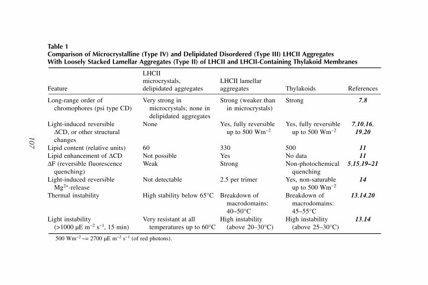
Lamellar A
ggregates of LHC
II and LHC
II-Lipid Macro-A
ssemblies
107
Table 1Comparison of Microcrystalline (Type IV) and Delipidated Disordered (Type III) LHCII AggregatesWith Loosely Stacked Lamellar Aggregates (Type II) of LHCII and LHCII-Containing Thylakoid Membranes
LHCIImicrocrystals, LHCII lamellar
Feature delipidated aggregates aggregates Thylakoids References
Long-range order of Very strong in Strong (weaker than Strong 7,8
chromophores (psi type CD) microcrystals; none in in microcrystals)delipidated aggregates
Light-induced reversible None Yes, fully reversible Yes, fully reversible 7,10,16,
�CD, or other structural up to 500 Wm�2 up to 500 Wm�2 19,20
changesLipid content (relative units) 60 330 500 11
Lipid enhancement of �CD Not possible Yes No data 11
�F (reversible fluorescence Weak Strong Non-photochemical 5,15,19–21
quenching) quenchingLight-induced reversible Not detectable 2.5 per trimer Yes, non-saturable 14
Mg2+-release up to 500 Wm�2
Thermal instability High stability below 65°C Breakdown of Breakdown of 13,14,20
macrodomains: macrodomains:40–50°C 45–55°C
Light instability Very resistant at all High instability High instability 13,14
(>1000 µE m�2 s�1, 15 min) temperatures up to 60°C (above 20–30°C) (above 25–30°C)
500 Wm�2 ~= 2700 µE m�2 s�1 (of red photons).
107

108 Simidjiev, Várkonyi, and Garab
1.3. LHCII-Lipid Macro-Assemblies
The light-induced structural changes depend largely on the presence of lipids(7), and the addition of isolated thylakoid lipids substantially enhance the �CD(11). Freshly isolated LHCII (Type II), prepared with the procedure describedhere, assembles in lamellar aggregates of loosely stacked sheets. This structureis retained after the addition of phosphatidylglycerol (PG) or sulfoquinovosyl-diacylglycerol (SQDG). Upon the addition of digalactosyldiacylglycerol (DGDG),closed vesicles are formed, which stack to each other; upon the (gradual) addi-tion of monogalactosyldiacylglycerol (MGDG), the loosely stacked lamellaeare (gradually) transformed into onion-type structures or into stacked bundlesof membranes (11). When disordered large aggregates (that contain less lipidsthan lamellar aggregates but more than microcrystals) are to be restored bylipids, usually flat multilamellar arrays are obtained with all lipids, includingMGDG (9); these, however, are not capable of undergoing light-induced rever-sible rearrangements (as measured by �CD of their so-called �-type (psi, poly-merization, and salt-induced) bands that originate from the long-range chiralorder of the chromophores). (Trimer-monomer transition [14] may still be pos-sible, but for that we have no systematic study yet.)
2. MaterialsAll buffers should be kept in refrigerator (4ºC) and used within 1 mo.
2.1. Buffers1. Buffer A: 50 mM Tricine, pH 7.8 (with NaOH), 0.4 M sorbitol.2. Buffer B: 20 mM Tricine, 5 mM EDTA, pH 7.8 (with NaOH), 50 mM sorbitol.3. Buffer C: 20 mM Tricine, pH 7.8 (with NaOH).4. Buffer D: 0.5 M sucrose cushion equilibrated with 20 mM Tricine, pH 7.8 (with
NaOH).5. Buffer E: 50 mM Tricine, pH 7.8 (with NaOH) and 100 mM sorbitol.
2.2. Stock Solutions1. 20% Triton-X 100 (Fluka) buffered with 20 mM Tricine, pH 7.8 (with NaOH).
Store it at 4°C for up to 2 mo in dark brown bottle.2. 2 M KCl.3. 1 M MgCl2.
3. Methods
3.1. Isolation of LHCIIWe use pea or spinach leaves with good turgor and dark green color, but
other plants might be equally good. For instance, Krupa et al. (6) used rye; ourmethod is based on their procedure, as described previously (7).

Lamellar Aggregates of LHCII and LHCII-Lipid Macro-Assemblies 109
1. Take 50–60 g of fresh pea leaves (or approx 400 g of spinach), wash it with coldwater, and then in chilled distilled water, put in dark at 4°C for at least 2 h. Homog-enize with a mixer in 250 mL of buffer A (see Note 1).
2. Filter the homogenate through four layers of unused cheesecloth. Do not wash thecloth because detergent may influence the structure of the isolated LHCII.
3. Centrifuge at 5000g for 5 min.4. Discard the supernatant and suspend the pellet in buffer B. Use medium size brush
for crude homogenization of the pellet, and then use Potter homogenizer. Besure that all the material is finely homogenized, without visible big particles (see
Note 2).5. Centrifuge at 10,000g for 10 min. Discard the supernatant (see Note 2).6. Resuspend the pellet in cold buffer C to obtain an absorbance of about 1 in 0.2
mm cuvette at 680 nm, therefore, one can quickly adjust the chlorophyll content(see Note 3).
7. Add Triton-X 100 (Fluka), from the solution, to obtain final concentration of0.7–0.9%. This is required for lamellar aggregates (Type II). To get LHCII micro-crystals (Type IV—delipideted form), the final Triton concentration has to be1.1–1.3% (see Note 4).
8. Stir on ice continuously for at least 45 min, until the visible clouds disappear.Continue stirring up to 60 min if clouds are present (see Note 5).
9. Centrifuge at 30,000g for 40 min. The insoluble material will be sedimented, andthe supernatant will predominantly contain LHCII (see Note 6).
10. Discard the pellet and add to the supernatant 20–25 mM MgCl2 and 100–150 mM
KCl, from the stock solutions. Stir gently to precipitate the crude LHCII. It takesabout 5 min to see clouds appearing in the suspension. Then, continue to stir foranother 10–15 min (see Notes 7 and 8).
11. Layer the suspension on buffer D. In order to wash out the detergent; the volumeof buffer has to exceed 3 times of the volume of the LHCII suspension. Centrifugeat 10,000g for 15 min.
12. Resuspend the pellet in buffer E to obtain an absorbance of 0.8–1.0 in 0.2 mmcuvette.
13. Add Triton-X 100 up to 0.2% final concentration, from 20% stock solution. Put thesuspension in screw-cap tube, shake it; clouds will appear (best seen in reflectedlight). Shake until the clouds partially disappear (see Note 9).
14. Precipitate as in step 10. Stir suspension gently for approx 15 min.15. Lay the suspension on sucrose cushion (buffer D) and centrifuge at 30,000g for
40 min.16. For final purification suspend the pellet in buffer E and add 20 mM MgCl2 and
100 mM KCl, from stock to reach these final concentrations. Triton is omitted inthis step. Lay the suspension on 0.5 M Tricine-buffered sucrose cushion (bufferD) and centrifuge at 10,000g for 10 min. The final purification could be omitted ifthe chlorophyll a/b ratio is between 1 and 1.3.
Then, transfer the solution to Eppendorf tube and centrifuged at 3000g for 5min in Eppendorf centrifuge and resuspended in buffer C. This should be repeated

110 Simidjiev, Várkonyi, and Garab
three times. Finally the LHCII is homogenized again in buffer E and the chloro-phyll concentration and chlorophyll a/b are measured according to Arnon (18).
3.2. Preparation of LHCII-Lipid Macro-Assemblies
To obtain different thylakoid lipids, for LHCII incorporation, total lipid extrac-tion from thylakoid membranes was performed according to Bligh and Dyer(22) following by separation of different lipid classes on thin-layer chromatog-raphy (TLC) plates according to the procedure of Vigh et al. (23). The lipidswere stored in hexane containing 0.05% bromhydroxytoluene (BHT).
The preparation of LHCII-lipid complexes was as follows:
1. Transfer the required lipid concentration to a sharp-conical glass tube and evapo-rate the hexane under argon or nitrogen stream.
2. Add buffer C to the dry lipid and fill the tube with nitrogen or argon, then close itwith cap or Parafilm “M.”
3. Vortex vigorously until the lipids are completely dissolved. Usually SQDG, PG,and DGDG are dissolved upon 4–5 min vortexing. During that time place the tubeon ice several times for approx 30 s each time. Change vortexing and ice duringthe whole procedure of dissolving. Store the dissolved lipid mixture on ice.
4. To dissolve MGDG, add 0.05–0.08% Triton X-100 from the stock solution to buf-fer C. Then vortex vigorously for about 30 s, transfer the tube to ice for 30 s andsonicate the suspension in a water bath sonicator for another 30 s. Repeat thesesteps until all lipids are dissolved, usually four to five times.
5. Add the desired amount of LHCII preparation to the lipid mixture, fill the tubewith nitrogen or argon, close it, and vortex mildly for about 20 s. Store the mix-ture on ice, and use it within 4 h.
3.3. Circular Dichroism (CD) Measurements
CD can be measured in a Jobin-Yvon CD6 dichrograph (Fig. 1). It is per-haps the easiest and quickest test for the quality of the preparation (7).
The samples are usually placed at a distance of 5 cm from the photomulti-plier. This can vary, but keeping the same geometry is important because ofthe involvement of differential scattering. Samples of 20 µg/mL chlorophyll con-tent can be measured in a glass cuvette with 1 cm optical pathlength.
The presence of light-induced CD changes, �CD, is a clear indication ofType II LHCII. This can be measured with a side illumination attachment. Inour measurements the samples were illuminated at 90° with respect to the mea-suring beam (Fig. 2). The actinic light from a 600 W tungsten halogen lamppassed through a heat filter (10 cm water) and 620 nm cutoff Corning 2-64 redfilter and was directed to the sample with a light guide. Stray light from theactinic beam was blocked with a broadband Corning 4-96 blue filter.
Before CD measurements, LHCII samples were kept in the dark, at roomtemperature for a few minutes. CD was continuously monitored at 495 nm.

Lamellar Aggregates of LHCII and LHCII-Lipid Macro-Assemblies 111
Fig. 1. Circular dichroism spectrum of loosely stacked lamellar aggregates of LHCII(Type II) and microcrystalline LHCII aggregates (Type IV).
Fig. 2. Light-induced CD changes in Type II LHCII.
112 Simidjiev, Várkonyi, and Garab
This is more convenient than in the red region, where fluorescence transientsmight contribute to the signal. (In the red, the two filters are interchanged.)
Because �CD is sensitive to the temperature, similar to �CD in thylakoidmembranes (19), it is essential that the light-induced changes be recorded inthe optimum temperature range, between 20 and 30°C. Note that �CD in somepreparations exhibits opposite sign. This is difficult to predict and not wellunderstood. It seems that in all cases the changes are between two states. Thisbistability may explain variations in the sign, which does not seem to affect themost commonly studied parameters, such as temperature and light-intensitydependencies, trimer-to-monomer transitions.
4. Notes
1. When using either pea, grown in the greenhouse, or spinach, from the local mar-ket or greenhouse, be sure that the plants are not treated with any kind of chemicalagents (e.g., insecticides, pesticides). The leaves must be fresh, with good turgor.This is important because the following steps will depend primarily on the plantmaterial chosen. Homogenization of 50–60 g pea needs about 150–200 mL ofbuffer A and for 400g of spinach use about 300–400 mL buffer A.
2. When discarding the supernatant, make sure the light upper part of the superna-tant is also thrown away. Just keep the tube upside-down for a minute until allunnecessary material drips out.
3. Homogenize the pellet until no particles are visible on the wall of Potter homog-enizer. The chlorophyll concentration (i.e., the optical density) must be properlyadjusted; otherwise there is a high risk that Mg ions cannot precipitate the LHCII.
4. The optimum concentration of Triton X-100 can vary from batch to batch. Forexample, the upper limit of 0.9% will be used when the material is fresh spinach.The same is valid also for preparation of LHCII microcrystals; when preparingmicrocrystals keep in mind that addition of higher than 1.6% Triton leads to inabil-ity to aggregate LHCII at all.
5. Clouds are visible for preparation of LHCII Types I, II, and partially III. WhenLHCII Type IV is prepared, no clouds are visible in a suspension and the coloris dark-green reddish. For Type IV, if clouds are still present after initial additionof Triton X-100, add some more detergent and stir for a few minutes until cloudsdisappear.
6. When lamellar aggregates of LHCII are prepared a bigger pellet is obtained andsmall pellets or just a trace are observed for microcrystals of LHCII.
7. Take only the supernatant; especially with lower concentrations of Triton X-100,there is loose pellet, which can spoil the experiment because it contains someunsolubilized thylakoid membranes and thus many additional proteins; and also alarger amount of lipids.
8. Add Mg2+ and K+ in this order, quickly one after the other. When this order ischanged no aggregation is possible and the whole experiment might fail.

Lamellar Aggregates of LHCII and LHCII-Lipid Macro-Assemblies 113
9. Addition of Triton X-100 should not exceed 0.2% final volume and shaking thetube with the detergent has to be short, 2–3 min followed by the addition of Mg2+
and K+ in this order; shaking continues for another 10–15 min, stop when cloudsare no longer generated. Addition of the detergent has to be adjusted after measur-ing the optical density—higher detergent concentration for higher optical density.
5. Note Added in ProofRecently the nature and sequence of thermo-optically inducible changes have
been identified in granal thylakoid membranes: light induces (i) unstacking ofmembranes, followed by (ii) a lateral disassembly of the chiral macrodomains,and (iii) monomerization of the LHCII trimers (24).
AcknowledgmentsThis work has been supported by grants from the Hungarian Fund for Basic
Research (OTKA T30324, T34188, and T42696).
References1. Kühlbrandt, W., Wang, D. G., and Fujiyoshi, Y. (1994) Atomic model of plant
light-harvesting complex by electron-crystallography. Nature 367, 614–621.2. Arntzen, C. J. (1978) Dynamic structural features of chloroplast lamellae. Curr.
Top. in Bioenerget. 8, 111–160.3. Garab, G. and Mustárdy, L. (1999) Role of LHCII-containing macrodomains in
the structure, function and dynamics of grana. Aust. J. Plant Physiol. 26, 649–658.4. Anderson, J. M. and Andersson, B. (1988) The dynamic photosynthetic mem-
brane and regulation of solar energy conversion. Trends Biol. Sci. 13, 351–355.5. Horton, P., Ruban, A. V., and Walters, R. G. (1996) Regulation of light harvesting
in green plants. Annu. Rev. Plant Physiol. Plant Mol. Biol. 47, 655–684.6. Krupa, Z., Huner, N. P. A., Williams, J. P., Maissan, E., and James, D. R. (1987)
Development at cold hardening temperatures-the structure and composition of pur-ified rye LHCII. Plant Physiol. 84, 19–24.
7. Simidjiev, I., Barzda, V., Mustárdy, L., and Garab, G. (1997) Isolation of lamellaraggregates of the light-harvesting chlorophyll a/b protein complex of photosys-tem II with long-range chiral order and structural flexibility. Anal. Biochem. 250,
169–175.8. Barzda, V., Mustárdy, L., and Garab, G. (1994) Size dependency of circular
dichroism in macroaggregates of photosynthetic pigment-protein complexes. Bio-
chemistry 33, 10,837–10,841.9. Simidjiev, I., Stoylova, S., Amenitsch, H., et al. (2000) Self-assembly of large,
ordered lamellae from non-bilayer lipids and integral membrane proteins in vitro.Proc. Natl. Acad. Sci. USA 97, 1473–1476.
10. Barzda, V., Istokovics, A., Simidjiev, I., and Garab, G. (1996) Structural flexibil-ity of chiral macroaggregates of light-harvesting chlorophyll a/b pigment-proteincomplexes. Light-induced reversible structural changes associated with energydissipation. Biochemistry 35, 8991–8997.

114 Simidjiev, Várkonyi, and Garab
11. Simidjiev, I., Barzda, V., Mustárdy, L., and Garab, G. (1998) Role of thylakoidlipids in the structural flexibility of lamellar aggregates of the isolated light-har-vesting chlorophyll a/b complex of photosystem II. Biochemistry 37, 4169–4173.
12. Garab, G., Faludi-Dániel, Á., Sutherland, J. C., and Hind, G. (1988). Macroor-ganization of chlorophyll a/b light-harvesting complex in thylakoids and aggregates:information from circular differential scattering. Biochemistry 27, 2425–2430.
13. Cseh, Z., Rajagopal, S., Tsonev, T., Busheva, M., Papp, E., and Garab, G. (2000)Thermooptic effect in chloroplast thylakoid membranes. Thermal and light sta-bility of pigment arrays with different levels of structural complexity. Biochemis-
try 39, 15,250–15,257.14. Garab, G., Cseh, Z., Kovács, L., et al. (2002) Light-induced trimer to monomer
transition in the main light-harvesting antenna complex of plants: thermo-opticmechanism. Biochemistry 41, 15,121–15,129.
15. Barzda, V., Jennings, R. C., Zucchelli, G., and Garab, G. (1999) Kinetic analysisof the light-induced fluorescence quenching in light-harvesting chlorophyll a/bpigment-protein complex of photosystem II. Photochem. Photobiol. 70, 751–759.
16. Zer, H., Vink, M., Keren, N., et al. (1999) Regulation of thylakoid protein phos-phorylation at the substrate level: reversible light-induced conformational changesexpose the phosphorylation site of the light-harvesting complex II. Proc. Natl. Acad.
Sci. USA 96, 8277–8282.17. Yang, D. H., Paulsen, H., and Andersson, B. (2000) The N-terminal domain of the
light-harvesting chlorophyll a/b-binding protein complex (LHCII) is essential forits acclimative proteolysis. FEBS Lett. 466, 385–388.
18. Arnon, D. J. (1949) Copper enzymes in isolated chloroplasts: polyphenoloxidasein Beta vulgaris. Plant. Physiol. 24, 1–15.
19. Istokovics, A., Simidjiev, I., Lajkó, F., and Garab, G. (1997) Characterization ofthe light induced reversible changes in the chiral macroorganization of the chro-mophores in cloroplast thylakoid membranes. Temperature dependence and effectof inhibitors. Photosynth. Res. 54, 45–53.
20. Grudzinski, W., Krupa, Z., Garstka, M., et al. (2002) Conformational rearrange-ments in light-harvesting complex II accompanying light-induced chlorophyll afluorescence quenching. Biochim. Biophys. Acta-Bioenergetics 1554, 108–117.
21. Gruszecki, W. I., Grudzinski, W., Matula, M., Kernen, P., and Krupa, Z. (1999)Light-induced excitation quenching and structural transition in light-harvestingcomplex II. Photosynth. Res. 59, 175–185.
22. Bligh, E. G. and Dyer, W. J. (1959) A rapid method of total lipid extraction andpurification. Canad. J. Biochem. Physiol. 37, 911–917.
23. Vigh, L., Horváth, I., and Thompson, G. A. Jr. (1988) Recovery of Dunaliella salina
cells following hydrogenation of lipids in specific membranes by a homogeneouuspalladium catalyst. Biochem. Biophys. Acta—Biomembranes 937, 42–50.
24. Dobrikova, A. G., Várkonyi, Z., Krumova, S. B., et al. (2003) Structural rearrange-ments in chloroplast thylakoid membranes revealed by differential scanning calo-rimetry and circular dichroism spectroscopy. Thermo-optic effect. Biochemistry
42, 11,272–11,280.

Separation, Purification, Characterization of LHCII Subcomplexes 115
115
From: Methods in Molecular Biology, Vol. 274: Photosynthesis Research ProtocolsEdited by: R. Carpentier © Humana Press Inc., Totowa, NJ
13
Separation, Purification, and Characterizationof Polypeptide Composition of Subcomplexesof the Main Light-Harvesting Chlorophyll a/b–ProteinComplex of Photosystem II
Grzegorz Jackowski
SummaryThe protocols regarding separation and purification of LHCII subcomplexes by non-denatur-
ing isoelectric focusing (ndIEF), confirmation of trimeric nature of the subcomplexes, and estab-
lishing their polypeptide composition are described below.
Key Words: Circular dichroism; denaturing isoelectrofocusing; electrophoresis; immunoblotting;
light-harvesting chlorophyll a/b–protein complex of photosystem II (LHCII); monomer; non-
denaturing isoelectrofocusing; polypeptide; stacked thylakoid membrane; subcomplex; trimer,
ultracentrifugation.
1. IntroductionLight interception and funnelling of excitation energy toward the reaction
center of photosystem (PS) II is mediated by an array of chlorophyll a/b–pro-
tein complexes. The most abundant of them, called LHCII, constitutes a com-
plicated supramolecular structure with a few levels of structural heterogeneity.
Heterogeneity at the DNA level stems from an occurence of multiple coding
genes, constituting members of Lhcb extended gene family. Individual genes
of Lhcb1-3 types code for various Lhcb1-3 apoproteins differing with respect
to their molecular masses and/or isoelectric point (pI) values (1), nevertheless
arrays of pigment molecules (chlorophylls and xantophylls) associated with
individual LHCII apoproteins appear identical with regard to their stoichiom-
etry per single copy of apoprotein and their organization. The heterogeneity at
the level of pigment–protein holocomplex stems from the fact, that in mature
thylakoid membranes LHCII occurs as a population of nonidentical pigment–
protein building blocs (subcomplexes) that based on structural in vitro studies

116 Jackowski
are thought to be trimeric (2,3). The subcomplexes have been shown to be
homo- or heterotrimeric permutations of individual Lhcb1-3 apoproteins, each
one associated with identical array of pigment molecules (4,5).
The goal of this chapter is to present protocols that have been invented and
applied to separate, purify, and analyze polypeptide composition of an individ-
ual LHCII trimeric subcomplexes. This chapter provides descriptions of com-
plete procedures, including notes on how to overcome possible difficulties,
with relation to the following:
1. Separation and purification of LHCII subcomplexes by non-denaturing isoelectric
focusing (ndIEF) of stacked thylakoid membranes or LHCII particles, separation
of mono- and trimeric forms of LHCII.
2. Running circular dichroism spectra of mono- and trimeric forms of LHCII as well
as of LHCII subcomplexes to confirm trimeric nature of the subcomplexes.
3. Analysis of polypeptide composition of LHCII subcomplexes by a combination of
electrophoretic, and immunological and denaturing isoelectric focusing approaches.
2. Materials1. Fresh leaves of carnation (Dianthus caryophyllus L.) and Arabidopsis thaliana L.
2. Rotating-knife blender.
3. Gauze.
4. Centrifugation and ultracentrifugation equipment.
5. Homogenization buffer: 0.4 M NaCl, 20 mM Tricine/NaOH, pH 8.0, 2 mM MgCl2,
0.2% BSA.
6. Hypotonic buffer: 0.15 M NaCl, 20 mM Tricine/NaOH, pH 8.0, 5 mM MgCl2,
0.2% BSA.
7. MNH buffer: 5 mM MgCl2, 15 mM NaCl, 20 mM Hepes/KOH, pH 7.5.
8. Triton X-100.
9. 2 mM EDTA, pH 7.5.
10. Glycerol.
11. MSK buffer: 1 M sucrose, 300 mM KCl, 40mM Mes/NaOH, pH 6.0.
12. n-Heptylthioglucoside.
13. TM buffer: 20 mM Tris/maleate, pH 7.0.
14. n-Dodecyl-�-D-maltoside.
15. Acrylamide, N, N'-methylene-bisacrylamide, ampholine carrier ampholites, ribo-
flavine.
16. SDS-PAGE equipment.
17. 20 mM NaOH.
18. 20 mM H3PO4.
19. pI marker proteins.
20. 2 mM Tris/maleate, pH 7.0.
21. Electroelution equipment.
22. Lithium dodecyl sulphate.

Separation, Purification, Characterization of LHCII Subcomplexes 117
23. Octyl �-D-glucopyranoside.
24. Dichrograph.
25. Electrophoresis 6���concentrated loading buffer: 375 mM Tris-HCl, pH 6.8, 12%
sodium dodecyl sulphate, 60% glycerol.
26. Trichloroacetic acid.
27. CBB G-250/1 staining solution: 0.08% Coomassie Brilliant Blue G-250, 0.8%
H3PO4, 8% (NH4)2SO4, 20% methanol.
28. Molecular weight marker proteins.
29. Methanol.
30. Transfer buffer: 25 mM Tris, pH 8.3, 192 mM glycine, 0.1% sodium dodecyl
sulphate, 20% methanol.
31. Nitrocellulose filter, foam sheets, filter paper sheets.
32. Electrotransfer equipment.
33. TBST buffer: 2.5 mM Tris-HCl, pH 7.6, 0.8% NaCl, 0.05% Tween-20.
34. TBS buffer: 2.5 mM Tris-HCl pH 7.6, 0.8% NaCl.
35. Anti Lhcb 1, 2, and 3 primary antibody.
36. Biotin/species-specific secondary antibody conjugate.
37. Streptavidine/horseradish peroxidase conjugate.
38. DAB staining solution: 1.15% Na2HPO4, pH 7.4, 0.34% NaH2PO4, 0.58% NaCl,
0.03% NiCl2 0.015% H2O2.
39. Acetone.
40. Urea.
41. Isoelectrofocusing equipment.
42. CBB G-250/2 staining solution: 0.08% CBB G-250, 0.8N H2SO4, 0.09N KOH,
12% trichloroacetic acid.
3. Methods
3.1. Isolation of Stacked Thylakoid Membranes (BBY Preparations)
The procedure described below is based on the method of Berthold et al. (6)
with the modifications described (7,8). Stacked thylakoid membranes are pro-
duced by detergent (Triton X-100) fragmentation of thylakoids, isolated by
osmotic rupture of chloroplasts. Low amounts of Triton X-100 cause a selec-
tive breakage at unstacked (grana margins, end membranes, stroma lamellae)
thylakoid regions while leaving stacked thylakoid membranes intact (Fig. 1).
High-salt conditions are administered throughout the procedure starting from
the osmotic rupture of chloroplast stage (see the composition of hypotonic and
MNH buffers) to keep stacked thylakoid membranes in an insoluble form
(inaccesible to detergent). Broken and intact membrane particles are separated
by differential centrifugation, according to variations in size and density.
Stacked thylakoid membranes isolated by the procedure described below
represent flat membrane fragments in inside-out orientation, having no tendency
to form closed vesicles (7).

118 Jackowski
1. Homogenize carnation (Dianthus caryophyllus L.) or Arabidopsis (Arabidopsis
thaliana L.) leaves (2���20 s) in the homogenization buffer, in a rotating-knife
blendor and filter the homogenate through four layers of gauze.
2. Centrifuge the filtrate for 10 min at 4000g at 4°C. The pellet now contains about
50% intact chloroplasts.
3. Resuspend the pellet in a hypotonic buffer (osmotic shock medium) and collect
the thylakoids by centrifugation for 10 min at 4000g at 4°C.
4. Make the thylakoids in a small volume of MNH buffer. Add Triton X-100 to a
final concentration of 2.9% (carnation) or 1% (Arabidopsis). Keep the final chloro-
phyll concentration at 2 mg/mL. Solubilize the thylakoids by stirring the mixture
for 25 min in the dark at 0°C (see Note 1).
Fig. 1. Triton X-100-dependent fragmentation of thylakoids. Under high-salt condi-
tions Triton X-100 causes a selective rupture of thylakoids at unstacked regions while
stacked thylakoid membranes are left intact as flat, inside-out membrane fragments.
Small fragments of unstacked thylakoid membranes have a tendency to reseal into right
side-out vesicles.

Separation, Purification, Characterization of LHCII Subcomplexes 119
5. Centrifuge the mixture for 10 min at 3000g at 4°C, discard starch-containing pellet
and spin the supernatant for 30 min at 40,000g at 4°C. Extensively wash the pellet
(stacked thylakoid membranes) twice with 2 mM EDTA, pH 7.5 (centrifuging washed
pellets for 30 min at 40,000g at 4°C), suspend it finally in a small volume of 10%
glycerol and store at �20°C. Alternatively, use stacked thylakoid membrane prepa-
ration directly for the isolation of LHCII (without suspending it in 10% glycerol).
3.2. Isolation of LHCII
The procedure described below is based on the method of Enami et al. (8)
with modifications described by Jackowski and Kluck (9). LHCII is isolated
by high K+ concentration (300 mM KCl)—induced aggregation from stacked
thylakoid membranes solubilized by a detergent (n-heptylthioglucoside).
LHCII is the only PSII building bloc able to aggregate in vitro in cation-depen-
dent manner.
This feature is believed to be related to te following:
1. LHCII capacity to control thylakoid stacking in vivo by locally decreasing the
repulsion of approaching, negatively charged thylakoids in the presence of good
electrostatic screening of cations (10).
2. LHCII capacity to promote interthylakoid van der Waals attraction force in vivo (11).
Aggregated LHCII and nonaggregated fragments of stacked thylakoid mem-
branes are separated by differential centrifugation.
1. Suspend the pellet of stacked thylakoid membrane preparation in the MSK buffer
so that the suspension contains 2 mg chlorophyll per mL. Add n-heptylthioglu-
coside to a final concentration of 2.2% and solubilize the membranes by incubat-
ing them (with occasional stirring) for 10 min in the dark at 0°C.
2. Introduce 1.5 vol. of MS buffer, keep the suspension for 5 min at 0°C.
3. Centrifuge the suspension at 35,000g for 10 min at 4°C, discard the supernatant
and extensively wash LHCII-containing pellet twice with 2 mM EDTA, pH 7.5
(centrifuging washed pellets for 5 min at 40,000g at 4°C), suspend it finally in a
very small volume of 10% glycerol and store at �20°C.
3.3. Separation and Purificationof LHCII Subcomplexes by Non-DenaturingIsoelectric Focusing of Stacked Thylakoid Membranes or LHCII
Outlined below are the steps utilized to yield LHCII subcomplexes in pure
form by the application of ndIEF system in vertical polyacrylamide slab gels,
a mild technique utilizing pI as resolving parameter (12).
1. Add n-dodecyl-�-D-maltoside to the preparation of stacked thylakoid membranes or
LHCII to the final concentration of 1% (LHCII) or 2% (stacked thylakoid membranes).

120 Jackowski
2. Fix the final chlorophyll concentration as 1–3 mg/mL (LHCII) or 1.5 mg/mL (stacked
thylakoid membranes).
3. Solubilize the preparations by incubating them (with occasional stirring) for 25
min in the dark at 0°C. Spin the surfactant extract at 12,300g for 5 min at 4°C to
remove insoluble residue.
4. Apply solubilized sample of stacked thylakoid membranes or LHCII to a well of
precooled vertical slab gel containing 7% acrylamide, 0.19% N,N'-methylene-bis-
acrylamide, 2% ampholine carrier ampholites (pH 3.5–5.0), n-dodecyl-�-D-malto-
side (0.47% in the case of the resolution of stacked thylakoid membranes and
0.375% in the case of LHCII) and 0.00075% riboflavine as polymerizing agent
using SDS-PAGE equipment. Use 0.5 mm (analytical purposes) or 1.5 mm (prepa-
rative purposes) -thick gel. Apply 20 mM NaOH as the cathode solution and 20 mM
H3PO4 as the anode solution. Take special care when overlayering samples applied
to the wells of the gels with cathode solution. The samples form a flat layer at the
bottom of the well and may not be mixed with cathode solution.
5. Focus the samples under continuous cooling for a total of 5–6 h at constantly in-
creasing voltage (50 –250V in 50V/30 min increments and 300–500V in 100V/1 h
increments). Protect the gel from light with an aluminium foil cover during the run.
6. Electroelute the green bands from the gel using TM as an electroelution buffer.
Add n-dodecyl-�-D-maltoside and glycerol to the eluates to yield 1% (2%) and
10% final concentrations, respectively, solubilize the samples for 25 min on ice
and purify by rerunning on a second IEF gel followed by second electroelution.
Determine pH of resulting green bands with respect to the series of pI marker pro-
teins (Fig. 2) (see Note 2–5).
3.4. Separation of Monomeric and Trimeric Forms of LHCII
Monomeric and trimeric forms of LHCII may be separated by a nonequilib-
rium, rate-zonal ultracentrifugation of solubilized LHCII sample in sucrose
gradient (13) owing to the large differences in size and shape.
1. Centrifuge LHCII preparation for 5 min at 40,000g at 4°C.
2. Suspend LHCII pellet in 2 mM Tris/maleate, pH 7.0, so that the suspension con-
tains 1.2 mg chlorophyll per mL. Add lithium dodecyl sulphate, octyl �-D-
glucopyranoside and n-dodecyl-�-D-maltoside to yield final concentrations of 1.2,
2.4, and 1.2%, respectively (carnation) or 0.2, 0.4, and 0.2%, respectively (Arabid-
opsis). Solubilize LHCII by incubating the suspension for 30 min on ice. Spin the
surfactant extract for 5 min at 12,300g at 4°C to remove insoluble residue.
3. Load solubilized LHCII on top of 0.2–0.8 M sucrose gradient containing 2 mM
Tris/maleate, pH 7.0, and run at 300,000g for 6.5 h at 4°C (Fig. 3). Harvest monome-
ric (upper green band) and trimeric (lower green band) forms of LHCII with a syringe.
3.5. Running Circular Dichroism Spectraof Mono- and Trimeric Forms of LHCII and of LHCII Subcomplexes
Circular dichroism spectra of monomeric and trimeric forms of LHCII vary
with respect to chl Qy as well as Soret region (14,15). Recording room temper-

Separation, Purification, Characterization of LHCII Subcomplexes 121
ature circular-dichroism spectra of monomeric and trimeric LHCII forms sepa-
rated as described in Subheading 3.4., allows the demonstration of two exci-
tonic features that have more enhanced amplitude in trimer than in monomer
of LHCII, namely 414 nm (+) and 493 nm (�) (5). The 493 nm (+) feature was
described earlier as “quenching” chlorophyll b exciton, gaining in strength in
aggregated trimers with respect to monomers of LHCII. Both excitonic fea-
tures appear significant in circular dichroism spectra of LHCII subcomplexes
isolated and purified by ndIEF confirming this way trimeric status of the sub-
complexes (5).
Fig. 2. Fractionation of stacked thylakoid membranes (BBY preparations) and
LHCII by non-denaturing isoelectrofocusing. 0.03 mg chlorophyll of BBY prepara-
tion isolated from Arabidopsis thaliana chloroplasts and 0.02 mg chlorophyll of LHCII
subcomplexes labelled A–C, electroeluted from the gel after preparative non-denatur-
ing isoelectrofocusing, were solubilized with 2%. n-Dodecyl-�-D-maltoside and resolved
in a 7% polyacrylamide slab gel containing 0.47% n-dodecyl-�-D-maltoside (A). 0.5
mg chlorophyll of LHCII sample isolated from carnation chloroplasts were solubilized
in 1% n-dodecyl-�-D-maltoside and resolved in a 7% polyacrylamide gel containing
0.75% n-dodecyl-�-D-maltoside. Individual LHCII subcomplexes were labeled A, B,
and C (B). pI values of pI marker proteins are shown to the right (A) or left (B). The
gels were not stained. In lane BBY in (A) only LHCII containing fragment of the gel
is shown. (Reproduced from refs. 5 [A] and 12 [B] with permission.)

122 Jackowski
Run room temperature circular dichroism spectra (400–700 nm) of mono-
meric and trimeric forms of LHCII harvested from sucrose gradients as well as
LHCII subcomplexes electroeluted from ndIEF gel (0.005 mg chlorophyll per
mL) using a dichrograph (Fig. 4).
3.6. Analysis of Polypeptide Composition of LHCII Subcomplexes
Outlined below are the electophoretic, dIEF-based, and immunological ap-
proaches that may be applied to examine polypeptide compositon of LHCII tri-
meric subcomplexes in terms of permutations of various Lhcb 1-3 gene products,
their molecular masses and subsets of pI isoforms. Electrophoretic procedure
is SDS-PAGE applying buffer system of Laemmli (16), dIEF procedure is based
on the protocol described by (17) and the immunological analysis is performed
according to the method described by Jansson et al. (18). Staining the gels after
SDS-PAGE is based on a protocol published by Neuhoff et al. (19) and staining
the ones after dIEF is performed according to the method described by Blakesley
and Boezi (20).
1. Mix electroeluates representing individual LHCII subcomplexes with concen-
trated electrophoresis loading buffer, heat them for 2 min at 100°C, cool rapidly
on ice, apply to the wells of 14% acrylamide slab resolving gel and run the gel at
25 mA for 3 h using SDS-PAGE equipment.
Fig. 3. Resolution of LHCII by ultracentrifugation in a sucrose gradient. 0.07 mg
chlorophyll of LHCII sample isolated from carnation chloroplasts were solubilized with
1.2% lithium dodecyl sulphate, 2.4% octyl �-D-glucopyranoside and 1.2% n-dodecyl-
�-D-maltoside and spun at 300,000g in 0.2–0.8 M sucrose gradient.

Separation, Purification, Characterization of LHCII Subcomplexes 123
Fig. 4. Circular dichroism spectra of LHCII subcomplexes as well as mono- and tri-
meric forms of LHCII. Circular dichroism spectra were run for LHCII subcomplexes,
labeled A–C, isolated and purified from Arabidopsis thaliana chloroplasts by two con-
secutive runs of non-denaturing isoelectrofocusing and for mono- and trimeric forms
of LHCII isolated and purified from Arabidopsis thaliana chloroplasts by ultracentri-
fugation in sucrose gradient. (Reproduced from ref. 5 with permission.)

124 Jackowski
Fig. 5. (Opposite page) SDS-PAGE, immunoblot and denaturing isoelectrofocusing
analysis of polypeptide compositon of LHCII subcomplexes. 0.02 mg chlorophyll of
polypeptides of LHCII subcomplexes labeled A–C isolated and purified from carna-
tion chloroplasts by non-denaturing isoelectrofocusing were resolved by SDS-PAGE
(A), transferred onto nitrocellulose filter and immunostained with anti Lhcb1-3 anti-
bodies (B) or resolved by denaturing iselectrofocusing (C). The gels in A and C were
stained with Coomassie Brilliant Blue. Apparent molecular weights of protein markers
are shown to the right (A,B). In lane (C) the positions of pI isoforms of 27 kDa (27/1-10)
and 26 kDa (26/1) polypeptides are shown. (Reproduced from refs. 12 [A and C] and
4 [B] with permission.)
2. Fix the gel for 30 min in 12% trichloroacetic acid.
3. Stain the gel overnight with CBB G-250/1 solution and destain it in 20% metha-
nol as long as necessary to achieve satisfactory visualization of the bands (usually
several hours) (Fig. 5A). Determine molecular weight of resulting blue bands with
respect to the series of molecular weight marker proteins.
4. After an electrophoretic separation of polypeptides of LHCII subcomplexes rinse
all the components of the electrotransfer sandwich (i.e., the gel, nitrocellulose
filter, foam sheets, and filter paper sheets) in transfer buffer for 30 min under
constant shaking.
5. Assemble the electrotransfer sandwich, and transfer the polypeptides on the nitro-
cellulose filter for 12–16 h at 30V at 4°C using transfer buffer and standard elec-
trotransfer equipment.
6. Disassemble the sandwich, rinse nitrocellulose filter for 10 min at room tempera-
ture in transfer buffer under continuous shaking. Wash the filter in TBST buffer
under the conditions described for rinsing nitrocellulose. All remaining steps are
performed at room temperature under constant shaking.
7. Wash the filter twice with water.
8. Incubate the filter in TBS buffer containing 3% bovine serum albumine for 1 h.
9. Wash the filter with TBST buffer (2���10 min + 1���15 min).
10. Incubate the filter with primary antibody (anti - Lhcb 1, 2, or 3) dissolved in
TBST buffer containing 1% bovine serum albumine for 1.5 h.
11. Wash the filter in TBST buffer (4���6 min).
12. Incubate the filter with biotin-conjugated species-specific secondary antibody dis-
solved in TBST buffer containing 1% bovine serum albumine for 1 h.
13. Wash the filter in TBST buffer (3���10 min).
14. Incubate the filter with streptavidine/peroxidase conjugate dissolved in TBST
buffer containing 1% bovine serum albumine for 1 h.
15. Wash the filter in TBST buffer (3���10 min).
16. Stain the filter with DAB staining solution under dim light for several minutes.
17. Destain the filter with water (2���1 min) and dry it (Fig. 5B).
18. Precipitate polypeptides of LHCII subcomplexes by adding 5 volumes of an ice-
cold 80% acetone to the electroeluates. Keep the suspenison for 24 h at �18°C.

Separation, Purification, Characterization of LH
CII Subcom
plexes125
125

126 Jackowski
19. Collect the pellets by centrifuging the suspension at 12,300g for 10 min at + 4°C.
Wash the pellets once with an ice-cold 100% acetone and centrifuge at 12,300g
for 10 min at +4°C. Dissolve the pellets in a isoelectrofocusing loading buffer.
20. Prefocus rod gel containing 5.5% acrylamide, 0.15% N,N'-methylene-bisacryla-
mide, 2% Triton X-100, 10% glycerol, 8 M urea, 2% ampholine carrier ampholytes
(3.5–5.0 pH, 4.0–6.0 pH and 3.5–10 pH blended at 1: 5.7 : 1.7 stoichiometry) and
0.0015% riboflavine as a polymerizing agent. under continuous cooling for a total
of 75 min at increasing voltage (50 V; 15 min, 100 V; 30 min, 150 V; 30 min). Use
20 mM NaOH as the cathode solution and 20 mM H3PO4 as the anode solution.
21. Apply the samples of polypeptides of LHCII subcomplexes to the gel rods and
focus them at constantly increasing voltage (50–500V in 50V; 30-min increments)
using the same electrode solutions as the ones administered during prefocusing.
Stain the gels rods overnight with CBB G-250/2 solution and destain them in
water as long as necessary to achieve satisfactory visualization of the bands (usu-
ally several minutes) (Fig. 5C).
4. Notes
1. When using leaves of plant species other than Dianthus catophyllus L. or Arabid-
opsis thaliana L. final Triton X-100 concentration required to get pure BBY prepara-
tion shall be established empirically for each individual species. The concentration
selected shall yield the BBY samples of lowest chlorophyll a/b ratio possible.
2. One of the commonest problem with this method is the appearance of the distur-
bances in the pH gradient resulting in distorted bands. pH gradient may be dis-
turbed due to excessive amount of salt in the sample or insufficient cooling of the
gel. When the problem arises it is recommended to perform additional washings
of the sample with 2 mM EDTA pH 7.5 before application to the gel (when the
problem is induced by excessive salt amount) or make sure there is a good contact
between cooling plate and undersurface of the gel (when the problem is induced
by insufficient cooling).
3. Another difficulty that may occur is sample aggregation within the wells of the
gel before starting the resolution, resulting in incomplete penetration of the gel by
the sample. To overcome this problem it is recommended to:
a. Perform additional washings of the sample with 2 mM EDTA, pH 7.5, (as the
aggregation may occur owing to excess of salt in the sample).
b. Always use freshly prepared solutions of n-dodecyl-�-D-maltoside as the solu-
bilizing agent making sure a correct acrylamide concentration within the gel
was used (7%).
4. Lack of sample resolution during the run may be overcome by using adequate acryl-
amide concentration and freshly prepared solution of n-dodecyl-�-D-maltoside as
the solubilizing agent.
5. When all potential problems are overcome LHCII subcomplexes are separated by
the method with the resolving power of between 0.01 and 0.02 of a pH unit.

Separation, Purification, Characterization of LHCII Subcomplexes 127
References1. Jansson, S. (1999) A guide to the identification of the Lhc genes and their rela-
tives in Arabidopsis. Trends Plant Sci. 4, 236–240.
2. Butler, J. P. G. and Kuhlbrandt, W. (1988) Determination of the aggregate size in
detergent solution of the light-harvesting chlorophyll a/b-protein complex from
chloroplast membranes. Proc. Natl. Acad. Sci. USA 85, 3797–3801.
3. Kuhlbrandt, W. (1987) Three-dimensional crystals of the light-harvesting chloro-
phyll a/b-protein complex from pea chloroplasts. J. Mol. Biol. 194, 757–762.
4. Jackowski, G. and Jansson, S. (1998) Characterization of photosystem II antenna
complexes separated by non-denaturing isoelectric focusing. Z. Natufrorforsch.
53c, 841–848.
5. Jackowski, G., Kacprzak, K., and Jansson, S. (2001) Identification of Lhcb1/
Lhcb2/Lhcb3 heterotrimers of the main light-harvesting chlorophyll a/b-protein
complex of photosystem II (LHCII). Biochim. Biophys. Acta 1504, 340–345.
6. Berthold, D. A., Babcock, G. T., and Yocum, C. F. (1981) A highly resolved,
oxygen-evolving photosystem II preparation from spinach thylakoid membranes.
FEBS Lett. 134, 231–234.
7. Dunahay, T. G., Staehelin, L. A., Seibert, M., Ogilvie, P. D., and Berg, S. P.
(1984) Structural, biochemical and biophysical characterization of four oxygen-
evolving photosystem II preparations from spinach. Biochim. Biophys. Acta 764,
179–193.
8. Enami, I., Kamino, K., Shen, J.-R., Satoh, K., and Katoh, S. (1989) Isolation and
characterization of photosystem II complexes which lack light-harvesting chloro-
phyll a/b proteins but retain three extrinsic proteins related to oxygen evolution
from spinach. Biochim. Biophys. Acta 977, 33–39.
9. Jackowski, G. and Kluck, E. (1994) The oligomeric arrangement of the light-har-
vesting chlorophyll a/b-protein complex of photosystem II. Z. Naturforsch. 49c,
337–342.
10. Barber, J. (1980) An explanation for the relationship between salt-induced thyla-
koid stacking and the chlorophyll flurescence changes associated with changes in
spillover of energy from photosystem II to photosystem I. FEBS Lett. 118, 1–10.
11. Sculley, M. J., Duniec, J. T., Thorne, S. W., Chois, W. S., and Boardman, H. K.
(1980) The stacking of chloroplast thylakoids. Quantitative analysis of them bal-
ance of ofrces between thylakoid membranes of chloroplasts and the role of diva-
lent cations. Arch. Biochem. Biophys. 201, 339–346.
12. Jackowski, G. and Przymusinski, R. (1995). The resolution and biochemical char-
acterization of subcomplexes of the main light-harvesting chlorophyll a/b-protein
complex of photosystem II (LHCII). Photosynth. Res. 43, 41–48.
13. Jackowski, G. (1996) The subcomplex organization of the major chlorohyll a/b-
protein light-harvesting complex of photosystem II (LHCII) in barley thylakoid
membrane. Z. Naturforsch. 51c, 454–463.
14. Hobe, S., Prytulla, S., Kuhlbrandt, W., and Paulsen, H. (1994) Trimerization and
crystallization of reconsituted light-harvesting chlorophyll a/b complex. EMBO
J. 13, 3423–3429.

128 Jackowski
15. Nussberger, S., Dekker, J. P., Kuhlbrandt, W., Van Bolhuis, B. M., Van Grondelle,
R., and Van Amerongen, H. (1994) Spectroscopic characterization of three differ-
ent monomeric forms of the main chlorohyll a/b binding protein from chloroplast
membranes. Biochemistry 33, 14,775–14,783.
16. Laemmli, U. K. (1970) Cleavege of structural proteins during the assembly of the
head of bacteriophage T4. Nature 277, 680–685.
17. O’Farell, P. H. (1975) High resolution two-dimensional electrophoresis of pro-
teins. J. Biol. Chem. 250, 4007–4021.
18. Jansson, S., Stefansson, H., Nystrom, U., Gustaffosn, P. A., and Albertsson, P.-A.
(1997) Antenna protein composition of PSI and PSII in thylakoid sub-domains.
Biochim. Biophys. Acta 1320, 297–309.
19. Neuhoff, V., Arold, N., Taube, D., and Erhardt, W. (1988) Improved staining of
proteins in polyacrylamide gels including isoelectric focusing gels with Coomassie
Brilliant Blue G-250 and R-250. Electrophoresis 9, 255–262.
20. Blakesley, R. W. and Boezi, J. A. (1977) A new staining technique for proteins in
polyacrylamide gels using Coomassie Brilliant Blue G-250. Anal. Biochem. 82,
580–582.
Isolation of CP43 and CP47 PSII Proximal Antenna Complexes 129
129
From: Methods in Molecular Biology, Vol. 274: Photosynthesis Research ProtocolsEdited by: R. Carpentier © Humana Press Inc., Totowa, NJ
14
Isolation of CP43 and CP47 Photosystem IIProximal Antenna Complexes From Plants
Rafael Picorel, Miguel Alfonso, and Michael Seibert
SummaryA single-column method to purify the CP43 and CP47 pigment–protein complexes of photo-
system (PS)II from higher plants is presented. To validate the isolation procedure, three differ-
ent species were used (Spinacea oleracea, Beta vulgaris, and Glycine max), and the procedure
worked similarly with all three. Oxygen-evolving core complex obtained from highly enriched
PSII membrane fragments were used as the starting material. The core complex is treated with
the chaotropic agent LiClO4 and the nonionic detergent n-dodecyl �-D-maltoside. After dialy-
sis against buffer with no detergent or chaotropic agent, the solubilized material is separated by
weak anion-exchange chromatography using a TSK-GEL Toyopearl DEAE 650s column. CP43
complex does not bind to the column and elutes with the first pigmented fractions. When the
eluate becomes colorless, the column is subjected to a 0–175 mM LiClO4 linear gradient. The
main pigment elution band corresponds to CP47 complex. The last pigmented elution band
contains both reaction center-CP47 and reaction center complexes.
Key Words: Anion-exchange chromatography; CP43; CP47; isolation; photosystem II; pigment–
protein complexes.
1. IntroductionPhotosystem (PS)II is a membrane-bound, pigment–protein complex present
in all oxygenic photosynthetic organisms, and it is composed of a large num-
ber of protein subunits and cofactors. The PSII core complex, an integral part
of PSII, is surrounded by the distal antenna complexes, including LHCII, CP29,
CP26, and CP24. It can be isolated from plants, algae, and cyanobacteria, and
it retains the ability to perform O2 evolution. The core complex is composed of
the D1-D2-cytochrome (Cyt) b559 reaction center complex (the site of primary
charge separation), the CP43 and CP47 proximal antenna complexes, and the
33-kDa extrinsic protein. The names of the proximal antenna complexes, CP,
130 Picorel, Alfonso, and Seibert
means chlorophyll (Ch1) protein, are derived from their apparent molecular
masses as determined by sodium dodecyl sulfate-polyacrylamide gel electro-
phoresis (SDS-PAGE) of the single polypeptide present in each complex. CP43
and CP47 are encoded by the chloroplast genes, psbC and psbB, respectively.
According to the three-dimentional structure of the core complex from cyano-
bacteria (1,2), CP43 is physically closer to the D1 and CP47 to the D2 reaction
center polypeptides. The reason for this is unclear, but CP43 seems to be more
affected by photoinhibitory conditions than CP47 (3), perhaps because D1 is the
main target of that process. These pigment–protein complexes probably func-
tion as a link for excitation energy transfer between the distal antenna com-
plexes and the reaction center. However, other functions have also been attributed
to the proximal antenna, including their implication in the assembly of the active
oxygen-evolving complex (3). The purification of native CP43 and CP47 com-
plexes, and their site-directed mutant analogues, is necessary to assess their
physical, chemical, and spectroscopical properties without interferences from
other photosynthetic pigmented proteins, to determine their precise chemical
composition, and to carry out in vitro reconstitution experiments. In this chap-
ter we describe a purification method to isolate CP43 and CP47 complexes using
a single anion-exchange chromatography column. The column is used to process
material obtained from the solubilization of a high-quality core complex using
detergent in the presence of a chaotropic agent. This method has been used suc-
cessfully with core complexes from three different plants.
2. Materials1. PSII core complexes from Spinacea oleracea, Beta vulgaris, and Glycine max
(see Note 1 and Chapter 4).
2. TSK-GEL Toyopearl (Fractogel in North America) DEAE 650s anion-exchange resin.
3. n-Dodecyl �-D-maltoside (DM).
4. Liquid chromatography column, a fraction collector and chromatogram plotter.
5. A high-performance liquid chromatography apparatus (HPLC).
6. A reversed-phase liquid chromatography column.
7. Buffer 1: 0.8 M Tris-HCl, pH 8.5.
8. Buffer 2: 50 mM MES, pH 6.0, 200 mM NaCl, and 300 mM sucrose.
9. Buffer 3: 50 mM MES, pH 6.0, 400 mM sucrose, and 10 mM NaCl.
10. Buffer 4: 20 mM BIS-Tris-HCl, pH 6.0, 4 M LiClO4, and 15% DM.
11. Buffer 5: 20 mM BIS-Tris-HCl, pH 6.0.
12. Buffer 6: 20 mM BIS-Tris HCl, pH 6.0, 0.05% DM.
3. MethodsThe basic protocols of this method have been published in Alfonso et al. (4),
but they are somewhat modified in the following sections. All procedure were
carried out at 4°C in the dark (see Fig. 1 for a flow diagram).

Isolation of CP43 and CP47 PSII Proximal Antenna Complexes 131
3.1. Solubilization of Core Complexes
1. Incubate high-quality PSII core complexes (see Note 1 and Chapter 4) with buffer 1,
for 30 min with gentle stirring to remove the 33-kDa extrinsic protein (see Note 2).
2. Centrifuge the suspension at 35,500g for 30 min.
3. Resuspend the pellet in buffer 2.
Fig. 1. Flow-chart diagram of CP43 and CP47 purification.

132 Picorel, Alfonso, and Seibert
4. Centrifuge the suspension once more under the same conditions.
5. Resuspend the resultant pellet at 1.5 mg Chl/mL in buffer 3.
6. Mix the suspension with an equal volume of buffer 4, and incubate for 15 min with
occasional hand shaking (see Note 3).
7. Dialyze the solubilized material in 10-kDa molecular cutoff tubing against buffer 5.
3.2. Ionic-Exchange Chromatography
1. Load the dialyzed material onto a TSK-GEL Toyopearl DEAE 650s weak anion-
exchange column (1.6���7.5 cm), previously equilibrated with buffer 6 at a flow rate
of 2 mL/min.
2. Wash the column with the same buffer at a flow rate of 1 mL/min, and collect 0.5
mL fractions of the eluate. The first green-colored elution fractions correspond to
CP43 because this complex does not bind to the column under these chromato-
graphic conditions.
3. When the eluate becomes colorless, subject the column to a 0–175 mM LiClO4
linear gradient in the same buffer at a flow rate of 0.5 mL/min, and collect 0.5 mL
fractions. After the application of the gradient, the first green colored fractions at
around 75 mM LiClO4 correspond to CP47.
4. Finally, another elution band comes out at around 125 mM LiClO4 and it contains
CP47-D1/D2/Cyt b559 and D1/D2/Cyt b559 complexes.
3.3. Room-Temperature Absorption Spectra:Simple and Rapid Selection Criteria for ObtainingHigh-Quality CP43 and CP47 Preparations1. Once the chromatography is completed, the room-temperature absorption spec-
trum of each fraction is taken in the 350–750 nm range, and the spectral charac-
teristics are used as the criteria for selecting the fractions that will constitute pure
CP43 and CP47 complex preparations.
2. If necessary, the highly concentrated fractions are diluted with buffer 6 for absorp-
tion spectroscopy.
3. The first colored chromatographic fractions exhibit absorption spectra in the red
region with a peak maximum at 671 nm and a smooth shoulder at around 682–683
nm. The slope of the red side of the band is less pronounced than that of the blue
side. The absorption spectra also show two prominent (around half of the absorp-
tion of the 436 nm band) broad bands in the 440–500 nm carotenoid region. Other
main peaks are at 436 and 417 nm due to the Soret transitions of Chl a. These
fractions correspond to CP43.
4. The first strong elution band from the column after application of the LiClO4
gradient (CP47) exhibits absorption spectra with a maximum at 675 nm in the red
region; two broad, weak bands in the carotenoid region; and Chl a peaks at 436
and 417 nm in the Soret region. The absorption in the carotenoid region is smaller
in CP47 than in CP43. In the case of CP43, the absorption of the carotenoid bands
is greater than that of the Chl a vibronic band at around 620 nm. In CP47 the
carotenoid absorption is almost the same as the Chl a vibronic band (see Note 4).

Isolation of CP43 and CP47 PSII Proximal Antenna Complexes 133
5. A summary of the criteria for simple, rapid selection of the acceptable elution
fractions is as follows (see Note 5):
CP43: a peak maximum at 671 nm, a smooth shoulder at 682–683 nm, and
much higher absorption in the carotenoid region than in the Chl a vibronic band at
around 620 nm (Fig. 2).
CP47: a peak maximum at 675 nm and low absorption in the carotenoid region
similar to the absorption of the Chl a vibronic band at around 620 nm. To increase
the quality of the CP43 and CP47 preparations, discard the less concentrated frac-
tions from both sides of the elution bands. The fractions, which constitute the
central part of the bands and comply with the above-described criteria, are pooled
and dialyzed against buffer 6 for 1 h to eliminate most of the LiClO4 before stor-
ing at �80°C until use (Fig. 2).
3.4. Additional Procedures for Analyzing the Qualityof the Preparations: Slower But Quantitative Techniques
3.4.1. Low-Temperature Absorption Spectra (see Note 6)Low-temperature absorption spectra of CP43 resolve several bands within
the main room-temperature absorption band (5,6) peaking at 671 nm. A well-
defined, sharp band is observed at 4K at 683 nm, a clearly defined shoulder is
apparent at around 678 nm, and the more intense main band appears at 671 nm.
In the carotenoid region, two distinct peaks at 495 and 466 nm are well resolved
(4). Low-temperature absorption spectra of CP47 in the red region exhibit com-
plex structural features with several bands peaking at around 683, 677, 670,
and 660 nm (7). Two well-defined peaks at 503 and 468 nm are also apparent
in the carotenoid region (4).
3.4.2. Pigment Analysis by HPLCPigments from CP43 or CP47 are extracted with 80% (v/v) cold, aqueous
acetone by sonicating the complexes for 1 min. This promotes pigment release
Fig. 2. Room-temperature absorption spectra of isolated CP43 and CP47.

134 Picorel, Alfonso, and Seibert
from the protein-detergent complexes, and the extracts are centrifuged for 5 min
in a microfuge. In both cases, the white pellet, containing detergent and dena-
tured protein, is discarded and the pigment-containing supernatant is injected
in an HPLC with a C-18, reversed-phase column using a mobile phase B con-
taining acetonitrile:methanol:water:ethyl acetate (7:0.96:0.04:8) (8). The
chromatograms are monitored at 450 nm and show only two main peaks that
correspond to Chl a and �-carotene. The presence of Chl b and xantophylls is
8a clear indication of contamination by other PSII antenna complexes.
3.4.3. Polypeptide Content Analysis by SDS-PAGEThe polypeptide content of CP43 and CP47 can be analyzed by SDS-PAGE
using a 12.5% acrylamide gel with 4 M urea. Coomassie Brilliant Blue stained
gels showing a single band at around 43 and 47 kDa indicate pure CP43 and
CP47, respectively.
4. Notes1. High-quality core-complex preparations (see Chapter 4) are a requisite for opti-
mal results using the above described, single-column chromatography procedure.
Unfortunately, PSII core complex preparations are often contaminated with vari-
ous amounts of the so-called minor PSII antenna complexes and possibly other
materials. One common contaminant is CP29 that elutes just before CP47 from the
TSK-GEL Toyopearl DEAE 650s column, but it can be eliminated easily by dis-
carding the first few fractions of the CP47 elution band. Proteins of 22- and 10-kDa
molecular weights are also present in some core preparations. These proteins do
not bind to the TSK-GEL Toyopearl DEAE 650s column, and thus, co-elute with
CP43. Minor contamination of these proteins should not be a problem if the central
part of the CP43 elution band is taken from the column. In the case of more seri-
ous contamination by these two proteins, several procedures are available to elimi-
nate these contaminants from CP43 preparations (5,6,9).
2. The elimination of the 33-kDa extrinsic protein before solubilization of the core
complex as explained in Subheading 3.1. is an important step to obtain pure CP47
complex because both proteins co-elute from the column under our experimental
conditions.
3. Preparation of buffer 4, containing 4 M LiClO4, should be done at room tempera-
ture, and the buffer should then be kept at that temperature until use. Low tem-
peratures result in precipitation of LiClO4. After mixing one part of core complex
in buffer 3 (at 4°C) and one part of buffer 4 (at room temperature), the suspension
is incubated at 4°C for 15 min as explained in Subheading 3.1. All buffers con-
taining DM should be prepared freshly before using.
4. When room-temperature absorption spectra of CP43 preparations are taken in the
750–350 nm region as mentioned in Subheading 3.3., it is helpful to examine
expanded spectra in the approx 750–600 nm region. The shoulder at 682–683 nm
is more apparent under these conditions, and if it is not apparent, the CP43 prepa-
ration can be considered poor quality.

Isolation of CP43 and CP47 PSII Proximal Antenna Complexes 135
5. The yield of this protocol is normally higher for CP43 than CP47 because a small
portion of the latter remains bound to D1-D2-Cyt b559 complex. This comes off
the column with the last colored fractions.
6. The concentration of LiClO4 and other salts should be reduced as much as possible
in the samples after isolation if they are to be used for low-temperature optical stud-
ies. Salts can interfere with formation of a transparent glass at low-temperature.
AcknowledgmentsThis work was supported by Spain by the MCYT (Grants PB98-1632 and
PB2002-00031) to R. P., and the USA by the Division of Energy Biosciences,
Office of Sciences, US Department of Energy (M. S.). The National Renew-
able Energy Laboratory is operated for the US Department of Energy by the
Midwest Research Institute and Battelle under Contract Number DE-AC36-99-
GO10337.
References1. Zouni, A., Witt, H. T., Kern, J., et al. (2002) Crystal structure of photosystem II
from Synechococcus elongatus at 3.8 Å resolution. Nature 409, 739–743.
2. Kamiya, N. and Shen, J. R. (2003) Crystal structure of oxygen-evolving photo-
system II from Thermosynechococcus vulcanus at 3.7 Å resolution. Proc. Natl.
Acad. Sci. USA 100, 98–1003.
3. Bricker, T. M. and Frankel, L. K. (2002) The structure and function of CP47 and
CP43 in photosystem II. Photosynth. Res. 72, 131–146.
4. Alfonso, M., Montoya, G., Cases, R., Rodríguez, R., and Picorel, R. (1994) Core
antenna complexes, CP43 and CP47, of higher plant photosystem II. Spectral
properties, pigment stoichiometry, and amino acid composition. Biochemistry 33,
10,494–10,500.
5. Jankowiak, R., Zazubovich, V., Rätsep, M., et al. (2000) The CP43 core antenna
complex of photosystem II possesses two quasi-degenerate and weakly coupled
Qx-trap states. J. Phys. Chem. 104, 11,805–11,815.
6. Groot, M. L., Frese, R. N., de Weerd, F. L., et al. (1999) Spectroscope properties of
the CP43 core antenna protein of photosystem II. Biophys. J. 77, 3328–3340.
7. Chang, H. C., Jankowiak, R., Yocum, C. F., et al. (1994) Exciton level structure
and dynamics in the CP47 antenna complex of photosystem II. J. Phys. Chem. 98,
7717–7724.
8. Gogorcena, Y., Molias, N., Larbi, A., Abadía, J., and Abadía, A. (2001) Char-
acterization of the responses of cork oak (Quercus suber) to iron deficiency. Tree
Physiol. 21, 1335–1340.
9. Shan, J., Wang, J., Ruan, X., et al. (2001) Changes of absorption spectra during
heat-induced denaturation of photosystem II core antenna complexes CP43 and
CP47: revealing the binding states of chlorophyll molecules in these two complexes.
Biochim. Biophys. Acta 1504, 396–408.

136 Picorel, Alfonso, and Seibert

Determination and Quantification of Photosynthetic Pigments 137
137
From: Methods in Molecular Biology, Vol. 274: Photosynthesis Research ProtocolsEdited by: R. Carpentier © Humana Press Inc., Totowa, NJ
15
The Determination and Quantificationof Photosynthetic Pigments by Reverse PhaseHigh-Performance Liquid Chromatography,Thin-Layer Chromatography, and Spectrophotometry
Tessa Pocock, Marianna Król, and Norman P. A. Huner
SummaryChorophylls and carotenoids are functionally important pigment molecules in photosynthe-
tic organisms. Methods for the determination of chlorophylls a and b, �-carotene, neoxanthin,and the pigments that are involved in photoprotective cycles such as the xanthophylls are dis-cussed. These cycles involve the reversible de-epoxidation of violaxanthin into antheraxanthinand zeaxanthin, as well as the reversible de-epoxidation of lutein-5,6-epoxide into lutein. Thischapter describes pigment extraction procedures from higher plants and green algae. Methods forthe determination and quantification using high-performance liquid chromatograpy (HPLC) aredescribed as well as methods for the separation and purification of pigments for use as standardsusing thin-layer chromatography (TLC). In addition, several spectrophotometric methods for thequantification of chlorophylls a and b are described.
Key Words: Antheraxanthin; �-carotene; neoxanthin; chlorophyll a; chlorophyll b; high-per-formance liquid chromatography; lutein epoxide; lutein; photosynthesis; pigment extraction; pig-ments; thin-layer chromatography; violaxanthinx anthophyll cycle; zeaxanthin.
1. IntroductionPigments are functionally important molecules in photosynthetic organisms.
They not only harvest the light energy necessary for carbon reduction but someserve to protect the organism from excess light. The balance of photosyntheticpigments is dynamic and contributes to the maintenance of photostasis withinthe cell (1). In chloroplasts, chlorophyll and some carotenoids are lipophilic andoccur as pigment–protein complexes within the thylakoid membrane. There-fore, the membrane has to be disrupted and the pigments must be separatedfrom their associated proteins during their extraction. Carotenoids also occur

138 Pocock, Król and Huner
within of the chloroplast envelope, particularly violaxanthin (2). The primarylight-harvesting pigments are chlorophylls a and b. Chlorophyll a is situated inthe light-harvesting complexes (LHC), the core antennae as well as the reac-tion centers, whereas chlorophyll b is only found in the LHCs. An importantcharacteristic of chlorophyll to keep in mind during their extraction is theirlability and sensitivity to light, heat, oxygen, and chemical degradation (3).These conditions should be avoided throughout sample preparation to preventthe possible formation of artifacts and to prevent their degradation.
The second class of photosynthetic pigments, the carotenoids, are more num-erous than the chlorophylls. Carotenoids are 40 carbon molecules, formed byjoining 8-C5 isoprene units and can be classified as carotenes, hydrocarbons, orxanthophylls. Carotenoids exhibit extensive conjugated double bonds, makingthem susceptible to oxidation and free radical reactions (4). Xanthophylls,which are hydroxyl- and epoxy-substituted carotenes, play a dual role within thechloroplast. First, they function in light-harvesting and energy transfer withinthe LHCs. Second, some serve to protect the photosynthetic apparatus from theharmful effects of excess light. The xanthophyll cycle is well described in plantsand algae. It is a component of nonphotochemical quenching that involves thedissipation of excess light energy as heat (5). Increases in chlorophyll a fluo-rescence quenching have been directly correlated to increases in zeaxanthinand antheraxanthin with concomitant decreases in violaxanthin (6) (Fig. 1A).Changes in the abundance of these pigments can be monitored accurately usingthe extraction and HPLC methods described below. A unique variation of thexanthophyll cycle is observed in the prasinophyte Mantoniella squamata wherenon-photochemical quenching is antheraxanthin-dependent; the second de-epox-idation to zeaxanthin is absent in this species (8). Interestingly, a new xantho-phyll cycle has been observed in the parasitic plant Cuscuta reflexa that involvesthe light dependent de-epoxidation of lutein-5,6-epoxide to lutein (9) (Fig. 1B).This confirms previous work performed on lutein deficient mutants of Arabido-
psis (lut2) and Chlamydomonas (lor1) indicating that lutein has a photopro-tective function (5,10). The xanthophyll cycle is induced during periods ofexcess light and can be seen visually in the HPLC chromatograms for Arabido-
psis thaliana and Chlamydomonas reinhardtii (Fig. 1). Carotenoids are verysusceptible to degradation and destruction. Therefore, all procedures shouldbe carried out rapidly and exposure to oxygen, light, heat, and acids should beavoided (11).
Methods for the determination and quantification of neoxanthin, lutein, caro-tenes, chlorophylls a and b, violaxanthin, antheraxanthin, and zeaxanthin fromplants and algae using HPLC are outlined in the following sections. In addition,separation and purification methods for pigments by TLC are described as wellas a rapid method for the quantification of chlorophylls by spectrophotometry.
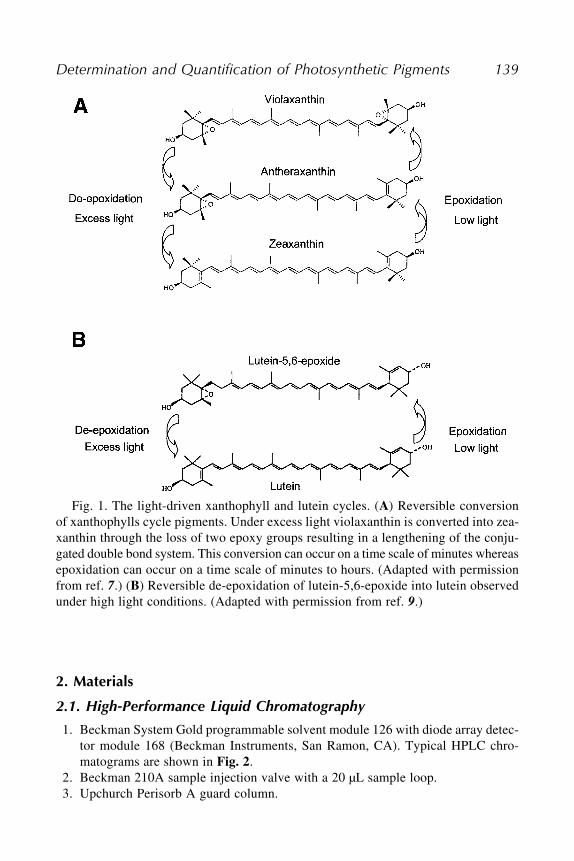
Determination and Quantification of Photosynthetic Pigments 139
2. Materials
2.1. High-Performance Liquid Chromatography
1. Beckman System Gold programmable solvent module 126 with diode array detec-tor module 168 (Beckman Instruments, San Ramon, CA). Typical HPLC chro-matograms are shown in Fig. 2.
2. Beckman 210A sample injection valve with a 20 µL sample loop.3. Upchurch Perisorb A guard column.
Fig. 1. The light-driven xanthophyll and lutein cycles. (A) Reversible conversionof xanthophylls cycle pigments. Under excess light violaxanthin is converted into zea-xanthin through the loss of two epoxy groups resulting in a lengthening of the conju-gated double bond system. This conversion can occur on a time scale of minutes whereasepoxidation can occur on a time scale of minutes to hours. (Adapted with permissionfrom ref. 7.) (B) Reversible de-epoxidation of lutein-5,6-epoxide into lutein observedunder high light conditions. (Adapted with permission from ref. 9.)

140 Pocock, Król and Huner
Fig. 2. HPLC chromatograms of Arabidopsis thaliana (A) and Chlamydomonas
reinhardii (C) before photoinhibition and after a 2 h exposure to high light (B andD respectively). Note the relative decrease in violaxanthin, and relative increases inantheraxanthin and zeaxanthin in photoinhibited Arabidopsis (B) and Chlamydomonas
(D). N, neo-xanthin; V, violaxanthin; Chlb, chlorophyll b; L, lutein; Chla, chlorophylla; �-C, �-carotene (Pocock, Król, Huner, unpublished).
Determination and Quantification of Photosynthetic Pigments 141
4. CSC-Spherisorb ODS-1 reverse phase column (5 µm particle size, 25���0.46 cmi.d.) (columns from Chromatographic Specialties Inc., Concord, ON, Canada).
5. MINI-BEADBEATER™ (Biospec Products, Inc., Bertlesville, OK).6. Vacuum flask.7. 0.45 µm syringe filters and 1 mL syringes.8. Hamilton syringe.9. HPLC grade acetone, acetonitrile, methanol, and hexane.
10. Tris[hydroxymethyl]aminomethane, Biotechnology performance certified, Mini-mum 99.9% (Trizma®Base, Sigma).
11. Zirconia/silica beads 0.1 mm.12. N2.
13. 0.1 M Tris-HCl buffer (pH 8.0) filtered through a vacuum flask.14. Solvent A: acetonitrile:methanol:0.1 M Tris-HCl (pH 8.0), (72/8/3.5 v/v/v).15. Solvent B: methanol:hexane (4/1 v/v).
2.2. ThinLayer Chromatography for Purification of Standards
1. Mortar and pestle.2. Miracloth.3. Silica Gel 60 TLC plates.4. Hamilton syringe for loading.5. Chromatography tank with lid.6. Filter paper for chromatography tank.7. Acetone, hexane, chloroform, isopropanol, and ethanol.8. Petroleum ether (boiling point 60–90°C).9. Petroleum benzene (boiling point 100–140°C).
10. N2.11. CaCO3, Ca(OH)2, MgO.12. KOH.13. Petroleum ether:acetone:chloroform (5/5/4 v/v).14. Petroleum ether:isopropanol:water (100/12/0.25 v/v).15. Plate preparation medium: CaCO3 + Ca(OH)2 + MgO (29.5 g + 5.0 g + 6.0 g) in
60 mL of 1.7% KOH.16. Separation medium A: Petroleum benzene (boiling point 100–140°C):acetone:
chloroform (5/5/4 v/v/v).
2.3. Chlorophyll Extraction
1. Same equipment for pigment extractions as listed previously.2. Acetone.3. Sodium phosphate.4. Buffered acetone for Porra protocol: 80% aqueous acetone containing 2.5 mM
sodium phosphate buffer (pH 7.8).

142 Pocock, Król and Huner
3. Methods
3.1. High-Performance Liquid Chromatography
3.1.1. Pigment Extraction From Plants
1. Grind 0.5 g tissue in a chilled mortar and pestle in 100% HPLC grade acetone.2. Filter extract through Miracloth, centrifuge for 5 min at 3024g to clarify.3. Store at minus �20°C, or preferably �80°C after bubbling with N2.
3.1.2. Pigment Extraction From Green Alga
1. Centrifuge fresh culture (5 mL) and resuspend the pellet in 1 mL cold 100% HPLCgrade acetone at 4°C in dim light.
2. Cells are broken and pigments are extracted in a MINI-BEADBEATER™ (BiospecProducts, Inc., Bertlesville, OK) using 0.1 mm zirconia/silica beads for 3���20 scycles.
3. Alternatively, cells can be broken using a French Press. Keep the cell at 4°C untiluse. Press an aliquot of cell culture (10 mL) twice at 10,000 PSI. Collect samplesin a centrifuge tube that is kept cold in a beaker of ice. Place a sample under alight microscope to check for cell disruption.
4. Clarify the supernatant by centrifugation and bubble with N2.5. Store at �20°C, or preferably �80°C.
3.1.3. Chromatography
1. Thaw and filter the extracts through 0.45 µm syringe filters.2. Prime the lines and pumps well.3. Set the flow rate for 2 cm3/min.4. Monitor the baseline until stable.
Pigments are eluted isocratically for 6 min with solvent A followed by a 2 minlinear gradient to 100% solvent B which continues isocratically for 4 min.
5. The total run time is 12 min.6. Wash the column for 8 min with solvent A before injecting the next sample.7. Absorbance is detected at 440 nm and peak areas are integrated by Beckman Sys-
tem Gold software.8. Retention times and response factors must be determined by calibrating the col-
umn by injecting known amounts of pure standards.9. Calculations: To determine the concentration of the pigment of interest the peak
area is multiplied by the response factor calculated from the chromatogram forthe standard (see Table 1).
Response factor = concentration of component/peak area
To determine the unknown concentration:
Peak area � response factor

Determination and Quantification of Photosynthetic Pigments 143
3.2. Thin-Layer Chromatography
3.2.1. Pigment Extraction for Higher Plants1. Grind a fresh sample of known weight in a chilled mortar and pestle in 100% ace-
tone at 4°C under green light.2. Filter sample through Miracloth.3. Concentrate the supernatant to a small volume by evaporating with N2.4. Load a known volume on the TLC plate by spotting sample at the start line with a
Hamilton syringe several times while allowing it to dry.
3.2.2. Alternative Method of Pigment Extraction for Higher Plants
If the pigments do not separate well or there is a lot of smearing the follow-ing modifications can be applied:
1. The acetone extract is used in phase partitioning with petroleum ether and watersaturated with NaCl (11).
2. Collect the petroleum ether phase.3. Wash the acetone phase a few times by partitioning in petroleum ether and water.4. Collect all petroleum ether phases and filter under vacuum through Na2SO4 to
remove water.5. Concentrate the pigment solution with N2 or, if you have a large volume, evapo-
rate it down to 0.5–1 mL in a rotating evaporator keeping the temperature below35°C with nitrogen in the sample.
6. Load TLC plate as described previously.
3.2.3 Pigment Separation by TLC
This method of TLC plate preparation is good for the separation of zeaxan-thin (14,15).
1. Prepare TLC plates by coating them with the plate preparation medium (see Sub-
heading 2.2., step 15).2. Dry the plates at 110°C for 45 min to remove water and keep them in the oven until
ready to use.3. Wrap filter paper around the inside perimeter of the tank.4. Place the prepared TLC plates in the separation medium A (see Subheading 2.2.,
step 16).5. Cover the tank with the lid and keep in the dark. Separation takes approx 1 h.6. Dissolve the bands in 1 mL of ethanol (xanthophylls), in hexane (�- and �-caro-
tene) or in acetone (chlorophyll).7. Calculations: Quantitative determination is performed according to:
C= E���V���1000/100���G���E 1%
where,C = concentration in mg carotenoid / g fresh weight
1 cm

144 Pocock, Król and Huner
E = maximal absorption of a known volume of carotenoid solution read at thewavelength of maximum absorptionV = volumeE1% = the extinction coefficient of a 1% (w/v) solution in a 1cm cuvet at adefined wavelength (the value of 2500 is used when no specific values are avail-able for an individual carotenoid or for a mixture of pigments)G = grams of the sample loaded on the TLC plateThe E1% and wavelength of maximum absorbance (� max) for individual caro-tenoids are listed in Table 2 (16).
3.3. Chlorophyll Extraction and Determination From Plants
3.3.1. Chlorophyll Extraction From Plants
1. Grind 0.5 g tissue in a chilled mortar and pestle in 5 mL 100% acetone.2. Filter extract through Miracloth.3. Centrifuge for 5 min at 3024g to clarify.4. Store covered, on ice until use. If you want to measure chlorophyll later, the sample
can be flushed with N2 and stored at �20°C.
3.3.2. Chlorophyll Analysis Using the Arnon Method
1. 0.05 mL of the pigment extract is added to 0.95 mL of 80% acetone.2. Absorption is measured at 663 nm (chl a), 645 nm (chl b) and 750 nm.3. Calculations (18):
1 cm
1 cm
Table 1The Molecular Weights, Response Factors, Relative RetentionTimes, and Wavelengths of Maximum Absorbance (����� Max)for Some Carotenoids and Chlorophyllsa
Pigment Molecular Response factor Relative retention � max nmweight time (min) (EtOH)
Neoxanthin 584.00 0.3813 4.046–4.309 415 439 467Violaxanthin 600.85 0.3813 4.621 419 440 470Antheraxanthin 584.84 0.4988 6.096 422 444 472Zeaxanthin 568.85 0.4951 8.642 428 450 478Lutein 568.85 0.4988 7.538 422 445 474�-carotene 536.85 0.5530 10.908 448 480 512
(Acetone)Chlorophyll a 893.48 1.4450 9.292 663Chlorophyll b 907.46 1.3710 6.918 645
The retention times will vary depending on solvents and the column.

Determination and Quantification of Photosynthetic Pigments 145
Subtract A750 from A663 and A645
Chlorophyll a (mg/g fresh weight) = (12.7 A663) � (2.69 A645) g fresh weight � VChlorophyll b (mg/g fresh weight) = (22.9 A645) � (4.68 A663) g fresh weight � VChls a+b (mg/g fresh weight) = (20.08 A645) + (8.02 A663) / g fresh weight � Vwhere, V = volume of chlorophyll extract (0.05 mL).
3.3.3. Chlorophyll Analysis Using the Porra Method
1. 0.05 mL of the pigment extract is added to 0.95 mL of 80% buffered acetone.2. Absorption is measured at 663.6 nm (chl a) and 646.6 nm (chl b).3. Calculations (19):
Chlorophyll a (µg/mL) = (12.25 A663.6) � (2.55 A646.6)Chlorophyll b (µg/mL) = (20.31 A646.6) � (44.91 A663.6)Chls a+b (µg/mL) = (17.76 A646.6) � (7.34 A663.6)
3.3.4. Chlorophyll Analysis Using the Jeffrey and Humphrey Method
1. Centrifuge an aliquot of fresh culture (5 mL) and resuspend the pellet in 1 mL cold90% acetone at 4°C in dim light.
2. Break cells in a MINI-BEADBEATER™ as described previously.3. Clarify the supernatant by centrifugation for 5 min at 3024g.4. Store covered, on ice.5. Calculations (20):
Chlorophyll a (µg/mL) = (11.93 A664) � (1.93 A647)Chlorophyll b (µg/mL) = (20.36 A647) � (5.50 A664)
4. Notes1. Solvents must be pure (HPLC grade).2. Temperature and light: Carotenoid extractions should be performed on ice or
at the lowest practical temperature and in diffuse or low light to avoid cis-trans
(E/Z) isomerization.3. Oxygen: The oxygen atoms of the hydroxy and epoxy groups of the xanthophylls
are derived from molecular oxygen. It has been reported that antheraxanthinexposed to air for 24 h at 50°C was partially oxidized to the diepoxide, violaxan-thin (13). For this reason and to avoid artifacts, carotenoids require careful extrac-tion and subsequent handling. Oxygen is displaced by bubbling the pigment extractswith N2.
4. Acids: The 5,6-epoxides such as neoxanthin and violaxanthin undergo conver-sion to the 5,8-epoxide form in the presence of acids. CaCO3 is often added to neu-tralize any acids present.
5. Response factors, molecular weights, retention times, and wavelength of maxi-mum absorbance (� max) for a range of pigments are found in Table 2.
6. Tris-HCl buffer must be filtered through a vacuum driven filter containing a mem-brane with pore size of 0.22 µm.

146 Pocock, Król and Huner
7. A guard column increases the life of the analytical column. Packing materialshould be the same material in the analytical column but of larger particle size.When clogged, the filters can be removed, placed in a small amount of solventused for pigment extraction and sonicated in a sonicating water bath. An alterna-tive is purchasing disposable guard columns. A dirty guard column will increasepressure in the system and compromise the separation while shifting the retentiontimes.
8. If pigment separation is problematic or if retention times shift, increase the col-umn washing with solvent A to 12 min from 8 min between runs.
9. Setting up a new column can be problematic. It is typical to have to test out severalcolumns (even though the packing material is supposedly identical) before select-ing one that provides the required resolution to separate the xanthophyll cyclepigments.
10. HPLC chromatograms can be saved as a DIF and opened in Microsoft Excel®
after which they can be reproduced in a graphing program such as Sigma Plot® orOrigin®.
11. Pure standards of Chl a, Chl b, lutein and �-carotene were obtained from Sigma,St. Louis, MO.
12. Pure standards of zeaxanthin, violaxanthin, antheraxanthin, and neoxanthin arenot available commercially and must be purified by thin-layer chromatography(see Subheading 3.2.) according to (14) and Hager and Meyer-Bertenrath (15).
13. An alternative method for the separation of xanthophylls and carotenes is the mod-ified protocol of Hager and Meyer-Bertenrath (15) or Król and Huner (17). Insteadof the previously described solvent system, the silica gel 60 plates are placed ineither a petroleum ether: isopropanol: H2O (100/12/0.25) solution or a solution ofpetroleum ether (boiling point 60–90°C):acetone (70/30).
Table 2Extinction Coefficients and Wavelengths of MaximumAbsorbance (����� Max) for Carotenoids and Chlorophylls in Various Solvents
Pigment Solvent E1%��max
�-Carotene Hexane 2420 564�-Carotene Hexane 2200 464Lutein-5,6-epoxide Ethanol 2400 440Violaxanthin Ethanol 2500 441Lutein Ethanol 2540 446Antheraxanthin Ethanol 2350 446Neoxanthin Ethanol 2270 438Zeaxanthin Ethanol 2480 451Chlorophyll a Acetone 840 663Chlorophyll b Acetone 518 645
1 cm

Determination and Quantification of Photosynthetic Pigments 147
14. The Rf values are not reproducible but their order of separation is consistent in aparticular solvent system. In these separation systems, the order of separation fromthe top to bottom of the plate is �-carotene, �-carotene, Chlorophyll a, Chlorophyllb, Lutein, Lutein 5–6 epoxide, Antheraxanthin, Violaxanthin, and Neoxanthin.
15. An unknown pigment can be identified by mixing the sample with a known carote-noid and rechromatographed on TLC plates prepared with MgO-Kieselguhr (1/1,w/w) using the solvent system acetone:petroleum ether (30/70) (3).
16. Do not use Na2SO4 to remove water from the acetone extract before washing andpartitioning (Subheading 3.2.2., step 3 and 4) as it is difficult to remove pigmentsfrom this drying agent.
17. Any equipment, such as chromatography and tanks, should be covered by blackcloths or aluminum foil or placed in a dark cupboard.
18. To prevent pheophytin formation, CaCO3 can be added during grinding.19. The conversion of chlorophyll to pheophytin is prevented by inhibiting chloro-
phyllase with acetone and in particular buffered acetone.20. Extinction coefficients are different for various solvents according to refs. 11 and 21.
References1. Huner, N. P. A., Öquist, G., and Sarhan, F. (1998) Energy balance to light and
cold. Trends Plant Sci. 6, 224–230.2. Young, A. J. (1993) Carotenoids in pigment-protein complexes, in Carotenoids in
Photosynthesis (Young, A. and Britton, G., eds.), Chapman and Hall, New York,pp. 72–95.
3. Gross, J. (1987) Pigment in fruits. Academic, Toronto.4. Britton, G. (1993) Structure and Nomenclature, in Carotenoids in Photosynthesis
(Young, A. and Britton, G., eds.), Chapman and Hall, New York, pp. 1–15.5. Niyogi, K. K., Björkman, O., and Grossman, A. (1997) The roles of specific xan-
thophylls in photoprotection. Proc. Natl. Acad. Sci. USA 94, 14,162–14,167.6. Demmig-Adams, B. and Demmig-Adams, W. W. (1996) The role of xanthophyll
cycle carotenoids in the protection of photosynthesis. Trends Plant Sci. 1, 21–26.7. Demmig-Adams, B. and Demmig-Adams, W. W. (1993) The xanthophyll cycle,
in Carotenoids in Photosynthesis (Young, A. and Britton, G., eds.), Chapman andHall, New York, pp. 206–251.
8. Goss, R., Böhme, K., and Wilhelm, C. (1998) The xanthophyll cycle of Man-
toniella squamata converst violaxanthin into antheraxanthin but not zeaxanthin:consequences for the mechanism of enhanced non-photochemicla energy dissipa-tion. Planta. 205, 613–621.
9. Bungard, R. A., Ruban, A. V., Hibberd, J. M., Press, M. C., Horton, P., and Scholes,J. (1999) Unusual carotenoid composition and a new type of xanthophylls cyclein plants. Proc. Natl. Acad. Sci. USA 96, 1135–1139.
10. Pogson, B. J., Niyogi, K. K., Björkman, O., and DellaPenna, D. (1998) Alteredxanthophylls compositions adversely affect chlorophyll accumulation and non-photochemical quenching in Arabidopsis mutants. Proc. Natl. Acad. Sci. USA 95,
13,324–13,329.
148 Pocock, Król and Huner
11. Schiedt, K. and Liaan-Jensen, S. (1995) Isolation and analysis, in Carotenoids
vol. 1A: Isolation and Analysis (Britton, G., Liaan-Jensen, S., and Pfander, H.,eds.), Birkhäuser Verlag, Basel, Switzerland, pp. 81–108.
12. Gilmore, A. M. and Yamamoto, H. Y. (1991) Resolution of lutein and zeaxanthinusing a non-endcapped, lightly carbon-coated C18 high-performance liquid chro-matographic column. J. Chromatography 543, 137–145.
13. Rowan, K. S. (1989) Photosynthetic pigments of algae. Cambridge University, UK.14. Diaz, M., Ball, E., and Luttge, U. (1990) Stress induced accumulation of the xan-
thophyll rhodoxanthin in leaves of Aloe vera. Plant Physiol. Biochem. 6, 679–682.15. Hager, A. and Meyer-Bertenrath, J. G. (1966) Die isolierung und Quantitative
bestimmung der carotinoide und chlorophylle von blattern, algen und isoliertenchloroplasten mit hilfe dunnschichtchromatographischer methoden. Planta 69,
198–217.16. Davies, B. H. (1976) Carotenoids in Chemistry and Biochemistry of Plant Pig-
ments, Vol. 2 (Goodwin, T. W, ed.), Academic, London, pp. 38–165.17. Król, M. and Huner, N. P. A. (1984) Growth and development at cold-hardening
temperatures. Pigment and benzoquinone accumulation in winter rye. Can. J. Bot.
63, 716–721.18. Arnon, D. I. (1949) Copper enzymes in isolated chloroplasts. Polyphenoloxidase
in Beta vulgaris. Plant Physiol. 24, 1–15.19. Porra, R. J., Thompson, W. A., and Kriedemann, P. E. (1989) Determination of
accurate extinction coefficients and simultaneous equations for assaying chloro-phylls a and b extracted with four different solvents: verification of the concen-tration of chlorophyll standards by atomic absorption spectroscopy. Biochim. et
Biophys. Acta 975, 384–394.20. Jeffrey, S. W. and Humphrey, G. F. (1975) New spectrophotometric equations for
determining chlorophylls a, b and c2 and c2 in higher plants, algae and naturalphytoplankton. Biochem. Physiol. Pflanzen. 167, 191–194.
21. Mackinney, G. (1941) Absorption of light by chlorophyll solutions. J. Biol. Chem.
140, 315–322.

Isolation and Identification of Chloroplast Lipids 149
149
From: Methods in Molecular Biology, Vol. 274: Photosynthesis Research ProtocolsEdited by: R. Carpentier © Humana Press Inc., Totowa, NJ
16
Isolation and Identification of Chloroplast Lipids
Norihiro Sato and Mikio Tsuzuki
SummaryGlycerolipids of photosynthetic organisms are accounted for largely by thylakoid membrane
lipids consisting of chloroplast-specific glycolipids, such as monogalactosyl diacylglycerol, digal-actosyl diacylglycerol, sulfoquinovosyl diacylglycerol, and a sole phospholipid, phosphatidyl-glycerol. In this chapter, methods for characterization of lipids from plant cells are described.The methods include extraction of total lipids from cells, separation of these lipids into individ-ual lipid classes by thin-layer chromatography (TLC), and identification of respective lipid classesby their mobility. We also show methods for determination of compositions of constituent fattyacids, distribution of fatty acids between sn-1 and sn-2 positions, and contents of individuallipid classes by gas-liquid chromatography. These methods are applicable to isolated chloro-plasts or membrane fractions such as thylakoid membranes.
Key Words: Fatty acid; gas-liquid chromatography; lipase from Rhizopus delemar; lipid; meth-anolysis; thin-layer chromatography.
1. IntroductionLipids in biomembranes interact among one another through hydrophobic
bonds, whereas they interact with membrane proteins not only through hydro-phobic bonds, but also with electrostatic and hydrogen bonds. The hydropho-bic bonds are eliminated by relatively nonpolar solvents such as chloroform,and the electrostatic and hydrogen bonds are cut by polar solvents such asmethanol. Thus, lipids can be prepared from cells or membrane preparationsas total lipids through extraction with a mixture of chloroform and methanol.From the total lipid fraction extracted with such a solvent system, individuallipid classes are separated through thin-layer chromatography (TLC) on thebasis of their particular mobility, and detected on TLC plates with a nondestruc-tive reagent such as primulin. Fatty acid methyl esters are prepared from indi-vidual lipid classes through transmethylation by methanolysis and analyzed

150 Sato and Tsuzuki
with gas-liquid chromatography for determination of fatty acid compositions.The chromatography is equipped with a column that separates molecular speciesof fatty acid methyl esters according to their partition property between gasand liquid phases at high temperatures. Each lipid class can be quantified throughestimation of contents of the constituent fatty acids relative to a content of aparticular fatty acid that is originally absent, but is added as an internal standardto the lipid fraction. Fatty-acid compositions at the sn-1 and sn-2 positions ofglycerol backbones can also be estimated through determination of fatty acidcompositions of both individual lipids and their sn-2-acyl-lysolipids synthe-sized through specific hydrolysis at the sn-1 positions by a lipase from Rhizopus
delemar. Two biosynthetic pathways designated as prokaryotic and eukaryoticpathways operate for glycerolipid synthesis in plants. The prokaryotic pathway,where metabolism is confined within plastids, produces prokaryotic lipids,similar to cyanobacterial lipids, containing fatty acids with a chain of 16 carbonatoms at the sn-2 positions. The eukaryotic pathway, through cooperation ofthree cellular compartments, i.e. plastids, cytoplasm, and endoplasmic reticu-lum, produces eukaryotic lipids possessing fatty acids with a chain of 18 carbonatoms at the sn-2 positions. Thus, information not only on their molecular struc-ture, but also on their synthetic pathway is provided by the analysis of pos-itional distribution of fatty acids of individual lipid classes. It has been shownthat chloroplast lipids are synthesized by pokaryotic and/or eukaryotic path-ways, although extra-chloroplast lipids are constructed exclusively by eukary-otic pathways (1).
2. Materials1. TLC plates (20 cm���20 cm, No. 5721 plate, Merck).2. TLC chamber.3. Capillary column (e.g., HR-Thermon 3000B, 0.25 mm���25 m, Shinwa Chemical
Industries, Kyoto).4. 25–28% ammonia solution, (toxic and corrosive).5. 0.01% primulin in 80% acetone.6. I2.7. Dittmer-Lester reagent: dissolve 4.01g of MoO3 in 100 mL of 25N H2SO4 by boil-
ing (solution A). Add 180 mg of molybdenum powder of 50 mL of solution A andboil for 15 min. Cool at room temperature and recover the supernatant by decan-tation (solution B). Mix equal volumes of solution A and B, and dilute threefoldwith H2O. Reagent is stable for several months at room temperature (2).
8. Anthrone reagent: dissolve 0.1 g of anthrone and 2 g of thiourea in 66% H2SO4.9. 5% (w/w) hydrogen chloride methanol solution. This solution is commercially
available, but can be prepared by bubbling anhydrous methanol with HCl gaspassed beforehand through sulfuric acid for dehydration. When you prepare this

Isolation and Identification of Chloroplast Lipids 151
in the laboratory, make a fresh solution every 3–4 mo. This is a toxic, corrosive,and flammable liquid.
10. n-Hexane (toxic and flammable liquid).11. Gas chromatograph.12. Primulin reagent: 0.01% primulin in 80% acetone.13. Lipase from Rhizopus delemar.14. A buffer for lipase: 40 mM Tris-HCl (pH 7.2), 0.05% Triton X-100.
3. MethodsThe methods described here show the isolation of total lipids, the separation
into individual lipid classes, and the detection and identification of lipid classes.Additionally, the determination of fatty acid compositions of respective lipidclasses and quantification of lipid classes by estimation of fatty acid contents,and the analysis of distribution of fatty acids between sn-1 and sn-2 positionsof glycerol backbones are described.
3.1. Lipid Extraction
Individual lipids can be isolated first as total lipid fraction. Shown below isthe method of the isolation according to Bligh and Dyer (3) (see Note 1).
3.1.1. Isolation of Lipids From Algae or Chloroplasts
1. Prepare cells of microalgae or chloroplasts as pellets (see Note 2) of 0.5–1.0 mLin a 50-mL centrifuge tube with a Teflon-lined screw cap (see Note 3).
2. Add 10 mL of methanol and agitate it for 30 s with a vortex mixer.3. Add 5 mL of chloroform and agitate it for 2 min with a vortex mixer.4. Let stand for 10 min.5. Add 5 mL of chloroform and agitate it with a vortex mixer for 30 s.6. Add 5 mL of distilled water and agitate it with a vortex mixer for 30 s. The solu-
tion will become turbid.7. Centrifuge at 1500g for 5 min. The solution will separate into three phases; the
upper phase of H2O and methanol, the medium phase of cell debris, and the lowerphase of chloroform.
8. Take the lower phase containing lipids with a Pasteur pipet into a flask suitablefor the evaporator. Do not contaminate the upper or medium phase.
9. Add 10 mL of chloroform to the remaining upper and medium phases and agitateit for 1 min with a vortex mixer.
10. Centrifuge at 1500g for 5 min. Recover the lower phase of chloroform and com-bine with the lipid solution prepared in Subheading 3.1.1., step 8.
11. Evaporate the solvent completely with rotary evaporator under reduced pressure.12. Add methanol or chloroform/methanol (2/1, by vol) for complete evaporation if
H2O remains.

152 Sato and Tsuzuki
13. Dissolve the lipids in an appropriate volume of chloroform/methanol (2/1, byvol), transfer the solution into a tube with a Tefron-lined screw cap, and store it at�20°C until use.
3.1.2. Isolation of Lipids From Leaves of Higher Plants
1. Cut green leaves (5 g of wet weight) into slices.2. Add 150 mL of chloroform/methanol (1/2, by vol) and homogenize it with a ho-
mogenizer.3. Filtrate the slurry through a piece of filter paper and recover the filtrate in a flask.4. Add 50 mL of chloroform and agitate it for 1 min.5. Add 100 mL of 1% KCl solution (w/v) and agitate it for 2 min.6. Let stand for half a day until the turbid solution separates into three phases.7. Recover lipids as described in steps 8–13 in Subheading 3.1.1.
3.2. Separation Into Individual Lipid Classes by TLC
TLC can separate individual lipid classes simultaneously on a TLC plateand in a short time (a few hours). For analysis of lipids prepared from plantcells, two-dimensional TLC with two distinct solvent systems is performed,because one-dimensional TLC should fail to separate some lipid classes.
1. Activate a precoated silica gel TLC plate (20 cm���20 cm, no. 5721 plate, Merck)by heating at 120°C for 1.5 h (see Note 4).
2. Cool at room temperature.3. Using a pencil on a TCL plate, outline an oblong spot of approx 5 mm���15 mm,
2.5 cm away from two neighboring sides of the plate (see Note 5).4. Apply lipids dissolved in 20–50 µL of chloroform/methanol (2/1, vol) to the spot
with a microsyringe.5. Develop the plate with the first solvent system, chloroform/methanol/H2O (65/
25/4, by vol) until the front line of the solvent comes 1–2 cm away from the upperside of the plate.
6. Dry the plate by heating the bottom surface with a hair dryer.7. Develop the plate with the second solvent system, chloroform/methanol/25–28%
ammonia solution (13/7/1, by vol) until the front line of the solvent comes 1–2 cmaway from the upper side of the plate.
8. Dry the plate by heating the bottom with a hair dryer.
3.3. Detection and Identification of Respective Lipid Classes
Lipid classes separated on a TLC plate must be detected with a non-destruc-tive reagent for further structural analyses, such as a determination of com-positions of constituent fatty acids. Primulin and I2 described in Subheading
3.3.1. are amenable to such study, being used for detection of all lipid classes.Zones of the detected lipid classes on the TLC plate are outlined with a pencil
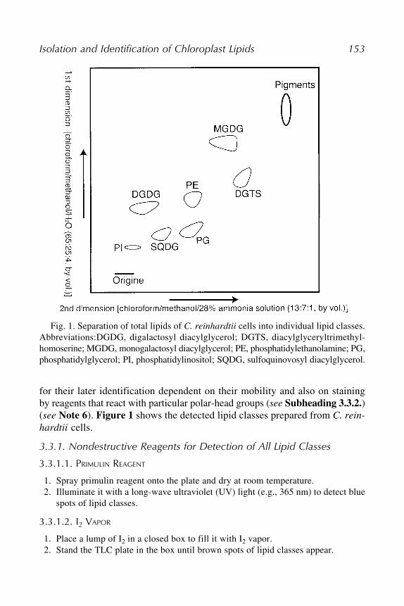
Isolation and Identification of Chloroplast Lipids 153
for their later identification dependent on their mobility and also on stainingby reagents that react with particular polar-head groups (see Subheading 3.3.2.)(see Note 6). Figure 1 shows the detected lipid classes prepared from C. rein-
hardtii cells.
3.3.1. Nondestructive Reagents for Detection of All Lipid Classes
3.3.1.1. PRIMULIN REAGENT
1. Spray primulin reagent onto the plate and dry at room temperature.2. Illuminate it with a long-wave ultraviolet (UV) light (e.g., 365 nm) to detect blue
spots of lipid classes.
3.3.1.2. I2 VAPOR
1. Place a lump of I2 in a closed box to fill it with I2 vapor.2. Stand the TLC plate in the box until brown spots of lipid classes appear.
Fig. 1. Separation of total lipids of C. reinhardtii cells into individual lipid classes.Abbreviations:DGDG, digalactosyl diacylglycerol; DGTS, diacylglyceryltrimethyl-homoserine; MGDG, monogalactosyl diacylglycerol; PE, phosphatidylethanolamine; PG,phosphatidylglycerol; PI, phosphatidylinositol; SQDG, sulfoquinovosyl diacylglycerol.

154 Sato and Tsuzuki
3.3.2. Destructive Reagents for Detection of Particular Lipid Classes
Outline lipid zones detected in advance by primulin, and treat the zones withDittmer-Lester or anthrone reagent for detection of phospholipids and glyco-lipids, respectively, as described below.
3.3.2.1. DITTMER-LESTER REAGENT
1. Spray the reagent onto the plate to detect blue spots of phospholipids.
3.3.2.2. ANTHRONE REAGENT
1. Spray Anthrone reagent onto plate.2. Heat the plate at 120°C to detect purple spots of glycolipids.
3.4. Determination of Fatty Acid Compositions and Contents of Lipids
It is not necessary to extract respective lipid classes from silica gels of theTLC plates for analysis of their constituent fatty acids. Fatty acid methyl estersare first produced according to the method described in Subheading 3.4.1.,then are analyzed by gas-liquid chromatography as in Subheading 3.4.2..
3.4.1. Preparation of Methyl Ester of Fatty Acids
1. Put 50 µL of an internal standard solution such as arachidic acid (1 mg/mL chloro-form) into a test tube with a Teflon-lined screw cap and dry it under N2 stream.This step is necessary for quantification of lipids, but is omitted for determinationof fatty acid compositions.
2. Scrape silica gels of lipid zones on TLC with the handle edge of a small spatula,and transfer them to the test tube with a piece of powder paper. Otherwise, trans-fer lipid fraction such as total lipids dissolved in chloroform/methanol (2/1, byvol) to the test tube, and dry under N2 stream.
3. Add 2–3 mL of 5% hydrogen chloride methanol solution and close the tube tightlywith a screw cap (see Note 7).
4. Heat at 90°C for 3 h in a heating block with occasional agitation with a vortexmixer, and then cool at room temperature.
5. Add 2–3 mL of n-hexane and agitate it for 30 s with a vortex mixer.6. After letting stand for separation into two phases, transfer the upper n-hexane
phase containing fatty acid methyl esters into a test tube suitable for evaporation.7. Evaporate the solvent with a rotary evaporator at 30–40°C.8. Add 2–3 mL of n-hexane to the remaining lower phase in Subheading 3.4.1., step
6, and agitate it for 30 s with a vortex mixer.9. After letting it stand for the separation, transfer the upper phase to the test tube in
Subheading 3.4.1., step 7, and evaporate the solvent.10. Repeat steps 8–9 above.11. Dissolve the methyl esters in 50 µL of n-hexane.

Isolation and Identification of Chloroplast Lipids 155
3.4.2. Analysis of Fatty Acid MethylEsters With Gas-Liquid Chromatography
1. Set up a gas chromatograph equipped with a capillary column (see Note 8). Tem-peratures of injector and detector of the flame ionization are 250°C, while that ofthe column is 180°C.
2. Inject 1 µL of the methyl ester solution.3. Record and store chromatograms with a chromatography data processor. Figure
2 shows a separation pattern of fatty acid methyl esters prepared from DGDG ofChlorella kesslerii (see Note 9). Peak areas that correspond to weights of fatty acidmethyl esters are calibrated by respective molecular weights for determination ofmolar ratios and compositions of fatty acids.
4. Total fatty acid contents of each lipid are calculated through multiplication of amolar ratio of total constituent fatty acids to an internal standard by the knowncontent of the internal standard. Lipid contents can thus be estimated by divisionof the total fatty acid contents by two.
Fig. 2. Separation of fatty acid methyl esters prepared from monogalactosyl diacyl-glycerol of C. reinhardtii. Fatty acyl groups are denoted by the numbers of carbon atomsand double bonds, e.g., 18:1(9) = oleoyl. aAn internal standard.

156 Sato and Tsuzuki
3.5. Determination of Fatty Acid Compositionsat sn-1 and sn-2 Positions of Individual Lipid Classes
Lipases that liberate fatty acids from lipids are classified into phospholipid-specific lipases and nonspecific lipases. Described below is the method of non-specific lipase from Rhizopus delemar that hydrolyzes ester bond at the sn-1position of diacylglycerol moiety (4).
1. Scrape off silica gels containing a lipid class separated by TLC into a test tube.2. Add 2–3 mL of chloroform/methanol (2/1, by vol) and agitate the tube for 2 min
for the lipid extraction.3. Centrifuge at 1500g for 5 min and recover the supernatant into a test tube suitable
for evaporation.4. Evaporate the solvent completely with a rotary evaporator5. Add 0.9 mL of 50 mM Tris-HCl, pH 7.2 and 0.05% Triton X-100 and agitate the
tube with a vortex mixer. Sonicate the solution for 5 min until the lipids are com-pletely dissolved.
6. Add 0.5 mg of lipase from Rhizopus delemar (Seikagaku corporation) dissolvedin 0.1 mL of 50 mM Tris-HCl, pH 7.2.
7. Incubate at 37°C for appropriate times (e.g., 10 min for monogalactosyl diacyl-glycerol, 20 min for digalactosyl diacylglycerol, 30–60 min for sulfoquinovosyldiacylglycerol or phosphatidylglycerol, 90 min for phosphatidylethanolamine, and360 min for phosphatidylcholine) (see Note 10).
8. Add 1 mL of chloroform/methanol (1/1 by vol) and agitate it for 1 min to extractproducts by the lipase.
9. Recover the lower phase and evaporate the solvent.10. Dissolve the lipids in 50 mL of chloroform/methanol (2/1 by vol), and develop it
by one-dimensional TLC with the solvent system of chloroform/methanol/H2O(65/25/4, by vol).
11. Spray primulin reagent to detect sn-2-acyl-lysolipids, original lipids, and releasedfatty acids. The sn-2-acyl-lysolipids migrates slower than original lipids, whilefatty acids move faster, positioned close to the front line of the solvent.
12. Analyze fatty acid methyl esters of the sn-2-acyl-lysolipids by gas-liquid chro-matography for determination of fatty acid compositions at the sn-2 positions,according to the method described in Subheading 3.4. Fatty acid compositionsat the sn-1 positions can be estimated by comparison of fatty acid compositionsbetween original lipids and sn-2-acyl-lysolipids.
4. Notes1. Use glass-made instruments for isolation and storage of lipids, because chloro-
form and methanol elute plasticizer of plastic instruments.2. Samples for isolation of total lipids can be stored not at �20°C, but at �80°C, for
repression of breakdown of lipid molecules by endogenous lipases.3. A larger pellet requires increases in volumes of reagents for subsequent lipid
isolation.

Isolation and Identification of Chloroplast Lipids 157
4. Activated TLC plates can be stocked in a desiccator, but activation just beforeperformance of TLC is recommended especially in places of high humidity.
5. The spot of lipids as an origin on the TLC plate should not be so big as to repressincreases in the sizes of respective lipid zones. Silica gel will perturb subsequentfatty acid analysis by gas-liquid chromatography, since the TLC plate is contami-nated with saturated fatty acids such as 16:0 and 18:0.
6. The reagents for detection of lipids with particular polar-head groups destroy lipidmolecules, therefore are not useful for their subsequent structural analyses.
7. Be careful not to use a cracked tube in case that the tube explodes.8. Chromatograph equipped with a capillary column is recommended owing to the
high performance in the separation of almost all fatty acid methyl esters, includ-ing isomers such as 18:1(9) and 18:1(11).
9. Molecular species of fatty acid methyl esters can be identified through compari-son of retention times on chromatograms with fatty acid methyl ester standardsthat can be prepared by methanolysis of commercially available fatty acids.
10. Fatty acids at the sn-2 positions of the lysolipids will be transferred to the sn-1positions and be hydrolyzed by the action of the lipase. Thus, fatty acids to beanalyzed should be sn-2-acyl-lysolipids, but not released fatty acids, and reactionshould be stopped before complete breakdown of original lipids.
References1. Roughan, P. G. and Slack, C. R. (1982) Cellular organization of glycerolipid
metabolism. Ann. Rev. Plant Physiol. 33, 97–132.2. Dittmer, J. C. and Lester, R. L. (1964) A simple, specific spray for the detection
of phospholipids on thin-layer chromatograms. J. Lipid Res. 5, 126–127.3. Bligh, E. G. and Dyer, W. J. (1959) A rapid method of total lipid extraction and
purification. Can. J. Biochem. Physiol. 37, 911–917.4. Fischer, W., Heinz, E., and Zeus, M. (1973) Suitability of lipase from Rhizo-
pus arrhizus delemar for analysis of fatty acid distribution in dihexosyl diglycer-ides, phospholipids, and plant sulfolipids. Hoppe-Seyler’s Z. Physiol. Chem. 354,
1115–1123.

158 Sato and Tsuzuki

DNA Adducts With CHL and CHLN As Antimutagenic Agents 159
159
From: Methods in Molecular Biology, Vol. 274: Photosynthesis Research ProtocolsEdited by: R. Carpentier © Humana Press Inc., Totowa, NJ
17
DNA Adducts With Chlorophylland Chlorophyllin As Antimutagenic AgentsSynthesis, Stability, and Structural Features
Heidar-Ali Tajmir-Riahi, Jean-Francois Neault,and Stavroula Diamantoglou
SummaryPorphyrins and their metal derivatives are strong DNA binders with association constants of
105 M�1 to 107 M�1. Some of these compounds have been used for radiation sensitization therapy
of cancer and are targeted to interact with cellular DNA. Chlorophyll (CHL) and chlorophyllin
(CHLN), a food-grade derivative of chlorophyll, the ubiquitous green plant pigment widely con-
sumed by humans, are potent inhibitors of experimental carcinogenesis. The aim of this report
was to examine the interaction of calf-thymus DNA with CHL and CHLN in aqueous solution
at physiological pH, with pigment/DNA(phosphate) molar ratios (r) of 1/80 to 1/2. Fourier
transform infrared (FTIR) difference spectroscopic method was used to determine the pigment
binding mode, binding constant, sequence selectivity, DNA secondary structure and structural
variations of the pigment–DNA complexes in aqueous solution.
Spectroscopic evidence showed that chlorophyll is an external DNA binder with no affinity
toward DNA intercalation. CHL bindings are through the backbone PO2 group and the guanine
N-7 site of the G-C base pair (major groove) with overall binding constant of K = 1.13 � 104
M�1 CHLN binds DNA via intercalative mode into the G-C and A-T-rich regions with a minor
perturbation of the backbone PO2 group with overall binding constant K = 3.56 � 103 M�1.
However, The CHL distributions are 60% with the backbone PO2 group and 20% with the G-C
base pairs, whereas CHLN intercalation is 25% with A-T and 15% with G-C base pairs. A partial
reduction of B-DNA structure in favor of A-DNA occurs upon CHL and CHLN complexation.
Key Words: DNA; chlorophyllin; chlorophyll; antimutagen; drug; binding mode; binding con-
stant; conformation; FTIR spectroscopy helix stability.
1. IntroductionDiet plays an important role in human cancer risk (1–4). Although attention
has focused on dietary carcinogens and promoters, recent evidence shows that

160 Tajmir-Riahi, Neault, and Diamantoglou
protective factors within the diet are also important in cancer risk. Several
chemical components of fruits and vegetables have been isolated and purified
and shown to be effective against carcinogenesis in experimental animal models
(5–8). Chlorophyll (CHL) (Structure 1) and its derivatives have been shown to
exert profound antimutagenic behavior against a wide range of potential human
carcinogens (7–9). Similarly, chlorophyllin (CHLN) (Structure 1), a food-grade
derivative of chlorophyll, has been used historically in the treatment of several
human conditions, with no evidence of human toxicity (10–12) and recently it
was used as a potent inhibitor of aflatoxin B1 hepatocarcinogenesis in rainbow
trout (13).
It has been suggested that the antimutagenic activity of chlorophyllin comes
from its strong complexation with parent mutagens or their intermediates, scav-
enging of free radicals and active oxygen species, and suppression or interference
with metabolic activation by specific cytochrome (P450) and other metabolizing
Structure 1

DNA Adducts With CHL and CHLN As Antimutagenic Agents 161
enzymes (14–17). CHLN was also shown in vivo to efficiently inhibit precar-
cinogenic target organ DNA adduction by aflatoxin B1 in trout (16) and 2-amino-
3-methylimidazol [4,5-f] quinoline in rat (18). Because the major target of these
anticancer drugs can involve DNA or DNA adducts, the interaction of DNA
with CHL and CHLN has major biological importance and thus, the present
study is designed to investigate pigment–DNA complexation in vitro and to
provide structural information regarding the pigment binding mode, sequence
preference, and DNA secondary structure, using infrared spectroscopy. Our
structural information provides, to our knowledge, the first spectroscopic evi-
dence regarding CHL–DNA and CHLN–DNA interactions and may elucidate
the nature of this biologically important complex formation.
More recently, vibrational spectroscopic method has been used to analyze
the nature of DNA–drug complexation and to provide structural information at
molecular level (19–20). Recently, we used vibrational spectroscopy (infrared
and Raman) for the structural characterization of diethylstilbestrol (DES)–
DNA, aspirin–DNA, vitamin–DNA and carbohydrate–DNA (21–24) as well
as cation–DNA (25,26) and protein complexes (27). We believe that FTIR dif-
ference spectroscopic method can be also applied here, in order to characterize
the nature of the pigment–DNA interaction.
The goal of this chapter is to describe the synthesis, separation, and FTIR
difference spectroscopic method for DNA complexation with CHL and CHLN
in aqueous solution at physiological pH, with pigment/DNA(P) molar ratios
of 1/80 to 1/2. Spectroscopic evidence regarding the pigment-binding mode,
binding constant, sequence selectivity, and biopolymer secondary structure is
provided. Furthermore, comparisons were made between the CHL–DNA and
CHLN–DNA complexes and the corresponding metalloporphyrin–DNA adducts
and the results are reported here. This study elucidates the nature of this bio-
logical interaction and the possible antimutagenic role of CHL and CHLN.
2. Materials1. 200 mg highly polymerized type I calf-thymus DNA sodium salt (7% Na content)
(Sigma).
2. 2 mg crystalline chlorophyllin (copper-trisodium salt) (Sigma).
3. 2 mg crystalline chlorophyll a (Sigma).
4. 1 g crystalline sodium cacodylate (Sigma).
5. Ethanol (100%).
6. Preparation of Pigment–DNA Complexes.
Sodium-DNA was dissolved to 2% w/w (0.05 M DNA [phosphate]) in 0.05 M
NaCl and 1 mM sodium cacodylate (pH 7.30) at 5°C for 24 h with occasional
stirring to ensure the formation of a homogeneous solution. The appropriate
amount of chlorophyll or chlorophyllin (0.3–12.5 mM) was prepared in distilled

162 Tajmir-Riahi, Neault, and Diamantoglou
water and added dropwise to DNA solution to attain desired pigment/DNA(P)
molar ratios of 1/80, 1/40, 1/20, 1/10, 1/4, and 1/2 at a final DNA concentra-
tion of 1% w/w or 0.025 M DNA (phosphate) (see Note 1). The solution pH
was adjusted to 7.30–6.80, using NaOH solution. The infrared spectra were
recorded 3 h after mixing of pigment and DNA solutions. The infrared spectra
of pigment–DNA complexes with r > 1/2 could not be recorded in solution due
to solid gel formation (see Note 2).
3. Methods
3.1. FTIR Measurements
The infrared spectra were recorded on a Bomem DA3-0.02 FTIR spectrom-
etry equipped with a nitrogen-cooled HgCdTe detector and KBr beam splitter.
The solution spectra were taken using AgBr windows with resolution of 4 cm�1
and 100–500 scans. The sample preparation and spectral measurements were
performed under green light (to avoid photodegradation of chlorophyllin or
chlorophyll in pigment–DNA complexes). The water subtraction was per-
formed as in our previous report (21,22). A good water subtraction is achieved
as shown by a flat baseline around 2200 cm�1 where the water combination
mode (28) is located (see Note 3). The difference spectra [(DNA solution +
pigment solution)–(DNA solution)] were produced, using a sharp DNA band
at 968 cm�1 as internal reference. This band, owing to deoxyribose C-C stretch-
ing vibrations, exhibits no spectral changes (shifting or intensity variations) on
pigment–DNA complexation and was cancelled upon spectral subtraction. The
intensity ratios of several DNA in-plane vibrations, related to A-T and G-C base
pairs and the PO2 stretching modes were measured with respect to the reference
band at 968 cm�1, as a function of pigment concentration with error of ± 2%.
These intensity ratio measurements are used to quantify the amounts of pig-
ment bindings to the backbone PO2 group and DNA bases. The detailed infra-
red spectral manipulations and intensity ratio calculations are presented in our
recent publications (21–26).
3.2. Analysis of CHL–DNA Complexes
The binding of CHL with DNA duplex is shown at different pigment con-
centrations (1/80 to 1/2) in Fig. 1A and Fig. 2A. CHL binding is to the back-
bone PO2 group and indirectly (via H2O) to the N-7 site of the guanine bases
through the central Mg cation. Evidence for direct cation-phosphate coordina-
tion is concluded from the major intensity increase (50%) of the PO2 anti-
symmetic stretching band at 1222 cm�1 together with the shift of this vibration
toward a lower frequency at 1220 cm�1 (Fig. 1A and Fig. 2A). Similarly, the
guanine band at 1717 cm�1 (28–31) gains in intensity (25%) and shifts toward

DNA Adducts With CHL and CHLN As Antimutagenic Agents 163
a lower frequency at 1715 cm�1 that results from an indirect Mg–N-7 interac-
tion via H2O (Fig. 1A and Fig. 2A). The bands at 1663 cm�1 (mainly thymine)
showed increase in intensity (30%) with no spectral shifting upon CHL inter-
action, whereas the bands at 1609 (adenine) and 1485 cm�1 (mainly cytosine)
exhibited a minor increase in intensity with no frequency shift in the spectra of
the CHL–DNA complexes (Fig. 1A and Fig. 2A). The observed spectral changes
show a direct Mg–PO2 binding with an indirect Mg–H2O N-7 coordination to
the guanine bases. However, a minor indirect cation interaction via H2O to
thymine O-2 atom can also be included, whereas, metal ion binding to the ade-
nine and cytosine bases is negligible. It is worth mentioning that at this stage
of complexation, the Mg–DNA binding sites are not involved in hydrogen
bonding and therefore this type of complexation does not bring about helix
destabilization. It should be noted that the direct Mg–PO2 coordination and
indirect Mg–N-7 (guanine) interaction through H2O are found in the crystal
structure of d(CpGpCpGpCpG) oligonucleotide, stabilizing left-handed Z-
DNA conformation (32). On the basis of the spectroscopic results, the Mg cation
binding to the backbone PO2 and the guanine N-7 sites are also suggested for the
Mg–ATP complexes with calf-thymus DNA in hydrated films (33). Raman
spectroscopic studies also showed direct Mg-PO2 binding for the Mg–DNA
complexes in aqueous solution (34). On the basis of the FTIR spectroscopy,
direct and indirect Mg cation bindings to the phosphate group and the base N-
7 atom of guanine or adenine were found in the solid state and solution struc-
ture of the Mg–guanosine-5'-monophosphate (GMP), Mg–deoxyguanosine-
5'-monophosphate dGMP) and Mg–adenosine-5'-monophosphate (AMP) com-
plexes (26,35,36).
3.3. CHLN–DNA Complexes
Figures 1B and 2B show how CHLN binds DNA at different pigment con-
centrations (r = 1/80 to 1/2). CHLN binds via intercalative mode into the G-C
and A-T regions. Evidence for this comes from the minor increase in the inten-
sity (5%) of the mainly G band at 1717 cm�1 and T band at 1663 cm�1 (28–31)
(Fig. 1B and Fig. 2B). These intensity changes were associated also with the
shift of the bands at 1717 (mainly G) to 1715 and 1663 (mainly T) to 1666 cm�1.
Similarly, the mainly adenine band at 1609 shifted toward a lower frequency
at 1605 cm�1. A minor intensity increase (5%) was also observed for the back-
bone PO2 antisymmetric stretching vibration at 1222 cm�1 upon CHLN com-
plex-ation (Fig. 2B). The spectral changes observed for the phosphate band at
1222 cm�1 are also owing to some degree of Cu-PO2 interaction (outside bind-
ing). The positive derivative features observed at 1710, 1660, and 1214 cm�1, in
the difference spectra of CHLN–DNA complexes, are resulting from the increase
in intensity of the bands at 1717, 1663, and 1222 cm�1 (Fig. 1B and Fig. 2B).

164 Tajmir-Riahi, Neault, and Diamantoglou
Fig. 1. FTIR spectra and difference spectra [(DNA solution + pigment solution)–
(DNA solution)] of the free calf-thymus DNA and its pigment adducts for chlorophyll
(A) and chlorophyllin (B) in aqueous solution at pH = 6.8–7.30 with different pig-
ment/DNA(P) molar ratios in the region 1800–600 cm�1.

DNA Adducts With CHL and CHLN As Antimutagenic Agents 165
Fig. 2. Intensity ratio variations for several DNA in-plane vibrations at 1717 (G,T),
1663 (T,G,A,C), 1609 (A), 1492 (C,G) and 1222 cm�1 (PO2 stretch) as a function of
pigment concentrations for chlorophyll (A) and chlorophyllin (B).
3.4. Calculation of Binding Constants
Calculation of the binding constants was carried out as reported for other pig-
ment complexes with DNA, RNA, and mononucleotides (37–40). By assum-
ing that there is only one type of interaction (intercalation) between pigment
and DNA molecule, the following equations can be established.

166 Tajmir-Riahi, Neault, and Diamantoglou
pigment + DNA � pigment : DNA Eq. 1
K = [pigment: DNA] / [pigment] [DNA] Eq. 2
pigment = CHL or CHLN
Because CHLN intercalation is limited to the G-C and A-T bases, the rela-
tive intensity variations of the bands at 1717 cm�1 (mainly G), at 1663 cm�1
(mainly T) were calculated for each drug concentration. The calculated inten-
sities were used as a function of pigment concentration to estimate the K(G)
for guanine and K(T) for thymine bases. The double reciprocal plot of 1/(I-I0)
vs 1/[pigment] is linear and the binding constant (K) can be estimated from the
ratio of the intercept to the slope. I0 is the initial relative intensity of the spe-
cific DNA absorption band and I is the relative intensity at different pigment
concentrations. The overall binding constants (K) are estimated to be 3.56 �
103 M�1 for CHLN-DNA and 1.13 � 104 M�1 for CHL–DNA complexes. The
estimated k values show stronger CHL-DNA interaction than the CHLN–DNA
complexes. Similar methods, based on the intensity ratio variations of the Raman
and infrared vibrational frequencies, have been used to determine the binding
constants of diethylstilbestrol (intercalating drug) (19) to polynucleotides and
methylmercury cation to mononucleotides (37).
The value of K = 3.56 � 103 M�1 estimated for the DNA–CHLN complexes
is consistent with the chlorophyllin being a weak DNA-intercalator, whereas
CHL is a major groove binder (see Note 4). The association constants of the
CHLN–DNA complexes are smaller than those of the strong DNA intercala-
tors, such as ethidium bromide, acridine orange, methylene blue, and other pig-
ments with binding constants ranging 105 M�1 to 106 M�1 (38–39). Similarly,
the K values for CHL-DNA adducts are smaller than those of the simple cation-
DNA complexes (40).
3.5. Pigment Distributions
Based on the K = 1.13 � 104 M�1 for the CHL–DNA complexes, CHL was
bound 60% to G-C and 25% to the backbone phosphate group (Fig. 3A). How-
ever, chlorophyllin distributions were 20% with A-T and 15% with G-C base
pairs and less than 10% around the backbone phosphate group (based on the
binding constant K = 3.5 � 103 M�1) (Fig. 3B).
3.6. DNA Conformation
Spectral changes were associated with the loss of the intensity and shifting
of the B-DNA indicator at 838 to 833 (CHLN) and 829 cm�1 (CHL), in the
spectra of the pigment–DNA complexes (Fig. 1A,B). The shift of the B-DNA
indicator (25,30) from 838 to 833-829 cm�1 was accompanied by the shift of
the other B-DNA marker band at 1717 to 1712 and 1710 cm�1 (Fig. 1A,B). The

DNA Adducts With CHL and CHLN As Antimutagenic Agents 167
observed spectral changes are related to a partial reduction of B-DNA struc-
ture towards A-DNA, upon CHL and CHLN interactions
CHLN, with four-coordinate copper cation in the center is a good candidate
for DNA intercalation, although Chl with five- or six-coordinate magnesium
ion (in aqueous solution) binds DNA via nonintercalative mode. Based on the
Fig. 3. Calculated distributions of the pigment bound to the A-T (1663 cm�1 mainly
thymine) and to the G-C (1717 cm�1 mainly guanine) and backbone phosphate (1222
cm�1) in aqueous solution with DNA concentration of 0.025 M (phosphate) as a func-
tion of pigment concentration (M) for chlorophyll (A) and chlorophyllin (B) based on
the K = 1.13 � 104 M�1 (CHL) and K = 3.56 � 103 M�1 (CHLN) at pigment concentra-
tion of 6.5 � 10�3 M�1.

168 Tajmir-Riahi, Neault, and Diamantoglou
infrared spectroscopic results presented here for the first time, it is evident that
CHLN binds DNA via intercalative mode into the G-C and A-T-rich regions
with minor pigment–PO2 interaction (outside binding). At high pigment con-
tent, minor helix destabilization occurs with a partial reduction of the B-DNA
structure in favor of A-DNA. On the other hand, CHL binding with DNA was
mainly through Mg–PO2 interaction (outside binding) with minor Mg–N-7 coor-
dination (major groove binding). CHL complexation resulted also in a major
reduction of B-DNA structure in favor of A-DNA with a partial helix opening
at high pigment content. The calculated binding constants are K = 1.13 � 104
M�1 for CHL–DNA and 3.56 � 103 M�1 for CHLN–DNA adducts. The differ-
ences in the stability of these pigment–DNA complexes can be attributed to a
stronger interaction of Mg–PO2 (external binding) in the CHL–DNA and a
weak intercalative mode of the chlorophyllin in the CHLN–DNA complexes
(see Note 5). The larger size of the CHLN (with respect to CHL) plays an impor-
tant role in the formation of less stable metalloporphyrin–DNA complexes.
4. Notes1. CHLN is soluble in water but not CHL. Chlorophyll was dissolved in ethanol and
then added to DNA solution.
2. At higher pigment concentrations, pigment aggregation does not favor DNA com-
plexation and lead to gel formation.
3. Water subtraction was carried out based on ref. 28. This method is a rough esti-
mate, but removes the water effectively.
4. The stronger CHL–DNA interaction allowed us to calculate the specific binding
constants to guanine N-7 with K (G) = 4.4 � 103 M�1 and to the backbone PO2 group
with K(P) = 2.90 � 104 M�1. This shows that the primary target of CHL is the back-
bone phosphate group (strong binding) and secondary binding at guanine bases
(weak binding).
5. Spectral changes observed for intercalating drug such as CHLN are less pronounced
than those of the major groove DNA binding such as CHL (see Fig. 2A,B).
AcknowledgmentsThis work is supported by the grants from the Natural Sciences and Engineer-
ing Research Council of Canada (NSERC) and FCAR (Québec).
References1. Doll, R. (1990) An overview of epidemiological evidence linking diet and cancer.
Proc. Nutr. Soc. 49, 119––131.
2. Doll, R. and Peto, R. (1981) The causes of cancer: quantitative estimates of avoid-
able risks of cancer in the United State today. J. Natl. Cancer Inst. 66, 1191–1308.
3. Farber, E. (1982) Chemical carcinogenesis, a biological perspective. Am. J. Pathol.
106, 271–296.

DNA Adducts With CHL and CHLN As Antimutagenic Agents 169
4. Wattenberg, L. W. (1990) Chemoprevention of cancer by naturally occurring and
synthetic compounds. Proc. Am. Assoc. Cancer Res. 32, 461–463.
5. Hayatus, H., Arimoto, S., and Negishi, T. (1988) Dietary inhibitors of mutagen-
esis and carcinogenesis. Mutat. Res. 202, 429–446.
6. Dragsted, L. O., Strube, M., and Larsen, J. C. (1993) Cancer protective factors in
fruits and vegetables: Biochemical and biological background. Pharmacol. Toxi-
col. 72, 116–135.
7. Lai, C., Butler, M. A., and Matney, T. S. (1980) Antimutagenic activities of com-
mon vegetables and their chlorophyll content. Mutat. Res. 77, 245–250.
8. Kimm, S., Tchai, B., Park, S., and Kang, S. (1982) Antimutagenic activity of
chlorophyll to direct and indirect-acting mutagens and its contents in the vegeta-
bles. Korean J. Biochem. 14, 1–7.
9. Kimm, S. and Park, S. (1982) Evidences for the existence of antimutagenic fac-
tors in edible plants. Korean J. Biochem. 14, 47–59.
10. Ong, T., Whong, W., Stewart, J., and Brockman, H. E. (1986) Chlorophyllin:
a potent antimutagen against environmental and dietary mixtures. Mutat. Res. 173,
111–115.
11. Harrison, J. W., Levin, S. E., and Trabin, B. (1954) The safety and fate of potas-
sium sodium copper chlorophyllin. J. Am. Pharm. Assoc. 43, 722–737.
12. Young, R. W. and Beregi, J. S. (1980) Use of chlorophyllin in care of geriatric
patients. J. Am. Geriatr. Soc. 28, 48–50.
13. Breinholt, V., Hendricks, J., Pereira, C., Arbogast, D., and Bailey, G. (1995)
Dietary chlorophyllin is a potent inhibitor of aflatoxin B1 hepatocarcinogenesis
in rainbow trout. Cancer Res. 55, 57–62.
14. Newmark, H. L. (1984) A hypotesis for dietary components as blocking agents of
chemical carcinogenesis: plant phenolics and pyrrole pigments. Nutr. Cancer 6,
58–70.
15. Arimoto, S., Negishi, T., and Hayatsu, H. (1980) Inhibitory effects of hemin on
mutagenic activities of carcinogens. Cancer Lett. 11, 29–33.
16. Dashwood, R. H., Breinholt, V., and Bailey, G. (1991) Chemoprotective proper-
ties of chlorophyllin: inhibition of aflatoxin B1 (AF B1)-DNA binding in vivo and
antimutagenic activity against AFB1 and two heterocyclic amines in salmonella
mutagenicity assay. Carcinogenesis (Lond.) 12, 939–942.
17. Romert, L., Curvall, M., and Jenssen, D. (1992) Chlorophyllin is both a positive
and negative modifier of mutagenicity. Mutagenesis 7, 349–355.
18. Dashwood, R. H. (1992) Protection by chlorophyllin against covalent binding
of 2-amino-3-methylimidazol[4,5-f] quinoline to rat liver DNA. Carcinogenesis
(Lond.) 13, 113–118.
19. Neault, J. F. and Tajmir-Riahi, H. A. (1997) RNA-diethylstilbestrol interaction
studied by FTIR difference spectroscopy. J. Biol. Chem. 272, 8901–8904.
20. Tajmir-Riahi, H. A., Ahmad, R., Naoui, M., and Diamantoglou, S. (1995) The
effect of HCl on the solution structure of calf-thymus DNA: a comparative study
of DNA denaturation by proton and metal cations using Fourier transform infra-
red difference spectroscopy. Biopolymers 35, 493–501.

170 Tajmir-Riahi, Neault, and Diamantoglou
21. Neault, J. F. and Tajmir-Riahi. H. A. (1996) Diethylstilbestrol-DNA interaction
studied by Fourier transform infrared and Raman spectroscopy. J. Biol. Chem.
271, 8140–8143.
22. Neault, J. F., Naoui, M., Manfait, M., and Tajmir-Riahi, H. A. (1995) Aspirin-
DNA interaction studied by FTIR and laser Raman difference spectroscopy. FEBS
Lett. 382, 26–30.
23. Neault, J. F., Naoui, M., and Tajmir-Riahi, H. A. (1995) DNA-drug interaction.
The effects of vitamin C on the solution structure of calf-thymus DNA studied by
FTIR and laser Raman spectroscopy. J. Biomol. Struct. Dyn. 13, 387–397.
24. Tajmir-Riahi, H. A., Naoui, M., and Diamantoglou, S. (1994) DNA-Carbohydrate
interaction. The effects of mono- and disaccharides on the solution structure of
calf-thymus-DNA. J. Biomol. Struct. Dyn. 12, 217–234.
25. Tajmir-Riahi, H. A., Neault, J. F., and Naoui, M. (1995) Does DNA acid fixation
produce left-handed Z structure? FEBS Lett. 370, 105–108.
26. Tajmir-Riahi, H. A. (1991) Interaction of guanylic acid with Mg(II), Ca(II), Sr(II)
and Ba(II) ions in the crystalline solid and aqueous solution. Evidence for the
ribose C2'-endo/anti, and C3'-endo/anti conformational changes. Biopolymers 31,
101–108.
27. Ahmed, A., Tajmir-Riahi, H. A., and Carpentier, R. (1995) A quantitative secon-
dary structure analysis of the 33 kDa extrinsic polypeptide of photosystem II by
FTIR spectroscopy. FEBS Lett. 363, 65–68.
28. Alex, S. and Dupuis, P. (1989) FT-IR and Raman investigation of cadmium bind-
ing by DNA. Inorg. Chim. Acta 157, 271–281.
29. Keller, P. B. and Hartman, K. A. (1986) The effect of ionic environment and mer-
cury (II) binding on the alternative structure of DNA. An infrared spectroscopic
study. Spectrochim. Acta 42A, 299–306.
30. Loprete, D. M. and Hartman, K. A. (1993) Conditions for stability of the B, C, Z
structural forms of poly(dG-dC) in the presence of lithium, potassium, magne-
sium, calcium and zinc cations. Biochemistry 32, 4077–4082.
31. Starikov, E. B., Semenov, M. A., Maleev, V. Y., and Gasan, A. I. (1991) Eviden-
tial study of correlated events in biochemistry: physicochemical machanisms of
nucleic acid hydration as revealed by factor analysis. Biopolymers 31, 255–273.
32. Gessner, R. V., Quigley, G. J., Wang, A. H.-J., Van der Marel, G. A., Van Boom,
J. H., and Rich, A. (1985) Structural basis for stabilization of Z-DNA by cobalt
hexammine and magnesium cations. Biochemistry 24, 237–240.
33. Bhattacharyya, R. G., Nayak, K. K., and Chakrabarty, A. N. (1988) Interaction of
MgATP2� with DNA: assessment of metal binding sites and DNA conformations
by spectroscopic andthermal denaturationstudies. Inorg. Chim. Acta 153, 79–86.
34. Langlais, M., Tajmir-Riahi, H. A., and Savoie, R. (1990) Raman spectroscopic
study of the effects of Ca2+, Mg2+, Zn2+, and Cd2+ ons on calf-thymus DNA: bind-
ing sites and conformational changes. Biopolymers 30, 743–752.
35. Tajmir-Riahi, H. A. (1990) Interaction of deoxyguanylic acid with alkaline earth
metal ions. Evidence for deoxyribose C3'-endo/anti, O4'-endo/anti and C2'-endo/
anti sugar conformational transitions. J. Biomol. Struct. Dyn. 8, 303–313.

DNA Adducts With CHL and CHLN As Antimutagenic Agents 171
36. Tajmir-Riahi, H. A. (1990) Interaction of adenylic acid with alkaline earth metal
ions in the crystalline solid and aqueous solution. Evidence for the sugar C2'-
endo/anti, C3'-endo/anti and C4'-exo/anti conformational changes. Biochim. Bio-
phys. Acta 1087, 49–54.
37. Tajmir-Riahi, H. A., Langlais, M., and Savoie, R. (1988) A laser Raman spectro-
scopic study of the interaction of methylmercury cation with AMP, ADP and ATP.
Biochim. Biophys. Acta 956, 211–216.
38. Tuite, E. and Kelly, J. M. (1995) The interaction of methylene blue, azure B, and
thionine with DNA: formation of complexes with polynucleotides and mononucle-
otides as model systems. Biopolymers 35, 419–433.
39. Tuite, E. and Norden, B. (1994) Sequence-specific interactions of methylene blue
with polynucleotides and DNA: a spectroscopic study. J. Am. Chem. Soc. 116,
7548–7556.
40. Ahmad, R., Arakawa, H., and Tajmir-Riahi, H. A. (2003) A comparative study of
DNA complexation with Mg(II) and Ca(II). Major and minor grooves bindings.
Biophy. J. 84, 2460–2466.

172 Tajmir-Riahi, Neault, and Diamantoglou

Incorporation and Analysis of LHCII in Model Systems 173
173
From: Methods in Molecular Biology, Vol. 274: Photosynthesis Research ProtocolsEdited by: R. Carpentier © Humana Press Inc., Totowa, NJ
18
Incorporation and Analysis of LHCII in Model Systems
Wieslaw I. Gruszecki
SummaryThe largest light-harvesting pigment-protein complex of Photosystem II (LHCII) is an
antenna complex comprising more than half of photosynthetically active chlorophyll pigments.Understanding photophysical processes in this pigment-protein complex and the relationshipbetween the structure and function of LHCII has been the subject of numerous studies, includ-ing those in the model systems, such as monomolecular layers, Langmuir-Blodgett films, planarlipid bilayers, and liposomes. This chapter describes the methods of the incorporation of LHCIIinto these particular model systems, control of intactness of LHCII after incorporation, and theexamination of this pigment-protein complex in model systems.
Key Words: Langmuir-Blodgett films; LHCII; liposomes; monolayers; planar lipid membranes.
1. IntroductionThe largest light-harvesting pigment–protein complex of photosystem II
(LHCII) has been the subject of numerous studies. Various studies have beencarried out in vivo or isolated from the photosynthetic membranes but alsoincorporated to various model systems such as monomolecular layers, Lang-muir-Blodgett (L-B) films, liposomes, and planar lipid bilayers. All the modelsystems listed above are very different, in terms of molecular structure, and aselection of particular model system depends on the nature of scientific problemone is going to investigate.
1.1. Monolayers
A monomolecular layer (monolayer) technique has been frequently appliedin studying molecular properties of lipids (1). In most cases, a monolayer isformed at the air–water interface by deposition of a solution of amphiphilic mole-cules at the interface. A solid monolayer is formed by compressing the layer,after the time required for the evaporation of molecules of a deposition solvent.

174 Gruszecki
The situation is different in the case of monomolecular layers formed withproteins. Most organic solvents suitable for deposition of lipid monolayers arenot suitable for preparing a protein solution, owing to the risk of denaturation.On the other hand, solvents appropriate for preparing protein solutions areusually miscible with the aqueous subphase and therefore a monolayer may notbe easily deposited at the air–water interface. In contrast to lipid monolayers,a formation of a protein monolayer requires an individual procedure for eachprotein. The main requirement for a deposition procedure is to preserve nativeprotein structure associated with physiological functions examined with theapplication of the monomolecular layers technique. A deposition solvent hasto dissolve bulk protein aggregates, on the one hand, and also allow depositionof protein molecules at the air–water interface. The method elaborated forLHCII is described in detail below.
1.2. Langmuir-Blodgett Films
Monomolecular layers at the air–water interface are often not suitable forspectroscopic measurements or measurements carried out with the applicationof microscopic techniques. Monolayers compressed at the interface to a cer-tain surface pressure, can be deposited to solid support, such as glass or mica,by means of L-B technique (2). The selection of a solid support for depositedmonolayers (L-B films) is associated with the nature of experiments conductedwith these samples. For example, films deposited to glass and in particular toquartz slides are suitable for electronic absorption and fluorescence spectros-copy (3,4) those deposited to mica are suitable for scanning force microscopy(5,6) and those deposited to silicon or to a monocrystal of ZnSe are suitable forinfrared absorption spectroscopy (3,7). These requirements apply for L-B filmsformed with LHCII as will be presented below.
1.3. Liposomes
In several cases, LHCII incorporated to bimolecular lipid membranes appearsto be a good model of studying functions of this pigment–protein complex.Both small unilamellar liposomes or large multilamellar liposomes may beapplied as a convenient and easy-to-prepare model of lipid bilayers, dependingon the nature of a scientific problem addressed. For example, the effects of lipidson spectroscopic properties of LHCII-bound photosynthetic pigments may beanalyzed with the application of multilamellar liposomes (8) but the effect ofLHCII on ion transport across lipid membranes has to be analyzed in the modelsystem composed of unilamellar vesicles (9). In such a case, ion-sensitive dyesor fluorescence labels trapped inside liposomes can be applied to monitor iontransport across the membrane (from the outer to the inner compartment of lipo-

Incorporation and Analysis of LHCII in Model Systems 175
somes). The procedures of incorporation of LHCII to liposomes is describedbelow.
1.4. Planar Lipid Biolayers
The problem of the effect of LHCII on lipid membrane permeability for ionscan be also addressed with the application of planar lipid bilayer model, alsocalled black or bimolecular lipid membranes (BLM) (9). Planar lipid bilayer isa model suitable for different kinds of electrical measurements, in particularwhen the membrane separates two aqueous phases where electrodes may beplaced. The effective procedure of incorporation of LHCII into BLMs involvestwo steps: the incorporation of a protein to liposomes, followed by the fusionof LHCII-containing liposomes with the planar lipid membrane (9,10). Thedetails of this method are presented below.
2. Materials
2.1. Monolayers of LHCII Deposited at the Air–Water Interface1. Water used as a subphase and for preparation of the buffer was redistilled and dis-
tilled a third time from KMnO4 in order to remove possible organic contaminations.The deposition medium was composed of 2-propanol and Tricine buffer (10 mM,pH 7.6 containing 10 mM KCl) in the proportion of 1:4 (by volume). 2-Propanol forpreparation of a deposition solution was of analytical grade. The air phase abovethe subphase has to be enriched with or exchanged for a neutral gas such as nitro-gen or argon in order to remove molecular oxygen and avoid oxidative degradationof LHCII during monolayer deposition and compression.
2. Langmuir-Blodgett films: Supports for deposition of L-B films may be effectivelycleaned with the so-called “piranha solution” composed of H2O2 (30%) and H2SO4(100%) in the proportion of 1:2 (by volume). Exceptional caution has to be paidwhile handling this hazardous mixture. After removing slides from this solutionand extensive washing with redistilled water, the samples are kept in redistilledwater alkalized with KOH solution to neutral pH values. Before use, solid supportsare additionally kept for at least 30 min under reduced pressure (less than 10�5
bar) in order to remove remaining impurities and to prevent possible contamination.3. Liposomes: Liposomes can be formed out of commercial lipids such as egg yolk
phosphatidylcholine or lipids isolated from plant material such as digalactosylo-diacyloglycerol. Liposomes are formed in the 10 mM Tricine or Bis-Tris buffer,pH range 7.2–7.6, containing 10 mM KCl.
4. Planar lipid bilayers: Planar bilayer lipid membranes can be formed from commer-cial lipids such as egg yolk phosphatidylcholine or asolectin dissolved in n-decane(7 mg/mL). Bathing solutions are composed of 10 mM Bis-Tris buffer, pH 7.2and KCl in the range 0.02 to 0.22 M. LHCII-containing liposomes were formed in abuffer solution as described above except that 0.4 M glycerol was additionallypresent in order to create an osmotic tension across a liposome membrane, requiredfor membrane fusion.

176 Gruszecki
3. Methods
3.1. LHCII in Monolayers
1. Form LHCII monolayers (5,6,11) in a Teflon trough (e.g., 10 � 40 cm, (5,6) andcompress with a Teflon barrier. The optimal rate of compression is between 5 cm2
min�1 and 20 cm2 min�1.2. Monitor surface pressure with the application of Langmuir method or Wilhelmy
plate method. In both cases commercially available tensiometers connected to acomputer acquisition system can be applied.
3. Spread LHCII at the argon–water interface using a nondestructive concentrationof 25% 2-propanol. This solvent was selected among several water miscible orga-nic solvents as one that did not lead to pigment extraction and protein denatur-ation at concentrations required to disintegrate bulk aggregates of LHCII.
4. Test integrity of LHCII by analysis of the efficiency of the excitation energy trans-fer between chlorophyll b and chlorophyll a. Figure 1 depicts chlorophyll fluo-rescence emission spectra of LHCII in a buffer containing different concentrationof 2-propanol, excited in the absorption maximum of chlorophyll a (440 nm) andchlorophyll b (470 nm). The existence of a single emission band characteristic ofchlorophyll a, centered at 680 nm is indicative of efficient excitation energy trans-fer from chlorophyll b to chlorophyll a. As can be seen, relatively high concentra-tions of alcohol disintegrate the complex to a level that affects excitation energytransfer. This is demonstrated by the appearance of an additional emission band inthe region of 660 nm (while excited at 470 nm), characteristic of chlorophyll b.Figure 2 presents the results of the same kind of fluorescence measurements car-ried out with single monolayer of LHCII formed at the argon–water interface anddeposited afterwards to quartz support by means of L-B technique.
5. Spread the protein suspension in a buffer supplemented with 25% (by volume) 2-propanol at the argon–water interface. Figure 3 depicts the surface pressure-molec-ular area isotherm of compression of LHCII monolayer.
6. Fit the linear part of the isotherm with a line and extrapolation of this line to zerosurface pressure gives the specific molecular area of LHCII close to 1450 Å2. Sucha value corresponds well with the molecular dimensions of LHCII: an ellipticalcross-section 30 Å � 50 Å (12). From this cross-section a molecular area in therange of 1180 Å2 (the elliptical surface) and 1500 Å2 (the rectangular surface)may be expected, taking into consideration molecular packing phenomena at theinterface.
7. Deposit L-B films of LHCII onto a solid support preferably within the surface pres-sure range from 15 mNm�1 to 20 mNm�1 with the speed of 5 cm2 min�1 or less (totalsurface of the slide or other support per time unit) using a commercial or home-made film-lift (3–6) (see Note 2).
8. Compress the monolayer during the deposition, preferably with the same speed asthe speed of the movement of the solid support. Figure 4 presents atomic forcemicroscopy image of the topography of LHCII monolayer deposited to mica bymeans of L-B technique.

Incorporation and Analysis of LHCII in Model Systems 177
3.2. LHCII in Liposomes
1. Liposomes containing incorporated LHCII were prepared at lipid concentrationin a buffer ranging from 1 mg/mL (9) to 10 mg/mL (8).
2. The thin film of a lipid is formed at the bottom of glass tube by evaporation fromchloroform or ethanol.
3. The lipid film is kept under reduced pressure (less than 1/105 bar) for at least30 min in order to remove the possible remaining traces of an organic solvent.
4. The tube is filled with the required volume of the buffer and small liposomes areformed by sonication with ultrasonic disintegrator (5 min at frequency 22 kHz,amplitude 1–8 µm) or extrusion procedure with the application of polycarbonateMillipore membranes (see Note 3).
Fig. 1. Fluorescence emission spectra recorded from LHCII suspension in a Tricinebuffer (10 mM, pH 7.6, containing 10 mM KCl) supplemented with 2-propanol in aconcentration 50, 33, and 29% (by volume, indicated). Excitation wavelengths at 440nm (solid line) and at 470 nm (dashed line) correspond to chlorophyll a and chloro-phyll b, respectively.
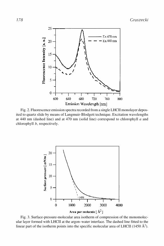
178 Gruszecki
Fig. 2. Fluorescence emission spectra recorded from a single LHCII monolayer depos-ited to quartz slide by means of Langmuir-Blodgett technique. Excitation wavelengthsat 440 nm (dashed line) and at 470 nm (solid line) correspond to chlorophyll a andchlorophyll b, respectively.
Fig. 3. Surface-pressure-molecular area isotherm of compression of the monomolec-ular layer formed with LHCII at the argon–water interface. The dashed line fitted to thelinear part of the isotherm points into the specific molecular area of LHCII (1450 Å2).

Incorporation and Analysis of LHCII in Model Systems 179
Fig. 4. Scanning force microscopy image of LHCII monolayer deposited to micaby means of Langmuir-Blodgett technique. The scan was recorded in a contact modewith NanoScope instrument from Digital Instruments at rate 3.4 Hz in cooperationwith Dr. Peter Kernen from ZYOMYX Inc., Hayward California. Bulk structures visi-ble in the topography of the Langmuir-Blodget film of LHCII correspond to the proteintrimeric structures.
5. The liposome suspension is then mixed with the suspension of LHCII in the samebuffer.
6. The mixture is vigorously vortexed for 5 min and then subjected to short pulses ofsonication (five times for 3 s).
7. The liposome suspension is then subjected to 3-min centrifugation at 15,000g, inorder to remove LHCII in an aggregated state in water phase that has not beenincorporated to liposomes.
8. An incorporation rate can be analyzed by evaluation of chlorophyll a or chloro-phyll b concentration in the liposome suspension of the known lipid content.

180 Gruszecki
3.3. LHCII in Planar Bilayer Lipid Membranes1. Planar bilayer lipid membranes (BLMs) can be formed from asolectin or egg yolk
phosphatidylcholine dissolved in n-decane.2. A small amount of forming solution was applied to a hole (1 mm in diameter) in a
Teflon cup located in a Teflon or Plexiglas chamber.3. The membrane separated two compartments, each of them containing a buffer
called bathing solution.4. A typical volume of these compartments is around 10 mL.5. The solutions in both compartments have to be stirred with magnetic microstirrers
during the formation of a membrane and experiments.6. The process of membrane thinning to the stage of a bilayer can be monitored by
visual inspection through a microscope and/or by measuring the electrical resis-tance across the membrane.
7. Reconstitution of LHCII into BLM is performed by the fusion of liposomes con-taining incorporated protein into a planar lipid membrane (9,10).
8. After the bilayer is formed, 50 µL of liposome suspension is added to one com-partment defined as cis. Next, CaCl2 is added to both compartments to get a finalconcentration of 10 mM Ca2+ (see Note 4).
9. Next, an osmotic gradient is formed between the cis and trans sides of the membraneby adding glycerol to the cis compartment to get to a final concentration of 0.2 M.
10. The process of membrane fusion and incorporation can be monitored by electri-cal measurements of the membrane conductivity (incorporation manifested by anincrease).
11. The incorporation process is usually completed within 20 min after injection ofthe liposome suspension.
4. Notes1. In order to prepare deposition solution for LHCII monolayers a suspension of the
protein in the buffer has to be supplemented with 2-propanol to the final concen-tration of 25% (by volume) gradually. The addition of small aliquots of the alco-hol and continuous stirring avoid LHCII denaturation and pigment extraction.The optimal deposition volume is between 50 µL and 100 µL. The initial surfacearea of deposition has to be at least 4000 Å2 per single LHCII monomer in orderto provide conditions for the formation of homogeneous layer. Concentration ofLHCII in a deposition medium is evaluated on the basis of chlorophyll a or chlo-rophyll b concentration and stoichiometry of pigment binding to this complex.
2. The deposition ratio (the ratio of a surface of solid support covered by monolayerand the decrease in the surface of monolayer during deposition of the L-B film)close to 1 reflects efficient deposition of a LHCII monolayer to the support.
3. The temperature of sonication, while preparing liposomes, has to be adjusted accord-ing to a lipid component in order to maintain lipids in the liquid crystalline form(above the main phase transition).
4. Specific resistance of the BLM membrane before incorporation of LHCII has to bein the range of magnitude of 108 � cm2 and the characteristic membrane capaci-tance around 0.4 µF cm�1.
Incorporation and Analysis of LHCII in Model Systems 181
AcknowledgmentsThe author wishes to express his gratitude to coworkers involved for years
in the studies of LHCII in model systems: Zbigniew Krupa, Peter Kernen,Magda Matula, Wojtek Grudzinski, Anna Wardak, Ewa Iwaszko and DarekNiedzwiedzki. These studies were financed by the State Committee for Scien-tific Research of Poland under the project 6P04A 002 19.
References1. Gaines, G. L. (1966) Insoluble Monolayers at Liquid-Gas Interfaces. Wiley, New
York.2. Munger, G., Lorrain, L., Gagne, G., and Leblanc, R. M. (1987) Adjustable sped
and vibration-free hydraulic system for Langmuir-Blodgett films deposition. Rev.
Sci. Instrum. 58, 285–288.3. Gruszecki, W. I., Zelent, B., Tajmir-Riahi, et al. (2000) Chlorophyll a-vio-
laxanthin interactions in monolayers at air-water interface and Langmuir-Blodgettfilms. Colloids Surfaces B: Biointerfaces 19, 117–125.
4. Niedzwiedzki, D. and Gruszecki, W. I. (2003) Interaction between chlorophyll aand violaxanthin in different steric conformations. Model studies in monomolec-ular layers. Colloids Surfaces B: Biointerfaces 28, 27–38.
5. Gruszecki, W. I., Grudzinski, W., Matula, M., Kernen, P., and Krupa, Z. (1999)Light-induced excitation quenching and structural transition in light-harvestingcomplex II. Photosynth. Res. 59, 175–185.
6. Kernen, P., Gruszecki, W. I., Matula, M., Wagner, P., Ziegler, U., and Krupa, Z.(1998) Light-harvesting complex II in monocomponent and mixed lipid-proteinmonolayers. Biochim. Biophys. Acta 1373, 289–298.
7. Grudzinski, W., Krupa, Z., Garstka, M., Maksymiec, W., Swartz, T. E., andGruszecki, W. I. (2002) Conformational rearrangements in Light-Harvesting Com-plex II accompanying light-induced chlorophyll a fluorescence quenching. Bio-
chim. Biophys. Acta 1554, 108–117.8. Gruszecki, W. I., Kernen, P., Krupa, Z., and Strasser, R. J. (1994) Involvement of
xanthophyll pigments in regulation of light-driven excitation quenching in light-harvesting complex of Photosystem II. Biochim. Biophys. Acta 1188, 235–242.
9. Wardak, A., Brodowski, R., Krupa, Z., and Gruszecki, W. I. (2000) Effect of light-harvesting complex II on ion transport across model lipid membranes. J. Photo-
chem. Photobiol. B: Biol. 56, 12–18.10. Gruszecki, W. I., Wardak, A., and Maksymiec, W. (1997) The effect of blue light
on electron transport in photosystem II reconstituted in planar bilayer lipid mem-brane. J. Photochem. Photobiol. B: Biol. 39, 265–268.
11. Grudzinski, W., Matula, M., Sielewiesiuk, J., Kernen, P., Krupa, Z., and Gruszecki,W. I. (2001) Effect of 13-cis violaxanthin on organization of light harvesting com-plex II in monomolecular layers. Biochim. Biophys. Acta 1503, 291–302.
12. Kühlbrandt, W., Wang, D. N., and Fujiyoshi, Y. (1994) Atomic model of plantlight-harvesting complex by electron crystallography. Nature 367, 614–621.

182 Gruszecki

PSII Reconstitution Into Proteoliposomes 183
183
From: Methods in Molecular Biology, Vol. 274: Photosynthesis Research ProtocolsEdited by: R. Carpentier © Humana Press Inc., Totowa, NJ
19
Photosystem II Reconstitution Into ProteoliposomesStructure–Function Characterization
Mário Fragata
SummaryThis chapter discusses the photosystem II (PSII) reconstitution into proteoliposomes. In the
first part of the chapter, protocols are outlined (1) for the preparation of lipid bilayer vesicles(liposomes) constituted of individual thylakoid lipids or their mixtures (2) for the preparationof PSII particles, and (3) for the incorporation of the PSII particles into the liposomes. In thesecond part of the chapter, methodologies are described for the structure–function characteriza-tion of the PSII–lipid complexes (proteoliposomes). This includes the sodium dodecyl sulfate-poly-acrylamide gel electrophoresis (SDS-PAGE) determination of the PSII proteins, measurementof oxygen-evolving activity of PSII in the proteoliposomes, and the study of structural changesof the PSII proteins upon their incorporation into the lipid bilayers by Fourier transform infra-red (FTIR) spectroscopy.
Key Words: Chloroplast lipids; infrared spectroscopy; lipid bilayer vesicles; lipid phase transi-tions; liposomes; oxygen evolution; photosystem II (PSII); proteoliposomes; structure–function;thylakoid membrane.
1. IntroductionThe chloroplasts of higher plants and algae have three membranes (outer,
inner, thylakoid) constituted of similar glyco- and phospholipids (1) for exam-ple, monogalactosyl diacylglycerol (MGDG; nonionic lipid), digalactosyl dia-cylglycerol (DGDG; nonionic lipid), sulfoquinovosyl diacylglycerol (SQDG;anionic lipid), phosphatidylglycerol (PG; anionic lipid), phosphatidylinositol (PI;nonionic lipid), and phosphatidylcholine (2–4) (PC; zwitterionic lipid betweenpH 2.0 and 10; see Note 1). Their average compositions in the outer, inner, andthylakoid membranes, as reported in refs. 5 and 6, are displayed in Table 1. Thetable shows that the inner and thylakoid membranes have similar lipid content.
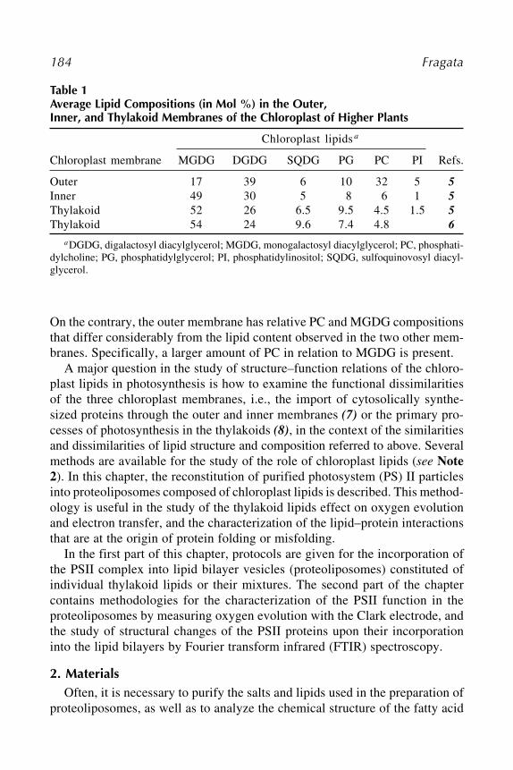
184 Fragata
On the contrary, the outer membrane has relative PC and MGDG compositionsthat differ considerably from the lipid content observed in the two other mem-branes. Specifically, a larger amount of PC in relation to MGDG is present.
A major question in the study of structure–function relations of the chloro-plast lipids in photosynthesis is how to examine the functional dissimilaritiesof the three chloroplast membranes, i.e., the import of cytosolically synthe-sized proteins through the outer and inner membranes (7) or the primary pro-cesses of photosynthesis in the thylakoids (8), in the context of the similaritiesand dissimilarities of lipid structure and composition referred to above. Severalmethods are available for the study of the role of chloroplast lipids (see Note
2). In this chapter, the reconstitution of purified photosystem (PS) II particlesinto proteoliposomes composed of chloroplast lipids is described. This method-ology is useful in the study of the thylakoid lipids effect on oxygen evolutionand electron transfer, and the characterization of the lipid–protein interactionsthat are at the origin of protein folding or misfolding.
In the first part of this chapter, protocols are given for the incorporation ofthe PSII complex into lipid bilayer vesicles (proteoliposomes) constituted ofindividual thylakoid lipids or their mixtures. The second part of the chaptercontains methodologies for the characterization of the PSII function in theproteoliposomes by measuring oxygen evolution with the Clark electrode, andthe study of structural changes of the PSII proteins upon their incorporationinto the lipid bilayers by Fourier transform infrared (FTIR) spectroscopy.
2. MaterialsOften, it is necessary to purify the salts and lipids used in the preparation of
proteoliposomes, as well as to analyze the chemical structure of the fatty acid
Table 1Average Lipid Compositions (in Mol %) in the Outer,Inner, and Thylakoid Membranes of the Chloroplast of Higher Plants
Chloroplast lipids a
Chloroplast membrane MGDG DGDG SQDG PG PC PI Refs.
Outer 17 39 6 10 32 5 5
Inner 49 30 5 8 6 1 5
Thylakoid 52 26 6.5 9.5 4.5 1.5 5
Thylakoid 54 24 9.6 7.4 4.8 6
aDGDG, digalactosyl diacylglycerol; MGDG, monogalactosyl diacylglycerol; PC, phosphati-dylcholine; PG, phosphatidylglycerol; PI, phosphatidylinositol; SQDG, sulfoquinovosyl diacyl-glycerol.

PSII Reconstitution Into Proteoliposomes 185
chains of the glyco- and phospholipids. The procedures for the purification ofsalts are given in Note 3, lipids in Note 4, and fatty acid analysis is discussedin Note 5.
2.1. Preparation of Lipid Bilayer Vesicles
1. Amicon cell equipment.2. Buffer: 20 mM MES (2-[N-morpholino]ethanesulfonic acid)-NaOH (pH 6.5),
400 mM sucrose, 15 mM NaCl, and 5 mM MgCl2.3. Chromatography columns.4. Gas chromatograph (e.g., Varian, model 3700, equipped with a Shimadzu integra-
tor, model C-R3A).5. HPLC equipment.6. Lipids:
Digalactosyl diacylglycerol (DGDG).Monogalactosyl diacylglycerol (MGDG).Sulfoquinovosyl diacylglycerol (SQDG).Phosphatidylcholine (PC).Phosphatidylglycerol (PG).Phosphatidylinositol (PI).
7. Millipore equipment.8. Sepharose-4B gel (Pharmacia Fine Chemicals).9. Sonicator (e.g., Heat Systems-Ultrasonics, Plainview, NY).
2.2. Preparation of PSII Particles
1. Barley seeds (or other adequate plant material).2. Buffer A: 50 mM Tricine (N-tris[hydroxymethyl]methylglycine)-NaOH (pH 7.8),
400 mM sorbitol, 10 mM NaCl, and 5 mM MgCl2.3. Buffer B: 50 mM Tricine-NaOH (pH 7.8), 10 mM NaCl, and 5 mM MgCl2.4. Buffer C: 20 mM MES (2-[N-morpholino]ethanesulfonic acid)-NaOH (pH 6.5),
400 mM sucrose, 15 mM NaCl, and 5 mM MgCl2.5. Buffer D (PSII storage buffer): 20 mM MES-NaOH (pH 6.5), 400 mM sucrose,
15 mM NaCl, 5 mM MgCl2, and 30% (v/v) glycerol.6. Cheesecloth tissue (Vertac™, Graphic Arts Cheesecloth, Veratec Inc., Graphic Arts
Products, Walpole, MA).7. Salts: MgCl2 and NaCl.8. Sugars: sorbitol and sucrose.9. Triton X-l00.
10. Vermiculite and polythene trays (or other adequate material).
2.3. PSII Reconstitution into Proteoliposomes
Buffer C: 20 mM MES (2-[N-morpholino]ethanesulfonic acid)-NaOH (pH6.5), 400 mM sucrose, 15 mM NaCl, and 5 mM MgCl2.
186 Fragata
2.4. SDS-PAGE
1. SDS-PAGE equipment.2. Resolving gel: acrylamide, ammonium persulphate, bis-acrylamide, isopropanol,
SDS, TEMED (N,N,N',N'-Tetramethyl ethylenediamine, N,N,N',N'-Di-(dimethyl-amino) ethane, or N,N,N',N'-Tetramethyl-1,2-diaminomethane), Tris-HCl buffer,urea.
3. Stacking gel: acrylamide, ammonium persulphate, bis-acrylamide, SDS, TEMED,Tris-HCl buffer, urea.
4. Sample buffer: bromophenol blue, glycerol, 2-mercaptoethanol, SDS, urea.5. Resolving gel buffer: hydrochloric acid, trizma base (Sigma Chemical Co., St. Louis,
MO).6. Stacking gel buffer: sulphuric acid, trizma base.7. Lower reservoir buffer: hydrochloric acid, trizma base.8. Upper reservoir buffer: boric acid, SDS, trizma base.9. Staining solution: acetic acid, Coomassie Brilliant Blue R-250 (Bio-Rad Labora-
tories, Richmond, CA), methanol.10. Destaining solution: acetic acid, methanol.11. A kit of protein molecular mass markers (e.g., RPN 800 kit from Amersham Inter-
national plc, Buckinghamshire, UK).
2.5. Measurement of Oxygen Evolution
1. Argon or nitrogen cylinder.2. Buffer C: 20 mM MES-NaOH (pH 6.5), 400 mM sucrose, 15 mM NaCl, and 5 mM
MgCl2.3. 2,5-Dichloro-p-benzoquinone (DCBQ).4. Dithionite.
2.6. Structural Study of PSII and PSII–Lipid With FTIR Spectroscopy
1. Argon or nitrogen cylinder.2. Buffer C: 20 mM MES – NaOH (pH 6.5), 400 mM sucrose, 15 mM NaCl, and 5 mM
MgCl2.3. FTIR spectrophotometer.4. Software program for the mathematical treatment of the infrared data; the use of
one of the Spectra-Calc programs from Galactic Industries Corp. (Salem, NH) isrecommended, but any appropriate mathematical software is acceptable.
5. Infrared spectroscopy optical windows (BaF2 or ZnSe).
3. MethodsSubheading 3.1. outlines the protocols for the preparation of lipid bilayer
vesicles, the extraction of PSII particles, and the PSII reconstitution into proteo-liposomes. Subheading 3.2. describes procedures for SDS-PAGE, the measure-ment of oxygen evolution in PSII, and the structural study of the proteoliposomesby FTIR spectroscopy.
PSII Reconstitution Into Proteoliposomes 187
3.1. Preparation of PSII Proteoliposomes
The protocols described in Subheadings 3.1.1., 3.1.2., and 3.1.3. are well-known, reliable procedures for the preparation of lipid bilayer vesicles (lipo-somes) of about 250 Å (25 nm) diameter, the preparation of PSII particles, andthe reconstitution of the PSII particles into the lipid bilayer vesicles (proteo-liposomes), respectively. It is noted, however, that several other proceduresfor performing the same purpose are available in the literature, as well as a vastarray of other methods designed for fundamental and applied research such asthe many present day therapeutical purposes. Note 6 guides the reader to someof those methodologies.
3.1.1. Preparation of Lipid Bilayer Vesicles
Before attempting to form lipid bilayer vesicles (liposomes) in aqueousmedia, one might consider any available information on the phase behavior ofthe lipids, a question that is crucial for the success of any preparation (dis-cussed in Note 7). Determine which lipids are bilayer-forming or nonbilayer-forming; second, address the question of the phase transition temperatures ofthe lipids. The latter point is particularly important because in most cases it isnot possible to obtain a liposome preparation at temperatures below the gel-to-liquid crystal phase transition temperature of the lipid. For example, lipidvesicles never form in aqueous mixtures of dipalmitoyl phosphatidylcholine(DPPC) with water at room temperature (see Note 7). In fact, the temperatureof most laboratories is well below the gel-to-liquid crystal transition of DPPCof 41°C (14), thereby indicating the need for heating the water-DPPC mixtureto temperatures above the 41°C limit.
The method described here is a standard procedure used for the formation oflipid bilayer vesicles constituted of either one lipid class or binary and ternarymixtures of different lipid species (4,15,21,22):
1. Solubilize 20 to 150 mg of the purified lipids (see Note 4) in diethyl ether (or anotherappropriate organic solvent), then dry under a current of nitrogen or argon to avoidoxidation of the lipids. Note, however, that the solubilization step can be skipped ifthe preparation of the bilayer vesicles is made with only one purified lipid species.
2. Disperse the dried lipids in 10 mL of a buffer medium containing 20 mM MES(pH 6.5), 400 mM sucrose, 15 mM NaCl, and 5 mM MgCl2 to give a lipid concen-tration of 10 mg/mL in the the final solution (see Subheading 2.1.).
3. Sonicate suspension in a test tube with a titanium sonicator probe (e.g., Heat Sys-tems-Ultrasonics, Plainview, NY) for 15 min at 160 W output in a sonifier cell dis-rupter from Heat Systems-Ultrasonics, model W-225R, having nitrogen or argonbubbling into the solution (see Note 8).
4. Centrifuge the mixture at 100,000g for 1 h and concentrate the supernatant to 1 or2 mL in a Amicon cell (or a similar equipment).

188 Fragata
5. Fractionate the lipid dispersion in a Sepharose-4B column (Pharmacia FineChemicals, 2.5 � 60 cm) and elute with the above described buffer (see Subhead-
ing 2.1.). Then, 5-mL fractions are collected. A typical elution diagram is pro-vided in Fig. 1.
6. Only the homogeneous fractions constituted of unilamellar vesicles (class IIIvesicles; Fig. 1) are retained for the preparation of proteoliposomes.
3.1.2. Preparation of PSII Particles
Before proceeding into the description of the methods used here, it is usefulto emphasize that:
1. The following protocols are designed for the extraction of PSII particles frombarley (Hordeum vulgare) seedlings; these protocols may need to be changed ifother biological materials are used to obtain the PSII particles.
Fig. 1. Elution diagram of phosphatidylcholine vesicles prepared by ultrasonic dis-persion in a buffer containing 20 mM MES (2-[N-morpholino]ethanesulfonic acid)-NaOH (pH 6.5), 400 mM sucrose, 15 mM NaCl, and 5 mM MgCl2 followed by ultra-centrifugation (100,000g; 1 h) and gel filtration in a Sepharose-4B column. The volumeof each fraction is 5 mL. I, class I liposomes constituted of large multilayered vesicles;II, class II liposomes constituted of mixtures of class I and class III; III, class III lipo-somes constituted of small single-layered vesicles of about 20–25 nm diameter.

PSII Reconstitution Into Proteoliposomes 189
2. All the steps described in this section are performed under green dim light at tem-peratures in the 0–4°C range.
3. All glassware, buffers and other materials must be precooled in a refrigerator beforeuse, and maintained in containers filled with ice during the extraction procedures.
4. All biological materials (chloroplasts, thylakoid membranes, PSII particles) mustalways be kept in closed dark containers filled with ice, unless one chooses towork in a cold room under green dim light.
3.1.2.1. CULTIVATION OF BARLEY SEEDLINGS
The following are the steps for soaking the seeds in water.
1. Wash 200 g of barley seeds throughly, then spread inside polythene trays; add waterto the trays until the seeds are immersed.
2. Cover the seeds with a layer of white tissue paper.3. Leave the trays in darkness for 24 h at room temperature.
The following are the steps for planting the seeds on vermiculite. All thesteps should take place in a growth chamber, if possible.
1. Add vermiculite to polythene trays to a height of 2 to 3 cm.2. Spread the barley seeds (presoaked in water; Subheading 3.1.2.1.) on the surface
of the vermiculite and sprinkle the seeds with water; the water should be spreadover the whole area of the polythene tray.
3. Spread vermiculite over the seeds to a height of 1 cm in order to cover all the seeds.4. Let the seeds germinate and grow for about 6 to 8 d at 23 ± 2°C and a light inten-
sity of 200 ± 20 µmol m�2 s�1.5. After germination, sprinkle the seeds every day with about 200 mL water until the
seedlings harvest.
3.1.2.2. ISOLATION OF CHLOROPLASTS AND THYLAKOID MEMBRANES
Thylakoid membranes are obtained from chloroplasts of 6- to 8-d-old-barley(Hordeum vulgare) seedlings according to the procedure of Berthold et al. (23)
with modifications described in (24,25).
1. Cut barley leaves to 1 cm length and introduce in a precooled homogenizer jar tofull volume.
2. Homogenize the barley leaf fragments (10–15 s) at 0°C in a precooled buffermedium containing 50 mM Tricine-NaOH (pH 7.8), 400 mM sorbitol, 10 mM NaCl,and 5 mM MgCl2 (buffer A) (see Subheading 2.2.).
The homogenization should take place in the dark. Cover the homogenizer jarwith a black cloth during operation.
3. Filter the homogenized slurry through eight layers of cheesecloth tissue, then cen-trifuge the filtrate at 1000g for 5 min at 4°C.
4. The pellet obtained in step 2 (chloroplasts) is dispersed in buffer A (see Sub-
heading 2.2.) to a total volume of 200–400 mL using a brush and a Vortex mixer;then, the dispersion is centrifuged at 1000g for 5 min at 4°C.

190 Fragata
5. Suspend the chloroplast pellet in a buffer containing 50 mM Tricine-NaOH (pH7.8), 10 mM NaCl, and 5 mM MgCl2 (buffer B) (see Subheading 2.2.) using brushand Vortex mixer; centrifuge at 1000g for 5 min at 4°C.
6. Suspend the pellet obtained in step 4 (thylakoid membranes) in a minimal volumeof a precooled buffer medium containing 20 mM MES (pH 6.5), 400 mM sucrose,15 mM NaCl, and 5 mM MgCl2 (buffer C) (see Subheading 2.2.) using brush,Vortex mixer and a teflon homogenizer; this step might be followed by a centrifu-gation at 1000g for 5 min at 4°C.
7. Suspend the pellet of thylakoid membranes obtained in step 5 in buffer C (see Sub-
heading 2.2.) to give a final chlorophyll (Chl) concentration of 2 mg/mL, and storeat approx �80°C until use.
8. The Chl concentration is estimated using 80% (v/v) acetone solutions accordingto the method of Arnon (26) (see Note 9).
3.1.2.3. ISOLATION OF PSII PARTICLES
1. Bring thylakoid membranes kept at �80°C (see Subheading 3.1.2.2.) to 0°C in acontainer filled with ice.
2. Estimate the chlorophyll concentration in the thylakoid samples according to theprocedure in Subheading 3.1.2.2.
3. Assay the oxygen-evolving activity of the thylakoid membranes prior to the isola-tion of the PSII particles.
4. Using a Vortex, mix 1 mL of the thylakoid membranes suspension (2 mg Chl/mL)with 0.5 mL of buffer C (see Subheading 2.2.).
5. With very gentle shaking, add dropwise 0.5 mL of 8% Triton X-l00 to the mixtureobtained in step 4 to give a final Chl concentration of 1 mg/mL; the final TritonX-100/Chl ratio should be 20/1.
During the addition of the Triton X-100 solution the use of a Vortex, or any othermechanical shaking device, should be avoided, this step must be done slowly, butas fast as possible, and the use of gloves is mandatory to avoid any skin contactwith the Triton X-100 solution.
6. Incubate the suspension obtained in step 5 in the dark for 20 min at 4°C, thencentrifuge at 1000g for 3 min at 4°C to precipitate the unbroken thylakoids.
7. Transfer supernatant of step 6 to one or several prechilled centrifuge tubes andcentrifuge immediately at 29,000g for 30 min at 4°C.
8. Discard the supernatant of each centrifuge tube of step 7 (containing Triton X-100),and add 1 mL of buffer C (see Subheading 2.2.) to the pellet of each of the tubes,followed by dispersing the pellets using a brush.
9. Add 10–15 mL of buffer C (see Subheading 2.2.) to each one of the centrifugetubes in step 8, and centrifuge immediately at 29,000g for 30 min at 4°C; in thisstep, the residual Triton X-100 will be removed.
10. Pool the pellets of all tubes used in step 9 (PSII particles) together upon suspensionin small volumes of buffer D (see Subheading 2.2.) to give a final volume of 1 mL.
11. Immediately after step 10, or as soon as possible, determine the characteristics ofthe PSII particles just prepared by measuring their chlorophyll content, the oxy-

PSII Reconstitution Into Proteoliposomes 191
gen-evolving activity, and the polypeptide composition with SDS-PAGE. It isworth noting that the electrophoresis test is particularly important to checkwhether the PSII particles are contaminated with PSI proteins.
12. Finally, the PSII particles are stored at �80°C until use.
3.1.3. PSII Reconstitution Into Proteoliposomes
It is important to note that all the following steps are performed in greendim light and at temperatures of approx 4°C; work either in a cold room ingreen dim light, or maintain all buffers and other materials in dark containersfilled with ice.
To prepare the PSII–lipid membranes follow the following steps (4,24,25):
1. Centrifuge solubilized particles at 29,000g for 30 min at 4°C, then suspend in 20 mM
MES (pH 6.5), 400 mM sucrose, 15 mM NaCl, and 5 mM MgCl2 (buffer C) (see Sub-
heading 2.2.); this step is repeated once using buffer C as the suspension medium.2. Gently mix the washed PSII particles obtained in step 1 in a vortex with the lipid
vesicles (see Subheading 3.1.1.); the lipid:chlorophyll ratio is maintained at 20/1(w:w) throughout (4).
3. The salts can be added at this stage to study the effect of ions on the activity of thePSII–lipid complex.
4. Incubate the protein–lipid mixtures in darkness at 0°C for 20 min.5. Immediately after the incubation step, use an aliquot of the preparation for oxy-
gen evolution determination according to the procedure outlined below (see Sub-
heading 3.2.2.).6. Measure their oxygen evolution activity.
3.2. Characterization of PSII Proteoliposomes
The protocols described here include first standard procedures of SDS-PAGE, and the measurement of oxygen evolution with a Clark-type electrode(Subheadings 3.2.1. and 3.2.2.). Next, Subheading 3.2.3. outlines the essen-tials of the FTIR spectroscopy methodology, which has been successfully usedin a large number of studies. For example, the examination of structural changesin the photosynthetic membrane induced by a variety of effects such as ultra-violet (UV)-B radiation (27) and heat stress (28). The examples discussed arelimited to the analysis of the “spectral window” between 1700 and 1480 cm�1
(Figs. 2–4) where most biolipids have no significant infrared absorption. Pro-cedures are described for the preparation of samples for FTIR spectroscopy,the measurement of infrared spectra, and the analysis of infrared data.
3.2.1. SDS-PAGE
The polypeptide composition of the PSII particles is analyzed by SDS-PAGE to determine whether they are contaminated with PSI proteins (8,30).

192 Fragata
First, it is mentioned that the protocols outlined hereunder (preparation ofthe gels for SDS-PAGE as well as many other experimental details) are takenfrom the procedures described in the work of Chua (29). Consult before pro-ceeding further in this section. In addition, it is specially important to note thefollowing:
1. All steps described below are performed at room temperature.2. SDS and TEMED may be stored at room temperature.3. Always prepare fresh solutions of urea and ammonium persulfate.4. While handling acrylamide (monomeric product), use a mouth-and-nose mask
and a pair of gloves; this precaution is not necessary upon polymerization of theacrylamide.
The standard proteins and PSII polypeptides are resolved on a linear gradi-ent gel with the separating gel containing 15% acrylamide and 6 M urea, andthe stacking gel having 5% acrylamide and 6 M urea. Before loading into thegel slots, the PSII samples are first solubilized with SDS. This is followed by a
Fig. 2. Infrared spectra of photosystem II (PSII), digalactosyl diacylglycerol(DGDG) and the PSII–DGDG complex between 1800 and 1480 cm�1. Abbreviations:I, amide I region (1700–1630 cm�1); II, amide II region (1580–1520 cm�1); Y8a,b andY19a, regions of the 8a and 8b (1630-1580 cm�1) splitting components of the funda-mental mode no. 8 and the high-frequency splitting component 19a (1520–1500 cm�1)of the phenol ring according to Wilson (39). Note that in the “spectoscopic window”
from 1700 to 1480 cm�1, DGDG has negligible absorbance.

PSII Reconstitution Into Proteoliposomes 193
Fig. 3. Infrared absorbance of H2O and D2O between 1800 and 1480 cm�1, in thespectral regions of the amide I, amide II, and the splitting components of the fundamen-tal modes no. 8 and no. 19 of the phenol ring (Fig. 2).
Fig. 4. Resolution enhancement of a untreated infrared spectrum of photosystem II(ABSu) using the Fourier self-deconvolution (FSD), second derivative (2nd-D) andfourth (4th-D) derivative methods. The calculations were performed with the “mathe-matical tool” of the Spectra-Calc program.

194 Fragata
centrifugation at 13,600g for 5 min to remove the unsolubilized membranes.Upon electrophoresis, the gels are stained for 3 h with a solution containing50% methanol, 10% acetic acid, and 0.125% R-250 Coomassie brilliant blue(Bio-Rad Laboratories, Richmond, CA). Gel destaining is done in solutionscontaining 60% water, 30% methanol, and 10% acetic acid. To estimate themolecular mass of the proteins, a plot of log molecular mass vs the migrateddistance (in centimeters) is used for the unknown proteins and standard proteinmarkers. The molecular masses of the markers in the RPN 800 kit fromAmersham International plc (Buckinghamshire, UK) are 15, 25, 30, 35, 50, 75,105, 160, and 250 kDa.
The PSII polypeptide subunits usually detected in the electrophoresis gelare the 16-, 23- and 33-kDa extrinsic proteins, the S protein, the �-cyt b559,the proximal antenna proteins (CP43 and CP47), and the D1 and D2 proteins inthe reaction center (34 and 32 kDa, respectively) (8).
3.2.2. Measurement of Oxygen EvolutionMeasurement of electron transport through PSII estimated as oxygen evolu-
tion in the PSII particles and the PSII–lipid complex is performed at 25°C witha Clark-type electrode using, for example, the equipment from Hansatech D.W.Oxygen Electrode Unit, King’s Lynn, Norfolk, UK (see Note 10).
The reaction medium (total volume: 2 mL) contains the following:
1. 1960 µL of the measurement buffer (buffer C; see Subheading 2.2.).2. 20 µL of 350 µM DCBQ (2,5-dichloro-p-benzoquinone) as exogenous electron
acceptor at the QA site (8), and3. 20 µL samples of PSII particles or PSII–lipid complex (final concentration: 12.5
µg Chl/mL).
The PSII and PSII–lipidI preparations are then illuminated with white lightat saturating light intensity. Note that usually the universal unit used for express-ing oxygen-evolving activity is µmol O2/mg Chl/h.
For the measurement of the pH effect on oxygen evolution, adjust the pH ofthe buffer media in the pH 3.0–10 range with HCl or NaOH. This practice isuseful to avoid changes of chemical composition of the reaction media whenone uses three different buffer systems to cover the pH 3.0–10 range.
3.2.3. Structural Study of PSII and PSII–Lipid With FTIR SpectroscopyFTIR spectroscopy is widely used in structural studies of proteins (31). Among
those studies, many examined the structure–function relations in the photosyn-thetic membrane (32–35). Although the useful infrared range spans from about4000 to 600 cm�1, most works are performed between 1700 and 1480 cm�1, i.e.,the amide I and amide II regions. The reason for this is that these spectralregions contain a set of vibrational modes that are related to several periodic

PSII Reconstitution Into Proteoliposomes 195
structures found in many proteins. In addition, the amide I and amide II regionsare very sensitive to conformational changes in the proteins secondary struc-tures such as those caused by UV light (27) or thermal effects (28,34,36).
Table 2 collects wavenumbers and vibrational modes of major bands betweenapprox 1780 and 1500 cm�1 in the infrared spectra of PSII, and provides informa-tion on the protein periodic structures deduced from the spectral data (27,31,35–39).
Table 2Wavenumbers and Vibrational Modes of the Major Spectral Bands Between1760 And 1500 cm�����1 in the Infrared Spectrum of Photosystem II With Indicationof Protein Periodic Structures in the Amide I and Amide II Regionsa
Wavenumber Vibrational modesSpectral region (cm�1) and protein periodic structuresb
Vibrational modes
Amides Ic, IId 1627 �aNH3+ or �NH2
1572, 1564 �aCOO�
1550, 1531 �sNH3+
Tyrosine 1620–1580
~1608 �8a ringe
~1590 �8b ringe
1520–1500 �19a ring (~1508 cm�1) + deformatione
Chl + lipids 1760–1692
~1739 �CO (sn1 or sn2 ester CO) of lipids~1737 �CO (ester CO) of chlorophylls~1693 �CO (free keto CO) of chlorophylls~1662 Bound keto CO of chlorophylls
Protein periodic structures
Amide I 1696–1620
1696–1665 Turns (e.g., �-turns), antiparallel �-sheet(~1693 cm�1)
1658–1654 �-helix + some random coil structures1648–1641 Random structures, loops1640–1620 �-sheet (~1636 cm�1), extended chain
(�-strand: ~1626 cm�1)Amide II 1580–1520
~1545 Some �-helical conformationsaData from Arrondo et al. (31), Gabashvili et al. (35), Ségui et al. (27), and literature cited
therein.bChl, chlorophyll; �, bending; �� ��asymmetric bending; �s , symmetric bending; �, stretching;
�a, asymmetric stretching.cAmide I: In-plane C = O stretching vibrations weakly coupled with CN stretching and CCN
deformation.dAmide II: In-plane NH bending strongly coupled with CN stretching.eWilson et al. (39).

196 Fragata
1. The region from 1780 to 1700 cm�1 is characterized by vibrational modes originat-ing in the lipids and chlorophylls.
2. The region from 1700 to 1600 cm�1 (amide I) is associated with an in-plane C = Ostretching vibration (approx 80%) weakly coupled with some contributions fromCN stretching and CCN deformation.
3. The region from 1580 to 1520 cm�1 (amide II) is assigned to an in-plane NH bend-ing strongly coupled with CN stretching.
4. The spectral bands at about 1608, 1590, and 1508 cm�1 originate in the vibrationalmodes of the phenol ring, e.g., in tyrosine.
The question of the “spectral window” between 1700 and 1480 cm�1 inlipid–protein studies is discussed first, then methods are outlined for the prepa-ration of samples for FTIR spectroscopy, the measurement of infrared spectra,and the analysis of infrared data.
3.2.3.1. “SPECTRAL WINDOW” BETWEEN
1700 AND 1480 CM�1 IN INFRARED SPECTRA OF BIOLIPIDS
It is interesting to note that in the study of lipid–protein interactions onetakes advantage of a useful “spectral window” between 1700 and 1480 cm�1
where most lipids do not absorb infrared radiation (35,40). This is clearly seenin Fig. 2 for the interaction between PSII and the galactolipid digalactosyldiacylglycerol (DGDG). That is, from about 1700 to 1480 cm�1 the DGDGabsorbance is negligible compared to the large absorbance of infrared light bythe PSII and PSII–DGDG complexes. This means that within the 1700–1480cm�1 range any lipid-induced change of the infrared spectra of the PSII–lipidcomplex is not affected by the lipid absorbance observed either at wavenumbersgreater than 1700 cm�1 or smaller than 1480 cm�1.
3.2.3.2. PREPARATION OF SAMPLES FOR FTIR SPECTROSCOPY
Infrared investigations of protein–lipid interaction are carried out in deute-rium oxide (D2O) to overcome the strong overlapping effect of the H2O absorp-tion in the amide I and amide II regions (see Fig. 3). The protocols given below,(41), outline a modified procedure for preparing liposomes and proteolipo-somes in D2O, and the steps for preparation of samples for layering on BaF2 orZnSe plates.
3.2.3.2.1. Preparation of Liposomes and Proteoliposomes in D2O
1. The lipid bilayer vesicles (liposomes) are prepared according to the protocolsdescribed in Subheading 3.1.1. except for replacement of the water solvent withD2O.
2. For preparing the PSII–lipid membranes (proteoliposomes), wash the PSII particlesobtained in Subheading 3.1.2. in D2O by centrigugation at 28,700g for 7 min at4°C, then complex with the liposomes obtained in step (a) (see Subheading 3.1.3.).

PSII Reconstitution Into Proteoliposomes 197
3.2.3.2.2. Preparation of Samples for Layering on BaF2 or ZnSe Plates
1. Centifuge aliquots of the PSII or PSII–lipid samples (1.5 mg ChL/mL) obtainedas described in step 1 at 28,700g for 7 min at 4°C.
2. Suspend the pellet in 3 mL D2O and centrifuge a second time (28,700g; 7 min; 4°C).3. Suspend the final pellet again in a D2O volume sufficient to make a solution with
a chlorophyll concentration of 0.333 mg/mL.4. Immediately layer an aliquot of the solution on 25 mm diameter BaF2 or ZnSe
plates that are stored in darkness on filter paper placed on ice in a controlledtemperature chamber (0°C).
5. Dehydrate for about 90 min under a current of nitrogen.
In the above conditions any 1H/2H exchange is minimized, thereby assuringthat the results are not influenced significantly by the presence of D2O mole-cules in the PSII samples.
3.2.3.3. MEASUREMENT OF INFRARED SPECTRA
The infrared absorbance measurements are made in a Nicolet FTIR spectro-photometer, model 420, or another appropiate instrument. In the Nicolet FTIRinstrument, 100 interferograms are collected and co-added using Omnic soft-ware facility. The infrared spectra are obtained upon subtraction of the spec-trum of the BaF2 or ZnSe plates used for deposition of the samples. The spectralresolution is between 1 and 2 cm�1.
3.2.3.4. ANALYSIS OF INFRARED DATA
The FTIR spectra are processed using the GRAMS/386 Spectra-Calc pro-gram, version 1.06A, from Galactic Industries Corp. (Salem, NH), or anotherappropriate software. Hereunder. information is provided for the baseline cor-rection, the mathematical analysis of FTIR spectra, the determination of thecontents in protein periodic structures, and the calculation of difference spectra.
1. Baseline Correction. Prior to data processing, or before any mathematical treat-ment of the FTIR spectra, it is important to perform a baseline correction of theoriginal spectra between about 4000 and 600 cm�1 using the “baseline correctiontool” of the Spectra-Calc program.
2. Mathematical Analysis of FTIR Spectra. Identification of the band maxima fre-quencies (or wavenumbers) is first done on inspection of the FTIR absorbancespectra. However, the amide I and amide II envelope is usually rather featureless(PSII and PSII–DGDG spectra in Fig. 2), rendering the analysis of the infraredspectra difficult or not worthy. To cope with this disadvantage refer to math-ematical methods of “resolution enhancement”. For example, the “mathematicaltool” of the Spectra-Calc program offers the possibility of performing varioustypes of resolution enhancement: the Fourier self-deconvolution (FSD), the secondand fourth derivatives, and curve-fitting analyses using Gaussian, Lorentzian, andVoigt functions.

198 Fragata
a. Fourier Self-Deconvolution (FSD). In this method the effective spectral band-width is synthetically narrowed. As apodization filters, FSD uses either theBessel or the Boxcar function, although in most instances the Bessel functionis preferred. Upon application of this method it becomes easier to identify theprincipal bands under a much larger multiband envelope with overlapping indi-vidual band features. This is seen in Fig. 4, which displays a typical untreatedabsorbance spectrum of PSII together with its FSD spectrum.
b. Second and Fourth Derivatives. The “differentiate tool” of the Spectra-Calcprogram provides the first and second derivatives using the Savitsky-Golayconvolution method. To obtain the fourth derivative, one uses the second deriv-ative spectrum as the starting data for the calculation. Now, it is important forthe good interpretation of the data that a “band maximum in the original spec-trum” (and the FSD spectrum) is displayed as a “band minimum in the secondderivative spectrum” and as a “band maximum in the fourth derivative spec-trum.” This is clearly seen in the amide I–II spectrum of PSII displayed in Fig.
4. As an example, one may wish to verify in Fig. 4 that the �-helix band maxi-mum (Table 2) seen in the original (untreated) spectrum at approx 1655.7 cm�1,is displayed at 1657.7 cm�1 in the FSD, second derivative and fourth derivativespectra, that is, a displacement of about 2 cm�1 to a higher wavenumber. In mostinstances, the 1657.7 cm�1 wavenumber, is taken as a better estimation of �-helixband maxima.
c. Curve-Fitting Analyses. The “curve-fitting tool” of the Spectra-Calc programautomatically calculates the best fit of Gaussian, Lorentzian, or Voigt bandsthat make up a complex set of overlapping peaks. The program works first ona guess at the number of overlapping bands present within the multiband enve-lope, their peak positions, their peak widths, and the peak types (e.g., Gaussian,Lorentzian, or their mixtures). Then, it iterates to locate a combination of bandheights, positions, and widths that best fit the experimental data. It is here thatthe data obtained with the FSD, second derivative and fourth derivative calcu-lations (see above) is extremely important. In fact, all the calculations sug-gested in this subsection should be performed sequentially, and followed bycomparisons with data available in the literature. The final result of the “curve-fitting analysis” is a set of synthetized spectral bands that represent the severalperiodic substructures that make up the molecular, or supra-molecular, struc-ture of the protein or protein complexes under study (Table 2).
3.2.3.5. DETERMINATION OF THE CONTENTS IN PROTEIN PERIODIC STRUCTURES
The procedure for determining the contents in protein periodic structures isquite simple. First, the total area of the amide I–II envelope surface from about1700 to 1500 cm�1 is determined using the “integration tool” of the Spectra-Calcprogram. Second, the individual areas of the different spectral bands obtainedin the “curve-fitting analysis” described above are well determined with the“integration tool.” Third, the percentages of �-helix, �-sheet, �-strands or any

PSII Reconstitution Into Proteoliposomes 199
of the other structures are found by computing the ratio of the individual bandareas in relation to the total area of the amide I–II surface (40).
To identify a given protein periodic structrure (�-helix, �-sheet, �-strand,etc.) with a specific spectral band use the information in Table 2, or data givenelsewhere in the literature.
3.2.3.6. CALCULATION OF DIFFERENCE SPECTRA
To obtain the difference spectra, i.e., the [PSII–lipid]-minus-[PSII] spectra,the methods developed in the literature (35,42,43) are applied. First, the areasunder the spectral envelope in the 1700-1500 cm�1 region, i.e., amides I and II,for the PSII and the PSII–lipid spectra are determined using the “integrationtool” of the Spectra-Calc program. Second, the PSII and the PSII–lipid areasare normalized according to the expression An = kAo, where Ao is the integralof the observed surface under the band envelope calculated with the Spectra-Calc Program, k is a scale factor that normalizes Ao to 100, and An is thenormalized area, i.e., 100. Third, the [PSII–lipid]-minus-[PSII] subtraction ofthe “normalized spectra” is performed.
4. Notes1. Phosphatidylcholine in the Thylakoid Membrane. Phosphatidylcholine is one of
the components of the outer membrane of the chloroplast (2). However, its pres-ence in the thylakoids is still a matter of controversy (3). Notwithstanding, it isinteresting to remark that the oxygen evolving activity of purified PSII particles isenhanced after incorporation into liposomes constituted of phosphatidylcholine (4).
2. Methodologies for Structure–function Studies of Chloroplast Lipids. Most meth-odologies available for the study of the chloroplast lipids role in structure–functionrelations are discussed in ref. 9. Structure–function. Revisions were presented inref. 10. In short, the major methods used presently are: isolated proteins reconsti-tuted into proteoliposomes, membranes with lipids inactivated by chemical modi-fication or by immunological methods, membranes selectively depleted of lipidsby chemical treatment, and mutants with genetically induced changes in lipid com-position.
3. Salts Purification. Commercially available inorganic salts may be contaminatedwith organic impuritites that usually give rise to changes in the surfaces proper-ties of native biological membranes and artificial lipid bilayer vesicles (liposomes)(11). The membrane properties affected by the presence of organic impurities ininorganic salts are, among other possible interferences, the polarity of the lipid-water interface and the evolution of interfacial reaction kinetics (11), and the lipid–protein interactions. The following procedure for purification of the salts is recom-mended. First, the salts are washed successively with three different organic solvents(methanol, benzene, chloroform) to remove the organic impurities. Second, thepurified salts are dried at 150–160°C for 24 h to remove any traces of adsorbed

200 Fragata
solvent. Third, the degree of purification of the salts obtained by this procedure ischecked by surface tension experiments.
The surface tension data of the purified salts dissolved in water (demineralized;distilled) might be in the range of values published in the literature.
4. Lipids Purification. The routine purification procedure used takes place in a HPLC(Water Associates, Milford, MA) equipped with two 510 pumps, an automaticgradient controller (model G80), a Rheodyne injector (model 7126) (Cotati, CA),with a 1-mL loop and a programmable ultraviolet-visible detector set at 205 nm(12,13). The lipid separation is performed on a silica cation-exchange columnoperated in isocratic mode. All solvents (HPLC grade) used in the mobile phaseare filtered through a membrane of 0.2-µm pore size (Millipore, Bedford, MA),and degassed under vacuum prior to their introduction into the HPLC system. Themobile phase is a n-hexane:isopropyl alcohol:water mixture, 70/30/2 (v:v:v). Theflow rate is 10 mL/min at 2400 PSI. The samples are dried in a stream of nitrogen,then dissolved in the elution mixture to give a final concentration of 5 mg/mL,followed by injection via the Rheodyne rotatory injector. The purified lipids arethereupon dissolved in chloroform and kept in a deep-freezer until use.
5. Fatty-Acid Chains Analyses. Analyses of the fatty acid chains of the lipids (12,13)
are done by gas chromatography of methyl esters formed from methanolysis ofthe lipid (0.1 mg) with 1 mL of BF3/MeOH 14% wt/vol (Pierce Chemical Co.).The mixture is heated 15 min at 100°C followed by cooling for approx 10 min;then n-hexane and bidistilled water are added to separate the fatty-acid methylesters dried by treatment with anhydrous Na2SO4 followed by a current of nitro-gen. The residue is dissolved in 50 µL of n-hexane. The fatty-acid analysis is carriedout in a Varian gas chromatograph (model 3700), equipped with a Shimadzu inte-grator (model C-R3A), using nitrogen as the carrier gas (12,13).
6. Other Methods for Preparation and Use of Liposomes. The evolution of the lipo-some methodology has been in constant progress since its early days (14). In fact,from their initial purpose as useful models of biological molecules (15,16), theliposomes became an indispensable ingredient in the study of lipid–protein inter-actions (proteoliposomes), and a powerful tool as drug transport vehicles in vivofor therapeutical uses such as the delivery of anticancer agents to malignant tumors(17). Papers are regularly published on the formation of small size liposomes ofapprox 250 Å (0.025 µm) diameter for new biochemical and physical-chemicalstudies (17), and the preparation of large unilamellar vesicles (LUV or “giantliposomes”) ranging from 10 to 500 µm diameter (18).
7. Phase Behavior of the Thylakoid Lipids. The phase behavior of a lipid species inits mixtures with other lipids and water is well described by the phase diagram ofthe lipid. It is noted, that a notable account of available phase diagrams and otherrelated questions is given in the excellent review in ref. 19. Among the many otherworks that were published on these matters, those in refs. 2 and 20 are directly relatedto the chloroplast lipids. For practical purposes, there are two main reasons thatrender useful the consultation of the phase diagram of the lipid used in the prepa-ration of liposomes or proteoliposomes. First, identify whether the lipid in questionis a “bilayer-forming” or a “nonbilayer-forming” species; in the latter case, use

PSII Reconstitution Into Proteoliposomes 201
binary or ternay mixtures of lipids. Second, identify the gel-to-liquid crystal transi-tion temperature of the lipid to know whether the formation of liposomes takesplace at room temperature (14,19). It is important to emphasize that the prepara-tion of lipid vesicles should always be performed above the phase transition tem-perature of the lipid species being used. This precaution is usually unnecessarywith native lipids that have transition temperatures several degrees below 0°C,but is essential if the vesicles are prepared with a synthetic lipid such as dipalmitoylphosphatidylcholine whose transition temperature is around 41°C (14), well abovethe room temperature of most laboratories. Detailed information on the phasebehavior and hydration of most phospholipids, e.g., phosaphatidylcholine andphosphatidylglycerol, has been described in ref. 19.
8. Sonication in a Capped Tube. The sonication step can be also performed, when-ever possible, in a special capped tube obtained from Heat Systems-Ultrasonics(Plainview, NY). The use of the capped tube avoids contamination of the lipidpreparations with titanium particles from most sonicator probes.
9. Estimation of Chlorophyll Concentration. The chlorophyll concentrations ofchlorplasts, thylakoid membranes, or PSII particles is estimated using 80% ace-tone solutions according to the procedure in ref. 26. In short, an aliquot of volumeVs of the sample added to a given volume of 80% acetone, Va. The mixture is firstvortexed, then centrifuged for 5 min in a IEC clinical centrifuge (or another simi-lar model). The supernatant is carefully transferred to test tubes paying particularattention of not disturbing the centrifugation pellet. Then, the absorbance (A) ofthe solutions is measured in a spectrophotometer at 645 and 663 nm. Finally, thechlorophyll concentration in mg/mL is calculated using the expression
[Chl] = [(20.2 � A645 + 9.02 � A663) � Va] / Vs
where A645 and A663 are the absorbances at 645 and 663 nm, respectively.10. The Oxygen Electrode. In general, the Hansatech Company (http://www.hansatech-
instruments.com) furnishes detailed theoretical and experimental documentationwith their equipment. In addition, a copy of the book The Use of the Oxygen Elec-trode and Fluorescence Probes in Simple Measurements of Photosynthesis byProfessor David A. Walker can be obtained from Hansatech.
AcknowledgmentsI wish first to thank Prof. C.-H. Huang for having introduced me many years
ago, at the Department of Biochemistry, University of Virginia Medical School,to the intricacies and niceties of the methods and practice of the preparation andcharacterization of liposomes. My warm thanks are also for Drs. F. Bellemare,F. Bernier, M. El-Kindi, I. S. Gabashvili, M. Joshi, J. G. Lessard, G. P. L’Heureux,A. Menikh, M. Méthot, E. K. Nénonéné, J. A. Ségui, G. Sridharan, K. Strzalka,D. Subhan, A. Tazi and several summer students, who have along the years helpedme to develop various methodologies of liposome and proteoliposome researchof which the present discussion is but one part. This work was supported on dif-ferent occasions by grants from the NSERC Canada, the Université du Québec

202 Fragata
à Trois-Rivières, the Département de chimie-biologie, the Groupe de recher-che en énergie et information biomoléculaires (GREIB), and the former Cen-tre de recherche en photobiophysique.
References
1. Joyard, J., Maréchal, E., Miège, C., Block, M. A., Dorne, A.-J., and Douce, R. (1998)Structure, distribution and biosynthesis of glycerolipids from higher plant chloro-plasts, in Lipids in Photosynthesis: Structure, Function and Genetics (Siegenthaler,P. A. and Murata, N., eds.), Kluwer Academic Publishers, Dordrecht, pp. 21–52.
2. Williams, W. P. (1998) The physical properties of thylakoid membrane lipids andtheir relation to photosysnthesis, in Lipids in Photosynthesis: Structure, Function
and Genetics (Siegenthaler, P. A. and Murata, N., eds.), Kluwer Academic Pub-lishers, Dordrecht, pp. 103–118.
3. Dorne, A.-J., Block, M. A., Joyard, J., and Douce, R. (1990) Do thylakoids reallycontain phosphatidylcholine? Proc. Natl. Acad. Sci. USA 87, 71–74.
4. Nénonéné, E. K. and Fragata, M. (1998) Interaction of photosystem II proteinswith non-aggregated membranes constituted of phosphatidylglycerol and the elec-trically neutral phosphatidylcholine enhances the oxygen-evolving activity. Chem.
Phys. Lipids 91, 97–107.5. Block, M. A., Dorne, A. J., Joyard, J., and Douce, R. (1983) Preparation and char-
acterization of membrane fractions enriched in outer and inner envelope mem-branes from spinach chloroplasts. II - Biochemical characterization. J. Biol. Chem.
258, 13,281–13,286.6. Siegenthaler, P. A., Rawyler, A., and Giroud, C. (1987) Spatial organization and
functional roles of acyl lipids in thylakoid membranes, in The Metabolism, Struc-
ture and Function of Plant Lipids (Stumpf, P. K., Mudd, J. B., and Nes, W. D.,eds.), Plenum, New York and London, pp. 161–168.
7. Keegstra, K. and Froehlich, J. (1999) Protein import into chloroplasts. Curr. Opin.
Plant Biol. 2, 471–476.8. Hankamer, B., Barber, J., and Boekema, E. J. (1997) Structure and membrane
organization of photosystem II in green plants. Annu. Rev. Plant Physiol. Plant
Mol. Biol. 48, 641–671.9. Siegenthaler, P. A. and Murata, N. (eds.) (1998) Lipids in Photosynthesis: Struc-
ture, Function and Genetics. Kluwer Academic Publishers, Dordrecht.10. CSIRO (ed.) (2001) PS2001 Proceedings: 12th International Congress on Photo-
synthesis. CSIRO Publishing, Melbourne.11. Lessard, J. G. and Fragata, M. (1986) Micropolarities of lipid bilayers and micelles.
3. Effect of monovalent ions on the dielectric constant of the water-membraneinterface of unilamellar phosphatidylcholine vesicles. J. Phys. Chem. 90, 811–817.
12. Fragata, M., Menikh, A., and Robert, S. (1993) Salt-mediated effects in nonioniclipid bilayers constituted of digalactosyldiacylglycerol studied by FTIR spectros-copy and molecular modellization. J. Phys. Chem. 97, 13,920–13,926.

PSII Reconstitution Into Proteoliposomes 203
13. Menikh, A. and Fragata, M. (1993) Fourier transform infrared spectroscopic studyof ion binding and intramolecular interactions in the polar head of digalactosyldiacylglycerol. Eur. Biophys. J. 22, 249–258.
14. Tanford, C. (1973) The Hydrophobic Effect: Formation of Micelles and Biologi-
cal Membranes. John Wiley, New York.15. Huang, C.-H. (1969) Studies on phosphatidylcholine vesicles. Formation and
physical characteristics. Biochemistry 8, 344–351.16. Fragata, M., El-Kindi, M., and Bellemare, F. (1985) Mixing of single-chain amphi-
philes in two-chain lipid bilayers. Characteristics of chlorophyll a and �-tocopherolincorporation in unilamellar phosphatidylcholine vesicles. Chem. Phys. Lipids 37,
117–125.17. Kepczynski, M., Ramasamy, P. P., Smith, K. M., and Ehrenberg, B. (2002) Do lipo-
some-binding constants of porphyrins correlate with their measured and predictedpartitioning between octanol and water? Photochem. Photobiol. 76, 127–134.
18. Zhao, H., Mattila, J.-P., Holopainen, J. M., and Kinnunen, P. K. J. (2001) Com-parison of the membrane association of two antimicrobial peptides, magainin 2and indolicidin. Biophys. J. 81, 2979–2991.
19. Marsh, D. (1990) CRC Handbook of Lipid Bilayers. CRC Press, Boca Raton.20. Garab, G., Lohner, K., Laggner, P., and Farkas, T. (2000) Self-regulation of the
lipid content of membranes by non-bilayer lipids: a hypothesis. Trends in Plant
Sci. 11, 489–494.21. Bellemare, F. and Fragata, M. (1981) Transmembrane distributions of �-toco-
pherol in single-lamellar mixed lipid vesicles. J. Memb. Biol. 58, 67–74.22. L’Heureux, G. P. and Fragata, M. (1988) Micropolarities of lipid bilayers and
micelles. 5. Localization of pyrene in small unilamellar phosphatidylcholine ves-icles. Biophys. Chem. 30, 293–301.
23. Berthold, D. A., Babcock, G. T., and Yocum, C. F. (1981) A highly resolvedoxygen-evolving photosystem II preparation from spinach thylakoid membranes.FEBS Lett. 134, 231–234.
24. Nénonéné, E. K. and Fragata, M. (1990) Effects of pH and freeze-thaw on photo-synthetic oxygen evolution of photosystem II particles incorporated into phos-phatidylglycerol bilayers. J. Plant Physiol. 136, 615–620.
25. Fragata, M., Strzalka, K., and Nénonéné, E. K. (1991) MgCl2-induced reversal ofoxygen evolution decay in photosystem II particles incubated with phosphatidyl-glycerol vesicles at high lipid/photosystem II ratio. J. Photochem. Photobiol. B:
Biol. 11, 329–342.26. Arnon, D. I. (1949) Copper enzymes in isolated chloroplasts: polyphenyloxidase
in Beta vulgaris. Plant Physiol. 14, 1–15.27. Ségui, J. A., Maire, V., Gabashvili, I. S., and Fragata, M. (2000) Oxygen evolution
loss and structural transitions in photosystem II induced by low intensity UV-Bradiation of 280 nm wavelength. J. Photochem. Photobiol. B: Biol. 56, 39–47.
28. Joshi, M. and Fragata, M. (1999) Heat-induced changes in the photochemicalcentres and the protein secondary structures of photosystem II studied by variablefluorescence and difference FT-IR spectroscopy. Z. Naturforsch. 54c, 35–43.

204 Fragata
29. Chua, N.-H. (1980) Electrophoretic analysis of chloroplast proteins. Methods in
Enzymology 69, 434–446.30. Chitnis, P. R. (2001) Photosystem I: function and physiology. Annu. Rev. Plant
Physiol. Plant Mol. Biol. 52, 593–626.31. Arrondo, J. L. R., Muga, A., Castresana, J., and Goñi, F. M. (1993) Quantitative
studies of the structure of proteins in solution by Fourier-transform infrared spec-troscopy. Prog. Biophys. Mol. Biol. 59, 23–56.
32. He, W.-Z., Newell, W. R., Haris, P. I., Chapman, D., and Barber, J. (1991) Proteinsecondary structure of the isolated photosystem II reaction centre and conforma-tional changes studied by Fourier transform infrared spectroscopy. Biochemistry
30, 4552–4559.33. MacDonald, G. M. and Barry, B. A. (1992) Difference FT-IR study of a novel
biochemical preparation of photosystem II. Biochemistry 31, 9848–9856.34. De Las Rivas, J. and Barber, J. (1997) Structure and thermal stability of photosys-
tem II reaction centres studied by infrared spectroscopy. Biochemistry 36, 8897–8903.35. Gabashvili, I. S., Menikh, A., Ségui, J., and Fragata, M. (1998) Protein structure
of photosystem II studied by FT-IR spectroscopy. Effect of digalactosyldiacylglyc-erol on the tyrosine side chain residues. J. Mol. Struct. 444, 123–133.
36. Arrondo, J. L. R., Castresana, J., Valpuesta, J. M., and Goñi, F. M. (1994) Struc-ture and thermal denaturation of crystalline and mon crystalline cytochrome oxi-dase as studied by infrared spectroscopy. Biochemistry 33, 11,650–11,655.
37. Krimm, S. and Bandekar, J. (1986) Vibrational spectroscopy and conformation ofpeptides, polypeptides, and proteins. Adv. Protein Chem. 38, 181–364.
38. Surewicz, W. K. and Mantsch, H. H. (1988) New insight into protein secondarystructure from resolution-enhanced infrared spectra. Biochim. Biophys. Acta 952,
115–130.39. Wilson, E. B. Jr., Decius, J. C., and Cross, P. C. (1955) The Theory of Infrared
and Raman Vibrational Spectra. McGraw-Hill, New York.40. Menikh, A. and Fragata, M. (1994) Protein secondary structure of the photosys-
tem II complex studied by FT-IR spectroscopy. Changes in the amide I regionmediated by digalactosyl diacylglycerol and divalent cations. J. Mol. Struct. 319,
101–107.41. Fragata, M., Nénonéné, E. K., Maire, V., and Gabashvili, I. S. (1997) Structure of
the phosphatidylglycerol-photosystem II complex studied by FT-IR spectroscopy.Mg(II) effect on the polar head group of phosphatidylglycerol. J. Mol. Struct. 405,
151–158.42. Heimburg, T. and Marsh, D. (1993) Investigation of secondary and tertiary struc-
tural changes of cytochrome c with anionic lipids using amide hydrogen exchangemeasurements: A FTIR study. Biophys. J. 65, 2408–2417.
43. Lee, D. C., Haris, P. I., Chapman, D., and Mitchell, R. C. (1990) Determination ofprotein secondary structure using factor analysis of infrared spectra. Biochemis-
try 29, 9185–9193.

Extraction of Functional Manganese and Calcium 205
205
From: Methods in Molecular Biology, Vol. 274: Photosynthesis Research ProtocolsEdited by: R. Carpentier © Humana Press Inc., Totowa, NJ
20
Extraction of the Functional Manganeseand Calcium From Photosystem II
Joel Freeman, Garth Hendry, and Tom Wydrzynski
SummaryManganese (Mn) and calcium (Ca) are both metal cofactors required for photosynthetic
oxygen evolution (1). The functional roles for these ions in the O2-evolving reactions are not
completely known. They are studied by comparative spectroscopic measurements between intact
and metal-depleted samples. In this chapter, we outline three experimental procedures used for
the various removal of Mn and Ca from photosystem (PS) II-containing (i.e,. O2-evolving) prep-
arations: the complete Mn extraction using a strong alkaline Ches buffer (pH 9.4)/MgCl2 wash,
partial Mn extraction using a mild hydroxylamine (pH 6.8) wash, and specific Ca extraction
through a low pH/citrate (pH 3) wash. The O2 evolution activities (measured by a Clarke-type
oxygen electrode), protein composition (determined by sodium dodecyl sulfate- polyacrylamide
gel electrophoresis), and the relative Mn and Ca content (measured by atomic absorption spec-
troscopy) are reported for each extraction procedure.
Key Words: Photosystem II; oxygen-evolving complex; manganese; calcium; photoactivation;
extrinsic proteins.
1. IntroductionThe photosynthetic oxidation of two water molecules into O2, four hydrogen
ions and four electrons occurs in photosystem (PS) II at an inorganic Mn4Ca
core, which, in combination with its ligating protein scaffold, is called the oxy-
gen-evolving complex (OEC). The reaction sequence proceeds via a series of
four light-driven, one-electron oxidation steps that are defined by the Sn states
(where n = 0, 1, 2, 3, or 4). Because manganese (Mn) ions can have a number of
stable oxidation states,for example, Mn(II), Mn(III), and Mn(IV), the Mn4Ca
core is considered to function as a charge accumulating unit (or battery) that upon
being charged to the most oxidized S4 state, reacts with water to produce O2 and

206 Freeman, Hendry, and Wydrzynski
the starting S0 state. Although low resolution (3.7–3.8 Å) crystal structures of
PSII have recently appeared in the literature (2,3), the organization of the Mn4Ca
core and the mechanism of O2 evolution are still relatively unknown. Much of
what is known about the OEC has come from spectroscopic studies of PSII
preparations using electron paramagnetic resonance (EPR), Fourier transform
infrared (FTIR), mass spectrometric, optical, and fluorescence techniques. For
these studies, the Mn and calcium (Ca) are extracted by various methods and
reconstituted to evaluate the chemical properties of the catalytic site. In this
chapter we report three basic procedures for variously extracting the Mn and
Ca from photosystem II that are commonly used in the spectroscopic studies.
2. Materials1. PSII-enriched membrane preparation.
2. Deionised (Milli Q) water for making solutions.
3. Acid-washed glassware.
4. Nylon cloth (~20 µ mesh).
5. Camel’s hair brush (for sample resuspension).
6. Centrifuge equipment (e.g., Sorval RC5C).
7. Chelex 100 Resin (100–200 mesh).
8. Standard buffer: 25 mM MES-NaOH, pH 6.5, 15 mM NaCl, 5 mM MgCl2, 400 mM
sucrose at 4°C.
9. Low MES standard buffer: 0.25 mM MES-NaOH, pH 6.5, 15 mM NaCl, 5 mM
MgCl2, 400 mM sucrose at 4°C.
10. High MES standard buffer: 50 mM MES-NaOH, pH 6.5, 15 mM NaCl, 5 mM
MgCl2, 400 mM sucrose at 4°C.
11. Wash buffer 1 to completely extract Mn: 20 mM CHES-NaOH, pH 9.4, 200 mM
MgCl2 at room temperature.
12. Wash buffer 2 to partially extract Mn: standard buffer plus 1.5 mM hydroxylamine
at 4°C.
13. Wash buffer 3 to extract functional Ca: 200 mM citrate, pH 3.0, 15 mM NaCl, 400
mM sucrose at 4°C.
14. Assay buffer: standard buffer containing 1 mM K3Fe(CN)6 and 0.2 mM PPBQ (p-
phenylbenzoquinone); a 20 mM stock solution of PPBQ is prepared in dimethyl-
sulfoxide (DMSO) at 25°C.
15. 80% acetone in 1 mM phosphate buffer, pH 7.0.
16. Clark oxygen electrode equipment (e.g., Hansatech system with 200 W projector
light source and 25°C circulating water bath).
17. Atomic absorption equipment (e.g., Varian Spectra A20).
18. Concentrated nitric and concentrated perchloric acids.
19. Sodium dodecyl sulfate-polyacrylamide gel electrophoresis (SDS-PAGE) equip-
ment (e.g., Biorad system).
20. Urea.
21. Ethylenediaminetetraacetic acid (EDTA).

Extraction of Functional Manganese and Calcium 207
22. Ethyleneglycoltetraacetic acid (EGTA).
23. Sonicator bath.
3. MethodsThe methods described below outline procedures for the complete extrac-
tion of Mn from PSII; the partial extraction of Mn; and the specific extraction
of the functional Ca. Protocols for characterization of the samples by O2 evo-
lution activity, protein composition, and metal content are included.
3.1. General Methods
3.1.1. PSII Preparation for Ca and Mn Extraction
1. Prepare PSII-enriched membrane samples according to the method of Berthold
et al. (4).
2. Isolate thylakoid membranes from market spinach by grinding about 400 g of
deveined, washed leaves in 800 mL of the standard buffer in a Waring blender for
10 s at 4°C in the dark or under a weak green safelight. (The homogenization may
be carried out in four, separate 100 g/200 mL batches.)
3. Filter the combined homogenate through two layers of cheesecloth and two layers
of nylon cloth (20 µ mesh) and centrifuge for 5 min at 4000g using a Sorval GSA
rotor at 4°C. 4. Resuspend the pellet containing the thylakoids (see Note 1) in 400
mL of the standard buffer and centrifuge again at the same speed.
4. Resuspend the washed pellet in a small volume of the standard buffer to a concen-
tration of 2.5 mg chlorophyll (Chl)/mL (see below for Chl determination) and
allow to sit for � 15 min in the dark on ice (4°C).
5. Dilute the total volume (V) of the thylakoid suspension with a V/4 volume of 25%
(v/v) Triton X-100 detergent solution added slowly (dropwise with gentle stirring
over several minutes) to solubilize the stromal membranes. The 25% Triton X-
100 solution is made in 20 mM MES-NaOH, pH 6.5. The final detergent concentra-
tion during solubilization should be 5% at a sample concentration of 2 mg Chl/mL.
6. Gently stir the thylakoid/Triton X-100 solution for 20 min in the dark on ice (4°C)
before centrifuging for 1 min at 5000g using eight centrifuge tubes in a Sorval SS-
34 rotor at 4°C in order to remove starch and unsolubilized material. (This step
may be repeated if there is a lot of starch in the sample.)
7. Centrifuge the resulting supernatant for 20 min at 47,000g at 4°C to collect the
PSII-enriched sample.
8. Wash the sample (see Note 2) twice in standard buffer using four centrifuge tubes
in a Sorval SS-34 rotor at 4°C to remove the excess detergent.
9. Resuspend the combined pellet in a small volume of standard buffer to a sample
concentration of roughly 2–4 mg Chl/mL and stored until use (see Note 3).
3.1.2. Chlorophyll Determination
1. Determine the chlorophyll concentration of a sample according to the procedure
of Porra et al. (5).

208 Freeman, Hendry, and Wydrzynski
2. Extract the chlorophyll pigments from a 10–20 µL aliquot of the sample in 5 mL
of 80% acetone solution.
3. Vortex the solution for one minute and then centrifuge in a clinical centrifuge at
1000g for one minute to remove any undissolved material. (The supernatant should
be pale green while the precipitated protein material will appear light brown.)
4. Measure the absorbance of the clarified supernatant in a spectophotometer at
646.6 nm, 663.6 nm, and 750 nm. (Ideally, sample dilutions should be used to
give absorbances in the range of 0.3 to 1.2 O.D. units for accurate determinations;
however, higher absorbances may be tolerated depending on the quality of the
spectrophotometer.)
5. The total chlorophyll (a + b) is calculated as:
Chl [µg/mL ] = [17.76 (Abs646.6 � Abs750) + 7.34(Abs663.6 � Abs750)] � DF
where DF is the dilution factor (i.e., 250–500).
3.2. Extraction Procedures
3.2.1 Complete Extraction of Mn
The following procedure is used to completely extract the functional Mn
from PSII. It is basically the same procedure reported earlier by Hunziker et al.
(6), but with some slight modifications (G. C. Dismukes, personal communi-
cation, January 2003).
1. Thaw approx 5 mg Chl of the frozen PSII sample and wash once in 50 mL of stan-
dard buffer. Resuspend the pellet in a small volume of low MES standard buffer
and the Chl concentration is determined.
2. Centrifuge an aliquot containing 4 mg Chl of the sample at 34,500g. Resuspend
the pellet in 16 mL of wash buffer 1 to extract the Mn (in which the final sample
concentration will be 0.25 mg Chl/mL) and gently stir at room temperature under
room light (5–10 µE) for 10 min.
3. The sample is then diluted 1 / 1 with 50 mM MES buffer, pH 6.5, to stop the
reaction and then centrifuge at 34,500g.
4. Wash the pellet sample once in standard buffer to which 1 mM EDTA has been
added (see Note 4).
5. Subsequently, the pellet sample is washed in chelex-treated standard buffer (see
Note 5) and resuspend in the same buffer to about 2–4 mg Chl/mL for analysis or
storage (see Note 3).
3.2.2 Partial Extraction of Mn
The procedure for the partial extraction of the functional Mn is similar to
the ones reported by Kuwabara and Murata (7) and Tamura and Cheniae (8).
1. Thaw approx 5 mg Chl of the frozen PSII sample and wash once in 50 mL of
standard buffer. Resuspend the pellet in a small volume of standard buffer and the
Chl concentration is determined.

Extraction of Functional Manganese and Calcium 209
2. An aliquot containing 4 mg Chl of the sample is centrifuge at 34,500g. Resuspend
the pellet in 16 mL of wash buffer 2 to partially extract Mn (in which the final
sample concentration will be 0.25 mg Chl/mL) and gently stir on ice in the dark
for 10 min.
3. Wash the pellet sample twice in chelex-treated standard buffer (see Note 5) and
resuspend in the same buffer to about 2–4 mg Chl/mL for analysis or storage (see
Note 3).
3.2.3 Specific Extraction of Ca
The procedure for the specific extraction of the functional Ca is the same as
the one reported by Latimer et al. (9).
1. Thaw approx 10 mg Chl of the frozen PSII sample and wash once in 50 mL of
standard buffer. Resuspend the pellet in a small volume of low MES standard
buffer and determine the Chl concentration and adjust to 4 mg Chl/mL.
2. Dilute a 2 mL aliquot containing 8 mg Chl of the sample with 2 mL of wash buffer
3 to specifically extract the Ca and stir in a 0°C ice bath (see Note 6) in the dark
for 5 min.
3. Dilute the sample with 4 mL of high MES standard buffer to which 100 µM EDTA
has been added and centrifuge at 34,500g.
4. Wash the pelleted sample twice in Chelex-treated standard buffer (see Note 5) and
resuspend in the same buffer to about 2–4 mg Chl/mL for analysis or storage (see
Note 3).
3.3. Analysis Procedures
3.3.1. O2 Evolution Activity
1. Measure the O2 evolution activity using a standard Clark O2 electrode set-up (e.g.,
Hansatech) (10).
2. Add an aliquot of the PSII sample containing 10–20 µg Chl to a water-jacketed
assay vessel that contains 1 mL of the assay buffer, which includes K3Fe(CN)6
and PPBQ as electron acceptors.
3. Connect the water-jacketed assay vessel to a 25°C circulating water bath and allow
the sample solution to temperature equilibrate in the dark for a few minutes.
4. Continuously illuminate the sample utilizing a strong actinic white light (e.g., a
200 W projector lamp) (see Note 7) for at least 1 min and record the amount of O2
evolved by the sample as a function of time.
5. Calibrate the O2 signal from the sample in terms of µmoles O2 by using the sig-
nal difference between air-saturated water at 25°C that contains 0.253 µmoles O2
mL�1 and after bubbling the air-saturated water with nitrogen gas to remove O2.
Calculate the initial rate (linear part) of O2 signal produced by the sample in the
light as µmoles O2 (mg Chl)�1 h�1 (see Note 9).
As shown in Table 1, the untreated PSII preparation has an O2 evolution
activity of about 700 µmoles O2 (mg Chl)�1 h�1. Depending on the source of

210 Freeman, Hendry, and Wydrzynski
the plant material and the sample preparation, control rates can vary between
600 and 900 µmoles O2 (mg Chl)�1 h�1. Upon complete extraction of the Mn,
the O2 evolution drops to zero, or the sample may show a slight O2 uptake.
Such samples can be reactivated to varying extents by adding back Mn and Ca
to the sample under turnover conditions using light flashes (11). Upon partial
removal of the Mn, the activity drops to 0–10% of the control. As indicated in
Table 1, for the samples reported here, no residual O2 evolution is observed
after partial Mn extraction. As is also shown in Table 1 O2 evolution can then
be reactivated to 37% of the control by incubating in standard buffer to which
1 mM MnCl2, 20 mM CaCl2, 10 µM DCPIP (2,6-dichlorophenolindophenol)
has been added in the presence of weak light (30 µE) (11). Similarly, upon the
specific removal of Ca the O2 evolution activity is also mostly lost and drops
to 7% of the control for the sample shown in Table 1. In this case, the activity
can be restored to 60% of the control by simply incubating the sample in the
standard buffer to which 20 mM CaCl2 h as been added for 1–2 h on ice in the
dark (12).
3.3.2. Protein Composition
The protein composition of PSII samples is determined by standard SDS-
PAGE (e.g., using a Biorad system) and the basic procedure of Lemmli (13).
The major protein subunits in PSII are visualized in 10–17.5% gradient poly-
acrylamide-resolving gel to which 6 M urea has been added.
1. PSII proteins are first solubilized by incubating two parts of the sample contain-
ing 1 mg Chl mL�1 with one part of 3 � 2% SDS solubilization buffer for 1 h at
room temperature.
Table 1O2 Evolution Activity of VariouslyExtracted Photosystem II Preparations
Activity
Sample [µmol O2 (mg Chl)�1 h�1]
Control 722 ± 10
Complete Mn Extracted 0
Partial Mn Extracted 0
Photoactivated 259
Specific Ca Extracted 61
Ca Reconstituted 290

Extraction of Functional Manganese and Calcium 211
2. A 20 µL aliquot of the solubilized sample is then applied to a well in a 6% poly-
acrylamide stacking gel and electrophoresed for about 8 h at 2–3 W constant power
or about 16 h at 1 W constant power.
3. The resolving gel is stained with Comassie brilliant blue and destained in the
standard glacial acetic acid/methanol solution.
Upon complete extraction of the functional Mn, three proteins of apparent
molecular masses of 33, 23, and 17 kDa are released. This is evidenced in Fig. 1
by comparison of the extracted pellet in lane 2 with the supernatant in lane 3.
These three proteins are known to form an extrinsic cap on the lumenal surface
of the PSII complex, which shields the Mn4Ca core from the aqueous solvent
phase (14). The 33 kDa protein is often called the manganese stabilizing pro-
tein (MSP) and is essential for keeping the functional Mn intact, whereas the
Fig. 1. Protein composition for variously extracted photosystem II preparations.
Lane 1, Standards; Lane 2, Complete Mn Extracted—Pellet; Lane 3, Complete Mn
Extracted—Supernatant; Lane 4, Partial Mn Extracted—Pellet; Lane 5, Partial Mn
Extracted—Supernatant; Lane 6, Specific Ca Extracted—Pellet; Lane 7, Specific Ca
Extracted—Supernatant; Lane 8, Control.

212 Freeman, Hendry, and Wydrzynski
23 kDa protein is believed to enhance the binding affinity for Ca. In this proce-
dure, the metal ions are released from PSII as the Mn4Ca core dissociates as a
result of exposure to the aqueous solvent.
Upon the partial extraction of the functional Mn using hydroxylamine treat-
ment, there is minimal loss of the extrinsic proteins, so that the structure of PSII
remains mostly intact. This is shown in Fig. 1 by comparison of the extracted
pellet in lane 4 with the supernatant in lane 5. In this procedure, the hydroxy-
lamine chemically reduces the functional Mn to Mn(II) which has a much
weaker binding affinity to the OEC and is readily released from the catalytic site.
Finally, upon the specific extraction of the functional Ca, the 33, 23, and 17
kDa extrinsic proteins are also released. This is shown in Fig. 1 by comparison
of the extracted pellet in lane 6 with the supernatant in lane 7. In this procedure,
the low pH used during the treatment reversibly dissociates the three extrinsic
proteins, which allows the Ca to be released as the citrate bridges the Ca bind-
ing site to stabilize the Mn4 cluster. Upon neutralizing the pH, the extrinsic pro-
teins rebind to PSII (15) and are stabilized by the added Ca; hence, a significant
part of the activity is restored. As shown by the untreated control sample in
lane 8 in Fig. 1, the other proteins characteristic of PSII are little affected by
these extraction procedures.
3.3.3 Metal Content
To determine the Mn and Ca content, samples are acid digested and the Mn
and Ca are measured by atomic absorption methods.
1. To remove extraneous, nonspecifically bound metal ions, mix 2 g of Chelex 100
with an aliquot of sample containing 2 mg Chl in 4 mL of 25 mM MES/NaOH
buffer, pH 6.5, and 15 mM NaCl.
2. Stir the solution gently for 1 h at 4°C in the dark.
3. Filter through a nylon cloth (20 µ mesh), that has been washed in chelexed, deion-
ized water, to remove the Chelex 100 beads.
4. Centifuge the sample at 47,000g in a Sorvall SS-34 rotor and resuspend the pellet
in a small volume of chelexed standard buffer (see Note 8).
5. Determine the sample concentration and treat the pellet of a 1 mg Chl aliquot with
2.5 mL concentrated nitric acid and 0.5 mL perchloric acid.
6. Using a glass rod, disperse the sample, then incubate for 2 h in a 50°C water bath.
7. Bring the digested sample to room temperature in a refrigerator and sonicate to
break up any undissolved material.
8. Bring the volume up to 10 mL with chlelexed, deionized water.
9. Analyze the sample by atomic absorption methods to determine the Mn and Ca
content.
As shown in Table 2, the control samples reported here contain 4.5 Mn per
200 Chl (see Note 9) as expected. Upon complete extraction of the functional

Extraction of Functional Manganese and Calcium 213
Mn this value drops to 0.7 Mn per 200 Chl. Upon partial removal of the func-
tional Mn, the Mn content drops to 1.9 Mn per 200 Chl.
The Ca content is difficult to evaluate as there are many sources of possible
contamination that can interfere with the quantification; from the glassware
used, to residual metals present in the acids needed to digest the sample. For
the control sample reported here carried through the acid digestion procedure,
about 22 Ca per 200 Chl were found. Upon the removal of the functional Ca,
the value drops to one-half or about 11 Ca per 200 Chl. It is expected that one-
half of the bound Ca per PSII is removed by this procedure. By using the ap-
proach of Kashino et al. (16), Shen et al. (17) reported 2.1 Ca per 200 Chl for
untreated samples and 1.1 Ca per 200 Chl after the low pH/citrate treatment.
However, in this approach, the samples are not acid digested but are only
chelexed treated and the Ca released into the supernatant is determined by
atomic absorption.
4. Notes1. The pellets from thylakoid and PSII-enriched samples should be gently dispersed
using a camel’s hair brush. An appropriate size brush should be chosen to fit the
size of the pellet. Dispersion of the sample by a vortex mixer should be avoided as
severe mechanical motions can inactivate the sample.
2. Throughout the various protocols, “washing” implies resuspension of the sample
in the appropriate buffer at 0.25 mg Chl mL�1 followed by centrifugation at 10,000
rpm in a Sorvall SS-34 rotor for 10 min at 4°C in the dark, unless otherwise stated.
3. Samples can be quick-frozen as small beads by dropping the sample from a Pas-
teur pipet into liquid nitrogen. The frozen beads can be collected using a metal
strainer and quickly transferred to a �80°C ultra-cold freezer.
4. A stock solution of 100 mM EDTA should be prepared by dissolving 3.76 g of the
disodium salt in 100 mL of deionized water at pH 8.0.
Table 2Metal Contents of Variously Extracted Photosystem II Preparations
Ca/200 Chl
This (acid digest
and chelex Reference 17
treated) work (chelex treated)
Control 4.5 22.0 2.1
Complete Mn Extracted 0.7 — —
Partial Mn Extracted 1.9 — —
Specific Ca Extracted — 11.5 1.1

214 Freeman, Hendry, and Wydrzynski
5. For chelexed treated solutions, 10 g of Chelex 100 is added to 1 L and allowed to
incubate for at least 1 d. Chelex 100 is prepared by washing the resin in a column
with four bed volumes of deionized water, four bed volumes of 0.5 M sodium
acetate at pH 6.5 and four bed volumes of deionized water.
6. To achieve a 0°C ice bath, 5–10 g of salt is added to 1 L of crushed ice. As the
sample solution incubates in the 0°C ice bath, make sure that it doesn’t freeze by
maintaining a gentle stirring.
7. When making light-induced O2 activity measurements, make sure that the actinic
light is saturating by focusing the light onto the sample chamber through a lens or
fiber optic. It is best to measure the light saturation curve for the measurements
using a set of calibrated neutral density filters.
8. Glassware should be acid washed and thoroughly rinsed in deionized water to
remove contaminating metal ions. This is particularly important for the metal
assays. To acid wash, the glassware is soaked for at least a day in 5% nitric acid.
9. To determine the metal content in terms of 200 Chl (the estimated photosynthetic
unit size for a typical PSII preparation), the mole fraction of the metal is deter-
mined per mole Chl of the starting sample multiplied by 200. Use the atomic
weights of 54.94 and 40.08 for Mn and Ca, respectively, and an average molecu-
lar weight of 900 for Chl.
References1. Bricker, T. M. and Ghanotakis, D. F. (1996) Introduction to oxygen evolution and
the oxygen-evolving complex. In: Oxygenic Photosynthesis: The Light Reactions
(Ort, D. R. and Yocum, C. F., eds.), Kluwer Academic Publishers, Dordrecht, pp.
113–136.
2. Zouni, A., Witt, H. T., Kern, J., Fromme, P., Krauß, N., Saenger, W., and Orth, P.
(2001) Crystal structure of photosystem II from Synechococcus elongatus at 3.8
Å resolution. Nature 409, 739–743.
3. Kamiya, N. and Shen, J.-R. (2003) Crystal structure of oxygen-evolving photo-
system II from Thermosynechococcus vulcansus at 3.7 Å resolution. Proc. Natl.
Acad. Sci. USA 100, 98–103.
4. Berthold, D. A., Babcock, G. T., and Yocum, C. F. (1981) A highly resolved,
oxygen-evolving photosystem II preparation from spinach thylakoid membranes.
FEBS Lett. 13, 231–233.
5. Porra, R. J., Thompson, W. A., and Kriedemann, P. E. (1989) Determination of
accurate extinction coefficients and simultaneous equations for assaying chloro-
phylls a and b extracted with four different solvents: verification of the concentra-
tion of chlorophyll standards by atomic absorption. Biochim. Biophys. Acta 975,
384–394.
6. Hunziker, D., Abramowicz, D. A., Damoder, R., and Dismukes, G. C. (1987)
Evidence for an association between 33 kDa extrinsic membrane protein, manga-
nese and photosynthetic oxygen evolution in correlation with the S2 multiline EPR
signal. Biochim. Biophys. Acta 890, 6–14.

Extraction of Functional Manganese and Calcium 215
7. Kuwabara, T. and Murata, N. (1983) Quantitative analysis of the inactivation of
photosynthetic oxygen evolution and the release of polypeptides and manganese
in the photosystem II particles of spinach chloroplasts. Plant and Cell Physiol.
24, 741–747.
8. Tamura, N. and Cheniae, G. (1987) Photoactivation of the water-oxidizing com-
plex in photosystem II membranes depleted of Mn and extrinsic proteins. I. Bio-
chemical and kinetic characterization. Biochim. et Biophys. Acta 890, 179–194.
9. Latimer, M. J., DeRose, V. J., Mukerji, I., Yachandra, V. K., Sauer, K., and Klein,
M. P. (1995) Evidence for the proximity of calcium to the manganese cluster of
photosystem II: determination by x-ray absorption spectroscopy. Biochemistry 34,
10,898–10,909.
10. Walker, D. (1990) “The Use of the Oxygen Electrode and Fluorescence Probes in
Simple Measurements of Photosynthesis,” Oxygraphics Limited, Sheffield, UK.
11. Ananyev, G. M. and Dismukes, C. G. (1996) Assembly of the tetra-Mn site of
photosynthetic water oxidation by photoactivation: Mn stoichiometry and detec-
tion of a new intermediate. Biochemistry 35, 4102–4109.
12. Vrettos, J. S., Stone, D. A., and Brudvig, G. W. (2001) Quantifying the ion selec-
tivity of the Ca2+ site in photosystem II: evidence for direct involvement of Ca2+
in O2 formation. Biochemistry 40, 7937–7945.
13. Laemmli, U. K. (1970) Cleavage of structural proteins during the assembly of the
head of bacteriophage T4. Nature 227, 680–685.
14. Hansson, Ö. and Wydrzynski, T. (1990) Current perceptions of Photosystem II.
Photosynth. Res. 23, 131–162.
15. Shen, J.-R. and Inoue, Y. (1991) Plant Cell Physiol. 32, 453–457.
16. Kashino, Y., Satoh, K., and Katoh, S. (1986) A simple procedure to determine the
Ca in oxygen-evolving preparations from Synechococccus sp. FEBS Lett. 205,
150–154.
17. Shen, J.-R., Satoh, K., and Katoh, S. (1988) Calclium content of oxygen-evolving
photosystem II preparations from higher plants: effect of NaCl treatment. Biochim.
Biophys. Acta 933, 358–364.

216 Freeman, Hendry, and Wydrzynski

Photoinhibition of PSII and Protease Activity 217
217
From: Methods in Molecular Biology, Vol. 274: Photosynthesis Research ProtocolsEdited by: R. Carpentier © Humana Press Inc., Totowa, NJ
21
Assay of Photoinhibitionof Photosystem II and Protease Activity
Yasusi Yamamoto, Yoji Nishi,Hitoshi Yamasaki, Suguru Uchida, and Satoshi Ohira
SummaryUnder light-stress conditions, the photosystem (PS)II reaction center D1 protein is photo-
damaged. The damage to the D1 protein is induced by singlet oxygen molecules and endoge-nous free radicals generated by the photochemical reactions of PSII. To maintain PSII activity,the oxidatively damaged D1 protein is replaced by a newly synthesized protein. Thus, degrada-tion and removal of the photodamaged D1 protein in PSII are essential steps for maintainingthe viability of PSII. In the present chapter, we describe the method to induce photoinhibitionof PSII both in vitro and in vivo, and also the method to assay the processes closely related tothe photoinhibition, including degradation of the damaged D1 protein and its crosslinking withthe neighboring polypeptides. The method to analyze the protease activity in the stroma thatrecognizes and digests the crosslinked products of the D1 protein generated by the light stressis also described.
Key Words: D1 protein; light stress; photosystem (PS)II; photoinhibition; protease; protein cross-linking; protein degradation; protein purification reactive oxygen species; Western blot analysis.
1. IntroductionIllumination of active oxygen-evolving photosystem (PS)II samples with
excessive light results in the full reduction of the plastoquinone electron accep-tors, QA and QB, of PSII, which induces release of the fully reduced plasto-quinones from their binding sites. This release stimulates charge recombinationbetween the reduced primary electron acceptor pheophytin and the oxidizedprimary electron donor P680+. This charge recombination process generates atriplet state of P680, which then reacts with oxygen to form singlet oxygenmolecules under aerobic conditions. The primary cause of photodamage to the

218 Yamamoto et al.
D1 protein under excessive illumination of healthy leaves, thylakoids, and PSIIsamples is, thus, the singlet oxygen produced in the overexcited PSII reactioncenter, and this is called the acceptor-side photoinhibition of PSII (1,2). Theevents occurring in the acceptor-side photoinhibition of PSII are the primarycleavage of the D1 protein to an N-terminal 23-kDa and a C-terminal 10-kDafragments, the secondary degradation of these fragments, and extensivecrosslinking of the photodamaged D1 protein with the surrounding polypeptidesin PSII (3). In the pioneering work of Greenberg et al. (4), which showed a 23.5kDa breakdown product of the D1 protein with Spirodela oligorrhiza, the pri-mary cleavage of the D1 protein was shown to take place at the stroma-exposedDE-loop of the D1 protein. The degradation process of the D1 protein is notclear yet, although several candidates are proposed for the proteolytic enzymes(5). As to the crosslinking of the photodamaged D1 protein, several crosslinkedproducts were identified, namely D1/D2, D1/the �-subunit of cytochrome b559,and D1/CP43 have been identified (6), but the specific crosslinking sites remainto be identified. Judging from the data that the herbicide 3-(3,4-dichlorophenyl)-1,1-dimethylurea (DCMU) inhibits the protein crosslinking, we assume that theQB binding site of the D1 protein may be involved in the event. Because stepsrelated to the acceptor-side mechanism of photoinhibition of PSII are dependenton oxygen, these experiments typically are carried out under aerobic conditions.
From in vitro studies, it has been shown that oxygen evolving system ofPSII is impaired under some stress conditions such as high or low temperatureconditions, and Ca2+- or Cl�-depleted conditions. When PSII is illuminatedunder these stress conditions, endogenous radicals are generated at the donorside of PSII that originate from oxidation of the primary electron donor, P680+,and the secondary electron donor, Tyr Z+, of PSII. These radicals induce sig-nificant damage to the D1 protein at the lumen-exposed portion, and this iscalled the donor-side photoinhibition of PSII (1,2). As the primary cause of thephotodamage in the donor-side photoinhibition of PSII is the generation ofcationic radicals, the process itself should not be dependent on oxygen, andtherefore the stress-related events are observed even under anaerobic conditions(3). It was suggested that cleavage of the D1 protein takes place at the lumen-exposed AB-loop of the D1 protein, and the 10-kDa N-terminal and a 23-kDaC-terminal fragments are produced (2). However, as far as the donor-side pho-toinhibition is induced under anaerobic conditions, the crosslinked products ofthe D1 protein and the antenna chlorophyll-binding protein CP43 are the majorproducts (7).
The photodamaged D1 protein is degraded by the action of proteases inthe chloroplasts. So far, only the proteases involved in the degradation of thedamaged D1 protein in the acceptor-side photoinhibition of PSII are known, andno protease is reported that recognizes the crosslinked or cleavage products of

Photoinhibition of PSII and Protease Activity 219
the D1 protein generated by the donor-side photoinhibition. It was proposedthat the primary cleavage of the D1 protein into the 23 kDa and 10 kDa frag-ments in the acceptor side photoinhibition is carried out by the DegP2 pro-tease, which is loosely bound to the stroma-exposed surface of the nonstackedregion of the thylakoids (8). The 23 kDa fragment is suggested to be digestedby the FtsH protease bound to the thylakoids (9). These successive proteolyticsteps may be involved in a specific pathway for proteolyzing photodamagedD1 protein. A recently proposed alternative and novel pathway of D1 degrada-tion involves rather significant cross-linking of the photodamaged D1 proteinand the surrounding polypeptides in PSII, which is followed by digestion ofthe crosslinked products by stromal protease(s) (3,6,10).
The events of photodamage and protein processing in both the donor-sideand acceptor-side photoinhibition mechanisms are analyzed by sodium dodecylsulfate (SDS)/urea-polyacrylamide gel electrophoresis (PAGE) and Western blotanalysis. The use of specific antibodies against the D1 protein and other PSII pro-teins, and fluorography with enhanced chemiluminescence (ECL), is employedroutinely as an alternative to previous radioactivity-based assays. In this chap-ter, we describe a method to induce photoinhibition of PSII, both in vitro andin vivo, and to detect the crosslinked, cleavage, and degradation products ofthe photodamaged D1 protein. An assay for the protease activity specificallydegrading the crosslinked products of the D1 protein also is described.
2. Materials
2.1. Preparation of PSII-Enriched MembranesSpinach or pea leaves. The details of the materials and methods for prepara-
tion of these samples are shown elsewhere in the same volume (3) (see Note 1).
2.2. Preparation of Leaf Discs1. Spinach or pea leaves.2. 3 mM Chloramphenicol or 2 mM lincomycin.3. A cork borer.
2.3. Preparation of Intact Chloroplasts1. Spinach or pea leaves.2. 5X Grinding medium (GM) stock solution: 1.65 M sorbitol, 5 mM MgCl2, 5 mM
MnCl2, 10 mM EDTA, 0.25 M Hepes-KOH (pH 7.5).3. 1X GM: 0.33 M sorbitol, 1 mM MgCl2, 1 mM MnCl2, 2 mM EDTA, 50 mM Hepes-
KOH, 0.25% (w/v) BSA, 5 mM Na-ascorbate.4. ST buffer: 0.33 M sorbitol, 50 mM Tricine-KOH (pH 8.0).5. PBF-Percoll: 0.56 g polyethylene glycol no. 4000, 0.185 g BSA, 0.185 g Ficoll,
18.5 mL Percoll.6. 0.5 M Na-ascorbate: 0.5 M Na-ascorbate, 50 mM Hepes-KOH (pH 7.5).

220 Yamamoto et al.
7. Percoll gradient (20%): 1.5 mL 5X GM, 1.5 mL PBF-Percoll, 1.5 mg glutathione(reduced form), 75 µL 0.5 M Na-ascorbate, 4.5 mL distilled water (total volume,7.5 mL).
8. Percoll gradient (50%): 3.6 mL 5X GM, 9.0 mL PBF-Percoll, 3.6 mg glutathione,180 µL 0.5 M Na-ascorbate, distilled water (total volume, 18 mL).
9. Percoll gradient (80%): 2.0 mL 5X GM, 8.0 mL PBF-Percoll, 2 mg glutathione,100 µL 0.5 M Na-ascorbate (total volume, 10 mL).
10. A blender.11. A centrifuge and a swinging bucket rotor.
2.4. Preparation of the Stromal Fraction and Intact Thylakoids1. Lysis buffer (LB): 5 mM MgCl2, 10 mM Mes-NaOH (pH 6.5).2. TC buffer: 50 mM sorbitol, 50 mM Tricine-KOH (pH 8.0), 15 mM NaCl, 5 mM MgCl2.3. An ultracentrifuge.
2.5. SDS/Urea-PAGE1. Acrylamide stock solution: 50% (w/v) acrylamide, 13.3% (w/v) bis-acrylamide
(total volume, 500 mL).2. Resolving gel solution: 12.5% acrylamide (5 mL acrylamide stock solution), 6 M
urea, 0.1% (w/v) SDS, 0.6 M Tris-HCl (pH 8.8) (total volume, 20 mL).3. Stacking gel solution: 4.5% acrylamide (0.9 mL acrylamide stock sokution), 6 M
urea, 0.1% (w/v) SDS, 0.125 M Tris-HCl (pH 6.8) (total volume, 10 mL).4. Electrophoresis buffer: 25 mM Tris-HCl, 0.192 M glycine, 0.1% (w/v) SDS (pH
adjustment not necessary) (total volume, 1/l).5. Lysis buffer: 6 M urea, 5% (w/v) SDS, 5% (w/v) �-mercaptoethanol, 5 mM EDTA,
5% (w/v) sucrose, 0.125 M Tris-HCl (pH 6.8) (total volume, 30 mL).6. Ammonium persulfate solution: 10% ammonium persulfate.7. TEMED (N,N,N',N'-tetramethylene-ethylenediamine) solution.8. Staining solution: 0.05% Coomassie brilliant blue R-250, 50% methanol, 7% ace-
tic acid.9. Destaining solution: 20% methanol, 7% acetic acid.
10. Molecular-weight marker proteins (a low-molecular-weight electrophoresis cali-bration kit available from Pharmacia, Sweden).
11. A vertical electrophoresis apparatus and a power supply.
2.6. Western Blot Analysis1. Transfer buffer: 0.192 M glycine, 25 mM Tris-HCl (pH 7.4), 10% (v/v) methanol.2. TBS: 0.15 M NaCl, 20 mM Tris-HCl (pH 7.4).3. TTBS: 0.15 M NaCl, 0.05% (v/v) Tween-20, 20 mM Tris-HCl (pH 7.4).4. Blocking buffer: 5% (v/v) skim milk, 0.02% (v/v) NaN3, 0.15 M NaCl, 0.05%
(v/v) Tween-20, 20 mM Tris-HCl (pH 7.4).5. The first antibody solution: the first antibody (raised in a rabbit) diluted according
to its titer, 1% (w/v) BSA, 0.01% (w/v) NaN3, 0.15 M NaCl, 0.05% (v/v) Tween-20, 20 mM Tris-HCl (pH 7.4).

Photoinhibition of PSII and Protease Activity 221
6. The second antibody solution: 1% (w/v) skim milk, 0.01% (w/v) the second anti-body (horse radish peroxidase-coupled anti-rabbit goat antibody purchased fromBioRad), 0.15 M NaCl, 0.05% (v/v) Tween-20, 20 mM Tris-HCl (pH 7.4).
7. Probe-removing solution: 2% (w/v) SDS, 100 mM �-mercaptoethanol, 62.5 mM
Tris-HCl (pH 6.7).8. PVDF membranes (Millipore).9. An electroblotting apparatus.
10. A power supply.
2.7. Activity Gel (Gelatin/SDS-PAGE)
1. Gelatin/SDS-PAGE: 0.2% (w/v) gelatin in the resolving gel of the SDS-PAGE (see
Note 2).2. The stromal fraction of intact chloroplasts.3. Renaturing buffer: 50 mM Tris-HCl (pH 8.0), 5 mM MgCl2, 1% (w/v) Triton-X100.4. Incubation buffer: 50 mM Tris-HCl (pH 8.0), 5 mM MgCl2.5. Staining solution (see Subheading 2.5.).6. Destaining solution (see Subheading 2.5.).7. Lysis buffer (LB) (see Subheading 2.4.).8. An electrophoresis apparatus.9. A knife or razor blade.
10. A glass homogenizer (a Teflon pestle and a glass container).
3. Methods
3.1. Preparation of Leaf Discs
1. Prior to cutting-out leaf discs, immerse spinach leaf petioles in a solution contain-ing chloramphenicol (3 mM) or lincomycin (2 mM) in the dark for 3 h to inhibitthe synthesis of the D1 protein.
2. Cut the fresh leaves with a cork borer at a diameter of 1 cm.
3.2. Preparation of Intact Chloroplasts
1. Rinse spinach leaves with tap water and cool them in ice.2. Cut the leaves in squares (2 cm � 2 cm) with a knife.3. Homogenize the leaves with a pre-cooled blender. Add 500 mL GM per 100 g
spinach leaves.4. Filter the homogenate with four layers of cheese cloth.5. Centrifuge the filtrate at 3000g for 90 min.6. Suspend the precipitates with a small volume of GM.7. Load the suspension on a Percoll gradient (20–50–80%) and centrifuge in a swing-
ing bucket rotor at 5500g for 10 min.8. The intact chloroplasts form a green band at the interface between the 50 and 80%
Percoll. Collect the band with a pipet.9. Dilute the intact chloroplast fraction with 5 volumes of ST.
10. Centrifuge at 1000g for 90 s and obtain the intact chloroplasts as a precipitate.

222 Yamamoto et al.
3.3. Preparation of the Stromal Fraction and Intact Thylakoids
1. Suspend the isolated intact chloroplasts in LB at a chlorophyll concentration of2 mg/mL, and incubate for 5 min on ice.
2. Centrifuge the suspension at 40,000g for 20 min; the supernatant is the stromalfraction.
3. Wash the precipitate with LB and suspend in TC at a chlorophyll concentration of0.5 mg/mL. This suspension is used as intact thylakoids.
3.4. Photoinhibitory Illumination
1. Induce photoinhibition of PSII by visible light by a conventional light source suchas a slide projector with a 1000 W tungsten lamp. Set heat cutoff filters betweenthe lamp and the samples.
2. Samples are placed in transparent plastic sample tubes (1 mL volume) for incuba-tion at a specific temperature, which are then placed in a reaction vessel connectedto a temperature-controlled circulating water bath. We constructed the reactionvessel from transparent acrylic plates.
3. Illuminate the sample tubes by light from the side or the top. Float the leaf discson the surface of the water in the reaction vessel and illuminate from the top. Toavoid the diffusion of CO2 through stomata becoming a rate-limiting factor foroverall photosynthesis, place the leaf discs upside-down on the water surface andilluminate them from the bottom. For this purpose, the transparent reaction vesselis put on an overhead projector. The light intensity is measured with a quantumsensor QSPAR (Hansatech, UK). The leaf discs are then homogenized and sub-jected to the assay of photoinhibition (see Note 3).
3.5. SDS/Urea-PAGE
The method is based on Laemmli (11). A 12.5% acrylamide gel is used herebut a gradient gel (for instance from 10 to 20%) can also be used. To improveresolution, 6 M urea is included both in the stacking and resolving gels, and 0.6M Tris-HCl (12) is used in the resolving gel. Samples are solubilized in LBalso containing 6 M urea. For the electrophoresis conditions, see Note 4.
3.6. Assay of the Crosslinked Products of the D1 ProteinGenerated by the Acceptor-Side Photoinhibition of PSIIWith Western Blot Analysis and Fluorography1. Separate the proteins of the samples by SDS/urea-PAGE.2. The proteins in an SDS/urea-PAGE gel are transferred to a PVDF membrane. The
power supply is set to 200 mA (constant current) and run for 1 h at 4°C.3. We use a wet-type blotting apparatus because proteins are evenly transferred to
the PVDF membranes.4. Incubate the PVDF membrane in TBS for 5 min with shaking. A small plastic con-
tainer can be used for the incubation.5. Incubate the membrane in blocking solution for 1 h with shaking.

Photoinhibition of PSII and Protease Activity 223
6. Rinse the membrane twice with TTBS.7. Incubate the membrane in a solution containing the first antibody for 1 h with shaking.8. Rinse the membrane twice with TTBS, then incubate once with TTBS for 15 min
and twice for 5 min. Incubate the membrane in the solution containing the secondantibody for 1 h.
9. Rinse the membrane with TTBS.10. Transfer the membrane to another plastic container and add the ECL detection
solution. The ECL detection solution is prepared by mixing the equal volumes oftwo reagents (denoted solutions 1 and 2). Use 4 mL of the solution for one 10 cm� 10 cm membrane. Incubate for 1 min.
11. Place the PVDF membrane in a plastic sack and seal it with a sealer.12. Under safe light in a dark room, lay the sack with the membrane in an X-ray film
cassette and place a piece of X-ray film over the sack.13. After exposure of the film to the PVDF membrane for an appropriate period,
develop the film with an X-ray film developer (Fig. 1).14. To reuse the membrane, remove the antibodies; incubate the membrane in 30–50
mL of the probe-removing solution for 1 h at 50°C with shaking in a tightly coveredplastic container (see Note 5).
15. Transfer the membrane to another container and rinse the membrane several timeswith TTBS.
16. Incubate the PVDF membrane with TTBS for several minutes with shaking. Repeatthis step until the �-mercaptoethanol odor is no longer present.
17. The membrane is ready for probing with another antibody, beginning with step 4
in Subheading 3.6. If the membrane is not to be used immediately, store it inblocking solution and in a refrigerator.
3.7. Assay of Protease ActivityThat Recognizes the Crosslinked Product of the D1 Protein
1. Illuminate the samples with strong light.2. Add the stromal fraction at room temperature and incubate for a given time.3. Stop the reaction by adding SDS/urea-PAGE lysis buffer.4. Analyze the proteins by SDS/urea-PAGE and Western blot analysis with the anti-
body against the D1 protein.5. The change in the amounts of the D1 protein crosslinked products is detected by
fluorography in the presence and absence of the stromal fraction (Fig. 1).
3.8. Electrophoretic Separation of an SDS-Resistant StromalProtease(S) by the Gelatin Activity Gel Method
1. Prepare a gelatin/SDS/urea-polyacrylamide gel.2. Subject the stromal fraction to gelatin/SDS/urea-PAGE at 4°C.3. Remove the SDS from the gel by incubating it in renaturation buffer at 25°C for
30 min; then transfer to incubation buffer at 37°C for 16 h (see Note 6).4. Stain the gel with Coomassie brilliant blue. Proteases are detected as transparent
bands in the gel where the gelatin has been digested by protease activity (Fig. 2).

224 Yamamoto et al.
Fig. 1. Profile of the crosslinked products of the D1 protein generated by the illumi-nation of spinach photosystem II membranes. The photosystem II membranes wereilluminated with white light (2000 µE m�2 s�1) for 60 min at 25°C. Where indicated,the samples were further incubated with the stromal fraction for 60 min at 25°C. Thecrosslinked products of the D1 proteins were detected by SDS/urea-PAGE and Westernblot analysis with specific antibody against the DE-loop of the D1 protein. D and Ldenote dark and light, respectively. The mobilities of the native D1 protein, the 41-kDacrosslinked product of the D1 protein and the �-subunit of cyt b559, the D1/D2 heterod-imer and the D1/CP43 crosslinked products are indicated at the left side of the gel.
Fig. 2. (Opposite page) Separation of an SDS-resistant stromal protease(s) in thestroma by gelatin/SDS-PAGE and examination of the effects of the protease(s) on thecrosslinked products of the D1 protein. (A) As a control experiment, trypsin was sepa-rated by a standard gelatin/SDS-PAGE. Trypsin was detected as a white band in a bluebackground by Coomassie staining. The relative molecular masses of marker proteinsare shown at the right side of the gel. (B) The SDS-resistant protease(s) in the stromawas detected as a white band at the top of the separation gel, as was reported previouslyby Sokolenko et al. (13). The protease activity was inhibited by the addition of apro-tinin, a serine-type protease inhibitor, while 3,4-dichloroisocoumarin (DCI), anotherserine-type protease inhibitor, and EDTA, an inhibitor of metalloproteases, had no effect

Photoinhibition of PSII and Protease Activity 225
on the protease activity. The concentrations of 3,4-DCI, aprotinin and EDTA were 20µM, 5 µM and 1.4 mM, respectively. (C) The effects of the stromal protease(s) on thecrosslinked products of the D1 protein were examined by SDS/urea-PAGE and Westernblot analysis with a specific antibody againt the DE-loop of the D1 protein. Spinachthylakoids were illuminated with white light (2000 µE m�2 s�1) for 90 min at 25°C.Where indicated, the illuminated thylakoids were further incubated with the isolatedprotease(s) for 60 min at 25°C. The protease(s) significantly digested the crosslinkedproducts of the D1 protein.

226 Yamamoto et al.
5. To extract the proteases from the gel, the gel is not stained with Coomassie, and ishomogenized with a glass homogenizer. Proteases are extracted from the homogenate.
6. The extracted protease activity can be monitored by several methods, including asensitive fluorescence assay (e.g., EnzChek Protease Assay Kits are available fromMolecular Probes Inc.).
4. Notes1. When preparing the membrane samples, spinach or pea leaves are usually placed
in a dark cold room overnight to deplete starch in the chloroplasts. It should benoted that all the sample preparation steps are carried out at 4°C in the dark undergreen safe light, because unnecessary exposure of the samples to light may affectthe results of photoinhibition studies. After preparation, the samples are immedi-ately frozen in liquid nitrogen and stored at �80°C. During storage, the samplesare kept in black sample tubes (or in tubes or bottles shielded from light by wrap-ping with aluminum foil).
2. For the conventional SDS-PAGE, urea is omitted from the gels and lysis buffershown in Subheading 2.5.
3. For the assay of degradation and crosslinking of the D1 protein in the illuminatedleaf discs, the leaf discs are homogenized in 5 mL of a solution containing 0.1 Msucrose, 0.2 M NaCl and 50 mM KH2PO4 (pH 6.9). The homogenate is quicklyfiltered through two layers of tissue and centrifuged at 10000g for 5 min. The pelletis suspended in a buffer solution containing 0.1 M sorbitol, 15 mM NaCl, 5 mM
MgCl2 and 50 mM Tricine-KOH (pH 7.6), and then subjected to SDS/urea-PAGEand Western blot analysis.
4. A 100 mm � 100 mm � 1 mm gel is used routinely for the electrophoresis. Therunning conditions are 6–10 mA (constant current) for 12 h (overnight) or 20–25mA for 5 h.
5. To identify the proteins involved in the crosslinking, the PVDF membranes arereused for immunoblotting with several specific antibodies.
To separate SDS-resistant proteases, the step for removing SDS is omitted. TheSDS-resistant proteases are detected as white bands at the top of the separationgel, indicating the digestion of gelatin in a blue background, as was shown previ-ously by Sokolenko et al. (13).
AcknowledgmentsWe would like to thank Dr. Larry Morand of UC Davis, for critically reading
the manuscript. Thanks are also due to Ms. Noriko Morita for her assistance inpreparing the manuscript.
References1. Barber, J. and Andersson, B. (1992) Too much of a good thing: light can be bad
for photosynthesis. Trends Biochem. Sci. 17, 61–66.2. Aro, E.-M., Virgin, I., and Andersson, B. (1993) Photoinhibition of photosystem II.
Inactivation, protein damage and turenover. Biochim. Biophys. Acta 1143, 113–134.

Photoinhibition of PSII and Protease Activity 227
3. Yamamoto, Y. (2001) Quality control of photosystem II. Plant Cell Physiol. 42,
121–128.4. Greenberg, B. M., Gaba, V., Mattoo, A. K., and Edelman, M. (1987) Identifica-
tion of a primary in vivo degradation product of the rapidly-turning-over 32 kdprotein of photosystem II. EMBO J. 6, 2865–2869.
5. Andersson, B. and Aro, E.-M. (1997) Proteolytic activities and proteases of plantchloroplasts. Physiol. Plant. 100, 780–793.
6. Ishikawa, Y., Nakatani, E., Henmi, T., et al. (1999) Turnover of the aggregatesand crosslinked products of the D1 protein generated by acceptor-side photoinhi-bition of photosystem II. Biochim. Biophys. Acta 1413, 147–158.
7. Henmi, T., Yamasaki, H., Sakuma, S., et al. (2003) Dynamic interaction betweenthe D1 protein, CP43 and OEC33 at the lumenal side of photosystem II in spinachchloroplasts: evidence from light-induced crosslinking of the proteins in the donor-side photoinhibition. Plant Cell Physiol. 4, 451–456.
8. Haußühl, K., Andersson, B., and Adamska, I. (2001) A chloroplast DegP2 pro-tease performs the primary cleavage of the photodamaged D1 protein in plant photo-system II. EMBO J. 20, 713–722.
9. Spetea, C., Hundal, T., Lohmann, F., and Andersson, B. (1999) GTP bound tochloroplast thylakoid membranes is required for light-induced, multienzyme degra-dation of the photosystem II D1 protein. Proc. Natl. Acad. Sci. USA 96, 6547–6552.
10. Ferjani, A., Abe, S., Ishikawa, Y., et al. (2001) Characterization of the stromalprotease(s) degrading the crosslinked products of the D1 protein generated by photo-inhibition of photosystem II. Biochim. Biophys. Acta 1503, 385–395.
11. Laemmli, U. K. (1970) Cleavage of structural proteins during the assembly of thehead of bacteriophage T4. Nature 227, 680–685.
12. Ikeuchi, M. and Inoue, Y. (1988) A new 4.8-kDa polypeptide intrinsic to the PSIIreaction center, as revealed by modified SDS-PAGE with improved resolution oflow-molecular-weight proteins. Plant Cell Physiol. 29, 1233–1239.
13. Sokolenko, A., Altschmied, L., and Herrmann, R. G. (1997) Sodium dodecyl sul-fate-stable proteases in chloroplasts. Plant Physiol. 115, 827–832.

228 Yamamoto et al.

Thermoluminescence 229
229
From: Methods in Molecular Biology, Vol. 274: Photosynthesis Research ProtocolsEdited by: R. Carpentier © Humana Press Inc., Totowa, NJ
22
ThermoluminescenceA Technique for Probing Photosystem II
Prafullachandra V. Sane
SummaryThe noninvasive technique of thermoluminescence (TL) monitors recombination reactions of
oxidized donors and quinone acceptors of photosystem (PS)II leading to light emission. Thetechnique is simple, inexpensive, and yet powerful in probing PSII using leaf discs, algal cells,thylakoids, or PSII preparations. The procedure for obtaining glow curves from photosyntheticmaterial has been described. Interpretation of the obtained data requires a thorough understand-ing of the charge pairs responsible for generating different TL bands. This chapter discusses char-acteristics of different TL bands to facilitate interpretation.
Thermoluminescence and delayed light emission (DLE) are related to each other and eachTL band represents one component of delayed light. The technique has found application inmonitoring several aspects of the PSII electron transport. Through the possibility of interpret-ing changes in the redox potentials of donors and acceptors on the basis of a shift in glow peaktemperature, the technique should prove useful in understanding the process of adaptation,responses to abiotic and biotic stresses, and structural modifications in the PSII polypeptides.
Key Words: Delayed light emission (DLE); electron transport; photosystem (PS)II; thermolu-minescence (TL).
1. IntroductionPre-illuminated oxygenic photosynthetic membranes emit light at distinct
temperatures when they are heated from low temperature in the dark. This phe-nomenon is similar to the one observed in many organic and inorganic com-pounds and is designated as thermoluminescence (TL). Although TL has beenextensively studied and used in dosimetry its study in photosynthetic membranesis rather recent. Photosynthetic TL could be defined as the emission of light at

230 Sane
distinct temperatures from pre-illuminated photosynthetic membranes duringwarming in the dark from low temperature. The TL emitted by the oxygenicphotosynthetic organisms is complex and consists of several components whilethe TL from anoxygenic photosynthetic bacteria is constituted by one or twocomponents. This chapter will restrict its scope to the TL from oxygen-evolv-ing photosynthetic membranes with occasional reference to TL in other sys-tems. It will also not discuss the calculation of activation energy, frequencyfactors, and other physical parameters.
2. Historical BackgroundThe discovery of TL in plants is attributed to Arnold (1) who previously
reported delayed luminescence from chloroplasts (2). Tollin and Calvin (3)
also reported TL from dried chloroplasts and followed these studies with addi-tional reports about their characteristics. However, Arnold and colleagues stud-ied this phenomenon in detail and made many contributions to its understand-ing. Arnold (4) reported TL in Chlorella cells but the instrumentation did notallow him to resolve different emission bands (peaks). He observed one band at�160°C and one peak at a higher temperature. In subsequent studies, they (5)
obtained TL curves by excitation of the algal cells of Scenedesmus and itsmutants at liquid nitrogen temperature. However the first well resolved glowcurves were reported in 1969 (6,7) and it became apparent that there are severaldistinct TL bands emitted by the chloroplast membranes. These studies of thelate sixties also provided the first evidence for the origin of TL in photosystem(PS)II. There were also indications that TL and delayed light emission (DLE)are related phenomena. The observation (5) that the mutant of Scenedesmus lack-ing PSII did not show any TL bands emitted in the temperature range of��50 to+50°C and the sensitivity of some of these bands to the addition of DCMU [3-(3,4-dichlorophenyl)-1,1-dimethylurea] that blocks electron transport betweenQA (the primary acceptor quinone of PSII) and QB (the secondary acceptor qui-none of PSII) were clear indications that most of the TL in this temperaturerange originated in PSII. The TL band observed at very low temperature (�160°C)called the Z band was unrelated to any of the photosystems (see Subheading
4.1.). These early studies were followed by detailed reports (8–13) from vari-ous laboratories (14,15). The data has elucidated the characteristics of each ofthe band, their relationship with the electron transport and S states of the wateroxidation complex, and the charge pairs responsible for most of the peaks, forexample. Initially there were some problems and confusion about the nomen-clature of different bands as different groups used different system of designat-ing the peaks. However most of the workers now use a common nomenclature.There are several excellent reviews on TL that have discussed in depth theresults from different laboratories (14–18).

Thermoluminescence 231
3. Methods
3.1. Instrumentation
Measurement of TL from photosynthetic membranes does not require a com-plicated or costly apparatus. In most laboratories the measurements have beenmade using a system assembled in the laboratory. Essentially one needs a set upwith a sample holder that can be cooled and heated at controlled temperature,a temperature sensor that can measure the temperature of the sample accurately,and a red sensitive photomultiplier (PM) tube, preferably end window type witha high voltage power supply. Additionally a system that can measure and pro-cess the signals from the PM tube and temperature sensor and display on y andx axis, respectively are necessary. The signal-to-noise ratio improves with thereduction of the distance between the sample and the PM tube. The light emittedfrom the sample can be focused on the PM tube using a strong lens to improvethe sensitivity. Furthermore, the noise can be reduced by cooling the PM tube.
With several improvements in the available electronic systems and the use ofa PC with data-acquisition system, the TL set up can be rather simple and yetquite versatile. One such simple set up was described by Zeinalov (19) and hasbeen used by the author. It is cheap to build, fast in its operation, and useful forroutine observations. This system uses a small heat capacity finger (sampleholder) that can be quickly cooled and heated at a fast rate (about 60°C/min).A cold finger allows measurement of several samples per hour. One of the bestsystems that is quite efficient and also versatile has been described by Ducruetand Miranda (20). When choosing the set up it is necessary to consider the extentof accuracy required in experiments. Most sample holders have a temperaturegradient between the sample and the sensor. However, suitable corrections canbe made for such a temperature gradient.
The difference in actual temperature of the sample and that monitored by thethermocouple has resulted in discrepancies in the peak temperatures reported inthe literature. However it is now recognized that the temperature maximum (Tm)of the recombination (glow peak) may also vary considerably depending on thegrowth conditions, and the stress, if any, the organism has faced, for example.
Through the use of data-acquisition systems and ability to process the signalusing software such as Origin, it is possible to bring out the signal buried in thenoise. In addition, the software that enables deconvolution of the complex sig-nal has helped identify individual peaks that constitute the complex signal. Theresearcher should, however, be careful in using the deconvolution programs. Itshould be kept in mind that only those bands that represent the known recom-binations between the charge pairs such as S2QA
�, S3QA�, S2QB
�, and S3QB�
appearing in the temperature range of �20 and +50°C be considered as thecomponents of the complex glow curve. Software for graphical and numerical

232 Sane
analysis of TL that allows not only curve fitting but also calculations of activa-tion energy values has been developed (20).
3.2. Procedures
3.2.1. Sample PreparationThe researcher may routinely use two types of samples; the leaf discs and
the suspension of cells or chloroplast or thylakoid preparations. A few tips areprovided for preparing the samples.
3.2.1.1. LEAF
Use leaves that are fully developed (unless the objective is to study devel-oping or greening leaves), well exposed to light, and in an active phase of thegrowth. To ensure reproducibility of the data, choose leaves of the same physi-ological characteristics. If interested in quantitative aspects, then the area ofthe leaf to be seen by the PM tube should be the same and its chlorophyll con-centration be known for comparison purposes. One can use the opposite pair ofleaves or two halves of the same leaf for better comparison. For dark incuba-tion, the leaf discs should be kept in well-moistened paper towels. Dark incuba-tion may be carried out for 30 min. It should be ensured that the dark incubationhas resulted in the loss of all the peaks where measurements are to be made.
In most experiments the scientists will be interested in ascertaining the effectof DCMU on the sample. This is necessary to know where the S2QB
�/S3QB�
peaks and the S2QA�/S3QA
� peaks appear. In the presence of DCMU, the samplecan undergo only one turnover as the electron transport beyond QA is blocked.To consider the distribution of S states mentioned in Subheading 8 then DCMUtreatment can provide only S2QA
� peak.However, we have seen the presence of S3QA
� peak also in DCMU-treatedsamples. This could occur if some of the S2 states do not revert to S1 in the dark.The AT peak that is the His+QA
� recombination band appears almost at the sametemperature as the S3QA
� band (the A band) in some plants and it is difficult todifferentiate the S3QA
� peak and AT peak. The two bands can be distinguishedby comparing the sample whose water oxidation complex has been destroyedby heat, Tris-HCl or tetranitromethane with the functional water oxidationcomplex.
The best way to introduce DCMU in the leaf disc is to vacuum infiltrate thesolution. Routinely, use a final concentration of DCMU in the range of 10 to20 µM containing less than 2% methanol. A stock solution of 1 to 2 mM in 50%methanol that can be diluted 100-fold with distilled water/buffer could be used.It is necessary to apply and release the vacuum three to four times to ensurepenetration of DCMU. In most cases, the properly vacuumed infiltrated leafdisc will sink in the DCMU solution.
Thermoluminescence 233
3.2.1.2. CELLS /CHLOROPLAST SUSPENSION
When the cells/chloroplasts are used for TL measurement it is better to mea-sure the optical density (OD) of the suspension. Usually a 5 mL suspension of0.6 to 0.8 OD can be loaded on to a 0.45 µ filter using the vacuum filtrationassembly. The chloroplast suspension cannot be loaded by vacuum filtrationon a 0.45 µ filter as the size of the chloroplast is much smaller and will passthrough the filter. It is advisable to use a thicker suspension of the chloroplastsor thylakoid preparation and load with the help of a brush or a pipet. DCMU ata given final concentration should be added to the suspension prior to loadingthe sample on the filter disc.
3.2.2. Loading the Sample
The sample used for TL measurements could be a leaf disc, a suspension ofisolated chloroplasts, algal/cyanobacterial cells, or purified thylakoid prepa-rations, for example. The sample (a leaf or a filter disc) is relaxed in the darkat room temperature for a length of time so that when measured without anyillumination it does not yield any measurable TL. As expected, the TL peaksappearing at temperatures higher than room temperature would take muchlonger to disappear in the dark. If interested in the measurement of the peaksappearing at higher temperatures, it is necessary to relax the sample for a longertime or at a higher temperature such that it does not disturb the photosyntheticcharacteristics of the sample or causes distortion in the appearance of other peaks.
The relaxed sample is placed on the sample holder and positioned using a clipor some device. The use of a thin plastic sandwich type holder for positioningthe leaf/filter disc is not uncommon. The use of a plastic holder does introducea temperature gradient but this can be corrected. The plastic holder protects thetemperature sensor of the holder. The sample is then subjected to illuminationat a given temperature or in a range of temperatures (see Subheading 3.2.3.) andquickly cooled by dipping in liquid nitrogen. The sample holder is then posi-tioned in a transparent Dewar flask so that light emitted during warming of thesample is focused on the window of the photomultiplier tube. The sample is thenheated at a predetermined rate. Most studies use a heating rate of 0.5 to 1°C/s.
3.2.3 Excitation of the Sample
Earlier studies (10–12) used continuous illumination from room temperatureto liquid nitrogen temperature while several studies used illumination at a fixedtemperature. Although the light intensity used in continuous illumination is notcritical it should be around the intensity that the organism was experiencing dur-ing its growth. If continuous illumination during freezing to low temperature isbeing used then the rate of cooling of the sample must be the same each time to

234 Sane
obtain reproducible data. The exposure of the sample to one, two, or multipleflashes at a desirable temperature generates selective peaks (21) identified to bearising in a given recombination reaction. In recent studies, flash excitation hasbeen preferred for this purpose. The flash must be intense and of short durationto ensure only a single turn-over.
Although flash excitation generates specific charges on donors and acceptorsthat on heating yield TL, the continuous illumination generates a complex glowcurve. It is, however, possible to separate out different peaks constituting thecomplex signal and sometimes provides useful information (22).
Scientists have also used excitation by flashes/illumination at two differenttemperatures (14) and excitation at room temperature followed by low temper-ature. The choice of excitation regime depends upon the objectives of the study.The flashing by one or a series of flashes is usually done at around 0°C. For thispurpose, the dark relaxed sample should be slowly cooled to the desired temper-ature. The sample immediately after the flash should be quickly cooled to �50°Cor lower. It should be realized that the recombination of charge pairs S2QA
�,S3QA
�, S2QB� and S3QB
� starts immediately. Peaks that appear at lower temper-atures such as S3QA
� and S2QA� will disappear rather fast. Incidentally, one can
use this relaxation of the “S” states for measuring their stability using differenttime periods before cooling the sample to low temperature.
4. Interpretation and Theoretical ConsiderationsUnlike many other techniques, the interpretation of the TL data requires an
understanding of the characteristics of different TL bands and their origin inthe charge pairs responsible for their appearance. Although the temperature atwhich a given peak appears is indicative of which charge pair recombination itmay be representing it has to be ascertained by flash/or inhibitor studies. Theresearcher, therefore, must have a good understanding of what characteristicseach peak has. He or she must also know how each charge pair is generateddepending on the illumination regime used by him/her. In this section a briefdescription is provided.
4.1. Characteristics of Important TL Bands
There is unanimity in the nomenclature of different TL bands and Table 1
provides the Tm of different bands normally observed in photosynthetic mate-rial, the identified recombining species (charge pairs) for their emission, and therelated DLE component, whenever known. Among the bands observed, thosethat appear at low temperatures (liquid helium temperatures; see ref. 23) and theZ band that appears at �160°C are of little importance in probing the function-ing of PSII. They appear in isolated chlorophylls and the light-induced chargeseparation associated with either PSII or PSI is not essential. Similarly the
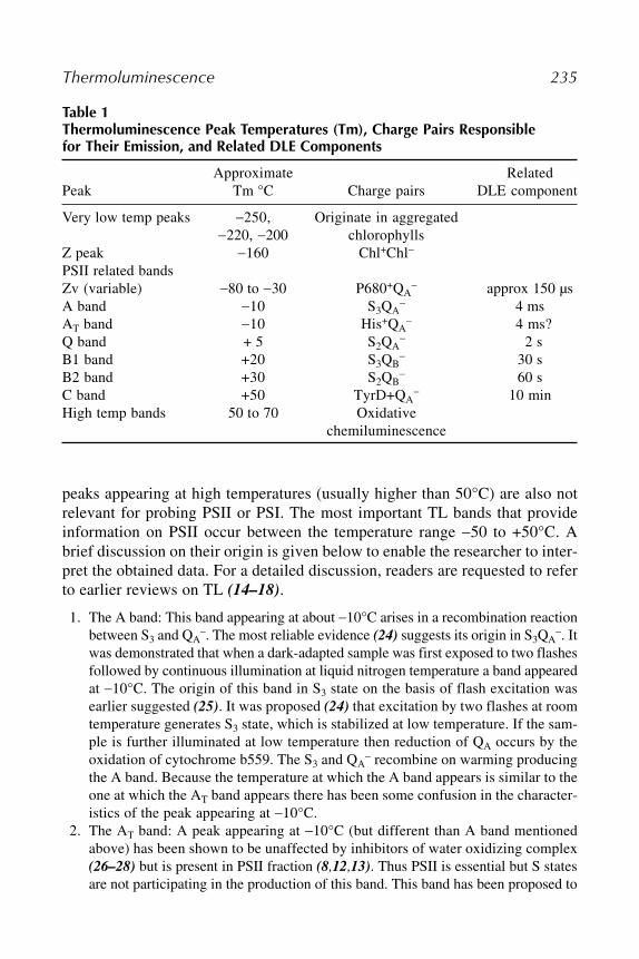
Thermoluminescence 235
peaks appearing at high temperatures (usually higher than 50°C) are also notrelevant for probing PSII or PSI. The most important TL bands that provideinformation on PSII occur between the temperature range �50 to +50°C. Abrief discussion on their origin is given below to enable the researcher to inter-pret the obtained data. For a detailed discussion, readers are requested to referto earlier reviews on TL (14–18).
1. The A band: This band appearing at about �10°C arises in a recombination reactionbetween S3 and QA
�. The most reliable evidence (24) suggests its origin in S3QA�. It
was demonstrated that when a dark-adapted sample was first exposed to two flashesfollowed by continuous illumination at liquid nitrogen temperature a band appearedat �10°C. The origin of this band in S3 state on the basis of flash excitation wasearlier suggested (25). It was proposed (24) that excitation by two flashes at roomtemperature generates S3 state, which is stabilized at low temperature. If the sam-ple is further illuminated at low temperature then reduction of QA occurs by theoxidation of cytochrome b559. The S3 and QA
� recombine on warming producingthe A band. Because the temperature at which the A band appears is similar to theone at which the AT band appears there has been some confusion in the character-istics of the peak appearing at �10°C.
2. The AT band: A peak appearing at �10°C (but different than A band mentionedabove) has been shown to be unaffected by inhibitors of water oxidizing complex(26–28) but is present in PSII fraction (8,12,13). Thus PSII is essential but S statesare not participating in the production of this band. This band has been proposed to
Table 1Thermoluminescence Peak Temperatures (Tm), Charge Pairs Responsiblefor Their Emission, and Related DLE Components
Approximate RelatedPeak Tm °C Charge pairs DLE component
Very low temp peaks �250, Originate in aggregated�220, �200 chlorophylls
Z peak �160 Chl+Chl�
PSII related bandsZv (variable) �80 to �30 P680+QA
� approx 150 µsA band �10 S3QA
� 4 msAT band �10 His+QA
� 4 ms?Q band + 5 S2QA
� 2 sB1 band +20 S3QB
� 30 sB2 band +30 S2QB
� 60 sC band +50 TyrD+QA
� 10 minHigh temp bands 50 to 70 Oxidative
chemiluminescence

236 Sane
arise in His+ of the PSII reaction center protein and QA� (29). Using site-directed
mutagenesis of the histidine on the donor side of PSII D1 polypeptide, it was dem-onstrated (30) that the emission of the AT band is affected by substitution of His195 and His 190 in Chlamydomonas.
3. The Q band: This is a well-characterized band that appears/intensified in DCMUtreated chloroplasts/leaf discs/algal cells (7,8,11,13). It was demonstrated (11)
that the appearance of this peak is accompanied by the decrease in the fluorescenceyield showing that the oxidation of QA
� is associated with its appearance. This peakappears if DCMU-treated chloroplasts are exposed to a single flash at �15°C (31).Its appearance requires functional water oxidizing complex since the peak wassensitive to heat treatment (12) and it was lost in Tris-HCl treated or tetranitro-methane treated chloroplasts (32). Its origin in S2QA
� recombination is thus clear.This is an important peak as its Tm reflects on the redox characteristics of QA (22).There are several references relating to this peak in the literature.
4. The B bands: The most studied band in photosynthetic TL is the B band. Earlierstudies using continuous light had shown that the B band appearing around 30°Cis lost by the addition of DCMU (5,7,11,13). The B band is absent if the oxygenevolving complex is either absent or inhibited (27,28,33) suggesting that it isrelated to the S states. The flash data indicated that it oscillates with a period offour (21,34). Because the flash-induced TL maximum appeared at second and sixthflash it was logical to conclude that S3 state may be responsible. However, B bandalso appears if a relaxed sample is excited by a single flash. Thus, the B band wassuggested to result from the S2/S3 state. Because the peak was sensitive to DCMU,the negative charge appeared to be coming from QB
�. A number of observationshave confirmed the involvement of QB
� in the appearance of this peak (15,17,18).Earlier, most workers considered the origin of the B band in S2/S3QB
� recombina-tion. However, it is now clear that there are two separate bands one arising inS2QB
� and another appearing at a lower temperature (by about 10–15°C) than theS2QB
� band and is the result of the S3QB� recombination. In leaves of different
species, we (unpublished data) see clearly S2QB� band by exciting the dark relaxed
sample with one flash and a combination of two peaks after two flashes originatingin S2QB
� and S3QB�, both fully sensitive to DCMU. The S3QB
� recombination hasbeen shown to emit 1.7- to 2-fold higher intensity than S2QB
� recombination (35,36).5. The C band: A band that appears at around 50°C was reported in earlier studies
(7,11). It is enhanced by DCMU (11,13) and oscillates with flash excitation givingmaximum in the S0 and S1 state (37). These observations suggest that the negativecharge may come from QA
� while the positive charge may reside on some donorcomponent of PSII. The earlier suggestion (37) that S0/S1 states may be involvedcould not be confirmed. It has been suggested that the positive equivalents locatedon YD+ (the tyrosine of D2 polypeptide) may recombine with QA
� to yield thisband (38–40). This band was shown to be preferentially excited by far red (740nm) light and enriched in a PSI fraction (12).
More recently, the band appearing at 45–50°C that shows oscillations and canalso be enhanced by far-red light has been suggested to originate in PSII centers

Thermoluminescence 237
that were initially in S2/S3QB oxidation state. During warming, the QB in thesecenters may become reduced by reversed electron flow or reduction of PQ poolvia an NADPH/PQ oxidoreductase (41,42). In addition, it was suggested that theintensity of this band may reflect the energy status of chloroplasts.
6. The Zv band. This band is designated as Zv band because its emission tempera-ture varies between �80 and �30°C depending on the temperature of excitation(13). A mechanism suggesting that the Zv band arises from charging of Z bandand A band was proposed (43). The charge pair responsible for its origin has beensuggested to be P680+QA
� (44,45). Using PSII reaction center preparations theband has been assigned to oxidized tyrosine and reduced plastoquinoine (46).
The peak temperatures are indicative of a given recombination reaction. How-ever the temperature maximum may vary considerably depending upon the condi-tions of growth, excitation stress, abiotic stresses, increase or decrease of energeticpotential (NADPH + ATP), for example. In wild type Synechosystis sp PCC 6803grown at 30°C, S2QB
� was observed at 24–26°C while the S2QA� was at 16–18°C
(47). In its mutants psbV and psbU the S2QB� appeared at 30–32°C and S2QA
� at16–18°C. For the same Synechosystis sp PCC 6803 grown also at 30°C the S2QB-was reported at 36°C (48) although in its NDFS mutant it appeared at 28°C. InSynechococcus grown at 36°C, S2QB
� was at 37°C while the same peak appearedat 30°C when the organism was shifted to 25°C that induces exchange of D1/1 byD1/2 (22). Therefore, it is necessary to ascertain the charge pair that a peak representsby some other way. Routinely, the effect of DCMU, the peak position with a sin-gle flash and two flashes are studied for those peaks that relate to S2QB
�/S3QB�/
S2QA� peaks. Although for the low temperature �10°C band it will be necessary to
ascertain whether the band observed is A band (S3QA�) or AT band (His+QA
�) byinactivating the water oxidizing complex using tetranitromethane or Tris-HCl orheat treatment if one is dealing with a suspension of cells or thylakoid/chloroplastpreparation.
4.2. Origin of Thermoluminescence
In semiconductors the TL has been well characterized and its origin hasbeen demonstrated to be in a recombination of a free hole and a free electrongenerated during irradiation of the sample by electromagnetic radiation. Ini-tially, this mechanism was proposed to be responsible for TL in photosyntheticmembranes (49). However, soon it was realized that in oxygen evolving pho-tosynthetic membranes the charges responsible for TL arose within PSII (5).
The observation that glow curves consisted of several peaks had alreadysuggested that different charge pairs were involved in generating different glowpeaks. The observations (34) that the major TL bands exhibited period fouroscillations provided strong evidence for the participation and specific identifi-cation of S states of the water oxidizing complex for providing positive chargesfor the recombination reaction resulting in TL. The earlier studies (11,12)

238 Sane
showing loss of most of the TL bands when S states were destroyed by Tris-HCl washing or by tetranitromethane had indicated the requirement of the func-tional water oxidizing complex for generating TL bands. The use of flashes ininducing specific TL bands has proven to be valuable in application of TL inprobing PSII reactions.
Although the generation of positive charges by the water-oxidizing com-plex identified the S states primarily S2 and S3 in TL, the use of inhibitors onthe acceptor side identified the components providing the negative charges forrecombining with the positive charges. It was already evident from DCMUstudies (7) that the acceptor side was involved in TL. Desai et al. (11) providedthe first evidence for linking TL to the oxidation of the fluorescence quencher(now identified as QA). They showed that the decrease in fluorescence yieldcoincided with the appearance of one of the TL peaks (Q-band). It is now wellestablished that the major TL bands appearing between �10°C and +50°C areassociated with the recombination of QA
� and QB� with the S2 and S3 states of
the water oxidizing complex. There are other recombinations involving otherdonors and quinone acceptors (QA/QB) of PSII that also yield TL peaks asmentioned earlier.
The light emitted as TL has characteristics similar to the chlorophyll fluo-rescence. Therefore, it was clear that the final step leading to TL must be theexcitation of chlorophyll to its singlet state. Those peaks that arise in isolatedchlorophylls (Z band, low temperature bands and the high temperature bands)probably originate in Chl+Chl� recombination. Those peaks that require acharge separation in PSII (the Zv, A, AT, Q, B, and C bands) originate as aresult of final recombination of P680+Ph� (P680 is the reaction center chloro-phyll of PSII and Ph is the pheophytin, the primary electron acceptor of PSII)leading to the formation of singlet excited P680. This singlet excited P680could emit light as TL or the recombination could excite a singlet in the coupledantenna chlorophyll that will emit light with the characteristics of chlorophyllfluorescence. The illumination of photosynthetic membranes results in chargeseparation (P680+Ph�) that is quickly stabilized by the oxidation of donor D toD+ and the reduction of acceptor A to A�. In PSII, the donor to P680 is tyrosine161 of D1 polypeptide, which reduces P680 and extracts an electron from water-oxidizing complex generating the higher oxidized S state in the process. Theacceptor in PSII is QA (the bound quinone) that oxidizes Ph� and is reduced toQA
�. It immediately reduces the mobile quinone QB unless the electron trans-port between QA and QB has been blocked. Thus on the acceptor side QA
� andor QB
� is generated. The formation of D+A� charge pair is accompanied by theloss of energy (the stabilization energy) and its recombination is preventedbecause of the barrier of the activation energy. Further lowering the tempera-ture of the sample prevents the recombination of D+A�. This stabilized charge

Thermoluminescence 239
pair (positively charged S states and the negatively charged quinone accep-tors) recombines when the temperature of the sample is raised during the warm-ing of the sample for TL measurement. The D+A� recombination occurs througha series of back reactions finally resulting in the generation of P680+Ph�. Therecombination of this radical pair has sufficient energy to generate an excitedsinglet of chlorophyll.
The increase in the temperature of a given TL peak indicates that the activa-tion energy needed to permit recombination is more. Conversely the decreasein the peak temperature indicates that the activation energy needed for therecombination has been lowered. As a rule of thumb the increase or decreasein peak temperature is related to the change in the redox potential of the pos-itively or negatively charged species. Thus if a given treatment causes a shift inthe peak temperature it is possible to conclude that the treatment has changedthe redox potential of either the acceptor or the donor species. Although theredox potential per se of the donor or acceptor cannot be calculated from theglow curve, it is possible to calculate the free energy of detrapping. From thisone can infer about the extent of a change in the redox potentials of the donorand acceptor species.
The fact that important TL bands that reflect on the functional aspect of PSIIoriginate in a recombination of positively charged donors (S states) and nega-tively charged acceptors QA
� and QB� allows one to explain the oscillatory
behavior of TL bands and prediction of luminescence pattern on flash excita-tion. Each flash generating P680+Ph� causes oxidation of the Mn cluster of wateroxidation complex. Thus beginning with S0 the flash excitation in sequenceconverts S0 to S1, S2, S3 and S4 depositing one positive charge through removalof an electron. However, simultaneously there is a release of proton in a 1,0,1,2pattern. Thus, when S0 is converted to S1, a proton along with an electron islost resulting in no net positive charge on S1. The conversion of S1 to S2 with aloss of an electron is not accompanied by a loss of a proton and hence S2 carriesa net positive charge. The conversion of S2 to S3 through a loss of an electronis accompanied by a loss of a proton. Thus, S3 retains a positive charge. The S3
to S4 conversion through a loss of an electron is accompanied by a loss of twoprotons. The S4 is not stable and quickly returns to S0 through the evolution ofoxygen from water. Thus, the only positively charged S states are S2 and S3
and predictably they recombine with the negatively charged quinone acceptorsQA
� and QB�.
Just as donor is oxidized by light induced charge separation P680+Ph- theacceptor side is reduced. Ph� is stabilized by reduction of QA to QA
�. HoweverQA
� immediately reduces QB to QB� depositing a negative charge on QB. If QB
was already in a reduced state then QB� will be converted to QB
2�. It will beimmediately protonated and replaced by another PQ (plastoquinone) molecule.

240 Sane
Thus, depending on the proportion of QB to QB� flash excitation will produce
positively charged S2/S3 and negatively charged QB�. Inoue (17) has explained
the flash induced S2/S3QB� band by assuming different initial distribution of
S0/S1 and QB/QB�. The details are presented as notes at the end of the chapter.
5. Relationship Between TL and DLEAs mentioned earlier, the discovery of TL had its origin in the observa-
tion of delayed luminescence from chloroplasts (2). Shuvalov and Litvin (6)
attempted to establish the relationship of different phases of delayed fluores-cence with different TL bands. Flash studies had shown that both TL and DLEundergo oscillations. The identification of specific charge pairs namely S2/S3QB
�
and S2/S3QA� responsible for different TL bands and the estimated half life of
each of the TL band at 25°C running into seconds (9,50,51) suggested thatdifferent components of DLE may be related to different TL bands.
Subsequently, it was demonstrated that delayed fluorescence in fact mimicsTL and that the two are interconvertible (52). This suggested a common originof TL and DLE. Subsequent work (53,54) provided additional support for therelation between TL and DLE. Using different inhibitors of PSII electron trans-port that affect both TL and DLE, a correlation between each of the componentof DLE with TL bands was established (55). It must be realized that some com-ponents of DLE may not have any relation with the TL bands as they may arisein temperature independent processes (18). The temperature jump experimentsthat show induced DLE by quickly raising the temperature of pre-illuminatedsamples also establish the correlation between DLE and TL (56–58).
The advantage of measuring TL over DLE under some situations is that thecomponents of DLE are better resolved using TL as each separate peak corre-sponds with one or the other component of DLE.
6. Application in PSII ResearchThe noninvasive TL technique has found several applications in probing
PSII. Because it monitors recombinations in charge pairs involving stable oxi-dized S states and reduced QA and QB, the technique has a potential to detectstructural changes in both the donor and acceptor side of PSII. The change inglow peak temperature reflects the changes in redox characteristics of QA andQB on the one hand and the S2 and S3 states on the other. Therefore it permitsdetection of subtle changes in the electron transport within PSII, stability of Sstates, and perturbation in the rate constants, for examples. A list of some ofthese with one or two relevant references is given below:
1. Effect of herbicides that block electron transport between QA and QB (59).2. Study of herbicide resistance (60).

Thermoluminescence 241
3. Site-directed mutations in D1 and D2 relating to donor and acceptor side (61,62).4. Study of transitions/stability/deactivation of S states (21,63,64).5. Bicarbonate effects on PSII (65,66).
6. Effects of removal and addition of extrinsic proteins on PSII preparations (67).7. Effects of Ca and Cl depletion on PSII (68,69).8. Light and temperature stress (22).9. Seasonal changes in the activity/activation of PSII (70).
10. Acclimation (71).11. Characterization of PSII reaction center (72).12. Role of lipids for structural stability of QB (73).13. Changes in energetic potential (NADPH + ATP) in plants (42) and metabolic state
of leaf (41).
7. Concluding RemarksThe technique of TL is rather simple, cheap, easy and yet it monitors in vivo
changes in redox characteristics of the donors (S states) and acceptors (QA andQB) that reflect on the changes in their structural environment. It has thereforefound increasing usefulness in several areas of PSII research. Although onecan calculate activation energies (not discussed in this chapter) from the glowcurves (51,74) it is not possible to calculate directly the redox potentials.
8. Notes
8.1. Identification of Precise Charge Pairs
The most useful charge pairs yielding valuable information on the function-ing of PSII are S3QA
�, S2QA�, S3QB
� and S2QB�. For the luminescence to occur
it is necessary that the donor species have a positive charge while the acceptorspecies must have the negative charge. Among the S states only S2 and S3 statesare the positively charged stable S states based on the proton release pattern of1, 0, 1, 2. Thus although each flash extracts one electron from the S state, theproton release pattern results in positive charge only on S2 and S3. It is possibleto predict luminescence involving S2QB
� and S3QB� recombinations on the
basis of flash induced redox reactions within PSII. Inoue (17) has provided adetailed discussion of the same.
When the photosynthetic membranes/cells/leaf tissue/chloroplasts arerelaxed in the dark for a long time, TL is not observed. Under such a dark-adapted state the only S states observed are S0 and S1. The S2 and S3 states aredeactivated in the dark to S0 and S1 states. The proportion of S0 : S1 is approx-imately 25 / 75. The proportion of QB
� : QB under similar conditions is also25 / 75. Thus in the dark-adapted sample we have the following distribution ofnon-luminescent combination of charge pairs.
242 Sane
S0QB : S0QB� : S1QB : S1QB
� (S0 : S1 = 2 : 6 and QB� : QB = 2 : 6)
1/1/5/1
A short duration intense flash will convert the distribution of the above tothe following
S1QB� : S1QB : S2QB
� : S2QB
1/1/5/1
Out of these, only S2QB� is luminescent yielding five units of TL intensity.
However if the dark relaxed sample was exposed to two successive shortduration flashes the distribution of charge pairs would be as follows
S2QB : S2QB� : S3QB : S3QB
�
1/1/5/1
Out of these, S2QB� and S3QB
� would be luminescent and hence would yieldtwo units of TL intensity. However actual intensity observed from S3QB
� isapprox 1.7-to 2-fold higher than S2QB
�. Thus we should get one unit of TLfrom S2QB
� and about 1.7 units of TL from S3QB� yielding a total intensity of
about 2.7 units or almost half that one gets after one flash.If the dark relaxed sample is exposed to three successive short duration
flashes the distribution of the charge pairs will be
S3QB� : S3QB : S0QB
� : S0QB
1/1/5/1
Only S3QB� will yield luminescence equivalent to about 1.7 unit of TL
intensity.If the dark relaxed sample was exposed to four successive short duration
flashes the distribution of charge pairs will be identical to what existed in thedark. Thus there will be no luminescence after four flashes.
These theoretical predictions have been observed (17) but are not seen allthe time since misses and double hits do occur and the distribution of QB toQB
� could also be different in different samples. The predicted luminescenceis a good guide and indicates:
1. To see primarily the S2QB� peak, expose the dark relaxed sample to only one flash.
2. To see only S3QB� peak expose the relaxed sample to three flashes.
3. Exposure to two flashes will yield luminescence from both S2QB� and S3QB
�.These two peaks can be easily separated by deconvolution. A single flash providesa major S2QB
� band with little contamination from S3QB� while two flashes yield
a peak of S3QB� with a shoulder of S2QB
� appearing at a slightly higher tempera-ture (unpublished data).

Thermoluminescence 243
The predicted distribution of S2/S3QB� depends upon how well relaxed the
sample is in the dark. If the sample is a thylakoid preparation and has beendark adapted for a short period then the distribution of the S states and QB
� : QB
has been observed to be S0 : S1 = 25 / 75 but QB� : QB is 50 / 50. Thus the briefly
dark adapted sample will have the following distribution
S0QB : S0QB� : S1QB : S1QB
�
1/1/3/3
None of the above charge pairs are luminescent. One can predict the distri-bution of charge pairs on exposure to 1, 2, 3, and 4 short duration flashes. Thedistribution will be as follows:
S0QB : S0QB� : S1QB : S1QB
�
1/1/3/3 No Flash (No TL)
S1QB� : S1QB : S2QB
� : S2QB
1/1/3/3 One flash (3 TL Units)
S2QB : S2QB� : S3QB : S3QB
�
1/1/3/3 Two flashes (6.1 TL Units)
S3QB� : S3QB : S0QB
� : S0QB
1/1/3/3 Three flashes (1.7 TL Units)
After four flashes the distribution of S states will be the same as existed in thedark relaxed sample. Thus in this type of sample the flash induced TL intensitywill show a peak at second, sixth, for example, flash numbers. In addition, asingle flash will yield only S2QB
� peak while the two flashes will give a majorpeak of S3QB
� with a shoulder of S2QB� appearing at a slightly higher tempera-
ture. Therefore, irrespective of the type of relaxed sample, a single flash willalways give an S2QB
� peak while the two flashes will give a mixture of bothS2QB
� and S3QB� with a higher intensity of S3QB
�.
References1. Arnold, W. A. and Sherwood, H. K. (1957) Are chloroplasts semiconductors?
Proc. Natl. Acad. Sci. USA 43, 105–114.2. Strehler, B. and Arnold, W. (1951) Light production by green plants. J. Gen. Phys-
iol. 34, 809–820.3. Tollin, G. and Calvin, M. (1957) The luminescence of chlorophyll-containing
plant material. Proc. Natl. Acad. Sci. USA 43, 895–908.4. Arnold, W. (1966) Light reaction in green plant photosynthesis: a method of study.
Science 154, 1046–1049.

244 Sane
5. Arnold, W. A. and Azzi, J. R. (1968) Chlorophyll energy levels and electron flowin photosynthesis. Proc. Natl. Acad. Sci. USA 61, 29–35.
6. Shuvalov, V. A. and Litvin, F. F. (1969) Mechanism of prolonged after-lumines-cence of plant leaves and energy storage in the photosynthetic reaction centers.Mol. Biol. 3, 59–73.
7. Rubin, A. B. and Venediktov, P. S. (1969) Storage of light energy by photosyn-thesizing organisms at low temperature. Biofizika 14, 105–109.
8. Lurie, S. and Bertsch, W. (1974) Thermoluminescence studies on photosyntheticenergy conversion. I. Evidence for three types of energy storage by photoreactionII of higher plants. Biochim. Biophys. Acta 357, 420–428.
9. Lurie, S. and Bertsch, W. (1974) Thermoluminescence studies on photosyntheticenergy conversion. II. Activation energies for three energy storage states associ-ated with photoreaction II of higher plants. Biochim. Biophys. Acta 357, 429–438.
10. Sane, P. V., Tatake, V. G., and Desai, T. S. (1974) Detection of the triplet states ofchlorophyll in vivo. FEBS Letters 45, 290–294.
11. Desai, T. S., Sane, P. V., and Tatake, V. G. (1975) Thermoluminescence studieson spinach leaves and Euglena. Photochem. Photobiol. 21, 345–350.
12. Sane, P. V., Desai, T. S., Tatake, V. G., and Govindjee (1977) On the origin ofglow peaks in Euglena cells, spinach chloroplasts and subchloroplast fragmentsenriched in system I or II. Photochem. Photobiol. 26, 33–39.
13. Ichikawa, T., Inoue, Y., and Shibata, K. (1975) Characteristics of thermolumines-cence bands in intact leaves and isolated chloroplasts in relation to the water-splitting activity in photosynthesis. Biochim. Biophys. Acta 408, 228–239.
14. Inoue, Y. and Shibata, K. (1982) Thermoluminescence from photosynthetic appa-ratus, in Photosynthesis: Energy Conversion by Plants and Bacteria (Govindjee,ed.), Academic, New York, pp. 507–533.
15. Sane, P. V. and Rutherford, A. W. (1986) Thermoluminescence from Photosyn-thetic membranes, in Light Emission by Plants and Bacteria (Govindjee, Amesz,J., and Fork, D. C., eds.), Academic, Orlando, pp. 329–360.
16. Demeter, S. and Govindjee (1989) Thermoluminescence in plants. Physiol. Plant.
75, 121–130.17. Inoue, Y. (1996) Photosynthetic Thermoluminescence as a simple probe of photo-
system II electron transport, in: Biophysical Techniques in Photosynthesis (Amesz,J. and Hoff, A. J. eds.), Kluwer Academic Publishers, Dordrecht, pp. 93–107.
18. Vass, I. and Govindjee. (1996) Thermoluminescence from the photosynthetic appa-ratus. Photosynthesis Research 48, 117–126.
19. Zeinalov, Y. and Maslenkova, L. (1996) A computerized equipment for thermolu-minescence investigations. Bulg. J. Plant Physiol. 22, 88–94.
20. Ducruet, J. M. and Miranda, T. (1992) Graphical and numerical analysis of ther-moluminescence and fluorescence F0 emission in photosynthetic material. Photo-
synth. Res. 33, 15–27.21. Inoue, Y. and Shibata, K. (1977) Oscillation of thermoluminescence at medium
low temperature. FEBS Lett. 85, 192–197.
Thermoluminescence 245
22. Sane, P. V., Ivanov, A. G., Sveshnikov, D., Huner, N. P. A., and Oquist, G. (2002)A transient exchange of the photosystem II reaction center protein D1:1 with D1:2 during low temperature stress of Synechococcus sp PCC 7942 in the light low-ers the redox potential of QB. J. Biol. Chem. 277, 32,739–32,745.
23. Noguchi, T., Inoue, Y., and Sonoike, K. (1992) Thermoluminescence emission atliquid helium temperature from photosynthetic apparatus and purified pigments.Biochim. Biophys. Acta 1141, 18–24.
24. Koike, H., Siderer, Y., Ono, T. A., and Inoue, Y. (1986) Assignment of thermolu-minescence A band to S3QA
� charge recombination: sequential stabilization of S3
and QA� by a two-step illumination at different temperatures. Biochim. Biophys.
Acta 850, 80–89.25. Inoue, Y. (1981) Charging of the A band thermoluminescence dependent on S3-
state in isolated chloroplasts. Biochim. Biophys. Acta 634, 309–320.26. Inoue, Y., Yamasita, T., Kobayashi, Y., and Shibata, K. (1977) Thermolumines-
cence changes during inactivation and reactivation of the oxygen-evolving sys-tem of isolated chloroplasts. FEBS Lett. 82, 303–306.
27. Rosza, Z. and Demeter, S. (1982) Effect of inactivation of the oxygen evolvingsystem on the thermoluminescence of isolated chloroplasts. Photochem. Photo-
biol. 36, 705–708.28. Sane, P. V., Desai, T. S., and Tatake, V. G. (1983) Characterization of glow peaks
of chloroplast membranes. Part I. - Relationship with “S” states. Ind. J. Exp. Biol.
21, 396–400.29. Ono, T. and Inoue, Y. (1991) Biochemical evidence for histidine oxidation in pho-
tosystem II depleted of the Mn-cluster for O2-evolution. FEBS Lett. 278, 183–186.30. Kramer, D. M., Roffey, R. A., Govindjee, and Sayre, R. T. (1994) The AT thermo-
luminescence band from Chlamydomonas reinhardtii and the effects of mutagen-esis of histidine residues on the donor side of the photosystem II D1 polypeptide.Biochim. Biophys. Acta 1185, 228–237.
31. Rutherford, W. A., Crofts, A. R., and Inoue, Y. (1982) Thermoluminescence as aprobe of photosystem II photochemistry; the origin of the flash-induced glowpeaks. Biochim. Biophys. Acta 682, 457–465.
32. Sane, P. V., Desai, T. S., Rane, S. S., and Tatake, V. G. (1983) Characterization ofglow peaks of chloroplast membranes. Part II—Relationship with redox compo-nents. Ind. J. Exp. Biol. 21, 401–404
33. Inoue, Y. (1976) Manganese catalyst as a possible cation carrier in thermolumi-nescence. FEBS Lett. 72, 279–282.
34. Inoue, Y. and Shibata, K. (1977) Thermoluminescence bands of chloroplasts ascharacterized by flash excitation, in Proc. Fourth Intl. Congr. On Photosynthesis
(Hall, D. O., Coombs, J., and Goodwin, T. W. eds.), The Biochemical Society,London, pp. 211–221.
35. Rutherford, W. A., Renger, G., Koike, H., and Inoue, Y. (1985) Thermolumines-cence as a probe of PSII: The redox and protonation state of the secondary accep-tor quinone and the O2 evolving enzyme. Biochim. Biophys. Acta 767, 548–556.

246 Sane
36. Demeter, S., Rosza, Z., Vass, I., and Hideg, E. (1985) Thermoluminescence studyof charge recombination in photosystem II at low temperature. II: Oscillatoryproperties of the Z and A thermoluminescence bands in chloroplasts dark-adaptedfor various time periods. Biochim. Biophys. Acta 809, 379–387.
37. Demeter, S., Vass, I., Horvath, G., and Laufer, A. (1984) Charge accumulationand recombination in photosystem II studied by thermoluminescence. II: Oscilla-tion of the C band by flash excitation. Biochim. Biophys. Acta 764, 33–39.
38. Demeter, S., Goussias, C., Bernet, G., Kovacs, L., and Petrouleas, V. (1993)Participation of the g = 1.9 and g = 1.82 EPR forms of the semi-quinone-iron com-plex, QA
�Fe2+ of photosystem II in the generation of the Q and C thermolumines-cence bands respectively. FEBS Lett. 336, 352–356.
39. Krieger, A., Weis, E., and Demeter, S. (1993) Low-pH-induced Ca2+ ion releasein the water-splitting system is accompanied by a shift in the midpoint redox poten-tial of the primary quinone acceptor QA. Biochim. Biophys. Acta 1144, 411–418.
40. Johnson, G. N., Boussac, A., and Rutherford, A. W. (1994) The origin of 40–50°C thermoluminescence bands in photosystem II. Biochim. Biophys. Acta 1184,
85–92.41. Krieger, A., Bolte, S., Dietz, K. J., and Ducruet J.-M. (1998) Thermolumines-
cence studies on the facultative crassulacean acid-metabolism plant Mesembry-
anthemum crystallinum L. Planta 205, 587–594.42. Roman, A. and Ducruet, J.-M. (2000) Evidence from leaf thermoluminescence
for a decrease of the [NADPH plus ATP] energetic potential in cold sensitive Pisum-
sativum L.varieties upon hardening at 5 degrees C. J. Plant Physiol. 157, 177–181.43. Desai, T. S., Tatake, V. G., and Sane, P. V. (1977) Characterization of the low
temperature thermoluminescence band Zv in leaf: an explanation for its variablenature. Biochim. Biophys. Acta 462, 775–780.
44. Vass, I., Chapman, D. J., and Barber, J. (1989) Thermoluminescence properties ofthe isolated photosystem II reaction center. Photosynth. Res. 22, 295–301.
45. Chapman, D. J., Vass, I., and Barber, J. (1991) Secondary electron transfer reac-tions of the isolated photosystem II reaction centre after reconstitution with plas-toquinone-9 and diacylglycerolipids. Biochim. Biophys. Acta 1057, 391–198.
46. Klevanik, A. V. (1995) Thermoluminescence during photosynthesis. 3. Isolatedreaction centers of photosystem II. Mol. Biol. 29, 382–386.
47. Shen, J. R., Qian, M., Inoue, Y., and Burnap, R. L. (1998) Functional character-ization of Synechosystis sp. PCC 6803 delta psbU and delta psbV mutants revealsimportant roles of cytochrome c-550 in cyanobacterial oxygen evolution. Bio-
chemistry 37, 1551–1558.48. Minagawa, J., Narusaka, Y., Inoue, Y., and Satoh, K. (1999) Electron transfer
between QA and QB in photosystem II is thermodynamically perturbed in photo-tolerant mutants of Synechocystis sp. PCC 6803. Biochemistry 38, 770–775.
49. Arnold, W. (1965) An electron-hole picture of photosynthesis. J. Phys. Chem. 69,
788–791.50. Vass, I., Horvath, G., Herczeg, T., and Demeter, S. (1981) Photosynthetic energy
conservation investigated by thermoluminescence. Activation energies and half-

Thermoluminescence 247
lives of thermoluminescence bands of chloroplasts determined by mathematicalresolution of glow curves. Biochim. Biophys. Acta 634, 140–152.
51. Tatake, V. G., Desai, T. S., Govindjee, and Sane, P. V. (1981) Energy storagestates of photosynthetic membranes: activation energies and life times of electronsin the trap states by thermoluminescence method. Photochem. Photobiol. 33,
243–250.52. Desai, T. S., Tatake, V. G., and Sane, P. V. (1982) A slow component of delayed
light emission as a function of temperature mimics glow peaks in photosyntheticmembranes. Evidence for identity. Biochim. Biophys. Acta 681, 383–386.
53. Rutherford, W. A., Govindjee, and Inoue, Y. (1984) Charge accumulation andphotochemistry in leaves studied by thermoluminescence and delayed light emis-sion. Proc. Natl. Acad. Sci. USA 81, 1107–1111.
54. Hideg, E. and Demeter, S. (1985) Binary oscillation of delayed luminescence:evidence for the participation of QB
� in the charge recombination. Z. Naturforsch.
40c, 827–831.55. Rane, S. S. and Sane, P. V. (1985) Characterization of glow peaks of chloroplast
membranes: Part IV: Identification of different components of delayed light andglow peaks of chloroplasts. Ind. J. Exp. Biol. 23, 370–374.
56. Mar, T. and Govindjee. (1971) Thermoluminescence in spinach chloroplasts andin Chlorella. Biochim. Biophys. Acta 226, 200–203.
57. Jursinic, P. A. and Govindjee. (1972) Thermoluminescence and temperature effectson delayed light emission (corrected for changes in quantum yield of fluores-cence) in DCMU-treated algae. Photochem. Photobiol. 15, 331–348.
58. Malkin, S. and Hardt, H. (1973) Kinetic characterization of T-jump thermolumi-nescence in isolated chloroplasts. Biochim. Biophys. Acta 305, 292–301.
59. Vass, I. and Demeter, S. (1982) Classification of photosystem II inhibitors bythermodynamic characterization of the thermoluminescence of inhibitor-treatedchloroplasts. Biochim. Biophys. Acta 682, 496–499.
60. Demeter, S., Vass, I., Hideg, E., and Sallai, A. (1985) Comparative thermolumi-nescence study of triazene-resistant and -susceptible biotypes of Erigeron canad-
ensis L. Biochim. Biophys. Acta 806, 16–24.61. Gleiter, H., Ohad, N., Hirschberg, J., Fromme, R., Renger, G., Koike, H., and
Inoue, Y. (1990) An application of thermoluminescence to herbicide studies. Z.
Naturforsch. 45c, 353–358.62. Etienne, A.-L., Ducruet, J.-M., Ajlani, G., and Vernotte, C. (1990) Comparative
studies on electron transfer in photosystem II of herbicide-resistant mutants fromdifferent organisms. Biochim. Biophys. Acta 1015, 435–440.
63. Demeter, S. and Vass, I. (1984) Charge accumulation and recombination in photo-system II studied by thermoluminescence. I: Participation of the primary acceptorQ and secondary acceptor B in the generation of thermoluminescence of chloro-plasts. Biochim. Biophys. Acta 764, 24–32.
64. Koike, H. and Inoue, Y. (1987) A low temperature sensitive intermediate statebetween S2 and S3 in photosynthetic water oxidation deduced by means of thermo-luminescence measurement. Biochim. Biophys. Acta 894, 573–577.

248 Sane
65. Sane, P. V., Govindjee, Desai, T. S., and Tatake, V. G. (1984) Characterization ofglow peaks of chloroplast membranes: Part III - Effects of bicarbonate depletionon peaks I and II associates with photosystem II. Indian J. Exp. Biol. 22, 267–269.
66. Govindjee, Nakatani, H. Y., Rutherford, A. W., and Inoue, Y. (1984) Evidencefrom thermoluminescence for bicarbonate action on the recombination reactionsinvolving the secondary quinone electron acceptor of photosystem II. Biochim.
Biophys. Acta 766, 416–423.67. Ono, T. and Inoue, Y. (1985) S-state turnover in the O2 evolving system of CaCl2-
washed photosystem II particles depleted of three peripheral proteins as measuredby thermoluminescence: removal of 33 kDa protein inhibits S3 to S4 transition.Biochim. Biophys. Acta 806, 331–340.
68. Ono, T. and Inoue, Y. (1989) Removal of Ca by pH 3.0 treatment inhibits S2 to S3
transition in photosynthetic oxygen evolution system. Biochim. Biophys. Acta 973,
443–449.69. Vass, I. and Inoue, Y. (1992) Thermoluminescence in the study of photosystem
II, in Topics in Photosynthesis. Vol II. The Photosystems: Structure, Function and
Molecular Biology (Barber, J., ed.), Elsevier, Amsterdam, pp. 259–294.70. Ivanov, A. G., Sane, P. V., Zeinalov, Y., Simidjiev, I., Huner, N. P. A., and Öquist,
G. (2002) Seasonal responses of photosynthetic electron transport in Scots pine(Pinus silvestris L.) studied by thermoluminescence. Planta 215, 457–465.
71. Zchut, S., Keren, N., Ohad, I., and Pick, U. (2003) Cold-acclimation protects photo-system II against freezing damage in the halotolerant alga Dunaliella salina. J.
Plant Physiol. 160, 185–192.72. Ramesh, V. M., Fish, A., Michaeli, D., et al. (2002) Isolation and characterization
of an oxygen evolving photosystem 2 core complex from the thermophilic cyano-bacterium Mastigocladus laminosus. Photosynthetica 40, 355–361.
73. Gombos, Z., Varkonyi, Z., Hagio, M., et al. (2002) Phosphatidylglycerol require-ment for the function of electron acceptor plastoquinone QB in the photosystem IIreaction center. Biochemistry 41, 3796–3802.
74. deVault, D. and Govindjee (1990) Photosynthetic glow peaks and their relation-ship with the free energy changes. Photosynth. Res. 24, 175–181.

Detection of Free Radicals and ROS 249
249
From: Methods in Molecular Biology, Vol. 274: Photosynthesis Research ProtocolsEdited by: R. Carpentier © Humana Press Inc., Totowa, NJ
23
Detection of Free Radicalsand Reactive Oxygen Species
Éva Hideg
SummaryIn plants, reactive oxygen species (ROS), also known as active oxygen species (AOS), are
associated with normal, physiological processes as well as with responses to adverse conditions.ROS are associated with stress in many ways; as primary elicitors, as products and propagatorsof oxidative damage, or as signal molecules initiating defense or adaptation. The photosyn-thetic electron transport is a major site of oxidative stress by visible or ultraviolet light, high orlow temperature, pollutants, or herbicides. ROS production can be presumed from detecting oxi-datively damaged lipids, proteins, or pigments as well as from the alleviating effects of addedantioxidants. On the other hand, measuring ROS by special sensor molecules provides moredirect information. This chapter focuses on the application of spin trapping electron paramagne-tic resonance (EPR) spectroscopy for detecting ROS; singlet oxygen and oxygen free radicalsin thylakoid membrane preparations.
Key Words: EPR spectroscopy; free radical; reactive oxygen species (ROS); singlet oxygen;spin trapping; thylakoid.
1. IntroductionA free radical is defined as any species containing one or more unpaired
electrons (1). Oxygen radicals are an important group among free radicals,although carbon- or sulphur-centered radicals and free radical oxides of nitro-gen are also formed in living systems. Besides oxygen-centered radicals, thegroup of reactive oxygen species (ROS) also involves nonradical forms of oxy-gen, such as singlet oxygen or hydrogen peroxide. Although the collectiveterms “reactive species,” ROS, and free radical are frequently used as syno-nyms, the groups of chemical molecules they refer to are not identical (Fig. 1).All ROS are derivatives of molecular oxygen (Fig. 2). Superoxide is formed

250 Hideg
when one electron is added to the ground-state oxygen molecule, addition ofone more electron followed by protonation results in H2O2. Further reductionsand protonations convert H2O2 into the neutral form, H2O. Singlet oxygen isalso generated from molecular oxygen, but via energy transfer. In this reac-tion, the spin restriction of ground (triplet) state oxygen is removed, so theoxidizing ability is increased (1–3).
Plants, like any other living organism, constantly produce and extinguishROS. Under natural conditions, there is usually no detectable pool of reactivespecies, because these react with other molecules shortly after being produced.Some of these reactions are harmful, leading to oxidative modification of mem-brane lipids, proteins or DNA; although others, for example the controlledcycling of electrons in the Asada-Halliwell cycle (4), or the H2O2 dependentpolymerization of phenols in lignin formation (1,5) are elements of ordinaryplant metabolism. A complex system of enzymes and other ROS scavengingmolecules keep the concentration of free radicals low, contrary to continu-ous production (5–7). This balance may be tipped under stress conditions, byincreased radical production, or by decreased antioxidant capacity. ROS pro-duction may increase as a result of imperfect electron transport, for example,
Fig. 1. Chemical classification of “reactive species”. Examples of oxygen free radi-cals: superoxide (O2
•�), hydroxyl (• OH), peroxyl (• OOR) and alkoxyl (• OR) radicals.Examples of nonradical ROS: singlet oxygen (1O2), oxone (O3), hydrogen-peroxide(H2O2), and other peroxides (ROOH). Free radicals that are not oxygen-centered arerepresented by sulphur-centered thiyl (RS •), carbon-centered methyl (• CH3) radicalsand the hydrogen atom (H •), which is the simplest free radical. Certain oxides of nitro-gen, such as NO • are also free radicals.

Detection of Free Radicals and ROS 251
in chloroplasts or in mitochondria, by electron leakage or via energy transferto oxygen. On the other hand, external sources (e.g., ozone, photosensitizers,or bipyridyl herbicides) may also induce free radical production in high concen-trations at unexpected locations, as compared to normal metabolic reactions.Scavenging these radicals may exhaust the antioxidant system, for example byoxidizing the ascorbate and glutahione pools, if these cannot be restored (re-reduced) fast enough. In addition, adverse temperature or water conditions maydecrease the activity of antioxidant enzymes, so these are unable to process theincreased load of free radicals. The photosynthetic electron transport is a majorsite of oxidative stress by visible or ultraviolet light, high or low temperature,pollutants, or herbicides (7–10).
This chapter focuses on detecting radicals under conditions, when the imbal-ance in the production and scavenging of reactive species allows specific exter-nal probes (ROS sensor molecules) to compete with the natural targets for ROS.Our examples are taken from research on ROS, singlet oxygen, and free radi-cal production in plants under stress by excess photosynthetically active radia-tion (photoinhibition). With minor adaptations, these techniques can be appliedto study other conditions, when increased production of ROS is expected.
Fig. 2. Ground state oxygen and its derivatives. Simplified illustration of electronson molecular orbits.

252 Hideg
2. Materials1. Grinding medium: Mes 50 mM, pH 7.2, 0.4 M sucrose, 15 mM NaCl, 5 mM
MgCl2, and 5 mM ascorbate.2. Resuspension buffer: potassium phosphate 50 mM, pH 7.2, 0.2 M sucrose, 15 mM
NaCl, and 5 mM MgCl2.3. DMPO (5,5-dimethyl-pyrrolin N-oxide).4. Tiron (1,2-dihydroxybenzene-3,5-disulphonate).
3. Methods
3.1. Thylakoid Membranes Isolation1. Isolate thylakoid membranes from market spinach. Wash mature and healthy leaves
in tap water, dry, and remove of midveins.2. Chop the leaves in a blender with ice cold grinding medium. Use approx120 mL
of grinding medium for 200 g of leaf and grind in short, 10- to 12-s intervals,repeated five to six times.
3. Filter the mixture through eight layers of cheesecloth and centrifuge at 7000g for15 min.
4. Resuspend the pellet in resuspension buffer to approximately one-third of origi-nal volume.
5. Centrifuge at 300g for 5 min to remove crude pellet and possible debris.6. Centrifuge the supernatant again at 7000g for 15 min, and resuspend the pellet in
the resuspension buffer to approx 1200–1500 µg Chl/mL.7. Conduct all centrifugation steps at 5–7°C, resuspend while keeping centrifuge tubes
on ice. Store thylakoid preparations in 0.3–0.5 mL volumes at �80 °C until use.8. Once thawed, keep samples on ice in the dark until use and dilute to 60–200 µg
Chl/mL using the above resuspensions buffer.9. Add ROS traps to diluted thylakoids in concentrations indicated below.
10. Once thawed, either discard surplus thylakoids or freeze again for experimentsother than ROS detection.
Experiments with samples prepared in sodium-phosphate buffer gave similarresults, but using Hepes lowered the amount of trapped ROS, although Hepeshad no influence on other parameters, such as the extent of stress induced dam-age. Photosynthetic activity of the preparations should be checked, for exampleby measuring steady-state oxygen evolution with a Clark-type oxygen elec-trode in the presence of an electron acceptor.
3.2. Spin Trapping EPR SpectroscopyElectron paramagnetic resonance (EPR), also called electron spin resonance
(ESR) spectroscopy, detects the presence of unpaired electrons, providing anexcellent technique for measuring free radicals. However, because free radi-cals are highly reactive and are usually present in small concentrations, theirdirect detection is practically impossible at room temperature, unless their radi-

Detection of Free Radicals and ROS 253
cal nature is stabilized by reacting with trapping molecules (12,13). The spinadducts produced in reactions between the free radical and the spin trap arealso radicals but are reasonably stable for biological experiments (Fig. 3.).Although singlet oxygen is not a free radical form of ROS, its reaction withspecific traps may also yield EPR detectable nitroxide radicals, therefore 1O2
detection is also discussed here. Structures of spin traps applied in this study areshown in Figs. 4–6. These chemicals are commercially available from severalcompanies.
EPR spectra of spin adducts are usually measured at room temperature, usingX-band spectrometers. In our experiments, a Bruker ECS-106 machine wasused. EPR parameters were: 9.45 GHz microwave frequency, 12 mW micro-wave power, 100 kHz modulation frequency, 0.2 mT modulation amplitude,104–105 receiver gain, depending on signal intensities and 10.2 ms time con-stant. To improve the signal : noise ratio, nine spectra were averaged.
Samples were measured in glass capillaries, at 15–20 µL volumes. Becausefunctioning plant samples are usually in the water-based preparation buffers, acritical step of EPR measurements is using as much sample as possible, butpreventing interference from the high microwave absorbance of water. Opti-mal amounts may vary with the type and quality of the spectrometer, espe-cially by its cavity.
Using an EPR flow cell allows the measurements of larger volumes than incapillaries or sample tubes, but the flow cell needs rigorous cleaning betweenchanging samples in order to avoid artifacts.
When using disposable capillaries, comparative EPR quantitation should beassured by keeping identical experimental conditions regarding both the sam-ples (volume, concentration) and sample holders (uniform tubes, the same cen-tral position in the cavity).
3.3. Applications of Spin Trapsin Photosynthetic Membrane Preparations
The following examples were taken from studies on ROS in the oxidativedamage of isolated thylakoid membranes caused by excess photosynthetically
Fig. 3. Representation of the principle of spin trapping indicating magnetic featuresand approximate lifetimes of the reagents and the product.

254 Hideg
Fig. 4. Spin trapping experiment using DMPO (50 mM) in isolated thylakoid mem-branes (100 µg/mL) exposed to 1600 µM m�2 s�1 photosynthetically active radiation.(A) structure of DMPO and the radical adduct formed upon reaction with a free radicalrepresented by R•. Depending on the chemical nature of R•, radical adducts show EPRspectra characterized with different hyperline splitting. (B) and (C) sampling strategyand typical EPR spectra. Single asterisks indicate the six lines belonging to a carbon-centered radical adduct, double asterisks identify the four lines of DMPO-OH.

Detection of Free Radicals and ROS 255
active radiation (photoinhibition) (see Note 1) (14–19). It is important to notethat results of ROS detecting experiments should always be interpreted as partof a complex study integrating as many aspects as possible, such as data on thestress-induced loss of physiological function, oxidative damage of membraneproteins, lipids or DNA, changes in antioxidant capacity, or induction of repairprocesses, for example.
In the experiment illustrated in Fig. 4, isolated thylakoid membranes (see
Note 2) were kept at constant temperature in a temperature controlled glasscuvet. Stress by photoinhibition was achieved by high-intensity (1600 µM m�2 s�1)photosynthetically active radiation using a KL-1500 (DMP, Switzerland) lamp.
Fig. 5. (A) Structure of Tiron and its superoxide radical adduct, Tiron-OOH, EPRspectrum of Tiron-OOH. (B) and (C): Spin trapping experiments using Tiron (50 mM)in isolated thylakoid membranes (100 µg/mL). Samples were exposed to 200 µM m�2
s�1 photosynthetically active radiation for 15 min either in the absence (B) or in thepresence (C) of 10 µM methyl-viologen.

256 Hideg
Samples contained 50 mM DMPO (5,5-dimethyl-pyrrolin N-oxide) (20).Because the stability of DMPO adducts in this experimental system was tooshort for the studied time range of photoinhibition (18), the spin trap was notkept in the sample through the experiment.
Nitroxide formation from DMPO was measured in short, 5- to 10-min inter-vals. DMPO was added after various periods of illumination and a sample waswithdrawn 5 or 10 min after DMPO addition for EPR measurement. Movingthis window of observation through the whole time course of the experiment,it was possible to compare ROS production during the progression of photo-inhibition. Typical examples of EPR spectra detected in the early and in thelate phase are shown in Fig. 4. The latter is a composite spectrum, composed
Fig. 6. (A) Structures of the sterically hindered amine Temp, its singlet oxygenadduct TempO and hydroxylamine TempOH, and the EPR spectrum of TempO. (B)
and (C): Spin trapping experiments using Temp (10 mM) in isolated thylakoid mem-branes (100 µg/mL). Samples were exposed to 1600 µM m�2 s�1 photosyntheticallyactive radiation for 15 min, then measured either directly (B) or after re-oxidizing ethyl-acetate-extracted TempOH into TempO (C).

Detection of Free Radicals and ROS 257
of hydroxyl and carbon-centered radical adducts of DMPO, while the formersignal mainly results from the carbon-centered radical adduct (14).
Although superoxide radicals also form characteristic adducts with DMPO,experiments with this trap can only give a straightforward answer for the involve-ment of superoxide radicals if these are the main radical species produced (21,
22). A relatively small concentration of superoxide (manifesting as a small amountof DMPO-OOH as compared to other DMPO adducts) may not be noticed ormay easily be detected as DMPO-OH (23,24). A good alternative is to use Tiron(1,2-dihydroxybenzene-3,5-disulphonate), a spin trap for detecting superoxideradicals (25,26) (see Note 3).
Figure 5 illustrates trapping superoxide radicals with Tiron in illuminatedthylakoid membranes. Isolated thylakoid membranes (100 µg Chl/mL) wereexposed to 200 µM m�2 s�1 photosynthetically active radiation in the presenceof 50 mM Tiron for 15 min. Without discussing mechanisms, we only note thatonly a small portion of superoxide is light stress-related and a similar spectrumwas observed using higher light intensities (17). The addition of 10 µM methyl-viologen markedly enhances superoxide production, as shown by the increaseof the Tiron-OOH adduct (Fig. 5).
4. Notes1. It is important to keep in mind that the added spin traps are in competition for
ROS with potential sites of oxidative damage (the natural targets of ROS) andwith any antioxidants present in the sample. In this way, failure to observe EPRsignal from spin adducts does not necessarily mean that ROS was not produced inthe sample. Similarly, when a free-radical adduct is observed, the technique doesnot tell us whether the trapped ROS is a primary elicitor or a by-product of thestudied stress reaction. In addition, all spin trapping techniques underestimate real,in situ ROS concentration, because usually only a small fraction of the producedradicals is trapped. This can be somewhat improved by adding more spin trap, butit should be kept in mind that some spin traps inhibit photosynthetic reactions athigh concentrations. In our thylakoid membrane experiments, DMPO and Tironwas tolerated up to 80–100 mM concentrations, but other spin traps, such aspyridyl-nitrones, were found to be more toxic (18). Spin adducts (as well as spintraps themselves) may be reduced by plant metabolites into molecules withoutEPR activity. This can be checked by generating spin adducts chemically (i.e.,without the biological sample) and comparing EPR signals in the absence and inthe presence of untreated samples. In such experiments, dilution effects createdduring adding the sample should be taken account. Nitroxides, especially six-membered heterocyclic radicals, such as TempO, the singlet oxygen adduct ofTemp (2,2,6,6-tetramethylpiperidine) (27), are sensitive to reducing agents (28),which convert the radical to a labile diamagnetic N-hydroxylamine (TempOH,Fig. 6A). The experiments illustrated in Fig. 6B,C were carried out similarly toabove ones with DMPO, but using 10 mM Temp. When Temp containing samples

258 Hideg
of photoinhibited thylakoids were measured directly, there was hardly any TempOsignal (Fig. 6B). However, when the sample was extracted into an organic solvent,it was possible to restore the nitroxide radical (Fig. 6C). To achieve this, photo-inhibited samples were mixed with ethylacetate (1/2 V/V) and allowed to separateinto two phases for a few minutes. The upper, organic phase (containing the reducedamine, but no photosynthetically active thylakoids) was removed and reoxidizedwith a catalytic amount (10–30 µg) of PbO2 before EPR spectroscopy.
2. Thylakoid preparations are good models for studying a number of photosyntheticreactions, but they are less complex than leaves. In addition, many in vivo stress-response reactions occur on different time scales than the possibilities of thyla-koid experiments. In this way, a direct extension of spin trapping experiments isnot possible, because neither spin traps nor spin adducts endure long enough toreport free radical production in leaves during environmental stress experimentslasting for days. Although clearly not a substitute for in vivo monitoring, studieson leaf extracts may prove useful. In these studies, whole plants or detached leaveswere exposed to stress conditions as long as necessary, and then frozen in liquidN2. Frozen leaf powders were ground in a mortar with a phosphate buffer contain-ing the ROS trap, then filtered and measured similarly to thylakoid samples. Inthese experiments, quick sample processing is essential, so only a small amountof leaves is used. The time between leaf harvesting and EPR measurement shouldnot only be as short as possible, but also uniform for all samples. When evaluatingresults of these “post-in vivo” experiments it is important to keep in mind that,although samples were collected immediately after the cessation of stress, but as aresult of the time delay caused by sample processing, the trapped radicals are notprimary products. In this way, the technique is not suitable for qualitative analysisof the ROS produced during the stress, but rather as a characterization of the anti-oxidant–pro-oxidant status of the stressed leaf (29,30).
3. Direct detection of reactive species with spin trapping is still a dynamically expand-ing field of biology. Although medical applications are dominant, the technique isgaining more recognition in plant studies. Extensive research is being carried outin several laboratories to develop improved spin traps with higher adduct stabilityand specificity. A few examples of spin traps, which may prove more versatile thanthe traps listed in this chapter are: pyridyl- (31), adamantyl-pyridyl- (32), glyco-sylated (33), or phosphorylated (34) nitrones. An alternative to EPR spectroscopyis detecting ROS with double sensors, which utilize the principle of spin trapping,but their conversion to nitroxide radical can also be monitored as fluorescence quench-ing (35–37) fluorescent sensors.
References1. Halliwell, B. and Gutteridge, J. M. (1998) Free Radicals in Biology and Medicine.
Oxford University Inc., New York.2. Cadenas, E. (1989) Biochemistry of oxygen toxicity. Annu. Rev. Biochem. 58,
79–110.3. Elstner, E. F. (1987) Metabolism of activated oxygen species, in The Biochemis-
try of Plants (Davies, D. D., ed.), Academic Press, San Diego, pp. 253–315.

Detection of Free Radicals and ROS 259
4. Asada, K. (1999) The water-water cycle in chloroplasts: scavenging of active oxy-gens and dissipation of excess photons. Annu. Rev. Plant Physiol. Plant Mol. Biol.
50, 601–639.5. Asada, K. (1994) Production and action of active oxygen species in photosyn-
thetic tissues, in Causes of Photooxidative Stress and Amelioration of Defence
Systems in Plants (Foyer, Ch. F. and Mullineaux, P. M., eds.), CRC Press, BocaRaton FL, pp. 77–104.
6. Smirnoff, N. (1995) Antioxidant systems and plant response to the environment,in Environment and Plant Metabolism (Smirnoff, N., ed.), Bios Scientific Pub-lishers Ltd. Oxford, pp. 218–244.
7. Allen, R. D. (1995) Dissection of oxidative stress tolerance using transgenic plants.Plant Physiol. 107, 1049–1054.
8. Aro, E.-M., Virgin, I., and Andersson, B. (1993) Photoinhibition of Photosystem II.Inactivation, protein damage and turnover. Biochim. Biophys. Acta 1143, 113–134.
9. Foyer, Ch. H., Lelandais, M., and Kunert, K. J. (1994) Photooxidative stress inplants. Physiol. Plant. 92, 696–717.
10. Vass, I. (1997) Adverse effects of UV-B light on the structure and function of thephotosynthetic apparatus, in Handbook of Photosynthesis (Pessarakli, M., ed.),Marcel Dekker, New York, pp. 931–949.
11. Krause, G. H. (1994) The role of oxygen in photoinhibition of photosynthesis, inCauses of Photooxidative Stress and Amelioration of Defence Systems in Plants
(Foyer, Ch. F. and Mullineaux, P. M., eds.), CRC Press, Boca Raton, FL, pp. 43–76.12. Evans, C. A. (1979) Spin trapping. Aldrichim Acta 12, 23–29.13. Janzen, E. G. (1980) Critical review of spin trapping in biological systems, in Free
Radicals in Biology, Vol IV (Pryor, W. A., ed.), Academic, New York, pp. 115–154.14. Hideg, É., Spetea, C., and Vass, I. (1994) Singlet oxygen and free radical produc-
tion during acceptor and donor side induced photoinhibition. Studies with spintrapping EPR spectroscopy. Biochim. Biophys. Acta 1186, 143–152.
15. Hideg, É., Spetea, C., and Vass, I. (1994) Singlet oxygen production in thylakoidmembranes during photoinhibition as detected by EPR spectroscopy. Photosynth.
Res. 39, 191–199.16. Hideg, É. and Vass, I. (1995) Singlet oxygen is not produced in photosystem I
under photoinhibitory conditions. Photochem. Photobiol. 62, 949–952.17. Hideg, É., Spetea, C., and Vass, I. (1995) Superoxide radicals are not the main
promoters of acceptor side induced photoinhibitory damage in spinach thylakoids.Photosynth. Res. 46, 399–407.
18. Hideg, É., Takátsy, A., Sár, P. C., Vass, I., and Hideg, K. (1999) Utilizing newadamantyl spin traps in studying UV-B-induced oxidative damage of photosys-tem II. J. Photochem. Photobiol. B: Biol. 48, 174–179.
19. Hideg, É. (1997) Free radical production in photosynthesis under stress condi-tions, in Handbook of Photosynthesis (Pessarakli, M., ed.), Marcel Dekker, NewYork, pp. 911–930.
20. Janzen, E. G. and I-Ping Liu, J. (1973) Radical addition reactions of 5,5-dimethyl-1-pyrroline-1-oxide. ESR spin trapping with a cyclic nitrone. J. Magn. Reson. 9, 510–512.

260 Hideg
21. Hiramatsu, M. and Kohno, M. (1987) Determination of superoxide dismutase activ-ity by electron spin resonance spectroscopy using the spin trap method. JEOL News
23A, 6–9.22. Buettner, G. R. and Mason, R. P. (1990) Spin-trapping methods for detecting
superoxide and hydroxyl free radicals in vitro and in vivo, in Methods in Enzy-
mology (Packer, L. and Glazer, A. N., eds.), Academic, San Diego, pp. 127–133.23. Finkelstein, E., Rosen, G. M., and Rauckman, E. J. (1979) Spin trapping of super-
oxide. Mol. Pharmacol. 16, 676–685.24. Finkelstein, E., Rosen, G. M., and Rauckman, E. J. (1980) Spin trapping. Kinetics
of the reaction of superoxide and hydroxyl radicals with nitrones. J. Amer. Chem.
Soc. 102, 4994–4999.25. Greenstock, C. L. and Miller, R. W. (1975) The oxidation of Tiron by superoxide
anion. Kinetics of the reaction in aqueous solutions and chloroplasts. Biochim.
Biophys. Acta 396, 11–16.26. Miller, R. W. and MacDowall, F. D. H. (1975) The Tiron free radical as a sensitive
indicator of chloroplastic photoautooxidation. Biochim. Biophys. Acta 387, 176–187.27. Lion, Y., Delmelle, M., and van de Vorst, A. (1976) New method of detecting
singlet oxygen production. Nature 263, 442–443.28. Couet, W. R., Brash, R. C., and Tozer, T. N. (1985) Factors affecting nitroxide reduc-
tion in ascorbate solution and tissue homogenates. Magn. Res. Imaging 3, 83–87.29. Hideg, É. and Björn, L. O. (1996) Ultraweak light emission, free radicals and
chilling sensitivity. Physiol. Plant. 98, 223–228.30. Hideg, É. and Vass, I. (1996) UV-B induced free radical production in plant leaves
and isolated thylakoid membranes. Plant Sci. 115, 251–260.31. Janzen, E. G., Dudley, R. L., and Shetty, R. V. (1979) Synthesis and electron
spin resonance chemistry of nitronyl labels for spin trapping. �-phenyl N-[5-(5-methyl-2,2-dialkyl-1,3-dioxanyl)] nitrones and �-(N-alkyl-pyridinium) N-(tert-butyl) nitrones. J. Am. Chem. Soc. 101, 243–245.
32. Sár, P. C., Hideg, É., Vass, I., and Hideg, K. (1998) Synthesis of �-aryl N-ada-mant-1-yl nitrones and using them for spin trapping of hydroxyl radicals. Bioorg.
Med. Chem. Lett. 8, 379–384.33. Ouari, O., Chalier, F., Bonaly, R., Pucci, B., and Tordo, P. (1998) Synthesis and
spin-trapping behaviour of glycosylated nitrones. J. Chem. Soc. Perkin. Trans. 2,
2299–2307.34. Frejaville, C., Karoui, H., Tuccio, B., et al. (1995) 5-(Diethoxyphosphoryl)-5-
methyl-1-pyrroline N-oxide: a new efficient phosphorylated nitrone for the in vitroand in vivo spin trapping of oxygen-centered radicals. J. Med. Chem. 38, 258–265.
35. Kálai, T., Hideg, É., Vass, I., and Hideg, K. (1998) Double (fluorescent and spin)sensors for detection of reactive oxygen species in the thylakoid membrane. Free.
Rad. Biol. Med. 24, 649–652.36. Hideg, É., Vass, I., Kálai, T., and Hideg, K. (2000) Singlet oxygen detection with
sterically hindered amine derivatives in plants under light stress. Meth. Enzymol.
319, 77–85.37. Bilski, P., Hideg, K., Kálai, T., Bilska, M. A., and Chignell, C. F. (2003) Interac-
tion of singlet molecular oxygen with double fluorescent and spin sensors. Free.
Rad. Biol. Med. 34, 489–495.
Stabilization of Photosynthetic Materials 261
261
From: Methods in Molecular Biology, Vol. 274: Photosynthesis Research ProtocolsEdited by: R. Carpentier © Humana Press Inc., Totowa, NJ
24
Stabilization of Photosynthetic Materials
Régis Rouillon, Pierre Euzet, and Robert Carpentier
SummaryIsolated photosynthetic materials have a relatively short active lifetime that limits their effec-
tive use. To circumvent this limitation, various immobilization techniques have been designed to
improve their stability both under storage and working conditions. The immobilization methods
are identified either as chemical or physical methods. In this chapter, two immobilization methods
frequently used are described; a physical method based on the entrapment of photosynthetic
materials in photo-crosslinkable poly(vinylalcohol) polymer bearing styrylpyridinium groups
(PVA-SbQ) and a chemical method where the photosynthetic materials are immobilized by co-
reticulation in an albumin-glutaraldehyde crosslinked matrix (BSA-Glu). Different immobiliza-
tion procedures in relation with various photosynthetic materials are mentioned.
Key Words: Bovine serum albumin (BSA); chloroplast; cyanobacteria; glutaraldehyde; immo-
bilization; photosynthetic; polyvinylalcohol; photosystem (PS) I; photosystem (PS) II; stabili-
zation; thylakoid membrane.
1. IntroductionIn thylakoid membranes, light energy is transduced into chemical energy.
At this level, light is absorbed by the photosynthetic pigments imbedded in
chlorophyll–protein complexes and its energy is transferred to the reaction
centers of photosystem (PS) I and II, where a charge separation takes place.
During this process, water molecules are cleaved and negatively charged species
are formed. These properties confer to thylakoid membranes a great potential
for various biotechnological applications. However, the isolated photosynthetic
materials have a relatively short active lifetime, which limits their effective use.
To circumvent this limitation, various immobilization techniques have been
developed to improve the stability of photosynthetic materials both under storage
and working conditions. The immobilization methods (Table 1) are identified

262 Rouillon, Euzet, and Carpentier
either as chemical or physical methods, depending on whether covalent bonds
are established or not (1).
In this chapter, two immobilization methods frequently used are described;
a physical one based on the entrapment of photosynthetic materials in photo-
crosslinkable poly(vinylalcohol) polymer bearing styrylpyridinium groups (PVA-
SbQ) (2–7) and a chemical one where the photosynthetic materials are immo-
bilized by co-reticulation in an albumin-glutaraldehyde cross-linked matrix (BSA-
Glu) (6,8–12). Different immobilization procedures are mentioned.
In the PVA-SbQ method (Fig. 1), the biological material is stabilized without
chemical bonding but is confined into a network established by the polymer-
ized PVA-SbQ. In the BSA-Glu method, the glutaraldehyde builds a network
of covalent bondings with the free NH2 groups of photosynthetic membrane pro-
teins and albumin. The role of albumin is mainly to protect the photosynthetic
material against too many bondings so that an adequate biological function is
retained.
In comparison to other immobilization methods, the use of PVA-SbQ or
BSA-Glu allows a better preservation of the photosynthetic activity. After a
Table 1Main Physical and Chemical MethodsUsed to Stabilize the Photosynthetic Materials
Physical Chemical
Adsorption Covalent coupling
• DEAE cellulose Reticulation
• paper filter disk • glutaraldehyde
• fiber glass filter disk Coreticulation: glutaraldehyde
• alumina filter disk different proteins
Gel entrapment • gelatin
polysaccharide gel • collagen
• agar • bovine serum albumin
• alginate
• carrageenan
• agarose
synthetical gel
• polyacrylamide
• polyurethane
• hydroxyethyl-acrylate
• poly(vinylalcohol)
• poly(vinyalcohol) bearing
styrylpyridinum groups

Stabilization of Photosynthetic Materials 263
storage of 90 d at 4°C in the dark and in dry state, a mixture of chloroplasts and
thylakoid membranes entrapped in PVA-SbQ polymers retains 20% of the ini-
tial activity (measurements of oxygen production). The same mixture stored at
�18°C shows 20% activity after a 427-d storage (2). After immobilization in
BSA-Glu, thylakoid membranes maintained in the dark at 4°C remain stable
about 200h. After 1000-h storage, the photosynthetic activity was near 40% of
initial activity (8).
Various immobilized materials were often used in phytotoxicity tests to detect
chemicals that interact with the process of photosynthesis. Despite the largely
differing mode of immobilization, the procedures led to strikingly similar detec-
tion capabilities for the herbicides tested (6).
2. Materials
2.1. Immobilization Procedures in PVA-SbQ1. Immobilization buffer: 25 mM MOPS-NaOH, pH 7.9, containing 300 mM man-
nitol, 2 mM ethylenediamine tetraacetic acid (EDTA), 1% (w/v) bovine serum
albumin (BSA) for mixtures of chloroplasts and thylakoid membranes or straight
Fig. 1. Structure of PVA-SbQ.

264 Rouillon, Euzet, and Carpentier
chloroplasts or thylakoid membranes (see Note 1); or 20 mM MES-NaOH, pH
6.2, for PSII submembrane fractions; or 20 mM sodium phosphate solution, pH 7.0,
containing 0.15 mM NaCl, and 1 mM MgCl2, for cyanobacteria.
2. 11% (w/v) poly(vinylalcohol) bearing styrylpyridinium groups solution (PVA-
SbQ) (see Notes 2 and 3).
3. Petri dishes.
4. Microtiter plates.
2.2. Immobilization Procedure in BSA-Glu
2.2.1. Preparation of Samples in Petri Dishes or Test Tubes
1. Immobilization buffer: 50 mM phosphate buffer, pH 7.1, for thylakoid membranes;
or 20 mM Mes-NaOH, pH 6.5, for PSII submembrane fractions; or 20 mM Tricine-
NaOH, pH 7.8, containing 10 mM KCl, 10 mM NaCl, and 5 mM MgCl2, for PSI
submembrane fractions.
2. 20% (w/v) BSA solution.
3. 1.5% (v/v) glutaraldehyde solution.
4. Petri dishes.
5. Test tubes.
2.2.2. Immobilization on the Surface of Screen-Printed Electrodes
1. Immobilization buffer: 15 mM MES-NaOH, pH 6.5, containing 0.5 M mannitol,
0.1 M NaCl, 5 mM MgCl2, and 0.05 mM chloramphenicol.
2. 10% (w/v) BSA solution in immobilization buffer.
3. 10% (v/v) glutaraldehyde solution.
4. Screen-printed electrodes.
2.2.3. Preparation of Samples in Microtiter Plate Wells
1. Immobilization buffer: 25 mM MOPS-NaOH, pH 7.9, containing 300 mM manni-
tol, 2mM ethylenediamine tetraacetic acid (EDTA), 1% (w/v) BSA.
2. 20% (w/v) BSA solution.
3. 1.5% (v/v) glutaraldehyde solution.
4. Microtiter plates.
3. Methods
3.1. Immobilization Procedures in PVA-SbQ
3.1.1. Preparation of a Thin Film
This procedure was used to immobilized spinach mixtures of chloroplasts and
thylakoid membranes (2), straight chloroplasts (2), spinach thylakoid membranes
(3), spinach PSII submembrane fractions (4), or whole cells of cyanobacterium
Synechococcus sp. PCC 7942 (5) (Fig. 2).

Stabilization of Photosynthetic Materials 265
1. Weigh 3 g of PVA-SbQ solution.
2. Add 500 mL of photosynthetic material diluted in the immobilization buffer to a
chlorophyll concentration of 3 mg/mL for mixtures of chloroplasts and thylakoid
membranes (2), straight chloroplasts (2), thylakoid membranes, (3), or PSII sub-
membrane fractions (4) and 0.8 mg/mL for whole cells of cyanobacteria (5) (see
Notes 4 and 5).
3. Homogenize with a spatula (see Note 6), and centrifuge the mixture for 5 min at
200g (see Note 7).
4. Spread in a mold to obtain a thin film (diameter: 3 cm. Mixture weigh: 0.8 g), then
homogenize the thin film on a mechanical shaker for 5 min at room temperature
in the dark.
5. Polymerize under UV light (235 and 365 nm) for 2 min (see Note 8) and dry for
24 h at 4°C in the dark.
Fig. 2. Preparation of a thin film with photosynthetic materials immobilized in PVA-SbQ.

266 Rouillon, Euzet, and Carpentier
6. Store the thin film at 4°C or �18°C in a dry state in the dark in Petri dishes.
7. Cut samples in the thin film with a hollow punch (see Note 9).
3.1.2. Preparation of Samples in Petri Dishes
This procedure was used to immobilized spinach thylakoid membranes (6).
1. Weigh 3 g of PVA-SbQ solution.
2. Add 175 µL of thylakoid membranes preparation (initial concentration of 2 mg
chlorophyll/mL) to 375 µL of immobilization buffer.
3. Mix the PVA-SbQ solution and the photosynthetic preparation.
4. Homogenize with a spatula (see Note 6) and centrifuge the mixture for 5 min at
200g (see Note 7).
5. Deposit the immobilization mixture (60 mg samples) in Petri dishes (see Note 10).
6. Polymerize under ultraviolet light (235 and 365 nm) for 2 min (see Note 8) and
dry for 24 h at 4°C in the dark.
7. Store the samples at 4°C or �18°C in a dry state in the dark in Petri dishes.
3.1.3. Preparation of Samples in Microtiter Plate Wells
This procedure was used to immobilized spinach thylakoid membranes (7).
1. Weigh 1.5 g of PVA-SbQ solution.
2. Dilute the PVA-SbQ solution (1/4) with immobilization buffer.
3. Mix with 250 µL of thylakoid membranes preparation (initial concentration of 2
mg chlorophyll/mL).
4. Homogenize with a spatula (see Note 6) and centrifuge the mixture for 5 min at
200g (see Note 7).
5. Place 150 µL of this mixture in a microtiter plate well and dry the plate during
24 h at 4°C in the dark until 30 µL of solution per well is left.
6. Polymerize the resulting mixture under ultraviolet light (235 and 365 nm) for
2 min (see Note 8) and incubate at �18°C for 2 d.
7. Store the microtiter plate at 4°C or �18°C in a dry state in the dark (see Note 11).
3.2. Immobilization Procedure in BSA-Glu
3.2.1. Preparation of Samples in Petri Dishes or Test Tubes
This procedure was used to immobilize spinach thylakoid membranes (6,8,9),
spinach PSII submembrane fractions (10), or spinach PSI submembrane frac-
tions (11).
1. Mix 1.65 mL of immobilization buffer specific for the preparation of photosynthe-
tic material used with 1.25 mL of 20% BSA and 1 mL of 1.5% glutaraldehyde (see
Note 12).
2. Incubate for 2 min at room temperature.
3. Add 0.6 mL of photosynthetic material diluted to 3.3 mg chlorophyll/mL (8,11) or
2 mg chlorophyll/mL (6,9,10) (see Note 13) and mix for 3–4 s using a vortex mixer.

Stabilization of Photosynthetic Materials 267
4. Distribute the preparation into 80 µL samples in appropriate vessels, such as Petri
dishes or test tubes, to obtain the desired shape and volume of immobilized mate-
rial (see Note 14).
5. Store for 2 h at �20°C.
6. Thaw the immobilized preparations at 4°C in the dark for at least 2 h before use
(see Note 15).
7. Cover the sample with the resuspension buffer to prevent them from drying.
8. Wash with distilled water before use (see Note 16).
3.2.2. Immobilization on the Surface of Screen-Printed Electrodes
This procedure was used to immobilized PSII submembrane fractions pre-
pared from the thermophilic cyanobacterium Synechococcus elongatus (12).
1. Mix 970 µL of 10% BSA in immobilization buffer with 970 µL of PSII submem-
brane fractions diluted to 200 µg chlorophyll/mL.
2. Add 60 µL of 10% glutaraldehyde and mix for 3–4 s using a pipet tip.
3. Place 5 µL on the surface of the working electrode (see Note 17) and leave the
electrode in the dark at 4°C until the mixture solidifies.
4. Use the electrode or store it at �20°C before use.
3.2.3. Preparation of Samples in Microtiter Plate Wells
This procedure was used to immobilized spinach thylakoid membranes (7).
1. Mix 1.25 mL of 20% BSA with 120 µL of 1.5% glutaraldehyde and 1.65 mL of
immobilization buffer.
2. Add 200 µL of thylakoid preparation (initial concentration of 2 mg chlorophyll/
mL) and mix for 3–4 s using a vortex mixer.
3. Place 50 µL of this mixture in a microtiter plate well and store at �18°C for 2 d.
4. Stored at 4°C before use (see Note 11).
3.3. Determination of Chlorophyll Concentration
1. Add 10 µL of photosynthetic membranes preparation to 5 mL acetone 80% in a
conical tube and mix carefully using a vortex mixer (see Note 18).
2. Centrifuge in a bench-top centrifuge for a few minutes to remove precipitated
proteins.
3. Verify the exact volume (5 mL) and adjust if necessary to compensate the evapo-
ration.
4. Measure the absorbance at 663 and 645 nm.
5. Taking the dilution of the membranes in the acetone solution into account, the
chlorophyll concentration (mg/mL) in the membrane preparation is calculated
from the following equation:
0.5 [22.22 (A645) + 9.05 (A663)],
in which A645 and A663 represent the absorbance values at the respective wavelengths.

268 Rouillon, Euzet, and Carpentier
4. Notes1. A 1% BSA concentration in the immmobilization buffer increases the stability of
the thylakoids membranes (2).
2. The PVA-SbQ polymers were provided by Toyo Gosei Kogyo Co, LTD Japan.
3. Different PVA-SbQ polymers with different degrees of polymerization can be
used. With thylakoid membranes, the residual photosynthetic activity and the stor-
age stability increase with the degree of polymerization (2).
4. Chlorophyll concentration was determined according to Arnon (13) or Porra and
colleagues (14).
5. Additional initial chlorophyll concentrations were also used: 1 or 2 mg/mL.
6. The PVA-SbQ solutions are viscous and cannot be homogenized with a vortex
mixer.
7. This operation allows eliminating bubbles. The centifugation speed must be low
to avoid sedimentation.
8. An ultraviolet lamp to read chromatographic plates is sufficient.
9. This method allows the evaluation the chlorophyll concentration, e.g., a 0.126 cm2
sample contains 6 µg of chlorophyll (spinach material) with an initial concentra-
tion of 3 mg chlorophyll/mL or 1.6 µg (cyanobacteria) with an initial concentra-
tion of 0.8 mg chlorophyll/mL.
10. The immobilized samples used for testing contain 20 µg chlorophyll.
11. It is possible to measure the activity of photosynthetic thylakoid membranes immo-
bilized in microtiter-plate wells using colorimetric methods.
12. Several immobilization buffers were tested for each type of photosynthetic mem-
branes and the buffer used here provides the best retention of native photosynthe-
tic activity and storage stability.
13. The chlorophyll concentration in the immobilization medium is important to obtain
the concentration/albumin-glutaraldehyde ratio that provides the best preservation
of the photosynthetic membrane integrity together with optimal immobilization.
14. The final immobilized material presents a soft sponge-like green tissue structure.
It is important to choose the appropriate vessel for immobilization because it can
be used to mold the immobilized material to any shape or volume required.
15. Best activities are obtained after at least 12 h.
16. For some applications, the immobilized material may be crushed into small parti-
cles using a mortar and pestle (10).
17. This volume is used for a big electrode printed in PVC. With a smaller ceramic
electrode, 0.5 or 1 mL are placed on the surface of the working electrode.
18. The method of Arnon (13) was initially used but is now modified according to
Porra et al. (14). The sample of photosynthetic membranes should be added to the
acetone while mixing. This is necessary to minimize the amount of chlorophyll
that remains bound to the precipitated proteins.
AcknowledgmentsPart of this work was supported by the European Community within the EC
contract QLK3-CT-2001-01629.

Stabilization of Photosynthetic Materials 269
References1. Papageorgiou, G. C. (1987) Immobilized photosynthetic microorganisms. Photo-
synthetica 21, 367–383.
2. Rouillon, R., Mestres, J. J., and Marty, J. L. (1995) Entrapment of chloroplasts
and thylakoids in polyvinylalcohol-SbQ. Optimization of membrane preparation
and storage conditions. Anal. Chim. Acta 311, 437–442.
3. Rouillon, R., Sole, M., Carpentier, R., and Marty, J. L. (1995) Immobilization of
thylakoids in polyvinylalcohol for the detection of herbicides. Sensor. Actuat. B
26–27, 477–479.
4. Rouillon, R., Boucher, N., Gingras, Y., and Carpentier, R. (2000) Potential for the
use of photosystem II submembrane fractions immobilised in poly(vinylalcohol)
to detect heavy metals in solution or in sewage sludges. J. Chem. Technol. Biot.
75, 1003–1007.
5. Rouillon, R., Tocabens, M., and Carpentier, R. (1999) A photoelectrochemical
cell for detecting pollutant-induced effects on the activity of immobilized cyano-
bacterium Synechococcus sp. PCC 7942. Enzyme Microb. Tech. 25, 230–235.
6. Laberge, D., Rouillon, R., and Carpentier, R. (2000) Comparative study of thyla-
koid membranes sensitivity for herbicide detection after physical or chemical
immobilization. Enzyme Microb. Tech. 26, 332–336.
7. Piletskaya, E. V., Piletsky, S. A., Sergeyeva, T. A., et al. (1999) Thylakoid mem-
branes-based test-system for detecting of trace quantities of the photosynthesis-
inhibiting herbicides in drinking water. Anal. Chim. Acta 391, 1–7.
8. Loranger, C. and Carpentier, R. (1994) A fast bioassay for phytotoxicity mea-
surements using immobilized photosynthetic membranes. Biotechnol. Bioeng. 44,
178–183.
9. Laberge, D., Chartrand, J., Rouillon, R., and Carpentier, R. (1999) In vitro phyto-
toxicity screening test using immobilized spinach thylakoids. Environ. Toxicol.
Chem. 18, 2852–2858.
10. Carpentier, R. and Lemieux, S. (1987) Immobilization of a photosystem II sub-
membrane fraction in a glutaraldehyde crosslinked matrix. Appl. Biochem. Bio-
technol. 15, 107–117.
11. Bonenfant, D. and Carpentier, R. (1990) Stabilization of the structure and func-
tions of a photosystem I submembrane fraction by immobilization in an albumin
glutaraldehyde matrix. Appl. Biochem. Biotechnol. 26, 59–71.
12. Koblizek, M., Maly, J., Masojidek, J., et al. (2002) A biosensor for the detection
of triazine and phenylurea herbicides designed using photosystem II coupled to a
screen-printed electrode. Biotechnol. Bioeng. 78, 110–116.
13. Arnon, D. I. (1949) Copper enzymes in isolated chloroplasts. Polyphenoloxydase
in B. vulgaris. Plant Physiol. 24, 1–15.
14. Porra, R. J., Thompson, W. A., and Kriedemann, P. E. (1989) Determination of
accurate extinction coefficients and simultaneous equations for assaying chloro-
phylls a and b extracted with four different solvents: verification of the concentra-
tion of chlorophyll standards by atomic absorption spectroscopy. Biochim. Biophys.
Acta 975, 384–394.

270 Rouillon, Euzet, and Carpentier

Phosphoproteins in Higher Plant Thylakoids 271
271
From: Methods in Molecular Biology, Vol. 274: Photosynthesis Research ProtocolsEdited by: R. Carpentier © Humana Press Inc., Totowa, NJ
25
Determination of Phosphoproteinsin Higher Plant Thylakoids
Eva-Mari Aro, Anne Rokka, and Alexander V. Vener
SummaryRedox-dependent thylakoid protein phosphorylation regulates both short- and long-term accli-
mation of the photosynthetic apparatus to changes in environmental conditions. The major thy-
lakoid phosphoproteins belong to photosystem (PS)II (D1, D2, CP43, PsbH) and its light-
harvesting antenna (Lhcb1, Lhcb2, CP29) but a number of minor phosphoproteins have also
been identified. The detection methods traditionally include the radiolabeling techniques, elec-
trophoretic separation of the phosphorylated and unphosphorylated forms of the protein, and
the use of phosphoamino acid antibodies. The recent progress in mass spectrometry (MS) tech-
niques and methods of proteomics allow for successful identification and analyses of protein
phosphorylation. In mass spectrometry approaches, exogenous tracer is not needed and natural
phosphorylation of proteins can be characterized with high sensitivity yielding the mapping of
exact phosphorylation sites in the proteins as well. Various methods for detection of thylakoid
phosphoproteins, including the preparation of phosphopeptides for mass spectrometric analyses
and techniques for phosphopeptide identification by electrospray ionization MS are described.
The experimental protocols for simultaneous identification of multiple phosphopeptides in com-
plex peptide mixtures and for assess of stoichiometry for in vivo phosphorylation of multiple pro-
teins are outlined.
Key Words: CP43; PsbH protein; 12 kDa thylakoid phosphoprotein; light-harvesting protein
of photosystem II; mass spectrometry; phospho-threonine antibody; reaction center proteins
D1 and D2.
1. IntroductionSeveral thylakoid proteins undergo reversible phosphorylation, which is reg-
ulated by the redox state of thylakoid electron transfer components (1). Numer-
ous thylakoid phosphoproteins have been reported but the most studied ones
are associated with photosystem (PS)II. Four of the PSII core proteins, the reaction

272 Aro, Rokka, and Vener
center D1 and D2 proteins, the chlorophyll a-binding internal antenna protein
CP43, and the small PsbH subunit are well-characterized phosphoproteins (2).
Additionally, the minor antenna protein CP29 (Lhcb4) (3) and the two major
LHCII proteins, Lhcb1 and Lhcb2 (2), are reversibly phosphorylated. Several
novel thylakoid phosphoproteins have recently been reported; the thylakoid
soluble phosphoprotein of 9 kDa (TSP9) being of particular interest in showing
reversible association with the thylakoid membrane (4). Although the exact
physiological role of thylakoid phosphoproteins is still under discussion, they
are likely to have various regulatory functions including the signaling for regula-
tion of gene expression, possibly both in the chloroplast and nuclear compart-
ments. The best characterized thylakoid phosphoproteins become phosphory-
lated at the threonine residue at or close to the N-terminus (5). One up to three
phosphorylation sites have been mapped in various thylakoid phosphoproteins
(2,4,6,7) Here we describe the most commonly used methods to detect the
phosphorylation of higher plant thylakoid proteins: labeling with 32P-adenosine
triphosphate (ATP), immunoblotting with phosphothreonine (P-Thr), or protein-
specific antibodies and using mass spectrometric approaches. The mass spec-
trometry (MS) techniques allow the mapping of exact phosphorylation sites in
phosphoproteins.
2. Materials1. P-Thr antibody (Zymed Laboratories Inc., San Francisco, CA and New England
BioLabs).
2. AP-Goat Anti-Rabbit IgG (Zymed Laboratories Inc., San Francisco, CA).
3. BSA for blocking (A-7030, Sigma).
4. Polyvinylidene fluoride (PVDF) membrane (Millipore).
5. Whatman 3MM filter paper.
6. A semidry transfer system.
7. TBS: 20 mM Tris-HCl, pH 7.5, 500 mM NaCl.
8. TTBS: TBS containing 0.05% Tween-20.
9. Chemiluminescence kit (New England BioLabs).
10. Fluorography cassettes or phosphoimager.
11. Sodium dodecyl sulphate-polyacrylamide gel electrophoresis (SDS-PAGE) equipment.
12. Homogenizer (Ultra Turrax T5FU) (IKA-Labortechnik Staufen, Germany).
13. Miracloth (Calbiochem).
14. NaF.
15. Laemmli solubilization buffer and electrophoresis buffer (8).
16. Porra acetone: 80% acetone buffered with 25 mM Hepes-KOH, pH 7.8.
17. [�-32P] ATP.
18. Sequencing-grade modified trypsin (Promega, Madison, WI).
19. Chelating Sepharose Fast Flow (Pharmacia).
20. FeCl3.

Phosphoproteins in Higher Plant Thylakoids 273
21. GaCl3, caution must be exercised with dissolving GaCl3 in water, as it is an extre-
mely exothermic reaction, which sputters and evolves HCl gas; wear protective
clothing and perform in a fume hood.
22. Acetonitrile.
23. ZipTipC18 (Millipore).
24. Triflouroacetic acid.
25. Formic acid.
26. Buffer 1: 50 mM Hepes-NaOH, pH 7.4, 300 mM sucrose, 5 mM MgCl2, 1 mM Na-
EDTA, 10 mM NaF and 1% bovine serum albumin (BSA).
27. Buffer 2: 10 mM Hepes-NaOH, pH 7.4, 5 mM sucrose, 5 mM MgCl2 and 10 mM
NaF.
28. Buffer 3: 10 mM Hepes-NaOH, pH 7.4, 100 mM sucrose, 5 mM NaCl, 10 mM
MgCl2 and 10 mM NaF.
29. Buffer 4: 50 mM Na2HPO4-NaH2PO4 (NaPB), pH 7.5, 0.3 M sucrose and 5 mM
MgCl2.
30. Osmotic shock medium: 10 mM NaPB, pH 7.5, 5 mM MgCl2 and 5 mM NaCl.
31. Buffer 5: 20 mM Tricine, pH 7.8, 5 mM MgCl2 and 5 mM NaCl.
32. Buffer 6: 50 mM Tricine, pH 7.8, 5 mM MgCl2 and 0.1 M sorbitol.
33. Buffer 7: 330 mM sorbitol, 50 mM sodium phosphate, pH 7.8, 1 mM EDTA, 10 mM
NaF, 0.15% BSA, 4 mM sodium ascorbate and 7 mM L-cystein.
34. Buffer 8: 10 mM sodium phosphate, pH 7.8, 5 mM MgCl2 and 10 mM NaF.
35. Buffer 9: 100 mM sorbitol, 50 mM sodium phosphate, pH 7.8, 5 mM MgCl2 and
10 mM NaF.
3. MethodsThe methods described below outline three possible ways to determine thy-
lakoid protein phosphorylation. The 32P-ATP labeling and immunodetection
with P-Thr antibodies are supplementary and allow identification of the phos-
phoproteins and estimation of their relative amounts. The mass spectrometric
analyses provide information on exact phosphorylation sites in the proteins
and on the states of phosphorylation for individual proteins. Labeling of pro-
teins with 32P orthophosphate is convenient for unicellular organisms but some-
times cumbersome for intact leaves and therefore the method will not be
described here.
3.1. Detection of Thylakoid Phosphoproteins by P-Thr Antibodies
This method has an advantage over labeling experiments in allowing the
detection of endogenous level of thylakoid protein phosphorylation in vivo
under specific environmental conditions (Fig. 1). To avoid dephosphorylation
during thylakoid isolation, all the isolation buffers should contain 10 mM NaF.
When used to study the endogenous phosphorylation levels in vivo, the control
experiments should include samples illuminated in far red (<700 nm) and red

274 Aro, Rokka, and Vener
light (650 ± 10 nm) to completely dephosphorylate and phosphorylate the thy-
lakoid proteins, respectively. In addition, a dilution series of thylakoids from
leaves illuminated with red light should be included to reveal the linearity of
the immunoresponse.
This method is also suitable for studies on regulation of thylakoid protein
phosphorylation using intact chloroplasts, isolated thylakoid membranes, or
membrane subfractions. The intensity of the immunoresponse with different
commercial antibodies differs between various phosphoproteins (Fig. 2) (see
Note 1). The origin of immunoresponse with commercial P-Thr antibodies
should always be specified (9,10).
3.1.1. Isolation of Thylakoid MembranesAfter In Vivo Phosphorylation (a Quick Protocol)
Leaves to be analyzed should be directly frozen in liquid nitrogen. All solu-
tions are supplemented with 10 mM NaF to avoid dephosphorylation during
thylakoid isolation and subfractionation. BSA (any high-quality grade) and NaF
are added before use. Avoid having thiol oxidants or reductants in the isolation
buffers. All procedures should be carried out at 4°C under dim light.
Fig. 1. LHCII protein phosphorylation in differentially light-treated leaves demon-
strated by immunoblotting with P-Thr antibodies and by [�-32P]-ATP labeling. After
dark adaptation, the leaves of mature pea plants were illuminated under different light
conditions for 2 h before isolation of thylakoid membranes. (A) LHCII protein phos-
phorylation in vivo detected by P-Thr antibody. (B) Autoradiogram of thylakoid mem-
branes after in vitro phosphorylation with [�-32P]-ATP (including 0.4 mM cold ATP).
(C) P-Thr immunoblot following [�-32P]-ATP labeling of thylakoid proteins, thus dem-
onstrating the total pool of Thr-phosphorylatable LCHII proteins in thylakoid samples.
Various light conditions for treatment of intact pea leaves before thylakoid isolation
are indicated as D, darkness; LL, 50 µmol photons m�� s��; HL, 600 µmol photons m��
s��; photosystem (PS)I and PSII, light favoring PSI and PSII excitation, respectively.

Phosphoproteins in Higher Plant Thylakoids 275
1. Homogenize leaves (2 g) in 5 mL of a grinding buffer (buffer 1) for 5 s with a homog-
enizer/ultraturrax.
2. Filter the homogenate through Miracloth and centrifuge at 1500g for 4 min.
3. Resuspend the pellet in a lysis buffer (buffer 2) (4 mL) and centrifuge at 3000g
for 5 min.
4. Finally resuspend the thylakoid pellet in a storage buffer (buffer 3) (50–100 µL).
5. Determined the chlorophyll concentration (11).
6. Freeze the thylakoids rapidly in liquid nitrogen and store at �70°C (see Note 2).
3.1.2. Separation of Thylakoid Proteinsby SDS-PAGE and Transfer of Proteins to a PVDF Membrane
SDS-PAGE is run according to Laemmli (8).
1. Prepare 0.75–1.0 mm thick polyacrylamide gels (160 � 200 mm) using 15% acryl-
amide with 6 M urea in the separation gel.
2. Solubilize the thylakoid sample with Laemmli sample buffer for 5 min at 65°C.
3. Load the thylakoid sample corresponding to 1 µg chlorophyll in each well.
4. Run the gels at 10 mA/gel for 16 h (see Note 3).
5. Transfer the proteins to a PVDF membrane (Immobilon-P) according to manu-
facturers instructions (see Note 4).
3.1.3. Visualization of Proteins With P-Thr Antibody
1. Block the membrane with 5% BSA (Sigma A-7030), prepared in TBS, for 1 h.
2. Incubate the membrane in primary antibody overnight (see Note 5).
Fig. 2. Immunodetection of thylakoid phosphoproteins by two commercial antibod-
ies. Lane 1, a polyclonal P-Thr antiboby from New England BioLabs and lane 2, a poly-
clonal P-Thr antiboby from Zymed Laboratiries Inc. Thylakoids were isolated from
spinach leaves, which had been illuminated for 30 min under 1500 µmol photons m��
s���before thylakoid isolation. Thylakoid sample corresponding to 1 µg of chlorophyll
was loaded in the well and the proteins were separated as described in Subheading 3.1.2.

276 Aro, Rokka, and Vener
3. Wash the membrane four times for 5 min with TTBS.
4. Incubate the membrane in the secondary antibody for 1–2 h.
5. Wash the membrane five times for 5 min with TTBS and two times for 5 min with
TBS.
6. Detect phosphoproteins using a chemiluminescence kit according to manufactur-
ers instructions (see Note 6).
7. For relative quantifications, scan the blots and compare intensities with controls
included in the gel side by side with the samples.
3.2. Immunodetection With Protein-Specific Antibodies
For some thylakoid proteins it is also convenient to separate the phosphory-
lated and nonphosphorylated forms of the protein based on the slightly slower
mobility of former during SDS-PAGE and then use a protein-specific antibody
to detect both forms of the protein (9,12,13). For quantitative purposes, care
should be taken to verify that both forms of the protein crossreact equally with
the antibody. Successful separation of the phosphorylated and nonphos-
phorylated forms of the PSII D1 protein can be obtained using the following
conditions.
3.2.1. Electrophoretic Separation of the ThylakoidProteins and Visualization of D1 Protein Phosphorylation
1. Prepare and load gels as described in Subheading 3.1.2.
2. Run the gels at 30 mA/gel for 16 h (see Note 7).
3. Transfer the proteins to PVDF membrane according to manufacturer’s instructions.
4. Block the membrane with 6% fat-free milk, prepared in TBS, for 1 h.
5. Incubate the membrane in primary, D1 antibody overnight.
6. Continue as described under Subheading 3.1.3. from the step 3 onward.
7. Quantify the immunoresponse using a laser densitometry and a software package
for an image quantification. Use appropriate standards and take care to work on
the linear response range (see Note 8).
3.3. Labeling of Thylakoid Phosphoproteins With 32P-ATP
This method is convenient for intact chloroplasts and isolated thylakoid mem-
branes. Because the method detects those phosphoproteins not already phos-
phorylated in the samples, it is important to isolate chloroplasts/thylakoids
from plants kept under conditions that do not favor phosphorylation. If no label-
ing of phosphoprotein is detected for a particular protein known to be a phos-
phoprotein, either the pool of phosphoprotein is already phosphorylated in the
sample under study or the kinase responsible for phosphorylation is inactive. When
using [�-32P]-ATP labeling it is convenient to check the endogenous phosphor-
ylation level of the protein under interest first with P-Thr antibodies (Fig. 2).

Phosphoproteins in Higher Plant Thylakoids 277
3.3.1. Isolation of Thylakoids for In Vitro Labeling With 32P-ATP
1. Homogenize leaves (20 g) in 40 mL of preparation buffer (buffer 4) three times
for 3 s in a rotating-knife blender.
2. Filtrate the homogenate through four layers of nylon net (a pore size of 20 µL) or
Miracloth.
3. Centrifuge the filtrate 1000g for 3 min.
4. Resuspend the pellet in the preparation buffer (buffer 4) (40 mL) and centrifuge
2400g for 5 min.
5. Resuspend the pellet in 40 mL of the osmotic shock medium and homogenize
three times with a Potter homogenizer.
6. Centrifuge 2400g for 5 min and wash the pellet with a washing buffer (buffer 5).
7. Centrifuge 2400g for 5 min and finally resuspend the thylakoid pellet in 3 mL of
a phosphorylation buffer (buffer 6).
3.3.2. Labeling of Thylakoid ProteinsWith [� -32P]-ATP and Visualization of the Phosphoproteins
1. Incubate thylakoids (0.3 mg chlorophyll/mL) in the presence of 0.1 mM [�-32P]-
ATP (0.02 mCi/mg chlorophyll) under a photon flux density of 300 µM photons
m���s�1 at room temperature for 30 min (see Note 9).
2. Spin down the thylakoids in an Eppendorf centrifuge with full speed for 1.5 min
and wash the excess label with cold phosphorylation buffer.
3. Centrifuge as above and resuspend the pellet in suitable buffer for further study.
4. Separate thylakoid proteins with SDS-PAGE as described under Subheading 3.1.2.
5. Dry the gel between two cellophane sheets and expose to X-ray film at room tem-
perature or use the phosphoimager. Work on the linear response range.
3.4. Mass Spectrometric Analyses of Phosphoproteins
The methods described below outline preparation of the surface-exposed
peptides from thylakoid membranes, enrichment of the phosphopeptides by
immobilized metal affinity chromatography (IMAC), identification of phospho-
peptides using electrospray ionization mass spectrometry (ESI-MS), sequencing
of the phosphorylated peptides by tandem MS, and measurement of phospho-
rylation states for thylakoid proteins using liquid chromatography-mass spec-
trometry (LC-MS).
3.4.1. Preparation of the Surface-ExposedPeptides From Thylakoid Membranes
For preparation of thylakoid membranes:
1. Homogenize 20 g of Arabidopsis or spinach leaves with a blender in 170 mL of
ice-cold preparation buffer (buffer 7).
2. Filtrate the suspension through four layers of Miracloth and centrifuge for 3 min
at 1000g.

278 Aro, Rokka, and Vener
3. Resuspend the chloroplast pellet in 60 mL of the preparation buffer and centrifuge
for 5 min at 3000g.
4. Resuspend the pellet in 50 mL of lysis buffer (buffer 8) and homogenize five times
in a Potter grinder.
5. Centrifuge for 5 min at 7500g.
6. Wash the pellet of thylakoid membranes twice with the wash buffer (buffer 9) and
three times with 25 mM NH4HCO3 (pH 8.0), 10 mM NaF (see Note 10). Centri-
fuge the thylakoids for 5 min at 6000g after each resuspension.
7. Finally, resuspend the thylakoid pellet to 3 mg of chlorophyll per mL in 25 mM
NH4HCO3 (to the final volume about 2–3 mL, see Note 11).
For preparation of the surface-exposed peptides from thylakoid membranes:
1. Incubate the thylakoid suspension with sequencing-grade modified trypsin (Pro-
mega) (8 µg trypsin/mg chlorophyll) at 22°C for 90 min (see Note 12).
2. Freeze, thaw, and centrifuge the digestion products for 20 min at 14,000g.
The supernatant containing released thylakoid peptides is used for mass
spectrometric analyses directly or after enrichment of the phosphopeptides by
immobilized metal affinity chromatography (IMAC).
3.4.2. Enrichment of the Phosphopeptides by IMAC
Enrichment of the phosphopeptides facilitates their subsequent identification
and sequencing by MS. Phosphopeptides are affinity enriched from the thyla-
koid peptides (prepared as described in Subheading 3.4.1) by chromatography
with immobilized Fe(III) or Ga(III) columns (see Note 13).
1. Pack columns with 50 µL of Chelating Sepharose Fast Flow (Pharmacia) beads.
2. Wash with 0.3 mL of water, followed by 0.3 mL 0.1% (v/v) acetic acid and charge
with 0.3 mL of 0.1 M FeCl3 or GaCl3.
3. Wash the unbound salts with 0.5 mL of 0.1% (v/v) acetic acid.
4. Mix the thylakoid peptides (0.2–0.3 mL) with an equal volume of 20% acetic acid
and load onto the columns.
5. After washing the columns twice with 0.2 mL of 0.1% (v/v) acetic acid, elute the
phosphopeptides with 300 µL of 20 mM of nonbuffered Na2HPO4.
The phosphopeptides enriched by IMAC could be directly analyzed by HPLC-
MS. However, for ESI-MS without prior HPLC they first should be desalted
on ZipTips (Millipore).
1. Prewet ZipTipC18 with 50% acetonitrile in water and equilibrate with 0.1% triflouro-
acetic acid in water.
2. Load the peptides by pipeting of 10–20 µL of the peptide sample.
3. Then wash the ZipTipC18 with 1% triflouroacetic acid in water.
4. Elute the desalted peptides by 10 µL of 50% acetonitrile in water.

Phosphoproteins in Higher Plant Thylakoids 279
3.4.3. Identification of phosphopeptides Using ESI-MS
For selective identification of phosphopeptides in complex peptide mixtures,
the precursor-ion scanning analyses by ESI-MS in negative ion mode is prefer-
able (see Note 14). This type of mass spectrometric analysis could be performed
using electrospray ionization triple quadrupole or hybrid (quadrupole-TOF)
mass spectrometers (see Note 15) equipped with either normal ion spray or
nanoelectrospray ion source. The samples after desalting on ZipTips (see Sub-
heading 3.4.2.) should not be acidified with triflouroacetic acid or formic acid,
which decreases negative ionization of the peptides. The peptides released from
the surface of thylakoid membrane by trypsin (see Subheading 3.4.1.) may be
subjected to direct analysis being dissolved in water with 25 mM NH4HCO3.
The nanoelectrospray capillaries are loaded with 2 µL of peptide solution
and negative ionization mode full-scan spectra are first recorded to determine
the range of mass to charge ratios (m/z) of the major negative molecular ions
present in the peptide mixture. Then, the precursor-ion scanning analyses with
detection of phosphoryl ions �79 m/z (PO3�) and �97 m/z (H2PO4
�) are per-
formed. The instrument settings from the software for the particular mass spec-
trometer are used for the full scanning and precursor-ion experiments. The
typical result of the precursor-ion scanning experiment for thylakoid peptides
is shown in Fig. 3. This spectrum was obtained using a hybrid mass spectrom-
eter API Q-STAR Pulsar i equipped with a nano-electrospray ion source. Using
of the Q-STAR mass spectrometer with the Pulsar hardware option has a spe-
cial advantage for the precursor-ion scanning experiments because it increases
the intensity of the phosphoryl ion signals by the order of magnitude.
The precursor-ion scanning experiment provides information on the m/z for
phosphorylated peptides present in the mixture. To determine the mass of the
corresponding phosphopeptides the full-scan spectrum should be examined in
the regions of m/z with the signals in precursor-ion experiment. This allows
determination of the charge state of the corresponding phosphopeptide and cal-
culation of its mass. The latter is used for calculation of the m/z for the positive
ions of corresponding phosphopeptides that are then subjected for tandem MS
as described in Subheading 3.4.4.
3.4.4. Sequencing of the Phosphorylated Peptidesby Tandem Mass Spectrometry
The electrospray ionization MS used for identification of the phosphory-
lated peptides (see Subheading 3.4.3.) are also exploited for fragmentation
and sequencing of these peptides. To this end, the peptides should be ionized
as positively charged, protonated ions. To increase the positive ionization the
peptide solutions (see Subheadings 3.4.1. and 3.4.2.) are acidified by addition

280 Aro, Rokka, and Vener
of formic acid to the final concentration 1–2% prior to the analyses. Complete
sequencing of the phosphorylated peptides requires clean selection of their
molecular ions for fragmentation (see Note 16), which is usually not feasible
from the total nonfractionated mixture of thylakoid peptides (see Subheading
3.4.1.). The mixtures of the phosphopeptides enriched by IMAC (see Subhead-
ing 3.4.2.) are suitable for direct tandem MS and sequencing.
The nanoelectrospray capillaries are loaded with 2 µL of the peptide mix-
ture in 50% acetonitrile in water with 1% formic acid and positive-ionization
mode full-scan spectra are first recorded. These spectra are analyzed for the
presence of the ions with m/z ratios calculated from the results of the precursor
ion analyses (see Subheading 3.4.3.), according to the mass and possible ion-
ization states of these phosphopeptides. The candidate ions are then selected and
subjected to collision-induced dissociation. This is performed using the same
sample but the product ion-type of measurements with the instrument settings
recommended by vendor of the particular mass spectrometer. Interpretation of the
Fig. 3. The precursor of �79 m/z ion (PO3�) spectrum for the mixture of the pep-
tides released from the thylakoid membranes of Arabidopsis thaliana by trypsin. The
spectrum is a result of 100 scans accumulated on a hybrid mass spectrometer API Q-
STAR Pulsar i (Applied Biosystems, Foster City, CA) equipped with a nano-electro-
spray ion source (MDS Protana, Odense, Denmark). The positions of the signals pro-
duced by the major phosphopeptides present in the mixture are indicated by the names
of corresponding proteins with the superscripts showing the negative charge state of
corresponding ions. The sequences of the phosphopeptides are presented in the insert.

Phosphoproteins in Higher Plant Thylakoids 281
product ion spectra generally allows for determination of the peptide sequence,
including even complete de novo sequencing. The latter is usually feasible for
the peptides not longer than 20 amino acids including phosphopeptides (see
Note 17).
3.4.5. Measurement of Phosphorylation Statesfor Thylakoid Proteins Using LC-MS
When the masses of the phosphorylated peptides present in the peptide mix-
ture released from the thylakoid membranes are determined, the stoichiometry
of phosphorylation for various thylakoid proteins can be determined by LC-
MS. Approximately 20 to 40 µL of the total peptide mixture obtained from the
thylakoid membranes (see Subheading 3.4.1.) is subjected to LC-MS. The
peptides are separated on 5 µm C18 MetaChem 150 � 1.0 mm column at a flow
rate 20 µL/min. A gradient of 0.1% (v/v) formic acid in water (A) and 0.1% (v/v)
formic acid in acetonitrile (B) is distributed as follow: 0% B for the first 3 min;
0% to 20% B from 3 to 20 min; 20% to 70% B from 20 to 105 min; 70% to
99% B from 105 to 115 min. The online detection with positive ion mode is
performed using either triple quadrupole or hybrid mass spectrometer with a
standard ionspray source. The instrument settings recommended for a particu-
lar mass spectrometer are used.
The phosphorylation states for particular thylakoid proteins are calculated
from a computer data file accumulated during the LC-MS run. First, the elu-
tion positions for the phosphopeptides with the known m/z are determined. Then,
the signals of the corresponding nonphosphorylated forms of these peptides,
eluted approx 1 to 2 min earlier, are found. The ratio of the sum of the peak
intensities for all ionization states of each phosphopeptide to that of the corre-
sponding nonphosphorylated peptide gives the stoichiometry of phosphoryla-
tion for the particular protein. Because both phospho- and nonphospho-forms
are detected simultaneously in the same sample, the stoichiometry of phospho-
rylation can be measured for individual proteins from the membrane sample
(see Note 18).
4. Notes1. Commercial polyclonal P-Thr antibodies show different crossreaction with dif-
ferent thylakoid phosphoproteins. If you are interested in a specific phosphopro-
tein it is worth checking several available antibodies for best immunoresponse.
With P-Thr antibodies it is not possible to compare the phosphorylation intensi-
ties of different thylakoid phosphoproteins with each other.
2. Freezing and storage of thylakoids at �20°C should be avoided, because of irre-
versible aggregation of proteins.
3. Do not run gels containing urea in cold room (4°C), because urea will precipitate.

282 Aro, Rokka, and Vener
4. Instead of using different anode and cathode buffers for protein transfer, they can
be substituted with one continuous buffer system (48 mM Tris-HCl, 39 mM gly-
cine, 0.0375% (w/v) SDS and 20% methanol (v/v).
5. There are occasionally large variations in the immunoresponse between different
antibody lots from the same manufacture. When you find the most suitable anti-
body for your purposes, order enough for the entire set of experiments.
6. Nitrocellulose membranes are not compatible with the chemiluminescense kit,
which has been mentioned in the Materials section.
7. Separation of the phosphorylated and nonphosphorylated forms of the D1 protein
is obtained only if the proteins are allowed to migrate a long distance in the gel. It
is good to use colored protein molecular weigh markers to monitor the migration.
8. It is important to ensure that the used antibody will crossreact equally with both the
phophorylated and nonphosphorylated protein forms. The antibody raised against
a peptide corresponding to amino acids 234–242 of DE-loop of Synechocystis
6803 D1 shows similar reactivity to nonphosphorylated and phosphorylated D1 (14).
9. To avoid dephosphorylation add 10 mM NaF to phosphorylation mixture and to
all solutions used after that step. However, omit NaF in case the phosphorylated
thylakoids are used to study the dephosphorylation of phosphoproteins.
10. The washes of thylakoid membranes with 25 mM ammonium bicarbonate (NH4
HCO3) are important for two reasons. First, these washes lead to destacking of thy-
lakoids, which increase the accessibility of trypsin to the surface exposed regions
of thylakoid membrane proteins. Second, the resulting supernatant of tryptic pep-
tides in 25 mM NH4HCO3 is compatible with direct analyses by MS.
11. The final resuspension of thylakoid membranes to a high chlorophyll concentra-
tion (about 3 mg of chlorophyll per mL) is important for good proteolytic diges-
tion and for a high concentration of the resultant peptides for analyses.
12. It is important to make the proteolytic treatment at 22 to 25°C but not at 37°C,
because a number of PSII phosphoproteins are rapidly dephosphotylated by the
heat-shock-activated membrane protein phosphatase at 37°C (15).
13. Using of IMAC with immobilized Fe(III) ions (16) as well as Ga(III) ions (17) is
recommended because they could be complementary and neither of them is per-
fect. Specifically, different sets of thylakoid phosphopeptides could be enriched
by either of these chromatographic techniques (6). The enrichment of the phos-
phopeptides could be increased by methylation of carboxylate groupes in the pep-
tides prior the IMAC (18), however, such a chemical modification leads also to a
number of side reactions in the major thylakoid phosphopeptides (A.V. Vener,
unpublished data).
14. The precursor-ion scanning technique allows for selective determination of the
mass to charge ratios (m/z) for phosphorylated peptides that produce the diagnos-
tic phosphoryl ions �79 m/z (PO3�) and �97 m/z (H2PO4
�) (4,19,20). In this type
of mass spectrometric experiment only the phosphorylated peptides present in the
peptide mixture are detected, because the detector is “blind” to all other, but the
phosphoryl fragment ions, and nonphosphorylated peptides do not produce signals.

Phosphoproteins in Higher Plant Thylakoids 283
15. In case of triple-quadrupole mass spectrometer the time required for a single pre-
cursor scan is shorter than in hybrid machine. This allows for accumulation of a
greater number of scans during the same experimental time if the triple quadru-
pole is used. However, hybrid mass spectrometers have higher sensitivity than tri-
plequads. Moreover, both diagnostic phosphoryl ions �79 m/z (PO3�) and �97 m/z
(H2PO4�) could be detected in the same experiment on hybrid machine, although
separate experiments should be performed for detection of these ions by triple quad-
rupole. Detection of both ions is important because the intensity of the �79 m/z
and �97 m/z signals differs significantly for different thylakoid phosphopeptides (6).
16. The ions of individual phosphopeptides should be selected for fragmentation. The
deconvolution of the phosphopeptide sequence is extremely hard if two or three
different peptide ions penetrate through the selection window and fragment simul-
taneously. Thus, the width of the selection window could be narrowed to 0.7 atomic
units. The narrowing of the selection increases the quality of the fragmentation
spectra, but reduces the intensity of the signals. Accordingly, if the parent phos-
phopeptide ion is not in close vicinity to the other peptide ions the selection window
could be broaden to 2 or 3 atomic units width, which would increase the signal
intensity due to fragmentation of all isotopic forms for the phosphopeptide.
17. The fragmentation spectra of phosphopeptides allow determination of the phos-
phorylated residues. A phosphoester bond between a phosphoryl group and a pep-
tide is less stable than a peptide bond, which leads to a prominent neutral loss of
phosphoric acid (H3PO4, 98 Da) from the positively charged peptide ions (6,19,
20). The neutral loss of the phosphoric acid also occurs in the fragment ions con-
taining phosphorylated residue. The series of y (C-terminal) and b (N-terminal)
fragment ions without the neutral loss (originated from nonphosphorylated frag-
ments of the peptide) together with the distinct ions that underwent the neutral
loss (originated from phosphorylated peptide fragments) in each spectrum usu-
ally allow identification of the phosphorylation sites.
18. The intensity of ionic species detected by mass spectrometry depends on the nature
of a particular peptide and its ionization properties. Consequently, quantitative com-
parisons of different peptides are generally not allowed. However, because phos-
phorylation of a peptide adds just 80 m/z (HPO3) and does not change the ionization
state of the peptide under acidic conditions, quantitation of a phosphopeptide rela-
tive to its parent peptide is possible using LC-MS in the positive ion mode (6).
Acknowledgments
The work in authors laboratories is supported by Academy of Finland, The
Finnish Ministry of Agriculture and Forestry (E.-M.A.), The Swedish Research
Council, The Swedish Research Council for Environment, Agriculture and
Spatial Planning (Formas) (A.V.V.) and Nordiskt Kontaktorgan för Jordbruks-
forskning (NKJ) (E.-M.A. and A.V.V.). Fig. 1 was reprinted by permission of
Blackwell Publishing Ltd.

284 Aro, Rokka, and Vener
References
1. Aro, E.-M. and Ohad, I. (2003) Redox regulation of thylakoid protein phosphory-
lation. Antioxidants & Redox Signaling 5, 55–67.
2. Bennet, J. (1991) Protein phosphorylation in green plant chloroplasts. Annu. Rev.
Plant Physiol. Plant Mol. Biol. 42, 281–311.
3. Bergantino, E., Dainese, P., Cerovic, Z., Sechi, S., and Bassi, R. (1995) A post-
translational modification of the photosystem II subunit CP29 protects maize from
cold stress. J. Biol. Chem. 270, 8474–8481.
4. Carlberg, I., Hansson, M., Kieselbach, T., Schroder, W. P., Andersson, B., and
Vener, A. V. (2003) A novel plant protein undergoing light-induced phosphoryla-
tion and release from the photosynthetic thylakoid membranes. Proc. Natl. Acad.
Sci. USA 100, 757–762.
5. Rintamäki, E. and Aro, E.-M. (2001) Phosphorylation of photosystem II proteins,
in Regulation of Photosynthesis (Aro, E.-M. and Andersson, B., eds.), Kluwer
Academic Publishers, Dordrecht, Netherlands, pp. 394–418.
6. Vener, A. V., Harms, A., Sussman, M. R., and Vierstra, R. D. (2001) Mass spec-
trometric resolution of reversible protein phosphorylation in photosynthetic mem-
branes of Arabidopsis thaliana. J. Biol. Chem. 276, 6959–6966.
7. Gómez, S. M., Nishio, J. N., Faull, K. F., and Whitelegge, J. P. (2002) The chlo-
roplast grana proteome defined by intact mass measurements from liquid chroma-
tography mass spectrometry. Mol. Cell Proteomics 1, 46–59.
8. Laemmli, U. K. (1970) Cleavage of structural proteins during assembly of head
of bacteriophage-T4. Nature 227, 680–685.
9. Rintamäki, E., Salonen, M., Suoranta, U.-M., Carlberg, I., Andersson, B., and
Aro, E.-M. (1997) Phosphorylation of light-harvesting complex II and photosys-
tem II core proteins shows different irradiance-dependent regulation in vivo. Appli-
cation of phosphothreonine antibodies to analysis of thylakoid phosphoproteins.
J. Biol. Chem. 272, 30,476–30,482.
10. Bergo, E., Pursiheimo, S., Paakkarinen, V., et al. (2002) Rapid and highly spe-
cific monitoring of reversible thylakoid protein phosphorylation by polyclonal
antibody to phosphothreonine-containing proteins. J. Plant. Phys. 159, 371–377.
11. Porra, R. J., Thompson, W. A., and Kriedemann, P. E. (1989) Determination of
accurate exitation coefficients and simultaneous-equations for assaying chloro-
phyll-a and chlorophyll-b extracted with 4 different solvents—Verification of the
concentration of chlorophyll standards by atomic-absorbtion spectroscopy. Bio-
chim. Biophys. Acta 975, 384–394.
12. Callahan, F. E., Ghirardi, M. L., Sopory, S. K., Mehta, A. M., Edelman, M., and
Mattoo, A. K. (1990) A novel matabolic form of the 32 kDa-D1 protein in grana-
localized reaction center of Photosystem II. J. Biol. Chem. 265, 15,357–15,360.
13. de Vitry, C., Diner, B. A., and Popot, J. L. (1991) Photosystem II particles from
Chlamydomonas reinhardtii. Purification, molecular weight, small subunit com-
position, and protein phosphorylation. J. Biol. Chem. 266, 16,614–16,621.

Phosphoproteins in Higher Plant Thylakoids 285
14. Rintamäki, E., Salo, R., Lehtonen, E., and Aro, E.-M. (1995) Regulation of D1
protein degradation during photoinhibition of Photosystem II in vivo: phosphory-
lation of the D1 protein in various plant groups. Planta 195, 379–386.
15. Rokka, A., Aro, E.-M., Herrmann, R. G., Andersson, B., and Vener, A. V. (2000)
Dephosphorylation of photosystem II reaction center proteins in plant photosyn-
thetic membranes as an immediate response to abrupt elevation of temperature.
Plant Physiol. 123, 1525–1536.
16. Andersson, L. and Porath, J. (1986) Isolation of phosphoproteins by immobilized
metal (Fe3+) affinity chromatography. Anal. Biochem. 154, 250–254.
17. Posewitz, M. C. and Tempst, P. (1999) Immobilized gallium(III) affinity chroma-
tography of phosphopeptides. Anal. Chem. 71, 2883–2892.
18. Ficarro, S. B., McCleland, M. L., Stukenberg, P. T., et al. (2002) Phosphoproteome
analysis by mass spectrometry and its application to Saccharomyces cerevisiae. Nat.
Biotechnol. 20, 301–305.
19. Steen, H., Kuster, B., and Mann, M. (2001) Quadrupole time-of-flight versus
triple-quadrupole mass spectrometry for the determination of phosphopeptides by
precursor ion scanning. J. Mass Spectrom. 36, 782–790.
20. Shou, W., Verma, R., Annan, R. S., et al. (2002) Mapping phosphorylation sites in
proteins by mass spectrometry. Methods Enzymol. 351, 279–296.

286 Aro, Rokka, and Vener

Photoprotection Mutants in Arabidopsis thaliana 287
287
From: Methods in Molecular Biology, Vol. 274: Photosynthesis Research ProtocolsEdited by: R. Carpentier © Humana Press Inc., Totowa, NJ
26
Identifying PhotoprotectionMutants in Arabidopsis thaliana
Jan Bart Rossel, Abby Cuttriss, and Barry J. Pogson
SummaryPlants have a range of mechanisms to protect against oxidative damage induced by excess
light and environmental stress. One of these processes consists of the detoxification of reactive
oxygen species by the ascorbate peroxidase (APX) family of enzymes, which convert H2O2
into H2O. Two of the genes encoding APX in Arabidopsis are induced by high light, namely
APX1 and APX2. We have applied a genetic approach to understanding the mechanisms of pho-
toprotection, using APX2 as an indicator of oxidative stress. Transgenic plants containing the
reporter gene luciferase linked to the APX2 promoter were EMS mutagenized and kindly pro-
vided to us by Mullineaux and colleagues (1,2). We have screened this mutagenized seed to iden-
tify mutants with aberrant photoprotection, based on altered luminescence resulting from altered
luciferase activity. Here we describe the screen and steps involved in the identification of the
mutations in an effort to identify novel photoprotective genes and products.
Key Words: Arabidopsis; ascorbate peroxidase; luciferase; mapping; positional cloning; oxida-
tive stress; photoprotection.
1. IntroductionThe survival of plants and consequently, most of life on earth, is ultimately
dependent on light. Light energy is converted to chemical energy through the
process of photosynthesis. However, exposure of a plant to light exceeding
that which can be utilized in photochemistry leads to inactivation of photosyn-
thetic functions (photoinhibition) and oxidative stress owing to the production
of reactive oxygen species (ROS) such as H2O2, superoxide (O2�), hydroxyl
radicals, and singlet oxygen (1O2) (3). ROS are extremely detrimental to plant
survival as they can induce the oxidation of lipids, proteins, and enzymes nec-
essary for the proper functioning of the chloroplast and cell as a whole (4). It is
therefore of interest to understand the processes a plant utilizes to protect itself

288 Rossel, Cuttriss, and Pogson
from excess light and perhaps enhance these processes, leading to plants more
resistant to excess light and related stresses.
Under normal growth conditions, plants have evolved several mechanisms
to protect themselves against the adverse effect of ROS formed during cellular
metabolism (5), including photoprotective compounds such as carotenoids and
vitamin E (�-tocopherol). Another line of defense consists of an antioxidant
system that provides protection against ROS produced during normal cellular
metabolic activity and photosynthesis. This defense mechanism consists of
enzymes such as superoxide dismutase (SOD), ascorbate peroxidase (APX), and
glutathione-S-transferase (GST) that can dismutate O2� radicals and scavenge
H2O2 (6).
Some members of the APX gene family, APX1 and APX2, are known to be
transcriptionally regulated. They are induced by high light, increased H2O2
levels, and are regulated by the redox state of the PQ pool. A reduced PQ pool (2,5-
dibromo-3-methyl-6-isopropyl-p-benzoquinone [DBMIB] treatment) increases
APX2 expression whereas an oxidized PQ pool [3-(3,4-dichlorophenyl)-1,1-
dimethylurea; DCMU treatment] inhibits expression, even under high light (1).
In order to investigate the regulatory pathways involved in the induction of
the oxidative stress indicator, APX2, we have designed a screen (Fig. 1) to
identify potential photoprotective mutants. This involved screening EMS muta-
genized transgenic plants for aberrant APX2 expression (1). The screen was
based on altered luminescence of a luciferase reporter gene behind the APX2
promoter (2). The method described here has the advantage of being automated
and allows consecutive screening for three classes of mutants; plants constitu-
tively expressing APX2, plants with an altered APX2 response after exposure
to high light, and plants in which APX2 exhibited an increased expression 15 h
after exposure to 1 h of high light.
Other published photoprotection screens target nonphotochemical quench-
ing (NPQ) (3), increased chlorophyll fluorescence (7), aberrant carotenoid accu-
mulation (8), delayed greening (9), and altered APX induction (2).
2. Materials1. Plants: EMS mutagenized and non-mutagenized Arabidopsis thaliana ecotype
Columbia transgenic plants containing the luciferase reporter gene APX2 promoter
construct.
2. D-Luciferin firefly, potassium salt (synth.) (BIOSYNTH, Staad Switzerland), make
0.1 M aliquots and store in �80°C.
3. Plates: Opaque 96-well cell culture plates (Packard, Australia); black is prefer-
able, white can be used.
4. TopCount NXT micro plate scintillation and luminescence counter (Packard,
Australia).

Photoprotection Mutants in Arabidopsis thaliana 289
5. MS medium: MS salts 4.3 g/L, sucrose 0.2% w/v, vitamins 1X, 1% phytagar (10).
6. Agarose 1000 (Invitrogen Life Technologies, cat. no. 10975-035).
7. Molecular markers and standard polymerase chain reaction (PCR) reagents for
mapping.
8. DNeasy Plant Mini Kit (Qiagen GmbH, Hilden, Germany).
3. Methods
3.1. Mutagenesis
3.1.1. Generate or Purchase Mutant Populations
If you wish to saturate the genome with mutations, you need to consider both
the number of mutations per seed and the total size of the population. Reports
range between 5000 and 125,000 (M1) seeds for EMS mutagenized popula-
tions (11), assuming about 100 mutations per seed. M1 populations can be
purchased from Lehle Seeds, (www.arabidopsis.com, Round Rock, TX) or
generated from existing reporter lines as described by Leyser (12) (see Note 1).
Ecotype selection is important if you anticipate a positional cloning approach
to gene identification, as molecular markers are based on sequence differences
between ecotypes. Columbia and Landsberg erecta ecotypes are preferable
because both have been sequenced, giving rise to multiple molecular markers
available for this combination (13).
Fig. 1. Mutant identification flow chart.

290 Rossel, Cuttriss, and Pogson
3.2. Screen and Identify MutantsA crucial step in identifying desired mutants is designing the initial screen.
Avoid multiple variables and labor intensive screens. Design the screen to be
automated or visual if possible. The screen described here utilizes an EMS
mutagenized population of an APX2-luciferase reporter line (2).
3.2.1 Mutant Screen Preparation1. Sterilize seeds (3 min in 25% bleach, 0.05% Tween-20, 5 min 70% ethanol, wash
four times in sterile water) and then plate on MS agar 1% plates and spread out
carefully leaving 5 mm space between each seed (see Note 2).
2. Germinate and grow plants for an average of 4 d (see Note 3).
3. When emerging roots are approx 5 mm long carefully transfer one plant to an
individual well in the 96-well plate using a small spatula. Each well of the 96-well
plate contains 200 µL of 0.8% MS agar with 50–100 µM luciferin.
4. Let the plantlets adapt for up to 1 wk so luciferin is evenly taken up throughout
the plants (see Note 4).
5. In each 96-well plate also include one nontransgenic plant and one nonmuta-
genized APX2-luciferase transgenic plant as controls.
3.2.2 Mutant Screen1. After 1 wk, measure luminescence generated by luciferase activity using the
TopCount micro plate scintillation and luminescence counter (see Note 5).
2. Measure at 0 h, after 1 h high-light stress and 15 h after return to moderate light.
Gain of function mutations could either have increased constitutive (basal) lumi-
nescence or a higher (or more rapid) level of expression under high light stress
due to altered induction of the APX2-luciferase transgene. Loss of function muta-
tions will either reflect intragenic lesions in the APX2-luciferase transgene or,
more interestingly, second site mutations that reduced expression of the transgene.
3. The TopCount plate reader will first need to be normalized with a normalization
plate provided by the manufacturer, correcting background and cross-well emission.
4. Depending on the concentration of luciferin, determine how long to count each
well (5–20 s) (see Note 6).
5. Count each plate twice and use average values of each well.
6. Determine an arbitrary cutoff value based on the control luminescence. We chose
a cutoff value of a greater than twofold induction or repression of APX2 as com-
pared to nonmutagenized control plants.
7. The same plates are then placed under high light for 1 h.
8. Immediately after the high light exposure, recount each plate using the same param-
eters as before. This screen will identify loss of function mutants or mutants with
extremely high induction of APX2.
9. Plates were then transferred back to the growth cabinet (80 µE, 24 h).
10. The next day, after approx 15 h, the plates were counted again. This screen identi-
fied mutants with increased APX2-luc expression as compared to nonmutagenized
APX2-luc plants.

Photoprotection Mutants in Arabidopsis thaliana 291
3.2.3. Rescreening Putative Mutants
Plants selected as a result of the initial screen were potted in soil and allowed
to self fertilize. Seeds from these plants were sterilized and plated out as described
previously. However, for each putative mutant, 8 plants were plated out in the 96-
well plates. The same treatments were carried out as above. If the results were
repeatable (see Note 6), the mutant line was selected for further characterization.
3.3. Allelism
If more than one line displays a similar phenotype, check for allelism. Per-
form reciprocal crosses (14) between homozygous mutants and analyze the F1
progeny for the mutant phenotype. Likewise, test for allelism against similar,
known mutations (see Note 7).
3.4. Establish Isogenic Line
Backcross mutants to the parental ecotype and self the resulting F1 prog-
eny. Repeat backcross three times to “clean up” the mutant line. For EMS
mutagenesis there will be numerous mutations per line and each backcross
will theoretically exclude half of these spurious mutations in the resulting prog-
eny, which will be homozygous for the altered luminescence phenotype. A seg-
regation analysis during these backcrosses can be informative in the case of a
complicated phenotype to determine if the phenotype is pleiotropic, or result-
ing from other mutations in different genes. A total of four backcrosses will
remove about 95% of the superfluous mutations, leaving a near isogenic line.
Additionally, the F1 generation can be analyzed to determine the nature of the
mutation (e.g., dominant, recessive or semidominant).
3.5. Create Mapping Population
1. Cross the homozygous mutant with alternative ecotype, preferably Landsberg erecta
wild-type (assuming mutant is in a Columbia background) (14).
2. Self the resulting F1 progeny to produce a F2 mapping population for use in posi-
tional cloning. F2 plants are selected for mapping based on their phenotype, namely
those that are homozygous for the mutant phenotype and thus homozygous at that
locus.
3. Aim for about 150 mutant plants in the first round of coarse mapping (13) (see
Fig. 2).
3.6. Positional Cloning
Having identified mutations of interest, the next step is to find the disrupted
gene responsible for the altered APX2 photoprotection phenotype.

292 Rossel, Cuttriss, and Pogson
Fig. 2. Identifying genes involved in photoprotection.

Photoprotection Mutants in Arabidopsis thaliana 293
3.6.1. MarkersSelect markers evenly spread across the genome. A good start is ordering a
kit, such as the Arabidopsis MapPairs microsatellite marker set from Research
Genetics (cat. no. 20506RG), or designing markers around the Cereon poly-
morphism database (http://www.arabidopsis.org/Cereon/) and ordering primer
sets individually. Alternatively, use the set of markers listed below, compiled
by Lukowitz et al. (15) (see Note 8) (Table 1).
In Arabidopsis, the most convenient and commonly used molecular marker
types are based on microsatellites and single nucleotide polymorphisms (SNPs).
Microsatellite or Insertion/Deletion (In/Del) markers rely on differences between
the two ecotypes in short repetitive sequences (also called simple sequence
length polymorphisms [SSLPs]) (13), that can be differentiated by PCR ampli-
fication of the microsatellite followed by size fractionation on agarose or acryl-
amide gels. SNPs can be utilized for molecular marker design in a number of
different ways. If the base change between ecotypes results in the loss or gain
of a restriction site, then differences can be utilized by way of a cleaved ampli-
fied polymorphism marker (CAPs). If a restriction site can be created around a
SNP by introducing a mismatch in the primer to create a CAP, then the marker
is called derived-cleaved amplified polymorphism (dCAPs). Both of these
marker types require PCR amplification of the SNP region, followed by a re-
striction digest to differentiate between different ecotypes, and are visualized
on an agarose gel. There are also other strategies based on denaturing high-
performance liquid chromatography and a number of automated high-through-
put approaches, which utilize various techniques, including mass spectrometry,
microarrays, and DNA sequencing technology.
An advantage of PCR-based markers is that they identify the genotype of
both chromosomes. For a particular marker locus, a single “Columbia-size”
fragment indicates homozygosity for the Columbia allele, a Landsberg erecta
fragment homozygosity for the Landsberg allele, or in the case of a heterozy-
gote, both fragments are present. The original mutant was identified in a Colum-
bia ecotype and crossed with a Landsberg erecta wild-type plant. Assuming the
mutation is recessive, both chromosomes in 100% of F2 plants with the mutant
phenotype will be Columbia at the point of the mutation. Near the mutated
gene, both chromosomes will be predominantly Columbia alleles for a given
marker and hence that locus is “linked”. Further away from the mutation, more
recombination events will have taken place, introducing increasingly more
Landsberg erecta sequence. At positions that are “unlinked” to the mutation,
segregation will be random owing to frequency of crossovers during meiosis and
thus the chromosomes will average 50/50 Columbia/Landsberg sequence alle-
les for each locus. This information can be used to determine linkage between
markers and the mutant locus; estimate distances between linked markers (see

294R
ossel, Cuttriss, and Pogson
Table 1Microsatellite Markers (collated by Lukowitz et al., 2000)
Product Size MgCl2
Chr. Position cM (BAC) Marker Forward Primer Reverse Primer (Col/Ler) (mM)
I 10 (F21M12) F21M12 GGCTTTCTCGAAATCTGTCC TTACTTTTTGCCTCTTGTCATTG 200/~160 2.0
39 (T22C5) ciw 12 AGGTTTTATTGCTTTTCACA CTTTCAAAAGCACATCACA 128/~115 1.5
72 (F14J22) ciw 1 ACATTTTCTCAATCCTTACTC GAGAGCTTCTTTATTTGTGAT 159/~135 2.0
81 (F14J16) nga 280 CTGATCTCACGGACAATAGTGC GGCTCCATAAAAAGTGCACC 105/85 1.5
113 (F28P22) nga 111 CTCCAGTTGGAAGCTAAAGGG TGTTTTTTAGGACAAATGGCG 128/162 1.5
II 11 (T18C20) ciw 2 CCCAAAAGTTAATTATACTGT CCGGGTTAATAATAAATGT 105/~90 2.5
30 (T26I20) ciw 3 GAAACTCAATGAAATCCACTT TGAACTTGTTGTGAGCTTTGA 230/~200 2.5
50 (F10A12) nga 1126 CGCTACGCTTTTCGGTAAAG GCACAGTCCAAGTCACAACC 191/199 2.0
73 (T7F6) nga 168 TCGTCTACTGCACTGCCG GAGGACATGTATAGGAGCCTCG 151/135 2.0
III 20 (MDC16) nga 162 CATGCAATTTGCATCTGAGG CTCTGTCACTCTTTTCCTCTGG 107/89 1.0
43 (MFE16) ciw 11 CCCCGAGTTGAGGTATT GAAGAAATTCCTAAAGCATTC 179/~230 2.5
70 (F18B3) ciw 4 GTTCATTAAACTTGCGTGTGT TACGGTCAGATTGAGTGATTC 190/~215 2.5
86 (T17J13) nga 6 TGGATTTCTTCCTCTCTTCAC ATGGAGAAGCTTACACTGATC 143/123 1.0
IV 10 (T15B16) ciw 5 GGTTAAAAATTAGGGTTACGA AGATTTACGTGGAAGCAAT 164/~144 2.0
47 (T6G15) ciw 6 CTCGTAGTGCACTTTCATCA CACATGGTTAGGGAAACAATA 162/~148 2.0
65 (F17L22) ciw 7 AATTTGGAGATTAGCTGGAAT CCATGTTGATGATAAGCACAA 130/~123 2.0
104 (T9A14) nga 1107 GCGAAAAAACAAAAAAATCCA CGACGAATCGACAGAATTAGG 150/140 1.5
V 10 (F7P15) CTR1 CCACTTGTTTCTCTCTCTAG TATCAACAGAAACGCACCGAG 159/143 2.5
42 (MQJ16) ciw 8 TAGTGAAACCTTTCTCAGAT TTATGTTTTCTTCAATCAGTT 100/~135 2.0
71 (MIK22) PHYC CTCAGAGAATTCCCAGAAAAATCT AAACTCGAGAGTTTTGTCTAGATC 207/222 2.0
88 (MFO20) ciw 9 CAGACGTATCAAATGACAAATG GACTACTGCTCAAACTATTCTTCGG 165/~145 1.0
115 (MSL3) ciw 10 CCACATTTTCCTTCTTTCATA CAACATTTAGCAAATCAACTT 140/~130 2.0
294

Photoprotection Mutants in Arabidopsis thaliana 295
Note 9 and Subheading 3.6.2.) and hence determine the position of a particu-
lar mutation. This is the basis for positional cloning.
3.6.2. Pool Samples and Run Markers
1. Initially, test approximately three molecular markers per chromosome on DNA
extracted from the 150 segregating F2 plants. Pooling of samples (preferably in
groups of five) for a bulked segregant analysis works well with a large population
and considerably reduces cost and time. However, it is not advisable for small
pool sizes (see Note 10).
2. Analyze results by scoring individual plants as CC, CL, or LL for each of the molec-
ular markers where C = Columbia and L = Landsberg (see Note 9).
3. Determine the recombination frequency as the number of chromosomes with an
L allele divided by the total number of chromosomes tested (i.e., two times the
number of plants) and multiplied by 100. A chromosome with an L allele for the
marker and C for the mutation is a recombinant, one is C for both the marker and
the mutant loci has not undergone crossover. A recombination frequency of 50%,
which is the maximum that is statisically possible, indicates unlinked markers.
Conversely, the lower the frequency of crossovers or recombinations, the closer
the marker is to the mutant locus. A recombination frequency of 1% indicates one
chromosomal crossover between the mutant locus and the marker’s locus per 100
F2 plants and this can be used to calculate genetic distance (centimorgans [cM])
(see Note 9). Although genetic distance is not directly equivalent to physical dis-
tance owing to variable recombination frequencies across chromosomes, a dis-
tance of 1 cM is equivalent to about 250 kb in Arabidopsis.
3.6.3. Fine Mapping
The initial mapping round and linkage analysis will give some idea of the
position of the mutation. Screen more seed from the F2 population for plants
that are homozygous for the mutation. Collect both leaf tissue and seed from
each plant. The objective of fine mapping is to identify plant(s) with crossovers
close to the mutant locus, i.e., <0.1–0.01 cM (that is, a 1/1000 to 1/10,000 event)
(Fig. 2). Thus, you need a population in the order of 5000 to be confident of
identifying such plants (see Note 11).
3.6.4. Quick Screen to Identify Recombinant Plants1. Choose two easy-to-score markers flanking the mutant locus. Prepare “dirty” DNA
from leaves collected in Subheading 3.6.3. in 96-well format (see Note 12). You
will need to screen the entire population with the two flanking markers within a week
as the “dirty” DNA degrades during 4°C storage. This will identify a few hundred
recombinants with crossovers (breakpoints) between the markers and mutant locus.
2. Calculate the genetic distance (cM) to determine the approximate location of the
mutant locus. Plants that are LL or CL for the marker indicate a recombination
event between the marker and the mutant locus, which will be CC.

296 Rossel, Cuttriss, and Pogson
3. The remaining plants without crossovers, i.e., CC, are uninformative and can be
discarded.
4. The recombinant plants with crossovers will help narrow down the region of the
mutation and can therefore be used for further fine mapping analysis.
5. Put half an approx 5mm leaf disc into a PCR tube (see Note 13) (work in 96-well
format if your thermocycler is compatible), add 40 µL 0.25 M NaOH and grind
until pigment starts to go into solution.
6. Heat in PCR block, 100°C for 30 s.
7. Add 40 µL 0.25 M HCl and 20 µL Tris-HCl (pH 8.0) 0.25% Triton X-100 and mix
gently.
8. Heat in PCR block, 100°C for 2 min.
9. Use 1 µL per 10 µL PCR reaction.
3.6.5. Extract High-Quality DNA
1. Using the Qiagen DNeasy kit, extract DNA from the recombinant plants (Sub-
heading 3.6.4.) and proceed with fine mapping.
2. Using the same principle as above, test for recombination between the mutant
locus and a range of markers that cover the region. Progressively, your recombi-
nant population will reduce in size as you fine map the mutation.
3. Depending on the distance between a particular crossover event and the mutation,
you can resolve the mutant locus down to 10 kb, although this value does vary
enormously and the closest crossover event in your recombinant population may
be 100s of kb from the mutant locus (see Subheading 3.6.2.).
4. The next step in gene identification depends on the resolution that could be achieved
by fine mapping and the identification of candidate genes.
3.6.6. Candidate Approach
1. To identify candidate genes in the region identified by fine mapping, check sequence
databases (see Note 14) for genes that might account for the phenotype.
2. Amplify candidate genes (standard PCR) from your various mutant alleles and
look for polymorphisms such as deletions that are resolvable on a standard gel or
sequence the entire gene to identify single base-pair mutations common to EMS
mutagenesis (see Note 15).
3. To check for aberrant transcripts, for example, mutations in the intron/exon splice
site, amplify the transcript by RT-PCR and run the products on a standard gel.
4. To identify altered transcript levels use real-time PCR or Northern blot analysis.
5. Finally, to confirm and recreate the mutant phenotype generate knockdown plants
for the candidate genes by RNA silencing (16) or complement the mutation with
wild-type candidate genes.
3.6.7. Complementation and Alternative Approaches
If fine mapping doesn’t reduce the interval sufficiently and/or it is impos-
sible to pick candidates, narrow down the remaining region by complementing

Photoprotection Mutants in Arabidopsis thaliana 297
mutant plants with large binary clones (17) spanning the region (see Note 16).
Additionally, other options to consider include microarrays to probe for differ-
ential expression of all genes. It is also worth considering sequencing the whole
region, although this is expensive and time consuming.
4. Notes1. Tagged mutant populations, such as T-DNA insertion lines, are convenient. A stable
tag can easily be identified and the interrupted gene identified by TAIL-PCR (17).
Untagged populations, such as chemical, require time-consuming positional-clon-
ing approaches to gene identification. However, chemical mutagenesis can produce
a range of subtle mutation types, such as missense mutations, promoter mutations,
and knockdowns, for example, which is advantageous in the case of a lethal knockout.
2. Seeds were initially plated out on a higher concentration of MS agar plates than
usual as this facilitates transfer to 96-well plates and stops roots from growing
deep. Seed clumping can be minimized by resuspending the seed in 0.1% agar (or
0.8% agar at 42°C) prior to plating.
3. It is best to transfer newly germinated seeds to the 96-well plates as the roots of
older seedlings make it difficult to transfer and properly place in the agar.
4. Depending on the expression level of the gene of interest it is advisable to determine
the ideal concentration of luciferin to be used as this affects the luminescence signal.
5. An alternative approach is to use a cooled CCD camera (�60 to �80°C) in a dark
box with image analysis software to visualize induction of luciferase in individual
plants in situ without transferring to the microtiter plate. This strategy has been
successfully applied by a number of researchers (18,19). However, the quality of
the camera (in particular very low dark noise) and dark box is critical as the level
of luminescence is very low and may require exposures of 5–20 min.
6. The effect of high light on gene expression may be transient, therefore, do not
count too many plates at once. In addition, results from the primary screen can be
variable resulting from different plant sizes, altered luciferin uptake, for example.
Thus, thoroughly re-screening candidate lines is essential. It would be advisable
to assay luciferase activity per gram fresh weight and also check to determine if
APX2 mRNA is also correspondingly altered.
7. Several different mutations in the one gene (i.e., alleles) can confirm the disrupted
gene responsible for the mutant phenotype. This is particularly important for pleio-
tropic phenotypes, especially in EMS mutants that can have in the order of 100
mutations per plant.
8. One can run some markers in tandem or duplex to save time (i.e., same PCR
tube) provided the product sizes do not overlap and you have appropriate controls.
However, some primer sets preferentially amplify larger fragments and can distort
the data. PCR conditions; all markers anneal at 55°C, for exact conditions see
Lukowitz et al. (15). The PCR products are analyzed on a 3.5% high-resolution
agarose (such as Agarose-1000) gel to resolve the small size differences. When
designing markers, this method can easily resolve down to about a 4 base pair (bp)
difference between ecotypes, provided the gel is poured hot to reduce “smiling”

298 Rossel, Cuttriss, and Pogson
and increase resolution. High percentage gels will have to be run significantly
longer than a normal 1% agarose gel. Keep marker products short (100 bp or less)
and optimize reactions carefully to reduce primer dimer interference.
9. Genetic map distance (D) can be determined in terms of map units or centimorgans
(cM) using the Kosambi function: D = 25ln(100 + 2r/100 � 2r), where r = recombi-
nation frequency. In fact, for many purposes, recombination frequency (recombi-
nants/parental) is a good approximation of map distance. Recombination frequency
(r) is calculated as number of Landsberg alleles for a marker (where homozygous
equals 2 Landsberg alleles and a heterozygote equals 1 Landsberg and 1 Columbia)
divided by the total number of alleles and expressed as a percentage.
10. If you use significantly less plants in the initial mapping round, a pooled approach
may be statistically misleading. Therefore, it is preferable for samples to be kept
separate.
11. You will need to screen at least 5000 plants. Some reports have not needed this
many, but it is easier to ensure sufficient resolution at this stage, rather than repeat
the screen and fine mapping on an additional population later.
12. This is an extremely quick and easy screen and may be easier to do prior to pheno-
typic scoring of the segregating F2 plants if you have a difficult phenotype to score.
13. Use minimal amounts of tissue, as impurities resulting from too much tissue inter-
fere with the subsequent PCR reactions.
14. The Arabidopsis Information Resource (TAIR, http://www.arabidopsis.org/),
MIPS Arabidopsis thaliana database (MATDB, http://mips.gsf.de/proj/thal/db/
index.html) and the National Center for Biotechnology Information (NCBI, http://
www.ncbi.nlm.nih.gov/) are all good resources for annotated sequence data.
15. Several alleles are useful for verification at this stage, especially if you are deal-
ing with EMS mutagenesis, which often yields single base-pair mutations, as mis-
takes and small variations are common in sequence database.
16. TAC clones are available from the Arabidopsis Biological Resource Centre (http://
www.biosci.ohio-state.edu/~plantbio/Facilities/abrc/abrchome.htm).
AcknowledgmentsWe would like to thank Dr. Phil Mullineaux (John Innes Institute, Norwich,
UK) for a productive collaboration and for kindly providing us with the wild
type APX2-luciferase and the EMS mutagenized APX2-luciferase seed.
References1. Karpinski, S., Reynolds, H., Karpinska, B., Wingsle, G., Creissen, G., and Mullineaux,
P. (1999) Systemic signalling and acclimation in response to excess excitation
energy in Arabidopsis. Science 284, 654–657.
2. Mullieaux, P., Ball, L., Escobar, C., Karpinska, B., Creissen, G., and Karpinski,
S. (2000) Are diverse signalling pathways integrated in the rgulation of Arabido-
psis antioxidant defence gene expression in response to excess excitation energy?
Phil. Trans. R. Soc. Lond. B. 355, 1531–1540.

Photoprotection Mutants in Arabidopsis thaliana 299
3. Niyogi, K. K. (1999) Photoprotection revisited: genetic and molecular approaches.
Annu. Rev. Plant Physiol. Plant Mol. Biol. 50, 333–359.
4. Foyer, C. H., Descourvieres, P., and Kunert, K. J. (1994) Protection against oxy-
gen radicals—an important defense—mechanism studied in transgenic plants.
Plant Cell Environ. 17, 507–523.
5. Asada, K. (1999) The water-water cycle in chloroplasts: scavenging of active oxy-
gens and dissipation of excess photons. Annu. Rev. Plant Physiol. Plant Mol. Biol.
50, 601–639.
6. Niyogi, K. K., Grossman, A. R., and Björkman, O. (1998) Arabidopsis mutants
define a central role for the xanthophyll cycle in the regulation of photosynthetic
energy conversion. Plant Cell 10, 1121–1134.
7. Meurer, J., Meierehoff, K., and Westhoff, P. (1996) Isolation of high-chlorophyll
fluorescence mutants of Arabidopsis thaliana and their characterisation by spec-
troscopy, immunoblotting and Northern hybridisation. Planta 198, 385–396.
8. Pogson, B., McDonald, K. A., Truong, M., Britton, G., and DellaPenna, D. (1996)
Arabidopsis carotenoid mutants demonstrate that lutein is not essential for photo-
synthesis in higher plants. Plant Cell 8, 1627–1639.
9. Park, H., Kreunen, S. S., Cuttriss, A. J., DellaPenna, D., and Pogson, B. J. (2002)
Identification of the carotenoid isomerase provides insight into carotenoid bio-
synthesis, prolamellar body formation and photomorphogenesis. Plant Cell 14,
321–332.
10. Murashige, T. and Skoog, F. (1962) A revised medium for rapid growth and bio-
assays with tobacco tissue cultures, Physiol. Plant. 15, 473–497.
11. Lightner, J. and Caspar, T. (1998) Seed mutagenesis of Arabidopsis. Arabidopsis
Protocols 82, 91–103.
12. Leyser, O. (2000) Mutagenesis. Plant Hormone Protocols 141, 133–144.
13. Jander, G., Norris, S. R., Rounsley, S. D., Bush, D. F., Levin, I. M., and Last, R. L.
(2002) Arabidopsis map-based cloning in the post-genome era. Plant Phys. 129,
440–450.
14. Koornneef, M., Alonso-Blanco, C., and Stam, P. (1998). Genetic Analysis. Arabi-
dopsis Protocols. 82, 105–117.
15. Lukowitz, W., Gillmor, C. S., and Scheible, W. (2000) Positional cloning in Ara-
bidopsis. Why it feels good to have a genome initiative working for you. Plant
Phys. 123, 795–805.
16. Wesley, S. V., Helliwell, C. A., Smith, N. A., et al. (1999) Complementation of
plant mutants with large genomic DNA fragments by a transformation-competent
artificial chromosome vector accelerates positional cloning. Proc. Natl. Acad. Sci.
USA 96, 6535–6540.
17. Kolar, C., Fejes, E., Ádám, E., Schäfer, E., Kay, S., and Nagy, F. (1998) Transcrip-
tion of Arabidopsis and wheat Cab genes in single tobacco transgenic seedlings
exhibits independent rhythms in a developmentally regulated fashion. Plant Jour-
nal 13, 563–569.
18. Xiong, L. M., Ishitani, M., Lee, H., and Zhu, J. K. (2001) The Arabidopsis LOS5/
ABA3 locus encodes a molybdenum cofactor sulfurase and modulates cold stress-
and osmotic stress-responsive gene expression. Plant Cell 13, 2063–2083.

300 Rossel, Cuttriss, and Pogson

Chloroplast Transformation in Chlamydomonas reinhardtii 301
301
From: Methods in Molecular Biology, Vol. 274: Photosynthesis Research ProtocolsEdited by: R. Carpentier © Humana Press Inc., Totowa, NJ
27
A Simple Method for ChloroplastTransformation in Chlamydomonas reinhardtii
Velupillai M. Ramesh, Scott E. Bingham, and Andrew N. Webber
SummaryPhotosystem (PS)I is a multi-subunit pigment–protein complex that uses light energy to
transfer electrons from plastocyanin to ferredoxin. Application of genetic engineering to photo-
synthetic reaction center proteins has led to a significant advancement in our understanding of
primary electron transfer events and the role of the protein environment in modulating these
processes. Chlamydomonas reinhardtii provides a system particularly amenable to analyze the
structure–function relationship of PSI. Chlamydomonas reinhardtii is also a favorable organ-
ism for chloroplast transformation because it contains a single chloroplast and grows hetero-
trophically when supplemented with acetate. Chlamydomonas has served as a model organism
for the development of chloroplast transformation procedures and the study of photosynthetic
mutants generated using this method. Exogenous cloned cpDNA can be introduced into the
chloroplast by using this biolistic gene gun method. DNA-coated tungsten or gold particles are
bombarded onto cells. Upon its entry into chloroplasts, the transforming DNA is released from
the particles and integrated into the chloroplast genome through homologous recombination. The
most versatile chloroplast selectable marker is aminoglycoside adenyl transferase (aadA), which
can be expressed in the chloroplast to confer resistance to spectinomycin or streptomycin. This
chapter describes the procedures for chloroplast transformation.
Key Words: Chlamydomonas reinhardtii; chloroplast transformation; electron transfer; photo-
system I; and site-directed mutagenesis.
1. IntroductionPhotosystem (PS)I is a multi-subunit pigment–protein complex that uses light
energy to initiate electron transfer from plastocyanin to ferredoxin. It consists
of 13 polypeptide subunits. The two largest subunits, PsaA and PsaB, form a
heterodimeric core taht binds approx 100 chlorophyll a molecules and the elec-
tron transfer cofactors P700, A, A0, A1, and Fx (1–3). Application of genetic

302 Ramesh, Bingham, and Webber
engineering to photosynthetic reaction center proteins has led to a significant
advancement in our understanding of primary electron transfer events and the
role of the protein environment in modulating these processes (4). Much of this
work has been restricted to purple bacteria and cyanobacteria in which manip-
ulations of the genes encoding reaction centers is fairly straightforward. In eukar-
yotes, biolistic transformation of the chloroplast genome has several inherent
complications as plants and many green algae are unable to grow in the absence
of photosynthesis. The majority of eukaryotes contain several to hundreds of
chloroplasts with each organelle containing 80–100 copies of chloroplast DNA.
Several of these limitations are addressed by using the green alga Chlamydo-
monas reinhardtii, which contains only a single chloroplast and grows heterotro-
phically when supplemented with acetate. Chlamydomonas has, therefore, served
as a model organism for the development of chloroplast transformation proce-
dures and the study of photosynthetic mutants generated using this method (2).
Exogenous cloned cpDNA can be introduced into the chloroplast by using this
biolistic gene gun method (4,5). DNA-coated tungsten or gold particles are
bombarded onto cells. Upon its entry into chloroplasts, the transforming DNA
is released from the particles and integrated into the chloroplast genome through
homologous recombination (5–7). Because of the efficient homologous chlo-
roplast recombination system, specific deletion or site-directed mutation could
be created relatively easily (8). This chapter describes the procedures for highly
efficient chloroplast transformation.
2. Materials
2.1. Growth1. Strains: Chlamydomonas reinhardtii strains CC125 and CC 2696.
2. Medium: Cox Chlamydomonas medium (CC) (1x): Tris-HCl base (2.5 g), glacial
Acetic acid (1 mL), NH4NO3 (0.5 g), MgSO4.7H2O (0.1 g), CaCl2.2H2O (0.02 g),
KH2PO4 (0.05 g), KCl (0.1 g), Hutner’s trace elements solution (1 mL).
3. Yeast extract should be added to the liquid CC medium (1X) at a final concentra-
tion of 0.1% before autoclaving.
4. Spectinomycin.
5. Hutner’s trace element solution: For 1 L of trace elements mix, dissolve each com-
pound in the volume of water indicated. The EDTA should be dissolved in boiling
water, and the FeSO4 should be prepared last to avoid oxidation.
EDTA, disodium salt (50 g in 250 mL H2O) ZnSO4. H2O (22 g in 100 mL H2O)
H3BO3 (11.4 g in 200 mL H2O), MnCl2.4H2O (5.06 g in 50 mL H2O), CoCl2
.6H2O
(1.61 g in 50 mL H2O), CuSO4.5H2O (1.57 g in 50 mL H2O), (NH4)6Mo7O24
.4H2O
(1.1 g in 50 mL H2O), FeSO4.7 H2O (4.99 g in 50 mL water).
Mix all solutions except EDTA. Bring this mixture to boil and add EDTA.
The mixture should turn green. When everything is dissolved, cool to 70°C.

Chloroplast Transformation in Chlamydomonas reinhardtii 303
Keeping temperature at 70°C, adjust the pH to 6.7 with 80–90 mL hot KOH
(20%). Bring the final solution to 1 L total volume. It should be clear green
initially. Stopper the flask with a cotton plug and let it stand for 1–2 wk, shak-
ing it once a day. Filter the solution using two layers of Whatmann no. 1 filter
paper. When the solution turns purple, store it in the refrigerator.
2.2. Particle Bombardment1. 2.5 M CaCl2.
2. 0.1 M Spermidine.
3. 100% Isopropyl alcohol (high-performance liquid chromatography grade).
4. M10 Tungsten (Bio-Rad, Richmond, CA).
5. Mutated plasmid DNA.
6. Macro carrier (Bio-Rad, Richmond, CA).
7. Biolistic Gun PDS-1000/He (Bio-Rad, Richmond, CA).
2.3. Minipreparation of DNA and Polymerase Chain Reaction (PCR)1. TEN buffer: 10 mM Tris-HCl, pH 8.0, 10 mM EDTA, 50 mM NaCl.
2. 20 mg/mL Pronase.
3. 10% Sodium dodecyl sulfate (SDS).
4. PCR primers-designed to flank the site of the introduced mutation and to amplify
the region of interest.
5. Agarose and agarose gel electrophoresis unit.
3. MethodsThe following methods out line the detailed procedure for the chloroplast
transformation:
1. Recipient strains and culture conditions.
2. Particle bombardment.
3. Selection and screening for homoplasmic transformants.
3.1. Recipient Strains and Culture Conditions
Chlamydomonas reinhardtii strains wild-type (Wt) CC 125 mt+ and Wt CC
2696 were obtained from the Chlamydomonas culture collection at Duke Univer-
sity and used as recipient strains for site-directed mutation. Strain Wt CC125
contains both PSI and PSII, whereas strain CC 2696 lacks both chlorophyll a/b
containing light-harvesting complexes and PSII in the thylakoid membrane as
it carries the DS521 cab deficiency mutation and a psbA deletion mutation.
Cells were maintained on 1.5% agar plates containing CC. For chloroplast trans-
formation, a starter culture was initiated by growing the recipient cells hetero-
trophically in 250 mL flasks containing autoclaved 100 mL CC liquid medium
at 25°C under the light intensity of 50 µm photons m�2 s�1 with constant shaking
for 2–3 d according to Harris (9). Then 1–2 mL of starter culture was transferred

304 Ramesh, Bingham, and Webber
to 1 L flasks containing sterilized 500 mL of CC medium and grown to a density
of 1–1.5 � 106 cells/mL under the same condition as described above. Then the
cells were concentrated to 5 � 107 cells/mL and 2 � 107 cells were spread on
plates containing spectinomycin (100 µg/mL) (see Notes 1 and 2).
3.2. Particle Bombardment
3.2.1. Preparation of M10 Tungsten Particle1. Weigh 90 mg tungsten particles, then transfer to a disposable glass tube.
2. Keep theRamesh, Bingham, and Webber tube in a beaker and bake in oven at 180°C
overnight.
3. Transfer tungsten particles to a 50 mL plastic conical tube and add 15 mL 70%
isopropanol and vortex for 3 min.
4. Leave at room temperature for 15 min and collect the tungsten particles by centri-
fugation at 20,000g for 5 min.
5. Wash the pellet three times with 5–10 mL in sterile deionized water followed by
centrifugation.
6. Suspend the particles in 1.5 mL sterile 40% glycerol and aliquot 60 µL in sterile
microfuge tubes and store at �20°C.
3.2.2. Precipitation of DNA Onto Tungsten Particles1. Vortex the microfuge tubes containing 60 µL of tungsten particles and add 5 µg of
DNA and continue to vortex for 30 s.
2. Add 60 µL of 2.5 M CaCl2 while vortexing.
3. Add 12 µL of 0.1 M spermidine while vortexing and continue to vortex for 1 min.
4. Leave at room temperature for 15 min.
5. Centrifuge for 10 s and discard the supernatant.
6. Carefully suspend the particles in 250 µL of 100% isopropyl alcohol by repeated
pipeting until there is no visible aggregate and vortex for 2 min (see Notes 3 and 4).
7. Centrifuge for 10 s and discard the supernatant.
8. Resuspend the particles in 60 µL of 100% isopropyl alcohol by repeated pipeting.
3.2.3. Particle Bombardment Using PDS-1000/He1. Load the 60 µL of DNA precipitated tungsten particles on the thin macrocarrier
and allow the particles to air dry.
2. Use a 1350 psi rupture disk.
3. Place the macrocarrier 5/8 of an inch from the rupture disk (see Note 5).
4. Place the Petri plates containing the recipient cells on the bottom self of the chamber.
5. Evacuate the chamber at least to 28.5 inch Hg and start the bombardment.
6. Incubate the plates under dim light for 2 wk until single colonies appear. Then
single colonies are randomly picked and streaked on to new plates and incubated
under dim light.
Using the above conditions, transformation efficiencies between 1 � 10�5 and
1 � 10�4 can be obtained.

Chloroplast Transformation in Chlamydomonas reinhardtii 305
3.3. Selection and Screening for Homoplasmic Transformants
3.3.1. PCR Analysis
Selection was performed using marker-recycling method as described by
Redding et al. (10). It is important to select for transformant cells in which
every copy of cpDNA contains the introduced mutation. PCR can be used to
screen for homoplasmy of each colony if the donor plasmid introduces a unique
restriction site in the region amplified. Primers are designed to flank the site of
the introduced mutation and then used to amplify the region of interest. The
PCR product is then digested with the restriction enzyme and size fractionated
by 2% agarose gel electrophoresis (Fig. 1). PCR analysis was carried out using
the mini-prepared DNA from a patch of plated cells as described below. Single
colony selection is repeated for two to three rounds to obtain complete homo-
plasmic transformants.
Fig. 1. Analysis of polymerase chain reaction (PCR) product from wild-type and
mutant cells. A 400 base pair fragment of PsaB was amplified from total cellular DNA
using primers that flank the site of the silent mutation in the donor plasmid that gener-
ates a Eae I site. The product was either loaded directly onto the 2% agarose gel (lanes
1, 3) or digested with Eae I (lanes 2, 4, 5, 6, and 7) before electrophoresis. Complete
digestion with Eae I (lanes 4 and 7) indicates that all copies of the wild-type PsaB
gene have been replaced with mutant copy. Wild-type, lanes 1and 2; Mutants contain-
ing the Eae I site, lanes 3, 4, 5, 6, and 7. Note that Eae I did not cut the PCR product
from wild-type cells (lane 2).

306 Ramesh, Bingham, and Webber
3.3.2. Mini-Preparation of DNAFrom Chlamydomonas Cells for PCR Analysis
1. Transfer a patch of cells (0.5 cm�2) from plate to a microfuge tube containing 400
µL TEN buffer and then suspend the cells by pipeting or vortexing
2. Add 50 µL of pronase and 50 µL of 10% SDS and then mix this solution by invert-
ing two to three times and incubate for 1 h at 50°C.
3. Extract the above solution once with phenol/chloroform/isoamylalcohol (25/24/1)
and centrifuge for 5 min.
4. Remove the top layer containing dissolved DNA and precipitate with two volumes
of 100% ethanol.
5. Pellet the DNA by centrifugation, wash once with 70% ethanol and then air dry.
6. Dissolve the DNA in 30 µL of sterile deionized water and use 1–2 µL of this DNA
for the PCR reaction.
Following the amplification, approx 15–20 µL of the PCR reaction mixture
can be digested with restriction enzyme and size fractionated by 2% agarose
gel electrophoresis. Figure 1 shows an example of PCR amplified DNA from
wt cells (lane 1, wt; lane 2, wt digested [no introduced enzyme site]) and two
mutants (lane 3, undigested mutant; lanes 4, 5, 6 digested) that have a unique
Eae I site introduced in the transforming plasmid. As shown in Fig. 1, the DNA
from wt cells does not cut with Eae I (Fig. 1, lane 2), whereas DNA from the
mutants cuts completely (lanes 4 and 6). If the mutants are not homoplasmic
then the DNA would not cut completely with Eae I. This assay is a very sensi-
tive screening method for homoplasmy. Erickson (11) reported that PCR can
be used to detect one wt copy at a dilution of 1 in 20,000.
4. Notes1. Several procedures for biolistic transformation of Chlamydomonas chloroplasts
have been published (4,11,12). Efficiency of transformation is sensitive to the con-
ditions used. The following three factors; growth stage of recipient cells, prepara-
tion of tungsten particles, and conditions of bombardment considerably affect the
efficiency of chloroplast transformation. Hence, we have slightly modified the
earlier method (4) especially in the preparation of tungsten particles as described
in the methods section. Preparation of tungsten particles by our modified method
and dissolving the DNA precipitated tungsten particles in isopropyl alcohol was
found to increase the chloroplast efficiency as isopropyl alcohol makes the tung-
sten particles well separated and prevents from re-aggregation.
2. Growth stage of recipient cells is very important because when cells are grown to
a density over 1.5 � 106 cells/mL there is a significant reduction in the transfor-
mation efficiency.
3. Quality of DNA is a parameter affecting transformation efficiency. Therefore it is
recommended that the CsCl purified DNA (13) should be used.

Chloroplast Transformation in Chlamydomonas reinhardtii 307
4. For resuspending the DNA coated tungsten particles, 100% isopropyl alcohol
should be used as it allows the tungsten particles to spread on the macro carrier uni-
formly without any aggregation.
5. During particle bombardment, the distance between the rupture disk and macro-
carrier and the vacuum pressure in the bombardment chamber should be maintained
as described in the method.
AcknowledgmentsThis work was supported by USDA no. 2001-35318-11137 to A.N.Webber.
References1. Brettel, K. (1997) Electron transfer and arrangement of the redox cofactors in photo-
system Biochimica. Et. Biophysica. Acta 1318, 322–373.
2. Webber, A. N., Su, H., Bingham, S. E., et al. (1996) Site-directed mutations affect-
ing the spectroscopic characteristics and midpoint potential of the primary donor
in photosystem I. Biochemistry 35, 12,857–12,863.
3. Gibasiewiez, K., Ramesh, V. M., Melkozernov, A. N., et al. (2001) Excitation
dynamics in the core antenna of PSI from Chlamydomonas reinhardtii CC 2696
at room temperature. J. Phys.Chem. B 105, 11,498–11,506.
4. Lee, H., Bingham, S. E., and Webber, A. N. (1998) Specific mutagenesis of reac-
tion center proteins by chloroplast transformation of Chlamydomonas reinhardtii.
Meth. Enzyomol. 297, 310–320.
5. Boynton, J. E., Gillham, N. W., Harris, E. H., et al. (1988) Chloroplast transforma-
tion in Chlamydomonas with high velocity microprojectiles. Science 240, 1534–1538.
6. Blowers, A. D., Bogorad, L., Shark, K. B., and Sanford, J. C. (1989) Transcrip-
tionalanalysis of endogenous and foreign genes in chloroplast transformants of
Chlamydomonas. Plant Cell 2, 1059–1070.
7. Newman, S. M., Boynton, J. E., Gillham, N. W., Randolphanderson, B. L.,
Johnson, A. M., and Harris, E. H. (1990) Transformation of chloroplast riboso-
mal-RNA genes in Chlamydomonas—molecular and genetic-characterization of
integration events. Genetics 126, 875–888.
8. Rochaix, J. D., Fischer, N., and Hippler, M. (2000) Chloroplast site-directed muta-
genesis of photosystem I in Chlamydomonas: electron transfer reactions and light
sensitivity. Biochimie 82, 635–645.
9. Harris, E. H. (1989) Chlamydomonas Source Book, Academic, San Deigo, CA.
10. Redding, K., MacMillan, F., Leibl, W., et al. (1998) A Systemic survey of con-
served histidines in the core subunits of photosystem I by site-directed mutagen-
esis reveals the likely axial ligands of P700. EMBO J. 17, 50–60.
11. Erickson, J. M. (1995) Chloroplast transformation: current results and future pros-
pects, in Oxygenic Photosynthesis: The Light Reactions (Ort, D. R. and Yocum,
C. F., eds.), Kluwer Academic Publishers, The Netherlands, p. 589.
12. Boynton, J. E. and Gillham, N. W. (1993) Chloroplast transformation in Chlamy-
domonas. Meth. Enzymol. 217, 510–536.
13. Sambrook, J., Fritsch, E. F., and Maniatis, T. (1989) Molecular cloning. Cold
Spring Harbor, NY.

308 Ramesh, Bingham, and Webber

Cyanobacterium Synechocystis PCC 6803 309
309
From: Methods in Molecular Biology, Vol. 274: Photosynthesis Research ProtocolsEdited by: R. Carpentier © Humana Press Inc., Totowa, NJ
28
The Construction of Gene Knockoutsin the Cyanobacterium Synechocystis sp. PCC 6803
Julian J. Eaton-Rye
SummaryA series of protocols are presented for the storage, growth, transformation, and characteri-
zation of wild-type (wt) and mutant strains of Synechocystis PCC 6803. These protocols include
the isolation of genomic DNA and the strategies required for the construction of specific gene
knockouts in this organism. This cyanobacterium has been used widely as a model for photosyn-
thesis research and the sequence of its genome, together with a database of mutants that have
already been constructed, is available at CyanoBase (http://kazusa.or.jp/cyano/). The details pro-
vided in this chapter do not assume any previous experience in working with cyanobacteria and
are intended to enable new investigators to take advantage of a wide-range of gene modification
and mutation mapping techniques that have been adapted for use in this system.
Key Words: Cell culture; CyanoBase; DNA isolation; growth curves; mutagenesis; oxygen
evolution; Synechocystis.
1. IntroductionThe cyanobacterium Synechocystis PCC 6803 is a naturally transformable
Gram-negative prokaryote that performs oxygenic photosynthesis (1,2). Trans-
formation is achieved via the uptake of DNA by type IV pili and incorporation
into the host genome by homologous double recombination (3,4). A glucose-
tolerant strain has been developed that is able to grow photoheterotrophically in
the presence of photosystem (PS)II-specific herbicides, such as atrazine or diu-
ron, thereby facilitating the study of PSII through oligonucleotide-directed muta-
genesis (4,5). The widespread use of Synechocystis PCC 6803 as a model system
led to its selection as the first photoautotrophic organism to have its genome

310 Eaton-Rye
sequenced and this information is accessible through CyanoBase at http://www.
kazusa.or.jp/cyano/ (6). The substrain selected for genomic sequencing is glucose-
tolerant but is noncompetent for transformation with exogenous DNA. A dis-
cussion of the different sub-strains together with an overview of the genomic
structure and functional genomics of Synechocystis PCC 6803 is provided in
ref. 7. The objective of this chapter is to describe the basic protocols for grow-
ing this organism, constructing gene knockouts, and confirming the genotype
and basic phenotype of the resulting mutants. The details presented assume no
previous experience working with cyanobacteria but they are intended to pro-
vide a series of protocols that may be used for the successful application of
more advanced mutagenesis studies with this model organism (5).
2. Materials
2.1. Cell Culture
1. Growth flasks (see Fig. 1).
2. Cole Palmer Masterflex tubing (CP-96400-25).
3. Millipore 0.2 µm filters (Millex FG50: MISLFG-050-10).
4. Aquarium pump(s).
5. BG-11 stock solutions as shown in Table 1.
6. Glucose, herbicide, and antibiotic stock solutions as shown in Table 2.
7. Antibiotic-resistance cassettes as shown in Table 3. These can be obtained from
the author upon request.
8. Sodium thiosulphate.
9. N-tris[hydroxymethyl]methyl-2-aminoethanesulfonic acid (TES).
10. Bacteriological agar.
11. Disposable 1 mL sterile pipets.
12. Parafilm.
13. Laminar-flow hood.
14. Growth cabinet (see Note 5).
2.2. The Use of CyanoBase
Software packages for primer design and restriction mapping.
2.3. Cloning Sequence Obtained From CyanoBase
pUC or pBR derivatives as cloning vectors. Specific vectors are suggested
in Subheading 3.3.2.
2.4. Transformation of Synechocystis PCC 6803
1. Sterile test tubes with culture-tube caps.
2. Gloves.
3. 70% Ethanol.

Cyanobacterium Synechocystis PCC 6803 311
4. Scissors and small forceps.
5. Nuclepore filters (SN: 145318).
6. Inoculation loop for streaking plates.
2.5. Verification of Mutant Genotype
1. 300-mL Centrifuge bottles.
2. Sodium iodide.
3. Tris buffer 1: 50 mM Tris-HCl (pH 8.0), 5 mM EDTA and 50 mM NaCl.
4. Lysozyme.
5. N-Lauryl sarcosine.
6. 45-mL Screw-capped phenol-resistant polypropylene centrifuge tubes.
7. Tris-HCl (pH > 7.8) equilibrated phenol.
8. Chloroform (containing 1/25 isoamylalcohol).
9. 3 M sodium acetate (pH 5.0).
Fig. 1. A modified Erlenmeyer flask used to culture Synechocystis PCC 6803 cells
based on an original design described by Williams (4). The 0.2 µm Millipore filter is
connected to a glass capillary tube with an outer diameter of 6.0 mm and an inner
diameter of 1.7 mm that extends 30 mm above the closed end of the flask and stops 10
mm from the bottom of the flask. The connection is made with Cole Palmer Masterflex
tubing. The sidearm is made with glass tubing that has a 20 mm outer diameter and it is
covered with a stainless steel culture-tube cap. This whole unit is autoclaved before use.

312 Eaton-Rye
10. Absolute ethanol.
11. 70% Ethanol
12. TE buffer: 10 mM Tris-HCl (pH 8.0) and 1 mM EDTA.
2.6. Basic Phenotypic Characterization
1. Clark-type oxygen electrode with FLS1 light source supplied by Hansatech (King’s
Lyn, Norfolk, UK).
2. Melles Griot OG 515 sharp cut-off yellow glass filter.
3. Neutral density filter set.
4. BG-11 containing 25 mM 4-(2-hydroxyethyl)-1-piperazine ethanesulfonic acid
(HEPES) (pH 7.5).
5. Sodium bicarbonate.
6. Methyl viologen.
7. Ascorbic acid.
8. 2,3,5,6-tetramethyl-p-phenylenediamine.
9. Potassium ferricyanide.
10. 2,5-dimethyl-p-benzoquinone.
Table 1Composition of Stock Solutions for BG-11 Liquid Medium (1)
Stock Ingredients Amount
100X BG-11 NaNO3 149.60 g/L
MgSO4.7H2O 7.49 g/L
CaCl2.2H2O 3.60 g/L
citric acid 0.60 g/L
0.25 M NaEDTA, pH 8.0 1.12 mL/L
Trace minerals 100.00 mL/L
Deionized water up to 1 L
Trace minerals H3BO3 2.860 g/L
MnCl2.4H2O 1.810 g/L
ZnSO4.7H2O 0.222 g/L
Na2MoO4.2H2O 0.390 g/L
CuSO4.5H2O 0.079 g/L
Co(NO3)2.6H2O 0.0494 g/L
Deionized water up to 1 L
1000X Ammonium iron(III) 0.60 g/100 mL
citrate, browna
1000X Na2CO3 2.00 g/100 mL
1000X K2HPO4 3.05 g/100 mL
aAlso known as ferric ammonium citrate.

Cyanobacterium Synechocystis PCC 6803 313
Table 2Additions for BG-11 Liquid Medium
Final
Solution Stock concentration Notes
Glucose 1 M 5 mM autoclave; store at 4°C
Atrazinea 20 mM 20 µM make in methanol; store at �20°C
Diuronb 20 mM 20 µM make in ethanol; store at �20°C
Chloramphenicol 50 mg/mL 25 µg/mL make in ethanol; store at �20°C
Erythromycin 25 mg/mL 25 µg/mL make in ethanol; store at �20°C
Kanamycin 50 mg/mL 25 µg/mL filter-sterilize; store at �20°C or 4°C
Spectinomycin 50 mg/mL 25 µg/mL filter-sterilize; store at �20°C or 4°C
a2-chloro-4-ethylamino-6-isopropylamino-s-triazine.b3,4-dichloro-1,1-dimethyl urea (DCMU).
Table 3Antibiotic-Resistance Markers
Plasmid from which
Resistance marker cassette was derived Accession or reference
Chloramphenicol pBR325 L08855
Erythromycin pRL425 Reference (21)
Kanamycin pUC4K (Tn 903) X06404
Spectinomycin pHP45� K02163
3. MethodsThis section will outline:
1. The culturing of Synechocystis PCC 6803 cells;
2. The use of CyanoBase to obtain sequence information for the design of PCR pri-
mers and cloning strategies;
3. The construction of plasmids for the introduction of mutations into Synechocystis
PCC 6803 cells;
4. Transformation of Synechocystis PCC 6803;
5. The verification of the cyanobacterial mutants’ genotype;
6. Measurements of growth curves and oxygen evolution in whole cells;
7. The registration of mutants with CyanoMutants, and
8. Information on additional methods to expand the utility of this system.
3.1. Cell Culture
The wild type (wt) can be obtained directly from the Pasteur Culture Collec-
tion (see Note 1) and the glucose-tolerant strain, utilized in PSII studies, is

314 Eaton-Rye
available on request from the author. The cells are maintained on BG-11 plates
at 30°C (see Note 2).
1. The stock solutions required to make BG-11 medium are given in Table 1.
2. To obtain 1 L of BG 11, combine 987 mL of deionized H2O with 10 mL of 100X
BG 11 and 1 mL each of 1000X ammonium iron (III) citrate brown, 1000X Na2CO3
and 1000X K2HPO4; however, for plates also add 15.0 g/L agar, 10 mL of 10 mM
TES-NaOH (pH 8.2), and 3 g/L sodium thiosulphate (see Note 3).
3. After autoclaving, allow the medium to cool to 55°C before adding glucose, her-
bicides, and/or antibiotics if these are required.
4. The plates should be poured and dried in a laminar-flow hood and cyanobacterial
cells should be spread using standard microbiological sterile techniques (see Note 4).
5. The plates should be placed in a growth chamber under constant illumination at
15–25 µE m�2 s�1 (see Note 5).
6. To avoid condensation, the plates should be placed right-side up and to minimize
contamination and dehydration they can be wrapped with parafilm.
For successful liquid cultures modified Erlenmeyer flasks are recommended
as shown in Fig. 1. Modified 200 and 500 mL flasks are generally the most use-
ful but 2 L flasks work well when large cultures are required.
1. Perform inoculation and sampling of flasks in a laminar-flow hood taking all pos-
sible care to maintain sterile conditions.
2. Scrape cells from a BG-11 plate using a disposable 1 mL pipet and introduce into
the culture flask so that several clumps of cells are clearly visible.
3. Liquid cultures are bubbled using an aquarium pump to pass air through a Milli-
pore 0.2 µm filter; however, before turning on the pump cultures should be left to
stand for at least 2 h (an overnight wait is also suitable). This procedure facilitates
the growth of the cultures.
4. Cell growth is monitored by measuring the turbidity, or optical density (OD), of
the cultures at 730 nm.
5. Liquid cultures should not be grown beyond an OD730 nm of 2.0 if the culture is to
be diluted for further use. To avoid inaccuracy when determining the OD 730 nm of
a culture it should be diluted to an OD730 nm < 0.4 to prevent errors resulting from
light scattering (NB. an OD730 nm of 0.25 = 1 � 108 cells/mL) (4).
6. When glucose, herbicides, or antibiotics are required in liquid media and plates
they should be added at the final concentrations supplied in Table 2. The antibiotic-
resistance cassettes providing resistance to the antibiotics in Table 2 are derived
from the plasmids given in Table 3.
7. The wt and mutant cultures can be stored at �80°C in sterile BG-11 containing
15% glycerol.
3.2. The Use of CyanoBaseThe initial step in the construction of a gene knockout is to obtain the sequence
of the target gene from CyanoBase for the design of PCR primers and the con-
struction of a restriction map of the intended PCR product.

Cyanobacterium Synechocystis PCC 6803 315
3.2.1. Obtaining Sequence From CyanoBase
1. In an internet browser enter http://www.kazusa.or.jp/cyano/.
2. In CyanoBase select the Synechocystis PCC 6803 genome and type the name of
the gene you wish to knockout into the box and press Search. If you do not know
the name of your gene perform a BLAST search (see Note 6).
4. CyanoBase will provide the unique identifier for this gene in the genome and
by clicking on this number a detailed summary of the information available on
this gene will be displayed. The nomenclature used to identify specific genes is
explained in the notes (see Note 7).
5. To ensure that adequate sequence is obtained for efficient homologous recombi-
nation select 1 kb up-stream and down-stream of the gene by entering the values
into the dialogue boxes and press Submit (see Note 8).
6. Save the nucleotide sequence obtained in a format that will enable the sequence to
be entered into a standard package that will give a restriction map.
3.3. Cloning Sequence Obtained From CyanoBase
In this section the design of PCR primers and the selection of a suitable vector
for cloning the sequence from CyanoBase will be explained.
3.3.1. Designing PCR Primers
Ideally the PCR product should be between 2.0 and 2.5 kb to facilitate clon-
ing. Primers can be designed for the sequence obtained from CyanoBase by
using a program for primer design or alternatively primers can be designed by
eye. Typically primers should be approx 20 nucleotides long and the 3' end
should contain two or three G or C bases. All standard criteria for designing
primers apply; such as avoiding sequences that can pair within a primer, primer
dimers, and maintaining equal G/C content in both primers of a pair. However,
before the primers are designed the restriction map of the sequence should be
examined to identify a suitable site within the open-reading frame (ORF) for
insertion of an antibiotic-resistance cassette for gene interruption and subse-
quent selection of the cyanobacterial transformant (see Note 9). Primers may
also be designed across restriction sites if this will simplify cloning or restric-
tion sites can be introduced into the primer, although in the latter case longer
primers may be necessary.
3.3.2. Vector Selection
Synechocystis PCC 6803 can be easily transformed with pT7Blue-T (Nova-
gen, Madison, WI) pUC 19 (New England BioLabs, Beverly, MA), pBluescript
(Stratagene, La Jolla, CA) and the pGEM-T (Promega, Madison, WI) vector sys-
tems. If the required restriction site for cloning the antibiotic-resistance marker
in the ORF is also present in the polylinker of the plasmid this can be initially

316 Eaton-Rye
removed by cutting and blunting the site, followed by religation of the plasmid,
before cloning in the PCR insert. It is also important to ascertain if any of the
flanking DNA that will be used for recombination contains any sequence for
neighboring genes and an appropriate PCR enzyme, with or without proof-
reading, should be chosen. In the simplest cases, the use of T/A cloning into
pGEM-T or pGEM-T Easy is recommended.
3.4. Transformation of Synechocystis PCC 6803
Once the gene of interest has been cloned and interrupted the knockout is
created by transformation into Synechocystis PCC 6803 using the protocol out-
lined in this section.
3.4.1. Cyanobacterial Transformation
For this procedure ensure that all work surfaces and equipment are sterile
(see Note 10).
1. Start a fresh cyanobacterial culture in BG-11, adding glucose and antibiotics as
appropriate. Grow for 2–3 d but do not let the OD730 nm increase above 0.5 as the
transformation efficiency declines in late log phase.
2. In a laminar-flow hood, transfer the cells from the flask to 50 mL sterile Falcon
tubes and spin down cells at approx 2760g for 5 min at room temperature.
3. Discard the supernatant and resuspend the pellet in 2 mL BG-11 medium and mea-
sure the OD730 nm (see Note 11).
4. Each transformation will be performed using a 0.5 mL volume of the cells at an
OD730 nm of 2.5. Dilute sufficient cells to an OD730 nm of 2.5 using BG-11 medium
(see Note 12).
5. Aliquot 0.5 mL volumes of cells (at an OD730 nm = 2.5) into sterile test tubes with
culture-tube caps.
6. Add 2–10 µg of DNA in 2–10 µL of TE buffer to each tube and shake. However,
leave one tube without the addition of DNA as a control.
7. Place tubes in a growth chamber at 30°C for 6 h in the light and shake the tubes
once at 3 h.
8. Prepare Nuclepore filters by cutting into halves or quarters and place onto BG-11
plates in a laminar-flow hood.
9. Place the sterile filter sections (referred to hereafter as filters) onto BG-11 plates
that do not contain antibiotics in a laminar-flow hood and plate 200 µL of the cells
onto the filters. Allow filters to dry before transferring plates to the growth room
(see Note 13).
10. Grow for 12 h and then transfer the filters to a BG-11 plate that contains the
appropriate antibiotic at half the concentration listed in Table 2. After 3 d transfer
the filters onto BG-11 plates containing the appropriate antibiotic at the concen-
tration given in Table 2 (see Note 13).

Cyanobacterium Synechocystis PCC 6803 317
11. Colonies should appear after 1 or 2 wk. Pick colonies and streak a single colony
on a BG-11 plate containing the appropriate additions (e.g., antibiotics) as shown
in Table 2 (see Notes 13 and 14).
12. To ensure segregation of the transformants restreaks should be performed at approx-
imately weekly intervals for 3 or 4 wk. PSII-specific mutants are normally fully
segregated after this time but other mutations may require additional restreaking
for several months. It should be noted that a failure to segregate implies that an
essential gene has been targeted for disruption.
3.5. Verification of Mutant Genotype
Because Synechocystis PCC 6803 cells contain approx 10 copies of their
genome it is essential to confirm that all copies contain the mutation. The most
rapid method for establishing the complete segregation of gene knockouts is
by colony PCR. However, this method may not always work and PCR from
isolated genomic DNA may be preferred (see Note 15). Alternatively, a South-
ern blot may be performed on the isolated genomic DNA. In this section, the
methods for colony PCR screening and isolating genomic DNA are presented
(see Note 16). For Southern blotting the large scale genomic DNA isolation
procedure is recommended.
3.5.1. Colony PCR
1. Make up a 50 µL PCR mix in a microfuge tube but do not add the polymerase
enzyme at this step.
2. Using an inoculation loop add a cyanobacterial colony to the PCR mix and dis-
perse with low-speed vortexing.
3. Collect the sample with a very short (<2 s) spin in a microfuge.
4. Add the polymerase enzyme and gently mix the sample with the pipet tip. Run the
reaction.
5. After the PCR amplification spin for 30 s at maximum speed in a microfuge (typi-
cally approx 13,600g). Next transfer the supernatant to a clean microfuge tube
and analyze the products on an agarose gel.
3.5.2. Rapid Small-Scale Genomic DNA Isolation From Plate Cultures
1. Scrape all the cells from a 3-wk-old plate and resuspend in 200 µL of saturated
NaI (2 g/mL) in a microfuge tube and incubate at 37°C for 10 min.
2. Add 1mL distilled, de-ionized (dd)H2O to dilute the NaI and centrifuge at 13,600g
for 10 min.
3. Discard the supernatant and resuspend the pellet by pipeting with a 1 mL pipet in
400 µL of Tris buffer 1.
4. Add 100 µL of a 50 mg/mL lysozyme solution and incubate for 10 min at 37°C
followed by the addition of 100 µL of a 10% N-lauryl sarcosine solution.
5. Gently mix the tube by inversion and incubate at 37°C for 10 min.

318 Eaton-Rye
6. Add 600 µL of Tris-HCl (pH >7.8) equilibrated phenol and mix gently on a rotat-
ing wheel for 20 min.
7. Centrifuge at 13,600g for 10 min and transfer the upper aqueous phase to a new
tube using a 1 mL pipet with the end removed to avoid shearing the DNA.
8. To this new tube add 600 µL of chloroform (containing a 1/25 volume of isoamyl-
alcohol) and gently mix on a rotating wheel for 20 min.
9. Transfer the upper aqueous phase, as in step 7, to a clean tube and ethanol pre-
cipitate the DNA by adding a one-tenth volume of 3 M sodium acetate (pH 5.0)
and two and a half volumes of absolute ethanol. Place the tube at �20°C for 3 h
and then collect the DNA by centrifugation at 13,600g for 20 min at 4°C.
10. Discard the supernatant and wash the pellet in chilled 70% ethanol (�20°C) to
remove salt. Centrifuge for 5 min and aspirate the supernatant. Dry the pellet at
room temperature and then resuspend in 50 µL of TE buffer and store at �20°C.
3.5.3. Large-Scale Genomic DNA Extraction From Liquid Culture
1. Weigh a 300 mL centrifuge bottle, add 75–250 mL of cell culture, and centrifuge
at 7000g for 5 min. Remove the supernatant and weigh the bottle again. Deter-
mine the weight of the cell paste (see Note 17).
2. Resuspend the cell paste in saturated NaI: for 1 g of paste use 2 mL of saturated
NaI (2 g NaI per mL H2O) and incubate at 37°C for 20 min.
3. Fill up the centrifuge bottle with water to dilute the NaI.
4. Centrifuge for 10 min at 2760g at 4°C and then pour off the supernatant.
5. Resuspend the pellet in 8 mL of Tris buffer 1, per gram of cells. Resuspend com-
pletely by passing through an 18-gage needle.
6. Per gram of cells, add 1.25 mL of a 50 mg/mL solution of lysozyme and mix gently.
Incubate at 37°C for 20 min (see Note 18).
7. Add 1 mL of 10% N-lauryl sarcosine (per gram cells), invert tube gently to mix,
and then incubate at 37°C for 20 min.
8. Put lysate into a 45 mL phenol-resistant, screw-capped plastic tube and add an
equal volume of Tris-HCl (pH >7.8) equilibrated phenol and place parafilm
around the lid to prevent leakage (see Note 19).
9. Mix gently on a wheel for 60 min and then centrifuge at 2760g for 10 min at 4°C.
10. Use a pipet with a 5 mL tip (to prevent shearing of the DNA) to remove the aque-
ous (upper) phase, which should be pink, and place in a clean phenol-resistant tube.
11. Add an equal volume of chloroform (containing 1/25 volume of isoamylalcohol)
to the aqueous phase, put parafilm around the lid and mix gently on a wheel for
45 min.
12. Centrifuge at 2760g for 10 min at 4°C and transfer the top aqueous phase to another
clean phenol-resistant centrifuge tube. For high-quality DNA it is recommended
to repeat steps 8–12 before proceeding to step 13.
13. Ethanol precipitate the DNA by adding a one tenth volume of 3 M sodium acetate
(pH 5.0) and two and a half volumes of absolute ethanol. Shake gently and place
tube at �20°C overnight.

Cyanobacterium Synechocystis PCC 6803 319
14. Centrifuge at 23,000g for 15 min at 4°C and then aspirate the ethanol.
15. Wash the pellet with chilled 70% ethanol (�20°C), centrifuge at 2760g for 5 min
at 4°C and aspirate the ethanol.
16. Put parafilm over the top of the tube and puncture several times with a pin. Dry in
a Speedvac (Savant, Holbrook, NY) or equivalent instrument.
17. Resuspend the pellet in 300 µL of TE buffer and store at �20°C in a microfuge tube.
3.6. Basic Phenotypic Characterization
Although the appropriate phenotypic characterization will depend on the
specific mutations that have been introduced, growth curves, and oxygen evo-
lution assays provide a simple assessment of photosynthetic performance in
mutant strains. Both of these measurements are described in this section.
3.6.1. Photoautotrophic Growth Curves
1. For each strain, grow a starter culture to an OD730 nm of approx 0.8. These cultures
may appropriately contain glucose and antibiotics (see Note 20).
2. Working in a laminar-flow hood pour 40 mL of the starter culture into a 50 mL
sterile Falcon tube and spin-down the cells at 2760g for 5 min at room temperature.
3. Ensuring that sterile conditions are maintained, decant the supernatant and resus-
pend the pellet using a vortex mixer in 5 mL of BG-11. Next top-up the Falcon tube
with 40 mL of BG-11 medium and spin-down the cells as in step 2.
4. Repeat the wash in step 3 two additional times to remove any traces of glucose.
5. After the final wash resuspend the pellet in 5 mL of BG-11 using a vortex mixer
and then, taking care to maintain sterile conditions, remove an aliquot of cells to
determine the OD730 nm (typically a 1 in 100 dilution is required to obtain an accu-
rate reading).
6. Prepare culture flasks by pouring in 150 mL of BG-11 and adding the appropriate
antibiotics. Next add the cells so that the starting OD730 nm in the flask is approx
0.05. Measure the exact OD730 nm and record this as the zero time point.
7. Attach the flasks to an aquarium pump and ensure that all cultures are bubbling
evenly. Measure the OD730 nm of the cultures every 12 or 24 h for 7 d (see Note 21).
3.6.2. Oxygen Evolution
The overall rate of photosynthesis, the rate of photosynthetic electron trans-
port through the thylakoid membrane, as well as the activities of both photo-
systems can be assayed using a Clark-type oxygen electrode and an FLS1 light
source supplied by Hansatech, UK. Saturating actinic light is required for these
measurements and this can be experimentally determined by measuring activ-
ity as a function of light intensity with the aid of neutral density filters. It is
recommended that the actinic light be passed through a Melles Griot OG 515
sharp cutoff yellow glass filter as this reduces photoinactivation of the samples.
Activity measurements should be performed at 30°C in BG-11 containing 25 mM
320 Eaton-Rye
HEPES-NaOH (pH 7.5). The chlorophyll a concentration should be between
10 and 20 µg/mL and the chlorophyll a should be extracted with methanol. The
chlorophyll a determinations can be performed according to MacKinney (8).
The overall rate of photosynthesis can be measured by adding 10 mM NaHCO3�
from a fresh 1 M NaHCO3� solution. Whole chain electron transport can be
assayed by adding 2 mM methyl viologen from a 100 mM methyl viologen stock
solution. This reaction will measure oxygen uptake and the reader is referred
to ref. 9 for a complete discussion of the relationship between oxygen uptake
and electron transport. A PSI partial reaction can be measured in the presence
of 1 mM ascorbic acid and 1 mM 2,3,5,6-tetramethyl-p-phenylenediamine as
electron donor (see Note 22). For this reaction 2 mM methyl viologen should
be present as the electron acceptor and 20 µM diuron should be present to block
PSII activity. To measure PSII activity the electron acceptor should be 1.0 mM
K3Fe(CN)6 with 0.2 mM 2,5-dimethyl-p-benzoquinone added to mediate between
PSII and the non-penetrating K3Fe(CN)6. The recommended stock solutions
are 250 mM for K3Fe(CN)6 and 50 mM for 2,5-dimethyl-p-benzoquinone (see
Note 22).
3.7. Registering a Mutant With CyanoBase
To register a new mutant at CyanoBase go to http://www.kazusa.or.jp/cy-
ano/ and select CyanoMutants. Select Registration and complete the requested
details. To view other entries either select Submission List or use the keyword
search.
3.8. Extending the Mutageneis System
The flexibility of Synechocystis PCC 6803 as a model organism for the study
of gene knockouts is not restricted to the antibiotic-resistance markers identi-
fied in Table 3. By using combinations of the antibiotic-resistance cassettes,
multiple genes can be inactivated in a single strain (10–12). Additionally,
markerless deletions can be obtained in a two-step process using the sacB gene
isolated from Bacillus subtilis. This gene encodes levansucrase which cata-
lyzes the breakdown of sucrose to glucose and fructose derivatives (13). Expres-
sion of this gene has been shown to be lethal to Anabaena PCC 7120 and
Synechocystis PCC 6803 (14,15). In the first transformation sacB, in tandem
with a selectable marker, is introduced into Synechocystis PCC 6803 with flank-
ing sequences to replace the target gene. The resulting strain is both resistant
to the antibiotic but sensitive to growth on 5% sucrose. In the second step, the
strain is transformed with a construct that contains only the flanking sequences
up-stream and down-stream of the inserted sacB and antibiotic-resistance cas-
sette. The markerless deletion mutant obtained is able to grow on sucrose but
is now sensitive to the antibiotic.
Cyanobacterium Synechocystis PCC 6803 321
Synechocystis PCC 6803 has also been widely used for protein structure/
function studies through the application of oligonucleotide-directed mutagene-
sis. For these experiments the target gene must first be replaced by an antibiotic-
resistance cassette and full segregation demonstrated so as to ensure that all wt
copies of the gene have been deleted. To introduce mutations a wt copy of the
gene, together with an antibiotic-resistance cassette and flanking up-stream and
down-stream sequences, are cloned into a vector, such as pGEM-T, that can be
used for the generation of ssDNA. The resulting construct is transformed into
E. coli strain CJ236. This strain is dUTPase and uracil-N-glycosylase deficient
(dut�ung�) and therefore allows the stable incorporation of dU rather than dT
into the single-stranded template. After the template has been used for in vitro
mutagenesis reactions it is transformed into a dut+ung+ strain of E. coli, thus
selecting against the parental strand. Details of this procedure can be found in
refs. 16–18 and examples of their specific use with Synechocystis PCC 6803
may be found in refs. 19 and 20 (see Note 23). Further details of a range of muta-
genesis-based strategies to study protein function in Synechocystis PCC 6803
have been described in Vermaas (5).
4. Notes1. Strains can be requested by email at [email protected] and the website is http://www.
pasteur.fr.
2. Synechocystis PCC 6803 is a mesophilic bacterium and is able to grow optimally
between 30 and 34°C.
3. When cooled to room temperature a brown precipitate is formed and the bottle
should be shaken before use. When 10 mL of 1 M TES-NaOH (pH 8.2) is added
the amount of deionized water should be adjusted accordingly. The organism is
basophilic and grows well between pH 8.0 and pH 10.0.
4. BG-11 plates can be stored at 4°C; however, when antibiotics are present storage
periods should not exceed 4 wk.
5. Lighting can be provided by fluorescent tubes or metal halide bulbs.
6. In CyanoBase you can perform a protein or nucleotide BLAST search by pasting
in your query sequence and this will identify the corresponding gene(s) in
Synechocystis PCC 6803.
7. The nomenclature used to identify genes in CyanoBase begins with three letters
followed by four numerals. The initial letter stands for the species, the second
letter indicates gene length where “l” indicates longer than 100 codons and “s”
less than 100 codons. The third letter indicates the direction of transcription on
the circular genome map (“r” for right and “l” for left). The number corresponds
to the sequential order of the putative open-reading frames.
8. When requesting nucleotide sequence be careful with respect to the direction of
the gene given under the “Location” information. If the direction is complement
then the nucleotide sequence will initiate with the larger number and terminate
with a smaller number.

322 Eaton-Rye
9. Ideally a single unique restriction site is selected for the introduction of an antibi-
otic-resistance cassette but if this is not possible a combination that results in an
internal deletion of the gene may also be used providing that at least 0.4 kb is
available for recombination at both ends.
10. Wash the laminar flow surfaces down with 70% ethanol, ethanol and flame your
scissors and forceps, wear gloves when handling the filters (even rub ethanol over
your gloves first). The Falcon tubes and test tubes used must also be sterile.
11. To accurately determine the OD730 nm dilute an aliquot so the reading of the diluted
sample is <0.4.
12. For high transformation efficiencies the OD730 nm of the cells to be transformed should
be between 2.0 and 3.0.
13. When using the glucose-tolerant strain to study mutations at the level of photo-
synthetic electron transport 5 mM glucose should be present in the BG-11 plates
during the first 12 h. Subsequently, if specifically studying mutations in PSII pro-
teins, 5 mM glucose and 20 µM atrazine or diuron should be present in the plates
to remove any selection pressure for the formation of PSII-specific revertants.
14. It is recommended that each BG-11 plate be divided into four quarters and four
colonies picked with one streaked out in each quadrant. These can then undergo
subsequent restreaks so that four replicates of each transformation are brought
through the segregation steps.
15. The procedure in Subheading 3.5.1. for colony PCR may be enhanced by initially
resuspending the colony in 200 µL TE containing 1% Triton X-100. The Triton X-
100 can be subsequently removed by one or two chloroform extractions and a 5–
10 µL aliquot of the upper aqueous phase added to the reaction. Heating the sample
to 95°C for 2–4 min prior to extracting with chloroform has been carried out in
some labs (e.g., http://microbiology.ucdavis.edu/meekslab/xpro6.htm).
16. In addition to the methods for genomic DNA isolation given in this section a rapid
method for the isolation of DNA from cells on plates utilizing glass beads to break
the cells is given in Vermaas (5).
17. For a maximum yield of genomic DNA do not let the culture grow beyond an
OD730 nm of 3.0 before commencing this procedure. In this first step, centrifuge bottles
compatible with either the Sorvall GSA or Beckman JA14 rotors are recommended.
18. Alternatively at step 6 in Subheading 3.5.3. dry lysozyme can be added at 10 mg/
mL followed by incubation at 37°C for 30 min. Following this incubation protein-
ase K and SDS are added to the suspension at a final concentration of 200 µg/mL
and 0.5%, respectively. The sample is then incubated at 60°C for 30 min before
proceeding to step 8 in Subheading 3.5.3. This procedure can increase the yield
of genomic DNA (S. Ermakova-Gerdes, personal communication).
19. Phenol-resistant polypropylene screw-capped tubes compatible with either the
Sorval GSA or Beckman JA17 rotors are recommended for steps 8–14 in Sub-
heading 3.5.3.
20. In the case of the glucose tolerant strain of Synechocystis PCC 6803 the procedure
outlined in Subheading 3.6.1., steps 1–7 can be adapted for mixotrophic growth
curves in the presence of 5 mM glucose or heterotrophic growth curves where, in
addition to 5 mM glucose, 20 µM atrazine or diuron are added.
Cyanobacterium Synechocystis PCC 6803 323
21. Before taking a reading it is necessary to top-up the culture to 150 mL with sterile
ddH2O to correct for evaporation. In addition, when the cultures exceed an OD730 nm
of 0.4 it is necessary to dilute them to obtain an accurate reading.
22. The stock solutions for 2,3,5,6-tetramethyl-p-phenylenediamine and 2,5-dim-
ethyl-p-benzoquinone are made up in ethanol.
23. Particularly in the case of membrane-spanning proteins DNA containing the pro-
moter sequence should not be used for homologous recombination. Synechocystis
PCC 6803 promoters may be recognized in E. coli and the expression of genes
encoding hydrophobic foreign proteins may impose a selective pressure to inacti-
vate expression. Thus upon reintroduction of the mutated gene into Synechocystis
PCC 6803 the gene may be found to have been silenced. This problem can be cir-
cumvented by designing separate deletion-mutant strains for the 5' and 3' halves
of the target gene.
AcknowledgmentsThe author wishes to thank Professor Wim Vermaas as many of the proce-
dures described in this chapter are based on methods that the author originally
acquired in the Vermaas laboratory at Arizona State University. The methods
for the isolation of genomic DNA are modified from an original procedure
designed by Dr. J. G. K. Williams. The author also thanks Dr. T. Summerfield
for helpful comments on the manuscript.
References1. Rippka, R., Deruelles, J., Waterbury, J. B., Herdman, M., and Stanier, R. Y. (1979)
Generic assignments, strain histories and properties of pure cultures of cyanobac-
teria. J. Gen. Microbiol. 111, 1–61.
2. Grigorieva, G. and Shestakov, S. (1982) Transformation in the cyanobacterium
Synechocystis sp. 6803. FEMS Microbiol. Lett. 13, 367–370.
3. Yoshihara, S., Geng, X. X., Okamoto, S., et al. (2001) Mutational analysis of
genes involved in pilus structure, motility, and transformation competency in the
unicellular motile cyanobacterium Synechocystis sp. PCC 6803. Plant Cell Phys-
iol. 42, 63–73.
4. Williams, J. G. K. (1988) Construction of specific mutations in photosystem II
photosynthetic reaction center by genetic engineering methods in Synechocystis
6803. Methods Enzymol. 167, 766–778.
5. Vermaas, W. F. J. (1998) Gene modifications and mutation mapping to study the
function of photosystem II. Methods Enzymol. 297, 293–311.
6. Kaneko, T., Sato, S., Kotani, H., et al. (1996) Sequence analysis of the genome of
the unicellular cyanobacterium Synechocystis sp. strain PCC6803. II. Sequence
determination of the entire genome and assignment of potential protein-coding
regions. DNA Res. 3, 109–136.
7. Ikeuchi, M. and Tabata, S. (2001) Synechocystis sp. PCC 6803—a useful tool in
the study of the genetics of cyanobacteria. Photosynth. Res. 70, 73–83.
324 Eaton-Rye
8. MacKinney, G. (1941) Absorption of light by chlorophyll solutions. J. Biol. Chem.
140, 315–322.
9. Allen, J. F. and Holmes, N. G. (1986) Electron transport and redox titration, in
Photosynthesis, Energy Transduction: A Practical Approach (Hipkins, M. F. and
Baker, N. R., eds.), IRL Press, Oxford, pp. 103–141.
10. Jansson, C., Debus, R. J., Osiewacz, H. D., Gurevitz, M., and McIntosh, L. (1987)
Construction of an obligate photoheterotrophic mutant of the cyanobacterium
Synechocystis 6803. Plant Physiol. 85, 1021–1025.
11. Chu, H.-A., Nguyen, A. P., and Debus, R. J. (1994) Site-directed photosystem II
mutants with perturbed oxygen-evolving properties. 2. Increased binding or pho-
tooxidation of manganese in the absence of the extrinsic 33-kDa polypeptide in
vivo. Biochemistry 33, 6150–6157.
12. Morgan, T. R., Shand, J. A., Clarke, S. M., and Eaton-Rye, J. J. (1998) Specific
requirements for cytochrome c-550 and the manganese-stabilizing protein in photo-
autotrophic strains of Synechocystis sp. PCC 6803 with mutations in the domain
Gly-351 to Thr-436 of the chlorophyll-binding protein CP47. Biochemistry 41,
14,437–14,449.
13. Gay, P., Le Coq, D., Steinmetz, M., Ferrari, E., and Hoch, J. A. (1983) Cloning
structural gene sacB, which codes for exoenzyme levansucrase of Bacillus sub-
tilis: expression of the gene in Escherichia coli. J. Bacteriol. 153, 1424–1431.
14. Cai, Y. P. and Wolk, C. P. (1990) Use of a conditionally lethal gene in Anabaena
sp. Strain PCC 7120 to select for double recombinants and to entrap insertion
sequences. J. Bacteriol. 172, 3138–3145.
15. Ermakova-Gerdes, S. and Vermaas, W. (1999) Development of a psbA-less/psbD-
less strain of Synechocystis sp. PCC 6803 for simultaneous mutagenesis of the
D1 and D2 proteins of photosystem II, in The Phototrophic Prokaryotes (Peschek,
G. A. and Loffelhardt, W., eds.), Kluwer Academic Publishers, Dordrecht, pp.
51–60.
16. Kunkel, T. A. (1985) Rapid and efficient site-specific mutagenesis without phe-
notypic selection. Proc. Natl. Acad. Sci. USA 82, 488–492.
17. Kunkel, T. A., Roberts, J. D., and Zakour, R. A. (1987) Rapid and efficient site-spe-
cific mutagenesis without phenotypic selection. Methods Enzymol. 154, 367–382.
18. Vandeyar, M. A., Weiner, M. P., Hutton, C. J., and Batt, C. A. (1988) A simple
and rapid method for the selection of oligodeoxynucleotide-directed mutants. Gene
65, 129–133.
19. Vermaas, W., Charité, J., and Eggers, B. (1990) System for site-directed mutagen-
esis in the psbD1/C operon of Synechocystis sp. PCC 6803, in Current Research
in Photosynthesis, Vol. I (Baltscheffsky, M., ed.), Kluwer Academic Publishers,
Dordrecht, pp. 231–238.
20. Eaton-Rye, J. J. and Vermaas, W. F. J. (1991) Oligonucleotide-directed mutagen-
esis of psbB, the gene encoding CP47, employing a deletion mutant strain of the
cyanobacterium Synechocystis sp. PCC 6803. Plant Mol. Biol. 17, 1165–1177.
21. Elhai, J. and Wolk, C. P. (1988) A versatile class of positive-selection vectors
based on the nonviability of palindrome-containing plasmids that allows cloning
into long polylinkers. Gene 68, 119–138.

Gene Inactivation 325
325
From: Methods in Molecular Biology, Vol. 274: Photosynthesis Research ProtocolsEdited by: R. Carpentier © Humana Press Inc., Totowa, NJ
29
Gene Inactivation in the CyanobacteriumSynechococcus sp. PCC 7002 and the Green SulfurBacterium Chlorobium tepidum Using In Vitro-MadeDNA Constructs and Natural Transformation
Niels-Ulrik Frigaard, Yumiko Sakuragi, Donald A. Bryant
SummaryInactivation of a chromosomal gene is a useful approach to study the function of the gene in
question and can be used to produce a desired phenotype in the organism. This chapter de-
scribes how to generate such mutants of the cyanobacterium Synechococcus sp. PCC 7002 and
the green sulfur bacterium Chlorobium tepidum by natural transformation with synthetic DNA
constructs. Two alternative methods to generate the DNA constructs, both performed entirely
in vitro and based on the polymerase chain reaction (PCR), are also presented. These methods
are ligation of DNA fragments with T4 DNA ligase, and megaprimer PCR.
Key Words: Chlorobium; cyanobacterium; gene inactivation; green sulfur bacterium; homolo-
gous recombination; megaprimer; natural transformation; polymerase chain reaction (PCR);
Synechococcus.
1. IntroductionTo inactivate a gene, typically a DNA construct is made in which the tar-
geted gene is insertionally inactivated, or a portion of the gene is replaced, by
a selectable marker conferring antibiotic resistance. The DNA construct must
then be introduced into the cells of the organism in question (e.g., by transfor-
mation, conjugation, or electroporation), and those cells (i.e., transformants or
transconjugates) in which the construct is incorporated into the genome by
homologous recombination are selected by their antibiotic resistance. Some
strains of bacteria are naturally transformable, which means that the cells can
take up and incorporate exogenous DNA into their genomes by natural pro-
cesses. Such bacteria can usually be readily transformed with DNA constructs

326 Frigaard, Sakuragi, and Bryant
made either in vivo (plasmids) or in vitro (polymerase chain reaction [PCR]-
based) (see Note 1). In vitro-based methods overcome some of the problems
associated with plasmid-based methods such as the cloning of toxic genes or the
absence of suitable restriction sites for insertion of the selectable marker. In
addition, any length of DNA can in principle be eliminated from the genome
of the target organism with in vitro-based methods. For example, DNA con-
structs can be made that inactivate or delete several adjacent genes. Successful
applications of in vitro techniques to generate gene inactivation constructs for
transformation of cyanobacteria (1,2) and green sulfur bacteria (3) have been
reported.
Two approaches to make DNA constructs for the insertional inactivation of
genes by in vitro methods are described here: the ligation approach (Subhead-
ing 3.1.) and the megaprimer approach (Subheading 3.2.). The two methods
are schematically depicted in Fig. 1. In both methods, the homologous DNA
regions that flank the antibiotic resistance cartridge are made by PCR from
genomic DNA (fragment A generated with primers a1 and a2 and fragment B
generated with primers b1 and b2; Fig. 1). However, the methods differ in how
the two flanking DNA fragments are joined with the antibiotic resistance car-
tridge to obtain the final gene inactivation construct. For comments on the
advantages and disadvantages of these methods, see Note 2. Several different
antibiotic resistance markers are available for both Synechococcus sp. PCC 7002
and C. tepidum (see Table 1). The protocols presented under Subheadings 3.1.
and 3.2. use the aadA marker from plasmid pSRA81 as an example.
In the ligation approach (Fig. 1A), the a2 and b2 primers are designed so frag-
ment A contains a PstI restriction site and fragment B contains an EcoRI site.
Plasmid pSRA81, which has an asymmetric polylinker, is then digested with
PstI and EcoRI to generate marker fragment M containing the resistance marker
gene aadA, which confers streptomycin and spectinomycin resistance (see Note
6). The three fragments are mixed and ligated with T4 DNA ligase. The DNA
mixture is electrophoretically separated on an agarose gel, and the desired gene
inactivation construct (fragment AMB) is excised from the gel and purified.
The AMB fragment is then either used directly, or amplified by PCR prior to
its use, for transformation. (Enough AMB fragment may be generated by liga-
tion alone such that subsequent amplification by PCR is unnecessary.)
In the megaprimer approach (Fig. 1B), the a2 and b2 primers are designed
so approx 20 nucleotides at the 3' end are complementary to the genomic DNA
containing the target gene and approx 20 nucleotides at the 5' end are comple-
mentary to a region on the pSRA81 plasmid containing the aadA marker.
Megaprimer PCR can then be carried out using fragments A and B as mega-
primers and pSRA81 as template to create the final gene inactivation construct.
Several publications discuss the optimization of megaprimer PCR (2,8,9).

Gene Inactivation 327
Fig. 1. Schematic depiction of two in vitro methods to generate DNA constructs for
gene inactivation by homologous recombination: (A) the ligation method, and (B) the
megaprimer PCR method. Arrows representing primers (a1, a2, b1, b2) point in the
5'�(3' direction and are shown parallel to homologous sequences. See text for details.

328 Frigaard, Sakuragi, and Bryant
To transform the bacteria with the mutagenesis constructs, fresh cells are
mixed with the DNA fragment. The cells are then incubated under nonselec-
tive conditions to permit DNA uptake, recombination of the inactivation con-
struct into the genome, and expression of the antibiotic resistance marker gene.
The cells are then transferred to selective conditions that only allow successful
transformants to grow. The final step is to verify by PCR that the desired gene
replacement has taken place and that the alleles have fully segregated in the
isolated clone.
2. Materials
2.1. Preparation of Mutagenesis Constructs
1. Equipment and supplies for performing agarose gel electrophoresis of DNA (gel-
casting system, power supply, agarose, ethidium bromide, TAE buffer, 5� loading
buffer, etc.).
2. Equipment and supplies for performing PCR (PCR machine, aerosol-barrier tips,
sterile water, etc.).
3. QIAquick® gel extraction kit (QIAquick® spin columns, QG buffer, PE buffer, EB
buffer; QIAGEN, www.qiagen.com).
4. QIAquick® PCR purification kit (QIAquick® spin columns, PB buffer, PE buffer,
EB buffer; QIAGEN, www.qiagen.com) (optional).
5. PLATINUM® Pfx DNA polymerase (polymerase, 10� amplification buffer, 50 mM
MgSO4 solution; Invitrogen, www.invitrogen.com) (see Note 7).
6. 2'-Deoxyribonucleoside 5'-triphosphate (dNTP) mixture for PCR.
7. Custom designed primers a1, a2, b1, and b2 (see Subheadings 3.1.1. and 3.2.1.).
Table 1Suitable Antibiotic Resistance Markers and Antibiotic Concentrationsfor Selection of Synechococcus sp. PCC 7002 and C. tepidum Transformants
Synechococcus sp.
Marker PCC 7002 C. tepidum Plasmids
aacC1 Gm 50 Gm 100 pMS255, MS266 (5)
aadA Sp 50 Sp 150 + Sm 300 pHP45� (6),
pSRA2, pSRA81 (see Note 4)
aphII Km 200 Not suitable (4) pRL161, pRL170 (7)
bla Ap 5–50 Not suitable (4) pBR322
cat Cm 10 See Note 3 pRL409 (7)
ermC Em 20 Em 2 pRL409 (7)
Numbers refer to the antibiotic concentration in µg/mL in liquid and solid media (see Note 5).
Ap, ampicillin; Cm, chloramphenicol; Em, erythromycin; Gm, gentamicin; Km, kanamycin; Sm,
streptomycin; Sp, spectinomycin.

Gene Inactivation 329
8. Appropriate restriction enzymes and incubation buffers (PstI and EcoRI are used
as examples in Subheading 3.1.; only necessary for the ligation method).
9. T4 DNA ligase and incubation buffer (only necessary for the ligation method).
10. Plasmid containing an appropriate antibiotic resistance marker (plasmid pSRA81
is used as an example in Subheadings 3.1. and 3.2.; see Table 1).
11. Supplies for ethanol precipitation of DNA (see Note 8) (optional).
2.2. Mutagenesis of Synechococcus sp. PCC 70021. Equipment for cultivation of Synechococcus sp. PCC 7002 in liquid and on solid
medium (illuminated incubator or aquarium bath at 38°C, sterile gas delivery/bub-
bling device, etc.).
2. Liquid A+ medium prepared with or without glycerol (see Subheading 3.3. and
Note 9).
3. Plates with solid A+ medium prepared with 1.5% (w/v) Bacto™ Agar (Becton Dick-
inson, Sparks, MD) and with or without glycerol (see Subheading 3.3. and Note 9).
4. Appropriate antibiotics (e.g., streptomycin and/or spectinomycin for the aadA
marker).
2.3. Mutagenesis of C. tepidum1. Equipment for cultivation of C. tepidum in liquid and on solid medium (anaerobic
chamber, anaerobic jars [BBL GasPak™ 100 system; Becton Dickinson], CO2-H2
generator pack [BBL GasPak™; Becton Dickinson], illuminated incubator at 42°C,
etc.).
2. Liquid CL medium (see Subheading 2.4.2.).
3. Plates with solid CP medium (see Subheading 2.4.3.).
4. Appropriate antibiotics (e.g., spectinomycin and streptomycin for the aadA marker).
2.4. Growth Media for C. tepidumThe liquid medium is stable for months. Plates with solid medium should be
used within a few days after preparation. Cysteine is included in the solid medium
to create reducing conditions, but may be excluded if it interferes with the desired
growth conditions. The plates are most conveniently poured under aerobic con-
ditions; however, the time that cysteine-containing medium is exposed to air
should be minimized to prevent oxidation of the cysteine. Thioacetamide is
used for generating H2S gas inside the anaerobic jar. Both the liquid and the
solid medium contain the redox-indicator resorufin (formed by degradation of
resazurin) which is colorless when reduced and pink around neutral pH when
oxidized. The described media are derived from ref. 18.
2.4.1. Stock SolutionsStore all stock solutions at 4°C.
1. CP/CL Salts A: 0.32 g of Na2.EDTA.2H2O, 5 g of MgSO4
.7H2O, 1.25 g of
CaCl2.2H2O, 10 g of NaCl, and distilled water up to 500 mL.

330 Frigaard, Sakuragi, and Bryant
2. CP/CL Salts B: 12.5 g of NH4CH3COO, 10 g of NH4Cl, 57.5 g of Na2S2O3.5H2O,
and distilled water up to 500 mL.
3. CP/CL Buffers: 12.5 g of KH2PO4, 52.5 g of MOPS (3-[N-morpholino]propane sul-
fonic acid), and distilled water up to 500 mL.
4. Vitamin B12 (1 mg/mL): 20 mg of vitamin B12, and distilled water up to 20 mL.
Filter-sterilize this solution.
5. Resazurin (10 mg/mL): 0.2 g of resazurin (sodium salt), and distilled water up to
20 mL.
6. Chlorobium trace elements: 5.2 g of EDTA, 190 mg of CoCl2.6H2O, 100 mg of
MnCl2.4H2O, 1.5 g of FeCl24H2O, 6 mg of H3BO3, 17 mg of CuCl2
.2H2O, 188
mg of Na2MoO4.2H2O, 25 mg of NiCl2
.6H2O, 70 mg of ZnCl2, 30 mg of VoSO4,
2 mg of Na2WO4.2H2O, 2 mg of NaHSeO3, and distilled water up to 1 L (10).
2.4.2. Liquid CL Medium
1. Prepare a solution by mixing in order: 800 mL of distilled water, 20 mL of CP/CL
Salts A, 20 mL of CP/CL Salts B, 20 mL of CP/CL Buffers, 1 mL of Chlorobium
trace elements, 50 µL of resazurin (10 mg/mL), and 20 µL of vitamin B12 (1 mg/
mL). Adjust the volume to 1 L with distilled water. Add and keep a magnetic stir
bar in the bottle. Autoclave the solution at 121°C for 20 min.
2. Prepare a sulfide-bicarbonate solution by dissolving 0.6 g of large, clear crystals
of Na2S.9H2O and 2 g of NaHCO3 in about 50 mL of distilled water in an almost
completed-filled screw-capped tube. (Do not store this solution—use it immediately
after preparation.) Add the solution through a 0.22-µm filter to the cooled medium
from step 1. (This may be done under aerobic conditions but the bottle should be
closed immediately after addition and transferred to an anaerobic chamber.)
3. The pH of the medium is usually within the desired range of 6.9–7.0 after addition
of the sulfide-bicarbonate solution; if not, adjust pH accordingly with 1 M HCl or
1 M NaOH.
2.4.3. Solid CP Medium
1. Prepare a solution by mixing in order: 800 mL of distilled water, 20 mL of CP/CL
Salts A, 20 mL of CP/CL Salts B, 20 mL of CP/CL Buffers, 1 mL of Chlorobium
trace elements, 50 µL of resazurin (10 mg/mL), 20 µL of vitamin B12 (1 mg/mL),
and 0.36 g of cysteine. Add and keep a magnetic stir bar in the bottle. Adjust pH
to 7.6 by slow addition of 10 M NaOH.
2. Add 15 g of Bacto™ Agar (Becton Dickinson, Sparks, MD) or 10 g of Phytagel
(Sigma, St. Louis, MO) and adjust the volume to 1 L with distilled water. (It is not
necessary to prewash these solidifying agents. Phytagel must be added slowly to
rapidly stirring medium to prevent clumping.)
3. Autoclave the solution at 121°C for 20 min. Close the lid tightly immediately
after the autoclave is opened to prevent oxidation of the cysteine. Let the medium
cool to roughly 50°C before proceeding.
4. Add antibiotics from a liquid stock solution if necessary.
Gene Inactivation 331
5. Pour the plates and let them cool for no longer than 20 min. (One liter of CP
medium makes about 20 to 30 plates. Do not stack the plates as this slows solidi-
fication. Pouring may be done in a cold room to speed up solidification. Move the
plates to an anaerobic chamber immediately after solidification. The plates are
pink when prepared and turn colorless when kept in the anaerobic chamber over-
night. The pH should be about 6.9–7.0 in the solidified medium; if the pH is out of
this range, adjust the pH accordingly in step 1 above.)
6. Incubation of the plates: Place the inoculated plates in a jar together with about
0.1 g of thioacetamide in a small disposable glass tube and an opened CO2-H2
generator GasPak. (Tip: open the GasPak 10 min before usage to allow the air to
diffuse out.) Activate the thioacetamide by adding 1 mL of 1 M HCl and activate
the GasPak by adding 10 mL of water. Rapidly close the jar, keep it dark for 2 h,
and then incubate it in the light. (Tip: If the jar is kept inside the anaerobic cham-
ber it is not necessary to include the palladium catalyst.)
3. Methods
3.1. Mutagenesis Construct Made by Ligation
3.1.1. Construction of PrimersFigure 1A shows the principle of designing the primers (a1 and a2 for frag-
ment A and b1 and b2 for fragment B; see Notes 1 and 10). Primers a2 and b2
should contain the indicated restriction site (see Note 11). The lengths of the A
and B fragments should be chosen such the AMB fragment can easily be iden-
tified and isolated from the ligation mixture, which will contain primarily AA,
BB, and AMB ligation products in addition to smaller amounts of other liga-
tion products and A and B fragments that have not ligated. For example, with
an M fragment of 1.0 kb, a suitable size of the A and B fragments is 0.6–0.8 kb
each, which makes the final AMB fragment about 2.2–2.6 kb. One may design
the PCR primers such that fragments A and B have different sizes. Restriction
endonuclease digestion of product AMB followed by agarose gel electrophore-
sis can then be used to verify that the final AMB construct has the expected
composition.
3.1.2. Preparation of Fragments A and B1. Synthesize fragments A and B by performing 100-µL PCR reactions. (For optimi-
zation of the reaction conditions, try two concentrations of Mg2+: 1.0 and 1.5 mM;
see Note 12.)
2. Identify one successful PCR reaction for fragments A and B by analyzing 5 µL of
the reaction mixtures on a 0.8% (w/v) agarose gel.
3. Concentrate and desalt the DNA from 100 µL of PCR reaction mixture by ethanol
precipitation (see Note 8) or purify the DNA on a QIAquick column and resus-
pend it in 50 µL of water or QIAGEN’s EB buffer. This should yield several µg of
each fragment.

332 Frigaard, Sakuragi, and Bryant
4. Digest fragments A and B with the appropriate restriction enzyme. (For example,
mix 50 µL of DNA solution, 10 µL of 10� reaction buffer, 50 U of enzyme, and
sterile water up to 100 µL, and incubate at the appropriate temperature for 4 to 5 h.)
5. Concentrate and desalt the DNA by ethanol precipitation or purify the DNA on a
QIAquick column and resuspend it in a total of 50 µL of 1� gel loading buffer.
6. Electrophorese the samples on a 0.8% (w/v) agarose gel, excise the bands corre-
sponding to fragments A and B, purify each DNA fragment using a QIAquick col-
umn, and elute each fragment in 30 µL of QIAGEN’s EB buffer.
3.1.3. Preparation of Fragment M
1. Digest an amount of plasmid corresponding to about 2 µg of fragment M (equiva-
lent to 7 µg of pSRA81) with the appropriate restriction enzymes.
2. Concentrate and desalt the DNA by ethanol precipitation or purify the DNA on a
QIAquick column and resuspend it in a total of 50 µL of 1� gel loading buffer.
3. Electrophorese the sample on an agarose gel, excise the band corresponding to frag-
ment M, purify the DNA on a QIAquick column, and elute it in 30 µL of QIAGEN’s
EB buffer.
3.1.4. Preparation of Mutagenesis Construct by Ligation and PCR
1. Set up a ligation reaction containing 30 µL of fragment A, 30 µL of fragment B,
30 µL of fragment M, 20 U of T4 DNA ligase, and 20 µL of 10�� ligase buffer.
Add sterile water up to a total volume of 200 µL. Incubate at room temperature for
3 to 4 h.
2. Concentrate and desalt the DNA by ethanol precipitation or purify the DNA on a
QIAquick column and resuspend it in a total of 30 µL of 1� gel loading buffer.
3. Electrophorese the sample on a 0.8% (w/v) agarose gel, excise the band corre-
sponding to the AMB ligation product, purify it using a QIAquick column, and
elute the DNA in 50 µL of QIAGEN’s EB buffer. This should yield at least 1 µg of
the final AMB product (see Note 13).
4. Amplify the AMB product by PCR using primers a1 and b1. Use the PCR condi-
tions stated in Note 12 except use 2 µL of AMB solution as template and 5 U of
PLATINUM Pfx DNA polymerase per 100 µL of reaction mixture, and use an
extension time of 3 min at 68°C.
5. Concentrate and desalt the DNA by ethanol precipitation or purify the DNA on a
QIAquick column and resuspend it in 50 µL of water or QIAGEN’s EB buffer.
(Purify the PCR product on an agarose gel as in step 3 if undesired DNA fragments
are present. DNA solubilized in either water or QIAGEN’s EB buffer is suitable
for addition to the cells for transformation.)
3.2. Mutagenesis Construct Made by Megaprimer PCR
3.2.1. Construction of Primers
Figure 1B shows the principle of designing the primers (a1 and a2 for fragment
A and b1 and b2 for fragment B; see Notes 1 and 10). A nucleotide sequence is

Gene Inactivation 333
contained in the 5' end of the a2 and b2 primers to allow fragments A and B to
bind to the template containing the antibiotic resistance marker. Examples of
such nucleotide sequences that bind to plasmids containing an antibiotic resis-
tance marker are shown in Table 2 (see Note 14). For example, to make a con-
struct containing the aadA gene, first design four primers such that primers a1
and X generate fragment A and primers b1 and Y generate fragment B (where
all primers are about 18 to 22 nucleotides long). Add the nucleotide sequences
listed in Table 2 to X and Y to obtain the final primers a2 and b2, which will be
about 40 nucleotides long and have the sequence 5'-GTTACCACCGCTGCG
TTC-X-3' and 5'-CAAGGTAGTCGGCAAATAATGT-Y-3', respectively. Illu-
strative examples of this kind of megaprimer PCR are available in the litera-
ture (2,3,9). Also see Note 7.
3.2.2. Preparation of Plasmid Template
1. Digest about 10 µg of pSRA81 with AhdI, which cuts the plasmid once. (A linear
DNA template usually gives a higher product yield in megaprimer PCR than a
circular DNA template.)
2. Concentrate and desalt the DNA by ethanol precipitation (see Note 8) or purify
the DNA on a QIAquick column, and resuspend it in 30 µL of water or QIAGEN’s
EB buffer.
3. Electrophorese 0.2 µL of the DNA solution on a 0.8% (w/v) agarose gel to esti-
mate the DNA concentration.
3.2.3. Preparation of Megaprimers by PCR
1. Synthesize fragments A and B by performing 100-µL PCR reactions. (For optimi-
zation of the reaction conditions, try two concentrations of Mg2+: 1.0 and 1.5 mM;
see Note 12.)
Table 2Examples of Nucleotide Sequences for Designing a2 and b2Primers to be Used in Megaprimer PCR (see Subheading 3.2.1.)
Primer Amplified
Marker Template type Sequence sequence (bp)
aacC1 pMS266 a2 5'-GGTCTCCACGCATCGTCA-X-3'
b2 5'-GTTACCACCGCTGCGTTC-X-3' 884
aadA pHP45�, a2 5'-GTTACCACCGCTGCGTTC-X-3' 981
pSRA2,b2 5'-CAAGGTAGTCGGCAAATAATGT-Y-3'
pSRA81
aphII pRL161, a2 5'-CTTTAGCAGCCCTTGCG-X-3' 1125
pRL170 b2 5'-TGACGAGTTCTTCTGAGCG-Y-3'

334 Frigaard, Sakuragi, and Bryant
2. Identify one successful PCR reaction for each of fragments A and B by analyzing
5 µL of the reaction mixtures on a 0.8% (w/v) agarose gel.
3. Concentrate and desalt the DNA from 100 µL of PCR reaction mixture by ethanol
precipitation or purify the DNA on a QIAquick column and resuspend it in 50 µL
sterile water or QIAGEN’s EB buffer (see Note 13). (Purify the megaprimers by
electrophoresis on an agarose gel if undesired DNA products are present.)
4. Electrophorese 1 µL of the DNA solutions on a 0.8% (w/v) agarose gel to estimate
the DNA concentration.
3.2.4. Preparation of Mutagenesis Construct by Double Megaprimer PCR1. Perform a 100-µL PCR reaction containing: 10 µL of 10� buffer, 0.3 mM of each
dNTP, 1.5 mM of Mg2+, 0.5 µM of each primer a1 and b1, about 0.5 µg of each
megaprimer A and B (typically about 10 µL), 0.3 µg of template (typically 1–2
µL), and 5 U of PLATINUM Pfx DNA polymerase; temperature program for PCR:
94°C for 2 min, 35 cycles of 94°C for 30 s, 58°C for 30 s, and 68°C for 3 min, and
a final elongation step at 68°C for 10 min. (For optimization of the reaction con-
ditions see Note 15.)
2. Concentrate and desalt the DNA by ethanol precipitation or purify the DNA on a
QIAquick column and resuspend it in a total of 30 µL of 1� gel loading buffer.
3. Electrophorese the sample on a 0.8% (w/v) agarose gel, excise the band correspond-
ing in size to the expected DNA product, purify it using a QIAquick column, and elute
the DNA in 50 µL of QIAGEN’s EB buffer. (DNA solubilized in either water or
QIAGEN’s EB buffer is suitable for addition to the cells for transformation.)
3.3. Transformation of Synechococcus sp. PCC 7002
For preparation of A+ medium (containing 1.0 g/L of NaNO3), refer to
Steven et al. (11) When attempting mutagenesis of genes encoding proteins
involved in photosynthesis, glycerol is frequently included in the A+ medium
to provide an alternative carbon source to CO2 (see Note 9). Currently, most
mutagenesis on Synechococcus sp. PCC 7002 involves the photosynthetic
apparatus, therefore the protocol given here includes 10 mM glycerol in the A+
medium. Synechococcus sp. PCC 7002 grows optimally at 38°C; however, plates
with solid medium are most conveniently incubated at, or slightly above, room
temperature (typically around 30°C). It is recommended to use pipets and pipet
tips with an aerosol barrier when handling liquid cultures, sterile media, and
gas mixtures to prevent contamination. Strains may be frozen and stored as
described in Note 16.
1. Prepare an exponentially growing culture of Synechococcus sp. PCC 7002 at 38°C
in liquid A+ medium containing 10 mM glycerol and bubbled with sterile air sup-
plemented with 1% CO2. Harvest the cells and resuspend them in fresh medium to
an OD730 nm of 2 to 3.

Gene Inactivation 335
2. Mix 1 to 5 µg of DNA and 0.8 mL of culture and incubate under strong illumina-
tion (about 250 µE m�2 s�1) at 38°C for 5 h while gently bubbling with sterile air
supplemented with 1% CO2. (Keep the volume of the added DNA solution less
than one-tenth of the culture volume.)
3. Spread the cell suspension over a plate with solid A+ medium containing 10 mM
glycerol and allow the cells to grow under moderate illumination (about 150 µE
m�2 s�1) at 30°C for about 3 d until a thin lawn of growth is visible.
4. Overlay the plate with sterile, melted 0.8% (w/v) agar in water containing antibio-
tic (not warmer than about 50°C) over the cells. Use about 3 mL per plate (diameter
9 cm) containing 40 to 50 mL of solid medium. (Adjust the amount of antibiotic
added such that the final concentration is calculated for the entire volume of solid
medium in the plate.)
5. Incubate the plate under the same conditions as in step 3 until single colonies
appear (at least 2 to 3 wk).
6. Transfer several colonies on fresh solid, A+ medium containing 10 mM glycerol
and the appropriate antibiotic and incubate again. Restreaking should be repeated
until a homozygous isolate is obtained (two to three restreakings from a single
colony is usually sufficient unless the gene product is required for viability or
strongly selected for under the growth conditions employed).
7. For each clonal isolate, streak one colony in a small area (about 1 cm2) on a fresh
plate and incubate until a thick patch of cells appear. Use this patch of cells for
verification of allele segregation (Subheading 3.5.). See Note 17.
3.4. Transformation of Chlorobium tepidumExcept for the centrifugation in Subheading 3.4., step 2, all other manipu-
lations from step 2 to step 7 should take place in an anaerobic chamber. Plates
may be incubated at 40 to 42°C at a distance of about 30 to 60 cm from a 100 W
incandescent light bulb and liquid cultures may be incubated at 42 to 48°C. It is
recommended to use pipets and pipet tips with an aerosol barrier when handling
liquid cultures and sterile media to prevent contamination. Strains may be fro-
zen and stored as described in Note 18.
1. Prepare a culture of C. tepidum in late exponential growth phase (see Note 19).
2. Aliquot 0.5 mL of culture into sterile screw-capped microcentrifuge tubes, cap
the tubes, and harvest the cells by centrifugation for 20 s. Discard the supernatant.
3. Add growth medium and DNA solution to a final volume of about 100 µL (contain-
ing a total of 0.1 to 1 µg of DNA) to a cell pellet and mix the suspension thor-
oughly by vigorous mixing. (Keep the volume of the added DNA solution less
than one-quarter of the medium volume.) Also prepare a negative control in which
growth medium but no DNA is added to an aliquot of cells.
4. Spot each suspension in a small area on separate non-selective CP plates and
incubate the plates overnight. (The cells should visibly have grown after this
incubation.)

336 Frigaard, Sakuragi, and Bryant
5. Scrape up as much of the cell material as possible and streak the cells on antibi-
otic-containing CP plates. Incubate the plates from 4 d to 3 wk depending upon
the growth defect anticipated for the mutation attempted (see Note 20).
6. Transfer several colonies to fresh antibiotic-containing CP plates and incubate
again. Restreaking should be repeated until a homozygous isolate is obtained
(three restreakings from a single colony is usually sufficient).
7. For each clonal isolate, transfer one colony to a tube containing 1 mL of growth
medium and incubate the culture until dense growth has occurred. Then add 10 to
20 mL of additional growth medium. Use this culture for verification of allele
segregation (Subheading 3.5.) (see Note 17).
3.5. Confirmation of Segregation by PCR
The two outermost primers used for making the gene inactivation constructs
(a1 and b1; Fig. 1) can be used for checking segregation of the attempted
mutation (see Note 10). This is conveniently done if the distance between the
a2 and b2 primers is much smaller than the length of the inserted antibiotic
resistance marker. In this way, the PCR product generated with the a1 and b1
primers will be longer in the segregated, homozygous mutant than in the wild-
type and heterozygous mutants and thus confirm segregation. Genomic DNA
from C. tepidum may be isolated as described in ref. 12. Genomic DNA from
Synechococcus sp. PCC 7002 may be isolated as described in ref. 13. Alterna-
tively, PCR may be performed by adding 1 µL of washed cells (same as a dense
culture) directly to a 50-µL PCR reaction mixture.
4. Notes1. For successful natural transformation of Synechococcus sp. PCC 7002 and C. tep-
idum with PCR-based DNA constructs, the two regions of homologous DNA
flanking the antibiotic resistance marker should be at least 500 bp each; higher
transformation frequencies are observed with increasing lengths of the flanking
DNA (4). In contrast, if the gene inactivation construct is made as a plasmid, flanks
of as little as 100 bp each are sufficient when the homologous DNA is flanked by
at least several hundred base pairs of vector DNA. If a plasmid is used for transfor-
mation, a higher transformation efficiency can be obtained in both Synechococcus
sp. PCC 7002 and C. tepidum if the plasmid is linearized by digestion with a restric-
tion enzyme prior to transformation. Details of parameters affecting transformation
efficiency can be found in the literature (14–16) for Synechococcus sp. PCC 7002
(formerly Agmenellum quadruplicatum strain PR-6) and Frigaard and Bryant (4)
for C. tepidum.
2. All primers needed in the ligation approach may be of standard, desalted quality.
However, the a2 and b2 primers needed in the megaprimer approach are rela-
tively long and should be of higher purity (e.g., PAGE or HPLC purified), and
thus are relatively expensive. The ligation approach requires the availability of an

Gene Inactivation 337
antibiotic resistance marker gene cloned into a plasmid with an appropriate poly-
linker (as in pSRA81, see Notes 4 and 6).
3. The cat marker from pRL409 that confers resistance to chloramphenicol in cyano-
bacteria does not function in C. tepidum (4). However, the cat marker from pGSS33
(similar to the cat marker in pBR325) has been reported to function in C. tepidum
(18). This is probably owing to a difference in the promoter for the cat gene in
pRL409 and pGSS33 (7). Chloramphenicol prevents growth of C. tepidum at con-
centrations of 5 to 30 µg/mL (4,18).
4. Plasmids pSRA2 and pSRA81 contain the aadA marker from pHP45� cloned in
high-copy-number vectors and flanked by suitable polylinkers (N.-U. Frigaard
and D. A. Bryant, unpublished) and are available from the authors upon request.
5. The growth of C. tepidum mutants in liquid cultures has been observed to be some-
what inhibited by the recommended concentrations of spectinomycin and strepto-
mycin even though the cells contain the aadA marker. Therefore, it is recommended
to measure growth rates of C. tepidum mutants in the absence of antibiotics.
6. The polylinker of pSRA81 containing the aadA gene is: HindIII-SphI-PstI-SalI-
aadA-XbaI-BamHI-KpnI-EcoRI (see Note 4). This polylinker allows other com-
binations of enzymes than PstI and EcoRI to be used if desired or necessary.
7. The DNA polymerase used for PCR in Subheadings 3.1. and 3.2. should be a proof-
reading polymerase with 3'�5' exonuclease activity such as the PLATINUM Pfx
DNA polymerase (Invitrogen) to minimize introduced mutations. In addition, non-
proofreading polymerases like Taq DNA polymerase nonspecifically add a nucleo-
tide (mostly an adenosine residue) to the 3' end of PCR products, which may inter-
fere with the priming ability of the megaprimers (fragments A and B) in the PCR
in Subheading 3.2.4., step 1.
8. Protocol for ethanol precipitation of DNA: Add 0.1 vol of 3 M sodium acetate, pH
5.0 and mix. Add 2.5 vol of cold ethanol (or 1 vol of cold isopropanol) and mix.
Incubate at �20°C for 15 min. Pellet DNA by centrifugation for 10 min at 4°C.
Wash the pellet with 700 µL room-temperature 70% (v/v) ethanol and centrifuge
again for 5 min. Let the pellet dry and redissolve it in an appropriate volume of
buffer. (For extraction of proteins and lipids prior to ethanol precipitation: add
an equal volume of phenol:chloroform:isoamyl alcohol [25/24/1 by vol] and mix
vigorously for 10 to 30 s. Centrifuge for 1 min at room temperature, and transfer
the top [aqueous] phase to a fresh tube.)
9. Because A+ medium contains no organic carbon source, Synechococcus may
exhibit growth difficulties when mutated in the photosynthetic apparatus. Provid-
ing glycerol as alternative carbon source to CO2 allows heterotrophic growth under
such conditions. However, because the wild-type strain of Synechococcus sp. PCC
7002 is somewhat glycerol sensitive, a glycerol-tolerant strain must first be isolated
by numerous transfers of large, single colonies on solid A+ medium containing 10
mM glycerol. Keep in mind it may be worthwhile to attempt the mutagenesis of
Synechococcus sp. PCC 7002 both in the absence and presence of glycerol to
determine whether your attempted mutation affects photosynthetic carbon metabo-
lism. (Tip: Serially subculturing the wild type in the presence of increasing glycerol

338 Frigaard, Sakuragi, and Bryant
concentrations in liquid medium can speed up the isolation of a glycerol-tolerant
strain.)
10. Primers are most conveniently designed using dedicated software. First design
four primers a1, b1, X, and Y, each about 18 to 22 nucleotides long, such that a1
and X generates fragment A, and b1 and Y generates fragment B (a suitable size of
fragment A and B is between 600 and 800 bp). Primers a2 and b2 are then obtained
by modification of X and Y, respectively, according to the method to be used (for
ligation approach, see Subheading 3.1.1., for megaprimer approach, see Sub-
heading 3.2.1.). A suitable position of the a2 primer is between the start codon
and about the midpoint of the target gene. The distance between the a2 and b2
primers should be significantly different from the length of the inserted antibiotic
resistance marker, since this will facilitate confirmation of segregation of the ob-
tained mutants by PCR using the a1 and b1 primers (see Subheading 3.5.). It is
therefore also advisable to check with dedicated software that the a1 and b1 primers
are compatible.
11. The restriction site can conveniently be introduced anywhere between the middle
of the primer and the 3' end. However, at least the first four bases from the 3' end
should be homologous to the template DNA. Primers designed this way and for
the purpose of ligation of PCR products need not be of highly purified quality;
primers of standard, desalted quality are much cheaper and will suffice. A general
tip about modifying the sequence of a primer: For every base that is changed from
a homologous base to a heterologous base, add one or two homologous bases to
either end of the primer.
12. Composition of a typical PCR reaction using genomic DNA for amplification of
fragments A and B: 10 µL of 10� buffer, 0.3 mM of each dNTP, 1 mM MgSO4 0.5
µM of each primer, 100 ng of genomic DNA, 2.5 U of PLATINUM Pfx DNA poly-
merase, sterile water to 100 µL. Typical temperature program: 94°C for 4 min, 35
cycles of 94°C for 30 s, 58°C for 30 s, and 68°C for 1 min, and a final elongation
step at 68°C for 10 min.
13. Care must be taken in purifying DNA to be used in PCR. Many contaminants
(including ethanol) from gel extraction kits inhibit PCR. It is recommended to let
QIAquick columns dry 5 min after washing with QIAGEN’s PE buffer to allow
residual ethanol to evaporate before adding QIAGEN’s EB buffer.
14. Alternative 5'-end sequences for designing a2 and b2 primers that will bind to
other plasmids can be obtained as follows: Design a pair of primers (each 16 to
22 nucleotides long) which will amplify the desired antibiotic resistance marker
(including promoter if desired). The 5'-end sequences needed for a2 and b2 then
corresponds to the complement sequences of this primer pair.
15. The concentration of megaprimers (fragments A and B) is not critical for success-
ful megaprimer PCR but should be similar to each other and roughly about 250 to
1500 ng each per 100 µL reaction mixture. The template concentration is more
critical and can be varied between 200 and 500 ng per 100 µL reaction mixture.
For optimization of the Mg2+ concentration try 1.5 and 2.0 mM. (In some instances,
it is possible to avoid Subheading 3.2.3., step 3, by using only 5 ng of genomic

Gene Inactivation 339
DNA in Subheading 3.2.3., step 1 and adding 5 µL of the crude PCR reaction mix-
ture from Subheading 3.2.3., step 1 directly to the megaprimer PCR reaction in
Subheading 3.2.4., step 1.)
16. Freezing and storage of wild type and mutant strains of Synechococcus sp. PCC
7002 can be performed as previously described (17): Harvest a late-exponential
culture and resuspend the cells in fresh A+ medium containing 10 mM glycerol
and 5% (v/v) methanol to one-tenth of the original culture volume. Aliquot into
1-mL samples in cryovials, place the cryovials in a refrigerated “Mr. Frosty” freez-
ing container (Nalgene, Rochester, NY) and transfer the container to �80°C, (this
device allows slow freezing). To revive, rapidly melt a culture by placing the cryo-
vial in water at 35°C, harvest the cells by centrifugation, and resuspend in fresh
A+ medium containing 10 mM glycerol. Keep the culture in the dark at 38°C for a
day before incubating under dim light.
17. Occasional reverification of the genotype of mutant strains is advisable, especi-
ally when the mutant does not have an easily discernible phenotype and since con-
tamination may thus be difficult to discern by the visual appearance of the culture
in liquid or on plates.
18. Freezing and storage of wild-type and mutant strains of C. tepidum can be per-
formed as follows: Add 0.25 vol of 50% (v/v) glycerol to a late-exponential cul-
ture, aliquot into 1-mL samples, and immediately transfer the tubes to �80°C. To
revive, melt a portion of the culture with finger heat, then either streak approx 10 µL
of culture on solid CP medium to obtain single colonies, or transfer 100 µL of cul-
ture to 1 mL of CL medium. The remaining glycerol stock may be transferred back
to �80°C and revived several times.
19. Continuous transfers of C. tepidum in liquid cultures tend to cause a loss of high
plating efficiency as well as accumulation of other spontaneous mutations. It is
therefore recommended to keep an axenic, antibiotic-sensitive culture of C. tepi-
dum with a high plating efficiency stored at �20°C and revive this culture when-
ever a transformation is to be done (see Note 18).
20. Colonies of nonsegregated and spontaneously resistant mutants may show up on
selective plates after 3 to 4 d. Colonies of segregated mutants may take longer to
appear and may be different in size and coloration.
AcknowledgmentsThis work has been supported by NIH grant GM-31625, NSF grants MCB-
972346 and MCB-0077586, and DOE grant DE-FG02-94ER20137 to D. A. B.
References1. Kong, R. and Xu, X. (2002) Three-piece-ligation PCR and application in disrup-
tion of chlorophyll synthesis genes in Synechocystis sp. PCC 6803. Curr. Micro-
biol. 44, 241–245.
2. Wang, H.-L., Postier, B. L., and Burnap, R. L. (2002) Optimization of fusion PCR
for in vitro construction of gene knockout fragments. BioTechniques 33, 26–32.

340 Frigaard, Sakuragi, and Bryant
3. Frigaard, N.-U., Voigt, G. D., and Bryant, D. A. (2002) Chlorobium tepidum
mutant lacking bacteriochlorophyll c made by inactivation of the bchK gene,
encoding bacteriochlorophyll c synthase. J. Bacteriol. 184, 3368–3376.
4. Frigaard, N.-U. and Bryant, D. A. (2001) Chromosomal gene inactivation in the
green sulfur bacterium Chlorobium tepidum by natural transformation. Appl. Envi-
ron. Microbiol. 67, 2538–2544.
5. Becker, A., Schmidt, M., Jäger, W., and Pühler, A. (1995) New gentamicin-resis-
tance and lacZ promoter-probe cassettes suitable for insertion mutagenesis and
generation of transcriptional fusions. Gene 162, 37–39.
6. Prentki, P. and Krisch, H. M. (1984) In vitro insertional mutagenesis with a selec-
table DNA fragment. Gene 29, 303–313.
7. Elhai, J. and Wolk, C. P. (1988) A versatile class of positive-selection vectors
based on the nonviability of palindrome-containing plasmids that allows cloning
into long polylinkers. Gene 68, 119–138.
8. Barik, S. and Galinski, M. S. (1991) “Megaprimer” method of PCR: Increased
template concentration improves yield. BioTechniques 10, 489–490.
9. Wach, A. (1996) PCR-synthesis of marker cassettes with long flanking homology
regions of gene disruptions in S. cerevisiae. Yeast 12, 259–265.
10. Wahlund, T. M., Woese, C. R., Castenholz, R. W., and Madigan, M. T. (1991) A
thermophilic green sulfur bacterium from New Zealand hot springs, Chlorobium
tepidum sp. nov. Arch. Microbiol. 156, 81–90.
11. Stevens, S. E. Jr., Patterson, C. O. P., and Myers, J. (1973) The production of
hydrogen peroxide by blue-green algae: a survey. J. Phycol. 9, 427–430.
12. Bickley, J. and Owen, R. J. (1995) Preparation of bacterial genomic DNA, in
Methods in Molecular Biology, Vol. 46: Diagnostic Bacteriology Protocols (Howard,
J. and Whitcombe, D. M., eds.), Humana Press, Totowa, NJ.
13. Murphy, R. C., Gasparich, G. E., Bryant, D. A., and Porter, R. D. (1990) Nucle-
otide sequence and further characterization of Synechococcus sp. PCC 7002 recA
gene: complementation of a cyanobacterial recA mutation by the Escherichia coli
recA gene. J. Bacteriol. 172, 967–976.
14. Stevens, S. E. Jr. and Porter, R. D. (1980) Transformation in Agmenellum quad-
ruplicatum. Proc. Natl. Acad. Sci. USA 77, 6052–6056.
15. Porter, R. D. (1986) Transformation in cyanobacteria. CRC Crit. Rev. Microbiol.
13, 111–132.
16. Essich, E., Stevens, S. E. Jr., and Porter, R. D. (1990) Chromosomal transforma-
tion in the cyanobacterium Agmenellum quadruplicatum. J. Bacteriol. 172, 1916–
1922.
17. Brand, J. J. (2003) Cryopreservation of Cyanobacteria. http://www-cyanosite.bio.
purdue.edu/protocols/cryo.html.
18. Wahlund, T. M. and Madigan, M. T. (1995) Genetic transfer by conjugation in
the thermophilic green sulfur bacterium Chlorobium tepidum. J. Bacteriol. 177,
2583–2588.

Index 341
341
Index
A
Arabidopsis thaliana, 287allelism, 291create mapping population, 291establish isogenic line, 291mutagenesis in, 289positional cloning, 291
markers, 293screen and identify mutants, 290
C
Circular dichroismLHCII, 110LHCII subcomplexes, 120
Chlamydomonas reinhardtichloroplasts transformation in
chlamydomonas reinhardti,301particle bombardment, 304recipient strains and cultureconditions, 303selection and screening forhomoplasmic transformants,305polymerase chain reaction
(PCR), 305mini-preparation of DNA, 306
Chlorophylla/b ratio, 1, 3, 5, 7, 11, 16chlorophyll–DNA complexes, 159
chloroplyll complexes, 159–161chlorophyllin complexes, 159–
161DNA conformation, 166FTIR measurements, 162–163
determination of chl concentration,4, 137, 267
Chloroplastschloroplasts lipids
determination of fatty acid, 154,156
extraction, 151isolation and identification, 149,
152isolation, 3preparation of broken, 13preparation of intact, 221transformation in chlamydomonas
reinhardti, 301particle bombardment, 304recipient strains and culture
conditions, 303selection and screening forhomoplasmic transformants,305mini-preparation of DNA, 306polymerase chain reaction
(PCR), 305Cyanobacterium
Nostoc sp, 80Synechocystis sp, 80Synechocystis sp. PCC 6803, 37, 38
cell culture, 313gene knockouts, 309
Synechocystis sp. PCC 7002gene inactivation, 325
Cytochrome b6f complexpurification and crystallization, 67–
68, 70subunits, 67–68, 74
Cytochrome C6, 19purification, 79–81, 86
CP43, CP47, 37–38isolation and preparation, 129–130
D
Digitonin, 2–3, 6–7, 29

342 Index
E
Electron paramagnetic resonance(EPR), 249, 252
free radicals detection, 249reactive oxygen species, 249
F
Ferrodoxin, 19Free radicals, 249FTIR
chlorophyll DNA complexes, 162proteoliposomes, 183, 186, 194–197
G
Gene inactivation, 325DNA constructs, 325–326in cyanobacterium Synechocystis sp.
PCC 7002, 325transformation of, 334
in green sulphur bacteriumChlorobium tepidum, 325
transformation of, 334ligation approach, 326, 331megaprimer approach, 326, 332natural transformation, 325PCR, 336
Gene knockouts construction, 309basic phenotypic characterization,
319oxygen evolution, 319
cloning sequence obtained fromCyanoBase, 315
in cyanobacterium Synechocystis sp.PCC6803, 309
transformation of Synechocystis sp.PCC6803, 316
PCR, 317use of CyanoBase, 314verification of mutant genotype, 317
Green sulphur bacterium Chlorobiumtepidum, 325
H
HPLCcore particles, 44photosynthetic pigments, 137, 139, 142
I
Ion exchange chromatography, 19, 23anionic, 87–89cationic, 90
Immobilization of photosyntheticmembranes, 261–262
albumin-glutaraldehyde (BSA-Glu),261–262
poly(vinylalcohol) (PVA-SbQ), 261–262
L
Leaf discs preparation, 221Light-harvesting Chlorophyll-a/b
complexes, 1, 20, 129native and recombinant, preparation
of, 93–94, 96subcomplexes, 115
separation and purification, 119LHCII
circular dichroism (CD), 110incorporation and analysis in
model systems, 173Langmuir-Blodgett (L-B)
films, 173–174liposomes, 173–174monolayers, 173planar liquid biolayers, 173–175
isolation, 108,119lamellar aggregates, 105–106lipid macro assemblies, 105–106,
108, 110Lipids
chloroplasts lipids,149determination of fatty acid, 154,
156

Index 343
extraction, 151isolation and identification, 149,
152proteoliposomes, 183, 185, 191
N
NADH deshydrogenase complex, 1, 5–6
P
Photoprotection mutans in Arabidopsisthaliana, 287
allelism, 291create mapping population, 291establish isogenic line, 291mutagenesis, 289positional cloning, 291
markers, 293screen and identify mutants, 290
Photosystem Iactivities, 1core complex, 19–20, 23, 25isolation from spinach, 11isolation and purification, 19–20particles (SDS-PAGE), 14reaction center , 16
PsaC, PsaD, PsaE, and PsaY, 11–12, 63–64
PSI complex Type III (PsaA andPsaB), 11–12, 49, 51, 64–65
PSI complex Type II, 12subunits from spinach, 63
Photosystem IIcore complexes, 129
solubilization, 131core particles isolation, 37–38, 44extrinsic proteins, 30isolation, 29, 55manganese and calcium, extraction
of, 205extraction procedures of Mn and
Ca, 208metal content, 212oxygen evolution, 209
PSII preparation for, 207protein composition, 210
oxygen evolution, 29, 43, 209, 230,319
oxygen-evolving complex(OEC), 29,129–130, 205–206
isolation of oxygen-evolvingmembranes, 32isolation of OEC subunitproteins, 34
photoinhibition and protease activity,217
assay of protease activity, 223cross-linking, 218, 223photoinhibitory illumination, 222SDS/Urea-PAGE, 222Western Blot and fluorography,
220, 222proteoliposomes, reconstitution into,
183, 185, 191characterization, 191FTIR, 186, 196–197lipid composition, 184oxygen evolution, 186, 194preparation of PSII
proteoliposomes, 187lipid bilayer vesicles, 187PSII particles, 188, 190
reaction center complexes fromplants, 53
5-Chl and 6-Chl, 53–54, 56, 58,61
D1, D2 , 37, 53Cyt b559, 37, 53isolation, 55purity of preparations, 59
thermoluminescence (TL), 229Photosynthetic pigments
chlorophylls a and b, carotenoids,137–138
chlorophyll a/b ratio, 1, 3, 5, 7, 11,16

344 Index
chlorophyll–DNA complexes, 159chloroplyll complexes, 159–161chlorophyllin complexes, 159–
161DNA conformation, 166FTIR measurements, 162–163
determination and quantification, 4,137, 267
HPLC, 137, 139, 142Plastocyanin, 11, 19, 79–81, 86Plastoquinone, 37P700
determination, 13, 15, 49–50ratio Chl/P700 19
R
Reactive oxygen species (ROS), 249,287, 288
S
Stabilization of photosyntheticmaterials, 261
albumin-glutaraldehyde (BSA-Glu),261–262
immobilization of photosyntheticmembranes, 261–262
poly(vinylalcohol) (PVA-SbQ), 261–262
Stroma, 1–6, 29, 106Stromal fraction, 222
T
Thermoluminescence (TL) and delayedlight emission (DLE), 229
application in PSII research, 240characteristics of important TL
bands, 234excitation of the sample, 233interpretation and theoretical
considerations, 234instrumentation, 231origin of, 237
relationship between TL and DLE,240
sample preparationcells/chloroplast suspension, 233leaf, 232
TLCchloroplasts lipids, 149, 152photosynthetic pigments, 137, 141,
143Thylakoid membranes
extrinsic proteins, 30fractionation, 1, 4free radicals, 249, 251
EPR, 252grana, 1–6, 29, 106immobilization, 261–262intact, 222isolation, 22, 69, 252isolation of stacked, 117phosphoproteins determination, 271
immunodetection with protein-specific antibodies, 276
labelling with 32P-ATP, 276mass spectrometric analyses of,
277P-Thr antibodies method, 273
reactive oxygen species (ROS), 249,251, 287–288
spin trapping EPR spectroscopy,252applications, 253
stabilization of photosyntheticmaterials, 261
immobilization of photosyntheticmembranes, 261–262albumin-glutaraldehyde (BSA-
Glu), 261–262poly(vinylalcohol) (PVA-
SbQ), 261–262Triton X-100, 2, 7, 11, 29, 56–57, 61,
94, 110, 112–113, 118, 126,207