(ISFA2018-L067) - J-Stage
6
(ISFA2018-L067) TRANSFER MOTION ON PLANAR STRUCTURE OF LIMB-MECHANISM ROBOT EQUIPPED WITH ELECTROMAGNETS Genki Sato the Department of Systems Innovation, Graduate School of Engineering Science, Osaka University, 1-3 Machikaneyama, Toyonaka, Osaka, 560-8531, JAPAN, [email protected].ac.jp Yasushi Mae the Department of Systems Innovation, Graduate School of Engineering Science, Osaka University, 1-3 Machikaneyama, Toyonaka, Osaka, 560-8531, JAPAN, [email protected] Masaru Kojima the Department of Systems Innovation, Graduate School of Engineering Science, Osaka University, 1-3 Machikaneyama, Toyonaka, Osaka, 560-8531, JAPAN, [email protected] Tatsuo Arai Beijing Advanced Innovation Center for Intelligent Robots and Systems, Beijing Institute of Technology, 5 South Zhongguancun Street, Haidian District, Beijing, 100081, CHINA, and the Global Alliance Lab, The University of Electro-Communications, 1-5-1 Chofugaoka, Chofu, Tokyo 182-8585, JAPAN [email protected] ABSTRACT Working robots are expected to be applied to work in various environments with complicated 3D structure such as plants and bridges. Such complicated 3D structures include multiple planar surfaces such as floor, wall, and ceiling. Robots are required to move on such environment composed of planar structures. A locomotion working robot ASTERISK with 6 limbs has been developed for moving and working on complicated environments. We developed a new type of ASTERISK whose limb has an electromagnet at the tip. Then it has locomotion ability in anti-gravity situation. We designed a transfer motion between planar surfaces for the ASTERISK. The transfer motion is verified by computer simulation. Furthermore, the motion is implemented to actual ASTERISK. Experimental results show the feasibility of the transfer motion of ASTERISK. I. INTRODUCTION In recent years, various type of working robots have been developed [1-6] for working in various environments instead of human workers. These robots are expected to be applied to work not only in outdoor natural environments but also in indoor/outdoor artificial environment with complicated structures. There are many large steel structures such as plants and bridges with complicated 3D structures in the world. They require maintenance of regular inspection tasks to keep their functional performance and safety. Hayakawa focused on the mechanism of movement of terrestrial mollusk such as snails with wave propagation movement which is the basic principle of abdominal movement, and developed wall climbing robot based on wave propagation movement [7]. Since the moving mechanism of the robot is connected to the suction part by the servomotor, it can be rotated inside the suction mechanism, so that it can change the traveling direction. In addition, this robot has two units, one unit can be picked up and run while another unit can be lifted, whereby the unit lifted by sucking the lifted unit onto the ground is moved in multiple directions. However, since this robot has a special movement mechanism, there is a possibility that movement of the robot becomes difficult on a structure dotted with protrusions. There is also a problem that it is impossible to change the traveling direction while lifting one unit. A walking type walled quadruped mobile robot [8] has also been prototyped, characterized in that it is equipped with a porous suction cup which does not become impossible to adsorb even if there are grooves or small steps. This robot uses a 3D parallel link leg mechanism that can generate a strong propulsive force by wall movement. The movable range of this mechanism is wide, and it can be considered that it can be used for the transfer operation between planes. However, since this 467 Proceedings of 2018 ISFA 2018 International Symposium on Flexible Automation Kanazawa, Japan, 15–19 July, 2018
-
Upload
khangminh22 -
Category
Documents
-
view
0 -
download
0
Transcript of (ISFA2018-L067) - J-Stage

Proceedings of 2018 ISFA 2018 International Symposium on Flexible Automation
Kanazawa, Japan, 15 - 19 July, 2018
(ISFA2018-L067)
TRANSFER MOTION ON PLANAR STRUCTURE OF LIMB-MECHANISM ROBOT EQUIPPED WITH ELECTROMAGNETS
Genki Sato the Department of Systems Innovation, Graduate School
of Engineering Science, Osaka University, 1-3 Machikaneyama, Toyonaka, Osaka, 560-8531, JAPAN,
Yasushi Mae the Department of Systems Innovation, Graduate School
of Engineering Science, Osaka University, 1-3 Machikaneyama, Toyonaka, Osaka, 560-8531, JAPAN,
Masaru Kojima the Department of Systems Innovation, Graduate School
of Engineering Science, Osaka University, 1-3 Machikaneyama, Toyonaka, Osaka, 560-8531, JAPAN,
Tatsuo Arai Beijing Advanced Innovation Center for Intelligent
Robots and Systems, Beijing Institute of Technology, 5 South Zhongguancun Street, Haidian District, Beijing,
100081, CHINA, and the Global Alliance Lab, The University of Electro-Communications, 1-5-1
Chofugaoka, Chofu, Tokyo 182-8585, JAPAN [email protected]
ABSTRACT
Working robots are expected to be applied to work in various environments with complicated 3D structure such as plants and bridges. Such complicated 3D structures include multiple planar surfaces such as floor, wall, and ceiling. Robots are required to move on such environment composed of planar structures. A locomotion working robot ASTERISK with 6 limbs has been developed for moving and working on complicated environments. We developed a new type of ASTERISK whose limb has an electromagnet at the tip. Then it has locomotion ability in anti-gravity situation. We designed a transfer motion between planar surfaces for the ASTERISK. The transfer motion is verified by computer simulation. Furthermore, the motion is implemented to actual ASTERISK. Experimental results show the feasibility of the transfer motion of ASTERISK.
I. INTRODUCTION In recent years, various type of working robots have been
developed [1-6] for working in various environments instead of human workers. These robots are expected to be applied to work not only in outdoor natural environments but also in indoor/outdoor artificial environment with complicated structures. There are many large steel structures such as plants and bridges with complicated 3D structures in the world. They
require maintenance of regular inspection tasks to keep their functional performance and safety.
Hayakawa focused on the mechanism of movement of terrestrial mollusk such as snails with wave propagation movement which is the basic principle of abdominal movement, and developed wall climbing robot based on wave propagation movement [7]. Since the moving mechanism of the robot is connected to the suction part by the servomotor, it can be rotated inside the suction mechanism, so that it can change the traveling direction. In addition, this robot has two units, one unit can be picked up and run while another unit can be lifted, whereby the unit lifted by sucking the lifted unit onto the ground is moved in multiple directions. However, since this robot has a special movement mechanism, there is a possibility that movement of the robot becomes difficult on a structure dotted with protrusions. There is also a problem that it is impossible to change the traveling direction while lifting one unit.
A walking type walled quadruped mobile robot [8] has also been prototyped, characterized in that it is equipped with a porous suction cup which does not become impossible to adsorb even if there are grooves or small steps. This robot uses a 3D parallel link leg mechanism that can generate a strong propulsive force by wall movement. The movable range of this mechanism is wide, and it can be considered that it can be used for the transfer operation between planes. However, since this
467
Proceedings of 2018 ISFA2018 International Symposium on Flexible Automation
Kanazawa, Japan, 15–19 July, 2018

robot needs to mount a pump for the suction mechanism, the whole volume is large and the total weight is also heavy, so it is difficult to work in the narrow part.
Compared with other moving mechanisms, the leg mechanism does not require a continuous ground and can select the contact point of the leg. Also, it is possible to change the posture of the robot variously on the spot. Many multi-legged robots are made up of 2, 4, and 6 legs, and gait responding to each leg number has been studied a lot [9-12]. As described above, the leg mechanism is excellent in ground adaptability, and work in a discrete environment such as a disaster site and an inspection work site is expected, and various researches are
conducted according to the adaptive environment and purpose. As one of the leg type mechanisms, Koyachi et al. noticed that mammals and insects in the nature use their legs skillfully for movement and work depending on the situation. Then, they introduced the concept of "limb" integrating the leg mechanism and the arm mechanism and proposed the “limb mechanism” of the arm leg integrated mechanism [13]. Through integration of these two mechanisms, it is possible to make the robot lighter and more compact, and it is possible to expand work capacity and adaptability to the environment. A limb-mechanism robot is compact and lightweight; it is optimal in the environment assumed at this time.
We have been developed limb-mechanism robot ASTERISK which has six limbs arranged every 60 degrees around the torso, there are features such that the robot has the same working and moving ability in all directions (shown in Fig. 1(a)). It also has a symmetrical design in the up and down direction, and has the same ability not only in the front, rear, left and right but also in the up and down direction (shown in Fig. 1(b), Table. 1).
In this research, in order to expand the work / mobility capability of robot in anti-gravity environment, the purpose is to establish especially the transfer motion between the planes by the limb-mechanism robot (shown in Fig. 2). As a basic verification, we propose a design method of posture when transferring from a plane on which the robot stands to a different plane at 90 degrees to the plane in anti-gravity environment. Further aiming at deriving an appropriate gait strategy with the existing limb-mechanism robot.
II. LIMB-MECHANISM ROBOT Limb-mechanism robot ASTERISK used in this study contains 18 motors and 6 Electromagnets. In total, ASTERISK weights 3.5 Kilograms (exclude battery) and is 270 mm. tall when standing in the initial posture. A. Specification of The Actuator
ASTERISK uses the total of 18 motors to operate, 3 per each limb. As per a result, the actuator must be capable to handle the robot’s weight. Moreover, our actuator must have enough precious angle and torque resolution not only for our walking pattern, but also for future study. According to all the conditions above, we believe Dynamixel DX-117 (as shown in Fig. 3) by ROBOTIS is the best candidate for our job. Table. 2 reflects the reason why we think Dynamixel DX-117 is the best candidate. Dynamixel DX-117 weights 66g, nonetheless it is able to generate up to 3.7N.m. Moreover, the resolutions of the feedback are relatively good with 0.29 for angle and 0.0036N.m for torque. B. Joint Ball
As we have stated before that ASTERISK could not walk in tripod mode with only 3 degrees of freedom per leg. As per a result, we had to increase at least one more degree of freedom. Nonetheless, we would prefer to add the passive component, which mean we do not have to control it and it will not require power. Joint-ball and spring (as shown in Fig. 4) seem to fit our qualification perfectly, since they do not require power. Moreover, spring will always push joint-ball back to its origin position, so no controlling is required.
Fig. 1 Overview of ASTERISK (a) and configuration model of ASTERISK's limb (b)
(a)
Table 1 Specifications of "ASTERISK"
(b)
Fig. 2 An application of Limb-mechanism robot to inspection tasks
Electromagnet
468
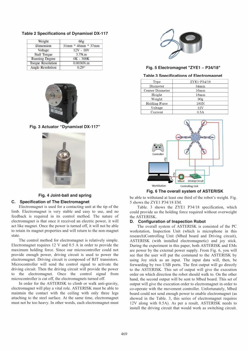
C. Specification of The Electromagnet Electromagnet is used for a contacting unit at the tip of the
limb. Electromagnet is very stable and easy to use, and no feedback is required in its control method. The nature of electromagnet is that once it received an electric power, it will act like magnet. Once the power is turned off, it will not be able to retain its magnet properties and will return to the non-magnet state.
The control method for electromagnet is relatively simple. Electromagnet requires 12 V and 0.5 A in order to provide the maximum holding force. Since our microcontroller could not provide enough power, driving circuit is used to power the electromagnet. Driving circuit is composed of BJT transistors. Microcontroller will send the control signal to activate the driving circuit. Then the driving circuit will provide the power to the electromagnet. Once the control signal from microcontroller is cut off, the electromagnets turned off.
In order for the ASTERISK to climb or walk anti-gravity, electromagnet will play a vital role. ASTERISK must be able to maintain the contact with the ceiling with only three legs attaching to the steel surface. At the same time, electromagnet must not be too heavy. In other words, each electromagnet must
be able to withstand at least one third of the robot’s weight. Fig. 5 shows the ZYE1 P34/18 EM.
Table. 3 shows the ZYE1 P34/18 specification, which could provide us the holding force required without overweight the ASTERISK. D. Configuration of Inspection Robot
The overall system of ASTERISK is consisted of the PCworkstation, Inspection Unit (which is microphone in thisresearch)Controlling Unit (Mbed board and Driving circuit), ASTERISK (with installed electromagnetic) and joy stick. During the experiment in this paper, both ASTERISK and EMs are power by the external power supply. From Fig. 6, you will see that the user will put the command to the ASTERISK by using Joy stick as an input. The input data will, then, be forwarding by two USB ports. The first output will go directly to the ASTERISK. This set of output will give the execution order on which direction the robot should walk to. On the other hand, the second output will be sent to Mbed board. This set of output will give the execution order to electromagnet in order to co-operate with the movement controller. Unfortunately, Mbed board could not send enough power to enable electromagnet (as showed in the Table. 3, this series of electromagnet requires 12V along with 0.5A). As per a result, ASTERISK needs to install the driving circuit that would work as switching circuit.
Fig. 3 Actuator “Dynamixel DX-117”
Fig. 4 Joint-ball and spring
Table 2 Specifications of Dynamixel DX-117
Table 3 Specifications of Electromagnet
Fig. 5 Electromagnet "ZYE1 – P34/18"
Fig. 6 The overall system of ASTERISK
469

When the output send from Workstation to the Mbed, the microcontroller board will send out the signal to driving circuit,
which will then switch the activation and deactivation of electromagnet sets according to the movement at that moment.
We adopt the close-loop control method. we use angle data as feedback. Right after the swing legs of ASTERISK reach to the destination positions, electromagnets will turn on. After the system executed the turn on command for electromagnets, system will read the angle feedback. If the control program could detect the significant change (angle’s differential is greater than 3°) for any leg, the control program will conclude that electromagnet on that leg does not turn on correctly. The control program will then try to re-position the leg where the contacting problem is presented. On the other hand, if the control program could not detect any change (angle’s differential is less than 3 ° ), program will conclude that electromagnets are successfully turned on. ASTERISK will continue with the next step of walking.
In the previous study [14], using the limb-mechanism robot ASTERISK equipped with an electromagnet at the tip of the leg, realized the movement under the plane by sticking the limbs to the ceiling upside down in anti-gravity situation (shown in Fig. 7)).
III. TRANSFER MOTION Figure 8(a) shows what is assumed as the adjacent plane to
which the robot transfers. The assumed adjacent plane is an incoming corner shape with an internal angle of 90°, and the transfer motions from the ground to the wall and the wall to the ceiling are obtained. In considering the transfer motion, it is important to consider not only the geometric conditions but also the load on a specific leg depending on the direction of gravity. Also, as a transfer motion by the leg robot, it is desirable that the posture change be as large as possible at the same grounding point, without stepping on the legs as much as possible. In other words, as shown in Fig. 8(b), when the legs are grounded on the wall, the height h from the center of the torso is equal to the value of the distance h' to the wall, so that the inclination θ of the torso from the ground is 45 degrees. In addition to this, Atarashi et al. also add work areas that can be grounded with six degrees of freedom of legs [15] .However, In the case of ASTERISK used this time, it is necessary to operate under the condition that the electromagnet is grounded at an angle where it can function properly. In this experiment, we move the ASTERISK legs vertically with respect to the wall surface, three each of the front and rear legs.
The torque of each servo motor of ASTERISK can be obtained from Fig. 9 from the difference between the target angle and the present angle. At this time, if the leg position vector of each limb is (𝑝𝑝𝑥𝑥, 𝑝𝑝𝑦𝑦, 𝑝𝑝𝑧𝑧),and the joint angle of the joint 𝐽𝐽𝑛𝑛(𝑛𝑛 = 1, 2, 3) is 𝜃𝜃𝑛𝑛(𝑛𝑛 = 1, 2, 3), the Jacobian matrix J is expressed as
J = ||
𝛿𝛿𝑝𝑝𝑥𝑥𝛿𝛿𝜃𝜃1
𝛿𝛿𝑝𝑝𝑥𝑥𝛿𝛿𝜃𝜃2
𝛿𝛿𝑝𝑝𝑥𝑥𝛿𝛿𝜃𝜃3
𝛿𝛿𝑝𝑝𝑦𝑦𝛿𝛿𝜃𝜃1
𝛿𝛿𝑝𝑝𝑦𝑦𝛿𝛿𝜃𝜃2
𝛿𝛿𝑝𝑝𝑦𝑦𝛿𝛿𝜃𝜃3
𝛿𝛿𝑝𝑝𝑧𝑧𝛿𝛿𝜃𝜃1
𝛿𝛿𝑝𝑝𝑧𝑧𝛿𝛿𝜃𝜃2
𝛿𝛿𝑝𝑝𝑧𝑧𝛿𝛿𝜃𝜃3
|| (1)
Using the Jacobian matrix and the torque τ =(𝜏𝜏1, 𝜏𝜏2, 𝜏𝜏3) generated at the joint 𝐽𝐽𝑛𝑛(𝑛𝑛 = 1, 2, 3) , the leg tip generating force F=(F_1,F_2,F_3) can be derived from
Fig. 8 Assumed transfer motion between two different adjacent plane (a). Intermediate posture of transfer motion (b). Transition process from
the ground to the wall(c)
(b) )
(a)
Fig. 9 Property of servo motor of ASTERISK
(c)
(a)
Fig. 7 Movement of ASTERISK with electromagnets in anti-gravity situation
470

F = 𝐽𝐽−𝑇𝑇𝜏𝜏 (2) Conversely, the torque τ of each joint can be derived from
τ = 𝐽𝐽𝑇𝑇𝐹𝐹 (3) from the leg tip generating force F. Equation (2) is the
forward hydrodynamics, and Equation (3) is the inverse hydrostatics.
The motion process for transferring from the ground to the wall is shown in Fig. 8(c) The left leg of the robot is called the Left leg. Also, legs located on the x axis are called Center legs and right legs are called Right legs. In addition to this, prefix "Front-", "Rear-" as front and back information, label each leg. First, ground the Front-Left leg and the Front-Right leg to the wall, and when the pitch angle reaches 45 °, ground the Front-Center leg to the wall and the Rear-Center leg to the ground. Then, step forward in the order of Front-Left leg, Front-Right leg, Rear-Left leg, Rear-Right leg, and release the grounding of the Front-Center leg · Rear-Center leg. Then tilt the fuselage further 45 °, ground the front-center leg, Rear-Center leg to the wall, then ground the Rear-Left leg, Rear-Right leg to the wall and transfer it.
Transfer motions are also conducted in the same motion process for transfer motions in other cases.
IV. SIMULATION In considering the gait generation in the anti-gravity
environment, the verification by the actual machine is not only inefficient but also causes the failure. Therefore, in this study, we have constructed a simulation environment for verifying the gait examined. In this simulation, Open Dynamics Engine [16] widely used as a dynamics engine is used.
On the simulator, the shape, link, joint characteristics of ASTERISK shown in Section 2 and the compliance of the servomotor shown in Fig. 9 are reproduced. Simulate whether the operation is possible for the transfer method described in Section 3. Here, the coefficient of static friction between the electromagnet of the leg and the wall, the ground, and the ceiling was set to infinity. In addition, the material of the wall, the ground and the ceiling are set as iron. In the initial state of the simulation, it was set with ASTERISK stationary on the ground in front of the wall and in case of placing it on the wall away from the ground with all the legs grounded on the wall. In the state of being in contact with the wall, we set the direction of gravity to be negative with respect to the direction of movement of ASTERISK by ODE setting so that it was arranged on the wall away from the ground.
Figure 10(a) shows the simulation of the transfer motion from the ground to the wall. The time required to complete the operation is 312 [sec]. At this time, as shown in Fig. 8(b), the transfer motion was classified into five operations. Also, let the torques of joints J1, J2, J3 be τ1, τ2, τ3 respectively. The torque output of each servo module in one cycle is shown in Fig. 10 (b). However, for the left and right legs, only the right leg is shown. The value of "Max torque" is 3.7 [N・m], which is the maximum torque value of the servo module "DX - 117" mentioned in Section 2. Looking at these figures, we can see that the output of any servo module realizes the gait without reaching the maximum torque value. On the other hand, it is possible to confirm where the value is extremely large, and it is necessary to control load distribution.
(b)
Fig. 10 Simulation result of ground to wall transfer motion (a) and torque output of each servo module in one cycle on each legs (b)
(a)
471
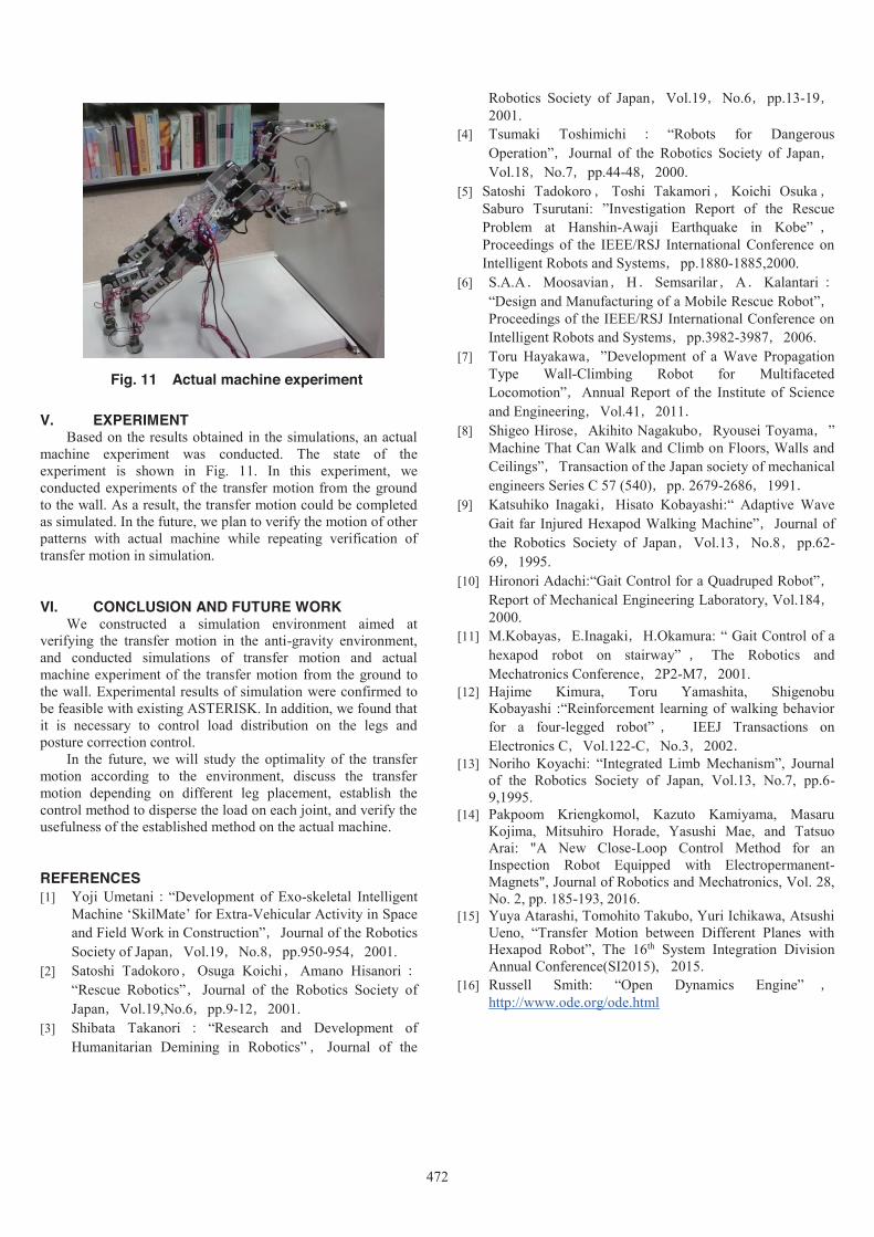
Fig. 11 Actual machine experiment
V. EXPERIMENT Based on the results obtained in the simulations, an actual
machine experiment was conducted. The state of the experiment is shown in Fig. 11. In this experiment, we conducted experiments of the transfer motion from the ground to the wall. As a result, the transfer motion could be completed as simulated. In the future, we plan to verify the motion of other patterns with actual machine while repeating verification of transfer motion in simulation.
VI. CONCLUSION AND FUTURE WORK We constructed a simulation environment aimed at
verifying the transfer motion in the anti-gravity environment, and conducted simulations of transfer motion and actual machine experiment of the transfer motion from the ground to the wall. Experimental results of simulation were confirmed to be feasible with existing ASTERISK. In addition, we found that it is necessary to control load distribution on the legs and posture correction control.
In the future, we will study the optimality of the transfer motion according to the environment, discuss the transfer motion depending on different leg placement, establish the control method to disperse the load on each joint, and verify the usefulness of the established method on the actual machine.
REFERENCES [1] Yoji Umetani:“Development of Exo-skeletal Intelligent
Machine ‘SkilMate’ for Extra-Vehicular Activity in Space and Field Work in Construction”,Journal of the Robotics Society of Japan,Vol.19,No.8,pp.950-954,2001.
[2] Satoshi Tadokoro,Osuga Koichi,Amano Hisanori:“Rescue Robotics”,Journal of the Robotics Society of Japan,Vol.19,No.6,pp.9-12,2001.
[3] Shibata Takanori : “Research and Development of Humanitarian Demining in Robotics” , Journal of the
Robotics Society of Japan,Vol.19,No.6,pp.13-19,2001.
[4] Tsumaki Toshimichi : “Robots for Dangerous Operation”,Journal of the Robotics Society of Japan,Vol.18,No.7,pp.44-48,2000.
[5] Satoshi Tadokoro , Toshi Takamori , Koichi Osuka ,Saburo Tsurutani: ”Investigation Report of the Rescue Problem at Hanshin-Awaji Earthquake in Kobe” ,Proceedings of the IEEE/RSJ International Conference on Intelligent Robots and Systems,pp.1880-1885,2000.
[6] S.A.A.Moosavian,H.Semsarilar,A.Kalantari:“Design and Manufacturing of a Mobile Rescue Robot”,Proceedings of the IEEE/RSJ International Conference on Intelligent Robots and Systems,pp.3982-3987,2006.
[7] Toru Hayakawa,”Development of a Wave Propagation Type Wall-Climbing Robot for Multifaceted Locomotion”,Annual Report of the Institute of Science and Engineering,Vol.41,2011.
[8] Shigeo Hirose,Akihito Nagakubo,Ryousei Toyama,” Machine That Can Walk and Climb on Floors, Walls and Ceilings”,Transaction of the Japan society of mechanical engineers Series C 57 (540),pp. 2679-2686,1991.
[9] Katsuhiko Inagaki,Hisato Kobayashi:“ Adaptive Wave Gait far Injured Hexapod Walking Machine”,Journal of the Robotics Society of Japan,Vol.13,No.8,pp.62-69,1995.
[10] Hironori Adachi:“Gait Control for a Quadruped Robot”, Report of Mechanical Engineering Laboratory, Vol.184,2000.
[11] M.Kobayas,E.Inagaki,H.Okamura: “ Gait Control of a hexapod robot on stairway” , The Robotics and Mechatronics Conference,2P2-M7,2001.
[12] Hajime Kimura, Toru Yamashita, Shigenobu Kobayashi :“Reinforcement learning of walking behavior for a four-legged robot” , IEEJ Transactions on Electronics C,Vol.122-C,No.3,2002.
[13] Noriho Koyachi: “Integrated Limb Mechanism”, Journal of the Robotics Society of Japan, Vol.13, No.7, pp.6-9,1995.
[14] Pakpoom Kriengkomol, Kazuto Kamiyama, Masaru Kojima, Mitsuhiro Horade, Yasushi Mae, and Tatsuo Arai: "A New Close-Loop Control Method for an Inspection Robot Equipped with Electropermanent-Magnets", Journal of Robotics and Mechatronics, Vol. 28, No. 2, pp. 185-193, 2016.
[15] Yuya Atarashi, Tomohito Takubo, Yuri Ichikawa, Atsushi Ueno, “Transfer Motion between Different Planes with Hexapod Robot”, The 16th System Integration Division Annual Conference(SI2015), 2015.
[16] Russell Smith: “Open Dynamics Engine” ,http://www.ode.org/ode.html
472