Ir LAW Chi Keung, Peter - HKIE Fire Division Website
44
8 th Annual Symposium 2016 “Fire Risk Management in Modern Cities” Paper 6 Formulation of Fire Safety Requirements for New Railway Infrastructures Speaker Ir LAW Chi Keung, Peter
-
Upload
khangminh22 -
Category
Documents
-
view
1 -
download
0
Transcript of Ir LAW Chi Keung, Peter - HKIE Fire Division Website

8th
Annual Symposium 2016
“Fire Risk Management in Modern Cities”
Paper 6
Formulation of Fire Safety Requirements for New Railway
Infrastructures
Speaker
Ir LAW Chi Keung, Peter

Formulation of Fire Safety Requirements for New Railway Infrastructures
Ir Peter Law
Overview
Formulation of Fire Safety Requirements
Regulatory Regime for Railway Fire Safety
Railway Development in Hong Kong
Conclusion
New Practical Guidelines
Smoke Control Systems of Railway Projects
Formulation of Fire Safety Requirements

Railway Development in Hong Kong
� Railways provide a reliable, fast and safe services to alleviate the pressure on the road network.
� Railway development in Hong Kong has experienced very fast growth.fast growth.
� The urban rail network has covered most of the urban areas in Hong Kong.
P. 3 of 62
Figure from MTRC - http://www.mtr.com.hkTotal Rail Length: 221.2 KmRailway Station: 175 Stations

100,000
120,000
140,000
160,000
180,000Mo
nthly
Month
ly Mo
nthly
Month
ly To
talTo
talTo
talTo
talUn
it in t
hous
ands
)Un
it in t
hous
ands
)Un
it in t
hous
ands
)Un
it in t
hous
ands
) Intercity, Light Rail & Bus
Cross-boundary
Airport Express
MTR MTR MTR MTR ---- Historic PatronageHistoric PatronageHistoric PatronageHistoric Patronage FiguresFiguresFiguresFigures
0
20,000
40,000
60,000
80,000
Jul-15 Aug-15 Sep-15 Oct-15 Nov-15 Dec-15 Jan-16
Month
ly Mo
nthly
Month
ly Mo
nthly
(( (( Unit
in th
ousa
nds)
Unit i
n tho
usan
ds)
Unit i
n tho
usan
ds)
Unit i
n tho
usan
ds)
MonthMonthMonthMonth
Airport Express
MTR Lines
Statistic data from MTRC - http://www.mtr.com.hkDaily Average (Patronage): Over 5 Million
Railway Development in Hong Kong
� 4 railway lines are being planned and constructed.
觀塘綫延綫觀塘綫延綫觀塘綫延綫觀塘綫延綫
WILWILWILWILWILWILWILWIL
觀塘綫延綫觀塘綫延綫觀塘綫延綫觀塘綫延綫
XRLXRLXRLXRLXRLXRLXRLXRL
SCLSCLSCLSCLSCLSCLSCLSCL
SIL(E)SIL(E)SIL(E)SIL(E)SIL(E)SIL(E)SIL(E)SIL(E)
KTEKTEKTEKTEKTEKTEKTEKTEPolicy AddressPolicy Address
20072007--08 08
P. 6 of 62

Railway Development Strategy 2014
� Providing a framework for planning the future expansion of Hong Kong’s railway network up Hong Kong’s railway network up to 2031.
� Total length of the railways will extend to over 300 Km by 2031.
P. 7 of 62
Regulatory Regime for Railway Fire Safety
� The Railway Development Strategy (RDS) Division of Hong Kong Fire Services Department (FSD) established on 2 April 2001.
Regulatory Regime for Railway Fire Safety
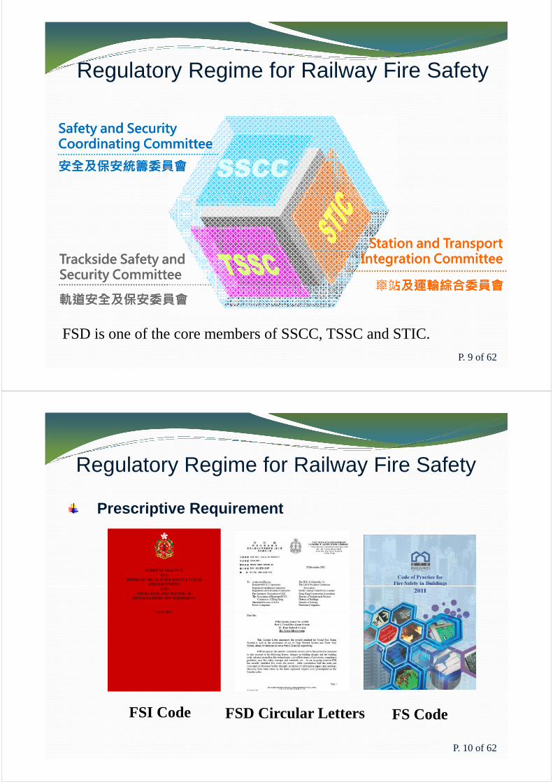
Safety and Security Safety and Security Coordinating Committee Coordinating Committee 安全及保安統籌委員會安全及保安統籌委員會
車站及運輸綜合委員會車站及運輸綜合委員會Trackside Safety and Trackside Safety and Security CommitteeSecurity Committee
Station and Station and TransportTransportIntegration CommitteeIntegration Committee
軌道安全及保安委員會軌道安全及保安委員會FSD is one of the core members of SSCC, TSSC and STIC.
P. 9 of 62
CODES OF PRACTICEFOR
MINIMUM FIRE SERVICE INSTALLATIONSAND EQUIPMENT
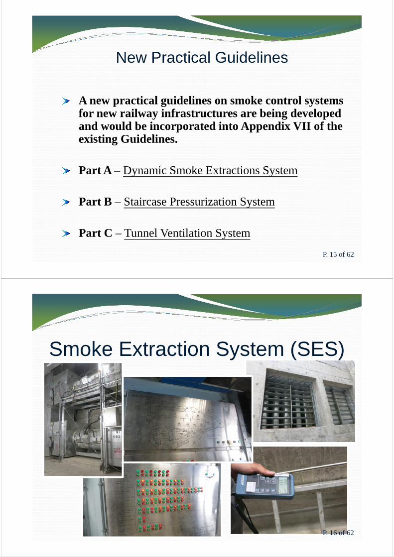
Prescriptive Requirement
Regulatory Regime for Railway Fire Safety
AND EQUIPMENTAND
INSPECTION AND TESTING OFINSTALLATIONS AND EQUIPMENT
April 2012
FSI Code FS CodeFSD Circular Letters
P. 10 of 62

Regulatory Regime for Railway Fire Safety
Fire Engineering Design
CIBSE Guide ESFPE Handbook
P. 11 of 62
Formulation of Fire Safety Requirements
Guidelines on Formulation of Fire Safety Requirements for New Railway Infrastructures
1st Edition 1 Edition 2nd Edition 3rd Edition
Fire Safety Strategy (FSS)Trackside Fire Safety Strategy (TFSS)
P. 12 of 62

Formulation of Fire Safety RequirementsGuidelines on Formulation of Fire Safety Requirements for New Railway Infrastructures
1st Edition- Issued in January 2013- Essential fire safety measures of railway lines-
2nd Edition- Issued in August 2013, bilingual version- Fire safety provisions of EAP, EEP, CP and site office- Special features of deep railway station
3rd Edition- To be issued- A new practical guidelines on smoke control systems
P. 13 of 62
Smoke Control Systems in Railway Projects
Smoke and hot gases are recognized as the major hazard.
The control and essential removal of smoke from the premise is crucial for fire safety.
The provisions of smoke control systems provide smoke free conditions and control the smoke spread for massive evacuation and fire-fighting.
P. 14 of 62
New Practical Guidelines
A new practical guidelines on smoke control systems for new railway infrastructures are being developed and would be incorporated into Appendix VII of the existing Guidelines. existing Guidelines.
Part A – Dynamic Smoke Extractions System
Part B – Staircase Pressurization System
Part C – Tunnel Ventilation System
P. 15 of 62
Smoke Extraction System (SES)
P. 16 of 62

Smoke Extraction System (SES)
Dynamic smoke extraction system is provided for:A Place of Safe Passage for 60 minutes (minimum).
Cabin Concept for Concession Area.
P. 17 of 62
Smoke Extraction System (SES)
Fire CompartmentationFan room accommodated more than one smoke extraction
system.
P. 18 of 62

Smoke Extraction System (SES)
Fire CompartmentationAll fans of the dynamic smoke extraction system forming part
of a fire rated duct.
The fan room shall contain no other services.
P. 19 of 62
Smoke Extraction System (SES)
Verification on System Performance
The designer of dynamic smoke extraction system shall be a registered professional engineer in the discipline of building services, fire or mechanical discipline of building services, fire or mechanical engineering.
Drawing and all calculations of dynamic smoke extraction system.
P. 20 of 62

Smoke Extraction System (SES)
Verification on System Performance
Hot smoke test shall be conducted in accordance with the requirements as stated in FSD Circular Letter 2/2002.
Smoke Extraction System (SES)
Smoke Discharge ArrangementDedicated vent shaft shall be designed for smoke extraction
purpose and it shall contain no other services.
In order to prevent re-circulation of smoke into the system In order to prevent re-circulation of smoke into the system through the vent shaft, the smoke discharge outlet and fresh air intake louver shall be separated by not less than 5m in any direction from all air inlets or other building openings.
No discharges shall be at a height above the surrounding horizontal surface of less than 3m to the bottom of the outlet and where below 6m shall not discharge downwards.
P. 22 of 62

Smoke Extraction System (SES)Concession Areas
The Cabin Concept is applied to concession areas of the station.
Cabin Concept- Sprinkler Controlled Fire
- Combination of smoke detection, sprinklers and a designated smoke extraction system.
P. 23 of 62
P. 24 of 62
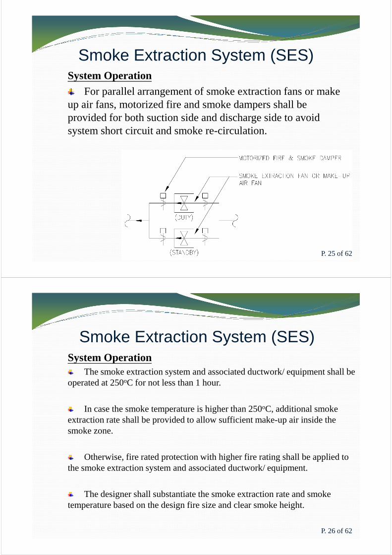
Smoke Extraction System (SES)System Operation
For parallel arrangement of smoke extraction fans or make up air fans, motorized fire and smoke dampers shall be provided for both suction side and discharge side to avoid system short circuit and smoke re-circulation.
P. 25 of 62
Smoke Extraction System (SES)System Operation
The smoke extraction system and associated ductwork/ equipment shall be operated at 250oC for not less than 1 hour.
In case the smoke temperature is higher than 250oC, additional smoke extraction rate shall be provided to allow sufficient make-up air inside the extraction rate shall be provided to allow sufficient make-up air inside the smoke zone.
Otherwise, fire rated protection with higher fire rating shall be applied to the smoke extraction system and associated ductwork/ equipment.
The designer shall substantiate the smoke extraction rate and smoke temperature based on the design fire size and clear smoke height.
P. 26 of 62

Smoke Extraction System (SES)
System OperationSmoke extraction fans and make-up air fans shall be electrically
interlocked.
Smoke detection system, sprinkler flow switch and manual override facility.
Once started, smoke extraction fans and make up air fan shall run continuously until stopped manually.
P. 27 of 62
Integrated Back-up panel (IBP)P. 28 of 62

Manual Override Panel for Smoke Extraction System
Main AFA Panel
P. 29 of 62
Smoke Extraction System (SES)
System ReliabilityTwo dedicated electrical supplies shall be
routed separately into the plant room and then connected into the switchboard for smoke extraction system.
The switchboard serving smoke extraction system shall be located in plant room next to system shall be located in plant room next to the fan room of smoke extraction system.
The plant room shall not contain other equipment.
Switchboard for smoke extraction system shall not be grouped with other services or installations.
Smoke extraction fan shall be installed in duplicate with automatic changeover facilities.
P. 30 of 62
Staircase Pressurization System (SPS)
P. 31 of 62
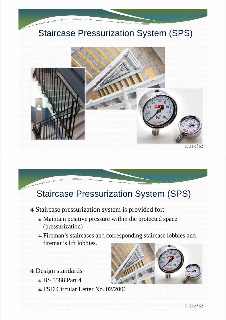
Staircase Pressurization System (SPS)
Staircase pressurization system is provided for:Maintain positive pressure within the protected space (pressurization)
Fireman’s staircases and corresponding staircase lobbies and fireman’s lift lobbies. fireman’s lift lobbies.
Design standardsBS 5588 Part 4
FSD Circular Letter No. 02/2006
P. 32 of 62

Staircase Pressurization System
Fire CompartmentationDedicated pressurization fans shall be designed for
the staircase and protected lobbies.
The supply air duct serving the pressurized staircase has to penetrate the staircase enclosure, the portion of the duct located outside the staircase shall be enclosed by the same fire rating as the pressurized space or fire compartment passed, whichever is greater.
Other non-essential services shall not pass through / not be installed at the protected lobby / staircase.
P. 33 of 62
Fan room Fan room
Fresh airFresh airFresh airFresh air
Pressure Relief
Air Release
Pressurized 50 Pa
MOA Staircase Fireman’s Lift Lobby
Accommodation
Pressurized 45 Pa
Vent Shaft
0 Pa
Direction of air flow (Open door scenario for MOA staircase)Direction of air flow (Open door scenario for MOA staircase) P. 34 of 62
2 m/s
Staircase Pressurization SystemVerification on System Performance
The designer of staircase pressurization system shall be a registered professional engineer in the discipline of building services, fire or mechanical engineering.
The provision of air release shall be provided to the accommodation.
The air release fan, ductwork and other associated equipment shall be suitable for continuous operation for the appropriate period of time and temperature as specified in the BS5588: Part 4 and FSD Circular Letter No. 2/2006.
P. 35 of 62
Staircase Pressurization SystemSmoke Discharge Arrangement
The smoke discharge shall be remote from and preferably down-wind of the intake of fresh air in order to prevent re-circulation of smoke.
The discharge end / louvre of air release shall not be mixed with The discharge end / louvre of air release shall not be mixed with other louvre or system.
Air release discharge outlets for staircase pressurization system shall be separated by not less than 5m in any direction from all air inlets or other openings into any building.
No discharges shall be at a height above the surrounding horizontal surface of less than 3m to the bottom of the outlet and where below 6m shall not discharge downwards.
P. 36 of 62
Staircase Pressurization System
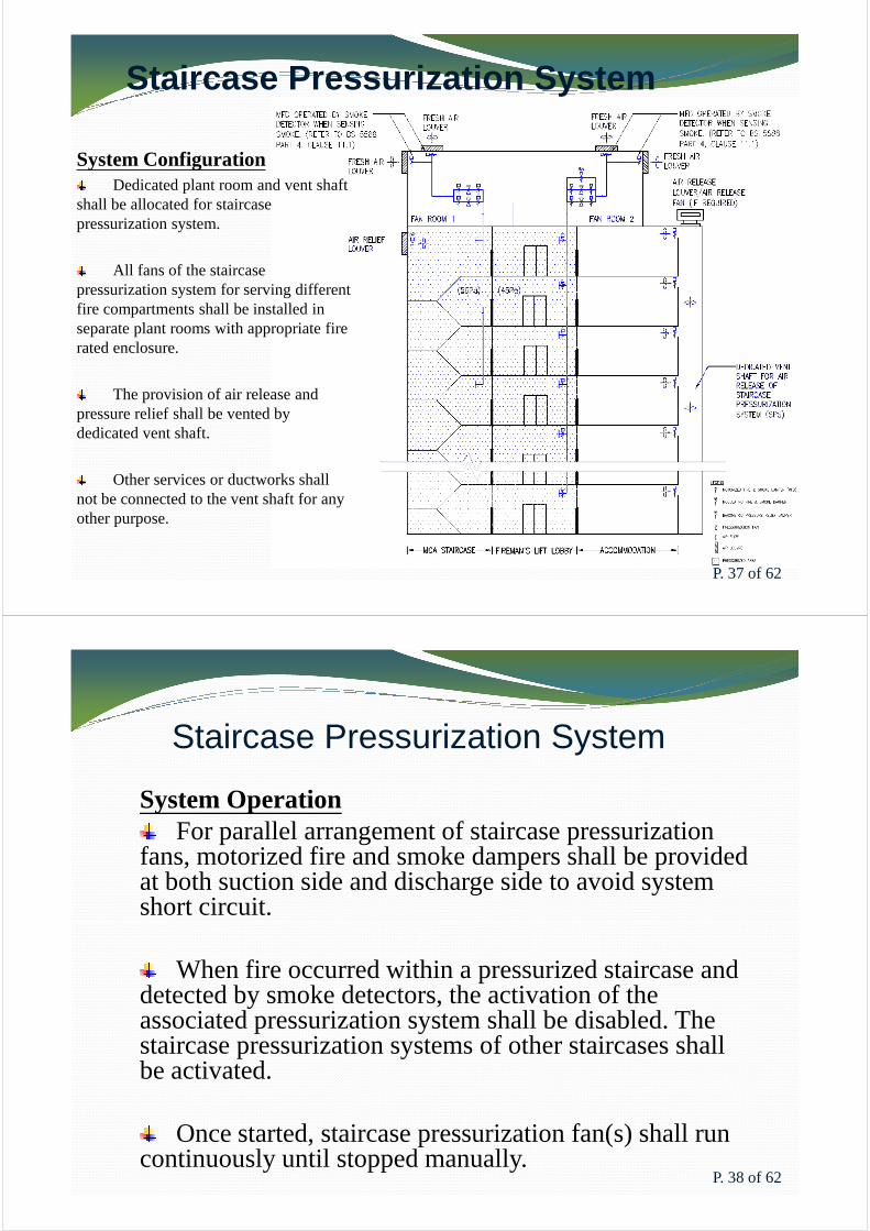
System ConfigurationDedicated plant room and vent shaft
shall be allocated for staircase pressurization system.
All fans of the staircase pressurization system for serving different fire compartments shall be installed in fire compartments shall be installed in separate plant rooms with appropriate fire rated enclosure.
The provision of air release and pressure relief shall be vented by dedicated vent shaft.
Other services or ductworks shall not be connected to the vent shaft for any other purpose.
P. 37 of 62
Staircase Pressurization System
System OperationFor parallel arrangement of staircase pressurization
fans, motorized fire and smoke dampers shall be provided at both suction side and discharge side to avoid system short circuit.
When fire occurred within a pressurized staircase and detected by smoke detectors, the activation of the associated pressurization system shall be disabled. The staircase pressurization systems of other staircases shall be activated.
Once started, staircase pressurization fan(s) shall run continuously until stopped manually.
P. 38 of 62

Staircase Pressurization System
System ReliabilityDuplicate fans instead of dual
motors shall be adopted.
Dedicated switchboard shall be designed for the staircase pressurization system and shall not be grouped with other systems. other systems.
The switchboard shall be located in the plant room next to the fan room for the staircase pressurization system.
The plant room shall not contain other equipment. If not, the switchboard shall be provided with proper fire rated enclosure.
P. 39 of 62
Tunnel Ventilation System (TVS)
P. 40 of 62

Tunnel Ventilation System (TVS)
Tunnel ventilation system is provided for:Drawing in fresh air from one end of the affected tunnel and expelling smoke at the other end via the vent shaft.
Preventing “back layering” of smoke in the direction of passenger evacuation.passenger evacuation.
Maintaining a smoke free path for emergency evacuation and fireman’s access in case of fire.
P. 41 of 62
Tunnel Ventilation System (TVS)
� Back-layering �The reversal of movement of smoke and hot gases counter
to the direction of the ventilation airflow.
� Critical velocity�The minimum steady-state velocity of the ventilation
airflow moving toward the fire
within a tunnel or passageway
that is required to prevent
back-layering at the fire site
P. 42 of 62
Tunnel Ventilation System (TVS)
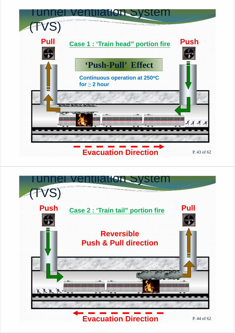
Pull Push
‘Push-Pull’ EffectContinuous operation at 250oC for ≥ 2 hour
Case 1 : ‘Train head” portion fire
Evacuation Direction
for ≥ 2 hour
P. 43 of 62
Tunnel Ventilation System (TVS)
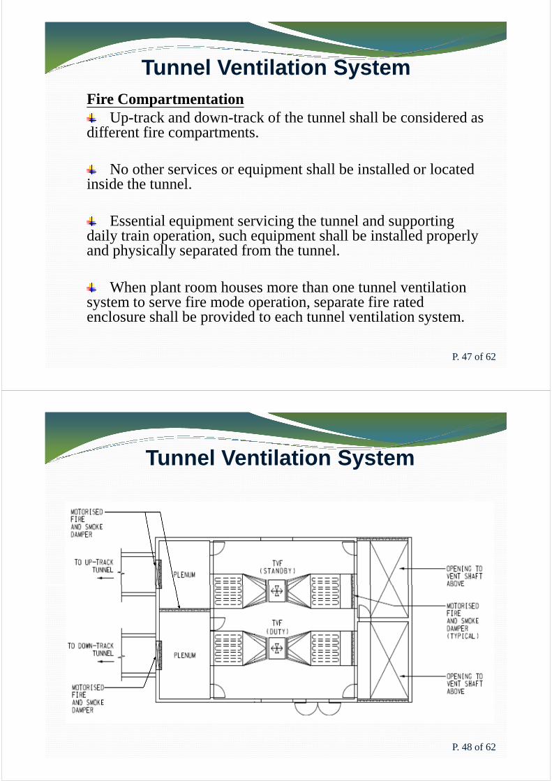
Push PullCase 2 : ‘Train tail” portion fire
Reversible Push & Pull direction
Evacuation Direction P. 44 of 62

Tunnel Ventilation System (TVS)
Ventilation Building Smoke Vent
P. 45 of 62
Tunnel Ventilation System (TVS)
Tunnel Ventilation Fans
P. 46 of 62
Tunnel Ventilation SystemFire Compartmentation
Up-track and down-track of the tunnel shall be considered as different fire compartments.
No other services or equipment shall be installed or located inside the tunnel.
Essential equipment servicing the tunnel and supporting daily train operation, such equipment shall be installed properly and physically separated from the tunnel.
When plant room houses more than one tunnel ventilation system to serve fire mode operation, separate fire rated enclosure shall be provided to each tunnel ventilation system.
P. 47 of 62
Tunnel Ventilation System
P. 48 of 62

Tunnel Ventilation System
Verification on System Performance
The designer of tunnel ventilation system shall be a register professional engineer in the discipline of building services, fire or mechanical engineering.building services, fire or mechanical engineering.
For the calculation of critical velocity, total heat release rate (fire size) shall be adopted instead of convective heat release rate.
P. 49 of 62
Tunnel Ventilation System
Smoke Discharge ArrangementIn order to prevent re-circulation of smoke into the
system via vent shaft, the smoke discharge outlets shall be separated by not less than 5m in any direction from all air inlets or other openings into any building.inlets or other openings into any building.
The outlets shall not discharge into any means of escape nor a free air fireman’s staircase.
No discharges shall be at a height above the surrounding horizontal surface of less than 3m to the bottom of the outlet and where below 6m shall not discharge downwards.
P. 50 of 62

Tunnel Ventilation SystemSystem Configuration
The tunnel ventilation system shall be designed to prevent the hot smoke flowing from the incident tunnel to non-incident tunnel via the cross-over area and cross-wall / cross-passage door.
If there are a dedicated Means of Access (MoA) corridor and MoA / EAP staircase near the overrun tunnel / main tunnel, provisions such as smoke lobby shall be provided to prevent smoke spilling into the MoA corridor and MoA / EAP staircase.
Tunnel ventilation control panel shall be provided for tunnel ventilation systems and located adjacent to main fire control panel at Station Control Room (SCR) / Fire Control Room (FCR).
P. 51 of 62
Tunnel Ventilation System
System OperationThe tunnel ventilation system with associated ductwork and
equipment shall be operated at 250°C for not less than two hours.
In case the smoke temperature is higher than 250°C, additional smoke extraction rate shall be provided to allow sufficient make-up air smoke extraction rate shall be provided to allow sufficient make-up air inside the smoke zone to be entrained and ensure the airstream temperature inside the system is less than 250°C.
Otherwise, fire rated protection with higher fire rating shall be applied to the tunnel ventilation system with associated ductwork and equipment to withstand the smoke temperature and maintain normal operation of the tunnel ventilation system.
The designer shall substantiate the smoke extraction rate and smoke temperature based on the design fire size and critical velocity.
P. 52 of 62

Tunnel Ventilation SystemSystem Operation
For parallel arrangement of tunnel ventilation fans, motorized fire and smoke dampers shall be provided at both suction side and discharge side to avoid system short circuit.
When tunnel ventilation system start under fire mode, tunnel When tunnel ventilation system start under fire mode, tunnel ventilation fans shall run continuously until stopped manually.
The tunnel ventilation system shall not be controlled or under the influence of any building management or automation system.
Overall operating status of related mode of the tunnel ventilation system should be individually monitored by the affected stations.
P. 53 of 62
Tunnel Ventilation System
System ReliabilitySwitchboard for tunnel ventilation system shall not be
grouped with other services or installations.
The switchboard serves the fan/motor/drive sets of tunnel ventilation system shall be located in plant room next to fan room of tunnel ventilation fan.
The plant room shall not contain other equipment. Two dedicated electrical supplies shall be routed separately into the plant room and then connected into the switchboard for tunnel ventilation system.
P. 54 of 62
Conclusion� Higher public expectation on fire safety of railway services
& align with the world’s enhanced fire safety requirements
� FSD offered persistent support to new railway projects and promulgated a guidelines on fire safety requirements for new railway infrastructuresnew railway infrastructures
� A new practical guidelines on smoke control systems for new railway projects were introduced
� FSD will take proactive approach in elevating fire safety standards of railway development in Hong Kong.
P. 55 of 62
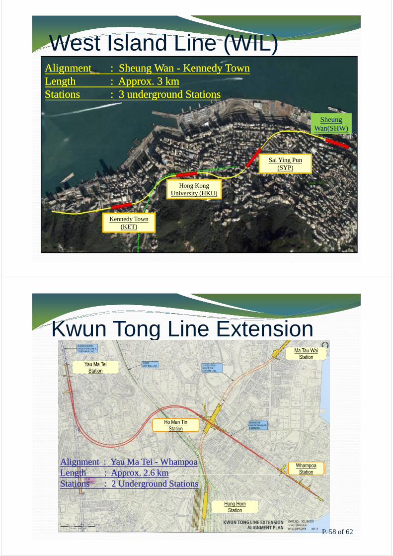
West Island Line (WIL)AlignmentAlignment :: SheungSheung WanWan -- KennedyKennedy TownTownLengthLength :: ApproxApprox.. 33 kmkmStationsStations :: 33 undergroundunderground StationsStations
Sheung Wan(SHW)
Kennedy Town (KET)
Hong Kong University (HKU)
Sai Ying Pun (SYP)
Kwun Tong Line ExtensionYau Ma Tei
Station
Ma Tau Wai
Station
Hung Hom
Station
Ho Man Tin
Station
Whampoa
Station
AlignmentAlignment :: YauYau MaMa TeiTei -- WhampoaWhampoaLengthLength :: ApproxApprox.. 22..66 kmkmStationsStations :: 22 UndergroundUnderground StationsStations
P. 58 of 62

South Island Line (SIL (E))
AlignmentAlignment :: AdmiraltyAdmiralty -- SouthSouth HorizonHorizonLengthLength :: ApproxApprox.. 77..33 kmkmStationsStations :: 55 StationsStations
Admiralty
Station
Ocean Park
Station
Wong Chuk Hang
Station
Lei Tung
Station
South Horizon
Station
Wong Chuk Hang Depot
NN
P. 59 of 62
Express Rail Link (HK Section)
VB1 - MPV
MAI PO VENT
BUILDING VB3 - TKP
TAI KONG PO
PLANT
BUILDING
VB4 - PHV
PAT HEUNG
VENT BUILDING
VB6 - KCV
KWAN CHUNG VENT
BUILDING
VB8 – MKV
MONG KOK
WEST VENT
BUILDING
AlignmentAlignment :: WestWest KowloonKowloon -- FutianFutianLengthLength :: ApproxApprox.. 3030 kmkm ((2626 kmkm withinwithin HK)HK)
VB0 - HPV
HUANGGANG
PARK VENT
BUILDINGSHEK KONG STABLING
SIDINGS (SSS) WITH
EMERGENCY RESCUE
SIDING (ERS)
VB2-NTV
NGAU TAM MEI VENT
BUILDING
VB5 – SMV
SHING MUN VENT
BUILDING
VB7-NCV
NAM CHEONG
VENT BUILDING
WKT
WEST KOWLOON
TERMINUS
P. 60 of 62

Shatin to Central Link(East-West Railway Corridor)
Hin Keng Station
Tai Wai Station
Alignment : Tai Alignment : Tai WaiWai -- Hung Hung HomHom
NN
Diamond Hill Station
Kai Tak Station
Sung Wong Toi Station
To Kwa Wan StationHo Man Tin Station
Alignment : Tai Alignment : Tai WaiWai -- Hung Hung HomHomLength : Approx. 9 kmLength : Approx. 9 kmStations : 7 Stations : 7 StationsStations
Hung Hom Station
P. 61 of 62
Shatin to Central Link(North-South Railway Corridor)
Admiralty
Station
AlignmentAlignment :: HungHung HomHom -- AdmiraltyAdmiraltyLengthLength :: ApproxApprox.. 66 kmkmStationsStations :: 33 UndergroundUnderground StationsStations
Hung Hom
Station
Exhibition
Station
P. 62 of 62
8th
Annual Symposium 2016
“Fire Risk Management in Modern Cities”
Paper 6
Formulation of Fire Safety Requirements for New Railway
Infrastructures
Speaker
Ir LAW Chi Keung, Peter

FORMULATION OF FIRE SAFETY REQUIREMENTS FOR NEW RAILWAY INFRASTRUCTURES
Ir Law Chi Keung, Peter
Hong Kong Fire Services Department, Railway Development Strategy Division, 2/F Tung Lo Wan Fire Station, 111 Victoria Park Road, Causeway Bay, HK
Abstract. In the past decades, railway development in Hong Kong has experienced very fast growth. Railway projects become complicated and with plenty of fire engineering design. Fire safety has an important role to play in developing the rail network.
Without preceding project references, Hong Kong Fire Services Department (FSD) in collaboration with Railway Corporation and other Government Departments draw up fire safety requirements for railway infrastructures to provide the most appropriate fire safety protection to passengers, operational staff and emergency personnel in the event of a fire.
To facilitate stakeholders of the railway industry to adopt a consistent fire safety design towards new railway infrastructures, Guidelines on Formulation of Fire Safety Requirements for New Railway Infrastructures (Guidelines) was first promulgated in January 2013. A new practical guidelines on smoke control systems for new railway infrastructures are being developed for dynamic smoke extraction system, staircase pressurization system and tunnel ventilation system and incorporated into Appendix VII of the existing Guidelines. This paper gives an overview of railway development and regulatory regime for railway fire safety in Hong Kong, as well as highlights some key issues of the new practical guidelines on smoke control systems.
Keywords: Fire Safety, Railway Infrastructures, Guidelines, Smoke Control Systems, Regulatory Regime
1. BACKGROUND OF RAILWAY DEVELOPMENT IN HONG KONG
Railways provide a reliable, fast and safe services to alleviate the pressure on the road network. With the rapid growth of social and economic development, promotion of safe and efficient rail transport system is the first priority among various transport policies in many metropolitan areas over the world.
In the past decades, railway development in Hong Kong has experienced very fast growth. The urban rail network has already covered most of the urban areas in Hong Kong. The existing railway network in Hong Kong has a total rail length of over 220 kilometers. To further enhance the usage of the public transport, various extensions of railway lines are also being planned and constructed. After the full commissioning of the West Island Line (WIL) in March 2015, there are four new railway projects under construction, namely, Kwun Tong Line Extension (KTE), South Island Line (East) (SIL(E)), Guangzhou-Shenzhen-Hong Kong Express Rail Link (XRL) and Shatin to Central Link (SCL).
The Government announced the Railway Development Strategy 2014 in September 2014. Having regard to transport demand, cost-effectiveness and the development needs of New Development Areas and other new development projects, the Strategy recommends that seven new railway projects be completed in the planning horizon up to 2031. When all the new railway projects recommended are completed, the total length of the railways will extend from 270 kilometers in 2021 to over 300 kilometers by 2031.

2. REGULATORY REGIME FOR RAILWAY FIRE SAFETY
The Railway Development Strategy (RDS) Division of Hong Kong Fire Services Department (FSD) was established in early 2001 subsequent to the implementation of the Railway Development Strategy 2000.
Instead of submitting building plans through the Centralized Processing System for ordinary building projects, three committees namely Station and Transport Integration Committee (STIC), Safety and Security Coordinating Committee (SSCC) and Trackside Safety and Security Committee (TSSC) are formed to ensure that railway infrastructures are designed, built and operated to the required safety standards. As one of the core members of STIC, SSCC and TSSC, FSD is responsible for giving advice on fire safety requirements to railway projects.
Railway projects become complicated and with plenty of fire engineering design. Fire safety has an important role to play in developing the rail network. The development of railway fire safety design in Hong Kong evolved from the first underground railway project in around 1970s. Without preceding project references and prescriptive requirements under the Codes of Practice for Minimum Fire Service Installations and Equipment and Inspection, Testing and Maintenance of Installations and Equipment (CoP), FSD in collaboration with Railway Corporation and other Government Departments draw up fire safety requirements for railway infrastructures to provide the most appropriate fire safety protection to passengers, operational staff and emergency personnel in the event of a fire.
3. GUIDELINES ON FORMULATION OF FIRE SAFETY REQUIREMENTS FOR NEW RAILWAY INFRASTRUCTURES
Railway premises generally include stations, tunnels, depots and ventilation buildings. Owing to the unique and complex design nature of railway stations and its associated premises, performance-based fire engineering designs have been widely adopted in the planning of railway projects. The aim is to provide for an overall level of safety that is equivalent to that which would result if fire safety was achieved through full compliance with the prescriptive provisions of the relevant codes of practice and to demonstrate adequate fire safety provisions and efficient allocation of resources to those higher risk areas.
To facilitate stakeholders of the railway industry to adopt a consistent fire safety design towards new railway infrastructures, Guidelines on Formulation of Fire Safety Requirements for New Railway Infrastructures (Guidelines) is developed to provide general guidance on formulation fire safety requirements by incorporating the latest fire safety measures of various railway lines under construction in Hong Kong. 1st edition of the guidelines was promulgated in January 2013 by introducing the essential fire safety measures of various railway lines under construction in Hong Kong with due regard to past experience and relevant international standards on railway safety.
2nd edition of the guidelines was then issued in August 2013 which is a bilingual version incorporating supplementary fire safety provisions such as: the requirements of emergency access point (EAP), emergency egress point (EEP) and cross passage (CP) for the trackside, general fire safety requirements for construction site office and engineering site office and special features of the deep railway station.
To meet the ever-increasing public expectation on railway safety and align with the world’s enhanced fire safety requirements, FSD aims to review current fire safety measures for elevating the fire safety standard of railway development in Hong Kong. Smoke control is one of the important subjects for achieving overall fire safety of railway project. A new practical guidelines on smoke control systems for new railway infrastructures are being developed for dynamic smoke extraction system, staircase pressurization system and tunnel ventilation

system and incorporated into Appendix VII of the existing Guidelines. The new Appendix VII is devised with due consideration of the special nature of railway project to provide invaluable guidance to the designer for their early planning and system design on various smoke control systems.
4. FEATURES OF SMOKE CONTROL SYSTEMS IN RAILWAY PROJECTS
Smoke and hot gases are recognized as the major hazard and a threat to life. The production of smoke from a fire is a more immediate hazard than the heat release. A fire environment is likely to create untenable conditions before the fire has reached its peak-heat release rate. The control and essential removal of smoke from the premise is a vital component in any fire safety schemes. The provisions of smoke control system provide smoke free conditions with a sufficient period for the protection of life and property and to reduce fire damage.
Smoke control systems, including dynamic smoke extraction system, staircase pressurization system and tunnel ventilation system, are required to maintain a tenable environment and control the smoke spread for facilitating massive evacuation and fire-fighting.
5. DYNAMIC SMOKE EXTRACTION SYSTEM
Dynamic smoke extraction system is provided for maintaining a Place of Safe Passage clear of smoke for a minimum of 60 minutes and containing smoke within the reservoir of a Concession Area by means of Cabin Concept. It is necessary to establish conservatively higher design fire as this form the basis of risk assessment and the provision of dynamic smoke extraction system. Annex A of the Appendix VII is devised for dynamic smoke extraction system. Technical requirements and system configuration of dynamic smoke extraction system are elaborated.
5.1. Fire Compartmentation
When fan room accommodated more than one smoke extraction system, separate fire rated enclosure shall be provided to each smoke extraction system in order to maintain proper fire compartment of different service spaces.
All fans of the dynamic smoke extraction system forming part of a fire rated duct shall be enclosed in the same fire rated enclosure if no dedicated fan room is allocated for single smoke extraction system.
The fan room housing smoke extraction system shall contain no other services. Services or ductwork other than smoke extraction system shall not pass through the fan room of smoke extraction system.
5.2. Verification on System Performance
The designer of dynamic smoke extraction system shall be a register professional engineer under Cap. 409 in the discipline of building services, fire or mechanical engineering. The designer shall be responsible for all statutory submissions. Each drawing and all calculations shall be verified and certified by the designer.
To further verify the system performance of dynamic smoke extraction system, hot smoke test shall be conducted in accordance with the requirements as stated in FSD Circular Letter 2/2002.
5.3. Smoke Discharge Arrangement
Dedicated vent shaft shall be designed for smoke extraction purpose and it shall contain no other services. In order to prevent re-circulation of smoke into the system through the vent shaft, the smoke discharge outlet and fresh air intake louver shall be separated by not less than 5m in any direction from all air inlets or other building openings. The outlets shall not discharge into any means of escape nor a fireman’s staircase.
No discharges shall be at a height above the surrounding horizontal surface of less than 3m to the bottom of the outlet and where below 6m shall not discharge downwards.
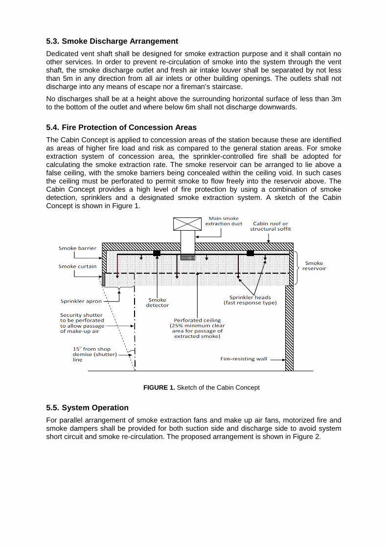
5.4. Fire Protection of Concession Areas
The Cabin Concept is applied to concession areas of the station because these are identified as areas of higher fire load and risk as compared to the general station areas. For smoke extraction system of concession area, the sprinkler-controlled fire shall be adopted for calculating the smoke extraction rate. The smoke reservoir can be arranged to lie above a false ceiling, with the smoke barriers being concealed within the ceiling void. In such cases the ceiling must be perforated to permit smoke to flow freely into the reservoir above. The Cabin Concept provides a high level of fire protection by using a combination of smoke detection, sprinklers and a designated smoke extraction system. A sketch of the Cabin Concept is shown in Figure 1.
FIGURE 1. Sketch of the Cabin Concept
5.5. System Operation
For parallel arrangement of smoke extraction fans and make up air fans, motorized fire and smoke dampers shall be provided for both suction side and discharge side to avoid system short circuit and smoke re-circulation. The proposed arrangement is shown in Figure 2.
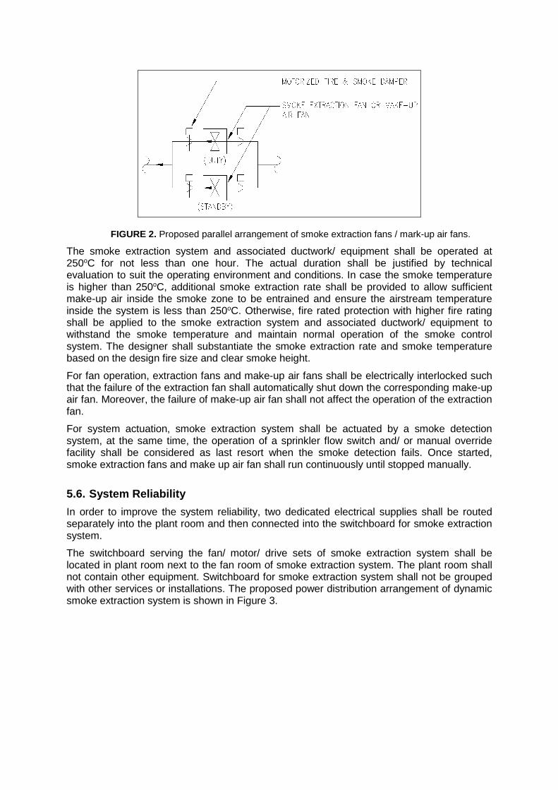
FIGURE 2. Proposed parallel arrangement of smoke extraction fans / mark-up air fans.
The smoke extraction system and associated ductwork/ equipment shall be operated at 250oC for not less than one hour. The actual duration shall be justified by technical evaluation to suit the operating environment and conditions. In case the smoke temperature is higher than 250oC, additional smoke extraction rate shall be provided to allow sufficient make-up air inside the smoke zone to be entrained and ensure the airstream temperature inside the system is less than 250oC. Otherwise, fire rated protection with higher fire rating shall be applied to the smoke extraction system and associated ductwork/ equipment to withstand the smoke temperature and maintain normal operation of the smoke control system. The designer shall substantiate the smoke extraction rate and smoke temperature based on the design fire size and clear smoke height.
For fan operation, extraction fans and make-up air fans shall be electrically interlocked such that the failure of the extraction fan shall automatically shut down the corresponding make-up air fan. Moreover, the failure of make-up air fan shall not affect the operation of the extraction fan.
For system actuation, smoke extraction system shall be actuated by a smoke detection system, at the same time, the operation of a sprinkler flow switch and/ or manual override facility shall be considered as last resort when the smoke detection fails. Once started, smoke extraction fans and make up air fan shall run continuously until stopped manually.
5.6. System Reliability
In order to improve the system reliability, two dedicated electrical supplies shall be routed separately into the plant room and then connected into the switchboard for smoke extraction system.
The switchboard serving the fan/ motor/ drive sets of smoke extraction system shall be located in plant room next to the fan room of smoke extraction system. The plant room shall not contain other equipment. Switchboard for smoke extraction system shall not be grouped with other services or installations. The proposed power distribution arrangement of dynamic smoke extraction system is shown in Figure 3.
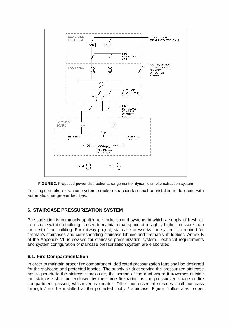
FIGURE 3. Proposed power distribution arrangement of dynamic smoke extraction system
For single smoke extraction system, smoke extraction fan shall be installed in duplicate with automatic changeover facilities.
6. STAIRCASE PRESSURIZATION SYSTEM
Pressurization is commonly applied to smoke control systems in which a supply of fresh air to a space within a building is used to maintain that space at a slightly higher pressure than the rest of the building. For railway project, staircase pressurization system is required for fireman’s staircases and corresponding staircase lobbies and fireman’s lift lobbies. Annex B of the Appendix VII is devised for staircase pressurization system. Technical requirements and system configuration of staircase pressurization system are elaborated.
6.1. Fire Compartmentation
In order to maintain proper fire compartment, dedicated pressurization fans shall be designed for the staircase and protected lobbies. The supply air duct serving the pressurized staircase has to penetrate the staircase enclosure, the portion of the duct where it traverses outside the staircase shall be enclosed by the same fire rating as the pressurized space or fire compartment passed, whichever is greater. Other non-essential services shall not pass through / not be installed at the protected lobby / staircase. Figure 4 illustrates proper

arrangement of staircase pressurization system.
FIGURE 4. Arrangement of staircase pressurization system
6.2. Verification on System Performance
The designer of staircase pressurization system shall be a register professional engineer under Cap. 409 in the discipline of building services, fire or mechanical engineering.
The provision of air release is crucial for staircase pressurization system and shall be provided to the accommodation and to comply with the requirements as stated in BS5588: Part 4 and FSD Circular Letter No. 2/2006.
The air release fan, ductwork and other associated equipment shall be suitable for continuous operation for the appropriate period of time and temperature as specified in the BS5588: Part 4 and FSD Circular Letter No. 2/2006.
The designer shall be responsible for all submissions. Each drawing and all calculations shall be verified and certified by the designer.
6.3. Smoke Discharge Arrangement
The smoke discharge shall be remote from and preferably down-wind of the intake of fresh air in order to prevent re-circulation of smoke. In addition, the discharge end / louvre of air release shall not be mixed with other louvre or system. Air release discharge outlets for staircase pressurization system shall be separated by not less than 5m in any direction from all air inlets or other openings into any building. The outlets shall not discharge into any means of escape nor a free air fireman’s staircase. No discharges shall be at a height above the surrounding horizontal surface of less than 3m to the bottom of the outlet and where

below 6m shall not discharge downwards.
6.4. System Configuration
Dedicated plant room and vent shaft shall be allocated for staircase pressurization system. Service ductwork not serving staircase pressurization system shall not pass through the plant room.
All fans of the staircase pressurization system for serving different fire compartments shall be installed in separate plant rooms with appropriate fire rated enclosure. Fans form part of a fire rated duct shall be enclosed in the same fire rated enclosure if no dedicated plant room is allocated for the staircase pressurization system.
The provision of air release and pressure relief shall be vented by dedicated vent shaft. Other services or ductworks shall not be connected to the vent shaft for any other purpose.
6.5. System Operation
For parallel arrangement of staircase pressurization fans, motorized fire and smoke dampers shall be provided at both suction side and discharge side to avoid system short circuit.
When fire occurred within a pressurized staircase and detected by smoke detectors, the activation of the associated pressurization system shall be disabled. The staircase pressurization systems of other staircases shall be activated.
In the event of a fire excluding that within the pressurized staircase, the fire alarm signal shall activate the pressurization system(s). The pressurization system(s) shall be kept in operation even though smoke spilling into the pressurized staircase and activated the smoke detector.
Once started, staircase pressurization fan(s) shall run continuously until stopped manually.
6.6. System Reliability
To enhance the system reliability, duplicate fans instead of dual motors shall be adopted.
Dedicated switchboard shall be designed for the staircase pressurization system and shall not be grouped with other systems. The switchboard shall be located in the plant room next to the fan room for the staircase pressurization system. The plant room shall not contain other equipment. If not, the switchboard shall be provided with proper fire rated enclosure. The plant room for the switchboard shall be provided with heat detector.
7. TUNNEL VENTILATION SYSTEM
In the event of train fire or tunnel fire in any sections of the tunnel, the tunnel ventilation system will be activated to draw in fresh air from one end of the affected tunnel and expel smoke at the other end via vent shaft. In order to prevent “back layering” of smoke in the direction of passenger evacuation, the designed tunnel air flow velocity in the incident tunnel shall be equal to or greater than the critical velocity at the fire site.
Tunnel ventilation system is provided inside tunnel or enclosed trackway to maintain a smoke free path for emergency evacuation and fireman’s access in case of fire. Annex C of the Appendix VII is devised for tunnel ventilation system. Technical requirements and system configuration of tunnel ventilation system are elaborated. Figure 5 shows the typical plant room arrangement of the fan room tunnel ventilation system.

FIGURE 5. Typical plant room arrangement of the fan room tunnel ventilation system
7.1. Fire Compartmentation
Up-track and down-track of the tunnel shall be considered as different fire compartments. No other services or equipment shall be installed or located inside the tunnel. Essential equipment servicing the tunnel and supporting daily train operation, such equipment shall be installed properly and physically separated from the tunnel.
When plant room houses more than one tunnel ventilation system to serve fire mode operation, separate fire rated enclosure shall be provided to each tunnel ventilation system in order to maintain fire compartment between different protected zones.
Fans form part of a fire rated duct shall be enclosed in the same fire rated enclosure if no dedicated plant room is allocated for single tunnel ventilation system, they shall be enclosed in the same fire rated enclosure.
7.2. Verification on System Performance
The designer of tunnel ventilation system shall be a register professional engineer under Cap. 409 in the discipline of building services, fire or mechanical engineering. The designer shall be responsible for all submissions. Each drawing and all calculations shall be verified and certified by the designer.
The tunnel ventilation system shall generate sufficient longitudinal air velocity to prevent back-layering of smoke due to tunnel fire. For the calculation of critical velocity, total fire heat release rate (fire size) shall be adopted instead of convective heat release rate.
7.3. Smoke Discharge Arrangement
In order to prevent re-circulation of smoke into the system via vent shaft, the smoke discharge outlets shall be separated by not less than 5m in any direction from all air inlets or other openings into any building. The outlets shall not discharge into any means of escape nor a free air fireman’s staircase. No discharges shall be at a height above the surrounding horizontal surface of less than 3m to the bottom of the outlet and where below 6m shall not discharge downwards.
7.4. System Configuration
The tunnel ventilation system shall be designed to prevent the hot smoke flowing from the incident tunnel to non-incident tunnel via the cross-over area and cross-wall / cross-passage door. Cross-wall or cross-passage doors shall be of fire rated and self-closing type.
If there are a dedicated Means of Access (MoA) corridor and MoA / EAP staircase near the overrun tunnel / main tunnel, provisions such as smoke lobby shall be provided to prevent smoke spilling into the MoA corridor and MoA / EAP staircase.
Tunnel ventilation control panel shall be provided for tunnel ventilation systems and located adjacent to main fire control panel at Station Control Room (SCR) / Fire Control Room (FCR). Plant room housing the switchboard for tunnel ventilation system shall be provided with heat detector and contain no other services.
7.5. System Operation
The tunnel ventilation system with associated ductwork and equipment shall be operated at 250°C for not less than two hours. The actual durat ion shall be justified by technical evaluation to suit the operating environment and conditions. In case the smoke temperature is higher than 250°C, additional smoke extraction r ate shall be provided to allow sufficient make-up air inside the smoke zone to be entrained and ensure the airstream temperature inside the system is less than 250°C. Otherwise, fi re rated protection with higher fire rating shall be applied to the tunnel ventilation system with associated ductwork and equipment to withstand the smoke temperature and maintain normal operation of the tunnel ventilation system. The designer shall substantiate the smoke extraction rate and smoke temperature based on the design fire size and critical velocity.
For parallel arrangement of tunnel ventilation fans, motorized fire and smoke dampers shall be provided at both suction side and discharge side to avoid system short circuit.
When tunnel ventilation system start under fire mode, tunnel ventilation fans shall run continuously until stopped manually. The tunnel ventilation system shall not be controlled or under the influence of any building management or automation system. Overall operating status of related mode of the tunnel ventilation system should be individually monitored by the affected stations.
7.6. System Reliability
Switchboard for tunnel ventilation system shall not be grouped with other services or installations. The switchboard serves the fan/motor/drive sets of tunnel ventilation system shall be located in plant room next to fan room of tunnel ventilation fan. The plant room shall not contain other equipment. Two dedicated electrical supplies shall be routed separately into the plant room and then connected into the switchboard for tunnel ventilation system.
8. CONCLUSION
To meet the higher public expectation on fire safety of railway services and align with the world’s enhanced fire safety requirements, FSD has been taking parallel actions positively in offering persistent support to new railway projects and promulgating a guidelines on fire safety requirements for new railway infrastructures.
A rational system for fire engineering design of a railway premise requires the fire safety strategy to be identified explicitly. In order to achieve the agreed fire safety strategy, suitable fire safety protections are required to be developed for railway premise. Achieving the proper level of protection is not possible with just one system or single procedure. It is the synergistic effect of all fire safety systems working together that keep facilities safe. Smoke

control systems play a pivotal role in maintaining overall fire safety level of railway premises. With the collaboration with Railway Corporation, a new practical guidelines on smoke control systems for new railway infrastructures are being developed for dynamic smoke extraction system, staircase pressurization system and tunnel ventilation system and incorporated into Appendix VII of the existing Guidelines. Key issues of the new practical guidelines on smoke control systems are elaborated. FSD will take proactive approach in elevating fire safety standards of railway development in Hong Kong.
ACKNOWLEDGMENTS
The authors would like to acknowledge the support provided by (1) Assistant Director (Fire Safety) of Hong Kong Fire Services Department Dr Shane S. H. Lo, (2) Project Director of MTR Corporation Ir Dr Philco N. K. Wong and (3) Project Manager of MTR Corporation Ir Dr Dono K. W. Tong for carrying out studies and research work reported in this paper.
REFERENCES
[1] Fire Services Department, Codes of Practice for Minimum Fire Service Installations and Equipment and Inspection, Testing and Maintenance of Installations and Equipment (CoP), April 2012.
[2] Fire Services Department, Guidelines on Formulation of Fire Safety Requirements for New Railway Infrastructures 2nd issue, September 2013.
[3] Buildings Department, Codes of Practice for Fire Safety in Buildings 2011, April 2012. [4] British Standards Institution, BS 5588-4:1998 Fire precautions in the design, construction and
use of buildings – Part 4: Code of practice for smoke control using pressure differentials, March 1998.
[5] The Chartered Institution of Building Services Engineers (CIBSE), CIBSE Guide E: Fire safety engineering, third edition, May 2010.