
IPC914-213-FL Series - Axiomtek
54
IPC914-213-FL Series Industrial and Fanless Computers User’s Manual
-
Upload
khangminh22 -
Category
Documents
-
view
0 -
download
0
Transcript of IPC914-213-FL Series - Axiomtek

IPC914-213-FL Series
Industrial and Fanless Computers
User’s Manual

ii
Disclaimers
This manual has been carefully checked and believed to contain accurate
information. Axiomtek Co., Ltd. assumes no responsibility for any infringements of
patents or any third party’s rights, and any liability arising from such use.
Axiomtek does not warrant or assume any legal liability or responsibility for the
accuracy, completeness or usefulness of any information in this document. Axiomtek
does not make any commitment to update the information in this manual.
Axiomtek reserves the right to change or revise this document and/or product at any
time without notice.
No part of this document may be reproduced, stored in a retrieval system, or
transmitted, in any form or by any means, electronic, mechanical, photocopying,
recording, or otherwise, without the prior written permission of Axiomtek Co., Ltd.
Copyright 2014 Axiomtek Co., Ltd.
All Rights Reserved
Jan 2014, Version A2
Printed in Taiwan

iii
Safety Precautions
Before getting started, please read the following important safety precautions.
1. The IPC914-213-FL Series does not come equipped with an operating
system. An operating system must be loaded first before installing any
software into the computer.
2. Be sure to ground yourself to prevent static charge when installing the
internal components. Use a grounding wrist strap and place all electronic
components in any static-shielded devices. Most electronic components are
sensitive to static electrical charge.
3. Disconnect the power cord from the IPC914-213-FL Series before making
any installation. Be sure both the system and the external devices are turned
OFF. Sudden surge of power could ruin sensitive components. Make sure the
IPC914-213-FL Series is properly grounded.
4. Make sure the voltage of the power source is correct before connecting the
equipment to the power outlet.
5. Turn OFF the system power before cleaning. Clean the system using a cloth
only. Do not spray any liquid cleaner directly onto the screen.
6. Do not leave this equipment in an uncontrolled environment where the
storage temperature is below -20℃ or above 80℃. It may damage the
equipment.
7. Do not open the system’s back cover. If opening the cover for maintenance
is a must, only a trained technician is allowed to do so. Integrated circuits on
computer boards are sensitive to static electricity. To avoid damaging chips
from electrostatic discharge, observe the following precautions:
Before handling a board or integrated circuit, touch an unpainted
portion of the system unit chassis for a few seconds. This will help to
discharge any static electricity on your body.
When handling boards and components, wear a wrist -grounding strap,
available from most electronic component stores .

iv
Classification
1. Degree of production against electric shock: not classified
2. Degree of protection against the ingress of water: IPX0
3. Equipment not suitable for use in the presence of a flammable anesthetic mixture
with air or with oxygen or nitrous oxide.
4. Mode of operation: Continuous
5. Type of protection against electric shock: Class I equipment
General Cleaning Tips
You may need the following precautions before you begin to clean the computer .
When you clean any single part or component for the computer, please read and
understand the details below fully.
When you need to clean the device, please rub it with a piece of dry cloth.
1. Be cautious of the tiny removable components when you use a vacuum cleaner
to absorb the dirt on the floor.
2. Turn the system off before you start to clean up the component or computer.
3. Never drop the components inside the computer or get circuit board damp or
wet.
4. Be cautious of all kinds of cleaning solvents or chemicals when you use it for
the sake of cleaning. Some individuals may be allergic to the ingredients.
5. Try not to put any food, drink or cigarette around the computer.
Cleaning Tools:
Although many companies have created products to help improve the process of
cleaning your computer and peripherals users can also use household items to clean
their computers and peripherals. Below is a listing of items you may need or want to
use while cleaning your computer or computer peripherals.
Keep in mind that some components in your computer may only be able to be
cleaned using a product designed for cleaning that component, if this is the case it
will be mentioned in the cleaning.
Cloth: A piece of cloth is the best tool to use when rubbing up a component.
Although paper towels or tissues can be used on most hardware as well, we
still recommend you to rub it with a piece of cloth .
Water or rubbing alcohol: You may moisten a piece of cloth a bit with some
water or rubbing alcohol and rub it on the computer. Unknown solvents may
be harmful to the plastics parts.

v
Vacuum cleaner: Absorb the dust, dirt, hair, cigarette particles, and other
particles out of a computer can be one of the best methods of cleaning a
computer. Over time these items can restrict the airflow in a computer and
cause circuitry to corrode.
Cotton swabs: Cotton swaps moistened with rubbing alcohol or water are
excellent tools for wiping hard to reach areas in your keyboard, mouse, and
other locations.
Foam swabs: Whenever possible it is better to use lint free swabs such as
foam swabs.
Note: It is strongly recommended that you should shut down the system before you
start to clean any single components.
Please follow the steps below:
1. Close all application programs
2. Close operating software
3. Turn off power switch
4. Remove all device
5. Pull out power cable

vi
Scrap Computer Recycling
If the computer equipments need the maintenance or are beyond repair, we strongly
recommended that you should inform your Axiomtek distributor as soon as possible for the
suitable solution. For the computers that are no longer useful or no longer working well, please
contact your Axiomtek distributor for recycling and we will make the proper arrangement.
Trademarks Acknowledgments
Axiomtek is a trademark of Axiomtek Co., Ltd.,PC/AT, PS/2, VGA are trademarks of
International Business Machines Corporation.
AMI are trademarks of American Megatrend Inc.
Intel® Core™ i3 LGA1155 Desktop Processor,
Intel® Core™ i5 LGA1155 Desktop Processor,
Intel® Core™ i7 LGA1155 Desktop Processor,
are registered trademarks of Intel Corporation.
Other brand names and trademarks are the properties and registered brands of their
respective owners.
vii
Table of Contents
Safety Precautions ................................................................................................. iii
Classification .......................................................................................................... iv
General Cleaning Tips ........................................................................................... iv
Scrap Computer Recycling ................................................................................... vi
CHAPTER 1 INTRODUCTION ........................................................................ 1
1.1 General Description ............................................................................ 2
1.2 System Specifications ........................................................................ 2 1.2.1 Main CPU Board ................................................................................................ 2 1.2.2 I/O System ......................................................................................................... 3 1.2.3 System Specification ........................................................................................ 4
1.3 Dimensions ......................................................................................... 5
1.4 I/O Outlets ........................................................................................... 6
1.5 Jumper Settings .................................................................................. 7 1.5.1 COM1 Jumper Setting ...................................................................................... 8 1.5.2 COM2 Jumper Setting ...................................................................................... 9 1.5.3 Auto Power button jumper setting ................................................................ 10
1.6 Connectors ........................................................................................ 10 1.6.1 Front Panel Connector (CN1) ........................................................................ 11 1.6.2 Power Connector (CN3) ................................................................................. 12 1.6.3 CPU & System Fan Connectors (FAN1, FAN2)............................................. 12 1.6.4 VGA Connector (CN8 & CN9) ......................................................................... 12 1.6.5 Ethernet RJ45 Connectors (LAN1, LAN2) ..................................................... 13 1.6.6 Serial Port Interface (CN2, CN4) .................................................................... 14 1.6.7 SATA Connectors (SATA1, SATA2) ............................................................... 14 1.6.8 USB Connector (CN10) ................................................................................... 15 1.6.9 USB Connectors (USB1, USB2) ..................................................................... 15 1.6.10 CFast
TM Socket (SCF1) ................................................................................... 16
1.7 Packing List ....................................................................................... 17
CHAPTER 2 HARDWARE INSTALLATION .................................................. 19
2.1 Installing the Processor ................................................................... 19
2.2 Installing the Memory Module .......................................................... 22
2.3 Installing the Hard Disk Drive .......................................................... 24
2.4 Installing the PCI or PCIe Card ........................................................ 26
CHAPTER 3 AMI BIOS UTILITY ................................................................... 29
3.1 Starting .............................................................................................. 29
3.2 Navigation Keys ................................................................................ 30
3.3 Main Menu ......................................................................................... 31
3.4 Advanced Menu ................................................................................. 32
3.5 Chipset Menu .................................................................................... 39
3.6 Boot Menu ......................................................................................... 43
3.7 Security Menu ................................................................................... 44
3.8 Save & Exit Menu .............................................................................. 45

viii
This page is intentionally left blank.

IPC914-213-FL Series User’s Manual
Introduction 1
CHAPTER 1
INTRODUCTION
This chapter contains general information and a detailed specification of the IPC914-
213-FL Series. Chapter 1 includes the following sections:
General Description
System Specifications
Dimensions
I/O Outlets
Jumper Settings
Connectors
Package List

IPC914-213-FL Series User’s Manual
Introduction 2
1.1 General Description
The IPC914-213-FL Series is a fanless system that can support Intel® CoreTM
i7/i5/i3
processors. The IPC914-213-FL Series supports Windows® XP, and Windows® XP
embedded Windows 7, and Fedora, suitable for the most endurable operation.
Reliable and Stable Design
The IPC914-213-FL Series adopts two anti-vibration hard-drive bays, which makes it
especially suitable for vibration environments, best for industrial automation, digital
signage and gaming application.
Embedded O.S. Supported
The IPC914-213-FL Series not only supports Windows® XP, but also supports
embedded OS, such as Windows® XP embedded. For storage device, the IPC914-
213-FL Series supports one 2.5" HDD driver bay and one onboard CFast™ socket.
1.2 System Specifications
1.2.1 Main CPU Board
CPU
Socket G2 Intel®
CoreTM
i7/i5/i3 processors, up to 35W
System Chipset
Intel®
HM65 chipset
BIOS
AMI BIOS, with Smart View and Customer CMOS Backup.
System Memory
Two 204-pin DDR3 1066/1333 MHz SODIMM sockets, with maximum up to 8GB
Features
Fanless Operation
Compact & Front IO design
Supports Four expansion slots
DC to DC power supply support 10V to 30V

IPC914-213-FL Series User’s Manual
Introduction 3
1.2.2 I/O System
Standard I/O Interface -- Front
ATX power on/off switch
One 2-pin connector output for remote power on/off switch
10VDC to 30VDC with phoenix power plug or External 150W AC Adapter
Six USB 2.0 ports
HDD access/Power LEDs
Three RS232(COM 2/3/4)
One RS232/422/485(COM 1)
One VGA connector
Two G.E. LAN ports
Expansion Slot
HAB104: Four PCI
HAB105: Two PCI & One PCIex1 & 1 PCIex16
NOTE: The maximum power rating for expansion slots at 60℃can not be exceeded the
following values
The maximum loading of 3.3V + 5.0Vsb + 5V is <49W.
The maximum loading of 3.3V + 5.0V+12V is <74W.

IPC914-213-FL Series User’s Manual
Introduction 4
1.2.3 System Specification
Drive Capacity
Supports One 2.5” HDD driver bay; one onboard CFast™ Socket
Power Input
10VDC to 30VDC with phoenix power plug
External 150W AC Adapter
– Power Input : 100VAC to 240VAC, 2A, 50~60HZ
– Power Output : 19VDC
Operation Temperature
Ambient with air flow: 0℃ ~ 60℃
Storage Temperature
-20℃ ~ 80℃
Humidity
10% ~ 90% (Non-condensing)
Dimensions
182mm (7.2”) (W) x 248 mm (9.8”) (D) x 185mm (7.3”) (H)
NOTE: All specifications and images are subject to change without notice.

IPC914-213-FL Series User’s Manual
Introduction 5
1.3 Dimensions
The following diagrams show you dimensions and outlines of the IPC914-213-FL
Series.

IPC914-213-FL Series User’s Manual
Introduction 6
1.4 I/O Outlets
The following figures show you I/O outlets on front and rear panels of the IPC914-
213-FL Series.
Front Panel
1. Ethernet x 2
2. VGA Port
3. USB 2.0 x 2
4. LED for Power & HDD
5. ATX Power Switch
6. Power Connector (AC-IN or Phoenix Plug)
7. RS-232/422/485(COM1)
8. RS-232(COM 2)
9. Remote power switch
10. USB 2.0 x 4
11. RS-232(COM 3)
12. RS-232(COM 4)

IPC914-213-FL Series User’s Manual
Introduction 7
1.5 Jumper Settings The IPC914-213-FL has a number of jumpers inside the chassis that allow you to
configure your system to suit your application. The table below lists the functions of
the various jumpers.
Jumper Default Setting Jumper Setting
JP4 COM1 Mode Selection
Default: RS-232 Short 1-2
JP3 COM1 Mode Selection
Default: RS-232 Short 3-5, 4-6
JP5 COM1 Mode Selection
Default: RS-232 Short 3-5, 4-6
JP1 COM1 Mode Select COM1 Pin 1: DCD Short 3-5
COM1 Pin 8: RI Short 4-6
JP2 COM2 Mode Select COM2 Pin 1: DCD Short 3-5
COM2 Pin 8: RI Short 4-6
JP7 Auto-Power Button Selection
Default: power always on Open 1-2

IPC914-213-FL Series User’s Manual
Introduction 8
1.5.1 COM1 Jumper Setting
These jumpers select the COM1 port’s communication mode to operate RS-232 or
RS-422/485.
Description Function Jumper Setting
COM1
RS-232
(Default)
JP4
JP3
JP5
RS-422
JP4
JP3
JP5
RS-485
JP4
JP3
JP5
Description Function Jumper Setting
COM1
CN2
Pin 1=5V
CN2
Pin 1=DCD
(Default)
CN2
Pin 8=12V
CN2
Pin 8=RI
(Default)

IPC914-213-FL Series User’s Manual
Introduction 9
1.5.2 COM2 Jumper Setting
These jumpers select the COM2 port’s communication mode to operate RS-232 or
RS-422/485.
Description Function Jumper Setting
COM2
CN4
Pin 1=5V
CN4
Pin 1=DCD (Default)
CN4
Pin 8=12V
CN4
Pin 8=RI (Default)

IPC914-213-FL Series User’s Manual
Introduction 10
1.5.3 Auto Power button jumper setting
Use this jumper (JP7) to select either Auto or Manual Button.
Description Function Jumper Setting
Auto-Power Button Selection
Manual Power
Button
Automatic
Power Button (Default)
1.6 Connectors Signals go to other parts of the system through connectors. Loose or improper
connection might cause problems, please make sure all connectors are properly and
firmly connected. Here is a summary table which shows all connectors on the
hardware.
Connector Description
Front Panel Connector CN1
Serial Port1 Connector CN2
Power Connector CN3
Serial Port2 Connector CN4
VGA Connector CN8
VGA Box header Connector CN9
CPU FAN Connector FAN1
SYSTEM FAN Connector FAN2
Ethernet 1 Connector LAN1
Ethernet 2 Connector LAN2
SATA1 Connector SATA1/3
SATA2 Connector SATA2/4
USB1 Connector USB1
USB2 Connector USB2
USB3 / USB 4 Connector CN10
USB5 / USB 6 Connector CN11
CFast™ Connector SCF1
DDRIII RAM Connector DIMM1
DDRIII RAM Connector SDIMM1

IPC914-213-FL Series User’s Manual
Introduction 11
1.6.1 Front Panel Connector (CN1)
Power LED
This 3-pin connector denoted as Pin 1, 3 and 5 connects the system power LED
indicator to such a switch on the case. Pin 1 is assigned as +, and Pin 5 as -. The
Power LED lights up when the system is powered ON. Pin 3 is defined as GND.
External Speaker and Internal Buzzer Connector
Pin 2, 4, 6 and 8 can be connected to the case-mounted speaker unit or internal
buzzer. While connecting the CPU card to an internal buzzer, please short pins 2-
4; while connecting to an external speaker, you need to set pins 2-4 to Open and
connect the speaker cable to pin 8 (+) and pin 2 ( -).
ATX Power On/Off Button
This 2-pin connector denoted as Pin 9 and 10 connects the front panel’s ATX
power button to the CPU card, which allows users to control ATX power supply to
be power on/off.
System Reset Switch
Pin 11 and 12 can be connected to the case-mounted reset switch that reboots
your computer instead of turning OFF the power switch. It is a better way to
reboot your system for a longer life of the system ’s power supply.
HDD Activity LED
This connection is linked to hard drive activity LED on the control panel. LED
flashes when HDD is being accessed. Pin 13 and 14 connect the hard disk drive
to the front panel HDD LED, Pin 13 assigned as -, and Pin 14 as +.
IPC914-213-FL Series User’s Manual
Introduction 12
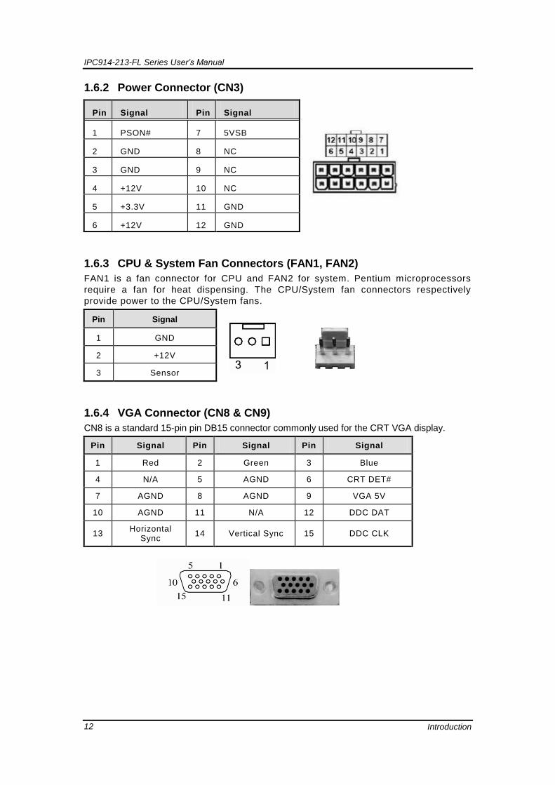
1.6.2 Power Connector (CN3)
Pin Signal Pin Signal
1 PSON# 7 5VSB
2 GND 8 NC
3 GND 9 NC
4 +12V 10 NC
5 +3.3V 11 GND
6 +12V 12 GND
1.6.3 CPU & System Fan Connectors (FAN1, FAN2)
FAN1 is a fan connector for CPU and FAN2 for system. Pentium microprocessors
require a fan for heat dispensing. The CPU/System fan connectors respectively
provide power to the CPU/System fans.
Pin Signal
1 GND
2 +12V
3 Sensor
1.6.4 VGA Connector (CN8 & CN9)
CN8 is a standard 15-pin pin DB15 connector commonly used for the CRT VGA display.
Pin Signal Pin Signal Pin Signal
1 Red 2 Green 3 Blue
4 N/A 5 AGND 6 CRT DET#
7 AGND 8 AGND 9 VGA 5V
10 AGND 11 N/A 12 DDC DAT
13 Horizontal
Sync 14 Vertical Sync 15 DDC CLK

IPC914-213-FL Series User’s Manual
Introduction 13
CN9 is an optional 16-pin pin Box-Header connector for ODM customer only. It shares the
same VGA signal with CN8 and cannot be used with CN8 simultaneously.
Pin Signal Pin Signal
1 Red 2 AGND
3 Green 4 NC
5 Blue 6 AGND
7 NC 8 DDC DAT
9 AGND 10 AGND
11 AGND 12 Horizontal Sync
13 AGND 14 Vertical Sync
15 DDC CLK 16 NC
1.6.5 Ethernet RJ45 Connectors (LAN1, LAN2)
The RJ-45 connector LAN1/LAN2 is for Ethernet. To connect the board to 100-Base-T or
1000-Base-T hub, just plug one end of the cable into LAN1 or LAN2, and then, connect the
other end (phone jack) to a 100-Base-T hub or 1000-Base-T hub.
Pin Signal
1 Tx+ (Data transmission positive)
2 Tx- (Data transmission negative)
3 Rx+(Data reception positive)
4 RJ-1(For 100 base T-Only)
5 RJ-1(For 100 base T-Only)
6 Rx- (Data reception negative)
7 RJ-1(For 100 base T-Only)
8 RJ-1(For 100 base T-Only)
A Active LED
B 100/1000 LAN LED
IPC914-213-FL Series User’s Manual
Introduction 14
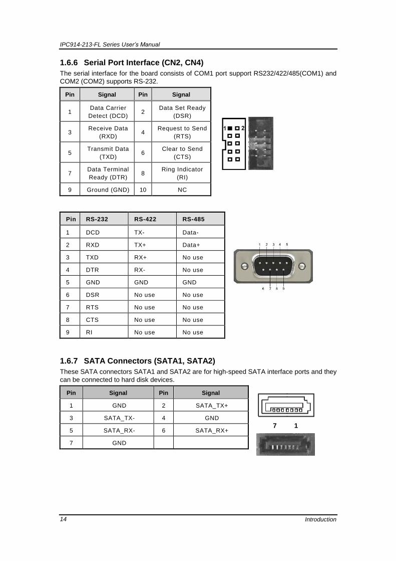
1.6.6 Serial Port Interface (CN2, CN4)
The serial interface for the board consists of COM1 port support RS232/422/485(COM1) and
COM2 (COM2) supports RS-232.
Pin Signal Pin Signal
1 Data Carrier
Detect (DCD) 2
Data Set Ready
(DSR)
3 Receive Data
(RXD) 4
Request to Send
(RTS)
5 Transmit Data
(TXD) 6
Clear to Send
(CTS)
7 Data Terminal
Ready (DTR) 8
Ring Indicator
(RI)
9 Ground (GND) 10 NC
Pin RS-232 RS-422 RS-485
1 DCD TX- Data-
2 RXD TX+ Data+
3 TXD RX+ No use
4 DTR RX- No use
5 GND GND GND
6 DSR No use No use
7 RTS No use No use
8 CTS No use No use
9 RI No use No use
1.6.7 SATA Connectors (SATA1, SATA2)
These SATA connectors SATA1 and SATA2 are for high-speed SATA interface ports and they
can be connected to hard disk devices.
Pin Signal Pin Signal
7 1
1 GND 2 SATA_TX+
3 SATA_TX- 4 GND
5 SATA_RX- 6 SATA_RX+
7 GND
IPC914-213-FL Series User’s Manual
Introduction 15
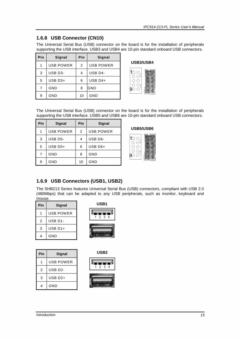
1.6.8 USB Connector (CN10)
The Universal Serial Bus (USB) connector on the board is for the installation of peripherals
supporting the USB interface. USB3 and USB4 are 10-pin standard onboard USB connectors.
Pin Signal Pin Signal
USB3/USB4
1
9
1 USB POWER 2 USB POWER
3 USB D3- 4 USB D4-
5 USB D3+ 6 USB D4+
7 GND 8 GND
9 GND 10 GND
The Universal Serial Bus (USB) connector on the board is for the installation of peripherals
supporting the USB interface. USB5 and USB6 are 10-pin standard onboard USB connectors.
Pin Signal Pin Signal
USB5/USB6
1
9
1 USB POWER 2 USB POWER
3 USB D5- 4 USB D6-
5 USB D5+ 6 USB D6+
7 GND 8 GND
9 GND 10 GND
1.6.9 USB Connectors (USB1, USB2)
The SHB213 Series features Universal Serial Bus (USB) connectors, compliant with USB 2.0
(480Mbps) that can be adapted to any USB peripherals, such as monitor, keyboard and
mouse.
Pin Signal USB1
1 2 3 4
5 6 7 8
1 USB POWER
2 USB D1-
3 USB D1+
4 GND
Pin Signal USB2
1 2 3 4
5 6 7 8
1 USB POWER
2 USB D2-
3 USB D2+
4 GND

IPC914-213-FL Series User’s Manual
Introduction 16
1.6.10 CFastTM
Socket (SCF1)
The board is equipped with a CFastTM
socket on the solder side to support a SATA signal card.
The socket is especially designed to avoid incorrect installation of the CFastTM
card. When
installing or removing the CFastTM
card, please make sure the system power is off. The
CFastTM
is defaulted as the C: or D: disk drive in your PC system.
Pin Signal Pin Signal
S1 GND P5 NC.
S2 TXP P6 NC.
S3 TXN P7 GND
S4 GND P8 NC.
S5 RXN P9 NC.
S6 RXP P10 NC.
S7 GND P11 NC.
P12 NC.
P13 +3.3 V
P1 NC. P14 +3.3 V
P2 GND P15 GND
P3 NC. P16 GND
P4 NC. P17 NC.
IPC914-213-FL Series User’s Manual
Introduction 17
1.7 Packing List
The package bundled with your IPC914-213-FL Series should contain the following
items:
IPC914-213-FL Series Unit x 1
19V 150W Adapter (for AC Version)
Driver CD
Quick Manual
Wall Mount Bracket x 2
Screw pack x 1
Foot pad x 4
Thermal pad for RAM x 1
If you can not find this package or any items are missing, please contact Axiomtek distributors
immediately.

IPC914-213-FL Series User’s Manual
Introduction 18
This page is intentionally left blank.

IPC914-213-FL Series User’s Manual
Hardware Installation 19
CHAPTER 2
HARDWARE INSTALLATION
The IPC914-213-FL Series are convenient for your various hardware configurations,
such as CPU (Central Processing Unit), Memory Module, HDD (Hard Disk Drive) and
PCIe card. The chapter 2 will show you how to install the hardware. It includes:
2.1 Installing the Processor
The Intel® Core™ i7/i5/i3 processors are available as a boxed processor for IPC914-
213-FL system. Intel recommends the processors should be installed by a computer
professional since this electronic device may cause serious damage to the installer,
system and processor if installed improperly.
Important Notes Before attempting to install a new processor, carefully review the
documentation that came with your system and make sure that you will not be voiding
your warranty by opening the computer or replacing your processor.
Instructions:
1. Make sure that your system can accommodate the Intel®
Core™ i7/i5/i3
Processors that you want to install. Check for motherboard, BIOS, and thermal
compatibility by using the manufacturer's documentation for the system, or by
contacting the vendor if necessary. This processor should only be installed in
systems supporting the Intel®
Core™ i7/i5/i3 Processors.
2. Obtain access to your processor socket as described in the documentation for
your system.
3. If the cooling solution prevents you from accessing the processor socket, you
may need to remove it. Instructions on how to remove your cooling solution
should be provided in the documentation that came with the system.
4. To un-install the current processor, use a screwdriver to disengage (open) the
socket actuator, as shown in Figure 1 below. (The most commonly used sockets
are Molex* or FoxConn* sockets, so they are used in the illustrations below.)
The socket actuator should open after only a half turn or so, and you should
then be able to remove the processor with your fingers.

IPC914-213-FL Series User’s Manual
Hardware Installation 20
Procedure of Installation:
Step 1 Turn off the system.
Step 2 Disconnect the power connector.
Step 3 Loosen screws to remove the top cover & right side cover from the chassis.
Step 4 Unscrew the CPU Card screws from the left side Heatsink and then remove the left
side heatsink from the chassis.
Step 5 After opening the top and side covers, you can locate the CPU socket as marked.
Align pins of the CPU with pin holes of the socket. Be careful of the CPU’s
orientation that you need to align the arrow mark on the CPU with the arrow key on
the socket. Place the CPU into the socket, and use a screwdriver to lock it onto the
socket and stick the thermal grease on CPU.

IPC914-213-FL Series User’s Manual
Hardware Installation 21
Step 6 Close the side cover back to the chassis and fasten all screws, then fasten 7 screws
on below red circle on board.
IPC914-213-FL Series User’s Manual
Hardware Installation 22
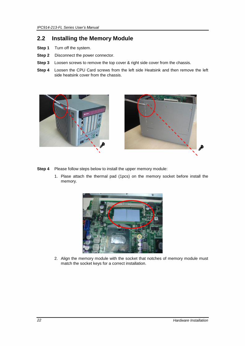
2.2 Installing the Memory Module
Step 1 Turn off the system.
Step 2 Disconnect the power connector.
Step 3 Loosen screws to remove the top cover & right side cover from the chassis.
Step 4 Loosen the CPU Card screws from the left side Heatsink and then remove the left
side heatsink cover from the chassis.
Step 4 Please follow steps below to install the upper memory module:
1. Plase attach the thermal pad (1pcs) on the memory socket before install the
memory.
2. Align the memory module with the socket that notches of memory module must
match the socket keys for a correct installation.

IPC914-213-FL Series User’s Manual
Hardware Installation 23
3. Install the memory module into the socket and push it firmly down until it is fully
seated. The socket latches are clipped on to the edges of the SO-DIMM.
Step 5 Put back the top and side cover to the chassis and fasten all screws.

IPC914-213-FL Series User’s Manual
Hardware Installation 24
2.3 Installing the Hard Disk Drive
The IPC914-213-FL Series offers a convenient drive bay module for users to install
HDD. The system offers users one 2.5” Hard Disk Drive for installation. Please
follow the steps:
Step 1 Turn off the system.
Step 2 Disconnect the power connector.
Step 3 Loosen screws to remove the HDD Side cover from the chassis.
Step 4 Open the HDD side cover and locate the Hard Disk Drives from the side.

IPC914-213-FL Series User’s Manual
Hardware Installation 25
Step 5 Use assembly parts to fix HDD with the bracket .
Step 6 Install and fix the HDD through the side, next, plug the power cable in HDD.
Step 7 Close the HDD side cover back to the chassis and fasten all screws.

IPC914-213-FL Series User’s Manual
Hardware Installation 26
2.4 Installing the PCI or PCIe Card
Step 1 Turn off the system.
Step 2 Disconnect the power connector.
Step 3 Loosen screws to remove the top cover from the chassis. Removing the PCI or PCIe
bracket by releasing the button as marked.
Step 4 Locate the PCI or PCIe slots.

IPC914-213-FL Series User’s Manual
Hardware Installation 27
Step 5 Align the PCI or PCIe card with the slot, and press the card into the slot until it is
firmly seated.
Step 6 Close the top cover back to the chassis and fasten all screws.

IPC914-213-FL Series User’s Manual
Hardware Installation 28
This page is intentionally left blank.

IPC914-213-FL Series User’s Manual
AMI BIOS Utility 29
CHAPTER 3
AMI BIOS UTILITY
The AMI UEFI BIOS provides users with a built-in setup program to modify basic
system configuration. All configured parameters are stored in a 16MB flash chip to
save the setup information whenever the power is turned off. This chapter provides
users with detailed description about how to set up basic system configuration
through the AMI BIOS setup utility.
3.1 Starting
To enter the setup screens, follow the steps below:
1. Turn on the computer and press the <Del> key immediately.
2. After you press the <Del> key, the main BIOS setup menu displays. You can access the other setup screens from the main BIOS setup menu, such as the Advanced and Chipset menus.
Note: If your computer cannot boot after making and saving system changes with Setup, you can restore BIOS optimal defaults by setting JP1 (see section 1.5.1) .
It is strongly recommended that you should avoid changing the chipset ’s defaults.
Both AMI and your system manufacturer have carefully set up these defaults that
provide the best performance and rel iability.
IPC914-213-FL Series User’s Manual
AMI BIOS Utility 30
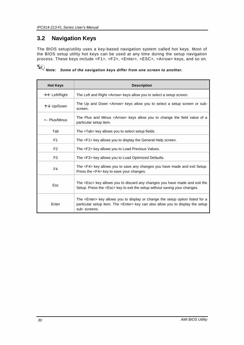
3.2 Navigation Keys
The BIOS setup/utility uses a key-based navigation system called hot keys. Most of
the BIOS setup utility hot keys can be used at any time during the setup navigation
process. These keys include <F1>, <F2>, <Enter>, <ESC>, <Arrow> keys, and so on.
Note: Some of the navigation keys differ from one screen to another.
Hot Keys Description
Left/Right The Left and Right <Arrow> keys allow you to select a setup screen.
Up/Down The Up and Down <Arrow> keys allow you to select a setup screen or sub-
screen.
+ Plus/Minus The Plus and Minus <Arrow> keys allow you to change the field value of a
particular setup item.
Tab The <Tab> key allows you to select setup fields.
F1 The <F1> key allows you to display the General Help screen.
F2 The <F2> key allows you to Load Previous Values.
F3 The <F3> key allows you to Load Optimized Defaults.
F4 The <F4> key allows you to save any changes you have made and exit Setup.
Press the <F4> key to save your changes.
Esc The <Esc> key allows you to discard any changes you have made and exit the
Setup. Press the <Esc> key to exit the setup without saving your changes.
Enter
The <Enter> key allows you to display or change the setup option listed for a
particular setup item. The <Enter> key can also allow you to display the setup
sub- screens.

IPC914-213-FL Series User’s Manual
AMI BIOS Utility 31
3.3 Main Menu
The first time you enter the setup utility, you will be in the Main setup screen. You
can always return to the Main setup screen by selecting the Main tab. System
Time/Date can be set up as described below. The Main BIOS setup screen is shown
below.
System LanguageUse this item to choose the system default language.
System Date/TimeUse this option to change the system time and date.
Highlight System Time or System Date using the <Arrow> keys. Enter new
values through the keyboard. Press the <Tab> key or the <Arrow> keys to
move between fields. The date must be entered in MM/DD/YY format. The
time is entered in HH:MM:SS format.

IPC914-213-FL Series User’s Manual
AMI BIOS Utility 32
3.4 Advanced Menu
Launch PXE OpROM
Use this item to enable or disable the boot ROM function of the onboard LAN chip
when the system boots up.
The Advanced menu also allows users to set configuration of the CPU and other
system devices. You can select any of the items in the left frame of the screen to go
to the sub menus:
► ACPI Settings
► CPU Configuration
► SATA Configuration
► USB Configuration
► W83627H Super IO Configuration
► W83627DHG Super IO Configuration
► W83627DHG H/W Monitor
For items marked with “”, please press <Enter> for more options.

IPC914-213-FL Series User’s Manual
AMI BIOS Utility 33
ACPI Settings
ACPI configuration can be configured in ACPI Settings. A description of the selected
item appears on the right side of the screen.
Enable ACPI Auto Configuration
Use this item to enable or disable BIOS ACPI auto configuration.
Enable Hibernation
Enable or disable system ability to hibernate (OS/S4 sleep state).
ACPI Sleep State
Allow you to select the Advanced Configuration and Power Interface (ACPI)
state to be used for system suspend. Here are the options for your selection;
S1 (CPU Stop Clock), S3 (Suspend to RAM) and Suspend Disable
**When you use S3 or S1 on XP OS, please connect your USB divice on
below red mark position.

IPC914-213-FL Series User’s Manual
AMI BIOS Utility 34
S3 Video Repost
Enable or disable S3 video repost.
CPU Configuration
This screen shows the CPU Configuration, and you can change the value of the
selected option.
Node 0 Information
View memory information related to Node 0.

IPC914-213-FL Series User’s Manual
AMI BIOS Utility 35
SATA Configuration
you can read the current installed hardware configurations from those SATA ports in
the SATA Configuration menu. During system boot up, BIOS will detect the present
SATA devices automatically.

IPC914-213-FL Series User’s Manual
AMI BIOS Utility 36
USB Configuration
USB configuration can be configured here by selecting and changing each item. A
description of the selected item appears on the right side of the screen.
Legacy USB Support
Use this item to enable or disable support for USB device on legacy
operating system. The default setting is Enabled. Auto option disables
legacy support if no USB devices are connected. Disable option will keep
USB devices available only for EFI applications.
USB transfer time-out
The time-out value for control, bulk and interrupt transfers.
Device reset time-out
USB mass storage device start unit command time-out.
Device power-up delay
Maximum time the device will take before it properly reports itself to the host
controller. “Auto” uses default value: for a root port it is 100ms, for a hub
port the delay is taken from hub descriptor

IPC914-213-FL Series User’s Manual
AMI BIOS Utility 37
Super IO Configuration
W83627UHG Serial Port Configuration
The configuration of serial port 1~4 are set <Auto> as default.
IPC914-213-FL Series User’s Manual
AMI BIOS Utility 38
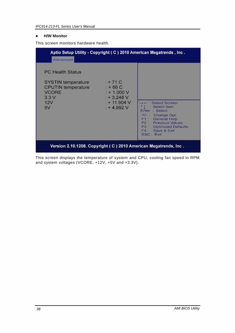
H/W Monitor
This screen monitors hardware health.
This screen displays the temperature of system and CPU, cooling fan speed in RPM
and system voltages (VCORE, +12V, +5V and +3.3V) .
IPC914-213-FL Series User’s Manual
AMI BIOS Utility 39
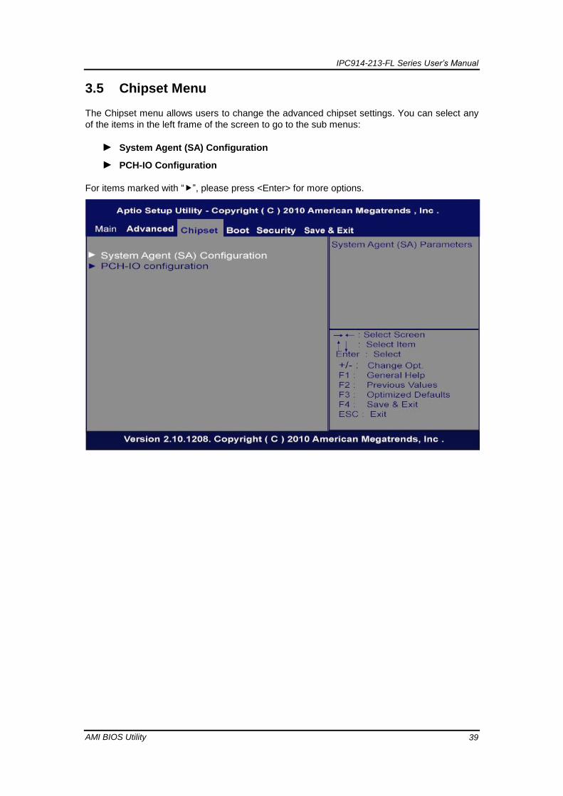
3.5 Chipset Menu
The Chipset menu allows users to change the advanced chipset settings. You can select any
of the items in the left frame of the screen to go to the sub menus:
► System Agent (SA) Configuration
► PCH-IO Configuration
For items marked with “”, please press <Enter> for more options.

IPC914-213-FL Series User’s Manual
AMI BIOS Utility 40
► Graphics Configuration
► Memory Configuration
For items marked with “”, please press <Enter> for more options.
IPC914-213-FL Series User’s Manual
AMI BIOS Utility 41
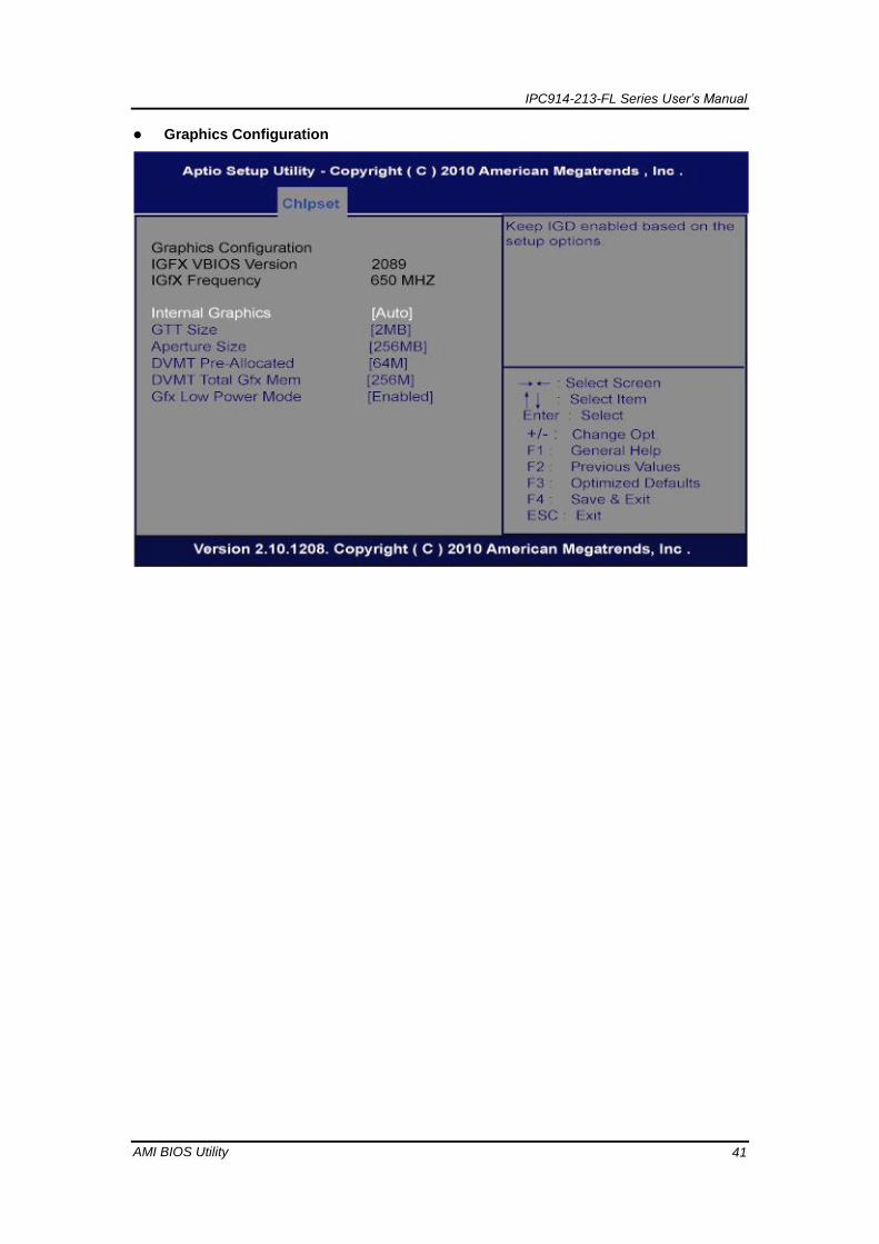
Graphics Configuration

IPC914-213-FL Series User’s Manual
AMI BIOS Utility 42
Memory Information

IPC914-213-FL Series User’s Manual
AMI BIOS Utility 43
3.6 Boot Menu
The Boot menu allows users to change boot options of the system.
Setup Prompt Timeout
Number of seconds to wait for setup activation key.65535 (0xFFFF) means
indefinite waiting.
Boot up Unlock State
Use this item to select the power-on state for the Unlock.
Quiet Boot
Enable or disable Quiet Boot option.
IPC914-213-FL Series User’s Manual
AMI BIOS Utility 44
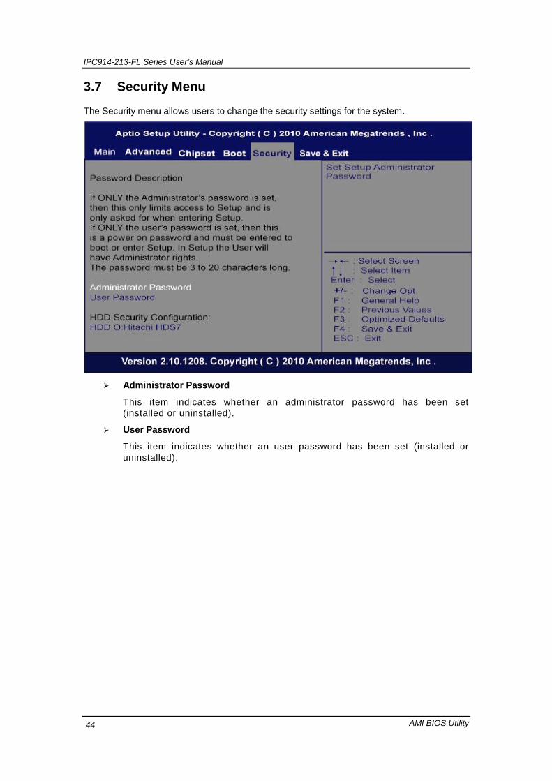
3.7 Security Menu
The Security menu allows users to change the security settings for the system.
Administrator Password
This item indicates whether an administrator password has been set
(installed or uninstalled).
User Password
This item indicates whether an user password has been set (installed or
uninstalled).

IPC914-213-FL Series User’s Manual
AMI BIOS Utility 45
3.8 Save & Exit Menu
The Save & Exit menu allows users to load your system configuration with optimal or
fail-safe default values.
Save Changes and Exit
When finish the system configuration settings, select this option to leave
Setup and return to Main Menu. Select Save Changes and Exit from the
Save & Exit menu and press <Enter>. Select Yes to save changes and exit .
Discard Changes and Exit
Select this option to quit Setup without making any permanent changes to
the system configuration and return to Main Menu. Select Discard Changes
and Exit from the Save & Exit menu and press <Enter>. Select Yes to
discard changes and exit.
Save Changes and Reset
When finish the system configuration settings, select this option to leave
Setup and reboot the computer so the new system configuration parameters
can take effect. Select Save Changes and Reset from the Save & Exit menu
and press <Enter>. Select Yes to save changes and reset .

IPC914-213-FL Series User’s Manual
AMI BIOS Utility 46
Discard Changes and Reset
Select this option to quit Setup without making any permanent changes to
the system configuration and reboot the computer. Select Discard Changes
and Reset from the Save & Exit menu and press <Enter>. Select Yes to
discard changes and reset.
Save Changes
When finish the system configuration settings, select this option to save
changes. Select Save Changes from the Save & Exit menu and press
<Enter>. Select Yes to save changes.
Discard Changes
Select this option to quit Setup without making any permanent changes to
the system configuration. Select Discard Changes from the Save & Exit
menu and press <Enter>. Select Yes to discard changes.
Restore Defaults
When select this option, all the settings will be restored to defaults
automatically. Select Restore Defaults from the Save & Exit menu and press
<Enter>.
Save as User Defaults
Select this option to save your current system configuration settings as User
Defaults. Select Save as User Defaults from the Save & Exit menu and
press <Enter>.
Restore User Defaults
When select this option, all the settings will be restored to user defaults
automatically. Select Restore User Defaults from the Save & Exit menu and
press <Enter>.


![9229w] 999.999 9 9 9 . . A. 9A a 9.9 1 9 9.9 fl fl fl aw 9.999999 9..](https://static.fdokumen.com/doc/165x107/631f96a163f0eba19606edfd/9229w-999999-9-9-9-a-9a-a-99-1-9-99-fl-fl-fl-aw-9999999-9.jpg)


