
IP central unit Gateway - JUNG
201
KNX/EIB Product documentation Seite: 1 of 200 Hardware description IP central unit Gateway Product name IP central unit Design: Rail-mounted device (REG) Article. no. IPZ 1000 REG ETS search path: Communication / IP /IP central unit Issue: 30.09.2006 Functional description: The IP central unit is the interface between an Ethernet (LAN = L ocal A rea N etwork) and the KNX/EIB. With the help of an Ethernet connection, the user has access to his intelligent building management system via a local PC of his LAN or via the Internet. The connection with the Internet cannot only be established via an LAN (e.g. in conjunction with DSL) but also with an analog modem (e.g. V.90 56K) or with an ISDN modem (with RS232 interface). The IP central unit can thus be easily integrated into new or already existing home or office networks. The IP central unit acts as a web server and can be comfortably operated from a browser (Microsoft © Internet Explorer Version 5.5 and higher) as a control, reporting and monitoring unit. The IP central unit moreover permits user-guided commissioning and configuration by enabling the user to make different settings via the web user interface. The KNX/EIB configuration is ensured by an ETS-embedded plug-in. The central unit can work as a bus system clock by using the Standard Time supplied by a time server in the Internet. The system clock can work as a central year time switch with astro function and day profiles (scheduler) and as a presence simulator. In addition, the following features are available: logic gates and information function per e-mail, an integrated e-mail address book, central functions and scenes for lighting, HVAC and alarm systems. Layout: Dimensions: Width: 144 mm (8 modules) Height: 90 mm Depth: 61 mm Controls: + 24 V - / LAN RS232 local bus Bereich: Linie: TLN- Nr.: IP - Zentrale IPZ 1000 REG DC 24V Power / Betrieb Online / Modem Link / LAN Made in Germany 82766903 IP- Adresse: Subnet Mask: DHCP: a b A B C D E F G H A programming LED (red) B programming button C a/b trigger input (e.g. extension output of a telecommunication system for analog terminals) D RS 232 (V.24) interface for connection of an external modem E LAN connection RJ45 socket F connection for local bus (reserved for future applications) G terminals for connection of external power supply H Power / Betrieb (green): Permanently lit up after initialization when the supply voltage is present. Online / Modem (yellow): Signals an active Internet connection via the modem (RS232) Link / LAN (yellow): Lit up in case of an existing link with the LAN (link with an Ethernet connection point as, for instance, a hub or a switch (straight) or a PC (cross)). Flickers during the transmission of data via the LAN.
-
Upload
khangminh22 -
Category
Documents
-
view
0 -
download
0
Transcript of IP central unit Gateway - JUNG

KNX/EIB
Product documentation Seite: 1 of 200
Hardware description
IP central unit
Gateway
Product name IP central unit Design: Rail-mounted device (REG) Article. no. IPZ 1000 REG ETS search path:
Communication / IP /IP central unit
Issue: 30.09.2006 Functional description:
The IP central unit is the interface between an Ethernet (LAN = Local Area Network) and the KNX/EIB. With the help of an Ethernet connection, the user has access to his intelligent building management system via a local PC of his LAN or via the Internet. The connection with the Internet cannot only be established via an LAN (e.g. in conjunction with DSL) but also with an analog modem (e.g. V.90 56K) or with an ISDN modem (with RS232 interface). The IP central unit can thus be easily integrated into new or already existing home or office networks. The IP central unit acts as a web server and can be comfortably operated from a browser (Microsoft© Internet Explorer Version 5.5 and higher) as a control, reporting and monitoring unit. The IP central unit moreover permits user-guided commissioning and configuration by enabling the user to make different settings via the web user interface. The KNX/EIB configuration is ensured by an ETS-embedded plug-in. The central unit can work as a bus system clock by using the Standard Time supplied by a time server in the Internet. The system clock can work as a central year time switch with astro function and day profiles (scheduler) and as a presence simulator. In addition, the following features are available: logic gates and information function per e-mail, an integrated e-mail address book, central functions and scenes for lighting, HVAC and alarm systems. Layout: Dimensions:
Width: 144 mm (8 modules) Height: 90 mm Depth: 61 mm Controls:
+ 24 V -
/
LAN RS232
local bus
Bereich:
Linie:
TLN-Nr.:
IP - ZentraleIPZ 1000 REGDC 24 V
Power / BetriebOnline / Modem
Link / LAN
M ade in Germany
827
6690
3
IP-Adresse:SubnetMask:
DHCP:
a b
A
B
C
DEFG
H
A programming LED (red) B programming button C a/b trigger input (e.g. extension
output of a telecommunication system for analog terminals)
D RS 232 (V.24) interface for connection of an external modem
E LAN connection RJ45 socket F connection for local bus (reserved
for future applications) G terminals for connection of external
power supply
H Power / Betrieb (green): Permanently lit up after initialization when the supply voltage is present. Online / Modem (yellow): Signals an active Internet connection via the modem (RS232) Link / LAN (yellow): Lit up in case of an existing link with the LAN (link with an Ethernet connection
point as, for instance, a hub or a switch (straight) or a PC (cross)). Flickers during the transmission of data via the LAN.

KNX/EIB
Product documentation Seite: 2 of 200
Hardware description
Technical data Type of protection IP 20 Mark of approval: KNX / EIB Ambient temperature: -5 °C ... +45 °C Storage / transport temperature: -25 °C ... +70 °C (storage above +45 °C reduces the lifetime) Mounting position: any Minimum distances: none Type of fastening: snap-fastening on DIN rail (no data rail required)
KNX / EIB supply (bus terminal)
Voltage: 21 – 32 V DC SELV Power consumption: typically 150 mW (the bus controller is supplied from the external
power supply) Connection: KNX / EIB supply and branch terminal
External supply (screw terminal)
Voltage: 24 V DC SELV (21 – 32 V DC. e.g. via unchoked output of a KNX/EIB power supply
Power consumption: typically 3 W / 6 W max. if the local bus interface is used (at 24 V DC)
Connection: Screw terminals: 0.5 – 4 mm² single and stranded wire without ferrule 0.5 – 2.5 mm² stranded wire with ferrule
Response on bus voltage failure Bus voltage only: no reaction (IP communication possible / any attempt to change or to
read KNX/EIB data points fails) Supply voltage:
no reaction (device shuts off completely)
Response on return of voltage Bus voltage only: The KNX/EIB interface re-initializes itself. Default values as per
presetting or as read out by the bus and updated are assigned to KNX/EIB datapoints.
Supply voltage: The devices re-initializes itself (boot procedure starts and lasts a few seconds. During booting, the green Power LED is off). Default values as per presetting or as read out by the bus and updated are assigned to KNX/EIB datapoints.
LAN Number: 1 Connection: RJ45 socket (10/100 MBit/s Fast Ethernet) 8-pole LAN connection: straight with an an Ethernet connection point (hub, switch, etc.),
crossed with a PC Protocols TCP/IP (HTTP to port 80), UDP, POP, SMTP, SNTP, PPP IP addressing: IP address, sub-net mask, gateway address and DNS server address
presettable DHCP possible (factory-set to active ), autoIP
a/b trigger input Number: 1 Signal voltage typically 30 - 60 V AC (ringing tone signal of analog telephones)
max. û = 96 V AC Signal duration: min. 40 ms Connection: Screw terminals:
0.5 – 4 mm² single and stranded wire without ferrule 0.5 – 2.5 mm² stranded wire with ferrule
KNX/EIB
Product documentation Seite: 3 of 200
Hardware description
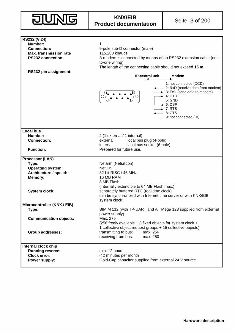
RS232 (V.24) Number: 1 Connection: 9-pole sub-D connector (male) Max. transmission rate 115.200 kbauds RS232 connection: A modem is connected by means of an RS232 extension cable (one-
to-one wiring) The length of the connecting cable should not exceed 15 m.
RS232 pin assignment:
96
51
1: not connected (DCD)2: RxD (receive data from modem)3: TxD (send data to modem)4: DTR5: GND6: DSR7: RTS8: CTS9: not connected (RI)
IP-central unit Modem
Local bus Number: 2 (1 external / 1 internal) Connection: external local bus plug (4-pole)
internal: local bus socket (6-pole) Function: Prepared for future use.
Processor (LAN)
Type: Netarm (Netsilicon) Operating system: Net OS Architecture / speed: 32-bit RISC / 46 MHz Memory: 16 MB RAM
8 MB Flash (internally extendible to 64 MB Flash max.)
System clock: separately buffered RTC (real time clock) can be synchronized with Internet time server or with KNX/EIB system clock
Microcontroller (KNX / EIB) Type: BIM M 112 (with TP-UART and AT Mega 128 supplied from external
power supply) Communication objects: Max. 275
(256 freely available + 3 fixed objects for system clock + 1 collective object request groups + 15 collective objects)
Group addresses: transmitting to bus: max. 256 receiving from bus: max. 250
Internal clock chip Running reserve: min. 12 hours Clock error: < 2 minutes per month Power supply: Gold-Cap capacitor supplied from external 24 V source

KNX/EIB
Product documentation Seite: 4 of 200
Hardware description
Table of Contents I
Page
1. Fitting and installation 6 1.1 Connections 6 1.2 Types of connection 9 2. Configuration 15 2.1 Internet basics 15
2.1.1 Exchange of data via the Web 15 2.1.2 IP addresses 16 2.1.3 DHCP 17 2.1.4 DNS name resolution 18 2.1.5 PPP – the modem link 18 2.1.6 SNTP – The network time protocol 19 2.1.7 SMTP and POP – The e-mail 19 2.1.8 Internet communication and dynamic Internet addresses 20
2.1.8.1 Internet connection 20 2.1.8.2 NAT – Address translation 21 2.1.8.3 Dynamic IP addresses – The DynDNS 23 2.1.8.4 Firewall and security settings 24 2.1.8.5 Access protection 25
2.2 Configuration settings 26 2.2.1 "IP configuration" parameters 26 2.2.2 "Security" parameters 27 2.2.3 "PPP" modem link parameters 28 2.2.4 "Users" and "Passwords" parameters 30 2.2.5 Internet access parameters "Modem / Internet" 32 2.2.6 Internal "System clock" parameters 34 2.2.7 Device configuration during commissioning with the "Discovery-Tool 36 2.2.8 "Directory server" parameters 37 2.2.9 Default configuration 38
3. Projecting and ETS plug-in 39 3.1 General 39 3.2 Creating the building and room structure 40
3.2.1 Starting the plug-in 40 3.2.2 Plug-in interface 43
3.2.2.1 Menu- and service functions 44 3.2.2.2 Representation of the object model 48 3.2.2.3 Representation and processing of group addresses and datapoints in the
ETS 51
3.2.3 Creating and editing an object model 55 3.2.3.1 Creation of a room structure 55 3.2.3.2 Definition of the required building services 56 3.2.3.3 Creation of the required functional groups 57 3.2.3.4 Creation and configuration of the datapoints 59 3.2.3.5 Assignment of group addresses 66
3.3 Logic operations 72 3.3.1 Creating logic operation modules 72 3.3.2 Editing logic operation modules 73
3.3.2.1 Defining input and output datapoint 73 3.3.2.2 Configuration of a standard logic operation 74 3.3.2.3 Configuration of a comfort logic operation 76
3.3.2.3.1 Setting the input parameters 77 3.3.2.3.2 Functioning of the module kernel 78 3.3.2.3.3 Setting the output parameters 80
3.3.3 Processing of input data 81

KNX/EIB
Product documentation Seite: 5 of 200
Hardware description
Table of Contents II (continued)
Page
4. Commissioning 82 4.1 General information 82 4.2 Programming of the IP central unit 82 4.3 Gateway-Browser 88 5. User interface and functions 91 5.1 General 91 5.2 Starting screen with user log-in 92 5.3 The user interface 94
5.3.1 Presentation and navigation 94 5.3.1.1 Working with the browser interface 96 5.3.1.2 Definition of terms 96 5.3.1.3 Help system 97 5.3.1.4 Recurring elements 98
5.3.1.4.1 Inserting, editing or deleting actions 98 5.3.1.4.2 Inserting, editing or deleting events / conditions 101 5.3.1.4.3 Navigation in complex applications 104
5.3.2 Application 'Building' 105 5.3.2.1 General 105 5.3.2.2 'Overview' tab 105 5.3.2.3 'Favorites' tab 106 5.3.2.4 'Rooms' tab 109 5.3.2.5 'Building services' tab 111 5.3.2.6 'Personalize' tab 113 5.3.2.7 'Rights' tab 116
5.3.3 Application 'Time scheduler' 118 5.3.3.1 Navigation in the scheduler 118 5.3.3.2 The annual overview of the time scheduler 119 5.3.3.3 The week profile of the time scheduler 123 5.3.3.4 The day profile of the time scheduler 124 5.3.3.5 Fixed day profiles in the time scheduler 129 5.3.3.6 Time scheduler tutorial 134
5.3.4 Application 'Presence simulation' 148 5.3.4.1 'Overview' tab 149 5.3.4.2 'Actions' tab 150 5.3.4.3 Switching times' tab 152 5.3.4.4 'Activation' tab’ 153 5.3.4.5 Presence simulation tutorial 154
5.3.5 Application 'Scenes' 159 5.3.5.1 'Active scenes' tab 159 5.3.5.2 'Scenes overview' tab 160 5.3.5.3 'Rights' tab 164 5.3.5.4 Scenes tutorial 165
5.3.6 Application 'Event' recorder' 170 5.3.6.1 'Active message handling' tab 170 5.3.6.2 'Overview' tab 172 5.3.6.3 'Adress book' tab 184 5.3.6.4 'E-mail sending options' tab 185 5.3.6.5 Event recorder tutorial 186
5.3.7 End program 193 5.3.8 Time and language settings 195

KNX/EIB
Product documentation Seite: 6 of 200
Hardware description
1. Fitting and installation The IP central unit is designed as a rail-mounted device (REG) and provided for installation in a switchgear cabinet or distribution board. Basically, the unit needs an external power supply of 24 VDC and a connection with the KNX / EIB. Depending on the configuration in which the device is used, an Ethernet (LAN) or a modem link via the RS232 interface and a connection with an analog telphone line may be required in addition. All other connections should be made before connecting the power supply.
1.1 Connections
• Ethernet connection:
If it is intended to connect the IP central unit to a local network (LAN), possibly with a connection to the Internet, or also directly to a PC, an Ethernet link is required. For this purpose, the IP central unit is equipped with an 8-pole RJ45 socket as network interface. This socket is connected by means of a twisted-pair (TP) cable which - depending on the devices to be connected with one another - must be designed as follows:
- as a one-to-one link cable (patch cable) in case of connection to the 'normal' or auto-MDIX port of a network distributor (e.g. hub, switch, router),
- as a crossover cable in case of direct connection to a PC (point-to-point link) The Ethernet lines used should correspond at least to the Cat.5 standard. The general guidelines governing the installation of Ethernet lines must be observed. The IP central unit supports the 10BaseT (10 Mbit) and 100BaseT (100 Mbit) standards.
When the physical connection with a network distributor or a PC is established, the yellow Link / LAN LED on the device front panel lights up when the supply voltage is applied. This LED flickers when data telegrams are being received via the Ethernet interface.
The logic link with the network will be established only after allocation of an IP address. The procedure of allocating an IP address is described in greater detail in chapter 2 "Configuration".
• Modem connection:
Depending on the type of connection, an analog modem or an an ISDN modem with serial RS232 interface can be connected to the IP central unit for Internet dial-in. The connection is made by means of a one-to-one interconnecting cable which should not be longer than 15 m.
96
51
1: not connected (DCD)2: RxD (receive data from modem)3: TxD (send data to modem)4: DTR5: GND6: DSR7: RTS8: CTS9: not connected (RI)
IP-central unit Modem
As soon as an online link has been established by or with the IP central unit, the yellow Online / Modem LED on the front panel of the device lights up. In this case, the exchange of data is in progress and online or phone call charges are accruing. The modem is controlled by means of internationally standardized AT commands so that a large variety of current modems can be connected. Further configuration settings, especially the definition of the type of modem used, are explained in chapter 2 "Configuration". The connection of a modem to the local telephone network is manufacturer-specific and the corresponding instructions should therefore be inferred from the documentation supplied with the modem used.

KNX/EIB
Product documentation Seite: 7 of 200
Hardware description
• Telephone connection:
The IP central unit is equipped with an analog telephone trigger input. Depending on the type of connection, this input can be used for triggering an Internet dial-in 'from outside'. This function is useful with time- or volume-based Internet charges (cf. 1.2 "Types of connection"). The IP central unit monitors the signal voltage at the a/b input for a ringing signal. If a ringing signal is detected, the central unit establishes a connection with the Internet via the configured link. As the ringing signal is only 'overheard' by the unit without answering the call, no call charges are accrued. There is no calling line identification (CLI) via the the a/b terminals. Each call coming in on the connected line is therefore interpreted as a trigger signal. For this reason, the connected analog telephone line should have a phone number of its own. This can be achieved with an independent telephone line or a separate analog extension in a branch exchange.
The telephone line is connected to the IP central unit by means of the screw terminal pair "a / b". The line itself is usually connected to the terminals of a PBX (cf. Fig. 1) or to an existing TAE telephone outlet box (cf. Fig. 2).
IP central unitTerminal strip
of a PBX
a bb a /a b
Fig. 1: connection to the terminal strip of a PBX
IP central unit
TAE-box
/a b
1 2 3 4 5 6
1 2
3 4
5 6
a b W E a2b2Telephone line /extension line
Fig. 2: connection to an existing TAE telephone outlet box If the device is connected to a TAE box as shown in Fig. 2, the connection to the IP central unit is interrupted when a terminal device is plugged into the TAE outlet box. For this reason, no terminal device should be plugged into the TAE outlet box. For reasons of clarity, the polarity of the line should be observed. On principle, the polarity of an analog telephone line connected to the IP central unit is of no importance.

KNX/EIB
Product documentation Seite: 8 of 200
Hardware description
• Connection of the supply voltage and bus connection:
The IP central unit needs an external supply voltage of 24 VDC for operation. This supply voltage can be derived, for instance, from the unchoked voltage output of a KNX/EIB power supply (21 – 32 V DC) The bus is connected with the bus connection terminal.
+ 24 V -
/
LAN RS232
local bus
Bereich:
Linie:
TLN-Nr.:
IP - ZentraleIPZ 1000 REGDC 24 V
Online / Modem Link / LAN
M ade in Germany
8276
6903
IP-Adresse:SubnetMask:
DHCP:
Power / Betrieb
a b
24 V DC+-
KNX / EIB
Fig 1: Connection of the external supply voltage and bus line

KNX/EIB
Product documentation Seite: 9 of 200
Hardware description
1.2 Types of connection
With the help of an Ethernet connection, the user has access to his KNX / EIB system via a local PC of his LAN or – in addition or alternatively – also via the Internet (cf. Fig. 2).
IP central unit asWeb serverBrowser (Internet-Explorer) as
Web client
PC
+ 24 V -
/
LAN RS232
local bus
Bereich:
Linie:
TLN-Nr.:
IP - ZentraleIPZ 1000 REGDC 24 V
Online / Modem Link / LAN
M ade in Ge rm an y
8276
6903
IP-Adresse:SubnetMask:
DHCP:
Power / Betrieb
a b
LAN (Local Area Network)
Fig. 1: access to the IP central unit via the local area network (LAN)
IP central unit asWeb serverBrowser (Internet-Explorer) as
Web client
PC
+ 24 V -
/
LAN RS232
local bus
Bereich:
Linie:
TLN-Nr.:
IP - ZentraleIPZ 1000 REGDC 24 V
Online / Modem Link / LAN
M ade in Ge rm an y
8276
6903
IP-Adresse:SubnetMask:
DHCP:
Power / Betrieb
a b
WAN (Wide Area Network)
Internet
Fig. 2: Access to the IP central unit via the Internet (WAN) The connection with the Internet cannot only be established via an LAN (e.g. in conjunction with DSL) but also with an analog modem (e.g. V.90 56K) or with an ISDN modem (with RS232 interface). The IP central unit can thus be easily integrated into new or already existing home or office networks.

KNX/EIB
Product documentation Seite: 10 of 200
Hardware description
The different types of connection are explained below. The configuration settings required for the respective type of connection are discussed in chapter 2 "Configuration" Type of connection A (operation in an LAN comprising only one PC)
PC
+ 24 V -
/
LAN RS232
local bus
Bereich:
Linie:
TLN-Nr.:
IP - ZentraleIPZ 1000 REGDC 24 V
Online / Modem Link / LAN
M ade in Ge rm an y
8276
6903
IP-Adresse:SubnetMask:
DHCP:
Power / Bet rieb
a b
crossover cable
IP central unit
Direct connection of a PC with the IP central unit by means of a crossover cable (transmit and receive lines crossed over / special network cable required) In this type of connection, only the PC directly connected with the central unit has access to the device.
Type of connection B: (operation in an LAN with one or more PCs via a network distributor)
PC 1 patch cable
IP central unit
+ 24 V -
/
LAN RS232
local bus
Bereich:
Linie:
TLN-Nr.:
IP - ZentraleIPZ 1000 REGDC 24 V
Online / Modem Link / LAN
M ade in Ge rm any
8276
6903
IP-Adresse:SubnetMask:
DHCP:
Power / Betrieb
a b
patch cable
PC 2 patch cable
e. g.hub / switch
This type of connection permits access to the IP central unit by several PCs of the local area network. The physical connection of the network components is realized by means of one-to-one patch cables. Information concerning the use of several PCs (clients): The IP central unit can establish a maximum of 10 IP connections (sessions) at the same time, i.e that a maximum of 10 clients can load data from the central unit (the server) at the same time. It should be noted, that Microsoft's InternetExplorer sometimes launches several logic IP sessions at the same time in order to accelerate the loading process. In spite of this strategy, the static viewing of a loaded website (no data download) is not dependent on a certain number of sessions.

KNX/EIB
Product documentation Seite: 11 of 200
Hardware description
Type of connection C (operation in an LAN with permanent connection to the Internet)
optionalPC
patch cable
IP central unit
Router
+ 24 V -
/
LAN RS232
local bus
Bereich:
Linie:
TLN-Nr.:
IP - ZentraleIPZ 1000 REGDC 24 V
Online / Modem Link / LAN
Made in Germ any
8276
6903
IP-Adresse:SubnetMask:
DHCP:
Power / Betrieb
a b
Internet
e. g.DSL
patch cable
With the help of a router or a proxy server, a local Ethernet (LAN) makes a permanent Internet connection available. This type of connection makes sense, for instance, in case of a DSL flat-rate or a dedicated telephone line for the Internet. The IP central unit can ensure by means of keep-alive telegrams that the link is not disconnected by the router or the service provider (ISP) Even after a forced disconnect by the service provider (depending on subscriber rate often after 24 hours of permanent connection) a permanent connection with Internet can thus be be upheld. The access 'from outside' is effected from an external PC with the browser as user interface and by entering the password ensuring user authorization. After successful log-in, the Web page of the IP central unit is displayed. The KNX/EIB system can be controlled and monitored by direct access. To enable the access to the IP central unit from the Internet, the router or the proxy server must redirect external HTTP requests addressed to the IP central unit inside the local area network. For redirection, the NAT (Network Address Translation) function can be used in the router. In this mode, the router translates HTTP requests from the Internet to the local IP address of the IP central unit. HTTP request are directed to port 80 of the central unit. Further basic notions and configuration settings are discussed in chapter 2 "Configuration".

KNX/EIB
Product documentation Seite: 12 of 200
Hardware description
Type of connection D (operation in an LAN with Internet dial-in after modem request / modem-tiggered dial-in)
optionalPC
patch cable
IP central unit
Router
Internete. g.DSL
patch cable
datatelephone -trigger
+ 24 V -
/
LAN RS232
local bus
Bereich:
Linie:
TLN-Nr.:
IP - ZentraleIPZ 1000 REGDC 24 V
Online / Modem Link / LAN
M ade in Ge rm an y
8276
6903
IP-Adresse:SubnetMask:
DHCP:
Power / Bet rieb
a b
Modem
With the help of a router or a proxy server, a local Ethernet (LAN) establishes a connection with the Internet after a modem request. This type of connection makes sense, for instance, in case of a DSL connection with a time- or volume-based rate. The trigger call via a modem connection (simple call to the telephone number of the modem) causes the IP central unit to establish a link with the Internet via its LAN interface. As soon as the link is established, the IP central unit can be accessed. The call to the modem does not establish a telephone contact so that no call charges will accrue. The modem simply detects the ringing signal and informs the IP central unit accordingly. In this case it is recommended to use modems permitting identification of the calling line (CLIP function). The feature can be used as a trigger call authorization function. When the CLIP function is active, only trigger calls from telephone numbers known to the IP central unit will be accepted. In this case, the transmission of the caller's telephone number must be supported by the telephone line. The IP central unit can ensure by means of keep-alive telegrams that the link is not disconnected by the router or the service provider (ISP). Even after a forced disconnect by the service provider (depending on the rate often after 24 hours of permanent connection) a permanent connection with Internet can thus be be upheld. To enable the access to the IP central unit from the Internet when the connection is established, the router or the proxy server must redirect external HTTP requests to the IP central unit within the local area network. For redirection, the NAT (Network Address Translation) function can be used in the router. In this mode, the router translates HTTP requests from the Internet to the local IP address of the IP central unit. For HTTP, the central unit is contacted at port 80 Further basic notions and configuration settings are discussed in chapter 2 "Configuration".

KNX/EIB
Product documentation Seite: 13 of 200
Hardware description
Type of connection E (operation in an LAN with Internet dial-in after telephone request / triggering via analog telephone connection)
optionalPC
patch cable
IP central unit
Router
Internete. g.DSL
patch cable
datatelephonetrigger
+ 24 V -
/
LAN RS232
local bus
Bereich:
Linie:
TLN-Nr.:
IP - ZentraleIPZ 1000 REGDC 24 V
Online / Modem Link / LAN
M ade in Ge rm an y
8276
6903
IP-Adresse:SubnetMask:
DHCP:
Power / Bet rieb
a b
analogtelephone connection
With the help of a router or a proxy server, a local Ethernet (LAN) establishes a connection with the Internet after a telephone request. This type of connection makes sense, for instance, in case of a DSL connection with time- or volume-based rate. The trigger call via the analog a-b input causes the IP central unit to establish a connection with the Internet via its LAN interface. As soon as the connection is established, the IP central unit logs in with the directory server. The call arriving at the a-b port does not establish a telephone contact so that no call charges will accrue. The IP central unit merely detects the ringing signal at the a-b terminals. There is no calling line identification (CLI) via the the a/b terminals. Each call coming in on the connected line is therefore interpreted as a trigger signal. For this reason, the connected analog telephone line should have a phone number of its own. This can be achieved with an independent telephone line or a separate analog extension in a branch exchange. The IP central unit can ensure by means of keep-alive telegrams that the link is not disconnected by the router or the service provider (ISP) Even after a forced disconnect by the service provider (depending on the rate often after 24 hours of permanent connection) a permanent connection with Internet can thus be be upheld. To enable the access to the IP central unit from the Internet when the connection is established, the router or the proxy server must redirect external HTTP requests to the IP central unit within the local area network. For redirection, the NAT (Network Address Translation) function can be used in the router. In this mode, the router translates HTTP requests from the Internet to the local IP address of the IP central unit. HTTP request are directed to port 80 of the central unit. Further basic notions and configuration settings are discussed in chapter 2 "Configuration".
KNX/EIB
Product documentation Seite: 14 of 200
Hardware description
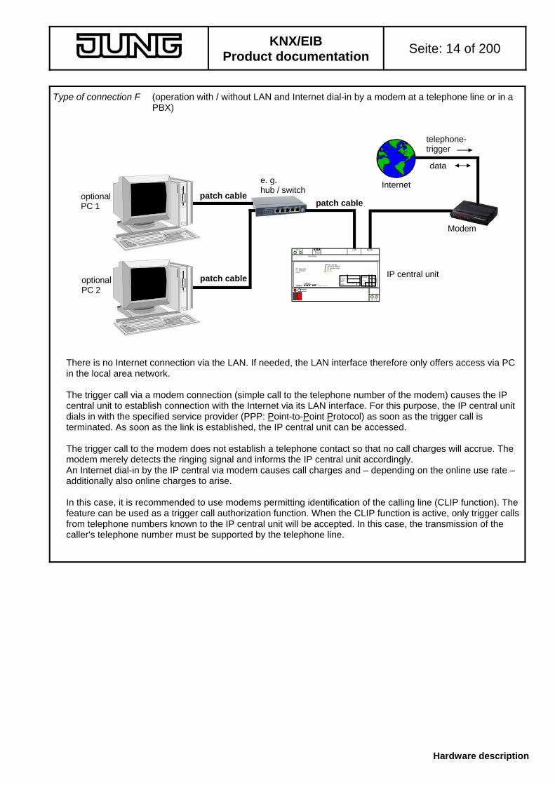
Type of connection F (operation with / without LAN and Internet dial-in by a modem at a telephone line or in a PBX)
IP central unit
Internet
data
telephone-trigger
Modem
optionalPC 1 patch cable
patch cable
optionalPC 2
patch cable
e. g.hub / switch
+ 24 V -
/
LAN RS232
local bus
Bereich:
Linie:
TLN-Nr.:
IP - ZentraleIPZ 1000 REGDC 24 V
Online / Modem Link / LAN
M ade in Ge rm an y
8276
6903
IP-Adresse:SubnetMask:
DHCP:
Power / Bet rieb
a b
There is no Internet connection via the LAN. If needed, the LAN interface therefore only offers access via PC in the local area network. The trigger call via a modem connection (simple call to the telephone number of the modem) causes the IP central unit to establish connection with the Internet via its LAN interface. For this purpose, the IP central unit dials in with the specified service provider (PPP: Point-to-Point Protocol) as soon as the trigger call is terminated. As soon as the link is established, the IP central unit can be accessed. The trigger call to the modem does not establish a telephone contact so that no call charges will accrue. The modem merely detects the ringing signal and informs the IP central unit accordingly. An Internet dial-in by the IP central via modem causes call charges and – depending on the online use rate – additionally also online charges to arise. In this case, it is recommended to use modems permitting identification of the calling line (CLIP function). The feature can be used as a trigger call authorization function. When the CLIP function is active, only trigger calls from telephone numbers known to the IP central unit will be accepted. In this case, the transmission of the caller's telephone number must be supported by the telephone line.

KNX/EIB
Product documentation Seite: 15 of 200
Software description
2. Configuration 2.1 Internet basics
The main role of the IP central unit is to act as a Web server and to make the contents of its Web pages available to the user. For this purpose, the IP central unit is either integrated into a local area network (LAN) or connected with the Internet via suitable gateways or modems.
The user can then access the Web server of the IP central unit via the Web interface of the browser (Microsoft InternetExplorer 5.5 and higher) installed on his PC. The access to the site and the transfer of the Web pages is enabled by the Hyper Text Transfer Protocol HTTP used all over the world.
By default, this protocol is part of the Transport Control Protocol – Internet Protocol TCP/IP which ensures the safe, hard- and software-independent communication of data worldwide. It is this Internet Protocol which permits combining an undefined number of individual networks (e.g. pivate networks) into a global network (e.g. the Internet). It permits the exchange of data between any two network subscribers in any two private networks (cf. Fig. 1). The physical structure of the networks or the transmission system (Ethernet, DSL, ISDN, etc.) is of no importance. The networks themselves are physically (and most often also logically) interconnected by means of suitable network nodes (routers, modems, bridges).
Internet
network 1
network 2
e.g. router
e.g. router
Fig. 1: Combining individual networks into a global network 2.1.1 Exchange of data via the Web
If a page of the IP central unit is to be loaded by the user interface of the PC, the browser (client) sends a HTTP request to the Web server. The IP central unit answers the request and transfers the requested page as a HTML file which is displayed by the Web browser with text, graphics and design (cf. Fig. 2). The contents of the HTML pages are dynamical and dependent on the state of the KNX / EIB datapoints.
HTTPPC+ 24 V -
/
LAN RS232
local bus
Bereich:
Linie:
TLN-Nr.:
IP - ZentraleIPZ 1000 REGDC 24 V
Online / Modem Link / LAN
M ade in Ge rm an y
8276
6903
IP-Adresse:SubnetMask:
DHCP:
Power / Betrieb
a b
IP central unit
HTTP-Response + HTML webpage
HTTP-Request
Fig. 2: Client-server principle for Web communication using the HTTP protocol

KNX/EIB
Product documentation Seite: 16 of 200
Software description
2.1.2 IP addresses
If the Web client intends to contact the Web server in order to make use of its services, the browser needs the IP address of the server. Every subscriber in an individual network has a distinct IP address of its own. This Internet address is a 32 -bit value which is specified for better readability always in form of four decimal numbers (8-bit values) separated by dots. This way of presenting the address is called 'dot notation'. Here is an example of a possible IP address of the IP central unit 192.168.1.100 .
For the purpose of distinguishing individual networks, the Internet address is divided into 'net-ID' and 'host-ID' The net-ID addresses the network and the host-Id addresses the network subscriber (e.g PC or IP central unit). Telephone numbers have a similar structure where code number and subscriber numer are distinguished. The net-ID shows whether the addressee with whom a network connection is to be made, is a member of the same network as the sender. If this part of the IP address is the same for the sender and the addressee, both communication partners are members of the same network. In the opposite case, the addressee is part of a different network. The part of the IP address belonging to the net-ID and the part belonging to the host-ID depends on the size of the individual network and is mainly determined by the subnet mask. Exactly like the IP address, the subnet mask, too, is 32-bit value represented in dot notation. On examining the subnet mask in binary notation it will be seen that the part representing the net-ID is filled with ones and that the part representing the host-ID is filled with zeros (cf. Fig. 3).
11111111 11111111 11111111 00000000binary notationNet-ID Host-ID
dot notation 255 . 255 . 255 . 0
32 8 0
Fig. 3: Bit structure and notation of the subnet mask (example) For every data packet to be transmitted, the transmitter compares the own IP address with the one of the receiver. The bits representing the host-ID above the section of the subnet mask filled up with zeros are disregarded. If the evaluated bits of both IP addresses are identical, the network subscriber to be contacted is located in the same subnet (cf. Fig. 4). If only one of the evaluated bits is different, the selected network subscriber is not located in the same subnet (cf. Fig. 5). In this case, the data packet must be handed over to the gateway (e.g. to the router) for further routing into the destination network as, for instance, the Internet. For this reason, the IP central unit needs the IP address of the gateway as well.
11111111 11111111 11111111 00000000
subnet mask 255 . 255 . 255 . 0
10101100 00010000 1110101110101100 00010000 11101011
IP address transmitter: 172.16.235.22IP address receiver: 172.16.235.15
Fig. 4: Transmitter and receiver in the same subnet (example)
11111111 11111111 11111111 00000000
subnet mask 255 . 255 . 255 . 0
10101100 00010000 1110101110101100 00010000 11101000
IP address transmitter: 172.16.235.22IP address receiver: 172.16.232.15
Fig 5: Transmitter and receiver in different subnets (example) If an Internet connection is not required (communication partner only in subnet), the IP address of the gateway is not needed (0.0.0.0 or empty entry field).

KNX/EIB
Product documentation Seite: 17 of 200
Software description
2.1.3 DHCP
According to the previous chapter, the IP central unit needs for the communication with other network subscribers the address of these subscribers, the own subnet mask and maybe also the IP address of an existing gateway. On principle, these addresses can be predefined during commissioning of the IP central unit and entered into the device configuration. For this purpose, the network administrator must make this information available to the operator or to the person installing the IP central unit. In larger networks, this procedure will soon entail considerable configuration and administration efforts. Not only for this reason does the use of DHCP (Dynamic Host Control Protocol) make sense.
The DHCP protocol permits automatic, coordinated and centrally configurable definition of the network parameters for the individual terminal devices as, for instance, the required IP addresses. The use DHCP requires at least one DHCP server in the network administrating the configuration data for a specific IP address space. Terminal devices suitable for DHCP such as the IP central unit request their IP address and the pertaining parameters such as subnet mask and gateway address from the DHCP server whenever they are booting (whenever their supply voltage is switched on).
Modern routers like those needed for connecting individual networks with the Internet and which relatively often used in conjunction with DSL connections for private applications are in most cases already equipped with a DHCP server. For this reason, DHCP can also be used even in smaller networks. The IP central unit is pre-activated and configured by default for use with DHCP at the factory. The integration of the IP central unit even into greater networks is therefore as easy as plug-and-play.
AutoIP with DHCP:
In some cases it may be that the IP central unit is to load a network configuration through DHCP after physical connection to the network, but cannot contact a DHCP server for this purpose. In this case, the IP central unit allocates itself an IP address from a predefined autoIP space and restarts with this self-allocated address. For this purpose, the IP central unit checks whether the address is already used by another network subscriber or not. The following values are set in the autoIP mode: IP configuration Range of values / value IP address 169.254.x.y Subnet mask 255.255.0.0 Gateway IP address 0.0.0.0 (no setting / no gateway available) DHCP deactivated The host-ID section of the IP address (x, y) has been selected at random. The auto-IP configuration remains valid until the IP central unit reboots (return of supply voltage) On principle, the search for a DHCP server takes places only once during a boot cycle. Additional auto-IP information:
During commissioning, IP central units installed in the network can be detected and localized with the help of the commissioning tool "Gateway browser". This tool uses a UDP broadcast to which all IP central units answer once with their IP addresses (for more detailed information, see chapter 4 "Commissioning".
In case of auto-IP, it can be expected that the PC from which the query was started and the IP central units work with different subnet masks, but are installed in the same sub-network. In order to ensure that the answer given by an IP central unit does reach the PC, the IP central unit sends the discovery message directly to the PC without contactig a gateway. This is also the reason why the gateway address is left empty with auto-IP. This is the only way to ensure detection of the random auto-IP addresses of the IP central units and to communicate with the devices.

KNX/EIB
Product documentation Seite: 18 of 200
Software description
2.1.4 DNS name resolution
A web browser establishes a network connection with the IP central unit by means of the IP address. Therefore, it is necessary to know the IP address of the IP central unit with which one intends to communicate. In the Internet, there are millions of different IP addresses. It would be very difficult for the users to handle all these addresses (and even those in smaller home networks) as the long numbers are extremely difficult to remember or even completely unknown. In this case, the DNS (Domain Name System) can be of help. The IP addresses are stored together with their corresponding domain names on DNS servers which ensure permanent updating of the data and make them available on request. The DNS is, so to say, the telephone directory of the Internet.
Domain names are strings of alphanumeric characters composed of at least on top-level domain (e.g. ".de" or ".com") and one or more sub-level domains. In addition, domain names in the Internet generally begin with the letters www (for world wide web) to designate a host name where Web information is available. Thus, it is not difficult to remember the Internet address www.jung.de whereas remembering the pertaining IP address in dot notation is hardly possible. This means that the user only has to enter the domain name of the desired destination in his Web browser. By means of the DNS, the Web browser translates the name automatically via the DNS into the pertaining IP address.
The IP central unit, too, gives the user or the installer in his capacity as systems administrator the possibility of entering domain names instead of direct IP addresses. Exactly like the Web browser, the IP central unit, too, needs the valid address of a DNS server in order to retrieve names. Exactly like the own IP address, the subnet screen form or the gateway address, this address can either be entered manually in the IP device configuration or allocated by DHCP.
Valid IP addresses for DNS servers will be allocated by the network administrator or by the respective Internet service provider (SP). In some cases, mini DNS servers are already integrated in the Internet router of the own network. This depends, however, on the router in use. In these case, the address of the DNS server is the same as that of the standard gateway. 2.1.5 PPP – the modem link
The PPP (Point-to-Point Protocol) is a protocol used for the control of data communication via the telephone line (mostly by means of analog modems or ISDN). A PPP link permits the use of different network protcols – among others also TCP/IP – and can therefore also be used for connecting the user with the Internet. The prerequisite for an access to the Internet is a valid user account with a service provider (ISP).
In order to establish a connection with the Internet via PPP, a telephone line permitting dial-in with the service provider is required. The connection is established by dialling a telephone number. As soon as the connection is established, the user must prove his legitimation by entering a user name and a password. After successful dial-in, data can be sent to or received from the Internet.
The IP central unit permits an Internet dial-in by modem as well. If the connection is implemented by means of a modem for data communication, the ISP user account data must be entered into the device configuration.
In addition, the IP central unit offers the possibility of checking the modem connection for proper function. For checking, a cycle interval is specified after the elapse of which the IP central unit establishes a connection with a specific SMTP e-mail server. No e-mails will be sent during checking. The communication with the SMTP server merely serves the purpose of checking the contact possibility with a valid destination in the Internet. If a communication error is being detected because the modem is not connected or because the telephone line is disturbed, the IP central unit resets the modem internally and terminates the connection. Troublefree operation is thus guaranteed. Checking is performed only if a data connection with the Internet via the modem is already existing.
It should be noted that the service provider allocates an Internet address also in thoses cases where the Internet is contacted via modem. If no designated telephone line is used for this purpose, the address is often allocated dynamically, i.e. it changes for each new dial-in attempt. Unlike an Internet connection via an LAN and a router, the IP address is generally not visible and therefore unknown. The use of a directory server in the Internet is therefore recommended. A directory server always has a fixed address or domain. Further information about how to reach the IP central unit from the Internet can be found in chapter 2.1.8 "Internet communication and dynamic Internet addresses"

KNX/EIB
Product documentation Seite: 19 of 200
Software description
2.1.6 SNTP – The network time protocol
The SNTP (Simple Network Time Protocol) is a standard protocol for date and time synchronization via networks. The SNTP is incorporated in the TCP/IP so that is possible to contact also NTP time servers in the Internet. A time server provides information about the current time precise to the second and about the current date and is in most cases controlled by a very accurate time standard. With an SNTP request addressed to such a server, the internal system clock of the IP central unit can be set and synchronized.
For launching an SNTP information request, the IP central unit needs the IP address of a time server (preferably a server of the same time zone). The address of a second server may be specified as an alternative in case the first one is not available. By default, two IP addresses of time servers connected to the Internet are listed in the device configuration. On principle, it is possible, however, to specify other servers as, for instance , time the servers in an internal company network.
After elapse of a parameterizable SNTP request interval and during the boot sequence, the IP central unit attempts to contact the predefined time servers. If this contact attempt fails for any reasons whatsoever, the internal system clock cannot be set. In this case, the clock will, however, continue to run with the expected deviation. Only after the request interval has elapsed will the IP central unit re-attempt to synchronize time and date.
As an alternative or in addition to using the SNTP, the internal clock of the IP central unit can be set manually via the Web interface (browser). Another possibility is a synchronization via the KNX / EIB. 2.1.7 SMTP and POP – the e-mail
E-Mail is a service in computer networks (especially in the Internet) permitting the exchange of electronic messages between a sender and one or more addressees. Besides the World Wide Web, E-mail is presently the Internet service most often used.
Unlike many other applications in the Internet or in the LAN, the sending of e-mails is a process where there is no direct contact between sender and addressee. In order to be independent of time and a permanent link, the person receiving an e-mail needs a mailbox on a mail server to store incoming messages. In the same way, the sender of the e-mail sends the mail to the mailbox of the addressee. This means that the sender, too, needs a valid e-mail-box.
The way of an e-mail from the sender to the addressee is divided in two sections where the mail transport is governed by different protocols. The SMTP (Simple Mail Transfer Protocol) controls the sending of an e-mail from the e-mail client (e-mail program on a PC or the IP central unit) to the mail server of the addressee. When the mail has reached its destination, it is stored in the mailbox of the addressee where it remains stored until the addressee collects his mail. To collect the incoming e-mails from the mailbox, the addressee can make use of the POP (Post Office Protocol). In this type of mail transfer, the addressee is not informed when e-mails arrive in his mailbox. He must rather check the mailbox himself for the presence of mails. Nowadays, the third version of the Post-Office-Protocol (POP3 in short) is in use.
An e-mail address is always composed of the mailbox name and the target domain. These two parts of the address are separated by the "@" sign. As both protocols, the SMTP and the POP3, are part of the TCP/IP, addressing requires name translation by a specified DNS server in this case, too, in order to find the IP address.
The IP central unit, too, can send e-mails with event-messages to addresses. When this function is used, the operator of the IP central unit must have a valid e-mail-box and enter the address of his SMTP server in the device configuration of the IP central unit. For safety reasons, service providers require authentication of the sender of the e-mail at the beginning of a transmission via SMTP. As a rule, providers require the user before sending an e-mail to contact the own mailbox via POP. Since POP requires transmission of a user name and a password as well, user authentication can be ensured by this means. For this reason, the IP central unit offers the possibility of entering also the POP access data into the configuration of the device if e-mails are to be transmitted.
The addresses of the SMTP and POP servers and also the required authentication procedure and the access data are communicated by the provider of the e-mail access or can be obtained from this source.

KNX/EIB
Product documentation Seite: 20 of 200
Software description
2.1.Internet communication and dynamic Internet addresses 2.1.8.1 Internet connection
In many applications, it is attractive or even necessary to control the IP central unit and thus its KNX / EIB building automation via the Internet or to display its operational status. Information about events taking place in the home or in the apartment can be transmitted by e-mail to the mobile phones or to pocket computers. A press on a button is sufficient to set the heating in the weekend house to a confortable temperature and a power failure at home can also be detected during the holidays so that the neighbours can be informed to take the necessary steps. Here are some examples of the monitoring and control functions offered by the IP central unit (cf. Fig. 6).
IP central unit
+ 24 V -
/
LAN RS232
local bus
Bereich:
Linie:
TLN-Nr.:
IP - ZentraleIPZ 1000 REGDC 24 V
Online / Modem Link / LAN
M a de i n Ge r m an y
8276
6903
IP-Adresse:SubnetMask:DHCP:
Power / Betrieb
a b
Internet
at home
at work
weekend house
Fig. 6: Control and monitoring of a KNX/EIB installation via the Internet There are different possibilities of connecting the complete local network or the IP central unit alone with the Internet. The most often used connection methods are set out in the description of the types of connection in the present documentation. A local network is generally connected with the Internet by means of a router or a proxy server in conjunction with a DSL line. This type of connection is nowadays widely used by private persons. Medium-sized or large-scale company networks often make use of dedicated Internet lines – often on an ATM basis – for this purpose.
Another traditional alternative – generally in conjunction with analog or ISDN telephone lines – is the Internet connection via a modem. In this case, the user must dial in with his service provider (ISP) and pay telephone charges and also online charges.
With LAN-based Internet connections, flat-rates permitting a constant connection with the Internet are more and more often used.
In any case, the service provider reserves a special and unique IP address for this Internet connection. Irrespective of the type of Internet connection (DSL router, modem, etc.) there is always at least one public IP address for this subscriber. From outside, the network can only be contacted via the one (or the few) public IP address(es).

KNX/EIB
Product documentation Seite: 21 of 200
Software description
2.1.8.2 NAT – Address translation
Due to the ever-increasing number of Internet subscribers, the availability of public IP addresses is decreasing. For this reason, smaller individual networks (such as the LAN at home or in the company) are connected to the Internet with an indepedent address space (independent net-ID, cf. chapter 2.1.2 "IP adresses") Routers (in their capacity as independent hardware or as software on a PC) have the task to route the data packets received from the Internet to the subscribers in the local network and into the opposite direction. Therefore, routers perform the task of interconnecting two network areas on a protocol level and generally work independent of the media so that the router interfaces can be connected to different media (Ethernet, DSL, ISDN, etc.).
Internet
private local network (LAN)
public IP address"80.153.161.63"
PC 1
PC 2
IP central unitprivate IP address"192.168.2.100"
private IP address"192.168.2.101"
private IP address"192.168.2.102"
router
Internet (WAN)
+ 24 V -
/
LAN RS232
local bus
Bereich:
Linie:
TLN-Nr.:
IP - ZentraleIPZ 1 000 REGDC 24 V
On line / Mo de m Li nk / LAN
M ade in G erm any
827
669
03
IP-Adresse:SubnetMask:
DHCP:
Powe r / Be tr ieb
a b
e. g. DSL
Fig. 7: Interconnection of a local network with private IP addresses and the Internet by means of a router
Computers in the Internet can thus contact the local network with the help of the public IP address of the router. The individual IP addresses of the network components inside the LAN are not known in the Internet. This means that the private address of the IP central unit is not known either. This property is at the same also a very important safety aspect.
In order to be able to contact the IP central unit in its capacity as a Web server from the Internet, the router must route the data packets intendend for the Web server to the IP central unit (in the example in Fig. 7, the public IP address "80.153.161.63" must be translated into the private one "192.168.2.102"). This address translation is ensured by the NAT (Network Address Translation) function.
The NAT in computer networks is a procedure for substituting an IP address in a data packet for another one. The function is often used for mapping private IP addresses onto public IP addresses at the interface between two networks. On the other hand, this translation serves the purpose of data security as the internal structure of the network remains obscure to the world outside (security through obscurity).

KNX/EIB
Product documentation Seite: 22 of 200
Software description
In addition to the routing of data packets, NAT offers the possibility of routing or of rewriting also the port addresses.
"What are port addresses ?" ...
Ports are address components used in network protocols for assigning data packets to the correct services (protocols). The port number is a 16-bit number, i.e. it has a value range from 0 to 65535. Certain applications use firmly allocated and generally known port numbers. These addresses usually have numbers from 0 to 1023 and are designated as the well-known ports (e.g. HTTP port 80, FTP port 21). Between port 1024 and port 49151 we find the registered ports. If needed, these ports can be registered by the producers of applications for their own protocols, similar to domain names. The remaining ports up to port number 65535 are so-called dynamic and/or private ports. These ports can be used variably as they are not registered and thus not assigned to a specific application. For known port numbers, the indication of the port address is not necessary as it is usually defined by the protocol used. Thus, it is not necessary, for instance, to state the port address after an Internet URL. It can, however, be specified in the form (":" + "port number") as an option: "http://www.xyz.de:80"
If NAT rewrites also the port numbers, we speak of masking or of PAT (Port Address Translation). Rewriting is necessary, for instance, if it is intended to operate two Web servers in the private network. Thus, it is possible, for instance, to rewrite the public standard HTML port 80 for the IP central unit and another port (e.g. 8080) for the second Web server. Both Web server are internally addressed via port 80 (cf. Fig. 8). In order to be able to access the IP central unit via HTTP, data packets with Web contents must always be rerouted to port 80 of the IP central unit. Rerouting of further ports is not needed for the operation of the IP central unit.
Internet
private local network (LAN)
"http://www.xyz.de" = "80.153.161.63" Port: 80
PC withweb server 2
IP central unitweb server 1
private IP address"192.168.2.100"Port 80
private IP address"192.168.2.102"Port: 80
Internet (WAN)
+ 24 V -
/
LAN RS232
local bus
Bereich:
Linie:
TLN-Nr.:
IP - ZentraleIPZ 1 000 REGDC 24 V
On line / Mo de m Li nk / LAN
M ade in G erm any
827
669
03
IP-Adresse:SubnetMask:
DHCP:
Powe r / Be tr ieb
a b
NAT(with port rerouting)NAT
(with port translation)
"http://www.xyz.de:8080" = "80.153.161.63" Port: 8080
web browser "http://www.xyz.de"
Fig. 8: Translation of a public IP address into a private one with port address translation during access to the IP central unit from the Web
The activation and the configuration of NAT in the router used is described in the documentation of the corresponding device. This function is often also referred to as "virtual server".

KNX/EIB
Product documentation Seite: 23 of 200
Software description
2.1.8.3 Dynamic IP addresses – The DynDNS
Each data line permitting a connection with the Internet will be allocated at least one public IP address by the service provider (ISP) A distinction must be drawn between static Internet connections on the one hand which can always be reached via the same public IP address and dynamic connections on the other hand to which valid public IP addresses are allocated only temporarily.
Static IP addresses are suitable for company networks or for permanent Internet presence. In these case, the Internet can work as a dedicated telephone line Dynamic IP addresses are mostly used in by private Internet connections and often also in conjunction with DSL. At each dial-in, the service povider allocates a suitable IP address to the connection. The advantage of this dynamic allocation of addresses lies – among other things – also in the fact that the reserves of valid IP addresses worldwide can be maintained this way. Some countries – among others Germany as well – still have legal regulations for dynamic Internet connections obliging the service provider to disconnect the line with the Internet after a maximum of 24 hours even the permanent data transfer is still going on. This interruption results in a change of the subscriber's IP address at least once every day. Direct redialling of the providers's number after an automatic disconnect is generally possible without any problems.
The automatic change of the public IP address is a disadvantage, if it is intended to operate an independent Web server in the private network for which it is important that it can be reached from the Internet. The IP central unit can be such a Web server. The IP central unit in one's own network can only be reached from the Internet, if one knows the allocated IP address.
The DNS can translate an Internet-URL such as "http://www.xyz.de" into the corresponding IP adddress (cf. 2.1.4 "Name resolution") This means that the IP addresses may change without the domain name changing ín the same way. The change of the IP address thus takes place in the background. The user is not informed of such change and there is also no need to do so. For addressing purposes it is only required that the DNS server is informed of the valid IP address. The DNS server must know when the address changes and which address is actually valid. It is for this purpose that the DynDNS (Dynamic Domain Name System) can be used.
When the DynDNS is used, a special client program coordinates the current public IP address with the DynDNS server immediately after the user has dialled the number of his Internet provider or cyclically thereafter. The client program is usually installed on a PC in the local network or preferably integrated in the router itself when the IP central unit is connected to the system. There are various independent and cost-free DynDNS servers all over the world. The best-known server service is certainly "www.dyndns.com" (English-speaking) For using the services of DynDNS, a user account must exist on a Dyn DNS server. A user registered with such a server selects one of the available domains under which he can be reached in the Internet. He can then be reached in the Internet under the registered DynDNS domain. Addressing via dynamic IP addresses in the Web browser is no longer necessary.
Many hardware routers available on the market offer a client solution for DynDNS. On account of the many different implementations and configurations, the reader is referred to the documentation of the devices used. Instructions concerning the registration and creation of a DynDNS access are supplied by the respective service providers. Information concerning the Internet communication via modem:
Also in case of access to the Internet via a modem, the service provider allocates a public Internet address to the subscriber line. Unlike in an Internet connection via an LAN and a router, it is generally difficult or even not possible at all to coordinate the IP address with a DynDNS server by means of client program when a modem connection is used. However, in order to be able to establish a connection with the IP central unit in a private network via a fixed destination in the Internet without knowing the dynamic IP address, it is possible to make use of a directory server for communication. The IP central unit is prepared ready for use with a directory server.
For servicing purposes, the IP address allocated by the service provider can be checked in case of modem use in the program "Gateway Browser" in the device configuration (cf. 4 "Commissioning").

KNX/EIB
Product documentation Seite: 24 of 200
Software description
2.1.8.4 Firewall and security settings
On account of the ever-increasing importance of network safety, especially in data communications with the Internet, the use of firewalls is becoming more and more frequent. Firewalls are ideally placed at the interface between individual networks for checking data traffic between them, for preventing undesired trafic from happening or for retransmitting only desired traffic. In this way, the communication between the local network and the Internet is monitored and controlled. Quite often, router or proxy servers have firewall properties, too.
The firewall permits defining which data packets are allowed into the local network and which data may leave the network. It is also possible to influence the port translation so that the access to ports can be blocked. Other firewall filters permit checking the contents of data packets and filtering out of certain program elements such as HTML-attached JavaScripts.
As an alternative or better in addition, so-called private firewalls may be installed on a PC. These firewalls, too, filter the data traffic on the computer which is to be used to access the IP central unit by means of the Web browser. Standard Web browser additionally have security settings influencing the authentication and the execution of various program packages.
For smooth operation, the IP central unit needs for the services used 'a free passage' through installed firewalls. For this reason, it must be possible to reach the IP central unit in its capacity as a Web server from the Internet which means that certain ports must not be blocked. It is generally recommended to integrate the IP central unit into a DMZ (DeMilitarized Zone) of the firewall. A DMZ is a logical area in the private network which is separated from the rest of the LAN and accessible from outside. The firewall filter rules for this area permit safe data communication with the IP central unit so that it is not necessary to abandon the security level offered by a firewall.
The firewall must permit communication with the IP central unit in both directions via the following ports (if the corresponding service is used): Port no. Service Function 21 FTP (TCP/IP) programming link (ETS) 25 SMTP (TCP/IP) e-mail (outgoing mails) 53 DNS (TCP/IP) name resolution for domain names / IP addresses 80 HTTP (TCP/IP) Web communication 110 POP3 (TCP/IP) e-mail (incoming mails) 123 NTP (TCP/IP) time server communication (also SNTP) 19001 Broadcast (UDP) discovery service The IP central unit partly transmits the contents of its Web page as JavaScript. A firewall installed in the IP central unit network or a private firewall on the PC operating the IP central unit must therefore not prevent the execution of JavaScripts. This applies in the same way also to the security settings of the controlling Web browser which must permit JavaScripting. On account of the multiple purposes for which they are used, firewalls have rather different configurations. For more detailed descriptions of the settings and possibilities, the reader is therefore referred to the documentation of the firewalls used.
KNX/EIB
Product documentation Seite: 25 of 200
Software description
2.1.8.5 Access protection
As described in the previous chapters, the access to the IP central unit via the Internet is by means of the public IP address of the Internet line to which the IP central unit is connected, either directly or through an LAN. Basically, everyone who knows the IP address or the domain name can establish contact with the unit. This does not mean, however, that the unit can also be directly operated. The IP central unit is equipped with different functions controlling the access to the unit and thus to the Web interface or any programming attempts... • Protection due to password authentication on different user levels:
The IP central unit has 4 user levels with different authorizations belonging to these levels or which can be assigned to them (cf. 2.2 "Configuration settings")
• Protection through authorized IP addresses:
The configuration of the IP central unit permits specifying the IP addresses which have access to the unit. If the central unit is accessed from the Internet, a non-authorized IP address and thus a non-authorized person can be rejected.
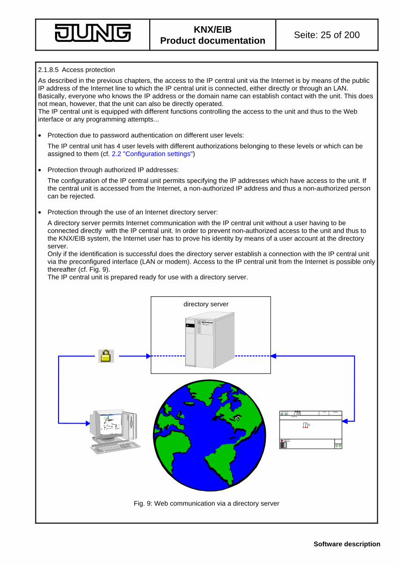
• Protection through the use of an Internet directory server:
A directory server permits Internet communication with the IP central unit without a user having to be connected directly with the IP central unit. In order to prevent non-authorized access to the unit and thus to the KNX/EIB system, the Internet user has to prove his identity by means of a user account at the directory server. Only if the identification is successful does the directory server establish a connection with the IP central unit via the preconfigured interface (LAN or modem). Access to the IP central unit from the Internet is possible only thereafter (cf. Fig. 9). The IP central unit is prepared ready for use with a directory server.
24 V DC
a b
LAN RS232
local bus
PowerOnline
Link
directory server
Fig. 9: Web communication via a directory server

KNX/EIB
Product documentation Seite: 26 of 200
Software description
2.2 Configuration settings
The IP central unit is configured by a plug-in integrated in the ETS. The configuration dialog appears after starting the plug-in and after clicking on the button "Configuration" in the righthand menu bar. As an alternative, the device configuration can be activated by selecting the menu item "Device configuration" in the context menu (right mouse click in left-hand tree view) or by clicking on the button in the upper menu bar. The configuration dialog consists of nine pages with parameter settings for the unit that are described in the following sub-chapters. 2.2.1 "IP configuration" parameters
Serial number. The serial number of the configured IP central unit is displayed in this box. When a new device is entered in the ETS project and when no contact has yet been established with another device, this box is empty. When an existing IP central unit project is loaded, the box shows the corresponding unit serial number. Each IP central unit has its own and unique serial number! Device description: This field contains the description of the project device. The description is entered in the ETS building or topology view under properties of the IP central unit (double click or context menu 'Properties') in the field "Description" . During programming of the IP central unit, this description is stored in the device memory. DHCP: This box can be used for switching DHCP on or off. When this box is ticked, the IP central unit tries to request an IP configuration from a DHCP server during the boot sequence. If the box is not ticked, there is no DHCP assistance and the required IP addresses must be entered in the address entry fields below. The IP central unit is delivered with the DHCP tick box activated. IP address, Subnet mask, Default gateway and DNS server: When DHCP is deactivated, the four IP addresses needed for TCP/IP communication and name resolution must be entered into the address fields. The following entries are required: own IP address of the central unit, subnet mask of the local network, address of the standard gateway (e.g.: router, proxy server, etc.) if an Internet link is required, and the IP address of an available DNS server. A detailed description of these addresses can be found in chapter 2.1.2 "IP adresses".
The IP configurations on this page are required only in case the LAN interface of the IP central unit is used.

KNX/EIB
Product documentation Seite: 27 of 200
Software description
2.2.2 "Security" parameters
The configuration of the IP central unit permits specifying the IP addresses which are allowed to access the unit (secure IP addresses). If the Web interface of the central unit is accessed from the Internet or from the local network or if a programming link is established, a non-authorized IP address and thus a non-authorized person can be rejected. The present configuration page permits activating the access protection. In addition, the page permits entering the IP addresses with access permission to the device. The address protection as such is activated by ticking the box "Edit IP addresses with authorized access". When the protection is activated, the IP addresses with authorized access must be entered into the entry field and then added to the list box. The addresses entered (10 max.) must be valid and also existing as network subscribers. The device can otherwise not be reached after programming of this configuration, neither via the Web interface nor via the programming interface of the ETS. If the list box remains empty, the access protection is alsways deactivated. IP addresses added to the list box can be removed by selecting the corresponding address and by clicking on the "Delete" button When the function "General authorization for local IP addresses" is active, all IP addresses of the own local network (same subnet mask) are allowed to access the IP central unit even if the access protection is activated. Non-authorized attempts to access the IP central unit will be rejected. Web pages are not displayed and the programming link will be aborted with an error message. If a directory server is used for connection with the Internet, the IP address of this server must be entered into the list box .
KNX/EIB
Product documentation Seite: 28 of 200
Software description
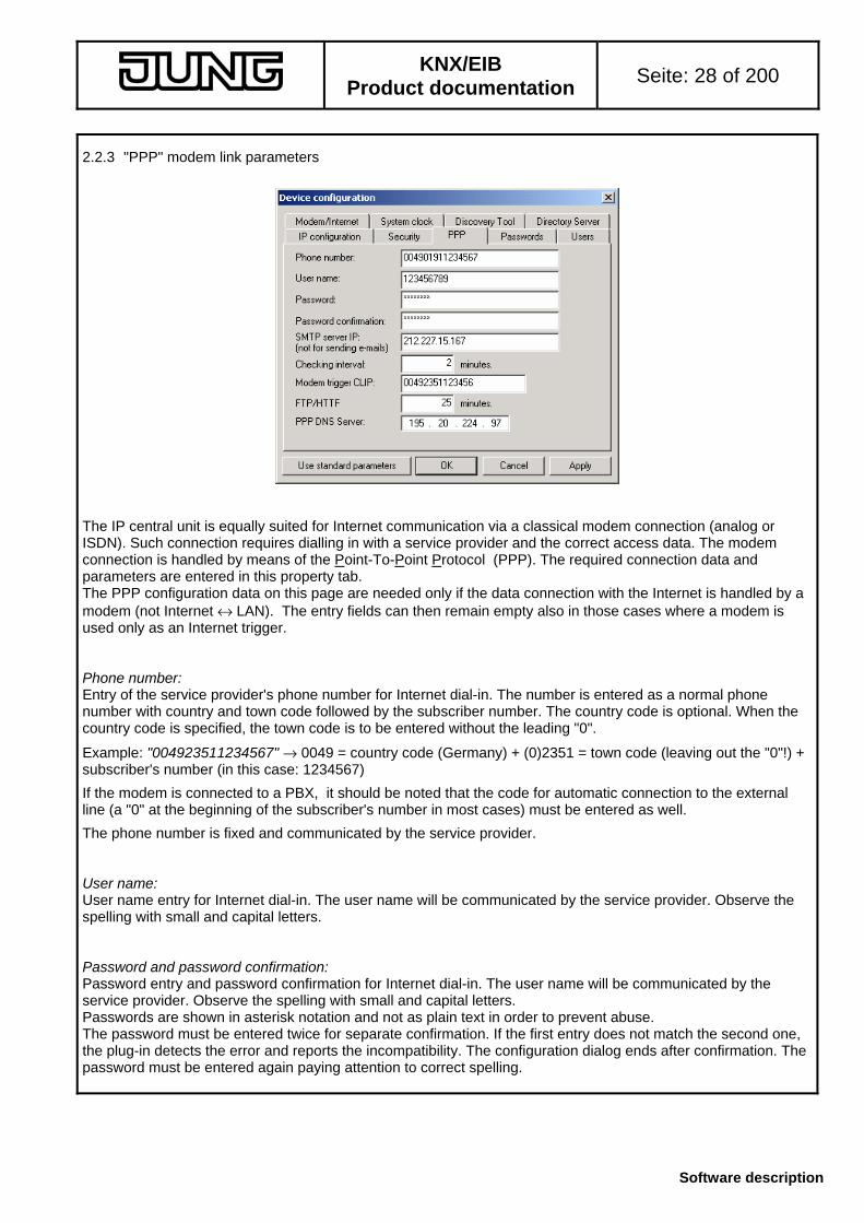
2.2.3 "PPP" modem link parameters
The IP central unit is equally suited for Internet communication via a classical modem connection (analog or ISDN). Such connection requires dialling in with a service provider and the correct access data. The modem connection is handled by means of the Point-To-Point Protocol (PPP). The required connection data and parameters are entered in this property tab. The PPP configuration data on this page are needed only if the data connection with the Internet is handled by a modem (not Internet ↔ LAN). The entry fields can then remain empty also in those cases where a modem is used only as an Internet trigger. Phone number: Entry of the service provider's phone number for Internet dial-in. The number is entered as a normal phone number with country and town code followed by the subscriber number. The country code is optional. When the country code is specified, the town code is to be entered without the leading "0".
Example: "004923511234567" → 0049 = country code (Germany) + (0)2351 = town code (leaving out the "0"!) + subscriber's number (in this case: 1234567)
If the modem is connected to a PBX, it should be noted that the code for automatic connection to the external line (a "0" at the beginning of the subscriber's number in most cases) must be entered as well.
The phone number is fixed and communicated by the service provider. User name: User name entry for Internet dial-in. The user name will be communicated by the service provider. Observe the spelling with small and capital letters. Password and password confirmation: Password entry and password confirmation for Internet dial-in. The user name will be communicated by the service provider. Observe the spelling with small and capital letters. Passwords are shown in asterisk notation and not as plain text in order to prevent abuse. The password must be entered twice for separate confirmation. If the first entry does not match the second one, the plug-in detects the error and reports the incompatibility. The configuration dialog ends after confirmation. The password must be entered again paying attention to correct spelling.

KNX/EIB
Product documentation Seite: 29 of 200
Software description
SMTP server IP: The IP central unit can test the data line when a modem is used and when the Internet connection is established. For testing, the IP central unit establishes a cyclical connection with the specified IP server. During the check, no e-mails will be sent. The communication with the SMTP server merely serves the purpose of checking the possibility of making contact with a valid destination in the Internet. If a communication error is being detected because the modem is not connected or because the telephone line is disturbed, the IP central unit resets the modem internally and terminates the connection. This means that the IP central unit remains operational and maintains its diagnostic capability in the local network even in case of malfunctions. The modem communication is activated again only during the next communication attempt with the Internet. If a fault is detected during an active data transmission (active session: e.g. transmission of an e-mail or loading of a Web page), there will be no reaction of the IP central unit on the HTTP level within the next 25 minutes. After this waiting time, all events or actions received during this time will be executed.
The IP address of the SMTP server must be entered in dot notation (!!). It always and absolutely necessary to specify a valid IP address and thus an existing server. In case of doubt, the Internet address of the SMTP server can be requested from the e-mail provider. The modem check cannot be deactivated. If the connected modem is used only as an Internet trigger (data transmission to the Internet via the LAN) it is not required to specify an SMTP server. Checking interval: The time specified in this box fixes the intervals at which the modem connection is checked cyclically for SMTP presence. If "0" is selected, checking goes on permanently. The modem check cannot be deactivated. Modem trigger CLIP: A modem connected to the IP central unit can be used for triggering an Internet dial-in 'from outside'. In this case, the IP central unit monitors the modem interface (RS-232) for incoming ring indication signals). When a ring signal is detected, the central unit contacts the Internet. When the modem trigger function is used, it is possible with a modem with CLIP function to identify the phone number of the trigger call if the modem used has the CLIP function and if this function is supported by the subscriber line. When a phone number is specified in this box, the IP central unit responds to a detected trigger only if the number transmitted with CLIP corresponds to the number entered in this box. The number is entered as a normal phone number with country and town code followed by the subscriber number and without blanks. The country code is optional. When the country code is specified, the town code is to be entered without the leading "0". The country code is dependent on the telephone company and the format of the subscriber's number transmitted with the CLIP function.
Example: "004923511234567" → 0049 = country code (Germany) + (0)2351 = town code (leaving out the "0"!) + subscriber's number (in this case: 1234567)
The country code can also be specified with the "+" sign as a placeholder for the "00" before the country code. If the modem is connected to a PBX, it should be noted that the code for automatic connection to the external line (a "0" at the beginning of the subscriber's number in most cases) must be entered as well. FTP/HTTP: Timeout interval for an established Internet connection via modem. If there is no exchange of HTTP or FTP data with the Internet anymore during this time (e.g. no more updating of Web pages and their contents, no e-mail transmission, etc.) the IP central unit disconnects the existing line. The yellow Online / Modem LED on the device front panel is lit up during an active modem connection. In this case, online and/or phone call charges are accruing. When the connection is no longer existing, the LED is extinguished.
If the value in this box is "0", the IP central unit disconnects the line immediately after data transmission is terminated.

KNX/EIB
Product documentation Seite: 30 of 200
Software description
2.2.4 "Users" and "Passwords" parameters
Definition of the parameters for device access protection. The IP central unit can be controlled and operated via a Web browser as a user interface. The device is commissioned with the ETS programming interface. To prevent unauthorized persons from getting access to the KNX/EIB building installation or the programming environment, the IP central unit distinguishes between four 4 user levels. The access to a user level is protected by a separate password for each level. The device is accessible via the following user levels.
Programming access is reserved exclusively to the...
• Systems administrator
The systems administrator is the programmer or the person putting the IP central unit into operation. In order to get an FTP programming access via the ETS or the "Gateway Browser" commissioning software to the device, the system administator password must always be entered. As a rule, the system integrator as system planner and the electrical fitter are granted systems administrator rights.
The access to the Web user interface is reserved to the...
• Administrator
The administrator has the full rights of operation and configuration on the user interface level of the IP central unit. He decides about the rights or possibilities to be granted to the subordinate access levels "User" and "Guest". The administrator should be the owner of the installation or the network administrator.
• User
The user is the person operating the Web interface. This person has access to the most elmentary displaying and operating structures. Users are normally family members or employees in a company.
• Guest access
The guest access allows the "broad public" to access display and operating elements. The guest access can be restricted so that elements can only be viewed, but not changed. The rights or possibilities granted to guests are determined by the "User" or the "Administrator".

KNX/EIB
Product documentation Seite: 31 of 200
Software description
Defining the names for the access levels:
The user names for the three levels of operation are defined on the "Users" parameter tab. When accessing the Web interface, the PC operator is requested to log in under one of the three names. The name entered into the identification dialog must be the same as the one parameterized in the device configuration. The correct spelling with small and capital letters must be observed. The name allocated to the system administration function is basically predefined as "sysadmin". For programming, no entry is required. Definition of the passwords for the access levels:
The passwords are entered in asterisk (*) notation and not in plain text to prevent unauthorized access. Each password must be entered twice for separate confirmation. If the first entry does not match the second one, the plug-in detects the error and reports the incompatibility. The configuration dialog ends after confirmation. The password must be entered again paying attention to correct spelling. Correct spelling with small and capital letters must be observed. A predefined default password programmed into the IP central unit at the factory exists only for the systems administrator.
Systems administrator default password: "sysadminpw"
This password must be entered already during initial commissioning. The existing password will be replaced by the one entered into the device configuration only after initial programming. On delivery, the passwords for administrator, user and guest are empty. The transmission of the passwords between the commissioning environment or the Web interface and the IP central unit via the Ethernet link is effected in plain text. User level information:
In the Web interface, the different access levels are implemented on the the directory level. In principle, the accessible pieces of information or settings are accessed via different directories in the storage sructure. This way, it can be ensured that all user levels are logically and functionally isolated from one another. Abuse can thus be prevented.

KNX/EIB
Product documentation Seite: 32 of 200
Software description
2.2.5 Internet access parameters "Modem / Internet"
Definition of the parameters required for access to the Internet. Depending on the type of connection used, the access to the Internet is either effected via the local network (in conjunction with a router, for instance) or by means of a modem connected to RS-232 interface of the IP central unit. The corresponding modem specifications must be parameterized on this tab even if the modem connected is used only for Internet trigger purposes. Internet connection via..: This parameter determines the device interface used for establishing an Internet connection. If the "via LAN" option is selected, the IP data are routed to the specified standard gateway and thus to the Internet. If the "via Modem" option is selected, data communication with the Internet is effected per PPP via the conncted modem. If a connection with the Internet is not needed or implemented (use only within local network; no modem or no Internet gateway installed), no settings are required for this parameter.

KNX/EIB
Product documentation Seite: 33 of 200
Software description
Modem type: When a modem is connected to the RS-232 interface of the IP central unit, an entry specifying whether the modem connected is an analog type or an ISDN type is necessary. Baud rate: When a modem is connected, the transmission speed of the RS-232 link (not the transmission speed on the telepone line) must be specified. The possible settings are based on the standards currently in use (38.600, 57.600 and 115.200 bauds) and must be set im compliance with the modem documention. Modern devices often have an automatic baud-rate detection function so that, in case of doubt, the fastest speed can be selected. Modem initialization command: The control and the exchange of data with the connected modem is effected by means of the internationally standardized AT commands. The AT initialization command required for an analog modem or for an ISDN modem can be entered in two separate boxes on this tab. A modem initialization command consists of a string of characters sometimes also of numbers. This string determines the modem's communication parameters, the dialling mode, waiting times, busy signal detection and so on. The individual command sequence can also vary depending on the manufacturer.
The plug-in device configuration for the IP central unit uses a standard initialization command with which most modems can be initialized and controlled. Changes in accordance with the description in the modem documentation must be made only in some individual cases.
If extension units are connected behind a PBX, it is necessary, for instance, to switch off the dial tone signal detection in the modem. Depending on the settings of the private branch exchange, a special internal dial tone will be heard at the extension when the 'receiver is picked up'. A modem in default configuration expects, however, the continuous dial tone from the phone company so that the device will not dial when the internal tone is detected. In this case, the initialization command can be changed with the sequence "ATX0" or "ATX3" (instead of "AT") This command deactivates the dial tone detection in the modem. As an alternative, the extension concerned can be programmed for "direct access to the exchange line". Modem name: A modem connected to the IP central unit can be used for triggering an Internet dial-in 'from outside'. In this case, the IP central unit monitors the modem interface (RS-232) for incoming ringing signals (ring indication function). When a ringing signal is detected, the central unit contacts the Internet. When the modem trigger and when modems with CLIP function are used, it is possible to identify the phone number launching the trigger call if the phone line supports this function. The functions discussed are not supported by all modems. The "Modem name" parameter displays a selection of standard modems having the CLIP function. If a modem type is selected in this box, the CLIP function is activated in the IP central unit. In the event of trigger signal detection the IP central unit reacts only if the phone number transmitted by way of CLIP corresponds to that indicated under "Modem trigger CLIP" on the PPP parameter tab. If "no CLIP modem" is selected, the calling line identification is deactivated. In this case, all incoming modem trigger signals are accepted. Please observe also the description of the "Clip Format" parameter. CLIP format: This parameter is only displayed and cannot be edited. It shows the CLIP format of the modem selected under "Modem name". The CLIP implementation in the modem depends on the manufacturer. The incoming phone number is often transmitted within the RING command (placeholder X). If a another modem than that offered in the "Modem name" selection is connected to the IP central unit, the modem name selected depends on the CLIP format supported by the device used. In this case, the device selected under "Modem name" must be such that the displayed CLIP format for the device corresponds to the format of the connected modem. The required information can be found in the documentation of the modem.

KNX/EIB
Product documentation Seite: 34 of 200
Software description
2.2.6 Internal "System clock" parameters
The "System clock" parameter tab is used for defining the use of the internal RTC clock module (RTC: Real Time Clock). This card also defines the time when and the way how the synchronization is effected. The internal clock of the IP central unit basically distinguishes between the following three modes of operation: 1. Independent stand-alone operation
In this mode, the clock is autonomous and independent of the KNX / EIB bus. If required, the clock controls the scheduler and the presence simulation or logs the event reports in the IP central unit with a time stamp. The clock can either be synchronized by setting the time-of-day and the date 'by hand' via the user interface or additionally by a time server (SNTP).
IP central unitLAN / internet time server
time / date
request
In this case, the parameter "Transmission of time and date" is without function. There are no KNX / EIB communication objects available either.

KNX/EIB
Product documentation Seite: 35 of 200
Software description
2. Master operation
In this mode of operation, the internal system clock transmits time and date to the KNX / EIB bus and controls - as in the autonomous mode - also the internal functions of the IP central unit.With a separate KNX/EIB trigger object it is possible to send time and date information to the bus on request. The clock can either be synchronized by setting the time-of-day and the date 'by hand' via the user interface or additionally by a time server (SNTP).
IP central unit
time / date
LAN / internet time server
KNX / EIB
trigger
time / date request
In the master mode, the following KNX/EIB communication objects are available:
Object name Function Format: Datapoint type SystemClock Time transmission of time-of-day 3 bytes 10.001 Time-of-day SystemClock Date transmission of date 3 bytes 11.001 date SystemClock Date reception of trigger signal 1 bit 1.xxx Boolean
Depending on the parameter "Transmission of time and date", the IP central unit transmits the actual time and date either cyclically (settings "every minute", "every hour", "at 0h00", "at 0h02" and "every hour and at 0h02") or only after a trigger request (setting "trigger").
3. Slave operation
In this mode of operation, the internal system clock works as a time and date receiver. This means that it receives the corresponding telegrams from the KNX / EIB bus and controls - as in the autonomous mode - the internal functions of the IP central unit. With a separate trigger object (request) the IP central unit can optionally request the bus to transmit time and date. The clock can either be synchronized by setting time and date 'by hand' via the user interface or additionally by a time server (SNTP).
IP central unit
time / date
LAN / internet time server
KNX / EIB
trigger
time / date
request
In the slave mode, the following KNX/EIB communication objects are available:
Object name Function Format: Datapoint type SystemClock Time reception of time 3 bytes 10.001 Time SystemClock Date reception of date 3 bytes 11.001 date SystemClock Date transmission of a trigger
signal 1 bit 1.xxx Boolean
The trigger object is available only when the box "Use system clock activation" is ticked. In this case, the IP central unit cyclically requests the bus by means of a trigger telegram to transmit the current time and date – for instance from a KNX/EIB system clock or from another IP central unit. The cycle time is determined by the parameter "Transmission of time and date" (the "Trigger" setting being in this case without function).

KNX/EIB
Product documentation Seite: 36 of 200
Software description
SNTP and 'manual' synchronization:
In all modes of operation, the internal clock can also be synchronized from an SNTP time server. If this option is selected, at least one IP address of a valid server must be entered in the field "SNTP IP address" A second SNTP server should be specified as an alternative and the IP address of this server entered in the field "Reserve SNTP IP address". If the first server cannot be reached – for instance because it is off for servicing purposes – the IP central unit tries to contact the second server and to request the transmission of date and time from this server. It should be noted that in case of IP addresses which are not part of the local subnet, the unit establishes an Internet connection. The default configuration already contains two known SNTP servers in the Internet. Information on further addresses can generally be obtained from the respective Internet service provider (ISP)
The system clock configuration moreover permits defining an "SNTP request interval". When the time specified in hours has elapsed (preset to "8"), the IP central unit contacts the time server and requests the transmission of the current time and date. The cyclical synchronization is thus ensured. When the power supply is switched on (boot sequence), the IP central unit synchronizes the internal clock with the signal from the SNTP. Thereafter, the interrogation interval starts running. If the SNTP synchronization attempt fails, the internal system clock will not be set. In this case, the clock will, however, continue to run with the expected deviation. Only after the next interrogation interval has elapsed will the IP central unit try again to receive a time and date signal.
As an alternative or in addition to using the SNTP, the internal clock of the IP central unit can be set manually in any mode via the Web interface (browser). (cf. 5. "User interface and functions"). 2.2.7 Device configuration during commissioning with the "Discovery-Tool"
The configuration dialog of the IP central unit permits locating and identifying the IP central units installed in the local network. This function is important during the commissioning procedure since the device is programmed via the network link of the PC used for commissioning. For commissioning, the IP central unit is contacted via its IP address. In many cases and especially if DHCP is being used, the ETS programmer does not know the IP address. The discovery tool which is part of the device configuration menu can be of help here. By clicking the "Search" button, the plug-in sends a special UDP broadcast telegram (UDP: User Datagram Protocol / contactless IP protocol). This broadcast will be answered only by IP central units which then return their address and their serial number to the plug-in. All answers of the target devices are displayed in a window in the configuration. An information as to whether the programming button on the device was pressed is also provided. This way, a searched IP central unit can be exactly identified. By selecting the desired device and by clicking the "Target device" button, the corresponding IP address is adopted in the device configuration. Further details can be found in chapter 4. "Commissioning".

KNX/EIB
Product documentation Seite: 37 of 200
Software description
2.2.8 "Directory server" parameters
With this parameter tab, the IP central unit can be configured if an an Internet directory server is to be used. The IP central unit is prepared for future communication applications with a directory server. The automatic maintenance of an Internet connection (keep-alive function) can also be activated on this parameter tab. Directory server: A directory server permits Internet communication with the IP central unit without a user having to be connected directly with the IP central unit. In order to prevent non-authorized access to the unit and thus to the KNX/EIB system, the Internet user has to prove his identity by means of a user account at the directory server. Only if the identification is successful does the directory server establish a connection with the IP central unit via the preconfigured interface (LAN or modem). Access to the IP central unit from the Internet is possible only thereafter. For the directory server to be able to communicate with the IP central unit, the IP central unit must have logged in with the directory server at least once. The log-in is automatic when the "Use directory server" box is ticked. In this case, the IP central unit logs in once with the directory server when the power supply is switched on (boot procedure). If a cyclical log-in is desired, a dial-in interval in minutes can be specified in addition (setting < "0"). Cyclical log-in with the directory server always makes use of an existing Internet connection. Therefore, no Internet connection will be established if it does not already exist anyway. The Internet server to be used is part of the default setting. Its IP address is stored in the IP central unit and cannot be changed. Important:
If a directory server is used for connection with the Internet, the IP address of this server must be entered additionally into the box listing the IP addresses with authorized access on the "Security" parameter tab. The access protection must then be activated. Information on the required IP address can in the future be obtained from the manufacturer.

KNX/EIB
Product documentation Seite: 38 of 200
Software description
Keep-alive of an Internet connection: Even without a directory server, an automatic log-in with an Internet destination makes sense and can be used. When the IP central unit is connected to the Internet via a DSL line and if it is to be reached permanently via this link, an automatic device must ensure that the Internet connection is always ensured. Example: With private DSL lines with dynamic IP addresses, the Internet service provider (even with flat rates) generally disconnects the line when no data are being exchanged anymore. After 24 hours at the latest, the line is always disconnected even if the data transfer is still going on. In these cases, it is necessary that the contact with the Internet is re-established immediately in order to ensure that the IP central unit is always online. Solution: By activating the automatic log-in with a directory server (check-box "Use directory server" ticked), the IP central unit can cyclically send a keep-alive telegram to the Internet so that there is always an exchange of data taking place and that even after automatic disconnection by the service provider the contact with the Internet is immediately re-established. The destination in the Internet (the directory server) is not of importance for this function. The line is kept alive only by the fact that the exchange of data with the Internet is going on. What is important, however, is that the IP central unit cyclically contacts a destination in the Internet. For this reason, a dial-in interval greater "0" must be parameterized. The time specified should be less than the Internet link timeout in the routers used, if existing and if activated in these devices. 2.2.9 Default configuration The plug-in of the IP central unit offers the possibility of resetting the configuration at any time to the default settings. Clicking on the "Use standard parameters" button at the bottom on the left in the configuration dialogue resets all parameters to default values. Merely the IP addresses and the selected subnet mask on the "IP configuration" parameter tab remain unchanged. DHCP is, however, activated.

KNX/EIB
Product documentation Seite: 39 of 200
Software description
3. Projecting and ETS plug-in 3.1 General
If the IP central unit is to work as a visualization tool and as an operation or control unit for a KNX/EIB system, the device needs precise information about the existing KNX/EIB installation. A plug-in specially developed for the IP central unit 'translates' the projecting data into a separate object model which is loaded into the IP central unit. The object model contains all KNX/EIB datapoints and parameter data and acts as the logical interface between the network and the installation bus. Each IP central unit in the ETS project has its own object model in the ETS database.
The user operates the object model created in the ETS by the systems administrator via the browser interface and has the possibility of changing or of viewing the state of the different datapoints. A change or an extension of the object model and thus of the data structure as such can only be made in the ETS. The ETS plug-in of the IP central unit is an integral part of the product database (no external plug-in) The plug-in can be used in the ETS from version 1.3 and in the ETS 3 from version 3.0 onwards. With the ETS 3, the plug-in is installed by a normal import of the product database in the *.VD3 format. With the ETS 2, the plug-in is installed in two steps, at first by running the installation program in the *.EXE format and by the subsequent import of the product database in the *.VD2 format It is basically recommended to install the latest ETS patches available. Instructions for the use of ETS 2:
Compared to the ETS 3, the plug-in itself and thus the complete projecting and commissioning environment is absolutely identical. With the ETS 2, only the data of the object model and the device configuration are not stored in the ETS database, but in a separate external file. ETS search path:
Communication / IP /IP central unit
ETS 2 symbol:
...
EIB
PEI type 00 Hex 0 Dec No adapter used Applications: No. Summarized description: Name: Version: 1 Generation of the object model for the IP central unit
device configuration IP central unit C00901 0.1
The plug-in of the IP central unit is started automatically as soon as the parameter dialogue is called up in the ETS ("Parameters" or "Edit parameters"). This is of course subject to the condition that the IP central unit has been introduced into the ETS project as a device from the product catalog.
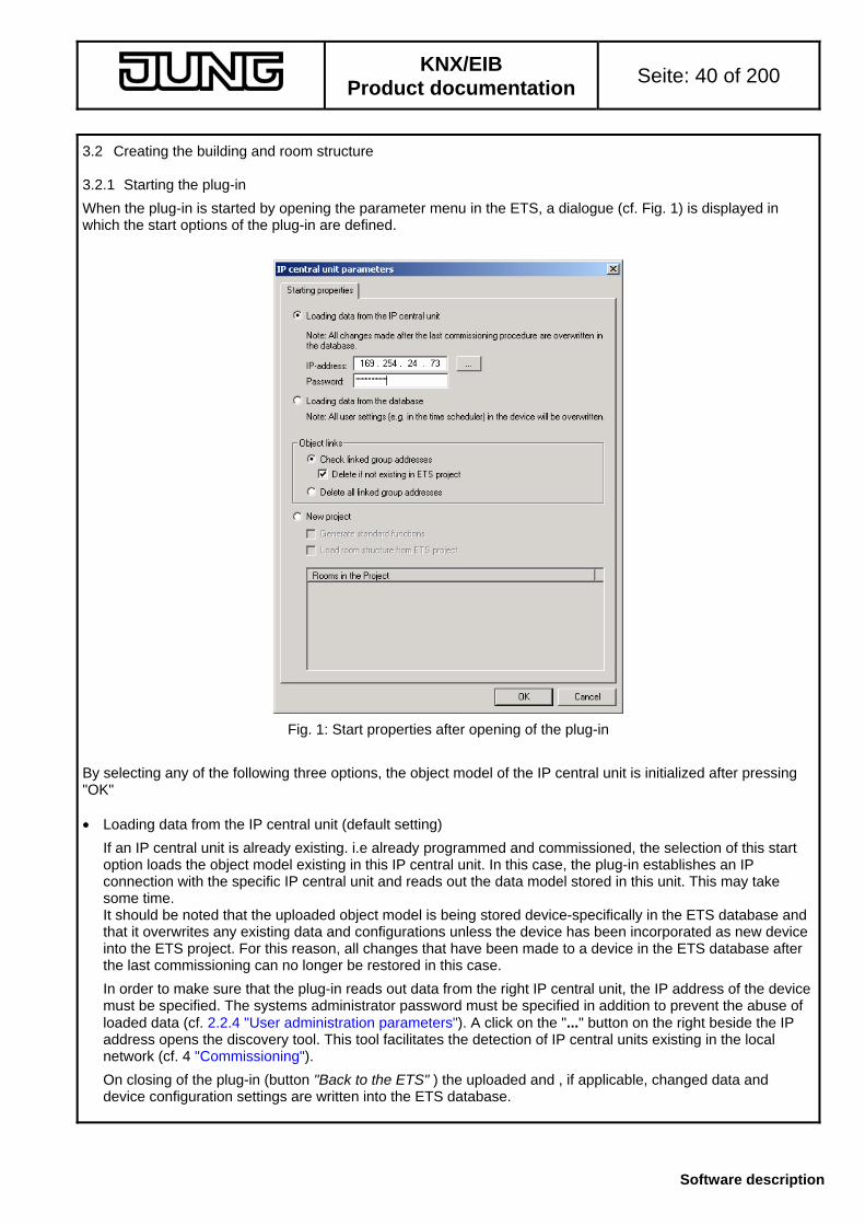
KNX/EIB
Product documentation Seite: 40 of 200
Software description
3.2 Creating the building and room structure 3.2.1 Starting the plug-in
When the plug-in is started by opening the parameter menu in the ETS, a dialogue (cf. Fig. 1) is displayed in which the start options of the plug-in are defined.
Fig. 1: Start properties after opening of the plug-in By selecting any of the following three options, the object model of the IP central unit is initialized after pressing "OK" • Loading data from the IP central unit (default setting)
If an IP central unit is already existing. i.e already programmed and commissioned, the selection of this start option loads the object model existing in this IP central unit. In this case, the plug-in establishes an IP connection with the specific IP central unit and reads out the data model stored in this unit. This may take some time. It should be noted that the uploaded object model is being stored device-specifically in the ETS database and that it overwrites any existing data and configurations unless the device has been incorporated as new device into the ETS project. For this reason, all changes that have been made to a device in the ETS database after the last commissioning can no longer be restored in this case.
In order to make sure that the plug-in reads out data from the right IP central unit, the IP address of the device must be specified. The systems administrator password must be specified in addition to prevent the abuse of loaded data (cf. 2.2.4 "User administration parameters"). A click on the "..." button on the right beside the IP address opens the discovery tool. This tool facilitates the detection of IP central units existing in the local network (cf. 4 "Commissioning").
On closing of the plug-in (button "Back to the ETS" ) the uploaded and , if applicable, changed data and device configuration settings are written into the ETS database.

KNX/EIB
Product documentation Seite: 41 of 200
Software description
• Loading data from the database
When this start option is selected, the object model stored in the ETS database is loaded. The plug-in is initialized with the data model that was stored in the database when the plug-in was closed last time. When programming, it should be noted that settings made by the user on the Web interface of the IP central unit such as, for instance, switching times or light-scene settings are overwritten with data from the ETS database.
On closing of the plug-in (button "Back to the ETS" ) the uploaded and , if applicable, changed data and device configuration settings are written into the ETS database.
• New project
This starting option must be selected in case an IP central unit is being projected and commissioned for the first time. If no further options are specified, the plug-in starts with an empty object model. Rooms, building services, functional groups and KNX/EIB datapoints must be generated completely 'by hand'. Alternatively, predefined building services and functional groups can be generated by ticking the "Generate standard functions" box. These pre-initialized elements can be used as a projecting model and are especially useful and advisable when an IP central unit is being projected for the first time. As a further alternative for generating a new object model, the building structure of the ETS project can be adopted for the plug-in. By ticking the "Load room structure from ETS project" box, the selection field "Rooms in the project" is being activated. This selection box lists all rooms or cabinets that were entered into the ETS project. By clicking the check-box before a room or a cabinet, this element is selected and taken over into the plug-in. The maximum number of rooms or cabinets that can altogether be taken over into the object model of the IP central unit is limited to 16. The designations of the rooms in the ETS can also be 'abstract' designations (e.g. the room "Central" for generating all central functions in the KNX/EIB installation).
On closing of the plug-in (button "Back to the ETS" ) the data and device configuration settings are written into the ETS database.
Checking the object links
The options "Loading data from the IP central unit" and "Loading data from the database" make use of existing object models. All generated KNX/EIB datapoints and the associated group addresses are either read out directly from an existing IP central unit or from a device projected in the database and adopted in the plug-in. There is then the possibility that the group addresses read out do exist in the plug-in, but not in the ETS project or that their data formats are not compatible. The programmer therefore has the choice of deciding what to do with the uploaded group addresses.
Fig. 2: Object links checking options during plug-in start
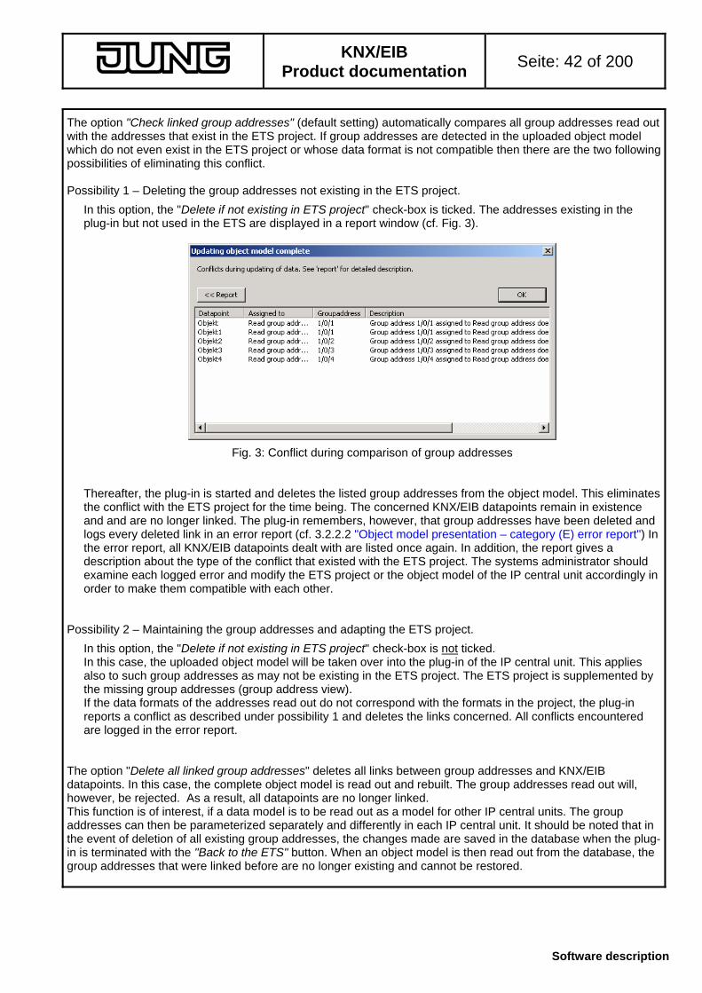
KNX/EIB
Product documentation Seite: 42 of 200
Software description
The option "Check linked group addresses" (default setting) automatically compares all group addresses read out with the addresses that exist in the ETS project. If group addresses are detected in the uploaded object model which do not even exist in the ETS project or whose data format is not compatible then there are the two following possibilities of eliminating this conflict. Possibility 1 – Deleting the group addresses not existing in the ETS project.
In this option, the "Delete if not existing in ETS project" check-box is ticked. The addresses existing in the plug-in but not used in the ETS are displayed in a report window (cf. Fig. 3).
Fig. 3: Conflict during comparison of group addresses Thereafter, the plug-in is started and deletes the listed group addresses from the object model. This eliminates the conflict with the ETS project for the time being. The concerned KNX/EIB datapoints remain in existence and and are no longer linked. The plug-in remembers, however, that group addresses have been deleted and logs every deleted link in an error report (cf. 3.2.2.2 "Object model presentation – category (E) error report") In the error report, all KNX/EIB datapoints dealt with are listed once again. In addition, the report gives a description about the type of the conflict that existed with the ETS project. The systems administrator should examine each logged error and modify the ETS project or the object model of the IP central unit accordingly in order to make them compatible with each other.
Possibility 2 – Maintaining the group addresses and adapting the ETS project.
In this option, the "Delete if not existing in ETS project" check-box is not ticked. In this case, the uploaded object model will be taken over into the plug-in of the IP central unit. This applies also to such group addresses as may not be existing in the ETS project. The ETS project is supplemented by the missing group addresses (group address view). If the data formats of the addresses read out do not correspond with the formats in the project, the plug-in reports a conflict as described under possibility 1 and deletes the links concerned. All conflicts encountered are logged in the error report.
The option "Delete all linked group addresses" deletes all links between group addresses and KNX/EIB datapoints. In this case, the complete object model is read out and rebuilt. The group addresses read out will, however, be rejected. As a result, all datapoints are no longer linked. This function is of interest, if a data model is to be read out as a model for other IP central units. The group addresses can then be parameterized separately and differently in each IP central unit. It should be noted that in the event of deletion of all existing group addresses, the changes made are saved in the database when the plug-in is terminated with the "Back to the ETS" button. When an object model is then read out from the database, the group addresses that were linked before are no longer existing and cannot be restored.

KNX/EIB
Product documentation Seite: 43 of 200
Software description
When no conflicts are detected, the plug-in reports a successful match of the group addresses during starting .
Fig. 4: All group addresses successfully read out and entered into the plug-in 3.2.2 Plug-in interface
The plug-in is started by opening the parameter view in the ETS. After readout of an existing object model from the specified source or after creation of a new model, the projecting interface of the plug-in is opened. The projecting interface is divided into four main parts (cf. Fig. 5). The size of each part or of the entire window can be changed at will by clicking and dragging with the mouse.
In the upper left part, the object model is represented in form of a tree structure with all building services, rooms, functional groups, KNX/EIB datapoints and linkage functions. The error report is also displayed in this window. The sector below (B) shows the group addresses existing in the ETS project and read out from the database. A link between the group addresses and the entry fields for KNX/EIB datapoints can be established by drag & drop from this part of the window. Changing or deleting of existing group addresses in the plug-in is not possible. The upper right part of the window (C) contains parameter sets and links of group addresses for the elements selected in the window on the left. The lower right part of the window (D) displays direct help texts describing the marked parameter element in the window above and shows the conflict descriptions of the error report.
Fig. 5: Projecting interface of the IP central unit plug-in

KNX/EIB
Product documentation Seite: 44 of 200
Software description
3.2.2.1 Menu- and service functions
The plug-in makes various menu and service functions available to the systems administrator. The symbol bar at the upper left provides different icons for selection (cf. Fig. 6) which fulfill different functions and tasks similarly to the function buttons on the right side of the plug-in (cf. Fig. 7). The individual elements are distinguished in Figs. 6 and 7 by numbers where identical numbers designate identical functions. Moreover, a context menu can be opened with a click on the right mouse button, when the mouse pointer is in a free field in the window of the object model (no tree node selected).
Fig. 6: Icons in the menu bar
Fig. 7: Function buttons The different functions are explained below.
• 1: Icon " " or context menu command "Delete"
This function results in a full reset of the object model. All building services, rooms, functional groups, datapoints (also the fixed ones of the system clock) and links are deleted. After execution of this command, the object model is in the default state. If a new object model was initialized with standard functions during starting, the services thus created by default are still existing even after deletion. The device configuration is not influenced by the deletion (except fo the system clock: master or slave operation is set back to autonomous operation).
• 2: Icon " " or context menu command "Save"
This function saves the actual data of the object model and the selected device configuration in the ETS database. This way, separate storage for the safeguarding of data is possible at any time independently of the termination of the plug-in.
• 3: Icon " ", Function button "Export object model" or context menu command "Export object model"
This function permits storing the complete object model and the device configuration in an external file, eg. as a model for other IP central units or in a backup file. Data can be exported either in a binary format "*.ingw" specially created for the IP central unit or in an "*.XML" format. For exporting an XML file, the Microsoft XML parser 4.0 must be installed on the PC ("msxml4.dll"). The program can be downloaded on the Microsoft-Homepage (www.microsoft.com/downloads) for operating systems from Windows 98 onwards. The respective program package is listed under "MSXML 4.0 Service Pack 2 (Microsoft XML Core Services)".
Information on XML: - For safety reasons, no passwords are exported when the export is in the XML format. They must be adapted
'manually' after the import. - The "XML" file format is not specifed as a default format in the export dialog. If an XML export is desired, the
file extension "*.xml" must be added manually to the file name.

KNX/EIB
Product documentation Seite: 45 of 200
Software description

KNX/EIB
Product documentation Seite: 46 of 200
Software description
• 4: Icon " ", Function button "Import object model" or context menu command "Import object model".
By executing this function, an object model exported beforehand as as "*.ingw" or "*.xml" file can be together with the device configuration into the plug-in (cf. "Export object model" on the preceding page). As during plug-in start, the plug-in is initialized in this case with the device model from the file. For this reason, object links with group addresses must be checked also in this case for plausibility and made compatible with the ETS project. For a description of the import options (cf. Fig. 8) please refer to chapter 3.2.1 "Starting the plug-in - Checking the objct links".
Fig. 8: Object links checking options during the import During the import, all project data and settings in the plug-in are overwritten with the data from the file!
Information on XML: - For safety reasons, no passwords are imported when importing data in XML format. They must be adapted
'manually' after the import. - The "XML" file format is not specifed as a default format in the import dialog. If an XML import is desired, the
file extension "*.xml" must be added manually to the file name. - When an XML file is loaded, its structure is checked for plausibility and correctness. In case of malfunction,
the data import is aborted with an error message and the project in the plug-in remains unchanged.
• 5: Icon " ", Function button "Commissioning" or context menu command "Commissioning"
This function activates the commissioning dialogue (cf. Fig. 9). A more detailed description of the commissioning procedure can be found in chapter 4. "Commissioning".
Fig. 9: Commissioning dialogue

KNX/EIB
Product documentation Seite: 47 of 200
Software description
• 6: Icon " ", Function button "Configuration" context menu command "Device configuration"
This function activates the device configuration (parameter settings). The configuration dialog consists of nine pages with parameter settings for the unit that are described in chapter 2.2 "Configuration settings".
• 7: Icon " " or context menu "Central addresses"
When this function is executed, the "Central group addresses" view in the upper right sub-window of the plug-in is displayed. This function permits linking centrally used group addresses with the created datapoints. An object filter permits selecting or masking rooms, services or functional groups in order to ensure fast and efficient linkage of the central addresses in the object model of the IP central unit.
Fig. 10. "Central group addresses" view A detailed description of the central group addresses and their use in projects can be found in chapter 3.2.2.3 "Representation and handling of group addresses and datapoints in the ETS".
• 8, 9 and 10: Icons " ", " " and " "
A click on these icons can be used to execute the "Cut ", "Copy " und "and paste " functions. In the object model (upper left sub-window of plug-in), these functions can be used to reorganize rooms, functions and datapoints (commands: cut and paste) and also copy (commands: copy and paste). With the copy function, project elements existing only once can be duplicated and also reproduced several times. Reorganization is an important function since the order of projected rooms, functional groups and datapoints on the user interface is determined by the projected order of these elements in the plug-in. A click on the icons leads to a response only in those cases where the underlying functions are available.
The duplication of datapoints by whatever procedure does not copy group addresses at the same time. The "Cut" (Ctrl + X), "Copy" (Ctrl + C) and the "Insert" (Ctrl + V) functions are still available as usual via the indicated keyboard shortcuts. Shifting or reorganizing of existing elements is also possible by drag & drop with the mouse pointer.

KNX/EIB
Product documentation Seite: 48 of 200
Software description
• 11: Icon " " or context menu "Print documentation".
For archiving purposes or as project history documentation, the plug-in can at any time document the workings of the IP central unit. This documentation is a detailed sum-up of all device configurations (parameter settings), the complete object model including settings and group addresses as well as the parameterized linking functions. The plug-in establishes the documentation in the "*.XLST" format, which is a formatted XML document that can be displayed, for instance, in a browser window (XSLT: Extensible Stylesheet Language (XSL) Transformations). By clicking on the " " icon or by activating the "Print documentation" command in the context menu, the standard Web browser (recommended: Microsoft© Internet Explorer from version 5.5 onwards) is launched and displays the XSLT file. The file can be printed or stored with the Web browser.
The language of the XSLT documentation is determined by the active language setting of the ETS.

KNX/EIB
Product documentation Seite: 49 of 200
Software description
3.2.2.2 Representation of the object model The object model is represented in the upper left sub-window of the plug-in in the form of a tree structure consisting of four categories (cf. Fig. 11).
Fig. 4: Object model in the plug-in The first category (A) shows a collection of the services installed under the basic node "Building services". When a new object model is being created, the 6 standard building services "Lighting", "Heating", "Blind /shutter", "Security", "Central" and "Ventilation" can be created as a starting option. No services are predefined when starting with an empty (default) model. Basically, up to 16 services can be created by selecting the basic node and then with a click on the right mouse button the context menu ("Add" command).

KNX/EIB
Product documentation Seite: 50 of 200
Software description
The second catergory (B) shows a collection of all rooms or cabinets under the basic node "Rooms". The object model of the IP central unit follows the building structure of the KNX/EIB installation. This means that all interfaces with the bus (KNX/EIB datapoints such as the communication objects "Switching" and "Dimming") are linked with a functional group (function channel such as "Dimming actuator - output 1") and then with a building service (e.g. "Lighting") and last not least with a room. A projecting example for this application is shown in Fig. 12.
Fig. 12: Projecting example for room – building service – functional group – datapoints The cross-room control of the entire KNX/EIB installation with the IP central unit can be performed by the user either on a room-oriented or a services-oriented basis. For this purpose, the Web browser's user interface distinguishes between room-oriented or function-oriented control. This ensures a clear-cut division for the IP central unit's user interface.
The control of the KNX/EIB installation is channel-oriented. By specifying a brightness value, switching or dimming is divided into separate functional groups and this is also the case for controlling a shutter or a heating system. A functional group can be, for instance, a sensor channel (touch sensor rocker 1) or an actuator output (dimming actuator output 1). Each functional group moreover consists of different datapoints (communication objects) permitting bus communication. The data formats of all conventional KNX specifications are supported.
When a new object model is being created, the rooms or cabinets incorporated in the ETS project can be adopted by the plug-in as an initialization model for starting purposes. No rooms will be 'imported' when the program is started with an empty object model (default). The IP central unit can handle up to 16 rooms max. Rooms, functional groups and datapoints can be created by selecting a basic node of category (B) and then with a click on the right mouse button the context menu ("Add" command). Alternatively, these elements can also be deleted at any time (context menu – "Delete" command). Under the basic node "Logic operations", the third category (C) shows a collection of all logic operation functions existing in the IP central unit. Logic operations can be introduced by selecting a node in this category and the "Add" command in the context menu with a click on the right mouse button. Alternatively, these elements can also be deleted at any time (context menu – "Delete" command). The fourth category (D) shows the fixed datapoints of the IP central unit. These are exclusively the bus datapoints of the internal system clock in master or slave mode, when the clock functions are activated. The fixed datapoints are represented in the ETS object view (no plug-in started) as separate objects (object numbers 257 – 259).

KNX/EIB
Product documentation Seite: 51 of 200
Software description
Under the basic node "Error report", the fifth category (E) shows a collection of all logged database conflicts that have occurred in the course of reconstruction of an existing object model – for instance during the start of the plug-in or during the import of a model – or during a central addressing operation. All faulty KNX/EIB datapoints are listed below the basic node of the error report. When a datapoint is marked, the pertaining set of parameters is shown in the upper right sub-window of the plug-in. The sub-window at the lower right contains a description of the conflicts that have been found exist with the ETS project.
The systems administrator should examine each logged error and modify the ETS project or the object model of the IP central unit accordingly in order to make them compatible with each other. Errors that have been checked or dealt with can be acknowledged by the systems administrator by ticking the confirmation box of an error in the tree structure (cf. Fig. 13). The error concerned will then be deleted immediateley and removed from the list. As an alternative, an error entry can be deleted with the "Delete" command in the context menu (click on right mouse button when error entry is activated).
It is also possible to confirm and to delete all logged errors at the same time by clicking in the confirmation box of the "Error report" basic node. In this case, the plug-in asks the user a second time whether it is really intended to remove all the errors from the list (cf. Fig. 14).
confirmation boxes
Fig. 13: Example of an error report in the object model
Fig: 14: Confirmation request before deletion of all error reports The error report is deleted completely as well when new central addresses are being allocated (cf. 3.2.2.3 "Representation and processing of group addresses and datapoints in the ETS"). Before the allocation, the user is requested to confirm the deletion of errors (cf. Fig. 15).
Fig 15: Confirmation to delete the error report during central address allocation The systems administrator has the possibility of creating a documentation of the complete error list. By selecting the "Error report" basic node and by pressing the right mouse button, the command "Display errors in the browser" becomes visible. When this command is executed, the plug-in generates an unformatted XML file which is displayed in the standard browser (recommended: Microsoft© Internet Explorer version 5.5 and later) and which can also be printed or saved there.

KNX/EIB
Product documentation Seite: 52 of 200
Software description
3.2.2.3 Representation and processing of group addresses and datapoints in the ETS Group addresses from the ETS project:
The group addresses created in the project are displayed like in the ETS in form of a separate tree structure in the lower left sub-window of the plug-in (cf. Fig. 16). Depending on the setting in the ETS, two or three address levels are displayed. A link between the group addresses and the entry fields for KNX/EIB datapoints can be established by drag & drop from this part of the window.
Fig. 16: Representation of group addresses in the plug-in Further new main groups, middle groups and subgroups can be created (cf. Fig. 17) Changing or deleting of existing group addresses in the plug-in is not possible.
Fig 17: Creation of a new group address Datapoints in the ETS:
All KNX/EIB datapoints of the IP central unit linked with transmit, receive or read group addresses (cf. 3.2.3.5 "Assignment of group addresses") are shown in ETS object view (plug-in not started) as separate communication objects. As soon as group address is assigned to a datapoint, the plug-in creates an object with a unique object number As this is a dynamic procedure, no names or designations permitting conclusions as to the function of the object will be allocated in the ETS screen.
If the diagnosis assist function of the ETS3 is used (telegram registration, telegram transmission), it is recommended to assign a KNX datapoint type to each object of the IP central unit depending on the data format. This must be done in the ETS3 screen under object properties separately for each object. As with all other bus devices, too, the values of the telegrams from or to the IP central unit be correctly formatted and if necessary displayed with their units in the diagnosis environment of the ETS3 only if the datapoint types are specified.
The linking of group addresses directly in the ETS without the plug-in being started is not possible. In this case, the ETS refuses to grant access. The modification of object properties (flags, etc.) in the ETS has no effect on the data model of the IP central unit.

KNX/EIB
Product documentation Seite: 53 of 200
Software description
Central addresses:
Clicking the " " icon in the symbol bar of the plug-in or executing the command "Central addresses" in the context menu opens the "Central group addresses" screen in the upper right sub-window of the plug-in. This function permits linking centrally used group addresses at the same time with different datapoints of the IP central unit. Central addresses permit, for instance, central OFF or panic ON functions for the lighting, central control of up/down movements of shutters or blinds or can be used to switch over the operating modes of all room temperature controllers in one building simultaneously. At first, the plug-in must informed of the datapoints to be linked with the central address. To facilitate the selection, the datapoints can be filtered for room, function and functional group and displayed by filtering result (cf. Fig. 18). Filtering of the objects is not absolutely necessary. If no filter is active (default), all datapoints are visible. The filter settings are dynamic, i.e. the filters first activated influence the other filter settings and may therefore have a restricting effect on selections. Empty rooms or functional groups without a linked datapoint are not shown in the overview. It should moreover be noted that – except for the fixed datapoints for the internal system clock – only KNX/EIB datapoints will be displayed. Internal datapoints cannot be linked with central addresses.
Thereafter, the datapoints to be linked with the central address are selected in the selection window. For this purpose, the check-box immediately before each datapoint must be ticked. Rooms, building services and functional groups, too, have a check-box. When these higher-order elements are activated, all subordinate datapoints will be selected automatically. To inform the user that not all of the subordinate datapoints have been selected, the plug-in displays the check-boxes of the higher-order tree nodes against a grey background (cf. Fig. 18 – A). When all subordinate datapoints boxes are ticked, the higher-order check-boxes are displayed against a white background (cf. Fig.18 – B)
A
B
only one data point of the functional group selected
all data points of the functional group group selected
selection window
Fig. 18. "Central group addresses" screen In a next step, the central group address to be linked with the selected datapoints (group address "3/1/1" in the example of Fig. 18) must be entered. When entering the address, make sure the spelling is correct (enter figures with slashes). As an alternative, an existing group address can be moved into the entry field by drag & drop. It should be noted, that the group address must be a valid and existing address in the ETS project. Central allocation is otherwise not possible. If necessary, a new group address must be created in the address window at lower left of the plug-in.

KNX/EIB
Product documentation Seite: 54 of 200
Software description
Depending on the parametrization of the group addresses, each datapoint can be bidirectional and, if necessary, also actively request object values from other bus devices. For a definition of these properties, each bus datapoint has different address fields so that values can be transmitted or received via special and, if needed, also different group addresses. Read requests can also be transmitted via separate group addresses.
In the further course of central group addressing in the plug-in of the IP central unit, it is necessary to fix the address fields of the selected datapoints into which the central address is to be entered. For this purpose, 4 control elements are provided on the right of the entry field for the central address which, if activated, enter the central group address into the corresponding address fields. Possible address fields
- transmit and receive group address
- receive group address
- read group address
- group address for masking the object status/value display.
More detailed information on the communication properties of the datapoints is provided in chapter 3.2.3.5 "Allocation of group addresses". After clicking on the "Adopt" button, the plug-in assigns the central address to the selected datapoints. Successful linking is confirmed by the plug-in (cf. Fig. 19). For the linking of further central addresses, anothe central group address can be entered and the procedure repeated.
Fig. 19: Confirmation of a successful linking operation with a central group address The linking of a central group address with the address fields of a datapoint may result in conflicts. To detect such conflicts, each linking operation is followed by a check. The following points are checked... • For all group addresses: The data format (1 bit, 1 byte, etc.) must be compatible. If a group address in the
ETS project or in the IP central unit is already linked to at least one communication object, the data format of the existing links is applicable. If a free group address is used, the format of the first linked object in the IP central unit is used for the data format compatibility check. The KNX datapoint types may differ if the data format is compatible.
• For transmit and receive group addresses: The datapoint must not be "Status indication only"
• For transmit, receive and read group addresses: Only one group address may be assigned,
• For transmit and receive group addresses: In the whole object model, a maximum of 250 group addresses may be 'receive-from-bus' addresses
• For read group addresses, receive group addresses and group addresses for status hiding: In the whole object model, a maximum of 256 group addresses may be 'transmit-to-bus' addresses,
• For receive group addresses and group addresses for status hiding: 4 group addresses max. per datapoint may be assigned,
• For receive group addresses and group addresses for status hiding: Only group addresses used in the ETS project may be linked,

KNX/EIB
Product documentation Seite: 55 of 200
Software description
When a conflict has been detected during the linking of central group addresses, i.e. if not all of the desired links could be implemented, the plug-in establishes an error report for all datapoints concerned. If an already linked group address is the reason of the conflict and if - for this reason - no further address can be linked with the address field of the datapoint, the plug-in asks the systems administrator in a separate dialog (cf. Fig. 20) which of the addresses is to be linked. Two options are available... 1. The already linked group address is retained select "No"
In this case, no central group address is assigned and the conflict documented in an error report.
2. The already linked group address is overwritten select "Yes" In this case, the old link is deleted and the new central group address is assigned. No error report will be established for this conflict.
Fig. 20: Example of a conflict in case of already linked group address In case further datapoints already linked with a group address will be found during the current adaptation procedure, the option last selected (Yes / No) can be applied to all other procedures. In this case, the check-box "Accept decision for all without further request" must be ticked. Important:
Any exisiting error report is completely deleted when new central addresses are assigned. Before the assignment, the user is requested to confirm the deletion of errors.

KNX/EIB
Product documentation Seite: 56 of 200
Software description
3.2.3 Creating and editing an object model The creation of a new object model basically requires the following steps for projecting of an IP central unit, preferably in the order described below. 1 Creation of a room structure
2 Definition of the required building services
3 Creation of the required functional groups
4 Creation and configuration of the datapoints
5 Allocation of the group addresses 3.2.3.1 Creation of a room structure The object model of the IP central unit follows the building structure of the KNX/EIB installation. This means that in projecting all other structural elements (functional groups in conjunction with a building service and datapoints) are always depending on a room. The first thing therefore is to create all the rooms needed. The designations chosen for the rooms can also be of 'abstract' nature. Thus, a room can be designated as a cabinet or accomodate exclusively central functions or alarm functions etc.
16 rooms or cabinets altogether can be created in the object model of the IP central unit. When the plug-in is started, there is the option to adopt the rooms or cabinets created in the ETS project also for the object model (cf. 3.2.1. "Starting the plug-in") Independent of this option, the systems administrator can create at any time further rooms 'manually' or modify or delete existing ones.
A room can be created in the object model of the plug-in by selecting the basic node "Rooms" and by clicking the right mouse button with the "Add" command (cf. Fig. 21). When a room is clicked after having been created, the room parameter "Name" appears in the upper right sub-window of the plug-in (cf. Fig. 21). Here, the room can be given a suitable name (max. 40 characters) which is also displayed on the Web interface of the IP central unit. Please note that due to the formatting of the Web interface, it is possible that not all the characters of the name are displayed. Only alphanumeric inputs (capital and small / no special characters) and blanks are allowed in the name.
Fig. 21: Creation of a room with the context menu
Fig 22: Room parameter "Name" The basic node "Rooms" shows the room resources. The figures in brackets give the number of all rooms created ("3" in the example in Fig. 21) as compared to the maximum of rooms available ("16"). With the help of the "Cut", "Copy" and "Paste" commands or with the mouse pointer and the keyboard, rooms can be reorganized or duplicated. When rooms are duplicated, all dependent elements such as functional groups and datapoints (without group addresses, however) are copied as well. The "Delete" command in the context menu of a room permits removing a room independently from the object model.

KNX/EIB
Product documentation Seite: 57 of 200
Software description
3.2.3.2 Definition of the required building services The cross-room control of the entire KNX/EIB installation with the IP central unit can be performed by the user either on a room-oriented or a function-oriented (building services) basis. For this purpose, the Web browser's user interface distinguishes between room-oriented or services-oriented control. A building service is understood, for instance, as the collection of all lighting fixtures or all window shadings, the security systems or the central functions in a building.
Max. 16 functions altogether can be created in the object model of the IP central unit. The plug-in starts with the option to select the 6 standard functions "Light", "Heating", "Shutters", "Security", "Central" and "Ventilation" as services in the object model (cf. 3.2.1 "Starting the plug-in"). Independent of this option, the systems administrator can at any time create further services 'manually' or modify existing ones.
A room can be created in the object model of the plug-in by selecting the basic node "Rooms" and by clicking the right mouse button with the "Add" command (cf. Fig. 23). When a room is clicked after having been created, the room parameter "Name" appears in the upper right sub-window of the plug-in (cf. Fig. 24). Here, the service can be given a suitable name (max. 40 characters) which is also displayed on the Web interface of the IP central unit. Please note that due to the formatting of the Web interface, it is possible that not all the characters of the name are displayed. Only alphanumeric inputs (capital and small / no special characters) and blanks are allowed in the name.
Fig. 23: Creating a building service with the context menu
Fig. 24: Building services parameter "Name" The basic node "Building services" shows the service resources. The figures in brackets give the number of all building services created ("6" in the example in Fig. 23) as compared to the maximum of rooms available ("16"). With the help of the "Cut", "Copy" and "Paste" functions or with the mouse pointer and the keyboard, services can be reorganized or duplicated. The "Delete" command in the context menu of a service permits removing a service independently from the object model. The 6 standard services cannot be deleted. In addition, services can only be deleted if they are not used in the object model, i.e. if they are not linked with any of the functional groups.

KNX/EIB
Product documentation Seite: 58 of 200
Software description
3.2.3.3 Creation of the required functional groups The control of the KNX/EIB installation is channel-oriented. As an example, the switching of a lighting or the control of a shutter or heating system is divided into separate functional groups. A functional group can be, for instance, a sensor channel (touch sensor rocker 1) or an actuator output (dimming actuator output 1). Each functional group moreover consists of different datapoints (communication objects) permitting bus communication.
The room- and services-oriented functional groups are created and defined in the object model based on the ETS project by the systems administrator. A functional group can be created by selecting the basic node of any of the rooms with the "Add" command after clicking the right mouse button (cf. Fig. 25).
Fig. 25: Creating a functional group with the context menu Thereafter, a window is opened where the new functional group must be assigned to a service. Two cases must be distinguished here which depend on the starting option of the plug-in (cf. 3.2.1 "Starting the plug-in") The following distinction is valid even if the object model has been read out directly from an existing IP central unit or from a model Case 1 – The object model was originally initialized with standard functions:
In this case, the systems administrator can fill the new functional group with predefined datapoints from a model functional group and assign the group to a predefined service (selection: "Predefined functional group" default) As an alternative, an empty functional group can be created (selection: "Functional group without objects") It is recommended, however, to work with predefined functional groups, especially when an IP central unit project is being projected for the first time.
When a predefined model is used, the systems administrator will be be confronted with a selection consisting of different functional groups. For the "Lighting" service, the selection offered includes the functions "Switching", "Dimming" and "Control unit"; for the "Shutter" service, the function "Blind/shutter" is available and for the "Heating" service, the functions "Heating 1 bit" and "Heating 8 bits" are offered. The functional groups are firmly associated with the services.
Fig. 26: Selection from predefined functional groups

KNX/EIB
Product documentation Seite: 59 of 200
Software description
When an empty functional group is created, the systems administrator must only select the service to which the functional group is to be assigned. All created services and also the predefined services are available for selection (cf. Fig. 27).
Fig. 27: Selecting a service for the new and empty functional group Case 2 – The object model was originally initialized without standard functions:
In this case, there is only the possibility of creating empty functional groups without datapoints. As above, the systems administrator only needs to select the service to which the functional group is to be assigned. All created services are available for selection (cf. Fig. 28).
Fig. 28: Selecting the service for the new and empty functional group For both cases, the following rules apply: The assignment of a functional group to a service is definite after pressing the "OK" button and can no longer be changed. After selection of a model or a service, the new functional group is created in the object model either with or without datapoints. When a functional group is clicked after having been created, the functional group parameters "Name" and "Service" (cannot be changed) appear in the upper right sub-window of the plug-in (cf. Fig. 29). Here, the functional group can be given a suitable name (max. 40 characters) which is also displayed on the Web interface of the IP central unit. Please note that due to the formatting of the Web interface, it is possible that not all the characters of the name are displayed. Only alphanumeric inputs (capital and small / no special characters) and blanks are allowed in the name.
Fig. 29: Group parameters "Name" and "Service" With the help of the "Cut", "Copy" and "Paste" commands or with the mouse pointer and the keyboard, functional groups can be reorganized or duplicated. The "Delete" command in the context menu of a functional group permits removing a functional group independently from the object model.

KNX/EIB
Product documentation Seite: 60 of 200
Software description
3.2.3.4 Creation and configuration of the datapoints As is the case with other bus devices, too, each form of data communication for the purposes of controlling a KNX/EIB installation works with communication objects. In the object model of the IP central unit, the communication objects are represented by the EIB datapoints. For each control information in acc. with the KNX standard, separate objects and the corresponding data formats can be parameterized in the plug-in of the IP central unit. Datapoints of the IP central unit can also be active only on an internal level. Internal datapoints have no interface with the bus and are used, for instance, for device-internal linking between logic operations or as display and control elements for special device functions (scene extension, presence simulation, etc.). Various datapoints can be combined into channel-oriented functional groups. This feature and the integration into services and rooms helps structure the user interface of the Web browser and permits fast and simple operation even by such persons who have not been given detailed instructions as to the use of the device.
A datapoint can be created by selecting the basic node of any of the functional groups with the "Add" command after clicking the right mouse button (cf. Fig. 29).
Fig. 29: Creating a datapoint with the context menu As an alternative, existing datapoints can also be duplicated with the "Copy" and "Paste" commands or by drag & drop with the mouse pointer and the keyboard. The duplication of datapoints does not result in linked group addresses being copied at the same time. If the object model was created with predefined functions, the datapoints suitable for functional group selection are already existing. It is recommended to delete datapoints not used from the object model in order to keep the user interface 'clean' and clearly arranged. The IP central unit can distinguish between 512 datapoints max. The basic node "Rooms" shows the datapoint resources. The figures in brackets give the number of all datapoints created ("11" in the example in Fig. 29) as compared to the maximum number of rooms available ("512"). It should be noted, that there are always 10 datapoints firmly established in the device which are not available to the systems administrator. Of the 502 datapoints freely available, a maximum of 256 can be used for the KNX/EIB. The remaining amount of datapoints can only be used internally. Per functional group, a maximumum of 10 datapoints can be created.
All KNX/EIB datapoints of the IP central unit linked with group addresses are shown in the ETS object view (plug-in not started) as separate communication objects. As soon as a group address is assigned to a datapoint, the plug-in creates an object with a unique object number. As this is a dynamic procedure, no names or designations permitting conclusions as to the function of the object will be allocated in the ETS screen. The linking of group addresses directly in the ETS without the plug-in being started is not possible. In this case, the ETS refuses to grant access. The modification of object properties (flags, etc.) in the ETS has no effect on the data model of the IP central unit.

KNX/EIB
Product documentation Seite: 61 of 200
Software description
Basic datapoint parameters
After clicking on an existing datapoint in the object model, the parameter dialog of a datapoint appears in the upper right sub-window of the plug-in (cf. Fig. 30).
Fig. 30: Parameter of a datapoint "Object name"
In this field, the datapoint can be given a suitable name (max. 40 characters) which is also displayed on the Web interface of the IP central unit. Please note that due to the formatting of the Web interface, it is possible that not all the characters of the name are displayed. Only alphanumeric inputs (capital and small / no special characters) and blanks are allowed in the name. The object name is not displayed in the ETS object view. "Object type":
This field determines the KNX datapoint type (DPT) of the selected datapoint. The datapoint type defines the data and display format and maybe also the unit of the datapoint value. The plug-in permits the parameterization of the following datapoint types as per KNX specification... DPT number formerly DPT name DPT format DPT unit 01.xxx EIS 1 boolean 1 bit --- 02.xxx EIS 8 1 bit with control (2 bits) 2 bits --- 04.002 EIS 13 character 1 byte --- 05.001 EIS 6 percent 1 byte % 05.xxx EIS 6 8-bit without sign 1 byte --- 05.xxx EIS 6 shutter position 1 byte % 06.010 EIS 14 mVZ 8-bit with sign 1 byte --- 07.xxx EIS 10 oVZ 2-octet without sign 2 bytes --- 08.xxx EIS 10 mVZ 2-octet with sign 2 bytes --- 09.xxx EIS 5 2-octet floating point number 2 bytes definable 10.001 EIS 3 time 3 bytes --- 11.001 EIS 4 date 3 bytes --- 12.xxx EIS 11 oVZ 4-octet without sign 4 bytes --- 13.xxx EIS 11 mVZ 4-octet with sign 4 bytes --- 14.xxx EIS 9 4-octet floating point number 4 bytes definable 16.001 EIS 15 character string 14 bytes --- 18.001 --- scene 1 byte ---
oVZ = without sign / mVZ = with sign

KNX/EIB
Product documentation Seite: 62 of 200
Software description
"Updating":
In its basic function, the IP central unit works as a visualization tool. In this capacity, it is generally important after Web interface updating to display the current data values and to make them available to the user. In addition, the inputs of a logic operation must also be always up to date.
The "Updating" parameter defines the updating cycle of the datapoint. This cycle influences the display behaviour of a data value during an updating of the Web interface and the state of the input variables for logic operations. Depending on parameterization, the IP central unit either launches a value request on the bus for value updating or processes the data value stored internally in the object model. The "Updating" parameter acts only on external KNX/EIB datapoints and can only be parametrized when a read group address has been projected. The following settings can be selected... - "always"
In this option, the data value of the concerned datapoint is actively requested during each each update of the Web interface or internal processing. The IP central generates for this purpose a value read telegram on the bus via the "read group address" (cf. 3.2.3.5 "Allocation of group addresses".
- "1 minute"
With this option, the data value of the concerned datapoint is requested from the bus only if at least 1 minute has passed since the last update.Only after the subsequent update of the Web interface or internal processing will the data value be actively requested from the bus with a value read telegram via the "read group address".
- "10 minutes"
With this option, the data value of the concerned datapoint is requested from the bus only if at least 10 minutes have passed since the last update. Only after the subsequent update of the Web interface or internal processing will the data value be actively requested from the bus with a value read telegram via the "read group address".
- "never" (default)
When this option is selected, the IP central will never request data values from the bus during a Web interface update or during internal processing. This setting is interesting, for instance, for data values which are being transmitted cyclically on the bus by other bus subscribers. In this case, a special data request from the IP central unit is not needed, as the values regularly 'update themselves' automatically.
In case of a data value request from the IP central unit, a value read telegram is generated on the bus separately for each datapoint even if some datapoints have the same group address. It should be noted that the bus load is relatively high during the value requests when the Web interface is updated with many datapoints in a room or in a service. This effect is accentuated when updates occur at short intervals. For datapoints with normally less frequent changes of the value (e.g. time switch channels, states of shutter channels, etc.), the "Updating" parameter should therefore be set to a time-controlled option (settings "1 minute" or better "10 minutes"). Information on data value updates:
• To enable a value request from the IP central unit to be answered it is necessary that the "R" flag be set in the communication object of the group in the bus device from which data are read. The value returned is displayed on the Web interface of the IP central unit and stored internally in the object model.
• When no value response is received, the value last stored in the object model continues to be displayed.
• When a value response is received on a "transmit-and-receive group address" or on a "receive group address", the IP central unit interprets this response as standard datapoint updating (like value write) and updates the object model.

KNX/EIB
Product documentation Seite: 63 of 200
Software description
Enlarged datapoint parameters Depending on the selected datapoint type (DPT) there are further datapoint parameters which are described below. "Display text"
For datapoint type "01.xxx Boolean", independent display texts can be defined for the data values "1" or "0". The display text of the corresponding data value is displayed in the Web interface. Examples:
Data value = "0"; "Display text for value 0" = "Off" Web interface display "Off"
Data value = "1"; "Display text for value 1" = "On" Web interface display "On" Data value = "0"; "Display text for value 0" = "Inactive" Web interface display "Inactive"
Data value = "1"; "Display text for value 1" = "Active" Web interface display "Active" If no display text is defined for a data value (default), then the value is displayed directly ("0" oder "1") "Unit"
For datapoint types "09.xxx 2-octet floating point number (2 bytes)" and "14.xxx 4-octet floating point number (4 bytes)" The "Unit" parameter can accomodate text consisting of 9 characters max. This text is displayed immediately behind the value display in the Web interface of the IP central unit. This parameter has no effect on the data format, the telegram transmission or the value display as such. It is nothing but additional display text that can be used to describe a displayed value.
The datapoint types "05.001 percent (1 byte)" and "05.xxx shutter position (1 byte)" are inseparably specified with the unit "%". For these types there is no parameter that can be used for the definition of a unit. "Value display":
For the datapoint types "09.xxx 2-octet floating point number (2 bytes)" and "14.xxx 4-octet floating point number (4 bytes)", the data value display in the Web interface can be formatted.
The parameter "Fractional digits" defines the number of all digits after the decimal point of the value to be displayed. Without specifying a number for this parameter (default), 4-byte floating point values are displayed with 6 digits after the decimal point whereas 2-byte floating point values are displayed with 2 digits. A setting of "0" hides all digits after the decimal point.

KNX/EIB
Product documentation Seite: 64 of 200
Software description
"Standard value":
After initialization of the IP central unit (booting after power up or after a restart command at the end of a programming action) or after return of bus voltage, a datapoint has by default the attribute "invalid", i.e. an empty data value. Especially those datapoints that are used as inputs for linking functions must have valid data values even after an initialization. For this purpose, a standard value which can be processed after booting as a valid value, can be parameterized separately for each datapoint. The standard value can be preset for each datapoint type.
As an alternative, a data value can be actively requested by the bus during an initialization of the IP central unit, after a return of bus voltage or after a BCU reset (programming of physical address) (cf. "Object properties in the browser" below). In case of a parametrized standard value, there will basically be no bus request.
If no standard values are defined in the plug-in (default) or if no response value will be received after a status request, the corresponding datapoints continue to be "invalid" after initialization or after return of bus voltage until a value is being received or preset. A standard value can also be predefined for internal datapoints. The table below does not only show the presettable standard values for each datapoint type, but also predefines the pertaining data value ranges. It is important to note that the standard values must be entered exactly as specified (including all digits after the decimal point in case of floating point numbers). DPT Standard value Footnote 01.xxx boolean values "0", "1" or [display text] 1) 02.xxx 1 bit with control (2 bits) values "0", "1", "2", "3" 2) 04.002 character a character as per 8-bit ASCII table 3) 05.001 percent values "0" to "100" 05.xxx 8-bit without sign values "0" to "360" 4) 05.xxx shutter position values "0" to "100" 5) 06.010 8-bit with sign values "-128" to "127" 07.xxx 2-octet without sign values "0" to "65535" 08.xxx 2-octet with sign values "-32768" to "32767" 09.xxx 2-octet floating point number depending on selected unit 6) 10.001 Time [weekday]-[hours]:[minutes]:[seconds] 7) 11.001 date [day].[month].[year] ("dd.mm.yyyy") 12.xxx 4-octet without sign values "0" to "4294967295" 13.xxx 4-octet with sign values "-2147483648" to "2147483647" 14.xxx 2-octet floating point number values "-3.4028235e+38" to "3.4028235e+38" 8) 16.001 character string 14 characters as per 8-bit ASCII table 18.001 scene values "1" to "64" 1) As standard value one of the two display text can be entered as well. In this case, the entries must, however,
be absolutely identical. On entering the values "0" or "1", they are automatically replaced by the plug-in with the display texts, if any.
2) Value "0" = No forced control – Switching "off" / value "1" = No forced control – Switching "on" / value "2" = Forced control "off" / Wert "3" = Forced control "on"
3) It is also possible to enter a decimal ASCII value (0 to 127). The plug-in will automatically convert the value into the corresponding ASCII character.
4) According to KNX-DPT 05.003 "Angle" (0°...360°).
5) Standard value "0" stands for an invalid position.

KNX/EIB
Product documentation Seite: 65 of 200
Software description
6) With datapoint type "09.xxx 2-octet floating point number" an additional distinction between subordinate datapoint types as per KNX specification is possible. The subordinate types are defined by the unit which can be selected beside the datapoint type (cf. Fig. 31).
Fig. 31: Unit used to distinguish 2-byte floating point datapoint types In acc. with KNX, the following parameterizations with respect to the standard value are possible.
DPT no. DTP type Standard value * Unit 9.001 Value_Temp -273.00 to 670760.00 ° C 9.002 Value_Tempd -670760.00 to 670760.00 K 9.003 Value_Tempa -670760.00 to 670760.00 K/h 9.004 Value_Lux 0 to 670760.00 Lux 9.005 Value_Wsp 0 to 670760.00 M/s 9.006 Value_Pres 0 to 670760.00 Pa 9.010 Value_Time1 -670760.00 to 670760.00 s 9.011 Value_Time2 -670760.00 to 670760.00 ms 9.020 Value_Volt -670760.00 to 670760.00 mV 9.021 Value_Curr -670760.00 to 670760.00 mA
*: The number of digits after the decimal point depends on the parameter "Digits after decimal point" (default) = "2"). A comma used to separate decimal digits is to be entered as a "." (point notation).
Notes on floating point values:
The Web interface basically permits the entry of values from "-671088,64" to "670760,96" independent of the unit. It should be noted, however, that only the values as determined by the unit will be transmitted on the bus or processed internally. Values exceeding the limits (in the negative or the positive range) will be ignored.
7) Datapoint type "10.001 Time-of-day" is used to transmit hours, minutes, seconds and also the weekday. These parameters must therefore be taken into consideration when assigning the standard value.
[weekday]-[hours]:[minutes]:[seconds]
[weekday] : 1=Monday; 2=Tuesday; 3=Wednesday; 4=Thursday; 5=Friday; 6= Saturday; 7=Sunday; 0=no day specified
[hours] : 0 ... 23 ; [minutes] : 0 ... 59 ; [seconds] : 0 ... 59
Example: "3-12:12:00" = Wednesday, 12 hours and 12 minutes and 0 seconds
8) Datapoint "14.xxx 4-octet floating point number" makes no further distinction as to subordinate datapoint types for the IP central unit. The standard value to be preset must lie within a range from "-3.4028235e+038" to "3.4028235e+038" The display format is [sign][base]e+[exponent] It should be noted that the plug-in automatically adapts the standard value to the display format of the Web interface and that the base may therefore also be rounded and adapted to digits after the decimal point.

KNX/EIB
Product documentation Seite: 66 of 200
Software description
Object properties in the browser
In the presetting, each datapoint created in the object model is displayed on the Web interface and is thus visible and accessible to the operator of the IP central unit. With respect to the availability and display on the Web interface, each datapoint can have properties independently assigned to it which may restrict operation of the unit or prevent it altogether. These properties and the assignment of special communication functions for KNX/EIB datapoints yield the the object properties described below (cf. Fig. 32). A property is activated by ticking the corresponding check-box.
Fig. 32: Object properties in the browser for datapoints "Invisible in the browser"
When this property is activated, no user can see this datapoint on the Web interface. This function is interesting for datapoints which serve as in- or ouput for the internal linking functions and which are not to be visualized or changed by the operator. This properties is effective for KNX/EIB or for internal datapoints. "Status display only":
If activated, this property ensures that no user can change the data value on the Web interface. The corresponding datapoint acts in this case only as a status display that cannot be edited. This function is useful, if actual temperatures of room temperature controllers or status values of non-adjustable automatic controls are to be indicated. Datapoints where this property is activated can only receive bus telegrams or data values, but not transmit values by themselves. This properties is effective for KNX/EIB or for internal datapoints.
Note for "Invisible in the browser" and for "Status display only":
The Web interface of the IP central unit distinguishes between the access levels "Administrator", "User" and "Guest" The users "Administrator" and "User" can grant the corresponding rights for the subordinate levels in the Web settings This way, it is possible that datapoints parameterized in the plug-in as visible or controllable can subsequently be made inaccessible to subordinate users (cf. 5. "User interface and functions")
The following properties can only be activated for KNX/EIB datapoints: "Readable":
Datapoints with this property can be read out via the bus. If this property is activated, other bus devices can read out the data value of a datapoint of the IP central unit by means of a value-read telegram transmitted to the transmit-and-receive group address (cf. 3.2.3.5 "Allocation of group addresses" If the value is a valid one, the IP central unit answers back via the same group address (value response). If no transmit-and-receive group address is parmeterized (field empty or "Status display only"), the read request will not be answered. No value request will be transmitted via the read or request group address either, if the data value is invalid in case of an external read request. "Status request"
This property can only be activated when a read group address is parameterized. After an initialization or return of bus voltage of the IP central unit, a datapoint has by default the value "invalid", i.e. the data value is empty. Especially those datapoints that are used as inputs for linking functions must have valid data values even after an initialization. For this purpose, the updating mechanism can be started during an initialization of the IP central unit or after a bus voltage return and data value requested from the bus via the read group address. If no response value is received after a status request, the datapoints concerned continue to be "invalid" after the initialization until a valid value is available. In case of a parametrized standard value, there will basically be no bus request.
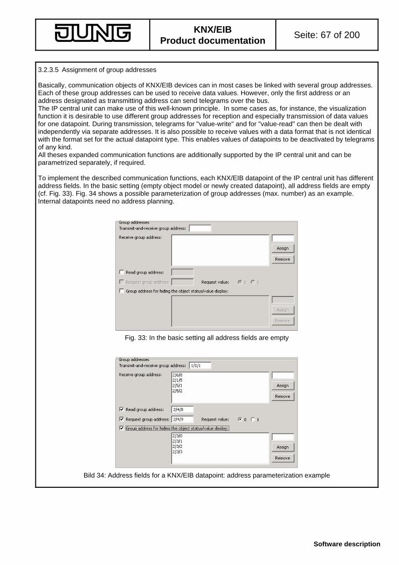
KNX/EIB
Product documentation Seite: 67 of 200
Software description
3.2.3.5 Assignment of group addresses Basically, communication objects of KNX/EIB devices can in most cases be linked with several group addresses. Each of these group addresses can be used to receive data values. However, only the first address or an address designated as transmitting address can send telegrams over the bus. The IP central unit can make use of this well-known principle. In some cases as, for instance, the visualization function it is desirable to use different group addresses for reception and especially transmission of data values for one datapoint. During transmission, telegrams for "value-write" and for "value-read" can then be dealt with independently via separate addresses. It is also possible to receive values with a data format that is not identical with the format set for the actual datapoint type. This enables values of datapoints to be deactivated by telegrams of any kind. All theses expanded communication functions are additionally supported by the IP central unit and can be parametrized separately, if required. To implement the described communication functions, each KNX/EIB datapoint of the IP central unit has different address fields. In the basic setting (empty object model or newly created datapoint), all address fields are empty (cf. Fig. 33). Fig. 34 shows a possible parameterization of group addresses (max. number) as an example. Internal datapoints need no address planning.
Fig. 33: In the basic setting all address fields are empty
Bild 34: Address fields for a KNX/EIB datapoint: address parameterization example

KNX/EIB
Product documentation Seite: 68 of 200
Software description
Address field "Transmit-and-receive group address"
The specified address is the one used for bus transmission or reception of the datapoint value. A change of the data value triggers immediately a corresponding bus telegram (ValueWrite). Similarly, valid values received are stored immediately in the object model and actions are executed, if any.
If no group address has been entered in the field, the datapoint cannot transmit its data value to the bus when a change occurs. Entering an address is not absolutely necessary. If the datapoint concerned has the communication property "Status display only", it is not possible to parameterize a "transmit-and-receive group address". The address field is then displayed against a grey blackground. In this case, data values can be received via the "receive group address".
When the object property "readable" is activated, external read requests are received via the "transmit-and-receive group address" and are answered by this address only. Address field "Receive group address":
This field permits the additional entry of up to four different group addresses through which data values can only be received. Valid values received are stored immediately in the object model and actions are executed, if any. If no additional receive group addresses are desired in the project, the address field can be left empty.
The default receive group addresses must not necessarily be used in the ETS project. If an existing address is provided but not used (no connection with other bus devices or datapoints), the plug-in informs the systems administrator about this condition with a special message (cf. Fig. 35) and links the group address with the datapoint.
Fig. 35: Example of a message saying that the specified address is not used in the ETS project. Address field "Read group address":
When the Web interface is initialized and updated, the IP central unit can request the values of its datapoints from the bus. This function can be separately activated for each datapoint and is dependent on the basic parameterization (parameter: "Updating") or on the object property of a datapoint ("Status request"). If parameterized, the IP central unit triggers a ValueRead telegram via the read group address during an update or on the occasion of a status request. If this feature is used, the address field must be enabled by ticking the corresponding check-box. In order to be able to answer a value request from the IP central unit, it is necessary that the "R" flag be set in the communication object of the group in the bus device from which data are read. The value returned in the form of a ValueResponse telegram is stored in the object model of the IP central unit and – if visible – displayed on the Web interface. When no data value is received as response, the value last stored in the object model continues to be valid or – after an initialization – invalid.
When a value response is received on a "transmit-and-receive address" or on a "receive group address", the IP central unit accepts this response, interprets it as a normal datapoint update (same as ValueWrite) and updates the object model accordingly.
The "read group address" can also be used to receive normal data telegrams (ValueWrite). If a datapoint – for instance in case of "Status display only" – is to make only value requests and to receive also telegrams from the bus via the same address, it is sufficient to parametrize the "read group address" only.

KNX/EIB
Product documentation Seite: 69 of 200
Software description
Address field "Request group address":
Some bus devices transmit a requested data value only in case the value has been requested beforehand via a separate group address by means of a 1-bit trigger object. For these cases, each datapoint of the IP central unit offers the possibility of parameterizing an additional group address for trigger requests. If this feature is used, the address field must be enabled by ticking the corresponding check-box. If no group address is parameterized, the check-box is automatically deleted by the plug-in.
The IP central unit transmits a ValueWrite telegram via the "request group address" to the trigger object of the contacted bus device, if the updating mechanism of a datapoint so requires or if the datapoint initializes itself via a status request. If the "request group address" is enabled and parameterized, no telegram will be transmitted in this case via the "read group address".
The value, which is returned as a rule via another group address, is received by the "read group address" and stored in the object model of the IP central unit and – if visible – also displayed on the Web interface. Values cannot be received via the "request group address".
For adaptation to the contacted bus device, the polarity of the trigger telegram is presettable (cf. Fig. 36).
Fig. 36: Parameterization of trigger telegram polarity A request group address can only be projected, if a "read group address" for the reception of the value response is existing. For this reason, the plug-in removes automatically also the parameterized "request group address" if the "read group address is deleted.
Fig. 37: Automatic deletion of the request group address When a value response is received on a "transmit-and-receive address" or on a "receive group address", the IP central unit accepts this response, interprets it as a normal datapoint update (like a ValueWrite telegram) and updates the object model accordingly.
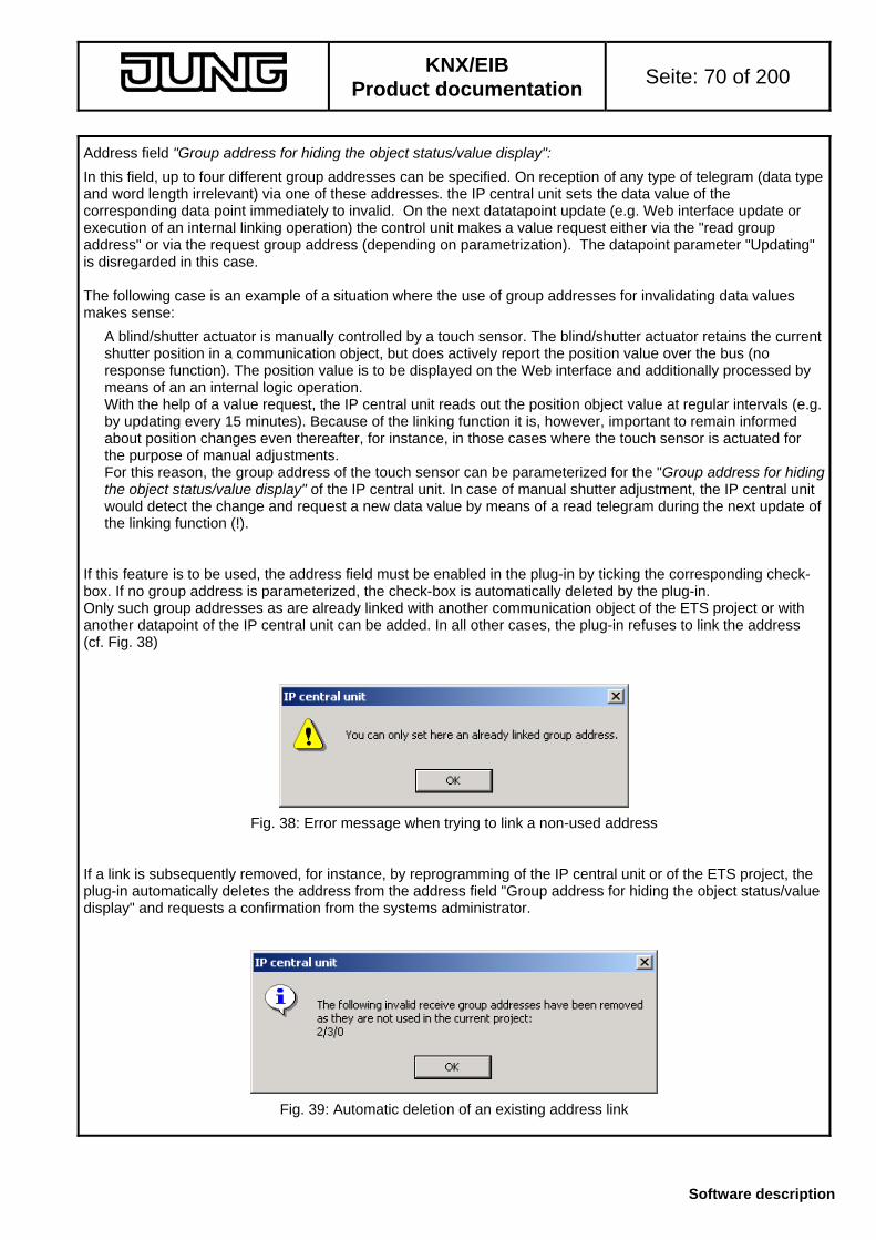
KNX/EIB
Product documentation Seite: 70 of 200
Software description
Address field "Group address for hiding the object status/value display":
In this field, up to four different group addresses can be specified. On reception of any type of telegram (data type and word length irrelevant) via one of these addresses. the IP central unit sets the data value of the corresponding data point immediately to invalid. On the next datatapoint update (e.g. Web interface update or execution of an internal linking operation) the control unit makes a value request either via the "read group address" or via the request group address (depending on parametrization). The datapoint parameter "Updating" is disregarded in this case. The following case is an example of a situation where the use of group addresses for invalidating data values makes sense:
A blind/shutter actuator is manually controlled by a touch sensor. The blind/shutter actuator retains the current shutter position in a communication object, but does actively report the position value over the bus (no response function). The position value is to be displayed on the Web interface and additionally processed by means of an an internal logic operation. With the help of a value request, the IP central unit reads out the position object value at regular intervals (e.g. by updating every 15 minutes). Because of the linking function it is, however, important to remain informed about position changes even thereafter, for instance, in those cases where the touch sensor is actuated for the purpose of manual adjustments. For this reason, the group address of the touch sensor can be parameterized for the "Group address for hiding the object status/value display" of the IP central unit. In case of manual shutter adjustment, the IP central unit would detect the change and request a new data value by means of a read telegram during the next update of the linking function (!).
If this feature is to be used, the address field must be enabled in the plug-in by ticking the corresponding check-box. If no group address is parameterized, the check-box is automatically deleted by the plug-in. Only such group addresses as are already linked with another communication object of the ETS project or with another datapoint of the IP central unit can be added. In all other cases, the plug-in refuses to link the address (cf. Fig. 38)
Fig. 38: Error message when trying to link a non-used address If a link is subsequently removed, for instance, by reprogramming of the IP central unit or of the ETS project, the plug-in automatically deletes the address from the address field "Group address for hiding the object status/value display" and requests a confirmation from the systems administrator.
Fig. 39: Automatic deletion of an existing address link

KNX/EIB
Product documentation Seite: 71 of 200
Software description
Linking the address fields with group addresses:
Only one group address can be linked with each of the address fields "transmit-and-receive group address", "read group address" and "request group address". These addresses can be entered either directly with the keyboard or by drag & drop. With direct entries it should be ensured that – depending on the settings in the ETS – group addresses with 2 or segments are entered with slashes ("/") The plug-in will otherwise not accept the address and delete the address field.
The address fields "receive group address" and "group address for hiding the object status/value display" permit the entry of up to four group addresses. Direct entry or linking by means of drag & drop is possible here as well. In case of direct entry, the address must be entered in the entry field above the "Adopt" button. A click on this button writes the specified address into the list box. A click on "Delete" button on the hand removes a highlighted address from the list box. If more than four group addresses or an already linked address are to be added to a list box, the plug-in prevents such association by displaying an error meassge (cf. Fig. 40).
Fig. 40: Error message during linking of an address with a list box Basically, only such group addresses as are existing in the address table of the ETS project can be linked with address fields. An address must therefore at first be created new in the ETS or in the plug-in if it was not projected before. The plug-in will otherwise report an error (cf. Fig. 41).
Fig. 41: Error message during an attempt to link a non-existing group address A group address can also be linked several times with different address fields of a datapoint, if such a link makes sense (e.g. same address with the "transmit-and-receive group address" and with the "read group address" transmitting, receiving and reading via the same group address = classical method)

KNX/EIB
Product documentation Seite: 72 of 200
Software description
The data format of a group address must correspond to the data format of the datapoint. The plug-in will otherwise report an error (cf. Fig. 42) and prevent linking. Only with "request group addresses" (size always 1 bit) and with "group address for masking the object status/value display" must the data type not be the same as the one parameterized.
Fig. 42: Error message in case of conflicts between data formats The changing of a datapoint type in the parametrization of the IP central unit may result in the deletion of those group addresses that are linked with a datapoint. This is the case, if the data type is changed, for instance, from 1-bit to 1-byte and if the group addresses concerned are linked with other devices in the ETS project. Due to the link existing with other devices, the data type is specified and cannot be changed by the IP central unit. In this case, the plug-in displays a confirmation window and requests the systems administrator to confirm switching over of the datapoint type and thus the deletion of linked group addresses (cf. Fig. 43).
Fig. 43: Confirmation dialogue for switching over of the datapoint type All KNX/EIB datapoints of the IP central unit linked with transmit, receive or read group addresses are shown in ETS object view (plug-in not started) as separate communication objects. As soon as a datapoint is assigned one of the above group addresses, the plug-in creates an object with a unique object number. As this is a dynamic procedure, no names or designations permitting conclusions as to the function of the object will be assigned in the ETS screen. The number of the created communication object will be indicated in the plug-in datapoint parameters below the "standard value" (e.g. as "CO no. 11"). For request group addresses, 1-bit collective objects are created in the ETS independent of the communication object. Depending on the data format, projected group addresses will always be linked with collective objects even with "group addresses for hiding the object status/value display". With regard to the linking of group addresses which are not yet linked with any other datapoint or bus device, the plug-in specifies the required datatype and stores it in the ETS database. When a group address in the object model of the IP central unit is no longer used, all associations for this address will be deleted in the plug-in as well. The linking of group addresses with communication objects directly in the ETS without the plug-in being started is not possible. In this case, the ETS refuses to grant access. The modification of object properties (flags, etc.) in the ETS has no effect on the data model of the IP central unit.

KNX/EIB
Product documentation Seite: 73 of 200
Software description
3.3 Logic operations Independent of the visualization function, the IP central unit can work as an autonomous logic operation controller. Available logic operators are "AND", "OR" and "EXCLUSIVE OR" which can still be enlarged by logical comparison operators when a comfort module is used. A logical operation is described as a module. Depending on its parameterization, it can have several inputs and an output which are linked with datapoints of the IP central unit. By using internal datapoints, logical operations can be combined with one another so that also more extensive logical operations can be implemented. 3.3.1 Creating logic operation modules The IP central unit permits creating up to 64 different logic operation modules in the object model. A logic operation module can be created by selecting the basic node "Logic operations" and by clicking the right mouse button with the "Add" command (cf. Fig. 44). The systems administrator must then decide whether the "Standard" or the "Comfort" type of logic operation is desired (cf. Fig. 45).
Fig. 44: Creating a logic operation module with the context menu
Fig. 45: Type of operation request When a module has been created, the parameter "Name" appears in the upper right sub-window of the plug-in after clicking on this new module (cf. Fig. 46). In this field, a convenient name (40 characters max.) can be entered for the module. Only alphanumeric inputs (capital and small letters / no special characters) and blanks are allowed in the name. The name is only displayed in the node of the logic operation tree of the plug-in for improved distinction between individual modules.
Fig. 46: "Name" of the logic operation module The basic node "Logic operations" shows the module resources. The figures in brackets give the number of all modules created ("1" in the example in Fig. 44) as compared to the maximum number of modules available ("64").
A logic module once created can be removed from the object model with the "Delete" command in the context menu of a module. The reorganization of created modules is not necessary and for this reason not possible either. Copying of logic operation modules is not possible.
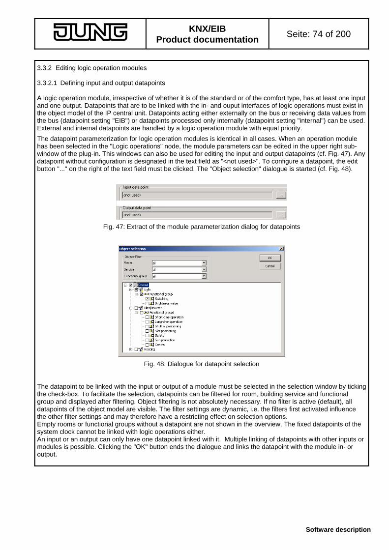
KNX/EIB
Product documentation Seite: 74 of 200
Software description
3.3.2 Editing logic operation modules 3.3.2.1 Defining input and output datapoints A logic operation module, irrespective of whether it is of the standard or of the comfort type, has at least one input and one output. Datapoints that are to be linked with the in- and ouput interfaces of logic operations must exist in the object model of the IP central unit. Datapoints acting either externally on the bus or receiving data values from the bus (datapoint setting "EIB") or datapoints processed only internally (datapoint setting "internal") can be used. External and internal datapoints are handled by a logic operation module with equal priority.
The datapoint parameterization for logic operation modules is identical in all cases. When an operation module has been selected in the "Logic operations" node, the module parameters can be edited in the upper right sub-window of the plug-in. This windows can also be used for editing the input and output datapoints (cf. Fig. 47). Any datapoint without configuration is designated in the text field as "<not used>". To configure a datapoint, the edit button "..." on the right of the text field must be clicked. The "Object selection" dialogue is started (cf. Fig. 48).
Fig. 47: Extract of the module parameterization dialog for datapoints
Fig. 48: Dialogue for datapoint selection The datapoint to be linked with the input or output of a module must be selected in the selection window by ticking the check-box. To facilitate the selection, datapoints can be filtered for room, building service and functional group and displayed after filtering. Object filtering is not absolutely necessary. If no filter is active (default), all datapoints of the object model are visible. The filter settings are dynamic, i.e. the filters first activated influence the other filter settings and may therefore have a restricting effect on selection options. Empty rooms or functional groups without a datapoint are not shown in the overview. The fixed datapoints of the system clock cannot be linked with logic operations either. An input or an output can only have one datapoint linked with it. Multiple linking of datapoints with other inputs or modules is possible. Clicking the "OK" button ends the dialogue and links the datapoint with the module in- or output.

KNX/EIB
Product documentation Seite: 75 of 200
Software description
3.3.2.2 Configuration of a standard logic operation A standard logic operation can establish a logical connection between up to 8 input datapoints. The type of logical operation can be selected from among "AND", "OR" and "EXCLUSIVE OR". The result of the operation is written into a datapoint. The logic operation module handles all configured inputs selectively and determines their logic state. An input has the logic level "1" (true), if its data value is not equal to "0". Similarly, an input has the logic level "0" (false), if its data value is equal to "0" Each input datapoint can be inverted independently so that the logical evaluation of the data value yields the opposite value (input "1" "0" or input "0" "1"). After individual evaluation, the module links all input states in acc. with the parameterized logic operation and determines the output state. This state can be "0" (false) or "1" (true). The output can optionally be inverted. Each output state can have a data value assigned. The parameter "Transmit value if operation result positive" defines the data value for an operation result of "1". Similarly, the parameter "Transmit value if operation result NOT positive" defines the data value for an operation result of "0". Depending on the logic output state determined, the parameterized data value is taken over into the output datapoint and thus into the object model. With KNX/EIB datapoints, the value is immediately transmitted to the bus thereafter. It should be noted that the entry into the parameter "Transmit value if operation..." has the same format as required by the output datapoint type (as far as formatting is concerned cf. 3.2.3.4 "Creation and configuration of datapoints – Standard value"). The data value is otherwise invalid and is not adopted in the object model and not transmitted to the bus. Notes:
• The inputs and outputs of the logic operation module can be linked with any type of datapoint and also with Boolean datapoints that are not 1-bit datapoints. The module treats the datapoints basically in such a way as if their values are equal to "0" (state "0" – false) or not equal to "0" (state "1" – true). "Time of day", "Date" and "Character string" are the only datapoint types that cannot be linked with inputs. All datapoint types can nonetheless be linked with outputs.
• The logic operation module can also be used with one input only (e.g. as inverter). In this case, the other 7 inputs of the module are not in use and the "Logic operation" parameter is without function. If more than one input is used, it is absolutely necessary to select a logic function for the "Logic operation" parameter
• The parameter field "Expression" shows the whole logic operation as it is processed internally in the IP central unit. This expression is additionally indicated in the object model tree node of the operation concerned behind the name of the module. For the systems administrator, the expression is of no importance. The manufacturer may need to know the expression for servicing purposes

KNX/EIB
Product documentation Seite: 76 of 200
Software description
Logic operation examples for a standard operation (E = input / A = output):
I. OR operation with 2 inputs (Boolean / E2 inverted) and one output (Boolean) "Transmit value if operation result positive" = "1" / "Transmit value if operation result NOT positive" = "0"
time
state input 1
state input 2
logical output state
logical evaluation input 1
logical evaluation input 2
output datapoint value
initialisationno change of inputs 1 and 2 --> output is not evaluated
1
0
1
0
1
0
1
0
1
0
1
0
II. AND operation with 2 inputs (E1 Boolean / E2 2-byte floating point value) and one output (2-byte floating point
value) "Transmit value if operation result positive" = "+ 23.00" / "Transmit value if operation result NOT positive" = "+ 7.00"
timeinitialisation
1
0
+ 21.00
0.00
1
0
1
0
1
0
+ 23.00
+ 7.00
state input 1
state input 2
logical output state
logical evaluation input 1
logical evaluation input 2
output datapoint value

KNX/EIB
Product documentation Seite: 77 of 200
Software description
3.3.2.3 Configuration of a comfort logic operation As compared to standard logic operations, comfort logic operations have enlarged check operators for the inputs and also additional updating conditions for the output. If needed, an additional inhibit object is also available.
After creating a comfort logic operation module and after clicking on this new module in the tree node of the operations, the parameter "Module" appears in the upper right sub-window of the plug-in. This parameter defines the logic kernel of the operation and thus the basic application as per the following diagrams...
"Standard"
operator
value
input 1
2
8
::
inverter
- Yes- No
transmit value
output
filter- only 1- only 0- only on change
logic operation
- AND- OR- XOR - value on TRUE
- value on FALSE
"Logic operation"
operator
value
input 1
2
8
::
operatorinhibit
value
logic operation
- AND- OR- XOR
1
0
inverter
- Yes- No
transmit value
output
filter- only 1- only 0- only on change
- value on TRUE- value on FALSE
"Comparator" 2
comparator
- =- <- <=- >- >=- <>
1
0
operator
value
input 1
operatorinhibit
value
inverter
- Yes- No
transmit value
output
filter- only 1- only 0- only on change
- value on TRUE- value on FALSE
"None" operator
value
input 1
inverter
- YES- NO
transmit value
output
filter- only1- only 0- only on change
- value on TRUE- value on FALSE
The individual modules basically distinguish themselves only by the availabitity of an inhibit object, the functioning of the module kernel and the number of available inputs. The input and output parameters can be set in all cases in an identical way. It is basically recommended to select a module whose scope of functions is suited to the application.

KNX/EIB
Product documentation Seite: 78 of 200
Software description
3.3.2.3.1 Setting the input parameters In case of comfort logic operations, the inputs can always be parameterized in the same way and independently of the selected module. The modules always work in acc. with the same principle described below. Operator function: The logic operation module handles all configured inputs – and also a disable input, if any – selectively and determines their logic state. The inputs of the logic operation module can be linked with any type of datapoint and also with Boolean datapoints that are not 1-bit datapoints. "Time of day", "Date" and "Character string" are the only datapoint types that cannot be linked with inputs. With these types, the input is always a logic "0". The data values are then compared to a predefined parameter value by means of the operator selected in the plug-in. The result of this comparison is either "0" (false) or "1" (true). The following mathematical operators are available... Operator Function Description <not used> no function Operator function is off. No input comparison.
Data value passed on unchanged to the next evaluation stage of the logic function.
NOT inverting Inverting of the logical state of the input: A data value equal to "0" is inverted into a logic "1" (true). A data value not equal to "0" is inverted into a logic "0" (false).
= equal to If the data value is equal to the parameter value, the logic state of the input is set to "1" (true). If the data value is not equal to the parameter value, the module sets the state to "0" (false").
< less than If the data value is less than the parameter value, the logic state of the input is set to "1" (true). If the data value is greater than or equal to the parameter value, the module sets the state to "0" (false").
<= less than or equal to
If the data value is less than or equal to the parameter value, the logic state of the input is set to "1" (true). If the data value is greater than the parameter value, the module sets the state to "0" (false").
> greater than If the data value is greater than the parameter value, the logic state of the input is set to "1" (true). If the data value is less than or equal to the parameter value, the module sets the state to "0" (false").
>= greater than If the data value is less than or equal to the parameter value, the logic state of the input is set to "1" (true). If the data value is less than the parameter value, the module sets the state to "0" (false").
<> not equal to If the data value is not equal to the parameter value, the logic state of the input is set to "1" (true). If the data value is equal to the parameter value, the module sets the state to "0" (false").
The result of the comparison represents the logic state of the input and is passed on to the next evaluation stage of the logic function. Note:
It must be ensured that the parameter value required for the comparison lies within the limits of the value range of the respective datapoint type. The format of the input value must be observed (for value limits and formatting cf. 3.2.3.4 "Creation and configuration of datapoints – Standard value") The logic state can otherwise not be determined properly.

KNX/EIB
Product documentation Seite: 79 of 200
Software description
3.3.2.3.2 Functioning of the module kernel The "Module" parameter defines the module kernel and thus the functioning of the logic operation (cf. 3.3.2.3 "Configuration of a comfort logic operation"). Module kernel "Standard":
Similar to a standard operation, the module can process up to 8 different inputs. Input parameters (operator) and output functions (filters, inverter) can be used in addition. The logic input states as determined by the operator function are processed as specified for the "Logic operation" parameter. The logic operations available are "AND", "OR" and "EXCLUSIVE OR". If more than one input is used, the parameter must have one of these operations specified. For inputs whose operator function is off (setting "<not used>", the logic operation module determines the logic state based on the input data value without comparing it to a parameterized value. Data values equal to "0" have the logic state "0" (false) whereas values not equal to "0" have the state "1" (true). The result of the logic operation ("0" oder "1) is passed on to the output.
operator
value
input 1
2
8
::
inverter
- Yes- No
transmit value
output
filter- only 1- only 0- only on change
logic operation
- AND- OR- XOR - value on TRUE
- value on FALSE
Module kernel "Logic operation":
As with the standard module kernel, up to 8 different inputs can be processed. Input parameters (operator) and output functions (filters, inverter) can be used here as well. If needed, an additional inhibit input is optionally available. The logic input states as determined by the operator function are processed as specified for the "Logic operation" parameter. The logic operations available are "AND", "OR" and "EXCLUSIVE OR". If more than one input is used, the parameter must have one of these operations specified. For inputs whose operator function is off (setting "<not used>", the logic operation module determines the logic state based on the input data value without comparing it to a parameterized value. Data values equal to "0" have the logic state "0" (false) whereas values not equal to "0" have the state "1" (true). The result of the logic operation ("0" or "1") is passed on to the output only if the inhibit input is not in logic state "1" (true). Otherwise, the inhibit function is active and the logic operation result is not passed on to the output. This means that the output state does not change when inhibit is active and that the state is not updated either. When the inhibit function is deactivated, the logic operation module recomputes the output state as in case of an input change and updates the output result, if necessary. Updates of the inhibit input from "inactive" to "inactive" or from "active" to "active" remain without effect.
operator
value
input 1
2
8
::
operatorinhibit
value
logic operation
- AND- OR- XOR
1
0
inverter
- Yes- No
transmit value
output
filter- only 1- only 0- only on change
- value on TRUE- value on FALSE

KNX/EIB
Product documentation Seite: 80 of 200
Software description
Module kernel "Comparator":
The comparator offers the possibility to compare up to two different inputs with one another in a logic operation. As with the "standard" module kernel, input parameters (operator) and output functions (filters, inverter) can be used. If needed, an additional inhibit input is optionally available. Comparison of an input value:
Only one input configured. The operator function of this input directly determines the comparator function. The result of the comparison is directly passed on to the output control, if needed with a time delay. The parameter "Logic operation" has not function. The comparator downstream is thus without effect. If the operator function is off (setting "<not used>", the logic operation module determines the logic state based on the input data value without comparing it to a parameterized value. Data values equal to "0" have the logic state "0" (false) whereas values not equal to "0" have the state "1" (true).
operatorinput 1
inverter
- YES- NO
transmit value
output
filter- only 1- only 0- only on change
operatorinhibit
value
1
0 - value on TRUE- value on FALSE
value
Comparison of two input values:
By selecting the "Logic operation" parameter, the second input is enabled and a comparison operator parameterized. The logic state is determined for each input in consideration of the own operator function. Both input states are compared based on the parametrized "Logic operation". The comparison operators available are the same as with the operator function for one input (cf. 3.3.2.3.1 "Setting the input parameters").
When the operator function is off for one or for both inputs (setting "<not used>") the logic operation module uses directly the input data values for comparison. This it is possible, for instance, to compare two temperature values with one another.
2
comparator
- =- <- <=- >- >=- <>
1
0
operator
value
input 1
operatorinhibit
value
inverter
- Yes- No
transmit value
output
filter- only 1- only 0- only on change
- value on TRUE- value on FALSE
The result of the logic operation ("0" or "1") is passed on to the output only if the inhibit input is not in logic state "1" (true). Otherwise, the inhibit function is active and the logic operation result is not passed on to the output. This means that the output state does not change when inhibit is active and that the state is not updated either. When the inhibit function is deactivated, the logic operation module recomputes the output state as in case of an input change and updates the output result, if necessary. Updates of the inhibit input from "inactive" to "inactive" or from "active" to "active" remain without effect.

KNX/EIB
Product documentation Seite: 81 of 200
Software description
Module kernel "None":
In this setting there is no module kernel, i.e. the input is connected immediately and without further processing with the output. Input parameters (operator) and output functions (filters, inverter) can be used here as well. This function makes sense, for instance, when filtering and inverting of data values is concerned. The logic input states determined by the operator function are passed onto the output control. When the operator function is off (setting "<not used>"), the logic operation module determines the logic state without comparison with a parmeterized value. Data values equal to "0" have the logic state "0" (false) whereas values not equal to "0" have the state "1" (true).
operator
value
input 1
inverter
- YES- NO
transmit value
output
filter- only1- only 0- only on change
- value on TRUE- value on FALSE
3.3.2.3.3 Setting the output parameters The logic output state ("0" or "1") is computed by the upstream logic elements and passed on to the output control. The output control can optionally invert the output state ("Invert" check-box ticked). Defining an output filter also permits suppressing a state. The filter properties are defined by the "Filter" parameter...
Setting "None": both output states "0" or "1" will be accepted.
Setting "Only 1": only output state "1" will be accepted. "0" results in no output reaction.
Setting "Only 0": only output state "0" will be accepted. "1" results in no output reaction. Moreover, it is possible to define whether a new output will be taken over only if the state has changed compared with the old one. This checking of the state can be activated by ticking the check-box "After a change only". A change of state takes place in the event of a change from "1" to "0", from "0" to "1", or when a state was invalid as, for instance, after initialization, and when a new valid value was computed.
The output parameters are processed in the order "Inverting" "Filtering" "Change".
Each output state can have a data value assigned. The parameter "Transmit value if operation result positive" defines the data value for an output state of "1". Similarly, the parameter "Transmit value if operation result NOT positive" defines the data value for an output state of "0". Depending on the logic output state determined, the parameterized data value is taken over into the output datapoint and thus into the object model. With KNX/EIB datapoints, the value is immediately transmitted to the bus thereafter. Note:
• The output of a logic operation module can be linked with any type of datapoint and also with Boolean datapoints that are not 1-bit datapoints.
• It must be ensured that the parameter value required for "Transmit value if operation result..." lies within the limits of the value range of the respective datapoint type. The format of the output value must be observed (for value limits and formatting cf. 3.2.3.4 "Creation and configuration of datapoints – Standard value") The data value is otherwise invalid.
• The parameter field "Expression" shows the whole logic operation as it is processed internally in the IP central unit. This expression is additionally indicated in the object model tree node of the operation concerned behind the name of the module. For the systems administrator, the expression is not of importance. The manufacturer may need to know the expression for servicing purposes

KNX/EIB
Product documentation Seite: 82 of 200
Software description
3.3.3 Processing of input data For all logic operations, the operation result is recomputed when the data value of an input changes or when it is updated. After detecting the change or the update of a value, the logic operation module requests the data values of all other input datapoints from the object model and recomputes the result of the logic operation. If a data value is invalid when requested by a logic operation module, the IP central unit triggers a read request on the bus for the concerned KNX/EIB datapoints in order to update the value. A datapoint can be invalid, if ...
- a value has been received by the "Group address for masking the object status/value display",
- after initialization of the IP central unit or after return of bus voltage, no response value has been received by the bus after a status request and when, additionally, no standard value has been set,
- an updating interval (parameter "Updating" set to "1 minute" or "10 minutes") has elapsed. For datapoints whose "Updating" parameter is set to "always", there will moreover and in all cases always be a read request when a logic operation module is being computed. The logic operation module recomputes the result of the logic operation only after the response for all datapoints has been received. Thus, it is ensured that the calculation is always performed with the latest input data. On account of this synchronous data comparison with the bus and the fixed response timeouts, the calculation of the output values may be delayed by 24 seconds max. Notes:
• If no data value is received as response after a read request or if no "read group address" is projected in the plug-in for the respective datapoint, the logic operation will be executed with the value "0" for the datapoint concerned.
• Internal datapoints are "invalid" only after an initialization of the IP central unit or after bus voltage return, if no standard value has been set. A valid value will be available only after a data value has been explicitly specified (e.g. by a logic operation result or by a value change on the Web interface.
• After an initialization a logic operation function will not be automatically executed even if valid data values (e.g. standard values) are existing. It is basically required that at least one data value must have changed or been updated after the initialization before a new result will be computed. This applies also to inverted input data values that are in a 'true' state after an initialization.
/
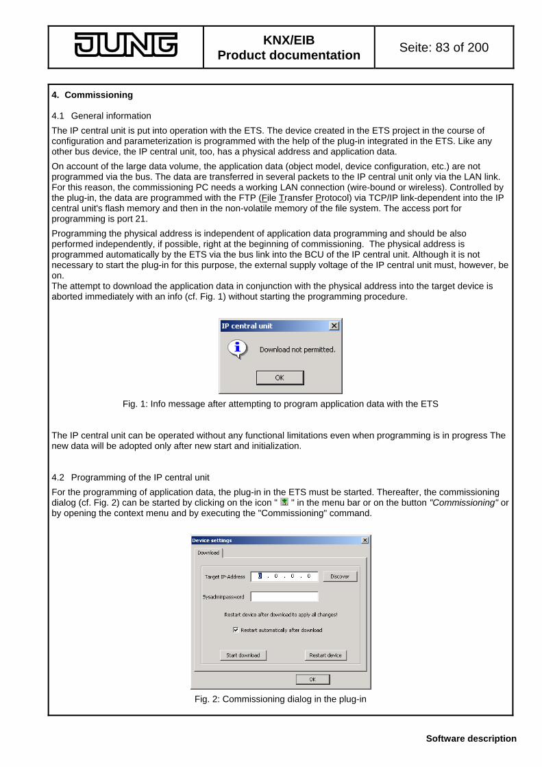
KNX/EIB
Product documentation Seite: 83 of 200
Software description
4. Commissioning 4.1 General information
The IP central unit is put into operation with the ETS. The device created in the ETS project in the course of configuration and parameterization is programmed with the help of the plug-in integrated in the ETS. Like any other bus device, the IP central unit, too, has a physical address and application data.
On account of the large data volume, the application data (object model, device configuration, etc.) are not programmed via the bus. The data are transferred in several packets to the IP central unit only via the LAN link. For this reason, the commissioning PC needs a working LAN connection (wire-bound or wireless). Controlled by the plug-in, the data are programmed with the FTP (File Transfer Protocol) via TCP/IP link-dependent into the IP central unit's flash memory and then in the non-volatile memory of the file system. The access port for programming is port 21.
Programming the physical address is independent of application data programming and should be also performed independently, if possible, right at the beginning of commissioning. The physical address is programmed automatically by the ETS via the bus link into the BCU of the IP central unit. Although it is not necessary to start the plug-in for this purpose, the external supply voltage of the IP central unit must, however, be on. The attempt to download the application data in conjunction with the physical address into the target device is aborted immediately with an info (cf. Fig. 1) without starting the programming procedure.
Fig. 1: Info message after attempting to program application data with the ETS The IP central unit can be operated without any functional limitations even when programming is in progress The new data will be adopted only after new start and initialization. 4.2 Programming of the IP central unit
For the programming of application data, the plug-in in the ETS must be started. Thereafter, the commissioning dialog (cf. Fig. 2) can be started by clicking on the icon " " in the menu bar or on the button "Commissioning" or by opening the context menu and by executing the "Commissioning" command.
Fig. 2: Commissioning dialog in the plug-in
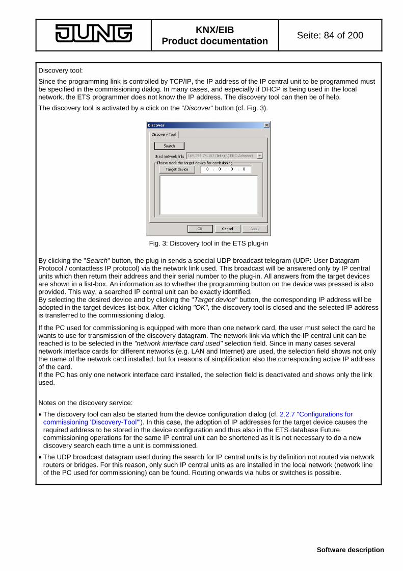
KNX/EIB
Product documentation Seite: 84 of 200
Software description
Discovery tool:
Since the programming link is controlled by TCP/IP, the IP address of the IP central unit to be programmed must be specified in the commissioning dialog. In many cases, and especially if DHCP is being used in the local network, the ETS programmer does not know the IP address. The discovery tool can then be of help.
The discovery tool is activated by a click on the "Discover" button (cf. Fig. 3).
Fig. 3: Discovery tool in the ETS plug-in
By clicking the "Search" button, the plug-in sends a special UDP broadcast telegram (UDP: User Datagram Protocol / contactless IP protocol) via the network link used. This broadcast will be answered only by IP central units which then return their address and their serial number to the plug-in. All answers from the target devices are shown in a list-box. An information as to whether the programming button on the device was pressed is also provided. This way, a searched IP central unit can be exactly identified. By selecting the desired device and by clicking the "Target device" button, the corresponding IP address will be adopted in the target devices list-box. After clicking "OK", the discovery tool is closed and the selected IP address is transferred to the commissioning dialog.
If the PC used for commissioning is equipped with more than one network card, the user must select the card he wants to use for transmission of the discovery datagram. The network link via which the IP central unit can be reached is to be selected in the "network interface card used" selection field. Since in many cases several network interface cards for different networks (e.g. LAN and Internet) are used, the selection field shows not only the name of the network card installed, but for reasons of simplification also the corresponding active IP address of the card. If the PC has only one network interface card installed, the selection field is deactivated and shows only the link used. Notes on the discovery service:
• The discovery tool can also be started from the device configuration dialog (cf. 2.2.7 "Configurations for commissioning 'Discovery-Tool'"). In this case, the adoption of IP addresses for the target device causes the required address to be stored in the device configuration and thus also in the ETS database Future commissioning operations for the same IP central unit can be shortened as it is not necessary to do a new discovery search each time a unit is commissioned.
• The UDP broadcast datagram used during the search for IP central units is by definition not routed via network routers or bridges. For this reason, only such IP central units as are installed in the local network (network line of the PC used for commissioning) can be found. Routing onwards via hubs or switches is possible.

KNX/EIB
Product documentation Seite: 85 of 200
Software description
Starting the programming procedure:
After entering the target address through the discovery tool or with the keyboard, the programming procedure can be started. To prevent unauthorized access to the device, each programming cycle is protected by means of the systems administrator password. The password entered must be identical with the password stored in the IP central unit. When the IP central unit is commissioned for the first time, the default password is "sysadminpw". For all subsequent programming operations, the password programmed during the last programming procedure into the IP central unit must be entered. The systems administrator password is defined in the device configuration in the ETS plug-in. Observe the spelling with small and capital letters. All passwords are transmitted as plaintext via the Ethernet. A click on the "Start commissioning procedure" button starts the application download. When the registered systems administrator password is correct, the application data are transferred thereafter step by step into the flash memory of the IP central unit. If the password is not correct, the plug-in reports an error (cf. Fig. 4) and aborts the programming procedure. During programming, the plug-in shows the progress by means of a bar chart (cf. Fig. 5). The data transmission can last a few minutes. The complete set of application data is transmitted during the download block by block in three configuration files. The programming procedurte can be aborted at any time by clicking on the "Abort" button. In this case, the plug-in stops the transmission of data only after a data segment has been programmed completely. Therefore, the program abortion may take place with a little delay.
Fig 4: Error message after entry of a wrong password
Fig. 5: Progress display during a programming cycle
Note:
IP central units not located inside the local network can be programmed by "remote-programming". In this case, it is necessary that the specified IP address which does not belong to the local network can be used to contact a "remote" IP central unit via FTP and that a valid gateway is registered in the IP configuration of the PC used for commissioning. It should be noted, however, that any proxy servers or firewalls 'in between' can make undisturbed communication and thus remote programming impossible. Another point in remote programming is that the programming progress cannot be correctly displayed.

KNX/EIB
Product documentation Seite: 86 of 200
Software description
After premature abortion of a programming cycle (user-induced or caused by communication difficulties) the plug-in issues an error message. If the abortion was due to communication problems, the error messages shown in figs. 7 or 8 & 9 are issued. In these cases, the operating system of the PC used for commissioning has detected an error. To correct the error, the 'reachability' of the IP central unit must be checked (network connection available?, power supply on?, etc.) and programming repeated.
Data already existing in the flash memory are not affected by an aborted programming cycle. Programmed data segments will be stored temporarily . New data will be taken over permanently into the flash memory only after the download has been 100% succesful.
Fig. 6: Error message after abortion of programming cycle
Fig. 7: Contact with IP central unit not possible
Figs. 8 & 9: Communication difficulties
During programming, the plug-in checks the serial number of the IP central unit. Each IP central unit has its own unique serial number which is written into the device configuration and thus into the ETS database when a project is being uploaded from an existing IP central unit. When a new device is entered in the ETS project and when no contact has yet been established with another device, the serial number is not known and empty. Checking the serial number at the beginning of a commissioning procedure can help to prevent inadvertent programming of a wrong device, especially if several IP central units are existing in the installation.
If the serial number stored in the ETS project is not identical with the one read out from the device, the plug-in issues a warning (cf. Fig. 10). A click on the "No" button aborts the programming cycle (cf. Fig. 11). If the warning is confirmed with "Yes", the plug-in continues with the programming of the IP central unit. The serial number in the ETS project is being replaced by the one of the programmed device. The serial number in the device remains unchanged.
Fig. 10: Warning message in case of different serial numbers
Fig. 11: Warning message in case of abortion of commissioning procedure

KNX/EIB
Product documentation Seite: 87 of 200
Software description
When all application data have been programmed into the target device, the plug-in terminates the download link. The data programmed into the flash memory will, however, be taken over into the runtime memory (RAM) as the new valid parameterization information only after a new start of the IP central unit.
By ticking the check-box "Automatic restart after commissioning" in the commissioning dialog, the system can be forced to restart directly after the end of the programming cycle. In this case, the IP central unit is re-initialized immediately after the download (cf. Fig. 12). By removing the check mark, a programming cycle can alternatively be performed without restart. This setting is useful, if a restart of the device and thus also a prolonged re-initialization phase is to be executed only later – for instance, during the evening hours – in order not to disturb the current operations.
Fig. 12: Confirmation of automatic restart after the end of programming
Fig. 13: Confirmation of end of programming without restart Irrespective of programming, the IP central unit can at any time be restarted 'by hand'. A click on the button "Restart device" in the commissioning dialog sends a restart command to the IP central unit (cf. Fig. 14)
Fig. 14: Confirmation after transmission of restart command The IP central unit can at any time be restarted independently of the ETS by cutting and by reactivating the power supply (24 V) of the unit.
After a restart, a programming cycle is definitely completed.

KNX/EIB
Product documentation Seite: 88 of 200
Software description
Notes on the use of a proxy server: Proxy servers are generally used especially in larger networks of companies, schools or offices. In a company, for instance, a proxy server handles the complete data communication for certain protocols between the computers of the staff members and the Internet. Thus, it is possible to monitor the data traffic out of and into the local network and to grant higher data security. The data traffic passing via FTP can also be routed via a proxy server. This feature depends on the Internet settings of a PC and is generally specified in the connection parameters for proxy servers. When a proxy for FTP is used, a special authentication depending on the access control of the server can be requested (proxy message) after the programming cycle of the IP central unit has been started. In this case, valid log-in data must be entered. In case of doubt, the responsible network administrator should be consulted. In case of repeated commissioning problems it may become necessary for the purpose of programming the IP central unit to bypass the proxy server with regard to a certain address room or even completely. As the required settings depend on the operating system of the PC, the network administrator in charge should be consulted in this case, too.
These instructions must also be observed when the user interface of the IP central unit is accessed via the Web.
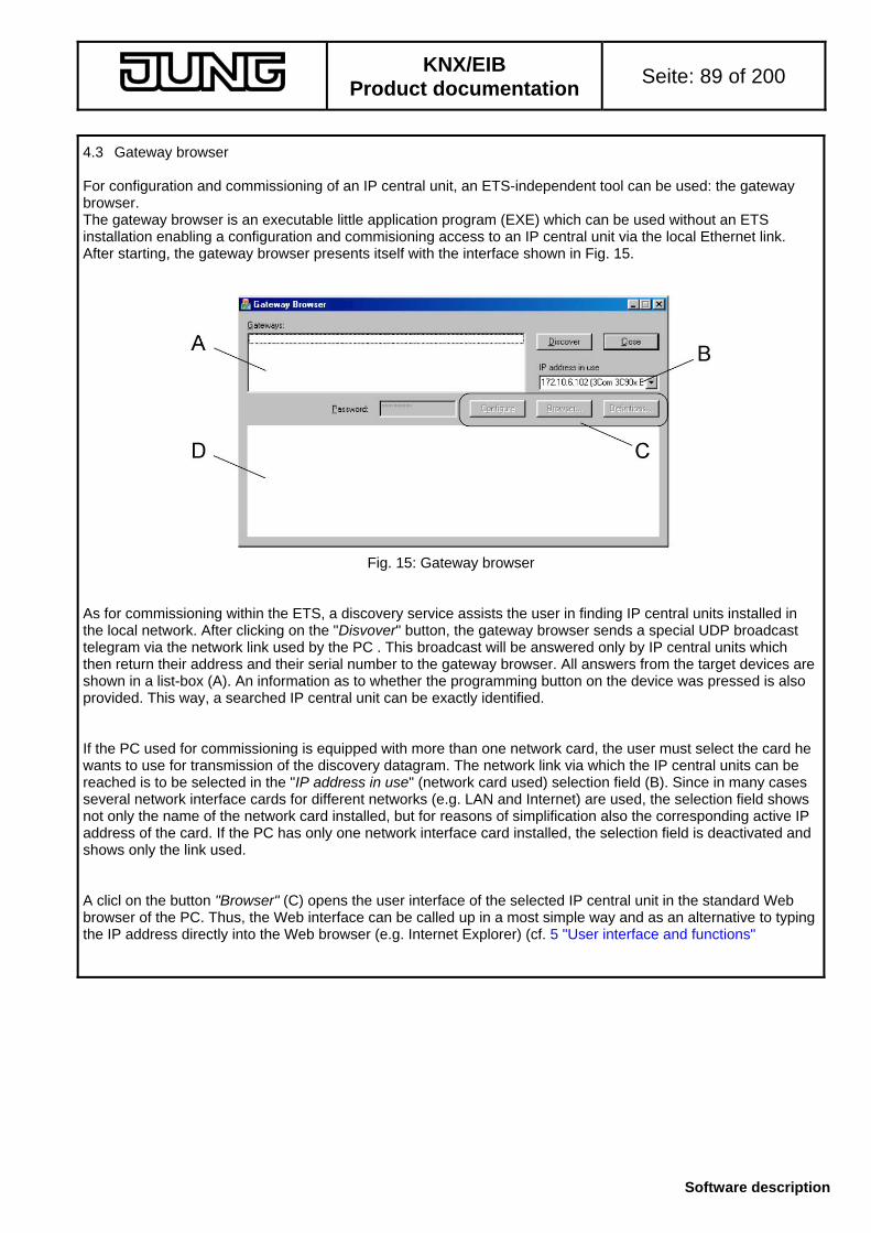
KNX/EIB
Product documentation Seite: 89 of 200
Software description
4.3 Gateway browser For configuration and commissioning of an IP central unit, an ETS-independent tool can be used: the gateway browser. The gateway browser is an executable little application program (EXE) which can be used without an ETS installation enabling a configuration and commisioning access to an IP central unit via the local Ethernet link. After starting, the gateway browser presents itself with the interface shown in Fig. 15.
Fig. 15: Gateway browser As for commissioning within the ETS, a discovery service assists the user in finding IP central units installed in the local network. After clicking on the "Disvover" button, the gateway browser sends a special UDP broadcast telegram via the network link used by the PC . This broadcast will be answered only by IP central units which then return their address and their serial number to the gateway browser. All answers from the target devices are shown in a list-box (A). An information as to whether the programming button on the device was pressed is also provided. This way, a searched IP central unit can be exactly identified. If the PC used for commissioning is equipped with more than one network card, the user must select the card he wants to use for transmission of the discovery datagram. The network link via which the IP central units can be reached is to be selected in the "IP address in use" (network card used) selection field (B). Since in many cases several network interface cards for different networks (e.g. LAN and Internet) are used, the selection field shows not only the name of the network card installed, but for reasons of simplification also the corresponding active IP address of the card. If the PC has only one network interface card installed, the selection field is deactivated and shows only the link used. A clicl on the button "Browser" (C) opens the user interface of the selected IP central unit in the standard Web browser of the PC. Thus, the Web interface can be called up in a most simple way and as an alternative to typing the IP address directly into the Web browser (e.g. Internet Explorer) (cf. 5 "User interface and functions"
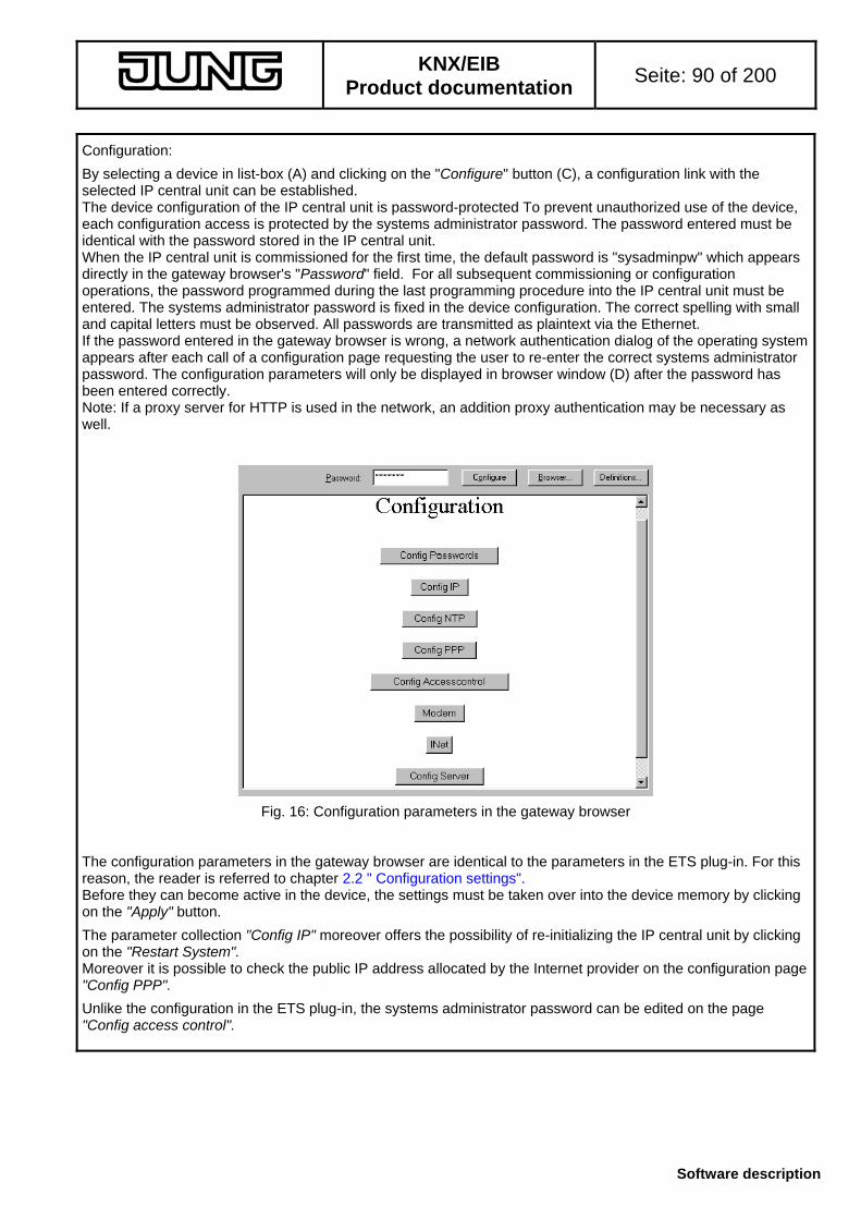
KNX/EIB
Product documentation Seite: 90 of 200
Software description
Configuration:
By selecting a device in list-box (A) and clicking on the "Configure" button (C), a configuration link with the selected IP central unit can be established. The device configuration of the IP central unit is password-protected To prevent unauthorized use of the device, each configuration access is protected by the systems administrator password. The password entered must be identical with the password stored in the IP central unit. When the IP central unit is commissioned for the first time, the default password is "sysadminpw" which appears directly in the gateway browser's "Password" field. For all subsequent commissioning or configuration operations, the password programmed during the last programming procedure into the IP central unit must be entered. The systems administrator password is fixed in the device configuration. The correct spelling with small and capital letters must be observed. All passwords are transmitted as plaintext via the Ethernet. If the password entered in the gateway browser is wrong, a network authentication dialog of the operating system appears after each call of a configuration page requesting the user to re-enter the correct systems administrator password. The configuration parameters will only be displayed in browser window (D) after the password has been entered correctly. Note: If a proxy server for HTTP is used in the network, an addition proxy authentication may be necessary as well.
Fig. 16: Configuration parameters in the gateway browser The configuration parameters in the gateway browser are identical to the parameters in the ETS plug-in. For this reason, the reader is referred to chapter 2.2 " Configuration settings". Before they can become active in the device, the settings must be taken over into the device memory by clicking on the "Apply" button.
The parameter collection "Config IP" moreover offers the possibility of re-initializing the IP central unit by clicking on the "Restart System". Moreover it is possible to check the public IP address allocated by the Internet provider on the configuration page "Config PPP".
Unlike the configuration in the ETS plug-in, the systems administrator password can be edited on the page "Config access control".

KNX/EIB
Product documentation Seite: 91 of 200
Software description
Commissioning and system administration:
The button "Definitions" (C) – when clicked – opens a dialog for user definitions (cf. Fig. 17). On the one hand, this dialog permits commissioning of the respective IP central unit when an object model is already existing. On the other hand, it is possible to administrate certain system files so that the operating system of the IP central unit can also be tailored to international users or to the country of use.
Fig. 17: User definitions dialog The command "Object model - backup" reads out and stores the object model programmed into the IP central unit, for instance, for filing purposes. The read-out lasts a few seconds. The object model is saved in a template file named "*.ingw. Similarly, the command "Object model – Restore" programs an object model in the form of an *.ingw file into the IP central unit. The object model as such must exist a priori, either created with the ETS as a model or read out from another IP central unit. The gateway browser cannot be used to create a new object model. The programming cycle lasts a certain time. After programming, the system is not automatically restarted. For the newly programmed object model to be taken over into the runtime memory (RAM) and thus as valid parameterization information, the system must be restarted 'by hand'.
The display language of the Web user interface of the IP central unit can be selected directly by the administrator in the Web control settings (cf. 5 "User interface and functions"). The language set ex factory is the standard language "German". Each selectable language is loaded from a language file in the flash memory of the IP central unit. The display window "Language / Help" in the user settings dialog shows the installed language files that can be selected together with the pertaining files of the online help. The gateway browser can be used at any time for loading other language or help files, for reloading or for deleting existing ones.
The gateway browser also offers the possibility of handling further country definitions in the operating system of the IP central unit. Legal and religious holidays and summer/winter time changes ("daylight saving time") vary with the country of use and must therefore also be reloadable. For this purpose, definition files can be reloaded separately in the user settings dialog ("Load" button). Alternatively, the country definitions can also be deleted completely (!) ("Delete" button), for instance, if there is no summer/winter time change or if no holidays are required or desired in the scheduler of the IP central unit.
It should be noted that the language files and the country definition files must comply with a certain format ("*.dat") and that they can be ordered – if available – only from the manufacturer.

KNX/EIB
Product documentation Seite: 92 of 200
Software description
5. User interface and functions 5.1 General The basic function of the IP central unit is to work as a central component for remote-control and monitoring of a KNX/EIB building installation. The IP central unit has an integrated Web server, which means for the user that the interface has the structure of an Internet page and is accessible as such. Thus, the building systems and services can be comfortably controlled by means of a PC with an Internet browser (Microsoft© Internet Explorer, version 5.5 and later) without installing additional software.
All pages of the user interface exist on the Web server as HTML pages and will be transmitted to the Web browser via HTTP when called up. For this purpose, the IP central unit is either integrated into a local network (LAN) or connected with the Internet by suitable gateways or modems.
To permit Web access to the IP central unit from the Internet, a router or a proxy server must be added to the system which routes the external HTTP requests on the IP central unit in the local network. For this purpose, NAT can be used. The router or the proxy translates the HTTP requests from the Internet to the local IP address of the IP central unit. Further basic notions and configuration settings for Internet communication are described in chapter "2. Configuration". The starting page of the user interface is opened by starting the Web browser and by typing the IP address or the Internet URL of the IP central unit into the address box and by confirming with Enter (cf. Fig. 1). For HTTP Web access purposes, the central unit is addressed at standard port 80. For this reason, it is not necessary to specify also the port in the address line. As an alternative, the user interface can be opened with the help of the Gateway browser (cf. "4.3 Gateway Browser"). This is especially useful in those cases where the IP address of the IP central unit is unknown to the user. It is recommended to store the starting page of the IP central unit as a Favorite or as a bookmark in the Web browser.
Fig 1: Opening the starting page of the user interface by entering and confirming the IP address (example) The user interface display is optimal for a screen resolution of "1024 x 768" to "1280 x 1024" pixels. The minimum resolution required to display all elements completely is "800 x 600" pixels.
The IP central unit transfers the contents of its Web page also partially as JavaScript. For this reason, the firewall installed in the local network of the IP central unit or a private firewall on the PC with which the IP central unit is controlled must be adjusted in such a way that the execution of JavaScripts is not prevented. In the same way, the safety settings in the controlling Web browser must permit JavaScripting.

KNX/EIB
Product documentation Seite: 93 of 200
Software description
5.2 Starting screen with user log-in After starting the user interface, the starting page appears in the Web browser (cf. Fig. 2). To prevent undesired persons from getting access to the follow-up pages and thus to the KNX/EIB building installation, the Web interface distinguishes between up to three user levels. The access to a user level is possible only after user log-in and is protected in each case by a separate password.
Fig. 2: Starting page of the user interface with user log-in The following user levels give access to the follow-up pages of the user interface...
• Administrator
The administrator is granted all operating and configuration rights in the user interface of the IP central unit. He decides which rights or possibilities will be granted to the subordinate access levels "User" and "Guest". The administrator should be the owner of the system or the network administrator.
• User
The user is the person using the Web interface. He will be granted access to the most elementary display and operating structures. Users are usually family members or employees in a company.
• Guest
The guest account grants the broad public access to special display and control elements. The limitations can be such that elements can only be viewed, but not changed. The rights or possibilities granted to guests are decided by the "User" or by the "Administrator".
The user interface handles the different access accounts on the directory level. The accessible pieces of information or settings are generally available via different directories of the memory structure. Thus, it is ensured that all user levels are to be considered from a logical and a functional point of view as isolated with respect to each other. Any misuse is therefore avoided. Those of the areas or settings that are accessible at the user or guest level only with restrictions or not at all, are described in the following chapters of the present documentation.

KNX/EIB
Product documentation Seite: 94 of 200
Software description
When accessing the user interface, the user will be requested to log-in and to establish his/her identity under one of the three accounts by clicking on one of the offered links ... • "log-in as ADMINISTRATOR"
• "log-in as USER"
• "Guest access" and an authentication dialogue is opened (cf. Fig. 3). In the dialogue window the same user name and the same password as that specified by the systems administrator in the device configuration (ETS Plug-In or Gateway-Browser) must be entered. Observe the spelling with small and capital letters.
Notes: Passwords are transferred in the network between user interface and IP central unit as plain text. On delivery, the user names are predefined as: Administrator = "admin", User = "user" and Guest access = "guest". The passwords are empty, so that the entry of a password after delivery is not necessary. Any password entry will in this case be ignored.
Fig. 3: Authentication dialogue for log-in and user identification shown for the "Administrator" account The way in which the authentication dialogue presents itself depends on the PC operating system. As a rule, the user is requested to enter the required log-in information, such as "user name" and "password". As an option, the password can be stored in a list, so that it must not be re-entered during at the next log-in. If the log-in has been successful, the IP central unit opens the building application and the access to the follow-up pages and thus to the KNX/EIB building installation is possible. Only in this case are all functions in the navigation bar of the user interface accessible.
If the log-in has failed, the authentication dialogue appears a second and possibly also a third time. If all log-in attempts were unsuccessful, the IP central unit rejects the user log-in and an empty browser page will be displayed. New log-in attempts are then possible only after the starting page is reloaded by refreshing the Web browser. If log-in has been successful, the IP central unit stores the access authorization for the user level as long as the employed Web browser is not closed. This means that, if the starting page is reloaded and if the user was registered beforehand as administrator, a new log-in as administrator is possible without authentication. A change of the user level, however, makes a new identification necessary. The IP central unit can at the same time build up a maximum of 10 IP connections (sessions). This means, that not more than 10 clients can download data from the central unit (server) at the same time. It should be noted that for loading a Web site the Microsoft Internet Explorer may start several logic IP sessions to accelerate the loading process. Independent of this limitation, the statical viewing of a loaded Web page (no download of data) is not dependent on any special number of sessions.

KNX/EIB
Product documentation Seite: 95 of 200
Software description
5.3 The user interface 5.3.1 Presentation and navigation The user interface of the IP central unit is operated like any other Internet page. It has graphical navigation, control and display elements that can be selected with the mouse pointer and edited. Text or values are entered by means of the PC keyboard. Fig. 4 shows the basic view of the user interface in the Web browser after successful user log-in.
Fig. 4: Basic view in the Web browser after successful log-in The Web browser window is basically divided in two sections. The upper part contains the information section and the main navigation elements. The lower part contains the workspace...
• Description of the IP central unit in information section (A):
A description of the IP central unit is displayed in the upper right corner of the Web browser. The description is entered in the ETS building or topology view under the properties of the projected IP central unit (double-click or context menu 'Properties') in the "Description" text field. During programming of the IP central unit, this description is stored in the memory of the device and displayed in all views of the Web browser - exactly as specified in the ITS. To avoid any uncontrolled access either by the plug-in or by the gateway browser, this designation should be chosen at the project start under mnemonic aspects.
• Actual system time of IP central unit (B):
The upper line indicates the actual system time at the time when the page is called up. The system time is used internally for the execution of time-controlled sequences. A mouse click on the line displays the settings of the system (cf. Chapter 5.3.8). As the browser view is static, the displayed time of day is stationary. The actual system time is displayed only after calling up a new page or during a data update.
• Manufacturer's logo (C))
A B C
D E
F

KNX/EIB
Product documentation Seite: 96 of 200
Software description
• Main navigation (D)
The main navigation permits selecting the individual applications of the IP central unit. After log-in, the first tab 'Building overview Favorites' is displayed. The following applications which are described in detail in the corresponding chapters are available: Buildings (cf. Chapter 5.3.2)
The states existing in the installation are displayed. The type of display depends on the one hand on the configuration by the fitter and by the authority level of the user and on the other hand by the selected sub tab. Time scheduler (cf. Chapter 5.3.3)
Similar to a calendar, the time scheduler permits planning actions which the IP central unit executes on a planned day at a certain point of time. Presence simulation (cf. Chapter 5.3.4)
The presence simulation permits activating devices at an arbitrary point of time in order to simulate presence in the building. Scenes (cf. Chapter 5.3.5)
The scene functions permit the execution of several actions at the same time in order, for instance, to create a scenario in a room (not restricted by devices and building services). Event recorder (cf. Chapter 5.3.6)
Depending on events occurring in the installation, the central unit can generate messages. These messages can be sent as an email or also shown as an information appearing on any of the displays in the installation. Help (cf. Chapter 5.3.1.3
The IP central unit offers an extract of this product documentation as online help. End program (cf. Chapter 5.3.7)
The 'End program' tab permits saving the settings permanently with system log-out. Any work on the IP central unit should always be terminated this way.
• Subnavigation (E)
Dependent on the selected application in the main navigation (D) and dependent on the respective work step, the subnavigation displays a selection of submenus. These submenus help with further navigation.
• Workspace (F)
The workspace presents the corresponding information about the selections made in the main and the subnavigation. In the workspace, settings can be viewed and changed. The individual tab sheets are described under the corresponding chapters.
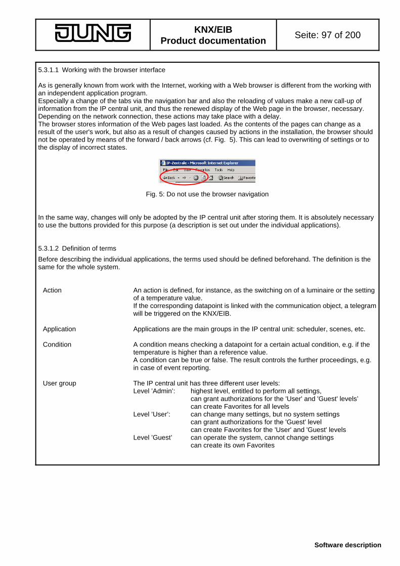
KNX/EIB
Product documentation Seite: 97 of 200
Software description
5.3.1.1 Working with the browser interface As is generally known from work with the Internet, working with a Web browser is different from the working with an independent application program. Especially a change of the tabs via the navigation bar and also the reloading of values make a new call-up of information from the IP central unit, and thus the renewed display of the Web page in the browser, necessary. Depending on the network connection, these actions may take place with a delay. The browser stores information of the Web pages last loaded. As the contents of the pages can change as a result of the user's work, but also as a result of changes caused by actions in the installation, the browser should not be operated by means of the forward / back arrows (cf. Fig. 5). This can lead to overwriting of settings or to the display of incorrect states.
Fig. 5: Do not use the browser navigation In the same way, changes will only be adopted by the IP central unit after storing them. It is absolutely necessary to use the buttons provided for this purpose (a description is set out under the individual applications). 5.3.1.2 Definition of terms
Before describing the individual applications, the terms used should be defined beforehand. The definition is the same for the whole system.
Action An action is defined, for instance, as the switching on of a luminaire or the setting
of a temperature value. If the corresponding datapoint is linked with the communication object, a telegram
will be triggered on the KNX/EIB. Application Applications are the main groups in the IP central unit: scheduler, scenes, etc. Condition A condition means checking a datapoint for a certain actual condition, e.g. if the
temperature is higher than a reference value. A condition can be true or false. The result controls the further proceedings, e.g.
in case of event reporting. User group The IP central unit has three different user levels: Level ’Admin’: highest level, entitled to perform all settings,
can grant authorizations for the 'User' and 'Guest' levels’ can create Favorites for all levels Level ’User’: can change many settings, but no system settings can grant authorizations for the 'Guest' level can create Favorites for the 'User' and 'Guest' levels Level ’Guest’ can operate the system, cannot change settings can create its own Favorites

KNX/EIB
Product documentation Seite: 98 of 200
Software description
Event The influencing of a state (e.g. by an action) is designated as an event. Switching off of a luminaire or the reporting of a temperature value is an event. In the same way, the renewed setting of an existing state is a priori an event. Events can be triggered by telegrams on the KNX/EIB, but also by actions of the
IP central unit itself (internal datapoints). An event is also evaluated in conjunction with a condition. (If an event has
occurred and if the condition has been fulfilled, then...) Function A function is a partial action of a device channel.
A dimmer, for instance, has the functions 'switching' and 'dimming'. A function is synonymous to datapoint or object.
Functional group A functional group is the collection of individual functions. A functional group usually describes a device channel, e.g. functional group
'Ceiling luminaire'. 5.3.1.3 Help system An extract of this product documentation is stored on the system as online help. The online help is accessible via the 'Help' tab (A) or via the direct help (B) in the respective applications in the workspace. In the second case, the corresponding chapter of the help is opened directly.
Fig. 6: Help system For the help function a second browser window is opened. Note on PopUp blockers:
Some browser installations prevent self-opening windows from being displayed (PopUp blockers). In this case, this browser function must be deactivated. The help can be opened alternatively by maintaining the CTRL-key pressed while clicking on the item. It is recommended to deactivate the PopUp blocker for the Internet page of the IP central unit.
A B

KNX/EIB
Product documentation Seite: 99 of 200
Software description
5.3.1.4 Recurring elements This chapter describes the operation of certain elements which repeat themselves in selected applications. The applications will then contain a reference to this chapter or explain deviating operations or functions. 5.3.1.4.1 Inserting, editing or deleting actions The applications scheduler, presence simulation, scenes and event reporting make use of actions. These actions are always created and edited in the same way:
Inserting an action:
Fig. 7: Inserting an action for an application To create a new action, a new dialogue is opened with the insert button. If the button is deactivated, the maximum number of actions for this application is reached. In this case, an action must be deleted before another one can be inserted. Procedure for creating a new action: 1) Selecting the function
Path: Room, Building service, Functional group, Function
Fig. 8: Starting the selection of a function (sorted acc. to rooms) Under ’Room’, the corresponding room in the project can be selected. For a selected room, the next filter stage 'Building service' is then opened, etc.
Fig. 9: Example for the selection of a function Note:
Depending on complexity, loading of data can take some time. As soon as the first selection criterion 'Room' is activated, the selection can begin.

KNX/EIB
Product documentation Seite: 100 of 200
Software description
2) Specifying a value (the value limits to be observed will be displayed, if any)
As soon as a function has been selected, the entry of the value will be enabled in accordance with the datapoint type. For the entry, either an entry field or a selection of predefined values can be offered, depending on type.
Fig. 10: Value entry examples for (upper left) Boolean values (upper right) control (lower left) value entry (lower right) scene control When values are entered in the entry field, a value check in accordance with the possible value range will be performed after pressing the ok button. If this check fails, a warning will be displayed:
Fig. 11: Error message in case of wrong value entry The warning displays in addition the admissible value range (example for datapoint type ‚DPT 09.xxx 2-octet floating point number (2 bytes)’). 3) Display of the inserted action
When the value check has taken place, the inserted action will be displayed in the overview of the respective application:
Fig. 12: Inserted action in the action overwiew Each entry is preceded by a selection button. If the entry is selected, the buttons edit and delete are enabled. If the maximum number of actions for an application has been reached, the insert button will be deactivated.

KNX/EIB
Product documentation Seite: 101 of 200
Software description
Editing an action: The edit button calls up a selected action for editing:
Fig. 13: Selected action in the overview permits editing The display for editing of an action is identical with the display for the insertion of a new action (cf. Fig. 9). The entry is dependent on the datapoint type.
Fig. 14: Editing of a created action The selection windows permit changing the value and also the function. Should another function be selected, the entered value is adapted to the datapoint type of the function. The changes are adopted with the ok button, whereas the cancel button rejects the change. Deleting an action To delete a created action, the desired entry must be selected in the overview (cf. Fig.°13). The delete button removes the entry from the corresponding application.

KNX/EIB
Product documentation Seite: 102 of 200
Software description
5.3.1.4.2 Inserting, editing or deleting events / conditions For some applications, events / conditions are used to control different activities of the IP central unit: Presence simulation: activating / deactivating the presence simulation Scenes Execution of a scene (trigger) Event reporting Triggering an event report Checking whether the criterion for transmission of a mail is fulfilled Events / conditions are handled like actions:
Inserting an event / condition:
Fig. 15: Inserting a new event for an application With the insert button, a new dialogue can be opened in order to create a new event. If the button is deactivated, the maximum number of events / conditions for this application is reached. In this case, delete first an event / a condition if new ones are to be inserted. The procedure of creating a new event or a new condition is similar to creating a new action: 1) Select the function
Path: Room, Building service, Functional group, Function
Fig. 16: Selecting a function (sorted acc. to rooms) Note:
Depending on its complexity, loading of a file may last some time. As soon as the first selection criterion 'Room' is activated, the selection can begin.

KNX/EIB
Product documentation Seite: 103 of 200
Software description
2) Specifying the value / the condition (value limits may be displayed)
As soon as a function has been selected, the value can be entered depending on the datapoint type. Depending on the type, this can be an entry field or a selection of predefined values. Additionally, the comparison operation can be selected:
Fig. 17: Example of value entry with logic comparison operators After entering values into the entry field, the value will be checked after clicking ok with regard to the possible value range. If this check fails, a message is displayed:
Fig. 18: Error message after entering a wrong value The admissible value range is additionally displayed in the message window (example for datapoint type DPT 09.xxx 2-octet floating-point no. (2 bytes)’) 3) Display of the inserted event / inserted condition
After confirming with ok , the inserted event / inserted condition will be displayed in the overview of the respective application:
Fig. 19: Inserted event / inserted condition in the overview Each entry is preceded by a selection button. If an entry has been selected, the buttons edit and delete are enabled. If the maximum number of events / conditions for an application has been reached, the insert button will be deactivated.

KNX/EIB
Product documentation Seite: 104 of 200
Software description
Editing an event / a condition: For editing an already created element, the desired event / desired condition must be selected from the overview and called up by clicking on the edit button in the editing dialogue.
Fig. 20: Selected event can be edited The display for editing an event / a condition is identical with the insertion of a new element, the entry is dependent on the datapoint type.
Fig. 21: Editing a created event / condition The selection fields permit changing the value and also the function. If another function is to be selected, the entered value is adapted to the datapoint type of the function. Changes are adopted with the ok button and rejected with the cancel button. Deleting an event / a condition To remove a created event / created condition, the respective entry must be selected from the overview (cf. Fig. 20). The delete button removes the entry from the corresponding application.

KNX/EIB
Product documentation Seite: 105 of 200
Software description
5.3.1.4.3 Navigation in complex applications If the settings for an application are distributed over several screens, they are accessible via the same set of menu buttons:
continue back . ok cancel adopt
continue accepts the settings and displays the next tab / next screen
back accepts the settings and goes back to the previous tab / previous screen
ok accepts the settings and goes to the next higher screen (in most cases an overview)
cancel discards the settings and goes to the next higher screen (in most cases an overview)
adopt accepts the settings and refeshes the screen The data are stored only temporarily. For permanent storage cf. chapter 5.3.7.

KNX/EIB
Product documentation Seite: 106 of 200
Software description
5.3.2 Application 'Building'
This application is intended for the manual control and visual display of the states of the KNX/EIB installation. The application has different tabs adapted to different functions. The type of display and the control are always the same. The application 'Building' moreover permits specifying the rights of the users which are then also applicable to other applications. 5.3.2.1 General
In the application 'Building', the configured functions and the states are displayed on different tab sheets. The information supplied depends on the rights of the respective user group and of programming. The room and building services tabs and an independent Favorite tab are available as different tabs for each user group displaying the data of functions in different constellations. 5.3.2.2 'Overview' tab
The 'Overview' tab sheet shows the installation and its operation. Path: Building Overview
Fig. 21: Navigation elements in the application ’Building’, ’Overview’ The installation overview is the first tab sheet in the 'Building' application (cf. Fig. 21 (A) ) which is called up after log-in. The user level is displayed behind the heading (B). The KNX/EIB installation has different views which are selected via the tabs (C) as follows: ’Favorites’ tab (cf. Chapter 5.3.2.3):
This tab sheet displays for each user level the functions of personal interest. The configuration is accessible via the item 'Personalize' in the subnavigation (cf. Chapter 5.3.2.6).
'Rooms' tab (cf. Chapter 5.3.2.4): The installation is displayed room by room. The rooms are those created in the project. 'Building services' tab (cf. Chapter 5.3.2.5): The installation is displayed service by service. The services are those created in the project..
AB C
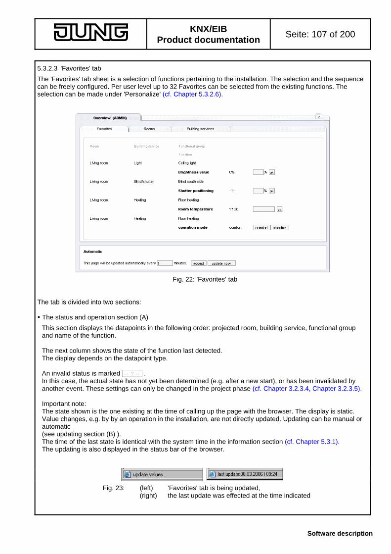
KNX/EIB
Product documentation Seite: 107 of 200
Software description
5.3.2.3 'Favorites' tab
The 'Favorites' tab sheet is a selection of functions pertaining to the installation. The selection and the sequence can be freely configured. Per user level up to 32 Favorites can be selected from the existing functions. The selection can be made under 'Personalize' (cf. Chapter 5.3.2.6).
Fig. 22: ’Favorites’ tab The tab is divided into two sections: The status and operation section (A)
This section displays the datapoints in the following order: projected room, building service, functional group and name of the function. The next column shows the state of the function last detected. The display depends on the datapoint type. An invalid status is marked -- ? -- . In this case, the actual state has not yet been determined (e.g. after a new start), or has been invalidated by another event. These settings can only be changed in the project phase (cf. Chapter 3.2.3.4, Chapter 3.2.3.5). Important note: The state shown is the one existing at the time of calling up the page with the browser. The display is static. Value changes, e.g. by by an operation in the installation, are not directly updated. Updating can be manual or automatic (see updating section (B) ). The time of the last state is identical with the system time in the information section (cf. Chapter 5.3.1). The updating is also displayed in the status bar of the browser.
Fig. 23: (left) 'Favorites' tab is being updated, (right) the last update was effected at the time indicated

KNX/EIB
Product documentation Seite: 108 of 200
Software description
There is also the possibility (cf. Fig. 22) to control the function via the browser interface. The possibility depends on the user rights and programming of the project. After an operation, all states are updated. Depending on project programming and the number of pieces of information on this page there may be delays. The frequency of operation should be adapted accordingly. Message no write right The message ’no write right’ makes controlling impossible. This can either be fixed in the project (cf. Chapter 3.2.3.4) or the right is otherwise limited by a higher user level (cf. Chapter 5.3.2.7). - Operation buttons ( e.g. 0 1 or OFF ON )
The buttons permit entering two states for this function, e.g. light ON, light OFF. The designation of the button (e.g. numbers 0,1 or words OFF, ON) are fixed for each function in the project. The buttons are operated by mouse-click. Depending on the project, a KNX/EIB telegram will then be sent. It is also possible to send a read telegram to the KNX/EIB in the course of the updating. For internal functions, the state will be set. - Entry field for operation (e.g. ok )
If a value can be entered (e.g. temperature), this can be entered in the provided entry field. Depending on the datapoint type, the separation sign (e.g. for values) is the decimal point or the colon (e.g. for time of day). Entry e.g. 12.3 for values Entry e.g. 03.03.2006 for dates Entry e.g. 12:55:00 for time of day (hours, minutes and seconds must be entered) If the mouse pointer remains for prolonged time on the entry field, the mouse pointer opens an info box indicating the possible data format for the entry.
Fig. 24: Info box at mouse pointer A mouse-click on ok sets the value and transmits a KNX/EIB telegram depending on project programming or otherwise sets the state in case of internal functions. The datapoint type ’Scene’ permits selecting between the buttons call up and store . A mouse-click on either of these buttons calls up or stores the specified scene number. After entering values, a value check is effected. If the value does not correspond to the provided format, an error message will be generated. The message provides help by indicating the possible format. The value is not accepted and there will be no transmission of a KNX/EIB telegram.
Fig. 25: Error message in case of invalid value entry

KNX/EIB
Product documentation Seite: 109 of 200
Software description
- Selection field for operation
Two datapoint types (KNX 02.xxx 1 bit with control, KNX 10.001 time of day) are controlled (partly) by means of selection fields. The different states can be selected from a list. If no further entries are possible (KNX 02.xxx 1 bit with control), the selection of an element sets the state and transmits a KNX/EIB telegram, if applicable.
Fig. 26: Selection field for operation With further entries (KNX10.001 time of day), a value can be entered besides the selection, and the state will only be set by a mouse-click on the ok button. Update window (B)
The display of the states in the browser is static and contains the values at the time when the page was called up. A change of the states, e.g. by an operation in the installation itself, is not displayed. Therefore, changing values indicated on the pages (states, time of day) must be updated. This can be set or triggered in the updating window (B). The updating function of the browser itself (Internet Explorer: screen Update) cannot be used for this purpose, as in this case, the starting page of the IP central unit will again be displayed. Updating can be performed automatically and manually. The values can be updated manually by clicking on the button update now . The browser can also update the values cyclically and automatically. Automatic updating can be parameterized in the entry field (cf. Fig. 27)
Fig. 27: Updating of values The updating time is set by default to 1 minute. The values are thus updated every minute. If another time (value in minutes) is entered, this time can be stored by clicking on the accept button. The setting is stored locally on the PC in the form of a so-called 'cookie' for the current operating system user. The cookie is coupled to the address of the IP central unit. The updating time for another IP central unit or the contact request from another computer (e.g. Internet-café) will be dealt with separately. In this case, the standard time of 1 minute will again be until the configuration is changed. During a manual or an automatic update, all states of the functions on the page actually displayed will be requested again from the object model. If a value request is programmed in the plug-in together with the update, the system will also transmit read telegrams on the KNX/EIB. The status bar of the browser shows the updating status (cf. Fig. 23). After the data have been made available by the IP central unit, the states will be updated and the system time indicated in the header. The speed depends on project programming, the number of information units on a page and the quality of the network link.

KNX/EIB
Product documentation Seite: 110 of 200
Software description
5.3.2.4 'Rooms' tab
This tab sheet shows all projected functions sorted according to the rooms accessible to the current user level. The tab sheet is accessible after a mouse-click on the 'Rooms' tab.
Fig. 28: 'Rooms' tab sheet The sections of this view are identical to those in the 'Favorites' tab sheet: The following structure is used: - the projected room (can be changed with tabs (A), more tabs via navigation arrow (B) ) - the projected building service (via branch labels (C) ) - the projected functional group - the projected function Navigation sections (A + B)
In the navigation, the rooms are represented as tabs. A room can be changed by clicking the room tab. A tab group contains up to four rooms and can be changed with the navigation arrow (B). After a change, the room displayed is always the first room of the new tab group. Branch to building services (C)
All building services projected for a room are listed in branch label line (C). After a mouse-click on a building service, the view presents the first entry of this service (browser scrolling to corresponding entry). If the building service is already visible (e.g. if only a few functions are projected in a service), there will be no scrolling of the browser window. Status and operation section (D)
This section displays the information concerning the functions in the room. The type of display depends on project programming. Non visible functions may have been disabled already in the project or are hidden due to user rights limitations.
AB
C
D
E

KNX/EIB
Product documentation Seite: 111 of 200
Software description
The structure is identical with the Favorites tab sheet: The first column shows the projected building service (example: 'Light') which corresponds also to the branch label in (C). The second column shows the projected functional group (Example: ’Ceiling luminaire'). Each function in this functional group is shown in a new line (Example: 'Switching' or 'Dimming') The state of the function is shown at the time when the page is called up. The states are shown like the states in the Favorites views: - -- ? -- no current value existing or value invalidated - formatting and display depend on project programming The updating instructions are the same as for the Favorites view. They can be preset in the update section (E) and updating can be started manually. With the corresponding rights, the state can be changed with the known control elements (buttons, entry field or selection field). Without the rights (e.g. disabled in the project or withdrawn by a higher user level), the message no write rights is displayed. When a new state is set (via button, selection, etc.), the state is adopted, a KNX/EIB telegram triggered if projected and the state of the displayed function read in again. In this case, a KNX/EIB read telegram can be triggered depending on projecting. Upate section (E)
The update section (E) is identical with that in the Favorites tab sheet. Manual updates can be triggered with the update now button and automatic updates can be configured by entering the time and by clicking on adopt .
During updating, the state is displayed in the status bar. Depending on projecting programming, KNX/EIB read telegrams are transmitted as well. After updating, the states displayed will be refreshed and the system time in the header adapted. The displayed states are always those at the time of the last update. Changes will be registered and adopted only when the time has elapsed or after manual updating.

KNX/EIB
Product documentation Seite: 112 of 200
Software description
5.3.2.5 'Building services' tab
This view shows all projected functions sorted acc. to the building services accessible to the current user level. The tab sheet is accessible after a mouse-click on the 'Building services' tab.
Fig 29: 'Buildings services' sheet The sections of this view are identical to those in the 'Rooms' view: The following structure is used: - the projected building service (can be changed with tabs (A), via navigation arrow (B) ) - the projected room (branch label (C) ) - the projected functional group - the projected function Navigation section (A + B)
Via the navigation, the building services are displayed as tabs. A building service can be changed by clicking the services tab. Up to four services are shown as a tab group which can be changed with the navigation symbol (B). After a change, the service shown is always the first service of the new tab group. Branch to rooms (C)
All rooms projected for a building service are listed in branching section (C). After a mouse-click on a room, the view presents the first entry of this room (browser scrolling to corresponding entry). If the room is already visible (e.g. if only a few functions are projected in service), there will be no scrolling of the browser window. Status and operation section (D)
This section displays the information concerning the functions in the building service. The type of display depends on project programming. Non visible functions may have been disabled already in the project or are hidden due to user rights limitations. The structure is identical withe the room tab: The first column shows the projected room (example: "Living room") which corresponds also to the branch label in (C). The second column shows the projected functional group (Example: ’Ceiling luminaire'). Each function in this functional group is shown in a new line (Example: 'Switching' or 'Dimming') The state of the function is shown at the time when the page is called up.
A B
C
D
E

KNX/EIB
Product documentation Seite: 113 of 200
Software description
The states are shown like the states in the Rooms and Favorites tab sheets: - -- ? -- no current value existing or value invalidated - formatting and display depend on project programming The updating instructions are the same as for the Rooms and Favorites view. They can be preset in the update section (E) and updating can be started manually. With the corresponding rights, the state can be changed with the known entry elements (buttons, entry field or selection field). Without the rights (e.g. disabled in the project or withdrawn by a higher user level), the message no write rights is displayed. When a new state is set (via button, selection, etc.), the state is adopted, a KNX/EIB telegram triggered if projected and the state of the displayed function re-read. In this case, a KNX/EIB read telegram can be triggered depending on projecting. Upate section (E)
The update section (E) is identical with that in the Rooms and Favorites view. Manual updates can be triggered with the update now button and automatic updates can be configured by entering the time and by clicking on adopt .
During updating, the state is displayed in the status bar. Depending on projecting, KNX/EIB read telegrams are transmitted as well. After updating, the states displayed will be refreshed and the system time in the header adapted. The displayed states are always those at the time of the last update. Changes will be registered and adopted only when the time has elapsed or after manual updating.
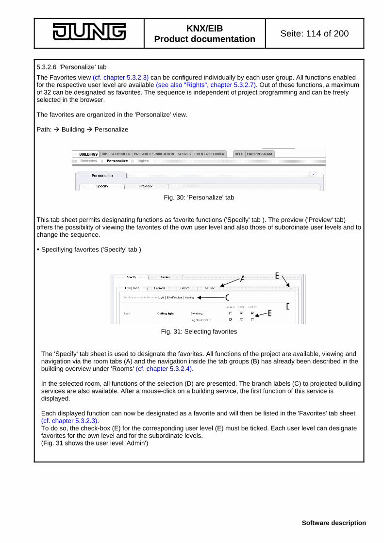
KNX/EIB
Product documentation Seite: 114 of 200
Software description
5.3.2.6 'Personalize' tab
The Favorites view (cf. chapter 5.3.2.3) can be configured individually by each user group. All functions enabled for the respective user level are available (see also "Rights", chapter 5.3.2.7). Out of these functions, a maximum of 32 can be designated as favorites. The sequence is independent of project programming and can be freely selected in the browser. The favorites are organized in the 'Personalize' view. Path: Building Personalize
Fig. 30: 'Personalize' tab This tab sheet permits designating functions as favorite functions ('Specify' tab ). The preview ('Preview' tab) offers the possibility of viewing the favorites of the own user level and also those of subordinate user levels and to change the sequence. Specifiying favorites ('Specify' tab )
Fig. 31: Selecting favorites The 'Specify' tab sheet is used to designate the favorites. All functions of the project are available, viewing and navigation via the room tabs (A) and the navigation inside the tab groups (B) has already been described in the building overview under 'Rooms' (cf. chapter 5.3.2.4). In the selected room, all functions of the selection (D) are presented. The branch labels (C) to projected building services are also available. After a mouse-click on a building service, the first function of this service is displayed. Each displayed function can now be designated as a favorite and will then be listed in the 'Favorites' tab sheet (cf. chapter 5.3.2.3). To do so, the check-box (E) for the corresponding user level (E) must be ticked. Each user level can designate favorites for the own level and for the subordinate levels. (Fig. 31 shows the user level 'Admin')
A
CD
E
B

KNX/EIB
Product documentation Seite: 115 of 200
Software description
After ticking the check-box (E), the setting is adopted directly. During the time of transfer to the IP central unit, an hourglass is displayed instead of the mouse pointer.
Fig. 32: Storing the setting after ticking a check-box After transmission, the settings of the favorites are read out from the IP central unit and the tab sheet will be updated. During this time, no further favorites should be added or removed, as the settings can otherwise not be coordinated. When the mouse pointer is displayed again, the tab sheet contains the actual Favorites settings. For permanent storage cf chapter 5.3.7. A maximum of 32 favorites can be selected per user level (of all rooms). If it is attempted to designate one more, the following error message is displayed:
Fig. 33: Error message after reaching the maximum number of favorites. In this case, another function must first be removed from the Favorites (options box not ticked), to insert a further favorite. Favorites preview and sequence ('Preview' tab )
The preview shows the desired favorites. In this view, the favorites of the different user levels can be viewed, the sequence changed and functions removed from the favorites as well.
Fig. 34: Preview for favorites User tabs (A) change display the individual user levels. Each user level can only access the own level and the subordinate user level. (Fig. 34 shows the 'Admin' user level)
A
CB

KNX/EIB
Product documentation Seite: 116 of 200
Software description
This tab sheet permits changing the sequence of the favorites. To do so, the favorite to be moved to another place must first selected with the buttons (B). Thereafter, the buttons << insert here and also the button remove favorite are active. For moving the selected favorite, the button << insert here must be clicked at the place where the favorite is to be inserted. The favorite at this place and the following favorites will be moved one place further down.
Fig. 35: Moving of favorites: (top) current sequence (center) 'Position' marked, insert in first place (mouse pointer) (bottom) new sequence, 'Position' inserted in first place With a click on the button << insert here the setting is adopted directly by the IP central unit and the actual display refreshed. Returning to the old sequence is not possible. For permanent storage cf. chapter 5.3.7. With the button remove favorite the marked function can be removed from the list of favorites. Adding a function is then again possible in the 'Specifiy' view.

KNX/EIB
Product documentation Seite: 117 of 200
Software description
5.3.2.7 'Rights' tab Note: This tab does not exist on user level 'Guest' .
It is possible to disable the operation of a function on the user levels or to hide the function altogether. From the start, the functions are visible on all user levels and can be operated (exception: limitations in the project: 'status display only', 'invisible in browser'). Path: Building Rights The rights are shown sorted acc. to the different rooms (cf. chapter 5.3.2.4 and chapter 5.3.2.6).
Fig. 36: 'Rights' view Besides the elements for navigating between the displayed rooms and room groups (Figs. 36 A + B), the tab sheet offers also branching (C) to the projected building services in the displayed room. The rights are granted in workspace (D). The following options can be used (F): User-rights level 'Admin': - Hiding of the function for the own level (can also be made visible again in this view) - Hiding of the functions for user levels 'User' and 'Guest' - Disabling of the control elements for this function for the user levels 'User' and 'Guest'
User-rights level 'User': - Hiding of the function for the user level 'Guest' - Disabling of the control elements for this function for the user level 'Guest'
Fig. 36 (G):
If the function is generally hidden (check-box under 'visible' not ticked), the check-box for the operation ('usable') is disabled. When the function is unhidden (check-box 'visible' ticked), the operation check-box is enabled, but remains unticked. If needed, the operation of the function can also be re-enabled (check-box 'usable').
A
C
B
E
FG
H
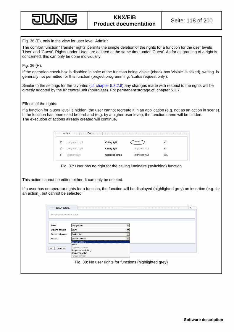
KNX/EIB
Product documentation Seite: 118 of 200
Software description
Fig. 36 (E), only in the view for user level 'Admin':
The comfort function 'Transfer rights' permits the simple deletion of the rights for a function for the user levels 'User' and 'Guest'. Rights under 'User' are deleted at the same time under 'Guest'. As far as granting of a right is concerned, this can only be done individually. Fig. 36 (H):
If the operation check-box is disabled in spite of the function being visible (check-box 'visible' is ticked), writing is generally not permitted for this function (project programming, 'status request only'). Similar to the settings for the favorites (cf. chapter 5.3.2.6) any changes made with respect to the rights will be directly adopted by the IP central unit (hourglass). For permanent storage cf. chapter 5.3.7. Effects of the rights:
If a function for a user level is hidden, the user cannot recreate it in an application (e.g. not as an action in scene). If the function has been used beforehand (e.g. by a higher user level), the function name will be hidden. The execution of actions already created will continue.
Fig. 37: User has no right for the ceiling luminaire (switching) function This action cannot be edited either. It can only be deleted. If a user has no operator rights for a function, the function will be displayed (highlighted grey) on insertion (e.g. for an action), but cannot be selected.
Fig. 38: No user rights for functions (highlighted grey)

KNX/EIB
Product documentation Seite: 119 of 200
Software description
5.3.3 Application 'Time scheduler'
The time scheduler is the calendar of the IP central unit. Similar to an agenda, actions can be executed at a certain time of day (switching time). The daily events are summarized in a day profile. Together with week profiles and special days (vacation or holiday) these profiles make up the year calendar. The calendar is the basis for the actions to be executed. Only the day profiles entered in the year calendar will be executed. Switching time: fixed time-of-day or a time calculated dependent on sunrise and sunset (astro time). A
switching time can include up to 32 actions. Day profile: a day profile may include up to 8 switching times. With the assignment of a date in the
year calendar, the pertaining actions are executed at these switching times. There are six individual day profiles, two fixed day profiles for vacation and free time as well as a day profile that is executed every day without exception.
Week profile: in the week profile, the existing day profiles are assigned to the weekdays MON-SUN.
This assignment is the basis for the year calendar for automatic generation. Year calendar: includes the list of manually assigned or automatically generated day profiles to be
actually exceuted. 5.3.3.1 Navigation in the scheduler
Bild 39: Scheduler navigation The 'Overview' tab shows the year calendar (cf. chapter 5.3.3.2), in which all actions are combined. This is the first view when the time scheduler is called up via the main navigation. The sub-navigation permits configuring a week profile (tab 'Week profile' cf. chapter 5.3.3.3) which combines existing day profiles for week planning. The day profiles can be configured in the tab 'Day profile' (cf. chapter 5.3.3.4). The tab 'Free time' is used for creating time periods for vacation and holidays (cf. chapter 5.3.3.5). The year calendar contains dates for two calendar years, the current year and the following year (e.g. 2006 and 2007). The year calendar is generated at each turn of the year as detected by the IP central unit itself (transition from 31.12 to 1.1. of the system clock) for the then current year (and the following year). The following settings are made (example: turn of the year 2005 2006) - the dates of the current year elapsed (2005) are discarded - the dates of the year which in the old year was the next year (2006) are adopted as the current year - the dates for the following year (2007) are recalculated based on week profile, vacation and holidays. The basis is always the year created in the scheduler (there may be deviations with regard to the year of the system time which is described below). A tutorial (cf chapter 5.3.3.6) contains an example of how to draw up the time scheduler for a model project.

KNX/EIB
Product documentation Seite: 120 of 200
Software description
5.3.3.2 The annual overview of the time scheduler
The scheduler overview shows the two calendar years in the scheduler . Path: Scheduler Overview
Fig. 40: Year calendar in the overview of the 'Scheduler' application
The overview shows the year definition (A + B), different tabs (C) and view (D). The year view (tab 'Year') shows the months of the year. Year definition (Fig. 40 A + B) The scheduler administers two calendar years. In normal operation, this is the current calendar year according to system time and the following year. Switching between the years is possible with buttons ( in the example ( 2006 2007 ), year 2006 is active; a click on the 2007 button displays 2007). If the views do not correspond to the year of the system time, no scheduler has been generated for this year. Manual switching is possible with the adopt current year button. The dates are then adopted or recalculated as already described (cf. chapter 5.3.3.1). (this button does not exist on the user level 'Guest') The deviations may be due to time information changed from outside: - the system put into operation for the first time - system time set by hand - with parameterization: reception of a KNX/EIB time telegram from a server containing year information
different from that of the system clock. The system clock is reset; for safety reasons the year calendar must be set manually (button adopt current year), as the entries in the scheduler may otherwise be deleted and cannot be rebuilt in case of incorrect time information.
- with parameterization: reception of a time telegram from an Internet server (NTP service) with year information deviating from that of the system clock. The system clock is reset; for safety reasons the year calendar must be set manually (button adopt current year), as the entries in the scheduler may otherwise be deleted and cannot be rebuilt in case of incorrect time information.
If the system clock detects the turn of the year by itself, the calendars will be copied as described and recalculated. Manual intervention is therefore needed only in some special cases.
AC B
D

KNX/EIB
Product documentation Seite: 121 of 200
Software description
Year scheduler tab sheets (Fig. 40 C + D)
The year scheduler is composed of the tabs 'Year', 'Month', 'Week' and 'Day'. These tabs show the same information. Depending on the tab selected, the information is presented in greater detail. A mouse-click on a tab with more detailed information (e.g. Year Month) shows the corresponding view based on the current system date. Thus, a change from the 'Year' tab on 10.12.2006 to the 'Month' tab will result in the display of December 2006. A mouse-click on a tab with less detailed information (e.g. Day Week) shows the corresponding view based on the selected date. If the 3.3.2006 is displayed in the Day view and if the Month view is selected with the tab, the week displayed will be KW9/2006. - view 'Year' (via the 'Year' tab (Fig. 40 C) )
- display of the months of the year - display of the day profiles with different colours
Fig. 41: a month on the year tab: (left) not configured (right) configuration example
Each colour corresponds to the day profile executed for that particular day. The colour code at the end of the page shows the pertaining day profiles :
Bild 42: Colour code for day profiles used The configuration of the day profiles is described in chapter 5.3.3.4, the fixed day profiles ’Leave' and 'Public holiday' are described in chapter 5.3.3.5.
Fig. 43: Available controls on the year tab From the Year tab, a direct change to the Month tab (detail) is possible (mouse-click on month name (A)). The Week tab is accessible via mouse-click on the week number (C) and the detailed Day tab is accessible via a mouse-click on the day (B).
C
B
A

KNX/EIB
Product documentation Seite: 122 of 200
Software description
- 'Month' view (via the 'Month' tab (Fig. 40 C) or mouse-click in the Year view on the name of the month (Fig. 43 A) )
The Month view shows a selected month with configured day profiles.
Fig. 44: Month view in detail with colour code for day profiles used (left) not configured (right) configuration example The view is the same as the minimized view of the year calendar. Changing over to further views is also done in the same way: - to the Week view via mouse-click on the the number of the week (cf. Fig. 43 C) - to the Day view via mouse-click on the day (cf. Fig. 43 B) The colour code at the bottom shows the colours of the possible day profiles.
- 'Week' view (via 'Week' tab (Fig. 40 C) or mouse-click on the number of the week in the Year view (Fig. 43 C) or Month view)
The Month view shows the selected week with configured day profiles.
Fig. 45: Week view in detail with colour code for day profiles used (left) not configured (right) configuration example
The view is used like the Month views in the year calendar. Changing over to other views is also possible: - to the Day view via mouse-click on the day - to the Month view via mouse-click on the name of the month The colour code at the bottom shows the colours of the possible day profiles.

KNX/EIB
Product documentation Seite: 123 of 200
Software description
- 'Day' view (via the the 'Day' tab (Fig. 40 C) or mouse-click on the date in the Year view (Fig. 43 B), Month view or Week view)
The day view shows the day profile, the configured switching times for this day profile and the switching times actually determined (if astro-dependent).
Fig. 46: Detailed view of a day with day profile and switching times The day view shows all switching functions of that day. The day itself can be changed with the navigation buttons (A). The tab for the Week, Month and Year views are also available. The switching times overview (B) shows all relevant switching times in a sorted list. These were taken from the day profile pertaining to the special day and also from the always valid day profile 'every day' (marked *). More information can be found in chapter 5.3.3.4 "Day profiles".
The day profile assigned can be changed manually via selection field (C). This field shows all the profiles presently active. They can be adopted with the adopt button. For permanent storage cf. chapter 5.3.7. Note: This button does not exist in the 'Guest' user level.
If the automatic function of the scheduler (week profile, leave, public holiday) performs a recalculation, it is possible that any existing manually assigned day profiles will be overwritten. The detail section (D) lists all actions pertaining to the switching times. These are taken from the day profiles (individual profile or day profile 'every day'). The switching times may be calculated for this day, if they are astro-dependent (E). In this case, the sunrise was calculated to occur at 7:02h for the given position.
The views in the year scheduler show the configured day profiles and permit assigning them manually to a date. The configuration of the profiles and the possible automatic assistance in the time scheduler are described in the following chapters.
A
CB
D
E

KNX/EIB
Product documentation Seite: 124 of 200
Software description
5.3.3.3 The week profile of the time scheduler Note: This view does not exist on the 'Guest' user level.
The automatic configuration of the two year calendars in the time scheduler is based on the following principle: 1) The day profile 'every day' is always active
2) Adoption of the configured week profile in the year calendar. All settings made to date (also manual ones) will be overwritten.
3) Entering of holidays / exception days (day profile 'Holiday' for the corresponding dates) into the year calendar, with the individual day profile from the week profile being overwritten.
4) Entering the time periods from the vacation section (day profile 'Vacation') into the year calendar, with the
individual day profile from the week profile and/or the fixed day profile from the holiday /exception day section being overwritten.
Due to the fact that the time period 'Vacation' is entered as the last one, this period has the highest priority. The day profile 'every day' is always executed irrespective of the entries in the year calendars. The week profile is the place where existing day profiles are combined into a 'Standard week'. This week definition is the basis of the time scheduler for automatic filling of the year calendar with the corresponding profiles. Path: Time scheduler Week profile
Fig. 47: Time scheduler week profile In the week profile view, an individually configured day profile can be selected which is entered as the basis when the year calendar is drawn up. The settings are made in the performed with the selection buttons (A) before the name of the respective day profile for each weekday. The settings are adopted with the button enter into year calendar . With the click on this button, the above described principle for drawing up the year calendar will be used. If the changes are not be adopted, this view can be quit via the main and the sub-navigation.
A

KNX/EIB
Product documentation Seite: 125 of 200
Software description
5.3.3.4 The day profile of the time scheduler Note: This view does not exist on the 'Guest' user level.
A day profile includes up to eight switching times. The profiles serve as a basis for the week profile, the vacation period and the holidays / exception days. There are three types of profiles which can be generated and handled in the same way: - individual day profile: can be used in the week profile or for manual assignment to a date - fixed day profile one day profile each for use as vacation period and holiday
(more details about fixed profiles cf. chapter 5.3.3.5) - profile 'every day' day profile executed every day and additional to the other profiles All three profile types are handled in the view of the day profiles. Path: Time scheduler Day profile
Fig. 48: Day profiles view In this view, the day profiles can be organized. Navigation is effected via the profile tabs (A). 4 day profiles are displayed. The tab group can be changed with navigation (B). The profile sequence is the following: - the day profile 'every day' - six individual day profiles (if not configured, the 'not defined' label is used) - the day profile 'Vacation' (used by the vacation definition in the 'Free time' view, cf. chapter 5.3.3.5) - the day profile 'Holiday' (used by the public holidays / exception days in the 'Free time' view,
cf. chapter 5.3.3.5) In the name section (C), the individual day profiles can be given a name. With adopt the name is assigned and appears as a tab. Thus, this his day profile is enabled as the active profile for further use. A new profile is generated by editing a profile that is not used (label 'not defined'). The profile buttons (D) permit deleting the day profile (button delete day profile ) and inserting of a new switching time in the current day profile (button new switching time ). During deletion, the day profile is removed from the year calendar and the week profile and no profile is entered or executed in its place. The fixed profiles and the day profile 'every day' cannot be deleted, but all switching times will be remvoved.
A BC D
E
F

KNX/EIB
Product documentation Seite: 126 of 200
Software description
Fig. 49: Warning before deletion of a day profile The day profile is deleted only after confirmation of the warning (Fig. °53). The switching time tabs (Fig. 48 E) show all switching times assigned. Up to four switching time tabs are displayed in a tab group. The well-known tab navigation permits changing between the groups. The detail section of a switching time (F) lists all actions pertaining to this switching time. It is possible to add actions to the switching time button insert action ). An action can be directly removed from a switching time with the delete button behind the respective action. The switching time and the assigned actions can be viewed end edited with the edit button at the end of the list. The complete switching time is removed from the day profile by means of the delete button. Switching times and actions in a switching time are organized in a separate view. This view has two tabs:
Fig. 50: Navigation for editing of a switching time in the day profile The 'Switching time' tab contains the time-of-day settings whereas the 'Actions' tab is used for organizing the actions pertaining to this switching time. The higher tab shows the name of the day profile actually edited.

KNX/EIB
Product documentation Seite: 127 of 200
Software description
'Switching time' tab for a day profile in the year calendar (Fig. °54)
The tab shows the configuration of the switching time:
Fig. 51: Switching time editing tab On this tab, the user can fix the time at which the pertaining actions in the day profile will be executed. There is no interdependence with respect to other switching times or other day profiles (e.g. profile 'every day'). In field (A), a fixed switching time in the format hh:mm can be specified. The time is adopted in navigation field (D). The elements of the navigation field are those in the general description in chapter 5.3.1.5.3: continue adopts the setting and displays the 'Actions' tab
ok adopts the setting and and displays the 'Day profiles' tab
cancel discards the setting and displays the 'Day profiles' tab
adopt adopts the setting and updates the tab contents For permanent storage cf. chapter 5.3.7. If the time of day is entered in a wrong format or if the entry contains wrong characters (e.g. letters), an error message is issued. In the astro field (B), the user can alternatively select a switching time depending on sunrise and sunset and a limit time. The time of sunrise or sunset (astro time) can be calculated from the local position (coordinates). For this purpose, the coordinates must have been entered on the general time setting tab (mouse-click on time of day in the header, cf. chapter 5.3.8)
A
B
D

KNX/EIB
Product documentation Seite: 128 of 200
Software description
The different modes in the astro field (B) can be selected with buttons. The limit time can also be entered in this field. The following sketches explain the different modes: Mode: Switching at 'Sunrise' at the latest at ..
If the sunrise occurs before the limit time, switching is effected at sunrise, otherwise not later than at the limit time. Application (example): Switching off the lighting outdoors in the morning
Mode: Switching at 'Sunrise' at the earliest at...
If the sunrise occurs after the limit time, switching is effected at sunrise, otherwise not earlier than at the limit time. Application (example): Opening a shutter in the morning
Mode: Switching at 'Sunset at the earliest at...
If the sunset occurs after the limit time, switching is effected at sunset, otherwise not earlier than at the limit time. Application (example): Switching on the lighting outdoors in the evening
Mode: Switching at 'Sunset at the latest at...
If the sunset occurs before the limit time, switching is effected at sunset, otherwise not later than at the limit time. Application (example): Closing a shutter in the evening
The limit time is entered in the format hh:mm. The time is adopted in navigation field (D).
Depending on the switching time used (fixed time, astro time) the time is designated accordingly in the overview ('Switching time', 'astro after', 'astro until'). The actual switching times for the corresponding date are then calculated in the detail tab (cf. chapter 5.3.3.2).
Notes on calculated sunrise / sunset times: If the specified astro coordinates lie in areas with polar days (midnight sun), the calculated switching times are determined near midnight (twilight times between 1:00h und 2:00h at night). Should these times not be executed, a fixed switching time or a suitable mode is to be chosen.
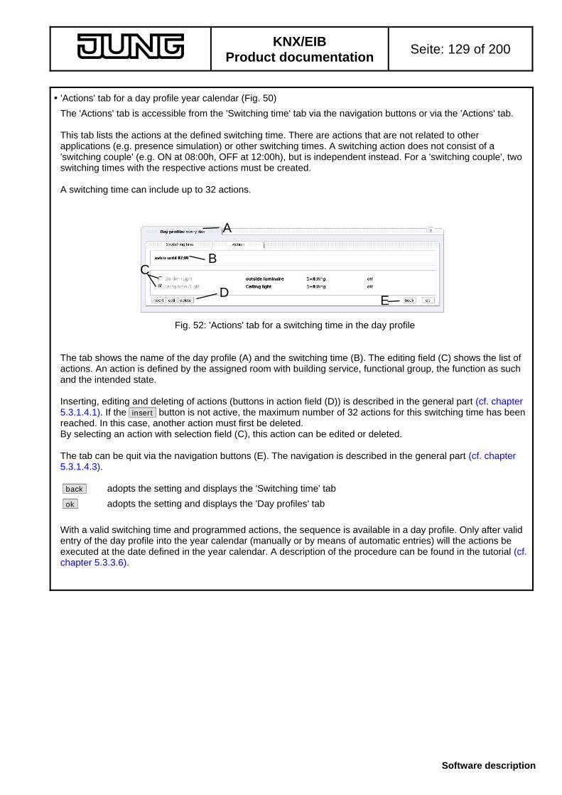
KNX/EIB
Product documentation Seite: 129 of 200
Software description
'Actions' tab for a day profile year calendar (Fig. 50)
The 'Actions' tab is accessible from the 'Switching time' tab via the navigation buttons or via the 'Actions' tab. This tab lists the actions at the defined switching time. There are actions that are not related to other applications (e.g. presence simulation) or other switching times. A switching action does not consist of a 'switching couple' (e.g. ON at 08:00h, OFF at 12:00h), but is independent instead. For a 'switching couple', two switching times with the respective actions must be created. A switching time can include up to 32 actions.
Fig. 52: 'Actions' tab for a switching time in the day profile The tab shows the name of the day profile (A) and the switching time (B). The editing field (C) shows the list of actions. An action is defined by the assigned room with building service, functional group, the function as such and the intended state. Inserting, editing and deleting of actions (buttons in action field (D)) is described in the general part (cf. chapter 5.3.1.4.1). If the insert button is not active, the maximum number of 32 actions for this switching time has been reached. In this case, another action must first be deleted. By selecting an action with selection field (C), this action can be edited or deleted. The tab can be quit via the navigation buttons (E). The navigation is described in the general part (cf. chapter 5.3.1.4.3). back adopts the setting and displays the 'Switching time' tab
ok adopts the setting and displays the 'Day profiles' tab
With a valid switching time and programmed actions, the sequence is available in a day profile. Only after valid entry of the day profile into the year calendar (manually or by means of automatic entries) will the actions be executed at the date defined in the year calendar. A description of the procedure can be found in the tutorial (cf. chapter 5.3.3.6).
A
ED
C B

KNX/EIB
Product documentation Seite: 130 of 200
Software description
5.3.3.5 Fixed day profiles in the time scheduler Note: This tab is not available on the 'Guest' user level.
The tab 'Free time' in the sub-navigation of the time scheduler is used for organizing the fixed day profiles 'Vacation' and 'Holiday'. The configuration of the switching times for the fixed day profiles is identical to that of the other profiles and is made on the 'Day profile' tab (cf. chapter 5.3.3.5).
Fig. 53: Extract year calendar with fixed profiles The time scheduler makes a distinction between 'Vacation' and 'Holiday. A 'Vacation' is a time span between two dates to which the day profile 'Vacation' is assigned in the year calendar (Fig. 57 B). As the 'Vacation profile' is entered as the last profile in the automatic generation, it may overwrite other profiles (Holiday, week profile, etc.). Vacations are defined by a concrete date with the year (e.g. 27.01.2006 to 02.02.2006). Eight vacation periods can be programmed. A 'Holiday' is a recurring day of the year for which the day profile 'Holiday' is entered (Fig. 53 A). A holiday can be a public holiday (can be downloaded from a file) or a private exception day. It is possible to specify fixed dates (e.g. New Year, always on the 1st of January) or have the day calculated on the basis of Easter Sunday (almost all movable holidays depend on Easter, e.g. Whitsun is 49 days after Easter). Holidays are always defined with respect to a year-neutral date (e.g.: 01.01.). 32 calculated holidays (national or regional ) and 32 further private holidays (exception days) can be programmed. The time spans ('Vacations') and the holidays / exception days are entered on this tab sheet. Path: Time scheduler Free time
Fig. 54: 'Vacation' tab in the time scheduler application The tab (A) can be used to switch between the 'Vacation' and the 'Holiday' tabs.
A
C
B
A
B

KNX/EIB
Product documentation Seite: 131 of 200
Software description
'Vacation' tab (Fig. 54)
The tab sheet consists of a field listing the the vacations already entered (Fig. 54 B) and a field for entering and editing a new vacation period (Fig. 54 C). The scheduler permits entering up to eight vacation periods. When eight periods have been entered, the editing field (C) is inactive. The vacation period entries remain in the scheduler even after the turn of the year (and thus after recalaculation of the calendar) and must be deleted manually. Vacation periods already entered can be edited with the respective edit or delete buttons at the end of the line. When a vacation period is edited, the editing field (C) is filled with the dates of already entered vacation periods which can then be changed. The dates are adopted with a click on the enter button. The period is entered in the year calendar with the day profile 'Vacation' and any deleted periods are filled by default with week and holiday profiles. A click on the delete button directly behind a vacation entry causes the correponding period to be refilled with the week and holiday profile. A profile that has been entered manually in the period before the entry of a vacation will be overwritten with the automatic settings. The delete action cannot be undone. In this case, the holiday must be re-entered. A vacation period can be created in the editing field (C) by giving the time period a name and by specifying the starting and the end date of the period. The format is the day/month/year format (tt.mm.jjjj). When the mouse pointer is on the date box, the format is indicated in an info-box at the mouse pointer:
Fig. 55: Help function for the entry format A click on the enter button adopts the period for the list (A) and enters it directly into the year calendar of the time scheduler. The list of vacations is the basis for entering the 'Vacation' day profile into the year calendar. If the dates are entered incorrectly or if no name has been assigned, an error message will be displayed. If the date at the beginning of the period is later than the date at the end of the period, the program displays a window suggesting to change the dates.
Fig. 56: Window suggesting to exchange starting and closing date of a period If the suggestion is accepted, the vacation is entered with changed dates. If the action is aborted, the program goes back to the editing view.

KNX/EIB
Product documentation Seite: 132 of 200
Software description
'Holidays' tab
This tab sheet permits the configuration of the calculated holidays (legal or regional holidays from an existing file) and of the private holidays (exception days) as well as the preview of all configured holidays for the actual annual definition of the time scheduler (cf. Chapter 5.3.3.1).
Fig. 57: 'Holidays' tab in the time scheduler application For navigation in these tab sheets, tab (A) is used. In the field of the calculated holidays (B), all actually loaded holidays are listed. These are taken from a data collection existing as a file on the system and which can be handled with the Gateway-Browser (cf. Chapter 4.3). The file can be used used in the definition file section (C). Navigation section (D) permits changing between the views in accordance with the general description (cf. Chapter 5.3.1.4.3). Organizing calculated holidays Model section (C) shows which definition file has been detected by the system. If no definition file is existing, the message 'no file existing' appears. In Fig. 61, the file 'Holidays Germany' is loaded.
If the calculated holidays are to be taken from this file, the section of calculated holidays can be filled with the definition from the definition file with the load file button. Restoring the old settings is not possible. Further or modified definition files are available from the manufacturer.
Edit field (B) shows all calculated holidays locally loaded in the system. The days are used when the check-box before the respective holiday is ticked. If the holiday is not to be used (e.g. if this is not a public holiday in one of the German Länder), it can be deactivated with a mouseclick on the check-box. Each mouseclick updates the views, enters the day profile 'Holiday' into the year calendar on the selected days (check-box before holiday ticked) and transfers the vacation period again. A vacation coinciding with a holiday selects the day profile 'Vacation' in the year calendar. The deactivation of a holiday replaces the entry in the year calendar with the corresponding model from the week profile. A vacation period, if any, is re-entered.
The selected holidays are calculated and entered into the calendars. During recalculation of the year calendar (e.g. turn of the year detected by system clock or during configuration of the week profile) the day profile 'Holiday' is adopted for these days.
A
C
B
D

KNX/EIB
Product documentation Seite: 133 of 200
Software description
In the 'private holidays' tab, up to 32 private exception days can be determined in addition to the already described calculated days. These are also uniform every year (fixed or depending on Easter Sunday) and are determined like the calculated holidays during the recalculation of the year calendar.
Fig. 58: 'Private holidays' tab in the time scheduler List section (B) contains all configured holidays. The respective days can be activated by means of the check-boxes. A change of the check-box results directly in an entry of the day profile 'Holiday' (or again in overwriting by a vacation period) into the year calendar on this day or the setting of default profiles from the week profile / vacation when the check-box is deactivated. A new exception day is entered in the insertion section (C). The name of the holiday and the date must be assigned with the date being entered witout the year. The format of the date can be: tt.mm. for a fixed date or +nn / -nn within -50 days before until +99 days after Easter Sunday The exception day is adopted with the button enter . The year calendar is accordingly recalculated on this day. The list section shows an entry depending on Easter Sunday with the corresponding offset instead of the date (cf. Fig. 58 E).
Deletion of an entry in list section (B) is possible with the delete button behind the corresponding entry. The deletion replaces the day profile 'Holiday' at the respective date by the week profile or by the day profile 'Vacation', if any.
A
C
B
D
E

KNX/EIB
Product documentation Seite: 134 of 200
Software description
The definitions made with regard to the calculated and the private holidays can be viewed in a preview ('Preview' tab).
Fig. 59: ’Preview’ of holidays in the time scheduler The entries are sorted according to the date for the current year in the time scheduler (cf. Chapter 5.3.3.1) as well as for the following year in list view (C). The configuration of the individual sections can be effected via view-tab (A). The view (Fig. 59) shows the private holidays (Maundy Thursday, 13/04/2006, calculated from the offset Easter –3 and birthday, 10/12/2006, as a fixed date). Year button permits changing between the current and the following year. Navigation section (D) permits going back to the 'private holidays' tab
A
C
B
D

KNX/EIB
Product documentation Seite: 135 of 200
Software description
5.3.3.6 Time-scheduler tutorial
The tutorial is to show the creation of a time scheduler with a possible (fictitious) configuration. The procedure is described with short explanations. Details and effects can be inferred from the previous chapters (cf. Chapter 5.3.3.x). Original state
The original state corresponds to the default states after initial generation of an object model and loading of the model from the ETS-PlugIn into the device. The project includes a switched outside luminaire in the room 'Garden', a switched luminaire in the living room and a heating with comfort and standby operating mode in the living room. All rights are granted. Objective
Configuring a year-scheduler for the years 2006 (current) and 2007 Requirements: (A1) : the outside luminaire is to be switched off every day at sun-rise (at the latest at 7:00h) (A2) : the outside luminare is to be switched on every day at sunset (at the latest at 20:00h) (A3) : on workdays and on Friday, the heating in the living room is to be switched to 'Comfort' at 6:30h (A4) : on workdays, the heating in the living room is to be switched to ’Stand-by’ at 22:30h (A5) : on Fridays, the heating in the living room is to be switched to ’Stand-by' at 23:30h (A6) : on weekends, the heating in the living room is to be switched to 'Comfort' at 8:00h and to 'Stand-by' at
23:30h (A7) : on holidays, the heating is to be controlled like on weekends (A8) : during vacations, the living room light is to be switched on at sunset and off at 22:00h;
a holiday 'Frankfurt' is planned for the time from 23rd to 27th April 2006 (A9) : the holidays in Germany (NRW) are to be entered (A10): Maundy Thursday is also a holiday (three days before Easter Sunday) (A11): location of the IP central unit for the calculation of the astro coordinates is Lüdenscheid, Germany The numbers referred to in the text correspond to the numbers indicated above.

KNX/EIB
Product documentation Seite: 136 of 200
Software description
Step 1: Setting the coordinates
For calculating the correct astro time, the coordinates must be entered only once. To do so, select the 'set date & time' tab (cf. Chapter 5.3.8).
Fig. 60: Time-scheduler turorial: entering coordinates The location is Lüdenscheid in Germany (A11).
Fig. 61: Time-scheduler turorial: entering coordinates for the location Select Lüdenscheid (A); the coordinates are displayed in fields (B) and stored with the adopt button. Step 2: Check year-calendar for up-to-dateness
In a new central unit, the year-scheduler is not yet initialized (cf. Chapter 5.3.3.1). Path: Time scheduler Overview
Fig. 62: Tutorial time-scheduler: year-calendar not initialized Fig. 62 shows that the year-calendar works with a deviating date (A). Pressing the adopt current year button updates the calendar.
A
A
B

KNX/EIB
Product documentation Seite: 137 of 200
Software description
Step 3: Configuring the day profile 'every day'
Path: Time scheduler Day profiles The dayprofile 'every day' ist the first tab. Switching times can be entered directly. Path: Time scheduler Day profiles Tab 'every day' (A1): Click on the new switching time button
in the 'Switching time' tab, select the mode 'Sunrise, at the latest at ...' and enter 07:00 as the limit time:
Fig. 63: Time-scheduler turorial: selection of switching-time mode for (A1) With the button continue , the settings are adopted and the 'Actions' tab is directly displayed where the
desired action is entered with the insert or new action button:
Fig. 64: Tutorial time-scheduler: selection of the action for (A1) The action is entered with ok . The generation of the switching time is terminated with ok . (A2): Corresponding procedure for the next switching time:
Path: Time-scheduler Day profiles Tab ’every day’ The second time is entered with the new switching time button: ’Switching time’ tab: mode‚ configure ’switching at sunset, at the latest at' with the limit time 20:00 ,
the continue button changes to the 'Actions' tab ’Actions’ tab: the insert button permits entering an action:
Fig. 65: Tutorial time-scheduler: selection of the action for (A2) The action is entered with ok
The generation of the switching time is terminated with ok
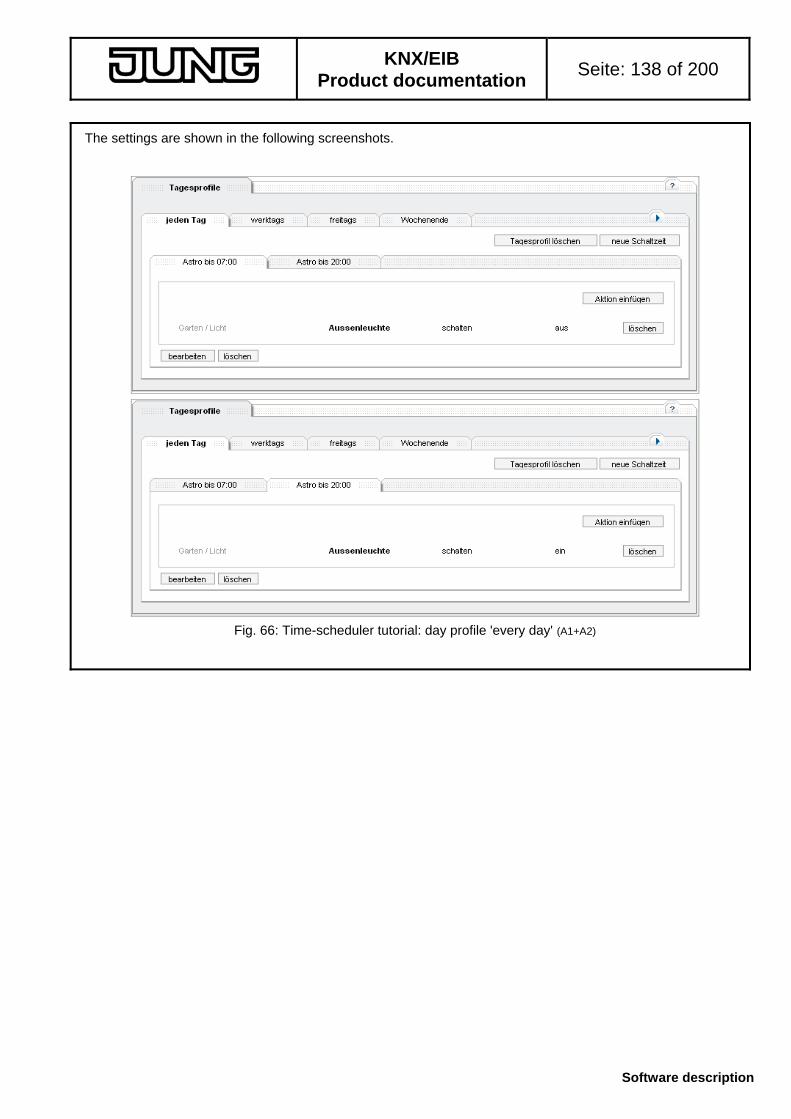
KNX/EIB
Product documentation Seite: 138 of 200
Software description
The settings are shown in the following screenshots.
Fig. 66: Time-scheduler tutorial: day profile 'every day' (A1+A2)

KNX/EIB
Product documentation Seite: 139 of 200
Software description
Step 4: Configuring the day profile 'Workdays'
Path: Time-scheduler Day profiles A new day profile must now be generated. For this purpose, a non used day profile is selected. (Tab 'not defined') and configured accordingly:
Fig. 67: Time-scheduler tutorial: generation of day profile 'Workdays' (A3 + A4) When the name has been assigned and the day profile generated with the adopt button, the switching times and actions can be defined as usual. (A3): Creating a new switching time ( new switching time button)
'Switching time' tab define fixed times 06:30 , continue button
’Actions’ tab insert new action ( insert button)
Fig. 68: Time-scheduler tutorial: selection of the action for (A3) Store the action with ok and adopt the switching time with ok . (A4): Create a new switching time ( new switching time button)
'Switching time' tab define fixed times 22:30 , continue button.
’Actions’ tab insert new actions ( insert button)
Fig. 69: Tutorial time-scheduler: selection of the action for (A4) Save the action with ok and adopt the switching time with ok .
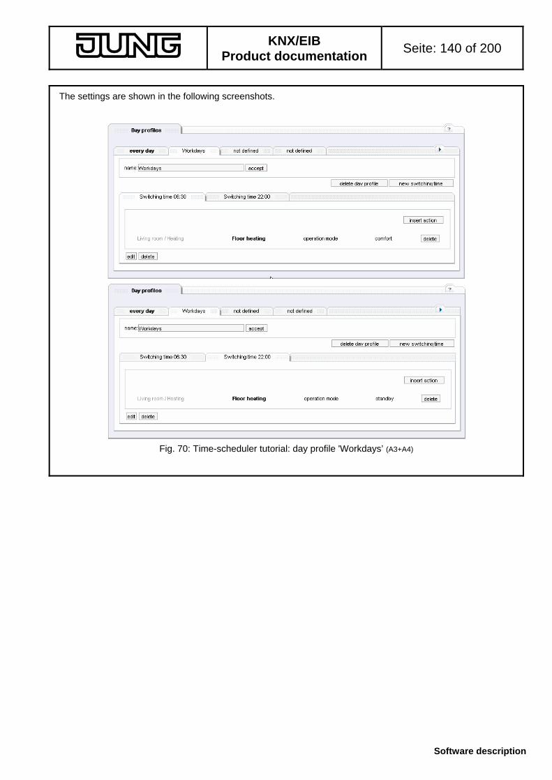
KNX/EIB
Product documentation Seite: 140 of 200
Software description
The settings are shown in the following screenshots.
Fig. 70: Time-scheduler tutorial: day profile 'Workdays’ (A3+A4)
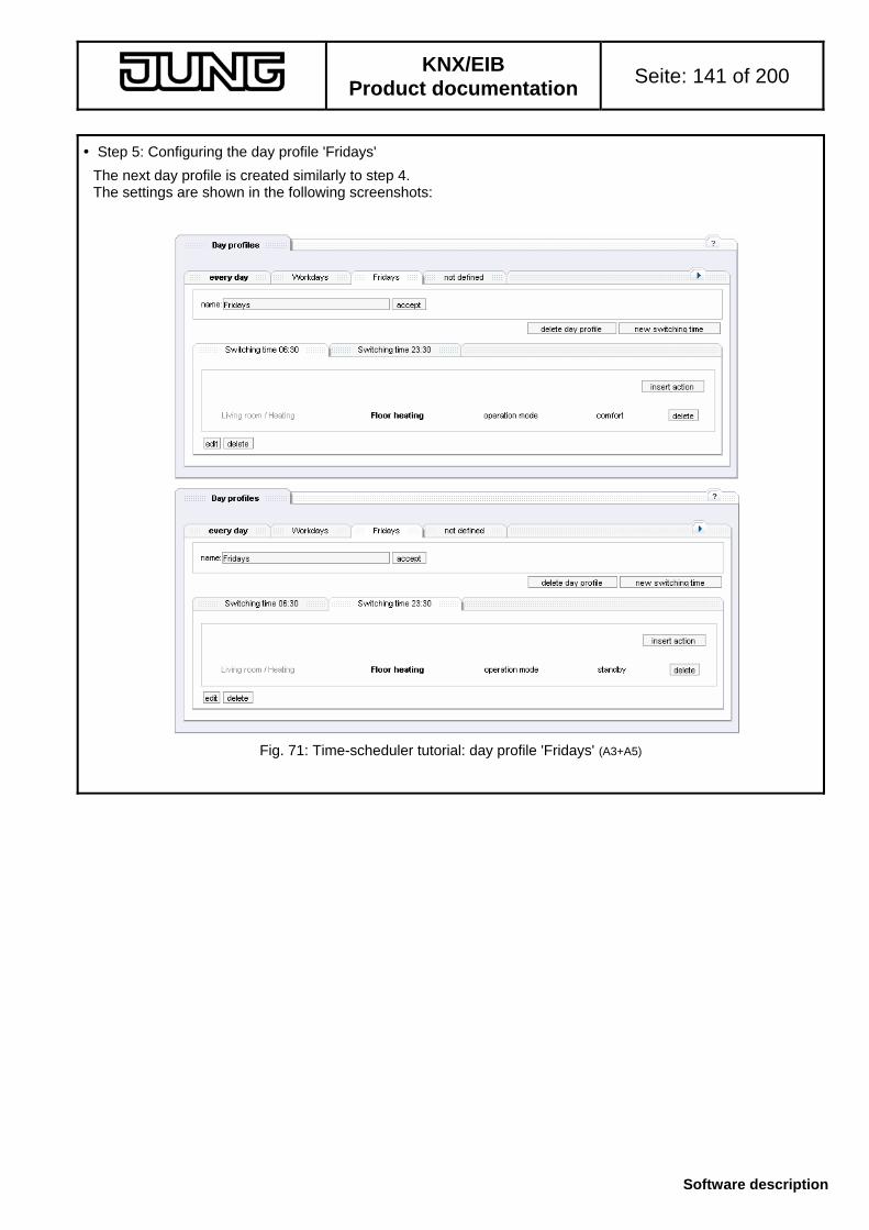
KNX/EIB
Product documentation Seite: 141 of 200
Software description
Step 5: Configuring the day profile 'Fridays'
The next day profile is created similarly to step 4. The settings are shown in the following screenshots:
Fig. 71: Time-scheduler tutorial: day profile 'Fridays' (A3+A5)

KNX/EIB
Product documentation Seite: 142 of 200
Software description
Step 6: Configuring the day profile 'Weekends'
The next day profile is created similarly to step 4 or 5. The settings are shown in the following screenshots:
Fig. 72: Time-scheduler turorial: day profile 'Weekends' (A6)

KNX/EIB
Product documentation Seite: 143 of 200
Software description
Step 7: Configuring the day profile 'Holiday'
The profile 'Holiday' is already created and can be found under the day-profile tabs as the last entry:
Fig. 73: Time-scheduler tutorial: navigation element for changing between the day-profile groups For changing, the tab group must be switched over twice with the navigation element. Configuration is similar to steps 4, 5 or 6. The settings are shown in the following screenshots:
Fig. 74: Time-scheduler tutorial: day profile 'Holiday' (A7)

KNX/EIB
Product documentation Seite: 144 of 200
Software description
Step 8: Configuring the day profile 'Vacation'
The profile 'Vacation' is also created and can be found in the day-profile tabs as the last entry. The configuration is similar to the previous steps. The result is shown in the following screenshots. For the astro time, the mode 'Switching at sunset, at the latest at ...' has been selected.
Fig. 75: Time-scheduler tutorial: day profile 'Vacation' (A8)
Note:
The first switching time ’Astro till 21:55’ has been selected in such a way that the last possible switching time occurs at 21:55h and not after the second switching event ('off', fixed at 22:00h).

KNX/EIB
Product documentation Seite: 145 of 200
Software description
Step 9: Planning the vacation (A8)
The vacation period is entered in the 'Free time' section: Path: Time scheduler Free time 'Vacation' tab
Fig. 76: Time-scheduler tutorial: entering the vacation (A8) The data are entered in the corresponding fields and adopted with the enter button. Vacation is then entered in the year-scheduler accordingly. Step 10: Planning the holidays (A9)
Holidays are configured in the 'Holiday' tab: Path: Time scheduler Free time 'Holiday' tab 'calculated holidays' tab’ At first the 'Holidays Germany' file is loaded with the load file button. The following holidays are not valid in NRW (federal state of germany) (A9): - Heilige Drei Könige - Friedensfest - Mariä Himmelfahrt - Reformationstag - Buß- und Bettag - Rosenmontag - Faschingsdienstag - Aschermittwoch
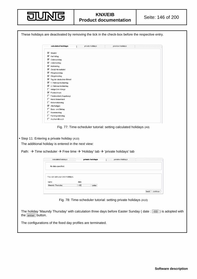
KNX/EIB
Product documentation Seite: 146 of 200
Software description
These holidays are deactivated by removing the tick in the check-box before the respective entry.
Fig. 77: Time-scheduler tutorial: setting calculated holidays (A9) Step 11: Entering a private holiday (A10)
The additional holiday is entered in the next view: Path: Time scheduler Free time 'Holiday' tab 'private holidays' tab
Fig. 78: Time-scheduler tutorial: setting private holidays (A10) The holiday 'Maundy Thursday' with calculation three days before Easter Sunday ( date : -03 ) is adopted with the enter button. The configurations of the fixed day profiles are terminated.

KNX/EIB
Product documentation Seite: 147 of 200
Software description
Step 11: Configuring the week profile (all A)
With the configuration of the week-profile, dates are adopted in the year-scheduler. Path: Time scheduler Week profile
Fig. 79: Tutorial time-scheduler: configuration of the week profile (A1 to A6) In the week profile, the weekdays Monday – Thursday are assigned to the day profile 'Workdays'; Friday is assigned to the profile 'Fridays' and weekend days Saturday and Sunday are assigned to the day profile 'Weekend'. The week profile is adopted with the enter into year-calendar button and the year-calendar will be filled. If necessary, holidays and vacations will be entered as well.

KNX/EIB
Product documentation Seite: 148 of 200
Software description
Step 12: Viewing the settings
The settings of the time scheduler can be checked in the overviews: Path: Time scheduler Overview
Fig. 80: Time-scheduler tutorial : year-calendar – April extracted – with day profiles set The example in Fig. 80 shows all profiles set: - KW14: standard week according to week profile - KW15, KW 16: holidays - KW16, KW17: vacations Step 12: Permanent storage of the settings
Till now, the settings have only been stored temporarily. For permanent storage cf. chapter 5.3.7. Path: Completing In the 'Completing’ tab click on the save button for permanent storage. After the confirmation message the data are stored in the IP central unit safe against mains voltage failure.

KNX/EIB
Product documentation Seite: 149 of 200
Software description
5.3.4 Application 'Presence simulation'
The presence simulation performs actions in a random sequence. This is comparable to a time-controlled scene (cf. Chapter 5.3.5) or a day profile of the time scheduler (cf. Chapter 5.3.3). The difference lies in the fact that the function can be activated / deactivated by an event and in the random time-calculation. The presence simulation performs actions. Up to 32 functions from the project can be used. For these functions, values can be added to up to six switching times (corresponds to an action) The actions are independent from one another and also with regard to other applications. Therefore, states of time-scheduler profiles or selected scenes can be changed by the presence simulation. For this reason, the functions and actions used should, if possible, be such functions / actions which are not influenced by other applications.
Fig. 81: Navigation in the presence simulation The navigation inside the presence simulation (PS) is effected by subnavigation: - Overview: synoptic display of the assignment Function – Time – Value - Actions: specifying of the functions and values at the configured times (cf. Chapter 5.3.4.2) - Swichting times: specifying the switching times and the common random time-period (cf. Chapter 5.3.4.3) - Activation: specifying of the event / condition for activating presence simulation (PS) (cf. Chapter
5.3.4.4)

KNX/EIB
Product documentation Seite: 150 of 200
Software description
5.3.4.1 'Overview' tab
The 'Overview' shows the configured presence simulation in the form of a table.
Fig. 82: Overview of the presence simulation In the status field (A), the status of the presence simulation can be set with the buttons activate presence simulation or inactivate presence simulation . If the presence simulation is activated, the respective actions will be executed at the switching times (if required, with random intervals). The possible random time-shift is displayed in random field (B). This can be changed in the 'Switching times' tab (cf. Chapter 5.3.4.3). The matrix of functions, switching times and values is displayed in overview field (C). The matrix contains up to 32 functions with room / building service assignment and function group (D), switching times (E) and the value for a function at a switching time (F). The following rules apply:
- (D) the function can be assigned in the 'Actions' tab (cf. Chapter 5.3.4.2)
- (E) the switching time can be configured in the 'Switching times' tab (cf. Chapter 5.3.4.3), the tab is sorted in ascending order. The times highlighted grey are not active. A mouseclick on the switching time goes to the tab "Switching times' for this time.
- (F) the value of a function for a switching time can be defined in the 'Actions' tab. Display ---- means that there is no value for the function of this switching time and that no action will be
executed. A click on the value goes directly to the 'Actions' tab of the corresponding function of the corresponding switching time.
A tutorial in chapter 5.3.4.5 gives an example of a simple simulation.
A
B
C
F
ED

KNX/EIB
Product documentation Seite: 151 of 200
Software description
5.3.4.2 'Actions' tab
In the 'Actions' tab, the functions for the presence simulation are specified and the values for a switching time entered. Path: Presence simulation Actions Depending on the subject, the view may have different subviews. List
The list of the already created functions and values is the beginning.
Fig. 83: 'Actions' tab in the presence simulation New functions can be added to the list with the well-known navigation ( insert ) button. The described selection dialogue is displayed (cf. Chapter 5.3.1.4.1).
Deviating handling: The dialogue specifies no value, only the function can be selected. With the ok button, the function is entered. into the list (cf. Fig. 83). The values for the corresponding switching times are inserted with the edit values button after the function has been selected via the buttons.
A function with the pertaining values can be removed after selection with the buttons and a click on the delete button.
The switching times are displayed in the order of the memory locations. There is no sorting of the switching times in this tabsheet.
Subview 'edit values'
With the edit values button or a mouseclick on a value in the overview of the presence simulation (cf. Chapter 5.3.4.1), the tabsheet for editing a value of a function pertaining to a certain switching time will be opened.
Fig. 84: Editing of values within the presence simulation
A B CD

KNX/EIB
Product documentation Seite: 152 of 200
Software description
A value can be specified for every switching time (active ones and also non active ones). The switching time is selected in the Time tab (A). Six switching-time tabs are available. The tab group can be changed with navigation (B). For each switching time, the user can select whether a value for this function will be entered (C). If this function for this switching time is not active (inactive), the value input field is hidden (D) and the function will not be assigned a value. If the function for this switching time is active (Fig. 84 field (C), 'active' button), a value can be entered depending on the datapoint type (cf. Chapter 5.3.1.4.1) When values are entered in the entry field, the entry range is specified as a support. Otherwise it is possible to select a predefined value by means of a selection. Clicking on ok adopts the value.
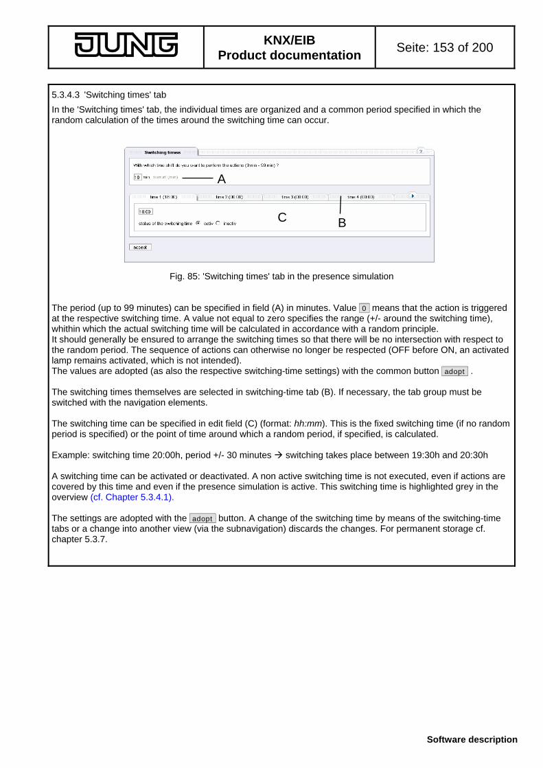
KNX/EIB
Product documentation Seite: 153 of 200
Software description
5.3.4.3 'Switching times' tab
In the 'Switching times' tab, the individual times are organized and a common period specified in which the random calculation of the times around the switching time can occur.
Fig. 85: 'Switching times' tab in the presence simulation The period (up to 99 minutes) can be specified in field (A) in minutes. Value 0 means that the action is triggered at the respective switching time. A value not equal to zero specifies the range (+/- around the switching time), whithin which the actual switching time will be calculated in accordance with a random principle. It should generally be ensured to arrange the switching times so that there will be no intersection with respect to the random period. The sequence of actions can otherwise no longer be respected (OFF before ON, an activated lamp remains activated, which is not intended). The values are adopted (as also the respective switching-time settings) with the common button adopt . The switching times themselves are selected in switching-time tab (B). If necessary, the tab group must be switched with the navigation elements. The switching time can be specified in edit field (C) (format: hh:mm). This is the fixed switching time (if no random period is specified) or the point of time around which a random period, if specified, is calculated. Example: switching time 20:00h, period +/- 30 minutes switching takes place between 19:30h and 20:30h A switching time can be activated or deactivated. A non active switching time is not executed, even if actions are covered by this time and even if the presence simulation is active. This switching time is highlighted grey in the overview (cf. Chapter 5.3.4.1). The settings are adopted with the adopt button. A change of the switching time by means of the switching-time tabs or a change into another view (via the subnavigation) discards the changes. For permanent storage cf. chapter 5.3.7.
A
BC
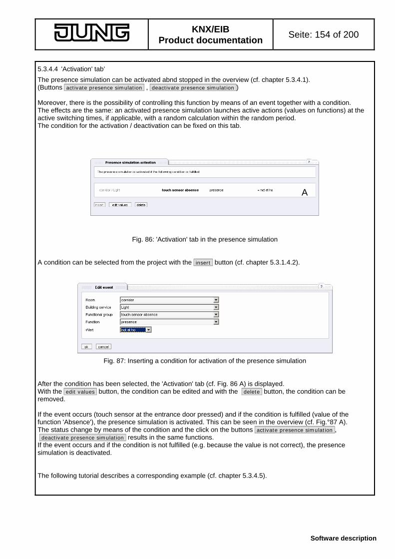
KNX/EIB
Product documentation Seite: 154 of 200
Software description
5.3.4.4 'Activation' tab’
The presence simulation can be activated abnd stopped in the overview (cf. chapter 5.3.4.1). (Buttons activate presence simulation , deactivate presence simulation ) Moreover, there is the possibility of controlling this function by means of an event together with a condition. The effects are the same: an activated presence simulation launches active actions (values on functions) at the active switching times, if applicable, with a random calculation within the random period. The condition for the activation / deactivation can be fixed on this tab.
Fig. 86: 'Activation' tab in the presence simulation A condition can be selected from the project with the insert button (cf. chapter 5.3.1.4.2).
Fig. 87: Inserting a condition for activation of the presence simulation After the condition has been selected, the 'Activation' tab (cf. Fig. 86 A) is displayed. With the edit values button, the condition can be edited and with the delete button, the condition can be removed. If the event occurs (touch sensor at the entrance door pressed) and if the condition is fulfilled (value of the function 'Absence'), the presence simulation is activated. This can be seen in the overview (cf. Fig.°87 A). The status change by means of the condition and the click on the buttons activate presence simulation , deactivate presence simulation results in the same functions. If the event occurs and if the condition is not fulfilled (e.g. because the value is not correct), the presence simulation is deactivated. The following tutorial describes a corresponding example (cf. chapter 5.3.4.5).
A

KNX/EIB
Product documentation Seite: 155 of 200
Software description
5.3.4.5 Presence simulation tutorial
The tutorial is to demonstrate the creation of a presence simulation with a possible (fictitious) configuration. The procedure is described with short explanations, details and effects can be inferred from the preceding chapters (cf. Chapter 5.3.4.x). Original state
The original state corresponds to the default states after initial drawing up of an object model and loading of a model from the ETS plug-in into the device. The project includes a switched outdoor luminaire in the 'Garden' room, a switched luminaire in the living room and a touch sensor in the corridor with a switching function. All rights are granted. Objective
Configuring a presence simulation Requirements: (A1) : at 18:00h, the luminaire is to be switched on in the living room and in the garden (A2) : at 20:30h, the luminaire is to be switched off in the living room (A3) : at 22:00h, the luminaire is to be switched off in the garden (A4) : the actual switching time is to vary by +/- 10min around the predefined switching time (A5) : a touch sensor in the corridor has the 'Absence' function which has been projected for ’AT HOME’ (0) and
’NOT AT HOME’ (1); this touch sensor is to activate the presence simulation (’NOT AT HOME’ status)
The numbers referred to in the text correspond to the numbers indicated above.
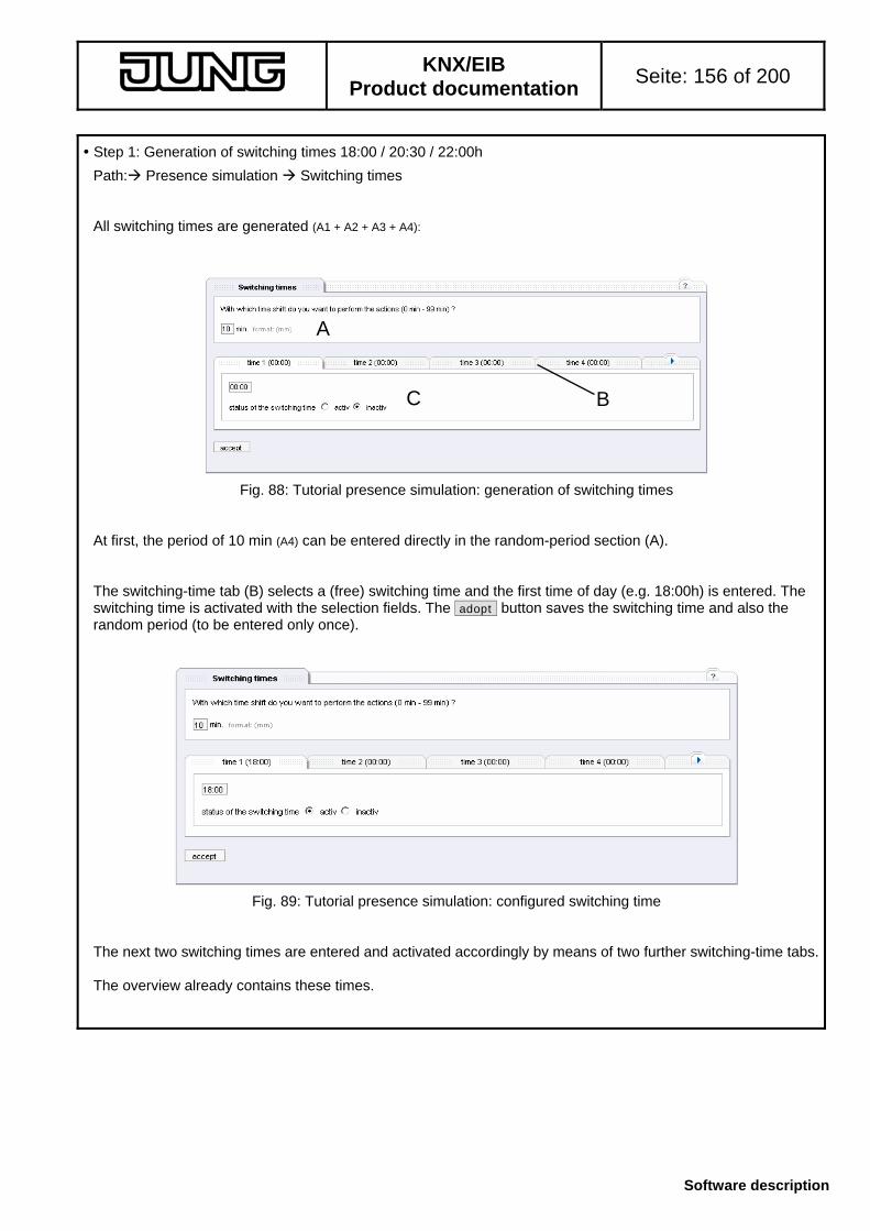
KNX/EIB
Product documentation Seite: 156 of 200
Software description
Step 1: Generation of switching times 18:00 / 20:30 / 22:00h
Path: Presence simulation Switching times All switching times are generated (A1 + A2 + A3 + A4):
Fig. 88: Tutorial presence simulation: generation of switching times At first, the period of 10 min (A4) can be entered directly in the random-period section (A). The switching-time tab (B) selects a (free) switching time and the first time of day (e.g. 18:00h) is entered. The switching time is activated with the selection fields. The adopt button saves the switching time and also the random period (to be entered only once).
Fig. 89: Tutorial presence simulation: configured switching time The next two switching times are entered and activated accordingly by means of two further switching-time tabs. The overview already contains these times.
A
C B

KNX/EIB
Product documentation Seite: 157 of 200
Software description
Step 2: Generating functions and values
Path: Presence simulation Actions Two functions are programmed: - Living room – lighting – ceiling luminaire - switching - Garden – lighting – outside luminaire – switching
Fig. 90: Tutorial presence simulation: inserting actions With the insert button, a new function can be selected. In the dialogue, the function is determined (without values) and inserted with the ok button.
Fig. 91: Tutorial presence simulation: function selection The values for a selected function (selection via selection fields before the function) are determined by means of the edit values button at the respective switching time.
Fig. 92: Tutorial presence simulation: value selection In the underdialogue 'edit action', the action is activated first, the value is set and adopted with the ok button.
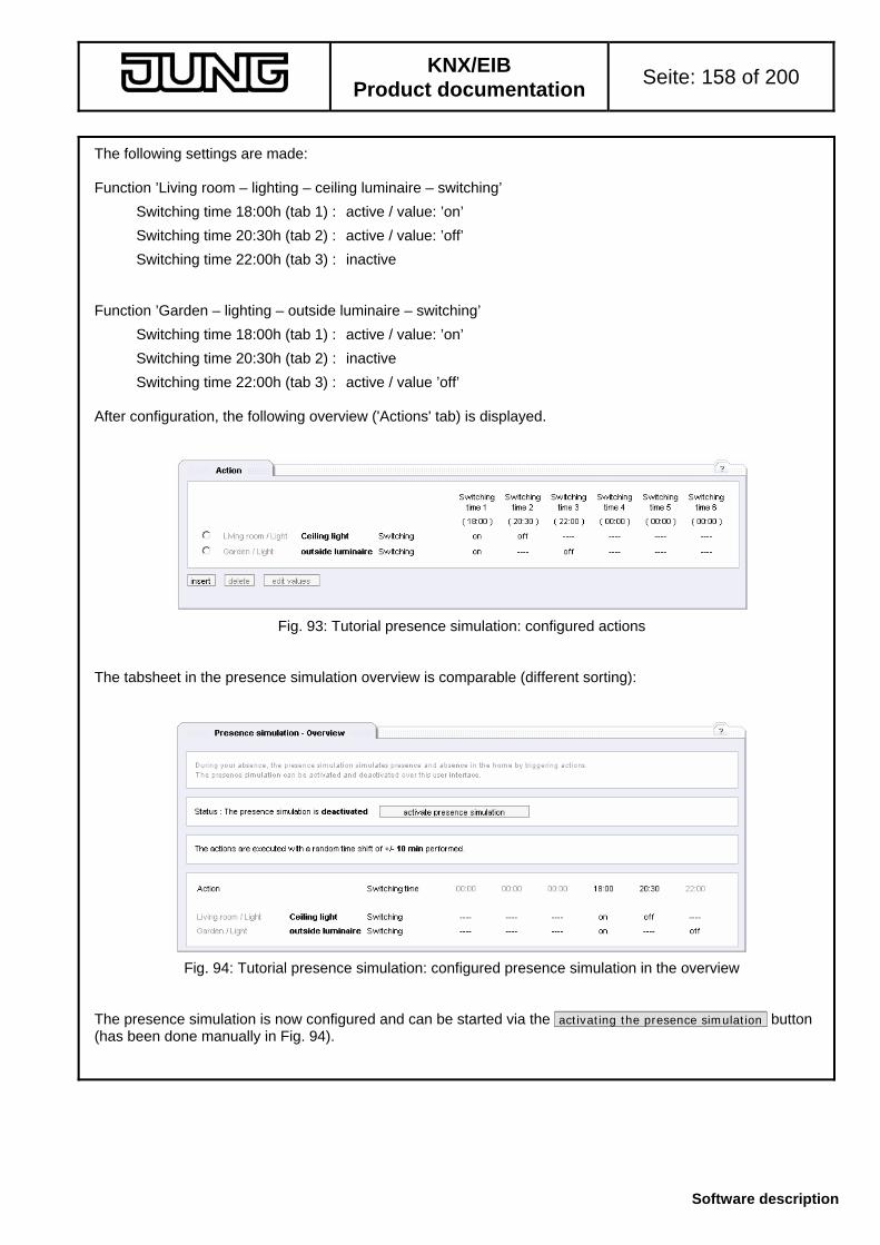
KNX/EIB
Product documentation Seite: 158 of 200
Software description
The following settings are made: Function ’Living room – lighting – ceiling luminaire – switching’
Switching time 18:00h (tab 1) : active / value: ’on’
Switching time 20:30h (tab 2) : active / value: ’off’
Switching time 22:00h (tab 3) : inactive Function ’Garden – lighting – outside luminaire – switching’
Switching time 18:00h (tab 1) : active / value: ’on’
Switching time 20:30h (tab 2) : inactive
Switching time 22:00h (tab 3) : active / value ’off’ After configuration, the following overview ('Actions' tab) is displayed.
Fig. 93: Tutorial presence simulation: configured actions The tabsheet in the presence simulation overview is comparable (different sorting):
Fig. 94: Tutorial presence simulation: configured presence simulation in the overview The presence simulation is now configured and can be started via the activating the presence simulation button (has been done manually in Fig. 94).

KNX/EIB
Product documentation Seite: 159 of 200
Software description
Step 3: Configuration of the activation via an event (A5)
Path: Presence simulation Activation Via the 'Activation' tab, the event is specified which is responsible for activating / deactivating the presence simulation. (A5) The touch sensor in the corridor has an absence function with the values ’AT HOME’ (0) and ’NOT AT HOME’ (1) The condition is entered via insert and adopted with the ok button:
Fig. 95: Tutorial presence simulation: configuration of the 'Activation' event Presence simulation is now completely condifured. When the touch sensor is pressed and when absence is signalled (value ’NOT AT HOME’), simulation is started. If on actuation the sensor transmits presence (value not equal to ’NOT AT HOME’), presence simulation is stopped. Step 4: Permanent storage of the settings
Until now, the settings have only been stored temporarily. For permanent storage cf. chapter 5.3.7. Path: Exit Click on the save button for permanent storage on the 'Exit' tab. After confirmation, the data in the IP central unit are safe against mains failure.

KNX/EIB
Product documentation Seite: 160 of 200
Software description
5.3.5 Application 'Scenes'
A scene is the setting of states with a certain number of functions at a certain point of time. The spatial or functional relationship between the individual actions is irrelevant. A scene can include up to 32 actions and be triggered via the Web interface and also by means of eight events. An event can come from the installation or from other applications (internal datapoints). Important note
A scene can include actions which are themselves actions for triggering another scene. It should be noted that no loop is created (scene1 triggers scene 2 which in turn triggers scene 1 etc.). 5.3.5.1 'Active scenes' tab
The overview shows all active scenes . At the beginning, no scenes are configured. Path: Scenes active scenes
Fig. 96: Empty tab 'active scennes' (no scene activated) Originally, no scenes are activated. They can be configured on the 'Scenes overview' tab (cf. Chapter 5.3.5.2).
Fig. 97: Active scenes Active scenes can be selected with the selection button and be called up by a mouseclick on the execute scene button. Editing and activating of scenes is done in the 'Scenes overview' tab (cf. Chapter 5.3.5.2).

KNX/EIB
Product documentation Seite: 161 of 200
Software description
5.3.5.2 'Scenes overview' tab Note: This tab does not exist on the 'Guest' level.
The scenes are edited in the scenes overview. All 32 scenes are always existing (depending on user right) (with the name 'Scene' by default') which are not active.
Fig. 98: 'Scenes overview' tab’ The scenes overview lists the designated names of scene (A) and the status of scene (B). If a scene is active, it can also be triggered via an (external) event. An active scene appears also on the 'active scenes' tab (cf. Chapter 5.3.5.1). A scene not yet edited still has the name 'Scene' (C) and is not active. A scene is selected with the selection button and can be called up by means of the execute button. This is also possible for non active scenes (e.g. for a test). .
A B
C

KNX/EIB
Product documentation Seite: 162 of 200
Software description
A selected scene can be configured with the edit button.
Fig. 99: Editing a scene In the name section (A), the name can be entered into the text box and adopted with the adopt button. This name is displayed in the 'Scenes overview' and in the 'active scenes' tab. On delivery of the device, the name 'Scene' is used. For better identification, a meaningful name should be selected. Activation section (B) is used to set the state of the scene to 'active' or 'inactive'. This can be done with the buttons activate scene / deactivate scene . Depending on which tab is selected (D), workspace (C) lists the programmed action or events required for executing the scene. The control elements (E) for actions and events have already been described in the general part (cf. Chapter 5.3.1.4.1 or Chapter 5.3.1.4.2) and the navigation elements (F) in chapter 5.3.1.4.3. An example for creating a scene is described in the tutorial (cf. Chapter 5.3.5.4).
A
B
C F E
D

KNX/EIB
Product documentation Seite: 163 of 200
Software description
Partial view 'Actions'
The partial view shows the actions and the events of the scene.
Fig. 100: Partial view 'Actions' Tabs (A) can be used to switch between the partial views 'Actions' and 'Events'. Actions are added to the scene with the insert button. Up to 32 actions can be assigned to a scene. Adding of an action is described in the general part (cf. Chapter 5.3.1.4.1) The action is listed together with room / building service, functional group, function and value. The value is displayed depending on the configuration of the datapoint.
Fig.°106: Actions inserted into a scene An action can be selected with the button in front of it. A selected action is modified with the edit button or removed from the scene with the delete button.
A

KNX/EIB
Product documentation Seite: 164 of 200
Software description
Partial view 'Events'
The second tab selects the partial view 'Events'. The scene can be triggered by up to eight events. If the event occurs (e.g. by sending a telegram to this datapoint), the stored condition is examined. If the result is correct (event occurred and condition fulfilled), the scene is triggered.
Fig. 101: Partial view 'Events' A special characteristic of the events in a scene is the option to trigger the scene only in case of a value change of the event (A). In this case, the check-box must be ticked. Generally, the condition (value) is checked for each event and the scene is triggered if this condition is fulfilled. If a device, for instance, transmits a value cyclically and if this is an event for executing a scene, the scene will be executed each time without the above option. If the check-box is ticked, the condition is checked again only after the value has changed. Example: Event / condition : sensor transmits value = 1
Sensor transmits value Option: value change only Option: always
Value 1 Scene triggered Ssene triggered Value 1 no check Scene triggered Value 1 no check Scene triggered
Value 0 Check, condition not fulfilled
Check, condition not fulfilled
Value 1 Scene triggered Scene triggered Events are added to the scene with the insert button. Up to eight events can be added to a scene. Adding of an event is described in the general part (cf. Cahpter 5.3.1.4. 2). The event is listed together with room / building service, functional group, function and operation (value). The value is displayed depending on the configuration of the datapoint.
Fig. 102: Events inserted into a scene An event can be selected with the button in front of it. A selected event is modified with the edit button or removed from the scene with the delete button.
AB

KNX/EIB
Product documentation Seite: 165 of 200
Software description
5.3.5.3 'Rights' tab Note: This tab does not exist on the 'Guest' and 'User' user levels.
The user level ’Admin’ can hide scenes for the lower user groups in the browser. These are then no longer configurable (user group ’User’) and no longer usable (user groups ’User’ and ’Guest’). The function of event-controlled triggering of the scene via the installation (trigger) as well as via other modules within the IP central unit remains unaffected. Path: Scenes Rights
Fig. 103: Granting rights for scenes The check-boxes can be ticked individually (standard setting) so that the scene is visible to the corresponding user group. When a check-box is not ticked, the scene is hidden. Ticking / unticking of the check-box results in the direct adoption of the settings. For permanent storage cf. chapter 5.3.7.

KNX/EIB
Product documentation Seite: 166 of 200
Software description
5.3.5.4 Scenes tutorial
The tutorial is to show the preparation of a scene with a possible (fictitious) configuration. The procedure is described with short explanations. Details and effects can be inferred from the previous chapters (cf. Chapter 5.3.5.x). Original state
The original state corresponds to the default states after initial drawing up of an object model and loading of a model from the ETS plug-in into the device. The project includes a switched outdoor luminaire in the 'Garden' room, a dimmable ceiling luminaire in the living room, a shutter with position control in the living room and a touch sensor with a switching function on the upper rocker. All rights are granted. Objective
Configured scene Requirements: (A1) : the ceiling luminaire in the living room is to be dimmed down to a brightness of 50% (A2) : the shutter in the living room is to move upwards (1%) (A3) : the luminaire in the garden is to be switched on (A4) : a touch sensor in the living room is to trigger the scene when the upper rocker (value 'on') is pressed (A5) : the scene is to be triggered for each corresponding value (A6) : the scene is configured so that it is not visible for the user group 'Guest The numbers referred to in the text correspond to the numbers indicated above.
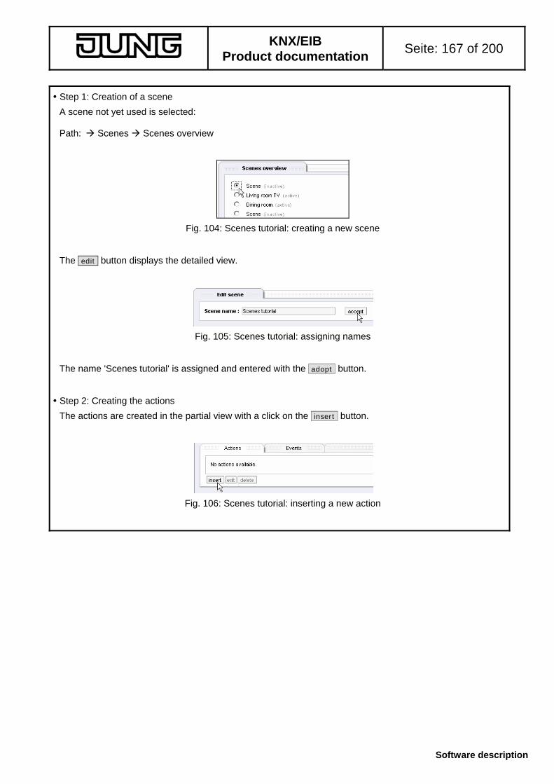
KNX/EIB
Product documentation Seite: 167 of 200
Software description
Step 1: Creation of a scene
A scene not yet used is selected: Path: Scenes Scenes overview
Fig. 104: Scenes tutorial: creating a new scene The edit button displays the detailed view.
Fig. 105: Scenes tutorial: assigning names The name 'Scenes tutorial' is assigned and entered with the adopt button. Step 2: Creating the actions
The actions are created in the partial view with a click on the insert button.
Fig. 106: Scenes tutorial: inserting a new action

KNX/EIB
Product documentation Seite: 168 of 200
Software description
The following actions are created and adopted with the ok button. (A1)
(A2)
(A3)
Fig. 107: Scenes tutorial: creating actions The created actions are shown in the partial view:
Fig. 108: Scenes tutorial: overview of the actions
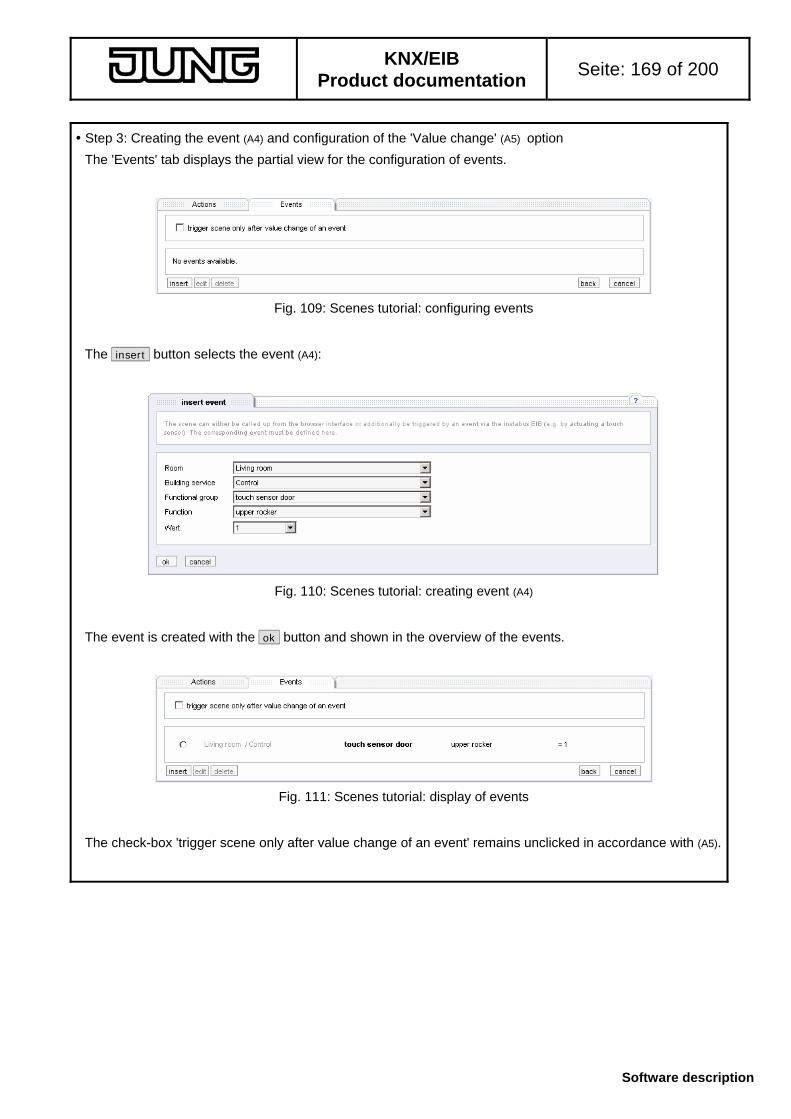
KNX/EIB
Product documentation Seite: 169 of 200
Software description
Step 3: Creating the event (A4) and configuration of the 'Value change' (A5) option
The 'Events' tab displays the partial view for the configuration of events.
Fig. 109: Scenes tutorial: configuring events The insert button selects the event (A4):
Fig. 110: Scenes tutorial: creating event (A4) The event is created with the ok button and shown in the overview of the events.
Fig. 111: Scenes tutorial: display of events The check-box 'trigger scene only after value change of an event' remains unclicked in accordance with (A5).

KNX/EIB
Product documentation Seite: 170 of 200
Software description
Step 4: Creating the rights (A6)
The user rights are created via the subnavigation. Path: Scenes User rights
Fig. 112: Scenes tutorial: specifying the rights for different user groups The check-box of the created scene 'Scenes tutorial' is deactivated in the 'Guest' column (A6). This means that this scene is not visible to this user group. Step 5: Activating the scene
Path: Scenes Scenes overview ’Scenes tutorial’ scene edit The created scene can be activated in the detailed view ( activate scene ) button and is thus completely configured. Step 6: Permanent storage of the settings
Till now, the settings have only be stored temporarily. For permanent storage cf. chapter 5.3.7. Path: End program Click on the save button for permanent storage on the 'End program' tab. After confirmation, the data in the IP central unit are safe against mains failure.

KNX/EIB
Product documentation Seite: 171 of 200
Software description
5.3.6 Application 'Event' recorder'
The Event recorder serves the purpose of generating messages after the occurrence of certain events and to save the time stamp of the last occurrence, if applicable. An event is defined, for instance, as the setting of a specific value, the exceeding of a measured value or the result of a complex hysteresis function. An event-message can be sent as an e-mail to one or more addressees. The e-mail can consist of a reference line and an e-mail text. The texts can contain current states of the IP central unit (with placeholders). An event-message can moreover be accompanied by two actions which are executed when the event takes place. 5.3.6.1 'Active message handling' tab
The overview of the active event-messages (recorders) shows all configured active recorders and also – if so configured and registered – the time stamp of the last occurrence. If no recorders are activated, the message text 'no active event recorders available. In this case, recorders can be configured in the 'Overview' tab.
Fig. 113: Tab of active recorders with different confirmation status The tab shows the list of active recorders (A) with the assigned names (B). If the function for saving the time stamp is active (cf. chapter 5.3.6.2), the last occurrence of the event is registered with date and time (system time) (C). The tab contents is updated every 10 seconds. An event-message can be selected with the selection buttons and edited after clicking on the edit button. An event-message configured for saving will be marked as 'new' when the event takes place and be confirmed manually with the button confirm (D). Fig. °113 shows the possible forms of an event-message:
(E): a newly arrived message not yet confirmed, with date and time (time stamp saving activated)
(F): a confirmed message with date and time (time stamp saving activated)
(G): a normal message without activated saving or an event not yet occurred
B C D FE
GA

KNX/EIB
Product documentation Seite: 172 of 200
Software description
If at least one event-message marked as 'new' has come in, an info is displayed in the overview tabs of the other applications. A click on the show overview button will then display the active recorders.
Fig 114: Info concerning new event-messages
The info disappears when all messages have been confirmed.
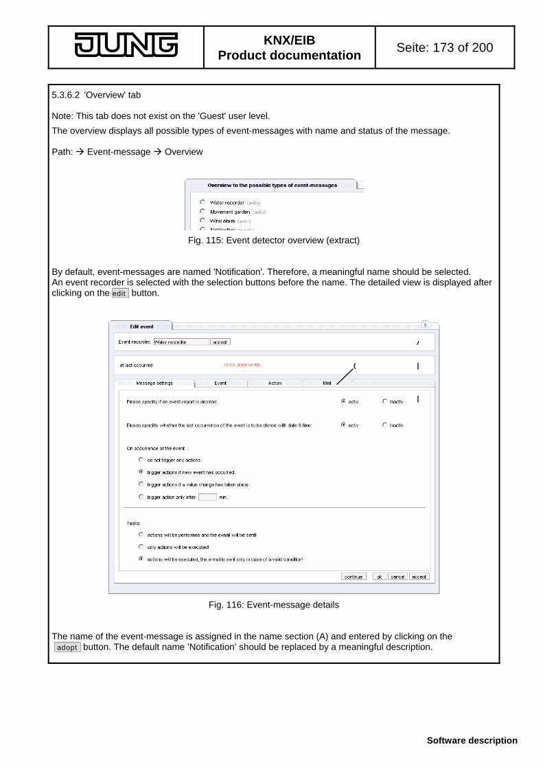
KNX/EIB
Product documentation Seite: 173 of 200
Software description
5.3.6.2 'Overview' tab Note: This tab does not exist on the 'Guest' user level.
The overview displays all possible types of event-messages with name and status of the message. Path: Event-message Overview
Fig. 115: Event detector overview (extract) By default, event-messages are named 'Notification'. Therefore, a meaningful name should be selected. An event recorder is selected with the selection buttons before the name. The detailed view is displayed after clicking on the edit button.
Fig. 116: Event-message details The name of the event-message is assigned in the name section (A) and entered by clicking on the adopt button. The default name ’Notification’ should be replaced by a meaningful description.
A
B
D
C

KNX/EIB
Product documentation Seite: 174 of 200
Software description
The info window (B) shows the time stamp of the last event, if so parameterized. If the detected event has not yet been confirmed, the corresponding marker at the recorder can be removed with confirm button. The event-message is then no longer displayed in the overview of the other applications (the info is removed when no message is marked anymore). The event recorder has four different configuration views which can be selected with the tabs (C). More settings are available in the respective workspace (D). On the tab sheets, the settings can be adopted or the tab sheet changed with the general navigation means (cf. chapter 5.3.1.4.3). 'Message settings' tab
The message settings tab sheet is used for basic configuration purposes.
Fig 117: 'Message settings' tab (partial view) The recorder can be activated or deactivated (A). An active recorder is listed on the tab sheet 'Active event-message handling' and is evaluated depending on parameterization. The time stamp saving function can be preset with the selection buttons (B). Active saving means that the time stamp is saved on occurrence of the event with an info that the event has occurred being issued at the same time. This info is shown on the overview tabs of the other applications. The info can be confirmed. The last time stamp is the one that is saved. In the events section (C), the conditions under which further steps (tasks) will be executed can be specified. The tasks include setting of the time stamp (if parameterized), sending of an e-mail (if parameterized) or triggering of actions (if parameterized).
A
B
C

KNX/EIB
Product documentation Seite: 175 of 200
Software description
The following options are available and can be selected with the selection buttons: - do not trigger any actions
No further actions will be executed. - trigger actions if new event has occurred
If the projected condition on the 'Event' tab has been fulfilled and if the event has occurred, the time stamp will be saved (if parameterized) and the marker 'new' be set, an e-mail sent (if parameterized) and up to two actions triggered (if parameterized). This is the case with every new event (and corresponding condition). If the same values are set several times, the event will be evaluated each time.
- trigger actions if a value change has taken place
The response is the same as with the previous setting option, on condition however, that there must have been a value change in the function triggering the event. If the same values are to be set several times, this event will be evaluated only once until a value change has taken place.
- trigger actions only after min.
When an event occurs, the tasks (time stamp, e-mail, action) will be executed. The recorder is then internally disabled for the specified time and any events occurring are not evaluated. The recorder will be re-enabled only after the time has elapsed. An event occurring thereafter is again evaluated and saved with the time stamp, if applicable. Parameterized actions, if any, are performed and an e-mail will be sent.
The settings are stored together with other settings in the navigation section. The actions section is used for specifying which tasks are to be performed (action and/or e-mail). The 'time stamp' task has already been configured (Fig. 117 B).
Fig. 118: Task section (partial view) The following options are available (select with selection buttons):
- actions will be performed and the e-mail will be sent
If actions and the e-mail are configured, they will performed and sent.
- only actions will be executed!
If actions are configured, they will be transmitted. An e-mail, if configured, will not be transmitted.
- actions will be executed; the e-mail is sent only in case of a valid condition
If actions are configured, they will be transmitted. A configured e-mail is transmitted only if the condition linked with the e-mail (function has a specific state) is valid. This setting is intended, for instance, in case an e-mail is to be sent only if no person is present, (a 'presence' function would have the status 'absent'). Otherwise, the message concerning actions is to be sent to a display.

KNX/EIB
Product documentation Seite: 176 of 200
Software description
'Event' tab
An event-message can be triggered by one and only one event. If this event occurs and if the preset condition is valid, tasks depending on parameterization will be triggered.
Fig. 119: Event-message from recorder The event can be created by means of the insert button. The event is configured as described in the general part (cf. chapter 5.3.1.4.2). The event can be modified or deleted by means of the edit or delete buttons . Besides the conditions already presented (equal to, less than, greater than, etc.), a hysteresis can be used with three modes. This hysteresis function is admissible only in the 'Event recorder' application and is described below. The hysteresis is provided especially for ongoing measurements with a message sequence. A fluctuating measuring value does not always trigger a message and stepwise messaging depending on the measurement caracteristic is also possible.
Fig. 120: Hysteresis function in an event-message The configuration is at first performed similar to the ususal events (Section A, cf. chapter 5.3.1.4.2) and offers the well-known functions. In addition, the hysteresis function can be used. The option field ’Hysteresis function' enlarges the tab by the hysteresis section (B). Depending on the mode, various fields will be activated.
B
A

KNX/EIB
Product documentation Seite: 177 of 200
Software description
Hysteresis mode‚ limit-value switch
Fig. 121: Hysteresis function, limit-value switch mode (partial view) Phase 1: The measuring value must fulfill the condition (field condition and value entry)
(in the example: measuring value > 10.0). The recorder is triggered ( if applicable, save time stamp, transmit actions and e-mail ).
The recorder is now disabled and will not be triggered anymore. Phase 2: The measuring value must now deviate from the trigger value (field value entry) by the limit value.
The direction is determined by the condition. If the condition is 'greater than', the value must be below the trigger value by the limit value, if the condition is 'less than', the value must be above the trigger value by the limit value (in the example: measuring value must be below 8.0 ). The recorder is then retriggered and is now re-enabled.
The next trigger event is again dependent on the condition and the trigger value (field value entry) (in the example: measuring value > 10.0) (Phase 1)
Message(T1)
Trigger valuel
recorder enabled (Phase1)
recorder disabled (Phase2)
measuring value
l: limit value
Message(T2)
Message(T3)
Message(T4)
Fig. 122: Hysteresis mode diagram 'Limit-value' switch The option 'Start at trigger threshold' is a configurable start condition: If the option is set, the recorder is disabled during system restart (Phase 2) and the measuring value must first be outside the trigger threshold (condition) to enable the recorder (in the example below 10.0).

KNX/EIB
Product documentation Seite: 178 of 200
Software description
Hysteresis mode 'simple hysteresis'
Fig. 123: Hysteresis function, mode simple hysteresis (partial view) The simple hysteresis constitutes a limiting range around the trigger value, so that fluctuating values do not retrigger the recorder. Only if the measuring value leaves the range consisting of last trigger value and limit value, will the recorder be triggered next time. In the example, the measuring value 11.0 (above trigger threshold 10.0) triggers the recorder. The values 10.0 to 13.0 do not trigger the recorder anymore. Only after the range consisting of last trigger value +/- limit value has been exceeded, will the recorder be retriggered. (in the example: last trigger value 11.0 +/ 2 limit value; triggering only if measuring value greater than 13.0).
Message(T1)
Trigger value
recorder enabled
recorder disabled
measuring value
l: limit value
l
l
Message(T2)
Message(T3)
Fig. 124: Hysteresis mode diagram 'simple hysteresis' The option 'Start at trigger threshold' is a configurable start condition: If the option is set, the recorder is disabled during system restart and the measuring value must first be outside the condition to enable the recorder (in the example below 10.0).

KNX/EIB
Product documentation Seite: 179 of 200
Software description
Hysteresis mode ’Hysteresis with step width correction
Fig.°125: Hysteresis function, Hysteresis with step width correction mode (partial view) The enlarged hysteresis is comparable to the simple hysteresis with the exception that the last trigger value has two different limit ranges. with rising measuring value characteristics (condition ’greater than'): the limit range is described by (trigger – limit value) until (trigger + step width). with falling measuring value characteristics (condition 'less than'): the limit range is described by (trigger – step width) until (trigger + limit value). In the example, the measuring value 11.0 (above trigger threshold 10.0) triggers the recorder. Values from 10.0 to 16.0 do not trigger the recorder anymore. Only if the range consisting of last trigger value - limit value to last triger value + step width is excceeded, will the recorder be retriggered. (in the example: last trigger value 11.0, triggering only if measuring value greater than 16.0).
Message(T1)
Trigger value
recorder enabled
recorder disabled
measuring value
l: limit value
s
l
Message(T2)
Message(T3)
s: step width
Fig. 126: Hysteresis mode diagram 'Hysteresis with step width correction' The option 'Start at trigger threshold' is a configurable start condition: If the option is set, the recorder is disabled during system restart and the measuring value must first be outside the condition to enable the recorder (in the example below 10.0). The hysteresis functions are used for monitoring of cooling plants or liquid levels etc. with notification if limits are exceeded in positive or in negative direction. During restart of a system (e.g. mains voltage failure or programming of configuration by the ETS plug-in) the old measuring values are no longer used and the system begins to recollect the data.
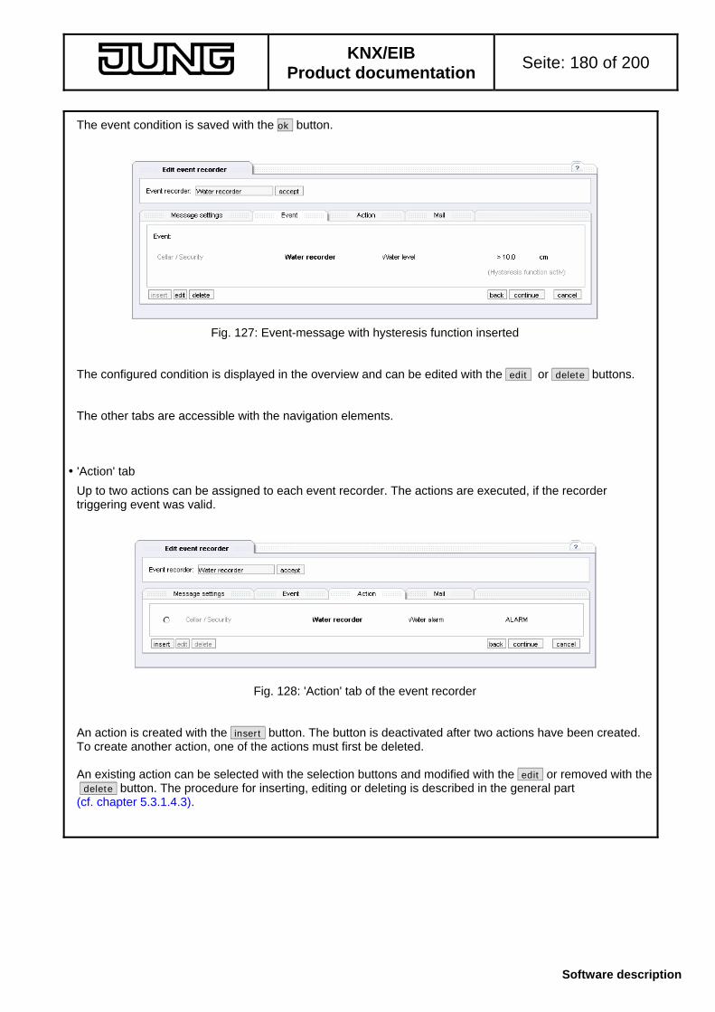
KNX/EIB
Product documentation Seite: 180 of 200
Software description
The event condition is saved with the ok button.
Fig. 127: Event-message with hysteresis function inserted The configured condition is displayed in the overview and can be edited with the edit .or delete buttons. The other tabs are accessible with the navigation elements. 'Action' tab
Up to two actions can be assigned to each event recorder. The actions are executed, if the recorder triggering event was valid.
Fig. 128: 'Action' tab of the event recorder An action is created with the insert button. The button is deactivated after two actions have been created. To create another action, one of the actions must first be deleted. An existing action can be selected with the selection buttons and modified with the edit or removed with the delete button. The procedure for inserting, editing or deleting is described in the general part (cf. chapter 5.3.1.4.3).

KNX/EIB
Product documentation Seite: 181 of 200
Software description
'Mail' tab
The configuration of the e-mail settings is performed on the 'Mail' tab. Correct handling of an individual e-mail from the event recorder is dependent on the basic settings in the address book (cf. chapter 5.3.6.3) and on the sending options (cf. chapter 5.3.6.4). An e-mail is sent if
- the event has been triggered (if applicable, dependent on a hysteresis function) and if - the mode for the occurrence of the event ('Message settings' tab) does not allow for a delay or limitation or
if the latter do not prevent triggering - the mode for the tasks provides for sending of an e-mail and if the condition for transmission, if any, is
fulfilled - the e-mail sending options are correctly set and valid addresses have been entered
Fig. 129: 'Mail' tab of event recorder Section (A) can be used to specifiy a condition. The condition is checked, when the mode 'actions are executed; e-mail sent only if the condition is valid!' is activated in the general part ('Message settings' tab). If the condition is fulfilled, the e-mail will be sent. The check is applied on the current state of the function to be checked and is not event-dependent. Specifiying a condition is similar to the creating an event (cf. chapter 5.3.1.4.2). In the address section (B), the addressees of an e-mail can be selected from among the contacts laid entered in the address book. The contacts of the address book are listed in the window on the right. They can be marked in the list (clicked) and added to the list of addressees of the e-mail with the <-- button (left window). Several contacts can be selected by maintaining the CTRL key pressed and by clicking on each contact. Similarly, contacts can be marked in the right window (clicked) and deleted from the list of addressees with the --> button. With the rights of the user group 'Admin', the edit button of the address book can be used to edit the contacts in the address book (name and e-mail address). In this case, the button back to recorder recorder name is available (recorder name is in this case the name assigned to the event recorder permitting direct dealing with the recorder settings). Settings performed in the message section (C) of the e-mail will not be stored when the address book edit function is used.
A
B
C
D

KNX/EIB
Product documentation Seite: 182 of 200
Software description
In the message section (C), a mail reference and the text of the mail as such can be entered. All entries are adopted with the navigation buttons. The e-mail message cannot deal with line breaks. Line breaks will be removed when the text is adopted. As soon as the contents have been entered (e.g. with adopt button), the preview shows the message actually transmitted. The reference line and the message itself can contain current data from the IP central unit. As these data can only be obtained by the time the e-mail is sent, it is necessary to insert placeholders for these data in the e-mail text or in the reference line. The placeholders consist of two control characters '«’,’»' and a command string. The following information is available: Placeholder Information
«ID» Identifier of the IP central unit (assigned in the ETS plug-in under properties)
«AcDate» the current system date
«AcTime» the current system time
«DP(ID).Name()» the name of a function (with internal functions ID)
«DP(ID).Value()» the value of a function (with internal functions ID)
«DP(ID).Room()» the room assignment of the function (with internal functions ID)
«DP(ID).Function()» the building service assignment of the function (with internal functions ID)
«DP(ID).Channel()» the functional group assignment of the function (with internal functions ID)
These control strings can be comfortably inserted in the e-mail message text or in the reference line when the fill-in help tab (D) is used. The preview shows the current states substituted for the placeholders. As these states are determined in each single case, the preview may be different from the actual contents of an e-mail at a certain time (a function may have another status at that time).
Fig. 130: Preview of the e-mail text with placeholders The preview shows that the placeholder (A) «DP(ID).Name()» has been replaced by the actual name (B) Water alarm . This applies also to the value of the function and the current system time. The placeholders must not be separated or modified in any way.
A B

KNX/EIB
Product documentation Seite: 183 of 200
Software description
The fill-in help (D) can be opened and closed with the navigation arrow.
Fig. 131: Fill-in help window on the 'Mail' tab The navigation arrow (A) permits opening and closing of the fill-in help window (D). The window can be used for inserting general information (B) or special information about a function (C). The procedure is always the same: At first, the information is selected with the selection buttons. Then, the cursor is moved to the position in the text message or the reference line where the information (the placeholder) is to be inserted. A click on the button insert at cursor position inserts the placeholder at the cursor position. For the special information about a function (e.g. the water alarm), the function must first be identified. This is possible with the selection dialog which is opened in a separate browser window. The window is opened with a click on the button … (D). Note: If the browser installed uses a so-called pop-up blocker, it is possible that the window cannot be opened. In this case, the browser displays an info window.
Fig. 132: Pop-up blocker info window In order to have access to the functions, the pop-up blocker should be deactivated for the Web pages of the IP central unit. As an alternative, the CTRL key can be held down when the button … is clicked. Normally, the pop-up blocker can thus be temporarily deactivated.
B CA
D

KNX/EIB
Product documentation Seite: 184 of 200
Software description
The function can be selected in the separate window.
Fig.133: Function selection window for fill-in help The desired function is selected for the fill-in help with the ok button. The system determines the internal number for use in the placeholders. The fill-in help can now generate the placeholder and insert it at the marked position. The information contained in the placeholder is only accessible if the placeholder is selected manually in the text.
Fig. 134: Info about a placeholder After marking the placeholder (A) with its control characters in the text (e-mail message or reference line), the value of the placeholder can be displayed with the button placeholder info (B).
B
A
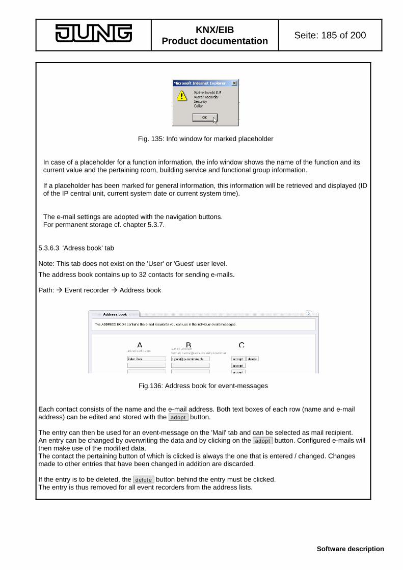
KNX/EIB
Product documentation Seite: 185 of 200
Software description
Fig. 135: Info window for marked placeholder In case of a placeholder for a function information, the info window shows the name of the function and its current value and the pertaining room, building service and functional group information. If a placeholder has been marked for general information, this information will be retrieved and displayed (ID of the IP central unit, current system date or current system time). The e-mail settings are adopted with the navigation buttons. For permanent storage cf. chapter 5.3.7.
5.3.6.3 'Adress book' tab Note: This tab does not exist on the 'User' or 'Guest' user level.
The address book contains up to 32 contacts for sending e-mails. Path: Event recorder Address book
Fig.136: Address book for event-messages Each contact consists of the name and the e-mail address. Both text boxes of each row (name and e-mail address) can be edited and stored with the adopt button. The entry can then be used for an event-message on the 'Mail' tab and can be selected as mail recipient. An entry can be changed by overwriting the data and by clicking on the adopt button. Configured e-mails will then make use of the modified data. The contact the pertaining button of which is clicked is always the one that is entered / changed. Changes made to other entries that have been changed in addition are discarded. If the entry is to be deleted, the delete button behind the entry must be clicked. The entry is thus removed for all event recorders from the address lists.
BA C

KNX/EIB
Product documentation Seite: 186 of 200
Software description
5.3.6.4 'E-mail sending options' tab Note: This tab does not exist on the 'User' or 'Guest' user level.
The sending of e-mails requires some general settings to be made. The present tab contains the e-mail server and other configuration settings. Path: Event-message E-mail sending options The necessary data are made available by the e-mail provider.
Fig. 137: E-mail transmit settings The following data must be entered: - the e-mail address of the sender (box 'E-mail address of the IP central unit') - the SMTP server used (box 'SMTP server') as IP address or URL If the server supports the security measure 'POP before SMTP' (previous log-in and collection of e-mails entitle the user to send mails), the check-box 'Preliminary POP3 contact required?' must be ticked. The other entry fields for POP3 settings are then enabled. Now, the following data can be entered: - the POP3 server used (field 'POP3 server') as IP address or URL - the POP3 user name - the POP3 password (directly indicated in encrypted form) The access is only an authorization access without data download . Other security measures are presently not supported. All data are entered with the adopt button. Configuration example: (e-mail account from www.web.de) Entries Value
E-mail address of IP central unit E-mail address used
SMTP server smtp.web.de
Preliminary POP3 contact required yes (check-box ticked)
POP3 server pop.web.de
User name web.de user name
Password web.de password

KNX/EIB
Product documentation Seite: 187 of 200
Software description
5.3.6.5 Event recorder tutorial
The tutorial is intended to demonstrate the preparation of an event recorder with a possible (fictitious) configuration. The procedure is described with short explanations. Details and effects can be inferred from the previous chapters (cf. chapter 5.3.6.x) . Original state
The original state corresponds to the default states after initial preparation of an object model and loading of the model from the ETS plug-in into the device. The project includes a water recorder in a room designated as 'Cellar' with a water alarm function (KNX DPT 01) and a water level function (value in cm, KNX DPT 09.). A touch sensor in the corridor can be used to control presence and absence. All rights are available. Objective
Configuring an event recorder Requirements: (A1) : the recorder is designated as 'Water recorder' (A2) : the event 'water level > 10 cm' is to be reported;
the hysteresis function is to be used so that a message is issued with rising water level every 10cm (10cm, 20cm, 30cm etc.)
(A3) : for every event (fltered in acc with hysteresis) an action and an e-mail is to be transmitted; an e-mail is to be transmitted only if the touch sensor state 'Absence (NOT AT HOME)' is active.
(A4) : the event-message is to be stored with a time stamp (A5) : the action 'Water alarm = ALARM (value: 1)' is to be set (A6) : an e-mail with the water level is to be sent to [email protected] (fictitious address)
Object: 'Water alarm' Text: 'The water level is xx cm'
The numbers referred to in the text correspond to the numbers indicated above.

KNX/EIB
Product documentation Seite: 188 of 200
Software description
Step 1: Preparation of the recorder and basic settings
Path: Event recorder Overview A recorder not yet in use (normally 'Notification') is selected with the button and opened by clicking on the edit button.
Fig. 138: Event recorder tutorial: editing a new recorder In the detail view, the name 'water alarm' (A1) is entered and saved with the adopt button.
Fig 139: Event recorder tutorial: assigning a name The recorder is then activated (genarally) and the time stamp storage is configured (A4):
Fig. 140: Event recorder tutorial: basic settings 1 The event recorder is to trigger at each event (filtering is performed in the hysteresis) (A2 + A3):
Bild 141: Event recorder tutorial: basic settings 2

KNX/EIB
Product documentation Seite: 189 of 200
Software description
It is intended that the actions will always be performed by the event recorder. When the state 'absent' is detected (value 'NOT AT HOME'), an e-mail is to be transmitted in addition (A3):
Fig. 142: Event recorder tutorial: basic settings 3 A click on the navigation button continue saves the data and displays the next view. Step 2: Creating the event with hysteresis
Path: Event recorder Edit message 'Event' tab' On the 'Event' tab already opened, the event is now defined (A2) with the insert button.
Fig. 143: Event recorder tutorial: creating an event The function 'Water level' of the functional group 'Water recorder' in the room 'Cellar' (building service 'Control') is selected. The alarm value (trigger) is 10.0 (cm); the condition is 'greater than'. Thus, the recorder is triggered by each measured value > 10.0 cm. In addition, the hysteresis function (check-box) is selected. The mode is 'Hysteresis with step width correction'; the limit value is 2 (cm) (fictitious). The step width correction is effected every 10cm. A possible measuring value characteristic might look as follows: 9.0 cm no trigger, below alarm threshold 10.2 cm first trigger, next limit value > 20.2 15.2 cm no trigger, still within limit range 23.4 cm next trigger, new limit value > 33.4 The event is adopted with ok and entered in the overview. A click on continue displays the 'Action' tab.

KNX/EIB
Product documentation Seite: 190 of 200
Software description
Step 3: Creating the action
Path: Event recorder Edit message 'Action' tab On the 'Action' tab already opened, the action is now defined with the insert button (A5):
Fig. 144: Event recorder tutorial: inserting an action The action is adopted with ok and entered in the overview. A click on continue displays the 'E-mail' tab. Step 4: Creating the e-mail
Path: Event recorder Edit message 'Mail' tab’ On the 'Mail' tab already opened, the transmit condition is fixed at first (A3) by selecting the condition with the edit button:
Fig. 145: Event recorder tutorial: Fixing the conditions for sending an e-mail The condition is adopted with the ok button. If a mail is to be transmitted, the program checks whether the state of the 'Absence' function of the touch sensor corresponds to the value 'NOT AT HOME' (1). The mail will be sent only if this is true. The condition is now displayed on the 'Mail' tab:
Fig. 146: Event recorder tutorial: condition for sending inserted

KNX/EIB
Product documentation Seite: 191 of 200
Software description
As the address book is still without entries ('No addresses in the book'), a click on the edit address book tab displays the address book. The contact is entered (A6) and saved with the adopt button. A click on return to the water recorder goes back to the recorder.
Fig. 147: Event recorder tutorial: creating a contact in the address book In the address list, 'Peter Pan' can now be selected (by clicking on the name) and adopted with the <-- button as mail recipient:
Fig. 148: Event recorder tutorial: adding a contact The message itself is configured with the fill-in help.
Fig. 149: Event recorder tutorial: creating the message The non-variable text is to be entered in the Reference line and Mail text fields (A). Thereafter, the fill-in help is displayed (B).
A
B

KNX/EIB
Product documentation Seite: 192 of 200
Software description
Fig. 150: Event recorder tutorial: fill-in help, user instructions The … button opens a new selection dialog (new browser window, observe pop-up blocker restrictions) in which the function 'Water level' is selected. (Path: room 'Cellar', building service 'Control', functional group 'Water recorder')
Fig. 151: Event recorder tutorial: function selection in separate window A click on the ok button adopts the internal function ID.
Fig. 152: Event recorder tutorial: required steps for placeholder insertion The desired information is selected with the buttons (B). The cursor is placed at the position in the mail message where this information is to be inserted as a placeholder (C). With the button insert at cursor position the placeholder is inserted in the e-mail text.
C
A
B
D

KNX/EIB
Product documentation Seite: 193 of 200
Software description
The settings are saved with the adopt button. In the preview, the placeholder is now replaced by the current water level (0.1 cm in this instant).
Fig. 153: Event recorder tutorial: e-mail message in the preview Before the mail is sent, the current water level is determined and inserted instead of the placeholder. The event recorder configuration is now terminated and can be closed with ok . Step 5: permanent storage of the settings
Till now, the settings have been saved only temporarily. For permanent storage cf. chapter 5.3.7. Path: End program For permanent storage click on the 'End program' tab on the save button. After the confirmation message the data are stored in the IP central unit safe against mains voltage failure.

KNX/EIB
Product documentation Seite: 194 of 200
Software description
5.3.7 End program
All settings are adopted only temporarily, but applied and executed immediately. To ensure a permanent saving even after a mains failure, the work should always be terminated by means of the 'End program' tab. Path: End program Two possibilities for ending the program are available:
Fig. 154: Terminating the connection with the IP central unit Saving data to the flash memory: save .
All settings are saved permanently and are available even after a mains failure (hysteresis history not saved). This option should always be selected. The saving procedure lasts ca. 2 min. The state of the saving procedure is cyclically interrogated. After saving, the following message is displayed:
Fig. 155: Info about closing of the browser window To terminate the connection with the IP central unit and especially the user authorization, the browser window used should be closed. This is adopted by the IP central unit, Nonetheless, the browser expects the confirmation of the user for automatic closing. This message should be confirmed with Yes , so that no persons can afterwards operate the IP central unit with the user authorization last employed. The connection is then terminated and can only be restarted by entering the IP address of the IP central unit into the URL entry box of the browser, by recalling the favorites in the browser (if existing) or with the gateway browser tool. A new user log-in is required.
KNX/EIB
Product documentation Seite: 195 of 200
Software description
Quit without saving: end program immediately .
This option does not save the data into the flash memory. In this case (and in the case that the browser window is simply closed), the data are available only temporarily. After a restart of the IP central unit, settings can get lost. If the end program immediately button is clicked, the system tries directly to close the browser window for safety reasons (cf. Fig. 155). The same conditions apply. The message can be confirmed with the ok button. The browser window is closed.
Safety storage For safety reasons, the IP central unit checks every two hours whether changes have been made to the configuration. If this is detected, the configuration is automatically saved permanently and is then again available even after a mains failure (hysteresis history not saved). Changes not saved manually within this sequence are then no longer available in case of a restart of the IP central unit. Message in case of working with the ETS plug-in (projecting):
During work with the plug-in, the data should first be uploaded from the IP central unit (cf. Chapter 3.2.1). These are the actual settings. The system does not resort to the stored backup copy. During the time of configuration in the plug-in, no changes should be made on the Web interface, as during re-writing of the ETS plug-in configuration this configuration will be overwritten by the uploaded state. After programming of the configuration with the plug-in, the system is restarted. During the work with the plug-in, the hysteresis history is lost, too.

KNX/EIB
Product documentation Seite: 196 of 200
Software description
5.3.8 Time and language settings Note: This tab does not exist on the 'Guest' user level.
The time and date settings of the system clock, the location coordinates for the astro calculation and the language can be configured in this tab. Path: Mouseclick on system time
Fig. 156: Configuration page call-up for date/time and language 'Time settings' tab
Path: Mouseclick on system time Time settings In the upper part, the system time and the procedure of Summer time/Winter time switch-over can be configured.
Fig. 157: Setting the time and the date The time and the date can be entered manually in the fields (A). In the time zone selection field (B), the corresponding time zone can be selected. Germany is part of time zone (GMT 1). In the time change section (C), the user can select whether the Summer time/Winter time switch-over is to be perfomed automatically (tick check-box) and in accordance with which system. The systems ’Europe’ and ’US’ are offered and can be selected by means of the selection button. If the time change-over is activated, the system time is adapted by the difference . Example Germany: On the last Sunday in March, the time is switched over to Summer Time (system time + 1 hour). All time-controlled actions in this time span are caught up. On the last Sunday in October, the time is switched to Winter Time (normal time) (system time -1 hour).
A
B
C

KNX/EIB
Product documentation Seite: 197 of 200
Software description
If these two modes are not applicable, the suitable time-change datefile can be loaded by means of the ’GatewayBrowser’ utility. If the file is loaded, the corresponding option is activated and the definition description is displayed. If no file is loaded, the option external definition is not active.
Fig. 158: (top) no definition-file loaded (bottom) definition-file loaded with ’Extern Europa’ ('External Europe') The file contains fixed data (e.g. 26.03.2006) and an offset for the system time (+1h) at this date. The file can be obtained from the manufacturer, if available. A click on the button set time accepts these data. The system time is changed and all new time-related tasks are recalculated. The time scheduler must in this case be manually modified (no automatic detection of a turn of a year) and checked (cf. Chapter 5.3.3). In addition, there is the possibility to adopt the system time of the PC, on which the browser window is opened, with the adopt data from PC button. When the check-box for time-change utilization is ticked, the IP central unit cannot determine the valid time zone. The info window asks for confirming this option: ok system calculating with Summer Time cancel system calculating with Winter Time The determined data are entered in the fields (Fig. 157 A + B). They can be checked and adopted with the set time button.
external definition

KNX/EIB
Product documentation Seite: 198 of 200
Software description
In the lower part of the time-setting window, the location coordinates for calculating the astro time of the time-scheduler are indicated.
Fig. 159: Determining the coordinates of the location The coordinates are indicated by means of the geographic position of the location. The globe is divided into 180 degrees of latitude, beginning with 0 degrees at the equator up to respectively 90 degrees at the North or South pole. Besides the latitude, there are moreover 360 degrees of longitude, beginning with the zero meridian from the North to the South pole through the observatory in Greenwich (England) with respectively 180 degrees of longitude to the West and to the East. Coordinates are usually indicated as 51° 13’ N, 7° 37’ E. (Lüdenscheid, 51 degrees 13 minutes of Nothern latitude, 7 degrees 37 minutes of Eastern longitude) The data for the IP central unit are entered in decimal form in the format +/- DD.DDD. Degrees of Nothern latitude and Eastern longitude are indicated without sign, degrees of Southern latitude and Western longitude are indicated with a negative sign. The conversion from the classical form (degrees, minutes, seconds) into the decimal form can be found in the Internet. As an alternative, the fill-in help can be used. This help contains coordinates of important cities and enters these into the entry boxes. When a country and the city have been selected, the system issues an information that the data will be adopted into the fields. The data can only be entered. Determining the actual coordinates from the indications in the fill-in help is not possible. For this reason, the fill-in help is reset when the Web page is renewed (the coordinates remain the same).
Fig. 160: Fill-in help for coordinates The coordinates are saved with the adopt button and are used as the basis for sunset and sunrise calculation (astro) in the time-scheduler.
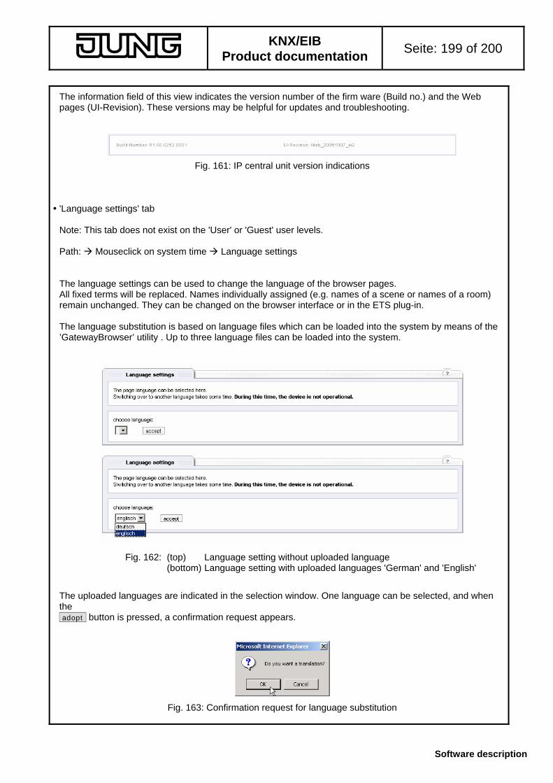
KNX/EIB
Product documentation Seite: 199 of 200
Software description
The information field of this view indicates the version number of the firm ware (Build no.) and the Web pages (UI-Revision). These versions may be helpful for updates and troubleshooting.
Fig. 161: IP central unit version indications 'Language settings' tab Note: This tab does not exist on the 'User' or 'Guest' user levels. Path: Mouseclick on system time Language settings The language settings can be used to change the language of the browser pages. All fixed terms will be replaced. Names individually assigned (e.g. names of a scene or names of a room) remain unchanged. They can be changed on the browser interface or in the ETS plug-in. The language substitution is based on language files which can be loaded into the system by means of the ’GatewayBrowser’ utility . Up to three language files can be loaded into the system.
Fig. 162: (top) Language setting without uploaded language (bottom) Language setting with uploaded languages 'German' and 'English' The uploaded languages are indicated in the selection window. One language can be selected, and when the adopt button is pressed, a confirmation request appears.
Fig. 163: Confirmation request for language substitution

KNX/EIB
Product documentation Seite: 200 of 200
Software description
If the request is confirmed, the language will be substituted by another one. During this time, the system should not be accessed from other browsers, from other users or from the ETS plug-in. During the replacements, the following wondow is visible:
Fig. 164: Info with language substitution in progress The language substitution lasts ca. 4 minutes. Thereafter, the language substitution window (in the new language) is again displayed (cf. Fig. 162). The language substitution is a permanent feature. The return to the old language is only possible by means of translation with the old language language file.

KNX/EIB
Product documentation Seite: 201 of 200
Software description
Software remarks
• PC minimum requirements for Web access:
Commercial-grade PC with Windows operating system (Win 98 SE and later) and Microsoft© Internet Explorer, Version 5.5 and later.
Recommended: Pentium IV processor (or comparable) with 2 GHz or more / min. 256 MB RAM / Microsoft© Internet Explorer 6.0 SP 2.
• Information concerning the ETS:
It is not possible to protect the BCU in the IP central unit with a password (BCU key). The BCU key selected in the ETS project has therefore no effect on the IP central unit.