Investigation on the thermal performance of different lightweight roofing structures and its effect...
9
Investigation on the thermal performance of different lightweight roofing structures and its effect on space cooling load Jun Han * , Lin Lu, Hongxing Yang Department of Building Services Engineering, The Hong Kong Polytechnic University, Kowloon, Hong Kong, PR China article info Article history: Received 21 December 2007 Accepted 23 December 2008 Available online 30 December 2008 Keywords: Building roof elements Thermal insulation Heat gain Sol-Air temperature Envelope colour Cooling load abstract The lightweight aluminum standing seam roofing system (LASRS) has been widely used as a building ele- ment in the construction of either commercial or governmental buildings, and has been proven to be an economic roofing system. However, little research has been conducted into its thermal performance and the effect of the absorptivity (colour) of its external surface on space cooling load in the hot humid area. This paper aims to investigate the thermal performance of the LASRS. A dynamic model is introduced for analyzing the transient heat transfer through the roofs, which was solved by the control volume finite- difference method employing an explicit scheme and validated by measured data. The simulation results show that the heat flux through the roofing system with a polyurethane insulation layer is smaller than that through the lightweight roof with glasswool insulation R1. The space cooling load reduction ratio for light painted envelop could reach about 9.3% compared with black painted one. The cooling load reduc- tion ratio ranges from 1.3% to 9.3% for the roof structure R1 with various surface colour. Therefore, the space cooling load for air conditioning of the building can be considerably reduced (up to 20%) by employing a lightweight roof using polyurethane insulation with white painted surface colour. Ó 2008 Elsevier Ltd. All rights reserved. 1. Introduction In recent years, there has been growing interest in analyzing the dynamic thermal characteristics of building envelopes to under- stand their thermal performance, optimal management and use of energy in buildings. The research helps to reduce building en- ergy use by choosing the building elements with better thermal performance, and to reduce the size of the air-conditioning system in the buildings, while a desirable indoor environmental quality (IEQ) is created for occupants in the buildings. For commercial buildings in Hong Kong, space cooling is needed over the whole year, which consumes around 50% of the total building energy use [1]. To reduce the space cooling load of a build- ing, choosing appropriate building envelop materials with better thermal performance is crucial, especially the thermal insulation materials. An insulation layer with good thermal performance can reduce the heat transfer through the building envelop. Amongst the building envelopes, the effect of the thermal perfor- mance of roof insulation material is critical as the heat gain through the roof accounts for large portion of the total building heat gain for buildings with large-spaces like sport arenas and exhibition halls. Therefore, for roof structures, properly arranging the insulation layer and selecting more efficient thermal insulation materials can help reduce the building space cooling load, the capacity of air-conditioning system, and the building energy use by reducing the heat gain though the roof structure. Many researchers have conducted research about building en- ergy modeling methods as energy efficient building design requires accurate methods for determining and understanding the transit heat transmission through building elements. Many existing build- ing energy simulation programs including DOE-2 [2], TRNSYS [3], EnergyPlus [4], and TARP [5] as well as thermal response factor method [6], transfer function method, the degree day and bin methods [7] are commonly used for building energy simulation. The finite-difference method was extensively used to predict the thermal performance of building envelopes, as reported by Al-Re- gib and Zubair [8], Ozel and Pihtili [9], Al-Sanea [10]. Al-Turki and Zaki [11] studied the effect of insulation and energy storage layers on the cooling load, and their findings showed that a contin- uous insulation layer is more efficient than dispersing the insula- tion materials within the building materials. The conduction heat transfer through composite plane walls had been studied by Zedan and Mujahid [12] by using Fourier series technique and inverse La- place transforms. The transient effect of heat transfer through insu- lated walls was investigated by E. Al-Regib and S.M. Zubair [8], and they found that the cooling loads of buildings with insulation layer placed close to the façade outside surface are smaller than the cooling loads of buildings with insulation placed close to the façade inside surface. 1359-4311/$ - see front matter Ó 2008 Elsevier Ltd. All rights reserved. doi:10.1016/j.applthermaleng.2008.12.024 * Corresponding author. Tel.: +852 2766 7958; fax: +852 2774 6146. E-mail address: [email protected] (J. Han). Applied Thermal Engineering 29 (2009) 2491–2499 Contents lists available at ScienceDirect Applied Thermal Engineering journal homepage: www.elsevier.com/locate/apthermeng
Transcript of Investigation on the thermal performance of different lightweight roofing structures and its effect...
Applied Thermal Engineering 29 (2009) 2491–2499
Contents lists available at ScienceDirect
Applied Thermal Engineering
journal homepage: www.elsevier .com/locate /apthermeng
Investigation on the thermal performance of different lightweight roofingstructures and its effect on space cooling load
Jun Han *, Lin Lu, Hongxing YangDepartment of Building Services Engineering, The Hong Kong Polytechnic University, Kowloon, Hong Kong, PR China
a r t i c l e i n f o a b s t r a c t
Article history:Received 21 December 2007Accepted 23 December 2008Available online 30 December 2008
Keywords:Building roof elementsThermal insulationHeat gainSol-Air temperatureEnvelope colourCooling load
1359-4311/$ - see front matter � 2008 Elsevier Ltd. Adoi:10.1016/j.applthermaleng.2008.12.024
* Corresponding author. Tel.: +852 2766 7958; fax:E-mail address: [email protected] (J. Han).
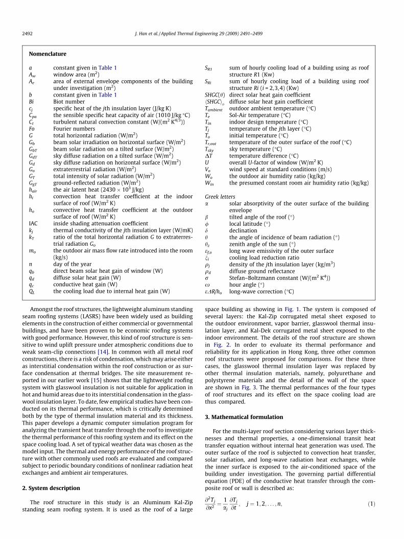
The lightweight aluminum standing seam roofing system (LASRS) has been widely used as a building ele-ment in the construction of either commercial or governmental buildings, and has been proven to be aneconomic roofing system. However, little research has been conducted into its thermal performance andthe effect of the absorptivity (colour) of its external surface on space cooling load in the hot humid area.This paper aims to investigate the thermal performance of the LASRS. A dynamic model is introduced foranalyzing the transient heat transfer through the roofs, which was solved by the control volume finite-difference method employing an explicit scheme and validated by measured data. The simulation resultsshow that the heat flux through the roofing system with a polyurethane insulation layer is smaller thanthat through the lightweight roof with glasswool insulation R1. The space cooling load reduction ratio forlight painted envelop could reach about 9.3% compared with black painted one. The cooling load reduc-tion ratio ranges from 1.3% to 9.3% for the roof structure R1 with various surface colour. Therefore, thespace cooling load for air conditioning of the building can be considerably reduced (up to 20%) byemploying a lightweight roof using polyurethane insulation with white painted surface colour.
� 2008 Elsevier Ltd. All rights reserved.
1. Introduction
In recent years, there has been growing interest in analyzing thedynamic thermal characteristics of building envelopes to under-stand their thermal performance, optimal management and useof energy in buildings. The research helps to reduce building en-ergy use by choosing the building elements with better thermalperformance, and to reduce the size of the air-conditioning systemin the buildings, while a desirable indoor environmental quality(IEQ) is created for occupants in the buildings.
For commercial buildings in Hong Kong, space cooling is neededover the whole year, which consumes around 50% of the totalbuilding energy use [1]. To reduce the space cooling load of a build-ing, choosing appropriate building envelop materials with betterthermal performance is crucial, especially the thermal insulationmaterials. An insulation layer with good thermal performancecan reduce the heat transfer through the building envelop.Amongst the building envelopes, the effect of the thermal perfor-mance of roof insulation material is critical as the heat gainthrough the roof accounts for large portion of the total buildingheat gain for buildings with large-spaces like sport arenas andexhibition halls. Therefore, for roof structures, properly arrangingthe insulation layer and selecting more efficient thermal insulation
ll rights reserved.
+852 2774 6146.
materials can help reduce the building space cooling load, thecapacity of air-conditioning system, and the building energy useby reducing the heat gain though the roof structure.
Many researchers have conducted research about building en-ergy modeling methods as energy efficient building design requiresaccurate methods for determining and understanding the transitheat transmission through building elements. Many existing build-ing energy simulation programs including DOE-2 [2], TRNSYS [3],EnergyPlus [4], and TARP [5] as well as thermal response factormethod [6], transfer function method, the degree day and binmethods [7] are commonly used for building energy simulation.The finite-difference method was extensively used to predict thethermal performance of building envelopes, as reported by Al-Re-gib and Zubair [8], Ozel and Pihtili [9], Al-Sanea [10]. Al-Turkiand Zaki [11] studied the effect of insulation and energy storagelayers on the cooling load, and their findings showed that a contin-uous insulation layer is more efficient than dispersing the insula-tion materials within the building materials. The conduction heattransfer through composite plane walls had been studied by Zedanand Mujahid [12] by using Fourier series technique and inverse La-place transforms. The transient effect of heat transfer through insu-lated walls was investigated by E. Al-Regib and S.M. Zubair [8], andthey found that the cooling loads of buildings with insulation layerplaced close to the façade outside surface are smaller than thecooling loads of buildings with insulation placed close to the façadeinside surface.
Nomenclature
a constant given in Table 1Aw window area (m2)Ae area of external envelope components of the building
under investigation (m2)b constant given in Table 1Bi Biot numbercj specific heat of the jth insulation layer (J/kg K)Cpa the sensible specific heat capacity of air (1010 J/kg �C)Ct turbulent natural convection constant (W/(m2 K4/3))Fo Fourier numbersG total horizontal radiation (W/m2)Gb beam solar irradiation on horizontal surface (W/m2)GbT beam solar radiation on a tilted surface (W/m2)GdT sky diffuse radiation on a tilted surface (W/m2)Gd sky diffuse radiation on horizontal surface (W/m2)Go extraterrestrial radiation (W/m2)GT total intensity of solar radiation (W/m2)GgT ground-reflected radiation (W/m2)hair the air latent heat (2430 � 103 J/kg)hi convection heat transfer coefficient at the indoor
surface of roof (W/m2 K)ho convective heat transfer coefficient at the outdoor
surface of roof (W/m2 K)IAC inside shading attenuation coefficientkj thermal conductivity of the jth insulation layer (W/mK)kT ratio of the total horizontal radiation G to extraterres-
trial radiation Go
mo the outdoor air mass flow rate introduced into the room(kg/s)
n day of the yearqb direct beam solar heat gain of window (W)qd diffuse solar heat gain (W)qc conductive heat gain (W)QL the cooling load due to internal heat gain (W)
SR1 sum of hourly cooling load of a building using as roofstructure R1 (Kw)
SRi sum of hourly cooling load of a building using roofstructure Ri (i = 2,3,4) (Kw)
SHGC(h) direct solar heat gain coefficienthSHGCi
Ddiffuse solar heat gain coefficient
Tambient outdoor ambient temperature (�C)Te Sol-Air temperature (�C)Tin indoor design temperature (�C)Tj temperature of the jth layer (�C)To initial temperature (�C)Tr,out temperature of the outer surface of the roof (�C)Tsky sky temperature (�C)DT temperature difference (�C)U overall U-factor of window (W/m2 K)Vo wind speed at standard conditions (m/s)Wo the outdoor air humidity ratio (kg/kg)Win the presumed constant room air humidity ratio (kg/kg)
Greek lettersa solar absorptivity of the outer surface of the building
envelopeb tilted angle of the roof (�)/ local latitude (�)d declinationh the angle of incidence of beam radiation (�)hz zenith angle of the sun (�)ef,o long wave emissivity of the outer surfaceni cooling load reduction ratioqj density of the jth insulation layer (kg/m3)qd diffuse ground reflectancer Stefan–Boltzmann constant (W/(m2 K4))x hour angle (�)eDR/ho long-wave correction (�C)
2492 J. Han et al. / Applied Thermal Engineering 29 (2009) 2491–2499
Amongst the roof structures, the lightweight aluminum standingseam roofing systems (LASRS) have been widely used as buildingelements in the construction of either commercial or governmentalbuildings, and have been proven to be economic roofing systemswith good performance. However, this kind of roof structure is sen-sitive to wind uplift pressure under atmospheric conditions due toweak seam-clip connections [14]. In common with all metal roofconstructions, there is a risk of condensation, which may arise eitheras interstitial condensation within the roof construction or as sur-face condensation at thermal bridges. The site measurement re-ported in our earlier work [15] shows that the lightweight roofingsystem with glasswool insulation is not suitable for application inhot and humid areas due to its interstitial condensation in the glass-wool insulation layer. To date, few empirical studies have been con-ducted on its thermal performance, which is critically determinedboth by the type of thermal insulation material and its thickness.This paper develops a dynamic computer simulation program foranalyzing the transient heat transfer through the roof to investigatethe thermal performance of this roofing system and its effect on thespace cooling load. A set of typical weather data was chosen as themodel input. The thermal and energy performance of the roof struc-ture with other commonly used roofs are evaluated and comparedsubject to periodic boundary conditions of nonlinear radiation heatexchanges and ambient air temperatures.
2. System description
The roof structure in this study is an Aluminum Kal-Zipstanding seam roofing system. It is used as the roof of a large
space building as showing in Fig. 1. The system is composed ofseveral layers: the Kal-Zip corrugated metal sheet exposed tothe outdoor environment, vapor barrier, glasswool thermal insu-lation layer, and Kal-Dek corrugated metal sheet exposed to theindoor environment. The details of the roof structure are shownin Fig. 2. In order to evaluate its thermal performance andreliability for its application in Hong Kong, three other commonroof structures were proposed for comparisons. For these threecases, the glasswool thermal insulation layer was replaced byother thermal insulation materials, namely, polyurethane andpolystyrene materials and the detail of the wall of the spaceare shown in Fig. 3. The thermal performances of the four typesof roof structures and its effect on the space cooling load arethus compared.
3. Mathematical formulation
For the multi-layer roof section considering various layer thick-nesses and thermal properties, a one-dimensional transit heattransfer equation without internal heat generation was used. Theouter surface of the roof is subjected to convection heat transfer,solar radiation, and long-wave radiation heat exchanges, whilethe inner surface is exposed to the air-conditioned space of thebuilding under investigation. The governing partial differentialequation (PDE) of the conductive heat transfer through the com-posite roof or wall is described as:
@2Tj
@x2 ¼1aj
@Tj
@t; j ¼ 1;2; . . . ; n; ð1Þ

4 5 6 7 810200 10200 10200 10200 10200
+1000
T- type Thermocouple
...
....
..
1000100
OUT SIDE ROOF
.
.
IN SIDE ROOF
50100
Data acquisition system
Fig. 1. The space under investigation and photo for the data acquisition system.
Fig. 2. Cross-section of the lightweight aluminum roofing system and its node arrangement for numerical analysis. The control volumes for the internal and boundary nodesare shown.
Out
side
pla
ster
Con
cret
e bl
ock
300m
mTh
erm
al in
sula
tion
100m
mM
etal
lath
Gyp
sum
boa
rd
Wall
Fig. 3. Schematic of four roof structures and the wall of the room under investigation.
J. Han et al. / Applied Thermal Engineering 29 (2009) 2491–2499 2493
2494 J. Han et al. / Applied Thermal Engineering 29 (2009) 2491–2499
where x and t are the space and time coordinates, respectively; Tj isthe temperature of the jth layer; a is the thermal diffusivity (k/qc)and qj, cj, kj are the density, the specific heat and the thermal con-ductivity of the jth layer material, respectively.
The adjacent layers are in good thermal contact, and hence theinterface resistance is negligible. The thermal conduction of theadjacent layers is expressed by:
Tj ¼ Tjþ1; j ¼ 1;2; . . . ;n� 1; ð2Þ
kj@Tj
@x¼ kjþ1
@Tjþ1
@x; j ¼ 1;2; . . . ; n� 1: ð3Þ
The initial temperature distribution across the roof is assumedto be uniform and is expressed as follows:
Tjðx; 0Þ ¼ To: ð4Þ
The boundary conditions at the inner surface of the roof surfaceare given as follows:
�k1@T@x
����x¼0¼ hiðTin � Tx¼0Þ; ð5Þ
where hi is the convection heat transfer coefficient; from the ASH-RAE handbook of fundamentals [7]: hi = 9.26 W/m2 K for upwarddirection of heat flow, and hi = 6.13 W/m2 K for downward directionof heat flow, Tin is the indoor design temperature.
The boundary conditions at the outer surface are:
�kn@T@x
����x¼H
¼ �aGT � ef ;orðT4sky � T4
r;outÞ þ hoðTr;out � TambientÞ; ð6Þ
where a is the solar absorptivity of the outer surface of the roof; GT isthe total intensity of solar radiation incident upon the outer surfaceof the roof; ef,o is the long wave emissivity of the outer surface of theroof; r is the Stefan–Boltzmann constant, 5.67 � 10�8 W m�2 K�4;Tsky is the sky temperature; Tr,out is the temperature of the outersurface of the roof; Tambient is the outdoor ambient temperature.
The convective heat transfer coefficient of the outer roof sur-face, ho, is dependent on the outdoor air conditions, such as airvelocity and its direction, and the temperature difference betweenthe roof outer surface and the ambient air. According to MoWiTTmodel (Yazadanian and Klems 1994) [16], the coefficient can bedetermined as follows:
ho ¼ffiffiffiffiffiffiffiffiffiffiffiffiffiffiffiffiffiffiffiffiffiffiffiffiffiffiffiffiffiffiffiffiffiffiffiffiffiffiffiffiffiffiffiffiffiffiffiffiffi½CtðDTÞ1=3�2 þ ½aðVoÞb�2
q; ð7Þ
where Ct is the turbulent natural convection constant; DT is thetemperature difference between the outer surface and outside air;a and b are constants; Vo is wind speed at standard conditions.The values of the coefficients and constants for MoWiTT modelare summarized in Table 1.
The total radiation on any inclined surface consists of threecomponents: beam solar radiation on a tilted surface GbT, sky dif-fuse radiation on a tilted surface GdT, and ground-reflected radia-tion GgT. The total radiation on an inclined surface is thencalculated by:
GT ¼ GbT þ GdT þ GgT : ð8Þ
The beam solar radiation on an inclined surface can be obtainedby multiplying a ratio Rb to the beam solar radiation on a horizon-tal surface. The ratio Rb can be determined as follows:
Table 1MoWiTT model constants.
Wind direction Ct (W m�2 K�4/3) a (W m�2 K (ms�1)b) b (�)
Windward 0.84 2.38 0.89Leeward 0.84 2.86 0.617
Rb ¼GbT
Gb¼ Gbn cos h
Gbn cos hz¼ cos h
cos hz: ð9Þ
According to Duffie and Beckman [17], the relationship betweenthe angle of incidence of beam radiation, h, and the various solarangles can be determined as follows:
cos h ¼ sin d sin / cos b� sin d cos / sin b cos c
þ cos d cos / cos b cos xþ cos d sin / sin b cos c cos x
þ cos c sin b sin c sin x; ð10Þ
where / is the local latitude; / = 22.3 �N for Hong Kong. coshz canbe calculated by following equation:
cos hz ¼ cosð/� bÞ cos d cos xþ sinð/� bÞ sin d: ð11Þ
The ground-reflected component is relatively easy to be mod-eled by assuming the inclined surface has a view factor to theground, ie. (1 � cosb)/2. d is declination, which can be determinedas:
d ¼ 23:45 sin 360284þ n
365
� �; ð12Þ
where n is the day of the year, b is the inclination of the roof surface.The ground-reflected radiation GgT can be described as:
GgT ¼ ðGb þ GdÞqd1� cos b
2
� �; ð13Þ
where qd is called diffuse ground reflectance, which is assumed to0.2 in the calculation.
The anisotropic model of sky diffuse radiation on the tilted sur-faces according to Reindl [18] is determined by:
GdT ¼Gd 1�Gb
Go
� �1þcosb
2
� �� 1þ
ffiffiffiffiffiffiGb
G
r�sin3 b
2
� � !þGb
Go�Rb
" #:
ð14Þ
In Eqs. (9)–(15), the knowledge of total horizontal radiation G anddiffuse solar radiation Gd are required. The total horizontal solarradiation G can be obtained from The Hong Kong Observatory. How-ever, data on beam solar radiation Gb and diffuse solar radiation Gd
are not available. Therefore, a correlation between horizontal dif-fuse Gd and total horizontal solar radiation G is required. A correla-tion between horizontal diffuse and horizontal total solar radiationas recommended by Yik et al. [19]:
Gd
G¼ 1� 0:435kT For 0 � kT < 0:325; ð15Þ
Gd
G¼ 1:41� 1:695kT For 0:325 � kT � 0:679; ð16Þ
Gd
G¼ 0:259 For kT > 0:679: ð17Þ
The sky clearness, kT, is defined as ratio of the total horizontal radi-ation G to extraterrestrial radiation Go, it can be determined by fol-lowing relationship:
Go ¼ Gsc 1þ 0:033 cos360n365
� �� �ðsin / sin dþ cos / cos d cosxÞ;
ð18Þ
where Gsc is the solar constant, and it equals to 1353 W/m2.By using the above equations, horizontal diffuse solar radiation
Gd can be evaluated. Thus the horizontal beam solar radiation Gb
can be obtained by following equation [20]:
G ¼ Gd þ Gb: ð19Þ
1516171819202122232425262728
10/11/2006 To 10/17/2006 Hong Kong
17:04 9:0413:0417:0421:041:045:049:0413:04
TEM
PER
ATU
RE(
Deg
ree
C)
TIME OF THE DAY (HOURS)
Simulated Measured
Fig. 4. Variation of the measured and simulated interior roof surface temperaturesfor R1.
26
27
28
)
Simulated Measured
J. Han et al. / Applied Thermal Engineering 29 (2009) 2491–2499 2495
Once beam solar radiation Gb and diffuse solar radiation Gd areobtained, the beam and diffuse radiation on the tilted surfaces canbe determined by Eqs. (9) and (14), the last term in Eq. (8) can bedetermined by Eq. (13). Therefore, the total solar radiation on aslope at any orientation is found by simply summing up the threecomponents, i.e., beam solar radiation on a tilted surface GbT, skydiffuse radiation on a tilted surface GdT and ground-reflected radi-ation GgT.
For fenestration heat gain, use the following equations accord-ing to ASHRAE fundamentals [7].
Direct beam solar heat gain qb:
qb ¼ AwGbT SHGCðhÞIAC: ð20Þ
Diffuse solar heat gain qd:
qd ¼ AwðGdT þ GgTÞhSHGCiDIAC: ð21Þ
Conductive heat gain qc:
qc ¼ UAwðTambient � TinÞ: ð22Þ
The total fenestration heat gain Qw is the sum of the three parts,where Aw is window area, GbT, GdT, and GgT are direct, diffuse andground-reflected irradiance, calculated using the equations de-scribed previously. SHGC(h) is direct solar heat gain coefficient asa function of incident angle; may be interpolated between valuesin Table 13 of Chapter 31, AHRAE Fundamentals [7]. hSHGCiD is dif-fuse solar heat gain coefficient, may be determined in the same ta-ble as mentioned previously. U is overall U-factor of window, IAC isthe inside shading attenuation coefficient, in this study it equals to1 for no inside shading device.
For a building or room with thermal lag of it’s envelop less than1 h, hourly cooling load may be determined by [7]
QðtÞ ¼Xn
j¼1
ðUeAeÞjðTeðtÞ � TinÞ þmoCpa½ToðtÞ � Tin�
þmohair½WoðtÞ �Win� þ AwðIACÞ½SHGCðhÞGdTðtÞþ hSHGCiDðGdTðtÞ þ GgTðtÞÞ� þ Q L; ð23Þ
where Ue is overall heat transfer coefficient of walls, roofs or walls,Ae is the area of external envelope components of the room, mo isthe outdoor air mass flow rate introduced into the room, hair isthe air latent heat (2430 � 102 J/kg), Wo is the outdoor air humidityratio, Win is the presumed constant room air humidity ratio, h is theincident angle, QL is the cooling load due to internal heat gain, cal-culating from McQuiston and Spitler [20], Te is the Sol-Air temper-ature, it can be determined as follows:
Te ¼ To þaGT
ho� eDR
ho: ð24Þ
The term eDRho
is called the long-wave correction, which is about3.9 �C for horizontal surfaces and zero for vertical surfaces. More-over, it is usually assumed that ho = 17 W/(m2 C) .
20
21
22
23
24
25
10/11/2006 To 10/17/2006 Hong Kong
18:04 13:0417:0421:041:045:049:0413:04
TEM
PER
ATU
RE
(ºC
TIME OF THE DAY(Hours)
Fig. 5. Variation of the measured and simulated roof insulation layer temperaturesfor R1.
4. Numerical solution procedure
The partial differential equations (PDE) that govern the one-dimensional transient heat transfer through composite insulationlayers is discretized by the control volume finite-difference meth-od using the explicit scheme. For stability consideration of the ex-plicit scheme, the stability requirements for the internal, boundaryand interface nodes are listed as follows:
For the internal node:
� 2� 1Fo
� �� 0 or Fo � 1
2: ð25Þ
For the boundary nodes:
� 1þ Bi� 12Fo
� �� 0 or Fo � 1
2ð1þ BiÞ : ð26Þ
For the interface nodes between the composite layers of differ-ent materials:
�ð2Foj þ 2Fojþ1 � 1Þ � 0 or ðFoj þ Fojþ1Þ �12; ð27Þ
where the Fourier numbers Fo = aDt/(Dx)2. For the interface nodes,the Fourier number is Foj = (kjDt/Dxj)/(qjcjDxj + qj+1cj+1Dtj+1),(j = 1,2,. . .,n � 1), where the subscript j refers to the layer number.The Biot number is found by Bi = hDx/k. For the numerical solutions,the time step Dt that satisfies the most stringent requirementamong all the nodes for the stability consideration can then be cho-sen for the final solution scheme.
5. Results and analysis
5.1. Validation of the numerical model
To validate the computer simulation program written by FOR-TRAN90, an on-site measurement of a large-space indoor stadiumwith 51 m(width) � 41 m(depth) � 18 m(height) in dimensionwas conducted during a typical season of Hong Kong to evaluatethe thermal performance of its roof structure. The total windowarea of the stadium is about 105 m2. T type thermocouples wereused to measure temperatures at different surface positions of
0 2 4 6 8 10 12 14 16 18 20 22 24 26
22.0
22.5
23.0
23.5
24.0Summer
R 2
R 3R 4
R 1
TEM
PER
ATU
RE
(DEG
C)
TIME OF DAY (HRS)
R 1 R 2 R 3 R 4
0 5 10 15 20 25 30
21.6
21.8
22.0
22.2
22.4
22.6
22.8
23.0
Winter
R2
R4R3
R1
TEM
PER
ATU
RE
(DEG
R C
)
TIME OF DAY (HRS)
R1 R2 R3 R4
2496 J. Han et al. / Applied Thermal Engineering 29 (2009) 2491–2499
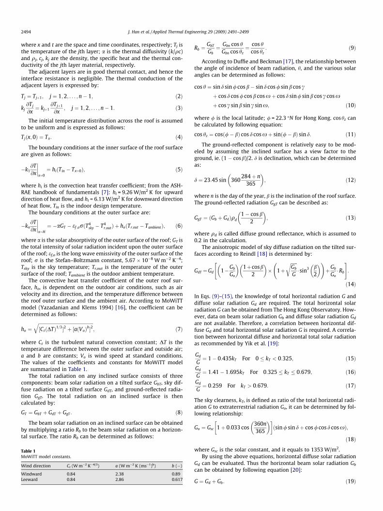
the roof as well as the outdoor climate conditions as shown inFig. 1. The weather data is shown in [21]. The measured data areutilized for both actual performance evaluation and computermodel validation. The results show that good agreement betweenthe predicted and measured data is achieved except there is a dis-agreement found in Day 3 due to data lost in the measurement, asshown in Figs. 4 and 5. As a whole, the measured interior roof sur-face temperatures agree well with the simulation results withinthe acceptable accuracy of 1–2 �C. Thus, the simulation modelcould be used to refine the design of the roof structure and otherbuilding elements. In the following section, the computer simula-tion program will be used to analyze the thermal performance ofvarious roofing systems and its affect on the space cooling load.
5.2. Seasonal thermal performance of the roofing systems
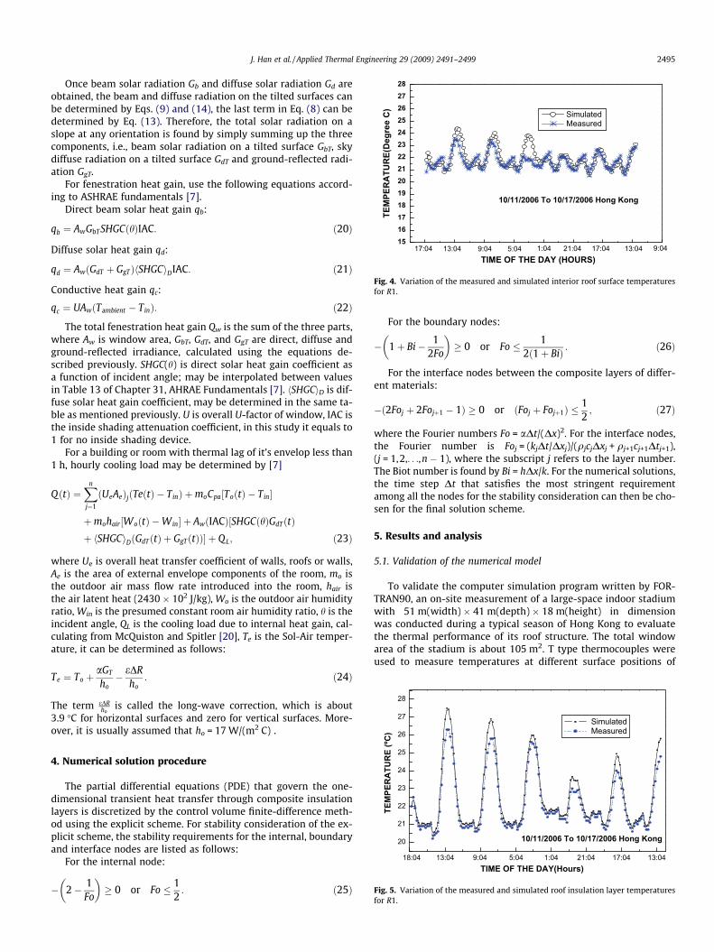
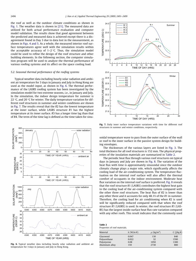
Typical weather data including hourly solar radiation and ambi-ent air temperature for 3 days in January and July in Hong Kong areused as the model input, as shown in Fig. 6. The thermal perfor-mance of the LASRS roofing system has been investigated by thesimulation model for two extreme seasons, i.e., in January and July.In the simulation, the indoor design temperature for summer is22 �C, and 20 �C for winter. The daily temperature variation for dif-ferent roof structures in summer and winter conditions are shownin Fig. 7. The results reveal that the R2 has the lowest temperatureat the inner surface, while LASRS structure R1 has the highesttemperature at its inner surface. R3 has a longer time lag than thatof R4. The term of the time lag is defined as the time taken for sinu-
Fig. 7. Daily inner surface temperature variations with time for different roofstructures in summer and winter conditions, respectively.
5
10
15
20
25
300 10 20 30 40 50 60 70 80
0
200
400
600
800
TEM
PER
ATU
RE
TIME OF YEAR (HRS)
ambient air
January
SOLA
R R
ADIA
TIO
N
TIME OF YEAR (HRS)
solar radiation
26
28
30
32
34
36
384340 4350 4360 4370 4380 4390 4400 4410 4420
0
200
400
600
800
1000
TEM
PER
ATU
RE
TIME OF YEAR (HRS)
ambient air
July
SOLA
R R
ADIA
TIO
N
solar radiation
(W/M
2 )(D
EGC
)(W
/M2 )
(DEG
R C
)
4340 4350 4360 4370 4380 4390 4400 4410 4420
0 10 20 30 40 50 60 70 80
Fig. 6. Typical weather data including hourly solar radiation and ambient airtemperature for 3 days in January and July in Hong Kong.
soidal temperature wave to pass from the outer surface of the wallor roof to the inner surface in the passive system design for build-ing envelopes.
The thicknesses of the various layers are listed in Fig. 3. Thetotal thickness for all roof structures is 152 mm. The physical prop-erties of the insulation materials are summarized in Table 2.
The periodic heat flux through various roof structures on typicaldays in January and July are shown in Fig. 8. The variation of theheat flux with time is approximately sinusoidal since the outdoorclimatic change plays a major role, which significantly affects thecooling load of the air-conditioning system. The temperature fluc-tuation on the internal roof surface will also affect the thermalcomfort of occupants in the indoor environment. Moderate heatflux variation on the internal roof surface is preferred. Fig. 8 revealsthat the roof structure R1 (LASRS) contributes the highest heat gainto the cooling load of the air-conditioning system compared withthe other three roof structures. The heat flux of R2 is lower thanany other three and it accounts for only 48.1% of the R1 in summer.Therefore, the cooling load for air conditioning when R2 is usedwill be significantly reduced compared with that when the roofstructure R1 (LASRS) is used. In winter, the roof structure R1 (LAS-RS) has the largest inside-surface heat flux rate variation comparedwith any other roofs. This result indicates that the commonly used
Table 2Properties of roof materials.
Material k (W/m K) q (kg/m3) C (J/kg K)
Glasswool 0.047 130 840Polyurethane 0.022 32 1590Polystyrene 0.08 1050 1300Aluminum alloy 159 2730 880
0 10 20 30 40 50 60 70 80
-4-3-2-10123456789
DAY 3
DAY 2DAY 1January
R4
R3
R2
R1
HEA
T G
AIN
TH
RO
UG
H R
OO
FS (W
/ M
2 )
TIME OF DAY (HRS)
R 1 R 2 R 3 R 4
-2
0
2
4
6
8
10
12
14
16
18
DAY 3DAY 2
DAY 1July
R2
R3
R4
R1 R1 R2 R3 R4
0 10 20 30 40 50 60 70 80TIME OF DAY (HRS)
HEA
T G
AIN
TH
RO
UG
H R
OO
FS (W
/ M
2 )
Fig. 8. Periodic inside-surface heat flux through various roof structures on typicaldays in January and July of Hong Kong.
J. Han et al. / Applied Thermal Engineering 29 (2009) 2491–2499 2497
LASRS structure has an undesirable thermal performance. Cautionis therefore needed in the application of this kind of roof when en-ergy efficiency is highly prioritized. It can be seen that the roofstructure R2 has a better thermal performance in terms of thesmallest heat flux fluctuation in both typical summer and winter.The results may indicate that polyurethane improves thermal per-formance of the roofing structure due to its smaller thermal con-ductivity as well as smaller thermal diffusivity.
5.3. Space cooling load
Cooling energy consumption of a building can be significantlyreduced by limiting solar heat gain through envelope, which de-pends on the absorptivity (colour) of external surface as it deter-mines the amount of absorbed solar radiation. Many works inthe literature have revealed that exterior surface colour of buildinghas significant effect on the thermal performance of the buildingenvelop [22,23]. However, there is little information on the effectof the envelop colour on the space cooling load of a large space
Fig. 9. Sample for vario
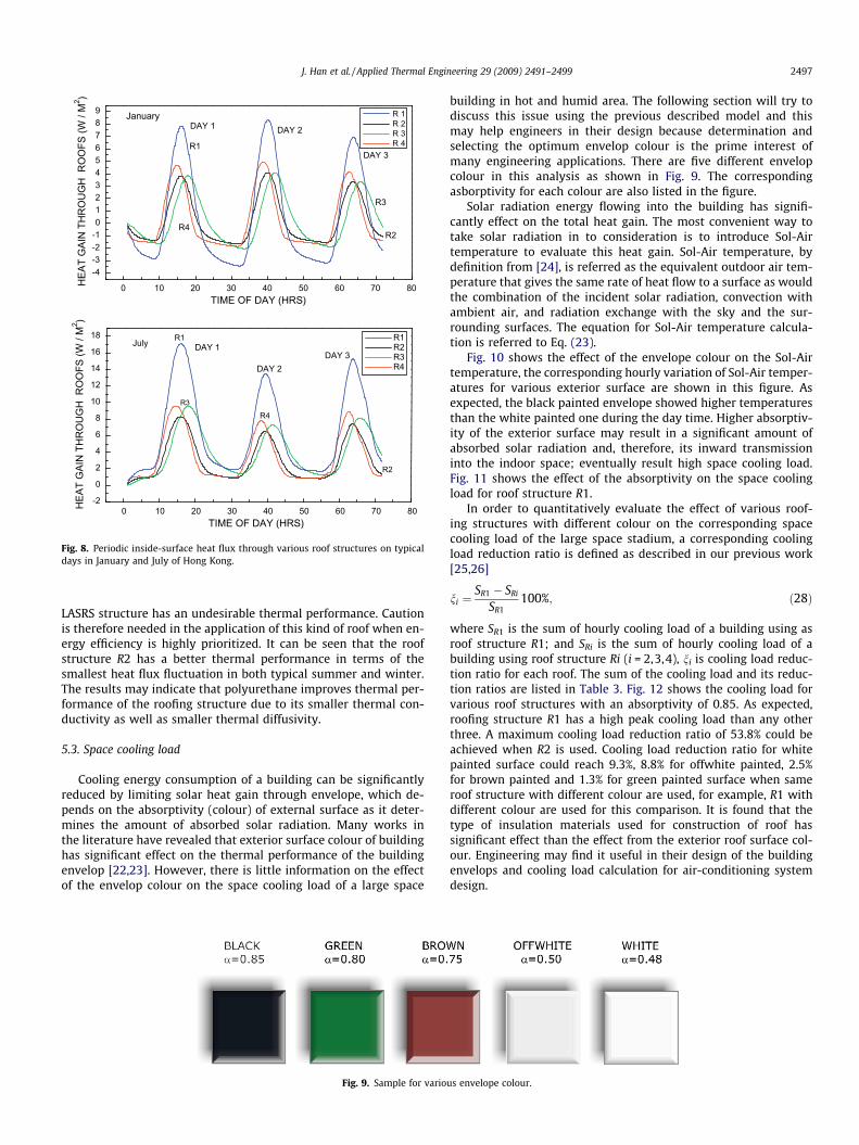
building in hot and humid area. The following section will try todiscuss this issue using the previous described model and thismay help engineers in their design because determination andselecting the optimum envelop colour is the prime interest ofmany engineering applications. There are five different envelopcolour in this analysis as shown in Fig. 9. The correspondingasborptivity for each colour are also listed in the figure.
Solar radiation energy flowing into the building has signifi-cantly effect on the total heat gain. The most convenient way totake solar radiation in to consideration is to introduce Sol-Airtemperature to evaluate this heat gain. Sol-Air temperature, bydefinition from [24], is referred as the equivalent outdoor air tem-perature that gives the same rate of heat flow to a surface as wouldthe combination of the incident solar radiation, convection withambient air, and radiation exchange with the sky and the sur-rounding surfaces. The equation for Sol-Air temperature calcula-tion is referred to Eq. (23).
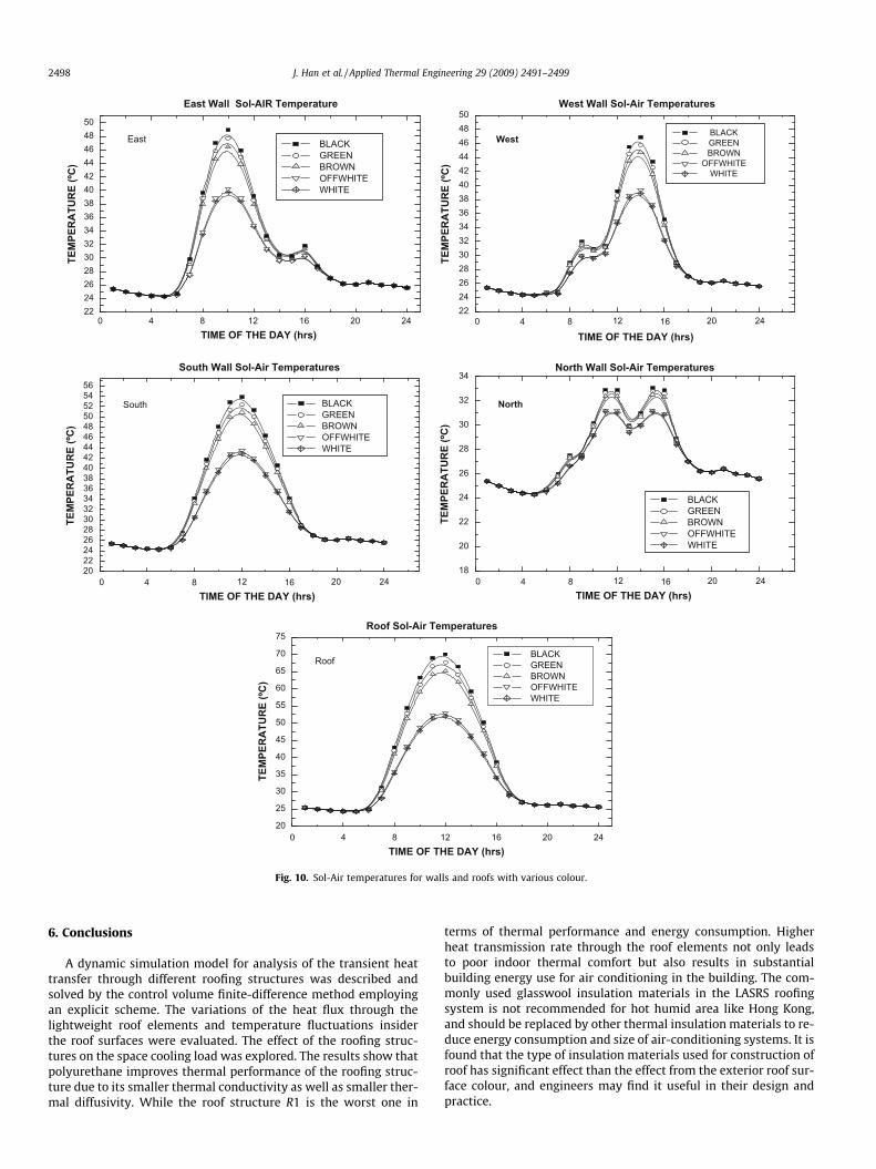
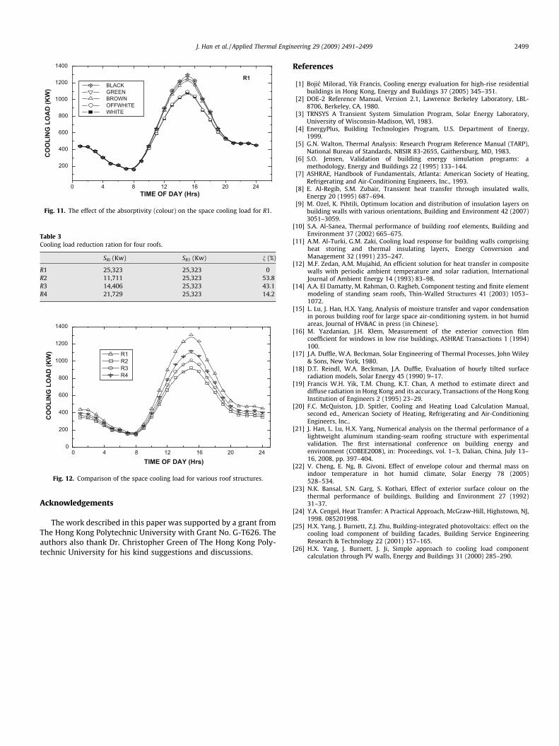
Fig. 10 shows the effect of the envelope colour on the Sol-Airtemperature, the corresponding hourly variation of Sol-Air temper-atures for various exterior surface are shown in this figure. Asexpected, the black painted envelope showed higher temperaturesthan the white painted one during the day time. Higher absorptiv-ity of the exterior surface may result in a significant amount ofabsorbed solar radiation and, therefore, its inward transmissioninto the indoor space; eventually result high space cooling load.Fig. 11 shows the effect of the absorptivity on the space coolingload for roof structure R1.
In order to quantitatively evaluate the effect of various roof-ing structures with different colour on the corresponding spacecooling load of the large space stadium, a corresponding coolingload reduction ratio is defined as described in our previous work[25,26]
ni ¼SR1 � SRi
SR1100%; ð28Þ
where SR1 is the sum of hourly cooling load of a building using asroof structure R1; and SRi is the sum of hourly cooling load of abuilding using roof structure Ri (i = 2,3,4), ni is cooling load reduc-tion ratio for each roof. The sum of the cooling load and its reduc-tion ratios are listed in Table 3. Fig. 12 shows the cooling load forvarious roof structures with an absorptivity of 0.85. As expected,roofing structure R1 has a high peak cooling load than any otherthree. A maximum cooling load reduction ratio of 53.8% could beachieved when R2 is used. Cooling load reduction ratio for whitepainted surface could reach 9.3%, 8.8% for offwhite painted, 2.5%for brown painted and 1.3% for green painted surface when sameroof structure with different colour are used, for example, R1 withdifferent colour are used for this comparison. It is found that thetype of insulation materials used for construction of roof hassignificant effect than the effect from the exterior roof surface col-our. Engineering may find it useful in their design of the buildingenvelops and cooling load calculation for air-conditioning systemdesign.
us envelope colour.
0 4 8 12 16 20 24222426283032343638404244464850
East
East Wall Sol-AIR Temperature
TEM
PER
ATU
RE
(ºC)
TIME OF THE DAY (hrs)
BLACK GREEN BROWN OFFWHITE WHITE
222426283032343638404244464850
BLACK GREEN BROWN
OFFWHITE WHITE
West
West Wall Sol-Air Temperatures
20222426283032343638404244464850525456
South
South Wall Sol-Air Temperatures
BLACK GREEN BROWN OFFWHITE WHITE
18
20
22
24
26
28
30
32
34
North
North Wall Sol-Air Temperatures
BLACK GREEN BROWN OFFWHITE WHITE
20
25
30
35
40
45
50
55
60
65
70
75
Roof
Roof Sol-Air Temperatures
BLACK GREEN BROWN OFFWHITE WHITE
0 4 8 12 16 20 24
TIME OF THE DAY (hrs)
0 4 8 12 16 20 24
TIME OF THE DAY (hrs)0 4 8 12 16 20 24
TIME OF THE DAY (hrs)
0 4 8 12 16 20 24TIME OF THE DAY (hrs)
TEM
PER
ATU
RE
(ºC)
TEM
PER
ATU
RE
(ºC)
TEM
PER
ATU
RE
(ºC)
TEM
PER
ATU
RE
(ºC)
Fig. 10. Sol-Air temperatures for walls and roofs with various colour.
2498 J. Han et al. / Applied Thermal Engineering 29 (2009) 2491–2499
6. Conclusions
A dynamic simulation model for analysis of the transient heattransfer through different roofing structures was described andsolved by the control volume finite-difference method employingan explicit scheme. The variations of the heat flux through thelightweight roof elements and temperature fluctuations insiderthe roof surfaces were evaluated. The effect of the roofing struc-tures on the space cooling load was explored. The results show thatpolyurethane improves thermal performance of the roofing struc-ture due to its smaller thermal conductivity as well as smaller ther-mal diffusivity. While the roof structure R1 is the worst one in
terms of thermal performance and energy consumption. Higherheat transmission rate through the roof elements not only leadsto poor indoor thermal comfort but also results in substantialbuilding energy use for air conditioning in the building. The com-monly used glasswool insulation materials in the LASRS roofingsystem is not recommended for hot humid area like Hong Kong,and should be replaced by other thermal insulation materials to re-duce energy consumption and size of air-conditioning systems. It isfound that the type of insulation materials used for construction ofroof has significant effect than the effect from the exterior roof sur-face colour, and engineers may find it useful in their design andpractice.
0
200
400
600
800
1000
1200
1400
CO
OLI
NG
LO
AD
(KW
) R1 R2 R3 R4
0 4 8 12 16 20 24
TIME OF DAY (Hrs)
Fig. 12. Comparison of the space cooling load for various roof structures.
0 4 8 12 16 20 24
200
400
600
800
1000
1200
1400
R1
CO
OLI
NG
LO
AD
(KW
)
TIME OF DAY (Hrs)
BLACK GREEN BROWN OFFWHITE WHITE
Fig. 11. The effect of the absorptivity (colour) on the space cooling load for R1.
Table 3Cooling load reduction ration for four roofs.
SRi (Kw) SR1 (Kw) n (%)
R1 25,323 25,323 0R2 11,711 25,323 53.8R3 14,406 25,323 43.1R4 21,729 25,323 14.2
J. Han et al. / Applied Thermal Engineering 29 (2009) 2491–2499 2499
Acknowledgements
The work described in this paper was supported by a grant fromThe Hong Kong Polytechnic University with Grant No. G-T626. Theauthors also thank Dr. Christopher Green of The Hong Kong Poly-technic University for his kind suggestions and discussions.
References
[1] Bojic Milorad, Yik Francis, Cooling energy evaluation for high-rise residentialbuildings in Hong Kong, Energy and Buildings 37 (2005) 345–351.
[2] DOE-2 Reference Manual, Version 2.1, Lawrence Berkeley Laboratory, LBL-8706, Berkeley, CA, 1980.
[3] TRNSYS A Transient System Simulation Program, Solar Energy Laboratory,University of Wisconsin-Madison, WI, 1983.
[4] EnergyPlus, Building Technologies Program, U.S. Department of Energy,1999.
[5] G.N. Walton, Thermal Analysis: Research Program Reference Manual (TARP),National Bureau of Standards, NBSIR 83-2655, Gaithersburg, MD, 1983.
[6] S.O. Jensen, Validation of building energy simulation programs: amethodology, Energy and Buildings 22 (1995) 133–144.
[7] ASHRAE, Handbook of Fundamentals, Atlanta: American Society of Heating,Refrigerating and Air-Conditioning Engineers, Inc., 1993.
[8] E. Al-Regib, S.M. Zubair, Transient heat transfer through insulated walls,Energy 20 (1995) 687–694.
[9] M. Ozel, K. Pihtili, Optimum location and distribution of insulation layers onbuilding walls with various orientations, Building and Environment 42 (2007)3051–3059.
[10] S.A. Al-Sanea, Thermal performance of building roof elements, Building andEnvironment 37 (2002) 665–675.
[11] A.M. Al-Turki, G.M. Zaki, Cooling load response for building walls comprisingheat storing and thermal insulating layers, Energy Conversion andManagement 32 (1991) 235–247.
[12] M.F. Zedan, A.M. Mujahid, An efficient solution for heat transfer in compositewalls with periodic ambient temperature and solar radiation, InternationalJournal of Ambient Energy 14 (1993) 83–98.
[14] A.A. El Damatty, M. Rahman, O. Ragheb, Component testing and finite elementmodeling of standing seam roofs, Thin-Walled Structures 41 (2003) 1053–1072.
[15] L. Lu, J. Han, H.X. Yang, Analysis of moisture transfer and vapor condensationin porous building roof for large space air-conditioning system. in hot humidareas, Journal of HV&AC in press (in Chinese).
[16] M. Yazdanian, J.H. Klem, Measurement of the exterior convection filmcoefficient for windows in low rise buildings, ASHRAE Transactions 1 (1994)100.
[17] J.A. Duffle, W.A. Beckman, Solar Engineering of Thermal Processes, John Wiley& Sons, New York, 1980.
[18] D.T. Reindl, W.A. Beckman, J.A. Duffie, Evaluation of hourly tilted surfaceradiation models, Solar Energy 45 (1990) 9–17.
[19] Francis W.H. Yik, T.M. Chung, K.T. Chan, A method to estimate direct anddiffuse radiation in Hong Kong and its accuracy, Transactions of the Hong KongInstitution of Engineers 2 (1995) 23–29.
[20] F.C. McQuiston, J.D. Spitler, Cooling and Heating Load Calculation Manual,second ed., American Society of Heating, Refrigerating and Air-ConditioningEngineers, Inc..
[21] J. Han, L. Lu, H.X. Yang, Numerical analysis on the thermal performance of alightweight aluminum standing-seam roofing structure with experimentalvalidation. The first international conference on building energy andenvironment (COBEE2008), in: Proceedings, vol. 1–3, Dalian, China, July 13–16, 2008, pp. 397–404.
[22] V. Cheng, E. Ng, B. Givoni, Effect of envelope colour and thermal mass onindoor temperature in hot humid climate, Solar Energy 78 (2005)528–534.
[23] N.K. Bansal, S.N. Garg, S. Kothari, Effect of exterior surface colour on thethermal performance of buildings, Building and Environment 27 (1992)31–37.
[24] Y.A. Cengel, Heat Transfer: A Practical Approach, McGraw-Hill, Highstown, NJ,1998. 085201998.
[25] H.X. Yang, J. Burnett, Z.J. Zhu, Building-integrated photovoltaics: effect on thecooling load component of building facades, Building Service EngineeringResearch & Technology 22 (2001) 157–165.
[26] H.X. Yang, J. Burnett, J. Ji, Simple approach to cooling load componentcalculation through PV walls, Energy and Buildings 31 (2000) 285–290.