Tribological Aspects of Thermally Sprayed Red Mud-Fly Ash and Red Mud-Al Coatings on Mild Steel
Upload
khangminh22Category
view
0download
0
152(f.SS:
X9" ISA
(T^^w-^
Investigation of Formation Damagefrom Mud Cleanout Acidsand Injection Waters in Aux VasesSandstone Reservoirs
Dennis J. Haggerty and Beverly Seyler
linois Petroleum 152
1997
Department of Natural Resources
ILLINOIS STATE GEOLOGICAL SURVEY


Investigation of Formation Damagefrom Mud Cleanout Acidsand Injection Waters in Aux VasesSandstone Reservoirs
Dennis J. Haggerty and Beverly Seyler
Illinois Petroleum 152
1997
f»«-»•* . _ ,
Illinois State Geological Survey
William W. Shilts, Chief JUL 2 3 ftq?615 East Peabody Drive UChampaign, IL 61820-6964 iL ^fcOL owMV, c y(217)333-4747

DISCLAIMERThis report was prepared by the Illinois State Geological Survey (ISGS) for work
sponsored by the State of Illinois and the U.S. Department of Energy (USDOE). It
presents reasonable interpretations of available scientific data. Any opinions, find-
ings, conclusions, or recommendations expressed in this report are those of the
authors and do not necessarily reflect the views of the USDOE. The ISGS, the
Illinois Department of Natural Resources, and the USDOE assume no liability with
respect to the use, or damages resulting from the use, of any information in this
report. This report does not constitute an endorsement for any commercially avail-
able product. Operators are encouraged to have their reservoir rock tested for com-patibility by service companies before adding any stimulation chemicals to their
wells.
ACKNOWLEDGMENTSThe authors acknowledge the contributions of Jonathan H. Goodwin, Bryan G. Huff,
Randall E. Hughes, Duane M. Moore, David G. Morse, and Donald F. Oltz, whoreviewed this report and offered useful suggestions. Hughes, Moore, and D. Scott
Beaty performed all x-ray diffraction analyses of samples, and Beaty provided someof the thin section analyses. The mud cleanout acid (MCA) used in this work wassupplied by Halliburton, Inc. of Duncan, Oklahoma; the company's cooperation,
particularly the help of David Simon, was much appreciated.
Editorial Board
Jonathan H. Goodwin, Chair
Michael L. Bamhardt Don Mickulic
Heinz H. Damberger William R RoyBeverly L Herzog C. Pius Weibel
David R. Larson
Printed by the authority of the State of Illinois/1997/900
rPx\ printed with soybean ink on recycled paper

CONTENTS
ABSTRACT 1
INTRODUCTION 1
EXPERIMENTAL OVERVIEW 5
Mud Cleanout Acids 7
Injection Waters 7
EXPERIMENTAL MATERIALS AND METHODS 8Materials 8
Petrographic Analyses 9
Coreflood Experiments 1
Coreflood Tests with Acids 1
2
Interrupted coreflood 12
Continuous acid corefloods 12Water Sensitivity Coreflood Experiments 12Acid Soak Experiments 13Crude Oil-Acid Compatibility Experiments 13
INITIAL RESERVOIR ROCK COMPOSITION 1
3
Bulk Mineralogy of Selected Aux Vases Sandstone Reservoirs 13Pore-Filling Mineral—Calcite 15
Pore-Lining Minerals 15
RESULTS AND IMPLICATIONS 1
9
Effect of MCA on Aux Vases Samples: Calcite Dissolution in Coreflood
Experiments 19Calcite Dissolution in Thin Section Analysis of MCA Coreflood Sample 22Dissolution of Calcite in MCA Soak Experiments 22Effect of MCA on Fines Migration 22Effect of MCA on Other Minerals 23Effect of 15% HCI Coreflood on Aux Vases Reservoir Sandstones 23Soaking Experiments Using 15% HCI 28Oil-Acid Compatibility Tests 30Avoiding Acid-induced Formation Damage in Aux Vases Reservoir
Sandstones 30Water Sensitivity of Aux Vases Reservoir Sandstones 31
CONCLUSIONS AND RECOMMENDATIONS 34
REFERENCES 36
APPENDIX 39I Petrographic Analyses 39
II Core Analyses 40

Digitized by the Internet Archive
in 2012 with funding from
University of Illinois Urbana-Champaign
http://archive.org/details/investigationoff152hagg

ABSTRACT
Diagenetic clay minerals line almost every pore of the Aux Vases Sandstone reser-
voirs in the Illinois Basin. Pore-filling calcite occurs locally. Fluids introduced during
drilling, completion, and water-flooding may preferentially react with the clay or other
minerals such as calcite cement in the pores, thus damaging the formation andreducing oil recovery.
Coreflood experiments were conducted on 1 -inch-diameter core plugs fromBoyd, Dale Consolidated, Energy, and Zeigler Fields.
• Prolonged contact (4 hours or more) with 15% hydrochloric acid (HCI) with noadditives not only dissolved the calcite, but produced leaching and disintegration of
the clay minerals, a closely intergrown mixture of mixed-layered illite/smectite,
chlorite, and illite.
• The pure 15% HCI solution also formed sludges when mixed with Aux Vasescrude oil. Thus, using 15% HCI without surfactants, clay stabilizers, or de-emulsifiers
will contribute to formation damage in Aux Vases Sandstone reservoirs.
• Injection of water less saline than the formation brine decreased permeability upto 56%, apparently through swelling of mixed-layered illite/smectite and migration
of fines. These reductions in permeability could not be reversed by subsequentinjection of water with higher salinities.
To avoid impairing permeability in Aux Vases reservoirs, oil field operators should
inject wells with waters as saline as the formation brines. Using a properly formu-
lated MCA may also significantly reduce formation damage and enhance oil re-
covery.
INTRODUCTION
Diagenetic clay minerals and other minerals present in the pores of Valmeyeran(Mississippian) Aux Vases Sandstone reservoirs (fig. 1) are likely to be responsible
for many oil-production problems encountered in this formation. The cementationof sand grains in the Aux Vases differs from the cementation of sand grains in the
Chesterian and other sandstone reservoirs in the Illinois Basin. As a result, the
same drilling, completion, and stimulation practices cannot be used successfully for
all formations.
Typical Chesterian reservoirs (fig. 2), for example, are composed of highly
lithified sandstones tightly cemented by quartz. Pore linings are dominated byquartz overgrowths and minor amounts of discrete crystallites of diagenetic
kaolinite, iron-chlorite, mixed-layered illite/smectite, and illite (fig. 3a).
Typical Aux Vases reservoir rock, however, is a poorly cemented, soft, friable,
fine-grained sandstone with pores lined with diagenetic clay minerals (fig. 3b)
(Seyler et al. in prep.). The diagenetic clay mineral suite in Aux Vases reservoirs is
a closely intergrown mixture of mixed-layered illite/smectite, chlorite, and illite. Nokaolinite was found in the Aux Vases reservoir rocks sampled for this study.
Introduced fluids come into contact and primarily react with pore-lining diage-
netic clay minerals rather than with the framework grains; therefore, the reservoirs
containing diagenetic clay minerals are more likely to react adversely to drilling,
completion, and recovery treatments than are the reservoirs with pore systemsdominated by quartz, a more stable mineral. For these reasons, Aux Vases Sand-stone reservoirs in the Illinois Basin are highly susceptible to formation damage that
may decrease the total amount of oil recovered.

Figure 1 Aux Vases Sandstone oil fields sampled for this study are Boyd, Dale Consolidated, Energy,
and Zeigler. Shaded areas show oil fields.

Formation damage, a commonproblem (Monaghan et al. 1958,
Abrams 1977, Krueger 1986, Simonand Anderson 1990, and Civan
1 992), can occur at any stage of res-
ervoir development. It results from
the reaction of reservoir rocks with
fluids introduced into the formation
during well drilling, completion, andstimulation.
Development of sandstone res-
ervoirs in the Illinois Basin typically
includes these steps:
1
.
drilling with freshwater mud;
2. perforating the potential reservoir
zone, if casing is used, or open hole
completions with casing cementedabove the producing zone;
3. preflushing with 15% hydrochlo-
ric acid (HCI) or mud cleanout acid
(MCA) to remove drilling mud;
4. cleaning out perforations or the
well bore with MCA;
5. initial swabbing to retrieve stimu-
lation fluids and induce oil flow to-
ward the wellbore;
6. hydraulic fracturing using a fresh-
water gelled pad and sand prop-
pant;
7. final swabbing during the produc-
tion test.
Some of these practices enhancethe potential for formation damagedue to the ubiquitous presence of
pore-lining diagenetic minerals in
Aux Vases sandstones. A series
of bench-scale experiments repre-
senting some common practices
was conducted to determine the
effects on Aux Vases sandstone
reservoirs in Boyd, Dale Consoli-
dated, Energy, and Zeigler Fields
(fig. 1). Of greatest interest was for-
mation damage that may be caused
by contact with fresh water, 15%HCI, and MCA.
BEECHCREEK
iilV
RENAULT I
,
i
| j |
Karnok J> \ ;
\
\ ^ '
Spar Mt^- '
-^v.|
. ,
|. , .
u, Jii ii - ii^ui
Fredonia > i Jf i iEt
y / y y<~~s-
"°i ? i pi °
I° i°
Figure 2 Aux Vases Sandstone forms the
transition from predominantly carbonate rocks of
the Middle Mississippian Valmeyeran series to
predominantly siliciclastic rocks of the Upper
Mississippian Chesterian series.

Figure 3a Scanning electron microphotograph (SEM) of sample from a
typical Chesterian Cypress Sandstone reservoir (1,324-ft depth, Marathon Oil
MI-16 Isaac Boyd, Lawrence Field) shows quartz overgrowths as the
predominant cementing agent and pore-lining mineral. Diagenetic clay
minerals are iron-rich chlorite, kaolinite, and fibrous illite.
Figure 3b SEM of a critical-point-dried sample from a typical Aux Vasesreservoir (2,400-ft depth, Budmark 3 Burr Oak, Energy Field) shows pore-lining
and -bridging diagenetic clay minerals (closely intergrown mixed-layered
illite/smectite, chlorite, and illite) and no quartz overgrowths.

A common deviation from these practices is incomplete swabbing in the final
stages of well completion. When circumstances are ideal, almost all stimulation
fluids are retrieved from the reservoir during final swabbing. When this is not
possible, however, stimulation fluids may be left in the reservoir overnight—or in-
definitely. Therefore, acid-soaking experiments were conducted to represent someconditions that may result from incomplete swabbing.
The experiments focused on five objectives:
1. determine how MCA containing 15% HCI with additives, typically used during
completion and/or stimulation, affects pore-lining minerals and the permeability of
Aux Vases reservoir rocks by conducting dynamic, constant rate injection coreflood
experiments;
2. investigate how 15% HCI and MCA affects crude oil from Aux Vases reservoirs
by conducting compatibility experiments;
3. examine how exposure to fluids of various salinities affects permeability in sam-ples of Aux Vases reservoirs by conducting coreflood experiments;
4. investigate the effects of long-term contact of 1 5% HCI and MCA with pore-lining
minerals in reservoir samples by conducting static soak experiments;
5. compare XRD analyses of the bulk mineralogy and SEM/EDX analyses of pore-
lining minerals with flood results to identify minerals that would be most affected by
fluids commonly used during drilling, completion, and stimulation of Aux Vasesreservoirs.
EXPERIMENTAL OVERVIEW
Five sets of bench experiments were conducted to attain the study's objectives
(table 1 ). The first set compared the compatibility of crude oil with 1 5% hydrochloric
acid (HCI) versus its compatibility with mud cleanout acid (MCA). These direct con-
tact experiments demonstrated the changes in physical properties of crude oil whenmixed with the acids.
Three coreflood experiments were performed to determine the effects on per-
meability and pore-lining minerals of continuously injecting MCA and 15% HCI at a
constant rate. MCA was injected into two core plugs, one from the 2,392.1 -foot
depth in the Budmark no. 2 Morgan Coal well at Energy Field, and the other from
the 2,627-foot depth in the Gallagher Drilling Company no. 2 Mack well at Zeigler
Field. HCI was injected into one sample from the 2,303.5-foot depth in the Budmarkno. 2 Morgan Coal well at Energy Field. Fluid was injected continuously to observe
changes in permeability.
In two coreflood experiments, the injection of MCA was interrupted several
times. One sample was from the 3,198.7-foot depth in the Farrar no. 1 McCreerywell at Dale Consolidated Field; the second sample was from the 2,391 .1 -foot depth
in the Budmark no. 2 Morgan Coal well at Energy Field. These interrupted coreflood
experiments were conducted to determine the effects of stopping injection andsoaking the samples in injection fluids for a few hours to a few days. One or moreshut-in periods are common during conventional well treatments with MCA. Inter-
rupted coreflood experiments represented shut-in periods during well stimulation.
The sensitivity of reservoir samples to water of different salinities was tested in
interrupted injection experiments on one core plug from each of three fields, Boyd,
Dale Consolidated, and Zeigler, and three core plugs from Energy Field.
Static soak experiments were conducted to compare changes in pore-lining
minerals in samples soaked in 15% HCI versus those soaked in MCA. For samples,

wafers were sliced from two core plugs from the Budmark no. 2 Morgan Coal well:
wafers from a depth of 2,392.8 feet were soaked in 15% HCI, and wafers from a
depth of 2,393 feet were soaked in MCA. The soak experiments represent condi-
tions of incomplete swabbing where acids used for drilling and stimulation cannot
be retrieved, or retrieval is delayed for a long time.
Coreflood experiments conducted in this study most closely represent the
totally flushed zone of a reservoir. Twenty-five to 50 pore volumes of fluid werecontinuously injected during coreflood experiments. A decrease in porosity or per-
meability is unlikely to occur in such thoroughly flushed samples because potential
precipitates have no time to accumulate; they are removed during mechanical
flushing of the core plug. As a result, coreflood experiments do not provide informa-
tion on conditions in incompletely flushed areas of the reservoir where the effects
of fines migrating and minerals precipitating from treatment fluids may bepronounced.
Table 1 Experimental overview
Type of experiment Fluids Field, well Depth ft To determine
Direct contact: Crude
crude oil and acids oils
Boyd, Baldridge B5 Bizot 2, 1 70
Dale, Farrar 2 McCullum Community 3, 1 58-3, 1 76
Energy, Budmark 2 Morgan Coal 2,385-2,395
Zeigler, Gallagher Drilling 1 Alex 2,615-2,630
Compatibility of
15%HCIvsMCA
Coreflood:
continuous injection
at a constant rate
MCA
MCA
15% HCI
Coreflood:
interrupted injection,
constant rate
MCA
MCA
Energy, Budmark 2 Morgan Coal 2,392.1
Zeigler, Gallagher Drilling 2 Mack 2,627
Energy, Budmark 2 Morgan Coal 2,393.5
Effects on permeability
and pore-lining
minerals
Dale Cons, Farrar 1 McCreery 3,198.7
Energy, Budmark 2 Morgan Coal 2,391 .1
Effects of interrupting
injection and soaking
sample in MCA;simulates potential
damage after injection
and before swabbing
Core waterflood: Waters,
interrupted injection, various
constant rate salinities
Boyd, Superior Oil 9 Sanders 2, 1 63
Energy, Budmark 2 Morgan Coal 2,390
Energy, Budmark 2 Morgan Coal 2,388
Zeigler, Gallagher Drilling 2 Mack 2,61
1
Dale Cons., Farrar 1 McCreery 3,200.6
Energy, Budmark 2 Morgan Coal 2,388.3
Sensitivity of rock to
injected water of
varying salinities; note
permeability changes
Acid soak 15% HCI Energy, Budmark 2 Morgan Coal 2,392.8
MCA Energy, Budmark 2 Morgan Coal 2,393
Long-term reaction of
reservoir rock to MCAand 15% HCI

The soak experiments were thus performed to observe reactions in long-term
experiments representing reactions in unflushed and incompletely flushed zones.
Mud Cleanout Acids
During drilling, the amount of mud or mud filtrate that invades the formation around
the wellbore generally depends on the permeability of the formation. Mud particles
in the drilling fluid are designed to form a mudcake or "skin" around the wellbore,
thus reducing infiltration into the reservoir. Although the mudcake reduces perme-
ability, some mud particles still move into a porous reservoir.
Filtrates from drilling muds can damage the reservoir by restricting oil flow
because of an increase in water saturation due to the relative permeability or vis-
cosity of oil. Emulsions may also form in the region of the wellbore. Clay minerals
sensitive to fresh water (Grim 1947) may swell in reaction to mud filtrates low in
salinity and further reduce formation permeability.
Mud cleanout acids of 15% HCI mixed with corrosion inhibitors, surfactants,
clay stabilizers, and deemulsifiers are routinely used by operators in the Illinois
Basin to remove mud and establish commercial oil productivity after drilling. Treat-
ment with 15% iron-sequestering acid also has been reported (Jeff Finnell, Equinox
Oil, Crossville, Illinois, pers. comm. 1991). Mud cleanout acids of 3% HF (hydro-
fluoric acid) combined with 12% HCI are not routinely used in Illinois' Aux Vasesreservoirs, probably because HF reacts adversely with the calcite or dolomite
cement generally present in reservoir sandstone.
The HCI in mud cleaning acid (MCA) mixtures can react adversely with clay
minerals (Ross 1969). Simon and Anderson (1990) demonstrated that HCI can
destroy clay minerals, of which chlorite is the most susceptible. Their x-ray diffrac-
tion (XRD) studies revealed that HCI attacked chlorite by leaching iron (Fe++
) ions
from the chlorite, thus causing a breakdown in the crystalline structure. The avail-
able evidence indicates that the amorphous residue from this acid-chlorite reaction
consists of iron hydroxide gels, which contribute to clogging of pore throats, andsignificantly impair formation permeability. According to Simon and Anderson
(1990), formation damage was less extensive at lower acid concentrations and
temperatures, and for shorter durations of exposure to the acid. No work has beenpublished previously on the effects of MCA on reservoirs containing the specific
suite of intergrown clay minerals found in the Aux Vases sandstone reservoirs.
Acid treatments may induce the mechanical breakup of sands and clay miner-
als, particularly where carbonate cements are present, and result in migration of
fines that impair permeability or plug perforations. Thus, although dissolution of
carbonate cement may improve permeability (Allen and Roberts 1989), it may also
dislodge sand grains or other fines held in place by the carbonate.
The effect of poorly formulated MCA on the oleic (oil) phase has been discussed
by Allen and Roberts (1989). HCI may become separated from additives in poorly
formulated MCA. When HCI reacts with oil, it can form emulsions and cause pre-
cipitation of asphaltenes and sludge. When a sludge forms, the reservoir's relative
permeability to water increases, thus water production increases. This response
may explain the immediate decline in oil production and the increase in water
production from some Aux Vases wells after MCA treatments.
Injection WatersThe sensitivity of smectite to fresh water is well known (Vaidya et al. 1957, Mungan1 965, Gray and Rex 1 966, Khilar and Fogler 1 981 ). The sensitivity of mixed-layered
illite/smectite (l/S) is less well understood because each clay mineral structure
within the l/S group/category may respond differently to treatment.
Major waterflooding operations in the Illinois Basin have traditionally drawninjection waters from surface pools or shallow fresh-water aquifers (Huff, ISGS,

pers. comm. 1995). Although some operators have investigated the compatibility of
injection water and formation brine, they have rarely considered the impact of
injection water on the mineral constituents of the reservoir. The choice of drilling,
completion, and injection fluids for the Aux Vases and other formations in the Illinois
Basin can be assisted by an understanding of the reservoir's mineral content andchemistry. This study will examine the sensitivity of clay minerals to the saline
content of injection waters.
EXPERIMENTAL MATERIALS AND METHODS
Materials
The core samples used in this study were obtained from the ISGS Geologic Sam-ples Library. (Table 2 shows the original sources.) Cores from Aux Vases reservoirs
were selected primarily on the basis of their availability.
Plugs 1 inch (2.54 cm) in diameter and as long as possible were drilled from
4-inch-diameter whole cores. They were cleaned at 1 50°F (66°C) in a C02-solvent,
core cleaning apparatus. The cleaning solution was high-pressure CO2 gas and a
solvent mixture of 60% toluene, 25% hexane, and 15% methanol. This cleaning
process, as shown by Seyler (unpublished 1992), adequately removes oil from
plugs without altering the mineral content of the reservoir rock.
Core plugs ranging in length from 1 inch (2.54 cm) to 2.5 inch (6.35 cm) were
used for the coreflood experiments. Variations in length did not affect results
because the measurements of each core plug were used for calculations. Eight
core plug wafers 1 .0 inches in diameter and 0.25 inches (0.635 cm) thick were used
in the MCA and HCI soak experiments.
The MCA solution used in this work was supplied by Halliburton, Inc., andcontained 15% HCI in a proprietary formulation of surfactants, suspending agents,
anti-sludge agents, clay mineral stabilizers, iron-sequestering agents, and corrosion
inhibitors. (A proprietary agreement with Halliburton prohibits our performing or
publishing chemical analyses of this MCA.)
Table 2 Samples used for the experiments and methods used to describe them
Field, well and Thin
well ID Depth ft SEM/EDX XRD section
Energy 2,393.5 Yes No No2 Morgan Coal 2,388.3 Yes Yes Yes1219923465 2,391.1 Yes No No
2,390 No Yes Yes2,388 No No No2,393 Yes No No2,392.8 Yes Yes Yes
Dale 3,198.7 Yes No Yes1 McCreery 3,200.6 No No No1205523456
Zeigler 2,611 Yes Yes Yes2 Mack 2,627 Yes Yes Yes1205523750
Boyd 2,163 No No No9 Sanders
1208102628

Produced Aux Vases formation brine, collected from the Budmark no. 3 MorganCoal lease (2,389 ft subsurface) in Energy Field and containing 126,000 parts per
million (ppm) total dissolved solids (TDS), was used as the formation water in these
experiments. The TDS content of Aux Vases brines generally ranges from 120,000
to 140,000 ppm (Demir 1995); therefore, the TDS content of the Energy Field brine
is typical of Aux Vases brines. A synthetic fresh-water mixture was prepared to
match the 1 ,200 ppm TDS composition of the fresh-water supply from a pond at
Energy Field (table 3).
The Aux Vases brine from Energy Field was filtered and used to flood core
samples from the Boyd Dale Consolidated, Energy, and Zeigler Fields. Varying
proportions of this brine and the synthetic freshwater supply were also injected into
the core plugs. The resistivities of these mixtures were determined with a resistivity
meter. Their salinities were calculated from the TDS-resistivity relationship estab-
lished by Demir (1995) for Aux Vases brines:
6786.09
(R W )
12853-1.022
TTDS(ppm) =
where
Rw = resistivity of water in Q-m,
T = water temperature, °F.
A degassed crude oil mixture from the Budmark no. 2 Morgan Coal well in Energy
Field was used in some of the experiments. The crude oil mixture has a density of
0.85 gm/cc (35° API gravity) and a viscosity of 6.57 cp at 77° F (25°C).
Petrographic AnalysesPetrographic analyses were performed on samples from Aux Vases reservoirs stud-
ied for the enhanced and improved oil recovery project cosponsored by the U.S.
Department of Energy and State of Illinois. More than 150 thin sections from AuxVases reservoirs were made and studied during this project (Seyler et al. in prep.).
In addition, several samples were collected from rocks adjacent to those supplying
the core plugs used in coreflood experiments to compare untreated with treated
reservoir rocks in Boyd, Dale Consolidated, Energy, and Zeigler Fields.
These analyses included standard optical microscopy with thin sections, x-ray
diffraction analysis (XRD), and scanning electron microscopy (SEM) with energy
Table 3 Characteristics of water mixtures
Type Ca2+
Na+
Ionic composition meq/l
Ba2+
Fe3+ Mg2+ CI" S042
"
HCO3" pHRwQ-m
TDS%
Formation brine 341 1883 0.0 0.4 173 2394 1.0 1.7 6.1 0.063 13.7
Supply water 16 14 0.1 0.0 13 28.2 13.5 1.5 5.3 0.433 1.2
95%(1)-5%* 0.064 13.5
90%(1)-10% 0.068 12.4
75%(1)-25% 0.076 10.5
50%(1)-50% 0.124 5.95
* 95% (by volume) of formation brine and 5% (by volume) of the supply water,
meq/l = mole wt/charge per liter

dispersive x-ray microbeam (EDX) analysis. Experimental details of thin section,
SEM/EDX, and XRD analyses are discussed in Appendix I. Thin sections were usedto characterize petrographic relationships, including framework grain composition,
cementing agents, grain size, porosity types, and reservoir quality. SEM/EDX analy-
ses identify the pore-lining constituents that will interact directly with fluids contact-
ing the formation; whereas XRD analyses provide the type and amount of all
minerals present.
Critical point drying was used, whenever possible, to observe the morphologyof potentially hydrated clay minerals coating the framework grains and to ensurethat air-drying of cores used in this study did not alter the clay minerals (Seyler et
al. in prep.). Fresh cores suitable for critical point drying were limited to two wells in
fields sampled for this study. Examples of critical point drying are included in this
study to illustrate typical untreated samples.
Coreflood ExperimentsCoreflood experiments were performed with a TEMCO™ integrated coreflood ap-paratus (described in Appendix II). Each core plug was cleaned in a C02/solventcore cleaner and vacuum-dried. The porosity of each core plug sample was deter-
mined at room temperature and atmospheric pressure by the saturation method,and its permeability to nitrogen gas was determined at atmospheric ambient confin-
ing pressure prior to the coreflood experiments (Tiab 1 985). Standard operating andquality control procedures for permeability and porosity measurements and other
analytical methods used in this paper are on file (ISGS Oil and Gas Section 1993).For baseline liquid permeability determination, brine was continuously injected
into a core sample at a rate of 1.5 cm3/min. This process resaturates samples that
were previously dry or contained an irreducible water saturation. This rate, whichcorresponds to a commonly observed reservoir flow velocity of 14 feet per day(ft/day) and 68.6 barrels per day in a 10-foot pay, was determined according to the
scaling coefficient of Kyte and Rapoport (1958). The scaling coefficient of unity
(LVuw = 1) corresponding to oil recovery of 65% at water breakthrough was used(Delclaud 1 991 ). No fines migration was observed in the core plugs when nonreac-tive liquid (brine) was injected at this rate. The pressure drop across the core samplewas continuously monitored and recorded directly by desktop computer. The effec-
tive permeability of the liquid at any time was determined from Darcy's equation bymeasuring the pressure drop across the core:
K(md) =100°^QL
AAP
where
u = viscosity of flowing liquid (in centipoise)
L = core length (cm)
A = core cross-sectional area (cm2
)
Q = liquid throughput (cm3/sec)
AP = pressure drop across core (atm)
Coreflood experiments were performed at a confining pressure of 1 ,000 psig (6895KPa) and a temperature of 75°F (24°C). The core samples were mounted in a con-ventional Hassler-type coreholder. Inside the coreholder, the core was inserted into
a rubber (viton) sleeve of slightly larger diameter. Metal end pieces and spacers,
which compensate for various core lengths, filled the remainder of the sleeve. The
10

space outside of the sleeve and inside the coreholder was filled with hydraulic fluid
to provide an even confining pressure on the sample. This procedure ensures that
fluid injected into the end-piece ports flows through, not around, the core sample,
and that no mixing of the confining pressure fluid and the injection fluid can occur.
The differential pressure across the core plug at a flow rate of 14 ft/day ranged from
10 to 50 psi (69.8-345 KPa). A back pressure of 50 to 75 psi (345-517 KPa) wasrequired to prevent gas bubbles and maintain single phase flow. Higher backpres-
sures were attempted to more closely simulate reservoir conditions. Using higher
backpressures resulted in regulator malfunction due to the generation of CO2 gas,
which caused erratic fluctuations in pressure and led to erratic permeability calcu-
lations.
The flow rate was selected because the average net pay of Aux Vases reser-
voirs is 10 feet and wellbores are commonly 4 to 6 inches in diameter. Initial
production rates from Aux Vases reservoirs can exceed 200 barrels of oil per day
(BOPD) but average less than 100 BOPD; these rates usually decline rapidly be-
cause these reservoirs have a solution-gas-drive mechanism. Experimental injec-
tion rates of 14 ft/day (1.5 cc/min) through the 1 -inch-diameter plugs (equivalent to
68.6 BOPD from an Aux Vases well) were selected, using the above parameters as
a guide. This rate was also chosen because of the limits of the available pressure
transducers.
Coreflood experiments were conducted at constant rates of injection, rather
than constant pressures. Some core plugs were continuously injected and perme-
ability calculated at a constant rate. Other experiments used discontinuous, con-
stant rate injection during which permeability was measured after each injection pulse.
Aux Vases reservoirs in this study occur between 2,100 and 3,200 feet below
the surface. A gradient of 1 psi/ft was used to estimate the overburden pressure.
This gradient, a typical sedimentary basin value (Leverson 1967), results in over-
burden pressures ranging from 2,100 to 3,200 psi. In addition, the average initial
bottom-hole pressure of the reservoirs sampled for this study is approximately 1 ,200
psi, as measured by drill stem tests. Hydrostatic pore pressure has a gradient of
approximately 0.45 psi/ft, therefore 1 ,200 psi is normal. Because reservoir condi-
tions are in flux once production is initiated, matching of exact reservoir conditions
during experiments is extremely difficult. At reservoir pressures lower than 3200 psi,
coreflow experimental results are not significantly different from those obtained at
atmospheric pressures (Amyx et al. 1960).
Bottom-hole temperatures measured during logging in these reservoirs range
from 24° to 36°C (75° to 98°F). Experiments run at room temperature are only 4° to
10°C (8° to 20°F) lower than the highest bottom-hole temperatures. Because the
temperature difference between Aux Vases wells and the laboratory is less than
10°C (20°F), the net effect of the temperature differences is negligible (Eickmeier
and Raimey 1970, Amyx et al. 1960).
One of the inherent limitations in using core plugs for experimentation is that
their small size represents a very small percentage of the total reservoir; therefore,
the entire range of effects that introduced fluids may have on reservoir behavior
cannot be fully determined. Nevertheless, the coreflood experiments conducted for
this study will enable a better understanding of the reaction of pore-lining minerals
with fluids introduced during the drilling, completion, or stimulation phase of an AuxVase reservoir at temperature and pressure conditions that approximate those
found in reservoirs. Another limitation in using coreflood techniques to simulate
reservoir conditions in this study is that each experiment represents a discrete
phase of the drilling, completion, or stimulation process. Determination of the cumu-
lative effects of fluid reactions on reservoir samples was beyond the scope of this
study but is recommended for future work.
11

Coreflood Tests with AcidsThe effects of the MCA and 15% HCI on permeabilities of Aux Vases core sampleswere examined under laboratory conditions. Coreflood tests with MCA were per-
formed on samples from Energy, Dale Consolidated, and Zeigler Fields (tables 1
and 2). The 15% HCI solution without additives was only injected through one sam-ple from Energy Field. Ten pore volumes of test fluid, driven through core plugsduring each experiment, ensured that the samples were completely flushed. There-fore, coreflooded samples represent the invaded portion of the reservoir around the
perimeter of the well bore. This invaded zone usually is totally flushed during well
stimulation, then swabbed to retrieve almost all the spent and unreacted fluids. All
effluents were collected, including migrated fines from these experiments.
Interrupted coreflood In the first test, MCA was injected into a dry core samplefrom the Dale Consolidated Field; there was no oil or water in the sample. Thisparticular test was used as a benchmark to isolate the short- and long-term effects
of the MCA solution on the rock from effects due to other fluid saturations.
The permeability of the sample to MCA was determined at hourly intervals fromhours 1 to 6, then at hours 50 and 74. This was an interrupted coreflood becausepermeability was measured after a set time, once equilibrium was reached. At this
time fluid injection was stopped, and the coreflood apparatus was closed-in for apermeability measurement, then it was restarted. The SEM/EDX analysis of thesample was performed after completion of the entire coreflood. While such pro-
longed exposure to MCA is rarely a planned part of the drilling and stimulation
process, it could occur if problems are encountered during mud cleanout and acid-
izing operations.
Continuous acid corefloods Continuous coreflood experiments were con-ducted to represent flushed, completely swabbed reservoir rock. In these andsubsequent MCA and HCI coreflood tests, core plugs were restored to their native
saturation states; saturation with formation brine was followed by displacement with
degassed crude oil until irreducible water saturation was attained. Core plugs werethen soaked in degassed crude oil for 48 hours to attain oil-water equilibrium
(Anderson 1987). Mobile oil in the continuous acid coreflood experiments wasdisplaced with brine, then the brine was displaced with either MCA or a 15% HCIsolution. All moveable brine was effectively flushed out using about 400 mL or 10pore volumes of the acid solutions for about 30 minutes. Effective permeabilities of
core plugs to acid solutions were continuously measured until equilibrium wasattained, usually in about 1 hour at the set flow rate.
Water Sensitivity Coreflood ExperimentsBrines of different salinities were injected into core plugs from Boyd, Dale Consoli-
dated, Energy, and Zeigler Fields (table 1). Two water sensitivity tests were per-
formed.
The first tested the effect of slowly decreasing water salinities on the permeabil-
ity of Aux Vases sandstone. The purpose of this test was to determine the lowestlevel of salinity that would not significantly reduce the permeability of the sample. It
was not necessary to conduct this particular test for every Aux Vases samplebecause a common trend of decreasing permeability with increasing exposure to
fresh water was observed in samples from all fields in the study. A core plug fromthe 2,388-foot depth of the Budmark no. 2 Morgan Coal well in Energy Field wasselected because of its typical mineralogy, porosity, and permeability. The waterinjection sequence was filtered formation brine, followed by a sequence of mixturesof formation brine (TDS = 120,000 ppm) and deionized water (TDS = 0.0) with
progressively lower salinities.
12

The objectives of the second test were to examine the effect of fresh water onAux Vases permeability and to investigate whether subsequent injection of brines
with higher salinities could restore permeability already impaired by fresh water.
Core plugs from Aux Vases reservoirs in Boyd, Dale Consolidated, Energy, andZeigler were used in these experiments. The sequence of injection in this test wasformation brine, fresh water, then mixtures of formation brine and fresh water with
progressively lower concentrations of the formation brine. Mixtures were changedwithout removing the plug and permeabilities were measured after equilibrium wasreached following injection of mixture.
Acid Soak ExperimentsIn some Illinois Aux Vases fields, a 15% HCI solution rather than MCA is used for
well cleanup, as a cost saving measure. Poorly formulated MCA may be inadver-
tently used where 15% HCI does not remain in solution, but separates from other
ingredients in the MCA. Static soak tests at ambient room temperatures and atmos-
pheric pressures were conducted to examine the changes in pore-lining minerals in
reservoirs. These experiments represent reservoir zones where stimulation acids
are not recovered during swabbing but remain in the reservoir until they are spent.
These underflushed zones are generally located away from the well bore, but mayoccur near the well bore when cleanup acids are allowed to remain in the borehole
for more than a few hours.
Two separate soak experiments were performed, one with MCA and the other
with a 1 5% HCI solution. In each test, eight 1 .0-inch (2.5-cm) diameter and 0.25-inch
(0.625-cm) thick core wafers of an Aux Vases core plug from the 2,393-foot depth
in the Budmark no. 2 Morgan Coal well in Energy Field were soaked in an acid
solution for intervals, each increasing by Vz hour (e.g., Vz, 1, V/2 , 2, 2 1/2...), ranging
from 30 minutes to 7 hours. The samples were immediately placed under vacuumand coated with gold and palladium in preparation for SEM/EDX analysis. Theeffects of the acid solutions on the pore minerals of Aux Vases sandstone reservoirs
were investigated using SEM/EDX analyses before and after soaking for 30 minutes
in the acid solutions. Permeability measurements were not possible before or after
these experiments.
Crude Oil-Acid Compatibility ExperimentsSimple compatibility experiments were conducted to determine the effects of both
the 15% HCI solution and MCA on four crude oils produced from the Aux VasesSandstone at Boyd, Dale, Energy, and Zeigler Fields. These experiments were con-
ducted to simulate the acid preflush step of the well completion and stimulation
process. The common industry practice of using atmospheric pressure and normal
room temperature 75°F (24°C) for shallow, normally pressured reservoirs was usedin these tests (Bradley 1987). Five mL of oil was poured slowly, without mixing into
25 x 125 mm glass test tubes containing 5 mL of the acid solution (MCA or 15%HCI). The mixture was inspected after remaining undisturbed at laboratory roomconditions for several hours.
INITIAL RESERVOIR ROCK COMPOSITION
Bulk Minerology of Selected Aux Vases Sandstone Reservoirs
Aux Vases reservoir samples generally consisted of 65-90% quartz, 3-15% feld-
spar, 0-1 5% calcite and 2-7% clay minerals (table 4). Siliciclastic framework grains
in Aux Vases reservoirs generally include, in descending order of relative abun-
dance, undulose quartz, non-undulose quartz, polycrystalline quartz, K-feldspar (or-
thoclase and microcline), plagioclase feldspar, and chert. Carbonate framework
13

Table 4 Aux Vases samples: bulk weight percentage of clay minerals; absolute percentage of other minerals
Perm. Porosity I l/S C BC Q Kf Pf Cc DDepth ft md % % % % % % % % % %
Farrar 1 McCreery, Dale Consolidated Field — API 1205523456
3,190.5 49.0 20.4 3.2 1.4 0.7 5.3 84.5 1.3 2.5 6.4 0.0
3,191.5 81.5 23.4 2.8 1.5 0.7 5 81.6 1.7 3.2 8.6 0.03,192.7 106.0 25.6 2.5 1.1 0.6 4.3 84.9 1.5 3.7 5.6 0.03,194.0 116.0 23.6 3.4 2.5 0.9 6.8 79.5 1.2 4.3 8.1 0.03,195.7 55.8 19.8 2.6 1.5 0.7 4.8 88.0 0.0 1.9 3.2 2.03,197.9 56.8 24.8 3.1 1.7 0.8 5.6 80.7 2.6 2.6 8.5 0.03,199.4 41.9 24.3 2.1 1.5 0.6 4.2 82.5 2.7 3.7 6.8 0.03,201.0 35.5 21.4 3.1 2.3 0.9 6.3 82.3 2.6 3.3 5.5 0.03,203.3 27.9 18.6 2.1 2.1 0.4 4.6 77.8 1.5 1.9 14.2 0.03,205.8 15.8 21.4 2.4 2.1 0.5 5.1 83.7 1.2 2.4 7.6 0.0
3,207.1 1.8 14.6 3.1 4.2 0.7 8 67.8 0.8 1.5 21.8 0.03,208.4 2.5 13.1 1.7 1.9 0.5 4.1 82.9 1.7 2.8 8.4 0.03,209.9 -0.1 0.7 5.2 4.7 1.9 11.8 68.4 1.2 1.8 16.8 0.03,212.7 NA NA 2.7 3.7 0.0 6.4 2.4 0.0 0.0 91.2 0.0
3,216.7 NA NA 1.5 2.0 0.0 3.5 2.9 0.0 0.0 93.6 0.0
3,219.2 NA NA 4.6 4.4 0.1 9.1 3.4 0.0 0.0 71.8 15.6
Gallagher Drilling Company 2 Mack, Zeigler Field — API 1205523750
2,605.5 24.9 14.4 5.5 2.7 1.1 9.4 69.2 0.0 2.9 18.5 0.02,606.5 216.0 25.1 3.7 2.7 2.2 8.7 64.2 3.0 7.4 16.7 0.02,608.5 49.0 22.1 2.9 1.2 1.9 6 85.0 1.1 3.9 3.9 0.1
2,610.5 64.0 22.1 2.4 1.4 2.2 6 86.4 0.6 4.0 2.9 0.0
2,611.5 124.0 24.1 1.7 0.8 1.9 4.3 86.2 0.4 4.9 3.9 0.32,612.5 152.0 25.5 4.2 1.9 3.3 9.4 72.1 8.9 6.1 3.4 0.0
2,614.5 35.6 23.6 2.3 1.2 3.7 7.1 77.9 2.3 9.0 3.7 0.0
2,617.5 89.5 24.5 0.5 0.3 1.5 2.3 91.4 0.0 4.4 1.9 0.0
2,618.5 47.8 24.8 1.2 0.6 4.3 6.2 82.7 0.2 7.1 3.8 0.02,620.5 47.8 23.5 2.0 2.1 6.0 10.1 61.8 20.5 4.3 3.3 0.0
2,621.5 56.0 23.8 2.2 0.7 7.2 10.1 78.8 0.6 6.4 4.2 0.0
2,623.7 NA NA 2.4 2.1 5.2 9.7 72.7 0.2 2.2 15.2 0.0
2,623.8 -0.1 8.8 2.5 1.9 5.3 9.7 80.3 5.0 3.1 1.9 0.0
2,625.5 -0.1 17.0 2.5 2.5 4.9 9.9 84.5 0.5 3.7 1.5 0.0
2,629 -0.1 11.0 1.0 1.1 3.0 5.1 90.6 0.4 3.9 0.0 0.0
Budmark 2 Morgan Coal, Energy Field— API 1219923465
2,387.6 184.0 21.3 1.6 0.9 2.4 5 80.8 0.0 8.2 6.0 0.0
2,388.4 246.0 21.7 1.2 1.1 1.9 4.2 56.5 0.2 8.2 30.9 0.0
2,390.1 69.0 23.6 1.4 0.7 2.5 4.7 85.4 0.6 2.6 6.7 0.0
2,392.7 85.0 23.3 0.8 0.3 1.7 2.7 72.7 0.2 7.8 16.6 0.0
2,394.7 69.0 20.6 1.0 0.5 3.0 4.5 76.3 0.4 6.3 12.5 0.0
2,395.2 4.3 13.6 1.6 0.9 4.1 6.6 63.5 0.0 2.5 27.5 0.0
Superior Oil Company 1 Price, Boyd Field— API 1208101972
2,129.0 0.0 7.3 1.2 0.9 0.5 2.6 93.7 2.0 1.0 0.5 0.2
2,131.0 1.7 17.7 0.8 0.6 1.5 2.9 90.7 3.3 2.3 0.5 0.3
2,133.0 118.0 15.1 0.5 0.3 0.7 1.5 88.3 1.3 0.5 8.1 0.2
2,134.0 81.0 11.4 3.7 2.6 2.5 8.8 80.6 1.2 0.8 8.4 0.2
2,135.0 0.0 7.0 0.4 0.3 1.1 1.8 67.6 1.2 0.8 28.5 0.1
Superior Oil Company 7 Sanders, Boyd Field — API 1208101950
2,141.0 42.0 21.6 1.1 0.8 0.7 2.6 80.9 2.5 0.7 12.9 0.5
2,144.0 362.0 24.2 0.4 0.3 0.7 1.5 84.2 2.6 1.3 10.1 0.4
2,151.0 140.0 21.5 1.4 1.0 1.6 4.1 84.9 3.2 1.6 6.0 0.3
2,155.0 58.0 19.5 0.6 0.5 1.3 2.4 88.3 2.9 1.1 4.7 0.5
Perm. = permeability, D = dolomite, Cc = calcite, C = chlorite, I = illite, l/S = illite/smectite, BC = bulk content,
KF = K-feldspar (microcline or orthoclase), PF = plagioclase feldspar, Q = quartz
14

>-t^ Ui
» 2? i.
/ c< c*5 DI
tGVJ J"-J J^ if""5 3
grains are common in some reservoirs such as Dale Consolidated and Energy
Fields. These carbonate grains include micritized pelloids, ooids, and marine fossil
fragments such as echinoderms, bryozoans, and brachiopods. Pore-filling halite,
observed in some samples from Zeigler Field, was not quantified during XRD analy-
ses because it was presumed to be precipitated from brine. Heavy minerals are very
rare in the Aux Vases, although trace amounts of zircon, anatase, and pyrite were
observed in thin sections.
Although the mineral compositions of Aux Vases reservoir samples were gen-
erally similar, relative mineral abundances differed significantly from one sample
depth to another within the same reservoir and from one reservoir to another.
Mixed-layered illite/smectite, chlorite, and illite, in an intimately intergrown mixture,
were the only clay minerals detected in these samples.
Pore-Filling Mineral—Calcite
Three types of calcite were observed in Aux Vases samples. In relative order
of abundance, they are (1) patchy cement filling intergranular porosity (fig. 4c);
(2) framework grains such as marine fossil fragments, ooids, and pelloids; and
(3) minute, late-stage euhedral crystals (fig. 4a) on diagenetic clay minerals that
coat framework grains and line pores. When thin sections are stained with a mixture
of alizarin red and potassium ferricyanide, the primary calcite becomes red and a
secondary ferroan variety appears violet.
Calcite cement is the most abundant form of calcite and its dissolution by acid
can significantly alter reservoir properties. Whether primary or secondary, it is locally
abundant in Aux Vases reservoirs. It may either occur as nodules or patchy
intergranular cement aligned along bedding planes in coarser grained laminae
(Seyleret al. in prep.).
A core sample from the 2,631 -foot depth in the Gallagher Drilling Companyno. 1 Mack well in Zeigler Field (fig. 5a) illustrates a tidally deposited, bidirectionally
crossbedded sandstone typical of most high-quality Aux Vases reservoirs. Thecoarser grained, porous laminae alternating with finer grained, less porous laminae,
as shown in thin section (fig. 5b), may cause a high degree of horizontal permeabil-
ity, which in turn, may lead to channeling. Because the coarser grained laminae
were originally more porous than the more clay-rich, finer grained laminae, they
were more favorable sites for precipitation of calcite cement. In some instances,
coarser grained laminae contain carbonate framework grains that serve as nuclea-
tion sites for calcite precipitation. Therefore, much of the calcite in reservoir sand-
stones is concentrated along coarser grained laminae. Dissolution of primary calcite
cement by acid may produce high permeability channels oriented along the strike
of crossbedding laminae. In contrast, the dissolving of nodules develops isolated
pores for only a marginal increase in permeability.
Pore-Lining Minerals
Pore-lining minerals in Aux Vases Sandstone reservoirs are, in descending order
of abundance, dominantly diagenetic clay minerals, calcite, partially dissolved feld-
spars, solid hydrocarbons, anatase, barium-rich celestite, and traces of dolomite
(Seyler et al. in prep.). Aux Vases reservoir sandstones rarely contain individual
crystallites of diagenetic clay minerals that are easily identified using SEM/EDX;therefore, XRD analyses were used to identified the clay mineral suite.
Pores in Aux Vases sandstone reservoirs are lined with and may be bridged by
diagenetic clay minerals that consist of an intimately intergrown mixture of mixed-
layered illite/smectite, chlorite, and illite (fig. 6). Although clay minerals constitute
only 2-7% of the bulk mineral content, SEM analysis indicates that clay minerals
coat more than 95% of pore surfaces; they are the first materials exposed to MCAor HCI when it is used to drill or stimulate a well. Therefore, an understanding of the
15

Figure 4 SEMS comparing acid-soaked with untreated wafers sliced from
1 -inch-diameter core plugs from two wells in Energy Field:
a) An untreated, critical-point-dried sample (2,405.2-ft depth, Budmark 3 Burr
Oak) shows a late-stage, minute calcite crystal with sharp euhedral edges (arrow)
on top of diagenetic clay minerals; its position indicates that it precipitated after
the clay minerals. This type of calcite is the first to be affected by exposure to
MCAor15%HCI.b) A minute calcite crystal (arrow) was etched on this sample (2,393.5-ft depth,
Budmark 2 Morgan Coal) after 30 minutes of soaking in MCA. Compare the
etched crystal faces with the straight euhedral crystal faces shown in figure 4a;
clay minerals do not appear to have been affected.
16

c) An untreated sample (2,393.5-ft depth, Budmark 2 Morgan Coal) showspatchy calcite cement filling pores (arrows). This type of calcite is much moreextensive than the minute late-stage crystals shown in figure 4a. Dissolution of
this type of calcite would improve porosity and permeability of reservoirs.
d) Partial dissolution of pore-filling calcite cement (arrow) after 30 minutes of
soaking the sample (depth 2,393.5-ft, Budmark 2 Morgan Coal) in MCA. Comparethis example with the untreated calcite cement shown in 4c. The edges of the
calcite are etched and contrast sharply with the flat, smooth cleavage surfaces
in the untreated sample. Note that the clay minerals appear to have been
unaffected.
17

-0.5
0-L0
Figure 5 a) Crossbedded sandstone (left), in a sample (2,631 -ft depth, Gallagher Drilling Co. 1 Mack, Zeigler Field) of a
typical Aux Vases reservoir shows coarser grained, more porous, darker oil-stained laminae that alternate with finer grained,
less porous, lighter unstained laminae, b) Thin section photomicrograph (right), of a sample from the same well (2,627-ft
depth) shows coarser grained, porous laminae alternating with finer grained, less porous laminae. Early-stage calcite cementmay fill pores in some coarser grained laminae. When this occurs, a band of calcite cement forms, aligned with crossbedding.
Its dissolution will cause local channelized permeability. Bar scale is 0.25 mm.
composition and response of these diagenetic clay minerals to injected fluids is of
utmost importance when selecting drilling muds and stimulation methods.
This composition is unique to the Aux Vases. The clay minerals in the overlying
sandstone reservoirs in Chesterian formations contain fibrous illite, kaolinite book-
lets, and iron-rich chlorite, which are easily identifiable from their unique morpholo-
gies and their representative elemental compositions. Because diagenetic clay
minerals are different in the overlying Cypress and other Chesterian sandstones
than they are in the Aux Vases, the experimental results from Aux Vases samples
should not be applied to Cypress sandstones. Chlorite identified by XRD and
SEM/EDX analyses in Aux Vases samples is typically not iron-rich, but contains
approximately equal amounts of iron and magnesium. Only a minute amount of
iron-rich chlorite was observed in two Aux Vases reservoir samples during
SEM/EDX examination. Therefore the typical chlorite is rich in aluminum or magne-sium, but not in iron.
This distinction is important because some of the literature (Simon and Ander-
son 1990) suggests that iron-rich chlorite is more soluble than aluminum- or mag-
nesium-rich chlorite. Reservoirs containing chlorite rich in iron may be more
18

Figure 6 SEM shows a close-up of typical intergrown diagenetic clay minerals
coating grains and lining pores in Aux Vases reservoirs. This sample wascritical-point-dried to preserve the morphology of hydrated clay minerals
composed of intimately intergrown mixed-layered illite/smectite, chlorite, and
illite. Fresh cores with preserved fluids needed for critical point drying were
available from only two wells. This sample (2,405-ft depth, Budmark 3 Burr Oak,
Energy Field) was chosen because the well is near the Budmark 2 Morgan Coal
well sampled for this study.
susceptible to formation damage than those containing other varieties of chlorite
because they may form insoluble iron oxides or iron hydroxides.
Expandable clay minerals, present in mixed-layered illite/smectite in all AuxVases samples, are discussed later in the section on water sensitivity.
RESULTS AND IMPLICATIONS
Effect of MCA on Aux Vases Samples: Calcite Dissolution in
Coreflood Experiments
Results from coreflood experiments injecting MCA through Aux Vases sandstone
samples from the Dale Consolidated, Energy, and Zeigler Fields showed that per-
meabilities of the samples increased with increasing contact time (figs. 7a, 8, 9).
The permeability increase is caused primarily by the dissolution of calcite by HCI in
the MCA according to the reaction:
CaC0 3 +2HCL ->C0 2 (g) + CaCI 2 +H 2
Carbon dioxide (CO2) gas was evolved and observed in the effluent.
The permeability to MCA increased by almost 100% in a sample from Dale
Consolidated Field (fig. 7a; 3,1 98.7 ft subsurface) after 30 hours of contact time but,
by about 50% for an Energy Field sample (fig. 8; 2,392.1 ft subsurface), although
the test sample from Energy Field contained slightly more calcite (about 10%, table
4) than did the sample from Dale Consolidated Field (about 6%, table 4). This
discrepancy occurred because the core plug from Dale Consolidated Field had
19

" irrrmniiMKulfliii- >i r i iViMfitriii>lii"il'iirfrtlwr iWfiii-tiiiiiliirniiliMd'iliI r riij&Mf-
Figure 7 a) An interrupted, constant flow
rate, acid coreflood exposed a core plug
(3,198.7-ft depth, Farrar 1 McCreery, Dale
Cons. Field) to MCA for 74 hours. Perme-
ability increased with MCA-rock contact
time as calcite cement dissolved, dislodg-
ing some fine grains that were flushed out
of the core sample.
T3E.
<O
E,
c
K (brine before MCAtreatment) = 27.5 md
A-B 1 -hr soak and flow'
B-C no MCA flow
C-D no MCA flow
-i 1 1 1 1 1 r—10 20 30 40 50 60 70
MCA contact time (hrs)
80
b) Photomicrograph of a thin section made from the core plug
after 74 hours of exposure to MCA shows that coarse grained
laminae, filled with calcite cement prior to the coreflood, de-
veloped a channelized pore system due to total dissolution of
calcite cement along the laminae. As a result, large over- sized
pores formed (arrow).
c) SEM photomicrograph of the same sample
after coreflood also shows enlarged pores
(arrow) and diagenetic clay minerals coat-
ing sili- ciclastic framework grains. Theframework grains have a bimodal size distri-
bution and are either very fine grained (1 00urn) or medium grained at250 urn or greater.
20

Rock/MCA contact time (hrs)
Figure 8 Permeability changes during a 30-hour, interrupted, constant flow rate
(1 .5 cm /min) coreflood test using a 1 -inch-diameter core plug (2,392.1 -ft depth,
Budmark 2 Morgan Coal, Energy Field). Permeability increased with MCA-rocksample contact (no flow) and flow times. The increase is more pronounced in the
McCreery core plug (fig. 7a) because of the dissolution of large amounts of calcite
cement aligned along crossbedding laminae; the Budmark 2 Morgan Coal
sample did not have as much calcite cement.
DE.
<
Q.
E03to
S>ooo
0)
A-B gas phase reduces permeability
B inception of mobile gas phaseA-C continuous acid flow
2 3 4 5
Rock/MCA contact time (hrs)
Figure 9 Permeability of a sample (2,627.5-ft depth, Gallagher Drilling Co. 2
Mack, Zeigler Field) varied significantly during a 4.5-hour, continuous, constant
rate coreflood test using MCA.
21
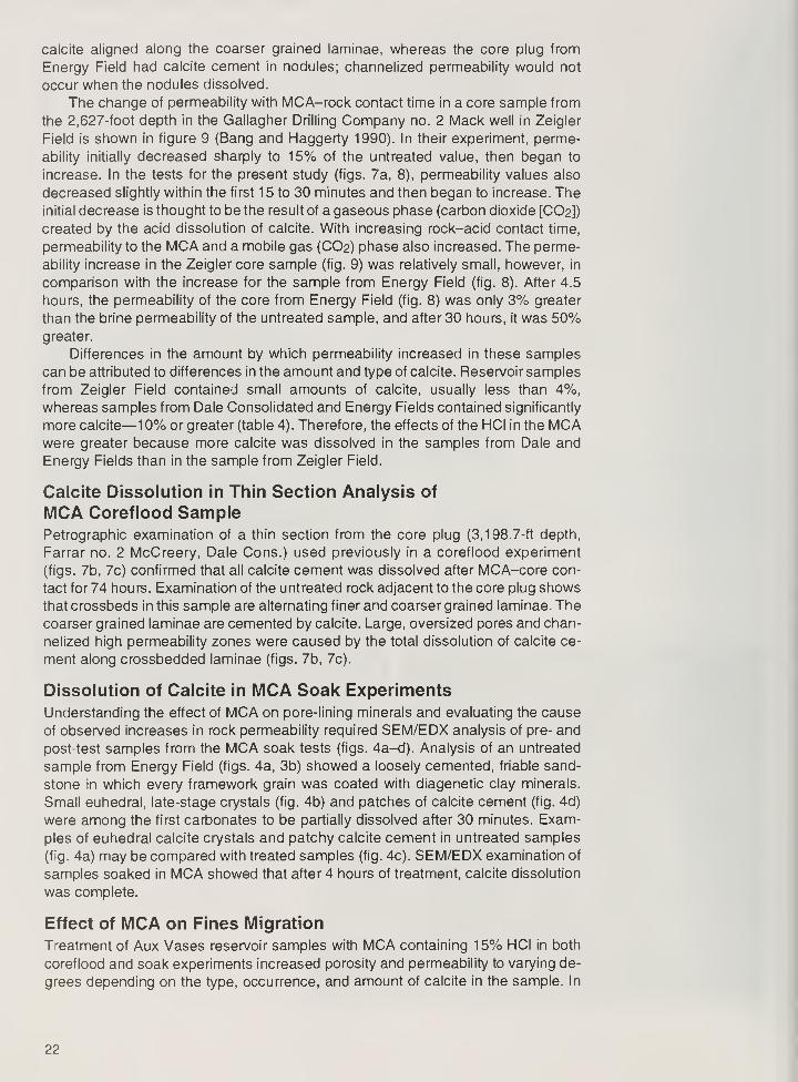
calcite aligned along the coarser grained laminae, whereas the core plug from
Energy Field had calcite cement in nodules; channelized permeability would not
occur when the nodules dissolved.
The change of permeability with MCA-rock contact time in a core sample from
the 2,627-foot depth in the Gallagher Drilling Company no. 2 Mack well in Zeigler
Field is shown in figure 9 (Bang and Haggerty 1990). In their experiment, perme-
ability initially decreased sharply to 15% of the untreated value, then began to
increase. In the tests for the present study (figs. 7a, 8), permeability values also
decreased slightly within the first 1 5 to 30 minutes and then began to increase. Theinitial decrease is thought to be the result of a gaseous phase (carbon dioxide [CO2])
created by the acid dissolution of calcite. With increasing rock-acid contact time,
permeability to the MCA and a mobile gas (CO2) phase also increased. The perme-
ability increase in the Zeigler core sample (fig. 9) was relatively small, however, in
comparison with the increase for the sample from Energy Field (fig. 8). After 4.5
hours, the permeability of the core from Energy Field (fig. 8) was only 3% greater
than the brine permeability of the untreated sample, and after 30 hours, it was 50%greater.
Differences in the amount by which permeability increased in these samples
can be attributed to differences in the amount and type of calcite. Reservoir samples
from Zeigler Field contained small amounts of calcite, usually less than 4%,whereas samples from Dale Consolidated and Energy Fields contained significantly
more calcite—10% or greater (table 4). Therefore, the effects of the HCI in the MCAwere greater because more calcite was dissolved in the samples from Dale and
Energy Fields than in the sample from Zeigler Field.
Calcite Dissolution in Thin Section Analysis of
MCA Coreflood SamplePetrographic examination of a thin section from the core plug (3,198.7-ft depth,
Farrar no. 2 McCreery, Dale Cons.) used previously in a coreflood experiment
(figs. 7b, 7c) confirmed that all calcite cement was dissolved after MCA-core con-
tact for 74 hours. Examination of the untreated rock adjacent to the core plug shows
that crossbeds in this sample are alternating finer and coarser grained laminae. Thecoarser grained laminae are cemented by calcite. Large, oversized pores and chan-
nelized high permeability zones were caused by the total dissolution of calcite ce-
ment along crossbedded laminae (figs. 7b, 7c).
Dissolution of Calcite in MCA Soak Experiments
Understanding the effect of MCA on pore-lining minerals and evaluating the cause
of observed increases in rock permeability required SEM/EDX analysis of pre- and
post-test samples from the MCA soak tests (figs. 4a-d). Analysis of an untreated
sample from Energy Field (figs. 4a, 3b) showed a loosely cemented, friable sand-
stone in which every framework grain was coated with diagenetic clay minerals.
Small euhedral, late-stage crystals (fig. 4b) and patches of calcite cement (fig. 4d)
were among the first carbonates to be partially dissolved after 30 minutes. Exam-
ples of euhedral calcite crystals and patchy calcite cement in untreated samples
(fig. 4a) may be compared with treated samples (fig. 4c). SEM/EDX examination of
samples soaked in MCA showed that after 4 hours of treatment, calcite dissolution
was complete.
Effect of MCA on Fines Migration
Treatment of Aux Vases reservoir samples with MCA containing 15% HCI in both
coreflood and soak experiments increased porosity and permeability to varying de-
grees depending on the type, occurrence, and amount of calcite in the sample. In
22

the reservoir, however, extensive dissolution of calcite cement may lead to pore
collapse because of the lithostatic load on the reservoir. Removal of cement can
also dislodge sand grains and clay particles, which can then migrate and impair
permeability in sandstone reservoirs (Amaefule and Masuo 1986). Fines migration
was observed in coreflood experiments using both MCA and 15% HCI in Aux Vasesreservoir samples, particularly after 24 hours of exposure to these stimulation fluids.
Microscopic examination using reflected and transmitted light showed that fines
filtered from the effluent in these experiments consisted of fine-grained sand andsilt-sized grains of nonclay minerals as well as particles of diagenetic clay minerals.
It was not possible to separate these migrated fines from the residue formed during
evaporation of 1 5% HCI or MCA. XRD and SEM/EDX analyses of these evaporated
solids were not successful in identifying the mineralogical composition of the mi-
grated fines.
Effect of MCA on Other Minerals
Other pore-lining minerals that may react with MCA include clay minerals, halite,
and K-feldspar; for example, a geochemical model (Demir 1995) simulating the
reaction of MCA with a clay mineral suite of iron-rich chlorite, smectite, and illite
predicted precipitation of the zeolite mordenite as a byproduct. Trace amounts of
pyrite and graphite were also predicted in Demir's model. Because pyrite and graph-
ite (carbon) are naturally occurring minerals in Aux Vases reservoirs samples, andthe amounts predicted by the model were below the detection limits of the XRD and
SEM/EDX, none of these minerals could be attributed to precipitation from this re-
action.
A mineral resembling mordenite, (Na2,K2,Ca)[Al2SiioC>24] 7H2O, was identi-
fied in the SEM/EDX analysis as a precipitate in a postflood core sample from the
Budmark no. 2 Morgan Coal well in Energy Field. Mordenite crystals have an
elongate, orthorhombic morphology and a characteristic chemical composition, un-
like the morphology and composition of any naturally occurring Aux Vases pore-lin-
ing minerals (fig. 10). Several SEM/EDX analyses of mordenite show that this
mineral precipitated on top of the last natural pore-lining diagenetic clay mineral.
The thin, delicate, needle-shaped crystals, which protrude into pores (fig. 10), would
have been broken or abraded during coreflooding had they been present prior to
the experiment. In addition, no mordenite was found during petrographic examina-
tion of more than 150 Aux Vases reservoir samples using SEM/EDX and thin
section techniques, including the two samples taken adjacent to the core plug. Theamount of mordenite precipitated was minor in terms of pore volume, therefore
porosity was not measurably affected.
Dissolution or disintegration of diagenetic clay minerals treated with MCA wasnot visually apparent during SEM/EDX examination. Chemical analysis of the MCA,which would have verified these visual observations, was not permitted because of
proprietary considerations. Some dissolution in samples treated with MCA could
have taken place without detection by SEM/EDX; however, the widespread dis-
solution and disintegration of clay minerals observed in some samples treated with
15% HCI was probably avoided because of clay-stabilizing additives in the MCA.
Effect of 15% HCI Coreflood on Aux Vases Reservoir
SandstonesInjecting a 15% HCI solution into a core plug from a depth of 2,393.5 feet in the
Budmark no. 2 Morgan Coal well in Energy Field showed that the permeability of
the core increased with increasing volumes of fresh acid (fig. 11). These results,
attributed to the dissolution of calcite in the sample, were contrary to expectations.
Literature on formation damage (Simon and Anderson 1990, Somerton and Radke
23

Figure 1 SEM of needle-shaped precipitates in pores of a sample (2,388.3-ft
depth, Budmark 2 Morgan Coal, Energy Field). It is believed that this precipitate
resulted from MCA reacting with pore minerals, particularly diagenetic clay
minerals and calcite. EDX analysis shows Si, Al, Na, Ca, and Mg in this
precipitate; the elemental composition and morphology suggest mordenite, a
zeolite.
Figure 11 Permeability of a core plug (2,393.5-ft depth, Budmark 2 MorganCoal, Energy Field) changed as the HCI-rock contact time increased during a
continuous, constant rate acid flood test using 15% HCI.
1983, Potter and Dibble 1985) suggests that a decrease in permeability is likely
when iron-rich chlorite clay minerals are exposed to 1 5% HCI without additives. This
anticipated loss of permeability has been attributed to the precipitation of iron hy-
droxide gels derived from the dissolution of iron-rich chlorite clay minerals (Somer-
24

ton and Radke 1 983). Chlorite in the Aux Vases is an aluminum- or magnesium-rich
variety that apparently does not produce these gels.
Chemical analyses of the effluent from the 15% HCI core flow experiment
showed that prolonged acid contact with the reservoir sample (more than 1 day)
may have caused leaching and disintegration of pore-lining diagenetic clay miner-
als, in addition to the total dissolution of calcite and dolomite. Table 5 shows the
results of analyses of effluent samples collected at 1 hour, 2 hours, and 2 days.
Significant amounts of sodium, magnesium, aluminum, calcium, manganese, andiron were found. With the exception of calcium and manganese, most of the major
ions in the effluent were most likely supplied by the reaction of diagenetic clay
minerals with 15% HCI. Lesser amounts of potassium, copper, barium, and chro-
mium were also present in the effluent. Although widespread leaching, disaggrega-
tion, or dissolution of pore-lining diagenetic clay minerals were not visually obvious
in many SEM images, some samples from soaking experiments (discussed below)
do show disintegration or dissolution of clay minerals. Figure 12d, for example,
shows that no clay mineral coatings remain on many of the framework grains, an
indication of disintegration and dissolution of diagenetic clay minerals. Therefore, it
is likely that leaching of clay minerals does occur but may not always be detectable
using SEM/EDX techniques.
Magnesium chloride (MgCte; fig. 13), the most common precipitate observed in
the core plug after completion of the 1 5% HCI coreflood experiment, is very soluble
in water; it would remain in solution under most reservoir conditions. It likely precipi-
tated during sample drying after completion of the coreflood experiment prior to
SEM/EDX analysis. Although not a factor under reservoir conditions, the presence
Table 5 Composition of effluent from HCI coreflow: Energy Field sample,
2,392.6-foot depth, Budmark 2 Morgan Coal well
mg/l
Effluent
sampled at Al As B Ba Be Ca
1 hour 26.5 0.2 0.26 2.18 0.004 8250
2 hours 250 .1 0.11 0.68 .001 1550
2 days 56.4 .1 0.1 0.83 0.002 3130
Cd Co Cr Cu Fe
1 hour 0.04 0.40 8.1 19.4 109
2 hours 0.46 0.46 11.1 10.6 409
2 days .01 0.34 15.1 9.21 158
K La Li Mg Mn Mo
1 hour 9 0.52 0.19 92.6 15.4 40.8
2 hours 7 0.19 0.47 177 4.09 21.2
2 days 6 0.28 0.12 48.5 7.49 15.4
Na Ni Li Mg Mn Mo
1 hour 895 131 08 0.010 .1 17.8
2 hours 168 57.4 0.14 0.009 .1 15.7
2 days 154 49.4 0.04 0.022 .1 19.2
Sr Ti TI V Zn Zr
1 hour 17.1 0.10 .1 0.02 1.64 0.07
2 hours 1.63 0.13 .1 0.70 1.74 0.07
2 days 2.35 0.11 .1 0.20 0.80 0.10
25

.
15.0 kVL0"m E2392 4.5h #0002
Figure 1 2 SEMs illustrate the effects of soaking Aux Vases core plug wafers
(2,392. 4-ft depth, Budmark 2 Morgan Coal, Energy Field) in a 1 5% HCI solution
without any of the additives found in MCA. The most common precipitates in
these samples are shown in figures 12a-c.
a) Gypsum crystals precipitated because of the reaction of pore minerals and
formation brine with 15% HCI. EDX analysis shows that S and Ca are the
predominant detectable elements in these crystals.
b) Blebs that do not display any crystalline structure and appear to be an
amorphous or gel-like substance containing Fe and CI, as identified by EDXanalysis. (The EDX unit used in this study detects elements with atomic
numbers of 6 or greater.)
26

c) In another amorphous material, EDX analysis has identified "Ca, CI, Al, Si,
and Fe. All these precipitates are attributed to the reaction of pore minerals
and formation brine with 15% HCI because they have not been observed in
any untreated samples.
d) The smooth quartz grains without their original clay mineral coatings (fig. 3b)
indicates widespread removal, disintegration, or dissolution of diagenetic clay
minerals—the effects of long-term soaking in 15% HCI.
27

Figure 1 3 SEM of magnesium chloride (MgCte), a precipitate evolving from the
reaction of 15% HCI and pore minerals during the core flow experiment. Both
MgCl2 and halite have a ramshom morphology; MgCl2 was identified by EDXanalysis. Because of its high solubility in water, the magnesium chloride probably
formed after the coreflood experiment when the sample (2,393.5-ft depth,
Budmark 2 Morgan Coal, Energy Field) was drying.
of MgCl2 shows that large amounts of magnesium were leached from the samplesduring the experiments (fig. 13). The source of the magnesium could be chlorite,
dolomite, or both.
Soaking Experiments Using 15% HCI
Soaking experiments were conducted with 1 5% HCI and a core plug from the samewell (Budmark no. 2 Morgan Coal) and depth (2,392.5 ft) as the core plug used in
the 15% HCI core flow experiment for Energy Field. The soaking experiments are
saturation tests that more closely resemble the conditions of incompletely swabbedzones of the reservoir, in contrast to the constant injection coreflood tests. In core-
flood experiments, the opportunity for precipitation of minerals due to the reaction
of stimulation fluids with minerals in the reservoir samples was more limited; fluids
were constantly flushed through the pore system, thus diluting and transporting any
reaction products out of the sample in the effluent. In the soak experiments, there
was no flushing of fluids through the pores of reservoir samples; therefore, the op-
portunity for mineral precipitation was greater than it was in the coreflood experi-
ments. If the rock remains unflushed, it is likely that any precipitates would remain
as pore occlusions.
The soaking experiments resulted in precipitates that evolved from the reaction
of pore-lining minerals with 15% HCI. Greater abundance and variety of potential
pore-occluding precipitates were found in wafers soaked in 15% HCI than in sam-
ples soaked in MCA, or in core plugs flooded with ten or more pore volumes of 1 5%HCI or MCA.
28

As the SEM/EDX analyses indicated, the precipitates that formed during the
core soak experiments included gypsum, microcrystalline iron chloride, microcrys-
talline aluminosilicates, and other microcrystalline phases containing significant
amounts of chlorine but no other detectable elements (figs. 12a-d). None of these
minerals or compounds have been observed in untreated reservoir samples. With
the exception of the gypsum, a common low temperature evaporite mineral, noneof these precipitates has an obvious crystal morphology. Instead, they have a
botryoidal or gel-like appearance, as shown in figure 12b. The lack of identifiable
crystal morphology may be attributed in part to the short time available for crystal-
lization, and the low temperature and pressure conditions of the experiments. Suchconditions sometimes result in the formation of mineraloids or gels, which are
amorphous natural solids that show no signs of crystallinity (Hurlbut 1971).
The lack of carbonates in samples soaked for more than 4 hours suggests that
porosity and permeability may increase under reservoir conditions. The experi-
ments also show that disintegration or dissolution of pore-lining clay minerals can
occur when they are exposed to 1 5% HCI for 6.5 hours (fig. 1 2d) or longer. Migration
of disintegrated clay minerals and fine-grained material dislodged by calcite disso-
lution can occlude permeability. Thus, the net effect of acid-treatments in reservoir
rocks with little or no calcite may be to reduce the permeability.
The potential for adverse reactions when 15% HCI or poorly formulated MCAis used in well completion treatments is confirmed by the data in table 6 (adapted
from Economides and Nolte 1989). The table lists minerals found in Aux Vasesreservoir samples and shows their relative reactivities with and likelihood for expo-
sure to introduced fluids under reservoir conditions; for example, although 65-90%of the typical reservoir sample was composed of quartz, it has a low likelihood of
exposure to introduced fluids because most Aux Vases quartz grains are coated
with diagenetic clay minerals. Quartz also has a very low reactivity to HCI; therefore,
the diagenetic clay minerals, not the quartz grains, have more exposure to reservoir
fluids. Of the common minerals in Aux Vases reservoir sandstones, calcite is the
able 6 Reactions of Aux Vases Sandstone minerals with well fluids*
lineral
Exposure
to fluids
Solubility
in 15% HCI Chemical composition Released
>uartz Low Insoluble Si02 None
-feldspar Low to med Low K(AISi30s) K+1
,AI+3
,Si+4
a-feldspar Low to med Insoluble Na(AISi30e) None
ite High Low (Fe,Mg)KxAl2(Si4-x Alx)Oio(OH)2 K+1
,AI+3
,Si+4
lixed-layered High Low (Fe,Mg)KxAl2(Si4-x, Alx)Oio(OH)2 K+1
,AI+3
,Si+4
lite/smectite Low(
1/2Ca,Na)-7(AI,Mg,Fe)4-
(Si,AI)8O20(OH)4-nH2O
Ca+2
,Na+1
,Fe+2
,Mg+2
,AI+3
,Si+4
hlorite High Low to med (Mg,Fe)5(AI,Fe)(AI,Si30io)(OH)8 Mg+2,Fe+2 ,AI+3
Si+4
alcite Low to high High CaC03 Ca+2
,C03"
e-dolomite Low High (Ca,Mg,Fe)C03 Mg+2,Fe+2,Ca+2,C03"
natase Low Insoluble Ti02 None
arite-celestite Low Insoluble (Ba,Sr)S04 None
olid H-carbon Low to med Med C,OH,H,S,N C+4,S+4
yrite Low Insoluble Fe2S None
Adapted from Piot and Pertuis (1989).
29

most reactive to 15% HCI. Ferroan calcite, dolomite, and ferroan dolomite, whenpresent, are also highly reactive carbonates, but are less common than calcite. Asa comparison of table 6 with table 4 shows, Aux Vases reservoir rocks contain
several minerals that release a variety of ions and precipitate as permeability-oc-
cluding secondary byproducts. Secondary byproducts observed in samples treated
with 15% HCI include gypsum (fig. 12a), gel-like substances rich in chlorides (fig.
12b), amorphous or gel-like material rich in aluminosilicates (fig. 12c), and
magnesium chloride (fig. 13).
The gel-like chlorides apparently precipitated or solidified when iron, magne-sium, sodium and/or calcium cations combined with chlorine anions and were abun-
dant in soaked samples. These ions would be available from the dissolution of clay
minerals and carbonates; the chloride anion was in abundant supply from the 15%HCI (Economides and Nolte 1 989). The gel-like aluminosilicates were less commonthan the gel-like or botryoidal chloride-rich precipitates, a condition that likely re-
flected the lesser availability of aluminum and silica (table 5) than that of chlorine
during the experiments. Most of the amorphous aluminosilicates were composed of
aluminum, silica, and minor amounts of sodium, magnesium, potassium, calcium,
and/or iron. These elements would have been released by dissolution of diagenetic
clay minerals (table 6). Gypsum (CaS04 • 2H2O) was found in samples soaked for
1 .5 hours or more in 1 5% HCI, but it was never detected in any untreated samples.
The likely source of sulfate (SO4) is the formation brine. Analyses of brines from
several Aux Vases reservoirs have detected SO4 concentrations of 500 mg/L or
greater, providing ample SO4 for gypsum precipitation. Formation brine chemistries
and their potential for reaction with injection fluids is discussed in greater detail by
Demir(1995).
Oil-Acid Compatibility Tests
Aux Vases crude oil emulsified immediately when 15% HCI was added. After 24
hours at atmospheric pressure and 77°F (25°C), a viscous sludge formed in crude
oil samples from Dale Consolidated, Energy, and Zeigler Fields. (An example from
Energy Field is shown in fig. 14a.) In contrast, no sludge formed when MCA wasadded to the same oil (fig. 14b). These results demonstrated that the Aux Vasescrude oil from Dale, Energy, and Zeigler Fields is HCI-acid-sensitive. MCA solutions
usually contain demulsifying and/or antisludging agents. Without the demulsifying
agents, acids react with crude oil to form sludges that can reduce permeability and
alter reservoir properties of relative permeability and rock wettability, resulting in
reduced oil flow and higher water production (Allen and Roberts 1989). These re-
sults indicate that MCA containing appropriate proportions of antisludging chemi-
cals should be used for Aux Vases cleanout operations.
Avoiding Acid-Induced Formation Damagein Aux Vases Reservoir SandstonesThe use of lower concentrations of HCI in MCA to maintain a weaker acidic envi-
ronment in the reservoir has been suggested as one way of combating formation
damage associated with MCA treatments (Simon and Anderson 1990). One opera-
tor at Energy Field reduced the acid concentration to 7.5% HCI, but has not ob-
served adverse effects on production from the treatments (Hiram Hughes, BudmarkOil Co., pers. comm. 1992). Despite this, it is recommended that only an MCAproperly formulated with appropriate additives be used to avoid potentially deleteri-
ous reactions with crude oil and clay minerals. The use of iron-sequestering agents
in the MCA is also suggested to prevent iron ions leaching from wellbore tubing or
acid reaction with soluble iron-rich minerals.
30

15% HC1 in Crude Oil
a
MCA in Crude Oil
Figure 14 a) Emulsified sludge formed immediately upon contact of Aux Vases oil with 1 5%HCI. b) When MCA was added to Aux Vases oil, sludge did not form, presumably because
of the surfactant in the MCA.
Water Sensitivity of Aux Vases Reservoir SandstonesWater sensitivity data for Aux Vases reservoir sandstones are sparse. An early study
on waterflooding operations in the oil-producing sandstones of Illinois (Whither-
spoon 1 952) reported the potential for reactions of clay minerals with injected water.
Witherspoon cited the work of Grim (1947), a pioneering clay mineralogist, whoidentified montmorillinite (smectite) as "the worst offender in this respect because
of its ability under certain conditions to absorb indefinite amounts of fresh water into
its crystalline structure." However, XRD analyses of Aux Vases sandstone reservoir
samples showed illite, chlorite and mixed-layered illite/smectite in appreciable quan-
tities but no pure smectite or kaolinite. Of the clay minerals present in the Aux
Vases, only the mixed-layered illite/smectite varieties have been reported to showwater sensitivity (Monaghan et al. 1958, Allen and Roberts 1989, Thomas 1985).
31

CD
CO
8>
ooo
CO<D
CD
formation brine
fresh water
12.4 11.7 11.1
Salinity (%)
Figure 15 Various mixtures of produced brine and deionized water were injected
into a core plug (2,388-ft depth, Budmark 2 Morgan Coal, Energy Field). Decreasing
salinity corresponded with decreasing permeability, which suggests that injection of
fluids less saline than formation brine can cause formation damage.
Various mixtures of produced brine and deionized water were injected into a
sample from the 2,388-foot depth in the Budmark no. 2 Morgan Coal well in Energy
Field (fig. 15) in a sequential manner to ascertain the minimum salinity that did not
impair permeability. It was found that the addition of 5% deionized water to the brine
reduced the permeability to water by 15%, and subsequent mixtures of 50% forma-
tion brine and 50% fresh water reduced permeability to water by 52% (fig. 15,
table 7). This result showed that (1) all injected waters with salinities below that of
the formation brine impaired the permeability of the Energy Field sample, and
(2) that the Aux Vases sandstone at Energy Field is very sensitive to brine solutions
that are less saline than the formation water.
Permeability values of samples from the 2,1 63-foot depth of the Superior Oil
no. 9 Sanders well in Boyd Field and the 2,61 1 -foot depth of the Gallagher Drilling
Company no. 2 Mack well in Zeigler Field decreased by 61.6% and 7.4%, respec-
tively, when the 100% formation brine was displaced with fresh water (fig. 16,
table 8). Initial results for low permeability samples from the 2,390-foot depth of the
Table 7 Water sensitivity of core plug to injection of
increasing amounts of fresh water (fig. 15)
% fresh- % formation % decrease in
water brine permeability
5 95 -14
10 90 -29.2
15 85 -48.7
20 80 -52.9
25 75 -54.7
50 50 -56.0
32

100
Injection water
Figure 16 Changes in permeability of core plugs tested with water of varying
salinities. The most pronounced decrease occurred in high permeability samples
from Energy and Boyd Fields. An early but brief increase in permeability in a low
permeability sample from Energy Field was probably due to dissolution of halite
precipitated when brine evaporated during air drying.
Budmark no. 2 Morgan Coal well in Energy Field and the 3,200-foot depth of the
Farrar no. 1 McCreery well in Dale Consolidated Field varied from this general trend.
Permeability values increased from 20 to 30 md when fresh water displaced forma-
tion brine from these samples. The experiment was repeated on a core plug higher
in permeability—a plug from the 2,388-foot depth of the Budmark no. 2 Morgan Coal
well in Energy Field: permeability values initially decreased from 60 to 12 md whenformation brine was displaced by fresh water (fig. 16) and did not increase wheninjected with increasingly saline solutions. The increase in permeability with injec-
tion of fresh water in the first Energy and Dale core plugs could have been the result
of precipitation of halite crystals from formation brine in the pores of the core sample
and their subsequent dissolution in fresh water. Halite has been observed as a
Table 8 Changes (%) in permeability of samples used in water sensitivity corefloods (fig. 1 6)
Boyd Energy Energy Dale Zeigler
Injection fluid 2,163-ft depth 2,388-ft depth 2,390-ft depth 3,200.6-ft depth 2,61 1 -ft depth
A Formation water 75 md initial k 47 md initial k 17 md initial k 19 md initial k 12.5 md initial k
B Freshwater -60.0% -74.5% +34.6% +5.3% No change
C 50% fresh water -66.7% -75.5% +5.88% -26.3% -48.0%
50% formation water
-89.6% -17.6% -36.8%D 25% freshwater -74.7%
75% formation water
E 10% fresh water -74.7% -91.7%
90% formation water
F 100%deionized -76.0% -93.6%
-20.6%
-23.5%
-42.1%
-53.7%
-54.4%
-56.0%
-58.4%
k = permeability
33

pore-filling mineral in some Aux Vases reservoir samples from Zeigler Field (Seyler
in prep).
Another purpose of these experiments was to determine whether exposure to
fresh water could be followed by injection of water higher in salinity (50% brine plus
50% fresh water), and thus restore permeability to original levels.
Experimental results (fig. 16, table 8) show that permeability was not restored
in any of the samples tested. The same result was reported by Monaghan et al.
(1958) using sandstone cores from sub-Clarkville Field of east Texas, Frio Field of
southwest Texas, and the Cockfield of the Texas Gulf Coast. According to our
experimental results, core permeabilities in all the core samples continued to de-
crease with injection of various mixtures of formation and fresh waters once initially
exposed to fresh water. The most likely explanations are that clay minerals perma-
nently swelled with the addition of fresh water or that deflocculated clay mineral
crystallites migrated to the pore throats in the samples and constricted fluid flow.
Because reverse flow in the plug (at the same rate) resulted in an initial 5% increase
in permeability and then a continuous permeability decrease with more flow in the
reverse direction, fines migration is most likely (Hewitt 1963).
The fresh-water sensitivity shown by the samples from the four fields (figs. 15,
16, table 8) indicates that injecting an Aux Vases reservoir with brines less saline
than the formation brine is likely to impair the permeability of the reservoir. The
salinity of the injection water and the formation brine must be equivalent, as shown
in the sample from Energy Field (fig. 15), to avoid impairing the permeability of the
reservoir. Reinjection of increasingly higher saline solutions did not restore initial
permeability; the damage could not be reversed (fig. 16).
CONCLUSIONS AND RECOMMENDATIONS
Experiments on the interactions between well stimulation acids, brines of various
salinities, and reservoir rock samples identified the key factors involved in formation
damage in the Aux Vases Sandstone. Permeability changes observed during the
experiments are summarized in table 9.
Although clay minerals constitute only 1-6% of the bulk mineral content of Aux
Vases reservoir samples, they line or bridge every pore of the reservoir. Conse-
quently, determining the composition of these diagenetic clay minerals and their
Table 9 Summary of experimental results
Experiment Figures Change in permeability
Crude oil/15% HCI 14 (Decrease)*
Crude oil/MCA 14 (No change)*
Continuous corefloods with MCA 8 and 9 Increase 0-60%Continuous coreflood with HCI 11 Increase up to 30%Discontinous coreflood with MCA 7 Increase up to 600%HCI soak 12a-d Could not measure
MCA soak 4b and 4d Could not measure
Water sensitivity
Gradual increase in freshwater 15 Decrease 15-56%
Boyd (2, 163-ft depth) 16 -60.0% to -76.0%
Energy (2,388-ft depth) 16 -74.5% to -93.6%
Energy (2, 190-ft depth) 16 +34.6% to -23.5%
Dale (3,200.6-ft depth) 16 +5.3% to -53.7%
Zeigler (2,611 -ft depth) 16 to -58.4%
* Inferred from experiment results, not directly measured.
34

reactions to drilling, completion, and injection fluids is vital for enhancing oil recovery
in the Illinois Basin.
1. In contact with acid, calcite is the most reactive pore mineral in Aux Vases
sandstone reservoirs; the second most reactive mineral is ferroan dolomite. Nocalcite remained in Aux Vases core samples after 4 hours of exposure to MCAconsisting of 1 5% HCI, with or without additives. The dissolution of calcite suggests
that use of MCA or a 15% HCI solution may increase the permeability of Aux Vases
sandstone reservoirs; however, the negative effects of acid treatment on the inti-
mately intergrown mixture of mixed-layered illite/smectite, chlorite, and illite mayreduce reservoir permeability.
Our experiments showed that the precipitates derived from the reaction of pore
minerals with 15% HCI were greater in variety and quantity than those formed by a
commercially formulated MCA; 15% HCI alone should not be used in treating AuxVases reservoirs.
2. Fines were detected in the effluent from the coreflood experiments. Removal of
calcite cement by MCA allowed sand, silt, and clay particles to be dislodged and
migrate. These fines are likely to be deposited in pore throats, thus reducing per-
meability. Dissolution of localized calcite cement in a sandstone may also cause
collapse and washout of sandstone around the wellbore.
3. The static soak experiments suggest that prolonged contact of acid with the
reservoir rock could result in leaching and disintegration of pore-lining diagenetic
clay minerals and the precipitation of pore-plugging material. Rock-acid contact
times of less than 1 day created less precipitate material than those exceeding 2
days. In addition, the greater abundance and variety of pore-occluding precipitates
in samples soaked in 15% HCI, rather than in MCA, demonstrated another advan-
tage of using MCA.
4. Results of oil-acid compatibility tests demonstrated that oil samples from Aux
Vases reservoirs in Boyd, Energy, and Zeigler Fields are acid-sensitive. However,
no sludges were formed when crude oil was mixed with MCA. This suggests that
the MCA used in these experiments was compatible with the crude oil, whereas a
15% HCI solution without additives was not.
5. In Aux Vases reservoir rocks, the intergrown diagenetic clay minerals, especially
the mixed-layered illite/smectite, reacted adversely to the salinity of injected waters.
Injection of water less saline than the formation brine impaired permeability, slightly
to severely. Injection of increasingly saline water did not restore permeability. Toavoid permeability impairment in Aux Vases reservoirs, oil field operators should
only inject wells with waters as saline as the formation brines.
35

REFERENCES
Abrams, A., 1 977, Mud design to minimize rock impairment due to particle invasion:
Journal of Petroleum Technology, v. 29, p. 586-592.
Allen, T.O., and A.P. Roberts, 1989, Formation damage (chapter 5), in Production
Operations: Oil & Gas Consultants International, Inc., Tulsa, Oklahoma, p. 67-79.
Amaefule, J.O., and ST. Masuo, 1986, Use of capillary-pressure data for rapid
evaluation of formation damage or stimulation: Society of Petroleum Engineers
Production Engineering, v. 1, p. 131-142.
Amyx, J.W., D.M. Bass, Jr., and R.L. Whiting, 1960, Petroleum Reservoir Engineer-
ing, Physical Properties: R.L. Mc Graw-Hill, New York, p. 96.
Anderson, W.G., 1987, Wettability literature survey, part 4: The effect of wettability
on capillary pressure: Journal of Petroleum Technology, v. 39, no. 10, p. 1283-
1300.
Bang, W., and D. Haggerty, 1 990, Effect of MCA on Aux Vases Sandstones: Illinois
State Geological Survey, Champaign, Oil and Gas Section, unpublished study,
p. 4-10.
Bradley, H.B., 1987, Petroleum Geology Handbook: Society of Petroleum Engi-
neers, Richardson, Texas, p. 54-58.
Civan, F., 1992, Evaluation and comparison of the formation damage models,
Proceedings of the International Symposium on Formation Damage Control,
Lafayette, Louisana, February 1992: Society of Petroleum Engineers, p. 219-
236.
Delclaud, J., 1991, Laboratory measurement of the residual gas saturation, in P.F.
Worthington and D. Longeron (eds.), Advances in Core Evaluation II, Proceedings
of the Second Society of Core Analysts, European Core Analysis Symposium,
London, UK, p. 431-451.
Demir, I., 1995, Formation water chemistry and modeling fluid-rock interaction for
improved oil recovery in Aux Vases and Cypress Formations, Illinois Basin:
Illinois State Geological Survey, Illinois Petroleum 148, p. 60.
Eickmeier, J.R., and H.J. Raimey, Jr., 1970, Wellbore temperature and heat losses
during production or injection operations, Proceedings of the 21st Annual Tech-
nical Meeting, Calgary, Canada, May 1970: Canadian Institute of Mining, paper
7016.
Gray, D.H., and R.W. Rex, 1966, in sandstones caused by clay dispersion and
migration, /'nS.W. Bailey (ed.), Clays and Clay Minerals, Proceedings of the 14th
National Conference on Clays and Clay Minerals: Clays and Clay Minerals
Society, Pergamon Press, Elmsford, New York, p. 355-366.
Grim, R.E., 1947, Relation of clay mineralogy to origin and recovery of petroleum:
American Association of Petroleum Geologists Bulletin, v. 31, no. 8, p. 1491-
1499.
Halliburton Services, 1991, Chemical Services Technical Data, CS-5065 (revised):
Halliburton Company, Duncan, Oklahoma, Section II, p. 7-8.

Hewitt, C.H., 1963, Analytical techniques for recognizing water-sensitive reservoir
rocks: Journal of Petroleum Technology, v. 15, no. 8, p. 813-818.
Hughes, R.E., and R.L Warren, 1989, Evaluation of the economic usefulness of
earth materials by X-Ray Diffraction, in R.E. Hughes and J.C. Bradbury (eds.),
Proceedings of the 23rd Forum on Geology of Industrial Minerals: Illinois State
Geological Survey, Illinois Mineral Notes 102, p. 47-58.
Hurlbut, C.S., 1971, Dana's Manual of Mineralogy (18th edition): John Wiley and
Sons, Inc., New York, p. 201.
Khilar, K.C., and H.S. Fogler, 1983, Water sensitivity of sandstones: Society of
Petroleum Engineers paper 10103, p. 55-64.
Krueger, R.F., 1986, An overview of and well productivity in oilfield operations:
Transactions of the American Institute of Mining, Metallurgy, and Petroleum
Engineers (AIME), v. 281, p. 131-152.
Kyte, J.R., and LA. Rapoport, 1958, Linear waterflood behavoirand end effects in
water-wet porous media: Transactions of the American Institute of Mining, Met-
allurgy, and Petroleum Engineers, v. 213, p. 423-426.
Levorsen, A.I., 1967, Geology of Petroleum (2nd edition): W.H. Freeman and Com-pany, San Francisco, California, 409 p.
Monaghan, P.H., R.A. Salathiel, B.E. Morgan, and A.D. Kaiser, Jr., 1959, Labora-
tory studies of in sands containing clays: Transactions of the American Institute
of Mining, Metallurgy, and Petroleum Engineers, v. 216, p. 209.
Mungan, N., 1965, Permeability reduction through changes in pH and salinity:
Journal of Petroleum Technology, v. 17, no. 12, p. 1449-1 453.
Oil and Gas Section, 1993, Improved and Enhanced Oil Recovery Through Reser-
voir Characterization: Standard Operating and QA/QC Procedures: Illinois State
Geological Survey, Open File Series 1993-13, 184 p.
Piot, B.M., and H.G. Perthuis, 1 989, Matrix acidizing of sandstones, in M.J. and K.G.
Nolte (eds.), Reservoir Stimulation (2nd edition), Economides: Prentice-Hall,
Englewood Cliffs, New Jersey, p. 14.1-14.6.
Potter, J.M., and W.E. Dibble, 1985, Chemical aspects of iron colloid plugging in
quartz sands and implications for formation damage: Journal of Petroleum Tech-
nology, September 1985, v. 37, no. 10, p. 1682-1688.
Ross, G.J., 1969, Acid dissolution of chlorites: release of magnesium, iron and
aluminum and mode of acid attack: Clay and Clay Minerals, v. 17, p. 347-354.
Seyler, B., 1 992, Effects of sample preparation (heating and cleaning) on diagenetic
clay mineral coatings in Aux Vases Sandstone samples: Illinois State Geological
Survey, Oil and Gas Section, unpublished report, p. 3.
Seyler, B., in prep., Reservoir characterization for effective reservoir management:
A comprehensive example; Zeigler Field, Franklin County, Illinois: Illinois State
Geological Survey, Illinois Petroleum series.
Seyler, B., R.E. Hughes, and D.S. Beaty, in prep., The role of diagenesis in AuxVases and Cypress Sandstones reservoir development: Illinois State Geological
Survey, Illinois Petroleum series.
37
Simon, D.E., and M.S. Anderson, 1 990, Stability of clay minerals in acid, in Proceed-
ings of the 9th Symposium on Formation Damage Control: Lafayette, Louisiana,
February 1990: Society of Petroleum Engineers, p. 201-212.
Somerton, W.H., and C.J. Radke, 1983, Role of clays in enhanced recovery of
petroleum from some California sands: Journal of Petroleum Technology, v. 35,
p. 643-654.
Tiab, D., 1985, Petrophysics Laboratory Manual: University of Oklahoma, Norman,
Oklahoma, 202 p.
Vaidya, R.N., O.C. Baptist, and J.W. Eliot, 1 957, Clay content and capillary behavior
of Wyoming reservoir sands: Transactions of the American Institute of Mining,
Metallurgy, and Petroleum Engineers, v. 210, p. 414-416.
Witherspoon, P. A., 1952, Some important aspects of water flooding in Illinois: Illi-
nois State Geological Survey Circular 180, 14 p.
38

APPENDIX I Petrographic Analyses
Thin section billets were impregnated with epoxy under vacuum at low tempera-
tures. After preparation, the thin sections were stained with potassium ferricyanide
and alizarine red to highlight distribution of carbonate phases.
All SEM/EDX analyses were performed on an Amray 1830 equipped with a
Noran (Tracor Northern) Z-MAX 30 Series EDX. SEM analyses were used to iden-
tify pore-lining minerals; the EDX was used for analysis of elemental composition.
Samples were sputter-coated with gold and palladium.
XRD analyses provide semiquantitative data on mineralogical composition of
select samples and were prepared according to ISGS standard operating proce-
dures. The XRD analyses were carried out on a Scintag diffraction system using
copper radiation and a liquid-nitrogen-cooled germanium detector. Clay mineral
determinations were made from smear slides of clay separates (u), which were
analyzed after air-drying, then solvated with ethylene glycol, and analyzed again
after heating at 572-662°F (300-350°C) (Hughes and Warren 1989). Further de-
tails are available in the manual of standard operating procedures (Oil and GasSection, ISGS 1993).
39

APPENDIX II Core Analyses
The TEMCO integrated coreflood apparatus consists of a coreholder placed in anoven cabinet and connected to a confining pressure pump and gauge, water andoil supplies, a pair of oil and water recycling cylinders, an inlet pressure transducer
and gauge, a backpressure regulator and gauge, a nitrogen gas supply cylinder, awet test meter, several rotameters, and pressure valves (fig. A-1) (Oil and GasSection, ISGS 1993).
31
32
V20
V21
I
L.JLJrrnLJLJi 1
I 2 I
II
V24
V25
^.V26
i4V23V22
V27
8"
13
>V28V29
V30,4 1 ».
V31j
1V9
/^KlO
"=rnf=P_«_ 11 12 V10
-—22-—21>— 20
V12
T=r
oven cabinet
1 oil rodded cylinder
2 water rodded cylinder
3 core holder
4 confining pressure fluid-in line
5 confining pressure release line
6 confining pressure pump7 pressure gauge8 injection fluid to core line
9 differential pressure transducer
10 micro pump fluid reservoir
1
1
injection fluid micro pump, oil-base
12 injection fluid micro pump, water-base13 reverse flow line
14 vacuum vapor trap
1
5
external oil clear cylinder
16 external water clear cylinder
17 input fluid filters
18 input transfer line, oil-base
19 input transfer line, water-base
20 vacuum line
21 air pressure line
22 vent line
23 back pressure regulator
24 effluent collection burette
25 wet test meter
26 rotameters
27 back pressure regulator bleed
28 back pressure regulator in line
29 back pressure regulator equilibrium line
30 external BPR port
V1 confining pressure valve
V2 BPR in valve
V3 BPR equilibrium valve
V4 BPR release valve
V5 BPR monitoring valve
V6 air pressure regulator valve
V7 BPR release regulator valve
V8 zero transducer valve
V9 rodded cylinder utility valve
V10 vent valve
V11 air valve
control panel cabinet
V12 vacuum valve
V13 positive transducer valve
V14 negative transducer valve
V15 rodded cylinder drain valve
V16 clear cylinder fill valve, oil-base
V17 clear cylinder fill valve, water-base
V18 BPR outlet valve
V19 effluent outlet valve
V20 rodded cylinder inlet valve, oil-base
V21 rodded cylinder outlet valve, oil-base
V22 forward flow core inlet valve, oil-base
V23 reverse flow core inlet valve, oil-base
V24 rodded cylinder inlet valve, water-base
V25 rodded cylinder outlet valve, water-base
V26 forward flow core inlet valve, water-base
V27 reverse flow core inlet valve, water-base
V28 confining fluid purge valve
V29 reverse flow control valve
V30 forward flow outlet valve
V31 reverse flow outlet valve
Figure A-1 Temco integrated coreflood apparatus
40


Copyright © 2022 FDOKUMEN