Investigation of a centrifugal compressor and study of the area ratio and TIP clearance effects on...
10
Journal of Thermal Science Vol.17, No.4 (2008) 314−323 Received: May 2008 Mohammad Durali: Professor www.springerlink.com DOI: 10.1007/s11630-008-0314-1 Article ID: 1003-2169(2008)04-0314-10 Investigation of a Centrifugal Compressor and Study of the Area Ratio and TIP Clearance Effects on Performance Mahdi Nili-Ahmadabadi 1 , Ali Hajilouy-Benisi 1 , Mohammad Durali 1 , Farhad Ghadak 2 1. School of Mechanical Engineering, Center of Excellence in Energy Conversion, Sharif University of Technology, PO Box:11365-8639, Tehran, Iran 2. Aerospace Engineering Department, Emam Hossein University In this research, the centrifugal compressor of a turbocharger is investigated experimentally and numerically. Performance characteristics of the compressor were obtained experimentally by measurements of rotor speed and flow parameters at the inlet and outlet of the compressor. Three dimensional flow field in the impeller and dif- fuser was analyzed numerically using a full Navier-Stokes program with SST turbulence model. The performance characteristics of the compressor were obtained numerically, which were then compared with the experimental results. The comparison shows good agreement. Furthermore, the effect of area ratio and tip clearance on the performance parameters and flow field was stud- ied numerically. The impeller area ratio was changed by cutting the impeller exit axial width from an initial value of 4.1 mm to a final value of 5.1 mm, resulting in an area ratio from 0.792 to 0.965. For the rotor with exit axial width of 4.6 mm, performance was investigated for tip clearance of 0.0, 0.5 and 1.0 mm. Results of this simula- tion at design point showed that the compressor pressure ratio peaked at an area ratio of 0.792 while the effi- ciency peaked at a higher value of area ratio of 0.878. Also the increment of the tip clearance from 0 to 1 mm re- sulted in 20 percent efficiency decrease. Keywords: centrifugal compressor, area ratio, tip clearance effect Introduction High efficiency and low inertia are two important aims of turbocharger manufacturers. Using small compressors, the inertia decreases at the cost of mass flow rate and efficiency reduction. Therefore measures have to be taken to improve the efficiency by better understanding the mechanisms of loss, blades aerodynamics and flow field of other components of compressor [1]. The air flow is deflected 90 ° in a centrifugal compres- sor compared to an axial compressor, and it is thoroughly three dimensional. Furthermore, flow inside a turbo- machine is viscous and compressible. These characters together with complicated geometry of blades and volute complicate the flow study. The design of centrifugal and mixed-flow compressors has still remained very empirical relying on the use of experimental and statistical results. This is because aside from principal dimensions, a large number of sec- ond-order parameters must be selected to define the im- peller and volute geometry. This selection is often ruled by several optimization criteria such as uniform flow, low machine footprint, stable characteristic curve and per- formance improvement. During the last few years, design and performance analysis of turbomachinery have experienced great pro-
Transcript of Investigation of a centrifugal compressor and study of the area ratio and TIP clearance effects on...
Journal of Thermal Science Vol.17, No.4 (2008) 314−323
Received: May 2008 Mohammad Durali: Professor
www.springerlink.com
DOI: 10.1007/s11630-008-0314-1 Article ID: 1003-2169(2008)04-0314-10
Investigation of a Centrifugal Compressor and Study of the Area Ratio and TIP Clearance Effects on Performance
Mahdi Nili-Ahmadabadi1, Ali Hajilouy-Benisi1, Mohammad Durali1, Farhad Ghadak2
1. School of Mechanical Engineering, Center of Excellence in Energy Conversion, Sharif University of Technology, PO Box:11365-8639, Tehran, Iran 2. Aerospace Engineering Department, Emam Hossein University
In this research, the centrifugal compressor of a turbocharger is investigated experimentally and numerically. Performance characteristics of the compressor were obtained experimentally by measurements of rotor speed and flow parameters at the inlet and outlet of the compressor. Three dimensional flow field in the impeller and dif-fuser was analyzed numerically using a full Navier-Stokes program with SST turbulence model. The performance characteristics of the compressor were obtained numerically, which were then compared with the experimental results. The comparison shows good agreement.
Furthermore, the effect of area ratio and tip clearance on the performance parameters and flow field was stud-ied numerically. The impeller area ratio was changed by cutting the impeller exit axial width from an initial value of 4.1 mm to a final value of 5.1 mm, resulting in an area ratio from 0.792 to 0.965. For the rotor with exit axial width of 4.6 mm, performance was investigated for tip clearance of 0.0, 0.5 and 1.0 mm. Results of this simula-tion at design point showed that the compressor pressure ratio peaked at an area ratio of 0.792 while the effi-ciency peaked at a higher value of area ratio of 0.878. Also the increment of the tip clearance from 0 to 1 mm re-sulted in 20 percent efficiency decrease.
Keywords: centrifugal compressor, area ratio, tip clearance effect
Introduction
High efficiency and low inertia are two important aims of turbocharger manufacturers. Using small compressors, the inertia decreases at the cost of mass flow rate and efficiency reduction. Therefore measures have to be taken to improve the efficiency by better understanding the mechanisms of loss, blades aerodynamics and flow field of other components of compressor [1].
The air flow is deflected 90° in a centrifugal compres-sor compared to an axial compressor, and it is thoroughly three dimensional. Furthermore, flow inside a turbo-machine is viscous and compressible. These characters
together with complicated geometry of blades and volute complicate the flow study.
The design of centrifugal and mixed-flow compressors has still remained very empirical relying on the use of experimental and statistical results. This is because aside from principal dimensions, a large number of sec-ond-order parameters must be selected to define the im-peller and volute geometry. This selection is often ruled by several optimization criteria such as uniform flow, low machine footprint, stable characteristic curve and per-formance improvement.
During the last few years, design and performance analysis of turbomachinery have experienced great pro-

Mahdi Nili-Ahmadabadi et al. Investigation of a Centrifugal Compressor and Study of the Area Ratio and TIP Clearance Effects 315
Nomenclature AR Area Ratio = Diffuser Exit Area / Impeller Inlet Area ω Compressor Rotational Speed b2 Impeller Outlet Width σ Slip Factor CL Tip Clearance Size ϕ Tangential Angle m& Mass Flow Rate Subscripts Pr Total to Total Pressure Ratio t Total T Temperature in Impeller Inlet Z Number of Blades out Volute Outlet γ Specific Heat Ratio dp Design Point η Total-to-total Isentropic Efficiency ave Average
gress due to increase in numerical computation power and the accuracy [2].
In recent years, several authors such as Van den Braembussche [3]; Cravero [4]; Sloteman et al.[5]; Goto et al. [6] have proposed integral procedures to design and analyze turbomachines, combining differ-ent computational tools. Most of these procedures combine a one-dimensional (1D) performance analysis with a quasi-three dimensional (Q-3D) method to ver-ify optimum compressor geometry. The optimum ge-ometry has been validated using 3D CFD flow simula-tions, concluding the effectiveness and the importance of the 1D and Q-3D approaches in compressor design [2].
Gonzalez [7] showed capability of a numerical simu-lation in capturing the dynamic and unsteady flow effects inside a centrifugal pump due to impeller-volute interac-tion. For numerical simulation, viscous Navier-Stokes equations were handled with an unsteady calculation and sliding mesh technique to take into account the impel-ler-volute interaction. Time averaged numerical results were compared with experimental performance curves and good agreement was found.
A 3D-CFD simulation of the impeller and volute of a centrifugal pump has been performed using CFX codes by Kouidri et al [2]. In their work, a 3D flow simulation for the impeller with structured grid backed up by a sen-sitivity analysis regarding grid quality and turbulence models was presented. They used ε−k , ω−k and SST for turbulence model and showed that the results of the three models were similar. The final impeller model obtained was used for a 3D quasi-unsteady flow simula-tion of the impeller-volute stage. This flow simulation was carried out for several impeller blades and volute tongue relative positions.
Several works like Gu et al. [8]; Muggli et al. [9]; Cravero and Marini [10] have shown good agreement between simulation and experimental results.
A centrifugal impeller, initially designed for a pressure ratio of about 5.5 and a mass flow rate of 0.959 kg/s, was tested with a vaneless diffuser for a range of design point
impeller area ratio from 2.322 to 2.945 by Schumann [11]. For each area ratio a series of impeller exit axial clearances were tried.
In the study presented in this paper, a turbocharger centrifugal compressor was tested in Sharif University turbocharger laboratory and its characteristic curves were obtained. The compressor was also simulated and ana-lyzed numerically and the computed characteristic curves were compared with the experimental results. The vali-dated numerical scheme was used to study the effect of area ratio and tip clearance effects on the characteristic parameters of the compressor.
Compressor-Volute Simulation
In this investigation, 3D flow inside the centrifugal compressor of a turbocharger including inlet, impeller, vaneless diffuser and volute was numerically analyzed. In addition to detailed flow field data, compressor char-acteristic curves were extracted. General geometry and dimensions of the compressor are shown in Fig.1 and Table 1 respectively.
Fig. 1 Geometry of the compressor with grid and impeller
geometry The first and the most important step of the numerical simulation of flow inside the compressor is the geometry definition and grid generation, which is usually the most time- consuming part. Selection of grid type and loca-tions for grid refinements are additional important tasks. In this simulation, tetrahedral elements were used for grid generation of impeller, while for vaneless diffuser

316 J. Therm. Sci., Vol.17, No.4, 2008
and volute, structured grid was applied. The finer grids were used for zones having steep gradients such as adja-cent to walls and blades. A total of 1.3 million elements were used for compressor grid.
Table 1 Geometric dimensions of impeller "6 pairs of main and splitter blades" and ambient condition
Parameter(unit) Value
Blade inlet angle (◦) 60
Blade outlet angle (◦) 0
Inlet tip diameter (m) 0.0545
Inlet hub diameter (m) 0.020
Ambient pressure (pa) 101000
Axial rotor length (m) 0.027
Outlet diameter (m) 0.084
Mean diffuser channel length (m) 0.02
Ambient Temperature (K) 300
Ambient air density (kg.m−3) 1.123
Numerical Model The design and optimization of compressors are in-
fluenced by many parameters such as efficiency, pressure ratio, flow coefficient, input power and blade tip Mach number. Calculation of these parameters and many other parameters is the main purpose of flow simulation inside a compressor. It is difficult to calculate flow field pa-rameters in turbomachines using CFD because the flow inside turbomachines has very special features[12] due to:
separation, reverse and secondary flows turbulent flow, boundary layer effects, compressibility effects, simultaneous computation in the absolute and rela-
tive frames. The flow pattern in the impeller and volute of the
compressor was analyzed using fully three-dimensional viscous program. Using a finite volume method, the Reynolds-averaged Navier-Stokes equations (RANS) which describe the conservation of mass, momentum and energy were used. The discretization of the equations was done via Segregated Implicit Method in which energy equation were solved independent of momentum and mass equations. The SIMPLEC algorithm was used for coupling pressure and velocity. The Reynolds stress terms in the momentum transport equations were re-solved using the shear-stress transport (SST) turbulence model, developed to blend the robust and accurate for-mulation of the k ω− model in the near-wall region with the free-stream independence of the k ε− model in the far field [13].
Using the frozen rotor method, solution domain was divided to stationary and moving zones and utilizes rela-tive motion between the various zones to transmit calcu-lated values between zones. To complete the model in rotating zones, Coriolis and centrifugal accelerations were added to momentum equations [14].
The frozen rotor method is a "non-physical snapshot approach" which cannot be compared to a snapshot of a transient simulation, because the solution "does not know anything about what happened before".
In the case of the current study, the computation do-main is circumferentially asymmetric and a transient computation will be too time-consuming. Therefore, it was decided to apply Frozen Rotor model. Compared to the "mixing plane interface model", it does not "mix" the impeller flow state into the volute. The mixing plane model on the other hand has the advantage that only one pitch of the impeller has to be modeled. But this ap-proach would not allow investigating different states of the impeller pitch depending on its circumferential loca-tion as done in section “Compressor Flow Field”.
Boundary Conditions The boundary conditions for all simulations were as
follows: 1- Mass flow rate applied normal to the inlet area with
no pre-whirl. Also, the total temperature, the turbulence intensity and hydraulic diameter must be introduced to the inlet.
2- Average static pressure imposed at the outlet. 3- Stationary adiabatic walls: zero velocity or no slip
condition. 4- Moving adiabatic walls: zero relative velocity re-
spect to the rotating reference frame.
Mesh Independence Theoretically, the errors in the solution related to the
grid must disappear for increasing mesh resolution (see Ferziger and Peric [15]). The compressor pressure ratio and efficiency at nominal flow conditions was taken as the parameters to evaluate three grid configurations (Fig. 2) and to determine the influence of mesh size on the solution. The selected convergence criterion was the at-tainment to a constant value for drag, lift and moment coefficients of walls. In Fig. 2, it is observed how the calculated compressor pressure ratio and efficiency reach an asymptotic value as the number of elements increases. According to this figure, the grid B (1.3 million elements) was considered to be sufficiently reliable to ensure mesh independency. The y+ value changes from 11 to 92 and its average was 28 for grid B.
Experimental Facilities The turbocharger test rig has been designed, estab-

Mahdi Nili-Ahmadabadi et al. Investigation of a Centrifugal Compressor and Study of the Area Ratio and TIP Clearance Effects 317
lished and equipped to investigate different automotive turbochargers under a variety of operational conditions based on flow simulation of a turbocharger using com-pressed air. The main test characteristic, which can be carried out in the rig, is steady flow in the turbine and compressor. The schematic arrangement of the test rig facility and test equipment is shown in Figure 3. Also, the turbocharger installed in the rig is shown in Figure 4.
1.18
1.184
1.188
1.192
1.196
1.2
0 50 100 150 200 250 300 350
Pr
Grid A 467352 Grid B
1310965 Grid C 3156785
Number of elements×104
0.66
0.665
0.67
0.675
0.68
0.685
0.69
0 50 100 150 200 250 300 350
Effic
ienc
y
Grid A 467352
Grid B 1310965
Grid C 3156785
Number of elements×104
Fig. 2 Effect of grid size on pressure ratio and efficiency of the compressor
Fig. 3 Schematic of the turbocharger test facility
Fig. 4 The turbocharger and instruments
Three screw compressors are employed to produce high-pressure air adjustable up to 13 bar gauge with maximum mass flow rate of 0.4 kg/s. The main com-pressed air supply line is a 3 inch diameter pipe. The compressed air stored in 3 tanks is purified using micro filters and traps. The mass flow rate is adjusted using electro-pneumatic valves. In order to measure the steady flow air mass flow rate, three orifice plates in turbine side and one orifice plate in compressor side are used. The flow metering setup is calibrated to BS 1042 [16]. An error analysis for the flow measurement system re-veals a maximum uncertainty of 1.5%. Pressures are measured by precision strain gauge transducers and ‘scanivalve’ channel selector. Total pressures are meas-ured using Pitot tubes. Maximum uncertainty is less than 0.001. Calibrated J type thermocouples are used to measure temperature. Temperature measurement is accu-rate to 1 C± ° . Instantaneous speed is recorded by infrared speed pick-up. Data is acquired automatically by a data acquisition system on a PC. The turbocharger compressor absorbs the turbine output power, acting as a dynamome-ter, and controls the rotational speed of the turbocharger. The compressor outlet air passes through an additional throttle valve and is exhausted to the atmosphere.
Results and Discussion
Experimental & Numerical Performance The compressor pressure ratio defined as follows, de-
pends on mass flow rate at constant rotating speed [17].
Pr t out
t in
PP
= (1)
The compressor total-to-total isentropic efficiency is defined as:
( 1) /(Pr 1)t in
t out t in
TT T
γ γ
η− −
=−
(2)
In Fig. 5, calculated pressure ratio obtained from nu-merical simulation is compared with experimental results. It shows that the maximum differences between numeri-cal and experimental results for 40000 rpm and 50000 rpm are 1.8 and 3.2 percent respectively. These results indicate that the calculated losses in numerical simulation are considered less than the actual losses. There can be two reasons for this:
1- The compressor actual flow is transient while the frozen rotor method ignores that.
2- The pressure ratio and hence compressibility effects increase by increasing rotational speed, therefore, the accuracy of Segregated Implicit Method decreases. The fact is that the solution of energy equation coupled with momentum equations is more accurate than the Segre-gated Implicit Method, but it is too time consuming.
318 J. Therm. Sci., Vol.17, No.4, 2008
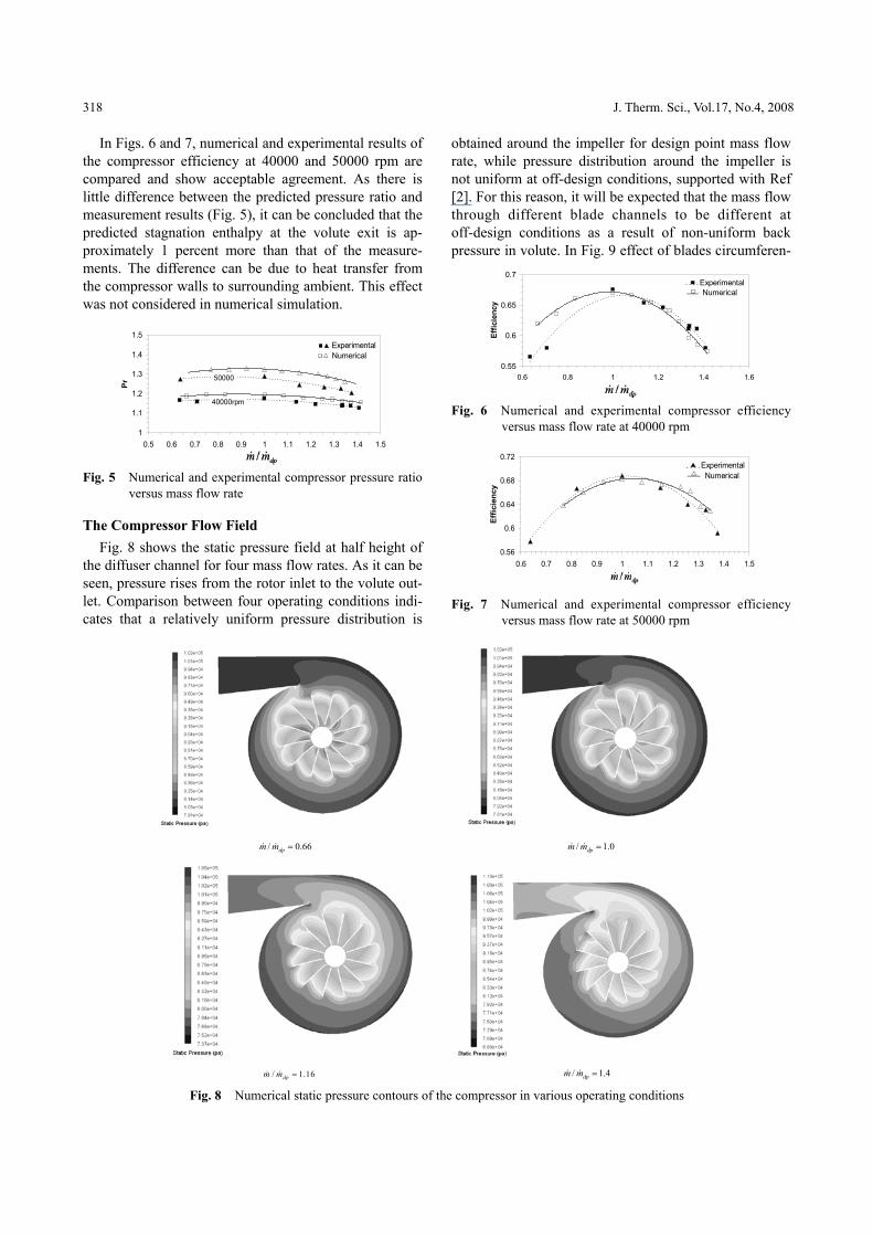
In Figs. 6 and 7, numerical and experimental results of the compressor efficiency at 40000 and 50000 rpm are compared and show acceptable agreement. As there is little difference between the predicted pressure ratio and measurement results (Fig. 5), it can be concluded that the predicted stagnation enthalpy at the volute exit is ap-proximately 1 percent more than that of the measure-ments. The difference can be due to heat transfer from the compressor walls to surrounding ambient. This effect was not considered in numerical simulation.
1
1.1
1.2
1.3
1.4
1.5
0.5 0.6 0.7 0.8 0.9 1 1.1 1.2 1.3 1.4 1.5
Pr
Experimental Numerical
50000
40000rpm
Fig. 5 Numerical and experimental compressor pressure ratio
versus mass flow rate
The Compressor Flow Field Fig. 8 shows the static pressure field at half height of
the diffuser channel for four mass flow rates. As it can be seen, pressure rises from the rotor inlet to the volute out- let. Comparison between four operating conditions indi-cates that a relatively uniform pressure distribution is
obtained around the impeller for design point mass flow rate, while pressure distribution around the impeller is not uniform at off-design conditions, supported with Ref [2]. For this reason, it will be expected that the mass flow through different blade channels to be different at off-design conditions as a result of non-uniform back pressure in volute. In Fig. 9 effect of blades circumferen-
0.55
0.6
0.65
0.7
0.6 0.8 1 1.2 1.4 1.6
Effic
ienc
y
Experimental Numerical
Fig. 6 Numerical and experimental compressor efficiency
versus mass flow rate at 40000 rpm
0.56
0.6
0.64
0.68
0.72
0.6 0.7 0.8 0.9 1 1.1 1.2 1.3 1.4 1.5
Effic
ienc
y
Experimental Numerical
Fig. 7 Numerical and experimental compressor efficiency versus mass flow rate at 50000 rpm
/ 0.66dpm m =& & / 1.0dpm m =& &
/ 1.16dpm m =& & / 1.4dpm m =& &
Fig. 8 Numerical static pressure contours of the compressor in various operating conditions
Mahdi Nili-Ahmadabadi et al. Investigation of a Centrifugal Compressor and Study of the Area Ratio and TIP Clearance Effects 319
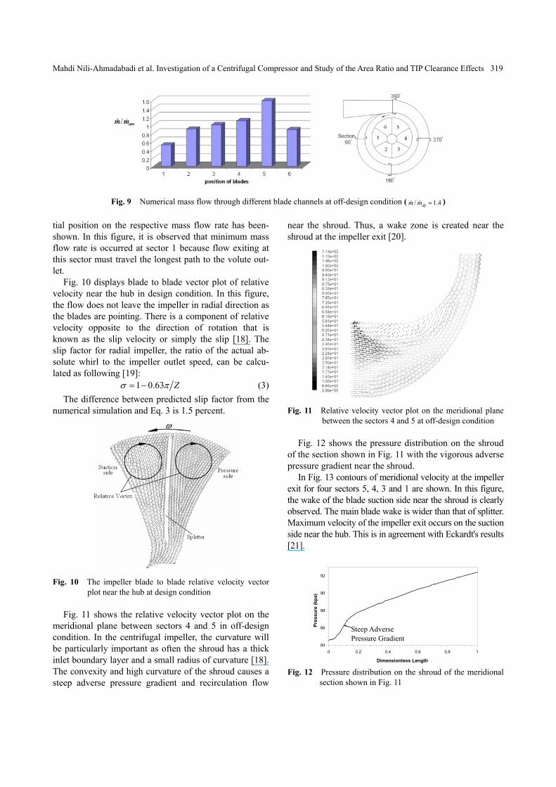
Fig. 9 Numerical mass flow through different blade channels at off-design condition ( / 1.4dpm m =& & )
tial position on the respective mass flow rate has been-shown. In this figure, it is observed that minimum mass flow rate is occurred at sector 1 because flow exiting at this sector must travel the longest path to the volute out-let.
Fig. 10 displays blade to blade vector plot of relative velocity near the hub in design condition. In this figure, the flow does not leave the impeller in radial direction as the blades are pointing. There is a component of relative velocity opposite to the direction of rotation that is known as the slip velocity or simply the slip [18]. The slip factor for radial impeller, the ratio of the actual ab-solute whirl to the impeller outlet speed, can be calcu-lated as following [19]:
1 0.63 Zσ π= − (3) The difference between predicted slip factor from the
numerical simulation and Eq. 3 is 1.5 percent.
Fig. 10 The impeller blade to blade relative velocity vector plot near the hub at design condition
Fig. 11 shows the relative velocity vector plot on the
meridional plane between sectors 4 and 5 in off-design condition. In the centrifugal impeller, the curvature will be particularly important as often the shroud has a thick inlet boundary layer and a small radius of curvature [18]. The convexity and high curvature of the shroud causes a steep adverse pressure gradient and recirculation flow
near the shroud. Thus, a wake zone is created near the shroud at the impeller exit [20].
Fig. 11 Relative velocity vector plot on the meridional plane between the sectors 4 and 5 at off-design condition
Fig. 12 shows the pressure distribution on the shroud
of the section shown in Fig. 11 with the vigorous adverse pressure gradient near the shroud.
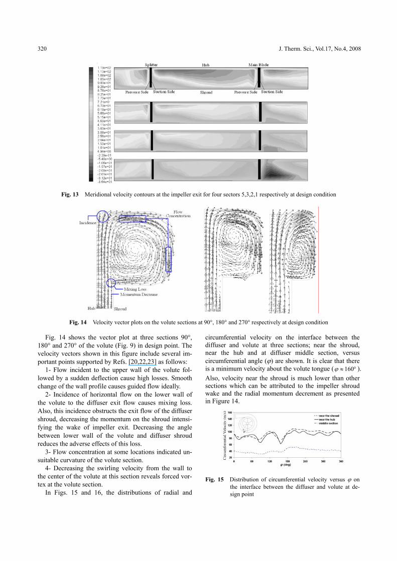
In Fig. 13 contours of meridional velocity at the impeller exit for four sectors 5, 4, 3 and 1 are shown. In this figure, the wake of the blade suction side near the shroud is clearly observed. The main blade wake is wider than that of splitter. Maximum velocity of the impeller exit occurs on the suction side near the hub. This is in agreement with Eckardt's results [21].
84
86
88
90
92
0 0.2 0.4 0.6 0.8 1
Dimensionless Length
Pres
sure
(kpa
)
Adverse Pressure Gradient
Fig. 12 Pressure distribution on the shroud of the meridional
section shown in Fig. 11
Steep Adverse Pressure Gradient
320 J. Therm. Sci., Vol.17, No.4, 2008
Fig. 13 Meridional velocity contours at the impeller exit for four sectors 5,3,2,1 respectively at design condition
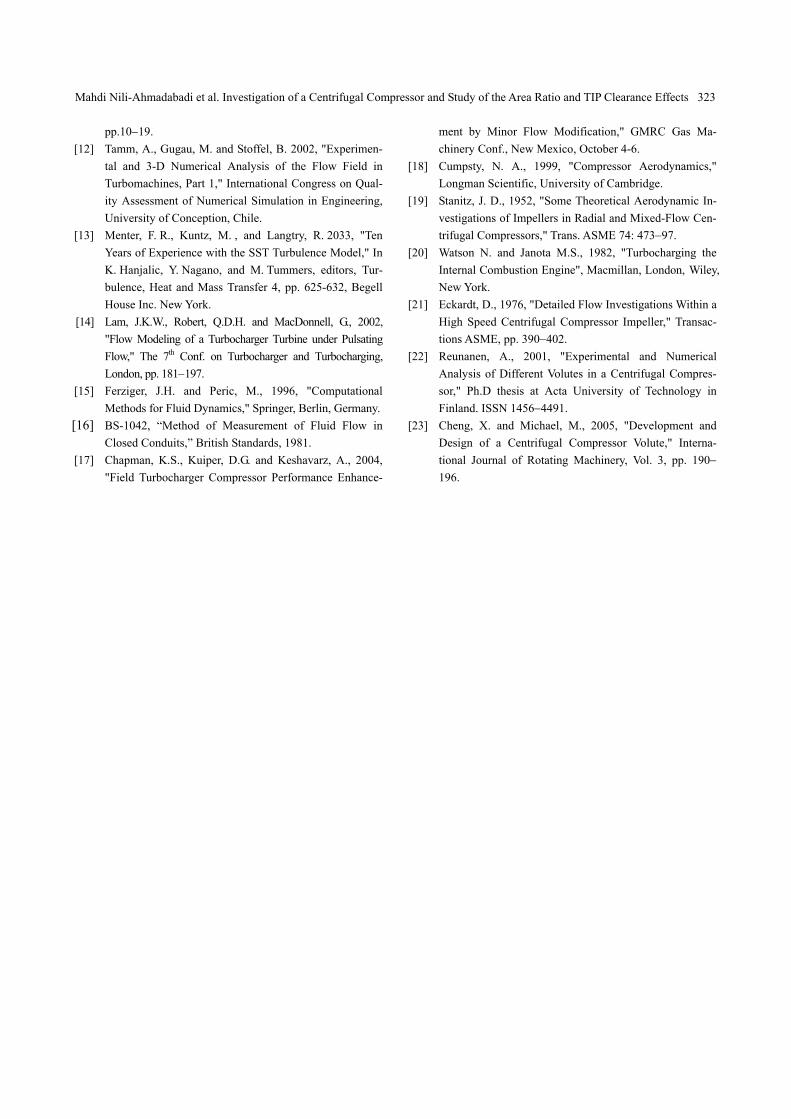
Fig. 14 Velocity vector plots on the volute sections at 90°, 180° and 270° respectively at design condition
Fig. 14 shows the vector plot at three sections 90°, 180° and 270° of the volute (Fig. 9) in design point. The velocity vectors shown in this figure include several im-portant points supported by Refs. [20,22,23] as follows:
1- Flow incident to the upper wall of the volute fol-lowed by a sudden deflection cause high losses. Smooth change of the wall profile causes guided flow ideally.
2- Incidence of horizontal flow on the lower wall of the volute to the diffuser exit flow causes mixing loss. Also, this incidence obstructs the exit flow of the diffuser shroud, decreasing the momentum on the shroud intensi-fying the wake of impeller exit. Decreasing the angle between lower wall of the volute and diffuser shroud reduces the adverse effects of this loss.
3- Flow concentration at some locations indicated un-suitable curvature of the volute section.
4- Decreasing the swirling velocity from the wall to the center of the volute at this section reveals forced vor-tex at the volute section.
In Figs. 15 and 16, the distributions of radial and
circumferential velocity on the interface between the diffuser and volute at three sections; near the shroud, near the hub and at diffuser middle section, versus circumferential angle (ϕ) are shown. It is clear that there is a minimum velocity about the volute tongue ( 160ϕ ≈ ° ). Also, velocity near the shroud is much lower than other sections which can be attributed to the impeller shroud wake and the radial momentum decrement as presented in Figure 14.
Fig. 15 Distribution of circumferential velocity versus ϕ on
the interface between the diffuser and volute at de-sign point
Circ
umfe
rent
ial V
eloc
ity (m
/s)

Mahdi Nili-Ahmadabadi et al. Investigation of a Centrifugal Compressor and Study of the Area Ratio and TIP Clearance Effects 321
Fig. 16 Distribution of radial velocity versus ϕ on the inter- face between the diffuser and volute at design point
Area Ratio & Tip Clearance Numerical Effects Considering a °60 sector of the impeller and diffuser
(Fig. 17) and applying a periodic boundary condition in both cases, three impellers with three different area ratios (Fig. 18) and three impellers with three different tip clearances were numerically simulated. Specified bound-ary conditions for all cases are: mass flux at the inlet and averaged static pressure at the outlet.
First, the impellers exit axial widths were changed from an initial value of 4.1 mm to a final value of 5.2 mm. Consequently, three area ratios of 0.792, 0.878 and 0.965 were obtained. At the same time, the tip clear-ance was kept equal to 0.5 mm. Considering the impeller exit axial width of 4.6 mm, three tip clearances of 0, 0.5 and 1 mm were modeled and analyzed. The mesh inde-pendency was checked as before to ensure that the num-bers of grids are sufficient to capture the losses. The nu-merical method and turbulence model were the same, as explained in sections Numerical Model and Boundary Conditions. To estimate the left side performance range, the mass flux was decreased to a value so that the slope of the pressure ratio-mass flux curve becomes negative.
Figs. 19 and 20 show the variations of total pressure ratio and total to total isentropic efficiency (diffuser out-let to the impeller inlet) versus mass flow rate. The fig-ures indicate that the total pressure peaks at a design point area ratio of approximately 0.792, while the effi-ciency peaks at the value of area ratio of approximately 0.878. These are in agreement with Schumann Results [11]. Also, the figures show that the area ratio increment causes the performance range to reduce and shift to the right.
Figs. 21 and 22 demonstrate the variations of pressure ratio and efficiency versus mass flow rate at three differ-ent tip clearances. Fig. 22 shows that the increment in tip clearance ratio from 0 to 0.11 and from 0.11 to 0.22 causes in average decrement in efficiency of 13% and 10% respectively (supported with Schumann results [11]). But the increment in tip clearance ratio expands the right side performance range. Technically, by increasing tip clearance, the fluid flows easily from pressure side to the
suction side and compensates the momentum lack on the suction side near the shroud (wake). This happens es-pecially at off-design conditions.
Fig. 17 60°-sector of the impeller
Fig. 18 Meridional geometric dimensions
1.14
1.16
1.18
1.2
1.22
0.02 0.05 0.08 0.11 0.14 0.17 0.2Mass Flow Rate (kg/s)
Pr
AR=0.878AR=0.792AR=0.965
Fig. 19 Numerical variation of pressure ratio versus mass flow rate at 3 different area ratios at design speed
50
55
60
65
70
75
80
0.02 0.05 0.08 0.11 0.14 0.17 0.2Mass Flow Rate (kg/s)
Efic
ienc
y
Fig. 20 Numerical variation of efficiency versus mass flow
rate at 3 different area ratios at design speed
Effic
ienc
y

322 J. Therm. Sci., Vol.17, No.4, 2008
1.12
1.16
1.2
1.24
1.28
0.02 0.05 0.08 0.11 0.14 0.17 0.2Mass Flow Rate (kg/s)
Pr
CL/b2=0.00CL/b2=0.11CL/b2=0.22
Fig. 21 Numerical variation of pressure ratio versus mass flow rate at 3 different tip clearances at design speed
50
60
70
80
90
100
0.02 0.05 0.08 0.11 0.14 0.17 0.2Mass Flow Rate (kg/s)
Effic
ienc
y
CL/b2=0.00CL/b2=0.11CL/b2=0.22
Fig. 22 Numerical Variation of efficiency versus mass flow rate at 3 different tip clearances at design speed
Conclusions
Numerical simulation of the performance of a turbo-charger compressor was carried out and compared with experimental results on actual turbocharger. Acceptable agreement between numerical and experimental per-formance was obtained. The following results were revealed from the numerical simulation: A relatively uniform pressure distribution observed
around the impeller at design point mass flow rate, while pressure distribution around the impeller is completely non-uniform at off-design conditions.
Mass flow rate passing through blades with differ-ent circumferential positions are not equal espe-cially at off-design conditions.
A relative vortex was detected on blade to blade plane.
The wake at impeller exit due to the main blade is larger than that of the splitter.
Cutting back the impeller exit axial width causes the mass flow rate to decrease and the pressure ratio to increase.
The area ratio increment causes the performance range to reduce and shift to the right of perform-ance chart.
Increasing the tip clearance ratio decreases the pres-sure ratio and efficiency but it expands the right side performance range significantly.
References
[1] Chen, H. Conner, W., 2002, "Turbocharger Compressor
Development for Passenger Car Gasoline Engine Appli-cations," The 7th Conf. on Turbochargers and turbocharging, IMechE, London, pp. 13−22
[2] Kouidri, S., and Asuaje, M., 2005, "Numerical Modeliza-tion of the Flow in Centrifugal Pump: Volute Influence in Velocity and Pressure Fields," International Journal of Rotating Machinery, Vol. 3, pp. 244−255.
[3] Paβrucker, H. and Van den Braembussche, R. A., May 2000, "Inverse Design of Centrifugal Impellers by Si-multaneous Modification of Blade Shape and Meridional Contour," in Proc.45th ASME International Gas Turbine and Aeroengine Congress and Exposition, Munich, Ger-many.
[4] Cravero, C., July 2002, "A Design Methodology for Ra-dial Turbomachinery. Application to Turbines and Com-pressors," in Proc. ASME Fluid Engineering Division Summer Meeting (FEDSM '02), Montreal, Quebec, Can-ada, paper FEDSM2002-31335.
[5] Sloteman, D. and Saad, A. and Cooper, P., May-June 2001, "Design of Custom Pump Hydraulics Using Tradi-tional Methods," in Proc. ASME Fluid Engineering Divi-sion Summer Meeting (FEDSM'01), New Orleans, LA, USA, paper FEDSM2002-18067.
[6] Goto, A. and Nohmi, M. and Sakurai, T., 2002, "Hydro-dynamic Design System for Pumps Based on 3-D CAD, CFD, and Inverse Design Method," Transactions ASME, Journal of Fluids Engineering, Vol. 124, no. 2, pp.329−335.
[7] Gonzales, J., and Fernandez, J., 2002, "Numerical Simu-lation of the Dynamic Effects Due to Impeller-Volute In-teraction in a Centrifugal Pump," Transactions of ASME, Vol. 124, pp.348−355.
[8] Gu, F., Engeda, A., Cave, M. and Di Liberti, L., 2001, "A Nu-merical Investigation on the Volute/Diffuser Interaction due to the Axial Distortion at the Impeller Exit," Transactions of the ASME, Journal of Fluid Engineering, Vol. 123, no. 3, pp. 475−483.
[9] Mugli, F., Holbein, P. and Dupont, P., May-June 2001, "CFD Calculation of a Mixed Flow Pump Characteristic from Shut-off to Maximum Flow," in Proc. ASME Fluid Engineering Division Summer Meeting (FEDSM'01), New Orleans, LA, USA, paper FEDSM2001-18072.
[10] Cravero, C. and Marini, M., July 2002, "Modeling of In-compressible Three-Dimensional Flow in Rotating Tur-bomachinery Passages," in Proc. ASME Fluids Engi-neering Division Summer Meeting (FEDSM'02), Mont-real, Quebec, Canada, paper FEDSM2002-31177.
[11] Schumann, L. F and Clark, D. A., 1987, "Effect of Area Ratio on the Performance of a 5.5:1 Pressure Ratio Cen-trifugal Impeller," Transactions of the ASME, Vol. 109,
Mahdi Nili-Ahmadabadi et al. Investigation of a Centrifugal Compressor and Study of the Area Ratio and TIP Clearance Effects 323
pp.10−19. [12] Tamm, A., Gugau, M. and Stoffel, B. 2002, "Experimen-
tal and 3-D Numerical Analysis of the Flow Field in Turbomachines, Part 1," International Congress on Qual-ity Assessment of Numerical Simulation in Engineering, University of Conception, Chile.
[13] Menter, F. R., Kuntz, M. , and Langtry, R. 2033, "Ten Years of Experience with the SST Turbulence Model," In K. Hanjalic, Y. Nagano, and M. Tummers, editors, Tur-bulence, Heat and Mass Transfer 4, pp. 625-632, Begell House Inc. New York.
[14] Lam, J.K.W., Robert, Q.D.H. and MacDonnell, G., 2002, "Flow Modeling of a Turbocharger Turbine under Pulsating Flow," The 7th Conf. on Turbocharger and Turbocharging, London, pp. 181−197.
[15] Ferziger, J.H. and Peric, M., 1996, "Computational Methods for Fluid Dynamics," Springer, Berlin, Germany.
]16[ BS-1042, “Method of Measurement of Fluid Flow in Closed Conduits,” British Standards, 1981.
[17] Chapman, K.S., Kuiper, D.G. and Keshavarz, A., 2004, "Field Turbocharger Compressor Performance Enhance-
ment by Minor Flow Modification," GMRC Gas Ma-chinery Conf., New Mexico, October 4-6.
[18] Cumpsty, N. A., 1999, "Compressor Aerodynamics," Longman Scientific, University of Cambridge.
[19] Stanitz, J. D., 1952, "Some Theoretical Aerodynamic In-vestigations of Impellers in Radial and Mixed-Flow Cen-trifugal Compressors," Trans. ASME 74: 473−97.
[20] Watson N. and Janota M.S., 1982, "Turbocharging the Internal Combustion Engine", Macmillan, London, Wiley, New York.
[21] Eckardt, D., 1976, "Detailed Flow Investigations Within a High Speed Centrifugal Compressor Impeller," Transac-tions ASME, pp. 390−402.
[22] Reunanen, A., 2001, "Experimental and Numerical Analysis of Different Volutes in a Centrifugal Compres-sor," Ph.D thesis at Acta University of Technology in Finland. ISSN 1456−4491.
[23] Cheng, X. and Michael, M., 2005, "Development and Design of a Centrifugal Compressor Volute," Interna-tional Journal of Rotating Machinery, Vol. 3, pp. 190− 196.