Investigation about the stab resistance of textile structures ...
195
HAL Id: tel-01527362 https://tel.archives-ouvertes.fr/tel-01527362 Submitted on 24 May 2017 HAL is a multi-disciplinary open access archive for the deposit and dissemination of sci- entific research documents, whether they are pub- lished or not. The documents may come from teaching and research institutions in France or abroad, or from public or private research centers. L’archive ouverte pluridisciplinaire HAL, est destinée au dépôt et à la diffusion de documents scientifiques de niveau recherche, publiés ou non, émanant des établissements d’enseignement et de recherche français ou étrangers, des laboratoires publics ou privés. Investigation about the stab resistance of textile structures, methods for their testing and improvements Priscilla Reiners To cite this version: Priscilla Reiners. Investigation about the stab resistance of textile structures, methods for their testing and improvements. Other. Université de Haute Alsace - Mulhouse, 2016. English. NNT : 2016MULH9513. tel-01527362
-
Upload
khangminh22 -
Category
Documents
-
view
2 -
download
0
Transcript of Investigation about the stab resistance of textile structures ...
HAL Id: tel-01527362https://tel.archives-ouvertes.fr/tel-01527362
Submitted on 24 May 2017
HAL is a multi-disciplinary open accessarchive for the deposit and dissemination of sci-entific research documents, whether they are pub-lished or not. The documents may come fromteaching and research institutions in France orabroad, or from public or private research centers.
L’archive ouverte pluridisciplinaire HAL, estdestinée au dépôt et à la diffusion de documentsscientifiques de niveau recherche, publiés ou non,émanant des établissements d’enseignement et derecherche français ou étrangers, des laboratoirespublics ou privés.
Investigation about the stab resistance of textilestructures, methods for their testing and improvements
Priscilla Reiners
To cite this version:Priscilla Reiners. Investigation about the stab resistance of textile structures, methods for theirtesting and improvements. Other. Université de Haute Alsace - Mulhouse, 2016. English. �NNT :2016MULH9513�. �tel-01527362�
UNIVERSITÉ DE HAUTE ALSACE LABORATOIRE DE PHYSIQUE ET MÉCANIQUE TEXTILES
THÈSE
pour obtenir le grade de
DOCTEUR DE L’UNIVERSITÉ DE HAUTE ALSACE DISCIPLINE : MÉCANIQUE
par
Priscilla REINERS
INVESTIGATION ABOUT THE STAB RESISTANCE OF TEXTILE
STRUCTURES, METHODS FOR THEIR TESTING AND IMPROVEMENTS
Soutenue le 29 Septembre 2016 devant le jury suivant: Pr. Laurence SCHACHER UHA – LPMT Directeur de thèse Pr. Dominique ADOLPHE UHA – LPMT Directeur de thèse Pr. Yordan KYOSEV HS Niederrhein Directeur de thèse Pr. Marie Louise KLOTZ HS Rhein-Waal Rapporteur Pr. Francois BOUSSU ENSAIT Rapporteur Pr. Anne SCHWARZ-PFEIFFER HS Niederrhein Examinatrice
ACKNOWLEDGEMENTS
I
ACKNOWLEDGEMENTS
I would like to acknowledge the support of the department of Textile and Clothing
Technology of the Niederrhein University of Applied Sciences for provide the
laboratories and equipment for the practical work, with particular thanks to my
colleagues from the third floor for their moral support.
I would also like to thank my supervisors, Prof. Laurence Schacher and Prof.
Dominique Adolphe of UHA, Mulhouse for this great chance to do this program in
cooperation with my home university and for their support during the complete period
of this thesis.
Numerous students have contributed to related areas of this research, and I am grateful
for their contributions.
Especially I would like to thank my supervisor Prof. Yordan Kyosev for his extremely
thorough and timely supervision and for his persistent, technical and moral support of
both me and this research.
Finally I would like to thank my husband Wolfgang for his patience and encouragement
during the long period of this thesis.
CONTENT
II
CONTENT
ACKNOWLEDGEMENTS I
CONTENT II
LIST OF FIGURES V
LIST OF TABLES X
LIST OF ABBREVIATIONS XI
INTRODUCTION 1
0 INTRODUCTION 2
CHAPTER 1 5
1 LITERATURE REVIEW 6
1.1 BODY ARMOUR- THE PERSONAL PROTECTIVE EQUIPMENT PPE 6
1.2 COMMON APPLICATION AREAS OF BODY ARMOUR FOR STAB UND SLASH
RESISTANCE 7
1.2.1 PERSONAL PROTECTION 7
1.2.2 PROTECTION OF OBJECTS 9
1.3 IMPORTANCE OF BODY ARMOUR 9
1.4 DEVELOPMENT OF BODY ARMOUR 10
1.4.1 HISTORY 11
1.5 TECHNOLOGY OF THE STAB EVENT 12
1.5.1 BASICS OF THE PENETRATION MECHANISMS 13
1.5.2 INFLUENCING FACTORS 15
1.5.3 CONCLUSION 20
1.6 BODY ARMOUR TECHNOLOGY 20
1.6.1 COMPOSITION AND CONSTRUCTION OF BODY ARMOUR 20
1.6.2 MATERIALS 28
1.6.3 YARNS 33
1.6.4 PHYSICAL PROPERTIES OF TEXTILE BODY ARMOUR 33
1.7 PROTECTION LEVELS AND CLASSIFICATION OF BODY ARMOUR 35
CONTENT
III
1.7.1 TECHNICAL GUIDELINE OF THE GERMAN POLICE (TR) 36
1.7.2 THE NIJ ARMOUR CLASSIFICATION SYSTEM 37
1.7.3 THE UK STANDARD HOSDB 38
1.8 TESTING METHODS, TEST STANDARDS 39
1.8.1 STAB METHODS 39
1.8.2 EVALUATION OF MEASUREMENT RESULTS 42
1.8.3 CUT METHODS 44
1.8.4 FRICTIONAL TEST PARAMETERS 45
1.9 CONCLUSIONS 53
CHAPTER 2 55
2 EXPERIMENTAL WORK 56
2.1 INTRODUCTION 56
2.2 MATERIALS 56
2.3 METHODS 57
2.3.1 MEASUREMENT OF STAB RESISTANCE 57
2.3.2 PRINCIPLE OF STAB MEASUREMENT 57
2.3.3 BOUNDARIES OF STAB MEASUREMENT 58
2.3.4 DEVELOPMENT OF A NEW EVALUATION METHOD OF MEASURING THE STAB
DEPTH 58
2.3.5 WEAR AND TEAR KNIFE AND REPRODUCIBILITY 63
2.3.6 INFLUENCE SAMPLE SIZE AND PRETENSION 65
2.4 STAB RESISTANCE OF FABRIC PANELS 68
2.4.1 INFLUENCE OF IMPACT ENERGY AND NUMBER OF LAYERS 68
2.4.2 RELATION BETWEEN STRUCTURE PARAMETERS AND PUNCTURE RESISTANCE 78
2.5 PARAMETERS, WHICH INFLUENCE THE STAB RESISTANCE OF WOVEN FABRICS 88
2.5.1 TEXTILE FRICTION 88
2.5.2 SEAM SLIPPAGE 102
2.5.3 PULLOUT 111
CHAPTER 3 120
3 IMPROVEMENT OF THE STAB RESISTANCE 121
3.1 INSERTION OF WOOL 121
CONTENT
IV
3.1.1 MATERIALS 121
3.1.2 METHODS 121
3.1.3 RESULTS 122
3.2 DEVELOPMENT OF BLEND YARNS WITH WOOL 131
3.2.1 MATERIALS 131
3.2.2 METHODS 132
3.2.3 RESULTS 133
3.3 SETTING UP OF MULTILAYER NARROW FABRIC BLENDS 140
3.3.1 MATERIALS AND METHODS 140
3.3.2 RESULTS 141
3.3.3 CONCLUSIONS 143
3.4 NUMERICAL INVESTIGATIONS OF THE PENETRATION THROUGH TEXTILES 143
3.4.1 ANALYTICAL METHODS 143
3.4.2 FEM SIMULATION OF STAB PENETRATION USING TRUSS ELEMENTS 147
3.4.3 FEM SIMULATION BASED ON SHELL ELEMENTS FOR THE YARNS 149
3.4.4 CONCLUSIONS 154
CONCLUSIONS AND FUTURE WORK 155
4 CONCLUSIONS 156
5 FUTURE WORK 162
APPENDIX VII
6 PUBLICATION BIBLIOGRAPHY FEHLER! TEXTMARKE NICHT DEFINIERT.
7 APPENDIX VII
7.1 MEAN VALUES OF STAB DEPTHS FOR ALL FABRICS VII
7.2 P170 VII
7.3 P230 VII
7.4 T170 VIII
7.5 T230 X
LIST OF FIGURES
V
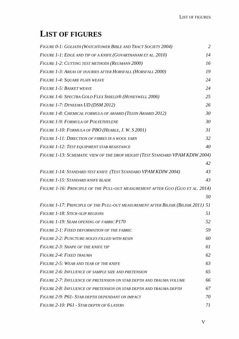
LIST OF FIGURES FIGURE 0-1: GOLIATH (WATCHTOWER BIBLE AND TRACT SOCIETY 2004) 2
FIGURE 1-1: EDGE AND TIP OF A KNIFE (GOVARTHANAM ET AL. 2010) 14
FIGURE 1-2: CUTTING TEST METHODS (REUMANN 2000) 16
FIGURE 1-3: AREAS OF INJURIES AFTER HORSFALL (HORSFALL 2000) 19
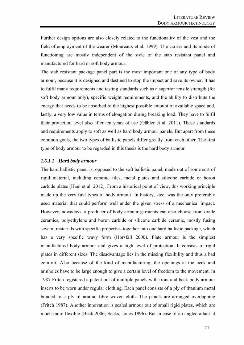
FIGURE 1-4: SQUARE PLAIN WEAVE 24
FIGURE 1-5: BASKET WEAVE 24
FIGURE 1-6: SPECTRA GOLD FLEX SHIELD® (HONEYWELL 2006) 25
FIGURE 1-7: DYNEEMA UD (DSM 2012) 26
FIGURE 1-8: CHEMICAL FORMULA OF ARAMID (TEIJIN ARAMID 2012) 30
FIGURE 1-9: FORMULA OF POLYETHYLENE 30
FIGURE 1-10: FORMULA OF PBO (HEARLE, J. W. S 2001) 31
FIGURE 1-11: DIRECTION OF FIBRES IN A WOOL YARN 32
FIGURE 1-12: TEST EQUIPMENT STAB RESISTANCE 40
FIGURE 1-13: SCHEMATIC VIEW OF THE DROP HEIGHT (TEST STANDARD VPAM KDIW 2004)
42
FIGURE 1-14: STANDARD TEST KNIFE (TEST STANDARD VPAM KDIW 2004) 43
FIGURE 1-15: STANDARD KNIFE BLADE 43
FIGURE 1-16: PRINCIPLE OF THE PULL-OUT MEASUREMENT AFTER GUO (GUO ET AL. 2014)
50
FIGURE 1-17: PRINCIPLE OF THE PULL-OUT MEASUREMENT AFTER BILISIK (BILISIK 2011) 51
FIGURE 1-18: STICK-SLIP REGIONS 51
FIGURE 1-19: SEAM OPENING OF FABRIC P170 52
FIGURE 2-1: FIXED DEFORMATION OF THE FABRIC 59
FIGURE 2-2: PUNCTURE HOLES FILLED WITH RESIN 60
FIGURE 2-3: SHAPE OF THE KNIFE TIP 61
FIGURE 2-4: FIXED TRAUMA 62
FIGURE 2-5: WEAR AND TEAR OF THE KNIFE 63
FIGURE 2-6: INFLUENCE OF SAMPLE SIZE AND PRETENSION 65
FIGURE 2-7: INFLUENCE OF PRETENSION ON STAB DEPTH AND TRAUMA VOLUME 66
FIGURE 2-8: INFLUENCE OF PRETENSION ON STAB DEPTH AND TRAUMA DEPTH 67
FIGURE 2-9: P61- STAB DEPTH DEPENDANT ON IMPACT 70
FIGURE 2-10: P61 - STAB DEPTH OF 6 LAYERS 71
LIST OF FIGURES
VI
FIGURE 2-11: P61- LOGARITHMIC CURVES 72
FIGURE 2-12: P61 - STAB DEPTH OF INCREASING LAYERS 73
FIGURE 2-13: P170 - STAB DEPTH OF INCREASING LAYERS 74
FIGURE 2-14: P230 - STAB DEPTH OF INCREASING LAYERS 75
FIGURE 2-15: T170 - STAB DEPTH OF INCREASING LAYERS 76
FIGURE 2-16: T230 - STAB DEPTH OF INCREASING LAYERS 77
FIGURE 2-17: OPTICAL OBSERVATION AFTER THE STAB IMPACT AT 20X MAGNIFICATION 79
FIGURE 2-18: COMPARISON OF PLAIN WEAVE SAMPLES AT 6 JOULE IMPACT 79
FIGURE 2-19:COMPARISON OF PLAIN WEAVE SAMPLES AT 9 JOULE IMPACT 80
FIGURE 2-20: OPTICAL OBSERVATION AFTER THE STAB AT 20X MAGNIFICATION 81
FIGURE 2-21: COMPARISON OF TWILL WEAVE SAMPLES AT 6 JOULE IMPACT 82
FIGURE 2-22: COMPARISON OF TWILL WEAVE SAMPLES AT 9 JOULE IMPACT 83
FIGURE 2-23: COMPARISON OF PLAIN WEAVE VS. TWILL WEAVE 170G/M² AT 6 JOULE 84
FIGURE 2-24: COMPARISON OF PLAIN WEAVE VS. TWILL WEAVE 170G/M² AT 9 JOULE 85
FIGURE 2-25: COMPARISON OF PLAIN WEAVE VS. TWILL WEAVE 230G/M² AT 6 JOULE 86
FIGURE 2-26: COMPARISON OF PLAIN WEAVE VS. TWILL WEAVE 230G/M² AT 9 JOULE 87
FIGURE 2-27: PRINCIPLE OF FRICTION MEASUREMENT 89
FIGURE 2-28: FIXED FABRIC ON THE SLED 90
FIGURE 2-29: FRICTION MEASUREMENT DEVICE 90
FIGURE 2-30: P61 COEFFICIENT OF FRICTION 91
FIGURE 2-31: P170 COEFFICIENT OF FRICTION 92
FIGURE 2-32: P230 COEFFICIENT OF FRICTION 92
FIGURE 2-33: T170 COEFFICIENT OF FRICTION 93
FIGURE 2-34: T230 COEFFICIENT OF FRICTION 93
FIGURE 2-35: WOOL COEFFICIENT OF FRICTION 94
FIGURE 2-36: STATIC AND KINETIC FRICTION WARP/WARP 95
FIGURE 2-37: STATIC AND KINETIC FRICTION WARP/WEFT 95
FIGURE 2-38: STATIC AND KINETIC FRICTION WEFT/WARP 96
FIGURE 2-39: STATIC AND KINETIC FRICTION WEFT/WEFT 96
FIGURE 2-40: P61 COMPARISON WITH WOOL – STATIC AND KINETIC 97
FIGURE 2-41: P170 COMPARISON WITH WOOL – STATIC AND KINETIC 97
FIGURE 2-42: P230 COMPARISON WITH WOOL – STATIC AND KINETIC 98
FIGURE 2-43: T170 COMPARISON WITH WOOL – STATIC AND KINETIC 98
FIGURE 2-44:T230 COMPARISON WITH WOOL – STATIC AND KINETIC 99
LIST OF FIGURES
VII
FIGURE 2-45: STATIC AND KINETIC FRICTION - WARP/WARP 99
FIGURE 2-46: STATIC AND KINETIC FRICTION - WARP/WEFT 100
FIGURE 2-47: STATIC AND KINETIC FRICTION - WEFT/WARP 100
FIGURE 2-48: STATIC AND KINETIC FRICTION - WEFT/WEFT 101
FIGURE 2-49: AUTOMATIC CALCULATION OF THE SEAM SLIPPAGE (ISO 13936-1) 103
FIGURE 2-50: OPTICAL OBSERVATION OF THE FABRIC OPENING AFTER THE STAB TESTS 104
FIGURE 2-51: STAB DEPTH OF PANELS OUT OF 6 AND 8 LAYERS 104
FIGURE 2-52: SEAM SLIPPAGE RESULTS FOR 6 MM SEAM OPENING 106
FIGURE 2-53: SEAM SLIPPAGE RESULTS FOR 8 MM SEAM OPENING 106
FIGURE 2-54: SEAM SLIPPAGE RESULTS FOR 10 MM SEAM OPENING 107
FIGURE 2-55: COMPARISON OF SEAM OPENING AT 6 MM WITH STAB DEPTH OF 6 LAYERS 108
FIGURE 2-56: COMPARISON OF SEAM OPENING AT 8 MM WITH STAB DEPTH OF 6 LAYERS 109
FIGURE 2-57: COMPARISON OF SEAM OPENING AT 6 MM WITH STAB DEPTH OF 8 LAYERS 110
FIGURE 2-58: COMPARISON OF SEAM OPENING AT 8 MM WITH STAB DEPTH OF 8 LAYERS 111
FIGURE 2-59: SCHEMATIC VIEW OF THE MEASUREMENT OF THE PULL-OUT FORCES 112
FIGURE 2-60: P230 INDIVIDUAL VALUE OF AN PULL-OUT TEST 113
FIGURE 2-61: P230 WARP - MAXIMUM AND MINIMUM PEAKS 114
FIGURE 2-62: P230 WEFT - MAXIMUM AND MINIMUM PEAKS 114
FIGURE 2-63: P230 COMPARISON OF WARP AND WEFT 115
FIGURE 2-64: T230 WARP - MAXIMUM AND MINIMUM PEAKS 115
FIGURE 2-65: T230 WEFT - MAXIMUM AND MINIMUM PEAKS 116
FIGURE 2-66: T230 COMPARISON OF WARP AND WEFT 116
FIGURE 2-67: COMPARISON OF PLAIN AND TWILL – WARP MAX. VALUES 117
FIGURE 2-68: COMPARISON OF PLAIN AND TWILL – WARP MIN. VALUES 117
FIGURE 2-69: COMPARISON OF PLAIN AND TWILL – WEFT MAX. VALUES 118
FIGURE 2-70: COMPARISON OF PLAIN AND TWILL – WEFT MIN. VALUES 118
FIGURE 3-1: STAB BEHAVIOUR OF AN ARAMID FABRIC 122
FIGURE 3-2: PICTURE SEQUENCE OF THE STAB PENETRATION OF AN ARAMID FABRIC 123
FIGURE 3-3: PICTURE SEQUENCE OF THE STAB PENETRATION OF A WOOL FABRIC 123
FIGURE 3-4: OPTICAL OBSERVATION OF STABBING FOR FABRIC P61 124
FIGURE 3-5: OPTICAL OBSERVATION OF STABBING FOR FABRIC P170 124
FIGURE 3-6: OPTICAL OBSERVATION OF STABBING FOR FABRIC P230 125
FIGURE 3-7: OPTICAL OBSERVATION OF STABBING FOR FABRIC T170 125
FIGURE 3-8: OPTICAL OBSERVATION OF STABBING FOR FABRIC T230 125
LIST OF FIGURES
VIII
FIGURE 3-9: STAB DEPTH RESULTS FOR FABRIC P61 126
FIGURE 3-10: STAB DEPTH RESULTS FOR FABRIC P170 127
FIGURE 3-11: STAB DEPTH RESULTS FOR FABRIC P230 127
FIGURE 3-12: STAB DEPTH RESULTS FOR FABRIC T170 128
FIGURE 3-13: STAB DEPTH RESULTS FOR FABRIC T230 129
FIGURE 3-14: IMPACT FORCES OF ARAMID PANELS WITH AND WITHOUT WOOL 130
FIGURE 3-15: SAURER HOLLOW SPINDLE SPINNING MACHINE ESP-SM-10 132
FIGURE 3-16: PRINCIPLE OF FRICTION MEASUREMENT (WANG, CHUNG 2013) 134
FIGURE 3-17: PRINCIPLE OF FRICTION MEASUREMENT WITH TWO SENSORS 134
FIGURE 3-18: FRICTION MEASUREMENT DEVICE 135
FIGURE 3-19: OUTPUT SENSOR 1 136
FIGURE 3-20: OUTPUT SENSOR 2 136
FIGURE 3-21: COEFFICIENTS OF FRICTION OF THE TEST SAMPLES 139
FIGURE 3-22: NARROW WEAVING MACHINE NFREQ 140
FIGURE 3-23: STAB DEPTHS OF THE NARROW FABRICS 142
FIGURE 3-24: ARAMID AND ARAMID/WOOL BLEND 142
FIGURE 3-25: MODEL OF THE PENETRATION TEST (LOMOV, S. V. AND MOSHKOV, G. V. 1998)
144
FIGURE 3-26: COMPUTED CALCULATION OF THE FORCE DURING THE PENETRATION 144
FIGURE 3-27: DEGREE OF FREEDOM OF 2D AND 3D TRUSS ELEMENTS (VEIT 2012) 147
FIGURE 3-28: INITIAL MESH FOR PENETRATION SIMULATION WITH IMPACTFEM, BASED ON
TRUSSES 148
FIGURE 3-29: DEFORMED GEOMETRY AT THE BEGINNING OF THE PUNCTURE 148
FIGURE 3-30: THE GEOMETRY MODEL OF A PLAIN WOVEN FABRIC 150
FIGURE 3-31: THE PENETRATION DEPTH INTO THE CLAY BY DIFFERENT KNIFE SHAPES (LEFT:
SHARP, RIGHT: BLUNT) 151
FIGURE 3-32: PENETRATION PROCESS 152
FIGURE 3-33: THE DEFORMATION OF FABRIC DURING THE PENETRATION PROCESS 152
FIGURE 3-34: THE STRUCTURAL DEFORMATION OF THE FABRIC AND SLIPPAGE OF THE YARN
153
FIGURE 3-35: THE STRUCTURAL DEFORMATION OF FABRIC AND SLIPPAGE OF YARN UNDER
DIFFERENT FRICTION COEFFICIENT 154
FIGURE 7-1: P170 - STAB DEPTH DEPENDANT ON IMPACT VII
FIGURE 7-2: P170- LOGARITHMIC CURVES VII

LIST OF FIGURES
IX
FIGURE 7-3: P230 - STAB DEPTH DEPENDANT ON IMPACT VIII
FIGURE 7-4: P230- LOGARITHMIC CURVES VIII
FIGURE 7-5: T170 - STAB DEPTH DEPENDANT ON IMPACT IX
FIGURE 7-6: T170- LOGARITHMIC CURVES IX
FIGURE 7-7:T230 - STAB DEPTH DEPENDANT ON IMPACT X
FIGURE 7-8: T230- LOGARITHMIC CURVES X
LIST OF TABLES
X
LIST OF TABLES TABLE 1-1: COMPARISON OF FIBRE PROPERTIES (HEARLE, J. W. S 2001) 28
TABLE 1-2: PROTECTION LEVELS TR (POLIZEITECHNISCHES INSTITUT (PTI) 2008) 36
TABLE 1-3: STAB PROTECTION CLASSES NIJ (NATIONAL INSTITUTE OF JUSTICE 2000) 37
TABLE 1-4: PROTECTION LEVELS HOSDB (CROFT, LONGHURST 2007B) 38
TABLE 2-1: PROPERTIES OF ARAMID FABRICS 57
TABLE 2-2: HEIGHTS OF STAB TESTS 69
TABLE 2-3: MEAN STAB DEPTH RESULTS FOR P61 69
TABLE 2-4: COEFFICIENTS OF DETERMINATION 72
TABLE 2-5: MEAN STAB DEPTH RESULTS FOR P170 74
TABLE 2-6: MEAN STAB DEPTH RESULTS FOR P230 75
TABLE 2-7: MEAN STAB DEPTH RESULTS FOR T170 76
TABLE 2-8: MEAN STAB DEPTH RESULTS FOR T230 77
TABLE 2-9: RESULTS OF SEAM SLIPPAGE IN WARP AND WEFT DIRECTION 105
TABLE 3-1: THE MEAN IMPACT FORCE VALUES FOR ARAMID PANELS WITH AND WITHOUT WOOL
130
TABLE 3-2: MACHINE PARAMETER FOR BLENDING YARNS 132
TABLE 3-3: LINEAR RELATIONSHIP OF WEIGHT AND FORCE 135
TABLE 3-4: SURFACES OF THE USED SAMPLES 137
TABLE 3-5: OUTPUT VOLTAGE FOR THE TEST SAMPLES 138
TABLE 3-6: CALCULATED FORCE OF THE TEST SAMPLES 138
TABLE 3-7: PARAMETER OF THE USED YARNS 141
TABLE 3-8: LISTING OUTPUT 146
LIST OF ABBREVIATIONS
XI
LIST OF ABBREVIATIONS B.C. Before Christ
CPPT Cut Protection Performance Tester
EKIN kinetic energy
EPOT potential energy
F Force
FK kinetic force
FN normal force
FS static force
G Gravity
g gram
h height
KR Knife Resistance
ln Logarithmic
m mass
N Newton
nm Nanometre
P61 Plain weave fabric – 61 g/m²
P170 Plain weave fabric – 170 g/m²
P230 Plain weave fabric – 230 g/m²
PBO Poly-para-phenylene-2,6-benzo-bisoxazole
PPE Personal Protective Equipment
LIST OF ABBREVIATIONS
XII
PTI Polizeitechnisches Institut (Technical Institute of the Police department)
R² Coefficient of determination
SK Schutzklassen (Protection classes)
SP Spike resistance
ST Stichschutz (Stab resistance)
STF Shear Thickening Fluid
T170 Twill weave fabric – 170 g/m²
T230 Twill weave fabric – 230 g/m²
TR Technische Richtlinie (Technical guideline)
UD Unidirectional
UHMWPE Ultra-high molecular weight Polyethylene
V Volume
v velocity
VPAM Vereinigung der Prüfstellen für angriffshemmende Materialien und
Konstruktionen
W Work (energy)
WC Cutting work
WFBY Work of friction between yarns
WFCY Work of friction for cutting yarns
WPP Work for penetration of plasticine
µ Coefficient of Friction

INTRODUCTION
INTRODUCTION
2
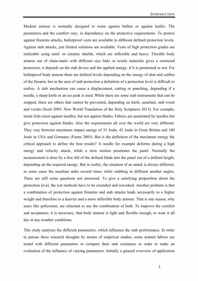
0 Introduction David replied to the Philistine: “You are coming against me with sword and spear and
javelin, but I am coming against you in the name of Jehovah of armies, the God of the battle
line of Israel, whom you have taunted. This very day Jehovah will surrender you into my
hand” (1 Samuel 4:45, 46).
In the whole human history, human fought against each other using weapons. One of the first
notations, which was written about 1040 B.C., can be found in 1 Samuel 17:4-6 (New World
Translation of the Holy Scriptures 2013), mentioning the Philistine Goliath:
Then a champion came out from the camps of the Philistines; his name was Goliath and his
height was six cubits and a span. He had a helmet of copper on his head, and he was wearing
a coat of mail of overlapping scales. The weight of the copper coat of mail was 5000 shekels.
He had shin guards of copper on his legs and a javelin of copper slung between his shoulders.
Only Goliath`s coat of mail already reached a weight of 5000
shekels which equates to 57 kilograms. The bible report shows
that he was in height six cubits and a span, which is equal to 2.90
meters. Since then, many developments were continued to
improve body armour. New materials were developed, which are
lighter, more flexible and give a particular protection against
attacks. In the modern age, body armour primary was developed
in the area of ballistic to protect against bullets, since firearms
were invented in the 19th century. But also the protection against
sharp edges, such as knifes increased in significance since a rise
in stab attacks against police or military personnel is increasing.
The annual report of the national police in Germany shows, that
6.8% of policemen were attacked in 2014 and 1.8% were injured.
About 2.8% of all criminal offences were personal injuries (Vegesack 2014). The head of the
police labour union of North Rhine Westphalia said in a radio interview in August 2015 that
every eighty minutes a policeman is attacked in North Rhine-Westphalia. The violence
against police members is increasing (BKA NRW 2012). Therefore a high interest of demand
of body armour is given.
Figure 0-1: Goliath (Watchtower Bible and Tract
Society 2004)
INTRODUCTION
3
Modern armour is normally designed to resist against bullets or against knifes. The
parameters and the comfort vary, in dependency on the protective requirements. To protect
against firearms attacks, bulletproof vests are available in different defined protection levels.
Against stab attacks, just limited solutions are available. Vests of high protection grades are
realizable using steel- or ceramic shields, which are inflexible and heavy. Flexible body
armour out of chain-mails with different size links or textile materials gives a restricted
protection, it depends on the stab device and the applied energy, if it is penetrated or not. For
bulletproof body armour there are defined levels depending on the energy of shot and calibre
of the firearm, but in the area of stab protection a definition of a protection level is difficult to
realize. A stab mechanism can cause a displacement, cutting or punching, depending if a
needle, a sharp knife or an ice peak is used. While there are some stab instruments that can be
stopped, there are others that cannot be prevented, depending on knife, assailant, stab event
and victim (Scott 2005; New World Translation of the Holy Scriptures 2013). For example,
metal foils resist against needles, but not against blades. Fabrics are penetrated by needles but
give protection against blades. Also the requirements all over the world are very different.
They vary between maximum impact energy of 35 Joule, 42 Joule in Great Britain and 100
Joule in USA and Germany (Fenne 2005). But is the definition of the maximum energy the
critical approach to define the best results? A needle for example deforms during a high
energy and velocity attack, while a slow motion penetrates the panel. Normally the
measurement is done by a free fall of the defined blade into the panel out of a defined height,
depending on the required energy. But in reality, the situation of an attack is always different,
in some cases the assailant stabs several times while stabbing in different another angles.
There are still some questions not answered. To give a satisfying proposition about the
protection level, the test methods have to be extended and reworked. Another problem is that
a combination of protection against firearms and stab attacks leads necessarily to a higher
weight and therefore to a heavier and a more inflexible body armour. That is one reason, why
users like policemen, are reluctant to use the combination of both. To improve the comfort
and acceptance, it is necessary, that body armour is light and flexible enough, to wear it all
day at any weather conditions.
This study analyses the different parameters, which influence the stab performance. In order
to pursue these research thoughts by means of empirical studies, some aramid fabrics are
tested with different parameters to compare their stab resistance in order to make an
evaluation of the influence of varying parameters. Initially a general overview of application
INTRODUCTION
4
fields is given in which such textiles for protection against mechanical effects such as cut or
stab attacks are applied. Then the threats that occur in the case of stab attacks are
characterized by analysing the processes and mechanism during a stab attack. A delimitation
between stab or puncture and slash attacks is difficult to define, therefore the protection
technology against puncture is in the focus, which is explained in a general description of the
application of puncture protection products and an analysis of the current state of the art with
focus on the materials which are used and their processing and structures. The subsequent
methodological part includes a description of the methodological approach based on the
description of the test fabric, the measurement setup and the practical experiments, as well as
the appropriate presentation and discussion of the results. This study analyses the different
parameters which influence the stab performance and compares different test methods to
determine these parameters, to represent some of these methods more realistic according to
everyday life and to improve some fabric properties.

CHAPTER 1
LITERATURE REVIEW BODY ARMOUR- THE PERSONAL PROTECTIVE EQUIPMENT PPE
6
1 Literature Review
1.1 Body armour- the Personal Protective Equipment PPE
PPE has to cover or replace the every day’s clothing to give a certain level of protection
against different threats. These textiles for protection determine an important field of
research and are also one of the most growing fields for industry and leisure time
(Byrne 2000). Body armour is a part of the area of PPE. It protects the body against
thermal, chemical or mechanical influences. PPE should protect to a required level and
maintain the health, without affecting the natural movements or the circulation of the
body. That means, that a good comfort is guaranteed, which encloses, that the PPE is
light and flexible and the heat and moisture transport from the body to the environment
is given. It is essential, that the PPE is not noticed by the wearer. At the same time it
should reduce the risk of injuries. According to the PPE guideline, the PPE has to
protect against all defined risks and should be suitable for the given conditions and meet
the ergonomic requirements (Directive 1989).Therefore the best compromise between
efficiency, comfort and costs have to be found.
There is a variety of PPE that need to protect against different hazards. The most
frequent and different kinds of threats for humans are mechanical risks like bullets,
knives or rotating machines (Byrne 2000). The cut and puncture resistances are part of
these mechanical threats, which mostly occur during attacks on humans. This work
focusses on the different danger areas where the puncture and cut protection is applied.
In the following, the importance of body armour against puncture and slash threats are
presented.
LITERATURE REVIEW COMMON APPLICATION AREAS OF BODY ARMOUR FOR STAB UND SLASH RESISTANCE
7
1.2 Common application areas of body armour for stab und slash
resistance
Normally it is expected that textiles give no high resistance against cut during
production (Reumann 2000). But for some application areas a high cut resistance of
textiles is an important factor to protect against unintended or wanton destruction by
sharp-edged objects. These textiles have to resist against forces, which occur during the
cut processes, to a certain level (Finkelmeyer 2002). Not only cut resistant textiles, but
also stab resistant textiles are required for some fields of application (Alpyildiz et al.
2011). The main goal in this application area is to absorb the maximum impact energy
to protect human beings against injuries.
In general, stab and slash resistant textiles can be divided in two significant application
areas. On the one hand the protection of human beings, in which the textiles protect the
human body from threats caused by pointed or sharp-edged objects. On the other hand
the protection of objects, where textiles protect objects but also the structures
themselves against destruction through stiches or cuts.
1.2.1 Personal protection
Personal protection includes all kinds of protective clothing in the areas of PPE and the
sports area. In general, stab-resistant clothing is manufactured, to protect humans
against accidental stab wounds and cuts (BGR196). This applies to the whole body, as
well as high-risk areas such as hands and arms (BGR200), which means that the wearer
is protected during his working sufficiently against cut and stab injuries. In general,
personal protective equipment is required for professional groups, who work every day
with sharp objects like sharp knives, saws, scissors or other sharp objects. Forest
workers are in the exercise of their activities permanently in contact with heavy, sharp
saws. Workers in the field of cutting in the textile and clothing industry also use sharp
knives, to cut multi-layer fabrics. Especially in the food industry accidents with hand
knives are not uncommon. About 30-40% of all accidents occur with hand knives (BGI
2004).
LITERATURE REVIEW COMMON APPLICATION AREAS OF BODY ARMOUR FOR STAB UND SLASH RESISTANCE
8
Applications in the sports area for puncture and cut resistant garments are among others
for motorcyclists, ski clothing, diving equipment and the fencing clothing (Finkelmeyer
2002).
However stab resistant textiles are not only used to prevent accidental stab injuries, but
also to protect against unintentional injuries by other people. Another risk group are the
employees of the Security Forces, such as police, Special Forces and security services.
They also have to be protected against stab and cut injuries adequately, because they are
constantly exposed to hazards in their profession, such as attacks with knives or other
sharp objects. Protection must be given to these life-threatening hazards. Due to the
diverse dangers, protection equipment needs to be adjusted respectively to the threat.
Primarily stab protective vests that protect the torso against serious or fatal dangers are
used. Since users mainly come from the police sector the police takes influence on the
testing methods or the development of new vests (Scott 2005; Fenne 2005, 2005). There
are two different kinds of body armour vests available- one type is worn under the
garments and cannot be seen and the other kind of vest is worn visibly on top of the
clothing. The armour also differs in the extent of their protection capability. Some
models give primarily a ballistic protection against projectiles, where the stab protection
panel can optionally be introduced through appropriate stab protection inserts. Another
type is a protective vest that combines ballistic and stab protection and the components
cannot be separated. In addition to the vest there do exist more body protection
equipment, which is used to protect the neck, trunk and extremities. This equipment
may consist of several components, which are intended to enable a modular
construction and can be worn in various combinations or alone (Damm 1997).
The need is also shown in the increase in violence. Insults of the worst kind, threats and
even physical assaults are happening in Job Centres, in customs, in classrooms, social
service offices and in many other jobs. And not just from time to time, but often (Peters
2015).
Wearing body armour is necessary if an increased probability of threat is given. This
protection means reducing the risk of injury to limit the potential harm. Due to the
different threats and numerous weapons, vests are classified into safety classes.
LITERATURE REVIEW IMPORTANCE OF BODY ARMOUR
9
1.2.2 Protection of objects
In this area, objects should be protected against hazardous materials or influences in the
fields of work and leisure time. In contrast to the personal protection area, textiles for
the protection of objects usually should preserve against destruction themselves. Cut
resistant textiles are attempted to reduce the problem of vandalism, which is the main
problem in this area (Finkelmeyer 2002). Due to vandalism, in Germany there is a loss
of around 1 billion euros each year, which is most often caused by the destruction of
objects within public institutions (European Union 2013). Targets of vandalism, which
manifests itself in the form of destructive punching or cutting stresses by knives or other
sharp objects, are for example seats and upholstery in public transport (Guerth 2015).
Other targets of vandalism are on the other hand truck tarpaulins, market stalls, tents
and convertible tops, as the textiles in these application areas have to fulfil a protective
function against theft actions (Reumann 2000; Finkelmeyer 2002). In particular truck
tarpaulins are an area, where optimized solutions for increased puncture and cut
resistance are required. About 3000 tons of transporting goods are transported every
year in Europe by truck about 60000 of these shipments annually are robbed what
brings about a significant economic damage (European Union 2013). In addition to the
primary protection against deliberate destruction protective textiles must also offer
protection against accidental cutting actions, which are as a secondary function no less
relevant. For example truck tarpaulins can be damaged or destroyed by sharp-edged
items (Reumann 2000).
Also in the area of sport and leisure items, puncture and cut resistant textiles can be
found as applications: inflatable boats can be damaged by sharp rocks or stones or tents,
when they stand on sharp-edged surfaces (Finkelmeyer 2002).
1.3 Importance of body armour
PPE with stab and cut protection are required by professional groups, in which the use
or contact with sharp knives, saws, scissors or other sharp objects are an everyday
occurrence. These areas include among others the forestry sector, the food production
sector, such as butcher, or the clothing sector. According to the professional association
of industry, about 45% of injuries with hand tools happen with knives (BGI 2004). Only
in the food sector 30 - 40% of all accidents happen with knives. Not only accidents but
LITERATURE REVIEW DEVELOPMENT OF BODY ARMOUR
10
also intentional injuries with sharp weapons lead to an increased demand for stab
resistant body armour (Aromaa, Viljanen 2010).
Another risk group are the employees of the Security Forces, such as the police or
security services (Jager 2013; Ohlemacher 2003). They also need to be protected
adequately against stitches and cuts. An important group of these were police officers
who are in their profession constantly exposed to the danger of attacks by knives and
other sharp instruments, which are used as weapons (Scott 2005). The annual report
2014 of the German Federal Police reported 2089 attacks on law enforcement officers.
This means, that 6.8% of all police officers were attacked during their work and 1.8%
were injured (Vegesack 2014). A study out of the year 2012 showed that just 53.5% of
police officers wore their safety vest during an attack and only 36.7% were protected
against stab attacks (Ellrich et al. 2012).
Another study in 2009 showed, that 84% of all attacks against police officers were body
attacks with the use of violence and 20% of them with weapons (Hunsicker 2015). The
protection of the police officer is given only conditionally, since most injuries in the
neck and back area occur. Therefore a PPE which protects these areas without limiting
the freedom of movement would be desirable (Hunsicker 2015).
Since there have been eight deadly attacks on police officers in NRW, a research project
was commissioned in 2000 to test body armour with puncture protection on carrying
capacity. After four months of wearing tests the analysis showed, that vests, which are
according to the Technical Guidelines for protective vests with integrated puncture
justice, bring only a low level of acceptance regarding the wearing comfort of the police
officers. Only lightweight jackets with a partial puncture gained a higher popularity,
however they are not according to the highest possible protection class (Lorei 2001).
The development of appropriate protective equipment should therefore be adapted to a
large extent to the needs of police officers (Fenne 2005).
1.4 Development of body armour
As long as people have hurt each other, both parties of every single battle have had the
wish to be inviolable so far. It led to many developments and a long chain of evolution
through the various ages. In the development of armour to protect people against
attacks, the vest is part of the body protection. Also, the materials which are used are
LITERATURE REVIEW DEVELOPMENT OF BODY ARMOUR
11
still under development. Ancient body armour should provide protection against
violence through stabs, cuts and bullets. Since the knife is one of the oldest tools but
also among the oldest weapons of man, the development of defence in form of armour
began his early start. The first knife-like weapons were made of bone or stone, the
handle usually consisted of horn, bone or wood. Since the realization of winning metal
and processing it, the manufacturing of blades for knifes for the everyday use and as a
long version in the form of a sword began. For some time now blades are made from
high-performance ceramics. The simple design of blades and handles is evident in
particular for the user but also for others to show a high hazard potential due to
unintentional and intentional injuries (BGI 2004).
1.4.1 History
The development of body armour began, when humans started to attack each other.
There are three different types of armour. Textile soft armour which was made of
leather and linen fabric or a combination of both was used in the past. Another material,
which was used, is chain mail made of metal rings. Also rigid armour made of horn,
metal or wood found its use (Fenne 2005). The first body armour, which was
mentioned, was 2500 B.C., which was manufactured out of metal or leather lamellae.
The Assyrians were the first, who had textile multilayer linen armour and lamellar
armour. This body armour was nearly similar for the next thousand years. The Greek
used flexible lamellar armour and later also mail designs between 1500 B.C: and 500
B.C. Chinese used some layers of rhinoceros skin and the Mongols used ox skin layers.
The Celts used chain-mail body armour out of front and back plates in the 4th century
B.C. and the Romans adapted it in the 2nd century B.C. But also textile armour was
used. The Japanese manufactured fabrics out of silk and quilted linen was worn in
northern India. Between the 2nd and 12th century body armour out of chain-mails was
adopted from the Europeans. The chains varied in link sizes, but also lamellar and
textile quilted armour was used. In Europe only body armour made out of animal skin
was used before (Horsfall 2000). Between the 12th and 16th century medieval knights
used plate armour, so it can be mentioned, that from the beginning of the 17th century
there was a continuous development of body armour but within the dominating plate
armour (Fenne 2005).
LITERATURE REVIEW TECHNOLOGY OF THE STAB EVENT
12
After the 17th century, with the development of firearms, most body armour wasn´t
effective any more. In the 1850s an Australian developed a suit of boiler-plate iron body
armour, which was the first effective protection against firearms (Fenne 2005).
The events of the The Second World War and the Korean War were turning points in
the development of protective clothing. The army and Air Force came up with a flak
jacket made out of nylon fabric (King 2009). In the 1950s the ballistic nylon vest was
improved and in the 1960s first high performance fibres entered the market for
armouring persons of risk (Fenne 2005).
In the mid-sixties, DuPont took the development of fibres a step further, introducing
para-aramid, which was sold under the name Kevlar®. This material is a liquid
crystalline polymer solution with extraordinary strength and stiffness and is proven to
be five times as strong as steel, what makes it possible, to produce light and safe vests.
Another manufacturer of this type of fibres is Akzo Nobel, who launched the product
Twaron®. Soon after the invention of Kevlar®, it was introduced to the National
Institute of Justice and adapted into a program which provided lightweight armour. In
the years 1975 and 1976, two new effective vests made of Kevlar entered the market.
The model K-15 combined out of a steel plate with 15 layers of Kevlar® aramid
(Armellino 1976) and the model Y, which was the first pure Kevlar® aramid (Ayoob
1983). The new type of fibre and thus the safety vest made out of this fibre became
necessary for the everyday police life and were proper for saving lives.
Since then, many new developments have penetrated the market, offering a broad
variety of ballistic options and stab resistant body armour. New materials are advertised
as being thinner, lighter and more resistant than the initial Kevlar®, however these
materials are offered at higher price points. Examples for these new substances are
DSM’s Dyneema®, Teijin Twaron’s Twaron®, Toyobo’s Zylon®, Honeywell’s
GoldFlex® and Spectra® and Pinnacle Armor’s DragonSkin®.
1.5 Technology of the stab event
The stab and cut resistance include very different and varying applications, like
presented in the previous chapter. This means that the mechanical stress, caused by
sharp or pointed objects in the respective areas vary widely (Horsfall, Arnold 2010).
The threat of a stab attack can be classified in two steps of mechanism. The pure
LITERATURE REVIEW TECHNOLOGY OF THE STAB EVENT
13
stabbing or punching means a penetration by a pointed item, but without cutting, like an
ice peak, awl, nail or needle, where the stab instrument penetrates the fabric, using the
tip and displaces the fibres to the sides and slips through the fabric. The slash or cut
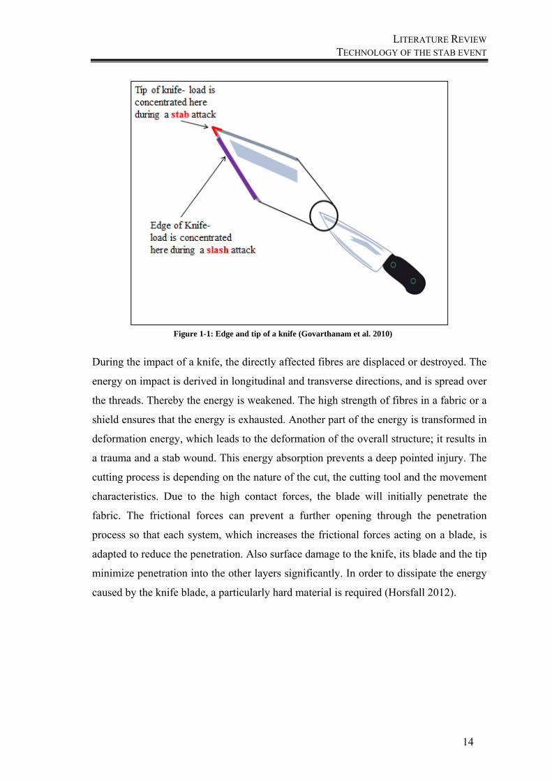
mechanism describes the penetration of the fabric, before it slices through the fibres and
cuts the fabric (Egres Jr et al. 2004). A threat by a knife includes both mechanisms, like
shown in Figure 1-1. The tip of the knife penetrates the fabric and displaces the fibres
and slips through the yarns, while the sharp edge slices through the fabric and cuts the
yarns. It is important to understand the principle of both mechanisms in order to
understand the variety of materials, which are used in dependency to their properties for
designing suitable protection garments. In the following chapter, the mechanism of stab
and slash penetrations are further characterized. In addition, the influencing factors
beside the penetration instrument are given and the interactions between them are
analysed. The resultant threats for human bodies complete this analysis.
1.5.1 Basics of the penetration mechanisms
There is no general or unique process to describe the mechanism of a stab attack, while
there are a huge variety of stab instruments and stab processes, which can be cutting,
punching or the displacements of fibres. The degree of blade sharpness causes different
damages onto the fibres (Aming, Chitaree 2010). In general, a stab instrument gives
energy to the surrounding material during the penetration until it comes to a standstill.
With regard to the development of stab resistant equipment it makes sense to analyse
the individual procedures since each of them absorbs energy and prevents a further
penetration of the textile layers to the human body. The goal is to reduce the total
puncture energy in a short period of time in order to stop the acting subject as early as
possible.
LITERATURE REVIEW TECHNOLOGY OF THE STAB EVENT
14
During the impact of a knife, the directly affected fibres are displaced or destroyed. The
energy on impact is derived in longitudinal and transverse directions, and is spread over
the threads. Thereby the energy is weakened. The high strength of fibres in a fabric or a
shield ensures that the energy is exhausted. Another part of the energy is transformed in
deformation energy, which leads to the deformation of the overall structure; it results in
a trauma and a stab wound. This energy absorption prevents a deep pointed injury. The
cutting process is depending on the nature of the cut, the cutting tool and the movement
characteristics. Due to the high contact forces, the blade will initially penetrate the
fabric. The frictional forces can prevent a further opening through the penetration
process so that each system, which increases the frictional forces acting on a blade, is
adapted to reduce the penetration. Also surface damage to the knife, its blade and the tip
minimize penetration into the other layers significantly. In order to dissipate the energy
caused by the knife blade, a particularly hard material is required (Horsfall 2012).
Figure 1-1: Edge and tip of a knife (Govarthanam et al. 2010)
LITERATURE REVIEW TECHNOLOGY OF THE STAB EVENT
15
Summarizing, the cutting process itself can be divided up into three processes after
Feiler: (Feiler 1970)
1. The work or energy to overcome the molecular bonding forces. It depends on
the material´s specification.
2. The deformation work, which is the sum out of the elastic and plastic
deformation, depending on the physical properties of the material and the
displaced volume.
3. The frictional force, which depends on the material´s properties, the surface
structure of the cutting instrument and forces acting on the surface.
This theoretical approach is often different from the practice, because as shown on the
one hand, in real life, a variety of instruments is used and secondly, a classification of
the injury`s energy is difficult, as it will be shown in the following chapter. Also the
distinction between the two mechanisms of stab and cut injuries is difficult, because
some instruments include both mechanisms, like shown. Therefore the mechanisms are
summarized in the following chapters as one threat. Also a lot of influencing factors
have to be taken into account.
1.5.2 Influencing factors
The cutting process is influenced by different parameters, which interact with each
other. They can be split up in two areas, the technological factor, which includes the
stabbing weapon itself with its geometry and the kinematic energy of action and the
material factor of the cut material itself (Feiler 1970; Finkelmeyer 2002). Also the
influence of human during a stab attack must be taken into account.
1.5.2.1 Technological factor
From the technological point of view, the threat level is influenced by the kinetic energy
of the knife-arm-system, which depends on the instrument´s factors like size and shape
of the weapon and its blade, the diameter and the angle of attack (Finkelmeyer 2002;
Yahya et al. 2014). Also the steel hardness, blade hardness and the knife grip influence
the threat level (Scott 2005). Both cut energy and failure initiation strain decrease with a
decreasing slice angle. The cut energy drops greatly when the blade angle decreases
from 90° it falls from 50 to 75% at a blade angle of 82.5° and decreasing further, but
more gradually, at lower angles. At a 45° blade angle, cut energies fall between 3 to
LITERATURE REVIEW TECHNOLOGY OF THE STAB EVENT
16
10% (Shin et al. 2003). The different kind of cutting methods can also vary. As a basis
for testing procedures Heudorfer gave an overview about the different methods. These
differ by the cutting tool, the characteristics of movements, like shown in Figure 1-2.
The movement characteristics depend especially on the cutting angle, which is different
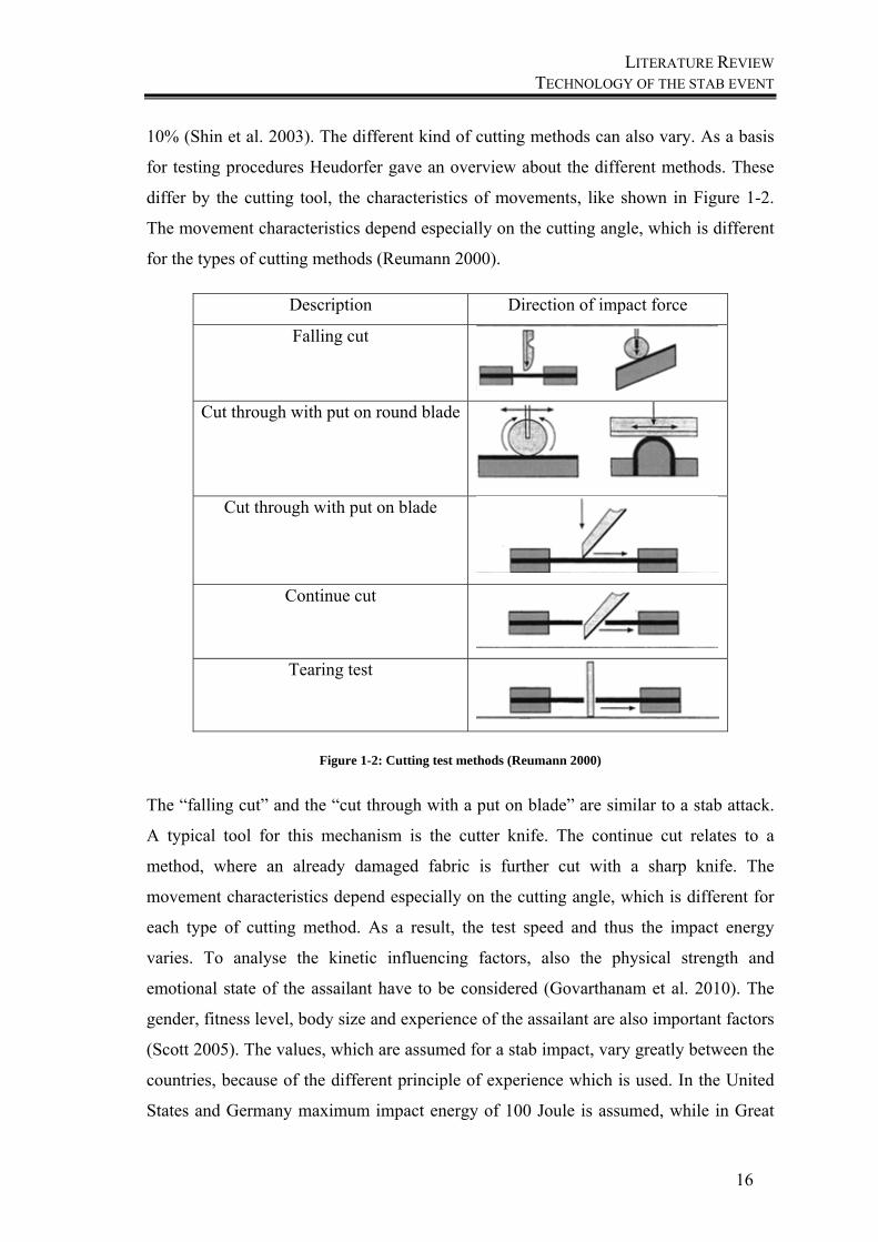
for the types of cutting methods (Reumann 2000).
Description Direction of impact force
Falling cut
Cut through with put on round blade
Cut through with put on blade
Continue cut
Tearing test
Figure 1-2: Cutting test methods (Reumann 2000)
The “falling cut” and the “cut through with a put on blade” are similar to a stab attack.
A typical tool for this mechanism is the cutter knife. The continue cut relates to a
method, where an already damaged fabric is further cut with a sharp knife. The
movement characteristics depend especially on the cutting angle, which is different for
each type of cutting method. As a result, the test speed and thus the impact energy
varies. To analyse the kinetic influencing factors, also the physical strength and
emotional state of the assailant have to be considered (Govarthanam et al. 2010). The
gender, fitness level, body size and experience of the assailant are also important factors
(Scott 2005). The values, which are assumed for a stab impact, vary greatly between the
countries, because of the different principle of experience which is used. In the United
States and Germany maximum impact energy of 100 Joule is assumed, while in Great
LITERATURE REVIEW TECHNOLOGY OF THE STAB EVENT
17
Britain values of 42 Joule are supposed. Experiments in Switzerland brought mean
values of 35 Joule (Damm 1997). Horsfall found out, that an overarm attack can reach
up to 115 Joule and 64 Joule was reached by an underarm attack (Horsfall et al. 1999).
In another research study, energy levels of 103 Joule were reached by volunteers
(Chadwick et al. 1999). One study compared over- and underarm attacks with a long-
and a short stabbing action. Long way attacks show higher speed values with up to 3.8
m/s for long overarm, 3.1 m/s for long underarm attacks, 2.8 m/s for short overarm
attacks and 2.4 m/s for short underarm attacks. Longer ways cause higher speeds and
result in higher impacts (Miller, Jones 1996).
1.5.2.2 Material structure factor
To produce soft body armour, it is necessary to manufacture textile structures out of the
previous mentioned materials. Due to their construction, textile structures have the
advantage to be flexible and can be woven, non-woven, knitted or laminated structures
made of yarns or fibres and due to their construction they have different properties. The
main goal of the fabric is to absorb energy in case of an impact and make sure that no
perforation occurs. Therefore an inelastic structure is most favourable, because the fibre
itself absorbs the energy and is not influenced by the construction, which gives way
from the amount of yarn reserve and varies on the type of construction.
Stab or cut resistant fabrics should resist against impact as long as possible. The
material, which is penetrated, influences the impact by its chemical and microscopic
structure and therefore by its mechanical properties. Also the sample size, the thickness
and the density are important influencing factors. A higher number of fabric layers
absorb more energy and especially spacer fabrics absorb more energy than plied fabric
layers (Cunniff 1992).
1.5.2.2.1 Stiching
The energy absorption can be increased by stitching of the fabric, because the fabric
layers are closer together. The lower gap between the layers leads to better interactions
between the fabrics. The distance between the seams have no significant influence
(Ahmad et al. 2008). Also the movement of the fabrics will be controlled through the
stitching, which leads to a better puncture behaviour (Suhaimi et al. 2012). Opposite to
that, Bilisik found out, that unstitched and stitched fabrics absorb the same energy but
stitching prevents deformations in one direction of the structures (Bilisik, Turhan 2009).
LITERATURE REVIEW TECHNOLOGY OF THE STAB EVENT
18
1.5.2.3 Influence on human by the threat
To classify the threat level, the energy of the threat has to be known, whereby the
energy level, which can be reached, varies greatly. Sharp weapons cause wounds, which
can be characterized by their depth and width in the skin. Most of the time the injury is
a combination of stab and cut, because usually both the attacker and the victim are in
motion (DiMaio, Dana 2006). A study in 1986 in Great Britain with 539 adult victims
showed, that 20% of them were attacked by sharp weapons, from which 11% were
broken drinking glasses and 6% were sharp knives. In total 54% of them were injured
through laceration (Shepherd et al. 1990). A simulation of stab penetrations is difficult
to do. Ankersen made stab tests on synthetic chamois and pigskin, which is similar to
the human skin (Ankersen et al. 1999). The most dangerous influences on the injury
level are the depth of the stab injuries and the body areas, which are penetrated. They
are presented in the following.
1.5.2.3.1 Depth of stab injuries
The depth of the of stab injuries determines the extent of the injury additionally to the
shape of the stabbing instrument and the fabric structure. The depth depends on the
victim’s body mass, his reaction and the position of the assailant, which means the
angle of attack. The stabbing potential is also influenced by the assailant. Here the
influencing factors are the gender, his fitness level and body mass, the physical size,
mental state and the training experience (Scott 2005). Connor made computer
tomographic measurements, carried out on 71 subjects to evaluate the distances of
organs to the skin. The results show that with stab wounds at a depth of up to 9 mm no
organs are injured because the smallest distance of an organ to the skin with 9 mm was
measured to the liver. The spleen lies in a distance of 12 mm to the skin and the kidneys
19 mm. The pleura have a distance to skin of 10 mm and the pericardium 12 mm. There
is no difference between male and female subjects (Connor et al. 1998). Bleetman
comes to the same conclusion, (Bleetman, Dyer 2000) after which the Home Office
Police Department has taken those parameters into account and has set a maximum
allowable penetration depth of 7 mm in their standards (Croft, Longhurst 2007c).

LITERATURE REVIEW TECHNOLOGY OF THE STAB EVENT
19
1.5.2.3.2 Body areas
After Fenne (in Scott 2005, page 669) the thoracic and abdominal region suffers the
largest share of attacks. The head, facial area and arms are the following two most likely
attack surfaces. The fewest puncture wounds are recorded as the legs, the neck and the
shoulder area.
Another study with police officers as victims in the year 2003 showed, that 42% were
injured in the face, 6% to the trunk, 14% to the hands, 12% to the arms and 11% to the
legs like presented in Figure (Horsfall et al. 2013).
Figure 1-3: Areas of injuries after Horsfall (Horsfall 2000)
LITERATURE REVIEW BODY ARMOUR TECHNOLOGY
20
1.5.3 Conclusion
The stab mechanism is a complex and variable process. To design improved body
armour, the physical properties of the material but also the mechanism during a stab
attack has to be recognized. Only if the interdependencies are taken into account, better
panels can be developed for a higher protection level.
From the multitude of factors it is difficult to define a level of protection. This is also
reflected in the large number of standards, which will be discussed later. Also high
kinetic energies are not always critical. A needle bends for example during a fast
penetration while it perforates the fabric at a slow penetration level.
An attack can only be inhibited, but an injury cannot be completely prevented. The goal
is always to absorb as much energy as possible, so that the penetration of the weapon is
thus reduced and the risk of injury decreases. Due to the high variation in blades,
mechanism, sharpness and geometry of the blade and many other factors, like presented
before, it is difficult to characterize the threat level of impact and define a test method
which covers the variety of stab mechanisms and other relevant factors. That is one
reason, why any comprehensive solution is currently not available.
1.6 Body armour technology
1.6.1 Composition and construction of body armour
Every stab resistant vest consists of three main parts, which are in most cases,
manufactured from completely different materials, chosen due to their specific
properties, ensuring, that the final product offers the best possible safety to its wearer.
The simplest construction of a vest is a panel out of two layers which build the carrier.
In these layers the stab resistant package panel then can be inserted. The carrier is the
only part of an impact resistant vest that actually allows any design alterations, which
makes it most valuable for organizations like Police Forces or Armies, since it provides
space for additional equipment and any other specifics that reflects the profession of its
wearer. There are two basic options available for the carrier: a carrier with removable
stab resistant packets and / or a carrier in which the panel is permanently inserted.
Minds argue about the pros and cons of both options, but in the context of female body
armour it should be mentioned, that removable plates allow the wearer and bearer of
such a vest a major reduction of weight when several plates are not necessarily needed.
LITERATURE REVIEW BODY ARMOUR TECHNOLOGY
21
Further design options are also closely related to the functionality of the vest and the
field of employment of the wearer (Moureaux et al. 1999). The carrier and its mode of
functioning are mostly independent of the style of the stab resistant panel and
manufactured for hard or soft body armour.
The stab resistant package panel part is the most important one of any type of body
armour, because it is designed and destined to stop the impact and save its owner. It has
to fulfil many requirements and testing standards such as a superior tensile strength (for
soft body armour only), specific weight requirements, and the ability to distribute the
energy that needs to be absorbed to the highest possible amount of available space and,
lastly, a very low value in terms of elongation during breaking load. They have to fulfil
their protection level also after ten years of use (Gäbler et al. 2011). These standards
and requirements apply to soft as well as hard body armour panels. But apart from these
common goals, the two types of ballistic panels differ greatly from each other. The first
type of body armour to be regarded in this thesis is the hard body armour.
1.6.1.1 Hard body armour
The hard ballistic panel is, opposed to the soft ballistic panel, made out of some sort of
rigid material, including ceramic tiles, metal plates and silicone carbide or boron
carbide plates (Hani et al. 2012). From a historical point of view, this working principle
made up the very first types of body armour. In history, steel was the only preferably
used material that could perform well under the given stress of a mechanical impact.
However, nowadays, a producer of body armour garments can also choose from oxide
ceramics, polyethylene and boron carbide or silicone carbide ceramic, mostly fusing
several materials with specific properties together into one hard ballistic package, which
has a very specific wavy form (Horsfall 2000). Plate armour is the simplest
manufactured body armour and gives a high level of protection. It consists of rigid
plates in different sizes. The disadvantage lies in the missing flexibility and thus a bad
comfort. Also because of the kind of manufacturing, the openings at the neck and
armholes have to be large enough to give a certain level of freedom to the movement. In
1987 Fritch registered a patent out of multiple panels with front and back body armour
inserts to be worn under regular clothing. Each panel consists of a ply of titanium metal
bonded to a ply of aramid fibre woven cloth. The panels are arranged overlapping
(Fritch 1987). Another innovation is scaled armour out of small rigid plates, which are
much more flexible (Beck 2006; Sacks, Jones 1996). But in case of an angled attack it
LITERATURE REVIEW BODY ARMOUR TECHNOLOGY
22
gives a very poor protection, because the knife can slip between the plates. To give a
better comfort, some researchers combined the plates with cut resistant yarns, which are
wrapped around the plates. This gives a better breathability to the wearer (Harpell et al.
1993). Another used material is granular ceramic armour, which consists of an array of
small ceramic elements which is bonded together on a rigid backing (McLean, Frutiger,
S. Dabek, R. Reeves, J. 2010). This is mostly done to create a higher degree of adaption
to the body for the vest as well as to better handle the energy that needs to be adsorbed
when an impact hits the garment. In theory, hard ballistic packages are sufficient to stop
any kinds of impacts; nevertheless, they are mostly used in a combination with soft
body armour panels to maximize comfort and safety for the wearer of the vest. The
working principle for hard ballistic packages underlies one simple principle: the panel
should be harder than the impacting threat. Depending on the materials used for panel
and weapon, both can deform during the impact due to the high energies and forces
working against each other at this point. Furthermore, energy can be led away from the
wearer if impact fragments rebound in the opposite direction. With steel, the molecular
structure at the hitting point can be destroyed during the shock, causing the performance
of the vest to decrease dramatically.
1.6.1.2 Soft body armour
Soft body armour is part of the PPE, most times in form of a vest, which protects the
body against impacts, like ballistic impacts or other impacting objects like knives or
spikes.
In the construction of soft body armour, several layers of textiles are put together to a
system against impact threats. The panel should maintain the freedom of movement
while still covering the most important areas, which are the organs of the body. That is
why they are designed in an ergonomically cut with consideration to the human
anatomy. The panel also needs to provide protection against light and humidity, because
some stab performance materials are sensitive to these influences and can lose their
properties. Therefore they are sealed into a waterproof and impermeable light plastic
foil and further encased into a textile carrier. This prevents the effect of light and
moisture to the fabric and therefore reduces the loss of performance.
A soft body armour panel consists of high performance fibres or filaments that are fused
in a woven or other bonded layering. Flexible body armour is also made out of multi-
LITERATURE REVIEW BODY ARMOUR TECHNOLOGY
23
layered fibre material or a blend of cut resistant fibres with a metal core (Kolmes,
Pritchard, C.E. Mussinelli, M. 2007; Donovan 1984; Zhu, Prickett 2003).
In general, the application of soft ballistic packages is limited to prevent knives to
penetrate, however, with the right amount of layering and a proper high performance
fibres as a base, the soft ballistic panel can be improved, to prevent threads entering the
human body tissue.
Apart from the general valid and needed properties of the fibre type, the type of
weaving or bonding that fuses the fibres together is of highest importance to the
functioning of the finished garment, as described before (Cavallaro 2011).
In principle, two different fabric constructions are used for manufacturing soft body
armour. On the one hand are conventional fabrics and on the other hand are
unidirectional laminate nonwovens (UD), which are also called shields.
1.6.1.2.1 Woven Fabrics
In the field of soft body armour construction, woven structures are very common among
other fabric constructions. Up to a certain velocity and density, square woven fabrics
can be more resistant than equivalent hard body armour (Shepherd et al. 1990). The
pattern that is used the most is square woven plain or basket weaves, like presented in
following.

LITERATURE REVIEW BODY ARMOUR TECHNOLOGY
24
Figure 1-4: Square plain weave
Figure 1-5: Basket weave
A balanced weave is normally used for the construction of protection garments, because
unbalanced weave structures lead to an asymmetric transverse deflection (Cunniff
1992). In this context, the cover factor of the fabric is from high importance. Studies
have shown that cover factors between 0.6 and 0.95 give an optimal performance (Scott
2005, p. 537). Values below are too loose and such loose yarn structures lead to a
displacement of the yarns, which then lead to a penetration of the fabric (Cheeseman,
Bogetti 2003). Values above 0.95 result in a degradation of the yarns under tension
during the weaving process. Also the crimp of the inserted yarns increases with a higher
density, which is not desirable; because the energy dissipation mechanism is depending
on the crimp of the fabric, which has to extend first until the main mechanism can take
its effect on the energy absorption (Bilisik, Korkmaz 2011). But a high yarn pre-tension
can reduce the cut resistance (Shin et al. 2006).
LITERATURE REVIEW BODY ARMOUR TECHNOLOGY
25
1.6.1.2.2 Laminates
Laminates are a combination of two or more materials to combine the useful properties
of the individual components. These laminates are called Unidirectional laminate
fabrics (UD-fabrics). They are nonwoven matrix systems, where yarns are aligned
unidirectional in one layer and the following layer is aligned in another direction,
normally 90° to the first one. They are permanently bonded together by heat, pressure or
adhesives. The properties of these UD-fabrics depend on the type of fibre, the type and
amount of resin, the number of layers and the bond between resin and fabric (Bhatnagar
2006). Different structures are used for stab resistant PPE and are discussed in the
following sub-sections.
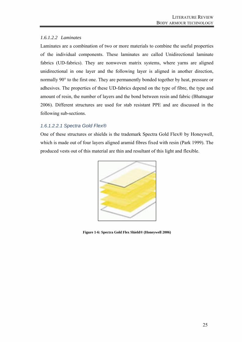
1.6.1.2.2.1 Spectra Gold Flex®
One of these structures or shields is the trademark Spectra Gold Flex® by Honeywell,
which is made out of four layers aligned aramid fibres fixed with resin (Park 1999). The
produced vests out of this material are thin and resultant of this light and flexible.
Figure 1-6: Spectra Gold Flex Shield® (Honeywell 2006)
LITERATURE REVIEW BODY ARMOUR TECHNOLOGY
26
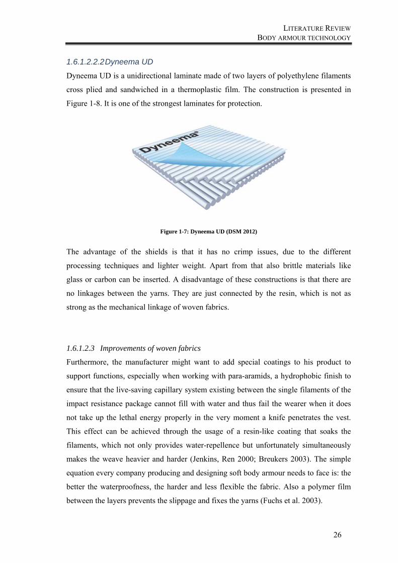
1.6.1.2.2.2 Dyneema UD
Dyneema UD is a unidirectional laminate made of two layers of polyethylene filaments
cross plied and sandwiched in a thermoplastic film. The construction is presented in
Figure 1-8. It is one of the strongest laminates for protection.
Figure 1-7: Dyneema UD (DSM 2012)
The advantage of the shields is that it has no crimp issues, due to the different
processing techniques and lighter weight. Apart from that also brittle materials like
glass or carbon can be inserted. A disadvantage of these constructions is that there are
no linkages between the yarns. They are just connected by the resin, which is not as
strong as the mechanical linkage of woven fabrics.
1.6.1.2.3 Improvements of woven fabrics
Furthermore, the manufacturer might want to add special coatings to his product to
support functions, especially when working with para-aramids, a hydrophobic finish to
ensure that the live-saving capillary system existing between the single filaments of the
impact resistance package cannot fill with water and thus fail the wearer when it does
not take up the lethal energy properly in the very moment a knife penetrates the vest.
This effect can be achieved through the usage of a resin-like coating that soaks the
filaments, which not only provides water-repellence but unfortunately simultaneously
makes the weave heavier and harder (Jenkins, Ren 2000; Breukers 2003). The simple
equation every company producing and designing soft body armour needs to face is: the
better the waterproofness, the harder and less flexible the fabric. Also a polymer film
between the layers prevents the slippage and fixes the yarns (Fuchs et al. 2003).
LITERATURE REVIEW BODY ARMOUR TECHNOLOGY
27
Another way to improve the performance of such a panel is to add a liquid, called Shear
Thickening Fluid. The Shear Thickening Fluid, short STF, as the name already
indicates, behaves like a solid when encountering mechanical stress or shear. STF is a
colloid, which is highly filled with miniscule, rigid and colloidal particles that repel
each other slightly and are suspended in a liquid. Due to the fact, that the particles repel
each other, they can easily float through the liquid without clumping together of
forming a layer at the bottom.
With the energy of a sudden impact, hydrodynamic forces overwhelm the repulsive
forces that exist between the tiny particles, driving them to stick together and forming
hydro clusters.
As soon as this energy is taken away, the particles start repelling each other again,
causing the hydro clusters to fall apart and the STF to be liquid once again.
The production of STF is fairly simple: it is made of colloidal silica particles, a
component, only a few nanometres (∼450nm) in diameter of sand and quartz,
suspended in polyethylene glycol, which is a polymer commonly used in e.g. lubricants.
Due to the size of the particles, some reports describe this fluid as nanotechnology. The
STF acts like a liquid, providing high flexibility and no restriction to movement, until
an object, in this case a blade, strikes it forcefully. At this point the relative motion of
the high performance yarns or fibres deform the fluid within milliseconds, forcing a
transition into a rigid state, providing less flexibility but high protection. Studies show,
that the addition of STF improves the stab behaviour of fabrics (Li 2012).
1.6.1.3 Conclusion
Multi-layer fabric packages of aramid, which are used for mechanical impact protection,
often don´t offer the required protection against stab protection with a sharp pointed
weapon. While developments of fabrics are already found, that enable adequate stab
resistance, there is still a large part of the solutions where combinations of different
structures of textiles with metals are used (Scott 2005). Also materials with the required
mechanical properties like strength or shear in form of plates or metal rings are used.
Stainless steel and titanium plates are also applied for this application. Ceramic plates
are also an ideal material, typically made of aluminium or boron carbide (Scott 2005). A
combination of textile materials such as aramid with steel or ceramic in form of
composite structures or sandwich constructions can give improved stab resistant results,
while they are lightweight and flexible. Also cut resistance gloves give a better
LITERATURE REVIEW BODY ARMOUR TECHNOLOGY
28
protection using a combination of cut-resistant fibre materials such as para-aramid with
steel wire. Also gloves out of leather with a high material thickness are established as an
important cut-resistant material (Heudorfer et al. 1996). Pure textile solutions often still
do not offer the required protection. Therefore it is important to analyse those influential
factors that cause the decreased stab resistance and develop improvements for better
panels (Karahan 2008).
1.6.2 Materials
In the manufacturing of textiles for protection against mechanical risks, like stab- or
slash resistant materials, different materials are used. The main task of these materials
is, to absorb and dissipate the energy, which is transmitted by the stab instrument. As a
result of this, the different kind of stab instruments can be stopped or not (Damm 1997).
The current development of stab resistant equipment often consists of one textile layer
in combination with an additional layer, which has the task, to increase the stab
resistance. In the following materials are presented, which are common used as personal
protective equipment against mechanical risks, because of their high breaking strength
and high modulus properties to be able to absorb a high amount of energy (Fenne 2005).
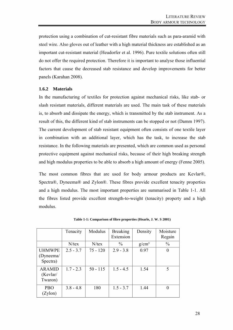
The most common fibres that are used for body armour products are Kevlar®,
Spectra®, Dyneema® and Zylon®. These fibres provide excellent tenacity properties
and a high modulus. The most important properties are summarised in Table 1-1. All
the fibres listed provide excellent strength-to-weight (tenacity) property and a high
modulus.
Table 1-1: Comparison of fibre properties (Hearle, J. W. S 2001)
Tenacity Modulus Breaking Extension
Density Moisture Regain
N/tex N/tex % g/cm³ % UHMWPE (Dyneema/
Spectra)
2.5 - 3.7 75 - 120 2.9 - 3.8 0.97 0
ARAMID (Kevlar/ Twaron)
1.7 - 2.3 50 - 115 1.5 - 4.5 1.54 5
PBO (Zylon)
3.8 - 4.8 180 1.5 - 3.7 1.44 0

LITERATURE REVIEW BODY ARMOUR TECHNOLOGY
29
But not just the high tech fibres have to be taken into account, also other fibre types
show an important role in this field.
Studies of the properties of wool have shown that the rough surface of wool, caused by
the scales, have very high friction forces (Bahadir, Jevsnik 2014; Frishman et al. 1948;
Lindberg, Gralén 1948; Mercer 1945; Zurek, Frydrych 1993).
During the stab test the yarns slide apart when the blade penetrates the fabric. Therefore
Sinnppoo (Sinnppoo et al. 2010) describes the use of wool fabrics in his studies. He put
mid-micron wool fibres into the woven structure to restrict the separation of the aramid
yarns and therefore also the friction behaviour of the fabrics. The function of the wool is
not to replace the aramid as the stab resistant material. As the friction is most important
in the area, where the knife penetrates the aramid fabric, the function of the wool layer
is to decrease the lateral separation of the yarns of the outer fabric layer.
The expected effect of decreasing the friction between the yarns is established in the
special surface of wool. The scales effect like barbed hooks, which claw into the surface
of the nearest yarn and avoid the sliding of them. The wool yarns prevent that the
filaments slide apart, they hold the directly impacted yarns in place for a better
dissipation of the impact energy. The scales stuck into each other or into other surface
irregularities. (Simpson, Crawshaw 2002) Because of the longitudinal friction between
the yarns of the wool and the filaments of the para-aramid the pull-out behaviour will
decrease (Sinnppoo et al. 2010).
In the following, the fibre properties are explained in detail.
1.6.2.1 Para-Aramid
The most common material for protective vests is para-aramid, because it can be found
in the most commonly manufactured products (Fenne 2005). For the first time, the
yellow organic synthetic fibres appeared in 1965 under the brand name Kevlar® from
DuPont. The other well-known brand is Twaron®, produced from Teijin Aramid and is
basically the same material as Kevlar®. Para-aramid is an aromatic polyamide,
consisting of cyclic aromatic elements and the amide group, namely phenyl group,
which is responsible for the high performance properties, like shown in Figure 1-9. Not
just these groups, but also the linear structure of the polymer chains are responsible for
these properties, because they can form easily strong intermolecular bonds.

LITERATURE REVIEW BODY ARMOUR TECHNOLOGY
30
Figure 1-8: Chemical formula of aramid (Teijin Aramid 2012)
Para-aramid has very good strength-to-weight properties, like high strength, high
modulus, high dimensional stability and hence an excellent cut resistance, which is a
result of the crystalline structure with the molecular chains oriented along the fibre axis
(Teijin Aramid 2012).
The main problem of the para-aramid fibres is the susceptibility to hydrolysis and
sensitivity to light, why it has to be protected from light and moisture. The low
resistance to UV radiation can cause the fibre to lose up to 75% of its strength.
Therefore the material is wrapped by an opaque and impermeable cover to prevent any
kind of degradation and loss of performance (Horrocks, Anand 2000).
1.6.2.2 Ultra-high molecular weight Polyethylene (UHMWPE)
UHMWPE is a special produced polyethylene with extremely long chains of
polyethylene, which are all aligned in one direction. The fibre production is carried out
by solvent or gel spinning and allows the molecules already to align in the solution,
which leads to extremely long molecular chains. The additional drawing process makes
the molecules become even more orientated.
Figure 1-9: Formula of Polyethylene
Under the current used fibre types for protection against mechanical threats, it is the
lightest material and the best material referring to its strength to weight ratio. It is
stronger than steel but also stronger than aramid and is not prone to degradation. The
low melting point of 150°C restricts its use to low temperature applications (Horrocks,
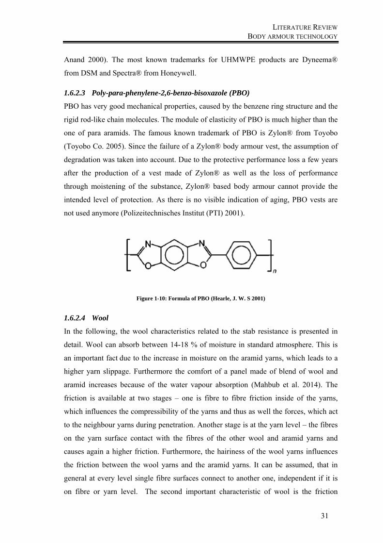
LITERATURE REVIEW BODY ARMOUR TECHNOLOGY
31
Anand 2000). The most known trademarks for UHMWPE products are Dyneema®
from DSM and Spectra® from Honeywell.
1.6.2.3 Poly-para-phenylene-2,6-benzo-bisoxazole (PBO)
PBO has very good mechanical properties, caused by the benzene ring structure and the
rigid rod-like chain molecules. The module of elasticity of PBO is much higher than the
one of para aramids. The famous known trademark of PBO is Zylon® from Toyobo
(Toyobo Co. 2005). Since the failure of a Zylon® body armour vest, the assumption of
degradation was taken into account. Due to the protective performance loss a few years
after the production of a vest made of Zylon® as well as the loss of performance
through moistening of the substance, Zylon® based body armour cannot provide the
intended level of protection. As there is no visible indication of aging, PBO vests are
not used anymore (Polizeitechnisches Institut (PTI) 2001).
Figure 1-10: Formula of PBO (Hearle, J. W. S 2001)
1.6.2.4 Wool
In the following, the wool characteristics related to the stab resistance is presented in
detail. Wool can absorb between 14-18 % of moisture in standard atmosphere. This is
an important fact due to the increase in moisture on the aramid yarns, which leads to a
higher yarn slippage. Furthermore the comfort of a panel made of blend of wool and
aramid increases because of the water vapour absorption (Mahbub et al. 2014). The
friction is available at two stages – one is fibre to fibre friction inside of the yarns,
which influences the compressibility of the yarns and thus as well the forces, which act
to the neighbour yarns during penetration. Another stage is at the yarn level – the fibres
on the yarn surface contact with the fibres of the other wool and aramid yarns and
causes again a higher friction. Furthermore, the hairiness of the wool yarns influences
the friction between the wool yarns and the aramid yarns. It can be assumed, that in
general at every level single fibre surfaces connect to another one, independent if it is
on fibre or yarn level. The second important characteristic of wool is the friction
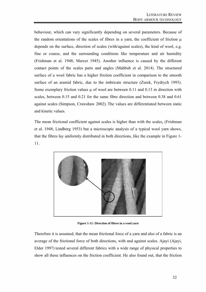
LITERATURE REVIEW BODY ARMOUR TECHNOLOGY
32
behaviour, which can vary significantly depending on several parameters. Because of
the random orientations of the scales of fibres in a yarn, the coefficient of friction µ
depends on the surface, direction of scales (with/against scales), the kind of wool, e.g.
fine or coarse, and the surrounding conditions like temperature and air humidity
(Frishman et al. 1948; Mercer 1945). Another influence is caused by the different
contact points of the scales parts and angles (Mahbub et al. 2014). The structured
surface of a wool fabric has a higher friction coefficient in comparison to the smooth
surface of an aramid fabric, due to the imbricate structure (Zurek, Frydrych 1993).
Some exemplary friction values µ of wool are between 0.11 and 0.13 in direction with
scales, between 0.15 and 0.21 for the same fibre direction and between 0.38 and 0.61
against scales (Simpson, Crawshaw 2002). The values are differentiated between static
and kinetic values.
The mean frictional coefficient against scales is higher than with the scales, (Frishman
et al. 1948; Lindberg 1953) but a microscopic analysis of a typical wool yarn shows,
that the fibres lay uniformly distributed in both directions, like the example in Figure 1-
11.
Figure 1-11: Direction of fibres in a wool yarn
Therefore it is assumed, that the mean frictional force of a yarn and also of a fabric is an
average of the frictional force of both directions, with and against scales. Ajayi (Ajayi,
Elder 1997) tested several different fabrics with a wide range of physical properties to
show all these influences on the friction coefficient. He also found out, that the friction

LITERATURE REVIEW BODY ARMOUR TECHNOLOGY
33
is also affected by experimental conditions, like changes in the normal pressure and a
limited influence to the test velocity.
1.6.3 Yarns
Not just the right material has to be chosen, but also the yarn has to fulfil requirements,
because they are the basis of the structure, which is manufactured for the protective
garment. One of the most important properties is the linear density. In the production it
is easier and cheaper to produce coarser yarns with more filaments and also the
handling is easier. But nevertheless, yarns with a lower linear density are lighter and
show a better performance against mechanical impacts due to higher energy absorption
because the bundle effect is lower. Bundles lead to a poor contact area between the
impact instrument and the filaments. Furthermore yarns made out of aramid filaments,
which are really fine and can consist of 1000 monofilaments, give the filaments the
opportunity to move individually and can spread while being impacted (Eichhorn 2009).
To give the filaments the opportunity to move individually, also yarn twists as low as
possible are recommended.
1.6.4 Physical properties of textile body armour
According to the German technical guideline TR, a body armour vest has to fulfil the
following requirements: a vest has to tighten easily and should not restrict its wearer in
his movements. It should also be able to be adapted within a standard size to the body
size (Polizeitechnisches Institut (PTI) 2008).
In general, body armour vests cover only the chest and back area of a human body.
Thereby the risk of serious or fatal injuries is minimized. Depending on the protection
level, the wearer requires light and flexible protection equipment. However, there is a
direct inverse relationship between protection and flexibility (Horsfall, Arnold 2010).
Thus, the requirements of comfort from the perspective of the wearer and the request to
the protective performance stand opposite to each other (Fenne 2005). Because of the
required protection level, body armour vests are made out of several flexible layers,
which can consist of up to forty layers and can lead to inflexibility and heaviness. This
can cause a vest to interfere with the movements of its wearer. A research study showed
that it is only possible to stop a knife with an amount of minimum 35 layers (Barnat,
Sokołowski 2014). An average multilayer body armour panel can consist of forty to
fifty layers, which has a negative impact on the mobility of the wearer (Fenne 2005). A
LITERATURE REVIEW BODY ARMOUR TECHNOLOGY
34
lot of researchers worked on new technologies to reduce the weight of such a panel,
while improving the comfort of it (Barker, Black 2009; Flambard 2000; Horsfall et al.
2013).
Studies of the German police have shown that especially in police interventions an
insufficient acceptance is given. That means that many police officers don´t wear their
vests and are therefore not protected in dangerous situations (Polizeitechnisches Institut
(PTI) 2001). Another study in this context analysed, that only 25% of these police
officers wear their vests always during their work time whereas more than 50% never or
seldom wear them (Lorei 2001). One reason is that they are exposed to extreme physical
stress. Therefore they need fast reactions and they have to adapt to the body. Due to the
long wearing times, protection vests should be comfortable and should not restrict the
wearers in their movements.
The comfort of protective panels is determined by different influencing factors in
dependency of the protection level, which is the most important factor, also for the
wearer.
1.6.4.1 Psychological influences
Body armour vests have to fulfil the required protection level to let the wearer feel save.
Thereby the wearer is motivated to wear it (Moser 2007). A vest should also be
invisible under the clothing, because in case of an attack other body areas like the head
would be the objective if an assailant notices the vest.
1.6.4.2 Thermo-physiological influences
The thermo-physiological comfort deals with the way clothing buffers and dissipates
metabolic heat and moisture, so the heat- moisture exchange has to be ensured (Yoo
2005). Even during long times of wearing and high body stress, wearing of a protection
vest must not result in a heat build-up. Body armour panels do not allow air circulations,
but the sweat production increases by physical activities or high ambient temperatures.
The problem is that sweat cannot evaporate on the skin. Wellbeing and performance of
the wearer decline. That is one reason, why wearers feel uncomfortable when wearing
vests (Lehmacher et al. 2007). Therefore, the moisture transport in fabrics plays an
extremely important role in the clothing comfort (Yueping Guo et al. 2008). One way,
LITERATURE REVIEW PROTECTION LEVELS AND CLASSIFICATION OF BODY ARMOUR
35
to get the present problem under control is the use of mesh fabrics as an inner layer of
the clothing. These fabrics carry the moisture away from the inside to the outside.
1.6.4.3 Ergonomical influences
The fit is one of the most important properties for the user and should match the
wearer´s body. If the vest does not fit, lightness and softness play no role. It is still
perceived as uncomfortable. The fit can be presented in four grading.
The first and easiest grade is a standard size. In the second stage, five grades of different
lengths are included. The third grading includes contour variations in the armholes and
necklines. An additional description of contours by mathematical curves is given in the
fourth grade. That means an individual adaption to the wearer, considering the
individual body characteristics such as cups for women and also an adaption to the kind
of activity, such as long car or motorbike drives (De 2015).
Additionally to the fit, the weight of the vest is an important ergonomic factor. After
long wearing times, the weight has a negative effect on the wearer.
Limits in flexible body armour panels out of fibrous materials are the high weight and
inflexibility while a puncture is still possible. The main goal in the development of body
armour is to increase the wearer´s comfort, where particularly the flexibility is still a
main factor. But these requirements of improvements are a challenge, because the
protection factor cannot be worsened. Therefore a balance between comfort and
protection has to be found (Scott 2005).
1.7 Protection levels and classification of body armour
Since there are many different levels of threats, there is no single vest that can protect
the wearer against all kind of threats. Different constructions of soft body armour create
different levels of protection and each has its own field of application. The usage of
each construction of soft body armour is restricted to certain threats, respectively kind
of blades, impact forces and speeds. The use of most constructions of textiles are not
sufficient for protection, thus soft body armour cannot give enough protection against a
penetration through sharp pointed weapons like knives or ice picks (Bhatnagar 2006).
That is why it is necessary to classify the different types of body armour.
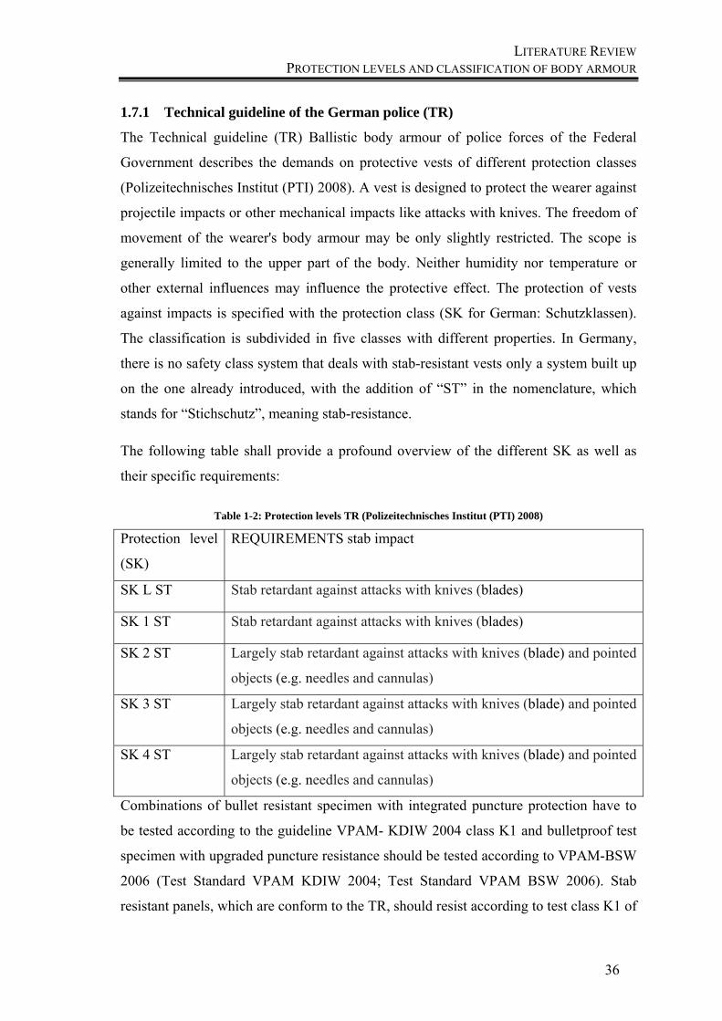
LITERATURE REVIEW PROTECTION LEVELS AND CLASSIFICATION OF BODY ARMOUR
36
1.7.1 Technical guideline of the German police (TR)
The Technical guideline (TR) Ballistic body armour of police forces of the Federal
Government describes the demands on protective vests of different protection classes
(Polizeitechnisches Institut (PTI) 2008). A vest is designed to protect the wearer against
projectile impacts or other mechanical impacts like attacks with knives. The freedom of
movement of the wearer's body armour may be only slightly restricted. The scope is
generally limited to the upper part of the body. Neither humidity nor temperature or
other external influences may influence the protective effect. The protection of vests
against impacts is specified with the protection class (SK for German: Schutzklassen).
The classification is subdivided in five classes with different properties. In Germany,
there is no safety class system that deals with stab-resistant vests only a system built up
on the one already introduced, with the addition of “ST” in the nomenclature, which
stands for “Stichschutz”, meaning stab-resistance.
The following table shall provide a profound overview of the different SK as well as
their specific requirements:
Table 1-2: Protection levels TR (Polizeitechnisches Institut (PTI) 2008)
Protection level
(SK)
REQUIREMENTS stab impact
SK L ST Stab retardant against attacks with knives (blades)
SK 1 ST Stab retardant against attacks with knives (blades)
SK 2 ST Largely stab retardant against attacks with knives (blade) and pointed
objects (e.g. needles and cannulas)
SK 3 ST Largely stab retardant against attacks with knives (blade) and pointed
objects (e.g. needles and cannulas)
SK 4 ST Largely stab retardant against attacks with knives (blade) and pointed
objects (e.g. needles and cannulas)
Combinations of bullet resistant specimen with integrated puncture protection have to
be tested according to the guideline VPAM- KDIW 2004 class K1 and bulletproof test
specimen with upgraded puncture resistance should be tested according to VPAM-BSW
2006 (Test Standard VPAM KDIW 2004; Test Standard VPAM BSW 2006). Stab
resistant panels, which are conform to the TR, should resist according to test class K1 of
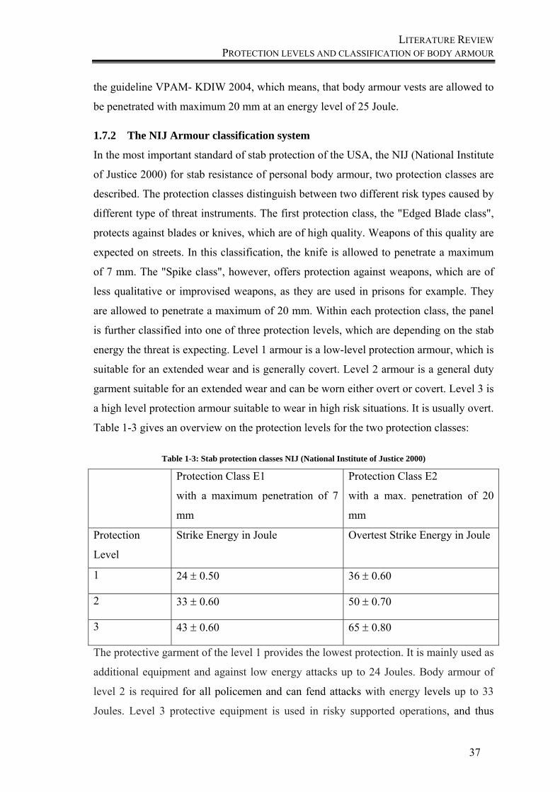
LITERATURE REVIEW PROTECTION LEVELS AND CLASSIFICATION OF BODY ARMOUR
37
the guideline VPAM- KDIW 2004, which means, that body armour vests are allowed to
be penetrated with maximum 20 mm at an energy level of 25 Joule.
1.7.2 The NIJ Armour classification system
In the most important standard of stab protection of the USA, the NIJ (National Institute
of Justice 2000) for stab resistance of personal body armour, two protection classes are
described. The protection classes distinguish between two different risk types caused by
different type of threat instruments. The first protection class, the "Edged Blade class",
protects against blades or knives, which are of high quality. Weapons of this quality are
expected on streets. In this classification, the knife is allowed to penetrate a maximum
of 7 mm. The "Spike class", however, offers protection against weapons, which are of
less qualitative or improvised weapons, as they are used in prisons for example. They
are allowed to penetrate a maximum of 20 mm. Within each protection class, the panel
is further classified into one of three protection levels, which are depending on the stab
energy the threat is expecting. Level 1 armour is a low-level protection armour, which is
suitable for an extended wear and is generally covert. Level 2 armour is a general duty
garment suitable for an extended wear and can be worn either overt or covert. Level 3 is
a high level protection armour suitable to wear in high risk situations. It is usually overt.
Table 1-3 gives an overview on the protection levels for the two protection classes:
Table 1-3: Stab protection classes NIJ (National Institute of Justice 2000)
Protection Class E1
with a maximum penetration of 7
mm
Protection Class E2
with a max. penetration of 20
mm
Protection
Level
Strike Energy in Joule Overtest Strike Energy in Joule
1 24 0.50 36 0.60
2 33 0.60 50 0.70
3 43 0.60 65 0.80
The protective garment of the level 1 provides the lowest protection. It is mainly used as
additional equipment and against low energy attacks up to 24 Joules. Body armour of
level 2 is required for all policemen and can fend attacks with energy levels up to 33
Joules. Level 3 protective equipment is used in risky supported operations, and thus
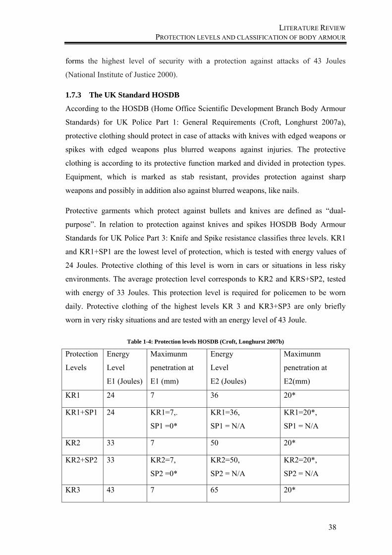
LITERATURE REVIEW PROTECTION LEVELS AND CLASSIFICATION OF BODY ARMOUR
38
forms the highest level of security with a protection against attacks of 43 Joules
(National Institute of Justice 2000).
1.7.3 The UK Standard HOSDB
According to the HOSDB (Home Office Scientific Development Branch Body Armour
Standards) for UK Police Part 1: General Requirements (Croft, Longhurst 2007a),
protective clothing should protect in case of attacks with knives with edged weapons or
spikes with edged weapons plus blurred weapons against injuries. The protective
clothing is according to its protective function marked and divided in protection types.
Equipment, which is marked as stab resistant, provides protection against sharp
weapons and possibly in addition also against blurred weapons, like nails.
Protective garments which protect against bullets and knives are defined as “dual-
purpose”. In relation to protection against knives and spikes HOSDB Body Armour
Standards for UK Police Part 3: Knife and Spike resistance classifies three levels. KR1
and KR1+SP1 are the lowest level of protection, which is tested with energy values of
24 Joules. Protective clothing of this level is worn in cars or situations in less risky
environments. The average protection level corresponds to KR2 and KRS+SP2, tested
with energy of 33 Joules. This protection level is required for policemen to be worn
daily. Protective clothing of the highest levels KR 3 and KR3+SP3 are only briefly
worn in very risky situations and are tested with an energy level of 43 Joule.
Table 1-4: Protection levels HOSDB (Croft, Longhurst 2007b)
Protection
Levels
Energy
Level
E1 (Joules)
Maximunm
penetration at
E1 (mm)
Energy
Level
E2 (Joules)
Maximunm
penetration at
E2(mm)
KR1 24 7 36 20*
KR1+SP1 24 KR1=7,.
SP1 =0*
KR1=36,
SP1 = N/A
KR1=20*,
SP1 = N/A
KR2 33 7 50 20*
KR2+SP2 33 KR2=7,
SP2 =0*
KR2=50,
SP2 = N/A
KR2=20*,
SP2 = N/A
KR3 43 7 65 20*

LITERATURE REVIEW TESTING METHODS, TEST STANDARDS
39
KR3+SP3 43 KR3=7,
SP3 =0*
KR3=65,
SP3 = N/A
KR3=20*,
SP3 = N/A
The penetration must not exceed 30mm to be permitted at E2 knife testing and one
penetration (no depth limit) is permissible for spike testing (Croft, Longhurst 2007c).
1.8 Testing methods, test standards
Like explained before, the stab event includes the stab and the cut or slash action. Due
to this, the known test standards for stab and cut methods of textiles are explained as
followed. The method for stab testing will be explained later during its application in
testing.
1.8.1 Stab methods
The stab resistance of stab resistant textiles can be tested according to different test
standards. In Germany or other German-speaking countries, the VPAM test instruction
VPAM KDIW 2004 “Stab and impact protection” is widely used.
The principle of measurement is shown in Figure 1-12: a blade of a defined sharpness
and size drops from a defined height which depends on the energy level for the stabbing
impact. The penetrated fabric layers are positioned on plasticine, a modelling material
that on the one hand absorbs the penetration of the knife and on the other hand gives the
opportunity to measure the different depths of penetration. The knife is mounted on a
sample holder and the drop mass of this unit is 2.5 kg. To ensure that the knife can fall
on the sample in such a way that the tool strikes it at a 90° angle, the sample holder is
led by rails. As samples of different thicknesses are tested, the drop height is adjusted
depending on application, to determine differences between the samples. Afterwards,
the stab depth in the plasticine is measured by using a ruler.
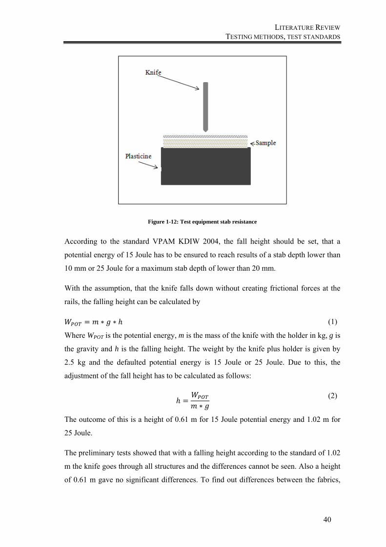
LITERATURE REVIEW TESTING METHODS, TEST STANDARDS
40
Figure 1-12: Test equipment stab resistance
According to the standard VPAM KDIW 2004, the fall height should be set, that a
potential energy of 15 Joule has to be ensured to reach results of a stab depth lower than
10 mm or 25 Joule for a maximum stab depth of lower than 20 mm.
With the assumption, that the knife falls down without creating frictional forces at the
rails, the falling height can be calculated by
∗ ∗ (1)
Where WPOT is the potential energy, m is the mass of the knife with the holder in kg, g is
the gravity and h is the falling height. The weight by the knife plus holder is given by
2.5 kg and the defaulted potential energy is 15 Joule or 25 Joule. Due to this, the
adjustment of the fall height has to be calculated as follows:
∗
(2)
The outcome of this is a height of 0.61 m for 15 Joule potential energy and 1.02 m for
25 Joule.
The preliminary tests showed that with a falling height according to the standard of 1.02
m the knife goes through all structures and the differences cannot be seen. Also a height
of 0.61 m gave no significant differences. To find out differences between the fabrics,
LITERATURE REVIEW TESTING METHODS, TEST STANDARDS
41
the falling height was reduced to 28.5 cm, which is equal to 6.9 Joule for the following
test series. With respect to this, the test speed was also reduced, due to
2 ∗ ∗ (3)
Where v represents the velocity of the falling knife in m/s during the test. According to
this equation, the test speed for a height of 1.02 m is 4.47 m/s, but for the height of 0.28
m a reduced speed of 2.34 m/s was measured.
∆ ∙ ∙
(4)
The kinetic energy EKIN, which occurs during the test results of these adjustments like
the following:
12∗ ∗
(5)
For the falling weight of 2.5 kg and the height of 0.285 m the mean impact force will be
calculated like this:
∆ ∗ ∗
(6)
Where dpenetration is the stab depth of the knife in the plasticine.
∆ (7)
where WC is the cutting work, WPP the work to penetrate the plasticine, WFBY the work
of the friction between the yarns and WFCY the work of friction of the cut yarns. From
initial tests with pure plasticine without fabric, the knife goes through the complete
plasticine, so we can assume that the energy loss for WPP is a negligible part of the
complete energy during this penetration. The energy of friction between the yarns and
the energy of friction during the cutting are in this case also negligible, because for the
practical evaluation it is important to have an idea about the average resistance of the
fabric against penetration. This average force is a calculated value, which would
correspond to the force if the penetration speed is constant, according to equation 7 and
can be used for the comparison of different fabrics. This force accumulates all above
mentioned influences and resistances, which are important during the development and
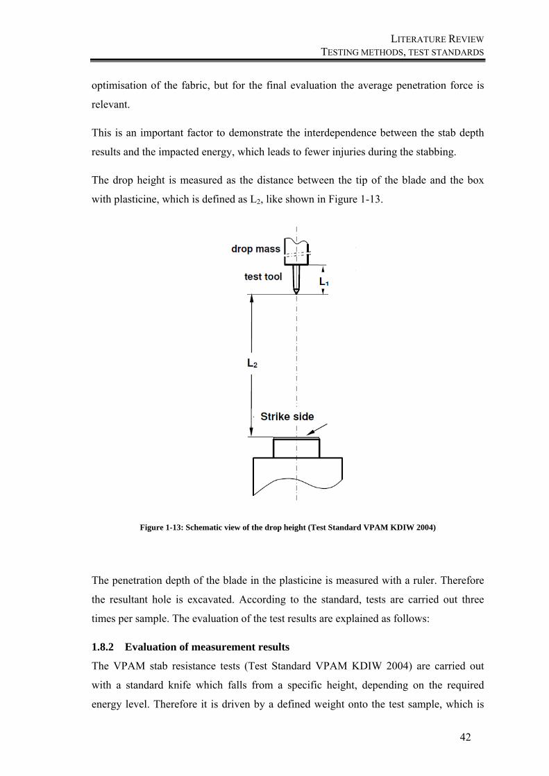
LITERATURE REVIEW TESTING METHODS, TEST STANDARDS
42
optimisation of the fabric, but for the final evaluation the average penetration force is
relevant.
This is an important factor to demonstrate the interdependence between the stab depth
results and the impacted energy, which leads to fewer injuries during the stabbing.
The drop height is measured as the distance between the tip of the blade and the box
with plasticine, which is defined as L2, like shown in Figure 1-13.
Figure 1-13: Schematic view of the drop height (Test Standard VPAM KDIW 2004)
The penetration depth of the blade in the plasticine is measured with a ruler. Therefore
the resultant hole is excavated. According to the standard, tests are carried out three
times per sample. The evaluation of the test results are explained as follows:
1.8.2 Evaluation of measurement results
The VPAM stab resistance tests (Test Standard VPAM KDIW 2004) are carried out
with a standard knife which falls from a specific height, depending on the required
energy level. Therefore it is driven by a defined weight onto the test sample, which is
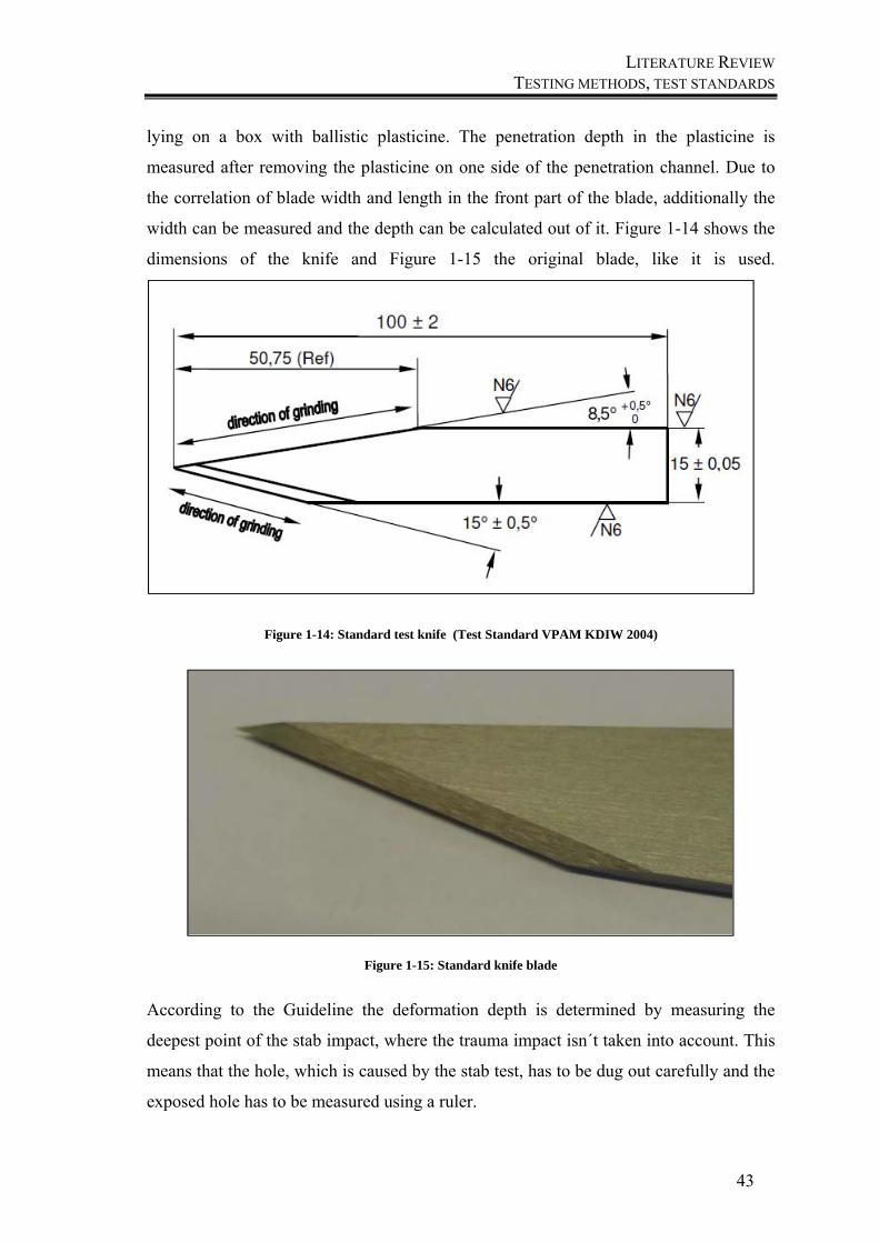
LITERATURE REVIEW TESTING METHODS, TEST STANDARDS
43
lying on a box with ballistic plasticine. The penetration depth in the plasticine is
measured after removing the plasticine on one side of the penetration channel. Due to
the correlation of blade width and length in the front part of the blade, additionally the
width can be measured and the depth can be calculated out of it. Figure 1-14 shows the
dimensions of the knife and Figure 1-15 the original blade, like it is used.
Figure 1-14: Standard test knife (Test Standard VPAM KDIW 2004)
Figure 1-15: Standard knife blade
According to the Guideline the deformation depth is determined by measuring the
deepest point of the stab impact, where the trauma impact isn´t taken into account. This
means that the hole, which is caused by the stab test, has to be dug out carefully and the
exposed hole has to be measured using a ruler.
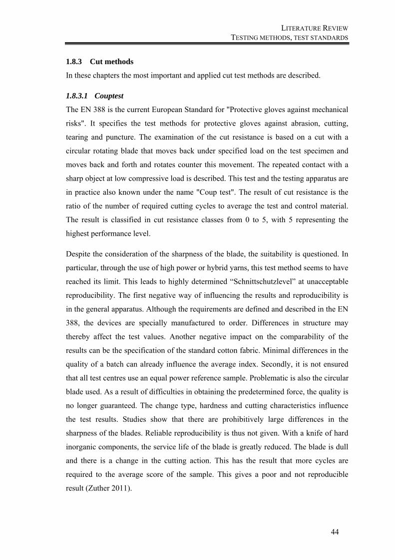
LITERATURE REVIEW TESTING METHODS, TEST STANDARDS
44
1.8.3 Cut methods
In these chapters the most important and applied cut test methods are described.
1.8.3.1 Couptest
The EN 388 is the current European Standard for "Protective gloves against mechanical
risks". It specifies the test methods for protective gloves against abrasion, cutting,
tearing and puncture. The examination of the cut resistance is based on a cut with a
circular rotating blade that moves back under specified load on the test specimen and
moves back and forth and rotates counter this movement. The repeated contact with a
sharp object at low compressive load is described. This test and the testing apparatus are
in practice also known under the name "Coup test". The result of cut resistance is the
ratio of the number of required cutting cycles to average the test and control material.
The result is classified in cut resistance classes from 0 to 5, with 5 representing the
highest performance level.
Despite the consideration of the sharpness of the blade, the suitability is questioned. In
particular, through the use of high power or hybrid yarns, this test method seems to have
reached its limit. This leads to highly determined “Schnittschutzlevel” at unacceptable
reproducibility. The first negative way of influencing the results and reproducibility is
in the general apparatus. Although the requirements are defined and described in the EN
388, the devices are specially manufactured to order. Differences in structure may
thereby affect the test values. Another negative impact on the comparability of the
results can be the specification of the standard cotton fabric. Minimal differences in the
quality of a batch can already influence the average index. Secondly, it is not ensured
that all test centres use an equal power reference sample. Problematic is also the circular
blade used. As a result of difficulties in obtaining the predetermined force, the quality is
no longer guaranteed. The change type, hardness and cutting characteristics influence
the test results. Studies show that there are prohibitively large differences in the
sharpness of the blades. Reliable reproducibility is thus not given. With a knife of hard
inorganic components, the service life of the blade is greatly reduced. The blade is dull
and there is a change in the cutting action. This has the result that more cycles are
required to the average score of the sample. This gives a poor and not reproducible
result (Zuther 2011).
LITERATURE REVIEW TESTING METHODS, TEST STANDARDS
45
1.8.3.2 Tomodynamometer
The EN ISO 13997 comes from the field of protective clothing. It includes the
"Determination of resistance to cutting by sharp objects". The force is determined,
which is required to sever the sample material in a movement over a set distance of 20
mm (reference distance). The test result is expressed in Newton (N) and is tested on a
dynamometer Tomo (TDM-100) interface testing machine. In contrast to the EN 388
there will not be a rotating circular blade, but a straight blade used in this test method.
As with the EN 388, a conductive material is placed between textile and adhesive tape
and connected to the frame. Once the blade cuts through the test material, it comes into
contact with the aluminium foil. The resulting electrical circuit stops the test
automatically.
The advantage of the procedure according to ISO 13997 compared to EN 388 is that the
blade does not need to be replaced after each test. In addition, there is a resist holender
contact between specimen and blade, but only a single contact. An influence of the test
results from abrasive effects of, for example, inorganic fibres is minimized. A
disadvantage is the relatively high price of checking because for each cut a new blade is
required. The EN388 test is cheap the circular blades can be used several times. In
addition, the test performance is simple and fast. A major disadvantage of the test
methods is the fact that it is checked only in one cutting direction. Thereby no
information on a possible isotropic cut resistance is possible.
1.8.3.3 Cut Protection Performance Tester CPPT
The ASTM F1790 is the American standard for measuring the cut resistance of
materials for protective clothing. (F1790) For the cutting test, a machine called Cut
Protection Performance Tester, called CPPD is used. The CPPT differs from the
structure and the cutting speed of ISO 13997, but is otherwise comparable.
1.8.4 Frictional test parameters
The friction behaviour of fabrics has to be split in two areas. First there is the friction
behaviour itself, which includes the fibre, yarn and fabric friction. The second
parameter is the yarn pull-out test. This test is a practical method to investigate the
material properties of a fabric. It provides useful information about the fabric`s
deformations and its ability to absorb energy, especially protective applications and
therefore the frictional behaviour of the fabric (Asayesh et al. 2012). It is influenced by
LITERATURE REVIEW TESTING METHODS, TEST STANDARDS
46
many mechanical properties like the yarn geometry and fabric weave structure (Pan,
Yoon 1993). A similar test to the pull-out test is the seam slippage. Here yarns are also
pulled out of a seam. It is explained in detail after the other methods.
1.8.4.1 Friction
The performance of textiles is greatly influenced by its frictional behaviour. Due to the
smooth surface of aramid fabrics, the stab resistant performance is affected by textile
frictions and their influencing factors (Ramkumar et al. 2005). They have to be taken
into account to increase stab resistant properties. The influencing factors of textile
friction behaviours can be divided into fibre friction, yarn friction and fabric friction.
1.8.4.1.1 Fibre friction
Fibre friction is related to the structural parameters and the bulk properties of fibres.
Fibre structural properties can be the crimp, or in case of wool, the scales type and size,
the fibres surface roughness or the molecular orientation. Some bulk properties are for
example the diameter, the fineness and the length of the fibres. Also the fibre material
itself influences the frictional behaviour. To determine the fibre-to-fibre friction and
fibre-to-other surface friction, also the test conditions have to be taken into account
(Hong et al. 2004).
1.8.4.1.2 Yarn friction
Yarn friction is related to both surface properties and bulk properties of yarns. Yarn
friction is determined by the before mentioned fibre parameters and the yarn structure
and bulk parameter, like yarn twist, spinning method (Ramkumar et al. 2003) or yarn
fineness. The coefficient of friction of yarn increases with an increasing yarn linear
density, due to the larger contact area and with an increasing yarn twist of ring and rotor
spun yarns, friction decreases for different materials. High twist results in a smaller area
of contact, and thus results in a lower frictional force. The yarn friction decreases with
an increased roughness of the yarn surface. However, with a very rough yarn surface
and increased unevenness, the yarn friction tends to increase.
Also here the test conditions to determine the frictional behaviour of yarns are
important, like the normal load, the frictional speed, contact geometry and the boundary
conditions (Ramkumar et al. 2004; Ajayi, Elder 1997). On top of that the friction of the
yarn is also influenced by finishing (Hwang et al. 2015).
LITERATURE REVIEW TESTING METHODS, TEST STANDARDS
47
1.8.4.1.3 Fabric friction
Fabric friction is related to both surface properties and bulk properties of fabrics.
Parameters affecting the fabric structure are the weave pattern and the fabric finishing
(Bazhenov, Goncharuk 2014). Twill weave pattern show higher friction forces than
plain weave pattern, due to the floating length of the yarns (Behera, Hari 2010; Ajayi
1992). The influence of operational parameters, like load pressure or the sliding speed,
was reported by several researchers (Ajayi, Elder 1997; Abghari 2011; Arshi et al.
2012; Hermann et al. 2004; Mihail 2015).
1.8.4.1.3.1 Friction measurement
In general the friction is the force that opposes the relative motion of two surfaces in
contact with the friction coefficient µ.
The frictional force F is mainly determined by the nature of the surfaces which are in
contact and the force that holds the surfaces in contact, which is known as the normal
force. The friction is governed by Amonton’s laws with: (Saville 1999)
∙ (8)
After Coulomb the friction is divided into static friction and sliding friction, which can´t
be separated strictly, because they can occur simultaneously or alternatively. It is the
force, which is required to move a carriage on the surface of a test sample to determine
the coefficient of static friction and kinetic friction. When a resting object starts to slide,
a force is required to start the object moving. It is known as the static friction. The static
friction force is proportional the normal or pressing force FN:
∙ (9)
The coefficient μs is the coefficient of static friction. It depends on the material
combination, but has on the other hand almost no dependency of the contact area of the
surfaces. Already Coulomb has determined that μs increases with the lifetime. Once the
object is moving, the force required to keep it moving is lower than the original starting
force and is known as sliding or dynamic friction. This movement in total is defined as
the frictional force. The frictional force FR is independent of the size of the contact area
and increases mostly linear with normal force FN. The coefficient of friction µ depends
on the surface (EN 14882:2005; Langston, Rainey 1954; Timble 2014).
LITERATURE REVIEW TESTING METHODS, TEST STANDARDS
48
The sliding or kinetic frictional force FK is the force, which acts after overcoming the
adhesion. Coulomb has found experimentally that the sliding friction is proportional to
the pressing force N and has no significant dependence of the contact area and
roughness of the surfaces. The kinetic coefficient of friction is approximately equal to
the static friction coefficient:
(10)
Hereby the sliding friction depends not, or only very weak, on the sliding speed. These
laws are practicable well for hard materials, but not for textile materials particularly at
low values of normal force. In most cases it is the sliding friction that is of practical
interest. To analyse the sliding process, several operational parameters which can
influence the results of the friction, are determined.
1.8.4.2 Pull-out
The pull-out effect is defined as the force, which is required to pull out one single yarn
out of the fabric structure, calculated as the sum of the frictional resistances at the
crossing points to overcome (Kirkwood et al. 2004; Bilisik 2011). Friction in turn is
most dependent on the linear density and the pattern (Rebouillat 1998).
The required force to pull out the yarn is more, the higher the friction coefficient is.
Some energy has to be mustered to move and displace the yarns out of their structure
and this leads to a higher energy absorption by the fabric (Cheeseman, Bogetti 2003).
The resistant energy which has to be overcome is due to friction forces. The friction of
the fabric plays a role, especially for lower impact velocities. There the frictional forces
at the yarn crossover points lead to the destruction of the fibres, which happens under
energy absorption. A higher fabric density will lead to more energy absorption, because
crossover points represent a higher resistance in form of friction (Bilisik, Korkmaz
2011). If the friction between the yarns is too high they would rather cut each other than
displace themselves. In case the friction is too low, there is no resistance against the
impact and yarn slippage occurs. Therefore the coefficient of friction has to be high
enough that yarns cannot be easily pulled out or moved aside. Some coefficients of
friction for interyarn friction, depending on the absorption capacity are (Zeng et al.
2006)
LITERATURE REVIEW TESTING METHODS, TEST STANDARDS
49
µ = 0.0 – 0.06 for low friction forces
µ = 0.06 – 0.2 for medium friction forces
µ = 0.2 – 1.0 for high friction forces
A high coefficient of friction leads to additional energy absorption, because more
energy is required for the pull-out force. The friction forces between aramid yarns
decrease in the state of wet yarns, because the blade can slide through easier and
therefore lead to a lower protection level (Bazhenov, Goncharuk 2014).
1.8.4.2.1 Pull-out measurements
The pull-out mechanism means that one yarn is pulled out of a fabric structure by
motion of the penetrator (Bilisik 2011). The mechanism is shared in two areas. In the
beginning of the test, the yarn has to be uncrimped. A high crimp of the yarns in the
fabric structure leads to a high energy absorption which is important for mechanical
impacts (Sadegh, Cavallaro 2012). The second region is the yarn translation region.
Figure 2-82 presents the effect on the yarn, when it is uncrimped before the mechanism
of yarn translation starts (Guo et al. 2014).
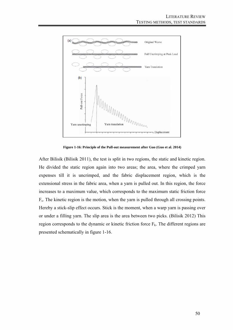
LITERATURE REVIEW TESTING METHODS, TEST STANDARDS
50
Figure 1-16: Principle of the Pull-out measurement after Guo (Guo et al. 2014)
After Bilisik (Bilisik 2011), the test is split in two regions, the static and kinetic region.
He divided the static region again into two areas; the area, where the crimped yarn
expenses till it is uncrimped, and the fabric displacement region, which is the
extensional stress in the fabric area, when a yarn is pulled out. In this region, the force
increases to a maximum value, which corresponds to the maximum static friction force
Fs. The kinetic region is the motion, when the yarn is pulled through all crossing points.
Hereby a stick-slip effect occurs. Stick is the moment, when a warp yarn is passing over
or under a filling yarn. The slip area is the area between two picks. (Bilisik 2012) This
region corresponds to the dynamic or kinetic friction force Fk. The different regions are
presented schematically in figure 1-16.
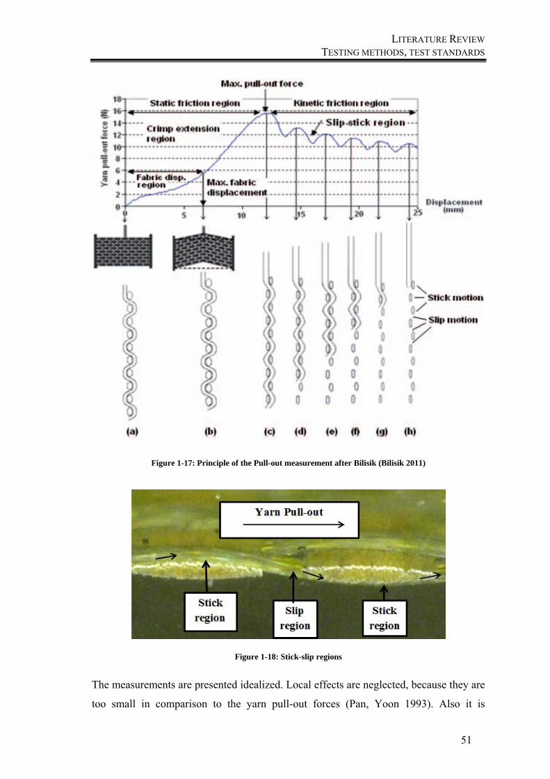
LITERATURE REVIEW TESTING METHODS, TEST STANDARDS
51
Figure 1-17: Principle of the Pull-out measurement after Bilisik (Bilisik 2011)
Figure 1-18: Stick-slip regions
The measurements are presented idealized. Local effects are neglected, because they are
too small in comparison to the yarn pull-out forces (Pan, Yoon 1993). Also it is
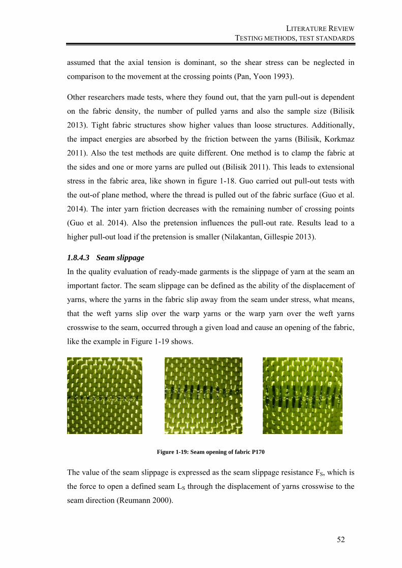
LITERATURE REVIEW TESTING METHODS, TEST STANDARDS
52
assumed that the axial tension is dominant, so the shear stress can be neglected in
comparison to the movement at the crossing points (Pan, Yoon 1993).
Other researchers made tests, where they found out, that the yarn pull-out is dependent
on the fabric density, the number of pulled yarns and also the sample size (Bilisik
2013). Tight fabric structures show higher values than loose structures. Additionally,
the impact energies are absorbed by the friction between the yarns (Bilisik, Korkmaz
2011). Also the test methods are quite different. One method is to clamp the fabric at
the sides and one or more yarns are pulled out (Bilisik 2011). This leads to extensional
stress in the fabric area, like shown in figure 1-18. Guo carried out pull-out tests with
the out-of plane method, where the thread is pulled out of the fabric surface (Guo et al.
2014). The inter yarn friction decreases with the remaining number of crossing points
(Guo et al. 2014). Also the pretension influences the pull-out rate. Results lead to a
higher pull-out load if the pretension is smaller (Nilakantan, Gillespie 2013).
1.8.4.3 Seam slippage
In the quality evaluation of ready-made garments is the slippage of yarn at the seam an
important factor. The seam slippage can be defined as the ability of the displacement of
yarns, where the yarns in the fabric slip away from the seam under stress, what means,
that the weft yarns slip over the warp yarns or the warp yarn over the weft yarns
crosswise to the seam, occurred through a given load and cause an opening of the fabric,
like the example in Figure 1-19 shows.
Figure 1-19: Seam opening of fabric P170
The value of the seam slippage is expressed as the seam slippage resistance FS, which is
the force to open a defined seam LS through the displacement of yarns crosswise to the
seam direction (Reumann 2000).
LITERATURE REVIEW CONCLUSIONS
53
It can be defined as:
∑ (11)
With ∑LS = Sum of openings to both directions in the seam area
This phenomenon leads to a reduced range of the end-use of possible areas. The
characteristic of migration or slippage is an important parameter and depends on
different fabric structure properties, like fibre type, pattern, the linear density of the
yarns and the number of yarns per unit length, but also the thread seam construction and
stich density (Milašius 2012). One important factor is also the yarn-to-yarn friction.
Especially very smooth fibre types lead to a high yarn migration, particular in the seam
area during high stress. Resultant of this, it is assumed, that the yarn friction is linked to
the seam slippage (Daukantiene, Lapinskienė 2012; Behera, Hari 2010; Malčiauskiene
et al. 2011). The seam slippage will decrease by higher friction forces (Backauskaite et
al. 2013).
In the area of stab resistance of textiles, special for high strength fibres like aramid, the
effect is given, that during the penetration with the knife, the yarns are not cut; they
migrate and cause an opening of the fabric. This phenomenon is given for all smooth
fibres, which are penetrated by a sharp shape like a knife. The aim of this chapter is to
analyse the interdependence between this displacement and the seam slippage, because
it is assumed to be similar to the seam slippage.
1.9 Conclusions
The analysis of the state of the art showed, that a lot of research has been done in the
field of protective garments against stab attacks. The need for stab resistant materials, the
materials which are currently used for slash and cut resistant applications and their
properties were reviewed in the state of the art. A main problem of these materials is the
missing friction behaviour, why a knife can penetrate a fabric easily. Therefore a lot of
layers are used to ensure adequate protection, but this leads to bad comfort behaviour
because of stiffness and heaviness. Also the test procedures to define the protection
level are incomplete or for improvement.
LITERATURE REVIEW CONCLUSIONS
54
Therefore this thesis deals with several focal points. First of all, the stab resistant
measurement itself is analysed to find out the weak points, which have to be improved.
Then test trials will be carried out using various fabrics, to find out the influential
parameters which affect the stab depth. These test parameters are analysed in following,
with an analysis, how to test them and where are the limitations in testing. Some test
procedures are improved.
Another focus lays on the fabrics itself, which will be improved in order to reduce
fabric layers and improve the comfort of them.
The last step will be a comparison of test results to simulations of the stabbing
behaviour. The goal is to develop lifelike simulations to give predictions of the
behaviour of new fabric developments.

CHAPTER 2
EXPERIMENTAL WORK
EXPERIMENTAL WORK INTRODUCTION
56
2 Experimental work
2.1 Introduction
In the previous chapters, the materials and methods, which are currently used for stab resistant
applications and also their properties, were described. It was shown, that a main problem of
these fabrics is the missing friction interaction between the yarns, why a knife can penetrate
theses fabrics easily. To guarantee the safety of the wearer, many layers have to be combined
which leads to a high weight of the safety vests and consequently a lower comfort for the
wearer like mentioned before.
An aim of this work is to analyse the influencing parameters of stab penetration and to
develop fabric combinations, which resist better against stab attacks.
In this chapter the stab measurement itself is discussed and boundaries of the method are
shown. Resultant of this, some improvements were done and presented in order to get reliable
and reproducible results. Afterwards an experimental investigation of stab penetration into
body armour is conducted. Therefore the properties of different fabric types are compared,
which influence the stab resistance using a standard stab test method. Like discussed in the
previous chapters, wool takes a positive influence on the comfort of stab resistance fabrics
(Mahbub 2015), but the influence onto the stab resistance wasn´t analysed. Therefore wool is
added to the fabrics, which are determined in the following chapters and combined with the
armour test panels.
Also test parameters, which can influence the stab resistance, are determined experimentally
to find better solutions in testing. Therefore evaluation methods are improved and described.
Then the influencing factors, which influence the stab depth, are explained in detail and test
series are made to find out the dependencies of the stab depth in order to investigate key
variables of the knife-armour interactions. After an analysis of the data, improvements in test
methods are presented and compared to the standard methods and materials.
2.2 Materials
The main high performance fibres, which are commonly used for stab resistant fabrics are
para-aramids and UHMWPE fibres, which were explained before. This work focusses on one
fibre type of this group, because the main focus is to compare the properties of one fibre type.
As aramid is most used in this field, this fibre was chosen for the following investigations. In
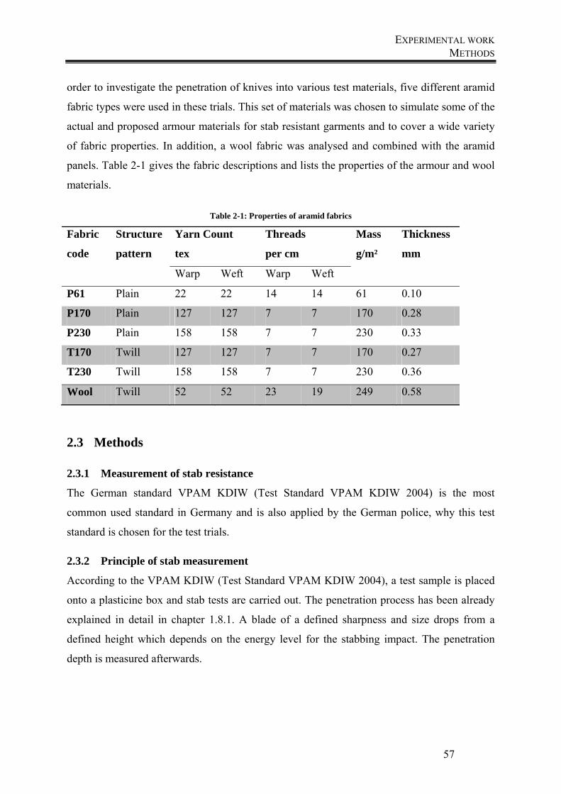
EXPERIMENTAL WORK METHODS
57
order to investigate the penetration of knives into various test materials, five different aramid
fabric types were used in these trials. This set of materials was chosen to simulate some of the
actual and proposed armour materials for stab resistant garments and to cover a wide variety
of fabric properties. In addition, a wool fabric was analysed and combined with the aramid
panels. Table 2-1 gives the fabric descriptions and lists the properties of the armour and wool
materials.
Table 2-1: Properties of aramid fabrics
Fabric
code
Structure
pattern
Yarn Count
tex
Threads
per cm
Mass
g/m²
Thickness
mm
Warp Weft Warp Weft
P61 Plain 22 22 14 14 61 0.10
P170 Plain 127 127 7 7 170 0.28
P230 Plain 158 158 7 7 230 0.33
T170 Twill 127 127 7 7 170 0.27
T230 Twill 158 158 7 7 230 0.36
Wool Twill 52 52 23 19 249 0.58
2.3 Methods
2.3.1 Measurement of stab resistance
The German standard VPAM KDIW (Test Standard VPAM KDIW 2004) is the most
common used standard in Germany and is also applied by the German police, why this test
standard is chosen for the test trials.
2.3.2 Principle of stab measurement
According to the VPAM KDIW (Test Standard VPAM KDIW 2004), a test sample is placed
onto a plasticine box and stab tests are carried out. The penetration process has been already
explained in detail in chapter 1.8.1. A blade of a defined sharpness and size drops from a
defined height which depends on the energy level for the stabbing impact. The penetration
depth is measured afterwards.
EXPERIMENTAL WORK METHODS
58
2.3.3 Boundaries of stab measurement
In practice, this measurement method is, however, quite difficult to implement and leads to
frequent discarding of the stab. When digging, it may happen that the stab hole is touched and
so falsifying the measuring result or becomes unusable. While three samples should be
measured according to the standard and to ensure reproducible and meaningful results, it
becomes quite difficult and expensive to get enough test material in case of the discard of
many measurement results. Therefore some users measure the cutting width on the surface of
the plasticine and it is shown, that the results are comparable and the cutting width is a more
reliable parameter for the stab resistance measurements than the penetration depth. (Aumann
et al. 2013; Ehrmann et al. 2013) This method gives also no information about the trauma
effect. These problems led to the development of a more productive method of measurement,
where the determination of the stab depth is done easier and the information about the trauma
size is given. Also other boundaries in the test standard are analysed. There is no information
about the sample size and a pretension of the test samples. Another problem is the usage of
the knife. According to the standard, it is just allowed to use a knife one time. This missing
information are analysed and added to a new test method, which is developed in scope of this
work. Therefore test series are done to analyse the sample size, the pretension and from
economic view, the tear of the knife is also analysed in a test series.
2.3.4 Development of a new evaluation method of measuring the stab depth
The new evaluation method is described, where the deformation depth and the trauma can be
poured out in plasticine and the deformation of the lowest fabric layer can be fixed. Thereby
the puncture can be measured accurately and fixed plastically. The plasticized samples can
also be measured in order to analyse and simulate movement, deformation and energy
absorption.
When preparing the test run small cups need to be filled with plasticine. It is important to
consider that no air bubbles emerge. The cup is worked into the background material just
below the knife tip. Then, a measurement sample has to be positioned on top of it, and the test
is performed by dropping the knife from a specified height. To fix the lowest fabric layer after
it is penetrated, the upper layers have to be removed carefully and it must be ensured that the
lowest fabric layer remains in its position. Subsequently, the cup can be carefully removed.
First, the deformation of the fabric is fixed with quick-drying adhesive. After the hardening of
the adhesive, the puncture in the plasticine is poured out and after hardening of the resin, the
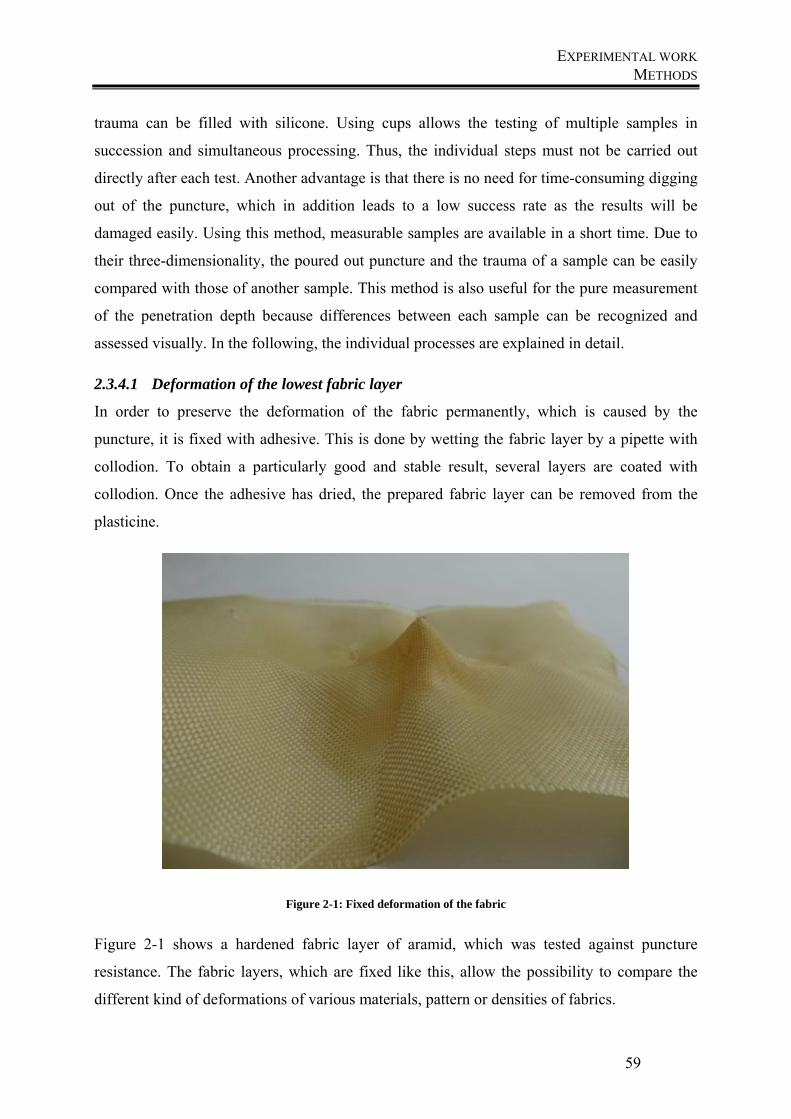
EXPERIMENTAL WORK METHODS
59
trauma can be filled with silicone. Using cups allows the testing of multiple samples in
succession and simultaneous processing. Thus, the individual steps must not be carried out
directly after each test. Another advantage is that there is no need for time-consuming digging
out of the puncture, which in addition leads to a low success rate as the results will be
damaged easily. Using this method, measurable samples are available in a short time. Due to
their three-dimensionality, the poured out puncture and the trauma of a sample can be easily
compared with those of another sample. This method is also useful for the pure measurement
of the penetration depth because differences between each sample can be recognized and
assessed visually. In the following, the individual processes are explained in detail.
2.3.4.1 Deformation of the lowest fabric layer
In order to preserve the deformation of the fabric permanently, which is caused by the
puncture, it is fixed with adhesive. This is done by wetting the fabric layer by a pipette with
collodion. To obtain a particularly good and stable result, several layers are coated with
collodion. Once the adhesive has dried, the prepared fabric layer can be removed from the
plasticine.
Figure 2-1: Fixed deformation of the fabric
Figure 2-1 shows a hardened fabric layer of aramid, which was tested against puncture
resistance. The fabric layers, which are fixed like this, allow the possibility to compare the
different kind of deformations of various materials, pattern or densities of fabrics.
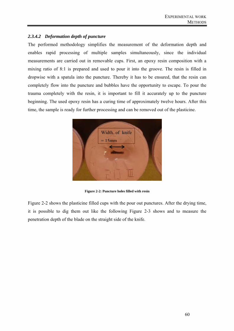
EXPERIMENTAL WORK METHODS
60
2.3.4.2 Deformation depth of puncture
The performed methodology simplifies the measurement of the deformation depth and
enables rapid processing of multiple samples simultaneously, since the individual
measurements are carried out in removable cups. First, an epoxy resin composition with a
mixing ratio of 8:1 is prepared and used to pour it into the groove. The resin is filled in
dropwise with a spatula into the puncture. Thereby it has to be ensured, that the resin can
completely flow into the puncture and bubbles have the opportunity to escape. To pour the
trauma completely with the resin, it is important to fill it accurately up to the puncture
beginning. The used epoxy resin has a curing time of approximately twelve hours. After this
time, the sample is ready for further processing and can be removed out of the plasticine.
Figure 2-2: Puncture holes filled with resin
Figure 2-2 shows the plasticine filled cups with the pour out punctures. After the drying time,
it is possible to dig them out like the following Figure 2-3 shows and to measure the
penetration depth of the blade on the straight side of the knife.
Width of knife
= 15mm

EXPERIMENTAL WORK METHODS
61
Figure 2-3: Shape of the knife tip
In addition to this simple measurement, three-dimensional models of the pour out punctures
were prepared. Figure 2-3 shows, how exactly the puncture was poured out. The cut surface
of the blade is exactly recognizable and also the beginning of the trauma can be seen. It can be
constructed as the stitch can be attached to the trauma, to visualize the action of the knife and
the impact energy. To compare the model with the blade, Figure 2-4 shows the standard knife,
which is used for testing the stab resistance according to VPAM.
2.3.4.3 Deformation of trauma
In addition to the penetration depth, it is possible to fix the resulting trauma. Here, a silicone
compound is filled directly into the deformation in the plasticine.
Length of the poured out knife tip
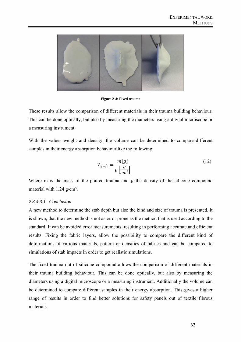
EXPERIMENTAL WORK METHODS
62
Figure 2-4: Fixed trauma
These results allow the comparison of different materials in their trauma building behaviour.
This can be done optically, but also by measuring the diameters using a digital microscope or
a measuring instrument.
With the values weight and density, the volume can be determined to compare different
samples in their energy absorption behaviour like the following:
³
³
(12)
Where m is the mass of the poured trauma and the density of the silicone compound
material with 1.24 g/cm³.
2.3.4.3.1 Conclusion
A new method to determine the stab depth but also the kind and size of trauma is presented. It
is shown, that the new method is not as error prone as the method that is used according to the
standard. It can be avoided error measurements, resulting in performing accurate and efficient
results. Fixing the fabric layers, allow the possibility to compare the different kind of
deformations of various materials, pattern or densities of fabrics and can be compared to
simulations of stab impacts in order to get realistic simulations.
The fixed trauma out of silicone compound allows the comparison of different materials in
their trauma building behaviour. This can be done optically, but also by measuring the
diameters using a digital microscope or a measuring instrument. Additionally the volume can
be determined to compare different samples in their energy absorption. This gives a higher
range of results in order to find better solutions for safety panels out of textile fibrous
materials.
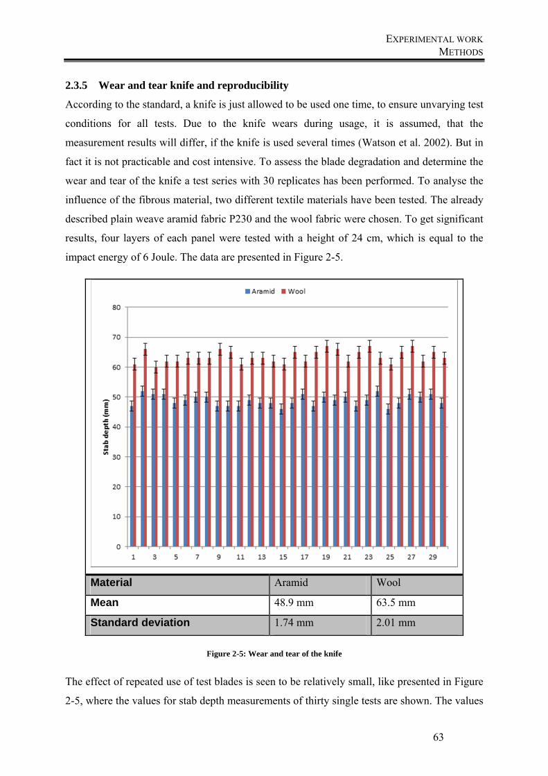
EXPERIMENTAL WORK METHODS
63
2.3.5 Wear and tear knife and reproducibility
According to the standard, a knife is just allowed to be used one time, to ensure unvarying test
conditions for all tests. Due to the knife wears during usage, it is assumed, that the
measurement results will differ, if the knife is used several times (Watson et al. 2002). But in
fact it is not practicable and cost intensive. To assess the blade degradation and determine the
wear and tear of the knife a test series with 30 replicates has been performed. To analyse the
influence of the fibrous material, two different textile materials have been tested. The already
described plain weave aramid fabric P230 and the wool fabric were chosen. To get significant
results, four layers of each panel were tested with a height of 24 cm, which is equal to the
impact energy of 6 Joule. The data are presented in Figure 2-5.
Material Aramid Wool
Mean 48.9 mm 63.5 mm
Standard deviation 1.74 mm 2.01 mm
Figure 2-5: Wear and tear of the knife
The effect of repeated use of test blades is seen to be relatively small, like presented in Figure
2-5, where the values for stab depth measurements of thirty single tests are shown. The values
EXPERIMENTAL WORK METHODS
64
vary between 46 mm and 52 mm for the aramid panels with a mean value of 48.9 mm and a
deviation value of 1.74 mm and 60 mm to 67 mm for the wool panel with a mean value of
63.5 mm and a deviation value of 2.01 mm. That means that the effect of wear on penetration
depth is not significant.
The aramid test series shows no significant changes in the results. For this reason, a knife was
used several times in following test series. For the ensuring of steady conditions each knife
has been used a maximum of 10 times.
Not only is the repeated use of the knives an economic problem, but also the number of tests.
According to the standard, three tests are carried out at one vest to determine the stab
resistance. To analyse, if three tests are enough, in order to obtain meaningful results, the
previous test series were analysed in order to see the variations in tests. The standard
deviations for the series showed values of 1.74 mm for aramid and 2.01 for wool. The
deviation is higher than the trend, why it is assumed, that the number of three tests is enough
to get meaningful results and work economical.
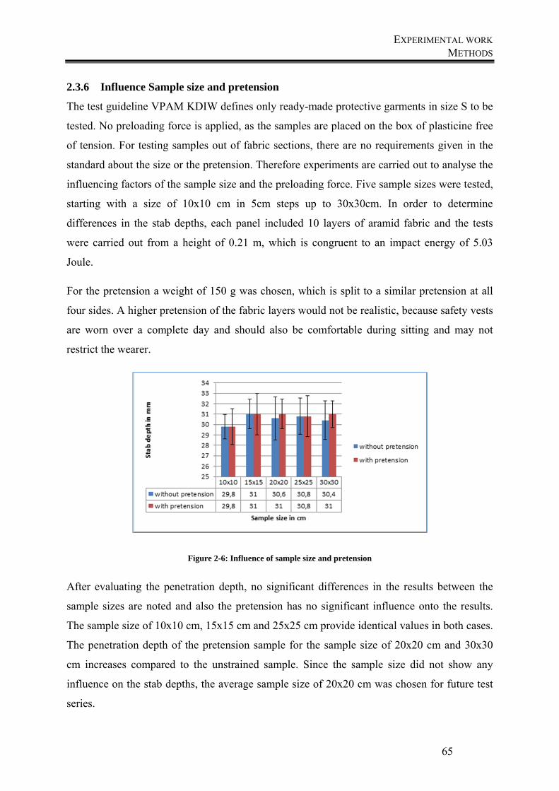
EXPERIMENTAL WORK METHODS
65
2.3.6 Influence Sample size and pretension
The test guideline VPAM KDIW defines only ready-made protective garments in size S to be
tested. No preloading force is applied, as the samples are placed on the box of plasticine free
of tension. For testing samples out of fabric sections, there are no requirements given in the
standard about the size or the pretension. Therefore experiments are carried out to analyse the
influencing factors of the sample size and the preloading force. Five sample sizes were tested,
starting with a size of 10x10 cm in 5cm steps up to 30x30cm. In order to determine
differences in the stab depths, each panel included 10 layers of aramid fabric and the tests
were carried out from a height of 0.21 m, which is congruent to an impact energy of 5.03
Joule.
For the pretension a weight of 150 g was chosen, which is split to a similar pretension at all
four sides. A higher pretension of the fabric layers would not be realistic, because safety vests
are worn over a complete day and should also be comfortable during sitting and may not
restrict the wearer.
Figure 2-6: Influence of sample size and pretension
After evaluating the penetration depth, no significant differences in the results between the
sample sizes are noted and also the pretension has no significant influence onto the results.
The sample size of 10x10 cm, 15x15 cm and 25x25 cm provide identical values in both cases.
The penetration depth of the pretension sample for the sample size of 20x20 cm and 30x30
cm increases compared to the unstrained sample. Since the sample size did not show any
influence on the stab depths, the average sample size of 20x20 cm was chosen for future test
series.
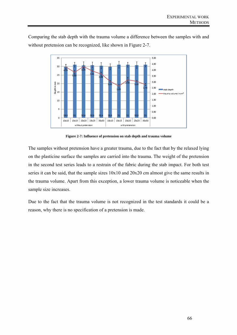
EXPERIMENTAL WORK METHODS
66
Comparing the stab depth with the trauma volume a difference between the samples with and
without pretension can be recognized, like shown in Figure 2-7.
Figure 2-7: Influence of pretension on stab depth and trauma volume
The samples without pretension have a greater trauma, due to the fact that by the relaxed lying
on the plasticine surface the samples are carried into the trauma. The weight of the pretension
in the second test series leads to a restrain of the fabric during the stab impact. For both test
series it can be said, that the sample sizes 10x10 and 20x20 cm almost give the same results in
the trauma volume. Apart from this exception, a lower trauma volume is noticeable when the
sample size increases.
Due to the fact that the trauma volume is not recognized in the test standards it could be a
reason, why there is no specification of a pretension is made.
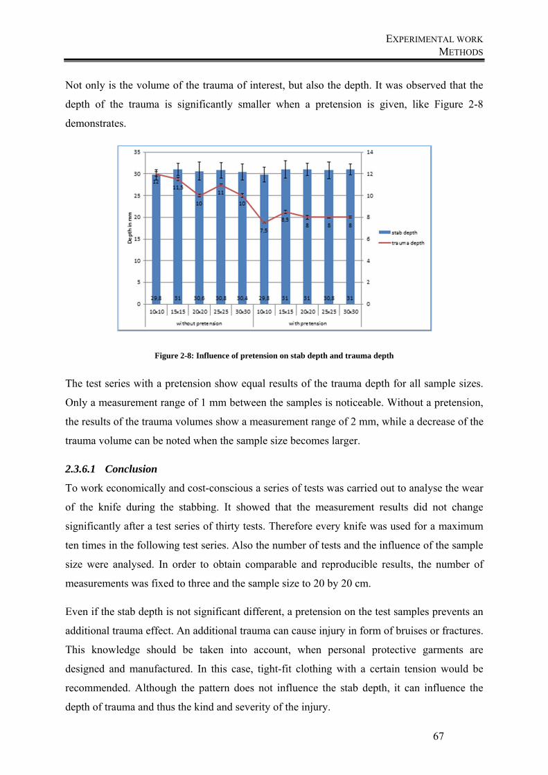
EXPERIMENTAL WORK METHODS
67
Not only is the volume of the trauma of interest, but also the depth. It was observed that the
depth of the trauma is significantly smaller when a pretension is given, like Figure 2-8
demonstrates.
Figure 2-8: Influence of pretension on stab depth and trauma depth
The test series with a pretension show equal results of the trauma depth for all sample sizes.
Only a measurement range of 1 mm between the samples is noticeable. Without a pretension,
the results of the trauma volumes show a measurement range of 2 mm, while a decrease of the
trauma volume can be noted when the sample size becomes larger.
2.3.6.1 Conclusion
To work economically and cost-conscious a series of tests was carried out to analyse the wear
of the knife during the stabbing. It showed that the measurement results did not change
significantly after a test series of thirty tests. Therefore every knife was used for a maximum
ten times in the following test series. Also the number of tests and the influence of the sample
size were analysed. In order to obtain comparable and reproducible results, the number of
measurements was fixed to three and the sample size to 20 by 20 cm.
Even if the stab depth is not significant different, a pretension on the test samples prevents an
additional trauma effect. An additional trauma can cause injury in form of bruises or fractures.
This knowledge should be taken into account, when personal protective garments are
designed and manufactured. In this case, tight-fit clothing with a certain tension would be
recommended. Although the pattern does not influence the stab depth, it can influence the
depth of trauma and thus the kind and severity of the injury.
EXPERIMENTAL WORK STAB RESISTANCE OF FABRIC PANELS
68
2.4 Stab resistance of fabric panels
After the principle influence of the stab measurement equipment, the influences of the test
conditions and the samples themselves were analysed. First the influence of the impact energy
was determined, which means, that different heights of impact were compared. After that,
different amount of layers were compared, before the fabric structures themselves were
analysed. The examination of the fabric panels was carried out in a multi-layer structure. For
this purpose, several layers of fabric were arranged one above the other, and then tested
together against stab penetration. The mean value of three tests is always presented.
The test panels were arranged from six to ten layers because with a lower amount of layers no
useful differences are visible.
2.4.1 Influence of impact energy and number of layers
First, the influence of impact energy onto the stab depths was analysed, why the stab heights
were varied. Relatively low impact energies between 4.5 joules and 9 joules were selected, to
find out differences between the patterns. The results are analysed and compared in the
following diagrams for one type of fabric. The fabrics having a similar behaviour, so the
results will be discussed in more detail for one fabric. For all other fabrics the results are
summarized in a table and the single values and graphs are presented in Appendix 7-1.
To analyse what influence the number of layers has on the test results, tests were analysed for
all fabric types with panels with different number of layers of aramid fabric.
In the first step, the impact energies were defined according to the calculation
∗ ∗ (13)
and
∗
(14)
Resultant of this, the heights were chosen as follows:
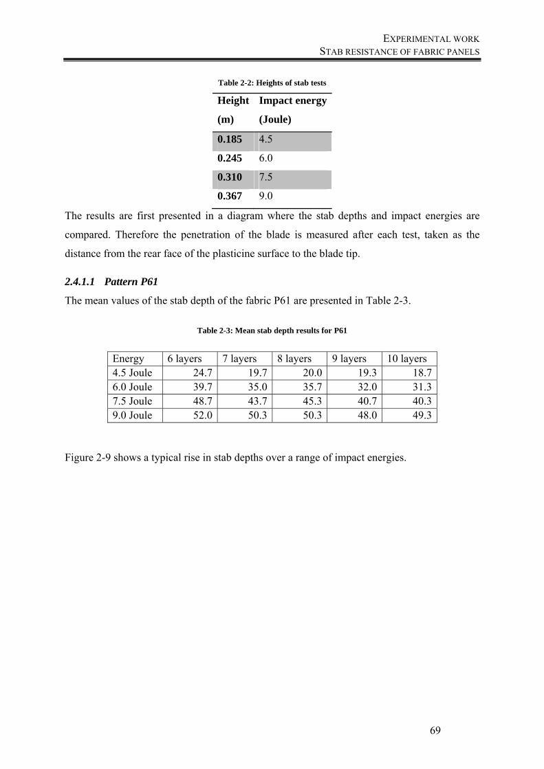
EXPERIMENTAL WORK STAB RESISTANCE OF FABRIC PANELS
69
Table 2-2: Heights of stab tests
Height
(m)
Impact energy
(Joule)
0.185 4.5
0.245 6.0
0.310 7.5
0.367 9.0
The results are first presented in a diagram where the stab depths and impact energies are
compared. Therefore the penetration of the blade is measured after each test, taken as the
distance from the rear face of the plasticine surface to the blade tip.
2.4.1.1 Pattern P61
The mean values of the stab depth of the fabric P61 are presented in Table 2-3.
Table 2-3: Mean stab depth results for P61
Energy 6 layers 7 layers 8 layers 9 layers 10 layers 4.5 Joule 24.7 19.7 20.0 19.3 18.7 6.0 Joule 39.7 35.0 35.7 32.0 31.3 7.5 Joule 48.7 43.7 45.3 40.7 40.3 9.0 Joule 52.0 50.3 50.3 48.0 49.3
Figure 2-9 shows a typical rise in stab depths over a range of impact energies.
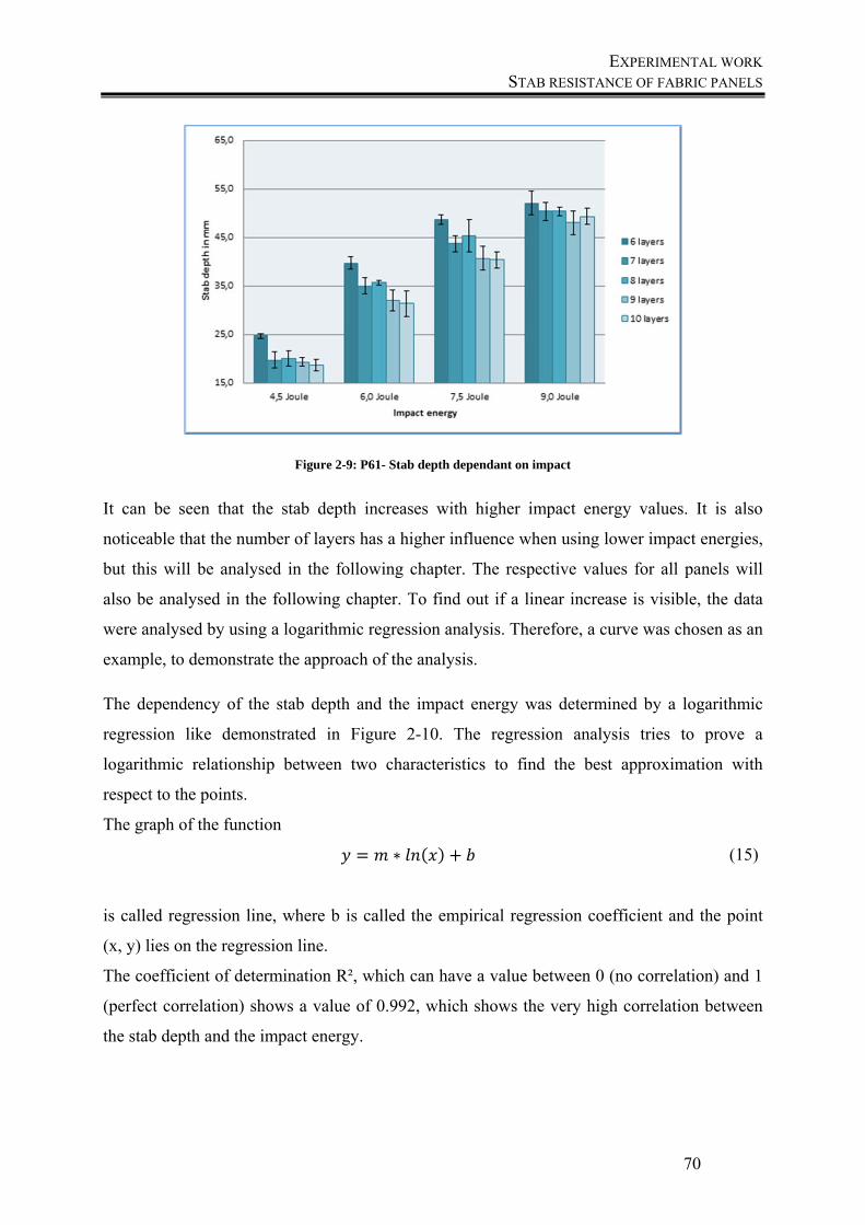
EXPERIMENTAL WORK STAB RESISTANCE OF FABRIC PANELS
70
Figure 2-9: P61- Stab depth dependant on impact
It can be seen that the stab depth increases with higher impact energy values. It is also
noticeable that the number of layers has a higher influence when using lower impact energies,
but this will be analysed in the following chapter. The respective values for all panels will
also be analysed in the following chapter. To find out if a linear increase is visible, the data
were analysed by using a logarithmic regression analysis. Therefore, a curve was chosen as an
example, to demonstrate the approach of the analysis.
The dependency of the stab depth and the impact energy was determined by a logarithmic
regression like demonstrated in Figure 2-10. The regression analysis tries to prove a
logarithmic relationship between two characteristics to find the best approximation with
respect to the points.
The graph of the function
∗ (15)
is called regression line, where b is called the empirical regression coefficient and the point
(x, y) lies on the regression line.
The coefficient of determination R², which can have a value between 0 (no correlation) and 1
(perfect correlation) shows a value of 0.992, which shows the very high correlation between
the stab depth and the impact energy.
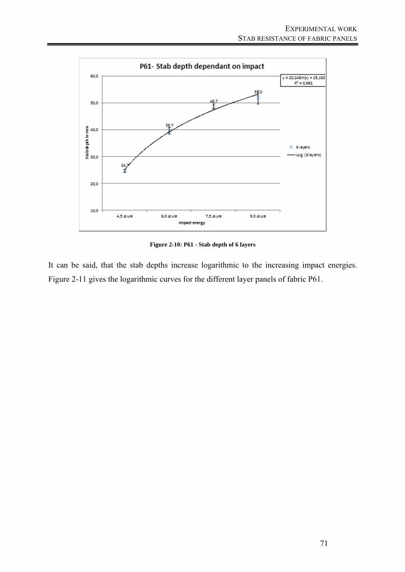
EXPERIMENTAL WORK STAB RESISTANCE OF FABRIC PANELS
71
Figure 2-10: P61 - Stab depth of 6 layers
It can be said, that the stab depths increase logarithmic to the increasing impact energies.
Figure 2-11 gives the logarithmic curves for the different layer panels of fabric P61.
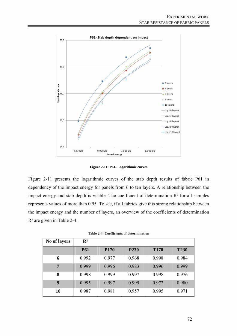
EXPERIMENTAL WORK STAB RESISTANCE OF FABRIC PANELS
72
Figure 2-11: P61- Logarithmic curves
Figure 2-11 presents the logarithmic curves of the stab depth results of fabric P61 in
dependency of the impact energy for panels from 6 to ten layers. A relationship between the
impact energy and stab depth is visible. The coefficient of determination R² for all samples
represents values of more than 0.95. To see, if all fabrics give this strong relationship between
the impact energy and the number of layers, an overview of the coefficients of determination
R² are given in Table 2-4.
Table 2-4: Coefficients of determination
No of layers R²
P61 P170 P230 T170 T230
6 0.992 0.977 0.968 0.998 0.984
7 0.999 0.996 0.983 0.996 0.999
8 0.998 0.999 0.997 0.998 0.976
9 0.995 0.997 0.999 0.972 0.980
10 0.987 0.981 0.957 0.995 0.971
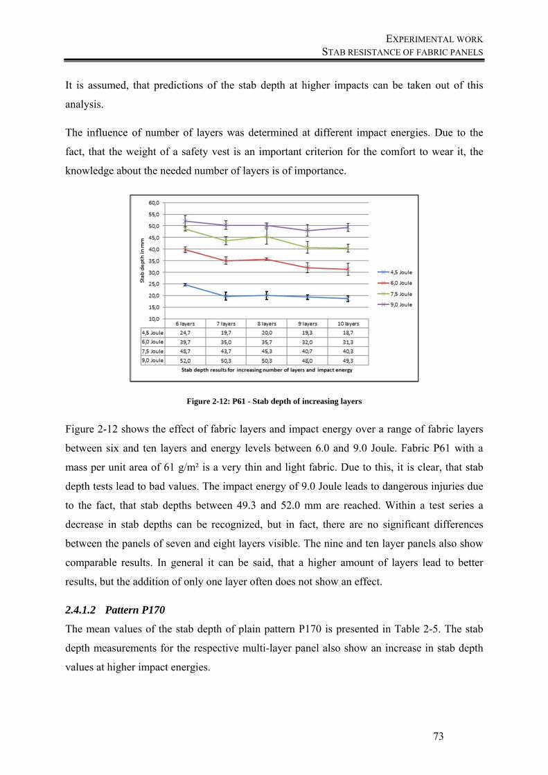
EXPERIMENTAL WORK STAB RESISTANCE OF FABRIC PANELS
73
It is assumed, that predictions of the stab depth at higher impacts can be taken out of this
analysis.
The influence of number of layers was determined at different impact energies. Due to the
fact, that the weight of a safety vest is an important criterion for the comfort to wear it, the
knowledge about the needed number of layers is of importance.
Figure 2-12: P61 - Stab depth of increasing layers
Figure 2-12 shows the effect of fabric layers and impact energy over a range of fabric layers
between six and ten layers and energy levels between 6.0 and 9.0 Joule. Fabric P61 with a
mass per unit area of 61 g/m² is a very thin and light fabric. Due to this, it is clear, that stab
depth tests lead to bad values. The impact energy of 9.0 Joule leads to dangerous injuries due
to the fact, that stab depths between 49.3 and 52.0 mm are reached. Within a test series a
decrease in stab depths can be recognized, but in fact, there are no significant differences
between the panels of seven and eight layers visible. The nine and ten layer panels also show
comparable results. In general it can be said, that a higher amount of layers lead to better
results, but the addition of only one layer often does not show an effect.
2.4.1.2 Pattern P170
The mean values of the stab depth of plain pattern P170 is presented in Table 2-5. The stab
depth measurements for the respective multi-layer panel also show an increase in stab depth
values at higher impact energies.
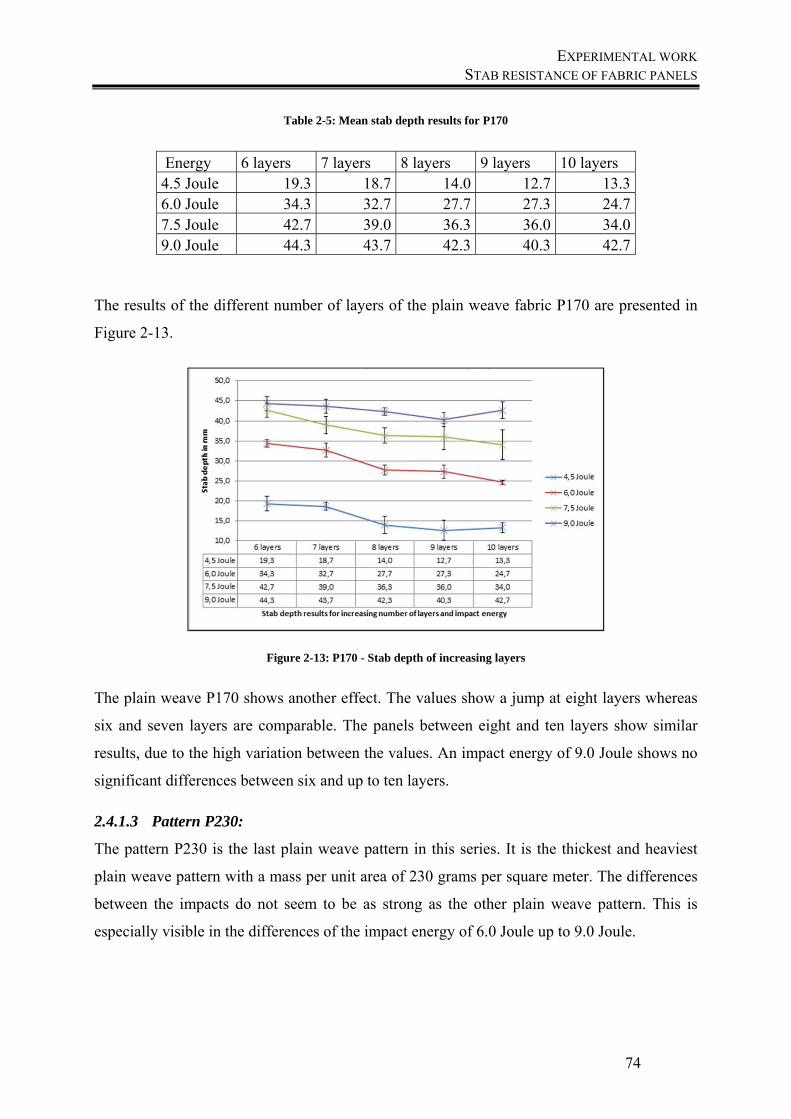
EXPERIMENTAL WORK STAB RESISTANCE OF FABRIC PANELS
74
Table 2-5: Mean stab depth results for P170
Energy 6 layers 7 layers 8 layers 9 layers 10 layers 4.5 Joule 19.3 18.7 14.0 12.7 13.3 6.0 Joule 34.3 32.7 27.7 27.3 24.7 7.5 Joule 42.7 39.0 36.3 36.0 34.0 9.0 Joule 44.3 43.7 42.3 40.3 42.7
The results of the different number of layers of the plain weave fabric P170 are presented in
Figure 2-13.
Figure 2-13: P170 - Stab depth of increasing layers
The plain weave P170 shows another effect. The values show a jump at eight layers whereas
six and seven layers are comparable. The panels between eight and ten layers show similar
results, due to the high variation between the values. An impact energy of 9.0 Joule shows no
significant differences between six and up to ten layers.
2.4.1.3 Pattern P230:
The pattern P230 is the last plain weave pattern in this series. It is the thickest and heaviest
plain weave pattern with a mass per unit area of 230 grams per square meter. The differences
between the impacts do not seem to be as strong as the other plain weave pattern. This is
especially visible in the differences of the impact energy of 6.0 Joule up to 9.0 Joule.
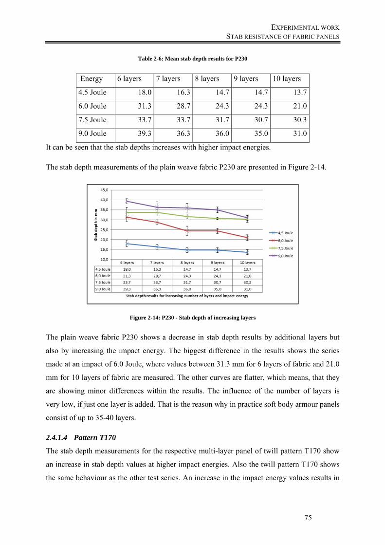
EXPERIMENTAL WORK STAB RESISTANCE OF FABRIC PANELS
75
Table 2-6: Mean stab depth results for P230
Energy 6 layers 7 layers 8 layers 9 layers 10 layers
4.5 Joule 18.0 16.3 14.7 14.7 13.7
6.0 Joule 31.3 28.7 24.3 24.3 21.0
7.5 Joule 33.7 33.7 31.7 30.7 30.3
9.0 Joule 39.3 36.3 36.0 35.0 31.0
It can be seen that the stab depths increases with higher impact energies.
The stab depth measurements of the plain weave fabric P230 are presented in Figure 2-14.
Figure 2-14: P230 - Stab depth of increasing layers
The plain weave fabric P230 shows a decrease in stab depth results by additional layers but
also by increasing the impact energy. The biggest difference in the results shows the series
made at an impact of 6.0 Joule, where values between 31.3 mm for 6 layers of fabric and 21.0
mm for 10 layers of fabric are measured. The other curves are flatter, which means, that they
are showing minor differences within the results. The influence of the number of layers is
very low, if just one layer is added. That is the reason why in practice soft body armour panels
consist of up to 35-40 layers.
2.4.1.4 Pattern T170
The stab depth measurements for the respective multi-layer panel of twill pattern T170 show
an increase in stab depth values at higher impact energies. Also the twill pattern T170 shows
the same behaviour as the other test series. An increase in the impact energy values results in
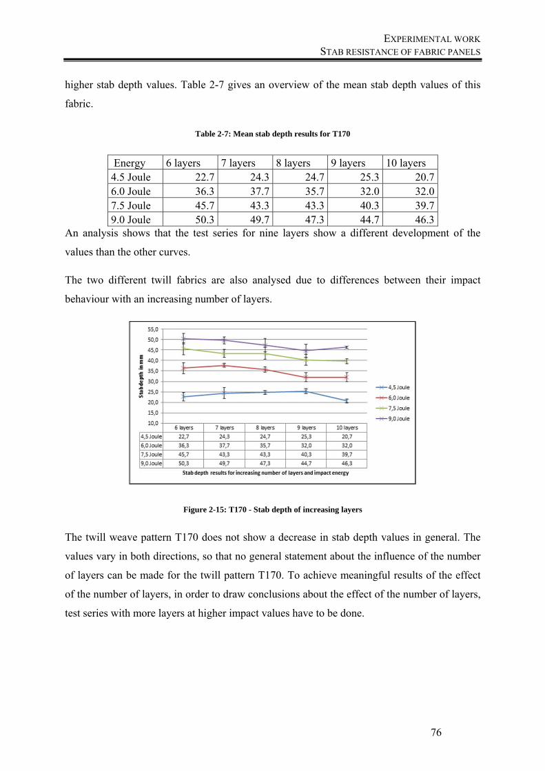
EXPERIMENTAL WORK STAB RESISTANCE OF FABRIC PANELS
76
higher stab depth values. Table 2-7 gives an overview of the mean stab depth values of this
fabric.
Table 2-7: Mean stab depth results for T170
Energy 6 layers 7 layers 8 layers 9 layers 10 layers 4.5 Joule 22.7 24.3 24.7 25.3 20.7 6.0 Joule 36.3 37.7 35.7 32.0 32.0 7.5 Joule 45.7 43.3 43.3 40.3 39.7 9.0 Joule 50.3 49.7 47.3 44.7 46.3
An analysis shows that the test series for nine layers show a different development of the
values than the other curves.
The two different twill fabrics are also analysed due to differences between their impact
behaviour with an increasing number of layers.
Figure 2-15: T170 - Stab depth of increasing layers
The twill weave pattern T170 does not show a decrease in stab depth values in general. The
values vary in both directions, so that no general statement about the influence of the number
of layers can be made for the twill pattern T170. To achieve meaningful results of the effect
of the number of layers, in order to draw conclusions about the effect of the number of layers,
test series with more layers at higher impact values have to be done.
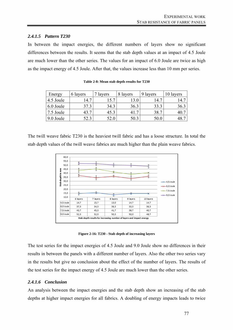
EXPERIMENTAL WORK STAB RESISTANCE OF FABRIC PANELS
77
2.4.1.5 Pattern T230
In between the impact energies, the different numbers of layers show no significant
differences between the results. It seems that the stab depth values at an impact of 4.5 Joule
are much lower than the other series. The values for an impact of 6.0 Joule are twice as high
as the impact energy of 4.5 Joule. After that, the values increase less than 10 mm per series.
Table 2-8: Mean stab depth results for T230
Energy 6 layers 7 layers 8 layers 9 layers 10 layers 4.5 Joule 14.7 15.7 13.0 14.7 14.7 6.0 Joule 37.3 34.3 36.3 33.3 36.3 7.5 Joule 43.7 45.3 41.7 38.7 40.7 9.0 Joule 52.3 52.0 50.3 50.0 48.7
The twill weave fabric T230 is the heaviest twill fabric and has a loose structure. In total the
stab depth values of the twill weave fabrics are much higher than the plain weave fabrics.
Figure 2-16: T230 - Stab depth of increasing layers
The test series for the impact energies of 4.5 Joule and 9.0 Joule show no differences in their
results in between the panels with a different number of layers. Also the other two series vary
in the results but give no conclusion about the effect of the number of layers. The results of
the test series for the impact energy of 4.5 Joule are much lower than the other series.
2.4.1.6 Conclusion
An analysis between the impact energies and the stab depth show an increasing of the stab
depths at higher impact energies for all fabrics. A doubling of energy impacts leads to twice
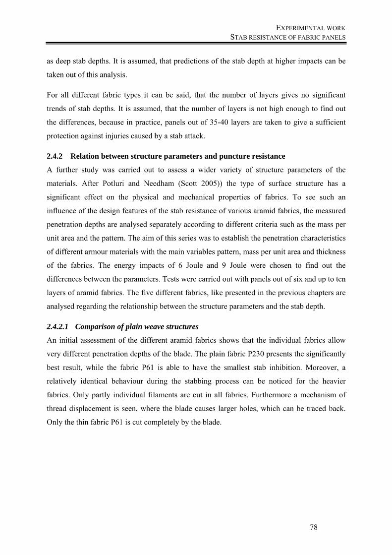
EXPERIMENTAL WORK STAB RESISTANCE OF FABRIC PANELS
78
as deep stab depths. It is assumed, that predictions of the stab depth at higher impacts can be
taken out of this analysis.
For all different fabric types it can be said, that the number of layers gives no significant
trends of stab depths. It is assumed, that the number of layers is not high enough to find out
the differences, because in practice, panels out of 35-40 layers are taken to give a sufficient
protection against injuries caused by a stab attack.
2.4.2 Relation between structure parameters and puncture resistance
A further study was carried out to assess a wider variety of structure parameters of the
materials. After Potluri and Needham (Scott 2005)) the type of surface structure has a
significant effect on the physical and mechanical properties of fabrics. To see such an
influence of the design features of the stab resistance of various aramid fabrics, the measured
penetration depths are analysed separately according to different criteria such as the mass per
unit area and the pattern. The aim of this series was to establish the penetration characteristics
of different armour materials with the main variables pattern, mass per unit area and thickness
of the fabrics. The energy impacts of 6 Joule and 9 Joule were chosen to find out the
differences between the parameters. Tests were carried out with panels out of six and up to ten
layers of aramid fabrics. The five different fabrics, like presented in the previous chapters are
analysed regarding the relationship between the structure parameters and the stab depth.
2.4.2.1 Comparison of plain weave structures
An initial assessment of the different aramid fabrics shows that the individual fabrics allow
very different penetration depths of the blade. The plain fabric P230 presents the significantly
best result, while the fabric P61 is able to have the smallest stab inhibition. Moreover, a
relatively identical behaviour during the stabbing process can be noticed for the heavier
fabrics. Only partly individual filaments are cut in all fabrics. Furthermore a mechanism of
thread displacement is seen, where the blade causes larger holes, which can be traced back.
Only the thin fabric P61 is cut completely by the blade.
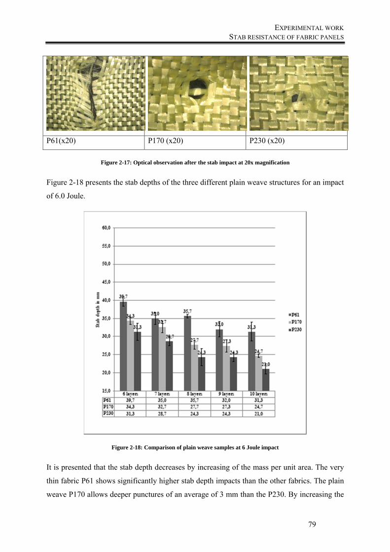
EXPERIMENTAL WORK STAB RESISTANCE OF FABRIC PANELS
79
P61(x20) P170 (x20) P230 (x20)
Figure 2-17: Optical observation after the stab impact at 20x magnification
Figure 2-18 presents the stab depths of the three different plain weave structures for an impact
of 6.0 Joule.
Figure 2-18: Comparison of plain weave samples at 6 Joule impact
It is presented that the stab depth decreases by increasing of the mass per unit area. The very
thin fabric P61 shows significantly higher stab depth impacts than the other fabrics. The plain
weave P170 allows deeper punctures of an average of 3 mm than the P230. By increasing the
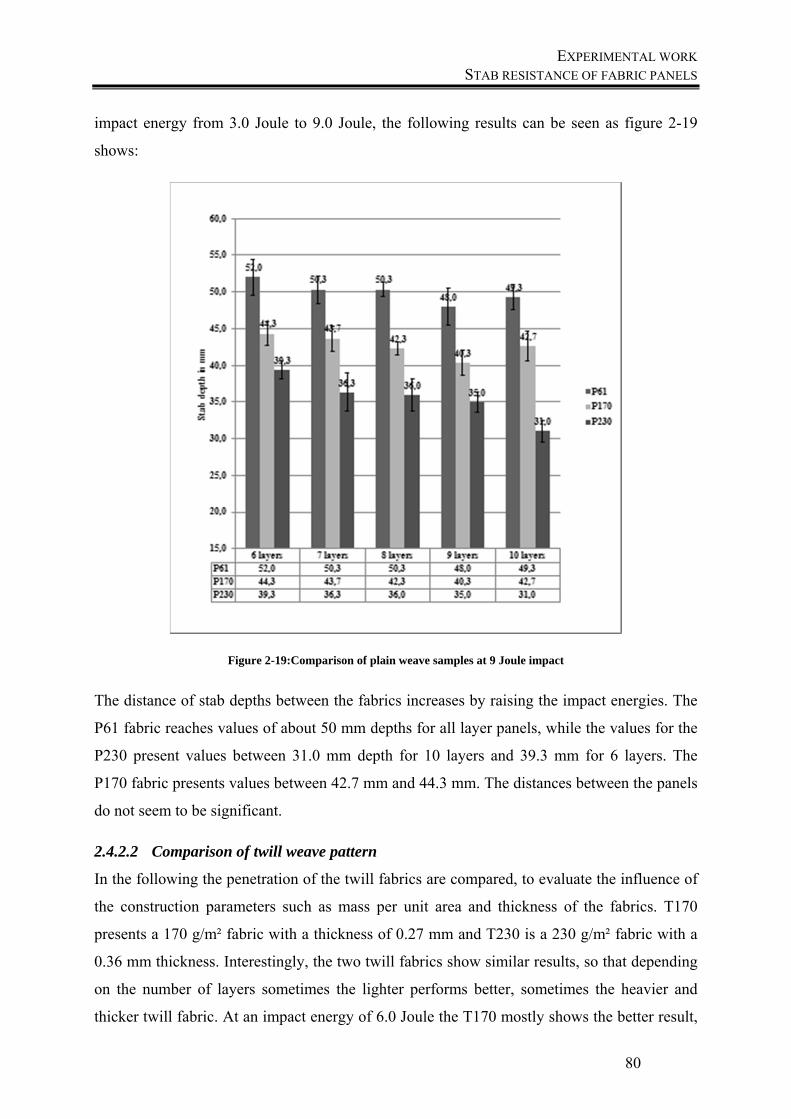
EXPERIMENTAL WORK STAB RESISTANCE OF FABRIC PANELS
80
impact energy from 3.0 Joule to 9.0 Joule, the following results can be seen as figure 2-19
shows:
Figure 2-19:Comparison of plain weave samples at 9 Joule impact
The distance of stab depths between the fabrics increases by raising the impact energies. The
P61 fabric reaches values of about 50 mm depths for all layer panels, while the values for the
P230 present values between 31.0 mm depth for 10 layers and 39.3 mm for 6 layers. The
P170 fabric presents values between 42.7 mm and 44.3 mm. The distances between the panels
do not seem to be significant.
2.4.2.2 Comparison of twill weave pattern
In the following the penetration of the twill fabrics are compared, to evaluate the influence of
the construction parameters such as mass per unit area and thickness of the fabrics. T170
presents a 170 g/m² fabric with a thickness of 0.27 mm and T230 is a 230 g/m² fabric with a
0.36 mm thickness. Interestingly, the two twill fabrics show similar results, so that depending
on the number of layers sometimes the lighter performs better, sometimes the heavier and
thicker twill fabric. At an impact energy of 6.0 Joule the T170 mostly shows the better result,
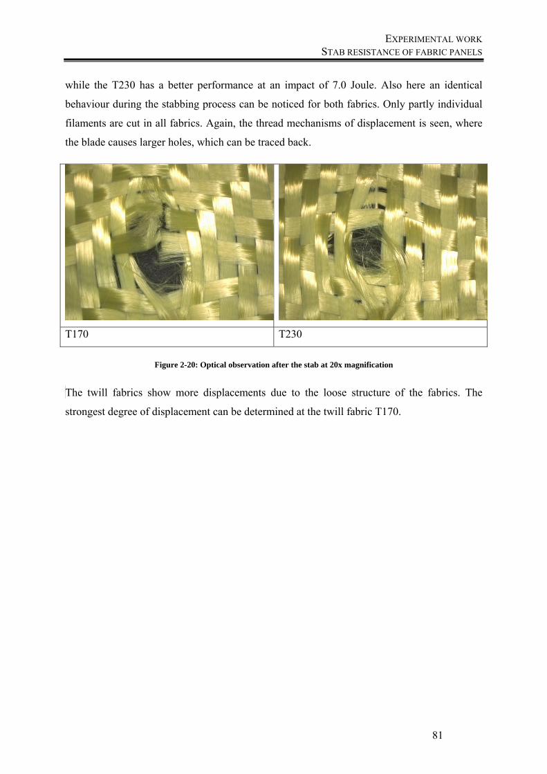
EXPERIMENTAL WORK STAB RESISTANCE OF FABRIC PANELS
81
while the T230 has a better performance at an impact of 7.0 Joule. Also here an identical
behaviour during the stabbing process can be noticed for both fabrics. Only partly individual
filaments are cut in all fabrics. Again, the thread mechanisms of displacement is seen, where
the blade causes larger holes, which can be traced back.
T170 T230
Figure 2-20: Optical observation after the stab at 20x magnification
The twill fabrics show more displacements due to the loose structure of the fabrics. The
strongest degree of displacement can be determined at the twill fabric T170.
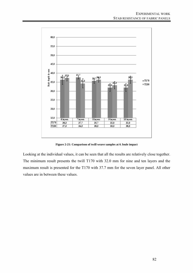
EXPERIMENTAL WORK STAB RESISTANCE OF FABRIC PANELS
82
Figure 2-21: Comparison of twill weave samples at 6 Joule impact
Looking at the individual values, it can be seen that all the results are relatively close together.
The minimum result presents the twill T170 with 32.0 mm for nine and ten layers and the
maximum result is presented for the T170 with 37.7 mm for the seven layer panel. All other
values are in between these values.
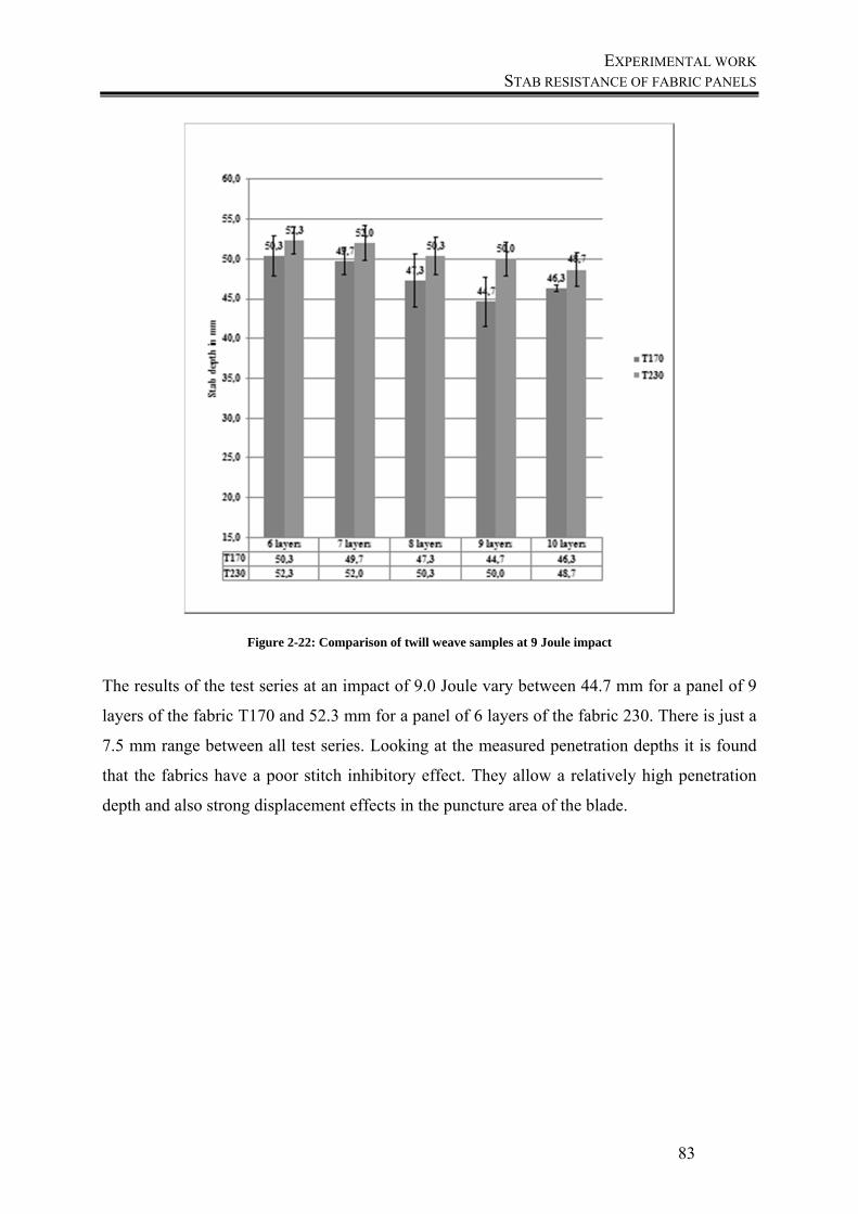
EXPERIMENTAL WORK STAB RESISTANCE OF FABRIC PANELS
83
Figure 2-22: Comparison of twill weave samples at 9 Joule impact
The results of the test series at an impact of 9.0 Joule vary between 44.7 mm for a panel of 9
layers of the fabric T170 and 52.3 mm for a panel of 6 layers of the fabric 230. There is just a
7.5 mm range between all test series. Looking at the measured penetration depths it is found
that the fabrics have a poor stitch inhibitory effect. They allow a relatively high penetration
depth and also strong displacement effects in the puncture area of the blade.
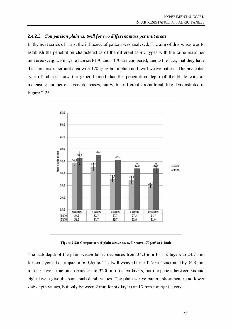
EXPERIMENTAL WORK STAB RESISTANCE OF FABRIC PANELS
84
2.4.2.3 Comparison plain vs. twill for two different mass per unit areas
In the next series of trials, the influence of pattern was analysed. The aim of this series was to
establish the penetration characteristics of the different fabric types with the same mass per
unit area weight. First, the fabrics P170 and T170 are compared, due to the fact, that they have
the same mass per unit area with 170 g/m² but a plain and twill weave pattern. The presented
type of fabrics show the general trend that the penetration depth of the blade with an
increasing number of layers decreases, but with a different strong trend, like demonstrated in
Figure 2-23.
Figure 2-23: Comparison of plain weave vs. twill weave 170g/m² at 6 Joule
The stab depth of the plain weave fabric decreases from 34.3 mm for six layers to 24.7 mm
for ten layers at an impact of 6.0 Joule. The twill weave fabric T170 is penetrated by 36.3 mm
in a six-layer panel and decreases to 32.0 mm for ten layers, but the panels between six and
eight layers give the same stab depth values. The plain weave pattern show better and lower
stab depth values, but only between 2 mm for six layers and 7 mm for eight layers.

EXPERIMENTAL WORK STAB RESISTANCE OF FABRIC PANELS
85
Also the two fabrics are compared at an impact energy of 9.0 Joule, to give additional
information on the differences of the impact behaviour of the different pattern.
Figure 2-24: Comparison of plain weave vs. twill weave 170g/m² at 9 Joule
The stab depth of the plain weave fabric decreases from 44.3 mm for six layers to 42.7 mm
for ten layers at an impact of 9.0 Joule. The twill weave fabric T170 is penetrated with 50.5
mm in a six-layer panel and decreases to 46.3 mm for ten layers, but the panels between six
and eight layers give the same stab depth values. The plain weave pattern gives better and
lower stab depth values of about 5 mm in mean.
Not only were the lighter fabrics with a weight of 170 g /m² compared, but also the heavier
fabrics with 230 g /m². They are presented in the following figures. Again a comparison was
made at two impact energies. First they were compared at an impact of 6.0 Joule. These two
samples have identical thread counts and fineness but differ in their pattern and also in the
fabric thickness.
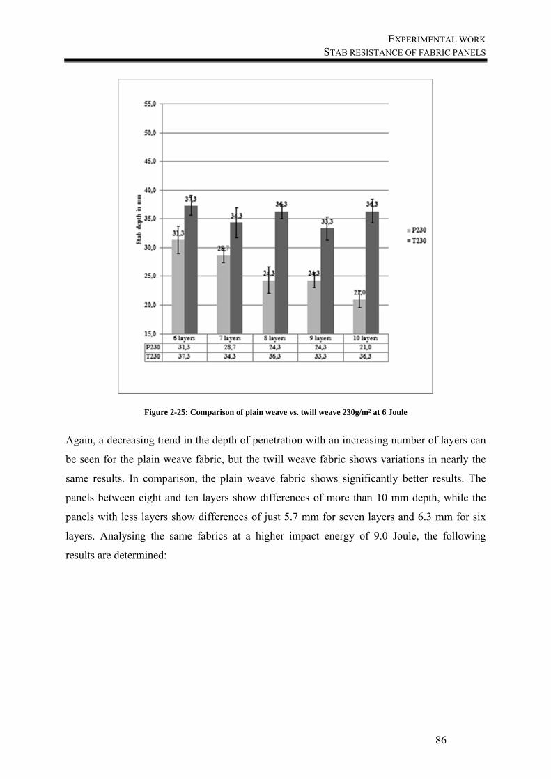
EXPERIMENTAL WORK STAB RESISTANCE OF FABRIC PANELS
86
Figure 2-25: Comparison of plain weave vs. twill weave 230g/m² at 6 Joule
Again, a decreasing trend in the depth of penetration with an increasing number of layers can
be seen for the plain weave fabric, but the twill weave fabric shows variations in nearly the
same results. In comparison, the plain weave fabric shows significantly better results. The
panels between eight and ten layers show differences of more than 10 mm depth, while the
panels with less layers show differences of just 5.7 mm for seven layers and 6.3 mm for six
layers. Analysing the same fabrics at a higher impact energy of 9.0 Joule, the following
results are determined:
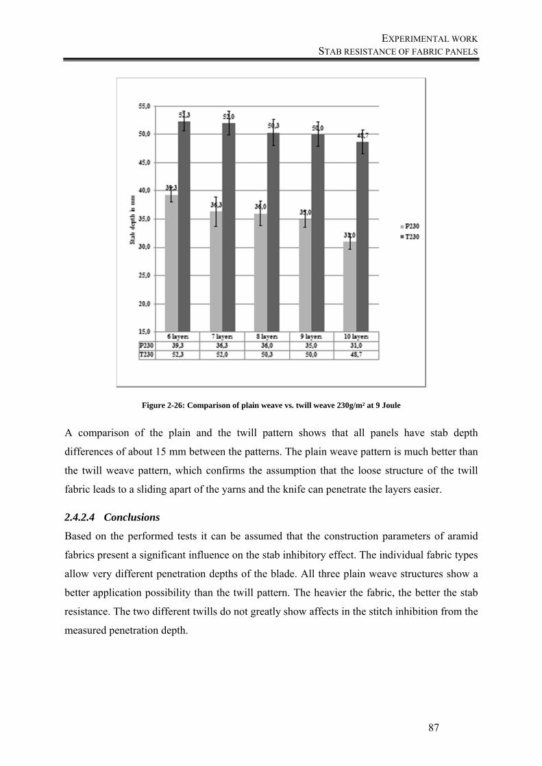
EXPERIMENTAL WORK STAB RESISTANCE OF FABRIC PANELS
87
Figure 2-26: Comparison of plain weave vs. twill weave 230g/m² at 9 Joule
A comparison of the plain and the twill pattern shows that all panels have stab depth
differences of about 15 mm between the patterns. The plain weave pattern is much better than
the twill weave pattern, which confirms the assumption that the loose structure of the twill
fabric leads to a sliding apart of the yarns and the knife can penetrate the layers easier.
2.4.2.4 Conclusions
Based on the performed tests it can be assumed that the construction parameters of aramid
fabrics present a significant influence on the stab inhibitory effect. The individual fabric types
allow very different penetration depths of the blade. All three plain weave structures show a
better application possibility than the twill pattern. The heavier the fabric, the better the stab
resistance. The two different twills do not greatly show affects in the stitch inhibition from the
measured penetration depth.
EXPERIMENTAL WORK PARAMETERS, WHICH INFLUENCE THE STAB RESISTANCE OF WOVEN FABRICS
88
2.5 Parameters, which influence the stab resistance of woven fabrics
In the production of body armour panels, multilayer aramid fabrics are normally used. A main
problem of these panels is the high weight and consequential lower comfort for the wearer,
like mentioned before. To reduce layers with a concomitance of the same safety standards, the
panel has to be improved (Reiners 2014). Due to the smoothness of para-aramid yarns, the
friction between the yarns and fabric layers is often too low; in this case slippage occurs,
which leads to lower impact against stabbing. In contrast to that, a higher friction between the
yarns leads to a higher energy absorption, because the yarn sliding is restricted (Guo et al.
2014; Nilakantan, Gillespie 2013).
In the following, the property of friction and other properties, which influence the yarn
migration, will be analysed and compared, to define how to measure the slippage of the yarns
but also the frictional behaviour.
2.5.1 Textile friction
The aim of this series was to find out interdependencies between the frictional characteristics
of different armour materials and the stabbing performance. Four aramid fabrics, which were
explained in detail before, were tested. They were chosen, in order to compare similar
structures. Two plain weaves with 170 g/m² and 230 g/m² and two twill weaves with 170 g/m²
and 230 g/m² were compared in order to analyse the influences of the pattern of same mass
per unit areas and also to compare different weight of similar patterns.
The static and dynamic coefficient of friction was determined according to the test standard
for coated fabrics (Standard DIN EN 14882), which is also suitable for textile fabrics. Figure
2-27 shows the principle of testing. In this test a sled (6) is placed on a fabric (5), which is
fixed free of tension on a horizontal surface (4). The sled is connected to a measuring device
(1), which records the force. For these test series, a Statimat ME was used with a
measurement head of 10 Newton. The sled is pulled by a free of tension yarn (2), which is
lead through an idler pulley (3) over the sample with a test speed of 100 mm/min, wherein the
maximum force for starting the movement (static) and the continuing constant speed over a
measurement distance of 50 mm (kinetic) is measured.
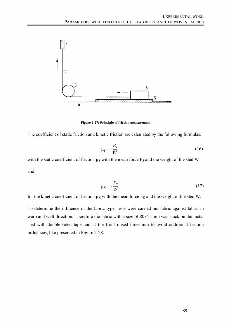
EXPERIMENTAL WORK PARAMETERS, WHICH INFLUENCE THE STAB RESISTANCE OF WOVEN FABRICS
89
Figure 2-27: Principle of friction measurement
The coefficient of static friction and kinetic friction are calculated by the following formulas:
μ ∙ (16)
with the static coefficient of friction µS with the mean force FS and the weight of the sled W
and
μ ∙ (17)
for the kinetic coefficient of friction µK with the mean force FK and the weight of the sled W.
To determine the influence of the fabric type, tests were carried out fabric against fabric in
warp and weft direction. Therefore the fabric with a size of 80x41 mm was stuck on the metal
sled with double-sided tape and at the front raised three mm to avoid additional friction
influences, like presented in Figure 2-28.
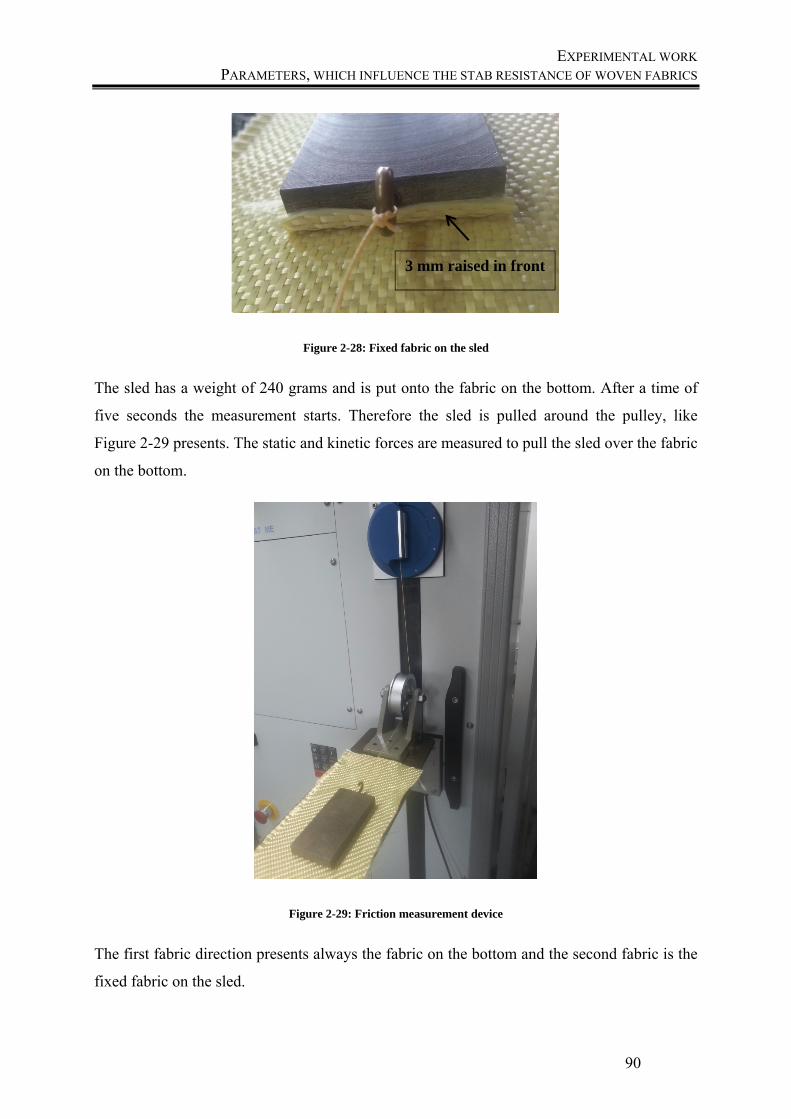
EXPERIMENTAL WORK PARAMETERS, WHICH INFLUENCE THE STAB RESISTANCE OF WOVEN FABRICS
90
Figure 2-28: Fixed fabric on the sled
The sled has a weight of 240 grams and is put onto the fabric on the bottom. After a time of
five seconds the measurement starts. Therefore the sled is pulled around the pulley, like
Figure 2-29 presents. The static and kinetic forces are measured to pull the sled over the fabric
on the bottom.
Figure 2-29: Friction measurement device
The first fabric direction presents always the fabric on the bottom and the second fabric is the
fixed fabric on the sled.
3 mm raised in front
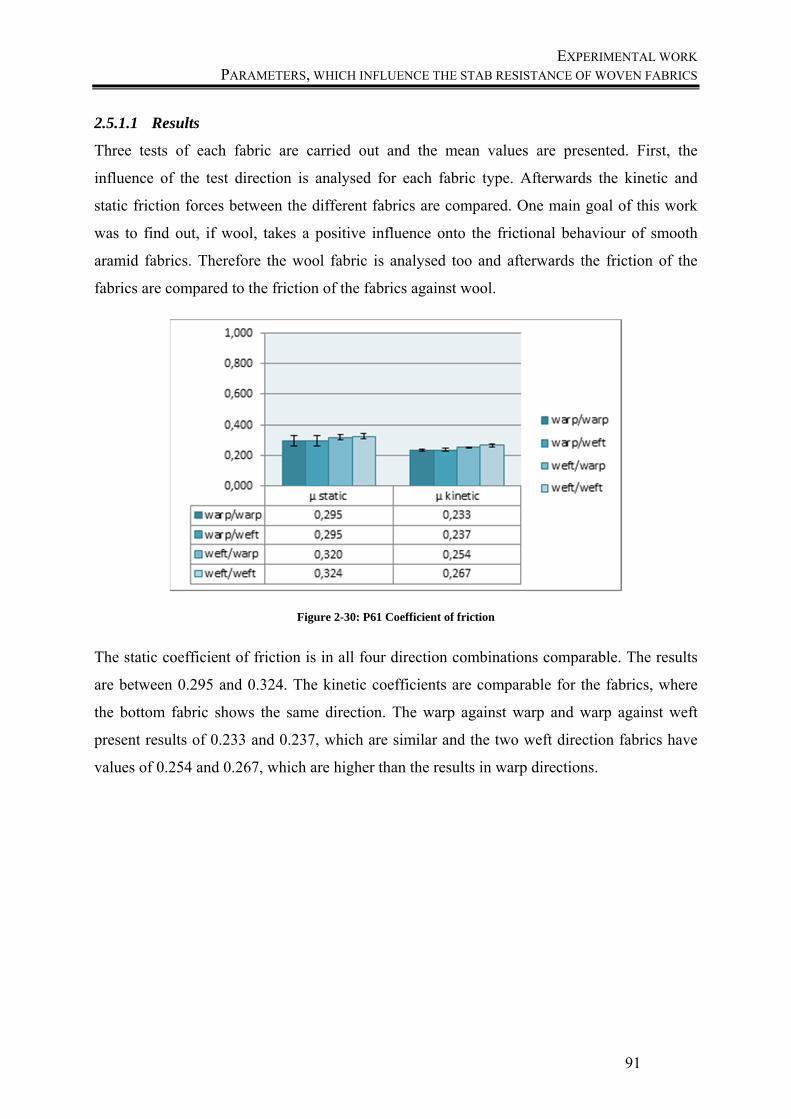
EXPERIMENTAL WORK PARAMETERS, WHICH INFLUENCE THE STAB RESISTANCE OF WOVEN FABRICS
91
2.5.1.1 Results
Three tests of each fabric are carried out and the mean values are presented. First, the
influence of the test direction is analysed for each fabric type. Afterwards the kinetic and
static friction forces between the different fabrics are compared. One main goal of this work
was to find out, if wool, takes a positive influence onto the frictional behaviour of smooth
aramid fabrics. Therefore the wool fabric is analysed too and afterwards the friction of the
fabrics are compared to the friction of the fabrics against wool.
Figure 2-30: P61 Coefficient of friction
The static coefficient of friction is in all four direction combinations comparable. The results
are between 0.295 and 0.324. The kinetic coefficients are comparable for the fabrics, where
the bottom fabric shows the same direction. The warp against warp and warp against weft
present results of 0.233 and 0.237, which are similar and the two weft direction fabrics have
values of 0.254 and 0.267, which are higher than the results in warp directions.
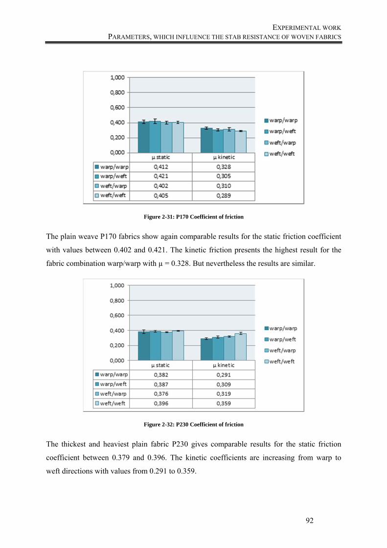
EXPERIMENTAL WORK PARAMETERS, WHICH INFLUENCE THE STAB RESISTANCE OF WOVEN FABRICS
92
Figure 2-31: P170 Coefficient of friction
The plain weave P170 fabrics show again comparable results for the static friction coefficient
with values between 0.402 and 0.421. The kinetic friction presents the highest result for the
fabric combination warp/warp with µ = 0.328. But nevertheless the results are similar.
Figure 2-32: P230 Coefficient of friction
The thickest and heaviest plain fabric P230 gives comparable results for the static friction
coefficient between 0.379 and 0.396. The kinetic coefficients are increasing from warp to
weft directions with values from 0.291 to 0.359.

EXPERIMENTAL WORK PARAMETERS, WHICH INFLUENCE THE STAB RESISTANCE OF WOVEN FABRICS
93
The results obtained for twill fabrics are presented in Figure 2-33 (170 g/m²) and Figure 2-34
(230 g/m²). Figure 2-33 shows the results for the twill fabric T170.
Figure 2-33: T170 Coefficient of friction
While the kinetic results for the coefficient of friction are comparable and show results
between 0.335 and 0.346, the static friction results vary. The weft/warp direction presents the
lowest friction resistance with a value of 0.362, while the other results are higher with values
between 0.408 and 0.429.
Figure 2-34: T230 Coefficient of friction
The results of the last twill pattern T230 give other results than the tested fabrics before. The
highest values of the static friction can be seen for the warp/warp and weft/weft directions
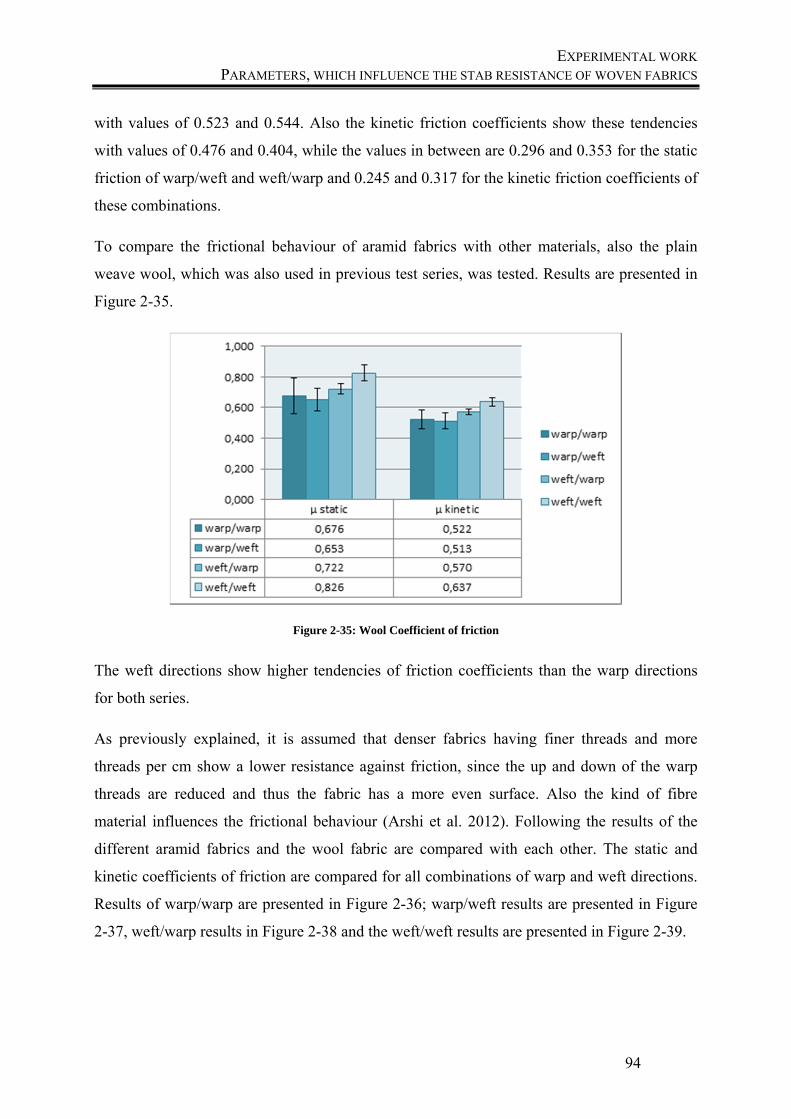
EXPERIMENTAL WORK PARAMETERS, WHICH INFLUENCE THE STAB RESISTANCE OF WOVEN FABRICS
94
with values of 0.523 and 0.544. Also the kinetic friction coefficients show these tendencies
with values of 0.476 and 0.404, while the values in between are 0.296 and 0.353 for the static
friction of warp/weft and weft/warp and 0.245 and 0.317 for the kinetic friction coefficients of
these combinations.
To compare the frictional behaviour of aramid fabrics with other materials, also the plain
weave wool, which was also used in previous test series, was tested. Results are presented in
Figure 2-35.
Figure 2-35: Wool Coefficient of friction
The weft directions show higher tendencies of friction coefficients than the warp directions
for both series.
As previously explained, it is assumed that denser fabrics having finer threads and more
threads per cm show a lower resistance against friction, since the up and down of the warp
threads are reduced and thus the fabric has a more even surface. Also the kind of fibre
material influences the frictional behaviour (Arshi et al. 2012). Following the results of the
different aramid fabrics and the wool fabric are compared with each other. The static and
kinetic coefficients of friction are compared for all combinations of warp and weft directions.
Results of warp/warp are presented in Figure 2-36; warp/weft results are presented in Figure
2-37, weft/warp results in Figure 2-38 and the weft/weft results are presented in Figure 2-39.
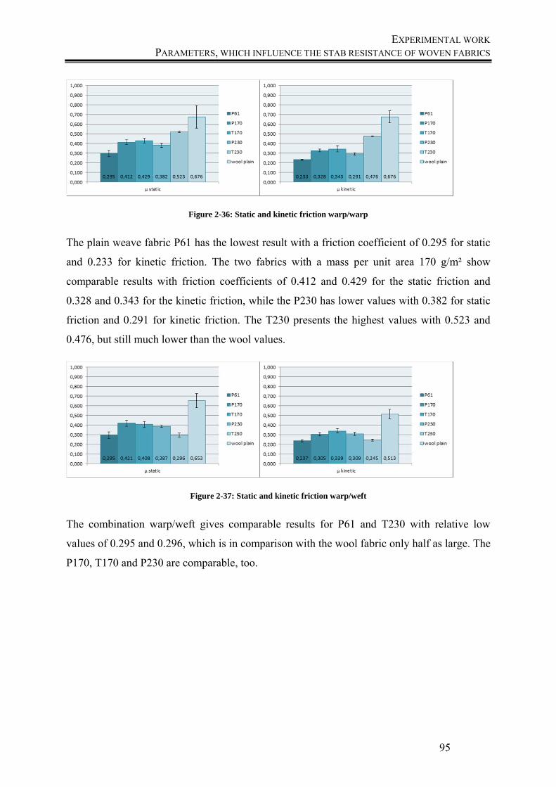
EXPERIMENTAL WORK PARAMETERS, WHICH INFLUENCE THE STAB RESISTANCE OF WOVEN FABRICS
95
Figure 2-36: Static and kinetic friction warp/warp
The plain weave fabric P61 has the lowest result with a friction coefficient of 0.295 for static
and 0.233 for kinetic friction. The two fabrics with a mass per unit area 170 g/m² show
comparable results with friction coefficients of 0.412 and 0.429 for the static friction and
0.328 and 0.343 for the kinetic friction, while the P230 has lower values with 0.382 for static
friction and 0.291 for kinetic friction. The T230 presents the highest values with 0.523 and
0.476, but still much lower than the wool values.
Figure 2-37: Static and kinetic friction warp/weft
The combination warp/weft gives comparable results for P61 and T230 with relative low
values of 0.295 and 0.296, which is in comparison with the wool fabric only half as large. The
P170, T170 and P230 are comparable, too.
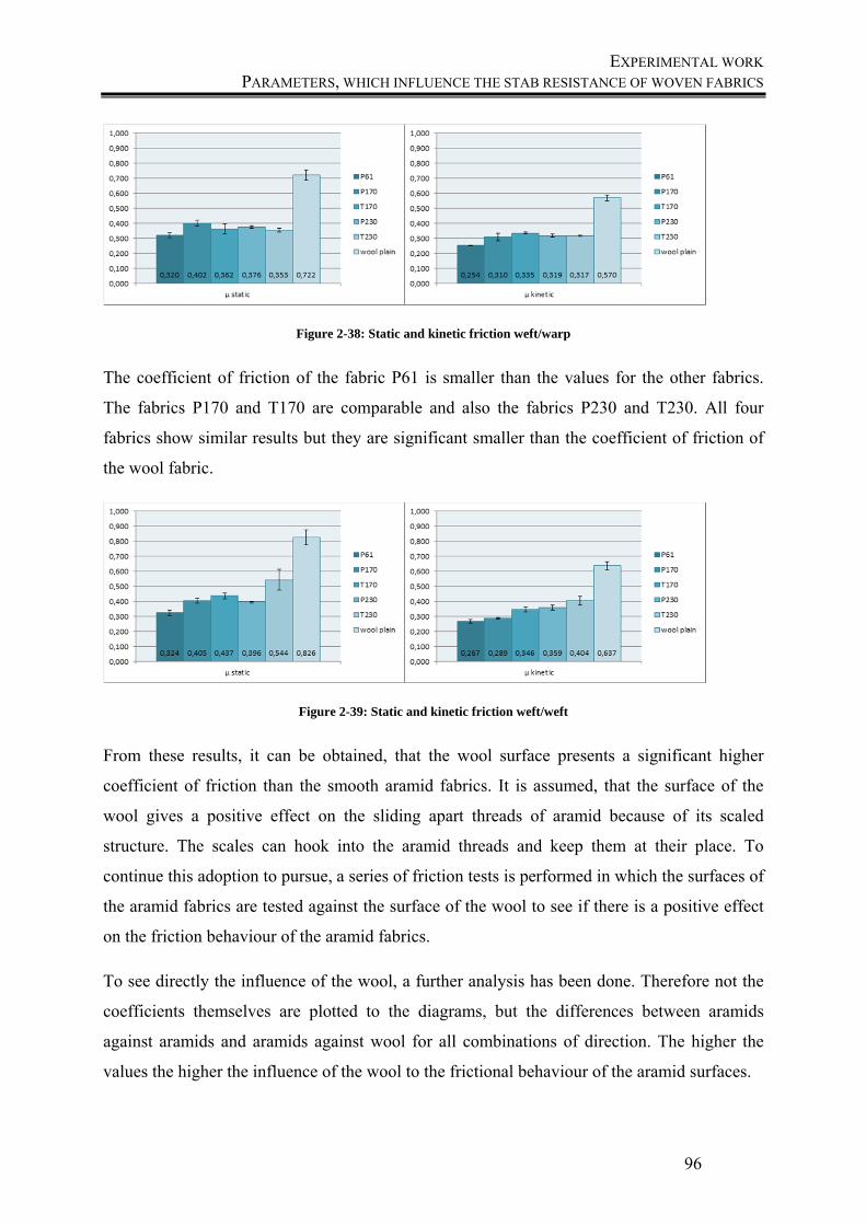
EXPERIMENTAL WORK PARAMETERS, WHICH INFLUENCE THE STAB RESISTANCE OF WOVEN FABRICS
96
Figure 2-38: Static and kinetic friction weft/warp
The coefficient of friction of the fabric P61 is smaller than the values for the other fabrics.
The fabrics P170 and T170 are comparable and also the fabrics P230 and T230. All four
fabrics show similar results but they are significant smaller than the coefficient of friction of
the wool fabric.
Figure 2-39: Static and kinetic friction weft/weft
From these results, it can be obtained, that the wool surface presents a significant higher
coefficient of friction than the smooth aramid fabrics. It is assumed, that the surface of the
wool gives a positive effect on the sliding apart threads of aramid because of its scaled
structure. The scales can hook into the aramid threads and keep them at their place. To
continue this adoption to pursue, a series of friction tests is performed in which the surfaces of
the aramid fabrics are tested against the surface of the wool to see if there is a positive effect
on the friction behaviour of the aramid fabrics.
To see directly the influence of the wool, a further analysis has been done. Therefore not the
coefficients themselves are plotted to the diagrams, but the differences between aramids
against aramids and aramids against wool for all combinations of direction. The higher the
values the higher the influence of the wool to the frictional behaviour of the aramid surfaces.
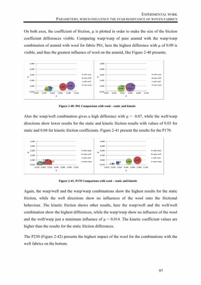
EXPERIMENTAL WORK PARAMETERS, WHICH INFLUENCE THE STAB RESISTANCE OF WOVEN FABRICS
97
On both axes, the coefficient of friction, µ is plotted in order to make the size of the friction
coefficient differences visible. Comparing warp/warp of pure aramid with the warp/warp
combination of aramid with wool for fabric P61, here the highest difference with µ of 0.09 is
visible, and thus the greatest influence of wool on the aramid, like Figure 2-40 presents.
Figure 2-40: P61 Comparison with wool – static and kinetic
Also the warp/weft combination gives a high difference with µ = 0.07, while the weft/warp
directions show lower results for the static and kinetic friction results with values of 0.03 for
static and 0.04 for kinetic friction coefficients. Figure 2-41 present the results for the P170.
Figure 2-41: P170 Comparison with wool – static and kinetic
Again, the warp/weft and the warp/warp combinations show the highest results for the static
friction, while the weft directions show no influences of the wool onto the frictional
behaviour. The kinetic friction shows other results, here the warp/weft and the weft/weft
combination show the highest differences, while the warp/warp show no influence of the wool
and the weft/warp just a minimum influence of µ = 0.014. The kinetic coefficient values are
higher than the results for the static friction differences.
The P230 (Figure 2-42) presents the highest impact of the wool for the combinations with the
weft fabrics on the bottom.
EXPERIMENTAL WORK PARAMETERS, WHICH INFLUENCE THE STAB RESISTANCE OF WOVEN FABRICS
98
Figure 2-42: P230 Comparison with wool – static and kinetic
They show values of 0.125 and 0.142, while the combination warp/warp just has a value of
0.048 and the warp/weft series a value of 0.015. The kinetic test series show another
behaviour. Here the weft/weft combination has a value of just 0.006, while the other series
show results between 0.023 and 0.032. In total the influence of wool onto the static friction is
higher than the influence onto the kinetic friction.
The twill fabric T170 (Figure 2-43) shows high values for the combinations warp/weft and
weft/weft for the kinetic friction and the static friction. The values in total are very high, so it
seems that the wool has a positive influence onto the surface of the aramid and the scales
hook to the aramid threads.
Figure 2-43: T170 Comparison with wool – static and kinetic
EXPERIMENTAL WORK PARAMETERS, WHICH INFLUENCE THE STAB RESISTANCE OF WOVEN FABRICS
99
Figure 2-44 present the results of the twill fabric T230.
Figure 2-44:T230 Comparison with wool – static and kinetic
The behaviour is similar to the T170. The warp/weft and weft/weft combinations show the
highest values, which are even higher than the values of the T170. The warp/weft
combination has a static coefficient of friction of 0.418 and a kinetic coefficient of 0.368. The
weft/weft combinations are nearly similar for static and kinetic with differences to pure
aramid combinations of 0.190 and 0.206. In total it can be said, that the wool takes a great
influence onto the friction behaviour of the aramid surface. While the plain pattern didn´t
show so high differences, the twill pattern presented high values.
To analyse the differences between the structures, the different pattern are compared, like
presented in Figure 2-45 for the warp/warp combination. Again the difference in the friction
coefficient between pure aramid and an aramid/wool combination was measured and plotted
to the diagrams.
Figure 2-45: Static and kinetic friction - warp/warp
The warp/warp combination with the wool presents the highest influence onto the P61 fabric,
the T170, P230 and T230 are comparable and the P170 show no influence through the wool
fabric. The warp/weft combination is presented in Figure 2-46.
EXPERIMENTAL WORK PARAMETERS, WHICH INFLUENCE THE STAB RESISTANCE OF WOVEN FABRICS
100
Figure 2-46: Static and kinetic friction - warp/weft
The warp/weft combination for the static friction show the best results for the twill fabrics
T170 and T230, while the fabric P61 is very low and the fabrics P170 and P230 show no
influence of the wool onto the panel. The kinetic friction show the same tendencies for the
T170 and T230, but the P61 and P170 are low and the P230 show nearly no influence. The
Figure 2-47 gives an overview over the combination weft/warp.
Figure 2-47: Static and kinetic friction - weft/warp
Here the mass per unit areas 230 g/m² fabrics P230 and T230 have the highest results, while
P61 and T170 have low values and P170 show nearly no influence of the wool onto the panel.
The kinetic friction coefficients show the same tendencies in the order of results but with
more even space between them. Figure 2-48 presents the combination of weft/weft.
EXPERIMENTAL WORK PARAMETERS, WHICH INFLUENCE THE STAB RESISTANCE OF WOVEN FABRICS
101
Figure 2-48: Static and kinetic friction - weft/weft
The weft/weft combination of T230 gives the highest difference between pure aramid and
aramid/wool combinations for the static and the kinetic friction. Also the other twill fabric
T170 shows a high influence of the wool onto the friction behaviour.
2.5.1.2 Conclusions
In total, the twill fabrics show the highest influence of the wool onto the frictional behaviour
of aramid fabrics. The plain weave fabric results show nearly no influence of the wool onto
the panels. The comparison of the weave direction shows the highest influence of the wool
onto the warp/weft and the weft/weft combination.
-
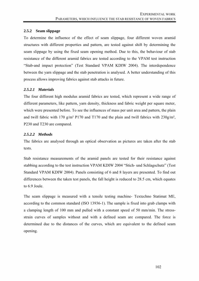
EXPERIMENTAL WORK PARAMETERS, WHICH INFLUENCE THE STAB RESISTANCE OF WOVEN FABRICS
102
2.5.2 Seam slippage
To determine the influence of the effect of seam slippage, four different woven aramid
structures with different properties and pattern, are tested against shift by determining the
seam slippage by using the fixed seam opening method. Due to this, the behaviour of stab
resistance of the different aramid fabrics are tested according to the VPAM test instruction
“Stab-and impact protection” (Test Standard VPAM KDIW 2004). The interdependence
between the yarn slippage and the stab penetration is analysed. A better understanding of this
process allows improving fabrics against stab attacks in future.
2.5.2.1 Materials
The four different high modulus aramid fabrics are tested, which represent a wide range of
different parameters, like pattern, yarn density, thickness and fabric weight per square meter,
which were presented before. To see the influences of mass per unit area and pattern, the plain
and twill fabric with 170 g/m² P170 and T170 and the plain and twill fabrics with 230g/m²,
P230 and T230 are compared.
2.5.2.2 Methods
The fabrics are analysed through an optical observation as pictures are taken after the stab
tests.
Stab resistance measurements of the aramid panels are tested for their resistance against
stabbing according to the test instruction VPAM KDIW 2004 “Stich- und Schlagschutz” (Test
Standard VPAM KDIW 2004). Panels consisting of 6 and 8 layers are presented. To find out
differences between the taken test panels, the fall height is reduced to 28.5 cm, which equates
to 6.9 Joule.
The seam slippage is measured with a tensile testing machine- Textechno Statimat ME,
according to the common standard (ISO 13936-1). The sample is fixed into grab clamps with
a clamping length of 100 mm and pulled with a constant speed of 50 mm/min. The stress-
strain curves of samples without and with a defined seam are compared. The force is
determined due to the distances of the curves, which are equivalent to the defined seam
opening.
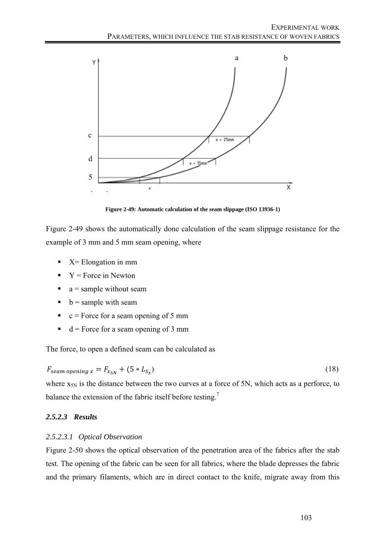
EXPERIMENTAL WORK PARAMETERS, WHICH INFLUENCE THE STAB RESISTANCE OF WOVEN FABRICS
103
Figure 2-49: Automatic calculation of the seam slippage (ISO 13936-1)
Figure 2-49 shows the automatically done calculation of the seam slippage resistance for the
example of 3 mm and 5 mm seam opening, where
X= Elongation in mm
Y = Force in Newton
a = sample without seam
b = sample with seam
c = Force for a seam opening of 5 mm
d = Force for a seam opening of 3 mm
The force, to open a defined seam can be calculated as
5 ∗ ) (18)
where x5N is the distance between the two curves at a force of 5N, which acts as a perforce, to
balance the extension of the fabric itself before testing.7
2.5.2.3 Results
2.5.2.3.1 Optical Observation
Figure 2-50 shows the optical observation of the penetration area of the fabrics after the stab
test. The opening of the fabric can be seen for all fabrics, where the blade depresses the fabric
and the primary filaments, which are in direct contact to the knife, migrate away from this
a b
c
d
5
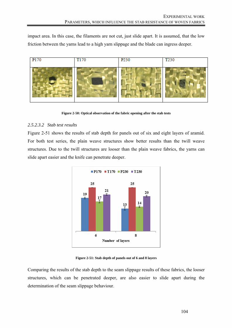
EXPERIMENTAL WORK PARAMETERS, WHICH INFLUENCE THE STAB RESISTANCE OF WOVEN FABRICS
104
impact area. In this case, the filaments are not cut, just slide apart. It is assumed, that the low
friction between the yarns lead to a high yarn slippage and the blade can ingress deeper.
Figure 2-50: Optical observation of the fabric opening after the stab tests
2.5.2.3.2 Stab test results
Figure 2-51 shows the results of stab depth for panels out of six and eight layers of aramid.
For both test series, the plain weave structures show better results than the twill weave
structures. Due to the twill structures are looser than the plain weave fabrics, the yarns can
slide apart easier and the knife can penetrate deeper.
Figure 2-51: Stab depth of panels out of 6 and 8 layers
Comparing the results of the stab depth to the seam slippage results of these fabrics, the looser
structures, which can be penetrated deeper, are also easier to slide apart during the
determination of the seam slippage behaviour.
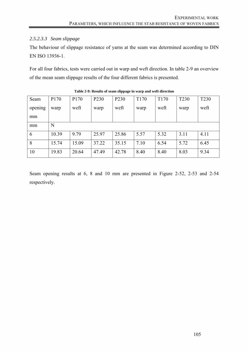
EXPERIMENTAL WORK PARAMETERS, WHICH INFLUENCE THE STAB RESISTANCE OF WOVEN FABRICS
105
2.5.2.3.3 Seam slippage
The behaviour of slippage resistance of yarns at the seam was determined according to DIN
EN ISO 13936-1.
For all four fabrics, tests were carried out in warp and weft direction. In table 2-9 an overview
of the mean seam slippage results of the four different fabrics is presented.
Table 2-9: Results of seam slippage in warp and weft direction
Seam
opening
mm
P170
warp
P170
weft
P230
warp
P230
weft
T170
warp
T170
weft
T230
warp
T230
weft
mm N
6 10.39 9.79 25.97 25.86 5.57 5.32 3.11 4.11
8 15.74 15.09 37.22 35.15 7.10 6.54 5.72 6.45
10 19.83 20.64 47.49 42.78 8.40 8.40 8.03 9.34
Seam opening results at 6, 8 and 10 mm are presented in Figure 2-52, 2-53 and 2-54
respectively.
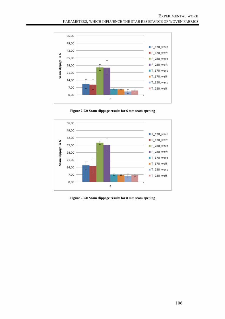
EXPERIMENTAL WORK PARAMETERS, WHICH INFLUENCE THE STAB RESISTANCE OF WOVEN FABRICS
106
Figure 2-52: Seam slippage results for 6 mm seam opening
Figure 2-53: Seam slippage results for 8 mm seam opening
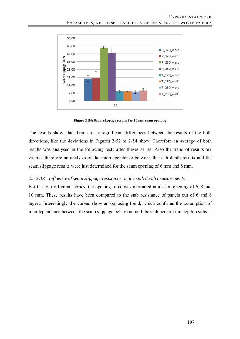
EXPERIMENTAL WORK PARAMETERS, WHICH INFLUENCE THE STAB RESISTANCE OF WOVEN FABRICS
107
Figure 2-54: Seam slippage results for 10 mm seam opening
The results show, that there are no significant differences between the results of the both
directions, like the deviations in Figures 2-52 to 2-54 show. Therefore an average of both
results was analysed in the following tests after theses series. Also the trend of results are
visible, therefore an analysis of the interdependence between the stab depth results and the
seam slippage results were just determined for the seam opening of 6 mm and 8 mm.
2.5.2.3.4 Influence of seam slippage resistance on the stab depth measurements
For the four different fabrics, the opening force was measured at a seam opening of 6, 8 and
10 mm. These results have been compared to the stab resistance of panels out of 6 and 8
layers. Interestingly the curves show an opposing trend, which confirms the assumption of
interdependence between the seam slippage behaviour and the stab penetration depth results.
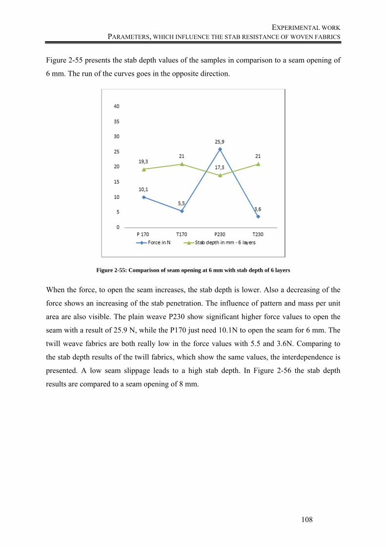
EXPERIMENTAL WORK PARAMETERS, WHICH INFLUENCE THE STAB RESISTANCE OF WOVEN FABRICS
108
Figure 2-55 presents the stab depth values of the samples in comparison to a seam opening of
6 mm. The run of the curves goes in the opposite direction.
Figure 2-55: Comparison of seam opening at 6 mm with stab depth of 6 layers
When the force, to open the seam increases, the stab depth is lower. Also a decreasing of the
force shows an increasing of the stab penetration. The influence of pattern and mass per unit
area are also visible. The plain weave P230 show significant higher force values to open the
seam with a result of 25.9 N, while the P170 just need 10.1N to open the seam for 6 mm. The
twill weave fabrics are both really low in the force values with 5.5 and 3.6N. Comparing to
the stab depth results of the twill fabrics, which show the same values, the interdependence is
presented. A low seam slippage leads to a high stab depth. In Figure 2-56 the stab depth
results are compared to a seam opening of 8 mm.
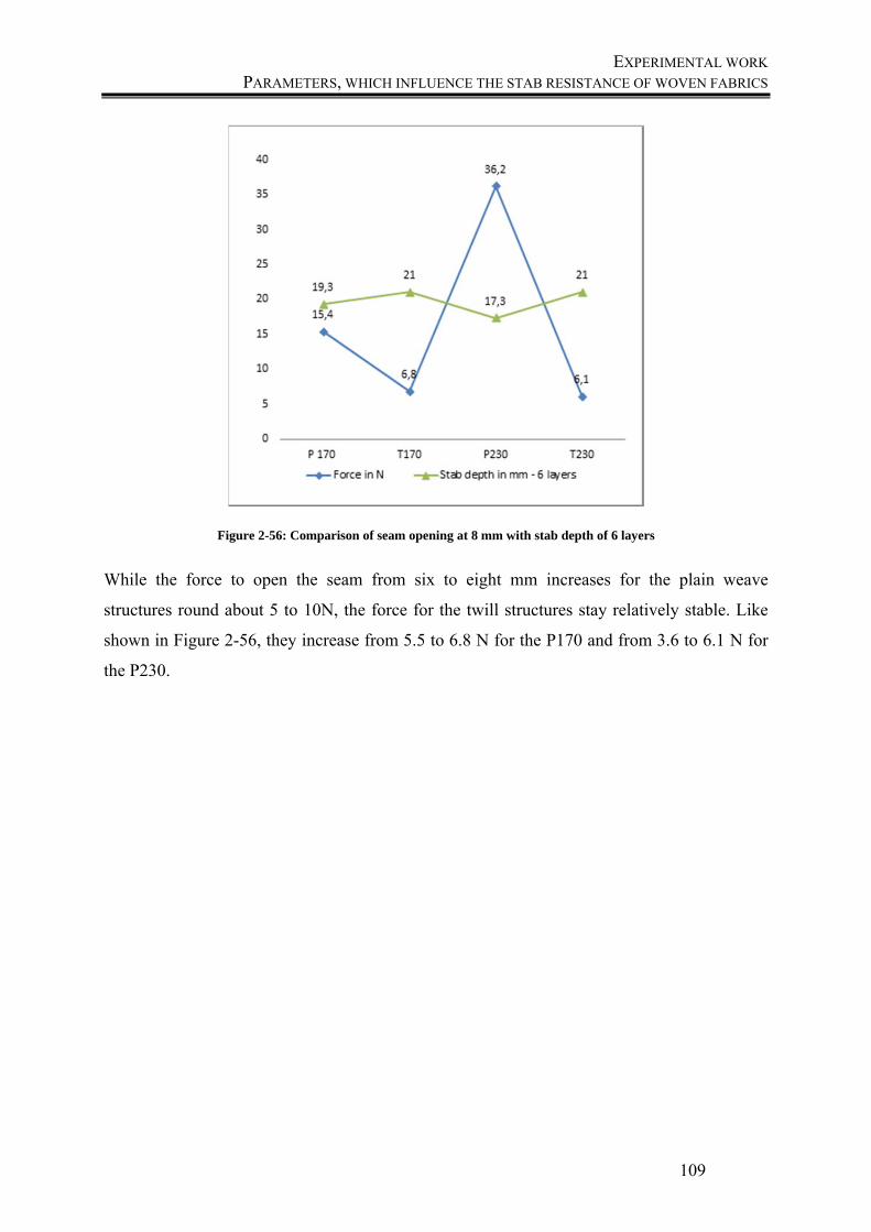
EXPERIMENTAL WORK PARAMETERS, WHICH INFLUENCE THE STAB RESISTANCE OF WOVEN FABRICS
109
Figure 2-56: Comparison of seam opening at 8 mm with stab depth of 6 layers
While the force to open the seam from six to eight mm increases for the plain weave
structures round about 5 to 10N, the force for the twill structures stay relatively stable. Like
shown in Figure 2-56, they increase from 5.5 to 6.8 N for the P170 and from 3.6 to 6.1 N for
the P230.
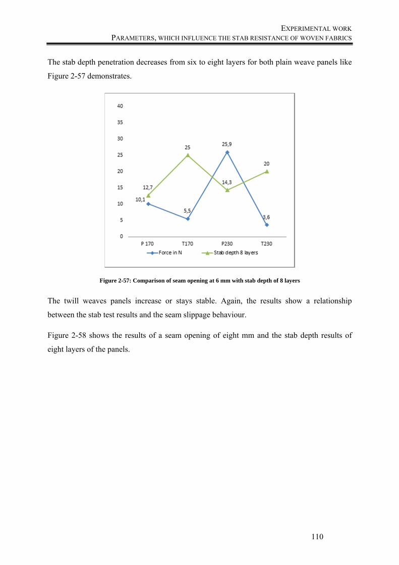
EXPERIMENTAL WORK PARAMETERS, WHICH INFLUENCE THE STAB RESISTANCE OF WOVEN FABRICS
110
The stab depth penetration decreases from six to eight layers for both plain weave panels like
Figure 2-57 demonstrates.
Figure 2-57: Comparison of seam opening at 6 mm with stab depth of 8 layers
The twill weaves panels increase or stays stable. Again, the results show a relationship
between the stab test results and the seam slippage behaviour.
Figure 2-58 shows the results of a seam opening of eight mm and the stab depth results of
eight layers of the panels.
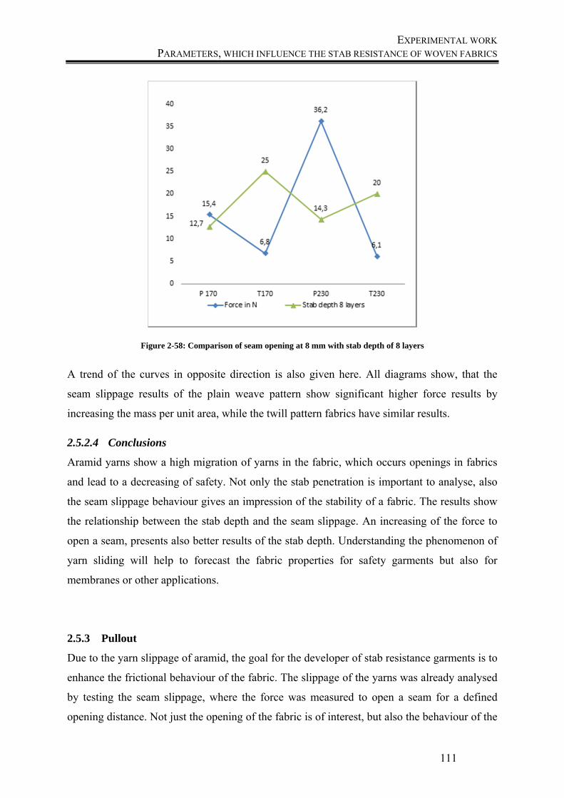
EXPERIMENTAL WORK PARAMETERS, WHICH INFLUENCE THE STAB RESISTANCE OF WOVEN FABRICS
111
Figure 2-58: Comparison of seam opening at 8 mm with stab depth of 8 layers
A trend of the curves in opposite direction is also given here. All diagrams show, that the
seam slippage results of the plain weave pattern show significant higher force results by
increasing the mass per unit area, while the twill pattern fabrics have similar results.
2.5.2.4 Conclusions
Aramid yarns show a high migration of yarns in the fabric, which occurs openings in fabrics
and lead to a decreasing of safety. Not only the stab penetration is important to analyse, also
the seam slippage behaviour gives an impression of the stability of a fabric. The results show
the relationship between the stab depth and the seam slippage. An increasing of the force to
open a seam, presents also better results of the stab depth. Understanding the phenomenon of
yarn sliding will help to forecast the fabric properties for safety garments but also for
membranes or other applications.
2.5.3 Pullout
Due to the yarn slippage of aramid, the goal for the developer of stab resistance garments is to
enhance the frictional behaviour of the fabric. The slippage of the yarns was already analysed
by testing the seam slippage, where the force was measured to open a seam for a defined
opening distance. Not just the opening of the fabric is of interest, but also the behaviour of the

EXPERIMENTAL WORK PARAMETERS, WHICH INFLUENCE THE STAB RESISTANCE OF WOVEN FABRICS
112
yarns, when they are pulled-out. The most common methods how researchers the pull-out
behaviour test, were already explained before. But in these methods, fabrics are clamped in at
the sides, which lead to extensional stress in the fabric. Therefore a new method is developed,
where these influences are prevented.
2.5.3.1 Materials
Two different fabrics are compared with each other to find out if there are influences on the
pull-out behaviour for the different fabric constructions. The fabrics P230 and T230 with 230
grams per square meter each and seven threads per cm in both directions are chosen.
2.5.3.2 Methods
To prevent the extensional stress in the fabric area, a new test method is proposed, where the
fabric is clamped on the top and the yarn, which will be pulled-out, is cut out. This yarn is
clamped in the bottom clamp. Figure 2-59 presents an example for one pull-out test.
Figure 2-59: Schematic view of the measurement of the Pull-out forces
The test specimen are prepared with a width of 50 mm and the test speed is 100mm/min. Five
tests are carried out per fabric direction and the mean values are compared.
In the beginning, the crimped yarn extends. After full extension, the first peak of the pull-out
force is visible, where the kinetic region begins. The yarn is pulled through all crossing points
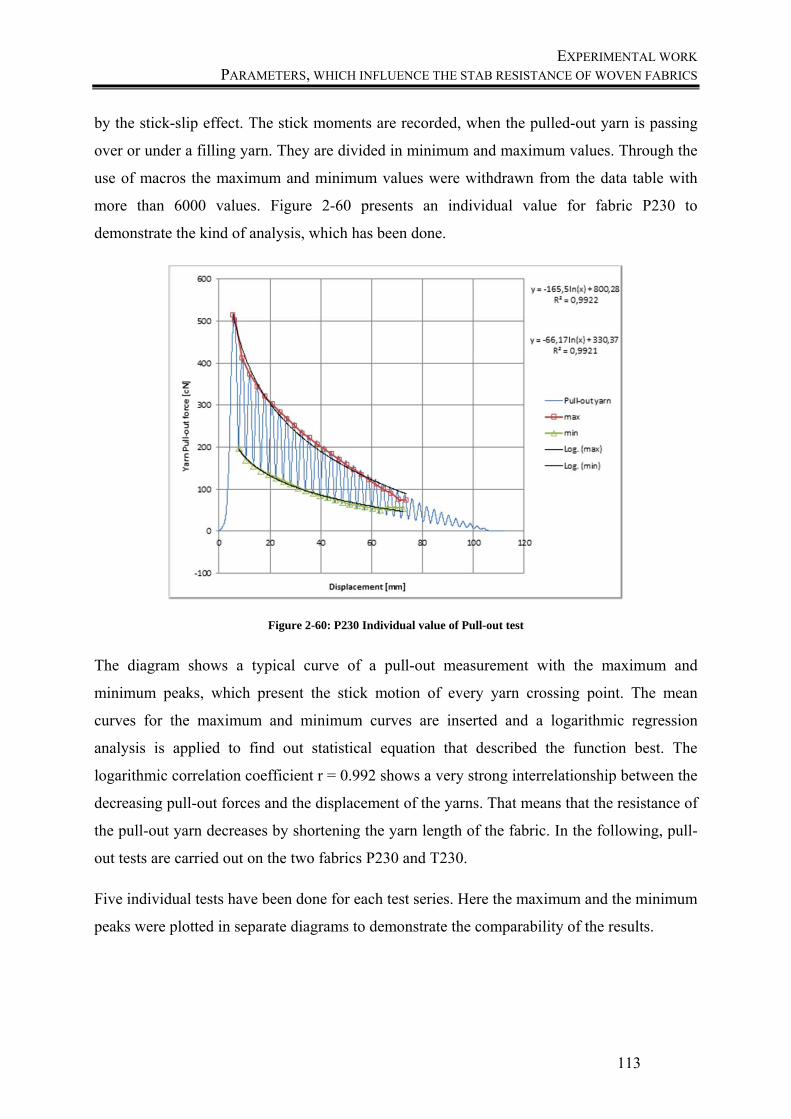
EXPERIMENTAL WORK PARAMETERS, WHICH INFLUENCE THE STAB RESISTANCE OF WOVEN FABRICS
113
by the stick-slip effect. The stick moments are recorded, when the pulled-out yarn is passing
over or under a filling yarn. They are divided in minimum and maximum values. Through the
use of macros the maximum and minimum values were withdrawn from the data table with
more than 6000 values. Figure 2-60 presents an individual value for fabric P230 to
demonstrate the kind of analysis, which has been done.
Figure 2-60: P230 Individual value of Pull-out test
The diagram shows a typical curve of a pull-out measurement with the maximum and
minimum peaks, which present the stick motion of every yarn crossing point. The mean
curves for the maximum and minimum curves are inserted and a logarithmic regression
analysis is applied to find out statistical equation that described the function best. The
logarithmic correlation coefficient r = 0.992 shows a very strong interrelationship between the
decreasing pull-out forces and the displacement of the yarns. That means that the resistance of
the pull-out yarn decreases by shortening the yarn length of the fabric. In the following, pull-
out tests are carried out on the two fabrics P230 and T230.
Five individual tests have been done for each test series. Here the maximum and the minimum
peaks were plotted in separate diagrams to demonstrate the comparability of the results.
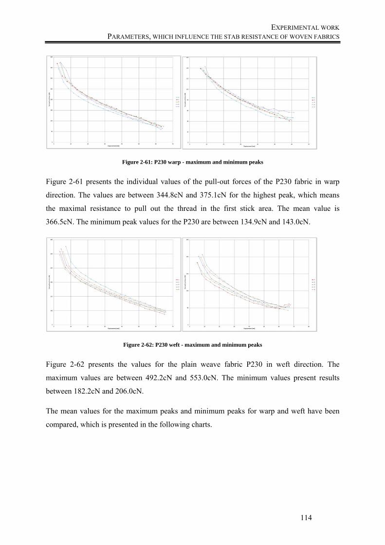
EXPERIMENTAL WORK PARAMETERS, WHICH INFLUENCE THE STAB RESISTANCE OF WOVEN FABRICS
114
Figure 2-61: P230 warp - maximum and minimum peaks
Figure 2-61 presents the individual values of the pull-out forces of the P230 fabric in warp
direction. The values are between 344.8cN and 375.1cN for the highest peak, which means
the maximal resistance to pull out the thread in the first stick area. The mean value is
366.5cN. The minimum peak values for the P230 are between 134.9cN and 143.0cN.
Figure 2-62: P230 weft - maximum and minimum peaks
Figure 2-62 presents the values for the plain weave fabric P230 in weft direction. The
maximum values are between 492.2cN and 553.0cN. The minimum values present results
between 182.2cN and 206.0cN.
The mean values for the maximum peaks and minimum peaks for warp and weft have been
compared, which is presented in the following charts.
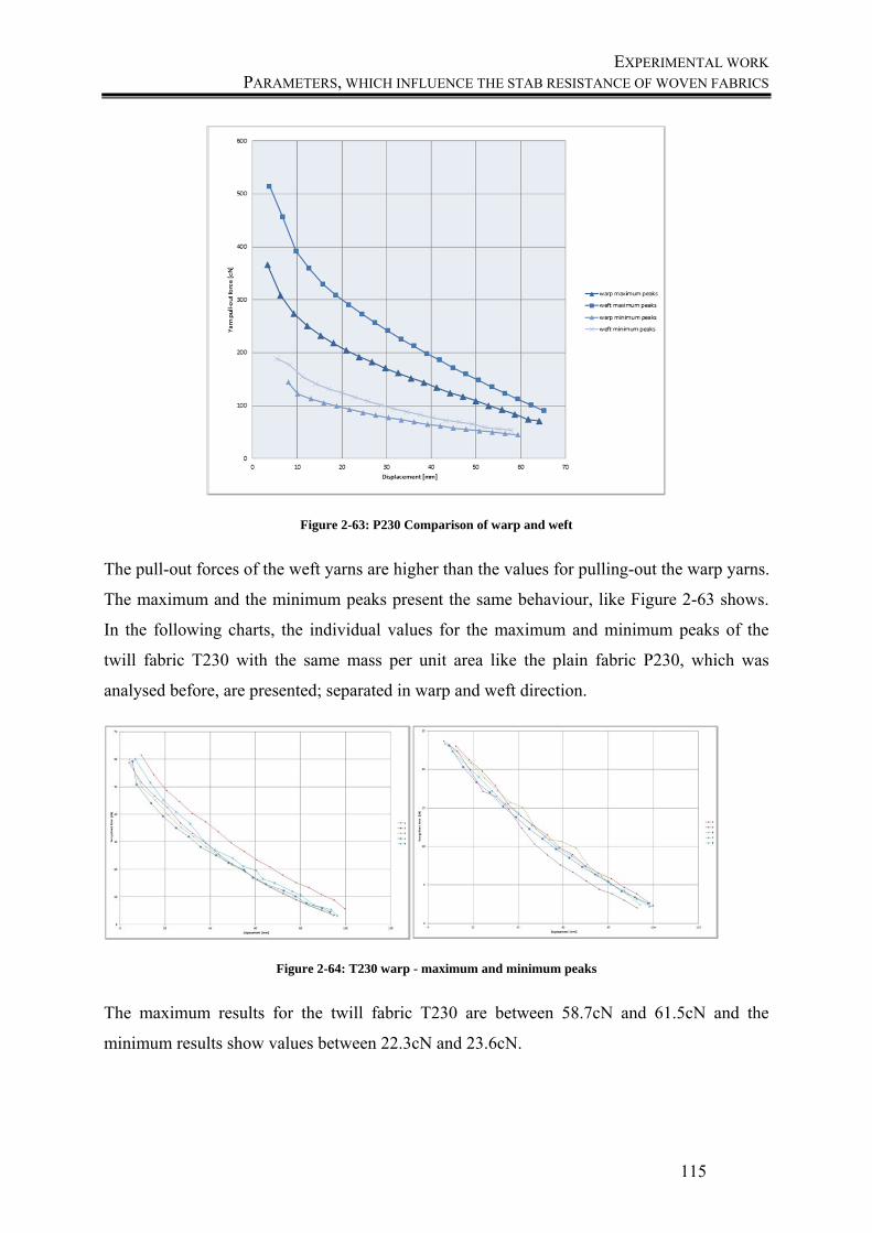
EXPERIMENTAL WORK PARAMETERS, WHICH INFLUENCE THE STAB RESISTANCE OF WOVEN FABRICS
115
Figure 2-63: P230 Comparison of warp and weft
The pull-out forces of the weft yarns are higher than the values for pulling-out the warp yarns.
The maximum and the minimum peaks present the same behaviour, like Figure 2-63 shows.
In the following charts, the individual values for the maximum and minimum peaks of the
twill fabric T230 with the same mass per unit area like the plain fabric P230, which was
analysed before, are presented; separated in warp and weft direction.
Figure 2-64: T230 warp - maximum and minimum peaks
The maximum results for the twill fabric T230 are between 58.7cN and 61.5cN and the
minimum results show values between 22.3cN and 23.6cN.
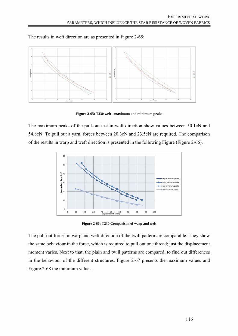
EXPERIMENTAL WORK PARAMETERS, WHICH INFLUENCE THE STAB RESISTANCE OF WOVEN FABRICS
116
The results in weft direction are as presented in Figure 2-65:
Figure 2-65: T230 weft - maximum and minimum peaks
The maximum peaks of the pull-out test in weft direction show values between 50.1cN and
54.8cN. To pull out a yarn, forces between 20.3cN and 23.5cN are required. The comparison
of the results in warp and weft direction is presented in the following Figure (Figure 2-66).
Figure 2-66: T230 Comparison of warp and weft
The pull-out forces in warp and weft direction of the twill pattern are comparable. They show
the same behaviour in the force, which is required to pull out one thread; just the displacement
moment varies. Next to that, the plain and twill patterns are compared, to find out differences
in the behaviour of the different structures. Figure 2-67 presents the maximum values and
Figure 2-68 the minimum values.
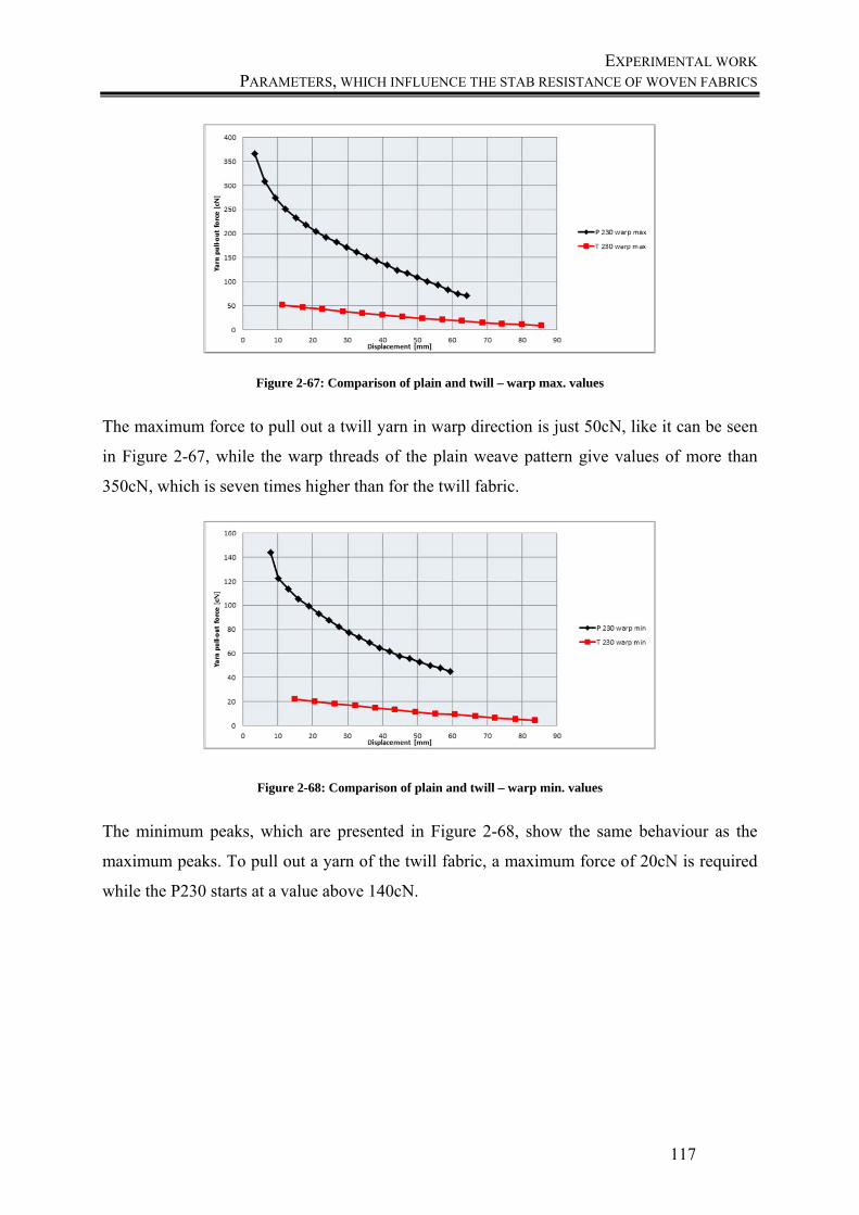
EXPERIMENTAL WORK PARAMETERS, WHICH INFLUENCE THE STAB RESISTANCE OF WOVEN FABRICS
117
Figure 2-67: Comparison of plain and twill – warp max. values
The maximum force to pull out a twill yarn in warp direction is just 50cN, like it can be seen
in Figure 2-67, while the warp threads of the plain weave pattern give values of more than
350cN, which is seven times higher than for the twill fabric.
Figure 2-68: Comparison of plain and twill – warp min. values
The minimum peaks, which are presented in Figure 2-68, show the same behaviour as the
maximum peaks. To pull out a yarn of the twill fabric, a maximum force of 20cN is required
while the P230 starts at a value above 140cN.
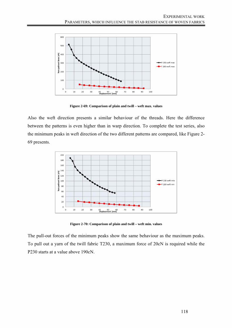
EXPERIMENTAL WORK PARAMETERS, WHICH INFLUENCE THE STAB RESISTANCE OF WOVEN FABRICS
118
Figure 2-69: Comparison of plain and twill – weft max. values
Also the weft direction presents a similar behaviour of the threads. Here the difference
between the patterns is even higher than in warp direction. To complete the test series, also
the minimum peaks in weft direction of the two different patterns are compared, like Figure 2-
69 presents.
Figure 2-70: Comparison of plain and twill – weft min. values
The pull-out forces of the minimum peaks show the same behaviour as the maximum peaks.
To pull out a yarn of the twill fabric T230, a maximum force of 20cN is required while the
P230 starts at a value above 190cN.
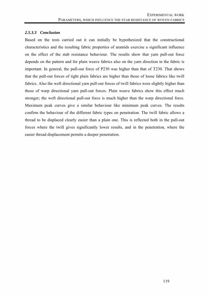
EXPERIMENTAL WORK PARAMETERS, WHICH INFLUENCE THE STAB RESISTANCE OF WOVEN FABRICS
119
2.5.3.3 Conclusion
Based on the tests carried out it can initially be hypothesized that the constructional
characteristics and the resulting fabric properties of aramids exercise a significant influence
on the effect of the stab resistance behaviour. The results show that yarn pull-out force
depends on the pattern and for plain weave fabrics also on the yarn direction in the fabric is
important. In general, the pull-out force of P230 was higher than that of T230. That shows
that the pull-out forces of tight plain fabrics are higher than those of loose fabrics like twill
fabrics. Also the weft directional yarn pull-out forces of twill fabrics were slightly higher than
those of warp directional yarn pull-out forces. Plain weave fabrics show this effect much
stronger; the weft directional pull-out force is much higher than the warp directional force.
Maximum peak curves give a similar behaviour like minimum peak curves. The results
confirm the behaviour of the different fabric types on penetration. The twill fabric allows a
thread to be displaced clearly easier than a plain one. This is reflected both in the pull-out
forces where the twill gives significantly lower results, and in the penetration, where the
easier thread displacement permits a deeper penetration.

CHAPTER 3
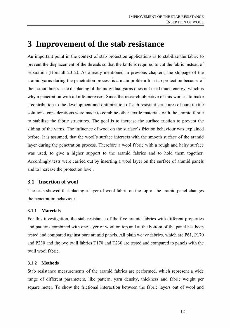
IMPROVEMENT OF THE STAB RESISTANCE INSERTION OF WOOL
121
3 Improvement of the stab resistance An important point in the context of stab protection applications is to stabilize the fabric to
prevent the displacement of the threads so that the knife is required to cut the fabric instead of
separation (Horsfall 2012). As already mentioned in previous chapters, the slippage of the
aramid yarns during the penetration process is a main problem for stab protection because of
their smoothness. The displacing of the individual yarns does not need much energy, which is
why a penetration with a knife increases. Since the research objective of this work is to make
a contribution to the development and optimization of stab-resistant structures of pure textile
solutions, considerations were made to combine other textile materials with the aramid fabric
to stabilize the fabric structures. The goal is to increase the surface friction to prevent the
sliding of the yarns. The influence of wool on the surface`s friction behaviour was explained
before. It is assumed, that the wool´s surface interacts with the smooth surface of the aramid
layer during the penetration process. Therefore a wool fabric with a rough and hairy surface
was used, to give a higher support to the aramid fabrics and to hold them together.
Accordingly tests were carried out by inserting a wool layer on the surface of aramid panels
and to increase the protection level.
3.1 Insertion of wool
The tests showed that placing a layer of wool fabric on the top of the aramid panel changes
the penetration behaviour.
3.1.1 Materials
For this investigation, the stab resistance of the five aramid fabrics with different properties
and patterns combined with one layer of wool on top and at the bottom of the panel has been
tested and compared against pure aramid panels. All plain weave fabrics, which are P61, P170
and P230 and the two twill fabrics T170 and T230 are tested and compared to panels with the
twill wool fabric.
3.1.2 Methods
Stab resistance measurements of the aramid fabrics are performed, which represent a wide
range of different parameters, like pattern, yarn density, thickness and fabric weight per
square meter. To show the frictional interaction between the fabric layers out of wool and
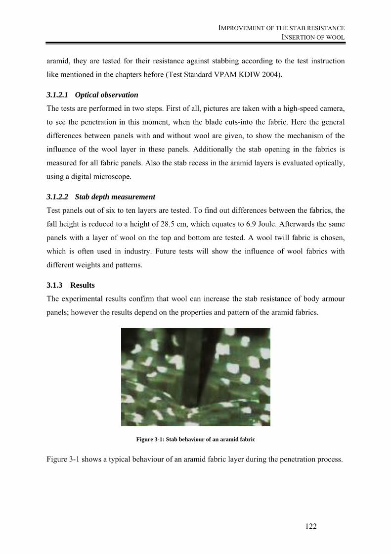
IMPROVEMENT OF THE STAB RESISTANCE INSERTION OF WOOL
122
aramid, they are tested for their resistance against stabbing according to the test instruction
like mentioned in the chapters before (Test Standard VPAM KDIW 2004).
3.1.2.1 Optical observation
The tests are performed in two steps. First of all, pictures are taken with a high-speed camera,
to see the penetration in this moment, when the blade cuts-into the fabric. Here the general
differences between panels with and without wool are given, to show the mechanism of the
influence of the wool layer in these panels. Additionally the stab opening in the fabrics is
measured for all fabric panels. Also the stab recess in the aramid layers is evaluated optically,
using a digital microscope.
3.1.2.2 Stab depth measurement
Test panels out of six to ten layers are tested. To find out differences between the fabrics, the
fall height is reduced to a height of 28.5 cm, which equates to 6.9 Joule. Afterwards the same
panels with a layer of wool on the top and bottom are tested. A wool twill fabric is chosen,
which is often used in industry. Future tests will show the influence of wool fabrics with
different weights and patterns.
3.1.3 Results
The experimental results confirm that wool can increase the stab resistance of body armour
panels; however the results depend on the properties and pattern of the aramid fabrics.
Figure 3-1: Stab behaviour of an aramid fabric
Figure 3-1 shows a typical behaviour of an aramid fabric layer during the penetration process.
IMPROVEMENT OF THE STAB RESISTANCE INSERTION OF WOOL
123
Figure 3-2: Picture sequence of the stab penetration of an aramid fabric
The picture sequence (Figure 3-2) shows the moment when the blade penetrates the woven
fabric: the blade depresses the fabric and the primary filaments, which are in direct contact to
the knife, migrate away from this impact area. In this case, the filaments are not cut, but
sliding apart. It is assumed, that the low friction between the yarns lead to a high yarn
slippage and the blade can ingress deeper. Therefore an additional test series was made with a
layer of wool on the top and bottom side. The pictures of this test run are presented in Figure
3-3.
Figure 3-3: Picture sequence of the stab penetration of a wool fabric
The blade depresses the wool layer and penetrates it through a cut. The woven wool fabric
may absorb the kinetic energy by deflection of the fabric, a friction at the contact region,
fabric shearing and crimp behaviour. Sadegh and Cavallaro (Sadegh, Cavallaro 2012)
described these steps as a normal impact between a projectile and a plain woven fabric, but it
is applicable as well for a blade penetration, but the importance and the starting point of the
different phenomena over the behaviour will be different. The following figures show the
effect of the wool layers on the first aramid layer after the penetration. But not just the first
layer shows these effects. All layers show these different effects between panels with and
without wool layers. All pictures were taken under a digital microscope with a 20x
magnification.
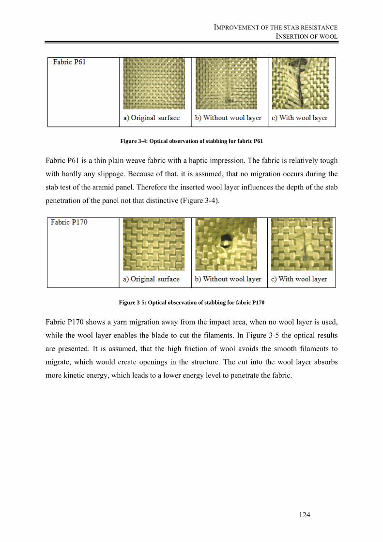
IMPROVEMENT OF THE STAB RESISTANCE INSERTION OF WOOL
124
Figure 3-4: Optical observation of stabbing for fabric P61
Fabric P61 is a thin plain weave fabric with a haptic impression. The fabric is relatively tough
with hardly any slippage. Because of that, it is assumed, that no migration occurs during the
stab test of the aramid panel. Therefore the inserted wool layer influences the depth of the stab
penetration of the panel not that distinctive (Figure 3-4).
Figure 3-5: Optical observation of stabbing for fabric P170
Fabric P170 shows a yarn migration away from the impact area, when no wool layer is used,
while the wool layer enables the blade to cut the filaments. In Figure 3-5 the optical results
are presented. It is assumed, that the high friction of wool avoids the smooth filaments to
migrate, which would create openings in the structure. The cut into the wool layer absorbs
more kinetic energy, which leads to a lower energy level to penetrate the fabric.

IMPROVEMENT OF THE STAB RESISTANCE INSERTION OF WOOL
125
Figure 3-6: Optical observation of stabbing for fabric P230
Also the plain woven fabric P230, presented in Figure 3-6, shows a similar effect of inserting
wool in the panel. While the panel without wool shows effects of migration, but also pull-out
of yarns, in the wool-including panel avoids the migration of the filaments and absorbs more
energy to cut the layers.
Figure 3-7: Optical observation of stabbing for fabric T170
The engaged twill fabrics show a loose woven structure, which leads to a high slippage of
yarns. Figure 3-7 shows the effect of knife penetration, when the filaments are migrating in
the panel without wool. There can be seen a small migration in the wool including panel, but
in this case most of the yarns are cut in this area.
Figure 3-8: Optical observation of stabbing for fabric T230
Also the twill woven fabric T230 shows effects of a high migration of the filaments in the
pure aramid panel, like shown in Figure 3-8. Both twill fabrics show a high yarn slippage in a
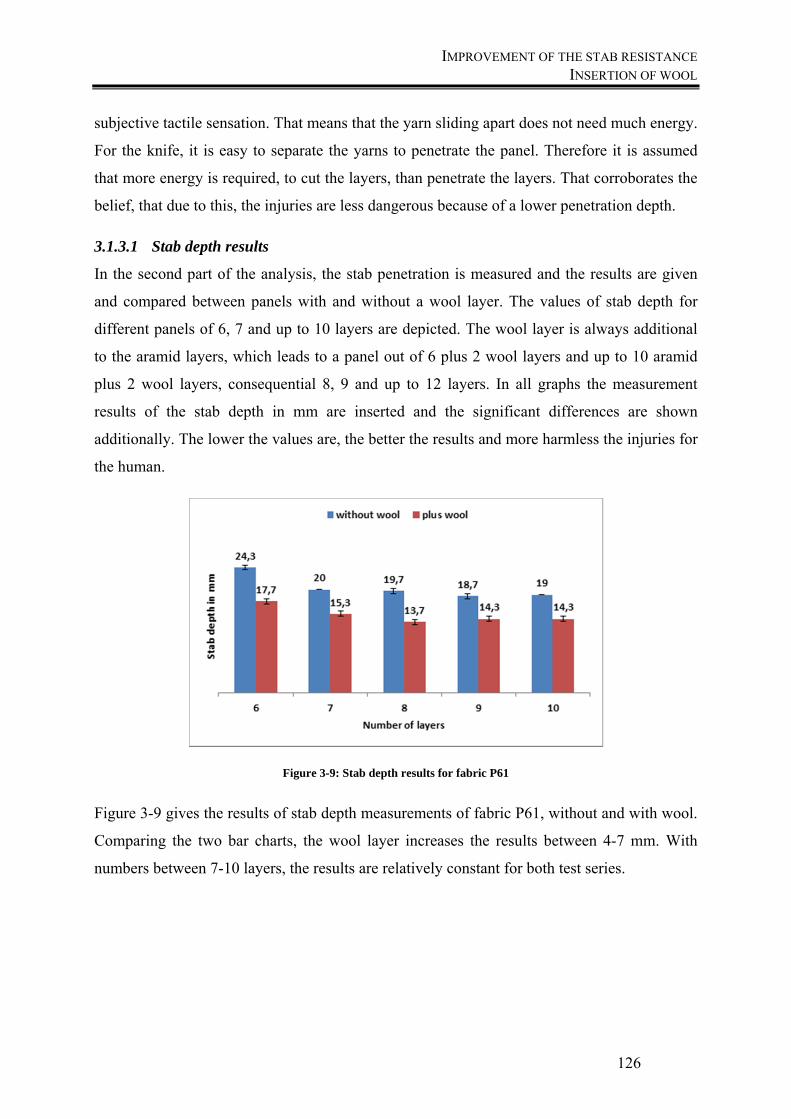
IMPROVEMENT OF THE STAB RESISTANCE INSERTION OF WOOL
126
subjective tactile sensation. That means that the yarn sliding apart does not need much energy.
For the knife, it is easy to separate the yarns to penetrate the panel. Therefore it is assumed
that more energy is required, to cut the layers, than penetrate the layers. That corroborates the
belief, that due to this, the injuries are less dangerous because of a lower penetration depth.
3.1.3.1 Stab depth results
In the second part of the analysis, the stab penetration is measured and the results are given
and compared between panels with and without a wool layer. The values of stab depth for
different panels of 6, 7 and up to 10 layers are depicted. The wool layer is always additional
to the aramid layers, which leads to a panel out of 6 plus 2 wool layers and up to 10 aramid
plus 2 wool layers, consequential 8, 9 and up to 12 layers. In all graphs the measurement
results of the stab depth in mm are inserted and the significant differences are shown
additionally. The lower the values are, the better the results and more harmless the injuries for
the human.
Figure 3-9: Stab depth results for fabric P61
Figure 3-9 gives the results of stab depth measurements of fabric P61, without and with wool.
Comparing the two bar charts, the wool layer increases the results between 4-7 mm. With
numbers between 7-10 layers, the results are relatively constant for both test series.
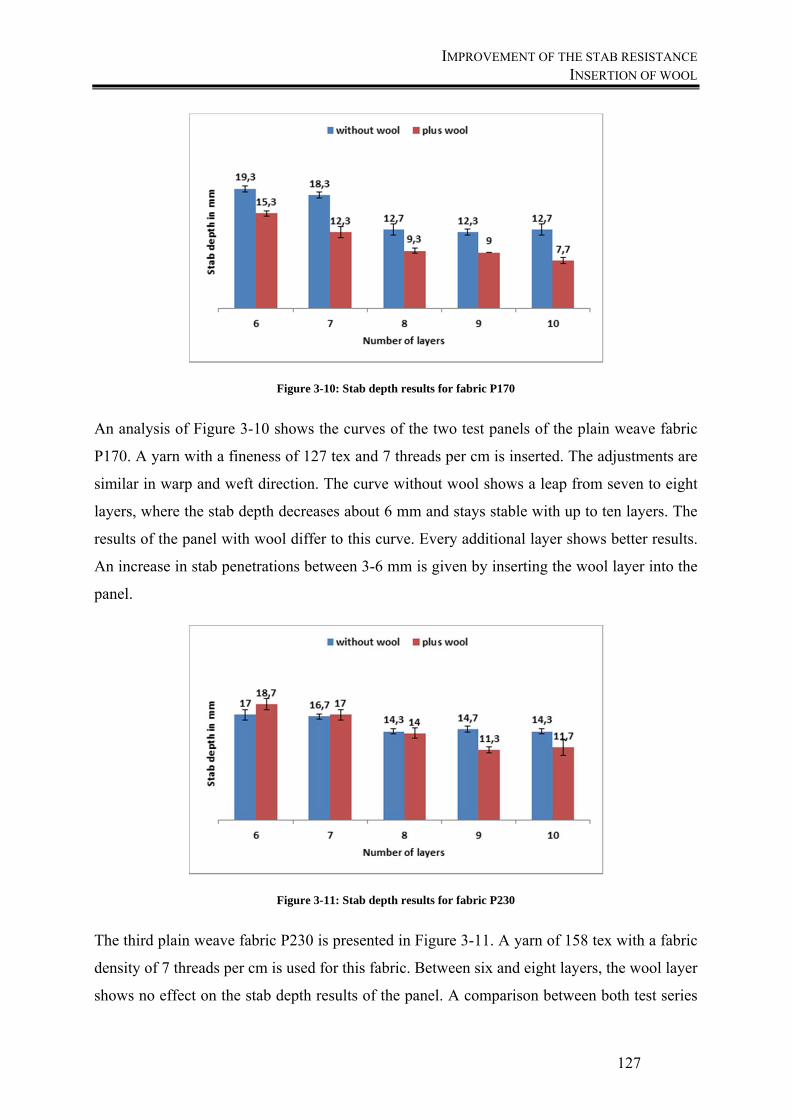
IMPROVEMENT OF THE STAB RESISTANCE INSERTION OF WOOL
127
Figure 3-10: Stab depth results for fabric P170
An analysis of Figure 3-10 shows the curves of the two test panels of the plain weave fabric
P170. A yarn with a fineness of 127 tex and 7 threads per cm is inserted. The adjustments are
similar in warp and weft direction. The curve without wool shows a leap from seven to eight
layers, where the stab depth decreases about 6 mm and stays stable with up to ten layers. The
results of the panel with wool differ to this curve. Every additional layer shows better results.
An increase in stab penetrations between 3-6 mm is given by inserting the wool layer into the
panel.
Figure 3-11: Stab depth results for fabric P230
The third plain weave fabric P230 is presented in Figure 3-11. A yarn of 158 tex with a fabric
density of 7 threads per cm is used for this fabric. Between six and eight layers, the wool layer
shows no effect on the stab depth results of the panel. A comparison between both test series

IMPROVEMENT OF THE STAB RESISTANCE INSERTION OF WOOL
128
shows similar results. The wool starts to influence the stab depth at nine layers and above. A
lower amount of layers show similar results. In comparison to the plain weave fabric P170,
which is designed with the same parameters except for the yarn count, the fabric with the
lower yarn count of 127 tex shows better results in stab resistance than the fabric P230 with
158 tex.
Figure 3-12: Stab depth results for fabric T170
The twill fabric T170, presented in Figure 3-12, shows a significant effect of holding the yarn
in place, caused by inserting the wool layer. All results without wool show stab depths, which
lead to fatal injuries. Inserting wool into this panel leads to excellent results also in a lower
area of layers. The twill fabric T170 and the plain weave fabric P170 are produced with the
same parameters, like yarn count and fabric density, but with a different pattern. The plain
weave panel without wool show significant better results than the twill fabric. By inserting
wool into the panels, the twill is influenced more by the wool and this leads to excellent
results, which are better than the results of the plain weave pattern.
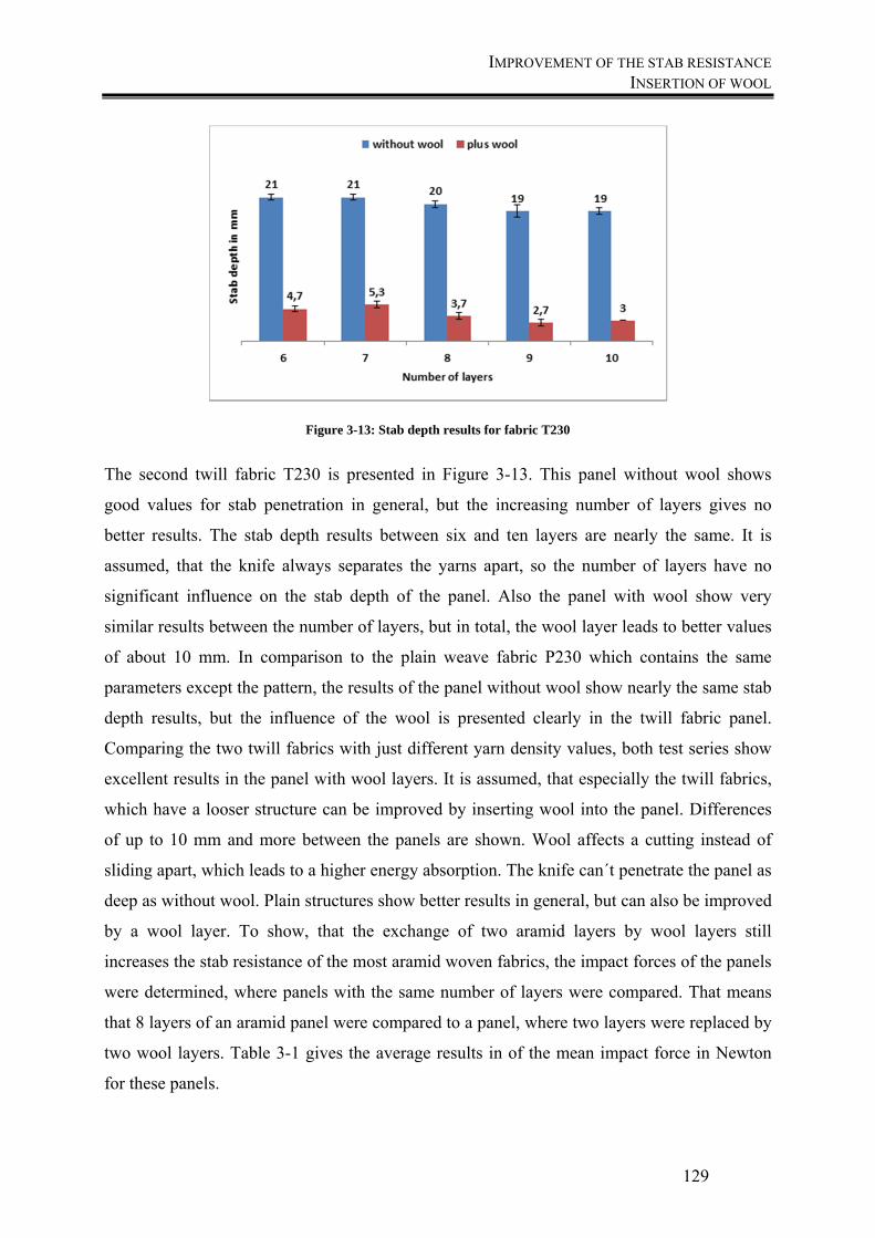
IMPROVEMENT OF THE STAB RESISTANCE INSERTION OF WOOL
129
Figure 3-13: Stab depth results for fabric T230
The second twill fabric T230 is presented in Figure 3-13. This panel without wool shows
good values for stab penetration in general, but the increasing number of layers gives no
better results. The stab depth results between six and ten layers are nearly the same. It is
assumed, that the knife always separates the yarns apart, so the number of layers have no
significant influence on the stab depth of the panel. Also the panel with wool show very
similar results between the number of layers, but in total, the wool layer leads to better values
of about 10 mm. In comparison to the plain weave fabric P230 which contains the same
parameters except the pattern, the results of the panel without wool show nearly the same stab
depth results, but the influence of the wool is presented clearly in the twill fabric panel.
Comparing the two twill fabrics with just different yarn density values, both test series show
excellent results in the panel with wool layers. It is assumed, that especially the twill fabrics,
which have a looser structure can be improved by inserting wool into the panel. Differences
of up to 10 mm and more between the panels are shown. Wool affects a cutting instead of
sliding apart, which leads to a higher energy absorption. The knife can´t penetrate the panel as
deep as without wool. Plain structures show better results in general, but can also be improved
by a wool layer. To show, that the exchange of two aramid layers by wool layers still
increases the stab resistance of the most aramid woven fabrics, the impact forces of the panels
were determined, where panels with the same number of layers were compared. That means
that 8 layers of an aramid panel were compared to a panel, where two layers were replaced by
two wool layers. Table 3-1 gives the average results in of the mean impact force in Newton
for these panels.
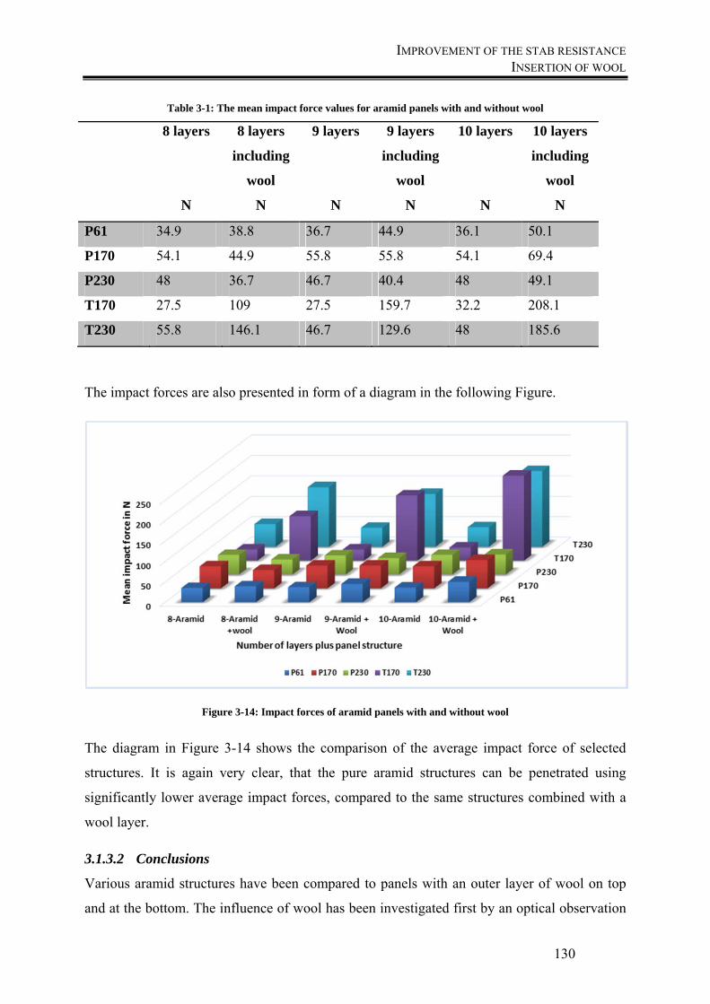
IMPROVEMENT OF THE STAB RESISTANCE INSERTION OF WOOL
130
Table 3-1: The mean impact force values for aramid panels with and without wool
8 layers
N
8 layers
including
wool
N
9 layers
N
9 layers
including
wool
N
10 layers
N
10 layers
including
wool
N
P61 34.9 38.8 36.7 44.9 36.1 50.1
P170 54.1 44.9 55.8 55.8 54.1 69.4
P230 48 36.7 46.7 40.4 48 49.1
T170 27.5 109 27.5 159.7 32.2 208.1
T230 55.8 146.1 46.7 129.6 48 185.6
The impact forces are also presented in form of a diagram in the following Figure.
Figure 3-14: Impact forces of aramid panels with and without wool
The diagram in Figure 3-14 shows the comparison of the average impact force of selected
structures. It is again very clear, that the pure aramid structures can be penetrated using
significantly lower average impact forces, compared to the same structures combined with a
wool layer.
3.1.3.2 Conclusions
Various aramid structures have been compared to panels with an outer layer of wool on top
and at the bottom. The influence of wool has been investigated first by an optical observation
IMPROVEMENT OF THE STAB RESISTANCE DEVELOPMENT OF BLEND YARNS WITH WOOL
131
of the fabric surface. It is shown, that wool prevents the yarn sliding of the below aramid
layer.
Two other assumptions can be derived, analysing the combined structure with the wool fabric.
It seems that the insertion of wool is able to contribute to a stabilization of the aramid fabric,
where it reduces the sliding apart of the filaments during the stab penetration and causes a cut,
which absorbs more energy. Furthermore, it can be assumed that an improvement in the
penetration depth of the blade through the use of wool is achievable mostly at those fabrics
where the threads move very easily and can be displaced, like it can be seen in the twill
structures. This improvement is noticeable only when the wool fabric is used as an outer
protective layer on the aramid layers.
Measuring the stab depth, the twill fabrics show the highest influence of inserting wool into
the panels. The investigation demonstrates that inserting wool into a protection panel can lead
to achieving acceptable stab depth values with fewer layers. This leads to a weight reduction
and improved wear comfort of the soft panels.
3.2 Development of blend yarns with wool
The previous chapter showed the positive influence onto the stab resistance laying a layer of
wool onto the stab resistant panel. To increase the friction coefficient of the fabric itself, wool
will be inserted into the panel. A reason for this consideration is the fact, that the fabric
friction is influenced by the yarn friction, like already mentioned before. Also the yarn
friction is influenced by yarn structural and bulk parameters.
3.2.1 Materials
To find the best combination of aramid and wool blend hollow spindle yarns with the highest
friction coefficient, three yarns with different twists per meter between 50 and 200 planned
twists per meter were produced on a Saurer hollow spindle spinning machine ESP-SM-10,
like presented in Figure 3-15. The core yarn consists out of an aramid yarn with a fineness of
930 dtex and the cover yarn is a wool staple yarn with a fineness of 28.8 tex.
Following parameters are used:
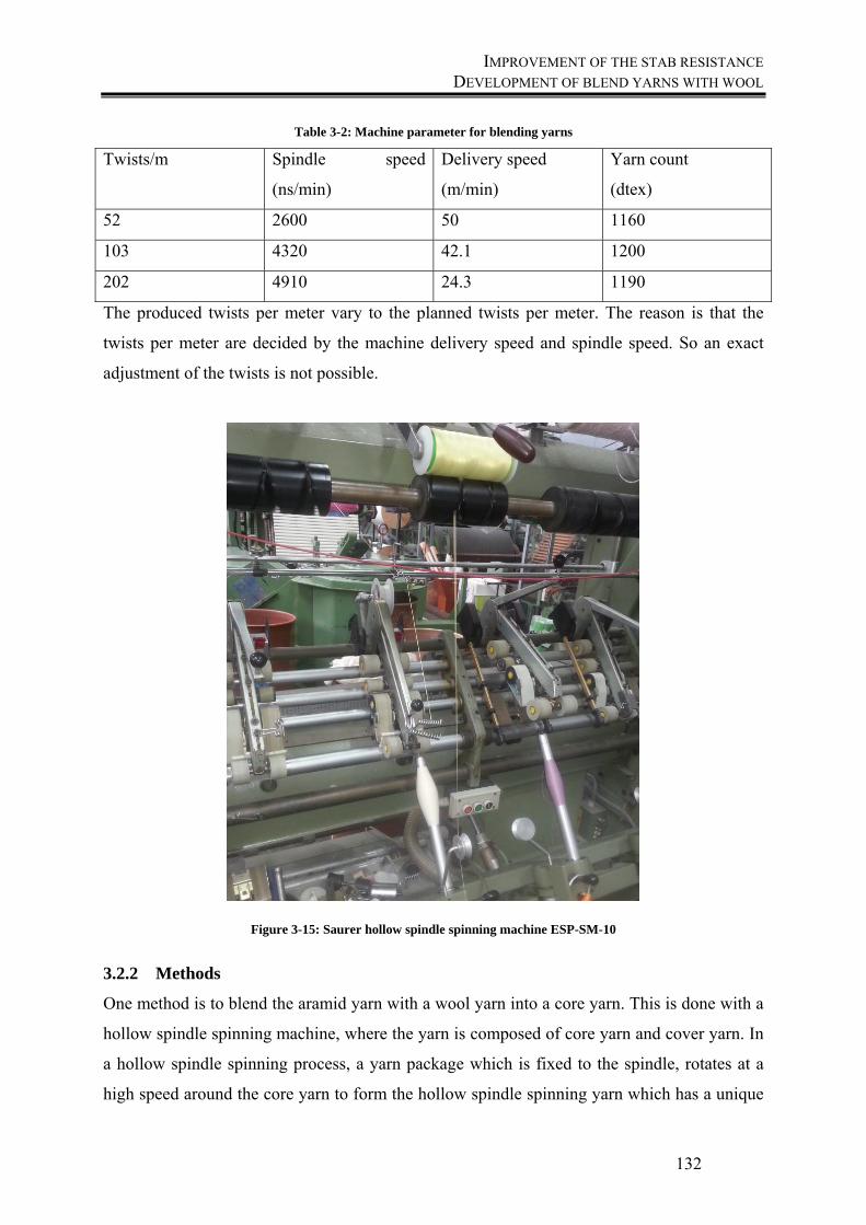
IMPROVEMENT OF THE STAB RESISTANCE DEVELOPMENT OF BLEND YARNS WITH WOOL
132
Table 3-2: Machine parameter for blending yarns
Twists/m Spindle speed
(ns/min)
Delivery speed
(m/min)
Yarn count
(dtex)
52 2600 50 1160
103 4320 42.1 1200
202 4910 24.3 1190
The produced twists per meter vary to the planned twists per meter. The reason is that the
twists per meter are decided by the machine delivery speed and spindle speed. So an exact
adjustment of the twists is not possible.
Figure 3-15: Saurer hollow spindle spinning machine ESP-SM-10
3.2.2 Methods
One method is to blend the aramid yarn with a wool yarn into a core yarn. This is done with a
hollow spindle spinning machine, where the yarn is composed of core yarn and cover yarn. In
a hollow spindle spinning process, a yarn package which is fixed to the spindle, rotates at a
high speed around the core yarn to form the hollow spindle spinning yarn which has a unique

IMPROVEMENT OF THE STAB RESISTANCE DEVELOPMENT OF BLEND YARNS WITH WOOL
133
yarn structure. In this case, aramid filament yarn is used as core yarn, because it provides
excellent tensile and stab resistant properties and a wool yarn as the cover yarn, because of its
high friction, caused by the scales on its surface. Combinations of both provide the favourable
properties of both yarns and modify the structures and properties of both yarns.
3.2.3 Results
3.2.3.1 Friction coefficient measurement
To measure the friction of a yarn, the calculation is done after Euler, who found the
relationship between the forces in a system, where a yarn running over a curved surface and
the frictional force is determined by the angle of contact with the surface and the tension
before and after the side of the contact. The tension on the uptake side is always higher than
on the feed side as the motion of the yarn is resisted by the frictional force:
(19)
and
1ln
(20)
where θ is the angular contact in radians, µ is the coefficient of friction, T1 the output tension
and T2 the input tension. A general way to measure yarn friction is to run it round a solid rod
and measure the friction by using the above relationship. The principle is presented in Figure
3-16.
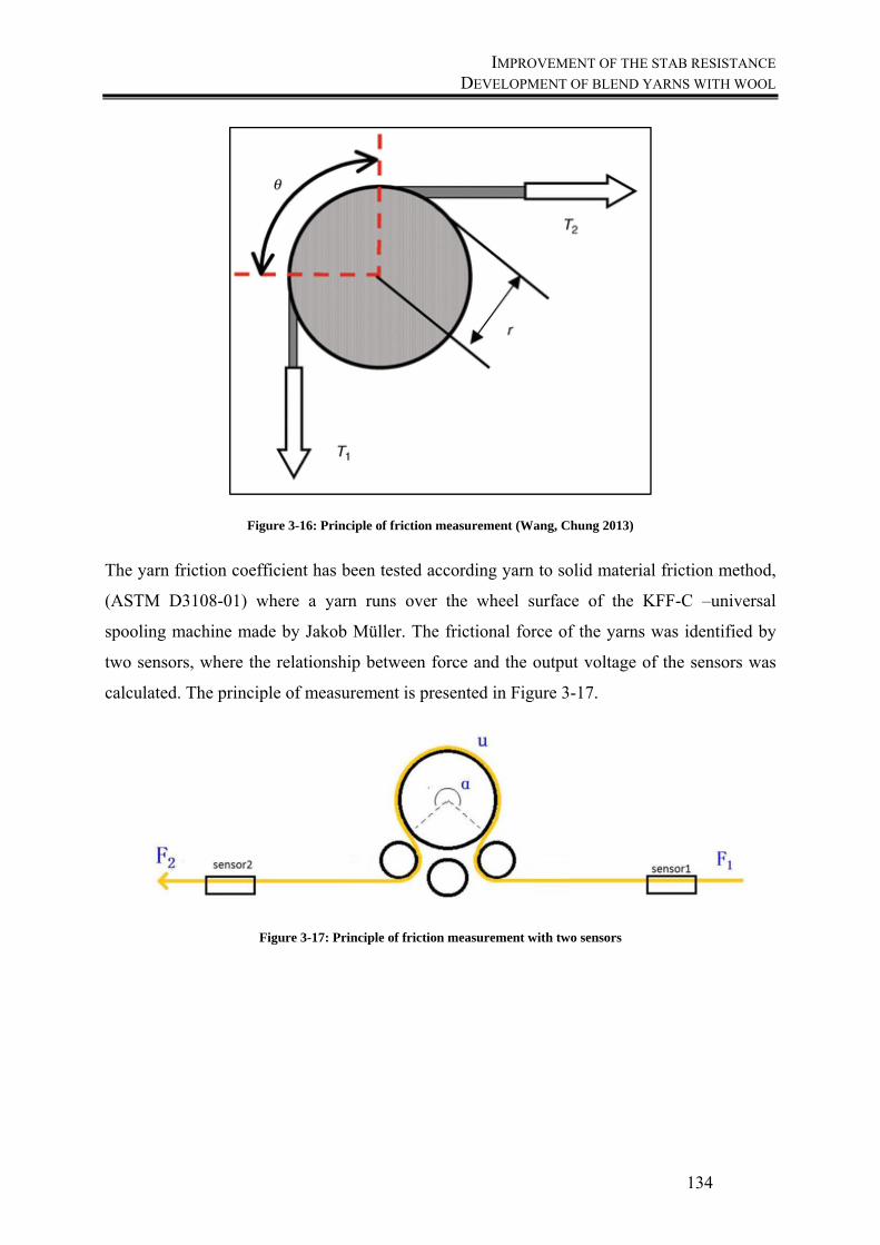
IMPROVEMENT OF THE STAB RESISTANCE DEVELOPMENT OF BLEND YARNS WITH WOOL
134
Figure 3-16: Principle of friction measurement (Wang, Chung 2013)
The yarn friction coefficient has been tested according yarn to solid material friction method,
(ASTM D3108-01) where a yarn runs over the wheel surface of the KFF-C –universal
spooling machine made by Jakob Müller. The frictional force of the yarns was identified by
two sensors, where the relationship between force and the output voltage of the sensors was
calculated. The principle of measurement is presented in Figure 3-17.
Figure 3-17: Principle of friction measurement with two sensors
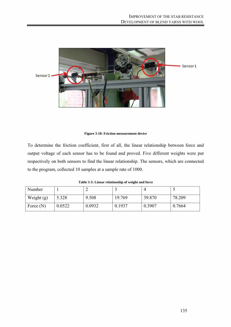
IMPROVEMENT OF THE STAB RESISTANCE DEVELOPMENT OF BLEND YARNS WITH WOOL
135
Figure 3-18: Friction measurement device
To determine the friction coefficient, first of all, the linear relationship between force and
output voltage of each sensor has to be found and proved. Five different weights were put
respectively on both sensors to find the linear relationship. The sensors, which are connected
to the program, collected 10 samples at a sample rate of 1000.
Table 3-3: Linear relationship of weight and force
Number 1 2 3 4 5
Weight (g) 5.328 9.508 19.769 39.870 78.209
Force (N) 0.0522 0.0932 0.1937 0.3907 0.7664
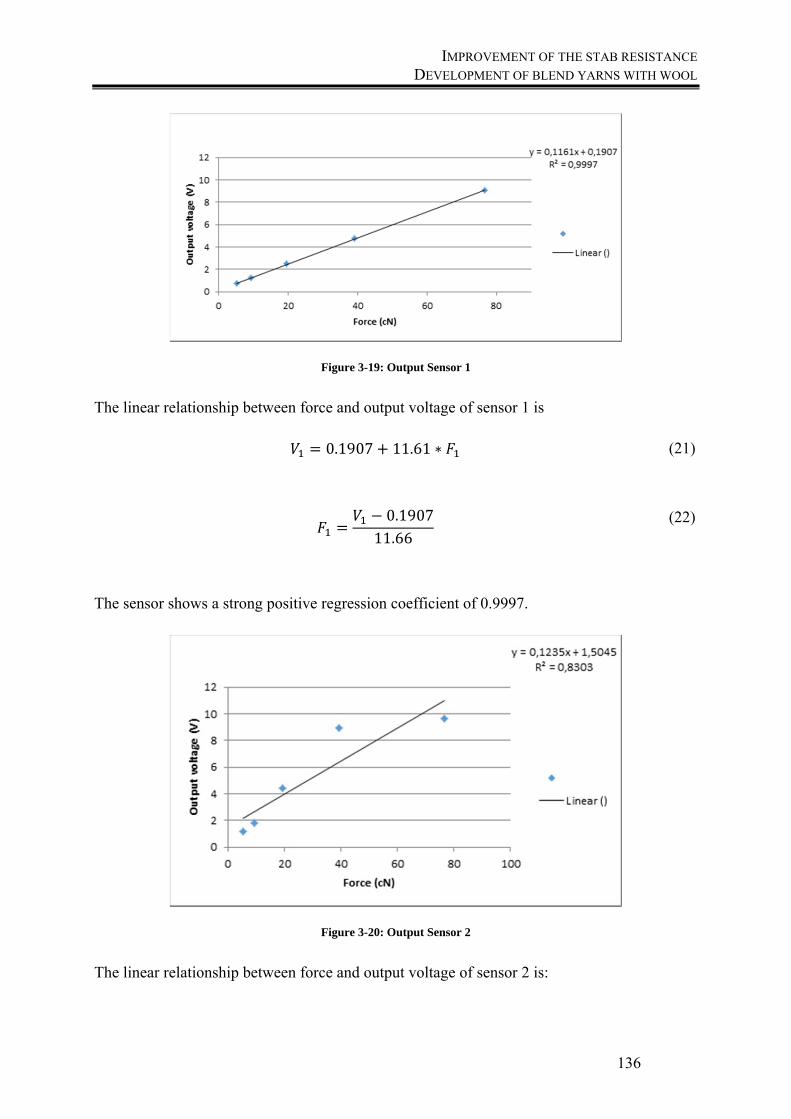
IMPROVEMENT OF THE STAB RESISTANCE DEVELOPMENT OF BLEND YARNS WITH WOOL
136
Figure 3-19: Output Sensor 1
The linear relationship between force and output voltage of sensor 1 is
0.1907 11.61 ∗ (21)
0.190711.66
(22)
The sensor shows a strong positive regression coefficient of 0.9997.
Figure 3-20: Output Sensor 2
The linear relationship between force and output voltage of sensor 2 is:
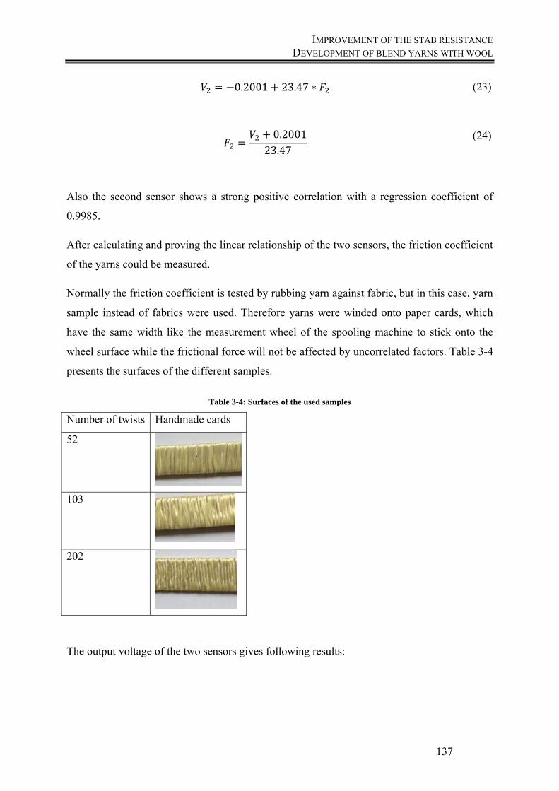
IMPROVEMENT OF THE STAB RESISTANCE DEVELOPMENT OF BLEND YARNS WITH WOOL
137
0.2001 23.47 ∗ (23)
0.200123.47
(24)
Also the second sensor shows a strong positive correlation with a regression coefficient of
0.9985.
After calculating and proving the linear relationship of the two sensors, the friction coefficient
of the yarns could be measured.
Normally the friction coefficient is tested by rubbing yarn against fabric, but in this case, yarn
sample instead of fabrics were used. Therefore yarns were winded onto paper cards, which
have the same width like the measurement wheel of the spooling machine to stick onto the
wheel surface while the frictional force will not be affected by uncorrelated factors. Table 3-4
presents the surfaces of the different samples.
Table 3-4: Surfaces of the used samples
Number of twists Handmade cards
52
103
202
The output voltage of the two sensors gives following results:
IMPROVEMENT OF THE STAB RESISTANCE DEVELOPMENT OF BLEND YARNS WITH WOOL
138
Table 3-5: Output voltage for the test samples
Yarn Fabric V1 V2 sV1 sV2
52 52 0.685138188 8.269455036 0.0627 0.5254
103 103 0.575497035 6.961100691 0.0590 0.4946
202 202 0.628579942 7.314271961 0.0793 0.6221
The force is calculated as mentioned before:
Table 3-6: Calculated force of the test samples
Yarn Fabric F1 F2
52 52 0.075438 0.343816
103 103 0.065995 0.288070
202 202 0.070567 0.303118
Out of these results the friction coefficient of each group can be calculated by using the
presented formula:
1
(25)
The following Figure presents the results of the coefficients of friction for the three yarns. The
yarn with 52 twists show the highest coefficient and resultant of this, the best friction
behaviour with a value of 0.48, but there is no significant difference between the yarns
visible.
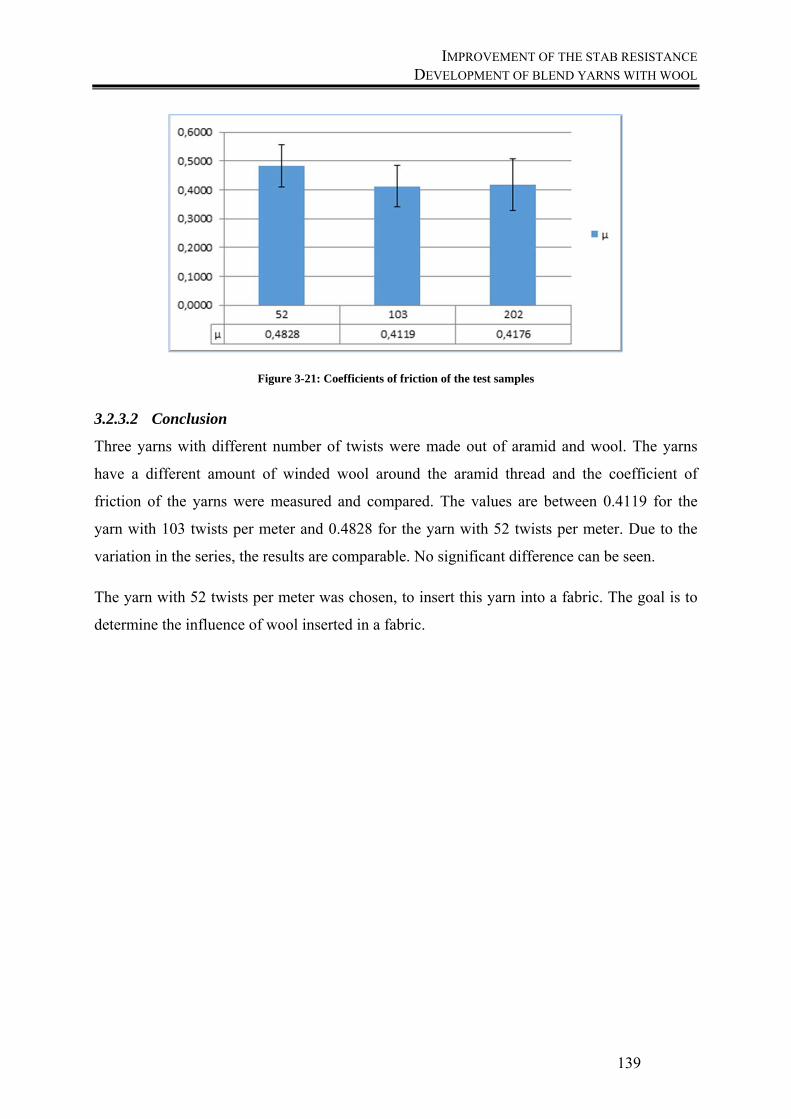
IMPROVEMENT OF THE STAB RESISTANCE DEVELOPMENT OF BLEND YARNS WITH WOOL
139
Figure 3-21: Coefficients of friction of the test samples
3.2.3.2 Conclusion
Three yarns with different number of twists were made out of aramid and wool. The yarns
have a different amount of winded wool around the aramid thread and the coefficient of
friction of the yarns were measured and compared. The values are between 0.4119 for the
yarn with 103 twists per meter and 0.4828 for the yarn with 52 twists per meter. Due to the
variation in the series, the results are comparable. No significant difference can be seen.
The yarn with 52 twists per meter was chosen, to insert this yarn into a fabric. The goal is to
determine the influence of wool inserted in a fabric.
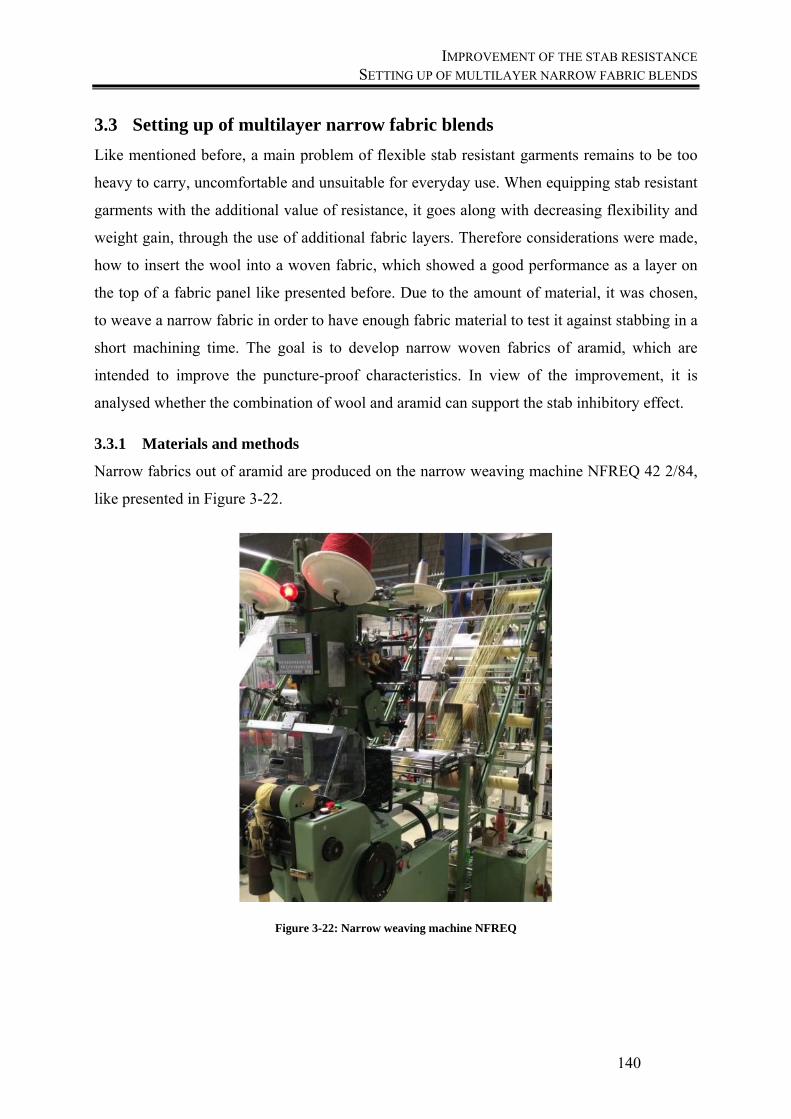
IMPROVEMENT OF THE STAB RESISTANCE SETTING UP OF MULTILAYER NARROW FABRIC BLENDS
140
3.3 Setting up of multilayer narrow fabric blends
Like mentioned before, a main problem of flexible stab resistant garments remains to be too
heavy to carry, uncomfortable and unsuitable for everyday use. When equipping stab resistant
garments with the additional value of resistance, it goes along with decreasing flexibility and
weight gain, through the use of additional fabric layers. Therefore considerations were made,
how to insert the wool into a woven fabric, which showed a good performance as a layer on
the top of a fabric panel like presented before. Due to the amount of material, it was chosen,
to weave a narrow fabric in order to have enough fabric material to test it against stabbing in a
short machining time. The goal is to develop narrow woven fabrics of aramid, which are
intended to improve the puncture-proof characteristics. In view of the improvement, it is
analysed whether the combination of wool and aramid can support the stab inhibitory effect.
3.3.1 Materials and methods
Narrow fabrics out of aramid are produced on the narrow weaving machine NFREQ 42 2/84,
like presented in Figure 3-22.
Figure 3-22: Narrow weaving machine NFREQ
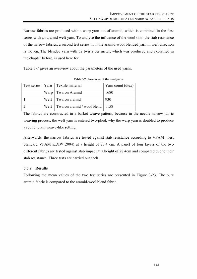
IMPROVEMENT OF THE STAB RESISTANCE SETTING UP OF MULTILAYER NARROW FABRIC BLENDS
141
Narrow fabrics are produced with a warp yarn out of aramid, which is combined in the first
series with an aramid weft yarn. To analyse the influence of the wool onto the stab resistance
of the narrow fabrics, a second test series with the aramid-wool blended yarn in weft direction
is woven. The blended yarn with 52 twists per meter, which was produced and explained in
the chapter before, is used here for.
Table 3-7 gives an overview about the parameters of the used yarns.
Table 3-7: Parameter of the used yarns
Test series Yarn Textile material Yarn count (dtex)
Warp Twaron Aramid 1680
1 Weft Twaron aramid 930
2 Weft Twaron aramid / wool blend 1158
The fabrics are constructed in a basket weave pattern, because in the needle-narrow fabric
weaving process, the weft yarn is entered two-plied, why the warp yarn is doubled to produce
a round, plain weave-like setting.
Afterwards, the narrow fabrics are tested against stab resistance according to VPAM (Test
Standard VPAM KDIW 2004) at a height of 28.4 cm. A panel of four layers of the two
different fabrics are tested against stab impact at a height of 28.4cm and compared due to their
stab resistance. Three tests are carried out each.
3.3.2 Results
Following the mean values of the two test series are presented in Figure 3-23. The pure
aramid fabric is compared to the aramid-wool blend fabric.
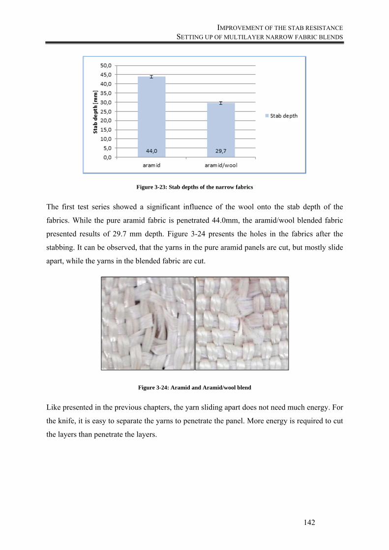
IMPROVEMENT OF THE STAB RESISTANCE SETTING UP OF MULTILAYER NARROW FABRIC BLENDS
142
Figure 3-23: Stab depths of the narrow fabrics
The first test series showed a significant influence of the wool onto the stab depth of the
fabrics. While the pure aramid fabric is penetrated 44.0mm, the aramid/wool blended fabric
presented results of 29.7 mm depth. Figure 3-24 presents the holes in the fabrics after the
stabbing. It can be observed, that the yarns in the pure aramid panels are cut, but mostly slide
apart, while the yarns in the blended fabric are cut.
Figure 3-24: Aramid and Aramid/wool blend
Like presented in the previous chapters, the yarn sliding apart does not need much energy. For
the knife, it is easy to separate the yarns to penetrate the panel. More energy is required to cut
the layers than penetrate the layers.
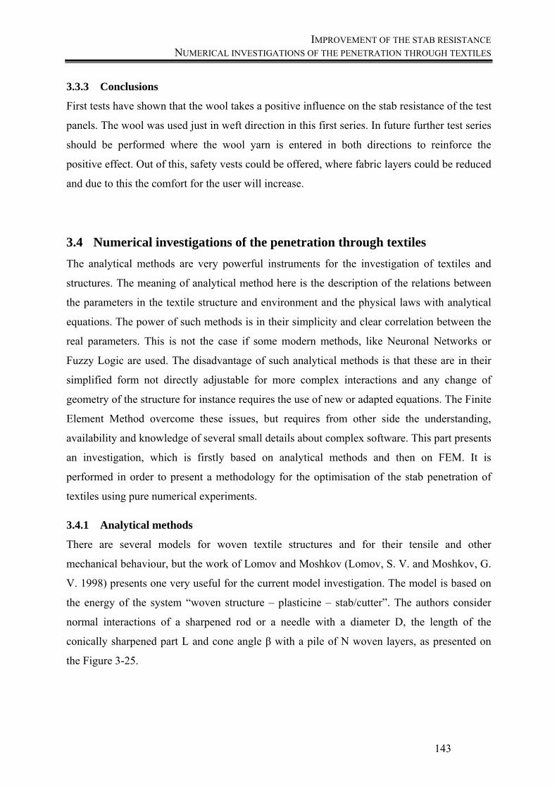
IMPROVEMENT OF THE STAB RESISTANCE NUMERICAL INVESTIGATIONS OF THE PENETRATION THROUGH TEXTILES
143
3.3.3 Conclusions
First tests have shown that the wool takes a positive influence on the stab resistance of the test
panels. The wool was used just in weft direction in this first series. In future further test series
should be performed where the wool yarn is entered in both directions to reinforce the
positive effect. Out of this, safety vests could be offered, where fabric layers could be reduced
and due to this the comfort for the user will increase.
3.4 Numerical investigations of the penetration through textiles
The analytical methods are very powerful instruments for the investigation of textiles and
structures. The meaning of analytical method here is the description of the relations between
the parameters in the textile structure and environment and the physical laws with analytical
equations. The power of such methods is in their simplicity and clear correlation between the
real parameters. This is not the case if some modern methods, like Neuronal Networks or
Fuzzy Logic are used. The disadvantage of such analytical methods is that these are in their
simplified form not directly adjustable for more complex interactions and any change of
geometry of the structure for instance requires the use of new or adapted equations. The Finite
Element Method overcome these issues, but requires from other side the understanding,
availability and knowledge of several small details about complex software. This part presents
an investigation, which is firstly based on analytical methods and then on FEM. It is
performed in order to present a methodology for the optimisation of the stab penetration of
textiles using pure numerical experiments.
3.4.1 Analytical methods
There are several models for woven textile structures and for their tensile and other
mechanical behaviour, but the work of Lomov and Moshkov (Lomov, S. V. and Moshkov, G.
V. 1998) presents one very useful for the current model investigation. The model is based on
the energy of the system “woven structure – plasticine – stab/cutter”. The authors consider
normal interactions of a sharpened rod or a needle with a diameter D, the length of the
conically sharpened part L and cone angle β with a pile of N woven layers, as presented on
the Figure 3-25.
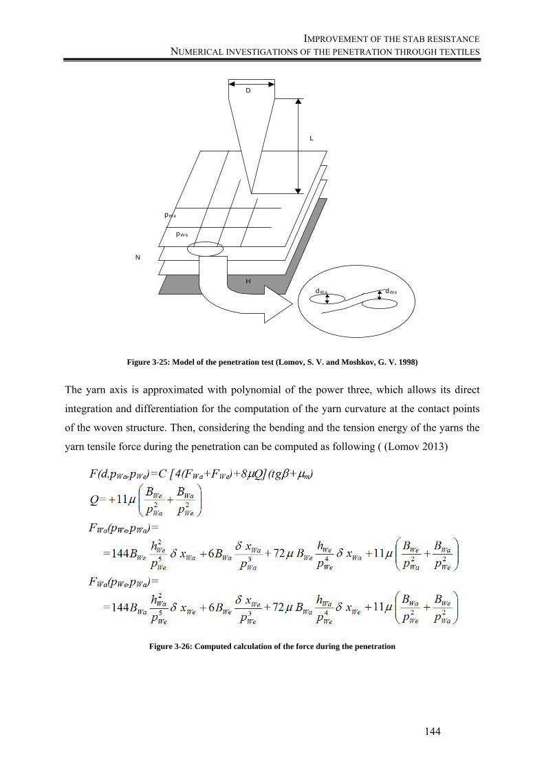
IMPROVEMENT OF THE STAB RESISTANCE NUMERICAL INVESTIGATIONS OF THE PENETRATION THROUGH TEXTILES
144
D
L
N
pW e
pW a
H
dW edW a
D
Figure 3-25: Model of the penetration test (Lomov, S. V. and Moshkov, G. V. 1998)
The yarn axis is approximated with polynomial of the power three, which allows its direct
integration and differentiation for the computation of the yarn curvature at the contact points
of the woven structure. Then, considering the bending and the tension energy of the yarns the
yarn tensile force during the penetration can be computed as following ( (Lomov 2013)
Figure 3-26: Computed calculation of the force during the penetration
IMPROVEMENT OF THE STAB RESISTANCE NUMERICAL INVESTIGATIONS OF THE PENETRATION THROUGH TEXTILES
145
Here the subscripts Wa and We denote the warp and weft yarns, B the bending rigidity, p – the
density in pics per dm and µ the friction coefficient.
The resistance of backing is then computed as following
4/)( 2 tgNbxHxFb (26)
And the energy equation becomes
JdxxFxFq
bp 0
(27)
Where q is the total penetration of the needle through a set of N layers of the same structure
with thickness L. This equation can be solved numerically and the penetration depth is
calculated until the state, where the complete energy of the falling cone is dissipated from the
bending and friction forces. If the penetration depth is higher than the L, then a complete
penetration is stated.
Software implementation of this procedure should be available for older computers (running
DOS) and names as program IMPACT, but this was not more executable under the current
Windows computers. For performing the calculations, a Matlab Script was written within the
FreeMat environment, which is an open source alternative of Matlab® 1.
The calculation as example gives results as following:
1 Matlab is a trade mark of Math Works Inc
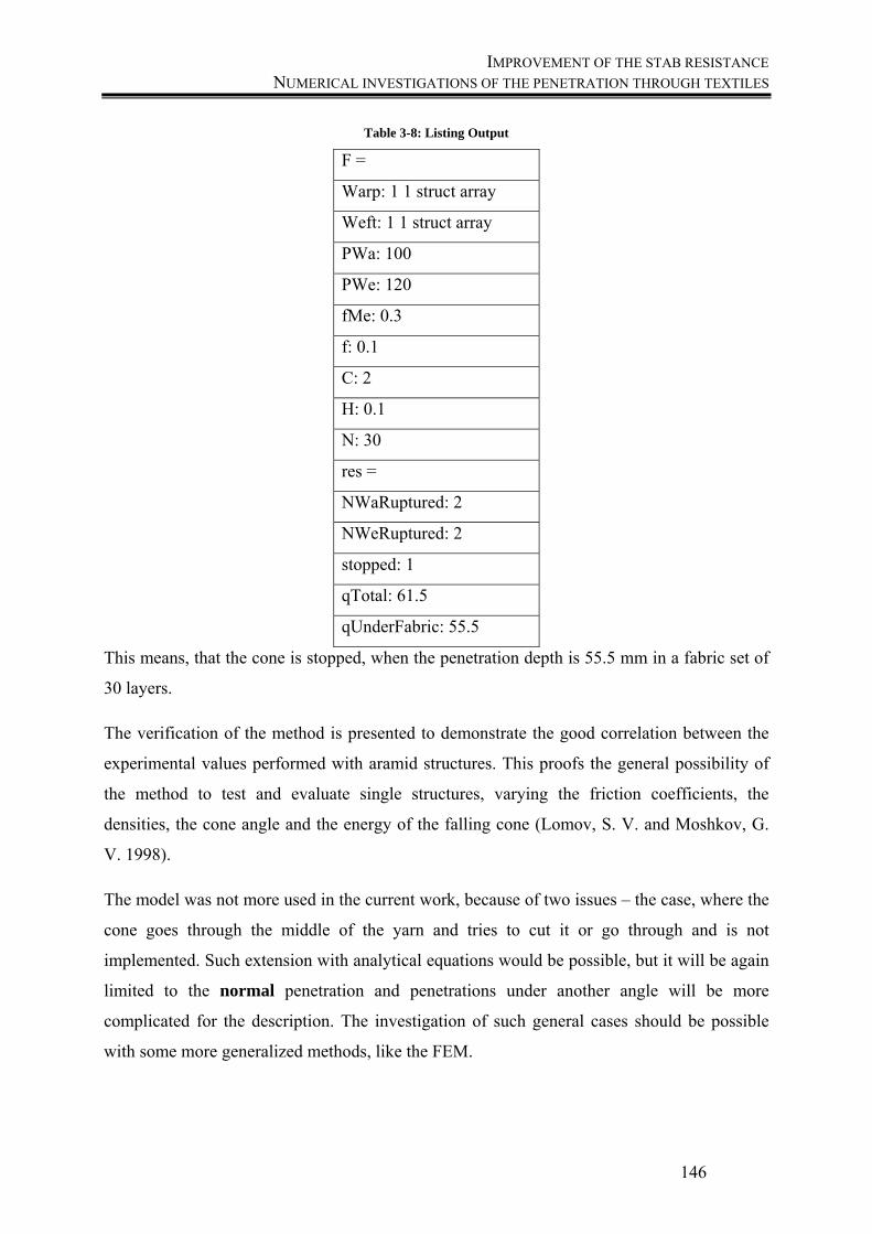
IMPROVEMENT OF THE STAB RESISTANCE NUMERICAL INVESTIGATIONS OF THE PENETRATION THROUGH TEXTILES
146
Table 3-8: Listing Output
F =
Warp: 1 1 struct array
Weft: 1 1 struct array
PWa: 100
PWe: 120
fMe: 0.3
f: 0.1
C: 2
H: 0.1
N: 30
res =
NWaRuptured: 2
NWeRuptured: 2
stopped: 1
qTotal: 61.5
qUnderFabric: 55.5
This means, that the cone is stopped, when the penetration depth is 55.5 mm in a fabric set of
30 layers.
The verification of the method is presented to demonstrate the good correlation between the
experimental values performed with aramid structures. This proofs the general possibility of
the method to test and evaluate single structures, varying the friction coefficients, the
densities, the cone angle and the energy of the falling cone (Lomov, S. V. and Moshkov, G.
V. 1998).
The model was not more used in the current work, because of two issues – the case, where the
cone goes through the middle of the yarn and tries to cut it or go through and is not
implemented. Such extension with analytical equations would be possible, but it will be again
limited to the normal penetration and penetrations under another angle will be more
complicated for the description. The investigation of such general cases should be possible
with some more generalized methods, like the FEM.
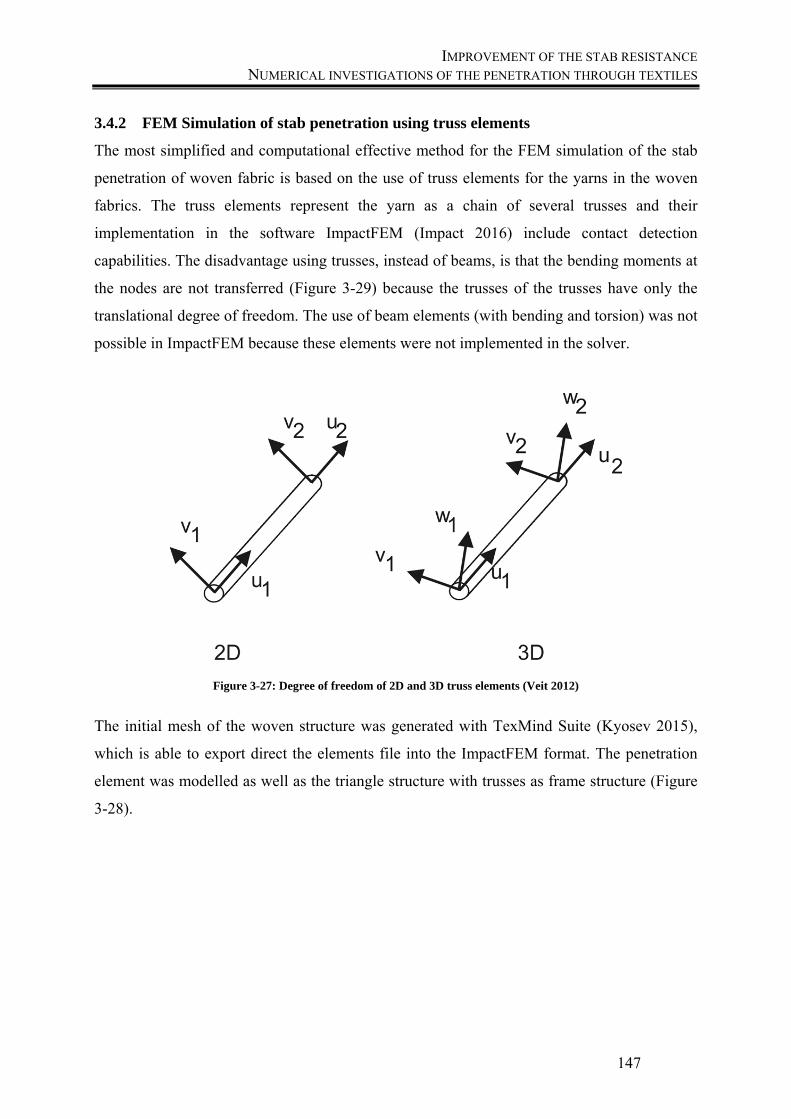
IMPROVEMENT OF THE STAB RESISTANCE NUMERICAL INVESTIGATIONS OF THE PENETRATION THROUGH TEXTILES
147
3.4.2 FEM Simulation of stab penetration using truss elements
The most simplified and computational effective method for the FEM simulation of the stab
penetration of woven fabric is based on the use of truss elements for the yarns in the woven
fabrics. The truss elements represent the yarn as a chain of several trusses and their
implementation in the software ImpactFEM (Impact 2016) include contact detection
capabilities. The disadvantage using trusses, instead of beams, is that the bending moments at
the nodes are not transferred (Figure 3-29) because the trusses of the trusses have only the
translational degree of freedom. The use of beam elements (with bending and torsion) was not
possible in ImpactFEM because these elements were not implemented in the solver.
Figure 3-27: Degree of freedom of 2D and 3D truss elements (Veit 2012)
The initial mesh of the woven structure was generated with TexMind Suite (Kyosev 2015),
which is able to export direct the elements file into the ImpactFEM format. The penetration
element was modelled as well as the triangle structure with trusses as frame structure (Figure
3-28).
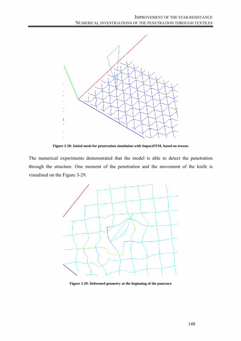
IMPROVEMENT OF THE STAB RESISTANCE NUMERICAL INVESTIGATIONS OF THE PENETRATION THROUGH TEXTILES
148
Figure 3-28: Initial mesh for penetration simulation with ImpactFEM, based on trusses
The numerical experiments demonstrated that the model is able to detect the penetration
through the structure. One moment of the penetration and the movement of the knife is
visualised on the Figure 3-29.
Figure 3-29: Deformed geometry at the beginning of the puncture
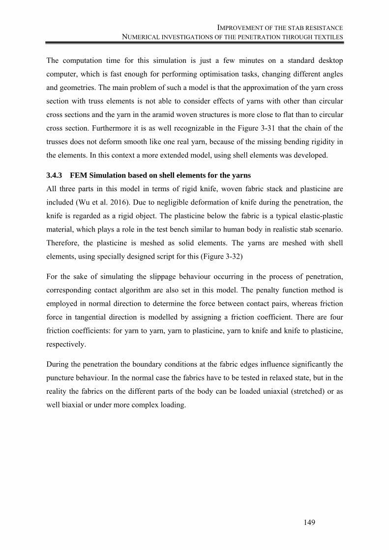
IMPROVEMENT OF THE STAB RESISTANCE NUMERICAL INVESTIGATIONS OF THE PENETRATION THROUGH TEXTILES
149
The computation time for this simulation is just a few minutes on a standard desktop
computer, which is fast enough for performing optimisation tasks, changing different angles
and geometries. The main problem of such a model is that the approximation of the yarn cross
section with truss elements is not able to consider effects of yarns with other than circular
cross sections and the yarn in the aramid woven structures is more close to flat than to circular
cross section. Furthermore it is as well recognizable in the Figure 3-31 that the chain of the
trusses does not deform smooth like one real yarn, because of the missing bending rigidity in
the elements. In this context a more extended model, using shell elements was developed.
3.4.3 FEM Simulation based on shell elements for the yarns
All three parts in this model in terms of rigid knife, woven fabric stack and plasticine are
included (Wu et al. 2016). Due to negligible deformation of knife during the penetration, the
knife is regarded as a rigid object. The plasticine below the fabric is a typical elastic-plastic
material, which plays a role in the test bench similar to human body in realistic stab scenario.
Therefore, the plasticine is meshed as solid elements. The yarns are meshed with shell
elements, using specially designed script for this (Figure 3-32)
For the sake of simulating the slippage behaviour occurring in the process of penetration,
corresponding contact algorithm are also set in this model. The penalty function method is
employed in normal direction to determine the force between contact pairs, whereas friction
force in tangential direction is modelled by assigning a friction coefficient. There are four
friction coefficients: for yarn to yarn, yarn to plasticine, yarn to knife and knife to plasticine,
respectively.
During the penetration the boundary conditions at the fabric edges influence significantly the
puncture behaviour. In the normal case the fabrics have to be tested in relaxed state, but in the
reality the fabrics on the different parts of the body can be loaded uniaxial (stretched) or as
well biaxial or under more complex loading.

IMPROVEMENT OF THE STAB RESISTANCE NUMERICAL INVESTIGATIONS OF THE PENETRATION THROUGH TEXTILES
150
Figure 3-30: The geometry model of a plain woven fabric
The first simulation results demonstrate that the chosen approach – using truss elements with
contact and friction capabilities and explicit simulation schema- is able to simulate the
puncture behaviour of the fabrics. Due to the low number of elements in the model it is
computationally efficient and allows performing several simulation cases per hour, which
gives the potential to be used within optimization loops or for performing full sets of designed
experiments. The movement of the yarns is similar to the observations in practical tests, but
the correct element size has to be investigated, in order to minimize the jumps in the forces
and movements of the yarns and resultant of that a nearly smooth behaviour to be observed.
The currently used large element size leads to fast and stable contact detection, but leads to
large changes of the forces. As the next step the simulation was verified.
Therefore the argument process is organized as following sequence: A <= B <= C <= D <= E,
where number A presents the penetration depth - a criterion for the response of knife stabbing.
B is the deformation area in the clay and C is the effect of fabric on the deformation area of
the clay. D explains the difference between a blunt and a sharp object. Unlike the blunt object
puncturing where the primary yarn is pushed by the blunt object, the knife stabbing includes a
penetrating process that the sharp tip of knife get through the fabric in an easy manner.
However, the increasing body of knife will push the yarn to forming a larger hole for
penetrating. Number E defines two different behaviours on the contact between the knife and
fabric. The first is the pressure force in the normal direction. The second is exerting force to
push yarn aside. The friction force which is determined by the pressure force and friction
coefficient between the contact pairs will resist the slippage movement of yarn in fabric,
which restrain the hole and consequently larger area is induced, the smaller depth is achieved.
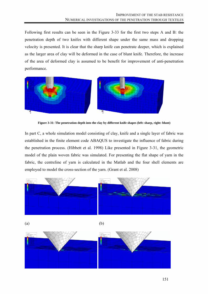
IMPROVEMENT OF THE STAB RESISTANCE NUMERICAL INVESTIGATIONS OF THE PENETRATION THROUGH TEXTILES
151
Following first results can be seen in the Figure 3-33 for the first two steps A and B: the
penetration depth of two knifes with different shape under the same mass and dropping
velocity is presented. It is clear that the sharp knife can penetrate deeper, which is explained
as the larger area of clay will be deformed in the case of blunt knife. Therefore, the increase
of the area of deformed clay is assumed to be benefit for improvement of anti-penetration
performance.
Figure 3-31: The penetration depth into the clay by different knife shapes (left: sharp, right: blunt)
In part C, a whole simulation model consisting of clay, knife and a single layer of fabric was
established in the finite element code ABAQUS to investigate the influence of fabric during
the penetration process. (Hibbett et al. 1998) Like presented in Figure 3-31, the geometric
model of the plain woven fabric was simulated. For presenting the flat shape of yarn in the
fabric, the centreline of yarn is calculated in the Matlab and the four shell elements are
employed to model the cross-section of the yarn. (Grant et al. 2008)
(a) (b)
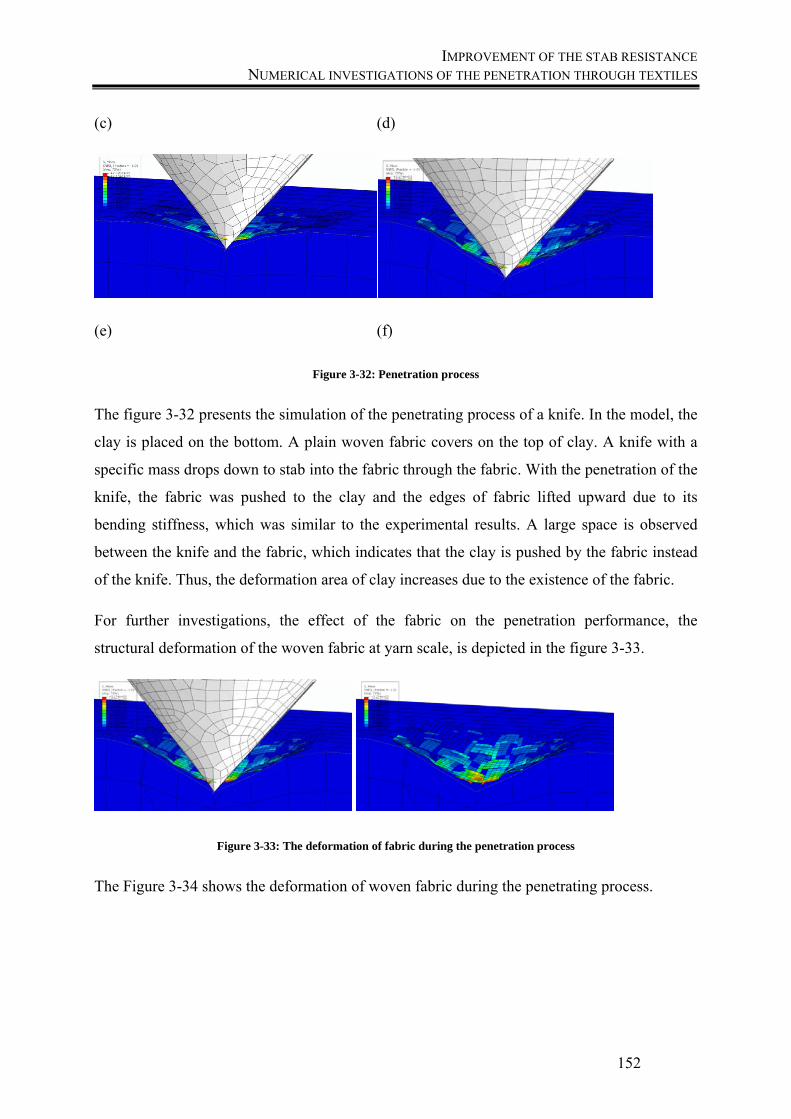
IMPROVEMENT OF THE STAB RESISTANCE NUMERICAL INVESTIGATIONS OF THE PENETRATION THROUGH TEXTILES
152
(c) (d)
(e) (f)
Figure 3-32: Penetration process
The figure 3-32 presents the simulation of the penetrating process of a knife. In the model, the
clay is placed on the bottom. A plain woven fabric covers on the top of clay. A knife with a
specific mass drops down to stab into the fabric through the fabric. With the penetration of the
knife, the fabric was pushed to the clay and the edges of fabric lifted upward due to its
bending stiffness, which was similar to the experimental results. A large space is observed
between the knife and the fabric, which indicates that the clay is pushed by the fabric instead
of the knife. Thus, the deformation area of clay increases due to the existence of the fabric.
For further investigations, the effect of the fabric on the penetration performance, the
structural deformation of the woven fabric at yarn scale, is depicted in the figure 3-33.
Figure 3-33: The deformation of fabric during the penetration process
The Figure 3-34 shows the deformation of woven fabric during the penetrating process.
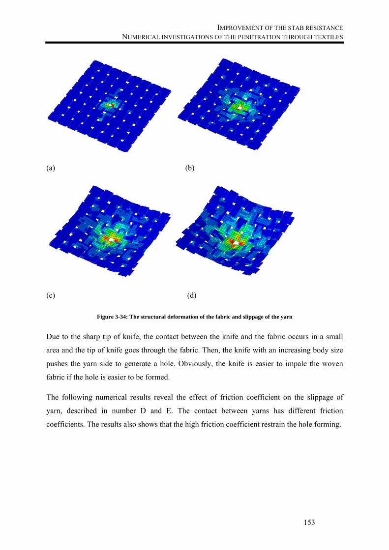
IMPROVEMENT OF THE STAB RESISTANCE NUMERICAL INVESTIGATIONS OF THE PENETRATION THROUGH TEXTILES
153
(a) (b)
(c) (d)
Figure 3-34: The structural deformation of the fabric and slippage of the yarn
Due to the sharp tip of knife, the contact between the knife and the fabric occurs in a small
area and the tip of knife goes through the fabric. Then, the knife with an increasing body size
pushes the yarn side to generate a hole. Obviously, the knife is easier to impale the woven
fabric if the hole is easier to be formed.
The following numerical results reveal the effect of friction coefficient on the slippage of
yarn, described in number D and E. The contact between yarns has different friction
coefficients. The results also shows that the high friction coefficient restrain the hole forming.
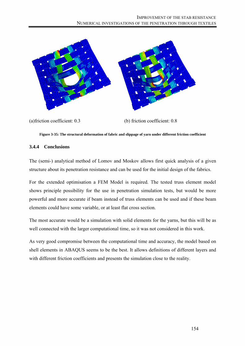
IMPROVEMENT OF THE STAB RESISTANCE NUMERICAL INVESTIGATIONS OF THE PENETRATION THROUGH TEXTILES
154
(a)friction coefficient: 0.3 (b) friction coefficient: 0.8
Figure 3-35: The structural deformation of fabric and slippage of yarn under different friction coefficient
3.4.4 Conclusions
The (semi-) analytical method of Lomov and Moskov allows first quick analysis of a given
structure about its penetration resistance and can be used for the initial design of the fabrics.
For the extended optimisation a FEM Model is required. The tested truss element model
shows principle possibility for the use in penetration simulation tests, but would be more
powerful and more accurate if beam instead of truss elements can be used and if these beam
elements could have some variable, or at least flat cross section.
The most accurate would be a simulation with solid elements for the yarns, but this will be as
well connected with the larger computational time, so it was not considered in this work.
As very good compromise between the computational time and accuracy, the model based on
shell elements in ABAQUS seems to be the best. It allows definitions of different layers and
with different friction coefficients and presents the simulation close to the reality.

CONCLUSIONS AND
FUTURE WORK
CONCLUSIONS NUMERICAL INVESTIGATIONS OF THE PENETRATION THROUGH TEXTILES
156
4 Conclusions The research goal of this thesis was to examine various aramid fabrics with regard to their
stabbing behaviour and to find influencing factors to this. An attack can only be inhibited, but
an injury cannot be completely prevented. The goal is always to absorb as much energy as
possible, so that the penetration is thus reduced and the risk of injury decreases. The stab
mechanism is a complex and variable process. The review showed the demand on research in
this area, because the most solutions involve hard body armour parts in combination with
fibrous materials. This material combinations show many disadvantages with regards to the
high weight and the missing flexibility. Other researchers also recommend textile solutions,
(Horsfall 2012) because they are flexible and in the field of ballistic panels they are already
used. The investigations carried out within this thesis are done to contribute to the
development of pure textile stab-resistant panels. Therefore the interdependencies between the
physical properties of the material but also the mechanism during a stab attack have to be
recognized, to develop higher protection levels. It was shown, that the multitude of factors
causes the problem to define a level of protection. For example, the high kinetic energies are
not always critical. A needle bends for example during a fast penetration while it perforates
the fabric at a slow penetration level.
General investigations were done to analyse the test parameters, which are defined in the test
standard but also this one, which are missing. It was shown, that the blade can be used several
times, without tearing and resultant of this, influencing the test results. The measurement
results did not change significantly after a test series of thirty tests, why every knife was used
for a maximum ten times in all test series. Also the not defined pretension during the stab tests
was analysed. It was demonstrated, that the pretension has no influence on the stab depth but
on the trauma size and volume. Even if the stab depth is not significant different, a pretension
on the test samples prevents an additional trauma effect. In this context a new method to
determine the stab depth was developed, which allows the analysis of the depth of the knife
during the impact, but additional to this, the trauma volume and depth and the deformed fabric
layer was fixed stable for further analyses like the measurement or the comparison with
simulation results. Also the sample size is not defined in the standard for fabric samples,
because just ready-made safety vests are tested. It was found that there are no differences
between sample sizes of 15 by 15cm up to 30 by 30cm. In order to obtain comparable and

CONCLUSIONS NUMERICAL INVESTIGATIONS OF THE PENETRATION THROUGH TEXTILES
157
reproducible results, the number of measurements was fixed to three and the sample size to 20
by 20 cm.
Based on the experiments carried out it can be said for all fabric types, that there is a direct
correlation between the number of tested layers and their stab inhibitory effect. With
increasing number of layers, the penetration depth of the blade will decrease. However, since
it does not make sense in terms of wearing comfort and the flexibility, to increase the number
of layers of fabric for stab resistant garments to an unlimited level, further properties which
lead to improved puncture resistance have to be analysed and taken into account.
The influence of impact energy onto the stab depths was analysed, why the stab heights were
varied between 4.5 joules and 9 joules, to find out differences between the patterns. It can be
said, that the stab depths increase linear to the increasing impact energies and also it is
noticeable that the number of layers has a higher influence when using lower impact energies.
Next step was to analyse the influence of the number of layers. For all different fabric types,
panels between six and ten layers were used, but it can be said, that the number of layers gives
no significant trends of stab depths. In practice, panels out of 35-40 layers are taken to give a
sufficient protection against injuries caused by a stab attack, what could be a reason for the
similar results of the panels.
A further study was carried out to evaluate the influence of the construction parameters of the
different fabrics, like mass per unit area and thickness. A comparison of the plain weave
fabrics presented, that the stab depth decreases with increasing of the mass per unit area.
Interestingly, the two twill fabrics show similar results, so that depending on the number of
layers sometimes the lighter performs better, sometimes the heavier and thicker twill fabric
was better. An identical behaviour during the stabbing process can be noticed for both fabrics.
Only partly individual filaments are cut in all fabrics while the mechanisms of displacement
could be seen, where the blade causes larger holes. The twill fabrics show much more
displacement due to the loose structure of the fabrics and have a poor stitch inhibitory effect.
They allow a relatively high penetration depth and also strong displacement effects in the
puncture area of the blade.
In the next series of trials, the influence of pattern was analysed of the different fabric types
with the same mass per unit area weight. Based on the performed tests it can be assumed that
the construction parameters of aramid fabrics present a significant influence on the stab
CONCLUSIONS NUMERICAL INVESTIGATIONS OF THE PENETRATION THROUGH TEXTILES
158
inhibitory effect. The individual fabric types allow very different penetration depths of the
blade. All three plain weave structures show a better application possibility than the twill
pattern and the heavier fabrics showed a better stab resistance. The two different twills do not
significantly show differences in the measured penetration depth.
Following, the properties, which influence the yarn migration were analysed and compared, to
define how to measure the slippage of the yarns but also the frictional behaviour. Therefore,
the frictional behaviour of different fabrics was tested to find out interdependencies between
the frictional characteristics of different armour materials and the stabbing performance. The
static and dynamic coefficients of friction were determined. To compare the frictional
behaviour of aramid fabrics with other materials, also the plain weave wool, which was also
used in previous test series, was tested. The weft directions show higher tendencies of friction
coefficients than the warp directions for both series. Denser fabrics having finer threads and
more threads per cm showed a lower resistance against friction thus the fabric has a more
even surface.
Also the kind of fibre material influences the frictional behaviour why tests aramid against
wool were carries out. Therefore the static and kinetic coefficients of friction of the different
aramid fabrics and the wool fabric were compared with each other for all combinations of
warp and weft directions. In total, the twill fabrics showed the highest influence of the wool
onto the frictional behaviour of aramid fabrics. The values were much higher than the plain
weave fabric results. The comparison of the weave direction showed the highest influence of
the wool onto the warp/weft and the weft/weft combination.
To determine the influence of the effect of seam slippage, the different woven aramid
structures were also tested against shift by determining the seam slippage and the
interdependence between the yarn slippage and the stab penetration was tested. Therefore the
opening force was measured at different seam openings and these results have been compared
to the stab resistance of 6 and 8 layers panels. An interdependence between the seam slippage
behaviour and the stab penetration depth results could be seen. Due to the migration of the
aramid yarns in the fabrics, the relationship between the decreasing of the force to open a
seam and worse results of the stab depth could be seen. Understanding the phenomenon of
yarn sliding will help to forecast the fabric properties for safety garments and other
applications.
CONCLUSIONS NUMERICAL INVESTIGATIONS OF THE PENETRATION THROUGH TEXTILES
159
The slippage of the yarns was also tested be the yarn pull-out method which is a practical
method to investigate the frictional properties of a fabric like the fabric`s deformations and its
ability to absorb energy.
To prevent the extensional stress in the fabric area, a new test method was found, where the
fabric is clamped on the top and the yarn, which will be pulled-out, is cut out. This yarn is
clamped in the bottom clamp.
To find out if there are influences on the pull-out behaviour for the different fabric
constructions, two different fabrics were compared with each other. Results of the plain
weave structures showed that the pull-out forces of the weft yarns were higher than the values
for pulling-out the warp yarns. The pull-out forces in warp and weft direction of twill pattern
were comparable. They showed the same behaviour in the force, which is required to pull out
one thread; just the displacement moment varied.
Based on the tests carried out it can be hypothesize that the constructional characteristics and
the resulting fabric properties of aramids exercise a significant influence on the effect of the
stab resistance behaviour. The results showed that yarn pull-out force depends on pattern and
for plain weave fabrics also on the yarn direction in the fabric. In general, the pull-out forces
of tight plain fabrics were higher than those of loose fabrics like twill fabrics. Also the weft
directional yarn pull-out forces of twill fabrics were slightly higher than those of warp
directional yarn pull-out forces. Plain weave fabrics show this effect much stronger; the weft
directional pull-out force was much higher than the warp directional force. The results
confirm the behaviour of the different fabric types on penetration. This is reflected both in the
pull-out forces where the twill give significantly lower results, and in the penetration, where
the easier thread displacement permits a deeper penetration.
An important point is the need to stabilize the fabric to prevent the displacement of the
threads. The friction tests showed that the wool´s surface interacts with the smooth surface of
the aramid layer during the penetration process. Therefore tests were carried out by inserting a
wool layer on the surface of aramid panels and to increase the protection level. The tests
showed that the placement of layer of wool fabric on the top of the aramid panel changes the
penetration behaviour. It could be seen in two different analyses. The influence of wool has
been investigated first by an optical observation of the fabric surface. A high-speed camera
picture sequence presented the penetration moment, when the blade penetrated the fabric.
CONCLUSIONS NUMERICAL INVESTIGATIONS OF THE PENETRATION THROUGH TEXTILES
160
Here general differences between the panels with and without wool could be recognized,
where wool prevented the yarn sliding of the below aramid layer. Additional to that, the stab
opening in the fabrics were measured for all fabric kits. Measuring the stab depth, all fabrics
showed a positive effect, when a layer of wool was lying on the aramid panel. The twill
fabrics showed the highest influence of inserting wool into the panels.
So it seems that the insertion of wool is able to contribute to a stabilization of the aramid
fabric, where it reduces the sliding apart of the filaments during the stab penetration and
causes a cut, which absorbs more energy. Furthermore, it can be assumed that an
improvement in the penetration depth of the blade through the use of wool is achievable most
in those fabrics where the threads move very easily and can be displaced, like it can be seen in
the twill structures. This improvement is also strongest when the wool fabric is used as an
outer protective layer on the aramid layers.
The investigation demonstrates that inserting wool into a protection panel can lead to the
achieving of acceptable stab depth values with fewer layers. This leads to weight reduction
and improved wear comfort of the soft panels.
It was shown, that laying a layer of wool onto the stab resistant panel, a positive influence
onto the stab resistance is given. But this was just a layer of wool on top; it was not inserted
directly into the panel. Therefore the next step was to insert the wool into the yarn to increase
the friction coefficient of the fabric itself. The used method was to blend the aramid yarn with
a wool yarn into a core yarn. This was done with a hollow spindle spinning machine, where
the yarn was composed of core yarn and cover yarn. To find the best combination of aramid
and wool blend hollow spindle yarns for the highest friction coefficient, three yarns with
different twists per meter between 50 and 200 planned twists per meter were produced.
Afterwards the friction of the yarns were measured and compared. The yarn with 52 twists
showed the highest coefficient and resultant of this the best friction behaviour but due to the
variation in the results, no significant differences between the yarns were visible.
To predict the stabbing behaviour of textiles the resistance mechanism of woven fabric
against the falling knife and its influence factors were investigated by numerical and
experimental methods. Simulation at different scales using explicit FEM was employed in
order to select suitable methods for practical optimisation of the protective textile systems.
The results also shows that the high friction coefficient restrain the hole forming. Additional
CONCLUSIONS NUMERICAL INVESTIGATIONS OF THE PENETRATION THROUGH TEXTILES
161
to theses simulations, the penetration depth of knife in plasticine has to be compared with the
experimental data to verify the validity of the numerical models. The resistance mechanism of
woven fabric against the falling knife also has to be discussed in detail by analysing the
slippage distance between yarns and corresponding absorption energy. Finally, the values for
the penetration depth of knife in various protection textile configurations should be compared
to evaluate the role of the number of layers in a woven fabric panel.
FUTURE WORK NUMERICAL INVESTIGATIONS OF THE PENETRATION THROUGH TEXTILES
162
5 Future work There exists a lot of knowledge that can be applied to stab resistant armour. The scope of this
research programme was to analyse the main factors, which influence the stabbing
performance of stab resistant textiles and improve some testing methods, to give a better
understanding of the interactions between the fabric and the knife during the impact. Due to
the fact, that there are many test methods to apply statements about the friction behaviour of
textiles, these methods should be compared to find interdependencies between them and the
stabbing performance of textiles.
The fabric structures, which had the highest stitch inhibiting effect in this work, should be
taken for further research to find out whether they are suitable for the actual application in
body protective equipment.
Also improvements made by material combinations that increase the stab resistance and thus
enabling an improved comfort in form of using less fabric layers were presented. Future work
should analyses, how to insert these fabric layers into a panel. Also the best combination of
protection level and comfort performance has to be found, in order to make it lighter and
comfortable.
Another point was the development of blended yarns out of aramid and wool. Further work
should be, to weave different structures out of them to compare the stab performance of theses
material combinations and find out, which one would be the best.
The simulation of the stabbing interaction has to be improved, to make realistic forecasts of
the resistance mechanism of woven fabric against the falling knife and its influence factors.
Simulation at different scales using explicit FEM has to be verified with practical results in
order to select suitable results for practical optimisation of the protective textile systems.
These could be used for real simulation of the puncture behaviour of aramid or other fabrics
with different knife shapes. The models should be verified with experiment. Due to the
limited time this was not possible. Different knife orientations and geometries and layer
number should be as well tested.

VII
APPENDIX

VIII
6 Publication bibliography Abghari, R. (2011): Design of a new instrument for measuring frictional properties of woven
fabrics. In IJE 24 (4), pp. 387–392. DOI: 10.5829/idosi.ije.2011.24.04b.09.
Ahmad, Mohd Rozi; Ahmad, Wan Yunus Wan; Salleh, Jamil; Samsuri, Azemi (2008): Effect
of fabric stitching on ballistic impact resistance of natural rubber coated fabric systems. In
Materials & Design 29 (7), pp. 1353–1358. DOI: 10.1016/j.matdes.2007.06.007.
Ajayi, J. O.; Elder, H. M. (1997): Fabric Friction, Handle, and Compression. In Journal of the
Textile Institute 88 (3), pp. 232–241. DOI: 10.1080/00405009708658547.
Ajayi, Joseph O. (1992): Fabric smoothness, friction, and handle. In Textile Research Journal
62 (1), pp. 52–59.
Alpyildiz, T.; Rochery, M.; Kurbak, A.; Flambard, X. (2011): Stab and cut resistance of
knitted structures: a comparative study. In Textile Research Journal 81 (2), pp. 205–214.
DOI: 10.1177/0040517510383617.
Aming, A.; Chitaree, R. (2010): Physical analysis of damaged tissue simulant covered with
textiles made by sharp knife stabbing. In Thai Journal of Physics 6, pp. 1–3.
Ankersen, J.; Birkbeck, A. E.; Thomson, R. D.; Vanezis, P. (1999): Puncture resistance and
tensile strength of skin simulants. In Proceedings of the Institution of Mechanical Engineers,
Part H: Journal of Engineering in Medicine 213 (6), pp. 493–501. DOI:
10.1243/0954411991535103.
Armellino, Richard A. (1976): Lightweight armor and method of fabrication: Google Patents.
Aromaa, Kauko; Viljanen, Terhi (2010): Survey of United Nations and other best practices in
the treatment of prisoners in the criminal justice system. Proceedings of the workshop held at
the Twelfth United Nations Congress on Crime Prevention and Criminal Justice, Salvador,
Brazil, 12-19 April 2010. Helsinki: European Institute for Crime Prevention and Control,
affiliated with the United Nations (HEUNI) (HEUNI publication series, no. 65).
Arshi, Ali; Jeddi, Ali Asghar Asgharian; Katbab, AliAsghar (2012): Frictional Behavior of
Plain Woven Fabrics Constructed from Polyester and Cotton Yarns in Different
Environmental Conditions. In Journal of Engineered Fibers and Fabrics 99.
IX
Asayesh, Azita; Niazkhani, Elaheh; Jeddi, Ali Asghar Asgharian (2012): Theoretical and
experimental estimation of the stored energy of plain knitted fabrics using yarn pullout test. In
Journal of Engineered Fibres and Fabrics 7 (1), pp. 121–128.
ASTM D3108-01, 2013: Standard Test Method for Coefficient of Friction, Yarn to Solid
Material.
ASTM F1790, 2015: Test Method for Measuring Cut Resistance of Materials Used in
Protective Clothing with CPP Test Equipment.
Ayoob, Massad F. (1983): The truth about self-protection: Police Bookshelf.
Backauskaite, Dainora; Daukantiene, Virginija; Vaitkevicius, Sigitas (2013): The Evaluation
of Yarn Slippage at the Sewn Seam in Woven Fabrics Using the New Methods. In Materials
Science 19 (4). DOI: 10.5755/j01.ms.19.4.2423.
Bahadir, SenemKursun; Jevsnik, Simona (2014): Analysing the Effect of Decatising on the
Frictional Properties of Wool Fabrics. In FIBRES & TEXTILES in Eastern Europe 2014 (22),
pp. 79–83.
Barker, Jessica; Black, Catherine (2009): Ballistic vests for police officers: using clothing
comfort theory to analyse personal protective clothing. In International Journal of Fashion
Design, Technology and Education 2 (2-3), pp. 59–69. DOI: 10.1080/17543260903300307.
Barnat, W.; Sokołowski, D. (2014): The Study of Stab Resistance of Dry Aramid Fabrics. In
Acta Mechanica et Automatica 8 (1). DOI: 10.2478/ama-2014-0010.
Bazhenov, S. L.; Goncharuk, G. P. (2014): The influence of water on the friction forces of
fibers in aramid fabrics. In Polym. Sci. Ser. A 56 (2), pp. 184–195. DOI:
10.1134/S0965545X14020011.
Beck, Jason Robert (2006): Vest. Applied for by Diamondback Tactical Llp. App. no. US
29/207,832. Patent no. WO 92/13250.
Behera, B. K.; Hari, P. K. (2010): Woven textile structure. Theory and applications.
Cambridge: Woodhead Pub. (Woodhead Publishing series in textiles, 115).
BGI (2004): BGI 864- Auswahl von Schnitt- und Stichschutz bei der Verwendung von
Handmessern in der Nahrungsmittelwirtschaft. Berufsgenossenschaftliche Infirmationen.
Fleischerei Berufsgenossenschaft.
X
Bhatnagar, Ashok (2006): Lightweight ballistic composites: military and law-enforcement
applications: Woodhead Publishing.
Bilisik, K. (2011): Experimental determination of yarn pull-out properties of para-aramid
(Kevlar(R)) woven fabric. In Journal of Industrial Textiles 41 (3), pp. 201–221. DOI:
10.1177/1528083711413411.
Bilisik, K. (2012): Stick-slip behavior of para-aramid (Twaron(R)) fabric in yarn pull-out. In
Textile Research Journal 83 (1), pp. 13–33. DOI: 10.1177/0040517512449052.
Bilisik, K. (2013): Determination of stick-slip stage of single and multiple yarn ends pull-out
in para-aramid (Kevlar(R)) woven fabric. In Journal of Industrial Textiles 43 (1), pp. 90–115.
DOI: 10.1177/1528083712447312.
Bilisik, K.; Korkmaz, M. (2011): Single and multiple yarn pull-outs on aramid woven fabric
structures. In Textile Research Journal 81 (8), pp. 847–864. DOI:
10.1177/0040517510391703.
Bilisik, K.; Turhan, Y. (2009): Multidirectional Stitched Layered Aramid Woven Fabric
Structures and their Experimental Characterization of Ballistic Performance. In Textile
Research Journal 79 (14), pp. 1331–1343. DOI: 10.1177/0040517509104275.
BKA NRW (2012): Lagebild "Gewalt gegen Polizeivollzugsbeamtinnen/-beamte".
Bundeskriminalamt. Available online at
http://www.innenministerkonferenz.de/IMK/DE/termine/to-beschluesse/13-12-
06/Anlage7.pdf?__blob=publicationFile&v=3, checked on 8/20/2015.
Bleetman, Anthony; Dyer, Jules (2000): Ultrasound assessment of the vulnerability of the
internal organs to stabbing: determining safety standards for stab-resistant body armour. In
Injury 31 (8), pp. 609–612. DOI: 10.1016/s0020-1383(00)00061-9.
Breukers, Joseph Judtih (2003): Stab-resisting material, a coated carrier to be used therewith,
and clothing made of said material: Google Patents.
Byrne, C. (2000): Technical textiles market – an overview. In A. R. Horrocks, S. Anand
(Eds.): Handbook of technical textiles. With assistance of C. Byrne. Boca Raton, FL: CRC
Press/Woodhead Pub., pp. 1–23.
Cavallaro, Paul V. (2011): Soft body armor: an overview of materials, manufacturing, testing,
and ballistic impact dynamics. DTIC Document.
XI
Chadwick, E.K.J; Nicol, A.C; Lane, J.V; Gray, T.G.F (1999): Biomechanics of knife stab
attacks. In Forensic Science International 105 (1), pp. 35–44. DOI: 10.1016/S0379-
0738(99)00117-6.
Cheeseman, Bryan A.; Bogetti, Travis A. (2003): Ballistic impact into fabric and compliant
composite laminates. In Composite Structures 61 (1), pp. 161–173.
Connor, S. E.J.; Bleetman, A.; Duddy, M. J. (1998): Safety standards for stab-resistant body
armour: a computer tomographic assessment of organ to skin distances. In Injury 29 (4),
pp. 297–299.
Croft, J.; Longhurst, D. (2007a): HOSDB Body Armour Standards for UK Police (2007) Part
1: General Requirements-39/07/A. In Home Office, London.
Croft, J.; Longhurst, D. (2007b): HOSDB Body Armour Standards for UK Police (2007) Part
2: Ballistic Resistance. In C) Crown Copyright.
Croft, J.; Longhurst, D. (2007c): HOSDB Body Armour Standards for UK Police (2007) Part
3: Knife and Spike Resistance-39/07/C. In Home Office, London.
Cunniff, P. M. (1992): An analysis of the system effects in woven fabrics under ballistic
impact. In Textile Research Journal 62 (9), pp. 495–509.
Damm, H. R. (1997): Stichschutz von Schutzwesten. Deutsche Polizeiführungsakademie
Münster. Available online at http://www.pfa.nrw.de/PTI_Internet/pti-
intern.dhpol.local/WG/Schutzausstattung/Stichschutz_97.html, checked on 12/21/2015.
Daukantiene, V.; Lapinskienė, M. (2012): Influence of the deformation mode on seam
slippage in woven fabrics. In Fibers Polym 13 (8), pp. 1086–1093. DOI: 10.1007/s12221-012-
1086-8.
De, G. V. (2015): Adjustable cut resistant protective garment and kit therefore. Applied for by
Sioen NV. Patent no. EP2873336 A1.
DiMaio, V. J. M.; Dana, S. E. (2006): Handbook of forensic pathology: CRC Press.
Directive, Council (1989): 89/686/EEC Personal protective equipment. In Official Journal of
the European Communities, p. 18.
Donovan, James G. (1984): Penetration resistant textile panels with plies of nylon and plies of
Kevlar. App. no. US 06/580,438. Patent no. US4574105 A.
XII
DSM (2012): DSM, “Dyneema UniDirectional,”. Available online at
http://www.dsm.com/products/dyneema/en_GB/science-innovation/science/scientific-
cases/dyneema-anti-stab-technology.html, checked on 3/13/2016.
Egres Jr, R. G.; Decker, M. J.; Halbach, C. J.; Lee, Y. S.; Kirkwood, J. E.; Kirwood, K. M. et
al. (2004): Stab resistance of shear thickening fluid (STF)-Kevlar composites for body armor
applications: World Scientific.
Ehrmann, Andrea; Aumann, Susanne; Brücken, Andrea; Weber, Marcus O.; Bacbe, Thorsten
(2013): Determination of the penetration depth of the blade in stab protection measurements
according to VPAM. In Technical Textiles/Technische Textilen 56 (5), pE229-E230.
Eichhorn, S. J. (2009): Handbook of textile fibre structure (Woodhead publishing in textiles,
Number 88).
Ellrich, K.; Baier, D.; Pfeiffer, C. (2012): Polizeibeamte als Opfer von Gewalt: Ergebnisse
einer Befragung von Polizeibeamten in zehn Bundesländern: Nomos.
EN 14882:2005, 2005: EN 14882 Determination of the static and dynamic coefficient of
friction.
European Union (2013): EU transport in figures. Luxembourg: Publications Office of the
European Union (Statistical pocketbook).
Feiler, M. (1970): Ein Beitrag zur Klärung der Vorgänge beim Schneiden dünner flächiger
Materialien. Dissertation. Stuttgart: na.
Fenne, P. (2005): Protection against knives and other weapons. In Richard A. Scott (Ed.):
Textiles for protection. With assistance of Paul Fenne. Cambridge, Boca Raton: Woodhead
Pub.; CRC (Woodhead publishing in textiles), pp. 648–677.
Finkelmeyer, S. (2002): Grundlagen zur Konstruktion textiler Flächengebilde mit erhöhter
Schneidresistenz für den Objektschutz. Dresden: W.e.b. (Dresdner Forschungen.
Maschinenwesen, Bd. 8).
Flambard, X. (2000): Resistance á la coupure, á la perforation et au feu de structures textiles
mailláes. Available online at http://books.google.de/books?id=uSZwNwAACAAJ.
Frishman, D.; Smith, A. L.; Harris, M. (1948): Measurement of the frictional properties of
wool fibers. In Textile Research Journal 18 (8), pp. 475–480.
Fritch, D. P. (1987): Protective body armor. Patent no. US 4,660,223.
XIII
Fuchs, Y.l; Bottger, Ch.; Fels, A. (2003): Stab resistant material. Patent no. US 6,662,369 B2.
Gäbler, A.; Hendrix, M.; Herzog, M.; Geßner, E. (2011): Langzeitverhalten von
weichballistischen Materialien. TH Wildau [FH], Wissenschaftliche Beiträge.
Govarthanam, K. K.; Anand, S. C.; Rajendran, S. (2010): Development of Advanced Personal
Protective Equipment Fabrics for Protection Against Slashes and Pathogenic Bacteria Part 1:
Development and Evaluation of Slash-resistant Garments. In Journal of Industrial Textiles 40
(2), pp. 139–155. DOI: 10.1177/1528083710366722.
Grant, Michael; Boyd, Stephen; Ye, Yinyu (2008): CVX: Matlab software for disciplined
convex programming.
Guerth, J. (2015): Vandalism in public transport and facilities. Vandalismus in öffentlichen
Verkehrsmitteln und-einrichtungen: diplom. de.
Guo, Z.; Hong, J.; Zheng, J.; Chen, W. (2014): Loading rate effects on dynamic out-of-plane
yarn pull-out. In Textile Research Journal 84 (16), pp. 1708–1719. DOI:
10.1177/0040517514527376.
Hani, A.R Azrin; Roslan, A.; Mariatti, J.; Maziah, M. (2012): Body Armor Technology: A
Review of Materials, Construction Techniques and Enhancement of Ballistic Energy
Absorption. In AMR 488-489, pp. 806–812. DOI: 10.4028/www.scientific.net/AMR.488-
489.806.
Harpell, G. A.; Prevorsek, D. C.; Gerlach, M. W. (1993): Flexible substrate covered with fiber
network. Patent no. US 5,254,383.
Hearle, J. W. S (2001): High-performance fibres. Boca Raton, Cambridge, England: CRC
Press; Woodhead Pub. (Woodhead Publishing Limited series on fibres).
Hermann, D.; Ramkumar, S. S.; Seshaiyer, P.; Parameswaran, S. (2004): Frictional study of
woven fabrics: The relationship between the friction and velocity of testing. In J. Appl.
Polym. Sci. 92 (4), pp. 2420–2424. DOI: 10.1002/app.20213.
Heudorfer, W.; Gebhardt, H.; Bulheller, S. (1996): Schnittfestigkeit von Schutzhandschuhen:
Wirtschaftsverl. NW, Verlag für Neue Wiss.
Hibbett; Karlsson; Sorensen (1998): ABAQUS/standard: User's Manual: Hibbitt, Karlsson &
Sorensen.
XIV
Honeywell (2006): Ballistic-resistant materials. Available online at https://www.honeywell-
spectra.com/?document=gold-shield-and-gold-flex-ballistic-composite-materials-
overview&download=1.
Hong, J.; Jayaraman, S.; Layton, J. M. (2004): Friction in Textiles A critical appreciation of
recent developments. In Textile progress 34 (1/2).
Horrocks, A. R.; Anand, S. (Eds.) (2000): Handbook of technical textiles. With assistance of
C. Byrne. Boca Raton, FL: CRC Press/Woodhead Pub.
Horsfall, I. (2000): Stab resistant body armour. PHD Thesis. Edited by Cranfield University
Horsfall, I.; Arnold, M. R. (2010): Protecting from Slash Knife Attacks. Edited by Cranfield
University. Defence Academy of the United Kingdom. Shrivenham.
Horsfall, I.; Prosser, P.D; Watson, C.H; Champion, S.M (1999): An assessment of human
performance in stabbing. In Forensic Science International 102 (2-3), pp. 79–89. DOI:
10.1016/s0379-0738(99)00055-9.
Horsfall, I.; Watson, C. H.; Champion, S. M. (2013): Optimizing the stacking sequence in
dual-purpose body armors. In Journal of Applied Mechanics 80 (3), p. 31901.
Horsfall, Ian (2012): Key issues in body armour: threats, materials and design. In Advances in
Military Textiles and Personal Equipment, p. 1.
Hunsicker, E. (2015): How can Germany protect its police against attacks of interferrers? Wie
kann Deutschland seine Polizei vor Angriffen von Störern wirksam (er) schützen? München:
GRIN Verlag.
Hwang, Hyun-Sik; Malakooti, Mohammad H.; Patterson, Brendan A.; Sodano, Henry A.
(2015): Increased interyarn friction through ZnO nanowire arrays grown on aramid fabric. In
Composites Science and Technology 107, pp. 75–81. DOI:
10.1016/j.compscitech.2014.12.001.
Impact (2016): Impact Finite Elemente Program: Impact. Available online at
http://www.impact-fem.org/, checked on 5/8/2016.
ISO 13936-1, 2004: ISO 13936-1 Determination of the slippage resistance of yarns at a seam
in woven fabrics – Part 1: Fixed seam opening method.
XV
Jager, J. (2013): Gewalt gegen Polizeibeamtinnen und Polizeibeamte. Abschlussbericht. With
assistance of Klatt, T.,Bliesener, T. Institut für Psychologie, Christian-Albrechts-Universität.
Kiel.
Jenkins, S.; Ren, J. (2000): Protective material. Patent no. US20030104739 A1.
Karahan, M. (2008): Comparison of ballistic performance and energy absorption capabilities
of woven and unidirectional aramid fabrics. In Textile Research Journal 78 (8), pp. 718–730.
King, L. (2009): Lightweight body armor. In The Quartermaster Review (March-April 1953).
Kirkwood, J. E.; Kirkwood, K. M.; Lee, Y. S.; Egres, R. G.; Wagner, N. J.; Wetzel, E. D.
(2004): Yarn Pull-Out as a Mechanism for Dissipating Ballistic Impact Energy in Kevlar(R)
KM-2 Fabric: Part II: Predicting Ballistic Performance. In Textile Research Journal 74 (11),
pp. 939–948. DOI: 10.1177/004051750407401101.
Kolmes, N. H.; Pritchard, C.E. Mussinelli, M. (2007): High performance fiber blend and
products made therefrom. Patent no. US 5,628,172.
Kyosev, Y. (2015): TexMind Braider and Converter tools. Available online at
www.texmind.com.
Langston, J. H.; Rainey, W. T. (1954): A Literature Survey on Fiber Friction. In Textile
Research Journal 24 (7), pp. 643–653.
Lehmacher, E. J.; Jansing, P.; Küpper, T. (2007): Thermophysiological responses caused by
ballistic bullet-proof vests. In Annals of Occupational Hygiene 51 (1), pp. 91–96.
Li, H. (2012): Synthesis and Stab Resistance of Shear Thickening Fluid (STF) Impregnated
Glass Fabric Composites. In FIBRES & TEXTILES in Eastern Europe 20 (6A), p. 95.
Lindberg, J. (1953): Relationship Between Various Surface Properties of Wool Fibers Part II:
Frictional Properties. In Textile Research Journal 23 (4), pp. 225–236.
Lindberg, J.; Gralén, N. (1948): Measurement of Friction Between Single Fibers II. Frictional
Properties of Wool Fibers Measured by the Fiber-Twist Method. In Textile Research Journal
18 (5), pp. 287–301.
Lomov, Stepan V. (2013): Open data formats and scripting in integrated meso-level textile
composite simulations. 19th International Conference on Composite Materials. Montreal,
Kanada.
XVI
Lomov, S. V. and Moshkov, G. V. (1998): Modelling a “Californian Ice Pick Test”: first step
towards model of stab resistance. Edited by Colchester: Defence Clothing and Textile
Agency. Personal Armour Systems Symposium (PASS-98).
Lorei, C. (2001): Das Tragen von Schutzwesten bei der Polizei. In Polizei & Wissenschaft (1),
pp. 13–39.
Mahbub, R. F. (2015): Comfort and stab-resistant performance of body armour fabrics and
female vests. RMIT University.
Mahbub, R. F.; Wang, L.; Arnold, L.; Kaneslingam, S.; Padhye, R. (2014): Thermal comfort
properties of Kevlar and Kevlar/wool fabrics. In Textile Research Journal 84 (19), pp. 2094–
2102. DOI: 10.1177/0040517514532157.
Malčiauskiene, E.; Milašius, A.; Laureckiene, G. Milasius, R. (2011): Influence of Weave
into Slippage of Yarns in Woven Fabric. In Materials Science 17 (1), pp. 47–51.
McLean, J. G.; Frutiger, S. Dabek, R. Reeves, J. (2010): Simulation of Granular Ceramic
Armor Under Impact from Bullets. In 11th International LS-DYNA® Users Conference 2010.
Mercer, E. H. (1945): The Frictional Properties of Wool Fibres: Council for Scientific and
Industrial Research.
Mihail, B. et all (2015): Tribological performance of the blend PBT and short aramid fibers.
In INCAS BULLETIN 7 (1), pp. 29–36. DOI: 10.13111/2066-8201.2015.7.1.3.
Milašius, R. (2012): Influence of Fabric Structure Parameters on Seam Slippage. In FIBRES
& TEXTILES in Eastern Europe 20 (3), p. 92.
Miller, S.A; Jones, M.D (1996): Kinematics of four methods of stabbing: a preliminary study.
In Forensic Science International 82 (2), pp. 183–190. DOI: 10.1016/0379-0738(96)01994-9.
Moser, K. (2007): Wirtschaftspsychologie. Berlin, Heidelberg: Springer Medizin Verlag
Heidelberg.
Moureaux, B.; Pfister, F. V.; van Zijl, N. A. (1999): Specially shaped multilayer armor. Patent
no. US5943694 A.
National Institute of Justice (2000): Stab Resistance of Personal Body Armor. 0115.00. In US
Department of Justice, Office of Justice Programs, National Institute of Justice.
XVII
New World Translation of the Holy Scriptures (2013): New World Translation of the Holy
Scriptures. Bible. revised. Patterson, NY, USA: WATCH TOWER BIBLE AND TRACT
SOCIETY OF PENNSYLVANIA.
Nilakantan, G.; Gillespie, John W. (2013): Yarn pull-out behavior of plain woven Kevlar
fabrics: Effect of yarn sizing, pullout rate, and fabric pre-tension. In Composite Structures
101, pp. 215–224. DOI: 10.1016/j.compstruct.2013.02.018.
Ohlemacher, T. (2003): Gewalt gegen Polizeibeamtinnen und-beamte 1985-2000: eine
kriminologische Analyse: Nomos-Verlag-Ges.
Pan, Ning; Yoon, Mee-Young (1993): Behavior of yarn pullout from woven fabrics:
theoretical and experimental. In Textile Research Journal 63 (11), pp. 629–637.
Park, Andrew D. (1999): Ballistic laminate structure in sheet form. Applied for by Park,
Andrew D. Patent no. 5935678.
Peters, G. (2015): In vielen Jobs nehmen die Gewaltübergriffe zu. 303000th ed. Edited by
Rheinische Post. Düsseldorf. Available online at http://www.rp-
online.de/nrw/staedte/moenchengladbach/in-vielen-jobs-nehmen-die-gewaltuebergriffe-zu-
aid-1.5521364, checked on 1/4/2016.
Polizeitechnisches Institut (PTI) (2001): Schutzwesten. Edited by Polizei Führungsakademie.
Available online at http://www.pfa.nrw.de/PTI_Internet/pti-
intern.dhpol.local/WG/Schutzausstattung/Schutzwesten/Schutzwesteninfo-
1/Schutzwesteninfo-06-01.html.
Polizeitechnisches Institut (PTI) (2008): Technische Richtlinie "Ballistische Schutzwesten".
Test Standard VPAM BSW 2006, 2006: Prüfrichtlinie “Ballistische Schutzwesten” der
Vereinigung der Prüfstellen für angriffshemmende Materialien und Konstruktionen (VPAM).
Ramkumar, S. S.; Rajanala, R.; Parameswaran, S.; Sarkar, A. K.; Sawhney, A. P.S. (2005):
Frictional characterization of polymeric materials: A review. In AATCC review 5 (2), pp. 17–
20.
Ramkumar, S. S.; Shastri, L.; Tock, R. W.; Shelly, D. C.; Smith, M. L.; Padmanabhan, S.
(2003): Experimental study of the frictional properties of friction spun yarns. In J. Appl.
Polym. Sci. 88 (10), pp. 2450–2454. DOI: 10.1002/app.11993.
XVIII
Ramkumar, S.S; Umrani, A.S; Shelly, D.C; Tock, R.W; Parameswaran, S.; Smith, M.L
(2004): Study of the effect of sliding velocity on the frictional properties of nonwoven fabric
substrates. In Wear 256 (3-4), pp. 221–225. DOI: 10.1016/S0043-1648(03)00440-X.
Rebouillat, S. (1998): Tribological properties of woven para-aramid fabrics and their
constituent yarns. In Journal of Materials Science 33 (13), pp. 3293–3301.
Reiners, P. (2014): Comparison of the comfort related properties of multilayer aramide fabrics
for stab resistant textiles. Proceedings ADITC 2014.
Reumann, Ralf-Dieter (Ed.) (2000): Prüfverfahren in der Textil- und Bekleidungstechnik.
Berlin [u.a.]: Springer.
Standard DIN EN 14882, 2005: Rubber or plastic coated fabrics - Determination of the static
and dynamic coefficient of friction.
Sacks, M.; Jones, G. (1996): Flexible armor. Patent no. US 5,515,541.
Sadegh, Ali M.; Cavallaro, Paul V. (2012): Mechanics of energy absorbability in plain-woven
fabrics: an analytical approach. In Journal of Engineered Fibers and Fabrics 7 (1).
Saville, B. P. (1999): Physical testing of textiles. Cambridge, England, Boca Raton, Fla.:
Woodhead Pub., in association with the Textile Institute; In North and South America by
CRC Press.
Scott, Richard A. (Ed.) (2005): Textiles for protection. With assistance of Paul Fenne.
Cambridge, Boca Raton: Woodhead Pub.; CRC (Woodhead publishing in textiles).
Shepherd, J. P.; Shapland, M.; Pearce, N. X.; Scully, Crispian (1990): Pattern, severity and
aetiology of injuries in victims of assault. In Journal of the Royal Society of Medicine 83 (2),
pp. 75–78.
Shin, H.-S; Erlich, D. C.; Simons, J. W.; Shockey, D. A. (2006): Cut Resistance of High-
strength Yarns. In Textile Research Journal 76 (8), pp. 607–613. DOI:
10.1177/0040517506067335.
Shin, Hyung-Seop; Erlich, D. C.; Shockey, D. A. (2003): Test for measuring cut resistance of
yarns. In Journal of Materials Science 38 (17).
Simpson, W. S.; Crawshaw, G. H. (2002): Wool. Science and technology. Boca Raton, FL,
Cambridge, England: CRC Press; Woodhead (Woodhead Publishing Limited series on fibres).
XIX
Sinnppoo, K.; Arnold, L.; Padhye, R. (2010): Application of Wool in High-velocity Ballistic
Protective Fabrics. In Textile Research Journal 80 (11), pp. 1083–1092. DOI:
10.1177/0040517509352517.
Suhaimi, S. A.; Salleh, J.; Ahmad; Ahmad, N. A.; Bakar, N. A.A. (2012): Puncture resistance
of Twaron fabric layers with different stitching patterns. In International Journal of Textile
Science 1 (5), pp. 44–48.
Teijin Aramid (2012): Twaron – a versatile high-performance fiber. Edited by Teijin Aramid.
Available online at http://www.teijinaramid.com/wp-
content/uploads/2012/02/1090308_Twaron-productbrochurefinal_051.pdf, checked on
1/5/2016.
Timble, N.B (2014): Fabric Friction. 1. Aufl. Edited by Aravin Prince Periyasamy.
Saarbrücken: LAP LAMBERT Academic Publishing.
Toyobo Co., L. T.D. (2005): Zylon® (PBO fiber) Technical Information. Edited by L. T.D.
Toyobo Co. Available online at http://www.toyobo-global.com/seihin/kc/pbo/index.html,
checked on 1/5/2016.
Vegesack, v. G. et.all (2014): Jahresbericht 2014 Bundespolizei. Edited by
Bundespolizeipräsidium, Stabstelle Presse- und Öffentlichkeitsarbeit. Potsdam.
Veit, Dieter (2012): Simulation in textile technology: Theory and applications. With
assistance of Y. Kyosev: Elsevier.
Test Standard VPAM KDIW 2004, 2011: VPAM KDIW 2004 Stab and Impact Resistance -
Requirements, classifications and test procedures.
Wang, Q. Jane; Chung, Yip-Wah (Eds.) (2013): Encyclopedia of Tribology. Boston, MA:
Springer US.
Watchtower Bible and Tract Society (2004): My Book of Bible Stories. 1 volume.
Pennsylvania, USA: Watchtower Bible and Tract Society.
Watson, Celia H.; Horsfall, Ian; Champion, Steve M.; Harrod, I. C. (2002): Blade Sharpness
and its Effect on the Testing of Body Armours. In PASS (Personal Armour Systems
Symposium).
Wu, Zhenyu; Reiners, Priscilla; Kyosev, Yordan (2016): FEM modelling of stab penetration
test trough woven fabrics at different scales. In Euromech COLLOQUIUM 569:
MULTISCALE MODELING OF FIBROUS AND TEXTILE MATERIALS.
XX
Yahya, M. F.; Ghani, S. A.; Salleh, J. (2014): Effect of impactor shapes and yarn frictional
effects on plain woven fabric puncture simulation. In Textile Research Journal 84 (10),
pp. 1095–1105. DOI: 10.1177/0040517513515319.
Yoo, S. (2005): Comfort Properties of Heat-Resistant Protective Workwear in Varying
Conditions of Physical Activity and Environment. Part I: Thermophysical and Sensorial
Properties of Fabrics. In Textile Research Journal 75 (7), pp. 523–530. DOI:
10.1177/0040517505053949.
Yueping Guo; Yi Li; Tokura, H.; Wong, T.; Chung, J.; Wong, A. S.W. et al. (2008): Impact
of Fabric Moisture Transport Properties on Physiological Responses when Wearing Protective
Clothing. In Textile Research Journal 78 (12), pp. 1057–1069. DOI:
10.1177/0040517508090496.
Zeng, X. S.; Tan, V. B.C.; Shim, V. P.W. (2006): Modelling inter‐yarn friction in woven
fabric armour. In International Journal for Numerical Methods in Engineering 66 (8),
pp. 1309–1330.
Zhu, Reiyao; Prickett, Larry John (2003): Cut resistant fabric. Patent no. 09/595314.
Zurek, W.; Frydrych, I. (1993): Comparative Analysis of Frictional Resistance of Wool
Yarns. In Textile Research Journal 63 (6), pp. 322–335. DOI: 10.1177/004051759306300604.
Zuther, F. (2011): EN 388 -zeitgemäß und geeignet? In Sicherheitsingenieur 2011(6), pp. 2–6.
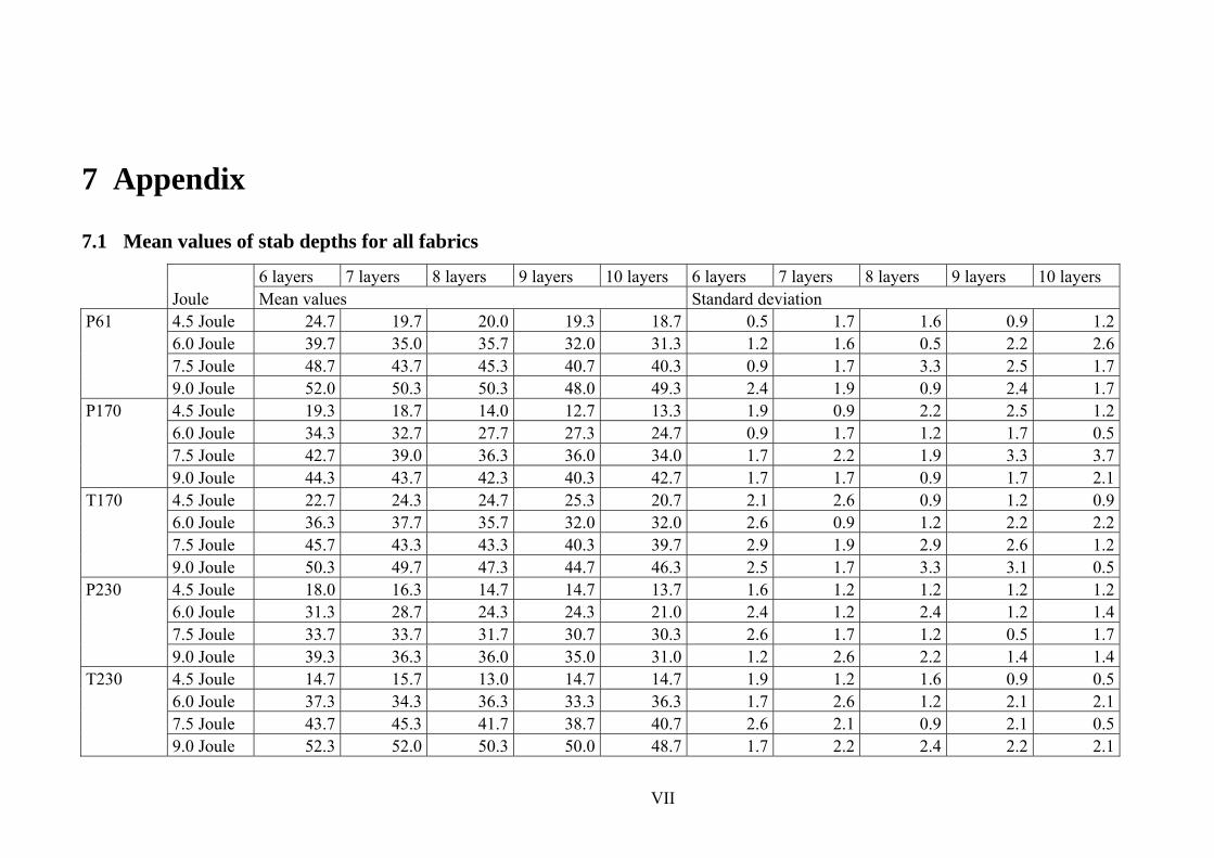
VII
7 Appendix
7.1 Mean values of stab depths for all fabrics
6 layers 7 layers 8 layers 9 layers 10 layers 6 layers 7 layers 8 layers 9 layers 10 layers Joule Mean values Standard deviation
P61 4.5 Joule 24.7 19.7 20.0 19.3 18.7 0.5 1.7 1.6 0.9 1.2 6.0 Joule 39.7 35.0 35.7 32.0 31.3 1.2 1.6 0.5 2.2 2.6 7.5 Joule 48.7 43.7 45.3 40.7 40.3 0.9 1.7 3.3 2.5 1.7 9.0 Joule 52.0 50.3 50.3 48.0 49.3 2.4 1.9 0.9 2.4 1.7 P170 4.5 Joule 19.3 18.7 14.0 12.7 13.3 1.9 0.9 2.2 2.5 1.2 6.0 Joule 34.3 32.7 27.7 27.3 24.7 0.9 1.7 1.2 1.7 0.5 7.5 Joule 42.7 39.0 36.3 36.0 34.0 1.7 2.2 1.9 3.3 3.7 9.0 Joule 44.3 43.7 42.3 40.3 42.7 1.7 1.7 0.9 1.7 2.1 T170 4.5 Joule 22.7 24.3 24.7 25.3 20.7 2.1 2.6 0.9 1.2 0.9 6.0 Joule 36.3 37.7 35.7 32.0 32.0 2.6 0.9 1.2 2.2 2.2 7.5 Joule 45.7 43.3 43.3 40.3 39.7 2.9 1.9 2.9 2.6 1.2 9.0 Joule 50.3 49.7 47.3 44.7 46.3 2.5 1.7 3.3 3.1 0.5 P230 4.5 Joule 18.0 16.3 14.7 14.7 13.7 1.6 1.2 1.2 1.2 1.2 6.0 Joule 31.3 28.7 24.3 24.3 21.0 2.4 1.2 2.4 1.2 1.4 7.5 Joule 33.7 33.7 31.7 30.7 30.3 2.6 1.7 1.2 0.5 1.7 9.0 Joule 39.3 36.3 36.0 35.0 31.0 1.2 2.6 2.2 1.4 1.4 T230 4.5 Joule 14.7 15.7 13.0 14.7 14.7 1.9 1.2 1.6 0.9 0.5 6.0 Joule 37.3 34.3 36.3 33.3 36.3 1.7 2.6 1.2 2.1 2.1 7.5 Joule 43.7 45.3 41.7 38.7 40.7 2.6 2.1 0.9 2.1 0.5 9.0 Joule 52.3 52.0 50.3 50.0 48.7 1.7 2.2 2.4 2.2 2.1
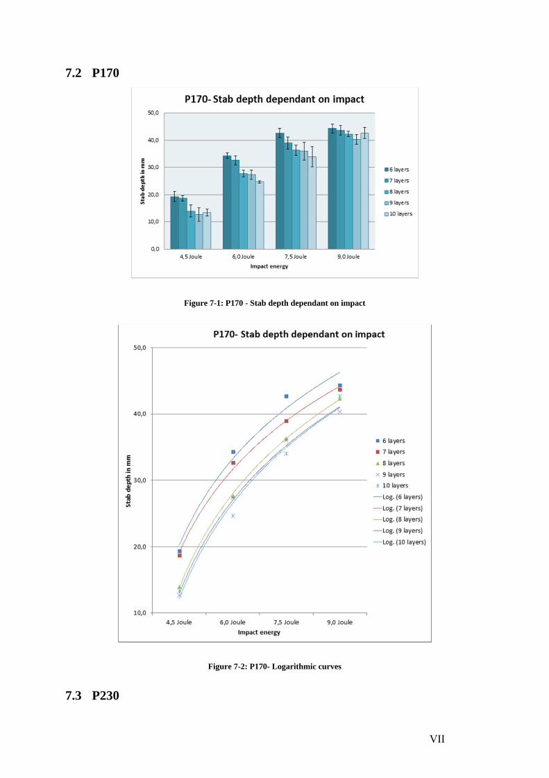
VII
7.2 P170
Figure 7-1: P170 - Stab depth dependant on impact
Figure 7-2: P170- Logarithmic curves
7.3 P230
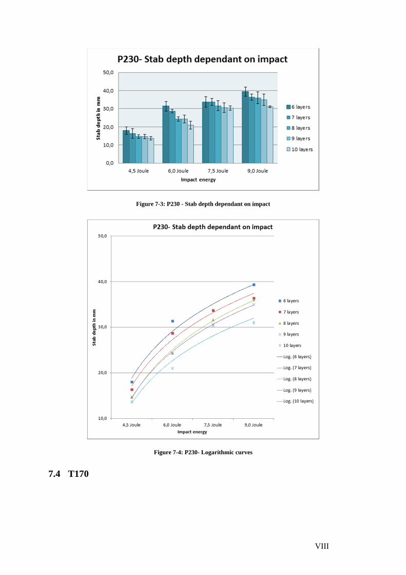
VIII
Figure 7-3: P230 - Stab depth dependant on impact
Figure 7-4: P230- Logarithmic curves
7.4 T170
IX
Figure 7-5: T170 - Stab depth dependant on impact
Figure 7-6: T170- Logarithmic curves
X
7.5 T230
Figure 7-7:T230 - Stab depth dependant on impact
Figure 7-8: T230- Logarithmic curves