Introduction - Shop for books, journals, and more.
31
1 1 Introduction Membrane separations are an accepted means for separating non- condensable gases; that is, gases that ordinarily condense only under low- temperature or cryogenic conditions. The technology might be in wider use if (1) better and more selective membrane materials were available and (2) the necessary mathematical representations and calculations were better spelled-out for the separations attainable. In fact, the one sometimes depends on the other. Of particular interest are ways in which separations could be enhanced using relatively nonselective membranes. A special case is pervaporation, in which the feed material is a liquid but the permeate is a gas. That is, the temperature and pressure of the permeate are such that the permeated components exist in the gaseous phase. Conceivably, however, the feedstream could be a gas but the permeate conditions and compositions are such that the components constitute a liquid phase. For the particular purposes here, however, all streams are in a gaseous state. The general subject has been explored in a number of past reviews 1–8 and, for instance, is the main concern of the Journal of Membrane Science. The subject has also been of interest to the Gas Research Institute, which has held workshops on the subject. 3,4 The Gas Research Institute, in fact, jointly sponsored a project with the Dow Corning Corporation and others aimed at correlating and predicting the permeability behavior of membranes from the chemical structure. 9,10 The American Institute of Chemical Engineers has maintained an active interest through its Symposium Series. 11–13 Membrane Processes in Separation and Purification, 14 published in 1993, contains chapters on pervaporation, facilitated transport membrane processes, membrane gas absorption processes, hollow fiber contactors, membrane reactors, and the preparation and application of inorganic membranes. In addition to an introductory chapter by the editors, Polymeric www.elsevier.com Copyright 2003 Elsevier Science All rights reserved.
-
Upload
khangminh22 -
Category
Documents
-
view
2 -
download
0
Transcript of Introduction - Shop for books, journals, and more.

1
1
Introduction
Membrane separations are an accepted means for separating non-condensable gases; that is, gases that ordinarily condense only under low-temperature or cryogenic conditions. The technology might be in wideruse if (1) better and more selective membrane materials were availableand (2) the necessary mathematical representations and calculations werebetter spelled-out for the separations attainable. In fact, the one sometimesdepends on the other. Of particular interest are ways in which separationscould be enhanced using relatively nonselective membranes.
A special case is pervaporation, in which the feed material is a liquidbut the permeate is a gas. That is, the temperature and pressure of thepermeate are such that the permeated components exist in the gaseousphase. Conceivably, however, the feedstream could be a gas but the permeateconditions and compositions are such that the components constitute aliquid phase. For the particular purposes here, however, all streams are ina gaseous state.
The general subject has been explored in a number of past reviews
1–8
and, for instance, is the main concern of the
Journal of Membrane Science
.The subject has also been of interest to the Gas Research Institute, whichhas held workshops on the subject.
3,4
The Gas Research Institute, in fact,jointly sponsored a project with the Dow Corning Corporation and othersaimed at correlating and predicting the permeability behavior of membranesfrom the chemical structure.
9,10
The American Institute of Chemical Engineers has maintained an active
interest through its Symposium Series.
11–13
Membrane Processes in Separation and Purification
,
14
published in1993, contains chapters on pervaporation, facilitated transport membraneprocesses, membrane gas absorption processes, hollow fiber contactors,membrane reactors, and the preparation and application of inorganicmembranes. In addition to an introductory chapter by the editors,
Polymeric
www.elsevier.com Copyright 2003 Elsevier Science All rights reserved.
2 MEMBRANE SEPARATIONS TECHNOLOGY
Gas Separation Membranes
,
15
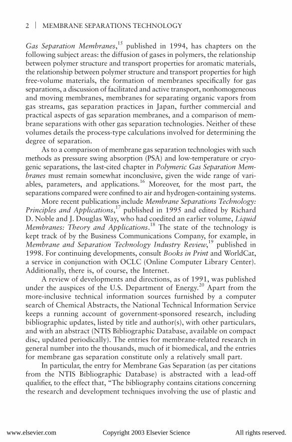
published in 1994, has chapters on thefollowing subject areas: the diffusion of gases in polymers, the relationshipbetween polymer structure and transport properties for aromatic materials,the relationship between polymer structure and transport properties for highfree-volume materials, the formation of membranes specifically for gasseparations, a discussion of facilitated and active transport, nonhomogeneousand moving membranes, membranes for separating organic vapors fromgas streams, gas separation practices in Japan, further commercial andpractical aspects of gas separation membranes, and a comparison of mem-brane separations with other gas separation technologies. Neither of thesevolumes details the process-type calculations involved for determining thedegree of separation.
As to a comparison of membrane gas separation technologies with suchmethods as pressure swing absorption (PSA) and low-temperature or cryo-genic separations, the last-cited chapter in
Polymeric Gas Separation Mem-branes
must remain somewhat inconclusive, given the wide range of vari-ables, parameters, and applications.
16
Moreover, for the most part, theseparations compared were confined to air and hydrogen-containing systems.
More recent publications include
Membrane Separations Technology:Principles and Applications
,
17
published in 1995 and edited by RichardD. Noble and J. Douglas Way, who had coedited an earlier volume,
LiquidMembranes: Theory and Applications
.
18
The state of the technology iskept track of by the Business Communications Company, for example, in
Membrane and Separation Technology Industry Review
,
19
published in1998. For continuing developments, consult
Books in Print
and WorldCat,a service in conjunction with OCLC (Online Computer Library Center).Additionally, there is, of course, the Internet.
A review of developments and directions, as of 1991, was publishedunder the auspices of the U.S. Department of Energy.
20
Apart from themore-inclusive technical information sources furnished by a computersearch of Chemical Abstracts, the National Technical Information Servicekeeps a running account of government-sponsored research, includingbibliographic updates, listed by title and author(s), with other particulars,and with an abstract (NTIS Bibliographic Database, available on compactdisc, updated periodically). The entries for membrane-related research ingeneral number into the thousands, much of it biomedical, and the entriesfor membrane gas separation constitute only a relatively small part.
In particular, the entry for Membrane Gas Separation (as per citationsfrom the NTIS Bibliographic Database) is abstracted with a lead-offqualifier, to the effect that, “The bibliography contains citations concerningthe research and development techniques involving the use of plastic and
www.elsevier.com Copyright 2003 Elsevier Science All rights reserved.
Introduction
3
metal or metallic membranes.” A specific example of an additional statementof scope (June 1993) is, “Included are such topics as recent advances inmembrane science and technology, gas separations using composite hollowfiber membranes, optimal cascade theory for the separation of mixtureson semipermeable membranes and gas separation by a continuous mem-brane column.” Another example (August 1993) is, “Citations reviewisotope separation, osmotic techniques, reverse osmosis, and preparationof membranes for specific separation processes. The permeability of polymermembranes is discussed in terms of physical properties as well as molecularstructure.” And, in closing, “The selectivity of polymeric films for a varietyof gases is also included.” A subject or terms index and title list are included.As the examples will indicate, the coverage is extensive.
Representative samples from the NTIS data file, which give an indi-cation of some of the directions in which membrane research is headed,include the references about coal-derived gases and liquids and their furtherseparation or conversion,
21–27
in particular high-temperature ceramic mem-branes and the use of membranes as catalytic reactors. Similar remarkscould be made for metallic membranes; for example, the diffusion of hydro-gen through metals is a subject of long standing. Membrane separationprocesses in the petrochemical industry, for instance, are reviewed in
Mem-brane Separation Processes in the Petrochemical Industry
.
5
With regardto the separation of liquids, some recent developments are presented byCabasso et al.,
28
and for the separation of solids and liquids by hyperfiltra-tion, by Leeper and Tsao.
29
The commercial implementation largely remainsto be seen.
Of notable mention, the
Membrane Handbook
was published in1992.
30
Another work of interest is
Membrane Separations Technology:Principles and Applications
, edited by R. D. Noble and S. A. Stern, a volumein Elsevier’s Membrane Science and Technology Series.
31
Also, appropriateentries can be found in the
Encyclopedia of Chemical Processing andDesign
(Volume 27)
32
and the
Kirk-Othmer Encyclopedia of ChemicalTechnology
(Volume 15).
33
Evidently, the subject has not yet reached thestatus of a chemical engineering unit operation, since the necessaryprocess-type calculations are as yet ill-defined or undefined. For instance,consult the section on membrane separations in the seventh edition of
Perry’s Chemical Engineers’ Handbook
.
34
Notwithstanding all of this,the principal item of interest here is not in membrane materials or mem-brane cells per se, nor in the usual considerations of membrane scienceand technology, but in the derivations and process-type calculationsinvolved in predicting the degree of separation that can be attained. It is amatter more complicated than ordinarily thought or expected and a fitting
www.elsevier.com Copyright 2003 Elsevier Science All rights reserved.
4 MEMBRANE SEPARATIONS TECHNOLOGY
continuation of the unit operations concept as embodied in chemical andprocess engineering.
For the record, however, a few background preliminaries aboutmembranes will first be introduced.
1.1 MEMBRANE MATERIALS
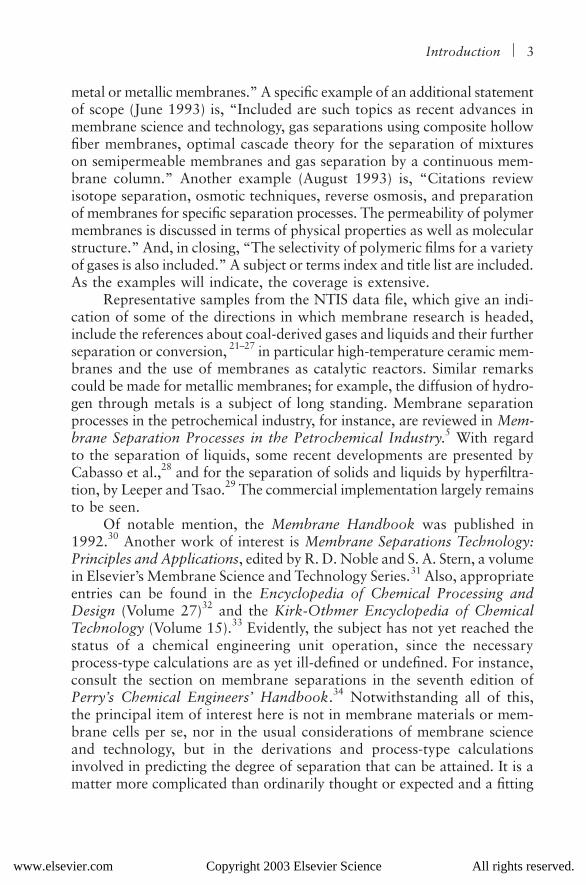
A considerable array of membrane materials exist for various gaseousseparations, some more effective than others.
10
That is, some are morepermeable and more selective than others. It depends on the system to beseparated, however. In other words, materials are not yet available forthe full array of gaseous mixtures encountered. A partial listing is presentedin Tables 1.1 through 1.3, giving properties and selectivity or relative per-meability of components.
4,9,10,30,35
Table 1.1
Relative Permeability for Cellulose Acetate Membranes
GasRelative
Permeability
H
2
O(g) (considered fast) 100H
2
12HeH
2
S 10CO
2
6O
2
1.0ArCO 0.3CH
4
0.2N
2
0.18C
2
H
6
(considered slow) 0.10
Source: W. H. Mazur and M. C. Chan.
10,35
Table 1.2
Permeability to Oxygen
PolymerPermeability
(in 10
−
9
¥
cm
3
/sec-cm
2
-cm Hg/cm)
Dimethyl Silicone 50Polybutadiene 13Polyethylene 0.1Nylon 0.004Teflon 0.0004
Source: Gas Research Institute.
3,10
www.elsevier.com Copyright 2003 Elsevier Science All rights reserved.

Introduction
5
The oxygen/nitrogen membrane separation for air, perhaps the mostobvious, has also been one of the most studied and is sort of a baselinereference. The sharp separation between nitrogen and oxygen on a com-mercial scale remains in the domain of cryogenics, although membraneseparations have been used successfully when only a relatively minorincrease in the oxygen content of air is sought, as in portable oxygenconcentrators for home use.
The separation of refinery gases is also an item of interest; for instance,gas streams containing hydrogen. In the main, membrane methods pertainto the separation of noncondensable gases; that is, to gases not readilyliquifiable except by low-temperature or cryogenic means.
In Table 1.4, the interim state of technology is acknowledged asfeasible for various binary separations; future needs are also listed.
4,9,10,28,36
Some of the commercial technologies and suppliers are reviewed andlisted.
10,30,35
Table 1.3
Selectivity for Dimethyl Silicone Polymer
Gases Selectivity (
α
=
P
i
/P
j
)
O
2
/N
2
2.0CO
2
/CH
4
3.4CO
2
/H
2
4.9CO
2
/CO 9.0H
2
S/CO 28.0
Source: Gas Research Institute.
3,10
Table 1.4
Membrane Separations: State of the Technology
Known Separations To Be Determined
H
2
/C
1
+
H2/CO2H2/CO H2S/CO2He/C1 NH3/H2H2O(g)/C1+ NH3/C1+H2S/C1+ NH3/N2CO2/C1+ SO2/C1+CO2/N2 SO2/CO2CO2/CO NO2/C1+NO2/CO C1/C2NO2/N2 N2/C1CO2/air Ar/air
Organic vapors
Note: C1+ represents methane and heavier hydrocarbons.Source: W. J. Schell.10,36
www.elsevier.com Copyright 2003 Elsevier Science All rights reserved.
6 MEMBRANE SEPARATIONS TECHNOLOGY
Formerly, membrane materials consisted mainly of barrier types, some-times called permeable or semipermeable, in which the gases flowed intoand through the pores and interstices, which were of molecular dimen-sions; for example, measured in angstroms. There is the use of materialssimilar to molecular-sieve adsorbents, for example. For single-phase liquidsystems or solutions, the processes may be referred to by the terms dialysisand osmosis, whereas for gas-liquid, gas-solid, or liquid-solid separations,the terms micro- and ultrafiltration are more appropriate.
(Some recent developments in membrane processes for the separationof organic liquids are presented in Cabasso et al.,28 as previously noted; thesame may be said for the use of hyperfiltration as applied in ethanol recov-ery.29 The latter subject is of relevance also in the processing of nonpasteur-ized beers; that is, in the separation of spent yeasts after fermentation.)
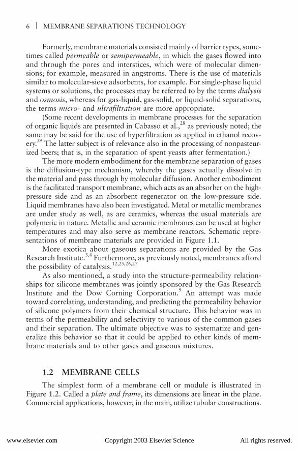
The more modern embodiment for the membrane separation of gasesis the diffusion-type mechanism, whereby the gases actually dissolve inthe material and pass through by molecular diffusion. Another embodimentis the facilitated transport membrane, which acts as an absorber on the high-pressure side and as an absorbent regenerator on the low-pressure side.Liquid membranes have also been investigated. Metal or metallic membranesare under study as well, as are ceramics, whereas the usual materials arepolymeric in nature. Metallic and ceramic membranes can be used at highertemperatures and may also serve as membrane reactors. Schematic repre-sentations of membrane materials are provided in Figure 1.1.
More exotica about gaseous separations are provided by the GasResearch Institute.3,4 Furthermore, as previously noted, membranes affordthe possibility of catalysis.12,25,26,27
As also mentioned, a study into the structure-permeability relation-ships for silicone membranes was jointly sponsored by the Gas ResearchInstitute and the Dow Corning Corporation.9 An attempt was madetoward correlating, understanding, and predicting the permeability behaviorof silicone polymers from their chemical structure. This behavior was interms of the permeability and selectivity to various of the common gasesand their separation. The ultimate objective was to systematize and gen-eralize this behavior so that it could be applied to other kinds of mem-brane materials and to other gases and gaseous mixtures.
1.2 MEMBRANE CELLS
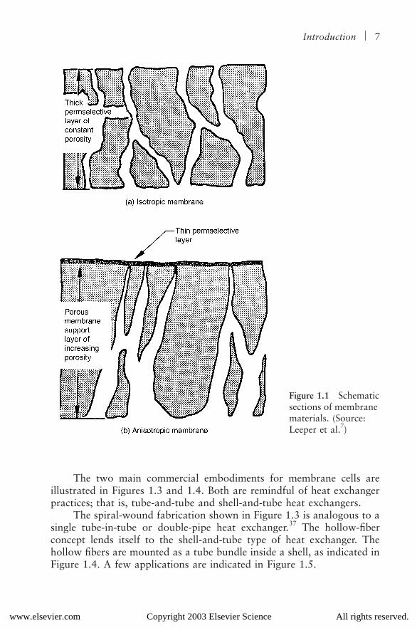
The simplest form of a membrane cell or module is illustrated inFigure 1.2. Called a plate and frame, its dimensions are linear in the plane.Commercial applications, however, in the main, utilize tubular constructions.
www.elsevier.com Copyright 2003 Elsevier Science All rights reserved.
Introduction 7
The two main commercial embodiments for membrane cells areillustrated in Figures 1.3 and 1.4. Both are remindful of heat exchangerpractices; that is, tube-and-tube and shell-and-tube heat exchangers.
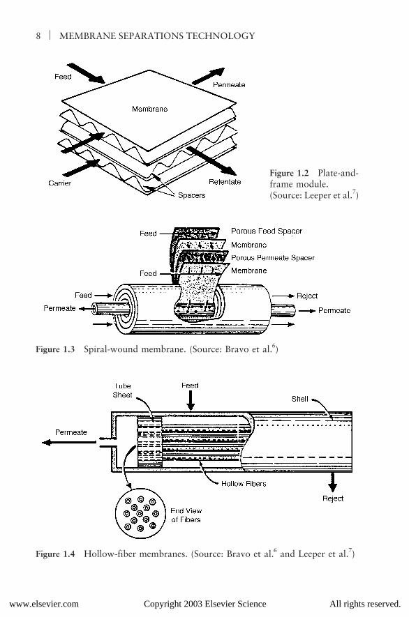
The spiral-wound fabrication shown in Figure 1.3 is analogous to asingle tube-in-tube or double-pipe heat exchanger.37 The hollow-fiberconcept lends itself to the shell-and-tube type of heat exchanger. Thehollow fibers are mounted as a tube bundle inside a shell, as indicated inFigure 1.4. A few applications are indicated in Figure 1.5.
Figure 1.1 Schematic sections of membrane materials. (Source: Leeper et al.7)
www.elsevier.com Copyright 2003 Elsevier Science All rights reserved.
8 MEMBRANE SEPARATIONS TECHNOLOGY
Figure 1.2 Plate-and-frame module. (Source: Leeper et al.7)
Figure 1.3 Spiral-wound membrane. (Source: Bravo et al.6)
Figure 1.4 Hollow-fiber membranes. (Source: Bravo et al.6 and Leeper et al.7)
www.elsevier.com Copyright 2003 Elsevier Science All rights reserved.
Introduction 9
1.3 THE ENHANCEMENT OF SEPARATION
With a membrane showing high selectivity between the gases to beseparated, a single-stage operation suffices. For membranes of lower selec-tivity, more involved juxtapositions become necessary. Examples are shownin Figures 1.6 and 1.7 for multistage taper and cascade arrangements.10
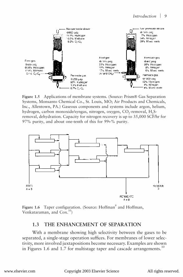
Figure 1.5 Applications of membrane systems. (Source: Prism Gas Separation Systems, Monsanto Chemical Co., St. Louis, MO; Air Products and Chemicals, Inc., Allentown, PA.) Gaseous components and systems include argon, helium, hydrogen, carbon monoxide/syngas, nitrogen, oxygen, CO2-removal, H2S-removal, dehydration. Capacity for nitrogen recovery is up to 35,000 SCF/hr for 97% purity, and about one-tenth of this for 99+% purity.
Figure 1.6 Taper configuration. (Source: Hoffman9 and Hoffman, Venkataraman, and Cox.10)
www.elsevier.com Copyright 2003 Elsevier Science All rights reserved.

10 MEMBRANE SEPARATIONS TECHNOLOGY
The taper configuration of Figure 1.6 does not produce a sharp sep-aration. In this case, only the less-permeable component tends to be recov-ered in the pure form as the reject. The permeate product is a mixture,although the proportions differ from the feed. The effect is similar to theconcept of stripping the more permeable component from the reject phase.
The taper configuration can be changed so that the more permeablecomponent is concentrated in the permeate, whereas the reject productis a mixture. This corresponds to rectification or absorption, in which themore permeable component is concentrated in the permeate phase andthe less permeable component is absorbed from the permeate phase. Theanalogy is to distillation practices.
It may be noted that the cascade arrangement of Figure 1.7, ifsuitably disentangled, corresponds to a multistage operation as encoun-tered in absorption, stripping, and distillation practices.
Figure 1.7 Cascade. (Source: Hoffman9 and Hoffman et al.10)
www.elsevier.com Copyright 2003 Elsevier Science All rights reserved.
Introduction 11
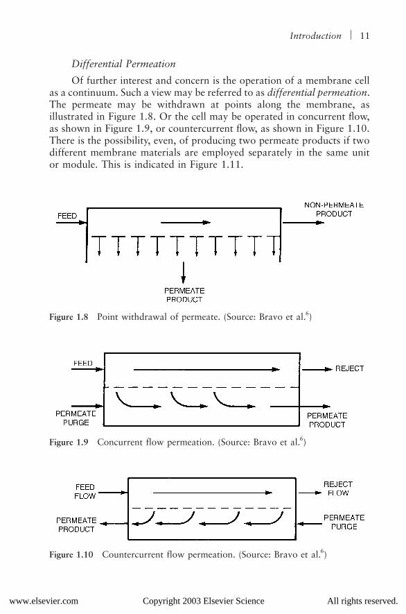
Differential Permeation
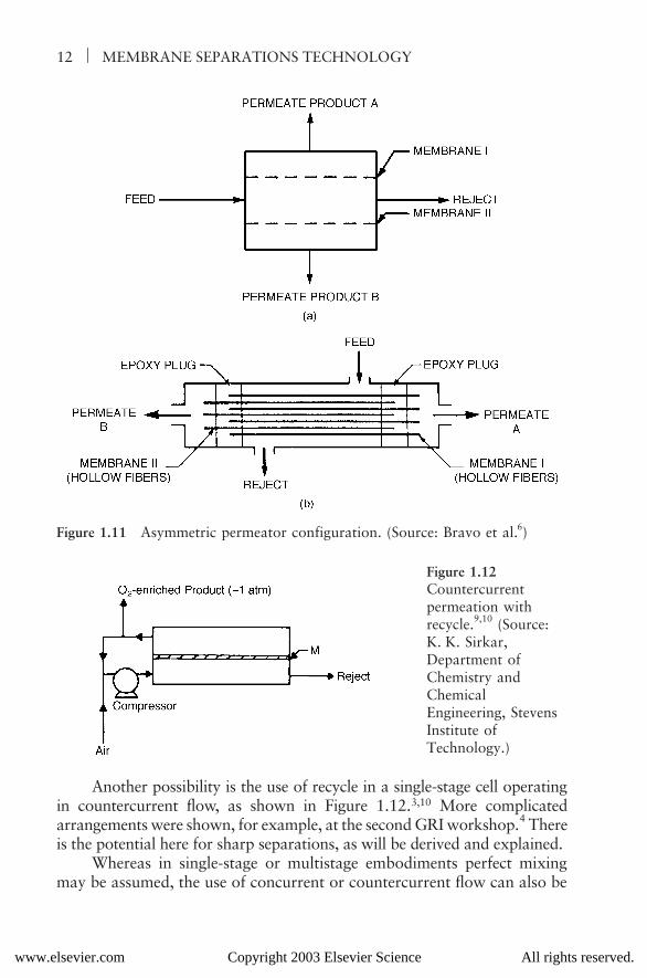
Of further interest and concern is the operation of a membrane cellas a continuum. Such a view may be referred to as differential permeation.The permeate may be withdrawn at points along the membrane, asillustrated in Figure 1.8. Or the cell may be operated in concurrent flow,as shown in Figure 1.9, or countercurrent flow, as shown in Figure 1.10.There is the possibility, even, of producing two permeate products if twodifferent membrane materials are employed separately in the same unitor module. This is indicated in Figure 1.11.
Figure 1.8 Point withdrawal of permeate. (Source: Bravo et al.6)
Figure 1.9 Concurrent flow permeation. (Source: Bravo et al.6)
Figure 1.10 Countercurrent flow permeation. (Source: Bravo et al.6)
www.elsevier.com Copyright 2003 Elsevier Science All rights reserved.
12 MEMBRANE SEPARATIONS TECHNOLOGY
Another possibility is the use of recycle in a single-stage cell operatingin countercurrent flow, as shown in Figure 1.12.3,10 More complicatedarrangements were shown, for example, at the second GRI workshop.4 Thereis the potential here for sharp separations, as will be derived and explained.
Whereas in single-stage or multistage embodiments perfect mixingmay be assumed, the use of concurrent or countercurrent flow can also be
Figure 1.11 Asymmetric permeator configuration. (Source: Bravo et al.6)
Figure 1.12Countercurrent permeation with recycle.9,10 (Source: K. K. Sirkar, Department of Chemistry and Chemical Engineering, Stevens Institute of Technology.)
www.elsevier.com Copyright 2003 Elsevier Science All rights reserved.
Introduction 13
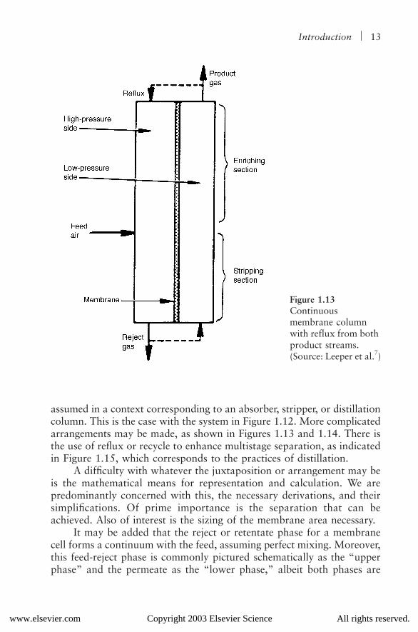
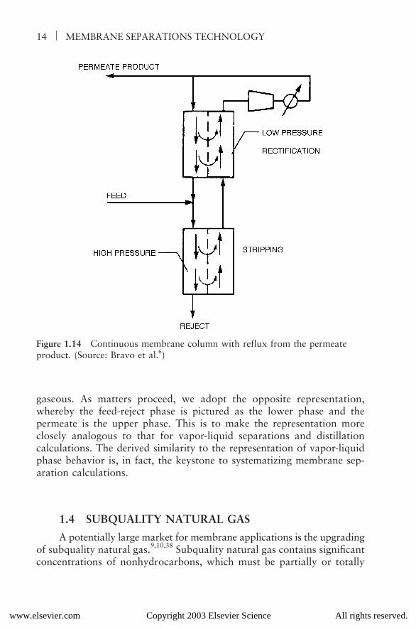
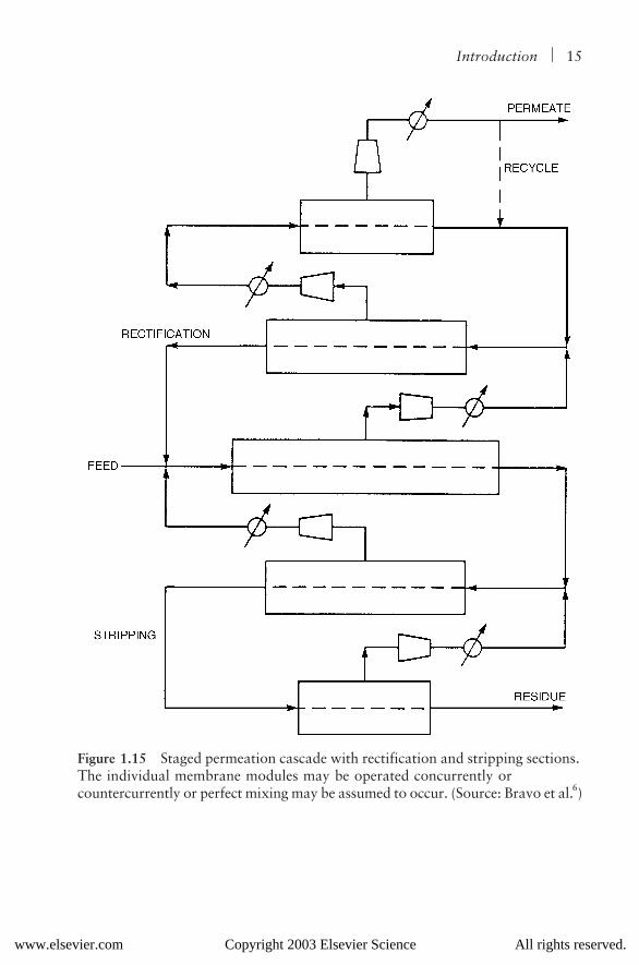
assumed in a context corresponding to an absorber, stripper, or distillationcolumn. This is the case with the system in Figure 1.12. More complicatedarrangements may be made, as shown in Figures 1.13 and 1.14. There isthe use of reflux or recycle to enhance multistage separation, as indicatedin Figure 1.15, which corresponds to the practices of distillation.
A difficulty with whatever the juxtaposition or arrangement may beis the mathematical means for representation and calculation. We arepredominantly concerned with this, the necessary derivations, and theirsimplifications. Of prime importance is the separation that can beachieved. Also of interest is the sizing of the membrane area necessary.
It may be added that the reject or retentate phase for a membranecell forms a continuum with the feed, assuming perfect mixing. Moreover,this feed-reject phase is commonly pictured schematically as the “upperphase” and the permeate as the “lower phase,” albeit both phases are
Figure 1.13Continuous membrane column with reflux from both product streams. (Source: Leeper et al.7)
www.elsevier.com Copyright 2003 Elsevier Science All rights reserved.
14 MEMBRANE SEPARATIONS TECHNOLOGY
gaseous. As matters proceed, we adopt the opposite representation,whereby the feed-reject phase is pictured as the lower phase and thepermeate is the upper phase. This is to make the representation moreclosely analogous to that for vapor-liquid separations and distillationcalculations. The derived similarity to the representation of vapor-liquidphase behavior is, in fact, the keystone to systematizing membrane sep-aration calculations.
1.4 SUBQUALITY NATURAL GAS
A potentially large market for membrane applications is the upgradingof subquality natural gas.9,10,38 Subquality natural gas contains significantconcentrations of nonhydrocarbons, which must be partially or totally
Figure 1.14 Continuous membrane column with reflux from the permeate product. (Source: Bravo et al.6)
www.elsevier.com Copyright 2003 Elsevier Science All rights reserved.
Introduction 15
Figure 1.15 Staged permeation cascade with rectification and stripping sections. The individual membrane modules may be operated concurrently or countercurrently or perfect mixing may be assumed to occur. (Source: Bravo et al.6)
www.elsevier.com Copyright 2003 Elsevier Science All rights reserved.
16 MEMBRANE SEPARATIONS TECHNOLOGY
removed to market and utilize the gas. The three principal nonhydrocar-bons found are nitrogen, carbon dioxide, and hydrogen sulfide, in thatorder. Carbon dioxide and hydrogen sulfide are selectively removed bywell-known and successful technologies. Chief among these are acid gasabsorption and adsorption methods, which are well documented in theliterature.
It may be added, however, that membrane systems have been usedsuccessfully to separate carbon dioxide from natural gas, notably inenhanced oil recovery operations.39 Here, (supercritical) carbon dioxide isinjected into a petroleum-bearing formation, where the carbon dioxideincreases the oil mobility and its subsequent recovery. The carbon dioxide–rich gaseous effluent is recovered, and the carbon dioxide concentratedand reinjected.
With the nitrogen content of subquality natural gas, it is another story.The two principal methods in current but limited use are low-temperature,or cryogenic separation or distillation, and selective adsorption. The formeris judged too costly; the latter is starting to make inroads. Membraneseparations wait in the wings. More on the general subject of upgradingnatural gas follows.
To be adjudged pipeline-quality natural gas, the hydrogen sulfidecontent must be below 25 grains per SCF (standard cubic foot), whichcalculates out to about 0.0004 mol %. The hydrogen sulfide removedand recovered may be oxidized to the sulfur oxides, to be vented or,preferably, converted, say, in a lime-water wash for disposal as calciumsulfate (gypsum). In sufficient quantities and concentrations, the recoveredhydrogen sulfide may be partially oxidized to elemental sulfur via theClaus process or its equivalent.
Permissible carbon dioxide levels in pipeline-quality natural gas arecharacteristically up to 2–3 mol %. The recovered carbon dioxide is beingincreasingly touted for enhanced oil recovery operations rather than beingvented to the atmosphere.
The allowable nitrogen content is dictated mostly by the requiredBtu content for the natural gas. Assuming the natural gas per se at about1000 Btu/SCF, the nitrogen content could range up to 10 mol %, wherebythe Btu content would be no lower than 900 Btu/SCF, the generallyaccepted cutoff for the Btu-rating. However, pipeline requirements arestarting to be more stringent for the nitrogen content and, in some instances,about 3 mol % is the maximum allowable.
Whereas low-temperature or cryogenic methods can be used toseparate out the nitrogen, this technology is expensive and not com-monly used. The use of selective adsorbents is emerging, and may prove
www.elsevier.com Copyright 2003 Elsevier Science All rights reserved.
Introduction 17
economically viable. There is the possibility, however, that membraneseparations may prove equally viable, an assessment yet to be determined,and will in large part depend on the further development of suitablemembrane materials.
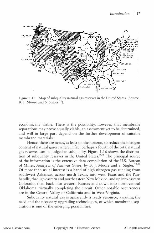
Hence, there are needs, at least on the horizon, to reduce the nitrogencontent of natural gases, where in fact perhaps a fourth of the total naturalgas reserves can be judged as subquality. Figure 1.16 shows the distribu-tion of subquality reserves in the United States.9,38 The principal sourceof the information is the extensive data compilation of the U.S. Bureauof Mines, Analyses of Natural Gases, by B. J. Moore and S. Stigler.40,41
Of more than usual interest is a band of high-nitrogen gas running fromsouthwest Arkansas, across north Texas, into west Texas and the Pan-handle, through eastern and northeastern New Mexico, and up into easternColorado, then back into western Kansas and down into north-centralOklahoma, virtually completing the circuit. Other notable occurrencesare in the Central Valley of California and in West Virginia.
Subquality natural gas is apparently a ready resource, awaiting theneed and the necessary upgrading technologies, of which membrane sep-aration is one of the emerging possibilities.
Figure 1.16 Map of subquality natural gas reserves in the United States. (Source: B. J. Moore and S. Stigler.41).
www.elsevier.com Copyright 2003 Elsevier Science All rights reserved.

18 MEMBRANE SEPARATIONS TECHNOLOGY
1.5 REPRESENTATIONS AND CALCULATIONS
In many respects, single-stage and multistage membrane separationscan be viewed as analogous to the steady-state flash separations anddistillations calculated for vapor-liquid systems. The concept of phaseequilibrium and the K-value or equilibrium vaporization ratio is replacedby the use of the membrane rate equation, assuming perfect mixing ofthe respective phases involved. Usually, all these phases are gaseous, butthe methodology may be applied to gas-liquid or vapor-liquid systems,or to all-liquid systems.
The single-stage membrane unit becomes equivalent to a so-calledflash vaporization. The flash vaporization calculation itself is straightfor-ward, with the vapor and liquid phases assumed at equilibrium, and ispresented in a number of references.42–45 The limits correspond to thedew-point and bubble-point calculations for vapor-liquid equilibrium,which are special or limiting cases for the flash vaporization calculation.It is the object, therefore, to adapt the membrane calculation to thetechniques for the flash vaporization calculation and thereby take advan-tage of the relative simplicity of the latter.
Other procedures and calculation techniques have been developedfor both stagewise and differential permeation, such as those presentedS-T Hwang and K. Kammermeyer,46 but they are not pursued here, inas-much as the analogy is to be made specific to vapor-liquid mass transferunit operations. In this way, the conventions and techniques alreadydeveloped for mass transfer operations can be more readily utilized. Alsonote that the symbols and terminology used for membrane permeationhave evolved through the years and vary from one author to another.
Extension can be made to cascade or multistage operations, carriedout analogously to a distillation column. The absorption and strippingfactor concept or rearrangement may be employed for the calculations,as has also been employed for distillation.42 The temperature, moreover,is assumed constant from stage to stage. This is the common assumptionin absorption, for instance, although in distillation the temperature mark-edly varies from stage to stage and plate to plate.
The preceding assumes that perfect mixing takes place; that is, thereare no changes in flow rate and composition across or perpendicular tothe face of the membrane surfaces. Furthermore, the flow rates andcompositions at the cell are those of the streams leaving the cell.
Of special consideration is the investigation of the cell as a contin-uum, first with point withdrawal of the permeate, then in both concurrentand countercurrent flow for the permeate and the reject phases. For thistreatment, differential permeation is the mode of attack. The differential
www.elsevier.com Copyright 2003 Elsevier Science All rights reserved.
Introduction 19
forms so obtained must be integrated, however, which becomes a com-plicating procedure in concurrent flow, and particularly in countercurrentflow. Hence, there is occasion for simplification or reduction.
Note that these types of process calculations, aimed at predictingbehavior from known or assigned membrane permeabilities, are not ordi-narily pursued in the various updates on the utilization of membraneseparations. The topic of utilization can be further searched on the Inter-net or, more succinctly, in WorldCat, the compendium of books publishedin the English language, by key word(s) or subject, author, and title. Atthis writing, a search of WorldCat, for instance, under the title “Mem-brane Separations…” yields less than 100 titles, whereas a search underthe more general title “Membranes” yields results numbering in thethousands. For example, a couple of updates about applications areDonald R. Paul’s Membrane Technology for Gas Separations,47 and S. P.Nunes and K.-N. Peinemann’s Membrane Technology in the ChemicalIndustry.48 The field is expanding, as a further search of the literature willreveal. What has been missing are the concomitant calculation procedures,which this volume addresses.
1.6 PERMEATION UNITS
The following derivations and calculations avoid any specificassumptions about units. Instead, the quantities have been described ashaving “consistent” units. The degree of separation and recovery, moreover,is independent of the units. If, however, numerical values for permeability,pressure, and flow rate are used, then specific units are required, whichin turn determine membrane area, given the membrane thickness, or theoverall membrane permeability.
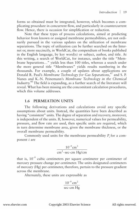
Commonly used units for the membrane permeability Pi for a com-ponent i are
that is, 10−9 cubic centimeters per square centimeter per centimeter ofmercury pressure change per centimeter. The units designated centimetersof mercury (Hg) per centimeter, therefore, pertain to the pressure gradientacross the membrane.
Alternately, these units are expressible as
10 cmcm -sec-cm Hg/cm
9 3
2
−
10 cmsec-cm Hg
9 2−
www.elsevier.com Copyright 2003 Elsevier Science All rights reserved.

20 MEMBRANE SEPARATIONS TECHNOLOGY
which, when multiplied by the operating pressure difference in the appro-priate and consistent units, becomes the diffusion coefficient or diffusivity;here, this would be measured in 10−9 cm2/sec.
Other units used for the permeability of solids to gases are presentedin the International Critical Tables (vol. V, pp. 76–77):49
Thus, the former units are used for say gases through metals and rubber,the latter units for gases through glass. To convert to the pressure unitsof cm Hg, the numerical values in the preceding units would be multipliedby 76 cm Hg/atm. Some representative values for hydrogen, taken fromthe International Critical Tables,49 are furnished in Table 1.5. All thepermeabilities increase with temperature. A side effect of hydrogen is thatit can dissolve into the interstices of metals, affecting the ductility andstrength, called hydrogen embrittlement. Additionally, hydrogen is reac-tive, notably to impurities in the metal, that is, components or phasesother than the pure metallic state itself. A prime example of this is withsteels and their makeup.
Table 1.5 Permeability of Solids to Hydrogen at Elevated Temperatures
System Temp. (°C)10−6 cm2/sec-atm
10−9 cm2/sec-atm
10−9 cm2/sec-cm Hg
H-Cu 500 3.5 46.1750 8 105
H-Fe 500 100 1316600 336 4421
H-Ni 500 3.8 50750 31.6 416
H-Pd 500 4450 58550600 5750 75660
H-Pt 600 0.77 0.1800 4.8 63.2
H-Zn 300 0.4 5.3H-rubber 20 0.3 3.9
100 2.6 34.2H-SiO2 500 6.2–28 0.08–0.37
800 35–100 0.46–1.3H-Pyrex 600 Inappreciable Inappreciable
Source: International Critical Tables, vol. V, pp. 76–77.
10 cmsec-atm
or10 cm
-atm
2 9 2− −6
sec
www.elsevier.com Copyright 2003 Elsevier Science All rights reserved.
Introduction 21
Henceforth, the symbol Pi or, say, Pj is used for the permeability ofan arbitrary component i or j. That is, both i and j denote the keycomponents for the separation, especially for a two-component systembut also in a multicomponent system. Inasmuch as the symbol P also isused to denote pressure, as is the common practice, some other symbolcould be adopted for permeability, say lower-case, script, or boldface Por Greek or the like. However, the subscripted Pi or Pj seems self-evident,so pressure is also subscripted to provide its distinguishing feature.
Therefore, PL stands for the higher or upstream pressure (or rejectpressure) at the membrane and PV, for the lower or downstream pressure(or permeate pressure), with the difference PL − PV denoting the pressure-drop across the membrane proper. The analogy is akin to that used forphase separations. Furthermore, the usage in the main appears self-evidentin context.
The flow is stated in cubic centimeters at standard conditions of tem-perature and pressure; that is, in standard cubic centimeters. The emphasishere, moreover, is for gases rather than liquids. A statement could be madeequivalently, however, for the flow of liquids through membrane barriers.
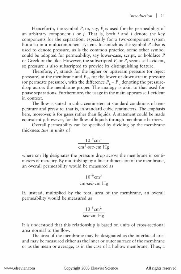
Overall permeability can be specified by dividing by the membranethickness ∆m in units of
where cm Hg designates the pressure drop across the membrane in centi-meters of mercury. By multiplying by a linear dimension of the membrane,an overall permeability would be measured as
If, instead, multiplied by the total area of the membrane, an overallpermeability would be measured as
It is understood that this relationship is based on units of cross-sectionalarea normal to the flow.
The area of the membrane may be designated as the interfacial areaand may be measured either as the inner or outer surface of the membraneor as the mean or average, as in the case of a hollow membrane. Thus, a
10 cmcm -sec-cm Hg
9 3
2
−
10 cmcm-sec-cm Hg
9 3−
10 cmsec-cm Hg
9 2−
www.elsevier.com Copyright 2003 Elsevier Science All rights reserved.
22 MEMBRANE SEPARATIONS TECHNOLOGY
mean value can also be adapted, in common with the practice for theconduction of heat through a tube wall.
The permeability as measured in the preceding centimeter-gram-second (cgs) system may also be converted to the English system, even tothe units of darcies or millidarcies for the flow of fluids through porousmedia, as employed in the petroleum industry.
The concept of the diffusion coefficient, or diffusivity, also is usedas the measure of the diffusion of one substance through another. Thedriving force is the concentration difference, via Fick’s law, which can berelated to the partial pressure difference by means of the equation of state.It is applicable to mixtures occurring as a common phase but can beapplied as well to the case where the second substance is a solid, say, asin dialysis. The dimensions are ordinarily (distance)2/time (e.g., cm2/sec).Since the equation of state is implicitly involved, the conversion betweenpermeability and diffusivity is more pronouncedly temperature (and pres-sure) dependent.
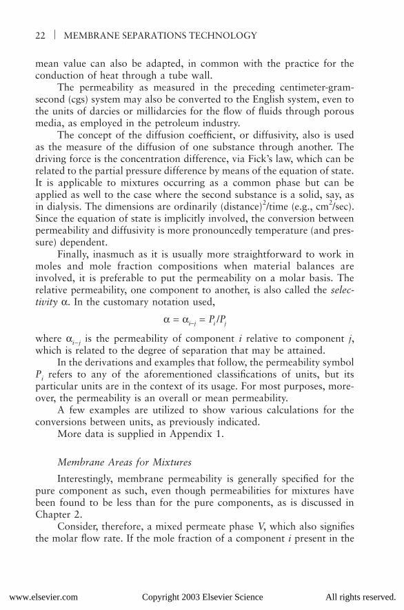
Finally, inasmuch as it is usually more straightforward to work inmoles and mole fraction compositions when material balances areinvolved, it is preferable to put the permeability on a molar basis. Therelative permeability, one component to another, is also called the selec-tivity α. In the customary notation used,
α = αi−j = Pi /Pj
where αi−j is the permeability of component i relative to component j,which is related to the degree of separation that may be attained.
In the derivations and examples that follow, the permeability symbolPi refers to any of the aforementioned classifications of units, but itsparticular units are in the context of its usage. For most purposes, more-over, the permeability is an overall or mean permeability.
A few examples are utilized to show various calculations for theconversions between units, as previously indicated.
More data is supplied in Appendix 1.
Membrane Areas for Mixtures
Interestingly, membrane permeability is generally specified for thepure component as such, even though permeabilities for mixtures havebeen found to be less than for the pure components, as is discussed inChapter 2.
Consider, therefore, a mixed permeate phase V, which also signifiesthe molar flow rate. If the mole fraction of a component i present in the
www.elsevier.com Copyright 2003 Elsevier Science All rights reserved.
Introduction 23
permeate phase is designated yi and the mole fraction present in the feed-reject phase L is denoted xi, then the permeation relationship shouldpresumably be of the basic form
Vyi = Pi(PLxi − PVyi)A
where A is the membrane interfacial area and (PL − PV) is the total pressuredifference across the membrane proper. However, the partial pressuredifference (PLxi − PVyi) represents the driving force for component i, so tospeak, albeit it may be adjusted using the idea of an “activity” difference.
Moreover, the units should be consistent; that is, the permeability Pishould have the units of moles per unit time per unit area per unit pressure(or partial pressure) difference and refer to the permeability measured forthe pure component i. As such, it would denote an overall permeability;that is, the membrane thickness has already been taken into account.
The preceding is the basic form adapted for Chapter 2 and thefollowing chapters, albeit the membrane area A may be incorporated intothe permeability term for simplification purposes.
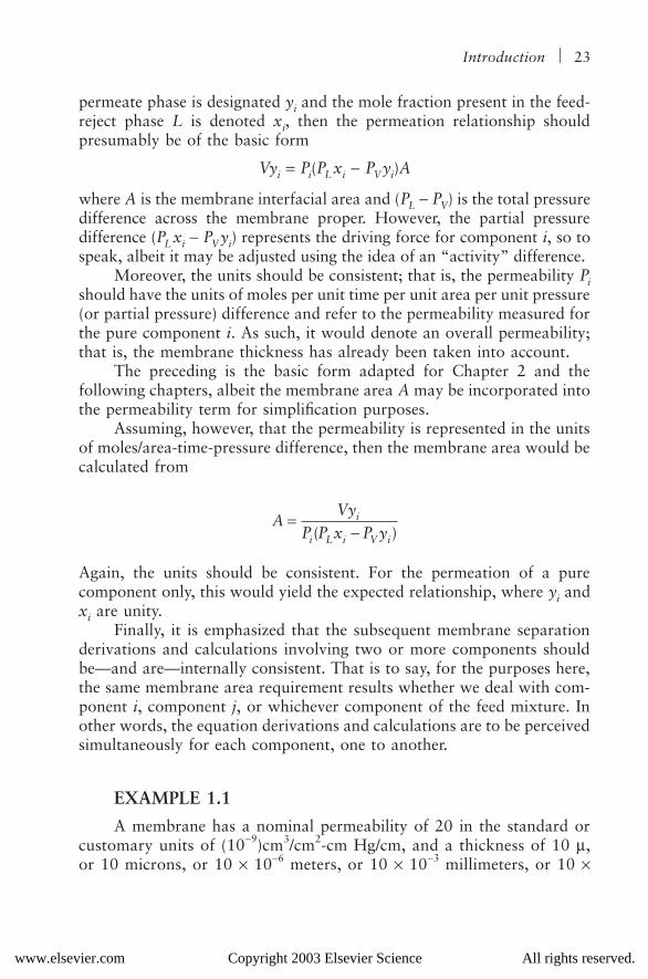
Assuming, however, that the permeability is represented in the unitsof moles/area-time-pressure difference, then the membrane area would becalculated from
Again, the units should be consistent. For the permeation of a purecomponent only, this would yield the expected relationship, where yi andxi are unity.
Finally, it is emphasized that the subsequent membrane separationderivations and calculations involving two or more components shouldbe—and are—internally consistent. That is to say, for the purposes here,the same membrane area requirement results whether we deal with com-ponent i, component j, or whichever component of the feed mixture. Inother words, the equation derivations and calculations are to be perceivedsimultaneously for each component, one to another.
EXAMPLE 1.1
A membrane has a nominal permeability of 20 in the standard orcustomary units of (10−9)cm3/cm2-cm Hg/cm, and a thickness of 10 µ,or 10 microns, or 10 × 10−6 meters, or 10 × 10−3 millimeters, or 10 ×
AVy
P P x P yi
i L i V i
=−( )
www.elsevier.com Copyright 2003 Elsevier Science All rights reserved.
24 MEMBRANE SEPARATIONS TECHNOLOGY
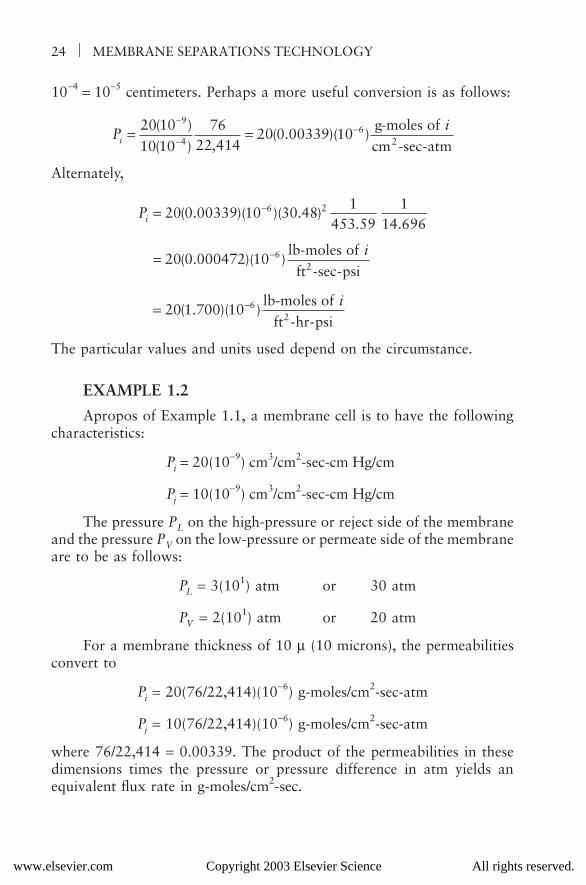
10−4 = 10−5 centimeters. Perhaps a more useful conversion is as follows:
Alternately,
The particular values and units used depend on the circumstance.
EXAMPLE 1.2
Apropos of Example 1.1, a membrane cell is to have the followingcharacteristics:
Pi = 20(10−9) cm3/cm2-sec-cm Hg/cm
Pj = 10(10−9) cm3/cm2-sec-cm Hg/cm
The pressure PL on the high-pressure or reject side of the membraneand the pressure PV on the low-pressure or permeate side of the membraneare to be as follows:
PL = 3(101) atm or 30 atm
PV = 2(101) atm or 20 atm
For a membrane thickness of 10 µ (10 microns), the permeabilitiesconvert to
Pi = 20(76/22,414)(10−6) g-moles/cm2-sec-atm
Pj = 10(76/22,414)(10−6) g-moles/cm2-sec-atm
where 76/22,414 = 0.00339. The product of the permeabilities in thesedimensions times the pressure or pressure difference in atm yields anequivalent flux rate in g-moles/cm2-sec.
Pi
i = =−
−−20 10
10 1076
22 41420 0 00339 10
9
46( )
( ) ,( . )( )
g-moles ofcm -sec-atm2
P
i
i
i =
=
=
−
−
−
20 0 00339 10 30 481
453 591
14 696
20 0 000472 10
20 1 700 10
6 2
6
6
( . )( )( . ). .
( . )( )
( . )( )
lb-moles offt -sec-psi
lb-moles offt -hr-psi
2
2
www.elsevier.com Copyright 2003 Elsevier Science All rights reserved.
Introduction 25
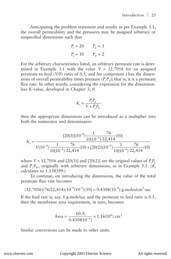
Anticipating the problem statement and results as per Example 3.1,the overall permeability and the pressures may be assigned arbitrary orunspecified dimensions such that
Pi = 20 PL = 3
Pj = 10 PV = 2
For the arbitrary characteristics listed, an arbitrary permeate rate is deter-mined in Example 3.1 with the value V = 12.7056 for an assignedpermeate-to-feed (V/F) ratio of 0.5, and for component i has the dimen-sions of overall permeability times pressure (Pi PV); that is, it is a permeateflux rate. In other words, considering the expression for the dimension-less K-value, developed in Chapter 3, if
then the appropriate dimensions can be introduced as a multiplier intoboth the numerator and denominator:
where V = 12.7056 and [20(3)] and [20(2)] are the original values of PiPLand PiPV, originally with arbitrary dimensions, as in Example 3.1. (Kicalculates to 1.138399.)
To continue, on introducing the dimensions, the value of the totalpermeate flux rate becomes
(12.7056)(76/22,414)(10−9/10−3)(10) = 0.4308(10−6) g-moles/cm2-sec
If the feed rate is, say, 1 g-mole/sec and the permeate to feed ratio is 0.5,then the membrane area requirement, in turn, becomes
Similar conversions can be made to other units.
KP P
V P Pii L
i V
=+
KV
i =+
−−
−−
−−
[ ( )]( )( ) ,
( )
( )( ) ,
( ) [ ( )]( )( ) ,
( )
20 3 101
10 1076
22 41410
101
10 1076
22 41410 20 2 10
110 10
7622 414
10
94
94
94
Area cm= =−1 0 5
0 4308 101 16 10
66 2( . )
. ( ). ( )
www.elsevier.com Copyright 2003 Elsevier Science All rights reserved.

26 MEMBRANE SEPARATIONS TECHNOLOGY
EXAMPLE 1.3
The unit of permeability used in the petroleum industry for the flowof fluids through porous media, in oil and gas production, is the darcy.44,45
Usually, the permeability of oil- and gas-producing formations is given inmillidarcies, a millidarcy being 1/1000 of a darcy.
The origins are in the Darcy (d’Arcy) relationship, which relates flowrate to the pressure gradient:
where
v = superficial flow velocity;K = permeability coefficient for flow through porous media;µ = viscosity;P = pressure;x = linear dimension opposite to the direction of flow.
The superficial velocity is the actual volumetric rate divided by the totalcross-sectional area normal to the direction of flow.
A porous medium having a permeability of 1 darcy, at standardconditions, permits the flow of a fluid of 1 centipoise viscosity at thesuperficial rate of 1 cm/sec under a pressure gradient of 1 atm/cm. In thisformula, v is in cm/sec, K is in darcies, µ is in centipoises (centigrams/cm-sec), P is in atm, and x is in cm. (A centipoise is 1/100 of a poise. A poisehas the dimensions of g/cm-sec, whereas a centipoise has the dimensionsof centigrams/cm-sec.) The actual units for K in darcies would be centi-gram-cm/atm-sec2.
In the English system, the superficial flow velocity is in ft/sec, thepermeability coefficient is in ft3/sec2, the viscosity is in British viscosityunits (BVUs) of lb/ft-sec (to convert to BVU, multiply the viscosity incentipoises by 6.72 × 10⁻⁴), P is in psf (lb per ft2), and x is in ft.
If the flow velocity is to be in ft/hr, then the viscosity is measuredin lb/ft-hr; that is, the viscosity in centipoises is multiplied by (6.72 × 10⁻⁴)(3600) = 2.42.
Conversion may be made to the actual volumetric rate by multiplyingby the cross-sectional area normal to flow. In turn, conversion may bemade to the mass flow rate by multiplying the actual volumetric flow rateby the density of the fluid at flow conditions. Dividing by the molecularweight of the fluid will give the molar flow rate.
vK P
x= −
µdd
www.elsevier.com Copyright 2003 Elsevier Science All rights reserved.
Introduction 27
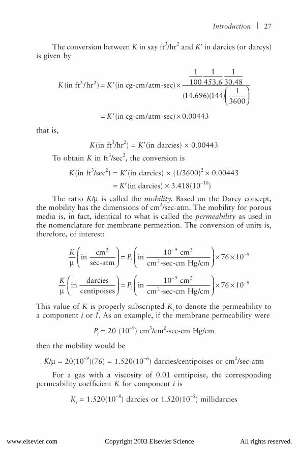
The conversion between K in say ft3/hr2 and K′ in darcies (or darcys)is given by
that is,
K(in ft3/hr2) = K′(in darcies) × 0.00443
To obtain K in ft3/sec2, the conversion is
K(in ft3/sec2) = K′(in darcies) × (1/3600)2 × 0.00443
= K′(in darcies) × 3.418(10−10)
The ratio K/µ is called the mobility. Based on the Darcy concept,the mobility has the dimensions of cm2/sec-atm. The mobility for porousmedia is, in fact, identical to what is called the permeability as used inthe nomenclature for membrane permeation. The conversion of units is,therefore, of interest:
This value of K is properly subscripted Ki to denote the permeability toa component i or I. As an example, if the membrane permeability were
Pi = 20 (10−9) cm3/cm2-sec-cm Hg/cm
then the mobility would be
K/µ = 20(10−9)(76) = 1.520(10−6) darcies/centipoises or cm2/sec-atm
For a gas with a viscosity of 0.01 centipoise, the correspondingpermeability coefficient K for component i is
Ki = 1.520(10−8) darcies or 1.520(10−5) millidarcies
K K
K
( ) ( ) . .
( . )( )
( ) .
in ft /hr in cg-cm/atm-sec
in cg-cm/atm-sec
3 2 = ′ ×
= ′ ×
1100
1453 6
130 48
14 696 1441
3600
0 00443
KP
KP
i
i
µ
µ
incm-atm
incm
cm - -cm Hg/cm
indarcies
centipoisesin
cmcm - -cm Hg/cm
2 3
2
3
2
sec sec
sec
=
× ×
=
× ×
−−
−−
1076 10
1076 10
99
99
www.elsevier.com Copyright 2003 Elsevier Science All rights reserved.
28 MEMBRANE SEPARATIONS TECHNOLOGY
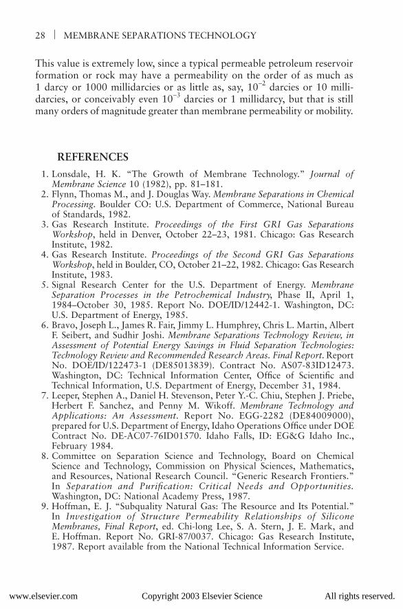
This value is extremely low, since a typical permeable petroleum reservoirformation or rock may have a permeability on the order of as much as1 darcy or 1000 millidarcies or as little as, say, 10−2 darcies or 10 milli-darcies, or conceivably even 10−3 darcies or 1 millidarcy, but that is stillmany orders of magnitude greater than membrane permeability or mobility.
REFERENCES
1. Lonsdale, H. K. “The Growth of Membrane Technology.” Journal ofMembrane Science 10 (1982), pp. 81–181.
2. Flynn, Thomas M., and J. Douglas Way. Membrane Separations in ChemicalProcessing. Boulder CO: U.S. Department of Commerce, National Bureauof Standards, 1982.
3. Gas Research Institute. Proceedings of the First GRI Gas SeparationsWorkshop, held in Denver, October 22–23, 1981. Chicago: Gas ResearchInstitute, 1982.
4. Gas Research Institute. Proceedings of the Second GRI Gas SeparationsWorkshop, held in Boulder, CO, October 21–22, 1982. Chicago: Gas ResearchInstitute, 1983.
5. Signal Research Center for the U.S. Department of Energy. MembraneSeparation Processes in the Petrochemical Industry, Phase II, April 1,1984–October 30, 1985. Report No. DOE/ID/12442-1. Washington, DC:U.S. Department of Energy, 1985.
6. Bravo, Joseph L., James R. Fair, Jimmy L. Humphrey, Chris L. Martin, AlbertF. Seibert, and Sudhir Joshi. Membrane Separations Technology Review, inAssessment of Potential Energy Savings in Fluid Separation Technologies:Technology Review and Recommended Research Areas. Final Report. ReportNo. DOE/ID/122473-1 (DE85013839). Contract No. AS07-83ID12473.Washington, DC: Technical Information Center, Office of Scientific andTechnical Information, U.S. Department of Energy, December 31, 1984.
7. Leeper, Stephen A., Daniel H. Stevenson, Peter Y.-C. Chiu, Stephen J. Priebe,Herbert F. Sanchez, and Penny M. Wikoff. Membrane Technology andApplications: An Assessment. Report No. EGG-2282 (DE84009000),prepared for U.S. Department of Energy, Idaho Operations Office under DOEContract No. DE-AC07-76ID01570. Idaho Falls, ID: EG&G Idaho Inc.,February 1984.
8. Committee on Separation Science and Technology, Board on ChemicalScience and Technology, Commission on Physical Sciences, Mathematics,and Resources, National Research Council. “Generic Research Frontiers.”In Separation and Purification: Critical Needs and Opportunities.Washington, DC: National Academy Press, 1987.
9. Hoffman, E. J. “Subquality Natural Gas: The Resource and Its Potential.”In Investigation of Structure Permeability Relationships of SiliconeMembranes, Final Report, ed. Chi-long Lee, S. A. Stern, J. E. Mark, andE. Hoffman. Report No. GRI-87/0037. Chicago: Gas Research Institute,1987. Report available from the National Technical Information Service.
www.elsevier.com Copyright 2003 Elsevier Science All rights reserved.
Introduction 29
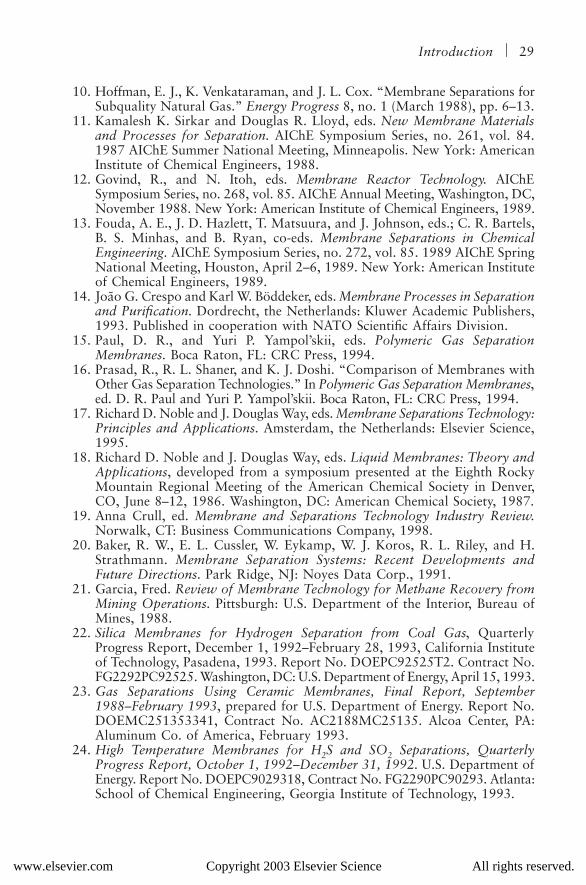
10. Hoffman, E. J., K. Venkataraman, and J. L. Cox. “Membrane Separations forSubquality Natural Gas.” Energy Progress 8, no. 1 (March 1988), pp. 6–13.
11. Kamalesh K. Sirkar and Douglas R. Lloyd, eds. New Membrane Materialsand Processes for Separation. AIChE Symposium Series, no. 261, vol. 84.1987 AIChE Summer National Meeting, Minneapolis. New York: AmericanInstitute of Chemical Engineers, 1988.
12. Govind, R., and N. Itoh, eds. Membrane Reactor Technology. AIChESymposium Series, no. 268, vol. 85. AIChE Annual Meeting, Washington, DC,November 1988. New York: American Institute of Chemical Engineers, 1989.
13. Fouda, A. E., J. D. Hazlett, T. Matsuura, and J. Johnson, eds.; C. R. Bartels,B. S. Minhas, and B. Ryan, co-eds. Membrane Separations in ChemicalEngineering. AIChE Symposium Series, no. 272, vol. 85. 1989 AIChE SpringNational Meeting, Houston, April 2–6, 1989. New York: American Instituteof Chemical Engineers, 1989.
14. João G. Crespo and Karl W. Böddeker, eds. Membrane Processes in Separationand Purification. Dordrecht, the Netherlands: Kluwer Academic Publishers,1993. Published in cooperation with NATO Scientific Affairs Division.
15. Paul, D. R., and Yuri P. Yampol’skii, eds. Polymeric Gas SeparationMembranes. Boca Raton, FL: CRC Press, 1994.
16. Prasad, R., R. L. Shaner, and K. J. Doshi. “Comparison of Membranes withOther Gas Separation Technologies.” In Polymeric Gas Separation Membranes,ed. D. R. Paul and Yuri P. Yampol’skii. Boca Raton, FL: CRC Press, 1994.
17. Richard D. Noble and J. Douglas Way, eds. Membrane Separations Technology:Principles and Applications. Amsterdam, the Netherlands: Elsevier Science,1995.
18. Richard D. Noble and J. Douglas Way, eds. Liquid Membranes: Theory andApplications, developed from a symposium presented at the Eighth RockyMountain Regional Meeting of the American Chemical Society in Denver,CO, June 8–12, 1986. Washington, DC: American Chemical Society, 1987.
19. Anna Crull, ed. Membrane and Separations Technology Industry Review.Norwalk, CT: Business Communications Company, 1998.
20. Baker, R. W., E. L. Cussler, W. Eykamp, W. J. Koros, R. L. Riley, and H.Strathmann. Membrane Separation Systems: Recent Developments andFuture Directions. Park Ridge, NJ: Noyes Data Corp., 1991.
21. Garcia, Fred. Review of Membrane Technology for Methane Recovery fromMining Operations. Pittsburgh: U.S. Department of the Interior, Bureau ofMines, 1988.
22. Silica Membranes for Hydrogen Separation from Coal Gas, QuarterlyProgress Report, December 1, 1992–February 28, 1993, California Instituteof Technology, Pasadena, 1993. Report No. DOEPC92525T2. Contract No.FG2292PC92525. Washington, DC: U.S. Department of Energy, April 15, 1993.
23. Gas Separations Using Ceramic Membranes, Final Report, September1988–February 1993, prepared for U.S. Department of Energy. Report No.DOEMC251353341, Contract No. AC2188MC25135. Alcoa Center, PA:Aluminum Co. of America, February 1993.
24. High Temperature Membranes for H2S and SO2 Separations, QuarterlyProgress Report, October 1, 1992–December 31, 1992. U.S. Department ofEnergy. Report No. DOEPC9029318, Contract No. FG2290PC90293. Atlanta:School of Chemical Engineering, Georgia Institute of Technology, 1993.
www.elsevier.com Copyright 2003 Elsevier Science All rights reserved.

30 MEMBRANE SEPARATIONS TECHNOLOGY
25. Upgrading of Raw Natural Gas Using High-Performance Polymer Membranes.Report No. DOEMETCC937068, CONF930951662. Morgantown, WV:Department of Energy, Morgantown Energy Technology Center, 1993.
26. Department of Chemical Engineering, University of Southern California, LosAngeles. High Temperature Ceramic Membrane Reactors for Coal LiquidUpgrading, Final Report, September 21, 1989–November 20, 1992. ReportNo. DOEPC89879T13, Contract No. AAC2289PC89679. Washington, DC:U.S. Department of Energy, 1992.
27. Department of Chemical Engineering, University of Colorado, Boulder.Direct Methane Conversion to Methanol, Quarterly Status Report, October1, 1992–December 31, 1992. Report No. DOEMC271153343, Contract No.FG2190MC27115. Washington, DC: U.S. Department of Energy, 1993.
28. Cabasso, I., S. A. Stern, H. R. Acharya, W. Li, E. Korngold, T. Makensie,Z. Liu, and E. Poda. Energy Efficient Membrane Processes for the Separationof Organic Liquids. Report No. DOE/ID/12232-1-P1,P2,P3. Washington,DC: U.S. Department of Energy, 1987.
29. Leeper, S. A., and G. T. Tsao. Membrane Separation in Ethanol Recovery:An Analysis of Two Applications of Hyperfiltration. Report No. EGG-J-05285. Idaho Falls, ID: EG&G Idaho Inc., 1986.
30. W. S. Winston Ho and K. K. Sirkar, eds. Membrane Handbook. New York:Van Nostrand, 1992.
31. Noble, R. D., and S. A. Stern, eds. Membrane Science and Technology Series.Membrane Separations Technology: Principles and Applications. Amsterdam,the Netherlands: Elsevier, 1995.
32. McKetta, J. J., and W. A. Cunningham, eds. Encyclopedia of ChemicalProcessing and Design, vol. 27. New York: Marcel Dekker, 1988.
33. Grayson, M., and D. Eckroth, eds. Kirk-Othmer Encyclopedia of ChemicalTechnology, 3d ed., vol. 15. New York: Wiley, 1981.
34. Perry, Robert H., late ed.; Don W. Green, ed.; James O. Maloney, assoc. ed.Perry’s Chemical Engineers’ Handbook, 7th ed. New York: McGraw-Hill,1997.
35. Mazur, W. H., and M. C. Chan. “Membranes for Natural Gas Sweeteningand CO2 Enrichment.” Chemical Engineering Progress 78, no. 10 (1982), p. 38.
36. Schell, W. J. “Membrane Use Technology Growing.” Hydrocarbon Processing62, no. 8 (1983), p. 43.
37. Schell, W. J., and C. D. Houston. “Spiral-Wound Permeators for Purificationand Recovery.” Chemical Engineering Progress 78, no. 10 (1982), p. 33.
38. Hoffman, E. J. “Subquality Natural Gas Reserves.” Energy Sources 10, no. 4(1988), pp. 239–245.
39. Coady, A. B., and J. A. Davis. “CO2 Recovery by Gas Permeation.,” ChemicalEngineering Progress 78, no. 10 (1982), p. 44.
40. Moore, B. J. Analyses of Natural Gases, 1917–1980, Bureau of MinesInformation Circular 8870. Washington, DC: U.S. Department of the Interior,1982.
41. Moore, B. J., and S. Stigler. Analyses of Natural Gases, 1917–85, Bureau ofMines Information Circular 9129. Washington, DC: U.S. Department of theInterior, 1986, updated yearly; also available from NTIS on magnetic tape,floppy disks, or high-density disks.
www.elsevier.com Copyright 2003 Elsevier Science All rights reserved.
Introduction 31
42. Hoffman, E. J. Azeotropic and Extractive Distillation. New York: WileyInterscience,1964; Huntington, NY: Krieger, 1977.
43. Brown, G. G., A. S. Foust, D. L. Katz, R. Schneidewind, R. R. White, W. P.Wood, G. M. Brown, L. E. Brownell, J. J. Martin, G. B. Williams, J. T.Banchero, and J. L. York. Unit Operations. New York: Wiley, 1950.
44. Katz, D. L., D. Cornell, R. Kobayashi, F. H. Poettmann, J. A. Vary, J. R.Elenbaas, and C. F. Weinaug. Handbook of Natural Gas Engineering. NewYork: McGraw-Hill, 1959.
45. Hoffman, E. J. Phase and Flow Behavior in Petroleum Production. Laramie,WY: Energon, 1981.
46. Hwang, S.-T., and K. Kammermeyer. Membranes in Separations, vol. VII ofTechniques of Chemistry, ed. A. Weissberger, Chapters 4 and 8, Appendix B.New York: Wiley Interscience, 1975.
47. Paul, Donald R. Membrane Technology for Gas Separations. New York:American Institute of Chemical Engineers, 1999.
48. Nunes, S. P., and K.-N. Peinemann, eds. Membrane Technology in theChemical Industry. New York: Wiley, 2001.
49. International Critical Tables. New York: McGraw-Hill, 1926–1930.
www.elsevier.com Copyright 2003 Elsevier Science All rights reserved.