INTRODUCTION, COMPOSITE BASICS AND ROAD MAP
20
INTRODUCTION, COMPOSITE BASICS AND ROAD MAP* S.T. Peters This is an introduction to composites and will encourage the reader to obtain more informa- tion. Only the basic concepts will be covered here; reference will be made to the chapters in the book that expand or follow up and elabo- rate on these basics. The reader will see that the subjects of this book cover the spectrum of composites and range from the basic and sim- ple to the complex. Thus, there are complicated equations because they are the tools that are used every day to describe real structures; and there will also be the more gen- eral, less complicated approaches that are limited in analysis power. These chapters have been developed by the most knowledgeable composite professionals in the world; a blend of academicians and the engineers who fabri- cate real composite structures. Modern structural composites, frequently referred to as ’Advanced Composites’, are a blend of two or more components, one of which is made up of stiff, long fibers, and the other, a binder or ’matrix’ which holds the fibers in place. The fibers are strong and stiff relative to the matrix and are generally orthotropic (having different properties in two different directions). The fiber, for advanced structural composites, is long, with length to diameter ratios of over 100. The fiber’s strength and stiffness are usually much greater, perhaps several times more, than the matrix material. The matrix material can by polymeric (e.g. polyester resins, epoxies), Handbook of Composites. Edited by S.T. Peters. Published in 1998 by Chapman & Hall, London. ISBN 0 412 54020 7 metallic, ceramic or carbon. When the fiber and the matrix are joined to form a composite they retain their individual identities and both directly influence the composite’s final proper- ties. The resulting composite will generally be composed of layers (laminae) of the fibers and matrix stacked to achieve the desired proper- ties in one or more directions. The high strength or stiffness to weight ratios of advanced composites are well known, but there are other advantages also (Table 1.1). These advantages translate not only into air- craft, but into everyday activities, such as longer drives with a graphite-shafted golf club (because more of the mass is concentrated at the clubhead) or less fatigue and pain because a graphite composite tennis racquet has mher- ent damping. Generally, the advantages accrue for any fiber/composite combination and dis- advantages are more obvious with some. These advantages have now resulted in many more reasons for composite use as shown in Table 1.2. Proper design and material selection can circumvent many of the disadvantages. 1.1 MATERIAL SYSTEMS An advanced composite laminate can be tai- lored so that the directional dependence of strength and stiffness matches that of the load- ing environment. To do that, layers of unidirectional material called laminae are ori- * This chapter has been adapted from S.T. Peters, in Handbook of Plastics Elastomers and Composites, 3rd edn, (ed. C.A. Harper). McGraw-Hill, New York, 1996, and is used with permission of the McGraw-Hill companies.
Transcript of INTRODUCTION, COMPOSITE BASICS AND ROAD MAP
INTRODUCTION, COMPOSITE BASICS AND ROAD MAP*
S.T. Peters
This is an introduction to composites and will encourage the reader to obtain more informa- tion. Only the basic concepts will be covered here; reference will be made to the chapters in the book that expand or follow up and elabo- rate on these basics. The reader will see that the subjects of this book cover the spectrum of composites and range from the basic and sim- ple to the complex. Thus, there are complicated equations because they are the tools that are used every day to describe real structures; and there will also be the more gen- eral, less complicated approaches that are limited in analysis power. These chapters have been developed by the most knowledgeable composite professionals in the world; a blend of academicians and the engineers who fabri- cate real composite structures.
Modern structural composites, frequently referred to as ’Advanced Composites’, are a blend of two or more components, one of which is made up of stiff, long fibers, and the other, a binder or ’matrix’ which holds the fibers in place. The fibers are strong and stiff relative to the matrix and are generally orthotropic (having different properties in two different directions). The fiber, for advanced structural composites, is long, with length to diameter ratios of over 100. The fiber’s strength and stiffness are usually much greater, perhaps several times more, than the matrix material. The matrix material can by polymeric (e.g. polyester resins, epoxies),
Handbook of Composites. Edited by S.T. Peters. Published in 1998 by Chapman & Hall, London. ISBN 0 412 54020 7
metallic, ceramic or carbon. When the fiber and the matrix are joined to form a composite they retain their individual identities and both directly influence the composite’s final proper- ties. The resulting composite will generally be composed of layers (laminae) of the fibers and matrix stacked to achieve the desired proper- ties in one or more directions.
The high strength or stiffness to weight ratios of advanced composites are well known, but there are other advantages also (Table 1.1).
These advantages translate not only into air- craft, but into everyday activities, such as longer drives with a graphite-shafted golf club (because more of the mass is concentrated at the clubhead) or less fatigue and pain because a graphite composite tennis racquet has mher- ent damping. Generally, the advantages accrue for any fiber/composite combination and dis- advantages are more obvious with some. These advantages have now resulted in many more reasons for composite use as shown in Table 1.2. Proper design and material selection can circumvent many of the disadvantages.
1.1 MATERIAL SYSTEMS
An advanced composite laminate can be tai- lored so that the directional dependence of strength and stiffness matches that of the load- ing environment. To do that, layers of unidirectional material called laminae are ori-
* This chapter has been adapted from S.T. Peters, in Handbook of Plastics Elastomers and Composites, 3rd edn, (ed. C.A. Harper). McGraw-Hill, New York, 1996, and is used with permission of the McGraw-Hill companies.

2 Introduction, composite basics and road map
Table 1.1 Advantages/disadvantages of advanced composites
Advantages Disadvantages
Weight reduction High strength or stiffness to weight ratio
Tailorable properties Can tailor strength or stiffness to be in the load direction
___- Cost of raw materials and fabrication
Transverse properties may be weak
Redundant load paths (fiber to fiber)
Longer life (no corrosion)
Lower manufacturing costs because of less part count
Inherent damping Analysis is difficult
Increased (or decreased) thermal or electrical conductivity
Matrix is weak, low toughness
Reuse and disposal may be difficult
Difficult to attach
Matrix subject to environmental degradation
ented to satisfy the loading requirements. These laminae contain fibers and a matrix. Because of the use of directional laminae, the tensile, flex- ural and torsional shear properties of a structure can be disassociated from one another to some extent and a golf shaft, for example, can be changed in torsional stiffness without chang- ing the flexural or tensile stiffness.
Fibers can be of the same material within a lamina or several fibers mixed (hybrid). The common commercially available fibers are as follows:
0 fiberglass; 0 graphite; 0 aramid; 0 polyethylene; 0 boron; 0 silicon carbide; 0 silicon nitride, silica, alumina, alumina silica.
The advantages of fiberglass (Chapter 7) are its high tensile strength and strain to failure, but heat and fire resistance, chemical resistance, moisture resistance and thermal and electrical properties are also cited as reasons for its use. It is by far the most widely used fiber, primar- ily because of its low cost; but its mechanical properties are not comparable with other structural fibers.
Carbon/graphite fibers (Chapter 9) have demonstrated the widest variety of strengths and modulii and have the greatest number of suppliers. The fibers begin as an organic fiber, rayon, polyacrylonitrile or pitch which is called the precursor. The precursor is then stretched, oxidized, carbonized and graphi- tized. There are many ways to produce these fibers, but the relative amount of exposure at temperatures from 2500-3000°C results in greater or less graphitization of the fiber. Higher degrees of graphitization usually result in a stiffer fiber (higher modulus) with greater electrical and thermal conductivities and usually higher cost.
The organic fiber Kevlar 49, (Chapter 10) also called aramid, essentially revolutionized pressure vessel technology because of its great tensile strength and consistency coupled with low density, resulting in much more weight effective designs for rocket motors. Aramid composites are still widely used for pressure vessels but have been largely supplanted by the very high strength graphite fibers. Aramid composites have relatively poor shear and compression properties; careful design is requires for their use in structural applications that involve bending or compression.

Material systems 3
Table 1.2 The reasons for using composites
Reason for use Material selected Appl ica t ion/driver Lighter, stiffer stronger Boron, all carbodgraphites, Military aircraft, better
___
some aramid performance
Controlled or zero thermal expansion
Environmental resistance
Lower inertia, faster startups, less deflection
Lightweight, damage tolerance
More reproducible complex surfaces
Less pain and fatigue
Reduces logging in ‘old growth’ forests
Reduces need for intermediate support and resists constant 100% humidity atmosphere
Tailorability of bending and twisting response
Transparency to radiation
Crashworthiness
Higher natural frequency, lighter
Water resistance
Ease of field application
Commercial aircraft, operating costs
Spacecraft with high positional
sensors
Tanks and piping, corrosion resistance to industrial chemicals, crude oil, gasoline at elevated temperatures
Industrial rolls, for paper, films
Very high modulus carbon/graphite accuracy requirements for optical
Fiberglass, vinyl esters, bisphenol A fumarates, chlorendic resins
High strength carbon/graphite, epoxy
High strength carbon/graphite, CNG tanks for ’green’ cars, trucks fiberglass, (hybrids), epoxy
High strength or high modulus carbon graphite/ epoxy Carbon/graphite/epoxy Tennis, squash and racquetball
and busses to reduce environmental pollution
High-speed aircraft. Metal skins cannot be formed accurately
racquets. Metallic racquets are no longer available
Laminated ‘new’ growth wooden support beams with high modulus fibers incorporated
Aramid, carbon/graphite
High strength Cooling tower driveshafts carbon/graphite-epoxy
Carbon/graphite-epoxy Golf shafts, fishing rods
Carbon/ graphite-epoxy X-ray tables
Carbon/ graphite-epoxy Racing cars
Carbon/ graphite-epoxy Automotive and industrial driveshafts
Fiberglass (woven fabric), Commercial boats polyester or isopolyester
Carbon/graphite, fiberglass - epoxy, tape and fabric
Freeway support structure repair after earthquake
The polyethylene fibers have the same property drawbacks as aramids, but also suf- fer from low melting temperature which limits
their use to composites that cure or operate below 149°C (300°F) and a susceptibility to degradation by ultraviolet light exposure.

4 lntvodmction, composite basics and road map
Both of these types of fibers have wide usage in personal protective armor. In spite of the drawbacks, production of both of these fibers is enjoying strong worldwide growth.
Boron fibers (Chapter 8), the first advanced composite fibers to be used on production aircraft, are produced as individual mono- filaments upon a tungsten or carbon substrate by pyrolytic reduction of boron trichloride (BC1,) in a sealed glass chamber. The relatively large cross section fiber is used today primar- ily in metal matrix composites which are processed at temperatures which would attack carbon/graphite fibers.
1.2 MATRIX SYSTEMS
If parallel and continuous fibers are combined with a suitable matrix and cured properly, uni- directional composite properties such as those shown on Table 1.3 are the result.
The functions and requirements of the matrix are to:
0 keep the fibers in place in the structure; 0 help to distribute or transfer loads; 0 protect the filaments, both in the structure
and before and during fabrication; 0 control the electrical and chemical proper-
ties of the composite; 0 carry interlaminar shear.
Table 1.3 Properties of typical unidirectional graphite/epoxy composites (Fiber volume fraction, V , = 0.62)
High strength High modulus
Elastic constants GPa (psi x I O 6 ) GPa (psi x I O 6 )
Longitudinal modulus, E, 145 (21) 220 (32) Transverse modulus, E , 9.6 (1.4) 6.9 (1.0) Shear modulus, G , 5.8 (0.85) 4.8 (0.7) Poisson’s ratio (dimensionless) u ~ , 0.30 0.30
Strength properties MPa ( Z 0 3 psi) MPa (lo3 psi)
Longitudinal tension, Ft”, 2139 (310) 760 (110)
Longitudinal compression, FCUL 1724 (250) 690 (100) Transverse compression, FCUT 76 (11) 170 (25) Inplane shear, PLT 87 (12.6) 70 (10) Interlaminar shear, F’,”” 128 (18.5) 70 (10)
~~
~~ ~ ~~ ~~ ~~~ ~~ .~
~ ~~~ ~~~~ ~ ~
Transverse tension, FtUT 54 (7.8) 28 (4)
Ultimate strains
Longitudinal tension, Transverse tension, Longitudinal compression, ECUL Transverse compression, EC1lT Inplane shear
- -~ %
1.4 0.67 0.9 3.6 2.0
0.3 0.4 0.3 2.8 -
Physical properties Density, kg/m3 (Ib/in3) 1600 (0.056) 1700 (0.058) Longitudinal CTE,
Transverse CTE ~ E / K (pe/OF) 21.6 (12) 58 (32) From References 1, 2 and 3; CTE = coefficient of thermal expansion
ye/K (pe/OF) -0.079 (-0.044) -0.54 (-0.3)

Matrix systems 5
The needs, or desired properties of the matrix, that depend on the purpose of the struc- ture are:
0 minimize moisture absorption; 0 have low shrinkage; 0 Must wet and bond to fiber; 0 low coefficient of thermal expansion; 0 must flow to penetrate the fiber bundles
completely and eliminate voids during the compacting/curing process; have reasonable strength, modulus and elongation (elongation should be greater than fiber);
0 must be elastic to transfer load to fibers; 0 have strength at elevated temperature
(depending on application); 0 have low temperature capability (depend-
ing on application); 0 have excellent chemical resistance (depend-
ing on application); 0 be easily processable into the final compos-
ite shape; 0 have dimensional stability (maintain its
shape).
There are many matrix choices available; each type has impact on the processing technique, physical and mechanical properties and envi- ronmental resistance of the finished
Table 1.4 Selection criteria for epoxy resin systems
composite. The common thermoset matrices for composites include the following:
0 polyester and vinylesters (Chapter 2); 0 epoxy (Chapter 3); 0 bismaleimide (BMI) (Chapter 4); 0 polyimide (Chapter 4);
cyanate ester and phenolic triazine
Each of the resin systems has some drawbacks, which must be accounted for in design and manufacturing plans.
Polyester matrices have been in use for the longest period, and are used in the widest range and greatest number of structures. The usable polymers may contain up to 50% by weight of unsaturated monomers and solvents such as styrene. Polyesters cure via a catalyst (usually a peroxide) resulting in an exothermic reaction, which can be initiated at room tem- perature.
The most widely used matrices for advanced composites have been the epoxy resins. These resins cost more than polyesters and do not have the high temperature capabil- ity of the bismaleimides or polyimides, but because of the advantages shown in Table 1.4 they are widely used.
(Chapter 5).
Advantages Disadvantages
Adhesion to fibers and to resin No by-products formed during cure Low shrinkage during cure High or low strength and flexibility
Solvent and chemical resistance Resistance to creep and fatigue
Solid or liquid resins in uncured state Wide range of curative options Adjustable curing rate Good electrical properties
Resins and curatives somewhat toxic in uncured form
Absorb moisture Heat distortion point lowered by moisture absorption Change in dimensions and physical properties due to moisture absorption Limited to about 200°C upper temperature use (dry) Difficult to combine toughness and high temperature resistance High thermal coefficient of expansion High degree of smoke liberation in a fire May be sensitive to ultraviolet light degradation Slow curing

6 Introduction, composite basics and road map
There are two resin systems in common use for higher temperatures, bismaleimides and polyimides. New designs for aircraft demand a 177°C (350°F) operating temperature not met by the other common structural resin systems. The primary bismaleimide in use is based on the reaction product from methylene dianiline (MDA) and maleic anhydride: bis (4-maleimi- dophenyl) methane (MDA BMI).
Two newer resin systems have been devel- oped and have found applications in widely diverse areas. The cyanate ester resins, mar- keted by Ciba-Geigy, have shown superior dielectric properties and much lower moisture absorption than any other structural resin for composites. The dielectric properties have enabled their use as adhesives in multilayer microwave printed circuit boards, and the low moisture absorbance have caused them to be the resin of universal choice for structurally- stable spacecraft components.
The phenolic triazine (PT) resins also have superior elevated temperature properties, along with excellent properties at cryogenic temperatures. Their resistance to proton
radiation under cryogenic conditions was a prime cause for their choice for use in the superconducting supercollider, subsequently canceled by the US Congress.
Polyimides are the highest temperature polymer in general advanced composite use with a long term upper temperature limit of 232°C (450°F) or 316°C (600°F). Two general types are: condensation polyimides, that release water during the curing reaction, and addition type polyimides with somewhat eas- ier process requirements.
1.3 FIBER MATRIX SYSTEMS
The end user sees a composite structure. Someone else, probably a prepregger, com- bined the fiber and the resin system and someone else caused the cure and compaction to result in a laminated structure. A schematic of the steps to arrive at a finished composite from the initial fiber is shown in Fig. 1.1.
In many cases, the end user of the structure has fabricated the composite from prepreg, which is a low-temperature-stable combination
R O V I N G WEAUE?
N?
UNI TRPE COLLIMRTE
A
Fig. 1.1 Manufacturing steps in composite structure.

Fiber matrix systems 7
of the resin, its curing agents and the fiber. The three types of continuous fibers, roving, tape and woven fabric available as prepregs give the end user many options in terms of design and manufacture of a composite structure. Although the use of dry fibers and impregna- tion at the work (i.e. filament winding, pultrusion or hand lay-up) is very advanta- geous in terms of costs; there are many advantages to the use of prepregs as shown in Table 1.5, particularly for the manufacture of modem composites.
Table 1.5 Advantages of prepregs over wet impregnation
The prepreg process for thermoset matrices can be accomplished by feeding the fiber con- tinuous tape, woven fabric or roving through a resin-rich solvent solution and then removing the solvent by hot tower drying. The excess resin is removed via a doctor blade or meter- ing rolls and then the product is staged to the cold-stable prepreg form, (B stage) (Fig. 1.2).
The newer hot melt procedure for prepregs is gradually replacing the solvent method because of environmental concerns. A film of resin that has been cast hot onto release paper
Prepregs reduce the handling damage to dry fibers
Improve laminate properties by better dispersion of short fibers
Prepregs allow the use of hard-to-mix or proprietary resin systems
Allow more consistency because there is a chance for inspection before use
Heat curing provides more time for the proper laydown of fibers and for the resin to move and degas before cure
Increased curing pressure reduces voids and improves fiber wetting
Most prepregs have been optimized as individual systems to improve processing
Release Poly Unwind
Prepreg Wind
Pump and Unwind Reservoir
Fig. 1.2 Schematic of typical solvent prepregging process. (Adapted from Reference 2.)

8 Introduction, composite basics and road map
0 Pauer
0
Doctor Plate 1
Impregnation Zone
Paper
T Take-up Paper Prepreg
Windup Creel
Chill Plate Plate 2
Fig. 1.3 Schematic of typical film impregnating process. (Adapted from Reference 2.)
is fed, along with the reinforcement, through a series of heaters and rollers to force the resin into the reinforcement. Two layers of resin are commonly used so that a resin film is on both sides of the reinforcement; one of the release papers is removed and the prepreg is then trimmed, rolled and frozen (Fig. I.3)2. The sol- vent technique has been largely replaced for advanced fibers because of environmental pol- lution concerns and a need to exert better control over the amount of resin on the fiber.
1.3.1 UNIDIRECTIONAL PLY PROPERTIES
The manufacturer of the prepreg reports an areal weight for the prepreg and a resin per- centage, by weight. Each of the different fibers has a different density, resulting in a composite of different density at the same fiber volume percentage. Since fiber volume is used to relate the properties of the manufactured composites, the following equations can be used to convert between weight fraction and fiber volume.
where:
Wf = weight fraction of fiber wf = weight of fiber wc = weight of composite pf = density of fiber p, = density of composite uf = volume of fiber u, = volume of composite Vf = volume fraction of fiber V, = volume fraction of matrix p, = density of matrix.
A percentage fiber that is easily achievable and repeatable in a composite and convenient for reporting mechanical and physical proper- ties for several fibers is 60%. The properties of unidirectional fiber laminates are shown in Table 1.3 for carbon/graphite/epoxy. Values for the other fibers can be seen in their respec- tive chapters. These values are for individual lamina or for a unidirectional composite, and they represent the theoretical maximum (for that fiber volume) for longitudinal in plane properties. Transverse, shear and compression properties will show maxima at different fiber volumes and for different fibers, depending on how the matrix and fiber interact. These val- ues can be used to calculate the properties of a laminate which has fibers oriented in several directions. To do that, the methods of descrip- tion for ply orientation must be introduced.
Quasi-isotropic laminate 9
1.4 PLY ORIENTATIONS, SYMMETRY AND BALANCE
1.4.1 PLY ORIENTATIONS
One of the advantages of using a modern com- posite is the potential to orient the fibers to respond the load requirements. This means that the composite designer must show the material, the fiber orientations in each ply, and how the plies are arranged (ply stackup).
A 'shorthand' code for ply fiber orientations has been adapted for use in layouts and studies.
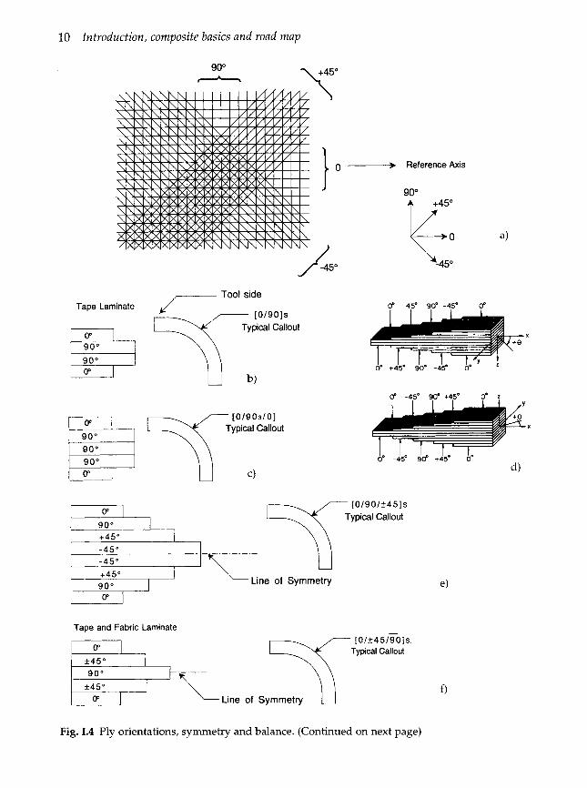
Each ply (lamina) is shown by a number rep- resenting the direction of the fibers in degrees, with respect to a reference ( x ) axis. 0" fibers of both tape and fabric are normally aligned with the largest axial load (axis) (Fig. 1.4(a)).
Individual adjacent plies are separated by a slash in the code if their angles are different (Fig. 1.4@)).
The plies are listed in sequence, from one laminate face to the other, starting with the ply first on the tool and indicated by the code arrow with brackets indicating the beginning and end of the code.
Adjacent plies of the same angle of orienta- tion are shown by a numerical subscript (Fig. 1.4(c)).
When tape plies are oriented at angles equal in magnitude but opposite in sign, (+) and (-) are used. Each (+) or (-) sign represents one ply. A numerical subscript is used only when there are repeating angles of the same sign. Positive and negative angles should be consis- tent with the coordinate system chosen. An orientation shown as positive in one right handed coordinate system may be negative in another. If the y and z axis directions are reversed, the f 45 plies are reversed (Fig. 1.4(d)).
Symmetric laminates with an even number of plies are listed in sequence, stating at one face and stopping at the midpoint. A subscript 'S' following the bracket indicates only one half of the code is shown (Fig. 1.4(e)).
Symmetric laminates with an odd number of plies are coded as a symmetric laminate except that the center ply, listed last, is over-
lined to indicate that half of it lies on either side of the plane of symmetry (Fig. 1.4(f)).
1.4.2 SYMMETRY
The geometric midplane is the reference sur- face for determining if a laminate is symmetrical. In general, to reduce out-of- plane strains, coupled bending and stretching of the laminate and complexity of analysis, symmetric laminates should be used. However, some composite structures (e.g. fila- ment wound pressure vessels) can achieve geometric symmetry so that symmetry through a single laminate wall is not neces- sary, if it constrains manufacture. To construct a midplane symmetric laminate, for each layer above the midplane there must exist an identi- cal layer (same thickness, material properties, and angular orientation) below the midplane (Fig. 1.4(e)).
1.4.3 BALANCE
All laminates should be balanced to achieve in- plane orthotropic behavior. To achieve balance, for every layer centered at some positive angle +e there must exist an identical layer oriented at -8 with the same thickness and material properties. If the laminate contains only 0" and/or 90" layers it satisfies the requirements for balance. Laminates may be midplane s p - metic but not balanced and vice versa. Figure 1.4(e) is symmetric and balanced whereas Fig. 1.4(g) is balanced but unsymmetric .
1.5 QUASI-ISOTROPIC LAMINATE
The goal of composite design is to achieve the lightest, most efficient structure by aligning most of the fibers in the direction of the load. Many times there is a need, however, to pro- duce a composite which has some isotropic properties, similar to metal, because of multi- ple or undefined load paths. A 'quasi-isotropic' laminate lay-up accomplishes this for the x and y planes only; the z or through-the-laminate-
10 Introduction, composite basics and road map
90" -
,-. Tool side Tape Laminate ,/
[0/9O]s Typical Callout
[0/9O]s
I I P 1
I \ \
Reference Axis
90" lz; 0" 45' 90' -45' 0"
0" -450 w +450 0" L
[0/903/0]
[0/90/*45]s Typical Callout T P I
90" +45" -45" -45" +45" 90" Line of Symmetry
V I
Tape and Fabric Laminate [ 0 /f4 5 /To 1 s.
Typical Callout
0 Line of Symmetry
Fig. 1.4 Ply orientations, symmetry and balance. (Continued on next page)

Methods of analysis 11
Tape Laminate p, +45" -45" -4 5"
+45"
Fabric Laminate
I 0".90" I
j 0",90" I
[0/90/f45/ i 452/ 9 0 / 01 Typical Callout
[(0,90)/(~45)/(0,90)] Typical Callout
h)
Fig. 1.4 Ply orientations, symmetry and balance. (Continued)
thickness plane is quite different and lower. 1. arrive at quick values to determine if a com- Most laminates produced for aircraft applica- posite is feasible; tions have been, with few exceptions, 2. arrive at values for insertion into computer 'quasi-isotropic'. As designers become more programs for laminate analysis or finite ele- confident and have access to a greater database ment analysis; with fiber-based structures, more applications will evolve. For a quasi-isotropic laminate, the following are requirements:
3. check on the results of computer analysis.
The rule of mixtures holds for composites. The micromechanics formula to arrive at the
0
0
0
It must have three layers or more. Individual layers must have identical stiff- ness matrices and thicknesses. The layers must be oriented at equal angles. For example, if the total number of layers is M , the angle between two adjacent layers should be 360"ln. If a laminate is con- structed from identical sets of three or more layers each, the condition on orientation must be satisfied by the layers in each set, for example: ( O o / + 60"), or ( O o / + 45"/90)s.
Young's modulus for a given composite is:
Ec = V, E, + Vm Em
and v, + vm = 1
= V, E , + Em (1 - V,) (1.3) where
Ec = composite or ply Young's modulus in tension for fibers oriented in direction of applied load
V = volume fraction of fiber ( f ) or matrix (m) E = Young's modulus of fiber ( f ) or matrix
1.6 METHODS OF ANALYSIS (m). There are a number of methods in common But, since the fiber has much higher use for the analysis of composite laminates. Young's modulus than the matrix, the second The use of micromechanics, i.e. the application part of the equation can be ignored.
E, >> Em of the properties of the constituents to arrive at the properties of the composite ply can be used to: Ec = E,V, (1.4)
12 Introduction, composite basics and road map
This is the basic rule of mixture and repre- sents the highest Young’s modulus composite, where all fibers are aligned in the direction of load. The minimum Young’s modulus for a reasonable design (other than a preponder- ance of fibers being orientated transverse to the load direction) is the quasi-isotropic com- posite and can be approximated by:
Ec = (3/8) E,V, (1.5) The quasi-isotropic modulus, E, of a composite laminate is (3/8)E,+(5/8)EZ where E,, is the modulus of the lamina in the fiber direction and E, is the transverse modulus of the lamina3. The transverse modulus for polymeric-based composites is a small fraction of the longitudinal modulus (see E, in Table 1.3) and can be ignored, for preliminary estimates, resulting in a slightly lower-than-theoretical value for Ec for a quasi- isotropic laminate. This approximate value for the quasi-isotropic modulus represents the lower limit of composite modulus. It is useful in comparing of composite properties to those of metals and in establishing if a composite is
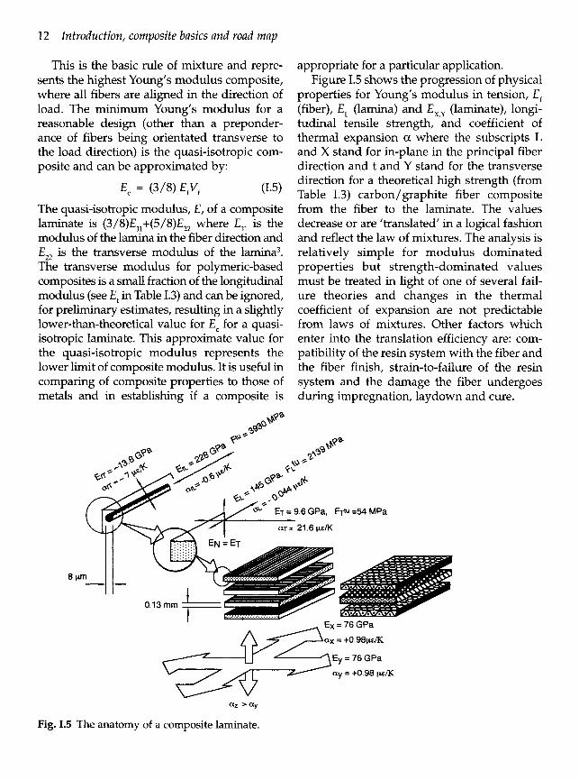
appropriate for a particular application. Figure 1.5 shows the progression of physical
properties for Young’s modulus in tension, E , (fiber), E, (lamina) and Ex,, (laminate), longi- tudinal tensile strength, and coefficient of thermal expansion a where the subscripts L and X stand for in-plane in the principal fiber direction and t and Y stand for the transverse direction for a theoretical high strength (from Table 1.3) carbon/graphite fiber composite from the fiber to the laminate. The values decrease or are ’translated’ in a logical fashion and reflect the law of mixtures. The analysis is relatively simple for modulus dominated properties but strength-dominated values must be treated in light of one of several fail- ure theories and changes in the thermal coefficient of expansion are not predictable from laws of mixtures. Other factors which enter into the translation efficiency are: com- patibility of the resin system with the fiber and the fiber finish, strain-to-failure of the resin system and the damage the fiber undergoes during impregnation, laydown and cure.
.6 GPa, FT‘“ =54 MPa
E x = 76 GPa
a x = 4.98peK
Ey = 76 GPa
a y = 4.98 ~ E K r a 2 >ay
Fig. 1.5 The anatomy of a composite laminate.

Composite fabrication techniques 13
Table 1.6 High-strength carbon/graphite laminate properties
Laminate Longitudinal Bending Shear modulus modulus, modulus, E,, (GPa) E , (GPa) G,, (GPa)
(0/90,/0) 76.5 126.8 5.24 (90/0,/90) 76.5 26.3 5.24 (02/902/OJ 98.5 137.8 5.24 (0,/~45,/0,) 81.3 127.5 21.0 (0/+45/90)> 55.0 89.6 21.0 Aluminum 41.34 41.34 27.56
Table 1.6 shows mechanical values for sev- eral composite laminates with the fiber of Table 1.3 and a typical resin system. The first and second entries are for simple 0/90 lami- nates and show the effect of changing the position of the plies. The effect of increasing the number of 0 plies is shown next and the final two laminates demonstrate the effect of +45 plies on mechanical properties, particu- larly the shear modulus. The last entry is a quasi-isotropic laminate. These laminates are then compared to a typical aluminum alloy.
When employing the data extracted from tables, some caution should be observed by the reader. The values seen in many tables of data may not always be consistent for the same materials or the same group of materials from several sources for the following reasons:
1. Manufacturers have been refining their pro- duction processes so that newer fibers may have greater strength or stiffness. These new data may not be reflected in the com- piled data.
2. The manufacturer may not be able to change the value quoted for the fiber because of government or commercial restrictions imposed by the specification process of his customers.
3. There are many different high-strength fibers commercially available. Each manu- facturer has optimized their process to maximize their mechanical properties and each process may differ from that of the
competitor, so vendor values in a generic class may differ widely.
4. Most tables of values are presented as 'typi- cal values'. Those values and the values that are part of the menu of many computer analysis programs should be used with care. Each user must find their own set of values for design, develop useful design allow- ables, and apply appropriate 'knock down' factors, based on the operating environ- ments expected in service. (Chapter 33 and Appendix A give guidelines.)
1.7 COMPOSITE FABRICATION TECHNIQUES
The goals of the composite manufacturing process are to:
0 achieve a consistent product by controlling - fiber thickness; - fiber volume; - fiber directions;
0 minimize voids; 0 reduce internal residual stresses; 0 process in the least costly manner.
The procedures to reach these goals involve iterative processes to select the three key com- ponents:
0 composite material and its configuration;
0 process.
Once material selection has been completed, the first step leading to the acceptable com- posite structure is the selection of tooling, which is intimately tied to process and mater- ial. For all curing techniques the tool must be:
0 strong and stiff enough to resist the pres- sure exerted during cure;
0 dimensionally stable through repeated heating and cooling cycles;
0 light enough to respond reasonably quickly to the changes in cure cycle temperature and to be moved in the shop;
0 leakproof so that the vacuum and pressure cycles are consistent.
0 tooling;
14 Introduction, composite basics and road map
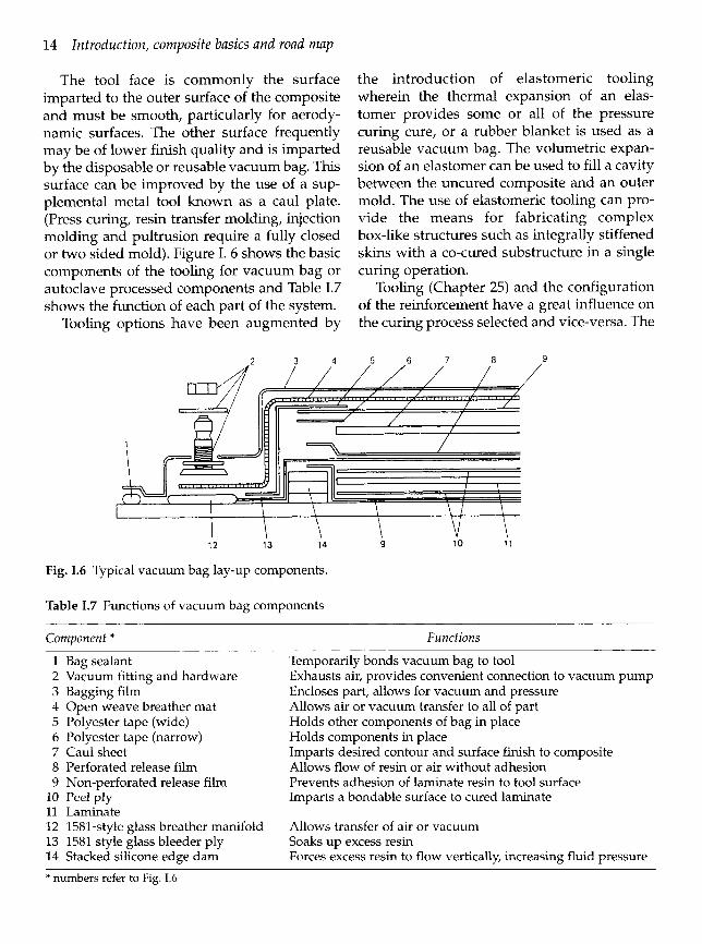
The tool face is commonly the surface imparted to the outer surface of the composite and must be smooth, particularly for aerody- namic surfaces. The other surface frequently may be of lower finish quality and is imparted by the disposable or reusable vacuum bag. This surface can be improved by the use of a sup- plemental metal tool known as a caul plate. (Press curing, resin transfer molding, injection molding and pultrusion require a fully closed or two sided mold). Figure I. 6 shows the basic components of the tooling for vacuum bag or autoclave processed components and Table 1.7 shows the function of each part of the system.
Tooling options have been augmented by
2 3 4
the introduction of elastomeric tooling wherein the thermal expansion of an elas- tomer provides some or all of the pressure curing cure, or a rubber blanket is used as a reusable vacuum bag. The volumetric expan- sion of an elastomer can be used to fill a cavity between the uncured composite and an outer mold. The use of elastomeric tooling can pro- vide the means for fabricating complex box-like structures such as integrally stiffened skins with a co-cured substructure in a single curing operation.
Tooling (Chapter 25) and the configuration of the reinforcement have a great influence on the curing process selected and vice-versa. The
5 6 7 8 9
12 13 14 9 10 1 1
Fig. 1.6 Typical vacuum bag lay-up components.
Table 1.7 Functions of vacuum bag components
Component * Functions -
1 2 3 4 5 6 7 8 9
10 11 12 13 14
Bag sealant Vacuum fitting and hardware Bagging film Open weave breather mat Polyester tape (wide) Polyester tape (narrow) Caul sheet Perforated release film Non-perforated release film Peel ply Laminate 1581-style glass breather manifold 1581 style glass bleeder ply Stacked silicone edge dam
Temporarily bonds vacuum bag to tool Exhausts air, provides convenient connection to vacuum pump Encloses part, allows for vacuum and pressure Allows air or vacuum transfer to all of part Holds other components of bag in place Holds components in place Imparts desired contour and surface finish to composite Allows flow of resin or air without adhesion Prevents adhesion of laminate resin to tool surface Imparts a bondable surface to cured laminate
Allows transfer of air or vacuum Soaks up excess resin Forces excess resin to flow vertically, increasing fluid pressure
* numbers refer to Fig. 1.6
Composite fabrication techniques 15
probable reinforcement configuration that facilitates the completion of the finished com- posite is shown on Table 1.8.
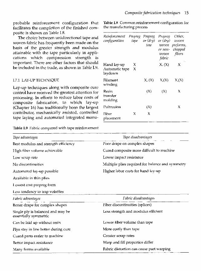
The choice between unidirectional tape and woven fabric has frequently been made on the basis of the greater strength and modulus attainable with the tape particularly in appli- cations which compression strength is important. There are other factors that should be included in the trade, as shown in Table 1.9.
1.7.1 LAY-UP TECHNIQUE
Lay-up techniques along with composite cure control have received the greatest attention for processing. In efforts to reduce labor costs of composite fabrication, to which lay-up (Chapter 16) has traditionally been the largest contributor, mechanically assisted, controlled tape laying and automated integrated manu-
Table 1.9 Fabric compared with tape reinforcement
Table 1.8 Common reinforcement configuration for the manufacturing process
Reinforcement Prepreg Prepreg Prepreg Other, configuration tape or (dry) or (dry) woven
tow woven preforms, or non- chopped woven fibers fabric
Handlay-up X x, (XI x Automatic tape X lay down
Filament x, (X) x m x m winding
Resin (XI (X) X transfer molding
Pultrusion (X) X
Fiber X X placement
Tape advantages Tape disadvantages
Best modulus and strength efficiency
High fiber volume achievable
Low scrap rate
No discontinuities
Automated lay-up possible
Available in thin plies
Lowest cost prepreg form
Less tendency to trap volatiles
Fabric advantages Fabric disadvantages
Better drape for complex shapes
_ _ _ _ _ ~ - ~ Poor drape on complex shapes
Cured composite more difficult to machine
Lower impact resistance
Multiple plies required for balance and symmetry
Higher labor costs for hand lay-up
~ _ _ ~ _ _ _ - - ~ _ _ Fiber discontinuities (splices)
Single ply is balanced and may be essentially symmetric
Less strength and modulus efficient
Can be laid up without resin
Plys stay in line better during cure
Cured parts easier to machine
Better impact resistance
Many forms available
Lower fiber volume than tape
More costly than tape
Greater scrap rates
Warp and fill properties differ
Fabric distortion can cause part warping

16 Introduction, composite basics and road m a p
facturing systems have been developed. Table 1.10 shows some of the considerations for choosing a lay-up technique.
In addition to any cost savings by the use of an automated technique for long production runs, there are two key quality assurance fac- tors which validate the automated techniques. They are: greatly reduced chance that release paper or film could be retained, which would destroy shear and compressive strength if undetected, and reduced probability of the addition or loss of an angle ply which would cause warping due to the laminate’s lack of symmetry and balance.
All curing techniques use heat and pressure to cause the matrix to flow and wet out all the fibers before the matrix solidifies (Chapter 26).
Table 1.10 Considerations in composite lay-up technique
Generally, the percent matrix weight is higher before cure initiation; the matrix flows out of the laminate and takes the excess resin with the potential voids. An arbitrary 1% void limit has been adopted for most autoclaved com- posites; filament wound and pultruded composites will have higher void volumes depending upon the application.
An autoclave is essentially a closed, pres- surized oven; many common epoxy laminates are cured at an upper temperature of 177°C (350°F) and 6 MPa (100 psi). Autoclaves are still the primary tool in advanced composite processing and have been built up to 16 m (55 feet) long at 6.1 m (20 feet) diameter. Since autoclaves are expensive to build and operate, many other methods of curing, compacting
Considerat ion Manual Flat tape Contoured tape Orientation accuracy
Ply count
Release film retention
Labor costs
Machine costs
Production rate
Machine ’up’ time
Varying tape widths
Tape lengths
Cutting waste
Compaction pressure
Programming
Least accurate Automatic
Dependent on operator, Dependent on count Mylars operator
Up to operator Automatic
High 86% improvement
N/A Some costs
quoted
Low (1.5 Ib/h) 10 lb/h
N/A Not a consideration
Not a concern Easily changed
Longer tapes more Longer is more difficult economical
Scrap on cutting Less scrap
No pressure Less voids
N/A N/A
Somewhat dependent on tape accuracy and computer program
Program records
Automatic removal
Additional improvement
Approximately 1M$ or greater
Approximately same as flat tape
Complex program and machine make this a consideration
Difficulty in changing
Longer tape is more economical
Least scrap due to back and forth laydown
Least voids
Necessary

Composite fabrication techniques 17
composites have been developed. The two newest and most attractive methods are fiber placement and resin transfer molding.
1.7.2 RESIN TRANSFER MOLDING
Previous discussions have centered on moving resin out of the laminate to reduce voids. Resin transfer involves the placement of dry fiber reinforcement into a closed mold and then injecting a catalyzed resin into the mold to encapsulate the reinforcement and form a composite (Chapter 20). The impetus for the use of this process comes from the large cost reductions that can be realized in raw materi- als and lay-up. The process can utilize low injection pressures i.e. 55 MPa (80 psi), there- fore, the tooling can be lower cost plastic or a vacuum bag rather than metal.
a wind eye at speeds synchronized with the mandrel rotation, control winding angle of the reinforcement and the fiber lay-down rate.
The reinforcement may be wrapped in adja- cent bands or in repeating bands that are stepped the width of the band and that even- tually cover the mandrel surface. Local reinforcement can be added to the structure using circumferential windings, local helical bands, or by the use of woven or unidirec- tional cloth. The wrap angle can be varied from low angle helical to high angle circum- ferential or 'hoop', which allows winding from about 4"-90" relative to the mandrel axis; newer machines can 'place' fiber at 0".
1.7.4 FIBER PLACEMENT
Fiber placement, initially developed by Hercules Aerospace Co., is a cross between fil- ament winding and automatic tape laydown, retaining many of the advantages of both. The natural outgrowth of adding multiple axes of control to filament winding machines results in control of the fiber laydown so that non axi- symmetric surfaces can be wound. This involves the addition of a modified tape lay- down head to the filament winding machine and much more. The Cincinnati-Milacron
1.7.3 FILAMENT WINDING
Filament winding is a process by which con- tinuous reinforcements in the form of rovings or tows (gathered, untwisted strands of fiber) are wound over a rotating mandrel. The man- drel can be cylindrical, round or any other shape as long as it does not have re-entrant curvature. Special machines (Fig. 1.7) traversing - -
machine additions include in-process com- paction, individual tow cut/start capabilities, a resin tack control system, differential tow
f 1 payout, low tension on fiber and enhanced off- iine programming (Chapter 22). I / 1.7.5 PULTRUSION
11 Pultrusion is an automated process for the I manufacture of constant volume/shape pro- I files from composite materials (Chapter 23).
The composite reinforcements are continu- ously pulled through a heated die and shaped and cured simultaneously. If the cross-sec-
f tional shape is conducive to the process, it is
r 4 the fastest and most economical method of Fig. 1.7 The helical filament wound ply. (Courtesy composite production. Straight and cured con- of Westinghouse Electric Co., Marine Division.) figurations can be fabricated with square,
c F p
18 Introduction, composite basics and road map
round, hat-shaped, angled 'I' or 'T'-shaped cross-sections from vinylester, polyester, or epoxy matrices with E and S-glass, Kevlar and graphite reinforcements.. The curing is effected by combinations of dielectric preheat- ing and microwave or induction (with conductive reinforcements like carbon graphite) while the shape traverses the die.
I
1.7.6 BRAIDING, WEAVING AND OTHER PREFORM TECHNIQUES
Braiding, weaving, knitting and stitching rep- resent methods of forming a shape, generally referred to as preforming, with the composite fibers before impregnation (Chapter 18). The shape may be the final product or some inter- mediate form such as a woven fabric. The braiding process is continuous and is amenable to round or rectangular shapes or smooth curved surfaces and can transition easily from one shape to another.
The other fabric preforming techniques are weaving, knitting and the non-structural stitching of unidirectional tapes. Stitching sim- ply uses a non-structural thread, such as nylon or Dacron, to hold dry tapes at selected fiber angles. Preforming in this manner results in a higher-cost raw material but saves labor costs for orientation of individual lamina. The stitched preform has known, stable fiber ori- entations similar to woven fabric, without the crossovers which could reduce compressive strength.
1.8 MECHANICS OF COMPOSITE MATERIALS
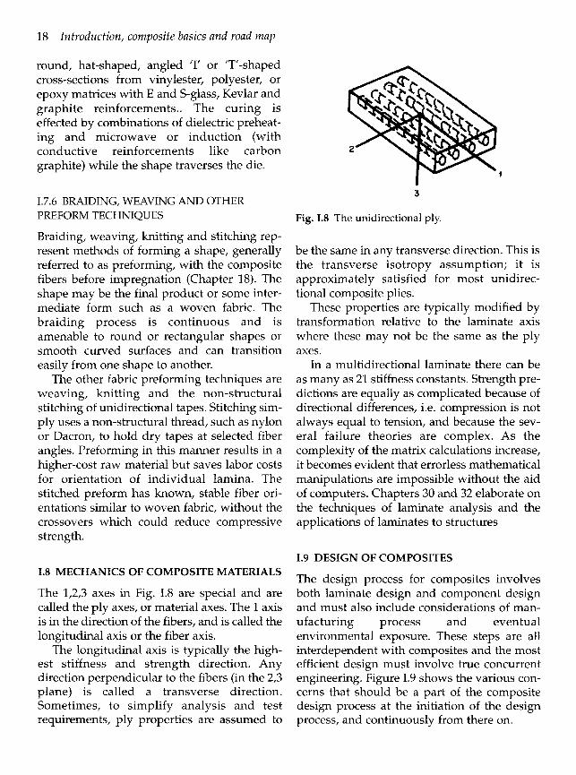
The 1,2,3 axes in Fig. 1.8 are special and are called the ply axes, or material axes. The 1 axis is in the direction of the fibers, and is called the longitudinal axis or the fiber axis.
The longitudinal axis is typically the high- est stiffness and strength direction. Any direction perpendicular to the fibers (in the 2,3 plane) is called a transverse direction. Sometimes, to simplify analysis and test requirements, ply properties are assumed to
3
Fig. 1.8 The unidirectional ply.
be the same in any transverse direction. This is the transverse isotropy assumption; it is approximately satisfied for most unidirec- tional composite plies.
These properties are typically modified by transformation relative to the laminate axis where these may not be the same as the ply axes.
In a multidirectional laminate there can be as many as 21 stiffness constants. Strength pre- dictions are equally as complicated because of directional differences, i.e. compression is not always equal to tension, and because the sev- eral failure theories are complex. As the complexity of the matrix calculations increase, it becomes evident that errorless mathematical manipulations are impossible without the aid of computers. Chapters 30 and 32 elaborate on the techniques of laminate analysis and the applications of laminates to structures
1.9 DESIGN OF COMPOSITES
The design process for composites involves both laminate design and component design and must also include considerations of man- ufacturing process and eventual environmental exposure. These steps are all interdependent with composites and the most efficient design must involve true concurrent engineering. Figure 1.9 shows the various con- cerns that should be a part of the composite design process at the initiation of the design process, and continuously from there on.

Design of composites 19
1.9.1 LAMINATE DESIGN RECOMMENDATIONS
1. Take advantage of the orthotropic nature of the fiber composite ply. 0 To carry in-plane tensile or compressive
loads align the fibers in the directions of these loads.
0 For in-plane shear loads, align most fibers at -c 45" to these shear loads.
0 For combined normal and shear in-plane loading provide multiple or intermediate ply angles for a combined load capabil- ity.
2. Intersperse the ply orientations. 0 If a design requires a laminate with 16
plies at *45", 16 plies at 0", and 16 plies at 90°, use the interspersed design (90,/ -c 45,/0,),s rather than (90,/ .+ 45,/10,)s. Concentrating plies at nearly the same angle (0" and 90" in the above example) provides the opportunity for large matrix cracks to form. These produce lower laminate allowables, probably because large cracks are more injurious to the fibers, and more readily form delaminations than the finer cracks occurring in interspersed laminates.
0 If a design requires all 0" plies, some 90" plies (and perhaps some off-angle plies ) should be interspersed in the laminate to provide some biaxial strength and stabil- ity and to accommodate unplanned
Composite Material
Environmental Considerations
Component
Fig. 1.9 Design considerations for composites.
loads. This improves handling character- istics, and serves to prevent large matrix cracks from forming. Locally reinforce with fabric or mat in areas of concentrated loading. (This tech- nique is used to locally reinforce pressure vessel domes).
0 Use fabric, particularly fiberglass or Kevlar, as a surface ply to restrict surface (handling) damage. Ensure that the laminate has sufficient fiber orientations to avoid dependence on the matrix for stability. A minimum coverage of 6 to 10% of total thickness in 0, ?45", 90" directions is recommended.
3. Select the lay-up to avoid mismatch of properties of the laminate with those of the adjoining structures - or provide a shear/separator ply.
Poisson's ratio: if the transverse strain of a laminate greatly differs from that of adjoining structure, large interlaminar stresses are produced under load. Coefficient of thermal expansion: tem- perature change can produce large interlaminar stresses if coefficient of ther- mal expansion of the laminate differs greatly from that of adjoining structure.
0 The ply layer adjacent to most bonded joints should not be perpendicular to the direction of loading. Thicken the com- posite in the joint area, soften the composite by adding fiberglass or angle plies and select the highest strain-capa- bility adhesive.
4. Use multiple ply angles. Typical composite laminates are constructed from multiple unidirectional or fabric layers which are positioned at angular orientations in a specified stacking sequence. From many choices, experience suggests a rather narrow range of practical construction from which the final laminate configuration is usually selected. The multiple layers are usually ori- ented in at least two different angles, and possibly three or four; (go, O0/&" , or

20 Introduction, composite basics and road map
0 ° / ~ 0 / 9 0 0 cover most applications, with 0 between 30 and 60 degrees). Unidirectional laminates are rarely used except when the basic composite material is only mildly orthotropic (e.g. certain metal matrix appli- cations) or when the load path is absolutely known or carefully oriented parallel to the reinforcement (e.g. stiffener caps).
Further suggestions can be seen in Chapter 31.
1.10 COMPOSITE TESTING
To ensure consistent, reproducible compo- nents, three levels of testing are employed: incoming materials testing, in-process testing and control and final structure verification.
1.10.1 INCOMING MATERIALS TESTING
Incoming materials testing seeks to verify the conformance of the raw materials to specifica- tions and to insure processibility. The levels of knowledge of composite raw materials do not approach those for metals, which can be bought to several consensus specifications and will appear generally identical although pur- chased from many manufacturers. Although there are fewer suppliers for composite raw materials, the numbers of permutations of resins, fibers and manufacturers prevents the kind of standardization necessary to be able to buy composite raw materials as if they were alloys. ASTM (American Society for Testing and Materials), SAE/AMS/NOMETCOM (Society of Automotive Engineers, Aeronautical Materials Standards / Nonmetallic Materials Committee) and SACMA (Suppliers of Advanced Composite Materials Association)
attempt to standardize the raw materials and their test methods by publication of specifica- tions (Appendix A). However, these standards have not reached the level of use to allow com- plete dependence upon them without supplier-user interaction and user testing.
The fabricators of composites will rely on specifications for control of fiber, resin and/or the prepreg. Many prepreg resin and fiber vendors will certify only to their own specifi- cations which may differ from those shown; users should consult the vendors to determine what certification limits exist before commit- ting to specification control.
As part of raw materials verification, com- posite design effort and final product verification mechanical testing of composite test specimens will be performed. The testing of composite materials offers unique chal- lenges because of the special characteristics of composites. Factors not considered important in metals testing are very important in testing composites (Chapters 34,39).
REFERENCES
1.
2.
3.
4.
5.
Foral, R.F. and Peters, S.T., Composite Structures and Technology Seminar Notes, 1989 Hercules Data Sheet for AS-4/3901-6 prepreg H050-377/GF Prod Hdbk (4)/jc/2 Agarwal, B.D. and Broutman, L.J., Analysis and Performance of Fiber Composites 2nd edn, John Wiley and Sons, New York, 1990 p. 103 Mayorga, G.D. in International Encyclopedia of Composites, (ed. S.M. Lee) Vol 4, VCH Publishers, N.Y., N.Y., 1991 Tsai, S.W. and Pagano, N.J. in Composite Materials Workshop, (eds. S.W. Tsai, J.C. Halpin and N.J. Pagano), Technomic Publishing Co., Lancaster, PA, 1978, p. 249