The Technical Basics - hamwaves.com
40
Bonus Chapter 1 The Technical Basics In This Chapter Operating a receiver Operating a transmitter Operating hand-helds and mobiles Building antennas and feedlines Digital interfacing Working the satellites Learning about ionospheric propagation S o here you are, wondering what all those controls really do. What is a/an [insert your favorite mystifying term here]? This chapter will help you understand some of the technical details behind the front panel, making you a better operator. Before plunging in, here are a few reminders: Read the operating manuals. Follow the manufacturer’s recommendations. Don’t be afraid to ask for help. Remember that your equipment may not have all of the features I discuss in this chapter; or it may call them by other, proprietary names. If you understand the function, you’ll likely be able to figure out what the function or control is called on your gear. In this chapter, I avoid proprietary names, but when I do use them, I identify them as such. I am also going to assume that you can set your radio to any desired frequency, select the desired mode (SSB/CW/FM/and so on), and can find any of the controls and navigate the configuration menus. In Appendix B, there are a number of references to useful resources. As a begin- ner, you should visit or read these “early and often.” Ham radio is a lifetime learning experience and no ham knows everything.
-
Upload
khangminh22 -
Category
Documents
-
view
0 -
download
0
Transcript of The Technical Basics - hamwaves.com

Bonus Chapter 1
The Technical BasicsIn This Chapter� Operating a receiver
� Operating a transmitter
� Operating hand-helds and mobiles
� Building antennas and feedlines
� Digital interfacing
� Working the satellites
� Learning about ionospheric propagation
So here you are, wondering what all those controls really do. What is a/an[insert your favorite mystifying term here]? This chapter will help you
understand some of the technical details behind the front panel, making youa better operator.
Before plunging in, here are a few reminders:
� Read the operating manuals.
� Follow the manufacturer’s recommendations.
� Don’t be afraid to ask for help.
Remember that your equipment may not have all of the features I discuss inthis chapter; or it may call them by other, proprietary names. If you understandthe function, you’ll likely be able to figure out what the function or control iscalled on your gear. In this chapter, I avoid proprietary names, but when I douse them, I identify them as such. I am also going to assume that you can setyour radio to any desired frequency, select the desired mode (SSB/CW/FM/andso on), and can find any of the controls and navigate the configuration menus.
In Appendix B, there are a number of references to useful resources. As a begin-ner, you should visit or read these “early and often.” Ham radio is a lifetimelearning experience and no ham knows everything.
559877 BC01.qxd 3/11/04 9:21 AM Page B1

Operating a ReceiverThe receiver is without a doubt the most important part of any station. Youcan’t even begin a contact without being able to hear the other station. To keepthe other station tuned in and to reject noise and interference, the receiver hasmore controls than any other piece of gear and you’ll want to know how to usethem all. My description of the controls is generic. Your operating manual willdescribe the function of each control in your particular radio.
The function of a receiver is to zero in on one tiny, nearly infinitesimal por-tion of the radio spectrum, exclude all other signals except for the desiredone, and maintain an even level of output for a wide range of input signalstrengths. The better it does those three things, the better a receiver it is.Let’s start with the first of those three functions — the one you will use morethan any other — tuning.
TuningThe large tuning knob or knobs on radios designed for primary use on singlesideband (SSB) and Morse code (CW) transmissions is simple and intuitive touse. There are a number of adjustments you can make to the way it works.
� Tuning Rate and Up/Down: Changing the tuning rate varies the rate atwhich the frequency changes with each turn of the tuning knob. For CW,you might want the radio to tune slowly — just 1 or 2 kHz per revolution.On SSB, that rate makes tuning from signal to signal too slow, so youmight want 5 or even 10 kHz per turn of the knob. Step size is the small-est amount of frequency change you can make and changing it may havea similar effect to changing the tuning rate. Front panel Up/Down buttonsgenerally have a much larger step to allow you to move quickly within aband. Your tuning knob may also sense the speed at which you are turn-ing it and increase or decrease the tuning rate accordingly.
� Fast/Jog/Band/Lock: To really change frequency in a hurry, the radio mayhave a Fast function. This greatly increases the tuning rate when active(and may have other effects). Jog acts like a joystick to slew frequency upand down very quickly. Band moves you from one ham band to another.Lock freezes all frequency adjustments until pressed again. (This can bevery disconcerting if you don’t notice it or forget that it’s on — suddenlyyour radio won’t tune!)
� Display Frequency: On SSB or FM, the display frequency is the carrierfrequency of your signal, something to keep in mind when operatingnear a band edge. Properly adjusted SSB signals are about 3 kHz wide. Ifyou are on USB, stay 3 kHz below the band edge, and stay 3 kHz above
B2 Ham Radio For Dummies
559877 BC01.qxd 3/11/04 9:21 AM Page B2

the band edge on LSB. On CW (or RTTY or PKT), the display frequencyis usually the frequency at which a signal will produce the desired tone,not the actual signal transmission frequency. This is discussed more inthe section on filtering, below.
� Pitch: Not to be confused with sidetone (the audio tone you hear whensending CW), the pitch control allows you to configure the filters so thattheir peak response will be at the audio frequency you prefer for copy-ing CW. Pitch doesn’t affect your transmit frequency.
� Scanning: VFO scanning sweeps the receiver frequency across the bandbetween a start and stop frequency. Memory scanning steps through aset of channels and stops if a signal that opens the squelch is found.
VFO and memory controlThe tuning knob controls a VFO (Variable Frequency Oscillator) that deter-mines a radio’s frequency. A radio only has one VFO circuit, but the radio’smicroprocessor can control it in a way that makes it look like there are two:VFO A and VFO B. There are lots of uses for two VFOs — saving a net or sched-ule frequency, keeping watch on a frequency for a DX station, and so on.
Switching between VFO A and B is controlled by buttons labeled somethinglike “A_B” and “A_
_B.” The first means “change VFO B to match VFO A.” Thesecond means “exchange VFO A with VFO B.” The transfer may also includemode and filter selection.
If there are two DX stations you’re trying to work, use the A and B VFOs to“bounce” between the pileups. Tune to station #1, save VFO A to VFO B, tuneto station #2, then press “A_
_B” to change between pileups instantly. You haveto remember who you’re calling on your own, though.
VFO A and B are really just special cases of a radio’s memory channels. Thememories store a radio’s frequency, mode, and other control parameters.Because most hams have “favorite” frequencies, operate on nets, hang aroundcalling frequencies, or have regular schedules, it’s nice to be able to recall themquickly. Memories are treated as numbered channels. Contents are viewed bychanging from VFO to MEM operation, then selecting a memory. The settingscan then be transferred to one of the VFOs for operating. Information is storedin memories by setting the radio’s frequency, mode, and so on in VFO opera-tion and then writing the settings into a memory channel.
Along with VFO A and VFO B and the memory channels, many rigs also have ascratchpad memory. This memory takes fewer steps to write and recall so thatit can be used quickly. Another type of memory is called bandstacking registers.These store VFO settings from a single band. The contents are recalled byrepeatedly pressing the keypad button for that band. For example, if I have apair of registers on each band, I might elect to use one for CW operation andthe other for SSB, or for SSB and FM.
B3Bonus Chapter 1: The Technical Basics
559877 BC01.qxd 3/11/04 9:21 AM Page B3
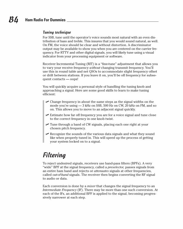
Tuning techniqueFor SSB, tune until the operator’s voice sounds most natural with an even dis-tribution of bass and treble. This insures that you would sound natural, as well.On FM, the voice should be clear and without distortion. A discriminatoroutput may be available to show you when you are centered on the carrier fre-quency. For RTTY and other digital signals, you will likely tune using a visualindicator from your processing equipment or software.
Receiver Incremental Tuning (RIT) is a “fine-tune” adjustment that allows youto vary your receive frequency without changing transmit frequency. You’lluse this in round table and net QSOs to accommodate slight frequency offsetor drift between stations. If you leave it on, you’ll be off frequency for subse-quent contacts — oops!
You will quickly acquire a personal style of handling the tuning knob andapproaching a signal. Here are some good skills to learn to make tuning efficient:
� Change frequency in about the same steps as the signal widths on themode you’re using — 3 kHz on SSB, 500 Hz on CW, 20 kHz on FM, and soon. This allows you to move to an adjacent signal quickly.
� Estimate how far off frequency you are for a voice signal and tune closeto the correct frequency in one knob twist.
� Tune through a band of CW signals, placing each one right at yourchosen pitch frequency.
� Recognize the sounds of the various data signals and what they soundlike when properly tuned in. This will speed up the process of gettingyour system locked on to a signal.
FilteringTo reject undesired signals, receivers use band-pass filters (BPFs). A very“wide” BPF at the signal frequency, called a preselector, passes signals froman entire ham band and rejects or attenuates signals at other frequencies,called out-of-band signals. The receiver then begins converting the RF signalto audio or data.
Each conversion is done by a mixer that changes the signal frequency to anIntermediate Frequency (IF). There may be more than one such conversion. Ateach of the IFs, an additional BPF is applied to the signal, becoming progres-sively narrower at each step.
B4 Ham Radio For Dummies
559877 BC01.qxd 3/11/04 9:21 AM Page B4

The sequence of filters is shown in Figure B1-1. The preselector is shown passingin-band signals. A roofing filter rejects all but nearby signals. It gets that namebecause it acts like a “roof” over other, narrower filters. In subsequent stages,narrower signal filters attempt to isolate just the desired signal. Think of the fil-ters as a narrowing sequence of windows through which your receiver looks atthe radio spectrum.
Chapter 12 refers to fixed-bandwidth crystal filters. Digital Signal Processing(DSP) filters are now standard in most radios and are much more flexiblewith nearly equivalent performance. Signal filters for SSB have a 1.8 to 3 kHzbandwidth. For CW and digital data, filter bandwidths are from 250 Hz to 1kHz. FM requires a 15 kHz filter. Install the greatest amount of filtering yourbudget allows, because this is an important receiver function.
Selecting a filterWhen you select an operating mode, the radio will also select an assumedchoice of filter — usually the widest filter you have installed for that mode. (Ifyou don’t have a narrow CW filter installed, the radio will use the SSB filter.)
Frequencyconverters
Amateur band
Desiredsignal
Undesiredsignals
(In-band)
Undesiredsignal
(In-band)
Undesiredsignal
(Out-of-band)
Mixer
Signalsrejectedoutsidefilters
Mixer
Antenna
PreselectorRF RF
Signals passinside filters
IF#1
RoofingFilter
IF#1
IF#2
SignalFilter
Figure B1-1:Preselec-
tors, roofingfilters, and
signal filtersall reject
undesiredsignals.
B5Bonus Chapter 1: The Technical Basics
559877 BC01.qxd 3/11/04 9:21 AM Page B5

While tuning and for casual contacts, to avoid missing signals use the widestfilter settings that give you an acceptable amount of noise or interference. I likea wider filter for the cleaner sound and to hear a little bit of “what’s going onaround me.” If the band is crowded or noisy, select a narrower filter or reducefilter bandwidth. It’s important to have the CW or data signals tuned in prop-erly so that as you “tighten up” the filters, you don’t have to adjust the mainVFO. Using the wider filters will also develop your ability to copy “by ear.”
With fixed-bandwidth filters, your choice of bandwidth is limited to whateverfilters are installed in the radio. Some radios can vary the net bandwidth byshifting IF frequencies or using DSP. Practice adjusting this control to getused to the different sound qualities at different filter bandwidths.
Shifting away from and notching out interferenceAnother popular filtering feature is known as IF Shift and proprietary namessuch as “Passband Tuning (PBT).” This allows you to offset the frequencies ofthe various IF stages so that the filters pass higher or lower frequencies thannormal. This is useful if a nearby QSO is a little too close for comfortable lis-tening. You can shift your receiver’s filters just a bit higher or lower in fre-quency and reduce the amount of interference. This removes some of theincoming signal’s high or low frequencies, but may result in a dramaticimprovement in intelligibility.
You can also remove a small portion of the received audio by using the notchfilter. This is intended to reject single interfering tones, such as a tuner-upperor broadcast carrier. The notch frequency can be varied throughout the audiorange and gives speech a somewhat hollow sound. If the receiver output“sounds funny,” check to see if your notch filter is on.
Hearing well by using gain controlThe receiver will do its best to output a clean, clear signal, but it has to copewith an extremely wide range of signal strengths and noises, roughly a factorof 10 billion (100 dB) to 1, give or take a couple orders of magnitude. It’samazing that receivers do as well as they do. You can give your receiver ahelping hand by learning how to make the best use of all of its controls.
When a receiver isn’t able to properly handle the signals coming into theantenna jack, the circuits become overloaded and distortion occurs. If morethan one strong signal is present, they can mix together and cause intermodu-lation products or intermod. Both intermod and distortion create interferingsignals in the receiver. The most common stages to be overloaded are the front-end stages closest to the antenna. Front-end overload results in the severeinterference.
B6 Ham Radio For Dummies
559877 BC01.qxd 3/11/04 9:21 AM Page B6

To tell if your receiver is being overloaded, turn on the attenuator. If the noiseor interference disappears or is reduced by more than the amount of attenua-tion (figure about 6 dB per S-unit), then your receiver is being overloaded.Leave the attenuator on, turn down the RF Gain, or otherwise reduce thelevel of signals coming in through the antenna.
Automatic Gain Control (AGC) keeps the output of the receiver steady by con-tinually adjusting the gain of the various IF and RF amplifiers. Louder signalscause AGC to turn the gain down and vice versa. The AGC circuit needs torespond at different speeds to CW, data, or voice signals — FAST (for dataand CW) and SLOW (for voice) to give the signal an even output level. SettingAGC to AUTO sets the response speed based on the selected mode and OFFdisables it entirely (you’ll have to operate the RF Gain control manually).
The AGC circuit uses the audio output to make a decision on what overallgain should be. If a loud and undesired signal is close by, it can fool AGC intoreducing gain unnecessarily. To the listener, it sounds like the desired signalhas done a deep fade. This is called AGC pumping and causes severe distor-tion that can sound like interference from a nearby station.
You can give your receiver the best chance to output a clean signal by settingyour gain controls as follows:
� Preamplifier: Turn this OFF unless really needed. Although the preampmakes weak signals stronger, it will make it easier for a strong signal tocause overload. Proprietary features such as “Advanced Intercept Point(AIP)” or “Intercept Point Optimization (IPO)” are really preamp controls —when you turn them ON, they reduce receiver gain to reduce overload.
� Attenuator: Reduces the incoming signals at the antenna terminal. Don’tbe shy about adding some attenuation to help the receiver cope withstrong signals.
� RF Gain: Controls the gain of the IF stages. When you turn this controldown, you’ll notice your receiver’s S-meter going up. That’s because the S-meter is really measuring how much the AGC circuit is reducing gain. Astrong signal requires a lot of gain reduction to maintain a constant outputlevel, so the meter shows a large deflection. When RF Gain is turned down,it’s the same as if the AGC circuit is responding to a large signal. ReducingRF Gain will often make the band sound “cleaner” because noise isn’tbeing amplified as much. Adjust RF Gain frequently!
� Noise Blanker (NB): Turn this OFF unless really needed. Noise blankerslook for the short, sharp pulses characteristic of ignition or line noise.When one is detected, they turn off the receiver for the duration of thepulse. When strong signals are present, they often fool the noise blankerinto turning off the receiver. The resulting distortion is similar to AGCpumping and can be quite disruptive. Use sparingly.
B7Bonus Chapter 1: The Technical Basics
559877 BC01.qxd 3/11/04 9:21 AM Page B7

� DSP Noise Reduction (NR): This works on the output audio signal insteadof the RF and IF signals as for Noise Blanker. The DSP circuit analyzes thesignals to decide what is noise and removes it. The results can be prettyamazing with a lot of band noise just disappearing. The DSP sometimescreates artifacts in the resulting audio that may be objectionable.
Practice is the key! If you wait until you have interference to start learninghow to use the gain controls, you’ll be clumsy and your contact will likely bedisrupted. Learn the various symptoms of receiver ailments and what con-trols cure the problem.
These controls and settings don’t form a group, so I just cover them one at a time:
� Receive Antenna: Some radios have the ability to let the receiver listento a different antenna than the transmitter uses. Why? This is popular onthe lower HF bands where an efficient transmit antenna may pick up toomuch noise. If the regular receiver input signal is also available (usuallycalled “RX Out”), then the signal can be filtered or processed before itgets to the receiver. Remember that if you set the receiver to use thereceive antenna and nothing is connected, the receiver will sound dead.
� Squelch: A very odd word for a perfectly understandable function. Squelchmutes the audio output unless the signal exceeds a level set by thesquelch control. This keeps you from having to listen to noise until asignal appears. Remember that if you accidentally turn up the squelchlevel, no audio will be heard and the receiver will sound dead.
Operating a TransmitterNow that we have those complicated receivers behind us, it’s time to turnour attention to the outgoing part of the radio, the transmitter. Start simpleby setting the radio to CW mode.
CW operationTransceivers have a 1⁄4-inch phone jack input labeled “Key” on the front orrear (or both) panels. Look at your operating manual for the correct plugstyle (mono or stereo) and wiring.
Some radios include a CW keyer that is turned on and off by a front panelbutton or a configuration menu selection. Keys, keyers, and paddles all pluginto the same jack, so you’ll have to read the manual to find out what theproper wiring is for each. Keys and keyers both have the same plug wiring.
B8 Ham Radio For Dummies
559877 BC01.qxd 3/11/04 9:21 AM Page B8

If using an external keyer causes the radio to send garbled code, then therig’s internal keyer is active. Turn the keyer function OFF so that the radiothinks it’s being keyed by a straight key.
If the rig keys as soon as you plug in your key or keyer, regardless of whetherthe keyer is turned on or not, then you probably don’t have the right type ofplug on the key cable or it’s miswired. Most radios use a stereo phone jack toaccept a key or a paddle, so a mono plug shorts the middle contact to ground.
Semi- or Full-Break In (QSK) switches between transmit and receive so rapidlythat you can hear other signals between your own dits and dahs. QSK helpsyou coordinate with another operator or use a busy frequency. If you haveVOX turned on, QSK is defeated and the radio remains in transmit while youare sending.
The control for output power is labeled “RF PWR” or “CAR” (for “Carrier”). Ifyour radio has an internal antenna tuner, the minimum power will be set to afew watts so that the tuner control circuitry has enough power to work.
Controlling speech audioSetting up a transmitter for clean speech operation is more complicated thanCW. The most important adjustments are for microphone gain (usually labeled“MIC GAIN”) and speech processing, which is called “Compression” or “Process-ing.” Your operating manual will have a specific procedure for adjusting bothof these controls. It’s an important responsibility to have a properly adjustedsignal to preserve your own intelligibility and to prevent interference to others.
Microphone gain controls the amplification of the weak microphone signal.Set too low and your output power will be low. Set too high and your audiowill be distorted. Use your radio’s Automatic Level Control (ALC) indicator toset the microphone gain as described in the operating manual. By itself, ALCdoes not guarantee a clean signal.
If you have a station monitor (available as an accessory from most radio manu-facturers), it’s easy to set your microphone gain. With the speech processorOFF, turn up the microphone gain until the maximum output on voice peaksstops increasing, then back off one-tenth of a turn or so.
The next step is to adjust the speech processor. Speech processing increasesyour average signal power, but at the expense of distorting your audio byamplifying the low level portions more than the high level portions. This iscalled compression. You don’t need it at all if your signal is getting through well.With a modest amount of compression, you will be a little “louder” to the otherstation. With too much compression, you sound like a bad public address
B9Bonus Chapter 1: The Technical Basics
559877 BC01.qxd 3/11/04 9:21 AM Page B9

system. Follow the operating manual’s instructions for setting the level ofprocessing. I find that more than 10 dB of compression in the processor hurtsmore than it helps.
If your over-the-air audio is distorted on voice peaks, some of your RF outputsignal may be getting picked up byf the microphone cable. Identify RF feed-back by slowly reducing power or using a dummy load for transmitting whilehaving a nearby ham listen or using a separate receiver to listen to your ownsignal. If the distortion disappears, then it’s RF feedback, almost always causedby a broken microphone cable connection or poor radio grounding.
If your radio has a monitor feature, you can listen to your transmit audio as youspeak. This helps you adjust your audio, but isn’t a substitute for an off-the-air report on your signal. You should use the monitor only when using head-phones, otherwise you will have audio feedback between the microphoneand speaker.
As with CW, output power is set by the “RF PWR” or “CAR” (for “Carrier”)control. If you use AM, the amount of carrier your signal contains is set bythis control. For SSB, it controls the Peak Envelope Power (PEP), and for FM itcontrols the overall transmitter output power.
Setting the VOX systemOperate for a long session using only Push-to-Talk (PTT) with a hand mic andyour aching thumb and elbow will illustrate the need to use Voice-Operated-Transmit or VOX. VOX uses the audio from your microphone to switch theradio to transmit. Properly adjusted, it supports a very natural, flowing con-versation. There are three main VOX controls:
� VOX Gain: Sets how much audio from the microphone it takes to acti-vate or trip the VOX. High VOX Gain means that it only takes a whisper(or your breathing) to trip. This is irritating to listeners and causes unin-tentional transmissions. VOX Gain should be set to the minimum levelrequired for your ordinary speech to trip the VOX. Microphone gainaffects VOX sensitivity, but not vice versa.
� VOX Delay: Once the VOX circuit is tripped, VOX Delay controls how longit takes to return to receive if you’re not speaking. The delay should be justlong enough to hold the radio in transmit between words and phrases. Settoo short and you will rapidly switch between transmit and receive, chop-ping up your speech and wearing out the switching components.
B10 Ham Radio For Dummies
559877 BC01.qxd 3/11/04 9:21 AM Page B10

� Anti-VOX: If you use a speaker or like your headphone audio loud, that canalso cause the VOX to trip. Anti-VOX takes a little bit of the received audioand subtracts it from the microphone signal. This prevents the receivedaudio from causing a transmission. Turning up Anti-VOX too far can makeoperation of the VOX system sluggish or drop out inappropriately.
What is MOX? MOX stands for Manually Operated Transmit and allows theoperator to switch between receive and transmit manually, if necessary.
Microphone techniqueLearning how to use a microphone will pay huge dividends on the air. Start byusing a good quality microphone. Don’t waste the capabilities of an expensiveradio with a cheap, garage sale microphone. Chapter 13 shows several popu-lar styles, and a new radio will include a decent hand-mic.
Learn how to set the transmit speech controls so that your voice sounds itsbest on the air at a natural speaking level. Find a nearby friend who knowsyour voice, then meet on a band that’s closed for the evening or a spot that’snot busy and practice getting all of the controls set properly. With your friendlistening, learn how to set the processor so that you don’t generate interfer-ence or splatter on nearby frequencies. Memorize the ALC and compressionlevels for proper operation.
Speaking over a microphone is different than speaking in person. Hams newto SSB or FM have a tendency to slur and hurry their words and phrases,making them very difficult to understand. Practice speaking very clearly,using phonetics, taking deep breaths, and modulating your voice more thanyou would if you were face-to-face with the other person. They can’t see yourface, so the visual cues of conversation aren’t there. All of the informationhas to come from your voice alone, just like a radio announcer.
Repeating this excellent advice from Chapter 11: YOU DON’T NEED TO SHOUTINTO THE MICROPHONE! Shouting doesn’t make you any louder at the otherend! By adjusting your microphone gain and speech processor, you can createa very understandable signal at normal voice levels! Your contacts and familywill thank you for doing so. Save the shouting for celebrating your latest DXcontact!
The microphone should not touch your lips or be directly in front of yourmouth. The sudden gusts of air as you form letters like “P” and “B” (they’recalled plosives) sound like annoying pops and thumps. A desk mic should bea few inches from your mouth. Boom mics should be to the side of or belowyour mouth. Speak across a hand mic to minimize the effects of the air gusts.Check on the air to see what works best for you and your microphone.
B11Bonus Chapter 1: The Technical Basics
559877 BC01.qxd 3/11/04 9:21 AM Page B11

VFO control and operating splitThe same VFO and memory functions work on transmit, so only TransmitIncremental Tuning (XIT) is new. Like RIT, this is a “fine-tune” adjustment thatlets you listen to one frequency and move your transmitter around. I find thismost useful when calling a DX station a little off frequency in a pileup. Thesame caution as for RIT applies, as well — if you forget that it’s on, you’ll beoff frequency for subsequent contacts.
Operating split properly is an important skill in a variety of settings. Whenoperating split, the receive frequency is set by one VFO and the transmit fre-quency by the other. Split is usually used in HF DX operation (see Chapter 11)within a single band and on VHF/UHF satellite operation between bands.
Learn how to do this properly to avoid causing unintentional interferenceand transmit in the right spot. Here is an example procedure for HF splitoperation:
1. Tune VFO A to the transmit frequency of the station you’re listening to.
2. Press “A_B” to store that frequency into VFO B.
3. Tune VFO A to the frequency where the station is listening.
4. Press “A__B” to switch VFOs and listen to the station on VFO B.
5. Set the transmitter to use VFO A — consult your operating manual forthe exact steps to do this. It might be a “SPLIT” button on the frontpanel or a VFO A/VFO B control switch.
6. With power turned all the way down, press PTT or key the transmitter.Your display should change to the transmit frequency. Turn power back up.
This seems complicated, but with a few repetitions, you’ll become quite usedto it. The procedure for cross-band split is similar, but depends on how yourradio is designed, so consult the manual for the exact instructions.
TunersAdjusting an antenna tuner can seem confusing at first, but there is a methodto the madness. The tuner’s operating manual may provide some guidelines,but assuming that you have one of the popular “T-circuit” units (see Figure
B12 Ham Radio For Dummies
559877 BC01.qxd 3/11/04 9:21 AM Page B12

B1-2) with two capacitors and one inductor, following these steps will allowyou to find a match most of the time:
1. Be sure the tuner is well grounded and that all connections to anten-nas and the radio are secure.
If your tuner has an antenna switch, double-check to be sure the rightantenna is selected.
2. Set the capacitors and inductors to their maximum values (the actualinductance and capacitance).
This configures the tuner to have the least effect — a good place to start.
3. Reduce power output from the radio to a few watts of CW (use theminimum power necessary to tune) and send a brief call sign to iden-tify yourself.
Watching the SWR meter on the radio or tuner, make short transmis-sions of a few seconds while you make adjustments.
4. Adjust the inductor for the minimum SWR, then the input capacitor(closest to the transmitter) for minimum SWR.
Repeat until SWR reaches 1:1 or a satisfactory value. If there is no clearminimum, reset the input or output capacitor to half value and try again.
5. Adjust the output capacitor for minimum SWR.
Readjust both the input capacitor and the inductor for minimum SWR.Repeat until SWR reaches 1:1 or a satisfactory value.
6. When you are done tuning, identify yourself on the air once again.
Make a table of your tuner setting for your favorite bands and antennas tominimize on-the-air tuning.
If you can’t achieve a match with any combination of settings, the impedanceat the tuner’s output is probably beyond the ability of the tuner to match to50 ohms. You could also have a bad feedline or connection. Try the antennaon a different frequency or try the tuner on a “known good” antenna to besure it is working okay.
There are also tuning aids such as the Vectronics VEC-512 (www.vectronics.com) that use the receiver to detect noise as the antenna is tuned. This allowsyou to avoid transmitting while tuning up.
B13Bonus Chapter 1: The Technical Basics
559877 BC01.qxd 3/11/04 9:21 AM Page B13

AmplifiersAdjusting a high power tube amplifier is similar to adjusting an antenna tuner.Your amplifier’s manual will tell you how to adjust your particular model aswell as specify limits for input or drive power. Here is the general procedure(follow the same recommendations as with a tuner for short transmissionsand recording common control settings):
1. Reduce transmitter power to 10 or 20 watts.
Set the amplifier’s bandswitch to the desired band and the bias switch tothe CW or CW/TUNE position. Set the LOAD control to its minimum value.
2. Apply drive to the amplifier.
While watching the plate current, adjust the TUNE control for a “dip” inplate current.
“T“- circuitAntenna Tuners
“Pi“- circuitAmplifier Output
Moving tapchangesfrequency andimpedance
TUNECap
LOADCap
Inductor
Ant
Inductor
InputCap
OutputCap
Moving tapdecreasesinductance
Ant
Figure B1-2:“T” and “Pi”
impedancematching
circuitsfound in
tuners andamplifiers.
B14 Ham Radio For Dummies
559877 BC01.qxd 3/11/04 9:21 AM Page B14

3. Adjust the LOAD control so that output power or plate currentapproaches the desired level.
Readjust the TUNE control to dip the plate current. If necessary,increase drive and readjust LOAD and TUNE.
An amplifier’s output adjustment circuit is very much like an antenna tuner inthat it matches the impedance of the tube or tubes to the 50-ohm load. It isusually configured as a “Pi” circuit as shown in Figure B1-2. The TUNE controladjusts the output circuit for resonance, causing the dip in plate current. TheBAND switch varies the inductance which works with the TUNE capacitor toset the resonant frequency and with the LOAD capacitor to adjust the outputimpedance.
Amplifiers generate a lot of RF power, which can be dangerous if not treatedwith respect. Understand the RF safety rules in your license manual. Be sureyour feedlines and antennas are sufficiently rated to handle the amplifier’soutput. The tubes or transistors in your amplifier are expensive; follow themanufacturer’s guidelines exactly and do not exceed the operating limits forinput or output power.
RF safetyAs you’ll recall from your licensing study, you’ll need to perform an RF safetyevaluation once you decide on power levels and antenna placement. If you planon using an indoor antenna, the evaluation will be more important because ofits proximity to people. Plan ahead so that your station meets all safety con-cerns from the moment it’s finished.
Operating Hand-helds and MobilesAll of the things you’ve learned about operating a receiver and transmitterapply whether you’re operating from home or on the road. Along with theoperating guidelines in Chapter 10, there are some additional technical tipsand tricks that help make mobile and portable operation more efficient.
Do you think driving while talking on a mobile phone is unsafe? Try watchingsomeone try to drive while configuring a radio to use a new repeater channel!This is not a smart thing to do in motion, even with the radio display up onthe dashboard. Talking in heavy traffic is also unsafe. Pull over and get thejob done or stand by until traffic clears up.
B15Bonus Chapter 1: The Technical Basics
559877 BC01.qxd 3/11/04 9:21 AM Page B15

Programming memories and cloningYou’ll quickly find a number of useful frequencies to store in your radio. You’llalso find that just loading the information into the next available memory chan-nel results in a disorganized list that’s inconvenient to use. Group similar infor-mation into consecutive channels. Reserve one block for 2-meter repeaters,another for 70-cm, some for the land-mobile or aviation channels, several forbroadcast stations, and so forth, depending on your radio’s capability. Thatway, if you forget the exact channel number, you’ll know what group it’s in andcan find it quickly.
Programming the memories from the radio’s front panel can also get old. Manyradios have the ability to download memory information from a PC program.This is quite convenient and can make setting up a whole band full of frequen-cies a breeze. Cloning refers to duplicating the configuration of an entire radioin another radio. This can be done by using a PC program to program eachradio individually. Some radios also have a standalone cloning function thatuses a special cable to connect two radios together.
Selecting and charging batteriesThere are three types of batteries used with hand-held and portable radios:disposable alkaline, rechargeable Nickel-Cadmium (Ni-Cad), and Lithium-Ion(Li-Ion), referring to the electro-chemistry inside the battery. Of the three,disposable alkaline and Li-Ion chemistry offer the greatest energy density,which is measured in Watts/kg. Higher energy density is good because itmeans longer operating times from a given size battery.
Battery packs hold pre-assembled groups of cells inside a single case. Thebatteries charge and discharge as a unit. The pack’s energy storage capacitygradually dwindles as the batteries age. When it is no longer able to hold an ade-quate charge, it must be replaced or rebuilt. Always have a spare battery pack.
A small battery pack charger is a standard accessory for hand-held and port-able radios. Most are wall-transformers that take several hours to rechargeeven small packs. A more convenient solution is the drop-in charger that holdsthe entire radio while charging the battery. Drop-in chargers also act as a basefor the radio during stationary use. Unfortunately, radios and packs are notstandardized, so one manufacturer’s charger won’t charge other packs.
To use disposable batteries or individual rechargeable cells, you need theempty battery pack that can be easily disassembled to load them. An advan-tage of using the individual rechargeable cells is that they can be charged byany manufacturer’s charger. The advantage quickly becomes apparent whenyou have several radios from different manufacturers.
B16 Ham Radio For Dummies
559877 BC01.qxd 3/11/04 9:21 AM Page B16

Simple chargers just dump charge into a battery until its terminal voltage(voltage across the + and - terminals) comes up to a nominal rated value. Atthat point, the charger can’t force any more change into the battery. Quickchargers apply a lot of charge to the battery in a hurry (which makes it heatup) until the battery reaches rated voltage. After that, it switches to tricklecharge, just supplying enough current to keep the battery charged. (This isalso called float charging.) Quick chargers can recharge even a large batterypack in an hour.
If you use large batteries, such as gel-cells or deep-cycle automotive batteries,a charger designed specifically for those batteries must be used. Automotivebattery chargers are generally not suitable for long-term use; they are just forgetting enough charge into the battery to start a car and will damage the bat-tery if left connected. Many hardware and RV stores sell inexpensive tricklechargers just for these batteries.
External powerMost hand-held radios can be run from external DC power. To operate from acar, they must accept the automotive range of 9–16 VDC. Car-power adaptersare available that plug into a cigarette lighter plug. Some hand-helds cannottransmit while external power is attached.
Mobile radios take a lot more current than hand-held radios — up to 25 ampsfor 100-watt output models. Supplying this amount of power to the radio willrequire at least some under-the-dash work to find an adequately rated DC cir-cuit. You may have to run the radio power cables into the engine compart-ment and directly to the battery. Using a lighter plug is generally not anoption for the larger mobile rigs.
B17Bonus Chapter 1: The Technical Basics
Battery capacityIf you are going to use batteries for hand-heldsor portable radios (as opposed to solar power ora generator), learn how to calculate total energyusage in terms of ampere-hours (A-h). This is arating of how long the battery can supply a givenamount of current while maintaining its ratedvoltage. A battery with an 8 A-h capacity can the-oretically supply 1 ampere for 8 hours or 8 amps
for 1 hour. Realistically, derate a battery to 80% ofits rated capacity. Figure out how long you expectto operate from a fully-charged battery and addup the total current usage from all equipment.Multiply those two figures together (current andtime) to get your required battery capacity.
559877 BC01.qxd 3/11/04 9:21 AM Page B17

BE CAREFUL! Automotive batteries can supply a lot of current and a short-circuit can have disastrous consequences. Never work on an automotive electri-cal system with the battery connected. Mobile stereo shops can often consulton or perform the installation professionally. When using external power of anysort, be sure the power cable has a fuse in the positive lead. Some cords alsohave a fuse in the negative lead to protect against short-circuits to that lead.
Mechanical safetyIf you have a radio in your car, make sure it is secure. Even a small hand-heldcan be hazardous in a crash. Don’t place unsecured rigs on the dashboard orseat. Install a microphone clip — grabbing for a microphone or sliding radiohas caused more than one accident!
Building Antennas and FeedlinesThis section will not be a discussion on the theory of how antennas and trans-mission lines work — that’s quite beyond the scope of this book. I will coversome of the technical aspects of building and installing antenna systems. Fordetailed information on antenna design, The ARRL Antenna Book is the acknowl-edged ham radio antenna reference. The ARRL also offers online antennatheory and modeling classes.
Building wire antennasThe first thing to cover with wire antennas is, strangely enough, wire! Thereare lots of different types of wire and some are more suitable than others formaking antennas. Avoid using aluminum or galvanized wire because of stretch-ing, difficulty of making reliable connections, and resistive losses.
� Soft-drawn solid copper: Used for electrical wiring in the home in sizesof 10 to 16 AWG. Soft-drawn wire will stretch several percent under ten-sion, affecting antenna tuning. Solid wire will also break if nicked, kinked,or flexed repeatedly.
� Stranded copper: Also used for home electrical wiring with the sameconcerns about stretching. More flexible than solid wire and resistsbreaking better.
� Hard-drawn copper: Stronger than soft-drawn, but has the same ten-dency to break at nicks and if repeatedly flexed.
� Copperweld: Solid or solid steel wire for strength with a copper claddingfor good conductivity. Excellent for antennas in 10–18 AWG. Can be diffi-cult to work with due to springiness, but the stranded versions are easierto work with.
B18 Ham Radio For Dummies
559877 BC01.qxd 3/11/04 9:21 AM Page B18
For general antenna work, the inexpensive THHN insulated wire sold in homeimprovement stores is fine. If you are planning on putting up large or heavyantennas or live in a windy area, then the Copperweld is a better choice. Manytypes of wire specifically for antennas are available from vendors such as TheWireman (www.thewireman.com) or the Radio Works (www.radioworks.com).
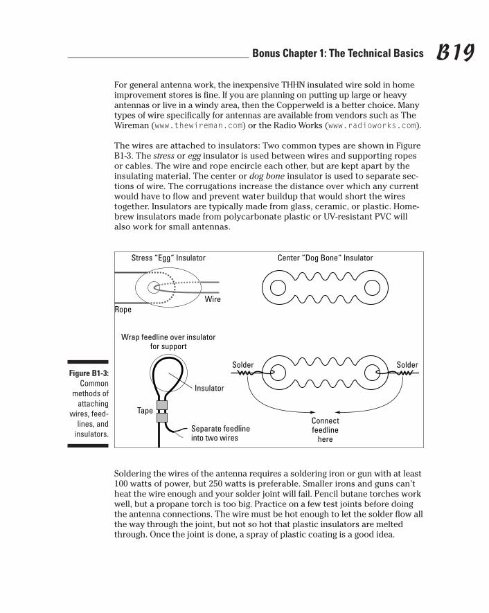
The wires are attached to insulators: Two common types are shown in FigureB1-3. The stress or egg insulator is used between wires and supporting ropesor cables. The wire and rope encircle each other, but are kept apart by theinsulating material. The center or dog bone insulator is used to separate sec-tions of wire. The corrugations increase the distance over which any currentwould have to flow and prevent water buildup that would short the wirestogether. Insulators are typically made from glass, ceramic, or plastic. Home-brew insulators made from polycarbonate plastic or UV-resistant PVC willalso work for small antennas.
Soldering the wires of the antenna requires a soldering iron or gun with at least100 watts of power, but 250 watts is preferable. Smaller irons and guns can’theat the wire enough and your solder joint will fail. Pencil butane torches workwell, but a propane torch is too big. Practice on a few test joints before doingthe antenna connections. The wire must be hot enough to let the solder flow allthe way through the joint, but not so hot that plastic insulators are meltedthrough. Once the joint is done, a spray of plastic coating is a good idea.
Stress “Egg“ Insulator Center “Dog Bone“ Insulator
WireRope
Wrap feedline over insulatorfor support
Separate feedlineinto two wires
Insulator
Tape
Solder
Connectfeedline
here
SolderFigure B1-3:
Commonmethods of
attachingwires, feed-
lines, andinsulators.
B19Bonus Chapter 1: The Technical Basics
559877 BC01.qxd 3/11/04 9:21 AM Page B19

Attaching the feedline can be done many ways as long as it is supported ade-quately. Remember that the feedline will hang from the insulator, flexing inthe wind. The figure shows one of many ways of taking the stress off the elec-trical connections. If you prefer to terminate the feedline in a connector, theBudwig 809 center insulator has a built-in coaxial connector. It’s also impor-tant to keep water out of coaxial cable. Once the connections are complete,coat the exposed braid and center conductor with a sealant such as “LiquidElectrical Tape” (available at hardware store electrical departments).
Useful knots to learn are the Sheetbend, Bowline, Two Half-Hitches, Fisher-man’s knot, Square Knot, and the Clove Hitch. Log on to www.scouter.com,select Scout Skills, and enter knots into the search window to find good knotreferences. The Two Half-Hitches knot is useful for attaching ropes to insula-tors and branches. The Clove Hitch attaches ropes to supports and posts.Ropes should be UV-resistant to prevent gradual deterioration and suddenfailure.
While the time-honored technique of supporting wire antennas is to throw arope through the branches of a tree, this often leads to the antenna falling inthe wind or after the tree gradually abrades the rope. What works better is toinstall a pulley in the tree (either on a rope or attached directly to the tree) andrun the support line through the pulley. This allows the support line to move inthe wind. A counterweight will provide tension, while allowing movement.
I hate to keep nagging you about safety, but be sure that your wires won’t goanywhere near a power line, including underneath them. When you are throw-ing lines into trees, be sure you know where that line can go on its journey.
Manufactured beams and vertical antennasAlong with the ubiquitous wires, hams have a wide assortment of antennas to buy from dozens of manufacturers. These are usually made of aluminumtubing, held together with U-bolts, rivets, and clamps. Quad antennas are theexception, being made from wire loops supported on fiberglass arms orspreaders. Let’s start with a piece of oft-neglected advice:
� Follow the manufacturer’s instructions. Many antenna problems are reallycaused by failures to follow directions. Unless you are very experienced,do just what the manufacturer says. If the instructions don’t make sense,ask a friend to have a look or call the customer service department. It’s alot easier to get it right before it goes up in the air!
Here are two valuable tips for assembling antennas made from aluminumtubing, whether they are multi-band HF verticals, beams, or simplemonopoles.
B20 Ham Radio For Dummies
559877 BC01.qxd 3/11/04 9:21 AM Page B20
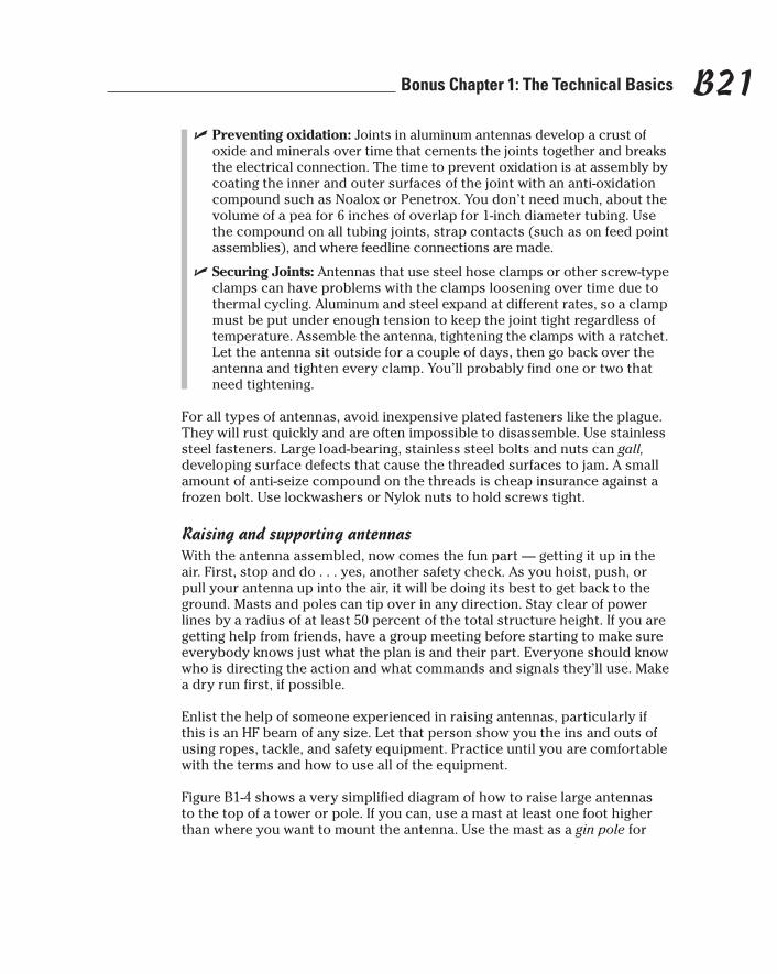
� Preventing oxidation: Joints in aluminum antennas develop a crust ofoxide and minerals over time that cements the joints together and breaksthe electrical connection. The time to prevent oxidation is at assembly bycoating the inner and outer surfaces of the joint with an anti-oxidationcompound such as Noalox or Penetrox. You don’t need much, about thevolume of a pea for 6 inches of overlap for 1-inch diameter tubing. Usethe compound on all tubing joints, strap contacts (such as on feed pointassemblies), and where feedline connections are made.
� Securing Joints: Antennas that use steel hose clamps or other screw-typeclamps can have problems with the clamps loosening over time due tothermal cycling. Aluminum and steel expand at different rates, so a clampmust be put under enough tension to keep the joint tight regardless oftemperature. Assemble the antenna, tightening the clamps with a ratchet.Let the antenna sit outside for a couple of days, then go back over theantenna and tighten every clamp. You’ll probably find one or two thatneed tightening.
For all types of antennas, avoid inexpensive plated fasteners like the plague.They will rust quickly and are often impossible to disassemble. Use stainlesssteel fasteners. Large load-bearing, stainless steel bolts and nuts can gall,developing surface defects that cause the threaded surfaces to jam. A smallamount of anti-seize compound on the threads is cheap insurance against afrozen bolt. Use lockwashers or Nylok nuts to hold screws tight.
Raising and supporting antennasWith the antenna assembled, now comes the fun part — getting it up in theair. First, stop and do . . . yes, another safety check. As you hoist, push, orpull your antenna up into the air, it will be doing its best to get back to theground. Masts and poles can tip over in any direction. Stay clear of powerlines by a radius of at least 50 percent of the total structure height. If you aregetting help from friends, have a group meeting before starting to make sureeverybody knows just what the plan is and their part. Everyone should knowwho is directing the action and what commands and signals they’ll use. Makea dry run first, if possible.
Enlist the help of someone experienced in raising antennas, particularly ifthis is an HF beam of any size. Let that person show you the ins and outs ofusing ropes, tackle, and safety equipment. Practice until you are comfortablewith the terms and how to use all of the equipment.
Figure B1-4 shows a very simplified diagram of how to raise large antennas to the top of a tower or pole. If you can, use a mast at least one foot higherthan where you want to mount the antenna. Use the mast as a gin pole for
B21Bonus Chapter 1: The Technical Basics
559877 BC01.qxd 3/11/04 9:21 AM Page B21

the antenna, holding its weight with a block and tackle and a rope held at theground level. The climber at the top can then work without having to supportthe weight of the antenna, too. Lift the antenna using a sling instead of tyingthe rope to the boom-to-mast plate. This lets the climber attach the boom-to-mast U-bolts immediately without any other rigging.
Use a snatch block at the base of the tower to keep the rope crew away fromthe base of the tower. They can see the climber and stay clear of any droppedobject. It also keeps all of the pulling force in line with the tower and not toone side. The tag line under the antenna is to control and steer the antennaas it goes up. If there are guy lines to avoid, having one or more tag linesallows the ground crew to steer the antenna around them.
This only scratches the surface of safe rigging techniques. Don’t attempt alarge project without adequate help and preparation. “Book learning” is notenough to protect you, your helpers, and your equipment. Be safe!
Truss
Mast
Element
HaulLine
Antennagoes here
Antenna
Block andTackle
Turnbuckle
U-boltBoom
Carabiner
Pipe hitches
Boom-to-MastPlate
Element-to-BoomClamp
TagLine Snatch
Block
Pull
Nylon websling
Figure B1-4:Basic
elements ofYagi-style
beams andhow to
raise them.
B22 Ham Radio For Dummies
559877 BC01.qxd 3/11/04 9:21 AM Page B22
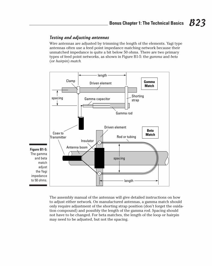
Testing and adjusting antennasWire antennas are adjusted by trimming the length of the elements. Yagi typeantennas often use a feed point impedance matching network because theirunmatched impedance is quite a bit below 50 ohms. There are two primarytypes of feed point networks, as shown in Figure B1-5: the gamma and beta(or hairpin) match.
The assembly manual of the antennas will give detailed instructions on howto adjust either network. On manufactured antennas, a gamma match shouldonly require adjustment of the shorting strap position (don’t forget the oxida-tion compound) and possibly the length of the gamma rod. Spacing shouldnot have to be changed. For beta matches, the length of the loop or hairpinmay need to be adjusted, but not the spacing.
GammaMatch
lengthlength
Driven elementClamp
Rod or tubing
Gamma capacitor
Gamma rod
Shortingstrapspacingspacing
BetaMatch
lengthlength
Driven element
spacingspacing
Insulator
Antenna boom
Coax toTransmitter
Figure B1-5:The gamma
and betamatchadjust
the Yagiimpedanceto 50 ohms.
B23Bonus Chapter 1: The Technical Basics
559877 BC01.qxd 3/11/04 9:21 AM Page B23

For a manufactured antenna, the network dimensions after adjustment shouldbe fairly close to those in the manual. If they differ by more than 10 percent, ifthe minimum SWR can’t be lowered below 1.5:1, or if the adjustments don’tbehave as represented in the manual, something is wrong. Stop and check theassembly and all element lengths. If all seems to be assembled properly, takecareful notes about what happens as you adjust the antenna, then contact themanufacturer.
An SWR sweep checks the antenna over the bands for which it is designed. Youcan do this with your transmitter and SWR meter, at the risk of causing interfer-ence. A noise bridge can be used with a receiver to measure impedance at dif-ferent frequencies, but the sequence of measurements is a little cumbersome. Iheartily recommend the use of an SWR Analyzer, shown in Figure B1-6.
The analyzer makes it easy to measure SWR at numerous points across aband while putting out only a very low-level signal. The SWR is read directlyon a numeric display along with the test frequency. A meter also shows theSWR, making it easy to find the point of minimum SWR. Using an SWR ana-lyzer makes short work of adjusting an antenna’s feed network or elementlength for minimum SWR at the desired frequency.
Power jackAntennaconnector
Readimpedance
Selectband
Adjustfrequency
ReadSWR
Figure B1-6:An SWRanalyzer
measuresSWR,
frequency,impedance,
and otherparameters.
B24 Ham Radio For Dummies
559877 BC01.qxd 3/11/04 9:21 AM Page B24

If at all possible, test and adjust the antenna at the installed height. Ground andnearby objects can affect the antenna, making SWR measurements inaccurate.If you adjust the antenna under those conditions, it will act differently once inplace, sometimes quite differently. If you can’t adjust the antenna in place, hangit pointing straight up (HF) or point it into the sky (VHF/UHF) with the reflector(the longest or largest element) parallel to and 6 to 10 feet off the ground.
Placing ground in the least sensitive part of the antenna’s pattern minimizesits effect and the adjustment should be close to actual performance once in theair. The antenna’s resonant point will likely rise a small amount — less than 100kHz at HF and barely noticeable at higher frequencies — when raised.
Radials for ground-plane verticalsThe ground-plane antenna relies on an electrically-reflective surface to “makeup the other half” of its 1⁄4-wavelength radiator. If you happen to live on a metalship or in a building with a metal roof to mount the antenna on, you’re lucky!Most of us have to make do with dirt and wires, though, which aren’t nearly soconductive.
The more conductive you can make the ground under your antenna, thesmaller the amount of power that will be lost and the stronger your signalwill be. The usual and most practical technique is to use wires stretched outradially from the base of the antenna. Needless to say, you can’t just leavethem scattered about your yard, so what do you do? How many do you need?
You’ll hear scary numbers of radials, like “120,” but don’t think that you musthave that many or the vertical won’t work. You can get pretty close to topperformance with 16 to 32 wires. The usual length is 1⁄4-wavelength at thelowest frequency of operation. Radials are not tuned. That length is just thepoint of diminishing returns: longer than that and additional benefits aresmall. Make the radial wires as long as is convenient. If you can only lay downshort wires, then use as many as you can.
Do you have to dig up the whole back yard? Not at all. If you have a lawn orfield, Mother Nature will work for you. Mow the grass as short as you canwhere you will lay down the wires. Attach the radial wire to the ground connec-tion at the antenna and stretch it out on the ground to full length. Hold the wiredown with jumbo bobby pins or 6-inch pieces of stiff wire bent double everyfew feet. Then wait. In a few days, the wires will be disappearing below thegrass and after a few weeks, the natural thatching and aerating processes willpull the wire down to the roots of the grass and the wires will be invisible andun-mowable.
To connect the radials at the base of the antenna, use a ring of heavy copperwire as a bus for soldering all the radial wires together. A single piece of strapor flashing can connect the ring to the antenna feed point ground. Anotherpopular method is to use a metal plate with a lot of screw terminals.
B25Bonus Chapter 1: The Technical Basics
559877 BC01.qxd 3/11/04 9:21 AM Page B25

Working with feedlines and connectorsThe different types of feedlines and connectors were covered in Chapter 12and I assume that you’ve made your purchase. Now it’s time to install someconnectors (if you’re using coaxial cable) and put that feedline to work!Putting connectors on coax has a reputation for being difficult, but that’s nottrue . . . if you have the proper tools and use them properly.
Let’s start with the PL-259 (the plug that goes on the end of the cable). Install-ing the PL-259 connectors properly will prevent frustrating and hard-to-isolatefailures, so it’s to your benefit to learn how to do it correctly.
The tools you will need are:
� A sharp utility knife and small, sharp wire cutters.
� A coax stripping tool. RG-8 and RG-213 size strippers are available fromThe RF Connection at www.therfc.com/index.htm. RadioShack carriesa smaller model for RG-59 and RG-59 as part number 278-248.
� A 100 to 250-watt soldering gun or iron and damp cellulose sponge (notplastic).
� Rosin-core solder.
� Locking pliers.
� A small vise (a machinist’s vise will do).
While there are as many ways to install PL-259s as there are hams, we’ll deferto the manufacturer’s instructions. Amphenol (a large connector manufac-turer) publishes instructions on their Web site for installing all of their RFconnectors. The PL-259 instructions with drawings can be found for RG-8 andRG-213 cables at www.amphenolrf.com. Select UHF, then Straight Cable Plugs,find the 83-1SP, and select Assembly Instructions. The ARRL Handbook alsohas a set of instructions. Figure B1-7 shows a typical workbench setup for“doing” connectors. Make sure you have adequate lighting. To make theseinstructions work for you:
� Practice on a piece of scrap cable.
� Put the outer connector shell (called the backshell or coupler) on firstand be sure it’s pointed the right way, with the knurled end towards theconnector body. Double-check before doing any soldering. (We’ve all putthem on backwards or forgotten — you’ll join the club eventually.)
� When trimming the jacket, disturb the braid as little as possible and tryto avoid nicking the individual strands. Be sure the coax stripper bladedepth is set properly.
B26 Ham Radio For Dummies
559877 BC01.qxd 3/11/04 9:21 AM Page B26

� When trimming the center insulator, don’t nick the center conductor. Cutclose to the conductor, then twist off the insulation.
� Make sure the plug body is clean of any grease or oil. A touch-up with asteel or brass bristle brush will clean off any oxidation. A severely grimyconnector shouldn’t be used at all.
� After you’re done trimming, slide the plug body on and off to be sure allof the center conductor strands go into the center pin and that none areflared outward to short against the body. This is a good time to double-check that backshell.
� When screwing the plug body onto the cable jacket, a tiny dab of oil orsilicon grease on the jacket will make the job easier. Clamp the lockingpliers on the knurled portion of the plug body and turn the body in aneven motion as it seats on the jacket. Don’t use pliers on the jacket — ifyou can’t hold the cable by hand, something is blocking the connector.
� Use a small vise to hold the cable as you work on it. Only tighten enoughto secure the cable; don’t bite into the jacket. You’ll need to twist thecable by 180 degrees in each direction as you solder.
� Make sure your soldering iron is hot and the tip is clean. Hold the ironagainst the body hole and melt a little solder on the tip to aid in transfer-ring the heat to connector. Be patient! Wait for the solder to start to flowonto the connector body and into the hole. This will take at least 15 sec-onds for most irons. The solder shouldn’t “bead up” in the hole.
� When you’ve done one hole, loosen the vise and twist the cable to thenext hole. Don’t wait between holes; keep the connector hot.
� When all four holes are soldered, use the damp sponge to soak up someof the heat from the connector. Don’t soak the connector with water, justhold the sponge against the plug body.
� To complete the job, reorient the cable in the vise so that the connectorangles slightly down and then solder the center pin. Fill the hole withsolder to prevent water from entering.
� When the connector has cooled, wipe off any flux residue and use theutility knife to trim any excess solder from the center pin. Check forshort circuits with an ohmmeter.
To crimp or not to crimp? Crimp-on PL-259 connectors are certainly a lot easierto put on, but there’s a catch. They should never be exposed to the weather,nor should they be used where vibration or mechanical stress (bending orpulling) will be present. The crimp between the shield and connector body willdeteriorate over time, creating a lossy, intermittent connection. Sealing theconnector with tape will help, but you are much better off limiting the crimpconnectors to indoor use.
B27Bonus Chapter 1: The Technical Basics
559877 BC01.qxd 3/11/04 9:21 AM Page B27
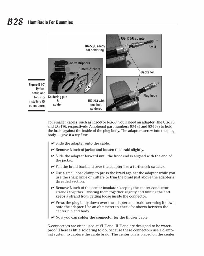
For smaller cables, such as RG-58 or RG-59, you’ll need an adapter (the UG-175and UG-176, respectively, Amphenol part numbers 83-185 and 83-168) to holdthe braid against the inside of the plug body. The adapters screw into the plugbody — give it a try first:
� Slide the adapter onto the cable.
� Remove 3⁄4 inch of jacket and loosen the braid slightly.
� Slide the adapter forward until the front end is aligned with the end ofthe jacket.
� Fan the braid back and over the adapter like a turtleneck sweater.
� Use a small hose clamp to press the braid against the adapter while youuse the sharp knife or cutters to trim the braid just above the adapter’sthreaded section.
� Remove 5⁄8 inch of the center insulator, keeping the center conductorstrands together. Twisting them together slightly and tinning the endkeeps a strand from getting loose inside the connector.
� Press the plug body down over the adapter and braid, screwing it downonto the adapter. Use an ohmmeter to check for shorts between thecenter pin and body.
� Now you can solder the connector for the thicker cable.
N-connectors are often used at VHF and UHF and are designed to be water-proof. There is little soldering to do, because these connectors use a clamp-ing system to capture the cable braid. The center pin is placed on the center
Coax strippers
Cutters & pliers
RG-58/U readyfor soldering
RG-213 withone holesoldered
Plug body
Braid
UG-175/U adapter
Backshell
Soldering gun&
solder
Figure B1-7:Typical
setup andtools for
installing RFconnectors.
B28 Ham Radio For Dummies
559877 BC01.qxd 3/11/04 9:21 AM Page B28

conductor and soldered with a small iron. The hole is very small, so using amagnifier may be a good idea. The installation instructions are found by fol-lowing the Type N link at www.amphenolrf.com, then selecting Straight CablePlugs. Choose a connector for the type of cable you are using and selectAssembly Instructions.
Because the N-connectors do not solder the braid to the body of the connector,they can be reused. The gaskets should be replaced if the connector has beeninstalled for any length of time. The center pin can also be reused, removingthe solder inside by heating followed by a sharp shake against a wastebasketor workbench. Be careful when flinging molten solder around — wear eyeprotection.
BalunsBalun (pronounced “B_L-_n”) is an abbreviation of “balanced-to-unbalancedtransformer.” Baluns are found at antenna feed points and at coaxial-to-openwire junctions. There are two types of baluns: choke baluns and impedancetransformer baluns.
The function of a choke balun is to prevent RF current from flowing on theoutside of a coaxial cable. It does not perform any impedance transformation.At the end of a feedline, the RF energy inside a coaxial cable will flow bothinto the load and back along the outer surface of the braid. RF current mayalso flow on the outside of the line due to picking up energy from an antenna.This is undesirable because the current should flow in the load, such as anantenna. By preventing the undesired current flow, the unbalanced energy inthe coaxial line (where the outside of the shield is grounded) is made to drivea balanced load (where equal currents flow in and out of each terminal).
Choke baluns make the outside of the cable shield look like a high impedanceto RF current. Make a choke balun by coiling the feedline in a single layer tomake the outer shield into an inductor. (The inner conducting surfaces areunaffected.) Table B-1 shows the coil diameter and number of turns that arerequired at the various frequencies. Another type of choke balun is made byplacing a number of ferrite beads over the end of the cable. Bead baluns canbe homemade or purchased commercially.
Table B-1 Coil and Bead Choke BalunsFrequency Range Number of Turns or Beads Type of Bead Material
Coil 3.5–14 MHz 8 turns, 7” diameter —-
Coil 14–30 MHz 6 turns, 4” diameter —-
Bead HF and VHF 12 beads Amidon FB-77-1024
B29Bonus Chapter 1: The Technical Basics
559877 BC01.qxd 3/11/04 9:21 AM Page B29
Impedance transformer baluns are used to change the impedance of a feed-line to a value that matches a load or that of another feedline. Impedancetransformers are specified by the ratio of transformation: 4:1, 6:1, 9:1, and soon. Those that use ferrite cores can only be used over a specific frequencyrange. They also connect unbalanced coaxial feedlines to a balanced load,but do not prevent RF current from flowing on the outside of the coaxialcable if the line picks up energy from an antenna.
Digital InterfacingThe major hurdle to using the digital modes is getting all the signals to andfrom the radio. Because most radios are designed to transmit voice and CW,not data, you’ll need to make use of whatever inputs and outputs the radioprovides. Luckily, the process is straightforward and more radios are beingdesigned with dedicated interfaces for data.
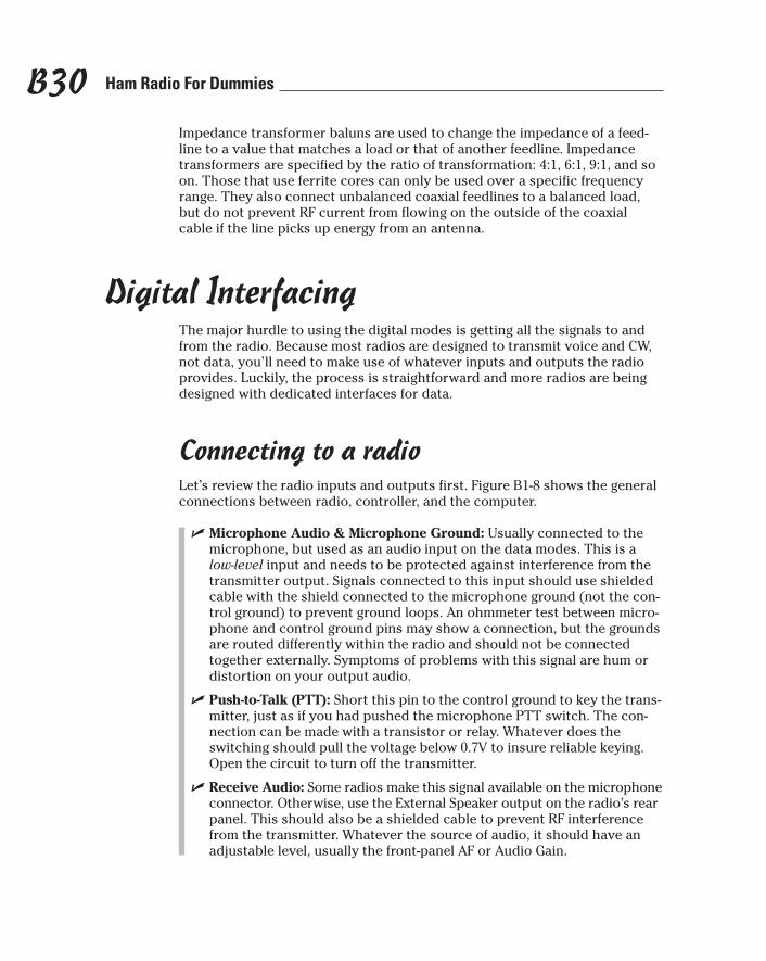
Connecting to a radioLet’s review the radio inputs and outputs first. Figure B1-8 shows the generalconnections between radio, controller, and the computer.
� Microphone Audio & Microphone Ground: Usually connected to themicrophone, but used as an audio input on the data modes. This is alow-level input and needs to be protected against interference from thetransmitter output. Signals connected to this input should use shieldedcable with the shield connected to the microphone ground (not the con-trol ground) to prevent ground loops. An ohmmeter test between micro-phone and control ground pins may show a connection, but the groundsare routed differently within the radio and should not be connectedtogether externally. Symptoms of problems with this signal are hum ordistortion on your output audio.
� Push-to-Talk (PTT): Short this pin to the control ground to key the trans-mitter, just as if you had pushed the microphone PTT switch. The con-nection can be made with a transistor or relay. Whatever does theswitching should pull the voltage below 0.7V to insure reliable keying.Open the circuit to turn off the transmitter.
� Receive Audio: Some radios make this signal available on the microphoneconnector. Otherwise, use the External Speaker output on the radio’s rearpanel. This should also be a shielded cable to prevent RF interferencefrom the transmitter. Whatever the source of audio, it should have anadjustable level, usually the front-panel AF or Audio Gain.
B30 Ham Radio For Dummies
559877 BC01.qxd 3/11/04 9:21 AM Page B30
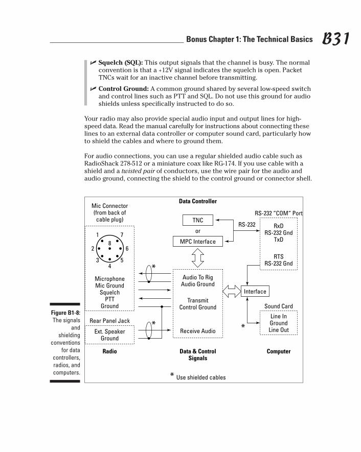
� Squelch (SQL): This output signals that the channel is busy. The normalconvention is that a +12V signal indicates the squelch is open. PacketTNCs wait for an inactive channel before transmitting.
� Control Ground: A common ground shared by several low-speed switchand control lines such as PTT and SQL. Do not use this ground for audioshields unless specifically instructed to do so.
Your radio may also provide special audio input and output lines for high-speed data. Read the manual carefully for instructions about connecting theselines to an external data controller or computer sound card, particularly howto shield the cables and where to ground them.
For audio connections, you can use a regular shielded audio cable such asRadioShack 278-512 or a miniature coax like RG-174. If you use cable with ashield and a twisted pair of conductors, use the wire pair for the audio andaudio ground, connecting the shield to the control ground or connector shell.
8
4
MicrophoneMic Ground
SquelchPTT
Ground
Mic Connector(from back ofcable plug)
Radio ComputerData & ControlSignals
Data Controller
1 7
62
5*
3
* *
* Use shielded cables
Audio To RigAudio Ground
TransmitControl Ground
Receive Audio
RxDRS-232 Gnd
TxD
RS-232 “COM“ Port
RTSRS-232 Gnd
Line InGroundLine Out
Sound Card
MPC Interface
RS-232
Interface
TNC
or
Rear Panel Jack
Ext. SpeakerGround
Figure B1-8:The signals
andshielding
conventionsfor data
controllers,radios, andcomputers.
B31Bonus Chapter 1: The Technical Basics
559877 BC01.qxd 3/11/04 9:21 AM Page B31

Using an external data controllerPacket operation requires a Terminal Node Controller (TNC) between the com-puter and radio. Another popular piece of equipment is the Multi-ProtocolController (MPC), used primarily on HF. Both of these connect to a PC serial or“COM” port using RS-232 signals. To connect these to a radio requires a specialcable carrying the signals described in Figure B1-8.
There is no standard connector on an external controller, so you’ll have tomake up your own cable. The controller manufacturer may provide an unter-minated cable that plugs into the controller, but relies on you to make con-nections to the radio. Follow the rules for shields and grounding discussed inthe previous section.
When you are making data and audio cables, that’s a good time to slip a fer-rite bead or two over the cable. The beads can then be held in place againstthe connector with a cable tie. This is a lot easier than having to wind the cableon a larger (and more expensive) core when interference occurs.
The controller is a central point for a lot of wires and cables: power, digitaldata, control lines, and low-level audio. It’s an easy target for RF pickup, sogrounding is doubly important. Be sure to tie the case of your controller tothe shack RF ground system and keep cables as short as is practical.
Interfacing directly to a computerMore and more software is available that uses the computer sound card toencode and decode data signals without an external controller. Computersand radio have entirely different notions about grounding, particularly in theRF-laden environment of ham radio. The solution is to use an interface circuitthat isolates the grounds of the two systems, but allows audio and controlsignals to pass.
Both MFJ Enterprises (www.mfjenterprises.com) and West Mountain Radio(www.westmountainradio.com) make popular sound card/radio interfaceunits. You will also find interface kits and wiring instructions on the fine Website of Ernie Mills WM2U (www.qsl.net/wm2u). The PSK31 page found thereis an excellent tutorial on connecting a computer to a radio.
The key to all of these interfaces is the use of transformer coupling. Small audiotransformers pass the data signals in each direction, but there is no direct con-tact. This breaks any ground loops between the computer and radio, keepingnoise and hum from the AC power lines from contaminating the low-level audiosignals. Control lines are less touchy about noise but are often isolated withoptoisolators.
B32 Ham Radio For Dummies
559877 BC01.qxd 3/11/04 9:21 AM Page B32

Optoisolators or optocouplers are a package containing a light-emitting diodeand a light-sensitive transistor. When the input circuit drives current throughthe LED, turning it on, it also turns on the output transistor. This makes opto-isolators ideal for transferring control signals between systems without makingdirect contact between them. For additional information about these devices,download the documents “General Description” and “Application Examples”from the Vishay Electronics Web site (www.vishay.com/optocouplers/related#appnot).
Adjusting the data signalThe data controller or sound card software must have a proper signal to workwith or you won’t be able to send or receive data effectively. By understandingthe basics of the signals, you’ll have much better on-the-air results. First, readthe background information in Chapter 12 on the data mode you are using,including the reference materials. You need to know what kind of a signalyou’re tuning in!
Second, there are three adjustments you need to master:
� Tuning: The adjustment of receiver frequency so that the data signaltones are of the proper frequency (on SSB-based modes) or that thesignal’s carrier frequency is centered in the receiver’s passband (for FMmodes). VHF packet channels are centered on known frequencies, so set-ting your radio’s frequency to the desired channel is generally sufficient.For other modes, tuning guidance is provided by displays on the con-troller or in the PC software. Tuning displays generally have marks orguides that correspond to the desired signal frequencies or amplitudes.When your receiver is on the right frequency, the display will show thesignal concentrated on those marks. Each controller and program aresomewhat different, so consult the manual or Help files for a specificdescription. Once you get the signal tuned in, listen to it by ear to get afeel for what properly tuned signals of each type sound like.
� Outgoing audio level: The level of the audio signal input to the micro-phone connector as modified by the Mic Gain control. Just like for voiceoperation, the radio’s operating manual should have a procedure to followto insure that you don’t set the level too high, which causes distortionand interference. The speech processor should be OFF for data. If youset the level too low, then your signal will be weak, but otherwise okay.There are two adjustment points: one in the controller, the interface, orthe sound card software, with the other being the radio’s Mic Gain con-trol. If there are no instructions, a good starting point is to set the con-troller or software gain to 50% of maximum and then adjust the Mic Gain.
B33Bonus Chapter 1: The Technical Basics
559877 BC01.qxd 3/11/04 9:21 AM Page B33

� Incoming audio level: The level of the audio signal supplied by thereceiver. The single control that affects output level is AF Gain. The con-troller or program instructions should guide you on the best way to setthis signal level. If you don’t have instructions, find a signal on the airthat is fairly free of noise or fading. Increase the level until you can get aclear tuning indication on your controller or software. When the tuning isset properly, reduce the level until you are no longer able to receive thedata reliably. Now increase the level until data is copied reliably and notethe characteristics of the tuning display or listen to the signal by ear.
Specifying the frequency of a digital signal on SSB equipment has the sameproblem as SSB voice. Do you specify the frequency of the carrier or of one ofthe data tones or of the center frequency of the transmitted signal? The usualconvention, as with voice, is to specify the carrier frequency. If I say to a friend,I’ll meet you on RTTY at 14.085 MHz, what I’m really saying is that I’ll set mydisplayed frequency (i.e. the carrier) to 14.085 MHz LSB, but the actual tones of2125 Hz and 2295 Hz tones will actually cause RF signals at 14.085 MHz to 2125or 2295 Hz = 14.082875 and 14.082715 MHz. It’s easier to use the displayed car-rier frequency. Be sure to ask!
Working the SatellitesCommunicating through the amateur satellites is not that much different fromusing a repeater or chasing a DX station that is operating split. There is oneadditional element to consider: The station you’re trying to communicate withis moving in the sky. That means you have to know when and where the satel-lite will be visible to you. You will also have to be able to compensate for theDoppler shift resulting from its motion. Here’s an example showing how to makea satellite voice QSO.
An FM repeater satellite is the easiest and can be accessed with a dual-bandVHF/UHF hand-held or mobile radio. Let’s say you want to try the Saudisat 1-C,also known as SO-50. It is a cross-band repeater that you access on 145.850MHz (67.0 Hz CTCSS tone) and transmits on 436.795 MHz. You may be able towork the satellite with a rubber duck antenna, but a dual-band mobile whip willwork much better.
� Log on to the AMSAT Web site (www.amsat.org) and obtain the orbitalelements as discussed in Chapter 12. Enter them into your satellitetracking software and determine when the satellite will be visible. (Makesure the satellite is operational, as well.)
� Program three memory channels of your radio to use when the satellite isapproaching, when it is closest to you at mid-pass, and when it is reced-ing. Table B-2 shows the appropriate frequencies. As it approaches, the
B34 Ham Radio For Dummies
559877 BC01.qxd 3/11/04 9:21 AM Page B34

Doppler shift will cause you to hear the satellite at a higher frequency andthe satellite will hear you at a higher frequency. The converse is true whenthe satellite is moving away. Note that the transmitter and receiver Dopplershifts are in opposite directions, this is because the Doppler shift onlyapplies to the receiving station. The satellite will experience a Doppler shifton your signal, too, so you must compensate by moving your transmitterin the opposite direction. Note also that Doppler shift is frequency-sensi-tive and so is greater at higher frequencies (although it’s the same percent-age of the frequency).
Table B-2 SO-50 Operating ChannelsReceive Transmit Rx Offset/Tx Frequency (MHz) Frequency (MHz) Offset (kHz)
Approaching Channel 436.800 145.748 +5/-2
Mid-pass Channel 436.795 145.850 0/0
Receding Channel 436.790 145.852 -5/+2
� Select the approaching channel and at the appropriate hour listen for thesatellite’s signal with the receiver squelch open. When it comes in range,you’ll hear the noise level begin to drop. Alternate between the approach-ing and mid-pass channels to see which gives the best reception.
� Listen to the signal as the satellite passes overhead and moves away,switching to the receding channel as necessary until the signal fades.Practice receiving on a few more passes and see if you hear others usingthe satellite. You’ll quickly learn how contacts are made.
� Satellite passes are short, so keep transmissions to a minimum. Try ashort transmission, such as “This is NØAX calling.” You might get ananswer! Only one person can use the satellite at any time, so keep thecontact short — the longest passes are only 10 to 15 minutes!
Satellite transpondersThe SSB/CW transponders are frequency converters that receive signals over arange of input frequencies and translate them to a range of output frequencies.For example, one of AO-40’s transponders has an input or uplink range of435.550 to 435.800 MHz and an output or downlink of 24048.025 to 24048.275MHz. Notice that the uplink and downlink bands have the same width (250 kHz)so that if I transmit 10 kHz from an uplink band edge, I will be 10 kHz from thedownlink band edge. Each uplink/downlink pair is called a mode that is identi-fied with letters corresponding to the ham bands used. For example, Mode U/Smeans the satellite is receiving on 435 MHz (U) and transmitting on 2.4 GHz (S).
B35Bonus Chapter 1: The Technical Basics
559877 BC01.qxd 3/11/04 9:21 AM Page B35
The downlink band of an inverting transponder is inverted from the uplink,meaning that signals at the high end of the uplink are found at the lower end ofthe downlink. You’ll need to know that before trying to communicate throughthe satellites. The information is available on the AMSAT Web site.
To work the satellite transponders, you’ll need a radio that can operate cross-band split. Because the uplink and downlink are on different bands, the radiowill have to jump from one band to another when you key the transmitter. Theradio will also have to operate full duplex, that is, receive and transmit on thosetwo bands simultaneously. You’ll need to hear your own signal on the satellite’sdownlink in order to be able to find stations calling you and to compensate forDoppler shift as the satellite moves.
To do this, you can use two separate radios or purchase one of the “satelliterigs” that are made just for this purpose, such as the Kenwood TS-2000, YaesuFT-847, or Icom IC-910H. Using separate radios requires that you performtuning operations manually. Either way, it will take some practice and I recom-mend that you listen to the satellite downlinks to become comfortable withtuning and the characteristics of the signals before transmitting.
You don’t have to have a big array of antennas, steerable in both azimuth andelevation to work the satellites, either. Many stations use nothing more thanomnidirectional verticals, although that limits the amount of time they canaccess the “bird.” A simple turnstile over reflector antenna can be home-brewed
B36 Ham Radio For Dummies
Working the International Space Station (ISS)The ISS has a VHF voice and data ham radiostation aboard and nearly all of the astronautsthat call it home are hams! You can talk to themor send and receive messages. While theirschedule is very busy, they enjoy using hamradio to keep in touch and break up the routinein space. You can connect to the packet stationaboard the ISS and receive a nice certificate asa result!
You’ll need a 2-meter FM radio with 10 to 25watts of output. An omnidirectional antenna willwork and a small beam is even better. You alsoneed a packet radio TNC such as a KantronicsKPC-3 or the equivalent. You’ll need a computerrunning a terminal program, such as Hyperterm
or Procomm, configured to log all of the datagoing to and from the TNC. With your trans-ceiver set to the ISS frequencies (145.990 MHzuplink and 145.800 MHz downlink), wait for along pass visible at your location. Your TNC willbegin to decode messages if anyone else islogged on to the ISS system. When you see theall-clear message, try to connect by typing “CRS0ISS-1.” If you’re successful, you’ll get aCONNECT message back! If not, keep trying ongood passes and sooner or later, you’ll make itthrough!
The complete procedure, including how to setup your TNC, is posted on the Ham Radio ForDummies Web site.
559877 BC01.qxd 3/11/04 9:21 AM Page B36

for a few dollars and a pair mounted on an inexpensive TV antenna rotator for360-degree coverage. Start by listening for satellites on your existing antennasto determine if you need a more capable antenna.
There is a lot of terminology associated with satellites — more than I can coverhere. If you plan on making the satellites a regular part of your operation, I rec-ommend that you study the references on the AMSAT Web site, in Chapter 11,and Appendix B. You’ve experienced the basics of satellite operation and nowwill be able understand the discussions as you construct a more capable satel-lite ground station.
Learning about Ionospheric PropagationChapters 8 and 9 introduce the day/night characteristics of the HF bands andthe basic types of propagation you’ll encounter on the VHF and UHF bands.Once you start operating regularly, you’ll want to know more about how propa-gation works and how it can be predicted. Propagation of radio waves is suffi-ciently complex that you can spend a lifetime studying it, but you only needto commit a few hours of reading time to learn the basics.
Start by reading the chapter on Radio Wave Propagation in The ARRL AntennaBook. (It may be available at your library.) This valuable reference covers all ofthe common propagation types, their causes, and their effects. It also includesa discussion of how predictions are made for what HF bands are open andwhen. (Other references are listed in Appendix B.) What I present here are thefundamental concepts involved.
Reflection and absorptionPropagation on the HF bands is a continual balancing act between the abilityof the ionosphere to reflect and to absorb radio waves. The ionosphere canbe thought of as having three layers in order of increasing height: D, E, and F(which also splits into the F1 and F2 layers). All are in sufficiently thin air thatsolar ultraviolet (UV) radiation can partially ionize the molecules by knock-ing electrons free. The ionized layers affect radio waves as you learned duringyour licensing studies, bending and absorbing them.
Reflection by bending is primarily performed by the F layers. As frequencyincreases, ability to bend signals decreases, resulting in a maximum frequencyat which a signal can be returned to Earth. This is the Maximum Useable Fre-quency or MUF. The stronger the solar radiation, the more the ionosphere canbend a signal and the higher the MUF. This is why the higher HF bands on 14MHz and higher come to life with the sunrise and close again after dark.
B37Bonus Chapter 1: The Technical Basics
559877 BC01.qxd 3/11/04 9:21 AM Page B37

There is one other variable that affects MUF and that is angle of incidence. Justas even rough surfaces can reflect light well at low angles, the ionosphere’slayers reflect signals better at low angles. At high angles, such as straight up,the F layers may pass a signal right through to outer space, where a signal graz-ing them at a few degrees may reflect cleanly. This results in the skip zone sur-rounding your station on the higher HF bands; few local signals are heard, butDX signals may be strong. The local signals aren’t reflected by the ionosphereat the high angle required to come back down to your antenna.
There is one problem with higher levels of solar radiation: The lower layersbecome lossier to signals travelling through them, particularly at low frequen-cies. At some point, enough signal is lost so that there is a Minimum UseableFrequency, as well. For example, during the day the D layer effectively absorbsenergy on the 7 MHz band and below, making long-distance contacts impossi-ble. As the sun sets, reducing its illumination of the ionosphere, these bandscome alive with long-distance contacts.
Predicting propagationGiven the dependence of absorption and reflection on frequency, angle, andsolar radiation levels, this can make for a complex situation. That’s wherepropagation prediction tables and programs come in. These programs takesolar radiation, time, date, and the Earth’s geomagnetic field into account, cal-culating the expected signal levels between any two points on Earth at anyHF frequency. You or your computer can supply the time and date. The geo-magnetic field has been mapped by scientists over the years so that for mostconditions, the strength of the ionosphere over any point on Earth is known.That leaves the solar radiation levels.
Solar and geomagnetic indicesSolar radiation data and the conditions of the ionosphere (disturbed or stable)are measured continually here on Earth and by satellites in orbit. The data ismade available to Web sites and is broadcast by WWV (www.boulder.nist.gov/timefreq/stations/wwv.html) at 18 minutes past the hour (and at 45minutes past the hour on WWVH). There are three key indices that are usedby propagation prediction: solar flux, the A index, and the K index. WWVannouncements also include the current and predicted state of the geomag-netic field.
The solar flux is a measure of how much energy is entering the Earth’s atmos-phere. As mentioned earlier, more radiation means higher MUFs and thatmakes the HF DXers and VHF Sporadic-E operators happy. The flux ranges froma low of 65 during sunspot cycle minimums to approximately 300 during solaroutbursts.
B38 Ham Radio For Dummies
559877 BC01.qxd 3/11/04 9:21 AM Page B38

The A and K indices measure how active the geomagnetic field is. More activ-ity disturbs the ability of the ionospheric layers to reflect signals and causesmore absorption. The higher the values for these indices, the worse the con-ditions on HF will be, in general. If the K index is reported as 0, 1, or 2, condi-tions are generally good. Values of 3 or 4 are somewhat disturbed, and a valueof 5 or more indicates a storm (9 is the maximum). The A index varies over awider range and reacts more quickly than the K index, so look for changes inthe A index to indicate future conditions.
Propagation prediction programs use this information (usually just the Kindex) to calculate the strength of a signal travelling between two points. Theionosphere’s reflective and absorptive characteristics are taken into account,as well. The result is a prediction of what the MUF will be for that particularpath and the expected signal levels or signal-to-noise ratio. Here are three ofthe popular programs:
� W6ELProp by W6EL: A freeware Windows program (www.qsl.net/w6elprop)
� Wincap Wizard 3 by Kangaroo Tabor Software: (www.taborsoft.com/wwizard3)
� VOACAP: Developed for Voice of America and available to the publicfrom several sources (try ON4BAA’s excellent propagation Web site atwww.stroobandt.com/propagation/index.html)
Solar stormsSometimes the sun’s quiet radiance changes to a violent outburst fromsunspots, the more active regions on the sun. These can have dramaticeffects on the ionosphere and propagation, so hams pay pretty close atten-tion to them. Here are some of the more common terms you’ll hear:
� Blackout or Sudden Ionospheric Disturbance (SID): A sudden pulse of X-rays from the sun can cause all ionospheric layers to become highlylossy to radio signals. If you are on the air during an SID, signal strengthstarts dropping and a hissing noise rises to eventually cover all but thestrongest signals. The bands generally recover from an SID in a few hours.
� Coronal Mass Ejection (CME): Not to be confused with what happensafter drinking too much Mexican beer, a CME occurs when a large amountof material, highly ionized gas and charged particles, is repelled from thesun’s surface. The material impacts the Earth’s geomagnetic field 30 to 36hours after it is detected and may cause geomagnetic storms.
� Geomagnetic Storm: A significant worldwide disturbance of the Earth’sgeomagnetic field. This also stirs up the ionosphere’s layers and makesthem less reflective and more lossy.
B39Bonus Chapter 1: The Technical Basics
559877 BC01.qxd 3/11/04 9:21 AM Page B39

� Solar Flare: A large radiation pulse from the sun that occurs when someof the stored magnetic energy in the sun’s outer layers is released. Thelargest and most disruptive are the X-class flares, followed by M-class,and then C-class, which are essentially normal behavior.
� Solar Wind: The stream of charged particles (mostly protons) that flowssteadily outward from the sun. Higher velocity or density can disturbthe ionosphere and cause a geomagnetic storm.
Near real-time information about solar activity is available from numerous Websites. Two of my favorites are Spaceweather (www.spaceweather.com) and, byTomas NW7US, www.hfradio.org/propagation.html. You will not only getactivity updates, but images from the solar observatory satellites, pictures ofauroral activity, and other interesting data. It’s safe to say that you’ll want tobookmark one of these or a similar site to keep an eye on Ol’ Sol.
B40 Ham Radio For Dummies
559877 BC01.qxd 3/11/04 9:21 AM Page B40