Introduction and Review of Statics - COPYRIGHTED MATERIAL
47
P1: IML/OVY P2: IML/OVY QC: IML/OVY T1: IML GTBL006-01 GTBL006-Riley-v19 January 5, 2006 0:57 Chapter 1 Introduction and Review of Statics 1-1 INTRODUCTION The primary objective of a course in mechanics of materials is the development of relationships between the loads applied to a nonrigid body and the internal forces and deformations induced in the body. Ever since the time of Galileo Galilei (1564– 1642), scientists and engineers have studied the problem of the load-carrying capacity of structural members and machine components, and have developed mathematical and experimental methods of analysis for determining the internal forces and the deformations induced by the applied loads. The experiences and observations of these scientists and engineers of the last three centuries are the heritage of the engineer of today. The fundamental knowledge gained over the last three centuries, together with the theories and analysis techniques developed, permit the modern engineer to design, with complete competence and assurance, structures and machines of unprecedented size and complexity. The subject matter of this book forms the basis for the solution of three general types of problems: 1. Given a certain function to perform (transporting traffic over a river by means of a bridge, conveying scientific instruments to Mars in a space vehicle, con- verting water power into electric power), of what materials should the machine or structure be constructed, and what should be the sizes and proportions of the various elements? This is the designer’s task, and obviously there is no single solution to any given problem. 2. Given the completed design, is it adequate? That is, does it perform the function economically and without excessive deformation? This is the checker’s problem. 3. Given a completed structure or machine, what is its actual load-carrying capac- ity? The structure may have been designed for some purpose other than the one for which it is now to be used. Is it adequate for the proposed use? For example, a building may have been designed as an office building but is later found to be desirable for use as a warehouse. In such a case, what maximum loading may the floor safely support? This is the rating problem. Because the complete scope of these problems is obviously too comprehensive for mastery in a single course, this book is restricted to a study of individual members and very simple structures or machines. The design courses that follow will consider the entire structure or machine, and will provide essential background for the complete analysis of the three problems. 1 COPYRIGHTED MATERIAL
-
Upload
khangminh22 -
Category
Documents
-
view
0 -
download
0
Transcript of Introduction and Review of Statics - COPYRIGHTED MATERIAL

P1: IML/OVY P2: IML/OVY QC: IML/OVY T1: IML
GTBL006-01 GTBL006-Riley-v19 January 5, 2006 0:57
Chapter 1Introduction andReview of Statics
1-1 INTRODUCTIONThe primary objective of a course in mechanics of materials is the development ofrelationships between the loads applied to a nonrigid body and the internal forcesand deformations induced in the body. Ever since the time of Galileo Galilei (1564–1642), scientists and engineers have studied the problem of the load-carryingcapacity of structural members and machine components, and have developedmathematical and experimental methods of analysis for determining the internalforces and the deformations induced by the applied loads. The experiences andobservations of these scientists and engineers of the last three centuries are theheritage of the engineer of today. The fundamental knowledge gained over thelast three centuries, together with the theories and analysis techniques developed,permit the modern engineer to design, with complete competence and assurance,structures and machines of unprecedented size and complexity.
The subject matter of this book forms the basis for the solution of threegeneral types of problems:
1. Given a certain function to perform (transporting traffic over a river by meansof a bridge, conveying scientific instruments to Mars in a space vehicle, con-verting water power into electric power), of what materials should the machineor structure be constructed, and what should be the sizes and proportions of thevarious elements? This is the designer’s task, and obviously there is no singlesolution to any given problem.
2. Given the completed design, is it adequate? That is, does it perform the functioneconomically and without excessive deformation? This is the checker’s problem.
3. Given a completed structure or machine, what is its actual load-carrying capac-ity? The structure may have been designed for some purpose other than the onefor which it is now to be used. Is it adequate for the proposed use? For example,a building may have been designed as an office building but is later found to bedesirable for use as a warehouse. In such a case, what maximum loading maythe floor safely support? This is the rating problem.
Because the complete scope of these problems is obviously too comprehensivefor mastery in a single course, this book is restricted to a study of individualmembers and very simple structures or machines. The design courses that followwill consider the entire structure or machine, and will provide essential backgroundfor the complete analysis of the three problems.
1
COPYRIG
HTED M
ATERIAL

P1: IML/OVY P2: IML/OVY QC: IML/OVY T1: IML
GTBL006-01 GTBL006-Riley-v19 January 5, 2006 0:57
2 CHAPTER 1 INTRODUCTION AND REVIEW OF STATICS
The principles and methods used to meet the objective stated at the beginningof this chapter depend to a great extent on prerequisite courses in mathematicsand mechanics, supplemented by additional concepts from the theory of elasticityand the properties of engineering materials. The equations of equilibrium fromstatics are used extensively, with one major change in the free-body diagrams;namely, most free bodies are isolated by cutting through a member instead ofsimply removing a pin or some other connection. The internal force on the cutsection is related to the stresses (force per unit area) generated by the cohesiveforces holding the member together. The size and shape of the member must beadjusted to keep the stress below the limiting value for the type of material fromwhich the member is constructed.
In some instances, the specified maximum deformation, not the specifiedmaximum stress, will govern the maximum load that a member may carry. Inother instances, it may be found that the equations of equilibrium (or motion) arenot sufficient to determine all of the unknown loads or reactions acting on a body.In such cases it is necessary to consider the geometry (the change in size or shape)of the body after the loads are applied. The deformation per unit length in anydirection or dimension is called strain.
Some knowledge of the physical and mechanical properties of materials isrequired in order to create a design, to properly evaluate a given design, or even towrite the correct relation between an applied load and the resulting deformationof a loaded member. Essential information will be introduced as required, andmore complete information can be obtained from textbooks and handbooks onproperties of materials.
1-2 CLASSIFICATION OF FORCESForce is one of the most important of the basic concepts in the study of mechanicsof materials (or the mechanics of deformable bodies). Force is the action of onebody on another; forces always exist in equal magnitude, opposite direction pairs.Forces may result from direct physical contact between two bodies or from twobodies that are not in direct contact. For example, consider a person standing on asidewalk. The person exerts a force on the sidewalk through direct physical contactbetween the soles of his or her shoes and the sidewalk; the sidewalk in turn exertsan equal magnitude, opposite direction force on the soles of the person’s shoes. Ifthe person were to jump, the contact force would vanish but there would still be agravitational attraction (force between two bodies not in direct contact) betweenthe person and the earth. The gravitational attraction force exerted on the person bythe earth is called the weight of the person; an equal magnitude, opposite direction,attraction force is exerted on the earth by the person. Another type of force thatexists without direct physical contact is an electromagnetic force.
Contact forces are called surface forces, since they exist at surfaces of
F1 F2Concentrated
loads
Figure 1-1
contact between two bodies. If the area of contact is small compared to the size ofthe body, the force is called a concentrated force; this type of force is assumed toact at a point. For example, the force applied by a car wheel to the pavement ona bridge (see Fig. 1-1) is often modeled as a concentrated force. Also, a contactforce may be distributed over a narrow region in a uniform or nonuniform manner.This situation would exist where floor decking contacts a floor joist, as shown inFig. 1-2a. Here, the floor decking exerts a uniformly distributed load (force) onthe joist, as shown in Fig. 1-2b. The intensity of the distributed load is w and hasdimensions of force per unit length.

P1: IML/OVY P2: IML/OVY QC: IML/OVY T1: IML
GTBL006-01 GTBL006-Riley-v19 January 5, 2006 0:57
1-2 CLASSIFICATION OF FORCES 3
Floor decking
w
Joist
(a)
Joist
(b)
Figure 1-2
Other common types of forces are external, internal, applied, and reaction.To illustrate, consider the beam loaded and supported, as shown in Fig. 1-3a. Afree-body diagram of the beam is shown in Fig. 1-3b. All forces acting on the free-body diagram are external forces; that is, they represent the interaction betweenthe beam (the object shown in the free-body diagram) and the external world(everything else that has been discarded). Force F is a concentrated force, whereasw is a uniformly distributed load with dimensions of force/length. The forces Fand w are called applied forces or loads. They are the forces that the beam isdesigned to carry. Forces Ax, Ay, and B are necessary to prevent movement of thebeam. Such supporting forces are called reactions. Force distributions at supportsare complicated, and reactions are usually modeled as concentrated forces.
Once again, all the forces shown in Figure 1-3 are external forces. At everysection along the beam, there also exists a system of equal magnitude, oppositedirection pairs of internal forces between the atoms on either side of the section.The study of mechanics of materials or mechanics of deformable bodies depends onthe calculation of these internal forces at various sections of a structure or machineelement and how these forces are distributed over the sections. The determinationof internal forces is discussed in Section 1-5.
In our previous discussion of loads (forces), we saw that the loads might beconcentrated forces or distributed forces. Furthermore, we assumed that the forcesdid not vary with time, that is, they were static loads. In many situations, loadsmay be a function of time. For example, a sustained load is a load that is constantover a long period of time, such as the weight of a structure (called dead load).This type of load is treated in the same manner as a static load; however, for somematerials and conditions of temperature and stress, the resistance to failure may
(a)
F
BA
w
(b)
F
B
Axx
y
Ay
Figure 1-3

P1: IML/OVY P2: IML/OVY QC: IML/OVY T1: IML
GTBL006-01 GTBL006-Riley-v19 January 5, 2006 0:57
4 CHAPTER 1 INTRODUCTION AND REVIEW OF STATICS
be different under short-time loading and sustained loading. An impact load is arapidly applied load which transfers a large amount of energy in a short periodof time. Vibration normally results from an impact load, and equilibrium is notestablished until the vibration is eliminated, usually by natural damping forces.A repeated load is a load that is applied and removed many thousands of times.The helical springs that close the valves on an automobile engine are subjected torepeated loading.
1-3 EQUILIBRIUM OF A RIGID BODYA rigid body (a body that does not deform under the action of applied loads) is inequilibrium when the resultant of the system of forces acting on the body is zero.This condition is satisfied if
ΣF = 0 (1-1)
ΣMO = 0 (1-2)
Equation 1-1 states that the vector sum of all external forces acting on the bodyis zero, whereas Eq. 1-2 states that the vector sum of the moments of the externalforces about any point O (on or off the body) is zero. Equations 1-1 and 1-2 are thenecessary and the sufficient conditions for equilibrium of a rigid body. The twovector equations of equilibrium may be written as six scalar equations. Selectinga right-handed, xyz-rectangular coordinate system, the equations of equilibriummay be written
�Fx = 0 �Fy = 0 �Fz = 0 (1-3)
�Mx = 0 �My = 0 �Mz = 0 (1-4)
Equation 1-3 states that the sum of all external forces acting on the body in the x-,y-, and z-directions is zero. Equation 1-4 states that the sum of the moments of allof the external forces acting on a body about the x-, y-, and z-axes is zero. Manyproblems encountered in mechanics of materials are two-dimensional in nature.Selecting the x- and y-axes in the plane of the forces and the z-axis perpendicularto the plane, the equations of equilibrium reduce to
�Fx = 0 �Fy = 0 �Mz = 0 (1-5)
These equations of equilibrium would be applicable for the force system shownin Fig. 1-3b, which is coplanar and noncurrent. If the force system acting on thebody is coplanar and concurrent, as in the light suspended from the ceiling by twowires shown in Fig. 1-4, Eqs. 1-3 and 1-4 reduce to
�Fx = 0 �Fy = 0 (1-6)
Other types of force systems exist for problems encountered in the study of mechan-ics of materials. Students should not try to memorize the equations of equilibriumthat apply for each of the various force systems. Rather, Eqs. 1-3 and 1-4 shouldbe reduced to equations appropriate for the particular problem at hand. This willbe illustrated in the example problems presented at the end of this section.

P1: IML/OVY P2: IML/OVY QC: IML/OVY T1: IML
GTBL006-01 GTBL006-Riley-v19 January 5, 2006 0:57
1-3 EQUILIBRIUM OF A RIGID BODY 5
x
y
Figure 1-4
Note from previous discussions that the equations of equilibrium are appliedto a system of forces. The system of forces may act on a single body or on a systemof connected bodies. A free-body diagram is a carefully prepared drawing thatshows a “body of interest” separated from all other interacting bodies and thatshows all external forces, both known and unknown, that are applied to the body.The word “free” in the name “free-body diagram” emphasizes the idea that allbodies exerting forces on the body of interest are removed or withdrawn and arereplaced by the forces that they exert. At each position on the free-body diagramwhere other bodies have been removed, the equal magnitude, opposite directionpairs of forces have been broken, and the forces which act on the free-body diagrammust be shown. These forces may be either surface forces or body forces, or both.An important body force is the gravitational attraction of the earth, that is, theweight of the body.
The following examples illustrate the use of free-body diagrams togetherwith the equations of equilibrium to determine unknown forces acting on rigidbodies. The importance of drawing a correct free-body diagram cannot be overem-phasized. The free-body diagram clearly establishes which body or portion of thebody is being studied. A correct free-body diagram clearly identifies all forces(both known and unknown) that must be included in the equations of equilibrium.The methods commonly used to find the unknown forces which act on rigid bodiesmust be thoroughly mastered, since these methods, as well as an extension of thesemethods to deformable bodies, are used throughout this book.
Example Problem 1-1 The rigid structure shown in Fig. 1-5a is sub-jected to a 5000-lb force P. The connections at joints A, B, and C are frictionlesspins. Determine the forces at A and B on member AB.
SOLUTIONWe first draw a free-body diagram of member AB, as shown in Fig. 1-5b. MemberAB is “freed” from interacting bodies: the bracket and pin at A and member BC.At the places where AB is separated from interacting bodies, we show externalforces acting on AB. Since member BC is a straight two-force member, the forceT must lie along the member. The force at pin A has an unknown magnitude anddirection. We show this force as two components, Ax and Ay, where the directionshave been assumed. The weight of member AB is assumed to be small comparedto the applied force P and is not shown on the free-body diagram. The free-bodydiagram contains three unknowns, Ax, Ay, and T . These unknowns, together with

P1: IML/OVY P2: IML/OVY QC: IML/OVY T1: IML
GTBL006-01 GTBL006-Riley-v19 January 5, 2006 0:57
6 CHAPTER 1 INTRODUCTION AND REVIEW OF STATICS
(a)
(b)
P
T
BA
C
5000 lb
45°Axx
y
Ay
4 ft
4 ft
Figure 1-5
the 5000-lb applied load, constitute a coplanar, nonconcurrent force system. Theequations of equilibrium 1-3 and 1-4 for this system of forces reduce to
�Fx = 0 �Fy = 0 �MA = 0 (a)
where �Mz = 0 has been replaced with �MA = 0 (point A is the intersection of� Point A was chosen for the moment equa-
tion since two of the unknown forces (Ax and
Ay) intersect at point A. Therefore, the mo-
ment equation relative to point A contains
only one unknown (T) and can be solved
immediately for the value of T . Two of the
unknown forces also intersect at points B(forces Ax and T) and C (forces Ay and T),
and these would also be good points to use
for the moment equation.
the z-axis and the plane of the two-dimensional structure). Point A was selected forthe moment equation; any other point on or off body AB could have been selected.There is no particular order in which we write the equations of equilibrium;mathematical convenience usually dictates the order. In this example, we use theorder given in Eq. (a).
+ → �Fx = 0: Ax − T cos45◦ = 0 (b)
+ ↑ �Fy = 0: Ay + T sin 45◦−5000 = 0 (c)
+ �MA = 0: (T sin 45◦)(4) − 5000(4) = 0 (d )
Equation (d ) is solved for T , which is then substituted into Eqs. (b) and (c) tofind the components of the pin forces at A. The results are
Ax = 5000 lb Ay = 0.04795 lb T = 7071 lb (e)

P1: IML/OVY P2: IML/OVY QC: IML/OVY T1: IML
GTBL006-01 GTBL006-Riley-v19 January 5, 2006 0:57
1-3 EQUILIBRIUM OF A RIGID BODY 7
Before proceeding further, we examine the results. Why were the forces writtenwith the number of significant figures shown in Eq. (e)? For example, considerthe solution of Eq. (d ):
T = 5000
sin 45= 7071.067812 lb ( f )
Although results should always be reported as accurately as possible, the numbersto the right of the decimal point in Eq. ( f ) have meaning only if the original data(dimensions and applied load) are known to the same relative accuracy as thesolution for the force T . One of the tasks in all engineering work is to determinethe accuracy of the given data and the expected accuracy of the final answer.Results should always reflect the accuracy of the given data.
It is not possible, however, for students to examine or question the accuracyof the given data in a textbook. It is also impractical in an introductory courseto give error bounds on every number. Therefore, since an accuracy greater thanabout 0.2 percent is seldom possible for practical engineering problems, all givendata in Example Problems and Homework Problems, regardless of the numberof figures shown, will be assumed sufficiently accurate to justify rounding off thefinal answer to approximately this degree of accuracy (three to four significantfigures). One commonly used rounding scheme uses the leading digit to determinehow many significant figures to keep in the final answer. If the first nonzero digitof the result is a 1, then the answer is reported with four significant figures;otherwise the answer is reported with three significant figures.
Of course, all intermediate steps in the solution must maintain more sig-nificant figures than are used to represent the final results so as to reduce theeffect of roundoff errors on the final results. Using the value of T from Eq. ( f )in Eq. (c) would yield Ay = 0 instead of the value shown in Eq. (e). The point ofthis discussion is: Don’t report final results with more accuracy than is justifiedby the data and don’t round off numbers too much too soon. For this exampleproblem, then, the answer is
Ax = 5000 lb Ay = 0 lb T = 7070 lb Ans.
8 m
3 m
A B
900 kg
(a)x
y
Figure 1-6(a)
Example Problem 1-2 A 900-kg mass is supported by a roller thatcan move along a beam, as shown in Fig. 1-6a. The beam is supported by a pinat A and a roller at B.
(a) Neglect the mass of the beam and determine the reactions at A and B.
(b) If the mass of the beam is 8.5 kg/m, determine the reactions at A and B.
SOLUTIONThe beam can be modeled as a rigid member with frictionless pin and rollersupports at A and B. A free-body diagram for the beam is constructed by “freeing”the beam from its supports at A and B and from the roller that supports the 900-kgmass, as shown in Fig. 1-6b.
(a) As in Example Problem 1-1, the components Ax and Ay of the pin reaction atA are shown. Rollers exert forces on the beam that are perpendicular to the

P1: IML/OVY P2: IML/OVY QC: IML/OVY T1: IML
GTBL006-01 GTBL006-Riley-v19 January 5, 2006 0:57
8 CHAPTER 1 INTRODUCTION AND REVIEW OF STATICS
beam. The masses of the bar and roller connecting the 900-kg mass to thebeam are neglected. The force F in Fig. 1-6b is the weight of the 900-kg mass,F = mg = 8829 N. There are three unknown forces (Ax, Ay, and B) shownon the free-body diagram (Fig. 1-6b) for the beam. The three equations ofequilibrium available to solve for the unknowns are
(b)
Ax
Ay B
F = mg = (900)(9.81) N
(d)
Ax
Ay B
8829 N 667.1 N
(c)
Ax
Ay B
F = 8829 N w = 83.39 N/m
3 m1 m
4 m
3 m 5 m
3 m 5 m
Figure 1-6(b–d)
�Fx = 0 �Fy = 0 �MA = 0
+ → �Fx = 0: Ax = 0
+ ↑ �Fy = 0: Ay + B − 8829 = 0
+ �MA = 0: B(8) − 8829(3) = 0
Solving for Ay and B gives
Ay = 5518 N B = 3311 N
Thus, the reactions at supports A and B are
Ax = 0 N Ay = 5520 N B = 3310 N Ans.
(b) For a beam mass of 8.5 kg/m, the uniformly distributed force on the beamresulting from its weight is w = mg = (8.5)(9.81) = 83.39 N/m. A free-bodydiagram for this beam is shown in Fig. 1-6c. In the equilibrium equations,the distributed force is statically equivalent to a single force whose magni-tude is equal to the area under the load diagram (the area of a rectangle,8 m × 83.39 N/m = 667.1 N) and which acts through the centroid of the loaddiagram (which is 4 m to the right of A). The free-body diagram of Fig. 1-6dand the equations of equilibrium give
+ → �Fx = 0: Ax = 0
+ ↑ �Fy = 0: Ay + B − 8829 − 8(83.39) = 0
+ �MA = 0: B(8) − 8829(3) − 8(83.39)(4) = 0
Solving gives
� The maximum difference in the results
from parts (a) and (b) is less than 10 percent.
In many problems in engineering, we ne-
glect the weight of members as being small
when compared to the applied loads. As you
gain experience in solving problems, you
will be able to judge when you can safely ne-
glect and when you must include the weights
of members of a structure or machine. Of
course, if you have any doubts, the safest
approach is to include these weights.
Ay = 5852 N B = 3644 N
Thus, the reactions at A and B are
Ax = 0 N Ay = 5850 N B = 3640 N Ans.
Example Problem 1-3 The truss shown in Fig. 1-7a supports oneside of a bridge; an identical truss supports the other side. Floor beams carryvehicle loads to the truss joints. A 3400-lb car is stopped on the bridge. Assumethat the weight of the car is evenly distributed among the wheels and that the center

P1: IML/OVY P2: IML/OVY QC: IML/OVY T1: IML
GTBL006-01 GTBL006-Riley-v19 January 5, 2006 0:57
1-3 EQUILIBRIUM OF A RIGID BODY 9
of gravity of the car is 16 ft from support A. Calculate the support reactions andthe forces in members BD, DE, and CE of the truss.
13 ft 13 ft
32 ft 32 ft
16 ft
16 ft
DB
ECA
(a)
Figure 1-7(a)
SOLUTIONWe model an actual truss by making four assumptions:
1. Truss members are connected only at their ends.
2. Truss members are connected by frictionless pins.
3. The truss is loaded only at the joints.
4. The weights of the members may be neglected.
These assumptions are idealizations of actual structures, but real trusses behaveaccording to the idealizations to a high degree of approximation. As a resultof the assumptions, each member of a truss is a two-force member. Since trussmembers are also usually straight, the force is along the member, and a memberis subjected to either tension or compression.
According to assumption 3, we must proportion the weight of the car be-tween the joints of the truss. Half of the car’s weight, 3400/2 = 1700 lb, is carriedby the truss shown and the other half is carried by the truss on the other side ofthe bridge. Since the weight is evenly distributed to each wheel and the center ofgravity of the car is midway between A and C, 850 lb will be applied to joint Aand 850 lb will be applied to joint C. A free-body diagram of the entire truss isshown in Fig. 1-7b. The equations of equilibrium yield
+ → �Fx = 0: Ax = 0
+ ↑ �Fy = 0: Ay + E − 850 − 850 = 0
+ �MA = 0: E(64) − 850(32) = 0
850 lb
DB
ECA
EAy
Ax
850 lb
(b)
y
x
32 ft 32 ft
Figure 1-7(b)
P1: IML/OVY P2: IML/OVY QC: IML/OVY T1: IML
GTBL006-01 GTBL006-Riley-v19 January 5, 2006 0:57
10 CHAPTER 1 INTRODUCTION AND REVIEW OF STATICS
Thus, the support reactions are
Ax = 0 lb Ay = 1275 lb E = 425 lb Ans.
The forces in the various members of the truss can be found using either
� By Newton’s third law (action-reaction), a
force that points away from (pulls on) a joint
also points away from (pulls on) a mem-
ber. That is, the corresponding member is
in tension. If all member forces are shown
in tension (pointing away from the joints)
on free-body diagrams, then a positive sign
for a force will indicate that the correspond-
ing member is in tension (as assumed on the
free-body diagram), while a negative sign
for a force will indicate that the correspond-
ing member is in compression.
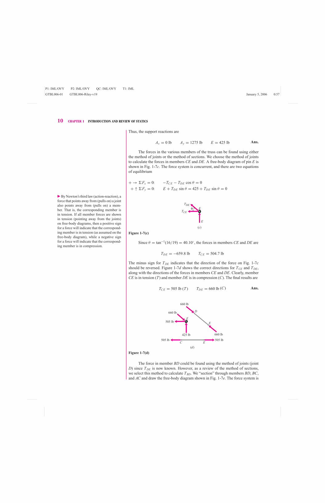
the method of joints or the method of sections. We choose the method of jointsto calculate the forces in members CE and DE. A free-body diagram of pin E isshown in Fig. 1-7c. The force system is concurrent, and there are two equationsof equilibrium
+ → �Fx = 0: −TC E − TDE cos θ = 0
+ ↑ �Fy = 0: E + TDE sin θ = 425 + TDE sin θ = 0
E
TDE
θTCE
E
(c)
Figure 1-7(c)
Since θ = tan−1(16/19) = 40.10◦, the forces in members CE and DE are
TDE = −659.8 lb TC E = 504.7 lb
The minus sign for TDE indicates that the direction of the force on Fig. 1-7cshould be reversed. Figure 1-7d shows the correct directions for TCE and TDE,along with the directions of the forces in members CE and DE. Clearly, memberCE is in tension (T) and member DE is in compression (C). The final results are
TC E = 505 lb (T ) TDE = 660 lb (C) Ans.
425 lb
E
(d)
D
660 lb
660 lb
660 lb
505 lb
505 lb
505 lb
E
EC
Figure 1-7(d)
The force in member BD could be found using the method of joints (jointD) since TDE is now known. However, as a review of the method of sections,we select this method to calculate TBD. We “section” through members BD, BC,and AC and draw the free-body diagram shown in Fig. 1-7e. The force system is

P1: IML/OVY P2: IML/OVY QC: IML/OVY T1: IML
GTBL006-01 GTBL006-Riley-v19 January 5, 2006 0:57
1-3 EQUILIBRIUM OF A RIGID BODY 11
(e)
850 lb 425 lb
DTBD
TBC
TACEC
32 ft
16 ft
Figure 1-7(e)
coplanar and noncurrent, and there are three equations of equilibrium. Summingmoments about point C eliminates all unknowns except the desired force in BD.
+ �MC = 0: TB D(16) + 425(32) = 0
TB D = −850 lb = 850 lb (C) Ans.
Example Problem 1-4 A bag of potatoes is sitting on the chair ofFig. 1-8a. The force exerted by the potatoes on the frame at one side of the chairis equivalent to horizontal and vertical forces of 24 N and 84 N, respectively, at Eand a force of 28 N perpendicular to member BH at G (as shown in the free-bodydiagram of Fig. 1-8b). Find the forces acting on member BH .
24 N
A B
θ
θ84 N
28 N
0.1 m
0.3 m
0.3 m
0.1 m 0.2 m0.2 m
0.4 m
0.5 m 0.5 m
A B
C
F E D
G
H
(a) (b)
Figure 1-8
SOLUTIONThe equations of equilibrium for the entire chair (Fig. 1-8b) are
+ → �Fx = 0: 24 − 28 cos θ = 0
+ ↑ �Fy = 0: A + B − 84 − 28 sin θ = 0
+ �MB = 0: 0.2(84) − 0.5(24) − 0.4A +(
0.3 + 0.5
cos θ
)(28) = 0

P1: IML/OVY P2: IML/OVY QC: IML/OVY T1: IML
GTBL006-01 GTBL006-Riley-v19 January 5, 2006 0:57
12 CHAPTER 1 INTRODUCTION AND REVIEW OF STATICS
84 N
24 N
Fx
Fy Dy
Dx
(a)
Cx
Cy
A
Dx
Dy
(b)
B
28 N
Fy
Fx
Cy
Cx
(c)
0.2777 m
0.2223 m
0.1333 m0.1667 m
0.1 m0.4 m
θ
0.3 m
x
y
Figure 1-9
where θ = tan−1(3/5) = 30.96◦. The first equation is satisfied identically. Theremaining two equations give
A = 73.82 N B = 24.58 N
Next the chair is disassembled and free-body diagrams are drawn for eachpart (Fig. 1-9). For member DF, the equilibrium equations can be written
+ → �Fx = 0: Dx − Fx + 24 = 0
+ ↑ �Fy = 0: Fy + Dy − 84 = 0
+ �MD = 0: 0.4(84) − 0.5Fy = 0
which gives
Fy = 67.2 N Dy = 16.80 N Dx = Fx − 24 N
Now the equations of equilibrium for member BH are
+ → �Fx = 0: Fx + Cx − 28 cos θ = 0
+ ↑ �Fy = 0: 24.58 + Cy − 67.2 − 28 sin θ = 0
+ �MC = 0:
(0.3 + 0.1667
sin θ
)(28) + 0.1333(24.58)
+ 0.1667(67.2) − 0.2777Fx = 0
which have only three unknowns remaining and can be solved to get
Fx = 115.1 N Cx = −91.0 N Cy = 57.0 N

P1: IML/OVY P2: IML/OVY QC: IML/OVY T1: IML
GTBL006-01 GTBL006-Riley-v19 January 5, 2006 0:57
1-3 EQUILIBRIUM OF A RIGID BODY 13
Then the forces acting on member BH are
B = 24.6 j N Ans.
C = −91.0 i + 57.0 j N Ans.
F = 115.1 i − 67.2 j N Ans.
plus the applied force of 28 N perpendicular to the bar at G. These forces areshown on the “report diagram” of Fig. 1-10.
The “report diagram,” though not necessary, may be used to check the results.
28 N
115.1 N
67.2 N
57.0 N
24.6 N
91.0 N
Figure 1-10
For example,
+ → �Fx = 0: −28 cos 30.96◦ + 115.1 − 91.0 = 0.08925 ∼= 0
+ ↑ �Fy = 0: −28 sin 30.96◦ − 67.2 + 57.0 + 24.6 = −4.307 × 10⁻³ ∼= 0
+ �MF = 0: 28(0.3) + 57.0 (0.1667) − 91.0 (0.2777) + 24.6 (0.3)
= 0.0112 ∼= 0
The force and moment equations of equilibrium do not exactly equate to zerodue to roundoff error.
75 lb
8 in. 4 in.A
C
B
y
x
5 in.
(a)
Ay
Ax
B
C
75 lb
(b)
8 in.
5 in.
Figure 1-11
Example Problem 1-5 The weight of books on a shelf bracket isequivalent to a vertical force of 75 lb as shown on Fig. 1-11a. All members aremade of 195-T6 cast aluminum, and all pins have 1/4-in. diameters. Determine allforces acting on all three members of this frame.
SOLUTIONFirst draw the free-body diagram of the entire shelf bracket as in Fig. 1-11b.Here the “body of interest” is the frame ABC. The pins at A, B, and C remainattached to the frame, and thus the forces that would result from removal of thepins are not shown on the free-body diagram. The bracket at A has been removedfrom the frame, and the forces that the bracket exerts at A are shown as Ax andAy (directions assumed). Similarly, the rocker at C has been removed, and theforce of the rocker on the frame is shown as C. The equations of equilibrium are
+ �MA = 0: 5C − 8(75) = 0
+ → �Fx = 0: Ax + C = 0
+ ↑ �Fy = 0: Ay − 75 = 0
which are solved to get the support reactions
Ax = −120.0 lb Ay = 75.0 lb C = 120.0 lb Ans.
TAC
TAC
A
C
(a)
Figure 1-12(a)
Next, dismember the bracket and draw separate free-body diagrams of eachmember (Fig. 1-12). Members AC and BC are straight two-force members, andthus the forces in these members must act along the members. Pin A connects a

P1: IML/OVY P2: IML/OVY QC: IML/OVY T1: IML
GTBL006-01 GTBL006-Riley-v19 January 5, 2006 0:57
14 CHAPTER 1 INTRODUCTION AND REVIEW OF STATICS
75 lb
Ax
C
(c)
Ay
A
TAC
B
B
B
B
C
TAC
(b)
5
512
12
8 in. 4 in.
Figure 1-12(b, c)
support and two members. Since member AC is a two-force member, pin A will beleft attached to member AB. The forces that act on pin A are the support reactionsAx and Ay and a vertical force due to the two-force member AC. Similarly, pinB connects two members, one of which is a two-force member. Therefore, pinB is left attached to member AB, and the only force on pin B is along the two-force member BC. Pin C connects a support and two members. Since both of themembers are two-force members, pin C is arbitrarily left attached to member BC,and thus the force on pin C due to member AC is vertical. Then the equations ofequilibrium can be written for member AB (Fig. 1-12b)
+ �MB = 0: 4(75) + 12TAC − 12(75.0) = 0
+ �MA = 0: 12[(
5/13
)B] − 8(75) = 0
from which
TAC = 50.0 lb B = 130.0 lb Ans.
(c)
A
C
(a)
A
B
B
130.0 1b
50.0 1b130.0 1b
75.0 1b
50.0 1b
50.0 1b
120.0 1b
50.0 1b
75 1b
120.0 1b
125
125
C
(b)
Figure 1-13
It is easily verified that these values also satisfy the equations of equilibrium forthe other free-body diagrams. These forces are all shown on the “report diagrams”of Fig. 1-13.

P1: IML/OVY P2: IML/OVY QC: IML/OVY T1: IML
GTBL006-01 GTBL006-Riley-v19 January 5, 2006 0:57
1-3 EQUILIBRIUM OF A RIGID BODY 15
Example Problem 1-6 Determine the reaction at support A of thepipe system shown in Fig. 1-14a. The 200-N force is parallel to the z-axis. Neglectthe weights of the pipe and the wrench.
x y
z
350 mm
A
250 mm
180 mm
230 mm
200 N
(a)
Figure 1-14(a)
SOLUTIONA free-body diagram of the pipe system is shown in Fig. 1-14b. The support atA is modeled as a rigid support that does not translate or rotate. There are threeforces Ax, Ay, and Az to prevent translation and three couples Mx, My, and Mz toprevent rotation. Couple Mx lies in the yz-plane, couple My lies in the xz-plane,and couple Mz lies in the xy-plane. Since there are six equations of equilibrium fora three-dimensional force system, all six unknowns can be found. Using Eqs. 1-3and 1-4 yields
� The summation �Mx is the net tendency
of all forces and moments to rotate the pipe
about the x-axis through point A. For the
200-N force, this is just the magnitude of
the force times the perpendicular distance
between the line of action of the force and
the x-axis through point A. For a more com-
plicated force system, the tendency to rotate
the body about the x-axis would be com-
puted using the x-component of the vector
product r × F.
�Fx = 0: Ax = 0
�Fy = 0: Ay = 0
�Fz = 0: Az − 200 = 0
�Mx = 0: Mx − 200(0.350 + 0.230) = 0
�My = 0: My − 200(0.180) = 0
�Mz = 0: Mz = 0
350 mm
250 mm
180 mm
230 mm
x y
z 200 N
(b)
Az
Mz
My
MxAx
Ay
Figure 1-14(b)

P1: IML/OVY P2: IML/OVY QC: IML/OVY T1: IML
GTBL006-01 GTBL006-Riley-v19 January 5, 2006 0:57
16 CHAPTER 1 INTRODUCTION AND REVIEW OF STATICS
Thus, the reaction at A is
Ax = 0 N Ay = 0 N Az = 200 N Ans.
Mx = 116.0 N · m My = 36.0 N · m Mz = 0 N · m Ans.
Since all the reactions are positive, they act in the directions shown on the free-body diagram of Fig. 1-14b.
Example Problem 1-7 A 1000-lb load is securely fastened to ahoisting cable as shown in Fig. 1-15a. The tension in the flexible cable does notchange as it passes around the small frictionless pulley at the right support. Theweight of the cable may be neglected. Plot the tensions in the two cables (TAB andP) as a function of the sag distance d (0 ≤ d ≤ 10 ft). Determine the minimumsag d for which P is less than
(a) Twice the weight of the load.
(b) Four times the weight of the load.
(c) Eight times the weight of the load.
dAB
C
1000 lb P
30 ft
10 ft
(a)
Figure 1-15(a)
SOLUTIONThe ring B holds the wires together, and it will be isolated to generate thefree-body diagram shown in Fig. 1-15b. The tension forces in the cables and theweight of the load are concurrent at the ring B. Writing the x- and y-componentsof the equilibrium equation for the free-body diagram of Fig. 1-15b results in
+ → �Fx = 0: TBC cos θC − TAB cos θA = 0 (a)
+ ↑ �Fy = 0: TAB sin θA + TBC sin θC − 1000 = 0 (b)
Solving Eq. (a) for TAB gives
TAB = TBC cos θC
cos θA(c)

P1: IML/OVY P2: IML/OVY QC: IML/OVY T1: IML
GTBL006-01 GTBL006-Riley-v19 January 5, 2006 0:57
1-3 EQUILIBRIUM OF A RIGID BODY 17
and substituting Eq. (c) into Eq. (b) gives
TBCsin θC cos θA + sin θA cos θC
cos θA= 1000 (d )
A a b
d
B
C
10 ft
TAB
1000 lb
TBC
(b)
(c)
θC
θC
θA
θA
Figure 1-15(b, c)
Before we can solve Eq. (d ) for TBC , we need to know how the angles θC
and θA are related to the sag distance d. From the geometry of the triangles inFig. 1-15c
sin θA = d/10a = 10 cos θA
b = 30 − atan θC = d/b
(e)
All that remains is to choose some values for d and to solve Eqs. (c)–(e) for thetensions. For example, when d = 6 ft, Eqs. (e) give
θA = sin−1 6
10= 36.8699◦
a = 10 cos 36.8699◦ = 8 ft
b = 30 − 8 = 22 ft
θC = tan−16
22= 15.2551◦
Then, Eqs. (d ) and (c) give
TBC = 1013.49 lb
TAB = 1222.22 lb
where TBC = P because the tension in the hoisting cable does not change as thecable goes around the small pulley. Figure 1-15d shows the results of repeatingthis process for various values of the sag distance d and graphing the results.
(d)
8
7
5
6
4
3
1
2
0
Sag, d (ft)
Cab
le f
orce
(ki
p)
10543 8 976210
Resultant force
P
TAB
Figure 1-15(d)
P1: IML/OVY P2: IML/OVY QC: IML/OVY T1: IML
GTBL006-01 GTBL006-Riley-v19 January 5, 2006 0:57
18 CHAPTER 1 INTRODUCTION AND REVIEW OF STATICS
When d = 10 ft, the load hangs directly below the support A, cable ABcarries the entire load, and the hoisting cable is slack, P = 0 lb. As the load israised (d gets smaller), the force in both cables increases. At d = 3.28 ft, the forcein the hoisting cable is twice the load; at d = 1.66 ft, the force in the hoistingcable is four times the load; and at d = 0.833 ft, the force in the hoisting cableis eight times the weight of the load being lifted. As d goes to zero, the forces inthe two cables both go to infinity.
PROBLEMS
Introductory Problems
1-1* A person is holding a 20-lb object as shown in Fig. P1-1.
Determine the force T in the biceps muscle and the force F of
the humerus against the ulna, in terms of the weight W of the
forearm, which acts through G. For the position shown, both Tand F act vertically.
T
F
5.5 in.1.5 in.
G
11.5 in.
Figure P1-1
1-2* A worker is using a hoist and cable to lift a 175-kg engine
from a car as shown in Fig. P1-2. Determine the forces in the
three cables attached to the ring.
10.0°
80.0°Ring
Figure P1-2
1-3 An 800-lb homogeneous cylinder is supported by two rollers
as shown in Fig. P1-3. Determine the forces exerted by the
rollers on the cylinder. All surfaces are smooth (frictionless).
60° 60°
Figure P1-3
1-4* A curved slender bar is loaded and supported as shown in
Fig. P1-4. Determine the reactions at supports A and B.
300 N
1.5 m
C
A
45°
B
Figure P1-4
1-5 A curved slender bar is loaded and supported as shown in
Fig. P1-5. Determine the reaction at support A.
250 lb3 ft
B
A
Figure P1-5

P1: IML/OVY P2: IML/OVY QC: IML/OVY T1: IML
GTBL006-01 GTBL006-Riley-v19 January 5, 2006 0:57
1-3 EQUILIBRIUM OF A RIGID BODY 19
1-6 Determine the forces in members BC, CD, and DE of the
truss shown in Fig. P1-6.
A B C
E FD
x
y
3 m
10 kN 15 kN
3 m 3 m
3 m
Figure P1-6
1-7* The lawn mower shown in Fig. P1-7 weighs 35 lb. Deter-
mine the force P required to move the mower at a constant
velocity and the forces exerted on the front and rear wheels by
the inclined surface.
P
G
30°
34 in.
15°
13 in.14 in.
4 in.
x
y
Figure P1-7
1-8 A human femur is modeled as shown in Fig. P1-8. The ab-
ductor muscle force is M = 4060 N, and the femoral load is
J = 5210 N. Determine the force P and the couple C.
37 mm
J
M
P
C
16 mm
Figure P1-8
1-9* Determine the forces in members CD, CF, and FG of the
bridge truss shown in Fig. P1-9.
30° 30°60°60°
15 ft 15 ft
10 kip 20 kip
15 ft
A
B
C
E
FG
D
Figure P1-9
1-10* The coal wagon shown in Fig. P1-10 is used to haul coal
from a mine. If the mass of the coal and wagon is 2000 kg, de-
termine the force P required to move the wagon at a constant
velocity and the forces exerted on the front and rear wheels by
the inclined surface.

P1: IML/OVY P2: IML/OVY QC: IML/OVY T1: IML
GTBL006-01 GTBL006-Riley-v19 January 5, 2006 0:57
20 CHAPTER 1 INTRODUCTION AND REVIEW OF STATICS
G
P
30°
2 m
2 m 1 m
1 m
Figure P1-10
1-11 A 30-lb force P is applied to the brake pedal of an automo-
bile as shown in Fig. P1-11. Determine the force Q applied to
the brake cylinder and the reaction at support A.
Figure P1-11
1-12* A beam is loaded and supported as shown in Fig. P1-12.
Determine the reaction at support A.
2 m 2 m
2 kN
AB
3 kN·m
y
x
Figure P1-12
1-13 A beam is loaded and supported as shown in Fig. P1-13.
Determine the reactions at supports A and B.
Figure P1-13
1-14 Pulleys A and B of the chain hoist shown in Fig. P1-14 are
connected and rotate as a unit. The chain is continuous, and
each of the pulleys contains slots that prevent the chain from
slipping. Determine the force F required to hold a 450-kg block
W in equilibrium if the radii of pulleys A and B are 90 mm and
100 mm, respectively.
W
A
F
B
C
Figure P1-14
1-15* A bracket of negligible weight is used to support the dis-
tributed load shown in Fig. P1-15. Determine the reactions at
the supports A and B.

P1: IML/OVY P2: IML/OVY QC: IML/OVY T1: IML
GTBL006-01 GTBL006-Riley-v19 January 5, 2006 0:57
1-3 EQUILIBRIUM OF A RIGID BODY 21
12 in.
10 lb/in.
18 in.
B
A
Figure P1-15
1-16 The wood plane shown in Fig. P1-16 moves with a constant
velocity when subjected to the forces shown. Determine
a. The shearing force of the wood on the plane.
b. The normal force, and its location, of the wood on the plane.
160 mm60 mm
75 mm
60 mm
60 mm
40 N
70 N
70ϒ 16°
Figure P1-16
Intermediate Problems
1-17* Forces of 25 lb are applied to the handles of the pipe pliers
shown in Fig. P1-17. Determine the force exerted on the pipe
at D and the force exerted on handle DAB by the pin at A.
Figure P1-17
1-18* A pair of vise grip pliers is shown in Fig. P1-18. Determine
the force F exerted on the block by the jaws of the pliers when
a force P = 100 N is applied to the handles.
Figure P1-18
1-19 The Gambrel truss shown in Fig. P1-19 supports one side
of a bridge; an identical truss supports the other side. Floor
beams carry vehicle loads to the truss joints. Calculate the
forces in members BC, BG, and CG when a truck weighing
7500 lb is stopped in the middle of the bridge as shown. The
center of gravity of the truck is midway between the front and
rear wheels.
Figure P1-19

P1: IML/OVY P2: IML/OVY QC: IML/OVY T1: IML
GTBL006-01 GTBL006-Riley-v19 January 5, 2006 0:57
22 CHAPTER 1 INTRODUCTION AND REVIEW OF STATICS
1-20* A transmission line truss supports a 5-kN load, as shown
in Fig. P1-20. Determine the forces in members FG and CD.
Figure P1-20
1-21 Three smooth homogeneous cylinders A, B, and C are
stacked in a V-shaped trough as shown in Fig. P1-21. Cylin-
der A weighs 100 lb; cylinders B and C each weigh 200 lb. All
cylinders have a 5-in diameter. Determine the minimum angle
θ for equilibrium.
Figure P1-21
1-22 The mass of block A in Fig. P1-22 is 250 kg. Block A is
supported by a small wheel that is free to roll on the continu-
ous cable between supports B and C. The length of the cable is
42 m. Determine the distance x and the tension T in the cable
when the system is in equilibrium.
Figure P1-22
1-23* The wrecker truck of Fig. P1-23 has a weight of 15,000 lb
and a center of gravity at G. The force exerted on the rear (drive)
wheels by the ground consists of both a normal component By
and a tangential component Bx while the force exerted on the
front wheels consists of a normal force Ay only. Determine the
maximum pull P that the wrecker can exert when θ = 30◦ if
Bx cannot exceed 0.8By (because of friction considerations)
and the wrecker does not tip over backwards (the front wheels
remain in contact with the ground).
Figure P1-23
1-24 A drum of oil with a mass of 200 kg is supported by a pair of
frames (the second frame is behind the one shown) as shown
in Fig. P1-24. Determine all forces acting on member ACE.
Figure P1-24
P1: IML/OVY P2: IML/OVY QC: IML/OVY T1: IML
GTBL006-01 GTBL006-Riley-v19 January 5, 2006 0:57
1-3 EQUILIBRIUM OF A RIGID BODY 23
1-25* The hot-air balloon shown in Fig. P1-25 is tethered with
three mooring cables. If the net lift of the balloon is 900 lb,
determine the force exerted on the balloon by each of the three
cables.
Figure P1-25
1-26* A 100-kg traffic light is supported by a system of cables
as shown in Fig. P1-26. Determine the tensions in each of the
three cables.
Figure P1-26
1-27 A force of 20 lb is required to pull the stopper DE in
Fig. P1-27. Determine all forces acting on member BCD.
Figure P1-27
1-28 The front-wheel suspension of an automobile is shown in
Fig. P1-28. The pavement exerts a vertical force of 2700 N on
the tire. Determine the force in the spring and the forces at A,
B, and D.
Figure P1-28
P1: IML/OVY P2: IML/OVY QC: IML/OVY T1: IML
GTBL006-01 GTBL006-Riley-v19 January 5, 2006 0:57
24 CHAPTER 1 INTRODUCTION AND REVIEW OF STATICS
1-29* Determine all forces acting on member ABCD of the frame
of Fig. P1-29.
Figure P1-29
1-30 The flat roof of a building is supported by a series of parallel
plane trusses spaced 2 m apart (only one such truss is shown in
Fig. P1-30). Calculate the forces in all the members of a typical
truss when water collects to a depth of 0.2 m as shown. The
density of water is 1000 kg/m3.
Figure P1-30
1-31 Two bodies W 1 and W 2 weighing 200 lb and 150 lb, respec-
tively, rest on a cylinder and are connected by a rope as shown
in Fig. P1-31. If all surfaces are smooth, determine
a. The reactions of the cylinder on the bodies.
b. The tension in the rope.
c. The angle θ .
Figure P1-31
1-32* The homogeneous door shown in Fig. P1-32 has a mass
of 60 kg and is held in the position shown by the rod AB. The
rod is held in place by smooth horizontal pins at A and B. The
hinges at C and D are smooth, and the hinge at C can support
thrust along its axis. Determine all forces that act on the door.
Figure P1-32
1-33 A farmer is using the hand winch shown in Fig. P1-33 to
slowly raise a 40-lb bucket of water from a well. In the posi-
tion shown, force P is vertical. The bearings at C and D exert
only force reactions on the shaft. Bearing C can support thrust
loading; bearing D cannot. Determine the magnitude of force
P and the components of the bearing reactions.

P1: IML/OVY P2: IML/OVY QC: IML/OVY T1: IML
GTBL006-01 GTBL006-Riley-v19 January 5, 2006 0:57
1-3 EQUILIBRIUM OF A RIGID BODY 25
Figure P1-33
1-34* A scissors jack for an automobile is shown in Fig. P1-34.
The screw threads exert a force F on the blocks at joints A and
B. Determine the force P exerted on the automobile if F =800 N and θ = 15◦. Repeat for θ = 30◦ and θ = 45◦.
Figure P1-34
1-35* The fold-down chair of Fig. P1-35 weighs 25 lb and has its
center of gravity at G. Determine all forces acting on member
ABC.
Figure P1-35
1-36 A frame is loaded and supported as shown in Fig. P1-36.
Determine the reactions at supports A and C and all forces
acting on member ADE.
Figure P1-36
1-37 Forces of 50 lb are applied to the handles of the bolt cutter
of Fig. P1-37. Determine
a. All forces acting on the handle ABC.
b. The force exerted on the bolt at E.

P1: IML/OVY P2: IML/OVY QC: IML/OVY T1: IML
GTBL006-01 GTBL006-Riley-v19 January 5, 2006 0:57
26 CHAPTER 1 INTRODUCTION AND REVIEW OF STATICS
Figure P1-37
Challenging Problems
1-38* The garage door ABCD shown in Fig. P1-38 is being raised
by a cable DE. The one-piece door is a homogeneous rectan-
gular slab which has a mass of 100 kg. Frictionless rollers Band C run in tracks at each side of the door as shown. Deter-
mine the tension T in the cable and the forces B and C on the
frictionless rollers when d = 1.875 m.
Figure P1-38
1-39* The crane and boom shown in Fig. P1-39 weigh 12,000 lb
and 600 lb, respectively. When the boom is in the position
shown, determine
a. The maximum load that can be lifted by the crane.
b. The tension in the cable used to raise and lower the boom
when the load being lifted is 3600 lb.
c. The pin reaction at boom support A when the load being
lifted is 3600 lb.
Figure P1-39
1-40 Figure P1-40 is a simplified sketch of the mechanism used
to raise the bucket of a bulldozer. The bucket and its contents
weigh 10 kN and have a center of gravity at H . Arm ABCDhas a weight of 2 kN and a center of gravity at B; arm DEFGhas a weight of 1 kN and a center of gravity at E. The weight
of the hydraulic cylinders can be ignored. Calculate the force
in the horizontal cylinders CJ and EI and all forces acting on
arm DEFG for the position shown.
Figure P1-40
1-41 The mechanism of Fig. P1-41 is designed to keep its load
level while raising it. A pin on the rim of the 4-ft-diameter
pulley fits in a slot on arm ABC. Arms ABC and DE are each
4 ft long, and the package being lifted weighs 80 lb. The mech-
anism is raised by pulling on the rope that is wrapped around
the pulley. Determine the force P applied to the rope and all
forces acting on the arm ABC when the package has been lifted
4 ft, as shown.

P1: IML/OVY P2: IML/OVY QC: IML/OVY T1: IML
GTBL006-01 GTBL006-Riley-v19 January 5, 2006 0:57
1-3 EQUILIBRIUM OF A RIGID BODY 27
Figure P1-41
1-42* Bar AB of Fig. P1-42 has a uniform cross section, a mass
of 25 kg, and a length of 1 m. Determine the angle θ for
equilibrium.
Figure P1-42
1-43 The homogeneous door shown in Fig. P1-43 has a mass of
25 kg and is supported in a horizontal position by two hinges
and a bar. The hinges have been properly aligned; therefore,
they exert only force reactions on the door. Assume that the
hinge at B resists any force along the axis of the hinge pins.
Determine the reactions at supports A, B, and D.
Figure P1-43
Computer Problems
1-44 A pair of steel pipes is stacked in a box as shown in Fig.
P1-44. The masses and diameters of the smooth pipes are
mA = 5 kg, mB = 20 kg, dA = 100 mm, and dB = 200 mm.
Plot the two forces exerted on pipe A (by pipe B and by the side
wall) as a function of the distance b between the walls of the
box (200 mm ≤ b ≤ 300 mm). Determine the range of b for
which
a. The force at the side wall is less than WA, the weight of pipe
A.
b. Neither of the two forces exceeds 2WA.
c. Neither of the two forces exceeds 4WA.
Figure P1-44
1-45 A worker positions a 250-lb crate by pulling on the rope BDas shown in Fig. P1-45. The 3-ft long rope BD is horizontal
(θ = 0) when the 5-ft long rope AB is vertical (φ = 0).
a. What is the maximum distance bmax that the crate can be
pulled to the side using this arrangement?
b. Calculate and plot the forces in ropes AB and BD as a func-
tion of the distance b for 0 ≤ b ≤ bmax.
c. How could the worker pull the crate to the side more than
the bmax calculated in part a?
Figure P1-45

P1: IML/OVY P2: IML/OVY QC: IML/OVY T1: IML
GTBL006-01 GTBL006-Riley-v19 January 5, 2006 0:57
28 CHAPTER 1 INTRODUCTION AND REVIEW OF STATICS
1-46 A 50-kg load is suspended from a pulley as shown in Fig.
P1-46. Pulleys B and C are both frictionless and free to rotate,
and the weight of the cable may be neglected. Plot the force
P required for equilibrium as a function of the sag distance
d (0 ≤ d ≤ 1 m). Determine the minimum sag dmin for which
P is less than
a. Twice the weight of the load.
b. Four times the weight of the load.
c. Eight times the weight of the load.
Figure P1-46
1-47 A 75-lb stop light is suspended between two poles as shown
in Fig P1-47. Neglect the weight of the flexible cables and plot
the tension in both cables as a function of the sag distance
d ( 0 ≤ d ≤ 8 ft). Determine the minimum sag dmin for which
both tensions are less than
a. 100 lb.
b. 250 lb.
c. 500 lb.
Figure P1-47
1-48 The wrecker truck shown in Fig. P1-48 has a mass of 6800
kg and a center of gravity at G. The force exerted on the rear
(drive) wheels by the ground consists of both a normal compo-
nent By and a tangential component Bx, while the force exerted
on the front wheels consists of a normal force Ay only.
a. Plot P, the maximum pull that the wrecker can exert, as a
function of θ (0◦ ≤ θ ≤ 90◦) if Bx cannot exceed 0.8By (be-
cause of friction considerations) and the wrecker does not
tip over backward (the front wheels remain in contact with
the ground).
b. On the same graph, plot Ay, Bx, and By as functions of the
angle θ .
Figure P1-48
1-49 An overhead crane consists of an I-beam supported by a
simple truss as shown in Fig. P1-49. If the uniform I-beam
weighs 400 lb, plot the force in members BC, CF, and EF as a
function of the position d ( 0 ≤ d ≤ 8 ft).
Figure P1-49

P1: IML/OVY P2: IML/OVY QC: IML/OVY T1: IML
GTBL006-01 GTBL006-Riley-v19 January 5, 2006 0:57
1-3 EQUILIBRIUM OF A RIGID BODY 29
1-50 A light pole is braced using a lightweight flexible cable
DGH as shown in Fig. P1-50. The uniform pole ABCD weighs
4200 N; the combined weight of the light fixture and arm CEFis 7500 N and acts at E; and the weight of the arm BG can be
neglected. Assume that the arms EC and BG are braced to re-
main perpendicular to the pole ABCD and that the connection
at A cannot provide any significant moment. Plot TDG and TGH
(the tensions in the two parts of the cable) and FBG (the force
in the brace BG) as functions of b, the length of the brace, for
0.5 m ≤ b ≤ 3 m.
Figure P1-50
1-51 The crane and boom shown in Fig. P1-51 weigh 12,000 lb
and 600 lb, respectively. The pulleys at D and E are small, and
the cables attached to them are essentially parallel.
a. Plot d, the location of the resultant force of the ground on
the crane relative to point C, as a function of the boom
angle θ ( 0◦ ≤ θ ≤ 80◦ ) when the crane is lifting a 3600-lb
load.
b. Plot A/3600 and TBD/3600 as functions of the boom angle
θ ( 0◦ ≤ θ ≤ 80◦ ) when the crane is lifting a 3600-lb load (in
which A is the magnitude of the reaction force on the pin
at A, TBD is the tension in the cable raising the boom, and
3600 lb is the weight of the load being lifted).
c. It is desired that the resultant force on the tread always be at
least 1 ft behind C to ensure that the crane is never in dan-
ger of tipping over. Plot W max, the maximum load that may
be lifted, as a function of the boom angle θ ( 0◦ ≤ θ ≤ 80◦ ).
(Don’t forget to check the tension in cable BD.)
Figure P1-51
1-52 A group of workers proposes to raise a uniform 250-kg post
AB to a vertical position using the rope and brace arrangement
shown in Fig. P1-52a. Assume that the weight of the brace can
be neglected and that end A acts as a frictionless pin for both
the 6-m-long post AB and the 6-m-long brace AC.
a. Plot the rope force P and the force FAC in the brace AC as
functions of the angle θ ( 0◦ ≤ θ ≤ 90◦ ).
b. Repeat the problem if two braces are used as shown in Fig.
P1-52b. Plot the rope force P and the brace forces FAC and
FAD as functions of the angle θ ( 0◦ ≤ θ ≤ 90◦ ). Assume that
when the force in brace AD becomes zero, the brace falls
out of the way and from that point on the rope is attached to
C instead of D.
B
B
C
P DA
θ
θ
CD
PA
6 m
6 m
7 m
45°
60°
45°
(a)
(b)
Figure P1-52

P1: IML/OVY P2: IML/OVY QC: IML/OVY T1: IML
GTBL006-01 GTBL006-Riley-v19 January 5, 2006 0:57
30 CHAPTER 1 INTRODUCTION AND REVIEW OF STATICS
1-53 The hydraulic cylinder BC is used to tip the box of the dump
truck shown in Fig. P1-53. If the combined weight of the box
and the load is 22,000 lb and acts through the center of gravity
G, plot
a. C/22,000, the force in the hydraulic cylinder divided by
the weight of the truck box, as a function of the angle
θ ( 0◦ ≤ θ ≤ 80◦ ).
b. A/22,000, the magnitude of the reaction force on the pin Adivided by the weight of the truck box, as a function of the
angle θ ( 0◦ ≤ θ ≤ 80◦ ).
Figure P1-53
1-4 EQUILIBRIUM OF A DEFORMABLE BODYAll of the equilibrium problems considered thus far have assumed that the bodiesare rigid. That is, the shape of the body and its orientation relative to its surround-ings were assumed to be independent of the loads applied to the body. However,no body is perfectly rigid. Wires subjected to tension forces will stretch. Beamscarrying loads will bend. Shafts subjected to torques will twist. In fact, one of theprimary objectives of a course in mechanics of materials is to develop relationshipsbetween the loads applied to a nonrigid body and the deformation of the body.
If the wire or beam or shaft is very stiff, the amount of deformation will bevery small and the deformation will have a negligible effect on the solution of theequilibrium equations. If the wire or beam or shaft is not very stiff, however, thedeformation can affect the geometry of the problem used to write the equilibriumequations, which will in turn affect the solution of the equilibrium equations.The interaction between the loads acting on a body, the deformation of the body,and the geometry of the free-body diagram makes the solution of deformable bodyproblems much more complex than the solution of rigid body problems. Frequentlythe solution of deformable body problems requires either a trial-and-error solutionor a numerical solution or an iterative solution method.
Fortunately, most engineering structures and machines are designed “stiff,”that is, they do not deform very much. For such problems, the solution of theequilibrium equations often ignores the deformation and treats the structure asthough it were rigid. Example Problem 1-8 illustrates the difficulties encounteredin the solution of deformable body problems and the errors that may result fromneglecting the deformation in the solution of the equilibrium equations.
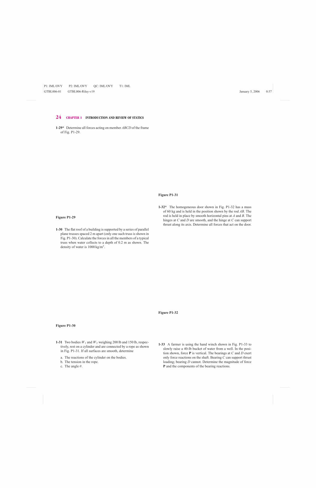
Example Problem 1-8 A 5000-lb weight W is to be supported bya very stiff (rigid) bar AB and a deformable (nonrigid) wire BC, as shown in Fig.1-16a. The connections at A, B, and C are frictionless pins, the brackets at Aand C are rigid, and the weights of the bar and the wire may be neglected. The
P1: IML/OVY P2: IML/OVY QC: IML/OVY T1: IML
GTBL006-01 GTBL006-Riley-v19 January 5, 2006 0:57
1-4 EQUILIBRIUM OF A DEFORMABLE BODY 31
(a)
BA
C
4 ft
4 ft
W
Figure 1-16(a)
relationship between the tension in the wire TBC and the deformation (stretch)of the wire δ is given by TBC = kδ where k depends on the cross-sectionalarea of the wire and the type of material from which the wire is made, and δ =Lf − Li, the difference between the final (deformed) length of the wire and theinitial (undeformed) length of the wire. If Fig. 1-16a represents the unloadedconfiguration of the structure (δ = 0), determine the tension in the wire afterthe load is applied for k = 5000 lb/in. Repeat for k = 2500 lb/in. and for k =1000 lb/in.
SOLUTIONSince bar AB is rigid and the support bracket at A is fixed to the wall, bar ABmust pivot about pin A due to the load W . Wire BC will increase in length byan amount δ since it is deformable. The loaded configuration of the structure isshown in Fig. 1-16b. The rotation of the bar can be described by the angle θ , andthe deformation δ of the wire can be written as δ = Lf − Li.
A free-body diagram of the bar in the deformed configuration is shown inFig. 1-16c. The equations of equilibrium give
+ → �Fx = 0: Ax − T cos (45 + θ/2) = 0 (a)
+ ↑ �Fy = 0: Ay + T sin (45 + θ/2) − W = 0 (b)
+ �MA = 0: [T sin (45 + θ/2)](4 cos θ )
−[T cos (45 + θ/2)](4 sin θ )
−W (4 cos θ ) = 0
(c′)
Using the trigonometric relation
sin (A − B) = sin A cos B − cos A sin B

P1: IML/OVY P2: IML/OVY QC: IML/OVY T1: IML
GTBL006-01 GTBL006-Riley-v19 January 5, 2006 0:57
32 CHAPTER 1 INTRODUCTION AND REVIEW OF STATICS
(b)
B'
x
y
β
θA
C
W
β = 45° – θ–2
Figure 1-16(b)
Eq. (c′) may be written
4T sin (45 − θ/2) − 4W cos θ = 0 (c)
Equations (a), (b), and (c) contain four unknowns Ax, Ay, T , and θ . Thus, thereare four unknowns and three equations of equilibrium. We need an additionalindependent equation to solve the problem. The equations of equilibrium (a),(b), and (c) are necessary for equilibrium, but they are not sufficient to solvethe problem. The additional equation comes from the relationship between theforce in the wire and the deformation of the wire. Such a relationship will bedeveloped in Chapter 4; we merely state the result here to complete this example.
(c)
β
θ
W
Ax
Ay
x
y
T
4 cos θ
4 sin θ
Figure 1-16(c)

P1: IML/OVY P2: IML/OVY QC: IML/OVY T1: IML
GTBL006-01 GTBL006-Riley-v19 January 5, 2006 0:57
1-4 EQUILIBRIUM OF A DEFORMABLE BODY 33
The force–deformation relation depends on the type of material from which thewire is made, and the relationship may be linear or nonlinear. Herein we limitour discussion to a linear relationship between force and deformation. Thus, weassume the behavior shown in Fig. 1-16d
T = kδ (d )
δ
T
k
(d)
Figure 1-16(d)
where k is a material constant (the slope of a T − δ curve) that depends on thetype of material from which the wire is made. For the wire,
� In Chapter 3 it will be shown that the
constant of proportionality k = E A
Lwhere
E is the modulus of elasticity of the material
and L and A are the length and the cross-
sectional area of the wire. For a steel wire 18
in. in diameter, k = 5420 lb/in. or for a steel
tie rod 14
in. in diameter, k = 21,690 lb/in.,
little error is introduced by treating the struc-
ture as rigid. For an aluminum alloy wire 1/8
in. in diameter, however, k = 1808 lb/in., and
the error introduced by treating the structure
as rigid is about 6 percent. For more “stretch-
able” support materials, the error would be
even greater.
Li =√
(4)2 + (4)2 = 5.657 ft = 67.88 in.
Since δ = Lf − Li = Lf − 67.88 in., we need to determine the deformed lengthof the wire in order to find T . Using Fig. 1-16b and the law of cosines,
(B ′C)2 = L2
f = (48)2 + (48)2 − (2)(48)(48) cos (90◦ + θ )
from which
Lf = 67.88√
1 + sin θ in.
The deformation δ of the wire is
δ = Lf − Li = 67.88√
1 + sin θ − 67.88
= 67.88[√
1 + sin θ − 1] in.(e)
The relationship between the applied load and the deformation of the structureis found by substituting Eq. (e) into Eq. (d ). The result is then used in Eq. (c) togive
67.88 k (√
1 + sin θ − 1) sin (45 − θ/2) = W cos θ ( f )
If k = 5000 lb/in., then Eq. ( f ) gives θ = 2.465◦; Eq. (c) gives
T = 7221 lb Ans.
Equation (a) gives Ax = 4995 lb, and Eq. (b) gives Ay = −215 lb. This comparesto the solution of Example Problem 1-1 (in which this structure was assumedto be rigid), which had T = 7071 lb, Ax = 5000 lb, and Ay = 0 lb. For this verystiff wire, the sag of the beam (θ = 2.465◦) would barely be noticeable and theerror in the value of T from treating the structure as rigid would be only about2 percent.
If k = 2500 lb/in., then Eq. ( f ) gives θ = 5.097◦; Eq. (c) gives
T = 7379 lb Ans.
Equation (a) gives Ax = 4890 lb; and Eq. (b) gives Ay = −444 lb.If k = 1000 lb/in., then Eq. ( f ) gives θ = 14.246◦; Eq. (c) gives
T = 7893 lb Ans.

P1: IML/OVY P2: IML/OVY QC: IML/OVY T1: IML
GTBL006-01 GTBL006-Riley-v19 January 5, 2006 0:57
34 CHAPTER 1 INTRODUCTION AND REVIEW OF STATICS
Equation (a) gives Ax = 4846 lb, and Eq. (b) gives Ay = −1230 lb. For this lessstiff wire, the sag of the beam is definitely noticeable and the error in the valueof T from treating the structure as rigid would be over 10 percent.
The process illustrated in this example is typical of the solution of de-formable body problems. Regardless of the type of structure or machine compo-nent or the type of loading, the solution process generally consists of these threesteps
1. Equations of equilibrium, (a), (b), and (c)
2. Force-deformation relationship, Eq. (d )
3. Geometry of deformation, Eq. (e)
Since the equations of equilibrium must be applied to the forces acting on thedeformed structure, the three sets of equations are often interdependent. It isthis interdependence that makes the solution of deformable body problems morecomplex than the solution of rigid-body problems.F1
F3
F4
F5
A B
Plane a-a
(a)
F3
F4
F5(d)
F1
F2
F2
A
(b)
F1
F2
AC
(c)
CB
C
R
R
C
Figure 1-17
1-5 INTERNAL FORCESIn the study of mechanics of materials, it is necessary that we examine the internalforces that exist throughout the interior of a body. We consider an arbitrary body inequilibrium, as shown in Fig. 1-17a. The forces F1, F2, F3, F4, and F5 are appliedloads and support reactions (found using the equations of equilibrium). We passan imaginary “cutting plane” a–a (henceforth called a section) through the body,and separate the body into two parts A and B. Considering a free-body diagram ofpart A (Fig. 1-17b) we note that, in addition to the applied forces F1 and F2, thematerial of part B exerts forces on the material of part A over the section. Theseforces are internal to the body as a whole but are external for part A. The forceson the section are distributed over the surface in an unknown fashion. However,we can replace the distributed force system by a resultant force R and a resultantcouple C. In general, the couple C depends on where we place the force R. Inmechanics of materials we place R at the centroid C of the section, as shown inFig. 1-17c. We use a double arrowhead to distinguish the couple C (vector) fromthe force R (vector). On the section, the distributed force system of Fig. 1-17b isstatically equivalent to the force system R and C of Fig. 1-17c. The force system Rand C will be referred to as an internal force system. We recognize that the internalforce system depends on the orientation of the section.
Instead of part A, we could have considered part B, as shown in Fig. 1-17d.By applying Newton’s third law to every pair of particles on the section for partsA and B of the body, we have that the distributed force systems over the section ofparts A and B are equal in magnitude but opposite in sense, and thus the resultantforce R and the resultant couple C on the two parts of the body are equal inmagnitude but opposite in sense.
Because the body as a whole is in equilibrium, any portion of the body isalso in equilibrium. Thus, using the equations of equilibrium and the force systemshown in Fig. 1-17c,
ΣF = 0: F1 + F2 + R = 0
ΣMC = 0: M1 + M2 + C = 0

P1: IML/OVY P2: IML/OVY QC: IML/OVY T1: IML
GTBL006-01 GTBL006-Riley-v19 January 5, 2006 0:57
1-5 INTERNAL FORCES 35
where M1 and M2 are the moments of forces F1 and F2, respectively, about thecentroid of the section. We would find the same result using the free-body diagramof part B shown in Fig. 1-17d. Thus, we find the resultant of the internal forcesystem using the equations of equilibrium. However, we cannot find the exactdistribution of the internal forces until we learn how to determine the deformationof the body.
Experience indicates that materials behave differently to forces trying to
F1
F2
AVy
Vz P
(a)
y
x
z
F1
F2
AMy
Mz T
(b)
y
x
z
F4
F5
(c)
y
Vy
Vz
xz
F3
P
F4
F5
(d)
y
My
Mz
xz
F3
T
Figure 1-18
pull atoms apart than to forces trying to slide atoms past each other. Therefore, itis standard practice to resolve the resultants R and C into components along andperpendicular to the section, as shown in Fig. 1-18. For convenience we select anxyz-coordinate system in which x is perpendicular to the section and y and z liein the section. The component of R which is perpendicular to the section, Rx, iscalled a normal force; this force tends either to pull the body apart or to compressthe body (Fig. 1-18a). The symbol P is often used to denote the normal force. Thecomponents of R that lie in the section are called shear forces; these forces tendto slide part A of the body relative to part B. The symbol V is often used to denoteshear forces; hence, the forces Vy and Vz in Fig. 1-18a.
The component T of couple C shown in Fig. 1-18b tends to twist the bodyand is called a twisting couple (or twisting moment, or torque). The componentsMy and Mz tend to bend the body and are called bending couples (or bendingmoments). Throughout this book we will examine the effects on a deformablebody of the components of R and C.
The section shown in Figs. 1-18a and b is called a positive section since theoutward normal to the section points in a positive coordinate direction. The sectionshown in Figs. 1-18c and d is called a negative section since the outward normalto the section points in a negative coordinate direction.
A resultant force or couple component is defined as positive if the componentis in a positive coordinate direction when acting on a positive section. Thus, all ofthe force and couple components shown in Figs. 1-18a and b are positive. If theinternal forces exerted on part A of the body by part B are called positive, then theother half of the internal forces (exerted on part B of the body by part A) shouldalso be called positive. Therefore, a force or couple component will also be definedas positive if the component is in the negative coordinate direction when actingon a negative section. Hence, all of the force and moment components shown inFigs. 1-18c and d are also positive.
The components of the internal force system can be found using the equationsof equilibrium (Eqs. 1-3 and 1-4).
�Fx = 0 �Fy = 0 �Fz = 0 (1-3)
�Mx = 0 �My = 0 �Mz = 0 (1-4)
The equations of equilibrium should be applied to the body (or portion ofthe body) in its deformed state. However, as we saw in Example Problem 1-8, thesupport reactions (or, in this case internal forces) cannot be found until we knowthe relationship between the forces applied to the body and the deformation ofthe body. As we shall see in later chapters of this book, we can determine supportreactions and internal forces using the undeformed configuration of a body. Weaccept this statement for now and illustrate the determination of internal forceswith the following examples.

P1: IML/OVY P2: IML/OVY QC: IML/OVY T1: IML
GTBL006-01 GTBL006-Riley-v19 January 5, 2006 0:57
36 CHAPTER 1 INTRODUCTION AND REVIEW OF STATICS
Example Problem 1-9 A post and bracket are used to support apulley, as shown in Fig. 1-19a. A cable passing over the pulley supports a 2200-N force. Determine the internal forces on a section at the support at A.
300 mm
A
(a)
64 mm
500 mm
B
2200 N
Figure 1-19(a)
2200 N
y
x
z
(b)
2200 N
PT
Vy
MyMz
Vz
300 mm
500 mm
Figure 1-19(b)
SOLUTIONA section (perpendicular to the post) is passed through the post at a distance of30 mm above the support at A. A free-body diagram of the part of the structureabove the section is shown in Fig. 1-19b. The xyz-coordinate axes were arbitrarilyselected, but the origin of the coordinate system is at the centroid of the section.Coordinate x is perpendicular to the section, whereas coordinates y and z lie inthe section. Thus, the section on which the force and couple components act is apositive section, and the force and couple components shown in Figure 1-19b arepositive. The couples T , My, and Mz are represented by curved arrows instead ofvectors, as was done in Fig. 1-18b. The twisting couple T (torque) lies in the yz-plane; the bending couples My and Mz lie in the xz- and xy-planes, respectively.The equations of equilibrium (Eqs. 1-3 and 1-4) yield
�Fx = 0: P + 2200 = 0
�Fy = 0: Vy = 0
�Fz = 0: Vz − 2200 = 0
�Mx = 0: T − 2200(0.300) = 0
�My = 0: My − 2200(0.500) = 0
�Mz = 0: Mz − 2200(0.300) = 0
Solving for the internal force system gives
P = −2200 N Vy = 0 N Vz = 2200 N Ans.
T = 660 N · m My = 1100 N · m Mz = 660 N · m Ans.

P1: IML/OVY P2: IML/OVY QC: IML/OVY T1: IML
GTBL006-01 GTBL006-Riley-v19 January 5, 2006 0:57
1-5 INTERNAL FORCES 37
The negative sign for P indicates that the force is opposite to that shown in Fig.1-19b, therefore, P is a compressive force.
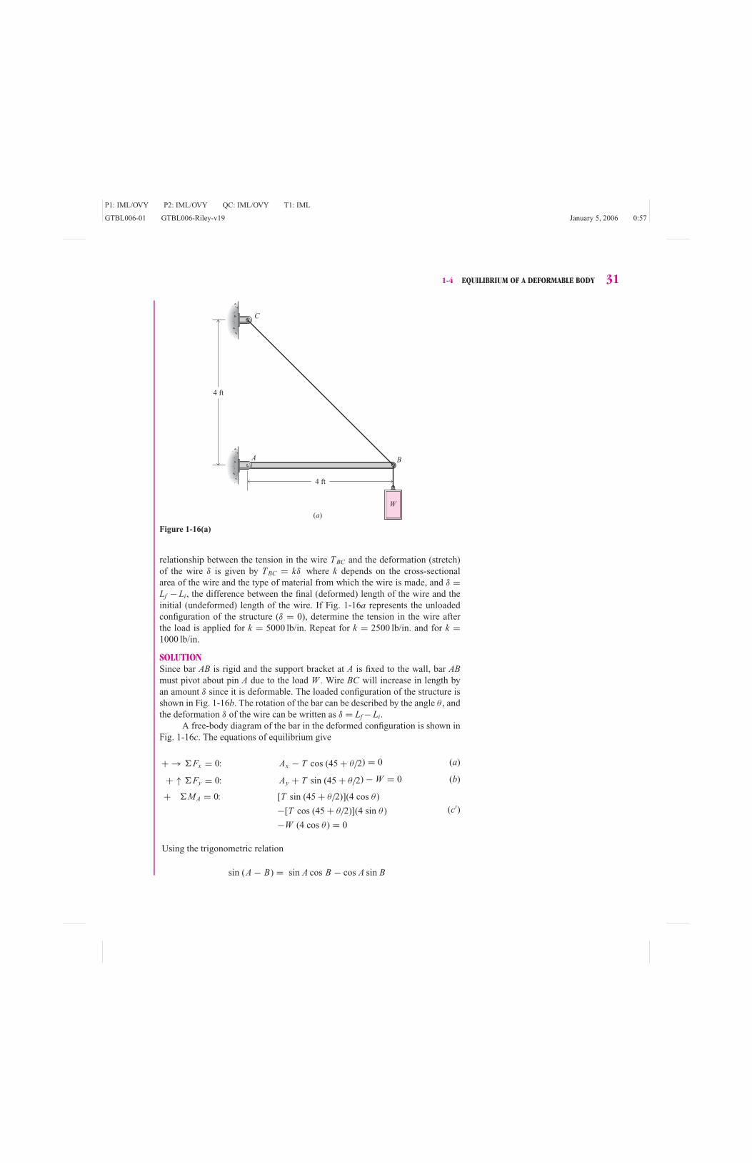
Example Problem 1-10 The cantilever beam shown in Fig. 1-20ais subjected to both concentrated and distributed loads. Determine (a) the supportreactions and (b) the internal forces on a section 4 m to the right of the supportat A.
2 kN/m
(a)
5 kN
A x
y
3 m 2 m
Figure 1-20(a)
SOLUTION
(a) A free-body diagram of the complete beam is shown in Fig. 1-20b. Thesupport at A does not translate or rotate; thus, forces Ax and Ay and coupleMA may exist. The distributed load has been replaced by its resultant, R =wl = 2 kN/m(5 m) = 10 kN, acting 2.5 m to the right of A. The equations ofequilibrium give
+ → �Fx = 0: Ax = 0
+ ↑ �Fy = 0: Ay − 10 − 5 = 0
+ �MA = 0: MA − 10(2.5) − 5(3) = 0
(b)
5 kN10 kN
Ax
Ay
MA 2.5 m0.5 m
Figure 1-20(b)
Solving gives the support reactions
Ax = 0 kN Ay = 15.00 kN MA = 40.0 kN · m Ans.

P1: IML/OVY P2: IML/OVY QC: IML/OVY T1: IML
GTBL006-01 GTBL006-Riley-v19 January 5, 2006 0:57
38 CHAPTER 1 INTRODUCTION AND REVIEW OF STATICS
(b) A vertical section is passed through the beam 4 m to the right of A. A free-body diagram of the part of the beam to the left of the section is shown inFig. 1-20c. The section as well as the force and couple components shownin Fig. 1-20c are positive. The distributed load is shown to illustrate thatthe forces acting on that part of the beam must be shown on the free-bodydiagram. The 10-kN resultant force on the free-body diagram of Fig. 1-20bcannot be used for the free-body diagram of the part of the beam shown inFig. 1-20c. The free-body diagram of Fig. 1-20c is redrawn in Fig. 1-20d,where the distributed load on this part of the beam has been replaced by itsresultant. The equations of equilibrium give
+ → �Fx = 0: P = 0
+ ↑ �Fy = 0: 15.00 − 8 − 5 + Vy = 0
+ �Mz = 0: 40.0 − 15.00(4) + 8(2) + 5(1) + Mz = 0
5 kN
2 kN/m
Vy
y
MzP
x
(c)
4 m
40.0 kN · m
15.00 kN
Figure 1-20(c)
The internal forces on the section are
P = 0 kN Vy = −2.00 kN Mz = −1.000 kN · m Ans.
The negative signs indicate that the directions of shear force Vy and bendingcouple Mz are opposite to those shown in Fig. 1-20d.
� The internal force system acting on the
portion of the beam to the right of the
section is equal in magnitude and opposite
in sense to the internal force system acting
on the portion of the beam to the left of the
section. Either portion of the beam can be
used to determine the internal force system.
Using the left portion of the beam, however,
required that we first determine the forces
and moments exerted on the beam by the
wall. Generally speaking, the portion which
is acted on by the fewest applied forces will
be the easiest to use.
5 kN8 kN
2 m 1 m 1 m15.00 kN
Vy
y
MzP
x
(d)
40.0 kN · m
Figure 1-20(d)
A more convenient way to solve part (b) is to use the free-body diagram ofFig. 1-20e, which shows the part of the beam to the right of the section (a negativesection for the positive coordinate axes shown in Fig. 1-20d). The distributed loadfor this part of the beam has been replaced by its resultant; we note that the 5-kNconcentrated load is not shown on the free-body diagram as it does not act on
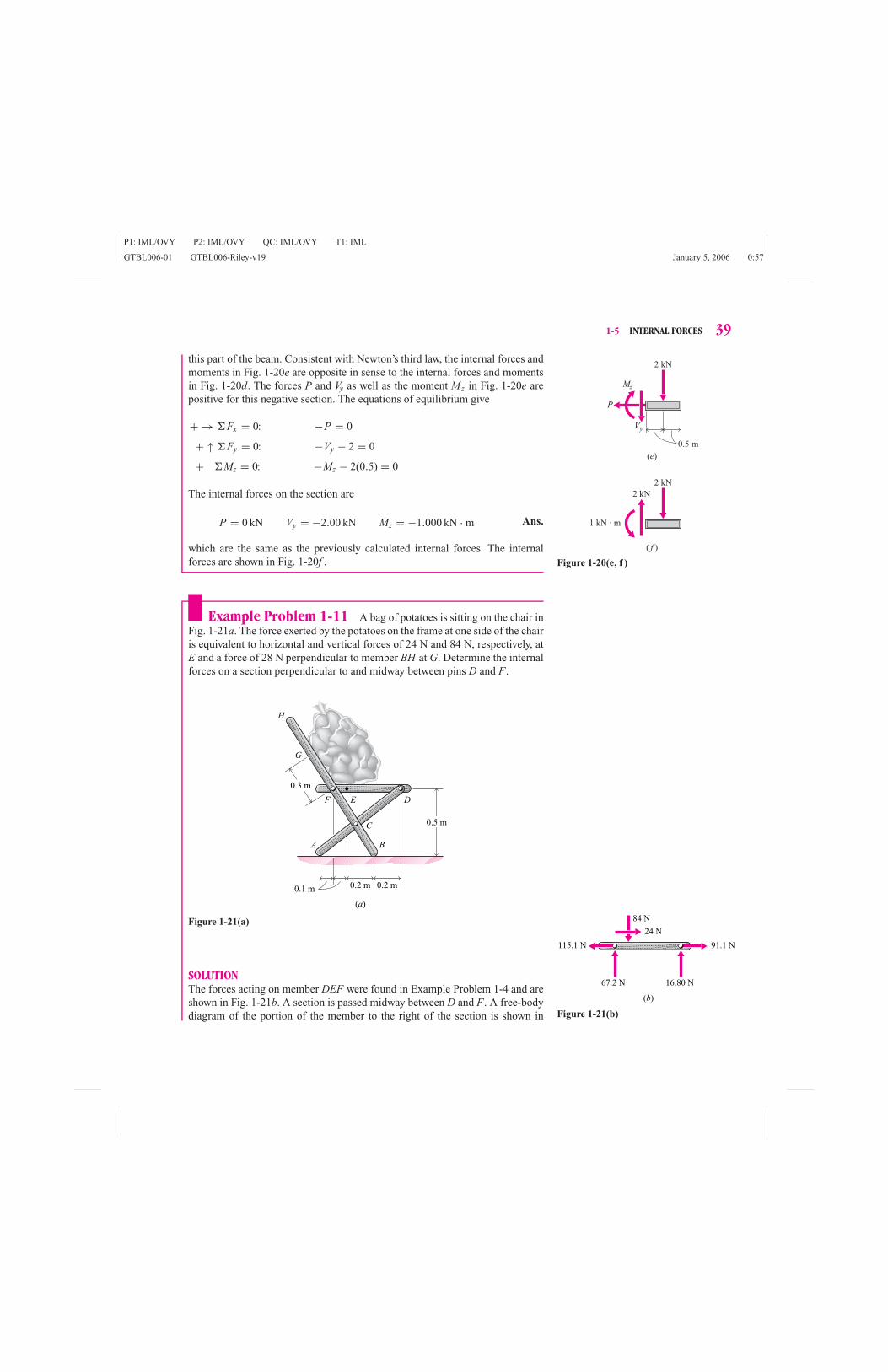
P1: IML/OVY P2: IML/OVY QC: IML/OVY T1: IML
GTBL006-01 GTBL006-Riley-v19 January 5, 2006 0:57
1-5 INTERNAL FORCES 39
this part of the beam. Consistent with Newton’s third law, the internal forces andmoments in Fig. 1-20e are opposite in sense to the internal forces and momentsin Fig. 1-20d. The forces P and Vy as well as the moment Mz in Fig. 1-20e arepositive for this negative section. The equations of equilibrium give
+ → �Fx = 0: −P = 0
+ ↑ �Fy = 0: −Vy − 2 = 0
+ �Mz = 0: −Mz − 2(0.5) = 0(e)
2 kN
P
Vy
Mz
( f )
2 kN
2 kN
1 kN · m
0.5 m
Figure 1-20(e, f )
The internal forces on the section are
P = 0 kN Vy = −2.00 kN Mz = −1.000 kN · m Ans.
which are the same as the previously calculated internal forces. The internalforces are shown in Fig. 1-20f .
Example Problem 1-11 A bag of potatoes is sitting on the chair inFig. 1-21a. The force exerted by the potatoes on the frame at one side of the chairis equivalent to horizontal and vertical forces of 24 N and 84 N, respectively, atE and a force of 28 N perpendicular to member BH at G. Determine the internalforces on a section perpendicular to and midway between pins D and F.
0.3 m
0.1 m 0.2 m0.2 m
0.5 m
A B
C
F E D
G
H
(a)
Figure 1-21(a) 84 N
16.80 N
91.1 N115.1 N
67.2 N
24 N
(b)
Figure 1-21(b)
SOLUTIONThe forces acting on member DEF were found in Example Problem 1-4 and areshown in Fig. 1-21b. A section is passed midway between D and F. A free-bodydiagram of the portion of the member to the right of the section is shown in

P1: IML/OVY P2: IML/OVY QC: IML/OVY T1: IML
GTBL006-01 GTBL006-Riley-v19 January 5, 2006 0:57
40 CHAPTER 1 INTRODUCTION AND REVIEW OF STATICS
Fig. 1-21c. Positive axes and internal forces are shown on the free-body diagram.The equations of equilibrium yield
+ ← �Fx = 0: P − 91.1 = 0 (a)
+ ↓ �Fy = 0: Vy − 16.80 = 0 (b)
+ �Mz = 0: Mz + 16.80(0.25) = 0 (c)
0.25 m
P
y
x
(c)
91.1 N
16.80 N
Mz
Vy
Figure 1-21(c)
The internal forces on the section are
P = 91.1 N Vy = 16.80 N Mz = −4.20 N · m Ans.
Students are encouraged to solve the problem using a free-body diagram of aportion of the member to the left of the section.
PROBLEMS
Introductory Problems
1-54* Three forces are applied along the centerline of a steel
bar as shown in Fig. P1-54. Determine the internal forces on
transverse cross sections in intervals AB, BC, and CD of the
bar.
Figure P1-54
1-55* A human femur is modeled in Fig. P1-55. The abductor
muscle force is M = 90 lb, and the femoral load is J = 120 lb.
Determine the internal forces on section a–a.
11/2 in.
1 in.
5/8 in.
J
M
aa
Figure P1-55

P1: IML/OVY P2: IML/OVY QC: IML/OVY T1: IML
GTBL006-01 GTBL006-Riley-v19 January 5, 2006 0:57
1-5 INTERNAL FORCES 41
1-56 The man shown in Fig. P1-56 has a mass of 75 kg; the
beam has a mass of 40 kg. The beam is in equilibrium with the
man standing at the end and pulling on the cable. Determine
the internal forces on a section perpendicular to and midway
between
a. A and B.
b. B and C.
1.5 m1.5 m
A
G
CB
Figure P1-56
1-57* Determine the internal forces on section a–a in the angle
bracket shown in Fig. P1-57.
Figure P1-57
1-58 Determine the internal forces acting at the centroid of sec-
tion A–A of the C-clamp shown in Fig. P1-58. The force P has
a magnitude of 2000 N.
Figure P1-58
Intermediate Problems
1-59* Four sets of flexible cables, spaced at 120◦ intervals, are
used to stabilize a 400-ft communications tower. The tower and
one cable from each set are shown in Fig. P1-59. The weight
of the tower is 40 lb/ft, and the communications equipment
at the top weighs 2000 lb. Determine the axial forces (normal
forces acting along the centerline) on transverse cross sections
at points A, B, C, and D of the tower.
Figure P1-59
1-60* Determine the internal forces acting on section a–a in the
bar rack shown in Fig. P1-60 if each bar has a mass of 50 kg.

P1: IML/OVY P2: IML/OVY QC: IML/OVY T1: IML
GTBL006-01 GTBL006-Riley-v19 January 5, 2006 0:57
42 CHAPTER 1 INTRODUCTION AND REVIEW OF STATICS
Figure P1-60
1-61 The reaction between a crutch and the ground is 35 lb, as
shown in Fig. P1-61. Determine the internal forces acting on
section a–a.
Figure P1-61
1-62 The front-wheel suspension of an automobile is shown in
Fig. P1-62. The pavement exerts a vertical force of 2700 N on
the tire. Determine the internal forces on a section perpendic-
ular to and midway between C and D.
Figure P1-62
1-63 A pin-connected system of levers and bars is used as a toggle
for a press as shown in Fig. P1-63. Three members are joined
by pin D, as shown in the insert. Determine the internal forces
on a section perpendicular to and midway between D and Ewhen P = 1000 lb.
Figure P1-63
Challenging Problems
1-64* A steel shaft 120 mm in diameter is supported in flexible
bearings at its ends. Two pulleys, each 500 mm in diameter,
are keyed to the shaft. The pulleys carry belts that produce the
forces shown in Fig. P1-64. Determine the internal forces on a
vertical section through point A.

P1: IML/OVY P2: IML/OVY QC: IML/OVY T1: IML
GTBL006-01 GTBL006-Riley-v19 January 5, 2006 0:57
1-5 INTERNAL FORCES 43
Figure P1-64
1-65* A device for lifting rectangular objects such as bricks and
concrete blocks is shown in Fig. P1-65. The coefficients of fric-
tion at all vertical contact surfaces are μs = 0.4 and μk = 0.3.
The device is to lift two blocks, each weighing 15 lb. Deter-
mine the internal forces on a vertical section 4 in. to the left of
pin B.
Figure P1-65
1-66 An automobile engine with a mass of 360 kg is supported by
an engine hoist, as shown in Fig. P1-66. Determine the internal
forces on section a–a.
Figure P1-66
1-67 Determine the internal forces on section a–a of the pipe
system shown in Fig. P1-67.
Figure P1-67
1-68* Determine the internal forces on section a–a in bar ABC
of the three-bar frame shown in Fig. P1-68.
Figure P1-68

P1: IML/OVY P2: IML/OVY QC: IML/OVY T1: IML
GTBL006-01 GTBL006-Riley-v19 January 5, 2006 0:57
44 CHAPTER 1 INTRODUCTION AND REVIEW OF STATICS
Computer Problems
1-69 The hook shown in Fig. P1-69 supports a 10-kip load. Plot
P, V , and M , the internal forces and moment transmitted by a
section of the hook, as a function of the angle θ (0◦ ≤ θ ≤ 150◦).
Figure P1-69
1-70 Forces of 100 N are being applied to the handles of the vise
grip pliers shown in Fig. P1-70. Plot P, V , and M , the internal
forces and moment transmitted by section a–a of the handle,
as a function of the distance d (20 mm ≤ d ≤ 30 mm).
Figure P1-70
1-71 A 4000-lb cart rolls along a beam as shown in Fig. P1-71.
a. Show that the maximum bending moment in the beam oc-
curs at the wheel that is closer to the middle of the beam.
b. Plot |M |max, the maximum bending moment in the beam, as
a function of the cart’s position x (0 ft ≤ x ≤ 15 ft).
Figure P1-71
1-72 A group of workers proposes to raise a uniform 250-kg post
AB to a vertical position using the rope and brace arrangement
shown in Fig. P1-72. Assume that the weight of the brace can
be neglected and that end A acts as a frictionless pin for both the
6-m-long post AB and the 6-m-long brace AC. Plot P, V , and M ,
the internal forces and moment transmitted by section a–a of
the post, as a function of the distance from A (0 m ≤ b ≤ 6 m).
Figure P1-72
SUMMARY
Review Problems Force is the action of one body on another. The primary objectiveof a course in mechanics of materials is the development of relationships betweenthe forces applied to a body and the internal forces and deformations induced inthe body.
Forces always exist in equal magnitude, opposite direction pairs. In order tostudy these forces, it is necessary to isolate the body from its surroundings or fromother parts of the body at each point where forces are to be determined. The resultantof the internal force system is then found using the equations of equilibrium. The

P1: IML/OVY P2: IML/OVY QC: IML/OVY T1: IML
GTBL006-01 GTBL006-Riley-v19 January 5, 2006 0:57
REVIEW PROBLEMS 45
importance of drawing a correct free-body diagram cannot be overemphasized.The free-body diagram clearly establishes which body or portion of the body isbeing studied. A correct free-body diagram clearly identifies all forces (both knownand unknown) that must be included in the equations of equilibrium.
A rigid body (a body that does not deform under the action of applied loads)is in equilibrium when the resultant of the system of forces acting on the bodyis zero. This condition is satisfied if the vector sum of all external forces actingon the body is zero and the vector sum of the moments of the external forcesabout any point O (on or off the body) is zero. Although no body is perfectly rigid,most engineering structures and machines are designed “stiff,” that is, they do notdeform very much. For such problems, the solution of the equilibrium equationsoften ignores the deformation and treats the structure as though it were rigid.However, we cannot find the exact distribution of the internal forces until we learnhow to determine the deformation of the body.
The subject matter of this book forms the basis for the solution of threegeneral types of problems encountered by engineers in the design and analysis ofstructures and machines:
� Design: Given a certain function to perform, of what materials should the ma-chine or structure be constructed, and what should be the sizes and proportionsof the various elements?
� Checking: Given the completed design, is it adequate—does it perform thefunction economically and without excessive deformation?
� Rating: Given a completed structure or machine, what is its actual load-carryingcapacity?
Some knowledge of the physical and mechanical properties of materials is requiredin order to create a design, to properly evaluate a given design, or even to write thecorrect relation between an applied load and the resulting deformation of a loadedmember. Essential information will be introduced as required.
Don’t report final results with more accuracy than is justified by the dataand don’t round off numbers too much too soon. Although results should alwaysbe reported as accurately as possible, the final answer should not be more pre-cise than the data from which it was derived. One of the tasks in all engineeringwork is to determine the accuracy of the given data and the expected accuracyof the final answer. Results should always reflect the accuracy of the given data.All data in Example Problems and Homework Problems will be assumed suffi-ciently accurate to justify rounding off the final answer to three or four significantfigures.
REVIEW PROBLEMS
1-73* The collar A shown in Fig. P1-73 is free to slide on the
smooth rod BC. Determine the forces exerted on the collar by
the cable and by the rod when the force F = 900 lb is applied
to the collar.
Figure P1-73

P1: IML/OVY P2: IML/OVY QC: IML/OVY T1: IML
GTBL006-01 GTBL006-Riley-v19 January 5, 2006 0:57
46 CHAPTER 1 INTRODUCTION AND REVIEW OF STATICS
1-74* A 500-kg mass is supported by a four-bar truss as shown in
Fig. P1-74. Determine the force in each member of the truss.
Figure P1-74
1-75 The electric motor shown in Fig. P1-75 weighs 25 lb. Due to
friction between the belt and pulley, the belt forces have mag-
nitudes of T1 = 21 lb and T2 = 1 lb. Determine the support
reactions at A and B.
Figure P1-75
1-76* Determine the force P required to push the 135-kg cylinder
over the small block shown in Fig. P1-76.
Figure P1-76
1-77 For the beam shown in Fig. P1-77, determine
a. The reactions at supports A and B.
b. The internal forces on a transverse cross section 10 ft to the
right of support A.
Figure P1-77
1-78 The jaws and bolts of the wood clamp in Fig. P1-78 are
parallel. The bolts pass through swivel mounts so that no mo-
ments act on them. The clamp exerts forces of 300 N on each
side of the board. Treat the forces on the boards as uniformly
distributed over the contact areas and determine the forces in
each of the bolts. Show on a sketch all forces acting on the
upper jaw of the clamp.
Figure P1-78
1-79* A three-bar frame is loaded and supported as shown in Fig.
P1-79. Determine the internal forces transmitted by
a. Section a–a in bar BEF.
b. Section b–b in bar ABCD.
Figure P1-79

P1: IML/OVY P2: IML/OVY QC: IML/OVY T1: IML
GTBL006-01 GTBL006-Riley-v19 January 5, 2006 0:57
REVIEW PROBLEMS 47
1-80 Forces of 5 N are applied to the handles of the paper punch
of Fig. P1-80. Determine the force exerted on the paper at Dand the force exerted on the pin at B by handle ABC.
Figure P1-80
1-81* A shaft is loaded through a pulley and a lever (Fig. P1-81)
that are fixed to the shaft. Friction between the belt and pulley
prevents slipping of the belt. Determine the force P required for
equilibrium and the reactions at supports A and B. The support
at A is a ball bearing, and the support at B is a thrust bearing.
The bearings exert only force reactions on the shaft.
Figure P1-81
1-82* The masses of cartons 1, 2, and 3, which rest on the plat-
form shown in Fig. P1-82, are 300 kg, 100 kg, and 200 kg,
respectively. The mass of the platform is 500 kg. Determine
the tensions in the three cables A, B, and C that support the
platform.
Figure P1-82
1-83 The clamp of Fig. P1-83 is used to hold two boards. If the
clamping force is 300 N, determine the internal forces on sec-
tion a–a.
Figure P1-83
1-84 Two bars, a pulley, and a cable are used to support a block
as shown in Fig. P1-84. The two bars have negligible weight.
The mass of the pulley is 50 kg, and the mass of the block is
100 kg. Determine the internal forces on cross section a–a in
bar AB.
Figure P1-84