Interactive Learning Tools: Animating Statics
10
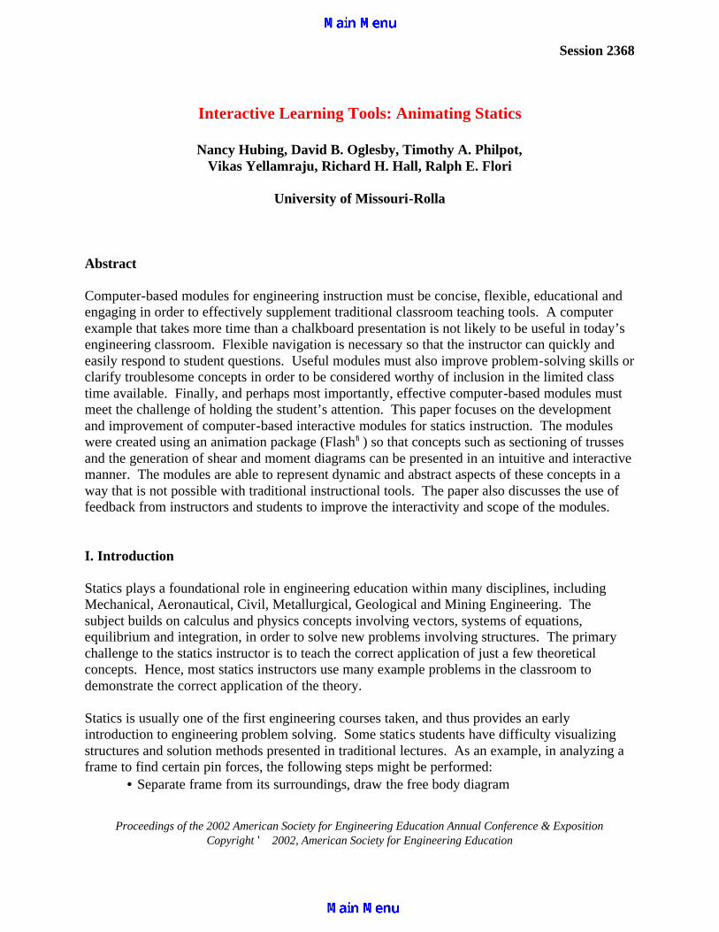
Session 2368 Proceedings of the 2002 American Society for Engineering Education Annual Conference & Exposition Copyright ' 2002, American Society for Engineering Education Interactive Learning Tools: Animating Statics Nancy Hubing, David B. Oglesby, Timothy A. Philpot, Vikas Yellamraju, Richard H. Hall, Ralph E. Flori University of Missouri-Rolla Abstract Computer-based modules for engineering instruction must be concise, flexible, educational and engaging in order to effectively supplement traditional classroom teaching tools. A computer example that takes more time than a chalkboard presentation is not likely to be useful in today’s engineering classroom. Flexible navigation is necessary so that the instructor can quickly and easily respond to student questions. Useful modules must also improve problem-solving skills or clarify troublesome concepts in order to be considered worthy of inclusion in the limited class time available. Finally, and perhaps most importantly, effective computer-based modules must meet the challenge of holding the student’s attention. This paper focuses on the development and improvement of computer-based interactive modules for statics instruction. The modules were created using an animation package (Flash fi ) so that concepts such as sectioning of trusses and the generation of shear and moment diagrams can be presented in an intuitive and interactive manner. The modules are able to represent dynamic and abstract aspects of these concepts in a way that is not possible with traditional instructional tools. The paper also discusses the use of feedback from instructors and students to improve the interactivity and scope of the modules. I. Introduction Statics plays a foundational role in engineering education within many disciplines, including Mechanical, Aeronautical, Civil, Metallurgical, Geological and Mining Engineering. The subject builds on calculus and physics concepts involving vectors, systems of equations, equilibrium and integration, in order to solve new problems involving structures. The primary challenge to the statics instructor is to teach the correct application of just a few theoretical concepts. Hence, most statics instructors use many example problems in the classroom to demonstrate the correct application of the theory. Statics is usually one of the first engineering courses taken, and thus provides an early introduction to engineering problem solving. Some statics students have difficulty visualizing structures and solution methods presented in traditional lectures. As an example, in analyzing a frame to find certain pin forces, the following steps might be performed: • Separate frame from its surroundings, draw the free body diagram
Transcript of Interactive Learning Tools: Animating Statics
Session 2368
Proceedings of the 2002 American Society for Engineering Education Annual Conference & Exposition Copyright © 2002, American Society for Engineering Education
Interactive Learning Tools: Animating Statics
Nancy Hubing, David B. Oglesby, Timothy A. Philpot,
Vikas Yellamraju, Richard H. Hall, Ralph E. Flori
University of Missouri-Rolla
Abstract Computer-based modules for engineering instruction must be concise, flexible, educational and engaging in order to effectively supplement traditional classroom teaching tools. A computer example that takes more time than a chalkboard presentation is not likely to be useful in today’s engineering classroom. Flexible navigation is necessary so that the instructor can quickly and easily respond to student questions. Useful modules must also improve problem-solving skills or clarify troublesome concepts in order to be considered worthy of inclusion in the limited class time available. Finally, and perhaps most importantly, effective computer-based modules must meet the challenge of holding the student’s attention. This paper focuses on the development and improvement of computer-based interactive modules for statics instruction. The modules were created using an animation package (Flash®) so that concepts such as sectioning of trusses and the generation of shear and moment diagrams can be presented in an intuitive and interactive manner. The modules are able to represent dynamic and abstract aspects of these concepts in a way that is not possible with traditional instructional tools. The paper also discusses the use of feedback from instructors and students to improve the interactivity and scope of the modules. I. Introduction Statics plays a foundational role in engineering education within many disciplines, including Mechanical, Aeronautical, Civil, Metallurgical, Geological and Mining Engineering. The subject builds on calculus and physics concepts involving vectors, systems of equations, equilibrium and integration, in order to solve new problems involving structures. The primary challenge to the statics instructor is to teach the correct application of just a few theoretical concepts. Hence, most statics instructors use many example problems in the classroom to demonstrate the correct application of the theory. Statics is usually one of the first engineering courses taken, and thus provides an early introduction to engineering problem solving. Some statics students have difficulty visualizing structures and solution methods presented in traditional lectures. As an example, in analyzing a frame to find certain pin forces, the following steps might be performed: · Separate frame from its surroundings, draw the free body diagram
Proceedings of the 2002 American Society for Engineering Education Annual Conference & Exposition Copyright © 2002, American Society for Engineering Education
· Find support reactions of the whole frame · Dismember frame, draw free body diagrams of members · Analyze the members to find required forces. To solve this problem on the chalkboard, the instructor would probably draw the original frame attached to its surroundings, erase the surroundings, label and solve for support reactions, re-draw the separate members of the dismembered frame, and finally analyze some or all of the members to find the required forces. Such an example presented on the chalkboard could take 15 or more minutes of class time, depending upon the complexity of the frame. A student who has not been exposed to this type of problem before will likely spends all 15 minutes concentrating on accurately recording everything the instructor puts on the board, and is thus likely to miss the key solution steps involved. A large part of the problem with presenting a meaningful example is that the instructor must spend far more time drawing and redrawing than focusing on key points. In recent years, many engineering instructors have attempted to improve student learning by incorporating computer-based, multimedia examples and modules in the classroom [1,2,3,4]. It is often assumed that students will respond with interest and enthusiasm to deviations from the traditional chalkboard lecture, but this is not always the case [1,2]. In one study involving a fundamentals of mechanics course at the U.S. Air Force Academy, it was found that some students were intimidated by multimedia examples while other students expressed the ever-present concern that such examples were not beneficial in preparing for the next exam [1]. Other studies have concluded that multimedia modules can improve student learning, such as the study performed in a Stanford mechanical systems course, where it was found that test scores were significantly improved after including a multimedia motorized systems module [3]. These mixed results serve to emphasize the fact that effective multimedia modules for the classroom require periodic revision based on student feedback and learning, as well as updating based on new enabling technologies. The faculty of the Basic Engineering Department at the University of Missouri-Rolla (UMR) have had an ongoing interest in the development and use of technology in the classroom [5,6,7]. Several years ago BEST (Basic Engineering Software for Teaching) Dynamics was developed as a multimedia collection of kinematics and kinetics problems that enable the user to vary inputs to test a wide variety of configurations and behavior [5]. This was followed by BEST Statics and On Call Instruction (OCI) for Statics, which were subsequently combined to create Statics On-Line [6], an interactive multimedia collection of problems and lessons which forms an integral part of the statics course currently taught at UMR. The current work on multimedia modules for statics instruction is part of a larger project involving dynamics and mechanics of materials [7]. Several animated Flash® examples have been used in statics classrooms at UMR during the past year [8]. Macromedia Flash is an animation software package that uses vector graphics to keep file sizes small, which makes it particularly suitable for animation and interactivity (buttons and navigation) on the Web. The statics examples presented in [8] were specifically developed for the classroom, as opposed to individual student work. The examples tend to be fairly long, but contain navigational aids so that the instructor can skip around as desired. Unfortunately, the
Proceedings of the 2002 American Society for Engineering Education Annual Conference & Exposition Copyright © 2002, American Society for Engineering Education
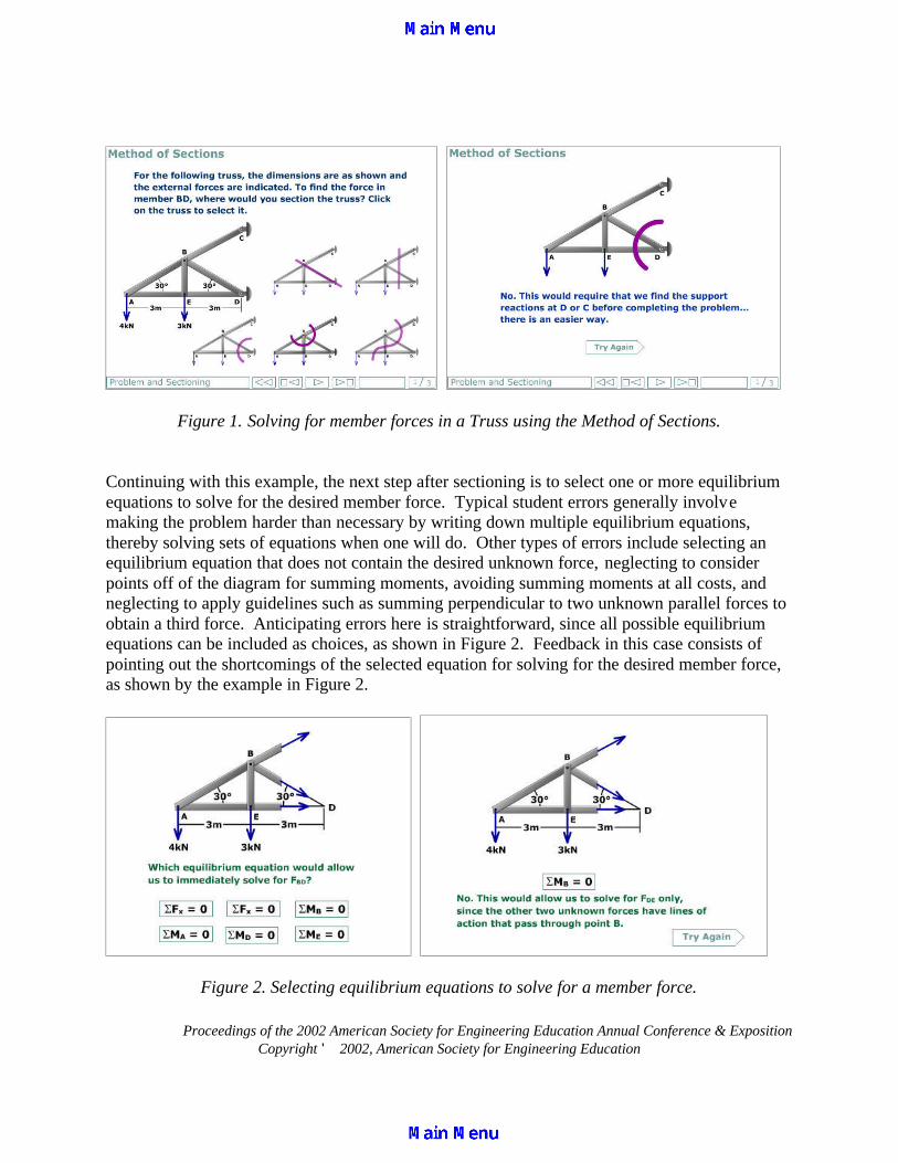
student response to these examples has been mediocre, at best. As soon as the switch is made from the blackboard to the computer example, students tend to sit back, lay down their pencil and visibly relax. The instructor’s attempts to engage the students during these examples have been less successful than similar efforts in more traditional portions of the lecture. It is clear that many students view the computer-based examples as unimportant to their knowledge of the material. As a next step in our attempt to incorporate interactive multimedia modules into statics instruction, we have solicited input from faculty and a few upperclass students as to the content and structure of the examples. The student feedback specifically suggested shorter examples that focus on one or two specific concepts. The examples developed for [8] are in depth, final exam-style problems that cover multiple concepts. In contrast, the query-based, interactive modules presented in this work are shorter and more focused on specific concepts or misconceptions. Although the modules take a significant amount of time to develop, they are efficient and easy to use in the classroom. This paper is organized as follows. Section II presents examples focusing on two concepts related to solving for member forces in trusses; sectioning and selecting appropriate equilibrium equations. The modules presented in Section III focus on concepts encountered in solving for pin forces in a frame, such as developing the ability to successfully dismember a frame and draw consistent free body diagrams of members. Section IV presents an intuitive approach to generating shear and bending moment diagrams. Finally, Section V concludes with comments on assessment and some ideas for future work. II. Trusses The truss example presented in [8] is long and thorough, going through both the Method of Joints and Method of Sections for solving for several member forces in a roof truss. The truss modules reported in this work instead focus on just two concepts: (1) Drawing section lines for the Method of Sections and (2) Selecting equilibrium equations to apply to a joint or part of the truss in order to minimize the required work. Since the Flash modules are structured such that the student or class selects the best method from a collection of possibilities, it is necessary to anticipate typical wrong answers to include as choices. Engineering instructors know that the same types of errors in solving specific problems tend to appear repeatedly on homework and exams. For example, when solving for member forces in a truss using the Method of Sections, a few students will draw section lines through pins or along members. Additional examples of common errors include cutting through more than 3 unknown members, sectioning without cutting through the member of interest, drawing incomplete section lines that do not partition the truss, neglecting to analyze a joint for a quick solution, and examining a joint with no known forces or loads. In order to address students’ misconceptions, these types of errors were included in the solution choices. Feedback, in the form of an explanation for each incorrect solution choice, is included in the module, as shown in Figure 1.
Proceedings of the 2002 American Society for Engineering Education Annual Conference & Exposition Copyright © 2002, American Society for Engineering Education
Figure 1. Solving for member forces in a Truss using the Method of Sections. Continuing with this example, the next step after sectioning is to select one or more equilibrium equations to solve for the desired member force. Typical student errors generally involve making the problem harder than necessary by writing down multiple equilibrium equations, thereby solving sets of equations when one will do. Other types of errors include selecting an equilibrium equation that does not contain the desired unknown force, neglecting to consider points off of the diagram for summing moments, avoiding summing moments at all costs, and neglecting to apply guidelines such as summing perpendicular to two unknown parallel forces to obtain a third force. Anticipating errors here is straightforward, since all possible equilibrium equations can be included as choices, as shown in Figure 2. Feedback in this case consists of pointing out the shortcomings of the selected equation for solving for the desired member force, as shown by the example in Figure 2.
Figure 2. Selecting equilibrium equations to solve for a member force.
Proceedings of the 2002 American Society for Engineering Education Annual Conference & Exposition Copyright © 2002, American Society for Engineering Education
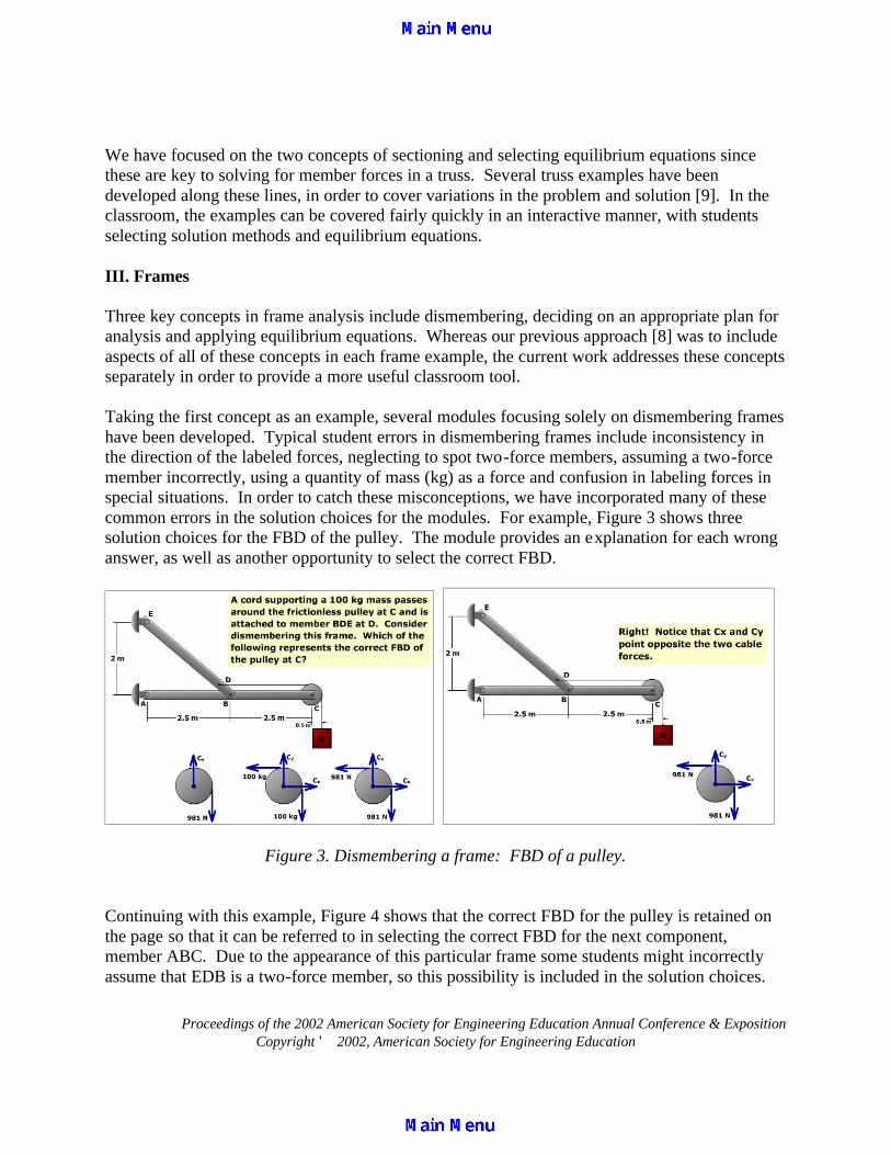
We have focused on the two concepts of sectioning and selecting equilibrium equations since these are key to solving for member forces in a truss. Several truss examples have been developed along these lines, in order to cover variations in the problem and solution [9]. In the classroom, the examples can be covered fairly quickly in an interactive manner, with students selecting solution methods and equilibrium equations. III. Frames Three key concepts in frame analysis include dismembering, deciding on an appropriate plan for analysis and applying equilibrium equations. Whereas our previous approach [8] was to include aspects of all of these concepts in each frame example, the current work addresses these concepts separately in order to provide a more useful classroom tool. Taking the first concept as an example, several modules focusing solely on dismembering frames have been developed. Typical student errors in dismembering frames include inconsistency in the direction of the labeled forces, neglecting to spot two-force members, assuming a two-force member incorrectly, using a quantity of mass (kg) as a force and confusion in labeling forces in special situations. In order to catch these misconceptions, we have incorporated many of these common errors in the solution choices for the modules. For example, Figure 3 shows three solution choices for the FBD of the pulley. The module provides an explanation for each wrong answer, as well as another opportunity to select the correct FBD.
Figure 3. Dismembering a frame: FBD of a pulley. Continuing with this example, Figure 4 shows that the correct FBD for the pulley is retained on the page so that it can be referred to in selecting the correct FBD for the next component, member ABC. Due to the appearance of this particular frame some students might incorrectly assume that EDB is a two-force member, so this possibility is included in the solution choices.
Proceedings of the 2002 American Society for Engineering Education Annual Conference & Exposition Copyright © 2002, American Society for Engineering Education
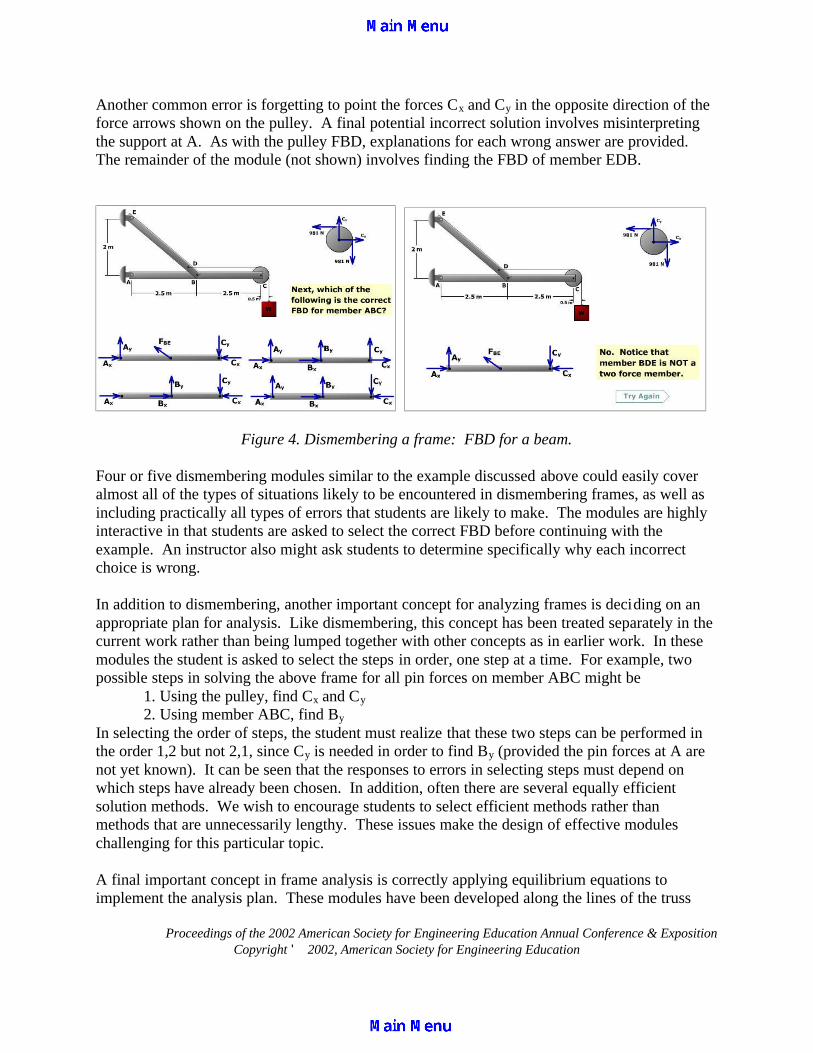
Another common error is forgetting to point the forces Cx and Cy in the opposite direction of the force arrows shown on the pulley. A final potential incorrect solution involves misinterpreting the support at A. As with the pulley FBD, explanations for each wrong answer are provided. The remainder of the module (not shown) involves finding the FBD of member EDB.
Figure 4. Dismembering a frame: FBD for a beam. Four or five dismembering modules similar to the example discussed above could easily cover almost all of the types of situations likely to be encountered in dismembering frames, as well as including practically all types of errors that students are likely to make. The modules are highly interactive in that students are asked to select the correct FBD before continuing with the example. An instructor also might ask students to determine specifically why each incorrect choice is wrong. In addition to dismembering, another important concept for analyzing frames is deciding on an appropriate plan for analysis. Like dismembering, this concept has been treated separately in the current work rather than being lumped together with other concepts as in earlier work. In these modules the student is asked to select the steps in order, one step at a time. For example, two possible steps in solving the above frame for all pin forces on member ABC might be
1. Using the pulley, find Cx and Cy 2. Using member ABC, find By
In selecting the order of steps, the student must realize that these two steps can be performed in the order 1,2 but not 2,1, since Cy is needed in order to find By (provided the pin forces at A are not yet known). It can be seen that the responses to errors in selecting steps must depend on which steps have already been chosen. In addition, often there are several equally efficient solution methods. We wish to encourage students to select efficient methods rather than methods that are unnecessarily lengthy. These issues make the design of effective modules challenging for this particular topic. A final important concept in frame analysis is correctly applying equilibrium equations to implement the analysis plan. These modules have been developed along the lines of the truss

Proceedings of the 2002 American Society for Engineering Education Annual Conference & Exposition Copyright © 2002, American Society for Engineering Education
example shown in Figure 2, where all possible equilibrium equations are provided and the student selects the appropriate equation(s) for implementing the step. For classroom implementation, all of the frame analysis modules discussed in this section are specific to a single topic, and each one only takes a few minutes to complete in the statics classroom. IV. Shear and Bending Moment Diagrams One key to successful analysis of beams involves determining the distribution of internal shear force and bending moment for the beam. The ability to accurately sketch the shear force and bending moment diagrams using the differential relationships between load, shear force and bending moment [10] is a valuable tool. To facilitate the learning of this procedure we use interactive modules where the student is required to specify the information needed to sketch the shear force and bending moment diagrams for a loaded beam. Each module begins with the loading on the beam and the initial point (x,V) on the shear diagram specified. The student is asked to specify, by clicking on the grid, the location of the next critical point for the curve. If correctly located, feedback based on the governing differential relationships is given to reinforce why the location is correct, as shown in Figure 5. Once the correct point is specified, the student is asked to select the type of connecting curve between the two points (Line, Parabola-Concave Up, Parabola-Concave Down, Cubic) as shown in Figure 6. When correctly specified the connecting curve is drawn.
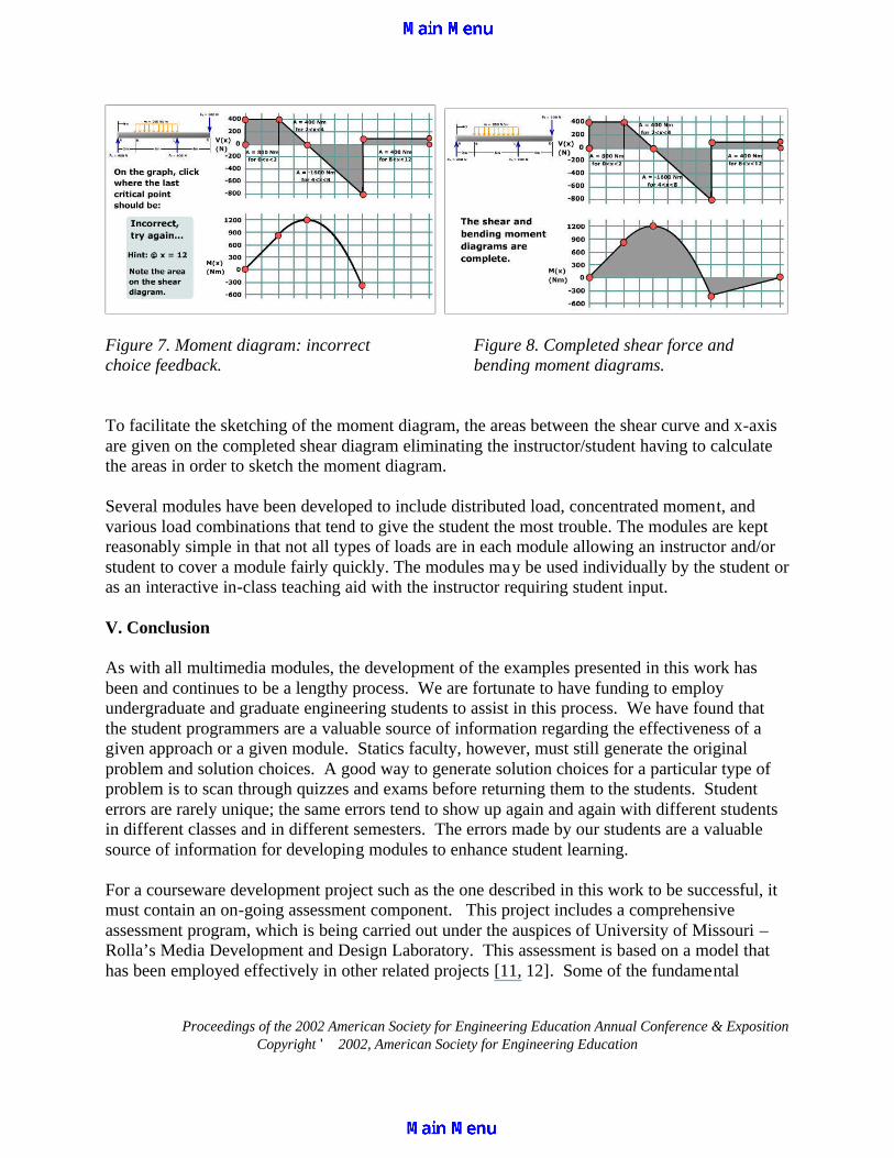
Figure 5. Shear diagram: correct choice Figure 6. Selecting connecting curve feedback. shape. When an incorrect location is picked for a point feedback is given in the form of a hint to enable the picking of the correct location as shown in Figure 7. This interactive process is continued until the complete shear force and bending moment diagrams are sketched as shown in Figure 8. In addition to selecting the next critical point and curve shape, the student will be asked to specify zero shear locations and maximum/minimum moment values where appropriate.
Proceedings of the 2002 American Society for Engineering Education Annual Conference & Exposition Copyright © 2002, American Society for Engineering Education
Figure 7. Moment diagram: incorrect Figure 8. Completed shear force and choice feedback. bending moment diagrams. To facilitate the sketching of the moment diagram, the areas between the shear curve and x-axis are given on the completed shear diagram eliminating the instructor/student having to calculate the areas in order to sketch the moment diagram. Several modules have been developed to include distributed load, concentrated moment, and various load combinations that tend to give the student the most trouble. The modules are kept reasonably simple in that not all types of loads are in each module allowing an instructor and/or student to cover a module fairly quickly. The modules may be used individually by the student or as an interactive in-class teaching aid with the instructor requiring student input. V. Conclusion As with all multimedia modules, the development of the examples presented in this work has been and continues to be a lengthy process. We are fortunate to have funding to employ undergraduate and graduate engineering students to assist in this process. We have found that the student programmers are a valuable source of information regarding the effectiveness of a given approach or a given module. Statics faculty, however, must still generate the original problem and solution choices. A good way to generate solution choices for a particular type of problem is to scan through quizzes and exams before returning them to the students. Student errors are rarely unique; the same errors tend to show up again and again with different students in different classes and in different semesters. The errors made by our students are a valuable source of information for developing modules to enhance student learning. For a courseware development project such as the one described in this work to be successful, it must contain an on-going assessment component. This project includes a comprehensive assessment program, which is being carried out under the auspices of University of Missouri – Rolla’s Media Development and Design Laboratory. This assessment is based on a model that has been employed effectively in other related projects [11, 12]. Some of the fundamental
Proceedings of the 2002 American Society for Engineering Education Annual Conference & Exposition Copyright © 2002, American Society for Engineering Education
themes of this model are: a) the assessment process is iterative, with assessment ongoing during development; b) multiple experimental methodologies are utilized; and c) conclusions and recommendations are based on the triangulation of multiple qualitative and quantitative outcomes. Laboratory based usability assessment has been initiated, and will be followed by applied assessment of the software within the context of Statics classes at UMR. References
1. Bowe, M., Jensen, D., Feland, J., Self, B. “When Multimedia Doesn’t Work: An Assessment of Visualization Modules for Learning Enhancement in Mechanics”, Proceedings of the ASEE Annual Conference, Albuquerque, NM, June 2001.
2. Rhymer, D., Jensen, D., Bowe, M., “An Assessment of Visualization Modules for Learning Enhancement in Mechanics”, Proceedings of the ASEE Annual Conference, Albuquerque, NM, June 2001.
3. Reamon, D.T., Sheppard, S.D., “Educational Interactive Multimedia Software: Can it Effectively Teach Engineering Concepts?”, Proceedings of DETC, 1999 ASME Design Engineering Technical Conferences, Las Vegas, NV, September 1999.
4. Ngo, C.C., Lai, F.C., “Teaching Thermodynamics with the Aid of Web-Based Modules”, Proceedings of the ASEE Annual Conference, Albuquerque, NM, June 2001.
5. Flori, R.E., Koen, M.A., Oglesby, D.B., “Basic Engineering Software for Teaching (“BEST”) Dynamics”, ASEE Journal of Engineering Education, 1996: p. 61-67.
6. Oglesby, D.B, Carney, E.R., Prissovsky, M., Crites, D., “Statics On-Line: A Project Review”, Proceedings of the ASEE Annual Conference, Seattle, WA, June 1998.
7. Flori, R., Oglesby, D., Philpot, T., Hubing, N., Hall, R., Yellamraju, V., “Incorporating Web-Based Homework Problems in Engineering Dynamics,” Proceedings of the ASEE Annual Conference, Montreal, Canada, June 2002
8. Hubing, N., Oglesby, D.B., “Animating Statics: Flash in the Classroom”, American Society for Engineering Education Midwest Section Conference, Manhattan, Kansas, March 2001.
9. http://www.umr.edu/~bestmech/preview.html is the location for examples presented in this work. 10. Hibbeler, R.C., Engineering Mechanics-Statics, 9th Edition, Prentice-Hall, Inc. 11. Eller, V.E., R.H. Hall, and S.E. Watkins, Multimedia web-based resources for engineering education: The
media design and assessment laboratory at UMR. Proceedings of the annual meeting of the American Society for Engineering Education, Albuquerque, NM, 2001.
12. Hall, R.H., et al., Design and assessment of web-based learning environments: The smart engineering project and the instructional software development center at U.M.R., in Cybereducation: The Future of Long Distance Education, L.R. Vandervert and L.V. Shavinina, Editors. 2001, Mary Ann Liebert, Inc.: New York. p. 137 – 156.
Acknowledgement This work was supported in part by a grant from the United States Department of Education Fund for the Improvement of Post-Secondary Education (FIPSE #P116B000100). Biographical Information
NANCY HUBING Dr. Hubing is an Associate Professor in the Basic Engineering Dept. at the University of Missouri-Rolla. Prior to joining the BE department in August 2000, she was on the faculty of the Electrical and Computer Engineering Dept.

Proceedings of the 2002 American Society for Engineering Education Annual Conference & Exposition Copyright © 2002, American Society for Engineering Education
at UMR from 1989 to 1999, and taught high school physics 1999-00. She completed her Ph.D. in ECE at NC State University in 1989. Dr. Hubing enjoys research involving educational methods and technology in the classroom. DAVID B. OGLESBY David B. Oglesby is a Professor of Basic Engineering and a Research Associate for the Instructional Softwa re Development Center at the University of Missouri-Rolla. Dr. Oglesby received a B. S. degree in Civil Engineering from the Virginia Military Institute in 1963, and M. S. and D Sc. degrees in Applied Mechanics from the University of Virginia in 1965 and 1969, respectively. He is actively involved in developing software for teaching statics. TIMOTHY A. PHILPOT Timothy A. Philpot is an Assistant Professor in the Basic Engineering Department at the University of Missouri – Rolla. He completed his PhD degree at Purdue University in 1992, the M.Engr.degree at Cornell University in 1980, and the B.S. at the University of Kentucky in 1979, all in Civil Engineering. Dr. Philpot teaches Mechanics of Materials and is the PI of the US Department of Education grant that supported this work. YELLAMRAJU VIKAS Yellamraju Vikas is a Software Support Analyst at UMR. He works in designing, developing and implementation of online education tools. He has M.S in I.E from University of Oklahoma and B.Tech. in Mech Engg from Nagarjuna University, India. He also has 3 years professional experience in Polyester/Nylon Monofilament Yarn plant in India. His present work involves research on multimedia and online learning technology for engineering applications.
RICHARD H. HALL Richard H. Hall, Associate Professor of Psychology at UMR, will be moving to UMR’s new Information Science and Technology program in the fall of 2002. He received his BS degree in Psychology from the University of North Texas, and PhD degree in Experimental Psychology from Texas Christian University. He is the director of UMR’s Media Design and Assessment Laboratory, and his research focuses on Web Design and Usability Assessment. RALPH E. FLORI Dr. Ralph E. Flori was educated as a petroleum engineer (UM-Rolla PhD ‘87). Now an associate professor in the Basic Engineering dept. at the University of Missouri-Rolla, he teaches dynamics, statics, mechanics of materials and a freshman engineering design course, and is actively involved in developing educational software for teaching engineering mechanics courses. He has earned thirteen awards for outstanding teaching and faculty excellence.