INTRA-CLUSTER ROUTING WITH BACKUP PATH IN SENSOR NETWORKS
14
Dhinaharan Nagamalai et al. (Eds) : CCSEA, DKMP, AIFU, SEA - 2015 pp. 141–154, 2015. © CS & IT-CSCP 2015 DOI : 10.5121/csit.2015.50212 INTRA-CLUSTER ROUTING WITH BACK- UP PATH IN SENSOR NETWORKS Turki Abdullah 1 , Hyeoncheol Zin 1 , Mary Wu 2 , and ChongGun Kim 1 * 1 Department of Computer Engineering, Yeungnam University, Korea [email protected] , [email protected], [email protected] 2 Yongnam Theological University and Seminary, Korea [email protected] ABSTRACT The novel applications of sensor networks impose some requirements in wireless sensor network design. With the energy efficiency and lifetime awareness, the throughput and network delay also required to support emerging applications of sensor networks. In this paper, we propose throughput and network delay aware intra-cluster routing protocol. We introduce the back-up links in the intra-cluster communication path. The link throughput, communication delay, packet loss ratio, interference, residual energy and node distance are the considered factors in finding efficient path of data communication among the sensor nodes within the cluster. The simulation result shows the higher throughput and lower average packet delay rate for the proposed routing protocol than the existing benchmarks. The proposed routing protocol also shows energy efficiency and lifetime awareness with better connectivity rate. KEYWORDS Intra-cluster routing; payoff function; wireless sensor network; throughput and energy- aware; back-up path. 1. INTRODUCTION Wireless sensor network (WSN) is the connection among the tiny mobile or stationary sensor nodes so that they can share data wirelessly [6][18-19]. The use of sensor networks growing rapidly from healthcare to ocean bed monitoring, and from smart home to space shuttle. The innovative applications of sensor networks impose novel challenges on its protocol design. The energy efficiency, lifetime awareness, energy balancing, network throughput and delay minimization, antenna design and sensor miniaturization are the existing research challenges of sensor network design [9]. Clustering is a proven technique to ensure energy efficient communication. Most of the cluster based sensor network research handles the issue of inter-cluster routing and very few of them consider network throughput and network delay of their proposal. Currently, huge network traffic is generated by the sensors and devices of internet of things (IoT) [7][20], smart home and smart grid networks [10-13]. The throughput and delay must be considered for efficient management and control of this type of sensor enabled network. In this paper, the intra-cluster routing protocol is proposed to ensure reliable data transmission through introducing back-up link in the communication path. Intra-cluster routing is the process
-
Upload
independent -
Category
Documents
-
view
5 -
download
0
Transcript of INTRA-CLUSTER ROUTING WITH BACKUP PATH IN SENSOR NETWORKS
Dhinaharan Nagamalai et al. (Eds) : CCSEA, DKMP, AIFU, SEA - 2015
pp. 141–154, 2015. © CS & IT-CSCP 2015 DOI : 10.5121/csit.2015.50212
INTRA-CLUSTER ROUTING WITH BACK-
UP PATH IN SENSOR NETWORKS
Turki Abdullah
1, Hyeoncheol Zin
1, Mary Wu
2, and ChongGun Kim
1*
1Department of Computer Engineering, Yeungnam University, Korea
[email protected] , [email protected], [email protected] 2Yongnam Theological University and Seminary, Korea
ABSTRACT
The novel applications of sensor networks impose some requirements in wireless sensor network
design. With the energy efficiency and lifetime awareness, the throughput and network delay
also required to support emerging applications of sensor networks. In this paper, we propose
throughput and network delay aware intra-cluster routing protocol. We introduce the back-up
links in the intra-cluster communication path. The link throughput, communication delay,
packet loss ratio, interference, residual energy and node distance are the considered factors in
finding efficient path of data communication among the sensor nodes within the cluster. The
simulation result shows the higher throughput and lower average packet delay rate for the
proposed routing protocol than the existing benchmarks. The proposed routing protocol also
shows energy efficiency and lifetime awareness with better connectivity rate.
KEYWORDS
Intra-cluster routing; payoff function; wireless sensor network; throughput and energy- aware;
back-up path.
1. INTRODUCTION
Wireless sensor network (WSN) is the connection among the tiny mobile or stationary sensor
nodes so that they can share data wirelessly [6][18-19]. The use of sensor networks growing
rapidly from healthcare to ocean bed monitoring, and from smart home to space shuttle. The
innovative applications of sensor networks impose novel challenges on its protocol design. The
energy efficiency, lifetime awareness, energy balancing, network throughput and delay
minimization, antenna design and sensor miniaturization are the existing research challenges of
sensor network design [9].
Clustering is a proven technique to ensure energy efficient communication. Most of the cluster
based sensor network research handles the issue of inter-cluster routing and very few of them
consider network throughput and network delay of their proposal. Currently, huge network traffic
is generated by the sensors and devices of internet of things (IoT) [7][20], smart home and smart
grid networks [10-13]. The throughput and delay must be considered for efficient management
and control of this type of sensor enabled network.
In this paper, the intra-cluster routing protocol is proposed to ensure reliable data transmission
through introducing back-up link in the communication path. Intra-cluster routing is the process
142 Computer Science & Information Technology (CS & IT)
to find out the efficient path to forward network traffic (or data) towards the cluster head within
the cluster. We consider the link throughput, delay, packet loss ratio, interference, residual energy
[14-17] and node distance to select the links and corresponding sensor node to establish path of
the intra-cluster communication. We also use the penalty functions, which helps the sensor nodes
not to select the path with lower than the required or expected throughput and delay. And thus in
contrast of conventional cost model, we use the payoff function in determining intra-cluster
communication path as Midha Surabhi et al. [8] used the payoff function in their game theoretic
model.
2. LITERATURE REVIEW AND RELATED WORKS
Routing is the process of selecting best paths in a network. Routing strategy may design without
constructing or considering any clusters. Most of the routing algorithms in wired network like
Dijkstra’s single source shortest path algorithm were developed without considering any clusters.
Some of the routing policy like [21] developed a routing algorithm following no-clustering
strategy. Intra-cluster routing is the process to find out the efficient path to forward data towards
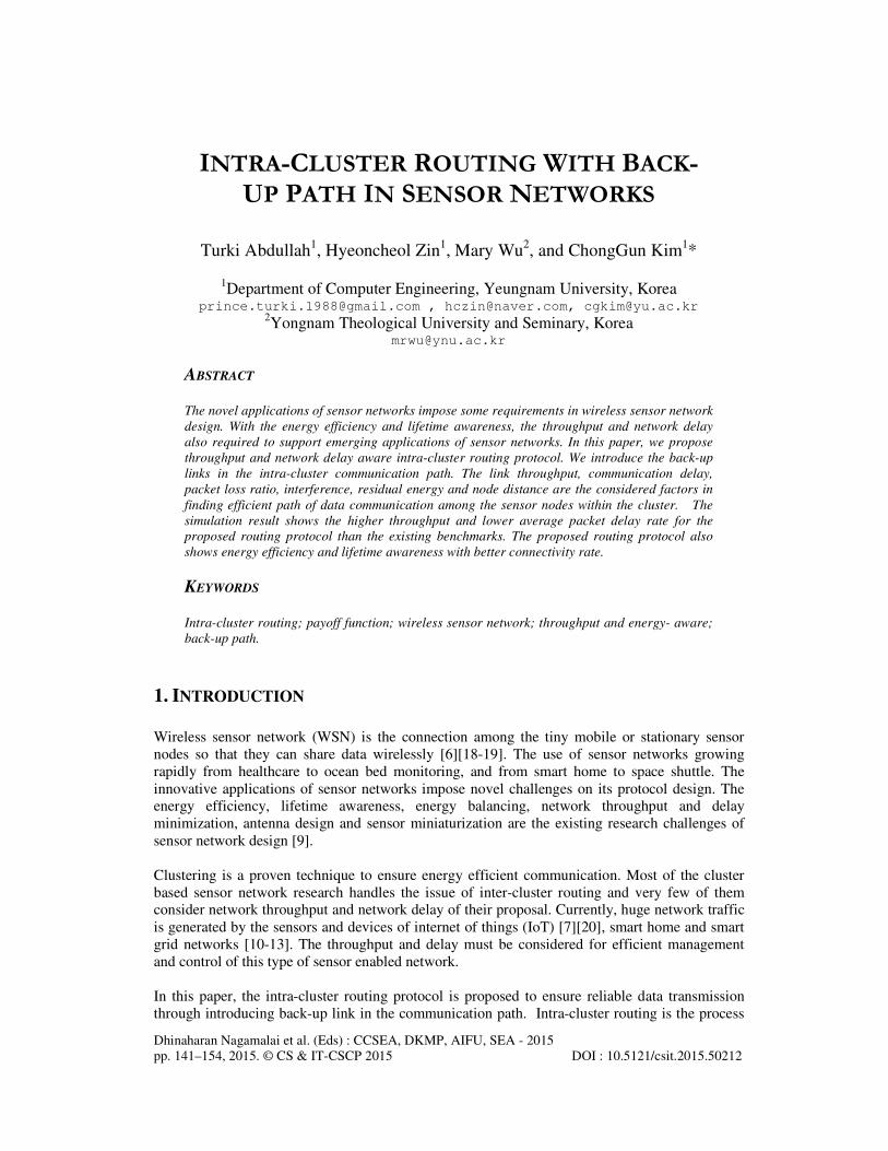
the cluster head within the cluster. Reference [5] proposed a method of intra-cluster routing.
Figure 1: Different routing strategies (a) No Clustering (b) Intra-cluster routing (c) Inter-cluster routing
Inter-cluster routing is the process to find out the efficient path to forward data towards the base
station (BS) following cluster to cluster communication. So, inter-cluster routing protocol deals
with efficient communication among the clusters. Reference [22] proposed a method of inter-
cluster routing. Different routing strategies are shown in Figure 1.
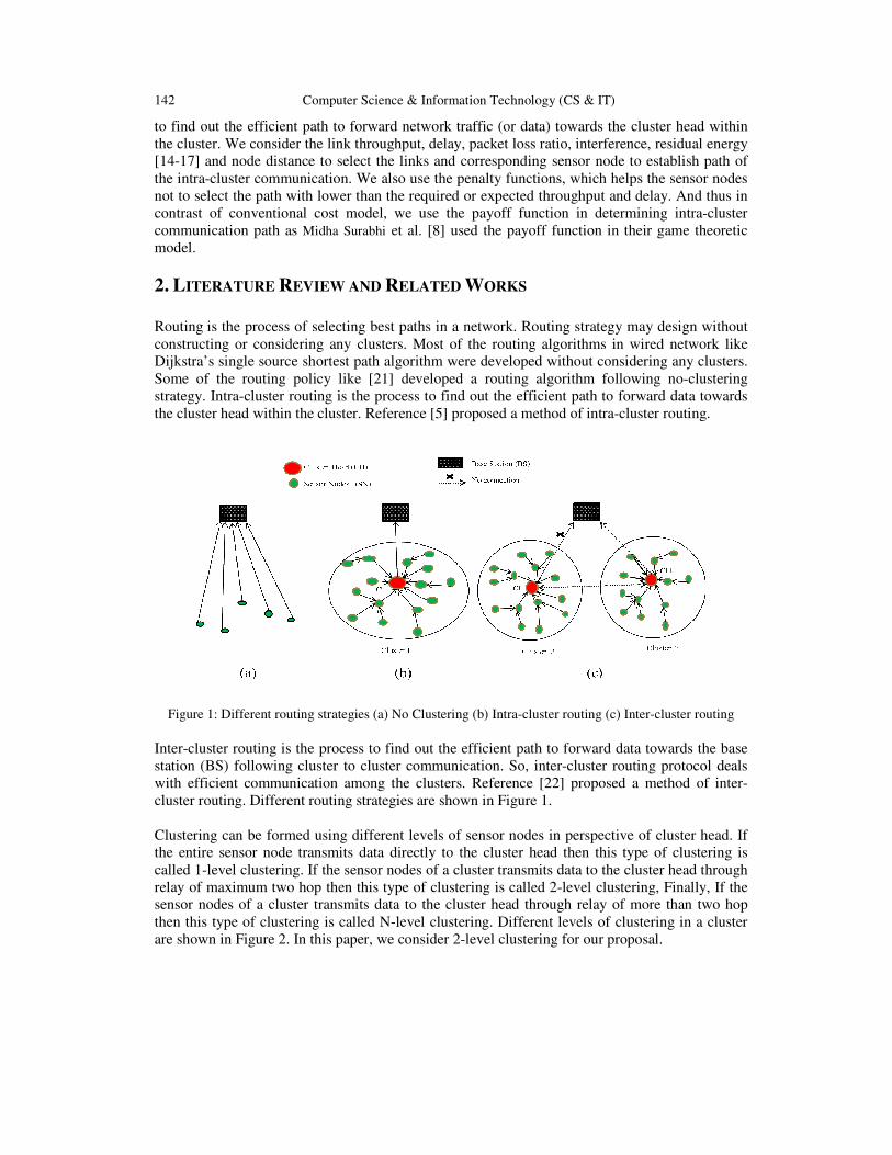
Clustering can be formed using different levels of sensor nodes in perspective of cluster head. If
the entire sensor node transmits data directly to the cluster head then this type of clustering is
called 1-level clustering. If the sensor nodes of a cluster transmits data to the cluster head through
relay of maximum two hop then this type of clustering is called 2-level clustering, Finally, If the
sensor nodes of a cluster transmits data to the cluster head through relay of more than two hop
then this type of clustering is called N-level clustering. Different levels of clustering in a cluster
are shown in Figure 2. In this paper, we consider 2-level clustering for our proposal.
Computer Science & Information Technology (CS & IT) 143
Figure 2: Different level of clustering (a) N- Level Clustering (b) 1-Level Clustering (c) 2-Level Clustering
Some of the protocols are based on hierarchical network structure and some are based on flat
network structure, some are QoS based and some are negotiation based. However, the energy
efficiency, lifetime awareness, security and network throughputs are the main design goals of
WSN routing protocols. A multiple alternating path based on-demand routing protocol is
proposed for ad hoc networks, which is an extension of AODV routing protocol [1]. The authors’
explored multiple path of data transmission for higher throughput with energy efficiency. This
proposal is not based on any clustering mechanism and thus hard to manage the sensor networks
in densely deployed environment.
The energy efficient and dual-path routing protocol is proposed in [2], to handle the temporary
failure of sensor node after cluster head died in cluster-based WSN. Here, the authors mainly
focus on inter cluster routing and try to handle the exception of CH failing. Cluster-based multi-
path routing for multi-hop wireless networks is proposed in [3]. The authors’ also focused on
inter-cluster routing with multiple paths to enhance network throughput. It allows only one path
to go over a cluster to reduce interference among two parallel paths. Maintaining routing table for
multiple paths causes’ higher energy consumption in resource constrained sensor networks.
Whereas in our proposed routing protocol we introduce backup links to enhance network
throughput in an intra-cluster communication environment.
A proactive routing protocol i.e. Energy Adaptive Clustering Hierarchy (LEACH) is proposed in
[4], where a cluster is formed according to the communication range and cluster head is selected
by the base station (BS) in a uniform random distributed manner. It is the seminal paper, which
shows the way to develop energy efficient WSN through clustering. It is proactive routing
protocol, where the node in the network periodically sends data towards CH by following
predefined schedule. Easiness of cluster formation and sensor network configuration is one of the
best criteria of LEACH protocol. Multi-path or back-up path is not considered in LEACH
protocol and thus lower network throughput, higher packet loss and retransmission rate diminish
the gain of energy efficiency.
The energy-aware routing in cluster-based sensor networks (EARCBSN) is proposed in [5]. In the
proposed method, the authors’ assigns a centralized network manager or gateway node to manage
intra-cluster communication efficiently. The gateway node sets the route mainly based on energy
usage, distance, propagation delay, queuing cost and maximum connections per relay. The
authors’ show the higher throughput and energy efficiency of their proposed routing scheme
144 Computer Science & Information Technology (CS & IT)
through simulation. In contrast, we proposed a reactive intra-cluster routing protocol based on
payoff function with the back-up links for energy efficiency, lifetime awareness and higher
network throughput.
3. PROPOSED METHODS
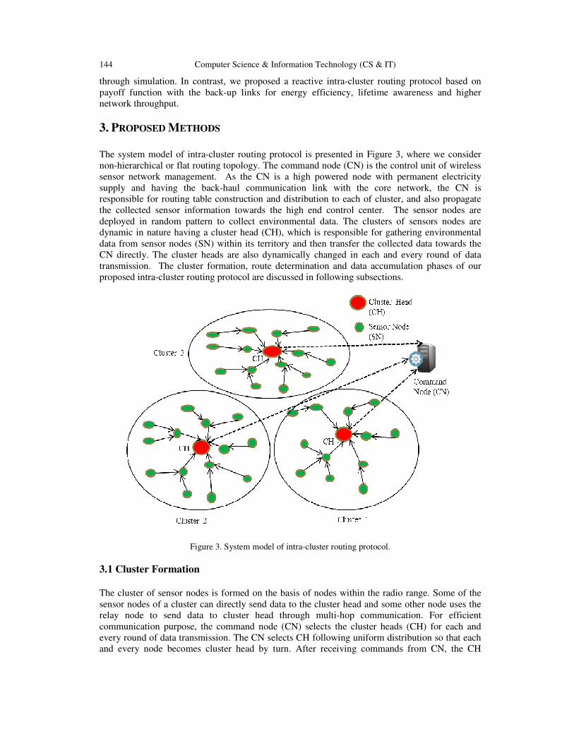
The system model of intra-cluster routing protocol is presented in Figure 3, where we consider
non-hierarchical or flat routing topology. The command node (CN) is the control unit of wireless
sensor network management. As the CN is a high powered node with permanent electricity
supply and having the back-haul communication link with the core network, the CN is
responsible for routing table construction and distribution to each of cluster, and also propagate
the collected sensor information towards the high end control center. The sensor nodes are
deployed in random pattern to collect environmental data. The clusters of sensors nodes are
dynamic in nature having a cluster head (CH), which is responsible for gathering environmental
data from sensor nodes (SN) within its territory and then transfer the collected data towards the
CN directly. The cluster heads are also dynamically changed in each and every round of data
transmission. The cluster formation, route determination and data accumulation phases of our
proposed intra-cluster routing protocol are discussed in following subsections.
Figure 3. System model of intra-cluster routing protocol.
3.1 Cluster Formation
The cluster of sensor nodes is formed on the basis of nodes within the radio range. Some of the
sensor nodes of a cluster can directly send data to the cluster head and some other node uses the
relay node to send data to cluster head through multi-hop communication. For efficient
communication purpose, the command node (CN) selects the cluster heads (CH) for each and
every round of data transmission. The CN selects CH following uniform distribution so that each
and every node becomes cluster head by turn. After receiving commands from CN, the CH
Computer Science & Information Technology (CS & IT) 145
broadcast his headship status to the sensor network and expecting membership request from
normal sensor nodes (SNs). The SNs send the membership request with their positional and
energy level information to the nearest CH. After receiving membership request with necessary
information the CH determines the throughput, delay, SINR, packet loss ratio of the
communication link between each SN and CH. The CH then sends that information to the CN for
efficient routing table construction as we discussed in section 3.2.
The CN node then sends the routing table to CH. Finally, CH sends the routing information i.e.
next hop node; back-up next-hop node and acting node status to each member SNs. CH also sends
the soft and hard threshold to each of its member SNs for energy efficient data transmission. The
cluster formation procedure is presented in algorithm 1 as intra-cluster routing procedure.
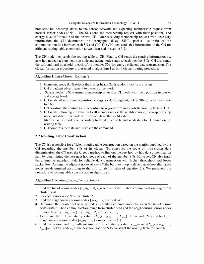
Algorithm 1: Intra-Cluster_Routing ()
1. Command node (CN) selects the cluster heads (CH) randomly to form clusters.
2. CH broadcast advertisement to the sensor network.
3. Sensor nodes (SN) transmit membership request to CH node with their position in cluster
and energy level.
4. CH sends all sensor nodes position, energy level, throughput, delay, SINR, packet loss ratio
to CN.
5. CN construct the routing table according to Algorithm 2 and sends the routing table to CH.
6. CH sends following information to all member nodes: the next-hop node, back-up next-hop
node and state of the node with soft and hard threshold values.
7. Member sensor nodes act according to the defined state and sends data to CH based on the
routing table.
8. CH compress the data and sends to the command
3.2 Routing Table Construction
The CN is responsible for efficient routing table construction based on the metrics supplied by the
CH regarding the member SNs of its cluster. To construct the route of intra-cluster data
dissemination, the CN uses the Greedy method to find out the best hop-by-hop data dissemination
path by determining the best next-hop node of each of the member SNs. However, CN also finds
the alternative next-hop node for reliable data transmission with higher throughput and lower
packet loss. Among the adjacent nodes of any SN the best next-hop node and next-hop alternative
nodes are determined according to the link suitability value of equation (1). We presented the
procedure of routing table construction in algorithm 2.
Algorithm 2: Routing_Table_Construction ()
1. Find the list of sensor nodes {d1,d2, …dm}, which are within 1-hop communication range from
cluster head
2. For each sensor node N of the cluster C
3. Find the neighbouring sensor nodes {s1,s2, …sn} of node N
4. Determine the feasible set of relay nodes by finding common nodes between the list of sensor
nodes within 1-hop communication range from cluster head and the neighbouring sensor nodes
of node N i.e. {a1,a2, …ak} = {d1,d2, …dm} ∩ {s1,s2, …sn}
5. Determine the link suitability values {LN,a1, LN,a2, … , LN,ak} from node N to each of the
neighbouring sensor nodes {a1,a2, …ak} using equation (1).
6. Find the sensor node ai with maximum link suitability values Lmax1= max{LN,a1, LN,a2, … ,
LN,ak}and set the node ai as the next hop node of N to construct the routing table for node N.
146 Computer Science & Information Technology (CS & IT)
7. Find the sensor node aj with maximum (i.e. second highest) link values Lmax2= max{ {LN,a1,
LN,a2, … , LN,ak}\ {LN,ai}} and set the node aj as the back-up next hop node of N to construct the
routing table for node N.
8. Define the state of the node N from the set of states’ S={sensing, aggregating, active, relaying,
inactive} sequentially following random distribution to construct the routing table for node
N.
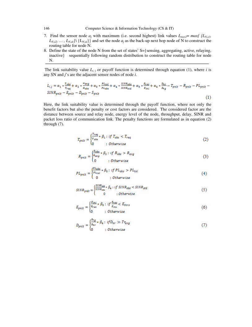
The link suitability value Li, j or payoff function is determined through equation (1), where i is
any SN and j’s are the adjacent sensor nodes of node i.
Here, the link suitability value is determined through the payoff function, where not only the
benefit factors but also the penalty or cost factors are considered. The considered factor are the
distance between source and relay node, energy level of the node, throughput, delay, SINR and
packet loss ratio of communication link. The penalty functions are formulated as in equation (2)
through (7).
Computer Science & Information Technology (CS & IT) 147
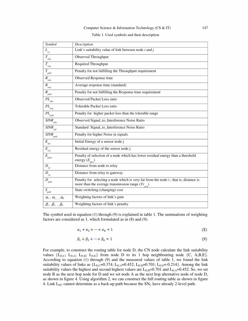
Table 1. Used symbols and their description
The symbol used in equation (1) through (9) is explained in table 1. The summations of weighting
factors are considered as 1, which formulated as in (8) and (9).
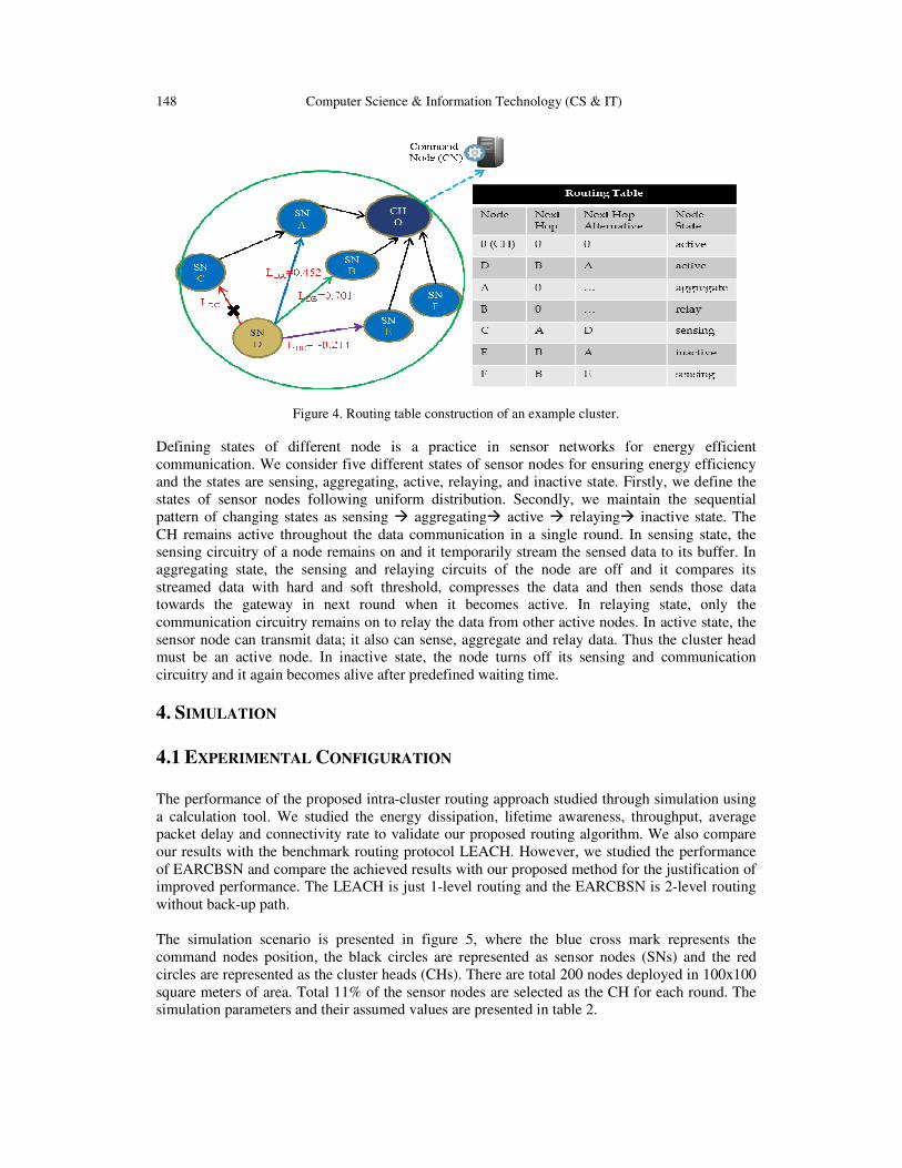
For example, to construct the routing table for node D, the CN node calculate the link suitability
values {LD,C; LD,A; LD,B; LD,E} from node D to its 1 hop neighbouring node {C, A,B,E}.
According to equation (1) through (9) and the measured values of table 1, we found the link
suitability values of links as {LD,C=0.374; LD,A=0.452; LD,B=0.701; LD,E=-0.214}. Among the link
suitability values the highest and second highest values are LD,B=0.701 and LD,A=0.452. So, we set
node B as the next hop node for D and we set node A as the next hop alternative node of node D,
as shown in figure 4. Using algorithm 2, we can construct the full routing table as shown in figure
4. Link LDC cannot determine as a back-up path because the SNC have already 2-level path.
Symbol Description
Li,j
Link’s suitability value of link between node i and j
Tobs
Observed Throughput
Treq
Required Throughput
Tpnlt
Penalty for not fulfilling the Throughput requirement
Robs
Observed Response time
Ravg
Average response time (standard)
Rpnlt
Penalty for not fulfilling the Response time requirement
PLobs
Observed Packet Loss ratio
PLavg
Tolerable Packet Loss ratio
PLpnlt
Penalty for higher packet loss than the tolerable range
SINRobs
Observed Signal_to_Interference Noise Ratio
SINRstd
Standard Signal_to_Interference Noise Ratio
SINRpnlt
Penalty for higher Noise in signals
Eini
Initial Energy of a sensor node j
Eres
Residual energy of the sensor node j
Epnlt
Penalty of selection of a node which has lower residual energy than a threshold
energy (Ethrs
)
Dnr
Distance from node to relay
Drg
Distance from relay to gateway
Dpnlt
Penalty for selecting a node which is very far from the node i ; that is, distance is
more than the average transmission range (Travg
)
Spnlt
State switching (changing) cost
α1 , α2 , …,α6 Weighting factors of link’s gain
β1 , β2 , …,β6 Weighting factors of link’s penalty
148 Computer Science & Information Technology (CS & IT)
Figure 4. Routing table construction of an example cluster.
Defining states of different node is a practice in sensor networks for energy efficient
communication. We consider five different states of sensor nodes for ensuring energy efficiency
and the states are sensing, aggregating, active, relaying, and inactive state. Firstly, we define the
states of sensor nodes following uniform distribution. Secondly, we maintain the sequential
pattern of changing states as sensing � aggregating� active � relaying� inactive state. The
CH remains active throughout the data communication in a single round. In sensing state, the
sensing circuitry of a node remains on and it temporarily stream the sensed data to its buffer. In
aggregating state, the sensing and relaying circuits of the node are off and it compares its
streamed data with hard and soft threshold, compresses the data and then sends those data
towards the gateway in next round when it becomes active. In relaying state, only the
communication circuitry remains on to relay the data from other active nodes. In active state, the
sensor node can transmit data; it also can sense, aggregate and relay data. Thus the cluster head
must be an active node. In inactive state, the node turns off its sensing and communication
circuitry and it again becomes alive after predefined waiting time.
4. SIMULATION
4.1 EXPERIMENTAL CONFIGURATION
The performance of the proposed intra-cluster routing approach studied through simulation using
a calculation tool. We studied the energy dissipation, lifetime awareness, throughput, average
packet delay and connectivity rate to validate our proposed routing algorithm. We also compare
our results with the benchmark routing protocol LEACH. However, we studied the performance
of EARCBSN and compare the achieved results with our proposed method for the justification of
improved performance. The LEACH is just 1-level routing and the EARCBSN is 2-level routing
without back-up path.
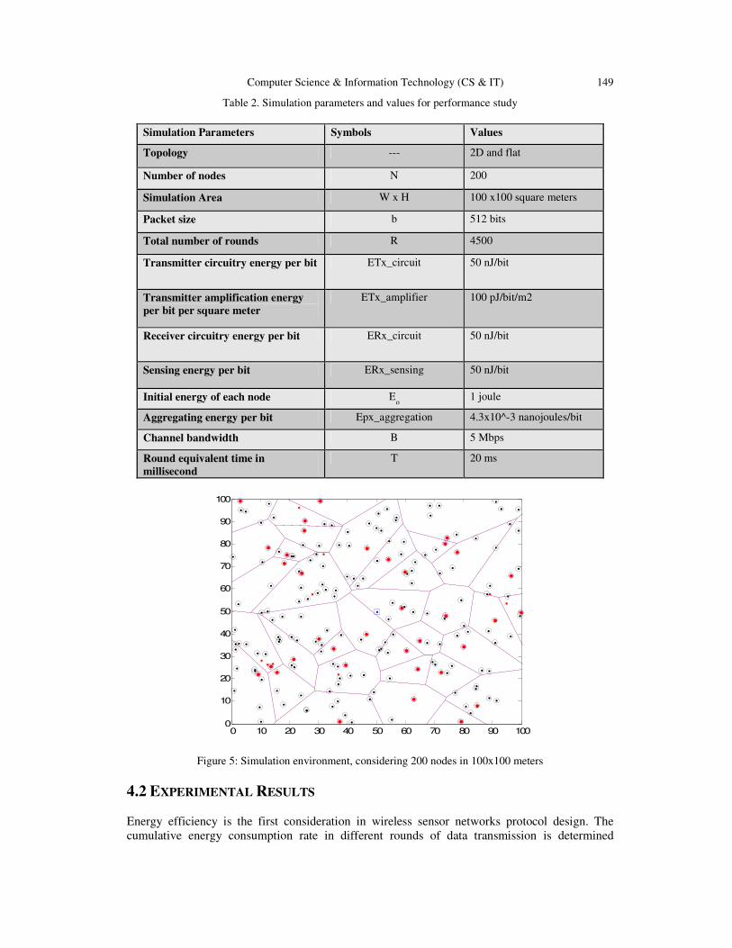
The simulation scenario is presented in figure 5, where the blue cross mark represents the
command nodes position, the black circles are represented as sensor nodes (SNs) and the red
circles are represented as the cluster heads (CHs). There are total 200 nodes deployed in 100x100
square meters of area. Total 11% of the sensor nodes are selected as the CH for each round. The
simulation parameters and their assumed values are presented in table 2.
Computer Science & Information Technology (CS & IT) 149
Table 2. Simulation parameters and values for performance study
Simulation Parameters Symbols Values
Topology --- 2D and flat
Number of nodes N 200
Simulation Area W x H 100 x100 square meters
Packet size b 512 bits
Total number of rounds R 4500
Transmitter circuitry energy per bit ETx_circuit 50 nJ/bit
Transmitter amplification energy
per bit per square meter
ETx_amplifier 100 pJ/bit/m2
Receiver circuitry energy per bit ERx_circuit 50 nJ/bit
Sensing energy per bit ERx_sensing 50 nJ/bit
Initial energy of each node Eo 1 joule
Aggregating energy per bit Epx_aggregation 4.3x10^-3 nanojoules/bit
Channel bandwidth B 5 Mbps
Round equivalent time in
millisecond
T 20 ms
0 10 20 30 40 50 60 70 80 90 1000
10
20
30
40
50
60
70
80
90
100
Figure 5: Simulation environment, considering 200 nodes in 100x100 meters
4.2 EXPERIMENTAL RESULTS
Energy efficiency is the first consideration in wireless sensor networks protocol design. The
cumulative energy consumption rate in different rounds of data transmission is determined
150 Computer Science & Information Technology (CS & IT)
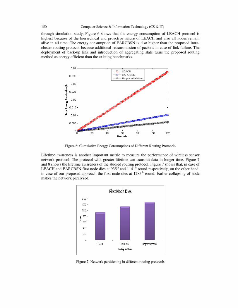
through simulation study. Figure 6 shows that the energy consumption of LEACH protocol is
highest because of the hierarchical and proactive nature of LEACH and also all nodes remain
alive in all time. The energy consumption of EARCBSN is also higher than the proposed intra-
cluster routing protocol because additional retransmission of packets in case of link failure. The
deployment of back-up link and introduction of aggregating state turns the proposed routing
method as energy efficient than the existing benchmarks.
Figure 6: Cumulative Energy Consumptions of Different Routing Protocols
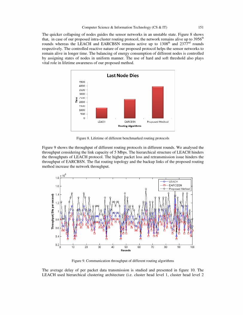
Lifetime awareness is another important metric to measure the performance of wireless sensor
network protocol. The protocol with greater lifetime can transmit data in longer time. Figure 7
and 8 shows the lifetime awareness of the studied routing protocol. Figure 7 shows that, in case of
LEACH and EARCBSN first node dies at 935th and 1141st round respectively, on the other hand,
in case of our proposed approach the first node dies at 1283th round. Earlier collapsing of node
makes the network paralyzed.
Figure 7: Network partitioning in different routing protocols
Computer Science & Information Technology (CS & IT) 151
The quicker collapsing of nodes guides the sensor networks in an unstable state. Figure 8 shows
that, in case of our proposed intra-cluster routing protocol, the network remains alive up to 3956th
rounds whereas the LEACH and EARCBSN remains active up to 1308th and 2377nd rounds
respectively. The controlled reactive nature of our proposed protocol helps the sensor networks to
remain alive in longer time. The balancing of energy consumption of different nodes is controlled
by assigning states of nodes in uniform manner. The use of hard and soft threshold also plays
vital role in lifetime awareness of our proposed method.
Figure 8. Lifetime of different benchmarked routing protocols
Figure 9 shows the throughput of different routing protocols in different rounds. We analysed the
throughput considering the link capacity of 5 Mbps. The hierarchical structure of LEACH hinders
the throughputs of LEACH protocol. The higher packet loss and retransmission issue hinders the
throughput of EARCBSN. The flat routing topology and the backup links of the proposed routing
method increase the network throughput.
Figure 9. Communication throughput of different routing algorithms
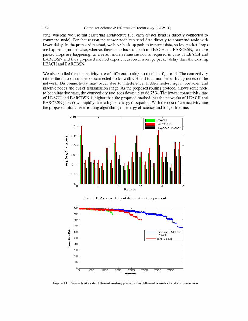
The average delay of per packet data transmission is studied and presented in figure 10. The
LEACH used hierarchical clustering architecture (i.e. cluster head level 1, cluster head level 2
152 Computer Science & Information Technology (CS & IT)
etc.), whereas we use flat clustering architecture (i.e. each cluster head is directly connected to
command node). For that reason the sensor node can send data directly to command node with
lower delay. In the proposed method, we have back-up path to transmit data, so less packet drops
are happening in this case, whereas there is no back-up path in LEACH and EARCBSN, so more
packet drops are happening, as a result more retransmission is required in case of LEACH and
EARCBSN and thus proposed method experiences lower average packet delay than the existing
LEACH and EARCBSN.
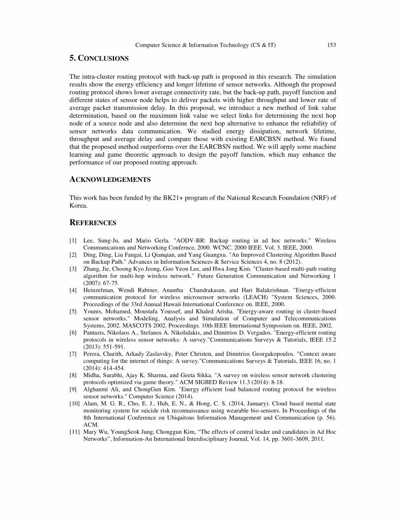
We also studied the connectivity rate of different routing protocols in figure 11. The connectivity
rate is the ratio of number of connected nodes with CH and total number of living nodes on the
network. Dis-connectivity may occur due to interference, hidden nodes, signal obstacles and
inactive nodes and out of transmission range. As the proposed routing protocol allows some node
to be in inactive state, the connectivity rate goes down up to 68.75%. The lowest connectivity rate
of LEACH and EARCBSN is higher than the proposed method, but the networks of LEACH and
EARCBSN goes down rapidly due to higher energy dissipation. With the cost of connectivity rate
the proposed intra-cluster routing algorithm gain energy efficiency and longer lifetime.
Figure 10. Average delay of different routing protocols
Figure 11. Connectivity rate different routing protocols in different rounds of data transmission
Computer Science & Information Technology (CS & IT) 153
5. CONCLUSIONS
The intra-cluster routing protocol with back-up path is proposed in this research. The simulation
results show the energy efficiency and longer lifetime of sensor networks. Although the proposed
routing protocol shows lower average connectivity rate, but the back-up path, payoff function and
different states of sensor node helps to deliver packets with higher throughput and lower rate of
average packet transmission delay. In this proposal, we introduce a new method of link value
determination, based on the maximum link value we select links for determining the next hop
node of a source node and also determine the next hop alternative to enhance the reliability of
sensor networks data communication. We studied energy dissipation, network lifetime,
throughput and average delay and compare those with existing EARCBSN method. We found
that the proposed method outperforms over the EARCBSN method. We will apply some machine
learning and game theoretic approach to design the payoff function, which may enhance the
performance of our proposed routing approach.
ACKNOWLEDGEMENTS
This work has been funded by the BK21+ program of the National Research Foundation (NRF) of
Korea.
REFERENCES
[1] Lee, Sung-Ju, and Mario Gerla. "AODV-BR: Backup routing in ad hoc networks." Wireless
Communications and Networking Confernce, 2000. WCNC. 2000 IEEE. Vol. 3. IEEE, 2000.
[2] Ding, Ding, Liu Fangai, Li Qianqian, and Yang Guangxu. "An Improved Clustering Algorithm Based
on Backup Path." Advances in Information Sciences & Service Sciences 4, no. 8 (2012).
[3] Zhang, Jie, Choong Kyo Jeong, Goo Yeon Lee, and Hwa Jong Kim. "Cluster-based multi-path routing
algorithm for multi-hop wireless network." Future Generation Communication and Networking 1
(2007): 67-75.
[4] Heinzelman, Wendi Rabiner, Anantha Chandrakasan, and Hari Balakrishnan. "Energy-efficient
communication protocol for wireless microsensor networks (LEACH) "System Sciences, 2000.
Proceedings of the 33rd Annual Hawaii International Conference on. IEEE, 2000.
[5] Younis, Mohamed, Moustafa Youssef, and Khaled Arisha. "Energy-aware routing in cluster-based
sensor networks." Modeling, Analysis and Simulation of Computer and Telecommunications
Systems, 2002. MASCOTS 2002. Proceedings. 10th IEEE International Symposium on. IEEE, 2002.
[6] Pantazis, Nikolaos A., Stefanos A. Nikolidakis, and Dimitrios D. Vergados. "Energy-efficient routing
protocols in wireless sensor networks: A survey."Communications Surveys & Tutorials, IEEE 15.2
(2013): 551-591.
[7] Perera, Charith, Arkady Zaslavsky, Peter Christen, and Dimitrios Georgakopoulos. "Context aware
computing for the internet of things: A survey."Communications Surveys & Tutorials, IEEE 16, no. 1
(2014): 414-454.
[8] Midha, Surabhi, Ajay K. Sharma, and Geeta Sikka. "A survey on wireless sensor network clustering
protocols optimized via game theory." ACM SIGBED Review 11.3 (2014): 8-18.
[9] Alghanmi Ali, and ChongGun Kim. "Energy efficient load balanced routing protocol for wireless
sensor networks." Computer Science (2014).
[10] Alam, M. G. R., Cho, E. J., Huh, E. N., & Hong, C. S. (2014, January). Cloud based mental state
monitoring system for suicide risk reconnaissance using wearable bio-sensors. In Proceedings of the
8th International Conference on Ubiquitous Information Management and Communication (p. 56).
ACM.
[11] Mary Wu, YoungSeok Jung, Chonggun Kim, “The effects of central leader and candidates in Ad Hoc
Networks”, Information-An International Interdisciplinary Journal, Vol. 14, pp. 3601-3609, 2011.
154 Computer Science & Information Technology (CS & IT)
[12] Mary Wu, InTaek Leem, Jason J. Jung and ChongGun Kim, "A Resource Reuse Method in Cluster
Sensor Networks in Ad Hoc Networks," Intelligent Information and Database Systems, Lecture Notes
in Computer Science, Volume 7197/2012, 40-50, 2012.
[13] Ahmed, Mohammad Helal Uddin, Alam Md Golam Rabiul, Kamal Rossi, Hong Choong Seon, and
Sungwon Lee. "Smart grid cooperative communication with smart relay." Journal of Communications
and Networks 14, no. 6 (2012): 640-652.
[14] Mary Wu, Chonggun Kim, "A cost matrix agent for shortest path routing in ad hoc networks," Journal
of Network and Computer Applications, 33, 646-652, 2010.
[15] Mary Wu, SeongGwon Cheon, Chonggun Kim, “A Central Leader Election Method using the
Distance Matrix in Ad Hoc Networks”, New Challenges for Intelligent Information and Database
Systems, Vol. 351, pp. 107-116, 2011.
[16] Alam, Md, Golam Rabiul, Chayan Biswas, Naushin Nower, and Mohammed Shafiul Alam Khan. "A
Reliable Semi-Distributed Load Balancing Architecture of Heterogeneous Wireless etworks." arXiv
preprint arXiv:1202.1918 (2012).
[17] Mary Wu, Byungchul Ahn, ChongGun Kim, "A Channel Reuse Procedure in Clustering Sensor
Networks, " Applied Mechanics and Materials V.284-287 pp.1981-1985.
[18] Jaime Lloret, “Underwater Sensor Nodes and Networks”, Sensors 2013, 13(9), 11782-11796
[19] Faezeh Arab Hassani, Yoshishige Tsuchiya and Hiroshi Mizuta, "In-Plane Resonant Nano-Electro-
Mechanical Sensors: A Comprehensive Study on Design, Fabrication and Characterization
Challenges”, Sensors 2013, 13(7), 9364-9387.
[20] Fang, Shifeng, Li Da Xu, Yunqiang Zhu, Jiaerheng Ahati, Huan Pei, Jianwu Yan, and Zhihui Liu.
"An Integrated System for Regional Environmental Monitoring and Management Based on Internet of
Things." IEEE Trans. Industrial Informatics 10, no. 2 (2014): 1596-1605.
[21] Chang,, L. Tassiulas, “Energy Conserving Routing in Wireless Ad-Hoc Networks,” In Proc.
International Conference on Computer Communications, Tel-Aviv, Israel, 2000, pp. 22-31.
[22] Zhang, Jie, Choong Kyo Jeong, Goo Yeon Lee, and Hwa Jong Kim. "Cluster-based multi-path routing
algorithm for multi-hop wireless network." Future Generation Communication and Networking 1
(2007): 67-75.