IntesisBox PA-AW2-MBS-1 English User Manual - rjTec.eu
20
IntesisBox ® PA-AW2-MBS-1 v.1.0 Modbus RTU (EIA-485) Interface for Panasonic Air to Water systems. Compatible with Panasonic Aquarea H generation models. User Manual Issue Date: 12/2017 r1.1 EN Order Code: IBMBSPAN001A000: IntesisBox Modbus Slave for Panasonic Aquarea H Generation
-
Upload
khangminh22 -
Category
Documents
-
view
0 -
download
0
Transcript of IntesisBox PA-AW2-MBS-1 English User Manual - rjTec.eu

IntesisBox® PA-AW2-MBS-1 v.1.0
Modbus RTU (EIA-485) Interface for Panasonic Air to Water
systems. Compatible with Panasonic Aquarea H generation models.
User Manual Issue Date: 12/2017
r1.1 EN
Order Code:
IBMBSPAN001A000: IntesisBox Modbus Slave for Panasonic Aquarea H Generation

PA-AW2-MBS-1 User’s Manual r1.1 EN
© Intesis Software S.L.U. - All rights reserved This information is subject to change without notice
IntesisBox® is a registered trademark of Intesis Software SLU
URL
Phone
http://www.intesisbox.com
+34 938047134
2/20
© Intesis Software S.L.U. 2017. All Rights Reserved.
Information in this document is subject to change without notice. No part of this publication
may be reproduced, stored in a retrieval system or transmitted in any form or any means
electronic or mechanical, including photocopying and recording for any purpose other than the
purchaser’s personal use without the written permission of Intesis Software S.L.U.
Intesis Software S.L.U. Milà i Fontanals, 1 bis 08700 Igualada Spain TRADEMARKS
All trademarks and tradenames used in this document are acknowledged to be the copyright of
their respective holders.

PA-AW2-MBS-1 User’s Manual r1.1 EN
© Intesis Software S.L.U. - All rights reserved This information is subject to change without notice
IntesisBox® is a registered trademark of Intesis Software SLU
URL
Phone
http://www.intesisbox.com
+34 938047134
3/20
INDEX
1. Presentation .......................................................................................................... 4
2. Connection ............................................................................................................ 5
2.1 Connection to the Hydro unit ................................................................................ 5
2.2 Connection to the EIA-485 bus ............................................................................. 5
3. Quick Start Guide ................................................................................................... 6
4. Modbus Interface Specification ................................................................................ 7
4.1 Modbus physical layer.......................................................................................... 7
4.2 Modbus Registers ................................................................................................ 7
4.2.1 General System Control ................................................................................. 7
4.2.2 Zones .......................................................................................................... 8
4.2.3 Tank Configuration ........................................................................................ 9
4.2.4 Consumption .............................................................................................. 10
4.2.5 Maintenance ............................................................................................... 10
4.2.6 Unit Configuration ....................................................................................... 10
4.2.7 Considerations on Temperature Registers ...................................................... 11
4.2.8 Zones ........................................................................................................ 11
4.3 DIP-switch Configuration Interface ...................................................................... 12
4.4 Implemented Functions ..................................................................................... 15
4.5 Device LED indicator ......................................................................................... 15
4.6 EIA-485 bus. Termination resistors and Fail-Safe Biasing mechanism ...................... 16
5. Electrical and Mechanical features .......................................................................... 17
6. List of supported Hydro Unit Types. ........................................................................ 18
7. Error Codes ......................................................................................................... 19

PA-AW2-MBS-1 User’s Manual r1.1 EN
© Intesis Software S.L.U. - All rights reserved This information is subject to change without notice
IntesisBox® is a registered trademark of Intesis Software SLU
URL
Phone
http://www.intesisbox.com
+34 938047134
4/20
PA-AW2-MBS-1
PA-AW2-MBS-1
PA-AW2-MBS-1
1. Presentation
The PA-AW2-MBS-1 interface allows a complete and natural
integration of Panasonic Air-to-Water Systems into
Modbus RTU (EIA-485) networks.
Compatible with Aquarea H models from Panasonic
Reduced dimensions. 93 x 53 x 58 mm.
3.7” x 2.1” x 2.3”
• Quick and easy installation. Mountable on DIN rail, wall, or even inside the Hydro unit.
• External power not required.
• Direct connection to Modbus RTU (EIA-485) networks. Up to 63 PA-AW2-MBS-1 devices can
be connected in the same network. PA-AW2-MBS-1 is a Modbus slave device.
• Direct connection to the Hydro unit. Up to 1 Hydro unit can be connected to PA-AW2-MBS-1. The cable for this connection is also supplied.
• Configuration from both on-board DIP-switches and Modbus RTU.
• Total Control and Supervision.
• Real states of the Hydro unit's internal variables.
• Allows simultaneous use of the remote controls of the Hydro unit and Modbus RTU.
*Up to 63 IntesisBox devices can be installed in the same Modbus RTU bus. However, depending on the configured speed, the installation
of Modbus Repeaters may be required.
Up to 63
Hydro
units*
Modbus RTU EIA-485 network
Modbus RTU
Master device
• SCADA
• PLC
• DDC
• BMS
• HMI
• Controller
• etc

PA-AW2-MBS-1 User’s Manual r1.1 EN
© Intesis Software S.L.U. - All rights reserved This information is subject to change without notice
IntesisBox® is a registered trademark of Intesis Software SLU
URL
Phone
http://www.intesisbox.com
+34 938047134
5/20
Figure 2.1 PA-AW2-MBS-1 connection diagram
2. Connection
The interface comes with a specific cable and connector to establish direct connection with the
Aquarea H Generation’s system. It comes as well with a plug-in terminal block of 2 poles to
establish direct connection with the Modbus RTU EIA-485 network.
2.1 Connection to the Hydro unit
To connect the PA-AW2-MBS-1 interface with the Hydro unit, these steps must be followed:
Disconnect Mains Power from the Hydro unit. Open the front cover of the Hydro unit to have
access to the electronic circuit. Once the electronic circuit is reached, locate the socket
connector marked as CN-CNT.
Take the cable that comes with the interface, insert one of its connectors (the one installed in
the shortest uncovered part) into the socket of the PA-AW2-MBS-1, and the other connector
(the one installed in the largest uncovered part) to the socket CN-CNT of the Hydro unit's
electronic circuit. You can place the PA-AW2-MBS-1 inside or outside the Hydro unit depending
on your needs. Remember that the PA-AW2-MBS-1 must also be connected to the Modbus RTU
EIA-485 network. Close the Hydro unit's front cover again to finish the connection.
Do not modify the length of the cable supplied with the interface, it may affect the correct
interface´s operation.
2.2 Connection to the EIA-485 bus
Connect the EIA-485 bus wires to the plug-in terminal block of PA-AW2-MBS-1 and keep the
polarity on this connection (A+ and B-). Make sure that the maximum distance to the bus is
1,200 meters (3,937 ft). Loop or star typologies are not allowed in the case of the EIA-485 bus.
A terminator resistor of 120Ω must be present at each end of the bus to avoid signal reflections.
The bus needs a fail-safe biasing mechanism (see section 4.6 for more details).
CN-CNT
Hydro unit
Internal control board
200 mm / 7.9”
40 mm / 1.6”
Connection cable supplied with the interface.
Fixing screw
90 mm / 3.5” IntesisBox®
PA-AW2-MBS-1
MODBUS RTU
EIA-485
Bus
EIA485 A B
Hydro Unit
53 mm / 2.1”
For wall mounting, extract the upper and lower staples until you hear the "click".
Use these holes to attach the cable using the staple and screw provided.

PA-AW2-MBS-1 User’s Manual r1.1 EN
© Intesis Software S.L.U. - All rights reserved This information is subject to change without notice
IntesisBox® is a registered trademark of Intesis Software SLU
URL
Phone
http://www.intesisbox.com
+34 938047134
6/20
3. Quick Start Guide
1. Disconnect the Hydro unit from the Mains Power.
2. Attach the interface next to the Hydro unit (wall mounting) following the instructions of
the diagram above or install it inside the Hydro unit (respect the safety instructions
given by Panasonic).
3. Connect the provided cable of the Panasonic interface between the Hydro unit and the
IntesisBox interface following the instructions of the diagram above.
4. Connect the EIA-485 bus to the connector EIA485 of the interface.
5. Close the Hydro indoor unit.
6. Check the DIP-Switch configuration of the IntesisBox interface and make sure it matches
the current installation’s parameters (see section 4.3).
By default, the interface is set to:
Modbus Slave Address 1
Modbus baud rate 9600 bps
These parameters can be modified from SW4 and SW3 DIP-Switches.
All other switch positions are set at low level (Off position ) by default.
NOTE: All changes on the DIP-Switch configuration require a system power cycle to be
applied.
7. Connect the Hydro unit system to Mains Power.
IMPORTANT: The IntesisBox interface requires to be connected to the Hydro unit
(powered) to start communicating.
ON ON
SW3 SW4

PA-AW2-MBS-1 User’s Manual r1.1 EN
© Intesis Software S.L.U. - All rights reserved This information is subject to change without notice
IntesisBox® is a registered trademark of Intesis Software SLU
URL
Phone
http://www.intesisbox.com
+34 938047134
7/20
4. Modbus Interface Specification
4.1 Modbus physical layer
PA-AW2-MBS-1 implements a Modbus RTU (Slave) interface, to be connected to an EIA-485
line. It performs 8N2 communication (8 data bits, no parity and 2 stop bit) with several
available baud rates (2400 bps, 4800 bps, 9600 bps -default-, 19200 bps, 38400 bps, 57600
bps, 76800 bps and 115200 bps). It also supports 8N1 communication (8 data bits, no parity
and 1 stop bit).
4.2 Modbus Registers
All registers are type “16-bit unsigned Holding Register” and they use the standard Modbus big
endian notation.
4.2.1 General System Control
Register Address
(protocol address)
Register Address
(PLC address) R/W Description
0 1 R/W System On/Off
0: Off
1: On (Default)
1 2 R Outdoor temperature 1,2
-127..127ºC (ºC/x10ºC)
-260.6..260.6ºF
2 3 R Outlet water temperature 1,2
0..127ºC (ºC/x10ºC)
32..260.6ºF
3 4 R Inlet water temperature 1,2
0..127ºC (ºC/x10ºC)
32..260.6ºF
4 5
R/W
Operating mode
1: Heat
2: Heat Tank
3: Tank
4: Cool Tank
5: Cool
6: Auto (Default)
R
7: Auto Tank
8: Auto Heat
9: Auto Heat Tank
10: Auto Cool
11: Auto Cool Tank
5 6 R/W
Heat mode water temp. setting method
1: Compensation curve
2: Direct (Default)
6 7 R/W
Cool mode water temp. setting method
1: Compensation curve
2: Direct (Default)
1 Magnitude for this register can be adjusted to Celsius x 1ºC, Celsius x 10ºC (default) or Fahrenheit. 2 It is not possible turn to x10 the value shown in Fahrenheit.

PA-AW2-MBS-1 User’s Manual r1.1 EN
© Intesis Software S.L.U. - All rights reserved This information is subject to change without notice
IntesisBox® is a registered trademark of Intesis Software SLU
URL
Phone
http://www.intesisbox.com
+34 938047134
8/20
4.2.2 Zones
Register Address
(protocol address)
Register Address
(PLC address) R/W Description
9 10 R/W
Zone 1/Zone 2 On/Off 3
1: On/Off
2: Off/On
3: On/On
10 11 R
Zone 1 sensors 3,4
1: Water temperature
2: External room sensor
3: Internal room sensor
4: Room thermistor
5: Pool Sensor
11 12 R
Zone 2 sensors 3,4
1: Water temperature
2: External room sensor
3: Internal room sensor
4: Room thermistor
5: Pool Sensor
12 13 R/W
Zone 1 setpoint temperature 3,4
COOL
Water shift
-5..5ºC (ºC/x10ºC) // -5..5ºF
Water
5..20ºC (ºC/x10ºC) // 41..68ºF
Room
18..35ºC (ºC/x10ºC) // 64.4..95ºF
HEAT
Water shift
-5..5ºC (ºC/x10ºC) // -5..5ºF
Water
5..55/65ºC (ºC/x10ºC) // 41..131/149ºF
Room
10..30ºC (ºC/x10ºC) // 50..86ºF
Pool
15..35ºC (ºC/x10ºC) // 59..95ºF
13 14 R/W
Zone 2 setpoint temperature 1,2,3,4
COOL
Water shift
-5..5ºC (ºC/x10ºC) // -5..5ºF
Water
5..20ºC (ºC/x10ºC) // 41..68ºF
Room
18..35ºC (ºC/x10ºC) // 64.4..95ºF
HEAT
Water shift
-5..5ºC (ºC/x10ºC) // -5..5ºF
Water
5..55/65ºC (ºC/x10ºC) // 41..131/149ºF
Room
10..30ºC (ºC/x10ºC) // 50..86ºF
Pool
15..35ºC (ºC/x10ºC) // 59..95ºF
3 More information about zone 1 and zone 2 on Section 4.2.8 4 See Section 4.2.7 to understand the options available

PA-AW2-MBS-1 User’s Manual r1.1 EN
© Intesis Software S.L.U. - All rights reserved This information is subject to change without notice
IntesisBox® is a registered trademark of Intesis Software SLU
URL
Phone
http://www.intesisbox.com
+34 938047134
9/20
14 15 R
Zone 1 current temperature 1,2,3,4
Water outlet/room/pool
-127..127ºC (ºC/x10ºC)
-260.6..260.6ºF
15 16 R
Zone 2 current temperature 1,2,3,4
Water outlet/room/pool
-127..127ºC (ºC/x10ºC)
-260.6..260.6ºF
16 17 R
Zone 1 temperature setting mode 3,4
1: Room temperature
2: Compensation curve (Water Temp)
3: Direct (Water Temp)
4: Pool Temp
17 18 R
Zone 2 temperature setting mode 3,4
1: Room temperature
2: Compensation curve (Water Temp)
3: Direct (Water Temp)
4: Pool Temp
18 19 R Zone 1 min Setpoint temperature 1,3
Any (ºC/x10ºC)
19 20 R Zone 1 max Setpoint temperature 1,3
Any (ºC/x10ºC)
20 21 R Zone 2 min Setpoint temperature 1,3
Any (ºC/x10ºC)
21 22 R Zone 2 max Setpoint temperature 1,3
Any (ºC/x10ºC)
4.2.3 Tank Configuration
Register Address
(protocol address)
Register Address
(PLC address) R/W Description
30 31 R/W Tank On/Off 4
0: Off
1: On
32 33 R Tank current water temperature 1,2
-127..127ºC (ºC/x10ºC)
-260.6..260.6ºF
33 34 R/W Tank water setpoint temperature 1,2
40..66/75ºC (ºC/x10ºC)
104..150.8/167ºF
34 35 R Tank heater 4
1: Internal
2: External
35 36 R Tank min water setpoint temperature 1,2,4
Any (ºC/x10ºC/Fº)
36 37 R Tank max water setpoint temperature 1,2,4
Any (ºC/x10ºC/Fº)

PA-AW2-MBS-1 User’s Manual r1.1 EN
© Intesis Software S.L.U. - All rights reserved This information is subject to change without notice
IntesisBox® is a registered trademark of Intesis Software SLU
URL
Phone
http://www.intesisbox.com
+34 938047134
10/20
4.2.4 Consumption
Register Address
(protocol address)
Register Address
(PLC address) R/W Description
45 46 R Tank mode energy consumption 4
0..50.800 W
46 47 R Heat mode energy consumption
0..50.800 W
47 48 R Cool mode energy consumption
0..50.800 W
4.2.5 Maintenance
Register Address
(protocol address)
Register Address
(PLC address) R/W Description
52 53 R
Error Code 5
0: No Error
0xxx: U+err
1xxx: H+err
2xxx: F+err
64 65 R Device Status
1: Off
2: On
70 71 R Current error status
0: No error
1: Error
4.2.6 Unit Configuration
Register Address
(protocol address)
Register Address
(PLC address) R/W Description
81 82 R Tank connection 4
0: No
1: Yes
82 83 R Number of zones 3
1: 1 zone
2: 2 zones
83 84 R Zone 1 setup 3,4
1: Room
2: Pool
84 85 R Zone 2 setup 3,4
1: Room
2: Pool
85 86 R Direction
1: Room
2: Tank
86 87 R
Outdoor type
1: STD
2: TCAP
3: HWT
5 See section 7 for possible error codes and their explanation

PA-AW2-MBS-1 User’s Manual r1.1 EN
© Intesis Software S.L.U. - All rights reserved This information is subject to change without notice
IntesisBox® is a registered trademark of Intesis Software SLU
URL
Phone
http://www.intesisbox.com
+34 938047134
11/20
4.2.7 Considerations on Temperature Registers
Setpoint temperature may be controlled from 4 different internal parameters of the Hydro Unit:
Water shift, Water, Room and Pool.
All of these parameters depend on the configuration of the Zone setup, Zone temp. setting
mode and Operation Mode.
Find below the correspondence of this configuration to know which internal parameter is
modified when we are controlling registers 12 and 13 (Modbus Protocol Address), corresponding
to Zone 1 setpoint temperature and Zone 2 setpoint temperature respectively.
Notice that temperature’s values temperature registers are expressed according to the
temperature´s format configured through its onboard DIP-Switches (See “4.3 - DIP-switch
Configuration Interface”). These following formats are possible:
• Celsius value: Value in Modbus register is the temperature value in Celsius (i.e. a
value “22” in the Modbus register must be interpreted as 22ºC)
• Decicelsius value: Value in Modbus register is the temperature value in
decicelsius (i.e. a value “220” in the Modbus register must be interpreted as
22.0ºC)
• Fahrenheit value: Value in Modbus register is the temperature value in
Fahrenheit (i.e. a value “72” in the Modbus register must be interpreted as 72ºF
(~22ºC).
4.2.8 Zones
Aquarea H Generation includes the possibility to control up to 2 different zones. The register 82
(Modbus protocol address) indicates the number of zones configured in the Hydro unit: 1 or 2
zones.
Taking this information into account and only in case that Hydro unit is controlling 2 zones, the
register address 9 (Modbus protocol address) can be used to switch on/off the zones. Notice
that if the Hydro unit is configured to manage a single zone, the use of the register address 9
(Modbus protocol address) doesn’t have any effect.
Please, check the Hydro Unit User’s Manual for more information about the zones’ configuration
and their options.
Zone x setup
Zone1 (Prot Add 83)
Zone2 (Prot Add 84)
Zone x temp. set. mode
Zone1 (Prot Add 16)
Zone2 (Prot Add 17)
Operation Mode
(Prot Addr 4)
Zone x set. temp.
Zone1 (Prot Add 12)
Zone2 (Prot Add 13)
Zone x current temp
Zone 1 (Prot Add 14)
Zone 2 (Prot Add 15)
1: Room
1: Room temperature 1: Heat
2: Heat Tank
3: Tank
4: Cool Tank
5: Cool
Room Room
2: Compensation Curve Water Shift
Water
3: Direct Water
2: Pool 4: Pool Temp 1: Heat
2: Heat Tank Pool Pool
PA-AW2-MBS-1 User’s Manual r1.1 EN
© Intesis Software S.L.U. - All rights reserved This information is subject to change without notice
IntesisBox® is a registered trademark of Intesis Software SLU
URL
Phone
http://www.intesisbox.com
+34 938047134
12/20
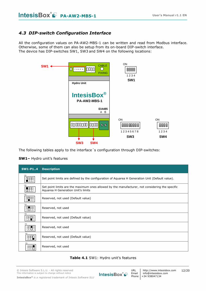
4.3 DIP-switch Configuration Interface
All the configuration values on PA-AW2-MBS-1 can be written and read from Modbus interface.
Otherwise, some of them can also be setup from its on-board DIP-switch interface.
The device has DIP-switches SW1, SW3 and SW4 on the following locations:
The following tables apply to the interface´s configuration through DIP-switches:
SW1– Hydro unit’s features
SW1-P1..4 Description
Set point limits are defined by the configuration of Aquarea H Generation Unit (Default value).
Set point limits are the maximum ones allowed by the manufacturer, not considering the specific Aquarea H Generation Unit’s limits
Reserved, not used (Default value)
Reserved, not used
Reserved, not used (Default value)
Reserved, not used
Reserved, not used (Default value)
Reserved, not used
Table 4.1 SW1: Hydro unit’s features
SW3 SW4
FIXING
CABLE
IntesisBox® PA-AW2-MBS-1
EIA485 A B
Hydro Unit
SW1
SW1
SW4
ON
1 2 3 4
ON
SW3
1 2 3 4
1 2 3 4 5 6 7 8
ON
ON
ON
ON
ON
ON
ON
ON
ON

PA-AW2-MBS-1 User’s Manual r1.1 EN
© Intesis Software S.L.U. - All rights reserved This information is subject to change without notice
IntesisBox® is a registered trademark of Intesis Software SLU
URL
Phone
http://www.intesisbox.com
+34 938047134
13/20
SW3/SW4 – Baud rate configuration
SW3-P7..8 SW4-P3 Description
2400bps
4800bps
9600bps (Default value)
19200bps
38400bps
57600bps
76800bps
115200bps
Table 4.2 SW3-SW4: Modbus baud rate
SW4 – Degrees/Decidegrees (x10), temperature magnitude (ºC/ºF) and EIA-485 termination
resistor.
Table 4.3 SW4: Temperature and termination resistor configuration
SW4-P1..2-4 Description
Temperature values in Modbus register are represented in degrees (x1) (Default value)
Temperature values in Modbus register are represented in decidegrees (x10)
Temperature values in Modbus register are represented in Celsius degrees (Default value)
Temperature values in Modbus register are represented in Fahrenheit degrees
EIA-485 bus without termination resistor (Default value)
Internal termination resistor of 120Ω connected to EIA-485 bus
ON
ON
ON
ON
ON
ON
ON ON
ON ON
ON ON
ON ON
ON ON
ON ON
ON ON
ON ON

PA-AW2-MBS-1 User’s Manual r1.1 EN
© Intesis Software S.L.U. - All rights reserved This information is subject to change without notice
IntesisBox® is a registered trademark of Intesis Software SLU
URL
Phone
http://www.intesisbox.com
+34 938047134
14/20
SW3 – Modbus Slave address
Table 4.4 SW3: Modbus slave address
Add
SW3-P1..6
Add
SW3-P1..6
Add
SW3-P1..6
Add
SW3-P1..6
Add
SW3-P1..6
0
13
26
39
52
1
14
27
40
53
2
15
28
41
54
3
16
29
42
55
4
17
30
43
56
5
18
31
44
57
6
19
32
45
58
7
20
33
46
59
8
21
34
47
60
9
22
35
48
61
10
23
36
49
62
11
24
37
50
63
12
25
38
51
ON
ON
ON
ON
ON
ON
ON
ON
ON
ON
ON
ON
ON
ON
ON
ON
ON
ON
ON
ON
ON
ON
ON
ON
ON
ON
ON
ON
ON
ON
ON
ON
ON
ON
ON
ON
ON
ON
ON
ON
ON
ON
ON
ON
ON
ON
ON
ON
ON
ON
ON
ON
ON
ON
ON
ON
ON
ON
ON
ON
ON
ON
ON
ON

PA-AW2-MBS-1 User’s Manual r1.1 EN
© Intesis Software S.L.U. - All rights reserved This information is subject to change without notice
IntesisBox® is a registered trademark of Intesis Software SLU
URL
Phone
http://www.intesisbox.com
+34 938047134
15/20
4.4 Implemented Functions
PA-AW2-MBS-1 implements the following standard Modbus functions:
3: Read Holding Registers
4: Read Input Registers
6: Write Single Register
16: Write Multiple Registers (Despite this function is allowed, the interface does not
allow to write operations on more than 1 register with the same request, this means that
length field should be always be 1 when this function is being used in case of writing)
4.5 Device LED indicator
The device includes two LED indicators to show all the possible operational states. In the
following table there are written the indicators which can be performed and their meaning.
L1 (yellow LED)
Device status LED indication ON / OFF Period Description
During not normal operation
LED blinking 500ms ON / 500ms OFF Communication error
During normal operation
LED flashing 100ms ON / 1900ms OFF Normal operation (configured and working properly)
L1 (green LED) & L2 (red LED)
Device status LED indication ON / OFF Period Description
During normal operation
LED Pulse 5sec ON / --- OFF Device Start-up
During not normal operation
LED alternatively
blinking 500ms ON / 500ms OFF EEPROM failure

PA-AW2-MBS-1 User’s Manual r1.1 EN
© Intesis Software S.L.U. - All rights reserved This information is subject to change without notice
IntesisBox® is a registered trademark of Intesis Software SLU
URL
Phone
http://www.intesisbox.com
+34 938047134
16/20
4.6 EIA-485 bus. Termination resistors and Fail-Safe Biasing
mechanism
EIA-485 bus requires a 120Ω terminator resistor at each end of the bus to avoid signal
reflections.
In order to prevent fail status detected by the receivers, which are “listening” the bus, when all
the transmitters’ outputs are in three-state (high impedance), it is also required a fail-safe
biasing mechanism. This mechanism provides a safe status (a correct voltage level) in the bus
when all the transmitters’ outputs are in three-state. This mechanism must be supplied by the
Modbus Master.
The PA-AW2-MBS-1 device includes an on-board terminator resistor of 120Ω that can be
connected to the EIA-485 bus by using DIP-switch SW4.
Some Modbus RTU EIA-485 Master devices can provide also internal 120Ω terminator resistor
and/or fail-safe biasing mechanism (Check the technical documentation of the Master device
connected to the EIA-485 network in each case).

PA-AW2-MBS-1 User’s Manual r1.1 EN
© Intesis Software S.L.U. - All rights reserved This information is subject to change without notice
IntesisBox® is a registered trademark of Intesis Software SLU
URL
Phone
http://www.intesisbox.com
+34 938047134
17/20
5. Electrical and Mechanical features
Enclosure
Plastic, type PC (UL 94 V-0) Net dimensions (dxwxh): 93 x 53 x 58 mm / 3.7” x 2.1” x 2.3” Color: Light Grey. RAL 7035
Operation Temperature
0ºC to +60ºC
Weight 85 g. Stock Temperature
-20ºC to +85ºC
Mounting Wall DIN rail EN60715 TH35.
Operational Humidity
<95% RH, non-condensing
Terminal Wiring (for low-voltage signals)
For terminal: solid wires or stranded wires (twisted or with ferrule)
1 core: 0.5mm2… 2.5mm2 2 cores: 0.5mm2… 1.5mm2
3 cores: not permitted
Stock Humidity <95% RH, non-condensing
Modbus RTU port
1 x Serial EIA485 Plug-in screw terminal block (2 poles):
A, B Compatible with Modbus RTU EIA-485 networks
Isolation voltage 1500 VDC
Hydro unit port 1 x Specific connector Specific cable included
Isolation resistance
1000 MΩ
Switch 1 (SW1)
1 x DIP-Switch for Hydro Unit features Protection IP20 (IEC60529)
Switch 3 (SW3)
1 x DIP-Switch for Modbus RTU settings LED indicators 1 x Onboard LED - Operational status
Switch 4 (SW4)
1 x DIP-Switch for extra functions
EIA-485
Port
Hydro Unit
connection
DIP
Switch SW3
DIP
Switch SW1 LED
Indicator
DIP
Switch SW4

PA-AW2-MBS-1 User’s Manual r1.1 EN
© Intesis Software S.L.U. - All rights reserved This information is subject to change without notice
IntesisBox® is a registered trademark of Intesis Software SLU
URL
Phone
http://www.intesisbox.com
+34 938047134
18/20
6. List of supported Hydro Unit Types.
A list of Panasonic Hydro unit model’s references compatible with PA-AW2-MBS-1 and their
available features can be found in:
https://www.intesisbox.com/intesis/support/compatibilities/IntesisBox_PA-AW2-xxx-1_Compatibility.pdf

PA-AW2-MBS-1 User’s Manual r1.1 EN
© Intesis Software S.L.U. - All rights reserved This information is subject to change without notice
IntesisBox® is a registered trademark of Intesis Software SLU
URL
Phone
http://www.intesisbox.com
+34 938047134
19/20
7. Error Codes
Error
Code
Modbus
Error in
Remote
Controller
Error Description
0 H00 No abnormality detected
112 H12 Indoor/Outdoor capacity unmatched
115 H15 Outdoor compressor temperature sensor abnormality
120 H20 Water pump abnormality
123 H23 Indoor refrigerant liquid temperature sensor abnormality
127 H27 Service valve error
128 H28 Abnormal solar sensor
131 H31 Abnormal swimming pool sensor
136 H36 Abnormal buffer tank sensor
138 H38 Brand code not match
142 H42 Compressor low pressure abnormality
143 H43 Abnormal Zone 1 sensor
144 H44 Abnormal Zone 2 sensor
162 H62 Water flow switch abnormality
163 H63 Refrigerant low pressure abnormality
164 H64 Refrigerant high pressure abnormality
165 H65 Deice circulation error
167 H67 Abnormal External Thermistor 1
168 H68 Abnormal External Thermistor 2
170 H70 Back-up heater OLP abnormality
172 H72 Tank sensor abnormal
174 H74 PCB communication error
175 H75 Low water temperature control
176 H76 Indoor - control panel communication abnormality
190 H90 Indoor/outdoor abnormal communication
191 H91 Tank heater OLP abnormality
195 H95 Indoor/Outdoor wrong connection
198 H98 Outdoor high pressure overload protection
199 H99 Indoor heat exchanger freeze prevention
212 F12 Pressure switch activate
214 F14 Outdoor compressor abnormal revolution
215 F15 Outdoor fan motor lock abnormality
216 F16 Total running current protection
220 F20 Outdoor compressor overheating protection
222 F22 IPM (power transistor) overheating protection
223 F23 Outdoor Direct Current (DC) peak detection
224 F24 Refrigeration cycle abnormality
225 F25 Cooling/Heating cycle changeover abnormality
227 F27 Pressure switch abnormality
229 F29 Low Discharge Superheat
230 F30 Water outlet sensor 2 abnormality
232 F32 Abnormal Internal Thermostat
236 F36 Outdoor air temperature sensor abnormality
237 F37 Indoor water inlet temperature sensor abnormality
240 F40 Outdoor discharge pipe temperature sensor abnormality
241 F41 PFC control
242 F42 Outdoor heat exchanger temperature sensor abnormality
243 F43 Outdoor defrost sensor abnormality
245 F45 Indoor water outlet temperature sensor abnormality
246 F46 Outdoor Current Transformer open circuit
248 F48 Outdoor EVA outlet temperature sensor abnormality

PA-AW2-MBS-1 User’s Manual r1.1 EN
© Intesis Software S.L.U. - All rights reserved This information is subject to change without notice
IntesisBox® is a registered trademark of Intesis Software SLU
URL
Phone
http://www.intesisbox.com
+34 938047134
20/20
249 F49 Outdoor bypass outlet temperature sensor abnormality
295 F95 Cooling high pressure overload protection
In case to detect an error code not listed, contact your closest Panasonic technical support
service.